sps envirowall external wall insulation system …
TRANSCRIPT

Page 1 of 19
TECHNICAL APPROVALS FOR CONSTRUCTION
APPROVAL
INSPECTION
TESTING
CERTIFICATION
SPS Envirowall Limited25/26 Rosevale RoadParkhouse Industrial Estate WestNewcastle under LymeStaffordshire ST5 7EFTel: 0845 1300 983 Fax: 0845 1300 984e-mail: [email protected]: www.spsenvirowall.co.uk
British Board of Agrément tel: 01923 665300Bucknalls Lane fax: 01923 665301Watford [email protected] WD25 9BA www.bbacerts.co.uk©2016
The BBA is a UKAS accredited certification body — Number 113. The schedule of the current scope of accreditation for product certification is available in pdf format via the UKAS link on the BBA website at www.bbacerts.co.uk
Readers are advised to check the validity and latest issue number of this Agrément Certificate by either referring to the BBA website or contacting the BBA direct.
SPS ENVIROWALL EXTERNAL WALL INSULATION SYSTEM
ENVIROWALL TS RAIL SYSTEM
This Agrément Certificate Product Sheet(1) relates to the Envirowall TS Rail System, an external wall insulation system with EPS insulation boards, mechanically-fixed rail profiles, a reinforced basecoat and render and brick slip finishes. The system is for use installed onto new and existing domestic and non-domestic buildings of sheathed lightweight steel frame construction.(1) Hereinafter referred to as ‘Certificate’.
CERTIFICATION INCLUDES:• factors relating to compliance with Building Regulations
where applicable• factors relating to additional non-regulatory information
where applicable• independently verified technical specification• assessment criteria and technical investigations• design considerations• installation guidance• regular surveillance of production• formal three-yearly review.
KEY FACTORS ASSESSEDThermal performance — the system can be used to improve the thermal performance of external walls and can contribute to satisfying the requirements of the national Building Regulations (see section 6).
Strength and stability — the system can adequately resist wind loads and impact damage. The impact resistance is dependent on the finish chosen (see section 7).
Behaviour in relation to fire — the system has a B-s1, d0 reaction to fire classification in accordance with BS EN 13501-1 : 2007 (see section 8).
Risk of condensation — the system can contribute to limiting the risk of interstitial and surface condensation (see section 11).
Durability — when installed and maintained in accordance with the Certificate holder’s recommendations and the terms of this Certificate, the system will remain effective for at least 30 years (see section 13).
Agrément Certificate05/4206
Product Sheet 3
The BBA has awarded this Certificate to the company named above for the system described herein. This system has been assessed by the BBA as being fit for its intended use provided it is installed, used and maintained as set out in this Certificate.
On behalf of the British Board of Agrément
Date of Second issue: 14 October 2016 John Albon — Head of Approvals Claire Curtis-Thomas
Originally certificated on 9 March 2009 Construction Products Chief Executive
Page 2 of 19
In the opinion of the BBA, the Envirowall TS Rail System, if installed, used and maintained in accordance with the provisions of this Certificate, can satisfy or contribute to satisfying the relevant requirements of the following Building Regulations (the presence of a UK map indicates that the subject is related to the Building Regulations in the region or regions of the UK depicted):
The Building Regulations 2010 (England and Wales) (as amended)
Requirement: A1 Loading
Comment: The system can sustain and transmit wind loads to the substrate wall. See sections 7.1 to 7.5 of this Certificate.
Requirement: B4 (1) External fire spread
Comment: The system can satisfy this Requirement. See sections 8.1 to 8.6 of this Certificate.Requirement: C2 (b) Resistance to moisture
Comment: The system provides a degree of protection against rain ingress. See sections 4.4 and 10.1 of this Certificate.
Requirement: C2(c) Resistance to moisture
Comment: The system can contribute to minimising the risk of interstitial and surface condensation. See sections 11.1, 11.2 and 11.4 of this Certificate.
Requirement: L1 (a)(i) Conservation of fuel and power
Comment: The system can contribute to satisfying this Requirement. See sections 6.2 and 6.3 of this Certificate.Regulation: 7 Materials and workmanship
Comment: The system is acceptable. See section 13.1 and the Installation part of this Certificate.Regulation: 26 CO2 emission rates for new buildingsRegulation: 26A Fabric energy efficiency rates for new dwellings (applicable to England only)Regulation: 26A Primary energy consumption rates for new buildings (applicable to Wales only)Regulation: 26B Fabric performance values for new dwellings (applicable to Wales only)
Comment: The system can contribute to satisfying these Regulations; however, appropriate compensating fabric/services measures may need to be taken. See sections 6.2 and 6.3 of this Certificate.
The Building (Scotland) Regulations 2004 (as amended)
Regulation: 8(1)(2) Durability, workmanship and fitness of materials
Comment: The system can contribute to the construction satisfying this Regulation. See sections 12 and 13.1 and the Installation part of this Certificate.
Regulation: 9 Building standards applicable to constructionStandard: 1.1 Structure
Comment: The system can sustain and transmit wind loads to the substrate wall. See sections 7.1 to 7.5 of this Certificate.Standard: 2.6 Spread to neighbouring buildings
Comment: The external surface of the system is classified as ‘low risk’, with reference to clauses 2.6.4(1)(2), 2.6.5(1) and 2.6.6(2). See sections 8.1 to 8.8 of this Certificate.
Standard: 2.7 Spread on external walls
Comment: The external surface of the system is classified as ‘low risk’, with reference to clauses 2.7.1(1)(2) and 2.7.2(1)(2) and Annex 2A(1). See sections 8.1 to 8.8 of this Certificate.
Standard: 3.10 Precipitation
Comment: The system will contribute to a construction satisfying this Standard, with reference to clauses 3.10.1(1)(2) and 3.10.2(1)(2). See sections 4.4 and 10.1 of this Certificate.
Standard: 3.15 Condensation
Comment: The system can satisfy the requirements of this Standard, with reference to clauses 3.15.1(1)(2), 3.15.4(1)(2) and 3.15.5(1)(2). See sections 11.3 and 11.4 of this Certificate.
Standard: 6.1(b) Carbon dioxide emissionsStandard: 6.2 Buildings insulation envelope
Comment: The system can contribute to satisfying these Standards, with reference to clauses 6.1.1(1)(2), 6.1.2(1)(2), 6.1.3(1), 6.1.6(1), 6.1.10(2), 6.2.1(1)(2), 6.2.3(1), 6.2.4(2), 6.2.5(2), 6.2.6(1), 6.2.7(1), 6.2.8(2), 6.2.9(1)(2), 6.2.10(1), 6.2.11(1), 6.2.12(2) and 6.2.13(1)(2). See sections 6.2 and 6.3 of this Certificate.
Standard: 7.1(a)(b) Statement of sustainability
Comment: The system can contribute to satisfying the relevant requirements of Regulation 9, Standards 1 to 6, and therefore will contribute to a construction meeting the bronze level of sustainability as defined in this Standard. In addition, the product can contribute to a construction meeting a higher level of sustainability as defined in these Standards, with reference to clauses 7.1.4(1)(2) [Aspect 1(1)(2) and 2(1)], 7.1.6(1)(2)
[Aspect 1(1)(2) and 2(1)] and 7.1.7(1)(2) [Aspect 1(1)(2)]. See section 6.2 of this Certificate.Regulation: 12 Building standards applicable to conversions
Comment: All comments given for the system under Regulation 9, Standards 1 to 6, also apply to this Regulation, with reference to 0.12.1(1)(2) and Schedule 6(1)(2).
(1) Technical Handbook (Domestic). (2) Technical Handbook (Non-Domestic).
Regulations
Page 3 of 19
The Building Regulations (Northern Ireland) 2012 (as amended)
Regulation: 23 Fitness of materials and workmanship
Comment: The system is acceptable. See section 13.1 and the Installation part of this Certificate.Regulation: 28(b) Resistance to moisture and weather
Comment: The system provides a degree of protection against rain ingress. See sections 4.4 and 10.1 of this Certificate.
Regulation: 29 Condensation
Comment: The system contributes to minimising the risk of interstitial and surface condensation. See section 11.4 of this Certificate.
Regulation: 30 Stability
Comment: The system can sustain and transmit wind loads to the substrate wall. See section 7.1 to 7.5 of this Certificate.
Regulation: 36(a) External fire spread
Comment: The system can satisfy this Regulation. See sections 8.1 to 8.6 of this Certificate.Regulation: 39(a)(i) Conservation measures
Comment: The system can contribute to satisfying this Regulation. See sections 6.2 and 6.3 of this Certificate.Regulation: 40 Target carbon dioxide emission rate
Comment: The systems can contribute to satisfying this Regulation. See sections 6.2 and 6.3 of this Certificate.
Construction (Design and Management) Regulations 2015Construction (Design and Management) Regulations (Northern Ireland) 2016
Information in this Certificate may assist the client, designer (including Principal Designer) and contractor (including Principal Contractor) to address their obligations under these Regulations.See section: 3 Delivery and site handling (3.1 and 3.3) of this Certificate.
Additional Information
NHBC Standards 2016NHBC accepts the use of the Envirowall TS Rail System, provided it is installed, used and maintained in accordance with this Certificate, in relation to NHBC Standards, Part 6 Superstructure (excluding roofs), Chapter 6.9 Curtain walling and cladding.
Technical Specification
1 Description1.1 The Envirowall TS Rail System is for use on steel-framed buildings which incorporate vertical steel studs (minimum thickness 1.5 mm and minimum flange width 50 mm) at 600 mm centres, sheathed with a fire-rated, exterior-grade sheathing board, cement particle board or boards with equivalent structural properties. The system incorporates fixing rails secured to the sheathing board through spacers that create a 15 mm wide drainage cavity between the sheathing and insulation (see Figure 1).
1.2 The system comprises the following components:Base profile• base profile — aluminium base rail with drainage holes, mechanically fixed at 300 mm centres to the sheathing
board to create a minimum of 15 mm (nominal) wide drainage cavity (see Table 2 and section 4.5)• base profile fixing — zinc-coated, carbon steel fixings, 6 mm to 8 mm diameter with a shank length of 50 mm to
80 mm.Horizontal rail support system• horizontal support rail profiles — PVC or aluminium holding or supporting T-rails, fastened to the substrate through
the spacers and sheathing board at 300 mm centres in the horizontal direction and 500 mm centres in the vertical direction
• vertical rails — PVC T-sections fitting into grooves in the insulation boards to support edges• 15 mm spacers — PVC packers, in a range of thicknesses to maintain the design drainage cavity width• mechanical fixings(1) — zinc-coated, carbon steel fixings, 6 mm to 8 mm diameter with a shank length of 50 mm to
80 mm, for fixing the horizontal rail profiles to the substrate.(1) Other fixings may be used provided they can be demonstrated to have equal or higher pull-out, plate diameter and plate stiffness characteristics.

Page 4 of 19
Insulation(1)
• white expanded polystyrene insulation boards — 500 mm by 500 mm, in a range of thicknesses between 60 mm and 200 mm(2) with a tensile resistance greater than 150 kN m–2. The boards are manufactured to comply with BS EN 13163 : 2012 and are classified as Class E in accordance with BS EN 13501-1 : 2007.
(1) For declared thermal conductivity values D), see Table 3.(2) Insulation thicknesses of 20 mm, 30 mm, 40 mm and 50 mm would generally be used in reveals.
Basecoat• EnviroRend Basecoat — polymer-modified cementitious render supplied as a powder to which clean water is
added. Applied to a minimum thickness of 5 mm.Reinforcement mesh• EnviroMesh — an alkali-resistant glassfibre mesh, with a 4 mm by 4 mm grid size and a nominal weight 165 gm–2.Adhesive • SpeedySlips Adhesive mortar — polymer-modified ready to use paste supplied in a range of colours.Primer• EnviroCryl Primer — an acrylic primer, available in a range of colours• EnviroSil Primer — a silicone resin-based emulsion primer. Finishes • SpeedySlips (acrylic) — 65 mm by 215 mm by 4 mm to 6 mm thick simulated brick slips comprising inorganic
fillers and aggregates with an organic binder. Also available in corner profile 65 mm by 215 mm by 115 mm• Envirowall Acrylic Render — acrylic-based render finish supplied pre-mixed in a range of colours applied to a
thickness of 2 mm to 2.5 mm• EnviroSil Silicone Render — silicone resin-based, textured coating with particle size up to 3 mm, applied to a
thickness of 1.5 mm to 3 mm. Available in a range of colours.
Figure 1 Envirowall TS Rail System
insulation
reinforcing mesh
primer
finish
basecoat
1.3 Ancillary materials also used with this system:• aluminium or PVC-U base profile rail (drained and vented)• aluminium or PVC-U corner profile with mesh and optional PVC-U nosing• profile connectors and fixings• water drainage deflector channels (for used above the windows).
1.4 Ancillary materials used with the system but outside the scope of this Certificate:• lightweight steel-frame construction, including the sheathing • breather membrane• insect mesh• cavity stops• joint sealant• sealing tape• PU foam filler• aluminium or PVC-U movement joint• aluminium or PVC-U expansion joint.

Page 5 of 19
2 Manufacture2.1 Components are either manufactured by the Certificate holder or bought in from suppliers, to an agreed specification.
2.2 As part of the assessment and ongoing surveillance of product quality, the BBA has:• agreed with the manufacturer the quality control procedures and product testing to be undertaken• assessed and agreed the quality control operated over batches of incoming materials• monitored the production process and verified that it is in accordance with the documented process• evaluated the process for management of nonconformities• checked that equipment has been properly tested and calibrated• undertaken to carry out the above measures on a regular basis through a surveillance process, to verify that the
specifications and quality control operated by the manufacturer are being maintained.
2.3 The management system of SPS Envirowall Limited has been assessed and registered as meeting the requirements of BS EN ISO 9001 : 2008 and BS EN ISO 14001 : 2004 by CQS (Certified Quality Systems) Limited (Certificate SP240369 and SP240368 respectively).
3 Delivery and site handling3.1 Each package carries the product identification, manufacturer’s batch number and the BBA logo incorporating the number of this Certificate. The components are delivered to site in the packaging and quantities listed in Table 1.
Table 1 Component supply details
Component Packaging/quantity/size
PVC or aluminium fixing rail T-profiles comprising horizontal and vertical profiles lengths of 2500 mm
Drainage base rail lengths of 2500 mm
15 mm PVC spacers sealed packs
Insulation boards sealed packs
Aluminium or PVC-U base profile, and edge, corner, render stop ends lengths of 2500 mm
EnviroRend Basecoat 25 kg bag
EnviroSil Primer/EnviroCryl Primer 25 kg bucket
SpeedySlips Adhesive mortar 20 kg bucket
SpeedySlips 174 per box
EnviroMesh 50 m roll, 1 m wide
EnviroSil Silicone Render 25 kg bucket
Envirowall Acrylic Render 25 kg bucket
Mechanical fixings boxed by the manufacturer
3.2 The insulation must be stored on a firm, clean, level base, off the ground and under cover until required for use. Care must be taken when handling to avoid damage.
3.3 The insulation must be protected from prolonged exposure to sunlight, either by storing opened packs under cover or re-covering with opaque polythene sheeting. Care must be taken to avoid contact with solvents or materials containing volatile organic components. The boards must not be exposed to open flame or other ignition sources. Boards that become damaged, soiled or wet should be discarded.
3.4 The adhesive, basecoat and topcoats and all cementitious materials must be stored in dry conditions within 5ºC and 30ºC, off the ground and protected from moisture. Contaminated material must be discarded.
3.5 The rails must be protected from humidity and stored indoors.
Assessment and Technical InvestigationsThe following is a summary of the assessment and technical investigations carried out on the Envirowall TS Rail System.
Design Considerations
4 General4.1 The Envirowall TS Rail System, when installed in accordance with this Certificate, is effective in reducing the thermal transmittance (U value) of external walls of new and existing buildings. It is essential that the detailing techniques specified in this Certificate are carried out to a high standard if the ingress of water into the insulation is to be avoided and the full thermal benefit obtained from treatment with the system.
4.2 For improved thermal/carbon-emissions performance, the designer should consider additional/alternative fabric and/or services measures.

Page 6 of 19
4.3 The system is for application to the outside of sheathed lightweight steel-framed new or existing domestic and non-domestic buildings up to 18 metres in height (with the exception of the system noted in section 8.5 of this Certificate, which is unrestricted). Prior to installation of the system, wall surfaces should comply with section 14 of this Certificate.
4.4 New walls/sheathing boards are subject to the national Building Regulations and should be constructed in accordance with the relevant recommendations of:
• BS EN 1993-1-3 : 2006• BS EN 1993-1-2 : 2005.
4.5 New walls not subject to the regulatory requirements should also be built in accordance with the Standards identified in section 4.4 of this Certificate.
4.6 The system must provide a nominal 15 mm wide drained cavity between the sheathing board and the insulation panels. This cavity is unventilated to the outside air and could affect the thermal performance of the insulation system. Therefore openings should be > 500 mm2 per metre of length (in the horizontal direction), see BS EN ISO 6946 : 2007.
4.7 The structural frame of the building, including the sheathing boards, is the responsibility of the building designer and is outside the scope of this Certificate. However, the building’s steel frame and sheathing-associated fixings should be structurally adequate and designed to resist racking due to wind and other forces. The structure must also be able to withstand the loads applied to it from the insulation system (see Table 2 for minimum specifications) and give an acceptable resistance to pull-out of fixings (see section 7). It is essential that appropriate movement joints are incorporated into the system.
Table 2 Minimum construction specification
Item Characteristic Specifications
Lightweight steel-framed (LWSF) structure(1) Grade and dimensions Continuously hot-dip coated in accordance with BS EN 10346 : 2015. The LWSF structure should be not less than 1.2 mm thick with a minimum of 50 mm flanges, in accordance with Eurocode 3 of BS EN 1993-1-3 : 2006
sheathing board(1)
(eg, cement particle board)Thickness and Class type 12 mm sheathing board 1380 kg·m–3 apparent density and
> 4500 modulus of elasticity in bending (MPa) Class 1 in accordance with BS EN 634-2 : 2007
(1) The board and the structural LWSF frame must be of an exterior grade and the minimum acceptable specification given here. Both components are outside the scope of this Certificate.
4.8 The system will give a degree of protection against rain ingress and provide a decorative finish. However, care should be taken to ensure that walls are adequately weathertight prior to its application. It may only be installed where there are no signs of dampness on the inner surface of the wall other than those caused solely by condensation.
4.9 The effect of the system on the acoustic performance of a construction is outside the scope of this Certificate.
4.10 The fixing of sanitary pipework, plumbing, rainwater goods, satellite dishes, clothes lines, hanging baskets and similar items to the system are outside the scope of this Certificate.
4.11 External pipework and ducts should be removed before installation and alterations made to underground drainage, to accommodate repositioning of the pipework to the finished face of the system.
4.12 All detailing, such as window sills, should be designed and installed so as to discharge water away from the building.
4.13 It is essential that the system is installed and maintained in accordance with the conditions set out in this Certificate.
5 Practicability of installationThe system should only be installed by specialised contractors who have successfully undergone training and registration by the Certificate holder (see section 15).
Note: The BBA operates a UKAS-accredited Approved Installer Scheme for external wall insulation (non-mandatory); details of approved installer companies are included on the BBA’s website (www.bbacerts.co.uk).
6 Thermal performance6.1 Calculations of thermal transmittance (U value) should be carried out in accordance with BS EN ISO 6946 : 2007 and BRE Report BR 443 : 2006, using the insulation manufacturer’s declared thermal conductivity (D value) of 0.038 Wm–1K–1.
6.2 The U value of a completed wall will depend on the insulation thickness, fixing method and type of fixing, and the insulating value of the substrate steel frame and its internal finish. Calculated U values for sample constructions in accordance with the national Building Regulations are given in Table 3, and are based on the
thermal conductivities given in section 6.1.

Page 7 of 19
6.3 Care must be taken in the overall design and construction of junctions with other elements and openings to minimise thermal bridges and air infiltration. Detailed guidance can be found in the documents supporting the national Building Regulations.
Table 3 Insulation thickness required to achieve U value (1)(2)(6) using PVC or aluminium profile fixings
U value(W·m–2·K–1)(5)
Thickness of insulation(mm)
PVC profiles(3) Aluminium profiles(4)
EPS 70 White EPS 70 White
0.18 200 —
0.19 190 200
0.25 140 140
0.26 130 140
0.28 120 130
0.30 110 120
0.35 90 100
(1) Wall construction inclusive of 12.5 mm plasterboard ( = 0.25 W·m–1·K–1), 100 mm steel frame (ignored for purposes of calculation), 12 mm cement-bonded particle board ( = 0.23 W·m–1·K–1).
(2) Assumes an air gap correction (DU) of 0.01 and incremental insulation thicknesses of 10 mm.(3) A U value correction should be included for the PVC profiles as described in Table 4, column 4.(4) A U value correction should be included for the aluminium profiles as described in Table 4, column 5.(5) When applying the maximum available insulation thickness, these walls can achieve U values from
0.18 to 0.19 W.m–2.K–1 depending on insulation type and wall type.(6) Cavity assumed to be vented (ie, having a ventilation rate of <500 mm2·m).
6.4 In order to take account of the correction in a combined method U value calculation, the data in Table 4 for PVC or aluminium rails and splines should be used.
Table 4 Corrections to U value for PVC or aluminium profiles using the combined method
Insulation thickness (mm)
Rail length, L (m)
Wall area, A (m2)
PVC profile linear thermal transmittance,
c (W·m–1·K–1)
Aluminium profile linear thermal
transmittance, c (W·m–1·K–1)
50 1 1 0.007 0.052
60 1 1 0.006 0.038
70 1 1 0.004 0.029
80 1 1 0.003 0.023
90 1 1 0.003 0.019
100 1 1 0.002 0.015
110 1 1 0.002 0.013
120 1 1 0.002 0.011
130 1 1 0.001 0.010
140 1 1 0.001 0.009
150 1 1 0.001 0.008
160 1 1 0.001 0.007
170 1 1 0.001 0.006
180 1 1 0.001 0.005
190 1 1 0.001 0.005
200 1 1 0.001 0.004
Correction to U value should be made as follows:U = U0+(L* c)/A.
Where:
U0 is U value of wall without rail profile presentc is linear thermal transmittance of rail L is length of rail A is wall area.

Page 8 of 19
7 Strength and stabilityGeneral
7.1 When installed on suitable walls, the system can adequately transfer to the wall the self-weight and negative (suction) and positive (pressure) wind loads normally experienced in the UK.
7.2 Positive wind load is transferred to the substrate wall directly via compression of the render and insulation through the horizontal rail profiles and sheathed LWSF structure.
7.3 Negative wind load is resisted by the bond between the insulation and render (bond strength resistance is >80 kN·m–2 and a safety factor of 9 should be applied), and the strength of the connection between the insulation, horizontal rail support system and sheathed LWSF structure.
7.4 The wind loads on the walls should be calculated in accordance with BS EN 1991-1-4 : 2005 and its UK National Annex. Special consideration should be given to locations with high wind-load pressure coefficients, as additional fixings may be necessary. In accordance with BS EN 1990 : 2002, it is recommended that a load factor of 1.5 is used to determine the ultimate wind load to be resisted by the system.
7.5 Assessment of structural performance for individual installations should be carried out by a suitably qualified and experienced individual to confirm that:• the substrate wall has adequate strength to resist the additional loads that may be applied as a result of installing the
system, ignoring any positive contribution that may occur from the system, and give an acceptable resistance to pull-out of fixings. The system must be secured to the wall with a rail support system that is fixed to the cavity rail spacers
• the proposed system and associated fixing and profiles layout (see Figure 4) provides adequate resistance to negative wind loads, based on test and site investigation results (see section 7.7)
• an appropriate number of site-specific pull-out tests are conducted on the substrate of the building to determine the minimum resistance to failure of the fixings used for the rail. The characteristic pull-out resistance should be determined in accordance with the guidance given in ETAG 014 : 2011, Annex D (minimum test characteristic = 0.6 x mean of 5 lowest tests results).
7.6 The minimum number of fixings through the rail profile, the span and centres is determined by test. Provided the substrate wall is suitable and an appropriate fixing selected, the fixings will adequately support and transfer the weight of the render insulation system to the substrate wall at the spacings given in this Certificate (see section 7.7). However, the system’s designer should assess it on an individual basis.
7.7 Tests carried out on the system using a steel-framed wall and installed with horizontal rails attached to 12 mm cement particle board (providing a minimum of 15 mm drained cavity construction) and spaced at 600 mm horizontal by 150 mm vertical centres with steel fixings (with a head diameter of 14 mm) placed at a maximum of 300 mm centres, vertical T-splines (covered by a reinforced basecoat) and render finish, indicated that the system can resist a design wind load resistance(1) of 0.50 kN·m2 (see section 4.6).(1) The design resistance is determined by the ultimate wind failure obtained from a dynamic wind uplift test. The characteristic value is divided by
a material safety factor of 3.
7.8 Typical characteristics pull-out strengths of the horizontal rail fixings are given in Table 5.
Table 5 Fixing – typical characteristic pull-out strength for the sheathing board
Fixing type Substrate facing (sheathing board) Characteristic pull-out strength (kN)
Ejot LS 5.5 x 50 12 mm cement particle board (CPB) 0.93
7.9 The permitted deflection of the system incorporating a sheathed LWSF constructions should be designed in accordance with BS EN 1993-1-2 : 2005, ie span 300 mm. Deflection must be limited to prevent damage to the system and the Certificate holder’s advice sought.
Impact resistance7.10 Hard body impact tests were carried out in accordance with ETAG 004 : 2013. The system is suitable for the Use Categories listed in Table 6 of this Certificate.
Page 9 of 19
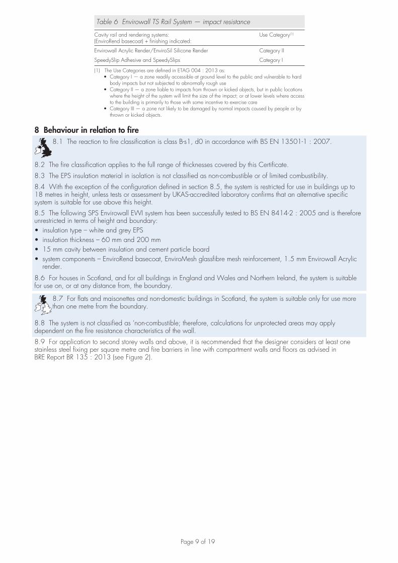
Table 6 Envirowall TS Rail System — impact resistance
Cavity rail and rendering systems:(EnviroRend basecoat) + finishing indicated:
Use Category(1)
Envirowall Acrylic Render/EnviroSil Silicone Render Category II
SpeedySlip Adhesive and SpeedySlips Category I
(1) The Use Categories are defined in ETAG 004 : 2013 as:•CategoryI—azonereadilyaccessibleatgroundleveltothepublicandvulnerabletohard
body impacts but not subjected to abnormally rough use•CategoryII—azoneliabletoimpactsfromthrownorkickedobjects,butinpubliclocations
where the height of the system will limit the size of the impact; or at lower levels where access to the building is primarily to those with some incentive to exercise care
•CategoryIII—azonenotlikelytobedamagedbynormalimpactscausedbypeopleorbythrown or kicked objects.
8 Behaviour in relation to fire8.1 The reaction to fire classification is class B-s1, d0 in accordance with BS EN 13501-1 : 2007.
8.2 The fire classification applies to the full range of thicknesses covered by this Certificate.
8.3 The EPS insulation material in isolation is not classified as non-combustible or of limited combustibility.
8.4 With the exception of the configuration defined in section 8.5, the system is restricted for use in buildings up to 18 metres in height, unless tests or assessment by UKAS-accredited laboratory confirms that an alternative specific system is suitable for use above this height.
8.5 The following SPS Envirowall EWI system has been successfully tested to BS EN 8414-2 : 2005 and is therefore unrestricted in terms of height and boundary:• insulation type – white and grey EPS • insulation thickness – 60 mm and 200 mm• 15 mm cavity between insulation and cement particle board• system components – EnviroRend basecoat, EnviroMesh glassfibre mesh reinforcement, 1.5 mm Envirowall Acrylic
render.
8.6 For houses in Scotland, and for all buildings in England and Wales and Northern Ireland, the system is suitable for use on, or at any distance from, the boundary.
8.7 For flats and maisonettes and non-domestic buildings in Scotland, the system is suitable only for use more than one metre from the boundary.
8.8 The system is not classified as ‘non-combustible; therefore, calculations for unprotected areas may apply dependent on the fire resistance characteristics of the wall.
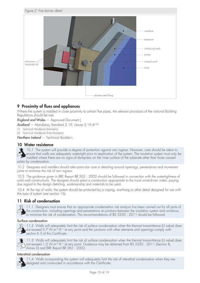
8.9 For application to second storey walls and above, it is recommended that the designer considers at least one stainless steel fixing per square metre and fire barriers in line with compartment walls and floors as advised in BRE Report BR 135 : 2013 (see Figure 2).
Page 10 of 19
Figure 2 Fire barrier detail
insulation
reinforcing mesh
primer
finish
basecoat
mineral wool
stainless steel fixing
aluminium horizontal rail
9 Proximity of flues and appliances Where the system is installed in close proximity to certain flue pipes, the relevant provisions of the national Building Regulations should be met:England and Wales — Approved Document JScotland — Mandatory Standard 3.19, clause 3.19.4(1)(2)
(1) Technical Handbook (Domestic).(2) Technical Handbook (Non-Domestic).
Northern Ireland — Technical Booklet L.
10 Water resistance10.1 The system will provide a degree of protection against rain ingress. However, care should be taken to ensure that walls are adequately watertight prior to application of the system. The insulation system must only be installed where there are no signs of dampness on the inner surface of the substrate other than those caused
solely by condensation.
10.2 Designers and installers should take particular care in detailing around openings, penetrations and movement joints to minimise the risk of rain ingress.
10.3 The guidance given in BRE Report BR 262 : 2002 should be followed in connection with the watertightness of solid wall constructions. The designer should select a construction appropriate to the local wind-driven index, paying due regard to the design detailing, workmanship and materials to be used.
10.4 At the top of walls, the system should be protected by a coping, overhang or other detail designed for use with this type of system (see section 16).
11 Risk of condensation11.1 Designers must ensure that an appropriate condensation risk analysis has been carried out for all parts of the construction, including openings and penetrations at junctions between the insulation system and windows, to minimise the risk of condensation. The recommendations of BS 5250 : 2011 should be followed.
Surface condensation11.2 Walls will adequately limit the risk of surface condensation when the thermal transmittance (U value) does not exceed 0.7 W·m–2·K–1 at any point and the junctions with other elements and openings comply with section 6.3 of this Certificate.
11.3 Walls will adequately limit the risk of surface condensation when the thermal transmittance (U value) does not exceed 1.2 W·m–2·K–1 at any point. Guidance may be obtained from BS 5250 : 2011 (Section 8, Annex D) and BRE Report BR 262 : 2002.
Interstitial condensation11.4 Walls incorporating the system will adequately limit the risk of interstitial condensation when they are designed and constructed in accordance with this Certificate.

Page 11 of 19
11.5 The water vapour resistance factor (µ) and equivalent air layer thicknesses (Sd) are shown in Table 7.
Table 7 Water vapour resistance factors and equivalent air layer thickness
Render system Equivalent air layer thickness Sd(m)
Water vapourresistance
µ
Expanded polystyrene – 20–40(1)
EnviroRend + Envirowall Acrylic render (primer and finish) 0.20
EnviroRend + EnviroSil Silicone render 0.16
SpeedySlip adhesive 0.49(2) 245
EnviroRend (basecoat) 0.08(2) 16
SpeedySlips 0.58(2) 116
(1) Taken from BS EN ISO 10456 : 2007, Table 4.(2) Taken from BS EN 12524 : 2000, Table 2.
12 Maintenance and repair12.1 An initial inspection should be made within 12 months and regularly checked thereafter to include:
• visual inspection of the render for signs of damage. Cracks in the render exceeding 0.2 mm must be repaired• examination of the sealant around openings and service entry points• visual inspection of architectural details designed to shed water to confirm that they are performing properly• visual inspection to ensure that water is not leaking from external downpipes or gutters; such leakage could
penetrate the rendering• necessary repairs effected immediately and the sealant joints at window and door frames replaced at regular intervals• maintenance schedules, which should include the replacement and resealing of joints, for example between the
insulation system and window and door frame.
12.2 Damaged areas must be repaired using the appropriate components and procedures detailed in the Certificate holder’s installation instructions and in accordance with BS EN 13914-1 : 2005.
13 Durability13.1 The system will have a service life of not less than 30 years, provided any damage to the surface finish is repaired immediately and regular maintenance is undertaken, as described in section 12 of this Certificate.
13.2 The renders containing Portland cement may be subject to lime bloom. The occurrence of this may be reduced by avoiding application in adverse weather conditions. The effect is transient and is less noticeable on lighter colours.
13.3 The renders may become discoloured with time, the rate depending on the initial colour, the degree of exposure and atmospheric pollution, as well as the design and detailing of the wall. In common with traditional renders, discoloration by algae and lichens may occur in wet areas. The appearance may be restored by a suitable power wash or, if required, by over coating.
13.4 To maintain a high quality aesthetic appearance, it may be necessary to periodically overcoat the building using system-compatible coatings as per section 1.2 of this Certificate and as recommended by the Certificate holder and in accordance with BS EN 1062-1 : 2004. Care should be taken not to adversely affect the water vapour transmission or fire characteristics of the system. The advice of the Certificate holder should be sought as to the suitability of a particular product.
Installation
14 Site survey and preliminary work14.1 A pre-installation survey of the property must be carried out to determine suitability for treatment and any repairs necessary to the building structure (sheathing board or steel frame) before application of the system. A specification is prepared for each elevation of the building indicating:• the position of beads• detailing around windows, doors and at eaves• damp-proof course (dpc) level• exact position of expansion joints, if required• areas where flexible sealants must be used• any alterations to external plumbing• the position of fire barriers.

Page 12 of 19
14.2 The survey should include tests conducted on the walls of the building by the Certificate holder or their approved installers (see section 15) to determine the pull-out resistance of the specified mechanical fixings for the substrate to withstand the building’s expected wind loading, based on calculations using the fixing’s pull-off resistance test data. In addition, the type and minimum number of fixings are selected as per section 7. The advice of the Certificate holder should be sought to ensure the proposed fixing pattern is sufficient.
14.3 The flatness of surfaces must be checked; this may be achieved using a straight edge spanning the storey height. Any irregularities, must be made good prior to installation to ensure that the insulation boards are installed with a smooth, in-plane finished surface.
14.4 On existing buildings, purpose-made window sills must be fitted to extend beyond the finished face of the system. New buildings should incorporate suitably deep sills.
14.5 For new buildings, internal wet work, eg screed or plastering, should be completed and allowed to dry prior to the installation of the system.
14.6 All modifications and necessary repairs to the building structure are completed before installation commences.
15 Approved installersApplication of the system, within the context of this Certificate, must be carried out by approved installers recommended or recognised by the Certificate holder. Such an installer is a company:• employing operatives who have been trained and approved by the Certificate holder to install the system• which has undertaken to comply with the Certificate holder’s application procedure, containing the requirement for
each application team to include at least one member operative trained by the Certificate holder• subject to at least one inspection per annum by the Certificate holder to ensure suitable site practices are being
employed. This may include unannounced site inspections.
16 ProcedureGeneral16.1 Application is carried out in accordance with the Certificate holder’s installation instructions.
16.2 Weather conditions should be monitored to ensure correct application and curing conditions. Application of coating materials must not be carried out at temperatures below 5ºC or above 30ºC, or if exposure to frost is likely, and the coating must be protected from rapid drying. In addition, cementitious-based renders must not be applied if the temperature will fall below 0°C within 72 hours of completion.
16.3 All rendering should be in accordance with the relevant recommendations of BS EN 13914-1 : 2005.
Positioning and securing insulation boards16.4 The base profile is secured to the sheathing board above the dpc (see Figure 3) using approved profile fixings and the 15 mm spacers at approximately 300 mm centres. Base profile connectors are inserted at the base of the system’s joints. Extension profiles are fixed to the front lip of the base profile. Stop end profiles are installed where required.
Figure 3 Typical section of starter/base
EPS insulation board
basecoat
render finish
reinforcing mesh
base profile
base profile fixing and 15 mm spacer4 mm drainage holes at 30 mm centres
vertical rail
16.5 Packing shims are used at fixing points behind the starter/base profile where it is necessary to overcome surface irregularities and maintain alignment of the face of the insulation.

Page 13 of 19
16.6 The cavity spacer tracks are mechanically fixed to the sheathing board and through the building’s substrate, with the specified fixings at a maximum of 300 mm centres either side of the rail. Rails may need packing to ensure they are true to line and level. Drainage deflection channels are mechanically fixed over all window and door openings and horizontal and vertical intumescent strips (outside the scope of this Certificate) are installed following the designer’s instructions. Care should be taken not to overdrive the fixings.
Figure 4 Rail profile fixing pattern
ELS type self drillingself tapping fixing horse shoe packerref: ESPS-PO
TS horizontal railsref: ESPS-TS-HR
insulation board
sheathing board
TS vertical railsref: ESPS-TS-VR
TS horizonal railsref: ESPS-TS-HR
ELS type self drilling, selftapping screw. Fixed at300 mm centres
16.7 The first insulation board is positioned onto the base profile, and is used to position the first horizontal rail (see Figure 4). The fixing rail slots into the pre-cut groove in the insulation board. The level is checked and the rail is positioned away from the substrate using the 15 mm spacers. It is important that the fixing rail fits tightly and locates fully into the groove in the insulation; it should not be forced into position.
16.8 Once the horizontal fixing rails are in position and the insulation board is placed onto the fixing rail, the vertical fixing rails are positioned and fixed to the horizontal rails and EPS grooves. The next insulation board is slotted into place. It is important to ensure that the fixing rails fit securely into the grooved insulation and that the insulation boards are tightly butted together, particularly at corners.
16.9 Joints greater than 2 mm between boards should be filled with slivers of insulation slab or PU foam. Gaps greater than 10 mm should be closed by repositioning or, where appropriate, by cutting boards to fit. Alignment should be checked as work proceeds.
16.10 Subsequent boards are positioned so that the vertical joints are staggered by a minimum of 100 mm, with any open joints in the insulation system filled and overlapped at the building corners (see Figure 5). Installation is continued until the whole wall is completely covered including, where appropriate, the building soffits.
Page 14 of 19
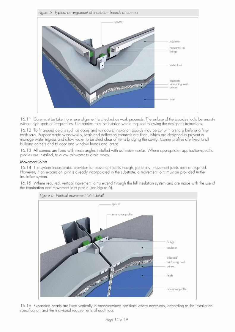
Figure 5 Typical arrangement of insulation boards at corners
insulation
fixings
reinforcing meshprimer
finish
basecoat
spacer
vertical rail
horizontal rail
16.11 Care must be taken to ensure alignment is checked as work proceeds. The surface of the boards should be smooth without high spots or irregularities. Fire barriers must be installed where required following the designer’s instructions.
16.12 To fit around details such as doors and windows, insulation boards may be cut with a sharp knife or a fine-tooth saw. Purpose-made window-sills, seals and deflection channels are fitted, which are designed to prevent or manage water ingress and allow water to be shed clear of items bridging the cavity. Corner profiles are fixed to all building corners and to door and window heads and jambs.
16.13 All corners are fixed with mesh angles installed with adhesive mortar. Where appropriate, application-specific profiles are installed, to allow rainwater to drain away.
Movement joints16.14 The system incorporates provision for movement joints though, generally, movement joints are not required. However, if an expansion joint is already incorporated in the substrate, a movement joint must be provided in the insulation system.
16.15 Where required, vertical movement joints extend through the full insulation system and are made with the use of the termination and movement joint profile (see Figure 6).
Figure 6 Vertical movement joint detail
insulation
fixings
reinforcing meshprimer
finish
movement profile
spacer
termination profile
basecoat
16.16 Expansion beads are fixed vertically in predetermined positions where necessary, according to the installation specification and the individual requirements of each job.
Page 15 of 19
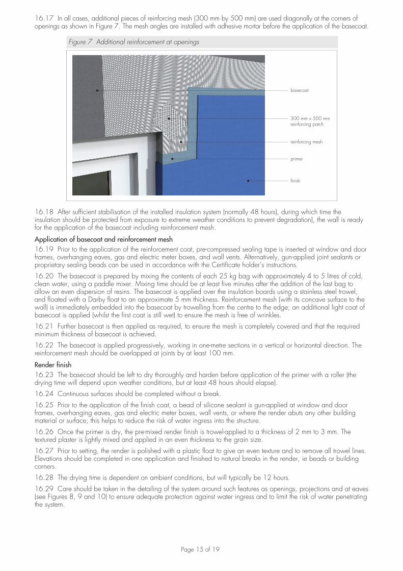
16.17 In all cases, additional pieces of reinforcing mesh (300 mm by 500 mm) are used diagonally at the corners of openings as shown in Figure 7. The mesh angles are installed with adhesive mortar before the application of the basecoat.
Figure 7 Additional reinforcement at openings
reinforcing mesh
primer
finish
basecoat
300 mm x 500 mmreinforcing patch
16.18 After sufficient stabilisation of the installed insulation system (normally 48 hours), during which time the insulation should be protected from exposure to extreme weather conditions to prevent degradation), the wall is ready for the application of the basecoat including reinforcement mesh.
Application of basecoat and reinforcement mesh16.19 Prior to the application of the reinforcement coat, pre-compressed sealing tape is inserted at window and door frames, overhanging eaves, gas and electric meter boxes, and wall vents. Alternatively, gun-applied joint sealants or proprietary sealing beads can be used in accordance with the Certificate holder’s instructions.
16.20 The basecoat is prepared by mixing the contents of each 25 kg bag with approximately 4 to 5 litres of cold, clean water, using a paddle mixer. Mixing time should be at least five minutes after the addition of the last bag to allow an even dispersion of resins. The basecoat is applied over the insulation boards using a stainless steel trowel, and floated with a Darby float to an approximate 5 mm thickness. Reinforcement mesh (with its concave surface to the wall) is immediately embedded into the basecoat by trowelling from the centre to the edge; an additional light coat of basecoat is applied (whilst the first coat is still wet) to ensure the mesh is free of wrinkles.
16.21 Further basecoat is then applied as required, to ensure the mesh is completely covered and that the required minimum thickness of basecoat is achieved.
16.22 The basecoat is applied progressively, working in one-metre sections in a vertical or horizontal direction. The reinforcement mesh should be overlapped at joints by at least 100 mm.
Render finish16.23 The basecoat should be left to dry thoroughly and harden before application of the primer with a roller (the drying time will depend upon weather conditions, but at least 48 hours should elapse).
16.24 Continuous surfaces should be completed without a break.
16.25 Prior to the application of the finish coat, a bead of silicone sealant is gun-applied at window and door frames, overhanging eaves, gas and electric meter boxes, wall vents, or where the render abuts any other building material or surface; this helps to reduce the risk of water ingress into the structure.
16.26 Once the primer is dry, the pre-mixed render finish is trowel-applied to a thickness of 2 mm to 3 mm. The textured plaster is lightly mixed and applied in an even thickness to the grain size.
16.27 Prior to setting, the render is polished with a plastic float to give an even texture and to remove all trowel lines. Elevations should be completed in one application and finished to natural breaks in the render, ie beads or building corners.
16.28 The drying time is dependent on ambient conditions, but will typically be 12 hours.
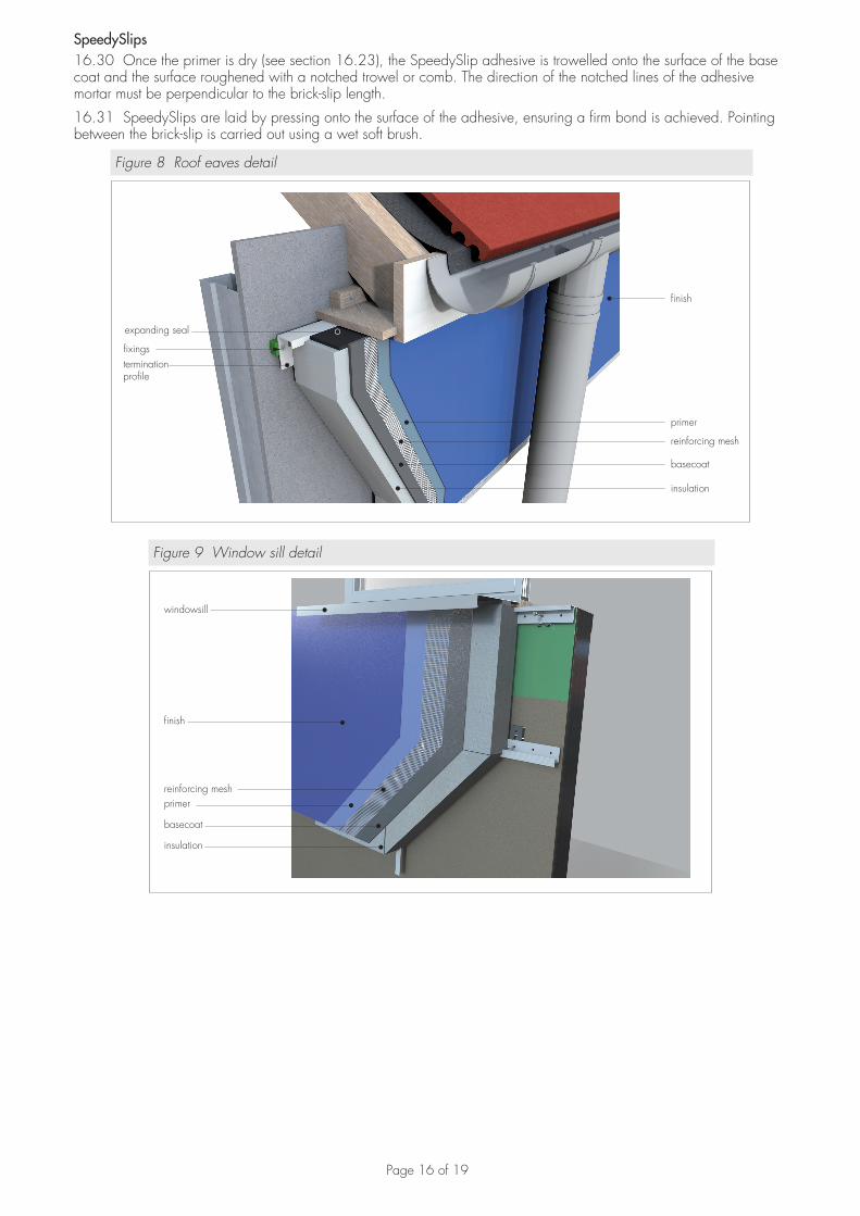
16.29 Care should be taken in the detailing of the system around such features as openings, projections and at eaves (see Figures 8, 9 and 10) to ensure adequate protection against water ingress and to limit the risk of water penetrating the system.
Page 16 of 19
SpeedySlips16.30 Once the primer is dry (see section 16.23), the SpeedySlip adhesive is trowelled onto the surface of the base coat and the surface roughened with a notched trowel or comb. The direction of the notched lines of the adhesive mortar must be perpendicular to the brick-slip length.
16.31 SpeedySlips are laid by pressing onto the surface of the adhesive, ensuring a firm bond is achieved. Pointing between the brick-slip is carried out using a wet soft brush.
Figure 8 Roof eaves detail
insulation
fixings
reinforcing mesh
primer
finish
basecoat
expanding seal
terminationprofile
Figure 9 Window sill detail
insulation
reinforcing meshprimer
finish
basecoat
windowsill
Page 17 of 19
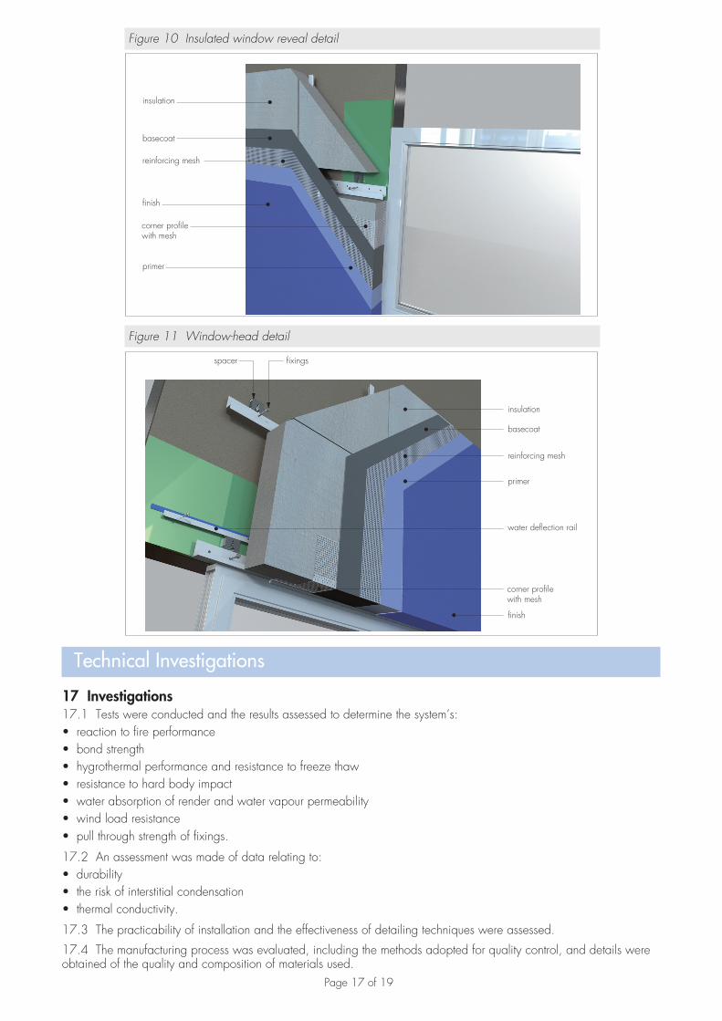
Figure 10 Insulated window reveal detail
insulation
reinforcing mesh
primer
finish
basecoat
corner profilewith mesh
Figure 11 Window-head detail
insulation
reinforcing mesh
primer
finish
basecoat
spacer fixings
water deflection rail
corner profilewith mesh
Technical Investigations
17 Investigations17.1 Tests were conducted and the results assessed to determine the system’s:• reaction to fire performance• bond strength• hygrothermal performance and resistance to freeze thaw• resistance to hard body impact• water absorption of render and water vapour permeability• wind load resistance• pull through strength of fixings.
17.2 An assessment was made of data relating to:• durability• the risk of interstitial condensation• thermal conductivity.
17.3 The practicability of installation and the effectiveness of detailing techniques were assessed.
17.4 The manufacturing process was evaluated, including the methods adopted for quality control, and details were obtained of the quality and composition of materials used.
Page 18 of 19
BibliographyBS 5250 : 2011 Code of practice for control of condensation in buildings
BS EN 634-2 : 2007 Cement bonded particleboards — Specification — Requirements for OPC bonded particleboards for use in dry, humid and exterior conditions
BS EN 1062-1 : 2004 Paints and varnishes — Coating materials and coating systems for exterior masonry and concrete — Classification
BS EN 1990 : 2002 Eurocode — Basis of structural design
BS EN 1991-1-4 : 2005 Eurocode 1 — Actions on structures — General actions — Wind actionsNA to BS EN 1991-1-4 : 2005 UK National Annex to Eurocode 1 — Actions on structures — General actions — Wind actions
BS EN 1993-1-2 : 2005 Eurocode 3 : Design of steel structures — General rules — Structural fire designBS EN 1993-1-3 : 2006 Eurocode 3 : Design of steel structures — General rules — Supplementary rules for cold-formed members and sheetingBS EN 8414-2 : 2005 Fire performance of external cladding systems — Test method for non-loadbearing external cladding systems fixed to and supported by a structural steel frame
BS EN 10346 : 2015 Continuously hot-dip coated steel flat products for cold forming — Technical delivery conditions
BS EN 13501-1 : 2007 Fire classification of construction products and building elements — Classification using test data from reaction to fire tests
BS EN 13163 : 2012 Thermal insulation products for buildings — Factory made expanded polystyrene (EPS) products
BS EN 13914-1 : 2005 Design, preparation and application of external rendering and internal plastering — External rendering
BS EN ISO 6946 : 2007 Building components and building elements — Thermal resistance and thermal transmittance — Calculation method
BS EN ISO 9001 : 2008 Quality management systems — Requirements
BS EN ISO 14001 : 2004 Environmental management systems — Requirements with guidance for use
BRE Report 135 (BR 135 : 2013) Fire performance of external thermal insulation for walls of multistorey buildings
BRE Report 262 (BR 262 : 2002) Thermal insulation: avoiding risks
BRE Report 443 (BR 443 : 2006) Conventions for U-value calculations
ETAG 004 : 2013 Guideline for European Technical Approval of External Thermal Insulation Composite Systems (ETICS) with Rendering
ETAG 014 : 2011 Guideline for European Technical Approval of Plastic Anchors for fixing of external thermal insulation composite systems with rendering

Page 19 of 19
Conditions of Certification
18 Conditions18.1 This Certificate:• relates only to the product/system that is named and described on the front page• is issued only to the company, firm, organisation or person named on the front page — no other company, firm,
organisation or person may hold or claim that this Certificate has been issued to them• is valid only within the UK• has to be read, considered and used as a whole document — it may be misleading and will be incomplete to be
selective• is copyright of the BBA• is subject to English Law.
18.2 Publications, documents, specifications, legislation, regulations, standards and the like referenced in this Certificate are those that were current and/or deemed relevant by the BBA at the date of issue or reissue of this Certificate.
18.3 This Certificate will remain valid for an unlimited period provided that the product/system and its manufacture and/or fabrication, including all related and relevant parts and processes thereof:• are maintained at or above the levels which have been assessed and found to be satisfactory by the BBA• continue to be checked as and when deemed appropriate by the BBA under arrangements that it will determine• are reviewed by the BBA as and when it considers appropriate.
18.4 The BBA has used due skill, care and diligence in preparing this Certificate, but no warranty is provided.
18.5 In issuing this Certificate, the BBA is not responsible and is excluded from any liability to any company, firm, organisation or person, for any matters arising directly or indirectly from:• the presence or absence of any patent, intellectual property or similar rights subsisting in the product/system or any
other product/system• the right of the Certificate holder to manufacture, supply, install, maintain or market the product/system• actual installations of the product/system, including their nature, design, methods, performance, workmanship and
maintenance• any works and constructions in which the product/system is installed, including their nature, design, methods,
performance, workmanship and maintenance• any loss or damage, including personal injury, howsoever caused by the product/system, including its manufacture,
supply, installation, use, maintenance and removal• any claims by the manufacturer relating to CE marking.
18.6 Any information relating to the manufacture, supply, installation, use, maintenance and removal of this product/system which is contained or referred to in this Certificate is the minimum required to be met when the product/system is manufactured, supplied, installed, used, maintained and removed. It does not purport in any way to restate the requirements of the Health and Safety at Work etc. Act 1974, or of any other statutory, common law or other duty which may exist at the date of issue or reissue of this Certificate; nor is conformity with such information to be taken as satisfying the requirements of the 1974 Act or of any statutory, common law or other duty of care.
British Board of Agrément tel: 01923 665300Bucknalls Lane fax: 01923 665301Watford [email protected] WD25 9BA www.bbacerts.co.uk©2016