sps - lv mv heat shrink cable joints & terminations (full catalogue)
TRANSCRIPT
Terminations & AccessoriesTerminations XLPE / PILC 0.6-33kV 1-5Coldshrink Terminations 7.2-33kV 6-7
Technical Data 8Termination Kit Contents 9-12
Bushing Boots / Earth Kits 13Cold Applied Bushing Boots 14
Bolt On Glands / Armour Earthing 15-17Insulators and Brackets 18
Termination Observation Study 19-20Triplex Terminations for 12kV Cables 21
JointsTriplex 12kV Joints 21
Universal Heat Shrink/Resin Joint 7.2/12kV 22Universal Heat Shrink Joint 7.2/12kV 233 Core Joints XLPE / PILC 17.5-33kV 24-26
Single Core Joints XLPE / PILC 27-28Earthing / Cross Bonding on Single Cores 29
MV Live Pot End / Abandonment Kits 30Cold Shrink Joints 7.2 -33kV 31
LV Joints for XLPE / PILC Cables 44-45Zero Halogen / Fire Resistant Joints 46-47
Airfield Lighting and Traffic Control Joints 48LV Live Pot End / Abandonment Kits 49
Heat Shrink ComponentsMV Busbar Tubing 32-34
Anti Track / Sheds / Tape 36MV Anti Track And Conductive Breakouts 37
Heat Shrink Cable Entry Seals 50Cable Repair / Busbar Tape 51
Breakout Boots and End Caps 52Wraparound Repair Sleeves 53
Thin Wall Heat Shrink Sleeve 55Thick / Medium Wall Heat Shrink Tube 56-57
Zero Halogen LSF Heat Shrink Tube 58Connectors
MV Copper Compression Lugs / Ferrules 40MV Aluminium Compression Lugs / Ferrules 41
MV Mechanical Shearbolt Lugs / Ferrules 42LV Copper Compression Lugs / Ferrules 60
LV Mechanical Shearbolt Ferrules 60Tapes / Tooling / Misc
MV Busbar Heat Shrink Tape 35Anti Track Mastic Tape 36
Stress Control Mastic Tapes 38Roll Springs / Earth Braids / Mesh 39
Cable Preparation Tools 43LV Busbar Heat Shrink Tape / Nylon Glands 51
Connector Patch Tape 54Black Melt Tape / Epr Tape / Zero Hal Tape 59Gas Torch Kits / Crimp Tools / Cable Cutter 61
Termination Clearances Chart 62Cable Conversion Chart 65

Unit E3, Crown Way, Crown Park Industrial Estate, Rushden, Northants, UK, NN10 6FDTel: +44 (0)1933 356758 Fax: +44 (0)1933 413821 Email: [email protected] Skype: shrinkpolymersystems www.shrinkpolymersystems.co.uk
The CompanyShrink Polymer Systems was established in 1990 and are based in Northamptonshire in the UK. We also have a joint-venture company based in the Sultanate of Oman and have plans to expand further in the near future.
We specialise in the manufacture of heat shrink and cold shrink cable joints, terminations and cable accessories up to voltage class 33kV.
Whether by phone, email or by site visits, we are here to provide solutions to challenging problems as well as standard applications. Our experienced team have many decades of combined experience in this field.
Quality and ServiceIf you only want the lowest cost kits, there are others who can help you. If however, you seek:
• reliable products that will last the life of the cable
• technical backup and service 24/7
• jointer training and fault analysis
• competitive prices and good deliveries
Then you need to contact us and see why we are the partner of choice for many well known companies both here in the UK and overseas.
At SPS, quality is integral to what we offer and not just because we are registered to the latest ISO 9001:2008 standard.
ExportOur export market continues to increase, by closely working with appointed agents and electric utility companies.
We export to most parts of the world including Europe, The Middle / Far East and Africa. Our website features our customer list, see:
www.shrinkpolymersystems.co.uk
for more details.
We are always interested in working with experienced agents and are open to joint venture possibilities.
Unit E3, Crown Way, Crown Park Industrial Estate, Rushden, Northants, UK, NN10 6FDTel: +44 (0)1933 356758 Fax: +44 (0)1933 413821 Email: [email protected] Skype: shrinkpolymersystems www.shrinkpolymersystems.co.uk
1
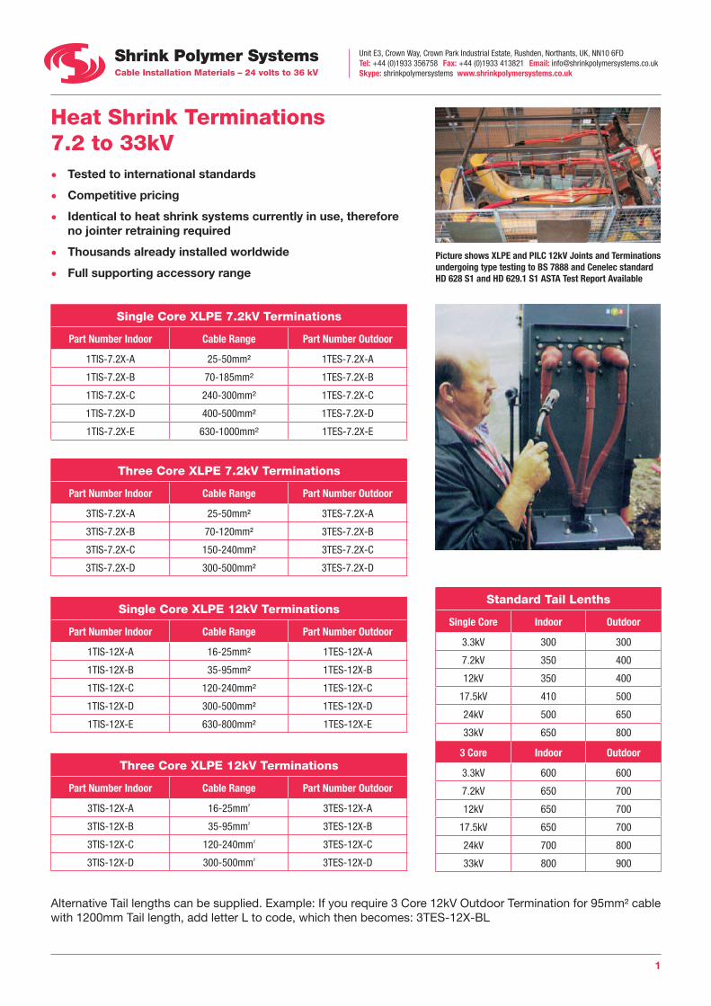
Heat Shrink Terminations 7.2 to 33kV • Tested to international standards
• Competitive pricing
• Identical to heat shrink systems currently in use, therefore no jointer retraining required
• Thousands already installed worldwide
• Full supporting accessory range
Single Core XLPE 7.2kV Terminations
Part Number Indoor Cable Range Part Number Outdoor
1TIS-7.2X-A 25-50mm² 1TES-7.2X-A
1TIS-7.2X-B 70-185mm² 1TES-7.2X-B
1TIS-7.2X-C 240-300mm² 1TES-7.2X-C
1TIS-7.2X-D 400-500mm² 1TES-7.2X-D
1TIS-7.2X-E 630-1000mm² 1TES-7.2X-E
Three Core XLPE 7.2kV Terminations
Part Number Indoor Cable Range Part Number Outdoor
3TIS-7.2X-A 25-50mm² 3TES-7.2X-A
3TIS-7.2X-B 70-120mm² 3TES-7.2X-B
3TIS-7.2X-C 150-240mm² 3TES-7.2X-C
3TIS-7.2X-D 300-500mm² 3TES-7.2X-D
Single Core XLPE 12kV Terminations
Part Number Indoor Cable Range Part Number Outdoor
1TIS-12X-A 16-25mm² 1TES-12X-A
1TIS-12X-B 35-95mm² 1TES-12X-B
1TIS-12X-C 120-240mm² 1TES-12X-C
1TIS-12X-D 300-500mm² 1TES-12X-D
1TIS-12X-E 630-800mm² 1TES-12X-E
Three Core XLPE 12kV Terminations
Part Number Indoor Cable Range Part Number Outdoor
3TIS-12X-A 16-25mm² 3TES-12X-A
3TIS-12X-B 35-95mm² 3TES-12X-B
3TIS-12X-C 120-240mm² 3TES-12X-C
3TIS-12X-D 300-500mm² 3TES-12X-D
Picture shows XLPE and PILC 12kV Joints and Terminations undergoing type testing to BS 7888 and Cenelec standard HD 628 S1 and HD 629.1 S1 ASTA Test Report Available
Standard Tail Lenths
Single Core Indoor Outdoor
3.3kV 300 300
7.2kV 350 400
12kV 350 400
17.5kV 410 500
24kV 500 650
33kV 650 800
3 Core Indoor Outdoor
3.3kV 600 600
7.2kV 650 700
12kV 650 700
17.5kV 650 700
24kV 700 800
33kV 800 900
Alternative Tail lengths can be supplied. Example: If you require 3 Core 12kV Outdoor Termination for 95mm² cable with 1200mm Tail length, add letter L to code, which then becomes: 3TES-12X-BL

Unit E3, Crown Way, Crown Park Industrial Estate, Rushden, Northants, UK, NN10 6FDTel: +44 (0)1933 356758 Fax: +44 (0)1933 413821 Email: [email protected] Skype: shrinkpolymersystems www.shrinkpolymersystems.co.uk
2
Heat Shrink Terminations 7.2 to 33kV
Single Core XLPE 17.5kV Terminations
Part Number Indoor Cable Range Part Number Outdoor
1TIS-17.5X-A 25-70mm² 1TES-17.5X-A
1TIS-17.5X-B 95-185mm² 1TES-17.5X-B
1TIS-17.5X-C 240-400mm² 1TES-17.5X-C
1TIS-17.5X-D 500-630mm² 1TES-17.5X-D
Three Core XLPE 17.5kV Terminations
Part Number Indoor Cable Range Part Number Outdoor
3TIS-17.5X-A 25-70mm² 3TES-17.5X-A
3TIS-17.5X-B 95-185mm² 3TES-17.5X-B
3TIS-17.5X-C 240-400mm² 3TES-17.5X-C
Single Core XLPE 24kV Terminations
Part Number Indoor Cable Range Part Number Outdoor
1TIS-24X-A 25-35mm² 1TES-24X-A
1TIS-24X-B 35-95mm² 1TES-24X-B
1TIS-24X-C 120-185mm² 1TES-24X-C
1TIS-24X-D 240-300mm² 1TES-24X-D
1TIS-24X-E 400-630mm² 1TES-24X-E
Three Core XLPE 24kV Terminations
Part Number Indoor Cable Range Part Number Outdoor
3TIS-24X-A 25-35mm² 3TES-24X-A
3TIS-24X-B 50-95mm² 3TES-24X-B
3TIS-24X-C 120-185mm² 3TES-24X-C
3TIS-24X-D 240-300mm² 3TES-24X-D
Single Core XLPE 33kV Terminations
Part Number Indoor Cable Range Part Number Outdoor
1TIS-36X-A 35-70mm² 1TES-36X-A
1TIS-36X-B 95-185mm² 1TES-36X-B
1TIS-36X-C 240-400mm² 1TES-36X-C
1TIS-36X-D 500-630mm² 1TES-36X-D
Three Core XLPE 33kV Terminations
Part Number Indoor Cable Range Part Number Outdoor
3TIS-36X-A 35-70mm² 3TES-36X-A
3TIS-36X-B 95-185mm² 3TES-36X-B
3TIS-36X-C 240-400mm² 3TES-36X-C

Unit E3, Crown Way, Crown Park Industrial Estate, Rushden, Northants, UK, NN10 6FDTel: +44 (0)1933 356758 Fax: +44 (0)1933 413821 Email: [email protected] Skype: shrinkpolymersystems www.shrinkpolymersystems.co.uk
3
Heat Shrink Terminations 7.2 to 33kV
Single Core PILC 17.5kV Terminations
Part Number Indoor Cable Range Part Number Outdoor
1TIS-12P-A 50-95mm² 1TES-12P-A
1TIS-12P-B 120-240mm² 1TES-12P-B
1TIS-12P-C 300-400mm² 1TES-12P-C
1TIS-12P-D 500-800mm² 1TES-12P-D
Three Core PILC 17.5kV Terminations
Part Number Indoor Cable Range Part Number Outdoor
3TIS-12P-A 25-50mm² 3TES-12P-A
3TIS-12P-B 70-95mm² 3TES-12P-B
3TIS-12P-C 120-185mm² 3TES-12P-C
3TIS-12P-D 240-400mm² 3TES-12P-D
Single Core PILC 24kV Terminations
Part Number Indoor Cable Range Part Number Outdoor
1TIS-24P-A 25-50mm² 1TES-24P-A
1TIS-24P-B 70-185mm² 1TES-24P-B
1TIS-24P-C 240-300mm² 1TES-24P-C
1TIS-24P-D 400-630mm² 1TES-24P-D
Three Core PILC 24kV Terminations
Part Number Indoor Cable Range Part Number Outdoor
3TIS-24P-A 25-50mm² 3TES-24P-A
3TIS-24P-B 70-95mm² 3TES-24P-B
3TIS-24P-C 120-185mm² 3TES-24P-C
3TIS-24P-D 240-300mm² 3TES-24P-D
Single Core PILC 33kV Terminations
Part Number Indoor Cable Range Part Number Outdoor
1TIS-36P-A 50-95mm² 1TES-36P-A
1TIS-36P-B 120-185mm² 1TES-36P-B
1TIS-36P-C 240-400mm² 1TES-36P-C
1TIS-36P-D 500-630mm² 1TES-36P-D
Three Core PILC 33kV Terminations
Part Number Indoor Cable Range Part Number Outdoor
3TIS-36P-A 35-70mm² 3TES-36P-A
3TIS-36P-B 95-185mm² 3TES-36P-B
3TIS-36P-C 240-400mm² 3TES-36P-C
Unit E3, Crown Way, Crown Park Industrial Estate, Rushden, Northants, UK, NN10 6FDTel: +44 (0)1933 356758 Fax: +44 (0)1933 413821 Email: [email protected] Skype: shrinkpolymersystems www.shrinkpolymersystems.co.uk
4
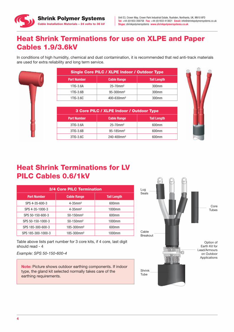
Heat Shrink Terminations for use on XLPE and Paper Cables 1.9/3.6kV In conditions of high humidity, chemical and dust contamination, it is recommended that red anti-track materials are used for extra reliability and long term service.
Single Core PILC / XLPE Indoor / Outdoor Type
Part Number Cable Range Tail Length
1TIS-3.6A 25-70mm² 300mm
1TIS-3.6B 95-300mm² 300mm
1TIS-3.6C 400-630mm² 300mm
3 Core PILC / XLPE Indoor / Outdoor Type
Part Number Cable Range Tail Length
3TIS-3.6A 25-70mm² 600mm
3TIS-3.6B 95-185mm² 600mm
3TIS-3.6C 240-400mm² 600mm
Heat Shrink Terminations for LV PILC Cables 0.6/1kV
3/4 Core PILC Termination
Part Number Cable Range Tail Length
SPS 4-35-600-3 4-35mm² 600mm
SPS 4-35-1000-3 4-35mm² 1000mm
SPS 50-150-600-3 50-150mm² 600mm
SPS 50-150-1000-3 50-150mm² 1000mm
SPS 185-300-600-3 185-300mm² 600mm
SPS 185-300-1000-3 185-300mm² 1000mm
Table above lists part number for 3 core kits, if 4 core, last digit should read - 4
Example: SPS 50-150-600-4
Note: Picture shows outdoor earthing components. If indoor type, the gland kit selected normally takes care of the earthing requirements.
Core Tubes
Lug Seals
Cable Breakout
Shrink Tube
Option of Earth Kit for
Lead/Armours on Outdoor
Applications
Unit E3, Crown Way, Crown Park Industrial Estate, Rushden, Northants, UK, NN10 6FDTel: +44 (0)1933 356758 Fax: +44 (0)1933 413821 Email: [email protected] Skype: shrinkpolymersystems www.shrinkpolymersystems.co.uk
5
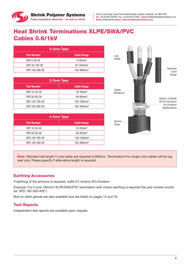
Heat Shrink Terminations XLPE/SWA/PVC Cables 0.6/1kV
2 Core Type
Part Number Cable Range
SPS 4-35-2X 4-35mm²
SPS 35-150-2X 35-150mm²
SPS 150-400-2X 150-400mm²
3 Core Type
Part Number Cable Range
SPS 10-35-3X 10-35mm²
SPS 50-95-3X 50-95mm²
SPS 120-185-3X 120-185mm²
SPS 185-300-3X 185-300mm²
4 Core Type
Part Number Cable Range
SPS 10-35-4X 10-35mm²
SPS 50-95-4X 50-95mm²
SPS 120-185-4X 120-185mm²
SPS 185-300-4X 185-300mm²
Note: Standard tail length if core tubes are required is 600mm. Terminations for single core cables will be lug seal only. Please specify if alternative length is required.
Earthing Accessories If earthing of the armours is required, suffix E1=Indoor EO=Outdoor
Example: If a 4 core 185mm² XLPE/SWA/PVC termination with indoor earthing is required the part number would be: SPS 185-300-4XE1.
Bolt on earth glands are also available and are listed on pages 15 and 16.
Test Reports Independent test reports are available upon request.
Optional Core
Tubes
Lug Seals
Cable Breakout
Shrink Tube
Option of Earth Kit for Armours
on Outdoor Applications
Unit E3, Crown Way, Crown Park Industrial Estate, Rushden, Northants, UK, NN10 6FDTel: +44 (0)1933 356758 Fax: +44 (0)1933 413821 Email: [email protected] Skype: shrinkpolymersystems www.shrinkpolymersystems.co.uk
6
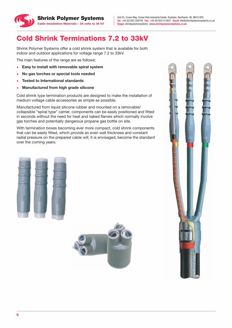
Cold Shrink Terminations 7.2 to 33kV Shrink Polymer Systems offer a cold shrink system that is available for both indoor and outdoor applications for voltage range 7.2 to 33kV.
The main features of the range are as follows:
• Easy to install with removable spiral system
• No gas torches or special tools needed
• Tested to International standards
• Manufactured from high grade silicone
Cold shrink type termination products are designed to make the installation of medium voltage cable accessories as simple as possible.
Manufactured from liquid silicone rubber and mounted on a removable/collapsible “spiral type” carrier, components can be easily positioned and fitted in seconds without the need for heat and naked flames which normally involve gas torches and potentially dangerous propane gas bottle on site.
With termination boxes becoming ever more compact, cold shrink components that can be easily fitted, which provide an even wall thickness and constant radial pressure on the prepared cable will, it is envisaged, become the standard over the coming years.
Unit E3, Crown Way, Crown Park Industrial Estate, Rushden, Northants, UK, NN10 6FDTel: +44 (0)1933 356758 Fax: +44 (0)1933 413821 Email: [email protected] Skype: shrinkpolymersystems www.shrinkpolymersystems.co.uk
7
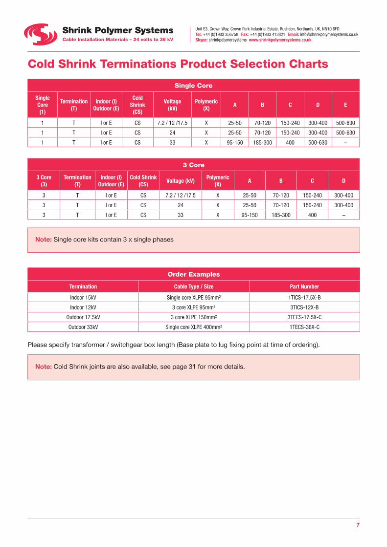
Cold Shrink Terminations Product Selection Charts
Single Core
Single Core(1)
Termination (T)
Indoor (I) Outdoor (E)
Cold Shrink (CS)
Voltage (kV)
Polymeric (X)
A B C D E
1 T I or E CS 7.2 / 12 /17.5 X 25-50 70-120 150-240 300-400 500-630
1 T I or E CS 24 X 25-50 70-120 150-240 300-400 500-630
1 T I or E CS 33 X 95-150 185-300 400 500-630 –
3 Core
3 Core(3)
Termination (T)
Indoor (I) Outdoor (E)
Cold Shrink (CS)
Voltage (kV)Polymeric
(X)A B C D
3 T I or E CS 7.2 / 12 /17.5 X 25-50 70-120 150-240 300-400
3 T I or E CS 24 X 25-50 70-120 150-240 300-400
3 T I or E CS 33 X 95-150 185-300 400 –
Note: Single core kits contain 3 x single phases
Order Examples
Termination Cable Type / Size Part Number
Indoor 15kV Single core XLPE 95mm² 1TICS-17.5X-B
Indoor 12kV 3 core XLPE 95mm² 3TICS-12X-B
Outdoor 17.5kV 3 core XLPE 150mm² 3TECS-17.5X-C
Outdoor 33kV Single core XLPE 400mm² 1TECS-36X-C
Please specify transformer / switchgear box length (Base plate to lug fixing point at time of ordering).
Note: Cold Shrink joints are also available, see page 31 for more details.
Unit E3, Crown Way, Crown Park Industrial Estate, Rushden, Northants, UK, NN10 6FDTel: +44 (0)1933 356758 Fax: +44 (0)1933 413821 Email: [email protected] Skype: shrinkpolymersystems www.shrinkpolymersystems.co.uk
8
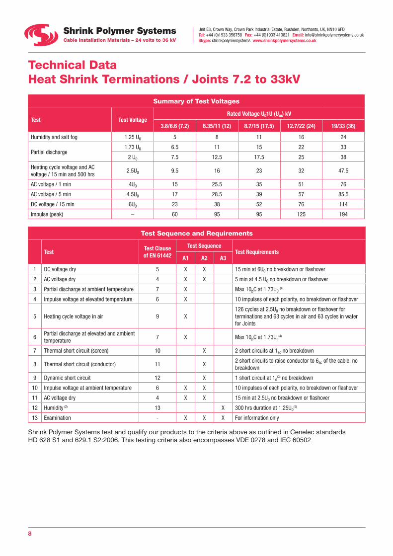
Technical Data Heat Shrink Terminations / Joints 7.2 to 33kV
Summary of Test Voltages
Test Test VoltageRated Voltage U01U (Um) kV
3.8/6.6 (7.2) 6.35/11 (12) 8.7/15 (17.5) 12.7/22 (24) 19/33 (36)
Humidity and salt fog 1.25 U0 5 8 11 16 24
Partial discharge1.73 U0 6.5 11 15 22 33
2 U0 7.5 12.5 17.5 25 38
Heating cycle voltage and AC voltage / 15 min and 500 hrs
2.5U0 9.5 16 23 32 47.5
AC voltage / 1 min 4U0 15 25.5 35 51 76
AC voltage / 5 min 4.5U0 17 28.5 39 57 85.5
DC voltage / 15 min 6U0 23 38 52 76 114
Impulse (peak) – 60 95 95 125 194
Test Sequence and Requirements
TestTest Clause of EN 61442
Test SequenceTest Requirements
A1 A2 A3
1 DC voltage dry 5 X X 15 min at 6U0 no breakdown or flashover
2 AC voltage dry 4 X X 5 min at 4.5 U0 no breakdown or flashover
3 Partial discharge at ambient temperature 7 X Max 10pC at 1.73U0 (4)
4 Impulse voltage at elevated temperature 6 X 10 impulses of each polarity, no breakdown or flashover
5 Heating cycle voltage in air 9 X126 cycles at 2.5U0 no breakdown or flashover for terminations and 63 cycles in air and 63 cycles in water for Joints
6Partial discharge at elevated and ambient temperature
7 X Max 10pC at 1.73Uo(4)
7 Thermal short circuit (screen) 10 X 2 short circuits at 1sc no breakdown
8 Thermal short circuit (conductor) 11 X2 short circuits to raise conductor to 6sc of the cable, no breakdown
9 Dynamic short circuit 12 X 1 short circuit at 1d(3) no breakdown
10 Impulse voltage at ambient temperature 6 X X 10 impulses of each polarity, no breakdown or flashover
11 AC voltage dry 4 X X 15 min at 2.5U0 no breakdown or flashover
12 Humidity (2) 13 X 300 hrs duration at 1.25U0(5)
13 Examination - X X X For information only
Shrink Polymer Systems test and qualify our products to the criteria above as outlined in Cenelec standards HD 628 S1 and 629.1 S2:2006. This testing criteria also encompasses VDE 0278 and IEC 60502
Unit E3, Crown Way, Crown Park Industrial Estate, Rushden, Northants, UK, NN10 6FDTel: +44 (0)1933 356758 Fax: +44 (0)1933 413821 Email: [email protected] Skype: shrinkpolymersystems www.shrinkpolymersystems.co.uk
9
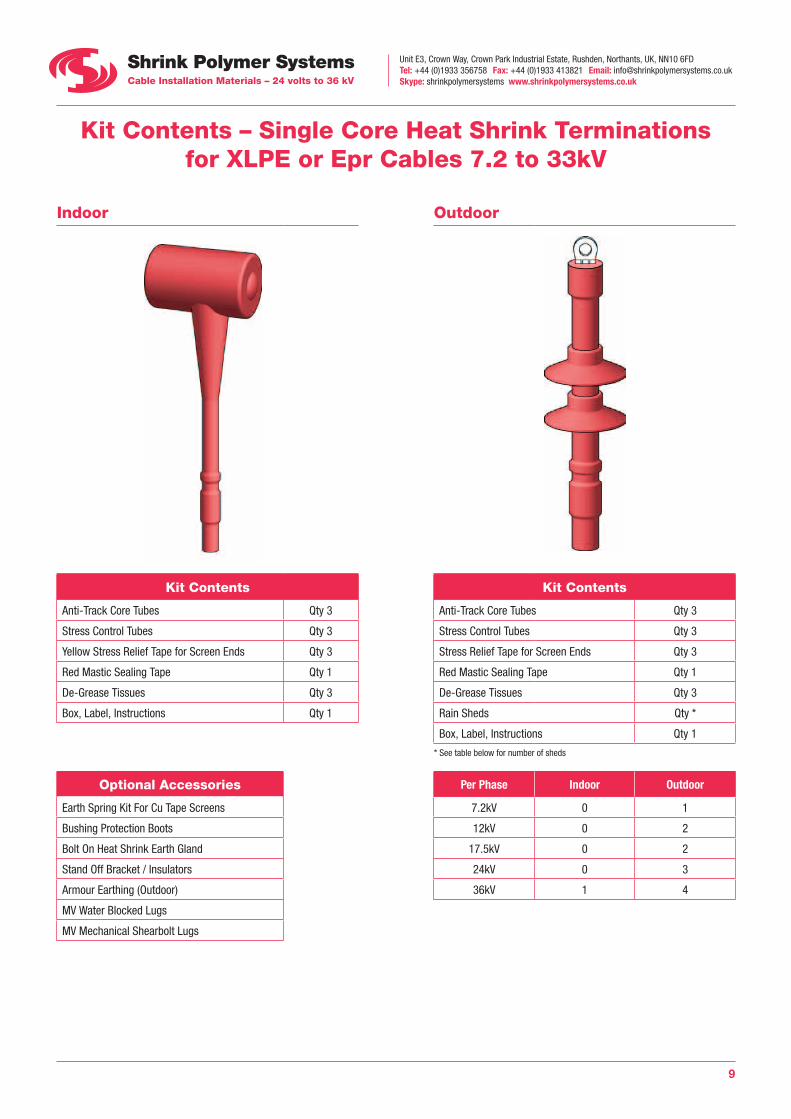
Kit Contents – Single Core Heat Shrink Terminations for XLPE or Epr Cables 7.2 to 33kV
Indoor Outdoor
Kit Contents Kit Contents
Anti-Track Core Tubes Qty 3 Anti-Track Core Tubes Qty 3
Stress Control Tubes Qty 3 Stress Control Tubes Qty 3
Yellow Stress Relief Tape for Screen Ends Qty 3 Stress Relief Tape for Screen Ends Qty 3
Red Mastic Sealing Tape Qty 1 Red Mastic Sealing Tape Qty 1
De-Grease Tissues Qty 3 De-Grease Tissues Qty 3
Box, Label, Instructions Qty 1 Rain Sheds Qty *
Box, Label, Instructions Qty 1
* See table below for number of sheds
Optional Accessories Per Phase Indoor Outdoor
Earth Spring Kit For Cu Tape Screens 7.2kV 0 1
Bushing Protection Boots 12kV 0 2
Bolt On Heat Shrink Earth Gland 17.5kV 0 2
Stand Off Bracket / Insulators 24kV 0 3
Armour Earthing (Outdoor) 36kV 1 4
MV Water Blocked Lugs
MV Mechanical Shearbolt Lugs
Unit E3, Crown Way, Crown Park Industrial Estate, Rushden, Northants, UK, NN10 6FDTel: +44 (0)1933 356758 Fax: +44 (0)1933 413821 Email: [email protected] Skype: shrinkpolymersystems www.shrinkpolymersystems.co.uk
10
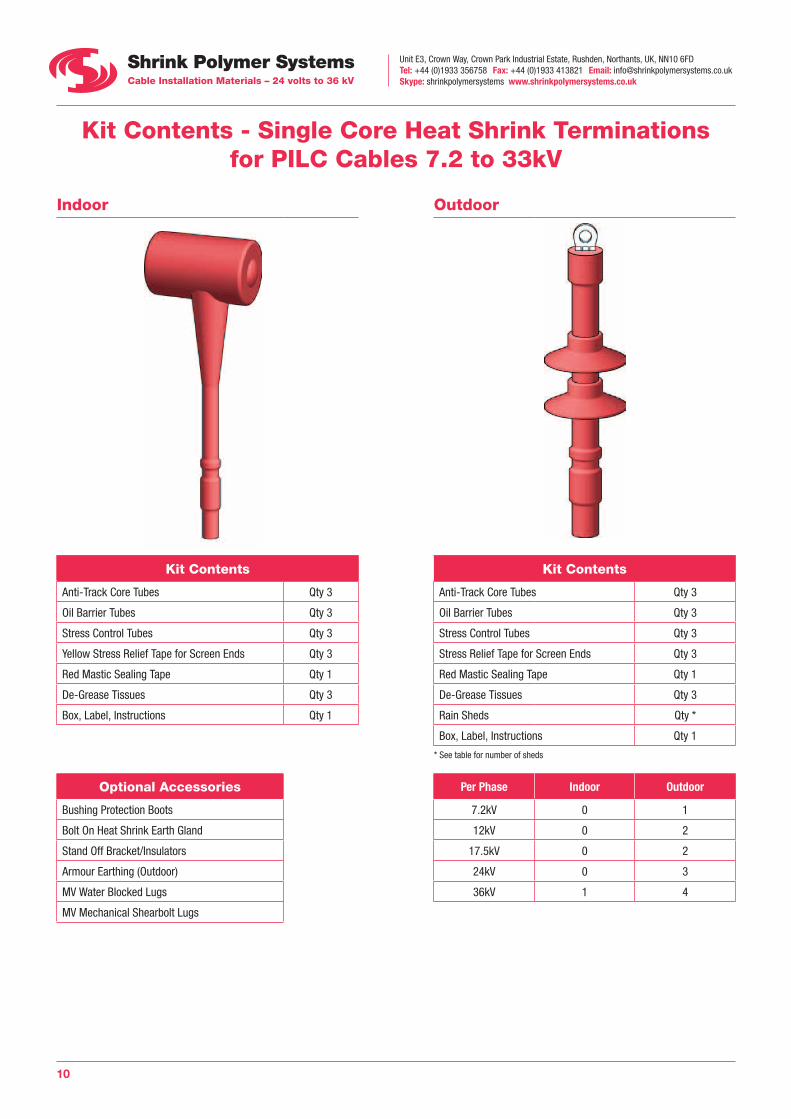
Kit Contents - Single Core Heat Shrink Terminations for PILC Cables 7.2 to 33kV
Indoor Outdoor
Kit Contents Kit Contents
Anti-Track Core Tubes Qty 3 Anti-Track Core Tubes Qty 3
Oil Barrier Tubes Qty 3 Oil Barrier Tubes Qty 3
Stress Control Tubes Qty 3 Stress Control Tubes Qty 3
Yellow Stress Relief Tape for Screen Ends Qty 3 Stress Relief Tape for Screen Ends Qty 3
Red Mastic Sealing Tape Qty 1 Red Mastic Sealing Tape Qty 1
De-Grease Tissues Qty 3 De-Grease Tissues Qty 3
Box, Label, Instructions Qty 1 Rain Sheds Qty *
Box, Label, Instructions Qty 1
* See table for number of sheds
Optional Accessories Per Phase Indoor Outdoor
Bushing Protection Boots 7.2kV 0 1
Bolt On Heat Shrink Earth Gland 12kV 0 2
Stand Off Bracket/Insulators 17.5kV 0 2
Armour Earthing (Outdoor) 24kV 0 3
MV Water Blocked Lugs 36kV 1 4
MV Mechanical Shearbolt Lugs
Unit E3, Crown Way, Crown Park Industrial Estate, Rushden, Northants, UK, NN10 6FDTel: +44 (0)1933 356758 Fax: +44 (0)1933 413821 Email: [email protected] Skype: shrinkpolymersystems www.shrinkpolymersystems.co.uk
11
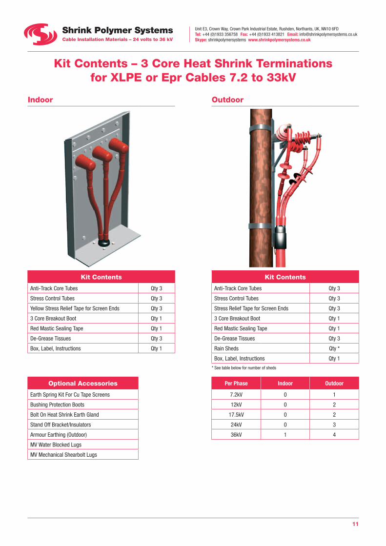
Kit Contents – 3 Core Heat Shrink Terminations for XLPE or Epr Cables 7.2 to 33kV
Indoor Outdoor
Kit Contents Kit Contents
Anti-Track Core Tubes Qty 3 Anti-Track Core Tubes Qty 3
Stress Control Tubes Qty 3 Stress Control Tubes Qty 3
Yellow Stress Relief Tape for Screen Ends Qty 3 Stress Relief Tape for Screen Ends Qty 3
3 Core Breakout Boot Qty 1 3 Core Breakout Boot Qty 1
Red Mastic Sealing Tape Qty 1 Red Mastic Sealing Tape Qty 1
De-Grease Tissues Qty 3 De-Grease Tissues Qty 3
Box, Label, Instructions Qty 1 Rain Sheds Qty *
Box, Label, Instructions Qty 1
* See table below for number of sheds
Optional Accessories Per Phase Indoor Outdoor
Earth Spring Kit For Cu Tape Screens 7.2kV 0 1
Bushing Protection Boots 12kV 0 2
Bolt On Heat Shrink Earth Gland 17.5kV 0 2
Stand Off Bracket/Insulators 24kV 0 3
Armour Earthing (Outdoor) 36kV 1 4
MV Water Blocked Lugs
MV Mechanical Shearbolt Lugs
Unit E3, Crown Way, Crown Park Industrial Estate, Rushden, Northants, UK, NN10 6FDTel: +44 (0)1933 356758 Fax: +44 (0)1933 413821 Email: [email protected] Skype: shrinkpolymersystems www.shrinkpolymersystems.co.uk
12
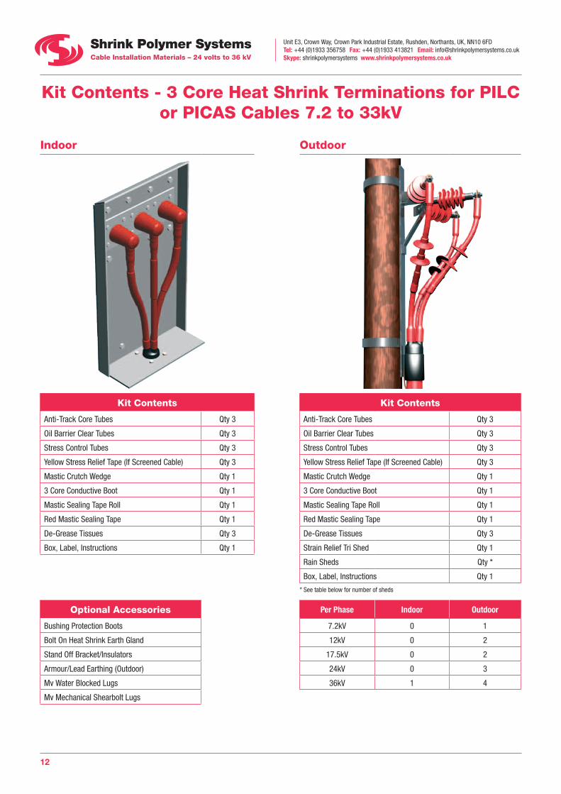
Kit Contents - 3 Core Heat Shrink Terminations for PILC or PICAS Cables 7.2 to 33kV
Indoor Outdoor
Kit Contents Kit Contents
Anti-Track Core Tubes Qty 3 Anti-Track Core Tubes Qty 3
Oil Barrier Clear Tubes Qty 3 Oil Barrier Clear Tubes Qty 3
Stress Control Tubes Qty 3 Stress Control Tubes Qty 3
Yellow Stress Relief Tape (If Screened Cable) Qty 3 Yellow Stress Relief Tape (If Screened Cable) Qty 3
Mastic Crutch Wedge Qty 1 Mastic Crutch Wedge Qty 1
3 Core Conductive Boot Qty 1 3 Core Conductive Boot Qty 1
Mastic Sealing Tape Roll Qty 1 Mastic Sealing Tape Roll Qty 1
Red Mastic Sealing Tape Qty 1 Red Mastic Sealing Tape Qty 1
De-Grease Tissues Qty 3 De-Grease Tissues Qty 3
Box, Label, Instructions Qty 1 Strain Relief Tri Shed Qty 1
Rain Sheds Qty *
Box, Label, Instructions Qty 1
* See table below for number of sheds
Optional Accessories Per Phase Indoor Outdoor
Bushing Protection Boots 7.2kV 0 1
Bolt On Heat Shrink Earth Gland 12kV 0 2
Stand Off Bracket/Insulators 17.5kV 0 2
Armour/Lead Earthing (Outdoor) 24kV 0 3
Mv Water Blocked Lugs 36kV 1 4
Mv Mechanical Shearbolt Lugs
Unit E3, Crown Way, Crown Park Industrial Estate, Rushden, Northants, UK, NN10 6FDTel: +44 (0)1933 356758 Fax: +44 (0)1933 413821 Email: [email protected] Skype: shrinkpolymersystems www.shrinkpolymersystems.co.uk
13
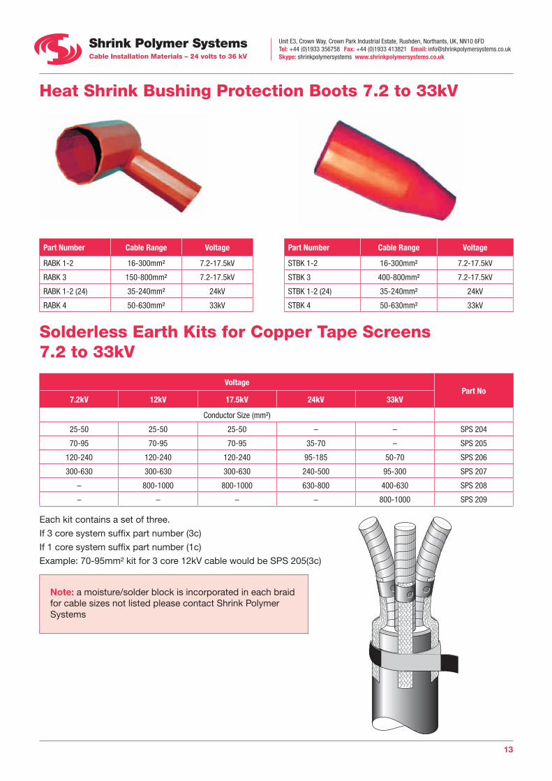
Heat Shrink Bushing Protection Boots 7.2 to 33kV
Part Number Cable Range Voltage Part Number Cable Range Voltage
RABK 1-2 16-300mm² 7.2-17.5kV STBK 1-2 16-300mm² 7.2-17.5kV
RABK 3 150-800mm² 7.2-17.5kV STBK 3 400-800mm² 7.2-17.5kV
RABK 1-2 (24) 35-240mm² 24kV STBK 1-2 (24) 35-240mm² 24kV
RABK 4 50-630mm² 33kV STBK 4 50-630mm² 33kV
Solderless Earth Kits for Copper Tape Screens 7.2 to 33kV
Voltage Part No
7.2kV 12kV 17.5kV 24kV 33kV
Conductor Size (mm²)
25-50 25-50 25-50 – – SPS 204
70-95 70-95 70-95 35-70 – SPS 205
120-240 120-240 120-240 95-185 50-70 SPS 206
300-630 300-630 300-630 240-500 95-300 SPS 207
– 800-1000 800-1000 630-800 400-630 SPS 208
– – – – 800-1000 SPS 209
Each kit contains a set of three.
If 3 core system suffix part number (3c)
If 1 core system suffix part number (1c)
Example: 70-95mm² kit for 3 core 12kV cable would be SPS 205(3c)
Note: a moisture/solder block is incorporated in each braid for cable sizes not listed please contact Shrink Polymer Systems
Unit E3, Crown Way, Crown Park Industrial Estate, Rushden, Northants, UK, NN10 6FDTel: +44 (0)1933 356758 Fax: +44 (0)1933 413821 Email: [email protected] Skype: shrinkpolymersystems www.shrinkpolymersystems.co.uk
14
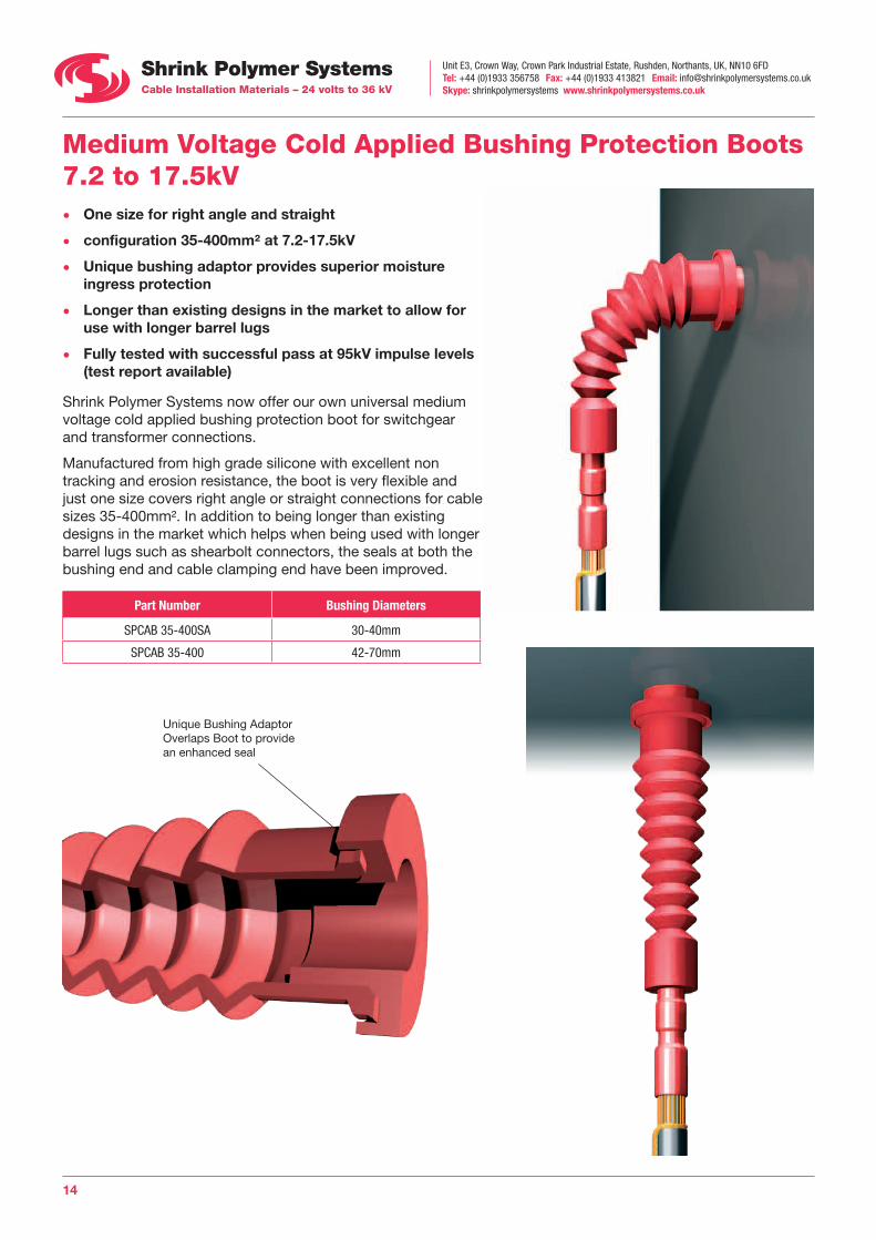
Medium Voltage Cold Applied Bushing Protection Boots 7.2 to 17.5kV • One size for right angle and straight
• configuration 35-400mm² at 7.2-17.5kV
• Unique bushing adaptor provides superior moisture ingress protection
• Longer than existing designs in the market to allow for use with longer barrel lugs
• Fully tested with successful pass at 95kV impulse levels (test report available)
Shrink Polymer Systems now offer our own universal medium voltage cold applied bushing protection boot for switchgear and transformer connections.
Manufactured from high grade silicone with excellent non tracking and erosion resistance, the boot is very flexible and just one size covers right angle or straight connections for cable sizes 35-400mm². In addition to being longer than existing designs in the market which helps when being used with longer barrel lugs such as shearbolt connectors, the seals at both the bushing end and cable clamping end have been improved.
Part Number Bushing Diameters
SPCAB 35-400SA 30-40mm
SPCAB 35-400 42-70mm
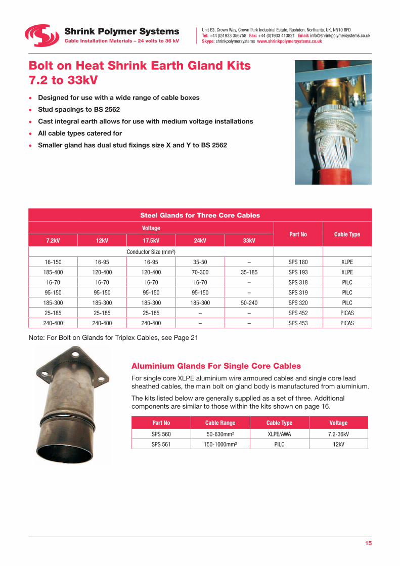
Unique Bushing AdaptorOverlaps Boot to providean enhanced seal
Unit E3, Crown Way, Crown Park Industrial Estate, Rushden, Northants, UK, NN10 6FDTel: +44 (0)1933 356758 Fax: +44 (0)1933 413821 Email: [email protected] Skype: shrinkpolymersystems www.shrinkpolymersystems.co.uk
15
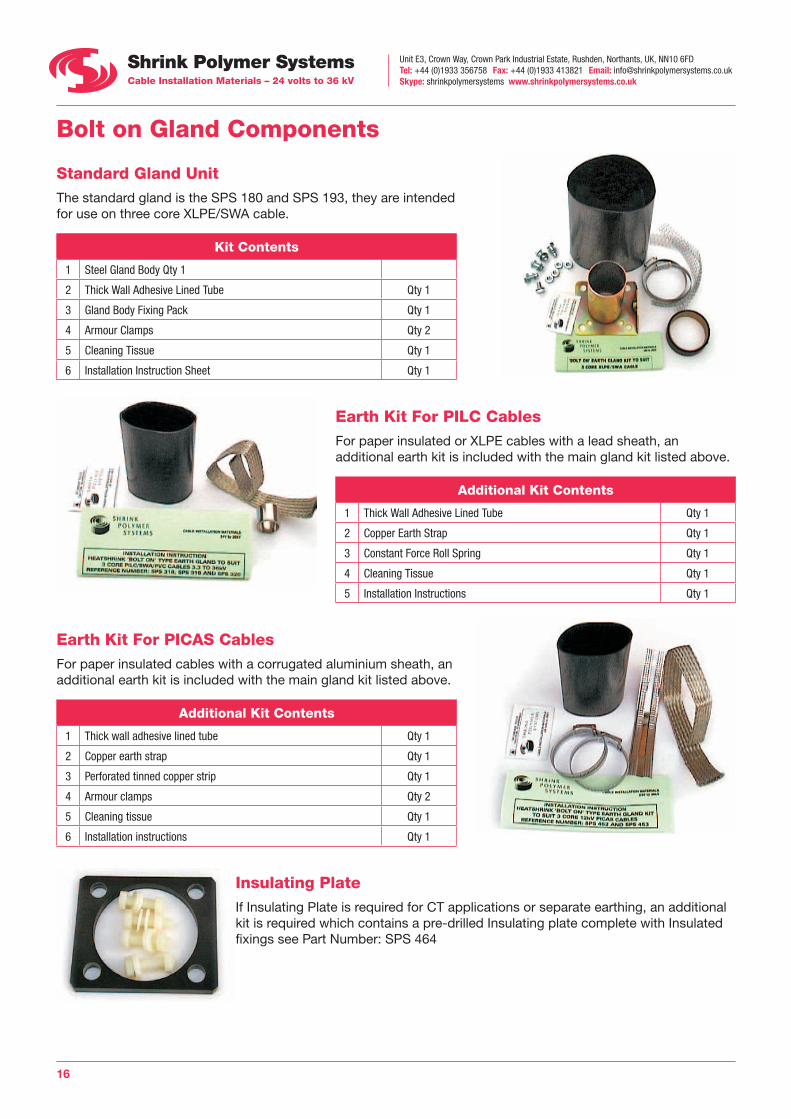
Bolt on Heat Shrink Earth Gland Kits 7.2 to 33kV • Designed for use with a wide range of cable boxes
• Stud spacings to BS 2562
• Cast integral earth allows for use with medium voltage installations
• All cable types catered for
• Smaller gland has dual stud fixings size X and Y to BS 2562
Steel Glands for Three Core Cables
Voltage Part No Cable Type
7.2kV 12kV 17.5kV 24kV 33kV
Conductor Size (mm²)
16-150 16-95 16-95 35-50 – SPS 180 XLPE
185-400 120-400 120-400 70-300 35-185 SPS 193 XLPE
16-70 16-70 16-70 16-70 – SPS 318 PILC
95-150 95-150 95-150 95-150 – SPS 319 PILC
185-300 185-300 185-300 185-300 50-240 SPS 320 PILC
25-185 25-185 25-185 – – SPS 452 PICAS
240-400 240-400 240-400 – – SPS 453 PICAS
Note: For Bolt on Glands for Triplex Cables, see Page 21
Aluminium Glands For Single Core Cables For single core XLPE aluminium wire armoured cables and single core lead sheathed cables, the main bolt on gland body is manufactured from aluminium.
The kits listed below are generally supplied as a set of three. Additional components are similar to those within the kits shown on page 16.
Part No Cable Range Cable Type Voltage
SPS 560 50-630mm² XLPE/AWA 7.2-36kV
SPS 561 150-1000mm² PILC 12kV
Unit E3, Crown Way, Crown Park Industrial Estate, Rushden, Northants, UK, NN10 6FDTel: +44 (0)1933 356758 Fax: +44 (0)1933 413821 Email: [email protected] Skype: shrinkpolymersystems www.shrinkpolymersystems.co.uk
16
Bolt on Gland Components
Standard Gland Unit The standard gland is the SPS 180 and SPS 193, they are intended for use on three core XLPE/SWA cable.
Kit Contents
1 Steel Gland Body Qty 1
2 Thick Wall Adhesive Lined Tube Qty 1
3 Gland Body Fixing Pack Qty 1
4 Armour Clamps Qty 2
5 Cleaning Tissue Qty 1
6 Installation Instruction Sheet Qty 1
Earth Kit For PILC Cables For paper insulated or XLPE cables with a lead sheath, an additional earth kit is included with the main gland kit listed above.
Additional Kit Contents
1 Thick Wall Adhesive Lined Tube Qty 1
2 Copper Earth Strap Qty 1
3 Constant Force Roll Spring Qty 1
4 Cleaning Tissue Qty 1
5 Installation Instructions Qty 1
Earth Kit For PICAS Cables For paper insulated cables with a corrugated aluminium sheath, an additional earth kit is included with the main gland kit listed above.
Additional Kit Contents
1 Thick wall adhesive lined tube Qty 1
2 Copper earth strap Qty 1
3 Perforated tinned copper strip Qty 1
4 Armour clamps Qty 2
5 Cleaning tissue Qty 1
6 Installation instructions Qty 1
Insulating Plate If Insulating Plate is required for CT applications or separate earthing, an additional kit is required which contains a pre-drilled Insulating plate complete with Insulated fixings see Part Number: SPS 464
Unit E3, Crown Way, Crown Park Industrial Estate, Rushden, Northants, UK, NN10 6FDTel: +44 (0)1933 356758 Fax: +44 (0)1933 413821 Email: [email protected] Skype: shrinkpolymersystems www.shrinkpolymersystems.co.uk
17
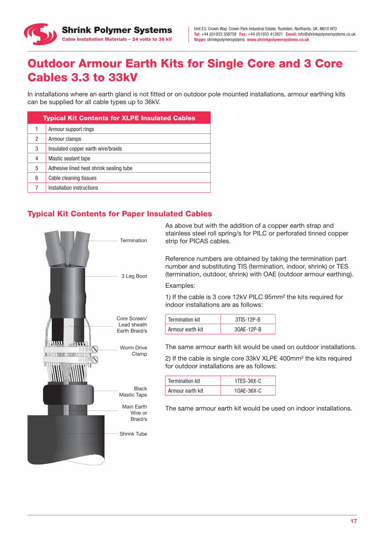
Outdoor Armour Earth Kits for Single Core and 3 Core Cables 3.3 to 33kV In installations where an earth gland is not fitted or on outdoor pole mounted installations, armour earthing kits can be supplied for all cable types up to 36kV.
Typical Kit Contents for XLPE Insulated Cables
1 Armour support rings
2 Armour clamps
3 Insulated copper earth wire/braids
4 Mastic sealant tape
5 Adhesive lined heat shrink sealing tube
6 Cable cleaning tissues
7 Installation instructions
Typical Kit Contents for Paper Insulated Cables As above but with the addition of a copper earth strap and stainless steel roll spring/s for PILC or perforated tinned copper strip for PICAS cables.
Reference numbers are obtained by taking the termination part number and substituting TIS (termination, indoor, shrink) or TES (termination, outdoor, shrink) with OAE (outdoor armour earthing).
Examples:
1) If the cable is 3 core 12kV PILC 95mm² the kits required for indoor installations are as follows:
Termination kit 3TIS-12P-B
Armour earth kit 3OAE-12P-B
The same armour earth kit would be used on outdoor installations.
2) If the cable is single core 33kV XLPE 400mm² the kits required for outdoor installations are as follows:
Termination kit 1TES-36X-C
Armour earth kit 1OAE-36X-C
The same armour earth kit would be used on indoor installations.
Termination
3 Leg Boot
Worm Drive Clamp
Black Mastic Tape
Main Earth Wire or Braid/s
Shrink Tube
Core Screen/Lead sheath
Earth Braid/s
Unit E3, Crown Way, Crown Park Industrial Estate, Rushden, Northants, UK, NN10 6FDTel: +44 (0)1933 356758 Fax: +44 (0)1933 413821 Email: [email protected] Skype: shrinkpolymersystems www.shrinkpolymersystems.co.uk
18
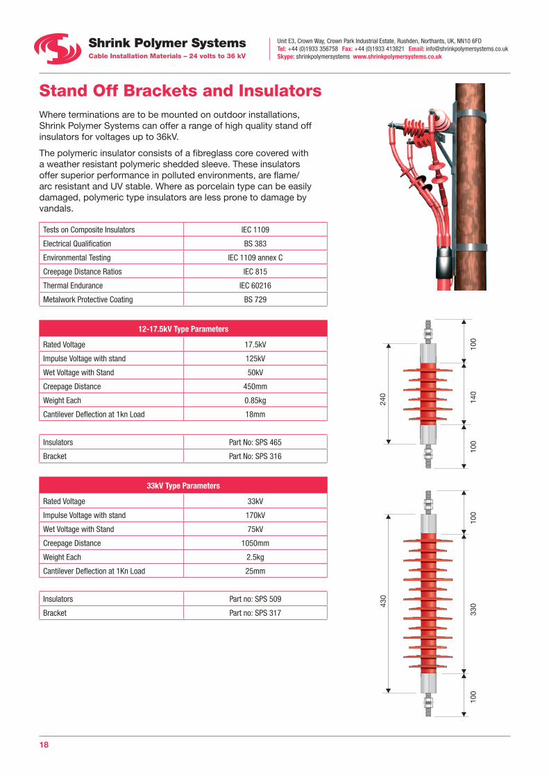
Stand Off Brackets and Insulators Where terminations are to be mounted on outdoor installations, Shrink Polymer Systems can offer a range of high quality stand off insulators for voltages up to 36kV.
The polymeric insulator consists of a fibreglass core covered with a weather resistant polymeric shedded sleeve. These insulators offer superior performance in polluted environments, are flame/arc resistant and UV stable. Where as porcelain type can be easily damaged, polymeric type insulators are less prone to damage by vandals.
Tests on Composite Insulators IEC 1109
Electrical Qualification BS 383
Environmental Testing IEC 1109 annex C
Creepage Distance Ratios IEC 815
Thermal Endurance IEC 60216
Metalwork Protective Coating BS 729
12-17.5kV Type Parameters
Rated Voltage 17.5kV
Impulse Voltage with stand 125kV
Wet Voltage with Stand 50kV
Creepage Distance 450mm
Weight Each 0.85kg
Cantilever Deflection at 1kn Load 18mm
Insulators Part No: SPS 465
Bracket Part No: SPS 316
33kV Type Parameters
Rated Voltage 33kV
Impulse Voltage with stand 170kV
Wet Voltage with Stand 75kV
Creepage Distance 1050mm
Weight Each 2.5kg
Cantilever Deflection at 1Kn Load 25mm
Insulators Part no: SPS 509
Bracket Part no: SPS 317
240
140
100
100
100
100
33043
0
Unit E3, Crown Way, Crown Park Industrial Estate, Rushden, Northants, UK, NN10 6FDTel: +44 (0)1933 356758 Fax: +44 (0)1933 413821 Email: [email protected] Skype: shrinkpolymersystems www.shrinkpolymersystems.co.uk
19
Medium Voltage Termination – Observations
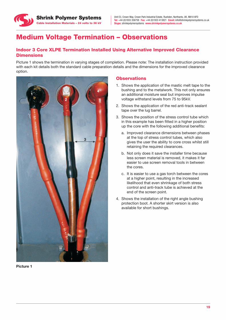
Indoor 3 Core XLPE Termination Installed Using Alternative Improved Clearance Dimensions Picture 1 shows the termination in varying stages of completion. Please note: The installation instruction provided with each kit details both the standard cable preparation details and the dimensions for the improved clearance option.
Observations 1. Shows the application of the mastic melt tape to the
bushing and to the metalwork. This not only ensures an additional moisture seal but improves impulse voltage withstand levels from 75 to 95kV.
2. Shows the application of the red anti-track sealant tape over the lug barrel.
3. Shows the position of the stress control tube which in this example has been fitted in a higher position up the core with the following additional benefits:
a. Improved clearance dimensions between phases at the top of stress control tubes, which also gives the user the ability to core cross whilst still retaining the required clearances.
b. Not only does it save the installer time because less screen material is removed, it makes it far easier to use screen removal tools in between the cores.
c. It is easier to use a gas torch between the cores at a higher point, resulting in the increased likelihood that even shrinkage of both stress control and anti-track tube is achieved at the end of the screen point.
4. Shows the installation of the right angle bushing protection boot. A shorter skirt version is also available for short bushings.
Picture 1
3
12
4
Unit E3, Crown Way, Crown Park Industrial Estate, Rushden, Northants, UK, NN10 6FDTel: +44 (0)1933 356758 Fax: +44 (0)1933 413821 Email: [email protected] Skype: shrinkpolymersystems www.shrinkpolymersystems.co.uk
20
Medium Voltage Termination – Observations
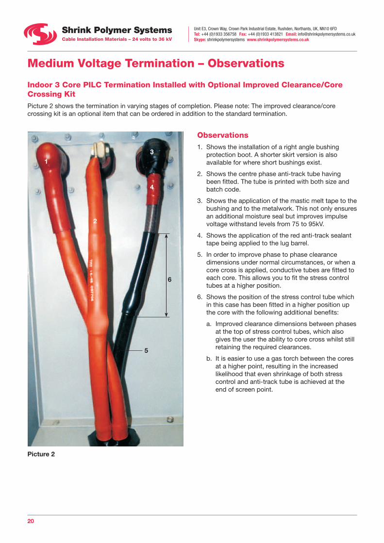
Indoor 3 Core PILC Termination Installed with Optional Improved Clearance/Core Crossing Kit Picture 2 shows the termination in varying stages of completion. Please note: The improved clearance/core crossing kit is an optional item that can be ordered in addition to the standard termination.
Picture 2
5
6
1
2
4
3
Observations 1. Shows the installation of a right angle bushing
protection boot. A shorter skirt version is also available for where short bushings exist.
2. Shows the centre phase anti-track tube having been fitted. The tube is printed with both size and batch code.
3. Shows the application of the mastic melt tape to the bushing and to the metalwork. This not only ensures an additional moisture seal but improves impulse voltage withstand levels from 75 to 95kV.
4. Shows the application of the red anti-track sealant tape being applied to the lug barrel.
5. In order to improve phase to phase clearance dimensions under normal circumstances, or when a core cross is applied, conductive tubes are fitted to each core. This allows you to fit the stress control tubes at a higher position.
6. Shows the position of the stress control tube which in this case has been fitted in a higher position up the core with the following additional benefits:
a. Improved clearance dimensions between phases at the top of stress control tubes, which also gives the user the ability to core cross whilst still retaining the required clearances.
b. It is easier to use a gas torch between the cores at a higher point, resulting in the increased likelihood that even shrinkage of both stress control and anti-track tube is achieved at the end of screen point.
Unit E3, Crown Way, Crown Park Industrial Estate, Rushden, Northants, UK, NN10 6FDTel: +44 (0)1933 356758 Fax: +44 (0)1933 413821 Email: [email protected] Skype: shrinkpolymersystems www.shrinkpolymersystems.co.uk
21
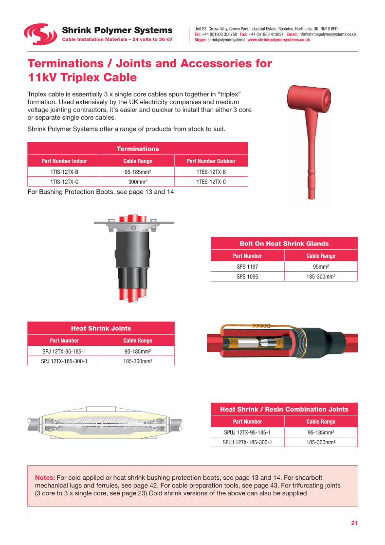
Terminations / Joints and Accessories for 11kV Triplex Cable Triplex cable is essentially 3 x single core cables spun together in “triplex” formation. Used extensively by the UK electricity companies and medium voltage jointing contractors, it’s easier and quicker to install than either 3 core or separate single core cables.
Shrink Polymer Systems offer a range of products from stock to suit.
Terminations
Part Number Indoor Cable Range Part Number Outdoor
1TIS-12TX-B 95-185mm² 1TES-12TX-B
1TIS-12TX-C 300mm² 1TES-12TX-C
For Bushing Protection Boots, see page 13 and 14
Bolt On Heat Shrink Glands
Part Number Cable Range
SPS 1197 95mm²
SPS 1095 185-300mm²
Heat Shrink Joints
Part Number Cable Range
SPJ 12TX-95-185-1 95-185mm²
SPJ 12TX-185-300-1 185-300mm²
Heat Shrink / Resin Combination Joints
Part Number Cable Range
SPUJ 12TX-95-185-1 95-185mm²
SPUJ 12TX-185-300-1 185-300mm²
Notes: For cold applied or heat shrink bushing protection boots, see page 13 and 14. For shearbolt mechanical lugs and ferrules, see page 42. For cable preparation tools, see page 43. For trifurcating joints (3 core to 3 x single core, see page 23) Cold shrink versions of the above can also be supplied

Unit E3, Crown Way, Crown Park Industrial Estate, Rushden, Northants, UK, NN10 6FDTel: +44 (0)1933 356758 Fax: +44 (0)1933 413821 Email: [email protected] Skype: shrinkpolymersystems www.shrinkpolymersystems.co.uk
22
Non Centralised Type Connectors
SPS Joint has tapered Profile with Conductors Centralised
Universal Heat Shrink / Resin Combination Joint for 7.2 to 12kV Cables • Suits 3 core XLPE
/ PILC /PICAS cables or transition combinations complete with tapered range taking mechanical connectors, high impact shell and twin pack polyurethane resin
• Offers the superior insulation benefits of heat shrink combined with resin for environmental protection
• Tested to BS7888 and Cenelec HD 628 S1 and HD 629 S1
Shrink Polymer Systems now offer from stock, a universal heat shrink joint complete with mechanical shearbolt connectors, high impact shell, twin pack polyurethane resin and full earthing accessories for XLPE, PILC and PICAS cable combinations.
The standard joint comes complete with modules that enable all cable types and sizes to be catered for. This is ideal for distributors who wish to cut down their stock levels and contractors that cannot be sure of the exact cables they will encounter on site.
Where the cables are known, only the modules required can be supplied to further reduce cost. Mechanical connectors can be substituted for compression connectors if preferred.
Part Number Conductor Size Cable Types
SPUJ 12U 35-70-3 35-70mm² XLPE/PILC/PICAS
SPUJ 12U 95-185-3 95-185mm² XLPE/PILC/PICAS
SPUJ 12U 185-300-3 185-300mm² XLPE/PILC/PICAS
SPUJ 12X 35-70-3 35-70mm² XLPE
SPUJ 12X 95-185-3 95-185mm² XLPE
SPUJ 12X 185-300-3 185-300mm² XLPE
SPUJ 12PX 35-70-3 35-70mm² Transition
SPUJ 12PX 95-185-3 95-185mm² Transition
SPUJ 12PX 185-300-3 185-300mm² Transition
SPUJ 12P 35-70-3 35-70mm² PILC/PICAS
SPUJ 12P 95-185-3 95-185mm² PILC/PICAS
SPUJ 12P 185-300-3 185-300mm² PILC/PICAS
Notes: Items 1-3 are the universal type, items 4-12 have only the required modules. Trifurcating joints are available.
Example: 3c 95mm² PILC to 3 x Single Core 95mm² XLPE = SPUJ 12PX-95-185-3-TRIF
Unit E3, Crown Way, Crown Park Industrial Estate, Rushden, Northants, UK, NN10 6FDTel: +44 (0)1933 356758 Fax: +44 (0)1933 413821 Email: [email protected] Skype: shrinkpolymersystems www.shrinkpolymersystems.co.uk
23
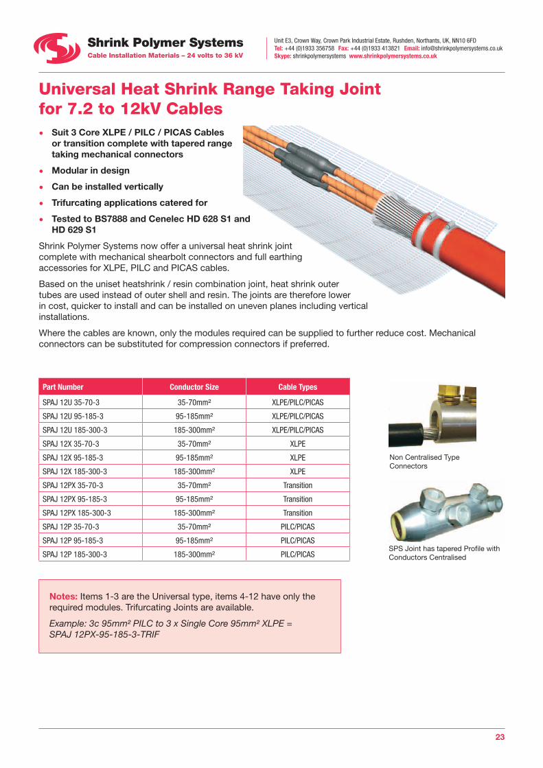
Non Centralised Type Connectors
SPS Joint has tapered Profile with Conductors Centralised
Universal Heat Shrink Range Taking Joint for 7.2 to 12kV Cables• Suit 3 Core XLPE / PILC / PICAS Cables
or transition complete with tapered range taking mechanical connectors
• Modular in design
• Can be installed vertically
• Trifurcating applications catered for
• Tested to BS7888 and Cenelec HD 628 S1 and HD 629 S1
Shrink Polymer Systems now offer a universal heat shrink joint complete with mechanical shearbolt connectors and full earthing accessories for XLPE, PILC and PICAS cables.
Based on the uniset heatshrink / resin combination joint, heat shrink outer tubes are used instead of outer shell and resin. The joints are therefore lower in cost, quicker to install and can be installed on uneven planes including vertical installations.
Where the cables are known, only the modules required can be supplied to further reduce cost. Mechanical connectors can be substituted for compression connectors if preferred.
Part Number Conductor Size Cable Types
SPAJ 12U 35-70-3 35-70mm² XLPE/PILC/PICAS
SPAJ 12U 95-185-3 95-185mm² XLPE/PILC/PICAS
SPAJ 12U 185-300-3 185-300mm² XLPE/PILC/PICAS
SPAJ 12X 35-70-3 35-70mm² XLPE
SPAJ 12X 95-185-3 95-185mm² XLPE
SPAJ 12X 185-300-3 185-300mm² XLPE
SPAJ 12PX 35-70-3 35-70mm² Transition
SPAJ 12PX 95-185-3 95-185mm² Transition
SPAJ 12PX 185-300-3 185-300mm² Transition
SPAJ 12P 35-70-3 35-70mm² PILC/PICAS
SPAJ 12P 95-185-3 95-185mm² PILC/PICAS
SPAJ 12P 185-300-3 185-300mm² PILC/PICAS
Notes: Items 1-3 are the Universal type, items 4-12 have only the required modules. Trifurcating Joints are available.
Example: 3c 95mm² PILC to 3 x Single Core 95mm² XLPE = SPAJ 12PX-95-185-3-TRIF
Unit E3, Crown Way, Crown Park Industrial Estate, Rushden, Northants, UK, NN10 6FDTel: +44 (0)1933 356758 Fax: +44 (0)1933 413821 Email: [email protected] Skype: shrinkpolymersystems www.shrinkpolymersystems.co.uk
24
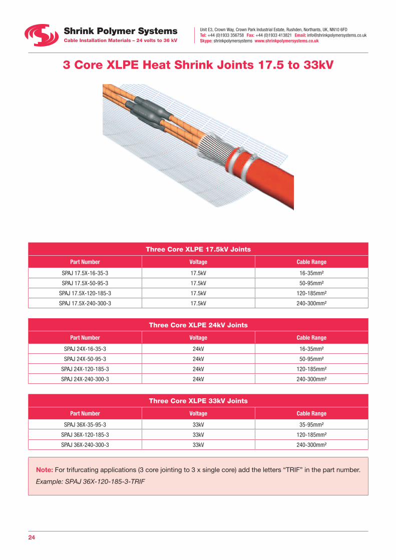
3 Core XLPE Heat Shrink Joints 17.5 to 33kV
Three Core XLPE 17.5kV Joints
Part Number Voltage Cable Range
SPAJ 17.5X-16-35-3 17.5kV 16-35mm²
SPAJ 17.5X-50-95-3 17.5kV 50-95mm²
SPAJ 17.5X-120-185-3 17.5kV 120-185mm²
SPAJ 17.5X-240-300-3 17.5kV 240-300mm²
Three Core XLPE 24kV Joints
Part Number Voltage Cable Range
SPAJ 24X-16-35-3 24kV 16-35mm²
SPAJ 24X-50-95-3 24kV 50-95mm²
SPAJ 24X-120-185-3 24kV 120-185mm²
SPAJ 24X-240-300-3 24kV 240-300mm²
Three Core XLPE 33kV Joints
Part Number Voltage Cable Range
SPAJ 36X-35-95-3 33kV 35-95mm²
SPAJ 36X-120-185-3 33kV 120-185mm²
SPAJ 36X-240-300-3 33kV 240-300mm²
Note: For trifurcating applications (3 core jointing to 3 x single core) add the letters “TRIF” in the part number.
Example: SPAJ 36X-120-185-3-TRIF

Unit E3, Crown Way, Crown Park Industrial Estate, Rushden, Northants, UK, NN10 6FDTel: +44 (0)1933 356758 Fax: +44 (0)1933 413821 Email: [email protected] Skype: shrinkpolymersystems www.shrinkpolymersystems.co.uk
25
3 Core PILC Heat Shrink Joints 17.5 to 33kV
Three Core PILC 17.5kV Joints
Part Number Voltage Cable Range
SPAJ 17.5P-25-50-3 17.5kV 25-50mm²
SPAJ 17.5P-70-95-3 17.5kV 70-95mm²
SPAJ 17.5P-120-185-3 17.5kV 120-185mm²
SPAJ 17.5P-240-400-3 17.5kV 240-400mm²
Three Core PILC 24kV Joints
Part Number Voltage Cable Range
SPAJ 24P-25-35-3 24kV 25-35mm²
SPAJ 24P-50-95-3 24kV 50-95mm²
SPAJ 24P-120-185-3 24kV 120-185mm²
SPAJ 24P-240-300-3 24kV 240-300mm²
Three Core PILC 33kV Joints
Part Number Voltage Cable Range
SPAJ 36P-50-95-3 33kV 50-95mm²
SPAJ 36P-120-185-3 33kV 120-185mm²
SPAJ 36P-240-300-3 33kV 240-300mm²
Note: For trifurcating applications (3 core jointing to 3 x single core) add the letters “TRIF” after part number.
Example: SPAJ 36P-120-185-3-TRIF
Unit E3, Crown Way, Crown Park Industrial Estate, Rushden, Northants, UK, NN10 6FDTel: +44 (0)1933 356758 Fax: +44 (0)1933 413821 Email: [email protected] Skype: shrinkpolymersystems www.shrinkpolymersystems.co.uk
26
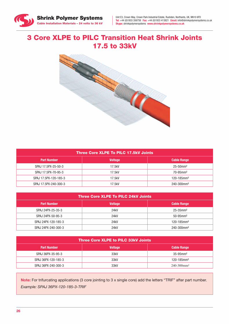
3 Core XLPE to PILC Transition Heat Shrink Joints 17.5 to 33kV
Three Core XLPE To PILC 17.5kV Joints
Part Number Voltage Cable Range
SPAJ 17.5PX-25-50-3 17.5kV 25-50mm²
SPAJ 17.5PX-70-95-3 17.5kV 70-95mm²
SPAJ 17.5PX-120-185-3 17.5kV 120-185mm²
SPAJ 17.5PX-240-300-3 17.5kV 240-300mm²
Three Core XLPE To PILC 24kV Joints
Part Number Voltage Cable Range
SPAJ 24PX-25-35-3 24kV 25-35mm²
SPAJ 24PX-50-95-3 24kV 50-95mm²
SPAJ 24PX-120-185-3 24kV 120-185mm²
SPAJ 24PX-240-300-3 24kV 240-300mm²
Three Core XLPE to PILC 33kV Joints
Part Number Voltage Cable Range
SPAJ 36PX-35-95-3 33kV 35-95mm²
SPAJ 36PX-120-185-3 33kV 120-185mm²
SPAJ 36PX-240-300-3 33kV 240-300mm²
Note: For trifurcating applications (3 core jointing to 3 x single core) add the letters “TRIF” after part number.
Example: SPAJ 36PX-120-185-3-TRIF
Unit E3, Crown Way, Crown Park Industrial Estate, Rushden, Northants, UK, NN10 6FDTel: +44 (0)1933 356758 Fax: +44 (0)1933 413821 Email: [email protected] Skype: shrinkpolymersystems www.shrinkpolymersystems.co.uk
27
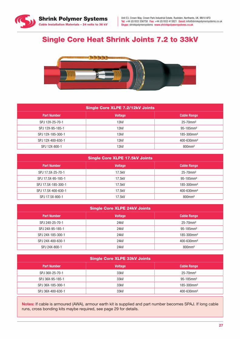
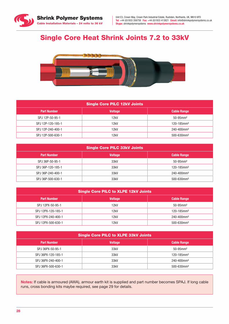
Single Core Heat Shrink Joints 7.2 to 33kV
Single Core XLPE 7.2/12kV Joints
Part Number Voltage Cable Range
SPJ 12X-25-70-1 12kV 25-70mm²
SPJ 12X-95-185-1 12kV 95-185mm²
SPJ 12X-185-300-1 12kV 185-300mm²
SPJ 12X-400-630-1 12kV 400-630mm²
SPJ 12X-800-1 12kV 800mm²
Single Core XLPE 17.5kV Joints
Part Number Voltage Cable Range
SPJ 17.5X-25-70-1 17.5kV 25-70mm²
SPJ 17.5X-95-185-1 17.5kV 95-185mm²
SPJ 17.5X-185-300-1 17.5kV 185-300mm²
SPJ 17.5X-400-630-1 17.5kV 400-630mm²
SPJ 17.5X-800-1 17.5kV 800mm²
Single Core XLPE 24kV Joints
Part Number Voltage Cable Range
SPJ 24X-25-70-1 24kV 25-70mm²
SPJ 24X-95-185-1 24kV 95-185mm²
SPJ 24X-185-300-1 24kV 185-300mm²
SPJ 24X-400-630-1 24kV 400-630mm²
SPJ 24X-800-1 24kV 800mm²
Single Core XLPE 33kV Joints
Part Number Voltage Cable Range
SPJ 36X-25-70-1 33kV 25-70mm²
SPJ 36X-95-185-1 33kV 95-185mm²
SPJ 36X-185-300-1 33kV 185-300mm²
SPJ 36X-400-630-1 33kV 400-630mm²
Notes: If cable is armoured (AWA), armour earth kit is supplied and part number becomes SPAJ. If long cable runs, cross bonding kits maybe required, see page 29 for details.
Unit E3, Crown Way, Crown Park Industrial Estate, Rushden, Northants, UK, NN10 6FDTel: +44 (0)1933 356758 Fax: +44 (0)1933 413821 Email: [email protected] Skype: shrinkpolymersystems www.shrinkpolymersystems.co.uk
28
Single Core Heat Shrink Joints 7.2 to 33kV
Single Core PILC 12kV Joints
Part Number Voltage Cable Range
SPJ 12P-50-95-1 12kV 50-95mm²
SPJ 12P-120-185-1 12kV 120-185mm²
SPJ 12P-240-400-1 12kV 240-400mm²
SPJ 12P-500-630-1 12kV 500-630mm²
Single Core PILC 33kV Joints
Part Number Voltage Cable Range
SPJ 36P-50-95-1 33kV 50-95mm²
SPJ 36P-120-185-1 33kV 120-185mm²
SPJ 36P-240-400-1 33kV 240-400mm²
SPJ 36P-500-630-1 33kV 500-630mm²
Single Core PILC to XLPE 12kV Joints
Part Number Voltage Cable Range
SPJ 12PX-50-95-1 12kV 50-95mm²
SPJ 12PX-120-185-1 12kV 120-185mm²
SPJ 12PX-240-400-1 12kV 240-400mm²
SPJ 12PX-500-630-1 12kV 500-630mm²
Single Core PILC to XLPE 33kV Joints
Part Number Voltage Cable Range
SPJ 36PX-50-95-1 33kV 50-95mm²
SPJ 36PX-120-185-1 33kV 120-185mm²
SPJ 36PX-240-400-1 33kV 240-400mm²
SPJ 36PX-500-630-1 33kV 500-630mm²
Notes: If cable is armoured (AWA), armour earth kit is supplied and part number becomes SPAJ. If long cable runs, cross bonding kits maybe required, see page 29 for details.
Unit E3, Crown Way, Crown Park Industrial Estate, Rushden, Northants, UK, NN10 6FDTel: +44 (0)1933 356758 Fax: +44 (0)1933 413821 Email: [email protected] Skype: shrinkpolymersystems www.shrinkpolymersystems.co.uk
29
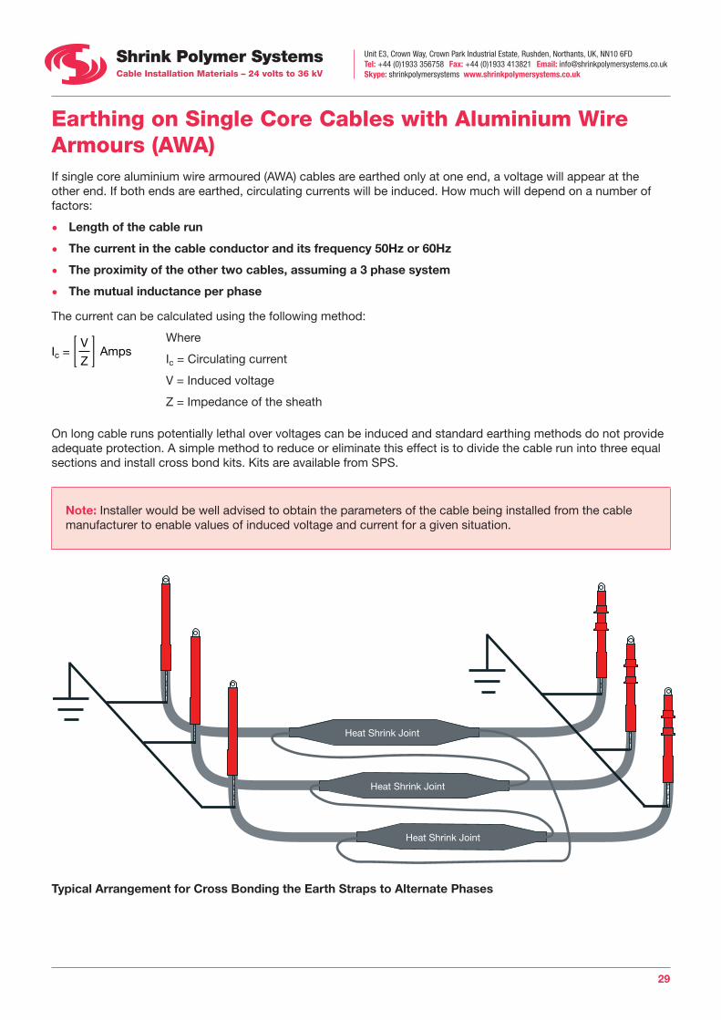
Ic = V
ZAmps
Earthing on Single Core Cables with Aluminium Wire Armours (AWA) If single core aluminium wire armoured (AWA) cables are earthed only at one end, a voltage will appear at the other end. If both ends are earthed, circulating currents will be induced. How much will depend on a number of factors:
• Length of the cable run
• The current in the cable conductor and its frequency 50Hz or 60Hz
• The proximity of the other two cables, assuming a 3 phase system
• The mutual inductance per phase
The current can be calculated using the following method:
Where
Ic = Circulating current
V = Induced voltage
Z = Impedance of the sheath
On long cable runs potentially lethal over voltages can be induced and standard earthing methods do not provide adequate protection. A simple method to reduce or eliminate this effect is to divide the cable run into three equal sections and install cross bond kits. Kits are available from SPS.
Note: Installer would be well advised to obtain the parameters of the cable being installed from the cable manufacturer to enable values of induced voltage and current for a given situation.
Heat Shrink Joint
Heat Shrink Joint
Heat Shrink Joint
Typical Arrangement for Cross Bonding the Earth Straps to Alternate Phases

Unit E3, Crown Way, Crown Park Industrial Estate, Rushden, Northants, UK, NN10 6FDTel: +44 (0)1933 356758 Fax: +44 (0)1933 413821 Email: [email protected] Skype: shrinkpolymersystems www.shrinkpolymersystems.co.uk
30
Live Pot End Kits to suit Single and 3 Core XLPE and Paper Cables 7.2-33kV Cables
Pot End KitsOccasionally medium voltage cable circuits need to be installed and energised in the ground but not immediately used to connect to transformers or switchgear. This maybe done at a later stage when perhaps an extension to a building/factory is undertaken and the previously
installed cable circuits, can then be utilised.
A live pot end kit is a reliable method of terminating a cable which will be left live. An extensive range of kits are available, see the selection chart below.
Abandonment KitsIf cables are left in the ground and must be sealed but not energised, abandonment kits can be supplied. From the outside they look similar to live pot end kits but internally, the phases are connected to earth so that if voltage is applied to the cables by mistake, an immediate earth fault occurs, tripping out the circuit breaker.
Example: Cable = 3 Core 95mm² 33kV XLPE / SWA / PVC
Live Pot End Kit = POT 36X-95-3
Abandonment Kit = AK 36X-95-3
1 = Single Core 3 = 3 Core
Cable Size In mm²
P = Paper Cable X = XLPE Cable
Voltage Class (kV) 7.2 / 12 / 17.5 / 24 / 33
POT = Live Pot End AK = Abandonment Kit
Pot End and Abandonment Kit Selection Chart
Outer Shrink tube
Unit E3, Crown Way, Crown Park Industrial Estate, Rushden, Northants, UK, NN10 6FDTel: +44 (0)1933 356758 Fax: +44 (0)1933 413821 Email: [email protected] Skype: shrinkpolymersystems www.shrinkpolymersystems.co.uk
31
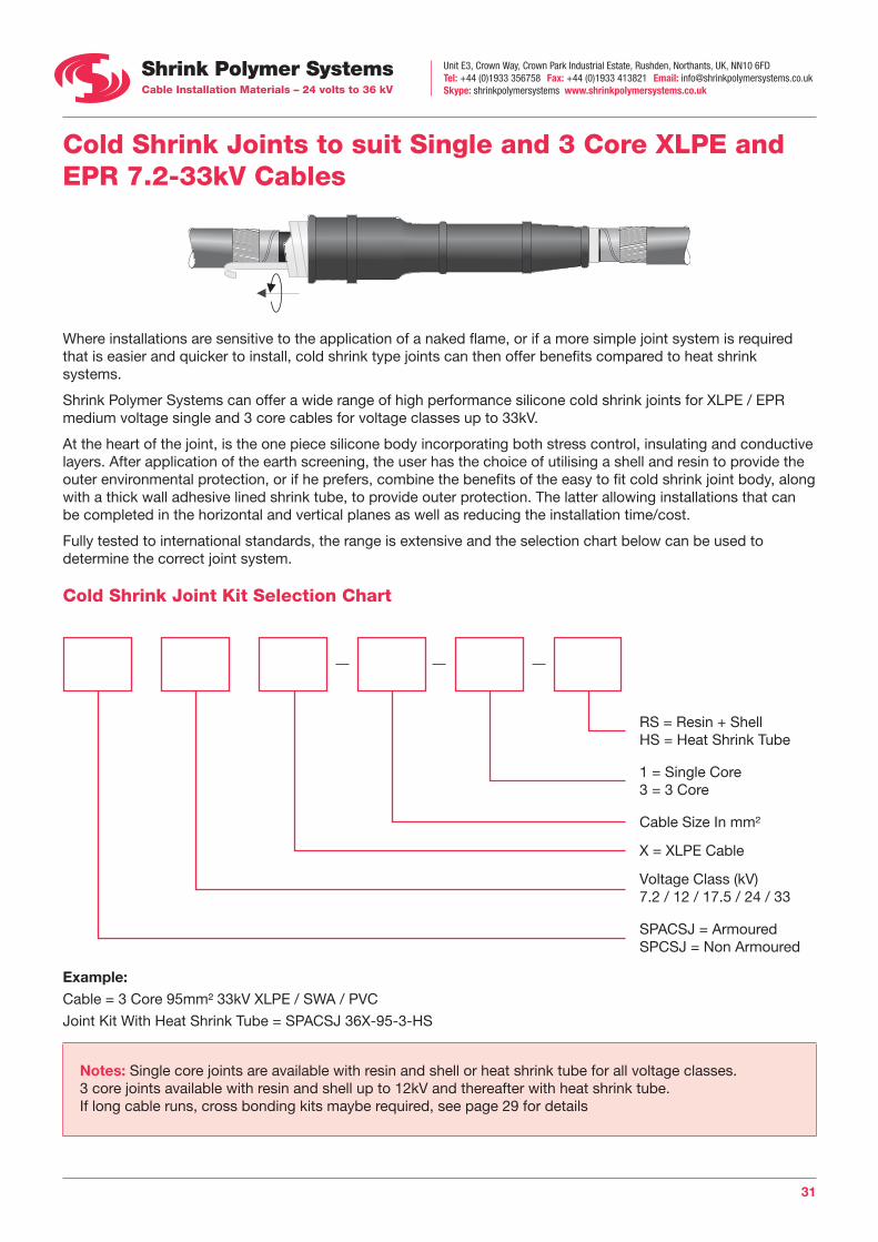
Cold Shrink Joints to suit Single and 3 Core XLPE and EPR 7.2-33kV Cables
Where installations are sensitive to the application of a naked flame, or if a more simple joint system is required that is easier and quicker to install, cold shrink type joints can then offer benefits compared to heat shrink systems.
Shrink Polymer Systems can offer a wide range of high performance silicone cold shrink joints for XLPE / EPR medium voltage single and 3 core cables for voltage classes up to 33kV.
At the heart of the joint, is the one piece silicone body incorporating both stress control, insulating and conductive layers. After application of the earth screening, the user has the choice of utilising a shell and resin to provide the outer environmental protection, or if he prefers, combine the benefits of the easy to fit cold shrink joint body, along with a thick wall adhesive lined shrink tube, to provide outer protection. The latter allowing installations that can be completed in the horizontal and vertical planes as well as reducing the installation time/cost.
Fully tested to international standards, the range is extensive and the selection chart below can be used to determine the correct joint system.
Cold Shrink Joint Kit Selection Chart
Example: Cable = 3 Core 95mm² 33kV XLPE / SWA / PVC
Joint Kit With Heat Shrink Tube = SPACSJ 36X-95-3-HS
Notes: Single core joints are available with resin and shell or heat shrink tube for all voltage classes.3 core joints available with resin and shell up to 12kV and thereafter with heat shrink tube. If long cable runs, cross bonding kits maybe required, see page 29 for details
RS = Resin + Shell HS = Heat Shrink Tube
1 = Single Core 3 = 3 Core
Cable Size In mm²
X = XLPE Cable
Voltage Class (kV) 7.2 / 12 / 17.5 / 24 / 33
SPACSJ = Armoured SPCSJ = Non Armoured
Unit E3, Crown Way, Crown Park Industrial Estate, Rushden, Northants, UK, NN10 6FDTel: +44 (0)1933 356758 Fax: +44 (0)1933 413821 Email: [email protected] Skype: shrinkpolymersystems www.shrinkpolymersystems.co.uk
32
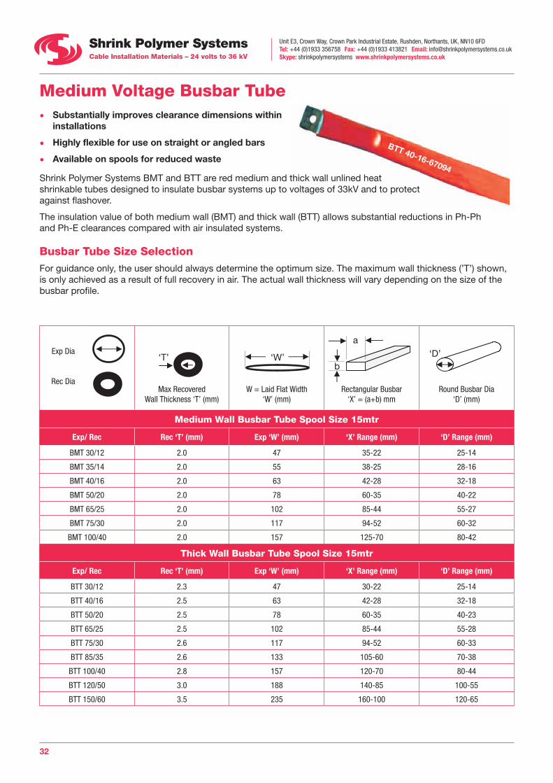
Medium Voltage Busbar Tube • Substantially improves clearance dimensions within
installations
• Highly flexible for use on straight or angled bars
• Available on spools for reduced waste
Shrink Polymer Systems BMT and BTT are red medium and thick wall unlined heat shrinkable tubes designed to insulate busbar systems up to voltages of 33kV and to protect against flashover.
The insulation value of both medium wall (BMT) and thick wall (BTT) allows substantial reductions in Ph-Ph and Ph-E clearances compared with air insulated systems.
Busbar Tube Size SelectionFor guidance only, the user should always determine the optimum size. The maximum wall thickness (’T’) shown, is only achieved as a result of full recovery in air. The actual wall thickness will vary depending on the size of the busbar profile.
Exp Dia
Rec Dia
‘T’ ‘W’ a
b‘D’‘T’ ‘W’ a
b‘D’
Max RecoveredWall Thickness ‘T’ (mm)
‘T’ ‘W’ a
b‘D’
W = Laid Flat Width ‘W’ (mm)
‘T’ ‘W’ a
b‘D’
Rectangular Busbar ‘X’ = (a+b) mm
‘T’ ‘W’ a
b‘D’
Round Busbar Dia ‘D’ (mm)
Medium Wall Busbar Tube Spool Size 15mtr
Exp/ Rec Rec ‘T’ (mm) Exp ‘W’ (mm) ‘X’ Range (mm) ‘D’ Range (mm)
BMT 30/12 2.0 47 35-22 25-14
BMT 35/14 2.0 55 38-25 28-16
BMT 40/16 2.0 63 42-28 32-18
BMT 50/20 2.0 78 60-35 40-22
BMT 65/25 2.0 102 85-44 55-27
BMT 75/30 2.0 117 94-52 60-32
BMT 100/40 2.0 157 125-70 80-42
Thick Wall Busbar Tube Spool Size 15mtr
Exp/ Rec Rec ‘T’ (mm) Exp ‘W’ (mm) ‘X’ Range (mm) ‘D’ Range (mm)
BTT 30/12 2.3 47 30-22 25-14
BTT 40/16 2.5 63 42-28 32-18
BTT 50/20 2.5 78 60-35 40-23
BTT 65/25 2.5 102 85-44 55-28
BTT 75/30 2.6 117 94-52 60-33
BTT 85/35 2.6 133 105-60 70-38
BTT 100/40 2.8 157 120-70 80-44
BTT 120/50 3.0 188 140-85 100-55
BTT 150/60 3.5 235 160-100 120-65
BTT 40-16-67094
Unit E3, Crown Way, Crown Park Industrial Estate, Rushden, Northants, UK, NN10 6FDTel: +44 (0)1933 356758 Fax: +44 (0)1933 413821 Email: [email protected] Skype: shrinkpolymersystems www.shrinkpolymersystems.co.uk
33
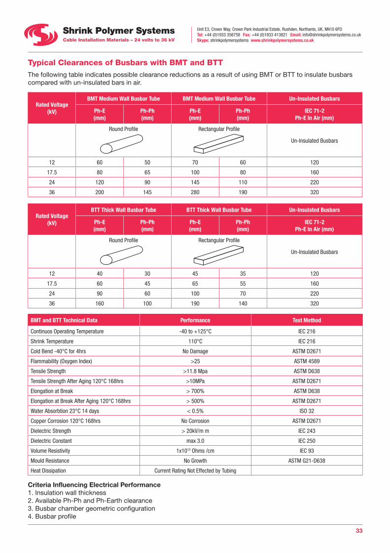
Typical Clearances of Busbars with BMT and BTT The following table indicates possible clearance reductions as a result of using BMT or BTT to insulate busbars compared with un-insulated bars in air.
Rated Voltage (kV)
BMT Medium Wall Busbar Tube BMT Medium Wall Busbar Tube Un-Insulated Busbars
Ph-E (mm)
Ph-Ph (mm)
Ph-E (mm)
Ph-Ph (mm)
IEC 71-2 Ph-E In Air (mm)
Round Profile Rectangular Profile
Un-Insulated Busbars
12 60 50 70 60 120
17.5 80 65 100 80 160
24 120 90 145 110 220
36 200 145 280 190 320
Rated Voltage (kV)
BTT Thick Wall Busbar Tube BTT Thick Wall Busbar Tube Un-Insulated Busbars
Ph-E (mm)
Ph-Ph (mm)
Ph-E (mm)
Ph-Ph (mm)
IEC 71-2 Ph-E In Air (mm)
Round Profile Rectangular Profile
Un-Insulated Busbars
12 40 30 45 35 120
17.5 60 45 65 55 160
24 90 60 100 70 220
36 160 100 190 140 320
BMT and BTT Technical Data Performance Test Method
Continuos Operating Temperature -40 to +125°C IEC 216
Shrink Temperature 110°C IEC 216
Cold Bend -40°C for 4hrs No Damage ASTM D2671
Flammability (Oxygen Index) >25 ASTM 4589
Tensile Strength >11.8 Mpa ASTM D638
Tensile Strength After Aging 120°C 168hrs >10MPa ASTM D2671
Elongation at Break > 700% ASTM D638
Elongation at Break After Aging 120°C 168hrs > 500% ASTM D2671
Water Absorbtion 23°C 14 days < 0.5% ISO 32
Copper Corrosion 120°C 168hrs No Corrosion ASTM D2671
Dielectric Strength > 20kV/m m IEC 243
Dielectric Constant max 3.0 IEC 250
Volume Resistivity 1x10¹³ Ohms /cm IEC 93
Mould Resistance No Growth ASTM G21-D638
Heat Dissipation Current Rating Not Effected by Tubing
Criteria Influencing Electrical Performance 1. Insulation wall thickness 2. Available Ph-Ph and Ph-Earth clearance 3. Busbar chamber geometric configuration 4. Busbar profile
Unit E3, Crown Way, Crown Park Industrial Estate, Rushden, Northants, UK, NN10 6FDTel: +44 (0)1933 356758 Fax: +44 (0)1933 413821 Email: [email protected] Skype: shrinkpolymersystems www.shrinkpolymersystems.co.uk
34
Medium Voltage Busbar Tube • Substantially improves clearance dimensions within switchgear installations
• Flexible for use on straight or angled bars
• Available on spools to reduce waste
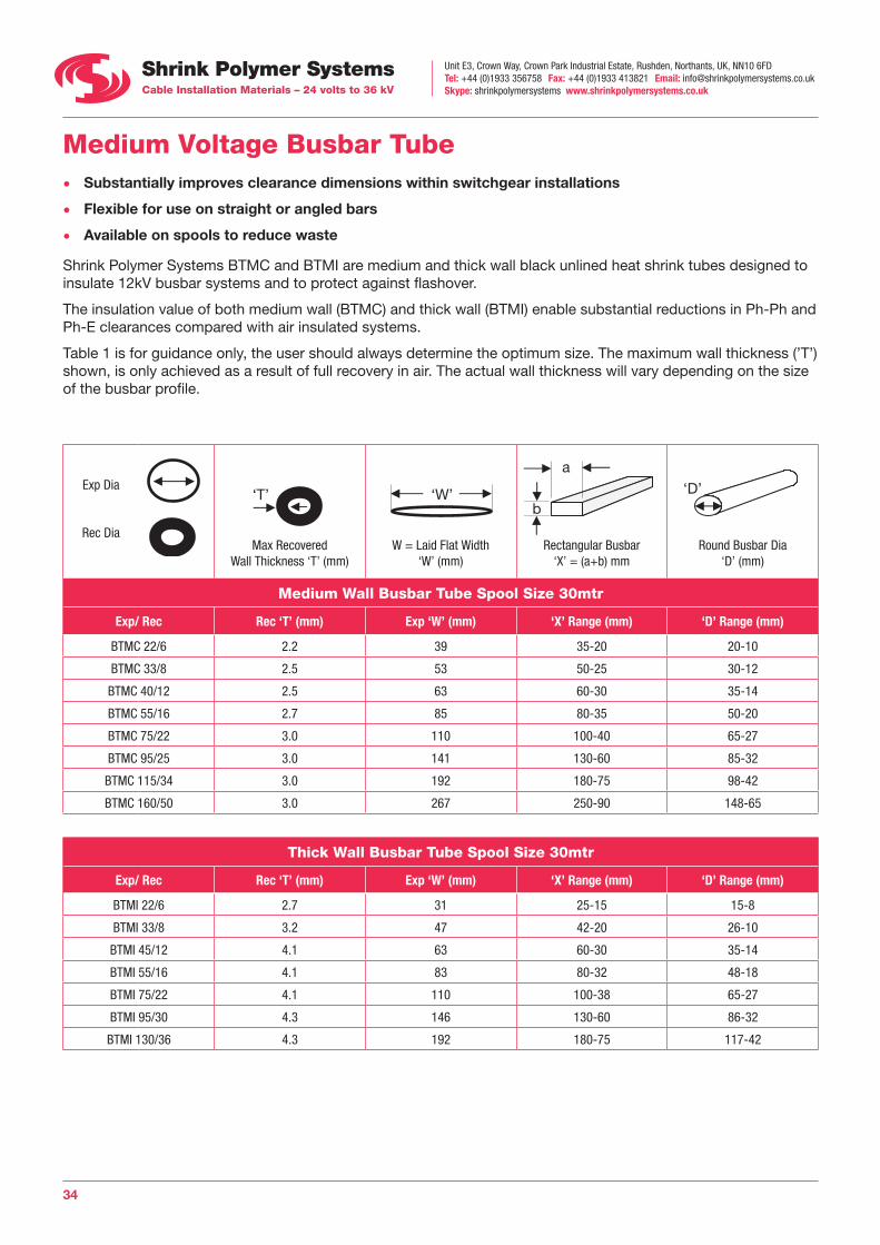
Shrink Polymer Systems BTMC and BTMI are medium and thick wall black unlined heat shrink tubes designed to insulate 12kV busbar systems and to protect against flashover.
The insulation value of both medium wall (BTMC) and thick wall (BTMI) enable substantial reductions in Ph-Ph and Ph-E clearances compared with air insulated systems.
Table 1 is for guidance only, the user should always determine the optimum size. The maximum wall thickness (’T’) shown, is only achieved as a result of full recovery in air. The actual wall thickness will vary depending on the size of the busbar profile.
Exp Dia
Rec Dia
‘T’ ‘W’ a
b‘D’‘T’ ‘W’ a
b‘D’
Max RecoveredWall Thickness ‘T’ (mm)
‘T’ ‘W’ a
b‘D’
W = Laid Flat Width ‘W’ (mm)
‘T’ ‘W’ a
b‘D’
Rectangular Busbar ‘X’ = (a+b) mm
‘T’ ‘W’ a
b‘D’
Round Busbar Dia ‘D’ (mm)
Medium Wall Busbar Tube Spool Size 30mtr
Exp/ Rec Rec ‘T’ (mm) Exp ‘W’ (mm) ‘X’ Range (mm) ‘D’ Range (mm)
BTMC 22/6 2.2 39 35-20 20-10
BTMC 33/8 2.5 53 50-25 30-12
BTMC 40/12 2.5 63 60-30 35-14
BTMC 55/16 2.7 85 80-35 50-20
BTMC 75/22 3.0 110 100-40 65-27
BTMC 95/25 3.0 141 130-60 85-32
BTMC 115/34 3.0 192 180-75 98-42
BTMC 160/50 3.0 267 250-90 148-65
Thick Wall Busbar Tube Spool Size 30mtr
Exp/ Rec Rec ‘T’ (mm) Exp ‘W’ (mm) ‘X’ Range (mm) ‘D’ Range (mm)
BTMI 22/6 2.7 31 25-15 15-8
BTMI 33/8 3.2 47 42-20 26-10
BTMI 45/12 4.1 63 60-30 35-14
BTMI 55/16 4.1 83 80-32 48-18
BTMI 75/22 4.1 110 100-38 65-27
BTMI 95/30 4.3 146 130-60 86-32
BTMI 130/36 4.3 192 180-75 117-42
Unit E3, Crown Way, Crown Park Industrial Estate, Rushden, Northants, UK, NN10 6FDTel: +44 (0)1933 356758 Fax: +44 (0)1933 413821 Email: [email protected] Skype: shrinkpolymersystems www.shrinkpolymersystems.co.uk
35
Anti-Track Busbar Insulation Tape • Reduces busbar clearance dimensions
• Protects against accidental flash over
• Adhesive coated
• Easy to apply
• Ideal for tee sections on busbar installations
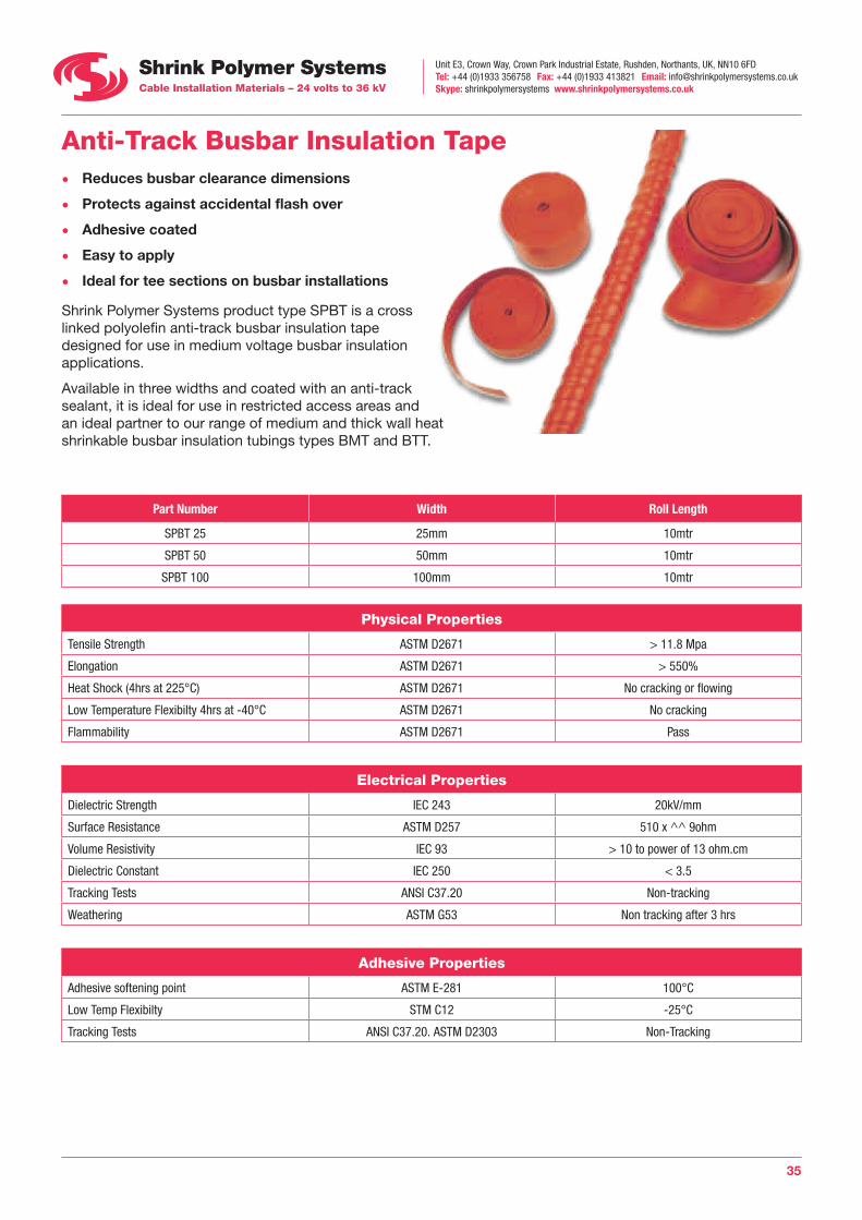
Shrink Polymer Systems product type SPBT is a cross linked polyolefin anti-track busbar insulation tape designed for use in medium voltage busbar insulation applications.
Available in three widths and coated with an anti-track sealant, it is ideal for use in restricted access areas and an ideal partner to our range of medium and thick wall heat shrinkable busbar insulation tubings types BMT and BTT.
Part Number Width Roll Length
SPBT 25 25mm 10mtr
SPBT 50 50mm 10mtr
SPBT 100 100mm 10mtr
Physical Properties
Tensile Strength ASTM D2671 > 11.8 Mpa
Elongation ASTM D2671 > 550%
Heat Shock (4hrs at 225°C) ASTM D2671 No cracking or flowing
Low Temperature Flexibilty 4hrs at -40°C ASTM D2671 No cracking
Flammability ASTM D2671 Pass
Electrical Properties
Dielectric Strength IEC 243 20kV/mm
Surface Resistance ASTM D257 510 x ^^ 9ohm
Volume Resistivity IEC 93 > 10 to power of 13 ohm.cm
Dielectric Constant IEC 250 < 3.5
Tracking Tests ANSI C37.20 Non-tracking
Weathering ASTM G53 Non tracking after 3 hrs
Adhesive Properties
Adhesive softening point ASTM E-281 100°C
Low Temp Flexibilty STM C12 -25°C
Tracking Tests ANSI C37.20. ASTM D2303 Non-Tracking
Unit E3, Crown Way, Crown Park Industrial Estate, Rushden, Northants, UK, NN10 6FDTel: +44 (0)1933 356758 Fax: +44 (0)1933 413821 Email: [email protected] Skype: shrinkpolymersystems www.shrinkpolymersystems.co.uk
36
d
D
C
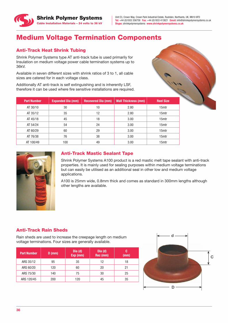
Anti-Track Rain Sheds Rain sheds are used to increase the creepage length on medium voltage terminations. Four sizes are generally available.
Part Number D (mm)Dia (d)
Exp (mm)Dia (d)
Rec (mm)C
(mm)
ARS 35/12 95 35 12 18
ARS 60/20 120 60 20 21
ARS 75/30 140 75 30 25
ARS 120/45 200 120 45 35
Medium Voltage Termination Components
Anti-Track Heat Shrink Tubing Shrink Polymer Systems type AT anti-track tube is used primarily for Insulation on medium voltage power cable termination systems up to 36kV.
Available in seven different sizes with shrink ratios of 3 to 1, all cable sizes are catered for in each voltage class.
Additionally AT anti-track is self extinguishing and is inherently LSF, therefore it can be used where fire sensitive installations are required.
Part Number Expanded Dia (mm) Recovered Dia (mm) Wall Thickness (mm) Reel Size
AT 30/10 30 10 2.80 15mtr
AT 35/12 35 12 2.80 15mtr
AT 45/18 45 18 3.00 15mtr
AT 54/24 54 24 3.00 15mtr
AT 60/29 60 29 3.00 15mtr
AT 76/38 76 38 3.00 15mtr
AT 100/49 100 49 3.00 15mtr
Anti-Track Mastic Sealant Tape Shrink Polymer Systems A100 product is a red mastic melt tape sealant with anti-track properties. It is mainly used for sealing purposes within medium voltage terminations but can easily be utilised as an additional seal in other low and medium voltage applications.
A100 is 25mm wide, 0.8mm thick and comes as standard in 300mm lengths although other lengths are available.
Unit E3, Crown Way, Crown Park Industrial Estate, Rushden, Northants, UK, NN10 6FDTel: +44 (0)1933 356758 Fax: +44 (0)1933 413821 Email: [email protected] Skype: shrinkpolymersystems www.shrinkpolymersystems.co.uk
37
Medium Voltage Termination and Joint Components
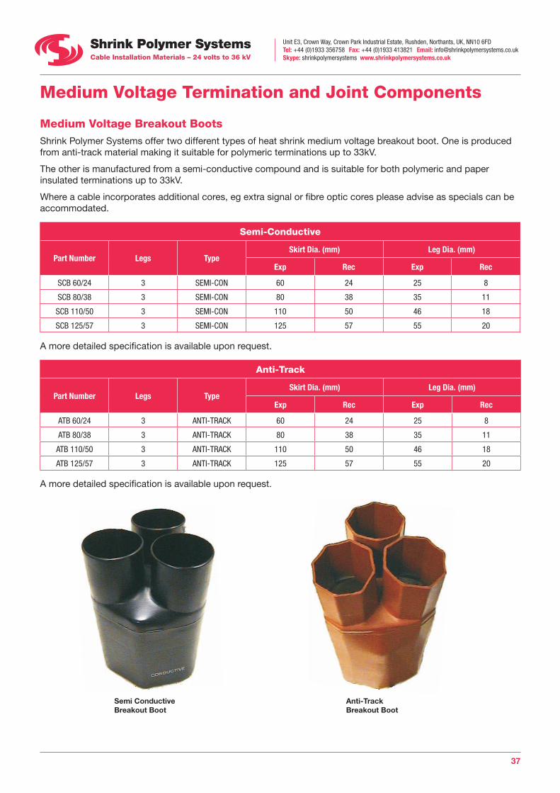
Medium Voltage Breakout Boots Shrink Polymer Systems offer two different types of heat shrink medium voltage breakout boot. One is produced from anti-track material making it suitable for polymeric terminations up to 33kV.
The other is manufactured from a semi-conductive compound and is suitable for both polymeric and paper insulated terminations up to 33kV.
Where a cable incorporates additional cores, eg extra signal or fibre optic cores please advise as specials can be accommodated.
Semi-Conductive
Part Number Legs TypeSkirt Dia. (mm) Leg Dia. (mm)
Exp Rec Exp Rec
SCB 60/24 3 SEMI-CON 60 24 25 8
SCB 80/38 3 SEMI-CON 80 38 35 11
SCB 110/50 3 SEMI-CON 110 50 46 18
SCB 125/57 3 SEMI-CON 125 57 55 20
A more detailed specification is available upon request.
Anti-Track
Part Number Legs TypeSkirt Dia. (mm) Leg Dia. (mm)
Exp Rec Exp Rec
ATB 60/24 3 ANTI-TRACK 60 24 25 8
ATB 80/38 3 ANTI-TRACK 80 38 35 11
ATB 110/50 3 ANTI-TRACK 110 50 46 18
ATB 125/57 3 ANTI-TRACK 125 57 55 20
A more detailed specification is available upon request.
Semi Conductive Breakout Boot
Anti-Track Breakout Boot
Unit E3, Crown Way, Crown Park Industrial Estate, Rushden, Northants, UK, NN10 6FDTel: +44 (0)1933 356758 Fax: +44 (0)1933 413821 Email: [email protected] Skype: shrinkpolymersystems www.shrinkpolymersystems.co.uk
38
Medium Voltage Termination and Joint Components
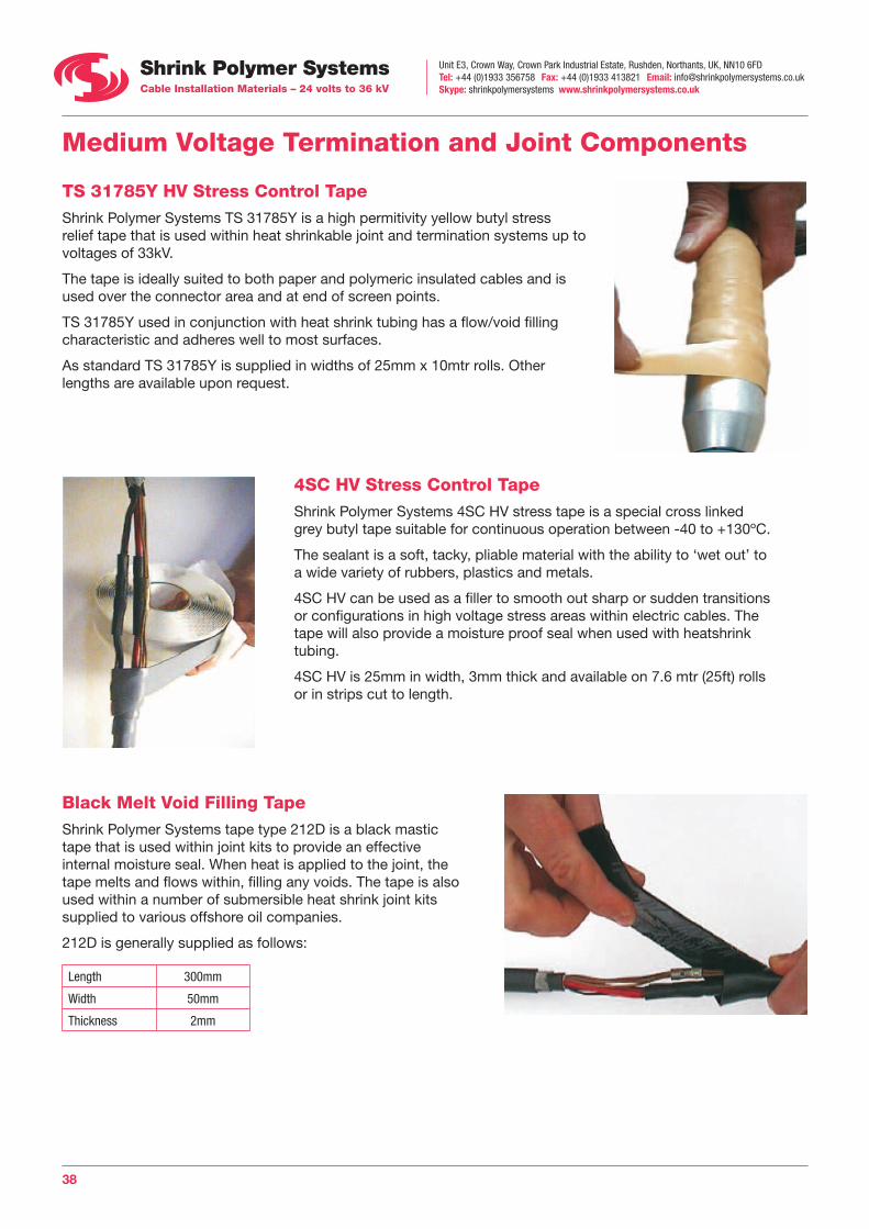
TS 31785Y HV Stress Control Tape Shrink Polymer Systems TS 31785Y is a high permitivity yellow butyl stress relief tape that is used within heat shrinkable joint and termination systems up to voltages of 33kV.
The tape is ideally suited to both paper and polymeric insulated cables and is used over the connector area and at end of screen points.
TS 31785Y used in conjunction with heat shrink tubing has a flow/void filling characteristic and adheres well to most surfaces.
As standard TS 31785Y is supplied in widths of 25mm x 10mtr rolls. Other lengths are available upon request.
4SC HV Stress Control Tape Shrink Polymer Systems 4SC HV stress tape is a special cross linked grey butyl tape suitable for continuous operation between -40 to +130ºC.
The sealant is a soft, tacky, pliable material with the ability to ‘wet out’ to a wide variety of rubbers, plastics and metals.
4SC HV can be used as a filler to smooth out sharp or sudden transitions or configurations in high voltage stress areas within electric cables. The tape will also provide a moisture proof seal when used with heatshrink tubing.
4SC HV is 25mm in width, 3mm thick and available on 7.6 mtr (25ft) rolls or in strips cut to length.
Black Melt Void Filling Tape Shrink Polymer Systems tape type 212D is a black mastic tape that is used within joint kits to provide an effective internal moisture seal. When heat is applied to the joint, the tape melts and flows within, filling any voids. The tape is also used within a number of submersible heat shrink joint kits supplied to various offshore oil companies.
212D is generally supplied as follows:
Length 300mm
Width 50mm
Thickness 2mm
Unit E3, Crown Way, Crown Park Industrial Estate, Rushden, Northants, UK, NN10 6FDTel: +44 (0)1933 356758 Fax: +44 (0)1933 413821 Email: [email protected] Skype: shrinkpolymersystems www.shrinkpolymersystems.co.uk
39
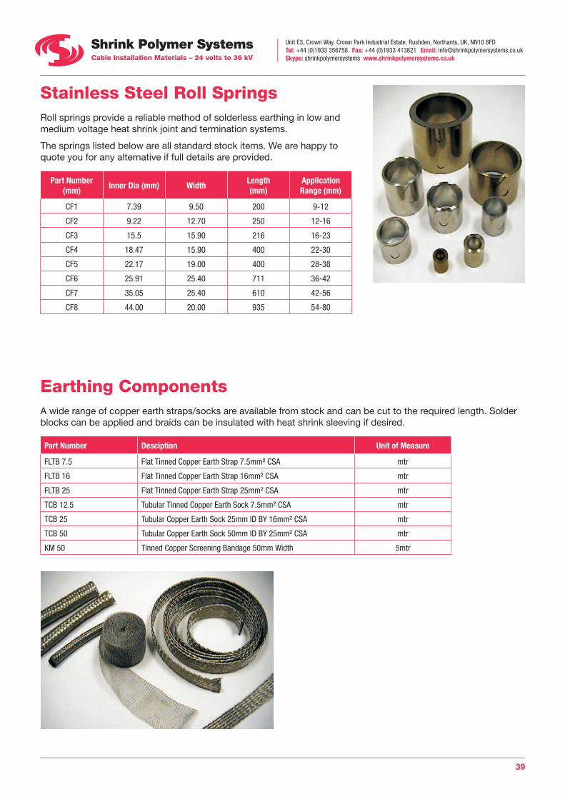
Stainless Steel Roll Springs Roll springs provide a reliable method of solderless earthing in low and medium voltage heat shrink joint and termination systems.
The springs listed below are all standard stock items. We are happy to quote you for any alternative if full details are provided.
Part Number (mm)
Inner Dia (mm) WidthLength (mm)
Application Range (mm)
CF1 7.39 9.50 200 9-12
CF2 9.22 12.70 250 12-16
CF3 15.5 15.90 216 16-23
CF4 18.47 15.90 400 22-30
CF5 22.17 19.00 400 28-38
CF6 25.91 25.40 711 36-42
CF7 35.05 25.40 610 42-56
CF8 44.00 20.00 935 54-80
Earthing Components A wide range of copper earth straps/socks are available from stock and can be cut to the required length. Solder blocks can be applied and braids can be insulated with heat shrink sleeving if desired.
Part Number Desciption Unit of Measure
FLTB 7.5 Flat Tinned Copper Earth Strap 7.5mm² CSA mtr
FLTB 16 Flat Tinned Copper Earth Strap 16mm² CSA mtr
FLTB 25 Flat Tinned Copper Earth Strap 25mm² CSA mtr
TCB 12.5 Tubular Tinned Copper Earth Sock 7.5mm² CSA mtr
TCB 25 Tubular Copper Earth Sock 25mm ID BY 16mm² CSA mtr
TCB 50 Tubular Copper Earth Sock 50mm ID BY 25mm² CSA mtr
KM 50 Tinned Copper Screening Bandage 50mm Width 5mtr
Unit E3, Crown Way, Crown Park Industrial Estate, Rushden, Northants, UK, NN10 6FDTel: +44 (0)1933 356758 Fax: +44 (0)1933 413821 Email: [email protected] Skype: shrinkpolymersystems www.shrinkpolymersystems.co.uk
40
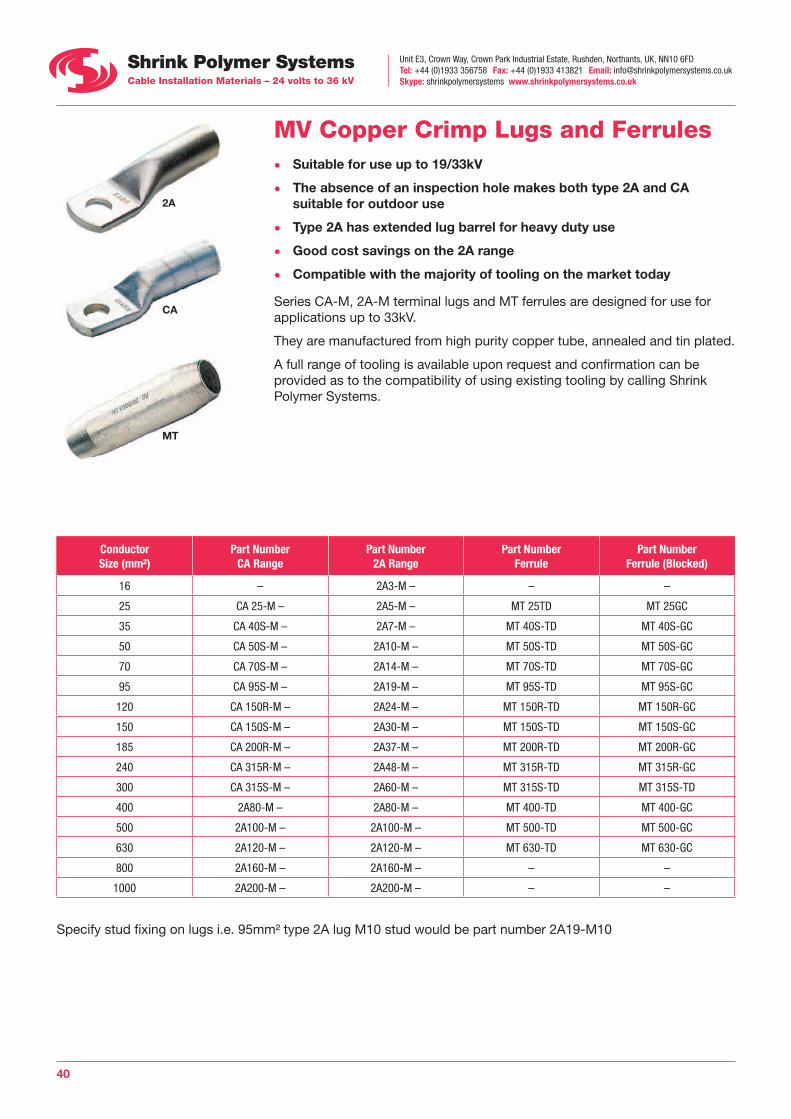
MV Copper Crimp Lugs and Ferrules • Suitable for use up to 19/33kV
• The absence of an inspection hole makes both type 2A and CA suitable for outdoor use
• Type 2A has extended lug barrel for heavy duty use
• Good cost savings on the 2A range
• Compatible with the majority of tooling on the market today
Series CA-M, 2A-M terminal lugs and MT ferrules are designed for use for applications up to 33kV.
They are manufactured from high purity copper tube, annealed and tin plated.
A full range of tooling is available upon request and confirmation can be provided as to the compatibility of using existing tooling by calling Shrink Polymer Systems.
ConductorSize (mm²)
Part NumberCA Range
Part Number2A Range
Part NumberFerrule
Part NumberFerrule (Blocked)
16 – 2A3-M – – –
25 CA 25-M – 2A5-M – MT 25TD MT 25GC
35 CA 40S-M – 2A7-M – MT 40S-TD MT 40S-GC
50 CA 50S-M – 2A10-M – MT 50S-TD MT 50S-GC
70 CA 70S-M – 2A14-M – MT 70S-TD MT 70S-GC
95 CA 95S-M – 2A19-M – MT 95S-TD MT 95S-GC
120 CA 150R-M – 2A24-M – MT 150R-TD MT 150R-GC
150 CA 150S-M – 2A30-M – MT 150S-TD MT 150S-GC
185 CA 200R-M – 2A37-M – MT 200R-TD MT 200R-GC
240 CA 315R-M – 2A48-M – MT 315R-TD MT 315R-GC
300 CA 315S-M – 2A60-M – MT 315S-TD MT 315S-TD
400 2A80-M – 2A80-M – MT 400-TD MT 400-GC
500 2A100-M – 2A100-M – MT 500-TD MT 500-GC
630 2A120-M – 2A120-M – MT 630-TD MT 630-GC
800 2A160-M – 2A160-M – – –
1000 2A200-M – 2A200-M – – –
Specify stud fixing on lugs i.e. 95mm² type 2A lug M10 stud would be part number 2A19-M10
2A
CA
MT
Unit E3, Crown Way, Crown Park Industrial Estate, Rushden, Northants, UK, NN10 6FDTel: +44 (0)1933 356758 Fax: +44 (0)1933 413821 Email: [email protected] Skype: shrinkpolymersystems www.shrinkpolymersystems.co.uk
41
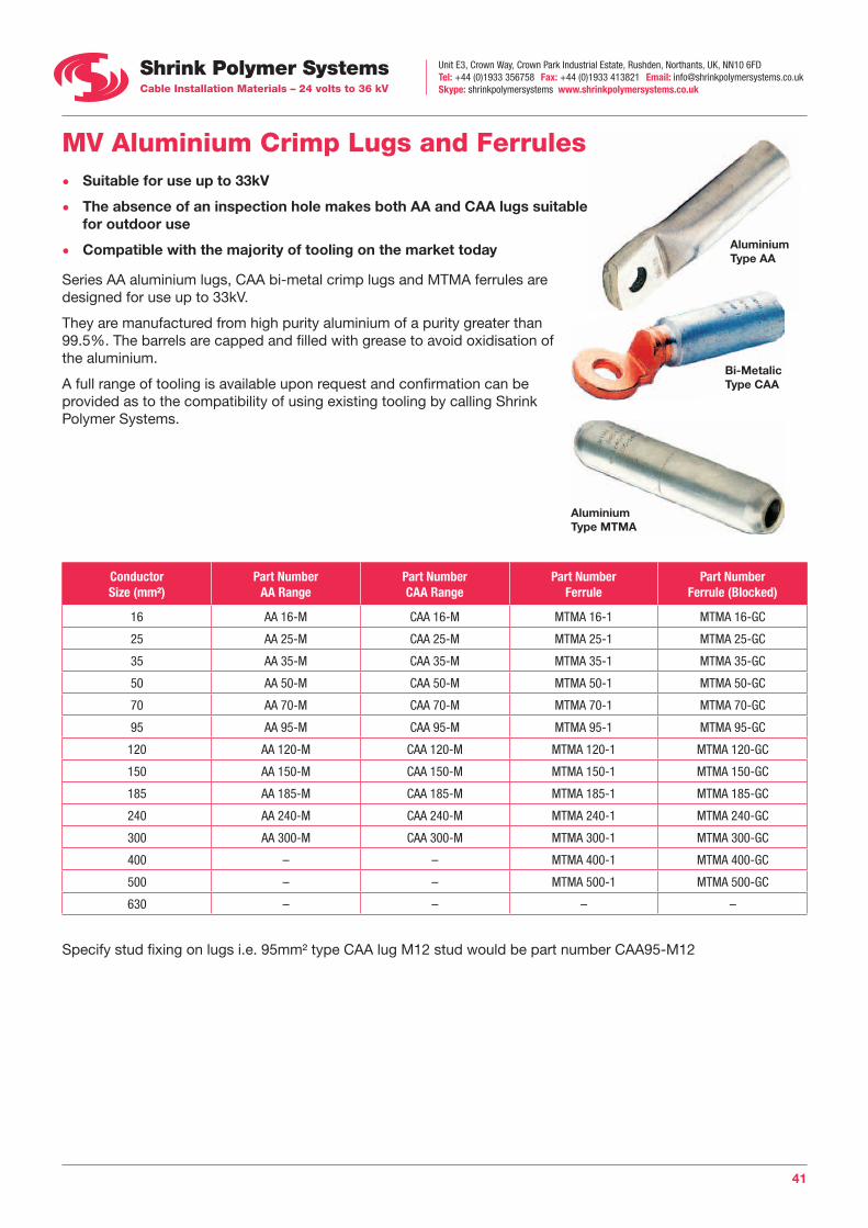
MV Aluminium Crimp Lugs and Ferrules • Suitable for use up to 33kV
• The absence of an inspection hole makes both AA and CAA lugs suitable for outdoor use
• Compatible with the majority of tooling on the market today
Series AA aluminium lugs, CAA bi-metal crimp lugs and MTMA ferrules are designed for use up to 33kV.
They are manufactured from high purity aluminium of a purity greater than 99.5%. The barrels are capped and filled with grease to avoid oxidisation of the aluminium.
A full range of tooling is available upon request and confirmation can be provided as to the compatibility of using existing tooling by calling Shrink Polymer Systems.
Aluminium Type AA
Bi-Metalic Type CAA
ConductorSize (mm²)
Part NumberAA Range
Part NumberCAA Range
Part NumberFerrule
Part NumberFerrule (Blocked)
16 AA 16-M CAA 16-M MTMA 16-1 MTMA 16-GC
25 AA 25-M CAA 25-M MTMA 25-1 MTMA 25-GC
35 AA 35-M CAA 35-M MTMA 35-1 MTMA 35-GC
50 AA 50-M CAA 50-M MTMA 50-1 MTMA 50-GC
70 AA 70-M CAA 70-M MTMA 70-1 MTMA 70-GC
95 AA 95-M CAA 95-M MTMA 95-1 MTMA 95-GC
120 AA 120-M CAA 120-M MTMA 120-1 MTMA 120-GC
150 AA 150-M CAA 150-M MTMA 150-1 MTMA 150-GC
185 AA 185-M CAA 185-M MTMA 185-1 MTMA 185-GC
240 AA 240-M CAA 240-M MTMA 240-1 MTMA 240-GC
300 AA 300-M CAA 300-M MTMA 300-1 MTMA 300-GC
400 – – MTMA 400-1 MTMA 400-GC
500 – – MTMA 500-1 MTMA 500-GC
630 – – – –
Specify stud fixing on lugs i.e. 95mm² type CAA lug M12 stud would be part number CAA95-M12
Aluminium Type MTMA
Unit E3, Crown Way, Crown Park Industrial Estate, Rushden, Northants, UK, NN10 6FDTel: +44 (0)1933 356758 Fax: +44 (0)1933 413821 Email: [email protected] Skype: shrinkpolymersystems www.shrinkpolymersystems.co.uk
42
MV Mechanical Shearbolt Terminal Lugs and Ferrules
Size
Usage of Concentric Sleeves for Conductor Types DIN VDE 0295
Sleeve (comp.) 90° 120° 90° 120°
1
blue 25-35 25 25-35
yellow 50-70 35-50 50-70 35 35 50
– 95 70 95 50-95(r) 50-70(*) 70-95(*) 50-95(r)
2
blue 50-70 50 50-70 50
yellow 95-120 70-95 95-120 50-70 50-70 70-95 50-70
– 150 120 150 95-150(r) 95(*)-120(r) 120-150(r) 95-150(r)
3
blue 70-95 70 70-95 70 70 70
yellow 120 95 120 70 95
red 150-185 120-150 150-185 95-120 95 120-150 95-120
– 240 185 240 150-185(*) 120-185(r) 185-240(r) 150-185(*)
4
blue 120 120
yellow 150-185 120-150 150-185 120 120-150 120
red 240 185 240 150 120 185 150
– 300 240-300 300 185-300(r) 150-240(r) 240 185-240
5
blue 95 95
yellow 120-185 95-150 120-185 95-120 95 95-150 95-120
red 240-300 185-240 240-300 150-185 120-150 185 150-185
– 400 300-400 400 240-300 185-300(r) 240 240
6
blue 300 300
yellow 400 300 400
red 500 400 500 300
– 630 500-630 630 400 300-400(*)
Key: (comp.) = compacted conductor (r) = rounded conductor (*) = slight rounding of conductor, e.g. with flat nose pliers
To select Terminal Lug, use code: MVML, add size 1-6, then state stud sizeExample: Conductor size = 185mm² circular stranded and you require M12 stud = MVML 3-M12
To select Through Connector, use code: MVMC, add sizeExample: Conductor size = 240mm² sector stranded = MVMC 5
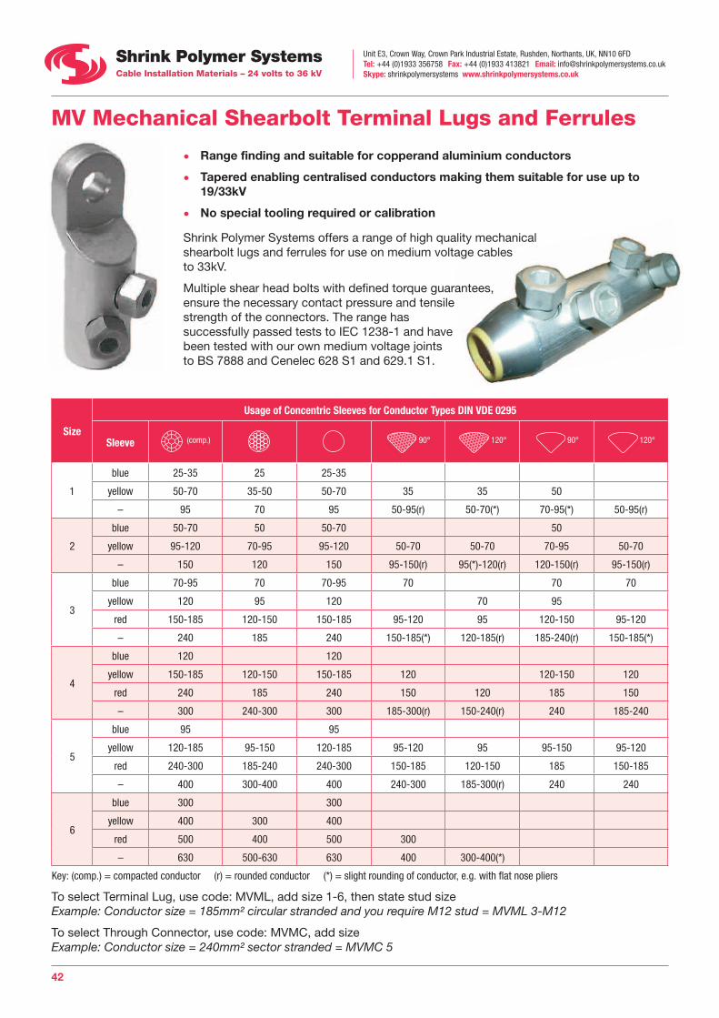
• Range finding and suitable for copperand aluminium conductors
• Tapered enabling centralised conductors making them suitable for use up to 19/33kV
• No special tooling required or calibration
Shrink Polymer Systems offers a range of high quality mechanical shearbolt lugs and ferrules for use on medium voltage cables to 33kV.
Multiple shear head bolts with defined torque guarantees, ensure the necessary contact pressure and tensile strength of the connectors. The range has successfully passed tests to IEC 1238-1 and have been tested with our own medium voltage joints to BS 7888 and Cenelec 628 S1 and 629.1 S1.

Unit E3, Crown Way, Crown Park Industrial Estate, Rushden, Northants, UK, NN10 6FDTel: +44 (0)1933 356758 Fax: +44 (0)1933 413821 Email: [email protected] Skype: shrinkpolymersystems www.shrinkpolymersystems.co.uk
43
MV Cable Preparation Tools One of the main factors in termination and joint failure is the poor removal of the semi-conductive screen on polymeric cables. Easy strip screens are quite straightforward and can be removed utilising the methods featured on our website in conjunction with the TT 2532 tool below.
However, with bonded screens, Shrink Polymer Systems can offer a wide variety of tools from several different manufacturers to assist in this essential task. However, we prefer to offer the limited range below because in our opinion, they work well, are good quality and are reasonably priced.
Semi-conductiveScreen
The TT 2532 scoring tools are intended for use with polymeric cables that have ‘strippable’ semi-conductive screen layers.
These tools have pre-set blades, ensuring no damage can be caused to the underlying primary insulation.
Part Number Blade Depth
TT 2532-1 0.4mm
TT 2532-2 0.6mm
The BRM RD1 is a tool designed to remove the core insulation from polymeric cables.
The tool is fully adjustable and removes the insulation with a spiral cut protecting the conductors from accidental damage.
The GB-P20 is intended for use with the removal of bonded type semi-conductive screen layers.
The tool is fully adjustable and shaves the screen layer off in a spiral pattern with minimum damage to the primary insulation below.
Part Number Cable O/D Part Number Cable O/D Spare Blade
BRM-RD1 14-40 GB-P20 10-50 GB-P20-S6

Unit E3, Crown Way, Crown Park Industrial Estate, Rushden, Northants, UK, NN10 6FDTel: +44 (0)1933 356758 Fax: +44 (0)1933 413821 Email: [email protected] Skype: shrinkpolymersystems www.shrinkpolymersystems.co.uk
44
Heat Shrink Joints to Suit Low Voltage Cables Type XLPE/SWA/PVC 0.6/3.3kV
• Meets the jointing requirements of BS6910 part 1, test report available
• Unlimited shelf life
• Slim profile, can be mounted vertically
• Allows for immediate backfill
• Zero halogen, fire resistant and non armoured types are also available
Shrink Polymer Systems heat shrink joint kits are intended for use with PVC and XLPE non screened cables for voltages up to 3.3kV.
The system comprises of adhesive lined connector insulation tubes, heavy duty armour cage (copper mesh on the smallest joints), armour support rings, armour clamps and an outer thick wall adhesive lined heat shrink tube.
Single core joints contain a heavy duty aluminium cage if the cable has aluminium wire armours.
Many thousands of our joints are installed worldwide including critical locations such as Ministry of Defence, Department of Transport, petro chemical sites and Network Rail / London Underground installations.
Heat Shrink Joints To Suit Single Core XLPE/AWA/PVC
Part Number Cable Range Voltage
SPA 50-95-1 50-95mm² 0.6/3.3kV
SPA 120-185-1 120-185mm² 0.6/3.3kV
SPA 240-300-1 240-300mm² 0.6/3.3kV
SPA 400-630-1 400-630mm² 0.6/3.3kV
Heat Shrink Joints to Suit XLPE/SWA/PVC
Part Number Cable Range Voltage
SPA 1.5-2.5 – 1.5-2.5mm² 600/1000V
SPA 4-6 – 4-6mm² 600/1000V
SPA 10-16 – 10-16mm² 600/1000V
SPA 25-50 – 25-50mm² 0.6/3.3kV
SPA 70-95 – 70-95mm² 0.6/3.3kV
SPA 120-185 – 120-185mm² 0.6/3.3kV
SPA 240-300 – 240-300mm² 0.6/3.3kV
Note: To denote number of cores, add number to end of reference.
Example: 12 core 2.5mm² = SPA 1.5-2.5-12
For non armoured cables, delete the letter A, for shipwiring cables, add letters SW after SPA, for hydrocarbon resistant joints add letters HC after SPA

Unit E3, Crown Way, Crown Park Industrial Estate, Rushden, Northants, UK, NN10 6FDTel: +44 (0)1933 356758 Fax: +44 (0)1933 413821 Email: [email protected] Skype: shrinkpolymersystems www.shrinkpolymersystems.co.uk
45
Heat Shrink Joints to Suit Low Voltage Cables Type PILC/SWA/PVC 0.6/3.3kV • Meets the jointing requirements of BS6910 part 1,
test report available
• Unlimited shelf life
• Slim profile, can be mounted vertically
• Allows for immediate backfill
• Zero halogen, fire resistant and non armoured types are also available
A range of joints are also available for jointing both PILC to XLPE transition and PILC to PILC cables.
These joints offer the same benefits and comprise of similar components to those in the polymeric range, with the addition of breakout boots, core tubes and earthing for the lead sheath on paper cables.
Heat Shrink Joints 3 Core PILC to PILC
Part Number Cable Range Voltage
SPAP 16-35-3 16-35mm² 600/1000V
SPAP 50-95-3 50-95mm² 600/1000V
SPAP 120-150-3 120-150mm² 600/1000V
Heat Shrink Joints 4 Core PILC to PILC
Part Number Cable Range Voltage
SPAP 16-35-4 16 -35mm² 600/1000V
SPAP 50-95-4 50 -95mm² 600/1000V
SPAP 120-150-4 120 -150mm² 600/1000V
SPAP 185-300-4 185 -300mm² 600/1000V
Heat Shrink Transition Joints 4 Core PILC to XLPE
Part Number Cable Range Voltage
SPAPX 16-35-4 16 -35mm² 600/1000V
SPAPX 50-95-4 50 -95mm² 600/1000V
SPAPX 120-185-4 120 -185mm² 600/1000V
SPAPX 185-300-4 185 -300mm² 600/1000V
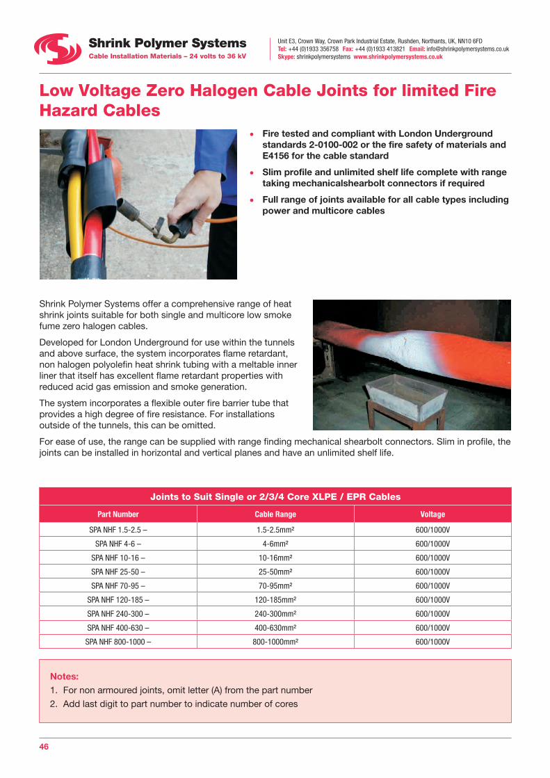
Unit E3, Crown Way, Crown Park Industrial Estate, Rushden, Northants, UK, NN10 6FDTel: +44 (0)1933 356758 Fax: +44 (0)1933 413821 Email: [email protected] Skype: shrinkpolymersystems www.shrinkpolymersystems.co.uk
46
Low Voltage Zero Halogen Cable Joints for limited Fire Hazard Cables
• Fire tested and compliant with London Underground standards 2-0100-002 or the fire safety of materials and E4156 for the cable standard
• Slim profile and unlimited shelf life complete with range taking mechanicalshearbolt connectors if required
• Full range of joints available for all cable types including power and multicore cables
Shrink Polymer Systems offer a comprehensive range of heat shrink joints suitable for both single and multicore low smoke fume zero halogen cables.
Developed for London Underground for use within the tunnels and above surface, the system incorporates flame retardant, non halogen polyolefin heat shrink tubing with a meltable inner liner that itself has excellent flame retardant properties with reduced acid gas emission and smoke generation.
The system incorporates a flexible outer fire barrier tube that provides a high degree of fire resistance. For installations outside of the tunnels, this can be omitted.
For ease of use, the range can be supplied with range finding mechanical shearbolt connectors. Slim in profile, the joints can be installed in horizontal and vertical planes and have an unlimited shelf life.
Joints to Suit Single or 2/3/4 Core XLPE / EPR Cables
Part Number Cable Range Voltage
SPA NHF 1.5-2.5 – 1.5-2.5mm² 600/1000V
SPA NHF 4-6 – 4-6mm² 600/1000V
SPA NHF 10-16 – 10-16mm² 600/1000V
SPA NHF 25-50 – 25-50mm² 600/1000V
SPA NHF 70-95 – 70-95mm² 600/1000V
SPA NHF 120-185 – 120-185mm² 600/1000V
SPA NHF 240-300 – 240-300mm² 600/1000V
SPA NHF 400-630 – 400-630mm² 600/1000V
SPA NHF 800-1000 – 800-1000mm² 600/1000V
Notes:1. For non armoured joints, omit letter (A) from the part number
2. Add last digit to part number to indicate number of cores

Unit E3, Crown Way, Crown Park Industrial Estate, Rushden, Northants, UK, NN10 6FDTel: +44 (0)1933 356758 Fax: +44 (0)1933 413821 Email: [email protected] Skype: shrinkpolymersystems www.shrinkpolymersystems.co.uk
47
Joints to Suit Multicore / Multipair XLPE / EPR Cables
Part Number Cable Range Voltage
SPA NHF 1.5-2.5-5 5 core 1.5-2.5mm² 600/1000V
SPA NHF 1.5-2.5-7 7 core 1.5-2.5mm² 600/1000V
SPA NHF 1.5-2.5-12 12 core 1.5-2.5mm² 600/1000V
SPA NHF 1.5-2.5-19 19 core1.5-2.5mm² 600/1000V
SPA NHF 1.5-2.5-27 27 core 1.5-2.5mm² 600/1000V
SPA NHF 1.5-2.5-37 37 core1.5-2.5mm² 600/1000V
SPA NHF 1.5-2.5-48 48 core 1.5-2.5mm² 600/1000V
SPA NHF 1.5-2.5-61 61 core 1.5-2.5mm² 600/1000V
Notes:1. For non armoured joints, omit letter (A) from the part number
2. Add letter “PR” to end of part number to indicate multipair cables
3. If cable size is 0.5-1.5mm², insert 0.5-1.5mm after SPA NHF then number of cores
Low Voltage Zero Halogen Cable Joints for Fire Resistant Cables
• Designed for use where low smoke fume and fire resistance is essential
• Designed and tested in leading UK fire testing laboratory, in accordance with the procedures specified in IEC 60331-21:1999
• Test report available
• Joints available for all types of LV and MV cables
Fire resistant cables are usually installed where vital electrical circuits are required to continue operating in the event of a fire. Shrink Polymer Systems can provide joint kits to suit these cable types for both single and multicore configurations.
In addition to utilising LSF/Zero halogen heat shrink tubes and fire barrier tubes, the joints also incorporate mica tape over each of the cores.
Mica tape is a slit silica tape constructed from 96% pure SiO2 silica fiber, coated one side with a pressure sensitive adhesive backing that facilitates installation. The adhesive decomposes at high temperatures, leaving a perfectly taped core
Suitable for use at 1800°F (982°C), and able to withstand short term exposure up to 3000°F (1650°C), mica tape when combined with our proven zero halogen joint range, enables the joint to work in these extreme conditions.

Unit E3, Crown Way, Crown Park Industrial Estate, Rushden, Northants, UK, NN10 6FDTel: +44 (0)1933 356758 Fax: +44 (0)1933 413821 Email: [email protected] Skype: shrinkpolymersystems www.shrinkpolymersystems.co.uk
48
Airfield Lighting Heat Shrink Joint Kits • A full range of heat shrink joint kits for all airfield ground
lighting cables
• Approved for use on Defence Estates RAF Bases within the UK and all major BAA civilian airports
• Thousands of joints installed worldwide on both military and civil airfields
Part Number Cable Type Connector Type
SPS 1003 New Primary 6mm² Joint Non Insulated
SPS 1003U Primary 6mm² to Itself or 8AWG Non Insulated
SPS 036 Secondary 2 Core 2.5-6mm² Insulated
SPS 1004 Primary Armoured 6mm² to Non Armoured 6mm² Non Insulated
SPS 1005 Primary CU Braided 6mm² Armoured Non Insulated
SPS 1005 Primary Brass Tape 6mm² Armoured Non Insulated
SPS 1014 Primary 5kV Non Screened 6mm² Cable Non Insulated
SPS 1015 Primary 5kV Screened 6mm² Cable Non Insulated
Traffic Control Cable Heat Shrink Joint Kits • A comprehensive range of heat shrink joints traffic, motorway and communication cables
• Approved by Department of Transport and Traffic Control Systems Unit London
• Incorporates our unique black melt tape for superior internal moisture sealing
Part Number To Suit Cable Type
SPS 013 Loop to Armoured Feeder (1 Pair)
SPS 021 Loop to Armoured Feeder (2 Pair)
SPS 022 Loop to Armoured Feeder (3 Pair)
SPS 023 Loop to Armoured Feeder (4 Pair)
SPS 012 Loop to Non Armoured (1 Pair) Twin Flex
SPS 018 4-8 Multicore SWA
SPS 019 12, 16-20 Multicore SWA
SPS 020 Feeder to Feeder 1-2 PAIR SWA
SPS 017 Loop to Loop (10 PER PACK)
SPS 031 3, 4 Pair to 2, 3, 4 Pair With 1 Pair Off
SPS 047 7-8 Core Temporary Traffic Light Cable (Lux Type)
SPS 148 2 Pair Telephone (Motorway)
SPS 035 20-30 Pair Telecom (Motorway)
SPS 162 30 Pair Uninterupt (Motorway)
SPS 167 Split Concentric 10mm² (Motorway)
SPS 168 Split Concentric 25mm² (Motorway)

Unit E3, Crown Way, Crown Park Industrial Estate, Rushden, Northants, UK, NN10 6FDTel: +44 (0)1933 356758 Fax: +44 (0)1933 413821 Email: [email protected] Skype: shrinkpolymersystems www.shrinkpolymersystems.co.uk
49
Low Voltage Live Pot End Kits Standard heat shrink end caps are often used to seal cable ends. However where cables are live, heat shrink live pot end kits should be used. Each core is separately sealed using small end caps and a screen bandage is applied to re-instate earth fault protection. Finally a thick wall outer heat shrink cap is applied marked with a live flash symbol.
Kits are available for XLPE and PILC cables although any cable type can be catered for if details are given.
The table below shows only the popular 4 core kits, for 2 or 3 core kits the codes should be changed by substituting the figure 4 shown after the cable range to either 2 or 3.
Example: For a 3 core XLPE kit 35mm², the correct code should be POT 4-35-3X
Part NumberPILC Cable
CableRange (mm²)
Part NumberXLPE Cable
POT 4-10-4PB 4 Core 4-10 POT 4-10-4X
POT 16-35-4PB 4 Core 16-35 POT 16-35-4X
POT 50-95-4PB 4 Core 50-95 POT 50-95-4X
POT 120-185-4PB 4 Core 120-185 POT 120-185-4X
POT 240-400-4PB 4 Core 240-400 POT 240-400-4X
Low Voltage Cable Abandonment Kits Heat shrink end caps are regularly used to seal cable ends. However, where a cable has been abandoned or overlayed, there is always a danger of mis-identification.
Shrink Polymer Systems range of abandonment kits effectively links all the individual cores to each other and earth. Using a simple insulation tester makes identifying the cable as abandoned a relatively simple matter, ensuring the cable is not accidentally energised.
Kits are available for XLPE and PILC although any cable type can be catered for if details are given.
The table below shows only the popular 4 core kits, for 2 or 3 core kits the codes should be changed by substituting the figure 4 shown after the cable range to either 2 or 3.
Example: For a 3 core XLPE kit 120mm², the correct code should be: SPAK 50-150-3X
Part NumberPILC Cable
CableRange (mm²)
Part NumberXLPE Cable
SPAK 4-35-4PB 4 Core 4-35 SPAK 4-35-4X
SPAK 50-150-4PB 4 Core 50-150 SPAK 50-150-4X
SPAK 185-300-4PB 4 Core 185-300 SPAK 185-300-4X
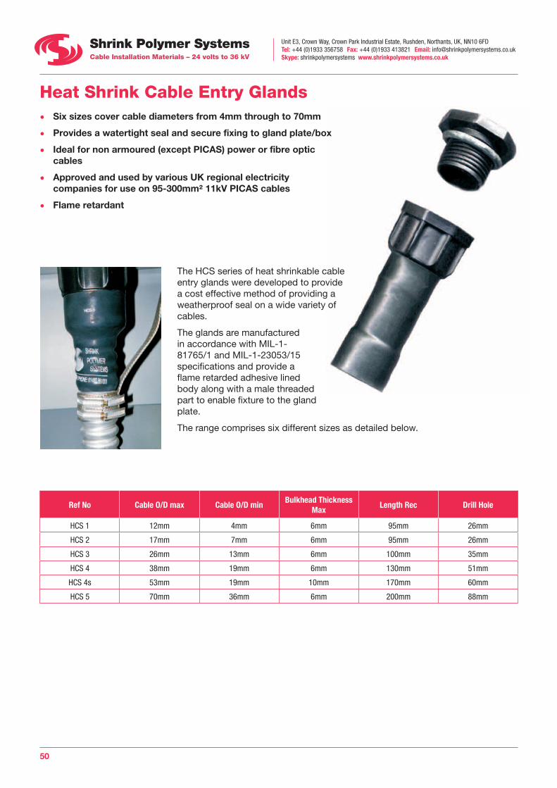
Unit E3, Crown Way, Crown Park Industrial Estate, Rushden, Northants, UK, NN10 6FDTel: +44 (0)1933 356758 Fax: +44 (0)1933 413821 Email: [email protected] Skype: shrinkpolymersystems www.shrinkpolymersystems.co.uk
50
Heat Shrink Cable Entry Glands • Six sizes cover cable diameters from 4mm through to 70mm
• Provides a watertight seal and secure fixing to gland plate/box
• Ideal for non armoured (except PICAS) power or fibre optic cables
• Approved and used by various UK regional electricity companies for use on 95-300mm² 11kV PICAS cables
• Flame retardant
The HCS series of heat shrinkable cable entry glands were developed to provide a cost effective method of providing a weatherproof seal on a wide variety of cables.
The glands are manufactured in accordance with MIL-1-81765/1 and MIL-1-23053/15 specifications and provide a flame retarded adhesive lined body along with a male threaded part to enable fixture to the gland plate.
The range comprises six different sizes as detailed below.
Ref No Cable O/D max Cable O/D minBulkhead Thickness
MaxLength Rec Drill Hole
HCS 1 12mm 4mm 6mm 95mm 26mm
HCS 2 17mm 7mm 6mm 95mm 26mm
HCS 3 26mm 13mm 6mm 100mm 35mm
HCS 4 38mm 19mm 6mm 130mm 51mm
HCS 4s 53mm 19mm 10mm 170mm 60mm
HCS 5 70mm 36mm 6mm 200mm 88mm
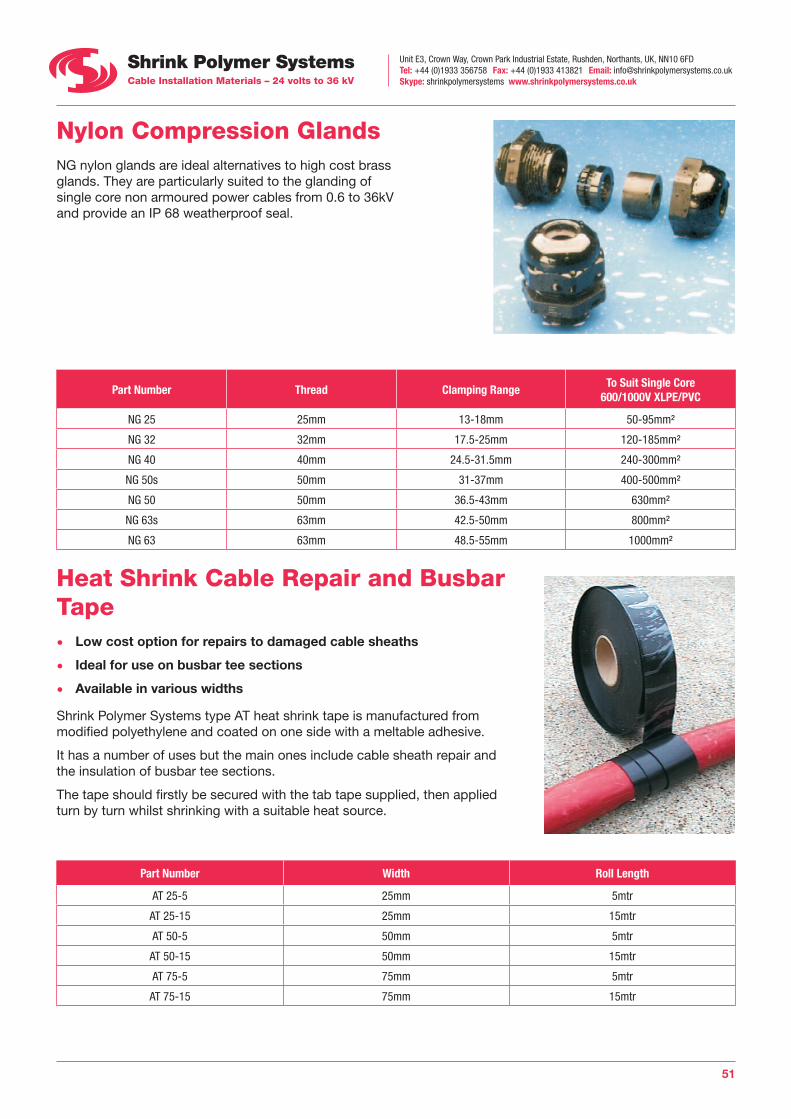
Unit E3, Crown Way, Crown Park Industrial Estate, Rushden, Northants, UK, NN10 6FDTel: +44 (0)1933 356758 Fax: +44 (0)1933 413821 Email: [email protected] Skype: shrinkpolymersystems www.shrinkpolymersystems.co.uk
51
Nylon Compression Glands NG nylon glands are ideal alternatives to high cost brass glands. They are particularly suited to the glanding of single core non armoured power cables from 0.6 to 36kV and provide an IP 68 weatherproof seal.
Part Number Thread Clamping RangeTo Suit Single Core
600/1000V XLPE/PVC
NG 25 25mm 13-18mm 50-95mm²
NG 32 32mm 17.5-25mm 120-185mm²
NG 40 40mm 24.5-31.5mm 240-300mm²
NG 50s 50mm 31-37mm 400-500mm²
NG 50 50mm 36.5-43mm 630mm²
NG 63s 63mm 42.5-50mm 800mm²
NG 63 63mm 48.5-55mm 1000mm²
Heat Shrink Cable Repair and Busbar Tape • Low cost option for repairs to damaged cable sheaths
• Ideal for use on busbar tee sections
• Available in various widths
Shrink Polymer Systems type AT heat shrink tape is manufactured from modified polyethylene and coated on one side with a meltable adhesive.
It has a number of uses but the main ones include cable sheath repair and the insulation of busbar tee sections.
The tape should firstly be secured with the tab tape supplied, then applied turn by turn whilst shrinking with a suitable heat source.
Part Number Width Roll Length
AT 25-5 25mm 5mtr
AT 25-15 25mm 15mtr
AT 50-5 50mm 5mtr
AT 50-15 50mm 15mtr
AT 75-5 75mm 5mtr
AT 75-15 75mm 15mtr
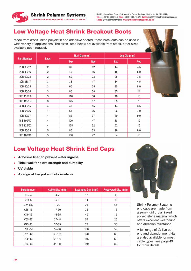
Unit E3, Crown Way, Crown Park Industrial Estate, Rushden, Northants, UK, NN10 6FDTel: +44 (0)1933 356758 Fax: +44 (0)1933 413821 Email: [email protected] Skype: shrinkpolymersystems www.shrinkpolymersystems.co.uk
52
Low Voltage Heat Shrink Breakout Boots Made from cross linked polyolefin and adhesive coated, these breakouts can be used in wide variety of applications. The sizes listed below are available from stock, other sizes available upon request.
Part Number LegsSkirt Dia (mm) Leg Dia (mm)
Exp Rec Exp Rec
2CB 30/12 2 30 12 14 4.5
2CB 40/16 2 40 16 15 5.0
2CB 60/23 2 60 23 25 7.5
3CB 38/17 3 38 17 14 4.5
3CB 60/25 3 60 25 25 8.0
3CB 80/38 3 80 38 35 11
3CB 110/50 3 110 50 46 18
3CB 125/57 3 125 57 55 20
4CB 40/15 4 40 15 14 3.5
4CB 65/26 4 65 26 26 7.0
4CB 82/37 4 82 37 30 9.0
4CB 100/47 4 100 47 38 12
4CB 125/52 4 125 52 52 15
5CB 80/33 5 80 33 26 8.0
5CB 100/42 5 100 42 34 10
Low Voltage Heat Shrink End Caps • Adhesive lined to prevent water ingress
• Thick wall for extra strength and durability
• UV stable
• A range of live pot end kits available
Part Number Cable Dia. (mm) Expanded Dia. (mm) Recovered Dia. (mm)
C12-4 4-7 12 4
C14-5 5-9 14 5
C25-8.5 9-20 25 8.5
C35-16 17-30 35 16
C40-15 16-35 40 15
C55-26 27-48 55 26
C75-36 37-65 75 36
C100-52 55-88 100 52
C120-60 65-105 120 60
C145-60 65-130 145 60
C160-82 85-145 160 82
Shrink Polymer Systems end caps are made from a semi-rigid cross linked polyethelene material which offers excellent weathering and abrasion resistance.
A full range of LV live pot end and abandonment kits are also available for most cable types, see page 49 for more details.
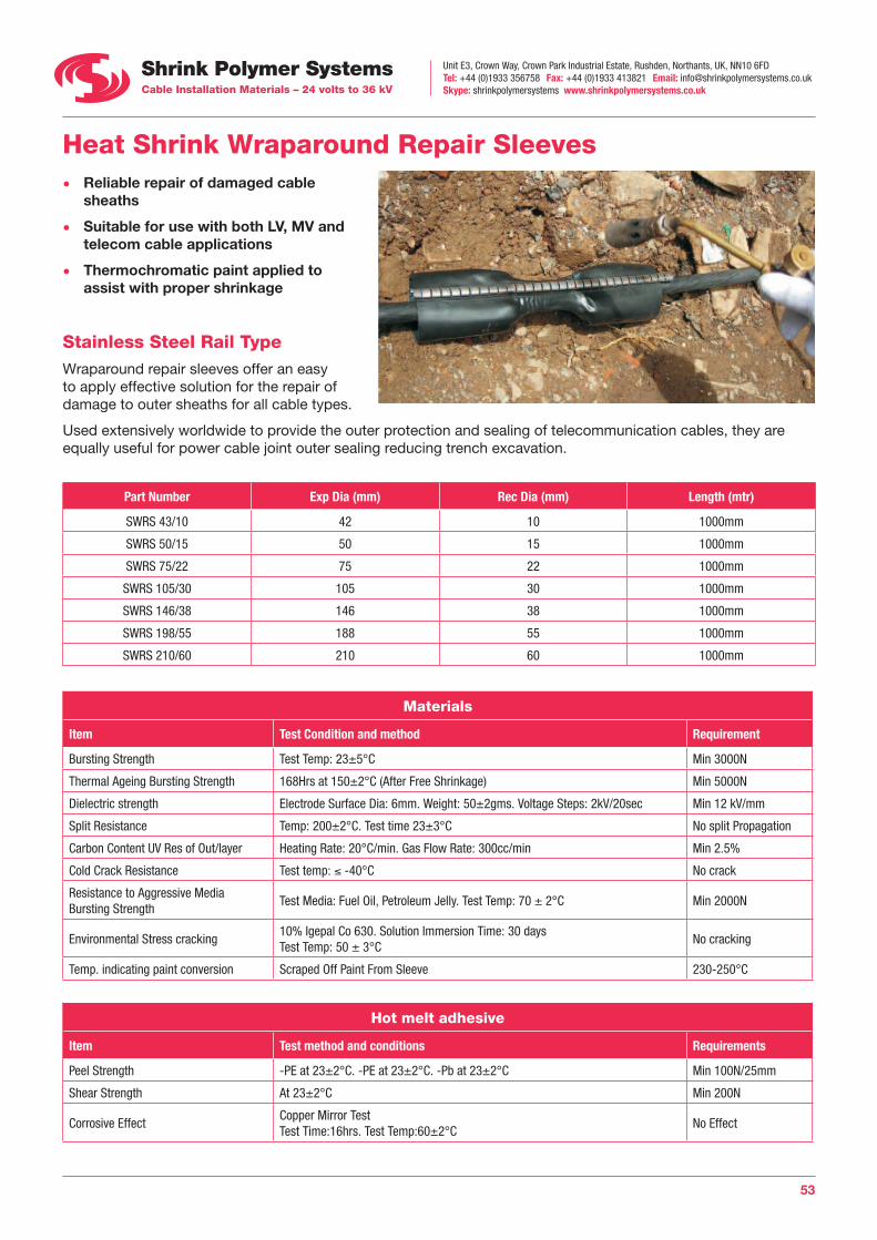
Unit E3, Crown Way, Crown Park Industrial Estate, Rushden, Northants, UK, NN10 6FDTel: +44 (0)1933 356758 Fax: +44 (0)1933 413821 Email: [email protected] Skype: shrinkpolymersystems www.shrinkpolymersystems.co.uk
53
Heat Shrink Wraparound Repair Sleeves • Reliable repair of damaged cable
sheaths
• Suitable for use with both LV, MV and telecom cable applications
• Thermochromatic paint applied to assist with proper shrinkage
Stainless Steel Rail Type Wraparound repair sleeves offer an easy to apply effective solution for the repair of damage to outer sheaths for all cable types.
Used extensively worldwide to provide the outer protection and sealing of telecommunication cables, they are equally useful for power cable joint outer sealing reducing trench excavation.
Part Number Exp Dia (mm) Rec Dia (mm) Length (mtr)
SWRS 43/10 42 10 1000mm
SWRS 50/15 50 15 1000mm
SWRS 75/22 75 22 1000mm
SWRS 105/30 105 30 1000mm
SWRS 146/38 146 38 1000mm
SWRS 198/55 188 55 1000mm
SWRS 210/60 210 60 1000mm
Materials
Item Test Condition and method Requirement
Bursting Strength Test Temp: 23±5°C Min 3000N
Thermal Ageing Bursting Strength 168Hrs at 150±2°C (After Free Shrinkage) Min 5000N
Dielectric strength Electrode Surface Dia: 6mm. Weight: 50±2gms. Voltage Steps: 2kV/20sec Min 12 kV/mm
Split Resistance Temp: 200±2°C. Test time 23±3°C No split Propagation
Carbon Content UV Res of Out/layer Heating Rate: 20°C/min. Gas Flow Rate: 300cc/min Min 2.5%
Cold Crack Resistance Test temp: ≤ -40°C No crack
Resistance to Aggressive MediaBursting Strength
Test Media: Fuel Oil, Petroleum Jelly. Test Temp: 70 ± 2°C Min 2000N
Environmental Stress cracking10% Igepal Co 630. Solution Immersion Time: 30 daysTest Temp: 50 ± 3°C
No cracking
Temp. indicating paint conversion Scraped Off Paint From Sleeve 230-250°C
Hot melt adhesive
Item Test method and conditions Requirements
Peel Strength -PE at 23±2°C. -PE at 23±2°C. -Pb at 23±2°C Min 100N/25mm
Shear Strength At 23±2°C Min 200N
Corrosive EffectCopper Mirror TestTest Time:16hrs. Test Temp:60±2°C
No Effect
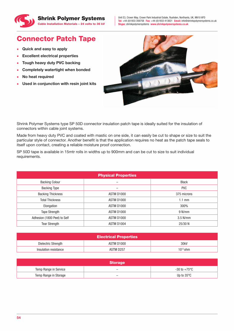
Unit E3, Crown Way, Crown Park Industrial Estate, Rushden, Northants, UK, NN10 6FDTel: +44 (0)1933 356758 Fax: +44 (0)1933 413821 Email: [email protected] Skype: shrinkpolymersystems www.shrinkpolymersystems.co.uk
54
Connector Patch Tape • Quick and easy to apply
• Excellent electrical properties
• Tough heavy duty PVC backing
• Completely watertight when bonded
• No heat required
• Used in conjunction with resin joint kits
Shrink Polymer Systems type SP 50D connector insulation patch tape is ideally suited for the insulation of connectors within cable joint systems.
Made from heavy duty PVC and coated with mastic on one side, it can easily be cut to shape or size to suit the particular style of connector. Another benefit is that the application requires no heat as the patch tape seals to itself upon contact, creating a reliable moisture proof connection.
SP 50D tape is available in 15mtr rolls in widths up to 900mm and can be cut to size to suit individual requirements.
Physical Properties
Backing Colour – Black
Backing Type – PVC
Backing Thickness ASTM D1000 375 microns
Total Thickness ASTM D1000 1.1 mm
Elongation ASTM D1000 300%
Tape Strength ASTM D1000 9 N/mm
Adhesion (1800 Peel) to Self ASTM D1000 3.5 N/mm
Tear Strength ASTM D1004 25/30 N
Electrical Properties
Dielectric Strength ASTM D1000 30kV
Insulation resistance ASTM D257 1012 ohm
Storage
Temp Range in Service – -30 to +75ºC
Temp Range in Storage – Up to 35ºC
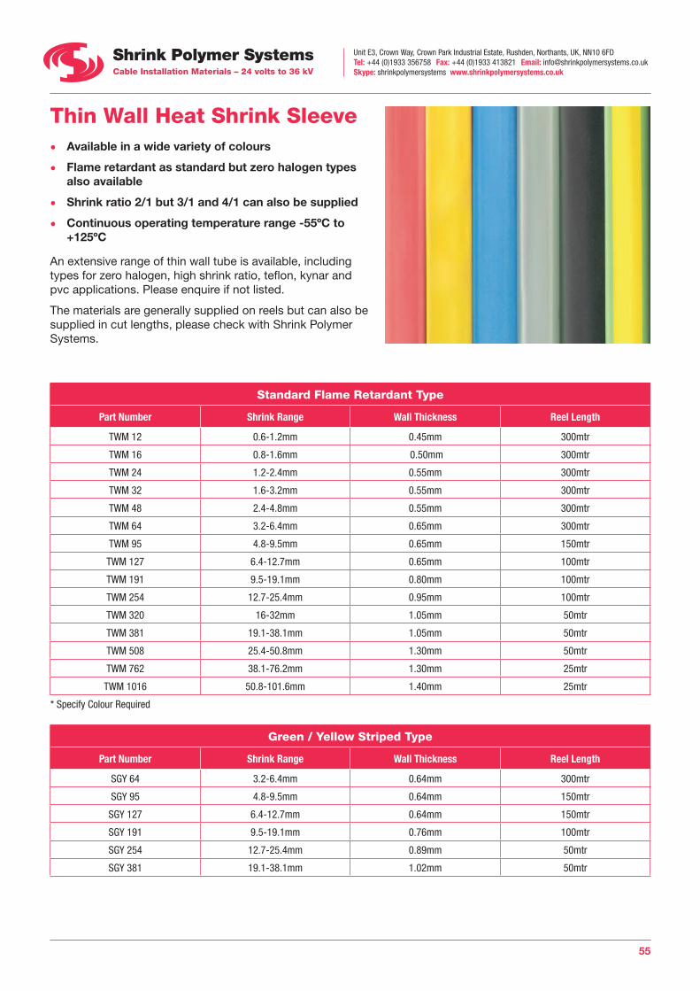
Unit E3, Crown Way, Crown Park Industrial Estate, Rushden, Northants, UK, NN10 6FDTel: +44 (0)1933 356758 Fax: +44 (0)1933 413821 Email: [email protected] Skype: shrinkpolymersystems www.shrinkpolymersystems.co.uk
55
Thin Wall Heat Shrink Sleeve • Available in a wide variety of colours
• Flame retardant as standard but zero halogen types also available
• Shrink ratio 2/1 but 3/1 and 4/1 can also be supplied
• Continuous operating temperature range -55ºC to +125ºC
An extensive range of thin wall tube is available, including types for zero halogen, high shrink ratio, teflon, kynar and pvc applications. Please enquire if not listed.
The materials are generally supplied on reels but can also be supplied in cut lengths, please check with Shrink Polymer Systems.
Standard Flame Retardant Type
Part Number Shrink Range Wall Thickness Reel Length
TWM 12 0.6-1.2mm 0.45mm 300mtr
TWM 16 0.8-1.6mm 0.50mm 300mtr
TWM 24 1.2-2.4mm 0.55mm 300mtr
TWM 32 1.6-3.2mm 0.55mm 300mtr
TWM 48 2.4-4.8mm 0.55mm 300mtr
TWM 64 3.2-6.4mm 0.65mm 300mtr
TWM 95 4.8-9.5mm 0.65mm 150mtr
TWM 127 6.4-12.7mm 0.65mm 100mtr
TWM 191 9.5-19.1mm 0.80mm 100mtr
TWM 254 12.7-25.4mm 0.95mm 100mtr
TWM 320 16-32mm 1.05mm 50mtr
TWM 381 19.1-38.1mm 1.05mm 50mtr
TWM 508 25.4-50.8mm 1.30mm 50mtr
TWM 762 38.1-76.2mm 1.30mm 25mtr
TWM 1016 50.8-101.6mm 1.40mm 25mtr
* Specify Colour Required
Green / Yellow Striped Type
Part Number Shrink Range Wall Thickness Reel Length
SGY 64 3.2-6.4mm 0.64mm 300mtr
SGY 95 4.8-9.5mm 0.64mm 150mtr
SGY 127 6.4-12.7mm 0.64mm 150mtr
SGY 191 9.5-19.1mm 0.76mm 100mtr
SGY 254 12.7-25.4mm 0.89mm 50mtr
SGY 381 19.1-38.1mm 1.02mm 50mtr
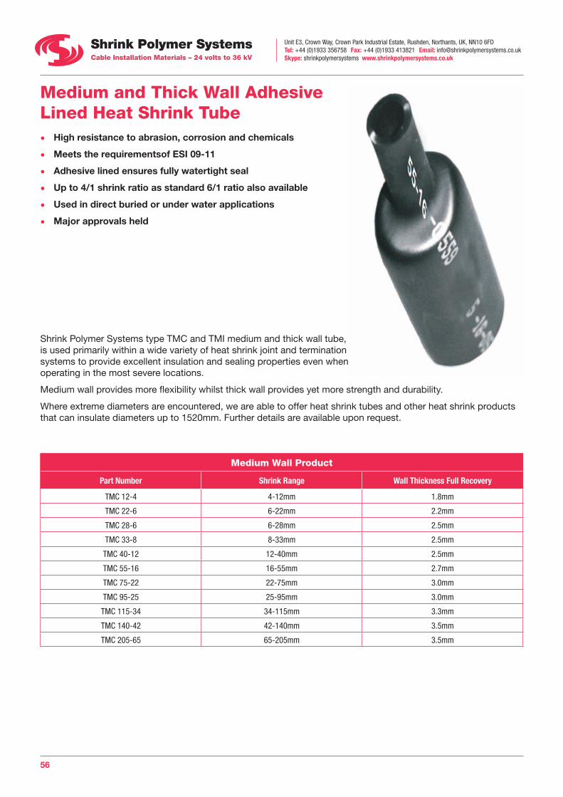
Unit E3, Crown Way, Crown Park Industrial Estate, Rushden, Northants, UK, NN10 6FDTel: +44 (0)1933 356758 Fax: +44 (0)1933 413821 Email: [email protected] Skype: shrinkpolymersystems www.shrinkpolymersystems.co.uk
56
Medium and Thick Wall Adhesive Lined Heat Shrink Tube • High resistance to abrasion, corrosion and chemicals
• Meets the requirementsof ESI 09-11
• Adhesive lined ensures fully watertight seal
• Up to 4/1 shrink ratio as standard 6/1 ratio also available
• Used in direct buried or under water applications
• Major approvals held
Shrink Polymer Systems type TMC and TMI medium and thick wall tube, is used primarily within a wide variety of heat shrink joint and termination systems to provide excellent insulation and sealing properties even when operating in the most severe locations.
Medium wall provides more flexibility whilst thick wall provides yet more strength and durability.
Where extreme diameters are encountered, we are able to offer heat shrink tubes and other heat shrink products that can insulate diameters up to 1520mm. Further details are available upon request.
Medium Wall Product
Part Number Shrink Range Wall Thickness Full Recovery
TMC 12-4 4-12mm 1.8mm
TMC 22-6 6-22mm 2.2mm
TMC 28-6 6-28mm 2.5mm
TMC 33-8 8-33mm 2.5mm
TMC 40-12 12-40mm 2.5mm
TMC 55-16 16-55mm 2.7mm
TMC 75-22 22-75mm 3.0mm
TMC 95-25 25-95mm 3.0mm
TMC 115-34 34-115mm 3.3mm
TMC 140-42 42-140mm 3.5mm
TMC 205-65 65-205mm 3.5mm
Unit E3, Crown Way, Crown Park Industrial Estate, Rushden, Northants, UK, NN10 6FDTel: +44 (0)1933 356758 Fax: +44 (0)1933 413821 Email: [email protected] Skype: shrinkpolymersystems www.shrinkpolymersystems.co.uk
57
Thick Wall Product
Part Number Shrink Range Wall Thickness Full Recovery
TMI 9-3 3-9mm 1.8mm
TMI 12-3 3-12mm 1.8mm
TMI 22-6 6-22mm 2.2mm
TMI 33-8 8-33mm 3.2mm
TMI 45-12 12-45mm 4.1mm
TMI 55-16 16-55mm 4.1mm
TMI 75-22 22-75mm 4.1mm
TMI 95-29 29-95mm 4.3mm
TMI 130-36 36-130mm 4.3mm
TMI 160-55 55-160mm 4.3mm
TMI 200-65 65-200mm 4.3mm
Standard Lengths Available
Medium Wall 1200 and 1500mm,
Thick Wall 1200 and 1500mm,
Other lengths available on request
Property Test Method Performance
Tensile Strength ASTM D638 14.0MPA
Ultimate Elongation ISO 37 >400%
Operating Temperature IEC 216 -550C to +1100C
Min Shrink Temperature – 1200C
Longitudinal Change UL 224 ±10%
Specific Gravity ISO/R1183 1.1
Dielectric Strength IEC 243 >20kV/mm
Elongation after Heat Ageing ISO 37 (168 hrs at 150ºC) >300%
Heat Shock ASTM D2671 No dripping, flowing (4 hrs at 225ºC) or cracking
Low Temperature Flexibility ASTM D1693 (4 hrs at -55ºC) No cracking or splitting
Water Absorbtion ISO 62 <0.15%
Fluid Resistance Various Fluids ISO 1817, ISO 37 MIL-1-23053 Good to excellent
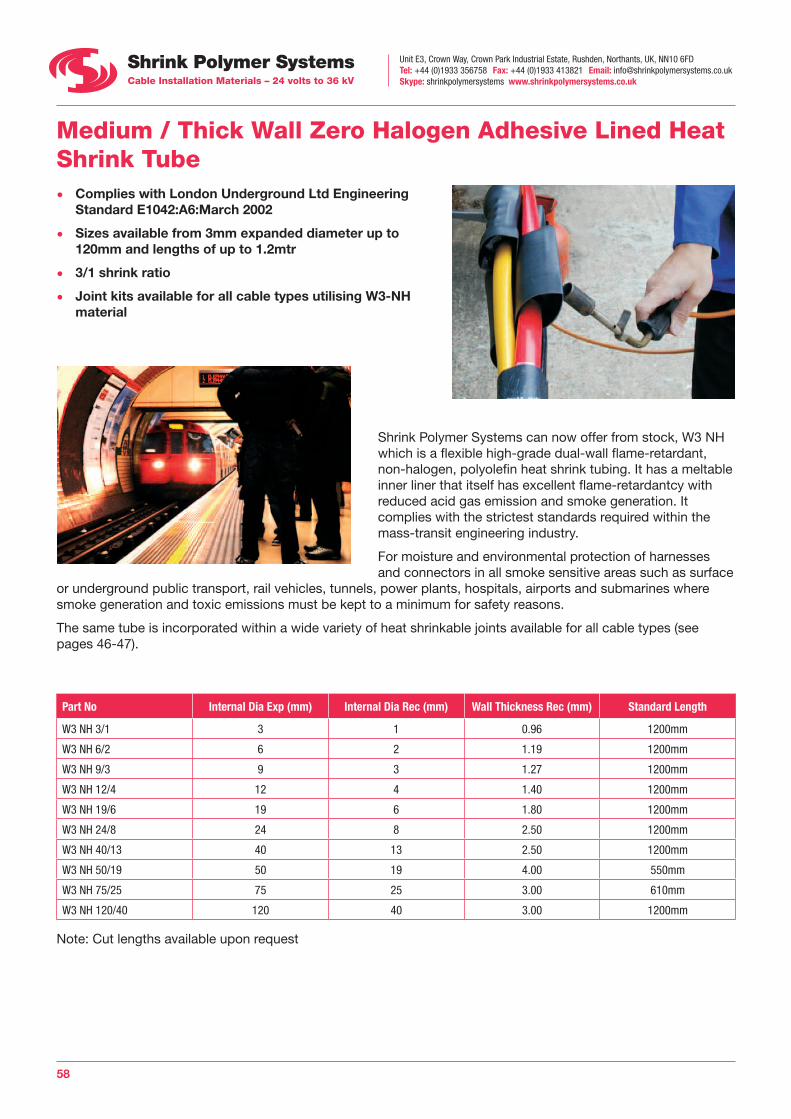
Unit E3, Crown Way, Crown Park Industrial Estate, Rushden, Northants, UK, NN10 6FDTel: +44 (0)1933 356758 Fax: +44 (0)1933 413821 Email: [email protected] Skype: shrinkpolymersystems www.shrinkpolymersystems.co.uk
58
Medium / Thick Wall Zero Halogen Adhesive Lined Heat Shrink Tube • Complies with London Underground Ltd Engineering
Standard E1042:A6:March 2002
• Sizes available from 3mm expanded diameter up to 120mm and lengths of up to 1.2mtr
• 3/1 shrink ratio
• Joint kits available for all cable types utilising W3-NH material
Shrink Polymer Systems can now offer from stock, W3 NH which is a flexible high-grade dual-wall flame-retardant, non-halogen, polyolefin heat shrink tubing. It has a meltable inner liner that itself has excellent flame-retardantcy with reduced acid gas emission and smoke generation. It complies with the strictest standards required within the mass-transit engineering industry.
For moisture and environmental protection of harnesses and connectors in all smoke sensitive areas such as surface
or underground public transport, rail vehicles, tunnels, power plants, hospitals, airports and submarines where smoke generation and toxic emissions must be kept to a minimum for safety reasons.
The same tube is incorporated within a wide variety of heat shrinkable joints available for all cable types (see pages 46-47).
Part No Internal Dia Exp (mm) Internal Dia Rec (mm) Wall Thickness Rec (mm) Standard Length
W3 NH 3/1 3 1 0.96 1200mm
W3 NH 6/2 6 2 1.19 1200mm
W3 NH 9/3 9 3 1.27 1200mm
W3 NH 12/4 12 4 1.40 1200mm
W3 NH 19/6 19 6 1.80 1200mm
W3 NH 24/8 24 8 2.50 1200mm
W3 NH 40/13 40 13 2.50 1200mm
W3 NH 50/19 50 19 4.00 550mm
W3 NH 75/25 75 25 3.00 610mm
W3 NH 120/40 120 40 3.00 1200mm
Note: Cut lengths available upon request
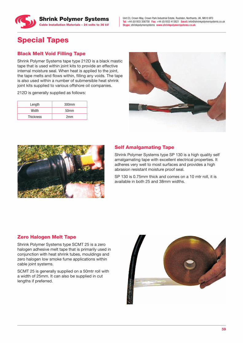
Unit E3, Crown Way, Crown Park Industrial Estate, Rushden, Northants, UK, NN10 6FDTel: +44 (0)1933 356758 Fax: +44 (0)1933 413821 Email: [email protected] Skype: shrinkpolymersystems www.shrinkpolymersystems.co.uk
59
Special Tapes
Black Melt Void Filling Tape Shrink Polymer Systems tape type 212D is a black mastic tape that is used within joint kits to provide an effective internal moisture seal. When heat is applied to the joint, the tape melts and flows within, filling any voids. The tape is also used within a number of submersible heat shrink joint kits supplied to various offshore oil companies.
212D is generally supplied as follows:
Length 300mm
Width 50mm
Thickness 2mm
Self Amalgamating Tape Shrink Polymer Systems type SP 130 is a high quality self amalgamating tape with excellent electrical properties. It adheres very well to most surfaces and provides a high abrasion resistant moisture proof seal.
SP 130 is 0.75mm thick and comes on a 10 mtr roll, it is available in both 25 and 38mm widths.
Zero Halogen Melt Tape Shrink Polymer Systems type SCMT 25 is a zero halogen adhesive melt tape that is primarily used in conjunction with heat shrink tubes, mouldings and zero halogen low smoke fume applications within cable joint systems.
SCMT 25 is generally supplied on a 50mtr roll with a width of 25mm. It can also be supplied in cut lengths if preferred.
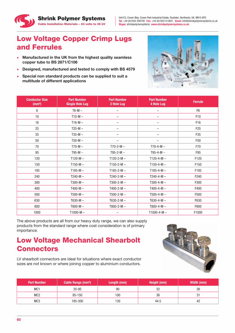
Unit E3, Crown Way, Crown Park Industrial Estate, Rushden, Northants, UK, NN10 6FDTel: +44 (0)1933 356758 Fax: +44 (0)1933 413821 Email: [email protected] Skype: shrinkpolymersystems www.shrinkpolymersystems.co.uk
60
Low Voltage Copper Crimp Lugs and Ferrules • Manufactured in the UK from the highest quality seamless
copper tube to BS 2871/C106
• Designed, manufactured and tested to comply with BS 4579
• Special non standard products can be supplied to suit a multitude of different applications
Conductor Size (mm²)
Part Number Single Hole Lug
Part Number 2 Hole Lug
Part Number 4 Hole Lug
Ferrule
6 T6-M – – – F6
10 T10-M – – – F10
16 T16-M – – – F16
25 T25-M – – – F25
35 T35-M – – – F35
50 T50-M – – – F50
70 T70-M – T70-2-M – T70-4-M – F70
95 T95-M – T95-2-M – T95-4-M – F95
120 T120-M – T120-2-M – T120-4-M – F120
150 T150-M – T150-2-M – T150-4-M – F150
185 T185-M – T185-2-M – T185-4-M – F185
240 T240-M – T240-2-M – T240-4-M – F240
300 T300-M – T300-2-M – T300-4-M – F300
400 T400-M – T400-2-M – T400-4-M – F400
500 T500-M – T500-2-M – T500-4-M – F500
630 T630-M – T630-2-M – T630-4-M – F630
800 T800-M – T800-2-M – T800-4-M – F800
1000 T1000-M – – T1000-4-M – F1000
The above products are all from our heavy duty range, we can also supply products from the standard range where cost consideration is of primary importance.
Low Voltage Mechanical Shearbolt Connectors LV shearbolt connectors are ideal for situations where exact conductor sizes are not known or where joining copper to aluminium conductors.
Part Number Cable Range (mm²) Length (mm) Height (mm) Width (mm)
MC1 35-95 90 32 26
MC2 95-150 100 36 31
MC3 185-300 130 44.5 42

Unit E3, Crown Way, Crown Park Industrial Estate, Rushden, Northants, UK, NN10 6FDTel: +44 (0)1933 356758 Fax: +44 (0)1933 413821 Email: [email protected] Skype: shrinkpolymersystems www.shrinkpolymersystems.co.uk
61
Miscellaneous Tools
Gas Torch Kits Two gas torch kits are available complete with burner heads that were specifically developed for use with heat shrink products.
SPS 201
This kit features an auto ignite handle, hot air burner head, hose and fittings and adaptors so that standard propane cylinders or the ultra portable primus 2000 cylinders can be used.
SPS 202
The kit comes with the standard handle and heat shrink burner head, cylinder adaptor and hose and fittings.
Ratchet Crimp Tool Part Number CR 1 The CR 1 is a high quality tool designed for use with pre-insulated crimp terminals ranging from 0.5-6mm² (reds, blues and yellows). Its unique feature is that the dies are equal both sides which eliminates the danger of applying an insulation crimp to the terminal itself.
Ratchet Crimp Tool Part Number CRN 1 The CRN 1 is a high quality tool designed for use with non-insulated crimp terminals ranging from 0.25-10mm².
The CRN 1 was used in tests for 6mm² and 8AWG connector tests and approved for use on AGL cables by what was the the DOE / PSA. now Defence Estates.
Ratchet Cable Cutter - Part Number SPCC 380 The SPCC 380 is a hand operated ratchet tool that is designed to cut non steel wire armoured copper and aluminium cables up to 35mm² diameter (300mm LV XLPE / PVC cable approx). The precision ground blades provide long service life and the tool also features a safety catch. Length 340mm, Weight 1.2kg
Other models are available upon request.
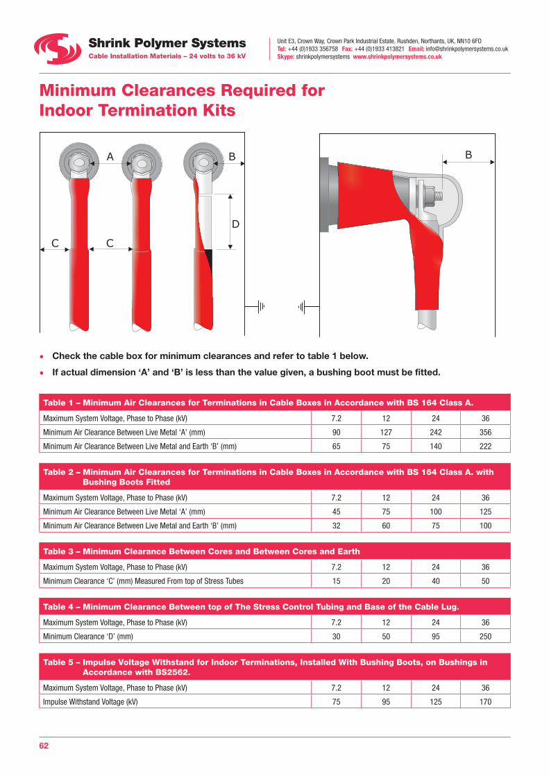
Unit E3, Crown Way, Crown Park Industrial Estate, Rushden, Northants, UK, NN10 6FDTel: +44 (0)1933 356758 Fax: +44 (0)1933 413821 Email: [email protected] Skype: shrinkpolymersystems www.shrinkpolymersystems.co.uk
62
Minimum Clearances Required for Indoor Termination Kits
• Check the cable box for minimum clearances and refer to table 1 below.
• If actual dimension ‘A’ and ‘B’ is less than the value given, a bushing boot must be fitted.
Table 1 – Minimum Air Clearances for Terminations in Cable Boxes in Accordance with BS 164 Class A.
Maximum System Voltage, Phase to Phase (kV) 7.2 12 24 36
Minimum Air Clearance Between Live Metal ‘A’ (mm) 90 127 242 356
Minimum Air Clearance Between Live Metal and Earth ‘B’ (mm) 65 75 140 222
Table 2 – Minimum Air Clearances for Terminations in Cable Boxes in Accordance with BS 164 Class A. with Bushing Boots Fitted
Maximum System Voltage, Phase to Phase (kV) 7.2 12 24 36
Minimum Air Clearance Between Live Metal ‘A’ (mm) 45 75 100 125
Minimum Air Clearance Between Live Metal and Earth ‘B’ (mm) 32 60 75 100
Table 3 – Minimum Clearance Between Cores and Between Cores and Earth
Maximum System Voltage, Phase to Phase (kV) 7.2 12 24 36
Minimum Clearance ‘C’ (mm) Measured From top of Stress Tubes 15 20 40 50
Table 4 – Minimum Clearance Between top of The Stress Control Tubing and Base of the Cable Lug.
Maximum System Voltage, Phase to Phase (kV) 7.2 12 24 36
Minimum Clearance ‘D’ (mm) 30 50 95 250
Table 5 – Impulse Voltage Withstand for Indoor Terminations, Installed With Bushing Boots, on Bushings in Accordance with BS2562.
Maximum System Voltage, Phase to Phase (kV) 7.2 12 24 36
Impulse Withstand Voltage (kV) 75 95 125 170
D
C
A B
C
B

Unit E3, Crown Way, Crown Park Industrial Estate, Rushden, Northants, UK, NN10 6FDTel: +44 (0)1933 356758 Fax: +44 (0)1933 413821 Email: [email protected] Skype: shrinkpolymersystems www.shrinkpolymersystems.co.uk
63
Notes

Unit E3, Crown Way, Crown Park Industrial Estate, Rushden, Northants, UK, NN10 6FDTel: +44 (0)1933 356758 Fax: +44 (0)1933 413821 Email: [email protected] Skype: shrinkpolymersystems www.shrinkpolymersystems.co.uk
64
Notes
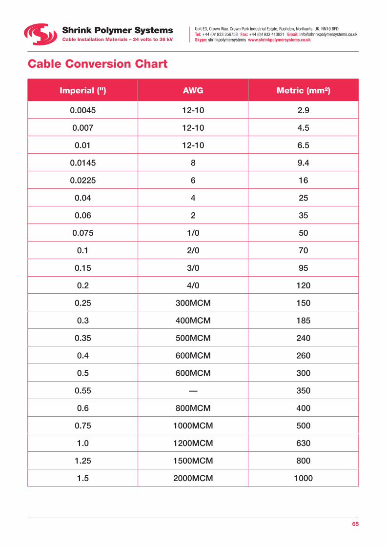
Unit E3, Crown Way, Crown Park Industrial Estate, Rushden, Northants, UK, NN10 6FDTel: +44 (0)1933 356758 Fax: +44 (0)1933 413821 Email: [email protected] Skype: shrinkpolymersystems www.shrinkpolymersystems.co.uk
65
Cable Conversion Chart
Imperial (") AWG Metric (mm²)
0.0045 12-10 2.9
0.007 12-10 4.5
0.01 12-10 6.5
0.0145 8 9.4
0.0225 6 16
0.04 4 25
0.06 2 35
0.075 1/0 50
0.1 2/0 70
0.15 3/0 95
0.2 4/0 120
0.25 300MCM 150
0.3 400MCM 185
0.35 500MCM 240
0.4 600MCM 260
0.5 600MCM 300
0.55 — 350
0.6 800MCM 400
0.75 1000MCM 500
1.0 1200MCM 630
1.25 1500MCM 800
1.5 2000MCM 1000
Head Office: Unit E3, Crown Way, Crown Park Industrial Estate, Rushden, Northants, UK, NN10 6FDTel: +44 (0)1933 356758 Fax: +44 (0)1933 413821 Email: [email protected] Skype: shrinkpolymersystemswww.shrinkpolymersystems.co.uk
Oman Office: Tel: +968 24446475 Fax: +968 24446547 Email: [email protected]
Des
ign:
ww
w.jh
urle
ydes
ign.
co.u
k
Certificate Number 1865