sps matta pelvic system - stryker meded · name stryker trauma was adopted. prof. letournel...
TRANSCRIPT
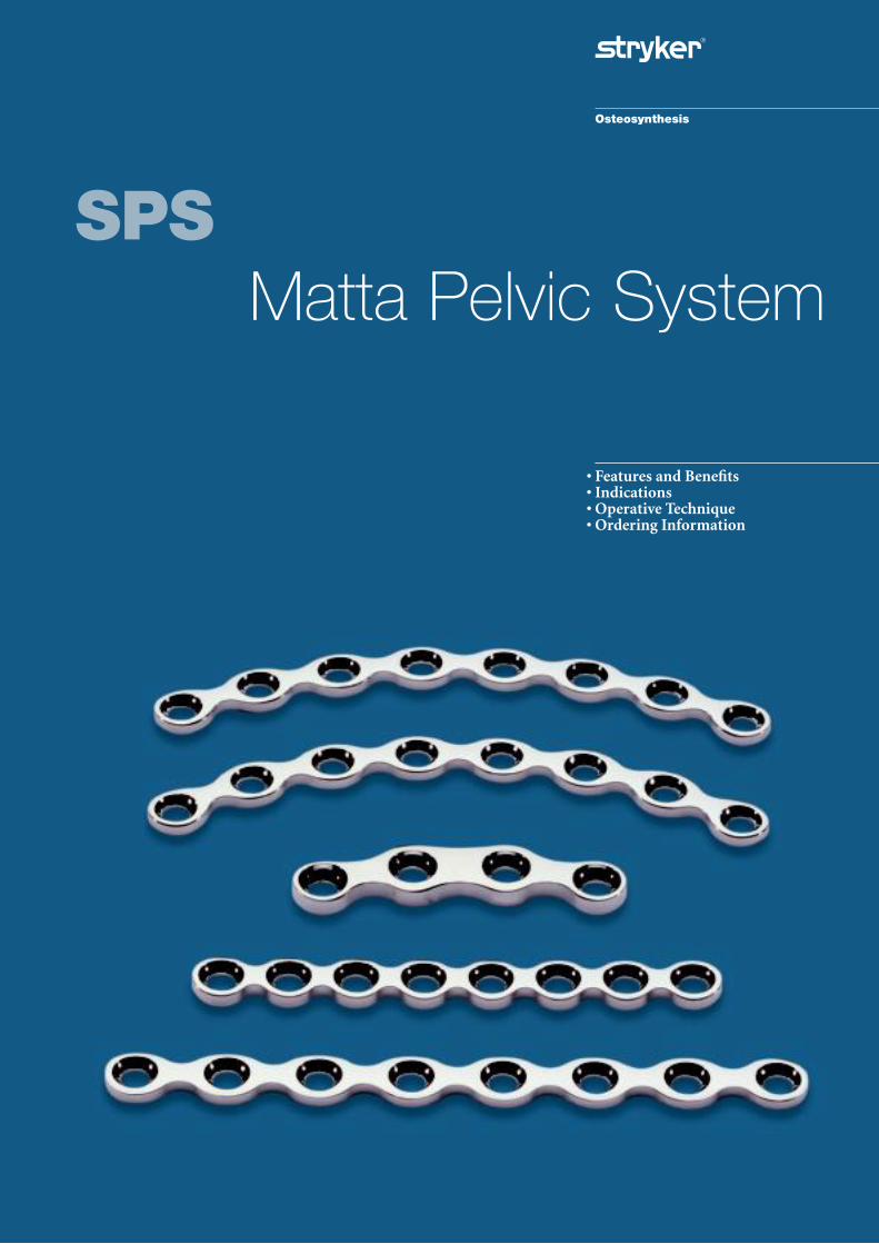
SPSMatta Pelvic System
• Features and Benefits• Indications• Operative Technique• Ordering Information

2
Implant Rationale
The Matta Pelvic Set consists of fivedifferent plate designs. The plates aredifferentiated by design, stiffness or function.
MPS Plates
Straight and curved pelvic andacetabular plates with a hole spacing of 16mm are available. Curved platesare designed to match either the male(R108) or the female (R88) pelvic brimrespectively. These plates are ratherstiff and are preferred for the pelvicbrim and when a more rigid implant is necessary.
MPS Flex Plate
These plates have reduced hole spacing(12mm) and are made of annealedstainless steel, resulting in less stiffness.They are therefore easily contouredand preferred when a stiff implant is not required e.g. posterior wallfractures, ilium fixation etc.
MPS Symphysis Plate
With 3.2mm thickness and increasedwidth through the midsection togetherwith a anatomically curved radius of75mm, this plate normally obviates theneed for axial contouring. This plate isavailable in either a four or six holeoption.
Screws
All the Matta Pelvic System screwshave a hexagonal head with a sphericalunderside and conform fully to the requirements set by ASTM F138 & F139/ISO 5832- standards.Screw fixation of the pelvis oftenrequires the use of extra-long screws.In addition to the standard screwrange the system includes 3.5mmcortical screws up to 110mm, 4.5mmcortical screws up to 120mm and6.5mm cancellous screws up to 130mm.
All the cortical screws within the rangeare self-tapping. Three cutting fluteson the tip of each screw allows cleanercutting and help to reduce “compacting”of the bone chips at the tip of the screw.Due to specially designed cuttinggrooves, they also offer an enhancedinsertion torque.
Depending on the screw selection,the screw heads can be almostcompletely countersunk into thespecifically designed plate holes.
Material Composition
ASTM F138 & F139/ISO 5832-1material standards provide rigidspecifications, which define thechemical composition, microstructuralcharacteristics and mechanicalproperties of implant quality Stainless Steel. These standards ensurethat Stainless Steel 316LVM even ifprovided by different suppliers,is consistent and compatible.The material used for all plates andscrews in this system complies withthese standards.
Rationale
The Matta Pelvic Set is designed to address all fractures of the acetabulum andpelvis. The extremely complex anatomy of the pelvic bone, particularly theacetabular region requires perfect anatomical reduction if good functional anddurable results are to be achieved.
The shape, material properties, plate malleability and hole spacing of the platestake into account the current demands from clinical physicians for sufficientfatigue strength, optimised transfer of loading forces, a standardised operativetechnique with broad applicability.
All implants are made in Stainless Steel (316 LVM).

3
The System is designed with the kind collaboration of the following Clinician:Joel M. Matta, M.D. Good Samaritan Hospital, Los Angeles, California withthanks to the late Prof. Emile Letournel.
In 1983 the Osteo company of Selzach,Switzerland produced the firstcommercially available acetabular andpelvic fixation set at the request of, andunder the guidance of Prof. Letournel.
In 1996 Osteo was purchased byStryker Corporation and later thename Stryker Trauma was adopted.Prof. Letournel initially chaired the first course, Fractures of theAcetabulum and Pelvis in Paris in 1984 and at his invitation I joined the faculty. Today Stryker Traumacontinues to sponsor this course underthe chairmanship of myself and others.
Letournel thereby established the nowwell accepted acetabular and pelvicfracture treatment principles of perfectreduction and stable fixation and alsobrought to acceptance the importanceof specialised instrumentation andimplants to achieve this end.
In 1998 I was asked to be a consultantfor Stryker Trauma for theireducational program and for revisingand updating the acetabular and pelvicset. My past involvement with the Pariscourses as a faculty member and laterchairman as well as my preference forthe Letournel designed Osteo platesmade accepting this offer logical.
As per Letournel‘s originalspecifications the curved plates areavailable in two radii: 108mm to matchthe curvature of the male pelvic brimand 88mm to match the female.
The main complaint that was heardregarding the plates was that they were too stiff and the holes were toofar apart. The curved plates are nowslightly less stiff and the hole interval is reduced to 16mm from 18mm.A new plate called the MPS Flex platehas also been added with a 12mm holespacing and flexibility similar to arecon plate. Both plates are 2.5mmthick and the stiffness is controlled by hardening or annealing. The thinprofile limits soft tissue intrusion and also facilitates improved screw angulation.
Though the flexible MPS Flex plate has shown to be adequate for manyfixations it is my opinion that anumber of surgeons choose it toofrequently and to the detriment offixation. It may seem convenient thatwhen this plate is applied incompletelycontoured, tightening the screwscompletes the contouring. What thismeans in effect is that the bone iscontrolling the contour of the platerather than the plate controlling thecontour of the fractured bone.
I prefer the standard curved andstraight plates for the majority offixations including posterior wallfractures. I reserve use of the MPS Flex plate for fractures thatrequire the closer hole spacing or extreme contouring.
The current set includes the clampsand reduction aids that I considermost valuable. This brochure and our education courses will help thesurgeon learn their application.In many ways the instruments andtheir use is more important than theplates that are chosen just as reductionis usually a more important problemthan fixation. An important reductioninstrument that is not included is theorthopedic extension table. The mosteffective table to date is the Tasserittable previously called the Judet table.
It is inevitable that surgeons that usethis set will wish at times for a slightlydifferent plate that is not in the box or a clamp of another design.Surgeons who address these fracturesfrequently (as I do) will probably keepan additional box of items that areoccasionally useful. To make a sethowever that is affordable and widelyuseful the contents must be carefullychosen. It is expected that the set will evolve as surgeons contribute their comments.
Judet and Letournel concluded earlyon the most important factor in asuccessful operation was a perfect preoperative understanding of the X-raysand fracture pattern. The same is true today. The surgeons knowledge,skill and dedication remain theprimary determinants of the patient`soutcome and the design of this setseeks to facilitate this.
Joel M. Matta, M.D.
Clinical Design Surgeon
Introduction

4
Cases and TraysThe Matta Pelvic System consists offour different cases available in plasticor metal* with a variety of dedicated,removable inserts. The two plate racks,the screw rack and the tray inserts forthe basic instruments offer optimummodularity for storage and sterilisation.The pre-formed inserts for the basicinstruments allow for easy access tothe instruments which are arranged in a logical order.
*reduction case only available in plastic
Plates and ScrewsIn addition to the extra long 3.5mm and 4.5mm self-tapping cortical screwrange, the Matta Pelvic Set includes a selected range of partially threaded6.5mm cancellous screws. These canoffer the option to perform a strongindependent interfragmentary Lag-Screws fixation without the need for an additional screw set.The “all in one” implant case contains a wide range of pelvic and acetabularplates together with a dedicatedSymphysis plate.
Drills and TapsContained within the basic instrumentset are all the relevant drill bits andtaps corresponding to each screwdiameter. Titanium oxide coating onthe drill bits and taps for the 3.5mmscrews enhances not only the cuttingefficiency but the longevity andimproved visual identity of eachinstrument. While all of the corticalscrews in the set are self-tapping theinclusion of the taps offers cliniciansthe option of pre-tapping in densecortical bone.
Introduction

5
The Pelvic System design is based on input from Dr. Joel M. Matta, M.D.Los Angeles, theatre and sterilisation staff, data from literature and bothpractical and biomechanical testing results of the system.
Features Benefits
Stainless Steel cold worked and • Excellent plate malleability forannealed plates available optimum adaptation to the
pelvic surfaces
Straight and curved plate options • Increased indication coverage all in one set
Rounded plate ends • Reduced potential for soft tissue irritation
Dedicated Symphysis Pubis plate • Strong with anatomical fit
3.5/4.5mm screw hole option • Flexibility of 3.5mm or 4.5mm screws
Low screw head profile in plate hole • Reduced potential for soft tissue irritation
Self-tapping cortical screws • Quick, simple and more efficient
Increased screw angulation with • Optimised for posterior wall fixation3.5mm screws
4 options of Reduction pins • Flexibility of choice of ø5mm or ø6mm and 150mm or 180mm length
Equal hole spacing on plate • Great operative flexibility for screw and plate placement
Advanced plate bender • Easy and smooth three dimensional bending of plates
Bending Templates • Allows plate bending away from the operative field
Spiked Disk • Can be used in combination withreduction forceps and ball spike forincreased bone contact
Elastosil® or Canevasit Handles • Surgeon choice
Screwdriver Holding Sleeve • Efficiency in pick up insertion/removal via “No-touch” technique
Reduction Instruments • Specialist forceps and optimised clampdesign, small unique reduction forcepsfor 3.5mm screws
Specific Nerve Retractors • 2 sizes available for optimal soft tissueretraction
Modular case design • Maximum flexibility for sterilisationmethod in either outer base or insterilisation container
Dedicated basic instrument case • All instruments for 3 screw sizes in one set
Features and Benefits

Key:
Internalaspect
The Matta Pelvic System is indicatedfor fractures of the:
• Pelvic Ring
• Acetabulum
• Sacrum
• Ilium
• Sacroiliac joint dislocations
• Symphysis Pubis disruption
• Revision surgery of pseudoarthroses,non-unions and mal-unions
• Osteotomies
• Pelvic arthrodeses
• Total hip revision surgery
Contraindications
The physician's education, trainingand professional judgement mustbe relied upon to choose the most
appropriate device and treatment.Conditions presenting an increasedrisk of failure include:
Any active or suspected latent infectionor marked local inflammation in or about the affected area.
Compromised vascularity that wouldinhibit adequate blood supply to thefracture or the operative site.
Bone stock compromised by disease,infection or prior implantation thatcan not provide adequate support and/or fixation of the devices.
Material sensitivity, documented or suspected.
Obesity. An overweight or obese patientcan produce loads on the implant thatcan lead to failure of the fixation of thedevice or to failure of the device itself.
Patients having inadequate tissuecoverage over the operative site.
Implant utilization that would interferewith anatomical structures orphysiological performance.
Any mental or neuromuscular disorderwhich would create an unacceptable riskof fixation failure or complications inpostoperative care.
Other medical or surgical conditionswhich would preclude the potentialbenefit of surgery.
MPS Flex Plate (annealed)
Posterior Wall, Ilium and Iliac Crest.
MPS Symphysis Plate, R75
Symphysis Pubis.
MPS Curved R88 Plate
Pelvic Ring (female),Iliac Crest, Posterior Wall.
MPS Curved R108 Plate
Pelvic Ring (male), IliacCrest, Posterior Wall.
Indications
MPS Straight Plate
Pelvic Ring, internal andexternal aspect of theIlium, Posterior Wall.
6
Key:
Internal aspectExternal aspect

The 3.5mm self-tapping cortical screwsare the recommended screws for platefixation and are best adapted to thepelvic bone. 4.5mm cortical screws areoften too large and their voluminousheads create a slight prominence abovethe plates, which may lead to softtissue irritation in certain applications.
Therefore, these screws should only be used exceptionally to fix a plate,i.e. when a smaller screw does not get sufficient purchase.
Furthermore, the plate holes aredesigned to accept introduction of3.5mm screws inserted at extremeangles, up to 35 degrees in all directions.This capability is essential as it must bepossible to avoid penetrating the hipjoint or to be able to drive a screwobliquely in the area of the iliac bone,avoiding a previously inserted isolated screw.
Possible Lag-Screws using 4.5mmcortical or 6.5mm cancellous screws:
a) From the crest of the anteriorborder (screw 1) in the thickness ofthe iliac wing. It is always possible toinsert a screw from the antero-inferior iliac spine, passing 1 or 2 cm above the acetabulum (length 100 –120mm) (screw 2).
b) Along the axis of the anteriorcolumn (screw 3).This screw is veryuseful to secure a transverse fractureor an anterior column, through anextended ilio–femoral approach.The screw should start from theposterior aspect of the iliac wingpillar approx. 3-4cm above theacetabulum.
c) In the thickness of the iliac wing,but from posterior to anterior,
starting from the posterior part of the iliac wing or theposterior–superior iliac spine toreduce a sacroiliac joint fracturedislocation (screws 4 and 5).
d) Along the axis of the posterior column (screw 6).
For all these Lag-Screws, it is essentialto drill intermittently, step by step, andchange the direction of the drill ifyou feel penetration of a cortex.Remain in the correct axis and advancethe drill as far as possible.
Independent interfragmentaryCompression
Often independent (isolated)interfragmentary Lag-Screws are used in conjunction with pelvic and acetabular fixation.
The screw thread takes no purchase in the near fragment because the screwhas a shaft with no thread and /or thedrill hole in the near fragment is equalto the outside diameter of the screw.The cortex in the near fragment has tobe overdrilled therefore to create a“gliding” hole. Overdrilling the cortexin this manner allows the screw thread
7
to take purchase in the bone of theopposite fragment.
Drill Guides
Use the Double Drill Guide REF702417 and the 4.5mm Drill (DoubleDrill Guide REF 702418 and Drill3.5mm for screws 3.5mm) to overdrillthe near cortex. Insert the oppositeside of the relevant drill guide into the pre-drilled hole for precise axialalignment and use the correspondingdrill for the corehole of the screw.This procedure will prevent the loss of reduction and fixation during screw insertion.
Screw Fixation

8
Symphysis Pubis Disruption
Fixation of a pure disruption of theSymphysis Pubis using a dedicated MPS Symphysis 4 hole plate.
Two screws of 40mm to 45mm into each pubic bone provide a solid support.
Transverse Plus Posterior Wall Fracture
Operated through the Kocher-Langenbeck approach.
• Two 3.5mm independent Lag-Screwsmaintain the transverse fracture.
• Two independent screws maintainthe posterior wall fragments.
• One MPS Flex 8 hole plate(annealed) or a MPS Curved 6 holeplate spans the posterior fragmentsand fixes the transverse fracture at the same time.
Operative Technique

9
Ilium Fracture
• One 6.5mm partially threadedcancellous screw inserted from theanterior-inferior iliac spine, passing 1cm to 2cm above the acetabulum.
• One 3.5mm independent Lag-Screw in the iliac crest starting from theanterior branch.
• One MPS Straight 4 hole platescrewed over the fracture line in the area of the pelvic brim.
Anterior Column Fracture
Fixation of a fracture of the anteriorcolumn by ilio-inguinal approach.
• An independent Lag-Screw firstmaintains the reduction, then aMPS Curved 10 hole plate was shapedto adapt itself optimally to the pelvicbrim going from the pubic spine to the vicinity of the sacroiliac joint,a minimum of two screws beyond thefracture line. The central screws areparallel to the quadrilateral surface.
Operative Technique

10
Sacrum Fracture
• Longitudinal posterior approach.
• Fixation of a sacrum fracture byplacing two 6.5mm cancellous screws(preferably 16mm thread) throughthe lateral iliac wing and advancingthese screws into the S1 vertebral body.
Both Column Fracture
Both column fracture operatedthrough the ilio-inguinal approach.
• One independent Lag-Screw fixes thereduction of a separated posteriorfragment of the pelvic brim, just in front of the sacroiliac joint.
• One MPS Flex 6 hole plate (annealed)placed on the upper aspect of thewing over the posterior fracture line.
• One long MPS Curved 10 hole platealong the pelvic brim (R108mm or 88mm depending upon the case)fixes the anterior column.
• Two 3.5mm independent Lag-Screwsrunning from the upper aspect of thetrue pelvis fix the reduction ofthe posterior column.
• Two 3.5mm independent Lag-Screws in the iliac crest fix the reduction of the wing fracture lines.
Operative Technique

11
Pure Posterior Wall Fracture
Typical fixation of a fracture of theposterior wall.
• Two 3.5mm independent Lag-Screwsinitially fix the fragments with thedesired anatomical reduction.
• One MPS Curved R108 6 hole plateor alternatively a MPS Flex 8 holeplate (annealed) spans the fragmentsalong its axis (Neutralisation plate).
Posterior Vertical Ilium Fracture
Anterior component of a Malgaine fracture.
• Two 3.5mm independent Lag-Screwsin the crest fix the reduction of thewing fragment.
• One 6.5mm independent cancellous Lag–Screw starting from theposterior part of the iliac wing fixesthe reduction of the separatedanterior fragment.
• One MPS Flex 6 hole plate(annealed) screwed onto the external aspect of the iliac wing.
Operative Technique

12
The Matta Pelvic Systems forceps and other reduction instruments are designedfor the use with the irregular, large and flat bony surfaces of the pelvic region.The angles and length of the jaws accommodate the innominate bone from thecrest to the pelvic brim and cope with the various surgical approaches.
Reduction of acetabular fractures are best performed on the orthopedicextension table allowing distal and lateral traction.
Reduction Forceps with Points
These forceps can be applied directlyto the bone`s surface or be used withshallow drill holes.
Faraboef Forceps
The versatile Faraboef clamps can be used to grasp and manipulate the iliac wingor as reduction forceps with provisional screws of either 3.5mm or 4.5mm diameter.
Instruments
Reduction Forceps
13
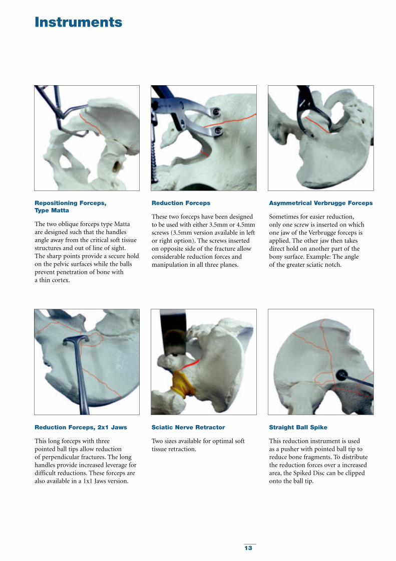
Repositioning Forceps, Type Matta
The two oblique forceps type Mattaare designed such that the handlesangle away from the critical soft tissuestructures and out of line of sight.The sharp points provide a secure holdon the pelvic surfaces while the ballsprevent penetration of bone with a thin cortex.
Reduction Forceps, 2x1 Jaws
This long forceps with three pointed ball tips allow reduction of perpendicular fractures. The longhandles provide increased leverage fordifficult reductions. These forceps arealso available in a 1x1 Jaws version.
Reduction Forceps
These two forceps have been designedto be used with either 3.5mm or 4.5mmscrews (3.5mm version available in leftor right option). The screws insertedon opposite side of the fracture allowconsiderable reduction forces andmanipulation in all three planes.
Sciatic Nerve Retractor
Two sizes available for optimal softtissue retraction.
Asymmetrical Verbrugge Forceps
Sometimes for easier reduction,only one screw is inserted on whichone jaw of the Verbrugge forceps isapplied. The other jaw then takesdirect hold on another part of thebony surface. Example: The angle of the greater sciatic notch.
Straight Ball Spike
This reduction instrument is used as a pusher with pointed ball tip toreduce bone fragments. To distributethe reduction forces over a increasedarea, the Spiked Disc can be clippedonto the ball tip.
Instruments

14
Stainless Plate Holes TitaniumSteel Length REFREF mm
425702 26.5 2 N/A425703 42.5 3 4 N/A425704 58.5 4 4 N/A425705 74.5 5 N/A425706 90.5 6 4 N/A425707 106.5 7 N/A425708 122.5 8 4 N/A425709 138.5 9 N/A425710 154.5 10 4 N/A425711 170.5 11 N/A425712 186.5 12 4 N/A425713 202.5 13 N/A425714 218.5 14 4 N/A425715 234.5 15 N/A425716 250.5 16 4 N/A425718 282.5 18 N/A425720 314.5 20 N/A
Stainless Plate Holes TitaniumSteel Length REFREF mm
425754 46.5 4 4 N/A425755 58.5 5 N/A425756 70.5 6 4 N/A425757 82.5 7 N/A425758 94.5 8 4 N/A425759 106.5 9 N/A425760 118.5 10 4 N/A425761 130.5 11 N/A425762 142.5 12 4 N/A425763 154.5 13 N/A425764 166.5 14 4 N/A425765 178.5 15 N/A425766 190.5 16 4 N/A425767 202.5 17 N/A425768 214.5 18 4 N/A425770 238.5 20 N/A425772 262.5 22 N/A
Stainless Plate Holes TitaniumSteel Length REFREF mm
425604 58.5 4 4 N/A425605 74.5 5 4 N/A425606 90.5 6 4 N/A425607 106.5 7 N/A425608 122.5 8 4 N/A425609 138.5 9 N/A425610 154.5 10 4 N/A425611 170.5 11 N/A425612 186.5 12 4 N/A425613 202.5 13 N/A425614 218.5 14 4 N/A425615 234.5 15 N/A425616 250.5 16 4 N/A425618 282.5 18 N/A425620 314.5 20 N/A
Stainless Plate Holes TitaniumSteel Length REFREF mm
425654 58.5 4 4 N/A425655 74.5 5 4 N/A425656 90.5 6 4 N/A425657 106.5 7 N/A425658 122.5 8 4 N/A425659 138.5 9 N/A425660 154.5 10 4 N/A425661 170.5 11 N/A425662 186.5 12 4 N/A425663 202.5 13 N/A425664 218.5 14 4 N/A425665 234.5 15 N/A425666 250.5 16 4 N/A425668 282.5 18 N/A425670 314.5 20 N/A
Stainless Plate Holes TitaniumSteel Length REFREF mm
425794 58.5 4 4 N/A425796 90.5 6 4 N/A
Ordering Information – Plates
MPS Curved R108 Plate
MPS Curved R88 Plate
MPS Symphysis Plate, R75
MPS Straight Plate
MPS Flex Plate (annealed)
4 Recommended set item

15
Stainless Steel Screw TitaniumREF Length mm REF
338610 10 N/A338612 12 4 N/A338614 14 4 N/A338616 16 4 N/A338618 18 4 N/A338620 20 4 N/A338622 22 4 N/A338624 24 4 N/A338626 26 4 N/A338628 28 4 N/A338630 30 4 N/A338632 32 4 N/A338634 34 4 N/A338636 36 4 N/A338638 38 4 N/A338640 40 4 N/A338642 42 N/A338644 44 N/A338645 45 4 N/A338646 46 N/A338648 48 N/A338650 50 4 N/A338655 55 4 N/A338660 60 4 N/A338665 65 4 N/A338670 70 4 N/A338675 75 4 N/A338680 80 4 N/A338685 85 4 N/A338690 90 4 N/A338695 95 4 N/A338700 100 4 N/A338705 105 4 N/A338710 110 4 N/A338715 115 N/A338720 120 N/A
Stainless Steel Screw TitaniumREF Length mm REF
341030 30 N/A341035 35 N/A341040 40 N/A341045 45 N/A341050 50 4 N/A341055 55 4 N/A341060 60 4 N/A341065 65 4 N/A341070 70 4 N/A341075 75 4 N/A341080 80 4 N/A341085 85 4 N/A341090 90 4 N/A341095 95 4 N/A341100 100 4 N/A341105 105 4 N/A341110 110 4 N/A341115 115 4 N/A341120 120 4 N/A341125 125 4 N/A341130 130 4 N/A341135 135 N/A341140 140 N/A341145 145 N/A341150 150 N/A
Stainless Diameter Thickness TitaniumSteel mm mm REFREF
390016 13.0 4 1.5 N/A390019 9.0 4 1.0 N/A
Stainless Steel Screw TitaniumREF Length mm REF
340614 14 4 N/A340616 16 4 N/A340618 18 4 N/A340620 20 4 N/A340622 22 4 N/A340624 24 4 N/A340626 26 4 N/A340628 28 4 N/A340630 30 4 N/A340632 32 4 N/A340634 34 4 N/A340636 36 4 N/A340638 38 4 N/A340640 40 4 N/A340642 42 4 N/A340644 44 4 N/A340646 46 4 N/A340648 48 4 N/A340650 50 4 N/A340652 52 4 N/A340654 54 4 N/A340655 55 N/A340656 56 4 N/A340658 58 4 N/A340660 60 4 N/A340662 62 N/A340664 64 N/A340665 65 4 N/A340666 66 N/A340668 68 N/A340670 70 4 N/A340672 72 N/A340675 75 4 N/A340676 76 N/A340680 80 4 N/A340685 85 4 N/A340690 90 4 N/A340695 95 4 N/A340700 100 4 N/A340705 105 4 N/A340710 110 4 N/A340715 115 4 N/A340720 120 4 N/A340725 125 N/A340730 130 N/A340735 135 N/A340740 140 N/A340745 145 N/A340750 150 N/A
Stainless Steel Screw TitaniumREF Length mm REF
342045 45 N/A342050 50 4 N/A342055 55 4 N/A342060 60 4 N/A342065 65 4 N/A342070 70 4 N/A342075 75 4 N/A342080 80 4 N/A342085 85 4 N/A342090 90 4 N/A342095 95 4 N/A342100 100 4 N/A342105 105 4 N/A342110 110 4 N/A342115 115 4 N/A342120 120 4 N/A342125 125 4 N/A342130 130 4 N/A342135 135 N/A342140 140 N/A342145 145 N/A342150 150 N/A
Ordering Information – Screws
3.5mm Cortical Screw, Self Tapping
6.5mm Cancellous Screw, 16mm Thread
Washer
6.5mm Cancellous Screw, 32mm Thread
4.5mm Cortical Screw, Self Tapping
4 Recommended set itemFor full range of standard non-self tapping screws pleaserefer to the Stryker® Trauma Product Catalogue.

164 Recommended set item
Reference Description
710312 4 Template MPS Flex plate, 8 H710313 4 Template MPS Flex plate, 18 H710315 4 Template MPS Straight plate, 8 H710316 4 Template MPS Straight plate, 18 H710318 4 Template MPS Curved R108 plate, 8 H710319 4 Template MPS Curved R108 plate, 18 H710321 4 Template MPS Curved R88 plate, 8 H710322 4 Template MPS Curved R88 plate, 18 H
702902 4 Bending Iron for Pelvic plates
702903 4 Bending Plier
702921 4 Small Repositioning Forceps,type Matta
702922 4 Large Repositioning Forceps,type Matta
702924 4 Repositioning Forceps for Screws ø4.5mm
702925 4 Repositioning Forceps for Screwsø3.5mm, Right
702947 4 Repositioning Forceps for Screwsø3.5mm, Left
702926 4 Small Reduction Forceps with PointsL130mm
702927 4 Large Reduction Forceps with PointsL200mm
702928 4 Faraboef Forceps L190mm702929 4 Faraboef Forceps L250mm
702930 4 Repositioning Forceps, 2x1 Jaws702948 4 Repositioning Forceps, 1x1 Jaws
702932 4 Repositioning Forceps with SerratedJaws L140mm
700641 4 Modified Verbrugge Forceps
700647 4 Curved Chisel
Optional Instruments
390086 Reduction Pin ø6.0mm x 150mm,AO Fitting
390087 Reduction Pin ø6.0mm x 180mm,AO Fitting
700367 Large T-Handle, AO Quick Coupling702845 Screwdriver Hex. 2.5mm, L280,
with Canevasit Handle702846 Screwdriver Hex. 3.5mm, L300,
with Canevasit Handle702847 Straight Ball Spike L300mm,
with Canevasit Handle702848 Canevasit Handle Small, AO Coupling702849 Canevasit Handle Large, AO Coupling710311 Template MPS Flex plate, 5 H710314 Template MPS Straight plate, 5 H710317 Template MPS Curved R108 plate, 5 H710320 Template MPS Curved R88 plate, 5 H
Reference Description
700351 4 Calibrated Drill Bit ø2.5mm x180mm, AO Fitting
700355 4 Calibrated Drill Bit ø2.5mm x230mm, AO Fitting
700353 4 Drill Bit ø3.5mm x 180mm, AO Fitting
700356 4 Calibrated Drill Bit ø3.2mm x180mm, AO Fitting
700357 4 Calibrated Drill Bit ø3.2mm x230mm, AO Fitting
700354 4 Drill Bit ø4.5mm x 180mm, AO Fitting
702804 4 Tap ø3.5mm x 180mm, AO Fitting702806 4 Tap ø4.5mm x 180mm, AO Fitting702807 4 Tap ø6.5mm x 180mm, AO Fitting
702811 4 Countersink ø6.0mm x 100mm,AO Fitting
702812 4 Countersink ø8.0mm x 100mm,AO Fitting
702842 4 Screwdriver Hex 2.5mm, L280mm702843 4 Screwdriver Hex 3.5mm, L300mm
702851 4 Screwdriver Hex 2.5mm, L165mm,AO Fitting
702853 4 Screwdriver Hex 3.5mm, L165mm,AO Fitting
702861 4 Screwdriver Holding Sleeve forScrews ø3.5mm
702862 4 Screwdriver Holding Sleeve forScrews ø4.5/6.5mm
702417 4 Double Drill Guide ø3.2/4.5mm702418 4 Double Drill Guide ø2.5/3.5mm
702876 4 Depth Gauge 0-110mm, for Screws ø2.7/3.5/4.0mm, Titanium
702877 4 Depth Gauge 0-150mm, for Screws ø4.5/6.5mm,Titanium
702911 4 Straight Ball Spike
702912 4 Straight Ball Spike, AO Fitting
702923 4 Spiked Disk
702427 4 T-handle small, AO Quick Coupling
702428 4 Small Teardrop-Handle,AO Quick Coupling
702429 4 Large Teardrop-Handle,AO Quick Coupling
702915 4 Small Sciatic Nerve Retractor702916 4 Large Sciatic Nerve Retractor
390083 4 Reduction Pin ø5.0mm L150mm,AO Fitting
390084 4 Reduction Pin ø5.0mm L180mm,AO Fitting
900106 4 Screw Forceps
Ordering Information – Instruments

174 Recommended set item
REF Description
901686 4 Screw Rack with Lids (Implant Case Screws)
901618 4 Plastic Base (Basic Instruments)
901619 Metal Base Optional (Basic Instruments)
901687 4 Plastic Lid (Basic Instruments)
901688 4 Upper Tray Insert(Basic Instruments)
901689 4 Lower Tray Insert(Basic Instruments)
901690 4 Plastic Base (Reduction Instruments)
901691 4 Plastic Lid (Reduction Instruments)
REF Description
901557 4 Plastic Base (Implant Case Plates)901557 4 Plastic Base (Implant Case Screws)
901591 Metal Base Optional (Implant Case Plates)
901591 Metal Base Optional(Implant Case Screws)
901681 4 Plastic Lid (Implant Case Plates)
901682 4 Tray Insert (Implant Case Plates)
901683 4 Rack with Lid # 1(Implant Case Plates)
901684 4 Rack with Lid # 2(Implant Case Plates)
901685 4 Plastic Lid (Implant Case Screws)
Ordering Information – Cases and Trays

18
R.Niklaus / 5.12.2001
R.Niklaus / 5.12.2001
R.Niklaus / 5.12.2001
It is necessary to correctly shape the plate in such a way as to perfectly apply itto the reduced contour of the pelvis or the acetabulum.
The fitting of the plate on the bonysurface should be as perfect as possibleso the insertion of screws will notcause the fragments to change position(Figure 1).
During plating and screw insertion,it is always the bone which is drawntowards the plate, not the platetowards the bone (Figure 2).
It’s an important fact that the platemust be bent, as far as possible, in thespaces between the holes, so as to alterthem as little as possible (Figure 6). Itis a well known fact that rectangularplates do not bend in a regular fashion
but rather at the level of their holes(Figure 7). Thus Sherman type plateswith equal hole spacing and narrowingbetween the holes, are best adapted tosuch shaping and allow for a perfectadaptation to the pelvic contours.
For a plate to apply perfectly on a bone, it must be possible to shape it in all directions:
• bend it along it’s main axis (Figure 3a, 3b)
• bend it along it’s main axis (twist),to give it an helicoidal shape (Figure 4a, 4b)
• bend it “on the flat” to adapt to thecurves of the iliac crest or the upperaspect of the pelvic brim, or to makeit possible to span a fragment of theposterior wall or posterosuperior wallalong it’s major axis (Figure 5a, 5b).
This type of bending should alwaysbe performed first since it is verydifficult to bend the plate in thisfashion after a main axis bend ortwist has been made.
Figure 5b
Figure 1 – Correct Figure 2 – Incorrect
R.Niklaus / 5.12.2001
Figure 7
Figure 6
R.Niklaus / 6.12.2001
Figure 3a Figure 4a
R.Niklaus / 6.12.2001
Figure 5a
Figure 3b Figure 4b
Correct
Precise fitting of the plate. No danger of displacement of the fragmentsduring screw insertion.
Incorrect
When tightening the screws, thefragment will be drawn towards the plate.
In certain instances it is desirable tocontour the plate to a slight mismatchwith the bone. Subsequent insertionand tightening of the screws causes theplate to manipulate the bone, thereforeaiding to obtain or maintain thereduction.
Additional Information
Plate Bending

19
Additional Information
Small Fragment Set
Basic Fragment Set
Other Stryker Plating Systems
A wide selection of plates, each featuringK-wire holes – for improved primarystabilisation; rounded plate ends – to facilitate the option of subcutaneousplate insertion; uniform hole spacingwith bi-directional holes offeringincreased screw angulation; as well asthe unique outer plate contouring are all features of the implant set.
A comprehensive screw range is enhanced not only by a new self-cutting design but by the inclusion of a small range of 2.7mm screws forindependent interfragmentary screwfixation obviating the need for anadditional screw set.
A full range of instrumentation is complimented by the unique rangeof reduction clamps and forceps.These non-standardised instrumentsoffer the Clinician new possibilities in their approach to small bonefracture reduction and fixation.
Featuring:
Modular Case design2.7mm cortical screws – self tapping3.5mm cortical screws – self tapping4.0mm cancellous screws – Partial thread4.0mm cancellous screws – Full threadDrill, Taps, Countersink – AO couplings3 diameters of K-wiresModular and Fixed Angle Drill GuidesCompression plateReconstruction plate1/3rd Tubular plateCloverleaf plateT-plateOblique T-plateCalcaneal plateElastosil® HandlesCombined Hook and Ball SpikeCombined Periosteal and FreerElevatorHohmann RetractorsBending Irons and TemplatesOptional Bending PlierForceps
This system offers Clinicians multiple options for the most common treatments of small bone fractures.
A new selection of seven plates,each featuring K-wire and reductionholes – for improved primarystabilisation; rounded plate ends – to facilitate the option of subcutaneousplate insertion; uniform hole spacingwith bi-directional holes offeringincreased screw angulation; as well as the unique outer plate contouringare all features of the implant set.
A comprehensive screw range isenhanced by a self-cutting design.A full range of instrumentation iscomplemented by the unique range of reduction clamps and forceps.These non-standardised instrumentsoffer the Clinician new possibilities in their approach to large-bonefracture reduction and fixation.
Featuring:
Modular Case design
4.5mm cortical screws – self tapping
6.5mm cancellous screws – 16mm thread
6.5mm cancellous screws – 32mm thread
6.5mm cancellous screws – Full thread
Drill, Taps, Countersink – AO couplings
2 Diameters of K-wires
Modular and Fixed Angle Drill Guides
Compression plate – Broad
Compression plate – Narrow
T-plate
T-Buttress plate
L-Buttress plate
Reconstruction plate
Elastosil® Handles on all fixed handleinstruments
Combined Hook and Ball Spike
Combined Periosteal and Freer Elevator
Hohmann Retractors
Bending Irons and Templates
Optional Table Plate Bender Plier
Forceps
This System offers Clinicians multiple options for the most common treatmentsof long-bone fractures.

Biologics
Surgical Products
Neuro & ENT
Trauma, Extremities & Deformities
Biologics
Surgical Products
Neuro & ENT
Trauma, Extremities & Deformities
Stryker Trauma AGBohnackerweg 1CH-2545 SelzachSwitzerland
www.osteosynthesis.stryker.com
The information presented in this brochure is intended to demonstrate a Stryker product. Always refer to the packageinsert, product label and/or user instructions before using any Stryker product. Surgeons must always rely on their ownclinical judgment when deciding which products and techniques to use with their patients. Products may not be availablein all markets. Product availability is subject to the regulatory or medical practices that govern individual markets. Pleasecontact your Stryker representative if you have questions about the availability of Stryker products in your area.
Stryker Corporation or its subsidiary owns the registered trademark: Stryker Wacker-Chemie GmbH owns the following trademark: Elastosil
Literature Number: 982184LOT B1506
Copyright © 2006 StrykerPrinted in Switzerland