squareness error mapping of a coordinate measuring machine ... · squareness error mapping of a...
TRANSCRIPT
1
SLAC-PUB-5836 June 1992 (4
SQUARENESS ERROR MAPPING OF A COORDINATE MEASURING MACHINE USING A %-DIMENSIONAL REFERENCE OBJECT.*
B.T.Wand, V.E.Bressler, R.E.Ruland
Stanford Linear Accelerator Center, Stanford University, Stanford Ca, 94309
. .
.~ 1. 2.
.- 3. 4. 5.
- --.I 6. 7.
ABSTRACT.. ................................................................................................................................ 2 INTRODUCTION.. ...................................................................................................................... .2 CONCEPT OF METHOD ............................................................................................................ .2 BORE PLATE .............................................................................................................................. 3 MEASUREMENTS ...................................................................................................................... 3 RESULTS ..................................................................................................................................... .3 ACKNO%‘LEDGMENTS ............................................................................................................ .4 .
Appendix A : CONCEPT OF METHOD Appendix B: BORE PLATE CALIBRATION Appendix C: MEASUREMENTS Appendix D: RESULTS
(Submitted for Publication)
* Work supported by the Department of Energy Contract DE-AC03-76SF00515
STANFORD LINEAR ACCELERATOR CENTER SURVEY AND ALIGNMENT TEAM
- .-’
1. ABSTRACT
This publication describes and documents the calibration procedure to improve the accuracy (as specified by the manufacturer) of a MITUTOYO (X06-10 CMM (Coordinate Measuring Machine) by 50 %. This goal was achieved with the assistance of the PTB (Physikalische Technische Bundesanstah) in
-- Braunschweig, Germany. The PTB is the equivalent of the NIST in Washington DC.
; I*-
2. INTRODUCTION
.I Smaller and therefore cheaper CMMs (Coordinate Measuring Machines) are becoming .-
_- quite popular. Considering that it has been only a few years since the so-called bench top CMMs first appeared, the number of such,units now in the market is quite surprising. For the
_ -.. _ fidticilization effort of the. Final Focus Test - Beam (FFTB) electro magnets a CMM was .- .--
required which could be operated next to the fully powered magnets. A bench top CMM was essential and a MITUTOYO C806-10 was selected. Although these bench top CMMs provide fairly good measurement results, they are less accurate and less accurately assembled than a first order CMM. A method is suggested by Dr. Trapetl to improve the accuracy of CMMs. The flB developed a software package to determine 22 error parameters of a CMM. These 22
-parameters define a column type CMM completely. Unfortunately this software package is still unavailable but an agreement was reached that the PTB will assist us to determine a subset of error parameters. The squareness errors of a CMM usually account for
_ 80% of the error budget. Therefore we decided that six parameters ( three squareness and three non-linearity parameters) will be .a sufficient number of parameters to be determined for our MITUTOYO C806-10 CMM.
‘Dr.-Ing.‘E. Trapet, Dr.-Ing. F. W%ldele; Determination of the parametric errors of Coordinate Measuring Machines and Machine Tools using reference objects. Appendix E.
3. CONCEPT OF METHOD
Trapet’s method is easy to use and only low priced equipment is needed. It achieves a satisfactory accuracy and facilitates tracebility. A pre-calibrated, 2-dimensional object (bore plate) is measured in four defined positions in the working space. The software package derives subsequently from the plate measurements the final parametric errors of the CMM. It is well suited for calibration purposes.
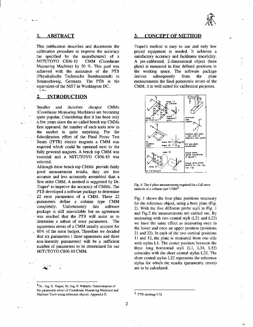
Fig. 1: The 6 plate measurements required for a full error analysis of a column type CMM2
Fig. 1 shows the four plate positions necessary for the reference object, using a bore plate (Fig. 2). With the five different probe styli in Fig. 1 and Fig.2 the measurements are carried out. By measuring with two central styli (L21 and L22) we have the same effect as measuring once in the lower and once an upper position (positions 21 and 22). In each of the two vertical positions 11 and 12, the plate is me&red from one side with stylus Ll. The center position between the three long horizontal styli (Ll, L31, L32) coincides with the short central stylus L22. The short central stylus L22 represents the reference stylus for which the results (parametric errors) are to be calculated.
2 PTB drawing 5.32
2
I :
L21=L22+100 mm extension
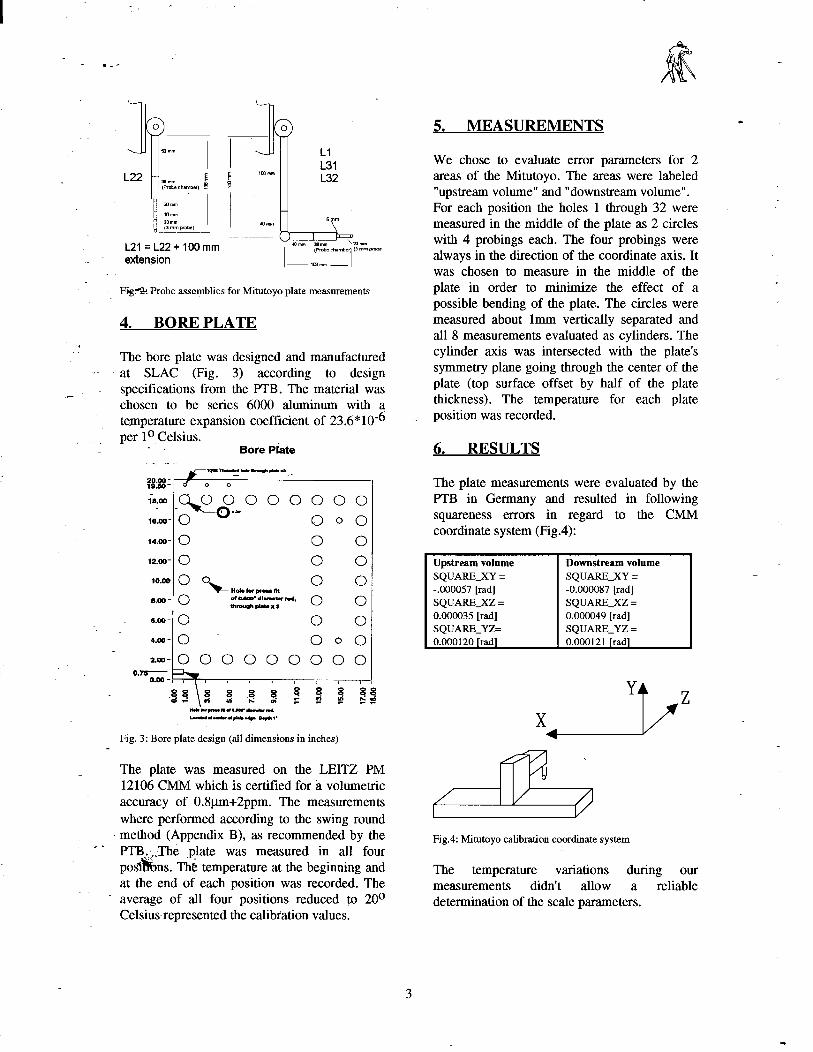
Fig.?% Probe assemblies for Mitutoyo plate measurements
Ll L31 L32
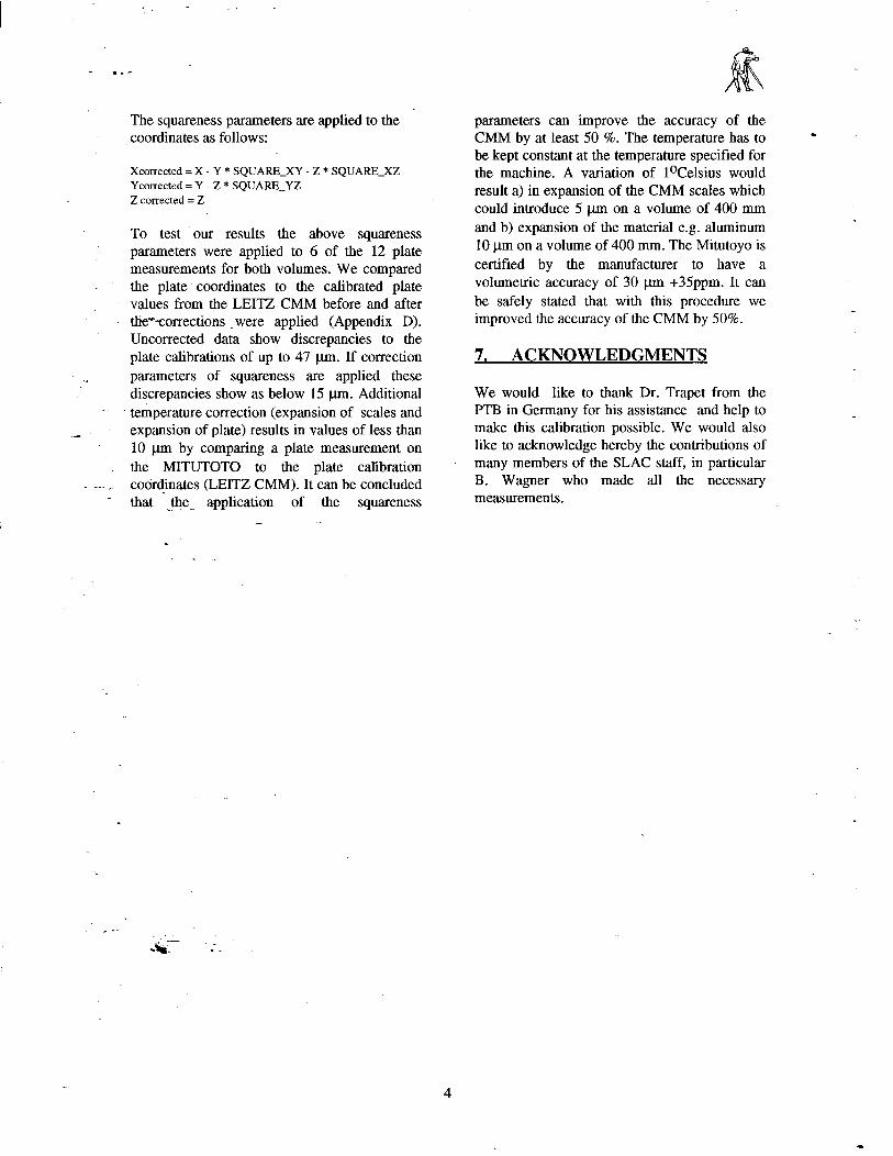
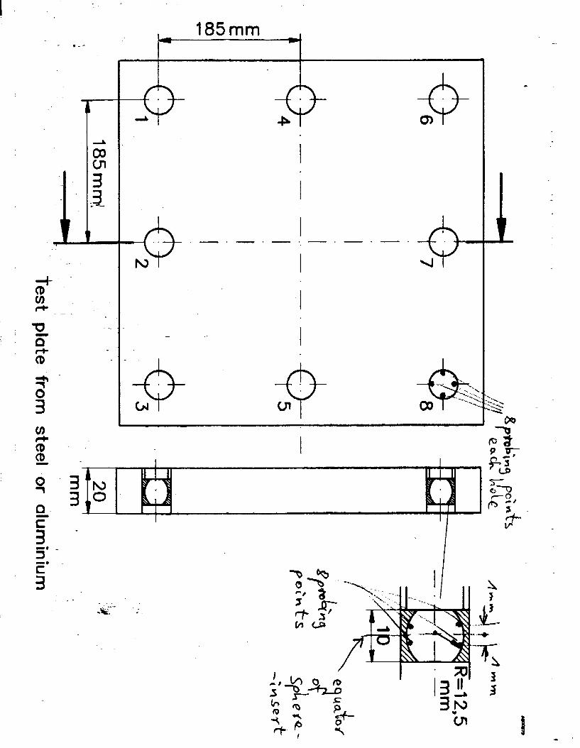
4. BORE PLATE . .
The bore plate was designed and manufactured .- at SLAC (Fig. 3) according to design
_- specifications from the PTB. The material was chosen to be series 6000 aluminum with a
_ temperature expansion coefficient of 23.6*10s6 per lo Celsius.
Bore Piate . . . IC-N.-mhCa~e - $?.#I
iii -$iiBO 0 0 0 0 0 lE.cc 0 000
14.00- 0 0 0
12.00- 0 0 0
1o.w 0 %
0 0 “oh hw pr lit
o.w- 0 of-*dluMbr~ 0 ~rough~Xl 0
o.w- 0 0 0
4.m- 0 000
~.~-000000000 0.7-
0.00-,7- I I
S$ f 5 2 f e 6 ‘s s i3 k$ r s
~ccm.l-.u,.d LruI”“w.lc.ds. c.+,’
Fig. 3: Bore plate design (all dimensions in inches)
The plate was measured on the LEITZ PM 12106 CMM which is certified for g volumetric accuracy of 0.8pm+2ppm. The measurements where performed according to the swing round
. method (Appendix B), as recommended by the ’ -. PTI!&._Th& .plate was measured in all four
posY%ns. The-temperature at the beginning and at the end of each position was recorded. The average of all four positions reduced to 20° Celsius-represented the calibiation values.
MEASUREMENTS a .
We chose to evaluate error parameters for 2 areas of the Mitutoyo. The areas were labeled “upstream volume” and “downstream volume”. For each position the holes 1 through 32 were measured in the middle of the plate as 2 circles with 4 probings each. The four probings were always in the direction of the coordinate axis. It was chosen to measure in the middle of the plate in order to minimize the effect of a possible bending of the plate. The circles were measured about lmm vertically separated and all 8 measurements evaluated as cylinders. The cylinder axis was intersected with the plate’s symmetry plane going through the center of the plate (top surface offset by half of the plate thickness). The temperature for each plate position was recorded.
6. RESULTS
The plate measurements were evaluated by the PTB in Germany and resulted in following squareness errors in regard to the CMM coordinate system (Fig.4):
Fig.4: Mitutoyo calibration coordinate system
The temperature variations during our measurements didn’t allow a reliable determination of the scale parameters.
I :
- .-’
The squareness parameters are applied to the coordinates as follows:
Xcorrected = X - Y * SQUARE_XY - Z * SQUARE_XZ Ycorrected = Y - Z * SQUARE-YZ Z corrected = Z
To test our results the above squareness parameters were applied to 6 of the 12 plate measurements for both volumes. We compared the plate coordinates to the calibrated plate values from the LEITZ CMM before and after the*-corrections were applied (Appendix D). Uncorrected data show discrepancies to the plate calibrations of up to 47 pm. If correction parameters of squareness are applied these discrepancies show as below 15 pm. Additional temperature correction (expansion of scales and expansion of plate) results in values of less than 10 pm by comparing a plate measurement on the MITUTOTO to the plate calibration codr$nates (LEITZ CMM). It can be concluded that the application of the squareness c --
- .
parameters can improve the accuracy of the CMM by at least 50 %. The temperature has to be kept constant at the temperature specified for the machine. A variation of loCelsius would result a) in expansion of the CMM scales which could introduce 5 pm on a volume of 400 mm and b) expansion of the material e.g. aluminum 10 pm on a volume of 400 mm. The Mitutoyo is certified by the manufacturer to have a volumetric accuracy of 30 pm +35ppm. It can be safely stated that with this procedure we improved the accuracy of the CMM by 50%.
7. ACKNOWLEDGMENTS
We would like to thank Dr. Trapet from the PTB in Germany for his assistance and help to make this calibration possible. We would also like to acknowledge hereby the contributions of many members of the SLAC staff, in particular B. Wagner who made all the necessary measurements.

- .-’
A P P E N D IX A
S T A N F O R D L I N E A R A C C E L E R A T O R C E N T E R S U R V E Y A N D A L I G N M E N T T E A M
Jt z BZmcJx u’ v point
2 q
. . ..-
q
.
x -: lo o 7
0 U
machine table
meas. .**
,*:
meas. 21 ‘.=
The 6 plate measurements required for a full
meus. 32
X M Xmax/2.
kinematic
machine zero point = zero point of kinematic axis systen
U,V are pfate coordinates
al woys state ten ter coordinates of.. sphere 1
GIWJIS state probe’ lengths Lj, L21, L22, L31, L32
- .-’ P robe se tups fo r M itu toyo p late m e a s u r e m e n ts
II ( 2 . 0
I I I u 5 o m m
L 2 f 3 8 A
-~
E ( P r o b e c h a m b e r ) 5
.I
2 0 m m .-
_ - 1 1 0 m m Z Q m m (3 m m probe )
4 2 2 + lO O m m ex te n $ iQ rj
,u E
1 O O m m
5
4 0 m m
L l L 3 1 L 3 2
5 ‘f”
I” 4 0 m m 3 8 m m 2 0 m m
( R o b e c h a m b e r ) ( 3 m m p r o b e )
m m m -I
- .-’
M E M O R A N D U M S L A C S U R V E Y &
A L IG N M E N T G R O U P
T E L E P H O N E ( 4 1 5 ) 9 2 6 - 2 2 8 6 B IN# 2 1
_ -TO : P U R C H A S ING ( - - -2 cc? - - R o b e r t R u l a n d F R O M : B e m d W a n d i 1 D A T E : 1 - 1 3 - 9 2 3
.I S U B J E C T : S o le source justi f ication fo r FFIB C M M cal ibrat ion
_- T h e F F T B C o o r d i n a te M e a s u r e m e n t M a c h i n e ( C M M ) f rom M ITUTO Y O d o e s n ’t m e e t th e accuracy r e q u i r e m e n ts wh ich a r e requ i red o f F F T B m a g n e t fidnci l izat ion appl icat ion. A p r o c e d u r e d e v e l o p e d by
_ .. _ th e P T B , th e G e r m a n equ iva len t o f o u r N IS T , w o u l d a l low us to m a p th e e r ro r p a r a m e ters o f th e C M M - l ike squa reness , s t ra ightness a n d l inear i ty o f th e 3 axis. W ith th o s e er ro rs m a p p e d it can b e expec te d th a t . . - -
w e h a v e c o m p e n s a te d fo r w 8 Q % o f th e to ta l e r ro r b u d g e t. P T B is wi l l ing to assist us with th is e r ro r m a p p ing o f th e C M M fo r M 6 0 0 0 D M ( - !$ - !O O O ). T h e P T B is th e on ly facility in th e wor ld wh ich is capab le o f r e n d .e r i ng th is assistance.
Dr. T r a p e t Physikal isch Techn ische B u n d e s a n s talt, L a b o r 5 .3 2 B u n d e s a l l e e 1 0 0 , P o s tfach 3 3 4 5 D - 3 3 0 0 B raunschwe ig F A X 0 1 1 - 4 9 - 5 3 1 - 5 9 2 3 0 0 6 P h o n e : 0 1 l - 4 9 - 5 3 1 - 5 9 2 - 5 3 2 0

I :
- .-’
APPENDIX B
-” --
STANFORD LINEAR ACCELERATOR CENTER SURVEY AND ALIGNMENT TEAM
- .-’
. .
_ -
. I= 5 c .- 2 ! a K .- 2 ii .- P = a
0
0
‘0
0 0 0 0 0 0 0 0 0
0 0 -- 0 0 0 0 0 0 0 0 0 0 0
0
0
0 a
0 x
0
c
0
d 0 0 0 0 0 0
0
0
0
0
0 I 0 -l
0 0 ’8 C O O ’L L
W ’S L
W .& L
W ’C L
0 0 ’6
W ’L
. W ’S
- 0 0 ’8
- .-’ I I I
# I. 1 ! 1 I I A I- I A I
-
_: -- .‘*r’. .-.
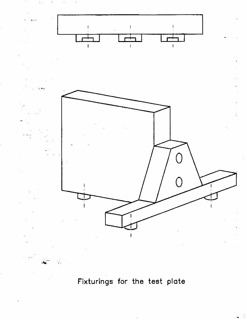
Fixturings for the test plate
- .-’
-. 3 -. c
3
. .
-9 o- -P
+
.
N
I
I
e.- . - . -
I
I
- . Q cJ4
I :
_-
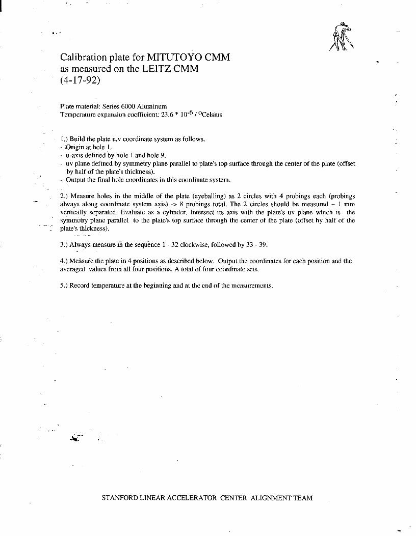
Calibration plate for MITUTOYO as measured on the LEITZ CMM (4- 17-92)
CMM
Plate material: Series 6000 Aluminum Temperature expansion coefficient: 23.6 * lo6 / OCelsius
1.) Build the plate u,v coordinate system as follows. - -&gin at hole 1. - u-axis defined by hole 1 and hole 9. - uv plane defined by symmetry plane parallel to plate’s top surface through the center of the plate (offset
by half of the plate’s thickness). - Output the final hole coordinates in this coordinate system.
2.) Measure holes in the middle of the plate (eyeballing) as 2 circles with 4 probings each (probings always along coordinate system axis) -> 8 probings total. The 2 circles should be measured e 1 mm vertically separated. Evaluate as a cylinder. Intersect its axis with the plate’s uv plane which is the symmetry plane parallel to the plate’s top surface through the center of the plate (offset by half of the plate’s thickness).
. . . . 3.) Always measure iii the sequence 1 - 32 clockwise, followed by 33 - 39.
-- 4.) Measure the plate in 4 positions as described below. Output the coordinates for each position and the averaged values from all four positions. A total of four coordinate sets.
5.) Record temperature at the beginning and at the end of the measurements.
STANFORD LINEAR ACCELERATOR CENTER ALIGNMENT TEAM
- .-’
. . cllu + Y -a rE I .-
C M + x-axis
0 u
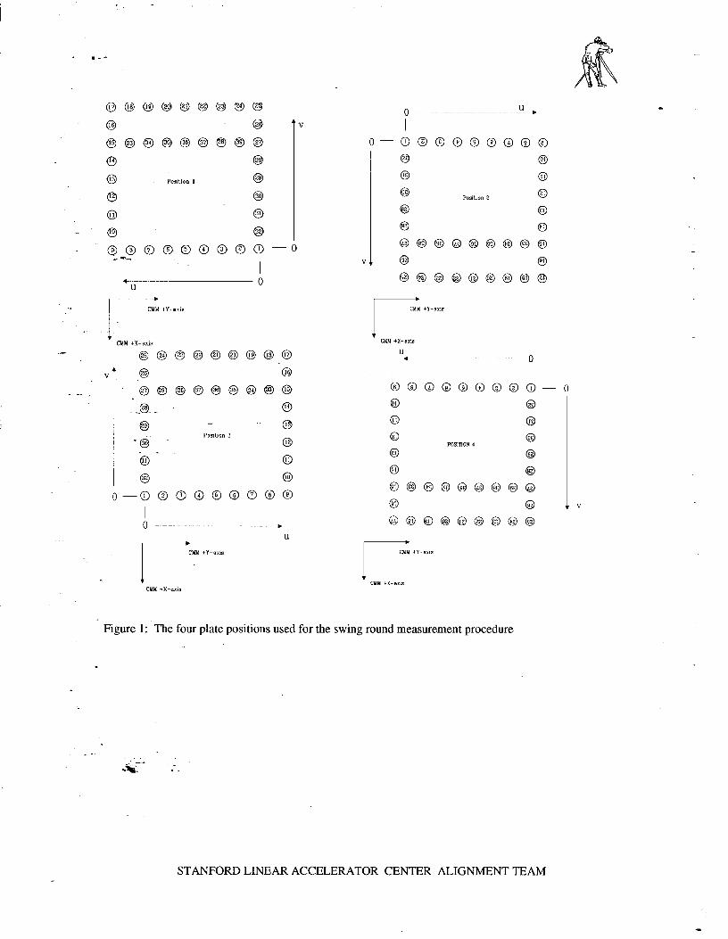
F igu re 1 : T h e fo u r p la te posi t ions u s e d fo r th e sw ing r o u n d m e a s u r e m e n t p r o c e d u r e
S T A N F O R D L INEAR A C C E L E R A T O R C E N T E R A L IG N M E N T T E A M
- .-’
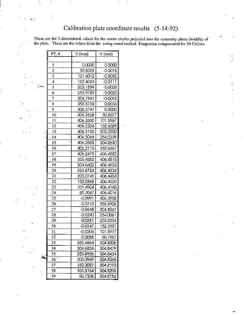
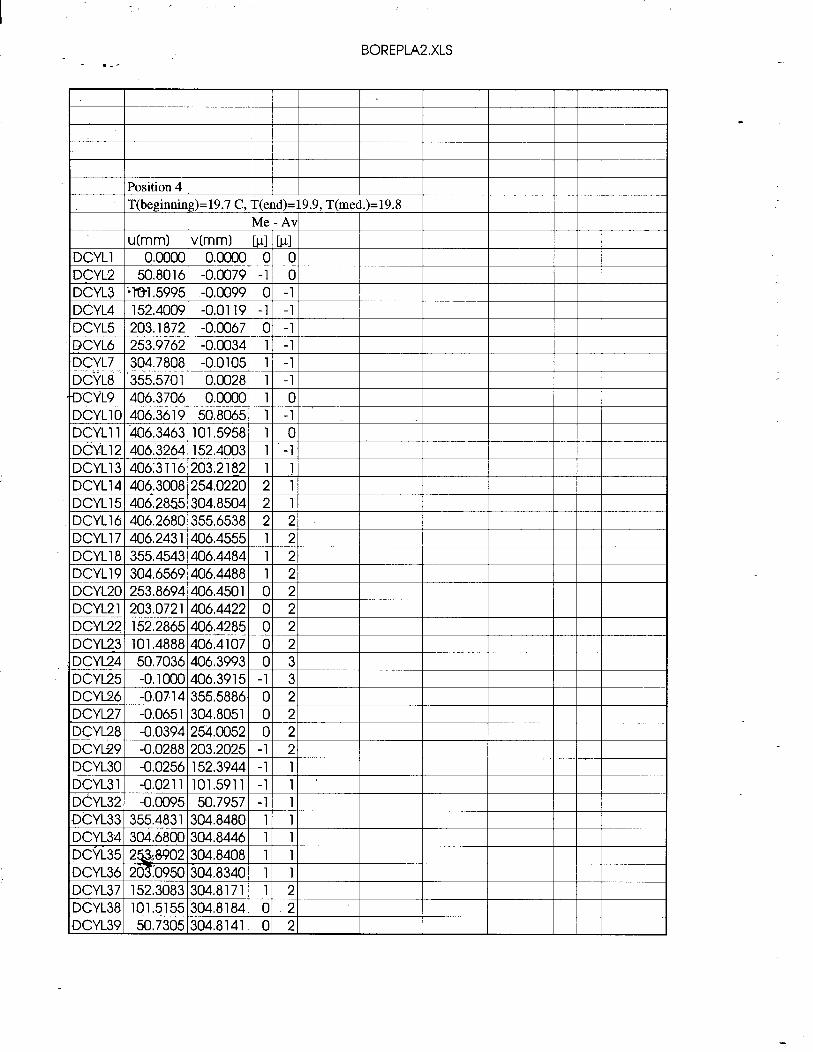
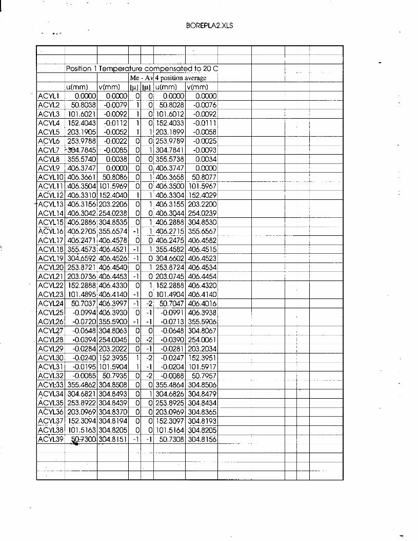
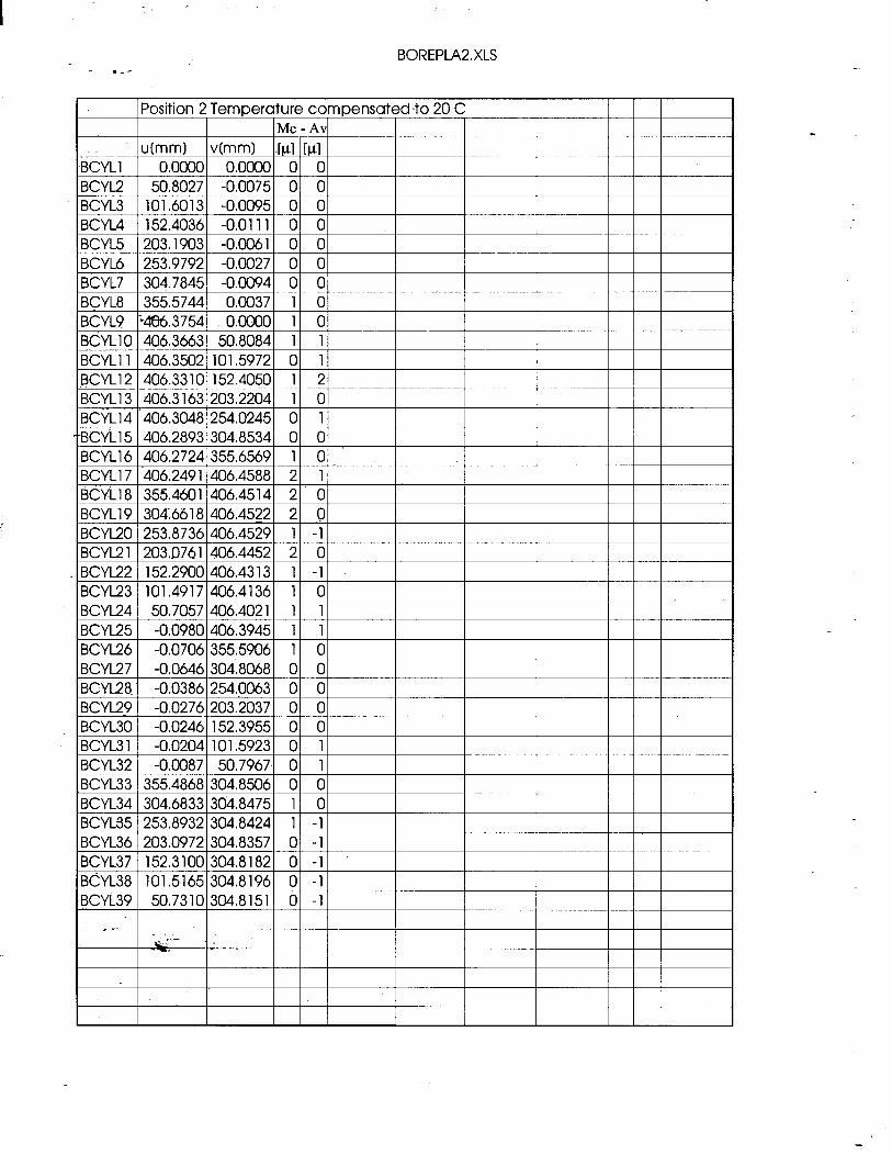
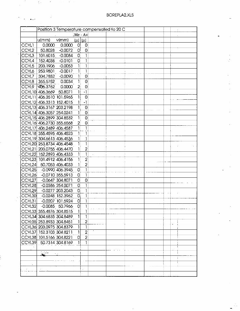
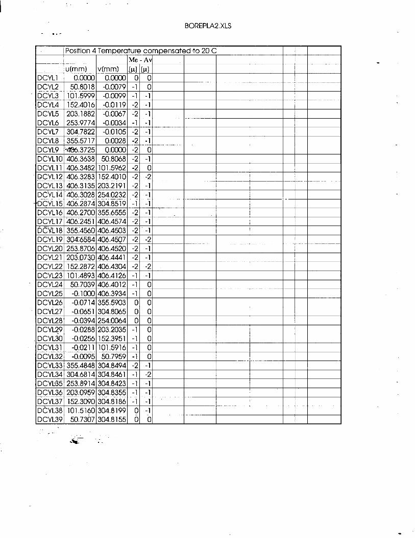
C a lib ra tio n p late coord ina te results (5 14 -92 )
T h e s e a r e th e 2 -d imens iona l va lues fo r th e cen te r circles p ro jec ted into th e s y m m e try p l a n e (m idd le ) o f th e plate. T h e s e a r e th e va lues f rom th e sw ing r o u n d m e th o d . T e m p e r a tu r c o m p e n s a te d fo r 2 0 Celsius.
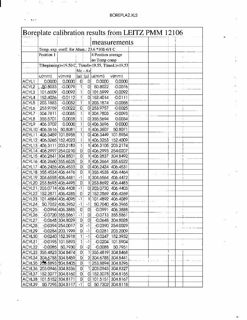
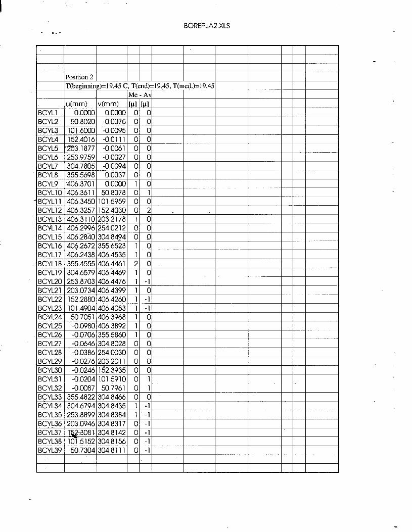
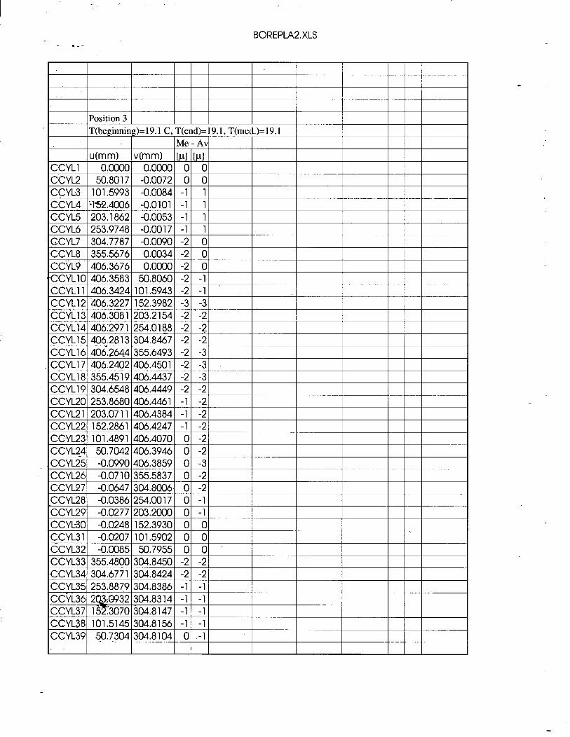
BOREPLA2,XLS
Boreplate calibration results from LEITZ PMM 12 106
ACYL37 152.3077 304.8160 0 0 152.3078 304.8155 ACYL38 101.5152 304.8171 0 0 101.5151 304.8167 ACYL39 50.7295 304.8117 -1 0 50.7302 304.8118
BOREPLA2.XLS
BCYl36 203.0946 304.8317 0 -1 BCYL37 1;&!+3081-304.8142 0 -1 BCYL38 101.5152 304.8156 0 -1 BCYL39 50.7304 304.8111 0 -1
- .-’ BOREPLA2,XLS
BOREPLA2.XLS
DCYL3 1 -0.0211 101.5911 -1 1 DCYL32 -0.0095 50.7957 -1 1 DCYL33 355.4831 304.8480 1 1 DCYL34 304.6800 304.8446 1 1
BOREPLA2,XLS - .--
BOREPLA2.XLS
- .-- BOREPLA2,XLS
BOREPLA2,XLS - .-’
DCYL37 152.3090 304.8186 -1 -1 DcYL38 101.5160 304.8199 0 -1 DCYL39 50.7307 304.8155 0 0

- .-’
-

- .-’
A P P E N D IX C
-” --
S T A N F O R D L I N E A R A C C E L E R A T O R C E N T E R S U R V E Y A N D A L I G N M E N T T E A M
- .-’
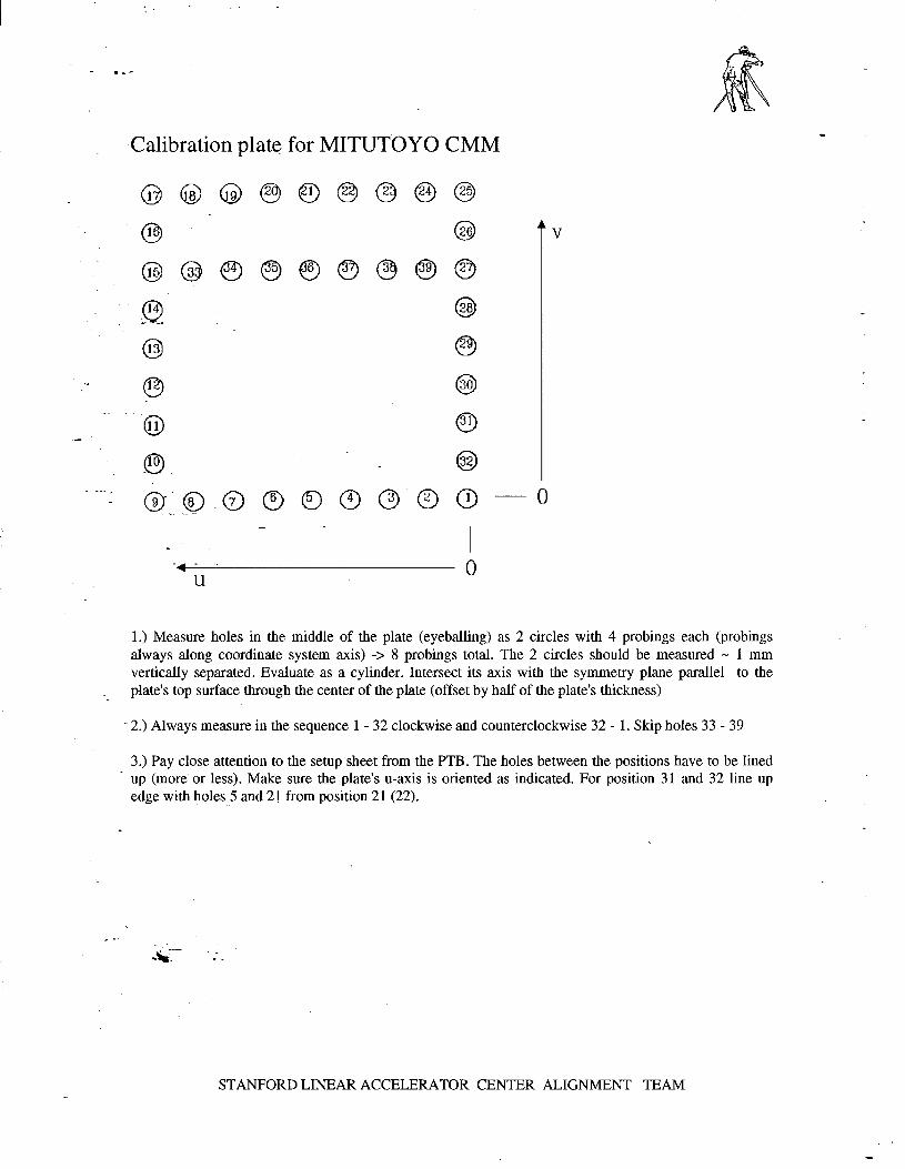
C a lib ra tio n p late fo r M ITUTO Y O C M M
0
- . U
0
1 .) M e a s u r e ho les in th e m idd le o f th e p la te (eyeba l l ing) as 2 circles with 4 p rob ings e a c h (p rob ings a lways a l o n g coo rd ina te system axis) - > 8 p rob ings to tal. T h e 2 circles shou ld b e m e a s u r e d M 1 m m vert ical ly s e p a r a te d . Eva lua te as a cyl inder. In tersect its axis with th e s y m m e try p l a n e para l le l to th e
.- p la te’s to p sur face th r o u g h th e cen te r o f th e p la te (o ffse t by hal f o f th e p la te’s th ickness)
-2 .) A lways m e a s u r e in th e s e q u e n c e 1 - 3 2 c lockwise a n d c o u n terc lockwise 3 2 - 1 . Sk ip ho les 3 3 - 3 9
3 .) P a y c lose a tte n tio n to th e se tup s h e e t f rom th e P T B . T h e ho les b e tween th e posi t ions h a v e to b e l ined u p ( m o r e ’ o r less). M a k e su re th e p la te’s u-ax is is o r i en te d as indicated. Fo r pos i t ion 3 1 a n d 3 2 l ine u p e d g e with ho les 5 a n d 2 1 f rom posi t ion 2 1 (22 ) .
S T A N F O R D L INEAR A C C E L E R A T O R C E N T E R A L IG N M E N T T E A M
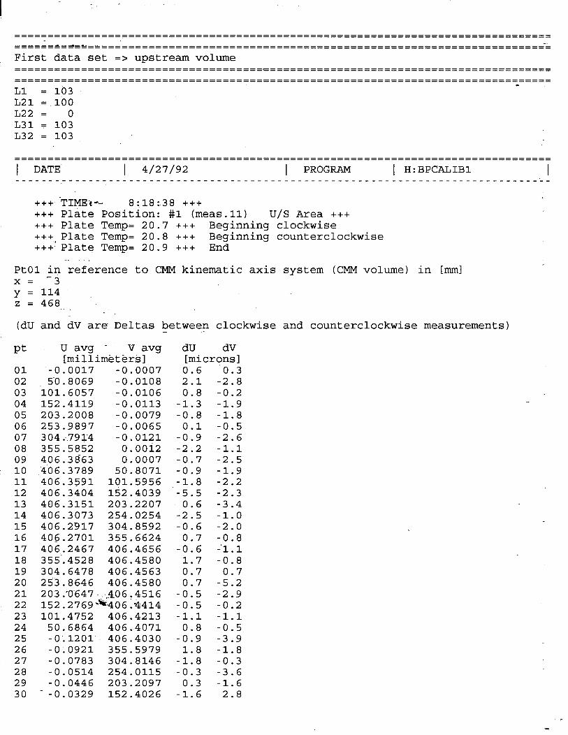
======t=~r’=====================================================================
First data set => upstream volume
----------------------------~~~~~~~~~~~~------------------------------------~-~~ -------------------------------------------------------------------------------- - Ll = 103 L21 = 100 L22= 0 L31 F 103 L32 = 103
-------------------------------------------------------------------------------- -------------------------------------------------------------------------------- 1 DATE 1 4/27/92 I PROGRAM 1 H:BPCALIBl I ---------------------------------------------------------------------------------
+++ -TIME*-- 8:18:38 +++ +++ Plate Position: #l (meas.11) U/S Area +++ +++ Plate Temp= 20.7 +++ Beginning clockwise +++ Plate Temp= 20.8 +++ ++-F“Plate Temp= 20.9 +++
Beginning counterclockwise End
.- PtOl in reference to CMM kinematic axis system (CMM volume) in [mm] x= Y= z =
.- 3 114 468 . . _ __
(dU and dV are- Deltas between clockwise and counterclockwise measurements) .
Pt dU dV [microns]
01 02 03 04 05 06 07 08 09 10 11 12 13 14 15 16 17 18 19 20 21 22 23 24 25 26 27 28 29 30
U avg - V avg [millim&t&rti]
'-0.0017 -0.0007 50.8069 -0.0108
101.6057 -0.0106 152.4119 -0.0113 203.2008 -0.0079 253.9897 -0.0065 304;.7914 -0.0121 355.5852 o.ooia 406.3863 0.0007 406.3789 50.8071 406.3591 101.5956 406.3404 152.4039 406.3151 203.2207 406.3073 254.0254 406.2917 304.8592 406.2701 355.6624 406.2467 406.4656 355‘.4528 406.4580 304.6478 406.4563 253.8646 406.4580 203.'0647,;..&06r4516 152.2769=406.-4414 101.4752 406.4213
50.6864 406.4071 -0.12Ol.m 406.4030 -0;0921 355.5979 -0.0783 304.8146 -0.0514 254.0115 -0.0446 203.2097
- -0.0329 152.4026
0.6 0.3 2.1 -2.8 0.8 -0.2
-1.3 -1.9 -0.8 -1.8
0.1 -0.5 -0.9 -2.6 -2.2 -1.1 -0.7 -2.5 -0.9 -1.9 -1.8 -2.2 -5.5 -2.3
0.6 -3.4 -2.5 -1.0 -0.6 -2.0
0.7 -0.8 -0.6 -'l.l
1.7 -0.8 0.7 0.7 0.7 -5.2
-0.5 -2.9 -0.5 -0.2 -1.1 -1.1
0.8 -0.5 -0.9 -3.9
1.8 -1.8 -1.8 -0.3 -0.3 -3.6
0.3 -1.6 -1.6 2.8

I :
31 --O-O253 101.5986 -1.0 -2.1 32 -0.0084 50.8001 -0.2 -0.2
. .
-
========J=======================================================================
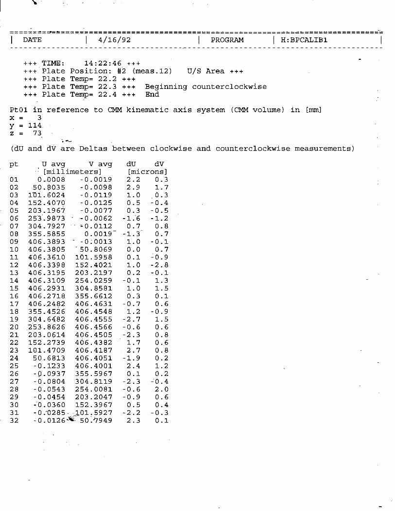
1 DATE I 4/16/92 I PROGRAM I H:BPCALIBl -1 ------r------------------------------~------------------------------------------
+++ TIME: 14:22:46 +++ +++ Plate Position: #i (meas.12) U/S Area +++ +++ Plate Temp= 22.2 +++ +++ Plate Temp= 22.3 +++ Beginning counterclockwise +++ Plate Temp= 22.4 +++ End
PtOl in reference to CMM kinematic axis system (CMM volume) in [mm] x= y = 11:. z= 73
(dU and dV are Deltas between clockwise and counterclockwise measurements)
Pt
01 02 03 04 05 06 07 08 09 10 11 12 13 14 15 16 17 18 19 20 21 22 23 24 25 26 27 28 29 30 31 32
V avg dU .v YmTZimeters]
dV [microns]
0,0008 -0.0019 2.2 0.3 50.8035 -0.0098 2.9 1.7
lU1.6024 -0.0119 1.0 0.3 152.4070 -0.0125 0.5 Lo.4 203.1967. -0.0077 0.3 -0.5 25-3-L-9873 - -0.0062 -1:6 -1.2 304.7927 --=0.0112 0.7 0.8 355.5855 0.0019- -1.3.. 0.7 406.3893 - --0;0013 1.0 -0.1 406.3805 -50.8069 0.0 0.7 406.3610 101.5958 0.1 -0.9 306.3398 152.4021 1.0 -2.8 406.3195 203.2197 0.2 -0.1 406.3109 254.0259 -0.1 1.3 406.2931 304.8581 1.0 1.5 406.2718 355.6612 0.3 0.1 4 0 6 i-2 4 e-2 406.4631 -0.7 0.6 355.4526 406.4548 1.2 -0.9 304.6482 406.4555 -2.7 1.5 253.8626 406.4566 -0.6 0.6 203.0614 406.4505 -2.3 0.8 152 -2739 406.4382 1.7 0.6 101.4709 406.4187 2.7 0.8
50.6813 406.4051 -1.9 0.2 -0.1233 406.4001 2.4 1.2 -0.0937 355.5967 0.1 0.2 -0.0804 304.8119 -2.3 LO.4 -O-.0543 254.0081 -0.6 2.0 -0.0454 203.2047 -0.9 0.6 -0.0360 152.3967 0.5 0.4 -O.-O285 -sc./0ir5927 -2.2 -0.3 -0.0126-x 50.?949 2.3 0.1
I :
================================================================================
I - .-’ I DATE 4/13/92 I PROGRAM 1 H:BPCALIBl I ______---_----______-----------------.-------------------------------------------
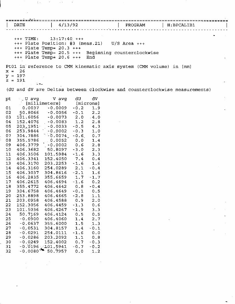
+++ TIME: 13:17:40 +++ +++ Plate Position: #3 (meas.21) U/S Area +++ +++ Plate Temp= 20.3 +++ +++ Plate Temp= 20.5 +++ Beginning counterclockwise +++ Plate Temp= 20.6 +++ End
PtOl in reference to CMM kinematic axis system (CMM volume) in [mm] x= 26 y = 197. z=l91
(dU and dV are Deltas between clockwise and counterclockwise measurements)
Pt
01 02 03 04 05 06 07 08 09 10 11 12 13 14 15 16 17 18 19 20 21 22 23 24 25 26 27 28 29 30 31 32
V avg dU .v YmZimeters]
dV [microns]
0.0037 -0.0009 -0.2 1.9 50.8066 -0.0056 -0.1 2.2
l-h;6056 -0.0073 2.0 .4.0 152.4076 -0.0083 1.2 2.8 20_3_,$951. -0.0033 -0..5 4.3 253.9844 - -0.0002 -0.3 1.0 304.7886 .- --0.0074- -0.6.. 0.7 355.5786 -0.0052 0.0 1.4 406.3779 -/&QOO2 0.6 2.8 406.3682 50.8097 -3.0 2.3 406.3506 101.5984 -1.6 3.3 .406.3341 152.4050 7.4 0.4 406.3170 203.2253 -1.6 1.6 406.3160 254.0289 2.1 -0.4 406.3037 304.8616 -2.1 1.6 406.2835 355.6659 1.7 -1.7 406:261-5 406.4694 -1.6 0.2 355.4772 406.4642 0.8 -0.4 304.6758 406.4649 -0.1 0.5 253.-8898 406.4665 -2.8 1.1 203.0958 406.4588 0.9 2.0 152.3056 406.4459 -1.3 0.6 101.5036 406.4267 --1.9 3.3
50.7169 406.4124 0.5 0.5 -0.0‘900 406.4060 1.4 2.7 -0.0637 355.6000 1.5 1.3 -0,053l 304.8157 1.4 -‘o .l -0.0291 254.0111 -1.6 0.0 -0.0286 203.2092 1.1 0.8 -0.0249 152.4002 0.7 -0.3 -O.'di96 -/.101.~941 -0.7 -0.2 -O.OO8O-X 50.7957 0.0 1.2
------~-‘-----------------------------------------------------------------------
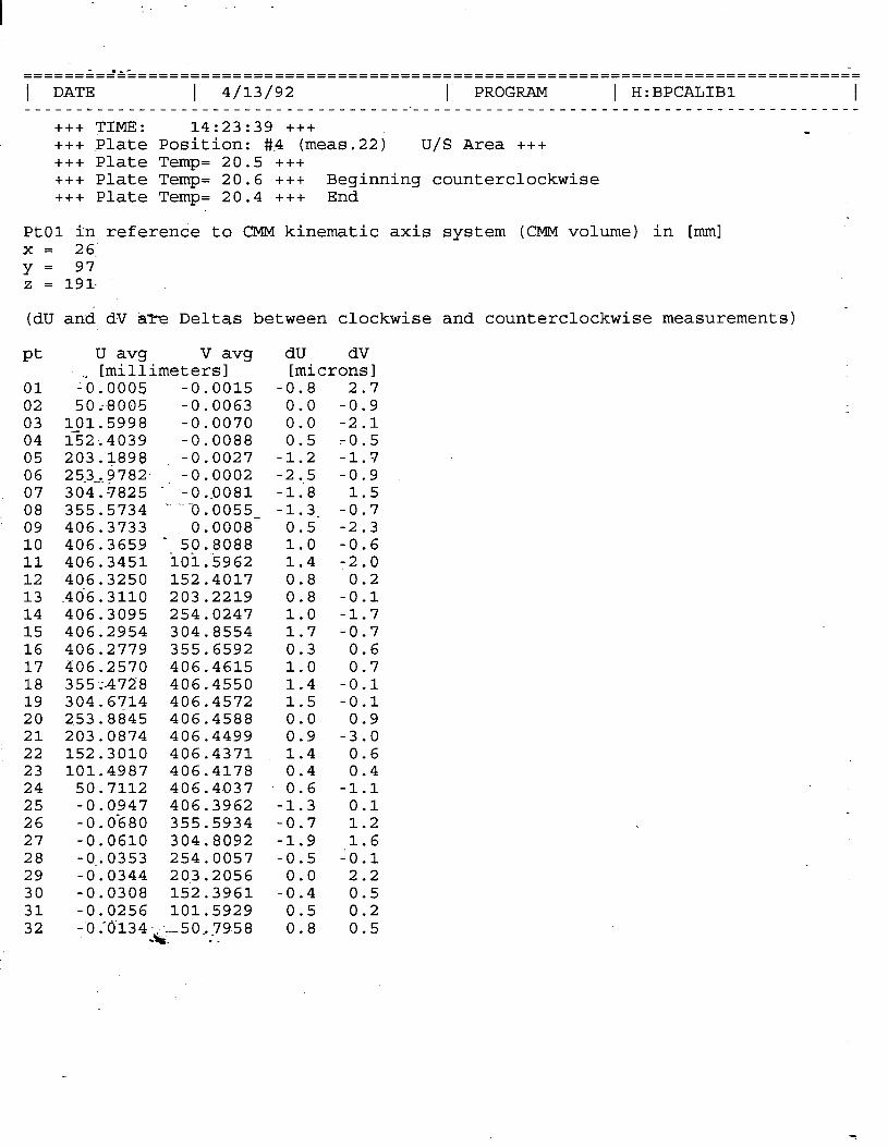
1 DATE I 4/13/92 I PROGRAM 1 H:BPCALIBl I -_--__c_____---__-__-~~-~~~~~~~~~~-~~~~-~---------------------------------------- +++ TIME: 14:23:39 +++ +++ Plate Position: #.4 (meas.22) U/S Area +++ +++ Plate Temp= 20.5 +++ +++ Plate Temp= 20.6 +++ Beginning counterclockwise +++ Plate Temp= 20.4 +++ End
-
PtOl in referende to CMM kinematic axis system (CMM volume) in [mm] x= 26 y= 97 z = 191-
(dU and dV W e Deltas between clockwise and counterclockwise measurements) -
Pt U avg V avg dU dV [millimeters] [microns]
01 G. 0005 -0.0015 -0.8 2.7 02 50 i-8005 -0.0063 0.0 -0.9 03 101.5998 -0.0070 0.0 -2.1 04 132;4039 -0.0088 0.5 -0.5 05 203.1898 -0.0027 -1.2 -1.7 06 25-3_,?782. -0.0002 -2..5 -0.9 07 304.7825 - -O.-O081 -1.8 1.5 08 .- 355.5734 --0.0055- -1-J. -0.7 09 406.3733 0.0008 0.5 -2.3 10 - 406.3659 -50;8088 1.0 -0.6 11 406.3451 iOi.%962 1.4 -2.0 12 406.3250 152.4017 0.8 0.2 13 .406.3110 203.2219 0.8 -0.1 14 406.3095 254.0247 1.0 -1.7 15 406 -2954 304.8554 1.7 -0.7 16 406.2779 355.6592 0.3 0.6 17 406.2570 406.4615 1.0 0.7 18 355.;.472-8 406.4550 1.4 -0.1 19 304.6714 406.4572 1.5 -0.1 20 253.8845 406.4588 0.0 0.9 21 203.0874 406.4499 0.9 -3.0 22 152.3010 406.4371 1.4 0.6 23 101.4987 406.4178 0.4 0.4 24 50.7112 406.4037 0.6 -1.1 25 -0.0947 406.3962 -1.3 0.1 26 -0.0‘680 355.5934 -0.7 1.2 27 -0.0610 304.8092 -1.9 1.6 28 -o-.0353 254.0057 -0.5 -0.1 29 -0.0344 203.2056 0.0 2.2 30 -0.0308 152.3961 -0.4 0.5 31 -0.0256 101.5929 0.5 0.2 32 -0. '~134~<~+5&7958 0.8 0.5
I :
------;-~-c--------------------------------------------------------------------- ------------------------~~~~~~~~~~~~~~~~------------------------------~~~--~~~~~
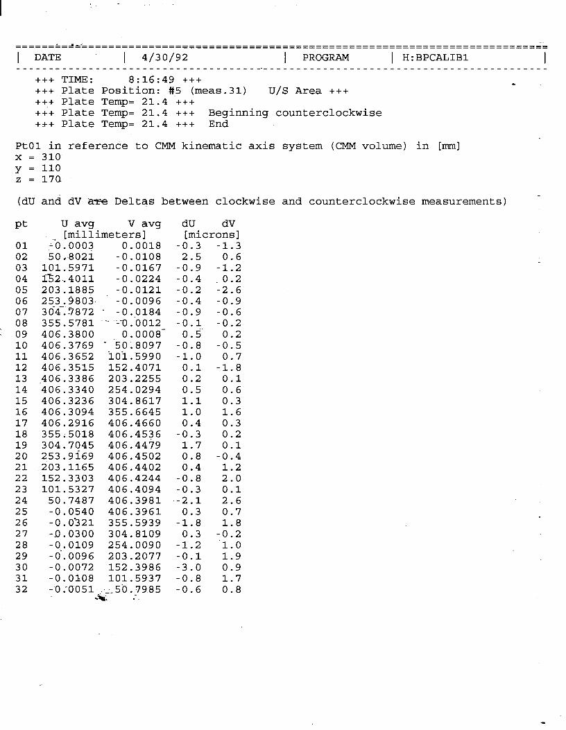
1 DATE 1 4/30/92 I PROGRAM 1 H:BPCALIBl -1 ____________________-----------------.-------------------------------------------
+++ TIME: 8:16:49 +++ - +++ Plate Position: #.5 (meas.31) U/S Area +++ +++ Plate Temp= 21.4 +++ +++ Plate Temp= 21.4 +++ Beginning counterclockwise +++ Plate Temp= 21.4 +++ End
PtOl in referende to CMM kinematic axis system (CMM volume) in [mm] x = 310 y = 110 z = 170
(dU and dV a= Deltas between clockwise and counterclockwise measurements)
Pt U avg V avg dU dV [millimeters] [microns]
01 1-o . 0003 0.0018 -0.3 -1.3 02 50 .-802i -0.0108 2.5 0.6 03 101.5971 -0.0167 -0.9 -1.2 04 fi2..4011 -0.0224 -0.4 ,0.2 05 203.1885 -0.0121 -0.2 -2.6 06 253.9803. -0.0096 -0.4 -0.9 07 304.7872 - -O.-O184 -0:9 -0.6 08 355.5781 .- '-0.0012 -0.1 -0.2 09 406.3800 0.0008- 0.5' 0.2 10 406.3769 - -5Oi8097 -0.8 -0.5 11 406.3652 ioi.5990 -1.0 0.7 12 406.3515 152.4071 0.1 -1.8 13 .406.3386 203.2255 0.2 0.1 14 406.3340 254.0294 0.5 0.6 15 406.3236 304.8617 1.1 0.3 16 406.3094 355.6645 1.0 1.6 17 406.2916 406.4660 0.4 0.3 18 355:.50X8 406.4536 -0.3 0.2 19 304.7045 406.4479 1.7 0.1 20 253.9169 406.4502 0.8 -0.4 21 203.1165 406.4402 0.4 1.2 22 152.3303 406.4244 -0.8 2.0 23 101.5327 406.4094 -0.3 0.1 24 50.7487 406.3981 --2.1 2.6 25 -0.0540 406.3961 0.3 0.7 26 -0.0521 355.5939 -1.8 1.8 27 -D.0300 304.8109 0.3 -0.2 28 -0.0109 254.0090 -1.2 '1.0 29 -O-.0096 203.2077 -0.1 1.9 30 -0.0072 152.3986 -3.0 0.9 31 -0.0108 101.5937 -0.8 1.7 32 -0X051--/>50,7985 -0.6 0.8
.*. --

-------i-* --_------=-====================================================================~= 1 DATE I 4/30/92 I PROGRAM 1 H:BPCALIBl I ______r________-_--_____________________----------------------------------------
+++ TIME: 10:47:10 +++ - +++ Plate Position: #.6 (meas.32) U/S Area +++ +++ Plate Temp= 21.4 +++ +++ Plate Temp= 21.4 +++ Beginning counterclockwise +++ Plate Temp= 21.4 +++ End
PtOl in referende to CMM kinematic axis system (CMM volume) in [mm] x = 100 y = 110 z = 170
(dU and dV -:e Deltas between clockwise and counterclockwise measurements) -
Pt
01 02 03 04 05 06 07 08 09 10 11 12 13 14 15 16 17 18 19 20 21 22 23 24 25 26 27 28 29 30 31 32
U avg V avg [millimeters]
-“0.0002 0.0000 50..8036 -0.0088
101.6014 -0.0138 fi2..4050 -0.0162 203.1921 -0.0107 253.4820. -0.0084 _ -.. _ 304..7881 - -0.0132 355.5804 .- ---cl :0004 406.3819 0.0007- 406.3789 - -50.. 8094 406.3686 iOi:5989 406.3552 152.4054
.406.3449 203.2226 406.3408 254.0305 406.3293 304.8616 406.3171 355.6659 406.3002 406.4681 355;5095 406.4586 304.7103 406.4572 253.9241 406.4551 203.1259 406.4466 152.3.396 406.4332 101.5418 406.4133
50.7558 406.4016 -0.0492 406.3974 -0.0-280 355.5940 --0.0271 304.8107 -0.0091 254.0068 -6.0057 203.2049 -0.0077 152.3963 -0.0106 101.5918 - 0 .'CJO52 -ec'I 5-O-.7960
.*, --
dU dV [microns] 0.4 0.6
-1.5 -0.8 -1.3 -0.3 -0.6 ,-1.1 -1.3 0.9 -2.3 -0.3 -0.4 -0.1
0.2 -0.8 -0.2' -0.5
0.9 -0.9 -0.8 0.3 -0.4 -0.1 -0.1 -0.9
2.2 1.4 -1.0 -1.6
0.4 -2.5 -1.5 -3.7
0.0 -0.3 1.1 -2.7
-0.7 -0.4 -0.1 0.5
0.1 -1.0 -0.7 -0.1 -0.1 -1.2
1.2 -0.9 -0.3 -2.1 -0.6 -0.6 -0.8 '2.1
0.7 -0.4 0.9 -1.1
-0.9 -1.0 -0.1 -0.1
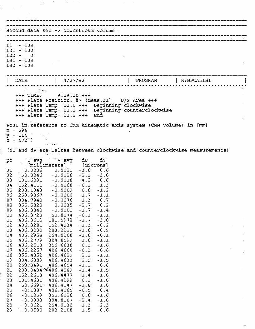
Second.data set => downstream volume.
L21 = 100 L22F 0 L31 = 103 L32 = -103
================================================================================ 1 DATE I 4/27/92 I PROGRAM 1 H:BPCALIBl I
-” --
+++ TIME: 9:29:10 +++ +++ Plate Position: #7 (meas.11) D/S Area +++ +++ Plate Temp= 21.0 +++ ++i'Plate Temp= 21.1 +++
Beginning clockwise Beginning counterclockwise
+++ Plate Temp= 21.2 +++ End
PtOlin.reference to CMM kinematic axis system (CMM volume) in [mm] x = 594 y = 114 - -. z=472. -
. . . -
(dU and dV are Deltas between clockwise and counterclockwise measurements)
Pt
01 02 03 04 05 06 07 08 09 10 11 12 13 14 15 16 17 18 19 20 21 22 23 24 25 26 27 28 29
U avg - -V. avg dU dV [millimeters] [microns]
0.0006 0.0021 50.8046 -0.0026
101.6091 -0.0018 152.4111 -0.0068 203.1943 -0.0009 2 5 3 .i.9 8 g-7 -0.0000 304.7940 -0.0076 355.5820 0.0035 406.3840 -0.0001 406.3728 50.8074 406.3515 101.5972 406.3281 152.4034 406.3030 203.2221 406.2958 254.0268 405.2779 304.8599 406.2513 355.6638 406‘.2257 406.4660 355.4352 406.4629 304.6389 406.4633 253 :8.491.sc.>06.465? 203.0434-x406:-&589 152.2613 406.4477 101.4631 406.4299
50.6691. 406.4147 -O-.1387 406.4065 -0.1059 355.6026 -0.0903 304.8187 -0.0621 254.0132
-3.8 -2.1
4.2 -0.1
0.8 1.7 1.3
-2.7 -1.7 -0.3 -1.7
1.3 -1.8 -1.8
1.8 0.3
-0.3 2.1 2.9
-1.3 -1.4
1.4 0.1
-1:8 -0.5
0.8 -2.4
1.3 -0.0530 203.2108 1.5
0.6 -3.8
0.6 -1.3 -1.2 -1.1
0.7 0.2
-1.4 -1.1 -3.0 -0.2 -0.9 -0.1 -1.1 -1.6 -0.8 -1.1 -1.5
0.8 -1.5
1.0 -1.0
1.0 0.4
-1.6 -1.0 -2.3 -0.6

I :
30 -0.0398 152.4016 -0.9 -2.1 31 -0.0290 101.5965 -1.7 -0.7 32 -0.0113 50.7998 -1.9 0.5
-” --
-
======‘=J,c,,,,,,,,,============================================================
1 DATE 1 4/16/92 I PROGRAM ) H:BPCALIBl -1 ------r-----------------------------~-------------------------------------------
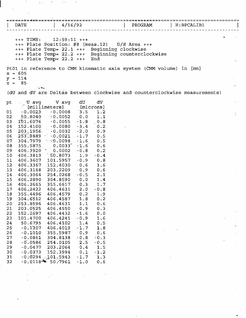
+++ TIME: 12:59:11 +++ +++ Plate Position: #8 (meas.12) D/S Area +++ +++ Plate Temp= 22.1 +++ Beginning clockwise +++ Plate Temp= 22.2 +++ Beginning counterclockwise +++ Plate Temp= 22.2 +++ End
PtOl in reference to CMM kinematic axis system (CMM volume) in [mm] x = 605 y = 114 z= 85
(dU and dV are Deltas between clockwise and counterclockwise measurements)
Pt V avg dU .- YmTEimeters]
dV [microns]
01 - 0 ,-0023 -0.0008 3.5 1.2 02 50.8040 -0.0052 0.0 1.1 03 17J1,6076 -0.0055 -1.8 ,0.8 04 152.4100 -0.0080 -3.4 0.2 05 203.i956. -0.0032 -2.0 0.9 06 253.9889 - -0.0021 -1;7 0.5 07 304.7979 .- .:-O.-O098 -1.6 0.5 08 355.5875 O-0033- -1.6' 0.6 09 406.3920 - 0;0002 -0.8 0.2 10 - 406.3813 5-0:8073 1.9 -0.4 11 406.3607 101.5957 -0.9 0.8 12 406.3367 152.4030 0.6 1.6 13 406.3168 203.2209 0.9 0.6 14 406.3064 254.0268 -0.5 2.1 15 406.2890 304.8590 0.0 1.4 16 406.2665 355.6617 0.3 1.7 17 40662422 406.4631 2.0 -0.8 18 355.4496 406.4579 0.2 1.9 19 304.6512 406.4587 1.8 0.2 20 253.8596 406.4631 1.1 0.6 21 203.0525 406.4550 0.9 0.3 22 152.2697 406.4432 -1.6 0.0 23 101.4700 406.4241 --0.9 1.6 24 50.6795 406.4102 1.4 0.5 25 -0.1307 406.4019 -1.7 1.8 26 -Q.lOlO 355.5987 0.9 0.6 27 -0.0861 304.8138 -0.8 -0.3 28 -O-.0586 254.0105 2.5 -0.5 29 -0.0477 203.2064 0.4 1.5 30 -0.0373 152.3994 0.1 -1.2 31 - 0 co-294 .sc._loi. 5943 -1.7 1.3 32 -0.0118**, 5O:-i961 -1.0 0.6
I :
------~-~-L-------------------------_-__
1 DATE 1 4/13/92 I PROGRAM 1 H:BPCALIBl I ______r___________________________ ---_------------------------------------------
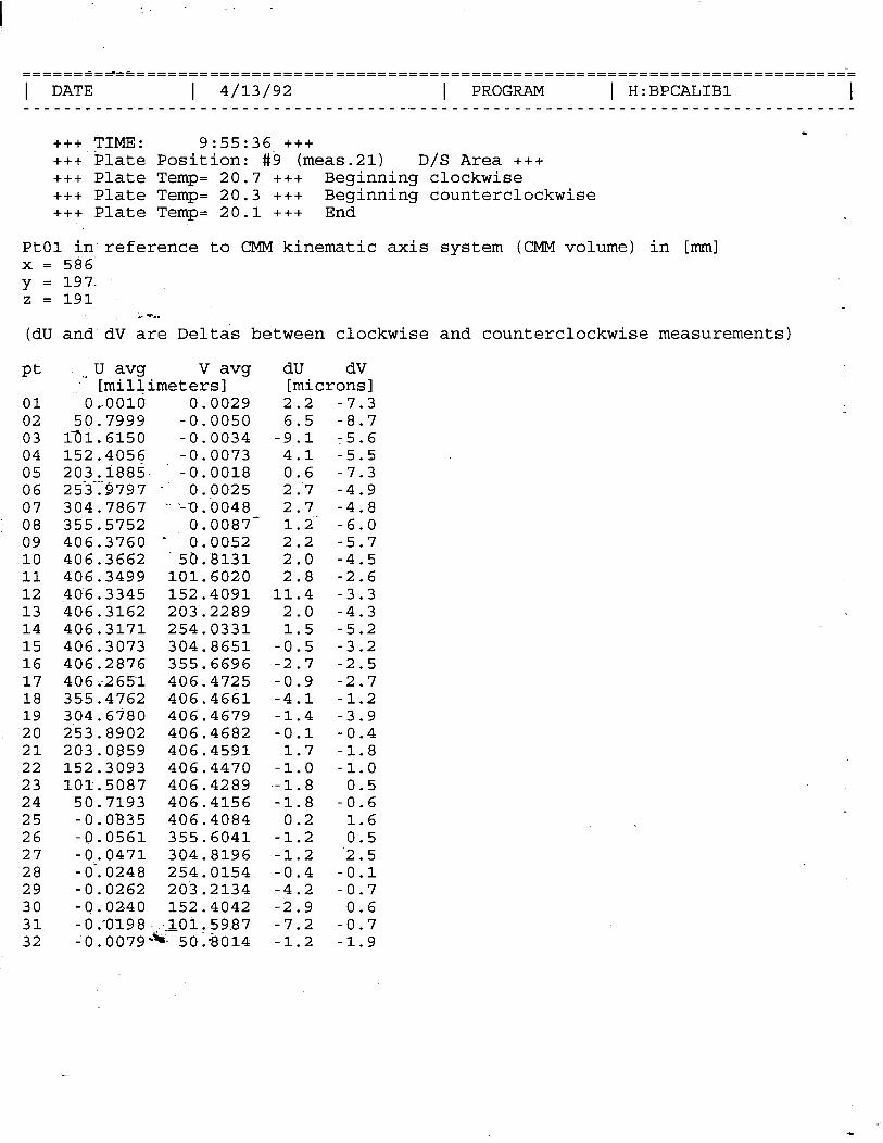
+++ TIME: 9:55:36 +++ +++Plate Position: #9 (meas.21) D/S Area +++ +++ Plate Temp= 20.7 +++ Beginning clockwise +++ Plate Temp= 20.3 +++ Beginning counterclockwise +++ Plate Temp= 20.1 +++ End
PtOl in reference to CMM kinematic axis system (CMM volume) in [mm] x = 586 y = 19 7. z=191
; 'c- (dU and dV are Deltas between clockwise and counterclockwise measurements)
Pt
01 02 03 04 05 06 07 08 09 10 11 12 13 14 15 16 17 18 19 20 21 22 23 24 25 26 27 28 29 30 31 32
V avg dU .v YmZimeters]
dV [microns]
O..OOld 0.0029 2.2 -7.3 50.7999 -0.0050 6.5 -8.7
131.6150 -0.0034 -9.1 ~5.6 152.4056 -0.0073 4.1 -5.5 203.i885- -0.0018 0.6 -7.3 253.9797 - 0.9025 2:7 -4.9 304.7867 ‘-'-0.0048 2.7 -4.8 355.5752 O-0087- 1.2.' -6.0 406.3760 - 0;0052 2.2 -5.7 406.3662 -50.8131 2.0 -4.5 406.3499 101.6020 2.8 -2.6 ,406.3345 152.4091 11.4 -3.3 406.3162 203.2289 2.0 -4.3 406.3171 254.0331 1.5 -5.2 406.3073 304.8651 -0.5 -3.2 406.2876 355.6696 -2.7 -2.5 406:-265-l 406.4725 -0.9 -2.7 355.4762 406.4661 -4.1 -1.2 304.6780 406.4679 -1.4 -3.9 253.8902 406.4682 -0.1 -0.4 203.0859 406.4591 1.7 -1.8 152.3093 406.4470 -1.0 -1.0 101.5087 406.4289 -1.8 0.5
50.7193 406.4156 -1.8 -0.6 -0.0835 406.4084 0.2 1.6 -9.0561 355.6041 -1.2 0.5 -0.0471 304.8196 -1.2 '2.5 -O-.0248 254.0154 -0.4 -0.1 -0.0262 203.2134 -4.2 -0.7 -0.0240 152.4042 -2.9 0.6 -0 .'0198 -sc.LOi r 5987 -7.2 -0.7 -0.0079- 50.8014 -1.2 -1.9
I :
------‘-~-c-------==-----------===--------------------------------------------~-
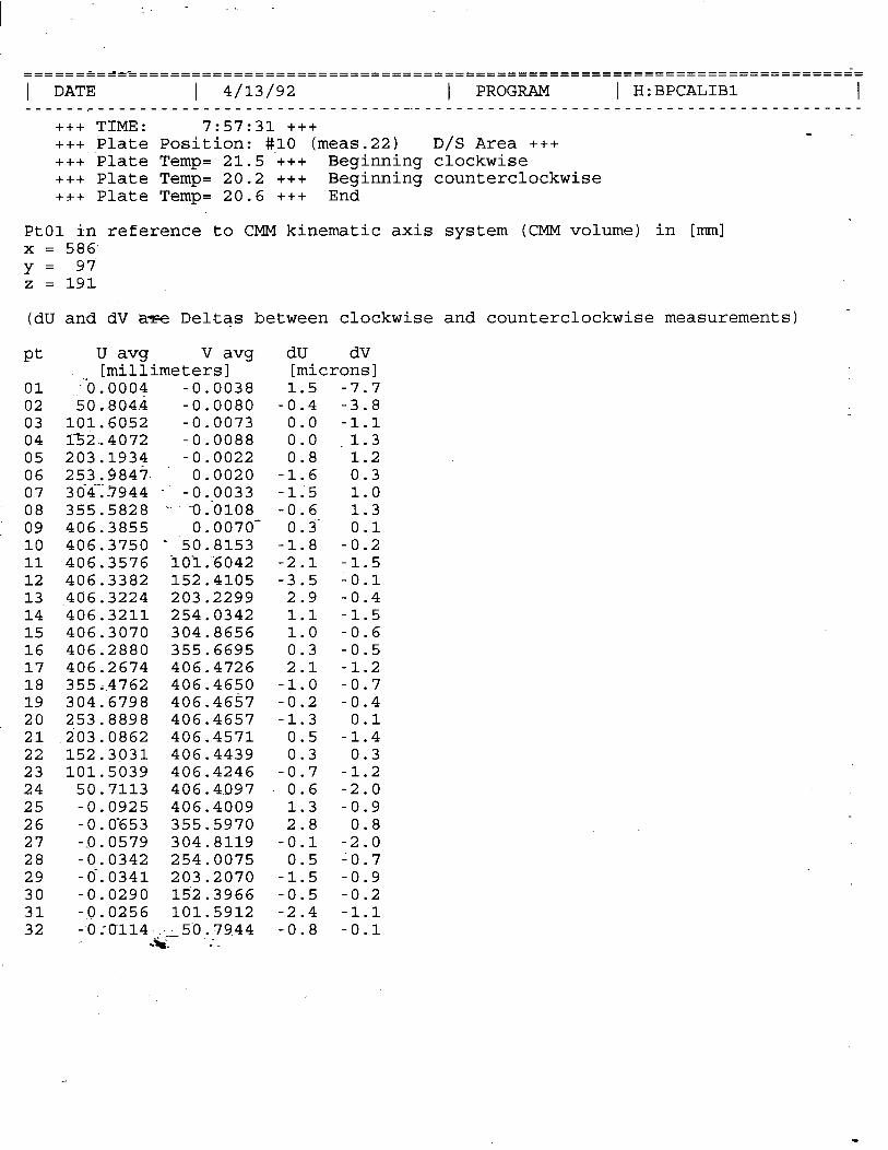
1 DATE I 4/13/92 I PROGRAM 1 H:BPCALIBl I ______r_____________-------------- --__------------------------------------------- +++ TIME: 7:57:31 +++ +++ Plate Position: #.lO (meas.22) D/S Area +++ +++ Plate Temp= 21.5 +++ Beginning clockwise +++ Plate Temp= 20.2 +++ Beginning counterclockwise +++ Plate Temp= 20.6 ttt End
PtOl in referende to CMM kinematic axis system (CMM volume) in [mm] x = 586 y= 97 z = 191
(dU and dV a= Deltas between clockwise and counterclockwise measurements) -
Pt
01 02 03 04 05 06 07 08 09 10 11 12 13 14 15 16 17 18 19 20 21 22 23 24 25 26 27 28 29 30 31 32
U avg V avg dU dV [millimeters] [microns]
-'b. 0004 -0.0038 1.5 -7.7 50,.8044 -0.0080 -0.4 -3.8
101.6052 -0.0073 0.0 -1.1 X52-4072 -0.0088 0.0 ,1.3 203.1934 -0.0022 0.8 1.2 253.9847. 0.0020 -1.6 0.3 _ -.. _ 304.7944 - -0.0033 -1;5 1.0 355.5828 .- --O.-O108 -0.6 1.3 406.3855 0.0070- 0.3 0.1 406.3750 - -50;8153 -1.8 -0.2 406.3576 ioi:6042 -2.1 -1.5 406.3382 152.4105 -3.5 -0.1 ,406.3224 203.2299 2.9 -0.4 406.3211 254.0342 1.1 -1.5 406.3070 304.8656 1.0 -0.6 406.2880 355.6695 0.3 -0.5 406.2674 406.4726 2.1 -1.2 355.64762 406.4650 -1.0 -0.7 304.6798 406.4657 -0.2 -0.4 253.8898 406.4657 -1.3 0.1 203.0862 406.4571 0.5 -1.4 152.3031 406.4439 0.3 0.3 101.5039 466.4246 -0.7 -1.2
50.7113 406.4097 0.6 -2.0 -0.0925 406.4009 1.3 -0.9 -0.0‘653 355.5970 2.8 0.8 -0.0579 304.8119 -0.1 -2.0 -0.0342 254.0075 0.5 -0.7 -O-.0341 203.2070 -1.5 -0.9 -0.0290 152.3966 -0.5 -0.2 -0.0256 101.5912 -2.4 -1.1 -0,0114,;-A50.7944 -0.8 -0.1
.** -;.
I
================================================================================ 1 DATE I 4/27/92 I PROGRAM 1 H:BPCALIBl -1 ---------------------------------------------------------------------------------
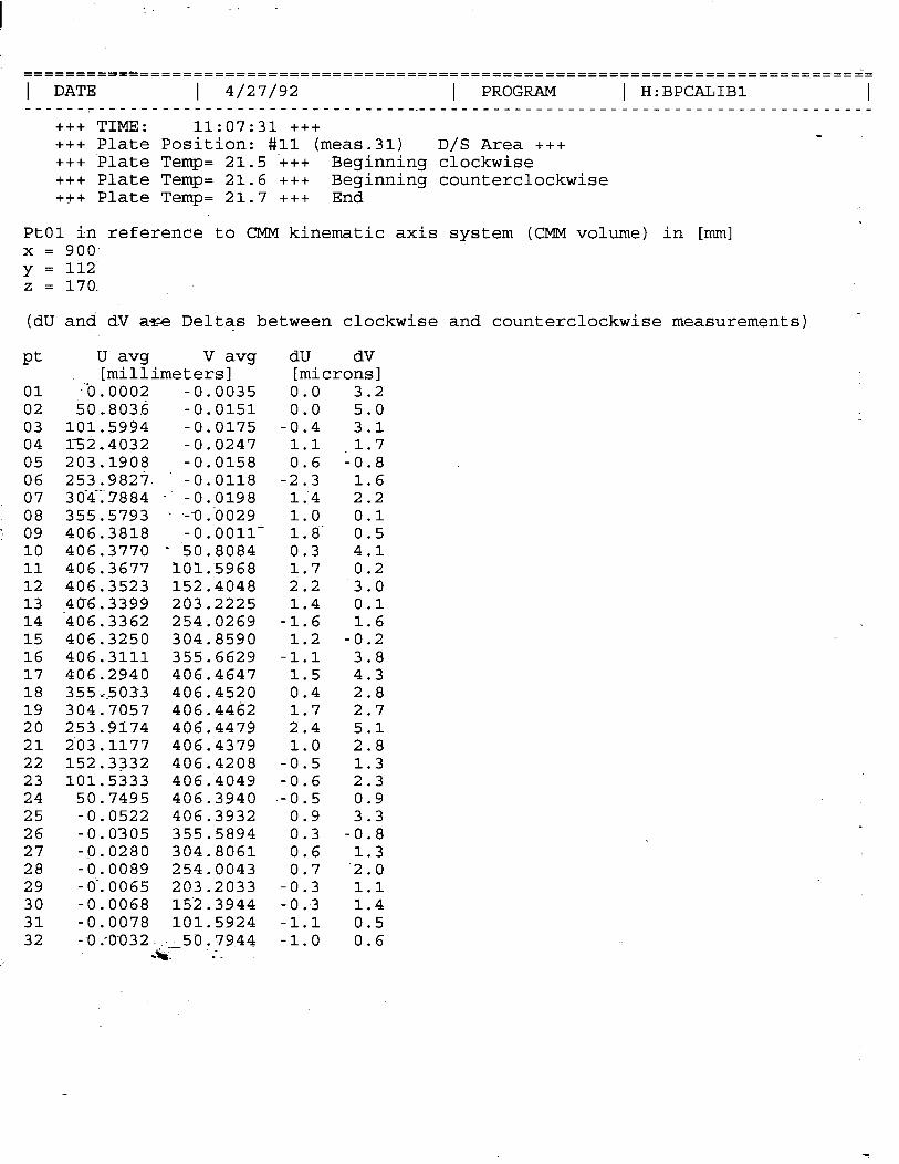
+++ TIME: 11:07:31 +++ +++ Plate Position: #ll (meas.31) D/S Area +++ t++ Plate Temp= 21.5 .+++ Beginning clockwise +++ Plate Temp= 21.6 +++ Beginning counterclockwise +++ Plate Temp= 21.7 ttt End
PtOl in reference to CMM kinematic axis system (CMM volume) in [mm] x = 900 y = 112 z = 170.
(dU and dV a%e Deltas between clockwise and counterclockwise measurements) -
Pt U avg V avg dU dV [millimeters] [microns]
01 -“0.0002 -0.0035 0.0 02 50*8036 -0.0151 0.0 03 101.5994 -0.0175 -0.4 04 132-4032 -0.0247 1.1 05 203.1908 -0.0158 0.6 06 253.9823. -0.0118 -2.3 07 30-4-17884 - -0.0198 l/4 08 355.5793 ..~ .=i):OO29 1.0 09 406.3818 -0.0011- 1.8' 10 406.3770 - -50;8084 0.3 11 406.3677 101.5968 1.7 12 406.3523 152.4048 2.2 13 406.3399 203.2225 1.4 14 ‘406.3362 254.0269 -1.6 15 406.3250 304.8590 1.2 16 406.3111 355.6629 -1.1 17 406.2940 406.4647 1.5 18 355.i.5033 406.4520 0.4 19 304.7057 406.4462 1.7 20 253.9174 406.4479 2.4 21 203.1177 406.4379 1.0 22 152.3332 406.4208 -0.5 23 101.5333 406.4049 -0.6 24 50.7495 406.3940 --0.5 25 -0.0522 406.3932 0.9 26 -0.0305 355.5894 0.3 27 -0.0280 304.8061 0.6 28 -0.0089 254.0043 0.7 29 -O-.0065 203.2033 -0.3 30 -0.0068 152.3944 -0.3 31 -0.0078 101.5924 -1.1 32 - O.-O-O32 -s;.150.7944 -1.0
.*. ',.
3.2 5.0 3.1
,1.7 -0.8
1.6 2.2 0.1 0.5 4.1 0.2 3.0 0.1 1.6
-0.2 3.8 4.3 2.8 2.7 5.1 2.8 1.3 2.3 0.9 3.3
-0.8 1.3
‘2.0 1.1 1.4 0.5 0.6
I
======‘==~=====================================================================
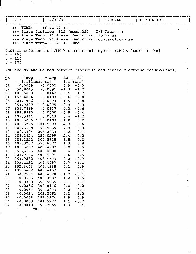
1 DATE I 4/30/92 I PROGRAM 1 H:BPCALIBl -1 ____________________----------------~------------------------------------------- +++ TIME: 15:41:43 +++ +++ Plate Position: #12 (meas.32) D/S Area +++ +++ Plate Temp= 21.4 .+tt Beginning clockwise +++ Plate Temp= 21.4 +++ Beginning counterclockwise +++ Plate Temp= 21.4 +++ End
PtOl in reference to CMM kinematic axis system (CMM volume) in [mm] x = 690 y = 110 z = 170.
(dU and dV =e Deltas between clockwise and counterclockwise measurements) -
Pt
01 02 03 04 05 06 07 08 09 10 11 12 13 14 15 16 17 18 19 20 21 22 23 24 25 26 27 28 29 30 31 32
U avg V avg [millimeters]
-“O. 0009 -0.0002 50..8045 -0.0091
101.6039 -0.0142 r52..4054 -0.0103 203.1936 -0.0093 253.9827. -0.0075 304.7899 - -0.0137 355.5830 .- .- -0 :0000 406.3841 0.0013- 406.3806 - -50;8103 406.3726 -101.~5993 406.3608 152.4065 406.3484 203.2233 406.3424 254.0299 406.3322 304.8635 406.3202 355.6672 406.3037 406.4702 355.5126 406.4600 304.7136 406.4574 253.9262 406.4573 203.1292 406.4487 152.3443 406.4338 101.5452 466.4152
50.7591 406.4028 -0.0465 406.3987 -0.0260 355.5965 -0.0236 304.8116 -0.0057 254.0073 -O-.0034 203.2053 -0.0058 152.3974 -0.0068 101.5927 -O:0018-~;.15D.7965
.*. ',.
dU dV [microns] 0.9 -0.3
-1.3 -1.7 -0.5 -1.2 -3.6 a2.0
1.5 -0.8 -0.9 0.3 -0;3 -0.6 -0.5 -0.4
0 -4' -1.2 -1.0 -0.2
4.3 0.6 7.9 0.3 3.2 0.1
-2.4 -0.2 1.5 0.0 1.3 0.9 0.0 0.5 0.4 1.7 0.6 0.5 0.2 -0.9 0.7 -1.1 0.1 0.9 0.4 0.1 1.7 -0.1 1.2 -1.5
-0.1 -0.1 0.0 -0.2
-0.2 '0.1 0.3 -1.0
-1.9 0.9 1.1 -0.7 1.3 0.1

I
- .-’
APPENDIX D
STANFORD LINEAR ACCELERATOR CENTER SURVEY AND ALIGNMENT TEAM
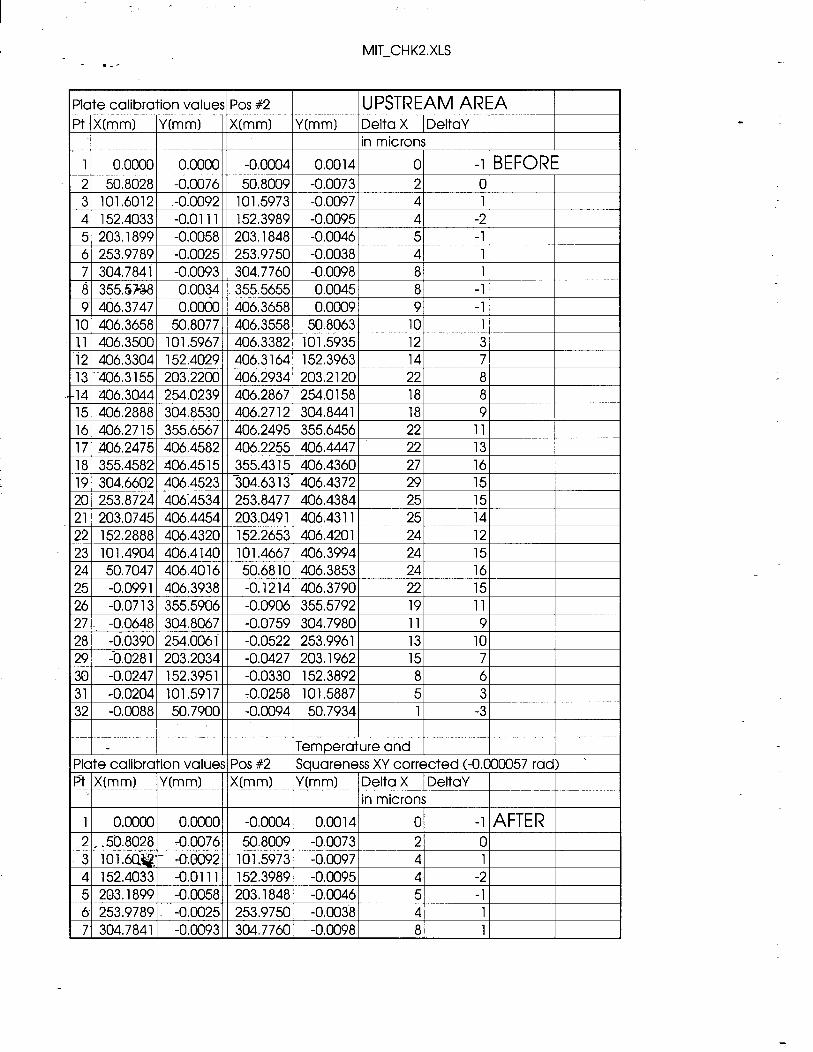
MIT-CHK2.XLS
I :
MIT-CHK2.XLS - .-’
32 1 -0.0088 1 50.7900 1 I -0.0065 1 50.7934 I -21 -51
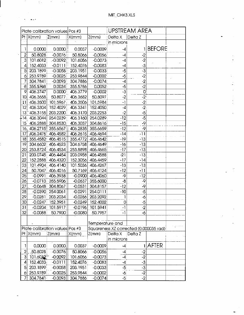
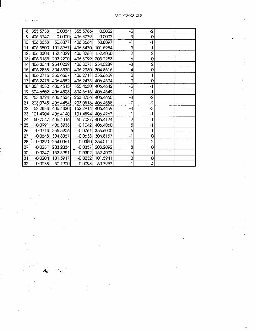
MIT-CHK3.XLS - .-’
qatecalibration values Pos#3 I I /UPSTREAM AREA ?X(mm) Z(mm) Nmm) Z0-nn-d Delta X [Delta Z
in microns 1 0.0000 0.0000 0.0037 -0.0009 -41 I BEFORE 2 50.8028 -0.0076 50.8066 -0.0056 -4 -2 3 101.6012 .-0.0092 101.6056 -0.0073 -4 -2 4 152.4033 -0.0111 152.4076 -0.0083 -4 -3 5 203.1899 -0.0058 203.1951 -0.0033 -5 -3 6 253.9789 -0.0025 253.9844 -0.0002 -5 -2 7 304.7841 -0.0093 304.7886 -0.0074 -4 -2
22 152.2888 406.4320 152.3056 406.4459 -17 -14 23 101.4904 406.4140 101.5036 406.4267 -13 -13
31 -0.0204 101.5917 -0.0196 101.5941 -1 -2 32 -0.0088 50.7900 -0.0080 50.7957 -1 -6
MIT-CHKS.XLS - .-'
.8 355.5738 0.0034 355.5786 0.0052 -5 -2 9 406.3747 0.0000 406.3779 -0.0002 -3 0
10 406.3658 50.8077 406.3664 50.8097 -1 -1 11 406.3500 101.5967 406.3470 101.5984 3 1 12 406.3304 152.4029 406.3288 152.4050 2 2 13 406.3155 203.2200 406.3099 203.2253 6 0 .141 406.30441 254.023911 406.30711 254.02891 -31 21 15 406.2888 304.8530 406.2930 304.8616 -4 0 16 406.2715 355.6567 406.2711 355.6659 0 1 17 406.2475 406.4582 406.2473 406.4694 0 0 18 355.4582 406.4515 355.4630 406.4642 -5 -1 19 304.6682 406.4523 304.6616 406.4649 -1 -1
2d -0.0713 355.5906 -0.0761 3$5.6QOO 5 1 27 -0.0648 304.8067 -0.0638 304.8157 -1 0 isi : -0.0390 254$061 -0.0380 254.0111 -1 2 29 -0.028Tm '203.2034 203.2092 8 0 _ -0.0357. 30 -0.0247 -152.3951 -0.0302 152.4002 6 -1 31 -0.0204. 101.5917 -0.0232 101.5941 3 0 32 -0.0088 50.7900 -0.0098 50.7957 1 -4
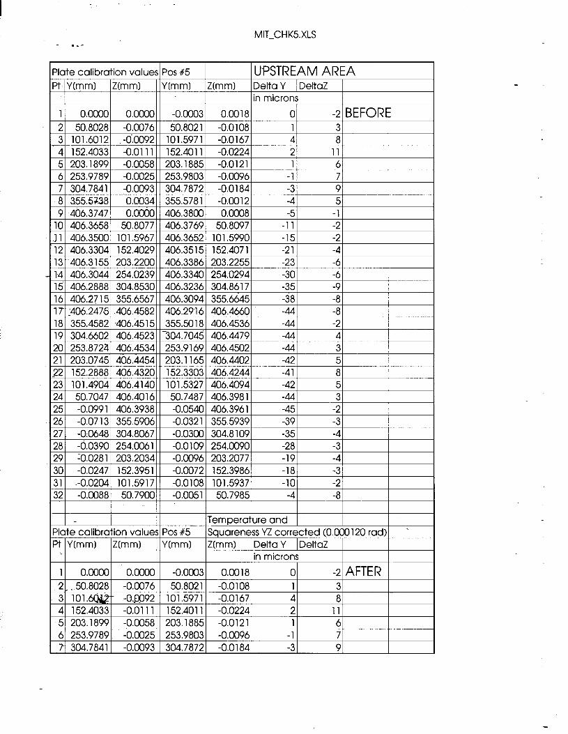
MIT-CHK5.XLS
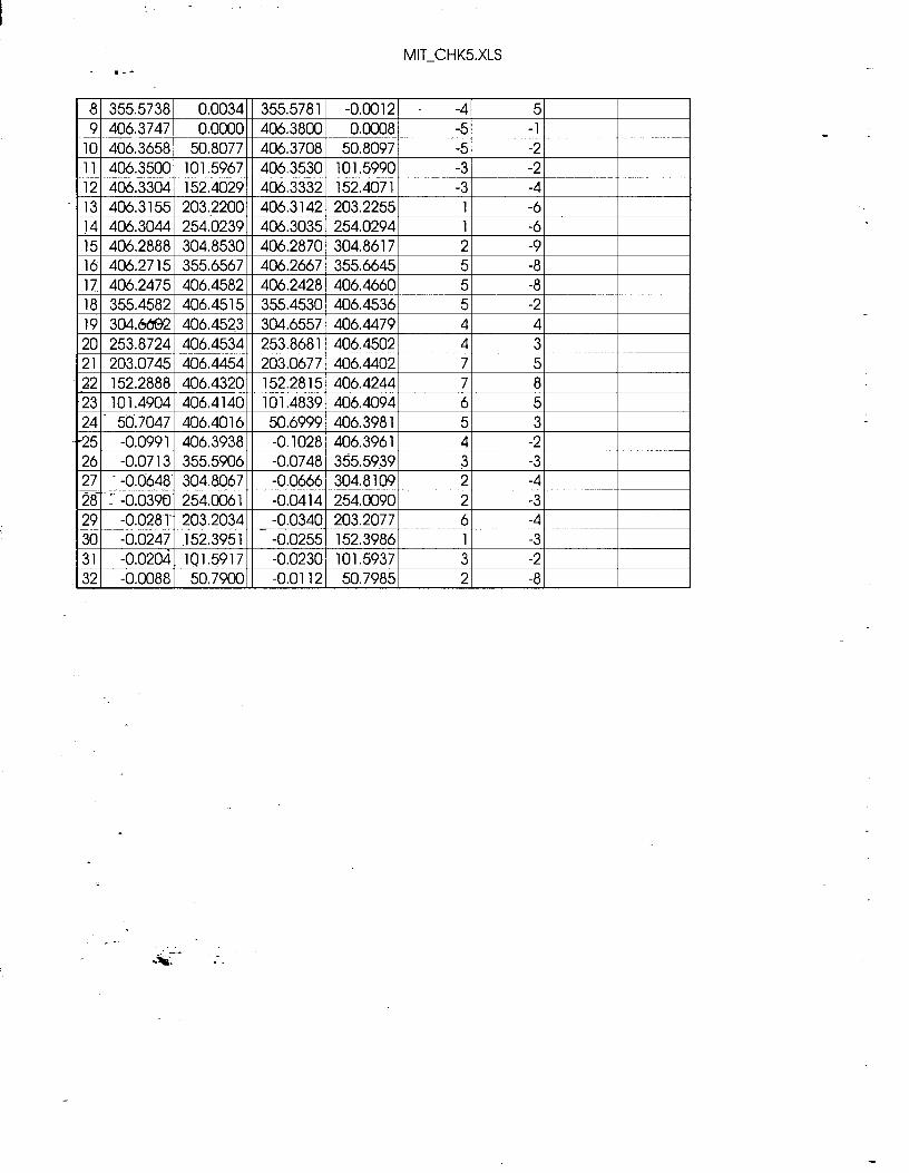
MIT-CHK5XLS
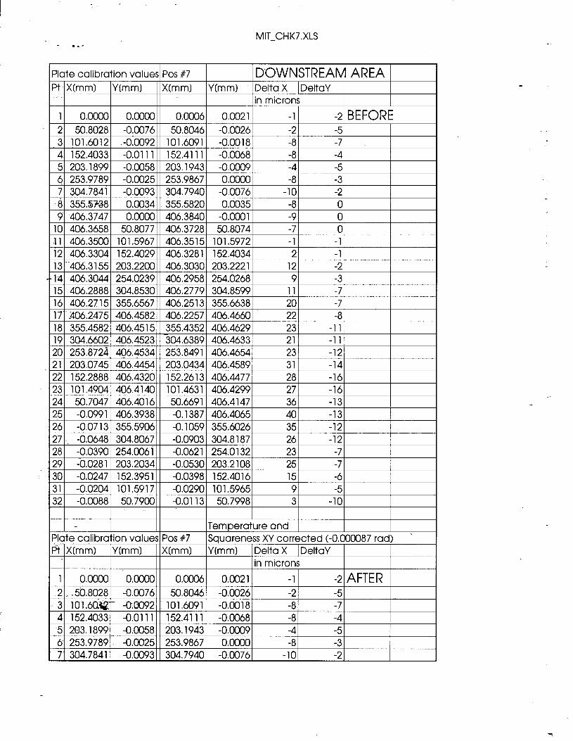
MIT-CHK7.XLS .-A
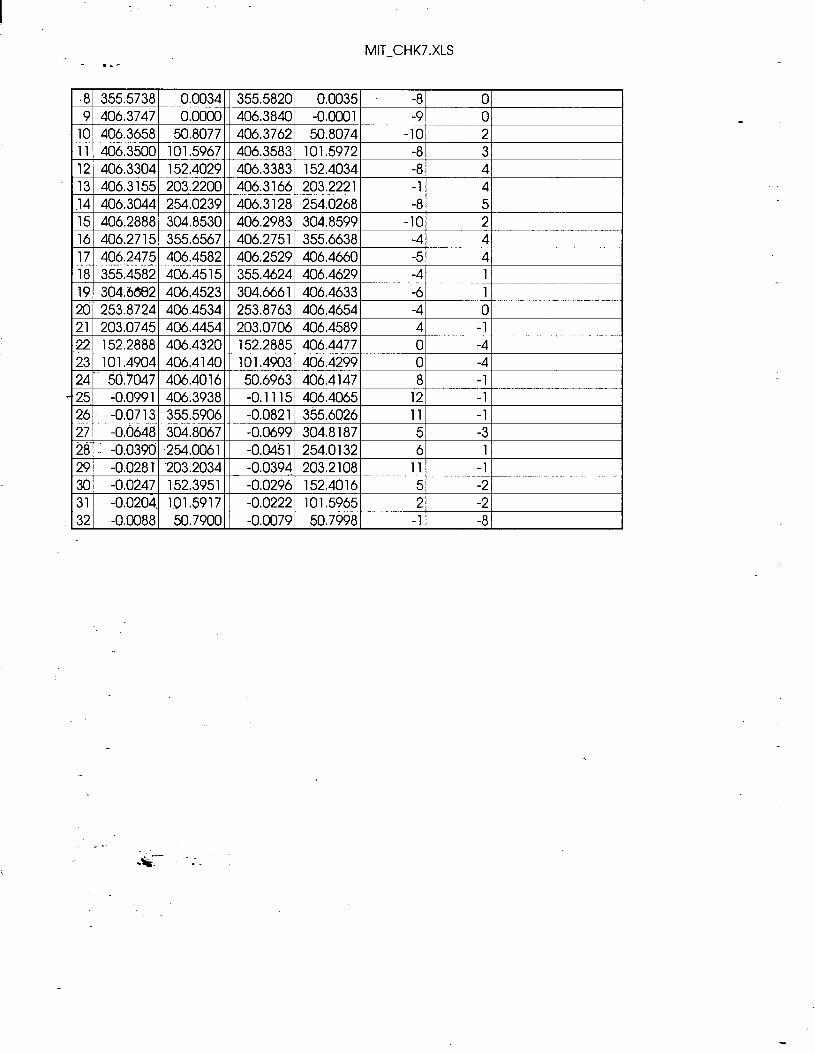
Plate calibration values Pos #7 1 DOWNSTREAM AREA 1 Pt X(mm) Wmm) X0-m-n) Y(mn-4 Delta X IDeltaY 1
in microns
29 -b-O28 1 203.2034 -0.0530 203.2108 25 -7 30 -0.0247 152.395 1 -0.0398 152.4016 15 -6 31 -0.0204 101.5917 -0.0290 101.5965 9 -5 32 -0.0088 50.7900 -0.0113 50.7998 3 -10
I I I I I I I
Temperature and 1 Plate calibration values Pos #7 Squareness XY corrected (-0.000087 rad) > F? IX(mm) IY(mm) I X(mm) Y(mm) IDelta X IDeltaY I
.
MIT-CHK7.XLS .--
.8 355.5738 0.0034 355.5820 0.0035 -8 0 9 406.3747 0.0000 406.3840 -0.0001 -9 0
10 406.3658 50.8077 406.3762 50.8074 -10 2 11 406.3500 101.5967 406.3583 101.5972 -8 3
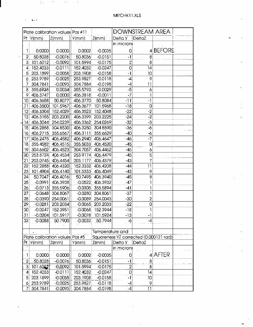
MITCHK 11 .XLS .--
Plate calibration values Pos #l 1 DOWNSTREAM AREA Pt Y(mm) Z0-nn-d Wmm) Z(mm) Delta Y I DeltaZ
in microns
1 I 0.00001 0.00001 I 0.0002 I -0.0035 1
Temperature and Plate calibration values Pos #5 Squareness YZ corrected (0.000 12 1 rad) - P-t IY(mm) jZ(mm) I Y(mm) Z(mm) IDelta Y IDeltaZ I
I in microns
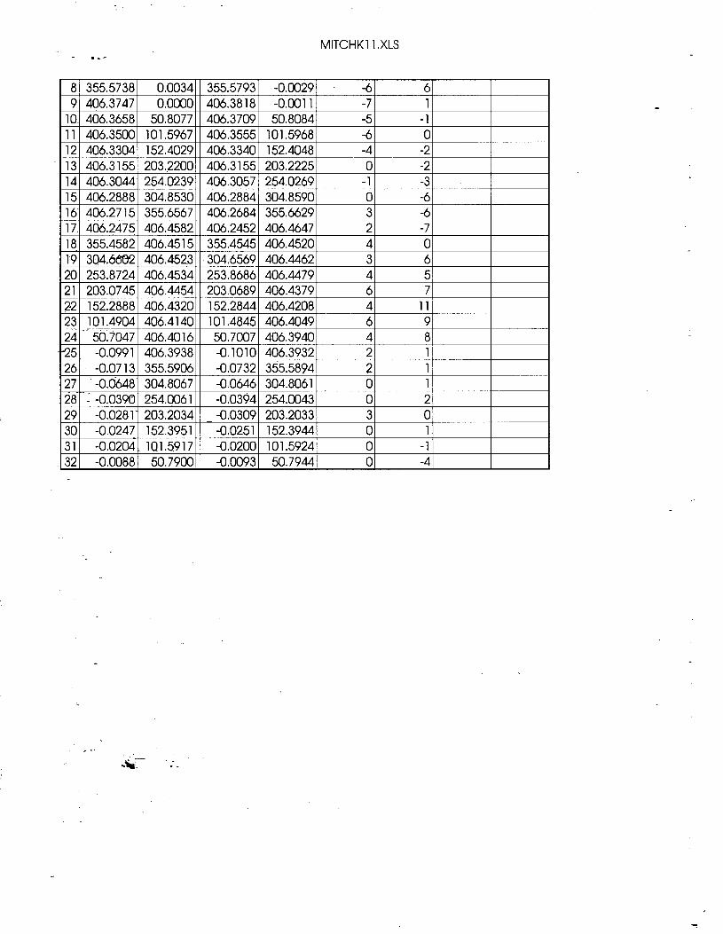
MlTCHKl 1 .XLS .--
321 -0.0088j 50.79001/ -0.00931 50.79441 01 -41
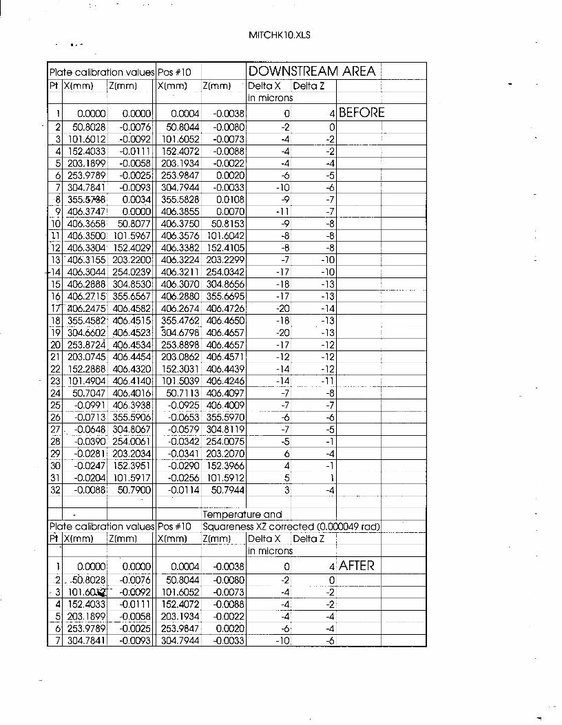
MITCHKlO.XLS
‘late calibration values/ Pos #lO I IDOWNSTREAM AREA /
8 355.5%3 0.0034 355.5828 0.0108 -9 -7 9 406.3747 0.0000 406.3855 0.0070 -11 -7
17’. a06.2475 406.4582 406.2674 406.4726 -20 -14 18 355.4582 406.4515 355.4762 406.4650 -18 -13 19 304.6602 406.4523 304.6798 406.4657 -20 -13
I- I II ITemoerature and I I I ‘late calibration values Pos #lo Squhreness XZ corrected (0.000049 rad) % 3 X(mm) Z0-nt-N Nmml Z(mm) Delta X I Delta Z
in microns 1 0.0000 0.0000 0.0004 -0.0038 01 4 AFTER

MITCHKlO.XLS .--
'8 355.5738 0.0034 355.5828 0.0108 . -9 -7 9 406.3747 0.0000 406.3855 0.0070 -11 -7
10 406.3658 50.8077 406.3732 50.8153 -7 -6 11 406.3500 101.5967 406.3540 101.6042 -4 -5 12 406.3304 152.4029 406.3329 152.4105 -2 -3 13 406.3155 203.2200 406.3153 203.2299 0 -4 .14 406.3044 254.0239 406.3122 254.0342 -8 -3 15 406.2888 304.8530 406.2963 304.8656 -8 -4 16 406.2715 355.6567 406.2756 355.6695 -4 -3 17 406.2475 406.4582 406.2532 406.4726 -6 -3 18 355.4582 406.4515 355.4620 406.4650 -4 -2 19 304.6602 406.4523 304.6656 406.4657 -5 -2 20 253.8724 406.4534 253.8756 406.4657 -3 -1 21 203.0745 406.4454 203.0720 406.4571 3 0 .22 152.2888 406.4320 152.2889 406.4439 0 -1 23 101.4904 406.4140 101.4897 406.4246 1 1 24 56.7047 406.4016 50.6971 406.4097 8 3 25. -0.0991 406.3938 -0.1067 406.4009 8 4 26 -0.0713 355.5906 -0.0777 355.5970 6 4 27 -0.6648 304.8067 -0.0686 304.8119 4 3 28 : -0.0390 254.pO61 -0.0431 254.0075 4 6 29 -0.0281m ‘203.2034 _ -0.0412 203.2070 13 2 30 -0.0247 -152.3951 -0.0343 152.3966 10 3 31 -0.0204 101.5917 -0.0292 101.5912 9 3 32 -0.0088 50.7900 -0.0132 50.7944 4 -3