sr 1460 effect of welded properties on aluminum structures progress report 11/25/09
DESCRIPTION
SR 1460 Effect of welded properties on Aluminum Structures Progress Report 11/25/09. Dr. Pradeep Sensharma & Joey Harrington BMT Designers & Planners [email protected] 703 920 7070 x 275 Dr. Matt Collette University of Michigan [email protected] (734) 764-8422. Agenda. Objective Tasks - PowerPoint PPT PresentationTRANSCRIPT
Ship Structure Committee
1
SR 1460Effect of welded properties on Aluminum
StructuresProgress Report
11/25/09
Dr. Pradeep Sensharma & Joey HarringtonBMT Designers & [email protected]
703 920 7070 x 275
Dr. Matt ColletteUniversity of Michigan
[email protected](734) 764-8422

Ship Structure Committee
2
Agenda
• Objective• Tasks• Schedule• Literature Survey• Failure Criteria• Stress-Strain Curves• Finite Element Models• Results• Future Work

Ship Structure Committee
3
Objective
•The goal of this project is to provide a basis for design of aluminum structures that will minimize the penalty on scantling selection
– Study all possible methods of modeling aluminum stiffened plate structure– Provide basis for modification to existing design standard

Ship Structure Committee
4
Tasks
•Task 1 - Develop Project Plan Based on the SOW•Task2 - Perform literature survey•Task 3 - Develop Matrix of Plate-Stiffener Combinations to be analyzed•Task 4 - Develop Stress-Strain relationship•Task 5 – Develop & Analyze FE Models•Task 6 – Volumetric Yield strength using Dr. Paik’s formula•Task 7 – Analyze results & Recommend changes to existing design standard•Task 8 – Prepare Final report

Ship Structure Committee
5
Schedule (cont.)
ID Task Name
1 Effect of Welded Properties on Aluminum Structure2 Kick - off Meeting3 Literature Survey4 Quarterly Progress Review 15 Review of Current Design Standards6 FE Modeling and Analysis7 Quarterly Progress Review 2 (Interim Results)8 Quarterly Progress Review 3 (Final FEA Results)9 Develop recommendations for Changes10 Draft Final Report11 Final Report12 Project Conclusion
2/5
5/15
8/7
11/30
2/5
February March April May June July August September October November December January February March

Ship Structure Committee
6
ScheduleTasks & Deliverable Expected Completion Date
Develop a work plan February 05, 2009(Deliverable 1)
Literature Survey March 31, 2009
Review of Current Design Standards April 30, 2009
Quarterly Progress Report/Review 1 May 15, 2009(Deliverable 2)
Model and Analyze FE Models November 15, 2009
Quarterly Progress Report/Review 2 (with interim results)
August 07, 2009(Deliverable 3)
Quarterly Progress Report/Review 3 (With Final FEA Results)
November 30, 2009(Deliverable 4)
Develop recommendations for changes in design standard
December 15, 2009
Draft Final Report January 05, 2010(Deliverable 5)
Final report that includes all activities and previous deliverables of this project including case studies.
February 05, 2010(Deliverable 6)

Ship Structure Committee
7
Finite Element Models•Matrix of Plate-Stiffener Combinations to be analyzed
Model Plate Stiffener Weld Location1 Light (4mm)/ 5083 Light (60x3/30x6)/5083 Plate stiffeners connection2 Heavy (6mm)/ 5083 Light (60x3/30x6)/5083 Plate stiffeners connection3 Heavy (6mm)/ 5083 heavy (100x6/40x10)/5083 Plate stiffeners connection4 Light (4mm)/ 5083 heavy (100x6/40x10 )/5083 Plate stiffeners connection5 Light (4mm)/ 5083 Light (60x3/30x6)/6082 Plate stiffeners connection6 Heavy (6mm)/ 5083 Light (60x3/30x6)/6082 Plate stiffeners connection7 Heavy (6mm)/ 5083 heavy (100x6/40x10 )/6082 Plate stiffeners connection8 Light (4mm)/ 5083 heavy (100x6/40x10 )/6082 Plate stiffeners connection9 Light (4mm)/ 6082 Light (60x3/30x6)/6082 Weld between two extruded
10 Heavy (6mm)/ 6082 Light (60x3/30x6)/6082 Weld between two extruded 11 Heavy (6mm)/ 6082 heavy (100x6/40x10 )/6082 Weld between two extruded 12 Light (4mm)/6082 heavy (100x6/40x10 )/6082 Weld between two extruded

Ship Structure Committee
8
Compressive Load • Tabulated results shown in next four slides• Observation
– Modeling entire structure as HAZ is extremely conservative.– In most cases modeling entire structure with Base Metal
properties gives about 10% higher strength than Combined models (Base + HAZ) for conventional model.
– Extruded models have higher strength than conventional models– Variation in strength prediction is large between models for
extruded case

Ship Structure Committee
9
Results (compressive load)Model1 Model2
FEA Simplified FEAStrain Stress % difference Strain Stress % difference
Combined 0.002000 96.9 - 0.001985 105.0 -base only 0.002000 100.8 4.1% 0.001985 107.1 2.0%HAZ only 0.001667 83.6 -13.7% 0.001533 87.8 -16.4%
Model5 Model6FEA Simplified FEA
Strain Stress % difference Strain Stress % differenceCombined 0.002000 96.9 - 0.001985 106.3 -base only 0.002200 103.6 6.8% 0.002030 108.7 2.3%HAZ only 0.001667 83.5 -13.9% 0.001533 88.1 -17.1%
Model9 Model10FEA Simplified FEA
Strain Stress % difference Strain Stress % differenceCombined 0.002667 126.5 - 0.002980 142.7 -base only 0.002667 134.6 6.4% 0.003025 146.8 2.8%HAZ only 0.001467 81.9 -35.3% 0.001533 89.5 -37.3%

Ship Structure Committee
10
Results (cont.)Model2 Model3
FEA Simplified FEAStrain Stress % difference Strain Stress % difference
Combined 0.002400 123.0 - 0.002121 131.2 -base only 0.002400 126.3 2.6% 0.002166 134.8 2.7%HAZ only 0.002200 105.5 -14.3% 0.001804 105.3 -19.8%
Model6 Model7FEA Simplified FEA
Strain Stress % difference Strain Stress % differenceCombined 0.002267 127.2 - 0.002302 139.3 -base only 0.002333 132.9 4.5% 0.002302 143.2 2.8%HAZ only 0.002133 104.4 -18.0% 0.001759 104.8 -24.8%
Model10 Model11FEA Simplified FEA
Strain Stress % difference Strain Stress % differenceCombined 0.002933 151.4 - 0.002889 173.9 -base only 0.002667 155.3 2.6% 0.002889 182.0 4.7%HAZ only 0.002067 103.1 -31.9% 0.001714 104.0 -40.2%
Ship Structure Committee
11
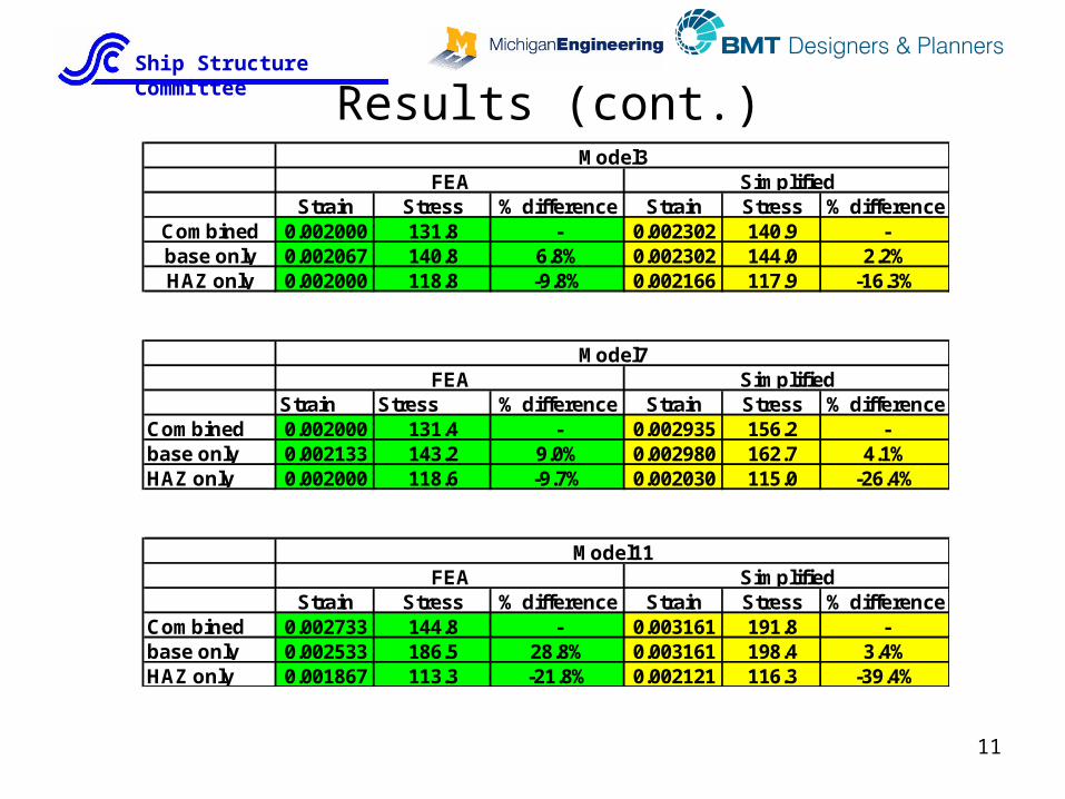
Results (cont.)Model3 Model4
FEA Simplified FEAStrain Stress % difference Strain Stress % difference
Combined 0.002000 131.8 - 0.002302 140.9 -base only 0.002067 140.8 6.8% 0.002302 144.0 2.2%HAZ only 0.002000 118.8 -9.8% 0.002166 117.9 -16.3%
Model7 Model8FEA Simplified FEA
Strain Stress % difference Strain Stress % differenceCombined 0.002000 131.4 - 0.002935 156.2 -base only 0.002133 143.2 9.0% 0.002980 162.7 4.1%HAZ only 0.002000 118.6 -9.7% 0.002030 115.0 -26.4%
Model11 Model12FEA Simplified FEA
Strain Stress % difference Strain Stress % differenceCombined 0.002733 144.8 - 0.003161 191.8 -base only 0.002533 186.5 28.8% 0.003161 198.4 3.4%HAZ only 0.001867 113.3 -21.8% 0.002121 116.3 -39.4%

Ship Structure Committee
12
Results (cont.)Model4
FEA SimplifiedStrain Stress % difference Strain Stress % difference
Combined 0.001733 100.4 - 0.002256 122.4 -base only 0.001867 109.2 8.7% 0.002256 124.0 1.3%HAZ only 0.001667 90.8 -9.6% 0.001894 100.4 -17.9%
Model8FEA Simplified
Strain Stress % difference Strain Stress % differenceCombined 0.001667 99.9 - 0.003161 152.3 -base only 0.002000 114.0 14.0% 0.003161 156.5 2.8%HAZ only 0.001533 90.0 -9.9% 0.001804 99.7 -34.6%
Model12FEA Simplified
Strain Stress % difference Strain Stress % differenceCombined 0.001933 115.3 - 0.003251 172.5 -base only 0.002267 146.8 27.3% 0.003206 175.8 1.9%HAZ only 0.001200 86.7 -24.8% 0.001804 100.1 -42.0%

Ship Structure Committee
13
Preliminary ObservationCompressive Load
• Is it possible to model aluminum structure as base metal with reduced proof stress (about 10%)?

Ship Structure Committee
14
Preliminary ObservationCompressive Load
• Developed new Stress-Strain curve for AL5083 and AL6082 by reducing proof stress by 10%
• Analyzed models 1 through 8 using this stress-strain curve with no HAZ
• Results with Modified stress-strain curve compared against the combined model (base + HAZ) in next two slides
Ramberg- OsgoodMaterial 5083 6082
0.2% Stress (N/mm^2)= 162 234Young's Modulus (N/mm^2) = 70000 70000n = 16 30

Ship Structure Committee
15
Results with Modified Stress-Strain Curve
Ultimate Strength - Model 1
0
20
40
60
80
100
120
0.0000 0.0005 0.0010 0.0015 0.0020 0.0025 0.0030 0.0035
Strain (mm/mm)
Str
ess
(Mp
a)
FEA (C)
FEA (B_mod)
Ultimate Strength - Model 2
0
20
40
60
80
100
120
140
0.0000 0.0005 0.0010 0.0015 0.0020 0.0025 0.0030 0.0035 0.0040
Strain (mm/mm)
Str
ess
(Mp
a)
FEA (C)
FEA (B_mod)
Ultimate Strength - Model 3
0
20
40
60
80
100
120
140
0.0000 0.0005 0.0010 0.0015 0.0020 0.0025 0.0030 0.0035 0.0040
Strain
Str
es
s (
Mp
a)
FEA (C)
FEA (B)_mod
Ultimate Strength - Model 4
0
20
40
60
80
100
120
0.0000 0.0005 0.0010 0.0015 0.0020 0.0025 0.0030 0.0035 0.0040
Strain
Str
es
s (
Mp
a)
FEA (C)
FEA (B_mod)

Ship Structure Committee
16
Results with Modified Stress-Strain Curve
Ultimate Strength - Model 5
0
20
40
60
80
100
120
0.0000 0.0005 0.0010 0.0015 0.0020 0.0025 0.0030 0.0035 0.0040
Strain
Str
ess
9Mp
a)
FEA (C)
FEA (B_mod)
Ultimate Strength - Model 6
0
20
40
60
80
100
120
140
0.0000 0.0005 0.0010 0.0015 0.0020 0.0025 0.0030 0.0035 0.0040
Strain
Str
ess
(Mp
a)
FEA (C)
FEA (B_mod)
Ultimate Strength - Model 7
0
20
40
60
80
100
120
140
0.0000 0.0005 0.0010 0.0015 0.0020 0.0025 0.0030 0.0035 0.0040
Strain
Str
ess
(Mp
a)
FEA (C)
FEA (B_mod)
Ultimate Strength - Model 8
0
20
40
60
80
100
120
0.0000 0.0005 0.0010 0.0015 0.0020 0.0025 0.0030 0.0035 0.0040
Strain
Str
ess
(Mp
a)
FEA (C)
FEA (B_mod)
Ship Structure Committee
17
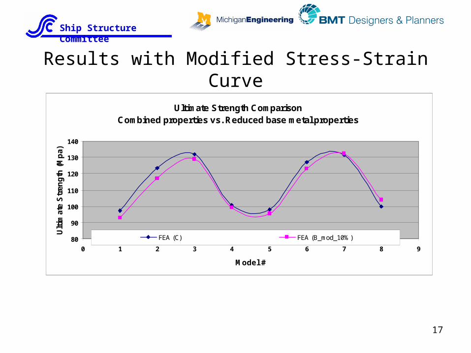
Results with Modified Stress-Strain Curve
Ultimate Strength Comparison Combined properties vs. Reduced base metal properties
80
90
100
110
120
130
140
0 1 2 3 4 5 6 7 8 9
Model #
Ult
imat
e S
tren
gth
(M
pa)
FEA (C) FEA (B_mod_10%)

Ship Structure Committee
18
• In early stages of design, aluminum structure can be modeled as base metal with reduced proof stress (about 10%). This will avoid time consuming analysis of fine mesh models with small HAZ elements.
• Dr. Paik’s empirical formula compares well with FEA and may also be used in the early stages design.
• In critical areas, structure should be modeled as combination of base metal and HAZ.
Compressive Load (cont)

Ship Structure Committee
19
Failure Criteria for Tensile & bending Loads
• Tensile and bending loads – what failure criteria?– Compressive loads reach distinct peak – well defined ultimate
strength– Tensile and bending loads – distinct peak may not be present
– When to stop analysis?• Fracture of weld – difficult without solid element or enriched shell-
element model – not practical• Limiting stress • Limiting strain or overall deflection
• Stress is current acceptance criteria by Classification societies and used in this study

Ship Structure Committee
20
Tensile Load Case
• Run analysis with base, base + HAZ, all HAZ models– 36 models
• Applied displacement range from 10-20mm• Compared the overall tensile force that causes a fixed
portion of the local material’s proof stress to be reached anywhere in the model
• Average stress versus strains are graphed for all 12 models (next 12 slides) along with Yield Point

Ship Structure Committee
21
Results – Tensile LoadModel Plate Stiffener Weld Location
1 Light (4mm)/ 5083 Light (60x3/30x6)/5083 Plate stiffeners connection
Model 1 - Tensile Load
-200
-150
-100
-50
0
0.0 0.1 0.2 0.3 0.4 0.5
Strain (x 10^-2)
Str
ess
(Mp
a)
FEA(C)
FEA(B)
FEA(HZ)
Yield Point
Model1 Model2Strain Stress % difference
Combined 0.003600 -169.7 -base only 0.003667 -174.0 2.6%HAZ only 0.003333 -139.5 -17.8%

Ship Structure Committee
22
Results (cont.)Model Plate Stiffener Weld Location
2 Heavy (6mm)/ 5083 Light (60x3/30x6)/5083 Plate stiffeners connection
Model2 Model3Strain Stress % difference
Combined 0.003600 -169.5 -base only 0.003667 -174.0 2.7%HAZ only 0.003333 -139.5 -17.7%
Model 2 - Tensile Load
-200
-150
-100
-50
0
0.0 0.1 0.2 0.3 0.4 0.5
Strain (x 10^-2)
Str
es
s (
Mp
a)
FEA (C)
FEA (B)
FEA (HZ)
Y ield Point

Ship Structure Committee
23
Results (cont.)Model Plate Stiffener Weld Location
3 Heavy (6mm)/ 5083 heavy (100x6/40x10)/5083 Plate stiffeners connection
Model3 Model4Strain Stress % difference
Combined 0.003600 -168.1 -base only 0.003667 -173.7 3.4%HAZ only 0.003333 -139.3 -17.1%
Model 3 - Tension Load
-200
-150
-100
-50
0
0.0 0.1 0.2 0.3 0.4 0.5
Strain (x 10^-2)
Str
ess
(Mp
a)
FEA (C)
FEA (B)
FEA (HZ)
Yield Point

Ship Structure Committee
24
Results (cont.)Model Plate Stiffener Weld Location
4 Light (4mm)/ 5083 heavy (100x6/40x10 )/5083 Plate stiffeners connection
Model4Strain Stress % difference
Combined 0.003533 -167.8 -base only 0.003667 -173.6 3.5%HAZ only 0.003333 -139.2 -17.0%
Model 4 - Tensiion Load
-200
-150
-100
-50
0
0.0 0.1 0.2 0.3 0.4 0.5
Strain (x 10^-2)
Str
es
s (
Mp
a)
FEA (C)
FEA (B)
FEA (HZ)
Y ield Point

Ship Structure Committee
25
Results (cont.)Model Plate Stiffener Weld Location
5 Light (4mm)/ 5083 Light (60x3/30x6)/6082 Plate stiffeners connection
Model5 Model6Strain Stress % difference
Combined 0.003533 -185.8 -base only 0.003733 -193.7 4.3%HAZ only 0.003333 -138.2 -25.6%
Model 5 - Tension Load
-250
-200
-150
-100
-50
0
0.0 0.1 0.2 0.3 0.4 0.5
Strain (x 10^-2)
Str
es
s 9
Mp
a)
FEA (C)
FEA (B)
FEA (HZ)
Y ield Point

Ship Structure Committee
26
Results (cont.)Model Plate Stiffener Weld Location
6 Heavy (6mm)/ 5083 Light (60x3/30x6)/6082 Plate stiffeners connection
Model6 Model7Strain Stress % difference
Combined 0.003533 -181.2 -base only 0.003733 -188.6 4.1%HAZ only 0.003333 -138.6 -23.5%
Model 6 - Tension Load
-250
-200
-150
-100
-50
0
0.0 0.1 0.2 0.3 0.4
Strain (x 10^-2)
Str
ess
(Mp
a)
FEA (C)
FEA (B)
FEA (HZ)
Yield Point

Ship Structure Committee
27
Results (cont.)Model Plate Stiffener Weld Location
7 Heavy (6mm)/ 5083 heavy (100x6/40x10 )/6082 Plate stiffeners connection
Model7 Model8Strain Stress % difference
Combined 0.003533 -191.6 -base only 0.003733 -203.0 5.9%HAZ only 0.003333 -137.2 -28.4%
Model 7 - Tension Load
-250
-200
-150
-100
-50
00.0 0.1 0.2 0.3 0.4 0.5
Strain (x 10^-2)
Str
ess
(Mp
a)
FEA (C)
FEA (B)
FEA (HZ)
Yield Point

Ship Structure Committee
28
Results (cont.)Model Plate Stiffener Weld Location
8 Light (4mm)/ 5083 heavy (100x6/40x10 )/6082 Plate stiffeners connection
Model8Strain Stress % difference
Combined 0.003533 -197.6 -base only 0.003733 -209.7 6.2%HAZ only 0.003333 -136.6 -30.9%
Model 8 - Tension Load
-250
-200
-150
-100
-50
0
0.0 0.1 0.2 0.3 0.4 0.5
Strain (x 10^-2)
Str
ess
(Mp
a)
FEA (C)
FEA (B)
FEA (HZ)
Yield Point

Ship Structure Committee
29
Results (cont.)Model Plate Stiffener Weld Location
9 Light (4mm)/ 6082 Light (60x3/30x6)/6082 Weld between two extruded
Model 9 - Tension Load
-300
-250
-200
-150
-100
-50
0
0.00 0.10 0.20 0.30 0.40 0.50
Strain (x 10^-2)
Str
es
s (
Mp
a)
FEA (C)
FEA (B)
FEA (HZ)
Yield Point
Model9 Model10Strain Stress % difference
Combined 0.004267 -184.6 -base only 0.004667 -253.4 37.3%HAZ only 0.003200 -133.8 -27.5%

Ship Structure Committee
30
Results (cont.)Model Plate Stiffener Weld Location
10 Heavy (6mm)/ 6082 Light (60x3/30x6)/6082 Weld between two extruded
Model10 Model11Strain Stress % difference
Combined 0.003867 -182.6 -base only 0.004667 -253.5 38.8%HAZ only 0.003200 -133.8 -26.7%
Model 10 - Tension Load
-300
-250
-200
-150
-100
-50
0
0.0 0.1 0.2 0.3 0.4 0.5
Strain (x 10^-2)
Str
es
s (
Mp
a)
FEA (C)
FEA (B)
FEA (HZ)
Yield Point

Ship Structure Committee
31
Results (cont.)Model Plate Stiffener Weld Location
11 Heavy (6mm)/ 6082 heavy (100x6/40x10 )/6082 Weld between two extruded
Model11 Model12Strain Stress % difference
Combined 0.004267 -221.0 -base only 0.004667 -253.1 14.5%HAZ only 0.003200 -133.5 -39.6%
Model 11 - Tension Load
-300
-250
-200
-150
-100
-50
0
0.0 0.1 0.2 0.3 0.4 0.5
Strain (x 10^-2)
Str
ess
(Mp
a)
FEA (C)
FEA (B)
FEA(HZ)
Yield Point

Ship Structure Committee
32
Results (cont.)Model Plate Stiffener Weld Location
12 Light (4mm)/6082 heavy (100x6/40x10 )/6082 Weld between two extruded
Model12Strain Stress % difference
Combined 0.004533 -229.6 -base only 0.004667 -253.0 10.2%HAZ only 0.003200 -133.5 -41.9%
Model 12 - Tension Load
-300
-250
-200
-150
-100
-50
0
0.0 0.1 0.2 0.3 0.4 0.5
Strain (x 10^-2)
Str
ess
(Mp
a)
FEA (C)
FEA (B)
FEA (HZ)
Yield Point

Ship Structure Committee
33
Results – Tensile Load
Tensile Load - Yield Point
-300
-250
-200
-150
-100
-50
0
0 1 2 3 4 5 6 7 8 9 10 11 12 13
Model number
Str
ess
(Mp
a)
FEA ( C )
FEA ( B )
FEA ( HZ )

Ship Structure Committee
34
Results – Tensile Load
Model1 Model2 Model3 Model4Strain Stress % difference Strain Stress % difference Strain Stress % difference Strain Stress % difference
Combined 0.003600 -169.7 - 0.003600 -169.5 - 0.003600 -168.1 - 0.003533 -167.8 -base only 0.003667 -174.0 2.6% 0.003667 -174.0 2.7% 0.003667 -173.7 3.4% 0.003667 -173.6 3.5%HAZ only 0.003333 -139.5 -17.8% 0.003333 -139.5 -17.7% 0.003333 -139.3 -17.1% 0.003333 -139.2 -17.0%
Model5 Model6 Model7 Model8Strain Stress % difference Strain Stress % difference Strain Stress % difference Strain Stress % difference
Combined 0.003533 -185.8 - 0.003533 -181.2 - 0.003533 -191.6 - 0.003533 -197.6 -base only 0.003733 -193.7 4.3% 0.003733 -188.6 4.1% 0.003733 -203.0 5.9% 0.003733 -209.7 6.2%HAZ only 0.003333 -138.2 -25.6% 0.003333 -138.6 -23.5% 0.003333 -137.2 -28.4% 0.003333 -136.6 -30.9%
Model9 Model10 Model11 Model12Strain Stress % difference Strain Stress % difference Strain Stress % difference Strain Stress % difference
Combined 0.004267 -184.6 - 0.003867 -182.6 - 0.004267 -221.0 - 0.004533 -229.6 -base only 0.004667 -253.4 37.3% 0.004667 -253.5 38.8% 0.004667 -253.1 14.5% 0.004667 -253.0 10.2%HAZ only 0.003200 -133.8 -27.5% 0.003200 -133.8 -26.7% 0.003200 -133.5 -39.6% 0.003200 -133.5 -41.9%
Ship Structure Committee
35
• Results for Models 1- 8 show small difference between combined and base model (max 6%).
• Modeling with properties of HAZ is very conservative (17%-30%).
• Results for Models 9 – 12 (AL 6082) indicate large differences depending on the model properties.
• In early stages of design, aluminum structure can be modeled as base metal with reduced proof stress (about 10%). This will give slightly conservative results.
Tensile Load (cont)

Ship Structure Committee
36
Pressure Load Case
• Run analysis with base, base + HAZ, all HAZ models– 36 models
• Applied Pressure range from 0.1 – 0.2 N/mm^2• Compared overall pressure that causes a fixed portion
of the local material’s proof stress to be reached anywhere in the model

Ship Structure Committee
37
Results – Lateral pressure
Yield Point with Lateral Load
0
0.02
0.04
0.06
0.08
0.1
0.12
0.14
0.16
0.18
0.2
0 2 4 6 8 10 12 14
Model #
Lat
eral
Pre
ssu
re (
N/m
m^
2)
FEA(C)
FEA(B)
FEA(HZ)

Ship Structure Committee
38
Results – Lateral pressure
% Difference in Yield Point compared to Combined case
-40%
-30%
-20%
-10%
0%
10%
20%
30%
40%
50%
60%
70%
0 2 4 6 8 10 12 14
Model #
Per
cen
tag
e D
iffe
ren
ce
FEA(B)
FEA(HZ)

Ship Structure Committee
39
• Results for Models 1- 8 indicate about 10% difference between combined and base model.
• Modeling with properties of HAZ is again very conservative (10%-30%).
• Results for Models 9 – 12 (AL 6082) indicate large differences depending on the model properties.
• In early stages of design, aluminum structure can be modeled as base metal with reduced proof stress (about 10%).
Pressure Load (cont)

Ship Structure Committee
40
• Further study to separate impact of material and weld location for 6082.
• Study effect of combined axial and lateral loads.
• Perform experiment under tensile, lateral and combined loads.
Future Work

Ship Structure Committee
41
Thank You