srem-di-csag-003 i1 r5 srem icd pmf003 and upemits.sso.esa.int/.../gaia_eiu/srem-di-csag-003.pdf ·...
TRANSCRIPT

SREM BatchDoc.No.: SREM-DI-CSAG-003Issue: 1 Rev.: 5Date: 15.08.2002 Page: i
© 1999 Contraves Space AG, Zürich / SwitzerlandFür dieses Dokument behalten wir uns alle Rechte vor / We reserve all rights in connection with this document
Distribution of this document is controlled by the Configuration Management Office. Only theholders listed below will automatically be informed of changesRequests for additional copies should be directed to the Project Manager.
Distribution List Issue / Revision
1/- 1/1 1/2 1/3 1/4 1/5
Internal Holders
Name / Acronym, Department Resp. for
H.J. Schneider PM C C C C C C
A. Boner PA C C C C C C
External Holders
Company, Name, Department Resp. for
Customer ESTEC C C C C C C
Legend:A - ApprovalR - ReviewC - CopyU - Updated Pages only
Date:
10.1
0.20
00
30.1
0.20
00
15.1
2.20
00
03.0
4.20
01
15.0
2.20
02
15.0
8.20
02

SREM BatchDoc.No.: SREM-DI-CSAG-003Issue: 1 Rev.: 5Date: 15.08.2002 Page: ii
© 1999 Contraves Space AG, Zürich / SwitzerlandFür dieses Dokument behalten wir uns alle Rechte vor / We reserve all rights in connection with this document
Document Change Record
Issue / Rev. Pages changed,added, removed Date Document Changes Approval
1 / 0 all 10.10.00 Initial Issue
1 / 1 7,11,15 30.10.00
Typographical error corrections in :Table 5.2-1 and paragraph 5.2.7 with respect toPower Supply wiring ,Table 5.4-1 with respect to “On-boardprogramming”
1 / 2 11, 33 15.12.00 Clarification and additional information in :Para. 5.2.6, 5.2.7 and Title of Figure 8.2-1
1 / 3 13-21,23, 27 03.04.01 Correction Chapter 5.2 correction and update ofTable 6.2-2 & 6.3-1 information
1 / 4 22 15.02.02 TM time clarification
1 / 5 5, 18, 22, 26 15.08.02
Added 4.6.3: field of view ‘to Space’.Para. 5.4.4 corrected and updatedPara. 6.2.1 corrected and updatedPara. 6.3 corrected and updated

SREM BatchDoc.No.: SREM-DI-CSAG-003Issue: 1 Rev.: 5Date: 15.08.2002 Page: iii
© 1999 Contraves Space AG, Zürich / SwitzerlandFür dieses Dokument behalten wir uns alle Rechte vor / We reserve all rights in connection with this document
Table of Content
1 SCOPE ................................................................................................................................2
1.1 Scope......................................................................................................................................21.2 Intended Use ...........................................................................................................................2
2 DOCUMENTS / ABBREVIATIONS..........................................................................................3
2.1 Applicable Documents.............................................................................................................32.2 Reference Documents.............................................................................................................32.3 Abbreviations ..........................................................................................................................3
3 SREM BATCH PFM UNITS SYSTEM DESCRIPTION ...............................................................4
4 MECHANICAL INTERFACE...................................................................................................4
4.1 Dimensions .............................................................................................................................44.2 Mass .......................................................................................................................................44.3 Center of Mass ........................................................................................................................44.4 Field-of-View ...........................................................................................................................44.5 External Surfaces and Finishes ...............................................................................................44.6 Mounting .................................................................................................................................4
5 ELECTRICAL INTERFACE ....................................................................................................7
5.1 Connectors..............................................................................................................................75.2 Power Interface .......................................................................................................................75.3 External RadFets................................................................................................................... 135.4 Control and Data Handling Interface ...................................................................................... 145.5 Manufacturer Test Connectors............................................................................................... 185.6 Components (EEE Parts) ...................................................................................................... 21
6 SOFTWARE INTERFACE ....................................................................................................22
6.1 Spacecraft-SREM Handshake ............................................................................................... 226.2 TC-Interface Definition........................................................................................................... 226.3 TM-interface Definition and Timing ........................................................................................ 26
7 ENVIRONMENTAL CHARACTERISTICS ..............................................................................31
7.1 Thermal Interface Characteristics .......................................................................................... 317.2 Shock and Vibration Characteristics ...................................................................................... 317.3 Radiation Environment .......................................................................................................... 317.4 Electromagnetic Compatibility................................................................................................ 317.5 Thermal Vacuum ................................................................................................................... 317.6 Environmental Stress Screening (ESS).................................................................................. 317.7 Burn-in .................................................................................................................................. 31
8 APPENDIX .........................................................................................................................32
8.1 Thermistor Resistance versus Temperature........................................................................... 32

SREM BatchDoc.No.: SREM-DI-CSAG-003Issue: 1 Rev.: 5Date: 15.08.2002 Page: iv
© 1999 Contraves Space AG, Zürich / SwitzerlandFür dieses Dokument behalten wir uns alle Rechte vor / We reserve all rights in connection with this document
8.2 Interface Drawing CR 207 374 AZ C...................................................................................... 33
TABLE OF TABLESTable 4.6-1 Connector Type and Part Numbers .......................................................................................5Table 5.2-1 Description of the Power Connector J1..................................................................................7Table 5.2-2 Power Input Parameters........................................................................................................9Table 5.2-3 ON/OFF-Command Pulse Specification...............................................................................11Table 5.2-4 Status Monitor Output Specification.....................................................................................11Table 5.2-5 Temperature Sensor Interface Specification ........................................................................12Table 5.3-1 Description of the External RadFet Connector J3 ................................................................13Table 5.3-2 External RadFet Interface Specification ...............................................................................14Table 5.4-1 Description of the Data Link Connector J2 ...........................................................................15Table 5.4-2 Data Link Interface Parameters ...........................................................................................18Table 5.5-1 Description of the Power Test Connector J41 ......................................................................18Table 5.5-2 Power Test Connector Voltages ..........................................................................................18Table 5.5-3 Description of the Digital Test Connector J42 ......................................................................19Table 5.5-4 Digital Test Interface Voltages.............................................................................................20Table 5.5-5 Description of the Analog Test Connector J43 .....................................................................20Table 5.5-6 Analog Test Signals Output Specification ............................................................................21Table 6.2-1 Telecommand Format .........................................................................................................22Table 6.2-2 Telecommand Set Table .....................................................................................................23Table 6.2-3 Register Bank Data Structure ..............................................................................................25Table 6.2-4 Memory Patch Command Sequence ...................................................................................26Table 6.3-1 Accumulation File Information .............................................................................................28Table 6.3-2 File (Group, Acquisition and Accumulation) Identification .....................................................29Table 6.3-3 Acquisition File Information .................................................................................................30Table 8.1-1 Thermistor Resistance versus Temperature ........................................................................32
TABLE OF FIGURES
Figure 1.1-1 SREM Batch Proto Flight Model ...........................................................................................2Figure 4.6-1 Interface Connectors............................................................................................................6Figure 5.2-1 Power Connector J1 Interface Schematic.............................................................................8Figure 5.2-2 SREM Batch Grounding and Shielding ...............................................................................10Figure 5.3-1 External RadFet Interface Schematic .................................................................................14Figure 5.4-1 Differential Data Link Interface Schematic ..........................................................................16Figure 5.4-2 Single Ended Data Link Interface Schematic ......................................................................17Figure 6.1-1 Spacecraft Handshake Principle.........................................................................................22Figure 6.3-1 Status Register Information ................................................................................................27Figure 8.2-1 SREM PFM Interface Drawing CR 207 374 AZC ................................................................33

SREM BatchDoc.No.: SREM-DI-CSAG-003Issue: 1 Rev.: 5Date: 15.08.2002 Page: 2
© 1999 Contraves Space AG, Zürich / SwitzerlandFür dieses Dokument behalten wir uns alle Rechte vor / We reserve all rights in connection with this document
1 SCOPE
1.1 Scope
This document defines the interface of the SREM Batch PFM units to the operator.
SREM Batch PFM units (CR RDE 027) are recurring units of SREM PFM2 (CR RDE 005), withhardware and software same as SREM IREM (CR RDE 026)
Figure 1.1-1 SREM Batch Proto Flight Model
1.2 Intended Use
SREM Batch PFM units are intended to be mounted on various spacecrafts to monitor the radiationenvironment and absorbed dose.

SREM BatchDoc.No.: SREM-DI-CSAG-003Issue: 1 Rev.: 5Date: 15.08.2002 Page: 3
© 1999 Contraves Space AG, Zürich / SwitzerlandFür dieses Dokument behalten wir uns alle Rechte vor / We reserve all rights in connection with this document
2 DOCUMENTS / ABBREVIATIONS
2.1 Applicable Documents
The following documents of the exact issue shown are applicable to the extent specifiedherein. If no issue is shown the latest issue is applicable :
AD01 CR 207 374 AZC Mechanical I/F Drawing (SREM/PFM)
2.2 Reference Documents
The following documents are for reference only; they are not needed to operate SREM Batch units.
RD01 CR RDE 027 _A_ SREM Batch (PFM3 and up), Parts ListRD02 CR RDE 026 _A_ IREM (PFM2), Parts ListRD03 CR RDE 005 _A_ SREM (PFM1), Parts ListRD04 TTC-B-01 Issue No.1 Spacecraft Data Handling Interface Standards, Sep 79RD05 EIA-422 Standard for Electrical Characteristics of Generators and
Receivers for used in Balanced Digital LinesRD06 MIL-STD-462D Measurement of Electromagnetic Interference
Characteristics, 11. Jan 93RD07 ESA PSS-01-802, Draft 2Test Requirements Specification for Space Equipment, Oct 95RD08 SREM-LI-CSAG-009 SREM Batch Configuration Items Data ListRD09 RFC-001, -003, -014, -015, -016, -018
Request for Changes covering modification of SREMPFM2 tobecome SREM-IREM
2.3 Abbreviations
CCA Circuit Card Assembly mm millimeterDC Direct Current ms millisecond°C degree Celsius nF nanoFaradEEE Electrical, Electronic, and
ElectromechanicalPSI Paul Scherrer Institute, CH-5232
Villigen, SwitzerlandEM Engineering Model SD16 Serial Data 16 bitFET Field Effect Transistor SREM Standard Radiation Environment
MonitorhPa hektaPascal TC TelecommandIREM Integral Radiation Environment
MonitorTM Telemetry
kg kilogram V VoltkOhm kiloOhm VDC Volt Direct CurrentM4 4 mm metric threaded screw % percentML16 Memory Load 16 bit µA microAmpereMOhm MegaOhm µs microsecond

SREM BatchDoc.No.: SREM-DI-CSAG-003Issue: 1 Rev.: 5Date: 15.08.2002 Page: 4
© 1999 Contraves Space AG, Zürich / SwitzerlandFür dieses Dokument behalten wir uns alle Rechte vor / We reserve all rights in connection with this document
3 SREM BATCH PFM UNITS SYSTEM DESCRIPTION
SREM Batch units detect and count electrons, protons and cosmic rays with a coarse spectral resolution.The measurement are based on silicon diodes polarized in reverse by a high voltage.
SREM Batch PFM units also measure the total radiation dose encountered by SREM itself and atdifferent remote locations on board of the spacecraft for housekeeping purposes.
SREM Batch PFM units operations are controlled by the spacecraft on-board computer via a standardinterface and ultimately of the ground station by means of telecommand and telemetry.
SREM Batch PFM units are powered from the primary power bus of the spacecraft.
4 MECHANICAL INTERFACE
4.1 Dimensions
The maximum dimensions are 242 x 122 x 96 mm (length x width x height); see AD01
4.2 Mass
The maximum mass without the interconnecting harnesses is less than 2.7 kg
4.3 Center of Mass
The center of the mass is shown in AD01
4.4 Field-of-View
Both detector heads have a 20 degree half-cone field-of-view.
4.5 External Surfaces and Finishes
The external surface is coated with thermal black paint (Chemglaze Z306) over a nickel finish.
4.6 Mounting
4.6.1 Hole Pattern
The mounting hole pattern is defined in AD01. The holes in the mounting feet are for M4 type screws.
4.6.2 Orientation
The unit is not mounting orientation sensitive.

SREM BatchDoc.No.: SREM-DI-CSAG-003Issue: 1 Rev.: 5Date: 15.08.2002 Page: 5
© 1999 Contraves Space AG, Zürich / SwitzerlandFür dieses Dokument behalten wir uns alle Rechte vor / We reserve all rights in connection with this document
4.6.3 Detector Field-of-View
The unit should be mounted such that the line of sight (Z-axis; see AD01) is looking outside theSpacecraft. Both detector heads should have a 20 degree half-cone free field-of-view to Space.
4.6.4 Thermal Protection
If the unit is covered by a thermal blanket, leaving both detector head openings uncovered is preferred.
4.6.5 Thermal Path
The main thermal path for heat dissipation from the unit is by conduction from the mounting feet to thespacecraft structure.
4.6.6 Mounting Hardware
The provision of the general mounting hardware (nuts, bolts, etc.) is the responsibility of the operator.
4.6.7 Cabling and Connectors
The provision of the cabling and the connectors is the responsibility of the operator. The test connectorsare not used for normal operation.
4.6.7.1 Connector Types and Part Numbers
To be mated with connector type ESA/SCC 3401/029or the commercial equivalent
SREM ConnectorReference
SREM Connectortype
Order number NomenclatureJ1 MDM 15PBRM7A174 3401029001B15SFR115 MDM connector, 15 pin,
receptacleJ2 MDM 15SBRM7A174 3401029001B15PFR115 MDM connector, 15 pin, plugJ3 MDM 31SBRM7A174 3401029001B31PFR115 MDM connector, 31 pin, plugJ41 (Manufacturer Test only) MDM-9SBRM7A174 3401029001B9PFR115 MDM connector, 9 pin, plugJ42 (Manufacturer Test only) MDM-51SBRM7A174 3401029001B51PFR115 MDM connector, 51 pin, plugJ43 (Manufacturer Test only) MDM-51SBRM7A174 3401029001B25PFR115 MDM connector, 51 pin, plug
Table 4.6-1 Connector Type and Part Numbers

SREM BatchDoc.No.: SREM-DI-CSAG-003Issue: 1 Rev.: 5Date: 15.08.2002 Page: 6
© 1999 Contraves Space AG, Zürich / SwitzerlandFür dieses Dokument behalten wir uns alle Rechte vor / We reserve all rights in connection with this document
Figure 4.6-1 Interface Connectors
4.6.8 Grounded or Isolated Mounting
The unit can be mounted to the host spacecraft in an electrically grounded mode or in an electricallyisolated mode. However, the unit housing is permanently connected to electrical ground via the mountingscrews of the circuit card assemblies inside of the housing. In order to electrically isolate the unitmounting screws from the housing, the screws have to be isolated from the housing.
4.6.8.1 Grounded Mode
In the grounded mode a separate grounding cable can be connected to a grounding lug at the unithousing and to the host spacecraft. The grounding lug is for a M4 type of screw, see AD01.
4.6.8.2 Isolated Mode
To electrically isolate the unit housing from the host spacecraft, an isolating sheet of CHO-THERM® orsimilar thermal gasket material shall be used between the unit baseplate and the mounting feet and thehost spacecraft.

SREM BatchDoc.No.: SREM-DI-CSAG-003Issue: 1 Rev.: 5Date: 15.08.2002 Page: 7
© 1999 Contraves Space AG, Zürich / SwitzerlandFür dieses Dokument behalten wir uns alle Rechte vor / We reserve all rights in connection with this document
5 ELECTRICAL INTERFACE
5.1 Connectors
The unit has a total of 6 microminiature MDM-Type connectors; 3 of which are for power, data andexternal RadFets, which are used for normal operation, and 3 test connectors which are accessible via aremovable (4 screws) cover and are used for manufacturer test purposes only.
5.2 Power Interface
5.2.1 Power Connector J1 (15 pin, plug)
Connector Pin Signal Nomenclature Signal Name /Description
Parameter
1 THERMISTOR_RTN Thermistor return2 RELAY-RTN Status output return3 INTERFACE_GND Interface ground4 OFF_COMMAND Off command pulse See para. 5.2.75 ON_RTN On Command pulse
returnSee para. 5.2.7
6 INTERFACE_GND Interface ground7 PRIMARY-RTN Primary power input
return8 PRIMARY_PWR Primary power input 22 to 55 VDC9 THERMISTOR Thermistor 10 kOhm10 RELAY_SENSE Status Output11 OFF_RTN Off command pulse
returnSee para. 5.2.7
12 INTERFACE_GND Interface ground13 ON_COMMAND On command pulse -See para. 5.2.7
-disconnected for PFM314 PRIMARY_RTN Primary power input
return15 PRIMARY_PWR Primary power input 22 to 55 VDC
Table 5.2-1 Description of the Power Connector J1

SREM BatchDoc.No.: SREM-DI-CSAG-003Issue: 1 Rev.: 5Date: 15.08.2002 Page: 8
© 1999 Contraves Space AG, Zürich / SwitzerlandFür dieses Dokument behalten wir uns alle Rechte vor / We reserve all rights in connection with this document
5.2.2 Power Interface Schematic
Primary PowerPrimary Power
Primary Power ReturnPrimary Power Return
Thermistor
Thermistor Return
Relay SenseRelay Return
15
8
14
7
9
1
10
2
3
6
12
SREM
Power Interface
Interface GND
Thermistor
YSI 44900 - T
Figure 5.2-1 Power Connector J1 Interface Schematic

SREM BatchDoc.No.: SREM-DI-CSAG-003Issue: 1 Rev.: 5Date: 15.08.2002 Page: 9
© 1999 Contraves Space AG, Zürich / SwitzerlandFür dieses Dokument behalten wir uns alle Rechte vor / We reserve all rights in connection with this document
5.2.3 Primary Power Specification (-30°C to +80°C)
Parameter Conditions Min. Typ. Max. UnitsInput Voltage 22 55* VDCTransients to zero Pulswidth: 10µs (10 to 10%)
Repetition: 10 HzInput voltage:- 22 VDC- 55 VDC
-22-55
VV
Transients to twice toinput voltage
Pulswidth: 10 µs (10 to 10%)Repetition: 10 HzInput voltage:- 22 VDC- 55 VDC
+22+55
VV
Square waves Duty cycle: 50 %Rise, fall time less than 20 % of repetitionperiodRepetition: 300 Hz to 300 kHz
1 Vpp
OFF Input Current 2 mAIsolation Resistance Primary_RTN to Interface_GND 1 100 MOhmIsolation Capacitance Primary_RTN to Interface_GND 12 50 nF
Table 5.2-2 Power Input Parameters
* Absolute max. Input Voltage: 60 V. Operation between 50 V and 60 V exceeds the standard derating ofcomponents in the DC/DC converter.
5.2.4 Primary Power Consumption
The maximum power consumption over the input voltage range and operating temperaturerange is 2.6 Watt DC
5.2.5 Grounding
The unit housing is permanently connected to electrical ground via the mounting screws ofthe CCA's inside of the housing.

SREM BatchDoc.No.: SREM-DI-CSAG-003Issue: 1 Rev.: 5Date: 15.08.2002 Page: 10
© 1999 Contraves Space AG, Zürich / SwitzerlandFür dieses Dokument behalten wir uns alle Rechte vor / We reserve all rights in connection with this document
RTN
DC/DC-ConverterShielding
SREM Housing
DC
Groundplane
Groundplane
Groundplane
Shielding
AGND
ShieldingShieldingShielding
+5V
GND
+6V
AGND
-6V
HV_
SREM Grounding and Shielding
AC
DC
AC
DC
AC
DC
ACPrimary Power
AC
DC
HV
1k
+5V
GND
+6V
AGND
-6V
HV_RTN
HV
Detector1
Detector2
Detector3
ChargeAmplifier
D1
ChargeAmplifier
D2
ChargeAmplifier
D3
AGND AGND
AGND
+6V
AGND
-6V
Front End Electronics
Analog Electronics
Groundplane
+5V
GNDDigital Electronics
BondingStud
Interface Ground
Shielding
Figure 5.2-2 SREM Batch Grounding and Shielding

SREM BatchDoc.No.: SREM-DI-CSAG-003Issue: 1 Rev.: 5Date: 15.08.2002 Page: 11
© 1999 Contraves Space AG, Zürich / SwitzerlandFür dieses Dokument behalten wir uns alle Rechte vor / We reserve all rights in connection with this document
5.2.6 Power-On Sequence
The unit requires at least 10 seconds after Power-On until the command and data interface will be ready.For performance measurements a 15 minutes warm-up time shall be observed for PFM3 and PFM4; forPFM5 and up the warm-up time is 4 hours.
5.2.7 Power-On with Autostart
The unit can internally be wired in “Autostart” mode, or in “Autostart&Commanded-Off” mode, or in“Commanded-On, Commanded-Off” mode.
Unless otherwise noted in the logbook, the units are internally wired in the “Commanded-On,Commanded-Off” mode.PFM3, however, is internally wired in the “Autostart&Commanded-Off” mode.
The unit is powered on resp. powered off with a defined pulse to the corresponding input; the pulse shallmeet the following specification (-30 to + 80°C) :Parameter Conditions Min. Typ. Max. Units
VoltageInput currentQuiescent state
Positive Pulse, pulsewidth: 13 ms + 2 ms12 16
300.5
VmAV
Table 5.2-3 ON/OFF-Command Pulse Specification
5.2.8 Status Monitoring
The status of the DC/DC-converter can be monitored via a relay driver output (Drain of FET) atRELAY_SENSE (J1-10), referenced to RELAY_RTN (J1-2) (Source of FET), and to INTERFACE_GND(J1-3, J1-6, J1-12). The +6V output of the DC/DC-converter drives the gate of the FET. RELAY_RTN isconnected internally to INTERFACE_GND; see Figures 5.2-1 and 5.2-2 .
The driver is a transistor type IRHF7110, HEXFET, RadHard, N-channel, 100V, 3.5A, TO-39 (TO-205AF)
Status Monitor Output Specification (-30 to + 80°C)Parameter Conditions Min. Typ. Max. UnitsRelay-senseRONIONUI (Leakage)
ON_state
OFF_State
1018020
100
OhmmAVµA
Table 5.2-4 Status Monitor Output Specification
5.2.9 Temperature Sensor
The temperature of the Power Supply CCA, which is closest to the baseplate of the unit, can bemonitored via a build-in thermistor (J1-9) referenced to THERMISTOR_RTN (J1-1). The 2-wire output iselectrically isolated from the unit housing as well as from any other ground connection; see Figure 5.2-1.The sensor is a thermistor type GSFC311P18-08S7R6, Thermistor, Precision, 10 kOhm at 25 °C, StyleRTH44 (MIL-T-23648/20).

SREM BatchDoc.No.: SREM-DI-CSAG-003Issue: 1 Rev.: 5Date: 15.08.2002 Page: 12
© 1999 Contraves Space AG, Zürich / SwitzerlandFür dieses Dokument behalten wir uns alle Rechte vor / We reserve all rights in connection with this document
Temperature Sensor Interface SpecificationParameter Conditions Min. Typ. Max. UnitsThermistor 25°C 9.959 10.0 10.041 kOhmTemperatureCharacteristic
See Data Sheet YSI 44900 –T(45031) (Appendix)
InterchangeabilityTolerance
0 to 75°CExposure over 75°C can decrease theaccuracy to
+0.1+1
°C°C
Table 5.2-5 Temperature Sensor Interface Specification

SREM BatchDoc.No.: SREM-DI-CSAG-003Issue: 1 Rev.: 5Date: 15.08.2002 Page: 13
© 1999 Contraves Space AG, Zürich / SwitzerlandFür dieses Dokument behalten wir uns alle Rechte vor / We reserve all rights in connection with this document
5.3 External RadFets
Up to 6 external RadFet sensors (total dose sensors) can be connected to the unit via the J3connector. Each RadFet and its temperature sensor requires a 5-wire connection. The provision of theexternal RadFet equipment, cabling, and connectors is the responsibility of the operator.
5.3.1 External RadFet Connector J3 (31 pin, receptacle)
ConnectorPin
SignalNomenclature
Signal Name / Description Type Parameter
1 DOSE_RTN3 External RadFet 3 dose return line signal (-) -6 V2 SUPPLY_DOSE3 Supply line for external RadFet 3 power +6 V3 DOSE2 External RadFet 2 dose signal line signal (+) analog (voltage)4 DOSE_RTN1 External RadFet 1 dose return line signal (-) -6 V5 SUPPLY_DOSE1 Supply line for external RadFet 1 power +6 V6 TEMP3 External RadFet 3 temperature signal line +
terminal of sensorsignal (+) analog (current)
7 TEMP2 External RadFet 2 temperature signal line +terminal of sensor
signal (+) analog (current)
8 TEMP1 External RadFet 1 temperature signal line +terminal of sensor
signal (+) analog (current)
9 DOSE_RTN6 External RadFet 6 dose return line signal (-) -6 V10 SUPPLY_DOSE6 Supply line for external RadFet 6 power +6 V11 DOSE5 External RadFet 5 dose signal line signal (+) analog (voltage)12 DOSE_RTN4 External RadFet 4 dose return line signal (-) -6 V13 SUPPLY_DOSE4 Supply line for external RadFet 4 power +6 V14 TEMP6 External RadFet 6 temperature signal line +
terminal of sensorsignal (+) analog (current)
15 TEMP5 External RadFet 5 temperature signal line +terminal of sensor
signal (+) analog (current)
16 TEMP4 External RadFet 4 temperature signal line +terminal of sensor
signal (+) analog (current)
17 DOSE3 External RadFet 3 dose signal line signal (+) analog (voltage)18 DOSE_RTN2 External RadFet 2 dose return line signal (-) -6 V19 SUPPLY_DOSE2 Supply line for external RadFet 2 power +6 V20 DOSE1 External RadFet 1 dose signal line signal (+) analog (voltage)21 TEMP_RTN3 External RadFet 3 temperature return line -
terminal of sensorsignal (-) analog (current)
22 TEMP_RTN2 External RadFet 2 temperature return line -terminal of sensor
signal (-) analog (current)
23 TEMP_RTN1 External RadFet 1 temperature return line -terminal of sensor
signal (-) analog (current)
24 not connected25 DOSE6 External RadFet 6 dose signal line signal (+) analog (voltage)26 DOSE_RTN5 External RadFet 5 dose return line signal (-) -6 V27 SUPPLY_DOSE5 Supply line for external RadFet 5 power +6 V28 DOSE4 External RadFet 1 dose signal line signal (+) analog (voltage)29 TEMP_RTN6 External RadFet 6 temperature return line -
terminal of sensorsignal (-) analog (current)
30 TEMP_RTN5 External RadFet 5 temperature return line -terminal of sensor
signal (-) analog (current)
31 TEMP_RTN4 External RadFet 4 temperature return line -terminal of sensor
signal (-) analog (current)
Table 5.3-1 Description of the External RadFet Connector J3

SREM BatchDoc.No.: SREM-DI-CSAG-003Issue: 1 Rev.: 5Date: 15.08.2002 Page: 14
© 1999 Contraves Space AG, Zürich / SwitzerlandFür dieses Dokument behalten wir uns alle Rechte vor / We reserve all rights in connection with this document
5.3.2 External RadFet Interface Schematic
SREM
External RadFet Interface
AD590
NMRC03P210-W2
1
B1
4
S
3 2
G D
+
-2
1
CASE
2N3822
D
S
G
Temp x
Temp - RTN x (-6V)
Dose - RTN x (-6V)
Dose x
Supply - Dose x (+6V)
External RadFet Box
ExternalRadFet
ControlledCurrentSource
Figure 5.3-1 External RadFet Interface Schematic
5.3.3 External RadFet Interface Specification
Parameter Conditions Min. Typ. Max. UnitsSupply voltage for ext. RadFet(signal SUPPLY_DOSEx)
referenced to -6V_CRD, no load 11.4 12 12.6 VDC
Output impedance ofSUPPLY_DOSEx
1 kOhm
RadFet voltage DOSEx below+6V_CRD voltage
voltage to frequency converteroperates in linear mode
4 VDC
Current from external RadFetsensors (signals TEMP_(7..1)and corresponding return path)
- temperature range:100 K .. 400 K
- sensor AD590
100 400 µA
Table 5.3-2 External RadFet Interface Specification
5.4 Control and Data Handling Interface
5.4.1 Data Link Connector J2 (15 pin, receptacle)
Connector Pin
SignalNomenclature
Signal Name / Description Type Parameter

SREM BatchDoc.No.: SREM-DI-CSAG-003Issue: 1 Rev.: 5Date: 15.08.2002 Page: 15
© 1999 Contraves Space AG, Zürich / SwitzerlandFür dieses Dokument behalten wir uns alle Rechte vor / We reserve all rights in connection with this document
1 GND Interface ground power2 /WR_EN_EEPROM Used for EEPROM “On-board
programming” 1/input
3 +TM_DATA Telemetry data output, true line output RS4224 +TC_DATA Telecommand data input, true line input RS4225 -TMS Telemetry sampling input, inverted line input RS4226 -TCS Telecommand sampling input, inverted
lineinput RS422
7 not connected8 +CLOCK OBDH Interface clock input, true line input RS4229 +2.5V Single ended mode, logic level
referenceoutput +2.5 V
10 -TM_DATA Telemetry data output, inverted line output RS42211 -TC_DATA Telecommand data input, inverted line input RS42212 not connected13 +TMS Telemetry sampling input, true line input RS42214 +TCS Telecommand sampling input, true line input RS42215 -CLOCK OBDH Interface clock input, inverted line input RS422
1/ To enable “On-board programming” by the operator for PFM3, this input shall be connected to groundJ2-1 PFM4 and up, however, can only be “ On-board programmed“ by the manufacturer, because it isnecessary to also connect an SREM internal jumper wire.
Table 5.4-1 Description of the Data Link Connector J2
5.4.2 Data Link Interface
Two different modes are possible for the data interface. Differential mode with RS422 levels and a singleended mode.

SREM BatchDoc.No.: SREM-DI-CSAG-003Issue: 1 Rev.: 5Date: 15.08.2002 Page: 16
© 1999 Contraves Space AG, Zürich / SwitzerlandFür dieses Dokument behalten wir uns alle Rechte vor / We reserve all rights in connection with this document
5.4.2.1 Data Link Interface Schematic (Differential - Mode)
+Clock-Clock
8
15
14
6
13
5
4
3
10
SREM
11
+TC_Sample-TC_Sample
+TM_Sample-TM_Sample
+TC_Data-TC_Data
+TM_Data+TM_Data
TM/TCController
LSB
MSBData
LD_SH
RD
1K
9
1K
2.5 V
5V_VCC
1GND
Differential Telecommand / -metryInterface
Figure 5.4-1 Differential Data Link Interface Schematic

SREM BatchDoc.No.: SREM-DI-CSAG-003Issue: 1 Rev.: 5Date: 15.08.2002 Page: 17
© 1999 Contraves Space AG, Zürich / SwitzerlandFür dieses Dokument behalten wir uns alle Rechte vor / We reserve all rights in connection with this document
5.4.2.2 Principle Data Link Interface Schematic (Single Ended - Mode)
+Clock 8
15
14
6
13
5
4
3
10
SREM
11
+TC_Sample
+TM_Sample
+TC_Data
+TM_Data
TM/TCController
LSB
MSBData
LD_SH
RD
1K
9
1K
2.5 V
5V_VCC
1GND
Single Ended Telecommand / -metryInterface
GND
Figure 5.4-2 Single Ended Data Link Interface Schematic

SREM BatchDoc.No.: SREM-DI-CSAG-003Issue: 1 Rev.: 5Date: 15.08.2002 Page: 18
© 1999 Contraves Space AG, Zürich / SwitzerlandFür dieses Dokument behalten wir uns alle Rechte vor / We reserve all rights in connection with this document
5.4.3 Data Link Interface Parameters
Parameter Conditions Min. Typ. Max. UnitsDifferential inputsVTH
IINH
IINL
-7 V < VCM < +7 VInputs +10 V and 0 VInputs 0 V and –10 V
200 400+1.8-2.7
mVmAmA
Differential outputsVOH
VOL
IO = -6 mAIO = +3 mA
+3.2+0.3
VV
+2.5V reference output VO no load +2.32 +2.5 +2.68 VTable 5.4-2 Data Link Interface Parameters
5.4.4 Telecommand and Telemetry (TC and TM)
Commands and data are exchanged serially with the spacecraft by means of one ML16 and one SD16interface via the J2 connector. The protocol is in accordance with TTC-B-01 (see RD-04). The signallevels are compliant with EIA-422 standard (see RD-05) and can be set to either differentially (default) orsingle ended by means of external jumper wires at the J2 connector (see Figure 5.4-2). For informationon TC and TM timing please refer to sections 6.2.1 and 6.3 respectively.
5.5 Manufacturer Test Connectors
5.5.1 Power Test Connector J41 (9 pin, receptacle)
ConnectorPin
Signal Nomenclature Signal Name / Description Parameter
1 +5V_TEST +5V_Test output (1 kOhm) +5 V2 +6V_TEST +6V_Test output (1 kOhm) +6 V3 -6V_TEST -6V_Test output (1 kOhm) -6 V4 +28V_TEST +28V_Test output (1 kOhm) +28 V5 HV_TEST HV_Test output 0.0105 x HV) +1.6 V6 TEST_GND Test ground (interface gnd)7 TEST_GND Test ground (interface gnd)8 TEST_GND Test ground (interface gnd)9 TEST_GND Test ground (interface gnd)
Table 5.5-1 Description of the Power Test Connector J41
Power Test Connector Voltages
Parameter Conditions Min. Typ. Max. Units+5V_Test (Rout = 1 kOhm) Load > 1 MOhm VCC VDC+6V_Test (Rout = 1 kOhm) Load > 1 MOhm U(+6V) VDC-6V_Test (Rout = 1 kOhm) Load > 1 MOhm U(-6V) VDC+28V_Test (Rout = 1 kOhm) Load > 1 MOhm U(+28V) VDCHV_Test (Rout = 99 kOhm) Load > 100 MOhm 0.0105 x HV VDC
Table 5.5-2 Power Test Connector Voltages

SREM BatchDoc.No.: SREM-DI-CSAG-003Issue: 1 Rev.: 5Date: 15.08.2002 Page: 19
© 1999 Contraves Space AG, Zürich / SwitzerlandFür dieses Dokument behalten wir uns alle Rechte vor / We reserve all rights in connection with this document
5.5.2 Digital Test Connector J42 (51 pin, receptacle)
ConnectorPin
Signal Nomenclature Signal Name / Description Type Parameter
1 A7 Address bus : bit 7 Output TTL2 A8 Address bus : bit 8 Output TTL3 A9 Address bus : bit 9 Output TTL4 A10 Address bus : bit 10 Output TTL5 +5V VCC (not for supply, resistor in series) Output +5 V6 AS Address strobe Output TTL7 DSN Data strobe Output TTL8 M/ION Memory / I/O select output TTL9 RD/WN Read / Write select output TTL10 O/IN Operand / Instruction select output TTL11 RDN Read strobe output TTL12 WRN Write strobe output TTL13 RDYN Ready output TTL14 CLKOUT Microprocessor reference clock (5MHz) output TTL15 CONFWN Configuration register read strobe output TTL16 /IRQ15 Interrupt request external test interface input TTL17 CONREQN Console request input TTL18 SUREN Start-up ROM enable output TTL19 NPU Normal power-up output TTL20 TGON Trigger-go counter output output TTL21 /FORCE_RESET Input for performing a full reset input TTL22 GND Ground (digital and interface) power23 A0 (LSB) Address bus : bit 0 (LSB) output TTL24 A1 Address bus : bit 1 output TTL25 A2 Address bus : bit 2 output TTL26 A3 Address bus : bit 3 output TTL27 A4 Address bus : bit 4 output TTL28 A5 Address bus : bit 5 output TTL29 A6 Address bus : bit 6 output TTL30 A11 Address bus : bit 11 output TTL31 A12 Address bus : bit 12 output TTL32 A13 Address bus : bit 13 output TTL33 A14 Address bus : bit 14 output TTL34 A15 (MSB) Address bus : bit 15 (MSB) output TTL35 /EXTPROME External PROM and Configuration select input TTL36 D0 (LSB) Data bus : bit 0 (LSB) bidir TTL37 D1 Data bus : bit 1 bidir TTL38 D2 Data bus : bit 2 bidir TTL39 D3 Data bus : bit 3 bidir TTL40 D4 Data bus : bit 4 bidir TTL41 D5 Data bus : bit 5 bidir TTL42 D6 Data bus : bit 6 bidir TTL43 D7 Data bus : bit 7 bidir TTL44 D8 Data bus : bit 8 bidir TTL45 D9 Data bus : bit 9 bidir TTL46 D10 Data bus : bit 10 bidir TTL47 D11 Data bus : bit 11 bidir TTL48 D12 Data bus : bit 12 bidir TTL49 D13 Data bus : bit 13 bidir TTL50 D14 Data bus : bit 14 bidir TTL51 D15 (MSB) Data bus : bit 15 (MSB) bidir TTL
Table 5.5-3 Description of the Digital Test Connector J42

SREM BatchDoc.No.: SREM-DI-CSAG-003Issue: 1 Rev.: 5Date: 15.08.2002 Page: 20
© 1999 Contraves Space AG, Zürich / SwitzerlandFür dieses Dokument behalten wir uns alle Rechte vor / We reserve all rights in connection with this document
Digital Test Interface Voltages
Parameter Conditions Min. Typ. Max. UnitsLogic inputs (on X1, J42)VIH
VIL
IIN VI = VCC or GND
2-0.3–10
VCC
0.3+0.8+10
VVµA
Logic outputs (on X1, J42)VOH
VOL
IOH = -4 mAIOL = +6 mA
+3.7 +0.4 mV
Table 5.5-4 Digital Test Interface Voltages
5.5.3 Analog Test Connector J43 (25 pin, receptacle)
Connector Pin
SignalNomenclature
Signal Name / Description Type Parameter
1 V_PLS_SHP_AMPL1
Shaped pulse detector 1 test output,analog
analog (voltage)
2 V_PLS_SHP_AMPL2
Shaped pulse detector 2 test output,analog
analog (voltage)
3 V_PLS_SHP_AMPL3
Shaped pulse detector 3 test output,analog
analog (voltage)
4 – 9 not connected10 COINCIDENCE coincidence signal,
generated at DigitalElectronic CCA
test output, digital TTL
11 LEVEL11 Comparator output test output, digital TTL12 LEVEL21 Comparator output test output, digital TTL13 LEVEL31 Comparator output test output, digital TTL14 – 16 AGND Analog signal and power
reference potential17 – 22 not connected23 – 25 GND Digital signal and power
reference potential
Table 5.5-5 Description of the Analog Test Connector J43

SREM BatchDoc.No.: SREM-DI-CSAG-003Issue: 1 Rev.: 5Date: 15.08.2002 Page: 21
© 1999 Contraves Space AG, Zürich / SwitzerlandFür dieses Dokument behalten wir uns alle Rechte vor / We reserve all rights in connection with this document
Analog Test Signals Output Specification
Parameter Conditions Min. Typ. Max. UnitssignalsV_PLS_SHP_AMPLx:- amplitude- DC offset- output impedance
of amplitude V_Dx 0.90 0.922
0.9410
%VDCkOhm
output voltage on signals:- LEVEL (31,21,11):
- Low- High
- COINCIDENCE:- Low- High
Isink = 3.2 mA (*)Isource = 100 µA (*) 3.0
2.4
3.50.4
0.4
VDCVDC
VDCVDC
Table 5.5-6 Analog Test Signals Output Specification
(*) Isink and Isource are the total current on the connectors J43 and X1 (internal connector).
5.6 Components (EEE Parts)
5.6.1 Active Parts
Most active parts (microcircuits, semiconductors) are of military or space as listed in the EEE parts list(see RD-08).
5.6.2 Passive Parts
The passive parts (resistors, capacitors, printed wiring boards, ect.) and some active parts are ofcommercial quality grade as listed in the EEE parts list (see RD-08).

SREM BatchDoc.No.: SREM-DI-CSAG-003Issue: 1 Rev.: 5Date: 15.08.2002 Page: 22
© 1999 Contraves Space AG, Zürich / SwitzerlandFür dieses Dokument behalten wir uns alle Rechte vor / We reserve all rights in connection with this document
6 SOFTWARE INTERFACE
6.1 Spacecraft-SREM Handshake
The connection between the unit and other systems has been realized with the serial TC/TM interface inaccordance with TTC-B-01 (see RD-04).There is a master-slave handshake between spacecraft and the unit. The spacecraft is the master andthe unit is the slave. The TC/TM interface is only used when it is requested by the spacecraft.
SpacecraftTC
TMSREM
Figure 6.1-1 Spacecraft Handshake Principle
6.2 TC-Interface Definition
6.2.1 Description and Timing
The unit receives 16 bit commands from the spacecraft via this serial interface.After each command reception an interrupt is generated to synchronise the data transfer. The minimumtime between two consecutive TCs from the spacecraft to SREM shall be 500 micro seconds. Commandsreceived with a shorter time gap are lost. TCs are distinguished into:- Commands- Register_Bank- Program Memory
6.2.2 Telecommands
6.2.2.1 Telecommand Format
All applied Telecommands have the following fixed format :
D15 D11 D10 D0Instruction Operand
Table 6.2-1 Telecommand Format

SREM BatchDoc.No.: SREM-DI-CSAG-003Issue: 1 Rev.: 5Date: 15.08.2002 Page: 23
© 1999 Contraves Space AG, Zürich / SwitzerlandFür dieses Dokument behalten wir uns alle Rechte vor / We reserve all rights in connection with this document
6.2.2.2 Telecommand Set Table
The table below contains all telecommands to communicate bidirectionally between the spacecraft andthe unit.TelecommandName
InstructionCode
Operandvalidity range
Operanddescription
Start accumulation 1 0..7, 0..127 The operand contains theaccumulation group (bit 7..10) andfile (bit 0..6) identifiers
Stop accumulation 2 N/APerform acquisition 3 0..31 Acquisition file identifierGet register 4 0..122 Register bank indexSet register 5 0..122 Register bank indexGet accumulation file 6 0..7, 0..127 The operand contains the
accumulation group (bit 7..10) andfile (bit 0..6) identifiers
Get acquisition file 7 0..31 Acquisition file identifierGet group 8 0..7 Group identifierGet memory 9 0..2047 The total number of 16 word
memory segments is 2048 (0..2047).
Get register more 10 N/AGet accumulation file more 11 N/AGet acquisition file more 12 N/AGet group more 13 N/AGet memory more 14 N/AMemory patch 15 0..2047 The total number of 16 word
memory segments is 2048 (0..2047).The number of 16 word programmemory segments is 512 (0..511).The number of 16 word datamemory segments is 1536(512..2047).
Integral Mode ON 16 0..2047 Accumulation Interval Size (0..127)Housekeeping Interval Size (1..15)
Integral Mode OFF 17 N/AIntegral Counting ON 18 N/A Proton Counter ID (0 .. 4)
Electron Counter ID (11 .. 14)Integral Counting OFF 19 N/A
Integral Ground Link ON 20 N/AIntegral Ground Link OFF 21 N/A
Integral Block TransmissionLimit
22 0..2047 Block Transmission Time Limit(1 .. 2047)
Table 6.2-2 Telecommand Set Table

SREM BatchDoc.No.: SREM-DI-CSAG-003Issue: 1 Rev.: 5Date: 15.08.2002 Page: 24
© 1999 Contraves Space AG, Zürich / SwitzerlandFür dieses Dokument behalten wir uns alle Rechte vor / We reserve all rights in connection with this document
6.2.3 Register_Bank
The Register_Bank is a composite data structure and it contains the following entities. Each entity isselected by an index ranging from 0 to 122 and it can be read by a 'Get Register' or can be written by a'Set Register' command.
Index Entity Identification Dim. Type Function0 SREM_STATUS none ushort SREM_CSCI status12
LT 100 ms / LSB ulong Local time
3 WFC none ushort Watchdog failure counter4 CFC " " Checksum failure counter5 DTCCR 5 µs / LSB " DTC clock register67
TC1_processed none ulong Total counts D1
89
S12_processed " " Proton alarm
1011
S13_processed " " Single protons
1213
S14_processed " " Single protons
1415
S15_processed " " Single protons
1617
TC2_processed " " Total counts D2
1819
S25_processed " " Heavy ions
2021
C1_processed " " Coincidence; protons
2223
C2_processed " " Coincidence;. protons
2425
C3_processed " " Coincidence; protons
2627
C4_processed " " Coincidence; protons
2829
TC3_processed " " Total counts D3
3031
S32_processed " " Electron alarm
3233
S33_processed " " Proton counts
3435
S34_processed " " Proton counts
3637
PL1 " " Dead time correction count (Busycounting rate) D1
3839
PL2 " " DTC count(Busy counting rate) D2
4041
PL3 none ulong Dead time correction count(Busy counting rate) D3
42 PAC_id " ushort Proton Alarm scaler ID (TC1..S34)

SREM BatchDoc.No.: SREM-DI-CSAG-003Issue: 1 Rev.: 5Date: 15.08.2002 Page: 25
© 1999 Contraves Space AG, Zürich / SwitzerlandFür dieses Dokument behalten wir uns alle Rechte vor / We reserve all rights in connection with this document
4344
PA_hy_lev " ulong Number of proton hyperactivity eventsper 10 sec period
4546
PA_un_lev " " Number of proton underactivity eventsper 10 sec period
47 EAC_id " ushort Electron Alarm scaler ID (TC1..S34)4849
EA_hy_lev " ulong Number of electron hyperactivityevents per 10 sec period
5051
EA_un_lev " " Number of electron underactivityevents per 10 sec period
52 AM_interval 10 µs / LSB ushort Analog measuring interval53 T_1_raw Hz " External temperature sensor 154 T_1_processed K " "55 T_2_raw Hz " External temperature sensor 256 T_2_processed K " "57 T_3_raw Hz " External temperature sensor 358 T_3_processed K " "59 T_4_raw Hz " External temperature sensor 460 T_4_processed K " "61 T_5_raw Hz " External temperature sensor 562 T_5_processed K " "63 T_6_raw Hz " External temperature sensor 664 T_6_processed K " "65 T_7_raw Hz " Internal temperature sensor66 T_7_processed K " "67 T_8_raw Hz " D1/D2 temperature sensor68 T_8_processed K " "69 T_9_raw Hz " D3 temperature sensor70 T_9_processed K " "71 RE_1_raw Hz " Reserve 172 RE_1_processed none " "73 RE_2_raw Hz " Reserve 274 RE_2_processed none " "75 RE_3_raw Hz " Reserve 376 RE_3_processed none " "77 RE_4_raw Hz " Reserve 478 RE_4_processed none " "79 RE_5_raw Hz " Reserve 580 RE_5_processed none " "81 RE_6_raw Hz " Reserve 682 RE_6_processed none " "121 C_checksum " " Current Checksum122 Version_ID " " SREM_CSCI version ID
Table 6.2-3 Register Bank Data Structure

SREM BatchDoc.No.: SREM-DI-CSAG-003Issue: 1 Rev.: 5Date: 15.08.2002 Page: 26
© 1999 Contraves Space AG, Zürich / SwitzerlandFür dieses Dokument behalten wir uns alle Rechte vor / We reserve all rights in connection with this document
6.2.4 Program Loading via Memory Patch
A program data segment is loaded into the program RAM with the 'Memory Patch' command. The dataformat of all segment entities is 'ushort'. The table below shows a 'Memory Patch' command sequencethat includes 3 control words (Index 0, 1, 18) and 16 data words (Index 2 to17).
Index D15 D11 D10 D0 Type0 Memory Patch
InstructionSegment Address ushort
1 Logical Inverse of MemoryPatch Instruction
Logical Inverse of Segment Address "
2 Memory Segment Word 0 "3 Memory Segment Word 1 "4 Memory Segment Word 2 "5 memory Segment Word 3 "6 Memory Segment Word 4 "7 Memory Segment Word 5 "8 Memory Segment Word 6 "9 Memory Segment Word 7 "10 Memory Segment Word 8 "11 Memory Segment Word 9 "12 Memory Segment Word 10 "13 Memory Segment Word 11 "14 Memory Segment Word 12 "15 Memory Segment Word 13 "16 Memory Segment Word 14 "17 Memory Segment Word 15 "18 Memory Segment Termination Word (MSTW) "
Table 6.2-4 Memory Patch Command Sequence
6.3 TM-interface Definition and Timing
The unit transmits 16 bit data to the spacecraft via this interface. After a TC reception the unit replieswithin 1ms maximum via the TM register. The minimum time between two consecutive TM data readsshall be 300 microseconds. Every time the spacecraft reads the TM registers, the unit will be informedby an acknowledge interrupt.TM data are distinguished into:- Register_Bank- Accumulation files- Groups- Acquisition files- Program Memory
Note: All data of the Register_Bank are readable and writeable with the exception of the Local Timeentity, which is only readable.

SREM BatchDoc.No.: SREM-DI-CSAG-003Issue: 1 Rev.: 5Date: 15.08.2002 Page: 27
© 1999 Contraves Space AG, Zürich / SwitzerlandFür dieses Dokument behalten wir uns alle Rechte vor / We reserve all rights in connection with this document
6.3.1 Register_Bank
The Register_Bank contents are read with the 'Get Register' and 'Get Register More' commands. Eachentity is selected by an index ranging from 0 to 122.
6.3.1.1 Status
The SREM_CSCI status register (SREM_STATUS) is a 16 bit word of the Register_Bank anddecomposed as follows :
Figure 6.3-1 Status Register Information
D15 D0
SREM State (busy = 1, ready = 0)
Proton Alarm Hyperactivity (yes = 1, no = 0)
Proton Alarm Underactivity (yes = 1, no = 0)
Electron Alarm Hyperactivity (yes = 1, no = 0)
Electron Alarm Underactivity (yes = 1, no = 0)
Watchdog Elapsed (yes = 1, no = 0)
Checksum Failure (yes = 1, no = 0)
High Voltage (on = 1, off = 0)
6.0V Voltage Out of Range (yes = 1, no = 0)
5.0 Voltage Out of Range (yes = 1, no = 0)
Command Validity (valid = 1, invalid = 0)
Operation Mode (Integral = 1, Standard = 0)
Integral Counting (on = 1, off = 0)
Accumulation (on = 1, off = 0)
BIT / TDB (failed =1, passed = 0)
Integral Ground Link (on = 1, off = 0)

SREM BatchDoc.No.: SREM-DI-CSAG-003Issue: 1 Rev.: 5Date: 15.08.2002 Page: 28
© 1999 Contraves Space AG, Zürich / SwitzerlandFür dieses Dokument behalten wir uns alle Rechte vor / We reserve all rights in connection with this document
6.3.2 Accumulation File
The Accumulation File contains the data collected during accumulation. It also contains a group and a fileidentification, the SREM_CSCI status and the local accumulation start and stop times.
Index Entity Identification Dim. Type Function0 Accumulation file ID none ushort Accumulation group/file identification1 ST " " SREM_STATUS23
START_A_LT 100 ms /LSB
ulong Start accumulation local time
45
STOP_A_LT 100 ms /LSB
" Stop accumulation local time
67
TC1_raw none " Total counts D1
89
S12_raw " " Proton alarm
1011
S13_raw " " Single protons
1213
S14_raw " " Single protons
1415
S15_raw " " Single protons
1617
TC2_raw " " Total counts D2
1819
S25_raw " " Heavy ions
2021
C1_raw " " Coincidence; protons
2223
C2_raw " " Coincidence; protons
2425
C3_raw " " Coincidence; protons
2627
C4_raw " " Coincidence; protons
2829
TC3_raw " " Total counts D3
3031
S32_raw " " Electron alarm
3233
S33_raw " " Proton counts
3435
S34_raw " " Proton counts
3637
PL1 " " Dead time correction count D1
3839
PL2 " " Dead time correction count D2
4041
PL3 " " Dead time correction count D3
Table 6.3-1 Accumulation File Information

SREM BatchDoc.No.: SREM-DI-CSAG-003Issue: 1 Rev.: 5Date: 15.08.2002 Page: 29
© 1999 Contraves Space AG, Zürich / SwitzerlandFür dieses Dokument behalten wir uns alle Rechte vor / We reserve all rights in connection with this document
6.3.3 Group
Each of the 8 Groups contains its Group identification, one Acquisition File and 128 Accumulation Files.
Group No. Acqu.File No.
Accu.File No.
Entity Identification
0 Group identification" 0 Acquisition file identification" " Acquisition file data" " "" " ." " ." " 0 Accumulation file identification (Group Root File)" " " Accumulation file data" " " "" " . ." " . ." " 127 Accumulation file identification" " " Accumulation file data" " " ". . . .. . . .. . . .. . . .7 . . Group identification" 7 . Acquisition file identification" " . Acquisition file data" " . "" " . ." " . ." " 0 Accumulation file identification (Group Root File)" " " Accumulation file data" " " "" " . ." " . ." " 127 Accumulation file identification" " " Accumulation file data" " " "
Table 6.3-2 File (Group, Acquisition and Accumulation) Identification

SREM BatchDoc.No.: SREM-DI-CSAG-003Issue: 1 Rev.: 5Date: 15.08.2002 Page: 30
© 1999 Contraves Space AG, Zürich / SwitzerlandFür dieses Dokument behalten wir uns alle Rechte vor / We reserve all rights in connection with this document
6.3.4 Acquisition File
The Acquisition File contains the actual total doses and temperatures of the corresponding internal andexternal sensors. In addition the Acquisition File includes the Acquisition File identification, theSREM_CSCI status and the local time.
Note: After a reset or restart the first valid acquisition data are available after 15 seconds.
Index Entity Identification Dim. Type Function0 Acquisition file ID none ushort Acquisition file identification1 SREM_STATUS " " SREM_CSCI status23
LT 100 ms / LSB ulong Local time
4 T_1_raw Hz ushort External temperature sensor 15 T_2_raw " " External temperature sensor 26 T_3_raw " " External temperature sensor 37 T_4_raw " " External temperature sensor 48 T_5_raw " " External temperature sensor 59 T_6_raw " " External temperature sensor 610 T_7_raw " " Internal temperature sensor11 T_8_raw " " D1/D2 temperature sensor12 T_9_raw " " D3 temperature sensor13 D_1_raw " " External total dose sensor 114 D_2_raw " " External total dose sensor 215 D_3_raw " " External total dose sensor 316 D_4_raw " " External total dose sensor 417 D_5_raw " " External total dose sensor 518 D_6_raw " " External total dose sensor 619 D_7_raw " " Internal total dose sensor20 AM_interval 10 µs / LSB " Analog measurement interval21 V_cal_ref_1_raw Hz " Calibration reference voltage 122 V_cal_ref_2_raw " " Calibration reference voltage 223 V_cal_ref_3_raw " " Calibration reference voltage 324 V_cal_ref_4_raw " " Calibration reference voltage 425 C_cal_ref_1_raw " " Calibration temperature Tc26 C_cal_ref_2_raw " " Calibration offset temperature Tofs27 SP none " Spare28 " " " "
Table 6.3-3 Acquisition File Information
6.3.5 Program Reading
A program data segment is read from the program RAM with the 'Get Memory' or 'Get Memory More'command. The data format is 'ushort'.

SREM BatchDoc.No.: SREM-DI-CSAG-003Issue: 1 Rev.: 5Date: 15.08.2002 Page: 31
© 1999 Contraves Space AG, Zürich / SwitzerlandFür dieses Dokument behalten wir uns alle Rechte vor / We reserve all rights in connection with this document
7 ENVIRONMENTAL CHARACTERISTICS
7.1 Thermal Interface Characteristics
7.1.1 Operating Temperature Range
The operating temperature range is –20 °C up to +60 °C.
7.1.2 Storage Temperature Range
The storage temperature range is –55 °C up to +100 °C.
7.1.3 Thermal Protection
Mounting the unit under a thermal blanket is preferred. Leaving the detector headsuncovered is preferred.
7.2 Shock and Vibration Characteristics
The unit is designed and qualified for the environments in accordance with ESA PSS-01-802 Draft 2 (seeRD-07), paragraphs 4.2.4 (Sinusoidal Vibration), 4.2.5 (Random Vibration), and 4.2.7 (Shock Test).PFM3 unit only is tested in all 3 axis, subsequent units are tested in the z-axis only.
7.3 Radiation Environment
The unit has been exposed to a 60 Co gamma source check at the PSI.
7.4 Electromagnetic Compatibility
The unit is designed and qualified for the environments CE01, CE03, CS01, CS03, RE02, and RS03 ofMIL-STD-462 (see RD-06).
7.5 Thermal Vacuum
The unit is designed and qualified for an ambient pressure of less than 1.3 x10⁻⁵ hPa .
7.6 Environmental Stress Screening (ESS)
PFM3 only is exposed to a Thermal Vacuum Cycle Test (4 cycles, -25/+60 °C).All units are exposed to a 24 hour bake-out test at +55 °C at an ambient pressure of less than 1.3 x10⁻⁵hPa.
7.7 Burn-in
The unit is burned-in at power-on for a total of more than 240 hours. During this time the unit is exposedto 15 thermal cycles –20/+55 °C .

SREM BatchDoc.No.: SREM-DI-CSAG-003Issue: 1 Rev.: 5Date: 15.08.2002 Page: 32
© 1999 Contraves Space AG, Zürich / SwitzerlandFür dieses Dokument behalten wir uns alle Rechte vor / We reserve all rights in connection with this document
8 APPENDIX
8.1 Thermistor Resistance versus Temperature
R Temp R Temp R Temp R Temp R Temp R Temp[Ohm] [°C] [Ohm] [°C] [Ohm] [°C] [Ohm] [°C] [Ohm] [°C] [Ohm] [°C]
237 150 561.6 114 1549 78 5193 42 22430 6 135200 -30242.3 149 576.4 113 1598 77 5389 41 23460 5 143000 -31247.8 148 591.6 112 1648 76 5592 40 24550 4 151200 -32253.4 147 607.3 111 1700 75 5805 39 25690 3 160000 -33259.2 146 623.5 110 1754 74 6026 38 26890 2 169300 -34265.1 145 640.3 109 1810 73 6258 37 28150 1 179200 -35271.2 144 657.5 108 1868 72 6500 36 29490 0 189800 -36277.4 143 675.3 107 1928 71 6752 35 30890 -1 201100 -37283.8 142 693.6 106 1990 70 7016 34 32370 -2 213200 -38290.6 141 712.6 105 2055 69 7291 33 33930 -3 226000 -39297.2 140 732.1 104 2122 68 7579 32 35570 -4 239800 -40304.2 139 752.3 103 2191 67 7880 31 37310 -5 254400 -41311.3 138 773.1 102 2264 66 8194 30 39140 -6 270000 -42318.7 137 794.6 101 2339 65 8523 29 41070 -7 286700 -43326.3 136 816.8 100 2417 64 8867 28 43110 -8 304600 -44
334 135 839.7 99 2497 63 9227 27 45270 -9 323700 -45342 134 863.4 98 2582 62 9605 26 47540 -10 344100 -46
350.3 133 887.9 97 2669 61 10000 25 49940 -11 366000 -47358.7 132 913.2 96 2760 60 10410 24 52480 -12 389400 -48367.4 131 939.3 95 2854 59 10840 23 55170 -13 414500 -49376.4 130 966.3 94 2952 58 11290 22 58010 -14 441900 -50385.6 129 994.2 93 3054 57 11770 21 61020 -15 470100 -51395.1 128 1023 92 3160 56 12260 20 64200 -16 501000 -52404.9 127 1053 91 3270 55 12790 19 67570 -17 534100 -53414.9 126 1084 90 3385 54 13330 18 71130 -18 569600 -54425.3 125 1116 89 3504 53 13900 17 74910 -19 607800 -55435.9 124 1149 88 3629 52 14500 16 78910 -20 648800 -56446.9 123 1183 87 3758 51 15130 15 83160 -21 692800 -57458.2 122 1218 86 3893 50 15790 14 87660 -22 740200 -58469.8 121 1255 85 4033 49 16490 13 92430 -23 791100 -59481.8 120 1293 84 4179 48 17220 12 97490 -24 845900 -60494.1 119 1337 83 4331 47 17980 11 102900 -25506.8 118 1372 82 4489 46 18790 10 108600 -26519.9 117 1414 81 4655 45 19630 9 114600 -27533.4 116 1458 80 4827 44 20520 8 121100 -28547.3 115 1503 79 5006 43 21450 7 127900 -29
Table 8.1-1 Thermistor Resistance versus Temperature
SREM BatchDoc.No.: SREM-DI-CSAG-003Issue: 1 Rev.: 5Date: 15.08.2002 Page: 33
© 1999 Contraves Space AG, Zürich / SwitzerlandFür dieses Dokument behalten wir uns alle Rechte vor / We reserve all rights in connection with this document
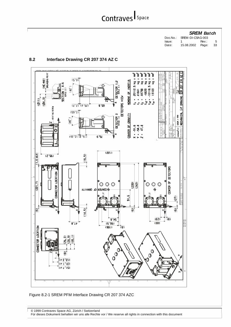
8.2 Interface Drawing CR 207 374 AZ C
Figure 8.2-1 SREM PFM Interface Drawing CR 207 374 AZC