sri-surf: a better surf powered by scaled-ram … · sri-surf: a better surf powered by scaled-ram...
TRANSCRIPT

SRI-SURF: A Better SURF Powered byScaled-RAM Interpolator on FPGA
Xijie Jia1,3, Kaiyuan Guo1, Wenqiang Wang4, Yu Wang1,2 and Huazhong Yang1
1E.E. Dept., TNLIST, Tsinghua University, Beijing, China; [email protected];3Kunming Institute of Physics, Kunming 650223, China; 4Microsoft Research Asia, Beijing, China
Abstract—Speed-Up Robust Feature (SURF) is an effectivealgorithm for feature extraction. We propose a novel Scaled-RAMInterpolator (SRI) on FPGA to deal with the high complexity ofSURF by introducing two methods. 1) Interpolation of IntegralImage (I3) restores the sub-pixel details of image to improvematching precision, and halves the memory access to achieveacceleration; 2) Multi-Scaled RAM (MSR) normalizes the storageallocation by scale to decrease complexity of memory access andreject redundant memory. With SRI, our system achieves bettermatching precision, higher processing speed, and lower storageoccupation. The results of evaluation implemented on Stratix IIIEP3SL340 FPGA show that 1) our SRI-SURF system performsbetter in matching than OpenSURF; 2) the system is capable toprocess 241K feature points per second (PPS), which is about7× of previous work on FPGA and is comparable to the recentASIC solution; 3) the maximal frame rate reaches 488FPS atVGA and 72FPS at 1080P, which outperforms designs in otherpublications; 4) our design is compact, which only occupies about22% logic resource and about 43% RAM resource at 1080P. Theproposed SRI-SURF meets the demand of real-time embeddedapplications with better precision at high resolution.
I. INTRODUCTION
Feature extraction is one of the key fundamental tasks incomputer vision field. Extracted features are usually usedto find corresponding regions between two images of thesame scene or object[1]. These features are usually invariantto affine transformations including translation, scale, rota-tion, and shear. Many aspects are challenging the task, forexample, various lights, different view angles, and noisefrom image sensor[2]. Feature extraction has been appliedwidely, such as in image mosaic[3], object recognition[4], 3Dreconstruction[5], and crowd counting[6]. These applicationsall require high matching precision on high resolution videosat real-time processing speed on embedded platform.
A lot of algorithms have been proposed to extract featurepoints, such as SIFT (Scale Invariant Feature Transform)[7],PCA-SIFT (Principle Component Analysis SIFT)[8], GLOH(Gradient Location-Orientation Histogram)[9], and SURF(Speed-Up Robust Feature)[1]. Among them, SURF, com-prised by stages Detection and Description, is 6000x fasterthan the others on CPU[10]. This is achieved by speeding upconvolution into near constant time with integral image. How-ever, SURF is still too complex to run at acceptable frame rate
This work was supported by 973 project 2013CB329000, National NaturalScience Foundation of China (No. 61373026), the Importation and Devel-opment of High-Caliber Talents Project of Beijing Municipal Institutions,Tsinghua University Initiative Scientific Research Program, and Huawei.
on serial computing platforms, such as CPU[11], especially forthe Detection stage[12]. SURF also allows parallel-processingbetween scales, which is much more suitable than SIFT to berealized on parallel hardware platforms for better performance.The Detection stage has been well solved by applying slide-window[12], switching the bottleneck of the SURF system tothe Description stage, where computation should be processedserially by points. Thus the processing of descriptor needsfurther acceleration.
The performance of a SURF system could be evaluatedby the following criteria: 1) frame rate (frames per second,FPS), a key metric of evaluating the performance of videosystem, should achieve at least 30FPS for real-time process-ing; 2) feature points per frame (PPF), related to the imageresolution and texture complexity, represents the workload ofthe system, and may cause decrease of FPS; 3) feature pointsper second (PPS). The MAX-PPS, calculated by the ratio ofclock frequency and clock cycles of computing one points,represents the calculating capacity of the system. The ACT-PPS, calculated by the product of frame rate and average-PPF, represents the requirement of application. For example,as for a video @640×480, 30FPS, 500PPF, the system needs15KPPS; as for a video @1920×1080, 30FPS, 3300PPF, therequirement increases to 99KPPS.
Early work on SURF acceleration is mainly implementedon GPU platform because of its good portability andhigh performance (32KPPS on GTX480 @791×704, 40FPS,800PPF[13]). But the energy efficiency of GPU is usu-ally low. FPGA platform achieves better energy efficiency.Due to the difficulty of hardware architecture design, sim-plification is usually done to implement SURF on FPGA[2][14][15][16][17]. But the performance was still insufficient(35KPPS on Virtex 6 @640×480, 356FPS, 100PPF[12]).ASIC provides best energy efficiency and higher performance(285KPPS on ASIC @1920×1080, 57FPS, ∼5000PPF[18]),but suffers from low flexibility and long development cycle.Considering the energy requirement of embedded system andthat the design of FPGA could be a part of design flow ofASIC, we choose FPGA hardware platform to accelerate theSURF algorithm. Thus we have to deal with the challenge onperformance when mapping SURF onto FPGA.
Besides, we also have to face the challenges on matchingprecision and resource occupation. The precision loss in pre-vious work is due to that: 1) the continuous image is sampledinto pixels by camera, causing quantization error and loss of
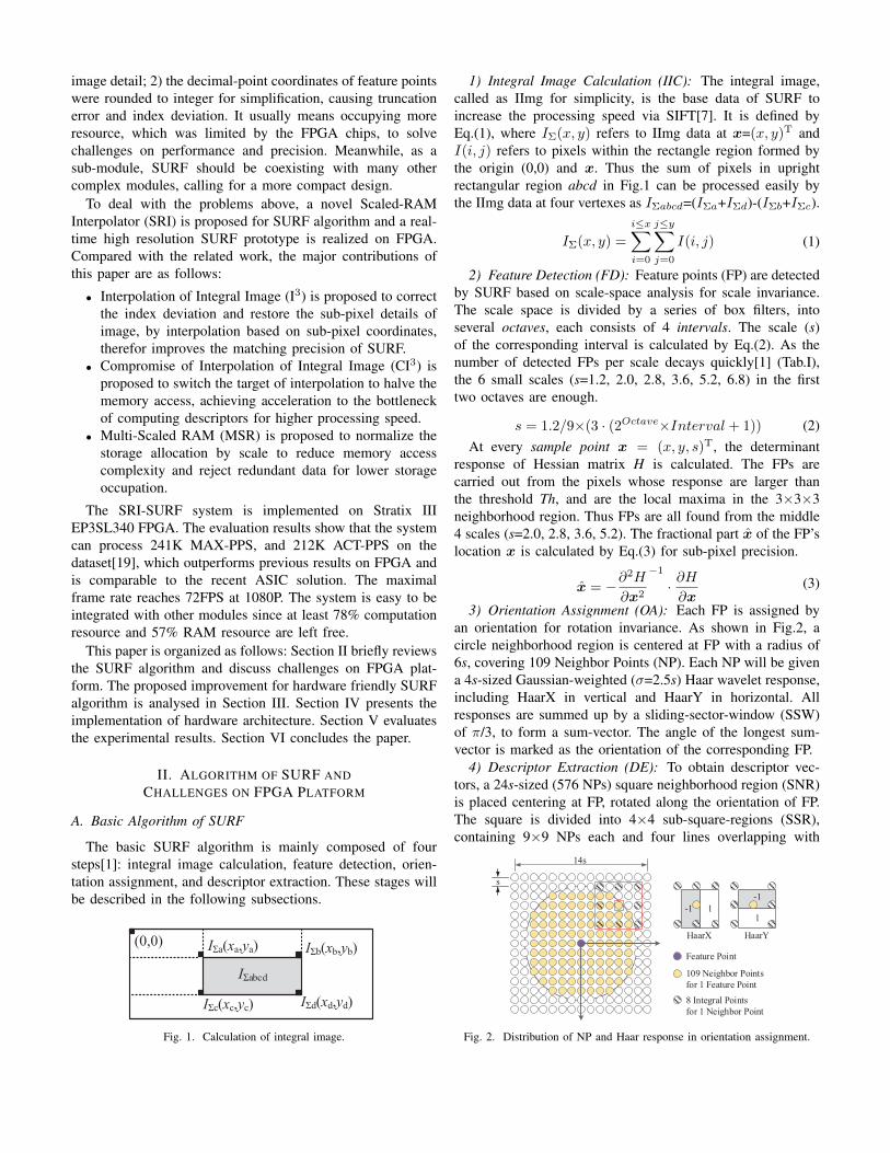
image detail; 2) the decimal-point coordinates of feature pointswere rounded to integer for simplification, causing truncationerror and index deviation. It usually means occupying moreresource, which was limited by the FPGA chips, to solvechallenges on performance and precision. Meanwhile, as asub-module, SURF should be coexisting with many othercomplex modules, calling for a more compact design.
To deal with the problems above, a novel Scaled-RAMInterpolator (SRI) is proposed for SURF algorithm and a real-time high resolution SURF prototype is realized on FPGA.Compared with the related work, the major contributions ofthis paper are as follows:
• Interpolation of Integral Image (I3) is proposed to correctthe index deviation and restore the sub-pixel details ofimage, by interpolation based on sub-pixel coordinates,therefor improves the matching precision of SURF.
• Compromise of Interpolation of Integral Image (CI3) isproposed to switch the target of interpolation to halve thememory access, achieving acceleration to the bottleneckof computing descriptors for higher processing speed.
• Multi-Scaled RAM (MSR) is proposed to normalize thestorage allocation by scale to reduce memory accesscomplexity and reject redundant data for lower storageoccupation.
The SRI-SURF system is implemented on Stratix IIIEP3SL340 FPGA. The evaluation results show that the systemcan process 241K MAX-PPS, and 212K ACT-PPS on thedataset[19], which outperforms previous results on FPGA andis comparable to the recent ASIC solution. The maximalframe rate reaches 72FPS at 1080P. The system is easy to beintegrated with other modules since at least 78% computationresource and 57% RAM resource are left free.
This paper is organized as follows: Section II briefly reviewsthe SURF algorithm and discuss challenges on FPGA plat-form. The proposed improvement for hardware friendly SURFalgorithm is analysed in Section III. Section IV presents theimplementation of hardware architecture. Section V evaluatesthe experimental results. Section VI concludes the paper.
II. ALGORITHM OF SURF ANDCHALLENGES ON FPGA PLATFORM
A. Basic Algorithm of SURF
The basic SURF algorithm is mainly composed of foursteps[1]: integral image calculation, feature detection, orien-tation assignment, and descriptor extraction. These stages willbe described in the following subsections.
(0,0)
IΣabcd
IΣa(xa,ya) IΣb(xb,yb)
IΣc(xc,yc) IΣd(xd,yd)
Fig. 1. Calculation of integral image.
1) Integral Image Calculation (IIC): The integral image,called as IImg for simplicity, is the base data of SURF toincrease the processing speed via SIFT[7]. It is defined byEq.(1), where IΣ(x, y) refers to IImg data at x=(x, y)T andI(i, j) refers to pixels within the rectangle region formed bythe origin (0,0) and x. Thus the sum of pixels in uprightrectangular region abcd in Fig.1 can be processed easily bythe IImg data at four vertexes as IΣabcd=(IΣa+IΣd)-(IΣb+IΣc).
IΣ(x, y) =
i≤x∑i=0
j≤y∑j=0
I(i, j) (1)
2) Feature Detection (FD): Feature points (FP) are detectedby SURF based on scale-space analysis for scale invariance.The scale space is divided by a series of box filters, intoseveral octaves, each consists of 4 intervals. The scale (s)of the corresponding interval is calculated by Eq.(2). As thenumber of detected FPs per scale decays quickly[1] (Tab.I),the 6 small scales (s=1.2, 2.0, 2.8, 3.6, 5.2, 6.8) in the firsttwo octaves are enough.
s = 1.2/9×(3 · (2Octave×Interval + 1)) (2)At every sample point x = (x, y, s)T, the determinant
response of Hessian matrix H is calculated. The FPs arecarried out from the pixels whose response are larger thanthe threshold Th, and are the local maxima in the 3×3×3neighborhood region. Thus FPs are all found from the middle4 scales (s=2.0, 2.8, 3.6, 5.2). The fractional part x̂ of the FP’slocation x is calculated by Eq.(3) for sub-pixel precision.
x̂ = −∂2H
∂x2
−1
· ∂H∂x
(3)
3) Orientation Assignment (OA): Each FP is assigned byan orientation for rotation invariance. As shown in Fig.2, acircle neighborhood region is centered at FP with a radius of6s, covering 109 Neighbor Points (NP). Each NP will be givena 4s-sized Gaussian-weighted (σ=2.5s) Haar wavelet response,including HaarX in vertical and HaarY in horizontal. Allresponses are summed up by a sliding-sector-window (SSW)of π/3, to form a sum-vector. The angle of the longest sum-vector is marked as the orientation of the corresponding FP.
4) Descriptor Extraction (DE): To obtain descriptor vec-tors, a 24s-sized (576 NPs) square neighborhood region (SNR)is placed centering at FP, rotated along the orientation of FP.The square is divided into 4×4 sub-square-regions (SSR),containing 9×9 NPs each and four lines overlapping with
Feature Point
109 Neighbor Points
for 1 Feature Point
14s
s
-1 1
-1
1
8 Integral Points
for 1 Neighbor Point
HaarX HaarY
Fig. 2. Distribution of NP and Haar response in orientation assignment.
yF
xO
Sub Region 1
Sub Region 2Overlap area
Feature Point
4x4 Center Points of
Sub-Square-Regions
24x24 Neighbor Points
for 1 Feature Point
xF
dxF
dyF
dx
dy
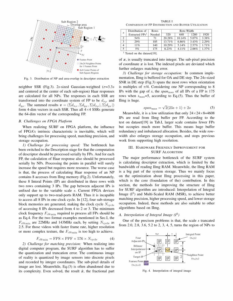
Fig. 3. Distribution of NP and area-overlap in descriptor extraction
neighbor SSR (Fig.3). 2s-sized Gaussian-weighted (σ=3.3sand centered at the center of each sub-region) Haar responsesare calculated for all NPs. The responses in each SSR aretransformed into the coordinate system of FP to be dxF
anddyF
. The summed results v = (ΣdxF,ΣdyF
,Σ|dxF|,Σ|dyF
|)form 4-dim vectors in each SSR. Thus all 4×4 SSRs generatethe 64-dim vector of the corresponding FP.
B. Challenges on FPGA Platform
When realizing SURF on FPGA platform, the influenceof FPGA’s intrinsic characteristic is inevitable, which willbring challenges for processing speed, matching precision, andstorage occupation.
1) Challenge for processing speed: The bottleneck hasbeen switched to the Description stage for that the computationof descriptor should be processed serially by FPs. And for eachFP, the calculation of Haar response also should be processedserially by NPs. Processing the points in parallel will surelyincrease the speed but requires more resource. The worse caseis that, the process of calculating Haar response of an NPcontains 8 accesses from IImg memory (Fig.2). Unfortunately,these 8 Interal Points (IP) are distributed in three rows withtwo rows containing 3 IPs. The gap between adjacent IPs isunfixed due to the variable scale s. Current FPGA devicesonly support up to two-read-ports RAM. Thus it is incapableto access all 8 IPs in one clock cycle. In [12], four sub-storageblock memories are generated, making the clock cycle Ncycle
of accessing 8 IPs decreased from 4 to 2 or 3. The minimumclock frequency Fclkmin required to process all FPs should beas Eq.4. For the two format examples mentioned in Sec.I, theFclkmin are 22MHz and 143MHz each, by setting Ncycle as2.5. For those videos with faster frame rate, higher resolutionor more complex texture, the Fclkmin is too high to achieve.
Fclkmin = FPS× PPF× 576×Ncycle (4)2) Challenge for matching precision: When realizing into
digital computer program, the SURF algorithm has to sufferthe quantization and truncation error. The continuous imageof reality is quantized by image sensors into discrete pixelsand recorded by integer coordinates. The sub-pixel details ofimage are lost. Meanwhile, Eq.(3) is often abandoned due toits complexity. Even solved, the result x̂, the fractional part
TABLE ICOMPARISON OF FP DISTRIBUTION AND BUFFER UTILIZATION
sDistribution of Rows Row-WidthExtracted FPs1 Needed 320 640 1280 1920
2 54% 71 20.28% 10.14% 5.07% 3.38%3 29% 105 13.71% 6.86% 3.43% 2.29%4 11% 140 10.29% 5.14% 2.57% 1.71%5 5% 175 8.23% 4.11% 2.06% 1.37%1 Tested on the dataset[19].
of x, is usually truncated into integer. The sub-pixel precisionof coordinate x is lost. The indexed pixels are deviated whichfurther enlarges matching error.
3) Challenge for storage occupation: In common imple-mentation, IImg is buffered for OA and DE step. The 24s-sizedSNR in DE step (Fig.3) spans the most rows when orientationis multiples of π/4. Considering one NP corresponding to 8IPs with the gap of s, the spanmax of all IPs of a FP is 175rows when smax=5, according to Eq.(5). Thus the buffer ofIImg is huge.
spanmax =√
2(23s+ 1) + 2s (5)Meanwhile, it is a low utilization that only 24×24×8=4608
IPs are read from IImg buffer per FP. According to thetest on dataset[19] in Tab.I, larger scale contains fewer FPsbut occupies much more buffer. This means huge bufferredundancy and imbalanced allocation. Besides, the wide row-width also enlarges storage occupation, and stops previouswork from supporting high resolution.
III. HARDWARE FRIENDLY IMPROVEMENT FORSURF ALGORITHM
The major performance bottleneck of the SURF systemis calculating descriptor extraction, which is limited by thebandwidth of reading IImg RAM. Meanwhile, the IImg RAMis a big part of the system storage. Thus we mainly focuson the optimization about IImg processing in this paper,which is the core (foundation of the) contribution. In thissection, the methods for improving the structure of IImgfor SURF algorithm are introduced: Interpolation of IntegralImage (I3) and Multi-Scaled RAM (MSR), to achieve bettermatching precision, higher processing speed, and lower storageoccupation. Indeed, these methods are also suitable to otheralgorithms based on IImg.
A. Interpolation of Integral Image (I3)
One of the precison problems is that, the scale s trancatedfrom 2.0, 2.8, 3.6, 5.2 to 2, 3, 4, 5, turns the region of NPs to
nVs
nHs
Feature Point
(xF,yF,s)
Neighbor Point
(xN,yN)
FP
NP
IP
IP
IP IP IP
IP
IPIP
s
s
Integral Point
(xI,yI)
Bilinear
Interpolation
on IP
Four
Adjacent-IPs
Target-IP
Fig. 4. Interpolation of integral image
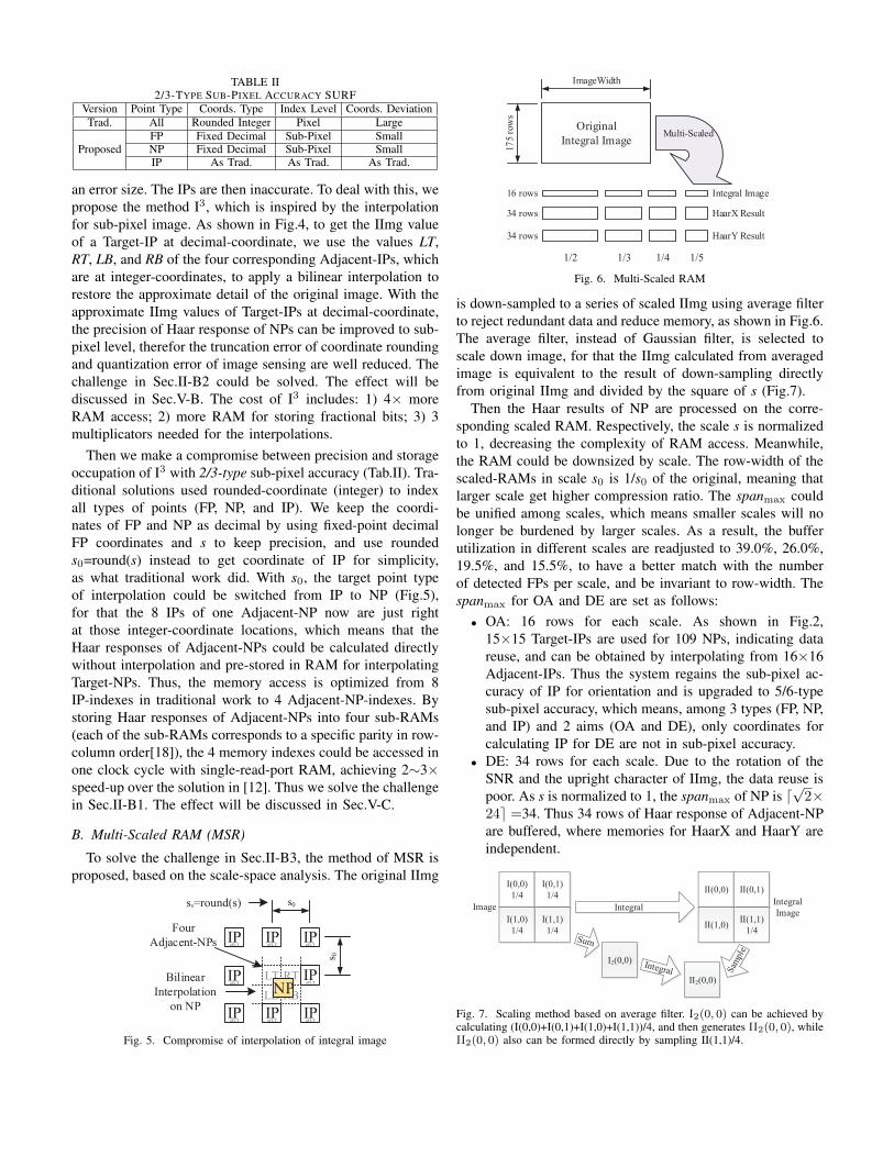
TABLE II2/3-TYPE SUB-PIXEL ACCURACY SURF
Version Point Type Coords. Type Index Level Coords. DeviationTrad. All Rounded Integer Pixel Large
ProposedFP Fixed Decimal Sub-Pixel SmallNP Fixed Decimal Sub-Pixel SmallIP As Trad. As Trad. As Trad.
an error size. The IPs are then inaccurate. To deal with this, wepropose the method I3, which is inspired by the interpolationfor sub-pixel image. As shown in Fig.4, to get the IImg valueof a Target-IP at decimal-coordinate, we use the values LT,RT, LB, and RB of the four corresponding Adjacent-IPs, whichare at integer-coordinates, to apply a bilinear interpolation torestore the approximate detail of the original image. With theapproximate IImg values of Target-IPs at decimal-coordinate,the precision of Haar response of NPs can be improved to sub-pixel level, therefor the truncation error of coordinate roundingand quantization error of image sensing are well reduced. Thechallenge in Sec.II-B2 could be solved. The effect will bediscussed in Sec.V-B. The cost of I3 includes: 1) 4× moreRAM access; 2) more RAM for storing fractional bits; 3) 3multiplicators needed for the interpolations.
Then we make a compromise between precision and storageoccupation of I3 with 2/3-type sub-pixel accuracy (Tab.II). Tra-ditional solutions used rounded-coordinate (integer) to indexall types of points (FP, NP, and IP). We keep the coordi-nates of FP and NP as decimal by using fixed-point decimalFP coordinates and s to keep precision, and use roundeds0=round(s) instead to get coordinate of IP for simplicity,as what traditional work did. With s0, the target point typeof interpolation could be switched from IP to NP (Fig.5),for that the 8 IPs of one Adjacent-NP now are just rightat those integer-coordinate locations, which means that theHaar responses of Adjacent-NPs could be calculated directlywithout interpolation and pre-stored in RAM for interpolatingTarget-NPs. Thus, the memory access is optimized from 8IP-indexes in traditional work to 4 Adjacent-NP-indexes. Bystoring Haar responses of Adjacent-NPs into four sub-RAMs(each of the sub-RAMs corresponds to a specific parity in row-column order[18]), the 4 memory indexes could be accessed inone clock cycle with single-read-port RAM, achieving 2∼3×speed-up over the solution in [12]. Thus we solve the challengein Sec.II-B1. The effect will be discussed in Sec.V-C.
B. Multi-Scaled RAM (MSR)
To solve the challenge in Sec.II-B3, the method of MSR isproposed, based on the scale-space analysis. The original IImg
NP
s0
s 0
s0=round(s)
Bilinear
Interpolation
on NP
IPof L T
IPof L T
IPof L T
IPof L T
IPof L T
IPof L T
IPof L T
IPof L T
Four
Adjacent-NPs
Fig. 5. Compromise of interpolation of integral image
Original
Integral Image
ImageWidth
17
5 r
ow
s
1/2 1/3 1/4 1/5
16 rows
34 rows
34 rows
Multi-Scaled
Integral Image
HaarX Result
HaarY Result
Fig. 6. Multi-Scaled RAM
is down-sampled to a series of scaled IImg using average filterto reject redundant data and reduce memory, as shown in Fig.6.The average filter, instead of Gaussian filter, is selected toscale down image, for that the IImg calculated from averagedimage is equivalent to the result of down-sampling directlyfrom original IImg and divided by the square of s (Fig.7).
Then the Haar results of NP are processed on the corre-sponding scaled RAM. Respectively, the scale s is normalizedto 1, decreasing the complexity of RAM access. Meanwhile,the RAM could be downsized by scale. The row-width of thescaled-RAMs in scale s0 is 1/s0 of the original, meaning thatlarger scale get higher compression ratio. The spanmax couldbe unified among scales, which means smaller scales will nolonger be burdened by larger scales. As a result, the bufferutilization in different scales are readjusted to 39.0%, 26.0%,19.5%, and 15.5%, to have a better match with the numberof detected FPs per scale, and be invariant to row-width. Thespanmax for OA and DE are set as follows:
• OA: 16 rows for each scale. As shown in Fig.2,15×15 Target-IPs are used for 109 NPs, indicating datareuse, and can be obtained by interpolating from 16×16Adjacent-IPs. Thus the system regains the sub-pixel ac-curacy of IP for orientation and is upgraded to 5/6-typesub-pixel accuracy, which means, among 3 types (FP, NP,and IP) and 2 aims (OA and DE), only coordinates forcalculating IP for DE are not in sub-pixel accuracy.
• DE: 34 rows for each scale. Due to the rotation of theSNR and the upright character of IImg, the data reuse ispoor. As s is normalized to 1, the spanmax of NP is d
√2×
24e =34. Thus 34 rows of Haar response of Adjacent-NPare buffered, where memories for HaarX and HaarY areindependent.
I2(0,0)
II2(0,0)
I(0,0)
1/4
I(0,1)
1/4
I(1,0)
1/4
I(1,1)
1/4
ImageIntegral
Image
II(0,0) II(0,1)
II(1,0)II(1,1)
1/4
Integral
Fig. 7. Scaling method based on average filter. I2(0, 0) can be achieved bycalculating (I(0,0)+I(0,1)+I(1,0)+I(1,1))/4, and then generates II2(0, 0), whileII2(0, 0) also can be formed directly by sampling II(1,1)/4.

Scaled-RAM Interpolator
I3
I3
Scaled
Haar
WaveletI3
MSR IImg
RAM Scale 2~5
SII
SubEE
SII
SubEO
SII
SubOE
SII
SubOO
LT RT
LB RBRD
MSR Haar
RAM Scale 2~5
SHX
SubEE
SHX
SubEO
SHX
SubOE
SHX
SubOO
RAM Scale 2~5
SHY
SubEE
SHY
SubEO
SHY
SubOE
SHY
SubOO
LT RT
LB RB
LT RT
LB RB
Calc
Haar
3xIMG_W
HaarY
HaarX
WR
WR
RD
IImg
Generator
Feature Detector
Det
1234
6Dets
(WLR=18)Orientation Generator
Scaled
IImg Pos
Generator
Scaled
IImg
Pos
Scaled
Integral
Image
Calc
Haar
5x15
FindOri
HaarXsin
cosFP
Ori
Descriptor Generator
Scaled
Haar Pos
Generator
FindDes64-dim
vectorFP
Des
IImg
Slide
WLRDet Scale 1
Det Scale 3
Det Scale 6
...
WLR
WLR
...
...
FindLocMax
Octave1
FindLocMax
Octave2
Det
2456
Find
Extreme
FP
Pos
FP
Pos
DataIn
Buffer
Image
In
NormDataOut
Buffer
FP
OutFP
All
FP
Pos
Scaled
Haar
Pos
HaarY
Img IImg WR
Clock Driven
Legend
clkwr
clkrd
clkwrclkrd
Pressure
Feedback
PPF Feedback
Fig. 8. Overall hardware architecture of the SRI-SURF system, including six main modules: Integral Image Generator (IIG), Feature Detector (FD), Scaled-RAM Interpolator (SRI), Orientation Generator (OG), Descriptor Generator (DG), and Normalizer (Norm).
...Frame 1 Input / Integral Image Calculation / Multi-Scaled Store
FeatureDetection Octave 2
FeatureDetection Octave 1
Descriptor1 ...2 3 N
Orientation...2 ..2 3 N221
...
N
NNN
Frame 2 Input / Integral Image Calculation / Multi-Scaled Store
FeatureDetection Octave 2
FeatureDetection Octave 1
Descriptor1 ...2 3 N
Orientation...2 ..2 3 N21
Time of one frame of input image
Time of one frame of output descriptor
Output
delay
Fig. 9. Operation flow of the designed architecture
With the help of MSR, the system is well compressed. In ourdesign, scale 2 to 5 are considered, indicating (16+34×2)×(1/2+1/3+1/4+1/5) =108 rows of RAM with original row-width. Without MSR, the spanmax of IP is 175 accordingto Eq.(5). Thus 38% RAM is saved. The costs of MSRare: 1) lower RAM reuse ratio due to specialized RAM, butcould be covered by MSR for reducing RAM size; 2) somehigh frequency details of image may be lost, but could becompensated by I3 for increasing precision. The effect will bediscussed in Sec.V-C.
Processing of DE is time consuming, due to high complexityof SURF. Our system needs 623 clock cycles for processingone FP of DE as introduced in Sec.V-C, which is comparableto the input time of one row of a small image. This leads tolarge amount of backlogged FPs. A buffered row may be wipedbefore all the FPs involved by this row finish calculations.Thus a few rows of safe-buffer should be added which enlargesbuffer size. The results will be shown in Sec.V-C.
IV. PROPOSED HARDWARE IMPLEMENTATION
A. Overall Architecture
Fig.8 shows the overall hardware architecture of the pro-posed SRI-SURF system, including six main modules: IImg
Generator (IIG), Feature Detector (FD), Scaled-RAM Interpo-lator (SRI), Orientation Generator (OG), Descriptor Generator(DG), and Normalizer (Norm). Comparing to traditional SURFsystem, the SRI module, powered by I3 and MSR methods, isthe key contribution in this paper. Its design detail is discussedin Section IV-C. While for preliminary, the design of the otherfive traditional modules are first briefly shown in Section IV-B.
Among all these modules, IIG, FD, RAM-Writing part ofSRI, and Norm are driven by clock clkwr, and RAM-Reading-and-Interpolation part of SRI, OG, and DG are driven byclock clkrd. This dual-clk domain structure is used to adaptdata input rate to maintain computation capacity. The systemis controlled by two closed-loop negative feedbacks to copewith the backlogged feature points. A signal from DG toIIG, indicating the processing pressure ratio, tunes the inputframe rate dynamically. A signal from Norm to FD, indicatingthe amount of processed feature points in a frame, tunesthe threshold Th of candidate points dynamically. Higher Thmeans that fewer feature points can be extracted.
The operation flow of the system is shown in Fig.9. Theprocessing and store of IImg are processed in parallel. Thecalculation of FD is well pipelined. For each FP, the steps ofcalculating OG and DG are pipelined. With the help of ournovel SRI module, the processing time of DG is saved, and the
FindOri
CODERCORDIC
HaarX
HaarY
...
36x Sub
Sum
...
+-
X2
Y2
Find
MaxOri
CORDIC
Angle
Gauss
Sqr
Y
X
FP
Pos
Scaled
IImg Pos
Generator
Scaled
Iimg Pos
Scaled
Integral Image
Calc
Haar
5x15
FP
Ori
Fig. 10. Architecture of Orientation Generator
system performance is accelerated to keep up with the inputvideo frame rate.
B. Brief Introduction to Design of Traditional Modules
1) IImg Generator (IIG): IIG module reads pixels from in-put buffer and outputs IImg data. Word Length Reduction[20]is applied to reduce bit-width of IImg, saving 33% RAM for8-bit VGA and 38% for 1080P.
2) Feature Detector (FD): FD module is implemented forlocating FPs. The core structure shown in Fig.8 is similarwith the work in [12]. IImgSlide module integrates a slidingwindow to index 32 IImg data for each scale of Det mod-ules. Results of 6 Dets are rearranged back to two octaves,assigned by FindLocMax module each to find local maxima.FindExtreme module solves Eq.(3).
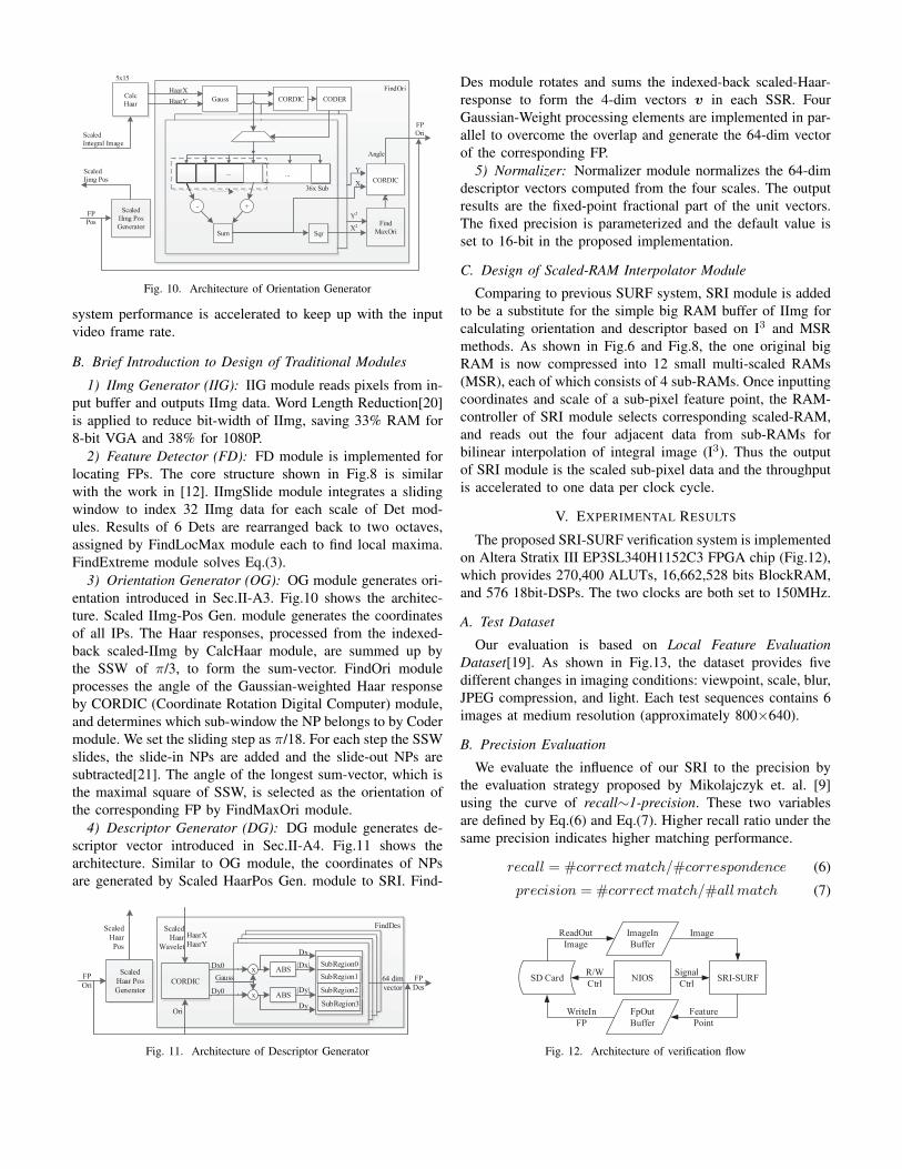
3) Orientation Generator (OG): OG module generates ori-entation introduced in Sec.II-A3. Fig.10 shows the architec-ture. Scaled IImg-Pos Gen. module generates the coordinatesof all IPs. The Haar responses, processed from the indexed-back scaled-IImg by CalcHaar module, are summed up bythe SSW of π/3, to form the sum-vector. FindOri moduleprocesses the angle of the Gaussian-weighted Haar responseby CORDIC (Coordinate Rotation Digital Computer) module,and determines which sub-window the NP belongs to by Codermodule. We set the sliding step as π/18. For each step the SSWslides, the slide-in NPs are added and the slide-out NPs aresubtracted[21]. The angle of the longest sum-vector, which isthe maximal square of SSW, is selected as the orientation ofthe corresponding FP by FindMaxOri module.
4) Descriptor Generator (DG): DG module generates de-scriptor vector introduced in Sec.II-A4. Fig.11 shows thearchitecture. Similar to OG module, the coordinates of NPsare generated by Scaled HaarPos Gen. module to SRI. Find-
nn000
nnnn
151515151515
nnnn
n
151515
nnn0
nn
1515
nnnn
15151515
6464
ve
64
FindDes
FP
Ori
Scaled
Haar
Pos
Scaled
Haar
Wavelet
64 dim
vector
FP
Des6464
HaarX
HaarY
ABSx
x
Gauss
ABS
CORDIC
Dx0
Dy0
Ori
Dx
|Dx|
|Dy|
Dy
SubRegion0
SubRegion1
SubRegion2
SubRegion3
Scaled
Haar Pos
Generator
Fig. 11. Architecture of Descriptor Generator
Des module rotates and sums the indexed-back scaled-Haar-response to form the 4-dim vectors v in each SSR. FourGaussian-Weight processing elements are implemented in par-allel to overcome the overlap and generate the 64-dim vectorof the corresponding FP.
5) Normalizer: Normalizer module normalizes the 64-dimdescriptor vectors computed from the four scales. The outputresults are the fixed-point fractional part of the unit vectors.The fixed precision is parameterized and the default value isset to 16-bit in the proposed implementation.
C. Design of Scaled-RAM Interpolator Module
Comparing to previous SURF system, SRI module is addedto be a substitute for the simple big RAM buffer of IImg forcalculating orientation and descriptor based on I3 and MSRmethods. As shown in Fig.6 and Fig.8, the one original bigRAM is now compressed into 12 small multi-scaled RAMs(MSR), each of which consists of 4 sub-RAMs. Once inputtingcoordinates and scale of a sub-pixel feature point, the RAM-controller of SRI module selects corresponding scaled-RAM,and reads out the four adjacent data from sub-RAMs forbilinear interpolation of integral image (I3). Thus the outputof SRI module is the scaled sub-pixel data and the throughputis accelerated to one data per clock cycle.
V. EXPERIMENTAL RESULTS
The proposed SRI-SURF verification system is implementedon Altera Stratix III EP3SL340H1152C3 FPGA chip (Fig.12),which provides 270,400 ALUTs, 16,662,528 bits BlockRAM,and 576 18bit-DSPs. The two clocks are both set to 150MHz.
A. Test Dataset
Our evaluation is based on Local Feature EvaluationDataset[19]. As shown in Fig.13, the dataset provides fivedifferent changes in imaging conditions: viewpoint, scale, blur,JPEG compression, and light. Each test sequences contains 6images at medium resolution (approximately 800×640).
B. Precision Evaluation
We evaluate the influence of our SRI to the precision bythe evaluation strategy proposed by Mikolajczyk et. al. [9]using the curve of recall∼1-precision. These two variablesare defined by Eq.(6) and Eq.(7). Higher recall ratio under thesame precision indicates higher matching performance.
recall = #correctmatch/#correspondence (6)
precision = #correctmatch/#all match (7)
SD Card NIOS
ImageIn
Buffer
FpOut
Buffer
SRI-SURF
ReadOut
Image
Image
Feature
Point
WriteIn
FP
R/W
Ctrl
Signal
Ctrl
Fig. 12. Architecture of verification flow
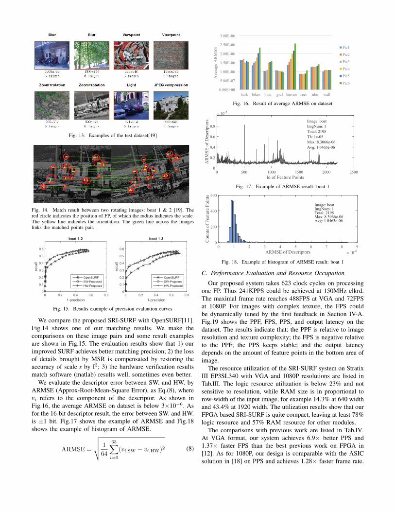
Fig. 13. Examples of the test dataset[19]Pic1: 1
Pic2: 2
Ori Mode: intpfixed
Des Mode: intpfixed
Threshold: 0.009
Total Ips1: 108
Total Ips2: 110
Top Percent: 0.3000
Matched Ipts: 17
Lapped ipts: 17
Plot DiffY%: -0.0100
Plot DiffValue: -4.8000
Count DiffY: 17
DiffY Perct: 1
Fig. 14. Match result between two rotating images: boat 1 & 2 [19]. Thered circle indicates the position of FP, of which the radius indicates the scale.The yellow line indicates the orientation. The green line across the imageslinks the matched points pair.
1-precision
0 0.2 0.4 0.6 0.8
recall
0
0.1
0.2
0.3
0.4
0.5
0.6
boat 1-2
OpenSURF
SW-Proposed
HW-Proposed
1-precision
0 0.2 0.4 0.6 0.8
recall
0
0.1
0.2
0.3
0.4
0.5
0.6
boat 1-3
OpenSURF
SW-Proposed
HW-Proposed
Fig. 15. Results example of precision evaluation curves
We compare the proposed SRI-SURF with OpenSURF[11].Fig.14 shows one of our matching results. We make thecomparisons on these image pairs and some result examplesare shown in Fig.15. The evaluation results show that 1) ourimproved SURF achieves better matching precision; 2) the lossof details brought by MSR is compensated by restoring theaccuracy of scale s by I3; 3) the hardware verification resultsmatch software (matlab) results well, sometimes even better.
We evaluate the descriptor error between SW. and HW. byARMSE (Approx-Root-Mean-Square Error), as Eq.(8), wherevi refers to the component of the descriptor. As shown inFig.16, the average ARMSE on dataset is below 3×10⁻⁶. Asfor the 16-bit descriptor result, the error between SW. and HW.is ±1 bit. Fig.17 shows the example of ARMSE and Fig.18shows the example of histogram of ARMSE.
ARMSE =
√√√√ 1
64
63∑i=0
(vi,SW − vi,HW)2 (8)
0.00E+00
5.00E-07
1.00E-06
1.50E-06
2.00E-06
2.50E-06
3.00E-06
bark bikes boat graf leuven trees ubc wall
Aver
age
AR
MS
E Pic1
Pic2
Pic3
Pic4
Pic5
Pic6
Fig. 16. Result of average ARMSE on dataset
Id of Feature Points
0 500 1000 1500 2000 2500
AR
MS
E o
f D
escr
ipto
rs
10-5
0
0.2
0.4
0.6
0.8
1
Image: boat
ImgNum: 1
Total: 2198
Th: 1e-05
Max: 8.3066e-06
Avg: 1.0463e-06
Fig. 17. Example of ARMSE result: boat 1
ARMSE of Descriptors 10-6
0 1 2 3 4 5 6 7 8 9
Co
un
ts o
f F
eatu
re P
oin
ts
0
200
400
600
Image: boatImgNum: 1Total: 2198Max: 8.3066e-06Avg: 1.0463e-06
Fig. 18. Example of histogram of ARMSE result: boat 1
C. Performance Evaluation and Resource Occupation
Our proposed system takes 623 clock cycles on processingone FP. Thus 241KPPS could be achieved at 150MHz clkrd.The maximal frame rate reaches 488FPS at VGA and 72FPSat 1080P. For images with complex texture, the FPS couldbe dynamically tuned by the first feedback in Section IV-A.Fig.19 shows the PPF, FPS, PPS, and output latency on thedataset. The results indicate that: the PPF is relative to imageresolution and texture complexity; the FPS is negative relativeto the PPF; the PPS keeps stable; and the output latencydepends on the amount of feature points in the bottom area ofimage.
The resource utilization of the SRI-SURF system on StratixIII EP3SL340 with VGA and 1080P resolutions are listed inTab.III. The logic resource utilization is below 23% and notsensitive to resolution, while RAM size is in proportional torow-width of the input image, for example 14.3% at 640 widthand 43.4% at 1920 width. The utilization results show that ourFPGA based SRI-SURF is quite compact, leaving at least 78%logic resource and 57% RAM resource for other modules.
The comparisons with previous work are listed in Tab.IV.At VGA format, our system achieves 6.9× better PPS and1.37× faster FPS than the best previous work on FPGA in[12]. As for 1080P, our design is comparable with the ASICsolution in [18] on PPS and achieves 1.28× faster frame rate.

0
1000
2000
3000
4000
5000
bark bikes boat graf leuven trees ubc wall
Po
ints
Per
Fra
me
(PP
F)
Pic1
Pic2
Pic3
Pic4
Pic5
Pic6
(a) PPF, average is 2KPPF.
0
50
100
150
200
250
bark bikes boat graf leuven trees ubc wall
Fra
mes
Per
Sec
ond
(F
PS
)
Pic1
Pic2
Pic3
Pic4
Pic5
Pic6
(b) FPS, average is 118FPS.
0
50,000
100,000
150,000
200,000
250,000
300,000
bark bikes boat graf leuven trees ubc wall
Po
ints
Per
Sec
on
d (
PP
S)
Pic1
Pic2
Pic3
Pic4
Pic5
Pic6
(c) PPS, average is 212KPPS, about 88% of MAX-PPS
0
50
100
150
200
250
bark bikes boat graf leuven trees ubc wall
Outp
ut
Lat
ency
(ns) Pic1
Pic2
Pic3
Pic4
Pic5
Pic6
(d) Latency, average is 113ns.
Fig. 19. Performance evaluation results on dataset
TABLE IIIRESOURCE OCCUPATION ON THE SELECTED FPGA
Modules Registers 18bit DSPs VGA BRAM bits 1080P BRAM bitsIIG+SRI 4.5K / 1.7% 21 / 3.7% 1.7M / 10.0% 5.1M / 30.7%
FE 25.0K / 9.3% 24 / 4.2% 639K / 3.8% 2.0M / 12.3%OG 13.0K / 4.8% 12 / 2.0% 49K / 0.3% 50K / 0.3%DG 13.1K / 4.9% 32 / 5.6% 15K / 0.09% 16K / 0.09%
Norm 5.0K / 1.9% 0 / 0.0% 9K / 0.06% 9K / 0.06%Total 60.7K / 22.4% 89 / 15.5% 2.4M / 14.3% 7.2M / 43.4%
TABLE IVCOMPARISON WITH PREVIOUS WORK
Ver. Clock Res. FPSPoints Points
Scale Chip Function(MHz) Per PerFrame Second
[13] 1,400 791 40 800 32K NA GTX480 FE+OG+DG×704
[2] 100 VGA 2 49 0.1K 8 Virtex5+ FE+OG+DGPowerPC[15] 25 VGA 60 100 6.0K 6 3×Virtex4 FE+OG+DG
[17] 200 300 42 250 10.5K 4 Zynq7 FE+OG+DG×300[12] 156 VGA 356 100 35K 6 Virtex6 FE+OG+DG[16] 25 VGA 131 1614 211K 6 Zynq7 FE+OG[18] 200 1080P 57 5000 285K 8 ASIC FE+OG+DG
Ours 150 VGA 488 480 241K 6 StratixIII FE+OG+DG1080P 72 3250
VI. CONCLUSION AND FUTURE WORK
Powered by I3 and MSR presented in this paper, our SRImodule enhances the SURF algorithm with better matchingprecision than OpenSURF. The high processing speed and lowstorage occupation of our whole system make the SRI-SURFalgorithm practical in real-time high resolution applications onFPGA platform.
In the future, a Dual-Thread SRI-SURF could be realizedfor 2x accelerating and relieve the backlog problem mentionedin Sec.III-B, by making full use of MSR’s parallelism amongscales. One thread is for scale 2. The other thread withadditional I3, OG, and DG processes FPs in scale 3, 4, and 5,exchanging computation resources for speed. The two threadsshare one MSR. Little storage occupation will be increased.
REFERENCES
[1] H. Bay et al., “SURF: Speeded Up Robust Features,” in ECCV, 2006,vol. 3951, pp. 404–417.
[2] M. Schaeferling et al., “Object Recognition on a Chip: A CompleteSURF-Based System on a Single FPGA,” in ReConFig, 2011, pp. 49–54.
[3] J. Hong et al., “Image Mosaic Based on SURF Feature Matching,” inICISE, 2009, pp. 1287–1290.
[4] M.-L. Wang et al., “Object recognition from omnidirectional visualsensing for mobile robot applications,” in SMC, 2009, pp. 1941–1946.
[5] M. Segundo et al., “Automating 3D reconstruction pipeline by surf-based alignment,” in ICIP, 2012, pp. 1761–1764.
[6] H. Zhang et al., “Large crowd count based on improved SURF algo-rithm,” TCEC, vol. 12, no. 4, pp. 865–874, 2014.
[7] D. G. Lowe, “Distinctive image features from scale-invariant key-points,” IJCV, vol. 60, no. 2, pp. 91–110, 2004.
[8] Y. Ke et al., “PCA-SIFT: a more distinctive representation for localimage descriptors,” in CVPR, vol. 2, 2004, pp. 506–513.
[9] K. Mikolajczyk et al., “A performance evaluation of local descriptors,”PAMI, vol. 27, no. 10, pp. 1615–1630, 2005.
[10] J. Luo et al., “A comparison of SIFT, PCA-SIFT and SURF,” in IJIP,2009, pp. 131–183.
[11] C. Evans, “Notes on the OpenSURF Library,” Tech. Rep., 2009.[12] X. Fan et al., “Implementation of high performance hardware architec-
ture of OpenSURF algorithm on FPGA,” in FPT, 2013, pp. 152–159.[13] P. Mistry et al., “Analyzing Program Flow Within a Many-kernel
OpenCL Application,” in GPGPU, 2011, pp. 1–8.[14] D. Bouris et al., “Fast and Efficient FPGA-Based Feature Detection
Employing the SURF Algorithm,” in FCCM, 2010, pp. 3–10.[15] T. Sledevic et al., “SURF algorithm implementation on FPGA,” in BEC,
2012, pp. 291–294.[16] C. Wilson et al., “A power-efficient real-time architecture for SURF
feature extraction,” in ReConFig, 2014, pp. 1–8.[17] Y.-S. Do et al., “A new area efficient SURF hardware structure and its
application to Object tracking,” in TENCON, 2013, pp. 1–4.[18] L. Liu et al., “SURFEX: A 57fps 1080P resolution 220mW silicon
implementation for simplified speeded-up robust feature with 65nmprocess,” in CICC, 2013, pp. 1–4.
[19] K. Mikolajczyk et al. “Local Feature Evaluation Dataset,” http://www.robots.ox.ac.uk/∼vgg/research/affine/.
[20] H. Belt, “Word length reduction for the integral image,” in ICIP, 2008,pp. 805–808.
[21] B. Han et al., “Fast calculating feature point’s main orientation in SURFalgorithm,” in CMCE, vol. 6, 2010, pp. 165–168.