srv02 user manual 6.2 potentiometer 20 6.3 tachometer 21 6.4 encoder 21 7 technicalsupport 22 srv02...
TRANSCRIPT

Solutions for teaching and research. Made in Canada.Solutions for teaching and research. Made in Canada.
CAPTIVATE. MOTIVATE. GRADUATE.
USER MANUALSRV02 Rotary Servo Base Unit
Set Up and Configuration

© 2015 Quanser Inc., All rights reserved.
Quanser Inc.119 Spy CourtMarkham, OntarioL3R [email protected]: 1-905-940-3575Fax: 1-905-940-3576
Printed in Markham, Ontario.
For more information on the solutions Quanser Inc. offers, please visit the web site at:http://www.quanser.com
This document and the software described in it are provided subject to a license agreement. Neither the software nor this document may beused or copied except as specified under the terms of that license agreement. All rights are reserved and no part may be reproduced, stored ina retrieval system or transmitted in any form or by any means, electronic, mechanical, photocopying, recording, or otherwise, without the priorwritten permission of Quanser Inc.
Waste Electrical and Electronic Equipment (WEEE)This symbol indicates that waste products must be disposed of separately from municipal household waste, according to Directive2002/96/EC of the European Parliament and the Council on waste electrical and electronic equipment (WEEE). All products at theend of their life cycle must be sent to a WEEE collection and recycling center. Proper WEEE disposal reduces the environmentalimpact and the risk to human health due to potentially hazardous substances used in such equipment. Your cooperation in properWEEE disposal will contribute to the effective usage of natural resources. For information about the available collection andrecycling scheme in a particular country, go to ni.com/citizenship/weee.
电子信息产品污染控制管理办法 (中国 RoHS)
中国客户 National Instruments 符合中国电子信息产品中限制使用某些有害物质命令 (RoHS)。
关于National Instruments 中国 RoHS合规性信息,请登录 ni.com/environment/rohs_china (For information about China RoHS compliance, go to ni.com/environment/rohs_china)
This product meets the essential requirements of applicable European Directives as follows:• 2006/95/EC; Low-Voltage Directive (safety)
• 2004/108/EC; Electromagnetic Compatibility Directive (EMC)
SRV02 User Manual 2

CONTENTS1 Presentation 4
1.1 Description 41.2 Rotary Modules and Experiment Overview 4
2 SRV02 Components 62.1 SRV02 Component Nomenclature 62.2 Component Description 62.3 SRV02-ETS Components 8
3 SRV02 Specifications 8
4 SRV02 Setup and Configuration 124.1 Gear Configuration 124.2 Load Configurations 13
5 Wiring Procedure 145.1 Cable Nomenclature 145.2 Connections for Single Channel DAQ and Amplifier 155.3 Connections for Two-Channel DAQ and Single-Channel Amplifier 175.4 Connections using a Two-Channel Amplifier 19
6 Testing and Troubleshooting 206.1 Motor 206.2 Potentiometer 206.3 Tachometer 216.4 Encoder 21
7 Technical Support 22
SRV02 User Manual v 1.0

1 PRESENTATION
1.1 Description
The Quanser SRV02 rotary servo plant, pictured in Figure 1.1, consists of a DC motor that is encased in a solidaluminum frame and equipped with a planetary gearbox. The motor has its own internal gearbox that drives externalgears. The SRV02 is equipped with three sensors: potentiometer, encoder, and tachometer. The potentiometer andencoder sensors measure the angular position of the load gear and the tachometer can be used to measured itsvelocity.
Figure 1.1: Quanser SRV02 system
There are two SRV02 options available: SRV02-ET and SRV02-ETS. The SRV02-ETS system includes a slip ringassembly that allows the modules to be rotated the full 360 degrees.
Caution: This equipment is designed to be used for educational and research purposes and is notintended for use by the general public. The user is responsible to ensure that the equipment will be used bytechnically qualified personnel only.
1.2 Rotary Modules and Experiment Overview
The SRV02 rotary plant can be used stand-alone for several experiments but it also serve as a base component forseveral add-on modules. Table 1.1 below lists these modules and the corresponding experiments that are suppliedwith them. Thus a new plant is obtained by adding a module which presents new modeling and control challenges.
SRV02 User Manual 4

System Experiment DescriptionSRV02 SRV02 QUARC Inte-
grationDescribes how to use
SRV02 Modeling Model the speed of the SRV02 using a first-order transferfunction.
SRV02 Position Control Regulate position of the SRV02 load gear to a desired an-gle using PID.
SRV02 Speed Control Control the angular rate of the SRV02 load gears using aPI and a lead compensator.
Ball and beam Balance Control Model the system and develop a cascade PD controller tostabilize the ball to a position along the beam.
Flexible Joint Vibration Control Derive the plant dynamics and design a controller that com-pensates for the flexibilities in the joint while regulating theposition of the arm tip to desired location.
Flexible Link Vibration Control Model the plant and identify the natural frequency of thebeam. Then, develop a system that controls the tip of beamto a desired position.
Single Pendulum Self-Erecting SingleInverted PendulumControl
Design a nonlinear energy-based swing-up controller anda linear balance compensator to swing-up the pendulumfrom the resting downward position to the upright verticalposition.
Double Pendulum Double-Inverted Pen-dulum Balance Control
Model the system and then design a controller that bal-ances the pendulum while the servo is tracking a referenceposition.
Gyroscope Heading Control Design a feedback loop that can maintains the position ofthe SRV02 load gear, i.e. the heading, while the rotarybase underneath is manually perturbed.
1-DOF Torsion Vibration Control Control the position of the output shaft to desired setpointby rejecting the vibrations introduced by the torsional mem-ber.
2 DOF Torsion Vibration Control Control the position of the output shaft to desired setpointby rejecting the vibrations introduced by both torsionalmembers.
2 DOF Robot 2D Task-Based Posi-tion Control
Control the position of the end-effector given a desired pla-nar (x,y) position. This involves servo position control aswell as developing the forward and inverse kinematics ofthe plant.
2 DOF Pendulum 2 DOF Gantry Control Control the position of the pendulum tip to a desired (x,y)position while dampening the motions of the pendulum.
2 DOF Pendulum 2 DOF Inverted Pen-dulum Balance Control
Develop a balance controller that keeps the 2 DOF pendu-lum in the upright vertical position.
2D Ball Balancer Ball Position Control Control the position of a ball that is free tomove on a swivel-ing 2 DOF plate. The plate angles are controlled by at-tached servo units and the ball position is measured us-ing an overhead digital camera with image processing soft-ware.
Table 1.1: SRV02-based Experiments
SRV02 User Manual v 1.0

2 SRV02 COMPONENTSThe SRV02 components are identified in Section 2.1. Some of the those components are then described in Section2.2.
2.1 SRV02 Component Nomenclature
The SRV02 components listed in Table 2.1 below are labeled in figures 2.1a, 2.1b, 2.1c, 2.1d, and 2.1e. Notethat Figure 2.1a shows the SRV02 in the low-gear configuration and Figure 2.1b is the SRV02 in the high-gearconfiguration. These different gear setups will be explained later in Section 4.1.
ID Component ID Component1 Potentiometer 13 Tachometer2 Bottom plate 14 Ball-bearing block3 Posts 15 Motor connector4 Motor pinion gear: 72-teeth (low-gear) 16 Tachometer connector5 Load gear: 72-teeth (low-gear) 17 Encoder connector6 Potentiometer anti-backlash gear 18 S1 & S2 connector (i.e. potentiometer)7 Anti-backlash springs 19 Motor pinion gear: 24-teeth (high-gear)8 Load shaft (i.e. output shaft) 20 Load gear: 120-teeth (high-gear)9 Motor 21 Bar inertial load10 Gearbox 22 Disc inertial load11 Potentiometer 23 Thumb screws12 Encoder
Table 2.1: SRV02 Components
2.2 Component Description
2.2.1 DC Motor
The SRV02 incorporates a Faulhaber Coreless DC Motor model 2338S006 and is shown in Figure 2.1c with ID #9.This is a high efficiency, low inductance motor that can obtain a much faster response than a conventional dc motor.The complete specification sheet of the motor is included in [2].
Caution: High-frequency signal applied to a motor will eventually damage the gearbox motor and the motorbrushes. The most likely source for high frequency noise is derivative feedback. If the derivative gain is set too high,a noisy voltage will be fed into the motor. To protect your motor, you should always band limit your signal (especiallyderivative feedback) to a value of 50 Hz.
Caution: Input ±15 V, 3 A peak, 1 A continuous.
Caution: Exposed moving parts.
2.2.2 Potentiometer
All SRV02 models are equipped with a Vishay Spectrol model 132 potentiometer, shown in in Figure 2.1c with label#11. It is a single turn 10 kΩ sensor with no physical stops and has an electrical range of 352 deg. The total outputrange of the sensor is ±5 V over the full 352 deg range. Note that a potentiometer provides an absolute positionmeasurement as opposed to a relative measurement from, for instance, an incremental encoder. See [6] for a fulllisting of the potentiometer specifications.
SRV02 User Manual 6

Figure 2.2: SRV02 potentiometer wiring
As illustrated in Figure 2.2, the potentiometer is connected to a ±12 V DC power supply through two 7.15 kΩ biasresistors. Under normal operations, terminal 1 should measure -5 V while terminal 3 should measure 5 V. The actualposition signal is available at terminal 2.
2.2.3 Tachometer
All SRV02 models are equipped with a tachometer that is directly attached to the DC motor and is depicted withID #13 in Figure 2.1c. This prevents any latencies in the timing of the response and ensures that the speed of themotor is accurately measured. Refer to [3] for the tachometer specification sheet.
Figure 2.3: SRV02 tachometer wiring
The motor and tachometer wiring diagram is shown in Figure 2.3. The 4-pin DIN motor connector, component #19,connects the power amplifier to the positive and negative motor leads. This is the motor input voltage signal thatdrives the motor. The 6-pin mini DIN tachometer connector, component #18 shown in Figure 2.1d, is directly wiredto the positive and negative tachometer terminals. This supplies a voltage signal that is proportional to the rotationalspeed. The tachometer connector is typically connected to the S3 analog input connector on the power amplifier.
2.2.4 Encoder
All SRV02 models have an optical encoder installed that measures the angular position of the load shaft. It ispictured in Figure 2.1c with the label #12. The encoder used is a US Digital E2 single-ended optical shaft encoderthat offers a high resolution of 4096 counts per revolution in quadrature mode (1024 lines per revolution). Thecomplete specification sheet of the E2 optical shaft encoder is given in [1].
Remark that incremental encoders measure the relative angle of the shaft (as opposed to the potentiometer whichmeasures the absolute angle).
SRV02 User Manual v 1.0

Figure 2.4: SRV02 encoder wiring
The position signal generated by the encoder can be directly connected to the data-acquisition device using astandard 5-pin DIN cable. The internal wiring of the encoder and the 5-pin DIN connector on the SRV02, component#17, is illustrated in Figure 2.4.
Caution: Make sure you connect the encoder directly to your data-acquistion device and not to the poweramplifier.
2.3 SRV02-ETS Components
TheSRV02-ETS, pictured in Figure 2.5, is an SRV02-ET systemwith a slip ringmounted on the load gear. This allowsan external load attached on top of the slip ring unit to rotate 360 degrees freely without any cable entanglements.In addition to the components listed in Table 2.1, Table 2.2 lists some components found on the SRV02-ETS unitalone.
The components in Table 2.2 are shown and identified in Figure 2.6.
ID Component ID Component24 Slip ring module chassis 28 Right connector on slip ring25 Slip ring 29 Left connector on SRV0226 Slip ring top plate 30 Right connector on SRV0227 Left connector on slip ring
Table 2.2: Additional components on the SRV02-ETS
2.3.1 Slip Ring Description
The eight-contact slip ring channels the signals attached to the Left and Right connectors on the slip ring, ID #27and ID #28 depicted in Figure 2.6, to the Left and Right connectors on the SRV02 base, ID #27 and ID #28 shownin Figure 2.6. This allows the load attached to the load gear atop the slip ring, ID #8, to move freely 360 degreeswithout any cable entanglements. This is especially useful, for instance, when usedwith the inverted rotary pendulumexperiments.
3 SRV02 SPECIFICATIONSTable 3.1 lists and characterizes the main parameters associated with the SRV02. Some of these are used in themathematical model. More detailed information about the gears is given in Table 3.2 and the calibration gains forthe various sensors on the SRV02 are summarized in Table 3.3.
SRV02 User Manual 8

Symbol Description Value VariationVnom Motor nominal input voltage 6.0 VRm Motor armature resistance 2.6 Ω ± 12%Lm Motor armature inductance 0.18 mHkt Motor current-torque constant 7.68× 10⁻³ N-m/A ± 12%km Motor back-emf constant 7.68× 10⁻³ V/(rad/s) ± 12%Kg High-gear total gear ratio 70
Low-gear total gear ratio 14ηm Motor efficiency 0.69 ± 5%ηg Gearbox efficiency 0.90 ± 10%Jm,rotor Rotor moment of inertia 3.90× 10⁻⁷ kg-m2 ± 10%Jtach Tachometer moment of inertia 7.06× 10⁻⁸ kg-m2 ± 10%Jeq High-gear equivalent moment of inertia
without external load2.087× 10−3 kg-m2
Low-gear equivalent moment of inertiawithout external load
9.7585× 10⁻⁵ kg-m2
Beq High-gear Equivalent viscous dampingcoefficient
0.015 N-m/(rad/s)
Low-Gear Equivalent viscous dampingcoefficient
1.50×10⁻⁴ N-m/(rad/s)
mb Mass of bar load 0.038 kgLb Length of bar load 0.1525 mmd Mass of disc load 0.04 kgrd Radius of disc load 0.05 mmmax Maximum load mass 5 kgfmax Maximum input voltage frequency 50 HzImax Maximum input current 1 Aωmax Maximum motor speed 628.3 rad/s
Table 3.1: Main SRV02 Specifications
Symbol Description ValueKgi Internal gearbox ratio 14Kge,low Internal gearbox ratio (low-gear) 1Kge,high Internal gearbox ratio (high-gear) 5m24 Mass of 24-tooth gear 0.005 kgm72 Mass of 72-tooth gear 0.030 kgm120 Mass of 120-tooth gear 0.083 kgr24 Radius of 24-tooth gear 6.35× 10⁻³ mr72 Radius of 72-tooth gear 0.019 mr120 Radius of 120-tooth gear 0.032 m
Table 3.2: SRV02 Gearhead Specifications
Symbol Description Value VariationKpot Potentiometer sensitivity 35.2 deg/V ± 2 %Kenc Encoder sensitivity 4096 counts/revKtach Tachometer sensitivity 1.50 V/kRPM ± 2 %
Table 3.3: SRV02 Sensor Specifications
SRV02 User Manual v 1.0

(a) Low-gear (b) High-gear
(c) Front view (d) Connectors
(e) Inertial Loads
Figure 2.1: SRV02 components
SRV02 User Manual 10

Figure 2.5: SRV02-ETS
Figure 2.6: Components on the SRV02-ETS
SRV02 User Manual v 1.0

4 SRV02 SETUP AND CONFIGU-RATION
As discussed in Section 4.1, the SRV02 can be setup with two different gear configurations depending on the ex-periment being performed. Also, Section 4.2 shows how the SRV02 can be fitted with different loads.
Caution: If the equipment is used in a manner not specified by the manufacturer, the protection providedby the equipment may be impaired.
4.1 Gear Configuration
4.1.1 Description
The SRV02 can be setup in the low-gear configuration or the high-gear configuration, as pictured in Figure 4.1aand Figure 4.1b, respectively. The high-gear setup is required to be used with additional modules such as theball-and-beam device, the flexible link module, and the gyroscope.
(a) Low-gear (b) High-gear
Figure 4.1: SRV02 Gear Configurations
4.1.2 Changing Gear Configuration
Follow this procedure to change between high-gear and low-gear ratio:
1. Using the supplied Allen keys, loosen the set screws on the three gear shafts.
2. Remove the gears from the shafts.
3. Slide the new gears into place as described below:
• Low-gear configuration shown in Figure 4.1a: place the 72-tooth gear, ID #5 in Figure 2.1a, onto the loadshaft, ID #8 in Figure 2.1a, and the 72-tooth pinion gear, ID #4 in Figure 2.1a, on the motor shaft.
• High-gear configuration depicted in Figure 4.1b: slide the 120-tooth gear, ID #20 in Figure 2.1b, followedby the 72-tooth gear, ID #8 in Figure 2.1b, on the load shaft and place the 20-tooth pinion gear, ID #19 inFigure 2.1b, on the motor shaft.
SRV02 User Manual 12

Note: The potentiometer gear, component #6 in Figure 2.1b, is an anti-backlash gear and special precautionneed to be taken when installing it. In order to insert it properly, rotate its two faces against each other suchthat the springs are partially pre-loaded. Do not fully extend the springs when you pre-load the gears.
4. Ensure the teeth of all the three gears are meshed together. Remark that in the high-gear setup, the top72-tooth load gear is meshed with the potentiometer gear, ID #6 in Figure 2.1b.
5. Tighten the set-screws on each shaft with the supplied Allen keys.
4.2 Load Configurations
4.2.1 Description
The SRV02 is supplied with two external loads: a bar and a disk. These can be attached to the SRV02 load gearto vary the moment of inertia seen at the output. The SRV02 with the end of the bar load connected is pictured inFigure 4.2a. Either the end of the bar or the center of the bar can be used. In Figure 4.2b the SRV02 with the diskload attached is shown.
(a) Bar load (b) Disc load
Figure 4.2: SRV02 Load Configurations
4.2.2 Installing Load
Follow this procedure to connect either the bar or disc load to the load gear:
1. Slide the center hole of the load on the output shaft of the SRV02, component #8 in Figure 2.1b. For the barload (ID #21 in Figure 2.1e), use either the center hole in the middle of the bar or the center hole at the an endof the bar onto the output shaft.
2. Align the two holes adjacent to the center hole with the screw holes of the load gear.
3. Using the two 8-32 thumb screws provided, ID #23 in Figure 2.1e, fasten the inertial load to the output gear.The SRV02 with the bar load and the disk load attached is shown in Figure 4.2a and Figure 4.2b, respectively.Make sure all the screws are properly tightened before operating the servo unit.
Caution: Do not apply a load that weighs over 5 kg at any time.
For instructions on how to install one the SRV02 modules (e.g. rotary flexible joint) see the user manual correspond-ing to that module.
SRV02 User Manual v 1.0

5 WIRING PROCEDUREThe following is a listing of the hardware components used in this experiment:
1. Power Amplifier: Quanser VoltPAQ-X1, or equivalent.
2. Data Acquisition Board: Quanser Q1-cRIO, Q2-USB, Q8-USB, QPID/QPIDe, NI DAQ, or equivalent.
3. Rotary Servo Plant: Quanser SRV02-ET, SRV02-ETS, or equivalent.
See the corresponding documentation for more information on these components. The cables supplied with theSRV02 are described in Section Section 5.1 and the procedure to connect the above components is given in Section5.2.
Caution: When using a Quanser VoltPAQ power amplifier, make sure you set the Gain to 1!
5.1 Cable Nomenclature
The cables used to connect the Quanser SRV02 system with a power amplifier and data acquisition device areshown in Table 5.1. Depending on your configuration, not all these cables are necessary.
SRV02 User Manual 14

Cable Type Description
(a) RCA Cable
2xRCA to 2xRCA This cable connects an analog output of the dataacquisition terminal board to the power module forproper power amplification.
(b) Motor Cable
4-pin-DIN to 6-pin-DIN This cable connects the output of the power module,after amplification, to the desired DC motor on theservo.
(c) Encoder Cable
5-pin-stereo-DIN to 5-pin-stereo-DIN
This cable carries the encoder signals between anencoder connector and the data acquisition board (tothe encoder counter). Namely, these signals are: +5VDC power supply, ground, channel A, and channelB
(d) Analog Cable
6-pin-mini-DIN to 6-pin-mini-DIN
This cable carries analog signals (e.g., from joystick,plant sensor) to the amplifier, where the signals canbe either monitored and/or used by a controller. Thecable also carries a± 12 VDC line from the amplifierin order to power a sensor and/or signal conditioningcircuitry.
(e) 5-pin-DIN to 4xRCA
5-pin-DIN to 4xRCA This cable carries the analog signals, unchanged,from the amplifier to the Digital-To-Analog inputchannels on the data acquisition terminal board.
Table 5.1: Cables used to connect SRV02 to amplifier and DAQ device
5.2 Connections for Single Channel DAQ and Am-plifier
This section describes the typical connections used to connect the SRV02 plant to a data acquisition device and apower amplifier. Only the encoder and tachometer sensors are connected (i.e., potentiometer is NOT used).The connections are summarized in Table 5.2, and pictured in Figure 5.1. Connection details are given below.
Note: The wiring diagram shown in Figure 5.1 is using a generic data acquisition device. The same connectionscan be applied for any data acquisition system that has 1x analog input, 1x analog output, and 1x encoder input(e.g., single Q1-cRIO module).
SRV02 User Manual v 1.0

Cable#
From To Signal
1 DAQ: Analog Output #0 Amplifier Amplifier Commandconnector
Control signal to the amplifier.
2 Amplifier: To Load con-nector
SRV02 Motor connector Power leads to the SRV02 dc motor.
3 DAQ: Encoder Input #0 SRV02 Encoder connector Encoder load shaft angle measure-ment.
4 Amplifier: To ADC con-nector
DAQ: White (S2) to Analog Input#0
Connects tachometer measurement(white RCA, S2) to Analog Input #0.
5 Amplifier S1 & S2 connec-tor
SRV02 TACH connector Tachometer (S2) load shaft rate mea-surement.
Table 5.2: SRV02 Wiring
Figure 5.1: Connecting the SRV02 to a Single-Channel DAQ and Amplifier
Follow these steps to connect the SRV02 system:
1. Make sure that your data acquisition device is installed and is operational. For example, if using the QuanserQ2-USB see Reference [5].
2. Make sure everything is powered off before making any of these connections. This includes turning off yourPC and the amplifier.
SRV02 User Manual 16

3. Connect one end of the 2xRCA to 2xRCA cable from the Analog Output Channel #0 on the terminal boardto the Amplifier Command connector on the amplifier, i.e., use both white or both red RCA connectors. Seecable #1 shown in Figure 5.1.
4. Connect the 4-pin-stereo-DIN to 6-pin-stereo-DIN that is labeled from To Load on the amplifier to the Motorconnector on the SRV02. See connection #2 shown in Figure 5.1.
5. Connect the 5-pin-stereo-DIN to 5-pin-stereo-DIN cable from the Encoder connector on the SRV02 panel toEncoder Input # 0 on the terminal board, as depicted by connection #3 in Figure 5.1. Caution: Any encoder should be directly connected to the data-acquisition terminal board (or equivalent)using a standard 5-pin DIN cable. DO NOT connect the encoder cable to the amplifier!
6. Connect the To ADC socket on the amplifier to Analog Inputs #0-1 on the terminal board using the 5-pin-DINto 4xRCA cable, as illustrated in Figure 5.1. The RCA side of the cable is labeled with the channels: yellow isS1, white is S2, red is S3, and black is S4. The yellow S1 connector goes to Analog Input Channel #0 and thewhite S2 connector goes to Analog Input Channel #1.
7. Connect the TACH connector on the SRV02 to the S1 & S2 socket on the SRV02 using the 6-pin-mini-DINto 6-pin-mini-DIN cable. This connection is labeled #5 in Figure 5.1. It combines the potentiometer (S1)measurement with the tachometer (S2) measurement.
8. Connect the S1 & S2 connector on the SRV02 to the S1 & S2 socket on the amplifier using the 6-pin-mini-DINto 6-pin-mini-DIN cable. See connection #6 in Figure 5.1. This carries the potentiometer (S1) and tachometer(S2) signals.
5.3 Connections for Two-Channel DAQ and Single-Channel Amplifier
This section describes the typical connections used to connect the SRV02 plant to a data acquisition device and apower amplifier. The connections are summarized in Table 5.3, and pictured in Figure 5.2. Connection details aregiven below.
Note: The wiring diagram shown in Figure 5.2 is using a generic data acquisition device. The same connectionscan be applied for any data acquisition system that has least 2x analog inputs, 1x analog output, and 1x encoderinput.
Cable#
From To Signal
1 Terminal Board: AnalogOutput #0
Amplifier Amplifier Commandconnector
Control signal to the amplifier.
2 Amplifier: To Load con-nector
SRV02 Motor connector Power leads to the SRV02 dc motor.
3 Terminal Board: EncoderInput #0
SRV02 Encoder connector Encoder load shaft angle measure-ment.
4 Amplifier: To ADC con-nector
Terminal Board:
• S1 to Analog Input #0
• S2 to Analog Input #1
Connects analog sensor signals S1and S2 to Analog Input Channels #0and #1, respectively.
5 SRV02 S1 & S2 connec-tor
SRV02 TACH connector Combine potentiometer (S1) andtachometer (S2) signals.
6 Amplifier S1 & S2 connec-tor
SRV02 S1 & S2 connector Potentiometer load shaft angle (S1)measurement and tachometer (S2)load shaft rate measurement.
Table 5.3: SRV02 Wiring
SRV02 User Manual v 1.0

Figure 5.2: Connecting the SRV02 to a Single-Channel Amplifier and Two-Channel DAQ
Follow these steps to connect the SRV02 system:
1. Make sure that your data acquisition device is installed and is operational. For example, if using the QuanserQ2-USB see Reference [5].
2. Make sure everything is powered off before making any of these connections. This includes turning off yourPC and the amplifier.
3. Connect one end of the 2xRCA to 2xRCA cable from the Analog Output Channel #0 on the terminal boardto the Amplifier Command connector on the amplifier, i.e., use both white or both red RCA connectors. Seecable #1 shown in Figure 5.1.
4. Connect the 4-pin-stereo-DIN to 6-pin-stereo-DIN that is labeled from To Load on the amplifier to the Motorconnector on the SRV02. See connection #2 shown in Figure 5.1.
5. Connect the 5-pin-stereo-DIN to 5-pin-stereo-DIN cable from the Encoder connector on the SRV02 panel toEncoder Input # 0 on the terminal board, as depicted by connection #3 in Figure 5.1. Caution: Any encoder should be directly connected to the data-acquisition terminal board (or equivalent)using a standard 5-pin DIN cable. DO NOT connect the encoder cable to the amplifier!
6. Connect the To ADC socket on the amplifier to Analog Inputs #0-1 on the terminal board using the 5-pin-DINto 4xRCA cable, as illustrated in Figure 5.1. The RCA side of the cable is labeled with the channels: yellow isS1, white is S2, red is S3, and black is S4. The yellow S1 connector goes to Analog Input Channel #0 and thewhite S2 connector goes to Analog Input Channel #1.
SRV02 User Manual 18
7. Connect the TACH connector on the SRV02 to the S1 & S2 socket on the SRV02 using the 6-pin-mini-DINto 6-pin-mini-DIN cable. This connection is labeled #5 in Figure 5.1. It combines the potentiometer (S1)measurement with the tachometer (S2) measurement.
8. Connect the S1 & S2 connector on the SRV02 to the S1 & S2 socket on the amplifier using the 6-pin-mini-DINto 6-pin-mini-DIN cable. See connection #6 in Figure 5.1. This carries the potentiometer (S1) and tachometer(S2) signals.
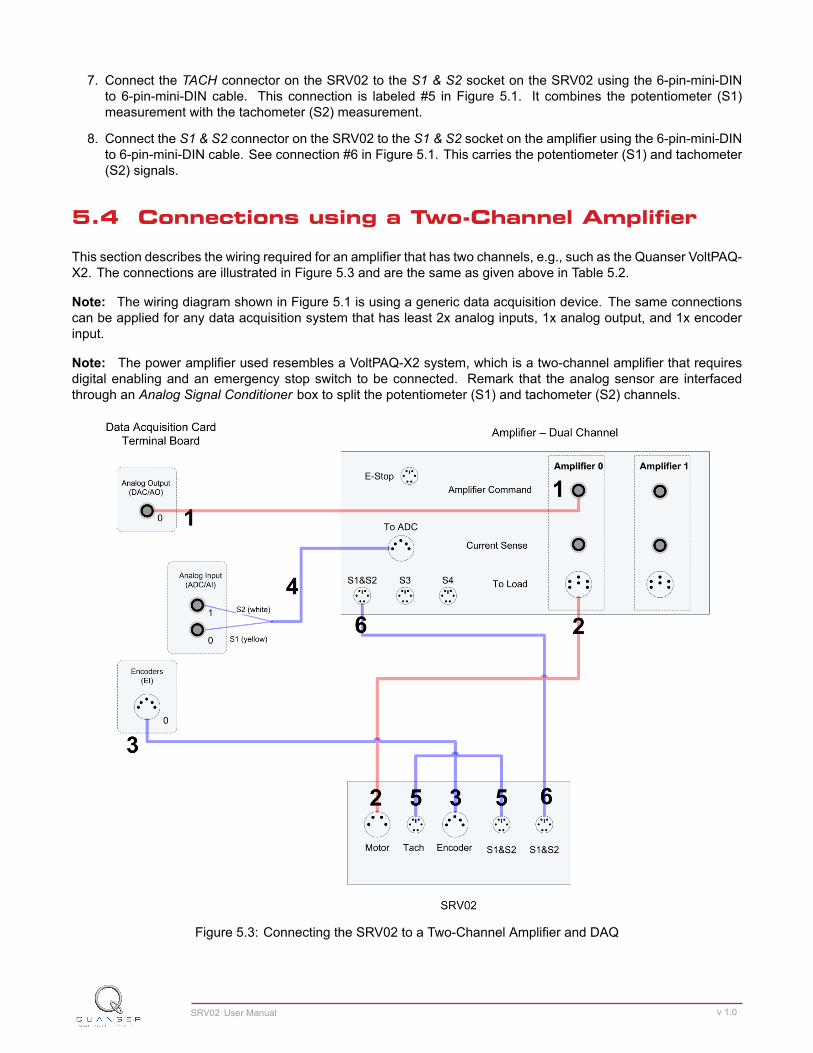
5.4 Connections using a Two-Channel Amplifier
This section describes the wiring required for an amplifier that has two channels, e.g., such as the Quanser VoltPAQ-X2. The connections are illustrated in Figure 5.3 and are the same as given above in Table 5.2.
Note: The wiring diagram shown in Figure 5.1 is using a generic data acquisition device. The same connectionscan be applied for any data acquisition system that has least 2x analog inputs, 1x analog output, and 1x encoderinput.
Note: The power amplifier used resembles a VoltPAQ-X2 system, which is a two-channel amplifier that requiresdigital enabling and an emergency stop switch to be connected. Remark that the analog sensor are interfacedthrough an Analog Signal Conditioner box to split the potentiometer (S1) and tachometer (S2) channels.
Figure 5.3: Connecting the SRV02 to a Two-Channel Amplifier and DAQ
SRV02 User Manual v 1.0

6 TESTING AND TROUBLESHOOT-ING
This section describes some functional tests to determine if your SRV02 is operating normally. It is assumed thatthe SRV02 is connected as described in the Section 5, above. To carry out these tests, it is preferable if the user canuse a software such as QUARCror LabVIEW™ to read sensor measurements and feed voltages to the motor. SeeReference [4] to learn how to interface the SRV02 with QUARC. Alternatively, these tests can be performed with asignal generator and an oscilloscope.
6.1 Motor
6.1.1 Testing
Ensure the SRV02 motor is operating correctly by going through this procedure:
1. Apply a voltage to analog output channel #0 of the terminal board using, for example, the QUARC software.
2. The motor gear, component #4 shown in Figure 2.1b, should rotate counter-clockwise when a positive voltageis applied and clockwise when a negative voltage is applied. Remark that the motor shaft and the load shaftturn in opposite directions.
6.1.2 Troubleshooting
If the motor is not responding to a voltage signal, go through these steps:
• Verify that the power amplifier is functional. For example when using the Quanser VoltPAQ device, is the greenLED lit?
• Check that the data-acquisition board is functional, e.g. ensure it is properly connected, that the fuse is notburnt.
• Make sure the voltage is actually reaching the motor terminals (use a voltmeter or oscilloscope).
• If the motor terminals are receiving the signal and the motor is still not turning, your motor might be damagedand will need to be repaired. Please see Section 7 for information on contacting Quanser for technical support.
6.2 Potentiometer
6.2.1 Testing
Test the SRV02 potentiometer with the following procedure:
1. Using a program such as QUARC, measure the analog input channel #0.
2. The potentiometer should output a positive voltage when the potentiometer gear, component #6 in Figure 2.1b,is rotated counter-clockwise. The measurement should increase positively towards 5 V until the discontinuityis reached, at which point the signal abruptly changes to -5 V and begins to increase again.
SRV02 User Manual 20

6.2.2 Troubleshooting
Follow the steps below if the potentiometer is not measuring correctly:
• Verify that the power amplifier is functional. For example when using the Quanser VoltPAQ device, is thegreen LED lit? Recall the analog sensor signal go through the amplifier before going to the data-acquisitiondevice (except when using the Q3 ControlPAQ). Therefore the amplifier needs to be turned on to read thepotentiometer.
• Check that the data-acquisition board is functional, e.g. ensure it is properly connected, that the fuse is notburnt.
• Measure the voltage across the potentiometer. Ensure the potentiometer is powered with a ±12 V at the 6-pin-mini DIN connector and ±5 V at the potentiometer terminals, as described in Section 2.2.2. If the voltage fromthe wiper does not change when you rotate the potentiometer shaft, your potentiometer needs to be replaced.Please see Section 7 for information on contacting Quanser for technical support.
6.3 Tachometer
6.3.1 Testing
Test the tachometer on the SRV02 by performing the following:
1. Apply a 2.0 V signal to Analog Output Channel #0 in order to drive the motor.
2. Measure Analog Input Channel #2 to read the tachometer. When applying 2.0 V to the motor, the tachometershould be measuring a value of approximately 3.0 V.
6.3.2 Troubleshooting
If no signals are received from the tachometer, go through this method:
• Verify that the power amplifier is functional. For example when using the Quanser VoltPAQ device, is the greenLED lit? Recall the analog sensor signal go through the amplifier before going to the data-acquisition device(except when using the Q3 ControlPAQ). It needs to be turned on to read from the tachometer.
• Check that the data-acquisition board is functional, e.g. ensure it is properly connected, that the fuse is notburnt.
• Measure the voltage across the tachometer. When moving the load gear back and forth, is the voltage beingmeasured changing? If not, then the tachometer needs to be replaced. Please see Section 7 for informationon contacting Quanser for technical support.
6.4 Encoder
6.4.1 Testing
Follow this procedure to test the SRV02 encoder:
1. Measure Encoder Input Channel #0 using, for instance, the QUARC software.
SRV02 User Manual v 1.0

2. Rotate the SRV02 load gear, component #5 in Figure 2.1b, one rotation and the encoder should measure 4096counts in quadrature mode.Note: Some data acquisition systems do not measure in quadrature and, in this case, one-quarter of the ex-pected counts are received, i.e. 1024 counts. In addition, some data acquisition systems measure in quadra-ture but increment the count by 0.25 (as opposed to having an integer number of counts). Make sure thedetails of the data-acquisition system being used is known. The counters on the Quanser DAQ boards mea-sure in quadrature and therefore a total of four times the number of encoder lines per rotation, e.g. a 1024-lineencoder results in 4096 integer counts for every full rotation.
6.4.2 Troubleshooting
If the encoder is not measuring properly, go through this procedure:
• Check that the data-acquisition board is functional, e.g. ensure it is properly connected, that the fuse is notburnt.
• Check that both the A and B channels from the encoder are properly generated and fed to the data-acquisitiondevice. Using an oscilloscope, there should be two square waves, signals A and B, with a phase shift of 90degrees. If this is not observed then the encoder may be damaged and need to be replaced. Please seeSection 7 for information on contacting Quanser for technical support.
7 TECHNICAL SUPPORTTo obtain support from Quanser, go to http://www.quanser.com/ and click on the Tech Support link. Fill in the formwith all the requested software and hardware information as well as a description of the problem encountered. Also,make sure your e-mail address and telephone number are included. Submit the form and a technical support personwill contact you.
SRV02 User Manual 22

REFERENCES[1] US Digital. E2 Optical Kit Encoder, 2007.
[2] Faulhaber. DC-Micromotors Series 2338, 2002.
[3] Faulhaber. DC-Motor-Tacho Combinations, 2002.
[4] Quanser Inc. SRV02 QUARC Integration, 2008.
[5] Quanser Inc. Q2-USB Data-Acquisition System User's Guide, 2010.
[6] Vishay Spectrol. Model 132, 138, 139, 2001.
SRV02 User Manual v 1.0

Solutions for teaching and research. Made in Canada.
[email protected] +1-905-940-3575 QUANSER.COM Solutions for teaching and research. Made in Canada.
[email protected] +1-905-940-3575 QUANSER.COM
2 DOF Robot
2 DOF Inverted Pendulum
Gyro/Stable Platform
Multi-DOF Torsion2 DOF Gantry
Flexible Joint
Ball and Beam Double Inverted Pendulum
Flexible LinkInverted Pendulum
Rotary Servo Base Unit
2 DOF Ball Balancer
Over ten rotary experiments for teaching fundamental and advanced controls concepts
Quanser’s rotary collection allows you to create experiments of varying complexity – from basic to advanced. Your lab starts with the Rotary Servo Base Unit and is designed to help engineering educators reach a new level of efficiency and effectiveness in teaching controls in virtually every engineering discipline including electrical, computer, mechanical, aerospace, civil, robotics and mechatronics. For more information please contact [email protected].
©2015 Quanser Inc. All rights reserved.