ss-ethercat user manual - applied motion...9200117 09152017 ethercat user manual 8 ethercat state...
TRANSCRIPT

920-0117 Rev B09/15/2017
1
EtherCAT User Manual
APPLIED MOTION PRODUCTS, INC.
SS-EtherCAT User Manual
920-0117 Rev B09/15/2017
EtherCAT User Manual
2
ContentsIntroduction to EtherCAT .................................................................................................. 5Commonly Used Acronyms ............................................................................................. 5Protocol ........................................................................................................................... 6
Logical Addressing ............................................................................................................6Auto Increment Addressing ...............................................................................................6Fixed Node Addressing .....................................................................................................6EtherCAT Frame Structure .................................................................................................7EtherCAT State Machine ....................................................................................................8EtherCAT Status Indicator LED ..........................................................................................9CANopen over EtherCAT ....................................................................................................10Synchronization .................................................................................................................11EtherCAT Slave Information ...............................................................................................11
CiA402 Drive Profile ........................................................................................................ 12Operation Modes ...............................................................................................................12Profile Position Mode ........................................................................................................13
General Mode Description ..........................................................................................13Enable Profile Position Mode .....................................................................................13Set Running Parameters .............................................................................................13Starting/Stopping Motion ...........................................................................................13Controlword Bits .........................................................................................................13
Profile Velocity Mode ........................................................................................................18General Mode Description ..........................................................................................18Enable Profile Velocity Mode ......................................................................................18Set Running Parameters .............................................................................................18Enable Drive Operation ...............................................................................................18Starting/Stopping Motion ...........................................................................................18
Torque Profile Mode ..........................................................................................................20General Mode Description ..........................................................................................20Enable Torque Profile Mode ........................................................................................20Set Running Parameters .............................................................................................20Enable Drive Operation ...............................................................................................20Starting/Stopping Torque ............................................................................................20Parameter Calculations – Example .............................................................................21Current Verification – Example ...................................................................................21
Cyclic Synchronous Position mode ...................................................................................23General Mode Description ..........................................................................................23Enable Cyclic Synchronous Position Mode ................................................................23Enable Drive Operation ...............................................................................................23
Cyclic Synchronous Velocity mode ...................................................................................24General Mode Description ..........................................................................................24Enable Drive Operation ...............................................................................................24

920-0117 Rev B09/15/2017
3
EtherCAT User ManualHoming Mode ...................................................................................................................25
Set Running Parameters .............................................................................................25Enable Homing Mode .................................................................................................25Starting the Homing Procedure ...................................................................................25
Homing Method Diagrams ................................................................................................26Q Program Mode ...............................................................................................................42
General Mode Description ..........................................................................................42Q Program Execution ..................................................................................................42
Touch Probe ......................................................................................................................43Related Objects: ..........................................................................................................43
Object Dictionary ............................................................................................................. 46General Objects .................................................................................................................46
0x1000 Device Type ....................................................................................................460x1008 Device Name ..................................................................................................460x1009 Hardware Version ...........................................................................................460x100A Software Version ............................................................................................460x1010 Store Parameters ............................................................................................470x1011 Restore Default Parameters ............................................................................470x1018 Identity ...........................................................................................................490x1600 ~ 0x1603 RPDO Mapping Parameter .............................................................490x1A00 ~ 0x1A03 TPDO Mapping Parameter .............................................................540x1C32 Sync Manager Output Parameter ...................................................................590x1C33 Sync Manager Input Parameter ......................................................................60
CiA402 Device Profile Objects ...........................................................................................610x603F Error Code .....................................................................................................610x6040 Control Word .................................................................................................620x6041 Status Word ...................................................................................................640x6060 Mode of Operation .........................................................................................670x6061 Mode of Operation Display ............................................................................670x6064 Position Actual Value .....................................................................................670x6065 Following Error Window ................................................................................670x606C Velocity Actual Value .....................................................................................680x6071 Target Torque .................................................................................................680x6073 Max Current ...................................................................................................680x6074 Torque Demand Value ....................................................................................680x6078 Current Actual Value ......................................................................................680x607A Target Position ...............................................................................................690x607C Home Offset ...................................................................................................690x607F Max Profile Speed ..........................................................................................690x6081 Profile Velocity ...............................................................................................690x6083 Profile Acceleration ........................................................................................690x6084 Profile Deceleration ........................................................................................700x6085 Quickstop Deceleration ..................................................................................700x6087 Torque Slope ..................................................................................................700x6098 Homing Method .............................................................................................70

920-0117 Rev B09/15/2017
EtherCAT User Manual
4
0x6099 Homing Speed ...............................................................................................710x609A Homing Acceleration .....................................................................................710x60B8 Touch Probe Function ....................................................................................720x60B9 Touch Probe Status ........................................................................................730x60BA Touch Probe Position 1 Positive Value ..........................................................730x60BB Touch Probe Position 1 Negative Value .........................................................730x60BC Touch Probe Position 2 Positive Value ..........................................................730x60BD Touch Probe Position 2 Negative Value .........................................................740x60F4 Following Error Actual Value ..........................................................................740x60FD Digital Inputs .................................................................................................740x60FE Digital Outputs ...............................................................................................750x60FF Target Velocity................................................................................................750x6502 Supported Drive Modes .................................................................................76
Manufacturer Specific Objects ...........................................................................................770x2001 Home Switch ..................................................................................................770x2002 Output Status .................................................................................................770x2005 Torque Constant .............................................................................................770x2006 Clear Alarm ....................................................................................................770x2007 Q Segment Number ........................................................................................780x200B Status Code ...................................................................................................780x200C Zero Position .................................................................................................780x200F Alarm Code ....................................................................................................790x2010 Position Loop Proportional Gain ....................................................................800x2011 Position Loop Differential Gain ......................................................................800x2012 Position Loop Differential Filter .....................................................................800x2013 Velocity Loop Proportional Gain ....................................................................800x2014 Velocity Loop Integrator Gain .........................................................................800x2015 Acceleration Feedforward Gain.......................................................................800x2016 PID Filter ........................................................................................................810x2019 Drive Temperature ..........................................................................................810x201A In Position Counts .........................................................................................810x201C Encoder Resolution .......................................................................................810x201D In Position Error Range .................................................................................810x201E In Position Timing .........................................................................................81
Parameter Unit Scaling .................................................................................................... 82Distance, Velocity, Acceleration and Deceleration .............................................................82

920-0117 Rev B09/15/2017
5
EtherCAT User ManualIntroduction to EtherCAT
EtherCAT (Ethernet for Control Automation Technology) is a real-time Industrial Ethernet technology originally developed by Beckhoff Automation. The main focus during the development of EtherCAT was on short cycle times (≤ 100 µs), low jitter for accurate synchronization (≤ 1 µs) and low hardware costs.
The EtherCAT master sends a telegram that passes through each node. Each EtherCAT slave device reads the data addressed to it “on the fly”, and inserts its data in the frame as the frame is moving downstream. The frame is delayed only by hardware propagation delay times. The last node in a segment (or branch) detects an open port and sends the message back to the master using Ethernet technology’s full duplex feature.
Line, tree, star, or daisy-chain: EtherCAT supports almost all of topologies. Up to 65,535 devices can be connected to EtherCAT, so network expansion is virtually unlimited.
EtherCAT® is registered trademark and patented technology, licensed by Beckhoff Automation GmbH, Germany.
Commonly Used Acronyms100Base-Tx 100 MBit/s Ethernet on twisted pairs
AL Application Layer
CAN Controller Area Network
CANopen Application layer protocol for the CAN bus
CoE CANopen over EtherCAT
DC Distributed Clocks Mechanism to synchronize EtherCAT slaves and master
DL Data Link Layer
EMCY Emergency Object
ESI EtherCAT Slave Information
ESC EtherCAT Slave Controller
ETG EtherCAT Technology Group
PDO Process Data Object
SDO Service Data Object
XML eXtensible Markup Language - used for the ESI file

920-0117 Rev B09/15/2017
EtherCAT User Manual
6
ProtocolEtherCAT embeds its payload in a standard Ethernet frame. The frame is identified with the Identifier (0x88A4) in the
EtherType field. During startup, the master device configures and maps the process data on the slave devices. The EtherCAT frame contains one or more datagrams. The datagram header indicates what type of access the master device would like to execute:
-Read, write, read-write
-Access to a specific slave device through direct addressing, or access to multiple slave devices through logical addressing
Logical AddressingLogical addressing is used for the cyclical exchange of process data. Each datagram addresses a specific part of the
process image in the EtherCAT segment, for which 4 GBytes of address space is available. During network startup, each slave device is assigned one or more addresses in this global address space. If multiple slave devices are assigned addresses in the same area, they can all be addressed with a single datagram. Since the datagrams completely contain all the data access related information, the master device can decide when and which data to access. For example, the master device can use short cycle times to refresh data on the drives, while using a longer cycle time to sample the I/O; a fixed process data structure is not necessary.
In addition to cyclical data, further datagrams can be used for asynchronous or event driven communication. Besides the logical addressing, the master device can also address a slave in two ways:
Auto Increment AddressingWith Auto increment addressing, the master device addresses a slave via its position in the network. This method is used
during network boot-up to determine the network topology and compare it to the planned topology.
Fixed Node AddressingAfter checking the network configuration, the master device can assign each node a configured node address and
communicate with the node via this fixed address. This enables targeted access to devices, even when the network topology is changed during operation.

920-0117 Rev B09/15/2017
7
EtherCAT User ManualEtherCAT Frame StructureIn EtherCAT, the data between the master and the slaves is transmitted in Ethernet frames. An EtherCAT Ethernet frame
consists of one or several EtherCAT datagrams, each addressing individual devices and/or memory areas. The EtherCAT frame structure is pictured in the following figure. Each EtherCAT datagram consists of a datagram header, the data area and a working counter (WKC), which is incremented by all EtherCAT nodes that are addressed by the datagram and have exchanged associated data.
Ethernet Header (14 bytes) EtherCAT Data FSC
Destination SourceEtherType (88A4h) EtherCAT Header EtherCAT Datagrams FSC
6 bytes 6 bytes 2 bytes 2 bytes 44 ~ 1498 bytes 4 bytes
EtherCAT Datagrams1st EtherCAT Datagram 2nd EtherCAT Datagram … nth EtherCAT Datagram
EtherCAT DatagramDatagram Header Data WKC
10 bytes max. 1486 bytes 2 bytes
FSC: Frame Check Sequence
WKC: Working Counter

920-0117 Rev B09/15/2017
EtherCAT User Manual
8
EtherCAT State MachineBoth the master and the slaves have a state machine with the states shown below. After boot the slaves are in INIT state,
and then it’s up to the master to request state transitions. The standardized EtherCAT state machine is defined in the following figure. The bootstrap state is not supported.
State SDO RPDO TPDO Description
INIT × × × State after device initialization. No communication on the Application Layer.
PRE-OP √ × ×After initialization of communication, device enters into
this state. SDO is available at this state.SAFE-OP √ × √ SDO and TPDO are available at this state.
OP √ √ √ All of the SDO and PDO are available at this state. Drive fully operational.
BOOT × × × Not used.

920-0117 Rev B09/15/2017
9
EtherCAT User ManualEtherCAT Status Indicator LEDThe LEDs are used for indicating status of EtherCAT. There are two Link / Activity LEDs (one for each RJ 45 Ethernet
connector) and two status LEDs (RUN and ERR).
LED indicator descriptions:
LED Color Status Description
Link / Activity GreenOFF no Ethernet connectionON Ethernet is connected
Flickering activity on line
RUN Green
OFF initialization stateBlinking pre-operational state
Single Flash safe-operational stateON operational state
ERR Red
OFF no errorBlinking general error
Single Flash sync errorDouble Flash watch dog error
Notes:
Flickering: Rapid flashing with a period of approx. 50ms (10 Hz)
Blinking: Flashing with equal on and off periods of 200ms (2.5Hz)
Single Flash: Repeating ON for 200ms and OFF for 1s
Double Flash: Two flashes with a period of 200ms followed by 1s OFF period

920-0117 Rev B09/15/2017
EtherCAT User Manual
10
CANopen over EtherCATApplied Motion Products’ EtherCAT drives support CANopen over EtherCAT (CoE) which is the application layer
communication protocol. CiA 402 drive profile is supported. The CoE device architecture is as below:
Following message types are used:
SDO (Service Data Object): SDO is used for acyclic data transmission. This communication can be used in PRE-OP, Safe-OP and OP state.
PDO (Process Data Object): PDO is used for cyclic data transmission. Data that will be transmitted or received is defined by PDO mapping.
EMCY (Emergency Object): EMCY is used for error report when a fault has occurred in the drive.

920-0117 Rev B09/15/2017
11
EtherCAT User ManualSynchronizationThe EtherCAT solution for synchronizing nodes is based on distributed clocks (DC). The calibration of the clocks in the
nodes is completely hardware-based. The time from the first DC slave device is cyclically distributed to all other devices in the system. With this mechanism, the slave device clocks can be precisely adjusted to this reference clock. The resulting jitter in the system is significantly less than 1µs.
Since the time sent from the reference clock arrives at the slave devices slightly delayed, this propagation delay must be measured and compensated for each slave device in order to ensure synchronicity and simultaneousness. This delay is measured during network startup or, if desired, even continuously during operation, ensuring that the clocks are simultaneous to within much less than 1µs of each other.
Applied Motion Products’ EtherCAT drives provide three synchronization modes:
Free Run
Slave’s application is not synchronized to EtherCAT Master. Master and slave have an individual independent cycle.SM Event
Slave’s application is synchronized to SM Event.DC SYNC Event
Slave’s application is synchronized to SYNC Event.
The synchronization cycle that SS-EC EtherCAT drive can support are: 500μs, 1ms, 2ms and 4ms.
EtherCAT Slave InformationEvery EtherCAT device is delivered with an EtherCAT Slave Information (ESI) file in XML format. It describes the identity
and all features of the device. The XML files for Applied Motion Products’ EtherCAT drive can be downloaded from Applied Motion Products’ website.
920-0117 Rev B09/15/2017
EtherCAT User Manual
12
CiA402 Drive Profile
Operation ModesSS EtherCAT drive supports following operation modes (0x6060):
Profile Position (PP)
Profile Velocity (PV)
Torque Profile (TQ)
Cyclic Synchronous Position (CSP)
Cyclic Synchronous Velocity (CSV)
Homing (HM)
Q Program (Applied Motion Products’ specific mode)

920-0117 Rev B09/15/2017
13
EtherCAT User ManualProfile Position Mode
General Mode DescriptionProfile Position Mode is a point-to-point operating mode using set-points which consist of velocity, acceleration,
deceleration, and target position. Once all these parameters have been set, the drive buffers the commands and begins executing the set-point. When using a set of set-points method, a new set-point can be sent to the drive while a previously sent set-point is still executing.
Enable Profile Position ModeTo enable the Profile Position Mode, the value 0001h must be written to the mode of operation
OD entry, located at dictionary address 6060h. The mode of operation can be verified using OD 6061h - mode of operation display - which is updated when the current operation mode is accepted.
Set Running ParametersSet the distance, velocity, acceleration, and deceleration using OD entries 607Ah, 6081h, 6083h, and 6084h respectively.
Starting/Stopping MotionAfter power up or node reset, the drive is in disabled state. The value 0006h must be written to the control word OD
entry, located at dictionary address 6040h. This will put the drive into “ready to switch on” state and is ready to enable drive operation. If the value 0006h is not written to the control word first, the drive operation can not be enabled.
To indicate a new set-point and start motion, toggle bit 4 by sending 001Fh to controlword OD entry 6040h.
To enable drive operation, the value 001Fh must be written to the controlword OD entry, located at dictionary address 6040h. This will also signal that there is a new set-point ready. The drive acknowledges the receipt of a valid set-point using bit 12 of the statusword at OD 6041h. Because the set-point is edge-triggered, once the drive receives and processes the set-point, the new set-point of the controlword must be cleared by writing 000Fh to the controlword register.
While the drive is acting on a set-point, a new set-point may be entered and triggered using the new set-point. The second set-point will be received as soon as it is processed, or at the end of the previous set-point, which ever is later.
Controlword BitsNew Set-point (bit 4) - set this bit high to clock in a new set-point. Once the drive has accepted the set-point, it will
respond by setting statusword bit 12 high. Controlword bit 4 should then be taken low.
Change of Set-point (bit 9) - if this bit is low, the previous set-point will be completed and the motor will come to rest before a new set-point is processed. If bit 9 is high, the motor will continue at the speed commanded by the previous set-point until it has reached the position commanded by the previous set-point, then transition to the speed of the new set-point.
Change Set-point Immediately (bit 5) - if this bit is high, the new set-point will take effect immediately. The motor speed will transition to the speed and position commanded by the new set-point.
Abs/rel (bit 6) - if this bit is high, the set-point distance is relative. For example, if the previous motor position was 10,000 steps and a new set-point is issued with a distance of 20,000, the final position will be 30,000. If bit 6 is low, the distance is absolute. If the previous motor position was 10,000 and a new set-point is issued with a distance of 20,000, the new position will be 20,000. (The distance traveled from the previous position to the new position will be 10,000 steps.) For best results, do not change this bit while the motor is moving.
Note: Two set-points can be set up, but if status bit 12 is high, then the buffer is full and another set-point will be ignored.

920-0117 Rev B09/15/2017
EtherCAT User Manual
14
Single Set-Point

920-0117 Rev B09/15/2017
15
EtherCAT User Manual
Multiple Set-Points, Stopping Between Moves
In this example, controlword bits 9 (Change of Set-point) and 5 (Change Set Immediately) are 0. The motor comes to rest between moves.
Multiple Set-Point Profile Position Move with Stopping Between Moves

920-0117 Rev B09/15/2017
EtherCAT User Manual
16
Multiple Set-Points, Continuous Motion
In this example, controlword bit 9 (Change of Set-point) is 1 and controlword bit 5 (Change Set Immediately) is 0. The motor continues at the speed of the first set-point until is reaches the distance of the first set-point, then changes to the new set-point speed. The motion is continuous.

920-0117 Rev B09/15/2017
17
EtherCAT User Manual
Multiple Set-Points, Immediate Change in Motion
In this example, controlword bit 9 (Change of Set-point) is 1 and controlword bit 5 (Change Set Immediately) is 1. The motor immediately changes to the new set-point speed without completing the first set-point. The motion is continuous.

920-0117 Rev B09/15/2017
EtherCAT User Manual
18
Profile Velocity Mode
General Mode DescriptionProfile Velocity Mode is a relatively simple operating mode. Once the velocity, acceleration, and deceleration are set,
the drive will either command the motor to accelerate to the running velocity according to the acceleration parameter, or to halt movement according to the deceleration parameter.
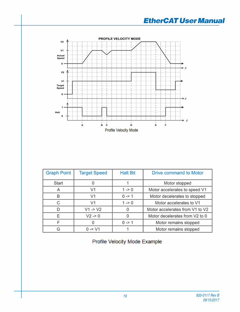
The figure below shows an example of Profile Velocity Mode. The top graph shows the actual speed of the motor, the middle graph the target speed value, and the bottom graph the halt bit in the controlword.
The table below explains how the halt bit and target velocity may be used together to affect motor speed. Between points B and C, the motor does not come to a complete stop, but decelerates according to the profile deceleration value starting at point B. When the halt bit transitions at point C, it accelerates immediately back to the target speed. At Point E, reducing the target speed to zero has the same effect as enabling the halt bit, since the drive is commanding the motor to move at zero speed.
It should be noted that both enabling the halt bit and setting the target velocity to zero keep torque applied to the motor. In order to allow the shaft to move freely, the drive’s state must be put in the Drive Disabled state.
Enable Profile Velocity ModeTo enable the Profile Velocity Mode, the value 0003h must be written to the mode of operation OD entry, located at
dictionary address 6060h.The mode of operation can be verified using OD 6061h - mode of operation display - which is updated when the current operation mode is accepted.
Set Running ParametersSet the velocity, acceleration, and deceleration using OD entries 60FFh, 6083h, and 6084h respectively.
Enable Drive OperationAfter power up or node reset, the drive is in disabled state. The value 0006h must be written to the control word OD
entry, located at dictionary address 6040h. This will put the drive into “ready to switch on” state and is ready to enable drive operation. If the value 0006h is not written to the control word first, the drive operation can not be enabled.
To enable drive operation, the value 010Fh must be written to the controlword OD entry, located at dictionary address 6040h. This puts the drive into Operation Enabled state, with the motion halted.
Starting/Stopping MotionTo start and stop motion, toggle the controlword halt bit (bit 8). When the halt bit is set to 0, motion will start or continue;
when the halt bit is set to 1, motion will stop. The bit can be toggled by writing 010Fh and 000Fh to controlword OD entry 6040h.
920-0117 Rev B09/15/2017
19
EtherCAT User Manual

920-0117 Rev B09/15/2017
EtherCAT User Manual
20
Torque Profile Mode
General Mode DescriptionTorque Profile mode is a servo-control torque operating mode. It requires knowledge of the Torque Constant of the motor
in N·m/A. This information can be found in the servo motor print.
For Step-Servo products like SS EtherCAT, the motor is step motor which does not have a fixed torque constant. It is not recommended that Step-Servo products are used in Torque Profile mode.
Enable Torque Profile ModeTo enable Torque Profile Mode, the value 0004h must be written to the mode of operation OD entry, located at dictionary
address 6060h. The mode of operation can be verified using OD 6061h - mode of operation display - which is updated when the current operation mode is accepted.
Set Running ParametersTo operate in Torque Profile mode, the following parameters must be set
Enable Drive OperationAfter power up or node reset, the drive is in disabled state. The value 0006h must be written to the control word OD
entry, located at dictionary address 6040h. This will put the drive into “ready to switch on” state and is ready to enable drive operation. If the value 0006h is not written to the control word first, the drive operation can not be enabled.
To enable drive operation, the value 000Fh must be written to the controlword OD entry, located at dictionary address 6040h. This puts the drive into the Operation Enabled state with no torque applied.
It should be noted that both enabling the halt bit and setting the target torque to zero will ramp down the torque applied to the motor according to the torque slope. At the end of the slope no torque will be applied to the motor, allowing the shaft to move freely.
Starting/Stopping TorqueTo start and stop motion, toggle the controlword halt bit (bit 8). When the halt bit is set to 0, motion will start or continue;
when the halt bit is set to 1, motion will stop. The bit can be toggled by writing 010Fh and 000Fh to controlword OD entry 6040h.

920-0117 Rev B09/15/2017
21
EtherCAT User ManualParameter Calculations – Example
An application requires a torque of 50 oz-in. and a torque slope of 25 oz-in/sec. The motor print lists the Torque Constant of the motor as 0.07N·m/A. The N·m/A constant given must first be converted into mN·m/A, as required by the Torque Constant OD entry. The formula used for this is
As the drive works primarily in N·m, the desired 50 oz-in of torque must also be converted into N·m, using the conversion factor 141.6 oz-in/N·m.
Now, the resultant torque of 0.3531N·m must be converted into mN·m, as required by the Target Torque OD entry.
The result is a value of 353 mN·m, rounded to the nearest whole number, for the Target Torque OD Entry
Finally, the desired slope must be converted from the given units of oz-in/sec into the required units of mN·m/sec
Rounding to the nearest whole number results in a Torque Slope of 177 mN·m/sec.
Current Verification – ExampleIt is important to check that the current required of the drive is within the limits of the servo amplifier. The drive being
used, for example, has a continuous rating of 7 amps, and a peak current of 14 amps, which may be held continuously for 2 seconds. This means that a current of 7 amps can be held indefinitely, and currents between 7 and 14 amps may be used in short bursts.
Using the target torque and torque constant from the example above the current draw can be checked, as shown:
The resultant current, 5.0443A, is below the 7A continuous current rating of the drive, and well below the peak current rating of 14A. It is possible for the drive to maintain a current of 7A
indefinitely, and peak up to 14A for up to two seconds continuously. Values between 7A and
14A may be held proportionally long.

920-0117 Rev B09/15/2017
EtherCAT User Manual
22
Torque Profile Mode
920-0117 Rev B09/15/2017
23
EtherCAT User ManualCyclic Synchronous Position mode
General Mode DescriptionIn this mode the master controller generates a trajectory and sends target position (0x607A) to the drive at every PDO
update cycle. The primary feedback from the drive is the actual motor position and optionally, actual motor velocity and torque. Position, velocity, and torque control loops are all closed in the drive which acts as a follower for the position commands.
Enable Cyclic Synchronous Position ModeTo enable the Cyclic Synchronous Position mode, the value 0008h must be written to the mode of operation OD entry,
located at dictionary address 6060h. The mode of operation can be verified using OD 6061h - mode of operation display - which is updated when the current operation mode is accepted.
Enable Drive OperationAfter power up or node reset, the drive is in disabled state. The value 0006h must be written to the control word OD
entry, located at dictionary address 6040h. This will put the drive into “ready to switch on” state and is ready to enable drive operation. If the value 0006h is not written to the control word first, the drive operation can not be enabled.
To enable drive operation, the value 000Fh must be written to the controlword OD entry, located at dictionary address 6040h. This puts the drive into Operation Enabled state.
920-0117 Rev B09/15/2017
EtherCAT User Manual
24
Cyclic Synchronous Velocity mode
General Mode DescriptionIn this mode the master controller sends target velocity (0x60FF) to the drive at every PDO update cycle. The primary
feedback from the drive is the actual motor position and optionally, actual motor velocity and torque. Velocity and torque control loops are closed in the drive. If necessary, position loop is closed in the master controller.
Enable Cyclic Synchronous Velocity ModeTo enable the Cyclic Synchronous Velocity mode, the value 0009h must be written to the mode of operation OD entry,
located at dictionary address 6060h. The mode of operation can be verified using OD 6061h - mode of operation display - which is updated when the current operation mode is accepted.
Enable Drive OperationAfter power up or node reset, the drive is in disabled state. The value 0006h must be written to the control word OD
entry, located at dictionary address 6040h. This will put the drive into “ready to switch on” state and is ready to enable drive operation. If the value 0006h is not written to the control word first, the drive operation can not be enabled.
To enable drive operation, the value 010Fh must be written to the controlword OD entry, located at dictionary address 6040h. This puts the drive into Operation Enabled state, with the motion halted.

920-0117 Rev B09/15/2017
25
EtherCAT User ManualHoming Mode
Set Running ParametersSet the homing and index velocities, acceleration/deceleration, offset and home sensor (if required) using OD entries
6099h, 609Ah, 607Ch, and 2001h respectively.
Note: It is important that the limit switch settings have been defined in configuration software prior to using the CANopen Homing Mode.
Enable Homing ModeTo enable Homing Mode, the value 0006h must be written to the mode of operation OD entry, located at dictionary
address 6060h. The mode of operation can be verified using OD 6061h - mode of operation display - which is updated when the current operation mode is accepted.
After power up or node reset, the drive is in disabled state. The value 0006h must be written to the control word OD entry, located at dictionary address 6040h. This will put the drive into “ready to switch on” state and is ready to enable drive operation. If the value 0006h is not written to the control word first, the drive operation can not be enabled.
To put the drive into Operation Enabled Mode, write 000Fh to the controlword OD entry, located at dictionary address 6040h.
Starting the Homing ProcedureSet the Homing Method required using OD entry 6098h. To start the homing procedure, bit 4 of the controlword OD entry
located at dictionary address 6040h, must transition from 0 to 1. The status of the homing procedure can be monitored using the statusword OD entry 6041h.

920-0117 Rev B09/15/2017
EtherCAT User Manual
26
Homing Method DiagramsHoming Method 1
Homes to the first index CCW after the CW limit switch is reached.
Homing Method 2
Homes to the first index CW after the CCW limit switch is reached.

920-0117 Rev B09/15/2017
27
EtherCAT User ManualHoming Method 3
Homes to the first index CW after the positive home switch changes state; the initial direction of motion is dependent on the state of the home switch.
Homing Method 4
Homes to the first index CCW after the positive home switch changes state; the initial direction of motion is dependent on the state of the home switch.

920-0117 Rev B09/15/2017
EtherCAT User Manual
28
Homing Method 5
Homes to the first index CCW after the negative home switch changes state; the initial direction of motion is dependent on the state of the home switch.
Homing Method 6
Homes to the first index CW after the negative home switch changes state; the initial direction of motion is dependent on the state of the home switch.
920-0117 Rev B09/15/2017
29
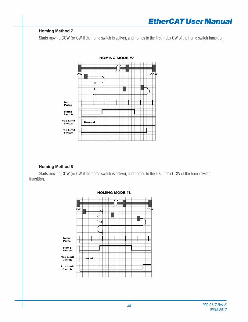
EtherCAT User ManualHoming Method 7
Starts moving CCW (or CW if the home switch is active), and homes to the first index CW of the home switch transition.
Homing Method 8
Starts moving CCW (or CW if the home switch is active), and homes to the first index CCW of the home switch transition.

920-0117 Rev B09/15/2017
EtherCAT User Manual
30
Homing Method 9
Starts moving CCW and homes to the first index CW of the home switch transition.
Homing Method 10
Starts moving CCW and homes to the first index CCW of the home switch transition.

920-0117 Rev B09/15/2017
31
EtherCAT User ManualHoming Method 11
Starts moving CW (or CCW if the home switch is active), and homes to the first index CCW of the home switch transition.
Homing Method 12
Starts moving CW (or CCW if the home switch is active), and homes to the first index CW of the home switch transition.

920-0117 Rev B09/15/2017
EtherCAT User Manual
32
Homing Method 13
Starts moving CW and homes to the first index CCW of the home switch transition.
Homing Method 14
Starts moving CW and homes to the first index CW of the home switch transition shown above.
920-0117 Rev B09/15/2017
33
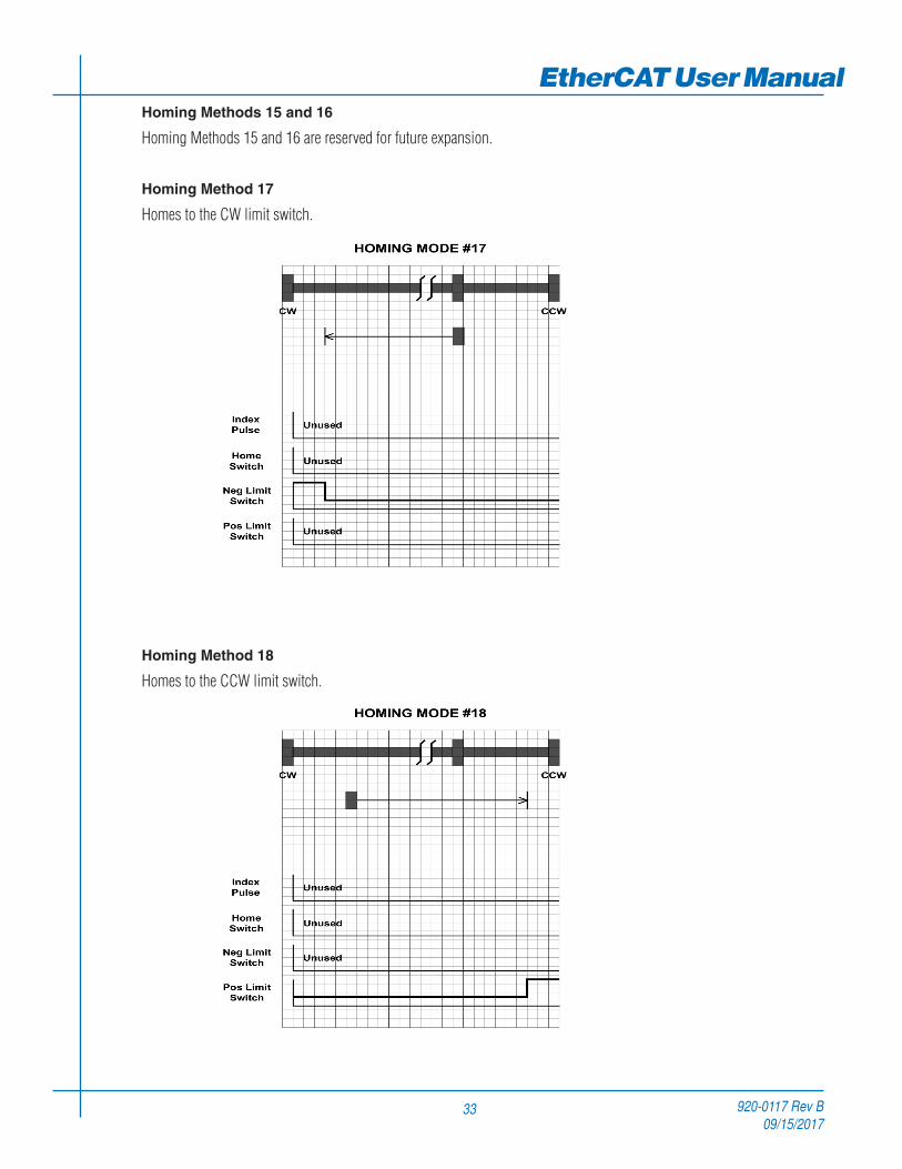
EtherCAT User ManualHoming Methods 15 and 16
Homing Methods 15 and 16 are reserved for future expansion.
Homing Method 17
Homes to the CW limit switch.
Homing Method 18
Homes to the CCW limit switch.

920-0117 Rev B09/15/2017
EtherCAT User Manual
34
Homing Methods 19 and 20
Home to the home switch transition.

920-0117 Rev B09/15/2017
35
EtherCAT User ManualHoming Methods 21 and 22
Home to the home switch transition.

920-0117 Rev B09/15/2017
EtherCAT User Manual
36
Homing Methods 23 and 24
Home to the home switch transition shown below, and “bounce off” the CCW limit, if required.

920-0117 Rev B09/15/2017
37
EtherCAT User ManualHoming Methods 25 and 26
Home to the home switch transition shown below, and “bounce off” the CCW limit, if required.

920-0117 Rev B09/15/2017
EtherCAT User Manual
38
Homing Methods 27 and 28
Home to the home switch transition shown below, and “bounce off” the CW limit, if required.

920-0117 Rev B09/15/2017
39
EtherCAT User ManualHoming Methods 29 and 30
Home to the home switch transition shown below, and “bounce off” the CW limit, if required.

920-0117 Rev B09/15/2017
EtherCAT User Manual
40
Homing Methods 31 and 32
Homing Methods 31 and 32 are reserved for future expansion.Homing Method 33
Homes to the next index pulse CW from the current position. If the CW limit is hit, the drive resets to the CCW limit, and continues searching for a limit in the CW direction.
Homing Method 34
Homes to the next index pulse CCW from the current position. If the CCW limit is hit, the drive resets to the CW limit, and continues searching for a limit in the CCW direction.

920-0117 Rev B09/15/2017
41
EtherCAT User ManualHoming Method 35
Takes the current position to be the home position; the Home Offset value is ignored, and the motor does not move at all.

920-0117 Rev B09/15/2017
EtherCAT User Manual
42
Q Program Mode
General Mode DescriptionIn order to expand the functionality of Applied Motion Products’ EtherCAT drives, the Q programming language may be
used to execute complex motion profiles that may not be possible within the scope of CiA 402. The Q program must be written and pre-loaded into the EtherCAT drive using Q programmer integrated in the configuration software.
Q Program ExecutionTo execute a stored Q program on a single drive, a value of -1 (FFh) must be written to the mode of operation OD entry,
located at dictionary address 6060h. The mode of operation can be verified using OD entry 6061h - mode of operation display - which is updated when the current operation mode is accepted.
Next, the desired Q segment number, 1-12, must be written to the Q Segment Number register, located at address 2007h.
After power up or node reset, the drive is in disabled state. The value 0006h must be written to the control word OD entry, located at dictionary address 6040h. This will put the drive into “ready to switch on” state and is ready to enable drive operation. If the value 0006h is not written to the control word first, the drive operation can not be enabled.
To enable drive operation, a value of 000Fh must be written to the controlword OD entry, located at dictionary address 6040h. This puts the drive into Operation Enabled state and ready to run the Q program.
To run the selected Q program, a value of 001Fh must be written to the controlword. The Q program will then run to completion. The Q program may be re-executed by a 0->1 transition of the Q Program start bit (bit 4) in the controlword.
To halt execution of a Q program, the halt bit (bit 8) of the controlword must be set to 1. The Q program will halt immediately and start from the beginning the next time a 0->1 transition is seen on the Q Program start bit after the halt bit has been cleared.

920-0117 Rev B09/15/2017
43
EtherCAT User ManualTouch Probe Function
Touch Probe is a latching function to capture the position value of the encoder by sensing the edge-triggered digital input of the drive. SS EtherCAT drive have two digital inputs for touch probe function. Input X7 is used as the touch probe 1 input. Input X8 is used as the touch probe 2 input.
Related Objects
Index Object
0x60B8 Touch Probe Function0x60B9 Touch Probe Status0x60BA Touch Probe Position 1 Positive Value0x60BB Touch Probe Position 1 Negative Value0x60BC Touch Probe Position 2 Positive Value0x60BD Touch Probe Position 2 Negative Value
Positive value is captured at “rising edge” of digital input. Negative value is captured at “falling edge” of digital input.
When working with inputs and outputs it is important to remember the designations low and high. If current is flowing into or out of an input or output the logic state for that input/output is defined as low or closed. If no current is flowing, or the input/output is not connected, the logic state is high or open.
Rising edge means the status from low to high. Falling edge means the status from high to low. For more details of each object, please refer to “Object Dictionary” section of this manual.

920-0117 Rev B09/15/2017
EtherCAT User Manual
44
Timeing Diagram
Figure 22: Timing diagram for Touch probe example
0x60B8 Bit 0Enable Touch Probe 1
0x60B8 Bit 1Trigger first event
0x60B8 Bit 4Enable Sampling at positive edge
0x60B8 Bit 5Enable Sampling at negative edge
0x60B9 Bit 0Touch Probe 1 is enabled
0x60B9 Bit 1Touch Probe 1 positive edge stored
0x60B9 Bit 2Touch Probe 1 negative edge stored
Touch Probe Signal
0x60BATouch Probe position 1 positive value
0x60BBTouch Probe position 1 negative value
0000 yyyy
0000 xxxx
uuuu
1
2
3
4
5
6
7
8
9
104a
6a
11
12
12a
13
14
14
14
14a
1
8a
Timing diagram for Touch Probe example

920-0117 Rev B09/15/2017
45
EtherCAT User ManualTable 38: Touch Probe Timing example
Number Touch probe behavior (1) 60B8h, Bit 0 = 1 Enable Touch Probe 1,
60B8h Bit 1, 4, 5 Configure and Enable Touch Probe 1 positive and negative edge (2) 60B9h Bit 0 = 1 Status “Touch Probe 1 enabled” is set (3) External touch probe signal has positive edge (4) 60B9h Bit 1 = 1 Status “Touch Probe 1 positive edge stored” is set
(4a) 60BAh Touch probe position 1 positive value is stored (5) External touch probe signal has negative edge (6) 60B9h Bit 2 = 1 Status “Touch Probe 1 negative edge stored” is set
(6a) 60BBh Touch probe position 1 negative value is stored (7) 60B8h:4 Sample positive edge is disabled (8) 60B9h Bit 0 = 0 Status “Touch Probe 1 positive edge stored” is reset
(8a) 60BAh Touch probe position 1 positive value is not changed (9) 60B8h Bit 4 = 1 Sample positive edge is enabled
(10) 60BAh Touch probe position 1 positive value is not changed (11) External touch probe signal has positive edge (12) 60B9h Bit 1 = 1 Status “Touch Probe 1 positive edge stored” is set
(12a) 60BAh Touch probe position 1 positive value is stored (13) 60B8h Bit 0 = 0 Touch Probe 1 is disabled (14) 60B9h Bit 0, 1, 2 = 0 Status Bits are reset
(14a) 60BAh, 60BBh Touch probe position 1 positive/negative value are not changed
→
→→
→→
→→
→
→→
→→
Touch Probe Timing example
920-0117 Rev B09/15/2017
EtherCAT User Manual
46
Object DictionaryThe most important part of a device profile is the Object Dictionary description. The Object Dictionary is essentially a
grouping of objects accessible via the network in an ordered predefined fashion. Each object within the dictionary is addressed using a 16-bit index.
Object can be mainly divided into general object (from 0x1000) for EtherCAT communication, CiA402 device profile object (from 0x6000) for CANopen over EtherCAT (CoE), and manufacturer specific object (from 0x2000) exclusively provided by this drive.
General Objects
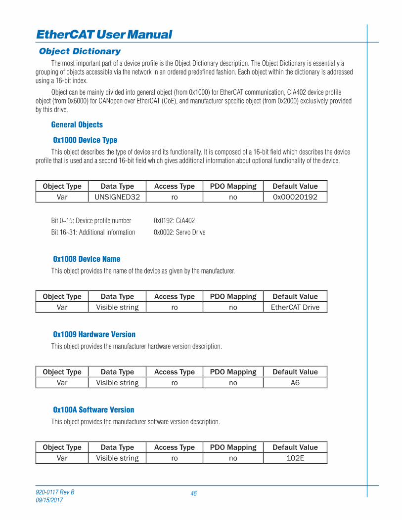
0x1000 Device TypeThis object describes the type of device and its functionality. It is composed of a 16-bit field which describes the device
profile that is used and a second 16-bit field which gives additional information about optional functionality of the device.
Object Type Data Type Access Type PDO Mapping Default ValueVar UNSIGNED32 ro no 0x00020192
Bit 0~15: Device profile number 0x0192: CiA402
Bit 16~31: Additional information 0x0002: Servo Drive
0x1008 Device NameThis object provides the name of the device as given by the manufacturer.
Object Type Data Type Access Type PDO Mapping Default ValueVar Visible string ro no EtherCAT Drive
0x1009 Hardware VersionThis object provides the manufacturer hardware version description.
Object Type Data Type Access Type PDO Mapping Default ValueVar Visible string ro no A6
0x100A Software VersionThis object provides the manufacturer software version description.
Object Type Data Type Access Type PDO Mapping Default ValueVar Visible string ro no 102E

920-0117 Rev B09/15/2017
47
EtherCAT User Manual0x1010 Store Parameters
This object supports the saving of parameters in non-volatile memory.
Index Sub Index Name PDO Mapping Default Value1010 00 max sub-index no 1
01 Store Parameters no 0
You need to write ‘65766173h’ into sub index 01 to save parameters in non-volatile memory.
‘65766173h’ is the ASCII code for “save”.
MSB LSBASCII e v a sHex 65h 76h 61h 73h
0x1011 Restore Default ParametersThis object supports the restoring of parameters in non-volatile memory.
Index Sub Index Name PDO Mapping Default Value1011 00 max sub-index no 1
01 Restore Default Parameters no 0
You need to write ‘64616F6Ch’ into sub index 01 to restore parameters in non-volatile memory.
‘64616F6Ch’ is the ASCII code for “load”.
MSB LSBASCII d a o lHex 64h 61h 6Fh 6Ch
920-0117 Rev B09/15/2017
EtherCAT User Manual
48
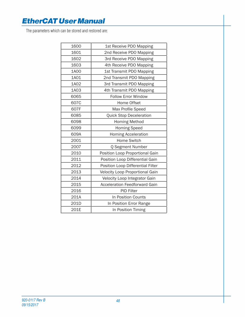
The parameters which can be stored and restored are:
1600 1st Receive PDO Mapping1601 2nd Receive PDO Mapping1602 3rd Receive PDO Mapping1603 4th Receive PDO Mapping1A00 1st Transmit PDO Mapping1A01 2nd Transmit PDO Mapping1A02 3rd Transmit PDO Mapping1A03 4th Transmit PDO Mapping6065 Follow Error Window607C Home Offset607F Max Profile Speed6085 Quick Stop Deceleration6098 Homing Method6099 Homing Speed609A Homing Acceleration2001 Home Switch2007 Q Segment Number2010 Position Loop Proportional Gain2011 Position Loop Differential Gain2012 Position Loop Differential Filter2013 Velocity Loop Proportional Gain2014 Velocity Loop Integrator Gain2015 Acceleration Feedforward Gain2016 PID Filter201A In Position Counts201D In Position Error Range201E In Position Timing

920-0117 Rev B09/15/2017
49
EtherCAT User Manual0x1018 Identity
This object contains general information about the device.
Object Type Data Type Access Type PDO Mapping Default ValueArray UNSIGNED32 ro no -
Sub Index Name Default Value00 max sub-index 401 Vendor ID 0x0000040402 Product code 103 Revision 104 Serial number -
0x1600 ~ 0x1603 RPDO Mapping ParameterThis object contains the mapping parameters for the PDOs the device is able to receive. The sub-index 00h contains the
number of valid entries within the mapping record. The number of valid object entries shall be the number of the application objects that shall be received with the corresponding RPDO. The sub-index from 01h to number of entries contains the information of the mapped application variables. The object describes the content of the PDO by their index, sub-index and length. The length contains the length of the application object in bit. The length contains the length of the application object in bit. This may be used to verify the mapping.
The structure of the entries from sub-index 01h – 0Ch is as follows:
MSB LSBindex (16 bit) sub-index (8 bit) object length (8 bit)
920-0117 Rev B09/15/2017
EtherCAT User Manual
50
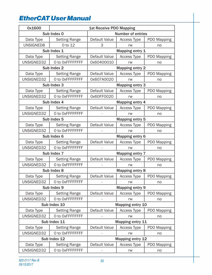
0x1600 1st Receive PDO MappingSub Index 0 Number of entries
Data Type Setting Range Default Value Access Type PDO MappingUNSIGNED8 0 to 12 3 rw no
Sub Index 1 Mapping entry 1Data Type Setting Range Default Value Access Type PDO Mapping
UNSIGNED32 0 to 0xFFFFFFFF 0x60400010 rw noSub Index 2 Mapping entry 2
Data Type Setting Range Default Value Access Type PDO MappingUNSIGNED32 0 to 0xFFFFFFFF 0x607A0020 rw no
Sub Index 3 Mapping entry 3Data Type Setting Range Default Value Access Type PDO Mapping
UNSIGNED32 0 to 0xFFFFFFFF 0x60FF0020 rw noSub Index 4 Mapping entry 4
Data Type Setting Range Default Value Access Type PDO MappingUNSIGNED32 0 to 0xFFFFFFFF - rw no
Sub Index 5 Mapping entry 5Data Type Setting Range Default Value Access Type PDO Mapping
UNSIGNED32 0 to 0xFFFFFFFF - rw noSub Index 6 Mapping entry 6
Data Type Setting Range Default Value Access Type PDO MappingUNSIGNED32 0 to 0xFFFFFFFF - rw no
Sub Index 7 Mapping entry 7Data Type Setting Range Default Value Access Type PDO Mapping
UNSIGNED32 0 to 0xFFFFFFFF - rw noSub Index 8 Mapping entry 8
Data Type Setting Range Default Value Access Type PDO MappingUNSIGNED32 0 to 0xFFFFFFFF - rw no
Sub Index 9 Mapping entry 9Data Type Setting Range Default Value Access Type PDO Mapping
UNSIGNED32 0 to 0xFFFFFFFF - rw noSub Index 10 Mapping entry 10
Data Type Setting Range Default Value Access Type PDO MappingUNSIGNED32 0 to 0xFFFFFFFF - rw no
Sub Index 11 Mapping entry 11Data Type Setting Range Default Value Access Type PDO Mapping
UNSIGNED32 0 to 0xFFFFFFFF - rw noSub Index 12 Mapping entry 12
Data Type Setting Range Default Value Access Type PDO MappingUNSIGNED32 0 to 0xFFFFFFFF - rw no

920-0117 Rev B09/15/2017
51
EtherCAT User Manual0x1601 2nd Receive PDO Mapping
Sub Index 0 Number of entriesData Type Setting Range Default Value Access Type PDO Mapping
UNSIGNED8 0 to 12 1 rw noSub Index 1 Mapping entry 1
Data Type Setting Range Default Value Access Type PDO MappingUNSIGNED32 0 to 0xFFFFFFFF 0x60600008 rw no
Sub Index 2 Mapping entry 2Data Type Setting Range Default Value Access Type PDO Mapping
UNSIGNED32 0 to 0xFFFFFFFF - rw noSub Index 3 Mapping entry 3
Data Type Setting Range Default Value Access Type PDO MappingUNSIGNED32 0 to 0xFFFFFFFF - rw no
Sub Index 4 Mapping entry 4Data Type Setting Range Default Value Access Type PDO Mapping
UNSIGNED32 0 to 0xFFFFFFFF - rw noSub Index 5 Mapping entry 5
Data Type Setting Range Default Value Access Type PDO MappingUNSIGNED32 0 to 0xFFFFFFFF - rw no
Sub Index 6 Mapping entry 6Data Type Setting Range Default Value Access Type PDO Mapping
UNSIGNED32 0 to 0xFFFFFFFF - rw noSub Index 7 Mapping entry 7
Data Type Setting Range Default Value Access Type PDO MappingUNSIGNED32 0 to 0xFFFFFFFF - rw no
Sub Index 8 Mapping entry 8Data Type Setting Range Default Value Access Type PDO Mapping
UNSIGNED32 0 to 0xFFFFFFFF - rw noSub Index 9 Mapping entry 9
Data Type Setting Range Default Value Access Type PDO MappingUNSIGNED32 0 to 0xFFFFFFFF - rw no
Sub Index 10 Mapping entry 10Data Type Setting Range Default Value Access Type PDO Mapping
UNSIGNED32 0 to 0xFFFFFFFF - rw noSub Index 11 Mapping entry 11
Data Type Setting Range Default Value Access Type PDO MappingUNSIGNED32 0 to 0xFFFFFFFF - rw no
Sub Index 12 Mapping entry 12Data Type Setting Range Default Value Access Type PDO Mapping
UNSIGNED32 0 to 0xFFFFFFFF - rw no

920-0117 Rev B09/15/2017
EtherCAT User Manual
52
0x1602 3rd Receive PDO MappingSub Index 0 Number of entries
Data Type Setting Range Default Value Access Type PDO MappingUNSIGNED8 0 to 12 1 rw no
Sub Index 1 Mapping entry 1Data Type Setting Range Default Value Access Type PDO Mapping
UNSIGNED32 0 to 0xFFFFFFFF 0x60710010 rw noSub Index 2 Mapping entry 2
Data Type Setting Range Default Value Access Type PDO MappingUNSIGNED32 0 to 0xFFFFFFFF - rw no
Sub Index 3 Mapping entry 3Data Type Setting Range Default Value Access Type PDO Mapping
UNSIGNED32 0 to 0xFFFFFFFF - rw noSub Index 4 Mapping entry 4
Data Type Setting Range Default Value Access Type PDO MappingUNSIGNED32 0 to 0xFFFFFFFF - rw no
Sub Index 5 Mapping entry 5Data Type Setting Range Default Value Access Type PDO Mapping
UNSIGNED32 0 to 0xFFFFFFFF - rw noSub Index 6 Mapping entry 6
Data Type Setting Range Default Value Access Type PDO MappingUNSIGNED32 0 to 0xFFFFFFFF - rw no
Sub Index 7 Mapping entry 7Data Type Setting Range Default Value Access Type PDO Mapping
UNSIGNED32 0 to 0xFFFFFFFF - rw noSub Index 8 Mapping entry 8
Data Type Setting Range Default Value Access Type PDO MappingUNSIGNED32 0 to 0xFFFFFFFF - rw no
Sub Index 9 Mapping entry 9Data Type Setting Range Default Value Access Type PDO Mapping
UNSIGNED32 0 to 0xFFFFFFFF - rw noSub Index 10 Mapping entry 10
Data Type Setting Range Default Value Access Type PDO MappingUNSIGNED32 0 to 0xFFFFFFFF - rw no
Sub Index 11 Mapping entry 11Data Type Setting Range Default Value Access Type PDO Mapping
UNSIGNED32 0 to 0xFFFFFFFF - rw noSub Index 12 Mapping entry 12
Data Type Setting Range Default Value Access Type PDO MappingUNSIGNED32 0 to 0xFFFFFFFF - rw no
920-0117 Rev B09/15/2017
53
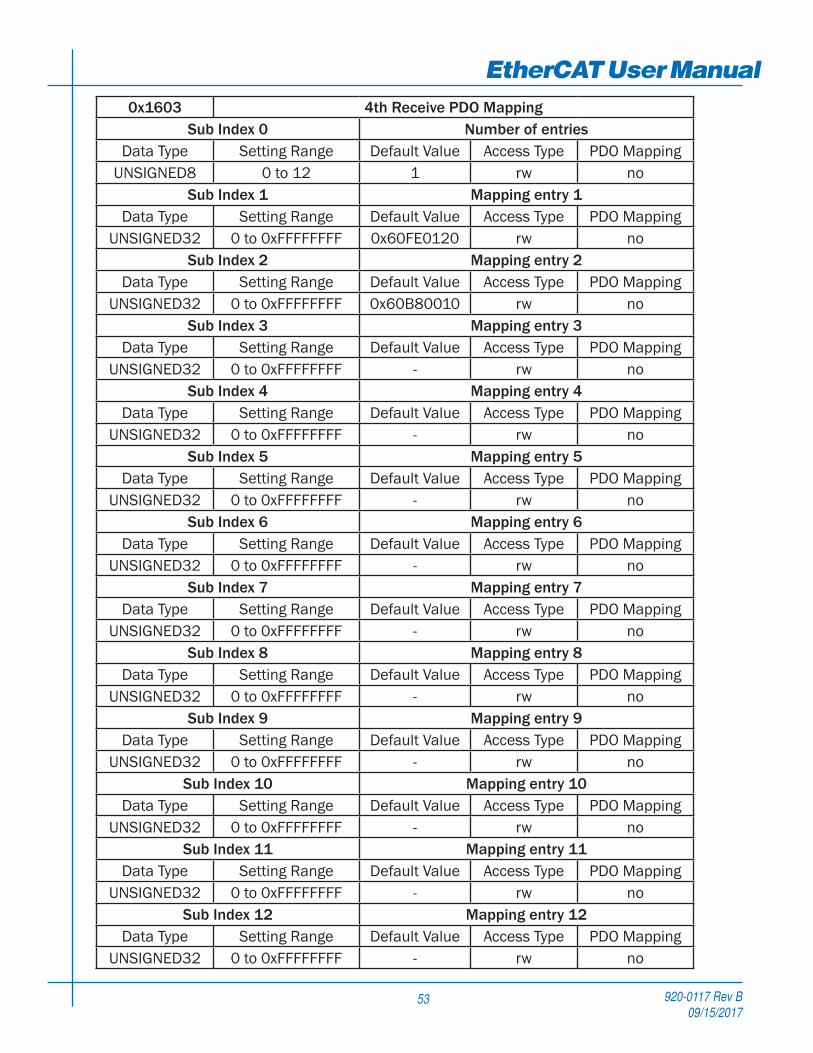
EtherCAT User Manual0x1603 4th Receive PDO Mapping
Sub Index 0 Number of entriesData Type Setting Range Default Value Access Type PDO Mapping
UNSIGNED8 0 to 12 1 rw noSub Index 1 Mapping entry 1
Data Type Setting Range Default Value Access Type PDO MappingUNSIGNED32 0 to 0xFFFFFFFF 0x60FE0120 rw no
Sub Index 2 Mapping entry 2Data Type Setting Range Default Value Access Type PDO Mapping
UNSIGNED32 0 to 0xFFFFFFFF 0x60B80010 rw noSub Index 3 Mapping entry 3
Data Type Setting Range Default Value Access Type PDO MappingUNSIGNED32 0 to 0xFFFFFFFF - rw no
Sub Index 4 Mapping entry 4Data Type Setting Range Default Value Access Type PDO Mapping
UNSIGNED32 0 to 0xFFFFFFFF - rw noSub Index 5 Mapping entry 5
Data Type Setting Range Default Value Access Type PDO MappingUNSIGNED32 0 to 0xFFFFFFFF - rw no
Sub Index 6 Mapping entry 6Data Type Setting Range Default Value Access Type PDO Mapping
UNSIGNED32 0 to 0xFFFFFFFF - rw noSub Index 7 Mapping entry 7
Data Type Setting Range Default Value Access Type PDO MappingUNSIGNED32 0 to 0xFFFFFFFF - rw no
Sub Index 8 Mapping entry 8Data Type Setting Range Default Value Access Type PDO Mapping
UNSIGNED32 0 to 0xFFFFFFFF - rw noSub Index 9 Mapping entry 9
Data Type Setting Range Default Value Access Type PDO MappingUNSIGNED32 0 to 0xFFFFFFFF - rw no
Sub Index 10 Mapping entry 10Data Type Setting Range Default Value Access Type PDO Mapping
UNSIGNED32 0 to 0xFFFFFFFF - rw noSub Index 11 Mapping entry 11
Data Type Setting Range Default Value Access Type PDO MappingUNSIGNED32 0 to 0xFFFFFFFF - rw no
Sub Index 12 Mapping entry 12Data Type Setting Range Default Value Access Type PDO Mapping
UNSIGNED32 0 to 0xFFFFFFFF - rw no

920-0117 Rev B09/15/2017
EtherCAT User Manual
54
0x1A00 ~ 0x1A03 TPDO Mapping ParameterThis object contains the mapping for the PDOs the device is able to transmit. The sub-index 00h contains the number
of valid object entries within the mapping record. The sub-index from 01h to number of entries contains the information of the mapped application objects. The object describes the content of the PDO by their index, sub-index and length. The length contains the length of the application object in bit. This may be used to verify the mapping.
The structure of the entries from sub-index 01h – 0Ch is as follows:
MSB LSBindex (16 bit) sub-index (8 bit) object length (8 bit)

920-0117 Rev B09/15/2017
55
EtherCAT User Manual0x1A00 1st Transmit PDO Mapping
Sub Index 0 Number of entriesData Type Setting Range Default Value Access Type PDO Mapping
UNSIGNED8 0 to 12 5 rw noSub Index 1 Mapping entry 1
Data Type Setting Range Default Value Access Type PDO MappingUNSIGNED32 0 to 0xFFFFFFFF 0x603F0010 rw no
Sub Index 2 Mapping entry 2Data Type Setting Range Default Value Access Type PDO Mapping
UNSIGNED32 0 to 0xFFFFFFFF 0x60410010 rw noSub Index 3 Mapping entry 3
Data Type Setting Range Default Value Access Type PDO MappingUNSIGNED32 0 to 0xFFFFFFFF 0x60640020 rw no
Sub Index 4 Mapping entry 4Data Type Setting Range Default Value Access Type PDO Mapping
UNSIGNED32 0 to 0xFFFFFFFF 0x606C0020 rw noSub Index 5 Mapping entry 5
Data Type Setting Range Default Value Access Type PDO MappingUNSIGNED32 0 to 0xFFFFFFFF 0x60F40020 rw no
Sub Index 6 Mapping entry 6Data Type Setting Range Default Value Access Type PDO Mapping
UNSIGNED32 0 to 0xFFFFFFFF - rw noSub Index 7 Mapping entry 7
Data Type Setting Range Default Value Access Type PDO MappingUNSIGNED32 0 to 0xFFFFFFFF - rw no
Sub Index 8 Mapping entry 8Data Type Setting Range Default Value Access Type PDO Mapping
UNSIGNED32 0 to 0xFFFFFFFF - rw noSub Index 9 Mapping entry 9
Data Type Setting Range Default Value Access Type PDO MappingUNSIGNED32 0 to 0xFFFFFFFF - rw no
Sub Index 10 Mapping entry 10Data Type Setting Range Default Value Access Type PDO Mapping
UNSIGNED32 0 to 0xFFFFFFFF - rw noSub Index 11 Mapping entry 11
Data Type Setting Range Default Value Access Type PDO MappingUNSIGNED32 0 to 0xFFFFFFFF - rw no
Sub Index 12 Mapping entry 12Data Type Setting Range Default Value Access Type PDO Mapping
UNSIGNED32 0 to 0xFFFFFFFF - rw no
920-0117 Rev B09/15/2017
EtherCAT User Manual
56
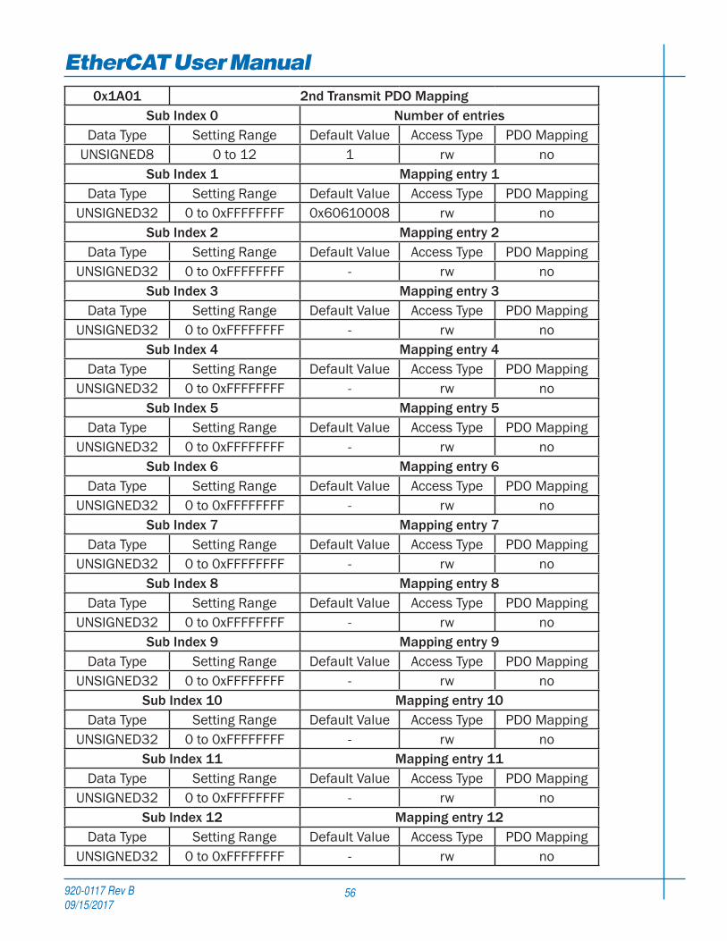
0x1A01 2nd Transmit PDO MappingSub Index 0 Number of entries
Data Type Setting Range Default Value Access Type PDO MappingUNSIGNED8 0 to 12 1 rw no
Sub Index 1 Mapping entry 1Data Type Setting Range Default Value Access Type PDO Mapping
UNSIGNED32 0 to 0xFFFFFFFF 0x60610008 rw noSub Index 2 Mapping entry 2
Data Type Setting Range Default Value Access Type PDO MappingUNSIGNED32 0 to 0xFFFFFFFF - rw no
Sub Index 3 Mapping entry 3Data Type Setting Range Default Value Access Type PDO Mapping
UNSIGNED32 0 to 0xFFFFFFFF - rw noSub Index 4 Mapping entry 4
Data Type Setting Range Default Value Access Type PDO MappingUNSIGNED32 0 to 0xFFFFFFFF - rw no
Sub Index 5 Mapping entry 5Data Type Setting Range Default Value Access Type PDO Mapping
UNSIGNED32 0 to 0xFFFFFFFF - rw noSub Index 6 Mapping entry 6
Data Type Setting Range Default Value Access Type PDO MappingUNSIGNED32 0 to 0xFFFFFFFF - rw no
Sub Index 7 Mapping entry 7Data Type Setting Range Default Value Access Type PDO Mapping
UNSIGNED32 0 to 0xFFFFFFFF - rw noSub Index 8 Mapping entry 8
Data Type Setting Range Default Value Access Type PDO MappingUNSIGNED32 0 to 0xFFFFFFFF - rw no
Sub Index 9 Mapping entry 9Data Type Setting Range Default Value Access Type PDO Mapping
UNSIGNED32 0 to 0xFFFFFFFF - rw noSub Index 10 Mapping entry 10
Data Type Setting Range Default Value Access Type PDO MappingUNSIGNED32 0 to 0xFFFFFFFF - rw no
Sub Index 11 Mapping entry 11Data Type Setting Range Default Value Access Type PDO Mapping
UNSIGNED32 0 to 0xFFFFFFFF - rw noSub Index 12 Mapping entry 12
Data Type Setting Range Default Value Access Type PDO MappingUNSIGNED32 0 to 0xFFFFFFFF - rw no

920-0117 Rev B09/15/2017
57
EtherCAT User Manual0x1A02 3rd Transmit PDO Mapping
Sub Index 0 Number of entriesData Type Setting Range Default Value Access Type PDO Mapping
UNSIGNED8 0 to 12 1 rw noSub Index 1 Mapping entry 1
Data Type Setting Range Default Value Access Type PDO MappingUNSIGNED32 0 to 0xFFFFFFFF 0x60770010 rw no
Sub Index 2 Mapping entry 2Data Type Setting Range Default Value Access Type PDO Mapping
UNSIGNED32 0 to 0xFFFFFFFF - rw noSub Index 3 Mapping entry 3
Data Type Setting Range Default Value Access Type PDO MappingUNSIGNED32 0 to 0xFFFFFFFF - rw no
Sub Index 4 Mapping entry 4Data Type Setting Range Default Value Access Type PDO Mapping
UNSIGNED32 0 to 0xFFFFFFFF - rw noSub Index 5 Mapping entry 5
Data Type Setting Range Default Value Access Type PDO MappingUNSIGNED32 0 to 0xFFFFFFFF - rw no
Sub Index 6 Mapping entry 6Data Type Setting Range Default Value Access Type PDO Mapping
UNSIGNED32 0 to 0xFFFFFFFF - rw noSub Index 7 Mapping entry 7
Data Type Setting Range Default Value Access Type PDO MappingUNSIGNED32 0 to 0xFFFFFFFF - rw no
Sub Index 8 Mapping entry 8Data Type Setting Range Default Value Access Type PDO Mapping
UNSIGNED32 0 to 0xFFFFFFFF - rw noSub Index 9 Mapping entry 9
Data Type Setting Range Default Value Access Type PDO MappingUNSIGNED32 0 to 0xFFFFFFFF - rw no
Sub Index 10 Mapping entry 10Data Type Setting Range Default Value Access Type PDO Mapping
UNSIGNED32 0 to 0xFFFFFFFF - rw noSub Index 11 Mapping entry 11
Data Type Setting Range Default Value Access Type PDO MappingUNSIGNED32 0 to 0xFFFFFFFF - rw no
Sub Index 12 Mapping entry 12Data Type Setting Range Default Value Access Type PDO Mapping
UNSIGNED32 0 to 0xFFFFFFFF - rw no

920-0117 Rev B09/15/2017
EtherCAT User Manual
58
0x1A03 4th Transmit PDO MappingSub Index 0 Number of entries
Data Type Setting Range Default Value Access Type PDO MappingUNSIGNED8 0 to 12 1 rw no
Sub Index 1 Mapping entry 1Data Type Setting Range Default Value Access Type PDO Mapping
UNSIGNED32 0 to 0xFFFFFFFF 0x60FD0020 rw noSub Index 2 Mapping entry 2
Data Type Setting Range Default Value Access Type PDO MappingUNSIGNED32 0 to 0xFFFFFFFF 0x60B90010 rw no
Sub Index 3 Mapping entry 3Data Type Setting Range Default Value Access Type PDO Mapping
UNSIGNED32 0 to 0xFFFFFFFF 0x60BA0020 rw noSub Index 4 Mapping entry 4
Data Type Setting Range Default Value Access Type PDO MappingUNSIGNED32 0 to 0xFFFFFFFF 0x60BB0020 rw no
Sub Index 5 Mapping entry 5Data Type Setting Range Default Value Access Type PDO Mapping
UNSIGNED32 0 to 0xFFFFFFFF 0x60BC0020 rw noSub Index 6 Mapping entry 6
Data Type Setting Range Default Value Access Type PDO MappingUNSIGNED32 0 to 0xFFFFFFFF 0x60BD0020 rw no
Sub Index 7 Mapping entry 7Data Type Setting Range Default Value Access Type PDO Mapping
UNSIGNED32 0 to 0xFFFFFFFF - rw noSub Index 8 Mapping entry 8
Data Type Setting Range Default Value Access Type PDO MappingUNSIGNED32 0 to 0xFFFFFFFF - rw no
Sub Index 9 Mapping entry 9Data Type Setting Range Default Value Access Type PDO Mapping
UNSIGNED32 0 to 0xFFFFFFFF - rw noSub Index 10 Mapping entry 10
Data Type Setting Range Default Value Access Type PDO MappingUNSIGNED32 0 to 0xFFFFFFFF - rw no
Sub Index 11 Mapping entry 11Data Type Setting Range Default Value Access Type PDO Mapping
UNSIGNED32 0 to 0xFFFFFFFF - rw noSub Index 12 Mapping entry 12
Data Type Setting Range Default Value Access Type PDO MappingUNSIGNED32 0 to 0xFFFFFFFF - rw no

920-0117 Rev B09/15/2017
59
EtherCAT User Manual0x1C32 Sync Manager Output Parameter
This object is used to configure the output sync manager.
0x1C32 Sync Manager Output ParameterSub Index 0 Number of entries
Data Type Setting Range Default Value Access Type PDO MappingUNSIGNED8 - 32 ro no
Sub Index 1 Sync typeData Type Setting Range Default Value Access Type PDO Mapping
UNSIGNED16 - 0x0001 rw noSub Index 2 Cycle time
Data Type Setting Range Default Value Access Type PDO MappingUNSIGNED32 - 0 ro no
Sub Index 4 Sync types supportedData Type Setting Range Default Value Access Type PDO Mapping
UNSIGNED16 - 0x8007 ro noSub Index 5 Minimum cycle time
Data Type Setting Range Default Value Access Type PDO MappingUNSIGNED32 - 0 ro no
Sub Index 6 Calc and copy timeData Type Setting Range Default Value Access Type PDO Mapping
UNSIGNED32 - 0 ro noSub Index 8 Get cycle time
Data Type Setting Range Default Value Access Type PDO MappingUNSIGNED16 - 0 rw no
Sub Index 9 Delay timeData Type Setting Range Default Value Access Type PDO Mapping
UNSIGNED32 - 0 ro noSub Index 10 Sync0 cycle time
Data Type Setting Range Default Value Access Type PDO MappingUNSIGNED32 - 0 rw no
Sub Index 11 SM event missedData Type Setting Range Default Value Access Type PDO Mapping
UNSIGNED16 - 0 ro noSub Index 12 Cycle time too small
Data Type Setting Range Default Value Access Type PDO MappingUNSIGNED16 - 0 ro no
Sub Index 32 Sync errorData Type Setting Range Default Value Access Type PDO Mapping
BOOL - 0 ro no

920-0117 Rev B09/15/2017
EtherCAT User Manual
60
0x1C33 Sync Manager Input ParameterThis object is used to configure the input sync manager.
0x1C33 Sync Manager Input ParameterSub Index 0 Number of entries
Data Type Setting Range Default Value Access Type PDO MappingUNSIGNED8 - 32 ro no
Sub Index 1 Sync typeData Type Setting Range Default Value Access Type PDO Mapping
UNSIGNED16 - 0x0022 rw noSub Index 2 Cycle time
Data Type Setting Range Default Value Access Type PDO MappingUNSIGNED32 - 0 ro no
Sub Index 4 Sync types supportedData Type Setting Range Default Value Access Type PDO Mapping
UNSIGNED16 - 0x8007 ro noSub Index 5 Minimum cycle time
Data Type Setting Range Default Value Access Type PDO MappingUNSIGNED32 - 0 ro no
Sub Index 6 Calc and copy timeData Type Setting Range Default Value Access Type PDO Mapping
UNSIGNED32 - 0 ro noSub Index 8 Get cycle time
Data Type Setting Range Default Value Access Type PDO MappingUNSIGNED16 - 0 rw no
Sub Index 9 Delay timeData Type Setting Range Default Value Access Type PDO Mapping
UNSIGNED32 - 0 ro noSub Index 10 Sync0 cycle time
Data Type Setting Range Default Value Access Type PDO MappingUNSIGNED32 - 0 rw no
Sub Index 11 SM event missedData Type Setting Range Default Value Access Type PDO Mapping
UNSIGNED16 - 0 ro noSub Index 12 Cycle time too small
Data Type Setting Range Default Value Access Type PDO MappingUNSIGNED16 - 0 ro no
Sub Index 32 Sync errorData Type Setting Range Default Value Access Type PDO Mapping
BOOL - 0 ro no

920-0117 Rev B09/15/2017
61
EtherCAT User ManualCiA402 Device Profile Objects
0x603F Error CodeThis object reads back the most recent error code generated by the drive.
Object Type Data Type Access Type PDO Mapping Default ValueVar UNSIGNED16 ro yes 0
Two error codes are as below:
Error Code Description0x7500 EtherCAT communication error0xFF02 Over Voltage0xFF03 Over Temperature0xFF04 Open Motor Winding0xFF05 Internal Voltage Bad0xFF06 Position Limit0xFF07 Bad Encoder0xFF08 reserved0xFF09 reserved0xFF0A Excess Regen0xFF0B Safe Torque Off0xFF31 CW Limit0xFF32 CCW Limit0xFF33 CW Limit and CCW Limit0xFF34 Current Foldback0xFF35 Move while Disabled0xFF36 Under Voltage0xFF37 Blank Q Segment0xFF41 Save Failed0xFFFF Other Error
Note: Items in bold italic represent Drive Faults, which automatically disable the motor.
When Fault happens, after the condition that caused the error has been resolved,
write 80h to object 0x6040 to clear the error code in object 0x603F and object 0x200F.
When Warning happens, after the condition that caused the error has been resolved, write 01h to object 0x2006 to clear the error code in object 0x603F and object 0x200F.

920-0117 Rev B09/15/2017
EtherCAT User Manual
62
0x6040 Control WordThis object is used to control the state and motion of the drive. It can be used to enable / disable the driver power output,
start, and abort moves in all operating modes, and clear fault conditions.
Object Type Data Type Access Type PDO Mapping Default ValueVar UNSIGNED16 rw yes 0
The bits of the control word are defined as follows:
Bit Name0 Switch On1 Enable Voltage2 Quick Stop3 Enable Operation4 Operation Mode Specific5 Operation Mode Specific6 Operation Mode Specific7 Fault Reset8 Halt9 Operation Mode Specific
10 Reserved11 Manufacturer Specific12 Manufacturer Specific13 Manufacturer Specific14 Manufacturer Specific15 Manufacturer Specific
Details on Bits 0 to 3 and 7
CommandBit of Control word
Bit 7 Bit 3 Bit 2 Bit 1 Bit 0Shutdown 0 x 1 1 0Switch on 0 0 1 1 1
Switch on + Enable operation 0 1 1 1 1Disable voltage 0 x x 0 x
Quick stop 0 x 0 1 xDisable Operation 0 0 1 1 1Enable Operation 0 1 1 1 1
Fault reset 0 -> 1 x x x x

920-0117 Rev B09/15/2017
63
EtherCAT User ManualDetails on Bits 4, 5, 6, 8 and 9
For PP mode
Bit Name Value Description
4 New Set Point0
Toggle this bit from 0->1 to clock in a new set point1
5 Change Set Point Immediately
0Positioning shall be completed (target reached) before the next
one gets started1 Next positioning shall be started immediately
6 Abs/Rel0 Target position shall be an absolute value1 Target position shall be a relative value
8 Halt0 Positioning shall be executed or continued1 Axis shall be stopped
9 Change of Set Point
0
The previous set-point will be completed and the motor will come to rest
before a new set point is processed
1
The motor will continue at the speed commanded by the previous set
point until it has reached the position commanded by the previous set
point, then transition to the speed of the new set point
For HM mode
Bit Name Value Description
4 Homing Operation Start
0 Do not start homing procedure1 Start or continue homing procedure
8 Halt0 Enable bit 41 Stop axis
For Q mode
Bit Name Value Description
4 Q Program Start
0Toggle this bit from 0->1 to run Q program1
8 Halt0 Enable bit 41 Stop axis

920-0117 Rev B09/15/2017
EtherCAT User Manual
64
0x6041 Status WordThe object indicates the current state of the drive. It consists of bits that indicate the state according to the drive and
operation mode.
Object Type Data Type Access Type PDO Mapping Default ValueVar UNSIGNED16 ro yes 0
The bits of the status word are defined as follows:
Bit Name0 Ready to Switch On1 Switched On2 Operation Enabled3 Fault4 Voltage Enabled5 Quick Stop6 Switch On Disabled7 Warning8 Manufacturer Specific9 Remote
10 Target Reached11 Internal Limit Active12 Operation Mode Specific13 Operation Mode Specific14 Manufacturer Specific15 Manufacturer Specific
The following bits indicate the status of the device:
State Bit 6 Bit 5 Bit 3 Bit 2 Bit 1 Bit 0Not Ready to Switch On 0 x 0 0 0 0
Switch On Disabled 1 x 0 0 0 0Ready to Switch On 0 1 0 0 0 1
Switched On 0 1 0 0 1 1Operation Enabled 0 1 0 1 1 1
Fault 0 x 1 1 1 1Fault Reaction Active 0 x 1 1 1 1
Quick Stop Active 0 0 0 1 1 1
920-0117 Rev B09/15/2017
65
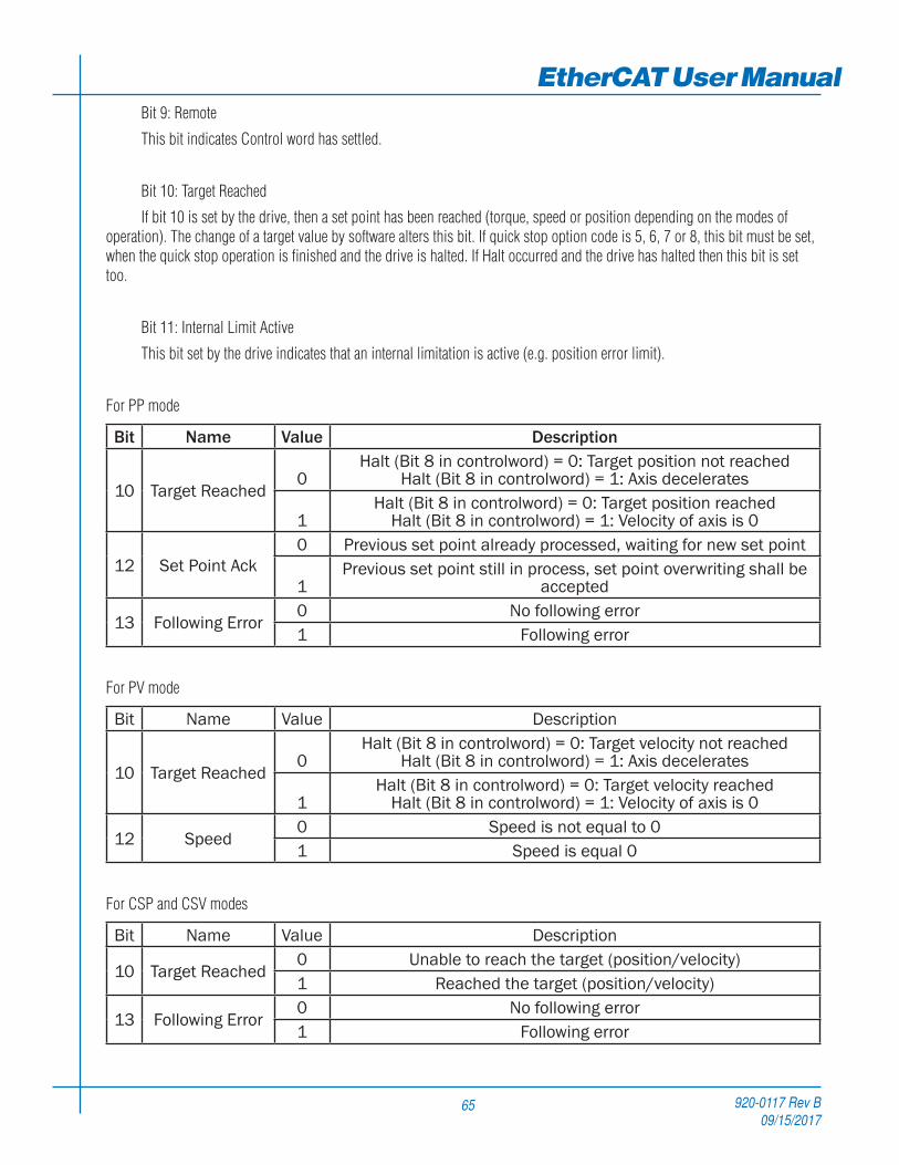
EtherCAT User ManualBit 9: Remote
This bit indicates Control word has settled.
Bit 10: Target Reached
If bit 10 is set by the drive, then a set point has been reached (torque, speed or position depending on the modes of operation). The change of a target value by software alters this bit. If quick stop option code is 5, 6, 7 or 8, this bit must be set, when the quick stop operation is finished and the drive is halted. If Halt occurred and the drive has halted then this bit is set too.
Bit 11: Internal Limit Active
This bit set by the drive indicates that an internal limitation is active (e.g. position error limit).
For PP mode
Bit Name Value Description
10 Target Reached0
Halt (Bit 8 in controlword) = 0: Target position not reached Halt (Bit 8 in controlword) = 1: Axis decelerates
1Halt (Bit 8 in controlword) = 0: Target position reached
Halt (Bit 8 in controlword) = 1: Velocity of axis is 0
12 Set Point Ack0 Previous set point already processed, waiting for new set point
1Previous set point still in process, set point overwriting shall be
accepted
13 Following Error0 No following error1 Following error
For PV mode
Bit Name Value Description
10 Target Reached0
Halt (Bit 8 in controlword) = 0: Target velocity not reached Halt (Bit 8 in controlword) = 1: Axis decelerates
1Halt (Bit 8 in controlword) = 0: Target velocity reached
Halt (Bit 8 in controlword) = 1: Velocity of axis is 0
12 Speed0 Speed is not equal to 01 Speed is equal 0
For CSP and CSV modes
Bit Name Value Description
10 Target Reached0 Unable to reach the target (position/velocity) 1 Reached the target (position/velocity)
13 Following Error0 No following error1 Following error

920-0117 Rev B09/15/2017
EtherCAT User Manual
66
For HM mode
Bit Name Value Description
10 Target Reached0
Halt (Bit 8 in controlword) = 0: Home position not reached Halt (Bit 8 in controlword) = 1: Axis decelerates
1Halt (Bit 8 in controlword) = 0: Home position reached
Halt (Bit 8 in controlword) = 1: Velocity of axis is 0
12 Homing Attained0 Homing Mode not yet complete1 Homing Mode carried out successfully
13 Homing Error0 No homing error1 Homing error
For Q program mode
Bit Name Value Description
10 Target Reached0
Halt (Bit 8 in controlword) = 0: Q program running Halt (Bit 8 in controlword) = 1: Axis decelerates
1Halt (Bit 8 in controlword) = 0: Q program finishes or not started
Halt (Bit 8 in controlword) = 1: Velocity of axis is 0

920-0117 Rev B09/15/2017
67
EtherCAT User Manual0x6060 Mode of Operation
This object is used to set operation mode.
Object Type Data Type Access Type PDO Mapping Default ValueVar INTEGER8 rw yes 0
This drive provides the following operation modes:
Value Mode
-1 Q Program Mode (Applied Motion Products’ specific)
1 Profile Position Mode (PP)3 Profile Velocity Mode (PV)4 Torque Profile Mode (TQ)6 Homing Mode (HM)8 Cyclic Synchronous Position Mode (CSP)9 Cyclic Synchronous Velocity Mode (CSV)
In SM synchronization mode, PP, PV, TQ, HM and Q modes are supported.
In DC synchronization mode, CSP, CSV and HM modes are supported.
0x6061 Mode of Operation DisplayThis object displays current operation mode of the drive. Definition of value is same as Mode of Operation (0x6060).
Object Type Data Type Access Type PDO Mapping Default ValueVar INTEGER8 ro yes 0
0x6064 Position Actual ValueThis object provides the actual value of the position measured by encoder. The unit of this object is step.
Object Type Data Type Access Type PDO Mapping Default ValueVar INTEGER32 ro yes 0
0x6065 Following Error WindowThis object indicates the configured range of tolerated position values symmetrically to the position demand value. If
the position actual value is out of the following error window, a following error (Position Limit) occurs. A following error may occur when a drive is blocked, unreachable profile velocity occurs (Jog mode should be Mode 1), or at wrong closed-loop coefficients. The unit of this object is encoder count. If the value of the following error window is 0, the following control shall be switched off.
Object Type Data Type Access Type PDO Mapping Default ValueVar UNSIGNED32 rw no 1000

920-0117 Rev B09/15/2017
EtherCAT User Manual
68
0x606C Velocity Actual ValueThis object provides the actual velocity value derived from encoder. The unit of this object is count/s.
Object Type Data Type Access Type PDO Mapping Default ValueVar INTEGER32 ro yes 0
0x6071 Target TorqueThis object is the input value for the torque controller in Torque Profile Mode. This object can only be accessed in Servo
(or Step Servo) drive. The unit of this object is mN·m.
Object Type Data Type Access Type PDO Mapping Default ValueVar INTEGER16 rw yes 0
This object parameters is related to the other torque values, such as Torque Slope (index 0x6087) and Torque Constant (index 0x2005).
0x6073 Max CurrentThis object configures the max continues current permissible value of the drive. The unit of this object is 0.01Amps.
Object Type Data Type Access Type PDO Mapping Default ValueVar UNSIGNED16 rw no -
0x6074 Torque Demand ValueThis parameter is the output value of the torque limit function (if available within the torque control and power-stage
function). This object can only be accessed in Servo (or Step Servo) drive. The unit of this object is mN·m.
Object Type Data Type Access Type PDO Mapping Default ValueVar UNSIGNED16 ro yes 0
0x6078 Current Actual ValueThis object refers to the instantaneous current in the motor. This object can only be accessed in Servo (or Step Servo)
drive. The unit of this object is 0.01Amps.
Object Type Data Type Access Type PDO Mapping Default ValueVar INTEGER16 ro yes 0

920-0117 Rev B09/15/2017
69
EtherCAT User Manual0x607A Target Position
This object specifies the target position in Profile Position (PP) mode and Cyclic Synchronous Position (CSP) mode. The unit of this object is step. It is related to electronic gearing setting.
It is used as absolute coordinate or relative coordinate depending on the Bit 6 (0x6040.6) setting of the Control Word in the PP mode, and is always used as absolute value in the CSP mode.
Object Type Data Type Access Type PDO Mapping Default ValueVar INTEGER32 rw yes 0
0x607C Home OffsetThis object is the difference between the zero position for the application and the home sensor position (found during
homing). During homing the home sensor position is found and once the homing is completed the zero position is offset from the home position by adding the Home Offset to the home position. All subsequent absolute moves shall be taken relative to this new zero position. The unit of this object is step.
Object Type Data Type Access Type PDO Mapping Default ValueVar INTEGER32 rw yes 0
0x607F Max Profile SpeedThis object configures the maximum speed allowed in either direction in a move profile. The unit of this object is
count/s.
Object Type Data Type Access Type PDO Mapping Default ValueVar UNSIGNED32 rw yes 1000000
0x6081 Profile VelocityThis object configures the velocity normally attained at the end of the acceleration ramp during a profiled move and is
valid for both directions of motion. This object sets the velocity value except the velocity parameter in Profile Velocity mode (pv). The unit of this object is count/s.
Object Type Data Type Access Type PDO Mapping Default ValueVar UNSIGNED32 rw yes 200000
0x6083 Profile AccelerationThis object configures the acceleration ramp in a profiled move. The unit of this object is count/s^2.
Object Type Data Type Access Type PDO Mapping Default ValueVar UNSIGNED32 rw yes 2000000
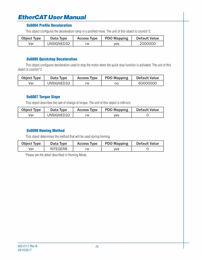
920-0117 Rev B09/15/2017
EtherCAT User Manual
70
0x6084 Profile DecelerationThis object configures the deceleration ramp in a profiled move. The unit of this object is count/s^2.
Object Type Data Type Access Type PDO Mapping Default ValueVar UNSIGNED32 rw yes 2000000
0x6085 Quickstop DecelerationThis object configures deceleration used to stop the motor when the quick stop function is activated. The unit of this
object is count/s^2.
Object Type Data Type Access Type PDO Mapping Default ValueVar UNSIGNED32 rw no 60000000
0x6087 Torque SlopeThis object describes the rate of change of torque. The unit of this object is mN·m/s.
Object Type Data Type Access Type PDO Mapping Default ValueVar UNSIGNED32 rw yes 0
0x6098 Homing MethodThis object determines the method that will be used during homing.
Object Type Data Type Access Type PDO Mapping Default ValueVar INTEGER8 rw yes 0
Please see the detail described in Homing Mode.

920-0117 Rev B09/15/2017
71
EtherCAT User Manual0x6099 Homing Speed
This object determines the speeds that will be used during homing.
There are two parts to define those speeds.
Sub-index 1 to set the speed to search home switch.
Sub-index 2 to set the speed to search zero position.
The unit of this object is count/s.
Object Type Data Type Access Type Default ValueArray UNSIGNED32 rw 0
Sub Index Name PDO Mapping Default Value00 max sub-index no 201 speed during search for switch yes 002 speed during search for zero yes 0
0x609A Homing AccelerationThis object establishes the acceleration to be used for all accelerations and decelerations with the standard homing modes.
The unit of this object is count/s^2.
Object Type Data Type Access Type PDO Mapping Default ValueVar UNSIGNED32 rw yes 0

920-0117 Rev B09/15/2017
EtherCAT User Manual
72
0x60B8 Touch Probe FunctionThis object configures the function of touch probe.
Object Type Data Type Access Type PDO Mapping Default ValueVar UNSIGNED16 rw yes 0
Bit Value Definition
00 Switch off touch probe 11 Enable touch probe 1
10 Trigger first event1 Trigger continuously
2, 3
00 Trigger with touch probe 1 input01 reserved10 reserved11 reserved
40 Switch off sampling at rising edge of touch probe 11 Enable sampling at rising edge of touch probe 1
50 Switch off sampling at falling edge of touch probe 11 Enable sampling at falling edge of touch probe 1
6, 7 - reserved
80 Switch off touch probe 21 Enable touch probe 2
90 Trigger first event1 Trigger continuously
10, 11
00 Trigger with touch probe 2 input01 reserved10 reserved11 reserved
120 Switch off sampling at rising edge of touch probe 21 Enable sampling at rising edge of touch probe 2
130 Switch off sampling at falling edge of touch probe 21 Enable sampling at falling edge of touch probe 2
14, 15 - reserved
Positive value is captured at “rising edge” of digital input. Negative value is captured at “falling edge” of digital input.
When working with inputs and outputs it is important to remember the designations low and high. If current is flowing into or out of an input or output the logic state for that input/output is defined as low or closed. If no current is flowing, or the input/output is not connected, the logic state is high or open.
Rising edge means the status from low to high. Falling edge means the status from high to low.

920-0117 Rev B09/15/2017
73
EtherCAT User Manual0x60B9 Touch Probe Status
This object provides the status of touch probe.
Object Type Data Type Access Type PDO Mapping Default ValueVar UNSIGNED16 ro yes 0
Bit Value Definition
00 Touch probe 1 is switched off1 Touch probe 1 is enabled
10 Touch probe 1 no rising edge value stored1 Touch probe 1 rising edge position stored
20 Touch probe 1 no falling edge value stored1 Touch probe 1 falling edge position stored
3 - 7 0 reserved
80 Touch probe 2 is switched off1 Touch probe 2 is enabled
90 Touch probe 2 no rising edge value stored1 Touch probe 2 rising edge position stored
100 Touch probe 2 no falling edge value stored1 Touch probe 2 falling edge position stored
11 - 15 0 reserved
0x60BA Touch Probe Position 1 Positive ValueThis object provides the position value triggered by Touch Probe 1 at rising edge.
Object Type Data Type Access Type PDO Mapping Default ValueVar INTEGER32 ro yes 0
0x60BB Touch Probe Position 1 Negative ValueThis object provides the position value triggered by Touch Probe 1 at falling edge.
Object Type Data Type Access Type PDO Mapping Default ValueVar INTEGER32 ro yes 0
0x60BC Touch Probe Position 2 Positive ValueThis object provides the position value triggered by Touch Probe 2 at rising edge.
Object Type Data Type Access Type PDO Mapping Default ValueVar INTEGER32 ro yes 0

920-0117 Rev B09/15/2017
EtherCAT User Manual
74
0x60BD Touch Probe Position 2 Negative ValueThis object provides the position value triggered by Touch Probe 2 at falling edge.
Object Type Data Type Access Type PDO Mapping Default ValueVar INTEGER32 ro yes 0
0x60F4 Following Error Actual ValueThis object displays the actual position error (following error) between the target position and the actual position. The
unit of this object is encoder count.
Object Type Data Type Access Type PDO Mapping Default ValueVar INTEGER32 ro yes 0
0x60FD Digital InputsThis object monitors the inputs status of the drive.
Object Type Data Type Access Type PDO Mapping Default ValueVar UNSIGNED32 ro yes 0x00FF0000
Bit Name Description
0 CCW limit A “0” means no limit alarm.A “1” means limit alarm occurs.1 CW limit
2 Home Sensor A “0” means home sensor is not active. A “1” means home sensor is active.
3~15 Reserved16 Input X1
A “0” means the input is open. A “1” means the input is closed.
17 Input X218 Input X319 Input X420 Input X521 Input X622 Input X723 Input X8
24~31 Reserved
When working with inputs and outputs it is important to remember the designations low and high. If current is flowing into or out of an input or output the logic state for that input/output is defined as low or closed. If no current is flowing, or the input/output is not connected, the logic state is high or open.

920-0117 Rev B09/15/2017
75
EtherCAT User Manual0x60FE Digital Outputs
This object configures or monitors the digital outputs of the drive.
Object Type Data Type Access Type Default ValueArray UNSIGNED32 rw 0
Sub Index Name PDO Mapping Default Value00 max sub-index no 201 physical outputs yes 0x0000000002 bit mask no 0x00000000
Description of physical outputs:
Bit 0~15 are reserved.
Bit 16~19 are for outputs Y1 ~ Y4 correspondingly.
Bit 20~31 are reserved.
A “0” turns an output on (closed). A “1” turns an output off (open).
Example:
0x000F0000 Turn off all four outputs.
0x000A0000 Turn on Y1 and Y3. Turn off Y2 and Y4.
Description of bit mask:
Bit 0~15 are reserved.
Bit 16~19 are for outputs Y1 ~ Y4 correspondingly.
Bit 20~31 are reserved.
A “0” deselects (mask off) an output. A “1” selects an output.
Example:
0x000F0000 Select all four outputs.
0x000A0000 Deselect (mask off) Y1 and Y3. Select Y2 and Y4.
0x60FF Target VelocityThis object configures the velocity parameters in Profile Velocity Mode and Cyclic Sync Velocity Mode.The unit of this
object is count/s.
Object Type Data Type Access Type PDO Mapping Default ValueVar INTEGER32 rw yes 0

920-0117 Rev B09/15/2017
EtherCAT User Manual
76
0x6502 Supported Drive ModesThis object provides information on the supported drive modes.
Object Type Data Type Access Type PDO Mapping Default Value
Var UNSIGNED32 ro no 429
Bit Description0 PP: Profile Position Mode1 VI: Velocity Mode2 PV: Profile Velocity Mode3 TQ: Torque Profile Mode4 reserved5 HM: Homing Mode6 IP: Interpolated Position Mode7 CSP: Cyclic Sync Position Mode8 CSV: Cyclic Sync Velocity Mode9 CST: Cyclic Sync Torque Mode
10~31 reserved
Bit value 0: Not supported.
Bit value 1: Supported.
SS EtherCAT drive now supports PP, PV, TQ, HM, CSP, CSV modes.

920-0117 Rev B09/15/2017
77
EtherCAT User ManualManufacturer Specific Objects
0x2001 Home SwitchThis object configures which input is used as the home switch in Homing.
Object Type Data Type Access Type PDO Mapping Default ValueVar UNSIGNED8 rw no 8
0x2002 Output StatusThis object reads back the status of the drive’s outputs.
Object Type Data Type Access Type PDO Mapping Default ValueVar UNSIGNED32 ro no 0x000F0000
Bit 0~15 are reserved.
Bit 16~19 are for outputs Y1 ~ Y4 correspondingly.
Bit 20~31 are reserved.
A “0” means the output is closed. A “1” means the output is open.
Example:
0x000F0000 All four outputs of the drive are open.
0x000A0000 Outputs Y1 and Y3 are closed. Output Y2 and Y4 are open.
0x2005 Torque ConstantThis object configures the motor’s torque constant. The unit of this object is mN·m/Amps.
Object Type Data Type Access Type PDO Mapping Default ValueVar UNSIGNED16 rw no 0
0x2006 Clear AlarmThis object provides the feature to clear alarm of the drives. After the condition that caused the error has been resolved,
set this value to 01h can clear the error code in object 0x603F and object 0x200F
Object Type Data Type Access Type PDO Mapping Default ValueVar UNSIGNED8 wo no 0
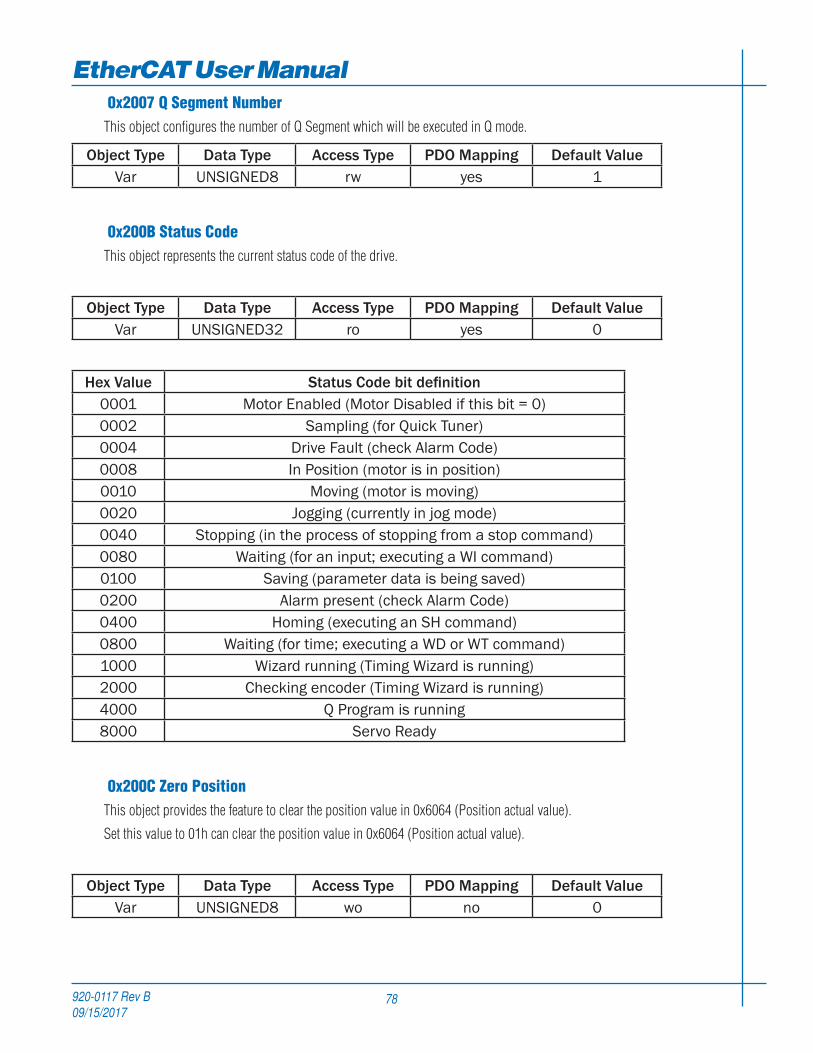
920-0117 Rev B09/15/2017
EtherCAT User Manual
78
0x2007 Q Segment NumberThis object configures the number of Q Segment which will be executed in Q mode.
Object Type Data Type Access Type PDO Mapping Default ValueVar UNSIGNED8 rw yes 1
0x200B Status CodeThis object represents the current status code of the drive.
Object Type Data Type Access Type PDO Mapping Default ValueVar UNSIGNED32 ro yes 0
Hex Value Status Code bit definition0001 Motor Enabled (Motor Disabled if this bit = 0)0002 Sampling (for Quick Tuner)0004 Drive Fault (check Alarm Code)0008 In Position (motor is in position)0010 Moving (motor is moving)0020 Jogging (currently in jog mode)0040 Stopping (in the process of stopping from a stop command)0080 Waiting (for an input; executing a WI command)0100 Saving (parameter data is being saved)0200 Alarm present (check Alarm Code)0400 Homing (executing an SH command)0800 Waiting (for time; executing a WD or WT command)1000 Wizard running (Timing Wizard is running)2000 Checking encoder (Timing Wizard is running)4000 Q Program is running8000 Servo Ready
0x200C Zero PositionThis object provides the feature to clear the position value in 0x6064 (Position actual value).
Set this value to 01h can clear the position value in 0x6064 (Position actual value).
Object Type Data Type Access Type PDO Mapping Default ValueVar UNSIGNED8 wo no 0

920-0117 Rev B09/15/2017
79
EtherCAT User Manual0x200F Alarm Code
This object reads back a hexadecimal value of the most recent alarm code of the drive.
Object Type Data Type Access Type PDO Mapping Default ValueVar UNSIGNED32 ro yes 0
Each bit in alarm code indicates one type of warnings or faults status.
Hex Value SS EtherCAT00000001 Position Limit00000002 CCW Limit00000004 CW Limit00000008 Over Temperature00000010 Internal Voltage Bad00000020 Over Voltage00000040 Under Voltage00000080 Over Current00000100 Open Motor Winding00000200 Bad Encoder00000400 Communication Error00000800 Bad Flash00001000 No Move00002000 Current Foldback00004000 Blank Q Segment00008000 NV Memory Double Error00010000 Excess Regen00020000 -00040000 Safe Torque Off00080000 -00100000 -
Note: Items in bold italic represent Drive Faults, which automatically disable the motor.
When Fault happens, after the condition that caused the error has been resolved,
write 80h to object 0x6040 to clear the error code in object 0x603F and object 0x200F.
When Warning happens, after the condition that caused the error has been resolved,
write 01h to object 0x2006 to clear the error code in object 0x603F and object 0x200F.

920-0117 Rev B09/15/2017
EtherCAT User Manual
80
0x2010 Position Loop Proportional GainThis object configures the tuning parameter - Position Loop Proportional Gain. This parameter is the primary gain term
for minimizing the position error.
Object Type Data Type Access Type PDO Mapping Default ValueVar UNSIGNED16 rw no -
0x2011 Position Loop Differential GainThis object configures the tuning parameter - Position Loop Differential Gain. This parameter works to damp low speed
oscillations.
Object Type Data Type Access Type PDO Mapping Default ValueVar UNSIGNED16 rw no -
0x2012 Position Loop Differential FilterThis object configures the tuning parameter - Position Loop Differential Filter. This filter is a simple one-pole, low-pass
filter intended for attenuating high frequency oscillations.
Object Type Data Type Access Type PDO Mapping Default ValueVar UNSIGNED16 rw no -
0x2013 Velocity Loop Proportional GainThis object configures the tuning parameter - Velocity Loop Proportional Gain. This parameter is used to minimize the
velocity error.
Object Type Data Type Access Type PDO Mapping Default ValueVar UNSIGNED16 rw no -
0x2014 Velocity Loop Integrator GainThis object configures the tuning parameter - Velocity Loop Integrator Gain. This parameter is used to minimize steady
state velocity errors.
Object Type Data Type Access Type PDO Mapping Default ValueVar UNSIGNED16 rw no -
0x2015 Acceleration Feedforward GainThis object configures the tuning parameter - Acceleration Feedforward Gain. This parameter improves acceleration
control by compensating for the load inertia.
Object Type Data Type Access Type PDO Mapping Default ValueVar UNSIGNED16 rw no -

920-0117 Rev B09/15/2017
81
EtherCAT User Manual0x2016 PID Filter
This object configures the tuning parameter - PID Filter. It sets the servo control overall filter frequency. The filter is a simple one-pole, low-pass filter intended for attenuating high frequency oscillations.
Object Type Data Type Access Type PDO Mapping Default ValueVar UNSIGNED16 rw no -
0x2019 Drive TemperatureThis object reads back the drive’s temperature measured by on board temperature sensor.
The unit of this object is 0.1 centigrade.
Object Type Data Type Access Type PDO Mapping Default ValueVar UNSIGNED16 ro no -
0x201A In Position CountsThis object configures the in position counts to determine if the motor is in position (dynamic).
Object Type Data Type Access Type PDO Mapping Default ValueVar UNSIGNED16 rw no 20
0x201C Encoder ResolutionThis object reads back the encoder resolution in lines. For step-servo motors, this object is read only.
Object Type Data Type Access Type PDO Mapping Default ValueVar UNSIGNED16 ro no 5000
0x201D In Position Error RangeThis object configures the in position counts to determine if the motor is in position (static).
Static means checking whether the motor is in position when the motor is stopped. This object is the same as “PD” command in Host Command Reference.
Object Type Data Type Access Type PDO Mapping Default ValueVar UNSIGNED16 rw no 10
0x201E In Position TimingThis object configures the time duration for in-position judging condition. If it is always in-position within the time
duration, the drive will define the motor as in-position. This object is the same as “PE” command in Host Command Reference. Time is counted as processor cycles, one cycle refers to ·200µsec for SS EtherCAT drive.
Object Type Data Type Access Type PDO Mapping Default ValueVar UNSIGNED16 rw no 10

920-0117 Rev B09/15/2017
EtherCAT User Manual
82
Parameter Unit Scaling
Distance, Velocity, Acceleration and Deceleration
For speed and acceleration and deceleration parameters, it is based on the encoder resolution of the motor.
When your Drive connect with HT17/23/24/34-SS Motors, the encoder resolution is 20000 counts/rev
Parameter Type Speed ValueDistance 1 rev 20000
Speed 1 rps 20000Accel/Decel 100 eps/s 2000000
When your Drive connect with HT11-SS Motors, the encoder resolution is 4096 counts/rev
Parameter Type Speed ValueDistance 1 rev 4096
Speed 1 rps 4096Accel/Decel 100 eps/s 409600
920-0117 Rev B09/15/2017
83
EtherCAT User Manual
Applied Motion Products
404 Westridge Drive
Watsonville, CA 95076
USA
tel / 831-761-6555
www.applied-motion.com