ss7 port adapter installation and configuration - cisco.com · vii ss7 port adapter installation...
TRANSCRIPT

SS7 Port Adapter Installation and ConfigurationProduct Number: PA-MCX-8TE1-M=Platform Supported: Cisco 7500 Routers with VIP
Corporate HeadquartersCisco Systems, Inc.170 West Tasman DriveSan Jose, CA 95134-1706 USAhttp://www.cisco.comTel: 408 526-4000
800 553-NETS (6387)Fax: 408 526-4100
Text Part Number: OL-3527-01

THE SPECIFICATIONS AND INFORMATION REGARDING THE PRODUCTS IN THIS MANUAL ARE SUBJECT TO CHANGE WITHOUT NOTICE. ALL STATEMENTS, INFORMATION, AND RECOMMENDATIONS IN THIS MANUAL ARE BELIEVED TO BE ACCURATE BUT ARE PRESENTED WITHOUT WARRANTY OF ANY KIND, EXPRESS OR IMPLIED. USERS MUST TAKE FULL RESPONSIBILITY FOR THEIR APPLICATION OF ANY PRODUCTS.
THE SOFTWARE LICENSE AND LIMITED WARRANTY FOR THE ACCOMPANYING PRODUCT ARE SET FORTH IN THE INFORMATION PACKET THAT SHIPPED WITH THE PRODUCT AND ARE INCORPORATED HEREIN BY THIS REFERENCE. IF YOU ARE UNABLE TO LOCATE THE SOFTWARE LICENSE OR LIMITED WARRANTY, CONTACT YOUR CISCO REPRESENTATIVE FOR A COPY.
The following information is for FCC compliance of Class A devices: This equipment has been tested and found to comply with the limits for a Class A digital device, pursuant to part 15 of the FCC rules. These limits are designed to provide reasonable protection against harmful interference when the equipment is operated in a commercial environment. This equipment generates, uses, and can radiate radio-frequency energy and, if not installed and used in accordance with the instruction manual, may cause harmful interference to radio communications. Operation of this equipment in a residential area is likely to cause harmful interference, in which case users will be required to correct the interference at their own expense.
The following information is for FCC compliance of Class B devices: The equipment described in this manual generates and may radiate radio-frequency energy. If it is not installed in accordance with Cisco’s installation instructions, it may cause interference with radio and television reception. This equipment has been tested and found to comply with the limits for a Class B digital device in accordance with the specifications in part 15 of the FCC rules. These specifications are designed to provide reasonable protection against such interference in a residential installation. However, there is no guarantee that interference will not occur in a particular installation.
Modifying the equipment without Cisco’s written authorization may result in the equipment no longer complying with FCC requirements for Class A or Class B digital devices. In that event, your right to use the equipment may be limited by FCC regulations, and you may be required to correct any interference to radio or television communications at your own expense.
You can determine whether your equipment is causing interference by turning it off. If the interference stops, it was probably caused by the Cisco equipment or one of its peripheral devices. If the equipment causes interference to radio or television reception, try to correct the interference by using one or more of the following measures:
• Turn the television or radio antenna until the interference stops.
• Move the equipment to one side or the other of the television or radio.
• Move the equipment farther away from the television or radio.
• Plug the equipment into an outlet that is on a different circuit from the television or radio. (That is, make certain the equipment and the television or radio are on circuits controlled by different circuit breakers or fuses.)
Modifications to this product not authorized by Cisco Systems, Inc. could void the FCC approval and negate your authority to operate the product.
The Cisco implementation of TCP header compression is an adaptation of a program developed by the University of California, Berkeley (UCB) as part of UCB’s public domain version of the UNIX operating system. All rights reserved. Copyright © 1981, Regents of the University of California.
NOTWITHSTANDING ANY OTHER WARRANTY HEREIN, ALL DOCUMENT FILES AND SOFTWARE OF THESE SUPPLIERS ARE PROVIDED “AS IS” WITH ALL FAULTS. CISCO AND THE ABOVE-NAMED SUPPLIERS DISCLAIM ALL WARRANTIES, EXPRESSED OR IMPLIED, INCLUDING, WITHOUT LIMITATION, THOSE OF MERCHANTABILITY, FITNESS FOR A PARTICULAR PURPOSE AND NONINFRINGEMENT OR ARISING FROM A COURSE OF DEALING, USAGE, OR TRADE PRACTICE.
IN NO EVENT SHALL CISCO OR ITS SUPPLIERS BE LIABLE FOR ANY INDIRECT, SPECIAL, CONSEQUENTIAL, OR INCIDENTAL DAMAGES, INCLUDING, WITHOUT LIMITATION, LOST PROFITS OR LOSS OR DAMAGE TO DATA ARISING OUT OF THE USE OR INABILITY TO USE THIS MANUAL, EVEN IF CISCO OR ITS SUPPLIERS HAVE BEEN ADVISED OF THE POSSIBILITY OF SUCH DAMAGES.
SS7 Port Adapter Installation and ConfigurationCopyright © 2002, Cisco Systems, Inc.All rights reserved.
CCSP, CCVP, the Cisco Square Bridge logo, Follow Me Browsing, and StackWise are trademarks of Cisco Systems, Inc.; Changing the Way We Work, Live, Play, and Learn, and iQuick Study are service marks of Cisco Systems, Inc.; and Access Registrar, Aironet, ASIST, BPX, Catalyst, CCDA, CCDP, CCIE, CCIP, CCNA, CCNP, Cisco, the Cisco Certified Internetwork Expert logo, Cisco IOS, Cisco Press, Cisco Systems, Cisco Systems Capital, the Cisco Systems logo, Cisco Unity, Empowering the Internet Generation, Enterprise/Solver, EtherChannel, EtherFast, EtherSwitch, Fast Step, FormShare, GigaDrive, GigaStack, HomeLink, Internet Quotient, IOS, IP/TV, iQ Expertise, the iQ logo, iQ Net Readiness Scorecard, LightStream, Linksys, MeetingPlace, MGX, the Networkers logo, Networking Academy, Network Registrar, Packet, PIX, Post-Routing, Pre-Routing, ProConnect, RateMUX, ScriptShare, SlideCast, SMARTnet, StrataView Plus, TeleRouter, The Fastest Way to Increase Your Internet Quotient, and TransPath are registered trademarks of Cisco Systems, Inc. and/or its affiliates in the United States and certain other countries.
All other trademarks mentioned in this document or Website are the property of their respective owners. The use of the word partner does not imply a partnership relationship between Cisco and any other company. (0502R)

OL-3527-01
C O N T E N T S
Preface vii
Objectives vii
Organization vii
Related Documentation viii
Obtaining Documentation ix
World Wide Web ix
Documentation CD-ROM ix
Ordering Documentation ix
Documentation Feedback ix
Obtaining Technical Assistance x
Cisco.com x
Technical Assistance Center x
Cisco TAC Web Site xi
Cisco TAC Escalation Center xi
C H A P T E R 1 Overview 1-1
Port Adapter Overview 1-1
Channelized T1/E1 Overview 1-2
Features 1-3
LEDs 1-4
Cables, Connectors, and Pinouts 1-5
Port Adapter Slot Locations on the Cisco 7507 and Cisco 7513 1-6
Cisco 7507 Router Slot Numbering 1-6
Cisco 7513 Router Slot Numbering 1-7
Identifying Interface Addresses 1-8
C H A P T E R 2 Preparing for Installation 2-1
Required Tools and Equipment 2-1
Software and Hardware Requirements 2-2
Checking Hardware and Software Compatibility 2-2
Safety Guidelines 2-2
Safety Warnings 2-2
Electrical Equipment Guidelines 2-4
iiiSS7 Port Adapter Installation and Configuration

Contents
Telephone Wiring Guidelines 2-5
Preventing Electrostatic Discharge Damage 2-5
FCC Class A Compliance 2-6
C H A P T E R 3 Removing and Installing the SS7 Port Adapter 3-1
VIP Overview 3-1
Removing the VIP 3-2
Online Insertion and Removal (OIR) 3-2
Procedure for Removing the VIP 3-4
Removing and Installing the SS7 Port Adapter 3-4
Reinstalling the VIP and Connecting the SS7 Port Adapter Cables 3-7
Reinstalling the VIP 3-7
Connecting the SS7 Port Adapter Interface Cables 3-8
Verifying the VIP and SS7 Port Adapter Installation 3-9
Observing LEDs and System Messages 3-10
SS7 Port Adapter LEDs 3-10
System Messages 3-11
Using show Commands to Verify the VIP Status 3-12
Using show Commands to Display Interface Information 3-13
C H A P T E R 4 Configuring the SS7 Port Adapter 4-1
Using the EXEC Command Interpreter 4-1
Configuring the Interfaces 4-2
Shutting Down an Interface 4-2
Performing a Basic Configuration 4-4
Specifying Card Type is Required 4-4
Configuring the Controller 4-5
Clocking on the SS7 Port Adapter 4-5
Creating a Basic Controller Configuration for the SS7 Port Adapter 4-6
Performing a Basic Data Interface Configuration 4-8
Configuring Cyclic Redundancy Checks 4-9
Configuring Drop and Insert 4-10
Checking the Configuration 4-11
Using show Commands to Verify the New Interface Status 4-11
Troubleshooting Tips 4-11
Using the show version or show hardware Commands 4-12
Using the show diag Command 4-12
Using the show interfaces Command 4-13
ivSS7 Port Adapter Installation and Configuration
OL-3527-01

Contents
Using the ping cs7 Command to Verify Network Connectivity between ITPs 4-14
Using loopback Commands 4-14
T1 Loopback Examples 4-14
E1 Loopback Examples 4-15
vSS7 Port Adapter Installation and Configuration
OL-3527-01

Contents
viSS7 Port Adapter Installation and Configuration
OL-3527-01

Preface
This preface describes the objectives and organization of this document and explains how to find additional information on related products and services. This preface contains the following sections:
• Objectives, page vii
• Organization, page vii
• Related Documentation, page viii
• Obtaining Documentation, page ix
• Obtaining Technical Assistance, page x
ObjectivesThis document describes how to install and configure the eight-port multichannel T1/E1 port adapter (PA-MCX-8TE1-M[=]), hereafter referred to as the SS7 Port Adapter. This port adapter is used in the Cisco 7507 and 7513 routers.
Note The SS7 Port Adapter is only for use with the IP Transfer Point (ITP) Cisco IOS software to terminate SS7 T1/E1 links.
OrganizationThis document contains the following chapters:
Section Title Description
Chapter 1 Overview Describes the SS7 Port Adapter and its LED displays, cables, and receptacles.
Chapter 2 Preparing for Installation Describes safety considerations, tools required, and procedures you should perform before the actual installation.
viiSS7 Port Adapter Installation and Configuration
OL-3527-01

PrefaceRelated Documentation
Related DocumentationYour router and the Cisco IOS software running on it contain extensive features and functionality, which are documented in the following resources:
• Cisco IOS software:
For configuration information and support, refer to the modular configuration and modular command reference publications in the Cisco IOS software configuration documentation set that corresponds to the software release installed on your Cisco hardware.
Note You can access Cisco IOS software configuration and hardware installation and maintenance documentation on the World Wide Web at http://www.cisco.com, http://www-china.cisco.com, or http://www-europe.cisco.com.
• SS7 over IP
Cisco IP Transfer Point (ITP) is a Cisco hardware and Cisco IOS software SS7-over-IP (SS7oIP) solution. ITP provides a highly reliable, cost effective medium for migrating Signaling System 7 (SS7), the telecommunications network signaling technology, to the mobile wireless industry IP environment. For information about ITP, access http://www.cisco.com, http://www-china.cisco.com, or http://www-europe.cisco.com and search on the topic “IP Transfer Point.”
• Cisco 7507 and 7513 routers:
For hardware installation and maintenance information, refer to the Cisco 7500 Series Installation and Configuration Guide that shipped with your Cisco 7507 or 7513 router.
• For international agency compliance, safety, and statutory information for WAN interfaces:
– Site Preparation and Safety Guide
– Cisco 7500 Series Regulatory Compliance and Safety Information
• To view Cisco documentation or obtain general information about the documentation, refer to the following sources:
– “Obtaining Documentation” section on page ix
– Customer service at 800 553-6387 or 408 526-7208. Customer service hours are 5:00 a.m. to 6:00 p.m. Pacific time, Monday through Friday (excluding Cisco-observed holidays). You can also send e-mail to [email protected].
– Cisco Information Packet that shipped with your router
Chapter 3 Removing and Installing the SS7 Port Adapter
Describes the procedures for installing and removing the SS7 Port Adapter in the supported platform.
Chapter 4 Configuring the SS7 Port Adapter Provides instructions for configuring the SS7 Port Adapter on the supported platform.
Section Title Description
viiiSS7 Port Adapter Installation and Configuration
OL-3527-01

PrefaceObtaining Documentation
Obtaining DocumentationThese sections explain how to obtain documentation from Cisco Systems.
World Wide WebYou can access the most current Cisco documentation on the World Wide Web at this URL:
http://www.cisco.com
Translated documentation is available at this URL:
http://www.cisco.com/public/countries_languages.shtml
Documentation CD-ROMCisco documentation and additional literature are available in a Cisco Documentation CD-ROM package, which is shipped with your product. The Documentation CD-ROM is updated monthly and may be more current than printed documentation. The CD-ROM package is available as a single unit or through an annual subscription.
Ordering DocumentationYou can order Cisco documentation in these ways:
• Registered Cisco.com users (Cisco direct customers) can order Cisco product documentation from the Networking Products MarketPlace:
http://www.cisco.com/cgi-bin/order/order_root.pl
• Registered Cisco.com users can order the Documentation CD-ROM through the online Subscription Store:
http://www.cisco.com/go/subscription
• Nonregistered Cisco.com users can order documentation through a local account representative by calling Cisco Systems Corporate Headquarters (California, U.S.A.) at 408 526-7208 or, elsewhere in North America, by calling 800 553-NETS (6387).
Documentation FeedbackYou can submit comments electronically on Cisco.com. In the Cisco Documentation home page, click the Fax or Email option in the “Leave Feedback” section at the bottom of the page.
You can e-mail your comments to [email protected].
You can submit your comments by mail by using the response card behind the front cover of your document or by writing to the following address:
Cisco SystemsAttn: Document Resource Connection170 West Tasman DriveSan Jose, CA 95134-9883
ixSS7 Port Adapter Installation and Configuration
OL-3527-01

PrefaceObtaining Technical Assistance
We appreciate your comments.
Obtaining Technical AssistanceCisco provides Cisco.com as a starting point for all technical assistance. Customers and partners can obtain online documentation, troubleshooting tips, and sample configurations from online tools by using the Cisco Technical Assistance Center (TAC) Web Site. Cisco.com registered users have complete access to the technical support resources on the Cisco TAC Web Site.
Cisco.comCisco.com is the foundation of a suite of interactive, networked services that provides immediate, open access to Cisco information, networking solutions, services, programs, and resources at any time, from anywhere in the world.
Cisco.com is a highly integrated Internet application and a powerful, easy-to-use tool that provides a broad range of features and services to help you with these tasks:
• Streamline business processes and improve productivity
• Resolve technical issues with online support
• Download and test software packages
• Order Cisco learning materials and merchandise
• Register for online skill assessment, training, and certification programs
If you want to obtain customized information and service, you can self-register on Cisco.com. To access Cisco.com, go to this URL:
http://www.cisco.com
Technical Assistance CenterThe Cisco Technical Assistance Center (TAC) is available to all customers who need technical assistance with a Cisco product, technology, or solution. Two levels of support are available: the Cisco TAC Web Site and the Cisco TAC Escalation Center.
Cisco TAC inquiries are categorized according to the urgency of the issue:
• Priority level 4 (P4)—You need information or assistance concerning Cisco product capabilities, product installation, or basic product configuration.
• Priority level 3 (P3)—Your network performance is degraded. Network functionality is noticeably impaired, but most business operations continue.
• Priority level 2 (P2)—Your production network is severely degraded, affecting significant aspects of business operations. No workaround is available.
• Priority level 1 (P1)—Your production network is down, and a critical impact to business operations will occur if service is not restored quickly. No workaround is available.
The Cisco TAC resource that you choose is based on the priority of the problem and the conditions of service contracts, when applicable.
xSS7 Port Adapter Installation and Configuration
OL-3527-01

PrefaceObtaining Technical Assistance
Cisco TAC Web Site
You can use the Cisco TAC Web Site to resolve P3 and P4 issues yourself, saving both cost and time. The site provides around-the-clock access to online tools, knowledge bases, and software. To access the Cisco TAC Web Site, go to this URL:
http://www.cisco.com/tac
All customers, partners, and resellers who have a valid Cisco service contract have complete access to the technical support resources on the Cisco TAC Web Site. The Cisco TAC Web Site requires a Cisco.com login ID and password. If you have a valid service contract but do not have a login ID or password, go to this URL to register:
http://www.cisco.com/register/
If you are a Cisco.com registered user, and you cannot resolve your technical issues by using the Cisco TAC Web Site, you can open a case online by using the TAC Case Open tool at this URL:
http://www.cisco.com/tac/caseopen
If you have Internet access, we recommend that you open P3 and P4 cases through the Cisco TAC Web Site.
Cisco TAC Escalation Center
The Cisco TAC Escalation Center addresses priority level 1 or priority level 2 issues. These classifications are assigned when severe network degradation significantly impacts business operations. When you contact the TAC Escalation Center with a P1 or P2 problem, a Cisco TAC engineer automatically opens a case.
To obtain a directory of toll-free Cisco TAC telephone numbers for your country, go to this URL:
http://www.cisco.com/warp/public/687/Directory/DirTAC.shtml
Before calling, please check with your network operations center to determine the level of Cisco support services to which your company is entitled: for example, SMARTnet, SMARTnet Onsite, or Network Supported Accounts (NSA). When you call the center, please have available your service agreement number and your product serial number.
xiSS7 Port Adapter Installation and Configuration
OL-3527-01

PrefaceObtaining Technical Assistance
xiiSS7 Port Adapter Installation and Configuration
OL-3527-01
SS7 PorOL-3527-01
C H A P T E R 1
OverviewThis chapter describes the SS7 Port Adapter and contains the following sections:
• Port Adapter Overview, page 1-1
• Channelized T1/E1 Overview, page 1-2
• Features, page 1-3
• LEDs, page 1-4
• Cables, Connectors, and Pinouts, page 1-5
• Port Adapter Slot Locations on the Cisco 7507 and Cisco 7513, page 1-6
• Identifying Interface Addresses, page 1-8
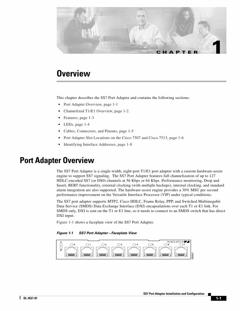
Port Adapter OverviewThe SS7 Port Adapter is a single-width, eight-port T1/E1 port adapter with a custom hardware-assist engine to support SS7 signaling. The SS7 Port Adapter features full channelization of up to 127 HDLC-encoded SS7 (or DS0) channels at 56 Kbps or 64 Kbps. Performance monitoring, Drop and Insert, BERT functionality, external clocking (with multiple backups), internal clocking, and standard alarm integration are also supported. The hardware-assist engine provides a 30% MSU per second performance improvement on the Versatile Interface Processor (VIP) under typical conditions.
The SS7 port adapter supports MTP2, Cisco HDLC, Frame Relay, PPP, and Switched Multimegabit Data Service (SMDS) Data Exchange Interface (DXI) encapsulations over each T1 or E1 link. For SMDS only, DXI is sent on the T1 or E1 line, so it needs to connect to an SMDS switch that has direct DXI input.
Figure 1-1 shows a faceplate view of the SS7 Port Adapter.
Figure 1-1 SS7 Port Adapter—Faceplate View
6585
3
AL
EN
0 1 2 3 4 5 6 7PA-MCX-8TE1-M
1-1t Adapter Installation and Configuration

Chapter 1 OverviewChannelized T1/E1 Overview
Channelized T1/E1 OverviewWhen you are running channelized data, each DS1 interface can provide up to 24 T1 channel groups if your SS7 Port Adapter is configured for T1, or 31 E1 channel groups if your SS7 Port Adapter is configured for E1. The T1 channel groups are numbered from 0 to 23 and the E1 channel groups are numbered from 0 to 30. Each T1 channel group provides up to twenty-four 56k or 64-kbps time slots, which are numbered 1 to 24. Each E1 channel group provides up to thirty-one 64-kbps time slots, which are numbered 1 to 31. Multiple time slots can be mapped to a single channel group. Each channel group is presented to the system as a serial interface that can be configured individually. Usable bandwidth for each channel group is calculated as n x 56 kbps or n x 64 kbps, where n is the number of T1 time slots (1 to 24) or E1 channels (1 to 31).
Each of the channels on the SS7 Port Adapter uses a portion of the bandwidth (fractional T1 or E1) or the entire bandwidth for data transmission. Usable bandwidth for each channel is n x 56 kbps or n x 64 kbps, where n is a number from 1 to 24 for T1 and 1 to 31 for E1. When you are not running at full T1 and E1 speeds, the unused portion of the bandwidth cannot be used and is filled with idle channel data.
Note Time slots on the SS7 Port Adapter are numbered 1 to 24 for T1 and 1 to 31 for E1, instead of the zero-based scheme (0 to 23 or 0 to 30) used with other Cisco products. This numbering scheme is to ensure consistency with telco numbering schemes for T1 and E1 channels within channelized equipment.
The SS7 Port Adapter supports Facility Data Link (FDL) in Extended Superframe (ESF) framing on T1 networks, as well as network and payload loopbacks. Bit error rate testing (BERT) is supported on each of the T1 or E1 links. BERT can be run only on one port at a time.
Note On a SS7 Port Adapter configured for T1, BERT is done only over a framed T1 signal.
The SS7 Port AdapterSS7 Port Adapter does not support the aggregation of multiple T1s or E1s (called inverse muxing or bonding) for higher bandwidth data rates.
1-2SS7 Port Adapter Installation and Configuration
OL-3527-01

Chapter 1 OverviewFeatures
FeaturesThe SS7 Port Adapter provides the following features:
• Singlewide port adapter with 8 T1 or E1 RJ48c ports
• Runs on Cisco 7500 Versatile Interface Processor (VIP)
• Integrated CSU/DSU
• Software configurable for E1/T1
• Software configurable for 56/64 kbps timeslots in E1 and T1 modes
• Common external clock source with multiple backups or internal clock
• MTP2 FISU/LSSU generation and filtering
• Drop and Insert for non-SS7 timeslots
• ANSI, ITU, and China SS7 variant support
1-3SS7 Port Adapter Installation and Configuration
OL-3527-01

Chapter 1 OverviewLEDs
LEDsThe SS7 Port Adapter has a green enabled LED, a bicolor alarm LED, and a bicolor port status LED for each port onthe port adapter (see Figure 1-2).
Figure 1-2 LEDs on the SS7 Port Adapter
After system initialization, the enabled LED goes on to indicate that the port adapter has been enabled for operation.
The following conditions must be met before the SS7 Port Adapter is enabled:
• The SS7 Port Adapter is correctly connected and is receiving power.
• A valid system software image for the port adapter has been downloaded successfully.
• The system recognizes the SS7 Port Adapter.
If any of the above conditions are not met, or if the initialization fails for other reasons, the enabled LED does not go on.
Table 1-1 lists the functions of the LEDs.
6585
3
AL
EN
0 1 2 3 4 5 6 7PA-MCX-8TE1-M
Table 1-1 SS7 Port Adapter LEDs
LED Label Color State Function
EN Green On Indicates the SS7 Port Adapter is powered up.
Off Indicates the SS7 Port Adapter is not ready or is disabled.
AL Amber On Indicates an alarm condition exists on the remote end of one of the T1/E1 ports.
Red On Indicates an alarm condition exists locally on one of the T1/E1 ports.
Off Indicates no alarms detected on any port.
0 through 7 Green On Indicates the port is enabled and in frame.
Yellow On Indicates the port is in loopback.
Off Indicates that the port is not enabled, the received signal is bad, or an alarm condition exists.
1-4SS7 Port Adapter Installation and Configuration
OL-3527-01

Chapter 1 OverviewCables, Connectors, and Pinouts
Cables, Connectors, and PinoutsThe T1/E1 interface receptacles on the SS7 Port Adapter are RJ-48C connectors for both T1 (100 ohm) and E1 (120 ohm).
After you properly connect a port to a line, it takes approximately 30 seconds for Cisco IOS to report that the line is up.
Each connection supports T1 (100-ohm) or E1 (120-ohm) interfaces that meet T1.403 and ACCUNET TR62411 standards. The RJ-48C connector does not require an external transceiver. The DS1 ports are T1 interfaces that use foil twisted-pair (FTP) cables.
Note Shielded cables (FTP) with 120-ohm impedance are required to comply with CE marking requirements.
Figure 1-3 shows the SS7 Port Adapter interface cable connector
Figure 1-3 SS7 Port Adapter Interface Cable Connector
Table 1-2 lists the signal pinouts and descriptions for the RJ-48C connector.
2493
98 7 6 5 4 3 2 1
RJ-48C connector
Table 1-2 RJ-48C Connector Pinouts
Pin Signal
1 RX tip
2 RX ring
3 No connection
4 TX tip
5 TX ring
6 No connection
7 No connection
8 No connection
1-5SS7 Port Adapter Installation and Configuration
OL-3527-01

Chapter 1 OverviewPort Adapter Slot Locations on the Cisco 7507 and Cisco 7513
Port Adapter Slot Locations on the Cisco 7507 and Cisco 7513This section describes port adapter slot locations on the Cisco 7507 and Cisco 7513 platforms and summarize the slot location conventions on those platforms.
Cisco 7507 Router Slot NumberingOn a Cisco 7507 router, the VIP with the SS7 Port Adapter can be installed in any slot except slot 2 or 3.
Figure 1-4 shows a Cisco 7507 with an SS7 port adapter installed on the VIP in slot 5.
Figure 1-4 SS7 Port Adapter in the Cisco 7507
EJECT
SLOT 0
SLOT 1
NORMAL
CPU HALTRESET
AUX.
CONSOLE
RO
UT
E SW
ITC
H PR
OC
ESSO
R 2
SLAVE
MASTER
SLAVE/MASTER
6585
5
Slot 0 1 2 3 4 5 6
Upper power supply
Chassisgroundingreceptacles
Lowerpower supply
I
O
DC FAILAC POWER
I
O
DC FAILAC POWER
RSP slots
Captiveinstallation screw
Captiveinstallation screw
ENABLE
AL EN
01
23
45
67
PA
-MC
-8T
E1
-SS
7
1-6SS7 Port Adapter Installation and Configuration
OL-3527-01

Chapter 1 OverviewPort Adapter Slot Locations on the Cisco 7507 and Cisco 7513
Cisco 7513 Router Slot NumberingOn a Cisco 7513 router, the VIP with the SS7 Port Adapter can be installed in any slot except slot 6 or 7.
Figure 1-5 shows a Cisco 7513 with an SS7 port adapter installed on the VIP in slot 11.
Figure 1-5 SS7 Port Adapter in the Cisco 7513
ENABLE
6585
6
EJECT
SLOT 0
SLOT 1
NORMAL
CPU HALTRESET
AUX.
CONSOLE
RO
UT
E SW
ITC
H PR
OC
ESSO
R 2
SLAVE
MASTER
SLAVE/MASTER
Blower module
Cable-managementbracket
Card cage andprocessor modules
Air intake vent
Power supplies
Chassis groundingreceptacles 0
I
ACOK
FANOK
OUTPUTFAIL
0
I
ACOK
FANOK
OUTPUTFAIL
POWER
APOWER
B
AL EN
01
23
45
67
PA
-MC
-8T
E1
-SS
7
1-7SS7 Port Adapter Installation and Configuration
OL-3527-01

Chapter 1 OverviewPort Adapter Slot Locations on the Cisco 7507 and Cisco 7513
Identifying Interface Addresses This section describes how to identify interface addresses for the SS7 Port Adapter in the supported platforms. Interface addresses specify the actual physical location of each interface on a router or switch.
Interfaces on a port adapter maintain the same address regardless of whether other port adapters are installed or removed. However, if you move a port adapter to a different slot, the system recognizes it as a new device. In that case the port adapter would have to be reconfigured.
Note Interface ports are numbered from left to right starting with 0.
Table 1-3 explains how to identify interface addresses for the SS7 Port Adapter on a VIP in the supported platforms.
Table 1-3 Identifying Interface Addresses
Platform Interface Address Format Numbers Syntax
VIP in Cisco 7507 router interface-processor-slot-number/port-adapter-bay-number/interface-port-number:channel-group
Interface processor slot: any except 2 or 3PA bay number: 0 or 1Interface port number: 0 - 7Channel Group: 0-23 (T1) 0-30 (E1)
5/0/0:1
VIP in Cisco 7513 router interface-processor-slot-number/port-adapter-bay-number/interface-port-number:channel-group
Interface processor slot: any except 6 or 7PA bay number: 0 or 1Interface port number: 0 - 7Channel Group: 0-23 (T1) 0-30 (E1)
11/0/0:1
1-8SS7 Port Adapter Installation and Configuration
OL-3527-01
SS7 PorOL-3527-01
C H A P T E R 2
Preparing for InstallationThis chapter describes the general equipment, safety, and site preparation requirements for installing the SS7 Port Adapter. This chapter contains the following sections:
• Required Tools and Equipment, page 2-1
• Software and Hardware Requirements, page 2-2
• Checking Hardware and Software Compatibility, page 2-2
• Safety Guidelines, page 2-2
• FCC Class A Compliance, page 2-6
Required Tools and EquipmentYou need the following tools and parts to install a port adapter. If you need additional equipment, contact a service representative for ordering information.
• PA-MCX-8TE1-M(=) port adapter, hereafter referred to as the SS7 Port Adapter
• Shielded cables (FTP [foil twisted-pair]) with 120-ohm impedance
• Number 2 Phillips screwdriver
• Your own electrostatic discharge (ESD)-prevention equipment or the disposable grounding wrist strap included with all upgrade kits, field-replaceable units (FRUs), and spares
• Antistatic mat
• Antistatic container
2-1t Adapter Installation and Configuration
Chapter 2 Preparing for InstallationSoftware and Hardware Requirements
Software and Hardware RequirementsTable 2-1 lists the recommended minimum Cisco IOS software release required to use the SS7 Port Adapter in the supported router platforms.
Checking Hardware and Software CompatibilityTo check the minimum software requirements of Cisco IOS software with the hardware installed on your router, Cisco maintains the Software Advisor tool on Cisco.com. This tool does not verify whether modules within a system are compatible, but it does provide the minimum IOS requirements for individual hardware modules or components.
Note Access to this tool is limited to users with Cisco.com login accounts.
To access Software Advisor, click Login at Cisco.com and go to Technical Support Help—Cisco TAC: Tool Index: Software Advisor. You can also access the tool by pointing your browser directly to http://www.cisco.com/cgi-bin/support/CompNav/Index.pl.
Choose a product family or enter a specific product number to search for the minimum supported software release needed for your hardware.
Warning This equipment will be inoperable when main power fails.
Safety GuidelinesThis section provides safety guidelines that you should follow when working with any equipment that connects to electrical power or telephone wiring.
Safety WarningsSafety warnings appear throughout this publication in procedures that, if performed incorrectly, might harm you. A warning symbol precedes each warning statement.
Table 2-1 SS7 Port Adapter Software and Hardware Requirements
Supported Platform Recommended Minimum Cisco IOS Release
Cisco 7500 VIP4-80 Cisco IOS Release 12.2(4)MB3 or a later release of Cisco IOS Release 12.2
2-2SS7 Port Adapter Installation and Configuration
OL-3527-01

Chapter 2 Preparing for InstallationSafety Guidelines
Warning This warning symbol means danger. You are in a situation that could cause bodily injury. Before you work on any equipment, be aware of the hazards involved with electrical circuitry and be familiar with standard practices for preventing accidents. To see translations of the warnings that appear in this publication, refer to the Regulatory Compliance and Safety Information document that accompanied this device.
Waarschuwing Dit waarschuwingssymbool betekent gevaar. U verkeert in een situatie die lichamelijk letsel kan veroorzaken. Voordat u aan enige apparatuur gaat werken, dient u zich bewust te zijn van de bij elektrische schakelingen betrokken risico's en dient u op de hoogte te zijn van standaard maatregelen om ongelukken te voorkomen. Voor vertalingen van de waarschuwingen die in deze publicatie verschijnen, kunt u het document Regulatory Compliance and Safety Information (Informatie over naleving van veiligheids- en andere voorschriften) raadplegen dat bij dit toestel is ingesloten.
Varoitus Tämä varoitusmerkki merkitsee vaaraa. Olet tilanteessa, joka voi johtaa ruumiinvammaan. Ennen kuin työskentelet minkään laitteiston parissa, ota selvää sähkökytkentöihin liittyvistä vaaroista ja tavanomaisista onnettomuuksien ehkäisykeinoista. Tässä julkaisussa esiintyvien varoitusten käännökset löydät laitteen mukana olevasta Regulatory Compliance and Safety Information -kirjasesta (määräysten noudattaminen ja tietoa turvallisuudesta).
Attention Ce symbole d'avertissement indique un danger. Vous vous trouvez dans une situation pouvant causer des blessures ou des dommages corporels. Avant de travailler sur un équipement, soyez conscient des dangers posés par les circuits électriques et familiarisez-vous avec les procédures couramment utilisées pour éviter les accidents. Pour prendre connaissance des traductions d’avertissements figurant dans cette publication, consultez le document Regulatory Compliance and Safety Information (Conformité aux règlements et consignes de sécurité) qui accompagne cet appareil.
Warnung Dieses Warnsymbol bedeutet Gefahr. Sie befinden sich in einer Situation, die zu einer Körperverletzung führen könnte. Bevor Sie mit der Arbeit an irgendeinem Gerät beginnen, seien Sie sich der mit elektrischen Stromkreisen verbundenen Gefahren und der Standardpraktiken zur Vermeidung von Unfällen bewußt. Übersetzungen der in dieser Veröffentlichung enthaltenen Warnhinweise finden Sie im Dokument Regulatory Compliance and Safety Information (Informationen zu behördlichen Vorschriften und Sicherheit), das zusammen mit diesem Gerät geliefert wurde.
Avvertenza Questo simbolo di avvertenza indica un pericolo. La situazione potrebbe causare infortuni alle persone. Prima di lavorare su qualsiasi apparecchiatura, occorre conoscere i pericoli relativi ai circuiti elettrici ed essere al corrente delle pratiche standard per la prevenzione di incidenti. La traduzione delle avvertenze riportate in questa pubblicazione si trova nel documento Regulatory Compliance and Safety Information (Conformità alle norme e informazioni sulla sicurezza) che accompagna questo dispositivo.
Advarsel Dette varselsymbolet betyr fare. Du befinner deg i en situasjon som kan føre til personskade. Før du utfører arbeid på utstyr, må du vare oppmerksom på de faremomentene som elektriske kretser innebærer, samt gjøre deg kjent med vanlig praksis når det gjelder å unngå ulykker. Hvis du vil se oversettelser av de advarslene som finnes i denne publikasjonen, kan du se i dokumentet Regulatory Compliance and Safety Information (Overholdelse av forskrifter og sikkerhetsinformasjon) som ble levert med denne enheten.
2-3SS7 Port Adapter Installation and Configuration
OL-3527-01

Chapter 2 Preparing for InstallationSafety Guidelines
Electrical Equipment GuidelinesFollow these basic guidelines when working with any electrical equipment:
• Before beginning any procedures requiring access to the chassis interior, locate the emergency power-off switch for the room in which you are working.
• Disconnect all power and external cables before moving a chassis.
• Do not work alone when potentially hazardous conditions exist.
• Never assume that power has been disconnected from a circuit; always check.
• Do not perform any action that creates a potential hazard to people or makes the equipment unsafe; carefully examine your work area for possible hazards such as moist floors, ungrounded power extension cables, and missing safety grounds.
Aviso Este símbolo de aviso indica perigo. Encontra-se numa situação que lhe poderá causar danos físicos. Antes de começar a trabalhar com qualquer equipamento, familiarize-se com os perigos relacionados com circuitos eléctricos, e com quaisquer práticas comuns que possam prevenir possíveis acidentes. Para ver as traduções dos avisos que constam desta publicação, consulte o documento Regulatory Compliance and Safety Information (Informação de Segurança e Disposições Reguladoras) que acompanha este dispositivo.
¡Advertencia! Este símbolo de aviso significa peligro. Existe riesgo para su integridad física. Antes de manipular cualquier equipo, considerar los riesgos que entraña la corriente eléctrica y familiarizarse con los procedimientos estándar de prevención de accidentes. Para ver una traducción de las advertencias que aparecen en esta publicación, consultar el documento titulado Regulatory Compliance and Safety Information (Información sobre seguridad y conformidad con las disposiciones reglamentarias) que se acompaña con este dispositivo.
Varning! Denna varningssymbol signalerar fara. Du befinner dig i en situation som kan leda till personskada. Innan du utför arbete på någon utrustning måste du vara medveten om farorna med elkretsar och känna till vanligt förfarande för att förebygga skador. Se förklaringar av de varningar som förkommer i denna publikation i dokumentet Regulatory Compliance and Safety Information (Efterrättelse av föreskrifter och säkerhetsinformation), vilket medföljer denna anordning.
2-4SS7 Port Adapter Installation and Configuration
OL-3527-01

Chapter 2 Preparing for InstallationSafety Guidelines
Telephone Wiring GuidelinesUse the following guidelines when working with any equipment that is connected to telephone wiring or to other network cabling:
• Never install telephone wiring during a lightning storm.
• Never install telephone jacks in wet locations unless the jack is specifically designed for wet locations.
• Never touch uninsulated telephone wires or terminals unless the telephone line has been disconnected at the network interface.
• Use caution when installing or modifying telephone lines.
Preventing Electrostatic Discharge DamageElectrostatic discharge (ESD) damage, which can occur when electronic cards or components are improperly handled, results in complete or intermittent failures. Port adapters and processor modules comprise printed circuit boards that are fixed in metal carriers. Electromagnetic interference (EMI) shielding and connectors are integral components of the carrier. Although the metal carrier helps to protect the board from ESD, use a preventive antistatic strap during handling.
Following are guidelines for preventing ESD damage:
• Always use an ESD wrist or ankle strap and ensure that it makes good skin contact.
• Connect the equipment end of the strap to an unfinished chassis surface.
• When installing a component, use any available ejector levers or captive installation screws to properly seat the bus connectors in the backplane or midplane. These devices prevent accidental removal, provide proper grounding for the system, and help to ensure that bus connectors are properly seated.
• When removing a component, use any available ejector levers or captive installation screws to release the bus connectors from the backplane or midplane.
• Handle carriers by available handles or edges only; avoid touching the printed circuit boards or connectors.
• Place a removed board component-side-up on an antistatic surface or in a static shielding container. If you plan to return the component to the factory, immediately place it in a static shielding container.
• Avoid contact between the printed circuit boards and clothing. The wrist strap only protects components from ESD voltages on the body; ESD voltages on clothing can still cause damage.
• Never attempt to remove the printed circuit board from the metal carrier.
Caution For safety, periodically check the resistance value of the antistatic strap. The measurement should be between 1 and 10 megohms (Mohms).
2-5SS7 Port Adapter Installation and Configuration
OL-3527-01

Chapter 2 Preparing for InstallationFCC Class A Compliance
FCC Class A ComplianceThis equipment has been tested and found to comply with the limits for a Class A digital device, pursuant to part 15 of the FCC rules. These limits are designed to provide reasonable protection against harmful interference when the equipment is operated in a commercial environment. This equipment generates, uses, and can radiate radio-frequency energy and, if not installed and used in accordance with the instruction manual, may cause harmful interference to radio communications. Operation of this equipment in a residential area is likely to cause harmful interference, in which case users will be required to correct the interference at their own expense.
You can determine whether your equipment is causing interference by turning it off. If the interference stops, it was probably caused by the Cisco equipment or one of its peripheral devices. If the equipment causes interference to radio or television reception, try to correct the interference by using one or more of the following measures:
• Turn the television or radio antenna until the interference stops.
• Move the equipment to one side or the other of the television or radio.
• Move the equipment farther away from the television or radio.
• Plug the equipment into an outlet that is on a different circuit from the television or radio. (That is, make certain the equipment and the television or radio are on circuits controlled by different circuit breakers or fuses.)
Note The SS7 Port Adapter has been designed to meet these requirements. Modifications to this product that are not authorized by Cisco Systems, Inc., could void the various approvals and negate your authority to operate the product.
2-6SS7 Port Adapter Installation and Configuration
OL-3527-01

SS7 PorOL-3527-01
C H A P T E R 3
Removing and Installing the SS7 Port AdapterDepending on the circumstances, you might need to install a new SS7 port adapter on a VIP motherboard or replace a failed port adapter in the field. This chapter describes how to remove the VIP, how to remove the SS7 Port Adapter from the VIP, and also how to install a new or replacement port adapter. Before you begin installation, read Chapter 2, “Preparing for Installation” for a list of parts and tools required for installation.
This chapter contains the following sections:
• VIP Overview, page 3-1
• Removing the VIP, page 3-2
• Online Insertion and Removal (OIR), page 3-2
• Removing and Installing the SS7 Port Adapter, page 3-4
• Reinstalling the VIP and Connecting the SS7 Port Adapter Cables, page 3-7
• Verifying the VIP and SS7 Port Adapter Installation, page 3-9
VIP OverviewThe VIP, a single motherboard, supports up to two single-width port adapters, or one dual-width port adapter. Figure 3-1 shows a VIP with two installed single-width port adapters. A dual-width port adapter occupies both port adapter slots (not shown).
Note To ensure proper airflow in the router and compliance with EMI prevention standards, a VIP with one single-width port adapter must have a blank port adapter installed in the empty port adapter slot location.
Caution When powering off the router, wait a minimum of 30 seconds before powering it on again.
Note A VIP without at least one installed port adapter is not supported.
3-1t Adapter Installation and Configuration

Chapter 3 Removing and Installing the SS7 Port AdapterRemoving the VIP
Figure 3-1 VIP with Two Single-Width Port Adapters—Horizontal Orientation Shown
Removing the VIPYou must remove the VIP in order to replace the SS7 Port Adapter. This section describes the procedure for removing a VIP from the router.
Note To help prevent dust and contaminants from entering the chassis, do not leave the interface processor slot open. If you do not plan to reinstall the VIP immediately, insert an interface processor filler in the empty slot
Caution In Cisco 7507, Cisco 7507-MX, Cisco 7513, or Cisco 7513-MX routers with the high system availability (HSA) or high availability (HA) feature enabled, online insertion and removal of any interface processor in either CyBus might cause the standby RSP2 to reboot with a bus error or a processor memory parity error. The active RSP recovers from this event and issues a “cBus Complex Restart” message. Systems that are configured with an RSP4 or an RSP8 as the system standby are not affected and do not experience this problem. For more information on HSA or HA, refer to your RSP Installation and Configuration Guide.
Online Insertion and Removal (OIR)Online board installation and removal refers to the capability to remove and install specific interface processors while the system is in operation. VIPs connected to the CxBus support OIR without causing system crash or error. These boards are designed to be removed from the system with no disassembly other than external interface cabling.
2656
1
CPU memoryDIMM U1
Port adapterin slot 0
Port adapterin slot 1
Packetmemory
DIMM U5
CPUBus connector
3-2SS7 Port Adapter Installation and Configuration
OL-3527-01

Chapter 3 Removing and Installing the SS7 Port AdapterOnline Insertion and Removal (OIR)
Within the SS7 network, alternate linksets on the ITP are configured so that a path is always available for signalling traffic flow across the linkset on the redundant VIP in the event of a network, hardware or maintenance condition.
Removing a VIP with a port adapter is typically done either because of a failed port or a problem directly with the VIP itself. The port adapter itself cannot be removed without removing the VIP. If the VIP with port adapter is to be removed for replacement, we recommend that you shut down the linkset containing any in service links before you remove the VIP. This will allow traffic to be rerouted to the alternate linkset. If removal of the affected VIP is performed while links within a linkset are active, rerouting of traffic will also occur to the alternate linkset on the redundant VIP. It is required that the 7500 system console messages report that the remaining active links and linkset become unavailable before inserting the replacement VIP.
Note To perform OIR properly, wait 30 seconds between removal and reinsertion of the VIP.
It is wise to gracefully shut down the system before removing a port adapter that has active traffic moving through it. Removing a module while traffic is flowing through the ports can cause system disruption. Once the module is inserted, the ports can be brought back up.
Note As you disengage the module from the router or switch, online insertion and removal (OIR) administratively shuts down all active interfaces in the module.
OIR allows you to install and replace modules while the router is operating; you do not need to notify the software or shut down the system power, although you should not run traffic through the module you are removing while it is being removed. OIR is a method that is seamless to end users on the network, maintains all routing information, and preserves sessions.
The following is a functional description of OIR for background information only; for specific procedures for installing and replacing a module in a supported platform, refer to the “Removing and Installing the SS7 Port Adapter” section on page 3-4.
Each module has a bus connector that connects it to the router. The connector has a set of tiered pins in three lengths that send specific signals to the system as they make contact with the module. The system assesses the signals it receives and the order in which it receives them to determine if a module is being removed from or introduced to the system. From these signals, the system determines whether to reinitialize a new interface or to shut down a disconnected interface.
Specifically, when you insert a module, the longest pins make contact with the module first, and the shortest pins make contact last. The system recognizes the signals and the sequence in which it receives them.
When you remove or insert a module, the pins send signals to notify the system of changes. The router then perfoms the following procedure:
1. Rapidly scans the system for configuration changes.
2. Initializes newly inserted port adapters or administratively shuts down any vacant interfaces.
3. Brings all previously configured interfaces on the module back to their previously installed state. Any newly inserted interface is put in the administratively shutdown state, as if it was present (but not configured) at boot time. If a similar module type is reinserted into a slot, its ports are configured and brought online up to the port count of the originally installed module of that type.
3-3SS7 Port Adapter Installation and Configuration
OL-3527-01

Chapter 3 Removing and Installing the SS7 Port AdapterRemoving and Installing the SS7 Port Adapter
Procedure for Removing the VIPIf your router does not have the HSA or HA feature enabled, perform only Step 4 through Step 7 in the following procedure. If the router has the HSA or HA feature enabled with an RSP2 configured as the system standby, we recommend that you perform all the steps in the following procedure:
Step 1 Attach an ESD-preventive wrist strap between you and an unpainted chassis surface.
Step 2 Remove the standby RSP2.
Step 3 Wait 20 to 30 seconds. This time will vary depending on the number of interfaces installed in your system.
Step 4 Disconnect all cables from the VIP interface ports.
Step 5 Use a screwdriver to loosen the captive installation screws at both ends of the board.
Caution Always use the ejector levers to remove a VIP or interface processor. Failure to do so can cause erroneous system error messages indicating a board failure.
Step 6 Place your thumbs on the ejector levers and simultaneously pull both of the ejector levers outward to release the board from the backplane connector.
• Use the board’s handle to carefully pull it straight out of the slot, keeping your other hand under the carrier to guide it.
• If you removed a VIP or interface processor and the interface processor slot is to remain empty, install an interface processor filler (Product Number MAS7K-BLANK=) to keep dust out of the router, maintain proper airflow inside the router, and ensure compliance with EMI approvals by providing a tight EMI-preventive seal. Do not leave the interface processor slot open.
Step 7 Place the removed board on an antistatic mat or foam pad, or place it in an antistatic container if you plan to return it to the factory.
Note If you do not have a Cisco 7507 or Cisco 7513 with the HSA or HA features enabled and an RSP2 configured as the system standby, proceed to the section “Removing and Installing the SS7 Port Adapter”; otherwise, proceed to Step 8.
Step 8 Wait 20 to 30 seconds. This time will vary depending on the number of interfaces installed in your system.
Step 9 Reinsert the standby RSP2.
This completes the procedure for removing a VIP from your Cisco 7500 series router. You are now ready to remove or install the SS7 Port Adapter. Proceed to the “Removing and Installing the SS7 Port Adapter” section on page 3-4.
Removing and Installing the SS7 Port AdapterThis section describes safe and proper handling of a port adapter and provides an illustrated procedure for removing and installing the SS7 Port Adapter.
3-4SS7 Port Adapter Installation and Configuration
OL-3527-01
Chapter 3 Removing and Installing the SS7 Port AdapterRemoving and Installing the SS7 Port Adapter
Safe and Proper Handling of the SS7 Port Adapter
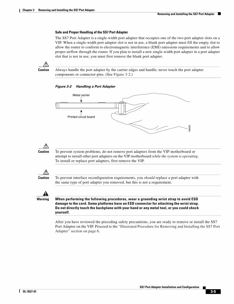
The SS7 Port Adapter is a single-width port adapter that occupies one of the two port adapter slots on a VIP. When a single-width port adapter slot is not in use, a blank port adapter must fill the empty slot to allow the router to conform to electromagnetic interference (EMI) emissions requirements and to allow proper airflow through the router. If you plan to install a new single-width port adapter in a port adapter slot that is not in use, you must first remove the blank port adapter.
Caution Always handle the port adapter by the carrier edges and handle; never touch the port adapter components or connector pins. (See Figure 3-2.)
Figure 3-2 Handling a Port Adapter
Caution To prevent system problems, do not remove port adapters from the VIP motherboard or attempt to install other port adapters on the VIP motherboard while the system is operating. To install or replace port adapters, first remove the VIP.
Caution To prevent interface reconfiguration requirements, you should replace a port adapter with the same type of port adapter you removed, but this is not a requirement.
Warning When performing the following procedures, wear a grounding wrist strap to avoid ESD damage to the card. Some platforms have an ESD connector for attaching the wrist strap. Do not directly touch the backplane with your hand or any metal tool, or you could shock yourself.
After you have reviewed the preceding safety precautions, you are ready to remove or install the SS7 Port Adapter on the VIP. Proceed to the “Illustrated Procedure for Removing and Installing the SS7 Port Adapter” section on page 6.
H64
20
Metal carrier
Printed circuit board
3-5SS7 Port Adapter Installation and Configuration
OL-3527-01

Chapter 3 Removing and Installing the SS7 Port AdapterRemoving and Installing the SS7 Port Adapter
Illustrated Procedure for Removing and Installing the SS7 Port Adapter
Note When you reach Step 6 of this procedure, refer to the more detailed information at the beginning of the “Reinstalling the VIP” section on page 3-7.
Figure 3-3 describes removing and installing a single-width port adapter such as the SS7 Port Adapter.
Figure 3-3 Removing and Installing a Single-Width Port Adapter
EJECT
SLOT 0
SLOT 1
NORMAL
CPU HALTRESET
AUX.
CONSOLE
RO
UT
E SW
ITC
H PR
OC
ESSO
R 2
SLAVE
MASTER
SLAVE/MASTER
I
O
DC FAILAC POWER
I
O
DC FAILAC POWER
A
B
Note: You must first remove the VIP from the chassis before removing a port adapter from the VIP4.
Step 1To remove the port adapter, removethe screw that secures the portadapter (or blank port adapter).(See A.)
Step 2With the screw removed, grasp the handle on the front of the port adapter (or blank port adapter) and carefully pull it out of its slot, away from the edge connector at the rear of the slot. (See A.)
2932
7
Screw
Step 3To insert the port adapter, carefully align the port adapter carrier between the upper andthe lower edges of the port adapter slot. (See B.)
Step 4Install the screw in the rear of theport adapter slot. Do not overtighten the screw. (See A.)
Step 5Carefully slide the new port adapter into the port adapter slot until the connector on the port adapter is completely seated in the connectorat the rear of the port adapter slot.(See B.)
Step 6Reinstall the VIP motherboard in the chassis, and tighten the captive installation screw on each end of the VIP faceplate. (See C.)
ENABLE
AL EN
01
23
45
67
PA
-MC
-8T
E1
-SS
7
C
Captiveinstallationscrew
Upper edgeLower edge
Carrier
3-6SS7 Port Adapter Installation and Configuration
OL-3527-01

Chapter 3 Removing and Installing the SS7 Port AdapterReinstalling the VIP and Connecting the SS7 Port Adapter Cables
After you have installed the SS7 Port Adapter on the VIP motherboard (Step 5), you are ready to reinstall the VIP in the router chassis and connect the SS7 Port Adapter cables. Proceed to the “Reinstalling the VIP and Connecting the SS7 Port Adapter Cables” section on page 3-7.
Reinstalling the VIP and Connecting the SS7 Port Adapter Cables
This section describes the following tasks:
• Reinstalling the VIP, page 3-7
• Connecting the SS7 Port Adapter Interface Cables, page 3-8
Reinstalling the VIP
Note Reinstalling the VIP in the router chassis is illustrated in the final step (Step 6) of the “Illustrated Procedure for Removing and Installing the SS7 Port Adapter” section on page 3-6. If you have already reinstalled the VIP in the router chassis, proceed to the “Connecting the SS7 Port Adapter Interface Cables” section on page 3-8.
After you have installed the SS7 Port Adapter on the VIP, you must reinstall the VIP. The VIP slides into an open interface processor slot and connects directly to the backplane. The interface processors are keyed to guide pins on the backplane, so the VIP can be installed only in an interface processor slot.
Note To ensure compliance with EMI approvals by providing a tight EMI seal for the Cisco 7500 and the Cisco 7000 routers, we recommend that you first install interface processors in the interface processor slots closest to the RSP slots, and then work out to the interface processor slots furthest from the RSP slots. For more information on interface processor slots on your router, refer to the Cisco 7500 Series Installation and Configuration Guide or the appropriate Quick Start Guide for the Cisco 7500 series routers, or refer to Cisco 7000 Hardware Installation and Maintenance manual for the Cisco 7000 series routers.
Caution Remove or insert only one interface processor at a time. Allow the system to complete its discovery and initialization of the interfaces before removing or inserting another interface processor. Disrupting the sequence before the system has completed verification can cause the system to detect spurious hardware failures.
3-7SS7 Port Adapter Installation and Configuration
OL-3527-01

Chapter 3 Removing and Installing the SS7 Port AdapterReinstalling the VIP and Connecting the SS7 Port Adapter Cables
Use the following procedure to install a new VIP:
Step 1 Attach an ESD-preventive wrist strap between you and an unpainted chassis surface.
Step 2 Ensure that a console terminal is connected to the console port (on the RSP or RSP7000) and that your console is turned on, or that you have a reliable Telnet connection to the system.
Step 3 Hold the VIP handle with one hand and place your other hand under the carrier to support the VIP and guide it into the slot. Avoid touching the card or any connector pins.
Caution To prevent ESD damage, handle interface processors by the handles and carrier edges only.
Step 4 Place the back of the VIP in the slot and align the notch on the carrier with the groove in the slot.
Step 5 While keeping the VIP parallel to the backplane, carefully slide it into the slot until the back of the faceplate makes contact with the ejector levers, and then stop.
Caution Always use the ejector levers when installing or removing interface processors. An interface processor that is partially seated in the backplane might cause the system to hang and subsequently crash, and shoving or slamming the interface processor into the slot can damage the backplane pins and board.
Step 6 Using your thumbs, simultaneously push both ejector levers inward until the VIP is pushed entirely into its slot.
Step 7 Tighten both of the captive installation screws.
Caution To ensure proper EMI isolation for the router, be sure to tighten the captive installation screws on each VIP immediately after you install it and before proceeding with the installation of each remaining VIP or other interface processor.
Connecting the SS7 Port Adapter Interface CablesThe SS7 Port Adapter uses shielded twisted-pair cables with RJ-48C connectors to connect to a PBX or to the Public Switched Telephone Network (PSTN).
Note Shielded cables (FTP [foil twisted-pair]) with 120-ohm impedance are required to comply with CE marking requirements. These shielded cables are not available from Cisco Systems; they are available from outside commercial cable vendors.
To connect FTP cables with RJ-48C connectors to the SS7 Port Adapter, proceed as follows:
Step 1 Attach the cable directly to one of the RJ-48C ports on the SS7 Port Adapter.
Step 2 Attach the network end of the cable to your external equipment.
3-8SS7 Port Adapter Installation and Configuration
OL-3527-01

Chapter 3 Removing and Installing the SS7 Port AdapterVerifying the VIP and SS7 Port Adapter Installation
Step 3 Repeat Step 1 and Step 2 for the other SS7 Port Adapter ports.
Figure 3-4 Connecting the SS7 Port Adapter Twisted-Pair Cable with RJ-48C Connector
Note Port adapters have a handle attached, but this handle is not shown in Figure 3-4 to allow a full view of the detail on each port adapter’s faceplate.
Warning To reduce the risk of fire, use only 26 AWG or larger telecommunication line cord.
Warning Do not work on the system or connect or disconnect cables during periods of lightning activity.
Warning To avoid electric shock, do not connect safety extra-low voltage (SELV) circuits to telephone-network voltage (TNV) circuits. LAN ports contain SELV circuits, and WAN ports contain TNV circuits. Some LAN and WAN ports both use RJ-48C connectors. Use caution when connecting cables.
This completes the VIP and SS7 Port Adapter installation. You can now verify the installation. Proceed to the “Verifying the VIP and SS7 Port Adapter Installation” section on page 3-9.
Verifying the VIP and SS7 Port Adapter InstallationThis section describes the procedures you can use to verify your VIP and SS7 Port Adapter installation. It includes information on the following topics:
• Observing LEDs and System Messages, page 10
• Using show Commands to Verify the VIP Status, page 12
• Using show Commands to Display Interface Information, page 13
Twisted-pair cablewith RJ-48C connector
To PBX or PSTN
6585
4
AL
EN
0 1 2 3 4 5 6 7PA-MCX-8TE1-M
3-9SS7 Port Adapter Installation and Configuration
OL-3527-01

Chapter 3 Removing and Installing the SS7 Port AdapterVerifying the VIP and SS7 Port Adapter Installation
Observing LEDs and System MessagesAfter you install the VIP and connect the SS7 Port Adapter cables, you can verify the installation by observing the port adapter LED states and the system messages displayed on your console terminal.
When the system has reinitialized all interfaces, the enabled LED on the VIP port adapters and on all interface processors should go on, depending on your connections and configuration. The console screen also displays a message as the system discovers each interface during its reinitialization.
SS7 Port Adapter LEDs
Note The VIP has no LEDs that are visible or usable when the VIP is installed. The port adapters you install on the VIP have status and interface LEDs.
The SS7 Port Adapter has a green enabled LED, a bicolor alarm LED, and a bicolor port status LED, one for each port on the port adapter (see Figure 3-5).
Figure 3-5 LEDs on the SS7 Port Adapter
After system initialization, the enabled LED goes on to indicate that the port adapter has been enabled for operation.
The following conditions must be met before the SS7 Port Adapter is enabled:
• The SS7 Port Adapter is correctly connected and is receiving power.
• A valid system software image for the port adapter has been downloaded successfully.
• The system recognizes the SS7 Port Adapter.
If any of the above conditions are not met, or if the initialization fails for other reasons, the enabled LED does not go on.
Table 3-1 lists the functions of the LEDs.
6585
3
AL
EN
0 1 2 3 4 5 6 7PA-MCX-8TE1-M
Table 3-1 SS7 Port Adapter LEDs
LED Label Color State Function
EN Green On Indicates the SS7 Port Adapter is powered up.
Off Indicates the SS7 Port Adapter is not ready or is disabled.
AL Amber On Indicates an alarm condition exists on the remote end of one of the T1/E1 ports.
Red On Indicates an alarm condition exists locally on one of the T1/E1 ports.
Off Indicates no alarms detected on any port.
3-10SS7 Port Adapter Installation and Configuration
OL-3527-01

Chapter 3 Removing and Installing the SS7 Port AdapterVerifying the VIP and SS7 Port Adapter Installation
System Messages
When you remove and replace interface processors, the system provides status messages on the console screen. The messages are for information only.
The following sample display shows the events logged by the system when a VIP with an SS7 Port Adapter is removed from interface processor slot 4. The system reinitializes the remaining interface processors and marks as down the SS7 Port Adapter interface on the VIP that was removed from slot 4:
Router#00:51:01: %OIR-6-REMCARD: Card removed from slot 4, interfaces disabled%LINK-5-CHANGED: Interface serial 4/0/0, changed state to administratively down
The following sample display shows the events logged by the system when a VIP with a SS7 Port Adapter is reinserted into interface processor slot 4. The the system automatically brings up the interfaces that were up when the VIP was removed:
Router#00:52:30: %OIR-6-INSCARD: Card inserted in slot 4, interfaces administratively shut down00:52:35: %LINK-3-UPDOWN: Interface Serial4/0/0:1, changed state to up
When a new VIP is inserted or when a VIP is moved to a new slot, the system recognizes the new interfaces but leaves them in the shutdown state until you configure them and change their state to up.
The following sample display shows the events logged by the system as you insert a new VIP in interface processor slot 6:
Router#01:00:00: %OIR-6-INSCARD: Card inserted in slot 6, interfaces administratively shut down
To verify that the VIP is installed correctly, observe the LEDs and system messages as described in the following steps. If you experience other problems that you are unable to solve, contact a service representative for assistance.
Step 1 While the system reinitializes each interface, observe the console display messages and verify that the system discovers the VIP as follows:
• If you installed a new VIP, the system should recognize all new interfaces but leave them configured as down. (You must configure new interfaces to make them available.)
• If you replaced a VIP, the system should recognize each interface and place it in the same state (up or down) each was in when you removed the VIP.
Step 2 When the reinitialization is complete, verify that the enabled LED on each port adapter goes on and remains on. If it does, proceed to Step 5. If it does not, proceed to the next step.
0 through 7 Green On Indicates the port is enabled and in frame.
Yellow On Indicates the port is in loopback.
Off Indicates that the port is not enabled, the received signal is bad, or an alarm condition exists.
Table 3-1 SS7 Port Adapter LEDs (continued)
LED Label Color State Function
3-11SS7 Port Adapter Installation and Configuration
OL-3527-01

Chapter 3 Removing and Installing the SS7 Port AdapterVerifying the VIP and SS7 Port Adapter Installation
Step 3 If the enabled LED on a port adapter fails to go on, suspect that the VIP board connector is not fully seated in the backplane. Loosen the captive installation screws, and then firmly push both ejector levers into place until they are approximately in the same orientation as the VIP faceplate. Tighten the captive installation screws. After the system reinitializes the interfaces, the enabled LED on the port adapter should go on. If it does, proceed to Step 5. If it does not, proceed to Step 4.
Step 4 If the enabled LED still fails to go on, remove the VIP and try installing it in another available interface processor slot.
• If the enabled LED goes on when the VIP is installed in the new interface processor slot, suspect a failed backplane port in the original interface processor slot.
• If the enabled LED still fails to go on, but other LEDs go on to indicate activity, proceed to Step 5 to resume the installation checkout; suspect that the enabled LED on the port adapter has failed. Contact a service representative to report the problem and obtain further instructions.
• If no LEDs go on, suspect that the VIP is faulty. Contact a service representative to report the problem and obtain further instructions.
• If just the enabled LED still fails to go on, remove the VIP and ensure the port adapters are firmly installed in their port adapter slots. Remove and reinstall them accordingly.
Step 5 If the VIP is new and not a replacement, you must configure all new interfaces to make them available. (This does not have to be done immediately, but new interfaces are not be available until you configure them.)
Step 6 If the VIP is a replacement, use the show interfaces type interface-processor-slot- number/port-adapter-slot-number/interface-port-number command or the show controllers command to verify the status of the interfaces. (See the following section, “Using show Commands to Verify the VIP Status.”)
If you replaced a VIP with a new VIP with a greater number of interfaces (for example, if you replaced a VIP with a single port adapter with a VIP with two port adapters), the system recognizes the interfaces on the previously configured port adapter but does not recognize the additional port adapter interfaces. The new interfaces remain in the shutdown state until you configure them.
Step 7 When the interfaces are up, check the activity of each interface by observing the status LEDs, which are described in the appropriate LED section of your port adapter installation and configuration notes.
Step 8 In general, if an interface LED fails to go on and a cable is connected to the interface port, check the cable connection and make certain it is properly seated in the connector.
Using show Commands to Verify the VIP StatusThe following steps use show commands to verify that the new interfaces are configured and operating correctly.
Step 1 Use the show version command to display the system hardware configuration. Ensure that the list includes the new interfaces.
Step 2 Display all the current interface processors and their interfaces with the show controllers command. Verify that the new VIP appears in the correct interface processor slot.
Step 3 Specify one of the new interfaces with the show interfaces type interface-processor-slot- number/port-adapter-slot-number/interface-port-number command and verify that the first line of the display specifies the interface with the correct slot number. Also verify that the interface and line protocol are in the correct state: up or down.
3-12SS7 Port Adapter Installation and Configuration
OL-3527-01

Chapter 3 Removing and Installing the SS7 Port AdapterVerifying the VIP and SS7 Port Adapter Installation
Step 4 Display the protocols configured for the entire system and specific interfaces with the show protocols command. If necessary, return to configuration mode to add or remove protocol routing on the system or specific interfaces.
Step 5 Display the running configuration file with the show running-config command. Display the configuration stored in the RSP NVRAM using the show startup-config command. Verify that the configuration is accurate for the system and each interface.
If the interface is down and you configured it as up, or if the displays indicate that the hardware is not functioning properly, ensure that the network interface is properly connected and terminated. If you still have problems bringing the interface up, contact a service representative for assistance.
Note The outputs that appear in this document may not match the output you receive when running these commands. The outputs in this document are examples only.
Using show Commands to Display Interface InformationTo display information about a specific interface, use the show interfaces command in the format show interface type interface-processor-slot-number/port-adapter-slot-number/interface-port-number
:channel-group-number.
The following is an example of the show interface serial command:
Router#show interface serial 4/0/0:0Serial4/0/0:0 is up, line protocol is up Hardware is cxBus T1 MTU 290 bytes, BW 56 Kbit, DLY 20000 usec, reliability 255/255, txload 1/255, rxload 1/255 Encapsulation SS7 MTP2, crc 16, loopback not set Keepalive set (10 sec) Last input 00:00:46, output 00:00:46, output hang never Last clearing of "show interface" counters 00:32:16 Queueing strategy: fifo Output queue 0/40, 0 drops; input queue 0/75, 0 drops 5 minute input rate 0 bits/sec, 0 packets/sec 5 minute output rate 0 bits/sec, 0 packets/sec 65 packets input, 714 bytes, 0 no buffer Received 0 broadcasts, 0 runts, 0 giants, 0 throttles 0 input errors, 0 CRC, 0 frame, 0 overrun, 0 ignored, 0 abort 67 packets output, 598 bytes, 0 underruns 0 output errors, 0 collisions, 0 interface resets 0 output buffer failures, 0 output buffers swapped out 0 carrier transitions no alarm present Timeslot(s) Used:1, subrate: 56Kb/s, transmit delay is 0 flags Transmit queue length 109Router#
To display hardware information about all of the interface processors in your router, including the VIP, use the show controller command.
3-13SS7 Port Adapter Installation and Configuration
OL-3527-01
Chapter 3 Removing and Installing the SS7 Port AdapterVerifying the VIP and SS7 Port Adapter Installation
Following is an example of the show controller command used with a Cisco 7500 series router:
Router#show controller t1 4/0/0T1 4/0/0 is up. Applique type is Channelized T1 Cablelength is long gain36 0db No alarms detected. alarm-trigger is not set Framing is ESF, Line Code is B8ZS, Clock Source is Internal. Data in current interval (0 seconds elapsed): 0 Line Code Violations, 0 Path Code Violations 0 Slip Secs, 0 Fr Loss Secs, 0 Line Err Secs, 0 Degraded Mins 0 Errored Secs, 0 Bursty Err Secs, 0 Severely Err Secs, 0 Unavail SecsRouter#
To display the configuration of the system hardware (the number of each interface processor type installed), the software version, the names and sources of configuration files, and the boot images, use the show version (or show hardware) command.
To determine specific hardware configuration information about a VIP installed in your system (including the amount of installed CPU and packet memory), use the show diag slot command.
Following example of a VIP with an SS7 Port Adapter; the VIP is installed in interface processor slot 2:
Following is an example of the show diag slot command that shows an SS7 Port Adapter in interface processor slot 2 of a Cisco 7513 router:
Router# show diag 2Slot 2: PA-MCX-8TE1-M Port adapter, 8 ports Port adapter is analyzed Port adapter insertion time 00:52:22 ago EEPROM contents at hardware discovery: Hardware Revision : 1.0 PCB Serial Number : SIC04412B7S Part Number : 115-22681-01 Board Revision : 02 RMA Test History : 00 RMA Number : 0-0-0-0 RMA History : 00 Deviation Number : 0-0 IDPROM FIELD FORMAT ERROR, index 0x29 EEPROM format version 4 EEPROM contents (hex): 0x00: 04 FF 40 03 52 41 01 00 C1 8B 53 49 43 30 34 34 0x10: 31 32 42 37 53 82 73 58 99 01 42 30 32 03 00 81 0x20: 00 00 00 00 04 00 80 00 00 00 00 CB 00 00 00 00 0x30: 00 00 00 00 00 00 00 00 00 00 00 00 00 00 00 00 0x40: 00 00 00 00 00 00 00 00 00 00 00 00 00 00 00 00 0x50: 00 00 00 00 00 00 00 00 00 00 00 00 00 00 00 00 0x60: 00 00 00 00 00 00 00 00 00 00 00 00 00 00 00 00 0x70: 00 00 00 00 00 00 00 00 00 00 00 00 00 00 00 00
After you have installed and verified the VIP and SS7 Port Adapter, you are ready to configure the SS7 Port Adapter.
3-14SS7 Port Adapter Installation and Configuration
OL-3527-01

SS7 PorOL-3527-01
C H A P T E R 4
Configuring the SS7 Port AdapterTo continue your SS7 Port Adapter installation, you must configure the card type as either T1 or E1 and then configure the interfaces.
This chapter contains the following sections:
• Using the EXEC Command Interpreter, page 4-1
• Configuring the Interfaces, page 4-2
• Checking the Configuration, page 4-11
Using the EXEC Command Interpreter You modify the configuration of your router through the software command interpreter called the EXEC (also called enable mode). You must enter the privileged level of the EXEC command interpreter with the enable command before you can use the configure command to configure a new interface or change the existing configuration of an interface. The system prompts you for a password if one has been set.
The system prompt for the privileged level ends with a pound sign (#) instead of an angle bracket (>). At the console terminal, use the following procedure to enter the privileged level:
Step 1 At the user-level EXEC prompt, enter the enable command. The EXEC prompts you for a privileged-level password as follows:
Router> enable
Password:
Step 2 Enter the password (the password is case sensitive). For security purposes, the password is not displayed.
When you enter the correct password, the system displays the privileged-level system prompt (#):
Router#
To configure the new interfaces, proceed to the “Configuring the Interfaces” section on page 4-2.
4-1t Adapter Installation and Configuration

Chapter 4 Configuring the SS7 Port AdapterConfiguring the Interfaces
Configuring the InterfacesThe SS7 Port Adapter interfaces can be configured as DSX-1/DS1 or G.703 interfaces. After you verify that the new SS7 Port Adapter is installed correctly (the enabled LED goes on), use the privileged-level configure command to configure the new interfaces. Have the following information available:
• Protocols you plan to route on each new interface
• Clock timing source you plan to use for each new interface and clock speeds for external timing
If you installed a new SS7 Port Adapter or if you want to change the configuration of an existing interface, you must enter configuration mode to configure the new interfaces. If you replaced a SS7 Port Adapter that was previously configured, the system recognizes the new interfaces and brings each of them up in their existing configuration.
For a summary of the configuration options available and instructions for configuring interfaces on a SS7 Port Adapter, refer to the appropriate configuration publications listed in the “Related Documentation” section on page viii.
You execute configuration commands from the privileged level of the EXEC command interpreter, which usually requires password access. Contact your system administrator, if necessary, to obtain password access. (See the “Using the EXEC Command Interpreter” section on page 4-1 for an explanation of the privileged level of the EXEC.)
This section contains the following subsections:
• Shutting Down an Interface, page 4-2
• Performing a Basic Configuration, page 4-4
• Configuring the Controller, page 4-5
• Performing a Basic Data Interface Configuration, page 4-8
• Configuring Cyclic Redundancy Checks, page 4-9
• Configuring Drop and Insert, page 4-10
Shutting Down an Interface Before you remove an interface that you will not replace, or replace port adapters, use the shutdown command to shut down (disable) the interfaces to prevent anomalies when you reinstall the new or reconfigured port adapter. When you shut down an interface, it is designated administratively down in the show command displays.
Follow these steps to shut down an interface:
Step 1 Enter the privileged level of the EXEC command interpreter (also called enable mode). (See the “Using the EXEC Command Interpreter” section on page 4-1 for instructions.)
Step 2 At the privileged-level prompt, enter configuration mode and specify that the console terminal is the source of the configuration commands, as follows:
Router# configure terminalEnter configuration commands, one per line. End with CNTL/Z.Router(config)#
Step 3 Shut down interfaces by entering the interface command and then the shutdown command. Table 4-1 shows the command syntax and example.
4-2SS7 Port Adapter Installation and Configuration
OL-3527-01

Chapter 4 Configuring the SS7 Port AdapterConfiguring the Interfaces
When you have finished, press Ctrl-Z—hold down the Control key while you press Z—or enter end or exit to exit configuration mode and return to the EXEC command interpreter.
Note If you need to shut down additional interfaces, enter the interface serial command (followed by the interface address of the interface) for each of the interfaces on your port adapter. Use the no shutdown command to enable the interface.
Step 4 Write the new configuration to NVRAM as follows:
Router# copy running-config startup-config[OK]Router#
The system displays an OK message when the configuration has been stored in NVRAM.
Step 5 Verify that new interfaces are now in the correct state (shut down) using the show interface command:
Router# show interface serial4/0/0:0Serial4/0/0:0 is administratively down, line protocol is down Hardware is cxBus T1 MTU 290 bytes, BW 56 Kbit, DLY 20000 usec, reliability 255/255, txload 1/255, rxload 1/255 Encapsulation SS7 MTP2, crc 16, loopback not set Keepalive set (10 sec) Last input 00:01:04, output 00:01:04, output hang never Last clearing of "show interface" counters 00:04:13 Queueing strategy: fifo Output queue 0/40, 0 drops; input queue 0/75, 0 drops 5 minute input rate 0 bits/sec, 0 packets/sec 5 minute output rate 0 bits/sec, 0 packets/sec 11 packets input, 693 bytes, 0 no buffer Received 0 broadcasts, 0 runts, 0 giants, 0 throttles 0 input errors, 0 CRC, 0 frame, 0 overrun, 0 ignored, 0 abort 8 packets output, 72 bytes, 0 underruns 0 output errors, 0 collisions, 1 interface resets 0 output buffer failures, 0 output buffers swapped out 0 carrier transitions no alarm present Timeslot(s) Used:1, subrate: 56Kb/s, transmit delay is 0 flags Transmit queue length 109Router#
Table 4-1 Syntax of the shutdown Command
Command Purpose Example
interface typeinterface-processor-slot-number/port-adapter-bay-number/interface-port-number:channel-group
Specifies the interface and enters Interface configuration mode.
Router(config)# interface serial5/0/0:0
shutdown Disables the interface. Router(config-if)# shutdown
4-3SS7 Port Adapter Installation and Configuration
OL-3527-01

Chapter 4 Configuring the SS7 Port AdapterConfiguring the Interfaces
Step 6 Re-enable interfaces by doing the following:
a. Repeat Step 3 to re-enable an interface. Substitute the no shutdown command for the shutdown command.
b. Repeat Step 4 to write the new configuration to memory. Use thecopy running-config startup-config command.
c. Repeat Step 5 to verify that the interfaces are in the correct state. Use the show interface command followed by the interface type and interface address of the interface.
For complete descriptions of software configuration commands, refer to the publications listed in the “Related Documentation” section on page viii.
Performing a Basic Configuration Following are instructions for a basic configuration. You might also need to enter other configuration commands, depending on the requirements for your system configuration and the protocols you plan to route on the interface. For complete descriptions of configuration commands and the configuration options available for serial interfaces, refer to the appropriate software documentation.
Specifying Card Type is Required
Because the PA-MCX port adapter can be configured for E1 or T1 connectivity, you must specify the card type as E1 or T1, as described in the following procedure. There is no default card type. The port adapter is not functional until the card type is set. Information about the port adapter is not indicated in the output of any show commands unless the card type has been set to E1 or T1.
In the following procedure, press the Return key after each step unless otherwise noted. At any time you can exit the privileged level and return to the user level by entering disable at the prompt as follows:
Router# disable
Router>
Step 1 Enter configuration mode and specify that the console terminal is the source of the configuration commands, as follows:
Router# configure terminalEnter configuration commands, one per line. End with CNTL/Z.Router(config)#
Step 2 Specify whether the card is to be used as T1 or E1 by using the card type command in configuration mode.
• The example below sets the card in slot 1 to T1:
Router(config)# card type t1 1 0
• The example below sets the card in slot 1 to E1:
Router(config)# card type e1 1 0
4-4SS7 Port Adapter Installation and Configuration
OL-3527-01

Chapter 4 Configuring the SS7 Port AdapterConfiguring the Interfaces
Note To change the card type of the SS7 Port Adapter after the card type command has been entered, you must remove the card from the router, save the running configuration to NVRAM, and reboot the router. When the router has finished rebooting, reinsert the card and repeat Step 2.
Configuring the ControllerThis section describes line clocking on the SS7 Port Adapter and lists the steps for a basic controller configuration.
Note It is recommended that any controller that is not used for SS7 links or BITS clocking should be shut down.
Clocking on the SS7 Port Adapter
Each SS7 Port Adapter in the ITP shares a clocking source for all T1s or E1s serviced on that card. The clocking options and commands for each are as follows:
• Clocking source is internally generated.clock source internalThis option imposes the requirements that all devices connected to the ITP must derive their clock from the T1/E1 by which they are connected to the ITP.
• Clocking source is derived from a T1/E1 that is terminated on the card.clock source line {primary | secondary priority}The SS7 Port Adapter on the ITP derives its clock from an adjacent node. All other T1s or E1s on the card are clocked with this derived source. This option imposes the restrictions that all adjacent nodes connected to T1s or E1s on that card must either derive the clock from the T1/E1 to which they are connected or are derive the clock from the same source as the ITP.
• Clocking source is provided through a dedicated port on that card via BITS (a common source received via satelite and used to synchronize all clocks across a CO and between COs)clock source bits {primary | secondary priority}A common dedicated clock source is wired to all devices and used by each device for all T1/E1 timing.A controller that is configured for BITS clocking cannot be used to carry data.
Clocking on the SS7 Port Adapter is driven by one clock source for the entire card. Each port can be configured with a priority from highest (0) to lowest (7) to determine which port's line clocking will drive the clocking for the port adapter. Table 4-2 provides the details of a hypothetical scenario. In this scenario, port 8 is configured with priority 0 (the highest priority). Therefore, if its line is up, it drives the clock for the whole card. But, if the line interface is down, as shown here, then the port with the next highest priority (in this example, port 3, with a priority of 2) would become primary.
Table 4-2 Sample Data for Determining Line Clocking Priority
Port Source State Priority
1 Line Up 2
2 Internal
4-5SS7 Port Adapter Installation and Configuration
OL-3527-01

Chapter 4 Configuring the SS7 Port AdapterConfiguring the Interfaces
Creating a Basic Controller Configuration for the SS7 Port Adapter
The following steps make up a basic controller configuration for the SS7 Port Adapter:
Step 1 Enter configuration mode and specify that the console terminal is the source of the configuration commands, as follows:
Router# configure terminalEnter configuration commands, one per line. End with CNTL/Z.Router(config)#
Step 2 Enter controller configuration mode and specify a controller by entering the controller t1 or controller e1 command, followed by the interface address of the interface you plan to configure. Table 4-3 provides examples.
Step 3 Enter the framing [sf | esf] configuration command to set the framing format for T1, as in the following example:
Router(config-controller)# framing esf
Enter the framing crc4 configuration command to set the framing format for E1, as in the following example:
Router(config-controller)# framing crc4
Step 4 Enter the linecode b8zs command to select the line coding for T1:
Router(config-controller)# linecode b8zs
3 Line Up 3
4 Internal
5 Internal
6 Internal
7 Line Down 4
8 Line Down 0
Table 4-2 Sample Data for Determining Line Clocking Priority (continued)
Port Source State Priority
Table 4-3 Examples of the controller Command
Command Purpose Example
controller t1interface-processor-slot-number/port-adapter-bay-number/interface-port-number
Specifies the controller and enters Controller configuration mode.
The following example is for the first interface of a port adapter in port adapter bay 0 of interface processor slot 6:
Router(config)# controller t1 6/0/0Router(config-controller)#
controller e1interface-processor-slot-number/port-adapter-bay-number/interface-port-number
Specifies the controller and enters Controller configuration mode.
The following example is for the second interface of a port adapter in port adapter bay 1 of interface processor slot 6:
Router(config)# controller e1 6/1/1Router(config-controller)#
4-6SS7 Port Adapter Installation and Configuration
OL-3527-01

Chapter 4 Configuring the SS7 Port AdapterConfiguring the Interfaces
Enter the linecode hdb3 command to select the line coding for E1:
Router(config-controller)# linecode hdb3
Step 5 Enter the clock source {bits {primary | secondary priority} | internal | line {primary | secondary priority}} command to set the clock source, as in the following 3 variations of the command:
Router(config-controller)# clock source internalRouter(config-controller)# clock source line {primary | secondary priority}Router(config-controller)# clock source bits {primary | secondary priority}
Use the no form of this command to restore the default, which is line.
Step 6 Enter the channel-group number timeslots value {speed [56 | 64]} configuration command to set the channel group, as in the following example:
Router(config-controller)# channel-group 0 timeslots 12 speed 64
Note The channel-group number can be from 0 to 23 and the time slot value can be from 1 to 24 for T1. The channel-group number can be from 0 to 30 and the time slot value can be from 1 to 31 for E1. The maximum number of channel groups per each eight-port SS7 Port Adapter is 127.All channelized interfaces configured on the SS7 Port Adapter must use the same speed.
Step 7 Enter the description line (up to 80 characters describing this controller) configuration command to set the description, as in the following example:
Router(config-controller)# description Arizona 3 Router; location: building 2
Step 8 Enter the cablelength {long [gain26 | gain36] [0db | -7.5db | -15db | -22.5db]} configuration command to set the cable length, as in the following example:
Router(config-controller)# cablelength long gain26 -15db
Enter the no form of this command to restore the default, which is gain36, 0dB.
Step 9 For T1 enter the fdl {att | ansi} configuration command to set the Facility Data Link (FDL), as in the following example:
Router(config-controller)# fdl ansi
Use the no form of this command to disable FDL.
Note The fdl configuration command is not allowed in Super Frame mode.
Step 10 Enter the shutdown configuration command to shut down the controller, as in the following example:
Router(config-controller)# shutdown
To exit controller configuration mode and return to global configuration mode, enter the exit command. To exit configuration mode and return to privileged EXEC mode, use the end command or press Ctrl-Z.
4-7SS7 Port Adapter Installation and Configuration
OL-3527-01

Chapter 4 Configuring the SS7 Port AdapterConfiguring the Interfaces
Performing a Basic Data Interface ConfigurationThis section provides instructions for a basic data interface configuration. You might also need to enter other configuration commands, depending on the requirements for your system configuration and the protocols you plan to route on the interface. For complete descriptions of configuration commands and the configuration options available for serial interfaces, refer to the appropriate software documentation.
In the following procedure, press the Return key after each step unless otherwise noted. At any time you can exit the privileged level and return to the user level by entering disable at the prompt as follows:
Router# disable
Router>
Step 1 Enter configuration mode and specify that the console terminal is the source of the configuration commands, as follows:
Router# configure terminalEnter configuration commands, one per line. End with CNTL/Z.Router(config)#
Step 2 Specify the first interface to configure by entering the interface serial command, followed by the interface address of the interface you plan to configure. Table 4-4 provides an example.
Step 3 Configure the serial interface to use MTP2 encapsulation, as in the following example:
Router(config-if)# encapsulation mtp2
Step 4 Add any other interface commands required to enable routing protocols and adjust the interface characteristics.
Step 5 After including all of the configuration commands to complete your configuration, press Ctrl-Z—hold down the Control key while you press Z—or enter end or exit to exit configuration mode and return to the EXEC command interpreter prompt.
Step 6 Write the new configuration to NVRAM as follows:
Router# copy running-config startup-config[OK]Router#
Table 4-4 Example of the interface serial Command
Command Purpose Example
interface typeinterface-processor-slot-number/port-adapter-bay-number/interface-port-number:channel-group
Specifies the interface and enters Interface configuration mode.
Router(config)# interface serial5/0/0:0Router(config-if)#
4-8SS7 Port Adapter Installation and Configuration
OL-3527-01

Chapter 4 Configuring the SS7 Port AdapterConfiguring the Interfaces
Configuring Cyclic Redundancy ChecksCRC is an error-checking technique that uses a calculated numeric value to detect errors in transmitted data. All interfaces use a 16-bit CRC (CRC-CITT) by default but also support a 32-bit CRC. The sender of a data frame calculates the frame check sequence (FCS). Before it sends a frame, the sender appends the FCS value to the message. The receiver recalculates the FCS and compares its calculation to the FCS from the sender. If there is a difference between the two calculations, the receiver assumes that a transmission error occurred and sends a request to the sender to resend the frame.
Before you can enable 32-bit CRC, you must use the interface serial command (followed by the interface address of the interface) to select the interface on which you want to enable 32-bit CRC.
4-9SS7 Port Adapter Installation and Configuration
OL-3527-01

Chapter 4 Configuring the SS7 Port AdapterConfiguring the Interfaces
Table 4-5 summarizes cyclic redundancy check (CRC) commands.
When you have finished, press Ctrl-Z—hold down the Control key while you press Z—or enter end or exit to exit configuration mode and return to the EXEC command interpreter prompt. Then write the new configuration to NVRAM using the copy running-config startup-config command.
For command descriptions, refer to the Configuration Fundamentals Configuration Guide publication. For more information, see the “Related Documentation” section on page viii.
To check the interface configuration using show commands, proceed to the “Checking the Configuration” section on page 4-11.
Configuring Drop and InsertPerform the steps in this section if you are setting up Drop and Insert.
Step 1 Enter the command to set up TDM channel groups for the Drop-and-Insert function, as in the following example:
Router(config-controller)# tdm-group tdm-group-no timeslots timeslot-listRouter(config-controller)#
The argument tdm-group-no is a value from 0 to 23 for T1 and from 0 to 30 for E1; it identifies the group. The group numbers for controller groups must be unique.
The argument timeslot-list is a single number, numbers separated by commas, or a pair of numbers separated by a hyphen to indicate a range of timeslots. The valid range is from 1 to 24 for T1. For E1, the range is from 1 to 31.
Step 2 Activate the controller with the no shutdown command, as in the following example:
Router(config-controller)# no shutdownRouter(config-controller)#
Step 3 Exit controller configuration mode, as follows:
Router(config-controller)# exitRouter(config)#
Step 4 Set up the connection between two T1 or E1 TDM groups of timeslots for Drop and Insert.
Router(config)# connect id {T1 | E1} slot/port-1 tdm-group-no-1 {T1 | E1} slot/port-2 tdm-group-no-2Router(config)#
The argument id is a name for the connection.
Table 4-5 CRC Commands
Command Purpose Example
crc size Enable 32-bit CRC The following example enables 32-bit CRC on a serial interface:
Router(config)# interface serial 3/0:0Router(config-if)# crc 32
no crc size Return to default 16-bit CRC The following example disables 32-bit CRC on a serial interface and returns to the default 16-bit CRC:
Router(config)# interface serial 3/0:0Router(config-if)# no crc 32
4-10SS7 Port Adapter Installation and Configuration
OL-3527-01

Chapter 4 Configuring the SS7 Port AdapterChecking the Configuration
The argument slot/bay/port identify each controller by its location.
The arguments tdm-group-no-1 and tdm-group-no-2 identify the TDM group numbers (from 0 to 23 or 30) on the specified controller. The groups were set up in Step 1.
Checking the Configuration After configuring the new interface, use the show commands to display the status of the new interface or all interfaces, and use the ping command to check connectivity. This section includes the following subsections:
• Using show Commands to Verify the New Interface Status, page 4-11
• Using the ping cs7 Command to Verify Network Connectivity between ITPs, page 4-14
• Using loopback Commands, page 4-14
Using show Commands to Verify the New Interface Status Table 4-6 demonstrates how you can use the show commands to verify that new interfaces are configured and operating correctly and that the SS7 Port Adapter appears in them correctly. Sample displays of the output of selected show commands appear in the sections that follow. For complete command descriptions and examples, refer to the publications listed in the “Related Documentation” section on page viii.
Troubleshooting Tips
If information about the PA-MCX port adapter is not indicated in show command output, it is probably because the card type has not been specified.
Because the PA-MCX port adapter can be configured for E1 or T1 connectivity, you must specify the card type as E1 or T1, as described in “Performing a Basic Configuration” section on page 4-4. There is no default card type. The port adapter is not functional until the card type is set.
Note The outputs that appear in this document may not match the output you receive when running these commands. The outputs in this document are examples only.
Table 4-6 Using show Commands
Command Function Example
show version orshow hardware
Displays system hardware configuration, the number of each interface type installed, Cisco IOS software version, names and sources of configuration files, and boot images
Router# show version
show controllers Displays all the current interface processors and their interfaces
Router# show controllers
4-11SS7 Port Adapter Installation and Configuration
OL-3527-01

Chapter 4 Configuring the SS7 Port AdapterChecking the Configuration
If an interface is shut down and you configured it as up, or if the displays indicate that the hardware is not functioning properly, ensure that the interface is properly connected and terminated. If you still have problems bringing up the interface, contact a service representative for assistance. This section includes the following subsections:
• Using the show version or show hardware Commands, page 4-12
• Using the show diag Command, page 4-12
• Using the show interfaces Command, page 4-13
Choose the subsection appropriate for your system. Proceed to the “Using the ping cs7 Command to Verify Network Connectivity between ITPs” section on page 4-14 when you have finished using the show commands.
Using the show version or show hardware Commands
Display the configuration of the system hardware, the number of each interface type installed, the Cisco IOS software version, the names and sources of configuration files, and the boot images, using the show version (or show hardware) command.
Note The outputs that appear in this document may not match the output you receive when running these commands. The outputs in this document are examples only.
Using the show diag Command
Display the types of port adapters installed in your system (and specific information about each) using the show diag slot command, where slot is the port adapter slot in a router.
Note The outputs that appear in this document may not match the output you receive when running these commands. The outputs in this document are examples only.
show diag slot Displays types of port adapters installed in your system and information about a specific port adapter slot, interface processor slot, or chassis slot
Router# show diag 2
show interfaces type interface-processor-slot-number/port-adapter-bay-numberinterface-port-number
Displays status information about a specific type of interface (for example, serial) in a router
Router# show interfaces serial 5/0/0:0
show protocols Displays protocols configured for the entire system and for specific interfaces
Router# show protocols
show running-config Displays the running configuration file Router# show running-config
show startup-config Displays the configuration stored in NVRAM Router# show startup-config
Table 4-6 Using show Commands
Command Function Example
4-12SS7 Port Adapter Installation and Configuration
OL-3527-01

Chapter 4 Configuring the SS7 Port AdapterChecking the Configuration
Following is an example of the show diag command that shows an SS7 Port Adapter in interface processor slot 2 of a Cisco 7513 router:
Router# show diag 2Slot 2: PA-MCX-8TE1-M Port adapter, 8 ports Port adapter is analyzed Port adapter insertion time 00:52:22 ago EEPROM contents at hardware discovery: Hardware Revision : 1.0 PCB Serial Number : SIC04412B7S Part Number : 115-22681-01 Board Revision : 02 RMA Test History : 00 RMA Number : 0-0-0-0 RMA History : 00 Deviation Number : 0-0 IDPROM FIELD FORMAT ERROR, index 0x29 EEPROM format version 4 EEPROM contents (hex): 0x00: 04 FF 40 03 52 41 01 00 C1 8B 53 49 43 30 34 34 0x10: 31 32 42 37 53 82 73 58 99 01 42 30 32 03 00 81 0x20: 00 00 00 00 04 00 80 00 00 00 00 CB 00 00 00 00 0x30: 00 00 00 00 00 00 00 00 00 00 00 00 00 00 00 00 0x40: 00 00 00 00 00 00 00 00 00 00 00 00 00 00 00 00 0x50: 00 00 00 00 00 00 00 00 00 00 00 00 00 00 00 00 0x60: 00 00 00 00 00 00 00 00 00 00 00 00 00 00 00 00 0x70: 00 00 00 00 00 00 00 00 00 00 00 00 00 00 00 00
Using the show interfaces Command
The show interfaces command displays status information (including the physical slot and interface address) for the interfaces you specify.
Note The outputs that appear in this document may not match the output you receive when running these commands. The outputs in this document are examples only.
Following is an example of the show interfaces serial command. In this example, the SS7 Port Adapter is located in port adapter slot 4.
Router#show interface serial 4/0/0:0Serial4/0/0:0 is up, line protocol is up Hardware is cxBus T1 MTU 290 bytes, BW 56 Kbit, DLY 20000 usec, reliability 255/255, txload 1/255, rxload 1/255 Encapsulation SS7 MTP2, crc 16, loopback not set Keepalive set (10 sec) Last input 00:00:46, output 00:00:46, output hang never Last clearing of "show interface" counters 00:32:16 Queueing strategy: fifo Output queue 0/40, 0 drops; input queue 0/75, 0 drops 5 minute input rate 0 bits/sec, 0 packets/sec 5 minute output rate 0 bits/sec, 0 packets/sec 65 packets input, 714 bytes, 0 no buffer Received 0 broadcasts, 0 runts, 0 giants, 0 throttles 0 input errors, 0 CRC, 0 frame, 0 overrun, 0 ignored, 0 abort 67 packets output, 598 bytes, 0 underruns 0 output errors, 0 collisions, 0 interface resets 0 output buffer failures, 0 output buffers swapped out 0 carrier transitions no alarm present
4-13SS7 Port Adapter Installation and Configuration
OL-3527-01
Chapter 4 Configuring the SS7 Port AdapterChecking the Configuration
Timeslot(s) Used:1, subrate: 56Kb/s, transmit delay is 0 flags Transmit queue length 109Router#
Using the ping cs7 Command to Verify Network Connectivity between ITPsTo verify connectivity to another ITP, use the following command in EXEC mode:
The following is typical output of the cs7 ping command:
Router# ping cs7 2.2.23d19h:%CS7PING-6-RTT:Test Q.755 2.2.2:MTP Traffic test rtt 16/16/163d19h:%CS7PING-6-STAT:Test Q.755 2.2.2:MTP Traffic test 100% successful (1/1)3d19h:%CS7PING-6-TERM:Test Q.755 2.2.2:MTP Traffic test terminated.
If the connection fails, verify that you have the correct point code for the ITP and that the ITP is active (powered on), and repeat the ping cs7 command.
Using loopback CommandsWith the loopback test, you can detect and isolate equipment malfunctions by testing the connection between the SS7 Port Adapter interface and a remote device such as a modem or a CSU/DSU. The loopback command places an interface in loopback mode, which enables test packets that are generated from the ping cs7 command to loop through a remote device or compact serial cable. If the packets complete the loop, the connection is good. If not, you can isolate a fault to the remote device or compact serial cable in the path of the loopback test.
Depending on the mode of the port, issuing the loopback command checks the following path:
• When no compact serial cable is attached to the SS7 Port Adapter interface port, or if a DCE cable is attached to a port that is configured as line protocol up, the loopback command tests the path between the network processing engine and the interface port only (without leaving the network processing engine and port adapter).
• When a DTE cable is attached to the port, the loopback command tests the path between the network processing engine and the near (network processing engine) side of the DSU or modem to test the SS7 Port Adapter interface and compact serial cable.
T1 Loopback Examples
Specify loopback for a T1 controller and T1 channel using the loopback command. There are three main loopback modes: diagnostic, local (line and payload), and remote (iboc and esf). Specify the loopback format using the loopback [diagnostic | local | remote] command.
Note To shut down the T1 controller, use the shutdown command at the controller prompt.
Examples of specific loopback modes for the T1 controller follow:
Command Purpose
Router# ping cs7 [-duration seconds] [-ni network-indicator] [-rate MSU-per-second] [-size bytes] [-sls value | round-robin] [stop] point-code
Verify that you can reach ITP nodes.
4-14SS7 Port Adapter Installation and Configuration
OL-3527-01

Chapter 4 Configuring the SS7 Port AdapterChecking the Configuration
• The syntax of the loopback diagnostic command is as follows:
loopback [diagnostic]
Set the first T1 into diagnostic loopback.
Router# config tEnter configuration commands, one per line. End with CNTL/Z.Router(config)# controller t1 2/0/0Router(config-controller)# loopback diagnostic
In the preceding example, diagnostic loopback loops the outgoing transmit signal back to the receive signal and sends an alarm indication signal (AIS) to the network.
• The syntax of the loopback local command is as follows:
loopback [local {payload | line}]
Set the first T1 into local loopback.
Router# config tEnter configuration commands, one per line. End with CNTL/Z.Router(config)# controller t1 2/0/0Router(config-controller)# loopback local payload
In the preceding example, local loopback loops the incoming signal back to the line.
• The syntax of the loopback remote command follows:
loopback [remote {esf line | iboc | esf payload}]
Set the first T1 into remote line inband loopback.
Router# config tEnter configuration commands, one per line. End with CNTL/Z.Router(config)# controller t1 2/0/0Router(config-controller)# loopback remote esf line
This command causes the far end to loop its receive signal back to transmit.
E1 Loopback Examples
Specify loopback for an E1 controller using the loopback command. There are two main loopback modes: diagnostic and local (line and payload). Specify the loopback format using the loopback [diagnostic | local] command.
To shut down the E1 controller, use the shutdown command at the controller prompt.
Examples of specific loopback modes follow:
• The syntax of the loopback diagnostic command is as follows:
loopback [diagnostic]
Set the first E1 into diagnostic loopback.
Router# config tEnter configuration commands, one per line. End with CNTL/Z.Router(config)# controller E1 2/0/0Router(config-controller)# loopback diagnostic
In the preceding example, the loopback diagnostic command loops the outgoing transmit signal back to the receive signal and sends an AIS out to the network.
4-15SS7 Port Adapter Installation and Configuration
OL-3527-01

Chapter 4 Configuring the SS7 Port AdapterChecking the Configuration
• The syntax of the loopback local command is as follows:
loopback [local {payload | line}]
Set the first E1 into local loopback.
Router# config tEnter configuration commands, one per line. End with CNTL/Z.Router(config)# controller E1 2/0/0Router(config-controller)# loopback local payload
In the preceding example, the loopback local command loops the incoming signal back to the line.
4-16SS7 Port Adapter Installation and Configuration
OL-3527-01