ssloi design – vt team 6 page 2brown/vtshipdesign/2007ssloifinalreport.pdf · ssloi design – vt...
TRANSCRIPT
SSLOI Design – VT Team 6 Page 2
Executive Summary
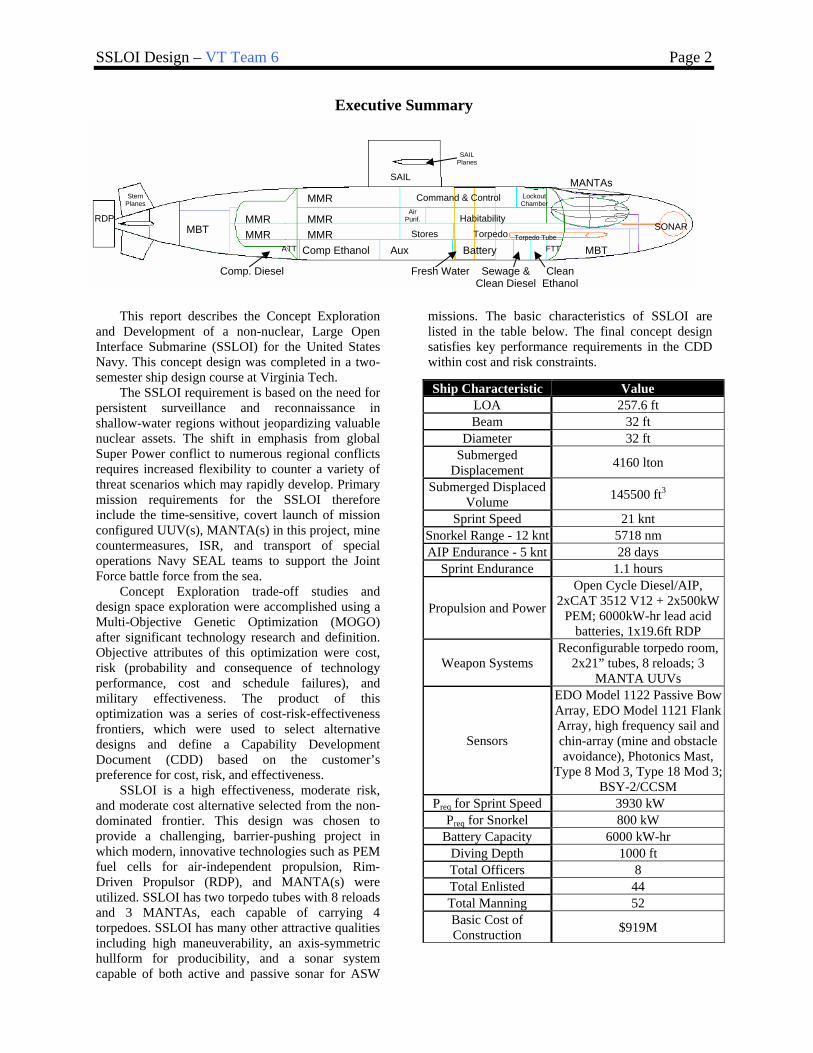
This report describes the Concept Exploration and Development of a non-nuclear, Large Open Interface Submarine (SSLOI) for the United States Navy. This concept design was completed in a two-semester ship design course at Virginia Tech.
The SSLOI requirement is based on the need for persistent surveillance and reconnaissance in shallow-water regions without jeopardizing valuable nuclear assets. The shift in emphasis from global Super Power conflict to numerous regional conflicts requires increased flexibility to counter a variety of threat scenarios which may rapidly develop. Primary mission requirements for the SSLOI therefore include the time-sensitive, covert launch of mission configured UUV(s), MANTA(s) in this project, mine countermeasures, ISR, and transport of special operations Navy SEAL teams to support the Joint Force battle force from the sea.
Concept Exploration trade-off studies and design space exploration were accomplished using a Multi-Objective Genetic Optimization (MOGO) after significant technology research and definition. Objective attributes of this optimization were cost, risk (probability and consequence of technology performance, cost and schedule failures), and military effectiveness. The product of this optimization was a series of cost-risk-effectiveness frontiers, which were used to select alternative designs and define a Capability Development Document (CDD) based on the customer’s preference for cost, risk, and effectiveness.
SSLOI is a high effectiveness, moderate risk, and moderate cost alternative selected from the non-dominated frontier. This design was chosen to provide a challenging, barrier-pushing project in which modern, innovative technologies such as PEM fuel cells for air-independent propulsion, Rim-Driven Propulsor (RDP), and MANTA(s) were utilized. SSLOI has two torpedo tubes with 8 reloads and 3 MANTAs, each capable of carrying 4 torpedoes. SSLOI has many other attractive qualities including high maneuverability, an axis-symmetric hullform for producibility, and a sonar system capable of both active and passive sonar for ASW
missions. The basic characteristics of SSLOI are listed in the table below. The final concept design satisfies key performance requirements in the CDD within cost and risk constraints.
Ship Characteristic Value LOA 257.6 ft Beam 32 ft
Diameter 32 ft Submerged
Displacement 4160 lton
Submerged Displaced Volume 145500 ft3
Sprint Speed 21 knt Snorkel Range - 12 knt 5718 nm AIP Endurance - 5 knt 28 days
Sprint Endurance 1.1 hours
Propulsion and Power
Open Cycle Diesel/AIP, 2xCAT 3512 V12 + 2x500kW
PEM; 6000kW-hr lead acid batteries, 1x19.6ft RDP
Weapon Systems Reconfigurable torpedo room,
2x21” tubes, 8 reloads; 3 MANTA UUVs
Sensors
EDO Model 1122 Passive Bow Array, EDO Model 1121 Flank Array, high frequency sail and chin-array (mine and obstacle avoidance), Photonics Mast,
Type 8 Mod 3, Type 18 Mod 3; BSY-2/CCSM
Preq for Sprint Speed 3930 kW Preq for Snorkel 800 kW
Battery Capacity 6000 kW-hr Diving Depth 1000 ft Total Officers 8 Total Enlisted 44 Total Manning 52 Basic Cost of Construction $919M
MMR
MMR
MMR Comp Ethanol Aux Battery ATT
Fresh Water
FTT
Sewage & Clean Diesel
Clean Ethanol
MBT
MBT
Comp. Diesel
SONAR
SAIL
SAIL Planes
Stern Planes
RDP
MANTAs Command & Control Lockout
Chamber
Habitability
Torpedo Stores
Air Purif. MMR
MMR Torpedo Tube
SSLOI Design – VT Team 6 Page 3
Table of Contents
EXECUTIVE SUMMARY...........................................................................................................................................................................................2
TABLE OF CONTENTS..............................................................................................................................................................................................3
1 INTRODUCTION, DESIGN PROCESS AND PLAN..................................................................................................................................5 1.1 INTRODUCTION.............................................................................................................................................5 1.2 DESIGN PHILOSOPHY, PROCESS, AND PLAN..................................................................................................5 1.3 WORK BREAKDOWN.....................................................................................................................................7 1.4 RESOURCES ..................................................................................................................................................7
2 MISSION DEFINITION ..................................................................................................................................................................................8 2.1 CONCEPT OF OPERATIONS (CONOPS) .........................................................................................................8
3 CONCEPT EXPLORATION ........................................................................................................................................................................11 3.1 TRADE-OFF STUDIES, TECHNOLOGIES, CONCEPTS AND DESIGN VARIABLES .............................................11
3.1.1 Hull-Form Alternatives ...................................................................................................................11 3.1.2 Propulsion and Electrical Machinery Alternatives.........................................................................13 3.1.3 Automation and Manning................................................................................................................20 3.1.4 Combat System Alternatives............................................................................................................21
3.2 DESIGN SPACE............................................................................................................................................30 3.3 SUBMARINE SYNTHESIS MODEL.................................................................................................................32 3.4 OBJECTIVE ATTRIBUTES.............................................................................................................................35
3.4.1 Overall Measure of Effectiveness (OMOE) ....................................................................................35 3.4.2 Overall Measure of Risk (OMOR) ..................................................................................................36 3.4.3 Cost .................................................................................................................................................38
3.5 MULTI-OBJECTIVE GENETIC OPTIMIZATION ..............................................................................................39 3.6 OPTIMIZATION RESULTS.............................................................................................................................39 3.7 BASELINE CONCEPT DESIGN AND DESIGN REVIEW ....................................................................................40
3.7.1 Baseline Concept Design Arrangements.........................................................................................41 3.7.2 Equilibrium Polygon.......................................................................................................................42 3.7.3 Baseline Design Review ..................................................................................................................43
3.8 BASELINE ITERATION 1 ..............................................................................................................................44 4 CONCEPT DEVELOPMENT (FEASIBILITY STUDY) ..........................................................................................................................48
4.1 HULL FORM................................................................................................................................................48 4.1.1 Final Hull Form Design..................................................................................................................48 4.1.2 Sail ..................................................................................................................................................50
4.2 STRUCTURAL DESIGN AND ANALYSIS ........................................................................................................51 4.2.1 Geometry, Components, and Materials...........................................................................................51 4.2.2 Stresses and Modes of Failure (Limit States)..................................................................................52
4.3 POWER AND PROPULSION ...........................................................................................................................57 4.3.1 Resistance and Effective Horsepower .............................................................................................57 4.3.2 Propulsion.......................................................................................................................................60 4.3.3 Fuel Calculations (Speed and Range).............................................................................................62 4.3.4 Propulsor ........................................................................................................................................64 4.3.5 Electric Load Analysis (ELA)..........................................................................................................65
4.4 MECHANICAL AND ELECTRICAL SYSTEMS .................................................................................................65 4.5 MANNING ...................................................................................................................................................67 4.6 SPACE AND ARRANGEMENTS......................................................................................................................67
4.6.1 Volume ............................................................................................................................................69 4.6.2 Main Machinery Spaces and Machinery Arrangement...................................................................69 4.6.3 Internal Arrangements ....................................................................................................................72 4.6.4 Living Arrangements/Habitability ..................................................................................................72 4.6.5 Final Concept External Arrangements ...........................................................................................74
SSLOI Design – VT Team 6 Page 4
4.7 FINAL CONCEPT DESIGN BALANCE AND TRIM ...........................................................................................75 4.7.1 Displacing Volumes ........................................................................................................................75 4.7.2 Internal and External Tanks............................................................................................................75 4.7.3 Final Weights ..................................................................................................................................76 4.7.4 Equilibrium Polygon.......................................................................................................................78 4.7.5 Load Conditions..............................................................................................................................78 4.7.6 Final Polygon Boundaries ..............................................................................................................80 4.7.7 Surface Condition ...........................................................................................................................80
4.8 DYNAMIC STABILITY AND MANEUVERABILITY..........................................................................................82 4.8.1 Motion and Control Surface Calculations ......................................................................................83 4.8.2 SSLOI Control Surfaces ..................................................................................................................83
4.9 COST AND RISK ANALYSIS .........................................................................................................................85 4.9.1 Cost and Producibility ....................................................................................................................85 4.9.2 Risk..................................................................................................................................................86
5 CONCLUSIONS AND FUTURE WORK....................................................................................................................................................87 5.1 ASSESSMENT ..............................................................................................................................................87 5.2 SUMMARY OF CHANGES MADE IN CONCEPT DEVELOPMENT .....................................................................87 5.3 FUTURE WORK ...........................................................................................................................................87 5.4 CONCLUSIONS ............................................................................................................................................88
REFERENCES ............................................................................................................................................................................................................89
APPENDIX A – INITIAL CAPABILITIES DOCUMENT (ICD) ........................................................................................................................90
APPENDIX B - ACQUISITION DECISION MEMORANDUM (ADM) ............................................................................................................93
APPENDIX C – CAPABILITY DEVELOPMENT DOCUMENT (CDD)...........................................................................................................94
APPENDIX D – MEASURES OF PERFORMANCE (MOP) AND VALUES OF PERFORMANCE (VOP) – PAIRWISE COMPARISON RESULTS.....................................................................................................................................................................................................................98
APPENDIX E – MACHINERY EQUIPMENT LIST...........................................................................................................................................101
APPENDIX F - WEIGHTS AND CENTERS BY SWBS NUMBER ..................................................................................................................102
APPENDIX G - HULLFORM MODEL.................................................................................................................................................................104
APPENDIX H – POWER AND PROPULSION CALCULATIONS..................................................................................................................107
APPENDIX I - COST CALCULATION ................................................................................................................................................................112
APPENDIX J – FINAL WEIGHT AND VOLUME SUMMARY AND SPREADSHEET ..............................................................................115
SSLOI Design – VT Team 6 Page 5
1 Introduction, Design Process and Plan 1.1 Introduction
This report describes the concept exploration and development of a Large Ocean Interface Submarine (SSLOI) for the United States Navy. The SSLOI requirement is based on the SSLOI Initial Capabilities Document (ICD) and the Virginia Tech SSLOI Acquisition Decision Memorandum (ADM). The design was completed in a two semester ship design course in the Aerospace and Ocean Engineering Department at Virginia Tech.
The overarching capability gap addressed by the SSLOI ICD is: To provide a conventional launch and recovery submarine of adequate size and flexibility with a large payload aperture. This capability will allow the submarine to be configured for specific missions including mine countermeasures, ISR and special operations, supporting vehicles of larger size than can be accommodated by 21 inch torpedo tubes. This capability must be provided while maintaining core inherent capabilities of stealth, anti-submarine warfare, anti-surface warfare and mobility.
SSLOI must support the following Joint Force functional areas: • Assure access for the Joint Force from the Sea • Provide self defense, project defense around friends and joint forces • Provide persistent Intelligence, Surveillance, and Reconnaissance (ISR)
The US military has identified six critical operational goals in the Quadrennial Defense Review. The SSLOI must support four of these goals.
• Protect critical bases of operations • Protect and sustain US forces while defeating denial threats • Deny enemy sanctuary by persistence surveillance • Track and rapid engagement
The “Naval Transformational Roadmap” and “Sea Power 21” provide the US Navy’s plan to support these goals in the areas of Sea Strike, Sea Shield, and Sea Base. These concepts are explained further in Section 2.1. The design of the SSLOI must be cost effective with a lead-ship Basic Cost of Construction (BCC) less than $1B. It is expected that 5 ships of this type will be built with IOC in 2015. SSLOI must minimize personnel vulnerability in combat through automation, innovative concepts for minimum crew size, and signature reduction.
1.2 Design Philosophy, Process, and Plan Traditionally the submarine design process is based on experience and rules of thumb. The process followed at
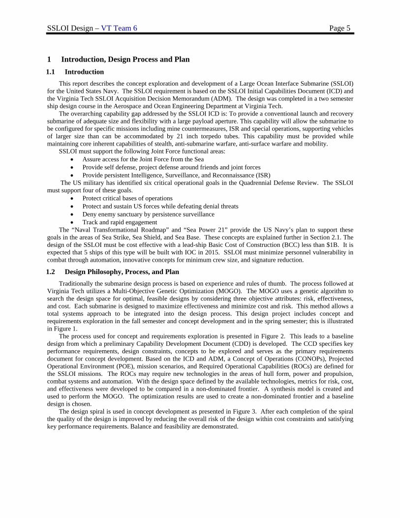
Virginia Tech utilizes a Multi-Objective Genetic Optimization (MOGO). The MOGO uses a genetic algorithm to search the design space for optimal, feasible designs by considering three objective attributes: risk, effectiveness, and cost. Each submarine is designed to maximize effectiveness and minimize cost and risk. This method allows a total systems approach to be integrated into the design process. This design project includes concept and requirements exploration in the fall semester and concept development and in the spring semester; this is illustrated in Figure 1.
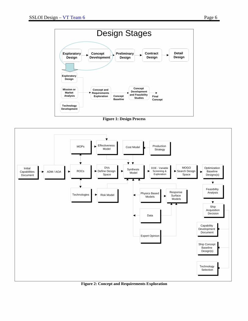
The process used for concept and requirements exploration is presented in Figure 2. This leads to a baseline design from which a preliminary Capability Development Document (CDD) is developed. The CCD specifies key performance requirements, design constraints, concepts to be explored and serves as the primary requirements document for concept development. Based on the ICD and ADM, a Concept of Operations (CONOPs), Projected Operational Environment (POE), mission scenarios, and Required Operational Capabilities (ROCs) are defined for the SSLOI missions. The ROCs may require new technologies in the areas of hull form, power and propulsion, combat systems and automation. With the design space defined by the available technologies, metrics for risk, cost, and effectiveness were developed to be compared in a non-dominated frontier. A synthesis model is created and used to perform the MOGO. The optimization results are used to create a non-dominated frontier and a baseline design is chosen.
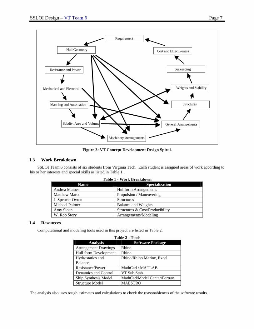
The design spiral is used in concept development as presented in Figure 3. After each completion of the spiral the quality of the design is improved by reducing the overall risk of the design within cost constraints and satisfying key performance requirements. Balance and feasibility are demonstrated.
SSLOI Design – VT Team 6 Page 6
Design Stages
Exploratory Design
Concept Development
Preliminary Design
Contract Design
Detail Design
Exploratory Design
Mission or Market Analysis
Concept and Requirements
Exploration
Technology Development
Concept Development
and Feasibility Studies
ConceptBaseline
FinalConcept
Figure 1: Design Process
Initial Capabilities Document
ADM / AOA ROCsDVs
Define Design Space
Technologies
MOPs Effectiveness Model
Synthesis Model
Cost Model
Risk Model
Production Strategy
DOE - Variable Screening & Exploration
MOGOSearch Design
Space
Ship Acquisition
Decision
Capability Development
Document
Ship Concept Baseline Design(s)
Technology Selection
Physics Based Models
Data
Expert Opinion
Response Surface Models
Optimization Baseline
Designs(s)
Feasibility Analysis
Figure 2: Concept and Requirements Exploration
SSLOI Design – VT Team 6 Page 7
Requirement
Seakeeping
General Arrangements
Weights and Stability
Manning and Automation
Hull Geometry
Resistance and Power
Structures
Mechanical and Electrical
Cost and Effectiveness
Subdiv, Area and Volume
Machinery Arrangements
Figure 3: VT Concept Development Design Spiral.
1.3 Work Breakdown SSLOI Team 6 consists of six students from Virginia Tech. Each student is assigned areas of work according to
his or her interests and special skills as listed in Table 1.
Table 1 - Work Breakdown Name Specialization
Andrea Maines Hullform Arrangements Matthew Martz Propulsion / Maneuvering J. Spencer Ovren Structures Michael Palmer Balance and Weights Amy Sloan Structures & Cost/Producibility W. Rob Story Arrangements/Modeling
1.4 Resources Computational and modeling tools used in this project are listed in Table 2.
Table 2 - Tools Analysis Software Package
Arrangement Drawings Rhino Hull form Development Rhino Hydrostatics and Balance
Rhino/Rhino Marine, Excel
Resistance/Power MathCad / MATLAB Dynamics and Control VT Sub Stab Ship Synthesis Model MathCad/Model Center/Fortran Structure Model MAESTRO
The analysis also uses rough estimates and calculations to check the reasonableness of the software results.
SSLOI Design – VT Team 6 Page 8
2 Mission Definition
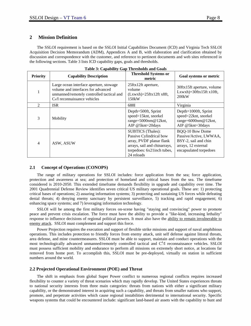
The SSLOI requirement is based on the SSLOI Initial Capabilities Document (ICD) and Virginia Tech SSLOI Acquisition Decision Memorandum (ADM), Appendices A and B, with elaboration and clarification obtained by discussion and correspondence with the customer, and reference to pertinent documents and web sites referenced in the following sections. Table 3 lists ICD capability gaps, goals and thresholds.
Table 3: Capability Gap Thresholds and Goals
Priority Capability Description Threshold Systems or metric Goal systems or metric
1
Large ocean interface aperture, stowage volume and interfaces for advanced unmanned/remotely controlled tactical and C4/I reconnaissance vehicles
25ftx12ft aperture, volume (Lxwxh)=25ftx12ft x8ft, 150kW
30ftx15ft aperture, volume Lxwxh)=30ftx15ft x10ft, 200kW
2 ISR 688I Virginia
3 Mobility
Depth=500ft, Sprint speed=15knt, snorkel range=5000nm@12knt, AIP @5knt=20days
Depth=1000ft, Sprint speed=22knt, snorkel range=6000nm@12knt, AIP @5knt=30days
4 ASW, ASUW
SUBTICS (Thales): Passive Cylindrical bow array, PVDF planar flank arrays, sail and chinarrays, torpedoes: 6x21inch tubes, 24 reloads
BQQ-10 Bow Dome Passive/Active, LWWAA, BSY-2, sail and chin arrays, 12 external encapsulated torpedoes
2.1 Concept of Operations (CONOPS) The range of military operations for SSLOI includes: force application from the sea; force application,
protection and awareness at sea; and protection of homeland and critical bases from the sea. The timeframe considered is 2010-2050. This extended timeframe demands flexibility in upgrade and capability over time. The 2001 Quadrennial Defense Review identifies seven critical US military operational goals. These are: 1) protecting critical bases of operations; 2) assuring information systems; 3) protecting and sustaining US forces while defeating denial threats; 4) denying enemy sanctuary by persistent surveillance, 5) tracking and rapid engagement; 6) enhancing space systems; and 7) leveraging information technology.
SSLOI will be among the first military forces on-scene having "staying and convincing" power to promote peace and prevent crisis escalation. The force must have the ability to provide a "like-kind, increasing lethality" response to influence decisions of regional political powers. It must also have the ability to remain invulnerable to enemy attack. SSLOI must complement and support this force.
Power Projection requires the execution and support of flexible strike missions and support of naval amphibious operations. This includes protection to friendly forces from enemy attack, unit self defense against littoral threats, area defense, and mine countermeasures. SSLOI must be able to support, maintain and conduct operations with the most technologically advanced unmanned/remotely controlled tactical and C4/I reconnaissance vehicles. SSLOI must possess sufficient mobility and endurance to perform all missions on extremely short notice, at locations far removed from home port. To accomplish this, SSLOI must be pre-deployed, virtually on station in sufficient numbers around the world.
2.2 Projected Operational Environment (POE) and Threat The shift in emphasis from global Super Power conflict to numerous regional conflicts requires increased
flexibility to counter a variety of threat scenarios which may rapidly develop. The United States experiences threats to national security interests from three main categories: threats from nations with either a significant military capability, or the demonstrated interest in acquiring such a capability, and threats from smaller nations who support, promote, and perpetrate activities which cause regional instabilities detrimental to international security. Specific weapons systems that could be encountered include: significant land-based air assets with the capability to hunt and
SSLOI Design – VT Team 6 Page 9
sink submarines; surface ships with full ASW capabilities; AIP, diesel and possibly nuclear submarines; mines (surface, moored and bottom).
Since many potentially unstable nations are located on or near geographically constrained bodies of water, the tactical picture will be on smaller scales relative to open ocean warfare. Many encounters may occur in shallow water, which increases the difficulty of detecting and successfully prosecuting targets. SSLOI must be capable of operating in the following environments: dense contact and threats with complicated targeting, noisy and reverberation-limited areas, crowded shipping areas, open ocean (sea states 0 through 9) and littoral regions, and all-weather scenarios.
2.3 SSLOI Operations and Missions SSLOI missions include the following:
• Intelligence, Surveillance, and Reconnaissance • Mine countermeasures • Transport of special operations SEAL teams • Time-sensitive, covert launch of mission configured MANTA(s)
2.4 Mission Scenarios
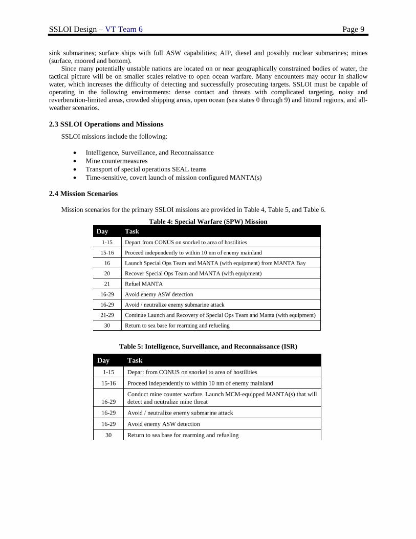
Mission scenarios for the primary SSLOI missions are provided in Table 4, Table 5, and Table 6.
Table 4: Special Warfare (SPW) Mission
Return to sea base for rearming and refueling30
Continue Launch and Recovery of Special Ops Team and Manta (with equipment) 21-29
Avoid / neutralize enemy submarine attack16-29
Avoid enemy ASW detection16-29
Refuel MANTA21
Recover Special Ops Team and MANTA (with equipment)20
Launch Special Ops Team and MANTA (with equipment) from MANTA Bay16
Proceed independently to within 10 nm of enemy mainland 15-16
Depart from CONUS on snorkel to area of hostilities1-15
TaskDay
Table 5: Intelligence, Surveillance, and Reconnaissance (ISR)
Return to sea base for rearming and refueling30
Avoid enemy ASW detection16-29
Avoid / neutralize enemy submarine attack16-29
Conduct mine counter warfare. Launch MCM-equipped MANTA(s) that will detect and neutralize mine threat16-29
Proceed independently to within 10 nm of enemy mainland 15-16
Depart from CONUS on snorkel to area of hostilities1-15
TaskDay
SSLOI Design – VT Team 6 Page 10
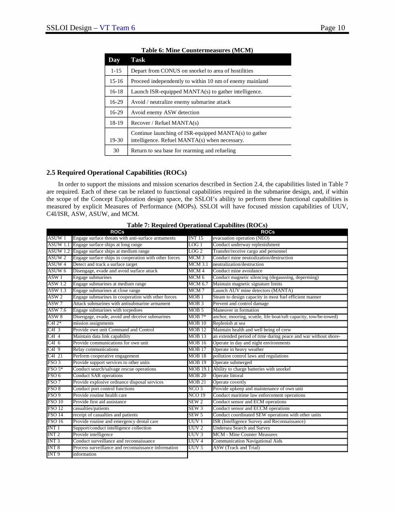
Table 6: Mine Countermeasures (MCM)
Return to sea base for rearming and refueling30
Continue launching of ISR-equipped MANTA(s) to gather intelligence. Refuel MANTA(s) when necessary.19-30
Recover / Refuel MANTA(s)18-19
Avoid enemy ASW detection16-29
Avoid / neutralize enemy submarine attack16-29
Launch ISR-equipped MANTA(s) to gather intelligence.16-18
Proceed independently to within 10 nm of enemy mainland 15-16
Depart from CONUS on snorkel to area of hostilities1-15
TaskDay
2.5 Required Operational Capabilities (ROCs) In order to support the missions and mission scenarios described in Section 2.4, the capabilities listed in Table 7
are required. Each of these can be related to functional capabilities required in the submarine design, and, if within the scope of the Concept Exploration design space, the SSLOI’s ability to perform these functional capabilities is measured by explicit Measures of Performance (MOPs). SSLOI will have focused mission capabilities of UUV, C4I/ISR, ASW, ASUW, and MCM.
Table 7: Required Operational Capabilites (ROCs)
ASUW 1 Engage surface threats with anti-surface armaments INT 15 evacuation operation (NEO)ASUW 1.1 Engage surface ships at long range LOG 1 Conduct underway replenishmentASUW 1.2 Engage surface ships at medium range LOG 2 Transfer/receive cargo and personnelASUW 2 Engage surface ships in cooperation with other forces MCM 3 Conduct mine neutralization/destructionASUW 4 Detect and track a surface target MCM 3.1 neutralization/destructionASUW 6 Disengage, evade and avoid surface attack MCM 4 Conduct mine avoidanceASW 1 Engage submarines MCM 6 Conduct magnetic silencing (degaussing, deperming)ASW 1.2 Engage submarines at medium range MCM 6.7 Maintain magnetic signature limitsASW 1.3 Engage submarines at close range MCM 7 Launch AUV mine detectors (MANTA)ASW 2 Engage submarines in cooperation with other forces MOB 1 Steam to design capacity in most fuel efficient mannerASW 7 Attack submarines with antisubmarine armament MOB 3 Prevent and control damageASW 7.6 Engage submarines with torpedoes MOB 5 Maneuver in formationASW 8 Disengage, evade, avoid and deceive submarines MOB 7* anchor, mooring, scuttle, life boat/raft capacity, tow/be-towed)C4I 2* mission assignments MOB 10 Replenish at seaC4I 3 Provide own unit Command and Control MOB 12 Maintain health and well being of crewC4I 4 Maintain data link capability MOB 13 an extended period of time during peace and war without shore-C4I 6 Provide communications for own unit MOB 16 Operate in day and night environmentsC4I 9 Relay communications MOB 17 Operate in heavy weatherC4I 21 Perform cooperative engagement MOB 18 pollution control laws and regulationsFSO 3 Provide support services to other units MOB 19 Operate submergedFSO 5* Conduct search/salvage rescue operations MOB 19.1 Ability to charge batteries with snorkelFSO 6 Conduct SAR operations MOB 20 Operate littoralFSO 7 Provide explosive ordnance disposal services MOB 21 Operate covertlyFSO 8 Conduct port control functions NCO 3 Provide upkeep and maintenance of own unitFSO 9 Provide routine health care NCO 19 Conduct maritime law enforcement operationsFSO 10 Provide first aid assistance SEW 2 Conduct sensor and ECM operationsFSO 12 casualties/patients SEW 3 Conduct sensor and ECCM operationsFSO 14 receipt of casualties and patients SEW 5 Conduct coordinated SEW operations with other unitsFSO 16 Provide routine and emergency dental care UUV 1 ISR (Intelligence Survey and Reconnaissance) INT 1 Support/conduct intelligence collection UUV 2 Undersea Search and SurveyINT 2 Provide intelligence UUV 3 MCM - Mine Counter MeasuresINT 3 Conduct surveillance and reconnaissance UUV 4 Communication Navigational AidsINT 8 Process surveillance and reconnaissance information UUV 5 ASW (Track and Trial)INT 9 information
ROCsROCs
SSLOI Design – VT Team 6 Page 11
3 Concept Exploration
Chapter 3 describes Concept Exploration. Trade-off studies, design space exploration and optimization are accomplished using a Multi-Objective Genetic Optimization (MOGO). The key to the success of this process is the preparation of alternatives, good data, necessary modifications to the ship synthesis model, and the development of rational and correct objective attributes.
3.1 Trade-Off Studies, Technologies, Concepts and Design Variables Available technologies and concepts necessary to provide required functional capabilities are identified and
defined in terms of performance, cost, risk and submarine impact (weight, area, volume, power). Trade-off studies are performed using technology and concept design parameters to select trade-off options in a multi-objective genetic optimization (MOGO) for the total submarine design. Technology and concept trade spaces and parameters are described in the following sections.
3.1.1 Hull-Form Alternatives
The technology selection process considered performance metrics, hull-form options, and modeling alternatives. Design lanes were used to specify hull-form design parameter ranges and initial hull-form point designs. Applicable alternatives were selected for consideration in Concept Exploration design space.
• High speed resistance (sprint/sustained speed) • Low speed resistance (AIP/endurance) • Snorkel Resistance • Stability and maneuverability • Teardrop shape • Cost and producibility: axisymmetric shape lowers costs • Volume for large object spaces (machinery spaces, mission spaces, MANTAs) • Stack-up length including extra length for mission bay space • Number of decks: 2 or 3 decks depending on internal arrangements • Hull depth/axisymmetric diameter • Structural efficiency (pressure hull)
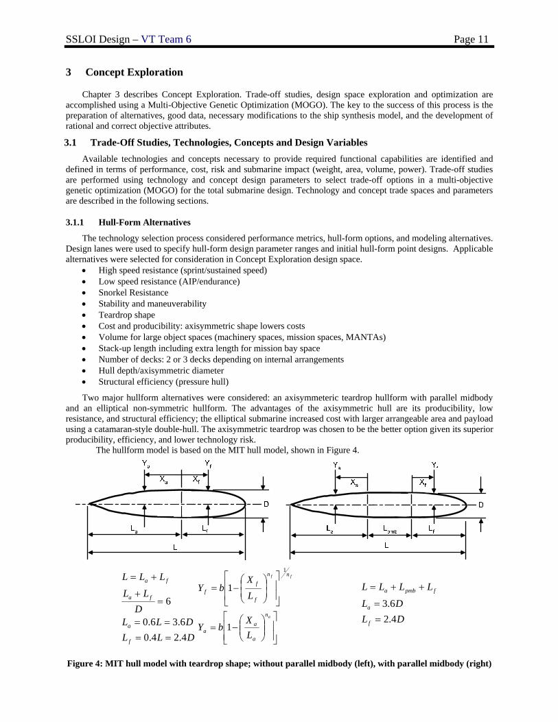
Two major hullform alternatives were considered: an axisymmeteric teardrop hullform with parallel midbody and an elliptical non-symmetric hullform. The advantages of the axisymmetric hull are its producibility, low resistance, and structural efficiency; the elliptical submarine increased cost with larger arrangeable area and payload using a catamaran-style double-hull. The axisymmetric teardrop was chosen to be the better option given its superior producibility, efficiency, and lower technology risk.
The hullform model is based on the MIT hull model, shown in Figure 4.
DLLDLL
DLL
LLL
f
a
fa
fa
4.24.06.36.0
6
====
=+
+=
⎥⎥⎦
⎤
⎢⎢⎣
⎡⎟⎟⎠
⎞⎜⎜⎝
⎛−=
⎥⎥
⎦
⎤
⎢⎢
⎣
⎡
⎟⎟⎠
⎞⎜⎜⎝
⎛−=
a
ff
n
a
aa
nn
f
ff
LX
bY
LX
bY
1
1
1
DLDL
LLLL
f
a
fpmba
4.26.3
==
++=
Figure 4: MIT hull model with teardrop shape; without parallel midbody (left), with parallel midbody (right)
SSLOI Design – VT Team 6 Page 12
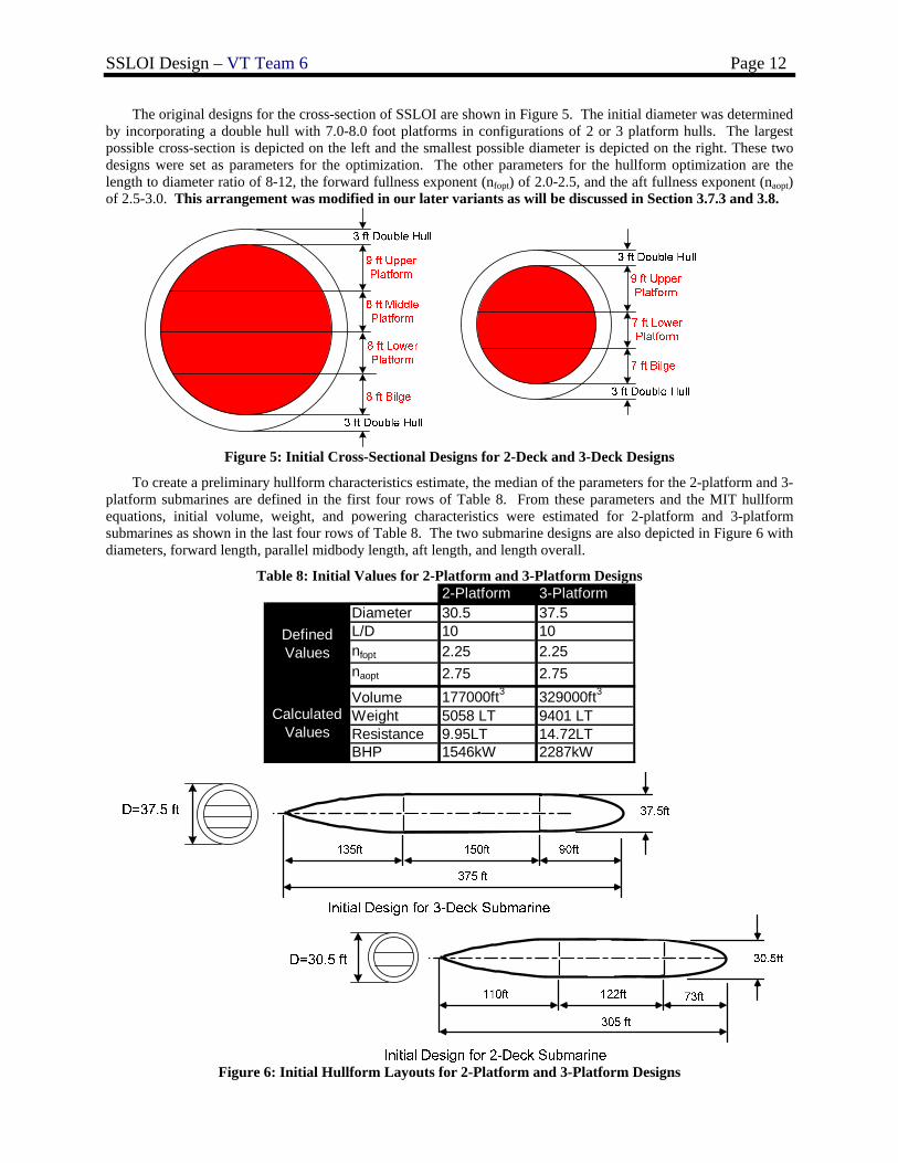
The original designs for the cross-section of SSLOI are shown in Figure 5. The initial diameter was determined by incorporating a double hull with 7.0-8.0 foot platforms in configurations of 2 or 3 platform hulls. The largest possible cross-section is depicted on the left and the smallest possible diameter is depicted on the right. These two designs were set as parameters for the optimization. The other parameters for the hullform optimization are the length to diameter ratio of 8-12, the forward fullness exponent (nfopt) of 2.0-2.5, and the aft fullness exponent (naopt) of 2.5-3.0. This arrangement was modified in our later variants as will be discussed in Section 3.7.3 and 3.8.
Figure 5: Initial Cross-Sectional Designs for 2-Deck and 3-Deck Designs
To create a preliminary hullform characteristics estimate, the median of the parameters for the 2-platform and 3-platform submarines are defined in the first four rows of Table 8. From these parameters and the MIT hullform equations, initial volume, weight, and powering characteristics were estimated for 2-platform and 3-platform submarines as shown in the last four rows of Table 8. The two submarine designs are also depicted in Figure 6 with diameters, forward length, parallel midbody length, aft length, and length overall.
Table 8: Initial Values for 2-Platform and 3-Platform Designs 2-Platform 3-Platform
Diameter 30.5 37.5L/D 10 10nfopt 2.25 2.25naopt 2.75 2.75Volume 177000ft3 329000ft3
Weight 5058 LT 9401 LTResistance 9.95LT 14.72LTBHP 1546kW 2287kW
Defined Values
Calculated Values
Figure 6: Initial Hullform Layouts for 2-Platform and 3-Platform Designs
SSLOI Design – VT Team 6 Page 13
3.1.2 Propulsion and Electrical Machinery Alternatives
3.1.2.1 Machinery Requirements
Based on the ICD, preliminary sizing (Section 3.1.1), and expert guidance, propulsion plant design requirements are as follows:
General Requirements: Propulsion must be non-nuclear and SSLOI must be capable of traveling from base to area of conflict under its own power on snorkel. Once in area of conflict, SSLOI must be capable of stealthy littoral maneuvering. To achieve these goals, SSLOI must operate in two modes: AIP with sprint and snorkel.
Sustained Speed and Propulsion Power: The sprint speed threshold is 15 knots with a goal of 22 knots. The snorkel range threshold at 12 knots is 3000
nm with a goal of 5000 nm (later increased to 5000-6500 nm based on design review). When functioning in AIP, the SSLOI must be capable of running at 5 knots for 20-30 days.
Submarine Control and Machinery Plant Automation: To reduce cost, minimum cost-effective manning must be used, considering a high level of automation.
Commercial off the Shelf (COTS) hardware will be considered where feasible. COTS will reduce cost, allow for greater producibility, and easier upgrades.
Propulsion Engine and Submarine Service Generator Certification: Because of the nature of combat, SSLOI must carry Navy-qualified, Grade A shock-certified machinery. To
reduce signatures a shrouded propeller and an Integrated Power System (IPS) should be considered.
3.1.2.2 Machinery Plant Alternatives
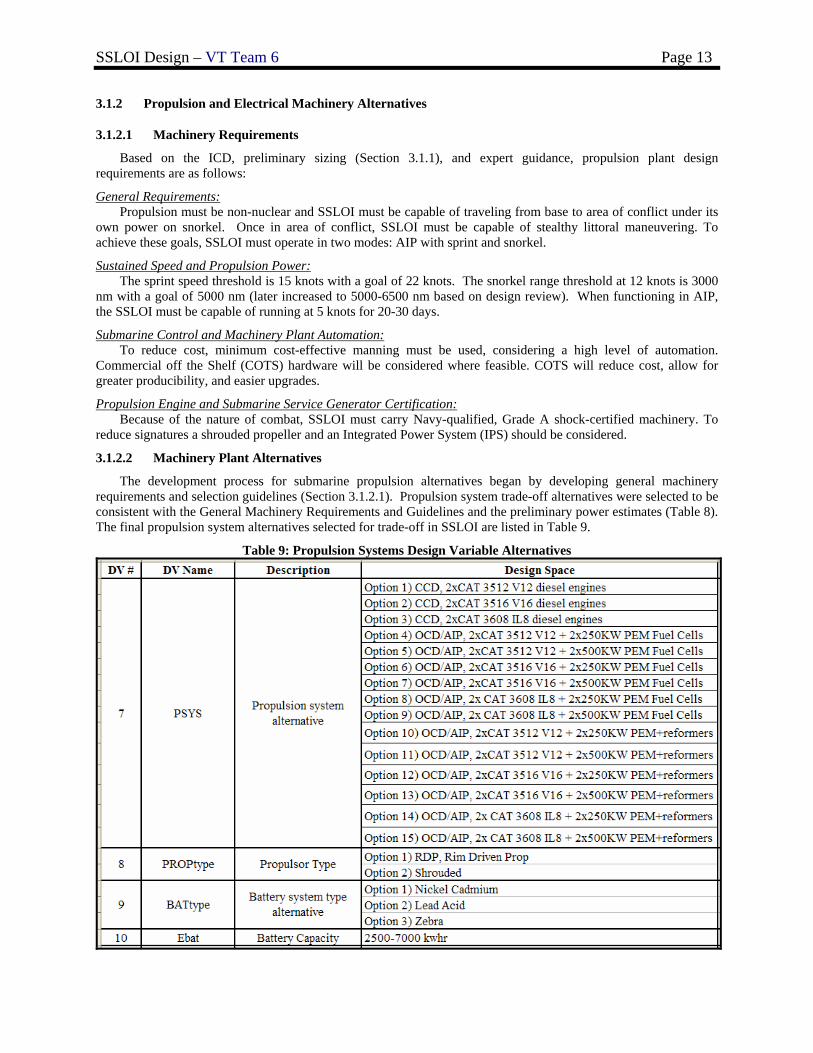
The development process for submarine propulsion alternatives began by developing general machinery requirements and selection guidelines (Section 3.1.2.1). Propulsion system trade-off alternatives were selected to be consistent with the General Machinery Requirements and Guidelines and the preliminary power estimates (Table 8). The final propulsion system alternatives selected for trade-off in SSLOI are listed in Table 9.
Table 9: Propulsion Systems Design Variable Alternatives
SSLOI Design – VT Team 6 Page 14
Various technologies were considered in initial propulsion concept development. Sterling engines, Rankine cycle systems, hydrogen storage, reformers and oxygen storage, closed cycle diesels, fuel cells, batteries, and propulsors were all assessed to determine their advantages and disadvantages.
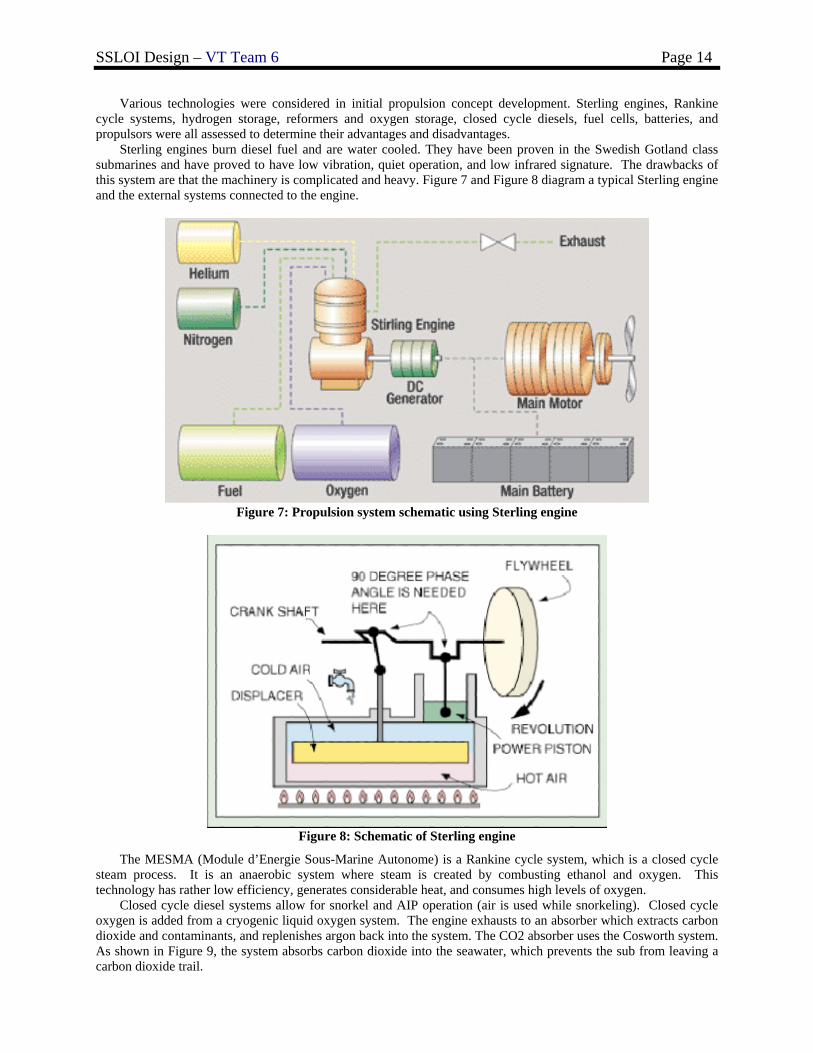
Sterling engines burn diesel fuel and are water cooled. They have been proven in the Swedish Gotland class submarines and have proved to have low vibration, quiet operation, and low infrared signature. The drawbacks of this system are that the machinery is complicated and heavy. Figure 7 and Figure 8 diagram a typical Sterling engine and the external systems connected to the engine.
Figure 7: Propulsion system schematic using Sterling engine
Figure 8: Schematic of Sterling engine
The MESMA (Module d’Energie Sous-Marine Autonome) is a Rankine cycle system, which is a closed cycle steam process. It is an anaerobic system where steam is created by combusting ethanol and oxygen. This technology has rather low efficiency, generates considerable heat, and consumes high levels of oxygen.
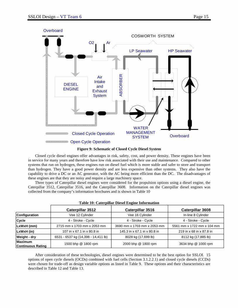
Closed cycle diesel systems allow for snorkel and AIP operation (air is used while snorkeling). Closed cycle oxygen is added from a cryogenic liquid oxygen system. The engine exhausts to an absorber which extracts carbon dioxide and contaminants, and replenishes argon back into the system. The CO2 absorber uses the Cosworth system. As shown in Figure 9, the system absorbs carbon dioxide into the seawater, which prevents the sub from leaving a carbon dioxide trail.
SSLOI Design – VT Team 6 Page 15
O2 Ar
DIESEL ENGINE
ABS
OR
BE
R
LP Seawater HP Seawater
WATER MANAGEMENT
SYSTEMClosed Cycle Operation
Open Cycle Operation
Air Intake and
Exhaust System
Overboard
OverboardCOSWORTH SYSTEM
Figure 9: Schematic of Closed Cycle Diesel System
Closed cycle diesel engines offer advantages in risk, safety, cost, and power density. These engines have been in service for many years and therefore have low risk associated with their use and maintenance. Compared to other systems that run on hydrogen, these engines run on diesel fuel which is more stable and safer to store and transport than hydrogen. They have a good power density and are less expensive than other systems. They also have the capability to drive a DC or an AC generator, with the AC being more efficient than the DC. The disadvantages of these engines are that they are noisy and require a large machinery space.
Three types of Caterpillar diesel engines were considered for the propulsion options using a diesel engine, the Caterpillar 3512, Caterpillar 3516, and the Caterpillar 3608. Information on the Caterpillar diesel engines was collected from the company’s information brochures and is shown in Table 10
Table 10: Caterpillar Diesel Engine Information
Caterpillar 3512 Caterpillar 3516 Caterpillar 3608Configuration Vee 12 Cylinder Vee 16 Cylinder In-line 8 CylinderCycle 4 - Stroke - Cycle 4 - Stroke - Cycle 4 - Stroke - CycleLxWxH (mm) 2715 mm x 1703 mm x 2053 mm 3690 mm x 1703 mm x 2053 mm 5561 mm x 1722 mm x 104 mmLxWxH (in) 107 in x 67.1 in x 80.8 in 145.3 in x 67.1 in x 80.8 in 219 in x 68 in x 87.8 in Weight - dry 6531 - 6537 kg (14,398 - 14,411 lb) 8028 kg (17,699 lb) 8112 kg (17,885 lb)Maximum Continuous Rating 1500 bhp @ 1800 rpm 2000 bhp @ 1800 rpm 3634 bhp @ 1000 rpm
After consideration of these technologies, diesel engines were determined to be the best option for SSLOI. 15 options of open cycle diesels (OCDs) combined with fuel cells (Section 3.1.2.2.1) and closed cycle diesels (CCDs) were chosen for trade-off as design variable options as listed in Table 9. These options and their characteristics are described in Table 12 and Table 13.
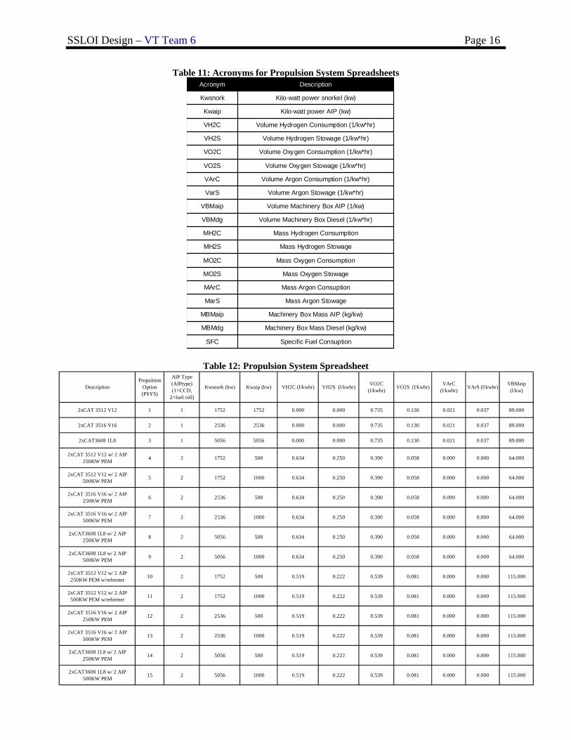
SSLOI Design – VT Team 6 Page 16
Table 11: Acronyms for Propulsion System Spreadsheets
Specific Fuel ConsuptionSFC
Machinery Box Mass Diesel (kg/kw)MBMdg
Machinery Box Mass AIP (kg/kw)MBMaip
Mass Argon StowageMarS
Mass Argon ConsuptionMArC
Mass Oxygen StowageMO2S
Mass Oxygen ConsumptionMO2C
Mass Hydrogen StowageMH2S
Mass Hydrogen ConsumptionMH2C
Volume Machinery Box Diesel (1/kw*hr)VBMdg
Volume Machinery Box AIP (1/kw)VBMaip
Volume Argon Stowage (1/kw*hr)VarS
Volume Argon Consumption (1/kw*hr)VArC
Volume Oxygen Stowage (1/kw*hr)VO2S
Volume Oxygen Consumption (1/kw*hr)VO2C
Volume Hydrogen Stowage (1/kw*hr)VH2S
Volume Hydrogen Consumption (1/kw*hr)VH2C
Kilo-watt power AIP (kw)Kwaip
Kilo-watt power snorkel (kw)Kwsnork
DescriptionAcronym
Table 12: Propulsion System Spreadsheet
DescriptionPropulsion
Option(PSYS)
AIP Type (AIPtype) (1=CCD,
2=fuel cell)
Kwsnork (kw) Kwaip (kw) VH2C (l/kwhr) VH2S (l/kwhr) VO2C (l/kwhr) VO2S (l/kwhr) VArC
(l/kwhr) VArS (l/kwhr) VBMaip (l/kw)
2xCAT 3512 V12 1 1 1752 1752 0.000 0.000 0.735 0.130 0.021 0.037 89.000
2xCAT 3516 V16 2 1 2536 2536 0.000 0.000 0.735 0.130 0.021 0.037 89.000
2xCAT3608 1L8 3 1 5056 5056 0.000 0.000 0.735 0.130 0.021 0.037 89.000
2xCAT 3512 V12 w/ 2 AIP 250KW PEM 4 2 1752 500 0.634 0.250 0.390 0.058 0.000 0.000 64.000
2xCAT 3512 V12 w/ 2 AIP 500KW PEM 5 2 1752 1000 0.634 0.250 0.390 0.058 0.000 0.000 64.000
2xCAT 3516 V16 w/ 2 AIP 250KW PEM 6 2 2536 500 0.634 0.250 0.390 0.058 0.000 0.000 64.000
2xCAT 3516 V16 w/ 2 AIP 500KW PEM 7 2 2536 1000 0.634 0.250 0.390 0.058 0.000 0.000 64.000
2xCAT3608 1L8 w/ 2 AIP 250KW PEM 8 2 5056 500 0.634 0.250 0.390 0.058 0.000 0.000 64.000
2xCAT3608 1L8 w/ 2 AIP 500KW PEM 9 2 5056 1000 0.634 0.250 0.390 0.058 0.000 0.000 64.000
2xCAT 3512 V12 w/ 2 AIP 250KW PEM w/reformer 10 2 1752 500 0.519 0.222 0.539 0.081 0.000 0.000 115.000
2xCAT 3512 V12 w/ 2 AIP 500KW PEM w/reformer 11 2 1752 1000 0.519 0.222 0.539 0.081 0.000 0.000 115.000
2xCAT 3516 V16 w/ 2 AIP 250KW PEM 12 2 2536 500 0.519 0.222 0.539 0.081 0.000 0.000 115.000
2xCAT 3516 V16 w/ 2 AIP 500KW PEM 13 2 2536 1000 0.519 0.222 0.539 0.081 0.000 0.000 115.000
2xCAT3608 1L8 w/ 2 AIP 250KW PEM 14 2 5056 500 0.519 0.222 0.539 0.081 0.000 0.000 115.000
2xCAT3608 1L8 w/ 2 AIP 500KW PEM 15 2 5056 1000 0.519 0.222 0.539 0.081 0.000 0.000 115.000
SSLOI Design – VT Team 6 Page 17
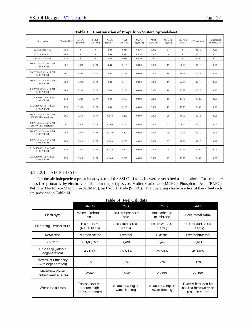
Table 13: Continuation of Propulsion System Spreadsheet
Description VBMdg (l/kw) MH2C (kg/kwhr)
MH2S (kg/kwhr)
MO2C (kg/kwhr)
MO2S (kg/kwhr)
MArC (kg/kwhr)
MArS (kg/kwhr)
MBMaip (kg/kw)
MBMdg (kg/kw) SFC (kg/kwhr) Transmission
efficiency eta
2xCAT 3512 V12 30.3 0 0 0.84 0.317 0.030 0.002 34 0 0.216 0.93
2xCAT 3516 V16 26.0 0 0 0.84 0.317 0.030 0.002 34 0 0.216 0.93
2xCAT3608 1L8 17.6 0 0 0.84 0.317 0.030 0.002 34 0 0.189 0.93
2xCAT 3512 V12 w/ 2 AIP 250KW PEM 30.3 3.490 0.874 0.44 0.165 0.000 0.000 19 30.99 0.216 0.96
2xCAT 3512 V12 w/ 2 AIP 500KW PEM 30.3 3.490 0.874 0.44 0.165 0.000 0.000 19 30.99 0.216 0.96
2xCAT 3516 V16 w/ 2 AIP 250KW PEM 26.0 3.490 0.874 0.44 0.165 0.000 0.000 19 22.98 0.216 0.96
2xCAT 3516 V16 w/ 2 AIP 500KW PEM 26.0 3.490 0.874 0.44 0.165 0.000 0.000 19 22.98 0.216 0.96
2xCAT3608 1L8 w/ 2 AIP 250KW PEM 17.6 3.490 0.874 0.44 0.165 0.000 0.000 19 17.78 0.189 0.96
2xCAT3608 1L8 w/ 2 AIP 500KW PEM 17.6 3.490 0.874 0.44 0.165 0.000 0.000 19 17.78 0.189 0.96
2xCAT 3512 V12 w/ 2 AIP 250KW PEM w/reformer 30.3 0.410 0.074 0.648 0.225 0.000 0.000 29 30.99 0.216 0.96
2xCAT 3512 V12 w/ 2 AIP 500KW PEM w/reformer 30.3 0.410 0.074 0.648 0.225 0.000 0.000 29 30.99 0.216 0.96
2xCAT 3516 V16 w/ 2 AIP 250KW PEM 26.0 0.410 0.074 0.648 0.225 0.000 0.000 29 22.98 0.216 0.96
2xCAT 3516 V16 w/ 2 AIP 500KW PEM 26.0 0.410 0.074 0.648 0.225 0.000 0.000 29 22.98 0.216 0.96
2xCAT3608 1L8 w/ 2 AIP 250KW PEM 17.6 0.410 0.074 0.648 0.225 0.000 0.000 29 17.78 0.189 0.96
2xCAT3608 1L8 w/ 2 AIP 500KW PEM 17.6 0.410 0.074 0.648 0.225 0.000 0.000 29 17.78 0.189 0.96
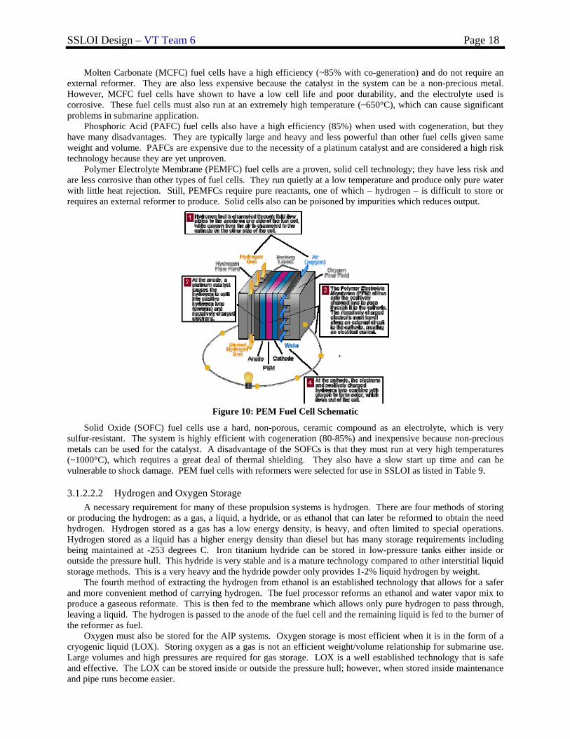
3.1.2.2.1 AIP Fuel Cells For the air-independent propulsion system of the SSLOI, fuel cells were researched as an option. Fuel cells are classified primarily by electrolyte. The four major types are: Molten Carbonate (MCFC), Phosphoric Acid (PAFC), Polymer Electrolyte Membrane (PEMFC), and Solid Oxide (SOFC). The operating characteristics of these fuel cells are provided in Table 14.
Table 14: Fuel Cell data
Excess heat can be used to heat water or
produce steam
Space heating or water heating
Space heating or water heating
Excess heat can produce high-
pressure steamWaste Heat Uses
220kW250kW1MW2MWMaximum Power Output Range (size)
85%60%80%85%Maximum Efficiency (with cogeneration)
45-60%35-50%35-50%45-60%Efficiency (without cogeneration)
O2/AirO2/AirO2/AirCO2/O2/AirOxidant
External/InternalExternalExternalExternal/InternalReforming
1100-1830°F (600-1000°C)
140-212°F (60-100°C)
300-390°F (150-200°C)
1100-1830°F (600-1000°C)Operating Temperature
Solid metal oxideIon exchange membrane
Liquid phosphoric acid
Molten Carbonate saltElectrolyte
SOFCPEMFCPAFCMCFC
SSLOI Design – VT Team 6 Page 18
Molten Carbonate (MCFC) fuel cells have a high efficiency (~85% with co-generation) and do not require an external reformer. They are also less expensive because the catalyst in the system can be a non-precious metal. However, MCFC fuel cells have shown to have a low cell life and poor durability, and the electrolyte used is corrosive. These fuel cells must also run at an extremely high temperature (~650°C), which can cause significant problems in submarine application.
Phosphoric Acid (PAFC) fuel cells also have a high efficiency (85%) when used with cogeneration, but they have many disadvantages. They are typically large and heavy and less powerful than other fuel cells given same weight and volume. PAFCs are expensive due to the necessity of a platinum catalyst and are considered a high risk technology because they are yet unproven.
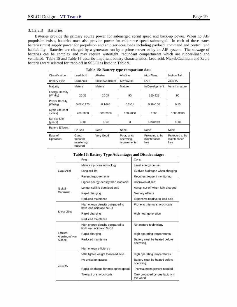
Polymer Electrolyte Membrane (PEMFC) fuel cells are a proven, solid cell technology; they have less risk and are less corrosive than other types of fuel cells. They run quietly at a low temperature and produce only pure water with little heat rejection. Still, PEMFCs require pure reactants, one of which – hydrogen – is difficult to store or requires an external reformer to produce. Solid cells also can be poisoned by impurities which reduces output.
Figure 10: PEM Fuel Cell Schematic
Solid Oxide (SOFC) fuel cells use a hard, non-porous, ceramic compound as an electrolyte, which is very sulfur-resistant. The system is highly efficient with cogeneration (80-85%) and inexpensive because non-precious metals can be used for the catalyst. A disadvantage of the SOFCs is that they must run at very high temperatures (~1000°C), which requires a great deal of thermal shielding. They also have a slow start up time and can be vulnerable to shock damage. PEM fuel cells with reformers were selected for use in SSLOI as listed in Table 9.
3.1.2.2.2 Hydrogen and Oxygen Storage A necessary requirement for many of these propulsion systems is hydrogen. There are four methods of storing
or producing the hydrogen: as a gas, a liquid, a hydride, or as ethanol that can later be reformed to obtain the need hydrogen. Hydrogen stored as a gas has a low energy density, is heavy, and often limited to special operations. Hydrogen stored as a liquid has a higher energy density than diesel but has many storage requirements including being maintained at -253 degrees C. Iron titanium hydride can be stored in low-pressure tanks either inside or outside the pressure hull. This hydride is very stable and is a mature technology compared to other interstitial liquid storage methods. This is a very heavy and the hydride powder only provides 1-2% liquid hydrogen by weight.
The fourth method of extracting the hydrogen from ethanol is an established technology that allows for a safer and more convenient method of carrying hydrogen. The fuel processor reforms an ethanol and water vapor mix to produce a gaseous reformate. This is then fed to the membrane which allows only pure hydrogen to pass through, leaving a liquid. The hydrogen is passed to the anode of the fuel cell and the remaining liquid is fed to the burner of the reformer as fuel.
Oxygen must also be stored for the AIP systems. Oxygen storage is most efficient when it is in the form of a cryogenic liquid (LOX). Storing oxygen as a gas is not an efficient weight/volume relationship for submarine use. Large volumes and high pressures are required for gas storage. LOX is a well established technology that is safe and effective. The LOX can be stored inside or outside the pressure hull; however, when stored inside maintenance and pipe runs become easier.
SSLOI Design – VT Team 6 Page 19
3.1.2.2.3 Batteries Batteries provide the primary source power for submerged sprint speed and back-up power. When no AIP
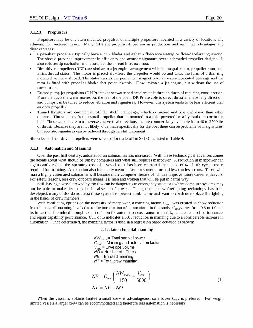
propulsion exists, batteries must also provide power for endurance speed submerged. In each of these states batteries must supply power for propulsion and ship services loads including payload, command and control, and habitability. Batteries are charged by a generator run by a prime mover or by an AIP system. The stowage of batteries can be complex and may require watertight, redundant compartments which are rubber-lined and ventilated. Table 15 and Table 16 describe important battery characteristics. Lead acid, Nickel/Cadmium and Zebra batteries were selected for trade-off in SSLOI as listed in Table 9.
Table 15: Battery type comparison data
Projected to be maintenance free
Projected to be maintenance free
Poor, strict operating requirements
Very GoodGood, frequent monitoring required
Ease of Operation
NoneNoneNoneNoneH2 GasBattery Effluent
5-10Unknown35-103-10Service Life (years)
1000-30001000100-2000500-2000200-2000Cycle Life (# of cycles)
0.150.19-0.360.2-0.40.1-0.60.02-0.175Power Density (kW/kg)
90160-2259020-3720-35Energy Density (Wh/kg)
Very ImmatureIn DevelopmentMatureMatureMatureMaturity
ZEBRALAISSilver/ZincNickel/CadmiumLead AcidBattery Type
Molton SaltHigh TempAlkalineAlkalineLead-AcidClassification
Table 16: Battery Type Advantages and Disadvantages
Only produced by one factory in the world
Tolerant of short circuits
Thermal management neededRapid discharge for max sprint speed
Battery must be heated before operating
No emission gasses
High operating temperatures50% lighter weight than lead acid
ZEBRA
High energy efficiency
Battery must be heated before operating
Reduced maintence
High operating temperaturesRapid charging
Not mature technologyHigh energy density compared to both lead acid and Ni/Cd
Lithium-Aluminum/Iron Sulfide
Reduced maintence
High heat generationRapid charging
Prone to internal short circuitsHigh energy density compared to both lead acid and Ni/Cd
Silver-Zinc
Expensive relative to lead acidReduced maintence
Memory effectsRapid charging
Abrupt cut-off when fully chargedLonger cell life than lead acid
Unproven at seaHigher energy density than lead acid
Nickel-Cadmium
Requires frequent monitoringRecent improvements
Evolves hydrogen when chargingLong cell life
Least energy denseMature / proven technology
Lead Acid
ConsPros
SSLOI Design – VT Team 6 Page 20
3.1.2.3 Propulsors
Propulsors may be one stern-mounted propulsor or multiple propulsors mounted in a variety of locations and allowing for vectored thrust. Many different propulsor-types are in production and each has advantages and disadvantages: • Open-shaft propellers typically have 6 or 7 blades and either a flow-accelerating or flow-decelerating shroud.
The shroud provides improvement in efficiency and acoustic signature over unshrouded propeller designs. It also reduces tip cavitation and losses, but the shroud increases cost.
• Rim-driven propellers (RDP) are similar to a jet engine arrangement with an integral motor, propeller rotor, and a rim/shroud stator. The motor is placed aft where the propeller would be and takes the form of a thin ring mounted within a shroud. The stator carries the permanent magnet rotor in water-lubricated bearings and the rotor is fitted with propeller blades that point inwards. Flow imitates a jet engine, but without the use of combustion.
• Ducted pump jet propulsion (DPJP) intakes seawater and accelerates it through ducts of reducing cross-section. From the ducts the water moves out the rear of the boat. DPJPs are able to direct thrust in almost any direction, and pumps can be tuned to reduce vibration and signatures. However, this system tends to be less efficient than an open propeller.
• Tunnel thrusters are commercial off the shelf technology, which is mature and less expensive than other options. Thrust comes from a small propeller that is mounted in a tube powered by a hydraulic motor in the hub. These can operate in transverse and vertical directions and are commercially available from 40 to 2500 lbs of thrust. Because they are not likely to be made specifically for the boat there can be problems with signatures, but acoustic signatures can be reduced through careful placement.
Shrouded and rim-driven propellers were selected for trade-off in SSLOI as listed in Table 9.
3.1.3 Automation and Manning
Over the past half century, automation on submarines has increased. With these technological advances comes the debate about what should be run by computers and what still requires manpower. A reduction in manpower can significantly reduce the operating cost of a vessel as it has been estimated that up to 60% of life cycle cost is required for manning. Automation also frequently means a faster response time and less careless errors. Those who man a highly automated submarine will become more computer literate which can improve future career endeavors. For safety reasons, less crew onboard means less men and women that will be put in harms way.
Still, having a vessel crewed by too few can be dangerous in emergency situations where computer systems may not be able to make decisions in the absence of power. Though some new firefighting technology has been developed, many critics do not trust these systems to protect a submarine and want to continue to place firefighting in the hands of crew members.
With conflicting options on the necessity of manpower, a manning factor, Cman, was created to show reduction from “standard” manning levels due to the introduction of automation. In this study, Cman varies from 0.5 to 1.0 and its impact is determined through expert opinion for automation cost, automation risk, damage control performance, and repair capability performance. Cman of .5 indicates a 50% reduction in manning due to a considerable increase in automation. Once determined, the manning factor is used in a regression based equation as shown:
Calculation for total manning
KWsnork = Total snorkel powerCman = Manning and automation factorVenv = Envelope volumeNO = Number of officersNE = Enlisted manningNT = Total crew manning
NONENT
VKWCNE envsnork
man
+=
⎟⎠⎞
⎜⎝⎛ +=
5000150 (1)
When the vessel is volume limited a small crew is advantageous, so a lower Cman is preferred. For weight
limited vessels a larger crew can be accommodated and therefore less automation is necessary.
SSLOI Design – VT Team 6 Page 21
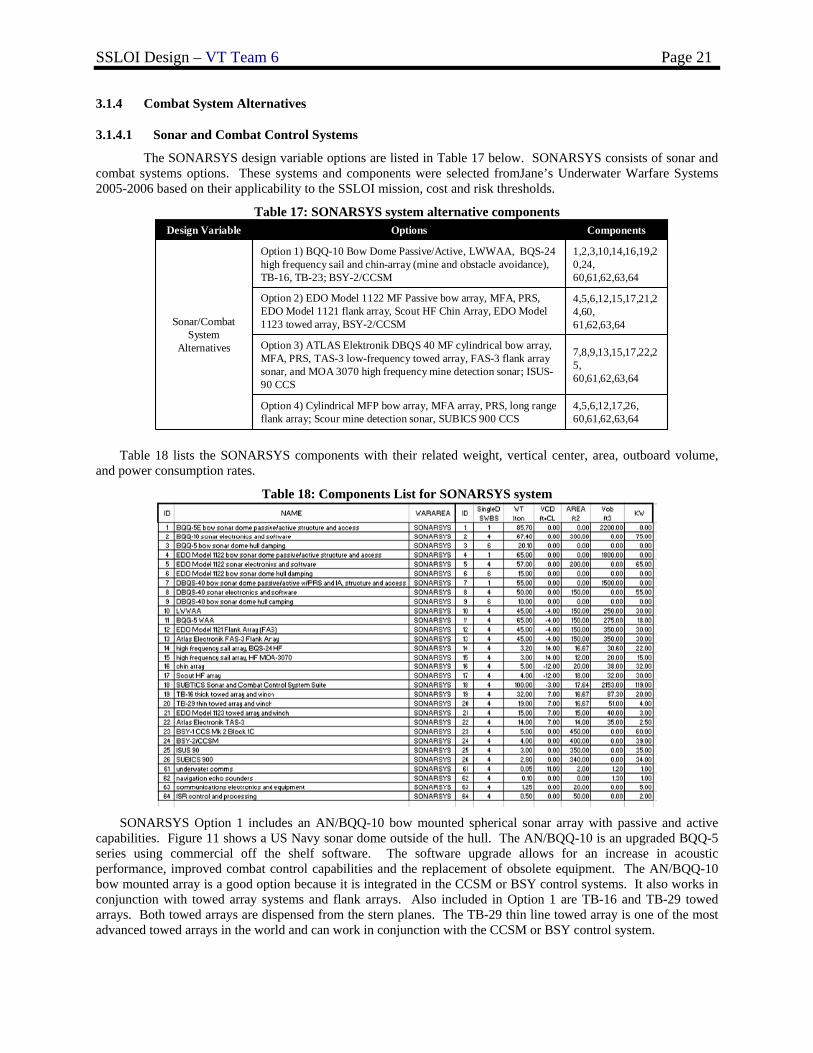
3.1.4 Combat System Alternatives
3.1.4.1 Sonar and Combat Control Systems
The SONARSYS design variable options are listed in Table 17 below. SONARSYS consists of sonar and combat systems options. These systems and components were selected fromJane’s Underwater Warfare Systems 2005-2006 based on their applicability to the SSLOI mission, cost and risk thresholds.
Table 17: SONARSYS system alternative components
4,5,6,12,17,26,60,61,62,63,64
Option 4) Cylindrical MFP bow array, MFA array, PRS, long range flank array; Scour mine detection sonar, SUBICS 900 CCS
7,8,9,13,15,17,22,25,60,61,62,63,64
Option 3) ATLAS Elektronik DBQS 40 MF cylindrical bow array, MFA, PRS, TAS-3 low-frequency towed array, FAS-3 flank array sonar, and MOA 3070 high frequency mine detection sonar; ISUS-90 CCS
4,5,6,12,15,17,21,24,60,61,62,63,64
Option 2) EDO Model 1122 MF Passive bow array, MFA, PRS, EDO Model 1121 flank array, Scout HF Chin Array, EDO Model 1123 towed array, BSY-2/CCSM
1,2,3,10,14,16,19,20,24,60,61,62,63,64
Option 1) BQQ-10 Bow Dome Passive/Active, LWWAA, BQS-24 high frequency sail and chin-array (mine and obstacle avoidance), TB-16, TB-23; BSY-2/CCSM
Sonar/Combat System
Alternatives
ComponentsOptionsDesign Variable
Table 18 lists the SONARSYS components with their related weight, vertical center, area, outboard volume,
and power consumption rates.
Table 18: Components List for SONARSYS system
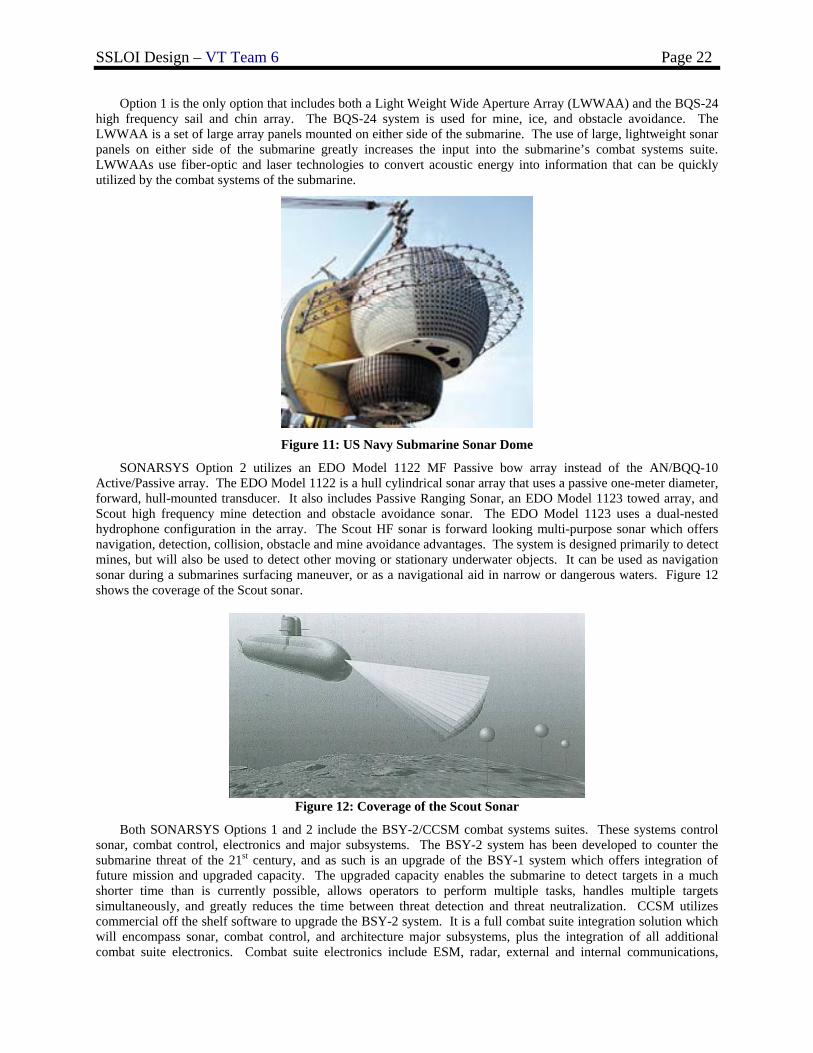
SONARSYS Option 1 includes an AN/BQQ-10 bow mounted spherical sonar array with passive and active
capabilities. Figure 11 shows a US Navy sonar dome outside of the hull. The AN/BQQ-10 is an upgraded BQQ-5 series using commercial off the shelf software. The software upgrade allows for an increase in acoustic performance, improved combat control capabilities and the replacement of obsolete equipment. The AN/BQQ-10 bow mounted array is a good option because it is integrated in the CCSM or BSY control systems. It also works in conjunction with towed array systems and flank arrays. Also included in Option 1 are TB-16 and TB-29 towed arrays. Both towed arrays are dispensed from the stern planes. The TB-29 thin line towed array is one of the most advanced towed arrays in the world and can work in conjunction with the CCSM or BSY control system.
SSLOI Design – VT Team 6 Page 22
Option 1 is the only option that includes both a Light Weight Wide Aperture Array (LWWAA) and the BQS-24 high frequency sail and chin array. The BQS-24 system is used for mine, ice, and obstacle avoidance. The LWWAA is a set of large array panels mounted on either side of the submarine. The use of large, lightweight sonar panels on either side of the submarine greatly increases the input into the submarine’s combat systems suite. LWWAAs use fiber-optic and laser technologies to convert acoustic energy into information that can be quickly utilized by the combat systems of the submarine.
Figure 11: US Navy Submarine Sonar Dome
SONARSYS Option 2 utilizes an EDO Model 1122 MF Passive bow array instead of the AN/BQQ-10 Active/Passive array. The EDO Model 1122 is a hull cylindrical sonar array that uses a passive one-meter diameter, forward, hull-mounted transducer. It also includes Passive Ranging Sonar, an EDO Model 1123 towed array, and Scout high frequency mine detection and obstacle avoidance sonar. The EDO Model 1123 uses a dual-nested hydrophone configuration in the array. The Scout HF sonar is forward looking multi-purpose sonar which offers navigation, detection, collision, obstacle and mine avoidance advantages. The system is designed primarily to detect mines, but will also be used to detect other moving or stationary underwater objects. It can be used as navigation sonar during a submarines surfacing maneuver, or as a navigational aid in narrow or dangerous waters. Figure 12 shows the coverage of the Scout sonar.
Figure 12: Coverage of the Scout Sonar
Both SONARSYS Options 1 and 2 include the BSY-2/CCSM combat systems suites. These systems control sonar, combat control, electronics and major subsystems. The BSY-2 system has been developed to counter the submarine threat of the 21st century, and as such is an upgrade of the BSY-1 system which offers integration of future mission and upgraded capacity. The upgraded capacity enables the submarine to detect targets in a much shorter time than is currently possible, allows operators to perform multiple tasks, handles multiple targets simultaneously, and greatly reduces the time between threat detection and threat neutralization. CCSM utilizes commercial off the shelf software to upgrade the BSY-2 system. It is a full combat suite integration solution which will encompass sonar, combat control, and architecture major subsystems, plus the integration of all additional combat suite electronics. Combat suite electronics include ESM, radar, external and internal communications,
SSLOI Design – VT Team 6 Page 23
submarine defensive warfare systems, navigation, total ship monitoring, periscope/imaging, navigation sensor system interface, tactical support devices and special purpose subsystems.
SONARSYS Option 3 uses an ATLAS Elektronik DBQS 40 integrated sonar system with ISUS-90 CCS. The DBQS 40 is an integrated bow array that incorporates a medium-frequency, cylindrical bow array operating in the 0.3 to 12 kHz band. It integrates a FAS-3 flank array, a Passive Ranging Sonar (PRS), intercept sonar a low frequency, passive towed array sonar (TAS-3). It also integrates active high frequency MOA 3070 mine detection sonar.
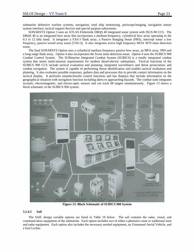
The final SONARSYS Option uses a cylindrical medium frequency passive bow array, an MFA array, PRS and a long range flank array. Option 4 also incorporates the Scout mine detection sonar. Option 4 uses the SUBICS 900 Combat Control System. The SUBmarine Integrated Combat System (SUBICS) is a totally integrated combat system that meets multi-mission requirements for modern diesel-electric submarines. Tactical functions of the SUBICS 900 CCS include tactical evaluation and planning; integrated surveillance and threat prosecution; and combat navigation. The system is capable of performing threat identification and enables tactical evaluation and planning. It also evaluates possible responses, gathers data and processes this to provide contact information on the tactical display. It performs torpedo/missile control functions and has displays that include information on the geographical situation with navigation function including alerts to approaching hazards. The combat suite integrates acoustic, electromagnetic, and electro-optic sensors and can track 68 targets simultaneously. Figure 13 shows a block schematic of the SUBICS 900 system.
Figure 13: Block Schematic of SUBICS 900 System
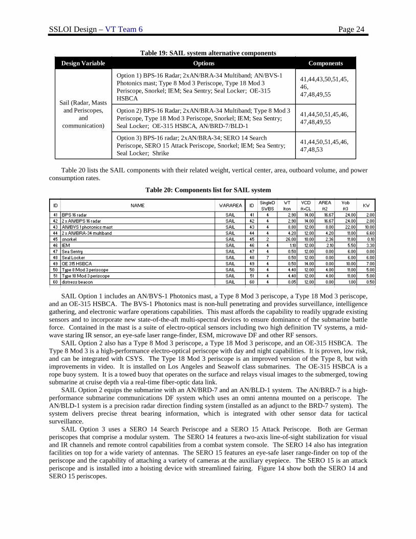
3.1.4.2 Sail
The SAIL design variable options are listed in Table 19 below. The sail contains the radar, visual, and communication equipment of the submarine. Each option includes two of either a photonics mast or traditional mast and radar equipment. Each option also includes the necessary snorkel equipment, an Unmanned Aerial Vehicle, and a Seal Locker.
SSLOI Design – VT Team 6 Page 24
Table 19: SAIL system alternative components
41,44,50,51,45,46,47,48,53
Option 3) BPS-16 radar; 2xAN/BRA-34; SERO 14 Search Periscope, SERO 15 Attack Periscope, Snorkel; IEM; Sea Sentry; Seal Locker; Shrike
41,44,50,51,45,46,47,48,49,55
Option 2) BPS-16 Radar; 2xAN/BRA-34 Multiband; Type 8 Mod 3 Periscope, Type 18 Mod 3 Periscope, Snorkel; IEM; Sea Sentry; Seal Locker; OE-315 HSBCA, AN/BRD-7/BLD-1
41,44,43,50,51,45,46,47,48,49,55
Option 1) BPS-16 Radar; 2xAN/BRA-34 Multiband; AN/BVS-1 Photonics mast; Type 8 Mod 3 Periscope, Type 18 Mod 3 Periscope, Snorkel; IEM; Sea Sentry; Seal Locker; OE-315 HSBCA
Sail (Radar, Masts and Periscopes,
and communication)
ComponentsOptionsDesign Variable
Table 20 lists the SAIL components with their related weight, vertical center, area, outboard volume, and power
consumption rates.
Table 20: Components list for SAIL system
SAIL Option 1 includes an AN/BVS-1 Photonics mast, a Type 8 Mod 3 periscope, a Type 18 Mod 3 periscope,
and an OE-315 HSBCA. The BVS-1 Photonics mast is non-hull penetrating and provides surveillance, intelligence gathering, and electronic warfare operations capabilities. This mast affords the capability to readily upgrade existing sensors and to incorporate new state-of-the-aft multi-spectral devices to ensure dominance of the submarine battle force. Contained in the mast is a suite of electro-optical sensors including two high definition TV systems, a mid-wave staring IR sensor, an eye-safe laser range-finder, ESM, microwave DF and other RF sensors.
SAIL Option 2 also has a Type 8 Mod 3 periscope, a Type 18 Mod 3 periscope, and an OE-315 HSBCA. The Type 8 Mod 3 is a high-performance electro-optical periscope with day and night capabilities. It is proven, low risk, and can be integrated with CSYS. The Type 18 Mod 3 periscope is an improved version of the Type 8, but with improvements in video. It is installed on Los Angeles and Seawolf class submarines. The OE-315 HSBCA is a rope buoy system. It is a towed buoy that operates on the surface and relays visual images to the submerged, towing submarine at cruise depth via a real-time fiber-optic data link.
SAIL Option 2 equips the submarine with an AN/BRD-7 and an AN/BLD-1 system. The AN/BRD-7 is a high-performance submarine communications DF system which uses an omni antenna mounted on a periscope. The AN/BLD-1 system is a precision radar direction finding system (installed as an adjunct to the BRD-7 system). The system delivers precise threat bearing information, which is integrated with other sensor data for tactical surveillance.
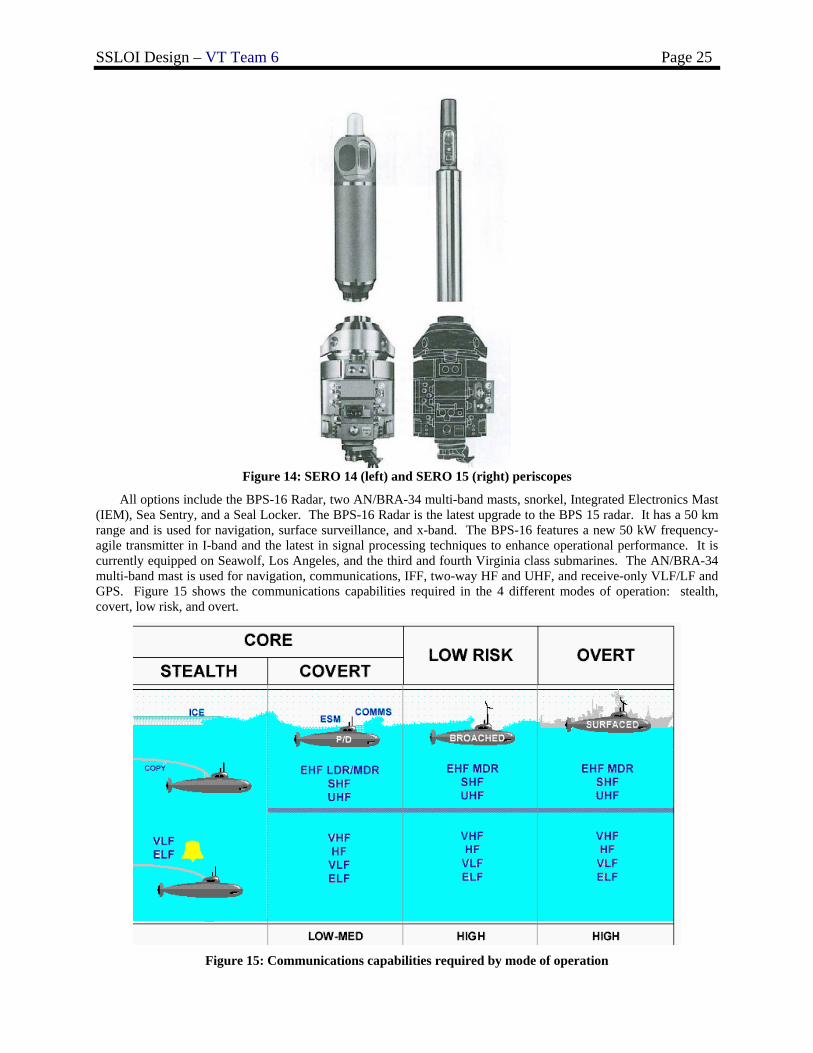
SAIL Option 3 uses a SERO 14 Search Periscope and a SERO 15 Attack Periscope. Both are German periscopes that comprise a modular system. The SERO 14 features a two-axis line-of-sight stabilization for visual and IR channels and remote control capabilities from a combat system console. The SERO 14 also has integration facilities on top for a wide variety of antennas. The SERO 15 features an eye-safe laser range-finder on top of the periscope and the capability of attaching a variety of cameras at the auxiliary eyepiece. The SERO 15 is an attack periscope and is installed into a hoisting device with streamlined fairing. Figure 14 show both the SERO 14 and SERO 15 periscopes.
SSLOI Design – VT Team 6 Page 25
Figure 14: SERO 14 (left) and SERO 15 (right) periscopes
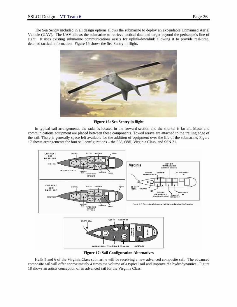
All options include the BPS-16 Radar, two AN/BRA-34 multi-band masts, snorkel, Integrated Electronics Mast (IEM), Sea Sentry, and a Seal Locker. The BPS-16 Radar is the latest upgrade to the BPS 15 radar. It has a 50 km range and is used for navigation, surface surveillance, and x-band. The BPS-16 features a new 50 kW frequency-agile transmitter in I-band and the latest in signal processing techniques to enhance operational performance. It is currently equipped on Seawolf, Los Angeles, and the third and fourth Virginia class submarines. The AN/BRA-34 multi-band mast is used for navigation, communications, IFF, two-way HF and UHF, and receive-only VLF/LF and GPS. Figure 15 shows the communications capabilities required in the 4 different modes of operation: stealth, covert, low risk, and overt.
Figure 15: Communications capabilities required by mode of operation
SSLOI Design – VT Team 6 Page 26
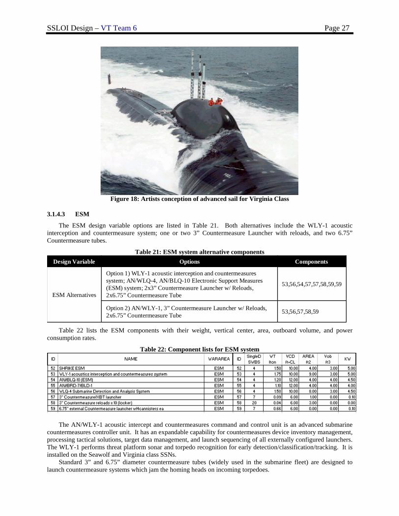
The Sea Sentry included in all design options allows the submarine to deploy an expendable Unmanned Aerial Vehicle (UAV). The UAV allows the submarine to retrieve tactical data and target beyond the periscope’s line of sight. It uses existing submarine communications assets for uplink/downlink allowing it to provide real-time, detailed tactical information. Figure 16 shows the Sea Sentry in flight.
Figure 16: Sea Sentry in flight
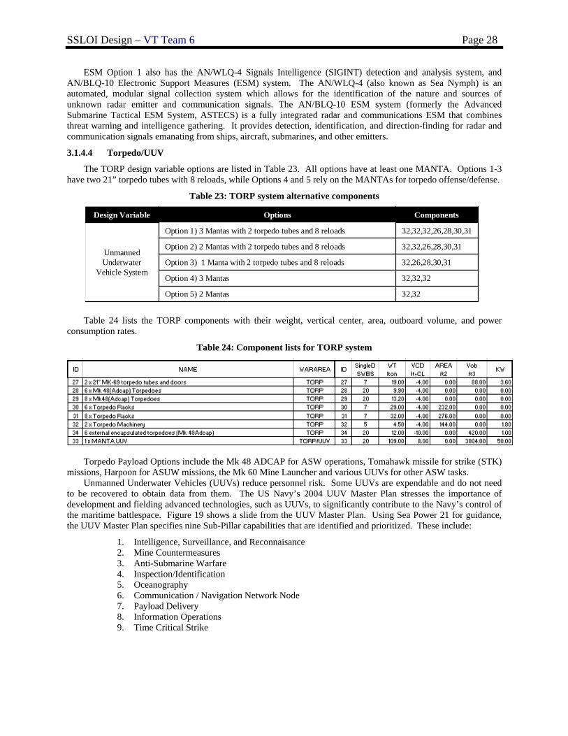
In typical sail arrangements, the radar is located in the forward section and the snorkel is far aft. Masts and communications equipment are placed between these components. Towed arrays are attached to the trailing edge of the sail. There is generally space left available for the addition of equipment over the life of the submarine. Figure 17 shows arrangements for four sail configurations – the 688, 688I, Virginia Class, and SSN 21.
Figure 17: Sail Configuration Alternatives
Hulls 5 and 6 of the Virginia Class submarine will be receiving a new advanced composite sail. The advanced composite sail will offer approximately 4 times the volume of a typical sail and improve the hydrodynamics. Figure 18 shows an artists conception of an advanced sail for the Virginia Class.
SSLOI Design – VT Team 6 Page 27
Figure 18: Artists conception of advanced sail for Virginia Class
3.1.4.3 ESM
The ESM design variable options are listed in Table 21. Both alternatives include the WLY-1 acoustic interception and countermeasure system; one or two 3” Countermeasure Launcher with reloads, and two 6.75” Countermeasure tubes.
Table 21: ESM system alternative components
53,56,57,58,59Option 2) AN/WLY-1, 3” Countermeasure Launcher w/ Reloads, 2x6.75” Countermeasure Tube
53,56,54,57,57,58,59,59
Option 1) WLY-1 acoustic interception and countermeasures system; AN/WLQ-4, AN/BLQ-10 Electronic Support Measures (ESM) system; 2x3” Countermeasure Launcher w/ Reloads, 2x6.75” Countermeasure TubeESM Alternatives
ComponentsOptionsDesign Variable
Table 22 lists the ESM components with their weight, vertical center, area, outboard volume, and power consumption rates.
Table 22: Component lists for ESM system
The AN/WLY-1 acoustic intercept and countermeasures command and control unit is an advanced submarine
countermeasures controller unit. It has an expandable capability for countermeasures device inventory management, processing tactical solutions, target data management, and launch sequencing of all externally configured launchers. The WLY-1 performs threat platform sonar and torpedo recognition for early detection/classification/tracking. It is installed on the Seawolf and Virginia class SSNs.
Standard 3” and 6.75” diameter countermeasure tubes (widely used in the submarine fleet) are designed to launch countermeasure systems which jam the homing heads on incoming torpedoes.
SSLOI Design – VT Team 6 Page 28
ESM Option 1 also has the AN/WLQ-4 Signals Intelligence (SIGINT) detection and analysis system, and AN/BLQ-10 Electronic Support Measures (ESM) system. The AN/WLQ-4 (also known as Sea Nymph) is an automated, modular signal collection system which allows for the identification of the nature and sources of unknown radar emitter and communication signals. The AN/BLQ-10 ESM system (formerly the Advanced Submarine Tactical ESM System, ASTECS) is a fully integrated radar and communications ESM that combines threat warning and intelligence gathering. It provides detection, identification, and direction-finding for radar and communication signals emanating from ships, aircraft, submarines, and other emitters.
3.1.4.4 Torpedo/UUV
The TORP design variable options are listed in Table 23. All options have at least one MANTA. Options 1-3 have two 21” torpedo tubes with 8 reloads, while Options 4 and 5 rely on the MANTAs for torpedo offense/defense.
Table 23: TORP system alternative components
32,32Option 5) 2 Mantas
32,32,32Option 4) 3 Mantas
32,26,28,30,31Option 3) 1 Manta with 2 torpedo tubes and 8 reloads
32,32,26,28,30,31Option 2) 2 Mantas with 2 torpedo tubes and 8 reloads
32,32,32,26,28,30,31Option 1) 3 Mantas with 2 torpedo tubes and 8 reloads
Unmanned Underwater
Vehicle System
ComponentsOptionsDesign Variable
Table 24 lists the TORP components with their weight, vertical center, area, outboard volume, and power consumption rates.
Table 24: Component lists for TORP system
Torpedo Payload Options include the Mk 48 ADCAP for ASW operations, Tomahawk missile for strike (STK) missions, Harpoon for ASUW missions, the Mk 60 Mine Launcher and various UUVs for other ASW tasks.
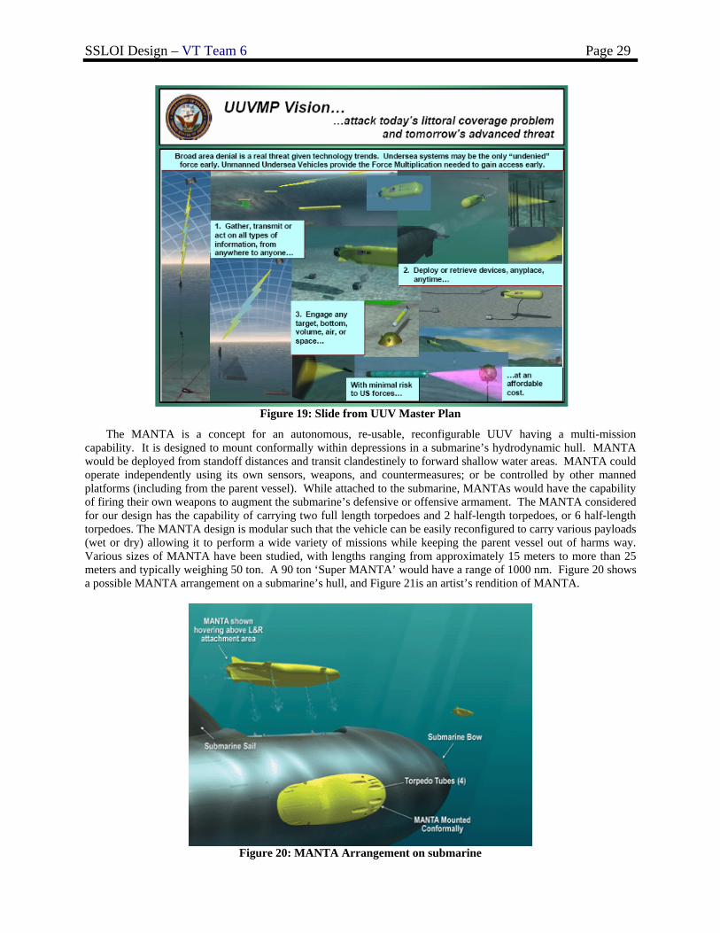
Unmanned Underwater Vehicles (UUVs) reduce personnel risk. Some UUVs are expendable and do not need to be recovered to obtain data from them. The US Navy’s 2004 UUV Master Plan stresses the importance of development and fielding advanced technologies, such as UUVs, to significantly contribute to the Navy’s control of the maritime battlespace. Figure 19 shows a slide from the UUV Master Plan. Using Sea Power 21 for guidance, the UUV Master Plan specifies nine Sub-Pillar capabilities that are identified and prioritized. These include:
1. Intelligence, Surveillance, and Reconnaisance 2. Mine Countermeasures 3. Anti-Submarine Warfare 4. Inspection/Identification 5. Oceanography 6. Communication / Navigation Network Node 7. Payload Delivery 8. Information Operations 9. Time Critical Strike
SSLOI Design – VT Team 6 Page 29
Figure 19: Slide from UUV Master Plan
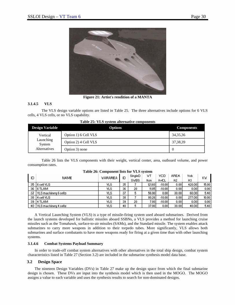
The MANTA is a concept for an autonomous, re-usable, reconfigurable UUV having a multi-mission capability. It is designed to mount conformally within depressions in a submarine’s hydrodynamic hull. MANTA would be deployed from standoff distances and transit clandestinely to forward shallow water areas. MANTA could operate independently using its own sensors, weapons, and countermeasures; or be controlled by other manned platforms (including from the parent vessel). While attached to the submarine, MANTAs would have the capability of firing their own weapons to augment the submarine’s defensive or offensive armament. The MANTA considered for our design has the capability of carrying two full length torpedoes and 2 half-length torpedoes, or 6 half-length torpedoes. The MANTA design is modular such that the vehicle can be easily reconfigured to carry various payloads (wet or dry) allowing it to perform a wide variety of missions while keeping the parent vessel out of harms way. Various sizes of MANTA have been studied, with lengths ranging from approximately 15 meters to more than 25 meters and typically weighing 50 ton. A 90 ton ‘Super MANTA’ would have a range of 1000 nm. Figure 20 shows a possible MANTA arrangement on a submarine’s hull, and Figure 21is an artist’s rendition of MANTA.
Figure 20: MANTA Arrangement on submarine
SSLOI Design – VT Team 6 Page 30
Figure 21: Artist's rendition of a MANTA
3.1.4.5 VLS
The VLS design variable options are listed in Table 25. The three alternatives include options for 6 VLS cells, 4 VLS cells, or no VLS capability.
Table 25: VLS system alternative components
0Option 3) none
37,38,39Option 2) 4 Cell VLS
34,35,36Option 1) 6 Cell VLSVertical Launching
System Alternatives
ComponentsOptionsDesign Variable
Table 26 lists the VLS components with their weight, vertical center, area, outboard volume, and power consumption rates.
Table 26: Component lists for VLS system
A Vertical Launching System (VLS) is a type of missile-firing system used aboard submarines. Derived from the launch systems developed for ballistic missiles aboard SSBNs, a VLS provides a method for launching cruise missiles such as the Tomahawk, surface-to-air missiles (SAMs), and the Standard missile. The system enables attack submarines to carry more weapons in addition to their torpedo tubes. More significantly, VLS allows both submarines and surface combatants to have more weapons ready for firing at a given time than with other launching systems.
3.1.4.6 Combat Systems Payload Summary
In order to trade-off combat system alternatives with other alternatives in the total ship design, combat system characteristics listed in Table 27 (Section 3.2) are included in the submarine synthesis model data base.
3.2 Design Space The nineteen Design Variables (DVs) in Table 27 make up the design space from which the final submarine
design is chosen. These DVs are input into the synthesis model which is then used in the MOGO. The MOGO assigns a value to each variable and uses the synthesis results to search for non-dominated designs.
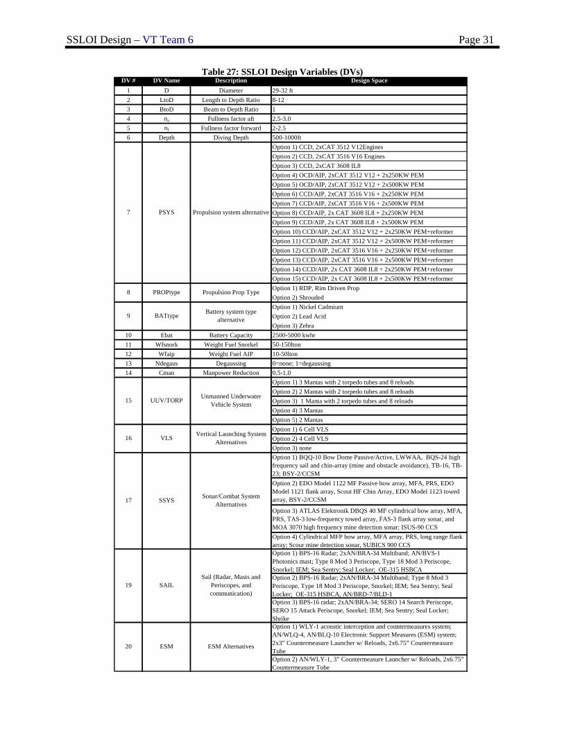
SSLOI Design – VT Team 6 Page 31
Table 27: SSLOI Design Variables (DVs) DV # DV Name Description Design Space
1 D Diameter 29-32 ft2 LtoD Length to Depth Ratio 8-123 BtoD Beam to Depth Ratio 14 na Fullness factor aft 2.5-3.05 nf Fullness factor forward 2-2.56 Depth Diving Depth 500-1000ft
Option 1) CCD, 2xCAT 3512 V12EnginesOption 2) CCD, 2xCAT 3516 V16 EnginesOption 3) CCD, 2xCAT 3608 IL8Option 4) OCD/AIP, 2xCAT 3512 V12 + 2x250KW PEMOption 5) OCD/AIP, 2xCAT 3512 V12 + 2x500KW PEMOption 6) CCD/AIP, 2xCAT 3516 V16 + 2x250KW PEMOption 7) CCD/AIP, 2xCAT 3516 V16 + 2x500KW PEMOption 8) CCD/AIP, 2x CAT 3608 IL8 + 2x250KW PEM Option 9) CCD/AIP, 2x CAT 3608 IL8 + 2x500KW PEM Option 10) CCD/AIP, 2xCAT 3512 V12 + 2x250KW PEM+reformerOption 11) CCD/AIP, 2xCAT 3512 V12 + 2x500KW PEM+reformerOption 12) CCD/AIP, 2xCAT 3516 V16 + 2x250KW PEM+reformerOption 13) CCD/AIP, 2xCAT 3516 V16 + 2x500KW PEM+reformerOption 14) CCD/AIP, 2x CAT 3608 IL8 + 2x250KW PEM+reformerOption 15) CCD/AIP, 2x CAT 3608 IL8 + 2x500KW PEM+reformerOption 1) RDP, Rim Driven PropOption 2) ShroudedOption 1) Nickel CadmiumOption 2) Lead AcidOption 3) Zebra
10 Ebat Battery Capacity 2500-5000 kwhr11 Wfsnork Weight Fuel Snorkel 50-150lton12 Wfaip Weight Fuel AIP 10-50lton13 Ndegaus Degaussing 0=none; 1=degaussing14 Cman Manpower Reduction 0.5-1.0
Option 1) 3 Mantas with 2 torpedo tubes and 8 reloadsOption 2) 2 Mantas with 2 torpedo tubes and 8 reloadsOption 3) 1 Manta with 2 torpedo tubes and 8 reloadsOption 4) 3 MantasOption 5) 2 MantasOption 1) 6 Cell VLSOption 2) 4 Cell VLSOption 3) noneOption 1) BQQ-10 Bow Dome Passive/Active, LWWAA, BQS-24 high frequency sail and chin-array (mine and obstacle avoidance), TB-16, TB-23; BSY-2/CCSMOption 2) EDO Model 1122 MF Passive bow array, MFA, PRS, EDO Model 1121 flank array, Scout HF Chin Array, EDO Model 1123 towed array, BSY-2/CCSM
Option 3) ATLAS Elektronik DBQS 40 MF cylindrical bow array, MFA, PRS, TAS-3 low-frequency towed array, FAS-3 flank array sonar, and MOA 3070 high frequency mine detection sonar; ISUS-90 CCSOption 4) Cylindrical MFP bow array, MFA array, PRS, long range flank array; Scour mine detection sonar, SUBICS 900 CCSOption 1) BPS-16 Radar; 2xAN/BRA-34 Multiband; AN/BVS-1 Photonics mast; Type 8 Mod 3 Periscope, Type 18 Mod 3 Periscope, Snorkel; IEM; Sea Sentry; Seal Locker; OE-315 HSBCAOption 2) BPS-16 Radar; 2xAN/BRA-34 Multiband; Type 8 Mod 3 Periscope, Type 18 Mod 3 Periscope, Snorkel; IEM; Sea Sentry; Seal Locker; OE-315 HSBCA, AN/BRD-7/BLD-1Option 3) BPS-16 radar; 2xAN/BRA-34; SERO 14 Search Periscope, SERO 15 Attack Periscope, Snorkel; IEM; Sea Sentry; Seal Locker; ShrikeOption 1) WLY-1 acoustic interception and countermeasures system; AN/WLQ-4, AN/BLQ-10 Electronic Support Measures (ESM) system; 2x3” Countermeasure Launcher w/ Reloads, 2x6.75” Countermeasure TubeOption 2) AN/WLY-1, 3” Countermeasure Launcher w/ Reloads, 2x6.75” Countermeasure Tube
Battery system type alternative9
16
17 SSYS
BATtype
7 PSYS Propulsion system alternative
8 PROPtype Propulsion Prop Type
Sonar/Combat System Alternatives
15 UUV/TORP Unmanned Underwater Vehicle System
20 ESM ESM Alternatives
VLS Vertical Launching System Alternatives
19 SAILSail (Radar, Masts and
Periscopes, and communication)
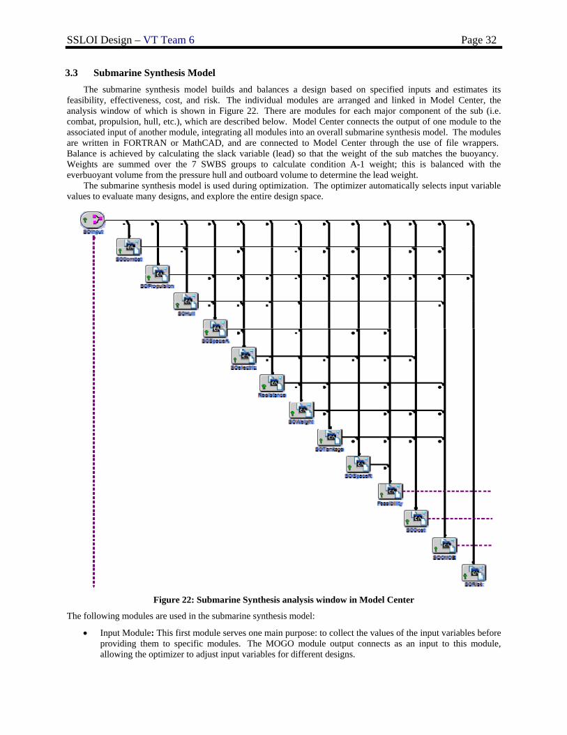
SSLOI Design – VT Team 6 Page 32
3.3 Submarine Synthesis Model The submarine synthesis model builds and balances a design based on specified inputs and estimates its
feasibility, effectiveness, cost, and risk. The individual modules are arranged and linked in Model Center, the analysis window of which is shown in Figure 22. There are modules for each major component of the sub (i.e. combat, propulsion, hull, etc.), which are described below. Model Center connects the output of one module to the associated input of another module, integrating all modules into an overall submarine synthesis model. The modules are written in FORTRAN or MathCAD, and are connected to Model Center through the use of file wrappers. Balance is achieved by calculating the slack variable (lead) so that the weight of the sub matches the buoyancy. Weights are summed over the 7 SWBS groups to calculate condition A-1 weight; this is balanced with the everbuoyant volume from the pressure hull and outboard volume to determine the lead weight.
The submarine synthesis model is used during optimization. The optimizer automatically selects input variable values to evaluate many designs, and explore the entire design space.
Figure 22: Submarine Synthesis analysis window in Model Center
The following modules are used in the submarine synthesis model:
• Input Module: This first module serves one main purpose: to collect the values of the input variables before providing them to specific modules. The MOGO module output connects as an input to this module, allowing the optimizer to adjust input variables for different designs.
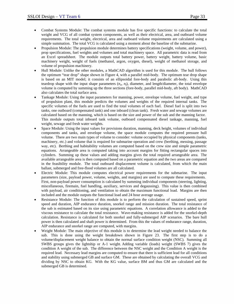
SSLOI Design – VT Team 6 Page 33
• Combat Systems Module: The combat systems module has five specific functions: to calculate the total weight and VCG of all combat system components, as well as their electrical, area, and outboard volume requirements. The total weight, electrical, area and outboard volume requirements are calculated using a simple summation. The total VCG is calculated using a moment about the baseline of the submarine.
• Propulsion Module: The propulsion module determines battery specifications (weight, volume, and power), prop specifications, fuel weights and volumes and total machinery space. All parametric data is read from an Excel spreadsheet. The module outputs total battery power, battery weight, battery volume, basic machinery weight, weight of fuels (methanol, argon, oxygen, diesel), weight of methanol storage, and volume of propulsion machinery.
• Hull Module: Unlike the other modules, a MathCAD algorithm is used for this module. The hull follows the optimum “tear drop” shape shown in Figure 4, with a parallel mid-body. The optimum tear drop shape is based on an MIT model; it consists of an ellipsoidal fore-body and parabolic aft-body. Using this teardrop shape with the input shape parameters (na, nf), diameter, and length/diameter, the total envelope volume is computed by summing up the three sections (fore-body, parallel mid-body, aft body). MathCAD also calculates the total surface area.
• Tankage Module: Using the input parameters for manning, power, envelope volume, fuel weight, and type of propulsion plant, this module predicts the volumes and weights of the required internal tanks. The specific volumes of the fuels are used to find the total volumes of each fuel. Diesel fuel is split into two tanks, one outboard (compensated tank) and one inboard (clean tank). Fresh water and sewage volumes are calculated based on the manning, which is based on the size and power of the sub and the manning factor. This module outputs total inboard tank volume, outboard compensated diesel tankage, manning, fuel weight, sewage and fresh water weights.
• Space Module: Using the input values for provisions duration, manning, deck height, volumes of individual components and tanks, and envelope volume, the space module computes the required pressure hull volume. There are two main types of volume to consider: volume occupied by physical components (tanks, machinery, etc.) and volume that is required for submarine operation and crew (berthing, messing, passage way, etc). Berthing and habitability volumes are computed based on the crew size and simple parametric equations. Arrangeable area is computed taking into account margins for fitting rectangular spaces into cylinders. Summing up these values and adding margins gives the total required arrangeable area. The available arrangeable area is then computed based on a parametric equation and the two areas are compared in the feasibility module. The total outboard displacement volume is calculated, from which the main ballast, submerged and free-flood volumes are all calculated.
• Electric Module: This module computes electrical power requirements for the submarine. The input parameters (size, payload power, volume, weights, and margins) are used to compute these requirements. First, non-payload power consumption is calculated by summing individual components (steering, lighting, miscellaneous, firemain, fuel handling, auxiliary, services and degaussing). This value is then combined with payload, air conditioning, and ventilation to obtain the maximum functional load. Margins are then included and the module outputs the functional load and 24 hour average usage.
• Resistance Module: The function of this module is to perform the calculation of sustained speed, sprint speed and duration, AIP endurance duration, snorkel range and mission duration. The total resistance of the sub is estimated based on its size using parametric equations. A correlation allowance is added to the viscous resistance to calculate the total resistance. Wave-making resistance is added for the snorkel-depth calculation. Resistance is calculated for both snorkel and fully-submerged AIP scenarios. The bare hull power is then calculated and shaft power is determined. From this the values of endurance range, duration, AIP endurance and snorkel range are computed, with margins.
• Weight Module: The main objective of this module is to determine the lead weight needed to balance the sub. This is done using the weight breakdown shown in Figure 23. The first step is to do a volume/displacement weight balance to obtain the normal surface condition weight (NSC). Summing all SWBS groups gives the lightship or A-1 weight. Adding variable (loads) weight (SWBS 7) gives the condition A weight of the sub. The difference between the NSC weight and the Condition A weight is the required lead. Necessary lead margins are computed to ensure that there is sufficient lead for all conditions and stability using submerged GB and surface GM. These are obtained by calculating the overall VCG and dividing by NSC to obtain KG. With the KG value, surface BM and thus GM are calculated and the submerged GB is determined.
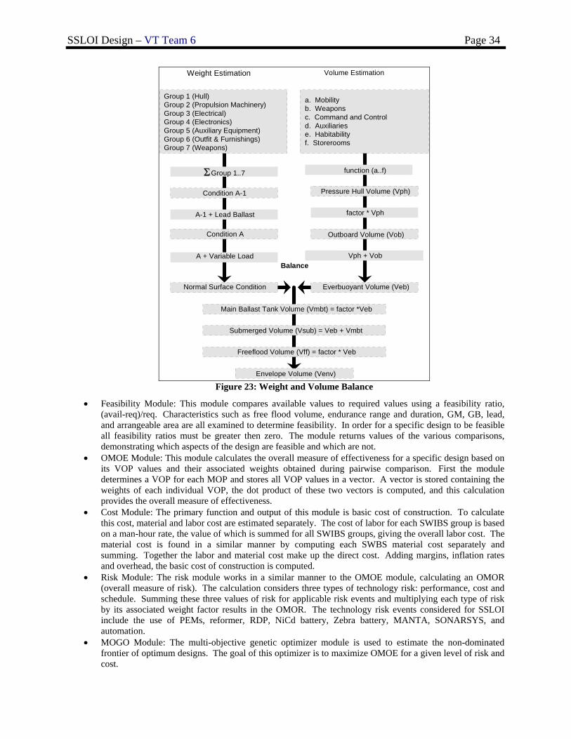
SSLOI Design – VT Team 6 Page 34
Weight Estimation Volume Estimation
Group 1 (Hull)Group 2 (Propulsion Machinery)Group 3 (Electrical)Group 4 (Electronics)Group 5 (Auxiliary Equipment)Group 6 (Outfit & Furnishings)Group 7 (Weapons)
Condition A-1
ΣGroup 1..7
A-1 + Lead Ballast
Condition A
A + Variable Load
a. Mobilityb. Weaponsc. Command and Controld. Auxiliariese. Habitabilityf. Storerooms
function (a..f)
Pressure Hull Volume (Vph)
factor * Vph
Outboard Volume (Vob)
Vph + Vob
Normal Surface Condition Everbuoyant Volume (Veb)
Balance
Envelope Volume (Venv)
Main Ballast Tank Volume (Vmbt) = factor *Veb
Submerged Volume (Vsub) = Veb + Vmbt
Freeflood Volume (Vff) = factor * Veb
Figure 23: Weight and Volume Balance
• Feasibility Module: This module compares available values to required values using a feasibility ratio, (avail-req)/req. Characteristics such as free flood volume, endurance range and duration, GM, GB, lead, and arrangeable area are all examined to determine feasibility. In order for a specific design to be feasible all feasibility ratios must be greater then zero. The module returns values of the various comparisons, demonstrating which aspects of the design are feasible and which are not.
• OMOE Module: This module calculates the overall measure of effectiveness for a specific design based on its VOP values and their associated weights obtained during pairwise comparison. First the module determines a VOP for each MOP and stores all VOP values in a vector. A vector is stored containing the weights of each individual VOP, the dot product of these two vectors is computed, and this calculation provides the overall measure of effectiveness.
• Cost Module: The primary function and output of this module is basic cost of construction. To calculate this cost, material and labor cost are estimated separately. The cost of labor for each SWIBS group is based on a man-hour rate, the value of which is summed for all SWIBS groups, giving the overall labor cost. The material cost is found in a similar manner by computing each SWBS material cost separately and summing. Together the labor and material cost make up the direct cost. Adding margins, inflation rates and overhead, the basic cost of construction is computed.
• Risk Module: The risk module works in a similar manner to the OMOE module, calculating an OMOR (overall measure of risk). The calculation considers three types of technology risk: performance, cost and schedule. Summing these three values of risk for applicable risk events and multiplying each type of risk by its associated weight factor results in the OMOR. The technology risk events considered for SSLOI include the use of PEMs, reformer, RDP, NiCd battery, Zebra battery, MANTA, SONARSYS, and automation.
• MOGO Module: The multi-objective genetic optimizer module is used to estimate the non-dominated frontier of optimum designs. The goal of this optimizer is to maximize OMOE for a given level of risk and cost.
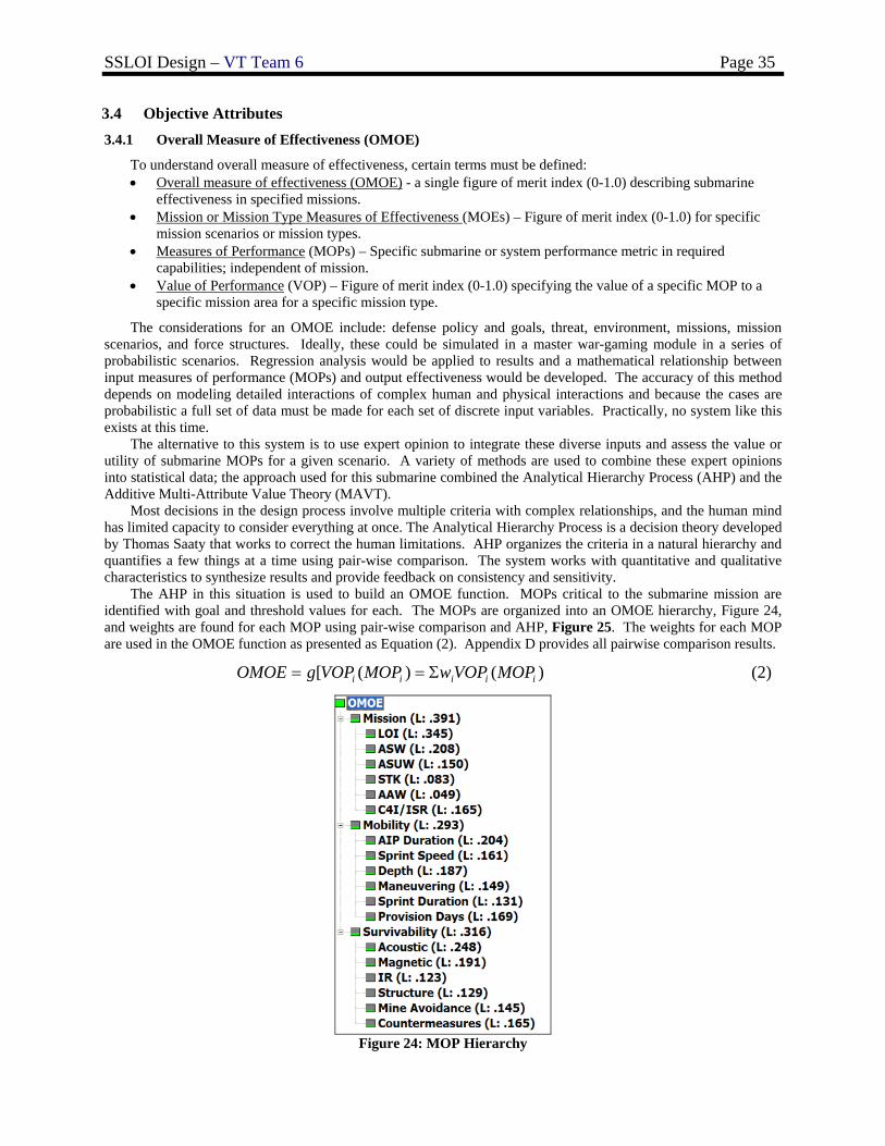
SSLOI Design – VT Team 6 Page 35
3.4 Objective Attributes 3.4.1 Overall Measure of Effectiveness (OMOE)
To understand overall measure of effectiveness, certain terms must be defined: • Overall measure of effectiveness (OMOE) - a single figure of merit index (0-1.0) describing submarine
effectiveness in specified missions. • Mission or Mission Type Measures of Effectiveness (MOEs) – Figure of merit index (0-1.0) for specific
mission scenarios or mission types. • Measures of Performance (MOPs) – Specific submarine or system performance metric in required
capabilities; independent of mission. • Value of Performance (VOP) – Figure of merit index (0-1.0) specifying the value of a specific MOP to a
specific mission area for a specific mission type.
The considerations for an OMOE include: defense policy and goals, threat, environment, missions, mission scenarios, and force structures. Ideally, these could be simulated in a master war-gaming module in a series of probabilistic scenarios. Regression analysis would be applied to results and a mathematical relationship between input measures of performance (MOPs) and output effectiveness would be developed. The accuracy of this method depends on modeling detailed interactions of complex human and physical interactions and because the cases are probabilistic a full set of data must be made for each set of discrete input variables. Practically, no system like this exists at this time.
The alternative to this system is to use expert opinion to integrate these diverse inputs and assess the value or utility of submarine MOPs for a given scenario. A variety of methods are used to combine these expert opinions into statistical data; the approach used for this submarine combined the Analytical Hierarchy Process (AHP) and the Additive Multi-Attribute Value Theory (MAVT).
Most decisions in the design process involve multiple criteria with complex relationships, and the human mind has limited capacity to consider everything at once. The Analytical Hierarchy Process is a decision theory developed by Thomas Saaty that works to correct the human limitations. AHP organizes the criteria in a natural hierarchy and quantifies a few things at a time using pair-wise comparison. The system works with quantitative and qualitative characteristics to synthesize results and provide feedback on consistency and sensitivity.
The AHP in this situation is used to build an OMOE function. MOPs critical to the submarine mission are identified with goal and threshold values for each. The MOPs are organized into an OMOE hierarchy, Figure 24, and weights are found for each MOP using pair-wise comparison and AHP, Figure 25. The weights for each MOP are used in the OMOE function as presented as Equation (2). Appendix D provides all pairwise comparison results.
)()([ iiiii MOPVOPwMOPVOPgOMOE Σ== (2)
Figure 24: MOP Hierarchy
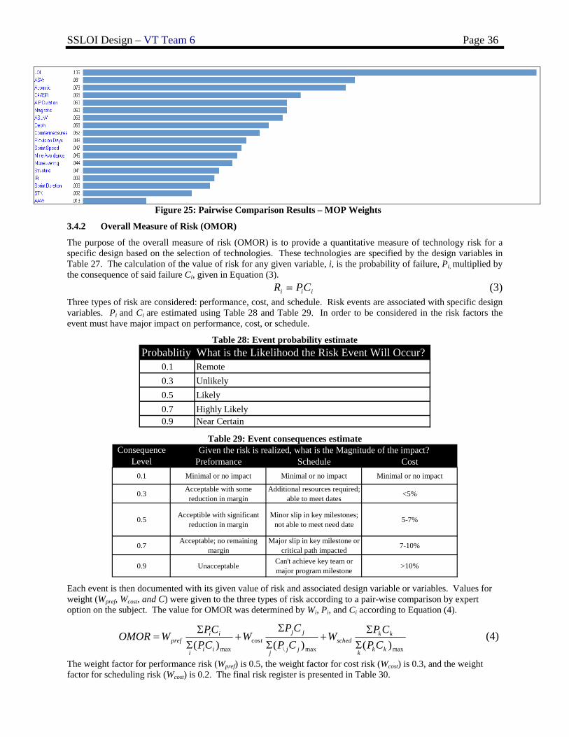
SSLOI Design – VT Team 6 Page 36
Figure 25: Pairwise Comparison Results – MOP Weights
3.4.2 Overall Measure of Risk (OMOR)
The purpose of the overall measure of risk (OMOR) is to provide a quantitative measure of technology risk for a specific design based on the selection of technologies. These technologies are specified by the design variables in Table 27. The calculation of the value of risk for any given variable, i, is the probability of failure, Pi, multiplied by the consequence of said failure Ci, given in Equation (3).
iii CPR = (3) Three types of risk are considered: performance, cost, and schedule. Risk events are associated with specific design variables. Pi and Ci are estimated using Table 28 and Table 29. In order to be considered in the risk factors the event must have major impact on performance, cost, or schedule.
Table 28: Event probability estimate Probablitiy What is the Likelihood the Risk Event Will Occur?
0.1 Remote0.3 Unlikely0.5 Likely0.7 Highly Likely0.9 Near Certain
Table 29: Event consequences estimate
Preformance Schedule Cost0.1 Minimal or no impact Minimal or no impact Minimal or no impact
0.3 Acceptable with some reduction in margin
Additional resources required; able to meet dates <5%
0.5 Acceptible with significant reduction in margin
Minor slip in key milestones; not able to meet need date 5-7%
0.7 Acceptable; no remaining margin
Major slip in key milestone or critical path impacted 7-10%
0.9 Unacceptable Can't achieve key team or major program milestone >10%
Given the risk is realized, what is the Magnitude of the impact?Consequence Level
Each event is then documented with its given value of risk and associated design variable or variables. Values for weight (Wpref, Wcost, and C) were given to the three types of risk according to a pair-wise comparison by expert option on the subject. The value for OMOR was determined by Wi, Pi, and Ci according to Equation (4).
maxmax\cos
max )()()( kkk
kksched
jjj
jjt
iii
iipref CP
CPWCPCP
WCP
CPWOMORΣΣ
+Σ
Σ+
ΣΣ
= (4)
The weight factor for performance risk (Wpref) is 0.5, the weight factor for cost risk (Wcost) is 0.3, and the weight factor for scheduling risk (Wcost) is 0.2. The final risk register is presented in Table 30.
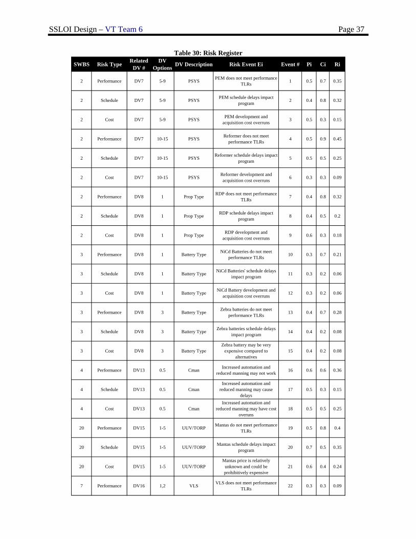
SSLOI Design – VT Team 6 Page 37
Table 30: Risk Register SWBS Risk Type Related
DV #DV
Options DV Description Risk Event Ei Event # Pi Ci Ri
2 Performance DV7 5-9 PSYS PEM does not meet performance TLRs 1 0.5 0.7 0.35
2 Schedule DV7 5-9 PSYS PEM schedule delays impact program 2 0.4 0.8 0.32
2 Cost DV7 5-9 PSYS PEM development and acquisition cost overruns 3 0.5 0.3 0.15
2 Performance DV7 10-15 PSYS Reformer does not meet performance TLRs 4 0.5 0.9 0.45
2 Schedule DV7 10-15 PSYS Reformer schedule delays impact program 5 0.5 0.5 0.25
2 Cost DV7 10-15 PSYS Reformer development and acquisition cost overruns 6 0.3 0.3 0.09
2 Performance DV8 1 Prop Type RDP does not meet performance TLRs 7 0.4 0.8 0.32
2 Schedule DV8 1 Prop Type RDP schedule delays impact program 8 0.4 0.5 0.2
2 Cost DV8 1 Prop Type RDP development and acquisition cost overruns 9 0.6 0.3 0.18
3 Performance DV8 1 Battery Type NiCd Batteries do not meet performance TLRs 10 0.3 0.7 0.21
3 Schedule DV8 1 Battery Type NiCd Batteries' schedule delays impact program 11 0.3 0.2 0.06
3 Cost DV8 1 Battery Type NiCd Battery development and acquisition cost overruns 12 0.3 0.2 0.06
3 Performance DV8 3 Battery Type Zebra batteries do not meet performance TLRs 13 0.4 0.7 0.28
3 Schedule DV8 3 Battery Type Zebra batteries schedule delays impact program 14 0.4 0.2 0.08
3 Cost DV8 3 Battery TypeZebra battery may be very
expensive compared to alternatives
15 0.4 0.2 0.08
4 Performance DV13 0.5 Cman Increased automation and reduced manning may not work 16 0.6 0.6 0.36
4 Schedule DV13 0.5 CmanIncreased automation and
reduced manning may cause delays
17 0.5 0.3 0.15
4 Cost DV13 0.5 CmanIncreased automation and
reduced manning may have cost overuns
18 0.5 0.5 0.25
20 Performance DV15 1-5 UUV/TORP Mantas do not meet performance TLRs 19 0.5 0.8 0.4
20 Schedule DV15 1-5 UUV/TORP Mantas schedule delays impact program 20 0.7 0.5 0.35
20 Cost DV15 1-5 UUV/TORPMantas price is relatively
unknown and could be prohibitively expensive
21 0.6 0.4 0.24
7 Performance DV16 1,2 VLS VLS does not meet performance TLRs 22 0.3 0.3 0.09
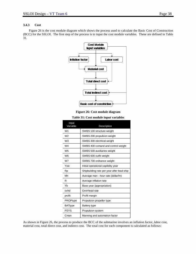
SSLOI Design – VT Team 6 Page 38
3.4.3 Cost
Figure 26 is the cost module diagram which shows the process used to calculate the Basic Cost of Construction (BCC) for the SSLOI. The first step of the process is to input the cost module variables. These are defined in Table 31.
Figure 26: Cost module diagram
Table 31: Cost module input variables
Manning and automation factorCman
Propulsion systemPSYS
Battery typeBATtype
Propulsion propeller typePROPtype
Profit marginprofit
Overhead rateovhd
Base year (appropriation)Yb
Average inflation rateR
Average man - hour rate (dollar/hr)Mh
Shipbuilding rate per year after lead shipRp
Initial operational capibility yearYoic
SWBS 700 ordnance weightW7
SWBS 600 outfit weightW6
SWBS 500 auxiliaries weightW5
SWBS 400 comand and control weightW4
SWBS 300 electrical weightW3
SWBS 200 propulsion weightW2
SWBS 100 structure weightW1
DescriptionInput
Variable
As shown in Figure 26, the process to produce the BCC of the submarine involves an inflation factor, labor cost, material cost, total direct cost, and indirect cost. The total cost for each component is calculated as follows:
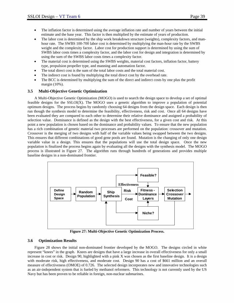
SSLOI Design – VT Team 6 Page 39
• The inflation factor is determined using the average inflation rate and number of years between the initial estimate and the base year. This factor is then multiplied by the estimate of years of production.
• The labor cost is determined by the ship work breakdown structure (weights), complexity factors, and man-hour rate. The SWBS 100-700 labor cost is determined by multiplying the man-hour rate by the SWBS weight and the complexity factor. Labor cost for production support is determined by using the sum of SWBS labor costs times a complexity factor, and the labor cost for design and integration is determined by using the sum of the SWBS labor costs times a complexity factor.
• The material cost is determined using the SWBS weights, material cost factors, inflation factor, battery type, propulsion propeller type, and manning and automation factor.
• The total direct cost is the sum of the total labor costs and the total material cost. • The indirect cost is found by multiplying the total direct cost by the overhead rate. • The BCC is determined by multiplying the sum of the direct and indirect costs by one plus the profit
margin (10%).
3.5 Multi-Objective Genetic Optimization A Multi-Objective Genetic Optimization (MOGO) is used to search the design space to develop a set of optimal
feasible designs for the SSLOI(X). The MOGO uses a genetic algorithm to improve a population of potential optimum designs. The process begins by randomly choosing 64 designs from the design space. Each design is then run though the synthesis model to determine the feasibility, effectiveness, risk and cost. Once all 64 designs have been evaluated they are compared to each other to determine their relative dominance and assigned a probability of selection value. Dominance is defined as the design with the best effectiveness, for a given cost and risk. At this point a new population is chosen based on the dominance and probability values. To ensure that the new population has a rich combination of genetic material two processes are performed on the population: crossover and mutation. Crossover is the merging of two designs with half of the variable values being swapped between the two designs. This ensures that different combinations of good gene pools are found. Mutation is the changing of only one design variable value in a design. This ensures that the populations will use the total design space. Once the new population is finalized the process begins again by evaluating all the designs with the synthesis model. The MOGO process is illustrated in Figure 27. The algorithm runs through hundreds of generations and provides multiple baseline designs in a non-dominated frontier.
DefineSolution
Space
RandomPopulation
ShipSynthesis
Feasible?
Niche?
Fitness -Dominance
Layers
SelectionCrossoverMutation
Risk
Cost
EffectivenessDefine Design Space
Figure 27: Multi-Objective Genetic Optimization Process.
3.6 Optimization Results Figure 28 shows the initial non-dominated frontier developed by the MOGO. The designs circled in white
represent “knees” in the graph. Knees are designs that have a large increase in overall effectiveness for only a small increase in cost or risk. Design 90, highlighted with a pink X was chosen as the first baseline design. It is a design with moderate risk, high effectiveness, and moderate cost. Design 90 has a cost of $661 million and an overall measure of effectiveness (OMOE) of 0.726. The selected design incorporates new and innovative technologies such as an air-independent system that is fueled by methanol reformers. This technology is not currently used by the US Navy but has been proven to be reliable in foreign, non-nuclear submarines.
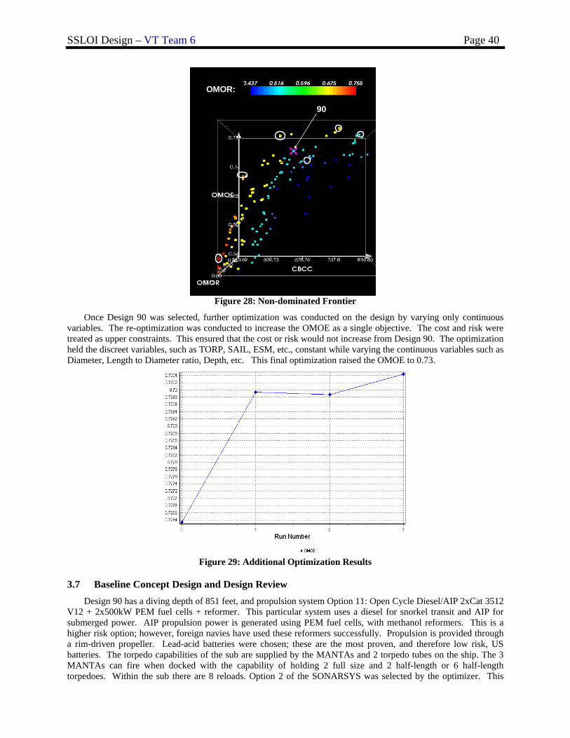
SSLOI Design – VT Team 6 Page 40
OMOR:
90
Figure 28: Non-dominated Frontier
Once Design 90 was selected, further optimization was conducted on the design by varying only continuous variables. The re-optimization was conducted to increase the OMOE as a single objective. The cost and risk were treated as upper constraints. This ensured that the cost or risk would not increase from Design 90. The optimization held the discreet variables, such as TORP, SAIL, ESM, etc., constant while varying the continuous variables such as Diameter, Length to Diameter ratio, Depth, etc. This final optimization raised the OMOE to 0.73.
Figure 29: Additional Optimization Results
3.7 Baseline Concept Design and Design Review Design 90 has a diving depth of 851 feet, and propulsion system Option 11: Open Cycle Diesel/AIP 2xCat 3512
V12 + 2x500kW PEM fuel cells + reformer. This particular system uses a diesel for snorkel transit and AIP for submerged power. AIP propulsion power is generated using PEM fuel cells, with methanol reformers. This is a higher risk option; however, foreign navies have used these reformers successfully. Propulsion is provided through a rim-driven propeller. Lead-acid batteries were chosen; these are the most proven, and therefore low risk, US batteries. The torpedo capabilities of the sub are supplied by the MANTAs and 2 torpedo tubes on the ship. The 3 MANTAs can fire when docked with the capability of holding 2 full size and 2 half-length or 6 half-length torpedoes. Within the sub there are 8 reloads. Option 2 of the SONARSYS was selected by the optimizer. This
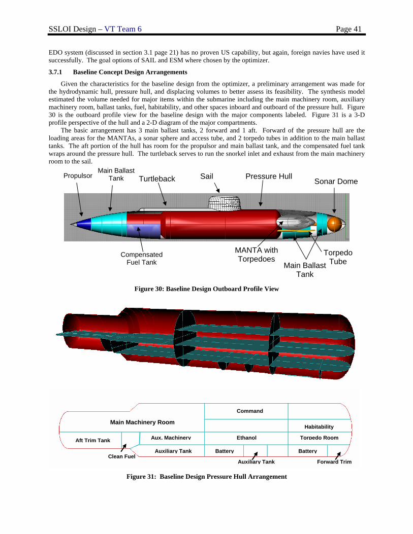
SSLOI Design – VT Team 6 Page 41
EDO system (discussed in section 3.1 page 21) has no proven US capability, but again, foreign navies have used it successfully. The goal options of SAIL and ESM where chosen by the optimizer.
3.7.1 Baseline Concept Design Arrangements
Given the characteristics for the baseline design from the optimizer, a preliminary arrangement was made for the hydrodynamic hull, pressure hull, and displacing volumes to better assess its feasibility. The synthesis model estimated the volume needed for major items within the submarine including the main machinery room, auxiliary machinery room, ballast tanks, fuel, habitability, and other spaces inboard and outboard of the pressure hull. Figure 30 is the outboard profile view for the baseline design with the major components labeled. Figure 31 is a 3-D profile perspective of the hull and a 2-D diagram of the major compartments. The basic arrangement has 3 main ballast tanks, 2 forward and 1 aft. Forward of the pressure hull are the loading areas for the MANTAs, a sonar sphere and access tube, and 2 torpedo tubes in addition to the main ballast tanks. The aft portion of the hull has room for the propulsor and main ballast tank, and the compensated fuel tank wraps around the pressure hull. The turtleback serves to run the snorkel inlet and exhaust from the main machinery room to the sail.
Figure 30: Baseline Design Outboard Profile View
Figure 31: Baseline Design Pressure Hull Arrangement
Propulsor SailTurtleback Main Ballast
Tank
Compensated Fuel Tank
Sonar Dome
Torpedo Tube
MANTA with Torpedoes
Pressure Hull
Main Ballast Tank
Main Machinery Room
Battery
Aux. Machinery
Battery Auxiliary Tank
Forward Trim Clean Fuel
Torpedo Room
Habitability
Command
Aft Trim Tank
Auxiliary Tank
Ethanol
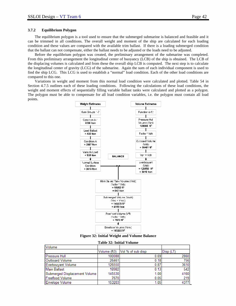
SSLOI Design – VT Team 6 Page 42
3.7.2 Equilibrium Polygon
The equilibrium polygon is a tool used to ensure that the submerged submarine is balanced and feasible and it can be trimmed in all conditions. The overall weight and moment of the ship are calculated for each loading condition and these values are compared with the available trim ballast. If there is a loading submerged condition that the ballast can not compensate, either the ballast needs to be adjusted or the loads need to be adjusted.
Before the equilibrium polygon was created, the preliminary arrangement of the submarine was completed. From this preliminary arrangement the longitudinal center of buoyancy (LCB) of the ship is obtained. The LCB of the displacing volumes is calculated and from these the overall ship LCB is computed. The next step is to calculate the longitudinal center of gravity (LCG) of the submarine. Again the sum of each individual component is used to find the ship LCG. This LCG is used to establish a “normal” load condition. Each of the other load conditions are compared to this one. Variations in weight and moment from this normal load condition were calculated and plotted. Table 54 in Section 4.7.5 outlines each of these loading conditions. Following the calculations of these load conditions, the weight and moment effects of sequentially filling variable ballast tanks were calculated and plotted as a polygon. The polygon must be able to compensate for all load condition variables, i.e. the polygon must contain all load points.
Figure 32: Initial Weight and Volume Balance
Table 32: Initial Volume
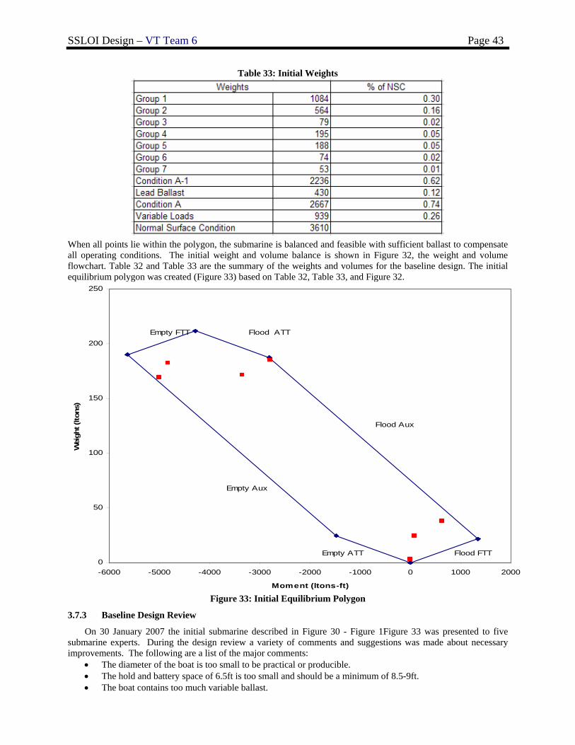
SSLOI Design – VT Team 6 Page 43
Table 33: Initial Weights
When all points lie within the polygon, the submarine is balanced and feasible with sufficient ballast to compensate all operating conditions. The initial weight and volume balance is shown in Figure 32, the weight and volume flowchart. Table 32 and Table 33 are the summary of the weights and volumes for the baseline design. The initial equilibrium polygon was created (Figure 33) based on Table 32, Table 33, and Figure 32.
0
50
100
150
200
250
-6000 -5000 -4000 -3000 -2000 -1000 0 1000 2000
Moment (ltons-ft)
Wei
ght (
ltons
)
Flood FTT
Flood Aux
Flood ATTEmpty FTT
Empty Aux
Empty ATT
Figure 33: Initial Equilibrium Polygon
3.7.3 Baseline Design Review
On 30 January 2007 the initial submarine described in Figure 30 - Figure 1Figure 33 was presented to five submarine experts. During the design review a variety of comments and suggestions was made about necessary improvements. The following are a list of the major comments:
• The diameter of the boat is too small to be practical or producible. • The hold and battery space of 6.5ft is too small and should be a minimum of 8.5-9ft. • The boat contains too much variable ballast.
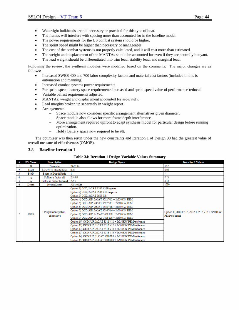
SSLOI Design – VT Team 6 Page 44
• Watertight bulkheads are not necessary or practical for this type of boat. • The frames will interfere with spacing more than accounted for in the baseline model. • The power requirements for the US combat system should be higher. • The sprint speed might be higher than necessary or manageable. • The cost of the combat systems is not properly calculated, and it will cost more than estimated. • The weight and displacement of the MANTAs should be accounted for even if they are neutrally buoyant. • The lead weight should be differentiated into trim lead, stability lead, and marginal lead.
Following the review, the synthesis modules were modified based on the comments. The major changes are as follows:
• Increased SWBS 400 and 700 labor complexity factors and material cost factors (included in this is automation and manning)
• Increased combat systems power requirements. • For sprint speed: battery space requirements increased and sprint speed value of performance reduced. • Variable ballast requirements adjusted. • MANTAs: weight and displacement accounted for separately. • Lead margins broken up separately in weight report. • Arrangements:
– Space module now considers specific arrangement alternatives given diameter. – Space module also allows for more frame depth interference. – More arrangement required upfront to adapt synthesis model for particular design before running
optimization. – Hold / Battery space now required to be 9ft.
The optimizer was then rerun under the new constraints and Iteration 1 of Design 90 had the greatest value of overall measure of effectiveness (OMOE).
3.8 Baseline Iteration 1 Table 34: Iteration 1 Design Variable Values Summary
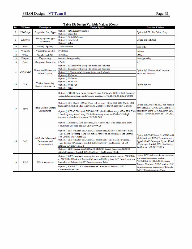
SSLOI Design – VT Team 6 Page 45
Table 35: Design Variable Values (Cont)
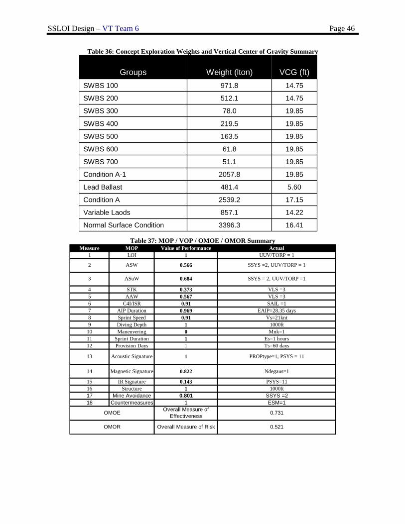
SSLOI Design – VT Team 6 Page 46
Table 36: Concept Exploration Weights and Vertical Center of Gravity Summary
16.413396.3Normal Surface Condition
14.22857.1Variable Laods
17.152539.2Condition A
5.60481.4Lead Ballast
19.852057.8Condition A-1
19.8551.1SWBS 700
19.8561.8SWBS 600
19.85163.5SWBS 500
19.85219.5SWBS 400
19.8578.0SWBS 300
14.75512.1SWBS 200
14.75971.8SWBS 100
VCG (ft)Weight (lton)Groups
Table 37: MOP / VOP / OMOE / OMOR Summary
Measure MOP Value of Performance Actual1 LOI 1 UUV/TORP = 1
4 STK 0.373 VLS =35 AAW 0.567 VLS =36 C4I/ISR 0.91 SAIL =17 AIP Duration 0.969 EAIP=28.35 days8 Sprint Speed 0.91 Vs=21knt9 Diving Depth 1 1000ft
10 Maneuvering 0 Mnk=111 Sprint Duration 1 Es=1 hours12 Provision Days 1 Ts=60 days
14 Magnetic Signature 0.822 Ndegaus=1
15 IR Signature 0.143 PSYS=1116 Structure 1 1000ft17 Mine Avoidance 0.801 SSYS =218 Countermeasures 1 ESM=1
Acoustic Signature
OMOE
0.5662 ASW
3 ASuW 0.684
0.521Overall Measure of RiskOMOR
SSYS =2, UUV/TORP = 1
SSYS = 2, UUV/TORP =1
PROPtype=1, PSYS = 111
Overall Measure of Effectiveness 0.731
13
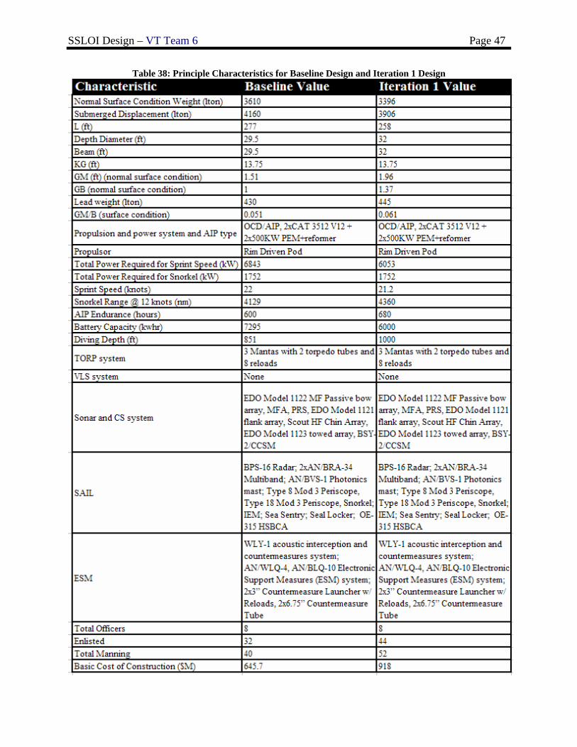
SSLOI Design – VT Team 6 Page 47
Table 38: Principle Characteristics for Baseline Design and Iteration 1 Design
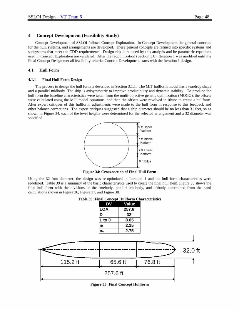
SSLOI Design – VT Team 6 Page 48
4 Concept Development (Feasibility Study)
Concept Development of SSLOI follows Concept Exploration. In Concept Development the general concepts for the hull, systems, and arrangements are developed. These general concepts are refined into specific systems and subsystems that meet the CDD requirements. Design risk is reduced by this analysis and he parametric equations used in Concept Exploration are validated. After the reoptimization (Section 3.8), Iteration 1 was modified until the Final Concept Design met all feasibility criteria. Concept Development starts with the Iteration 1 design.
4.1 Hull Form
4.1.1 Final Hull Form Design
The process to design the hull form is described in Section 3.1.1. The MIT hullform model has a teardrop shape and a parallel midbody. The ship is axisymmetric to improve producibility and dynamic stability. To produce the hull form the baseline characteristics were taken from the multi-objective genetic optimization (MOGO), the offsets were calculated using the MIT model equations, and then the offsets were revolved in Rhino to create a hullform. After expert critiques of this hullform, adjustments were made to the hull form in response to this feedback and other balance corrections. The expert critiques suggested that a ship diameter should be no less than 31 feet, so as shown in Figure 34, each of the level heights were determined for the selected arrangement and a 32 diameter was specified.
7 ft MiddlePlatform
7 ft LowerPlatform
9 ft UpperPlatform
9 ft Bilge
Figure 34: Cross-section of Final Hull Form
Using the 32 foot diameter, the design was re-optimized in Iteration 1 and the hull form characteristics were redefined. Table 39 is a summary of the basic characteristics used to create the final hull form. Figure 35 shows the final hull form with the divisions of the forebody, parallel midbody, and aftbody determined from the hand calculations shown in Figure 36, Figure 37, and Figure 38.
Table 39: Final Concept Hullform Characteristics DV Value
LOA 257.6’D 32’L to D 8.05nf 2.15na 2.75
65.6 ft115.2 ft 76.8 ft
257.6 ft
32.0 ft
65.6 ft115.2 ft 76.8 ft
257.6 ft
32.0 ft
Figure 35: Final Concept Hullform
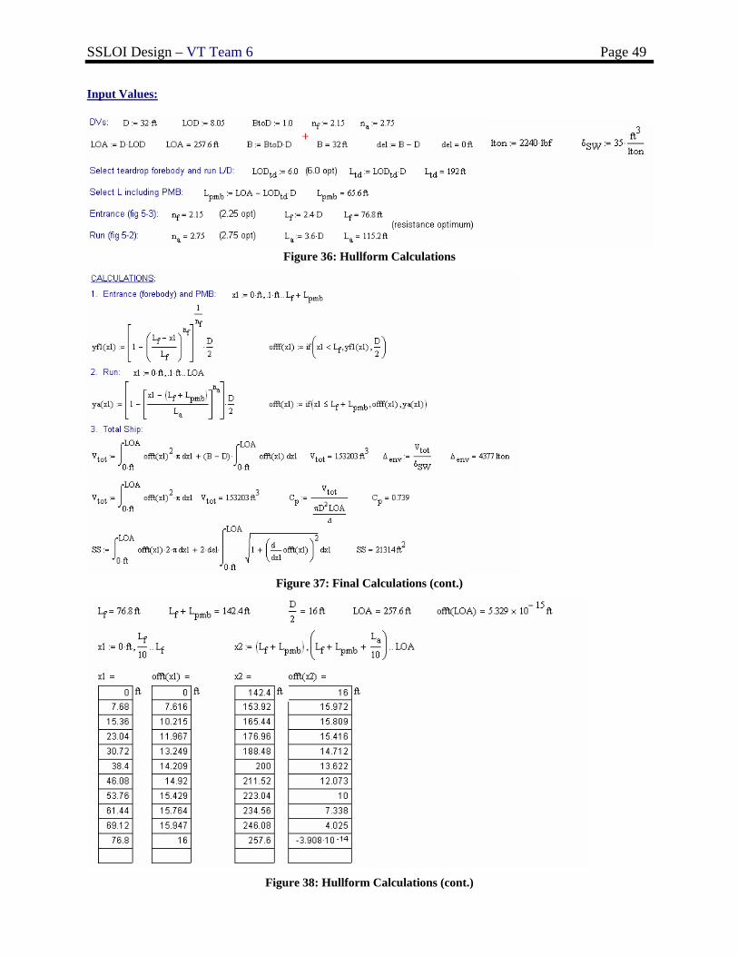
SSLOI Design – VT Team 6 Page 49
Input Values:
Figure 36: Hullform Calculations
Figure 37: Final Calculations (cont.)
Figure 38: Hullform Calculations (cont.)
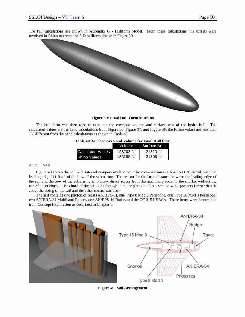
SSLOI Design – VT Team 6 Page 50
The full calculations are shown in Appendix G - Hullform Model. From these calculations, the offsets were revolved in Rhino to create the 3-D hullform shown in Figure 39.
Figure 39: Final Hull Form in Rhino
The hull form was then used to calculate the envelope volume and surface area of the hydro hull. The calculated values are the hand calculations from Figure 36, Figure 37, and Figure 38; the Rhino values are less than 1% different from the hand calculations as shown in Table 40.
Table 40: Surface Area and Volume for Final Hull form Volume Surface Area
Calculated Values 153203 ft3 21310 ft2
Rhino Values 153188 ft3 21506 ft2 4.1.2 Sail
Figure 40 shows the sail with internal components labeled. The cross-section is a NACA 0020 airfoil, with the leading edge 111 ft aft of the bow of the submarine. The reason for the large distance between the leading edge of the sail and the bow of the submarine is to allow direct access from the machinery room to the snorkel without the use of a turtleback. The chord of the sail is 31 feet while the height is 21 feet. Section 4.9.2 presents further details about the sizing of the sail and the other control surfaces.
The sail contains one photonics mast (AN/BVS-1), one Type 8 Mod 3 Periscope, one Type 18 Mod 3 Periscope, two AN/BRA-34 Multiband Radars, one AN/BPS-16 Radar, and the OE 315 HSBCA. These items were determined from Concept Exploration as described in Chapter 3.
Figure 40: Sail Arrangement
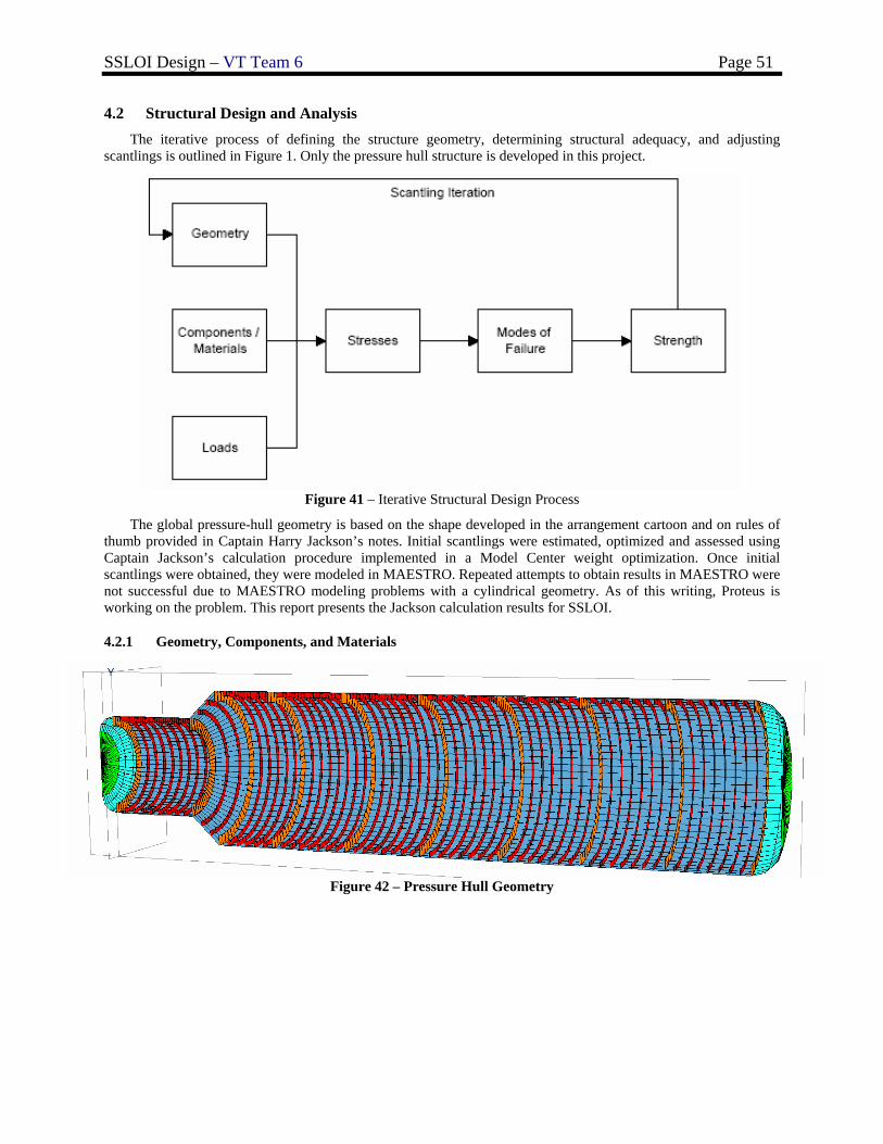
SSLOI Design – VT Team 6 Page 51
4.2 Structural Design and Analysis The iterative process of defining the structure geometry, determining structural adequacy, and adjusting
scantlings is outlined in Figure 1. Only the pressure hull structure is developed in this project.
Figure 41 – Iterative Structural Design Process
The global pressure-hull geometry is based on the shape developed in the arrangement cartoon and on rules of thumb provided in Captain Harry Jackson’s notes. Initial scantlings were estimated, optimized and assessed using Captain Jackson’s calculation procedure implemented in a Model Center weight optimization. Once initial scantlings were obtained, they were modeled in MAESTRO. Repeated attempts to obtain results in MAESTRO were not successful due to MAESTRO modeling problems with a cylindrical geometry. As of this writing, Proteus is working on the problem. This report presents the Jackson calculation results for SSLOI.
4.2.1 Geometry, Components, and Materials
Figure 42 – Pressure Hull Geometry
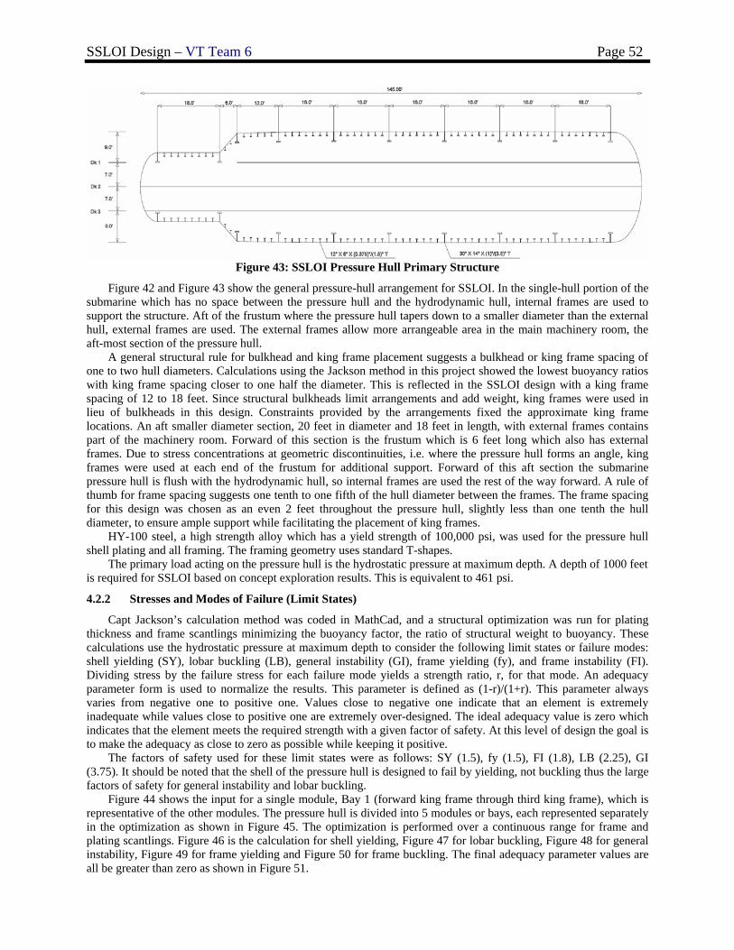
SSLOI Design – VT Team 6 Page 52
Figure 43: SSLOI Pressure Hull Primary Structure
Figure 42 and Figure 43 show the general pressure-hull arrangement for SSLOI. In the single-hull portion of the submarine which has no space between the pressure hull and the hydrodynamic hull, internal frames are used to support the structure. Aft of the frustum where the pressure hull tapers down to a smaller diameter than the external hull, external frames are used. The external frames allow more arrangeable area in the main machinery room, the aft-most section of the pressure hull. A general structural rule for bulkhead and king frame placement suggests a bulkhead or king frame spacing of one to two hull diameters. Calculations using the Jackson method in this project showed the lowest buoyancy ratios with king frame spacing closer to one half the diameter. This is reflected in the SSLOI design with a king frame spacing of 12 to 18 feet. Since structural bulkheads limit arrangements and add weight, king frames were used in lieu of bulkheads in this design. Constraints provided by the arrangements fixed the approximate king frame locations. An aft smaller diameter section, 20 feet in diameter and 18 feet in length, with external frames contains part of the machinery room. Forward of this section is the frustum which is 6 feet long which also has external frames. Due to stress concentrations at geometric discontinuities, i.e. where the pressure hull forms an angle, king frames were used at each end of the frustum for additional support. Forward of this aft section the submarine pressure hull is flush with the hydrodynamic hull, so internal frames are used the rest of the way forward. A rule of thumb for frame spacing suggests one tenth to one fifth of the hull diameter between the frames. The frame spacing for this design was chosen as an even 2 feet throughout the pressure hull, slightly less than one tenth the hull diameter, to ensure ample support while facilitating the placement of king frames. HY-100 steel, a high strength alloy which has a yield strength of 100,000 psi, was used for the pressure hull shell plating and all framing. The framing geometry uses standard T-shapes. The primary load acting on the pressure hull is the hydrostatic pressure at maximum depth. A depth of 1000 feet is required for SSLOI based on concept exploration results. This is equivalent to 461 psi.
4.2.2 Stresses and Modes of Failure (Limit States)
Capt Jackson’s calculation method was coded in MathCad, and a structural optimization was run for plating thickness and frame scantlings minimizing the buoyancy factor, the ratio of structural weight to buoyancy. These calculations use the hydrostatic pressure at maximum depth to consider the following limit states or failure modes: shell yielding (SY), lobar buckling (LB), general instability (GI), frame yielding (fy), and frame instability (FI). Dividing stress by the failure stress for each failure mode yields a strength ratio, r, for that mode. An adequacy parameter form is used to normalize the results. This parameter is defined as (1-r)/(1+r). This parameter always varies from negative one to positive one. Values close to negative one indicate that an element is extremely inadequate while values close to positive one are extremely over-designed. The ideal adequacy value is zero which indicates that the element meets the required strength with a given factor of safety. At this level of design the goal is to make the adequacy as close to zero as possible while keeping it positive. The factors of safety used for these limit states were as follows: SY (1.5), fy (1.5), FI (1.8), LB (2.25), GI (3.75). It should be noted that the shell of the pressure hull is designed to fail by yielding, not buckling thus the large factors of safety for general instability and lobar buckling.
Figure 44 shows the input for a single module, Bay 1 (forward king frame through third king frame), which is representative of the other modules. The pressure hull is divided into 5 modules or bays, each represented separately in the optimization as shown in Figure 45. The optimization is performed over a continuous range for frame and plating scantlings. Figure 46 is the calculation for shell yielding, Figure 47 for lobar buckling, Figure 48 for general instability, Figure 49 for frame yielding and Figure 50 for frame buckling. The final adequacy parameter values are all be greater than zero as shown in Figure 51.
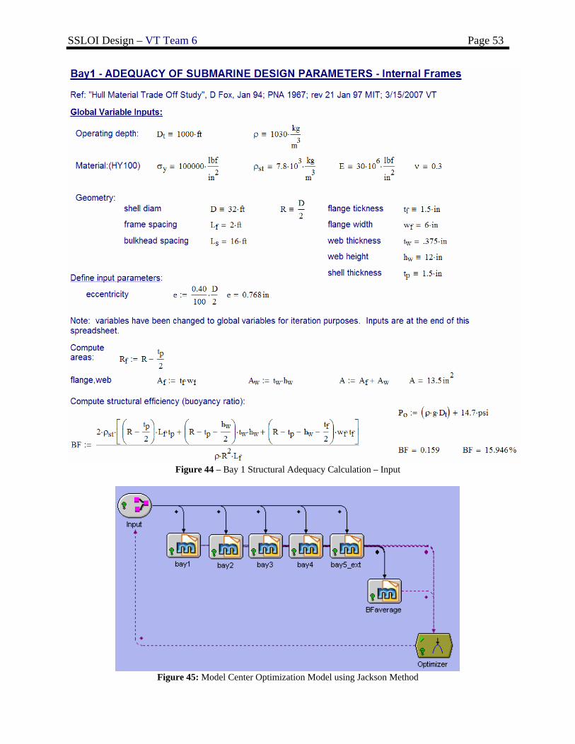
SSLOI Design – VT Team 6 Page 53
Figure 44 – Bay 1 Structural Adequacy Calculation – Input
Figure 45: Model Center Optimization Model using Jackson Method
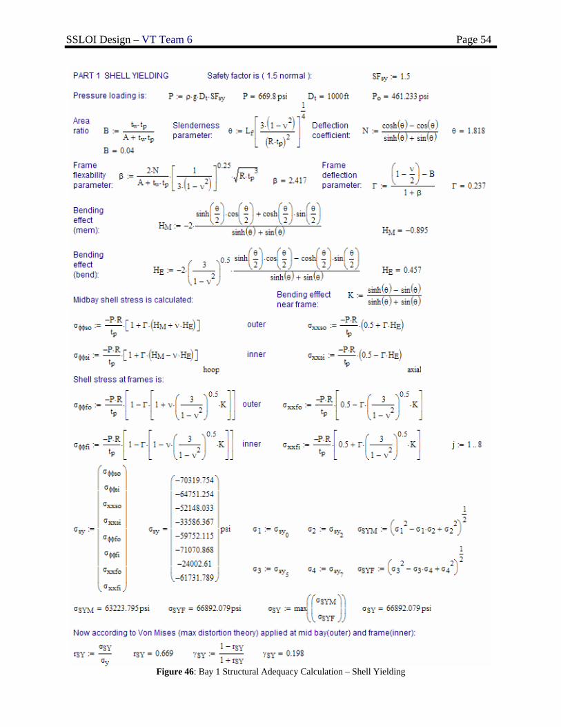
SSLOI Design – VT Team 6 Page 54
Figure 46: Bay 1 Structural Adequacy Calculation – Shell Yielding
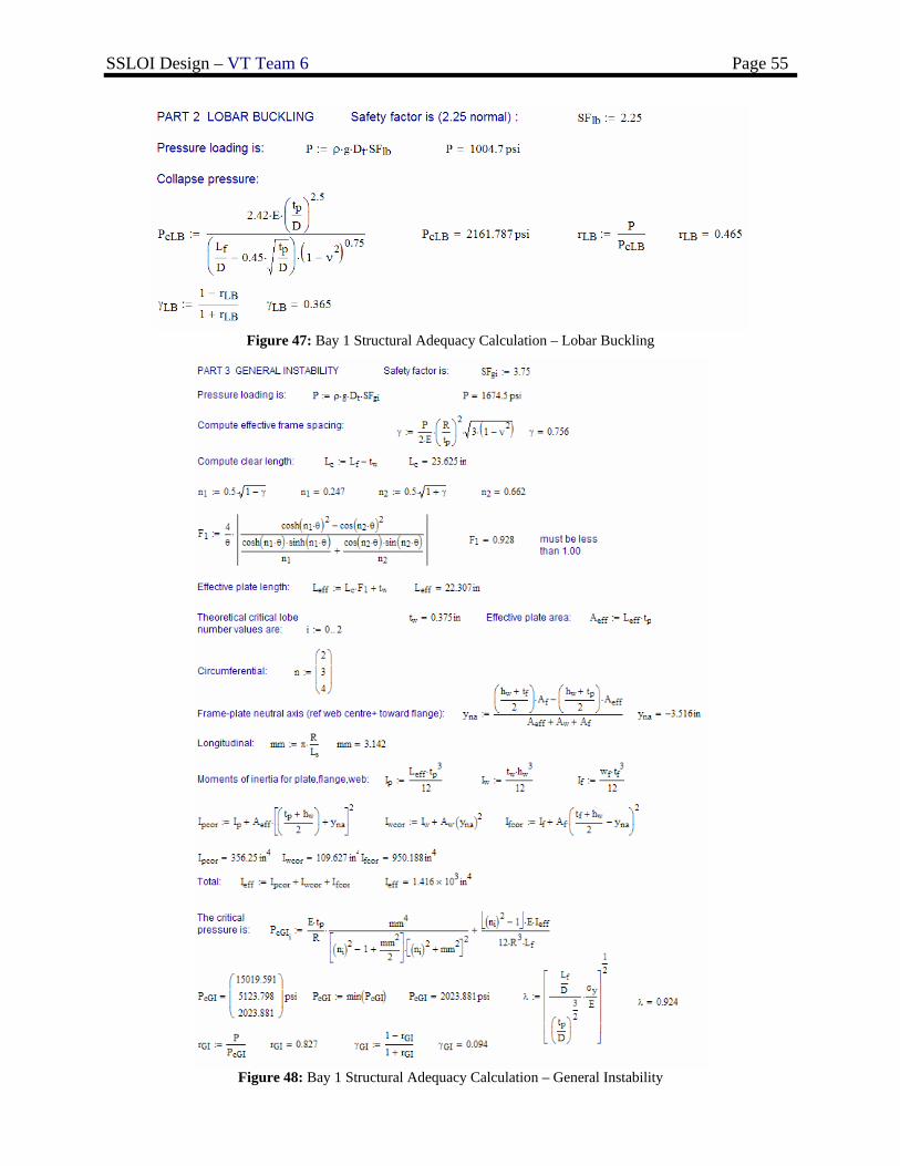
SSLOI Design – VT Team 6 Page 55
Figure 47: Bay 1 Structural Adequacy Calculation – Lobar Buckling
Figure 48: Bay 1 Structural Adequacy Calculation – General Instability

SSLOI Design – VT Team 6 Page 56
Figure 49: Bay 1 Structural Adequacy Calculation – Frame Yielding
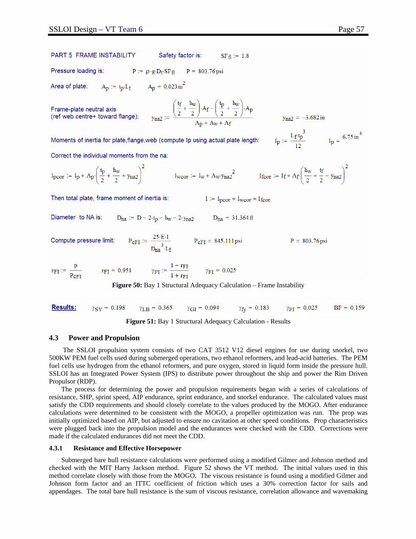
SSLOI Design – VT Team 6 Page 57
Figure 50: Bay 1 Structural Adequacy Calculation – Frame Instability
Figure 51: Bay 1 Structural Adequacy Calculation - Results
4.3 Power and Propulsion The SSLOI propulsion system consists of two CAT 3512 V12 diesel engines for use during snorkel, two
500KW PEM fuel cells used during submerged operations, two ethanol reformers, and lead-acid batteries. The PEM fuel cells use hydrogen from the ethanol reformers, and pure oxygen, stored in liquid form inside the pressure hull. SSLOI has an Integrated Power System (IPS) to distribute power throughout the ship and power the Rim Driven Propulsor (RDP).
The process for determining the power and propulsion requirements began with a series of calculations of resistance, SHP, sprint speed, AIP endurance, sprint endurance, and snorkel endurance. The calculated values must satisfy the CDD requirements and should closely correlate to the values produced by the MOGO. After endurance calculations were determined to be consistent with the MOGO, a propeller optimization was run. The prop was initially optimized based on AIP, but adjusted to ensure no cavitation at other speed conditions. Prop characteristics were plugged back into the propulsion model and the endurances were checked with the CDD. Corrections were made if the calculated endurances did not meet the CDD.
4.3.1 Resistance and Effective Horsepower
Submerged bare hull resistance calculations were performed using a modified Gilmer and Johnson method and checked with the MIT Harry Jackson method. Figure 52 shows the VT method. The initial values used in this method correlate closely with those from the MOGO. The viscous resistance is found using a modified Gilmer and Johnson form factor and an ITTC coefficient of friction which uses a 30% correction factor for sails and appendages. The total bare hull resistance is the sum of viscous resistance, correlation allowance and wavemaking
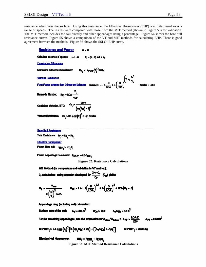
SSLOI Design – VT Team 6 Page 58
resistance when near the surface. Using this resistance, the Effective Horsepower (EHP) was determined over a range of speeds. The results were compared with those from the MIT method (shown in Figure 53) for validation. The MIT method includes the sail directly and other appendages using a percentage. Figure 54 shows the bare hull resistance curves. Figure 55 shows a comparison of the VT and MIT methods for calculating EHP. There is good agreement between the methods. Figure 56 shows the SSLOI EHP curve.
Figure 52: Resistance Calculations
Figure 53: MIT Method Resistance Calculations
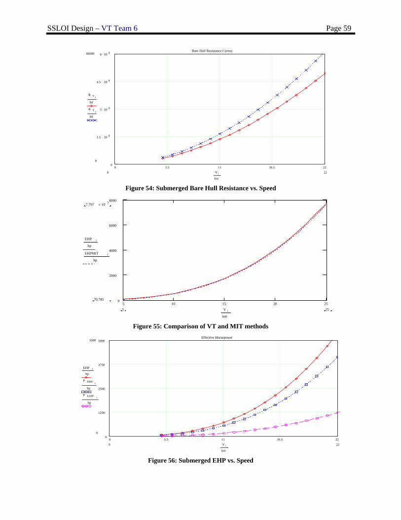
SSLOI Design – VT Team 6 Page 59
Figure 54: Submerged Bare Hull Resistance vs. Speed
Figure 55: Comparison of VT and MIT methods
Figure 56: Submerged EHP vs. Speed
0 5.5 11 16.5 220
1250
2500
3750
5000Effective Horsepower
5000
0
EHP i
hp
P EBH i
hp
P EAPP i
hp
220 V i
knt
5 10 15 20 250
2000
4000
6000
80007.797 10 3×
70.781
EHP i
hp
EHPMIT i
hp
255 V i
knt
0 5.5 11 16.5 220
1.5 .10 4
3 .10 4
4.5 .10 4
6 .10 4 Bare Hull Resistance Curves60000
0
R V i
lbf
R T i
lbf
220 V i
knt
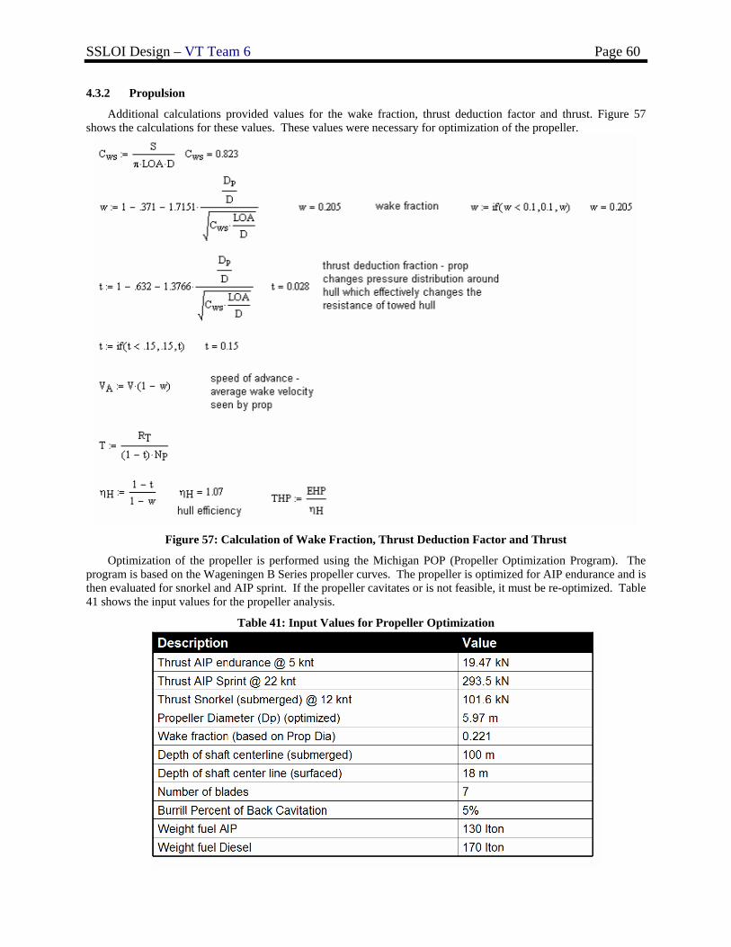
SSLOI Design – VT Team 6 Page 60
4.3.2 Propulsion
Additional calculations provided values for the wake fraction, thrust deduction factor and thrust. Figure 57 shows the calculations for these values. These values were necessary for optimization of the propeller.
Figure 57: Calculation of Wake Fraction, Thrust Deduction Factor and Thrust
Optimization of the propeller is performed using the Michigan POP (Propeller Optimization Program). The program is based on the Wageningen B Series propeller curves. The propeller is optimized for AIP endurance and is then evaluated for snorkel and AIP sprint. If the propeller cavitates or is not feasible, it must be re-optimized. Table 41 shows the input values for the propeller analysis.
Table 41: Input Values for Propeller Optimization
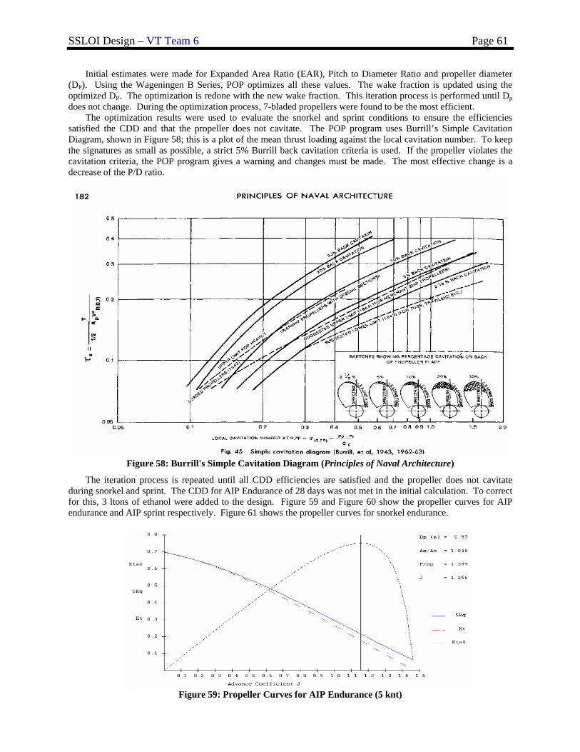
SSLOI Design – VT Team 6 Page 61
Initial estimates were made for Expanded Area Ratio (EAR), Pitch to Diameter Ratio and propeller diameter (DP). Using the Wageningen B Series, POP optimizes all these values. The wake fraction is updated using the optimized DP. The optimization is redone with the new wake fraction. This iteration process is performed until Dp does not change. During the optimization process, 7-bladed propellers were found to be the most efficient.
The optimization results were used to evaluate the snorkel and sprint conditions to ensure the efficiencies satisfied the CDD and that the propeller does not cavitate. The POP program uses Burrill’s Simple Cavitation Diagram, shown in Figure 58; this is a plot of the mean thrust loading against the local cavitation number. To keep the signatures as small as possible, a strict 5% Burrill back cavitation criteria is used. If the propeller violates the cavitation criteria, the POP program gives a warning and changes must be made. The most effective change is a decrease of the P/D ratio.
Figure 58: Burrill's Simple Cavitation Diagram (Principles of Naval Architecture)
The iteration process is repeated until all CDD efficiencies are satisfied and the propeller does not cavitate during snorkel and sprint. The CDD for AIP Endurance of 28 days was not met in the initial calculation. To correct for this, 3 ltons of ethanol were added to the design. Figure 59 and Figure 60 show the propeller curves for AIP endurance and AIP sprint respectively. Figure 61 shows the propeller curves for snorkel endurance.
Figure 59: Propeller Curves for AIP Endurance (5 knt)
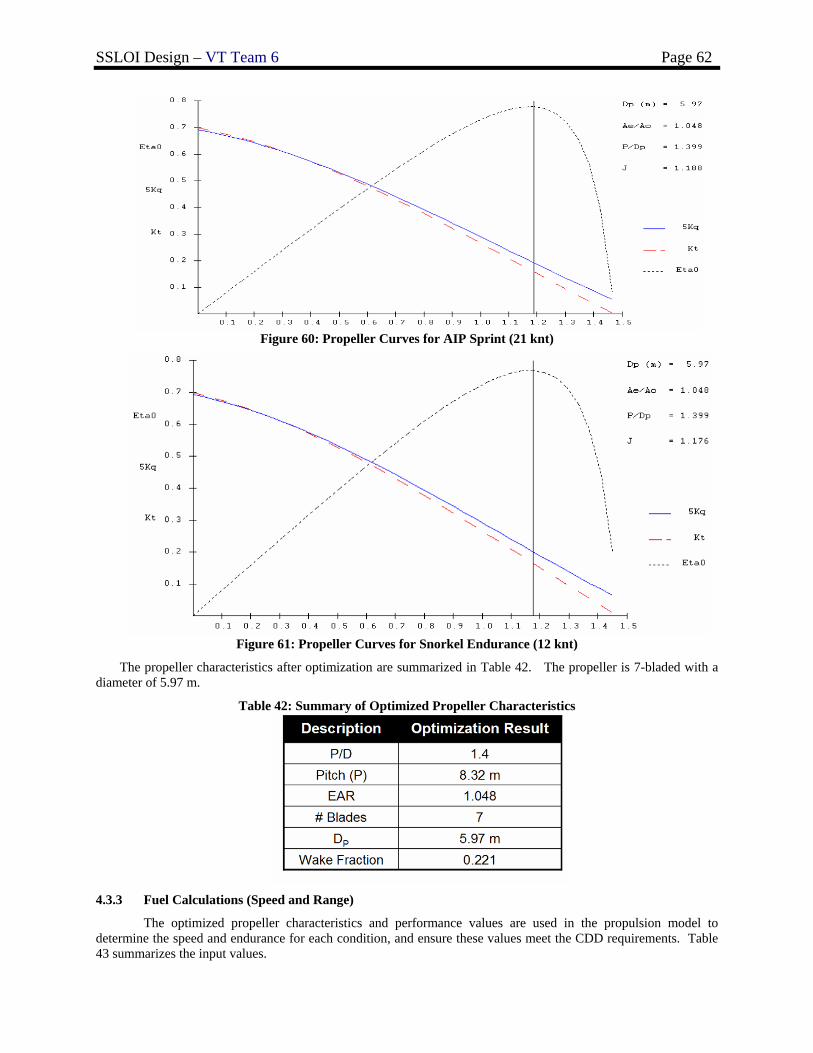
SSLOI Design – VT Team 6 Page 62
Figure 60: Propeller Curves for AIP Sprint (21 knt)
Figure 61: Propeller Curves for Snorkel Endurance (12 knt)
The propeller characteristics after optimization are summarized in Table 42. The propeller is 7-bladed with a diameter of 5.97 m.
Table 42: Summary of Optimized Propeller Characteristics
4.3.3 Fuel Calculations (Speed and Range)
The optimized propeller characteristics and performance values are used in the propulsion model to determine the speed and endurance for each condition, and ensure these values meet the CDD requirements. Table 43 summarizes the input values.
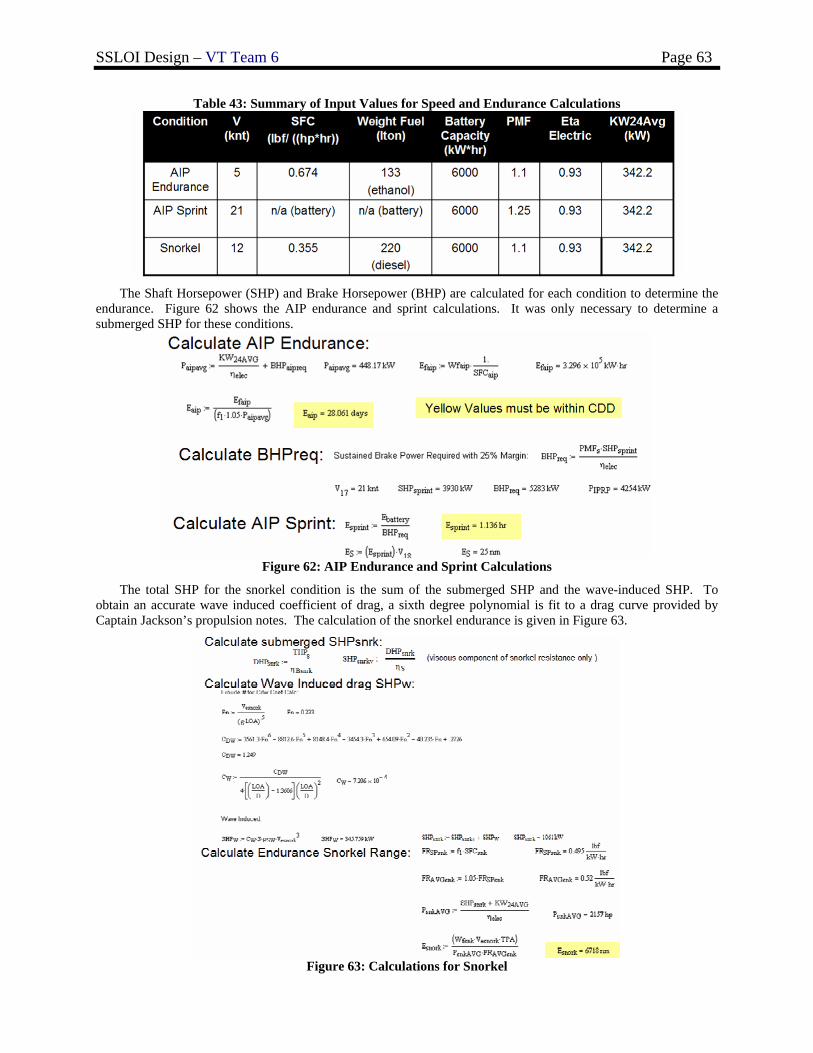
SSLOI Design – VT Team 6 Page 63
Table 43: Summary of Input Values for Speed and Endurance Calculations
The Shaft Horsepower (SHP) and Brake Horsepower (BHP) are calculated for each condition to determine the
endurance. Figure 62 shows the AIP endurance and sprint calculations. It was only necessary to determine a submerged SHP for these conditions.
Figure 62: AIP Endurance and Sprint Calculations
The total SHP for the snorkel condition is the sum of the submerged SHP and the wave-induced SHP. To obtain an accurate wave induced coefficient of drag, a sixth degree polynomial is fit to a drag curve provided by Captain Jackson’s propulsion notes. The calculation of the snorkel endurance is given in Figure 63.
Figure 63: Calculations for Snorkel
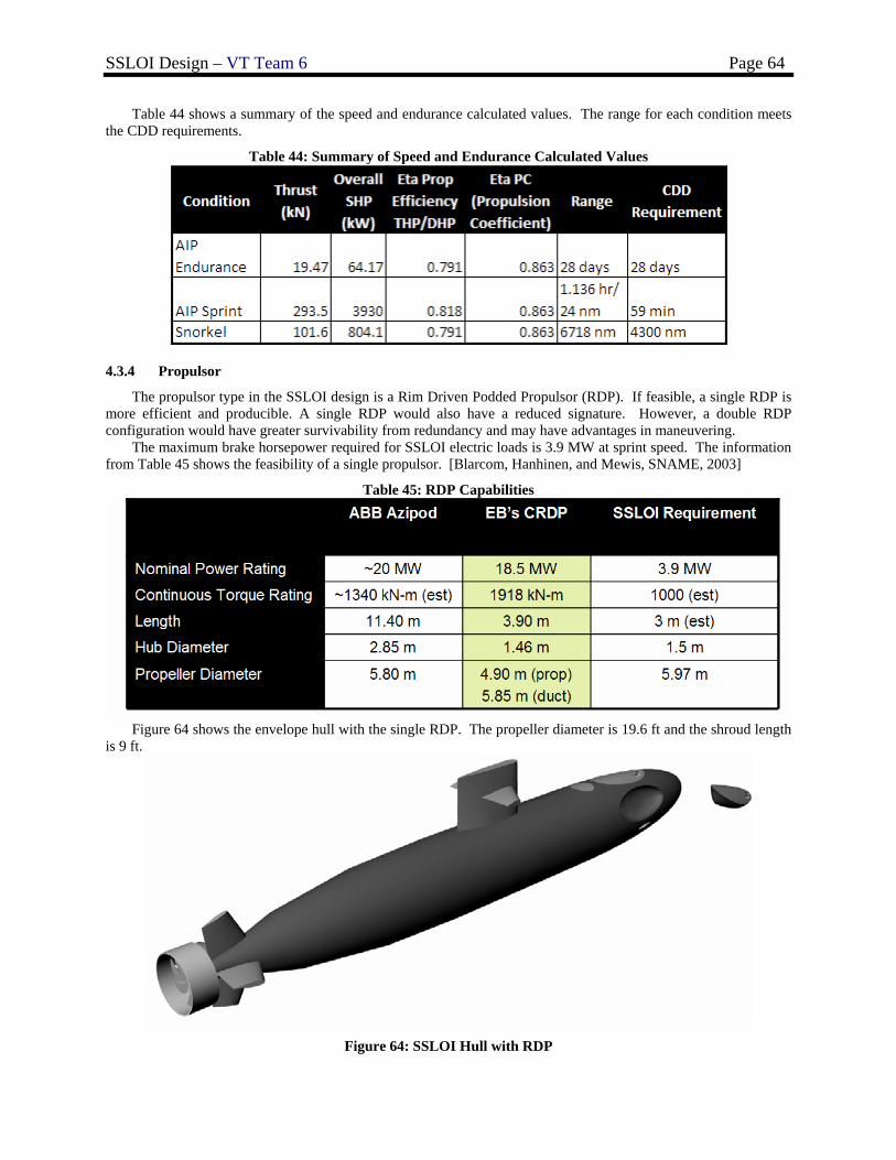
SSLOI Design – VT Team 6 Page 64
Table 44 shows a summary of the speed and endurance calculated values. The range for each condition meets the CDD requirements.
Table 44: Summary of Speed and Endurance Calculated Values
4.3.4 Propulsor
The propulsor type in the SSLOI design is a Rim Driven Podded Propulsor (RDP). If feasible, a single RDP is more efficient and producible. A single RDP would also have a reduced signature. However, a double RDP configuration would have greater survivability from redundancy and may have advantages in maneuvering.
The maximum brake horsepower required for SSLOI electric loads is 3.9 MW at sprint speed. The information from Table 45 shows the feasibility of a single propulsor. [Blarcom, Hanhinen, and Mewis, SNAME, 2003]
Table 45: RDP Capabilities
Figure 64 shows the envelope hull with the single RDP. The propeller diameter is 19.6 ft and the shroud length
is 9 ft.
Figure 64: SSLOI Hull with RDP
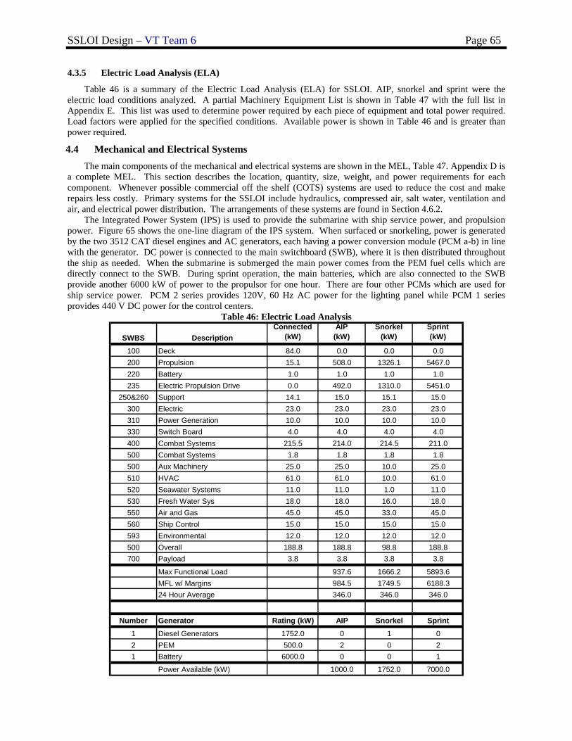
SSLOI Design – VT Team 6 Page 65
4.3.5 Electric Load Analysis (ELA)
Table 46 is a summary of the Electric Load Analysis (ELA) for SSLOI. AIP, snorkel and sprint were the electric load conditions analyzed. A partial Machinery Equipment List is shown in Table 47 with the full list in Appendix E. This list was used to determine power required by each piece of equipment and total power required. Load factors were applied for the specified conditions. Available power is shown in Table 46 and is greater than power required.
4.4 Mechanical and Electrical Systems The main components of the mechanical and electrical systems are shown in the MEL, Table 47. Appendix D is
a complete MEL. This section describes the location, quantity, size, weight, and power requirements for each component. Whenever possible commercial off the shelf (COTS) systems are used to reduce the cost and make repairs less costly. Primary systems for the SSLOI include hydraulics, compressed air, salt water, ventilation and air, and electrical power distribution. The arrangements of these systems are found in Section 4.6.2.
The Integrated Power System (IPS) is used to provide the submarine with ship service power, and propulsion power. Figure 65 shows the one-line diagram of the IPS system. When surfaced or snorkeling, power is generated by the two 3512 CAT diesel engines and AC generators, each having a power conversion module (PCM a-b) in line with the generator. DC power is connected to the main switchboard (SWB), where it is then distributed throughout the ship as needed. When the submarine is submerged the main power comes from the PEM fuel cells which are directly connect to the SWB. During sprint operation, the main batteries, which are also connected to the SWB provide another 6000 kW of power to the propulsor for one hour. There are four other PCMs which are used for ship service power. PCM 2 series provides 120V, 60 Hz AC power for the lighting panel while PCM 1 series provides 440 V DC power for the control centers.
Table 46: Electric Load Analysis
SWBS DescriptionConnected
(kW)AIP
(kW)Snorkel
(kW)Sprint(kW)
100 Deck 84.0 0.0 0.0 0.0200 Propulsion 15.1 508.0 1326.1 5467.0220 Battery 1.0 1.0 1.0 1.0235 Electric Propulsion Drive 0.0 492.0 1310.0 5451.0
250&260 Support 14.1 15.0 15.1 15.0300 Electric 23.0 23.0 23.0 23.0310 Power Generation 10.0 10.0 10.0 10.0330 Switch Board 4.0 4.0 4.0 4.0400 Combat Systems 215.5 214.0 214.5 211.0500 Combat Systems 1.8 1.8 1.8 1.8500 Aux Machinery 25.0 25.0 10.0 25.0510 HVAC 61.0 61.0 10.0 61.0520 Seawater Systems 11.0 11.0 1.0 11.0530 Fresh Water Sys 18.0 18.0 16.0 18.0550 Air and Gas 45.0 45.0 33.0 45.0560 Ship Control 15.0 15.0 15.0 15.0593 Environmental 12.0 12.0 12.0 12.0500 Overall 188.8 188.8 98.8 188.8700 Payload 3.8 3.8 3.8 3.8
Max Functional Load 937.6 1666.2 5893.6MFL w/ Margins 984.5 1749.5 6188.324 Hour Average 346.0 346.0 346.0
Number Generator Rating (kW) AIP Snorkel Sprint
1 Diesel Generators 1752.0 0 1 02 PEM 500.0 2 0 21 Battery 6000.0 0 0 1
Power Available (kW) 1000.0 1752.0 7000.0
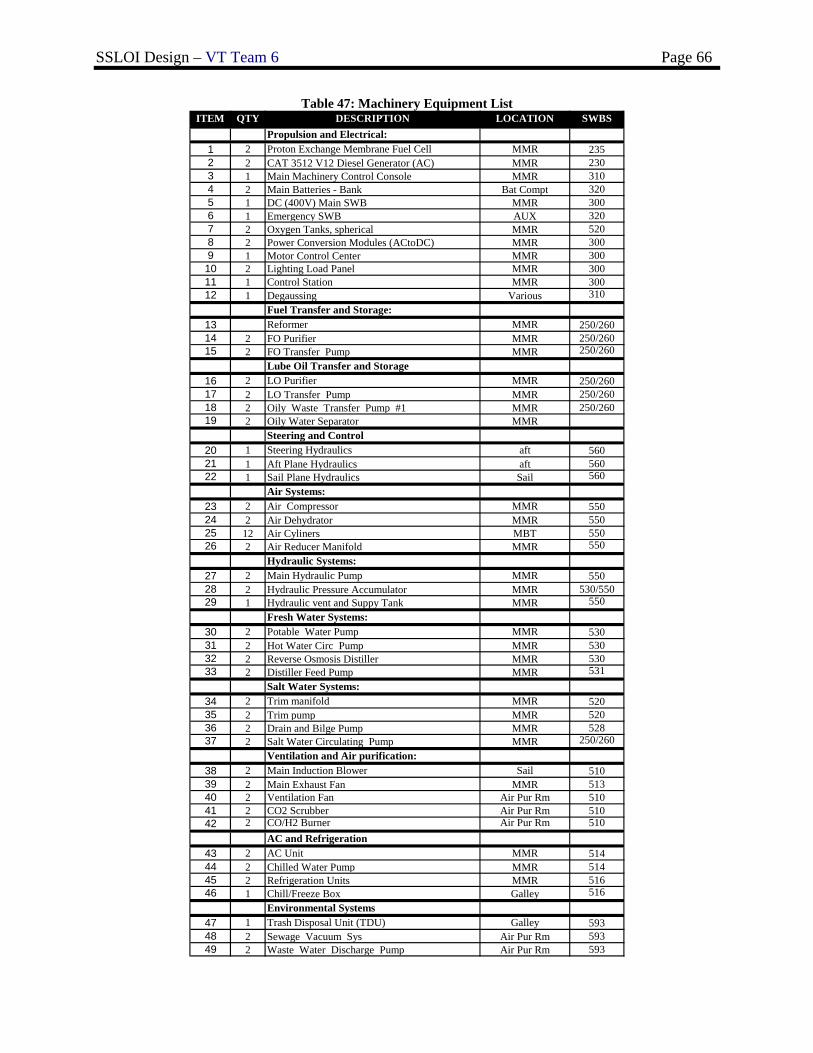
SSLOI Design – VT Team 6 Page 66
Table 47: Machinery Equipment List ITEM QTY DESCRIPTION LOCATION SWBS
Propulsion and Electrical:1 2 Proton Exchange Membrane Fuel Cell MMR 235
3 1 Main Machinery Control Console MMR 3104 2 Main Batteries - Bank Bat Compt 3205 1 DC (400V) Main SWB MMR 3006 1 Emergency SWB AUX 3207 2 Oxygen Tanks, spherical MMR 5208 2 Power Conversion Modules (ACtoDC) MMR 3009 1 Motor Control Center MMR 30010 2 Lighting Load Panel MMR 30011 1 Control Station MMR 30012 1 Degaussing Various 310
Fuel Transfer and Storage:13 Reformer MMR 250/26014 2 FO Purifier MMR 250/26015 2 FO Transfer Pump MMR 250/260
Lube Oil Transfer and Storage16 2 LO Purifier MMR 250/26017 2 LO Transfer Pump MMR 250/26018 2 Oily Waste Transfer Pump #1 MMR 250/26019 2 Oily Water Separator MMR
Steering and Control20 1 Steering Hydraulics aft 56021 1 Aft Plane Hydraulics aft 56022 1 Sail Plane Hydraulics Sail 560
Air Systems:23 2 Air Compressor MMR 55024 2 Air Dehydrator MMR 55025 12 Air Cyliners MBT 55026 2 Air Reducer Manifold MMR 550
Hydraulic Systems:27 2 Main Hydraulic Pump MMR 55028 2 Hydraulic Pressure Accumulator MMR 530/55029 1 Hydraulic vent and Suppy Tank MMR 550
Fresh Water Systems:30 2 Potable Water Pump MMR 53031 2 Hot Water Circ Pump MMR 53032 2 Reverse Osmosis Distiller MMR 53033 2 Distiller Feed Pump MMR 531
Salt Water Systems:34 2 Trim manifold MMR 52035 2 Trim pump MMR 52036 2 Drain and Bilge Pump MMR 52837 2 Salt Water Circulating Pump MMR 250/260
Ventilation and Air purification:38 2 Main Induction Blower Sail 51039 2 Main Exhaust Fan MMR 51340 2 Ventilation Fan Air Pur Rm 51041 2 CO2 Scrubber Air Pur Rm 51042 2 CO/H2 Burner Air Pur Rm 510
AC and Refrigeration43 2 AC Unit MMR 51444 2 Chilled Water Pump MMR 51445 2 Refrigeration Units MMR 51646 1 Chill/Freeze Box Galley 516
Environmental Systems47 1 Trash Disposal Unit (TDU) Galley 59348 2 Sewage Vacuum Sys Air Pur Rm 59349 2 Waste Water Discharge Pump Air Pur Rm 593
2 2 CAT 3512 V12 Diesel Generator (AC) MMR 230
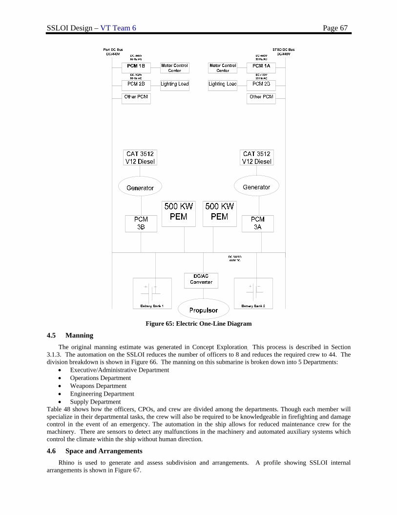
SSLOI Design – VT Team 6 Page 67
Figure 65: Electric One-Line Diagram
4.5 Manning The original manning estimate was generated in Concept Exploration. This process is described in Section
3.1.3. The automation on the SSLOI reduces the number of officers to 8 and reduces the required crew to 44. The division breakdown is shown in Figure 66. The manning on this submarine is broken down into 5 Departments:
• Executive/Administrative Department • Operations Department • Weapons Department • Engineering Department • Supply Department
Table 48 shows how the officers, CPOs, and crew are divided among the departments. Though each member will specialize in their departmental tasks, the crew will also be required to be knowledgeable in firefighting and damage control in the event of an emergency. The automation in the ship allows for reduced maintenance crew for the machinery. There are sensors to detect any malfunctions in the machinery and automated auxiliary systems which control the climate within the ship without human direction.
4.6 Space and Arrangements Rhino is used to generate and assess subdivision and arrangements. A profile showing SSLOI internal
arrangements is shown in Figure 67.
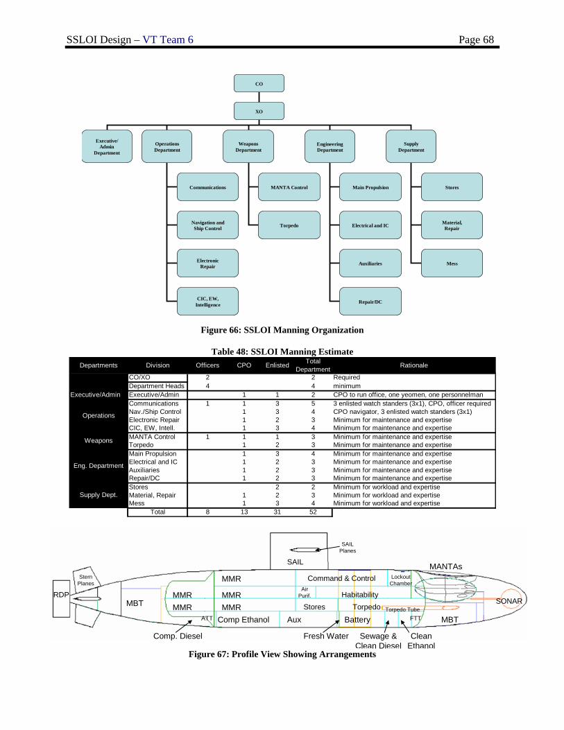
SSLOI Design – VT Team 6 Page 68
CO
XO
Executive/Admin
Department
OperationsDepartment
WeaponsDepartment
EngineeringDepartment
SupplyDepartment
Communications MANTA Control
Navigation andShip Control Torpedo
ElectronicRepair
Main Propulsion
Electrical and IC
Auxiliaries
Repair/DCCIC, EW,Intelligence
Stores
Mess
Material,Repair
Figure 66: SSLOI Manning Organization
Table 48: SSLOI Manning Estimate
MMR
MMR
MMRComp Ethanol Aux BatteryATT
Fresh Water
FTT
Sewage & Clean Diesel
Clean Ethanol
MBT
MBT
Comp. Diesel
SONAR
SAIL
SAIL Planes
Stern Planes
RDP
MANTAsCommand & Control Lockout
Chamber
HabitabilityTorpedoStores
Air Purif.MMR
MMR Torpedo Tube
Figure 67: Profile View Showing Arrangements
Departments Division Officers CPO Enlisted Total Department Rationale
CO/XO 2 2 RequiredDepartment Heads 4 4 minimum
Executive/Admin Executive/Admin 1 1 2 CPO to run office, one yeomen, one personnelmanCommunications 1 1 3 5 3 enlisted watch standers (3x1), CPO, officer requiredNav./Ship Control 1 3 4 CPO navigator, 3 enlisted watch standers (3x1)Electronic Repair 1 2 3 Minimum for maintenance and expertiseCIC, EW, Intell. 1 3 4 Minimum for maintenance and expertiseMANTA Control 1 1 1 3 Minimum for maintenance and expertiseTorpedo 1 2 3 Minimum for maintenance and expertiseMain Propulsion 1 3 4 Minimum for maintenance and expertiseElectrical and IC 1 2 3 Minimum for maintenance and expertiseAuxiliaries 1 2 3 Minimum for maintenance and expertiseRepair/DC 1 2 3 Minimum for maintenance and expertiseStores 2 2 Minimum for workload and expertiseMaterial, Repair 1 2 3 Minimum for workload and expertiseMess 1 3 4 Minimum for workload and expertise
Total 8 13 31 52
Operations
Weapons
Eng. Department
Supply Dept.
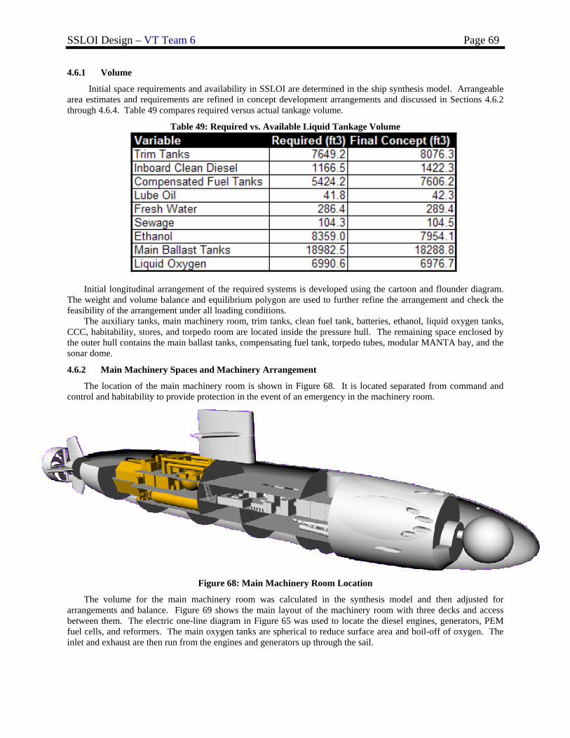
SSLOI Design – VT Team 6 Page 69
4.6.1 Volume
Initial space requirements and availability in SSLOI are determined in the ship synthesis model. Arrangeable area estimates and requirements are refined in concept development arrangements and discussed in Sections 4.6.2 through 4.6.4. Table 49 compares required versus actual tankage volume.
Table 49: Required vs. Available Liquid Tankage Volume
Initial longitudinal arrangement of the required systems is developed using the cartoon and flounder diagram. The weight and volume balance and equilibrium polygon are used to further refine the arrangement and check the feasibility of the arrangement under all loading conditions.
The auxiliary tanks, main machinery room, trim tanks, clean fuel tank, batteries, ethanol, liquid oxygen tanks, CCC, habitability, stores, and torpedo room are located inside the pressure hull. The remaining space enclosed by the outer hull contains the main ballast tanks, compensating fuel tank, torpedo tubes, modular MANTA bay, and the sonar dome.
4.6.2 Main Machinery Spaces and Machinery Arrangement
The location of the main machinery room is shown in Figure 68. It is located separated from command and control and habitability to provide protection in the event of an emergency in the machinery room.
Figure 68: Main Machinery Room Location
The volume for the main machinery room was calculated in the synthesis model and then adjusted for arrangements and balance. Figure 69 shows the main layout of the machinery room with three decks and access between them. The electric one-line diagram in Figure 65 was used to locate the diesel engines, generators, PEM fuel cells, and reformers. The main oxygen tanks are spherical to reduce surface area and boil-off of oxygen. The inlet and exhaust are then run from the engines and generators up through the sail.
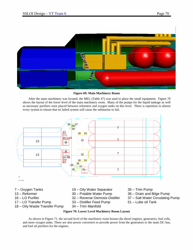
SSLOI Design – VT Team 6 Page 70
Figure 69: Main Machinery Room
After the main machinery was located, the MEL (Table 47) was used to place the small equipment. Figure 70 shows the layout of the lower level of the main machinery room. Many of the pumps for the liquid tankage as well as necessary purifiers were placed between reformers and oxygen tanks on this level. There is repetition in almost every system to ensure that no failed system will cause the submarine to fail.
7
7
7
7
32
33
32
30
34
373635
51
3330
16
19 18
17
16
19 18
1734
3537
36
7 – Oxygen Tanks13 – Reformer 16 – LO Purifier 17 – LO Transfer Pump18 – Oily Waste Transfer Pump
19 – Oily Water Separator30 – Potable Water Pump32 – Reverse Osmosis Distiller 33 – Distiller Feed Pump34 – Trim Manifold
35 – Trim Pump36 – Drain and Bilge Pump37 – Salt Water Circulating Pump51 – Lube oil Tank
13
13
Figure 70: Lower Level Machinery Room Layout
As shown in Figure 71, the second level of the machinery room houses the diesel engines, generators, fuel cells, and more oxygen tanks. There are also power converters to provide power from the generators to the main DC bus, and fuel oil purifiers for the engines.
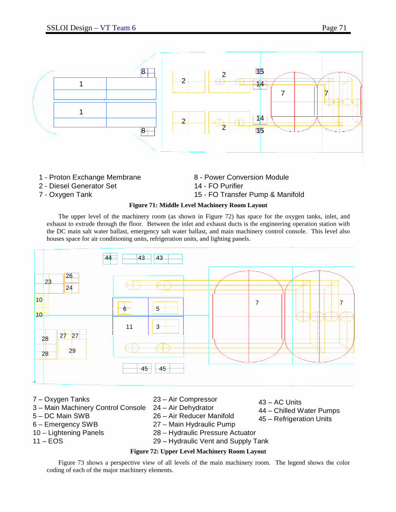
SSLOI Design – VT Team 6 Page 71
2
22
2 15
15
14
14
7 7
8
8
1 - Proton Exchange Membrane2 - Diesel Generator Set7 - Oxygen Tank
8 - Power Conversion Module14 - FO Purifier 15 - FO Transfer Pump & Manifold
1
1
Figure 71: Middle Level Machinery Room Layout
The upper level of the machinery room (as shown in Figure 72) has space for the oxygen tanks, inlet, and exhaust to extrude through the floor. Between the inlet and exhaust ducts is the engineering operation station with the DC main salt water ballast, emergency salt water ballast, and main machinery control console. This level also houses space for air conditioning units, refrigeration units, and lighting panels.
11
23
29
26
24
28
28 27 27
10
10
7 7
43
45
4344
45
7 – Oxygen Tanks3 – Main Machinery Control Console 5 – DC Main SWB6 – Emergency SWB10 – Lightening Panels 11 – EOS
23 – Air Compressor24 – Air Dehydrator26 – Air Reducer Manifold27 – Main Hydraulic Pump28 – Hydraulic Pressure Actuator 29 – Hydraulic Vent and Supply Tank
43 – AC Units44 – Chilled Water Pumps45 – Refrigeration Units
3
56
Figure 72: Upper Level Machinery Room Layout
Figure 73 shows a perspective view of all levels of the main machinery room. The legend shows the color coding of each of the major machinery elements.
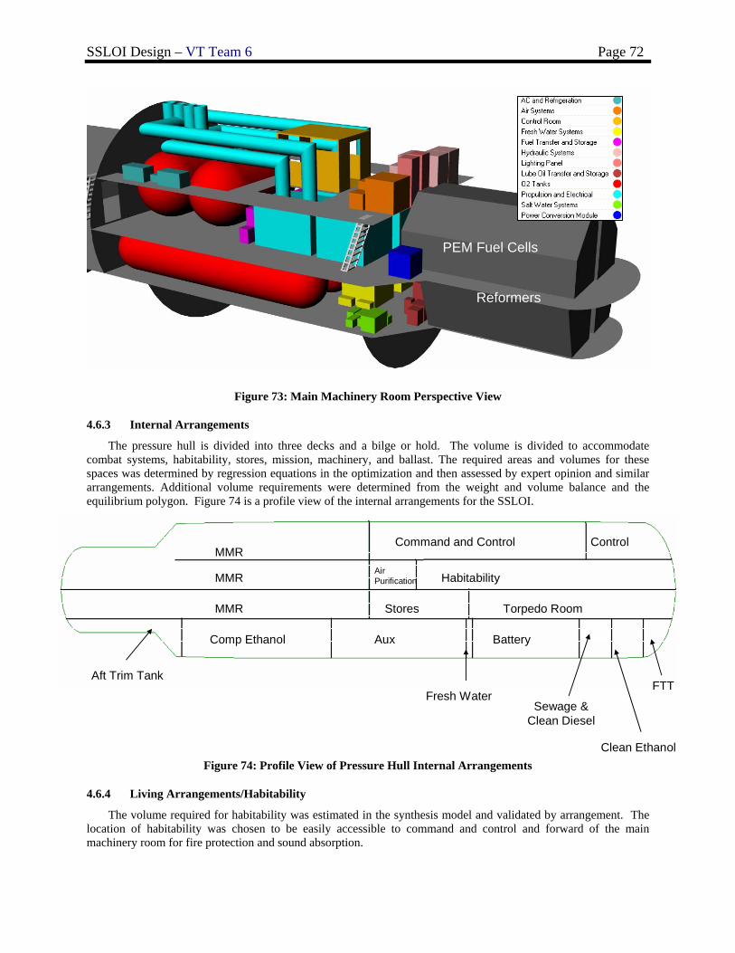
SSLOI Design – VT Team 6 Page 72
Figure 73: Main Machinery Room Perspective View
4.6.3 Internal Arrangements
The pressure hull is divided into three decks and a bilge or hold. The volume is divided to accommodate combat systems, habitability, stores, mission, machinery, and ballast. The required areas and volumes for these spaces was determined by regression equations in the optimization and then assessed by expert opinion and similar arrangements. Additional volume requirements were determined from the weight and volume balance and the equilibrium polygon. Figure 74 is a profile view of the internal arrangements for the SSLOI.
MMR
MMR
MMR
Command and Control Control
Air Purification Habitability
Stores Torpedo Room
Comp Ethanol Aux Battery
Aft Trim Tank
Fresh WaterFTT
Sewage & Clean Diesel
Clean Ethanol Figure 74: Profile View of Pressure Hull Internal Arrangements
4.6.4 Living Arrangements/Habitability
The volume required for habitability was estimated in the synthesis model and validated by arrangement. The location of habitability was chosen to be easily accessible to command and control and forward of the main machinery room for fire protection and sound absorption.
PEM Fuel Cells
Reformers
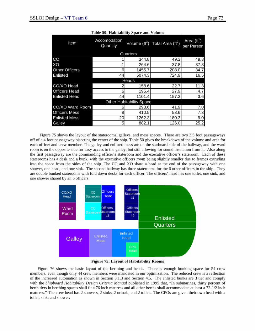
SSLOI Design – VT Team 6 Page 73
Table 50: Habitability Space and Volume
Item Accomodation Quantity Volume (ft3) Total Area (ft2) Area (ft2)
per Person
CO 1 344.8 49.3 49.3XO 1 264.6 37.8 37.8Other Officers 6 1455.7 208.0 34.7Enlisted 44 5074.3 724.9 16.5
CO/XO Head 2 158.6 22.7 11.3Officers Head 6 195.4 27.9 4.7Enlisted Head 44 1101.4 157.3 3.6
CO/XO Ward Room 6 293.6 41.9 7.0Officers Mess 8 410.5 58.6 7.3Enlisted Mess 20 1262.3 180.3 9.0Galley 5 882.1 126.0 25.2
Quarters
Heads
Other Habitability Space
Figure 75 shows the layout of the staterooms, galleys, and mess spaces. There are two 3.5 foot passageways off of a 4 foot passageway bisecting the center of the ship. Table 50 gives the breakdown of the volume and area for each officer and crew member. The galley and enlisted mess are on the starboard side of the hallway, and the ward room is on the opposite side for easy access to the galley, but still allowing for sound insulation from it. Also along the first passageway are the commanding officer’s stateroom and the executive officer’s stateroom. Each of these staterooms has a desk and a bunk, with the executive officers room being slightly smaller due to frames extruding into the space from the sides of the ship. The CO and XO share a head at the end of the passageway with one shower, one head, and one sink. The second hallway has three staterooms for the 6 other officers in the ship. They are double bunked staterooms with fold down desks for each officer. The officers’ head has one toilet, one sink, and one shower shared by all 6 officers.
Enlisted Quarters
Enlisted HeadEnlisted
Mess
Officers’Stateroom
#1
Officers Head
Galley
CO/XO Head
XO Stateroom
COStateroom
Ward Room
Officers’Stateroom
#2
Officers’Stateroom
#3
CPO Head
Figure 75: Layout of Habitability Rooms
Figure 76 shows the basic layout of the berthing and heads. There is enough bunking space for 54 crew members, even though only 44 crew members were mandated in our optimization. The reduced crew is a reflection of the increased automation as shown in Section 3.1.3 and Section 4.5. The enlisted bunks are 3 tier and comply with the Shipboard Habitability Design Criteria Manual published in 1995 that, “In submarines, thirty percent of berth tiers in berthing spaces shall fit a 76 inch mattress and all other berths shall accommodate at least a 72-1/2 inch mattress.” The crew head has 2 showers, 2 sinks, 2 urinals, and 2 toilets. The CPOs are given their own head with a toilet, sink, and shower.
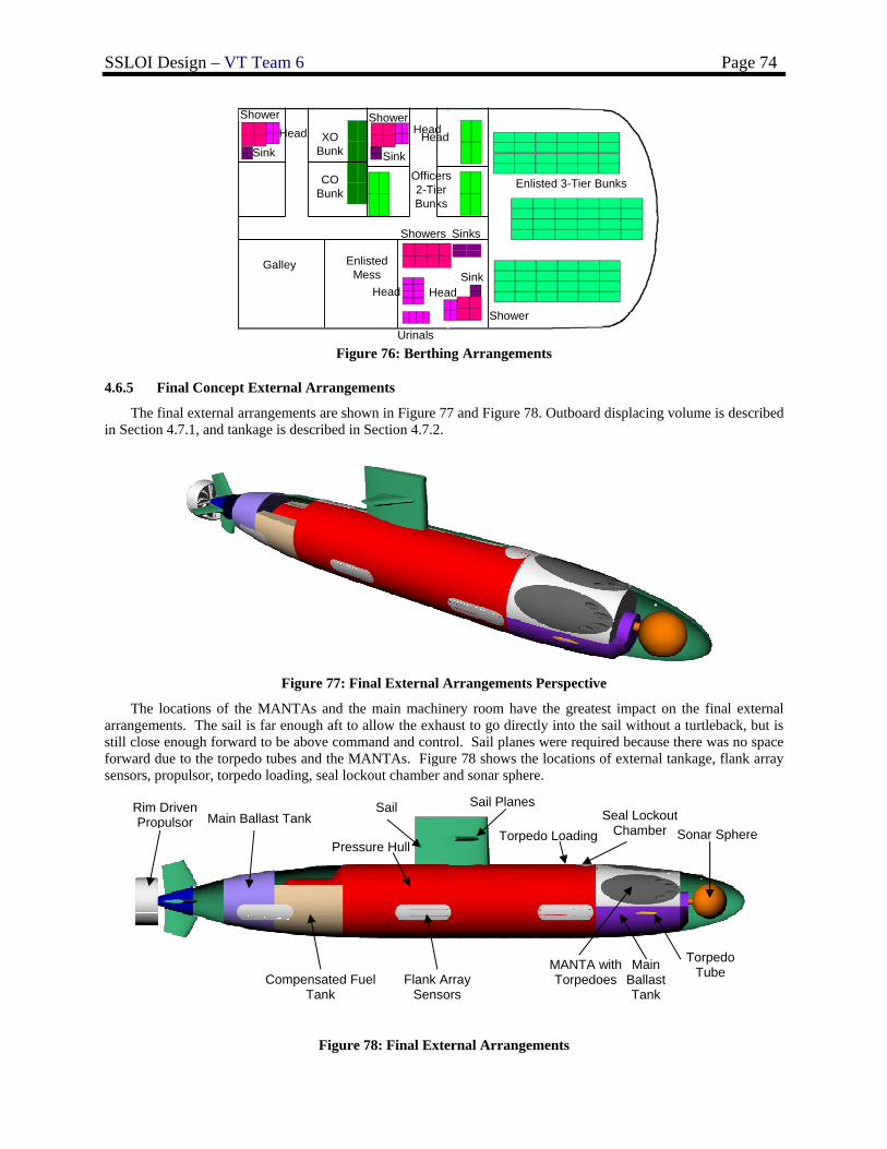
SSLOI Design – VT Team 6 Page 74
Officers 2-Tier Bunks
Enlisted 3-Tier Bunks
ShowerHead
Sink
Showers
Head
Sinks
Urinals
ShowerHead
Sink
CO Bed
XO Bunk
CO Bunk
Head
Shower
SinkGalley
Head
Enlisted Mess
Figure 76: Berthing Arrangements
4.6.5 Final Concept External Arrangements
The final external arrangements are shown in Figure 77 and Figure 78. Outboard displacing volume is described in Section 4.7.1, and tankage is described in Section 4.7.2.
Figure 77: Final External Arrangements Perspective
The locations of the MANTAs and the main machinery room have the greatest impact on the final external arrangements. The sail is far enough aft to allow the exhaust to go directly into the sail without a turtleback, but is still close enough forward to be above command and control. Sail planes were required because there was no space forward due to the torpedo tubes and the MANTAs. Figure 78 shows the locations of external tankage, flank array sensors, propulsor, torpedo loading, seal lockout chamber and sonar sphere.
Figure 78: Final External Arrangements
Sail Main Ballast Tank
Compensated Fuel Tank
Sonar Sphere
Torpedo Tube MANTA with
Torpedoes
Pressure Hull
Rim Driven Propulsor
Flank Array Sensors
Sail Planes Seal Lockout
Chamber Torpedo Loading
Main Ballast Tank
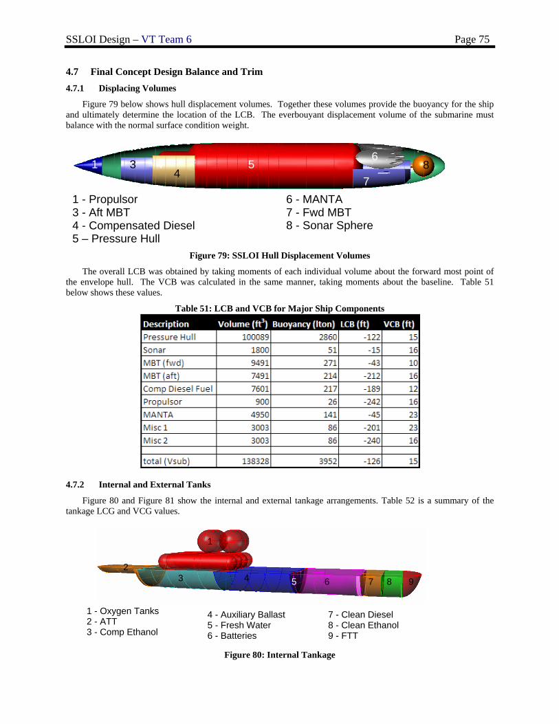
SSLOI Design – VT Team 6 Page 75
4.7 Final Concept Design Balance and Trim 4.7.1 Displacing Volumes
Figure 79 below shows hull displacement volumes. Together these volumes provide the buoyancy for the ship and ultimately determine the location of the LCB. The everbouyant displacement volume of the submarine must balance with the normal surface condition weight.
Figure 79: SSLOI Hull Displacement Volumes
The overall LCB was obtained by taking moments of each individual volume about the forward most point of the envelope hull. The VCB was calculated in the same manner, taking moments about the baseline. Table 51 below shows these values.
Table 51: LCB and VCB for Major Ship Components
4.7.2 Internal and External Tanks
Figure 80 and Figure 81 show the internal and external tankage arrangements. Table 52 is a summary of the tankage LCG and VCG values.
Figure 80: Internal Tankage
1
1 - Oxygen Tanks 2 - ATT 3 - Comp Ethanol
4 - Auxiliary Ballast 5 - Fresh Water 6 - Batteries
1
2 3 4 5 6 7 8 9
7 - Clean Diesel 8 - Clean Ethanol 9 - FTT
1 - Propulsor 3 - Aft MBT 4 - Compensated Diesel 5 – Pressure Hull
6 - MANTA 7 - Fwd MBT 8 - Sonar Sphere
1 4
2
5
7
61 3
4
7 8
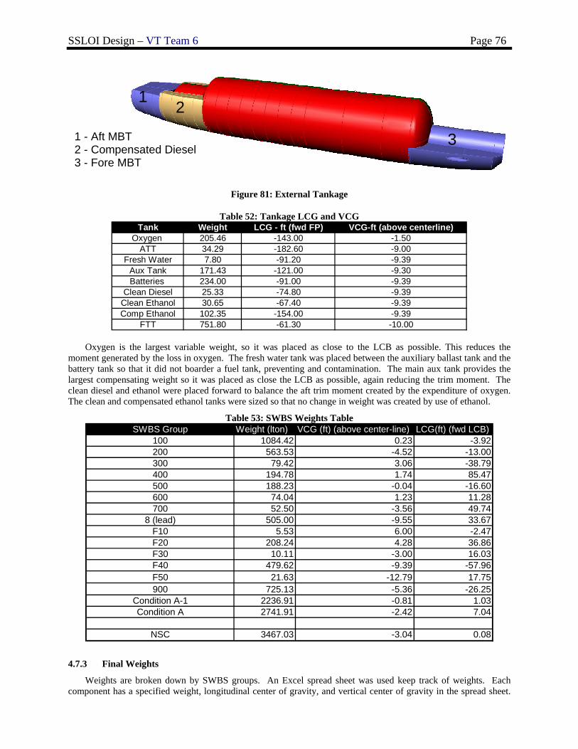
SSLOI Design – VT Team 6 Page 76
Figure 81: External Tankage
Table 52: Tankage LCG and VCG
Oxygen is the largest variable weight, so it was placed as close to the LCB as possible. This reduces the moment generated by the loss in oxygen. The fresh water tank was placed between the auxiliary ballast tank and the battery tank so that it did not boarder a fuel tank, preventing and contamination. The main aux tank provides the largest compensating weight so it was placed as close the LCB as possible, again reducing the trim moment. The clean diesel and ethanol were placed forward to balance the aft trim moment created by the expenditure of oxygen. The clean and compensated ethanol tanks were sized so that no change in weight was created by use of ethanol.
Table 53: SWBS Weights Table SWBS Group Weight (lton) VCG (ft) (above center-line) LCG(ft) (fwd LCB)
100 1084.42 0.23 -3.92200 563.53 -4.52 -13.00300 79.42 3.06 -38.79400 194.78 1.74 85.47500 188.23 -0.04 -16.60600 74.04 1.23 11.28700 52.50 -3.56 49.74
8 (lead) 505.00 -9.55 33.67F10 5.53 6.00 -2.47F20 208.24 4.28 36.86F30 10.11 -3.00 16.03F40 479.62 -9.39 -57.96F50 21.63 -12.79 17.75900 725.13 -5.36 -26.25
Condition A-1 2236.91 -0.81 1.03Condition A 2741.91 -2.42 7.04
NSC 3467.03 -3.04 0.08
4.7.3 Final Weights
Weights are broken down by SWBS groups. An Excel spread sheet was used keep track of weights. Each component has a specified weight, longitudinal center of gravity, and vertical center of gravity in the spread sheet.
Tank Weight LCG - ft (fwd FP) VCG-ft (above centerline)Oxygen 205.46 -143.00 -1.50
ATT 34.29 -182.60 -9.00Fresh Water 7.80 -91.20 -9.39
Aux Tank 171.43 -121.00 -9.30Batteries 234.00 -91.00 -9.39
Clean Diesel 25.33 -74.80 -9.39Clean Ethanol 30.65 -67.40 -9.39Comp Ethanol 102.35 -154.00 -9.39
FTT 751.80 -61.30 -10.00
1 - Aft MBT 2 - Compensated Diesel 3 - Fore MBT
1 2
3
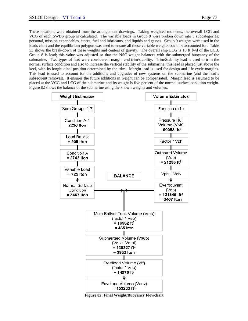
SSLOI Design – VT Team 6 Page 77
These locations were obtained from the arrangement drawings. Taking weighted moments, the overall LCG and VCG of each SWBS group is calculated. The variable loads in Group 9 were broken down into 5 subcategories: personal, mission expendables, stores, fuel and lubricants, and liquids and gasses. Group 9 weights were used in the loads chart and the equilibrium polygon was used to ensure all these variable weights could be accounted for. Table 53 shows the break-down of these weights and centers of gravity. The overall ship LCG is 10 ft fwd of the LCB. Group 8 is lead; this value was adjusted so that the NSC weight balances with the submerged buoyancy of the submarine. Two types of lead were considered; margin and trim/stability. Trim/Stability lead is used to trim the normal surface condition and also to increase the vertical stability of the submarine; this lead is placed just above the keel, with its longitudinal position determined by the trim. Margin lead is used for design and life cycle margins. This lead is used to account for the additions and upgrades of new systems on the submarine (and the lead’s subsequent removal). It ensures the future additions in weight can be compensated. Margin lead is assumed to be placed at the VCG and LCG of the submarine and its weight is five percent of the normal surface condition weight. Figure 82 shows the balance of the submarine using the known weights and volumes.
Figure 82: Final Weight/Buoyancy Flowchart
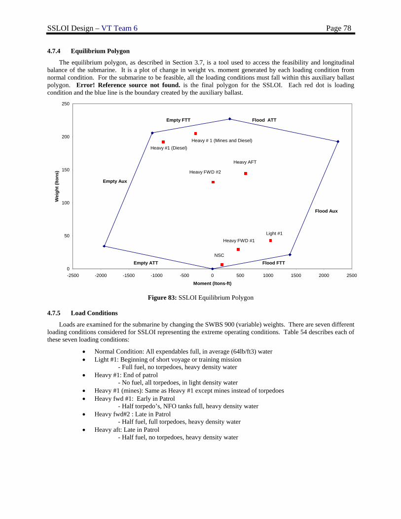
SSLOI Design – VT Team 6 Page 78
4.7.4 Equilibrium Polygon
The equilibrium polygon, as described in Section 3.7, is a tool used to access the feasibility and longitudinal balance of the submarine. It is a plot of change in weight vs. moment generated by each loading condition from normal condition. For the submarine to be feasible, all the loading conditions must fall within this auxiliary ballast polygon. Error! Reference source not found. is the final polygon for the SSLOI. Each red dot is loading condition and the blue line is the boundary created by the auxiliary ballast.
0
50
100
150
200
250
-2500 -2000 -1500 -1000 -500 0 500 1000 1500 2000 2500
Moment (ltons-ft)
Wei
ght (
ltons
)
Flood FTT
Flood Aux
Flood ATTEmpty FTT
Empty Aux
Empty ATT
Light #1
NSC
Heavy #1 (Diesel) Heavy # 1 (Mines and Diesel)
Heavy FWD #1
Heavy FWD #2
Heavy AFT
Figure 83: SSLOI Equilibrium Polygon
4.7.5 Load Conditions
Loads are examined for the submarine by changing the SWBS 900 (variable) weights. There are seven different loading conditions considered for SSLOI representing the extreme operating conditions. Table 54 describes each of these seven loading conditions:
• Normal Condition: All expendables full, in average (64lb/ft3) water • Light #1: Beginning of short voyage or training mission
- Full fuel, no torpedoes, heavy density water • Heavy #1: End of patrol
- No fuel, all torpedoes, in light density water • Heavy #1 (mines): Same as Heavy #1 except mines instead of torpedoes • Heavy fwd #1: Early in Patrol
- Half torpedo’s, NFO tanks full, heavy density water • Heavy fwd#2 : Late in Patrol
- Half fuel, full torpedoes, heavy density water • Heavy aft: Late in Patrol
- Half fuel, no torpedoes, heavy density water
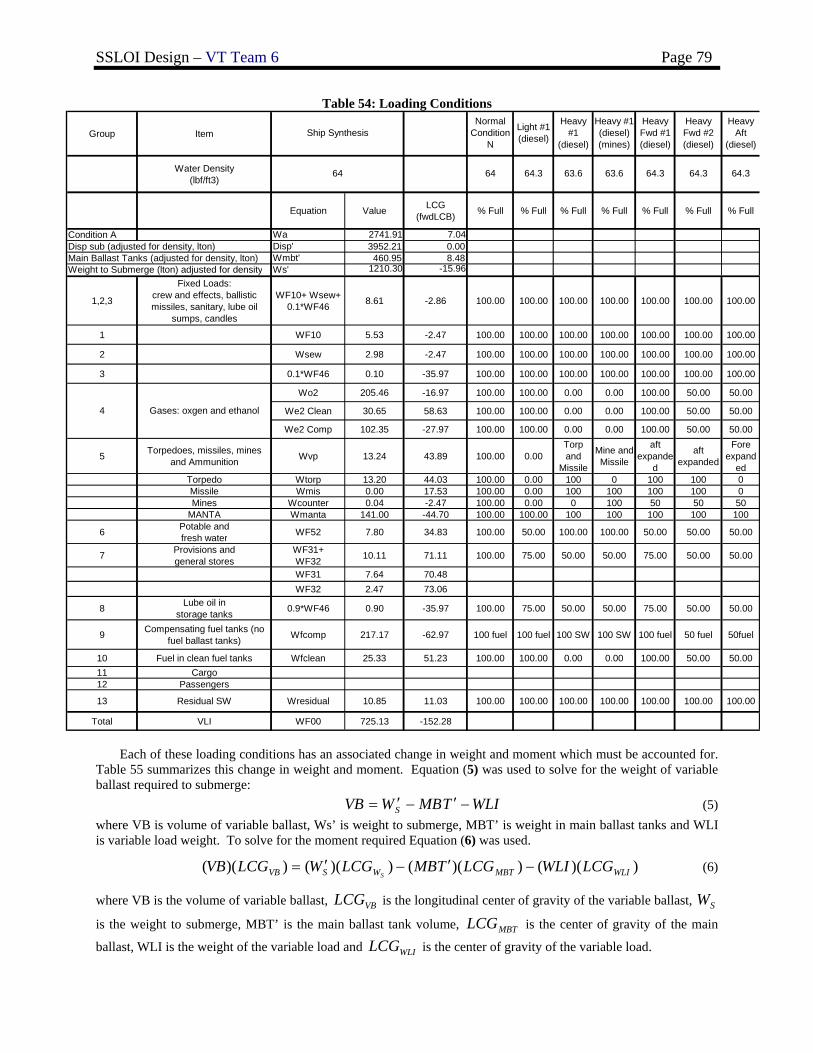
SSLOI Design – VT Team 6 Page 79
Table 54: Loading Conditions
Group Item
Water Density(lbf/ft3)
Equation Value LCG (fwdLCB) % Full % Full % Full % Full % Full % Full % Full
Condition A Wa 2741.91 7.04Disp sub (adjusted for density, lton) Disp' 3952.21 0.00Main Ballast Tanks (adjusted for density, lton) Wmbt' 460.95 8.48Weight to Submerge (lton) adjusted for density Ws' 1210.30 -15.96
1,2,3
Fixed Loads:crew and effects, ballistic missiles, sanitary, lube oil
sumps, candles
WF10+ Wsew+ 0.1*WF46 8.61 -2.86 100.00 100.00 100.00 100.00 100.00 100.00 100.00
1 WF10 5.53 -2.47 100.00 100.00 100.00 100.00 100.00 100.00 100.00
2 Wsew 2.98 -2.47 100.00 100.00 100.00 100.00 100.00 100.00 100.00
3 0.1*WF46 0.10 -35.97 100.00 100.00 100.00 100.00 100.00 100.00 100.00
Wo2 205.46 -16.97 100.00 100.00 0.00 0.00 100.00 50.00 50.00
We2 Clean 30.65 58.63 100.00 100.00 0.00 0.00 100.00 50.00 50.00
We2 Comp 102.35 -27.97 100.00 100.00 0.00 0.00 100.00 50.00 50.00
5 Torpedoes, missiles, minesand Ammunition Wvp 13.24 43.89 100.00 0.00
Torp and
Missile
Mine and Missile
aft expande
d
aft expanded
Fore expand
edTorpedo Wtorp 13.20 44.03 100.00 0.00 100 0 100 100 0Missile Wmis 0.00 17.53 100.00 0.00 100 100 100 100 0Mines Wcounter 0.04 -2.47 100.00 0.00 0 100 50 50 50
MANTA Wmanta 141.00 -44.70 100.00 100.00 100 100 100 100 100
6 Potable andfresh water WF52 7.80 34.83 100.00 50.00 100.00 100.00 50.00 50.00 50.00
7 Provisions andgeneral stores
WF31+WF32 10.11 71.11 100.00 75.00 50.00 50.00 75.00 50.00 50.00
WF31 7.64 70.48WF32 2.47 73.06
8 Lube oil in storage tanks 0.9*WF46 0.90 -35.97 100.00 75.00 50.00 50.00 75.00 50.00 50.00
9 Compensating fuel tanks (no fuel ballast tanks) Wfcomp 217.17 -62.97 100 fuel 100 fuel 100 SW 100 SW 100 fuel 50 fuel 50fuel
10 Fuel in clean fuel tanks Wfclean 25.33 51.23 100.00 100.00 0.00 0.00 100.00 50.00 50.0011 Cargo12 Passengers
13 Residual SW Wresidual 10.85 11.03 100.00 100.00 100.00 100.00 100.00 100.00 100.00
Total VLI WF00 725.13 -152.28
64.3
4 Gases: oxgen and ethanol
Heavy Fwd #2 (diesel)
Heavy Aft
(diesel)
Normal Condition
N
Light #1 (diesel)
6464 64.3
Ship Synthesis
63.6 64.3 64.363.6
Heavy #1
(diesel)
Heavy #1 (diesel) (mines)
Heavy Fwd #1 (diesel)
Each of these loading conditions has an associated change in weight and moment which must be accounted for. Table 55 summarizes this change in weight and moment. Equation (5) was used to solve for the weight of variable ballast required to submerge:
WLITMBWVB S −′−′= (5) where VB is volume of variable ballast, Ws’ is weight to submerge, MBT’ is weight in main ballast tanks and WLI is variable load weight. To solve for the moment required Equation (6) was used.
))(())(())(())(( WLIMBTWSVB LCGWLILCGTMBLCGWLCGVBS
−′−′= (6)
where VB is the volume of variable ballast, VBLCG is the longitudinal center of gravity of the variable ballast, SW
is the weight to submerge, MBT’ is the main ballast tank volume, MBTLCG is the center of gravity of the main
ballast, WLI is the weight of the variable load and WLILCG is the center of gravity of the variable load.
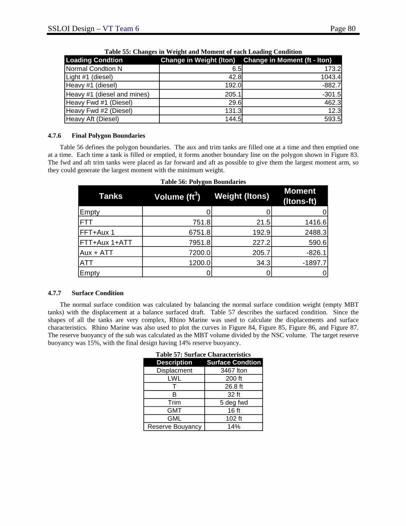
SSLOI Design – VT Team 6 Page 80
Table 55: Changes in Weight and Moment of each Loading Condition Loading Condtion Change in Weight (lton) Change in Moment (ft - lton)Normal Condtion N 6.5 173.2Light #1 (diesel) 42.8 1043.4Heavy #1 (diesel) 192.0 -882.7Heavy #1 (diesel and mines) 205.1 -301.5Heavy Fwd #1 (Diesel) 29.6 462.3Heavy Fwd #2 (Diesel) 131.3 12.3Heavy Aft (Diesel) 144.5 593.5
4.7.6 Final Polygon Boundaries
Table 56 defines the polygon boundaries. The aux and trim tanks are filled one at a time and then emptied one at a time. Each time a tank is filled or emptied, it forms another boundary line on the polygon shown in Figure 83. The fwd and aft trim tanks were placed as far forward and aft as possible to give them the largest moment arm, so they could generate the largest moment with the minimum weight.
Table 56: Polygon Boundaries
Tanks Volume (ft3) Weight (ltons) Moment (ltons-ft)
Empty 0 0 0FTT 751.8 21.5 1416.6FFT+Aux 1 6751.8 192.9 2488.3FTT+Aux 1+ATT 7951.8 227.2 590.6Aux + ATT 7200.0 205.7 -826.1ATT 1200.0 34.3 -1897.7Empty 0 0 0
4.7.7 Surface Condition
The normal surface condition was calculated by balancing the normal surface condition weight (empty MBT tanks) with the displacement at a balance surfaced draft. Table 57 describes the surfaced condition. Since the shapes of all the tanks are very complex, Rhino Marine was used to calculate the displacements and surface characteristics. Rhino Marine was also used to plot the curves in Figure 84, Figure 85, Figure 86, and Figure 87. The reserve buoyancy of the sub was calculated as the MBT volume divided by the NSC volume. The target reserve buoyancy was 15%, with the final design having 14% reserve buoyancy.
Table 57: Surface Characteristics
Description Surface CondtionDisplacment 3467 lton
LWL 200 ftT 26.8 ftB 32 ft
Trim 5 deg fwdGMT 16 ftGML 102 ft
Reserve Bouyancy 14%
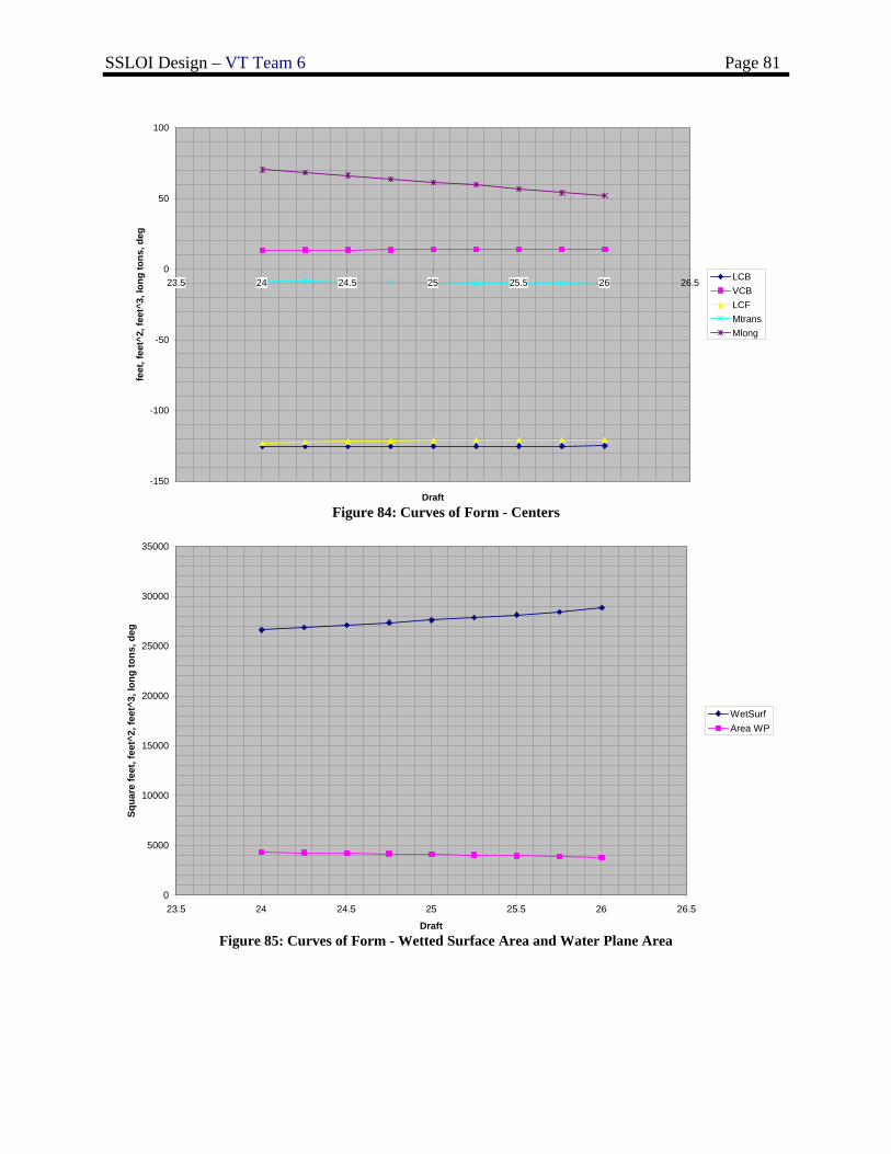
SSLOI Design – VT Team 6 Page 81
Figure 84: Curves of Form - Centers
Figure 85: Curves of Form - Wetted Surface Area and Water Plane Area
0
5000
10000
15000
20000
25000
30000
35000
23.5 24 24.5 25 25.5 26 26.5
Draft
Squa
re fe
et, f
eet^
2, fe
et^3
, lon
g to
ns, d
eg
WetSurfArea WP
-150
-100
-50
0
50
100
23.5 24 24.5 25 25.5 26 26.5
Draft
feet
, fee
t^2,
feet
^3, l
ong
tons
, deg
LCBVCBLCFMtransMlong
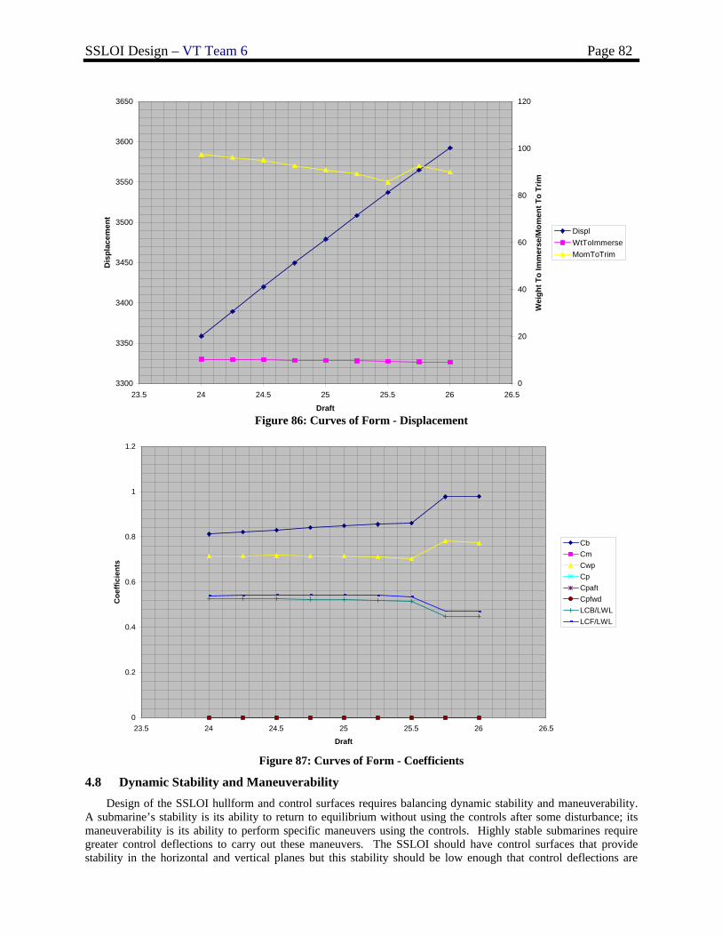
SSLOI Design – VT Team 6 Page 82
Figure 86: Curves of Form - Displacement
Figure 87: Curves of Form - Coefficients
4.8 Dynamic Stability and Maneuverability Design of the SSLOI hullform and control surfaces requires balancing dynamic stability and maneuverability.
A submarine’s stability is its ability to return to equilibrium without using the controls after some disturbance; its maneuverability is its ability to perform specific maneuvers using the controls. Highly stable submarines require greater control deflections to carry out these maneuvers. The SSLOI should have control surfaces that provide stability in the horizontal and vertical planes but this stability should be low enough that control deflections are
0
0.2
0.4
0.6
0.8
1
1.2
23.5 24 24.5 25 25.5 26 26.5
Draft
Coe
ffici
ents
CbCmCwpCpCpaftCpfwdLCB/LWLLCF/LWL
3300
3350
3400
3450
3500
3550
3600
3650
23.5 24 24.5 25 25.5 26 26.5
Draft
Dis
plac
emen
t
0
20
40
60
80
100
120
Wei
ght T
o Im
mer
se/M
omen
t To
Trim
DisplWtToImmerseMomToTrim
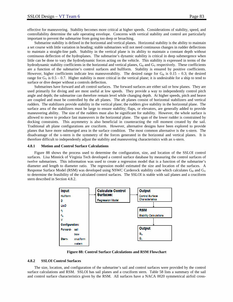
SSLOI Design – VT Team 6 Page 83
effective for maneuvering. Stability becomes more critical at higher speeds. Considerations of stability, speed, and controllability determine the safe operating envelope. Concerns with vertical stability and control are particularly important to prevent the submarine from going too deep or broaching.
Submarine stability is defined in the horizontal and vertical planes. Horizontal stability is the ability to maintain a set course with little variation in heading; stable submarines will not need continuous changes in rudder deflections to maintain a straight-line path. Stability in the vertical plane is its ability to maintain a constant depth without continuous deflection of the hydroplanes. The submarine’s dynamic stability is critical in deep submergence when little can be done to vary the hydrodynamic forces acting on the vehicle. This stability is expressed in terms of the hydrodynamic stability coefficients in the horizontal and vertical planes, GH and GV respectively. These coefficients are a function of the submarine’s control surfaces and hullform. Stability is ensured by positive coefficients. However, higher coefficients indicate less maneuverability. The desired range for GH is 0.15 – 0.3; the desired range for GV is 0.5 – 0.7. Higher stability is more critical in the vertical plane; it is undesirable for a ship to tend to surface or dive deeper without a controls deflection.
Submarines have forward and aft control surfaces. The forward surfaces are either sail or bow planes. They are used primarily for diving and are most useful at low speeds. They provide a way to independently control pitch angle and depth; the submarine can therefore remain level while changing depth. At higher speeds, pitch and heave are coupled and must be controlled by the aft planes. The aft planes consist of horizontal stabilizers and vertical rudders. The stabilizers provide stability in the vertical plane; the rudders give stability in the horizontal plane. The surface area of the stabilizers must be large to ensure stability; flaps, or elevators, are generally added to provide maneuvering ability. The size of the rudders must also be significant for stability. However, the whole surface is allowed to move to produce fast maneuvers in the horizontal plane. The span of the lower rudder is constrained by docking constraints. This asymmetry is also beneficial in counteracting the roll moment created by the sail. Traditional aft plane configurations are cruciform. However, alternative designs have been explored to provide planes that have more submerged area in the surface condition. The most common alternative is the x-stern. The disadvantage of the x-stern is the symmetry of the forces generated in the horizontal and vertical planes. It is therefore difficult to independently adjust the stability and maneuvering characteristics with an x-stern.
4.8.1 Motion and Control Surface Calculations
Figure 88 shows the process used to determine the configuration, size, and location of the SSLOI control surfaces. Lisa Minnick of Virginia Tech developed a control surface database by measuring the control surfaces of twelve submarines. This information was used to create a regression model that is a function of the submarine’s diameter and length to diameter ratio. The regression model estimated the size and location of the surfaces. A Response Surface Model (RSM) was developed using NSWC Carderock stability code which calculates GH and GV to determine the feasibility of the calculated control surfaces. The SSLOI is stable with sail planes and a cruciform stern described in Section 4.8.2.
Figure 88: Control Surface Calculations and RSM Flowchart
4.8.2 SSLOI Control Surfaces
The size, location, and configuration of the submarine’s sail and control surfaces were provided by the control surface calculations and RSM. SSLOI has sail planes and a cruciform stern. Table 58 lists a summary of the sail and control surface characteristics given by the RSM. All surfaces have a NACA 0020 symmetrical airfoil cross-
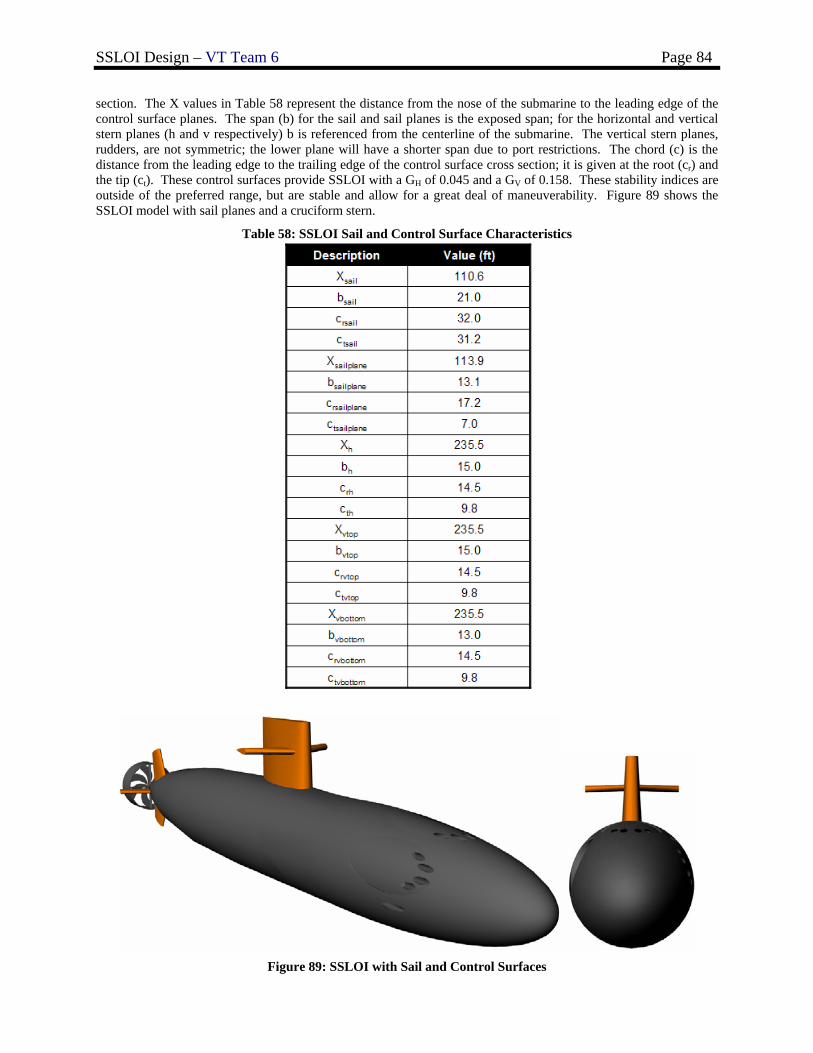
SSLOI Design – VT Team 6 Page 84
section. The X values in Table 58 represent the distance from the nose of the submarine to the leading edge of the control surface planes. The span (b) for the sail and sail planes is the exposed span; for the horizontal and vertical stern planes (h and v respectively) b is referenced from the centerline of the submarine. The vertical stern planes, rudders, are not symmetric; the lower plane will have a shorter span due to port restrictions. The chord (c) is the distance from the leading edge to the trailing edge of the control surface cross section; it is given at the root (cr) and the tip (ct). These control surfaces provide SSLOI with a GH of 0.045 and a GV of 0.158. These stability indices are outside of the preferred range, but are stable and allow for a great deal of maneuverability. Figure 89 shows the SSLOI model with sail planes and a cruciform stern.
Table 58: SSLOI Sail and Control Surface Characteristics
Figure 89: SSLOI with Sail and Control Surfaces
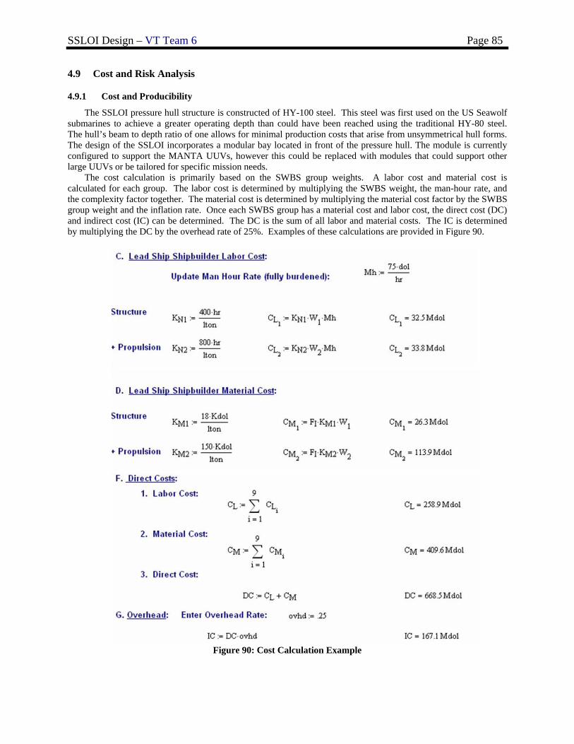
SSLOI Design – VT Team 6 Page 85
4.9 Cost and Risk Analysis
4.9.1 Cost and Producibility
The SSLOI pressure hull structure is constructed of HY-100 steel. This steel was first used on the US Seawolf submarines to achieve a greater operating depth than could have been reached using the traditional HY-80 steel. The hull’s beam to depth ratio of one allows for minimal production costs that arise from unsymmetrical hull forms. The design of the SSLOI incorporates a modular bay located in front of the pressure hull. The module is currently configured to support the MANTA UUVs, however this could be replaced with modules that could support other large UUVs or be tailored for specific mission needs.
The cost calculation is primarily based on the SWBS group weights. A labor cost and material cost is calculated for each group. The labor cost is determined by multiplying the SWBS weight, the man-hour rate, and the complexity factor together. The material cost is determined by multiplying the material cost factor by the SWBS group weight and the inflation rate. Once each SWBS group has a material cost and labor cost, the direct cost (DC) and indirect cost (IC) can be determined. The DC is the sum of all labor and material costs. The IC is determined by multiplying the DC by the overhead rate of 25%. Examples of these calculations are provided in Figure 90.
Figure 90: Cost Calculation Example
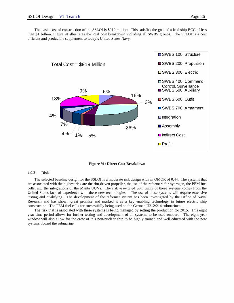
SSLOI Design – VT Team 6 Page 86
The basic cost of construction of the SSLOI is $919 million. This satisfies the goal of a lead ship BCC of less than $1 billion. Figure 91 illustrates the total cost breakdown including all SWBS groups. The SSLOI is a cost efficient and producible supplement to today’s United States Navy.
16%
26%
18%9%
7%
4%
3%
6%
1%4% 5%
SWBS 100: Structure
SWBS 200: Propulsion
SWBS 300: Electric
SWBS 400: Command,Control, SurveillanceSWBS 500: Auxiliary
SWBS 600: Outfit
SWBS 700: Armament
Integration
Assembly
Indirect Cost
Profit
Total Cost = $919 Million
Figure 91: Direct Cost Breakdown
4.9.2 Risk
The selected baseline design for the SSLOI is a moderate risk design with an OMOR of 0.44. The systems that are associated with the highest risk are the rim-driven propeller, the use of the reformers for hydrogen, the PEM fuel cells, and the integrations of the Manta UUVs. The risk associated with many of these systems comes from the United States lack of experience with these new technologies. The use of these systems will require extensive testing and qualifying. The development of the reformer system has been investigated by the Office of Naval Research and has shown great promise and marked it as a key enabling technology in future electric ship construction. The PEM fuel cells are successfully being used on the German U212/214 submarines.
The risk that is associated with these systems is being managed by setting the production for 2015. This eight year time period allows for further testing and development of all systems to be used onboard. The eight year window will also allow for the crew of this non-nuclear ship to be highly trained and well educated with the new systems aboard the submarine.
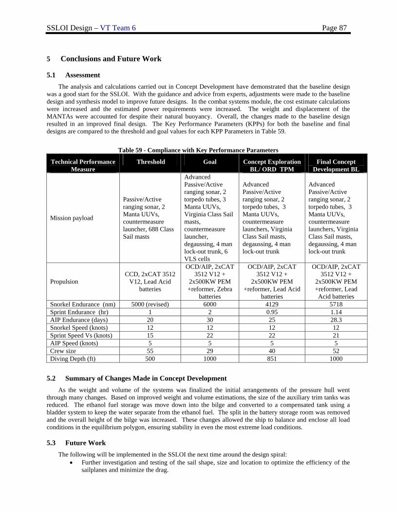
SSLOI Design – VT Team 6 Page 87
5 Conclusions and Future Work
5.1 Assessment The analysis and calculations carried out in Concept Development have demonstrated that the baseline design was a good start for the SSLOI. With the guidance and advice from experts, adjustments were made to the baseline design and synthesis model to improve future designs. In the combat systems module, the cost estimate calculations were increased and the estimated power requirements were increased. The weight and displacement of the MANTAs were accounted for despite their natural buoyancy. Overall, the changes made to the baseline design resulted in an improved final design. The Key Performance Parameters (KPPs) for both the baseline and final designs are compared to the threshold and goal values for each KPP Parameters in Table 59.
Table 59 - Compliance with Key Performance Parameters
Technical Performance Measure
Threshold Goal Concept Exploration BL/ ORD TPM
Final Concept Development BL
Mission payload
Passive/Active ranging sonar, 2 Manta UUVs, countermeasure launcher, 688 Class Sail masts
Advanced Passive/Active ranging sonar, 2 torpedo tubes, 3 Manta UUVs, Virginia Class Sail masts, countermeasure launcher, degaussing, 4 man lock-out trunk, 6 VLS cells
Advanced Passive/Active ranging sonar, 2 torpedo tubes, 3 Manta UUVs, countermeasure launchers, Virginia Class Sail masts, degaussing, 4 man lock-out trunk
Advanced Passive/Active ranging sonar, 2 torpedo tubes, 3 Manta UUVs, countermeasure launchers, Virginia Class Sail masts, degaussing, 4 man lock-out trunk
Propulsion CCD, 2xCAT 3512
V12, Lead Acid batteries
OCD/AIP, 2xCAT 3512 V12 +
2x500KW PEM +reformer, Zebra
batteries
OCD/AIP, 2xCAT 3512 V12 +
2x500KW PEM +reformer, Lead Acid
batteries
OCD/AIP, 2xCAT 3512 V12 +
2x500KW PEM +reformer, Lead Acid batteries
Snorkel Endurance (nm) 5000 (revised) 6000 4129 5718 Sprint Endurance (hr) 1 2 0.95 1.14 AIP Endurance (days) 20 30 25 28.3 Snorkel Speed (knots) 12 12 12 12 Sprint Speed Vs (knots) 15 22 22 21 AIP Speed (knots) 5 5 5 5 Crew size 55 29 40 52 Diving Depth (ft) 500 1000 851 1000
5.2 Summary of Changes Made in Concept Development As the weight and volume of the systems was finalized the initial arrangements of the pressure hull went
through many changes. Based on improved weight and volume estimations, the size of the auxiliary trim tanks was reduced. The ethanol fuel storage was move down into the bilge and converted to a compensated tank using a bladder system to keep the water separate from the ethanol fuel. The split in the battery storage room was removed and the overall height of the bilge was increased. These changes allowed the ship to balance and enclose all load conditions in the equilibrium polygon, ensuring stability in even the most extreme load conditions.
5.3 Future Work The following will be implemented in the SSLOI the next time around the design spiral:
• Further investigation and testing of the sail shape, size and location to optimize the efficiency of the sailplanes and minimize the drag.
SSLOI Design – VT Team 6 Page 88
• Further investigation and testing of the seakeeping and maneuvering capabilities.
5.4 Conclusions The SSLOI provides a non-nuclear platform to aid the United States Navy in the increasingly common
shallow-water regional missions that require great flexibility to counter a variety of threat scenarios. The SSLOI allows for this flexibility by supporting the unmanned vehicle, MANTA, that has the ability to be configured for a variety of missions. The SSLOI supports three MANTAs that have the ability to fire their two full size torpedoes and six half size torpedoes while docked. In addition to the MANTA’s torpedoes the SSLOI has two inboard torpedo tubes. The SSLOI is a cost effective submarine that uses the alternative propulsion option, fuel cells. The use of fuel cells allows cost saving by reducing the amount of fuel to operate and the reduced level of moving machinery allows for quieter operation. Although this technology is new to the United States Navy, fuel cells are a maturing technology in foreign submarines. With only a few knowledge barriers to conquer, SSLOI is highly producible and effective with minimal risk, and is the ideal solution to the new model of a cost effective littoral warfare.
SSLOI Design – VT Team 6 Page 89
References
1. AIP Selection: The Importance of Submarine Integration and Other Non-Headline Discriminations. 1999. Warship ’99: Naval Submarines 6.
2. Brown, Dr. Alan and LCDR Mark Thomas, USN. “Reengineering the Naval Ship Concept Design
Process.” 1998. 3. Brown, A.J., “Ship Design Notes”, Virginia Tech AOE Department, 2006.
4. Comstock, John P., ed. Principles of Naval Architecture, New Jersey: Society of Naval Architects and
Marine Engineers (SNAME), 1967. 5. Clancy, Tom. “SUBMARINE: A guided Tour Inside a Nuclear Warship.” Berkley; New York, New York.
1993. 6. Federation of American Scientists. Federation of American Scientists. 10/05-12/05
<http://www.fas.org/main/home.jsp>. 7. Jackson, Captain. “Submarine Design Notes,” MIT. 8. “Military.com.” Equipment Guide. 10/05-12/05 <www.military.com> 9. Minnick, Lisa. “A Parametric Model for Predicting Submarine Dynamic Stability in Early Stage Design”,
Unpublished Master’s Thesis, Virginia Tech AOE Department, 2006. 10. Naval Source. Naval History. 10/05-12/05 <www.navsource.org> 11. Pearson and Walters. “Warship ’99: Naval Submarines 6”
12. “US Navy Shipboard Combat Systems.” 2004. Global Security.org. 10/04-12/04
<http://www.globalsecurity.org/military/systems/ship/systems/index.html>. 13. U.S. NavyFact File. 2004. U.S. Navy Home Page.
<http://www.chinfo.navy.mil/navpalib/factfile/ffiletop.html>. 14. Van Blarcom, et al. “Scale Model Testing of a Commercial Rim-Driven Propulsor Pod”, Journal of Ship
Production, Vol. 19, No. 2, May 1, 2003. 15. Watts, Anthony J. “Janes Underwater Warfare Systems 2005-2006.” Biddles Limited. Alexandria,
Virginia. 2005. 16. Zebra Battery Fact Sheet. 2002. www.rolls-royce.com
SSLOI Design – VT Team 6 Page 90
Appendix A – Initial Capabilities Document (ICD)
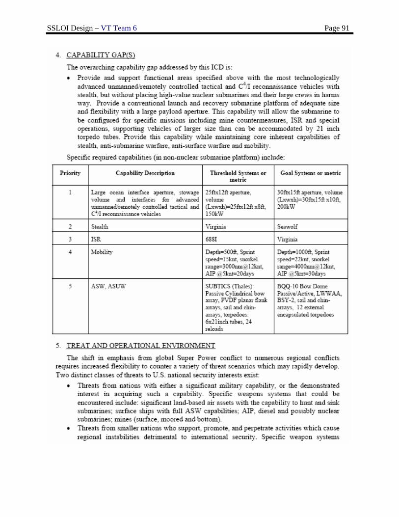
SSLOI Design – VT Team 6 Page 91
SSLOI Design – VT Team 6 Page 92
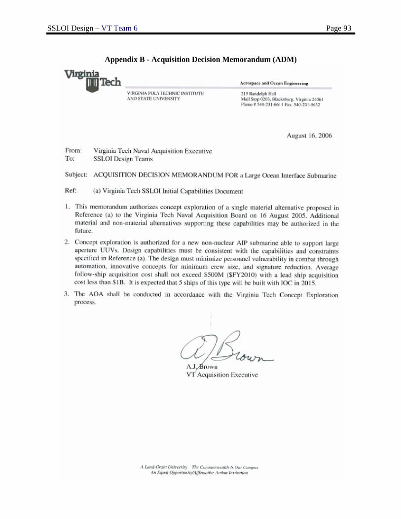
SSLOI Design – VT Team 6 Page 93
Appendix B - Acquisition Decision Memorandum (ADM)
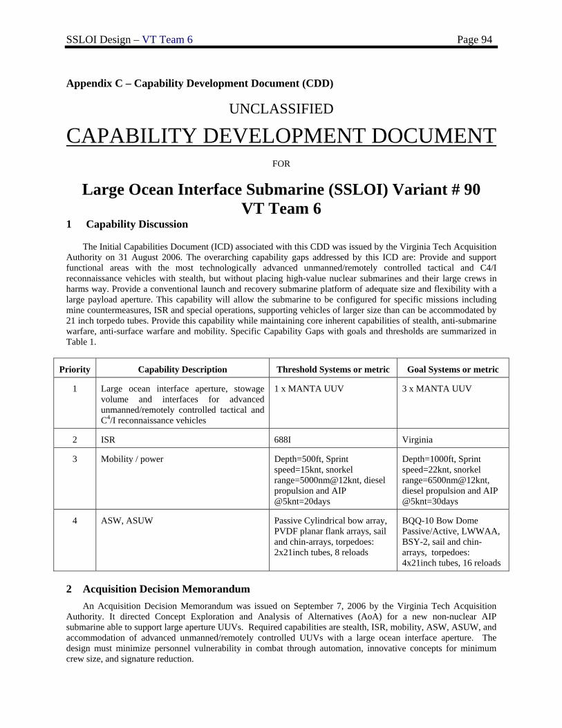
SSLOI Design – VT Team 6 Page 94
Appendix C – Capability Development Document (CDD)
UNCLASSIFIED
CAPABILITY DEVELOPMENT DOCUMENT FOR
Large Ocean Interface Submarine (SSLOI) Variant # 90 VT Team 6
1 Capability Discussion
The Initial Capabilities Document (ICD) associated with this CDD was issued by the Virginia Tech Acquisition Authority on 31 August 2006. The overarching capability gaps addressed by this ICD are: Provide and support functional areas with the most technologically advanced unmanned/remotely controlled tactical and C4/I reconnaissance vehicles with stealth, but without placing high-value nuclear submarines and their large crews in harms way. Provide a conventional launch and recovery submarine platform of adequate size and flexibility with a large payload aperture. This capability will allow the submarine to be configured for specific missions including mine countermeasures, ISR and special operations, supporting vehicles of larger size than can be accommodated by 21 inch torpedo tubes. Provide this capability while maintaining core inherent capabilities of stealth, anti-submarine warfare, anti-surface warfare and mobility. Specific Capability Gaps with goals and thresholds are summarized in Table 1.
Priority Capability Description Threshold Systems or metric Goal Systems or metric
1 Large ocean interface aperture, stowage volume and interfaces for advanced unmanned/remotely controlled tactical and C4/I reconnaissance vehicles
1 x MANTA UUV 3 x MANTA UUV
2 ISR 688I Virginia
3 Mobility / power Depth=500ft, Sprint speed=15knt, snorkel range=5000nm@12knt, diesel propulsion and AIP @5knt=20days
Depth=1000ft, Sprint speed=22knt, snorkel range=6500nm@12knt, diesel propulsion and AIP @5knt=30days
4 ASW, ASUW Passive Cylindrical bow array, PVDF planar flank arrays, sail and chin-arrays, torpedoes: 2x21inch tubes, 8 reloads
BQQ-10 Bow Dome Passive/Active, LWWAA, BSY-2, sail and chin-arrays, torpedoes: 4x21inch tubes, 16 reloads
2 Acquisition Decision Memorandum An Acquisition Decision Memorandum was issued on September 7, 2006 by the Virginia Tech Acquisition
Authority. It directed Concept Exploration and Analysis of Alternatives (AoA) for a new non-nuclear AIP submarine able to support large aperture UUVs. Required capabilities are stealth, ISR, mobility, ASW, ASUW, and accommodation of advanced unmanned/remotely controlled UUVs with a large ocean interface aperture. The design must minimize personnel vulnerability in combat through automation, innovative concepts for minimum crew size, and signature reduction.
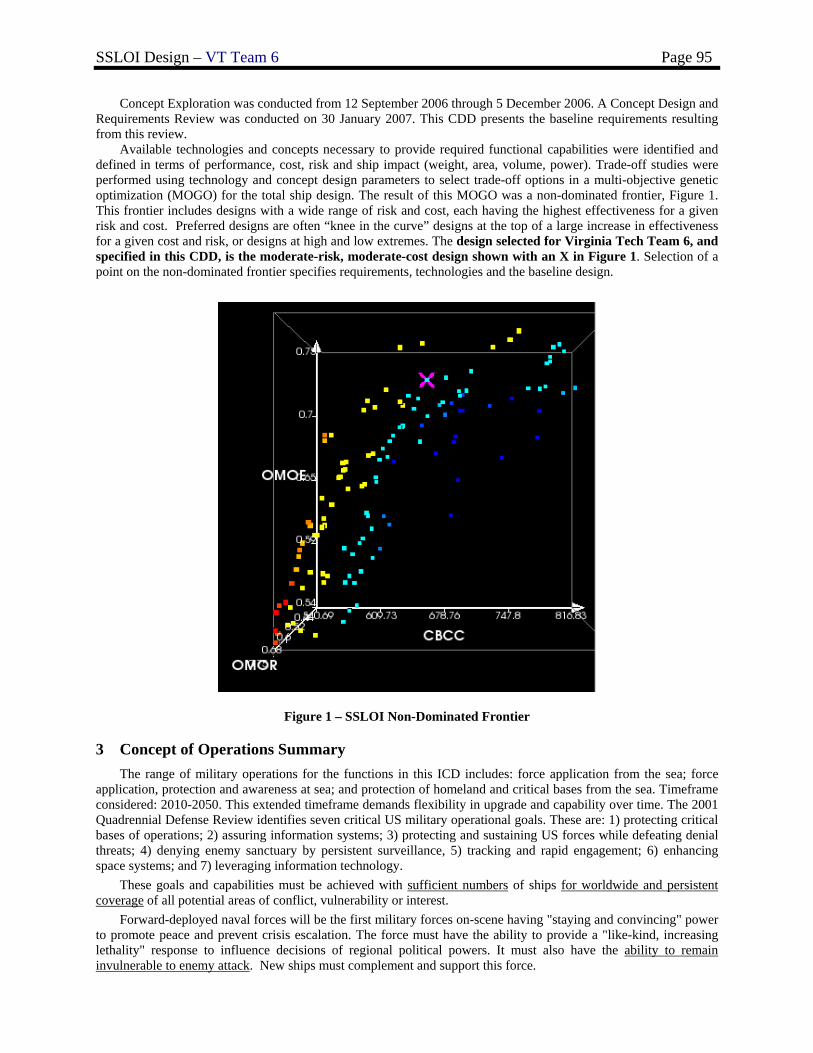
SSLOI Design – VT Team 6 Page 95
Concept Exploration was conducted from 12 September 2006 through 5 December 2006. A Concept Design and Requirements Review was conducted on 30 January 2007. This CDD presents the baseline requirements resulting from this review.
Available technologies and concepts necessary to provide required functional capabilities were identified and defined in terms of performance, cost, risk and ship impact (weight, area, volume, power). Trade-off studies were performed using technology and concept design parameters to select trade-off options in a multi-objective genetic optimization (MOGO) for the total ship design. The result of this MOGO was a non-dominated frontier, Figure 1. This frontier includes designs with a wide range of risk and cost, each having the highest effectiveness for a given risk and cost. Preferred designs are often “knee in the curve” designs at the top of a large increase in effectiveness for a given cost and risk, or designs at high and low extremes. The design selected for Virginia Tech Team 6, and specified in this CDD, is the moderate-risk, moderate-cost design shown with an X in Figure 1. Selection of a point on the non-dominated frontier specifies requirements, technologies and the baseline design.
Figure 1 – SSLOI Non-Dominated Frontier
3 Concept of Operations Summary The range of military operations for the functions in this ICD includes: force application from the sea; force
application, protection and awareness at sea; and protection of homeland and critical bases from the sea. Timeframe considered: 2010-2050. This extended timeframe demands flexibility in upgrade and capability over time. The 2001 Quadrennial Defense Review identifies seven critical US military operational goals. These are: 1) protecting critical bases of operations; 2) assuring information systems; 3) protecting and sustaining US forces while defeating denial threats; 4) denying enemy sanctuary by persistent surveillance, 5) tracking and rapid engagement; 6) enhancing space systems; and 7) leveraging information technology.
These goals and capabilities must be achieved with sufficient numbers of ships for worldwide and persistent coverage of all potential areas of conflict, vulnerability or interest.
Forward-deployed naval forces will be the first military forces on-scene having "staying and convincing" power to promote peace and prevent crisis escalation. The force must have the ability to provide a "like-kind, increasing lethality" response to influence decisions of regional political powers. It must also have the ability to remain invulnerable to enemy attack. New ships must complement and support this force.
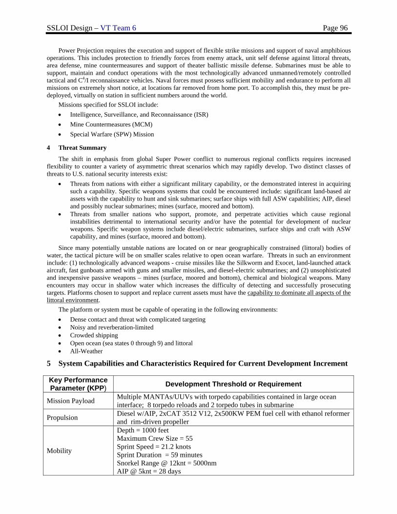
SSLOI Design – VT Team 6 Page 96
Power Projection requires the execution and support of flexible strike missions and support of naval amphibious operations. This includes protection to friendly forces from enemy attack, unit self defense against littoral threats, area defense, mine countermeasures and support of theater ballistic missile defense. Submarines must be able to support, maintain and conduct operations with the most technologically advanced unmanned/remotely controlled tactical and C4/I reconnaissance vehicles. Naval forces must possess sufficient mobility and endurance to perform all missions on extremely short notice, at locations far removed from home port. To accomplish this, they must be pre-deployed, virtually on station in sufficient numbers around the world.
Missions specified for SSLOI include: • Intelligence, Surveillance, and Reconnaissance (ISR) • Mine Countermeasures (MCM) • Special Warfare (SPW) Mission
4 Threat Summary
The shift in emphasis from global Super Power conflict to numerous regional conflicts requires increased flexibility to counter a variety of asymmetric threat scenarios which may rapidly develop. Two distinct classes of threats to U.S. national security interests exist:
• Threats from nations with either a significant military capability, or the demonstrated interest in acquiring such a capability. Specific weapons systems that could be encountered include: significant land-based air assets with the capability to hunt and sink submarines; surface ships with full ASW capabilities; AIP, diesel and possibly nuclear submarines; mines (surface, moored and bottom).
• Threats from smaller nations who support, promote, and perpetrate activities which cause regional instabilities detrimental to international security and/or have the potential for development of nuclear weapons. Specific weapon systems include diesel/electric submarines, surface ships and craft with ASW capability, and mines (surface, moored and bottom).
Since many potentially unstable nations are located on or near geographically constrained (littoral) bodies of water, the tactical picture will be on smaller scales relative to open ocean warfare. Threats in such an environment include: (1) technologically advanced weapons - cruise missiles like the Silkworm and Exocet, land-launched attack aircraft, fast gunboats armed with guns and smaller missiles, and diesel-electric submarines; and (2) unsophisticated and inexpensive passive weapons – mines (surface, moored and bottom), chemical and biological weapons. Many encounters may occur in shallow water which increases the difficulty of detecting and successfully prosecuting targets. Platforms chosen to support and replace current assets must have the capability to dominate all aspects of the littoral environment.
The platform or system must be capable of operating in the following environments: • Dense contact and threat with complicated targeting • Noisy and reverberation-limited • Crowded shipping • Open ocean (sea states 0 through 9) and littoral • All-Weather
5 System Capabilities and Characteristics Required for Current Development Increment
Key Performance Parameter (KPP) Development Threshold or Requirement
Mission Payload Multiple MANTAs/UUVs with torpedo capabilities contained in large ocean interface; 8 torpedo reloads and 2 torpedo tubes in submarine
Propulsion Diesel w/AIP, 2xCAT 3512 V12, 2x500KW PEM fuel cell with ethanol reformer and rim-driven propeller
Mobility
Depth = 1000 feet Maximum Crew Size = 55 Sprint Speed = 21.2 knots Sprint Duration = 59 minutes Snorkel Range @ 12knt = 5000nm AIP @ 5knt = 28 days
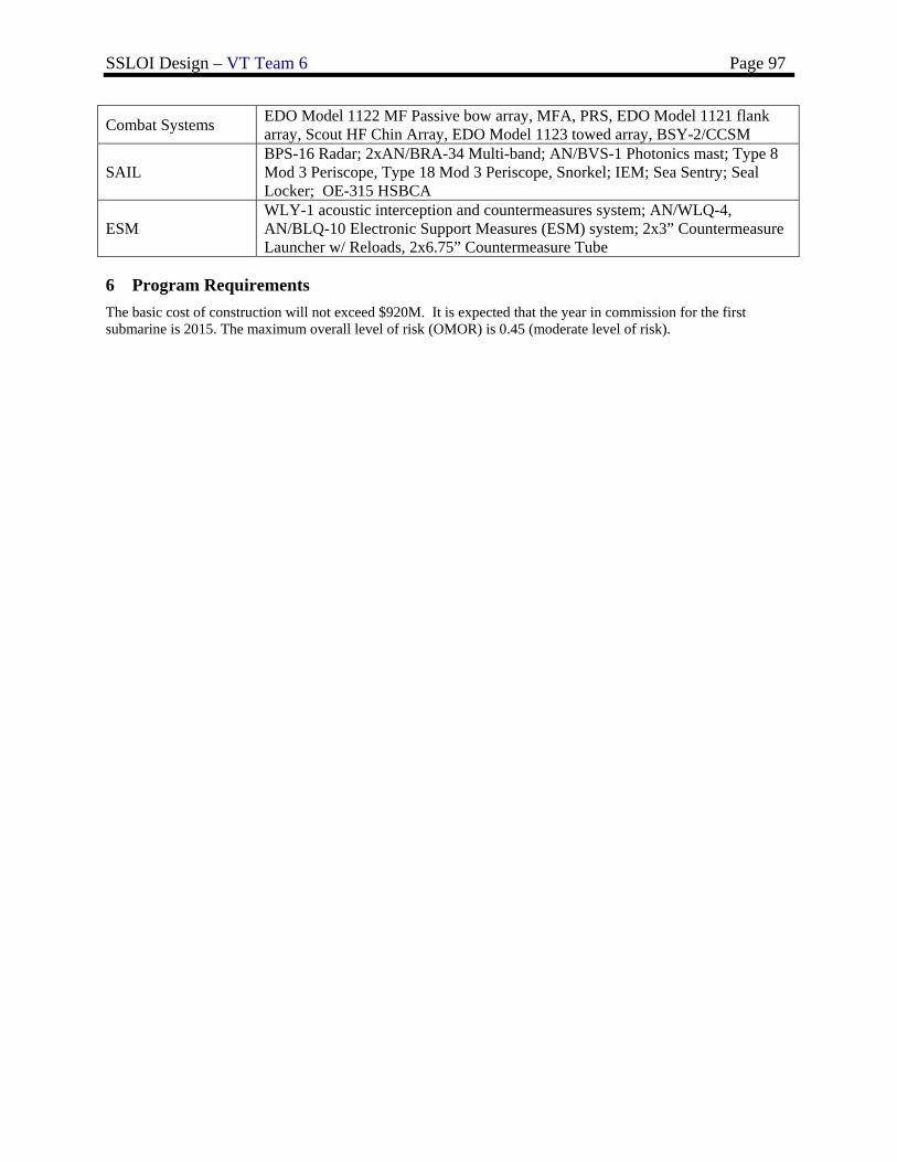
SSLOI Design – VT Team 6 Page 97
Combat Systems EDO Model 1122 MF Passive bow array, MFA, PRS, EDO Model 1121 flank array, Scout HF Chin Array, EDO Model 1123 towed array, BSY-2/CCSM
SAIL BPS-16 Radar; 2xAN/BRA-34 Multi-band; AN/BVS-1 Photonics mast; Type 8 Mod 3 Periscope, Type 18 Mod 3 Periscope, Snorkel; IEM; Sea Sentry; Seal Locker; OE-315 HSBCA
ESM WLY-1 acoustic interception and countermeasures system; AN/WLQ-4, AN/BLQ-10 Electronic Support Measures (ESM) system; 2x3” Countermeasure Launcher w/ Reloads, 2x6.75” Countermeasure Tube
6 Program Requirements The basic cost of construction will not exceed $920M. It is expected that the year in commission for the first submarine is 2015. The maximum overall level of risk (OMOR) is 0.45 (moderate level of risk).
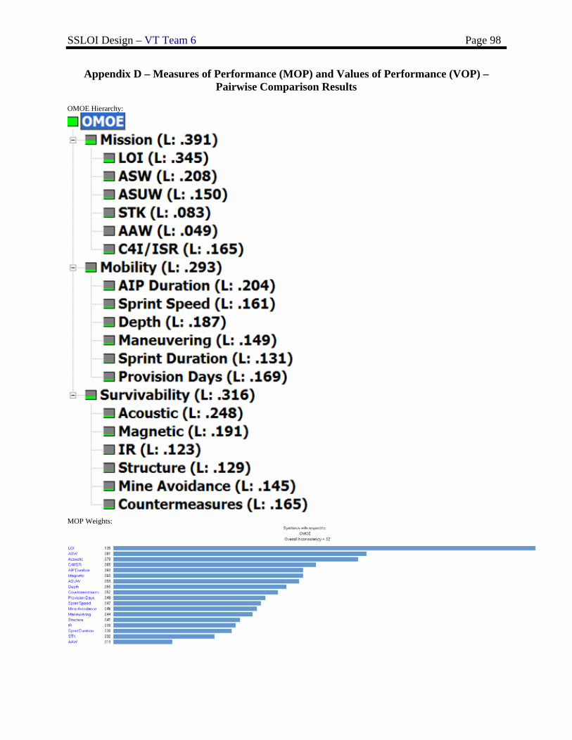
SSLOI Design – VT Team 6 Page 98
Appendix D – Measures of Performance (MOP) and Values of Performance (VOP) – Pairwise Comparison Results
OMOE Hierarchy:
MOP Weights:
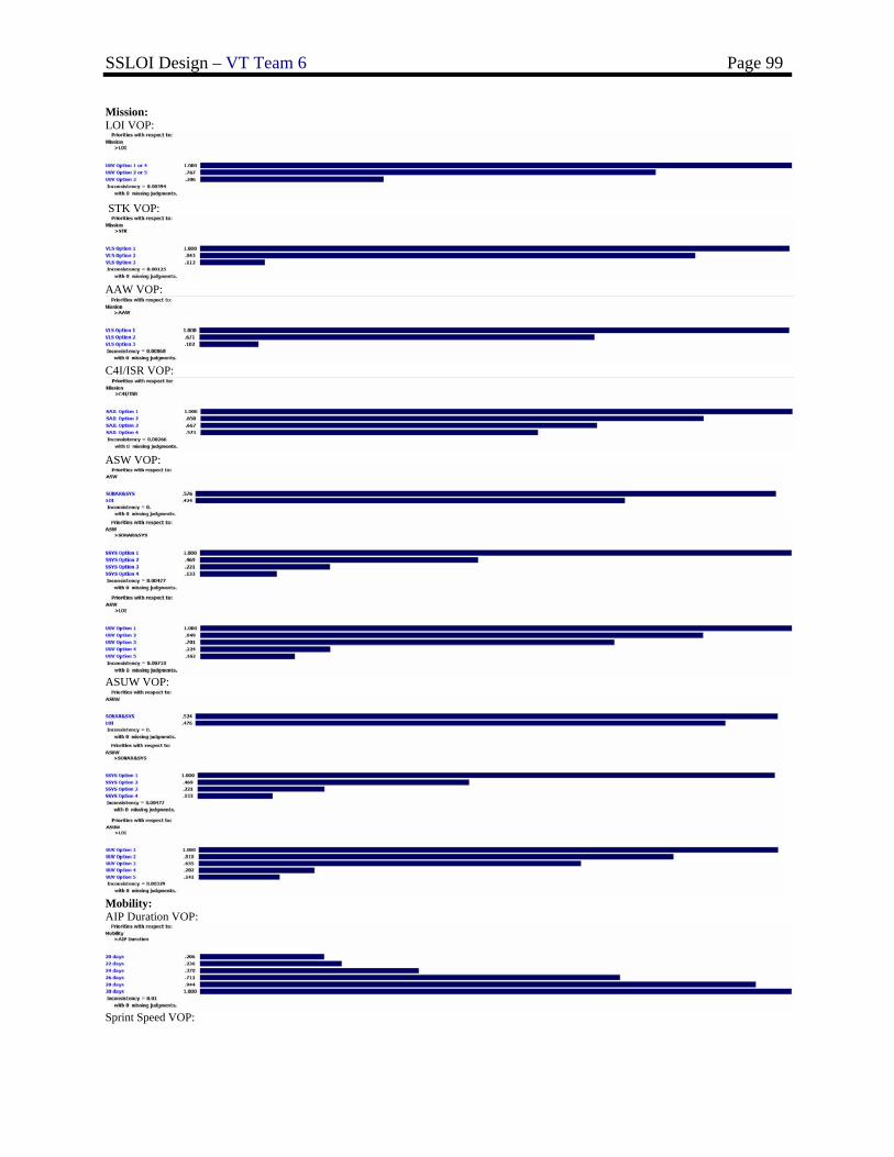
SSLOI Design – VT Team 6 Page 99
Mission: LOI VOP:
STK VOP:
AAW VOP:
C4I/ISR VOP:
ASW VOP:
ASUW VOP:
Mobility: AIP Duration VOP:
Sprint Speed VOP:
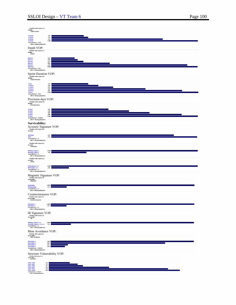
SSLOI Design – VT Team 6 Page 100
Depth VOP:
Sprint Duration VOP:
Provision days VOP:
Survivability: Acoustic Signature VOP:
Magnetic Signature VOP:
Countermeasures VOP:
IR Signature VOP:
Mine Avoidance VOP:
Structure Vulnerability VOP:
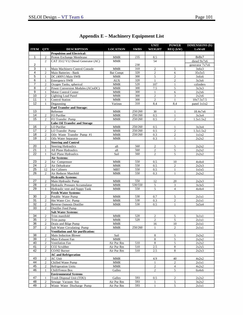
SSLOI Design – VT Team 6 Page 101
Appendix E – Machinery Equipment List
ITEM QTY DESCRIPTION LOCATION SWBSUNIT
WEIGHTPOWER
REQ (kW)DIMENSIONS (ft)
LxWxHPropulsion and Electrical:
1 2 Proton Exchange Membrane MMR 235 8.5 8x8x7diesel 9x7x6
generator 7x7x6 3 1 Main Machinery Control Console MMR 310 2 5 3x6x34 2 Main Batteries - Bank Bat Compt 320 2 6 35x5x55 1 DC (400V) Main SWB MMR 300 5 2 3x6x66 1 Emergency SWB AUX 320 1 2 3x3x67 2 Oxygen Tanks, spherical MMR 520 107 1 cylinders8 2 Power Conversion Modules (ACtoDC) MMR 300 7.5 5 3x3x39 1 Motor Control Center MMR 300 1 6 2x2x610 2 Lighting Load Panel MMR 300 2 3 2x2x611 1 Control Station MMR 300 2 1 10x7.5x7.512 1 Degaussing Various 310 8.4 8.4 panel 1x1x2
Fuel Transfer and Storage:13 Reformer MMR 250/260 30 1 18.4x7x614 2 FO Purifier MMR 250/260 0.5 1 3x3x415 2 FO Transfer Pump MMR 250/260 0.5 2 1.5x1.5x2
Lube Oil Transfer and Storage16 2 LO Purifier MMR 250/260 0.5 1 3x3x417 2 LO Transfer Pump MMR 250/260 0.5 2 1.5x1.5x218 2 Oily Waste Transfer Pump #1 MMR 250/260 0.3 2 1x1x219 2 Oily Water Separator MMR 0.3 1 2x2x2
Steering and Control20 1 Steering Hydraulics aft 560 2 5 2x2x221 1 Aft Plane Hydraulics aft 560 2 5 2x2x222 1 Sail Plane Hydraulics Sail 560 2 5 2x2x2
Air Systems:23 2 Air Compressor MMR 550 0.5 10 4x4x424 2 Air Dehydrator MMR 550 0.5 2 2x2x325 12 Air Cyliners MBT 550 0.5 1 1x1x526 2 Air Reducer Manifold MMR 550 0.3 1 2x2x2
Hydraulic Systems:27 2 Main Hydraulic Pump MMR 550 12 20 2x2x328 2 Hydraulic Pressure Accumulator MMR 530/550 5 3 3x3x529 1 Hydraulic vent and Suppy Tank MMR 550 5 4 4x4x4
Fresh Water Systems:30 2 Potable Water Pump MMR 530 0.7 5 2x1x131 2 Hot Water Circ Pump MMR 530 0.3 2 2x1x132 2 Reverse Osmosis Distiller MMR 530 0.5 1 5x5x433 2 Distiller Feed Pump
Salt Water Systems:34 2 Trim manifold MMR 520 2 5 3x1x135 2 Trim pump MMR 520 2 5 2x1x136 2 Drain and Bilge Pump MMR 16 10 2x1x137 2 Salt Water Circulating Pump MMR 250/260 1 2 2x1x1
Ventilation and Air purification:38 2 Main Induction Blower Sail 8 5 2x2x239 2 Main Exhaust Fan MMR 8 5 2x2x240 2 Ventilation Fan Air Pur Rm 510 8 5 2x2x241 2 CO2 Scrubber Air Pur Rm 510 2.5 8 2x2x542 2 CO/H2 Burner Air Pur Rm 510 2.5 8 2x2x3
AC and Refrigeration43 2 AC Unit MMR 4.9 40 4x2x244 2 Chilled Water Pump MMR 1 2 2x1x145 2 Refrigeration Units MMR 2 4 4x2x246 1 Chill/Freeze Box Galley 2 5 6x4x6
Environmental Systems47 1 Trash Disposal Unit (TDU) Galley 593 0.5 2 2x2x248 2 Sewage Vacuum Sys Air Pur Rm 593 1 5 3x2x249 2 Waste Water Discharge Pump Air Pur Rm 593 1 5 2x1x1
MMR230
542
2 CAT 3512 V12 Diesel Generator (AC)
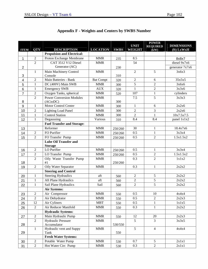
SSLOI Design – VT Team 6 Page 102
Appendix F - Weights and Centers by SWBS Number
ITEM QTY DESCRIPTION LOCATION SWBS UNIT
WEIGHT
POWER REQUIRED
(kW) DIMENSIONS
(ft) LxWxH Propulsion and Electrical: 1 2 Proton Exchange Membrane MMR 235 8.5 8x8x7
diesel 9x7x6 2
2 CAT 3512 V12 Diesel Generator (AC)
MMR 230
54 generator 7x7x6
3 1 Main Machinery Control
Console MMR
310 2 5 3x6x3
4 2 Main Batteries - Bank Bat Compt 320 2 6 35x5x5 5 1 DC (400V) Main SWB MMR 300 5 2 3x6x6 6 1 Emergency SWB AUX 320 1 2 3x3x6 7 2 Oxygen Tanks, spherical MMR 520 107 1 cylinders
8 2 Power Conversion Modules
(ACtoDC) MMR
300 7.5 5 3x3x3
9 1 Motor Control Center MMR 300 1 6 2x2x6 10 2 Lighting Load Panel MMR 300 2 3 2x2x6 11 1 Control Station MMR 300 2 1 10x7.5x7.5 12 1 Degaussing Various 310 8.4 8.4 panel 1x1x2 Fuel Transfer and Storage:
13 Reformer MMR 250/260 30 1 18.4x7x6 14 2 FO Purifier MMR 250/260 0.5 1 3x3x4 15 2 FO Transfer Pump MMR 250/260 0.5 2 1.5x1.5x2
Lube Oil Transfer and
Storage
16 2 LO Purifier MMR 250/260 0.5 1 3x3x4 17 2 LO Transfer Pump MMR 250/260 0.5 2 1.5x1.5x2
18 2 Oily Waste Transfer Pump
#1 MMR
250/260 0.3 2 1x1x2
19 2 Oily Water Separator MMR 0.3 1 2x2x2 Steering and Control
20 1 Steering Hydraulics aft 560 2 5 2x2x2 21 1 Aft Plane Hydraulics aft 560 2 5 2x2x2 22 1 Sail Plane Hydraulics Sail 560 2 5 2x2x2 Air Systems:
23 2 Air Compressor MMR 550 0.5 10 4x4x4 24 2 Air Dehydrator MMR 550 0.5 2 2x2x3 25 12 Air Cyliners MBT 550 0.5 1 1x1x5 26 2 Air Reducer Manifold MMR 550 0.3 1 2x2x2 Hydraulic Systems:
27 2 Main Hydraulic Pump MMR 550 12 20 2x2x3
28 2 Hydraulic Pressure
Accumulator MMR
530/550 5 3 3x3x5
29 1 Hydraulic vent and Suppy
Tank MMR
550 5 4 4x4x4
Fresh Water Systems: 30 2 Potable Water Pump MMR 530 0.7 5 2x1x1 31 2 Hot Water Circ Pump MMR 530 0.3 2 2x1x1
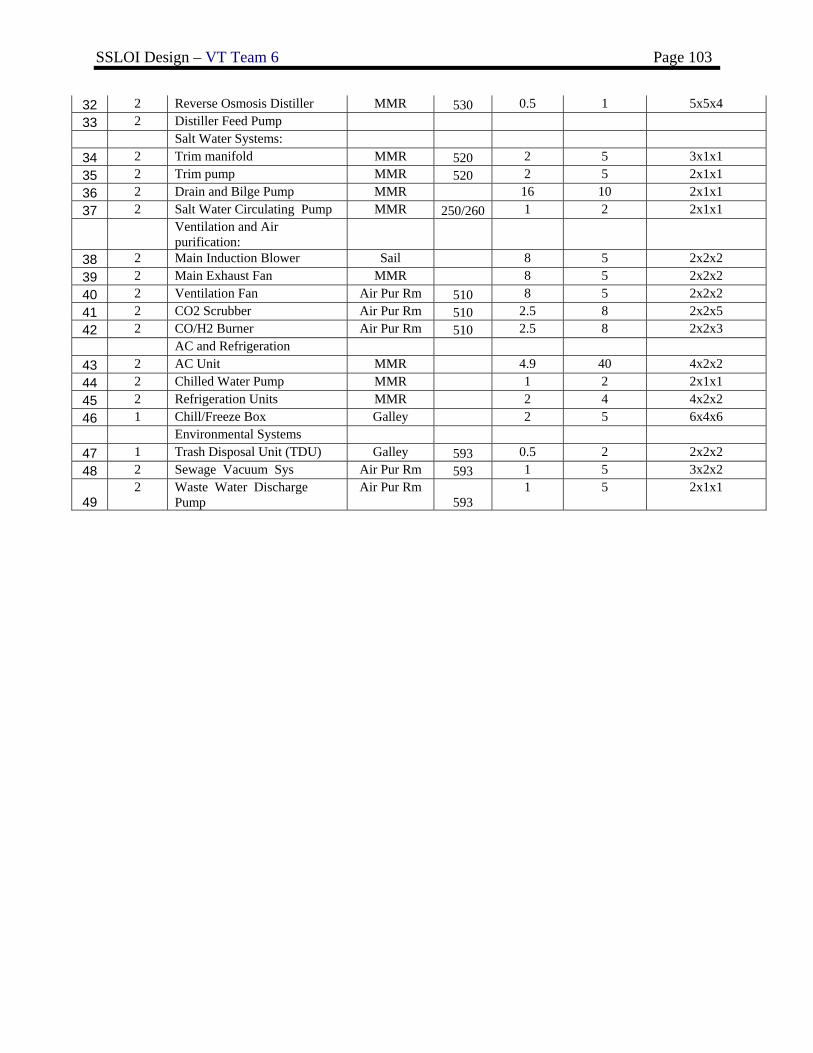
SSLOI Design – VT Team 6 Page 103
32 2 Reverse Osmosis Distiller MMR 530 0.5 1 5x5x4 33 2 Distiller Feed Pump Salt Water Systems:
34 2 Trim manifold MMR 520 2 5 3x1x1 35 2 Trim pump MMR 520 2 5 2x1x1 36 2 Drain and Bilge Pump MMR 16 10 2x1x1 37 2 Salt Water Circulating Pump MMR 250/260 1 2 2x1x1
Ventilation and Air
purification:
38 2 Main Induction Blower Sail 8 5 2x2x2 39 2 Main Exhaust Fan MMR 8 5 2x2x2 40 2 Ventilation Fan Air Pur Rm 510 8 5 2x2x2 41 2 CO2 Scrubber Air Pur Rm 510 2.5 8 2x2x5 42 2 CO/H2 Burner Air Pur Rm 510 2.5 8 2x2x3 AC and Refrigeration
43 2 AC Unit MMR 4.9 40 4x2x2 44 2 Chilled Water Pump MMR 1 2 2x1x1 45 2 Refrigeration Units MMR 2 4 4x2x2 46 1 Chill/Freeze Box Galley 2 5 6x4x6 Environmental Systems
47 1 Trash Disposal Unit (TDU) Galley 593 0.5 2 2x2x2 48 2 Sewage Vacuum Sys Air Pur Rm 593 1 5 3x2x2
49 2 Waste Water Discharge
Pump Air Pur Rm
593 1 5 2x1x1
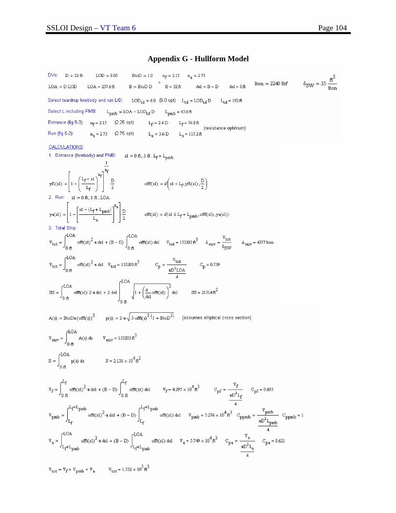
SSLOI Design – VT Team 6 Page 104
Appendix G - Hullform Model
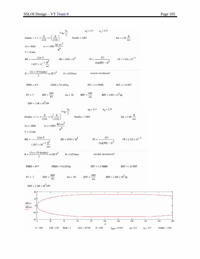
SSLOI Design – VT Team 6 Page 105
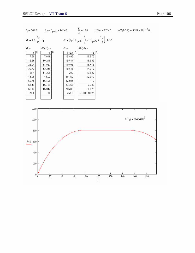
SSLOI Design – VT Team 6 Page 106
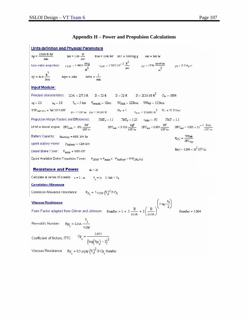
SSLOI Design – VT Team 6 Page 107
Appendix H – Power and Propulsion Calculations
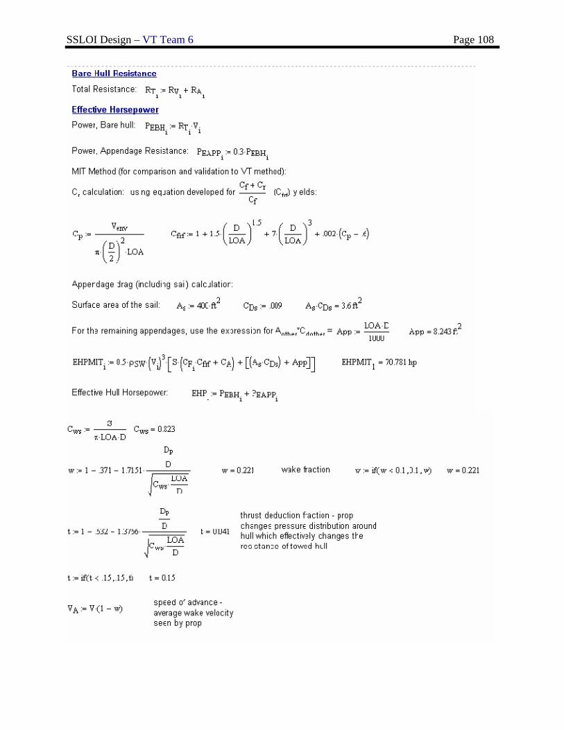
SSLOI Design – VT Team 6 Page 108
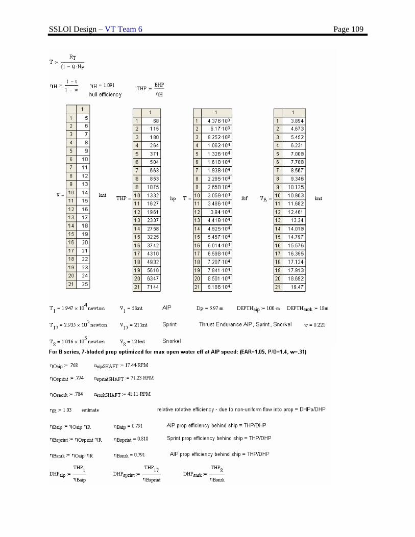
SSLOI Design – VT Team 6 Page 109
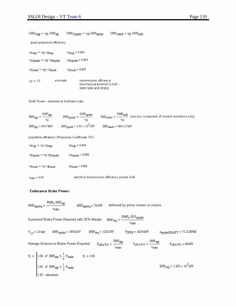
SSLOI Design – VT Team 6 Page 110
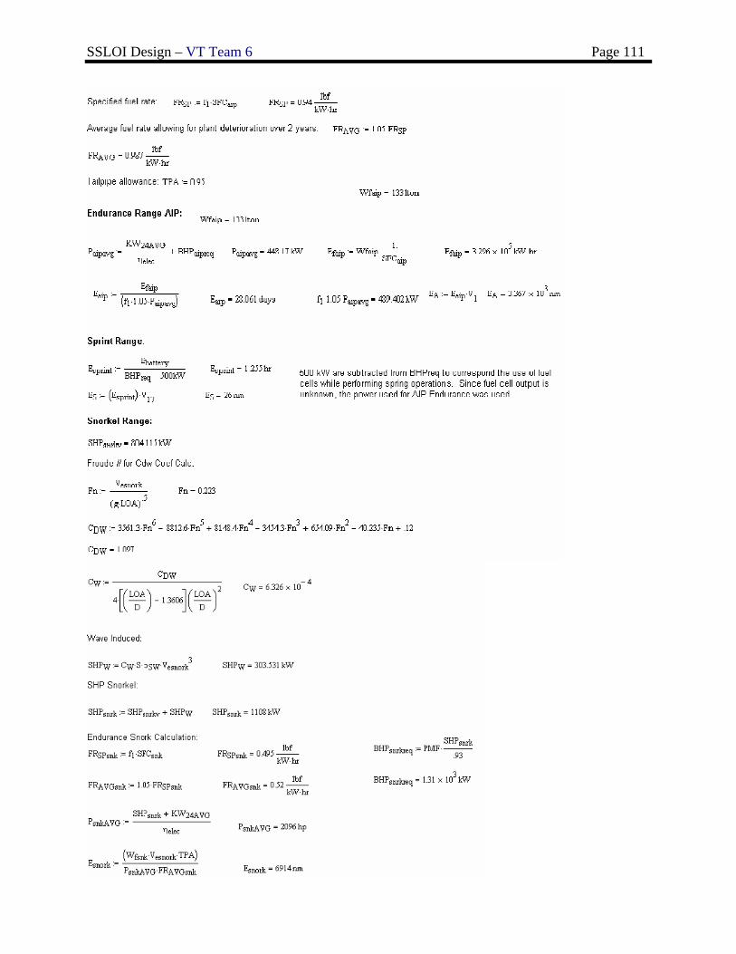
SSLOI Design – VT Team 6 Page 111
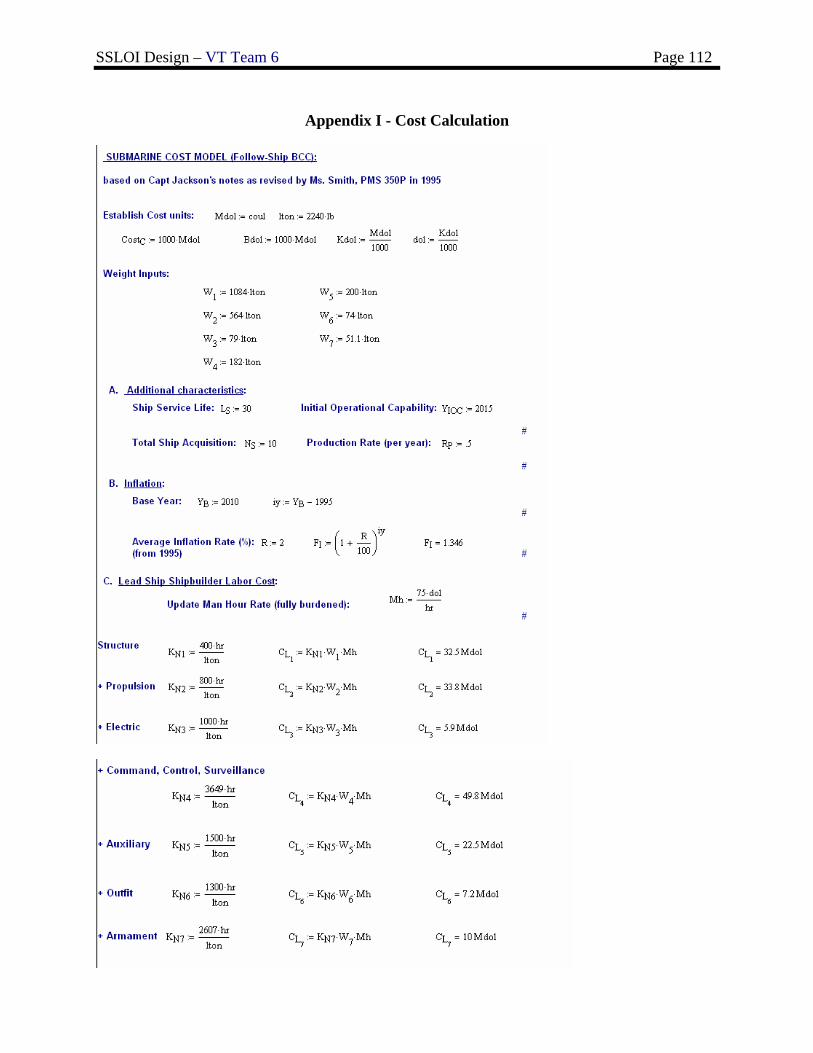
SSLOI Design – VT Team 6 Page 112
Appendix I - Cost Calculation
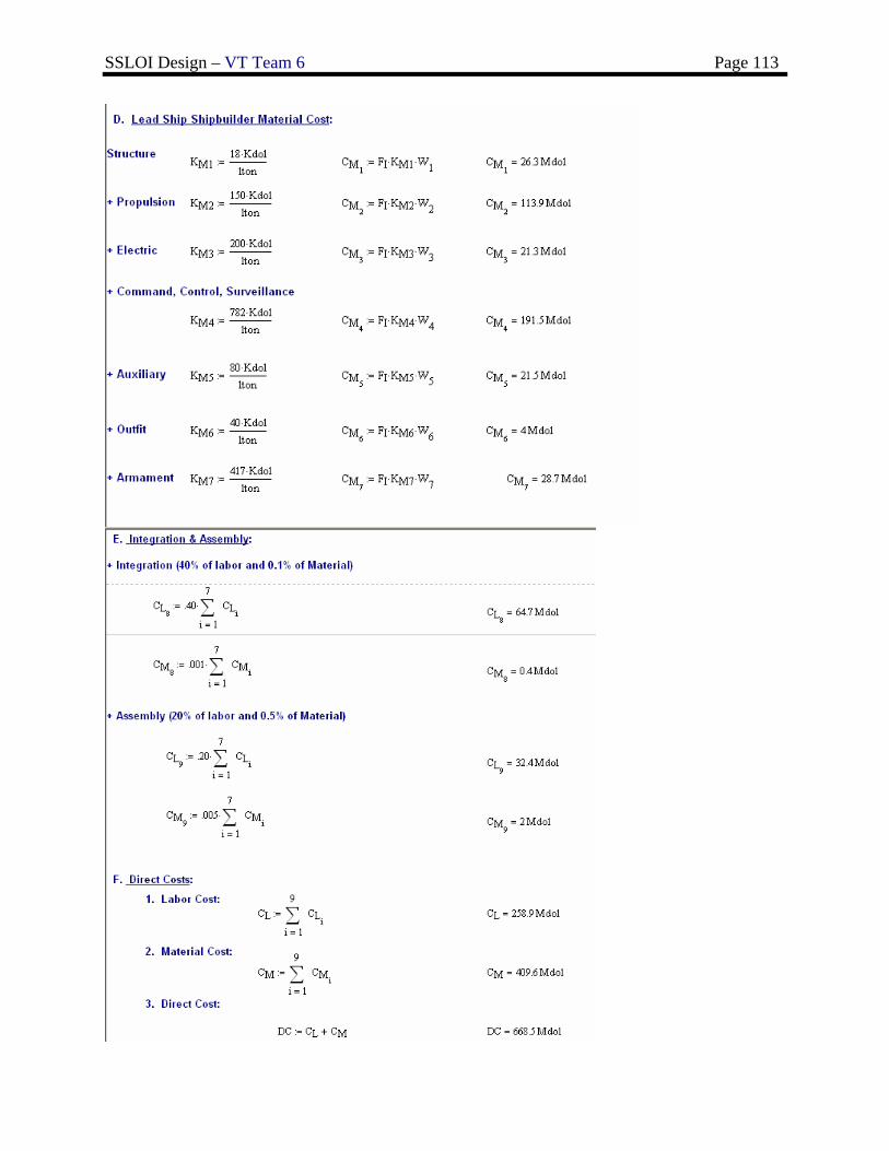
SSLOI Design – VT Team 6 Page 113
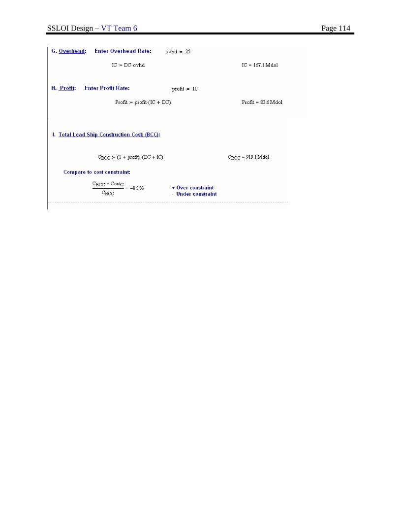
SSLOI Design – VT Team 6 Page 114
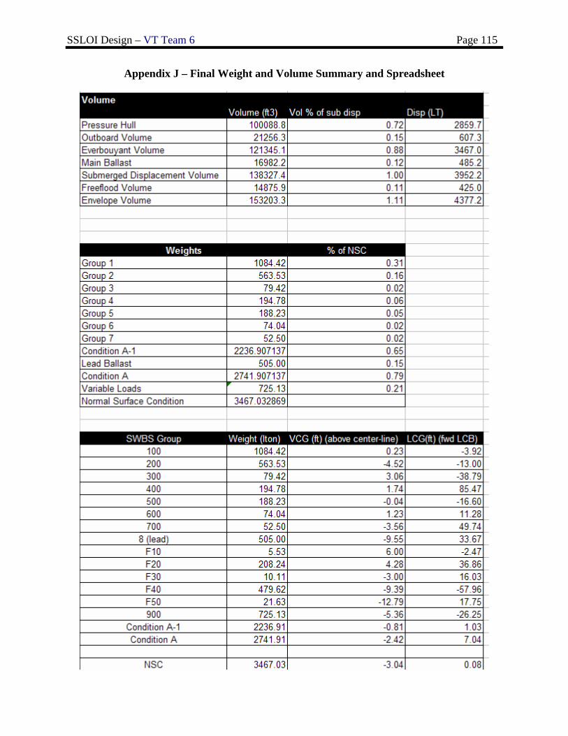
SSLOI Design – VT Team 6 Page 115
Appendix J – Final Weight and Volume Summary and Spreadsheet
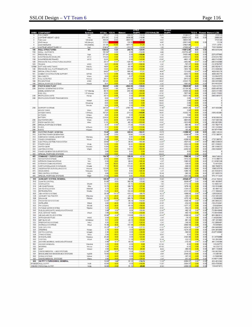
SSLOI Design – VT Team 6 Page 116
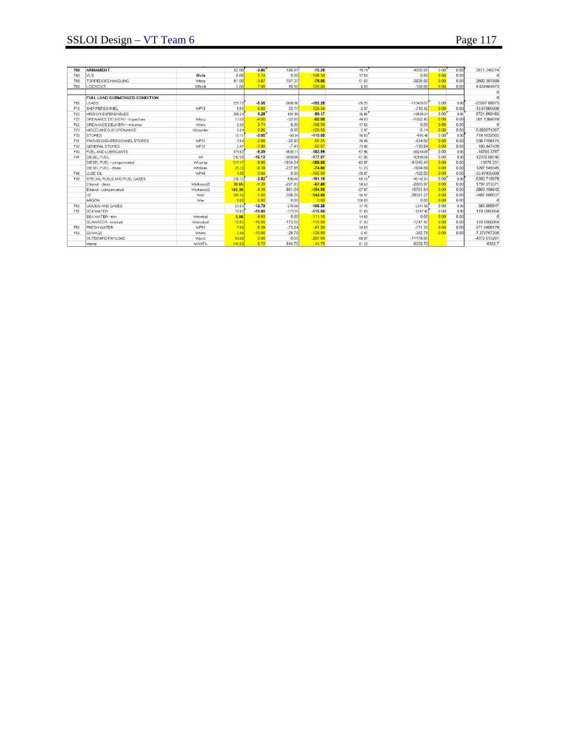
SSLOI Design – VT Team 6 Page 117