ssp 420 audi 2.0-litre tdi engine with common rail injection system
TRANSCRIPT

Audi 2.0-litre TDI Engine withCommon Rail Injection System
Self-Study Programme 420
Service Training

The 105 kW (143 hp) 2.0-litre TDI engine featuring
common rail (CR) injection technology marks the
birth of a new generation of dynamic and efficient
diesel engines. It reinterprets the qualities of the TDI
concept while addressing the future challenges facing
environmental protection in particular.
The 2.0-litre TDI CR engine is based on the successful
2.0-litre pump injector TDI engine, whereby the
combination of the 2.0-litre TDI unit with common rail
technology sets new standards.
The new 2.0-litre TDI CR engine built at Audi Hungaria
Motor in Györ already meets the high standards of the
Euro 5 exhaust emission standard due to come into
effect in 2010.
Thanks to the use of common rail technology, the
2.0-litre TDI CR engine has major advantages with
regard to exhaust emissions, acoustics, weight and
overall build height.
The TDI engines deliver high torque at low revs.
The goal for the development of the 2.0-litre TDI
CR engine was to enhance this character.
Cylinder block . . . . . . . . . . . . . . . . . . . . . . . . . . . . . . . . . . . . . . . . . . . . . . . . . . . . . . . 7
Crank mechanism . . . . . . . . . . . . . . . . . . . . . . . . . . . . . . . . . . . . . . . . . . . . . . . . . . . . 7
Balancer shaft module . . . . . . . . . . . . . . . . . . . . . . . . . . . . . . . . . . . . . . . . . . . . . . . . 9
Cylinder head . . . . . . . . . . . . . . . . . . . . . . . . . . . . . . . . . . . . . . . . . . . . . . . . . . . . . . . 10
Camshaft drive . . . . . . . . . . . . . . . . . . . . . . . . . . . . . . . . . . . . . . . . . . . . . . . . . . . . . . .11
4-valve technology. . . . . . . . . . . . . . . . . . . . . . . . . . . . . . . . . . . . . . . . . . . . . . . . . . . .12
Toothed belt drive . . . . . . . . . . . . . . . . . . . . . . . . . . . . . . . . . . . . . . . . . . . . . . . . . . . .13
Intake manifold with swirl flaps . . . . . . . . . . . . . . . . . . . . . . . . . . . . . . . . . . . . . . . .14
Oil circulation system . . . . . . . . . . . . . . . . . . . . . . . . . . . . . . . . . . . . . . . . . . . . . . . . .16
Crankcase ventilation system . . . . . . . . . . . . . . . . . . . . . . . . . . . . . . . . . . . . . . . . . .18
Coolant system. . . . . . . . . . . . . . . . . . . . . . . . . . . . . . . . . . . . . . . . . . . . . . . . . . . . . . .22
Exhaust gas recirculation cooling system. . . . . . . . . . . . . . . . . . . . . . . . . . . . . . . .24
The Self-Study Programme teaches the design and function of new vehicle models, new automotive components or new technologies.
The Self-Study Programme is not a Repair Manual.Values specified herein are intended for easier understanding only and refer to the software version valid at the time of preparation of the SSP.
For information about maintenance and repair work, always refer to the current technical literature.
Contents
Introduction
Common rail injection system
Engine management
2.0-litre 105 kW TDI engine with common rail injection system. . . . . . . . . . . . . . 4
System overview . . . . . . . . . . . . . . . . . . . . . . . . . . . . . . . . . . . . . . . . . . . . . . . . . . . . .42
Engine management . . . . . . . . . . . . . . . . . . . . . . . . . . . . . . . . . . . . . . . . . . . . . . . . . .44
Engine mechanicals
Introduction . . . . . . . . . . . . . . . . . . . . . . . . . . . . . . . . . . . . . . . . . . . . . . . . . . . . . . . . .25
Fuel system . . . . . . . . . . . . . . . . . . . . . . . . . . . . . . . . . . . . . . . . . . . . . . . . . . . . . . . . . .26
Auxiliary fuel pump . . . . . . . . . . . . . . . . . . . . . . . . . . . . . . . . . . . . . . . . . . . . . . . . . . 28
Fuel preheating valve . . . . . . . . . . . . . . . . . . . . . . . . . . . . . . . . . . . . . . . . . . . . . . . . .29
Common rail injection system . . . . . . . . . . . . . . . . . . . . . . . . . . . . . . . . . . . . . . . . 30
Service
Special tools . . . . . . . . . . . . . . . . . . . . . . . . . . . . . . . . . . . . . . . . . . . . . . . . . . . . . . . 62
NoteReference

4
420_009
Introduction
2.0-litre 105 kW TDI engine with common rail injection system
The 2.0-litre TDI engine with common rail injection system is based on the 1.9-litre/2.0-litre TDI engine with pump injection system. The predecessor engine (base engine) is one of the world's biggest-selling diesel engines.To meet the higher demands with regard to acoustics, fuel economy and exhaust emissions, a large number of engine components have been revised.
A major change was the adoption of the common rail technology for the injection system.Equipped with a diesel particulate filter, the engine meets current Euro 4 emission standards. In several markets the engine is also available without a diesel particulate filter. These engines meet the Euro 3 exhaust emission standard.

5
Specifications
Engine code CAGA
Type of engine 4-cylinder inline engine
Displacement in cm3 1968
Max. power in kW (bhp) 105 (143) at 4200 rpm
Max. torque in Nm 320 at 1750 to 2500 RPM
No. of valves per cylinder 4
Bore in mm 81
Stroke in mm 95.5
Compression ratio 16,5 : 1
Engine management Bosch EDC 17
Exhaust emission control Oxidising catalytic converter, water-cooled exhaust gas recirculation, maintenance-free diesel particulate filter
Exhaust emission standard Euro 4
420_078
2.0-litre TDI common rail engine
Technical features
– Common rail injection system with piezoelectric injectors
– Diesel particulate filter with upstream oxidising catalytic converter
– Intake manifold with swirl flap adjustment– Electrical EGR valve– Adjustable exhaust gas turbocharger with flow-
path feedback– Low-temperature EGR cooling system
Torque/power curve
Max. torque in Nm
Max. power in kW
Engine speed in rpm

6
420_131
420_130
420_133
420_132
420_129
Engine code on the engine block
Vehicle data storage module
Introduction
The new generation of engine codes can be iden-tified as follows:
– The first digit of the engine code begins with a "C".
– The three-digit engine codes are still used on the engine block.
– The four-digit engine codes can only be found on the vehicle data storage module, the control unit and the nameplate.
New engine code system
To reduce engine code diversity, a new fourth digit has been added to the three-digit engine code. The new fourth digit denotes the power level, e.g. A, B etc., whereby the base engine is identical. Power and torque are adapted by means of the engine control unit software. Engines with a modified exhaust emissions concept do not have a revised engine code.
Adhesive labels on the engine control unit
Adhesive label with engine code
Nameplate

7
420_011
420_010
Engine mechanicals
Crankshaft drive
Crankshaft
On account of the high mechanical load, the 2.0-litre TDI common rail engine uses a forged crankshaft.To reduce the load on the crankshaft bearings, the crankshaft has only four counterweights instead of the usual eight.The result is enhanced engine vibrational behaviour and reduced noise emission.
Counterweight
Oil pump spline
Counterweight
Cylinder block
The cylinder block of the 2.0-litre TDI engine with common rail injection system is made of cast iron with lamellar graphite. The cylinder-to-cylinder spacing is 88 mm.
The geometry of the cylinder block is based on that of the 2.0-litre TDI engine with pump injection system.

8
420_012
420_013
Engine mechanicals
Pistons
Like on the 2.0-litre 125 kW TDI engine with pump injection system, the pistons have no valve pockets. This modification reduces crevice volume.For purposes of cooling the piston ring zone, the piston has an annular cooling duct into which oil is injected through piston spray nozzles.
Piston of 2.0-litre common rail engine
The piston recess where the injected fuel is swirled and mixed with the air is aligned with the discharge plane of the injectors and has a wider and flatter geometry than the piston on the pump injector engine. (This allows the formation of a homo-geneous air-fuel mixture and reduces particulate matter formation).
Piston - 2.0-litre pump injector engine
Piston recess
Piston ring assembly
Oil cooling port
Oil spray port
Trapezoidal conrod attachment

9
Note
The idler gear must be replaced whenever the idler gear or the drive gear of balancer shaft I are detached.
412_028
Balancer shaft module
The 2.0-litre 105 kW TDI common rail engine has a balancer shaft module accommodated in the oil pan under the crankshaft.
Design
The balancer shaft module consists of a cast iron housing, two counteropposed balancer shafts, the helical-cut gear drive and the integrated Duocentric oil pump.
The rotation of the crankshaft is transmitted to the intermediate gear on the outside of the housing. The intermediate gear drives balancer shaft I. The motion is then transmitted from this balancer shaft through a pair of gears inside the housing to balancer shaft II and the Duocentric oil pump.
The gear drive is configured in such a way that the balancer shafts rotate at twice the speed of the crankshaft.
The gear drive backlash is set by means of a coating on the idler gear. This coating wears off when the engine is put into operation, resulting in a defined backlash.
Crankshaft gear
Idler gear
Drive gearBalancer shaft I
Duocentric oil pump
Drive gearBalancer shaft II
Housing
The balancer shaft module is driven by the crank-shaft through a gear drive. The Duocentric oil pump is integrated in the balancer shaft module.

10
420_007
Engine mechanicals
Cylinder head
The cylinder head of the 2.0-litre TDI engine with common rail injection system is a cross-flow aluminium cylinder head with two intake valves and two exhaust valves per cylinder. The injectors are arranged upright.The overhead intake and exhaust camshafts are coupled via a spur gear assembly with integrated valve lifters.
They are driven by a crankshaft through a timing belt and by the camshaft sprocket of the exhaust camshaft.The valves are actuated by low-friction roller cam followers with hydraulic valve lifters.The injectors are held in place by clamps in the cylinder head and can removed through small caps on the valve cover hood.
Cylinder head
Injectors
Camshaft exhaust
Exhaust ports
Intake camshaft
Clamping element

11
420_026
420_023
Reference
For information about the design and function of the valve lifters, please refer to SSP 325, Audi A6 ´05 Engines and Transmissions.
420_025
Design
The wider spur gear element (non-rigid spur gear) is positively connected to the exhaust camshaft. There are six ramps on the face. The narrower spur gear element (non-rigid spur gear) is radially and axially movable. There are recesses for the six ramps on the back.
Function
Both spur gear elements are pressed together in an axial direction by the force of a diaphragm spring, while being made to rotate by the ramps.
Rigid spur gear
Non-rigid spur gear
Diaphragm spring
Ladder frame
Exhaust camshaft
Intake camshaft
Camshaft drive
The intake and exhaust camshafts are coupled to the integrated tooth flank lifters through a spur gear assembly. The spur gear of the intake camshaft is driven by the spur gear of the exhaust camshaft. Backlash compensation provides low-noise camshaft drive.
Adaptor plate
Retaining ring
Non-rigid spur gear
Diaphragm spring
Rigid spur gear
Ramps

12
420_015
420_103
Engine mechanicals
4 valve technology
Two intake valves and two exhaust valves per cylinder are arranged upright in the cylinder head.
The charging port provides good charging of the combustion chamber, particularly at high engine speeds.
(To optimise the conditions of flow inside the intake and exhaust ports, the valve stem has been rotated 8.8° towards the engine's longitudinal axis.)
The shape, size and layout of the intake and exhaust ports are designed to ensure good volumetric efficiency and optimise the charge cycle inside the combustion chamber.
The intake ports are configured as swirl and charging ports. The swirl port produces the required swirling motion of the intake air.
Intake valves
Exhaust camshaft
Intake camshaft Injector
Swirl port
Charging port
The upright and centrally positioned injector is located above the centre of the piston recess.
Exhaust valves
Tangential exhaust port
Rotated valve stem

13
420_029
Note
For information on the replacement interval of the timing belt, please refer to "Maintenance".
Toothed belt drive
The camshaft, the coolant pump and the high-pressure pump for the common rail injection system are driven through the timing belt.
Ancillary unit drive
The ancillary units (the alternator and the air condi-tioner compressor) are driven by the crankshaft through a ribbed V-belt.
Toothed belt drive
Ancillary unit drive by ribbed V-belt
Camshaft drive
Tension pulley
High-pressure pump drive
Coolantpump drive
Stabilising roller
Crankshaft drive
Sheave
Alternator drive
Air conditioner compressor drive
The ribbed V-belt has a fibrous coating which enhances frictional behaviour and minimises noise in wet and cold weather.

14
420_017
420_016
Engine mechanicals
Intake manifold with swirl flaps
Continuously variable swirl flaps are integrated in the intake manifold.
The swirl of the intake air is adjusted according to engine speed and load by the position of the swirl flaps.
The swirl flaps are actuated by the intake manifold flap motor V157 through a push rod. For this purpose, the servomotor is activated by the engine control unit. The intake manifold flap potentiometer G336, which is integrated in the intake manifold flap motor, provides the engine control unit with feedback on the current position of the swirl flaps.
Common intake manifold
Swirl port
Charging port
Swirl flap
Intake manifold flap motor V157

15
420_019
420_018
420_079
Function of the swirl flaps
The swirl flaps are closed when the engine is idling and running at low speed. This produces a strong swirl effect which optimises the mixture formation process.
The swirl flaps are opened when the engine is started, in limp-home mode and at full throttle.
While driving, the swirl flaps are adjusted continuously according to engine load and speed. This ensures the optimum air flow inside the combustion chamber in every operating range.
The swirl flaps are fully open at engine speeds of approx. 3000 rpm or higher. The increased air flow ensures optimum charging of the combustion chamber.
Charging port
Swirl port
Swirl flap closed

16
420_099
10 Crankshaft11 Oil spray nozzles for piston cooling12 Exhaust camshaft13 Intake camshaft14 Vacuum pump15 Turbocharger16 Oil return line17 Screen18 Flow restrictor
Legend
1 Oil pan2 Oil level and temperature sender G2663 Duocentric oil pump4 Oil pressure regulator5 Oil cooler6 Oil filter7 Short-circuit valve (filter bypass valve)8 Oil pressure retaining valve9 Oil pressure switch F1
Engine mechanicals
Oil circulation system

17
420_082
1
A A A A A
B B B B B B B B
C C C C C
9
14
85 6
34
11111111
A A A A A
B B B B B B B B
2
7
15
17
17
18
16
Lubrication system
A Duocentric oil pump (3) produces the oil pressure required by the engine. It is integrated in the balancer shaft module and driven through the balancer drive shaft. The oil pressure regulator (4) is a safety valve.
Cylinder head
Cylinder crankcase
A Camshaft bearingB Hydraulic valve liftersC Main bearing
Oil filter module
It prevents engine component damage due to high oil pressure, e.g. at low ambient temperatures and at high engine speed.The short-circuit valve (7) opens when the oil filter becomes clogged thereby ensuring that the engine is always lubricated.

18
420_030
Engine mechanicals
Crankcase ventilation system
In internal combustion engines, pressure differences between the combustion chamber and the crankcase result in air currents between the piston rings and the cylinder liner, or what are known as blow-by gases.To protect the environment, these oil-containing gases are recirculated to the intake tract through the crankcase ventilation system.
The increasingly stringent environmental protection requirements are placing tough demands with regard to effective oil separation. The multistage separation process minimises ingress of oil into the intake air and thereby reduces particulate emissions.
Oil separation takes place in three stages:
– Coarse separation– Fine separation– Damping chamber
The crankcase ventilation system components are integrated in the cylinder head cover together with the oil filler and the pressure accumulator for the engine vacuum system.
Primary oil separator
The blow-by gases flow from the crankshaft and camshaft space into a settling chamber. This chamber is integrated in the rocker cover. The larger oil droplets precipitate on the walls of the settling chamber and collect at the bottom of the settling chamber. The oil drips into the cylinder head through holes in the settling chamber.
Pressure regulating valve
Secondary oil separatorPrimary oil separator
Oil filler nozzle
Damping chamber

19
Flow pattern - overall
420_031
fromcrankcase
from crankcase
Cyclone
Settling chamber
Spring steel shuttle valves
to intake portDiaphragm
Support plate
Coil spring
Spring steel shuttle valve
Cover of pressure regulating valve
Outlet to intake port
Housing cover
Housing
Bottom section
Support
Damping chamber
Oil-containing blow-by gases from the crankcase
Oil-containing blow-by gases
Oil return line

20
420_086
420_032
Engine mechanicals
Secondary oil separator
Fine separation is achieved by means of a cyclone oil separator consisting of a total of four cyclones. Depending on the pressure differential between the intake manifold and the crankcase, two or four cyclones are activated by spring-steel shuttle valves. Due to the shape of the cyclone, the air is made to rotate.
Pressure regulating valve
CycloneFine oil-filtered air to intake port
Shuttle valves
Oil collecting chamberOil to
crankcase
Shuttle valve
Fine separation, small pressure differential
Fine separation, large pressure differential

21
420_100 420_101
420_119
Pressure regulating valve
If the vacuum inside the intake port is low, the valve opens due to the force of the compression spring.
If the vacuum inside the intake port is high, the pressure regulating valve closes.
Damping chamber
To avoid unwanted eddy currents when the gases are admitted into the intake manifold, the gases enter a damping chamber after they leave cyclone oil separator. In this chamber the kinetic energy of the gases from the cyclone is reduced. A residual amount of oil again precipitates out in the damping chamber.
Pressure regulating valve opens
Atmospheric pressure
Compression spring
Diaphragm
to intake port
The pressure regulating valve regulates the pressure for ventilating the crankcase. It consists of a diaphragm and a compression spring. The pressure regulating valve limits the vacuum inside the crankcase when the blow-by gases are admitted. If the vacuum inside the crankcase is too high, the engine seals could become damaged.
to intake port
Damping chamber

22
420_033
4
9
5
1
7
11
10
8
6
3
2
12
Engine mechanicals
The circuit is divided into a small cooling circuit and a large cooling circuit by an expansion thermostat, the coolant thermostat.
Coolant system
Schematic diagram
In the coolant system the coolant is circulated by a mechanical coolant pump. The pump is driven via the timing belt.
Legend
1 Heater heat exchanger2 Non-return valve3 Hose thermostat4 Coolant expansion tank5 Coolant temperature sender G626 Radiator outlet coolant temperature sender G83
7 Oil cooler8 Exhaust gas recirculation cooler pump V4009 Exhaust gas recirculation cooler10 Coolant thermostat11 Coolant pump12 Cooler

23
420_081
4
5
1
7
11
10
8
6
3
2
12
9
Low-temperature exhaust gas recirculation system
To reduce NOx emissions, the engine is equipped with a low-temperature exhaust gas recirculation system.
Function
When the coolant thermostat is closed, the exhaust-gas recirculation cooler is supplied with cold coolant directly from the engine cooling system by the exhaust gas recirculation cooler pump V400. Due to the lower exhaust gas temperature, a larger quantity of exhaust gas can be recirculated. This allows the combustion temperatures and, in turn, the nitrous oxide emissions to be reduced still further during the warm-up phase of the engine.
The electrical auxiliary water pump (exhaust gas recirculation cooler pump V400) is activated by the engine control unit and runs continuously after the engine has started.When the temperature exceeds approx. 70 °C, the hose thermostat opens and the non-return valve closes. The non-return valve prevents counter-flow, which can lead to excessive heat build-up in the exhaust gas recirculation cooler.
Legend
Heated coolant
Cooled coolant
Hose thermostat opens at approx. 70 °C or higher
It is configured to operate as an independent circuit until the operating temperature is reached.

24
420_098
420_115
Engine mechanicals
Vacuum box
Bypass valve
Exhaust gas inlet
Exhaust gas outlet
Bypass
Engine in the warm-up phase:
Bypass valve is closed allows gases to flow through the cooling tubes upwards of a temperature of approx. 37 °C. Since the coolant in the exhaust-gas recirculation cooler comes directly from the radiator outlet, the exhaust gases are fed into the combustion chamber cooled. The cooler exhaust gases lower the combustion temperature, thereby reducing the emission of nitrous oxides (NOx).
Cooled exhaust gas
Inlet coolant
Outlet coolant
Exhaust gas inlet
Exhaust gas recirculation cooling system
Engine cold:
Bypass valve is open and allows gases to flow through the bypass. The hot exhaust gases enable the catalytic converter to reach its operating temperature quickly.

25
420_035
Common rail injection system
Introduction
The new 2.0-litre TDI engine has a common rail injection system for mixture preparation. The common rail injection system is a high-pressure accumulator injection system for diesel engines.The "common rail" is a common fuel high-pressure accumulator which serves all injectors.
Pressure generation and fuel injection are kept separate from one another in this injection system. A separate high-pressure pump produces the high fuel pressure needed for injection. This fuel pressure is stored in a high-pressure accu-mulator (rail) and made available to the injectors along short injection lines. The common rail injection system is regulated by the Bosch EDC 17 engine management system.
Common rail injection system

26
5
7
4 3
6
10
Common rail injection system
Fuel system
Schematic diagram
1 Fuel pump (pre-supply pump) G6Delivers fuel continuously to the supply line.
2 Fuel preheating valvePrevents clogging of the filter with paraffin crystals at low ambient temperatures.
3 Auxiliary fuel pump V393Delivers the fuel from the supply line to the fuel pump.
4 Fuel filter
5 Fuel temperature sender G81Determines the current fuel temperature.
6 High-pressure pumpProduces the high fuel pressure required for injection.
7 Fuel metering valve N290Regulates the quantity of fuel to becompressed according to demand.
8 Fuel pressure regulating valve N276Sets the fuel pressure on the high-pressure side.
9 High-pressure accumulator (rail)Accumulates under high pressure thefuel required for injection for all cylinders.
10 Fuel pressure sender G247Determines the current fuel pressure onthe high-pressure side.
11 Pressure retention valveMaintains the pressure of the fuel returningfrom the injectors at approx. 10 bar.This pressure is required for properoperation of the injectors.
12 Injectors N30, N31, N32, N33
10 bar
0.3 - 0.5 bar
approx. 5.0 bar
Feed pressureReturn pressure
Pressure of fuel returning frominjectors 10 bar
High pressure 230 - 1800 bar

27
420_005
2
9
12
8
1
11
Note
With the 2.0-litre TDI CR engine, there is no fuel cooler fitted to the underbody. Exceptions apply to so-called 'hot climates'.
Fuel tank
10 bar

28
420_097
420_039
Common rail injection system
Auxiliary fuel pump V393 and fuel filter
To protect the high-pressure pump against conta-mination with dirt particles, e.g. due to mechanical abrasion, a fuel filter is integrated in the fuel supply line upstream of the high-pressure pump.
Auxiliary fuel pump
The auxiliary fuel pump is located in the underbody area at the front right. Its task is to deliver fuel from the fuel tank to the supply line leading to the high-pressure pump.
The auxiliary fuel pump is activated by the engine control unit through a relay, thereby increasing the fuel predelivery pressure in the fuel tank to approx. 5 bar.
This ensures a reliable supply of fuel to the high pressure pump in all operating states.
Effects of failure
If the auxiliary fuel pump fails, the engine will not run.
Fuel preheating valveAuxiliary fuel pump V393Fuel filter
Auxiliary fuel pump V393
Fuel filter
to engine
from tank

29
420_004
Note
Please make sure the fuel preheating valve is fitted in the correct position.
420_006
Fuel preheating valve
The fuel preheating valve was previously integrated in the fuel filter.The fuel preheating valve is a control valve in the fuel line. When the engine is cold, an expansion element with a control piston closes off the return line to the fuel tank.
In the fuel preheating valve, the heated fuel diverted from the engine flows into the supply line to the engine through an internal bypass. This heats up the cold fuel in the supply line running to the engine and thereby prevents clogging of the fuel filter at subzero temperatures due to paraffin precipitation.
Expansion element
The expansion element is a pressure-resistant metal cell filled with a wax-like expanding material.The increased fuel temperature causes the expanding material to melt, thereby considerably decreasing in volume. This pushes the inner pin connected to the control piston outwards and allows the fuel to flow unobstructed to the tank.
The opening temperature is approx. 15 °C and the adjustment range is approx. 2 mm.When the fuel temperature decreases, the expanding material cools down and contracts again, whereupon the spring-loaded control piston re-closes the return line to the fuel tank.
Bypass
to engine
Fuel cold
from tank
No recirculationto fuel tank
Fuel return line from engine
Fuel warm
to fuel tank

30
420_036
Reference
The functional principle of the common rail injection system with piezoelectric injectors is described in SSP 325 Audi A6 ´05 Engines and Transmissions.
Common rail injection system
Common rail injection system
Characteristics of the injection system:
– The injection pressure is near-continuously variable and can be adapted to the operating state of the engine.
– A high injection pressure of up to 1800 bar allows fine atomisation of the fuel and ensures a good mixture formation.
– A flexible injection sequence with multiple pre and post injections.
The common rail injection system provides the flexibility to adapt the injection pressure and the injection sequence to the operating state of the engine. As a result, the system has the capability to meet the ever-increasing requirements with regard to fuel efficiency, low emissions and smooth engine running.
Injectors N30, N31, N32, N33
Fuel pressure sender G247
High-pressure pump
Fuel supply line to high-pressure accumulator (rail)
High-pressure accumulator (rail)
Fuel pressure regulating valve N276
Engine control unit J623

31
420_107
Reference
For information about the design and func-tion of the injectors, refer to SSP 325 A6 ´05 Engines and Transmissions.
Injectors
Piezo controlled injectors are used in the common rail system of the 2.0-litre engine.
The injectors are controlled by means of a piezo-electric actuator. The switching speed of a piezo-electric actuator is roughly four times that of a solenoid valve.
Furthermore, in comparison with solenoid-controlled injectors, the piezo technology has approx. 75 % less moving mass in the injector pintle.
This has the following advantages:
– Very short switching times– Multiple partial injections (up to five) per
working cycle– Precisely controllable injection rates
Injection curve
Electrical connection
Rod filter
Fuel supply line (high pressure connection)
Fuel return line
Piezoelectric actuator
Coupling piston
Valve piston
Valve piston spring
Control valve
Restrictor plate
Injector spring
Oil seal
Injector pintle
Activation voltage(volts)
Injection(injection rate)
Post-injection
Main injection
Pre-injection

32
420_040
Note
When removing or replacing fuel-carrying components from the tank up to and including the high-pressure pump, always follow the procedure specified in the Workshop Manual.
Common rail injection system
Piston spring
Input shaft
Roller
Drive cam
High-pressure pump CP 4.1
The high-pressure pump is a single-piston reciprocating pump. It is driven by the crankshaft at engine speed through the timing belt. The task of the high-pressure pump is to produce the high fuel pressures of up 1800 bar required for injection.
Pressure is produced by two cams offset 180° on the input shaft, with the result that the injection phase is always timed to take place during the compression stroke of each cylinder.This means that the pump drive is loaded more evenly, and pressure fluctuations on the high-pressure side are kept to a minimum.
Pump piston
Intake valve
Fuel metering valve N290
Exhaust and non-return valve
Connection to rail
Fuel supply
Fuel return line
Overflow valve
Design of the high-pressure pump

33
420_041
Note
The moving parts in the high-pressure pump are lubricated by the fuel flowing through the pump.
Schematic design of the high-pressure pump
Exhaust and non-return valve
Intake valve
Intake from pump chamber
Fuel metering valve N290
Fine filterOverflow valve
Fuelreturn line
Fuelsupply line
Input shaft with cam
Roller
Pump piston
Connection to rail
Piston spring
Roller bearing block

34
420_087
Common rail injection system
High-pressure side
The auxiliary fuel pump supplies the high-pressure pump with sufficient fuel at a pressure of approx. 5 bar in every operating range of the engine.
The fuel flows through the fuel metering valve N290 to the high-pressure side of the pump.
The pump piston is pushed upwards by the cams on the input shaft. To minimise internal friction, a roller runs in a roller bearing block at the end of the cam race.
Exhaust and non-return valve
Fuel metering valve N290
Pump piston
Connection to rail
Roller bearing block
Roller

35
420_088
Intake stroke
Due to the piston spring, the downward stroke of the pump piston causes an increase in the volume of the compression chamber. Due to the resulting pressure differential (vacuum) between the high-pressure pump intake and the compression chamber, the intake valve opens and fuel flows into the compression chamber.
Intake valve
Intake
Exhaust and non-return valve
Pump piston

36
420_089
Common rail injection system
Feed stroke
At the start of the pump piston's upward stroke, the pressure inside the compression chamber rises and the intake valve closes. As soon as the fuel pressure inside the compression chamber exceeds the pressure on the high-pressure side, the exhaust valve (non-return valve) opens and the fuel flows to the high-pressure accumulator (rail).
Exhaust and non-return valve
Connection to rail
Intake valve
Intake
Exhaust and non-return valve
Pump pistonCompression chamber

37
420_090
Fuel metering valve N290
The fuel metering valve N290 is integrated in the high-pressure pump. It allows fuel compression on the high-pressure side to be regulated according to demand. This has the advantage that the high-pressure pump only has to generate the pressure actually required to meet the operating requirements at any given moment. Thus, the high-pressure pump consumes less power and unnecessary heating of the fuel is avoided.
Function
In the deenergised condition, the fuel metering valve N290 is open. To reduce the inflow rate to the compression chamber, the valve from the engine control unit is activated by means of a pulse width modulated (PWM) signal.
The PWM signal closes the fuel metering valve N290 in a pulsed fashion. Depending on duty cycle variation, the position of the control piston changes, as does the rate of fuel inflow into the compression chamber of the high-pressure pump.
Effects of failure
Engine power is reduced. The engine management system runs in limp-home mode.
tocompression
chamberControl piston
Connectionto return line

38
420_091
Common rail injection system
Low-pressure side
Overflow valve
The fuel pressure on the low-pressure side of the high-pressure pump is regulated by the overflow valve.
Function
The auxiliary fuel pump delivers fuel from the fuel tank into the high-pressure pump at a pressure of approx. 5 bar. This ensures a reliable supply of fuel to the high-pressure pump in all operating states.The overflow valve sets the internal fuel pressure in the high-pressure pump to approx. 4.3 bar.
The fuel delivered by the auxiliary fuel pump counteracts the pistons and the overflow valve piston spring. At a fuel pressure of over 4.3 bar, the overflow valve opens and allows fuel to flow into the return line. The excess fuel flows back into the fuel tank via the fuel return line.
Overflow valve
Fuel return line

39
High fuel pressure regulation
In the common rail injection system in the 2.0-litre TDI common rail engine, high fuel pressure is regulated by a so-called dual-regulator concept. Depending on the operating state of the engine, the high fuel pressure is regulated either by the fuel pressure regulating valve N276 on the rail or by the fuel metering valve N290 on the high pressure pump.
Regulation by the fuel pressure regulating valve N276
When the engine is started and to heat up the fuel, the high fuel pressure is regulated by the fuel pressure regulating valve N276. To heat up the fuel quickly, the high-pressure pump delivers and compresses more fuel than is needed. The excess fuel is redirected back to the fuel return line through the open fuel pressure regulating valve N276.
Regulation by both valves
At idle, when coasting and at low injection rates, fuel pressure is regulated simultaneously by both valves. This results in more exact regulation, which, in turn, improves idling quality, emissions and the transition to overrun.
For this purpose, the valves are activated by the engine control unit by means of a pulse-width modulated signal (PWM signal).
Dual-regulator concept
N276 regulation at engine start and for fuel heating
Dual-regulator operation at idle, in overrun and at low injection rates
N290 regulation at high injection rates and high rail pressures
Engine speed
Inje
ctio
n r
ate
Regulation by the fuel metering valve N290
At high injection rates and rail pressures, the high fuel pressure is regulated by the fuel metering valve N290. In this way, high fuel pressure is controlled according to demand. This reduces the power consumption of the high-pressure pump and avoids unnecessary heating of the fuel.

40
420_044
420_043
Note
The engine receives a start enabling signal through the engine control unit when the fuel pressure exceeds 120 bar and shuts off when the fuel pressure in the rail drops below 100 bar.
Common rail injection system
Fuel pressure regulating valve N276
The fuel pressure regulating valve N276 is located on the high-pressure accumulator (rail).
Fuel pressure is adjusted on the high-pressure side by the opening and closing action of the regulating valve.
For this purpose, the fuel pressure regulating valve N276 is activated by the engine control unit by means of a pulse width modulated signal.
Design
High-pressure accumulator (rail)
Valve stem
Magnetic coil
Return line to fuel tank
Electrical connection
Valve armature
Valve spring
Fuel pressure regulating valve N276
Fuel return line to tank
Fuel pressure sender G247

41
420_045
420_046
Regulating valve in rest position (engine "off")
If the regulating valve is not being driven, the pressure regulating valve is opened by the valve springs. The high-pressure side is connected to the fuel return line.
Volumetric equalisation between the high-pressure side and the low-pressure side is thereby ensured. This prevents vapour bubbles from occurring in the high-pressure accumulator (rail) while the engine is cooling down after shutoff and, in turn, enhances engine starting performance.
Regulating valve being driven (engine "on")
To set an operating pressure of 230 to 1800 bar in the high-pressure accumulator, the regulating valve is driven by the diesel direct injection system con-trol unit J248 by means of a pulse-width modulated (PWM) signal. A magnetic field is thereupon produced in the magnetic coil. The valve armature is energised and pushes the valve stem down into its seat. The fuel pressure in the high-pressure accumulator is counteracted by a magnetic force. Depending on the duty cycle of the drive circuit, the flow cross-section to the return line, i.e. the outflow rate, is modified. In this way, it is possible to compensate for pressure fluctuations in the high pressure accumulator.
Effects of failure
In the event of failure of the fuel pressure regulating valve N276, the engine will not run because the fuel pressure necessary for injection cannot be produced.

42
Engine management
System overview
Sensors
Engine speed sender G28
Hall sender G40
Accelerator pedal position sender G79
Air mass meter G70
Coolant temperature sender G62
Charge pressure sender G31 Intake air temperature sensor G42
Radiator outlet coolant temperature sender G83
Fuel temperature sender G81
Fuel pressure sender G247
Exhaust gas recirculation potentiometer G212
Lambda probe G39
Exhaust gas pressure sensor 1 G450
Exhaust gas temperature sender -1- G235
Exhaust gas temperature sender -4- G648
Clutch position sender G476
Charge-pressure actuator position sender G581
Intake manifold flap potentiometer G336
Throttle valve potentiometer G69
Exhaust gas temperature sender -3- G495
Brake light switch F
Glow period warning lamp K29
Exhaust gas warning lamp K83
Diesel particulate filter warning lamp K231
Control unit with display in dash panel
insert J285
Engine control unit J623

43
420_047
Fuel pump relay J17Fuel pump (pre-supply pump) G6
Auxiliary fuel pump relay J832 Auxiliary fuel pump V393
Injector, cylinder 1 N30 Injector, cylinder 2 N31 Injector, cylinder 3 N32 Injector, cylinder 4 N33
Fuel metering valve N290
Fuel pressure regulating valve N276
Charge pressure control solenoid valve N75
Intake manifold flap motor V157
Throttle valve control unit J338
Exhaust gas recirculation valve N18
Exhaust gas recirculation cooler changeover valve N345
Lambda probe heater Z19
Automatic glow period control unit J179 Glow plug 1 Q10 Glow plug 2 Q11 Glow plug 3 Q12 Glow plug 4 Q13
Actuators
Exhaust gas recirculation cooler pump V400
Diagnostic port
CA
N-l
ow
CA
N-h
igh
Pow
ertr
ain
CA
N d
ata
bu
s

44
420_048
Engine management
Engine management
The engine management system of the 2.0-litre TDI engine with common rail injection system is the EDC 17 Electronic Diesel Control system by Bosch. The EDC 17 engine management system is an improved version of the EDC 16. It differs from the EDC 16 in that it has higher computing power and greater storage capacity.
CA
N H
igh C
AN
Low
Data bus diagnostic interface J533 (Gateway)ACC informationIdle upMileage (km)DateTimeBrake lightTrailer detectorCCS informationInformation on oil level and oil tem-peratureAlternator loadAudi drive select informationLane departure warning system infor-mationElectric parking brake
CAN data bus interfaces(powertrain CAN data bus)
Engine control unit J623Idle information (EBC)Kick-down informationClutch pedal switchEngine speedACTUAL engine torqueCoolant temperatureBrake light switch informationBrake pedal switchCCS switch positionsCCS nominal speedNOMINAL/ACTUAL idling speedPreglow signalThrottle-valve angleIntake temperatureOBD2 lamp"Hot" warning lamp Coolant temperature
Fuel consumptionRadiator fan activationAir conditioner compressor Load shedding or power reductionParticulate filter lampStart controlInterlock switchStarter enableStarter de-meshOil temperatureCharge pressure controlAudi drive select informationUpshift or downshift recommen-dationEMI informationGearbox coding
Automatic gearbox control unit J217Shift mechanism activated/deacti-vatedAir conditioner compressor OFFLockup clutch statusTarget gearSelector lever positionNOMINAL engine torqueMotion resistance index (on downhill gradients)Limp-home programs (information on self-diagnostics)OBD2 statusTurbine speedNominal idling speed
Steering angle sensor G85Steering wheel angle (is used for pilot control of idling speed and for calculating engine torque based on the power requirements of the power steering system)
ABS control unit J104TCS requestABS requestEDL requestESP interventionBrake light switch ESPSpeed signalEBC intervention torqueLateral accelerationWheel speedTCS intervention torque
The messages list below are sent to the powertrain CAN data bus by the control units. As there are numerous messages, only the most important ones are shown in the following overview.

45
420_052
420_128
Exhaust gas turbocharger
In the 2.0-litre TDI common rail engine, charge pressure is produced by a turbocharger with a variable turbine geometry.It has adjustable guide vanes which can be used to control exhaust gas flow to the turbine wheel.
This has the advantage that an optimum charge (boost) pressure, i.e. good combustion, is achieved across the entire rev band. The adjustable guide vanes provide high torque at low revs and good acceleration from a standing start, as well as high fuel economy and low exhaust emissions at high revs. The guide vanes are adjusted by a vacuum-actuated linkage.
Flow restrictor
A stainless steel flow restrictor is installed down-stream of the turbocharger outlet in the charge air tract. Its function is to minimise unwanted turbo-charger noise.
Design and function
The turbocharger has to be able to develop charge pressure very quickly under full-throttle accelera-tion. The turbine and compressor wheel are accelerated quickly and the turbocharger approaches its pumping limit. This can result in airflow breakaway producing unwanted noise in the charge air tract.
The charge air causes the air to oscillate inside the chambers of the flow restrictor. These oscillations have roughly the same frequency as the noise produced by the charge air. Unwanted noise is minimised by superimposing the sound waves of the charge air and the air oscillation emanating from the chambers of the flow restrictor.
Resonance volume
Charge air from turbocharger
Flow restrictor
Exhaust gas turbocharger

46
420_050
420_094
1
3
56
7
8
92
4
Engine management
Charge pressure control solenoid valve N75
The charge pressure control solenoid valve N75 is an electro-pneumatic valve. The valve is used to control the vacuum required for adjustment of the guide vanes through the vacuum cell.
Effects of failure
In the event of valve failure, the vacuum cell will not be supplied with vacuum. A spring in the vacuum cell displaces the linkage of the adjustment mechanism in such a way that the guide vanes of the turbocharger are set to a steep angle of attack (limp-home position). At low engine speeds, i.e. low exhaust gas pressures, the charge pressure is low. The engine has little power.
Legend
1 Vacuum system
2 Engine control unit J623
3 Intake air
4 Charge-air cooler
5 Charge pressure control solenoid valve N75
6 Turbocharger compressor
7 Vacuum cell
8 Exhaust gas turbine with vane adjustment
9 Charge pressure sender G31Intake air temperature sensor G42
Charge pressure control system
The charge pressure control system controls the quantity of air compressed by the turbocharger.
Charge pressure control solenoid valve N75

47
420_095
420_096
Charge pressure sender G31/ Intake air temperature sensor G42
The charge pressure sender G31 and the intake air temperature sender G42 are integrated in a single component and located in the boost pipe upstream of the throttle valve.
Charge pressure sender G31
Signal utilisation
The signal from the charge pressure sender G31 is used to determine the current air pressure in the intake manifold.The engine control unit requires the signal to regulate the charge pressure.
Effects of failure
In the event of signal failure, no substitute function will be available.The charge pressure control system is switched off and engine power decreases noticeably.
Intake air temperature sensor G42
The engine control unit utilises the signal from the intake air temperature sensor G42 to regulate the charge pressure. Since temperature affects the density of the charge air, the engine control unit utilises the signal as a correction valve.
Charge pressure sender G31/Intake air temperature sensor G42
Charge pressure actuator position sender G581
The charge pressure actuator position sender G581 is integrated in the vacuum cell of the turbocharger.It is a distance sensor which enables the engine control unit to determine the position of the turbo-charger guide vanes.
Signal utilisation
The signal from the sensor indicates to the engine control unit the current position of the turbocharger guide vanes. This signal can, therefore, be used together with the signal from the charge pressure sender G31 to determine the status of the charge pressure control system.
Effects of failure
In the event of sensor failure, the signal from the charge pressure sender G31 and the engine speed are utilised to determine the position of the guide vanes. The exhaust emissions warning lamp K83 is activated.
Charge-pressure actuator position sender G581

48
420_053
Engine management
Legend
1 Intake air
2 Throttle valve control unit J338 with throttle valve potentiometer G69
3 EGR valve with EGR potentiometer G212 and EGR valve N18
4 Engine control unit J623
5 Exhaust gas feed line
6 Coolant temperature sender G62
7 Oxygen sensor G39
8 Exhaust manifold
9 Exhaust gas turbocharger
10 Exhaust gas cooler
11 Exhaust gas recirculation cooler changeover valve N345
12 Intake manifold flap motor V157 with intake manifold flap potentiometer G336
Exhaust gas recirculation
The purpose of exhaust gas recirculation is to reduce nitrous oxide emissions. By recirculating the exhaust gases, a partial amount of the exhaust gases is returned to the combustion process. This reduces the oxygen content in the air-fuel mixture, thereby slowing down the combustion process. The result is a reduction in peak combustion temperature and lower nitrous oxide emissions.
The exhaust-gas recirculation rate is controlled according to a characteristic map stored in the engine control unit. Allowance is made for engine speed, injection rate, intake air mass, intake air temperature and air pressure.
A broadband oxygen sensor is integrated in the exhaust line upstream of the particulate filter. The oxygen sensor enables the oxygen content in the exhaust gas to be measured over a wide range. The signal from the oxygen sensor is utilised as a correction valve for regulating the exhaust-gas recirculation rate in the exhaust gas recirculation system.
An exhaust gas recirculation cooler provides a further reduction in combustion temperature by cooling the recirculated exhaust gases, allowing a large quantity of exhaust gases to be recirculated.
This effect is intensified by the low-temperature exhaust gas recirculation system.
The function of the low-temperature exhaust gas recirculation system is explained in this booklet on page 23.

49
420_092
Exhaust gas recirculation valve N18
The EGR valve N18 is an electric-motor-actuated valve disc. It is driven by the engine control unit and can be adjusted continuously by an electric motor. The quantity of recirculated exhaust gas is controlled by the stroke of the valve disc.
Effects of failure
In the event of failure of EGR valve N18, the valve disc is closed by a valve spring. No exhaust gas can be recirculated.
Exhaust gas recirculation valve N18
Exhaust gas recirculation potentiometer G212
Exhaust gas recirculation potentiometer G212
The exhaust gas recirculation potentiometer G212 determines the position of the valve disc in the exhaust gas recirculation valve.
Signal utilisation
The signal indicates to the engine control unit the current position of the valve disc. The quantity of recirculated exhaust gas, i.e. the nitrous oxide content in the exhaust gas, is regulated on the basis of this information.
Effects of failure
In the event of sensor failure, the exhaust gas recirculation system is switched off. The exhaust gas recirculation valve drive is deenergised and the valve disc closed by a valve spring.

50
420_102
420_120
420_127
Engine management
Exhaust gas recirculation cooler changeover valve N345
The exhaust gas recirculation cooler is a switchable cooler. It enables the engine and the diesel parti-culate filter to reach their respective operating temperatures more quickly. The exhaust-gas recirculation cooler switches over to cooling mode when the coolant temperature exceeds approx. 37 °C.
The exhaust gas circulation cooler changeover valve N345 is an electro-pneumatic valve. It supplies the vacuum cell of the exhaust gas recirculation cooler with the amount of vacuum required to switch over the bypass valve.
Effects of failure
If the changeover valve fails, the bypass valve can no longer be actuated by the vacuum cell of the exhaust gas recirculation cooler. The bypass valve closes the bypass and the exhaust gas cooling system remains active. As a result, the engine and diesel particulate filter take longer to reach their respective operating temperatures.
Exhaust gas circulation cooler changeover valve N345
Intake manifold flap motor V157
Function: refer to page 14
Exhaust-gas recirculation cooler
Function: refer to page 24
Intake manifold flap motor V157

51
420_121
420_122
Throttle valve control unit J338
The throttle valve control unit J338 is installed in the direction of flow upstream of the exhaust gas recirculation valve. An electric motor which actuates the throttle valve through a gear mechanism is integrated in the throttle valve control unit J338. The throttle valve is continuously adjustable according to engine load and speed.
The throttle valve control unit J338 has the following tasks:
In specific operating situation, the throttle valve produces a difference between the intake manifold pressure and the exhaust gas pressure. The pressure difference ensures effective exhaust gas recirculation.When the diesel particulate filter is in regeneration mode, the intake air flow rate is regulated with the throttle valve.The throttle valve is closed when the engine is shut off. As a result, less air is induced and compressed, and the engine smoothly slows to a stop.
Effects of failure
In the event of failure of the throttle valve control unit, the exhaust gas recirculation rate cannot be regulated correctly. Active regeneration of the diesel particulate filter does not take place.
Throttle valve potentiometer G69
The throttle valve potentiometer G69 is integrated in the throttle valve drive. The sensor element determines the current position of the throttle valve.
Signal utilisation
The signal indicates to the engine control unit the current position of the throttle valve. This information is required for regulation of the exhaust gas recirculation system and particulate filter regeneration.
Effects of failure
In the event of failure of the throttle valve poten-tiometer, the exhaust gas recirculation system will be shut down and no active regeneration of the diesel particulate filter will take place.
Throttle valve control unit J338
Throttle valve potentiometer G69

52
420_054
420_055
Engine management
Diesel particulate filter
In the 2.0-litre TDI common rail engine, particulate emissions are reduced by a diesel particulate filter in addition to intra-engine modifications. The diesel particulate filter is located downstream of the oxidising catalytic converter. Both components are integrated in a close-coupled housing so that the operating temperature is reached rapidly.
Legend
1 Control unit with display in dash panel insert J2852 Engine control unit J6233 Air mass meter G704 Diesel engine5 Exhaust gas temperature sender -1- G2356 Turbocharger
7 Oxygen sensor G398 Oxidising catalytic converter9 Exhaust gas temperature sender 3 G49510 Exhaust gas pressure sensor 1 G45011 Exhaust gas temperature sender 4 G64812 Diesel particulate filter
Oxidising catalytic converter
Diesel particulate filter
Front exhaust pipe with decoupling element
System overview

53
Design
The diesel particulate filter and the oxidising cata-lytic converter are installed separately in a common housing.
420_056
The oxidising catalytic converter is located in the direction of flow upstream of the particulate filter.
– High level of safety in regeneration mode of the diesel particulate filter.
– When the vehicle is in overrun (coasting), excessive cooling of the diesel particulate filter by the induced cold air is avoided because the oxidation catalytic converter acts as a heat storage device in this situation.
Exhaust gas temperature sender 3 G495
Diesel particulate filter
Lambda probe G39
Oxidising catalytic converter
Connections to exhaust gas pressure sensor 1 G450 upstream and downstream of the diesel particulate filter
Exhaust gas temperature sender 4 G648
Exhaust gas flow from turbocharger
The upstream oxidation catalytic converter confi-guration has the following advantages in combi-nation with the common rail injection system:
– The temperature of the exhaust gas used for the regeneration cycle can be regulated more exactly (finely) in comparison with the catalysed soot diesel particulate filter. The heat level in the oxidising catalytic converter during the oxidation of hydrocarbons and carbon monoxide is measured directly upstream of the particulate filter by a temperature sensor. This information allows more exact determination of the fuel quantity post-injected to increase the exhaust gas temperature during the regeneration cycle.

54
420_057
420_123
Note
For general information regarding the diesel particulate filter system, refer to SSP 325 Audi A6 ´05 Engines and Transmissions.
Engine management
Oxidising catalytic converter
The substrate of the oxidising catalytic converter is made of metal in order to reach the activation temperature quickly. This metal element is coated with an aluminium oxide substrate. Platinum is vapour deposited onto the substrate as a catalyst for the hydrocarbons (HC) and carbon monoxide (CO).
Function
The oxidising catalytic converter converts a large proportion of the hydrocarbons (HC) and carbon monoxide (CO) into water vapour and carbon dioxide.
Treated exhaust gas without diesel particulates
Pretreated exhaust gas containing diesel particulates
Particulate separation
Diesel particulate filter
The diesel particulate filter consists of a honeycomb-shaped silicone carbide ceramic substrate subdivided into a multiplicity of small channels which are alternately closed, resulting in intake and exhaust ports separated by filter walls.
The filter walls are porous and coated with an aluminium oxide (and ceroxide) substrate. The precious metal platinum is vapour deposited onto this substrate as a catalyst.
Function
The soot-containing exhaust gas passes through the porous filter walls of the intake ports. Unlike the gaseous constituents of the exhaust gas, the particulate matter remains behind in the intake ports.
Oxidising catalytic converter
CO
HC
O2
C
CO2
NOx
H2O

55
Regeneration
The particulate filter must be regenerated regularly in order to prevent particulate matter from clogging the filter and impairing filter performance. The particulate matter which accumulates in the particulate filter is combusted (oxidised) during the regeneration process.
The particulate filter regeneration process comprises the following stages:
– Passive regeneration– Heating-up phase– Active regeneration– Regeneration run by customer– In-service regeneration
Heating-up phase
To heat a cold oxidising catalytic converter and particulate filter to operating temperature as quickly as possible, the engine management system per-forms a controlled post-injection after the main injection phase.
This fuel combusts inside the cylinder and increases the combustion temperature level. The resulting heat is transported by the air stream in the exhaust system to the oxidising catalytic converter and to the particulate filter, thus heating the latter.The heating-up phase is complete as soon as the operating temperatures of the oxidising catalytic converter and the particulate filter have been maintained for a set period of time.
Passive regeneration
During the passive regeneration phase, the parti-culate matter is continuously combusted without intervention on the part of the engine management system. This usually occurs at high engine loads, e.g. during motorway operation at exhaust gas temperatures of 350 °C - 500 °C.The particulate matter is converted to carbon dioxide by reaction with nitrogen dioxide.
56
420_060
Engine management
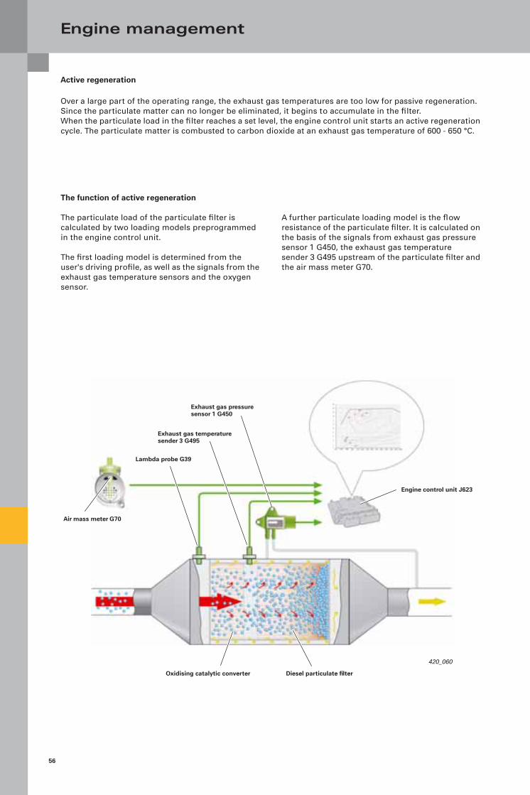
Active regeneration
Over a large part of the operating range, the exhaust gas temperatures are too low for passive regeneration. Since the particulate matter can no longer be eliminated, it begins to accumulate in the filter.When the particulate load in the filter reaches a set level, the engine control unit starts an active regeneration cycle. The particulate matter is combusted to carbon dioxide at an exhaust gas temperature of 600 - 650 °C.
Exhaust gas pressure sensor 1 G450
Engine control unit J623
Exhaust gas temperature sender 3 G495
Lambda probe G39
Air mass meter G70
Diesel particulate filterOxidising catalytic converter
The function of active regeneration
The particulate load of the particulate filter is calculated by two loading models preprogrammed in the engine control unit.
The first loading model is determined from the user's driving profile, as well as the signals from the exhaust gas temperature sensors and the oxygen sensor.
A further particulate loading model is the flow resistance of the particulate filter. It is calculated on the basis of the signals from exhaust gas pressure sensor 1 G450, the exhaust gas temperature sender 3 G495 upstream of the particulate filter and the air mass meter G70.

57
420_061
420_062
420_067
420_066
420_065
420_064
420_063
The following measures are taken by the engine control unit J623 during active regeneration in order to increase the exhaust gas temperature:
– Intake air feed is regulated by the throttle valve control unit J338.
– Exhaust gas recirculation is shut off in order to increase the combustion temperature and the oxygen level inside the combustion chamber.
– Shortly after the main injection has been shifted to "retard", the first post-injection is initiated in order to increase the combustion temperature.
– A further post-injection phase is initiated after the main injection. This fuel does not combust inside the cylinder, rather it evaporates in the combustion chamber.
– The unburned hydrocarbons of these fuel vapours are oxidised in the oxidising catalytic converter. The resulting heat provides an increase in exhaust gas temperature upstream of the particulate filter to approx. 620 °C.
– The signal from the exhaust gas temperature sender 3 G495 upstream of the particulate filter is utilised by engine control unit J623 to calcu-late the quantity of fuel for the retarded post-injection phase.
– The charge pressure is adapted so that the torque does not change noticeably for the driver during the regeneration process.

58
Note
For detailed information about driving performance while the diesel particulate filter warning lamp K231 is on, please refer to the vehicle owner's manual.
Note
In-service regeneration is not possible as of a particulate load of 45 grammes because the risk of causing irreparable damage to the filter is too high. In this case, the filter must be replaced.
Engine management
Regeneration run by customer
In extreme short-distance traffic, the exhaust gas temperature will not be high enough to regenerate the filter. When the load state of the diesel particulate filter reaches a certain limit value, the diesel particulate filter warning lamp K231 in the dash panel insert comes on.
Based on this signal, the driver is requested to carry out a regeneration run. The vehicle must be driven at an increased speed for a short period of time to ensure a high enough exhaust gas temperature and the constant operating conditions required for successful regeneration.
In-service regeneration
If the regeneration run is not successful and the par-ticulate load on the filter has reached 40 grammes, the glow period warning lamp K29 comes on in addition to the diesel particulate filter warning lamp K231.
The text "Engine fault Workshop" appears on the dash panel insert display. The driver is requested to take the vehicle to the nearest workshop. To avoid damaging the particulate filter, active regeneration of the diesel particulate filter is in this case disabled in the engine control unit.
The particulate filter can only be regenerated by an in-service regeneration at the workshop, which is carried out using the VAS 5051 A/B.

59
Regeneration stages of the 2.0-litre TDI common rail engine
Replacement of the filter
Load
in g
ram
mes
Example: Increase in particulate load
Passive regeneration
Active regeneration
Regeneration run by the customer
In-service regeneration
Example: Load characteristic after successful regeneration in each stage
Replacement of the filter
Time (s)

60
420_069
Engine management
Glow plug system
The 2.0-litre TDI engine with common rail injection system has a diesel quick start glow plug system. It allows the engine to be started immediately without a long glow period in practically all climatic conditions.
Advantages of the glow plug system:
– Petrol-engine-like starting at temperatures of up to -24 °C
– Extremely quick heating-up time - the glow plugs reach a temperature of 1000 °C within 2 seconds
Engine speed sender G28
Engine control unit J623
Automatic glow period control unit J179
Coolant temperature sender G62
Onboard power supply control unit J519 Control unit with display
in dash panel insert J285
Glow period warning lamp K29
Glow plug 1 Q10
Glow plug 4 Q13
Glow plug 3 Q12
Glow plug 2 Q11
– Controllable preheating and post-heating temperatures
– Self-diagnostic capability
– Part of Euro On-Board Diagnostic System - glow plug system
System overview

61
Function
Preheating
The steel glow plugs are activated in a phase-offset manner by the engine control unit J623 through the automatic glow period control unit J179 by means of a pulse-width modulated signal (PWM). The voltage at the individual glow plugs is set according to the frequency of the PWM pulses. For quick starting at an ambient temperature of less than 25 °C, the maximum voltage of 11.5 V is applied during the preheating phase. It ensures that the glow plug is heated to over 1000 °C within an extremely short period of time (max. 2 seconds). This reduces the preheating time of the engine.
Intermediate glow phase
To regenerate the particulate filter, an intermediate glow phase is initiated by the engine control unit J623. The intermediate glow phase serves to improve the combustion conditions during the regeneration process.
Post-glow phase
By continuously reducing the drive frequency of the PWM signal, the voltage for the post-glow phase is set to a rated voltage of 7 V depending on the operating point.
The post-glow phase continues until a coolant tem-perature of 25 °C is reached, or for up to 5 minutes after starting the engine. The post-glow phase serves to reduce hydrocarbon emissions and com-bustion noise during the warm-up phase of the engine.
Phase-offset activation of the glow plugs
To reduce the load on the vehicle electrical system during the glow phases, the glow plugs are activated in a phase-offset fashion. The falling signal edge always activates the next glow plug.
Glow plug
Time (s)
Cylinder 1
Cylinder 2
Cylinder 3
Cylinder 4

62
420_072
420_076
420_073
420_071
Special tools
Service
The special tools for the 2.0-litre 105 kW TDI engine with common rail injection system are shown below.
T10172 Plus adaptor
T3359 Rig pin
T10377 Assembly sleeve
T10050 Crankshaft stop

63
420_104
420_075
420_074
420_105
420_106
T40064 Puller
T40095 Holder
T40094 Camshaft fitting toolT40094/1 SupportT40094/2 SupportT40094/9 SupportT40094/10 SupportT40094/11 Lock
T40096/1 Tensioner
T40159 Socket insert with ball head
T40064/1 Press tool

42
0
All rights reserved. Technical specifications subject to change without notice.
CopyrightAUDI AGI/[email protected] +49-841/89-36367
AUDI AGD-85045 IngolstadtTechnical status: 12/07
Printed in GermanyA08.5S00.45.20
Vorsprung durch Technik
www.audi.co.uk