ssp-8160 / 8162 - manson engineering industrial ltd · this family of efficient, upgraded smps with...
TRANSCRIPT

SSP-8160/8162
Laboratory Grade 160W Constant Power Switching Mode Power Supply with Rotary Encoder Control
User Manual
Table of Content 1. Introduction Page 1 2. Warning Page 1 3. Caution Page 1 4. Operation Environmental Condition Page 2 5. Controls and Indicators (with drawings) Page 2 5.1 Knowing the controls & Indicators Page 3 6. Operation Modes Page 3-4 6.1 Normal Mode - using the power supply Page 4 6.2 The Preset Mode Page 4 6.3 DC Ramp & Waveform Generator Mode Page 4-6 6.4 Analogue Remote Control Mode Page 7-8 6.5 PC Interface/ Remote Control Programmable Mode Page 9 7. Remote Sensing Page 9 8. Summary of functions of the Menu/Shift button & key Lock Button Page 9 8.1 Setting the UVL (Upper Voltage Limit) & UCL (Upper Current Limit) Page 9 8.2 To activate the analogue remote control mode page 10 8.3 To deactivate the analogue remote control mode Page 10 8.4 Returning to factory default settings Page 10 8.5 Changing the Ammeter to Wattmeter Page 10 8.6 The Key Lock Button Page 10 8.7 DC Ramp & Waveform Generator Mode Page 10 9. Faults and Trouble Shooting Page 11 9.1 OUP: Over Voltage Protection Page 11 9.2 OTP: Over Temperature Protection Page 11 9.3 OCP: Over Current Protection Page 11 10. Specifications Page 12-13 11. PC Interface Control Page 14 A. Main Display Page 14 B. Connect to system Page 15-17 C. Display panel Page 18 D. Set output voltage value, current value and ON/OFF status Page 18 E. External Timed Program Page 19-20 F. Wave From Generator Page 20-23 G. Data log Page 23 H. Save, Load and print information Page 24 12. Command Set Page 25-27
P.1
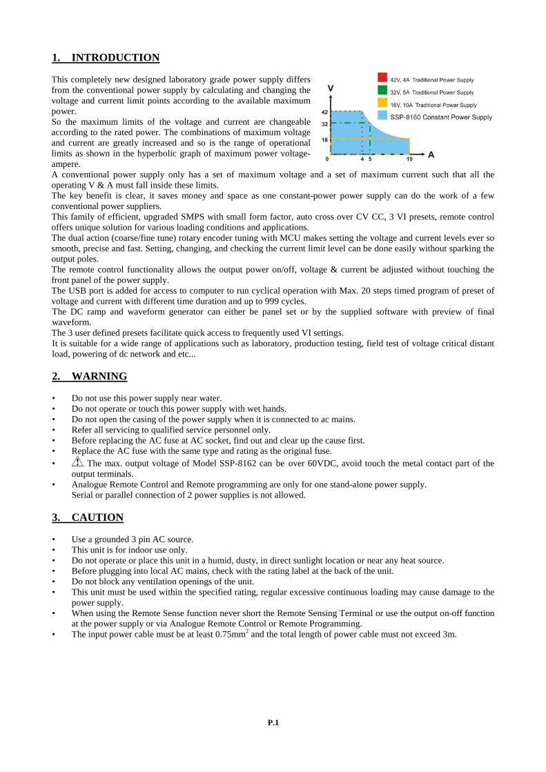
1. INTRODUCTION This completely new designed laboratory grade power supply differs from the conventional power supply by calculating and changing the voltage and current limit points according to the available maximum power. So the maximum limits of the voltage and current are changeable according to the rated power. The combinations of maximum voltage and current are greatly increased and so is the range of operational limits as shown in the hyperbolic graph of maximum power voltage-ampere. A conventional power supply only has a set of maximum voltage and a set of maximum current such that all the operating V & A must fall inside these limits. The key benefit is clear, it saves money and space as one constant-power power supply can do the work of a few conventional power suppliers. This family of efficient, upgraded SMPS with small form factor, auto cross over CV CC, 3 VI presets, remote control offers unique solution for various loading conditions and applications. The dual action (coarse/fine tune) rotary encoder tuning with MCU makes setting the voltage and current levels ever so smooth, precise and fast. Setting, changing, and checking the current limit level can be done easily without sparking the output poles. The remote control functionality allows the output power on/off, voltage & current be adjusted without touching the front panel of the power supply. The USB port is added for access to computer to run cyclical operation with Max. 20 steps timed program of preset of voltage and current with different time duration and up to 999 cycles. The DC ramp and waveform generator can either be panel set or by the supplied software with preview of final waveform. The 3 user defined presets facilitate quick access to frequently used VI settings. It is suitable for a wide range of applications such as laboratory, production testing, field test of voltage critical distant load, powering of dc network and etc... 2. WARNING • Do not use this power supply near water. • Do not operate or touch this power supply with wet hands. • Do not open the casing of the power supply when it is connected to ac mains. • Refer all servicing to qualified service personnel only. • Before replacing the AC fuse at AC socket, find out and clear up the cause first. • Replace the AC fuse with the same type and rating as the original fuse. • The max. output voltage of Model SSP-8162 can be over 60VDC, avoid touch the metal contact part of the output terminals. • Analogue Remote Control and Remote programming are only for one stand-alone power supply. Serial or parallel connection of 2 power supplies is not allowed.
3. CAUTION • Use a grounded 3 pin AC source. • This unit is for indoor use only. • Do not operate or place this unit in a humid, dusty, in direct sunlight location or near any heat source. • Before plugging into local AC mains, check with the rating label at the back of the unit. • Do not block any ventilation openings of the unit. • This unit must be used within the specified rating, regular excessive continuous loading may cause damage to the power supply. • When using the Remote Sense function never short the Remote Sensing Terminal or use the output on-off function at the power supply or via Analogue Remote Control or Remote Programming. • The input power cable must be at least 0.75mm2 and the total length of power cable must not exceed 3m.

P.2
4. OPERATION ENVIRONMENTAL CONDITION • 10-80% R.H. • Altitude up to 2000m • Installation category: CAT 2 • Pollution degree: 2 • Mains supply voltage fluctuation up to ±10% of the normal voltage 5. CONTROLS AND INDICATORS (1) LED panel meter display with CC/CV/W Indictor (2) Remote Control Indicator (Remote Control/ USB mode) (3) Output Voltage Control Knob (UVL upper voltage limit) (4) Output Current Control Knob (UCL upper current limit) (5) Power ON/OFF Switch (6) 6 Keys illuminate Keypad: - Preset Key 1, 2 & 3 - Menu Key (Shift Key)
- Lock/ Unlock Key (A/W meter Key) - Output ON/OFF (ΔV/Δt Key) (7) Output Safety Jack (Rated 10A for SSP-8160/ Rated 5A for SSP-8162) (8) USB port (For access to computer to run cyclical operation with programmable voltage, current, period time and cycle) (9) Remote Sensing Terminal (Warning! Shorting the remote sensing terminal or Connect sensing terminal in reverse polarity will damage the power supply) (10) Analogue Remote Control Terminal (11) AC Inlet socket (with fuse holder)
Front
Rear

P.3
5.1 Knowing the controls and indicators All the buttons when lit up indicate that they are activated. The lower row 3 buttons are of dual functions which work in conjunction with other lower buttons or with the voltage, current control knobs as defined by the green imprints. Through out this manual the Menu Key and Shift Key is the same Key. When used to enter into the menu mode (pressed and hold) it is termed as a Menu Key. See section 11 for summary of Menu Key. 6. OPERATION MODES There are 5 operation modes: Normal, Preset, DC Ramp & Waveform Generator, Analogue Remote Control & PC Interface Remote Programmable. The power supply is factory preset to Normal Mode with maximum: current level CC, UVL and UCL. 6.1 Normal Mode - using the power supply This series has 2 models. Make sure you have used the correct one. They have different output voltage range and current as following:
Model Number Output Voltage Range Total Rated Current
SSP-8160 0 ~ 42V (I ≤ 3.8A for 42V) 0 ~ 10A (V ≤ 16V for 10A)
SSP-8162 0 ~ 84V (I ≤ 1.9A for 84V) 0 ~ 5A (V ≤ 32V for 5A)
The maximum limits of the voltage and current are governed by the constant power rating of: V x I = 160 Watt Decrease the voltage setting to get a high current & vice versa for high voltage, as long as V x I is not over 160W. 6.1.1 Check the rating label of the power supply and make sure it complies with your AC mains voltage. Connect the power supply to the AC Mains using the provided power cord. 6.1.2 After unit is tuned on, the CV, V and A LED indicators are lit up displaying voltage & current 00.00. The output on-off button is set to off by default. Push the voltage/ current knob or turn one click in either direction to find out the present settings. Both displays return to 00.00 after a few seconds. 6.1.3 Using the control knobs The rotary encoder control knobs have fine and coarse tuning with clicking movement. Push the knobs to toggle between coarse and fine tuning, notice the subtle changes in brightness of related LED. Adjust the knobs to your desired values by trying coarse and fine tuning. The display will resume its normal brightness after few seconds to confirm your adjustment. 6.1.4 Connect the equipment to the power supply. Red (+) is connected to the positive polarity input of the equipment and Black (-) is connected to the negative polarity input of the equipment. 6.1.5 Push the output on/off button to power the equipment. Voltage and current will be displayed continuously CV or CC will be lit according to the settings. When an operation is finished, switch off the equipment first and then switch off the power supply. 6.1.6 Changing Ammeter to Wattmeter. This function is only valid when the output on/off is set to on. Press “Shift”/ (Manual) key and then press “Lock/Unlock” key to change Ammeter to Wattmeter. Unit is in Watt. To change back the Wattmeter to Ammeter, press “Shift” key and then press “Lock/Unlock” key 6.1.7 Key Lock Function: This function prevents any inadvertent change on your set voltage and current setting. Press “Lock/Unlock” key to lock or unlock all function keys and control knob on front panel. The “Lock/Unlock” key lights up when keys are locked.
P.4
6.1.8 Changing the values of UVL (Upper Voltage Limit) and UCL (Upper Current Limit) This function is designed to give additional protection for voltage sensitive and or current sensitive equipment/ loads. When the voltage or current at the output terminal exceeds the set upper limiting values, the output will be cut off. Furthermore these additional protective features are necessary for a power supply with such wide ranges of V & I. UVL setting: Press SHIFT “Menu” Key to light up, then press the VOLTAGE control knob. The voltmeter will show the present voltage limit and the Ammeter will show SUuL. Tune the Voltage control knob to your desired limit value. Press SHIFT “Menu” key to confirm with light out and return to normal operation. UCL setting: Press SHIFT “Menu” Key to light up, then press the CURRENT control knob. The voltmeter will show the SUCL and the ammeter will show the present current limit .Tune the CURRENT control knob to your desired limit value. Press SHIFT “Menu” key to confirm with light out and return to normal operation. Remark: The UVL and UCL setting are factory preset at maximum rated output values. The setting of UVL and UCL will affect the usable voltage range and current range and will trigger the respective protection if the newly set limits are exceeded. If remote sense function is used, allowance must be included in the setting of UVL for the gain in output voltage.
6.2 The Preset Mode a. There are 3 preset outputs (Preset 1/ Preset 2/ Preset 3) b. Simply press the Preset key 1 or 2 or 3 to enter into the preset V & I setting as the key lights up c. To check the preset values without affecting the output, press the “Shift” Key and then the selected Preset Key. The V and I settings of corresponding P1, P2, P3 will be show on the panel meters. d. To change the values of the Presets, press the preset key to light up and adjust the voltage/ current level. The newly set values of the Preset will be kept even after the power supply has been tuned off. e. To get back to the factory default setting for all 3 Presets see section: 8.4 f. The factory default settings of the 3 Presets are shown in the following table. g. Always check the voltage & current level of the Preset before setting output to on when connected to a load.
Factory Default Output Voltage Output Current
Preset 1 SSP-8160: 5V
SSP-8162: 5V
SSP-8160: 10A
SSP-8162: 5A
Preset 2 SSP-8160: 13.8V
SSP-8162: 13.8V
SSP-8160:10A
SSP-8162: 5A
Preset 3 SSP-8160: 20V
SSP-8162: 20V
SSP-8160: 8A
SSP-8162: 5A
6.3 DC Ramp & Waveform Generator Mode This feature uses the 3 Presets to generate the Ramp Up/ Down and other dc uniform waveforms such pulse, triangular, trapezium & etc by varying the voltage level, duration time (Func) at each voltage level and time interval (Δt) to move from one voltage to another voltage level. The number (Runt) of repetitive cycles of the waveform can be set as well. At the end of the cycle runs, the output will be off. It is strongly recommended to use the computer interface instead of panel programming to operate this function as the simulated open circuit output wave forms can be previewed at the PC and settings are done more conveniently and be saved. Also the actual loaded output waveform data can be logged for reference. 6.3.1 Definitions of ΔV a-b, Δt a-b, Func A/ B/ C and Runt . There are 3 settable DC voltage generators, namely A, B and C. Preset 1 = A Preset 2 = B Preset 3 = C

P.5
ΔV a-b means from voltage level A to voltage level B. Display Meters show: rUN A_b/ b_A/ A_C/ C_A/ b_C/ C_b (turn Current Knob) Δt a-b means time in seconds from voltage level A to level B, this transit time is adjustable from 0 to 20 seconds. Display Meters show: A_b_0000. Adjust Current Knob for transit time. The Func A/ B/ C means the duration time (0 to 600sec) at the Preset voltage. (adjust the Current Knob for time) Display Meters show: FUNA 0000
Run t means number of repetitive cycle Display Meters show: rUNt 0000 (adjust the Current Knob for number of cycles)
6.3.2 Using ΔV/Δt Function to generate Ramp 1. Make sure that the voltage and current of the Presets have been set first. In this example we use Preset 1=A=5V, Preset 2=B=10V. ΔV a-b=Displays “rUN A _ b”; Δt a-b=5 sec: Displays “A_b_0005”; Run t=3 cycles Func A=0 sec; Func b=15 sec 2. Press and hold MENU key until the displays change to “d u d t SEt” as below, if not, turn the Voltage Knob until the below displays appear.
3. Press the VOLTAGE KNOB to confirm the entry into this ΔV/Δt setting mode. 4. Turn the Voltage Knob to get to the required parameters and use the Current Knob to adjust settings of each parameter. 5. After all the settings have been done, make sure to press the Voltage Knob to confirm return to the Set Menu and Press the Menu Key to leave the Set Menu with no light on Menu Key. 6. To start the ΔV/Δt Function , press the selected Preset button then Menu button then two times on Output button. 7. At the end of the cycles, the output will be off. To stop ΔV/Δt Function at any time, press the Menu then Output button.

P.6
6.3.3 Using ΔV/Δt Function to generate various wave forms
This is a rather tricky operation, check the Preset key carefully to see if both are lit up and one is flashing. The flashing will jump from one to the other, A to B, then B to A. The waveform will repeat cyclically if until press “Shift” key and then press “ΔV/Δt” Key again . Example 1: Pulse waveform with 3sec at 10V and 1sec at 5V. set A (Preset 1) = 5V, set B (Preset 2) = 10V set Func. A = 1 second DISPLAY: FunA 001 by turn the Current control knob Func B = 3 seconds DISPLAY: FunB 003 using the same procedure as above Set Δt a-b = 0, DISPLAY: A_B_ 0000 Set Δt b-a = 0, DISPLAY: B_A_ 0000 Set rUNt 0000 = means cycling indefinitely To generate the waveform push “Shift” key and then press “ΔV/Δt” Key The waveform will repeat cyclically if rUNt 0000 is set to 0000 or according to number of cycles entered. To stop the cycle running just push “Shift” key and then press “ΔV/Δt” Key .
Example 2: Triangular wave form Set A = 5V , B = 10 V Set Δt a-b = 3 seconds , Set Δt b-a = 3 seconds Set Func. A = 3 seconds , Set Func. B = 3 seconds
Note : The waveform generation can be operated via our remote programming software with preview of the waveform and data logging of the output in graphical presentation as well. Details please see section 11 PC Application Software or CD.

P.7
6.4 ANALOGUE REMOTE CONTROL MODE 6.4.1 To enter into the Remote Control Mode a. Press and hold the “Menu” Key for 3 seconds b. Tune the Voltage control knob until the panel meter displays wording rC SEt as below, press Voltage control knob to confirm to entry the remote control mode.
c. Turn the Current control knob to select remote ON d. Press Voltage control knob to confirm to return to the Set menu e. Press Menu key to leave the Set menu f. The orange REMOTE led, LOCK/UNLOCK button, OUTPUT ON/OFF button will be on to confirm the unit is in Analogue Remote Control Mode. g. All the buttons and keys on the front panel are locked except the lock/unlock key. 6.4.2 To deactivate the Remote Control Mode a. Press Lock/Unlock key to unlock all the function keys b. Repeat step a to e and at step c select OFF. 6.4.3 Analogue Remote Control Methods and Set Ups After entering into the Remote Control Mode, the following external set ups can be selected. There are two methods for remote control of current and voltage adjustment. Both methods require both the current remote control part and the voltage remote control part to be set up and be in used at the same time in order for analogue remote control mode to be functional. Otherwise unit will be in CC mode all the time and the analogue remote control will not be functional. Method A Using two external variable DC voltage sources 6.4.4 Method A Using two external variable DC voltage sources
Remote Socket Pin Assignment for external variable voltage source PIN FUNCTIONS REMARKS
1 Internal DC +5V Less then 50mA
2 Voltage Adjust 0 - 5V
3 Current Adjust 0 - 5V
4 Ground
5 Output OFF Short to Ground
6 N.A.
7 N.A.
8 N.A. Adjust the CC current using external power supply connected to Pin 3. Output voltage setting by remote control Check the output voltage range of the power supply by varying the external voltage source connected to Pin 2.
P.8
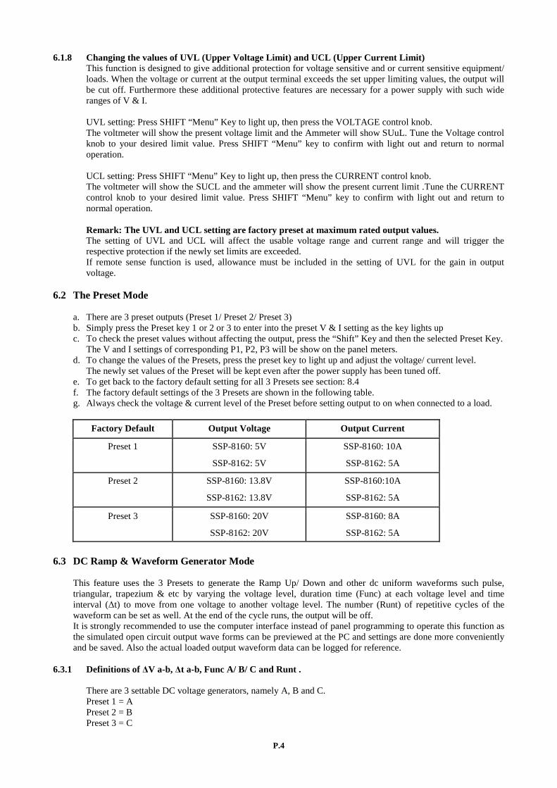
6.4.5 Method B Using two 0 – 5K Ohm variable resistors
Two variable resistors must be set up at the same time in order for the remote control to be functional. Remark: variable resistors 5Kohm.
Remote Socket Pin Assignment for variable resistor PIN FUNCTIONS REMARKS
1 Internal DC +5V Resistor end
2 Voltage Adjust Variable part of resistor
3 Current Adjust Variable part of resistor
4 Ground Another resistor end
5 Output OFF Short to Ground
6 N.A.
7 N.A.
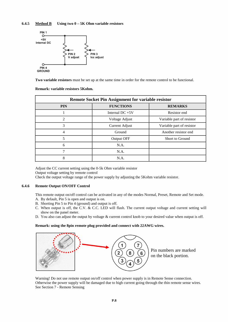
8 N.A. Adjust the CC current setting using the 0-5k Ohm variable resistor Output voltage setting by remote control Check the output voltage range of the power supply by adjusting the 5Kohm variable resistor. 6.4.6 Remote Output ON/OFF Control This remote output on/off control can be activated in any of the modes Normal, Preset, Remote and Set mode. A. By default, Pin 5 is open and output is on. B. Shorting Pin 5 to Pin 4 (ground) and output is off. C. When output is off, the C.V. & C.C. LED will flash. The current output voltage and current setting will show on the panel meter. D. You also can adjust the output by voltage & current control knob to your desired value when output is off. Remark: using the 8pin remote plug provided and connect with 22AWG wires. Warning! Do not use remote output on/off control when power supply is in Remote Sense connection. Otherwise the power supply will be damaged due to high current going through the thin remote sense wires. See Section 7 - Remote Sensing
Pin numbers are marked on the black portion.

P.9
6.5 PC Interface/ Remote Control Programmable Mode This PC Interface Mode connects the power supply to a PC via USB PORT. Application software for wave form generator, external cyclic timed programs, data logging of output with I, V, W with time span and setting of misc. parameters limits. See section 11 or manual in the supplied CD. 7. REMOTE SENSING Take note of the warnings, wrong disconnection sequence will damage the Power Supply Warning! Never short the Remote Sensing Terminal Always disconnect Remote Sensing Terminal first. DO NOT USE Output On Off on unit panel or by remote operation. It is recommended to use the key lock function to prevent accidental switching off the output by the output on/off switch. Connection: 1. First complete the power connections between power supply and equipment. 2. Check and make sure the power connections are secure. 3. Then make connections between Remote Sensing and equipment. Warning! Never short the Remote Sensing Terminal Never connect the Remote Sensing Terminal in reverse polarity Fig.3 showing connections between Remote Sensing, Power output and Equipment.
The remote sensing wire should be AT LEAST 22AWG wire size. Dis-connection: Wrong disconnect sequence will damage power supply 1. First disconnect the remote sensing connections. 2. Then disconnect the power connections between the power supply and equipment. Remote Sense commonly compensates about 0.25 to 0.75V. Use Twisted Remote Sense wires and shielding to prevent from picking up any radiated noise. 8. Summary of Functions of the Menu/ Shift button and Key Lock button 8.1 Set the UVL (Upper Voltage Limit) and UCL (Upper Current Limit) To set the UVL, press “Shift” button and then press Voltage control knob. The voltmeter will show the present limit and the Ammeter will show SUuL. Tune the Voltage control knob to your desired limit value. Press “Shift” key to confirm and return to normal operation. To set the UCL, press “Shift” Key and then press Current control knob. The Ammeter will show the present limit and the Voltmeter will show SUCL. Tune the Current control knob to your desired limit value. Press “Shift” key to confirm and return to normal operation.
P.10
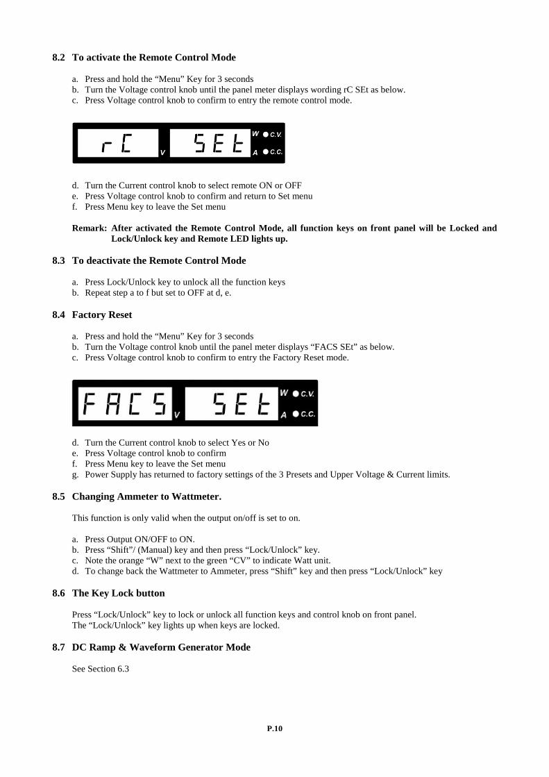
8.2 To activate the Remote Control Mode a. Press and hold the “Menu” Key for 3 seconds b. Turn the Voltage control knob until the panel meter displays wording rC SEt as below. c. Press Voltage control knob to confirm to entry the remote control mode.
d. Turn the Current control knob to select remote ON or OFF e. Press Voltage control knob to confirm and return to Set menu f. Press Menu key to leave the Set menu Remark: After activated the Remote Control Mode, all function keys on front panel will be Locked and Lock/Unlock key and Remote LED lights up. 8.3 To deactivate the Remote Control Mode a. Press Lock/Unlock key to unlock all the function keys b. Repeat step a to f but set to OFF at d, e. 8.4 Factory Reset a. Press and hold the “Menu” Key for 3 seconds b. Turn the Voltage control knob until the panel meter displays “FACS SEt” as below. c. Press Voltage control knob to confirm to entry the Factory Reset mode.
d. Turn the Current control knob to select Yes or No e. Press Voltage control knob to confirm f. Press Menu key to leave the Set menu g. Power Supply has returned to factory settings of the 3 Presets and Upper Voltage & Current limits. 8.5 Changing Ammeter to Wattmeter. This function is only valid when the output on/off is set to on. a. Press Output ON/OFF to ON. b. Press “Shift”/ (Manual) key and then press “Lock/Unlock” key. c. Note the orange “W” next to the green “CV” to indicate Watt unit. d. To change back the Wattmeter to Ammeter, press “Shift” key and then press “Lock/Unlock” key 8.6 The Key Lock button Press “Lock/Unlock” key to lock or unlock all function keys and control knob on front panel. The “Lock/Unlock” key lights up when keys are locked. 8.7 DC Ramp & Waveform Generator Mode See Section 6.3
P.11
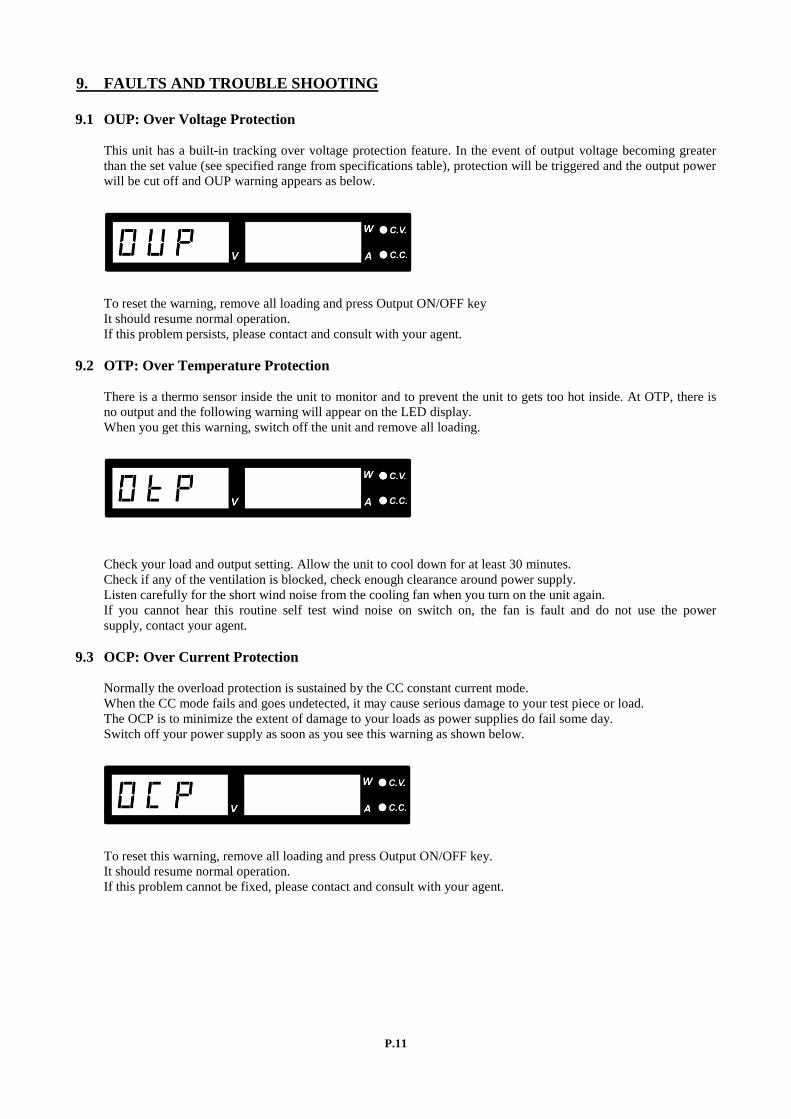
9. FAULTS AND TROUBLE SHOOTING 9.1 OUP: Over Voltage Protection This unit has a built-in tracking over voltage protection feature. In the event of output voltage becoming greater than the set value (see specified range from specifications table), protection will be triggered and the output power will be cut off and OUP warning appears as below.
To reset the warning, remove all loading and press Output ON/OFF key It should resume normal operation. If this problem persists, please contact and consult with your agent. 9.2 OTP: Over Temperature Protection There is a thermo sensor inside the unit to monitor and to prevent the unit to gets too hot inside. At OTP, there is no output and the following warning will appear on the LED display. When you get this warning, switch off the unit and remove all loading.
Check your load and output setting. Allow the unit to cool down for at least 30 minutes. Check if any of the ventilation is blocked, check enough clearance around power supply. Listen carefully for the short wind noise from the cooling fan when you turn on the unit again. If you cannot hear this routine self test wind noise on switch on, the fan is fault and do not use the power supply, contact your agent. 9.3 OCP: Over Current Protection Normally the overload protection is sustained by the CC constant current mode. When the CC mode fails and goes undetected, it may cause serious damage to your test piece or load. The OCP is to minimize the extent of damage to your loads as power supplies do fail some day. Switch off your power supply as soon as you see this warning as shown below.
To reset this warning, remove all loading and press Output ON/OFF key. It should resume normal operation. If this problem cannot be fixed, please contact and consult with your agent.
P.12
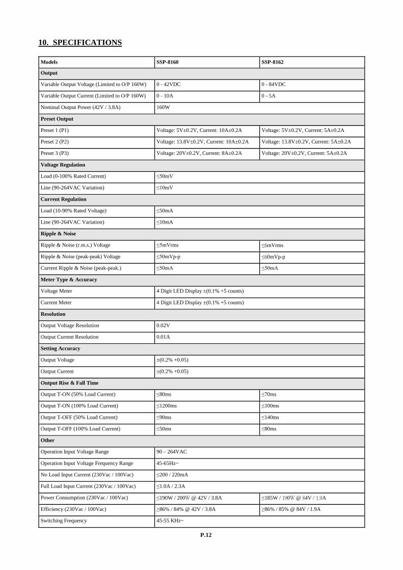
10. SPECIFICATIONS Models SSP-8160 SSP-8162
Output
Variable Output Voltage (Limited to O/P 160W) 0 - 42VDC 0 - 84VDC
Variable Output Current (Limited to O/P 160W) 0 - 10A 0 - 5A
Nominal Output Power (42V / 3.8A) 160W
Preset Output
Preset 1 (P1) Voltage: 5V±0.2V, Current: 10A±0.2A Voltage: 5V±0.2V, Current: 5A±0.2A
Preset 2 (P2) Voltage: 13.8V±0.2V, Current: 10A±0.2A Voltage: 13.8V±0.2V, Current: 5A±0.2A
Preset 3 (P3) Voltage: 20V±0.2V, Current: 8A±0.2A Voltage: 20V±0.2V, Current: 5A±0.2A
Voltage Regulation
Load (0-100% Rated Current) ≤50mV
Line (90-264VAC Variation) ≤10mV
Current Regulation
Load (10-90% Rated Voltage) ≤50mA
Line (90-264VAC Variation) ≤10mA
Ripple & Noise
Ripple & Noise (r.m.s.) Voltage ≤5mVrms ≤6mVrms
Ripple & Noise (peak-peak) Voltage ≤50mVp-p ≤60mVp-p
Current Ripple & Noise (peak-peak.) ≤50mA ≤50mA
Meter Type & Accuracy
Voltage Meter 4 Digit LED Display ±(0.1% +5 counts)
Current Meter 4 Digit LED Display ±(0.1% +5 counts)
Resolution
Output Voltage Resolution 0.02V
Output Current Resolution 0.01A
Setting Accuracy
Output Voltage ±(0.2% +0.05)
Output Current ±(0.2% +0.05)
Output Rise & Fall Time
Output T-ON (50% Load Current) ≤80ms ≤70ms
Output T-ON (100% Load Current) ≤1200ms ≤100ms
Output T-OFF (50% Load Current) ≤90ms ≤140ms
Output T-OFF (100% Load Current) ≤50ms ≤80ms
Other
Operation Input Voltage Range 90 – 264VAC
Operation Input Voltage Frequency Range 45-65Hz~
No Load Input Current (230Vac / 100Vac) ≤200 / 220mA
Full Load Input Current (230Vac / 100Vac) ≤1.0A / 2.3A
Power Consumption (230Vac / 100Vac) ≤190W / 200W @ 42V / 3.8A ≤185W / 190W @ 84V / 1.9A
Efficiency (230Vac / 100Vac) ≥86% / 84% @ 42V / 3.8A ≥86% / 85% @ 84V / 1.9A
Switching Frequency 45-55 KHz~

P.13
Models SSP-8160 SSP-8162
Tracking Over Voltage Protections O/P 0-10V: 115-135% of set voltage O/P 10-42V: 105-125% of set voltage
O/P 0-10V: 115-135% of set voltage O/P 10-84V: 105-125% of set voltage
Transient Response Time (50-100% Rated Load) ≤1.5ms
Power Factor Control Power factor correction >0.91 at optimal load
Cooling Method Natural Convection
Leakage Current ≤2mA
Protections Adjustable upper voltage limit, Adjustable upper current limit, Short Circuit, Overload, Over Temperature , Tracking OVP
Input Fuse T3.15AL250V
Safety & EMC
Safety Standard CE: EN 61010
Withstanding Voltage I/P-O/P: 3.0KVac, I/P-F/G: 1.5KVac, O/P-F/G: 0.5KVac
Insulation Resistance I/P-O/P, I/P-F/G, O/P-F/G : 100Mohm @500Vdc
EMC CE: EN55011
Harmonics Current Emission EN 61000-3-2
Voltage Fluctuations & Flicker EN 61000-3-3
EMC Immunity EN 61000-6-1
Environment
Working Temperature 0 to +40°C
Working Humidity 10-80% RH Non-condensing
Storage Temperature and Humidity -15 to +70°C 10-85% RH Non-condensing
Pollution Degree Class 2
General
Case Material Polycarbonate Front Panel and Electro-Galvanized Steel Enclosure
Case Protection IP20
Connection Dia. 4.0mm Safety Jack x3 (Output Positive, Negative and Function Ground)
Dimensions (WxHxD) 200 x 90 x 250 mm (7.9 x 3.6 x 10 inch)
Weight 2.5 kg (5.5 lb)
P.14
11. PC Interface Control Support OS: Windows XP/Vista/7/8 USB Driver: Silicon Lab CP210x USB driver
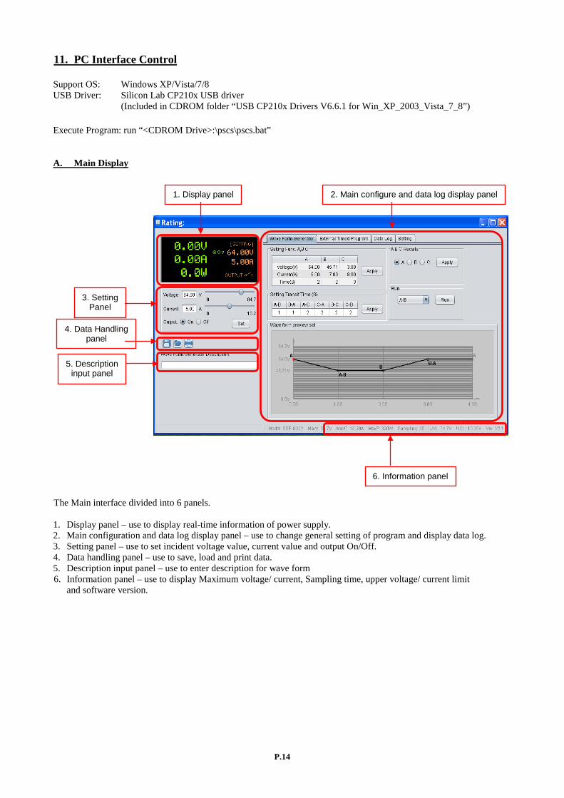
(Included in CDROM folder “USB CP210x Drivers V6.6.1 for Win_XP_2003_Vista_7_8”) Execute Program: run “<CDROM Drive>:\pscs\pscs.bat” A. Main Display
The Main interface divided into 6 panels. 1. Display panel – use to display real-time information of power supply. 2. Main configuration and data log display panel – use to change general setting of program and display data log. 3. Setting panel – use to set incident voltage value, current value and output On/Off. 4. Data handling panel – use to save, load and print data. 5. Description input panel – use to enter description for wave form 6. Information panel – use to display Maximum voltage/ current, Sampling time, upper voltage/ current limit and software version.
1. Display panel
3. Setting Panel
4. Data Handling panel
5. Description input panel
2. Main configure and data log display panel
6. Information panel
P.15
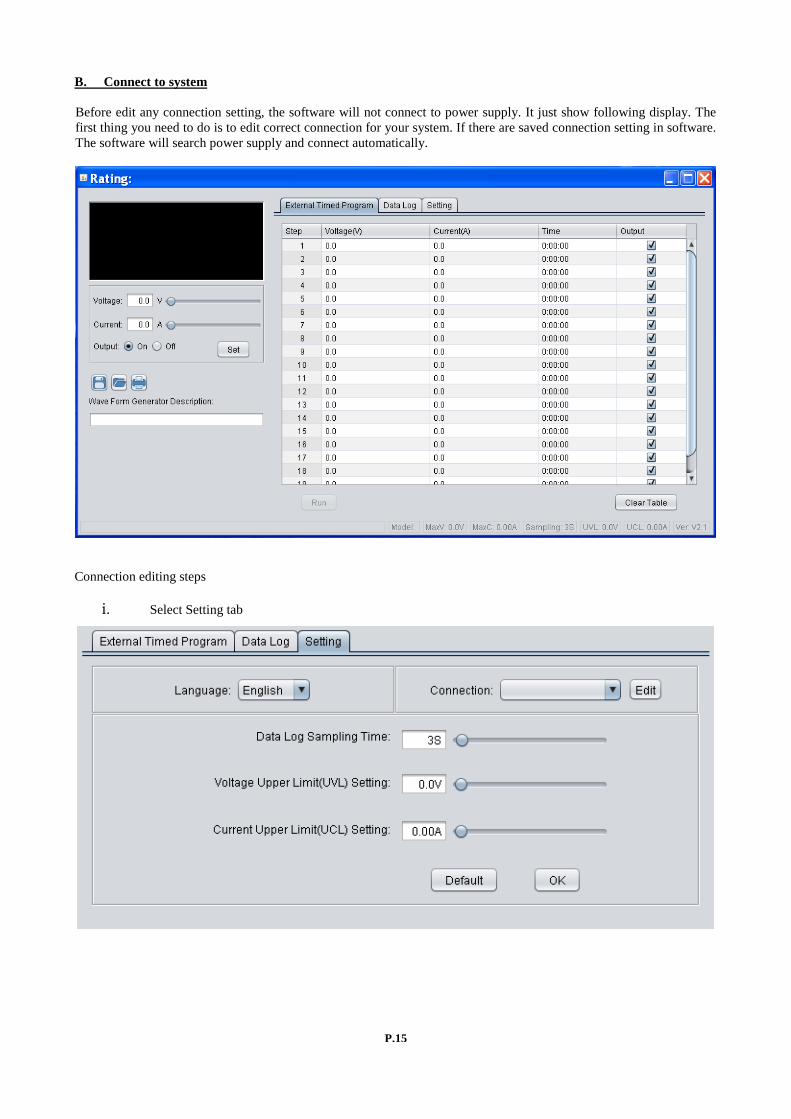
B. Connect to system Before edit any connection setting, the software will not connect to power supply. It just show following display. The first thing you need to do is to edit correct connection for your system. If there are saved connection setting in software. The software will search power supply and connect automatically.
Connection editing steps
i. Select Setting tab
P.16
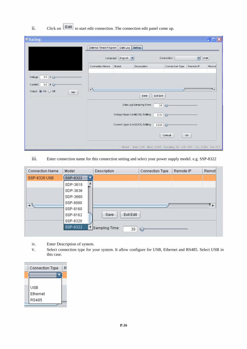
ii. Click on to start edit connection. The connection edit panel come up.
iii. Enter connection name for this connection setting and select your power supply model. e.g. SSP-8322
iv. Enter Description of system. v. Select connection type for your system. It allow configure for USB, Ethernet and RS485. Select USB in
this case.

P.17
vi. Then select COM port for your system. e.g. COM3
vii. Then Click to save setting then click to exit the edit page. The final setting for this page is like this.
After save configuration, the power supply connect automatically. The display change as follow.
P.18
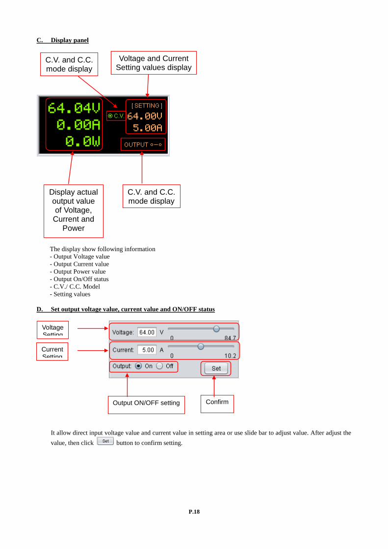
C. Display panel
The display show following information - Output Voltage value - Output Current value - Output Power value - Output On/Off status - C.V./ C.C. Model - Setting values
D. Set output voltage value, current value and ON/OFF status
It allow direct input voltage value and current value in setting area or use slide bar to adjust value. After adjust the value, then click button to confirm setting.
Voltage Setting
Current Setting
Output ON/OFF setting Confirm
C.V. and C.C. mode display
Voltage and Current Setting values display
Display actual output value of Voltage,
Current and Power
C.V. and C.C. mode display
P.19
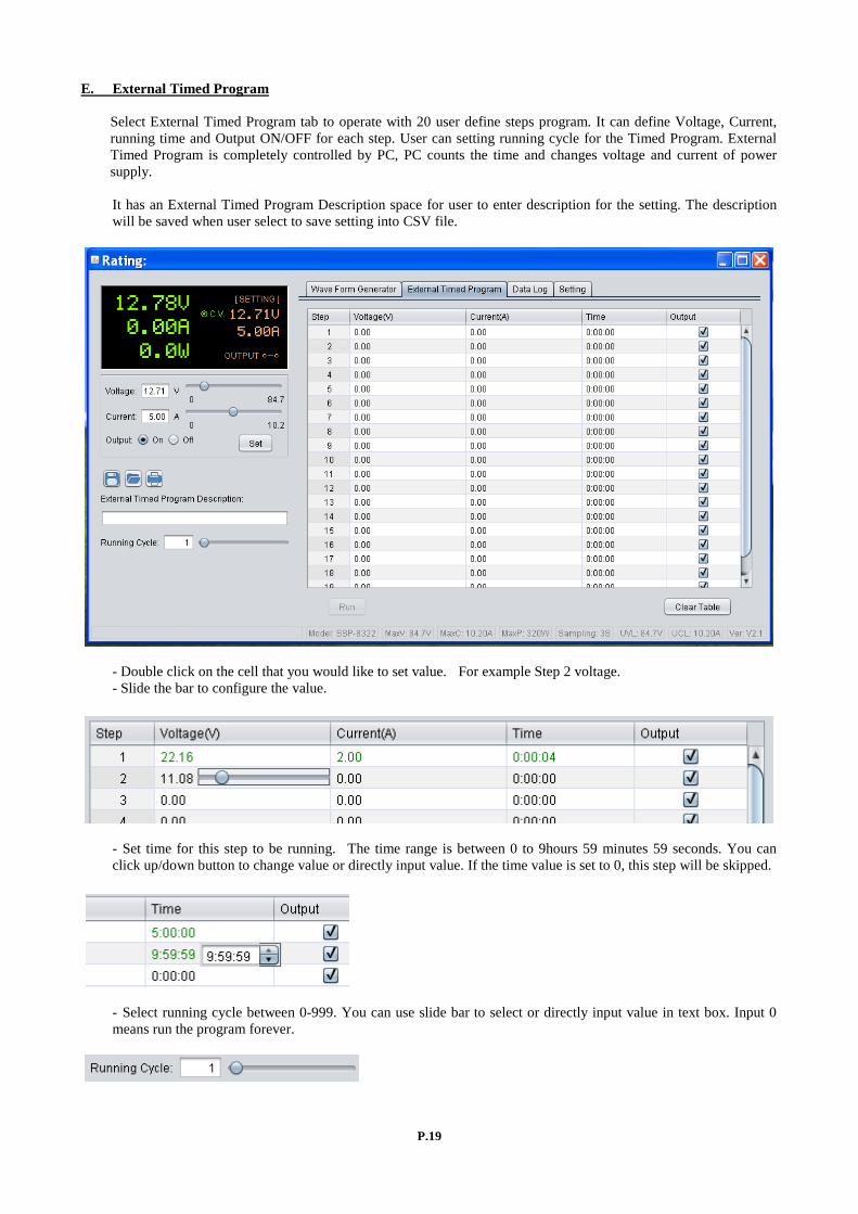
E. External Timed Program
Select External Timed Program tab to operate with 20 user define steps program. It can define Voltage, Current, running time and Output ON/OFF for each step. User can setting running cycle for the Timed Program. External Timed Program is completely controlled by PC, PC counts the time and changes voltage and current of power supply. It has an External Timed Program Description space for user to enter description for the setting. The description will be saved when user select to save setting into CSV file.
- Double click on the cell that you would like to set value. For example Step 2 voltage. - Slide the bar to configure the value.
- Set time for this step to be running. The time range is between 0 to 9hours 59 minutes 59 seconds. You can click up/down button to change value or directly input value. If the time value is set to 0, this step will be skipped.
- Select running cycle between 0-999. You can use slide bar to select or directly input value in text box. Input 0 means run the program forever.
P.20
- Click button to start running cycle.
- In between program running cycle, click button to stop program.
- Click to clear the setting.
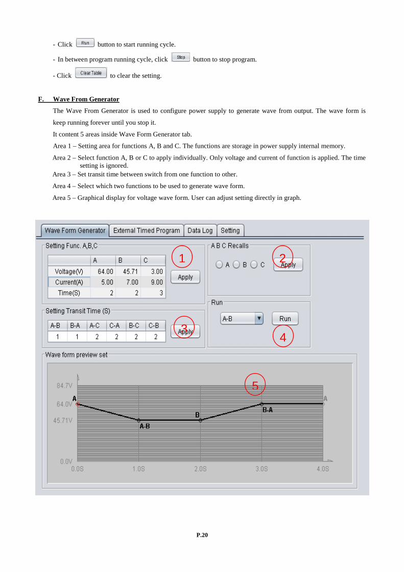
F. Wave From Generator
The Wave From Generator is used to configure power supply to generate wave from output. The wave form is
keep running forever until you stop it.
It content 5 areas inside Wave Form Generator tab.
Area 1 – Setting area for functions A, B and C. The functions are storage in power supply internal memory.
Area 2 – Select function A, B or C to apply individually. Only voltage and current of function is applied. The time setting is ignored.
Area 3 – Set transit time between switch from one function to other.
Area 4 – Select which two functions to be used to generate wave form.
Area 5 – Graphical display for voltage wave form. User can adjust setting directly in graph.
1 2
3 4
5
P.21
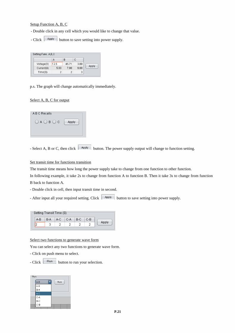
Setup Function A, B, C
- Double click in any cell which you would like to change that value.
- Click button to save setting into power supply.
p.s. The graph will change automatically immediately.
Select A, B, C for output
- Select A, B or C, then click button. The power supply output will change to function setting.
Set transit time for functions transition
The transit time means how long the power supply take to change from one function to other function.
In following example, it take 2s to change from function A to function B. Then it take 3s to change from function
B back to function A.
- Double click in cell, then input transit time in second.
- After input all your required setting. Click button to save setting into power supply.
Select two functions to generate wave form
You can select any two functions to generate wave form.
- Click on push menu to select.
- Click button to run your selection.
P.22
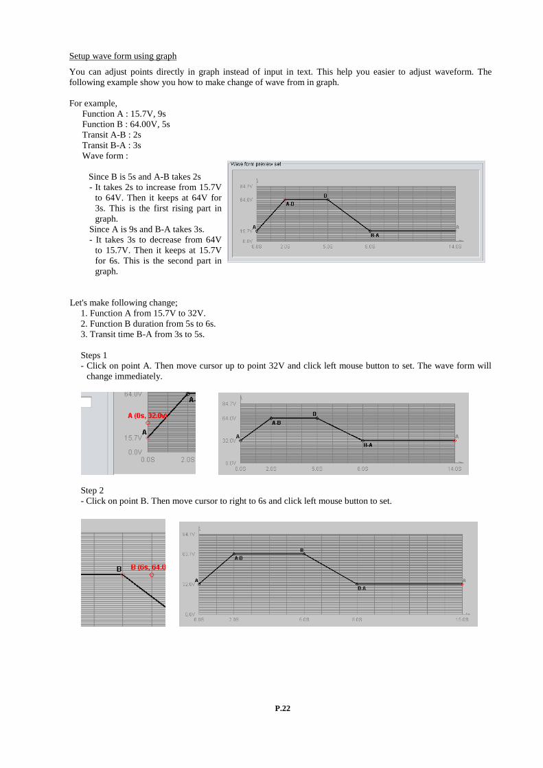
Setup wave form using graph
You can adjust points directly in graph instead of input in text. This help you easier to adjust waveform. The following example show you how to make change of wave from in graph. For example, Function A : 15.7V, 9s Function B : 64.00V, 5s Transit A-B : 2s Transit B-A : 3s Wave form :
Since B is 5s and A-B takes 2s - It takes 2s to increase from 15.7V
to 64V. Then it keeps at 64V for 3s. This is the first rising part in graph.
Since A is 9s and B-A takes 3s. - It takes 3s to decrease from 64V
to 15.7V. Then it keeps at 15.7V for 6s. This is the second part in graph.
Let's make following change; 1. Function A from 15.7V to 32V. 2. Function B duration from 5s to 6s. 3. Transit time B-A from 3s to 5s. Steps 1 - Click on point A. Then move cursor up to point 32V and click left mouse button to set. The wave form will
change immediately.
Step 2 - Click on point B. Then move cursor to right to 6s and click left mouse button to set.
P.23
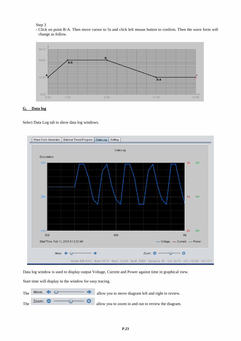
Step 3 - Click on point B-A. Then move cursor to 5s and click left mouse button to confirm. Then the wave form will
change as follow.
G. Data log
Select Data Log tab to show data log windows.
Data log window is used to display output Voltage, Current and Power against time in graphical view. Start time will display in the window for easy tracing.
The allow you to move diagram left and right to review.
The allow you to zoom in and out to review the diagram.

P.24
H. Save, Load and print information
The software allow to save, load, and print information for Wave Form Generator setting, External Timed Program setting and Data Log. All file will saved in CSV format with different file previous following by time stamp. Wave Form Generator file start with WFG. External Timed Program start with ETP. Data Log start with LOG. Use data handling button to operate with save, load and print.
- Click to save information to CSV file.
- Click to open and load information from CSV file.
- Click to print information to printer.
P.25
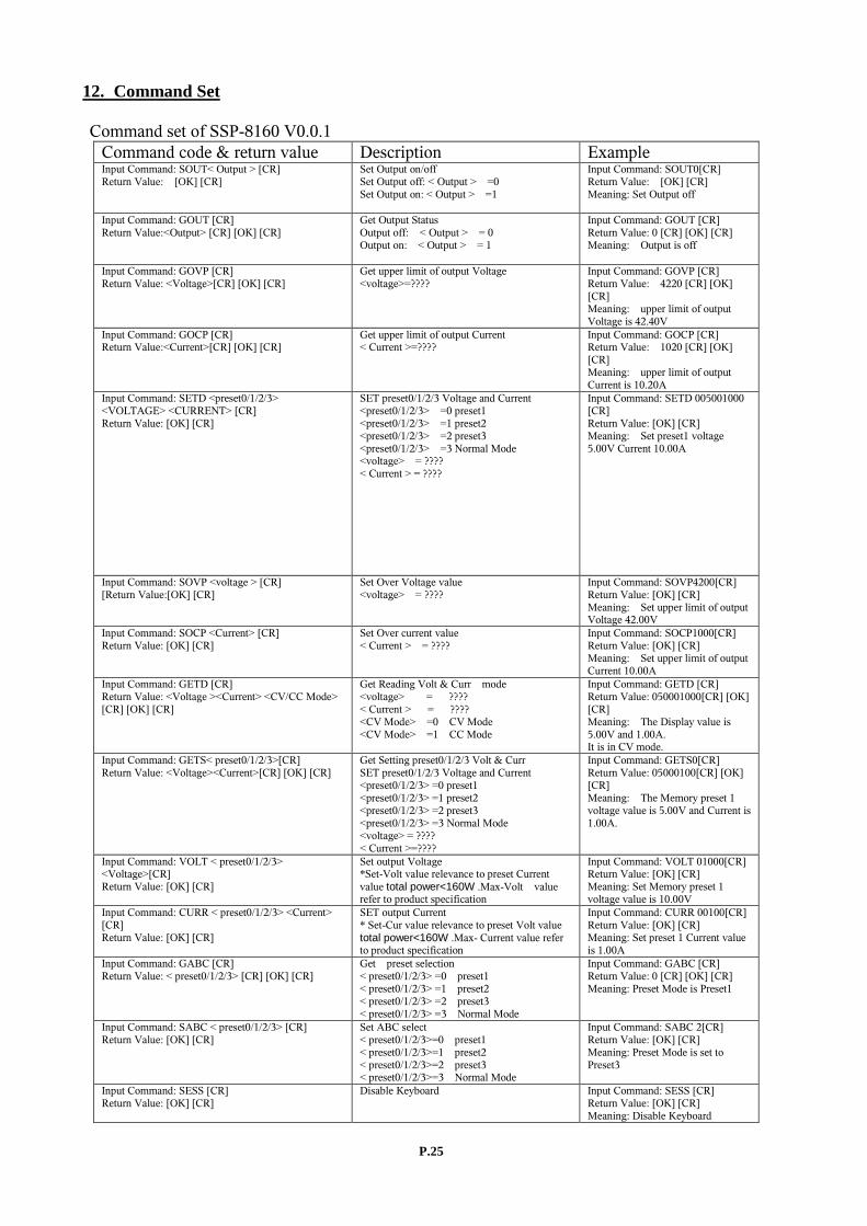
12. Command Set
Command set of SSP-8160 V0.0.1 Command code & return value Description Example Input Command: SOUT< Output > [CR] Return Value: [OK] [CR]
Set Output on/off Set Output off: < Output > =0 Set Output on: < Output > =1
Input Command: SOUT0[CR] Return Value: [OK] [CR] Meaning: Set Output off
Input Command: GOUT [CR] Return Value:<Output> [CR] [OK] [CR]
Get Output Status Output off: < Output > = 0 Output on: < Output > = 1
Input Command: GOUT [CR] Return Value: 0 [CR] [OK] [CR] Meaning: Output is off
Input Command: GOVP [CR] Return Value: <Voltage>[CR] [OK] [CR]
Get upper limit of output Voltage <voltage>=????
Input Command: GOVP [CR] Return Value: 4220 [CR] [OK] [CR] Meaning: upper limit of output Voltage is 42.40V
Input Command: GOCP [CR] Return Value:<Current>[CR] [OK] [CR]
Get upper limit of output Current < Current >=????
Input Command: GOCP [CR] Return Value: 1020 [CR] [OK] [CR] Meaning: upper limit of output Current is 10.20A
Input Command: SETD <preset0/1/2/3> <VOLTAGE> <CURRENT> [CR] Return Value: [OK] [CR]
SET preset0/1/2/3 Voltage and Current <preset0/1/2/3> =0 preset1 <preset0/1/2/3> =1 preset2 <preset0/1/2/3> =2 preset3 <preset0/1/2/3> =3 Normal Mode <voltage> = ???? < Current > = ????
Input Command: SETD 005001000 [CR] Return Value: [OK] [CR] Meaning: Set preset1 voltage 5.00V Current 10.00A
Input Command: SOVP <voltage > [CR] [Return Value:[OK] [CR]
Set Over Voltage value <voltage> = ????
Input Command: SOVP4200[CR] Return Value: [OK] [CR] Meaning: Set upper limit of output Voltage 42.00V
Input Command: SOCP <Current> [CR] Return Value: [OK] [CR]
Set Over current value < Current > = ????
Input Command: SOCP1000[CR] Return Value: [OK] [CR] Meaning: Set upper limit of output Current 10.00A
Input Command: GETD [CR] Return Value: <Voltage ><Current> <CV/CC Mode> [CR] [OK] [CR]
Get Reading Volt & Curr mode <voltage> = ???? < Current > = ???? <CV Mode> =0 CV Mode <CV Mode> =1 CC Mode
Input Command: GETD [CR] Return Value: 050001000[CR] [OK] [CR] Meaning: The Display value is 5.00V and 1.00A. It is in CV mode.
Input Command: GETS< preset0/1/2/3>[CR] Return Value: <Voltage><Current>[CR] [OK] [CR]
Get Setting preset0/1/2/3 Volt & Curr SET preset0/1/2/3 Voltage and Current <preset0/1/2/3> =0 preset1 <preset0/1/2/3> =1 preset2 <preset0/1/2/3> =2 preset3 <preset0/1/2/3> =3 Normal Mode <voltage> = ???? < Current >=????
Input Command: GETS0[CR] Return Value: 05000100[CR] [OK] [CR] Meaning: The Memory preset 1 voltage value is 5.00V and Current is 1.00A.
Input Command: VOLT < preset0/1/2/3> <Voltage>[CR] Return Value: [OK] [CR]
Set output Voltage *Set-Volt value relevance to preset Current value total power<160W .Max-Volt value refer to product specification
Input Command: VOLT 01000[CR] Return Value: [OK] [CR] Meaning: Set Memory preset 1 voltage value is 10.00V
Input Command: CURR < preset0/1/2/3> <Current> [CR] Return Value: [OK] [CR]
SET output Current * Set-Cur value relevance to preset Volt value total power<160W .Max- Current value refer to product specification
Input Command: CURR 00100[CR] Return Value: [OK] [CR] Meaning: Set preset 1 Current value is 1.00A
Input Command: GABC [CR] Return Value: < preset0/1/2/3> [CR] [OK] [CR]
Get preset selection < preset0/1/2/3> =0 preset1 < preset0/1/2/3> =1 preset2 < preset0/1/2/3> =2 preset3 < preset0/1/2/3> =3 Normal Mode
Input Command: GABC [CR] Return Value: 0 [CR] [OK] [CR] Meaning: Preset Mode is Preset1
Input Command: SABC < preset0/1/2/3> [CR] Return Value: [OK] [CR]
Set ABC select < preset0/1/2/3>=0 preset1 < preset0/1/2/3>=1 preset2 < preset0/1/2/3>=2 preset3 < preset0/1/2/3>=3 Normal Mode
Input Command: SABC 2[CR] Return Value: [OK] [CR] Meaning: Preset Mode is set to Preset3
Input Command: SESS [CR] Return Value: [OK] [CR]
Disable Keyboard Input Command: SESS [CR] Return Value: [OK] [CR] Meaning: Disable Keyboard
P.26
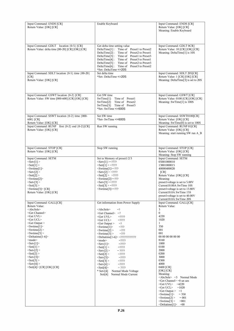
Input Command: ENDS [CR] Return Value: [OK] [CR]
Enable Keyboard Input Command: ENDS [CR] Return Value: [OK] [CR] Meaning: Enable Keyboard
Input Command: GDLT location {0-5} [CR] Return Value: delta time [00-20] [CR] [OK] [CR]
Get delta time setting value DeltaTime[1] : Time of Preset1 to Preset2 DeltaTime[2] : Time of Preset2 to Preset1 DeltaTime[3] : Time of Preset1 to Preset3 DeltaTime[4] : Time of Preset3 to Preset1 DeltaTime[5] : Time of Preset2 to Preset3 DeltaTime[6] : Time of Preset3 to Preset2 *Set- DeltaTime <=20S
Input Command: GDLT 0CR] Return Value: 10 [CR] [OK] [CR] Meaning: DeltaTime[1] is 10S
Input Command: SDLT location {0-5} time {00-20} [CR] Return Value: [OK] [CR]
Set delta time *Set- DeltaTime <=20S
Input Command: SDLT 205[CR] Return Value: 1 [CR] [OK] [CR] Meaning: DeltaTime[3] is set to 20S
Input Command: GSWT location {0-2} [CR] Return Value: SW time [000-600] [CR] [OK] [CR]
Get SW time SwTime[1]: Time of Preset1 SwTime[2]: Time of Preset2 SwTime[3]: Time of Preset3 *Set- SwTime <=600S
Input Command: GSWT [CR] Return Value: 0100 [CR] [OK] [CR] Meaning: SwTime[1] is 100S
Input Command: SSWT location {0-2} time {000-600} [CR] Return Value: [OK] [CR]
Set SW time *Set- SwTime <=600S
Input Command: SSWT0100[CR] Return Value: [OK] [CR] Meaning: SwTime[0] is set to 100S
Input Command: RUNP first {0-2} end {0-2}[CR] Return Value: [OK] [CR]
Run SW running Input Command: RUNP 01[CR] Return Value: [OK] [CR] Meaning: start running SW run A_B
Input Command: STOP [CR] Return Value: [OK] [CR]
Stop SW running Input Command: STOP [CR] Return Value: [OK] [CR] Meaning: Stop SW running
Input Command: SETM <Setv[1] > <Seti[1] > <Swtime[1]> <Setv[2] > <Seti[2] > <Swtime[2]> <Setv[3] > <Seti[3] > <Swtime[3]> [CR] Return Value: [OK] [CR]
Set to Memory of preset1/2/3 <Setv[1] >=???? <Seti[1] > =???? <Swtime[1]>=??? <Setv[2] > =???? <Seti[2] > =???? <Swtime[2]>=??? <Setv[3] >=???? <Seti[3] > =???? <Swtime[3]>=???
Input Command: SETM 05001000010 13801000015 40000400020 [CR] Return Value: [OK] [CR] Meaning: preset1voltage is set to 5.00V Current10.00A SwTime 10S preset1voltage is set to 13.80V Current10.0A SwTime 15S preset1voltage is set to 40.00V Current10.0A SwTime 20S
Input Command: GALL[CR] Return Value: <AbcSele> <Get Channel> <Get UVL> <Get UCL> <Get Output > <Swtime[1]> <Swtime[2] > <Swtime[3] > <Deltatime[1-6]> <mode> <Setv[1]> <Seti[1] > <Setv[2] > <Seti[2] > <Setv[3]> <Seti[3] > <Setv[4] > <Seti[4]> [CR] [OK] [CR]
Get information from Power Supply <AbcSele> =? <Get Channel> =? <Get UVL> =???? <Get UCL> =???? <Get Output > =? <Swtime[1]> =??? <Swtime[2] > =??? <Swtime[3] > =??? <Deltatime[1-6]> =???????????? <mode> =???? <Setv[1]> =???? <Seti[1] > =???? <Setv[2] > = ???? <Seti[2] > =???? <Setv[3]> =???? <Seti[3] > =???? <Setv[4] > =???? <Seti[4]> = ???? * Setv[4] Normal Mode Voltage
Seti[4] Normal Mode Current
Input Command: GALL[CR] Return Value: 3 0 4220 1020 1 350 001 001 00 00 00 00 00 00 8160 1000 0100 2000 0200 3000 0300 4000 0400 [CR] [OK] [CR] Meaning: <AbcSele> =3 Normal Mode <Get Channel> =0 un ues <Get UVL> =4220 <Get UCL> =1020 <Get Output > =1 <Swtime[1]> = 350 <Swtime[2] > = 001 <Swtime[3] > =001 <Deltatime[1]> =00

P.27
<Deltatime[2]> =00 <Deltatime[3]> =00 <Deltatime[4]> =00 <Deltatime[5]> =00 <Deltatime[6]> =00 <mode> = 8160 <Setv[1]> = 1000 <Seti[1] > =0100 <Setv[2] > =2000 <Seti[2] > =0200 <Setv[3]> =3000 <Seti[3] > =0300 <Setv[4] > =4000 <Seti[4]> =0400
Rev.2 04/2015 7673-8160-0002