ssp383 audi tt coupé ´07 - body - mrc malaysia · preparation of the ssp. ... audi space frame of...
TRANSCRIPT
38
3
All rights reserved. Technical specifications subject to change without notice.
CopyrightAUDI AGI/[email protected] +49-841/89-36367
AUDI AGD-85045 IngolstadtTechnical status: 05/06
Printed in GermanyA06.5S00.28.20
Audi TT Coupé ´07 - Body
Self-Study Programme 383
Vorsprung durch Technik www.audi.de Service Training
Audi-Space-Frame ASF® of the Audi TT Coupé
The development targets for the bodyshell of the Audi TT
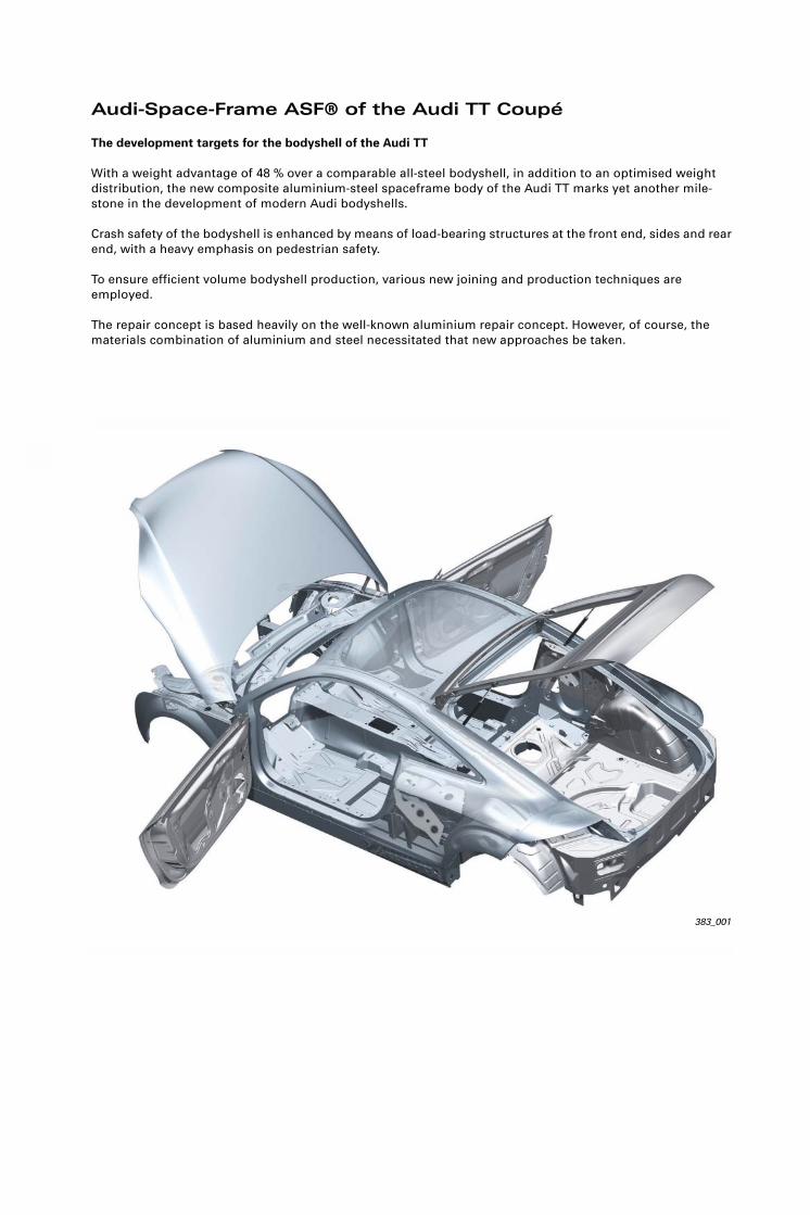
With a weight advantage of 48 % over a comparable all-steel bodyshell, in addition to an optimised weight distribution, the new composite aluminium-steel spaceframe body of the Audi TT marks yet another mile-stone in the development of modern Audi bodyshells.
Crash safety of the bodyshell is enhanced by means of load-bearing structures at the front end, sides and rear end, with a heavy emphasis on pedestrian safety.
To ensure efficient volume bodyshell production, various new joining and production techniques are employed.
The repair concept is based heavily on the well-known aluminium repair concept. However, of course, the materials combination of aluminium and steel necessitated that new approaches be taken.
383_001

NoteReferenceThe self-study programme teaches the design and function of new vehicle models, new automotive parts or new technologies.
The self-study programme is not a repair manual!All values given are intended as a guideline only and refer to the software version valid at the time of preparation of the SSP.
For maintenance and repair work, always refer to the current technical literature.
Contents
Overview . . . . . . . . . . . . . . . . . . . . . . . . . . . . . . . . . . . . . . . . . . . . . . . . . . . . . . . . . . . . 12
Punch riveting. . . . . . . . . . . . . . . . . . . . . . . . . . . . . . . . . . . . . . . . . . . . . . . . . . . . . . . . 13
Clinching . . . . . . . . . . . . . . . . . . . . . . . . . . . . . . . . . . . . . . . . . . . . . . . . . . . . . . . . . . . . 13
MIG welding . . . . . . . . . . . . . . . . . . . . . . . . . . . . . . . . . . . . . . . . . . . . . . . . . . . . . . . . . 14
Resistance spot welding and MAG welding. . . . . . . . . . . . . . . . . . . . . . . . . . . . . . 14
Structural bonding. . . . . . . . . . . . . . . . . . . . . . . . . . . . . . . . . . . . . . . . . . . . . . . . . . . . 15
New joining technique: solid punch riveting (Kerb-Konus riveting) . . . . . . . . . . 16
New joining technique: Flow Drill screwing . . . . . . . . . . . . . . . . . . . . . . . . . . . . . . 17
New joining technique: aluminium laser welding . . . . . . . . . . . . . . . . . . . . . . . . . 18
Dimensions . . . . . . . . . . . . . . . . . . . . . . . . . . . . . . . . . . . . . . . . . . . . . . . . . . . . . . . . . . . 4
Technological concept . . . . . . . . . . . . . . . . . . . . . . . . . . . . . . . . . . . . . . . . . . . . . . . . . 5
Contact corrosion . . . . . . . . . . . . . . . . . . . . . . . . . . . . . . . . . . . . . . . . . . . . . . . . . . . . . 6
Combination of steel and aluminium . . . . . . . . . . . . . . . . . . . . . . . . . . . . . . . . . . . . 7
Comparison of ASF concepts . . . . . . . . . . . . . . . . . . . . . . . . . . . . . . . . . . . . . . . . . . 10
Audi Space Frame of the Audi TT
Joining techniques and production processes
Bodyshell safety concept
Repair concept
Aluminium repairs . . . . . . . . . . . . . . . . . . . . . . . . . . . . . . . . . . . . . . . . . . . . . . . . . . . . 20
Steel repairs . . . . . . . . . . . . . . . . . . . . . . . . . . . . . . . . . . . . . . . . . . . . . . . . . . . . . . . . . 22
Aluminium-steel repairs . . . . . . . . . . . . . . . . . . . . . . . . . . . . . . . . . . . . . . . . . . . . . . . 23
Workshop equipment . . . . . . . . . . . . . . . . . . . . . . . . . . . . . . . . . . . . . . . . . . . . . . . . . 24
Qualification of aluminium. . . . . . . . . . . . . . . . . . . . . . . . . . . . . . . . . . . . . . . . . . . . . 25
Head-on collision, side impact and rear collision . . . . . . . . . . . . . . . . . . . . . . . . . 26
Pedestrian safety . . . . . . . . . . . . . . . . . . . . . . . . . . . . . . . . . . . . . . . . . . . . . . . . . . . . . 28
Electromechanical rear spoiler

4
Dimensions
Audi Space Frame of the Audi TT
383_002
Audi TT Coupé ’ 07 2,0 3,2 quattro
Transmission Manual gearbox S tronic Manual gearbox S tronic
Kerb weight without driver in kg 1260 1280 1410 1430
Max. perm. gross weight in kg 1660 1680 1810 1830
cw (rear spoiler extended) 0.3 0.3 0.31
Boot capacity in l 290 (700*) 290 (700*)
Max. power output in kW 147 (200 bhp) 184 (250 bhp)
vmax in kph 240 250
Acceleration 0-100 kph in s 6.6 6.4 5.9 5.7
Fuel consumption in l/100 km 7.7 7.7 10.3 9.4
* with the rear-seat back folded forward
5
Technological concept
383_003
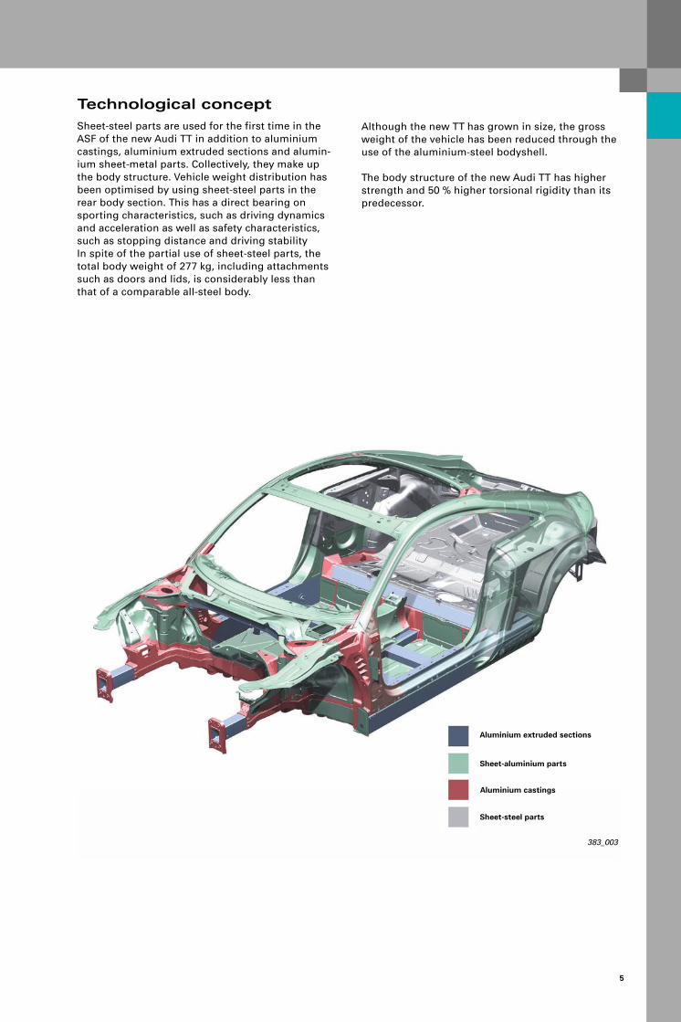
Aluminium castings
Sheet-aluminium parts
Aluminium extruded sections
Sheet-steel parts
Sheet-steel parts are used for the first time in the ASF of the new Audi TT in addition to aluminium castings, aluminium extruded sections and alumin-ium sheet-metal parts. Collectively, they make up the body structure. Vehicle weight distribution has been optimised by using sheet-steel parts in the rear body section. This has a direct bearing on sporting characteristics, such as driving dynamics and acceleration as well as safety characteristics, such as stopping distance and driving stability In spite of the partial use of sheet-steel parts, the total body weight of 277 kg, including attachments such as doors and lids, is considerably less than that of a comparable all-steel body.
Although the new TT has grown in size, the gross weight of the vehicle has been reduced through the use of the aluminium-steel bodyshell.
The body structure of the new Audi TT has higher strength and 50 % higher torsional rigidity than its predecessor.
6
Audi Space Frame of the Audi TT
383_004
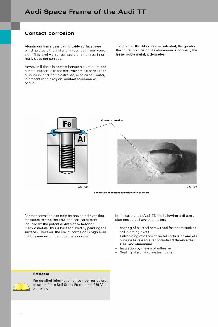
Contact corrosion
Aluminium has a passivating oxide surface layer which protects the material underneath from corro-sion. This is why an unpainted aluminium part nor-mally does not corrode.
However, if there is contact between aluminium and a metal higher up in the electrochemical series than aluminium and if an electrolyte, such as salt water, is present in this region, contact corrosion will occur.
The greater the difference in potential, the greater the contact corrosion. As aluminium is normally the lesser noble metal, it degrades.
383_005
Contact corrosion can only be prevented by taking measures to stop the flow of electrical current induced by the potential difference betweenthe two metals. This is best achieved by painting the surfaces. However, the risk of corrosion is high even if a tiny amount of paint damage occurs.
In the case of the Audi TT, the following anti-corro-sion measures have been taken:
– coating of all steel screws and fasteners such as self-piercing rivets
– Galvanising of all sheet-metal parts (zinc and alu-minium have a smaller potential difference than steel and aluminium)
– Insulation by means of adhesive– Sealing of aluminium-steel joints
Reference
For detailed information on contact corrosion, please refer to Self-Study Programme 239 "Audi A2 - Body" .
Schematic of contact corrosion with example
Contact corrosion

7
Joining steel and aluminiumThermal joining processes such as MIG welding can be ruled out because it is not possible by these means to make a joint which has the requisite struc-tural and dynamic strength and will not result in contact corrosion.
383_011
Steel
Aluminium
One of the challenges for the development of the Audi TT bodyshell was the attachment of the sheet-steel rear-end parts to the aluminium body assem-blies.
383_006
Aluminium-steel connections

8
Audi Space Frame of the Audi TT
This is ensured by non-thermal joining of parts using coated self-piercing rivets and special screws in combination with bonding.
Special requirements are made with regard to the strength and corrosion protection of the joints between aluminium body parts and steel parts.
Adhesive bonding is the basis for the corrosion pro-tection of corrosion-susceptible aluminium/galva-nised steel joints in the bodyshell of the Audi TT.In this way, the mating materials are superficially insu-lated, thus suppressing corrosion processes at the point of contact. As a further measure, all compos-ite joints either sealed with PVC or coated with wax preservative after the cataphoretic dip coating (KTL) process.
Aluminium and steel joints with faulty corrosion pro-tection can exhibit much higher corrosion rates than all-aluminium joints or all-steel joints.When making aluminium-steel joints, therefore, highest standards of quality must be maintained at all times during the production process and in the service workshop.
383_012
Adhesive
Adhesive

9
The aluminium sheet shown here exhibits severe contact corrosion, which has resulted in mechanical failure of the punch riveted joint.
This illustration shows clearly what effects contact corrosion can have if adequate corrosion protection is not provided. A this joint, the flange was sealed in the bodyshell without using adhesive.
In this case, the aluminium sheet showed no dam-age due to contact corrosion after exposure to iden-tical environmental conditions.
By way of a comparison, this illustration shows the same flange with an adhesive bond and sealing.
383_007
Seal
Seal
383_008
Seal
Adhesive
Seal

10
Audi Space Frame of the Audi TT
Comparison of ASF conceptsAudi A8 (2003 ➔)
383_013
Aluminium castings
Sheet aluminium parts
Aluminium extruded sections
383_014
Sill section Audi A8Three-chamber extruded section
383_017
A-post, Audi A8Single-chamber extruded section

11
Audi TT (2006 ➔)
383_009
Sheet aluminium parts
Aluminium extruded sections
Sheet-steel parts
Aluminium castings
383_015A-post, Audi TTSheet-aluminium sections (interior/exterior)
383_016
Sill section, Audi TTFour-chamber extruded section

12
Joining techniques and production processes
383_018Riveted joint
OverviewIn addition to well-known processes such as MIG welding or punch riveting, the joining techniques of Flow Drill screwing and Kerb-taper riveting are used for the first time on the Audi TT.In the production process, a laser cleaning method is used for cleaning before the roof drip moulding is attached by welding.
383_019
Flow-Drill screw connection
383_020Clean Laser
Technology Process Quantity per vehicle
Mechanical joining techniques
Punch rivetingFlow Drill screwingSolid punch riveting (Kerb-Konus)Clinching
1615 pce.229 pce.96 pce.164 pce.
Thermaljoining techniques
MIG weldingLaser weldingResistance spot weldingMAG weldingStud welding
21462 mm5309 mm1287 spots809 mm234 pce.
Bonding technology Bonding 97156 mm
Machining technology MillingDrillingThread cuttingBrushingRoll seamingClean lasering
188 mm16 pce.8 pce.2300 mm26737 mm4000 mm

13
Punch rivetingPunch riveting is one of the principal joining techniques used on the bodyshell of the new Audi TT. This tech-nique is used for joining aluminium body parts and for joining aluminium body parts to steel body parts.The process has been in use since launch of the Audi A2. Self piercing rivets with two different diameters and lengths are used in the Audi TT.
Punch riveting process
383_051
Applications of punch riveting
With clinching, the metal sheets to be joined are clamped between a die and a blankholder. The sheets are then pushed down into the die by a punch to form an interlocking joint. However, joints produced in this way is not as strong as joints produced by punch riveting, for example. In the Audi TT, this technology is used on attachments such as doors and lids. Several clinched joints are also located in the area of the B-post and rear wheel arch. In this area, aluminium sheets as well as steel and alu-minium sheets are clinched together.
Applications of clinching
383_053
Clinching process
Clinching
383_052
383_032

14
Joining techniques and production processes
MIG welding
The usual techniques of resistance spot welding and, to a lesser extent, metal active gas welding (MAG weld-ing) are used for joining sheet steel body parts in steel body manufacturing.
Resistance spot welding and MAG welding
383_055
Applications of MIG welding
383_057Applications of resistance spot welding
Applications of MAG welding
383_056
Resistance spot welding process
383_054
MIG welding process
Aluminium parts have largely been joined by means of metal inert gas welding since the launch of the Audi aluminium bodyshell in the Audi A8 (1994) . This technique is principally used to make joints between castings and extruded sections, as well as sheet-metal parts.This joining technique is notable for producing high-strength joints, but it introduces a great deal of heat into the joint and has a relatively slow process speed.

15
Structural bondingIn certain areas, adhesive bonding is used supplementary to clinched joints and punch riveted joints, solid punch riveted joints, Flow Drill screw connections and resistance spot welds. This improves joint strength. Adhesive bonding is also used for strengthening of seam joints, e.g. in the rear wheel arch. In other areas of the body, adhesive beads are used for sealing and insulation between aluminium and steel sheets, as well as for noise reduction.
Structural bonding process in production
383_058
383_059
Applications of structural adhesive

16
Joining techniques and production processes
New joining technique: solid punch riveting (Kerb-Konus riveting)
Solid punch riveting or Kerb-Konus riveting involves the use of aluminium or coated stainless steel rivets. In contrast to punch riveting, the rivet is punched through both sheets to be joined.Unlike steel rivets, aluminium solid punch rivets can be reworked mechanically. This is the case with the joint between the body side section and the drip moulding. However, the strength of solid punch riveted joints is inferior to that of punch riveted joints.
383_073Micrograph of a solid punch riveted joint
383_060Solid punch riveting process
383_061Solid punch riveting process in production
383_048Applications of solid punch riveting
Information on the repair concept
Aluminium solid punch rivets are used in the C-post drip moulding area, while coated stainless steel solid punch rivets are used in the region of the roof frame. Stainless steel rivets must not be drilled out or ground, due to the risk of corrosion.

17
383_062
Flow Drill screwing process
New joining technique: Flow Drill screwingAutomatic direct screwing enables joints to be made between any materials, even if these materials can be accessed from one side only. A special coated screw is driven under high surface pressure through a hole in the outer part to be joined. The lower part is not predrilled. The pressure and rotational speed soften the material and allow the screw to be inserted.
383_063
Screwing process in production
Flow Drill Screw
383_074
Micrograph of a Flow Drill screw connection
383_064Applications of Flow Drill screwing
Information on the repair concept
Flow Drill screws can be removed in the service workshop and replaced with new screws. In case of thread damage, screws are also available in oversize (M6 instead of M5) . For use in new parts, it may be necessary to predrill the material.

18
Joining techniques and production processes
New joining technique: aluminium laser welding (invisible roof seam)
Laser welding has been used for joining aluminium body parts since the launch of the Audi A2. In most cases, sheet-metal parts are welded onto castings or extruded parts. The invisible joint in the roof area is joined using a new joining technique: laser welding.
383_066
Laser welding process in production
383_025
Micrograph of the roof frame and roof panel joint
383_067
Applications of laser beam welding Invisible roof seam
Applications of laser beam welding
Laser beam
Evaporating metal vapour
Welding wire
Vapour / plasma / channel
Direction of welding
Laser-induced plasma
Liquid melt zone
Solid melt zone
383_065

19
To ensure consistent laser welding of aluminium parts, the parts to be welded must have a perfectly clean sur-face. This is achieved either by washing the component parts followed by chemical pickling or by using the new Laser Clean process. A controlled laser beam removes all residues from the surface by heating it for a short time. Parts cleaned using this method can be directly laser-welded.
383_075
Micrograph of a laser-welded seam withLaser Clean (above) and without cleaning (below)
383_069
383_068
Laser Clean process in production
The joint between the roof frame and roof panel is reworked and surface finished automatically in the produc-tion line by means of a brushing process.
383_070
Brushing process in production
383_071
383_072
Laser weld seam before (above) and after the brushing process (below)

20
Repair concept
383_023
Crash box
Bumper beam 1
Bumper beam Screw connections
Bumper beam 2
Aluminium repairThe repair concept for the all-aluminium body parts is similar to that for the repair of previous Audi alu-minium-bodied vehicles.
The front end of the vehicle is designed in such a way that the bumper beams and bolted crash boxes can be replaced after minor collisions up to approx. 15 kph.
If the vehicle structure is damaged, beam 1 can also be replaced by undoing the screw connection. All fur-ther damage to the vehicle front end can only be repaired by welding suitable genuine parts into place.
383_024
Joint between beam 1 and beam 2

21
The four-chamber extruded section is located beneath the sill moulding.A special repair method was developed for damaged outer chambers. When repair work is needed, the extruded section is split vertically so that the two rear chambers including the centre ridge of the four-chamber profile remain.
A dual-chamber genuine part developed specially for this repair solution is welded to the remainder of the sill profile using a continuous MIG weld seam at the top and bottom. In addition, the U-shaped chan-nel in the genuine part is filled with an adhesive bead which provides additional strength and elimi-nates noise transmission between the two sills.
383_039
MIG weld seam
Adhesive bead
New part

22
Repair concept
Steel repairsThe rear end of the Audi TT is only area where it is possible to carry out repair work involving only steel parts and where the aluminium-steel joint is fully intact.
This repair work can be carried out on the
– rear end section– rear side member (body side section undamaged)– rear floorpan
Basically, the repair procedure is the same as for all-steel-bodied vehicles. Due to the danger of contact corrosion in aluminium body parts, however, special safety precautions must be taken. Grinding dust of steel parts, particularly flying sparks caused by cut-ting or welding work, must not be allowed to drop onto the aluminium parts.
383_040
body parts which must be covered when carrying out steel repairs
Damage to be repaired
This also applies to painted aluminium parts! Red hot steel parts can damage the paintwork and steel particles can come into contact with the aluminium body parts, leading to contact corrosion on the undamaged aluminium body. Therefore, the complete bodyshell must be pro-tected carefully when carrying out steel repairs. This is done by using suitable protective covers and by masking the body with masking tape. Furthermore, cutting work may only be performed using a body saw. If grinding work is needed, this must be done using grinding discs which produce little or no fly-ing sparks. The spot welding machine should be used for welding work where possible, because it produces less weld spatter during the welding proc-ess.

23
Aluminium-steel repairsIn the case of body side or rear-end damage, both aluminium and steel body parts may become dam-aged. This is the case, for example, when the body side section (aluminium) and rear wheel arch (steel) are damaged. After removing the damaged parts, the new genuine parts are installed in accordance with the repair procedures described in the previous sections. Joining of steel and aluminium parts must be carried out with the greatest care in order to eliminate the possibility of future contact corrosion.
Two-component car body adhesive DA 001 730 A1 and rivets or screws are used for joining. As in series production, an insulating layer is placed between the two materials to prevent contact corro-sion. When welding steel body parts, the aluminium parts must be carefully covered and masked!
Reference
All body repair work must be performed in accordance with the guidelines set out in the current workshop literature!

24
Repair concept
Workshop equipment A special tool is required for repair work on alumin-ium-bodied vehicles. The basis is work scope 2010.
In addition to the special equipment and machines for stud welding, dent removal, bonding and rivet-ing, the aluminium welding technology is of special importance.
383_026
Aluminium body dent removal tools VAS 5196 and VAS 6049
383_076
Cordless punch riveter VAS 5279A
Aluminium inert gas welder VAS 6388
383_029383_028
Aluminium inert gas welder V.A.G 2001B
There are now two appliances with modern control systems whichare ideal for welding work on the Audi aluminium body. The welding appliances, when used properly, pro-duce perfect aluminium welded joints which have optimum strength.
Reference
For further information on the workshop equip-ment for Audi aluminium-bodied vehicles, refer to the workshop literature and the Audi Service Net.

25
383_049
EX 351
WeldingAluminium Certificate
Repeat exam
EX 353
Audi TTAluminium technology
AB 352
Aluminium technology
BT 350
WeldingAluminium technology
Welding Certificate
BT 351
BasicsBody
BT 352Basics
Vehicle electrical systems for car body
technology
BS 301 Occupant protection, airbags and belt ten-sioners
BS 310 Selective use of technical informationBS 360 Vehicle diagnosis, testing and information
system VAS 5051
A special knowledge and special skills are required to repair aluminium bodyshells. A prerequisite for successful body repairs is participation in the rele-vant training courses.
Particularly for welding work, certification of employees according to international standard DIN EN ISO 9606-2 is important.
Qualification of aluminium
Reference
For further information on the qualifications in aluminium technology, refer to the Audi Service Net.

26
Car body safety concept
Head-on collision, side impact and rear collisionLikewise, in terms of crash safety, the new TT makes no compromises. The front beams consist of alu-minium extruded sections and aluminium castings. In combination with the front beams and a sub-frame, they reduce and distribute the forces which act on the car body during a head-on collision. Large-sized beams in the rear end protect the occu-pant cell.High-strength aluminium beams in the doors provide side impact protection. The alumin-ium bonnet is designed to all requirements for pedestrian safety.
The simulation provides information on the collision behaviour of the body structure at a very early stage in the development process. For this purpose, calcu-lations are done on the basis of the available car body data using the Finite Elements Method. The results are incorporated into the ongoing design process, thus allowing the body structure design to be optimised in respect of the relevant crash loads.
383_031
Simulation Euro NCAP head-on collision

27
383_041
Euro NCAP head-on collision (64 kph with partial overlap)
To check the theoretical results and to meet statu-tory requirements, actual tests are conducted.
Various test conditions are simulated on the basis of the applicable standard.
383_042
Euro NCAP side impact (50 kph)
383_043ECE and Japan rear collision (50 kph)

28
Car body safety concept
Pedestrian safetyWhen designing the bonnet, importance was attached to a stable design which yields to absorb head impacts. This is achieved by the honeycomb-like structure of the car body inner panelling.
383_034
The overall concept provides for deformation zones between the bonnet and the units or car body struc-tural parts.
To reduce leg impact force at the front end, the bumper cover has been decoupled and an impact-absorbing foam part has been integrated between the bumper beam and bumper cover.
383_044
Pedestrian safety is an increasingly important fac-tor. Various measures were implemented in the new Audi TT in order to meet the safety requirements.

29
The development tools "Simulation" and "Testing" were used for design.
383_035
Lower legform(leg impact)
Headform (head impact)
Head impact
To test the head impact a hemisphere which repre-sents the head is catapulted onto the bonnet. The relevant physical variables are determined, on the basis of which conclusions are drawn regarding impact loads.
383_036
Leg impact
Leg impact is simulated by means of a test configu-ration in which a test body similar to the actual body part impacts the vehicle bumper.
383_037

30
Electromechanical rear spoiler
The new Audi TT has as standard an electrically extendable rear spoiler. The extended rear spoiler significantly increases driving stability at high speeds. The spoiler extends automatically at a speed of 120 kph and retracts at a speed of 80 kph. At speeds of less then 120 kph, the rear spoiler can be actuated manually with a switch in the centre console.
The unit consisting of the rear spoiler module and the spoiler wing is integrated in the boot lid of the Audi TT. The rear spoiler module with drive unit, input shaft and reversing mechanism (hinge) is bolted with self-adjusting elements to the sheet-steel spoiler wing painted in the body colour.
383_038
383_045
When repair work is needed, the spoiler wing can be replaced separately. The rear spoiler module is replaced completely in case of damage.
Reference
For further information on operation, function and diagnosis, refer to Self-studyProgramme 382 "Audi TT Coupé ‘07 - Electrical and Infotainment Systems“.

SSP 381 Audi TT Coupé ‘07 - Suspension System
– Front axle– Rear axle– Shock absorber system– Brake system
Order number: A06.5S00.26.20
SSP 382 Audi TT Coupé ‘07 - Electrical and Infotainment Systems
– Networking– Bus topology– Convenience electronics– Infotainment
Order number: A06.5S00.27.20
SSP 380 Audi TT Coupé ‘07
– Body– Occupant protection– Engine– Suspension system– Electrical system– Air conditioning– Infotainment
Order number: A06.5S00.25.20
SSP 383 Audi TT Coupé ‘07 - Body
– Audi Space Frame of the Audi TT– Joining techniques and production processes– Repair concept– Car body safety concept– Electromechanical rear spoiler
Order number: A06.5S00.28.20

38
3
All rights reserved. Technical specifications subject to change without notice.
CopyrightAUDI AGI/[email protected] +49-841/89-36367
AUDI AGD-85045 IngolstadtTechnical status: 05/06
Printed in GermanyA06.5S00.28.20
Audi TT Coupé ´07 - Body
Self-Study Programme 383
Vorsprung durch Technik www.audi.de Service Training