sstac/arts review of the draft
TRANSCRIPT


SSTAC/ARTS REVIEW OF THE DRAFTINTEGRATED TECHNOLOGY PLAN (ITP)
Volume VI: June 26-27
Controls and Guidance
Briefings from theJune 24-28, 1991 ConferenceMcLean, Virginia
(NASA-TM-I08654) SSTAC/ARTS REVIEW
OF THE gRAFT INTEGRATED TECHNGLOGY
PLAN ([TP). VOLUME 6: CONTROLS AND
GUIDANCE (NASA) 215 p
N93-20774
Uncl,_s
63/81 0150611
National Aeronautics and Space AdministrationOffice of Aeronautics, Exploration and TechnologyWashington, D.C. 20546

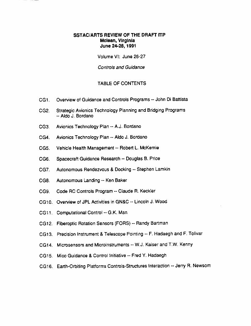
SSTAC/ARTS REVIEW OF THE DRAFT ITP
Mclean, VirginiaJune 24-28, 1991
Volume VI: June 26-27
Controls and Guidance
TABLE OF CONTENTS
CG1.
CG2.
CG3.
CG4.
CG5.
CG6.
CG7.
CG8.
CG9.
CG10.
CG11.
CG12.
CG13.
CG14.
CG15.
CG16.
Overview of Guidance and Controls Programs -- John Di Battista
Strategic Avionics Technology Planning and Bridging Programs-- Aldo J. Bordano
Avionics Technology Plan -- A.J. Bordano
Avionics Technology Plan -- Aldo J. Bordano
Vehicle Health Management -- Robert L. McKemie
Spacecraft Guidance Research -- Douglas B. Price
Autonomous Rendezvous & Docking -- Stephen Lamkin
Autonomous Landing -- Ken Baker
Code RC Controls Program -- Claude R. Keckler
Overview of JPL Activities in GN&C -- Lincoln J. Wood
Computational Control -- G.K. Man
Fiberoptic Rotation Sensors (FORS) -- Randy Bartman
Precision Instrument & Telescope Pointing -- F. Hadaegh and F, Tolivar
Microsensors and Microinstruments -- W.J. Kaiser and T.W. Kenny
Mico Guidance & Control Initiative -- Fred Y. Haclaegh
Earth-Orbiting Platforms Controls-Structures Interaction -- Jerry R. Newsom


Overview of Guidance and Controls
Programs
NASA HeadquartersOAET/Code RC
June 26, 1991
John Di Battista
i
i ot
GUIDANCEANDCONTROL PROGRAM
Advance critical areas of enabling and enhancing transportationand spacecraft guidance and control technologies that supportcivil, commercial, science, and exploration missions for the1990's and beyond. The technology program consists ofresearch and technology development in:
• Guidance Technology
• Controls Technology
• Computational Controls Technology
GGI-1

GUIDANCEAND CONTROLS
RESEARCH AND TECHNOLOGY
PROGRAM BASIS
• NATIONAL AERONAUTICS AND SPACE ACT OF 19515
.--Spaceaeiivities--stmll beconductedsoas Io contrib•te materially to_
(4) The est•blishment•f kmg.it•ge studies•f the polential benefitsto be gainedfrom, Iheopportunities for. •nd lhe problemsinvolvedin the ulili_,allonof aeronautical •nd space• ¢tivilk-i for pe•ceful •nd scientificpurposes;
($) The preservationor the rote •f the United Slatesas • leaderin aeronautical and spacescienceand tedanololfflind in the apptlculiooihereoTto the conductof pemcefulaetlvitieswithin •nd outsidethealmosphere;_
Space Technology to Meet Future Needs. Joe Shea Committee I_B'/
.... concepts such us adupatively controlled structures should bedeveloped ..... pg 104
TRANSPORTATION VEHICLES
There is u need for modern technology in future vehicles of all classes toenable new capabilities such us heavier lift capacity, to improve reliability,and to lower cost ...... pg 15
GUIDANCE AND CONTROLS PROGRAM
HISTORY
1958 - 1980 ................... RESEARCH AND TECHNOLOGY PROGRAM TOSUPPORT RIGID BOGY SPACECRAFT CONTROL WITHFLEXIBLE APPENDAGES AND PROVIDE CONTROLSUBSYSTEM COMPONENT TECHNOLOGY
1984 ................................ SDIO SUPPORT TO CONTROLS INITIATED
1978 -1984 .................... DARPA ACTIVE CONTROL OF FLEXIBLESTRUCTURES (ACOSS) PROGRAM
1980 ............................ PROGRAM INITIATED TO SUPPORT LARGECOMPLEX AND FLEXIBLE SPACECRAFT
1982. ......................... CODE R CONTROLS STRUCTURES INTERACTIONPROGRAM INITIATED
1988 .................................... PROGRAM PLANNING INITIATED TO PROVIDEADVANCED GUIOANCE TECHNOLOGY ( ADVANCED LAUNCHSYSTEM TECHNOLOGY PROGRAM )-1989
1989 ................................... COMPUTATIONAL CONTROLS PROGRAMIDENTIFIED
C(31-2

GUIDANCE AND CONTROLSPROGRAM
HISTORY
CONTINUED )
1989 -1991 ...................... EXPLORATION TECHNOLOGY PROGRAMS IN
AUTONOMOUS RENDEZVOUS AND DOCKING AND
AUTONOMOUS LANDER
1990 .................................... LAUNCH VEHICLE AVIONICS PLANNING
INITIATED BY STRATEGIC AVIONICS WORKING GROUP
GUIDANCE AND CONTROLPROGRAM
APPROACH:
• IDENTIFY TECHNOLOGY NEEDS THROUGH STUDIES, FUTURE MISSION
REQUIREMENTS AND GUIDANCE FROM CODE M,S. OTItERGOVERNMENT AGENCIES AND COMMERCIAL PROVIDERS,THE SSTACAND TIlE STRATEGIC AVIONICS WOKING GROUP, AND OTHERS
• IDENTIFY THE CENTERS WITH THE BEST CAPABILITIES ANDFACILITES FOR TIlE IDENTIRED TECHNOLOGY AREAS
• DEVELOP A COORDINATED PROGRAM USING INPUTS FROMCENTERS AND NASA HEADQUARTERS
• ESTABLISH PARTNERSHIPS BETWEEN THE CENTERS, INDUSTRY,UNIVERSITIES, AND OTHER GOVERNMENT LABORATORIES
• BASE PROGRAM ELEMENTS CARRY OUT GENERIC RESEARCH ANDTECHNOLOGY
• FOCUSED PROGRAM ELEMENTS HAVE ADVANCED BRASSBOARDDEMONSTRATION WHICH CONTRIBUTING TO TECtlNOLOGYTRANSFER, AND WHEN APPROPRIATE, PARTICIPATE IN FLIGHTEXPERIMENTS
• TRANSFER TECHNOLOGY TO THE USER FOR USE IN DEVELOPMENT
OF OPERATIONAL FLIGI IT SYSTEMS
CG1-3

GUIDANCE AND CONTROLS PROGRAM
• CRITICAL ENABLING GUIDANCE AND CONTROLS TECHNOLOGIES AREPROVIDED 1N ACCORDANCE WITII THE NATION'S LONG RANGE GOALS TOMAINTAIN THE PREMANCE OF OUR SPACECRAFT AND TRANSPORTATIONVEIIICLES
AND ENABLE THE DEVELOPMENT OF THE FOLLOWING TECHNOLOGIES:
• PROVIDE NEW AND EFFICIENT ADAFF1VE GUIDANCE ALGORITHMS• PROVIDE HIGHLY RELIABLE DISTRIBUTED FAULT TOLERANT
CONTROL SYSTEMS TECHNOLOGY• PROVIDE ROBUST CONTROLS TECHNOLOGY FOR LARGE
COMPLEX SPACE SYSTEMS INCLUDING SYSTEM IDENTIFICATION,ADAI:q'IVE CONTROL, PRECISION METROLOGY, SENSORS AND
ACTUATORS• PROVIDE COMPUTATIONAL CONTROLS TECHNOLOGY ENABLING
ORDERS OF MAGNITUDE INCREASES IN THE ABILITY TODESIGN, SYNTHESIZE, ANALYSE AND SIMULATE LARGECOMPLEX SPACE SYSTEMS
GUIDANCE AND CONTROLS PROGRAM
WORK BREAKDOWN STRUCTURE
LT ] "'1 , ""
I AUGMENTATION I-_-_-_--.-
I tmPFil[C i SION --IICONTROLSn&T I I lI POINTI'_O I
BASE I Im I SCIENCE II
I | AUC@IENT AT ION I
,_ COf_PUTAT IONAL I I .......
CONTROLSBASE
,I BASE II AUGMENTATION II I I I I l
I.J's,'_G,%7._" " "'I CONTROL I
I PLAT FOIqlM |
I AUCWIENTATION II I I 1 I i I

GUIDANCE & CONTROLS PROGRAM
ORGANIZATIONAL CHART
I Cede RC JDividee Di_.t'tor
I
Program ManalerGuldaat_ & Comrob
II i
I,_.. Aeromaneuvermg
..,A_aotlve Guidance | Gumance
/Fault Tolerant
"-Otstrlbuted _-- 5/C Controls
Controls Jj_. Computational
m5/C Controls Controls
--ComputationalControls
JSC
51C Controls
Computational--Controls
__TransportationControls
ExplorationAutonomousRendezvous &
DockingAutonomous
Lan_er
SIC Controls
_ Comout at tonalControls
-- ENploratlonAutonomous
Rendezvous &
Ooclt Ing
I
Computat IonalControls
+ Ii
GUIDANCE & CONTROLS PROGRAMSTATE OF THE ART:
_utclance T ethnology
• Sr_ut t le
• P_anetar¥ 51C and
Probes
Fault lolera¢It Distributed
Conifer
O Shuttle/Titan/
Atlas-Centaur/Delta
Spacecraft Control
e Riglg BoOy ControlTheory
• Gains AgJusted On OrPlt
toAccomogate Deployed
Conflguratlon Control
ComDutat Jonal Controls
• Efficient Computational
Algorithms• Real Time H/W In the
LOOp Simulations
• Parra)lel Processing
User Fr4engly Interface
Tedm7
• Precolcu;atoO ! lop(Is I weather
Potions
• Spinning Gyros/Imallt DissectorsStar Trackers
• Ballistic Planetory Entry wlthAero,_ynamlc De¢eterltton
• Shuttle TrIDle Regungancy with
Actuatdr Force Fight
• Titan/Delta Single StringS- Level Parts
• £_ntaur Dual Strt_,41Redundancy
•AlPS Fault TolerlmtArchltect_e Technology
• i_.alelo Soun/DesPtm Control
HuDble.Ulysges. & Mariner• Flexible AopenOage rnermal
System /Control SystemInteraction
• Orond Based Corge Soace System
Controls tes_tpeds
• Order N AlgorlU_ms/Symbollc
Logic
• Discos, Treetops, PIItPIX X, ate
• Space Station OynlcsSimulation
• Crier Casslhl Control Simulatorinterface
(;all
i': • Day of Laugh kl _.o_s/
Lldor wing $ounclers
, • Fiber O_t1¢$ Rotation SensorAerom_e_verlng
•AIPS Architecture
Implement align withB-Level Parts
• Launch on Schegualwith Fault
• Vehicle Health Hanagement
• Ro0ust S/C Control with
On OrOlt System ID anoAdlDt Co+ltroIs for
Complex S/C Inclu(lllngGrowth $S,Multl-lnstrument
Platforms ild Large
Segmented Telescopes
• Paralllzeg Order H
Algorithms
• Parallel Processing on Super-
computers with real time
H/W In the loop simulations
• Mclntosh Irks tnterface
CG1-5

GUIDANCE AND CONTROLSPROGRAM FACILITIES
• PLS SIMULATOR
• AIRLABS
• ACES/CASES
• SCOLE
• CARL
GUIDANCE & CONTROLS
PROGRAMACCOMPLISHMENTS:
• Developed Generic 100 Faster Space Slation Comrols Simulalor wilh Order NAlgorithms, Symbolic Equation Manipulalor and Parallel Processing
• Demonstrated Navigational Grade Fiber Optics Rmation (FORS) Gyro
• Developed Treetop, Conlops and Order N Discos Conlrols/Simulalion Codes
• Developed SHAPES Sensor for Large I00 M Anlerma Conlrol
• Provided Controls Algorithms Technology to Hubble Space Telescope for SolarArray Thermal Pumping Problem Fix
• Provided Real Time PLS Conlrols Simulalor
• Provided Adapeive Guidance LIDAR Winds Aloft Technogy
• Demonstraled distribuled fault tolerant Advanced Informmion Processing SystemBn_adboard
• Developed for demonstration Astro Solid Slate CCD SearTracker Saving Mission
• Developed robust efficient adaptive control system idenlification and controlalgorithms lechnology for large complex systems
CGI-6

GUIDANCE & CONTROLS PROGRAM
PICTURESOF
SS WorkstationFORS
HUBBLEPLS
LIDARASTRO
AIPSETC
GUIDANCE & CONTROLS PROGRAM
PROGRAM MILESTONES:
GUIDANCE PROGRAMPERFORM LIDAR WINI_ PROFILE Tl_crs AT KSC -1991
DEVELOP STOCA.qTIC _ GUIDANCE ALGORmlMSAND TRAJECTORY DESIGN TO4)I-S-- 1992
COMPLETE BEADBOARD OF A. i. BASED STAR TRACKER-lqR]
COMPLETE FORS SINGLE AXIS ENGINEERING MODEL--1993
CONTROLS PROGRAMCOMPLETI,, SPACECRAFT MCONT_OL SY,_TrF.MDE,gIGN GUIDELIED(_UMENI" --I_2
COMPLE'rE RMS CONTROL SYSTRM UI_RADE DESIGN PLAN--I¢g2
DEMONSTRAT'E PRECISION ,_TRUC'rURE ( INTERF'EROMETER )SIIAPE MEASURRMENT--Iqff2
COMPLETE PRELIMINARY MICRO GYRO DESIGN-Iqff3
VALIDATE AIPS CHARACTER ARcHrrECTURE-- lqff4J
COMPUTATIONAL CONTROLSUP(;RADE DISCO wrrH FLEXI6LE ORDER N DISCO -1992
MBODY MODEL REDUCTION COMPONENT REP. S/W- 1994
10 MSEC REAL'rIME SYSTEM SIMULATION ( 4NSTATE CAPABILITY)-- I_k$
0G1-7

GUIDANCE & CONTROLS PROGRAM
[rELATED NASA PROGRAMS:
• CODE R CONTROLS STRUCTURES INTERACTIONPROGRAM
• CODE M BRIDGING TASK IN ADAPTIVE GUIDANCE
• CODE R AERONAUTICS CONTROLS PROGRAM
• CODE R NASP GUIDANCE AND CONTROLS PROGRAM
i_ELATED GOVERNMENT PROGRAMS
• SDIO CONTROLS PROGRAMS IN COMPLEX SYSTEMS ANDADVANCED AVIONICS PROGRAM
• DOD ADVANCED LAUNCH SYSTEM (ALS) PROGRAMS INADAPTIVE GUIDANCE AND FAULT TOLERANT AVIONICS
GUIDANCE AND CONTROLS PROGRAM
($,M)
ExisflngProgram I FYgI]FY92[ FY931F Y941FY951FY96t FY97
CUIDANCE ANDCONTROLS [ 4650[ S205J 5700 1 6450 I 7000 J 7900 J 8900
GENERICIIYI_It,,ONICS [ 3281 ,401 '3701 420 1 490[ 560 I 6,.50I
RESOURCES BREAKDOWN FY 92 ONLY
GUIDANCE TECHNOLOGY
CONTROLS TECHNOLOGY
COMPUTATIONAL CONTROLS
FY92i
1355
2990
1200
CG1.8

MEW AREAS FOR AUGMENTATION REOUESTED:
* TRANSPORTATION VEHICLE AVIONICS - 1993
o AlYrONOMOUS RENDEZVOUS & DOCKING. 1994
• AUTONOMOUS LANDER. 1994
• PLATFORM G,N&C - 1994
• PRECISION POINTING . 1994
• MICROMACHINES - 1995
Transportation Technology
Earth-To-Orbit Transportation
1Earth-to-Orbit Vehicle Avionics I
OBJECTIVES• Programmatic
E_wek_p veh,_ mvienk_b _ sL_Dpon minn_za_zN3n _ lh_ cyckD
costs: mu_i.program _en_tK)n; mlegtate_ ltigh! and _ound=nlrastructuce; cor_nuous customer dnve_ reClu_rements; eflectwetecPmotogy ut_za'con and e_,Rion; nlmm_zat_n oe li|e cyclecosts; ability to record" and lty ,ruth tai(ures; mudulat, scalat:_e,
mamtamal_e and roOusl: increased pe_ormance and _ termsate ooerat=ons: rap_l ptolotyp_ng, 0emonstrat_o_, and mulb-teslbe<_ sucxx_labaey
• Teclm_.al
The speofic areas o( tech_ _ Ire aVlorl*¢_archftectures technokxjms and requ_ecl ,lmo_ance¢l so_'wate;vehicle health management (VHM) ao'vance¢l tect_concepts; gu_lance, nawgmm_ arK/con_'o_ am, ance<l akjorithmsand Oeve|opment environments; electrical actuators technology
Oevefooment: advanced (_ower manageme_ and conlro_ systemslandin o and recove_f systems technolo<Jy Oevelopment
• _993 $ 7.0 M• 1994 $11.0 M• 1995 $23.0 M
1996 $35.0 M• 1997 $36.5 M
SCHEDULE• k_entilycntcal=wioeCs_ re_uwements(1993-1996)• Defin, =Mon¢=arct_ectum¢oncel_ (1995-20¢Z)• Define VHM ao_anced te¢_ coeee_o_ (1993-1996)
• • Com_e advanced power management arch=tectuce dett_tto_(1993)
• Define GN&C design tco_ for r'iipid proto_ng (1994)• Define GN&C advance algorithms (19¢J0-1998}
• Define eieclrcaJ actuatm_ (ETA) power systems (1993)• Advan(_ recovery system Phase Ilia at MSFC (1993-1995)• Dehne requcements for mode_ng and lerge scale test of advanc,
recovery system (1995-1997)
PARTICIPANTSAv_o¢.c$ A_chdectu_eAv_n¢_ Software
Vehide Health ManagementGu, dance, NavKjation, & ConuolElectrical Actuation
Landing/Recovery SyslemsPower Management & Co_trol
ARC, JSC, & LaRCARC, JSC, & LaRCLeRC & M.SFC
I.aRC, JSC, & JPLLeRC & SSCJSC & MSFCLeRC
CG1-9
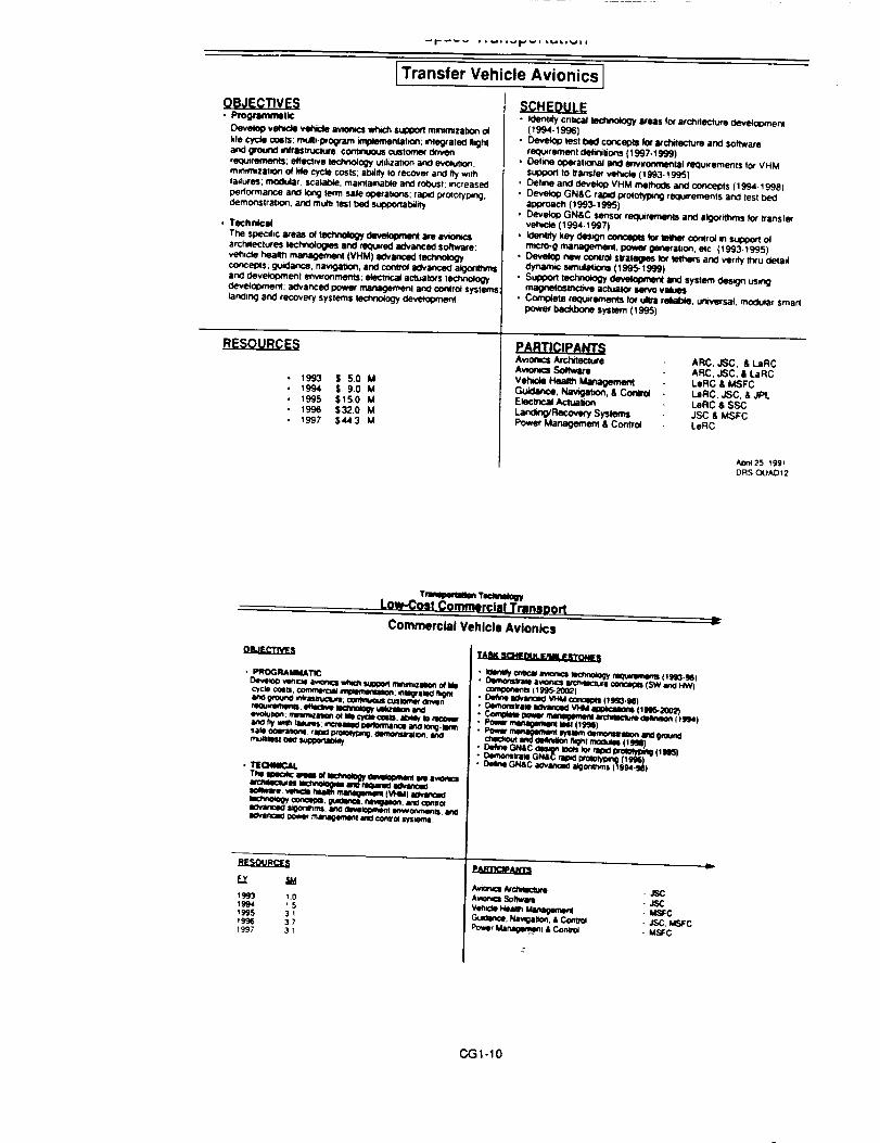
I Transfer Vehicle Avionics 1
• Progracrmull¢
Develop v_ veivde _ whi¢_ sulX)ort m_m_zat_ o_
lile cycle c_sls; mult=-I_ogram ¢npk_ntabort; mlegtaled nightand ground infrastructure; co_nuous customer QVJvenrequirements; eflectwe t_ogy ut_za.on and evo4ut_o_:m_t_zalIOn O_[_e Cycle COSTS;adder to rlhT,ovef and fly wdhtadures; motor scal_o_e maintainable and robust; increased
pedormatce anti long lena sale ooerat*ons: r_oM:l wototyp_g,c_emonstrabo_, arcs mutb ms1 bed s_
• Technical
The spec;h¢ areas o4 tecNtology _ we avk)cecsarch,ectures lechno4ogms and required advanced software;veh, c_e health mar_geme_ (VHM) aOvanced lect_o4ogy
_eots; g_B:lance, nawgatJon, and corWcd ao_ancecl algocithmsand o_evelopment enwtonmef_s; electncal acttJalors technologyclevelooment; ao'vance¢l power managemenl and contro_ systems
lanchng and recovery systems lechno4ogy development
• 1993• 1994• 1995• 1996• _997
$50M
$90M$15.0 M$32.0 M
$44.3 M
H_C.HEP_U_• _entJty cntcal tm:hnok_ areas tot architecture Oeve_ent
(1994-I_J6)• Develop msl bed concepts Im arctilectum and software
reo_J.eme_l {lefie_lions (1997-1999)• Delme ooe_at_0r_al and _wo_ reC!u_ements Io_ VHM
su0oorl to transle_ vehcle (1993-1995)Oelm4l and _ VHM methods and concepts (lCJ94.1996)Develop GN&C rapKI p4'olotyc)mg requ=rements and lesl bedag_oach (_g93-_995)Devek)p GN&C sensor req_rlm_ents and algorithms for transfmveh¢le (1994-1997)
IOenl_y key CleS;_ COCCOpIS k_ ll_hor cortlro_ _ SuIX)4_ olm*cro-g management, power generabon, elc (1993-1995)
new cont_o_ sl_alogms lot el_ anO ver_/y It_u deladclynam¢mmulalon=(1995-1999)Sulxx_ _ c_evelopme_andsyslemOes_ us,_magne_osmc_we actuator mNo v,_msCom_te m¢lu_rements lot _ rekal_, unn_'sal, modular smarl
power bec_bone system (1995)
PARTICIPANTSAv_r.cs A_chttec_ure
Vehx:_ I_a_h _Gu_v_e. Nav_atx)n, & Con_Electnca_ Aclua_mnLa_Recovery Sysmms
Power Management & ConlTo_
ARC, JSC, & LaRCARC, JSC. & LaRCLeRC & MSFC
LaRC, JSC, & JF)LLeRC & SSCJSC & MSFCLeRC
AOn_25 199_DRS OUADt2
TW T_Low-Cost Commercial Transoort
Commercial Vehicle Avionics
• n[cl,mlc.AL
m m andr_mo a¢_n_o
ao'vancm:lpower t_irm_,_l_l li_ cresol lysmml
TASK S_HI_ _A)LF_i4E _ q_T_¢ _t
• _ C_ av_cs m_o_y requm_nls (_S93._6)t.Wlm_slrsw a_omcs arc_ecl_e _ (SW am4_ (_995-2002)
• D_ne Wvance_ _ _ (1M_-N)• D*momsrm am.anc_l VHM al_*cal_n_ (lnS-2002)• Com_m _ mm_m_4 _ c_,_ i _4)
u_a_, oez_p zoo_z_ rata prmmyping (lWJIS)uemm_)r_ GN_C qmmoprotmy¢_g (l_J_)owrme GN&C aovan¢_o a_or_ns (tS,_-_)
r,M
1_ 37I_7 31
paLqlrtciP&m
Avmncm _ - JSCAvme_ Sollwa_ . JSCvm H._Im Managem_ - MSFCGu_an¢_, Naw_aaon. • Comm_ - JSC. MSFCPower Managen_n! & Conlml - MSFC
Ii-
CGI-10

Transportation Technology
Space Transportation
I Autonomous Landing I
OBJECTIVES
• Programmatic
Develop aulonomous landmQ tec_nok_ _ supports
technok)gy that enables planetary exl_orat_on seacecraft to landsatePy m the lace o! sunace hazards and close Io areas ofm*ss_o_ mteresl; autonomous GN&C techrK_ogy; ao'vancedsensor 0eveiopment
• Technical
The speohc areas of tec_ devetopmenl are concel_dehnllK>n and analysis o_ lechnoicgy to tao_tale--navlgatlon lot
!_'ecis_on landing; hazard detec-bon and av(xdance 0urmg termmaddescent; sensor cSevek_omenl modelling and aJgonmmOeveiownent tor Mars tecram narration; Mars terrain defiNbon
SCHEDULE
• Requ,rements definitmn (1993)
• A#emate sensor mo_ and algorithms deveic¢_ne_l a! systemand sensor levels (1994)
• Proto_pe ot sensor, algorffhms _ coml:_ simulahor_ssek_led for m_mentatK)n (1994); C_SR_lecb'develo1:)ment(1995); landing les! bed semulai_o_ (1997)
RESOURCES
199119921993
1994199519961997
$0.5M$ .... M
$ 2.0 M$ 4.5 M$6.0M$ 7.0 M$ 7.3 M
PARTICIPANTS
System En_neef_g JSC & JPL
Prec_oe Land_ JSC & JPL
Hazard Deteclion and Avoidance . JSC, JPL. & ARC
Sensor Derek)pro(rot JSC. JPI,.. & ARC
/,an125. 1_R1ORS-QUADS3
Transportation Technology
Space Transportation
[Autonomous Rendezvous & Docking I
• ProQranvllalic • Detine user rec_Jiri_ments tot' AR&D technology (19<J2-1993]
Develoo autonomous rendezvous and do(lung (AR&D) system
tecnno_ogy for sl)ace_afl m low geosynchro_)us Earth odors an¢tn planetary odnds m the discc_ine areas o_; sensors, GN&C
technology, and mect_amsms
• Technical
The soeofic areas of techno_ devek_ are define use(requwem(mls; conduct mess_on studies and analyses to delinepedormance requirements; identify and evaluate AR&D systemc_l des_ against users requirements; clefme
requ,rements tot i_otolype hardware and software
• Cuckct m_ss_on studies and Inalyss for ¢edormance
req_wemenUs (t gS3-1Sg4)
• k_r_, conce_a_ OesQns (_ gS4-1 996)
• Defin_k_ ol requ_ements lot proloty_e hardware and solfware
(1996-1998)
1991199219931994
199519961997
$0.5M$--- M$ 2.0 MSS.0M
$ 7.0 M$ 73 M$ 7.7 M
PARTICIPANTSGN&C Rac_ar Sensors & Mechar.sms . JSC
Vm_on Process_g MSFC
Neural Networks and N ARC
Interplanetary AR&D Ak_ JPL
Requ,rements
ADn__'=, _"" '
CG1-11

SPACEPLATFORMSTEOHNOLOGYEARTH ORBITING PLATFORMS
l CONTROLS J
_aQQlUmLtI_
ANOMN_LY_ISOF MUL_Wl_GRAIEDSVS1Em
m
IIm mlrnm uo_qJ_iim DEImN _twl _ _I_RIZMION
* _TIING ACCt,mACY(PUtTl_ AI_lCGNOB
• q.WETIblE _0.
RESOURCES"
1904 _'_Mt_ M2Mt _ M,5 M1997 $11.1 M
"TINSr_Ek_T eSCLOOB.Y_OflCO4_T_00( WLOP_r EFFOmS m _ _ RELATEOOTHEROCNERPlMENTPlqooRN_; REOOURGESARE _ (_ET ONLY
_llm FF.ATURE-_W_STEOlore TEST'iEOEVALUAT'IiONO
i ii
SPACEPLATFORMSTECHNOLOGYDEEP SPACE PLATFORMS
I_..SQURC_r
1994 $3,1 M19_S S4 e M199_ $50 M1997 $_.47.M
"_4S ELEMENTB GLO_LY C_ORDW_T_O_LOPMEHT EFrrQRTSe4 _ ANO_L_TEDOTHERGOV_IM4k_NTpIqOGRAMS,RESOURCESARE N_A OAETONlY
r.M2]G_uma
tamcTEC,qO_t,OOY A_ES_k'_ll. _ TOOLS_O I,_(:X_YO_VEI._t_NIlI,_.U_ TlCm. H/4_OW_ ty_VEL_mS
AI"TTTU_ _l) ur TI_LOGY *eNd, CONTROLM_rHOO£X.OGY
CGI-12

PRECISION POINTINGO_EClWESDEVELOP leRECmlOU _ TECHNOLOGY FOR
_ ANO TELESCOPES
CRfTICAL DIqVER IdgSlSONS:
MUL11PLE INSTRUMENT POMT1NO:NEXT EOS. GEOP_AT
FO_ TELESCOPE POINTING: ST.NO, MOI
TECHNOLOGY CHALLEI_E
INCREAllE IIPACE IIASED lrIBLESCOM Iq_TINO
CAPABILITY BY TWO OilER9 OF MAoNmJDEBEYONa HST
INCflEA_ REMOTE IIk'NSING IHSTIKIMENT POINTINGCAPABJUTY BY _ OF MAONIT1JOE
INCflEMm REUAINUTY, UFt'lrIME ANO EFFICIENCy OFPOBfTINQ COMPONENTS
EELLYEBAiU._t lira FINE OUlOANCE _ FOR SlWlII
19M AUTONOiJOUS FEATURE 11qACXlNQ SYSTEMDEMO FOR EOS-A2
2000 LINE OF S_HT lrlqANmrk'R
290_ TARGET RIEFERENCE _ DEMO FOROEOPLAT
AUTONOMOUS POINTINO SYSTEMEXIECUrTTVIEFOR EO$-A3
HIGH RELIABILITY/PERFORMANCt GYROSFOR ST-NO
PARTICIPANTS/RESOURCES
,H_ _ OVC
0 0 0 0 0
0 2.0 4.0 7.0 12.S
i
i ,i
INFORMATION SCIENCE & CONTROLS
PRODUCTS (FY 1003. _ lureSCIE_,EEXPLORATION • Idtcm gyr_. F'Y 1;5
• MIcm_ . FY 18
]_IJg.G]I.YL • aJk:ro_ an_zw, rp,_Devqmp mo clmommm, new clm _
, | UlCnO*_CmNES |
_ ANO UNSO_ _ .qPt. L_C'
• Lhgh_L _li. economk:J Irmn_emL RESOURCE INFOIqMATION
• cu=t_ cm_ FUNDING NET ($ K)• ElkSe & e¢_toe_f O_dupllcabon _ VLSI laD. tm3h. CURRENT AUGMENTATll0N
• From c-teal Jn-hoq_e emertm FY 1993 100
• Scmnce i eq)kxa ion mmUo_ a_lons we onabled wvl_ FY 1994 100
sma_' mtmme.B. FY 1995 10Q 3000
FY 1996 100 4000
FY ll)07 IO0 S000
MAJOfl FAGlUTIE$: NONE
TOTAL
100
IO0
3100
4100
$100
C,G1-13

SUMMARY
TRANSPORTATION AVIONICS TECHNOLOGYHAS HIGHEST PRIORITY TO RESPOND TO
CODE M REQUEST
CODE S RECOGNITION OF NEED FOR S/CCONTROLS RESEARCH AND TECHNOLOGYNOT STRONG IMPACTING AUGMENTATIONSPRIORITY
BASE PROGRAM HAS BEEN SUCCESSFULLSEED BED FOR AUGMENTATIONTECHNOLOGY PROGRAMS
INCREASED MANAGEMENT ATTENTION &
FUNDING REQUIRED FOR TECHNOLOGYTRANSFER
I ml
CG1-14

STRATEGIC AVIONICS TECHNOLOGY PLANNINGAND BRIDGING PROGRAMS
\
PRESENTATIONFOR
SSTAC CONTROLS COMMITTEE
NASA HEADQUARTERS
ALDOJ. BORDANOJOHNSON SPACECENTER
Stmteglc Avlonlcs Technology Working Group J
i Jt
f ASA
SATWG BACKGROUND
O A NASA STRATEGIC TRANSPORTATION AVIONICS TECHNOLOGY SYMPOSIUMWAS HELD IN WILLIAMSBURG IN NOVEMBER 1989
O AS A SYMPOSIUM FOLLOW-ON, A STRATEGIC AVIONICS TECHNOLOGYWORKING GROUP (SATWG) WAS ESTABLISHED IN EARLY 1990 ANDMEMBERSHIP INCLUDES:
• AMES RESEARCH CENTER• LEWIS RESEARCH CENTER• JOHNSON SPACE CENTER• MARSHALL SPACE FLIGHT CENTER• KENNEDY SPACE CENTER• STENNIS SPACE CENTER• LANGLEY RESEARCH CENTER• GODDARD SPACE FLIGHT CENTER• JET PROPULSION LABORATORY
Straleglc Avionics Technology Working Group J
C.,G2-1

SATWG GOALS & OBJECTIVES
O SUPPORT DEVELOPMENT OF A STRATEGIC SPACE AVIONICS TECHNOLOGY PLAN
O
O
O
O
• AVIONICS TECHNOLOGY STRATEGIES AND GOALS
• LONG-RANGE ELEMENTS TO SUPPORT FUTURE PROGRAMS
• ELEMENTS TO SUPPORT EXISTING PROGRAMS INCLUOING OPERATIONALINFRASTRUCTURE
PROMOTE AN EFFECTIVE COMMUNICATION, COOPERATION, AND TEAM BUILDINGENVIRONMENT IN SPACE AVIONICS BETWEEN NASA, INDUSTRY AND GOVERNMENTAGENCIES
DEVELOP COOPERATIVE PROGRAMS WITHIN ELEMENTS OF NASA
PROMOTEIMPROVED TECHNOLOGY TRANSFER PROCESSES, SUCH AS"BRIDGING,"BETWEENTECHNOLOGISTS, DEVELOPERS, CONTRACTORS, ANDPROGRAM MANAGERS
DEVELOP INNOVATIVE IDEAS AND ACT AS A SUPPORT GROUP TO ALL NASAPROGRAMS /
Strategic Avionics Technology Working Group
Inl II IN _ II
INCREMENTAL STRATEGIC TECHNOLOGY GOALS
ELV+
SSF
+
CTV
NSTS I
TECHNOLOGY
ental steps toward__
menl of Slraleg/c )/
Iogy Goals _
STV+
AMLS+
HLLV PLS
+
ACRV I
I +AIR LAUNCHVEHICLE
MARSMARS
PRECURSOR I
LUNAR I
, _ructure Supporl
( .Launch Op, • Mlsslon Ops
• Payload Op$ • Spacecraft Ops }
_.._nelary Surface Ops
TIME JSlritegic Avionlcs Technology Wprktng Group
CG2-2

KEY STRATEGIC AVIONICS TECHNOLOGY THEMES
O CUSTOMER FOCUSED EMPHASIS - UTILIZE AND BUILD UPON:
• SHUTTLE/SPACE STATION EXPERIENCE
• ALS TECHNOLOGY DEVELOPMENT
• COMMERCIAL TECHNOLOGY - - PRESENT AND FUTURE
• NASA ADVANCED TECHNOLOGY DEVELOPMENT
• EXPENDABLE LAUNCH VEHICLE EXPERIENCE
• DOD/DARPA TECHNOLOGY DEVELOPMENT
Slrallglc Avionics Technology Working Group J
KEY STRATEGIC AVIONICS TECHNOLOGY THEMES
O SIGNIFICANT CHALLENGES
• BUILD FAULT - TOLERANCE AVIONICS CHEAPER, FASTER, AND SIMPLER
- IMPROVED TECHNOLOGY INSERTION
- CONSIDER HARDWARE / ARCHTECTURE DEVELOPMENTAPPROACHES TO ADDRESS:
- - COMMONALTY, SCALABILITY, MODULARITY, AND LONG-TERMOPERABILITY REQUIREMENTS
- INVESTIGATE OPEN ARCHITECTURE CONCEPTS
• EXPLORATION DRIVERS
- MANNED/UNMANNED COMPATIBLE AVIONICS DESIGNS
- VEHICLE HEALTH MANAGEMENT (AUTOMATED & INTEGRATED)
- SPACE-BASED CHECKOUT, SUPPORTING PHASED ASSEMBLY
- REMOTE IN-FLIGHT & SURFACE-SITE TRAINING
Strategic Avionics Technology Working Group J
CG2-3

KEY STRATEGIC AVIONICS TECHNOLOGY THEMES
O FOCUS AREAS FOR THE FUTURE
TECHNOLOGY TO ENABLE CONTINUOUS IMPROVEMENT OF
OPERATIONAL SYSTEMS INCLUDING BOTH FLIGHT ELEMENTS AND
GROUND INFRASTRUCTURE
• TECHNOLOGY TO ADDRESS SIGNIFICANT FUTURE PROGRAM
REQUIREMENTS
- SPACE-BASED & REMOTE SURFACE OPERATIONS
- LONG DURATION MISSIONS
- ASSEMBLY IN SPACE
- INTERACTION OF FLIGHT VEHICLES/ELEMENTS
• DIFFERENT PLANNING PROCESSES ARE REQUIRED
)
Slrilteglc Avionics Technology Working Group J
m
f SASATWG STRUCTURE
STRATEGIC AVIONICS TECHNOLOGYWORKING GROUP
SPACE AVIONICS
ARCHITECTURE PANEL II
VEHICLE HEALTHMANAGEMENT PANEL
COMMUNICATIONS & ITRACKING PANELPOWER MANAGEMENT &
CONTROL PANEL
GUIDANCE, NAVIGATION & "_
Straleglc Avionics Technology Working Group J
CG2-4

SATWG ACTIVITIES & ACCOMPLISHMENTS
O INmATED FY '91 TECHNOLOGY BRIDGING TASKS
• ADAPTIVE ASCENT GUIDANCE NAVIGATION & CONTROL
• ELECTRICAL ACTUATION / POWER SYSTEMS
O FIVE MAJOR PLANNING PANELS IN PLACE AND ACTIVE
O QUARTERLY INDUSTRY TECHNICAL INTERCHANGE MEETINGS ESTABLISHED
O STRATEGIES FOR CUSTOMER DRIVEN AVIONICS FACILITIES AND TEST BEDSBEING DEVELOPED
O COORDINATION OF CODE M AVIONICS TECHNOLOGY REQUIREMENTS INPUTSACCOMPLISHED
Strategic Avionics Technology Working Group J
mt
SATWG ACTIVITIES & ACCOMPLISHMENTS
O COORDINATION OF CODE R ADVANCED AVIONICS TECHNOLOGY
REQUIREMENTS INPUTS ACCOMPLISHED
O SATWG INDUSTRY INTERFACE GROUP ESTABLISHED
• CONSOLIDATED INDUSTRY FEEDBACK ! RECOMMENDATIONS
O ACTIVE COOPERATIVE TECHNOLOGY TASKS
• SPACE AVIONICS REQUIREMENTS STUDY
• INS/GPS ORBITER APPLICATION STUDY
- INS/GPS FLIGHT TEST FOR AUTOMATIC LANDING
• ON-ORBIT RMS PERFORMANCE AND DYNAMICS
• PLS GN&C SIMULATION STUDY
• LIMITED FUNDING PRIME CONTRACTOR STUDIES-> "SEED PROJECTS"
/
Strategic Avionics Technology Working Group J
' _:_
_,r ¸.
CG2-5

INNOVATIVE TECHNOLOGY & PROGRAM DEVELOPMENT PROCESSES
O THREE PROCESS PROJECTS ARE PROPOSED AS A NEW BUSINESS APPROACH
#1 - AVIONICS TECHNOLOGY AND ADVANCED DEVELOPMENT PROCESS
#2 - AVIONICS DESIGN, DEVELOPMENT, TEST, AND EVALUATION PROCESS
#3 - AVIONICS OPERATIONS PROCESS
O TRENDS FOR PROCESS #1
• BECOMING MORE CUSTOMER FOCUSED
• TECHNOLOGY NEEDS DEVELOPED TO ADDRESS MULTIPLE PROGRAMS
• BECOMING MORE INTERDEPENDENT WITH PROCESS #2 AND PROCESS #3
(EXAMPLE- MATERIALS, MANUFACTURING ND OPERATIONS COST)
Strategic Avionics Technology Working Group J
I
INNOVATIVE TECHNOLOGY & PROGRAM DEVELOPMENT PROCESSES
O IMPLEMENTATION MODEL
• A TOP-DOWN / BOTTOM-UP ! MIDDLE-IN APPROACH IS PROPOSED
- TOP-DOWN = PROGRAM MANAGERS
- BOTTOM-UP = TECHNOLOGISTS
• TYPICAL MIDDLE-IN FUNCTIONS
- DEVELOP STRATEGIES ACROSS PROGRAMS -> TECHNOLOGY
UTILIZATION INCENTIVES TO PROGRAMS
- CONNECT POCKETS OF TECHNICAL AND MANAGERIAL EXCELLENCE
- IMPROVE NASA INSTITUTIONAL TECHNOLOGY, ENGINEERING, AND
OPERATIONS ELEMENTS IN A TEAMWORK ENVIRONMENT
- DEVELOP EARLY SPACE AVIONICS REC 5MENTS AS A FOUNDATION
FOR TECHNOLOGY AND ADVANCED DE 3PMENT PLANNING
- HORIZONTAL SE&I IS A PROPOSED TERM FOR THE MIDDLE-IN FUNCTION
Slraleglc Avionics Technology Working Group J
CG2-6ORIGINAL PAQ_ IS
OF POOR QUALITY
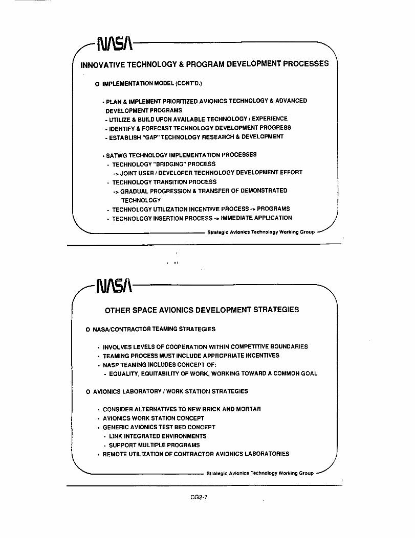
INNOVATIVETECHNOLOGY& PROGRAMDEVELOPMENTPROCESSES
O IMPLEMENTATION MODEL (CONTD.)
• PLAN & IMPLEMENT PRIORITIZED AVIONICS TECHNOLOGY & ADVANCED
DEVELOPMENT PROGRAMS
- UTILIZE & BUILD UPON AVAILABLE TECHNOLOGY / EXPERIENCE
- IDENTIFY & FORECAST TECHNOLOGY DEVELOPMENT PROGRESS
- ESTABLISH "GAP" TECHNOLOGY RESEARCH & DEVELOPMENT
• SATWG TECHNOLOGY IMPLEMENTATION PROCESSES
- TECHNOLOGY "BRIDGING" PROCESS
-> JOINT USER / DEVELOPER TECHNOLOGY DEVELOPMENT EFFORT
- TECHNOLOGY TRANSITION PROCESS
-> GRADUAL PROGRESSION & TRANSFER OF DEMONSTRATED
TECHNOLOGY
- TECHNOLOGY UTILIZATION INCENTIVE PROCESS-> PROGRAMS
- TECHNOLOGY INSERTION PROCESS -> IMMEDIATE APPLICATION /Strategic Avionics Technology Working Group J
OTHER SPACE AVIONICS DEVELOPMENT STRATEGIES
O NASA/CONTRACTOR TEAMING STRATEGIES
• INVOLVES LEVELS OF COOPERATION WITHIN COMPETITIVE BOUNDARIES
• TEAMING PROCESS MUST INCLUDE APPROPRIATE INCENTIVES
• NASP TEAMING INCLUDES CONCEPT OF:
- EQUALITY, EQUITABILITY OF WORK, WORKING TOWARD A COMMON GOAL
O AVIONICS LABORATORY / WORK STATION STRATEGIES
• CONSIDER ALTERNATIVES TO NEW BRICK AND MORTAR
• AVIONICS WORK STATION CONCEPT
• GENERIC AVIONICS TEST BED CONCEPT
- LINK INTEGRATED ENVIRONMENTS
- SUPPORT MULTIPLE PROGRAMS
• REMOTE UTILIZATION OF CONTRACTOR AVIONICS LABORATORIES
Slrateglc Avionics Technology Working Group J
CG2-7

OTHER SPACE AVIONICS DEVELOPMENT STRATEGIES
O INFLUENCE THE DEVELOPMENT OF STANDARDS, INTERFACE SPECIFICATIONS,
AND CHIP DEVICES, & OTHER INDUSTRY AVIONICS TRENDS
O CONSIDER A LIFE CYCLE PROCESS FOR DEVELOPMENT AND MAINTENANCE OF
AVIONICS HARDWARE AND SOFTWARE
• OPERATIONS COSTS ARE THE NUMBER ONE TOTAL PROGRAM COST DRIVER
FOR EXTENDED DURATION SPACE PROGRAMS
Strategic Avionics Technology Working Group J
SATWG CALENDER
EVENT DATEORGANIZATIONAL MEETING 4/5/90
FAULT TOLERANCE & RM 4/25/90
VEHICLE HEALTH MANAGEMENT 9111190
SATWG MEETING 11114-16/90
HEALTH MANAGEMENT CONF. 11/90
SATWG MEETING 2/26-28/91
VEHICLE HEALTH MANAGEMENT 6/10-13/91
SATWG MEETING 7/9-11/91
VEHICLE HEALTH MANAGEMENT 9/91
SATWG MEETING 1115-7191
VEHICLE HEALTH MANAGEMENT 11/91
SATWG MEETING 2/92
VEHICLE HEALTH MANAGEMENT 3/92
SATWG MEETING 6/92
HOST FOCUSNASA/HQ COORDINATION
MMC/DENVER FT & RM
HARRIS/MELBORNE VHM
GDSS/SAN DIEGO ARCHITECTURE
U. of CINCINNATI PROP. VHM
BOEING/SEATTLE SE & I
NASA-MSFC NLS VHM
ROCKWELL/DOWNEY POWER
NASA-KSC (JOINT JSC) SSF/SS/ACRV
LOCKHEED/NASHUA C & T
NASA-SSC SENSORS
MDAC-HUNTINGTON BCH GN & C
NASA-AMES SOFTWARE
MMC/DENVER VHM
Strategic Avionics Technology Working Group J
CG2-9

"BRIDGING THE GAP"
Advanced - ItTechnology
UsersTechnologyDevelopers
Strategic Avionics Technology Wprklng Group J
I Dt
!
/ I_JA_A TECHNOLOGY BRIDGING
• "Technology Bridging" Is a process that was spawned by theStrategic Avlolncs Technology Working Group (SATWG)
• It is a technology development and demonstration process that"bridges" technology providers, users and customers
• It Is a joint endeavor between government, industry and academia
• It employs the priclples of concurrent engineering
• It produces credible cost/benefits assessment
• Its objective Is to facilitate the transition of technology from thelab to a customer's project
• Once the customer has Incorporated the technology into hisadvanced development program the bridging project will eitherfocus on other applications or terminate so that othertechnology area bridging projects may be Initiated.
Electrical Actuation Technology BridgingJ
CG2-9

AUTONOMOUS GUIDANCE, NAVIGATION AND CONTROL
OBJECTIVE
• To develop and demonstrate autonomous guidance, navigation and controltechnologies In areas of:
- New sensors and sensing devices
• Ground end onboard guidance algorithms
- Navigation and control algorithms
- Vehicle monliorlog systems for autonomous ascent GN&C systems
PAYOFFS
• Increased launch probability
• Improved ascentJentry wind measurement technology
• Improved abort planning and failure adaptability
• Reduced cost from Improved operations
Office of Splice FIIghl
ELECTRICAL ACTUATIONBridging Activities
OBJECTIVES
• Develop and demonstrate a representative high power, cost effectiveelectrical actuation system suited for secondary objectives, includingflight / ground fluid control valves and surface systems applications.
PAYOFFS
. Elimination of maintenance intensive high pressure hydraulic systems
•Elimination of central hydraulic APU's, hazardous / toxic fluids
•Reduction of labor intensive tests, preparation time, and operations costs
•Improved dispatch reliability, operability, and abort recovery
•Improved launch window (late hold capability)
•Reduced stand-down time, rapid change-out / retest /
--_ _ Electrical Actuation Technolol_y Bddginl_ J
CG2-10

\
Electrical Actuation Technology Bridging TealnJSC
. Project managemenl &lntegraliun
Flight dynamk requirements 1
definition l
Fault tolerance I redundancy II LeRC
.Thrust Vector Control & ' ELA / power system integration |Propulsion Control Valveapplication_ ELA _ k development and demunstralion_
• -lr- -_BRIDGINGPROJECT
SSC
• ELA checkou! and operationalconcepts
• Costs / benefits anaysls for Shuttleops. processing
fluid control valve
application
• Costs / benefits analysis of ground testops. (quantify savings of eliminatinghydraulic valves)
/
Electrical ActuaUon Technology Bridging j
SATWG & PANEL CHARTERS
!
,Johnson 5pace Center" - Houston, Texa=
KENNETH J. COX [
APPENDIX
STRATEGIC AVIONICS TECHNOLOGY
WORKING GROUP
AND
SUB - PANEL
CHARTERS
4--
CG2-11

SATWG CHARTER
KEN_;ETIII. C(}._ I
O PROVIDE A FORUM TO SUPPORT THE DEVELOPMENT OF A SPACE STRATEGIC AVIONICSTECHNOLOGY PL[.N INCLUDING
O AVIONICS TECHNOLOGY STRATEGIES AND GOALS
O LONG-RANGE ELEMENTS TO SUPPORT FUTURE AND DEVELOPING PROGRAMS
O SUPPORT ELEMENTS FOR EXISTING PROGRAMS INCLUDING OPERATIOIIALINFRASTRUCTURE
O GUIDELINES FOR FUNCTIONAL COMMONALTY OF AVIONICS ARCHITECTURES
O DEVELOP COOPERATIVE PROGRAMS BETWEEN CODE R AND CODE M/S
O PROVIDE FOR AVIONICS TECHNICAL INTERCHANGE BETWEEN NASA TECHNOLOGISTS,ADVANCED DEVELOPERS, PROGRAMS, OPERATORS, AND MAJOR AVIONICS CONTRACTORS
O PROMOTE IMPROVED TECHNOLOGY TRANSFER PROCESSES, SUCH AS "BRIDGING,"BETWEEN TECHNOLOGISTS, DEVELOPERS, CONTRACTORS, AND PROGRAM MANAGERS
O DEVELOP INNOVATIVE IDEAS AND ACT AS A CONSULTING GROUP TO SUPPORT NASA NEWPROGRAMS
JCf_rsor _ _;zce Cet tor - IIou.clcr ' ", ,_
SPACE AVIONICSARCHITECTURE PANEL
CHARTERKE,_ETIIJ. I X I
O DEVELOP AN ADVANCED AVIONICS ARCItlTECTURE TECHNOLOGY PL .... OR SPACETRANSPORTATION AND EXPLORATION PROGRAMS WITH EMPHASIS ON LOWER LIFE CYCLECOST AND MORE EFFICIENT DDT&E COST
O DEVELOP AN EARLY TOP-LEVEL IDENTIFICATION OF AVIONICS ARCHITECTUREREQUIREMENTS AND DESIGN DRIVERS
O DEFINE SYSTEM ARCHITECTURE, SOFTWARE, AND HARDWARE STANDARDS FORDEVELOPMENT AND VERIFICATION
O
O
ESTABLISH AN OPEN ARCHITECTURE APPROACH
INCORPORATE TOP-DOWN CONCEPTS INVOLVING MODULARITY, COMMONALITY,SCALABILITY, AND INTERFACE STANDARDS
O INVESTIGATE AVIONICS COMMONALITY UTILIZATION STRATEGIES BETWEENO EARTH TO ORBIT LAUNCH VEHICLESO ORBITAL VEHICLESO TRANSFER AND EXCURSION VEHICLESO MOBILE AND FIXED SURFACE SYSTEMS
O FACILITATE SUPPORTABILITY AND LOGISTICS SUPPORT ORIGINAL PAGE ISOF POOR QUALITY
CG2-12

SPACE AVIONICSARCHITECTURE PAHEL
CHARTER (CONT'D)
Jotr5oo E_zce Certer - ,=:[_cr
KrNNETII J.COX I
O PROVIDE A FORUM FOR AVIONICS ARCHITECTURE TECHNOLOGY INTERCItAHGE BETWEENNASA, AEROSPACE INDUSTRY PARTNERS, DOD, AND THE COMMERCIAL SECTOR
O SUPPORT IDENTIFICATION OF AVAILABLE ArID FUTURE TECHNOLOGY
O IDENTIFY CRITICAL TECHNOLOGY AREAS FOR NASA
O ESTABLISH INITIAL TEST BED STANDARDS FOR PARTICIPATING CENTERS
O DEVELOP AN IMPROVED TECHNOLOGY IHSERTION PROCESS WITH A GOAL OF LOWERLIFE-CYCLE COST, FASTER PROJECT UTILIZATION, AND EVER-DEGREASING OPERATIONALCOSTS
O FOCUS ATTENTION ON THE PROCESSES FOR THE DEVELOPMENT AND MAINTENANCE OFAVIONICS SOFTWARE OVER THE LIFE-CYCLE OF MAJOR SYSTEMS
O DEFINE CRITICALITY CATEGORIES BASED ON CREW SAFETY, MISSION SUCCESS, MISSIOHSUPPORT, AND ENGINEERING ANALYSIS THAT MAY PERMIT EARLY TECHNOLOGYENHANCEMENT UPGRADES IN SELECTED AREAS
O EVALUATE METHODS FOR DEFINING EVOLVABLE REQUIREMENTS, DETERMININGREGRESSION TESTING POLICY AND ESTABLISHING REVERIFICATION CRITERIA
O DEVELOP INNOVATIVE IDEAS AND CREATE A CORPS OF EXPERTISE TO ACT AS A CONSULTIHGGROUP TO SUPPORT PROGRAMS
, ml
VEHICLE HEALTÁºÁMANAGEMENT PANEL
CHARTER
Johnson 5pace Center - Houston, Te,a3
KENNETII J. COX
O SERVE AS THE FOCUS FOR AUTOMATED VEHICLE HEALTH MONITORING AND CHECKOUTACTIVITIES; PROVIDE TECHNICAL INTERCIIANGE AMONG NASA, DOD, AND PRIVATESECTOR EFFORTS AND ADVOCACY FOR FURTItERING THE STATE-OF-THE-AnT
O DEVELOP SYSTEM REQUIREMENTS AND ARCtlITECTURAL CONCEPTS FOR AUTCMATEDCHECKOUT AND MONITORING OF LAUNCH AND SPACE VEHICLES
O DEVELOP INTEGRATION STRATEGIES FOR TIlE INCORPORATION OF AUTOMATEDCHECKOUT AND MONITORING SYSTEMS INTO FUTURE EARTH-TO-QRBIT, CREW RETURN,AND SPACE TRANSFER VEHICLES
O IDENTIFY AREAS FOR FUTURE RESEARCH AND TECHNOLOGY ACTIVITIES
O SERVE AS A CONSULTANT GROUP IN SUPPORT OF NASA PROGRAMS
O DEFINE AND PROVIDE FOR APPROPRIATE TEST AND DEMONSTRATIONS OF TECHNOLOGYAND SYSTEM CONCEPTS
O DEVELOP REQUIREMENTS AND PLANNING FOR TEST FACILITIES AND EQUIPMENT
" "_ O PUBLISH PERIODIC REPORTS PERTINENT TO ONGOING OR FUTURE PROGI3AP.1S
CG2-13
ORIGINAL PAGE ISOF POOR QUALITY

COMMUNICATIONS ANDTRACKING PANEL
CHARTER KENXETII J. COX IO DEVELOP AN ADVANCED COMMUNICATIONS AND TRACKING SYSTEMS TECHIJOLOGY PLAN
FOR SPACE TRANSPORTATION AND EXPLORATION PROGRAMS WITH EMPHASIS ON LOWERDDT&E COSTS, AND LOWER LIFE-CYCLE COSTS
O DEVELOP AN EARLY DEFINITION OF TOP LEVEL COMMUNICATIONS AND TRACKINGSYSTEM REQUIREMENTS AND DESIGN DIIIVERS
O DEFINE SYSTEMS ARCHITECTURE REQUIREMENTS AND STANDARDS FORHARDWARE/SOFTWARE DEVELOPMENT AND VERIFICATION
O ESTABLISH AN OPEN ARCHITECTURE APPROACH, WHICH INCORPORATES MODULARITY,COMMONALITY, AND INTERFACE STANDARDIZATION
O INVESTIGATE STRATEGIES FOR MULTIPROGRAM DEVELOPMENT OF COMMON ANDNEAR-COMMON ELEMENTS, COMMUNICATIONS SERVICES STANDARDS, TRACKING ANDNAVIGATION SENSOR STANDARDS
O PROVIDE A FORUM FOR COMMUNICATIONS AND TRACKING SYSTEMS TECHNOLOGYINTERCHANGE 3ETWEEN NASA, AEROSPACE INDUSTRY PARTNERS, DOD, AND THECOMMERCIAL SECTOR
O SUPPORT IDENTIFICATION OF AVAILABLE TECHNOLOGY
O DEVELOP PROJECTIONS OF FUTURE TECHNOLOGY CAPABILITIES
O IDENTIFY CRITICAL TECHNOLOGY AREAS FOR NASA PROGRAMS
O IDENTIFY CURRENT AND PLANNED TEST BED CAPABILITIES AT PARTICIPATII,'G CENTERS,AND ESTABLISH STANDARDS AND PROCEDURES FOR UTILIZATION
COMMUNICATIONS ANDTRACKING PANELCHARTER (COl'IT'D)
Johnson 5pace Center - HOUSLOm le_
KENNETII J. COX I
O DEVELOP AND FOSTER INNOVATIVE IDEAS AND CREATE A CORPS OF EXPERTISE TO ACT AS ACOMMUNICATIONS AND TRACKING SYSTEMS CONSULTING GROUP TO SUPPORT NASAPROGRAMS. PURSUE TECHNOLOGICAL ADVAHCES WHICH WILL PROVIDE;
O GREATER SPECTRUM EFFICIENCY
O AUTOMATED SYSTEM MANAGEMENT/',lid CONTROL
O GRACEFUL SYSTEM DEGRADATION AS TIlE RESULT OF FAILURES
O GREATER RFt/EMI IMMUNITY
O VERY LOW POWER CONSUMPTION
O NEW AREAS OF SPECTRUM UTILIZATION
O HIGHER IMAGE PROCESSING RATES
O INCREASED MATURITY LEVELS OF SENSOR FUSION
O HIGHER LEVELS OF CAPABILITY FOR AUTONOMOUS OPERATIOtlS
".' ! ,.?
CG2-14 ORiGJNAL PACE rS
Q_" pQn_ QUALITY

Johnson SDace Center - ItOUS(O_ Te_:
POWER MANAGEMENr ANDCONTROL PANEL
CHARTER KENNETII J. COX
O DEVELOP AN ADVANCED POWER MANAGEMENT AI,ID CONTROL SYSTEM TECI INOLOGY PLAflFOR SPACE TRANSPORTATION AND EXPLORATION PROGRAMS INCLUDING:
O ADVANCED INTEGRATED ELECTRICAL POWER SYSTEM TECHNOLOGIES TO SUPPORTFUTURE AND DEVELOPING PROGRAMS
O LONG RANGE STRATEGIES AND GOALS TO ENSURE FAULT TOLERANT POWER FOR ALLMISSION SCENARIOS
O DEVELOP OPERATIONAL INFRASTRUCTURES TO SUPPORT FUTURE TRANSPORTATIOtlAND EXPLORATION PROGRAMS
O PROVIDE GUIDELINES FOR FUNCTIOI,IAL COMMONALTY OF ELECTRICAL POWERMANAGEMENT AND CONTROL ARCHITECTURES ACROSS PROGRAMS
O PROVIDE A FORUM FOR ELECTRICAL POWER MAIIAGEMENT AND CONTROL TECHNOLOGYINTERCHANGE AMONG NASA, DOD, INDUSTRY AND THE COMMERCIAL SECTOR
O IDENTIFY AREAS FOR FUTURE RESEARCH AND TECHNOLOGY DEVELOPMEIIT ACTIVITIES
O DEFINE REQUIREMENTS FOR TECHNOLOGY DEVELOPMENT EFFORTS
O DEVELOP TEST FACILITIES AND EQUIPMENT
O DEVELOP AND PROVIDE FOR APPROPRIATE TESTS AND DEMONSTRATIONS OFTECHNOLOGY APPLICATIONS AND SYSTEMS CONCEPTS
O DEVELOP AN IMPROVED TECHNOLOGY INSERTION PROCESS TO REDUCE PERCEIVED RISK,LOWER OPERATIONAL AND LIFE-CYCLE COSTS, AND MAXIMIZE SYSTEM OPERABILITY ANDPOWER AVAILABILITY
t DtJO_ll$On 3pa(.e LOn(er - HOUS{or_, [e_
GN & C PANEL CHARTER
KENNETH J. COX [ 6/21/91
O THE GN & C PANELIS ESTABLISHED TO PROVIDE A FORUM TO FACILITATE THEEXCHANGE OF INFORMATION AMONG TECHNOLOGY DEVELOPERS, USERS, AND THESPACE AVIONICS COMMUNITY, AS A WHOLE
O THE PANEL WILL GATHER & DISSEMINATE USER NEEDS / REQUIREMENTS, ANDIDENTIFY & CATALOG TECHNOLOGY STATUS VIA LIVING DOCUMENTS
O FUTURE GN & C TECHNOLOGY PROJECTIONS & CAPABILITIES WILL BE RESEARCHED& MADE AVAILABLE
O THE PANEL WILL BE RESPONSIBLE FOR FOSTERING TECHNOLOGY INTERCHANGEBETWEEN NASA, OoD, AND THE COMMERCIAL SECTOR
O THE PANEL CHARTER DOES NOT INCLUDE THE DIRECTION OR MANAGEMENT OFTECHNOLOGY DEVELOPMENT
CG2-15


JemmnSlsmmC4mw.HoueUm,Texn
Integrated TechnologyPlan Overvlew
Navlgstlon, Control & Aeronautics Division
A. J. Borduno/EG 6/26/91
Avionics
Technology
Plan
Joilnl_n _ Contm'. Houa_u)_ Teus
Integrated TechnologyPlan Overview
Navlptlon, Control & Aeronautics Division
A. J. Bordmno/EG i 61261911
Integrated Technology Plan Elements
5.2.7 ETO Vehicle Avionics
5.2.7.1 Avionics Architecture
5.2.7.2 Avionics Software
5.2.7.3 Vehicle Health Management
5.2.7.4 GN&C
5.2.7.5 Electrical Actuators
5.2.7.6 Landing/Recovery Systems
5.2.7.7 Power Management & Control
5.3.8 Transfer Vehicle Avionics
5.3.8.1 Avionics Architecture
5.3.8.2 Avionics Software
5.3.8.3 Vehicle Health Management
5,3.8.4 GN&C
5.3.8.5 Tether Control
5.3.8.6 Electrical Actuators
5.3.8.7 Power Management & Control
5.3.D Autonomous Landing
5.3.10 Autonomous Rendezvous & Docking
CG_.!

Work BreakdownStructure
,kdmun _ Oinlet • Houston, TexaJ
Navigation, Conlro! & Aeronoutlcs Division
A. J. Bordano/EG J 6126191
I
I FOCUSED TECHNOLOGY
PROGRAMS I
,_ I l fI A.S_O.TAT_.III S.ACSSC,E.CSI I EXP_ORA.O.I
I I
I
* |1
__ Work BreakdownStructure (Con,,...d)
,kdwmm bow _. Hm_lc_ Tern
Navigation, Control & Aeronautics Division
/
A. J. Bordano/EG / 6/26/91
J
I TRANSPORTATION I
i I i( Experiments I
ETO VehicleAvionics
Low Cost ICommercial
Transport
.._ AmonomousIJfl_n i
._ AutonomousRendezvous &
Docking
/
i
CG_j-?

Generic Outline
d_v_m 8¢eoe ¢enl_ • Houston, Teu•
Navigation, Control & Aeronautics Division
A. J. Borduno/EG I 6/26/91
Presentation will cover each Identified Integrated TechnologyPlan Element and Subelement as follows
O Overview (at the element level 5.X.X)
Q Current & Related Programs (at the subelement level 5.X.X.X)
D Proposed Technology Program (at the subelement level 5.X.X.X)
Q Program Benefits (at the subelement level 5.X.X.X)
Note: The Integrated Technology Plan Report for these elementsand subelements is over 100 pages. This presentation will be ahigh level summary of that report.
i
,J_em_xmS_me O_r • 14muM_, Te_n
5.2.7 ETO Vehicle Avionics
Overview
Navigation, Control & Aeronautics Division
^. J. Bord,,no/EG 6/26/91
Q The next generation of space transports will need to have Increased miselon safety, moreautonomy for reduced craw workload, and reduced operational costs.
• Avionics Architecture. for Increased avionics performance
• Avionics Software - addresses mission end safety features In software operating systems kernel
• Vehicle Health Management - for self diagnosing and self compensating Integrated systems
• Power Management and Control - for reliable, universal, modular, electrical power bus systems
• Guidance, Navigation, end Control. offers efficient computational algorithms and sensors,software tools to enslyze complex body dynsmlce, and enhanced launch and land on demandprobability
• Electrical Actuation Systems - replaces hydraulic systems to enhance system reliability, reducedoperational cost
• Advanced Lending & Recovery Systems - for enhanced booster recovery and landing technology
D The following advanced vehicles will ell require some combination of these advancedtechnologies:
• HLLV, NLS, PLS, CTV, ACRV, ALS, end ELV'e
O ETO and Transfer Vehicle Avionics technology development share common goals which invitesand In fact, for cost effectlvenees, dictates collaboration and Interfacing between the two areas ofdevelopment.
CG3-3

6.2.7.1 ETO Vehicle Avionics:Avionics Architecture
Current & Rellted Programs
Navigation, Control & AeronauticsDlviWon
A. J. Bordano/EG
D_=tmm
. Flight Data System Open ArcNtK_ura RequirementsDefinition & Methodology Development
• Flight Data System Open An:hitecturs Document
• Flight Dma System System Profiles
• Flight Data System Open Architecture PerformanceAnalysis end Trades
. Flight Data System Open Architecture PrototypeDevelopment
Network Performarcs Model
• Bare 386 Reel-Ilrns Kernel Investigation
• Station Ffight-to-Ground Inleroparabllity EvJuation
. Appficatlons-to-RODB Data Type Analysis
1994 19950 IO I_ IO 0 IO _O
NASA5.2.7.1 ETa Vehicle Avionics:
Avionics Architecture
Propoled Technology
0m
Real time distributed preening tat bed developmentReal time disldbuted proceladng hetrogeneoul processing &
memory tnsta]laUon & o_ration in tilt bed
Real time distributed processing nslwork Installation & operationin lest bed
• Real time distributed proceselng hardwc, e sensitivity factordelerminallon
High CapaCity processing requirements dafini'donHigh capadly 32 and 64 I_t procssMng coal=anent prototype
development
High Capacity ¢oeclallzed ¢oprocusor prototype development &Intearation
• High r.,apedty multi-alga byte memory Idtarnath_and integration
Non-Stop computing requirements definitionNon-Stop computing system models development
• Non Slop system reconfiguration demonstration• Non-Stop computing test and verification technology definition• Launch vehicle advanced human-landed avionics displays andcontrols Interlace and aids requirements definition
• Avionics human tended alternative sensory mechanisms anddisplay prototype development
.Avionics DiSplays 8.nd Controls Advanced Human.Manhlne Test& Verification Technology Determination
Navioegon, Control & AeronauticsDivision
A. J. Bordeno/EO
1993 1994 !1995 1996 i997:3_10210:104 01102102104 01 02 O'3104 01102 03 04 at 02 O3104
'==:_ r
_33-4

5.2.7.1 ETO Vehicle Avionics:Avionics Architecture
Program Benefits
TECHNOLOGY BENEFITS
8pameCanter• ).lousto_Teus
NsvloaUon, Control & Aeronautics Division
A. J. Bordano/EG J 6/26/91i
WHY
• Deflnidou of interfaces and smnckuds
including pe_'fonnancecritedl [o establishverify mchitectore concepts.
• The mtnsfu" of ¢ommezclal t¢hnologte$ intospace rated components will enableoubuard
Focesdnl ctpablltde, to accommodateIrcw.ued complexity of d_ avloalusuite.
• Non-stop nXlubemenu and muld-fauhtolenmt components can be used m _tevaluate coccepts, their tssoctated costa, andlmplemenmflou dlmcuity.
ArchitectureJETO TechnololD,• Real-Time Distributed processing- Develop anclpmtotype via test beds advanced flight
dam system distributed and multiple heterogeneousprocessors, memory, buses and other keycomponents opcr-ung in real-rime.
- Detemdne sensitivity factors governing real-timeprocessing perfonrumce.
• High Capacity Processing- Develop requirements _1 prototy_ for 32 bit tnd
64 bit processing componenu_ memories and buses;specialized high speed coproce¢_ such u 1960 tndR4000; and muld-mepbyte memory idmrn_tves _1tcchnologie¢
• Non-Stop Computing- Develop, build end dernonSulte system
exhibiung muld-fauh tolmlm system tnd componentbelmvior and which exhibit recoUfllpmlble C'l_bllityto dete_nine the issues,costs _1 n_qui_rnenu
- Detemdne the techno|olpes needed to test, verify andcerdfy non-stop computing capabilities for spiceflil_hi operations
• Avmnics Displays and Controls- De£me requin_nents fo¢ edvanced humus-tended
display end couu'ol interfaces, aids end alternativesensory mechanisms
- Develop prototype end dernoustnte advanced loudenvironment or hoiolpmphic display and high fidelityvoice conurol interfaces
- Dele.mdne the technologi_ needed to test, verify tndce,'dfy advanced humlm-machine interfacecapabilities for flight opentious
• l_J'uddon of requirements for advm.--nddisplays and c_nuols, end pmeotypes of suchdevices can be used to present more effectivehuman intm-fs_ mechanisms to smmmuts fort_v_tmdou
• Development of flexibletrchttectures for reduceddevelopment and life cyclecosts
• Compatibility with I_'oundsystemsinbothperformancetaxi architecture
• Development of morenextt_e launch commitorkerin end lncRues in
misdou safety
• MoR effective use of damfusion to bcxeue the
machine pt'oceutng ofinfocmafloo for the ms_qnedlnu_'face.
om
• Space Applications GN&C Characteristics andMethods Defined
• Space Applications GN&C Family Generated andother Applications Identified
• Space Applications Characteristics and Methods
Defined for additional Applications
• Space Applications Coml_ned Demonstration wtthTarget Avionics Plalform
• Apl_icatlons-to-RODB Dam Type Analysis
• Matrix-X Simulation Devalopmenl
5.2.7.2 ETO Vahlcla Avionics:
Avionics Software
Currant & Related Programs
1990 1991:l_t_.Oa04 011021,
i
iil
1|
E
J|
1i!i
Nlvlgatlon, Control & AeronauticsDivision
A. J. Bordano/EO
1992 11993 1994 1995 1996_I04 O_10_lO_10410flO'ZlO_04 01 0'2f0_04 01 021C_0410_I02103 C_
i ! i
, ! i
II
CG3-5

5.2.7.2ETOVehicleAvionics:AvionicsSoftware
ProposedTechnologyIhna*mlm
•RealTimeDistdbutadProcemmrOpera_ngSystemlindServicesPrototype Develoornent
• Real Time D_stdbutad Network OOeralJng System and Set_::esPrototype Development
• ReaJ Time Distdbutad ProceWng Computer snd Network Integrationend DemonslralJon
• RsaJ time Distributed Processing Soflwm'e Senalthdly FactorDetamllnatlon
High Capacity Processing Software Requirements Definition
• High C¢oscfly 32 and 64 bit Processing Component Prototype SoftwareDevelopment
High Capacfly Spadallzed Coproceelor Pro_olype Software
rDevelopment & Inlearl_onI" High Capllcity Multl-mega byte Memory/Utematlves So(twlraDevelopment and ntagral on
!. Non-Stop Computing Soltwore Requirements Delinltlon
. Non-Stop Compul_ng Scltware Models Development
. Non-Slop Software Reconflguration DemonstralJon
• Non-Stop Computing Software Tests and Verification TlK:hnclogyDefinition
• Reusable Requirements and Archltectureal Alternatives Definition
• CASE Tool Data Repository Filter Development
• Reusaable Case Tool Component Oevelopmenl
, Reusable Prolotype Component Devalopmenl and Dome
• Launch Vehicle Advanced Human-Tended Avtonicl Ol_olaye endControls Interlace and Aids Requirements Deflnllton
• Avionics Human-Tended Altematk, e Sensory Mechanisms Jnd DisplayProlotvDe Deveioomenl
• Avionics Displays and Controls Advanced Hurnan-Mochdne Tell &Verification Technoloclv Determination
NavlgaUon, Control & Aeronautics
DlvlMonA. J. Boi_lono/EG
;993 1i9s4 1995 11996 lg97"_flaelallO41OllQIIOllO4 QtK_QStQ4|QS_' OflQ21Q_tO4
5.2.7.2 ETO Vehicle Avionics:Avionics Software
Program BenefitsTECHNOLOGY
Softw_JE'TO Technology• Real-zimc Dis_buted Procos.finE- Develop prototype and dcn-,ons_"at¢dL_ibutcd operldn|
sysu_msmd s¢_ic_ that oparil:c in re&l-dine overdismbutr,d and muldpie processors.
- De.mine sensifivi_ ftcu)r; |ovcmin| dL,slnl_¢dopcnldng system and services for Ral-dme processing_O_.
• HJ|h Cipacity Pmceuiqr:
- Develo.p md prmoty_ Iofrw_. f_ 32,/f_ bit pro_Mm_sFecl,uz_ copmce,uc_ suc_ is i960, g4000 mamulti-megabyte memory _d_'na_iv_ auoclam:l with malls_ora|edisk for spice qualir_d components
• Non-Stop Computing- Develop _nd demonsWat¢softwan; modeb cxhibifinE
multi-fault toienmt sysw.mand compo_cnl behavio¢luridn=configurable capabiliq/with md wRhoul human conm)ls
• Determine the tcchnologi_ nee.dadto l¢:St,verifycertify for flighl operations
. Softwan_ ReusabilityDevdop ind build Computer Aided SystemsEnsin¢_in $(CASE) toot data rcposaory filters for exchanging dambctw¢¢a _;ffor_nt CASE toOlSfor flight soflwu¢development
. Define _nd test R_ble mftw_'e fe_m'_ for flil;h_sohw_'e specific operadn| sysmms,services mdapplica_on_
• Avionic_ Dispi-ys and Cono'oL_- Develop and prototype knowl_Ige _ visual touch.
voice and othersem,ocy display and conmol aids to suppo¢1
human opuadon of complex systems- Determine the t_hnolog,_ n_eded to _.st, veJ_y md
c¢.,'tify _lvmc=d human-machi_ in','dace softwan:
BENEFITS
leili cl_llf • _ "relll
l,
NIvl0atlon, Control & Aeronaullcs Division
A. J. Bordnno/EG [ 6/26/91I
WHY
• Ealablislms capability and_ of opmain$ sysmms
buP..d wross multiple _s_s,netwoflcs and vehicles
• Add/domd processing capabilitymdpafmmaacc fa" the oa-txmd dmsys_-a_
• D_m_bm/o_ of _luircnmau a.dcompo¢,mts for fault rr,dsumccompud_| for evtiu_on ofconceptS, corn and implementationdifficuhy.
• E=uthli=b_Jgenericflight softwarer_s_=m¢lem(mts for _ across=myprolp'_t
• Dew..,miaadon of effective humaninzrfac¢ n_:Mnisms as thecomplexity and amount ofi_otmafion inca_ase
. A_z,tm'P_t of distributed
operating system and servicesP.quircmcnts
• Comp=fibility wi_h Foundsys_ml inbothpedom_ncea_d a,'chi_c_e
• More flcaible launch commitcriteria and increases in missionsafety
• Lower development and lifec;tclc costsfor the software¢l_:ff_n[
• Aids human d,la compn_hcnsionand mlX_
CG3-6
Descdptlon
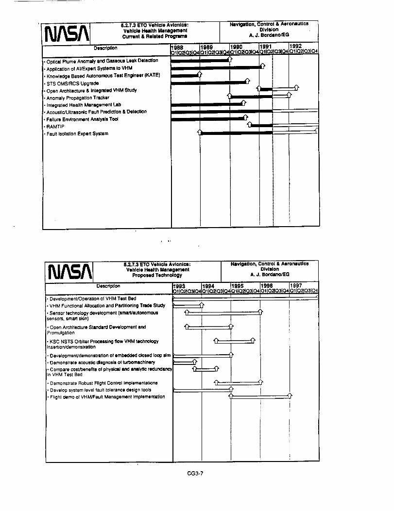
• Optical Rums Anomaly end Gaseous Leak Detection
• Application ol AI/Expert Systems to VHM
• Knowledge Based Autonomous Tasl Engineer (KATE)
• STS OMS/RCS Upgrade
• Open Architecture & Integrated VHM Study
• Anomaly Propagation Tracker
• Integrated Health Management lab
• Acoustic/Ultrasonic Fault Prediction & Detection
• Failure Environment Analysis Tool
• RAMTIP
• Fault Isolation Expert System
8.2.7.3 ETO Vehicle Avionics: l_v;,_,'_on, Co_,i_o; & Aeron=Utlca
Vehlrde Health Management Dlvlsion
Current & Related Programs A.J. Bordano/EG
1988 1989 11990 1991 1992
_llaqo3m olla2la31o4J.altoaoalod:_lla=Za3lodQIlQ_Q31Q4I ii_ =
o!
,rl
,a/
I
5.2.7.3 ETO Vahlcta Avionics:
Vehicle Health Management
Proposed Technology
Nlvlgatlon, Control & AorormutlcaDivision
A. J. Bordeno/EO
Description
i• Development/Operation of VHM Test Bad
• VHM Functional Allocation and Partitioning Trade Study
• Sensor technology development (smart/autonomous
sensors, smart skin)
Open Archltectura Standard Development end
Promulgation
KSC NSTS Orbiter ProcsWng flow VHM technologyinse rtio n/demonstration
DevelopmenVdemonstrstton of embedded dosed loop ldm
Demonstrate acoustic diagnosis of turbomachinery
• Comnare costroeneflts of physical and analytic redundancyin VHM Test Bed
• Demonstrate Robust Flight Control Implementations
• Develop system level fault tolerance design tools
• Flight demo of VHM/Fault Management Implementation
1993 1994 1995
OtlO_O_O40tlO_O310,_OlIO9031041997
O11O_1Q3tO_/
CG3-7

5.2.7.3 ETO Vehicle Avionics:Vehicle Health Management
.... Program Benefits
TEC..o, "E.EmS• Automat_ vehicle checkout
• Autonomous vehicle healthmanagement
• VHM system archimctwe andsoftware
• VHM sensors
• Residu,' lifeume es_on,dynamic healLh& sr,tus assessn_nt
• ExpeditepR-ta.nch open_mini_ l_nOm_l cos=
• Launch commit and C_._o Go
d_isig_ pr_m isexpedited• Mxximi-,'miss,o,clp.bilid.,
perfomumce: enhanced mttstoesuccess probability
• Enab/es inc_emea_ adolx/oa ofVHM concep_ md new hardwtre;n,._imizes technical riskr, Impmv_efficiency and robustness
• lncrcued knowledge of complexequipment's heJdthcondition
• Enhanced mission success
• lmpm .... ffonnaucermtrl_
Jolvmonsp4_ Cenl_. Home,Ion,Texas
Navigation, Control & Atroilutlcs DivisionA. J. Borduno/EG 6/26/91
III
I WHY
• Delays, launch aborts and Rcycles em too expensivein direcl A indin:ct costs;more efficient operltions
' Alleviates and ci_'umvoots effects of in-ill|ha failures
and delFtdations
• VHM techniques allow weight and power u, vings bysubstituting software intelligence for some physicalredundancy
• Different systems, technoJo_es lind sensor; willd=veJop ,t dJffcrcm dines
• Progno_t and timely fault detecduo capabilities arerequired for complex equipment operating in exu'emeI;[IyimnmeeL_
• Component health b continuously monitored andincipient falhues ¢r_ detected perform they becomeaCUte
• Perfomm:¢_ redlines can be ¢alculeted dynamicallyand need not rely oo statistical (_;_imaLesof"l_ginnin$ of lite" (opdmJ=ic) or "end of I_c"(pesdmil_) projections of system catmbil|des
• Impro_d cost effecdvenetl ofpn_essing and malatenanceoperadons
I I I I I
• System elements may be _pl_'ed when needed asopposed to foliowtnll a poriodic (overly conservative)scheduk
5.2.7.4.1 ETO Vehicle Avionics:
GN&C AJgorlthrnsCurrent & Related Programs
Nlwigatlon, Control & AoromlutlcsOlvlslon
A. J. Bordano/EG
Descrll_lOn
Autonomous Launch Vehicle Reconflguratlon
• Baseline requirements forcurrant vehlcfss
Advanced GPS Navigation Techniques
• Initial tests in alrcratt
Autonomous Rsn(}o_ng GN&C
• Baseline requirements un_r development
1988 1999 199001102103104011a2t03104
11
1991 119920 II02_03_04 iO_Io2/O31O4
i
!
i
1!
CG3-8

5.2.7.4.1ETOVehicleAviohics:GN&CAlgorithm
ProposedTechnologyDescdptlon
Autonomous launch Vehicle Reconflguration
• Baseline requirements for advm_:ecl vehicles, GN&C Simul=qon
• Algorithm development• Level C requlrements development
Atmosphedc Adapatlve Entry GN&C
• Control concept development• Envlronmenlai model development and simulallon• Algodthm development and simulation
Numedc/Al Guidance Techniques
. AI concept development• Numedc Gulclance/Al Integration
. Detailed aJgorithm development and testingParallel Processing GN&C Methods
• GN&C processing concept development• Parallel GN&C architecture definition
• Algorithm development and simulation
Advanced GPS Navig_on Techniques• Advanced requirements baseline
• Advanced model development• Detailed sigodthm development and tesllng
Autonomous Rendezvous/Docking GN&C
, AR&D requirements development
• Algorithm concept development
• Algorithm testing and simulation
1993 1994
=110_0310401102p3104
NavigeUon, Control & AeronauticsOlvildon
A. J. Bordano/EO
1995 1996 1997
o_lOZl_O,oII_O_IO4otlo21o31o=
I
Joitmmn _ Comer - Hou_on, Texas
5.2.7.4.1 ETO Vehicle Avionics: Navigation, Control & Aeronautics DIvtsion
GN&C AlgorithmsProgram Benefits ^ J,Bordano/EG 6/26/9|
TECHNOLOGY BENEFITS WHY
Autonomous Launch Vehicle GN&C ReconfigunLdon• Identify new approachesto curront launch vehicle
Idgorithms and processesthat reduce or eliminaterecun'ing engincerin$ analysis, computer simulationand FRR activities
Atmospheric Adaplive Enn-y GN&C•Develop a GN&C system that can Imdve]y control
he=( rate, heat load or tcmpessmre while n_nuunlngan accuratl_Iandin| point
Num=ric/AlGuidance Techniques• Utiliz_ a_ificial in.'Higence _chniqt_s to provide
assuredconve_enc¢ of numeric guidam_ algoridu'ns
Pmdtel Processing GN&C Methods• Develop new approaches and algorithn_ thai can be
effectively used on parallel pmces,_ng computers
Advanced GPS Navigation Tcclmiques• Develop new algori_ and ¢n_t modeh to
improve GPS navigation accmtcy for ETO vehicles
Autonomous Rendezvous/DockingGN&C• Develop algorithm conceptsand approachesto
supportautonomousrendezvous
• RecmTing launch operations costscan ber=duced throush autmmtion _dirnprovemcnts to current GN&Calgorithms and operadonz approaches
• Improved thermal protection matin andw.dueed smnaldvit}, to aU'nosphen¢ andsystem un¢=ruunues
•Accm=. reliable guidance solutionsusing exact environment models
• Pc:form complex ON&C compu-,donsonbmrd using Fa."_d proc_sing
• Accun_, tu_ space vehicler_vllr_on
. Recurring costsreducedthrough
automationtnd impmven_nts to currantGN&C algorithmsand operations
approaches
CG3-9
• E|imintdon of manpowerinlensive -,'deities is needed forthe next generation of launchvehicles
• En=7 vehicle landingaccuracythermal protectionsystem
requiremenut ire driven by theability of Ihe GN&C sysmm to• dapt to dispersed atmosphericconditions
•Current numericguidanceg:hen_s _ not Issur_J of
always converging
• Sequewlal computation limitstoday's GN&C processing
• Changing environmenudcondition" can d¢lpld¢ dopplermeu_t$
• C_t AR&D operations rely
heavil_on pound besedn_qualpmcmums

Dmmmmmn
5.2.7.4.2 I_lQ Vohi¢le Avionic41:
GN&C Semmre
Current & Related Program
Optical Sensors Ior GN&C ApplicatlOml
• Optical Sensors for GN&C APl_catiorm
• Set requirements and proof ol concept testing lot the HighResolution AMItude Rmtl Sensor
Inertial Componenls and Systems for GN&C Appllcatlone
• Evluats inertial components for vendor spedflcatlon
compliance and vshlde applications
. Evalusle stale.of-the-art inertial sensors lot launch
vehlds, orbital vehicles, and payload packages
• Develop Inertial sensor packages lot payload inertialmeasurements
• Maintain data base ol state-of-the-art and proposed
Inertial sensor and system technoiogtu
1909QI102103104
Nevlgmtlon, Control & Aeroniu_lcsDivision
A. J, Bordano/EO
199001102103104
(
I I
1991 1992
Q11Q2JO3_04 QIlQ2_Q3t .Q_i
|
|
|
t$
i|
I
l "!iZ
!|
t
1i!
i li
5.2.7.4.2 ETO Vehicle Avionics:GN&C Sensors
Proposed Technology
Descflption
I Typical Schedule Ior GN&C Sensor InvuUgaUon J
iSpedfy requirements for sensor and system hardware
Spedfy requirements for software algorithms end dalabeses
Reasearch the currenttechnology lot required hsJdw'am ar,_soMware
Investigate and develop vadous idgodthms
Design, build:and IoborlltOfy test of protolype system
Fteld test ol protolypa system In Ix)ratohes, and/or remoteobservatories end sites
1993crq_21oslO4
5
',, I
Nmvlgetlon, Control & AeronauticsDlvlldon
A. J. Bordano/EG
11994 1995 i1996 1997ioqo2ta3104a_lomam04011021¢3104_ta2103104
l
FOH&C Scesor Inv_Uon I!
I
_,A,utmomous Atmude Ommlm_ sys_ De_t_pmera I•OpUca/ FI_ Sen_ Dev_mt• HodzontTMrldn Mwpplrl_OlltUrO RecognitionSlmsot Devslo_ninl i• MagnelonmCveS,rm_• FI)w-Op_ Gym Fleesen_ and Developmen_• _ kam Aecaeron_W• Codok Accolorometlr Irterlisl Mes.lurlmenl UNt (CAJMU)• _M, Ma0n, ac Sup*hen fUU (OUBIK)• MurdpleRIKiVlr GPS IMU, Grm41yWarms 7Nntng Efle¢ Dslct_' (OWl.TED). _tatPJM_omactmed Accei_mem w_h H_(F.M_)• integrated Flb_.-Optlcl Gym GP_/lnorlild Nevi0Mon Syslom[F(_PStNS}
CG3.10

5.2.7.4.2 ETO Vehicle Avionics:GN&C Sensors
Program BenefitsTECHNOLOGY
Jotmmeet Slmce C4mter • Hou*Wn, Texas
Navigation, Control & Aeronautics Division
A. J. Bordano/EG
WHY
6/26/91
BENEFITS
Optical Rate Sensor, • PRcL_ion vehicle attinxie .tel thing opdcal • Provid_.lrel[tlbk; imllging reJI time navigationtecnmquel suplxxl for ,-ann 0¢'Oll missions
uwnornoqs Attitude • Precision vehicle attitude using optical imaging • Provide| n_U.|bl_ re_l_ tinge qttimde detenminationctermmatmn _ystem techntquel system lof I¢llln orbit mlsstons
Horizon Sensor • precision nnyigation capabilities using optical • I_Tov.idcs _elisbl_ real time navigation support fortmagmg tecnntqucs u.ann omit mtsslons
• ]precilion nayigation ca_bjlities using opticaltmegmg ino smlrage tecnnlquel
• Aziqmt_ dete.Jnminatio0 in s smaller, lighter, lesscosuy, tess power pacnage
• High Mean Time Before Failure (MTBF) lowpower, |mgumz rate
"l-U_lhu_lTrlBF,_:nve,, PJ...O ¢Oml_ldbin
• HJghJmguJ& rate inenitl senso¢ with improvedrat= uneanty
• Preci, don, low power, mudl, wJiabieiCCCleZtuon measurement
•Sing|= sensor pmvidel all inertial Rnsin$requh-cmen_.
• C..a]clda_ auimd= from n_]_w poei_ons of OPtIP_.,etVer'S 011 _ VP.JU¢Ie
rraln MapRing/Fesmreecognition_ystem
Magnetoresisfive Sensor
tCderomcmc Fiber-Ov_(]TOG). Most ma_urc
°Fiber Optic Gym Closed Loop
ibrRdng BeamCcc/P..romct¢r
o|is Acceip.r_on lnenialuremcnt unit
Ca it}re,suasionMulbple Receiver GPS IMU
vitl.Wave/Lense Thtn_gttect l._t ec_
Eleclros_..tic/Micmmachineacc¢lefon0¢[er
• CaJcu_eRiadvbli_.r,ff_cu pf nmstve bodieson trajectory mm UY_ ume-lceepmg
• ]-Ugh sensitivity, small size, low power
• _[igh MTBF, =elf ca/itnlmg lnati,d Navipfion_ystcm
, Pr_videl reliable Ral time suppon for Em_h orbitmissions
• Provifle highly reliable autonomous navigation andILngutar ral" _nllng
• Prov_ Ifighly RJiabie autonomous navigation and_l_t= me sensing
• Provifle highly reJiabie autonomous navigation andImguttr ra_e sensmg
• l_'ovide hil_hly wJiable aumnomot_ navigation andimaiir acted=moon measurement support
• Proyide highly reliable compact autonomousnavqlanon support
• Proyide hlgldy reliable compact autonomousnavtgadod support
• Provide rmvigadon for launch and low Earth orbitveld_el
• I_rovi_e n_xe accurate Aavi_Ltipn sqpp0n fortauncl3 Irajectonel trio tot _Jt-_ nav_gauon
• Provide Cgmpacl autonomous navigation tadtccetenmon measurement support
• Provide _l,ij0dy r_liable navigation suppon for lowOfIM[ml_LqlonS
5.2.7.5 Ere Vehicle Avionics: Navigation, Control & AeronauticsElectrical Actuation Olvllion
Current & Related Prograrnl A.J. Bordeno/EG
Description | 988
31JQ2_Q3_Q4
• General Dynamics 25-40 Horsepower EMA DDT&E
Program (SATWG ELA Technology Bddglng Program)
• JSC Actuator Test Set end Fadllty Davelopmenl endOperation
• Honeywell TVC EMA Development Project
• Assessment of ETO actuation task reQulremants and ELA
suitability
. System Engineering to Identify design parameters and
sensitivities; key tra_t criteria
• Evaluate Parker-Hannlfln Nosawheal Steedng EHA at JSCATS
1989 1990 1991 1992QIIO2_O3_Q_O1[02103104 OliO2103tO4 Ot [02_O3104
l
CG3-11

Dncrlp_on
8.2.7.5 E_O Vohlde Avlonlcl:F.Jectrlcll ActuaUon
Proposed TK_nology
Demonstrate & Ev|_uate a 10 Horsepower EtA device
• Demonstrate & Evudu_e a 75 Horsepower ELA device
• Design and OuaJlfy s Fm_lly of El.As for Flight Crftk:alApplications
• Integrate an ELA Pro_u4slon Conlr_ Vllvs In SSC SSMETesl Stand
• Develop end Vefldats ELA FBJII Management/VHMStrategies
• Demonstrate ELA Fault Managen'Nlnt/VHM Straleglse InVHM Test Bed
• Flight Demonstration of a Flight CdtJcsl ELA
NavigsUon, Control & AeronauticsOlvlldon
A. J. Bordsno/EO
1993 1994 1995
o11o'ato31c_mlo2!___,_1996011O21031O4
i997
OllO21O31O_
J_ms_t Ilcam C_W • NmBum,Te_:
TECHNOLOGY
• ElccmomccharucaJActu*don (EMA)
• Elecu'ohyckosum¢Actuation (EHA)
• b4.,A (aJJtechnologies)
5.2.7.5 ETO Vehicle Avionics:Electrical ActuationProgram Benefits
BENEFITS I
• Exl:_:lJte pm-lzunch opcntions; minimiz=pcno,n¢t costs
• Opendon.I udety incRased
• Dis_buted system is moR fault]danBgemlenmt
• Greatly reduced risk of system failure=
F.xpedh¢ pro-launch opomions, minimizeI_nonnex costs
• Opcxzdond safety incn_esed
• Discibuted sys_m is more fmull/dml_Iolcrlnt
• Gready P.duced risk of system fsilures• Dkecdy applicable m flilht-cridcaJ
applications
• lnhercnuy supports basncconslructsol VHJ_4inidadve
• Expedites launch syslem processingcheckout ope_dons
• Allows sy_em leve! funcdomdity test ,, lowcost in t=ms of =umpower, _ne, and special¢onflipu',,donsAestsupport equipment
NavlgMlon, Control & Aeronautics Division
A. J. Bordano/EG 6/26/91
WHY
• Hydraulic sysl=m elimin=u_d; pmfli|ht corn=el systemcheckout is cxpedLu_d,does not cnudl t, uum:lousopcntions
• Haxlwdous nukb, ston=d em_gy syslems, fluid mplenishmcmopen,dons eliminau_l
• Diqxibuted sys=emeJcmcnu; no ccnmd single point failures.no fluid couplinp Io bast or leak
• Ve_ low system pan count• Cenmdized hydraulic system elirmnatcd; pm_ght control
sys,'m checkout b expedhed,does neeenml periodichaza_ous opor_ons
• Haza_lous fluids, slomd cnerlW systems, fluid mpienishmemoporzdem eliminated
• Db_buuxl System elcmems; nocenmd single point failures,no ex_'nal fluid couplings
• Very low system pan count• ElIAs provide inh_-ent load-sharing ability• Ovulold capacity is similar m convention_Jhydraulics• Actuator can be backdnven with udjustable impcdamce
Ivanable dampin I capabiliP/)• 3tropic ¢iecmcai Ind command interlace wRh host vehicle
• Obviates need for ¢xtun, t hydraul/c supportc.m_
• Long "shelf life" without need for constant _rvicing
• Magnetosmcdve andother direct acting
mauirem;flI|• lncrea_l reliability
• Unit co_ is reduced
• Exl:wJne|y low parts count [for magne_osmcdve, I movingpan t)
• Devices are m¢chanic_ly r_ladvely zimple
CG3-12

5.2.7.6ETOVehicleAvionics:Landing/RecoverySylffdlltllCurmnl&RelatedProgmr_
DeSCdl_lon 1988IQIQIQ
Parachute Aaro Sdencee
• Multi-Body Simulation
• . Baseline set of requirements Ior mulU-body simulation
• Computational Fluid Dyanmk:s (CFD)
• . Basetlne set of reoulremente Ior CFD code davelooment• Wind Tunnel Testing
.. Baseline set of requirements tor wind tunnel testing• Flight Demonstration
• . Basellns set of requirements for flight demonstrationAdvanced Recovery System (ARS) Demonstraflon
• Flight Demonstration
• . Augmented ARS Phase IliA Program
•. Baseline set of reaments for landna fibre wind tunnel testParachute Guidance, Navigation & Control
• Simulation Development• . Baseline set of requirements Ior elmulatlon development
• Sensor/Avionics Configuration
.. Baseline set of requirements for sensor/avlonlcs conflgura_on
• GN&C Software Development
•. Baseline set of requirements for GN&C software development
Impact Systems Test Bed
• Test Planning & Testbed DesJgNFabdceUon
o. Baseline set of reouiraments Ior Impact avstems testAdvanced Instrumentation
System Development
.. Baseline set of requirements for Instrumentation deaNtion anddevelopment
NIvlgabon, Control & AeronauticsDivision
A. J. BordllnolEG
1989
o IOIOIO1990 1991 1992
ala la IOto IOilQ IO : IO Io toI
a I ,i ,!1=1ii 'iil
i [ '
__A 5.2.7.6 ETO Vehicle Avionics:Landlng/Flecovery Syetem=
Propoud Technology
Descdpfion
Parachute Aero Sciences
• MulU-body sJmulatlon development
• CFD code davelopmenVaPl_ICation
• Wind tunnel testing
• Flight demonstration
Advanced Recovery System (ARS) Demonstration
• Augmented ARS Phase IliA Program
• Landing flare wind tunnel program
Parachute Guidance, Navigation, & Conlml
• Definition of simulation requirements
• Inertial simulation clpal_tiy using pdmilry eero data base
• Definition of representative sensor/avionics configuration
• Testing of representative sensors/actuators
• Definition of GN&C software requirements & code
development
• Procuremenblntegratlon of sensorlefleclor hardware
Impacl Systems Test Bed
• Test Planning
• Tastbed design
• Testbed fabrication & preparation
• Landing system testAdvanced Instrumentation
• Definition ot Instrumentation requirements
• System development
• Experimental validation of measurement techniques
Navigation, Control & AeronauticsOlvlldon
A. J. Bordlno/EG
1993 1994 1995 1996 !1997ollo,40=odo11_0310,ollc_o31a4allOaa31Q4atlo21a31Q,
_9
't
,=
,=
9_I
I
CG3-13

5.2.7.6 ETO Vehicle Avionics:Landing/Recovery SystemsProgram Benefits
_""_'-""llTECHNOLOGY
ParachuteAero Sciences• Muld-body simuladoa development forre,alisdc modeling of I_rlchut= lyitemdync'_cs• Computationalfluid dynamicscodedevelopmentto model Ihe unsteady flowphysics• Wind |unne_tesdng toacqu_eda_pasefor cond-cdngmaJe$o.xllesand I_esltn|scaling effects• Flight demoasmulml to m! intellnaedsystem I_orna,ce
AdvaJced Rmovcr_ 5ysmem(AKS) Pt,u_It[A• AulP_emed AP.S Phase Ilia prooam fordemo,sultion of flared landinl;c_bUity• Lmtin| fl_ wind tun_.J IXOlFamtoacquiredatabasefor laxxmdun=development aad assessmealof ¢a)lale_ectsPmchute GH&C• Inertialsimulado_capaldU_,forRalistlcmodeJ_n$of Im,lnued s_e=pe._onoance
• OeP_doette_Lngo! mF,eseou_Ivesm'umr/avioni_c_afigura_ for messJagenvL,onmen_ effem_
•ON&C sofnv_eemClU_meeu andcededevelopmentfor mumcm_eetof _empedorrnance
BENEFITS
• Realisdc modeJinl_of parachuteinflation,dymuaicsor"muluple p_chutcs in tclusterand landing flare dmuladon
• Providesimlxoved und=rsumdin|ofpm'achuteflowfieids to assist incanopyseuctumldesign
• Provides dalabase for use in s/Itemsimulation oraclestudies
• Phystcllu=dn| of lntelPlSedsystem
• FurtherKlvanc=knowledgeof largeseal¢glidingpm'achutesyslems
• Providesdatsb¢_ for us=in Improvb8def'midonoir_ anddevelopmentOfwadiagpanum_m
• Realts_ modella| of h_lnu_l sysnm tosem_ 8ndeffegtorrequ_mem_
laldaece aad _l_t co..ol _0dd._ _1de/1,ido, ofa_ ¢o_dlrmdon
• Provides r_dltme fmdtw..k o!e_vL.o,me, ml effects m_ _ winds _1densityv_itdoa to improvela_.._|accuracies
• Provideslm=ln_l ON&C system m_ppon ptnghute huxUa| systen_dcvelo_meat
.JehMmtIlemmC_mW•_ Texast
NlvJgotJon. Control &/UlromluUP_l OJvJsJorlt
I
A. J. Bordlno/_G l 6/26/91I
WHY
• Allowsforsystemstndc studiesto yieldmoo=optimumdesignand reducedflighttesdn|requirements
• Provides improved design processandreducedtestingrequirements
• Provides validation of design tools_ndessessm_t of so,dinSp_'wne_
• Provides in_=lplled_ messn_nl anddemomm'axtoaof Wocedm'essnchasauk.me la_nl pm
• Dmxa_nms depot. Im:ddon fl_.dlondOnI gap_bUldes
. Provides v_ldadon _ dedgn tools andmumssmmtor"seaJlngperame_
• Allowsfor sysm trades_udiestoimprove
gn tad improvelandinl_
COml_amd_|for=nvbo_B_BI effects
• Providesin_lF_l system 8.5,5=ssrne_tandof fla_ binding 8nd utrgeting
5.2.7.6 ETO Vehicle Avionics:Landing/Recovery Systems
Program Benefits (Continued)
TECHNOLOGY
ImpactSystemsTestBed• Te,_abeddesign/fala-icadonto evalua_candidateimpactattenuationsystems: Landin| system test to assesscandidateimpact8ttenuadoasystemix_t'ormance
Advanced[ns_lat_oo• Me_u_=m=ntW_=m dev_k)l=ncntforenhancingsy,m=mda_gn _d validationofdesignmob• E.xlx_in_nudval_ladoo_ mm_m=amttechniquesm_ tasmm_n_accgrlciesandcapabilideato meagh-eflow prope_es
BENEFRS
,kmm_t_ C_,W;,,,,Nm_m,Ten*
I _lvlDItlon, Control & Aoroiouti¢, DivisionA.J. Bordano_EG 6/26/91
WHY
• Provid=capsbiUPjto evalulteclndidat¢mq)gctaacnuadon system
• Providesphysicaltesting of candidatesystemsandconcepu
• Providessys_=mmn_asur=localla?.mam_oapm'aehu_ecanopyand loadsm SaSlamStoatines
•Prov_les_m_smem of_ms_umeaudonLen_ioeaelocalflowfield
CG3-14
• Reduc_ impactconditionsforvarietyofdisl)ealedflight conditions8ndallows forland iandinp
• Provides integrated system assessment ofimpacttlte.a_tion capabilities and systemcertification
• Improveabilitytovalidatenewdesigntoolsandenhance_dklence insystem
undo'stuntingofcanopy_ape andattitudesensitivities

Oesc_tl:_on
5.2.7.7 ETa Vehicle Avionics:
Powei" Menagsment& Control
Currant & Related Progrlm_
• Advanced (High C_k::_,) Fuel Celt Development
• JSC Integrated ActuJtor/Power System Test Set FndlltyDevelopment end Operation
• Flywheel Energy Storage Technology Investigation
• Power System Management Expert Systems Developmentand Demonstration
• Shuttle Power Distribution Bmuboen:l lab Developmentand Operations
• Advanced Motor Conlro41er Technology Development
1988
:_11a210,_o4
Navlgmtion, Control & AeronauticsOlvlJon
A. J. Bord|no/EO
1991 1992
OllC::_lC:l_(_ Olta21a3lo4i?
i?
t
?iii
z
i?s
ii!
5.2.7.7 ETa Vehicle Avionics: NevlgaUon, Control & AeronauticsPower Management & Control Division
Proposed Technology A.J. Bordano/EO
Description 1993 1994 11995 1996 1997
:11a_a31c_a11021a31a_iolto21o3lc_o_Io21a31a,01ta2103!a4
• Develop end Demonstrate Fault Tolerant Power SystemArchitectures
• identity Requirements Ior, Establish Sl:)ectflcstlon st"Integrated Utilities" Interface
• Demonstrate PMAC concepts In VHM Test Bed
• Demonstrate PMAC Concepts In Right Test Vehicle
• Demonstrate Flywheel Energy Storage Technology
• Develop and Demon=rite High Energy Density BatterySystems
CG3-15

5.2.7.7 ETa Vehicle Avionics:Power Management & Control
Program Benefits
._t_mn _ Cmw • Hm_m. Texn
t.
Navigation, Control & Aeronautics Division
A. J. Bordano/E:G I 6/26/9 !I
TECHNOLOGY BENEFITS WHY
• Autonomous recC_qllUrmim tmong • Expedite pre-lluur.h openuioas; minimize • PMAC lmplemenuuim supports automaledseries/pandlel circuit petha perionneJceatts vehicle checkout
• Increased mission successprobabillty • System is mm_ robust and fxult tolcram
-IntcJp'lltCd moduhlr sefvi¢_ backtx_le * Vehicle integrsrlon task Is simplified • All required services _ provided across,unified interf*,-e
, Power, thernud, data c|pabllides •re providedin • balanced fuhion • Integrated "utilities bus" chl,'ictenz_ by
high level of integration and multiplexing• Vehicle perfomumce is improved saves weight
• High frequency powe_ dislribedon * Vehicle peffmmance is improved • System components ire lighter, e_ciencicsInd control •re bighu
• High energy density b_tery systems * Enhimced mission success pmlxtbility • Elimtn•tes requirements for mo_ complextad technically risky dynamic powerpaemJon systems for launch vehicles
•Enhanced fuel ceils • Fuel cell system reH|bility is incr_tsed
• Advtnced ErJerl_ startle tad pow_cmKlifioning dcvtces (Le. flywheels),advanced _ ¢ontroUm
i i
* Enhimeed mission success
• Vehicle peKoanance Is increased
• Enhanced competibLLl_ with eleceriotl_cmtdon CEI.._) _x_aoiol_, lmpm_dsystem effk:teactes
• Advanced fuel ceJis have • higher net energy¢l_ty; power syst=m is U_ter for the samecqm_ty
• Pow_ supply, n_t,ulafio., and conditioningtechnology is matched to the uniquerequirements of EL.As
I_ {_ataf • Houmon,l"e_l
5.3.8 Transfe_ Vehicle Avionics k,,vi_,.o., Control & Aeronllutlcs Division
Overview ^ j. Bord•no/EG [ 6/26/91
Q The next generation of transfer vehicles will need to have Increased mission safety, more
autonomy for unmanned operation or reduced crew workload, and reduced operational costs.
[3 Transfer Vehicle and ETa Avionics technology development share common goals which Invites
and In fact, for cost effectiveness, dictates collaboration and Interfacing between the two areas of
development.
Q The goals of the NASA Transfer Vehicle Avionics Technology Development Program are:
• Build on a foundation provided by similar work for the ETa Vehicle Avionics Technology
Development Program.
• Provide the cepeblllty to develop self contained transportation systems for long duration
missions where ground support are not readily available.
• Advance technologies in vehlcle avlonlcs architecture, software, health management, GN&C,electrlcal actuators, end power management and control for short sad long duratlon mlsslons.
These technology goals are Intended to Improve efflclsncy and safety (reliablllty, robustness,
falture tolerance), decrease craw workload, and reduce cost of productlon/operation in the next
generation of Space Trensporlatlon Systems.
0 A major technology challenge arises In the development of self contained space transportation
systems necessary to operate without loglstlc supply llnes, for protracted periods of dormancy,
for long term exposures to charged partlcle/rediation and chsnglng environment expected of the
Interplanetary space and planet surfaces.
CG3-_6

•Right Dam System Open Achitectura document
• Flight Days System symem profilu
• Flight Dais System Open Achltecture performanceanalysis and trades
• Flight Dale System Open An:hlteclura prototype
development
• Network Pedormence Model
• Bare 386 Real Time Kernel InsstlgaiIon
• Station Right-to-Ground Interoperablllty Evaluation
• AppllcsUons-to-RODB Data Type Analysis
8.3.8.1 Trensler Vehicle Avionics: Navigation, Control & AarormutlcsA_onlcs Archltlctum Dlvlslon
Current & RekHed I_'ogran'm A.J. Bordono/EO
990 1991 1992 t1993 1994 1995IIQ2103 04 01102 Q8 04 O11QIIOllO41OtlrJe)K_3104OIIOel_lO4 Ol 0210310d
i
,;j,
t ii
N_A 5.3.8.1 Transler Vehicle Avlonl¢l: Navigation, Control & AeronauticsAvionics Architecture Dlvlllon
Proposed Technology A.J. Bordeno/EG
Description
Long Duration Flight (LDF) Architecture and SimulationRequirements Definition
LDF Architecture Predictlve/Altemaitves Simulation
Development
LDF Processing Embedded Simulation Architecture andComponent Prototype Development tar Infllght Health
Monitoring and Training
LDF Processing Inflight Mass Data Collection. TrendAnalysis, and System Performance Prototype Development
Multi-Systems and Multi-Vehicle (MS&MV) Processing
Requirements DeflnllJon (Including RoboUcs)• MS&MV Operations Andllteclura Development (Includingintegrated Robotics Architecture)
• MS&MV Off-Earth Processing Prototype Development• MS&MV Earth-Based and MCC Concept/PrototypeDevelopment• MS&MV Network LAN Prototype Development
• MS&MV Network WAN Prototype Development• MS&MV Network Advanced Intelligent Knowledge BasedPrototype Development
• Resynchronizatlon Processing Software Requirements forStopping. Recovery, and Resync Control
• Rssynchronlzation Processing Software Requirements forThread
• Avionics Dismays and Controls Ntemattve SensoryMechanism Prototype Development
• Avionics Disl_ays and Controls Advanced Total
Environment and High Fidelity Voice Control PrototypeDevelopment
1993 11994
QlIQ2103tQ4 !QIlQ2_Q31Q4
1995 1996 1997
QIlQL_Q31Q4 011Q_03104 QtIQ21Q3t04
/
!
?
i, ?
CG3-17

!_,___ Program Benefits
,k_mmn _ ¢ent_ - Houstm_.Texas
5,3.8.1 Transfer Vehicle Avionics:Avionics Architecture
TECHNOLOGY
Transfer Vehich= A,chitectln'e• Lone Duration Flllh! Ambitectu_=
Develop predictive models which account for cumulative spaceeffects _ Iltcrn_ w,slx)m_ mcehsnisms
- Prototype and demorUmll_ candidate ilchJ|ectur_ Incindin|embedded gmuladons for tnfltght health slams monitoring indU'sininI
- Prototype and demonsmue tnflt|ht massdata collection, Ixemlmdyd4, and system performmce forecasting
• Muld-Systems and Multi-Vehicle Rroce,tdnfiDefine amhitec'tm'_ to _ in muld._mm and mdfl-vehkkoperations, tncludinll advanced robotic zurchiteczuwj
-Develop tad prototypeflight data systems of off-Emh systems,Ear,-baseddatasystemsand ahemativemissiono0ntrolccnter
concepts• Muld-System_ ted Multi-Vehicle Networkz
- Develop and prototype Mvanced inter.pmceuor co¢rantudcadon(local _ networks) hardware and Inter-vehicle communication(wide area networks) I_Jrdware
- ]nvesdpte new test.cerd.rcadon, and vedfl_tion mehnolofik_for advmced network luu'dweR
• Resynchronizadon Processing
- Def:.m.erequinm_nu for stoppin$ and tccoverin I from degle andmuluple processing faiJm'es for opezadng under faull conditionsand for n-vnc,_fi procesdmI thxetds in both sinlgle tndmuldple vehicles
• Avionics Displays and Conm)Is- Define requ/:emen,- for advanced human.rended display and
control Interfaces, aids and titen_adve sensory mechanisms- Develop. build, prototype and demonstrate udvanced loud
environment or holo_aphtc display and hish fu:leUty voicecontrol interlaces
Nlvlgatlon, Control & Aeronautics Olvlelon
A. J. Bordano/EG 6/26/9]
I
BENEFITS WHY
• DeLrinidon or architectures and
standa_s to evaluate concepts andsystems before desilpacommimlem
• Evtb,,llon of the dalasystems
with heteroSeneees cemponentsand alternate combirmtiom ofhumans wKI robodc$
. Emdem dtt, con,4uudcsdoe inboth 1o_1 and wide tretenvkomuent
• Retllsdc testing of lime ,-.u datasynchronization and fruit recoveryscrms single and mddple vehicles
• Efficient d=ta fusion _ toeliminate coml_,heodon overloadon the human senses
. Esrablish criteria for longduration flight stressessuch as dormancy
• Development of szmdaxdsfor opemtin| at differentlevelsofautonomy acrossmuldpJe vehicles
• Effective dataoorJnumuluc_udon
• Satisfyraisonperformance and successcriteria
• Acceptability of advancedhumm-macldne interfaces
N_II_A S.Z.8.2 TrlmsterA_ordcsV_sonwsreAVtOnlcs: NsvlgsUon, Control&olvlldonAeronluticaCurrent & Relaled Programs A.J. Bordano/EG
1990' 11991 1992 1993 11994 1199s 11996OtiO21_t0410110 ! _)04 0tt021_]04 Ot)O210_tmtOl O= CO O4_O_O21Cla_O410_102_o3!o*
• Saace Applications GN&C Characteristicsand Methods Defines
• Space Applicatlons GN&C Family Geneml_land other Applications Identified
• Space Applications CharactedstJcs and
Methods Defined for Additional Applications
• Space Ap_lcations Combined Demonstrstlon_th Target Avlonlca Pllltorm
• Applicattons-to-RODB Data Type Anldys_
• Matrtx-X SImulstlon Development1 i
i
CG3-18
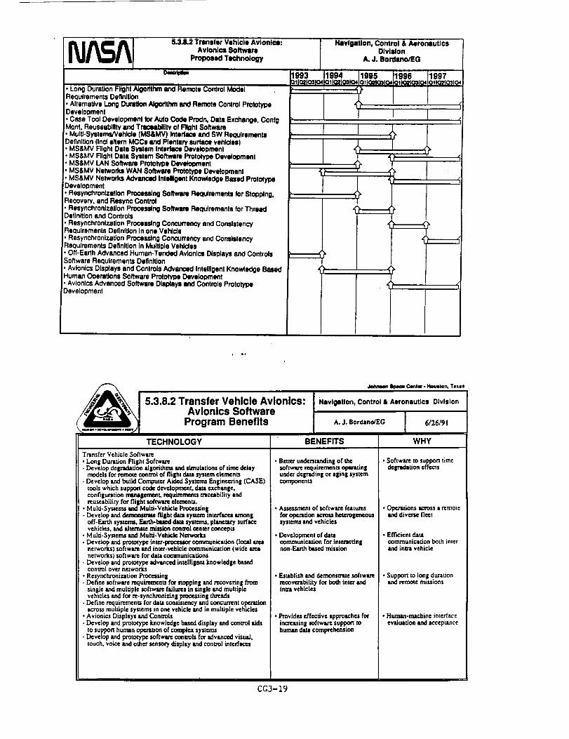
5.3.8.2 Trenaler Vehicle Avionics:Avionics Software
Proposed Technology
;. Long DuraUon Flight Algorithm and Remote Control ModeliReauiremants Definition
• Alternative Long Duramen Algorithm _ Remote Control ProlotypeDave ocment
• Case Tool Developmenl Ior Auto Code Prodn, Data Exchange, ConigMQnt. Reusesblllty and Trac_tbilltv of Fright Software. Muitl-SystemsNehlde (MS&MV) Intadlce and SW RequirementsDefinition (Incf eltam MCCs End Plantary Iwrtacs vehicles). MS&MV Flight Dale System Interface Development. MS&MV FllQht Data System Software Prototype Development. MS&MV LAN Software Pmtolype Oevelogment. MS&MV Nelworks WAN $oftwue Prototype Development
, MS&MV Networks Advanced Intelligent Knowiadge Based PrototypeDevelopment
, Resynchronlzntlon Processing Software Requirements lor Stopping,Reooverv, and Resync Control
Resynchronlzation Processing Software Requirements for ThreadDefinition and Controls
Resynchronlzation Processing Concurrency end ConsistencyReaulrements Definition in one Vehlde
R osynchronizalJon ProoessJng Concurrency and ConsistencyrReclulrements Definition In Multiple Vehldas
• Off-Earth Advanced Human-Tendad Avionics Displays and ControlsSorlware Reauirements Definition
, Avionics Displays and Controls Advanced Intelligent Knowledge BasedHuman Ooeration$ Software Prototym) Development, Avlonlcs Advanced Software Displays llnd Controls PrototypeDevelopment
NavlgeUon, Control & AeronauticsOlvlllon
A. J. Bordano/EG
1993 11994 1995 1996 1997=tlO_ o3 o41ollc_f_ o4 olt0_1031o40l)O_QalOi OflO2tO3tO_
J
/
i
/
Johmmn_ Career. Houston,T,see
5.3.8.2 Transfer Vehicle Avionics:Avionics Software
Program Benefits
TECHNOLOGYTnnsfer Vehicle Sohware
• Long Duration Flii_ht Sof|wsrc- Develop deipidmion ilgorlthms and simulations of time deJly
models for remote Control of flii[h[ dim s_,stem elements- Develop and build Computer Aided Systems En$ineoring {CASE}
tools which supportcode development, dab exchange,configun, ioo rrmnajjcmcnt, requirementS traceability andmuscability for flil_l sohwlrc elementS.
• Multi-Systcms sad Multi-Vehicle Proccsdn$- Develop and _ flilEht dill system intcrflcos lunon|
off-Em'th systems, F.m11Pbu_l dam systems, planetary surfm:_vehicles. _ IdmrnlW adsSioncomz_l cemer conceptS
• Multi-Systems and Multi-Vehicle Nctwor_- Develop _ prototype inte_r-lXOCeSm_comrnunicafion (load
networks) sohwm's and inter-vehicle communication (wide mnetworks) sohwer= for da:a commu_i,"-dons
- Develop and prototype advanced intellilem knowledlle basedcontrol over networks
• Rcsynchronizadon Proc_nll- Define sohwm'c mquL,,emcnts for stopping and rcoovcfing from
single and muldple softwan_ fsilun:s in single and multiplevehicles and for m-syncl'u'oni_dngpmee,ssin$ threads
- Define requirements for data co_liS_t_:y and concurrent oporldonacross multiple systems in one vcldcle and in muldple vehiclt=
• Avionics Displays and Conuois- Develop and pmtoty'pc know|edge based display and control aids
to support human o_on of complex sys:cms- Develop and pmmP/pe sohw_re conaob for advanced visu"],
touch, voice and o;ber sensoryd_play _ conool interfaces
BENEFITS
Navlgltlon, Control & Aeronautics Division
IA. J. Bordano/EG 6126/91
WHY
• Better understanding of thesohwm'erequb'emenu open_dnluB:lerdeiFadinl_ or a|ing systemcomponentS
• Ass_t of sohw_rc features
for opcntdc,n L_'OSShcte:o_eaeou_systcnu and vehicles
• Development of damcommunication for inler'lcdn|non-Ea_ b,sealmission
• Establish and demonsnltc sohwm'cmoover'abiliP/for both inter andInm_ vehicles
• Provides P.J'f_cdvesppro*ch_ forinc'Ra._inI softwm-_ support mhuman data compre_.nsion
CG3-19
• Software to support timedelPldltion effects
• Op¢._dons _moss a remote*nd d_vene fleet
. Eff'u::ient damcommunication both interand imxa vehicle
• Support to long durationand remote missions
• Human.machine interfaceevsduation and ,ccepuc_ce

8.3.8.3 Transfer Vehicle Avionics:Vehl¢lo Health Mar,sgtmentCurrent & Related Programs
D_cflpOon 1989 198901[Q2_Q3_Q4OllO2_O3_Q4d
• Earth to Orbit VHM devalopmenl
• Applicationof Al/Expert Systems to VHM
• KnowledgeBased AutonomousTesl Engineer (KATE)
• STS OMS/RCS Upgrade
Open Architecture& Integrated VHM Study
Anomaly Propagation Tracker
!" Integrated Health Management LabI. Failure Environment AnalysisTool• RAMTIP
• Fautt IsolationExpert System
Nlvigetlon, Control & AoronautlcsDivision
A. j, Bordano/EO
1990 1991 1992Q11QaQ34Q_Qt Q2103Od Ot Q2_Q3104
E
i f4".... "
; f
I,! ,: I /;! i
ii!$
!
t
!
i
5.3.8.3 Trarmler Vehicle AvJonl_l:Vehicle Hoelth Management
Proposed Technology
Description
DevelopmenUOperatlon el VHM test bed - Transfer systememphasis
VHM FunctionalAllocationand PartlonlngTrade StudySensor technologydevelopment (smaWautonomous
sensors,smart skin)
Open ArchitectureStandard DevelopmentandPromutgation
DevelopmentJdiDmonsUttiono! embedded ctosedloopsimulation
Comgare cosVbenefitsof phy_cal lind analytic redundancyinVHM Test Bed
Develop system level fault tolerance design tools!. Flightdemonstrationof VHM/Fault ManagementImplementation
Navigation, Control & AorormutlcsDivision
A. J. Bordano/EG
1994 1995 1996011Q.21031Q40110210_q04otla2lQ3104
I
9
CG3-20

TECHNOLOGY
• Automated vehicle checkout- PerforTncd continuously andwithout human intervention
• Autonomous vehicle hexlth
management
• VI-IM system architecture andsoftware
• VI-Uvl sensors(physical sensingdevices, snalyuc and other syntheticredundancy techniques) - useof"smart skin" for StTUCmzeSand
propellant system ¢lctoenu• ]:)Js_buz_l sensor m'chJtecmre
• Residual [lfelim¢ est_muion,dynamic health & sum= essessmnt- m.J_on op=rtdom will not be
compro_sed by being forc_l torely on devices and systemsofquestionablereliability
5.3.8.3 Transfer Vehlcle Avlonlcs:Vehicle Health Management
Program Benefits
BENEF_S '
• Im:nulsed proslx.Ctl of systemsurvival and mission s,cceu in banhenvironments
* Maximize mission caplbUities,performance; enhanced missionsuccessprobability
• Enables incremental adoption ofVHM concepts and new hardwa_;minimizes technical risks; impmve_efficiency and _10gStllC=:l
• Increased knowledge of complexequipment's health ¢ondJdon
• System is physically and functionallyredundant *nd can wifl-,.md la_scale physical insult without toudIo_ of functionality
• Enhanced mission mccem
• Improved petfonmace maqdns
• Improved cost effectiveness ofprocessing and maintenanceoperations
J_wmwt _ Cmntm"- Houston,Texas
Navlgltlon, Control & Aeronautics Division
A. J. Bordano/EG I 6126191I
WHY
• VHM allows supedor insight into system condidons;suppoclsboth hunum Ind mschine-I_uzed decisions
• Alleviates and circumvents effects of in-flight failuresand delFadations
• VHM techniques allow weight and power savings bysubstituting software intelligence forsome physicalredundancy
• Different sysu:ms, technologies and sensorswilldevelop at dtffez_at flmez
• Prognosis and I_¢ly fault detection capabilities arerequired for complex equipment o_ting in exurerncenvu'onments
• Component health h condnuously monitored andincipient failures are detected before they becomeacute
• Performance redllnes can be _dcul|ted dynamicallyand need aol rely on statisticalestimatesof"beglnnin$ of Ufe" (optimistic) or "end of life"(pessimistic) projecdoes of system capabitidcs
• System element= may be reps/red when needed uopposed m following a perk_c (ov='ly ¢ons¢_ryltivc)schedule
i ii
p
r_J_A 5.3.8.4.1 Transfer Vehicle Avlonl=s:GN&C Algorithms
Current & Related Programs
Description | 988
_I10_o310,Autonomous Navigation In Interplanetary Space
• Preliminary concepl development
Autonomous Rendezvous/Do<#Jng GN&C
• Baseline requirements under development
NavlgaUon, Control & AeronauticsDivision
A. J Bordano/EG
1989 1990 1991 1992
01102103_O4OlI0210310,OllO21031Od,OllO2_O3104
i
!
t
i
i!
CG3-21

5.3.8.4.1 Trarmlar Vehicle Avtonl¢l:
. GN&C Algodthlll
PropoNd T_hn_ogy
DelcIt_n
Predslon Orbit GN&C• GN&C concept devqdol_nt• Environment model development and simulation• Algorithm devMopment and Mmulatlon
Predsion Orbll GN&C• O_lml trajectory o_elo_,mt
, EnvlronmentM model development end Idmulatlon• Detailed algorithm devalopment and listing
:Advanced AnaJylical Pmpagatom• Anal_c Technk:iue Development• Detailed requirements development• Detailed algorithm develoPment and te_tng
GN&C for Atllflctal Gravity Vehk:les• Antllclal Aravtty al_mach masmont• GN&C archnecture dMInitlon
• Algorithm development and simulationAutonomous Navigation In Inlor_snetary Space
• Autonomous al_roac_ dQv0kx)mSnl• Concepl Irade studies• DelaJled algonthm development and listing
Numedcal/AI Guidance Techniques• AI conept development• Numedc Outdarce/AI Integration, Detailed elgorilhm development and tsstlng
Parallel ProceWng GIN&C Melho¢b• GN&C ixocmming concept derwent• Parallel GN&C srcNl_Jm dlllNllon. Algorithm development _ MmuMtlon
Autonomous Rendezvoul/DocNrlQ GN&C• AR&D rlKlulrsmonts dlv_nt• Algorithm concept develoomsnl
• Algorithm testing and Mmutation
Nlvlipll|on, Control &/_ronautlcsDlvlldon
A.J.eereano_a
,' ?
|
_L
I-r" r
GN&C Algorithms
Program Benefits
,kduumn _ C4mtm. _ Teua
5.3.8.4.1 Transfer Vehicle Avionics:
TECHNOLOGY
Precision Orbk GNAC
• Develop new appmachu and id|orithn_ forn_intainin_ ex_'11tei_ precise ocbit$
Low Thrust Vehicle GN&C
• Develop new ON&C algorithms for useon exaemely_ow thrust to weight mmSfer vehicles
Advlmced Analytic Prol_o_• Develop new m.dytic orbit pt'otmptor technique* for
onbotrd use
GN&C for Vehicle* Udli_g Artificial Gravity• Develop GN&C tlBonthrm for vehicles which ttse
spinning su'ucmre* to provide m'dfiebd ipravity forcrew membe_
Autonomous Navigabon in line,planetary Space• Develop autonomous navigation techniques and
alKodthms for useon deep apace mitsionsNumeric/At Guidance Techniqu=t• Utilize anificild intelligence technique, to provide
assuredconvergence of numeric guidlmce Idgodthms
ParalJel Processing _N&C Methods• Develop new approaches and dSodthms that can t_
effectively used on pm'tllel proce,sin| computen
Autonomous Ronderm,VDockinli GN&C• Develop algorithm conceptsand approaches to
support autonomous rendezvous
i_avlgatlon. Control & Aerormutir..I Division
A. J. Bord,,no/EG ] 6126/91
BENEFITS
• Allows efficient use of Ico_Tnchrono_orbits and Eanh/Monn. grab/Sun.Sun,tars Iibrttion points
• Will allow effective use of advanced
pmpublon systems such Is nuclearelectric
• Anldydc appronche* _re compumtiomdlymo_ efficient than n_w.dc approtche,and hive more I_urance of converlcnc¢
• Allow efficient opemdon of u'ansfervehicle, while simulum¢ously providingx heahhv crew ;llvimt'tmcnt
• Reduce or eliminate requirement forEarth bued navel|irish ertckin K
• Accurate. _lJabie guidance solutionsusin| cx_t environment models
Cortex GN&C compuutdons can be
perfon_ed,wireonboardIm_ielOroce._ml
Recurring corn can be reduced throughautomation and improvements to current(3N&C Id|othhms and ope_donsapproechel
I
WHY
• Udli.=inl these unu_. tl _oi__:luu'es precise mamtenance ofthe vehicle position
• Current ON&C algorithms weredeveloped for vehicles withrelatively hiKh thrust t9 weigh_
* Current analytic props|stars do.at provide the ancumeyt'_Ce.ttMy for the next _enerationof launch vehicles
• Rotational dynamics necessaryforartificial gravity has adverseeffects on GN&C
• Cunent deep space navigation isEarth rinsed
• Current numeric guidanceschemes tm not muted of
always conv_n_ ,
• Sequ_dM compmadon [imi_today's GN&C proce_in$
• Current AP-JLDopemdons rely
hmvil_ on IffonM basedmanualprocmuRs

5.3.8.4.2TrlmslerVehicleAvlonlcs:GN&CSensorl
Cummt& l_ed Pmgnm_
Optical Senses for GN&C A_ns
• Sel req_remtns and woof of concept testing lot theContinuous Stsfiar TrlcMng Ntltude Rsfemncs (CSTAR)
• Set requlmments and woof of concs_ lestlng for the Hlg#Resolution Affitude l:t_e Sensor
Inertial Componenats _ Systen_ Ior GN&C Appllcatfon8
• Evaluate inertial components Ior vendor _oedf_atloncompllencs and vehlde ICq_:_One
• Evaluate stsle-oJ-lhe-ml Inertial senses lor launch
vehicle, orbital vehldes, llnd payload packages
• Develop Inertial sensor padulgse for payk)ad Inelllalmeasurements
• Maintain dambue of stste-of-the-lut and proposed
inertial sensor end system technologies
1988
NavlglWon, Control & AeronlutlcsDlvtllon
A. j. Bordano/EO
1990
01102103_0,1
f
1091 1992
011Q21031Q4 O11021Q310,iI
'iiI
I
5.3.8.4.2 Transfer Vehicle Avlordcs:
GN&C Sermom
Proposed Technology
DeSCdl_on
Typical Schedule for GN&C Sefl|Ol' InvlNItlgstlon ]
Spedly requirements for sensor and system hardware
Saedfy requirements for software algorithms anddatabases
• Reasearch the current technology for required hardwareand software
'. Investigate and devek:)p vedous algorithms
• Design. build, and laborlHory test el prototype system
• Field test of prototype IP/stsm in Ilbomtodes, end/orremote observatories mnd I#es
1993
OllQ2103104
Navigation, Control & AeronauticsDivision
A. J. Bordano/EO
1996Otlo_O31o4
1994
01102103104
1997
OltO2103104
/
I tON&C Bonier InmllOation
• Autonomoul Alt_Kle DetunlmlUon System Do_ont
• OplP...__ Serum,"_t• HodzorVTemdn Mm_l=ing/F--tum Re¢x:)gnltlonSensor Development• Magnet_ullve• FIb_-OpUc Gym Rmnmh and Develoomer4• _ seam Accelememer• Codolls Accolemmst_ Inertial IdusummeN Unit (CAIMU)• C¢oadttve. Magnetic Supembn IMU (QUBIK)• GravityWave/Lense _ Effec Delec_ot(GWLTED)• Elocb'ostatlc_lcromad'_ A,oceleromet,i.'_ Hy'bdd Electronics(F..MA)
CG3-23

TECHNOLOGY
Optical Ra=eSen,era
Aumnomouq A_ttadeDetermination SystemHorizon Sensor
Terrain Mappmg/F_mr¢Recotnidon SystemMagnetoresisdve Sensor
lnterfemmctri¢ P]be_-Opt_Owe fIFO0) Mine mmteResonator Fiber-Optic Oyroti_bcrOO)Lcm mature
Optics Gym Closed
vL_°d_Pdni BeamA_¢leromcmrConolisAcc_le.rmJontne..rlJ*lMctsu_ment Unit f|MU3
Capacitive.Mqmuic
Sus_ndon IMU {OUBIK)GravilyW|vej1,ensc-Th_n|EffectDetector
F.JcctrosmJc/MJcmmachmcd
sccclcrornctu with hybridelectronics
5.3.8.4.2 Transfer Vehicle Avionics:GN&C Sensors
Program Benefits
• Prec/sion vehicle attitude rates usin| opdc=d
; techniquesPRcidon vehicle auimde usin| opdc_dimal_in|
• technk:p_lPrecision n*vistdon cspsbilitiesu,dn$ opticalin=gln Ktechniques
; Precision rmviplion ¢almbilides usinl o@tica]imsidns and smrsle tcchniou_l
• Provides azimuth dctumbuudon in l =mnilu,ll_mr, less cosdv. Im power mcJm_
High Mean Tlm= Before F_JJm¢ (Id'IqBF) lowI oo_r, =nrJlu rateI ' _gh MTBF, low power, RLO ¢om_dbl¢I _¢JI_ rm _qorI ;High MIullr rate_r_ _ withimprovedI tt_e ti_a_tY °v_r OF_ L°on FOG's[ • Pn¢imon, low power, =xudI, Rig=bin! acceleration _tt'nlent
• Sm_ Iow power/pan count IMU. Onlyamt_l_tm renulmd fm oomDte_ rv=tem,
• S/nl_e s4mlor pn_ all/n_ Rmdngutrements.
_ Cm_t_ • Ho,,-ton,Texas
Navigetlon, Control & Aeronautics Division
A. J, Bordano_G [ 6/26/91I I
WHY
Provides reliable in_|ing real dme navipuoni SUl_Xm forextended Lunar ind Min rmssi0ns
Provides mliabk n:al rime e_tude determinationxylem forextende_ L_ner ind Mnn missions
• Provides _"ebl¢ roaddec nsvigation support for
Lunar and Mm expIormor,( missions• Pt'ovides reliable real dme navigation support for
Lunar and MaJrT explorato_ missions•Pmyide light weight azimuth sensor for E,an.hand
o_oit [he[ rouuires Lllde _ower foro_. ration• Provide Idlldy _ immnomo_ n=viption a_d
• ImJlullr rat_ _ITn_In| f_ i_unlu"I_ M_ missionsProvide highly wJhlMn eutonomous =lvipuon and
InRu_ ttm ;¢nstngf_ Luntr and Msrs missions• Provklehighlyte.[labk==ulonomous n=vilpt.ion_ndllne=rtcceleradonmm_memem .
• Provide highly roll=bit compact au_mmousn_ntton sunnort for Lansr and Mm missiqp L
• Pmvid_ hilldyx_ll,bl_ommp,ct sutonomo_naviDdon sUl_on _or Lg,n_ and Mm mis,sions
• Provide mo_ e¢ctmue trillion support for' msudve bodies on vehicle Izsiectodes.
• llith _nsldvt_,, smelt size. low power
I
Jnmmlane0u_ n k.,'m,_:es.
• Pmvld¢ oom_ct autonomous navi_ion m_d_=mlon measurement forLunar _d Manmlsdons.
5.3.8.5 TranMer Vehicle Avionics:
Tettmr Control
me=re==
.Modet and Tool Development resulted In am ol_ItlonalSTOCS (englneedng tool for Tether design and analysis).
. Tether/Space Shuttle Inlerfererce Pro_ems/Conlrol
Tnteractlons amcl Tether Dynaml_ Analytds
• Pursue Right Design Assessment englneedngactivity/reports/presentations
• Initiate/continue effort to model the System EngineeringSimulator Io a¢comodmte Tether problems
• Mocflfy/Uixlate _ In STOCS its required
• initiate/complete STOCS rehost to Cray computer
• Inltlatel¢omplete checkout_adidadion of the first Tether
Satellite System mLsslon and en=dyze flight results.
• PreDare for Tether Right 2 and 3 and perform post flightana)yses
Navlgltlon, Control & k;ronlutlcsO!vl=lon
A. J. Oordano/EO
CG3-24

I _j_A B.3.8.5 Tmrmer Vehicle Avionic:ProposedTether TechnologyControl
.... beSC_lo_on 1993
Remote DockingP3elO_lllon
• Determine capture and mlem ocenark_. Demonstrate
performance advantages of each.
• Conducl trade studies.
• Identify key design parameters
• Define hardware/software lot aocumts rendezvous end
docklng
Passive Altitude control/manege mlcro-g
• Establish conlrol/micro-g concepts
. Identlfy key design pammelers, develop Jmuiallons
Alternate Propulsion
• Investigate tethers lot electromagnetic propulsioncapabilities, Identify requirements
• Develop malh models and produce concepluaJ designs
I_vlgatlon, Control & AeronauticsDivision
A. J. Bordano/EO
1994 1995
:lp_o_ o11ou.lo_o,oIIO_0_o4
'I, L
1996 1997
oIIo_o31o40',IQ_IO31oa
J
tt
5.3.8.5 Transfer Vehicle Avionics: Nevlgetlon, Control & Aeronautics Division
/,__1 Tether Control n
__...._ Program Benefits ^.j. ,ord..o_G I 6/26/9,] I I
TECHNOLOGY BENEFITS WHY
Remote Docking/Sepm'=ton• Determine c=p[un=and release sccmu'ios
for Space Station and In|erpllncm'yVehicle opera(ions
• [dcnlify key design panlmelerscharacterizing designs
• Define han:lwnwJsofm,=r¢n:quins,'nenLsfor accurate _ end docking
Pmiv¢ A¢fitade CoeaeVh_,nlgnY_cro-g
• Establish control ¢em:¢_,/_ .¢m-gmanagement coecelXSforvariousmodes ofopermtonofspacepinlformsand interplaneuu7 vddcles.
• Identfy key design parameterscharacterizing designs.
AJtemax¢Propulsion•Invesugatetheuse ofe.l=n'odynamic
propulsion for orbital maneuveringusing ted_en
• Produce concepmll designsthatiniegztte ¢ctheapropulsion into thevehicle control avionics
• Demonslrldon of performance tdvlmUtges ofusin| tethers for docidnll end sepznuioo.Establish hzrdwtreJsoftwa=erequirementsfor accurate rendezvous/docking
• Will esutblish tether systems versldleenough to accomplish m_cro-gmanagement,and enable fuel/energy savings throughpassive tether atdmde control
r
• Ertable a mns_ ot" pmducin_ orbit ch_gesfor spacevehicle with mJa_m.m e=_lD'expe_lk=re
• Potential for fuel saving and reducedconum_naton of solLr ='rays due to jeteffluent impingement
• Micm-$ numa_en_nt is dLf'fieult toachieve, somenmes requiring elaborttemountnl| schem_. Tethen may of_¢.ramorn feasible option. Fuel tnd energysavings for long duration vehicles Lr¢possible if ted_rs can be us_l for passiveco.m:d.
• Spice platforms in orbit for long periodsrequire f_ueat rnsupply missions forRfueJin|. Ele=lrndyninfic propulsion
udn$ ,.then could minimize thisrcquwement
CG3-25

(L3.8.6 Trlrmler VeNcle Avlont¢l:
EIq_ricaJ AotulUonCurrenl & Related Progmnm
Deec_k)n 1988, _lazl_o,
General Dyn_nlcs 25-40 Honmpower EMA DDT&E
Program (SATWG ELA Te(:hnok)g,/Brk_lng Program)
JSC Actuator Test Set and FIdJity Dsve_opmsnl endOperation
• Honeywell TVC EMA Development Project
• Assessment of ETO actuation talk requirements and ELA
suitability
• System Engineering to k_sntlh/¢_llgn pl.lmetsm andsensitivities; key trade cdtlda
• Evaluate Parksr-Hannlfln Nosewheel Stssdng EHA el JSCATS
I,blvlgltion, Control & Aerormutlc:sDivision
A. J.go_eno/i:o
1990o',Ic_o:_o,
G,
1991 1992Olla_a:_O4, otla2_a3ra_
i
trl
I "_
1
!
i1z
i
NASA 5.3.8.11Tmnl,er Vehicle Avionics:
Electric=l ActulUonProposed Technology
D;scrl_on
• Demonstrate & Evaluate a 10 Horupowsr ELA device
• Demonstrate & Ev_ue, ts a FraclJonal Horsepower EtAdevice
• Design and Query a Family of ELAs tor Transfer Vshk:ieFlight AppilcaUons
• Develop and Valklale EtA Fault Manlgsmenl/VHMSlralegles
• Demonstrate ELA Fau# Maulgement/VHM Strategies inVHM Test Bed
• Fligh! Demonstration of a Right Crll_caJELA
1993 1994:)_Io_o_la4a11_o:_o_
.L.
Nlvigltlon, Control & AaronlutlcsDivision
IL J. Bordlno/EG
1995 1996 1997a'l O2JO_0401JO2103104a11a2ta3!a_
I9
CG3-26

TECHNOLOGY
.Elcclromechanica.IActuation (EMA)
,EieccrohydrosulticActcadon (EHA)
• Magnems_icdv¢ =ndother direct acdng
5.3.8.6 Transfer Vehicle Avionics:Electrical ActuationProgram Benefits
BENEFITS
• Expedite system checkout opemdous; mlnimi=e_rsou_I cos_
• Opon=douMsafety increased
• Disu'ibuted system is more fault/damage mica'ant
• Greatly reduced risk of system failures• System oerformance marlins ere exoanded• F.xpodite tC_t_ verificadon ope,-adoes; minimize
personnel costs
• Opentdontl safety inc_.ased
• Dislributed system ismore fault/dmcmge tolenmt
• OP.Jdy reduced risk of system failure=Directly applicable to flight-cridca] ,pplicadons
• lnhetendy suppom b¢_c consmoctsof VehicleHcaJth Menalemcnt (VHM) iuidadve
• Expedites launch lysxem proceulng and checkoutopcnldons
• AUows Wstem level funodonalhy teat at low corn inten'm of manpower, rime, and q)egi*l¢onfigunldons/test support equipment requirements
• In_ wobabilltyof mi,,t,donSUCCess• l_c_tses reliance ou Iogtgic$ lifedm¢ w.qutn_ments
for get)air
• L'gRa_ r=liability
• Unitcostisreduced
Jotmeo_SlmoeC_tat • Hlouslo_,Texas
Navigation, Control & Aeronautics Division
A. J. Bordano/EC 6/26/91
WHY
• Hydraulic system eliminited; system checkout doesnot entail hazardous opomtions
• Xu.m, dous fluids, storedencrg_, systems,fluidreplenishment operations eliminated
• Distributed system elements; no cenmd single pointfailures, no fluid couplings to burst or le4d:
• Very low system part count• Actuadon svsmm weieht is reducel;I• Cenmdiz_l hydraulic system eliminated; checkout is
expedited, doel no_entail periodic hazardousopomdons
• _ fluids, stored eneqw systems, fluidx_plenishment opomdous elinmnated
• Distributed lyslem elements; no eemxM single pointfidlun_, no ext_md fluid couplinp to ha'It or leak
• Very low system _ count• EHAs provide Inhe_nt lore:l-sharing ability• Overicad capecity Is similar to couvendomd hydraulics• Ac.almr cambe hackd_ven with edjusmble imlP..dLnc¢
fvarisble damnin, etm*hllity)• Simple elecoicaJ and command inted'ace with host
vehiuic
• Obviwes need for exten_d hyd_u"c supportcv_
•Loeg "shelf life" without need for constant servicing
* Systems cen withstand rigors of extended missions,long duty cycles, protracted dormant periods
* Exa_mely low pm',.scount (for mspetoscricdve, lmoving panl)
• Devices are meclumically simple
5.3.8.7 Tramller Vehicle Avionics:
Power MImll0ement & Control
Curmnl & Related Programs
Description
Advanced (High Capacity) Fuel Coil Development
_. JSC Integrated Actuator/Power System Test Set FacilityDevelopment and Operation
• Flywheel Energy Storage Technology Investigation
• Power System Marmgement Expert Syslems Developmentand Demonstration
• Shuttle Power Distribution Brm_o=m:l lab Developmentand Operations
• Advanced Motor Controller Technology Development
Navigation, Control &/_romlutlcs•OlvlJon
A. J. Bordeno/EO
1989 1990 11991 1992Olla2103104 01102103104 01102103tO4 O11021Q3104
I
J
it
i
g
i
iiii
CG3-27

8.3.8.7 Transfer Vehicle AvioNcs:
Power Management & Control
Pmpoud Tlchn_ogy
DescdpUon
• Develop and Demonl_Be Faufl Tolerant Power SyltomArchitectures
• Identify ReQuirements for, _h SpeolllcalJon of
"integrated Utflflles" Interlace
• Demonstrate PMAC concepts In VHM Tul Bed
• Demonstrate PMAC Concepts In FHght Te_ VeNds
• Demonstrate Flywhool Enorgy Stom0o Technolo W
Develop end Demonstrate High Energy Dons_y BalterySystems
1993 Ia_I021o31o4
NIvi0atJon, Control & AeronauticsOlvlslon
A.J.Bo,_no_O
1994 1995QIIQ2_Q31Q4 QIIGEJQ3JQ4i
1996OIlQ'AQPIO4!
1997O$102fOslo4
_P
, it
%.,.......1,,.. ;,,,j
TECHNOLOGY
• Autonomous reconfipu'adoe m_m|scnerJplraJlel circuit
5.3.8.7 Transfer Vehicle Avionics:Power Management & Control
Program Benefits, L
BENEFITS
• Expedite system c_kout and self-test
•Ime_'uted modular service backbone
open, dons; ndnind_ zgRportpera_m.I corn
• Irc_sscd mission success pml_biSty;espe_diy for tonI duration ndcdons
• Vehicle inteipmtion task is Im_pUf_d
• Power, thcrmaJ,dala ¢aplddlides Ire providedin • btlanced fuhk_
• v_icic pedorman_ b improved
_ C8otB • HmMlto_ Texas
Navigation, Control & AsromiutJcS Division
A. J. Bordsno/EG 6/26/91
WHY
• PMAC implementation Suppom automatedvehicle checkout
• System is more robust and f.uh tolerant
• Supporu IFaduld delpldation rather thansuddentoud loss of funcdons
• All required lervi¢_ am pmvid_ acrossaunified interlace
• tn_lp'szed %dfid_ bus" chsra_erized byhi|h level of tnt¢lpradon and mutrlpiexing,laves wail|hi
•High frequency power d/sl_'ibudon •Vehicic performance is improved • Syszcmcomponents Ire ligh|er, etTicienciesand conaol k"ehi|h_
• Multi-mode pow_ lleneradon systems • Enhan¢_ mission success probability
• Enhanced mission success
,Vehicic perfon_mce b increased
• Suppom requimrmms for dosed loop vehiclesys,,'ms
; _ced comptdbLI/P/with ¢lemxic,Iactuation _LA) t_cb_olol[T, improvedsystem e_zciencieJ
CG3-28
-Enhanced fuel ceils
• Advanced EnerlW stora|e and powercondidonin| devi_ (i.e, flywh_is),udvanc,ed motor conmollers
• Appropriate power senerauon method isivldllbie to mltch operidonld environment(]ow earth orbit, planetary surfaces, deepspace)
• Fuel _:li sysunn rellabi/izy is i_creased• Advanced f.el cells Mve • I_gh_ net energy
density;.Powex r/stem is iilhU:x for the sameczpaCJ_/
• Regeneration capability IJIows o:II toproducewa_t or hydro|en/oxysen
•Pow=" supply,rejlularlon,and conditioningt¢chnoio|y is rn_tched to the uniquerequi_=mcntsofEL.As

_ Comw - I,k_L,mtcm,Texas
5.3.9 Autonomous Landing
Overview
Navigation, Control & Aeronautics Division
A. J. Bordsno/EG / 6/26/91I
Q The goal of the NASA Autonomous Landing Technology Development Project Is to enable sate,accurate, autonomous spacecraft landing using precision landing at a preeelocted safe location oron-board detection and avoidance of surface hazards to landing.
Q Mars and Lunar landings must be achieved safely regardless of surface hazards such as largerocks and steep slopes, be close to the ares of mission Interest, end occur without real timeground control.
O Earth orbiting and return spacecraft, such as the PLS and ACRV, require landing to be achievedreliably and on short notice.
Q There are three areas of technology thrust:
• Systems Engineering: Systems engineering activities include - the evaluation of landingaccuracy and the probability of safe landing for alternate landing approaches, and thedevelopment of detelled engineering models such as Lunar/Mars terrain models.
• Precision Landing: The principal objective of the precision landing work Is the development ofmethods of navigation with respect to the lending site. A second objective of the precisionlanding work is the development of guidance and flight control algorithms that can compensatefor environmental anomalies such as atmospheric density and wind variations while steering to
a preselected safe landing site.
• Hazard Detection & Avoidance Landing: The objective of the autonomous hazard detection &avoidance work Is to develop the sensors, algorithms, and operating strategy that will enableexploration spacecraft to detect during terminal descent • safe landing site.
=
n t,
N_m_A 5.3.9 Autonomous LandingCurrent & Related Programs
Description
System Engineedng
• SystemAnalysis
- Baselineset el landing requirementsfor Mars RoverSample Return (MRSR) dass missions
• PlanetarySudace Models•. An Initialversiono! a Mars Sudace Model
PrecisionLanding
. Image Matc:hlngNavigation
•. A baselineset of rlKlUlremontsI_USan InltlaJapproachto &test of Hybdd Optical Imago MstchlngNavigation
Hazard Detection& Avoidance
• Imaging Laser Radar
.. A baselineset of requirementsfor a detailed ¢onceptu=ldesign o! an Imaging laser
Navigation, Control & AeronauticsDivision
A. J. Bordano/EG
1988 1gag 1990 1991 19923tIQ21Q3tO,011Q2_Q31Q40tlO_O3104OtlOZO3104OtIQZO310,
¢l
CG3-29

NASA 5..1.9 AuKmomous landing
o,.=m_
Proposed Technology
System Engineering• System Ana_s•. Dev_OP ant of uutonomou=t_llng nmulmn_nt= _ a
ranQeof olanetarYexDforaUonmiddens•. GN&C SJn'_latlonenhancement=- Closedloop slrrmlstfonof G&C, nsvtgaUon/hazlud
detection san=or moclels,tarrsJnend 81mosohed¢ models•. DeveJopconcepts lind workstSIIonlevel prolotype of
man-machlne Interlace• Planetary Surh_l Models•. Development and testing of 8 Marl surface model•. Collection of tdghresolutiondlgltld terrain _ for Ewth
analoQso! Ms.an lemlln tYDw• Sensor Field Test•. ConceptlonJ Design of Sensor Fleld Tests.. Perform Sensor Reid Tests
PrecbmnLanding• Image/TarrlJn Matchlng NavlgldkN1•* Lanolng navtg_on raquirlments dellntllon•. Concept definition_ Ilmulltlon of Idtemlda
Imalle/torrJn rnatchlnastgorfthms A I_oceuonl•. Design, build and laboralotytest of prototype for seleCliK
imape/Ionltn rrJtchlnQlI=l_oach•. Reid Test of pmtoyl=eforletecled InulgMarrlln
matchlr_ nsvlaatlonlllXX'oach• GN&C for Landing tram Earth•. Guidance requirementsdellnltlon•. IrrvestlgaUonand protolyplngol va/Jousgutdence
algorithms
1993O_IQ21Q31_
II
Navigation, Control & AerormutlcsOlvhdon
A. J. Bordano/EO
1994011Q'_03104
1995 1996011C_Q3_04i 011C=103104
l@
1997QI[Q2_Q31Q4
'Pr--
t |1
i
Duc_ptlon
S.3& Autonomous LencUngPropelled Technology
•. Simu_.Uontsetlng el promisingguidanceslgodthrr_ withGPS navlaaltonand UdJr derived wind profile
•. Reid teal of protoypeguidance idgodthmHazard OotectlonKAvoidance• Laser Radar•. Develop 8 set of sensor lind systemrequirementsfor 8
ranos of Mml and Lunar axlDlorstlonlli_ng missions•. Spedflcatloml tar pmtoly_ Imlglng laser radar
• Altemste Hszsr¢l _Ko_Jon Sar4ors•. Devsl_ concmS _r Mton_e hezsrtl ctste_on
aooroe¢l_mand _ v_ J_tallon• Reld Teat•. Design, bu_ and laboralow tat el pmtoypesensor,
algodthmsand processorforselected haza_l dete_onapproach
•. Reid lest prototype of selected h=hzarddelocUonapproachfrom a hell¢ODterover Earth analogsof MerUanten'a_ntypes
NavlgaUon, Control & A_ronautlceOlvllJon
A. J. Borduno_O
1993 |1994 11995 11996 1997
CC3-30
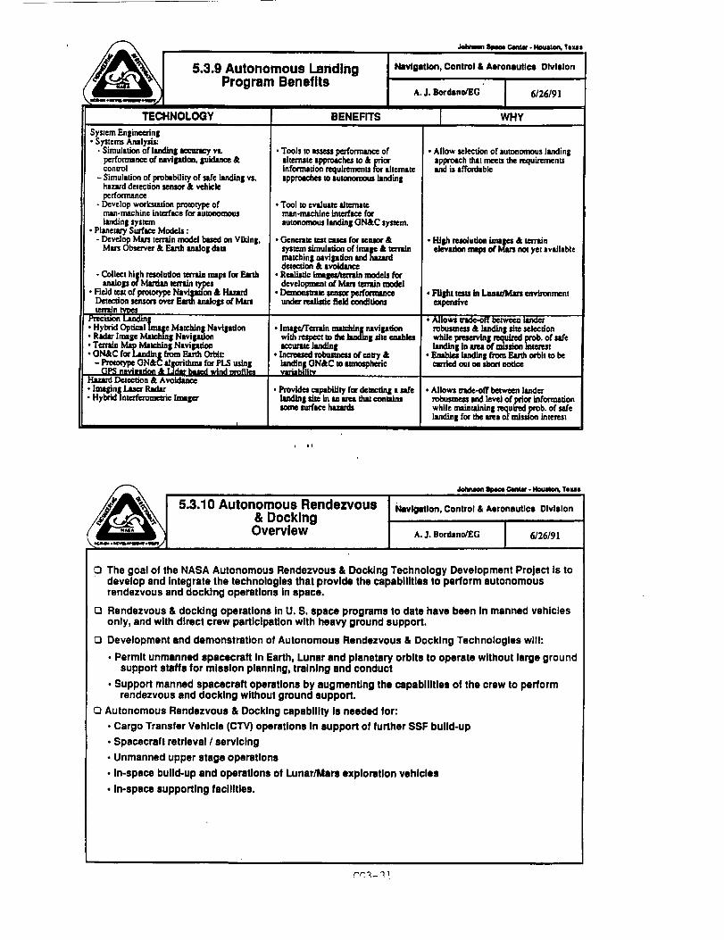
//__1 5.3.9 Autonomous Landing
___ Prog ra m Benefits
•loire*on area, ¢,nw. )4oum_ Tem,,
Navigation, Control & Aeronautics Division
IA. J. Bordsno/EG 6/26/9]
TECHNOLOGY
System Enginc_'ing• Systcn_s Analysis:
- Simulation of hmdln| _ vs.pcrfommnce of navlpdon0 luidance &conu-ol
- Simulation of probability of sa/c landing vs.hazard demcdon sensor & vehicle
performance- Develop worksn*rlon prototype of
man-machine interface for autonomouslandin8 system
• Planetary Surf_ Models :- Develop Man terrain model based on Vlldn|,
Mm Observu & Eartht, mlo| dam
-Collecthighresolutionten-Memaps forEarth
analogsofManlan termlntypes• FieldteslofprototypeNavigation& Ha.za_
Detectionsensmu ov_ Emh amdogs ofMmtemJn
• Hybrid Optical Ima F Matehtn| NavllmJon• Radar Image Mmchinl Navill_lon• Tcmdn Nbp Mamldn I Navipdm• GN&C for Lm-_tn| from Earth Orbi*"
- Prototype ON&C Idlp_idum for PLS uslnlGP_ n,*vindon & IJdnr based wind orofllm
Hazard _flon k Avoidance• lining Laser Radar• Hybrid InmK'emme_c Imslcr
BENEFITS
• Tools m assess pc_'_ ofalternate apprmches m & priorinfommdon mquircmcnu for alternateappmachu to autonomous landing
• Tool to evaluate alternatermm-mac.hine into'bLoc f_r
autonomous land/n| GN&C system.
• Generate test cases for sensor &
system slmuladm of lml_ &tenainmatching navipdon and hazarddemcdm & avoidance
• ReMis_c Im,_n models fordevelopment of Mars retain model
• Demom_*e seas_ peafmmnceu._er real_c field c_ditlms
• Im|c/Tcmdn malddn| ravlpdoowith respect m the hmdln| dm ambles,ccun_ hmdlng
• Increased robusmeu of emry &landing ON&C m mmosphedcvariability
•Provides mp, btlity for detecdnl • safelandinl site in *-m_m duu _mudmsome surface lumLrds
i WHY
• Allow selecdon ofautonomous landingapproach that meets the mquiRmenuand is affordable
• High m*oludon imat, es & terrainelevadm maps of IHm's n_ yet available
• FIllet tesls in _ mvtnmmemexpensive
• .Mlows u'm_*-off _ landorrol_smess & landing site seJecdonwhile prems_ I .nKluinM prob. of safe
• lmKIlnI In m ofmuudon tmte._stEnables lln(lln I from Emlh orbit to becm'ded out on short notice
• Allows I_de-off between lande_"mbusmess tnd level of prior infm'madonwhile mainlainin I required prob. of salelandin I for the area of ndsston interest
_ OenMr - _ Texas
& Docking5,3.10 Autonomous Rendezvous
Overview
i_vlgMIon, Control & Aeronautics Division
A. J. Sordano/EG / 6/26/9l
L
[3 The goal of the NASA Autonomous Rendezvous & Docking Technology Development Project Is to
develop and Integrate the technologies that provide the cepabllitlee to perform autonomous
rendezvous and docking operations In apace.
[3 Rendezvous & docking operations In U. S. space programs to date have been In manned vehicles
only, and with direct crew participation with heavy ground support.
Development and demonstration of Autonomous Rendezvous & Docking Technologies will:
• Permit unmanned spacecraft In Earth, Lunar and planetary orbits to operate without large groundsupport staffs for mission planning, training and conduct
• Support manned spacecraft operations by augmenting the cepnbllltlee of the crew to perform
rendezvous and docking without ground support.
Q Autonomous Rendezvous & Docking capability Is needed for:
• Cargo Transfer Vehicle (CTV) operations In eupport of further SSF build-up
• Spacecraft retrieval / servicing
• Unmanned upper stage operations
• In-space build-up and operations of Lunar/Mars exploration vehicles
• In-spsce supporting facilities.

D_
_L3.10 Autonomous
Rendezvous & DO=Un 8 (AR4m)Cunr_ t _mwd ProOr=_
AR&D Sensom
• Functlontd requiremento lot AR&O INmlonl will beIdenUffed end ¢omlNIred to the ¢umml lute of the art.
• Performed sensor trade study
• Pravlous studies and advanced developments Ior a laser IDocking Sensor, Optlc4d Cormlltor, lind GPS ReceiverProcessor.
I_vloIUon, Control & AerormutlcsDlvtjon
/L j. Bordano/1EG
1888 |1989 ]1890 i991otlo'ao,_o_o11021o=o4tOtlOSlO_04QqOaO31o4
AR&D GN&C Softwlue Algodthml
• Developed and demonstrnled grq)hlcst pMy'becks}mulal)on
• Developed and demortslreled Ooddng idmulatlon
• Functional requtremants for new GN&C eJgodthml _ be
Identified end compared to the current state of the =ul
J
i
itZ
i?i
!|
!
|
!i1!
iiiF
AR&D Mechanisms
. Idanllfled baseline AR&D med_lnkm_ rec_remenm
1992IQ1 O2tQ31O4
Description
u._o Autonomo=Rmtckzvotm&Dodcb_(AR&O)
Pro_NNmd Technology
AR&D Sensors
• Evaluate GN&C eutomal_ rendezvotm amd ¢locldngtechniques
• Ground demonstration o( sensor
• Fright expedments and demonstration= In • reollaUc
operational environment egldnlt mtypical mission tmenlLflo
AR&D GN&C Software Algorithms
• Profan'ed GN&C _ will be =elected end developed
• System validation almulll_or_
, Simulation demonstration o! GN&C eJgodthmindividual elements
• Flight experiments and demonstralJons In e realisticoperaUonal environment qaJnst • typicJ mMalon scenario
AR&D Mechanisms
• Preterrod AR&D mechanisms wgl be selecled lnd
pmJotyped
• Ground testing of AR&D mechanisms and IndivlduoJelements
• Flight expedmenta and demonstrations In • re=dlsU¢operational environment against • tYl_¢el ration soanerlo
Na',dgaUon, Control & Aeronautl¢_Olvltlon
A.J. sot=mona
lg93 1994 1995 1996 11997
_IIQ_Q3_Q4 QIlQ:21Q3JQ4 QIlQ2_Q3JQ'I QIlQ2_Q31Q410fl0210310,
CG3-32

_ 5.3.10 Autonomous Rendezvous &lDocking
Program Benefits
Johm_ _ _tu • Noustoa, Texas
Navigation, Control & Aeronautics Division
A. J. Bordano/EG / 6/26/91
1TECHNOLOGY
AR&:D Sensors
• Sensor Selection and Promtypinl:- Development of L'dve and pusive,
point-target and image-based,cooperative and non-coopomdve.optical and radio frequency navi|,,dcmcomponenL_
• Ground Demonstrations / RightExperiments- Sensor field test of active _1 pmtve,
point-mrliet and Ima|e-bu_,cooperative and non-cooperative,opdctl and radio f_quency navllzdOncomDonerl[_
GN&C Algorithms and Systems SimulationDevelopment
• Develop aJgodthm conceptsandapproaches to support IgtooomousRndezvous
• Develop concepts & wca'ksu_oQ levelprototype of man-machirm inm_face forautonomous navipdon
• Ground Dcmonsmtdons / FUghtExoeriments.
AR&D Mcchmdsms
• Mechanism Selection L,,,dProto_in|:- Development of AR&D support
mechanisms• Omund De_dor_ / Right
Experiments:
BENEFITS
• New light wetght, low power, and reliablesenSOlt3
• PhysicaJt_ting of zcdve ¢qd passive,point-mrlet and imate,-I_scd, coopezadvemadnon-cooperative, opdcaJ and radiofreque_7 r_viprlon msor compemenu
• Recurring costs can be educed throughautomation and lropro_m=ats to curRntGN&C allorldumand ope_tions
tppmsch_* Asscssmem ofman-machln¢ interfaces for
autonomous re_¢zvouMdocldn|.Consu'ucdonofsupportmmedals forfuturembdons.
• Intelrlted AR&D lyllem lul_
• Highly Rliable,lightweight Lamh_ and lowpowe_ latches, ammmuarketc.
• lntelplted AR&D r/slm= suite
WHY
• Required to required tosupportautonomous t_ndezvous and dockingproximity operations.
• Final tesdng phase for required AR&Dnsvipdon sensur componenu
• Ctm'e_tAR&D opemdo_ relyheavily onground bescd man--, I_lur=s
• Bectm"unden'mnding of man-uaehine Klvm:_ navipdonsystems interfiees for futuremissions
• _t of new sensor intt_facing withother AR&D svs_m comncxmntz
• Support of ARid)
• A:..seumemof/ndividuudmechanisms and
imqlra,ed AR&D system.
CG3-33


AVIONICS TECHNOLOGY PLAN
PRESENTATION
FOR
SSTAC CONTROLS COMMITTEE
NASA HEADQUARTERS
A'OOJeO,_OA.OJO..SO.S,'ACECE.TE_j
AVIONICS TECHNOLOGYPLAN •
•BACKGROUND
• CUSTOMER REQUIREMENTS
• TECHNOLOGY PLAN
• CONCLUDING REMARKS
w C,G4-1

BACKGROUND
HARDWARE
• COMPUTER PROCESSORS. BUSES, NETWORKS, TRANSMITTERS/RECEIVERSINPUT/OUTPUT DEVICES, SENSORS, DISPLAYS AND CONTROLS ....
SOFTWARE
• DATABASES, ARTIFICIAL INTELLIGENCE, LANGUAGES, OPERATING SYSTEMS,APPLICATION SOFTWARE ....
PACKAGING
• MATERIALS, CONTAINERS, CONNECTORS, HEATING/COOLING COMPONENTSINSTALLATION METHODS ....
• POWER MANAGEMENT
. CONVERTERS, SWITCHING, MATERIALS ....
• CHECKOUT AND TESTING
EATH MONITORING, BUILT IN TEST, EQUIPMENT, REDUNDANCY ....
BACKGROUND(CONCLUDED)
• VERIFICATION AND VALIDATION
• METHODOLOGIES, SIMULATIONS, FACILITIES ....
CG4-2
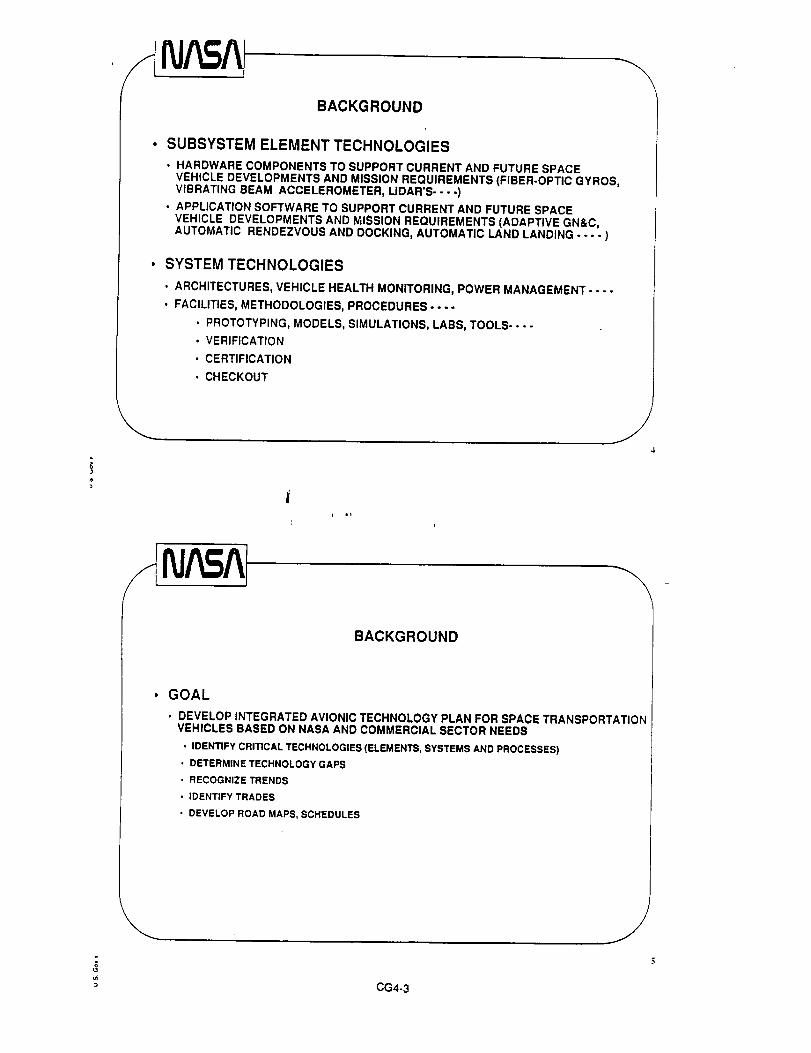
BACKGROUND
SUBSYSTEM ELEMENT TECHNOLOGIES
• HARDWARE COMPONENTS TO SUPPORT CURRENT AND FUTURE SPACEVEHICLE DEVELOPMENTS AND MISSION REQUIREMENTS (FIBER-OPTIC GYROS,VIBRATING BEAM ACCELEROMETER, LIDAR'S .... )
• APPLICATION SOFTWARE TO SUPPORT CURRENT AND FUTURE SPACEVEHICLE DEVELOPMENTS AND MISSION REQUIREMENTS (ADAPTIVE GN&C,AUTOMATIC RENDEZVOUS AND DOCKING, AUTOMATIC LAND LANDING .... )
SYSTEM TECHNOLOGIES
o ARCHITECTURES, VEHICLE HEALTH MONITORING, POWER MANAGEMENT ....
• FACILITIES, METHODOLOGIES, PROCEDURES ....
• PROTOTYPING, MODELS, SIMULATIONS, LABS, TOOLS ....
• VERIFICATION
• CERTIFICATION
• CHECKOUT
BACKGROUND
GOAL
• DEVELOP INTEGRATED AVIONIC TECHNOLOGY PLAN FOR SPACE TRANSPORTATIONVEHICLES BASED ON NASA AND COMMERCIAL SECTOR NEEDS
• IDENTIFY CRITICAL TECHNOLOGIES (ELEMENTS, SYSTEMS AND PROCESSES)
• DETERMINE TECHNOLOGY GAPS
• RECOGNIZE TRENDS
• IDENTIFY TRADES
• DEVELOP ROAD MAPS, SCHEDULES
CG4-3

CUSTOMER REQUIREMENTS
AVIONIC ARCHITECTURES
. MODULAR, STANDARDIZED, OPEN, SCALABLE, ROBUST, FAULT TOLERANT, MULTIVEHICLE
• MINIMIZE DDT&E COSTS
• SIGNIFICANTLY REDUCE OPERATIONS COST
SENSORS
• FOR THE MOST PART BEING DEVELOPED NEAR TERM OR EXIST TODAY
FAULT TOLERANT METHODOLOGIES
• SYSTEM ARCHITECTURES
• VOTING ALGORITHMS
• BUILT-IN TEST
• FAULT RECOVERY ( .... e.g., SPARES)
t ot
CUSTOMER REQUIREMENTS
DESIGN VERIFICATION AND VALIDATION METHODOLOGIES
• CONCEPTS, APPROACH, TOOLS, FACILITIES
. RAPID PROTOTYPING
, APPLICATION SOFTWARE ARCHITECTURES (e.g., CORE GN&C)
° AUTOMATED CODE GENERATION
• TESTING METHODS
SOFTWARE TECHNOLOGY
• REAL TIME DISTRIBUTED OPERATING SYSTEMS
• REDUNDANCY MANAGEMENT (FAULT DETECTION, ISOLATION, RECOVERY ANDRECONFIGURATION)
• MULTI PROCESSOR TASK SCHEDULING
• MISSION MANAGERS
AVIONICS PACKAGING TECHNOLOGIES ARE BEING DEVELOPED
/CG4-4

CUSTOMER REQUIREMENTS
POWER MANAGEMENT AND DISTRIBUTION TECHNOLOGIES AREBEING DEVELOPED
• NEW APPROACHES, ARCHITECTURES ARE PROPOSED
SOFTWARE APPLICATION TECHNOLOGIES
• ADAPTIVE GN&C
• AUTOMATIC RENDEZVOUS AND DOCKING
• AUTONOMOUS LANDING
GROUND/SPACE BASED CHECKOUT TECHNOLOGIES
• FAULT/TREND ANALYSIS
• ON-LINE BUILT IN TEST
• AUTONOMOUS CHECKOUT
CUSTOMER REQUIREMENTS
AVIONIC ARCHITECTURES
• CUSTOMIZED OPTIMIZED FOR SIZE, WEIGHT, POWER, PERFORMANCE VSOPEN MODULAR, SCALABLE, STANDARDIZED*
• DISTRIBUTED VS SEMI DISTRIBUTED
• FAULT DETECTION AND REDUNDANCY MANAGEMENT (HARDWARE VS SMARTSOFTWARE METHODS)
• PARTS (S LEVEL VS B LEVEL); SENSOR CONFIGURATIONS
* SENSOR AUGMENTATION
• SUN SENSORS, STAR TRACKERS VS GPS
DATA MANAGEMENT
• COMPUTER PROCESSOR OPTIONS, MEMORY, SIZE, ETC.
• LOCAL DATA BUS AND HIGH SPEED GLOBAL DATA BUS ISSUES
• I/O INTERFACES
• STANDARDS
* JIAWG, MASA, MPRAS & AIPS
CG4-5

CUSTOMER REQUIREMENTS(CONCLUDED)
POWER SOURCES
• BATTERY TYPES (SILVER ZINC, LITHIUM, ETC.)
PACKAGING
• AIRCRAFT STANDARDS, SPACE UNIQUE REQUIREMENTS
TESTABILITY
• OPERATIONAL COSTS AND FLEXIBILITY, AUTONOMOUS
H_
Integrated Technology
Plan Overview I
_ P._lmtlt • Hlouston, "rexm _
Navigation, Control & Aeronautics DIvlsion-
A. J. Bordano/EG [ 6/26/91
I
Avionics
Technology
Plan
CG4-_

Work Breakdown_,-_ Structure
Jc_nson_ Centw- Houston,Texas
Navigation, Control & Aeronautics Division
A. J. Bordano/EG / 6/26/91
l
FOCUSED TECHNOLOGYPROGRAMS
l I_[SPAC_SCE.cE 1 I _XP'ORA_ONI
I I[SPACEPLATFORMSJL OPEFIAT,ONS
Johnlm__¢:e Center• Houston,Tazas
Work BreakdownStructu re (co.tIn.,d)
Navigation, Control & Aeronautics Division -"
A. J. Bordano/EG I 6/26/91
I TRANSPORTA_ON t
... too.o,, Is"°"r'°'"_"°°I [_'o"no'o0',''0"'_,r_.n,.
._ ETO VehicleAvionics
.__ Low CostCommercial
Transport
q Autonomous /Landing
l_ Autonomous i
Rendezvous &Docking
= CG4-7

._ _ OenUlr - i'l_Jston, Teill=
Integrated TechnologyPlan Overview
Navigation, Control & Aeronautics Division
A.J. eord=mo/EG [ 612619 1L
Integrated Technology Plan Elements
5.2.7 ETO Vehicle Avionics
5.2.7.1 Avionics Architecture
5.2.7.2 Avionics Software
5.2.7.3 Vehicle Health Management
5.2.7.4 GN&C
5.2.7.5 Electrical Actuators
5.2.7.6 Landing/Recovery Systems
5.2.7.7 Power Management & Control
5.3.8 Transfer Vehicle Avionics
5.3.8.1 Avionics Architecture
5.3.8.2 Avionics Software
5.3.8.3 Vehicle Health Management
5.3.8.4 GN&C
5.3.8.5 Tether Control
5.3.8.6 Electrical Actuators
5.3.8.7 Power Management & Control
5.3.9 Autonomous Landing
5.3.10 Autonomous Rendezvous & Docking
, ¢i
Generic Outline
Johnson _ C4m_' - HOUltOn, Texas
Navigation, Control & Aeronautics Division
A. J. Bord=no/EG 6126191
Presentation will cover each identified Integrated TechnologyPlan Element and Subelement as follows
Overview (at the element level 5.X.X)
O Current & Related Programs (at the subelement level 5.×.X.X)
C3Proposed Technology Program (at the subelement level 5.X.X.X)
Program Benefits (at the subelement level 5.X.X.X)
Note: The Integrated Technology Plan Report for these elementsand subelements is over 100 pages. This presentation will be ahigh level summary of that report.
CG4-8

Johnlon _ Car+lit' • l,lOl,lllOrL, TIXaS
5.2.7 ETO Vehicle Avionics
Overview
Navigation, Control & Aeronautics Division
A. J. Bordsno/£G 6/20/_ 1
El The next generation of space transports will need to have increased mission safety, moreautonomy for reduced crew workload, and reduced operational costs.
• Avionics Architecture - for Increased avionics performance
• Avionics Software - addresses mission and safety features in software operating systems kernel
• Vehicle Health Management - for self diagnosing and self compensating Integrated systems
• Power Management and Control - for reliable, universal, modular, electrical power bus systems
• Guidance, Navigation, and Control - offers efficient computational algorithms and sensors,software tools to analyze complex body dynamics, and enhanced launch and land on demandprobability
• Electrical Actuation Systems - replaces hydraulic systems to enhance system reliability, reducedoperational cost
• Advanced Landing & Recovery Systems - for enhanced booster recovery and landing technology
Q The following advanced vehicles will all require some combination of these advancedtechnologies:
• HLLV, NLS, PLS, CTV, ACRV, ALS, and ELV's
O ETO and Transfer Vehicle Avionics technology development share common goals which Invitesand In fact, for cost effectiveness, dictates collaboration and interfacing between the two areas ofdevelopment.
NAm_A 5.2.7.1 ETO Vehicle Avionics:Avionics Architecture
Currant & Related Programs
o,o-c_n 1990 11991Io to_ _,in_p++o
• Flight Data System Open Architecture Requirements _" :
Definition & Methodology Development
Navigation, Control & AeronauticsDivision
A. J. Bordano/EG
1992 / 1993 |1994 1995oqn tn 1_ tnIn_lO_nt nl o pnln_n._
]
• FlightData System Open ArchitectureDocument• FlightData System System Profiles
• FlightData System Open ArchitecturePerformanceAnalysisand Trades
• FlightData System Open ArchitecturePrototypeDevelopment
• Network PerformanceModel
• Bare 386 Real-timeKernel Investigation
• Station Flight-to-GroundInteroperabilityEvaluation• Applications-to-RODBData Type Analysis
E
i
i
tc
i
II
r! Fp
t!
CG4-9
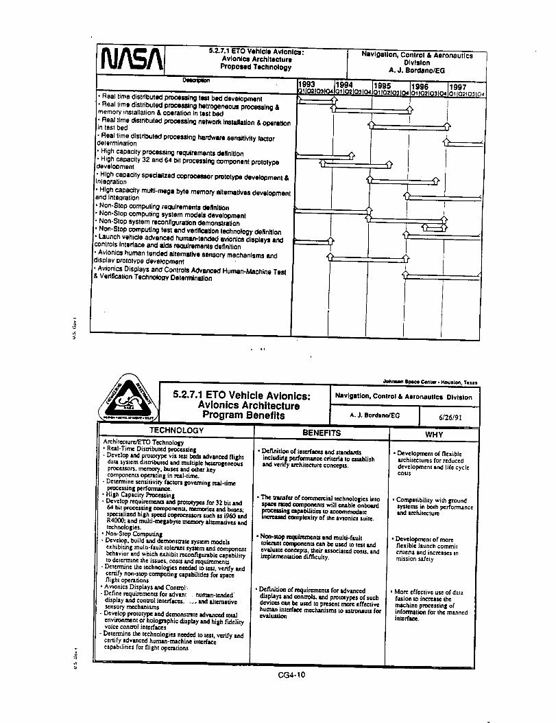
5.2.7.1 ETa Vehicle Avionics:
Avionics Architecture
Proposed Technology
om_peon
• Real time distributed procsuJng rut bed development• Real time distributed proceWng hatrogeneous processing &memow installation & o0eration In test bed
!. Rea t me d stribut_l processing network Instal ation & operationin test bed
• Real time distributed procss_ng horn*wars sensitivity Iw_'tordelerminstion
• High capacity processing requirement= definition
• High caD=getty32 anti 64 bit processing component prototyPedevelooment
• High capacity spedallzed ¢oorocsnor prototype development &inteoration
, High capadty multi-meg = byle memory alternatives devalopman!and Integration
• Non-Stop ¢ompuling requirement= Oe6nition• Non-Stop computing system models development• Non-Stop system reconfiguration demonstration
• Non-Stop computing test and verification technology definition
• Launch vehicle a_anced human-tsnded avio_cs _iSl_aY= andcontrols Interlace and aids reoulrements definition
• Avionics human tended alternative sensory mechanisms anddisplay crototYPe development
Avionics Displays and Controls Advanced Human-Machine Test& Verification Technology Determination
Navigation, Conlrol & AeronsuflcsDivision
A. J. Bordano/EG
1993 J1994 1995 11996 1199701Jo=losl0410_Io=los,04o_[02t031_10_fO=lC_104t0_102Ia3I0,
•
,q.I
t i¢,
I
I
, |1
Program Benefits
J4_vumn Space C4nte¢. Houston. Texas
I Navigation, Control & Aeroiautlcs DivisionA. J. Bordano/EG 6/26/91
5.2.7.1 ETa Vehicle Avionics:Avionics Architecture
TECHNOLOGY
Architecture./ETO TechnololD,• Re.zl-Tirne Disnibuted processing• Develop and prototype via ze.stbeds _lvanced flillhtdartsystemdismbutcd and mulupl¢hctcxolcncous
processors,memory, busesand other keycomponents operatinil in mat-time.
- Determine scnsilivicy rattan governing read-drncprocessing pcrfomum_
• High Czptci_/P'rocezzin|-Develop requiremutnand I_Dto_pes f_ 32 bitand
64 bit prcccssing ¢orrq_onenLz, memories and bus_s;specializedhigh_ coprtx:cssorssuchasi960andR4000; and muld-mepbyt¢ memory ah_'uadvesandtechnologies.
•Non-Stop Compufin_
-Develop, buitd and demonsm_te_P/s_m modelsexhibiting muir,-fault tolenMl[ system and componentbehavior Lnd which exhibit reconfilP_xablc capabilitym determine the issues,costs and mClUL'mnents
- Detcrm/ne the technologies needed to zest,verify andcertifynon-stopcomputingcapabilitiesfor _plcefligh!opera_ons
•AvionicsDisplaysand Conuol_
-Definercquin_mentsforadvanc •human-tendeddisplay and control interfaces, ._ and zd_=m|fiv¢senso_ mt.chanisms
- Develop prototype and demons_zlte advanced mudenvironment or holoi_nlphic display and high fideliz7voice conm0l inleffaces
- Det_'mine the technologies n(_:l_l to zest,verify andcertifyadvanced huma_.m_chin¢ Lnterfac¢capabilities for flight operations
BENEFITS
• Definition of inlerfaces and standardsincJudid| pe.ffonnancecliterJa 10es_btish
v¢fi_ryl*_hit¢¢t_r¢ concepts.
• The mmsf= of comn'_"cilJ te=hnolo|ies L,uospace razed componentswill enable onboasd
pmceuin| capabilities m accommodatemete.asedcomptextly of the avionics suite.
• No_-slop n=quimmcnls and mural-fault_olenm¢ c0mpom=n_can t_ u_.,d m test endevaduate concepts, the;,-associated costs,implen_ntadon dirficuhy.
• Definition or requirements for advanceddbplays and ¢onu'ols, and prototypes of suchdevices can be used to present more effectivehuwam inu:rfsc¢ mechanisr_toasmonauzsfor¢v=luation
WHY
• Development of flexiblearchitectures for reduceddevelopmentand lifecycleCOSTS
• Compatibilky with _'oundsystems in bolh perfonmancelind arehitectuR
•Developmenz ofmoreflexible launchcommitcriteria and increases inmission safety
• Mort effective use of datafusion w increase themachine processing ofinformation for the re=tunedint,-rf_.
CG4-10

W
• Space Applications GN&C Characteristics andMethods Defined
• Space Applications GN&C Family Generated andother Applications IdenlJfied
Space Applications Characteristics and MethodsDefined for additional Applications
Space Applications Combined Demonstration withTarget Avionics Platform
Applications-to-RODB Data Type Analysis
Matdx-X Simulation Development
5.2.7.2 ETO Vehlcle Avlonlcs: Navlgatlon, Control & AeronauticsAvlonlca Software Dlvlelon
Current & Related Programs A.J. Bordsno/EG
1990 1991 1992 1993 1994 1995 1996_1o=to_o4 010_0_o4 o11o_031o4 ol o=1o=o4 ol oz,lc=lo4 ol ozo=o4 ot o_o3 c_
i|
!
i
i I
iJ!,=
!ii
¢
!i
I
i
__A 5.2.7.2 ETO Vehlcle AvlonJcs:Avlonlca Software
Proposed Technology
ol
Real Time Distributed Processor Operating System and ServicesPrototype Development
Real 13me Distributed Network Operating System and ServicesPrototype Development
Real 13me Distributed Processing Computer and Network Integrationand Demonstration
Real time Distributed Processing Software Sensitivity FactorDetermination
High Capacity Processing Software Requkements DefinitionHigh Capacity 32 and 64 bit Processing Component Prototype Software
Development
• High Capacity Spedallzed Coprocessor Prototype SoftwareDevelopment & Integration
• High Capacity Multi-mega byte Memory Alternatives SoftwareDevelopment and Intemration
• Non-Slop Computing Software Requirements Definition• Non-Stop Computing Software Models Development• Non-Stop Software Reconfiguration Demonstration
• Non-Stop Computing Software Tests and Verification TechnologyDefinition
• Reusable Requirements and ArohitectureaJ Alternatives Definition
• CASE Tool Data Repository Filter Development• Reuseable Case Tool Component Development• Reusable Prototype Component Development and Dame• Launch Vehicle Advanced Human-Tended Avionics Displays andControls Interface and/_ds ReQuirements Definition
• Avionics Human-Tended Altemstive Sensory Mechanisms lind Display
Prototype Development
• Avionics Displays and Controls Advanced Human-Machine Test &Veritication Tachnolo(3y Determination
Navigation, Control & AeronauticsDivision
A. J. BordBno/EG
' "t
i iC,,
C_4-11

/_ I 5.2.7.2 ETO Vehicle Avionics:
/-__ I Avionics Software
__,,,_ Program Benefits
Jc_mNn_ ¢em_ • I.l_on, Toxn
NavigoUon, Control & AeronluUcs Division
6/26/91
WHY
A.J.Bordano/EG
TECHNOLOGY
Softwa,-e/'_rO Tnchnotogy• Real-dine Dis_ibutnd Procesdng- Develop prototype and damoosuale dislributed opemdng
systems and scr_cu that openue in mal.dme overdismbmed and muldple proeessoc¢
- Detenmne scnsid_ty flctors |ovemlng disu'ibuledoperating system end se_ces for z_d-tbne proce,_ngperformance.
* High Capaci_ Processing:Develop and prototype software fm 3ZK_4bit pmce4sors,specialized coprocessorssuch u 1960, R40(X) andmulti-megabyte memory aJm'nadv_l usocislM with massstorase disk for spaceqmdificd _Ls
• Non-Stop Computine- Develop and demons,rate soflwcre models exhibiting
multi-fault tolenmt system and component behavior lindreconfigtmlble capability with end without human conmols
- Determine Me teehnoloJp_ ncednd m lest, verify _KIcertify for flight operst_Mans
• Sohwa_e Reusability• Develop and build Computer Aided Sysm_ Engineering
(CASE) tool dam repository film1 f¢ ¢xctumgin| databetween different CASE tools for flight software.deveJopment
• Defleeand .'st reusablesoftwsrt featm1_forflightsoftware specific openedng sys=ms, re'vicesandapplicauons.
• Avionics Displays and Coomols• Develop and prototype knowledge l:mnd visual much,
voice and o_e_ sensorydLspisytaxi ¢oomd lids m supporthunum opcmdon of cpmpl_ s_
• Detcm'une the technololpcS needed m test, verify andcerlifyadvancedhurmm-muchine imerr_ software
BENEF_S
• Eslabiishes capability endpedfonmnce of operating systemsdistributed across multiple bu_:s.networks and vehicles
• Additional processing capability andperfmTmm_ for me o_-bo_rd damSYSU_m.
Delerminadon of requircn_nts andcomponents for fault r_isumtcomputing for evMuation ofconcepn, costs and impiementadoodifficult,/.
Establishesgeneric flight softwaresyslem el_llenL_ for reuse tctot4 ImyFoptm
• De_nrdnadm of effeedve humanimerface mechanisms as mecomple, xity lind amount oflefformadon inctta_
* Assessment of distributed
operating system and servicesrequirements
• Compatibility with IFoundsystemsinboth l_fformanceand mchiteetute
* More flexible launch commiucriteria and increases in missionsafety
• Lower development and life
chic cos= for the softwar_t:l_t
• Aids human dam comprehensionand response
5.2.7.4.1 ETO Vohlcl4; Avlonicl:
GN&C Algorithms
Current & Related Programs
Descnption
Autonomous Launch Vehicle Reconflgurstion
• Baseline requirements for current vehtc|es
Advanced GPS Navigation Techniques
• initial tests in aircraft
Autonomous Rendezvous/Docking GN&C
• Basetine requirements under 0evelopment
_Q98B 1989
Nsvlostion, Control & AoronsutlcsDivision
A. J. Bordsno/EG
1990
OliO21O31Q_
I I
1991 11992
otIO_0_1._,IO_JO_03!o,
: i
i ,
• i
CG4-'_2

5.2.7.4.1ETOVahlcleAvlonlcs:GN&CAJgorllhms
ProposedTechnologyNavigation,Conlrol&Aeronautics
Division --'-
A. J. BordanolEG
Description
Autonomous Launch Vehtc|e Reconflguration• Baseline requirernentll lor advanced vehicles. GN&C Simulation
• Algorithm development• Level C requirements development
Atmospheric Adapative Entry GN&C• Control concept development
• Environmental model development and Idmulatlon• Algorithm development end simulation
Numeric/AI Guidance Techniques
. AI concept development
• Numedc GuidenceJAI Integration• Detailed algorithm development and testing
Parallel Processing GN&C Methods
• GN&C processing concept development• Parallel GN&C architecture definition
• Algorithm development and simulationAdvanced GPS Navigation Techniques. Advanced requirements baseline
• Advanced model development
• Detailed aJgorithm development and testing
Autonomous Rendezvous/Docking GN&C. AR&D requirements development
• Algorithm concept development
• Algorithm testing and simulation
1993
QIIQ2103104
©
i !
' t? ,,?
_ , bt
J_m SIxDm Cdmlet - 14oult_ T*zn
5.2.7.4.1 ETO Vehicle Avionics: Navigation, Control & Aeronautics Division
A. J. Bordano/EG I 6/26/91I
WHY
GN&C AlgorithmsProgram Benefits
TECHNOLOGY
Autonomous Launch Vehicle GN&C Reconfiguradon• Identify new approachesto cuncm [zunc.hvehicle
algorithms and procc._cs that reduce or climinm¢rccumng engincenng analysis, ¢ompuu=rsimulationand FRR activities
Atmospheric Adapdve Eaa'y GN&C• Develop ,, GN&C Wstem that canL,'dvely control
heatrate., heat load or umq_xllJ_¢ while maJnudnin Ian accurate landin| I:mint
Numeric/At Guidance Techniques• Udlize artificial intelligence techniques to provide
assured convergence of numeric guida_¢¢ a.lgorithms
Pa.,_le]ProcessingGN&C Methods•Develop new approachesand |algorithmsthatcan b¢effectivelyusedon parallel processingcompute_
Advanced GPS Navipdon Techniques
•Developnew algorithmsand envi.-onn'cntmodels toimproveGP$ navig,.ionaccu.neyforETO vehicles
Autonomous Rendezvous/DockingGN&C• Develop ¢IgorithmconcepLsand approachesIo
_uppon autonomous rendezvous
BENEFITS
• R_'m'rinI launchoper_Jons costs can bel_lucndlhroulhlutoITidonIndimprovemeateto current GN&C|dgodthms and old.ions appro*chcs
• Improvedth¢nmd protection marlinu¢l_educedsensitivitytoatmospheric =andsys"m unc¢r_dnties
• Accu.,1,.,'.n::liable guidance soludoa=using ¢xlct =vimnmcnt models
• P_'fmm complex GN&C compumdonsonbo=rdusingpzrillel p_ing
• Accurate, autonomous sp,,'¢ vehiclenavigation
• R_un'lng costs n:ducnd throughautonmdonand improvements to currentGN&C Ilgo¢ithms and opestdonsapproaches
Elimination of manpowerintensive activities ts needed forthe r_xt generatio_tof launchvehiclP.J
Entry vehicle Ilndin I accuracythcmud prote¢=oe system
z_qu_nts m_ driven by theabiliP/of theGN&C system toadapt m dis_ amnosphericconditions
• Cun_nt numeric guidanceschemesare not usumd of
•'way,conveq_n_
,S_lucnd=lcomputationlimitstoday'sGN&C processing
• Changing cnvixonmcnudcondidons can delpade doppler_UJ_menL_
• Current AR&D op¢_dons rely
hnsvil_on IProundbe.sealmanualIxroce_tm=s

CONCLUDING REMARKS
TECHNOLOGY PLAN IS BASED ON "UNCONSTRAINED" INPUTS
PRIORITIES WILL BE ESTABLISHED BASED ON USER REQUIREMENTSAND TECHNOLOGY GAPS
HOWEVER, SOME THEMES HAVE CLEARLY EMERGED
• "TODAY'S AVIONICS SYSTEMS ARE CUSTOMIZED TO MAXIMIZE THE PERFORMANCEAND EFFICIENCY FOR A SPECIFIC VEHICLE APPLICATION. - - - • TODAY, IN THEAIRCRAFT INDUSTRY, A COMMON MODULE APPROACH IS BEING STANDARDIZED INORDER TO ACHIEVE HIGH PRODUCTION RATES WHICH NOT ONLY LOWERS COST BUTALLOWS COST TO BE AMORTIZED OVER MANY DIFFERENT AIRCRAFT WHICH CANUTILIZE THE SAME COMMON MODULES. THIS APPROACH PROVIDES THEFLEXIBILITY, SCALABILITY, AND LOW COST CHARACTERISTICS NOW BEING SOUGHTIN THE SPACE INDUSTRY. A COST EFFECTIVE APPROACH FOR THE SPACEINDUSTRY WOULD CONSIDER USING A MODULAR SYSTEM WITH COMMON BUILDINGBLOCKS SO THAT THE COST CAN BE SHARED OVER MANY VEHICLES ANDPROGRAMS."
CONCLUDING REMARKS
It
CRITICAL TECHNOLOGIES REQUIRED
. AVIONICS ARCHITECTURES (PROTOTYPING, SYSTEM TRADES, TEST, ETC.)WHICH ARE MODULAR, STANDARDIZED, OPEN AND HAVE THE ABILrI'Y TOCONFIGURE NEW OR REVISED SYSTEMS QUICKLY AND EFFICIENTLY WITHMINIMUM IMPACT ON COST AND SCHEDULE
• ADVANCED SOFTWAREFOR REDUNDANCY MANAGEMENT (FAULT DETECTION,ISOLATION, RECOVERY .... ) WHICH IS REUABLE, FLEXIBLE WITHOUT HIGHOVERHEAD
• ADVANCED SOFTWARE FOR DEVELOPMENT. VERIFICATION AND VALIDATION OFWHICH UTILIZE NEW TEST METHODS AND SIGNIFICANTLY REDUCE
LIFE CYCLE COSTS
• ADVANCED SOFTWARE FOR AUTONOMOUS CHECKOUT
• ADAPTIVE GUIDANCE. NAVI(_._TION AND CONTROL ALGORITHMS WHICHSUPPORT SAFE MISSION COMPLETION DURING NON NOMINAL CONDITIONS ANDREQUIRE MINIMUM GROUND SUPPORT
CG4-14
12

ROBERT L MCKEMIE
MSFC/EL43
JUNE 26, 1991
VEHICLE ilEALTil MANAGEMENT
• DEFINITION/SCOPE
•TECIINOLOGY NFFDS
• CURRENT ACTIVITIESAr:UTURE PLANS
• SUMMARY
C,(3S-I

VIIM OVERVIEW
DEFINITION - Vehicle Health Management: The ability m verify andmonitor vehicle health and to take appropriatecorrective actions necessary to maintain the vehicle in afunctional and/or sate statc.
- vehicle checkout- failure dctcction
- data processing- system rcconfiguration
ELEMENTS - Vehicle Health Management System includes:
Sensors
Data Collection and Processing Elements
Algorithms/Decision Models
Totally autonomous vehicle or containing ground basedelements.
Component/subsystem/system level elements
VHM OVERVIEW
FLIGHTCREW
SENSORS
DATAPROCESSING
II
S_YSTEM(S)_ ]
GROJNDSUPPORT
FLIGHT VEHICLE
SIMPLIFIED VHM SYSTEM
CG5-2

/: 1.147S-0-3G0
/ HM/AC Objectives/Requirements
- Hisfory
F Cumuia,ve Time
i" Anomallo=
t- Ovetsfressr- Environmonf" MT1BF
- Qual DEda- Test Dale
- Calibration DataEtc.
baa=• Continuity of learning from MFG
thin OPS and flight fo fllghf
• Commonality of HM/AC methods.tools, so,ware, efc:
• Slrtctured approach Io HM/AC
obJecltves/requtreme nls/trace ability
i Launch ICommit
t Proper Conllgurstion
All Systems In good heJfhLlKmch Redlines _ Current
Impending
EmergencyAnnundallon
L Unlt out of specCausol/ElfeclsPrognoll=
iFigure of Medl |
Monitor/Compare I
"Untlormlfy o! oDmmand(Reasonable. fast)
"Un_lormlfy of environ.
• I lislory el response
- PredlclKI response(Redllnes)
- Redundancy comparisons(Redllnes)
)',.Porlormance vedrmaflonl-*No4se" hislodes
I
appmpdate I_on
f Switch stdngs
Take componenls oll lineAbort/scrubEIc.
VIIM OVERVIEW
• VHM is not new, but must take advantage of new technologies.
]ncreascd Automation
- streamline vehicle checkout
- reduce ground/flight crew requirements
- Better Detection/Prediction Methods
enhance troubleshooting
rcdube hardware costs
- improve probability of mission success
reduce mainfenaqcc costs
- Improved Decision Making
- quicken response time
- provide consistent, rcliabtc decisions
- improve probability of mission success
- Improved Reliability
- reduce hardware costs
- improve probability of mission success
CG5-3

--OAET
ETO VEHICLE AVIONICS - (TRANS.) 1
TECHNOLOGY PERFORMANCE OBJECTIVES
PERFORMANCE
PARAMETER
VEHICLE HEALTH MANAGEMENT
COST
SAFETY/RELIABILITY
GROUND CHECKOUT
MISSION OPERATIONS
TECHNOLOGY INSERTION
FAULT DIAGNOSIS
APPX NEED DATE
CURRENT SOA
HIGH RECURRING
REDLINES
LABOR INTENSI VE/TIME CONSUMINGIi
MAN-IN-LOOP
REQUIRES REDESIGN
MANUAL
OBJECTIVE/REQUIREMENT
LOW RECURRING
SAFE SHUTDOWN/AUIOMATED SYSIEM
MANAGEMENT
INCREASED AUTOMATION/FASTER
PROCESSING
INCREASED AUTONOt'IY
PLUG-IN
AUTOtIATED
1996 (HLL V)
;c :,:
• L! '
Ii
l
[.!"L: '
•_, • ._..
No, I can'l slop Io consider anynew langled tools, ' 'rve gol a ball!e Io lighl!!
_X35-4

ADVANCED AVIONICS TECIINOLOGY REQUIREMENTS
VEIIICLE IIEALTII MANAGEMENT
OENERAL R EOUIREMENTS:
• DEVFJ.OP FLIGIIT AND GROUND AVIONICS SYSTEMS TllAT ENABLE AUTOMATI'.'I) VEIIICLE
CIIECKOUT AND MONITORING TO REDUCE LAUNCIi PROCESSING AND MISSION OI'F.RAllONS COSTS
ELEMENTS:
•INVESTIGATE SYSTEM ARC! IITECTtJRES TO DETERMINE OPTIMAL CONRGURATION 1'O SUPPORT
AUTOMATED VEHICLE IlEALTII MANAGEMENT. ARCIIITECTURE MUST BE SUPff)R'I1VE OF NEW
TECI1NOLOGY INTEGRATION AS rr BECOMES AVAILABLE WITI! A MINIMUM IMI'ACI' 1"O TI IE
FLIGIIT VEI IICt_ OR GROUND SYS'IF.M.
• INVESTIGATE POTENTIAL SENSOR TECI INOLOGIES TO ENABLE TIlE MONITORING OF CRITICAL
VEHICLE HEALTH PARAMETERS, BY SENSING CRrflCAL PARAME_RS EI,'FECI1VI_I.V, "GO/NO-GO"
DECISIONS, FAULT DETECTION, AND IIARDWARI'." IJFE PREDICTIONS CAN IIF. MADE IN A TIMFLY,
RELIABLE, AND CONSISTENT MANNER
• DEVELOP SYSTEMS ENGINEERING METI 1(3DOI.OGIES APPROACI IES AND T('K)I 21"O SUPPORT
DEVELOPMENT OF AN AUTOMATED I lEA LI'I I MANAGEMENT SYSTEM.
ADVANCED AVIONICS TI:t. IINOLOGY REQUIREMENTS
VEIIICLE IIEALTII MANAGEMENT
• DEVIF_J.OPSOFTWARE TECIINOI OGIF.._ (E.G., EXPERT SYSTEMS) TO ALLOW DELEGATION OF
DEL'3S|ON MAK/NG FROM CllECKOIfr PERSONNEL TO AUTOMATED I IEALTI ! MANAGEMENT SYSTEM
TIlls WILL ALLOW VEIIICLE PROCESSING Wflll A SMALLER ,TEST TEAM AND REI)UCF 1lIE CIIANCEOF I IUMAN 'ERROR.
*DEVELOP SIMULATION/DEMONSTRATION TECI INIOUF._ TO VERIFY PERFORMANCE OF TI IE
HEALTH MANAGEMENT SYSTEM AND TO ESTABI.ISII CONRDENCE IN AUTOMA1131) CI IECKOUT AND
CONTROL TOTAL CONFIDENCE IS REQUIRED PRIOR TO ITS FULL IMPLEMFN'rATION ON A R.IGI ITVI_I IICLE.
CG5-5

REpR E_I,'.NTATIVE TECllNf)I.O_,IR._
.SENSORS
-PLUME OPTICAL ANALYSIS
-ilYDROGEN LEAK D_CTION
-REMOTE OPTICAl. INSPECTION
-BIT
.SOFTWARE
-DATA TRENDING ALGORITIIMS
-NEURAL NETS
-PARITY SPACE ALGORITi IMS
-MODEL BASED DIAGNOSTICS
• SYSTEMS TOOLS
-COST/BENEFIT MODELLING
-DIGRAPI! TOOLS
-SYSTEM SIMULATION
VIIM ACTIVITIES/PI.ANNINC,
• ESTABLISIIED AS A SATWO (STRATEGIC AVIONICS TECIINOLOGY WORKING GROUP) PANEL
-MSFC/LeRC CO-CIIAIR
-EXTENSIVE NASA/INDUSTRY PARTICIPATION
• NASA/INDUSTRY MEETINO, SElYF., I_)0, INDIAI"LANTIC, FL
•VILM WORKSIlOP, LeRC, DEC., 1990 (SPACE BASED VEI IICLES)
• VHM WORKSIlOP, MSFG JUNE, 1991 (E-T-O LAUNCII SYSTEMS)
• DEVEIJ3P AND MAINTAIN VIIM TECIINOLOGY RF__UIRF.MENTS (ON-GOING)
•JSC/KSC WORKSIIOP (ORB/SSF), SEPT. 1991
•SENSOR WORKSIIOP (SSC), FALL, 1991
• SOFTWARE WORKSIIOP (ARC), SPRING, 1992
CG5-6

SUMMARY
• VHM PANEL ACTIVITIE._ PROVIDE NASA FOCUS FOR VHM TECHNOLOGY NEEDS/PLANS
-ESTABLISH JOINT NASA/INDUSTRY DIALOGUE
-IDENTIFY AND PRIORITIZE TECIINOLOGY N "EF.DS
-SUPPORT TECHNOLOGY DEVELOPMENT EFFORTS
-IDENTIFY/SUPPORT BRIDGING TASKS
•EFFORT WILL BE ON-GOING, LONG TERM ACTIVITY
• ENHANCED VIIM IS A KEY TO COST-EFFECTIVENESS AND MISSION SUCCESS OF FU'IURE
PROGRAMS
CG5-7


SPACECRAFT GUIDANCE RESEARCHAT LANGLEY
Douglas B. Price
Head, Spacecraft Controls Branch
Langley Research Center
June 26,1991
Briefing Contents
• Spacecraft Guidance Technology at LaRC
• Guidance Group Mission Statement
• Mission Statement Implementation
• Technical Program Summary
• Summary
CG6-1

SCB Guidance Group Mission
• To develop algorithmic technology forguidance of aeromaneuvering spacecraftsubject to uncertainties
• To identify and advocate technology forsybsystems needed by guidance algorithms;e.g. electro-optical sensors
• To actively Interchange technology andrequirements with Industry
How the Mission is Accomplished
• "Program requirements" are imposed bycharacteristics of a proposed mission/system,e.g. ALS
• Guidance group focusses inhouse andgrant-based academic research on programrequirements
• Resulting technology is shared with Industrialpartners via Technology Interchange Tasks
CG6-2

Technology Interchange Tasks
• Industrial researchers exercise anddemonstrate new technology withguidance group support
• "Lessons learned" and refined conceptsand requirements feed back to guidancegroup
• Guidance group works with academics toenhance university research focus
Research Implementation Flow
ProgramRequirements
Guidance ResearchProgram
I,.._I Technology Transfer to
v I Industry
I Technology and Reqs.from Industry
CG6-3

Technical Program Summary
• Issues
• Algorithmic technology activity
- goals
- guidance synthesis techniques
discrete time methods
perturbation methods
neural methods
- globally convergent algorithms
• Validation/modelling support
• Technology Interchange
Issues in AeromaneuveringSpacecraft Guidance
• Highly constrained trajectories
• Limited control authority/sluggish rotationalresponse
• Energy and/or constraint performancedominated by uncertain atmospheric effects
• Above issues are shared by:
- launch systems
- aerobrakes
- aerospace planes
CG6-4

Algorithmic Technology Goal:Direct Statistical Guidance Synthesis
(DSGS)• Statistics of process uncertainties are direct
inputs to a formal guidance synthesisalgorithm
- winds
- hardware failures
- plant uncertainties
• Benefits:
- design directly for probability ofachieving mission goals
- reduce design/testing cycles forguidance design
Steps Toward DSGS
1. Develop technology for reliable, accuratedeterministic optimal and suboptimalcontrol synthesis
2. Extend problem formulations to includerandom process statistics
3. a. Validate in test bed
b. Ensure that results have industrialapplicability
CG6-5

Trajectory Optimization Techniques
• Focus is on numerical solution of optimalcontrol necessary conditions in discrete time
o Inhouse, grant-based and contract work isImplemented in "Variational TrajectoryOptimization Tool Set" (VTOTS)
Iii_izati(}n Tool Set
Booster
CG6-6 ORIGINAL PAC_ !_
OF POOR QUALIT_

VTOTS Trajectory Prototyping Tool
GOAL:
• Fast, accurate solution of VariationalOptimal Control Boundary ValueProblems for:
- trajectory/configuration optimization
- guidance synthesis
• Very simple user interface: "OTIS-like"ease of use
VTOTS Participants
• NASA LaRC/Ga. Tech.
-joint development of algorithmic theory andproblem solution code
• McDonnell Douglas Space Systems Co.
- OTIS to VTOTS adaptation
- aeroheating capability
- automatic mesh generation issues
• Corneli University
- parallel Newton code for solving necessaryconditions
CG6-7

Impediments to "OTIS-Like"Ease of Use
• Derivation of necessary conditions
• State Inequality constraints
° Boundary conditions
° Numerical stability
° Lack of"OTIS-like"user community
i
mp
Derivation of Necessary Conditions
• Problem
-derive costate ODEs by differentiatingHamiltonlan
- solve nonlinear equations for controls
• Solution
- symbolic computation front end; usermerely inputs plant and cost function
- control equations represented as functionsto be zeroed (solved) at discrete time steps
CG6-8

State Inequality Constraints
• Problem
- pre-assume structure of active constraintarcs
- construct trajectory structure usinginternal boundary conditions andconditions on time derivatives of constraints
• Solution
- demonstrations and trades on severaldiscrete time problem representations, withconstraint necessary conditions representedby Mangasarian functions
no apriori imposition ofstructure on problem
Boundary Conditions
• Problem
-costate boundary conditions obtainedvia solution of nonsquare linear systemfor "undetermined multipliers"
• Solution
- state and costate necessary conditionsrepresented as an equivalent squarenonlinear system in states and costates
no analysis necessary forimplementation
CG6-9

Numerical Sensitivity
• Problem
- traditional methods for solution ofnecessary conditions highly nonconvergent
• Solution
-discrete time representations convergerobustly
-globally convergent methods underdevelopment for initial guesses
-analytic differentiation where possible;high-accuracy numerical differentiationtechniques else
Lack of OTIS-Like User Community
• Problem
-OTIS is an excellent package withstrong following
• Solution
- working with industrial partner to giveVTOTS
- similar "taste and feel" to OTIS- features for industrial utility
- pending successful VTOTS development,conduct an OTIS/VTOTS flyoff
- possibly seek co-sponsorshiparrangement with Air Force
CG6.10

Examples of Perturbations
Singular Perturbations
x = f(x,y,u)Ey = g(x,y,u)
Regular Plant Perturbations
X = f(x,u) + _,g(x,u)
Regular Trajectory Perturbations (Linearization)
x=x+Sx u=U+6u
It = f(_,U)8f 8f
Important Limitation of Discrete-TimeMethods
BANDWIDTH:
- frequency content of optimal trajectorylimited by discretization mesh density
- disturbances outside Nyquist frequencynot represented
these may be important forconstraint performance
CG6-11

Perturbation Methods
Exploit alternate plant representations forguidance synthesis
VTOTS:
Solve optimal control problem via moretractable trajectory representation
PERTURBATION METHODS:
Approximate optimal control problem byexpanding about solution of a convenient"neighboring" problem
Comments
• Guidance group supports research in allthree perturbation categories; Inhouseactivity in regular perturbations
• Regular perturbations are applicable tolaunch vehicles
• Regular perturbation schemes can beexploited to restore high-frequency effects(e.g. wind gusts) to guidance schemesbased on discrete-time optimal control
CG6-12

Candidate Hybrid Guidance Architecture
O,soro,o_ IControlLo-Pass ___
Plant
Continuous- time _._perturbationlogic
Hi-Pass
I
Neural Methods
• Current activity entirely contracted out
- 2 universities (joint activity)- 1 SBIR Phase II contract
• Both efforts stress use of neural net asrapid interpolation system, but
-different guidance architectures
- different training methods
CG6-13

Globally Convergent Algorithms
• Activity supports
- initial guess generation in VTOTS
-calculation of global minima in directoptimization problems
• Two approaches under investigation
-extensions to Chow-Yorke homotopytechniques
-"genetic" minimization algorithms
EQUATioN SOLVER
...... L
CG6-_4 ORt_i_L PAI_ IS
OF POOR QUALITY

Chow-Yorke Homotopy Techniques
• Extension of"continuation" method
-avoids singularities which can destroyprogress of calculations
- failure can occur when calculations become
smoothly unbounded
• Inhouse activity centers on procedures forpreserving boundedness
• FORTRAN implementations for generalfunctions and for VTOTS finite elementdiscretization
Genetic Algorithm
• Non-derivative procedure for functionalminimization
• At each iteration, a random population ofsolution candidates is modified by"reproduction, crossover and mutation"operations
• The-"fittest" - lowest cost - populationelements dominate "less fit" higher costelements
• We're not sure how it works, but itperforms impressively
CG6-15

Validation/Modelling Support
• Evaluation of candidate guidanceschemes via Monte Carlo simulation
• Development of high qualitysimulations of pertinent randomatmospheric phenomena for guidancevalidation
Stochastic Atmosphere Simulation
• Constructed and analyzed fidelity ofGausslan random model for synthetic KSCiaunchsite winds
• Procedure for controlling spatial frequencybandwidth of atmospheric variations in aninhouse trajectory simulationimplementation of the GRAM model
CG6-16

Monte Carlo Guidance Evaluations
Two studies underway
- performance evaluation of a suboptimalanalytic aerospace plane guidance rulefor ascent
- optimal control-based launchsite windprofiler requirements study for Shuttle
Generic Hypersonics (GH) Guidance& Optimization Program at Langley
Technical Focus:- Technology for trajectory and system
optimization and synthesis of suboptimalaerospace plane guidance laws
Approach:- Combined program of grant/contract/inhouse
research and development
- Exploit leveraging opportunities from otherLangley guidance activities
CG6-17

GH Guidance and Optimization Foci (I)
• Simplified procedures for solving variationaloptimal control problems
Finite element discretizations of optimaltrajectory boundary value problems (spinofffrom Advanced Launch System)
° Use of variational optimal control formulationsfor system configuration optimization
GH Guidance and Optimization Foci (11)
Motivations for emphasis on variational methods
• direct treatment of sensitivity functions
- useful for system optimization
• numerical schemes lead to solution ofequations, rather than search for minima
CG6-18

System Optimization Studies
• Comparison of static and variational optimalcontrol formulation of a system parameteroptimization problem
TASK: choose thrust angle for max performance
a) direct optimization of energy rate at points alonga fixed trajectory
b) optimal control of thrust angle for payload toorbit along identical trajectory
System Optimization Studies (11)
Exact calculation of state constraint sensitivityfunctions
• Constraint sensitivities obtained via quadratureof Lagrange multipliers on state constrainedtrajectory arcs
• Concept demonstration for dynamic pressureconstraint on fuel optimal ascent of LangleyAccelerator
• Results to be obtained via VariationalTrajectory Optimization Tool Set (VTOTS)
CG6-19

Other Technology InterchangeActivities
Active:
• Codevelopment of VTOTS with MDSS
Pending:
• Launch vehicle guidance exploitingregular perturbation of optimal returnfunction
• Aerobrake performance sensitivity toguidance and atmospheric knowledgeassumptions
Summary
• Guidance group develops technologies forguidance of aeromaneuvering spacecraft
• Guidance group's program focussesinhouse and academic resources onindustrial requirements
• Group implements technology interchangewith industry by constructing opportunitiesfor technology demonstration by industrialresearch groups
C,G6-20

Johnson •pete Center - Houston. Texas
r"u'onomous"'ndezvou.r.v,..,,on,Ou,.nc..A.on. O'v'.'onl_SA and Dock,ngTechnology Development Stephen Lamkin I June 26, 1991
Autonomous
Rendezvous & Docking
Technology Development
Status & Plans
Johnson $D1¢1 Center - Houston, Texs5
Autonomous Rendezvousand Docklng
Technology Development
NavigaUon, Guidance & Aeronautics Division,iml
Lamkln / June 26, 1991Stephen/
Why AR&D?
Lfadershin and America's Future in Snare: The SaID Ride Renort (Au_usl 198"/3
"_this initiative {M•rs Rover/Sample l_,tum) pblcel • premium on advanced technology _ to .uudmize thesdentlfl¢ return. It rlquim _ • Bib level oflopblldcatlon in •Ulolnldoa..."
Renort of the NASA 90-Day Sludv (Nov 1989_
"Element,, needin| technology development indude_ autonomous rends, vow and docklufr _[Which is] essentialto the cmt-elTective return of rumples from Mar= m part of the robotic missions."
Advisory Committee on the Future of the U.S. Suaee Pro_cam (December 1990)
"Among the more critical technology topics that must be pursued are _ automation and robotics, .. sensors._"
Renort of the Synthesis Groun. Executive Summary (May 1991)
"At Mars, we need Earth.independent operations, since round trip communications times will vary from seven to 40minules."
"Technology development is required in the following areas:
.. (6) Automated rendezvous and docking of large masses"
CG7-1

Autonomous Rendezvousand Docklng
Technology Development
Background
Johnson SPace Cen_er -Houstcn, Texas
i
Nlvlgstlon, Guidance & Aeronautics Division i
Stephen Lamkin I June 26, 1991
• I_xoloration Technoloav Proarsm AR&D fPreviouslv Pathfinder)- Identified Subtask Technology Requirements -- Developed Preliminary System Requirements
Docking Ground Demo (Sensor & Mechanism Hardware, GN&C) in FY91- AR&D Graphics Dame (Hardware Math Models, GN&C) in FY 90 & 91
• Conducted Rendezvous. Proximity Operations, & Dockina (RPOD) QualityFunction Deolovment (QFD)- Team Membe#s Include JSC Engineering & Operations Organizationsplus Industry(General Dynamics, Martin Marietta, Lockheed, McDonnellDouglas, TRW, Draper Labs)- Conducted Customer Needs Survey, both Programmatic (LMEPO,CTVPO) & Technological (Code R, JSC, MSFC)- Results will Support Development of NASA Strategic & Tactical Plans inthis Technology Area
t it
|ltferfadnl S _JtelNI• Power
• Propulsion• Thermal• Structure• Command & Cmltrol
Autonomous Rendezvousand Docking
Technology Development
,Johnson Space Center - HOUSton, Texas
Navigation, Guidance & Aeronautics Division
Stephen Lamkln I June 26, 1991m
!
AR&D System Con.c,e..p.,t.-.,2LOS
£• Monitoring
• RuSe lkmld
• Pe_leflmd
ContmCen_es
. Pore MECOto itatlorlaeplngGN&C "
_ - . petalled system supervision
I Gro.n l
GPS
DMIoe i
c ¢ i
kh I
I IIi I
11111
g! I
m !
X * Delete for Automated
CAqmbait7
Needed forAR&D Capability
CG7-2

Johnson 5p|ct CenCer - Hous¢on, Texas
Algorithms
- GN&C
• Supervisor
Sensors
- Rendezvous
• Radar
• Lader
- Prox Ops/Docklng
• LDS
• Imaging
Mechanisms
- Materials
- Passive
• Fluid Attenuators
• Magnetic Arran.- Active
• Controllers
• Control S/W
• Actuators
Autonomous Rendezvousand Docking
Technology Development
Nllvlglltlon, Guidance & Aeronautics Division
Stephen Lamkln ] June 26, 19911
Technology Readlness- Beyond LEO
Z ,_ I 2t 5 l En ineering] ConceptuaJ JB_rd
_.._on uemq Demo'ed I Demoeo I in S_
--Code R M
v
r
Comments
Basic Technologies arGBeing Developed.
Some ComponentTechnologies Have Be(
Tested InSpace
Autonomous Rendezvousand Docking
Technology Development
Johnson Spice Center - Houston, Texas
ge.,_henaUOn,Guidance & Aeronautics DiviSion
June 26, 1991
Issues & Trades
Functional Partitioning (Ground, Transfer Vehicle, SSF)
System Acceptability/Mission Success/Safety
Level of Independence
Modularity/Flexibility
Performance Requirements vs Mission Constraints (Sensors,Mechanisms, Control Effectors)
• . Fuel .. Plume Effects
• . Mechanism Intelligence .. Lighting
o. Sensor Handover Zones
o. Sensor Accuracy vs Mechanism Robustness
•o Environmental Effects (Thermal, Duration, Solar
Radiation)I1
iCG7-3

Autonomous Rendezvousand Docking
Technology Development
Milestones
F.,arth OrbII
Lunar Mi_dons
_n Missions
.'TY&
_92 _ lry94 PLgS
• Define Uler Requirements for AR&D
Technology
• Develop Graphics Slmulstlon forLunar/Mars Environment
• Conduct Mission S1udl•e & Analyse•
to Dsfin• System & PorformanseRequirements
• Develop & Evaluate AR&D SystemConcepts Suitable f_ UemRequirements
• Conduct Ground Demonstration• of
Brassbosrd Intsgmted System•& Individual F.Jements
• Conduct Flight F._perlments &Demonstrations In • RqNdlstlcEnvironment
limb
II
I
,Johnson SPa¢I CeNter - H0ul¢on. Texas
Navigation, Guidance & Aeronautics Division
Stephen Lamkln I June 26, 1991
!
IPI_&
LN, J,_r ' ram's Vd ,I,
e
F'Y2000
]3
i
Ca_7-4
ORIC_:_P,L P._,G'E :5
OF POOR QUALITY

INTEGRATED TECHNOLOGY PLAN
for the
CIVIL SPACE PROGRAM
AUTONOMOUS LANDING
Controls Committee Review
McLean, VA
June 26-27, 1991
Ken Baker
ER2/Intelligent Systems BranchAutomation & Robotics Division
Engineering Directorate
Johnson Space Center
OBJECTIVES
Amm_m_ul La_
Develop Technology to Enable Landing of Planetai-y Exploration Spacecraft:
• Safely in the Face of Surface Hazards Presented by Rough Terrain
• Accurately, i.e. Close to the Area of Mission Interest
• Autonomously, i.e. Without Real-Time Ground Control
BENEFITS
• Increased Probability of Safe Landing
• Reduced Structural Mass Needed to Make the Lander Robust Enough to Survive Touchdown
• Reduced Resources Needed to Survey Area of Mission Interest from Orbit Until Safe LandingSite Is Found
C.,G8-1

BASIC TECHNICAL APPROACH
Precision Landing
• Scenario:
Select, Prior to Deorbit, a Safe Landing Site Using High Resolution Orbital Imagery
-- During Descent, Maneuver Accurately Enough to Land Within That Site
Technology Need: Sensor, Algorithm & On-Board Computer to Provide Navigation
Measurements With Respect to the Surface of the Planet That Are:
Accurate and
D Robust to Variations in Operating Conditions Such As: Observing Geometry, Illumination
Geometry, etc,
On.Board Hazard Detection & Avoidance
• Scenario:
Aim the Lander At an Area That Is Expected A Priori to Contain Small, Safe Landing SitesWithin Its Maneuver Range
In Real-_me Detect a Safe Site & Maneuver to Land There
• Technology Need: Sensor, Algorithm & On-Board Computer That Provide Reliable Detection of
Landing Hazards Within the Current Terminal Maneuver Footprint
Iqt'_Nllnt't..dlrt._CtJl _ .1
tmm,J "rm_,_ P_
PATHFINDER STUDY RESULTS
Image Matching Navigation Using Visible Images (JpL, JSC)
• Template Matching of Optical Images (JPL):
Position Error on Simulated Mars Terrain: 0-50 Pixels I1
Possible Source of Errors;
Distortion of On-Board Image vs. Reference Due to Lander Trajectory Dispersion
Size and Resolution of Reference Image 12
• Hybrid Optical Image Matching (JSC):
Synthetic Estimation Filters 13.14 for Robust Detection of Landmarks
Taking Into Account Practical Limits of Real Optical Computing Devices
Being Tested on Images of Lab./Simulated Mars Terrain
Hazard Detection (JSCIARC)
• Sensor Surveys 15 That Included Laser Radar, Passive Computer Vision, Hybrid InterferometricImaging & SAR, Identified Imaging Laser Radar as the First Choice, But:
Arrays of GaAlAs Laser Diodes & Si Avalanche Photo-Diode Detectors with Pre-AmpsNeed Improvement
Best Performance from LADAR/Mars Terrain Simulations Is
Pr {Correct Detection of Hazard} ---0.95 --_ Pr {False Alarm} - 0.1216
_rC_8-2

WORK BREAKDOWN STRUCTURE
WBS CATEGORY ACTIVITIES
Systems Engineering
Pn:cision Landing
Hazard Detection &Avoidance
Determine Requirements
Develop Mats/lunar Surface Models
Identify Candidate Approaches & Associated Technology Development Needs
Collect Terrain Elevation Maps & Images for Earth Analogs of Mars TerrainClosed Loop Sim. of Precision Landing and of Hazard Detection & Avoidance
Select Most Promising Approaches for Development & Field Test of Prototypes
Develop & Evaluate Selected Techniques Such As:Track Orbital/Surface Beacon from Lander for Navigation Updates
Surface Image/Feature Matching for Navigation Updates Using Visible Images, Radar
Images or Digital Terrain Maps
Develop Prototype Instruments, Such As:Hybrid Optical Image Correlator
Imaging RadarOn-Board Digital Computer
Develop & Evaluate Selected Techniques Such As:Active Detection via Imaging Laser RadarPassive Computer Vision (Slope via Shape from Motion, Rock Detection via Shadows)
Hybrid Interferometric ImagingDevelop Prototype Instruments, Such As:
Imaging Laser Radar
Hybrid interferometric Imager
mt._xII/71$.al3._o41 Pt_ 9 ' ttau 2J. 1991
u,
,,.,j
5u_tnu_ Tw_,_te_, Phm_,a_l_ l Lar.dml
REFERENCES
1.
2.
3.
4.
5.
6.
7.
8.
9.
I0.
11.
Anon.,MRSR FlighzSystemRequirements,JetPlx_ulsionLaboratory/JohnsonSpaceCanter,Pasadena,CA/Houston,TX(June9,1989).
A.Friediander,MRSR MissionSuccessProbability,ScienceApplicationsInmmafionalCorp.,Schaumburg,Illinois(May23,1989).PresentationtoMRSR MDT/$DT Meeting
Anon.,"MRSR ProgramSystemRequirements,"650-2-200,JetPropulsionLaboratory/JohnsonSpaceCenter,Pasadena/Houston(June9,.1989).
Anon., MRSRFlight System Requirements, Jet Propulsion Laboratory/Johnson Space Center, Pasadena, CA/Houston,"IX(June 9, 1989).
IL Hain, Safe LandingArea Availability on the Surface of Mars, DraperLaboratory,Inc., Cambridge, MA (July 13, 1990)Presented at the Pathfinder/AutonomousLanderIntercemerWorkingGroupVideocon onSeptember 20, 1990
I'-LMuursky and N. L. C.rabiU, "V'drangSite Selection and Certification," NASA 5P--429, NASA Langley, Hampton,VA
(1981).
A. Engel, T. Bogner, T. Die.dam, and K. Spratlin,Autonomous Landing Study: Probability of Safe landing, DraperLaboratory, Cambridge, MA (July20, 1989). Briefingto MRSRMDT/SDT on July 20, 1989, NASA Conn'accNAS9.18147
T. J. Brand andS. R. Bauer, Deorbit/Entry Navigation Performance, DraperLaboratory,Cambridge, MA (September6,
1989). Presentationto MRSR Phase A MidtermReview, NASA Conlract NAS9-18147
J. R. Cart and L S. Sobek, "Digital Scene Matching Area Correlator(DSMAC')," pp. 36-.41in Image ProcessingforMissile Guidance, Proc. SPIE Vol.238, ed. T.E Weiner,(1980).
D. M. Prescott, Pershing 11 Weapon System Reuse Implementation Plan: Revision 1, PershingProject Manager's Office,Redstone Arsenal, Alabama (March 1990).
R. M. Vaughan, "Landmark Identification and Modelling for Ten'rain.FollowingNavigation," InterofficeMemorandum
314.8-772, Jet Propulsion Laboratory, Pasadena.CA (August 30, 1990).
CG8-3


CODE RC CONTROLS PROGRAM
OVERVIEW BRIEFING
FOR
CONTROLS COMMITTEE
OF THE
SPACE SYSTEMS & TECHNOLOGY ADVISORY COMMITTEE
CLAUDE R. KECKLER
NASA- LANGLEY RESEARCH CENTER
JUNE27,1991
OVERVIEW CONTENT
CONTROLS RESARCH, AND DEVELOPMENT OF ANALYTICAL TOOLS,SOFTWARE PACKAGES, AND HARDWARE COMPONENTS AT:
-ARC -GSFC -JPL
-JSC -LaRC -MSFC
CG9ol
GOALS
. Design & validate contmllem for rigid-txm_ contxol and vitralkm surxessio,
of the CSI Phase Zero Evolutk:,nary model.
APPROACH
• Apply advanced control design techniques:
- Linear-Quadratic-Gaussian (LQG)
- Dissipative
" Hw
- D_skaaUve_ L(_ (__,¢AC)
• Incorporate r_ bl _
• Evaluate via simulation and actuall testing,
. Compare results
I bt
SCHEMATIC OF CONTROL PROBLE
/e Suppress "pseudo" rigid body and. elaslk: motion in presence of disturb;
O Bes_ tie be based on imperfectkpm_d_elijm of the system
SAMPLER _._ DIGITALCONTROLLER_lJkC¢ldeeomemr_
CG9-2

CONTROLLER COMPARISONS
CLOSED-LOOP: EXPERIMENTAL TIME HISTORIES
ACCELERATION =8 (IN/S'2)
tOO
50
0
-5o
-Io0
.tSo
1130
5O
0
-$0
-IOO0 tB
,.dtll_hl_l!.,, ...........
"ql_ll,i. 'v.........
0 Ie,- 2_3 30
li.K'(,m¢)
• 1_4=lrBin
100
50
0
.50
-tO0
-150
im
5¢
©
.5o
-imi
IO 20 30
Imm(mc)
!0 20 30
CLOSED-LOOP DAMPING
EXPERIMENT VS ANALYSIS
LQG
DDC
Hoo
LQG/SD
EX P ER IMENT ANALYS I S
MODE 7
3%
8.5 %
1%
12%
MODE 8
3.5 %
14%
2%
16%
MODE 7
2.9 %
7.0%
1.6%
15 %
MODE 8
2.7 _,
23.9 %
2.4%
Y5%
CG9-3
ORIGIN_,L PAGE IS
OF POOR QUALITY

o_.
SPACECRAFT CONTROL LABORATORY
EXPERIMENT
(SCOLE) CONTROL LAWS
VIBRATION SUPPRESION USING THRUSTERS
RIGID BODY BANG-BANG SLEW ONLY
/lel_le 20 L_
BANHANG SLEW & VIBRATION SUPPRESIOf
"n_ (w_j
i |1
L.89- LO136

GRANTS
• MIT-
Develop faster photorefractive materials
* Johns Hopkins
Develop photorefractive thin films forlarge focal planes
* VPI
Analyse performance of interferometric sensorversus incoherent sensor for control of largereflector
Develop control laws for distributed sensingand processing
* UCLA
Develop optical processing for implementingcontrol
CG9-5
\
GF'_ L P_ "C_E"_OR_'_ " "
OF pOOR Q UAL'IT_r

CG9-6
OF PO_R QtJ._'_L!'I_"

OR|GIN,P,L P_G.E ISOF POOR QUALITY
CGg-7

BRIDGING 506 RTOP TECHNOLOGY TO THE USER COMMUNITY|l
....BRIDGE
iii .......
I I II
W
-- I I
NC/OC Pointing Performance ComparisonBased on March 30 SAGA Test Data
GYROHOLD
FINELOCK
COARSETRACK
EON EOD DAY NIGHT
NC OC NC OC
33.021.o18.311.1
12.8
9.9
29.3
26.1
31.124.215.310.5
ND
ND
77.324.328.5
ND
ND
NC OC
5.9(53) 13.0(42)
6.4(39) 11.3(45)
6.4(21) 9.4(42)
NC OC
4.1129 7.6(29)3.1q279.4q15'
ND 7.5(4)
5.0(4) 12.5(4)
ND • No Data, ( ) Duration of the Measurement in Minute=
All Numbers are RMS pointing errors in milli-aJ'cseconds (RSS o! V2 & V3)EO_ - END OF NIGHT, E0O - END OF DAY0C - ORIGINAL EONTROLLER(L.OCKHEED)
CG9-8 OR_r,i.e,L PAGE ISOF" POOR _ '",_ I..,,-,L.ITY
ACES III
PROGRAM ELEMENTS
H-INFINITY CONTROLLER DESIGN AND IMPLEMENTATION
BY OHIO UNIVERSITY INVESTIGATOR DR. DENNIS IRWIN
ONE-CAT CONTROLLER IMPLEMENTATION BY CONTROL
DYNAMICS COMPANY -- WORK COMPLETED AND FULLY
REPORTED IN PREVIOUS PRESENTATIONS
ADDITION OF THE BIDIRECTIONAL LINEAR THRUSTERS AND
THE ROLL TORQUE MOTORS TO THE ACES FACILITY
... THIS WORK PREEMPTED BY THE USE OF THE FACILITY
FOR THE...
• GUEST INVESTIGATOR PROGRAM
H-INFINITY CONTROLLER DESIGN, IMPLEMENTATION, & TEST
I
GOAL: DESIGN AND IMPLEMENT AN H,INFINITY CONTROLLER DESIGN ON THE
ACES FACILITY AND TEST IT FOR ROBUSTNESS AND PERFORMANCE
H-INFINITY DESIGN WAS PERFORMED; HOWEVER, THE PERFORMANCE WAS POOP.,BECAUSE OF THE REQUIREMENT FOR AN EXTREMELY RELIABLE SYSTEM MODEL
MODEL OF SUFFICIENT FIDELITY IS NOT AVAILABLE FOR ACES
EFFORT REFOCUSED ON REFINING MULTIVARIABLE MODELS (SYSTEM ID) ANDON PERFORMING CONTROLLER DESIGN USING EXPERIMENTAL FREQUENCYRESPONSE DATA
INNOVATIVE MODELING TECHNIQUE HAS BEEN DEVELOPED FOR MULTI-INPUT
MULTI-OUTPUT (MIMO) SYSTEMS
- - DETERMINANTAL MODELING
- - RESIDUE MATRIX IDENTIFICATION
CG9-9 ORIGINAL PAGE _S
OF POOR QUALITY
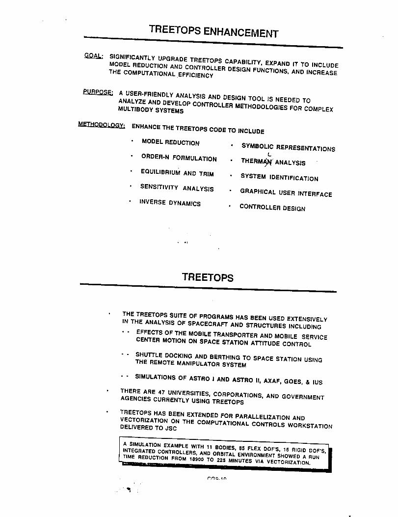
i
TREETOPS ENHANCEMENT
SIGNIFICANTLY UPGRADE TREETOPS CAPABILITY, EXPAND IT TO INCLUDE
MODEL REDUCTION AND CONTROLLER DESIGN FUNCTIONS, AND INCREASE
THE COMPUTATIONAL EFFICIENCY
PURPOSE: A USER-FRIENDLY ANALYSIS AND DESIGN TOOL IS NEEDED TO
ANALYZE AND DEVELOP CONTROLLER METHODOLOGIES FOR COMPLEX
MULTIBODY SYSTEMS
ENHANCE THETREETOPS CODE TOINCLUDE
• MODEL REDUCTION
• ORDER-N FORMULATION
• EQUILIBRIUM AND TRIM
• SENSITIVITY ANALYSIS
• INVERSE DYNAMICS
• SYMBOLIC REPRESENTATIONS
L
• THERMA)'I_" ANALYSIS
• SYSTEM IDENTIFICATION
• GRAPHICAL USER INTERFACE
• CONTROLLER DESIGN
TREETOPS
THE TREETOPS SUITE OF PROGRAMS HAS BEEN USED EXTENSIVELY
IN THE ANALYSIS OF SPACECRAFT ANDSTRUCTURES INCLUDING
-- EFFECTS OFTHE MOBILE TRANSPORTER AND MOBILE SERVICE
CENTER MOTION ON SPACE STATION ATTITUDE CONTROL
-- SHUTTLE DOCKING AND BERTHING TO SPACE STATION USING
THE REMOTE MANIPULATOR SYSTEM
- - SIMULATIONS OF ASTRO I AND ASTRO II, AXAF, GOES, & IUS
THERE ARE 47 UNIVERSITIES, CORPORATIONS, AND GOVERNMENT
AGENCIES CURRENTLY USING TREETOPS
TREETOPS HAS BEEN EXTENDED FOR PARALLELIZATION AND
VECTORIZATION ON THE COMPUTATIONAL CONTROLS WORKSTATION
DELIVERED TO JSC
ITA SIMULATION EXAMPLE WITH 11 BODIES, 85 FLEX DOF'S, 16 RIGID DOF*S, _11INTEGRATED CONTROLLERS, AND ORBITAL ENVIRONMENT SHOWED A RUN I
IME REDUCTION FROM 18900. TO .225.M..INUTES VIA VEC.TORIZATION. JL_ --I .... --; .......

CONTROL SYSTEM DESIGN ANALYSIS
CURRENT RESEARCH THRUSTS
- INteractive Controls Analysis (INCA) Program
- Windowed Observation of Relative Motion (WORM) Program
- Analysis and Simulation Tools for Engineering Controls (ASTEC)
- System Identification (FY90 Code RC)
- Robust Control of Flexible Structures (FY91 Code RC)
INCA OVERVIEW
- Comprehensive Control System Design Analysis Package
- Developed in Close Coordination with GSFC Controls Analysts
- For Large (100th Order) or Small Order Systems
- Runs on VAX Computers with VMS Operating System
- Version 3.13 Available Through COSMIC
C.,G9-11

WORM OVERVIEW
- 2 and 3 Dimensional Plotting Package
- INCA-derived Interface
- Used as Simulation and On-orbit Telemetry Output Deviceand as a Quick Means to Massage Data via Functional Relations
Runs on VAX Computers with VMS Operating Systems
- Version 2.32 Available Through COSMIC
ASTEC OVERVIEW
- Multi-platform Control System Design, Analysis and
Simulation Package
- Window/Mouse Environment
• Microsoft Windows 3.0 for PC
- Msclntosh
- X-Windows for Unix Systems
- Common Portable Math Library for all Versions
- C++ Programming Language
- INCA-based Algorithms
CG9-12

MULTIBODY APPLICATION TECHNOLOGY
Biomechanics
MolecularDynamics
Inverse DynamicsRolling/Sliding JointsGeneralized Joint Constraints
Non-linear StabilityVery Large Order Problems (100-500 DOF's)Clustering ConceptsGeneralized BodiesMassively Distributed Sensors/Actuators
Automotive
Human Factors
Robotics
Spacecraft
Real-time Man-in-the-Loop (50Hz goal)Real-time Hardware-in-the-LoopVisualization of Dynamic SystemsParallel Processing Load Apportionment
Man/Machine Interaction Dynamics & Performance
Intermittant Loop Closure with ImpactInertial Contact through SeatingGeared Joints
Modal SynthesisMethods for Noncollacation ProblemsDiscos callable by INCA for Nonlinear SimulationRecursive Linearization for Multibody SystemsDiscos Provided Linear Plant Model for INCA
JPL ADVANCED GN&CARCHITECTURE CONCEPTS
OBJECTIVE:
DEVELOP NEW GN&C SYSTEM ARCHITECTURES TO ENABLE GREATER
ON-BOARD AUTONOMOUS ROBUST CONTROL, STABILITY ANDPERFORMANCE
APPROACH:
• ADAPTIVECONTROLFORROBUSTSTABILITY/PERFORMANCEOFSPACECRAFTOPERATINGUNDERRAPIDCHANGINGCONFIGURATIONOR ENVIRONMENTCONDITIONS
IN-SPACE SYSTEM IDENTIFICATION FOR AUTONOMOUS ROBUSTCONTROL SYSTEM SELF-TUNING AND SYSTEM AND/OR ENVIRONMENTCHARACTERIZATION
REAL-TIME G&C ARCHITECTURE FOR ACCURATE FLIGHT PATH CONTROL
OF AEROMANEUVERING VEHICLES FOR ORBIT CAPTURE AND LANDINGAPPLICATIONS
EXPERIMENTALLY EVALUATE NEW CONTROL METHODOLOGIES ANDDEMONSTRATE THEM AT A LEVEL OF MATURITY FOR FLIGHTAPPLICATIONS
CGa _'_

• STABILIZATION & IDENTIFICATION
APPLICATION:
]N-SPACE SYSTEM IDENTIFICATION AND CONTROL TUNING TO ENABLERELIABLE PRECISE STABILIZATION OF FUTURE SPACECRAFT
MULTI-INSTRUMENT PLATFORMS
- LARGE ANTENNASMU LTI-APERTURE REFLECTORS
INTERFEROMETER 0 BSERVATORIES
DESCRIPTION OF EFFORT:
ADVANCES NEW IN-SPACE ID TECHNOLOGY THROUGH
- CONCEPTUAL INNOVATIONS- THEORETICAL DEVELOPMENT
- COMPUTER SIMULATION/VERIFICATION- PHYSICAL GROUND EXPERIMENTS
- APPLICATION METHODS AND SOFTWARE DELIVERABLES- FLIGHT EXPERIMENTS
i b!
STABILIZATION a IDENTIFICATION
PLANNED DEVELOPMENTS (FY'91-95)
• DEVELOP REDUCED VARIANCE SPECTRAL ESTIMATION OF THEPLANT TRANSFER FUNCTION
* DEVELOP THE ROBUSTNESS TO SYSTEM NOISE AND UNMODELEDPLANT DYNAMICS
• DEVELOP THE CAPABILITY TO HANDLE LARGE DATA SETS
• EXTEND THE CAPABILITY OF THE NEW ID METHODS TO LARGERMULTIVARIABLE SYSTEMS
DEVELOP THE FIRST GENERATION APPLICATION METHODS AND
SOFTWARE TOOLS FOR MULTIVARIABLE ID/ROBUST CONTROL
DESIGN, BUILD AND DEMONSTRATE A PROOF-OF-CONCEPT
NEURAL NET MIMO lID/ROBUST CONTROLLER
CF9-14

.J]_L ADAPTIVE POINTING AND TRACKING CONTROLI ,m I I I I ,, I I
APPLICATION:
ADAPTIVE CONTROLLERS ARE NEEDED FOR THE NEXT GENERATIONSPACE SYSTEMS WHICH HAVE ANY OR ALL OF THE FOLLOWING
ATTRIBUTES:
• HAVE SIGNIFICANT TIME-VARYING MASS PROPERTIES AND CHANGINGDISTURBANCE ENVIRONMENT
° CANNOT BE TESTED FULLY ON THE GROUND DUE TO LOGISTIC
CONSTR_NTS
• FLEXIBLE MODES AND/OR NON-COLLOCATED ACTUATOR/SENSORCONFIG URATIONS
• UNCERTAINTIES DUE TO LARGE ANGLE ARTICULATION, FAST SLEWOR OTHER NONLINEAR EFFECTS
JPL ADAPTIVE POINTING AND TRACKING CONTROL
DESCRIPTION OF EFFORT:
DEVELOP ON-BOARD STABLE MULTIVARIABLE ADAFrIVE REGULATIONAND TRACKING SYSTEM (SMARTS) CAPABILITY WHICH CAN CONTROL
SPACECRAFT WITH
• VERY HIGH ORDER OF STATE VARIABLES {E.G. 100'S)
• MANY SENSORS AND ACTUATORS
• UNCERTAIN AND/OR CHANGING SPACECRAFT DYNAMICSENVIRONMENT AND MISSION SCENARIOS
SMARTS I:
SM.AI"_q'SIf:
SMARTS Ill:
FOR SPACECRAFT WITH COLLOCATED SENSORS
AND ACTUATORS
FOR SPACECRAFT WITH SENSORS AND ACTUATORS
THAT CANNOT BE COLLOCATED
NEURAL BASED WITH LEARNING CAPABILITY
CG9-15

Jonnson 5pace Center- _louston. Texas
REVIEW OF CONTROLSTECHNOLOGY PROGRAM
NA_GATION, CONTROL AND AEROt_ILUTICS DIVlSIOfl
i,
JOHN W. SUNKEL [ NAY 29, 1991
TASK 1. CONTROL OF SPACECRAFT
ADVANCED CONTROL THEORY
DEVELOPMENT OF ROBUST CONTROL SYSTEM DESIGN
TECHNIQUES FOR DISTURBANCE REJECTION IN FLEXIBLE
SPACE STRUCTURES
DEVELOPMENT OF ADAPTIVE SYSTEM IDENTIFICATION AND
CONTROL TECHNIQUES BASED ON ARTIFICIAL NEURAL
NETWORKS.
!I
ADAPTIVE CONTROL
TESTING OF STATE SPACE SELF TUNING ADAPTIVE CONTROL
ON SPACE STATION ATTITUDE CONTROL SIMULATOR
REVIEW OF CONTROLSTECHNOLOGY PROGRAM
Jonnson 5pace Center- Houston, Texas
NJW1GATION, CONTROk, ,k_D AERONAUTICS DIVISION
i iI
] MAY 29, 1991JOHN W. SUNKELI
INFLIGHT EVALUATION OF THE STRUCTURAL INTEGRITY OFSPACECRAFT
DEMONSTRATE FREQUENCY BASED LOCALIZATION TO
SUPPORT STRUCTURAL HEALTH MONITORING OF FLEXIBLE
SPACECRAFT.
• ADVANCED RCS LOGIC FOR FLEXIBLE MULTI-BODY SPACE VEHICLES
- DEVELOP ADVANCED RCS LOGIC FOR FLEXIBLE MULTI-BODY
SPACECRAFT INCLUDING SPACE STATION DURING ORBITER
BERTHING
DEVELOP NEW RCS PHASE PLANE LOGIC TO ACCOMMODATE
SIGNIFICANT STRUCTURAL MODE INTERACTION
t_
CG9-16

Jonnson Space Center- HOustOn Texas
REVIEW OF CONTROLSTECHNOLOGY PROGRAM
NAVI_'t3ON, CONTROL_ AND AERONAUTICS DIVISIOH
JOHN W. SUNKEL I MAY29, 1991I
Hardware:
• The front end processor is a Silicon Graphics machine.
• The high speed parallel processing unit uses 4 Intei 860 boards.
• Intel 860 benchmark numbers:
SUN Data General SUN Silicon Graphics Intel
68020 88000 Sparc R3000/3010 80860
(1) 1.0 11.7 8.6 18.5 47.1
(2) 1.0 4.5 5.4 18.0 55.5
(1) Inversion of a 100x100 matrix
(2) Two-body dynamics simulation (approximately 10.8 MFLOPS)
REVIEW OF CONTROLSTECHNOLOGY PROGRAM
Jor_nson 5pace Center- HoustOt',, Texas
NAVIC._,_ON, CONTROL, AND AERONAUTICS DIVISION
JOHN W, SUNKEL MAY 29,1991
Performance:
• Space Station Example is for the assemble complete configuration thatincludes the following:
- 11 flexible bodies with flex modes up to 5Hz for 11 independentlyarticulating flexible body configuration
Total of 101 system degrees of freedom (85 flex and 16 rigid ) including corebody (9 modes), 2 Alpha booms (6 modes), and 8 solar panels (8 modeseach)
- SSF PDR RCS and CMG controllers running at 5 Hz
li
- Joint controllers for the solar panels
- Complete orbital environment
CG9-17
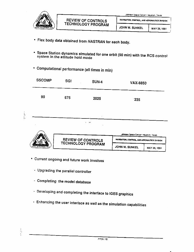
Jor_son 5Dace Center- Houston. Texas
REVIEW OF CONTROLSTECHNOLOGY PROGRAM
NAVIGATION, CONTROL, AND AERONAUTICS DIVISION
/ MAY29, 1991JOHN W. SUNKEL
• Flex body data obtained from NASTRAN for each body.
• Space Station dynamics simulated for one orbit (90 min) with the RCS controlsystem in the attitude hold mode
• Computational performance (all times in min)
SSCOMP SGI SUN-4 VAX-8850
90 675 2025 235
REVIEW OF CONTROLSTECHNOLOGY PROGRAM
Johnson 5oace Center- HouSton. Texas
NAVtGA'IION, CONTROL, lk_lO AEROttAUT_CS DIVISION
it
JOHN W. SUNKEL I MAY29, 1991I
• Current ongoing and future work involves
- Upgrading the parallel controller
Completing the model database
Developing and completing the interface to IGES graphics
- Enhancing the user interface as well as the simulation capabilities
m_O.l@

Ames Research Center
Overview iLC ......
Knowledge-based Control Technologies
• Adds enhanced robustness to RT fault management and control
• Provides graceful system degradation In fault-detected environmentwith minimum compromise to salety and reliability
• Provides automated monitoring of vehicle health and system statusincluding trend analysis
• Integrates symbolic knowledge with numeric (algorithmic) knowledge
HL/OAET 5-91 (LAH) J
f _J_A Ames Research Center
Elements of knowledge-based systems control technologies:
• Fault Diagnosis & Planning - - > Symbolic or model-based controllers
• Neural Nets & Fuzzy Control - - > Advanced Adaptive (Learning) Controls
• Model-based Reasoning - - • "Smart" Structures & Optimal Adaptive Controls
CG9-19
HL/OAET 5-91 (LAH) J

Fuzzy Logic Control
f
Automatic Train Control
- Has been In successfulapplication since July 1987 InSendal, Japan
- Uses rules of the form,
If speed of the train exceeds thespeed limit,
Then the maximum brake notchIs selected -
S/fSpace Shuttle attitude controM
- Under study at NASA JSC and NASAAmes, preliminary results showsignificant fuel savings over theconventional On-orbit digitalautopilot
- Uses rules of the form,
If attitude error Is Negative Mediumand attitude rate error is NegativeSmall,
Then Acceleration (converted to Jelon / oil command) is NegativeSmall
J \ s
SUMMARY
- COMPREHENSIVE, DIVERSIFIED RESEARCH PROGRAM
- OBJECTIVES AIMED AT RELEVANT NATIONAL GOALS
- SIGNIFICANT MILESTONES/PROGRESS BEING ACHIEVED
- RESOURCES LIMITING PACE OF ACHIEVEMENTS
CG9-20

OVERVIEW OF JPL ACTIVITIES IN TRANSPORTATION GUIDANCE, NAVIGATION, AND
CONTROL
LINCOLN J. WOOD
29 MAY 1991
JET PROPULSION LABORATORY
CALIFORNIA INSTITUTE OF TECHNOLOGY
PROGRAM ELEMENTS TO BE DISCUSSED
AEROMANEUVERING GUIDANCE, NAVIGATION, AND CONTROL (506-46-1 AND 506-
46-2)
PATHFINDER/ETP AEROBRAKING GN&C (591-42-3 AND 593-11-3)
PATHFINDER/ETP AUTONOMOUS LANDING (591-13-1 AND 591-13-2)
PATHFINDER/ETP AUTONOMOUS RENDEZVOUS AND DOCKING (591-21-2)
CGIO-1 1

O
FY89/gO PRODUCTS - SUMMARY
ONBOARD, REAL-TIME GUIDANCE AND CONTROL ALGORITHMS
0 SEVERAL NEW GUIDANCE ALGORITHMS FOR AEROASSISTED ORBIT TRANSFER,
INCLUDING SIMPLE, NEAR-OPTIMAL SCHEMES
0 PERTURBATION GUIDANCE ALGORITHMS WITH BOUNDED CONTROL
0 RE-ENTRY VEHICLE MODELING
0 ADAPTIVE AND NONADAPTIVE CONTROL ALGORITHM DEVELOPMENT
GUIDANCE AND NAVIGATION ALGORITHMS FOR AEROMANEUVERING ENTRY TO
LANDING
MARS APPROACH NAVIGATION ACCURACY ASSESSMENT
CHARACTERISTICS OF OPTIMAL AEROASSISTED TRAJECTORIES
0 MINIMUM-FUEL PROPULSIVE AND AEROASSISTED TRANSFERS BETWEEN
ARBITRARY ELLIPTICAL ORBITS
0 OPTIMAL AEROMANEUVERING PLANE CHANGE TRAJECTORIES USING MULTIPLE
ATMOSPHERIC PASSES
0 MAXIMUM AEROMANEUVERING ORBIT PLANE CHANGES SUBJECT TO HEATING
RATE CONSTRAINT
COMPARISON OF COST FUNCTIONS FOR AEROMANEUVERING TRAJECTORY
OPTIMIZATION PROBLEMS
0
LJW-2
0
PARTICIPANTS DURING FY89 AND FYgO
JPL
0
0
LINCOLN J. WOOD - TASK LEADER
WILLIAM M. McENEANEY/ALEX S. KONOPLIV/VIJAY ALWAR - GUIDANCE AND
NAVIGATION
DHEMETRIOS BOUSSALIS/ASIF ANMED/DON WANG - CONTROL SYSTEMS
UNIVERSITY OF MICHIGAN - PROFESSOR NGUYEN X. VINN (TRAJECTORY
OPTIMIZATION)
UNIVERSITY OF TEXAS AT AUSTIN - PROFESSORS DAVID G. HULL AND JASON
L. SPEYER (GUIDANCE)
RICE UNIVERSITY - PROFESSOR ANGELO MIELE (TRAJECTORY OPTIMIZATION
AND GUIDANCE)
0G10-2 LJW-3
FYB9 PRODUCTS: JPL IN-HOUSE - GUIDANCE AND NAVIGATION (506-46-2)
0 THREE NEW GUIDANCE ALGORITHMS DEVELOPED FOR AEROASSISTED ORBITAL
TRANSFER
0 BASED ONAPPROXIMATE SOLUTION OF OPTIMAL CONTROL PROBLEM - LOH'S
TERM ASSUMED DEPENDENT ON INDEPENDENT VARIABLE ONLY
0 APPLICABLE TO BOTH COPLANAR AND NON-COPLANAR ORBIT TRANSFERS
0 TWO ALGORITHMS MAXIMIZE EXIT SPEED FOR FIXED HEADING ANGLE,
ALTITUDE, AND FLIGHT PATH ANGLE AT EXIT - MOST USEFUL FOR PRE-
FLIGHT TRAJECTORY OPTIMIZATION
0 THIRD ALGORITHM MINIMIZES CONTROL EFFORT FOR FIXED VELOCITY,
HEADING ANGLE, ALTITUDE, AND FLIGHT PATH ANGLE AT EXIT
0 INTENDED FOR ONBOARD, REAL-TIME GUIDANCE
0 SIMPLE ENOUGH TO BE IMPLEMENTED ONBOARD
0 PERFORMED WELL IN PRESENCE OF ATMOSPHERIC MODELING ERRORS IN
PRELIMINARY TESTS
0 THREE UNIVERSITY CONTRACTS MONITORED
LJW-4
FY89 PRODUCTS: JPL IN-HOUSE - CONTROL SYSTEMS (506-46-i)
0 ADAPTIVE AND NONADAPTIVE CONTROL LAWS EVALUATED
0 FOR COPLANAR SKIP TRAJECTORY
0 USING BANK MODULATION FOR LIFT VECTOR CONTROL
0 USING AERODYNAMIC FORCES-AS WELL AS THRUSTERS FOR ROLL CONTROL
SIHULATION SOFTWARE EXPANDED TO INCLUDE OUT-OF-PLANE DYNAMICS
0 FOR CONTROL LAW EXPANSION TO INCLUDE BOTH ROLL AND PITCH AXIS
CONTROL
STUDY ON LEARNING AND DECISION-MAKING MODEL FOR HIGHER-LEVEL
ADAPTATION COMPLETED
0 METHODS TO COPE WITH GREATER RANGE OF UNCERTAINTY AND UNMODELED
CHANGES, ESPECIALLY IN AUTONOMOUS OPERATIONS
0G10-3 LJW-6

FY90 PRODUCTS:JPL IN-HOUSE - CONTROLSYSTEMS (506-46-1)
RE-ENTRY VEHICLE MODELING
0 DEVELOPED DYNAMIC AND KINEMATIC EQUATIONS OF MOTION FOR USE IN
DESIGN AND ANALYSIS OF CONTROL ALGORITHMS AND DEVELOPMENT OF
SIMULATION TOOLS
0 DERIVED AERODYNAMIC COEFFICIENTS AND STABILITY DERIVATIVES FOR
BICONIC AEROSHELL
0 DEVELOPED AEROMANEUVERING CONTROLS SIMULATION PROGRAM
CONTROL ALGORITHM DEVELOPMENT
0 CONDUCTED OPEN-LOOP SIMULATIONS TO EVALUATE VEHICLE AERODYNAMIC
PERFORMANCE AND STABILITY CHARACTERISTICS
0 CONDUCTED PRELIMINARY INVESTIGATION OF EFFECT OF LONGITUDINAL
NORMAL MODES OF OSCILLATION ON HYPERSONIC VEHICLE PERFORMANCE
EXTENDED PLANAR CONTROL LAWS TO 3-D VEHICLE DYNAMICS AND CONTROL
DEVELOPED CONTROL LAW FOR SUPPRESSION OF DOMINANT SHORT-PERIOD
NORMAL MODE OF OSCILLATION
OUALITATIVELY DEMONSTRATED PITCH OSCILLATION SUPPRESSION VIA
SIMULATION
0
0
LJW-7
FY89/90 PRODUCTS: aPL IN-HOUSE - MARS APPROACH NAVIGATION (591-42-3)
0 ACCURACY OF APPROACH NAVIGATION HAS MAJOR IMPACT ON ABILITY TO
PERFORM AEROCAPTURE AT MARS
0 ESTIMATES MADE OF TRAJECTORY KNOWLEDGE ACCURACY AT ENTRY INTERFACE,
ASSUMING VARIOUS DATA TYPES (FUNDED JOINTLY WITH JPL's EXPLORATION
INITIATIVE STUDIES OFFICE - CODES SL AND RZ)
O EARTH-BASED RADIO METRIC DATA ONLY (DOPPLER, RANGE, AND DELTA-
DOR AT ANTICIPATED ACCURACY LEVELS OF LATE 1990s)
0 EARTH-BASED PLUS VEHICLE-TO-VEHICLE RADIO METRIC DATA (MARS
ORBITER IN EITHER I/5-SOL OR AREOSYNCHRONOUS ORBIT)
0 EARTH-BASED RADIO DATA PLUS ONBOARD OPTICAL DATA (IMAGES OF
DEIHOS AND PHOBOS)
EARTH-BASED TRACKING OF BOTH APPROACH VEHICLE AND MARS ORBITER
0 (L/D =
0
REPRESENTATIVE ACCURACY REOUIREMENTS AT NOMINAL ENTRY TIME
0.7, V-INFINITY = 3.4 KM/S, 500-KM CIRCULAR TARGET ORBIT)
0 40 KM IN ALTITUDE
O 0.5 DEG IN FLIGHT PATH ANGLE
CG10-4LJ_-9
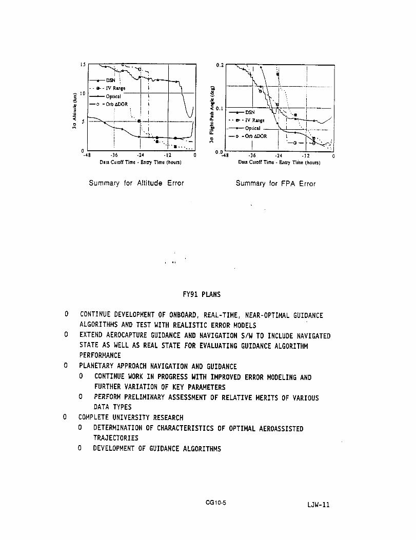
15
.<5
---o,,i.,-----[--\---- o - OTb_DOR I
_ ) T'm---...
0.2
_0.1
_r
0.O48
-_ Opticd -- ._"_l.-_._ _,.........
--o-O_b,_DO_ I IT--"_,",.
i ! -o-l Ji-48 -36 -24 -1.2 -36 -24 -12
Data Cutoff Time - Entry Time (hours) Data Cutoff Time - F..nn7 Time (hours)
Summary for Altitude Error Summary for FPA Error
FY91 PLANS
0 CONTINUE DEVELOPMENT OF ONBOARD, REAL-TIME, NEAR-OPTIMAL GUIDANCE
ALGORITHMS AND TEST WITH REALISTIC ERROR MODELS
0 EXTEND AEROCAPTURE GUIDANCE AND NAVIGATION S/W TO INCLUDE NAVIGATED
STATE AS WELL AS REAL STATE FOR EVALUATING GUIDANCE ALGORITHM
PERFORHANCE
0 PLANETARY APPROACH NAVIGATION AND GUIDANCE
0 CONTINUE WORK IN PROGRESS WITH IMPROVED ERROR MODELING AND
FURTHER VARIATION OF KEY PARAMETERS
0 PERFORM PRELIMINARY ASSESSMENT OF RELATIVE MERITS OF VARIOUS
DATA TYPES
0 COMPLETE UNIVERSITY RESEARCH
0 DETERMINATION OF CHARACTERISTICS OF OPTIMAL AEROASSISTED
TRAJECTORIES
0 DEVELOPMENT OF GUIDANCE ALGORITHMS
CG10-5 LJW-11

PLANS FOR FYg2 AND BEYOND (593-11-3)
FYg2
FY93
FY94
FY96
FYg7
FY98
IDENTIFY CANDIDATE GUIDANCE/ATMOSPHERIC SENSOR ARCHITECTURES
DEFINE NAVIGATION TECHNOLOGY
PERFORM CONCEPTUAL DEMONSTRATION OF GUIDANCE/NAVIGATION SYSTEM
BEGIN TESTBED VALIDATION OF LUNAR RETURN GN&C SYSTEM
DEFINE GN&C FOR FLIGHT TEST
BEGIN TESTBED VALIDATION OF GN&C SYSTEM FOR MARS
TASKS TO BE PERFORMED JOINTLY WITH I.ARC
LJW-13
CG10-6

GSFCJPLL|RCJSCMSFC
A NASA PROGRAM AUGMENTATION:
COMPUTATIONAL CONTROL
G. K. MAN
BRIEFING TO SSTAC - 6/27/91
AGENDA
• OBJECTIVE
• MOTIVATION
• CURRENT LIMITS
• NASA TOOL DEVELOPMENT EXPERTISE
• TECHNICAL APPROACH
• RECENT ACCOMPLISHMENTS
• FOREIGN CAPABILITIES
• TECHNOLOGY TRANSFER
• PLAN
• SUMMARY
CGl1-1
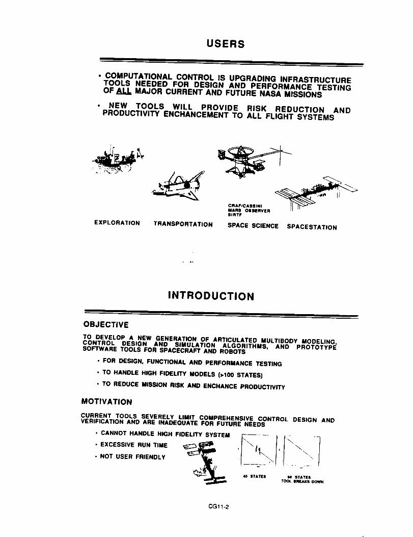
USERS
• COMPUTATIONAL CONTROL IS UPGRADING INFRASTRUCTURETOOLS NEEDED FOR DESIGN AND PERFORMANCE TESTINGOF ALL MAJOR CURRENT AND FUTURE NASA MISSIONS
• NEW TOOLS WILL PROVIDE RISK REDUCTION ANDPRODUCTIVITY ENCHANCEMENT TO ALL FLIGHT SYSTEMS
CRAFICASSINI
MARS OBSERVER
SlRTF
EXPLORATION TRANSPORTATION SPACE SCIENCE SPACESTATION
INTRODUCTION
OBJECTIVE
TO DEVELOP A NEW GENERATION OF ARTICULATED MULTIBODY MODELING,CONTROL DESIGN AND SIMULATION ALGORITHMS, AND PROTOTYPESOFTWARE TOOLS FOR SPACECRAFT AND ROBOTS
• FOR DESIGN, FUNCTIONAL AND PERFORMANCE TESTING
• TO HANDLE HIGH FIDELITY MODELS (2100 STATES)
• TO REDUCE MISSION RISK AND ENCHANCE PRODUCTIVITY
MOTIVATION
CURRENT TOOLS SEVERELY LIMIT COMPREHENSIVE CONTROL DESIGN ANDVERIFICATION ANO ARE INADEQUATE FOR FUTURE NEEDS
• CANNOT HANDLE HIGH FIDELITY SYSTEM
• EXCESSIVE RUN TIME
• NOT USER FRIENDLY
40 STATES 00 STATES
TOOt. BREAKS DOWN
CG 11-2

LIMITATION OF CURRENTTOOLS - GALILEO CASE STUDY
GALILEO SCAN PLATFORM POINTING CONTROL EXAMPLE
I=_XIEI.E ROTOR
I
SPACECRAFT CONFIGURATION HIGHLY EIMPUFiED MOOI[L |N DOF)
• CRAY X-MP CANNOT SIMULATE HIGHLY SIMPLIFIED GALILEO MODEL IN REAL-TIME (FALLS SHORT BY A FACTOR OF 10)
• CURRENT SIMULATION TECHNOLOGY LIMITS NASA'S ABILITY TO VERIFYSPACECRAFT DESIGN (REAL-TIME HARDWARE-IN-THE-LOOP TESTING ISLIMITED TO HIGHLY SIMPLIFIED RIGID BODY SIMULATIONS)
• NEED FOR NEW INFRASTRUCTURE TOOLS HAS REACHED A CRITICAL POINT.NEW TOOLS ARE NECESSARY TO SUPPORT CURRENT AND FUTURE AGENCYMISSIONS.
SPACECRAFT COMPUTATIONAL CONTROLTOOL DEVELOPMENT EXPERTISE
NASA TECHNICAL CONTRIBUTIONS
CONTROL DESIGN &ANALYSIS
CONTROL C
INCA
MATRIXx
SAMSON
,.I@lINCA
MULTIBODYSIMULATION
MBODY
mSCOS
SDEXACT
DISCOS
COMPUTER AIDEDENGINEERINGSHELL
IAC
ISM
IDEAS
CASCADE
CG11-3
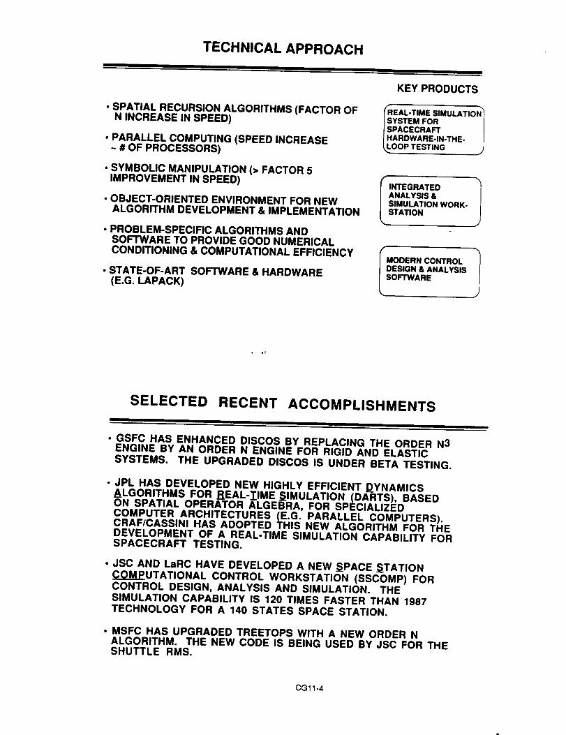
TECHNICAL APPROACH
• SPATIAL RECURSION ALGORITHMS (FACTOR OFN INCREASE IN SPEED)
• PARALLEL COMPUTING (SPEED INCREASE~ # OF PROCESSORS)
• SYMBOLIC MANIPULATION (> FACTOR 5IMPROVEMENT IN SPEED)
• OBJECT-ORIENTED ENVIRONMENT FOR NEWALGORITHM DEVELOPMENT & IMPLEMENTATION
• PROBLEM-SPECIFIC ALGORITHMS ANDSOFTWARE TO PROVIDE GOOD NUMERICALCONDITIONING & COMPUTATIONAL EFFICIENCY
• STATE-OF-ART SOFTWARE & HARDWARE(E.G. LAPACK)
KEY PRODUCTS
EAL-TIME SlMULATIoN'_
YSTEM FOR |PACECRAFT |ARDWARE-IN-THE- )
OOP TESTING .J
I INTEGRATED 1
ANALYSIS &SIMULATION WORK-STATION
ODERN CONTROL 1
ESIGN & ANALYSIS
OFTWARE
SELECTED RECENT ACCOMPLISHMENTS
I I
• GSFC HAS ENHANCED DISCOS BY REPLACING THE ORDER N3ENGINE BY AN ORDER N ENGINE FOR RIGID AND ELASTICSYSTEMS. THE UPGRADED DISCOS IS UNDER BETA TESTING.
• JPL HAS DEVELOPED NEW HIGHLY EFFICIENT DYNAMICSALGORITHMS FOR REAL-IIME SIMULATION (DARTS), BASEDON SPATIAL OPERATOR ALGEBRA, FOR SPECIALIZEDCOMPUTER ARCHITECTURES (E.G. PARALLEL COMPUTERS).CRAF/CASSlNI HAS ADOPTED THIS NEW ALGORITHM FOR THEDEVELOPMENT OF A REAL-TIME SIMULATION CAPABILITY FORSPACECRAFT TESTING.
• JSC AND LaRC HAVE DEVELOPED A NEW SPACE STATIONCOMPUTATIONAL CONTROL WORKSTATION (SSCOMP) FORCONTROL DESIGN, ANALYSIS AND SIMULATION. THESIMULATION CAPABILITY IS 120 TIMES FASTER THAN 1987TECHNOLOGY FOR A 140 STATES SPACE STATION.
• MSFC HAS UPGRADED TREETOPS WITH A NEW ORDER NALGORITHM. THE NEW CODE IS BEING USED BY JSC FOR THESHUTTLE RMS,
CG 11-4

IMPROVEMENT IN TECHNOLOGY FROM 1987
DEVELOPMENT OF ORDER N MULTIBODYSIMULATION CAPABILITY
RUN TIME
(COMPUTATIONAL
UNITS)
4,
35_
3'
25'
2'
_5
I
05
0
O 5 10 IS 20
FIDELITY (NUMBER Of" ELASTIC I_ODE$)
• ORDER N3. '87
1"7 ORDER N. 'gl
NEW/EMERGING CAPABILITIES
• ORDER-N DISCOSq • DARTS_/ • SSCOMP
• ORDER-N TREETOPS
FEATURES OF THE DARTS ALGORITHM
GENERAL EQUATIONS OF MOTION FOR A SPACECRAFT:
M(q)q+C(q,¢l) = T
CONVENTIONAL ALGORITHM
• REQUIRE ORDER N3 COMPUTATION* COMPUTE THE MASS MATRIX M• COMPUTE THE CORIOLIS AND
CENTRIFUGAL FORCES C
• SOLVE THE LINEAR EQUATION
MCI" =T-C FOR ¢1"
DARTS ALGORITHM
• REQUIRE ORDER N COMPUTATION• DOES NOT REQUIRE M, OR C OR
SOLVING THE LINEAR EQUATION• BASED UPON A SPATIAL OPERATOR
EXPRESSION FOR M "1
• RECURSIVELY COMPUTE el"
THE DARTS ALGORITHM
• REDUCES COMPUTATIONAL TIME (FROM CUBIC TO LINEAR COMPUTATIONALCOMPLEXITY)
• IS HIGHLY PARALLELIZABLE
• IS RECURSIVE AND MODULAR RESULTING IN REDUCED SOFTWARE COSTS
CGll-5

ARCHITECTURE OF THE DARTSALGORITHM
EXTERNAL AND ACTUATOR FORCES
11. RECURSION FROM EACH APPENDAGE
TOWARDS BUS ONE AT A TIME
_ EFFECTIVE FORCES
ON THE BUS
2. COMPUTE BUS ARTICULATED INERTIA
_ BUS ACCELERATION
3. RECURSION FROM BUS TOWARDS EACHOF THE APPENDAGES
1MODAL AND HINGE ACCELERATIONS q"
CRAF/CASSINI APPLICATION
|
REDUCES RUN TIME &HANDLES HIGH FIDELITY IN REAL-TIME
r-i i-1
• LIMITED TO 4 RIGID BODIESCONVENTIONAL ALGORITHM
• IkBODY SPACECRAFT• FLEXIBLE BUS, BOOMS & ANTENNA• PROPELLANT SLO_#I FOR 3 TANKS
• NEW CAPABILITY INCLUDES IMPORTANT AND DIFFICULT TO MODEL EFFECTSSUCH AS PROPELLANT SLOSH AND SPACECRAFT FLEXIBILITY (_UNABLE TO INCORPORATE) FOR SPACECRAFT TESTING
• ALLOWS ANSWERING THE SAME DESIGN QUESTION IN LESS THAN 1/10 OF THETIME
• A LARGE INCREASE IN MODEL FIDELITY IS OBTAINED WITH ONLY A SMALLINCREASE IN RUN TIME (THE RATE OF INCREASE OF RUNTIME IS REDUCED BYAN ORDER OF MAGNITUDE)
P-.,G11-6
FEATURES OF SSCOMP
. THE PROTOTYPE SSCOMP IS AN INTEGRATED SELF-CONTAINED CAD PLATFORM FOR SPACE STATION G,N & CANALYSIS
• ORDER-N ALGORITHM FOR FLEXIBLE MULTI-BODIES SPACECRAFT
° SYMBOLIC CODE GENERATOR• OBJECT ORIENTED INTERFACE
• 3-D SOLID MODELING FOR ANIMATION• SILICON GRAPHICS COMPUTER WITH 4 1-860 BOARDS
• COMPUTATIONAL PERFORMANCE FOR ONE (90 MIN) ORBITSIMULATION WITH RCS CONTROL SYSTEM IN ATTITUDE HOLDMODE (101 DEGREES OF FREEDOM)
SSCOMP ISGI ISUN-4 I VAX-885090(MIN) 675 2024 235
• SIGNIFICANCETHIS HIGH PERFORMANCE (A ORDER OF MAGNITUDEINCREASE IN SPEED) WORKSTATION IS THE MODEL FOR AFUTURE CONTROL ANALYSIS AND SIMULATION PLATFORM
FOREIGN CAPABILITY ISSUES
MAJOR FOREIGN MULTIBODY CAD PROGRAMS
NUBEMN-NEWEUL.
MEDYNA-
MESA VERDE-DECAP-
GERMANY SYM-GERMANY SPACAR-
GERMANY AUTODYN-
GERMANY PLEXUS-ITALY DAPHNE-
YUGOSLAVIANETHERLANDS
BELGIUM
FRANCEJAPAN
EMPHASIS- AUTOMOBILS, TRAINS, HELICOPTERS, SPORTS, ROBOTS,SPACECRAFT
• FOREIGN TECHNOLOGIES ARE ADVANCING AT A RAPID PACE:
• EUROPEANS ARE BUILDING POWERFUL TOOLS BASED ONU.S. TECHNOLOGY
• JAPAN IS ENTERING THE FIELD IN THE LAST 2 YEARS WITHAMBITIOUS GOALS
• U.S. IS UNIQUELY QUALIFIED TO MAINTAIN THE LEADERSHIPON HIGH P_RFORMANCE COMPUTIN(_ AND $1MULATION_ BYBUILDING ON OUR NEW HARDWARE AND SOFTWARETECHNOLOGIES
CG11-7

TECHNOLOGY TRANSFER
MULTIAGENCY, UNIVERSITY AND INDUSTRY WORKINGAND ADVISORY COMMITTEE TO FACILITATECOMMUNICATION
EARLY RELEASE OF TECHNOLOGY TO U.S. INDUSTRY
UNIVERSITY OF IOWA/NSF VERIFICATION LIBRARY FORREQUIREMENTS AND BENCHMARK PROBLEMS
ANNUAL TECHNOLOGY TRANSFER WORKSHOP/CONFERENCE TO DESEMINATE RESEARCH FINDINGS
PERFORMANCE OBJECTIVE & RESOURCE
KEY PARAMETERS PERFORMANCE OBJECTNES
• APPROXIMATE NEED DATE
• SYSTEM FIDELITY FOR
CONTROL DESIGN (# OFSTATES)
• RUN-TIME FOR REALTIMEHARDWARE-IN-THE-LOOPTESTING OF A 150 STATESSYSTEM (MSEC)
• USER FRIENDLINESS _rlME TOSETUP A 100 STATESSIMULATION)
10 100 400
100 10 510
DAYS HOURS MINUTES
i¢_=m
mm= I - = . _,m
rFUNDING REQUIREMENT FOR FY92 FY93 FY94 FY95 FY96ALL CENTERS ($K)
3600 3600 3600 3600 3600
CG11-8

LONG RANGE PLAN
TECHNOLOGY ROADMAP/SCHEDULE _ _
KEY PRODUCTS FY'90 FY'91 FY'92 FY'93 FY'94 FY'95 FY'96
USER RQT'S VERIFICATION _V
LIBRARY u._m.,
IMPROVEMENT OF SOA I
TREETOPS ENHANCEMENT I
NEW GENERATION SAN DEVELOP I
MBODY COMPONENT REP S/W__
REALTIME MBODY SIMULATION_
HIGH ORDER CONTROL SYN-THESIS AND ANAYSIS _
USER INTERFACE AND S/WINTEGRATION TECHNOLOGY
TRANSFER CONF
TECHNOLOGY TRANSFER CONF
w
o=mm. I1_
I
FmOw_ N
¢,_=m,
_v
I
;
t._lw E=lam,=m i
i!
,.. .,.,... i
m I=,=mml wlv_
v_
r,_un_ _ Ivw
m
_7o
'7
SUMMARY
• NEED FOR NEW GENERATION TOOLS HAS HIT CRITICAL
LEVEL
• NASA UNIQUELY QUALIFIED TO LEAD DEVELOPMENT OF
NEW TOOL
• NASA HAS MADE SIGNIFICANT TECHNICAL PROGRESS IN
KEY AREAS
• FAST ALGORITHMS FOR HARDWARE-IN-THE-LOOP
SIMULATION
• NEW ANALYSIS WORKSTATION
• PRELIMINARY PROGRAM PLAN DEFINED
• NASA READY FOR PROGRAM START NOW
CG11-9


Fiberoptic Rotation Sensors (FORS) :Technology Development and Transfer
Presentation to theSpace Science Technology Advisory Committee
Tysons Comer, VirginiaJune 27, 1991
Randy BsrtmanOptoelectronlc Sensor Systems and Technology Group
Guidance and Control SecUon (343).II=L
Overview
• Background Material
• What is FORS?• Why are we pursuing it?• Brief history of FORS development
• FORS Engineering Model Developmentand Technology Transfer
• Goal / Objectives / Assumptions• Schedule / Resources• Responsibilities
• Summary
CG12-1

What is FORS?
• All solid state optical gyro, based on the So.gnec effect
Unique (NASA patent #4,662,751) optical processingtechnique is used to convert gyro rotation rate into anoptical beat frequency
• Angular position is read by counting beats
Implemented through the use of
• Integrated optical circuits (AT&T Bell Labs, UTP)
• Polarization-maintaining, low loss optical fiber
• Semiconductor optical source, detectors operatingat a wavelength of 1.3 IjJrn
Note: Much of this technology is being developed byand for the telecommunications industry
FORS Principle of Operation - The Sagnac Effect
OBSOBS
OBS
Two light beams (CW and CCW)stlrt it the same time but race
In opposite dlrecUons iround awsveguide.
AS the phyelcst wavegulde rotates,the attached "observer" (068) andthe "start / finish line" (S/F) rotatewith it ...
... Giving an "unfair advantage" to CWIn the race for S/F: although It travelsno flmtar then CCW, CW arrives at S/Ffirst because of S/F'I roiaUon.
This "unfair advantage" manifests itself as a relative or "non-reciprocer' phase shift, 4) s , behveen the CW and
CCW beams, Suppose CW and CCW are Itghl beams of wavelength _. and the waveguide is an optical fiber of
length L wound on a sp¢ol of diameter D: then 4) s Is given by
4) s : 2x _d_c.Q
CG12-2
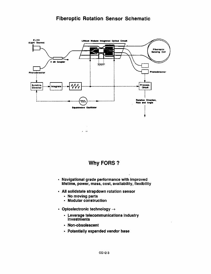
Fiberoptic Rotation Sensor Schematic
ELED
(Llghl Source)LllMum Niolllle Into0relld Opllcal Orc_lt
Flberopflc
Sensing Col!
Photodelictor
v
8quarewave Oscillator
3 dB Coupk;r _,
Photocletecior
io
*iooo
Rotation Direction,
Role ind Anll_
Why FORS ?
Navigational grade performance with improvedlifetime, power, mass, cost, availability, flexibility
All solidstate strapdown rotation sensor• No moving parts° Modular construction
Optoelectronic technology ->
• Leverage telecommunications industryinvestments
• Non-obsolescent
• Potentially expanded vendor base
CG 12-3

Inertial Sensors ComparisonDRIRU II vs. FORS
• CharacteristicsDRIRU II FORS (equiv. perf.)
Long term drift 0.003 deg/hr < 0.003 deg/hr (goal)Max. Input rate < 4 deg/s > 100 deg/s
• Operational fife 4 - 5 years > 12 years• Mass 17kg < 10 kg
Power (low rate) 15 W < 10Power (high rate) 23 W < 10 W
W
• Unit cost $ 2.1- $ 3.5 M $1.3 M
• Advantages of FORS end their Implications
• Greater lifetime: Allows extended (continuous) gyro operationduring mission. This simplifies mission planningand/or Increases operational flexibility.
• Reduced mass: Reduced launch cost (7 kg x $100 K/kg) and/orincreased science payload
Reduced power system cost (13 W x $ 80 K/W)and/or more power available for science payload
Reduced by $ 0.8 M - $ 2.2 M / IRU
• Reduced power:
• Lower unit cost:
iFORS Scaling and Design Flexibility
l• Increasing the diameter of the coil and/or the length of fiber
wound on It provides a strelghtforward means of ImwovlngFOR$ performance
• Take
• Coil dlamater D • 50 co,• Fiber length L • 10 km,• Wavelength _. • 1.3 pro, and• "NEPS" e = 1E -7 lad ;
• Then
• "NERR" .-, Q • 0.00025 deg/hr
• Conversely, FORS performance can be traded for reduced _._/..._size, mass and/or cost
• Take
• Co_ldiamater D•0cm,• Fiberiangth Lmlkm,• Wavelength _ • 1.3 l_n, end• "NEPS" e • 1E -6 red ;
• Then
• "NERR" --, _• 0.16 deg/hr
The modular nature of FOILS Irensiates Into great designflexlblllly, e.g. the aldllty to sspereto the peeolve, iow-rrmossensing coil(l) from the active electronioloptoelectronlccomponents.

FY78 FY79 FY80
FIRS Development - FY78 to FYg0
FY81 FY82 FY83 FY84 FYSSFY86 FY87 FY88IFY891FYgO.
Fcomponent lOC FORSdev. • lilt with CSDL
f,
"B-component tIC FORS Jdovetopmwnt • twit
_e_v lltIO ! tOCI
llopmwnl J
3-¢Omlla_aml 1IOC FIRS
AIIdll_r ITIstbed
,, ,
dovolopmonl
1¢ It,ll IntqrnlH 01111o11 Circuit (IOC)and compononUproceee development
FIRS i
JPL/CSDL Cooperative Development Effort
MOU / MOA between JPL and Charles Stark Draper Laboratoryfor cooperative development of JPL's FIRS technology
• Goal 1: Demonstrate FIRS technology readiness foruse on CRAF/Cassinl
• Goal 2: Develop and build first FIRS EM and flight units
• Goal 3: Transfer FIRS technology to American industry
CG12-5

Key JPL/CSDL Accomplishments 1989- 1991
• MOU / MOA between JPL / CSDL signed (8/89)
• JPL FORS technology transfer to CSDL
• Design, fabrication of 3 FORS brsssboerds
• Static & dynamic tests of brasaboarda
• IRU design / packaging studies initiated
• Successful FORS Technology Readiness Review (9/90)
• Additional funding commitments from Codes Q&R (-2/91)
• Preliminary review of FORS EM Development Plan (5/91)
CG12-6

JPLNASA-JPL
HIGH PERFORMANCE INERTIAL REFERENCE UNIT(FORS)
\ 6YRO
X PLANEGYRI)
FORS: Demonstrated "nav-grade" performance
Time interval
0.5 sec
100 sec
2 hours
Pointin0 error rea.* (30)_
2.3 _ad
43 lu'ad
0.5 mrad
Pointing error act. (3oL
0.15 prad
3.1 lxrad
0.5 mrad **
* CRAF / Cassini requirement
** Corresponds to rotation rate of 0.005°/hr
CG12-7

FORS Engineering Model Development Program
Goal
• Make available to NASA usersaspace-qualifiableFiberoptic Rotation Sensor (FOR_ Inertial Reference Unit (IRU)
A FORS IRU will possess navigational grade performanceand will offer significant advantages over current IRUs :
• Improved lifetime
• Lower power
• Lower mass
• Lower cost
• Greater design flexibility
CG12-8

Objectives
Develop, demonstrate engineering model* EORS four-axis IRU
• Develop, demonstrate FORS single-axis EM
• Develop, demonstrate flight-packaged, high reliabilityFORS optoelectronic components and interconnects
• Fabricate additional single-axis FORS units• Conduct reliability, acceptance & long-term trend tests
Transfer FORS technology to industry
• Multi-vendor base
Engineering model: Full flight functionality.Capable of being environmentally tested to flight environments.Same hardware, assembly techniques as flight hardware.Flight or nearly flight form factor.
Assumptions
Time frame
• Four-axis IRU EM by end of FY93
• Earliest users: AXAF, SIRTF, EOS, HST
Funding
• Total cost: $10.7 M over FY91-93
• Expected sources: NASA Codes Q, R, S(?), CSDL CSR
One Integrated program with two major activity areas
• FORS Instrument development ("system design")
• FORS optoelectronic component development
Cooperative effort with Industry: JPL-led, industry-performed
• FORS instrument: JPL / Charles Stark Draper Lab
• FORS components: JPL / vendors
t" r:. _ ,') <3

FORS Engineering Model Development Program
FY91 FY92 FY93
FORE INSTRUMENT DEVELOPMENT
I,FORE oFrOELECTRONIC COMPONENTS:
ADD. SINGLE AXIS FORE UNITS (ll) ($1.NI) |
Pill, teal; ule In IRU, II'end tests IJ I I I
4-AXI8 FORS IRU (EI.?M) i
Oe_dgn, ta, tnt and anaiyel8 II
FORS ACCEPT. t TREND TESTS
($1.OM)
I I I
FORS Engineering Model Development
Responsibilities Matrix
JPL CSDL Vendors
FORSInstrumentDevelopment
FORSOptoelectronlcComponentDevelopment
• Overall management
• Mission I IRU re(is.
• Reliability I QA stale.
• Environmental test
• Full tech Support
• F|liure modes
• Component reqe.
• Reliability / QA stds.
• Function / Env. tests
• Tech support
• Instrument design• Instrument feb
• Functlonml test
• Tech Irlmmfer
• Tech / mgL eupporl
• Component reqs.• Functional tests
• 8pacific components
indirect
Indirect
• Failure modes
• Camp. pv- _evelop.
• ReliabilP _A Itds.
• Functior_ _v. tests
• Mgt. support
CG12-I0

Summary
Why FORS?
• O.01-O.O01°/hr gyro for space applications
• Reduced mass, power, cost and Increased lifetime,reliability, design flexibility vs. spinning mass gyros
Successful development program to date
• Brassboards designed, fabricated and under test
• Demonstrated O.O05°/hr performance
Proceeding with development of Engineering Models
• JPL-led, Industry-performed
• Single-axis FORS EM by end of FY92
Model for technology transfer
• Multi-code funding (Codes R,Q,S)
• Joint effort with Industry (CSDL, others)
CG12-11


PRECISION
INSTRUMENT & TELESCOPE
POINTING
SCIENCE_
OBSERVATION SYSTEMS PROGRAM AREA
OFTHE
SPACE SCIENCETECHNOLOGYPROGRAM
F. Hadaegh
F. Tollvar
Integrated Technology Plan for the Civil Space Program ReviewTysons Corner, Virginia, June 24-28, lggl
PRECI_ON INSTRUME_ & TELESCOPE POIN_NG
AGENDA
TECHNOLOGY NEEDS
- APPLICATION THRUSTS- INSTRUMENT POINTING- TELESCOPES AND INTERFEROMETERS
INTEGRATED TECHNOLOGY DEVELOPMENT PLAN
- CHALLENGES- APPROACH- DEVELOPMENT PROGRAM- SCHEDULE
• RECOMMENDATIONS
CG13-1
AFT gl_2J +

PRECISION INSTRUMENT & TELESCOPE POINTING
TECHNOLOGY NEEDSI I
m
THE PRECISION INSTRUMENT & TELESCOPE POINTING PROGRAMWILL PROVIDE THE 1-2 ORDER-OF-MAGNITUDE INCREASE INPRECISION POINTING CAPABILITY (IE, POINTING CONTROL,STABILITY, AND KNOWLEDGE) REQUIRED BY NUMEROUS OSSAFUTURE MISSIONS
ASTROPHYSICS MISSION
• Moderate Optical Interfarornetar (MOI)• Imaging Intarlarometer (11)• Next Generation Space Telescope (ST-NG)• Large Deployable Reflector (LDR)• Lunar Based Interferometers and Segmented Reflectors
• EARTH SCIENCE MISSIONS
• Advanced LEO/GEO Instruments
• SOLAR SYSTEM EXPLORATION
• Toward Other Planetary Systems (TOPS 1 & 2)
t 16
AFT _IO624 ?A
PRECISION INSTRUMENT & TELESCOPE POINTING
APPLICATION THRUSTSI
PRECISIONINSTRUMENT &
TELESCOPEPOINTING
SCIENCEINSTRUMENT
POINTING
TELESCOPE/INTERFEROMETER
POINTING
• ADVANCED LEO/GEO EARTHOBSERVATIONS
• SOLAR SYSTEM EXPLORATIONPOINTING
• ADVANCED ASTROPHYSICS MISSIONS- SPACE INTERFEROMETERS- NG-ST
- SUBMM-IR (SMMM, LDR)
CG13-2AFT _)10624 ?

PRECISION INSTRUMENT & TELESCOPE POINTING
POINTING NEEDS vs SOA
a)t_
t_
of-oO
=,-
°_o
1000 t00
100
lO
1
0.1
0.01
0.001
Instrument Pointing ]
Landsat Voyager * Galileo Eos0 -- Landsat D *
UARS CRAF/ v",',,,t
Cassini """@,0 Next Gen
"/,".,._EO Plat
%,Copernicus
GeoIUE C NEEDS _ Plat
0
_0 HST Req.
I Telescope Pointing I fO""/////_ Adv ST
MOI/FFT 0
• I I I1970 1985 2000 Year
10
1
0.1
0.01
0.001
0.00oi
AFT,'C E B 9106243
t,J
u
>,
m
p.
c-"6o.
INSTRUMENTPOINTING NEEDS
CG13-3

® Electro-Optics/Cryogenics Division
Eos POLAR ORBITING PLATFORM
10310_44007
HPSP
SHA
LGA 1
RPWS
ANTENNA (4)
12 BAY
ELECTRONICS
TANK
MAG BOOM
TURNTABLE
SHADE
HIGH PRECISIONSCAN PLATFORM
HUYGENS _ PRESS.TITANPROBE TANK(2)
CA1 G(3)TARGET
REACTION
WHEEL(4)
LGA2
PROBE RELAY ANTENNA MAIN ENGINE
CASSINI DEPLOYED REAR TRIMETRIC VIEW
CG13-4
rHRUSTER
POD(4)
Y X
Z
! I 3090

PRECISION INSTRUMENT & TELESCOPE POINTING
GEOPLAT
,; **no P_l iN|
i&|WlUl
f t _ Iml*_ m / _41_m tMi i_ UlJII
F ! _mN lall I ll.I lam_mM
e ! i w_ ¢M|JI Iii
o * ma _amaLW t.II a|._ s_
ra**,=J,*r
0 r k/m_v IMq0m= .Pi I IP I .M* m
M ¢ ilaw _ hi44i JI Nl.r N
p,n I M,W _ iikr JU _1.1' M
P II I q[inlql _ II111.11 •
M qn Clmlo4 Ni I1.11 4P N
p ii _Mimm llll4111 ik=tlm=,**4=
i Is cdlw_m ¢a,i. g_.. 14nlo|r oilol l_m_m_ I.lu Ill* m
i1 &ls_=qlmPIkliP _ _ JI IIJP N
line
• INSTRUMENTS LARGER & MORE MASSIVE
• MORE STRINGENT POINTING REO!JREMENTS• MORE ELECTRICALPOWER &COOLING AREA
• STILL HIGH DATA RATES
Oea_w _ IM|
i
&|w|mm
/ 441o& m14_ i.I t.| i,
mm IM
Ii|li|Jm tN
IIIIII1_ tl
m m
_m mm
mm lum_
mm mm
_a| lS|i_|
_m mm
n
Instrumenl Changes As of Oct. 4, 1989
MICflOWAVE RADIOMETER(IIraIIlUMEIIT I)
PRECISION INSTRUMENT & TELESCOPE POINTING
INSTRUMENT POINTING TECHNOLOGY REQUIREMENTS vs SeA
PIXEL SIZE
POINTING
TECHNOLOGY
CONTROL 3 o
KNOWLEDGE 3 o
STABILITY 3 o
DATASET
COREGISTRATION
EOS, C/C STATE-OF-ART (1991I ADVANCED EOS/GEOPLAT/SOLAR SYS EXPL NEEDS
LEO (1 ilrr_e¢ • 3 m) LEO (1 ircae¢ • 3 m) GEe (1 ircae¢ • 160m)
30 m 3 m 30 m
Core AttJtucle/l"av Reference
Static Structure
Fixed Instrument Mounts
Pra-launch Alignment
Limited Autonomy/Servicing
108 arcsec
50 arcsec
100 arcsec/lO0 sac
10 arcsecJ1 sec
1 arcsec/O.01 sac
Via Ground Processing
of Image Data1
Registration to T Pixel Best Case
Precision Trackers & GPS
Active Structure Alignment
Precision Pointing and Isolation
On-board Attitude Transfer System
Extensive Autonomy
10 arcsec 1 arcsec
5 arcsec 0.5 arcsec
10 arcsec/100 sac I arcsec/lO0 sec
I arcsec/1 sac 0.1 arcsec,/1 sac
O1 arcsec/0.01 ssc 0.01 arcsec/0.01 sec
Via On-board Borasight Alignment Sensing
Autonomous Registration to _- Pixel
CG13-5 AFT/CEB 91062.1 5

PRECISION INSTRUMENT & TELESCOPE POINTING
INSTRUMENT POINTING STABILITYSTATE-OF-THE-ART vs FUTURE NEEDS
t_ 100
o3
=-
_... 10
"-' tO
r-.D
(.-
0_. 0.1
= Attitude Control
XIE
/
0.01
0.0001 0.001 0.01 0.1 I. 10.
Frequency (Hz)
1"Sudley, J and JR. Schulman. " In-Orbit Measurements ot LANDSAT-4 Thematic
Mapper Dynamic Disturbances," NASA,/Gocldard Space Flight Center.
& SWIRLS
Stability Stale-of-Art
t_
100. 1000.
AFTtCEB 9_0624 ¢:
TELESCOPE & INTERFEROMETERPOINTING NEEDS
CG13-6

NEXT CENTURY ASTROPHYSICS PROGRAM: CANDIDATEMAJOR AND MODERATE MISSIONS: 1995 - 2020
( FOR TECHNOLOGY PLANNING PURPOSES)
ULTRA VIOLET
VISIBLE
1990 1995 2000 2005 2010 2015 2020
RELATIVITY
I IINFRARED
I I
SUBMILLIMETEF I I
I I
RADIO I I
I I
X-RAY I I
I I
GAMMA RAY I I
I I
PNS _28R1
. ., • I 1 I I / I I I I I I I I I
I I I I I ,..,.I,=f,._inm,,J=._,n;I I I I I I
I m_,;_a 1 I I I I I I I I I I I I I I l I
' I I I I I I I I I Ii • im _'l=l:* I_l I.'i=: r;! ii i _I_-I "J._q=1-,, =_q _.lfl ,lil :=
I I I I I II I I I I I
I I I I I I
I [
iATIII_Ol2 I_il_lil:lI
iI1_ ' 'IIIIII
J, II
IIIIIIIII
IIIIIIItl
IIIIIIIll
II1[_IIIIII
IIIIII
IIIIII
IIII
III
II
IIIII1{_I
IIIIIIII
IIIIIIII
III
III
III
III I
I I I I I I I I I I I
--_ =I_IASECJO I =OPEFIATIONS 1,;:
ANGULAR RESOLUTION VERSUS WAVELENGTHFOR FUTURE ASTRONOMICAL SPACE INSTRUMENTS
0.000't
0.001
0.01V)
<[v
Z 0.1O
=
O
_ t
Z< 10
EAR1 I OLtFJIVA .TI(_I( ._ &PACEOBSERVATIONI! i Li : '-" /
-! _ .... I IrrERFmnoueT=_J " i
o i ° T-_--_ -
I ' ' , "=,=i.........!.....................i...........1...... .*
100m lOm Im lOcm lcm Imm 100_ I0_. 11J f
VLF RADIO MICROWAVE I $UBMM FAR In IR ViS u
WAVELENGTH
CG13-'7

CG13-8

PRECISION INSTRUMENT & TELESCOPE POINTING
MISSION REQUIREMENTS
MISSION
NGST
LTT
LAGOS
MOI
SIRTF
LDR
NGOVLBI
FIT
SMMM
FUSE
SMMI
LI
HXlF
TECHNOLOGY APERTURE/ POINTING POINTING MISSION
FREEZE DATE BASELINE ACCURACY STABILITY DURATION
2004 10 m 50 mad 5 nrad 15 YEARS
1995 2 m TBD TBD 10 YEARS
2009 10 7 km TBD 0.3 prad 10 YEARS
1997 20 m 0.3 nra¢l 0.3 nrad 5 YEARS
1994 1 m 300 nrad 300 nrld 3 YEARS
2006 20 m 250 nrad 125 nrad 10 YEARS
2000 TBD 500 nrad 500 nrad 10 YEARS
1997 30 m 0.8 nrad 0.8 nrad 10 YEARS
1996 3.65 m 2.5 mrad 1.25 mrad 2 YEARS
1993 1 m 2.5 nrad 1.25 nrad 4 YEARS
2006 1 km TBD TBD 10 YEARS
2003 10 km TBD TBD 10 YEARS
1999 TBD TBD TBD 10 YEARS
AFT/GES 9t 0624-8
PRECISION INSTRUMENT & TELESCOPE POINTING
INTEGRATED TECHNOLOGY DEVELOPMENT PLAN
CG13-9

PRECISION INSTRUMENT & TELESCOPE POINTING
TECHNOLOGY CHALLENGES
INCREASE SPACE BASED TELESCOPE POINTING CAPABILITYBY 1-ORDER OF MAGNITUDE BEYOND HST
• 10 FOLD IMPROVEMENT IN PRECISION/STABILITY• PROVIDE NEW CAPABILITIES FOR LINE-OF-SIGHT TRASFER,
TELESCOPE NODDING AND MULTI-APERTURE POINTING
INCREASE REMOTE SENSING INSTRUMENT POINTINGCAPABILITY BY 2-ORDERS OF MAGNITUDE
• 100 FOLD IMPROVEMENT IN PRECISION/STABILITY
• INCREASE SCIENCE THROUGHPUT AND OPERATIONAL
EFFICIENCY VIA ON-BOARD POINTING AUTOMATION
• PROVIDE NEW CAPABILITIES IN TARGET REFERENCED
POINTING, ATTITUDE TRANSFER AND INSTRUMENTCO-BORESIGHTING
INCREASE RELIABILITY, LIFETIME AND EFFICIENCY OFPOINTING COMPONENTS
• 3 FOLD IMPROVEMENT IN RELIABILITY AND LIFE OF CRITICAL
COMPONENTS
AFT 9}0_524 '_
PRECISION INSTRUMENT & TELESCOPE POINTING
TECHNOLOGY DEVELOPMENT APPROAC
FOCUSED DEVELOPMENT OF
- ADVANCED POINTING SYSTEM ARCHITECTURE
- SENSOR AND ACTUATOR BRASSBOARDS
- HARDWARE AND SOFTWARE TESTBED DEMONSTRATIONS
• COORDINATE PLANNING AND IMPLEMENTATION WITH OSSAADVANCED DEVELOPMENT
CG13.10

PRECISION INSTRUMENT & TELESCOPE POINTING
TECHNOLOGY DEVELOPMENT PROGRAM
INSTRUMENTS TELESCOPES
• SENSORS/ACTUATORS
- EXTENDED IMAGE/FEATURE TRACKERS• AUTONOMOUS STAR TRACKERS- ATTITUDE TRANSFER SYSTEMS- REACTIONLESS ACTUATORS- IMAGE MOTION COMPENSATION
• TARGET-REFERENCED POINTING TRACKING
- EARTH/FEATURE BASED• EARTH COORDINATES (LONGITUDE/lATITUDE)
• INSTRUMENT CO-BORESIGHTING
• MULTIPLE INSTRUMENTS• MULTI-SPECTRAL IMAGE REGISTRATION
• AUTONOMOUS POINTING EXECUTIVE
• HIGH LEVEL COMMAND CAPASIUTY- ON-BOARD SEQUENCE GENERATION/EXECUTION• SEOUENCE INTERRUPT/RESTART
• SYSTEMS DESIGN, ANALYSIS, INTEGRATION, ANDTESTING
. ADVANCED OPTICAL SENSORS
• FINE GUIDANCE SENSORS• AUTONOMOUS STAR TRACKERS- WNE-OF-SIGHT TRANSFER SYSTEMS
• INERTIAL ROTATION SENSORS/IRU'S
• PRECISION ACTUATORS
- SUPERQUIET HIGH-CAPACITY REACTIONWHEELS ANO CONTROL MOMENT GYROS
- MOMENTUM COMPENSATED POINTING/SEAM STEERING DEVICES
• SYSTEM DESIGN, ANALYSIS, INTEGRATION ANDTESTING
AFT 9T062_ '_
PRECISION INSTRUMENT & TELESCOPE POINTING
SCHEDULEI I
FISCAL YEAR 93 94 95 96 97 98 99 00 01 02 03 04 05 06
_NSTRUMENT _ _ _MISSIONFREEZE EOS-A1 EOS-A2 GEOPLAT EOS-A3
SYSTEMS & CONCEPTS
SENSORS&
ACTUATORS
AUTONOMOUS
POINTING
TELESCOPE
MISSION FREEZE
SYSTEMS &CONCEPTS
OPTICALSENSORS
GYROS/IRU'S
ACTUATORS
lARCH.& SYS DEFJTB_XP. DEV,.p =p -
[ ATT.TRANS.SYS ] i REACTIONLESSACT,jAUTONOMOUSTRACKER I DISTRIB.SENSING IFEATURE TRACKING DEM_ MUTI-SPECTRAL TRACKERS I
TARGET REFERENCED FqDINTING ICO-BORESIGHT DEVICE I
AUTONOMOUS POINTINO OEMO. I JkUTON POINT. SYS EXEC DEV
SMMM MOI LDR
I SMMM ARCH & SYS OEF _ MOt t LDR,, _
I FINE GUtD SENSORS I
I L,NE-OF-S_HTTRANSFER I
HIgH RI:I IARI_ ITYR_ICRF_RMANt_f: _YR_
NGST SMMI
NGST _ SMM_ l
FINE GUID SENSORS I
_.ONG BASEL!NE AT TRANS J
iHIGHCAPACITYRI_A_TIONWHEEL,C_-ONTROLMOMENTGYROS I
I_I_AM STeaRIN G A_T_ATORS I
BUDGET($M) -THISPLAN 5.0 70 g0 11.0 ...............
CG13-11

PRECISION INSTRUMENT & TELESCOPE POINTING
RECOMMENDATIONS
• PROCEED WITH PROGRAM PLANNING AT 10-12 MS/YEAR LEVEL
CONTINUE STRONG COORDINATION BETWEEN TECHNOLOGYDEVELOPERS AND USERS
- FORM INTERCENTER TECHNOLOGY DEVELOPERS AND USERSWORKING GROUP
REVIEW OF GOVERNMENT/INDUSTRY CAPABILITIES
- OSSA UPDATE OF MISSION REQUIREMENTS
• START EARLY (i.e., FY 93) TO INSURE AVAILABILITY OF TECHNOLOGYPRODUCTS TO NEAR TERM USERS (i.e., EOS, SMMM, and MOI)
AFT 9tO624 14
APPENDIX
C,,G13-12
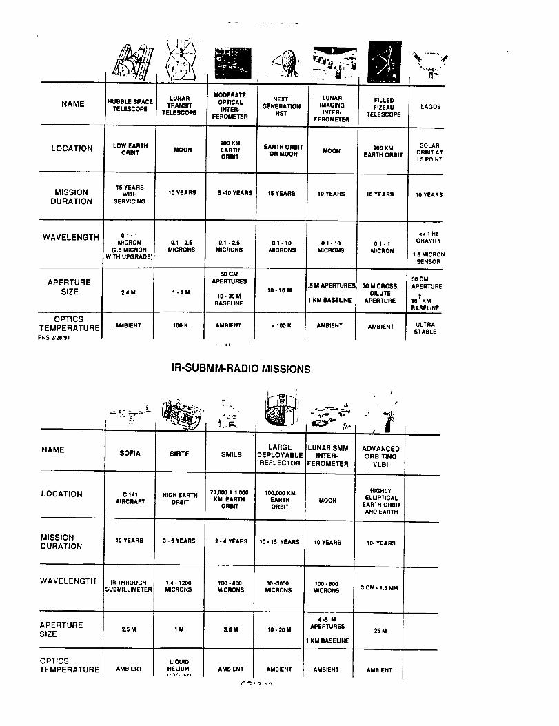
NAME
LOCATION
MISSION
DURATION
WAVELENGTH
APERTURE
SIZE
OPTICS
TEMPERATURE
PNS 2/28/91
HUBBLE SPACE
TELESCOPE
LOW EARTH
ORBIT
15 YEARSWITH
SERVICING
0.1-I
MICRON
(25 MICRON
WITH UPGRADE)
2.4 M
AMBIENT
LUNAR
TRANSff
TELESCOPE
MOON
10 YEARS
0.1 - 2.SMICRONS
1-2M
100 K
MODERATE
OPTICALINTER-
FEROMETER
900 KM
EARTHORBIT
S -10 YEARS
0.1 - 2.5
MICRONS
5O CM
APERTURES
10-30M
BASEUNE
AMBIENT
NEXT
GENERATION
HST
EARTH ORBR
OR MOON
15 YEARS
0.1-10
MICRONS
10- 18 M
,¢ I00 K
LUNAR
IMAGING
INTER.FEROMETER
MOON
10 YEARS
0.1-10MICRONS
.S M APERTURES
;1KM SASEUNE
AMBIENT
FILLED
FIZEAU
TELESCOPE
900 KM
EARTH ORBIT
10 YEARS
0.1 - I
MICRON
30M CROSS,DILUTE
APERTURE
AMBIENT
LAGOS
SOLARORBIT AT
L5 POINT
10YEARS
c_ 1 HZGRAVITY
1.6 MICRON
SENSOR
30 CM
APERTURE
107KM
BASEUNE
ULTRA
STABLE
IR-SUBMM-RADIO MISSIONS
NAME
LOCATION
MISSION
DURATION
WAVELENGTH
APERTURE
SIZE
OPTICS
TEMPERATURE
SOFIA
C 141
AIRCRAFT
10 YEARS
IR THROUGH
SUBMILLIMETER
2.5 M
AMBIENT
SIRTF
HIGH EARTH
ORBIT
3-GYEARS
1.4 - 1200
MICRONS
1M
SMILS
70,000 X 1,000KM EARTH
ORBIT
2-4 YEARS
1_-8_MICRONS
3.8 M
LARGE
DEPLOYABLE
REFLECTOR
100.000 KMEARTH
ORBIT
10-15 YEARS
30 -3000
MICRONS
10-20M
AMBIENT
LUNAR SMM
INTER.
FEROMETER
MOON
10 YEARS
100-8_MICRONS
4-5 MAPERTURES
1 KM BASEUNE
AMBIENT
/
/
ADVANCED
ORBITING
VLBI
HIGHLY
ELUPTICALEARTH ORBIT
AND EARTH
10- YEARS
3 CM - 1.5 MM
25M
AMBIENT
LIQUID
HELIUM AMBIENT
t" "3- _ '*J _'3

X-RAY, _-RAY MISSIONS
? "
NAME
LOCATION
MISSION_URATION
WAVELENGTH
B,PERTURESIZE
OPTICSTEMPERATUREPNS 2J28R 1
AXAF
600 KM
EARTHORBIT
15 YEARSWITH
SERVICING
0.00 - 10 KIV
1,700 CM 2
GRAZINGINCIDENCE
MIRRORS
AMBIENT
NUCLEAR
ASTROPHYSICSEXPLORER
LOW
EARTHORBIT
2 -4 YEARS
10 KIV - 10 MIIV
325 CM2AR_A,2600 CM"
VOLUME
AMBIENT
HARD X.RAY
IMAGINGFACILITY
SPACE
STAT)ON
ATTACHEDOR FREE
FLYER
10 YEARS
20 KeY • 2 MeV
20X20M,
30M=
CODED
APERTURE
AMQIIENT
VERY HIGH
THROUGHPUTFACILITY
MOON
20 YEARS
0.15 - 40 KeV
_0 X20 M
30M 2
GRAZINGINCIDENCE
AMB_NT
GAMMARAY
SPECTROSCOP_OBSERVATORY
MOON
10 YEARS
10 KtV - 10 MIV
1000 CM 2
AREA
7640 CM 3
VOLUME
i Jt
CG13-14

JPL
Microsensors and Microinstruments
W.J. Kaiser and T.W. Kenny
Center for Space Microelectronics TechnologyJet Propulsion Laboratory
California Institute of TechnologyPasadena, CA 91109
J
Outline
Motivation for work on Micro-sensors and Micro-instruments.
Some examples of miniature sensors for in-situ measurements.
Research and development of the Electron Tunneling Sensor./
Application to Infrared Detection.
Conclusions
C,G14-1

Motivation
Conventional Instruments often impose Mass, Volume. and Power consumptionwhich are incompatible with mission requirements.
Recent improvements in fabrication technology through 'Micro-machining'of silicon enable the construction of micro sensors and actuators. Thistechnology offers •
• Large potential reductions in mass, volume, and power consumptionof sensing instruments.
• High degree of flexibility in device design for optimization ofperformance characteristics.
• Array compatibility for multiple functions and redundancy.
Examples of successful commercial implimentation of this technology exist.
J
JIPL,Conventional Sensors
• Conventional sensors operate by converting the Signal to adisplacement of one sensor component relative to the rest of the sensor.The sensor then uses a capacitive, inductive, or optical transducer todirectly measure the relative displacement.
• Conventional sensors are often limited by noise in the transducer or thefollowing electronics. The sensitivity of existing transducers is improved
by increasing the volume, mass, or power consumption of the transducer.
• A more sensitive transducer would allow the design of smaller, lighter,or more sensitive devices.
J
CG14-2

Vacuum Tunneling Concept
Electron
Energy
Illl
Vlllll
I o_V exp[- a "_ S]
The current typically increases by one order of magnitude for each1 A reduction in electrode separation.
i
Transducer Sensitivity Comparison
Transducer Type Capacitivc Tunneling
Active Area
Electrode SeparationBias VoltageMeasurement Frequency/f4easurement Cun'ent
! % Transducer Signal
10 _m x 10 _t,n! pm! Volt200 kHz1.1 nA
90 A
loAxloA5A100mVDC- 10 MHzi nA
0.004A
J
CG14-3

f--JPL ,Advantages of the Electron Tunneling
Position Sensor
Improved sensitivity.Approximately 20,000 x more sensitive than conventional transducers.Allows use of less sophisticated electronics.
Sensitivity can be traded off to improve other characteristics, such asbandwidth, linearity ....
Microscopic active area.Less sensitive to contaminationAllows construction of micron-scale sensors
Low power consumption.
Simple electronic control system.
Compatible with silicon micromachining technology.
Tunnel Sensor Prototyl)es
Piezoelectric bimorph as aclualor wilh gold film and wire as tunneling
electrodes. Fealured sensilivity of ~ 10.5 g. Demonstrated use of
tunneling as displacement transducer in a useful device. Suffered from
temperature sensitivily and complicated fabrication.
Large micromachined folded cantilever wilh electrostatic deflection to control
separation and indium tip for tunnelling. First demonstration ofB
electrostatic deflection in a tunneling device.
Small micromachined cantilevers with inlegral tips for use as generic
transducer componcms. Characterizalion as acceleromeler gives
sensitivity of 10.8 g/,_ at 1 kllz. Use in broad class of scnsors undcr
investigation.
J
CG14-4

Micromachining Process
il................ I
1...... ......... ]
.... I . 1
Grow thin oxide of both surfaces of
doublepolished (100) wafer
Spin on resist
Copy mask onto resist
Etch oxide through mask
Etch wafer
t
Tunnel Sensor Operation
Spnng and "lip
Tunnel Counter-electrode
Dcfiecuo_ Counter electrode
Apply Deflection Voltllle Measure Tun_l Curr_nt
• Apply a deflection voltage until tunnel curt_nt appears
• Activate Feedback Loop to maintain constant tunnel current
• If device experiences acceleration, spring will flex. producing a change in
tunnel Ctll'rellL
CG14.5

i0"I0
-11""- 10gil
N
I0-Ia_o
Z
_ !0
10-1410 0
Measured Current Noise
....... ! " " """l ...... "!4 x 10⁻²
4 x 10⁻³
4x10- 4
4 x 10⁻⁵
........ i ........ , ........ , ...... , 4 x 10"610 1 10 2 10 3 10 4
Frequency (Hz)
Accelerometer Demonstration
Small Motor with Opto-Electronic FrequencySilicon Tunnel Sensor 3400 gm Seismic Mass Sensor and I gm Eccentric Mass
Foam Pad
Aluminum Blocks
C_14-6

pplications of the Electron Tunneling Transducer
• Accelerometers and Seismometers
• Force and Strain Sensors
• Magnetometers
• Infrared Detectors
• Pressure Sensors
• Microphones and Hydrophones
• Microscopic Particle Detectors
t...
¢qL
_J
[-
,ml
¢qt..._J
O
1000
100
Operating ranges of Quantum IR Detectors
10
10
Wavelength (microns)
@
10o 1000
¢_.,G14-7

lnl'rared Detectors
[_ Tunnel Sensor
Tip _ _'_ _ Membrane
__/_ _ ( Trapped Air
Window
• Radiation absorbed by metallic film and converted to heat.
• Conduction of heat to gas causes thermal expansion which deflects membrane.
• Membrane deflection measured by tunnel sensor.
/I--JPLII
Fealures of tile Infrared Tunnel Sensor
• Speed
• Size
• Operating Temperature
• Sensitivity
• IR Bandwidth
• Array Compatible
Response to 10 kHz at peak sensitivity.Response beyond 10 kHz with sensitivity
decreasing as I/f.
Active area of single element from 1 mm toless than 50 microns
Can operate at any temperature above 20 K
Approximately 10X more sensitive thanPyroelectric Detector at 300 K.
Thin metallic film absorbs radiation throughoutthe Infrared with 50% efficiency.
Elements feature low power dissipation and canbe microfabricated into 1-D and 2-D arrays.
CG14-8

(,,,.---JPLMicromachined Instruments for In-Situ Science
Micro-Weather Stations for in-situ measurements in the planetary boundarylayer.
• System needs include low mass, volume, and power consumption,
• Devices under development for measurement of pressure, wind velocity anddirection, temperature, humidity and atmospheric aerosols.
• Goal: To integrate a set of sensors into a miniature package suitable forwidespread deployment.
Micro-Seismometry Instrumentation
• System needs include low mass, volume, power consumption and highsensitivity.
• Devices under development for measurement of seismic signals.
• Goal: To produce sensitive, miniature seismometers.
Plans • Infrared Sensor
The improved sensor is operated in the (ollowing manner :
"lip Deflection Electrodes
• Apply deflection voltage until tuuneling current is observed.
• Activale feedback loop.to mainutin constant turn,cling current.
• If nmdiation is applied, feetrosck loop applies correction to defiectionelectrodes...y_.s_tiom hl deflectio,) voltase are processed as signal.
C.,G14-9

• Micro Weather Stations for in-s_tu measurements ;n the
Ma.rtSa.n planeta..,-y boundax?' layer (PBLI
• System need: Compact, low m _¢¢ atad low power stations
for wideJy &stnbuted measurements of PBL meteorology
• Devices currently under development for measurement of"
pressure, temperature, wind velocity and direction,
humJdiiy_ and atmospheric aerosols
• Low power InsI.rument, on-board proc_r
• Development directedto fabncationofsensorsformitiaJ
testinginenv_ronmentaJ chamber
• NlJcro seismometr)' _rtstrumentat_on
o System needs:Compac:, low ma._, and low power
seismometers forwide di.Tr.ribut_on.
• Currently ava.ilableseismometer systems are excessively
massive, (Approximately 4kg permeasurement a.xas)
• Develop compact, singlec .r.r.r.r.r.r.r.r.ry_a.]siliconseismometer
system,
• Extend currenttechnologytoincludeac'_.weelectronic
suspensionofse_smometer elements.
_ t _ pmL_.s.,.pq
_m_- ssgsh
C,G14-1C

lq.tcrom, icJ_led_d Scmso=s, ;_'t_atozl, ¢md Zms_ ]_ulples
Z_tl_lBIMtt appllcatiomn
Micro inl_Z_lllntl for IMIItlO_O_Oqy
0 telperl_ureo Prlssurl
o Wl_d VelOCity
o H_dity
o Aerolo_ dlteGtion
In*situ _oni_o:l_j
_XCFO iner_2ai _ruldance Irld control Conpect vehlClln4vlqatlon
M_Cr= Sl_lmO_lteFS pl&netal_ science_esource lapp;nq
wide IHinJor dOploy_en_
Coapa¢_ analyt;ca_ speCtrOSCOpy
lns_.ullntl foF in-sl=u scle_ce
l_Ot Oelli IIII )+Olrl
AuqllrS_
Nitro inl%1"_llent$ for gas lonitoriPal Ih'II=U imll_relentlEnvil_m_ntil _nitoring
Pllne_ry in-l;t_ sc_enc
Int_ared laagi_
AUlOIpI_IriC scienceIn-lit_ :lO_itOril_
_3cro optical lyl_IM Col_pa_'t q_oc_rome_lcsGas 6erection
In+situ smnitorim;
¢01pl_ colmu_X¢l_LO_ lyl_elll_lti-no_e _f
riDer-optic _ltvorZ
D R A F T
I£1CItOSI_SO]_ _ I£ICP.OII_STR_MZ_TS WOit][_G GitO_l_
CO01tDmATOIt
¥
-_
¥. WU;b_
als
&IPU_J'1_ ON l"_JD ]
Y Sr_MSLM
0/_4_TAL r.qG .+
_0 GItOEP
K c_a_T.C_Z
G. VARSlW _Ot
It L,e,/_
y. TA_
CG14-11
Conclusions
• Electron tunneling represents the first new transducer technology
in recent history. The sensitivity of electron tunneling to changes in-relative position exceeds that of all currently available motion transducers.
• Tunnel sensors can be constructed which are robust, operate in air, and inthe presence of environmental noise sources.
• Silicon micromachining has been used to fabricate tunnel sensors whichincorporate electrostatic deflection.
• Tunnel sensor components have been built for incorporation into a novel
infrared detector that is expected to be important for many applications.
Applications of the tunnel sensor to other types of measurement are beingexplored. Measurement of acceleration, pressure, temperature, magneticfields and other signals with devices based on the tunnel sensor may be
important.
P/
CG14-12

MICRO GUIDANCE & CONTROL INITIATIVE
Fred Y. Hadaegh
June 27, 1991
SSTAC ITP - OAET/RC
JPLo
!
MICRO GUIDANCE & CONTROL TECHNOLOGY INITIATIVE
TOPICS
OVERALL PURPOSE AND OBJECTIVES
MICRO G&C APPLICATION
PAYOFFS
SELECTED TASK THEMES & TECHNOLOGIES
TECHNOLOGY DEVELOPMENT PLAN
SUMMARY
ISSUES
CG15-1
MICRO GUIDANCE & CONTROL TECHNOLOGY
APPLICATIONS
THE APPLICATION NEEDS FOR FUTURE SPACE SYSTEMS HAVE BEEN IDENTIFIED ASFOLLOWS:
• NEW GUIDANCE AND CONTROL CAPABILITIES- DISTRIBUTED MICRO-SENSOR SYSTEM IDENTIFICATION- MULTIVARIABLE CONTROL OF STRUCTURAL DYNAMICS• DISTRIBUTED SHAPE & POSITION CONTROL OF MIRROR ARRAYS- EMBEDDED STABILIZATION OF TELESCOPE & INSTRUMENT OPTICS- DISTRIBUTED MICRO-INTERTIAL REFERENCES- EMBEDDED HEALTH MONITORING OF G&C EFFECTORS
TYPICAL APPLICATION:REMOTE SENSING PLATFORMS, INTERFEROMETERS & DEPLOYABLE REFLECTORS
• MINIATURIZE EXISTING CAPABILITIES- ATTITUDE & MANEUVER CONTROL SYSTEM- MICRO-INERTIAL REFERENCES- MICROELECTRO-OPTICS FOR MINIATURE CAMERAS & REMOTE SENSORS- INERTIAL NAVIGATION SYSTEMS- HEADING REFERENCE UNITS- MINI-CAMERA POINTING & STABILIZATION- ANTENNA POINTING & STABILIZATION
TYPICAL APPLICATION:MICRO-SPACECRAFT, MICRO-LANDERS, MICRO-ROVERS
MICRO GUIDANCE & CONTROL TECHNOLOGY
OVERALL PURPOSE: DEVELOP NEW MICRO-MINIATURIZED G&C SYSTEMARCHITECTURES AND FUNCTIONS THAT MEET THE NEEDS OF FUTURE SPACESYSTEMS
CONDUCT ADVANCED DEVELOPMENT THROUGH PROOF-OF-CONCEPTDEMONSTRATIONS
TRANSFER NEW TECHNOLOGIES TO NASA ADVANCED DEVELOPMENTSPACE PROGRAMS
KEY OBJECTIVES: DEVELOP THE G&C MICRO-SENSING, COMPUTATION, ANDCONTROL ARCHITECTURES AND FUNCTIONS THAT WILL ENABLE:
100/1 OR MORE REDUCTION IN SIZE, MASS, AND POWER
10/1 OR MORE RECURRING COST REDUCTION AND LOWER COST GROWTHRATES
SOLID STATE RELIABILITY AND REDUCED PERFORMANCE RISK
ROBUST PERFORMANCE OVER TEMPERATURE, VIBRATION, RADIATION
EMBEDDED HEALTH MONITORING
VIABLE DISTRIBUTED FAULT TOLERANT G&C ARCHITECTURES
CG15-2

MICRO GUIDANCE & CONTROL TECHNOLOGY INITIATIVE
PAYOFFS
- 10011 OR MORE REDUCTION IN SIZE, MASS, AND POWER
- 10/I OR MORE RECURRING COST REDUCTION AND LOWER COST GROWTHRATES
- SOLID STATE RELIABILITY AND REDUCED PERFORMANCE RISK
- ROBUST PERFORMANCE OVER TEMPERATURE; VIBRATION, RADIATION
- EMBEDDED HEALTH MONITORING
- VIABLE DISTRIBUTED FAULT TOLERANT G&C ARCHITECTURES
- MASSIVELY DISTRIBUTED CONTROL CAPABILITY
e
MICRO GUIDANCE & CONTROL TECHNOLOGY
SELECTED TASK THEMES
MAJOR ADVANCES IN MICRO G & C WILL BE INCORPORATED IN DEVELOPMENT PRODUCTS PLANNEDUNDER SIX TASK THEMES:
o
- MASSIVELY DISTRIBUTED MICROSENSING FOR SYSTEM ID & CONTROLTO ENABLE SPACE INTERFEROMETERS/LARGE REFLECTORS
- LIGHT POWERED REMOTE PROCESSING NETWORK FOR G&C MICROSENSINGTO ENABLE VIABLE DISTRIBUTED ID/CONTROL ARCHITECTURES
- MICRO G&C FOR MICRO-SPACECRAFT AND MICRO-ROVERSTO PROVIDE ESSENTIAL SYSTEM FUNCTIONS
- SIX-DEGRI=E-OF-FREEDOM MICRO-INERTIAL MEASUREMENT UNIT FOR
MICRO-SPACECRAFT AND MICRO-ROVERSTO ENABLE G&C NAVIGATION SUBSYSTEMS
- ACTIVELY CONTROLLED MICROMACHINED DEFORMABLE MIRRORS FOR ADAPTIVE REFLECTORSTO PROVIDE OPTICAL PERFORMANCE NOT OTHERWISE FEASIBLE
- EMBEDDED HEALTH SENSING FOR G&C EFFECTOR5TO PREDICT/MANAGE MISSION EFFECTIVENESS & LIFETIME
CG15-3

3-AXIS LIGHT POWERED SENSING SYSTEM
ENABLES
MASSIVELY DISTRIBUTED SENSING FOR I/D CONTROL
' 3.Axis Acc'clcromclcrw/Lot=! $1|na! I'recessin|
TRUSS STRUCI'UItE __LARGE SPACE//
FYH
Grd_l_ _ MOriON Sa_I,_SOIISe
GLNIIRIC 10 MUk'I_J C_ OF Xt.'t,,C_RS
ilJ f?l:iI
• L_LTA • CAIN J _ _ RL_NOD CONT. • ACCUMULATION• - .i,Osrlr- I +OOMI'AI_IOH
IoN 0 • Irrc.
I
q_UNI_ & MEASUREMENt
j ,.,Q.-_
FAC| I
ul
REMOTE SIGNAL I'ILfJ_,SSOIt FOR MOIlON SENSORS
FI_lUm
• Itudvek_p_dbel .3. I._ pq,_, <tOw Ira' moral
_ememlm
_---_ I,,%1.

MASSIVELY DISTRJ0EI'ED MICRO SENSING IE)R ID/CON'I](UI,
REMOTE PROCESSING NETWOIIK/STRUCTURE PIIASED [N'['EGRA'I'ION AND TEST
INITIAL PilASE INTERMEDIATE rIIASE FINAL I'IIASE
SENSOR ELEM ENT
ANALOG CONE). ELEC.
SENSOR + INTEGRATED ANALOG ELEC.
(ANALOG EXTERNAL INTERFACE}
SF-,NSOR ELEMENT
ANALOG COND. ELEC.
DIGITAL ELEC.
L
INTEGRATED
SENSOR ._ANALOG + DIGITAL ELEC.
(DIGITAL :EXTERNAL LN'I'ER_:AC '_
SENSOR ELEM .ILN'r
ANALOG COND, ELEC.
DIGITAL ELEC.
)I"11-I.,ELEC./I'WR bN'IEI_F,
I'IJI.I.Y IN'I'EGI(A'I'I:IJ
SI,_ISOR + ANALCX] + UIGfI'AL ELEC,
4"
FIDER OI'IICS IN'TF. ELI:C.
(OP'IICAL EXTERNAL II'_fER_ACE)
MICRO-SIJACECI_,AF4 ' G&C
i
(jl" hnagcr)-...._
(s,.,,,s_,,_o,-_--
I
I
I
N_ o.,,,,p,,t_,-
=0_C,,c,o,,w_,ccl,)-1I
--0",.St_,'_) I--_-(_Allicl|l:lliOll Molor)J
• Allilude DelcrnlinatioiD, Allitudc Control• Atticulatiun Control
Mitliatutc *Effccttns
I
IMicro
IDevices
I
Scaled down from convcnliullal
size, uut silicon micromachiucd
C,G15-5

MICRO-ROVER G&C
V
I
I
I (p imager)---.-]
(Encode:)________
!
I
I _( Mlnlslure *Arllculallun MotyrJ
g Computer _ =
• Attitude and Position Dctemlinatiou• Path Guidance• Articulation Control
II c_
II Micro
l1 Devices
II
* Scaleddown from co,lventional
size,notsiliconmicromachined
Micromachined Defo'rmable Mirror
25G • 256 "pisel$"
'Top view el delolmeMo mille[ I|IOITIWy
Aeeembly ¢oneleli el Iwo micfomeci)tned
elllcon welele mounted Ioce-io-goce and
bonded Iogethe¢ elollmd Ihelf peOpheflee
"See-U.ovgh" vOow el IOql) "plnole'.
)eveelln d the lepellilve. INe-Uo
- IOQ )qm -_
Ueomeily el Ihe mielo! oe$oenbly Me,Billed view el eevele! idlel$ ehowl))u
II)o ovelleppenu "CIolle-IlolcJ peel" pette.i
of I|IO O¢lulltO¢ I II|llOf euppoll sluuclure
CG 15-6

Micromachined Deformable Mirror
Side view el upper wiler
_.J 1he e,i. mon_a_o is e_oout.u,,_, i_ J JUm=kxma_Wnrow,=. I I
o,muiU-_llwdle_c_lclln. _..,. o .mcap_ .c,u=_srs.=. _=J
/>" Cm_luctlvo_ (see _k_,v)
1he IoulUladesO(lINI,OOSNliImVem IoolIMb_ toeql.n.IIw pore w_l I_o_ddemrNlo, b_ Imc_I= lheICSuillonI!ml_.
Side view o! Ihe lower weier
Timet_ conducllvepWl to,m mnW.lqmc_d¢api:i_. 1he¢I_ on lle ¢mpec_ cw,r,o_IIwpad scpi_illlonby blllnc_ig IIIOcbolmUcIo_c_lleoli_l lee eswld WIm l_sAeml Sl.r,,gs.
Side view el the mbror assembly
e
EMBEDDED iIEALTII MoNrroIAING OF G&C I,.:I,'I,'ECTORS
.ACCELEKOMETEi( INI'U'I3
UUTI'UT '10 G&C COP,II'U'II_I{
SIONAL _ I91AUNUS'I'IC ALUOKI'I11MS &
I'RO¢ .F.,3SINU / '11:.I.I..'M b'll{ Y
fflllEI I,SI;.NSUK$. I.LO.;. CI.IRIL I_NI"• SI'lJ :l:l:l:l:l:l:l:l:l_g, PRESSURE
Iteucllu. Wheel Tell Bed
CG 15-7
ORIGJI_LAL PAG_E.OF POOR QUALITY

/f-JPLA Micromachined Silico. Electro. Tu..di.g Se.sur
Center for Space Microeleclronics TechnologyJel i'ropulsDn Laborawry
CalOrornia in$liXule of TechnologyPasadena, CA 91109
• Tumtcl $e.sur Characteristics
• Al)plic.tio.s
!
Electron Tunneling Sensors
A New Class of Position Transducer With Poteutial Appiicatio.to Measureme.t of
• Acceleration
• hffrared Radiatio.
' Pressure:
All with Similar Electronic
. Temperature Requiremems.
• Mag.etic Fields
. Particle Flux
In many cases, arrays of sensors will be fabricated on single chip for
Redu.da.cy, Signal ldcmificatio., Focal-Pla.¢s, a.d for Multiplc-Function Packages.
col %-8

f--JPL.
Eledrun Tunneling
. h) tim early |98(J's, Uim]ig aud Ruhrcr at IBM invcmcd a llcwtechnique, Scanllillg 'l'umJclitlgMicroscopy (S'rM), rut sludyiug thcstructure of sur/accs wilh atomic-scale rcsolulioll.
. In STM, a "l'ip' is positioned several Angstroms abovc the surfaceof interest. With the al)l)lication of It voltage bias I)clwccn the tipand the surface, a stitall tumtelit|g currcttt is ubscrvctl.
/Surface
/f--JPLAdvantages o1'the Electron Tunneling
Position Seilsor
hnproved sensitivity.Approximately 20,000 x more sensitive than conventional trmtsducers.Larger signals allow use of less sophisticated electronics.Sensitivity can be traded off to improve other characteristics, such asbandwidth, linearity, ...
Microscopic active area.Less sensitive to contaminationAllows construction of micron-scale sensors
• Low power consumption.
• Simple electronic control system.
• Compatible with silicon micromachining technology.
m¢
e

f---JPL
Tunnel Accelerometer Operation
Apl)ly I.)tllcclit_l Volllll M¢lllurc 'l'unllCI CurlciiI
Slnmg ;..I lip
Wlllllld ( 'l*llllll'l I'lt'_*'lllll_
Jkllt't'll_,l I '11111111'1 rlt'tlllmJc
• Apply a deflectiott voltage utttil tuttttcl cutrettt aplmars.
• Aclivate I:eedback LOUlp lu m:lintain COilSlllllL tuiiiicl t:urretlt
• If device eXlwerient.'cs accclemtiun, slning will Ilcx, pttKlucing a t'h:mgc it,tu|mel cut-lettt.
J
JPLAccelerometer Components
Counter.Electrode
Au I._ flectiollElectrudes
Spring mid "lip
"lip
Aligmnetll I lules
CGIS-10
ORIGINAL PAP_ IS
OF POOR QUALITY

Transducer Sensitivity Comparison
Transducer Type Capacitive 'l'mmeling
Active Area
Electrode SeparationBias VoltageMeasurement FrequencyMeasurernent Current
1% Transducer Signal
10 .mx 10 lani .m1 Volt200 kHz1.1 nA
90A
IoAx loA5A100 mVDC - l0 Ml-lzIliA
0.0O4A
J
/,--JPLElectron Tunneling Sensors
Present Proof-of Concept demonstrations rely upon off-chip electronics"for simplicity and ease of modification.
Future completed devices will require integration of sensor and electronics.
Use of micromachined silicon for sensor structure will allow integrationof sensor and electronics ill the same silicon crystal.
..
Integrated sensors will be important for a broad class of NASA applicationsand will be candidales for technology transfer to induslry,
J
CG15-11

/---JrOLElectron Tunneling Sensors
Generic Requirements for Tunnel Sensor Operation :
. Analog or Digital Feedback Loop for Control of Tunueliug Current
Operational Amplifiers for Amplificatio. of I nA Current LocatedNear Transducer.
Comparator Circuit for Sensing Force Applied to Trausducer.
Output Circuit for Applying Correctiou 'lb Conlrolliug Capacitor.
• Muiltiplexer for Selecti.g Individual Sensor
• Digital Signal Processor for Pre-Processing and Coml)ressioq of Data.
• Interface Electronics
MI(..'I(I) • I;&C
Svs'rEMS
I)ISTRI LIU'I'I._D
IDICON IROL
tMU •
It- SI'ACECRAFI"
/p..ROVI.;R
IIE^LTII
blONrIORIN(J
ADAPTIVE
OI"IICS
CUMI'UNENT
TECIINOLOfilES
V1-_I
_- SENSORS /
ACTUAIOItS
FILIER.OP'rlCSI
DATA COMM.
MICI((I-(;&C 'I'ECIINOI,OGY I)I,_VI,.'I.I)I'MI,;NT I'I,AN
I rINTlOIIA11_ I FAIIRICAT§
$11ql_lIIII1UAIU Cl_,ll'trl E!
MULlrl AXIS 51"N_;1•
CG15-12
bIUL11 StAll(IN NI_rwIIIIK
F^BRICATE kIINIATUIIZED _
IiYflllU MICIil) CUMI'U'I El 1)

JPL MICRO GUIDANCE & CONTROL TECHNOLOGY INITIATIVE
SUMMARY
THIS INITIATIVE IS PLANNED TO:
• DEVELOP MICRO-G&C TECHNOLOGIES THAT MEET THE NEEDS OFFUTURE SPACE SYSTEMS
• ENABLE NEW CAPABILITY IN DISTRIBUTED CONTROL
• MAJOR REDUCTION IN G&C MASS, SIZE, POWER, PERFORMANCERISKS, COSTS AND COST GROWTH
• HAVE SELECTED TASK THEMES WITH TIME-PHASED DEVELOPMENTPRODUCTS OVER FIVE YEARS
• HAVE TASKS AND PRODUCTS THAT ARE SYNERGISTLCINSUPPORTING NEW G&C SYSTEM FUNCTIONS AND ARCHITECTURES
CG15-13

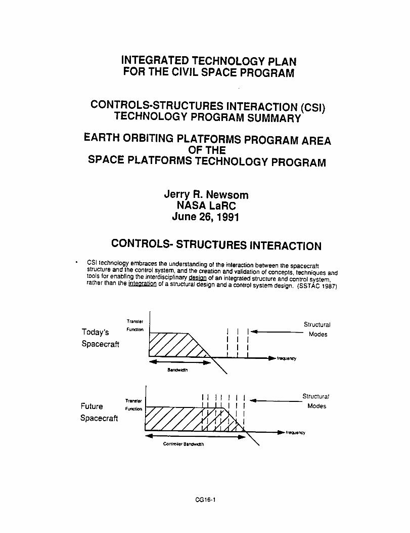
INTEGRATED TECHNOLOGY PLANFOR THE CIVIL SPACE PROGRAM
CONTROLS-STRUCTURES INTERACTION (CSI)TECHNOLOGY PROGRAM SUMMARY
EARTH ORBITING PLATFORMS PROGRAM AREAOF THE
SPACE PLATFORMS TECHNOLOGY PROGRAM
Jerry R. NewsomNASA LaRC
June 26, 1991
CONTROLS- STRUCTURES INTERACTION
CSI technology embraces the understanding of the interaction between the spacecraftstructure and the control system, and the creation and validation of concepts, techniques andtools for enabling the interdisciplinary ._ of an integrated structure and control system,rather than the _ of a structural design and a control system design. (SSTAC 1987)
Today's
Spacecraft
Transfer
Funclion
I I II I I
BanOwiolh
trmncy
Structural
Modes
Future
Spacecraft
Tr=msfer
Function
Controller Bandwdh
Structural
Modes
CG16-1

CONTROLS-STRUCTURES INTERACTION (CSI)TECHNOLOGY
GOAL:
DEVELOP VALIDATED CSI TECHNOLOGY FOR INTEGRATEDDESIGN/ANALYSIS AND QUALIFICATION OF LARGE FLEXIBLE SPACESYSTEMS AND PRECISION SPACE STRUCTURES
OBJECTIVES:
• To provide spacecraft dynamic response amplitude reductions of 50 percent, _or any input ormaneuver, with minimum increase in system mass.
• To enable the use of wide-bandwidth CSI control systems to achieve several orders of magnitudeimprovement in control and pointing capabilities.
To predict the on-orbit performance of CSI systems within 10 percent of all amplitude, frequency, tim(and stability requirements based on the results ol integrated analyses tuned/corrected by closed-loopground and/or flight test data.
• To develop unified controls-structures modeling, analysis and design methods which allow a compiet_iteration on all critical design variables Jna sJngJeintegrated computational framework.
• To develop the capability to validate the performance ot flight systems by analysis�ground tests.
CSI PROGRAM FOCUS MISSIONS
EARTH OBSERVATION PLATFORM
g_:.
OPT)GAL INTERFEROMETER
C-,G16-2
ASTROPHYSICS

II
CONTROLS STRUCTURES INTERACTION PROGRAM
Ground Test Methods
Integrated Design Methods
Guest Investigators Flight Experiments
BENEFITS STUDY
• PURPOSE: TO Quantify the Specific Advantages of CSI Technology forFuture Missions Requiring Large Space Structures.
• APPROACH: Select a Future NASA Mission and Define Differences in theSpacecraft Design and Performance Capability Using Both theConventional and CSI Approach.
• EXAMPLES: (1) Geostationary Platform
(2) Shuttle RMS
(3) Multipayload Platform
CG16-3

CG 16-4 ORIGINAL PAGE IS
OF POOR QUALITY

f_: ::_:__: i= i PoTEN'riAL. SPACE STATI()N___i ,I'._" _ BENEFITS DUE TO CSl (Timeline) ""_;_
:!ii- --1,
.w..
RMS settling time
6 -" RMS settling lime, 2"
Draper RMS Simulator response
Payload 3500 Ibs
Position,inches
/ % ¢2"
\/3°3iji IJ-307 j
-3H
-315 l
30 35 40 4S S0 55 60
Time, _,econds
Potential CSI benefits
_2
10 -
RMS 4Cure
lime, 3 selling 6
i-;".. ' hours 2 lime, hrs
1 2 3 4 S 6 7 8 g10111213141516
_-"" Damping ratio improvement factor
_J_.._-....._--_;= _ .-___-_=. _- ...... =_ .------...-_._. .................
:::2{;.:
,-,. ,-....a
Typical RMS flexible modef : 0.26 Hz
TIP responsewithout active vibration control
-2
Tip -4displacement, -6
in. -8
-10
"120 10 20 30 40
Time, sec
TIP responsewith active vibration control
0
-2
.4Tip
displacement, -6in. -8
-10
.12 _0 10 20 30 40
Time. sec
CG 16-5
G_' POOR QUALITY

MULTI-PAYLOAD PLATFORM CSI STUDY
UARS
OBJECTIVE: Oetetmlne Polentl=l Benefit=
of Applying CSl Technology
Io Multi.Instrument Spacecraft
EOS-A
13me
GROUND TESTS AND TEST METHODS
Ob!ectives
• To ascertain the applicability of theoretical CSI developmentsto complex hardware systems
• To develop ground test methods suitable for verifying that CSIspacecraft systems are adequate for flight
ADDrOa_h
• Develop hardware testbeds
• Perform in-house analysis and tests
• Conduct guest-investigator studies
CG16-6

THE PHASE-ZERO EVOLUTIONARY MODEL:A CONTROLS-STRUCTURES INTERACTION TESTBED
EXPERIMENTAL RESULTS
OPEN AND CLOSED-LOOP RESPONSES
MODE 6
ACCELEROMETER 8
(IWSEC^2)
MODE B
ACCELEROMETER 2
(IWSECA2)
o, : :'' ""' 'i! ii',!,i,,!,
.i00 [,I , " ' "i
o $ lO I$ 20 25 30
.... FREE DECAYEXCITATION
FEEDBACK CONTROL
50
0 i ii
-50o s Jo 1_ _ _s 30
- _ I_ TIME (SEC) ,. 1-i- vl
EXCITATION .... FREE DECAYFEEDBACK CONTROL
CG 16-7 ORIGinaL PAGE IS
OF POOR QUALITY

Y, in.
CEM LOSExcitation, 0-10 sec.
IO
$ ---
. ---_:
H
• +J _ .o
X, in.
Open- end Closed-Loop Test Date
Pointing Results• Closed-Loo_
Y, in._ "
• .t_ ,IO ,$ I | II I_
X, in.
Closed-Loop Simulation end Test Data_, =,'_ LaM(_ ¢=m=. Q_,t L=m
lOP bke _m
l II • • I IO I=" 14 II II 20
InBw- I_
T, -, ¢,_ee e,.,,. ¢_.,= _,_.. +
Y , .+_
-"t , ,"v,vvvv''+ """,/,• 2 • 6 I IN 13 l_l 16 81
_._
Real-Time Computer Hardware
1553 Bus
Parallel Bus I
(Remole)
(Local) + lFiber Optic Bus
CG16-8

SOFTWARE DEVELOPMENT OVERVIEW
Entire software system developed at Langley (ACD/FSGB)
. Real-Time Executive, Interfaces, Applications
- RIU and 1553B interface software developed jointly with SED
• Software for all 1750A's and PC/AT will be written in Ada
This is Langley's first production Ada project
Similar Ada based 1750A systems are proposed for EOS missions
Software system designed using object-orientated design methods
- Allows software to evolve in step with hardware system
-Testbed modules can be reused on future missions (CSI, EOS)
Believed to be one of the first real-time distributed Ada based 1750A
production systems anywhere.
GTM Testbed Description/GoalsPhase 0
Global LOS Pointing objective.Uniform structure.500 micro radlans accuracy.Active only, 6 accsls, II thruster=.
Phase 1Global LOS.Pointing objective.In(_g_ted controller &"structure.500 micro 11diane ecctJ_cy.Active only, $ scowls, 8 thrusters.
Phase 2Multi-Payload Pointing objective.Phue 1 structure.$ micro radlane accuracy.24 plug strut=, 3 gimbals.
Phase 3Multi-Payload Pointing objective.Redesigned structure.5 micro radlans accuracy.24 plazo struts, 3 gimbals.100 passive stTut.s,optimal sensoractuator placement.
Phase 4Integrated controller & structuremultl-payload free-flyer design.5 micro radish= accurllcy. Integratedpassive and active sensors/actuatoRend on-board power end computer=.
Implement LAC/HAC controlleron structure with realisticdynamics of space platforms.
Ouentify benefits of Integratedcontroller &structure design andassess predictive accuracy.
Implement distributed/centralizedcontrol/era for multi.payload platforms.
Varify Integration of passive, active smartsystems with multi-objective controller.
Ground test experiment for CSI Cllss 1 & 2flight demonstration.
CG16-9

CASES GTF (Ground Test Facility)
Status: Partially Operational
Test Articles: Boom, MPESS, Tip Plate completedBoom/MPESS suspended
Disturbance System: Integration nearing completion
Computer System: Delivered, Tested
CASES Software being developed
Sensors & Actuators:
AMED system: Final testing prior to integrationBLTs tested
BMT/TDS design in progress
Auxilliary sensors obtained (Accels, Force, etc...)
Electronics: Several subsystems complete
(Mux/Demux, Reaction Wheel, Gyro, etc ....
• Baseline Operational: Aug/Sept 1991
ll_ffDi _ _ rn@_.w _mtd*mmmAI_I_ "_--!:: II t::LI_
lILT. _ Lame* _ CASW
M1_$$f.INstt. A,vs_I¢ ml l.m_m_ |_ m litres
MiN*m INni,m E.l.ummm _ Sirdar
GUEST INVESTIGATOR PROGRAM
• GOAL: OBTAIN BEST AVAILABLE CSI TECHNOLOGY EFFORTFROM RESEARCHERS IN ACADEMIA & INDUSTRY.
APPROACH: GENERAL SOLICITATION OF PROPOSALSTHROUGH NRA WITH INTERCENTER SELECTIONTEAM,
ph_e J i
STATUS:
CompletedEight InvestigatorsTwo Test Beds[.aRC - MIni-MASTMSFC - Advanced Control Evaluation for Structures (ACES)
Phase II - Joint Program with the Air Force, Edwards AFB101 Proposals ReceivedFive Winners Announced December 1990Three Test Beds
LaRC - CSI Evolutionary Model (CEM)MSFC - Control, Astrophysics, and Structures Experiment In Space
(CASES)AF - Advanced Space Structure Technology Research Experiments
(ASTREX)
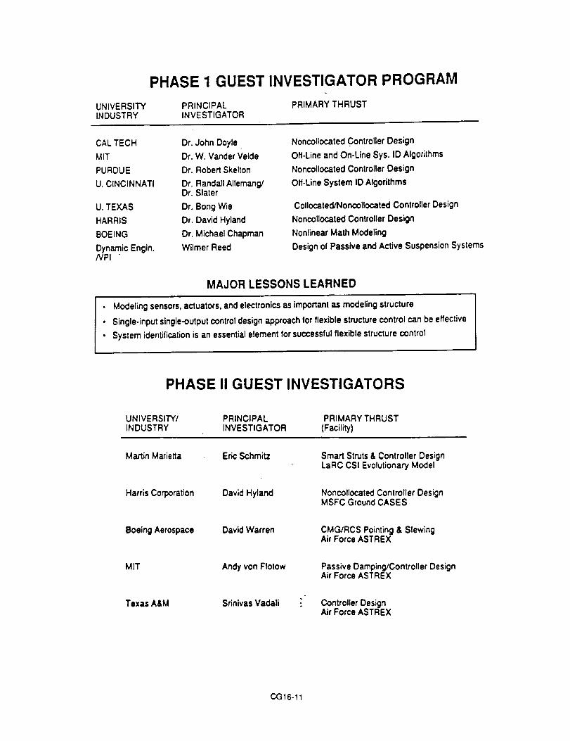
PHASE 1 GUEST INVESTIGATOR PROGRAM
UNIVERSITY PRINCIPALINDUSTRY INVESTIGATOR
CAL TECH Dr. John Doyle
MIT Dr. W. Vander Velde
PURDUE Dr. Robert Skelton
U. CINCINNATI Dr. Randall Allemang/Dr. Slater
U. TEXAS Dr. Bong Wie
HARRIS Dr. David Hyland
BOEING Dr. Michael Chapman
Dynamic Engin. Wilmer Reed/VPI
PRIMARY THRUST
Noncollocated Controller Design
Off-Line and On-Une Sys. ID Algorithms
Noncollocated Controller Design
Off-Line System ID Algorithms
Collocated/Noncollocated Controller Design
Noncollocated Controller Design
Nonlinear Math Modeling
Design of Passive and Active Suspension Systems
MAJOR LESSONS LEARNED
• Modeling sensors, actuators, and electronics as importanl as modeling structure
• Single-input single-output control design approach for flexible structure control can be effective
• System identification is an essential element for successful flexible structure control
PHASE II GUEST INVESTIGATORS
UNIVERSITY/ PRINCIPAL PRIMARY THRUSTINDUSTRY INVESTIGATOR (Facility)
Martin Marietla Eric Schmitz
Harris Corporation
Boeing Aerospace
David Hyland
David Warren
MIT Andy yon Flotow
Texas A&M
Smart Struts & Controller DesignLaRC CSI Evolutionary Model
Noncollocated Controller DesignMSFC Ground CASES
CMG/RCS Pointing & SlewingAir Force ASTREX
Passive Damping/Controller DesignAir Force ASTREX
Srinivas Vadali " Controller DesignAir Force ASTREX
CG16-11

INTE G RA TED S TR UCTURE/ C O NTR O LDESIGN
STRUCTURE
k COMPUTER
ICONTROL; SYSTEM
ACTUATOII
"kt
!DESIGN
SENSOR J
/
PROBLEM CLASSIFICATION
Class 1:
C:ass 3:
Pointing, vib. sup., no articulation
oO-°
Class 2: Pointing, vib. suD., with articulation
LJ "• Pq
°° •
lI
Nonlinear version of ctass 1
o•O.°•••.o'••°
''°°°''°''•°°°.. , .- . . .
C:ass 4: General nonlinear wig robe:tics
_k ,,m,
CG16-12

DESIGN PROBLEM i
_7.5 m
Design Variables - D;ss;p,ttivecontroller {;a;nsD;lm.e_t_s of s_rL,clural meml::)etS
I o_,=. ID=_U_ERI
Ova.: c.°.@Obje_ive Fund;on - For parameter 0 S p =; I,
M;n;,_;,e[_-To_,lM;ss. (J-P) ]Conttolle.clPedorm=,nce
COnstraintS
- Struclural member sizes arielRM$ point;rig error Itlarge antenna
CONVENTIONAL VS. INTEGRATED(Dynamic Dissipative Controller)
RMS < 10 p.rad
Initial Design
Control-optimizedDesign
p=o.ls
IntegratedDesignI}=o.15
ControlledPerformance
1.0
1.30
4.03
StructuralMass
1.0
1.0
0.66
ActuatorMass
1.0
1.45
1.44
TotalMass
1.0
1.18
0.97
CG16-13

INTEGRATED DESIGN VALIDATIONPHASE-1 CEM
zy
_: MINIMIZE THE AVERAGE CONTROL POWER WHILE MAINTAINING THERMS LINE OF SIGHT (LOS) TO A SPECIFIED VALUE WITHOUT ANY INCREASE INSTRUCTURAL MASS (OVER PHASE-0 DESIGN).
DESIGN VARIABLES
STRUCTURE - EFFECTIVE CROSS-SECTIONAL AREAS OF 21LONGERONS, BATTENS. AND DIAGONALS
CONTROL - ELEMENTS OF THE COMENSATOR AND GAINMATRICES OF A DYNAMIC DISSIPATIVE CONTROLLER
SIMULATION RESULTS
.12
.I
• w .08V_
31a: .06L/t
9.04
.02
• _ .007.005
.0OS
.004
.003
Phi,e-0
Phu=-I .....
.... | .... ! .... t .... t • - - = ! ....
50 tO0 ! 50 200 250 ,300t';me
'_ .ooz
.ool
Phue-OPhu.-I .....
.... ! .... ! .... I .... | .... ! ....
0 50 IO0 I_0 200 250 300l_me
CG16-14

JUSTIFICATION FOR ON-ORBIT CSI EXPERIMENTS
DEVELOP UNDERSTANDING OF GRAVITY EFFECTS ON GROUNDTESTING
• Direct Gravity Effects: stiffness, modal coupling, damping
• Indirect Gravity Effects via Suspension system dynamics:pendulous modes, local attachment loads, large angle articulationlimitations, etc.
• QUANTIFY ACCURACY OF PREDICTIONS OF ON-ORBITPERFORMANCE
DEMONSTRATE NEW FLIGHT QUALIFICATION PROCEDURE
• Dependent on on-orbit dynamic testing
• Subsequent adjustment of controller parameters
CSIO FLIGHT EXPERIMENTS
• JITTER SUPPRESSION EXPERIMENT (JSX)
• McDonnell Douglas Prime Contractor
• Funded by OAET's In-Space Technology Experiments Program(In-STEP)
MIDDECK ACTIVE CONTROL EXPERIMENT (MACE)
• MIT Prime Contractor
• Funded by In-STEP
• ADVANCED FREE-FLYER EXPERIMENT
• LaRC/MSFC/JPL Conceptual Definition in Progress
CG16-15

IMSa OaSl _ _ *¢1 r_¢P_OlO¢ F_ *_e_,_hr
JITTER SUPPRESSIONFOR
PRECISION SPA CE S TRUCTURESTcol *D.cr _sl
MIDDECK ACTIVE CONTROL EXPERIMENT (MACE)
Reactionwheelactuator
JScanning andpolntingpayload #1 Test article ,=(1_r
(stowage) .Sequencer-,Control computer
..... Data storageRata
Rate gyro(torsion) (2)
Proof.mass
actuators (4)
Activemembers (2)
Linear
[ Flrst flexible m°del acceler°melers(13)ottestfree-floatingarticle< 2 Hz
._ Payload #2
_'r2 Axis_"glmbal
motors
J

CST FREE FLYING EXPER'I'MEPIT
50LRR POIIITIMG PRYLOAO
SOLAR
f RCTI_E STRUTS
_ /f_ AXZS GII'SALS
P_MIELS
SUMMARY
. CONTROLS-STRUCTURES INTERACTION (CSl) IS A KEYENABLING TECHNOLOGY FOR FUTURE NASA SPACECRAFT
PROPER IMPLEMENTATION OF CSI TECHNOLOGY OFFERSTHE POTENTIAL FOR SIGNIFICANT IMPROVEMENTS INCAPABILITY
CSI iS EFFECTIVELY A NEW DISCIPLINE WHICHENCOMPASSES AND INTEGRALLY MERGES STRUCTURESAND CONTROLS
NASA HAS EMBARKED ON A MAJOR MULTI-CENTER EFFORTTO DEVELOP THIS TECHNOLOGY FOR PRACTICALAPPLICATION TO SPACECRAFT
CG16-17