st traction inverter system solution
TRANSCRIPT
ST traction inverter system solution
June 2020
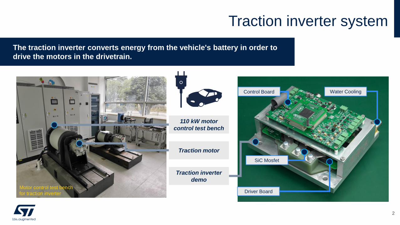
Control Board
Driver Board
Water Cooling
SiC Mosfet
Traction inverter system
2
The traction inverter converts energy from the vehicle's battery in order to
drive the motors in the drivetrain.
Traction motor
Traction inverter
demo
110 kW motor
control test bench
Motor control test bench
for traction inverter
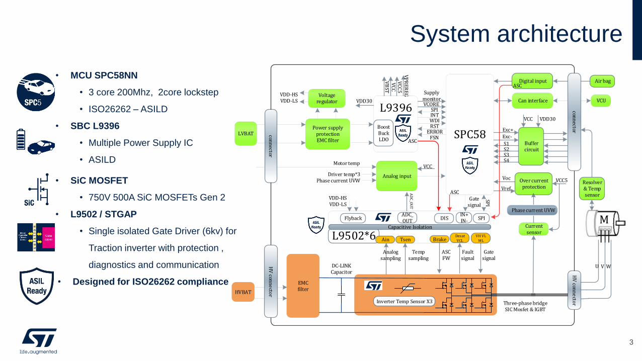
System architecture
• MCU SPC58NN
• 3 core 200Mhz, 2core lockstep
• ISO26262 – ASILD
• SBC L9396
• Multiple Power Supply IC
• ASILD
• SiC MOSFET
• 750V 500A SiC MOSFETs Gen 2
• L9502 / STGAP
• Single isolated Gate Driver (6kv) for
Traction inverter with protection ,
diagnostics and communication
• Designed for ISO26262 compliance
LVBAT
VCUVoltage
regulator
Power supply protectionEMC filter
Can interface
Analog input
SPC58
VDD-HSVDD-LS
SPIINTWDIRST
ERROR
Driver temp*3Phase current UVW
EMCfilter
HVBAT
ASC
SPI
Gate signal
Motor temp
Currentsensor
Over current protection
Voc
Vref
Buffercircuit
Exc+Exc-
S1S2S3S4
HV
conn
ecto
r
U V W
Supplymonitor
VB
STV
CC
VC
C5
VP
RE
RE
G
VCORE
VCC5
VDD30VCC
VCC
BoostBuckLDO
L9396
Flyback
Three-phase bridgeSIC Mosfet & IGBT
Inverter Temp Sensor X3
Tsen
Gate signal
VDD-HSVDD-LS
conn
ector
L9502*6Capacitive Isolation
Phase current UVW
Digital input Air bagASC
VDD30
M
HV
conn
ecto
r
conn
ector
Ain
FSNASC
VH VLML
DISADC_OUT
AD
C_O
UT
DC-LINK Capacitor
DesatVCLBrake
Fault signal
ASCFW
Temp sampling
Analog sampling
SPIIN+IN-
Resolver & Temp sensor
3
Traction inverter system highlights
4
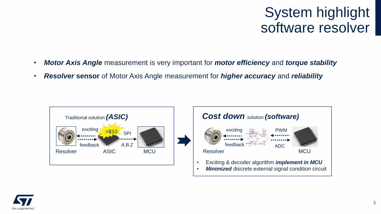
System highlightsoftware resolver
5
• Motor Axis Angle measurement is very important for motor efficiency and torque stability
• Resolver sensor of Motor Axis Angle measurement for higher accuracy and reliability
>$10
Resolver ASIC MCU
exciting
feedback
SPI
A,B,Z
Traditional solution (ASIC)
Resolver MCU
exciting
feedback
Cost down solution (software)
PWM
ADC
• Exciting & decoder algorithm implement in MCU
• Minimized discrete external signal condition circuit
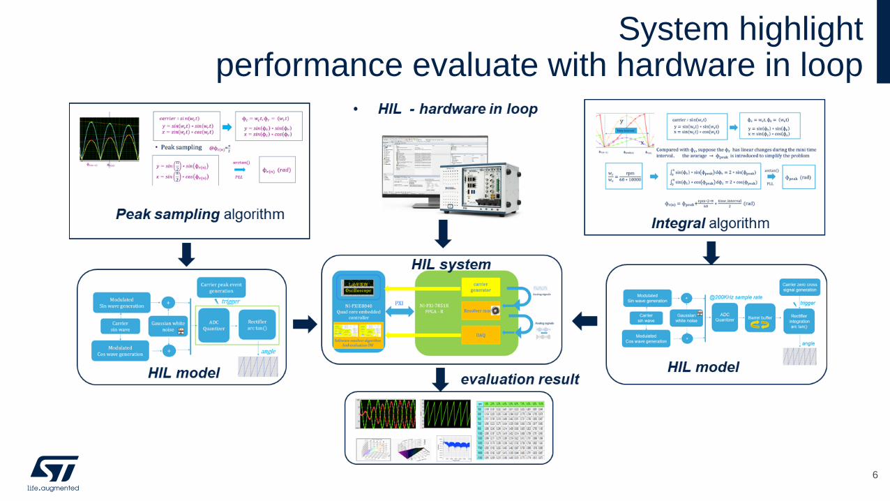
System highlightperformance evaluate with hardware in loop
6
7
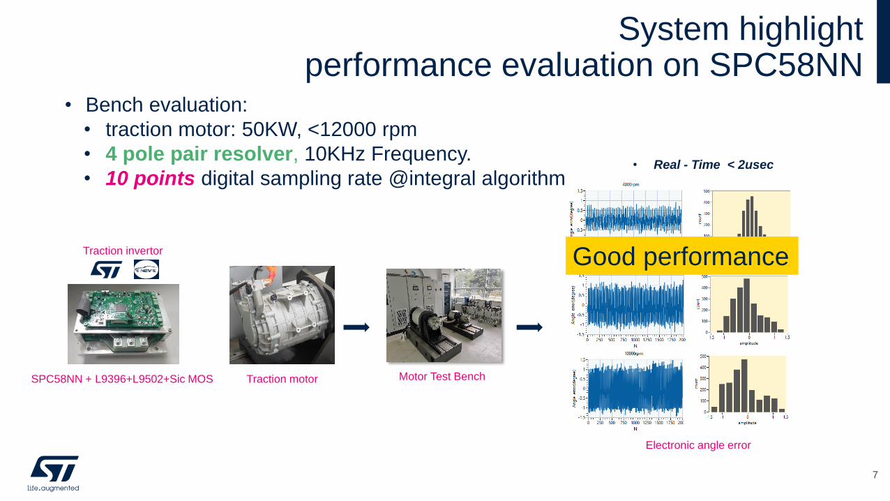
• Bench evaluation:
• traction motor: 50KW, <12000 rpm
• 4 pole pair resolver, 10KHz Frequency.
• 10 points digital sampling rate @integral algorithm
Electronic angle error
Good performance
• Real - Time < 2usec
SPC58NN + L9396+L9502+Sic MOS
Traction invertor
Motor Test Bench Traction motor
System highlightperformance evaluation on SPC58NN
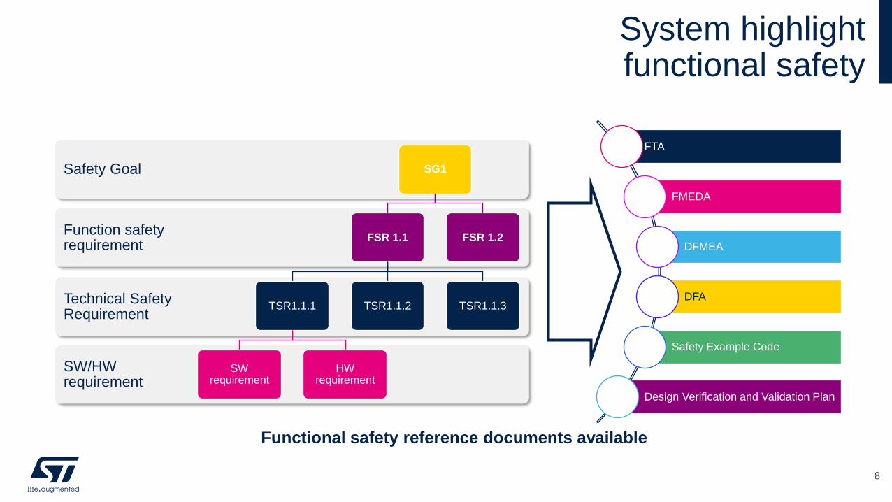
System highlightfunctional safety
8
FTA
FMEDA
DFMEA
DFA
Safety Example Code
Design Verification and Validation Plan
Functional safety reference documents available
SW/HW requirement
Technical Safety Requirement
Function safety requirement
Safety Goal SG1
FSR 1.1
TSR1.1.1
SW requirement
HW requirement
TSR1.1.2 TSR1.1.3
FSR 1.2
Traction inverter system keycomponents
9

SPC58NN Traction inverter
Automotive ASIL-D
applicationsISO26262
GTM344 SVPWM
SDADC Resolver software decoding
SARADC
High accuracy current
sampling , temperature
sampling and high voltage
sampling
Flash : 6576KB OTA
8X SPI
8X CANFD
Communication between
micro and SBC, micro and
Pre Driver , micro and CAN
transceiver ,etc.
Support calibration , CAN
Bus Communication
MCU SPC58NN
10
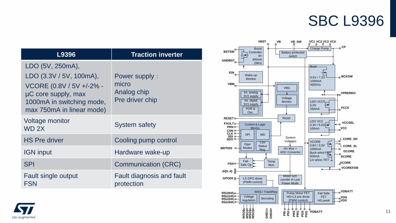
SBC L9396
L9396 Traction inverter
LDO (5V, 250mA),
LDO (3.3V / 5V, 100mA),
VCORE (0.8V / 5V +/-2% -
µC core supply, max
1000mA in switching mode,
max 750mA in linear mode)
Power supply:micro
Analog chip
Pre driver chip
Voltage monitor
WD 2XSystem safety
HS Pre driver Cooling pump control
IGN input Hardware wake-up
SPI Communication (CRC)
Fault single output
FSN
Fault diagnosis and fault
protection
FAULT
WDTDIS
Voltage
Monitor
Wake-up
Monitor
IGN
Boost
Controller
9V
300mA
2MHzGNDBST
BSTSW
VBG
VBM
VBST
CPCharge Pump
GN
DA
ResetRESET
GN
D1
Control & Logic
Blocks
SPI
Ctrl/
Status
Reg.
Temp
Mon
Oper
Modes
Fail-
Safe OpFSN
WD
CSN
SDISDO
CLK
Int. analog
3V3 supply
Int. digital
3V3 supply
POR &
Osc.
Buck
6.5V / 7.2V
1000mA
465KHz
BCKSW
VPREREG
LDO VCC5
5.0V
250mA VCC5
LDO VCC
3.3V / 5.0V
100mA VCC
VCCSEL
VCORE
0.8V / 3.3V
1000mA
Buck w/ext FET
500mA
Lin w/ext. FET
VCOREFDBK
Fail Safe
FET
HS predr
Pump Motor FET
HS+LS pre driver
(PWM control)
PD
S
VDBATTWSS / TrackRegRSU0H/L
WS
O0
WS
O1
WS
O2
WS
O3
AI[0..4]
HV Mux +
ADC Converter
Battery protected
switch
VB VB_SW
Decoding
GCORE
VC1 VC2
PD
G
VDSVDG
SCORE
System
Voltages
LS GPO driver
(PWM control)
GPOD0
Voltage
regulation
Motor turn
counter in Low
Power Mode
VC3 VC4
I_CORE_SH
I_CORE_SL
VCORE
PRN
RSU1H/LRSU2H/LRSU3H/L
PR
S
PR
G
PR
I
PD
I PDBATT 11
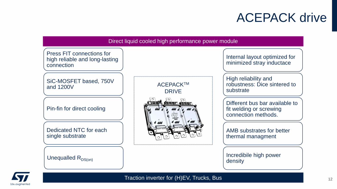
ACEPACK drive
Direct liquid cooled high performance power module
Traction inverter for (H)EV, Trucks, Bus
Press FIT connections for high reliable and long-lasting connection
SiC-MOSFET based, 750V and 1200V
Pin-fin for direct cooling
Dedicated NTC for each single substrate
Unequalled RDS(on)
ACEPACKTM
DRIVE
Internal layout optimized for minimized stray inductace
High reliability and robustness: Dice sintered to substrate
Different bus bar available to fit welding or screwing connection methods.
AMB substrates for better thermal managment
Incredibile high power density
12
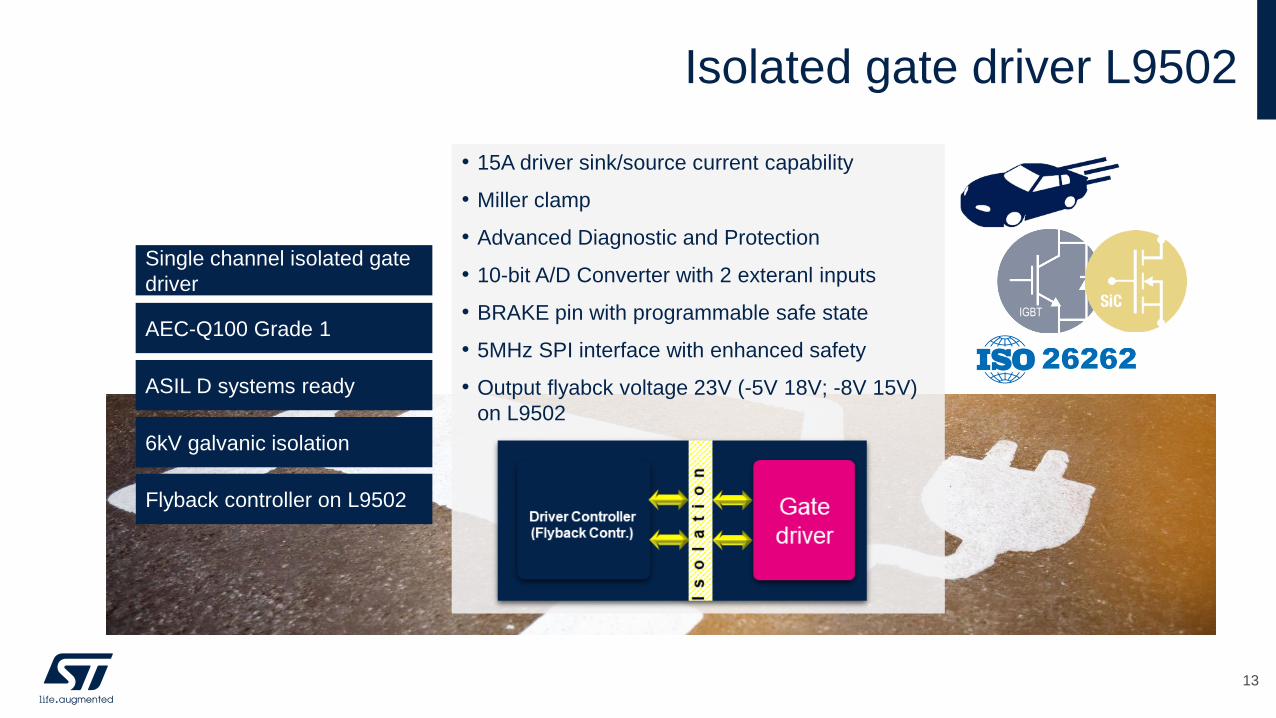
Isolated gate driver L9502
• 15A driver sink/source current capability
• Miller clamp
• Advanced Diagnostic and Protection
• 10-bit A/D Converter with 2 exteranl inputs
• BRAKE pin with programmable safe state
• 5MHz SPI interface with enhanced safety
• Output flyabck voltage 23V (-5V 18V; -8V 15V)
on L9502
Single channel isolated gate
driver
AEC-Q100 Grade 1
ASIL D systems ready
6kV galvanic isolation
Flyback controller on L9502
IGBT
13
Traction inverter system support package
14
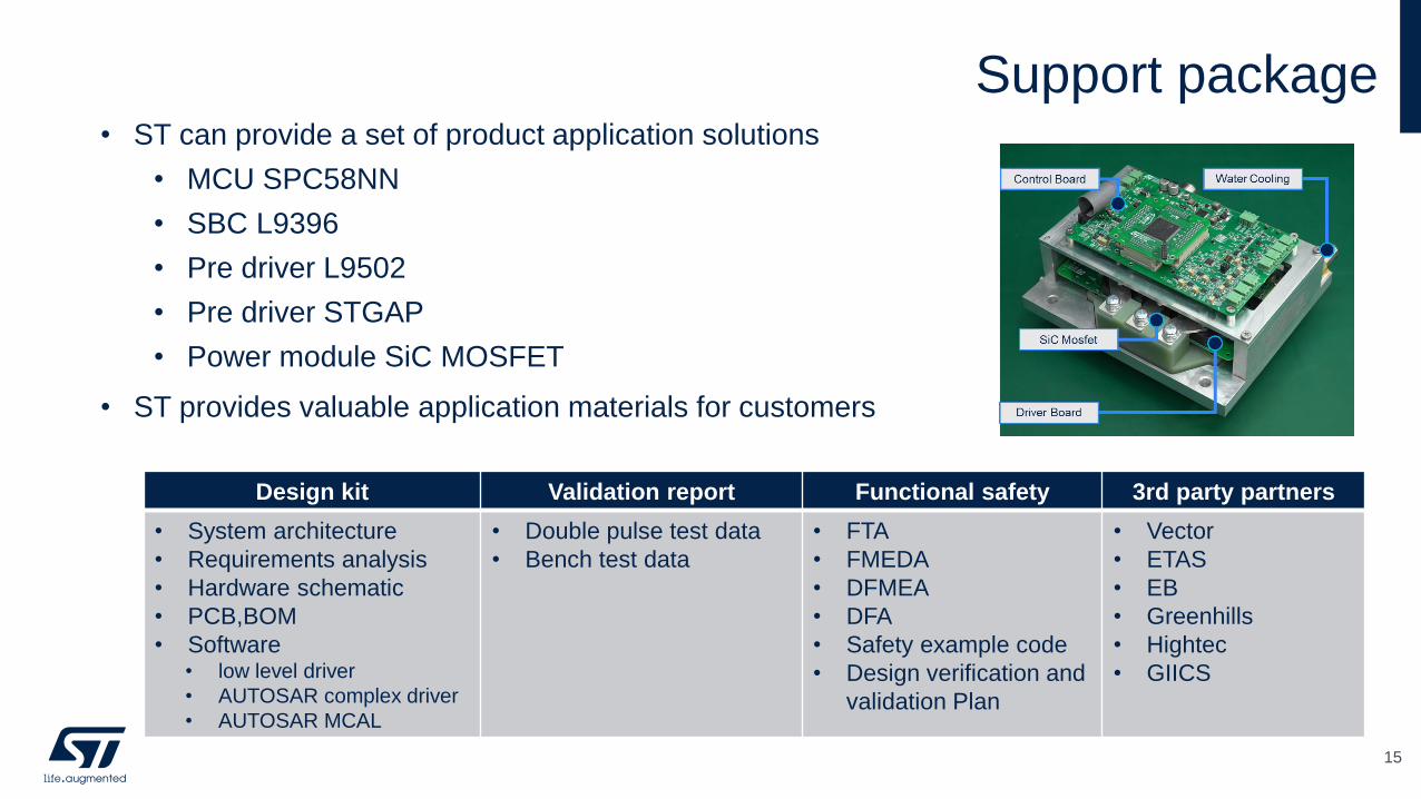
• ST can provide a set of product application solutions
• MCU SPC58NN
• SBC L9396
• Pre driver L9502
• Pre driver STGAP
• Power module SiC MOSFET
• ST provides valuable application materials for customers
Support package
15
Design kit Validation report Functional safety 3rd party partners
• System architecture
• Requirements analysis
• Hardware schematic
• PCB,BOM
• Software • low level driver
• AUTOSAR complex driver
• AUTOSAR MCAL
• Double pulse test data
• Bench test data
• FTA
• FMEDA
• DFMEA
• DFA
• Safety example code
• Design verification and
validation Plan
• Vector
• ETAS
• EB
• Greenhills
• Hightec
• GIICS
© STMicroelectronics - All rights reserved.
The STMicroelectronics corporate logo is a registered trademark of the STMicroelectronics
group of companies. All other names are the property of their respective owners.
Thank you