st60 tridata instrument owner’s handbook · marine electronics association ... (not illustrated)....
TRANSCRIPT

ST60 TridataInstrumentOwner’sHandbook
Document number: 81040-3Date: 1st April 2001
040_3cov.p65 06/04/01, 10:201

© Copyright Raymarine Limited 2001
040_3cov.p65 06/04/01, 10:202

Introduction i
ContentsIntroduction ............................................................................ v
EMC conformance ............................................................ v
Data inputs ....................................................................... vi
SeaTalk ....................................................................... vi
Stand alone operation ................................................. vi
Remote control ................................................................. vi
Mounting options ............................................................ vii
Parts supplied ..................................................................... viii
Chapter 1: Operation ............................................................. 1
1.1 Getting started ............................................................. 1
Calibration requirement .............................................. 1
Displayed information ................................................. 1
1.2 Normal operation ........................................................ 1
Depth ........................................................................... 2
Current depth display ............................................ 2
Depth alarm threshold displays ............................. 3
Adjusting alarm thresholds .............................. 3
Speed ........................................................................... 3
Boat speed ............................................................. 3
Maximum speed .................................................... 4
Average speed ........................................................ 4
Velocity made good (to windward) ....................... 4
Trip .............................................................................. 5
Log ......................................................................... 5
Trip screen ............................................................. 5
Water temperature .................................................. 6
Timers .................................................................... 6
Race-start timers .............................................. 6
040_3int.p65 06/04/01, 10:201

ii ST60 Tridata Instrument Owner’s Handbook
1.3 Alarms ......................................................................... 7
1.4 Display settings ........................................................... 7
Illumination ................................................................. 7
Contrast ....................................................................... 7
1.5 Remote control ............................................................ 8
Chapter 2: Maintenance and Fault Finding ........................ 9
2.1 Maintenance ................................................................ 9
Servicing and safety .................................................... 9
Instrument ................................................................... 9
Transducers ................................................................. 9
Cabling ........................................................................ 9
2.2 Fault finding .............................................................. 10
Preliminary procedures ............................................. 10
Fixing faults .............................................................. 10
Chapter 3: Installation ......................................................... 13
3.1 Planning your installation ......................................... 13
Site requirements ....................................................... 13
Transducers .......................................................... 13
Instrument ............................................................ 15
EMC guidelines ......................................................... 16
Suppression ferrites ............................................. 17
Connections to other equipment .................... 17
3.2 Procedures ................................................................. 17
Unpacking ................................................................. 18
Fitting the instrument ................................................ 18
Surface mounting ................................................ 18
Flush mounting .................................................... 19
Fitting the low-profile bezel ........................... 19
Flush mounting procedure ............................. 20
040_3int.p65 06/04/01, 10:202

Introduction iii
Bracket mounting ................................................ 22
Fitting transducer ...................................................... 22
Running transducer cable .................................... 22
Connecting the instrument ........................................ 23
Types of connection ............................................. 23
Signal connections ............................................... 23
Power supply connections ................................... 24
SeaTalk systems ............................................. 24
Stand alone instruments ................................. 25
Chapter 4: Calibration ......................................................... 27
4.1 Introduction .............................................................. 27
Speed readings ..................................................... 27
EMC conformance .................................................... 27
4.2 User calibration ......................................................... 28
Depth ......................................................................... 29
Depth units .......................................................... 29
Depth offset ......................................................... 30
Shallow alarm lock .............................................. 31
Speed ......................................................................... 31
Set speed units ..................................................... 31
Set speed resolution ............................................. 31
Set log units ......................................................... 31
Setting the correct speed ...................................... 31
Adjust to SOG ................................................ 33
Cal factor adjust ............................................. 33
Set temperature units ........................................... 33
Temperature calibration ....................................... 33
Timer alarm buzzer .............................................. 33
Leaving User calibration ........................................... 34
040_3int.p65 06/04/01, 10:203

iv ST60 Tridata Instrument Owner’s Handbook
4.3 Intermediate calibration ............................................ 34
Speed calibration ....................................................... 35
Leaving Intermediate calibration .............................. 39
4.4 Dealer calibration ...................................................... 39
User calibration on/off .............................................. 39
Response settings ...................................................... 39
Boat show mode ........................................................ 41
Factory defaults ......................................................... 41
Leaving Dealer calibration ........................................ 41
040_3int.p65 06/04/01, 10:204
Introduction v
IntroductionThank you for purchasing a Raymarine product. We are sure yourST60 instrument will give you many years of trouble-free operation.
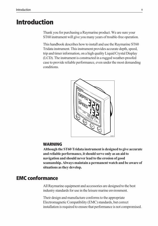
This handbook describes how to install and use the Raymarine ST60Tridata instrument. This instrument provides accurate depth, speed,trip and timer information, on a high quality Liquid Crystal Display(LCD). The instrument is constructed in a rugged weather-proofedcase to provide reliable performance, even under the most demandingconditions.
D4324-1
WARNINGAlthough the ST60 Tridata instrument is designed to give accurateand reliable performance, it should serve only as an aid tonavigation and should never lead to the erosion of goodseamanship. Always maintain a permanent watch and be aware ofsituations as they develop.
EMC conformanceAll Raymarine equipment and accessories are designed to the bestindustry standards for use in the leisure marine environment.
Their design and manufacture conforms to the appropriateElectromagnetic Compatibility (EMC) standards, but correctinstallation is required to ensure that performance is not compromised.
040_3int.p65 06/04/01, 10:205
vi ST60 Tridata Instrument Owner’s Handbook
Data inputsThe ST60 Tridata instrument can fulfil master and/or repeater roles byreceiving data either from the appropriate transducers and/or from aSeaTalk instrumentation system.
SeaTalkSeaTalk enables a number of compatible instruments to operate as asingle, integrated navigational system. Instruments in a SeaTalksystem are linked by means of a single cable, which feeds both powerand data. Instruments can therefore be added to the system by pluggingthem into the network. SeaTalk is flexible enough to adapt to anynumber of compatible instruments without requiring a centralprocessor. SeaTalk can also communicate via an interface, with non-SeaTalk equipment using the internationally-accepted NationalMarine Electronics Association (NMEA) protocol.
In a SeaTalk system, each instrument can be either a master ordedicated repeater unit. A master instrument is directly connected to atransducer (the device that provides the raw data), and transmits dataand control to other units on the network. A slave instrument is notdirectly connected to a transducer but repeats information provided byother equipment in the SeaTalk network.
Stand alone operationIn Stand alone operation, the ST60 Tridata instrument is connectedonly to the relevant transducers and does not display information from,or provide information to, any other instruments.
Remote controlWhen connected to SeaTalk, the ST60 Tridata instrument can becontrolled remotely by a SeaTalk Remote Keypad Unit, to provideinstant remote access to the various display readouts.
040_3int.p65 06/04/01, 10:206

Introduction vii
Mounting optionsIf you do not want to surface mount your ST60 instrument, options areavailable for:
• Flush mounting. If you have ordered the flush mounting option alow-profile bezel and four fixing screws are also provided.
• Bracket mounting.
040_3int.p65 06/04/01, 10:207

viii ST60 Tridata Instrument Owner’s Handbook
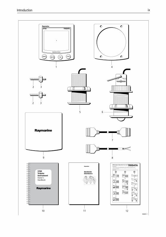
Parts suppliedUnpack your ST60 instrument and check that the following items arepresent:
• Item 1, ST60 Tridata instrument fitted with standard bezel forsurface mounting.
• Item 2, Fixing studs (2).
• Item 3, Thumb nuts (2).
• Item 4, Gasket.
• Item 5, Depth transducer.
• Item 6, Speed transducer, plus bung (not illustrated).
• Item 7, SeaTalk interconnection cable.
• Item 8, Power cable.
• Item 9, Instrument Cover.
• Item 10, Owner’s Handbook. A Warranty document and fittingtemplates are included in this Handbook.
• Item 11, Worldwide Service Centre Handbook.
• Item 12, Cue Card.
Spare spade terminals are also provided, to re-terminate transducercables if they have to be cut to facilitate installation.
Note: The above packing list is for an ST60 Tridata system. Where aninstrument is purchased separately, Speed and Depth transducers arenot included.
040_3int.p65 06/04/01, 10:208
Introduction ix
D4441-1
ST60 TridataInstrumentOwner'sHandbook
WorldwideDistributors
1 4
9
32
32
6
7
8
1110
5
TRIDATA
depth
Currentdepth
Shallow AlarmThreshold
reset
3s to Reset
Start/Stop
reset
Anchor shallowalarm threshold
Deepalarm threshold
speed
Boat speed
Maximumspeed
VMG towindward
Average speed
Anchor deepalarm threshold
trip
Log
Watertemperature
Count-up timer
10 minuterace start time
5 minuterace start timer
reset
3s to Reset
reset
3s to Reset
reset
3s to Reset
Start/Stop
reset reset
3s to Reset
Start/Stop
reset reset
3s to Reset
Trip
12
040_3int.p65 06/04/01, 10:219

x ST60 Tridata Instrument Owner’s Handbook
040_3int.p65 06/04/01, 10:2110
Chapter 1: Operation 1
Chapter 1: Operation1.1 Getting started
This handbook describes how to operate, maintain and install theRaymarine ST60 Tridata instrument.
Calibration requirementThe ST60 Tridata instrument is calibrated to factory (default) settingswhen first installed and must therefore be calibrated before use, inaccordance with the procedures in Chapter 4, Calibration, to ensureoptimum performance on your vessel.
Do NOT use the instrument until the calibration procedures havebeen satisfactorily completed.
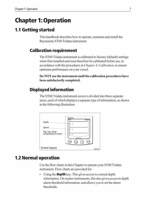
Displayed informationThe ST60 Tridata instrument screen is divided into three separateareas, each of which displays a separate type of information, as shownin the following illustration.
Depth
Speed
Trip, log, watertemperature & timer
Screen layout D4424-2
1.2 Normal operationUse the flow charts in this Chapter to operate your ST60 Tridatainstrument. Flow charts are provided for:
• Using the depth key. This gives access to current depthinformation. On master instruments, this also gives access to depthalarm threshold information, and allows you to set the alarmthresholds.
040_3c01.p65 06/04/01, 10:211

2 ST60 Tridata Instrument Owner’s Handbook
• Using the speed key. This gives access to maximum speed,average speed and Velocity Made Good (VMG) to windward.
• Using the trip key to gain access to log, trip, water temperature andtimer information.
All key presses are momentary unless otherwise stated.
DepthUse the depth key to select the required information, as shown in theUsing the depth key illustration. The depth measurement units areeither feet or metres, as selected during user calibration (see Chapter 4,Calibration).
Current depth
Shallowalarm threshold
Deepalarm threshold
Anchor shallowalarm threshold
Anchor deepalarm threshold
depth
depth
depth
depth
Using the depth key D4413-1
depth
reset
reset
reset
To enter and exit alarm adjust mode
In adjust mode, use
To enable/disable any alarm
trip
trip
Press for 2 seconds(toggle action)
Press and together
to decrease or to increase
Current depth displayThe current depth screen shows the title DEPTH, the selected depth unitsand the depth measurement. It also shows a depth trend indicator,which is either an up arrow to show seabed rising or a down arrow toshow seabed falling.
040_3c01.p65 06/04/01, 10:212

Chapter 1: Operation 3
If for any reason depth information is lost, the DEPTH title will flashonce per second and the displayed depth value will be the last goodreading.
Depth alarm threshold displaysThe alarm threshold displays are available if the instrument isoperating as a master. Each display is identified by the presence of analarm symbol and either an up arrow for a shallow alarm or a downarrow for a deep alarm. The shallow and deep anchor alarms areidentified by means of an additional anchor icon.
You can enable and disable individual alarm thresholds by pressing thereset key for 2 seconds, while the relevant alarm threshold isdisplayed.
Each alarm threshold is displayed for a nominal 7 seconds, and if noaction is taken during that time, the display will timeout to the currentdepth display.
Adjusting alarm thresholds
To adjust the alarm threshold levels, press the trip and reset keyssimultaneously to enter adjust mode, then use either the trip key (todecrease) or the reset key (to increase) the threshold value. When youhave set the required value, momentarily press the trip and reset keysagain, to save the alarm setting and exit the adjust mode.
Note: Adjustment of the shallow alarm threshold can be disabledduring calibration. When adjustment is disabled, you cannot enteradjust mode.
SpeedUse the speed key to select the required information, as shown in theUsing the speed key illustration. The speed measurement units areeither knots (KTS), miles per hour (MPH) or kilometres per hour (KMH),as selected during user calibration (see Chapter 4, Calibration).
The maximum speed, average speed and VMG to windward are eachdisplayed for a nominal 7 seconds, and if no action is taken during thattime, the display will timeout to the Boat speed display.
Boat speedShows the current speed and selected speed units.
040_3c01.p65 06/04/01, 10:213

4 ST60 Tridata Instrument Owner’s Handbook
speed
VMG towindward
speed
speed
Using the speed key D4414-1
Boat speed
Maximumspeed
Average speed speed
Maximum speedThe screen shows the maximum speed attained since the last reset.
The maximum speed value is reset automatically at power-up. If theinstrument is operating as a master, the maximum speed can also bereset manually by pressing the reset key for 2 seconds.
Average speedThe screen shows the average speed since the last reset.
The average speed value is reset automatically at power-up. If theinstrument is operating as a master, the average speed can also be resetmanually by pressing the reset key for 2 seconds.
Velocity made good (to windward)Velocity made good (VMG) information is available if your instrumentis part of a SeaTalk system to which a SeaTalk-compatible windinstrument is also connected.
040_3c01.p65 06/04/01, 10:214
Chapter 1: Operation 5
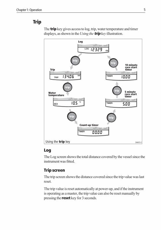
TripThe trip key gives access to log, trip, water temperature and timerdisplays, as shown in the Using the trip key illustration.
trip
trip
trip trip
Using the trip key D4415-1
Log
Trip
Watertemperature
Count-up timer
10 minuterace starttimer
5 minuterace starttimer
trip
trip
LogThe Log screen shows the total distance covered by the vessel since theinstrument was fitted.
Trip screenThe trip screen shows the distance covered since the trip value was lastreset.
The trip value is reset automatically at power-up, and if the instrumentis operating as a master, the trip value can also be reset manually bypressing the reset key for 3 seconds.
040_3c01.p65 06/04/01, 10:215
6 ST60 Tridata Instrument Owner’s Handbook
Water temperatureThe water temperature is shown in either degrees Celsius (°C) orFahrenheit (°F), as set during calibration (see Chapter 4, Calibration).
TimersThree timers are available:
• Count-up timer.
• 5-minute race start.
• 10-minute race start.
Times are either in seconds (S) or minutes (M), depending on thecounter values.
Use the trip key to select the required timer (see Using trip key flowdiagram). Once you have selected the required timer display, press thereset key to start the timer running. When a timer is running, thedelimiter (i.e. ‘.’or ‘:’) flashes. For lap timing, press the reset keymomentarily. To stop and reset a timer to the start value, press thereset key for 1 second.
Once a timer is running, you can leave the timer page and select anyother display. The counter will continue to run in the background.
Race-start timers
If you are using one of the race-start timers and the timer buzzer isenabled, the buzzer will:
• Double-beep every minute.
• Beep three times at the start of the last 30 seconds.
• Beep once for each of the last 10 seconds.
• Beep for 2 seconds at zero.
The timer buzzer is enabled or disabled as part of the calibrationprocedure (see Chapter 4, Calibration).
Note: After a race-start timer has counted-down to zero, it will thenstart counting up.
040_3c01.p65 06/04/01, 10:216

Chapter 1: Operation 7
1.3 AlarmsAn alarm condition occurs if:
• The depth is less than the SHALLOW or SHALLOW anchor threshold.
• The depth is greater than the DEEP anchor threshold.
• The depth crosses the DEEP threshold.
An alarm condition is indicated by an alarm buzzer and a flashingalarm symbol (bell icon) on the display. SHALLOW or DEEP alarms areindicated by up and down arrows respectively, and for anchor alarmsan anchor symbol is displayed..
When the instrument is operating as a master, you can check the alarmthresholds and if necessary set them up, as detailed under Normaloperation - Depth. If an alarm is not enabled, the associated displayshows an OFF legend.
1.4 Display settings
IlluminationWhen the instrument is first powered up, the display illumination is setto its lowest (courtesy) level, to facilitate initial access to the keys.
To adjust the level of display illumination:
1. Hold down the depth key for approximately one second, to enterthe illumination-adjust mode.
2. There are four preset illumination levels. Momentarily press thedepth key to cycle through the these levels until you reach thelevel you want.
3. Press any other key to leave the illumination-adjust mode.
Note: The display will also return to normal operation 7 seconds afterthe last key press.
ContrastTo adjust the display contrast:
1. Hold down the depth key for approximately two seconds, toenter the contrast-adjust mode.
040_3c01.p65 06/04/01, 10:217

8 ST60 Tridata Instrument Owner’s Handbook
2. There are four preset contrast settings. Momentarily press thedepth key to cycle through the these settings until you achieveoptimum display quality.
3. Press any other key to leave the contrast-adjust mode.
Note: The display will also return to normal operation 7 seconds afterthe last key press.
1.5 Remote controlWhen it is connected to SeaTalk, the ST60 Tridata instrument can becontrolled remotely with a SeaTalk Remote Keypad Unit. Remotecontrol of an instrument is indicated by a REMOTE legend on thedisplay, to indicate that the keypad has control.
Details on how to use the remote control facility can be found in theSeaTalk Remote Keypad Owner’s Handbook.
040_3c01.p65 06/04/01, 10:218
Chapter 2: Maintenance and Fault Finding 9
Chapter 2: Maintenance and Fault Finding2.1 Maintenance
Servicing and safety• Raymarine equipment should be serviced only by authorised
Raymarine service engineers. There are no user-serviceable parts inany Raymarine product.
• Some products generate high voltages, and so never handle thecables/connectors when power is being applied to the equipment.
• Always report any EMC related problem to your nearestRaymarine dealer. We will use any such information to improveour quality standards.
When requesting service, please quote equipment Type, ModelNumber and, if possible, Software Release Issue. The SoftwareRelease Issue can be ascertained by means of the IntermediateCalibration facility, see Chapter 4, Calibration.
InstrumentCertain atmospheric conditions may cause condensation to form on theinstrument window. This will not harm the instrument and can becleared by increasing the illumination to the brightest setting.
Periodically clean your ST60 instrument with a soft damp cloth. DoNOT use chemical and abrasive materials to clean the instrument.
TransducersRefer to the Installation and Maintenance instructions supplied withthe transducers.
CablingExamine all cables for chafing or other damage to the outer shield and,where necessary, replace and re-secure.
040_3c02.p65 06/04/01, 10:219
10 ST60 Tridata Instrument Owner’s Handbook
2.2 Fault finding
PrPrPrPrPreliminary preliminary preliminary preliminary preliminary proceduroceduroceduroceduroceduresesesesesChanges in the electronic environment may adversely affect theoperation of your ST60 equipment. Typical examples of such changesare:
• Electrical equipment has recently been installed or moved aboardyour vessel.
• You are in the vicinity of another vessel or shore station emittingradio signals.
If you appear to have a problem, first ensure that the EMCrequirements (see Chapter 3, Installation) are still being met beforefurther investigating the problem.
Fixing faultsAll Raymarine products are subjected to comprehensive test andquality assurance programmes prior to packing and shipping.However, if a fault occurs, use the following table to help identify andrectify the problem.
040_3c02.p65 06/04/01, 10:2110

Chapter 2: Maintenance and Fault Finding 11
Fault Cause Remedy
Instrument display blank. No supply. Check supply.Check cabling and security ofSeaTalk connectors.Check fuse/breaker.Return unit for repair.
No speed or temperature Speed transducer Check cabling andinformation. cabling problem security of transducer
connections.
No speed information. Speed transducer Clean paddle wheel.paddle wheel fouled See CAUTION below
No exchange of information SeaTalk cabling Check security of SeaTalkbetween SeaTalk instruments problem. connectors.
Disconnect instruments one byone to isolate faulty unit
Failure of a group of SeaTalk cabling or Check security of connectionsinstruments in SeaTalk chain connector problem. between functioning and
non-functioning instruments
LAST flashing or dashes Depth transducer or Check cabling cable ordisplayed continuously. connector problem. and security of transducer(depth greater than 3 feet) connections.
LAST flashes while Aerated water Ensure readings stabilisesunder way. Boat wakes when clear of disturbed water.
Prop wash etc.
CAUTIONIf you need to remove the speed transducer insert, have thetransducer bung to hand and secure it in the transducer bodyimmediately after the insert has been removed, to preventexcessive ingress of water.
If you are unable to rectify a problem, contact the Raymarine ProductSupport Department or your own National Distributor, for assistance.
040_3c02.p65 06/04/01, 10:2111

12 ST60 Tridata Instrument Owner’s Handbook
040_3c02.p65 06/04/01, 10:2112
Chapter 3: Installation 13
Chapter 3: InstallationThis chapter describes how to install the ST60 Tridata instrument, andassociated speed and depth transducers. The transducers are fitted inthe hull of the vessel and connected to the rear of the instrument. Theactual type of transducers depends on the type of hull in which they areto be installed.
For advice, or further information regarding the installation of thisequipment, please contact the Raymarine Product Support Departmentor your own National Distributor.
3.1 Planning your installationBefore starting the installation, spend some time considering the bestpositions for both transducer and instrument, such that the SiteRequirements and the EMC Guidelines (below) are satisfied.
Site requirements
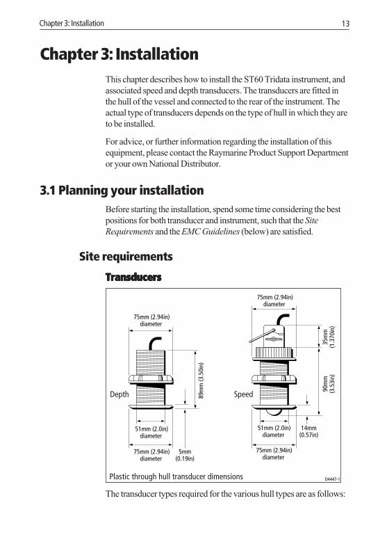
TransducersTransducersTransducersTransducersTransducers
75mm (2.94in)diameter
5mm (0.19in)
75mm (2.94in)diameter
51mm (2.0in)diameter
89m
m (3
.50i
n)
D4447-1Plastic through hull transducer dimensions
75mm (2.94in)diameter
14mm (0.57in)
90m
m(3
.53i
n)35
mm
(1.3
70in
)
75mm (2.94in)diameter
51mm (2.0in)diameter
Depth Speed
The transducer types required for the various hull types are as follows:
040_3c03.p65 06/04/01, 10:2113

14 ST60 Tridata Instrument Owner’s Handbook
Hull material Speed transducer Depth transducer
Glass reinforced M78712 Through hull plastic M78713 Through hull plastic, orplastic (GRP) M78718 Retractable through hull
Steel M78712 Through hull plastic M78713 Through hull plastic, orM78718 Retractable through hull
Aluminium M78712 Through hull plastic M78713 Through hull plastic, orM78718 Retractable through hull
Wood M78716 Through hull bronze M78714 Through hull bronze, orM78919 Retractable through hullbronze
Other transducer types are also available for specific requirements. Forfurther details, contact your local Raymarine dealer.
For accurate speed and depth readings the transducers should be sitedwithin the clear water flow areas indicated by the shaded areas in thefollowing diagram.
Sailing vessel
Planing powervessel
Displacement powervessel
Transducer siting D4349-1
The transducer should also:
• Be ahead of the propellers (10% of the water line length minimum).
• Be at least 150 mm (6 in) away from the keel (ideally ahead of thekeel if a sailing yacht).
• Be as near as possible to the centre line of the vessel.
040_3c03.p65 06/04/01, 10:2114
Chapter 3: Installation 15
• Be clear of other through-hull fittings or projections.
• Have sufficient clearance inside the hull to fit the nut.
• Have 100 mm (4 in) of headroom to allow for withdrawal.
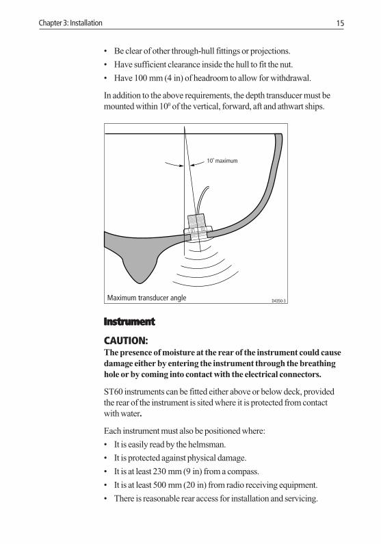
In addition to the above requirements, the depth transducer must bemounted within 100 of the vertical, forward, aft and athwart ships.
10˚ maximum
Maximum transducer angle D4350-3
InstrumentInstrumentInstrumentInstrumentInstrument
CAUTION:The presence of moisture at the rear of the instrument could causedamage either by entering the instrument through the breathinghole or by coming into contact with the electrical connectors.
ST60 instruments can be fitted either above or below deck, providedthe rear of the instrument is sited where it is protected from contactwith water.
Each instrument must also be positioned where:
• It is easily read by the helmsman.
• It is protected against physical damage.
• It is at least 230 mm (9 in) from a compass.
• It is at least 500 mm (20 in) from radio receiving equipment.
• There is reasonable rear access for installation and servicing.
040_3c03.p65 06/04/01, 10:2115

16 ST60 Tridata Instrument Owner’s Handbook
110mm (4.33in) 24mm(0.95in)
15mm(0.6in)
90m
m (4
.33i
n)di
amet
er
115m
m (4
.53i
n)
123mm (4.85in) 6.2mm(0.25in)
35mm(1.4in)
90m
m (4
.33i
n)di
amet
er
123m
m (4
.85i
n)
D4402-2Instrument dimensions
With standardbezel
With lowprofile bezel
EMC guidelinesAll Raymarine equipment and accessories are designed to the bestindustry standards for use in the leisure marine environment.
Their design and manufacture conforms to the appropriateElectromagnetic Compatibility (EMC) standards, but correctinstallation is required to ensure that EMC performance is notcompromised. Although every effort has been taken to ensure that theywill perform under all conditions, it is important to understand whatfactors could affect the operation of this product.
To minimise the risk of operating problems:
• All Raymarine equipment and cables connected to it should be:
• At least 1 m (3 feet) from any equipment transmitting or cablescarrying radio signals, e.g. VHF radios, cables and antennas. Inthe case of SSB radios, the distance should be increased to 2 m(7 ft).
• More than 2 m (6 ft) from the path of a radar beam. A radarbeam can normally be assumed to spread 20o above and belowthe radiating element.
040_3c03.p65 06/04/01, 10:2116

Chapter 3: Installation 17
• The equipment should be supplied from a different battery than theone used for engine start. Voltage drops below 10 V in the powersupply to our products can cause the equipment to reset. This willnot damage the equipment, but will cause the loss of someinformation and can change the operating mode.
• Genuine Raymarine cables should be used at all times. Cutting andrejoining these cables can compromise EMC performance and soshould be avoided unless doing so is detailed in the installationmanual.
• If a suppression ferrite is attached to a cable, this ferrite should notbe removed. If the ferrite has to be removed during installation itmust be reassembled in the same position.
Suppression ferritesThe following illustration shows the typical range of suppressionferrites fitted to Raymarine equipment. Always use the ferritesspecified by Raymarine.
Connections to other equipmentConnections to other equipmentConnections to other equipmentConnections to other equipmentConnections to other equipment
If your Raymarine equipment is going to be connected to otherequipment using a cable not supplied by Raymarine, a suppressionferrite MUST always be fitted to the cable close to the Raymarine unit.
3.2 ProceduresAs it is not possible to describe procedures for all possible installationscenarios, the procedures given here describe the broad requirementsfor installing the Speed and Depth transducers and the ST60 Tridatainstrument. Adapt these procedures as appropriate, to suit yourindividual requirement.
CAUTION:Where it is necessary to cut holes (e.g. for cable routing andinstrument mounting), ensure that these will not cause a hazard byweakening critical parts of the vessel’s structure.
040_3c03.p65 06/04/01, 10:2117

18 ST60 Tridata Instrument Owner’s Handbook
UnpackingUnpack your ST60 equipment and check that the items described inIntroduction are present.
Each ST60 instrument is supplied with a standard bezel for surfacemounting. Optional mounting kits are available for flush mounting andbracket mounting the instrument. If you have ordered the flushmounting option a low-profile bezel and four fixing screws are alsoprovided.
Fitting the instrumentThe ST60 Tridata instrument can be installed using one of a number ofdifferent mounting options:
• Surface mounting. Gives a profile of approximately 24 mm.
• Flush mounting. Gives a profile of approximately 6 mm.
• Bracket mounting.
The ST60 instruments can also be mounted behind a panel with justthe instrument dial and keys visible.
Surface mountingTo surface mount your ST60 instrument (see the Surface mountingillustration):
1. Ensure that:
• The selected location is clean, smooth and flat.
• There is sufficient space behind the location to accommodatethe rear of the instrument and connectors.
2. Apply the surface mount template (supplied at the rear of thishandbook) to the selected location and mark the centres for thefixing studs (1) and the aperture (3) that will take the rear casing ofthe instrument.
3. Drill out the two 5 mm fixing stud clearance holes (2).
4. Cut out the clearance hole (3) then remove the template.
5. Peel off the protective sheet from the self-adhesive gasket (4) thenstick the gasket into position on the rear of the instrument.
6. Screw the two fixing studs into the threaded sockets on the rear ofthe instrument.
7. Mount the assembled instrument, studs, bezel and gasket into thepanel. Secure from behind with the thumb nuts (5).
040_3c03.p65 06/04/01, 10:2118

Chapter 3: Installation 19
D4343-2Surface mounting1 12 234 5 5
Flush mountingThe Flush Mounting Kit uses a low-profile bezel to reduce the fittedprofile of the instrument, to approximately 6 mm above the panelfascia.
Fitting the low-profile bezelFitting the low-profile bezelFitting the low-profile bezelFitting the low-profile bezelFitting the low-profile bezel
In order to flush-mount your ST60 instrument, you must first replacethe standard bezel with the low-profile bezel as follows:
1. Hold the instrument in both hands with the display towards you.
2. Using both thumbs, gently press an upper corner of the instrumentfrom the bezel, then remove the bezel from the instrument. Retainthe rubber keypad which is released when the bezel is removed.
D4537-2
040_3c03.p65 06/04/01, 10:2119
20 ST60 Tridata Instrument Owner’s Handbook
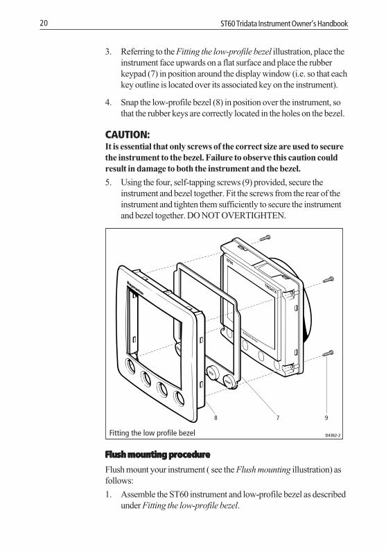
3. Referring to the Fitting the low-profile bezel illustration, place theinstrument face upwards on a flat surface and place the rubberkeypad (7) in position around the display window (i.e. so that eachkey outline is located over its associated key on the instrument).
4. Snap the low-profile bezel (8) in position over the instrument, sothat the rubber keys are correctly located in the holes on the bezel.
CAUTION:It is essential that only screws of the correct size are used to securethe instrument to the bezel. Failure to observe this caution couldresult in damage to both the instrument and the bezel.
5. Using the four, self-tapping screws (9) provided, secure theinstrument and bezel together. Fit the screws from the rear of theinstrument and tighten them sufficiently to secure the instrumentand bezel together. DO NOT OVERTIGHTEN.
D4362-2
78 9
Fitting the low profile bezel
Flush mounting procedureFlush mounting procedureFlush mounting procedureFlush mounting procedureFlush mounting procedure
Flush mount your instrument ( see the Flush mounting illustration) asfollows:
1. Assemble the ST60 instrument and low-profile bezel as describedunder Fitting the low-profile bezel.
040_3c03.p65 06/04/01, 10:2120

Chapter 3: Installation 21
2. Ensure that:
• The panel on which you intend to mount the instrument isbetween 3 mm and 20 mm thickness.
• The selected location is clean, smooth and flat.
• There is sufficient space behind the location to accommodatethe rear of the instrument and connectors.
3. Apply the flush mount template (supplied at the rear of thishandbook) to the selected location and mark out the aperture intowhich the assembled instrument and bezel will sit.
4. Cut out the aperture (3) for the assembled instrument and bezeland remove the template.
5. Peel off the protective sheet from the self-adhesive gasket (4) thenstick the gasket into position on the rear of the bezel.
Flush mounting D5462-1
1 13
4
5 56
6. Screw the two fixing studs (1) into the threaded sockets on the rearof the instrument.
7. Mount the assembled instrument, studs, bezel and gasket into thepanel.
8. Locate the flush mount bracket (6) onto the fixing studs andsecure the assembly to the panel with the thumb-nuts (5).
040_3c03.p65 06/04/01, 10:2121

22 ST60 Tridata Instrument Owner’s Handbook
Bracket mountingA Control Unit Mounting Bracket (Part No. E25009) enables you tomount your ST60 instrument in locations where other forms ofmounting are impractical. Although this provides a useful alternativemethod for securing your instrument, it is only suitable for use inpositions where the instrument will not be exposed to water.
To bracket mount your ST60 instrument, do so in accordance with theControl Unit Mounting Bracket Instruction Sheet.
Fitting transducerThe ST60 Tridata instrument is supplied, with appropriate through-hull Speed and Depth transducers.
Each transducer is supplied with detailed instructions for installationand maintenance. Before attempting to install a transducer, read theseinstructions and the Site requirements for transducers described in thisChapter.
Once you are satisfied you can meet all the installation requirements,install the transducer in accordance with the accompanying installationinstructions.
Running transducer cableEach transducer type has a 14 m (45 ft) cable fitted with spadeterminals for connection to the ST60 Tridata instrument. The mannerin which you run the cable will depend on the locations of thetransducer and instrument. The following guidelines are provided:
• If the cable has to be fed through the deck, always use a proprietarydeck gland.
• Where cables are fed through holes, always use grommets toprevent chafing.
• Secure long cable runs so they do not present a hazard.
• Do not route the cable through bilges.
• Wherever possible, route the cable away from fluorescent lights,engines, radio transmitting equipment, as these may causeinterference.
040_3c03.p65 06/04/01, 10:2122

Chapter 3: Installation 23
• It may be necessary to remove the spade connectors from thetransducer cable, to facilitate installation, e.g. if the cable has to berouted through narrow apertures. Extra spade connectors areprovided, to replace any that are removed when running the cable.In order to ensure a secure connection when fitting spadeconnectors, fold back the wire strands as shown in the followingillustration, before inserting the wire in the spade connector. Ensurethe wire strands do not extend beyond the rear of the spadeconnector insulation.
D4467-2Preparing wire for connection
3 mm
4 mm
Observing the above guidelines, run the transducer cable to the ST60Tridata instrument.
Connecting the instrument
Types of connectionThe ST60 Tridata instrument, can be connected:
• As a stand-alone, master instrument connected directly to a Speedand/or Depth transducer.
• As a SeaTalk repeater.
• To fulfil both repeater and master roles by being connected both tothe transducer and to SeaTalk.
Instruments connected to SeaTalk derive their power directly fromSeaTalk and no separate power connection is necessary. Where aSeaTalk system includes an autopilot, the power for the system isprovided by the autopilot.
A range of Raymarine SeaTalk extension cables is available to connectseparated instruments. These cables are supplied with a SeaTalkconnector fitted to each end. A junction box can be used to join cables.
Signal connectionsMake the necessary connections to your ST60 instrument (see theConnection to ST60 Tridata instrument illustration).
040_3c03.p65 06/04/01, 10:2123

24 ST60 Tridata Instrument Owner’s Handbook
SPEEDDEPTH
WhiteBrown
BlackScreenBlue
Connections to ST60 Tri Data instrument
Cable from Depth transducer
Cable from Speed transducer
ScreenGreen
SeaTalk cable SeaTalk cable
D4423-1
Red
Power supply connections
SeaTalk systemsSeaTalk systemsSeaTalk systemsSeaTalk systemsSeaTalk systems
CAUTIONWhen instruments are connected to SeaTalk, ensure that thepower supply for the SeaTalk 12 V line is protected by a 5 A fuse.
Systems with a large number of instruments on the SeaTalk bus mayrequire connections to the power supply from each end of the system(‘ring-main’ style), to maintain sufficient voltage throughout thesystem.
This requirement depends on the total length of the cable run and thetotal number of instruments in the system, as follows:
Cable run No. of instruments Power connections
Up to 10 m 13 maximum 126 maximum 2
Up to 20 m 7 maximum 113 maximum 2
040_3c03.p65 06/04/01, 10:2124
Chapter 3: Installation 25
D4311-1
5 A fused,12 V dc supply
(typically providedby autopilot)
Red
Screen
Red
Screen
1 2 3 4
Instruments5 to 16
17181920
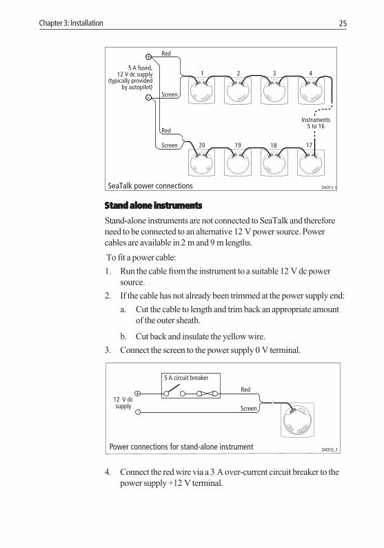
SeaTalk power connections
Stand alone instrumentsStand alone instrumentsStand alone instrumentsStand alone instrumentsStand alone instruments
Stand-alone instruments are not connected to SeaTalk and thereforeneed to be connected to an alternative 12 V power source. Powercables are available in 2 m and 9 m lengths.
To fit a power cable:
1. Run the cable from the instrument to a suitable 12 V dc powersource.
2. If the cable has not already been trimmed at the power supply end:
a. Cut the cable to length and trim back an appropriate amountof the outer sheath.
b. Cut back and insulate the yellow wire.
3. Connect the screen to the power supply 0 V terminal.
4. Connect the red wire via a 3 A over-current circuit breaker to thepower supply +12 V terminal.
040_3c03.p65 06/04/01, 10:2125

26 ST60 Tridata Instrument Owner’s Handbook
040_3c03.p65 06/04/01, 10:2126

Chapter 4: Calibration 27
Chapter 4: Calibration4.1 Introduction
The ST60 Tridata instrument is set up with factory-programmeddefault settings, so in order to optimise the performance of theinstrument on board a particular vessel, the procedures in this Chaptermust be carried out immediately after the completion of installationand before the equipment is used for navigational purposes.
Where practicable, the calibration procedures are presenteddiagrammatically to show the sequence of key presses and theresulting displays. Adjustment instructions are given as applicable.
Speed readingsOne of the reasons for calibration is to ensure that the speed readingsdisplayed on the instrument are a true reflection of the actual speed ofthe vessel.
In User calibration - Speed, you can:
• Automatically set the displayed speed reading to be the same as theSpeed Over Ground (SOG) (if SOG data is available).
• Manually apply a calibration factor, to set the displayed speed to therequired value.
If neither of the above methods are suitable, you can carry out a speedcalibration run over a measured distance, to enable the instrument tocalculate the correct calibration factor. This is described as part ofIntermediate calibration.
EMC conformance• Always check the installation before going to sea to make sure that
it is not affected by radio transmissions, engine starting etc.
• In some installations, it may not be possible to prevent theequipment from being affected by external influences. Althoughthis will not damage the equipment, it can lead to spurious resettingaction, or momentarily may result in faulty operation.
040_3c04.p65 06/04/01, 10:2127

28 ST60 Tridata Instrument Owner’s Handbook
4.2 User calibrationThe User calibration procedures enable you to:
• Set the required units for depth readings.
• Set the offset for depth readings, i.e. determine whether depthreadings are from the keel of the vessel or from the water line.
• Lock the shallow alarm.
• Set the required units for speed readings.
• Set the speed resolution.
• Select the log distance units
• Either calibrate the speed reading to Speed Over Ground (SOG) ormanually apply a calibration factor, to obtain correct speed throughthe water.
• Select temperature units.
• Calibrate for correct temperature readings.
• Set timer alarm buzzer on or off.
Separate routines are provided for the User calibration of the depth andspeed functions. To carry out either of these routines:
1. Power up the ST60 Tridata instrument.
To start User calibrationhold down
and
for approximately 2 seconds
speed
depth
speed
press either
depth
or
Starting User calibration D4416-1
see illustration User calibration - depth
see illustration User calibration - speed
User calibrationentry screen
040_3c04.p65 06/04/01, 10:2128
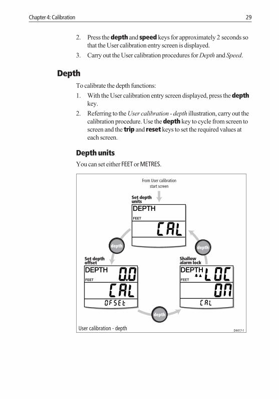
Chapter 4: Calibration 29
2. Press the depth and speed keys for approximately 2 seconds sothat the User calibration entry screen is displayed.
3. Carry out the User calibration procedures for Depth and Speed.
DepthTo calibrate the depth functions:
1. With the User calibration entry screen displayed, press the depthkey.
2. Referring to the User calibration - depth illustration, carry out thecalibration procedure. Use the depth key to cycle from screen toscreen and the trip and reset keys to set the required values ateach screen.
Depth unitsYou can set either FEET or METRES.
User calibration - depth
From User calibrationstart screen
depth
depth
depth
Set depthunits
Set depthoffset
Shallowalarm lock
D4417-1
040_3c04.p65 06/04/01, 10:2129

30 ST60 Tridata Instrument Owner’s Handbook
Depth offset
WARNING:The use of incorrect offset values could result in misleading depthinformation being displayed with a consequent risk of runningaground.
Depths are measured from the transducer to the sea bed. However, youcan use the depth offset screen to apply offsets to this distance, so thatthe displayed depth reading represents either the depth from the keel orthe depth from the water line. In order to do this, you need to know thevertical separation between the transducer position and:
• The bottom of the keel.• The water line.
Use the trip (decrement) and reset (increment) keys to set therequired offset value:
• If you want to display the depth reading from the transducer, set avalue of 0.0.
Offset valueof 0.0
+ve offsetvalues
-ve offsetvalues
D4352-2Depth offsets
• If you want to apply a water line offset, adjust the displayed readinguntil the appropriate positive offset value is shown.
040_3c04.p65 06/04/01, 10:2130

Chapter 4: Calibration 31
• If you want to apply a keel offset, adjust the displayed reading untilthe appropriate negative offset value is shown.
Shallow alarm lockWhen set to on, prevents alteration to the shallow depth alarmthreshold.
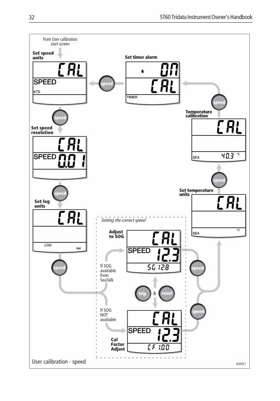
SpeedTo calibrate the speed functions:
1. With the User calibration entry screen displayed, press the speedkey.
2. Referring to the User calibration - speed illustration, carry out thecalibration procedure. Use the speed key to cycle from screen toscreen and the trip and reset keys to set the required values ateach screen (except Adjust to SOG display).
Set speed unitsSelect either KTS (knots), MPH (miles per hour) or KMH (kilometres perhour), as required.
Set speed resolutionSelect resolution of either 0.01 or 0.1 as required.
Set log unitsSelect either NM (nautical miles), SM (statute miles) or KM(kilometres), as required.
Setting the correct speedSet the displayed (current) speed using one of the following methods:
• Use the Adjust to Speed Over Ground (SOG) screen toautomatically set the current speed to SOG (if available fromSeaTalk). You must be running in slack tide conditions tosuccessfully use this method.
• Manually apply a calibration factor by means of the Cal factoradjust screen, to set the displayed speed value to your best estimateof the vessel’s speed.
040_3c04.p65 06/04/01, 10:2131
32 ST60 Tridata Instrument Owner’s Handbook
User calibration - speed
From User calibrationstart screen
speed
D4418-1
Set speedunits
Set speedresolution
Set logunits
speed
speed
trip reset&
Adjustto SOG
CalFactorAdjust
If SOGavailablefromSeaTalk
If SOGNOTavailable
speed
speed
speed
speed
Set temperatureunits
Temperaturecalibration
Set timer alarm
Setting the correct speed
speed
040_3c04.p65 06/04/01, 10:2132

Chapter 4: Calibration 33
Adjust to SOG
The Adjust to SOG screen is displayed only if SOG data is availablefrom SeaTalk. The current SOG is displayed in the bottom section ofthe display (SG12.8 in the illustration), and the current speed registeredby the instrument, as large figures in the middle section of the display(12.3 in the illustration).
It is recommended that, if you are running in slack tide conditions, youpress the reset key for 3 seconds, to accept the SOG as the currentspeed.
If you do not wish to accept SOG as the current speed, press the tripand reset keys together to select the Cal factor adjust display.
Cal factor adjust
The Cal factor adjust screen enables you to manually adjust thecalibration factor. It shows the current calibration factor in the bottomsection of the display (CF 1.00 in the illustration), and the current speedas large figures (12.3 in the illustration).
Use the trip or reset key to adjust the calibration factor so that thecurrent speed is the speed through the water.
If SOG data is available from SeaTalk, you can turn to the Adjust toSOG screen by pressing the trip and reset keys.
Note: If neither of the above methods gives satisfactory results, carryout the Speed calibration procedure (part of Intermediate calibration).
Set temperature unitsSelect either °C or °F, as required.
Temperature calibrationSet the display to show the current water temperature.
Timer alarm buzzerSwitches the count-up and race-start timer audible alarm on the ST60Tridata instrument being calibrated, on and off.
040_3c04.p65 06/04/01, 10:2133
34 ST60 Tridata Instrument Owner’s Handbook
Leaving User calibrationHold down the depth and speed keys for 2 seconds, to save yoursettings, exit User calibration and resume normal operation.
4.3 Intermediate calibrationIntermediate calibration enables you to:
• Check the instrument software version.
• Check the instrument status - either YES (master)) or NO (repeater).You can also change the depth status, as required. This feature isparticularly useful in preventing interference when using anotherproduct (e.g. a fishfinder) that operates at 200 kHz.
• Carry out a calibration run over a measured distance to ensureaccurate speed readings.
To start Intermediate calibration, hold down the depth and speedkeys for approximately 4 seconds (see Intermediate calibration flowchart).
To set the instrument status:
1. Press the depth key to select the Instrument status screen.
2. Press the trip and reset keys simultaneously to enter the depthadjust mode, then press either trip or reset to set the requiredstatus, i.e. either YES (for master operation) or NO (for repeateroperation).
Note: You must not allocate more than one master depth instrument inany system.
3. Press the trip and reset keys simultaneously again, to leave theadjust mode.
040_3c04.p65 06/04/01, 10:2134

Chapter 4: Calibration 35
speeddepth
Softwareversion
Instrumentstatus
(or NO for repeater)
(or NO for repeater)
Carry out speed calibrationas detailed in
Speed calibration - sheets 1 & 2
D4419-1Intermediate calibration
depth
depth
depth
Speed calibrationThe speed calibration procedure involves carrying out two runs over ameasured distance, to enable a calibration factor to be determined andapplied to your ST60 Tridata instrument, to ensure optimum accuracy.Each calibration run comprises outward and return legs, to minimisethe affect of tidal drift when the calibration factor is determined.
040_3c04.p65 06/04/01, 10:2135
36 ST60 Tridata Instrument Owner’s Handbook
Note: It is recommended that the speed calibration procedure iscarried out in conditions of minimum tidal drift.
To carry out a speed calibration, start the Intermediate calibrationprocedure and use the speed key to proceed to the Calibration runlength screen (see sheet 1 of the Speed calibration flow chart). Proceedwith the speed calibration as follows:
1. With the Calibration Run Length screen displayed, press the tripand reset keys together to enter adjust mode. In this mode, thedisplayed run length flashes on and off.
2. Set the length of the intended calibration run, using either the tripkey to decrement or the reset key to increment the run lengthvalue. You can set any value between 0.25 and 2.50.
3. Press trip and reset keys together to commence the speedcalibration. The Cal status screen is displayed. The text at thebottom of the screen alternates between Strt 1 and the calibrationfactor (CF) currently applied.
4. Start first outward leg of the calibration run and as you pass thestart point, press the speed key, so that the text out shows at thebottom of the screen. As the calibration run proceeds, thedisplayed value will increment.
5. At the end of the measured distance on the outward leg, press thespeed key again so that:
• The text rEtrn is flashing at the bottom of the screen.
• The displayed distance freezes. Note that this value will not bethe same as the measured distance due to errors introduced bytidal flow.
6. Turn the vessel round, start the return leg and as you do so, pressthe speed key so the rEtrn legend stops flashing and the displayedvalue increments.
7. At the end of the return leg, press the speed key to end thecalibration run. At this point:
• The text Strt 2 alternating with the new calibration factor isdisplayed at the bottom of the screen.
• The displayed distance freezes. This value should be very closeto the actual (measured) distance of the calibration run.
8. Press the depth and speed keys together, to store the newcalibration factor.
040_3c04.p65 06/04/01, 10:2136

Chapter 4: Calibration 37
To store the calibration factor, pressand
speeddepth
Carry out second cal runas described on sheet 2
Speed calibration - sheet 1 D4420-1
reset
speed
At the start of theoutward cal run
pressCarry out the
outward leg ofthe first cal run
At the start ofthe return cal
run press
Press
Carry out thereturn leg of
the first cal run
Press
from Intermediate calibration(Instrument status display)
At the endof theoutwardcal run
At the endof the returncal run
Calibrationrun length
to set lengthof calibration run
either
reset
Use
resettrip
trip
trip
speed
speed
speed
speed
Alternating
Alternating
and
and
040_3c04.p65 06/04/01, 10:2137

38 ST60 Tridata Instrument Owner’s Handbook
from Speedcalibration - sheet 1
At the start of theoutward cal run
press
At the start ofthe return cal
run press
At the end of theoutward cal run
press
At the endof the return
cal runpress
Carry out theoutward leg of
the secondcal run
Carry out thereturn leg ofthe second
cal run
Press
to store cal factor
speed
Press
Speed calibration - sheet 2 D4421-1
to return toInstrument status display(Intermediate calibration)
depth
speed
speed
speed
speed
depth
Alternating
and
9. Carry out a second calibration run (see sheet 2 of the Speedcalibration flow chart), using the procedure described above insteps 4 to 8.
Note: At the end of this second run, the text End alternating with thenew calibration factor is displayed at the bottom of the screen.
10. Press the speed key to leave distance calibration and return to theInstrument status screen.
040_3c04.p65 06/04/01, 10:2138
Chapter 4: Calibration 39
Leaving Intermediate calibrationHold down the depth and speed keys for 2 seconds, to save yoursettings, exit Intermediate calibration and resume normal operation.
4.4 Dealer calibrationThe Dealer calibration procedures enable the following parameters tobe set:
• User calibration on/off.
• Speed response.
• Depth response.
• Boat show mode on/off.
Dealer calibration also gives access to the Factory defaults screen. Thisenables you to re-apply the factory settings if you want to reset theinstrument to a known operating condition.
To commence Dealer calibration, hold down the depth and speedkeys together for approximately 12 seconds, to select the Dealercalibration entry page (see Dealer calibration diagram). Then press thetrip and reset keys together, to enter the calibration screen sequence.
Use the depth key to move from screen to screen and the trip or therest key to set the required values at each screen.
User calibration on/offPress either the trip or reset key to toggle the User calibration on oroff as required. With off selected, User calibration and Intermediatecalibration are both disabled.
Response settingsThe response values for both SPEED and DEPTH determine thefrequency at which information is updated. A low number provides asmooth response and a high number a much livelier update.
Use the trip trip trip trip trip (decrement) and reset reset reset reset reset (increment) keys to set therequired value. Response values are from 1 to 15.
040_3c04.p65 06/04/01, 10:2139

40 ST60 Tridata Instrument Owner’s Handbook
Hold down and
for approximately 12 seconds
reset
D4422-1
trip resetand
depth speed
depth
depth
depth
depth
depth
trip
Boat show mode
Dealer calibration
Factorydefaults
At each screen use
either or
to set the required values
Calibrationon/off
Speedresponse
Depth response
040_3c04.p65 06/04/01, 10:2140

Chapter 4: Calibration 41
Boat show mode
CAUTION:Do NOT enable this mode. It must only be used for demonstrationpurposes.
Ensure that the Boatshow Mode Use is set to OFF. If necessary, use thetrip trip trip trip trip or reset reset reset reset reset key to achieve this.
Factory defaultsYou can use this screen to reset the operating parameters to the factorydefault values. If you want to apply the factory defaults, ensure thedisplay shows YES, but if you want to retain the values you have set up,ensure that the display shows NO. Use the trip trip trip trip trip and reset reset reset reset reset keys to makethe required selection.
The values you have selected will be applied when you exit this screen.
Leaving Dealer calibrationHold down the depth and speed keys for 2 seconds to save yoursettings, exit Dealer calibration and resume normal operation.
040_3c04.p65 06/04/01, 10:2141

42 ST60 Tridata Instrument Owner’s Handbook
040_3c04.p65 06/04/01, 10:2142

D4436-1
Machine hole90mm (3.54in)
diameter
Drill 5mm (3/16in) diameter
Drill 5mm (3/16in) diameter
Shaded areas to be removed
TOPST60 Surface Mount Template
040_3tem.p65 06/04/01, 10:2143

040_3tem.p65 06/04/01, 10:2144

Shaded area to be removed
TOP
109 mm
ST60 Flush Mount Template
114
mm
4 holes6 mm diameter
D4437-1
040_3tem.p65 06/04/01, 10:2145

040_3tem.p65 06/04/01, 10:2146

Document number: 84064-8April 2001
Limited Warranty CertificateRaymarine warrants each new Light Marine/Dealer Distributor Product to be of good materials and workmanship, and will repair or exchange any parts proven to be defective in material and workmanship under normal use for a period of 2 years/24 months from date of sale to end user, except as provided below.Defects will be corrected by Raymarine or an authorized Raymarine dealer. Raymarine will, except as provided below, accept labor cost for a period of 2 years/24 months from the date of sale to end user. During this period, except for certain products, travel costs (auto mileage and tolls) up to 100 round trip highway miles (160 kilometres) and travel time of 2 hours, will be assumed by Raymarine only on products where proof of installation or commission by authorized service agents, can be shown.
Warranty LimitationsRaymarine Warranty policy does not apply to equipment which has been subjected to accident, abuse or misuse, shipping damage, alterations, corrosion, incorrect and/or non-authorized service, or equipment on which the serial number has been altered, mutilated or removed.Except where Raymarine or its authorized dealer has performed the installation, it assumes no responsibility for damage incurred during installation.This Warranty does not cover routine system checkouts or alignment/calibration, unless required by replacement of part(s) in the area being aligned.A suitable proof of purchase, showing date, place, and serial number must be made available to Raymarine or authorized service agent at the time of request for Warranty service.Consumable items, (such as: Chart paper, lamps, fuses, batteries, styli, stylus/drive belts, radar mixer crystals/diodes, snap-in impeller carriers, impellers, impeller bearings, and impeller shaft) are specifically excluded from this Warranty.Magnetrons, Cathode Ray Tubes (CRT), TFT Liquid Crystal Displays (LCD) and cold cathode fluorescent lamps (CCFL), hailer horns and transducers are warranted for 1 year/12 months from date of sale. These items must be returned to a Raymarine facility.All costs associated with transducer replacement, other than the cost of the transducer itself, are specifically excluded from this Warranty.Overtime premium labor portion of services outside of normal working hours is not covered by this Warranty.Travel cost allowance on certain products with a suggested retail price below $2500.00 is not authorized. When/or if repairs are necessary, these products must be forwarded to a Raymarine facility or an authorized dealer at owner’s expense will be returned via surface carrier at no cost to the owner.Travel costs other than auto mileage, tolls and two (2) hours travel time, are specifically excluded on all products. Travel costs which are excluded from the coverage of this Warranty include but are not limited to: taxi, launch fees, aircraft rental, subsistence, customs, shipping and communication charges etc. Travel costs, mileage and time, in excess to that allowed must have prior approval in writing. TO THE EXTENT CONSISTENT WITH STATE AND FEDERAL LAW:(1) THIS WARRANTY IS STRICTLY LIMITED TO THE TERMS INDICATED HEREIN, AND NO OTHER WARRANTIES OR REMEDIES SHALL BE BINDING ON RAYMARINE INCLUDING WITHOUT LIMITATION ANY WARRANTIES OF MERCHANTABLE OR FITNESS FOR A PARTICULAR PURPOSE.(2) Raymarine shall not be liable for any incidental, consequential or special (including punitive or multiple) damages.All Raymarine products sold or provided hereunder are merely aids to navigation. It is the responsibility of the user to exercise discretion and proper navigational skill independent of any Raymarine equipment.
84064_8.fm Page 1 Monday, April 9, 2001 4:42 PM

Factory Service Centers
United States of America UK, Europe, Middle East, Far EastRaymarine Inc22 Cotton Road, Unit DNashua, NH 03063-4219, USA
Raymarine LtdAnchorage Park, PortsmouthPO3 5TD, England
Telephone: +1 603 881 5200Fax: +1 603 864 4756www.raymarine.com
Telephone: +44 (0)23 9269 3611Fax: +44 (0)23 9269 4642www.raymarine.com
Sales & Order ServicesTelephone: +1 800 539 5539 Ext. 2333 or
+1 603 881 5200 Ext. 2333
Customer SupportTelephone: +44 (0)23 9271 4713Fax: +44 (0)23 9266 1228
Technical SupportTelephone: +1 800 539 5539 Ext. 2444 or
+1 603 881 5200 Ext. 2444Email: [email protected]
Email: [email protected]
Product Repair CenterTelephone: +1 800 539 5539 Ext. 2118
Purchased from Purchase date
Dealer address
Installed by Installation date
Commissioned by
Commissioning date
Owner’s name
Mailing address
This portion should be completed and retained by the owner.
Stick barcode label here
84064_8.fm Page 2 Monday, April 9, 2001 4:42 PM