sta 449 f1 jupiter - chemical instrumentation facility · sta 449 f1 system components 01/12...
TRANSCRIPT

Operating Instructions
Simultaneous TG-DTA/DSC Apparatus
STA 449 F1 Jupiter®

01/12 J:\STA449C\449-400\JUP_E3.DOC
Chapter III
System Components
STA 449 F1

System ComponentsSTA 449 F1
01/12 J:\STA449C\449-400\JUP_E3.DOC
CONTENTS
MEASURING UNIT ........................................................................................1
FRONT PANEL OF THE MEASURING UNIT ........................................................3
TFT DISPLAY ................................................................................................... 4
OPERATING ELEMENTS ...................................................................................... 5
REAR OF THE MEASURING UNIT ...................................................................7
GAS OUTLET VALVE ..................................................................................9
EVACUATION SYSTEM .............................................................................. 10
VACUUM CONTROL SYSTEM ............................................................................. 11
EVACUATION PROCEDURE FOR INSTRUMENTS WITHOUT AUTOVAC ...................... 11
EVACUATION PROCEDURE FOR INSTRUMENTS WITH AUTOVAC ............................ 14
HIGH-VACUUM MEASUREMENTS ...................................................................... 16
COOLING SYSTEMS ................................................................................. 17
CC 300 COOLING SYSTEM ............................................................................... 18
LN2 COOLING SYSTEM (WITH MAGNETIC VALVE) – 6.351.35 ............................. 19
SAFE USE OF LIQUID NITROGEN LN2 ................................................................. 20
SAFETY REGULATIONS FOR LN2 STORAGE VESSELS WITH NETZSCH DEWAR HEAD
(6.351.35) ................................................................................................... 20
PRECAUTIONS IN THE EVENT OF OPERATING FAULTS............................................. 21
FURNACES ............................................................................................. 22
RHODIUM FURNACE .............................................................................. 22
PURGING THE HEATING CHAMBER .................................................................. 23
TEMPERATURES, HEATING RATES AND LIFETIME ............................................... 24
SILICON CARBIDE FURNACE .................................................................... 25
TEMPERATURES, HEATING RATES AND LIFETIME ............................................... 26
PLATINUM FURNACE ............................................................................. 27
TEMPERATURES, HEATING RATES AND LIFETIME ............................................... 28
PURGING THE HEATING CHAMBER (OPTION) .................................................... 28

System ComponentsSTA 449 F1
01/12 J:\STA449C\449-400\JUP_E3.DOC
HIGH SPEED FURNACE ........................................................................... 29
TEMPERATURES, HEATING RATES AND LIFETIME ............................................... 30
PREPARATION ............................................................................................. 31
ADDITIONAL INFORMATION FOR THE INSTALLATION OF THE RADIATION SHIELD ..... 32
GRAPHITE FURNACE .............................................................................. 34
GAS AND VACUUM CONNECTIONS ................................................................. 35
SAFETY CONTROL SYSTEM (S.C.S.) ................................................................ 36
FUNCTION ............................................................................................... 36
GENERAL INFORMATION FOR USING PURGE GASES .......................................... 38
PRODUCING THE REQUIRED ATMOSPHERE IN THE FURNACE .............................. 40
PRODUCING THE REQUIRED ATMOSPHERE IN THE SAMPLE CHAMBER .................. 42
COOLING WATER SUPPLY .......................................................................... 43
CHANGING THE PROTECTIVE TUBE .................................................................. 45
LOW TEMPERATURE FURNACES ............................................................... 49
STEEL FURNACE / SILVER FURNACE ................................................................. 49
COOLING CONNECTIONS STEEL FURNACE / SILVER FURNACE ............................... 50
TEMPERATURES, LIFETIME ............................................................................. 50
ADDITIONAL INFORMATION FOR THE INSTALLATION OF THE RADIATION SHIELD ..... 51
WATER VAPOUR FURNACE ..................................................................... 53
SAMPLE CARRIER SYSTEM ........................................................................ 54
MEASURING HEADS ................................................................................ 55
THERMOCOUPLE TYPES ............................................................................ 57
SERVICE SWITCH ..................................................................................... 58

System ComponentsSTA 449 F1
01/12 J:\STA449C\449-400\JUP_E3.DOC
1
Measuring Unit
Figure 1: measuring unit STA 449 F1 Jupiter (details)
1 Hoisting Device
2
Gas Outlet Valve (open)
3
Furnace
4
Display and Operating Elements
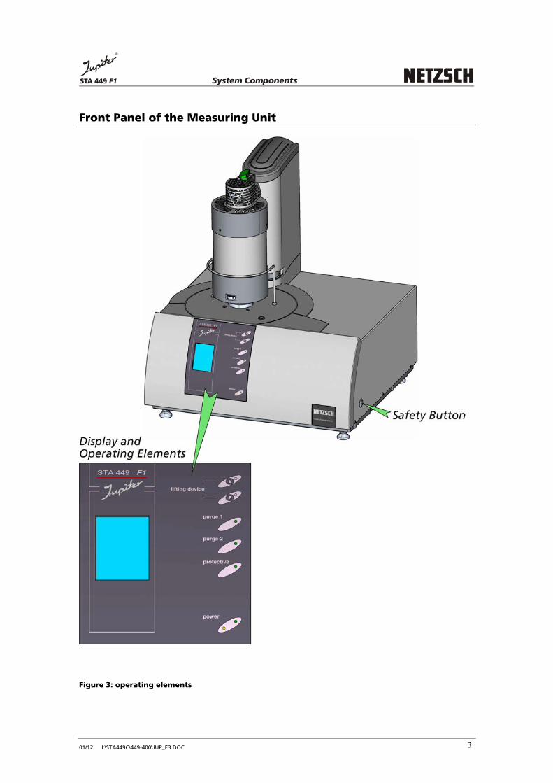
5 Safety Button

System ComponentsSTA 449 F1
01/12 J:\STA449C\449-400\JUP_E3.DOC
2
Figure 2: measuring unit STA 449 F1 Jupiter (cross - section)
System ComponentsSTA 449 F1
01/12 J:\STA449C\449-400\JUP_E3.DOC
3
Front Panel of the Measuring Unit
Figure 3: operating elements

System ComponentsSTA 449 F1
01/12 J:\STA449C\449-400\JUP_E3.DOC
4
TFT Display
Figure 4: TFT display
Label Function
1
display for the gas flow and the used gas type for purge 1, purge 2 and protective
2
display for the actual vacuum state (100% vacuum means minimum pressure)
3
display for the balance signal
4
display for the temperature signal
5
display for the type of temperature segment with end temperature of the segment
→ Dynamic segment heating up
→ Isothermal segment
→ Dynamic segment cooling down
→ Final emergency temperature
6
display for remaining time of the measurement

System ComponentsSTA 449 F1
01/12 J:\STA449C\449-400\JUP_E3.DOC
5
Operating Elements
Function Keys
open the measuring unit
close the measuring unit
Control Display
purge 1 control LED: purge gas 1 (sample chamber) "on/off"
→ green LED on: purge gas 1 is switched on
purge 2 control LED: purge gas 2 (sample chamber) "on/off"
→ green LED on: purge gas 2 is switched on
protective control LED: purge gas (balance system) "on/off"
→ green LED on: protective gas is switched on
green LED on: instrument is switched on
orange LED on: measurement is running

System ComponentsSTA 449 F1
01/12 J:\STA449C\449-400\JUP_E3.DOC
6
All electronic valves are proportional valves which open slowly. The LEDs on the front panel show the selected function and the opening (closing) of the valves. Initial state after switching on the power supply:
• all electronic valves are closed
• vacuum pump is switched off
• the system is under normal pressure
the hoisting device is blocked if:
• the system is not under normal pressure (e.g. vacuum)
• the measuring program is running

System ComponentsSTA 449 F1
01/12 J:\STA449C\449-400\JUP_E3.DOC
7
Rear of the Measuring Unit
Figure 5: rear of the measuring unit

System ComponentsSTA 449 F1
01/12 J:\STA449C\449-400\JUP_E3.DOC
8
No. label function
1 USB connection computer system
2 ASC ASC connection (No. 20)
3 transportation lock O = Operation T = Transport (see page 58 in this chapter)
4
power connection for furnaces
connection for 1 furnace
connection for 2nd furnace
connection for 1st furnace
5 external power unit connection for external power unit)
6 AC input 50/60Hz power connection 230 (115) V
7 thermoswitch fuse overtemperature
8 analog digital I/O analog digital input/output
9 turbo pump connection turbo pump
10 ext. MFC connection MFC box
11 valves vacuum
external
outputs CC 300
optional
connection magnetic valve – for AutoVac
connection gas outlet valve (furnace switch) – for AutoVac
connection LN2 cooling system CC 300
optional connection
12 water outlet connection thermostat outlet
13 water inlet connection thermostat inlet
14 pressure-relief valve outlet pressure-relief valve sample chamber
15 LN2 cooling connection cooling liquid nitrogen
16 AUX output power output for pumps etc.
17 vacuum flange connection to the vacuum pump
18 AC line on/off
AC input 50/60Hz
115V/T4A; 230V/T2A
power switch: instrument "on/off"
power connection 230 (115) V
mains fuses
19 purge 1
purge 2
protective
plug-in connection: purge gas 1
plug-in connection: purge gas 2
plug-in connection: protective gas
20 furnace connection to furnace power connection (No. 4)
21 ASC connection to ASC (No. 2)

System ComponentsSTA 449 F1
01/12 J:\STA449C\449-400\JUP_E3.DOC
9
Gas Outlet Valve
Gases evolved from the sample are passed through the gas outlet valve. The function "vacuum" can only be used if the gas outlet valve is closed. If the function "AutoVac" is used (special equipment), please take care that the gas outlet valve is opened. For dynamic measurements the gas outlet valve must also be opened.
gas outlet valve opened gas outlet valve closed
Figure 6: gas outlet valve
ATTENTION!
Both for measurements under static atmosphere and under vacuum (without AutoVac), the gas outlet valve on the furnace must be closed!
ATTENTION!
If a gas hose is connected to the gas outlet valve in order to discharge exhaust gases, the gas hose must not be brought into a liquid. Danger of flooding the balance system!

System ComponentsSTA 449 F1
01/12 J:\STA449C\449-400\JUP_E3.DOC
10
Evacuation System
An evacuation system can be connected to the measuring unit by means of the vacuum flange. The sample chamber can be evacuated up to a vacuum of approx. 10
-4 mbar.
The evacuating system consists of following components:
• vacuum pump (rotary pump or diaphragm pump)
• shut-off valve
• pressure gauge (option)
• connection cables and flanges
• vacuum hose
The installation of the evacuating system is described in chapter II!
The recipient is also provided with a safety valve (pressure relief valve), which opens at an excess pressure of 0.03 bar. Pressure gauge (TFT display - front of the measuring unit)
Figure 7: pressure gauge
normal pressure: no bar is shown in the display decreasing pressure: increasing % value is shown in the display minimum pressure: 100% vacuum is shown in the display overpressure: overpressure is shown in the display

System ComponentsSTA 449 F1
01/12 J:\STA449C\449-400\JUP_E3.DOC
11
Vacuum Control System
Evacuation procedure for instruments without AutoVac
• Select Gases and switches in the Diagnosis menu and switch off all gases (purge 1, purge 2 and protective).
• Close the gas outlet valve.
System ComponentsSTA 449 F1
01/12 J:\STA449C\449-400\JUP_E3.DOC
12
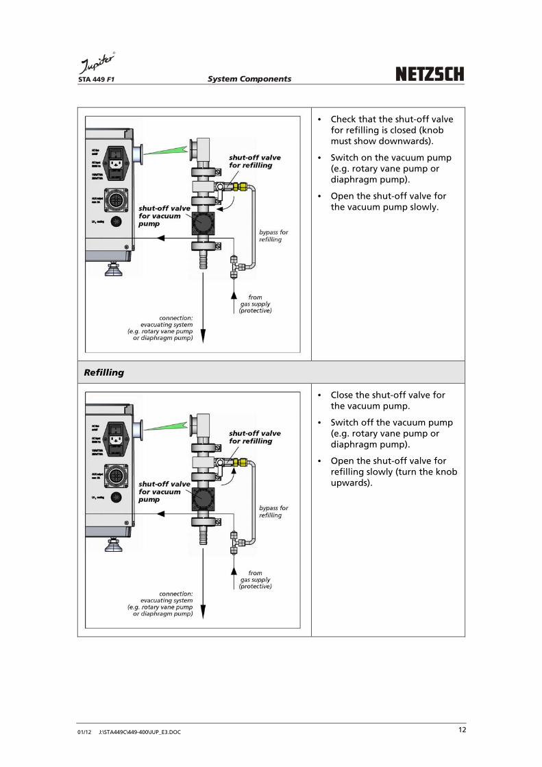
• Check that the shut-off valve for refilling is closed (knob must show downwards).
• Switch on the vacuum pump (e.g. rotary vane pump or diaphragm pump).
• Open the shut-off valve for the vacuum pump slowly.
Refilling
• Close the shut-off valve for the vacuum pump.
• Switch off the vacuum pump (e.g. rotary vane pump or diaphragm pump).
• Open the shut-off valve for refilling slowly (turn the knob upwards).

System ComponentsSTA 449 F1
01/12 J:\STA449C\449-400\JUP_E3.DOC
13
• Fill gas into the sample chamber up to a slight overpressure (see pressure gauge on the front display) and open the gas outlet valve.
To create a particularly clean gas atmosphere a defined gas (purge or protective) must be filled at first before the gas outlet valve is opened. If the outlet valve is opened at first, impurities can enter the measuring system.
System ComponentsSTA 449 F1
01/12 J:\STA449C\449-400\JUP_E3.DOC
14
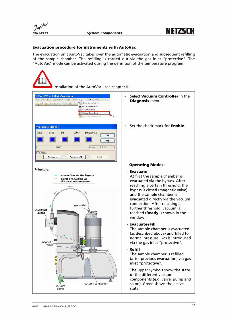
Evacuation procedure for instruments with AutoVac
The evacuation unit AutoVac takes over the automatic evacuation and subsequent refilling of the sample chamber. The refilling is carried out via the gas inlet "protective". The "AutoVac" mode can be activated during the definition of the temperature program.
Installation of the AutoVac - see chapter II!
• Select Vacuum Controller in the Diagnosis menu.
• Set the check mark for Enable.
Operating Modes:
- Evacuate
At first the sample chamber is evacuated via the bypass. After reaching a certain threshold, the bypass is closed (magnetic valve) and the sample chamber is evacuated directly via the vacuum connection. After reaching a further threshold, vacuum is reached (Ready is shown in the window).
- Evacuate+Fill
The sample chamber is evacuated (as described above) and filled to normal pressure. Gas is introduced via the gas inlet "protective".
- Refill
The sample chamber is refilled (after previous evacuation) via gas inlet "protective".
The upper symbols show the state of the different vacuum components (e.g. valve, pump and so on). Green shows the active state.
Principle:

System ComponentsSTA 449 F1
01/12 J:\STA449C\449-400\JUP_E3.DOC
15
The function "AutoVac" can also be selected during the definition of the
temperature program of the measurement:
• To activate the AutoVac set the check mark for Use AUTOVAC
Controller.
• Select the number of Evacuation + Fill cycles before starting the measurement.
• If necessary set the check mark for Keep Vacuum during
Measurement.
When using a diaphragm pump with AutoVac it is recommended to increase the
additional pumping time to approx. 5 to10 minutes:
• Select Vacuum Setting in the Extras menu.
• For using a diaphragm pump with AutoVac it is recommended to set the value for the additional pumping time to approx. 5 to 10 minutes.

System ComponentsSTA 449 F1
01/12 J:\STA449C\449-400\JUP_E3.DOC
16
High-Vacuum Measurements
For measurements under high vacuum the STA 449 F1 Jupiter can be equipped with a high vacuum pumping system.
Measurements under vacuum
Measurements under vacuum should only be carried out up to maximum furnace temperatures of 1400°C. Higher temperatures may cause damages on the instrument.
Hints for the use of the STC in case of measurements under vacuum
In case of measurements under vacuum with end temperatures up to the maximum furnace temperature we recommend to switch off the STC (Sample Temperature Controller). As the STC controls the sample temperature by the deviation between sample and furnace thermocouple, this can cause problems with furnace control (oscillation). In the worst case the furnace can be overheated. The STC can be switched on and off in the software (see Help system in the Proteus software).
System ComponentsSTA 449 F1
01/12 J:\STA449C\449-400\JUP_E3.DOC
27
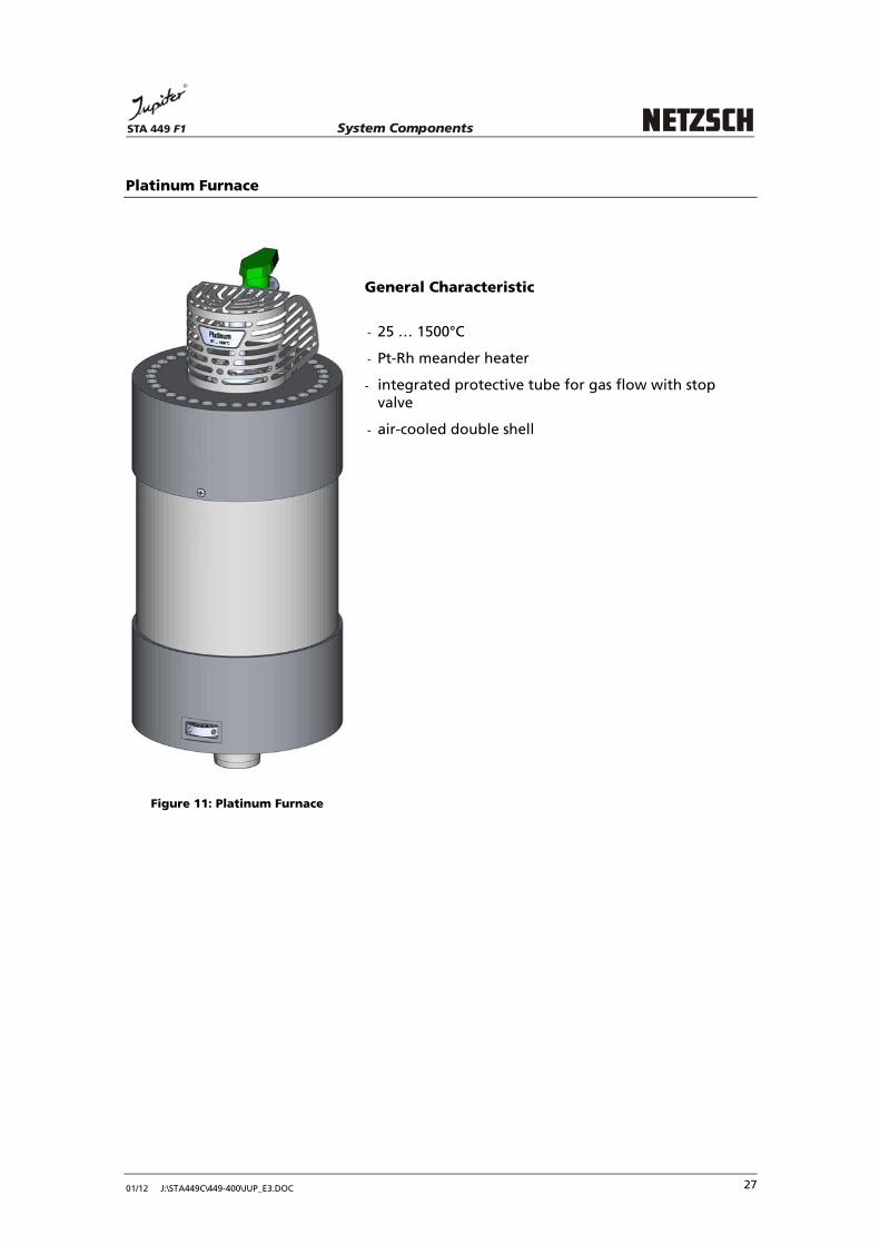
Platinum Furnace
Figure 11: Platinum Furnace
General Characteristic
- 25 … 1500°C
- Pt-Rh meander heater
- integrated protective tube for gas flow with stop valve
- air-cooled double shell
System ComponentsSTA 449 F1
01/12 J:\STA449C\449-400\JUP_E3.DOC
28
Temperatures, Heating Rates and Lifetime
The high-quality heating element of the furnace of a platinum-rhodium alloy allows a maximum furnace temperature of 1500°C. However, at high temperatures a physically conditioned volatilization of the precious metal alloy is detectable that results in an increased wear of the heating element, depending on temperature and time. The maximum heating rate in the temperature range to 1200°C is 50 K/min for this furnace. In order to reach a possibly high lifetime of the heating element the following experimental conditions should only be employed in exceptional case: a) heating rates of more than 20 K/min above 1200°C. b) longer holds at temperatures > 1350°C due to very low heating rates (<5 K/min) and/or
longer isothermal phases. From the view of lifetime of the heating element the ideal heating rates are between 10 and 20 K/min; the most favorable temperature program is heating up and switches off at the desired admitted maximum temperature.
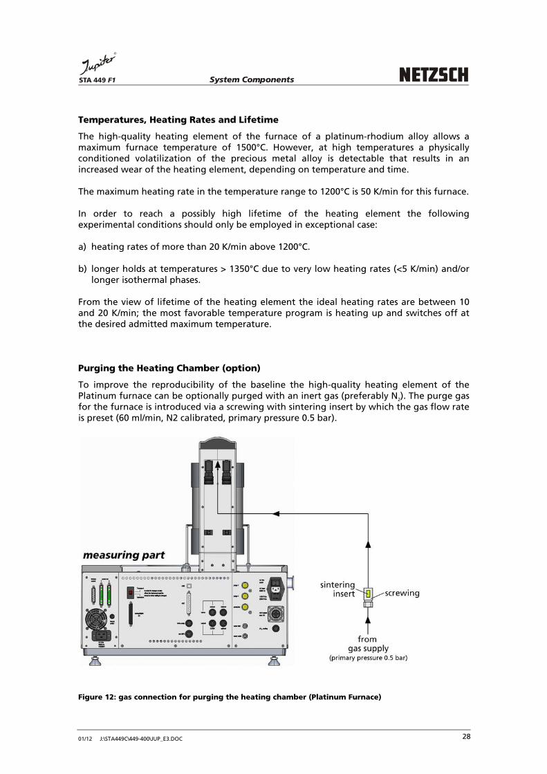
Purging the Heating Chamber (option)
To improve the reproducibility of the baseline the high-quality heating element of the Platinum furnace can be optionally purged with an inert gas (preferably N
2). The purge gas
for the furnace is introduced via a screwing with sintering insert by which the gas flow rate is preset (60 ml/min, N2 calibrated, primary pressure 0.5 bar).
Figure 12: gas connection for purging the heating chamber (Platinum Furnace)

System ComponentsSTA 449 F1
01/12 J:\STA449C\449-400\JUP_E3.DOC
54
Sample Carrier System
Principle
Figure 28: sample carrier system

System ComponentsSTA 449 F1
01/12 J:\STA449C\449-400\JUP_E3.DOC
55
Measuring Heads
Type thermocouples
available
TG (crucible)
S; P
TG (slip-on plate)
S; P
TG-DTA
E; K; S; W
ATTENTION!
Thermocouple type W is not applicable for measurements in oxidizing atmospheres! Protective gas required!
TG-DSC
E; K; S; B; P

System ComponentsSTA 449 F1
01/12 J:\STA449C\449-400\JUP_E3.DOC
56
TG
(for ASC)
S; P
TG-DSC
(for ASC)
S; K; P
sample carrier 2000°C / 2400°C
TG (crucible)
W ATTENTION!
Thermocouple type W is not applicable for measurements in oxidizing atmospheres! Protective gas required!
TG-DTA
W
ATTENTION!
Thermocouple type W is not applicable for measurements in oxidizing atmospheres! Protective gas required!

System ComponentsSTA 449 F1
01/12 J:\STA449C\449-400\JUP_E3.DOC
57
Thermocouple Types
type/temperature range/
atmospheres
Type E (Chromel-Konstantan)
(-150 to 700°C) oxidizing to 500°C reducing (reduces sensor lifetime) inert vacuum (reduces sensor lifetime) humid to 400°C
Type K (Chromel-Alumel)
(-150 to 800°C) oxidizing to 500°C reducing (reduces sensor lifetime) inert vacuum (reduces sensor lifetime) humid to 500°C
Type S (Pt-10%Rh/Pt)
(RT to 1650°C) oxidizing reducing (reduces sensor lifetime) inert vacuum (reduces sensor lifetime) humid to 1300°C
Type B (Pt-30%Rh/Pt-6%Rh)
(RT to 1700°C) oxidizing reducing (reduces sensor lifetime) inert vacuum (reduces sensor lifetime)
Type P (Platinel)
(-150 to 1000°C) oxidizing reducing (reduces sensor lifetime) inert vacuum (reduces sensor lifetime) humid to 1000°C
Type W (W3%Re-W25%Re)
(RT to 2400°C) inert reducing vacuum not for measurements in oxidizing atmospheres

System ComponentsSTA 449 F1
01/12 J:\STA449C\449-400\JUP_E3.DOC
58
Service Switch
• During transport the STA 449 F1 Jupiter is secured with a transport safety device – selected via the switch.
• The switch is placed at the left rear side of the instrument.
• For setting the switch use a small screw driver.
Normal operation (O)
Transport
Operation
• Set the switch to position O (Operation) and insert the sample carrier.
Transport (T)
Transport
Operation
• For the transport set the switch to position T (Transport). The furnace is moved into the upper end position. After this remove the sample carrier and move the furnace back into the lower end position.

01/12 J:\STA449C\449-400\JUP_E4.DOC
Chapter IV
Operating the Instrument
STA 449 F1
Operating the InstrumentSTA 449 F1
01/12 J:\STA449C\449-400\JUP_E4.DOC
CONTENTS
OPERATING THE INSTRUMENT ......................................................................... 1
OPEN THE INSTRUMENT .............................................................................. 1
INSERTING THE SAMPLE CARRIER ................................................................. 3
ADJUSTING THE SAMPLE CARRIER SYSTEM .................................................... 5
ADJUSTING THE FURNACE SYSTEM ............................................................... 6
PREPARING THE MEASUREMENT................................................................... 7
WHAT DO YOU NEED FOR THE MEASUREMENT? ..................................................... 7
CALIBRATION ................................................................................................... 8
CALIBRATION KITS ............................................................................................ 8
CALIBRATION OF THE BALANCE ........................................................................... 9
THERMOSTATIC CONTROL OF THE MEASURING PART ............................................. 10
SELECTION OF THE SAMPLE CARRIER SYSTEM ........................................................ 10
PRETREATMENT OF NEW SAMPLE CARRIER SYSTEMS ............................................. 11
PREPARING THE SAMPLE .................................................................................. 12
POWDERED SOLIDS ......................................................................................... 12
COMPACT SOLIDS ........................................................................................... 12
FILMS ........................................................................................................... 12
FIBERS .......................................................................................................... 13
LIQUIDS ........................................................................................................ 13
UNSTABLE SAMPLES ........................................................................................ 13
EVAPORATION REACTIONS ............................................................................... 13
MEASUREMENTS IN DEFINED ATMOSPHERES ........................................................ 14
SELECT THE SAMPLE CRUCIBLE ........................................................................... 14
WEIGH THE SAMPLE ........................................................................................ 14
SELECTION AND PREPARATION OF CRUCIBLES ....................................................... 14
COMPATIBILITY OF SOME SUBSTANCES AND CRUCIBLE MATERIALS .......................... 18

Operating the InstrumentSTA 449 F1
01/12 J:\STA449C\449-400\JUP_E4.DOC
STARTING THE MEASUREMENT - SHORT INSTRUCTION ..................................... 20
SELECTION OF THE GAS ATMOSPHERE ............................................................... 30
STATIC CONDITIONS ........................................................................................ 31
MEASUREMENTS UNDER STATIC CONDITIONS - THE PROS AND CONS ...................... 31
DYNAMIC CONDITIONS .................................................................................... 32
DYNAMIC CONDITIONS (DYNAMIC PROTECTIVE GAS ATMOSPHERE) ....................... 32
DYNAMIC CONDITIONS (DYNAMIC REACTION GAS ATMOSPHERE) ......................... 32
HINTS FOR USING PURGE GASES ................................................................ 34
MEASUREMENTS UNDER VACUUM - WHAT SHOULD BE CONSIDERED! ................. 39
TRANSPORT ........................................................................................... 40
CLEANING ............................................................................................. 41

Operating the InstrumentSTA 449 F1
01/12 J:\STA449C\449-400\JUP_E4.DOC 7
Preparing the Measurement
In thermoanalytical investigations the test parameters have a significant influence on the results. Information regarding the specific effects of the individual test parameters on the results of STA measurements can be found in the special literature (chapter V "Appendix"). The following parameters should be considered when preparing the measurement:
• calibration
• sample preparation
• sample weight
• reference material
• sample chamber temperature
• temperature program
• atmosphere
What do you
need for the
measurement?
Assemble the required materials before starting the measurement:
• purge gases (sample chamber and balance)
• liquid nitrogen (cooling low temperature furnace)
• sealing tool for pressure-tight crucibles
• tweezers
Operating the InstrumentSTA 449 F1
01/12 J:\STA449C\449-400\JUP_E4.DOC 8
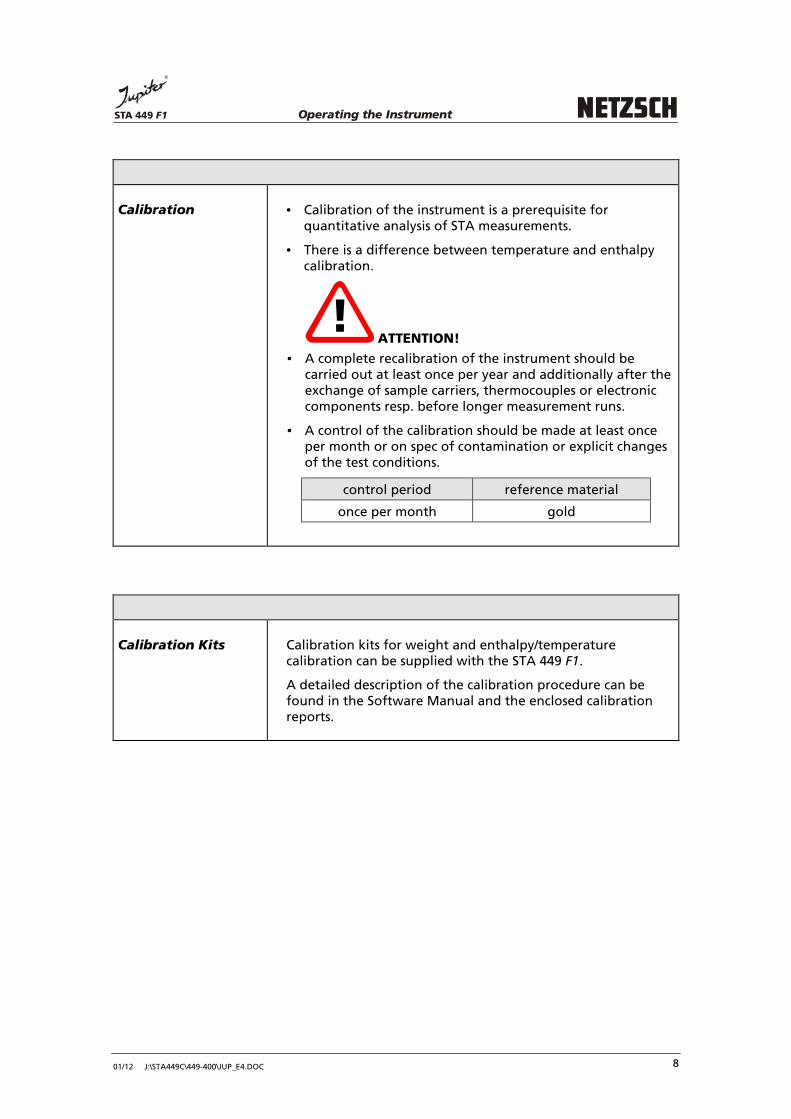
Calibration • Calibration of the instrument is a prerequisite for quantitative analysis of STA measurements.
• There is a difference between temperature and enthalpy calibration.
ATTENTION!
• A complete recalibration of the instrument should be carried out at least once per year and additionally after the exchange of sample carriers, thermocouples or electronic components resp. before longer measurement runs.
• A control of the calibration should be made at least once per month or on spec of contamination or explicit changes of the test conditions.
control period reference material
once per month gold
Calibration Kits Calibration kits for weight and enthalpy/temperature calibration can be supplied with the STA 449 F1.
A detailed description of the calibration procedure can be found in the Software Manual and the enclosed calibration reports.

Operating the InstrumentSTA 449 F1
01/12 J:\STA449C\449-400\JUP_E4.DOC 9
Calibration of the
Balance
A complete recalibration of the balance should be carried out at least once per year and additionally after transport, repairs and considerable changes in the test parameters (e.g. changing the sample carrier).
To get a well calibrated balance the following conditions are necessary:
• The balance should be in absolute equilibrium with stable TG signal!
• The instrument with it’s built in electronic should be switched on at least one day!
• Perform the balance calibration under static conditions without gas flow!
• The furnace should be at room temperature!
• The last measurement with heating should be finished the day before, if possible!
Proceed as follows:
• Open the NETZSCH measurement software.
• Select the menu: Diagnosis.
• Select: Balance Calibration.
• Start Calibration.
The complete procedure (step by step) is described when starting it.
Operating the InstrumentSTA 449 F1
01/12 J:\STA449C\449-400\JUP_E4.DOC 10
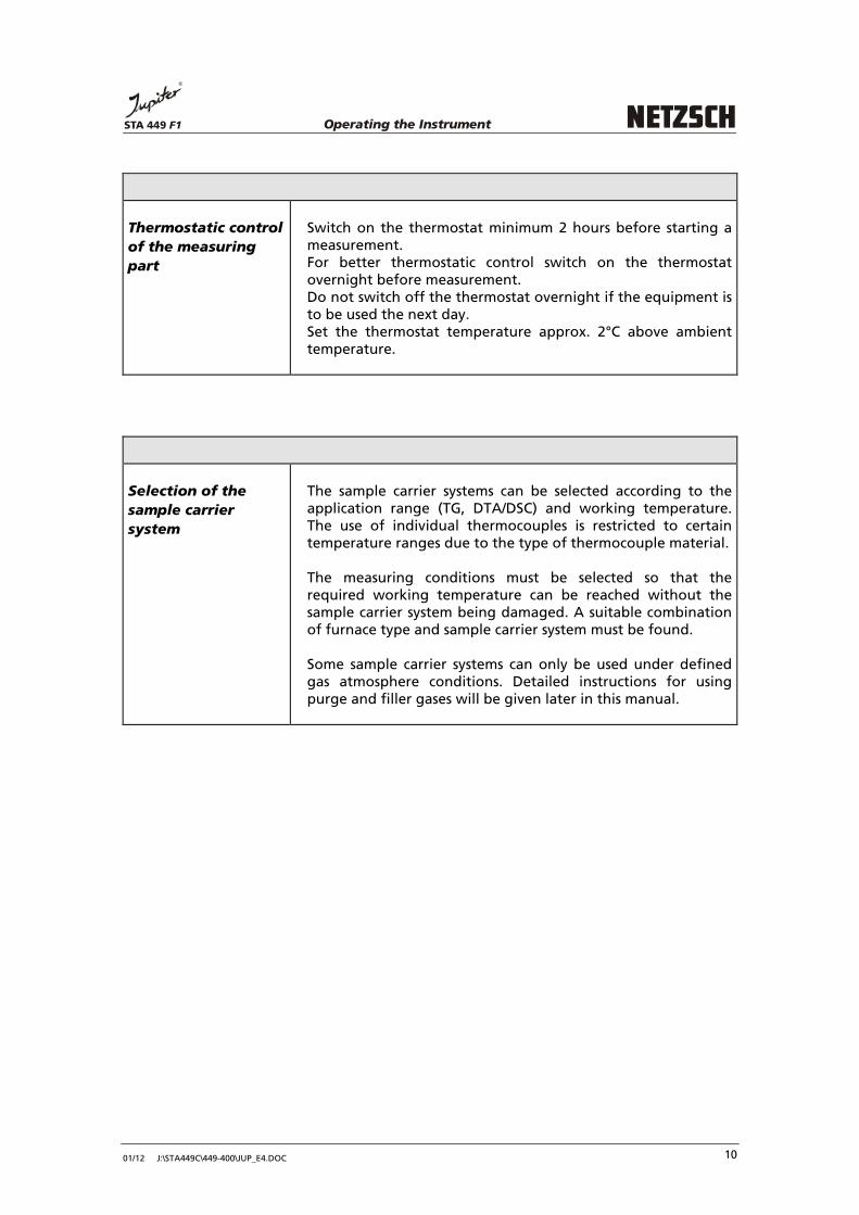
Thermostatic control
of the measuring
part
Switch on the thermostat minimum 2 hours before starting a measurement. For better thermostatic control switch on the thermostat overnight before measurement. Do not switch off the thermostat overnight if the equipment is to be used the next day. Set the thermostat temperature approx. 2°C above ambient temperature.
Selection of the
sample carrier
system
The sample carrier systems can be selected according to the application range (TG, DTA/DSC) and working temperature. The use of individual thermocouples is restricted to certain temperature ranges due to the type of thermocouple material.
The measuring conditions must be selected so that the required working temperature can be reached without the sample carrier system being damaged. A suitable combination of furnace type and sample carrier system must be found.
Some sample carrier systems can only be used under defined gas atmosphere conditions. Detailed instructions for using purge and filler gases will be given later in this manual.
Operating the InstrumentSTA 449 F1
01/12 J:\STA449C\449-400\JUP_E4.DOC 12
Preparing the Sample
When preparing the sample the effects to be interpreted and the consistency of the sample must be considered. Good thermal contact between the sample and heat-flux sensor is an indispensable requirement for optimum results. The methods most frequently used for preparation of solid and liquid samples are described below.
Powdered solids The sample is evenly distributed in the bottom of the sample crucible.
Compact solids
Compact solids, e.g. rubber or thermoplastic, are cut into thin slices with a knife, scalpel or razor blade. For the analysis a hollow drill is used to punch out a sample disc of a suitable size from this larger disc (taken from the center of the whole sample). If it is not possible to punch out a suitably sized disc, the bottom of the crucible is covered with thin slices of the material. A sample crucible must always be used. Direct application of the sample material increases the danger of contaminating the sensor!
Films Discs are punched from films with a hollow drill or punch pliers. The discs should completely cover the bottom of the crucible.
In order to improve the contact between the sample and crucible bottom, the lid should be placed on the crucible with the convex side down and sealed.

Operating the InstrumentSTA 449 F1
01/12 J:\STA449C\449-400\JUP_E4.DOC 13
Fibers The fiber can be cut into small pieces which are then spread parallel on the bottom of the crucible. The fiber is wound around a small rod. The coiled fiber is then removed from the rod and placed in the crucible. A bundle of fibers is wrapped with aluminum foil and cut at both ends. (The weight of the sample can be increased with voluminous fiber materials.) The fiber material with the foil wrapping is then placed in the crucible. The significance of the experimental results can be increased in all cases by adding a drop of silicone oil (improves the heat transfer).
Liquids Depending on the viscosity liquid samples can be dropped into the crucible with a thin glass rod, a micro-pipette or a syringe.
Unstable samples Unstable samples are tested in special pressure-tight crucibles (optional). The measuring unit must be recalibrated when pressure-tight crucibles are used.
Evaporation
reactions
When investigating evaporation reactions, e.g. evaporation of water of crystallization, a closed crucible with a small hole in the center of the lid should be used. The hole should be punched prior to sealing to avoid deformation of the crucible later.
Operating the InstrumentSTA 449 F1
01/12 J:\STA449C\449-400\JUP_E4.DOC 14
Measurements in
defined
atmospheres
For measurements in defined atmospheres, a needle should be used to pierce one to five holes in the lid of the crucible.
Select the sample crucible
See page 18: "Compatibility of some substances and crucible materials" in this
chapter.
Weigh the sample
− Weigh the sample with an analytical balance. Accuracy: ± 0.01 mg
− Clean the crucible and lid with acetone or alcohol prior to use.
− When filling the crucible, no sample material may remain on the edge of the crucible.
Selection and preparation of crucibles
?
− Do not touch the crucibles by hand. Use tweezers!
− Always heat up the crucible to the final working temperature before the first measurement.
− After treating the crucible with acids or solvents clean it with distilled water.
− Dry the crucible and heat it up again to final working temperature.
− Place PtRh-crucibles with the crucible rim (facing downwards) on to the sensor plate before first heating. In this way the crucibles do not stick to the sensor plate.
− PtRh-crucibles also tend to stick to the sensor plate of the sample carrier when heated above 1000°C.

Operating the InstrumentSTA 449 F1
01/12 J:\STA449C\449-400\JUP_E4.DOC 15
− Loosen the crucibles carefully (also on reference side) after every single run.
− Lift up the crucibles and replace them.
− Take care that the lids do not stick to the crucible rim.
− Check if a reaction between the crucible material and the sample will take place at the desired temperatures before measuring an unknown sample in a PtRh-crucible.
− Heat up a small amount of the sample on a piece of Pt-foil in a separate laboratory furnace.
− Traces of reaction will be visible on the surface of the foil. This indicates that PtRh-crucibles should not be used.
− If samples cannot be measured in PtRh-crucibles, use Al2O3 crucibles or Al2O3 liners.
− Cover the crucibles with a thin layer of platinum paint on the outer surface of wall, bottom and lid to improve the radiation behaviour.
− Heat up the crucible to final working temperature to burn out the solvents before using the crucibles on DSC.
− This treatment will have a positive effect on the Cp-data compared to those measured in Al2O3-
crucibles, especially in the temperature range above 900°C.

Operating the InstrumentSTA 449 F1
01/12 J:\STA449C\449-400\JUP_E4.DOC 16
How to insert an Al
2O
3 liner into a Pt crucible
alumina liner
Pt crucible
1
2
1) Pick up the alumina liner with the tweezers.
2) Hold the platinum crucible with the fingers of the other hand (wear clean gloves).
The platinum crucible should not be deformed.
3
3) The dimensions of the alumina liner and the platinum crucible are very similar (good thermal contact). To insert the liner in the crucible without damaging either part rotate them in opposite directions while moving the Al2O3 liner into place.
Remove the alumina liner in the same way.

Operating the InstrumentSTA 449 F1
01/12 J:\STA449C\449-400\JUP_E4.DOC 17
?
If the Al2O
3 liner does not fit in the crucible:
• Using the supplied reshaping tool roll the platinum crucible on a hard, clean support.
• Now the Al2O
3 liner can be easily inserted.
Use the tool for reshaping deformed or dented crucibles as well.
tool for reshapingPt cruciblesupport

Operating the InstrumentSTA 449 F1
01/12 J:\STA449C\449-400\JUP_E4.DOC 18
Compatibility of some Substances and Crucible Materials
The table below corresponds to our most current information. No claim is made that it is exhaustive. The user should regard it only as a guide. Because this is a compilation of data from the literature (H. K. Cammenga et al., Thermochimica Acta, 219, 1993) and from our own experience it is not possible to cover all possible combinations and measurement conditions. In case of doubt, it is advisable to run preliminary tests in a separate furnace. For platinum crucibles with Al
2O
3 inliners basically the same data like for corundum
crucibles applies. The only exception is nickel as a calibration substance. The melting point of nickel with 1455°C is above the recommended maximum working temperature for Pt crucibles on a type S sample carrier.
substance
crucible material
C5H10 H2O Ga In Sn Pb Zn Li2SO4x
H2O
Al Ag Au
corundum, Al2O3 0 0 + + + + + + + + +
bornitride, BN 0 0 + + + + + + + ? ?
graphite, C 0 0 + + + + + + + + -
silicate glass + + + + + + ? + - x x
fused silica, SiO2 + + + + + + + + - + +
aluminium, Al + . - + - + - + x x x
Al, oxidized + + + + + + + + x x x
silver, Ag + + - - - - - ? - x x
gold, Au + + . . - - - + - - x
nickel, Ni + + . . . . . ? - + -
iron, Fe + . . + . + - ? - + -
fine steel + + . + . + - ? - + -
platinum, Pt + + . . - - - + - - -
molybdenum, Mo + + . ? . ? . ? ? ? -
tantalum, Ta + + ? + ? ? ? + - + -
tungsten, W 0 0 . ? ? . + ? . + +
Source: Die Temperaturkalibrierung dynamischer Kalorimeter II. Kalibriersubstanzen, H. K. Cammenga, PTB-Mitteilungen 102 1/92 + no solubility, no influence on the melting temperature - melt dissolves the crucible material, significant change of melting temperature
. partial solution process, change of melting temperature may be ignored
x crucible melts ? compatibility unknown 0 combination cannot be realized

Operating the InstrumentSTA 449 F1
01/12 J:\STA449C\449-400\JUP_E4.DOC 19
Measuring metal samples in noble metal crucibles leads to alloy formation. It can cause dissolution of the crucible material and destruction of the sample carrier (sensor).
The following materials are critical for PLATINUM:
- halogens (Cl2, F
2, Br
2), aqua regia
- Li2CO
3, prior to emission of CO
2
- SiC from approx. 1000°C
- PbO, FeCl3
- Be alloys (begin to evaporate just above the melting point)
- HCl with oxidation agents (e.g. chromic acid, manganates, iron(III) salts, molten salts)
- reducing atmospheres
- Pb, Zn, metalls such as Pb, Zn, Sn, Ag, Au, Hg, Li, Na, K, Sb, Bi, Ni, Fe, steel, As, Si
- Se above 320°C (immediate cooling and removal of the sample at the end of the measurement recommended to prevent evaporation of selenium)
- metal oxides with reducing substances such as C, organic compounds or H2
- oxide in an inert gas atmosphere at higher temperatures (reduction)
- sulfur → roughening the surface
- alkali hydroxides, alkali carbonates, alkali sulfates, alkali cyanides and alkali rhodanides at higher temperatures
- KHSO4 at higher temperatures
- carbon black or free carbon above 1000°C
- SiO2 under reducing conditions
- SiC and Si3N
4 at temperatures above 100°C
- (release of elementary Si)
- HBr, KCN solution at higher temperatures
- high-temperature resistant oxides above 1000°C
no resistance to:
- mixtures of KNO3 and NaOH at 700°C under exclusion of air
- mixtures of KOH and K2S at 700°C under exclusion of air
- LiCl at 600°C
- Na2O
2 at 500°C under exclusion of air
- MgCl2, Ba(NO
3)
2 at 700°C
- HBr, HJ, H2O
2 (30%) and HNO
3 at 100°C
- KCl (the decomposition products which form during melting are damaging, melting point: 768°C)
limited resistance to:
- KHF2, LiF, NaCl at 900°C
- mixtures of NaOH and NaNO3 at 700°C under exclusion of air

Operating the InstrumentSTA 449 F1
01/12 J:\STA449C\449-400\JUP_E4.DOC 20
Starting the Measurement - Short Instruction
Detailed information on the individual steps can be found in the
hardware and software manuals.
Explained below is how to:
• create a baseline
• set up a measurement
• and measure a sample
1. Switch on the thermostat at least 3 hours before starting the measurement.
2. Switch on the computer system and measuring unit approx. 60 min. before starting the measurement.
Operating the InstrumentSTA 449 F1
01/12 J:\STA449C\449-400\JUP_E4.DOC 21
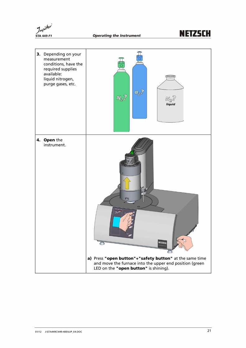
3. Depending on your measurement conditions, have the required supplies available: liquid nitrogen, purge gases, etc.
4. Open the instrument.
a) Press "open button"+"safety button" at the same time and move the furnace into the upper end position (green LED on the "open button" is shining).

Operating the InstrumentSTA 449 F1
01/12 J:\STA449C\449-400\JUP_E4.DOC 22
b) In the upper end position the furnace can be swung out by 30° to the left or to the right (parking position).
5. Insert two empty crucibles*. *for baseline (correction) measurements

Operating the InstrumentSTA 449 F1
01/12 J:\STA449C\449-400\JUP_E4.DOC 23
6. Close the instrument.
a) Swing the furnace back to the normal centered position.
b) Press "close button"+"safety button" at the same time and move the furnace into the lower end position (green LED on the "close button" is shining).

Operating the InstrumentSTA 449 F1
01/12 J:\STA449C\449-400\JUP_E4.DOC 24
7. Start the STA 449F1 measurement program.
8. Proceed as shown to create a baseline: �
see separate
software manual
New
Measurement Definition
Last Items- define Filename
Header
- sample Mass = 0!- select temperature calibration file/
sensitivity calibration file- define all sample settings (e.g. Identity, Name)
- define gases (purge and protective)
- select measurement type: Correction
Setup- check the instrument setup
Temperature Program - define all steps of the temperature program
click -
Measurethe program switches to the adjustment window
File Menu

Operating the InstrumentSTA 449 F1
01/12 J:\STA449C\449-400\JUP_E4.DOC 25
9. Push Initial Cond. ON. Wait for stable balance. Start the measurement. If necessary check the Instrument Configuration.
see separate
software manual
10. Prepare the sample.
Chapter IV
11. Weigh the sample.
Chapter IV
Operating the InstrumentSTA 449 F1
01/12 J:\STA449C\449-400\JUP_E4.DOC 26
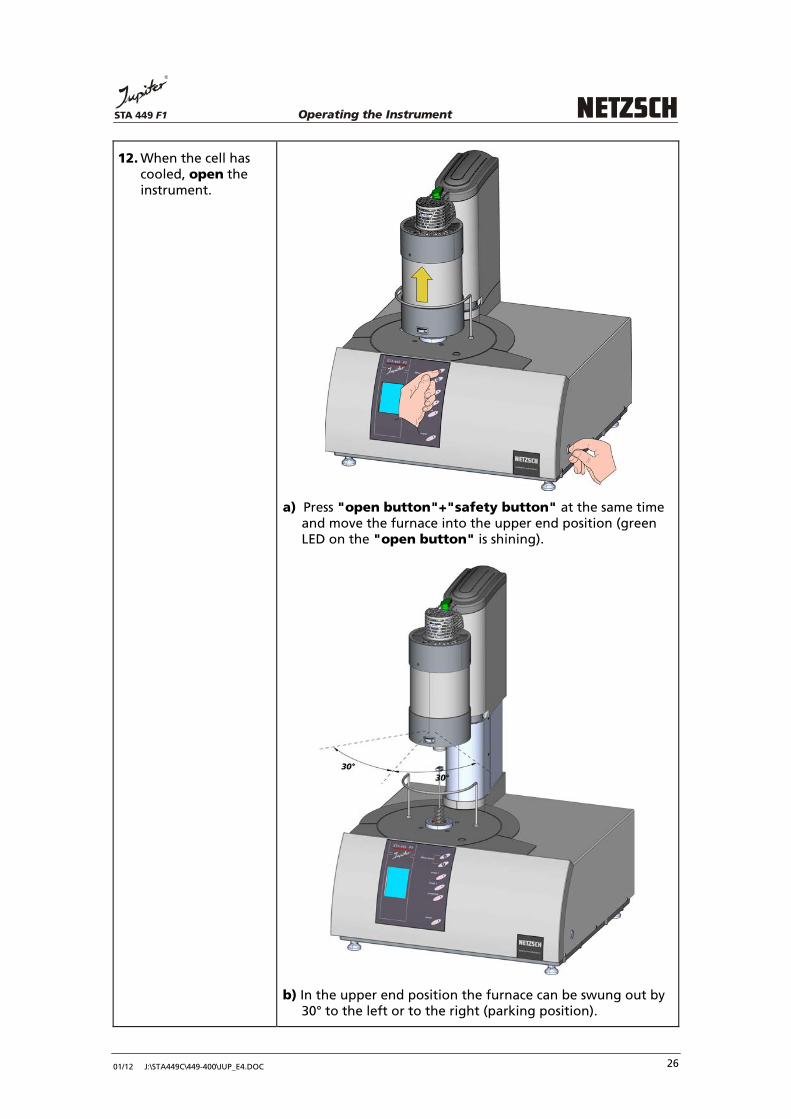
12. When the cell has cooled, open the instrument.
a) Press "open button"+"safety button" at the same time and move the furnace into the upper end position (green LED on the "open button" is shining).
b) In the upper end position the furnace can be swung out by 30° to the left or to the right (parking position).
Operating the InstrumentSTA 449 F1
01/12 J:\STA449C\449-400\JUP_E4.DOC 27
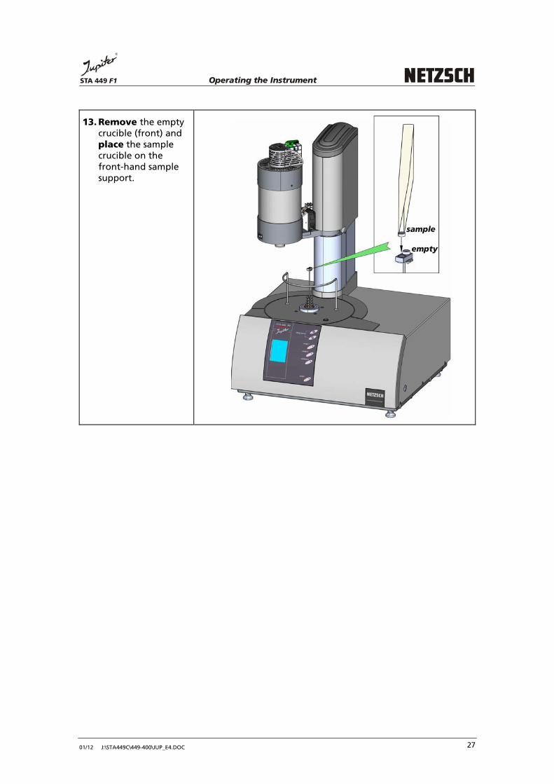
13. Remove the empty crucible (front) and place the sample crucible on the front-hand sample support.

Operating the InstrumentSTA 449 F1
01/12 J:\STA449C\449-400\JUP_E4.DOC 28
14. Close the instrument.
aaaa)))) Swing the furnace back to the normal centered position.
b) Press "close button"+"safety button" at the same time and move the furnace into the lower end position (green LED on the "close button" is shining).
Operating the InstrumentSTA 449 F1
01/12 J:\STA449C\449-400\JUP_E4.DOC 29
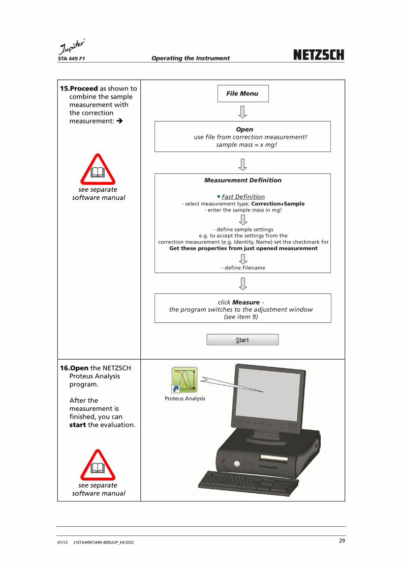
15.Proceed as shown to combine the sample measurement with the correction measurement: �
see separate
software manual
Measurement Definition
Fast Definition
- enter the sample mass in mg!- select measurement type: Correction+Sample
- define sample settingse.g. to accept the settings from the
correction measurement (e.g. Identity, Name) set the checkmark for Get these properties from just opened measurement
- define Filename
click -Measurethe program switches to the
(see item 9)adjustment window
File Menu
Openuse file from correction measurement!
sample mass = x mg!
16.Open the NETZSCH Proteus Analysis program. After the measurement is finished, you can start the evaluation.
see separate
software manual

Operating the InstrumentSTA 449 F1
01/12 J:\STA449C\449-400\JUP_E4.DOC 30
Selection of the Gas Atmosphere
In principle the STA 449 F1 Jupiter allows measurements under the following conditions:
• dynamic gas flow • static gas atmosphere • vacuum
Figure 4: gas flow diagram STA 449 F1 Jupiter

Operating the InstrumentSTA 449 F1
01/12 J:\STA449C\449-400\JUP_E4.DOC 31
Static Conditions
Static conditions mean that the furnace chamber is filled with gas and this filler gas will not be exchanged during measurement. The gas outlet valve must be closed.
Measurements under Static Conditions - the Pros and Cons In case of static measurements there is no protection of the weighing system by a continuous inert gas flow. This has effects on the function of the weighing system. In the most positive case "only" air humidity deposits on the surface of the weighing system. These deposits impair the stability behaviour of the STA 449 F1 Jupiter. Higher problems arise if aggressive gases reach the weighing system. This can lead to a damage of the weighing system. Measurements in static gas atmosphere are only admitted, if the sample does not release aggressive or condensable reaction products. The operator of the instrument is personally responsible that samples releasing aggressive, reactive or condensable reaction products are not measured under static conditions. Therefore static gas operation should be an exceptional case. If nevertheless you want to do static measurements:
- switch off the all gas connections - close the outlet valve
Measurements with closed outlet valve lead to a pressure increase inside the system. The measuring results are falsified (drift).
Our recommendation: Run the STA 449 F1 Jupiter in dynamic protective gas atmosphere (see page 32 in this chapter).

Operating the InstrumentSTA 449 F1
01/12 J:\STA449C\449-400\JUP_E4.DOC 32
Dynamic Conditions
In dynamic mode the sample chamber is purged with gas during measurement. The gas outlet valve must be opened.
Dynamic Conditions (Dynamic Protective Gas Atmosphere) The balance chamber must always be purged with inert protective gas. In case of dynamic measurements there is a protection of the weighing system by a continuous inert gas flow. The protective gas (pure, inert, dry) must continuously purge through the weighing system into the sample space. How to create a particularly clean gas atmosphere: Use a vacuum pump (a diaphragm pump is sufficient) for evacuation. Prior to starting the measurement the measuring system can be repeatedly evacuated and refilled with purge gases.
Dynamic Conditions (Dynamic Reaction Gas Atmosphere)
ATTENTION!
Penetration of corrosive purge gas into the balance chamber must be avoided!
- The balance chamber must always be purged with inert protective gas.
- Preadjust the flow rates of inert and reaction gas.
- Evacuate the measuring part.
- Introduce protective gas through the valve "protective" until pressure compensation has been reached.
- Wait until the inert gas flow has been stabilised.
- Introduce the reaction gas through the valve "purge 1/purge2".

Operating the InstrumentSTA 449 F1
01/12 J:\STA449C\449-400\JUP_E4.DOC 33
Recommended purge gas rates: Purge 1: approx. 50 ml/min Purge 2: approx. 50 ml/min Protective: 20 ml/min The reaction gas can also be introduced at a defined temperature. We recommend introducing the reaction gas during an isothermal heating segment (heating rate = constant). The gas flow becomes stable after some minutes.
ATTENTION! Do not open the instrument after finishing the measurement until the sample temperature has fallen below 300°C. Fill the instrument until pressure compensation is reached before opening.

Operating the InstrumentSTA 449 F1
01/12 J:\STA449C\449-400\JUP_E4.DOC 34
Hints for using Purge Gases
Inert gases, air and some reaction gases (non toxic, non flammable) can be used.
ATTENTION!
In order to avoid environmental hazards or damage to the instrument, the following in-structions must be followed when using filler or purge gas: • The measuring part is a vacuum tight, sealed construction. It is therefore possible to
carry out measurements in a controlled sample atmosphere. • To ensure safety while measuring at application temperatures above 1000°C it is im-
perative that ceramic parts are used in the reaction area (sample and furnace chamber). These parts are naturally exposed to stress due to permanent temperature changes. Thus cracks can develop and leakages occur especially in the hot zone. Due to the special properties of ceramic materials these defects cannot be predicted in advance and are therefore unavoidable even with regular preventative servicing (exchange of parts).
• Dry, inert gases are recommended for purging the sample chamber. Prior to the intro-
duction of gas a leakage test should be carried out whilst pre-evacuating the system in order to assure the purity of the sample atmosphere. We also recommend that the ex-pelled purge gas be passed into a suitable exhaust hood. Depending on the measuring conditions (sample material, atmosphere, temperature range) derivative products can also be formed due to thermal reactions when using inert gases. These products (e.g. HCN, CO, SO
2, dioxin) even in small amounts are very detrimental to health and must
not be allowed to pass into the work room. • Humid gas mixtures may only be used if condensations inside furnace and balance
system can be avoided. If a humid gas mixture is cooling down, the water begins to condensate at a certain temperature. This temperature is called the dew point. The temperature must not fall below this limit. NETZSCH offers special furnace types.
• The user must decide in advance whether toxic gases might be released during a
measurement. The safety precautions are absolutely essential if this should be the fact.

Operating the InstrumentSTA 449 F1
01/12 J:\STA449C\449-400\JUP_E4.DOC 35
When the measurement requires special reaction gases to be used in the sample chamber then a safety check of the potentially hazardous gas or gas mixture is imperative. In this case the following aspects have to be taken into consideration: • Do explosive gas mixtures or explosive compounds evolve when the sample has contact
with oxygen (air)? • Is it certain that no toxic compounds can evolve from the gases or gas mixtures when
using the chosen application temperatures? In this connection possible reactions between the purge gas in the weighing chamber and the reaction gas in the sample chamber should also be investigated.
• Can it be ruled out that the gases neither corrode the leads nor the seals which are used
in either the system or the surrounding equipment (valves, manometer or flow meter)? If not, leakages are to be expected.
• Which side effects do the gases or gas mixtures have on the system's accessories? These
effects do not result in leakages but would considerably increase wear and tear or could lead to a total failure of the system.
The following rules must definitely be noted and followed:
ATTENTION!
Under no circumstances may explosive gas mixtures be used. • When using flammable gases which form explosive compounds upon contact with
oxygen (air) or when using toxic compounds normal installation of the apparatus in an exposed part of the laboratory is forbidden.
• Hazards to the measuring part due to defects in the sample chamber area can be
avoided by installing a controllable surrounding (glove compartment). When using flammable gases the instrument can be placed in an oxygen-free environment; in addi-tion appropriate sensor systems enable the escape of hazardous gases to be easily de-tected. The latter is also true for toxic gases or compounds.
As limitations exist for certain parts of the instrument when being used in an oxygen-free atmosphere it is recommended that the manufacturer be contacted if necessary. For example certain heating elements cannot be used up to the given maximum temperature when in an inert atmosphere because they need the oxide forming oxygen atmosphere for the preservation of their protective coating. Information concerning the possibilities of using various gases can be found in the appro-priate technical literature or can be requested from the manufacturer or retailer of gases. The following is a selection of purge gases including their limiting properties. The list makes no claim on being complete.
Operating the InstrumentSTA 449 F1
01/12 J:\STA449C\449-400\JUP_E4.DOC 36
Helium (He) Chemically inert (inert gas) No technical safety limitations Argon (Ar) Chemically inert (inert gas) Asphyxiating No technical safety limitations Argon should not be used for low temperature investigations Nitrogen N2
Largely inert Asphyxiating No technical safety limitations but sample reactions are possible in the high temperature range. Air Oxidizing No technical safety limitations but sample reactions are possible. Application is possible above room temperature (maximum application temperature is determined by furnace ma-terial, sample carrier type, crucible material). The oxygen could liquefy if used in the low temperature range (LN
2).
Oxygen (O2)
Increases flammability (must not come into contact with fats or oils) No technical safety limitations but hefty reactions are possible with the sample. Application is possible above room temperature (maximum application temperature is de-termined by furnace material, sample carrier type, crucible material). Liquefaction could oc-cur in the low temperature range (LN2).
Carbon dioxide (CO2)
Non-toxic (MAK value 5000 vpm) Non-flammable Application is possible above room temperature. Hydrogen (H2)
The instrument is not destined and suitable for use under hydrogen atmosphere. It can happen that explosible mixtures are formed inside the system during the respective experiments.

Operating the InstrumentSTA 449 F1
01/12 J:\STA449C\449-400\JUP_E4.DOC 37
Ammonia (NH3)
Toxic (MAK value 50 vpm) Flammable Danger of explosion when in contact with oxygen. For safety reasons it is forbidden to use an instrument that has been installed in the normal way. Corrosion of seals is possible. Carbon monoxide (CO) Toxic (MAK value 10 vpm) Flammable Corrosive For safety reasons it is forbidden to use an instrument that has been installed in the normal way. Hydrogen sulphide (H2S)
Toxic (MAK value 10 vpm) Flammable, corrosive For safety reasons it is forbidden to use an instrument that has been installed in the normal way. Other reducing gases or gas mixtures For safety reasons it is not possible to use these gases as contact with oxygen or air could result in an explosive compound. However, certain gas compounds with inert gases are possible where the mixture ratio excludes all technical safety doubts while complying with the required analytical conditions. The manufacturers of gases and gas mixtures can pro-vide the required information. Chlorine (Cl2)
Very toxic (MAK value 5 vpm) Non-flammable, corrosive, caustic For safety reasons it is forbidden to use an instrument that has been installed in the normal way. Hydrogen chloride (HCl) Toxic (MAK value 5 vpm) Non-flammable, corrosive, caustic For safety reasons it is forbidden to use an instrument that has been installed in the normal way.

Operating the InstrumentSTA 449 F1
01/12 J:\STA449C\449-400\JUP_E4.DOC 38
Sulphur dioxide (SO2)
Toxic (MAK value 2 vpm) Non-flammable, corrosive For safety reasons it is forbidden to use an instrument that has been installed in the normal way. Fluorine (F2)
Very toxic (MAK value 0.1 vpm) Encourages burning, corrosive, caustic For safety reasons it is forbidden to use an instrument that has been installed in the normal way. Hydrogen fluoride (HF) Very toxic (MAK value 3 vpm) Very caustic, corrosive For safety reasons it is forbidden to use an instrument that has been installed in the normal way. Gaseous hydrocarbon Can form explosive gas mixtures with air For safety reasons it is forbidden to use an instrument that has been installed in the normal way. MAK values 2006
Operating the InstrumentSTA 449 F1
01/12 J:\STA449C\449-400\JUP_E4.DOC 39
Measurements under Vacuum - what should be considered! In case of measurements under vacuum a protection of the weighing system by an inert gas is not possible. Please really check: Are aggressive or condensable reaction products released?
Attention! Under vacuum conditions these products are sucked off via the weighing system! A damage of the weighing is pre-programmed. The operator of the instrument is personally responsible (for example by suitable pretests) that samples releasing aggressive, reactive or condensable reaction products are not measured under vacuum conditions.
Measurements under vacuum Measurements under vacuum should only be carried out up to maximum furnace temperatures of 1400°C. Higher temperatures may cause damages on the instrument.
Hints for the use of the STC in case of measurements under vacuum In case of measurements under vacuum with end temperatures up to the maximum furnace temperature we recommend to switch off the STC (Sample Temperature Controller). As the STC controls the sample temperature by the deviation between sample and furnace thermocouple, this can cause problems with furnace control (oscillation). In the worst case the furnace can be overheated. The STC can be switched on and off in the software (see Help system in the Proteus software).