stability of x-bracing systems with traditional bolted
TRANSCRIPT

Stability of X-Bracing Systems with Traditional Bolted Connections
R. Tremblay1, A. Davaran1 and A. Gélinas1
1Group for Research in Structural Engineering, Department of Civil, Geological and Mining Engineering, Ecole Polytechnique, Montreal, QC, Canada, H3C 3A7. email: [email protected] ABSTRACT This paper deals with the design for stability of steel concentrically X-bracing frames built with HSS bracing members. Traditional slotted-tube connections with bolted shear splices are used for the bracing members. Both single- and double-shear splices are investigated. Full-scale quasi-static cyclic test program showed that instability of the discontinuous braces initiated through bending deformations of the connection plates, prior to overall buckling of the bracing members. Elastic stability analysis is performed to assess the effective buckling length and compressive resistances of the bracing members with double shear connections. Brace resistances are also obtained from an analytical model that accounts for inelasticity effects and geometrical imper-fections of the brace connections. Numerical predictions are compared to test results and a numerical example is included to illustrate the method. INTRODUCTION
HSS tubular bracing members arranged in an X-bracing configuration is one
of the common bracing design options for building and industrial structures. The pos-sibility of using a reduced effective length factor, typically K = 0.5, for the compres-sion braces and the resulting smaller member sizes make this system attractive to de-sign engineers. The key issue in the stability of the compression brace in an X-bracing is the in-plane and out-of-plane restraint provided by the intersecting member acting in tension. In earlier analytical work on the stability of this system (e.g., DeWolf and Pelliccione, 1979; Picard and Beaulieu, 1987), bracing members were assumed to have pinned end connections and uniform flexural stiffness properties over their full length. Stoman (1989) and Segal et al. (1994) examined the influence of using fixed and semi-rigid end connections. Studies by Davaran (2001) and Davaran and Hovei-dae (2009) showed that the reduction of the flexural stiffness of the tension brace due to the presence of connection plates at the mid-connection can reduce the strength of the compression brace. Cyclic tests by Tremblay et al. (2003) indicated that a K factor of 0.5 can be used for out-of-plane buckling of HSS braces in X-braced frames when welded cover plates are used at the mid-connection to provide for flexural continuity of the cut brace.
In practice, X-bracing with slotted-HSS bolted plate connections are more commonly used. The connections can be detailed with single-shear (SS) lap splices or double-shear (DS) lap splices (Figure 1). The former type is simpler and easier to as-semble in the field. However, it is unsymmetrical and has inherent out-of-plane ec-centricity. Double shear connections are symmetrical (no eccentricity) and are typical-ly shorter as fewer bolts are needed. Fabrication and assembly on site of DS connec-tions are generally more difficult.
2662Structures Congress 2013 © ASCE 2013
Structures Congress 2013
Dow
nloa
ded
from
asc
elib
rary
.org
by
Ista
nbul
Uni
vers
itesi
on
07/2
0/13
. Cop
yrig
ht A
SCE
. For
per
sona
l use
onl
y; a
ll ri
ghts
res
erve
d.

a)
b)
Figure 1. Connections at brace intersection in X-bracing: a) Single shear bolted lap splices (SS); b) Double shear bolted lap splices (DS).
In a recent quasi-static cyclic test program (Gélinas et. al., 2012; Davaran et.
al., 2012), the stability of full-scale X-bracing specimens with details similar to those shown in Figure 1 was investigated. The tests revealed that instability of the discon-tinuous brace was initiated by flexural out-of-plane deformations of the connecting plates. Buckling modes involving plastic hinges forming in the connecting plates eventually formed without flexural deformations of the HSS members between the hinges (Figure 2). The compressive strengths associated to such buckling modes were lower than the expected brace compressive resistances.
Figure 2. Connection instability observed in the tested specimens. This paper investigates the stability of the discontinuous brace in steel X-
braced frames built with HSS bracing members with bolted slotted connections. Ex-perimental observations for the specimens with SS and DS connections are first re-ported. An analytical method is proposed to assess the effective length of discontinu-ous braces with DS connections including connection flexibility effects. The method is used to predict the values obtained by tests. In the last section of the paper, a design example is presented to illustrate the application of the method.
EXPERIMENTAL OBSERVATIONS
Description of the test specimens. The stability response of 11 X-bracing specimens subjected to quasi-static cyclic displacement is examined in this paper. The test frame was 7.5 m wide x 4.087 m high. The beams were connected to the columns using simple shear connections and lateral loads were essentially resisted by the bracing
2663Structures Congress 2013 © ASCE 2013
Structures Congress 2013
Dow
nloa
ded
from
asc
elib
rary
.org
by
Ista
nbul
Uni
vers
itesi
on
07/2
0/13
. Cop
yrig
ht A
SCE
. For
per
sona
l use
onl
y; a
ll ri
ghts
res
erve
d.
members. All bracing members were made of ASTM A500, gr. C square tubing. Three specimens were detailed with SS splice connections whereas DS connections were used for the remaining ones.
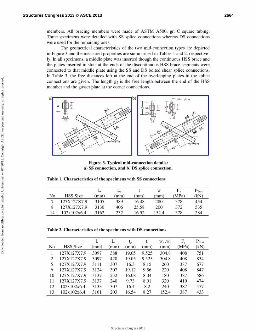
The geometrical characteristics of the two mid-connection types are depicted in Figure 3 and the measured properties are summarised in Tables 1 and 2, respective-ly. In all specimens, a middle plate was inserted though the continuous HSS brace and the plates inserted in slots at the ends of the discontinuous HSS brace segments were connected to that middle plate using the SS and DS bolted shear splice connections. In Table 3, the free distances left at the end of the overlapping plates in the splice connections are given. The length g2 is the free length between the end of the HSS member and the gusset plate at the corner connections.
a)
b)
Figure 3. Typical mid-connection details: a) SS connection, and b) DS splice connection.
Table 1. Characteristics of the specimens with SS connections
No HSS Size L
(mm) Lc
(mm) t
(mm) w
(mm) Fy
(MPa) PTest (kN)
7 8 14
127X127X7.9 127X127X7.9 102x102x6.4
3105 3130 3162
389 406 232
16.48 25.58 16.52
280 200
152.4
378 372 378
454 535 284
Table 2. Characteristics of the specimens with DS connections
No HSS Size L
(mm) Lc
(mm) tg
(mm) ts
(mm) wg ,wS (mm)
Fy (MPa)
PTest (kN)
1 2 5 6 10 11 12 13
127X127X7.9 127X127X7.9 127X127X7.9 127X127X7.9 127X127X7.9 127X127X7.9 102x102x6.4 102x102x6.4
3097 3097 3111 3124 3137 3137 3133 3161
388 428 307 307 232 240 307 203
19.05 19.05 16.3 19.12 16.08 9.73 16.4 16.54
9.525 9.525 8.15 9.56 8.04 8.01 8.2 8.27
304.8 304.8 260 220 180 320 240
152.4
408 408 387 408 387 410 387 387
751 834 677 847 586 474 477 433
2664Structures Congress 2013 © ASCE 2013
Structures Congress 2013
Dow
nloa
ded
from
asc
elib
rary
.org
by
Ista
nbul
Uni
vers
itesi
on
07/2
0/13
. Cop
yrig
ht A
SCE
. For
per
sona
l use
onl
y; a
ll ri
ghts
res
erve
d.
In specimens with DS connections, a clear distance is left between the two splice plates inserted at the HSS member ends. In practice, this opening can be filled with a shim plate having the same thickness as the middle plate, as illustrated in Fig-ure 3b. In the test program, no shim plate was used for Specimen no. 13. Specimens nos. 10 and 12 had shim plates attached to the splice plates by a few tack welds. For the remaining specimens with DS connections, pairs of parallel continuous structural welds were used to connect the shim plates to the splice plates. Table 3. Free distances left between connecting plates.
Connection Type
No. g1
(mm) g2
(mm) g3
(mm) e
(mm) Kc
SS 7 8 14
32 49 32
32 49 32
25 25 25
71 71 50
- - -
DS
1 2 5 6 10 11 12 13
40 80 32 32 32 40 32 32
40 40 32 40 32 40 32 32
25 25 25 25 25 25 25 25
50 50 50 50 50 50 50 36
1.55 1.48 1.81 1.78 2.16 1.95 1.77 2.12
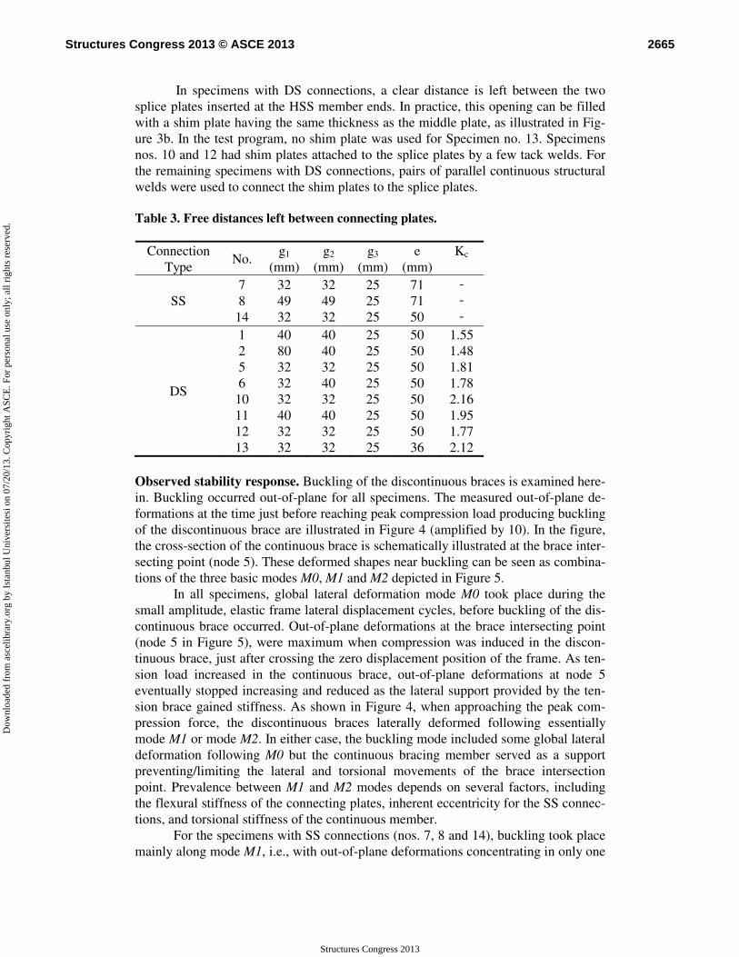
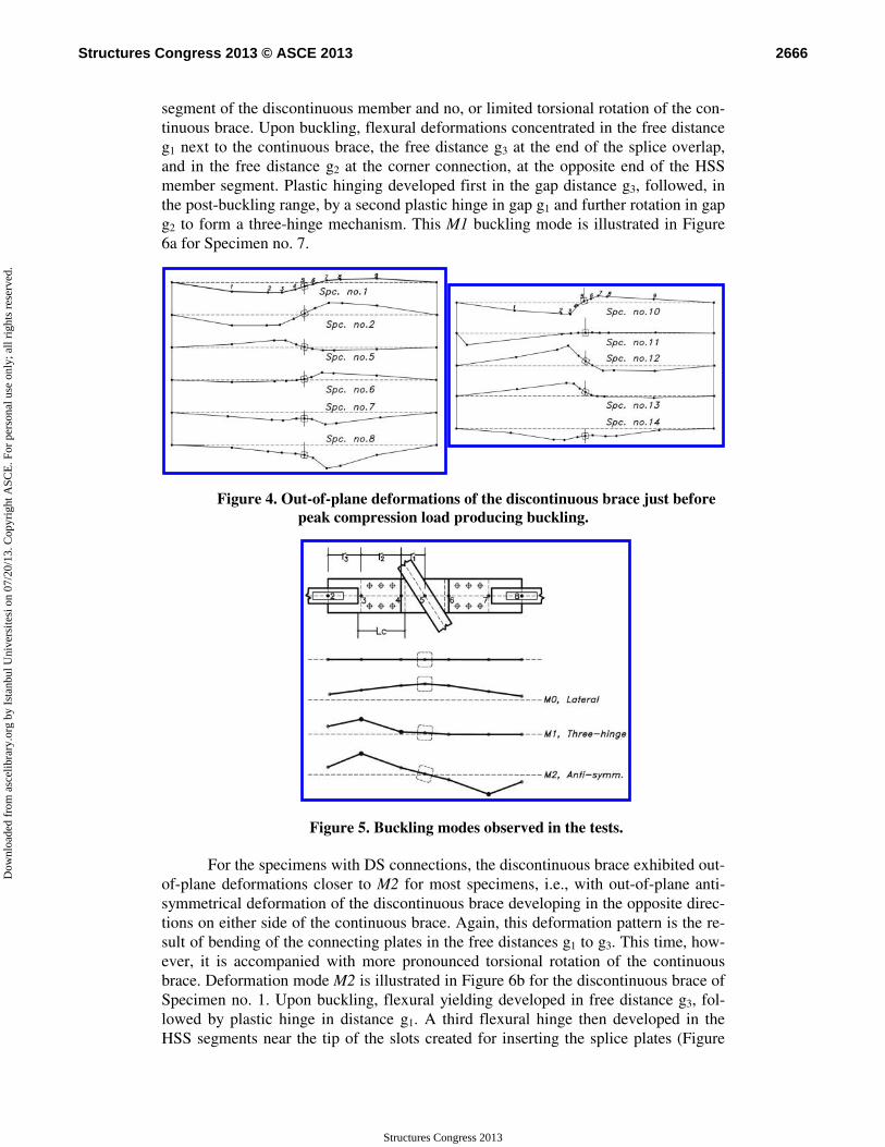
Observed stability response. Buckling of the discontinuous braces is examined here-in. Buckling occurred out-of-plane for all specimens. The measured out-of-plane de-formations at the time just before reaching peak compression load producing buckling of the discontinuous brace are illustrated in Figure 4 (amplified by 10). In the figure, the cross-section of the continuous brace is schematically illustrated at the brace inter-secting point (node 5). These deformed shapes near buckling can be seen as combina-tions of the three basic modes M0, M1 and M2 depicted in Figure 5.
In all specimens, global lateral deformation mode M0 took place during the small amplitude, elastic frame lateral displacement cycles, before buckling of the dis-continuous brace occurred. Out-of-plane deformations at the brace intersecting point (node 5 in Figure 5), were maximum when compression was induced in the discon-tinuous brace, just after crossing the zero displacement position of the frame. As ten-sion load increased in the continuous brace, out-of-plane deformations at node 5 eventually stopped increasing and reduced as the lateral support provided by the ten-sion brace gained stiffness. As shown in Figure 4, when approaching the peak com-pression force, the discontinuous braces laterally deformed following essentially mode M1 or mode M2. In either case, the buckling mode included some global lateral deformation following M0 but the continuous bracing member served as a support preventing/limiting the lateral and torsional movements of the brace intersection point. Prevalence between M1 and M2 modes depends on several factors, including the flexural stiffness of the connecting plates, inherent eccentricity for the SS connec-tions, and torsional stiffness of the continuous member.
For the specimens with SS connections (nos. 7, 8 and 14), buckling took place mainly along mode M1, i.e., with out-of-plane deformations concentrating in only one
2665Structures Congress 2013 © ASCE 2013
Structures Congress 2013
Dow
nloa
ded
from
asc
elib
rary
.org
by
Ista
nbul
Uni
vers
itesi
on
07/2
0/13
. Cop
yrig
ht A
SCE
. For
per
sona
l use
onl
y; a
ll ri
ghts
res
erve
d.
segment of the discontinuous member and no, or limited torsional rotation of the con-tinuous brace. Upon buckling, flexural deformations concentrated in the free distance g1 next to the continuous brace, the free distance g3 at the end of the splice overlap, and in the free distance g2 at the corner connection, at the opposite end of the HSS member segment. Plastic hinging developed first in the gap distance g3, followed, in the post-buckling range, by a second plastic hinge in gap g1 and further rotation in gap g2 to form a three-hinge mechanism. This M1 buckling mode is illustrated in Figure 6a for Specimen no. 7.
Figure 4. Out-of-plane deformations of the discontinuous brace just before peak compression load producing buckling.
Figure 5. Buckling modes observed in the tests.
For the specimens with DS connections, the discontinuous brace exhibited out-of-plane deformations closer to M2 for most specimens, i.e., with out-of-plane anti-symmetrical deformation of the discontinuous brace developing in the opposite direc-tions on either side of the continuous brace. Again, this deformation pattern is the re-sult of bending of the connecting plates in the free distances g1 to g3. This time, how-ever, it is accompanied with more pronounced torsional rotation of the continuous brace. Deformation mode M2 is illustrated in Figure 6b for the discontinuous brace of Specimen no. 1. Upon buckling, flexural yielding developed in free distance g3, fol-lowed by plastic hinge in distance g1. A third flexural hinge then developed in the HSS segments near the tip of the slots created for inserting the splice plates (Figure
2666Structures Congress 2013 © ASCE 2013
Structures Congress 2013
Dow
nloa
ded
from
asc
elib
rary
.org
by
Ista
nbul
Uni
vers
itesi
on
07/2
0/13
. Cop
yrig
ht A
SCE
. For
per
sona
l use
onl
y; a
ll ri
ghts
res
erve
d.
6c). Specimen no. 2 also deformed according to M2 mode (Figure 4). As illustrated in Figure 6d, inelastic deformations after buckling concentrated on only one side of the continuous brace.
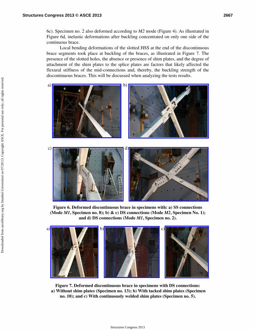
Local bending deformations of the slotted HSS at the end of the discontinuous brace segments took place at buckling of the braces, as illustrated in Figure 7. The presence of the slotted holes, the absence or presence of shim plates, and the degree of attachment of the shim plates to the splice plates are factors that likely affected the flexural stiffness of the mid-connections and, thereby, the buckling strength of the discontinuous braces. This will be discussed when analyzing the tests results.
a)
b)
c)
d)
Figure 6. Deformed discontinuous brace in specimens with: a) SS connections (Mode M1, Specimen no. 8); b) & c) DS connections (Mode M2, Specimen No. 1);
and d) DS connections (Mode M1, Specimen no. 2).
a)
b)
c)
Figure 7. Deformed discontinuous brace in specimens with DS connections: a) Without shim plates (Specimen no. 13); b) With tacked shim plates (Specimen
no. 10); and c) With continuously welded shim plates (Specimen no. 5).
2667Structures Congress 2013 © ASCE 2013
Structures Congress 2013
Dow
nloa
ded
from
asc
elib
rary
.org
by
Ista
nbul
Uni
vers
itesi
on
07/2
0/13
. Cop
yrig
ht A
SCE
. For
per
sona
l use
onl
y; a
ll ri
ghts
res
erve
d.
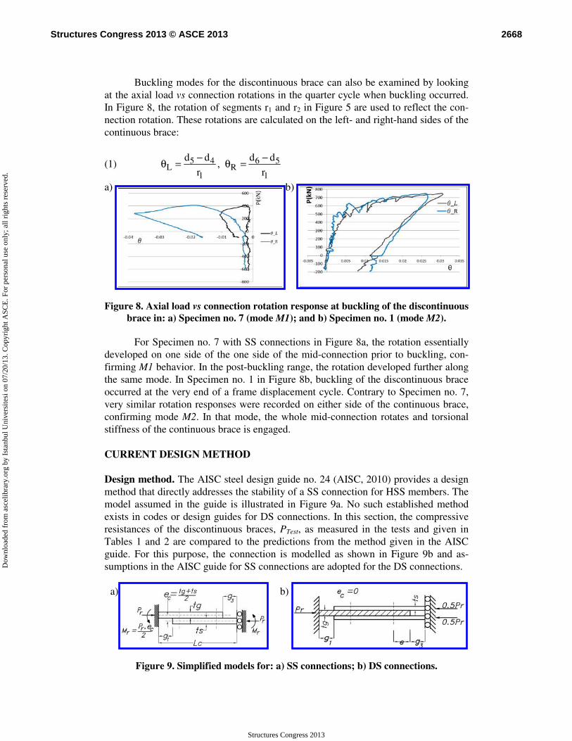
Buckling modes for the discontinuous brace can also be examined by looking
at the axial load vs connection rotations in the quarter cycle when buckling occurred. In Figure 8, the rotation of segments r1 and r2 in Figure 5 are used to reflect the con-nection rotation. These rotations are calculated on the left- and right-hand sides of the continuous brace:
(1) 5 4 6 5L R
1 1
d d d d,
r r
− −θ = θ =
a)
b)
Figure 8. Axial load vs connection rotation response at buckling of the discontinuous
brace in: a) Specimen no. 7 (mode M1); and b) Specimen no. 1 (mode M2).
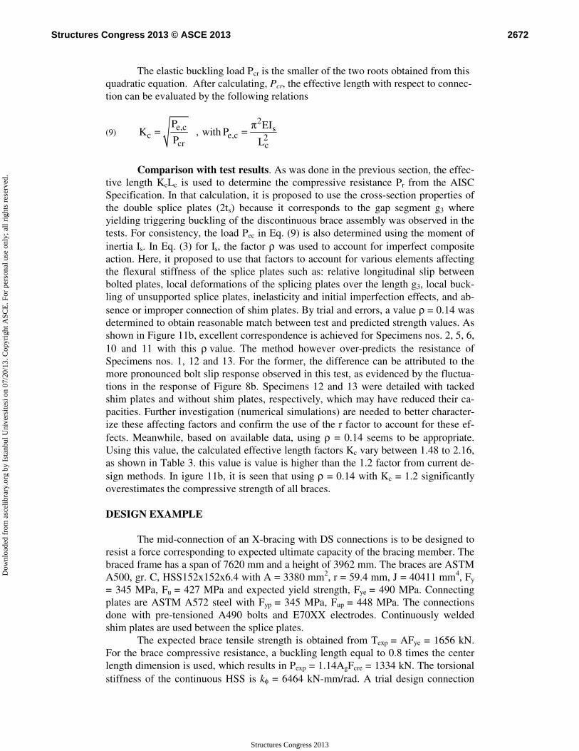
For Specimen no. 7 with SS connections in Figure 8a, the rotation essentially developed on one side of the one side of the mid-connection prior to buckling, con-firming M1 behavior. In the post-buckling range, the rotation developed further along the same mode. In Specimen no. 1 in Figure 8b, buckling of the discontinuous brace occurred at the very end of a frame displacement cycle. Contrary to Specimen no. 7, very similar rotation responses were recorded on either side of the continuous brace, confirming mode M2. In that mode, the whole mid-connection rotates and torsional stiffness of the continuous brace is engaged. CURRENT DESIGN METHOD Design method. The AISC steel design guide no. 24 (AISC, 2010) provides a design method that directly addresses the stability of a SS connection for HSS members. The model assumed in the guide is illustrated in Figure 9a. No such established method exists in codes or design guides for DS connections. In this section, the compressive resistances of the discontinuous braces, PTest, as measured in the tests and given in Tables 1 and 2 are compared to the predictions from the method given in the AISC guide. For this purpose, the connection is modelled as shown in Figure 9b and as-sumptions in the AISC guide for SS connections are adopted for the DS connections.
a)
b)
Figure 9. Simplified models for: a) SS connections; b) DS connections.
2668Structures Congress 2013 © ASCE 2013
Structures Congress 2013
Dow
nloa
ded
from
asc
elib
rary
.org
by
Ista
nbul
Uni
vers
itesi
on
07/2
0/13
. Cop
yrig
ht A
SCE
. For
per
sona
l use
onl
y; a
ll ri
ghts
res
erve
d.

For SS connections, the resistance is obtained using the interaction equation for combined flexure and compression from the AISC Specification (AISC 2010):
(2)
r r r
c c c
r r r
c c c
P 8 M P1.0 for 0.2
P 9 M P
P M P1.0 for 0.2
2P M P
⎛ ⎞+ ≤ ≥⎜ ⎟
⎝ ⎠
+ ≤ <
where Pc and Mc are the available strengths of the single plate in axial compression and flexure, respectively, as also determined from the Specification. The strength Pc is calculated with an effective length KcLc, where Kc = 1.2 and Lc is the length of the connection, and with the cross-section properties of the thinner of the two overlapping plates. In Figure 9a, lengths g1 and g3 are indicated for reference to the mid-connection detail of Figure 3a. From equilibrium, the moment Mr = Pr·ec/2. The con-nection axial resistance Pr is taken as the minimum Pr value obtained by solving the two expressions in Eq. (1).
For DS connections, the eccentricity ec = 0 and the connection resistance Pr is taken equal to the available strength Pc determined with the KcLc value used for SS connections. According to the AISC guide, Pc should also be determined based on the properties of the thinner cross-section. In Figure 9b, either the single plate with thick-ness tg or the section with two plates of thickness ts separated by the clear distance tg could be considered. For the second case, the moment of inertia, Is, is given by:
(3) ( )23
s gs ss s s
t tw tI 2 2w t
12 2
⎛ ⎞ +⎛ ⎞= + ρ⎜ ⎟ ⎜ ⎟⎜ ⎟ ⎝ ⎠⎝ ⎠
where ρ is a factor that accounts for the degree of composite action between the two plates. For the comparison, the calculations are performed for both cross-sections but preference will be given to the results obtained for the second (composite) one be-cause the tests clearly showed that buckling of the discontinuous brace occurred when flexural yielding initiated in the free distance g3. In Eq. (3), a conservative value ρ = 0 is assumed for this calculation, assuming that no, or limited composite action devel-ops between the two splice plates. Observation in tests showed that the two plates ex-hibited individual response in the post-buckling range (Figure 10), suggesting that this assumption could be appropriate for determining the buckling resistance. Comparison with test results. The predicted resistances are compared to the test re-sults in Figure 11. For SS connections, the Pr values are generally close (within 15%) to the measured values but, for two specimens, the predictions are on the non con-servative side. For the DS cases, the figure shows that large differences exist depend-ing on the cross-section adopted in the calculations. When using the single plate (tg) corresponding to the free length g1, the resistances are generally overestimated with predicted-to-test ratios varying between 1.08 and 1.84. Lower values are found when using the cross-section corresponding to the double splice plates (2ts). In that case, the test-to-predicted ratios range from 0.31 to 0.91, indicate that the approach would be very conservative. The deviations from the measured values for the DS connections are significantly greater than for the SS connections.
2669Structures Congress 2013 © ASCE 2013
Structures Congress 2013
Dow
nloa
ded
from
asc
elib
rary
.org
by
Ista
nbul
Uni
vers
itesi
on
07/2
0/13
. Cop
yrig
ht A
SCE
. For
per
sona
l use
onl
y; a
ll ri
ghts
res
erve
d.

Figure 10. Deformation of double splicing plates at plastic hinge node 3 or 7. a)
b)
Figure 11. Comparison between predicted axial resistances and test results for spec-
imens with: a) SS connections; b) DS connections. PROPOSED DESIGN METHOD FOR DS CONNECTIONS
Elastic buckling analysis. In this section, elastic buckling analysis is performed to determine the elastic buckling load and the corresponding effective length factor for DS connections. A model is developed assuming that the discontinuous bracing member and the overlapping length of the plates remained do not deform in bending at buckling and that out-of-plane displacements are only produced by the bending of the connecting plates in the free lengths, g1 to g3, as was observed in tests. The model is shown in Figure 12. The flexural stiffness of the connecting plates is represented by rotational springs located at connection ends (denoted by nodes 3, 4, 6 and 7 in Figure 4).
Figure 12. Model for prediction buckling of the DS connection.
The rotational stiffness of the springs can be defined by the properties of the connected plates as iii gEIk /= , where ig is the equivalent length of the plate seg-
ments involved in bending. For the segment g1, elastic finite element analysis of the
2670Structures Congress 2013 © ASCE 2013
Structures Congress 2013
Dow
nloa
ded
from
asc
elib
rary
.org
by
Ista
nbul
Uni
vers
itesi
on
07/2
0/13
. Cop
yrig
ht A
SCE
. For
per
sona
l use
onl
y; a
ll ri
ghts
res
erve
d.

flexural response of the middle plate connecting at an angle ω to the continuous brace (see Figure 3b) was performed to determine 1g . For segment g3, the length was in-
creased by the end distance e whereas no modification was needed for the segment g2:
(4)
egg
gg
ωτgg.
+==
⎟⎠⎞
⎜⎝⎛ −+=
33
22
6250
11 40
290
In Eq. (4) the parameter τ = 0.87t and 1.43t for plate width-to-thickness ratios
w/t = 10 and 20, respectively. Linear interpolation is used for intermediate w/t values. For spring k3, the flexural stiffness is determined using the moment of inertia Is from Eq. (3). This time, an intermediate value ρ = 0.14 is selected, as justified from test results and discussed in the next section. Finally, the torsional stiffness of the contin-uous brace is obtained from:
(5) ηωSinL
GJkφ
)2(.
22
= , where: )tanh(
)(
3
1 3
LλLλLλη
−= with
eP
TπLλ =
where η is a tensile stiffening parameter that magnifies the initial torsional stiffness due to tension load T in the continuous brace (Davaran, 2001). Based on these as-sumptions, assuming a perfectly anti-symmetrical buckling mode, the deformed shape at buckling of the model in Figure 12 can be entirely defined by the two degrees of freedom d1 and d3 and static equilibrium in the deformed position yields:
(6) K d 0= where K is the stiffness matrix of the system including nonlinear geometric effects:
⎟⎟⎠
⎞⎜⎜⎝
⎛ −−+−=2
21
1
311
1
2
1
γL
)γγ(k
γL
k
Lk φ ;
(7) ⎟⎟⎠
⎞⎜⎜⎝
⎛−
−−−+
−−+= P
)γγ(γL
)γ(k
)γγ(L
)γγ(k
Lk
211
23
21
21213 1
1
1
1
⎟⎟⎠
⎞⎜⎜⎝
⎛−−++= P
γL
)γ(k
γγL
)γγ(k
Lk φ
2
2
21
21131
1
2
1; ⎟⎟
⎠
⎞⎜⎜⎝
⎛−
−−=
1
1
21
2233 1
1
γL
k
)γγ(L
γk
Lk
In these expression, Laγ /1 = and 2 b / Lγ = (see Figure 12 for dimensions a
and b). By setting the determinant of that matrix equal to zero, the following quadratic equation is obtained :
(8) 0.2 =+− dPcP , where: 13 31 13 31 11 33c k k ; d k .k k .k= + = −
2671Structures Congress 2013 © ASCE 2013
Structures Congress 2013
Dow
nloa
ded
from
asc
elib
rary
.org
by
Ista
nbul
Uni
vers
itesi
on
07/2
0/13
. Cop
yrig
ht A
SCE
. For
per
sona
l use
onl
y; a
ll ri
ghts
res
erve
d.
The elastic buckling load Pcr is the smaller of the two roots obtained from this quadratic equation. After calculating, Pcr, the effective length with respect to connec-tion can be evaluated by the following relations
(9) 2
e,c sc e,c 2
cr c
P EIK , with P
P L
π= =
Comparison with test results. As was done in the previous section, the effec-
tive length KcLc is used to determine the compressive resistance Pr from the AISC Specification. In that calculation, it is proposed to use the cross-section properties of the double splice plates (2ts) because it corresponds to the gap segment g3 where yielding triggering buckling of the discontinuous brace assembly was observed in the tests. For consistency, the load Pec in Eq. (9) is also determined using the moment of inertia Is. In Eq. (3) for Is, the factor ρ was used to account for imperfect composite action. Here, it proposed to use that factors to account for various elements affecting the flexural stiffness of the splice plates such as: relative longitudinal slip between bolted plates, local deformations of the splicing plates over the length g3, local buck-ling of unsupported splice plates, inelasticity and initial imperfection effects, and ab-sence or improper connection of shim plates. By trial and errors, a value ρ = 0.14 was determined to obtain reasonable match between test and predicted strength values. As shown in Figure 11b, excellent correspondence is achieved for Specimens nos. 2, 5, 6, 10 and 11 with this ρ value. The method however over-predicts the resistance of Specimens nos. 1, 12 and 13. For the former, the difference can be attributed to the more pronounced bolt slip response observed in this test, as evidenced by the fluctua-tions in the response of Figure 8b. Specimens 12 and 13 were detailed with tacked shim plates and without shim plates, respectively, which may have reduced their ca-pacities. Further investigation (numerical simulations) are needed to better character-ize these affecting factors and confirm the use of the r factor to account for these ef-fects. Meanwhile, based on available data, using ρ = 0.14 seems to be appropriate. Using this value, the calculated effective length factors Kc vary between 1.48 to 2.16, as shown in Table 3. this value is value is higher than the 1.2 factor from current de-sign methods. In igure 11b, it is seen that using ρ = 0.14 with Kc = 1.2 significantly overestimates the compressive strength of all braces. DESIGN EXAMPLE
The mid-connection of an X-bracing with DS connections is to be designed to resist a force corresponding to expected ultimate capacity of the bracing member. The braced frame has a span of 7620 mm and a height of 3962 mm. The braces are ASTM A500, gr. C, HSS152x152x6.4 with A = 3380 mm2, r = 59.4 mm, J = 40411 mm4, Fy
= 345 MPa, Fu = 427 MPa and expected yield strength, Fye = 490 MPa. Connecting plates are ASTM A572 steel with Fyp = 345 MPa, Fup = 448 MPa. The connections done with pre-tensioned A490 bolts and E70XX electrodes. Continuously welded shim plates are used between the splice plates.
The expected brace tensile strength is obtained from Texp = AFye = 1656 kN. For the brace compressive resistance, a buckling length equal to 0.8 times the center length dimension is used, which results in Pexp = 1.14AgFcre = 1334 kN. The torsional stiffness of the continuous HSS is kφ = 6464 kN-mm/rad. A trial design connection
2672Structures Congress 2013 © ASCE 2013
Structures Congress 2013
Dow
nloa
ded
from
asc
elib
rary
.org
by
Ista
nbul
Uni
vers
itesi
on
07/2
0/13
. Cop
yrig
ht A
SCE
. For
per
sona
l use
onl
y; a
ll ri
ghts
res
erve
d.

satisfying all the code tension strength requirements is developed, which give prelim-inary plate thickness and widths. Plate dimensions from this first design trial are given in Table 4. The connection has 2 rows of three 22.2 mm bolts spaced 70 mm o/c. An edge distance e = 40 mm and the free lengths are: g1 = g2 = 44.5 mm and g3 = 25.4 mm. The corresponding modified lengths are 1g = 73.77 mm and 3g = 65.4 mm.
From geometry, a = Lc = 290 mm and b = 189 mm, which gives γ1 = 0.08437 and γ2 = 0.054902. For this first trial, stiffness k1 = 677x103 kN-mm/rad. Assuming ρ = 0.14, k3 = 913x103 kN-mm/rad. For simplicity, for the calculation of k2, the corner gusset plates are assumed to have the same dimensions as the middle plate. As will be dis-cussed, the dimensions assumed for k2 have little influence on the buckling strength of the discontinuous brace.
In Table 4, three values of resistances are computed for each trial: one consid-ering k2 and T = 0.5 Pexp, one with k2 = 0 and T = 0.5 Pexp and one with k2 = T = 0. For the first trial design, the factored resistance (φ = 0.9) is equal to 1149 kN, which is less than the required design strength of 1334 kN. As shown, ignoring k2 in the calcu-lations has nearly no effect because this rotational restraint is located far from the mid-connection. Similarly, for this example, the stiffening effect of T on the torsional restraint provided by the continuous brace also has negligible impact on the stability of the discontinuous brace. To increase of the strength of the discontinuous brace, the thickness of the splice plates is increased from 11.1 mm to 12.7 mm. This change in-creases the stiffness k3 to 1190x103 kN-mm/rad and, as shown in Table 4, it is suffi-cient to achieve the required compressive resistance of 1336 kN. It is noted that in all cases, the Kc factor is close to 2.0, which is larger than 1.2.
Table 4. Designed gusset plates and connection buckling capacity.
Trial No.
tg
(mm) ts
(mm) wg, ws
(mm) k2
(kN-mm/rad) T
(kN) Pcr
(kN) Kc φPc
(kN) 1 22.225 11.113 273 1124x103
0 0
0.5 Pexp 0.5 Pexp
1771 1723 1717
1.99 2.02 2.02
1149 1133 1131
2 22.225 12.7 273 1124x103 0 0
0.5 Pexp 0.5 Pexp
0
2098 2052 2045
2.09 2.11 2.11
1336 1322 1321
CONCLUSIONS
The response of 11 quasi-static cyclic tests on steel X-braced frames with HSS-slotted bolted connections was examined to study the stability response of the discontinuous bracing members. The compressive strength and buckling mode of the discontinuous braces was influenced by local bending deformations of the connecting plates at the mid-connections and, to a lesser extent, at the corner gusset plate connec-tions. Two buckling modes were observed: a three-hinge mode involving one half of the discontinuous brace and an anti-symmetrical mode involving both segments of the discontinuous brace. The buckling mode and compressive strength were influenced by the type of connections as well as the flexural stiffness and strength of the connecting plates.
The use of an effective length of 1.2 times the mid-connection length did not permit to accurately predict the measured specimen resistances. Longer effective
2673Structures Congress 2013 © ASCE 2013
Structures Congress 2013
Dow
nloa
ded
from
asc
elib
rary
.org
by
Ista
nbul
Uni
vers
itesi
on
07/2
0/13
. Cop
yrig
ht A
SCE
. For
per
sona
l use
onl
y; a
ll ri
ghts
res
erve
d.
lengths, varying from 1.5 to 2.2, were determined from elastic stability analysis per-formed to account for the geometry and flexibility of the mid-connections. Improved strength predictions could be achieved when using these values together with reduced flexural stiffness properties for the connections. The proposed model showed that the properties of the mid-connections influence more the compressive strength of discon-tinuous braces compared to the stiffness and strength of the corner connections. Fur-ther study is needed to better define the reduced connection properties that must be used to account for inelasticity and initial imperfection effects on the brace compres-sive strength.
REFERENCES
AISC (2010). ANSI/AISC 360-10, Specification for Structural Steel Buildings. American Institute of Steel Construction (AISC), Chicago, Il.
CSA. (2009). CSA-S16-09, Design of Steel Structures, Canadian Standards Association, Willowdale, ON.
Davaran, A. 2001. Effective length factor for discontinuous X-bracing systems. Journal of Engineering Mechanics, ASCE, 127(2): 106-112.
Davaran, A., and Hoveidae, N. 2009. Effect of mid-connection detail on the behavior of X-bracing systems. Journal of Construction Steel Research, 65(4): 985-990.
Davaran, A., Gélinas, A., and Tremblay, R. (2012). “Experimental seismic response of slotted connec-tions at the intersection of HSS braces in X-bracing systems.” Proc. Connections VII: Seventh In-ternational Workshop on Connections in Steel Structures, Timisoara, Romania, Paper No. 6-1.
DeWolf, J.T., and Pelliccione, J. F. (1979). “Cross-bracing design.” J. Struct. Div., ASCE, 105(7), 1379-1391.
Gélinas, A., Tremblay, R. and Davaran, A. 2012. Seismic Behavior of Steel HSS X-Bracing of the Conventional Construction Category. Proc. Structures Congress 2012, ASCE, Chicago, IL: 1649-1660.
Packer, J., Sherman, D., and Lecce, M. (2010). Hollow Structural Section Connections - Steel Design Guide No. 24, American Institute of Steel Construction (AISC), Chicago, Il.
Picard, A. and Beaulieu, D. (1987). “Design of diagonal cross-bracings. Part 1: Theoretical study.” Eng. J., AISC, 24(3), 122-126.
Segal, F., Levy, R., and Rutenberg, A. (1994). “Design of imperfect cross-bracings.” J. Engrg. Mech., ASCE, 120(5), 1057-1075.
Stoman, S.H. (1989). “Effective length spectra for cross bracings.” J. Struct. Eng., ASCE, 115(12), 3112-3122.
Tremblay, R., Archambault, M.-H., and Filiatrault, A. (2003). “Seismic response of concentrically braced steel frames made with rectangular hollow bracing members.” J. Struct. Eng., ASCE, 129(12), 1626-1636.
2674Structures Congress 2013 © ASCE 2013
Structures Congress 2013
Dow
nloa
ded
from
asc
elib
rary
.org
by
Ista
nbul
Uni
vers
itesi
on
07/2
0/13
. Cop
yrig
ht A
SCE
. For
per
sona
l use
onl
y; a
ll ri
ghts
res
erve
d.