stacked washer-dryer installation instructions · stacked washer-dryer installation instructions...
TRANSCRIPT
printed in U.S.A. 6 3717020
STACKED WASHER-DRYERINSTALLATION INSTRUCTIONS
LEAVE THESE INSTRUCTIONS WITH THE OWNER
IMPORTANT TO INSTALLERREMOVE THE DOOR FROM ALL DISCARDEDAPPLIANCES SUCH AS DRYERS ANDCOMBINATION WASHER/DRYERS TO AVOIDTHE DANGER OF A CHILD SUFFOCATINGSHOULD HE/SHE CRAWL INSIDE AND THEDOOR BE SHUT.
THE APPLIANCE MUST NOT BE INSTALLEDOR STORED IN AN AREA WHERE IT WILL BEEXPOSED TO WATER AND/OR WEATHER.
U.S. MODELSPLEASE READ THE FOLLOWING INSTRUC-TIONS CAREFULLY BEFORE STARTING TOINSTALL THE DRYER. FOR GAS DRYERS,THE INSTALLATION MUST CONFORM WITHTHE NATIONAL FUEL GAS CODE ANSIZ223.1, LATEST REVISION. ANY QUESTIONSCONCERNING THIS SHOULD BE REFERREDTO THE LOCAL GAS UTILITY.
CANADIAN MODELSPLEASE READ THE FOLLOWING INSTRUC-TIONS CAREFULLY BEFORE STARTING TOINSTALL THE DRYER. FOR GAS DRYERINSTALLATION, REFER TO STANDARDCAN/CGA B149 (.1 OR .2) INSTALLATIONCODE. ANY QUESTIONS SHOULD BEREFERRED TO THE LOCAL GAS UTILITY.
This folder contains information of interest to theowner. After the appliance has been properlyinstalled, LEAVE THESE INSTRUCTIONSWITH THE OWNER.
NOTICE:SERVICE CALLS PERFORMED
AS A RESULT OF POORINSTALLATION ARE THE
RESPONSIBILITY OF THEINSTALLER.
printed in U.S.A. 1
IMPORTANT TO OWNERRetain these instructions for future reference.
This new Maytag appliance is designed to serveyou dependably for many years. However, itcannot do so unless provided with sufficientelectrical power, suitable exhausting and if a gasmodel, adequate gas supply. We urge you toread this carefully to make sure all requirementsare met.
Operating instructions, safety precautions andyour warranty are in the accessory package witheach appliance. Read the operating instructionscarefully.
NOTE: A wiring diagram for the dryer is locatedon the inside of the dryer access panel. A wiringdiagram for the washer is located on the insideof the washer cabinet.
UNCRATINGTo remove carton, cut around bottom of cartonon or below dotted line. Cut down each cornerof carton (vertically) and “peel” carton away fromstacked washer/dryer. Fold carton material forremoval. Check the unit for shipping damage.
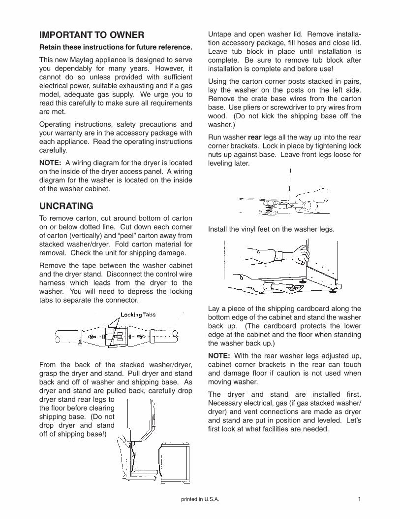
Remove the tape between the washer cabinetand the dryer stand. Disconnect the control wireharness which leads from the dryer to thewasher. You will need to depress the lockingtabs to separate the connector.
From the back of the stacked washer/dryer,grasp the dryer and stand. Pull dryer and standback and off of washer and shipping base. Asdryer and stand are pulled back, carefully dropdryer stand rear legs tothe floor before clearingshipping base. (Do notdrop dryer and standoff of shipping base!)
Untape and open washer lid. Remove installa-tion accessory package, fill hoses and close lid.Leave tub block in place until installation iscomplete. Be sure to remove tub block afterinstallation is complete and before use!
Using the carton corner posts stacked in pairs,lay the washer on the posts on the left side.Remove the crate base wires from the cartonbase. Use pliers or screwdriver to pry wires fromwood. (Do not kick the shipping base off thewasher.)
Run washer rear legs all the way up into the rearcorner brackets. Lock in place by tightening locknuts up against base. Leave front legs loose forleveling later.
Install the vinyl feet on the washer legs.
Lay a piece of the shipping cardboard along thebottom edge of the cabinet and stand the washerback up. (The cardboard protects the loweredge at the cabinet and the floor when standingthe washer back up.)
NOTE: With the rear washer legs adjusted up,cabinet corner brackets in the rear can touchand damage floor if caution is not used whenmoving washer.
The dryer and stand are installed first.Necessary electrical, gas (if gas stacked washer/dryer) and vent connections are made as dryerand stand are put in position and leveled. Let’sfirst look at what facilities are needed.
2 printed in U.S.A.
PREINSTALLATION CONSIDERATIONSLocation: The stacked washer/dryer is approvedfor zero clearance installation on the sides andthe back (depending on venting used). The loca-tion selected must take into consideration thedimensions of the unit and convenience for cus-tomer use and access in case service should beneeded. The floor must be capable of supportingthe weight of the unit (approximately 310 lbs.)plus water (approximately 150 lbs.) and be stable
enough to prevent excessive vibration in spincycles. A floor which is adequate for thestandard washer is sufficient for the stackedwasher/dryer.
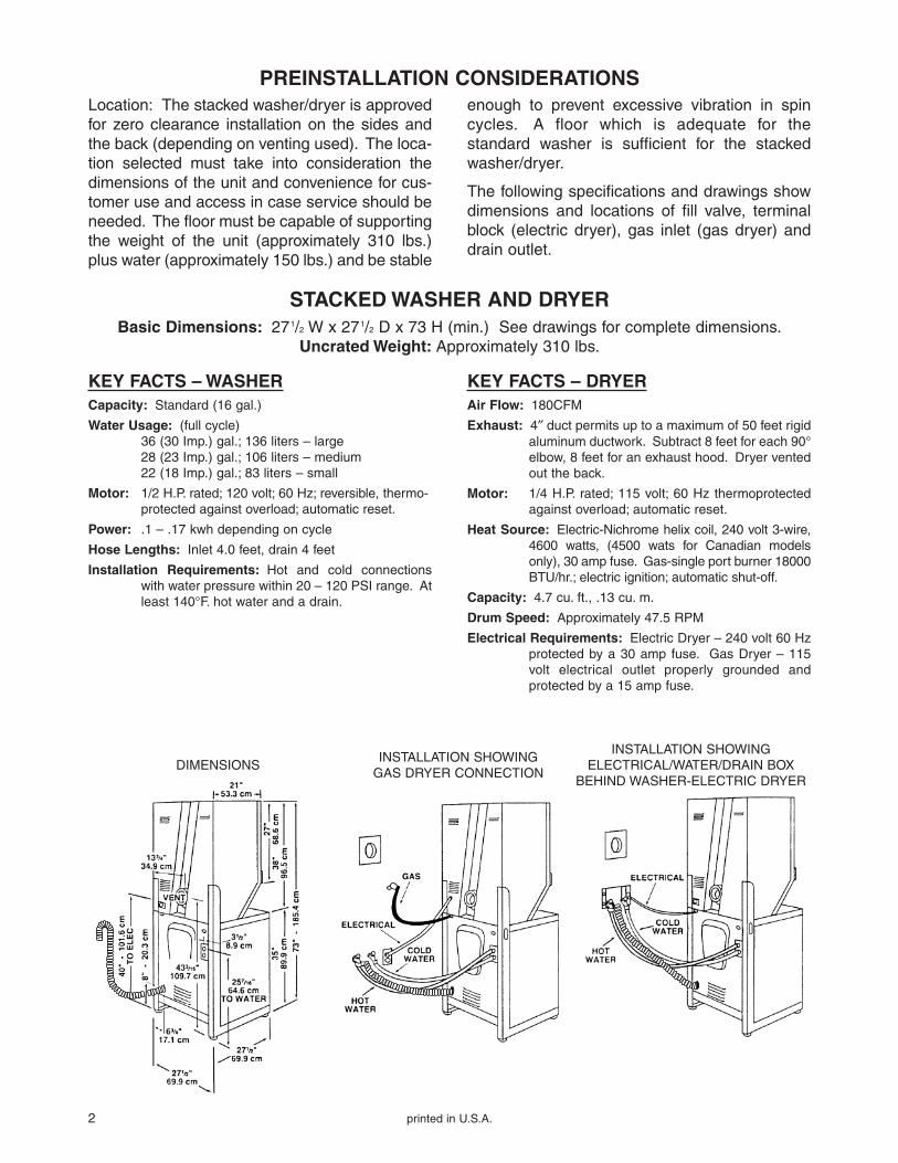
The following specifications and drawings showdimensions and locations of fill valve, terminalblock (electric dryer), gas inlet (gas dryer) anddrain outlet.
STACKED WASHER AND DRYERBasic Dimensions: 271/2 W x 271/2 D x 73 H (min.) See drawings for complete dimensions.
Uncrated Weight: Approximately 310 lbs.
KEY FACTS – WASHERCapacity: Standard (16 gal.)
Water Usage: (full cycle)36 (30 Imp.) gal.; 136 liters – large28 (23 Imp.) gal.; 106 liters – medium22 (18 Imp.) gal.; 83 liters – small
Motor: 1/2 H.P. rated; 120 volt; 60 Hz; reversible, thermo-protected against overload; automatic reset.
Power: .1 – .17 kwh depending on cycle
Hose Lengths: Inlet 4.0 feet, drain 4 feet
Installation Requirements: Hot and cold connectionswith water pressure within 20 – 120 PSI range. Atleast 140°F. hot water and a drain.
KEY FACTS – DRYERAir Flow: 180CFM
Exhaust: 4″ duct permits up to a maximum of 50 feet rigidaluminum ductwork. Subtract 8 feet for each 90°elbow, 8 feet for an exhaust hood. Dryer ventedout the back.
Motor: 1/4 H.P. rated; 115 volt; 60 Hz thermoprotectedagainst overload; automatic reset.
Heat Source: Electric-Nichrome helix coil, 240 volt 3-wire,4600 watts, (4500 wats for Canadian modelsonly), 30 amp fuse. Gas-single port burner 18000BTU/hr.; electric ignition; automatic shut-off.
Capacity: 4.7 cu. ft., .13 cu. m.
Drum Speed: Approximately 47.5 RPM
Electrical Requirements: Electric Dryer – 240 volt 60 Hzprotected by a 30 amp fuse. Gas Dryer – 115volt electrical outlet properly grounded andprotected by a 15 amp fuse.
DIMENSIONSINSTALLATION SHOWING
GAS DRYER CONNECTION
INSTALLATION SHOWINGELECTRICAL/WATER/DRAIN BOX
BEHIND WASHER-ELECTRIC DRYER
printed in U.S.A. 3
ALCOVE OR CLOSETINSTALLATIONWhen the stacked washer/dryer is to be installedin an alcove area or a closet, clearance shouldbe provided around the unit for an adequate airsupply and for ease of installation and servicing.An appliance installed in a closet shall have noother fuel burning appliance installed in thesame closet, such as gas furnace, water heateror space heater, etc.
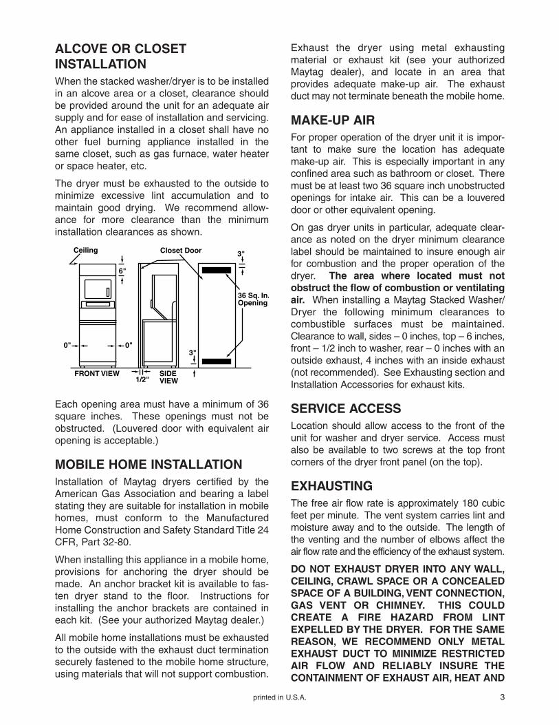
The dryer must be exhausted to the outside tominimize excessive lint accumulation and tomaintain good drying. We recommend allow-ance for more clearance than the minimuminstallation clearances as shown.
Exhaust the dryer using metal exhaustingmaterial or exhaust kit (see your authorizedMaytag dealer), and locate in an area thatprovides adequate make-up air. The exhaustduct may not terminate beneath the mobile home.
MAKE-UP AIRFor proper operation of the dryer unit it is impor-tant to make sure the location has adequatemake-up air. This is especially important in anyconfined area such as bathroom or closet. Theremust be at least two 36 square inch unobstructedopenings for intake air. This can be a louvereddoor or other equivalent opening.
On gas dryer units in particular, adequate clear-ance as noted on the dryer minimum clearancelabel should be maintained to insure enough airfor combustion and the proper operation of thedryer. The area where located must notobstruct the flow of combustion or ventilatingair. When installing a Maytag Stacked Washer/Dryer the following minimum clearances tocombustible surfaces must be maintained.Clearance to wall, sides – 0 inches, top – 6 inches,front – 1/2 inch to washer, rear – 0 inches with anoutside exhaust, 4 inches with an inside exhaust(not recommended). See Exhausting section andInstallation Accessories for exhaust kits.
SERVICE ACCESSLocation should allow access to the front of theunit for washer and dryer service. Access mustalso be available to two screws at the top frontcorners of the dryer front panel (on the top).
EXHAUSTINGThe free air flow rate is approximately 180 cubicfeet per minute. The vent system carries lint andmoisture away and to the outside. The length ofthe venting and the number of elbows affect theair flow rate and the efficiency of the exhaust system.
DO NOT EXHAUST DRYER INTO ANY WALL,CEILING, CRAWL SPACE OR A CONCEALEDSPACE OF A BUILDING, VENT CONNECTION,GAS VENT OR CHIMNEY. THIS COULDCREATE A FIRE HAZARD FROM LINTEXPELLED BY THE DRYER. FOR THE SAMEREASON, WE RECOMMEND ONLY METALEXHAUST DUCT TO MINIMIZE RESTRICTEDAIR FLOW AND RELIABLY INSURE THECONTAINMENT OF EXHAUST AIR, HEAT AND
Ceiling Closet Door
36 Sq. In.Opening
3"
3"
SIDEVIEW
6"
0" 0"
FRONT VIEW1/2"
Each opening area must have a minimum of 36square inches. These openings must not beobstructed. (Louvered door with equivalent airopening is acceptable.)
MOBILE HOME INSTALLATIONInstallation of Maytag dryers certified by theAmerican Gas Association and bearing a labelstating they are suitable for installation in mobilehomes, must conform to the ManufacturedHome Construction and Safety Standard Title 24CFR, Part 32-80.
When installing this appliance in a mobile home,provisions for anchoring the dryer should bemade. An anchor bracket kit is available to fas-ten dryer stand to the floor. Instructions forinstalling the anchor brackets are contained ineach kit. (See your authorized Maytag dealer.)
All mobile home installations must be exhaustedto the outside with the exhaust duct terminationsecurely fastened to the mobile home structure,using materials that will not support combustion.
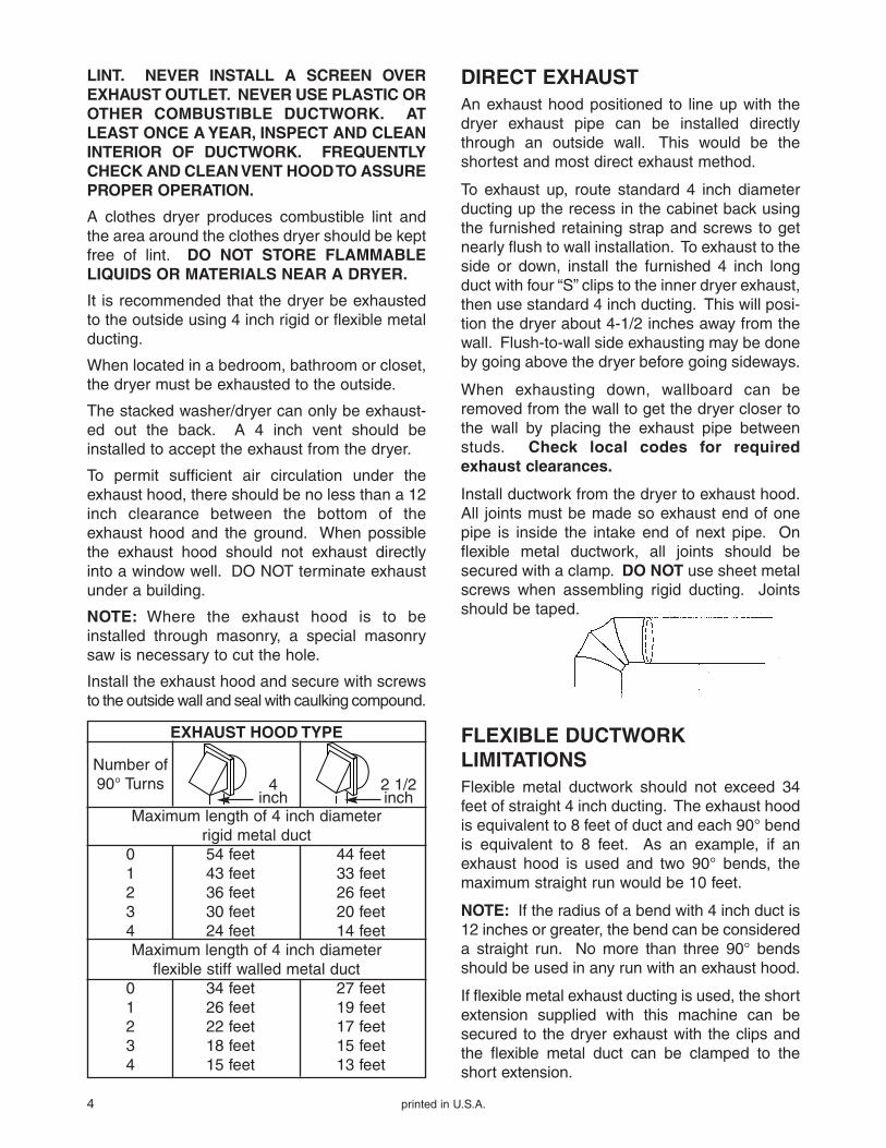
EXHAUST HOOD TYPE
Number of90° Turns
Maximum length of 4 inch diameterrigid metal duct
0 54 feet 44 feet1 43 feet 33 feet2 36 feet 26 feet3 30 feet 20 feet4 24 feet 14 feetMaximum length of 4 inch diameter
flexible stiff walled metal duct0 34 feet 27 feet1 26 feet 19 feet2 22 feet 17 feet3 18 feet 15 feet4 15 feet 13 feet
4 printed in U.S.A.
LINT. NEVER INSTALL A SCREEN OVEREXHAUST OUTLET. NEVER USE PLASTIC OROTHER COMBUSTIBLE DUCTWORK. ATLEAST ONCE A YEAR, INSPECT AND CLEANINTERIOR OF DUCTWORK. FREQUENTLYCHECK AND CLEAN VENT HOOD TO ASSUREPROPER OPERATION.
A clothes dryer produces combustible lint andthe area around the clothes dryer should be keptfree of lint. DO NOT STORE FLAMMABLELIQUIDS OR MATERIALS NEAR A DRYER.
It is recommended that the dryer be exhaustedto the outside using 4 inch rigid or flexible metalducting.
When located in a bedroom, bathroom or closet,the dryer must be exhausted to the outside.
The stacked washer/dryer can only be exhaust-ed out the back. A 4 inch vent should beinstalled to accept the exhaust from the dryer.
To permit sufficient air circulation under theexhaust hood, there should be no less than a 12inch clearance between the bottom of theexhaust hood and the ground. When possiblethe exhaust hood should not exhaust directlyinto a window well. DO NOT terminate exhaustunder a building.
NOTE: Where the exhaust hood is to beinstalled through masonry, a special masonrysaw is necessary to cut the hole.
Install the exhaust hood and secure with screwsto the outside wall and seal with caulking compound.
DIRECT EXHAUSTAn exhaust hood positioned to line up with thedryer exhaust pipe can be installed directlythrough an outside wall. This would be theshortest and most direct exhaust method.
To exhaust up, route standard 4 inch diameterducting up the recess in the cabinet back usingthe furnished retaining strap and screws to getnearly flush to wall installation. To exhaust to theside or down, install the furnished 4 inch longduct with four “S” clips to the inner dryer exhaust,then use standard 4 inch ducting. This will posi-tion the dryer about 4-1/2 inches away from thewall. Flush-to-wall side exhausting may be doneby going above the dryer before going sideways.
When exhausting down, wallboard can beremoved from the wall to get the dryer closer tothe wall by placing the exhaust pipe betweenstuds. Check local codes for requiredexhaust clearances.
Install ductwork from the dryer to exhaust hood.All joints must be made so exhaust end of onepipe is inside the intake end of next pipe. Onflexible metal ductwork, all joints should besecured with a clamp. DO NOT use sheet metalscrews when assembling rigid ducting. Jointsshould be taped.
4inch
2 1/2inch
FLEXIBLE DUCTWORKLIMITATIONSFlexible metal ductwork should not exceed 34feet of straight 4 inch ducting. The exhaust hoodis equivalent to 8 feet of duct and each 90° bendis equivalent to 8 feet. As an example, if anexhaust hood is used and two 90° bends, themaximum straight run would be 10 feet.
NOTE: If the radius of a bend with 4 inch duct is12 inches or greater, the bend can be considereda straight run. No more than three 90° bendsshould be used in any run with an exhaust hood.
If flexible metal exhaust ducting is used, the shortextension supplied with this machine can besecured to the dryer exhaust with the clips andthe flexible metal duct can be clamped to theshort extension.
printed in U.S.A. 5
RIGID DUCTWORKLIMITATIONSRigid metal ductwork should not exceed 54 feetof straight 4 inch duct. Each 90° elbow and theexhaust hood should be considered equivalentto 8 feet of straight ductwork.
For example, if an exhaust hood and two 90°elbows are used, the maximum straight ductallowed would be 26 feet. Not more than three90° elbows should be used in any rigid ductworkrun with an exhaust hood. Four feet of straightduct should be allowed between 90° elbows.
ELECTRICAL REQUIREMENTSIMPORTANT SAFETY PRECAUTIONS
WARNING: To prevent unnecessary risk of fire,electrical shock or personal injury, all wiring andgrounding must be done in accordance withlocal codes, or in the absence of local codes,with the National Electrical Code, ANSI/NFPA(for the United States) or the Canadian ElectricalCode, CSA C22.1 (for Canada). It is thepersonal responsibility and obligation of theappliance owner to provide adequate electricalservice for this appliance.
OBSERVE ALL NATIONAL CODES ANDLOCAL CODES AND ORDINANCES
GAS DRYER UNITS
A 120 volt, 60 Hz 15 ampere fuse electricalsupply is required. An individual branch (orseparate) circuit serving only this appliance isrecommended. DO NOT USE AN EXTENSIONCORD unless it meets all requirements as out-lined for grounding, polarizing (3-wire) andcapacity. Wire size should be at least No. 14.
BEFORE OPERATING OR TESTING, followgrounding instructions in Grounding section.
ELECTRICAL GROUNDING ISREQUIRED FOR THIS APPLIANCE.
GROUNDING INSTRUCTIONSThis appliance must be grounded. In the eventof malfunction or breakdown, grounding willreduce the risk of electrical shock by providing apath of least resistance for electric current. Thisappliance is equipped with a cord having anequipment-grounding conductor and a ground-ing plug. The plug must be plugged into an out-let that is properly installed and grounded inaccordance with all local codes and ordinances.
DANGER – Improper connection of the equip-ment-grounding conductor can result in a risk ofelectric shock. Check with a qualified electricianor serviceman if you are in doubt as to whetherthe appliance is properly grounded.
6 printed in U.S.A.
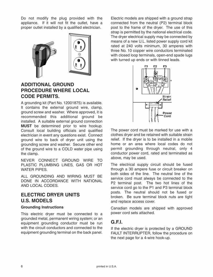
Do not modify the plug provided with theappliance. If it will not fit the outlet, have aproper outlet installed by a qualified electrician.
ADDITIONAL GROUNDPROCEDURE WHERE LOCALCODE PERMITS.A grounding kit (Part No. 12001875) is available.It contains the external ground wire, clamp,ground screw and washer. Where approved, it isrecommended this additional ground beinstalled. A suitable external ground connectionMUST be determined prior to wire hookup.Consult local building officials and qualifiedelectrician in event any questions exist. Connectground wire to back of dryer unit using thegrounding screw and washer. Secure other endof the ground wire to a COLD water pipe usingthe clamp.
NEVER CONNECT GROUND WIRE TOPLASTIC PLUMBING LINES, GAS OR HOTWATER PIPES.
ALL GROUNDING AND WIRING MUST BEDONE IN ACCORDANCE WITH NATIONALAND LOCAL CODES.
ELECTRIC DRYER UNITSU.S. MODELSGrounding Instructions
This electric dryer must be connected to agrounded metal, permanent wiring system; or anequipment grounding conductor must be runwith the circuit conductors and connected to theequipment grounding terminal on the back panel.
Electric models are shipped with a ground strapconnected from the neutral (P2) terminal blockpost to the frame of the dryer. The use of thisstrap is permitted by the national electrical code.The dryer electrical supply may be connected bymeans of a new U.L. listed power supply cord kitrated at 240 volts minimum, 30 amperes withthree No. 10 copper wire conductors terminatedwith closed loop terminals, open-end spade lugswith turned up ends or with tinned leads.
The power cord must be marked for use with aclothes dryer and be retained with suitable strainrelief. If the dryer is to be installed in a mobilehome or an area where local codes do notpermit grounding through neutral, only 4conductor power cord, rated and terminated asabove, may be used.
The electrical supply circuit should be fusedthrough a 30 ampere fuse or circuit breaker onboth sides of the line. The neutral line of theservice cord must always be connected to theP2 terminal post. The two hot lines of theservice cord go to the P1 and P3 terminal blockposts. The neutral should not be fused orbroken. Be sure terminal block nuts are tightand replace access cover.
Canadian models are shipped with approvedpower cord sets attached.
G.F.I.If the electric dryer is protected by a GROUNDFAULT INTERRUPTER, follow the procedure onthe next page for a 4-wire hook-up.

printed in U.S.A. 7
4-WIRE RECEPTACLEFor a 4-wire hook-up, the frame of a 120/240 voltmachine must NOT be connected to neutralterminals. It MUST be connected to the 4th wire(green) of the power supply or to the metalliccovering of a 3-wire supply.
If a 4-wire receptacle of NEMAtype is used, a matching U.L. list-ed power supply cord (pigtail)must be used. This cord containsfour No. 10 copper conductorswith spade or ring terminals on the dryer end.The 4th (grounding) conductor must be identifiedby a green cover and the neutral conductor by awhite cover. The cord should have a suitablestrain relief, and should be a minimum 4 feetlong. The power supply cord and strain relief arenot provided with the dryer.
4-WIRE SYSTEM CONNECTIONS1. Remove the terminal block cover.
2. Remove the ground strap screw from theterminal block support. Fold the ground strapover so both ends of the ground strap areattached to the center terminal block post.
3. Connect the neutral (white) wire of the powersupply cord to the center (silver colored) terminalof the terminal block. Connect the grounding(green) wire of the cord to the terminal blocksupport using the ground strap screw.
4. Connect the other two wires of the cord to theouter terminals of the terminal block.
5. Replace the terminal block cover.
208 VOLT OPERATIONA stacked washer/dryer model is available for208 volt operation.
Canadian Models
All Canadian models are shipped with the powercord attached. The dryer power cord should beplugged into a 30 ampere receptacle and fusedthrough a 30 ampere fuse or comparable circuitbreaker on both sides of the line.
NOTE: It is not permissible to convert a dryer inCanada to 208 volts. A 208 volt model is notavailable for Canada.
WATER SUPPLY AND DRAINWATER SUPPLY
The water supply to the washer unit should becapable of providing both adequate waterpressure and water temperature. The pressureshould fall within the range of 20 pounds persquare inch to 120 pounds per square inchwhen the washer is filling. Note that this is flowpressure and not static pressure. Low waterpressure will result in slow fill and could result ina water valve sticking open after a fill.
The recommended temperature of the hot wateras delivered to the washer should be 140° F.
Warm water temperature is a result of the mix ofthe hot and cold water supplies. The finaltemperature is dependent on both the pressureand the temperatures of the hot and coldsupplies. The desired temperature for warm isbetween 100° F. and 105° F.
DRAIN FACILITIES
The drain must be capable of accepting a flowrate of approximately 20 gallons per minute. Aninside diameter of at least 1 1/2 inches is required.
CLIP
NeutralPost
GroundStrap
Neutral
Strainrelief
3-Wire System withPower Cord Attached
Four-Wire Receptacle
N
G
L1 L2
4-Wire System withPower Cord Attached
NeutralPost
FoldedGroundStrap
Neutral
StrainRelief
8 printed in U.S.A.
36 inch standpipe recommended
If standpipe is less than 36 inches (or floordrain) – drain hose should be routed through theclip to raise hose to the proper height, use cliptie to securely hold drain hose in clip.
Installation accessory kits are available for othertypes of drain facility conditions…see WasherInstallation Accessory Kits table on page 13.
The use of a laundry built-in wall box can greatlysimplify installation.
If the faucets and/or drain is located to eitherside of the stacked washer/dryer, openings arelocated in the dryer stand uprights to allowhoses and power cords to be passed through.This is to allow installation against the back wall.(This is dependent on venting used.)
GAS CONNECTIONGas operated dryers are equipped with a burnerorifice for operation on NATURAL GAS. If thedryer is to be operated on LP GAS, it must beconverted correctly for safety and properperformance. Conversion kits from NATURAL toLPG, or LPG to NATURAL are available throughyour local Maytag dealer. If other conversionsare required, check with local gas utility forspecific information concerning conversionrequirement. NOTE: The conversion shouldalways be performed by a qualified servicetechnician.
NOTE: If the dryer is to be converted inCanada, the conversion shall be carried out inaccordance with the requirements of theprovincial authorities having jurisdiction and inaccordance with the requirements of the CAN-B149.1 and CAN1-B149.2 installation code.
A 1/2 inch gas supply line is recommended andmust be reduced to connect to the 3/8 inch gasline on the dryer.
IMPORTANT NOTE: When installing the gasline, route it so that it will not interfere with thewasher once the washer is pushed back intoposition. It is important to make sure the gas linedoes not come into contact with either thewasher drain hose or any part of the washer.
NOTE: A 3/8 inch x 1 inch pipe nipple is includ-ed to adapt valve connection from a 3/8 inchfemale to a 3/8 inch male I.P.S. connection.
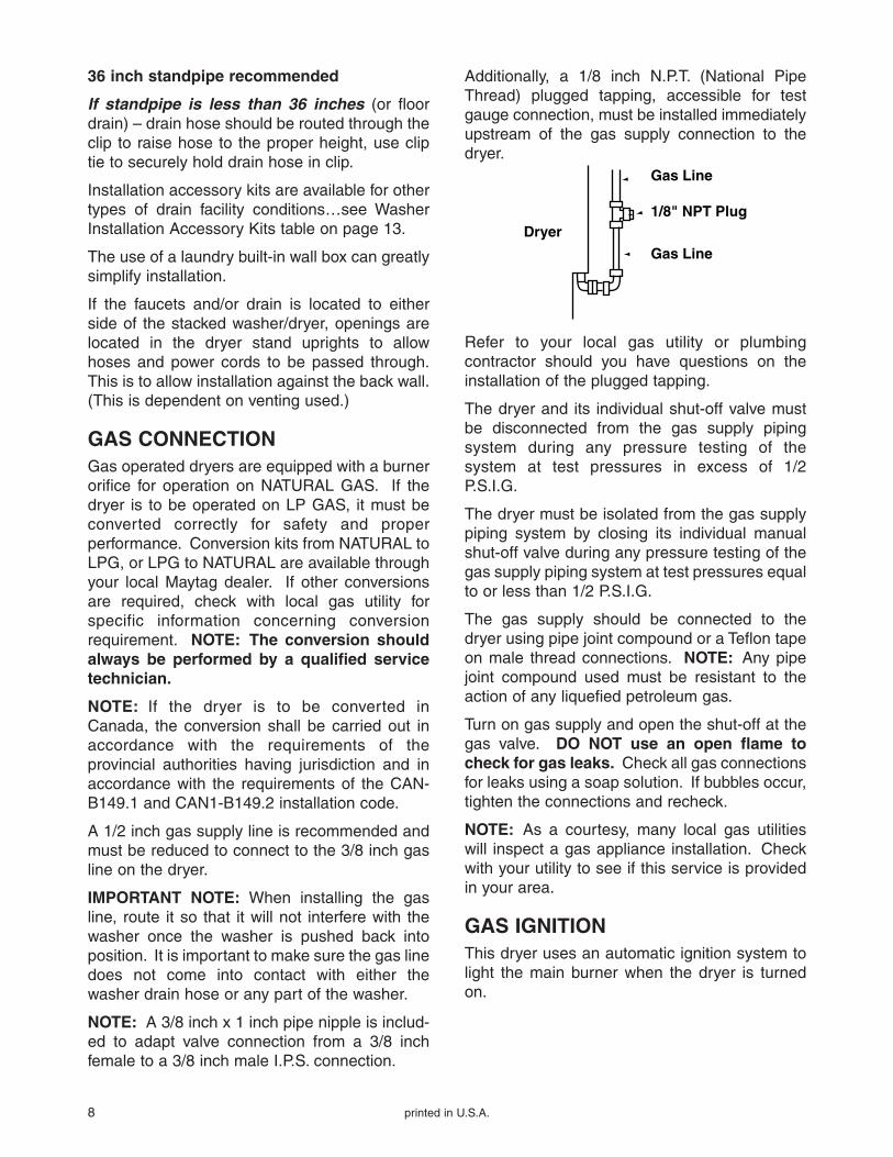
Additionally, a 1/8 inch N.P.T. (National PipeThread) plugged tapping, accessible for testgauge connection, must be installed immediatelyupstream of the gas supply connection to thedryer.
Dryer
Gas Line
1/8" NPT Plug
Gas Line
Refer to your local gas utility or plumbingcontractor should you have questions on theinstallation of the plugged tapping.
The dryer and its individual shut-off valve mustbe disconnected from the gas supply pipingsystem during any pressure testing of thesystem at test pressures in excess of 1/2P.S.I.G.
The dryer must be isolated from the gas supplypiping system by closing its individual manualshut-off valve during any pressure testing of thegas supply piping system at test pressures equalto or less than 1/2 P.S.I.G.
The gas supply should be connected to thedryer using pipe joint compound or a Teflon tapeon male thread connections. NOTE: Any pipejoint compound used must be resistant to theaction of any liquefied petroleum gas.
Turn on gas supply and open the shut-off at thegas valve. DO NOT use an open flame tocheck for gas leaks. Check all gas connectionsfor leaks using a soap solution. If bubbles occur,tighten the connections and recheck.
NOTE: As a courtesy, many local gas utilitieswill inspect a gas appliance installation. Checkwith your utility to see if this service is providedin your area.
GAS IGNITIONThis dryer uses an automatic ignition system tolight the main burner when the dryer is turnedon.
printed in U.S.A. 9
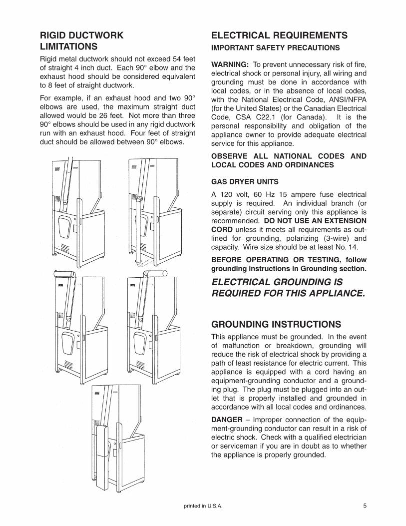
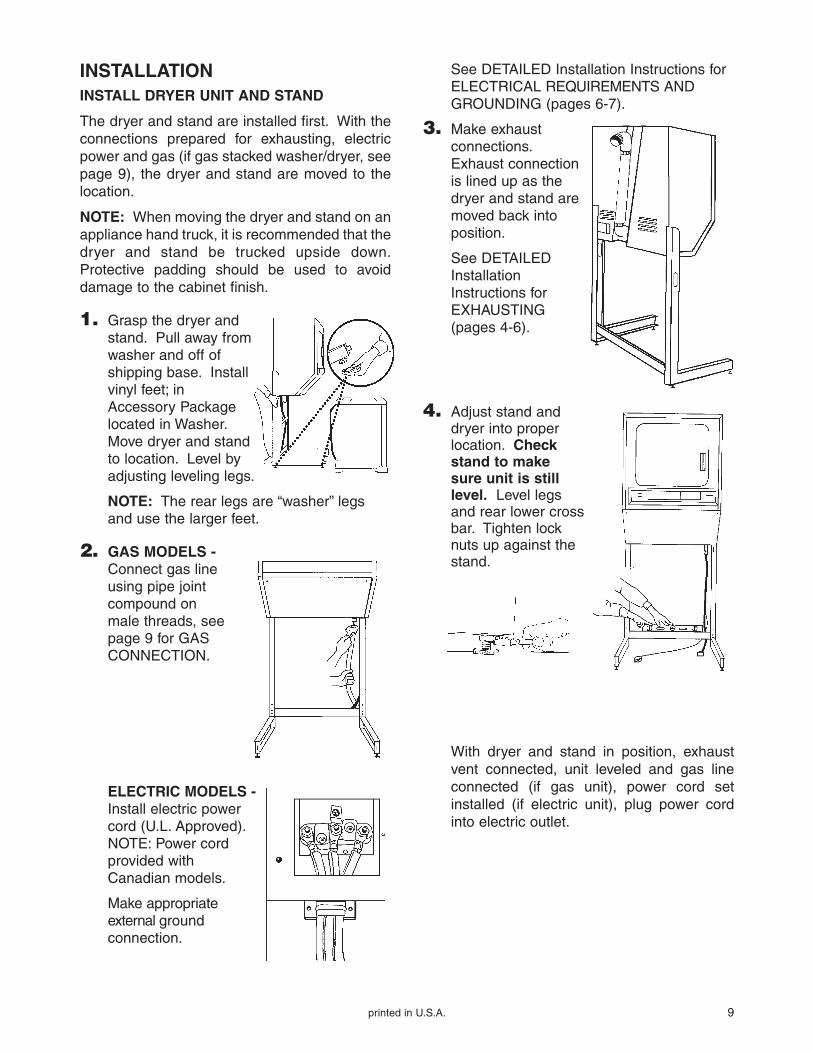
INSTALLATIONINSTALL DRYER UNIT AND STAND
The dryer and stand are installed first. With theconnections prepared for exhausting, electricpower and gas (if gas stacked washer/dryer, seepage 9), the dryer and stand are moved to thelocation.
NOTE: When moving the dryer and stand on anappliance hand truck, it is recommended that thedryer and stand be trucked upside down.Protective padding should be used to avoiddamage to the cabinet finish.
1. Grasp the dryer and stand. Pull away from washer and off of shipping base. Install vinyl feet; in Accessory Package located in Washer.Move dryer and standto location. Level by adjusting leveling legs.
NOTE: The rear legs are “washer” legsand use the larger feet.
2. GAS MODELS -Connect gas lineusing pipe jointcompound on male threads, seepage 9 for GASCONNECTION.
See DETAILED Installation Instructions forELECTRICAL REQUIREMENTS ANDGROUNDING (pages 6-7).
3. Make exhaustconnections.Exhaust connection is lined up as thedryer and stand aremoved back intoposition.
See DETAILEDInstallationInstructions forEXHAUSTING (pages 4-6).
4. Adjust stand anddryer into properlocation. Checkstand to makesure unit is stilllevel. Level legsand rear lower crossbar. Tighten locknuts up against thestand.
With dryer and stand in position, exhaustvent connected, unit leveled and gas lineconnected (if gas unit), power cord setinstalled (if electric unit), plug power cordinto electric outlet.
ELECTRIC MODELS -Install electric powercord (U.L. Approved).NOTE: Power cordprovided withCanadian models.
Make appropriateexternal groundconnection.
10 printed in U.S.A.
DRYER INSTALLATIONACCESSORIESVent Kit – standard – 4″ (10.16cm)
kit includes two elbows, three pipes andone vent hood
Vent Hood – 4″ (10.16cm) opening
Aluminum Pipe – 4″ x 24″ (10.16cm x 60.96cm)
Aluminum Elbow – 4″ (10.16cm)
Aluminum Window Plate – 15″ x 20″(38.10cm x 50.80cm) – 4″ (10.16cm)
Flexible Vent Kit – contains wide opening venthood, wall plate, two clamps and flexiblealuminum vent duct
Flexible Aluminum Vent Duct – 4″ (10.16cm)diameter – 38″ (81.28cm) length stretchesto 8′ (2.44m)
Clamp for Flexible Aluminum Duct
Exhaust Deflector Kit – inside exhaust kit
Natural to LPG Conversion Kit for Gas Valve
Dacron Lint Bag
Grounding Kit – contains ground wire, clamp,ground screw and washer(Part No. 12001875)
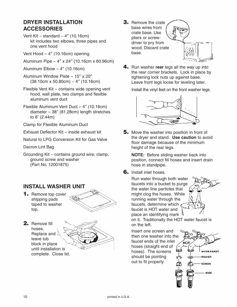
INSTALL WASHER UNIT1. Remove top cover
shipping pads taped to washer top.
2. Remove fill hoses.Replace and leave tub block in place until installation is complete. Close lid.
3. Remove the cratebase wires fromcrate base. Usepliers or screw-driver to pry fromwood. Discard cratebase.
4. Run washer rear legs all the way up intothe rear corner brackets. Lock in place bytightening lock nuts up against base.Leave front legs loose for leveling later.
Install the vinyl feet on the front washer legs.
5. Move the washer into position in front ofthe dryer and stand. Use caution to avoidfloor damage because of the minimumheight of the rear legs.
NOTE: Before sliding washer back intoposition, connect fill hoses and insert drainhose in standpipe.
6. Install inlet hoses.
Run water through both water faucets into a bucket to purge the water line particles that might clog the hoses. While running water through the faucets, determine which faucet is HOT water and place an identifying mark on it. Traditionally the HOT water faucet ison the left.
Insert one screen and then one washer into the faucet ends of the inlet hoses (straight end of hoses). The screens should be pointing out to fit properly.
printed in U.S.A. 11
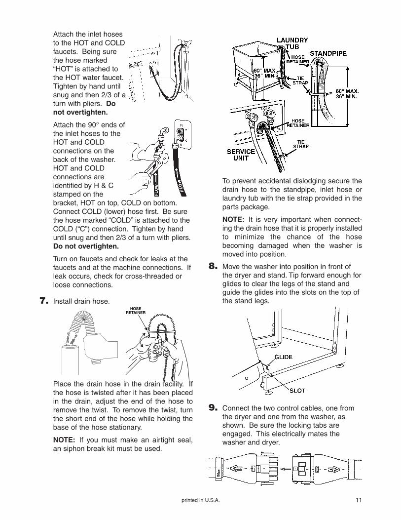
Attach the inlet hosesto the HOT and COLDfaucets. Being surethe hose marked“HOT” is attached tothe HOT water faucet.Tighten by hand untilsnug and then 2/3 of aturn with pliers. Donot overtighten.
Attach the 90° ends ofthe inlet hoses to theHOT and COLDconnections on theback of the washer.HOT and COLDconnections areidentified by H & Cstamped on thebracket, HOT on top, COLD on bottom.Connect COLD (lower) hose first. Be surethe hose marked “COLD” is attached to theCOLD (“C”) connection. Tighten by handuntil snug and then 2/3 of a turn with pliers.Do not overtighten.
Turn on faucets and check for leaks at thefaucets and at the machine connections. Ifleak occurs, check for cross-threaded orloose connections.
7. Install drain hose.HOSE
RETAINER
Place the drain hose in the drain facility. Ifthe hose is twisted after it has been placedin the drain, adjust the end of the hose toremove the twist. To remove the twist, turnthe short end of the hose while holding thebase of the hose stationary.
NOTE: If you must make an airtight seal,an siphon break kit must be used.
To prevent accidental dislodging secure thedrain hose to the standpipe, inlet hose orlaundry tub with the tie strap provided in theparts package.
NOTE: It is very important when connect-ing the drain hose that it is properly installedto minimize the chance of the hosebecoming damaged when the washer ismoved into position.
8. Move the washer into position in front ofthe dryer and stand. Tip forward enough forglides to clear the legs of the stand andguide the glides into the slots on the top ofthe stand legs.
9. Connect the two control cables, one fromthe dryer and one from the washer, asshown. Be sure the locking tabs areengaged. This electrically mates thewasher and dryer.
12 printed in U.S.A.
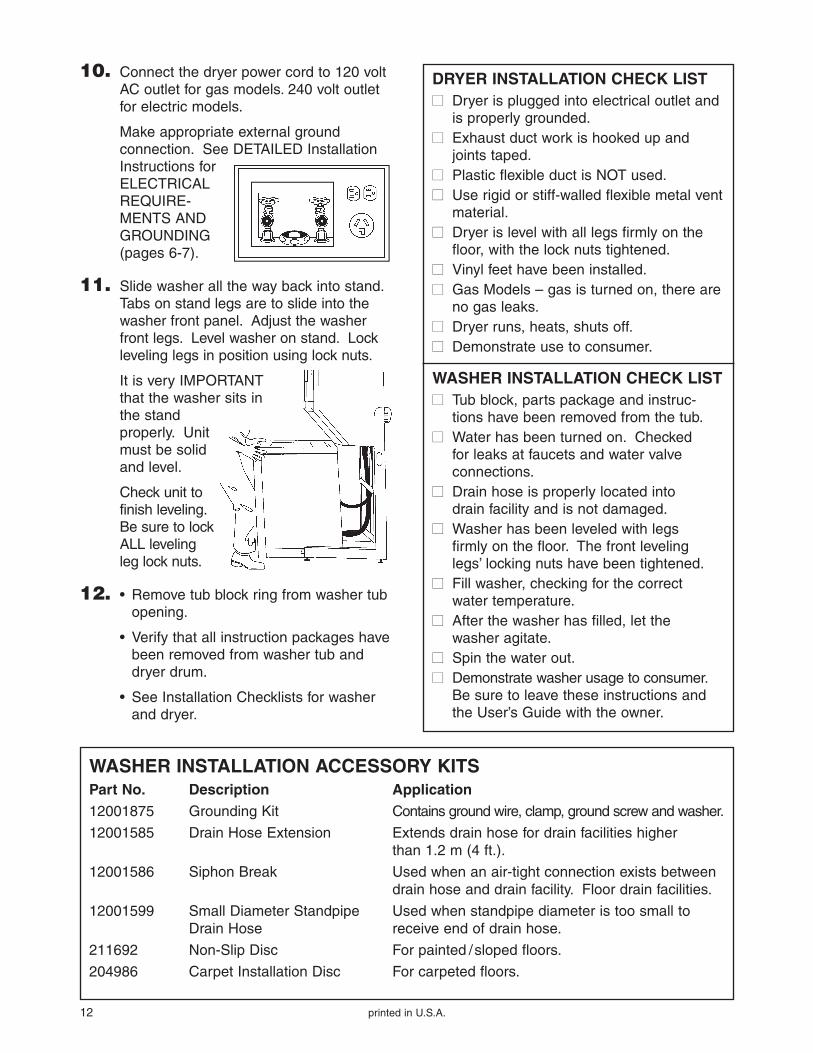
10. Connect the dryer power cord to 120 voltAC outlet for gas models. 240 volt outletfor electric models.
Make appropriate external groundconnection. See DETAILED InstallationInstructions forELECTRICALREQUIRE-MENTS ANDGROUNDING(pages 6-7).
11. Slide washer all the way back into stand.Tabs on stand legs are to slide into thewasher front panel. Adjust the washerfront legs. Level washer on stand. Lockleveling legs in position using lock nuts.
It is very IMPORTANTthat the washer sits inthe stand properly. Unitmust be solidand level.
Check unit tofinish leveling.Be sure to lockALL levelingleg lock nuts.
12. • Remove tub block ring from washer tubopening.
• Verify that all instruction packages havebeen removed from washer tub anddryer drum.
• See Installation Checklists for washerand dryer.
DRYER INSTALLATION CHECK LIST�� Dryer is plugged into electrical outlet and
is properly grounded.�� Exhaust duct work is hooked up and
joints taped.�� Plastic flexible duct is NOT used.�� Use rigid or stiff-walled flexible metal vent
material.�� Dryer is level with all legs firmly on the
floor, with the lock nuts tightened.�� Vinyl feet have been installed.�� Gas Models – gas is turned on, there are
no gas leaks.�� Dryer runs, heats, shuts off.�� Demonstrate use to consumer.
WASHER INSTALLATION CHECK LIST�� Tub block, parts package and instruc-
tions have been removed from the tub.�� Water has been turned on. Checked
for leaks at faucets and water valveconnections.
�� Drain hose is properly located intodrain facility and is not damaged.
�� Washer has been leveled with legsfirmly on the floor. The front levelinglegs’ locking nuts have been tightened.
�� Fill washer, checking for the correctwater temperature.
�� After the washer has filled, let thewasher agitate.
�� Spin the water out.�� Demonstrate washer usage to consumer.
Be sure to leave these instructions andthe User’s Guide with the owner.
WASHER INSTALLATION ACCESSORY KITSPart No. Description Application12001875 Grounding Kit Contains ground wire, clamp, ground screw and washer.
12001585 Drain Hose Extension Extends drain hose for drain facilities higher than 1.2 m (4 ft.).
12001586 Siphon Break Used when an air-tight connection exists betweendrain hose and drain facility. Floor drain facilities.
12001599 Small Diameter Standpipe Used when standpipe diameter is too small toDrain Hose receive end of drain hose.
211692 Non-Slip Disc For painted /sloped floors.
204986 Carpet Installation Disc For carpeted floors.
printed in U.S.A. 13
ADDITIONAL INFORMATION
ODD CYCLE OPERATIONThis Maytag stacked washer/dryer is manufac-tured for operation on 60 Hz approved electricalservice. It is not designed for use on 50 Hz ACelectrical service and conversion of the productfrom 60 to 50 cycle operation is not recom-mended. For additional information on 50 cycleproducts, write, MAYTAG INTERNATIONAL,INC., 8700 Bryn Mawr Ave., Chicago, Illinois60631 or GRAY DISTRIBUTING CO., LTD., P.O.Box 2597, Honolulu, Hawaii 96803.
LUBRICATIONNo routine lubrication is required to maintain thestacked washer/dryer. In the event somethingdoes need attention, contact an authorizedMaytag dealer or servicer.
FINISHAll the cabinetry and external finishes areprotected against rust to keep product lookingwell for many years. Cleaning and waxing willprovide additional protection to these finishes.
The washer top has a porcelain finish. Sinceporcelain is “glass” bonded to metal, it is verydurable. Avoid damage from sharp blows ofobjects or tools used around and in the appliance.
Clean the control panel with a soft damp cloth.Avoid abrasive cleaners that would scratch sur-face. A coat of household wax will reduce thechance of scratches on the control panel surface.
CAUTION: If “spilled” or used improperly,bleaches and other strong laundering chemicalscan permanently spot or stain finishes unlesswiped up immediately. Aerosol pretreatedproducts can also damage finish on controlpanel. When using these products on garmentsplaced in the stacked washer/dryer, it is advisableto avoid control panel area with the overspray.
WATER DAMAGE FROM FLOODINGIn the event the stacked washer/dryer isexposed to water from flooding, call your localMaytag dealer before using. Always unplug theappliance and have a qualified technicianinspect the appliance before any attempt ismade to operate the unit. Never wash productinside and out with a garden hose or pressurecleaning system.
REPLACEMENT PARTSIf your unit requires replacement parts, contactthe dealer from whom you purchased yourappliance, or Maytag Appliance Sales Co.,Customer Service Division, Box 2370, Cleveland,Tennessee, 37320-2370, phone 1-800-688-9900,for information on the nearest Maytag partdistributor.
Part and service manuals are available throughyour dealer or nearest parts distributor.