stainless steel pressure filter edfr
TRANSCRIPT
EN
7.7
17.2
/11.
17
1
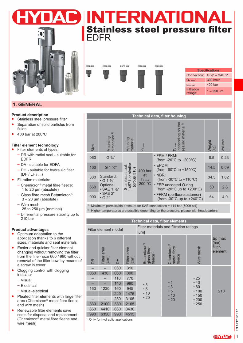
Stainless steel pressure filterEDFR
Product description ● Stainless steel pressure filter ● Separation of solid particles from
fluids ● 400 bar at 200°C
Filter element technology ● Filter elements of types:
– DR with radial seal - suitable for EDFR
– DA - suitable for EDFA – DH - suitable for hydraulic filter (DF / LF / ...)
● Filtration materials: – Chemicron® metal fibre fleece: 1 to 20 µm (absolute)
– Glass fibre mesh Betamicron®: 3 – 20 µm (absolute)
– Wire mesh: 25 to 250 µm (nominal)
– Differential pressure stability up to 210 bar
Product advantages ● Optimum adaptation to the
application thanks to 6 different sizes, materials and seal materials
● Easier and quicker filter element changing without removing the filter from the line - size 660 / 990 without removal of the filter bowl by means of a screw in cover
● Clogging control with clogging indicator
– Visual – Electrical – Visual-electrical
● Pleated filter elements with large filter area (Chemicron® metal fibre fleece and wire mesh)
● Renewable filter elements save costs for disposal and replacement (Chemicron® metal fibre fleece and wire mesh)
1. GENERAL
Technical data, filter housing
Siz
e
Mou
ntin
g di
men
sion
1)
Hou
sing
m
ater
ial
p S m
ax
T S m
ax
dep
endi
ng o
n th
e se
alin
g m
ater
ial 2
)
Wei
ght
[kg]
Volu
me
[l]
060 G ¾"
Sta
inle
ss s
teel
:1.
4571
or s
imila
r (g
roup
316
)
400 bar at
TS max 200 °C
• FPM / FKM: (from -20°C to +200°C)
• EPDM: (from -60°C to +150°C)
• NBR: (from -30°C to +110°C)
• FEP uncoated O-ring (from -20°C up to +200°C)
• FFKM (perfluorelastomer) (from -30°C up to +240°C)
8.5 0.23
160 G 1 ¼" 14.5 0.69
330 Standard: • G 1 ½“Optional: • SAE 1 ½“ • SAE 2“• G 2“
34.5 1.62
660 50 2.8
990 64 4.0
1) Maximum permissible pressure for SAE connections = 414 bar (6000 psi)2) Higher temperatures are possible depending on the pressure, please with headquarters
Technical data, filter elements
Filter element modelFilter materials and filtration ratings[µm]
Δp max [bar] filter-element
DR
Filte
r are
a
[cm
²]
DH
Filte
r are
a
[cm
²]
Bet
amic
ron®
gl
ass
fibre
fle
ece1)
Che
mic
ron®
m
etal
fibr
e fle
ece
Wire
mes
h
– – 030 310
• 3• 5• 10• 20
• 1• 3• 5• 10• 20
• 25• 40• 60• 100• 150• 200• 250
210
060 430 060 390– – 110 770– – 140 990
160 1230 160 945– – 240 1475– – 280 3105
330 2100 330 2165660 4410 660 3430990 6350 990 4515
1) Only for hydraulic applications
SpecificationsConnection: G ½" – SAE 2"QS max: 300 l/minpS max: 400 barFiltration ratings: 1 – 250 µm
EDFR 060 EDFR 160 EDFR 330 EDFR 660 EDFR 990

EN
7.7
17.2
/11.
17
2
2. FUNCTION AND SPECIAL FEATURES
FUNCTIONAL PRINCIPLE ● Flow through the filter element is from the outside to the
inside ● The separated solids remain on the outer side of the filter
element ● Particles being deposited during the filtration causes a loss
of pressure ● The contaminated filter element can be replaced or
cleaned
* For clogging indicators, see also separate data sheet.
TypeClogging indicator/differential pressure monitoring
Image Description
VisualPVD x B.x
● Visual display with green/red field ● Automatic reset
ElectricalPVD x Cx
● Electrical signal when trigger point is reached ● Switch type: normally closed or normally open ● Automatic reset
Visual-electricalPVD x D.x/-L
● Lamp for visual display ● Electrical signal (normally closed or normally open) ● Automatic reset
3. CLOGGING INDICATORS*

EN
7.7
17.2
/11.
17
3
* Please contact our Head Office if you have any queries regarding filter calculation
4. FILTER CALCULATION*
CHECKLIST FOR FILTER CALCULATIONSTEP 1: REQUIRED OPERATING DATA ● According to European Pressure Equipment Directive
2014/68/EU ● Type of operating medium ● Viscosity ● Operating pressure ● Operating temperature ● Flow rate ● Required filtration rating ● Type of solid substances to be discharged ● Solid particle content
STEP 2: FILTER SIZING ● Configured on basis of pressure drop curves
STEP 3: DETERMINING THE FILTRATION RATING ● As a basic rule:
as coarse as possible – as fine as necessary!
PDI
CIRCUIT DIAGRAM
Shut-off valve “c”
Bypass line
Optional
Inlet Outlet
Shut-off valve "a" Shut-off valve "b"
Items Supplied Fa. HYDAC

EN
7.7
17.2
/11.
17
4
PRESSURE DROP CURVES(Applies for water at 20 °C or for media up to 15 mm2/s)
Pre
ssur
e dr
op [b
ar]
Pre
ssur
e dr
op [b
ar]
Pre
ssur
e dr
op [b
ar]
Flow rate [l/min]
Flow rate [l/min]
Flow rate [l/min]
EDFRSize 060
EDFRSize 160
EDFRSize 330 / 660 / 990
EN
7.7
17.2
/11.
17
5
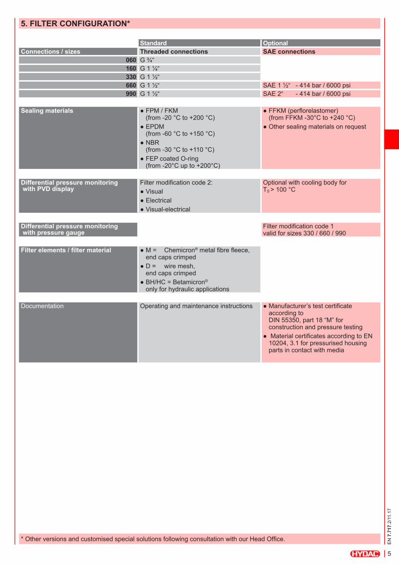
5. FILTER CONFIGURATION*
Standard OptionalConnections / sizes Threaded connections SAE connections
060 G ¾“160 G 1 ¼“330 G 1 ½“660 G 1 ½“ SAE 1 ½“ - 414 bar / 6000 psi990 G 1 ½“ SAE 2“ - 414 bar / 6000 psi
Sealing materials ● FPM / FKM (from -20 °C to +200 °C)
● EPDM (from -60 °C to +150 °C)
● NBR (from -30 °C to +110 °C)
● FEP coated O-ring (from -20°C up to +200°C)
● FFKM (perflorelastomer) (from FFKM -30°C to +240 °C)
● Other sealing materials on request
Differential pressure monitoring with PVD display
Filter modification code 2: ● Visual ● Electrical ● Visual-electrical
Optional with cooling body for TS > 100 °C
Differential pressure monitoring with pressure gauge
Filter modification code 1 valid for sizes 330 / 660 / 990
Filter elements / filter material ● M = Chemicron® metal fibre fleece, end caps crimped
● D = wire mesh, end caps crimped
● BH/HC = Betamicron®
only for hydraulic applications
Documentation Operating and maintenance instructions ● Manufacturer’s test certificate according to DIN 55350, part 18 “M” for construction and pressure testing
● Material certificates according to EN 10204, 3.1 for pressurised housing parts in contact with media
* Other versions and customised special solutions following consultation with our Head Office.
EN
7.7
17.2
/11.
17
6
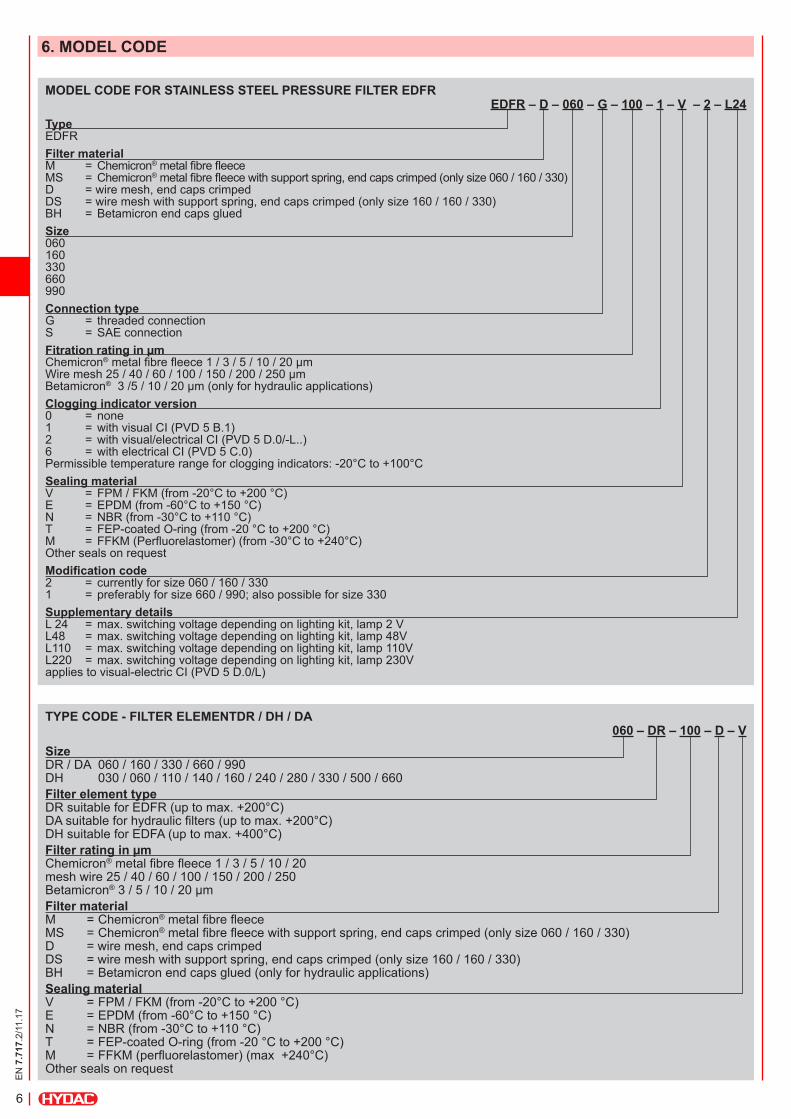
MODEL CODE FOR STAINLESS STEEL PRESSURE FILTER EDFREDFR – D – 060 – G – 100 – 1 – V – 2 – L24
Type EDFRFilter material M = Chemicron® metal fibre fleece MS = Chemicron® metal fibre fleece with support spring, end caps crimped (only size 060 / 160 / 330) D = wire mesh, end caps crimped DS = wire mesh with support spring, end caps crimped (only size 160 / 160 / 330) BH = Betamicron end caps gluedSize 060 160 330 660 990Connection type G = threaded connection S = SAE connectionFitration rating in µm Chemicron® metal fibre fleece 1 / 3 / 5 / 10 / 20 µm Wire mesh 25 / 40 / 60 / 100 / 150 / 200 / 250 µm Betamicron® 3 /5 / 10 / 20 µm (only for hydraulic applications)Clogging indicator version 0 = none 1 = with visual CI (PVD 5 B.1) 2 = with visual/electrical CI (PVD 5 D.0/-L..) 6 = with electrical CI (PVD 5 C.0) Permissible temperature range for clogging indicators: -20°C to +100°CSealing material V = FPM / FKM (from -20°C to +200 °C) E = EPDM (from -60°C to +150 °C) N = NBR (from -30°C to +110 °C) T = FEP-coated O-ring (from -20 °C to +200 °C) M = FFKM (Perfluorelastomer) (from -30°C to +240°C) Other seals on requestModification code 2 = currently for size 060 / 160 / 330 1 = preferably for size 660 / 990; also possible for size 330Supplementary details L 24 = max. switching voltage depending on lighting kit, lamp 2 V L48 = max. switching voltage depending on lighting kit, lamp 48V L110 = max. switching voltage depending on lighting kit, lamp 110V L220 = max. switching voltage depending on lighting kit, lamp 230V applies to visual-electric CI (PVD 5 D.0/L)
TYPE CODE - FILTER ELEMENTDR / DH / DA 060 – DR – 100 – D – V
Size DR / DA 060 / 160 / 330 / 660 / 990 DH 030 / 060 / 110 / 140 / 160 / 240 / 280 / 330 / 500 / 660Filter element type DR suitable for EDFR (up to max. +200°C) DA suitable for hydraulic filters (up to max. +200°C) DH suitable for EDFA (up to max. +400°C)Filter rating in µm Chemicron® metal fibre fleece 1 / 3 / 5 / 10 / 20 mesh wire 25 / 40 / 60 / 100 / 150 / 200 / 250 Betamicron® 3 / 5 / 10 / 20 µmFilter material M = Chemicron® metal fibre fleece MS = Chemicron® metal fibre fleece with support spring, end caps crimped (only size 060 / 160 / 330) D = wire mesh, end caps crimped DS = wire mesh with support spring, end caps crimped (only size 160 / 160 / 330) BH = Betamicron end caps glued (only for hydraulic applications)Sealing material V = FPM / FKM (from -20°C to +200 °C) E = EPDM (from -60°C to +150 °C) N = NBR (from -30°C to +110 °C) T = FEP-coated O-ring (from -20 °C to +200 °C) M = FFKM (perfluorelastomer) (max +240°C) Other seals on request
6. MODEL CODE

EN
7.7
17.2
/11.
17
7
B1
h2
h1
D
N1
D
N2
H1
D2
H2
G1/2
SW
D1
F2
F1
4xD4
B1
H1
h1
D
N1
D
N2
h2
H2 D2
G1/4
SW
D1
F2
F1
4xD4
7. DIMENSIONS, FILTER
Rem
oval
hei
ght,
filte
r ele
men
ts
Rem
oval
hei
ght,
filte
r ele
men
ts
The dimensions quoted are approximations, given in mm. Subject to technical modifications.
Air vent Air ventClogging indicator optional
Clogging indicator optional
Size DN1 DN2 B1 h1 h2 H1 H2 D1 D2 D4 SW E1 F1 F2EDFR 060 G3/4 G3/4 110 39 39 179 50 120 72 M6 27 G1/2 60 40EDFR 160 G1 1/4 G1 1/4 135 33 33 230 60 150 105 M10 32 G1/2 80 50EDFR 330 G1 1/2 G1 1/2 180 38 38 302 75 200 143 M12 46 G1/2 110 75EDFR 660 G1 1/2 G1 1/2 180 38 38 460 75 200 150 M12 46 G1/2 110 75EDFR 990 G1 1/2 G1 1/2 180 38 38 629 75 200 150 M12 46 G1/2 110 75
Filter modification number 1Standard for sizes 660 / 990
Filter modification number 2Standard variant for sizes 060 / 160 / 330
EN
7.7
17.2
/11.
17
8
D2
L
D1
D2
D1
L
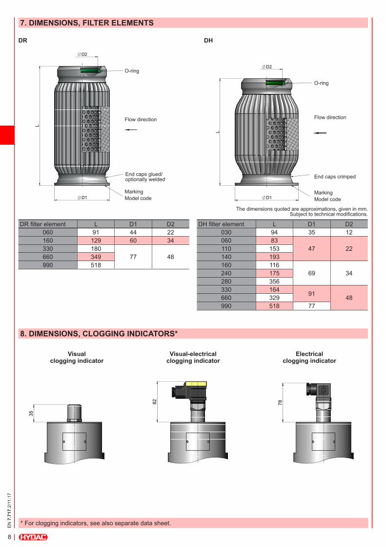
7. DIMENSIONS, FILTER ELEMENTS
8. DIMENSIONS, CLOGGING INDICATORS*
The dimensions quoted are approximations, given in mm. Subject to technical modifications.
DR filter element L D1 D2060 91 44 22160 129 60 34330 180
77 48660 349990 518
DH filter element L D1 D2030 94 35 12060 83
47 22110 153140 193160 116
69 34240 175280 356330 164 91 48660 329990 518 77
35
82
78
Visual clogging indicator
Visual-electrical clogging indicator
Electrical clogging indicator
DR DH
MarkingModel code
End caps glued/ optionally welded End caps crimped
Flow direction Flow direction
O-ring
O-ring
MarkingModel code
* For clogging indicators, see also separate data sheet.

EN
7.7
17.2
/11.
17
9
NOTEThe information in this brochure relates to the operating conditions and applications described. For applications and/or operating conditions not described, please contact the relevant technical department. Subject to technical modifications.
Process Technology GmbH Am Wrangelflöz 1 D-66538 Neunkirchen Tel.: +49 (0)6897 - 509-1241 Fax: +49 (0)6897 - 509-1278 Internet: www.hydac.com E-mail: [email protected]