stainless steel slip resistant connections · d5.5 design specifications for preloaded bolted...
TRANSCRIPT

Stainless steel slip resistant connections: D5.5 Design specifications for preloaded bolted connections
D6.4 Design recommendations and design examples
D7.2 Guidelines for design and execution
Report To RFCS, as deliverables from the research
project:
Execution and reliability of slip resistant
connections for steel structures using
carbon steel and stainless steel
(SIROCO)
Document: RT1764 Version: 02 Date: March 2018
SCI, Silwood Park, Ascot, Berkshire, UK, SL5 7QN Tel: + 44(0) 1344 636525 Fax: + 44(0) 1344 636570
P:\OSM\OSM600 SIROCO\Deliverables\D5.5, D6.4 and D7.2 Design and execution of slip resistant stainless steel connections FINAL.docx ii
Version Issue Purpose Author Reviewer Approved
01 01 For comment AXC NRB
02 01 For issue AXC NRB NRB
Although all care has been taken to ensure that all the information contained herein is accurate, The Steel Construction Institute assumes no responsibility for any errors or misinterpretations or any loss or damage arising therefrom.
For information on publications, telephone direct: +44 (0) 1344 636505 or Email: [email protected]
For information on courses, telephone direct: +44 (0) 1344 636500 or Email: [email protected]
Email: [email protected]
World Wide Web site: http://www.steel-sci.org
P:\OSM\OSM600 SIROCO\Deliverables\D5.5, D6.4 and D7.2 Design and execution of slip resistant stainless steel connections FINAL.docx iii
EXECUTIVE SUMMARY
This document combines three deliverables from the RFCS project Execution and reliability of slip resistant connections for steel structures using Carbon Steel and Stainless Steel (SIROCO), Grant Agreement number RFSR-CT-2014-00024:
D5.5 Design specifications for preloaded bolted connections made of stainless steel
D6.4 Design recommendations and design examples for stainless steel slip resistant connections
D7.2 Guidelines on design and execution of stainless slip resistant connections
The guidelines are based on the recommendations from the following project deliverables:
D5.4 Preloading behaviour and preloading levels for stainless steel bolt assemblies including relaxation with detailed specifications for recommended preloading methods (from WP5.3, 5.4, 5.6)
D5.5 Design specifications for preloaded bolted connections made of stainless steel (from WP5.3, 5.4, 5.6)
D6.2 Slip factors for typical stainless steel finishes and new types of finishes (from WP6.2 & 6.3)
D6.3 Numerical modelling of stainless steel slip resistant connections (from WP6.4)
Proposed amendments to EN 1993-1-4 and EN 1090-2 are also given at the end of these guidelines (from WP 7.4).

P:\OSM\OSM600 SIROCO\Deliverables\D5.5, D6.4 and D7.2 Design and execution of slip resistant stainless steel connections FINAL.docx iv

P:\OSM\OSM600 SIROCO\Deliverables\D5.5, D6.4 and D7.2 Design and execution of slip resistant stainless steel connections FINAL.docx v
Contents Page No
EXECUTIVE SUMMARY iii
1 INTRODUCTION 1 1.1 Background 1 1.2 Stainless steel bolts 2 1.3 Previous experience with stainless steel slip resistant connections 5 1.4 EN 1993-1-8 requirements for carbon steel 8
2 SCOPE OF GUIDELINES 11
3 PRELOADING OF BOLTING ASSEMBLIES MADE OF STAINLESS STEEL 13 3.1 General 13 3.2 Compatible bolting assemblies 13 3.3 Bolt tightening qualification procedure 17
4 DESIGN OF STAINLESS STEEL SLIP-RESISTANT CONNECTIONS 23 4.1 Design resistance of individual fasteners 23 4.2 Slip-resistant connections 23 4.3 Design examples 25
5 PROPOSED AMENDMENTS TO EN 1993-1-4 AND EN 1090-2 26 5.1 EN 1993-1-4 26 5.2 EN 1090-2 26
6 REFERENCES 28
Appendix A DESIGN EXAMPLES 29

P:\OSM\OSM600 SIROCO\Deliverables\D5.5, D6.4 and D7.2 Design and execution of slip resistant stainless steel connections FINAL.docx vi
P:\OSM\OSM600 SIROCO\Deliverables\D5.5, D6.4 and D7.2 Design and execution of slip resistant stainless steel connections FINAL.docx 1
1 INTRODUCTION
1.1 Background Stainless steel is the material of choice for critical structures in corrosive environments where maintenance and inspection are difficult or costly, or where the architectural design intent requires an alternative to carbon steel for aesthetic purposes.
Slip resistant connections are required for a range of structures such as bridges, cranes, radio masts, tubular towers, wind turbines etc. where slip has to be restricted and/or the structure is subjected to variable load. The performance of slip resistant connections depends on the tightening of bolts to a specified minimum preload and a friction coefficient for the faying (interface) surfaces. The level of preload in a bolt is governed by the strength of the bolt material, the bolt diameter and extent to which the bolt is strained (extended) during the installation and tightening process. Frictional resistance is highly dependent on the surface conditions of the parts being connected, and between the threads when tightening.
Some rules for the design and execution of slip resistant connections are given for carbon steel applications in EN 1993-1-8 [1] and the fabrication and erection specification, EN 1090-2 [2]. However, comparable rules are missing for stainless steel applications and it is simply stated in the stainless steel Eurocode that ‘testing has to be carried out to prove the acceptability of stainless steel preloaded connections’. This is because historically there have been a number of concerns about the use of stainless steel preloaded bolted connections because of a lack of knowledge about:
appropriate preloading methods, also to avoid galling1,
the impact of the time-dependent viscoplastic deformation behaviour of stainless steel on the performance of a preloaded connection,
appropriate slip factors for stainless steel faying surfaces.
Under the EU’s Research Fund for Coal and Steel project Execution and reliability of slip resistant connections for steel structures using Carbon Steel and Stainless Steel (SIROCO), comprehensive investigations were carried out to study the viscoplastic deformation behaviour of stainless steel bolts, plates and bolting assemblies. Furthermore, the preloading behaviour of stainless steel bolting assemblies and the performance of stainless steel slip resistant connections were investigated. Parametric studies were conducted to investigate the importance of individual key parameters and to generate additional data on the slip resistance of connections. Where appropriate, design rules were developed, based on an assessment of the test and numerical results.
1 If surfaces are under load and in relative motion, fastener thread galling or cold working can occur due to local adhesion and rupture of the surfaces. This behaviour is demonstrated by stainless steel, aluminium, titanium and other alloys which self-generate a protective oxide surface film for corrosion protection. In some cases weld bonding and seizure may result. In applications where disassembly will not occur and any loosening of fasteners is structurally undesirable, it may be an advantage. In applications where easy fastener removal for repairs is important, galling should be avoided. Several precautions can be taken to avoid this problem with stainless steel, including ensuring the threads are as smooth as possible, slowing down the speed of torqueing and lubrication of the internal or external threads with products containing molybdenum disulphide.
P:\OSM\OSM600 SIROCO\Deliverables\D5.5, D6.4 and D7.2 Design and execution of slip resistant stainless steel connections FINAL.docx 2
1.2 Stainless steel bolts Stainless steel bolts are covered by EN ISO 3506, Corrosion-resistant stainless steel fasteners [3,4]. The information below relates to the revision of EN ISO 3506 which is due to be published in 2018. The specification gives chemical compositions and mechanical properties for austenitic, martensitic, ferritic and duplex fasteners. Alternative materials not specifically covered in the specification are permitted if they meet the physical and mechanical property requirements and have equivalent corrosion resistance.
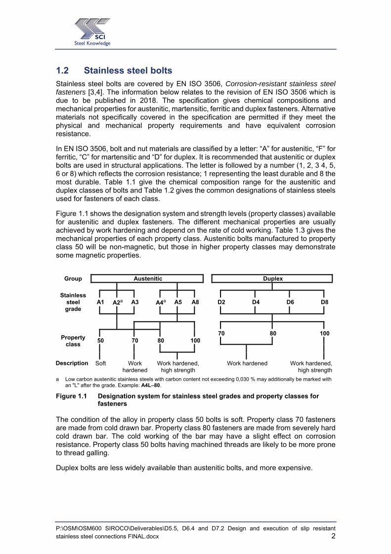
In EN ISO 3506, bolt and nut materials are classified by a letter: “A” for austenitic, “F” for ferritic, “C” for martensitic and “D” for duplex. It is recommended that austenitic or duplex bolts are used in structural applications. The letter is followed by a number (1, 2, 3 4, 5, 6 or 8) which reflects the corrosion resistance; 1 representing the least durable and 8 the most durable. Table 1.1 give the chemical composition range for the austenitic and duplex classes of bolts and Table 1.2 gives the common designations of stainless steels used for fasteners of each class.
Figure 1.1 shows the designation system and strength levels (property classes) available for austenitic and duplex fasteners. The different mechanical properties are usually achieved by work hardening and depend on the rate of cold working. Table 1.3 gives the mechanical properties of each property class. Austenitic bolts manufactured to property class 50 will be non-magnetic, but those in higher property classes may demonstrate some magnetic properties.
Group Austenitic Duplex
Stainless steel grade
A1 A2a A3 A4a A5 A8 D2 D4 D6 D8
Property class
70 80 100 50 70 80 100
Description Soft Work
hardened Work hardened,
high strength Work hardened Work hardened,
high strength
a Low carbon austenitic stainless steels with carbon content not exceeding 0,030 % may additionally be marked with an "L" after the grade. Example: A4L–80.
Figure 1.1 Designation system for stainless steel grades and property classes for fasteners
The condition of the alloy in property class 50 bolts is soft. Property class 70 fasteners are made from cold drawn bar. Property class 80 fasteners are made from severely hard cold drawn bar. The cold working of the bar may have a slight effect on corrosion resistance. Property class 50 bolts having machined threads are likely to be more prone to thread galling.
Duplex bolts are less widely available than austenitic bolts, and more expensive.

P:\OSM\OSM600 SIROCO\Deliverables\D5.5, D6.4 and D7.2 Design and execution of slip resistant stainless steel connections FINAL.docx 3
Table 1.1 Chemical composition of bolts to EN ISO 3506
Grade Chemical composition a
weight, % Other elements
and notes C Si Mn P S Cr Mo Ni Cu N
Aus
teni
tic
A1 0,12 1,0 6,5 0,020 0,15-0,35 16-19 0,7 5-10 1,75-2,25 — b, c, d
A2 0,10 1,0 2,0 0,050 0,03 15-20 — e 8-19 4 — f, g
A3 0,08 1,0 2,0 0,045 0,03 17-19 — e 9-12 1 — 5C Ti 0,8
and/or 10C Nb 1,0
A4 0,08 1,0 2,0 0,045 0,03 16-18,5 2,0-3,0 10-15 4 — g, h
A5 0,08 1,0 2,0 0,045 0,03 16-18,5 2,0-3,0 10,5-14 1
— 5C Ti 0,8 and/or
10C Nb 1,0 h
A8 0,03 1,0 2,0 0,040 0,03 19-22 6,0-7,0 17,5-26 1,5 — —
Dup
lex
D2 0,04 1,0 6,0 0,040 0,030 19-24 0,10-1,0 1,5-5,5 3 0,05-0,20Cr+3,3Mo+16N
24 j
D4 0,04 1,0 6,0 0,040 0,030 21-25 0,10-2,0 1,0-5,5 3 0,05-0,3024 <
Cr+3,3Mo+16N j
D6 0,03 1,0 2,0 0,040 0,015 21-26 2,5-3,5 4,5-7,5 — 0,08-0,35 —
D8 0,03 1,0 2,0 0,035 0,015 24-26 3,0-4,5 6,0-8,0 2,5 0,20-0,35 W 1,0
a Values are maximum unless otherwise indicated. b Selenium might be used to replace sulphur, however National regulations shall be taken into account in the
countries or regions concerned. c If the nickel content is below 8 %, the minimum manganese content shall be 5 %. d There is no minimum limit to the copper content provided that the nickel content is greater than 8 %. e Molybdenum may be present at the discretion of the manufacturer. However, if for some applications limiting of
the molybdenum content is essential, this shall be stated at the time of ordering by the purchaser. f If the chromium content is below 17 %, the minimum nickel content should be 12 %. g For austenitic stainless steels having a maximum carbon content of 0,030 %, nitrogen may be present but shall
not exceed 0,22 %. h At the discretion of the manufacturer the carbon content may be higher where required in order to obtain the
specified mechanical properties at larger diameters, but shall not exceed 0,12 % for austenitic steels. j This formula is used for the purpose of classification of duplex steels in accordance with this standard; it is not
intended to be used as a selection criterion for corrosion resistance.
Table 1.2 Common designations of stainless steels used for fasteners
Type ISO 3506 class
Common designations of stainless steels used for fasteners
Comments
Austenitic
A1 1.4570, 1.4305 Designed for machining 1
A2 1.4301, 1.4307 Basic austenitic
A3 1.4541, 1.4550 Stabilised basic austenitic
A4 1.4401, 1.4404, 1.4432, 1.4436, 1.4435
Molybdenum containing austenitic
A5 1.4571 Stabilised molybdenum austenitic
A8 1.4529, 1.4547 Super austenitic
Duplex
D2 1.4482, 1.4362 Lean duplex
D4 1.4162, 1.4062 Lean duplex
D6 1.4462 Standard duplex
D8 1.4410, 1.4501, 1.4507 Super duplex 1 The high sulphur content lowers resistance to corrosion compared to corresponding steels with normal sulphur content. Only specify with care.

P:\OSM\OSM600 SIROCO\Deliverables\D5.5, D6.4 and D7.2 Design and execution of slip resistant stainless steel connections FINAL.docx 4
The corrosion resistance of a stainless steel fastener should be at least equivalent to the material being joined, i.e., grade A2 bolts (or better) can be used to join grade 1.4301 material but grade A4 bolts (or better) should be used to join grade 1.4401 material.
For calculating the resistance of a bolt under tension or shear or combined tension and shear, the basic strength should be taken as the specified minimum tensile strength
given in Table 1.3 for the appropriate property class.
Hydrogen embrittlement is not encountered in austenitic stainless steels, nor with duplex steels which are produced and used in accordance with standard quality control measures. On the few occasions where this phenomenon has occurred with duplex steels, it was associated either with poor production control or unusual service exposure conditions. The risk of hydrogen embrittlement should be assessed for high strength components such as bolts with strength greater than property class 80.
Table 1.3 Minimum specified mechanical properties for bolts, screws and studs from austenitic and duplex steel grades
Stainless steel group
Stainless steel grade
Property class
Tensile strength, m
Stress at 0,2 % non-proportional elongation, pf
Elongation after fracture
MPa MPa mm
Austenitic
A1, A2, A3, A5
50 500 210 0,6 d
70 700 450 0,4 d
80 800 600 0,3 d
A4
50 500 210 0,6 d
70 700 450 0,4 d
80 800 600 0,3 d
100 1000 800 0,2 d
A8
70 700 450 0,4 d
80 800 600 0,3 d
100 1000 800 0,2 d
Duplex D2, D4 D6, D8
70 700 450 0,4 d
80 800 600 0,3 d
100 1000 800 0,2 d
Austenitic bolts to EN ISO 3506 property class 70 are the most widely available. Reference should be made to EN ISO 3506 for certain size and length restrictions. It is possible to have “specials” made to order and indeed, this sometimes produces an economical solution.
Bolts can be produced by a number of techniques, e.g. machining, cold rolling and forging. Rolled threads are stronger than machined threads because of the strain hardening which occurs during rolling. The compressive stresses at the surface of rolled threads improve resistance to fatigue corrosion and, in some cases, stress corrosion cracking (SCC). Rolled threads also have greater resistance to thread galling. Thread rolling is the most common method of producing bolts and screws, especially for large volume production of common sizes. For larger bolts (say from M36 upwards), and especially for the stronger duplex bolts, threads are more likely to be cut.
It is recommended that bolting material should be in the cold worked condition, property class 70 minimum. Bolting materials should not be used in the softened condition because of the propensity for galling. Using rolled as opposed to machined threads and

P:\OSM\OSM600 SIROCO\Deliverables\D5.5, D6.4 and D7.2 Design and execution of slip resistant stainless steel connections FINAL.docx 5
avoiding the use of fine threads and tight fitting thread forms reduces the likelihood of galling.
1.3 Previous experience with stainless steel slip resistant connections
Given the historical concerns with respect to stainless steel slip resistant connections noted above, the advice given by the code of practice for structural design of stainless steel (EN 1993-1-4[5]) and, the more general code of practice for connection design in steelwork (EN 1993-1-8), it is perhaps unsurprising that there are few examples to illustrate previous experience with stainless steel slip resistant connections. This situation is further exacerbated by the lack of European and/or other international product standards for stainless steel bolting assemblies for preloading applications. However, the following section provides examples of two relatively recent projects where preloaded stainless steel fasteners have been used in practice.
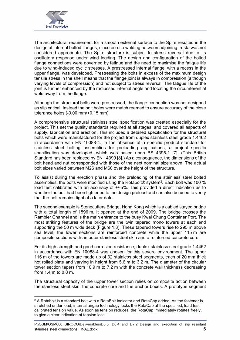
The first example is the Spire of Dublin, Ireland which dates back to 2003. The Spire is 120 m tall and is 3 m in diameter at the base tapering to a point at its pinnacle (Figure 1.2). The Spire is fabricated from rolled stainless steel plate grade 1.4404 to EN 10088-4 [6]. The plate is generally 20 mm thick although increased to 35 mm for the bottom 4 m and reduced to a minimum 10 mm near the top. The plate is finished with a shot-peened finish for the height of the Spire as well as a mirror polish finish near the base.
Figure 1.2 Spire of Dublin (left) and bolt holes in flange connection for a section of
the Spire (right) (Photo: Norton Associates)
The Spire was fabricated in eight sections (frusta), the longest being 20 m in length. The lowest seven frusta are joined by internal bolted flange connections. The two uppermost frusta are connected by a threaded connection.
P:\OSM\OSM600 SIROCO\Deliverables\D5.5, D6.4 and D7.2 Design and execution of slip resistant stainless steel connections FINAL.docx 6
The architectural requirement for a smooth external surface to the Spire resulted in the design of internal bolted flanges, since on-site welding between adjoining frusta was not considered appropriate. The Spire structure is subject to stress reversal due to its oscillatory response under wind loading. The design and configuration of the bolted flange connections were governed by fatigue and the need to maximise the fatigue life due to wind-induced cyclic stresses. A prestressed internal flange, with a recess in the upper flange, was developed. Prestressing the bolts in excess of the maximum design tensile stress in the shell means that the flange joint is always in compression (although varying levels of compression) and not subject to stress reversal. The fatigue life of the joint is further enhanced by the radiussed internal angle and locating the circumferential weld away from the flange.
Although the structural bolts were prestressed, the flange connection was not designed as slip critical. Instead the bolt holes were match reamed to ensure accuracy of the close tolerance holes (-0.00 mm/+0.15 mm).
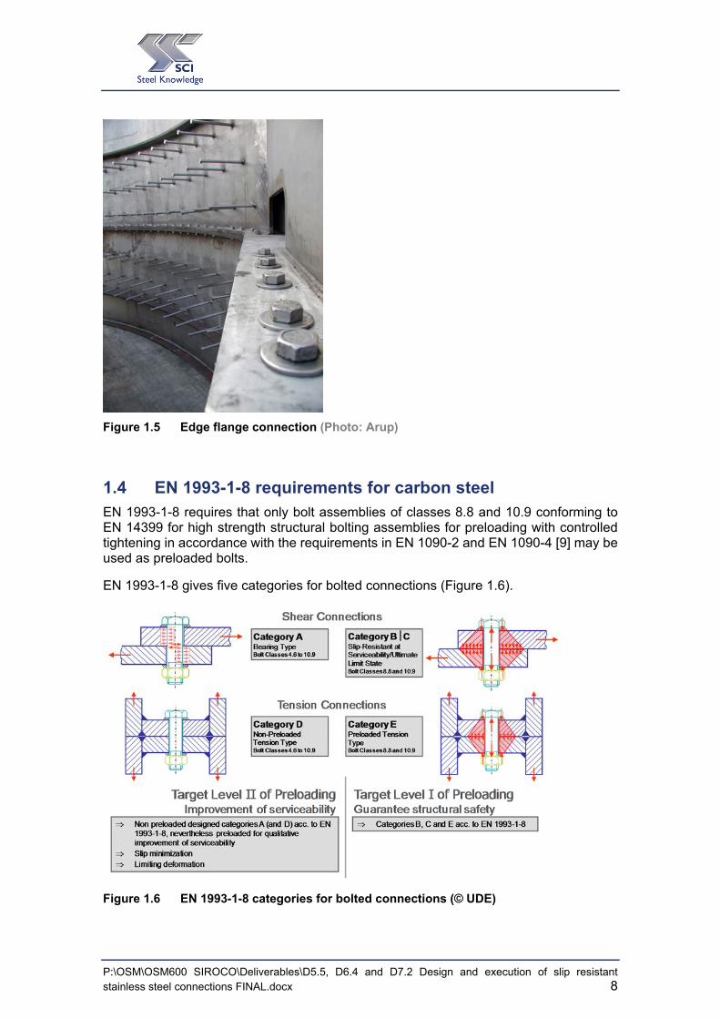
A comprehensive structural stainless steel specification was created especially for the project. This set the quality standards required at all stages, and covered all aspects of supply, fabrication and erection. This included a detailed specification for the structural bolts which were manufactured for the project from duplex stainless steel grade 1.4462 in accordance with EN 10088-4. In the absence of a specific product standard for stainless steel bolting assemblies for preloading applications, a project specific specification was developed, which was based upon BS 4395-1 [7]. (This British Standard has been replaced by EN 14399 [8].) As a consequence, the dimensions of the bolt head and nut corresponded with those of the next nominal size above. The actual bolt sizes varied between M26 and M60 over the height of the structure.
To assist during the erection phase and the preloading of the stainless steel bolted assemblies, the bolts were modified using the Rotabolt® system2. Each bolt was 100 % load test calibrated with an accuracy of +/-5%. This provided a direct indication as to whether the bolt had been tightened to the design preload and can also be used to verify that the bolt remains tight at a later date.
The second example is Stonecutters Bridge, Hong Kong which is a cabled stayed bridge with a total length of 1596 m. It opened at the end of 2009. The bridge crosses the Rambler Channel and is the main entrance to the busy Kwai Chung Container Port. The most striking features of the bridge are the twin tapered mono towers at each end supporting the 50 m wide deck (Figure 1.3). These tapered towers rise to 295 m above sea level; the lower sections are reinforced concrete while the upper 115 m are composite sections with an outer stainless steel skin and a reinforced concrete core.
For its high strength and good corrosion resistance, duplex stainless steel grade 1.4462 in accordance with EN 10088-4 was chosen for this severe environment. The upper 115 m of the towers are made up of 32 stainless steel segments, each of 20 mm thick hot rolled plate and varying in height from 5.6 m to 3.2 m. The diameter of the circular tower section tapers from 10.9 m to 7.2 m with the concrete wall thickness decreasing from 1.4 m to 0.8 m.
The structural capacity of the upper tower section relies on composite action between the stainless steel skin, the concrete core and the anchor boxes. A prototype segment
2 A Rotabolt is a standard bolt with a RotaBolt indicator and RotaCap added. As the fastener is stretched under load, internal airgap technology locks the RotaCap at the specified, load test calibrated tension value. As soon as tension reduces, the RotaCap immediately rotates freely, to give a clear indication of tension loss.

P:\OSM\OSM600 SIROCO\Deliverables\D5.5, D6.4 and D7.2 Design and execution of slip resistant stainless steel connections FINAL.docx 7
of the stainless steel skin was fabricated before construction began in order to develop appropriate welding procedures. At the same time slip tests were conducted to establish an appropriate slip factor that could be used for design purposes.
Figure 1.3 One of the two Stonecutters Bridge towers with the stay cables (Photo: Arup)
To facilitate lifting, each stainless steel skin segment was fabricated in two halves, with 25 mm thick stiffening flanges and 25 mm thick intermediate stiffening rings. High strength friction grip bolts of 22 mm diameter in duplex stainless steel (1.4462) were used for the vertical splices. The contact surface of the connecting plates required treatment to ensure that the coefficient of friction was greater than 0.2. The bolts were preloaded to achieve a shank tension of 165 kN. No slip was allowed at serviceability but slip was allowed at the ultimate limit state, with the remaining applied loads resisted in bearing.
Following the experience from the Spire of Dublin a similar approach was adopted for the specification of the bolts themselves; i. e. a project specification was developed based upon the former British Standard BS 4395-1 for high strength friction grip bolts.
Figure 1.4 Shear connectors on the inside of a tower segment (Photo: Arup)
P:\OSM\OSM600 SIROCO\Deliverables\D5.5, D6.4 and D7.2 Design and execution of slip resistant stainless steel connections FINAL.docx 8
Figure 1.5 Edge flange connection (Photo: Arup)
1.4 EN 1993-1-8 requirements for carbon steel EN 1993-1-8 requires that only bolt assemblies of classes 8.8 and 10.9 conforming to EN 14399 for high strength structural bolting assemblies for preloading with controlled tightening in accordance with the requirements in EN 1090-2 and EN 1090-4 [9] may be used as preloaded bolts.
EN 1993-1-8 gives five categories for bolted connections (Figure 1.6).
Figure 1.6 EN 1993-1-8 categories for bolted connections (© UDE)

P:\OSM\OSM600 SIROCO\Deliverables\D5.5, D6.4 and D7.2 Design and execution of slip resistant stainless steel connections FINAL.docx 9
The following categories apply to preloaded bolted connections:
(1) Bolted connections loaded in shear (shear connections)
Category B: slip resistant at serviceability limit state
Preloaded bolts in accordance with EN 14399 and EN 1090-2 should be used. The design serviceability shear load should not exceed the design slip resistance. The design ultimate shear load should not exceed the design shear resistance, nor the design bearing resistance.
Category B is appropriate if slip after SLS but before ULS only produces some unsightly deflections (which may be very unwelcome), but crucially, does not reduce the ultimate resistance of the element or structure. An example might be a splice connection in a roof truss.
Category C: slip resistant at ultimate limit state
Preloaded bolts in accordance with EN 14399 and EN 1090-2 should be used. The design ultimate shear load should not exceed the design slip resistance. In addition for a connection in tension, the design plastic resistance of the net cross-section at bolt holes , (see 6.2 of EN 1993-1-1 [10]), should be checked, at the ultimate limit state.
Category C is appropriate when slip below ULS might reduce the ultimate resistance of the element or structure. An example of this might be a plan bracing restraint system to a compression member – for example in a heavily loaded transfer truss. Slippage within the restraint system might reduce the buckling resistance, so this must be prevented.
(2) Bolted connection loaded in tension (tension connections)
Category E: preloaded
Preloaded 8.8 and 10.9 bolts in accordance with EN 14399 and EN 1090-2 should be used.
Where slip is not acceptable in a joint (e.g. because it is subject to reversal of shear load), Category B or C connections shall be applied.
The design checks for these connections are summarized in Table 1.4.
According to EN 1090-2, if other preload levels smaller than , according to EN 1090-2 and EN 1993-1-8 shall be used either in the design calculation or for serviceability reason, the tightening method, the tightening parameters and the inspection requirements have to be specified.

P:\OSM\OSM600 SIROCO\Deliverables\D5.5, D6.4 and D7.2 Design and execution of slip resistant stainless steel connections FINAL.docx 10
Table 1.4 Categories of bolted connections
Category Criteria
Shear connections
B
Slip resistant at serviceability
v,Ed,ser s,Rd,ser
v,Ed v,Rd
v,Ed b,Rd
C
Slip resistant at ultimate
v,Ed s,Rd
v,Ed b,Rd
v,Ed net,Rd
Tension connections
E
preloaded
t,Ed t,Rd
t,Ed b,Rd
The design tensile force t,Edshould include any force due to prying action. Bolts subjected to both shear force and tensile force should also satisfy the criteria given in Table 3.4 of EN 1993-1-8.

P:\OSM\OSM600 SIROCO\Deliverables\D5.5, D6.4 and D7.2 Design and execution of slip resistant stainless steel connections FINAL.docx 11
2 SCOPE OF GUIDELINES
These guidelines are based on the research results obtained in the research project SIROCO. Furthermore, recommendations are given on how to carry out tests to ensure a stainless steel slip connection is installed correctly to a defined preload level and to determine slip factors for scenarios not covered in these guidelines.
The guidelines are based on the results of the following experimental and numerical investigations:
(a) Preloading of stainless steel bolting assemblies
Five grades of stainless steel bolts in accordance with EN 10088, supplied by one bolt producer (Table 2.1):
Bumax 88 Austenitic stainless steel grades 1.4432/1.4436/1.4435 (A4) with equivalent mechanical properties to EN ISO 898-1 [11] property class 8.8
Bumax 109 Austenitic stainless steel grades 1.4432/1.4436/1.4435 (A4) with equivalent mechanical properties to EN ISO 898-1 property class 10.9
Bumax LDX Lean duplex stainless steel grade 1.4162 (D4) with equivalent mechanical properties to EN ISO 898-1 property class 10.9
Bumax DX Duplex stainless steel grade 1.4462 (D6) with equivalent mechanical properties to EN ISO 898-1 property class 10.9
Bumax SDX Super duplex stainless steel grade 1.4410 (D8) with equivalent mechanical properties to EN ISO 898-1 property class 10.9.
The Bumax 88 bolts tested in this project fulfil the strength requirements for property class 80 of EN ISO 3506 and the Bumax 109, LDX, DX and SDX bolts fulfil the requirements for property class 100.
In the absence of a specific product standard for stainless steel bolting assemblies for preloading applications, the following combination of bolts, nuts and washers were used for testing purposes, supplied by one producer of bolting assemblies:
Bolts: EN ISO 4014 Hexagon head bolts — Product grades A & B [12]
Bolts: EN ISO 4017 Fasteners – Hexagon head screws — Product grades A & B [13]
Nuts: EN ISO 4032 Hexagon regular nuts (style 1) — Product grades A & B [14]
Washers: EN ISO 7089 Plain washers — Normal series, Product grade A [15]
(EN ISO 4014 bolts have a parallel unthreaded section between the head and the threaded section whereas in EN ISO 4017 fasteners, the thread extends all the way to the head.)

P:\OSM\OSM600 SIROCO\Deliverables\D5.5, D6.4 and D7.2 Design and execution of slip resistant stainless steel connections FINAL.docx 12
Table 2.1 Nominal mechanical properties of stainless steel bolting assemblies and bolt/washer/nut combinations [© BUMAX]
Bolt Steel grade
Bolt type of stainless steel
Tensile strength Rm,min
Yield strength Rp0.2,min
Elongation min
Nut and washer steel grade
Nut and washer type of stainless steel
Nuts – Stress under proof load, min
Washers – Hardness, min
N/mm² N/mm² mm N/mm² HV
Bumax 88 Austenitic 800 640 0.3 d Bumax 88 Austenitic 800 200
Bumax 109 Austenitic 1000 900 0.2 d Bumax 109 Austenitic 1000 300
Bumax LDX Lean Duplex 1000 900 0.3 d Bumax 109 Austenitic 1000 300
Bumax DX Duplex 1000 900 0.3 d Bumax 109 Austenitic 1000 300
Bumax SDX Super Duplex 1000 900 0.3 d Bumax 109 Austenitic 1000 300
A range of Bumax bolting assemblies from M12 to M24 were tested using a variety of different lubricants.
(b) Slip factor tests for slip resistant connections made of stainless steel with different surface conditions (1D3, shot blasted, grit blasted and spray metallized with aluminium).
Four grades of stainless steel plate material in accordance with EN 10088-4:
austenitic stainless steel 1.4404
duplex stainless steel 1.4462
lean duplex stainless steel 1.4162
ferritic stainless steel 1.4003
Preloaded connections between different materials (stainless steel bolting assemblies in carbon steel plates or stainless bolting assemblies connecting a stainless plate to a carbon steel plate) are outside the scope of these guidelines.
3 1D is a mill finish and the most comment finish on hot rolled products. It is not reflective with a rough surface and is not normally used for decorative applications. It is the most common finish for structural sections.
P:\OSM\OSM600 SIROCO\Deliverables\D5.5, D6.4 and D7.2 Design and execution of slip resistant stainless steel connections FINAL.docx 13
3 PRELOADING OF BOLTING ASSEMBLIES MADE OF STAINLESS STEEL
3.1 General There is no product standard for preloaded stainless steel bolting assemblies comparable to the series of EN 14399 for high-strength carbon steel structural bolting assemblies. Therefore, bolt tightening qualification procedure (BTQP) tests have to be carried out for each configuration and batch of bolting assemblies made of stainless steel in order to specify the relevant tightening parameters and preloading method.
This BTQP consists of:
(a) suitability test for preloading on the basis of EN 14399-2;
EN 14399 requires this test for each batch of bolting assemblies to be used for preloading; usually it is carried out by the bolt producer. The k-class is determined by this test. This test has to be carried out for both carbon steel and stainless steel bolts.
(b) definition of tightening parameters based on a statistical evaluation according to EN 1990 [16].
Care is needed over the choice of lubricant because stainless steel preloaded assemblies are susceptible to galling if loaded into the plastic range. The assembly must be sufficiently well lubricated to enable the bolt to be loaded up to the required preload level using the chosen tightening procedure, without the occurrence of galling.
The guidelines are based on investigations for bolting assemblies consisting of EN ISO 4014/4017 bolts in property classes 8.8 and 10.9 with EN ISO 4032 nuts and EN ISO 7089 washers. These bolts have a smaller head and nut bearing surface than the carbon steel HV or HR systems according to EN 14399-3/-4 which were especially developed with optimised geometries for preloading. Furthermore, stainless steel bolting assemblies are not available on the market with calibrated lubrication needed for applying a specified preload level.
Various stainless steel bolting assemblies exist on the market produced by different bolt producers. It has to be emphasized that the recommendations presented in these guidelines are based on experiences with components from one stainless steel bolting assembly producer and one stainless steel plate producer. Herewith, the basis is given for drawing general conclusions but it is not possible to draw specific conclusions which are valid for all stainless steel bolting assemblies available on the market.
3.2 Compatible bolting assemblies Common examples for components of stainless steel bolting assemblies are given in the following paragraphs.
Bolts – product standards:
Stainless steel fasteners are widely available in geometries in accordance with EN ISO 4014 and EN ISO 4017:

P:\OSM\OSM600 SIROCO\Deliverables\D5.5, D6.4 and D7.2 Design and execution of slip resistant stainless steel connections FINAL.docx 14
EN ISO 4014:2011, Hexagon head bolts, Product grades A and B EN ISO 4017:2014, Fasteners, Hexagon head screws, Product grades A and B
Nuts – product standard:
EN ISO 4032:2012, Hexagon regular nuts (style 1), Product grades A and B
Washers – product standards:
Washers for bolting assemblies of property class 80 and 8.8 shall have at least a hardness of HV200. Washers for bolting assemblies of property class 100 and 10.9 shall have at least a hardness of HV300. EN ISO 7089:2000, Plain washers, Normal series, Product grade A EN ISO 7090:2000, Plain washers, chamfered, Normal series, Product grade A EN ISO 7092:2000, Plain washers, Small series, Product grade A EN ISO 7093-1:2000, Plain washers, Large series, Product grade A EN ISO 7093-2:2000, Plain washers, Large series, Product grade C
Mechanical properties and chemical compositions
EN ISO 3506-1:2009 Mechanical properties of corrosion-resistant stainless steel fasteners, Bolts, screws and studs
EN ISO 3506-2:2009 Mechanical properties of corrosion-resistant stainless steel fasteners, Nuts
Geometric difference between ISO 4014/17 and ISO 14399-3/4
Although stainless steel fasteners are widely available in geometries in accordance with EN ISO 4014 and EN ISO 4017, the preloading suitability tests according to ISO 14339-2 are carried out for bolts conforming to ISO 14399-3 (HR bolts) and 14399-4 (HV bolts). Comparison of the geometric differences between an M20 bolt and nut in accordance with these different standards are shown in Table 3.1 and Table 3.2.
It can be noted that the bolt head and nut dimension of components in accordance with EN ISO 4014/17 are smaller than the HR/HV bolts. This could lead to a higher surface pressure which might render stainless steel bolts unsuitable for preload. Analysis of the surface pressure on the clamped parts of stainless steel bolting assemblies was carried out [17] and the results showed that preloading of stainless steel bolting assemblies of property class of 100 up to , leads to surface pressure smaller than the nominal yield strength of the stainless steel plate material. It follows that EN ISO 4014/17 stainless steel bolting assemblies are suitable for preloading as far as the surface contact pressure is concerned.
P:\OSM\OSM600 SIROCO\Deliverables\D5.5, D6.4 and D7.2 Design and execution of slip resistant stainless steel connections FINAL.docx 15
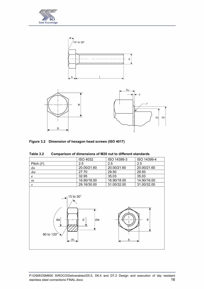
Table 3.1 Comparison of dimensions (in mm) of M20 bolt to different standards
L = 120 [mm] ISO 4014 ISO 4017 ISO 14399-3 ISO 14399-4
Pitch of thread ( ) 2.5 2.5 2.5 2.5
Thread Length ( ) 46 - 46 33
Depth of washer face ( ) 0.2/0.8 0.2/0.8 0.4/0.8 0.4/0.8
Transition diameter ( ) 22.4 22.4 24.4 24.0
Dia of unthreaded shank ( ) 19.48/20.00 - 19.16/20.84 19.16/20.84
Dia of washer face ( ) 27.70 27.7 29.5 29.5
Width across corners ( ) 32.95 32.95 35.03 35.03
Thickness of head ( ) 12.50 12.5 12.5 13
Radius under head ( ) 0.8 0.8 1.5 1.5
Width across flats ( ) 29.16/30.00 29.16/30.00 31.00/32.00 31.00/32.00
61.50 - 61.50 79.5
74.00 - 74.00 87
Figure 3.1 Dimension of hexagon head bolts (ISO 4014, ISO 14339-3 and ISO 14339-4)
P:\OSM\OSM600 SIROCO\Deliverables\D5.5, D6.4 and D7.2 Design and execution of slip resistant stainless steel connections FINAL.docx 16
Figure 3.2 Dimension of hexagon head screws (ISO 4017)
Table 3.2 Comparison of dimensions of M20 nut to different standards
ISO 4032 ISO 14399-3 ISO 14399-4 Pitch ( ) 2.5 2.5 2.5
20.00/21.60 20.00/21.60 20.00/21.60 27.70 29.50 29.50
32.95 35.03 35.03 16.90/18.00 16.90/18.00 14.90/16.00
29.16/30.00 31.00/32.00 31.00/32.00

P:\OSM\OSM600 SIROCO\Deliverables\D5.5, D6.4 and D7.2 Design and execution of slip resistant stainless steel connections FINAL.docx 17
3.3 Bolt tightening qualification procedure
3.3.1 General
Tightening of stainless steel bolting assemblies is possible using various tightening procedures, e. g. torque method, combined method or using direct tension indicator (DTI) in accordance with EN 1090-2. It is important that the tightening procedure and the required preload level are well-matched. The boundary conditions regarding the required preload level and tightening procedure have to be defined in advance, so that the test of suitability for preloading for the determination of all functional characteristics and k-classes of stainless steel bolting assemblies can be successfully carried out.
The process to qualify stainless bolting assemblies for preloading (Section 3.3.2) and the tightening method to achieved target preload (Section 3.3.3) is illustrated in the flow chart shown in Figure 3.3.
Figure 3.3 Flowchart for bolt tightening qualification procedure (BTQP)

P:\OSM\OSM600 SIROCO\Deliverables\D5.5, D6.4 and D7.2 Design and execution of slip resistant stainless steel connections FINAL.docx 18
3.3.2 Qualification of bolting assemblies
The suitability for preloading of the stainless steel bolting assemblies has to be assessed in accordance with EN 14399-2, Suitability test for preloading. It is a torque tightening test. The standard test is to tighten the bolt by turning the nut and to measure the following parameters whilst doing so:
bolt force,
tightening torque,
relative rotation between the nut and the bolt,
bolt elongation, if required.
In the suitability test, functional characteristics and particularly the two main criteria regarding the maximum bolt force reached during testing ( , ) and the ductility criteria (θ2i) have to be fulfilled, see definition of functional characteristics in Figure 3.4. Minimum values of the ductility criteria for stainless steel bolting assemblies are not defined. Values from EN 14339-3 for HR bolting system can be used when appropriate, otherwise values must be defined by experts for the tested bolting assemblies.

P:\OSM\OSM600 SIROCO\Deliverables\D5.5, D6.4 and D7.2 Design and execution of slip resistant stainless steel connections FINAL.docx 19
(a) Rotation – bolt force curve
(b) Torque – bolt force curve
Figure 3.4 Suitability tests in accordance with EN 14399-2 High-strength structural bolting assemblies for preloading, Part 2: Suitability for preloading
EN 1090-2 introduces k-classes K0, K1 and K2 which relate to the supply condition of the lubrication of the bolting assembly. For carbon steel bolting assemblies, the manufacturer would be expected to state the k-class for their products. The classification into the k-classes is based on the individual k-factors (and their coefficient of variation for k-class K2). The k-factor is determined from the relationship between the torque ( ) and the preload ( , ) as shown in Figure 3.4. EN 1090-2 limits the method of tightening of carbon steel bolting assemblies based upon the individual k-class.
The k-class-concept introduced in EN 1090-2 is not specified for stainless steel bolting assemblies. Therefore, it is necessary to qualify the tightening method according to the general requirements of EN 1090-2 and to determine the tightening parameters to achieve a reliable preload level for the preferred tightening method.

P:\OSM\OSM600 SIROCO\Deliverables\D5.5, D6.4 and D7.2 Design and execution of slip resistant stainless steel connections FINAL.docx 20
3.3.3 Determination of tightening parameters for a tightening method
Preloaded bolted connections can be distinguished in those connections in which the preload is used in the design process (target level I, categories B, C and E according to EN 1993-1-8) and those which are preloaded only to enhance the serviceability, e. g. to limit the deformation and slip in the connections (target level II, categories A and D according to EN 1993-1-8).
Once the preferred tightening method is selected, the tightening parameters have to be determined for the specific method which includes the specification of the suitable lubricant, the reference torque, the additional angle of rotation (if needed) etc.
In addition, for preloaded bolted connections meeting target level I, the preload in the bolting assembly must be reliably applied. For this reason, tightening parameters have to defined which fulfill the limiting criteria No. 1 to 3 given in Table 3.3. For preloaded bolted connections meeting target level II, the level of preload does not need to be checked, unless specified otherwise.
Nevertheless, it should be noted, that consideration of the limiting criteria no. 1 to 3 is recommended for the evaluation of reliable tightening parameters for both target levels I and II. After this first evaluation of tightening parameters in accordance with the limiting criteria given in Table 3.3, the tightening parameters can be relaxed for applications only required to meet target level II.
The limiting criteria no. 4 and 5 are to be considered if tightening in the elastic range of the bolting assembly is restricted, for example if the bolting assembly or components of the assembly have to be reused (Reuse is only allowed if special testing is carried out, e,g, for bridge bearings, but it is not regulated and covered in EN 1090-2.)
If tightening parameters for the combined method have to be evaluated, the limiting criteria no. 4 and 5 cannot be fulfilled, since the actual applied preload is usually far higher than the nominal preload level , and therefore also much higher than 4, which is the maximum allowable preload in a bolt considering simultaneously acting tensile and torsional stress due to the applied torque. In this case, other parameters have to be defined which avoid overstressing or failure of the bolting assembly.
4 See definition in Equation (3-6)
P:\OSM\OSM600 SIROCO\Deliverables\D5.5, D6.4 and D7.2 Design and execution of slip resistant stainless steel connections FINAL.docx 21
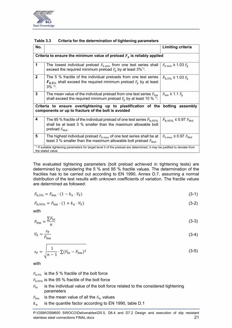
Table 3.3 Criteria for the determination of tightening parameters
No. Limiting criteria
Criteria to ensure the minimum value of preload is reliably applied
1 The lowest individual preload from one test series shall exceed the required minimum preload by at least 3%1).
≥ 1.03
2 The 5 % fractile of the individual preloads from one test series
, % shall exceed the required minimum preload by at least 3% 1).
, % ≥ 1.03
3 The mean value of the individual preload from one test series shall exceed the required minimum preload by at least 10 % 1).
≥ 1.1
Criteria to ensure overtightening up to plastification of the bolting assembly components or up to fracture of the bolt is avoided
4 The 95 % fractile of the individual preload of one test series , % shall be at least 3 % smaller than the maximum allowable bolt preload .
, % ≤ 0.97
5 The highest individual preload of one test series shall be at least 3 % smaller than the maximum allowable bolt preload .
≤ 0.97
1) If suitable tightening parameters for target level II of the preload are determined, it may be justified to deviate from the stated value.
The evaluated tightening parameters (bolt preload achieved in tightening tests) are determined by considering the 5 % and 95 % fractile values. The determination of the fractiles has to be carried out according to EN 1990, Annex D.7, assuming a normal distribution of the test results with unknown coefficients of variation. The fractile values are determined as followed:
, % ⋅ 1 ⋅ (3-1)
, % ⋅ 1 ⋅ (3-2)
with
∑ (3-3)
(3-4)
11⋅ ∑ (3-5)
with
, % is the 5 % fractile of the bolt force
, % is the 95 % fractile of the bolt force
is the individual value of the bolt force related to the considered tightening parameters
is the mean value of all the values
is the quantile factor according to EN 1990, table D.1

P:\OSM\OSM600 SIROCO\Deliverables\D5.5, D6.4 and D7.2 Design and execution of slip resistant stainless steel connections FINAL.docx 22
is the number of test results
is the standard deviation of
is the coefficient of variation for The maximum allowable bolt preload is calculated in accordance with Equation (3-6). The definition is based on the maximum possible preload defined in Section 5.5 of VDI 2230-1 [18].
∙
1 3 ∙32 ∙ ∙ ∙ 1.115
(3-6)
with
is the effective pitch diameter
is the diameter relating to the tensile stress area
is the pitch of the thread
is the minimum coefficient of friction in the thread , (determined from tests)
3.3.4 Inspection requirements
Inspection requirements should be in accordance with EN 1090-2, clause 12.5.2.
3.3.5 Stainless steel bolts for preloading
The test results showed it is possible to preload stainless steel bolting assemblies within the elastic range to ,
∗ and also to , . With a suitable lubricant, the functional characteristics can be successfully achieved and tightening parameters determined. Appropriate lubrication extends the plastic plateau of the bolt preload – angle rotation curve. The ability to satisfy the functional characteristics is highly dependent on the type of lubricant used. The suitability for preloading tests in SIROCO indicated that DOW Corning Molykote 1000 spray and Molykote D-321R spray were appropriate lubricants for preloading of stainless steel bolting assemblies. Other lubricants might also be appropriate and need to be validated by suitability tests.
Based on the tests conducted, it is evident that stainless steel bolting assemblies are suitable for preloading, provided a suitable lubricant is identified and the functional characteristics and tightening criteria can be satisfied.
In the tests carried out under SIROCO, galling only occurred with certain lubricants when the bolts were tightened into the plastic zone, i.e. at preload levels near to , and far exceeding , . Galling generally occurs on the interface between the washer and the nut, but may also occur between the paired threads. Galling can be avoided by a combination of the use of an appropriate lubricant and the use of a tightening procedure which avoids overtightening (i.e. not tightening too far beyond the required preload level
, . )
P:\OSM\OSM600 SIROCO\Deliverables\D5.5, D6.4 and D7.2 Design and execution of slip resistant stainless steel connections FINAL.docx 23
4 DESIGN OF STAINLESS STEEL SLIP-RESISTANT CONNECTIONS
The preload losses due to viscoplastic deformation (creep and relaxation) in stainless steel preloaded bolted assemblies are not significantly higher than those for equivalent connections made of carbon steel. Hence, the design rules for carbon steel slip-resistant connections are applicable to stainless steel slip-resistant connections, provided the slip factors for stainless steel are used.
The following design rules apply to stainless steel bolted assemblies using bolts of property classes 80 and 100, in accordance with EN ISO 3506. Alternatively, if the bolts are property class 8.8 or 10.9 in accordance with EN ISO 898-1, then they must fulfil the requirements of EN 15048 [19].
4.1 Design resistance of individual fasteners The design preload , to be used in design calculations should be taken as:
,0,7γ
EN 1993-1-8 Eq 3.1 (4-1)
This expression is applicable to preloaded bolting assemblies subject to tension which are not used in slip-resistant connections, for example where preloading is necessary to resist fatigue under varying loading.
The recommended value for γ is 1.1.
4.2 Slip-resistant connections
Design slip resistance
In applications where disassembly is unlikely to be necessary, stainless steel bolts can be preloaded to , and the design slip resistance is given by:
,
, Slip resistance at ULS (Category C) (4-2)
, ,
, , Slip resistance at SLS (Category B) (4-3)
where
is given in Table 4.1
is the number of friction planes;
μ is the slip factor obtained either by specific tests for the friction surface in accordance with EN 1090 or when relevant as given in Table 4.2.
The recommended values for and , are 1.25 and 1.1 respectively. Note that these values need to be verified for stainless steel slip resistant connections by a reliability assessment in accordance with EN 1990 Annex D.

P:\OSM\OSM600 SIROCO\Deliverables\D5.5, D6.4 and D7.2 Design and execution of slip resistant stainless steel connections FINAL.docx 24
For other surface conditions, the slip factor can be determined according to the slip factor test of Annex G, EN 1090-2.
Unlike for coated carbon steel slip-resistant connections, the influence of the preload level on the resulting slip factor is negligible for stainless steel slip-resistant connections.
For bolts of property classes 80 and 100, conforming with EN ISO 4014 or EN ISO 4107, and installed with controlled tightening in accordance with EN 1090-2, the preloading force , to be used in equations (4-2) and (4-3) should be taken as:
, 0.7 (4-4)
Nevertheless, a lower preload level can be used as long as the tightening parameters etc. are specified and the lower preload level is consequently considered in the design and execution process.
Table 4.1 Values of
Description s
Bolts in normal holes. 1.0
Bolts in either oversized holes or short slotted holes with the axis of the slot perpendicular to the direction of load transfer.
0.85
Bolts in long slotted holes with the axis of the slot perpendicular to the direction of load transfer.
0.7
Bolts in short slotted holes with the axis of the slot parallel to the direction of load transfer.
0.76
Bolts in long slotted holes with the axis of the slot parallel to the direction of load transfer.
0.63
Table 4.2 Slip factor, µ, for preloaded stainless steel bolted connections
Class of friction surfaces
Stainless steel grade
Surface condition Slip factor μ Surface finish Rz [μm]
A++ Duplex 1.4462/ Lean Duplex 1.4162
Aluminium spray metallized (measured dry film thickness (DFT) = 100 m 20 m)
≥ 40 (before coating application)
0.7
A+ Austenitic 1.4404/ Ferritic 1.4003 0.6
A Duplex 1.4462
Surfaces blasted with grit ≥ 50
0.5 Ferritic 1.4003 ≥ 45
B Austenitic 1.4404
Surfaces blasted with grit ≥ 45
0.4 Lean Duplex 1.4162 ≥ 40
C - - - 0.3
D Austenitic 1.4404 Surfaces blasted with shot
≥ 35 0.2
E Austenitic 1.4404 Surfaces as rolled ≥ 25 0.15
Note: Care is needed during grit and shot blasting processes to ensure there is no detrimental effect on the corrosion resistance.
P:\OSM\OSM600 SIROCO\Deliverables\D5.5, D6.4 and D7.2 Design and execution of slip resistant stainless steel connections FINAL.docx 25
In applications where easy fastener removal is important, in order to avoid any possibility of galling, stainless steel bolts should be only preloaded into the elastic range and the design slip resistance may be taken as:
,
,∗ Slip resistance at ULS (Category C) (4-5)
, ,
, ,
∗ Slip resistance at SLS (Category B) (4-6)
For bolts of property classes 80 and 100, conforming with EN ISO 4014 or EN ISO 4107, and installed with controlled tightening in accordance with EN 1090-2, the preloading force ,
∗ to be used in equations (4-5) and (4-6) may be taken as:
,∗ 0,7 (4-7)
Combined tension and shear
If a slip-resistant connection is subjected to an applied tensile force,Ft,EdorFt,Ed,ser, in
addition to the shear force, Fv,EdorFv,Ed,ser, tending to produce slip, the design slip resistance per bolt should be taken as follows:
for a category B connection: , , , 0.8 , ,
, (4-8)
for a category C connection: , , 0.8 ,
(4-9)
If, in a moment connection, a contact force on the compression side balances the applied tensile force, no reduction in the slip resistance is required.
4.3 Design examples Two design examples are given in Appendix A to illustrate the application of the design rules proposed for stainless steel slip resistant connections. The first example is the design of a tension member connection and the second is the design of a main girder splice. Duplex stainless steel (1.4462) and austenitic bolts (BUMAX 88) are used in both examples.
P:\OSM\OSM600 SIROCO\Deliverables\D5.5, D6.4 and D7.2 Design and execution of slip resistant stainless steel connections FINAL.docx 26
5 PROPOSED AMENDMENTS TO EN 1993-1-4 AND EN 1090-2
5.1 EN 1993-1-4
Existing text: 2.2.2 Preloaded bolts NOTE: High strength bolts made of stainless steel should not be used as preloaded bolts designed for a specific slip resistance, unless their acceptability in a particular application can be demonstrated from test results. Amendment: 2.2.2 Preloaded bolts The rules in EN 1993-1-8 are applicable to stainless steel providing slip factors for stainless steel are used.
In applications where easy fastener removal is important, in order to avoid any possibility of galling, stainless steel bolts may be preloaded to a level lower than
, and the design slip resistance taken as:
,
,∗ Slip resistance at ULS (Category C) (5-1)
, ,
,,∗ Slip resistance at SLS (Category B) (5-2)
For bolts of property classes 80 and 100, conforming with EN ISO 4014 or EN ISO 4107, and installed with controlled tightening in accordance with EN 1090-2, the preloading force ,
∗ to be used in equations (5-1) and (5-2) may be taken as:
,∗ 0.7 (5-3)
5.2 EN 1090-2
Existing text: 8.4 Preparation of contact surfaces in slip resistant connections
This clause is not applicable to stainless steels for which any requirement related to contact surfaces shall be specified. Amendment: 8.4 Preparation of contact surfaces in slip resistant connections
The slip factor tests in Annex G of EN 1090-2 can also be carried out for stainless steel applications. For each test, new stainless steel bolting assemblies have to be

P:\OSM\OSM600 SIROCO\Deliverables\D5.5, D6.4 and D7.2 Design and execution of slip resistant stainless steel connections FINAL.docx 27
used in order to take into account the viscoplastic deformation in the stainless steel bolt material in each test in the same way.
The measurement of the preload in the bolting assemblies has to be carried out in such a way that creep in the stainless steel bolt material does not influence the measured preloads. A relatively rigid load cell should be used, calibrated for linear strain-load behaviour. Implanted strain gauges are not suitable.
Surface treatment that may be assumed to provide the minimum slip factor according to the specified class of friction surface without test are given in Table 18 for carbon steel and Table 19 for stainless steel.
New Table 19 for EN 1090-2:
Classifications that may be assumed for friction surfaces between stainless steel plates
Class of friction surfaces
Stainless steel grade
Surface condition Slip
factor µ Surface finish Rz [μm]
A++ Duplex 1.4462/ Lean Duplex 1.4162
Aluminium spray metallized (measured dry film thickness (DFT) = 100 m 20 m)
≥ 40 (before coating application)
0.7
A+ Austenitic 1.4404/ Ferritic 1.4003
0.6
A Duplex 1.4462
Surfaces blasted with grit ≥ 50
0.5 Ferritic 1.4003 ≥ 45
B
Austenitic 1.4404
Surfaces blasted with grit
≥ 45
0.4 Lean Duplex 1.4162
≥ 40
C - - - 0.3
D Austenitic 1.4404 Surfaces blasted with shot
≥ 35 0.2
E Austenitic 1.4404 Surfaces as rolled ≥ 25 0.15
Addition to 8.5 Tightening of preloaded bolts For stainless steel bolting assemblies, bolt tightening qualification procedures should be carried out to ensure suitability for preloading of the bolt assemblies, determine the tightening parameters and confirm the reliability of the tightening method to achieve the design preload.
P:\OSM\OSM600 SIROCO\Deliverables\D5.5, D6.4 and D7.2 Design and execution of slip resistant stainless steel connections FINAL.docx 28
6 REFERENCES
[1] EN 1993-1-8: 2005, Eurocode 3: Design of steel structures – Part 1-8: Design of joints
[2] EN 1090-2:2008+A1:2011, Execution of steel structures and aluminium structures — Part 2: Technical requirements for steel structures
[3] EN ISO 3506-1:2009, Mechanical properties of corrosion-resistant stainless steel fasteners — Part 1: Bolt, screws and studs (ISO 3506-1:2009).
[4] EN ISO 3506-2:2009, Mechanical properties of corrosion-resistant stainless steel fasteners — Part 2: Nuts (ISO 3506-2:2009).
[5] EN 1993-1-4:2015, Eurocode 3: Design of steel structures – Part 1-4: General rules – Supplementary rules for stainless steels; EN 1993-1-4:2006 + A1:2015.
[6] EN 10088-4:2009 Stainless steels. Technical delivery conditions for sheet/plate and strip of corrosion resisting steels for construction purpose
[7] BS 4395-1:1969 Specification for high strength friction grip bolts and associated nuts and washers for structural engineering. General grade
[8] EN 14399 High-strength structural bolting assemblies for preloading.
[9] EN 1090-4. Execution of steel structures and aluminium structures. Part 4. Technical requirements for thin-gauge, cold-form steel elements and structures for roof, ceiling, floor and wall applications
[10] EN 1993-1-1: 2005. Eurocode 3. Design of steel structures. General rules and rules for buildings
[11] ISO 898-1:2013 Mechanical properties of fasteners made of carbon steel and alloy steel – Part 1: Bolts, screws and studs with specified property classes – Coarse thread and find pitch thread
[12] EN ISO 4014:2011, Hexagon head bolts — Product grades A and B (ISO 4014:2011).
[13] EN ISO 4017:2014, Fasteners – Hexagon head screws — Product grades A and B (ISO 4017:2014).
[14] EN ISO 4032:2013-04, Hexagon regular nuts (style 1) — Product grades A and B (ISO 4032:2012).
[15] EN ISO 7089:2000-11, Plain washers — Normal series, Product grade A (ISO 7089:2000).
[16] EN 1990:2002+A1:2005 Eurocode. Basis of structural design
[17] SIROCO D5.4 Preloading behaviour and preloading levels for stainless steel bolt assemblies including relaxation with detailed specification for recommended preloading methods
[18] VDI 2231 Part 1, Systematic calculation of high duty bolted joints, joints with one cylindrical bolt
[19] EN 15048 Non-preloaded structural bolting assemblies
P:\OSM\OSM600 SIROCO\Deliverables\D5.5, D6.4 and D7.2 Design and execution of slip resistant stainless steel connections FINAL.docx 29
APPENDIX A DESIGN EXAMPLES
Execution and reliability of slip-resistant connections for steel structures using CS and SS (SIROCO) CALCULATION SHEET
Project Name: SIROCO Sheet 1 of 4 Rev 1
Project Title SIROCO
Subject Design Example 1 – Connection of Tensile Bracing Member
Client
Research Fund for Coal and Steel
Made by AXC Date Mar 2018
Checked by NRB Date Mar 2018
1 Design Example 1 – Connection of Tensile Bracing Member
Check the slip resistant connection of a diagonal stainless steel bracing member to a stainless steel fabricated column, in accordance with EN 1993-1-8 and EN 1993-1-4. (It is based on Example 6 of The Steel Construction Institute’s publication P324 Tension Control Bolts 1.)
1.1 Structure The connection is shown below:
Stainless steel bolts are in accordance with EN ISO 4017 (full threaded bolts).
1.2 Action
Permanent and variable actions result in a vertical design shear force and a design tension force equal to:
VEd = 300 kN FEd = 400 kN
1 Tension Control Bolts, Grade S10T, in Friction Grip Connections, P324, The Steel
Construction Institute, Ascot, 2004

Design Example 1 – Connection of Tensile Bracing Member Sheet 2 of 4 Rev 1
1.3 Geometric properties EN 1993-1-8, Figure 6.2 tp = 20 mm (end plate thickness)
m = 90 – 12/2 - 8 = 76 mm (distance from bolt centre to toe of weld) e = emin = 50 mm (edge distance) As = 353 mm2 (M24 bolt tensile stress area)
1.4 Material properties
Duplex plate 1.4462 (13.5 mm ≤ t ≤ 75 mm) EN 10088-4 fyp = 460 N/mm2 fup = 640 N/mm2
Bumax 88 austenitic bolt (equivalent to carbon steel bolt of class property 8.8)
fyb = 640 N/mm2 fub = 800 N/mm2
Slip factor
μ = 0.5 for duplex grit blasted surface2
1.5 Design resistance – Plate and bolts
Resistance of end plate EN 1993-1-8, Basic requirement:
min , , ; , , ; , , Clause 6.2.4.1(6)
where , is the design tension resistance of a T-stub flange
Mode 1
, , 8 2 ,
2
EN 1993-1-8, Table 6.2
The effective length of the equivalent T-stub Σ 360 mm EN 1993-1-8,
Figure 6.2
, 0.25Σ
γ0.25 360 20 460
1.110 15.1 kNm
where γ 1.1 for stainless steel EN 1993-1-4, Table 5.1
Assuming no washer is used, from EN ISO 4017 for M24 setscrews = 33.25 mm EN ISO 4017
433.254
8.31mm
n = emin but ≤ 1.25m
n = emin = e2 = 50 mm ; 1.25m=1.25ⅹ76 = 95 mm
n = 50 mm
, , 8 50 2 8.31 15.1 102 76 50 8.31 76 50
883 kN
2 Execution and reliability of slip-resistant connections for steel structures using CS and SS
(SIROCO), RFCS research project, Deliverable 7.2 Guidelines for design and execution 2018

Design Example 1 – Connection of Tensile Bracing Member Sheet 3 of 4 Rev 1
Mode 2
, , 2 , ΣF ,
EN 1993-1-8, Table 6.2
F , γ
0.9 800 353
1.2510 203 kN
EN 1993-1-8, Table 3.4
, , 2 15.1 10 50 6 203 10
76 5010 484 kN
Mode 3
, , ΣF , 6 203 1218kN EN 1993-1-8, Table 6.2
min , , ; , , ; , , min 883; 484; 1218 484 kN
400kN 484kN ∴ OK
Note: In accordance with EN 1993-1-8 Table 3.2, the punching shear resistance
, should also be checked for tension connections.
1.6 Resistance of bolts under combined shear and tension
EN 1993-1-8, Table 3.4, Clause 3.6
Basic requirement:
,
,
,
1.4 ,1.0
Shear resistance of stainless steel bolt: EN 1993-1-4,
Clause 6.2
,
= 0.5 and A = As since fully threaded bolt (EN ISO 4017) are assumed to be used
1.25 for stainless steel EN 1993-1-4, Table 5.1
, 0.5 800 353
1.2510 113 kN
F , 0.9 800 353
1.2510 203 kN
, 6
3006
50kNand , 64006
66.7 kN
,
,
,
1.4 ,
50113
66.71.4 203
0.68 1.0
∴ OK

Design Example 1 – Connection of Tensile Bracing Member Sheet 4 of 4 Rev 1
1.7 Slip resistance of preloaded bolts
Basic requirement for slip-resistance at ultimate (Category C): EN 1993-1-8, Table 3.2
, ,
Slip resistance for combined tension and shear:
, , 0.8 ,
EN 1993-1-8, Clause 3.9.2(1) and SIROCO D7.23
is 1.0 for bolts in normal holes EN 1993-1-8, Table 3.6
is the number of friction planes = 1
Slip factor = 0.5 for duplex plate with grit blasted surface finish
1.25
, 0.7 0.7 800 353 10 197.7 kN
, 1.0 1 0.5 197.7 0.8 66.7
1.2557.7 kN
, 50kN , 57.7kN ∴ OK Thus the slip resistant connection has adequate resistance to the member axial load.
Note: In accordance with EN 1993-1-8 Table 3.2 for Category C connections, the bearing resistance , should be checked (EN 1993-1-8 Table 3.4) and the net
section resistance , should be checked (EN 1993-1-1 clause 6.2.3).
3 Execution and reliability of slip-resistant connections for steel structures using CS and SS
(SIROCO), RFCS research project, Deliverable 7.2 Guidelines for design and execution, 2018
Execution and reliability of slip-resistant connections for steel structures using CS and SS (SIROCO) CALCULATION SHEET
Project Name: SIROCO Sheet 1 of 8 Rev 1
Project Title SIROCO
Subject Design Example 2 – Main girder splice
Client
Research Fund for Coal and Steel
Made by AXC Date Mar 2018
Checked by NRB Date Mar 2018
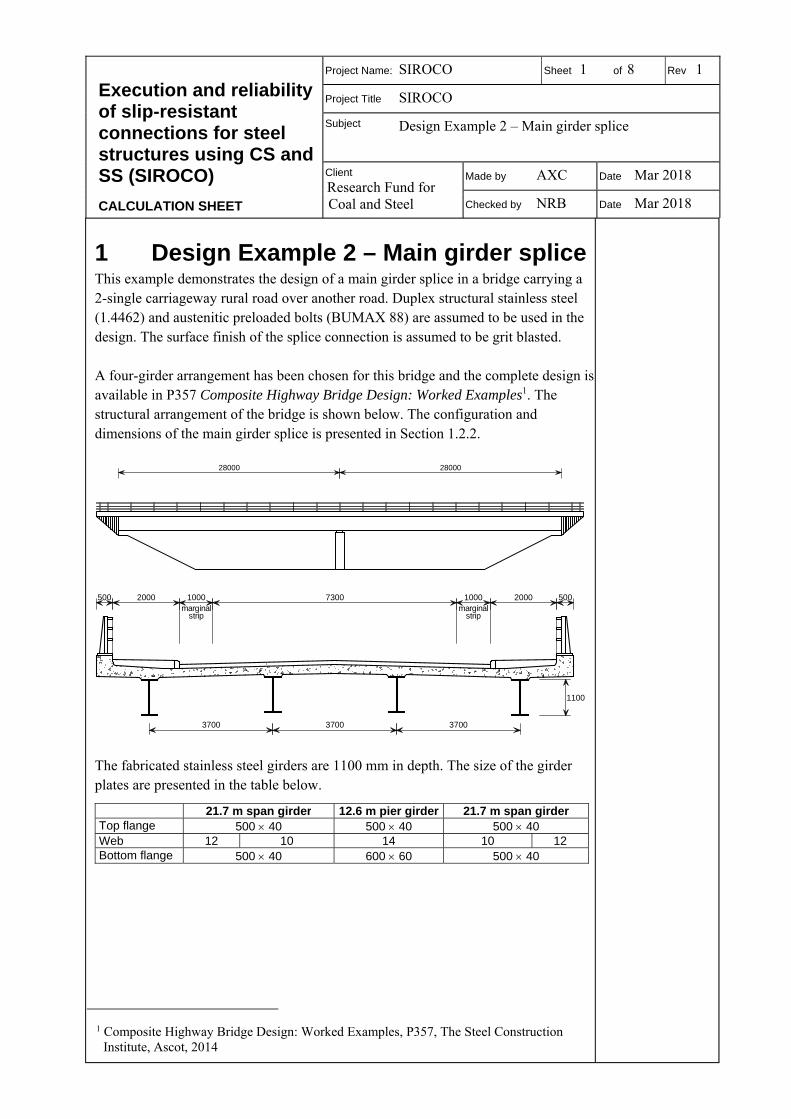
1 Design Example 2 – Main girder splice This example demonstrates the design of a main girder splice in a bridge carrying a 2-single carriageway rural road over another road. Duplex structural stainless steel (1.4462) and austenitic preloaded bolts (BUMAX 88) are assumed to be used in the design. The surface finish of the splice connection is assumed to be grit blasted. A four-girder arrangement has been chosen for this bridge and the complete design is available in P357 Composite Highway Bridge Design: Worked Examples1. The structural arrangement of the bridge is shown below. The configuration and dimensions of the main girder splice is presented in Section 1.2.2.
The fabricated stainless steel girders are 1100 mm in depth. The size of the girder plates are presented in the table below.
21.7 m span girder 12.6 m pier girder 21.7 m span girder Top flange 500 40 500 40 500 40 Web 12 10 14 10 12 Bottom flange 500 40 600 60 500 40
1 Composite Highway Bridge Design: Worked Examples, P357, The Steel Construction
Institute, Ascot, 2014
28000 28000
500 5001000 1000
3700 37003700
marginalstrip
marginalstrip
2000 20007300
1100
Design Example 2 – Main girder splice Sheet 2 of 8 Rev 1
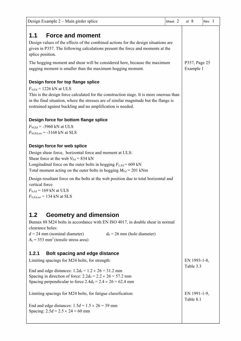
1.1 Force and moment
Design values of the effects of the combined actions for the design situations are given in P357. The following calculations present the force and moments at the splice position.
The hogging moment and shear will be considered here, because the maximum sagging moment is smaller than the maximum hogging moment.
P357, Page 25 Example 1
Design force for top flange splice
Ftf,Ed = 1226 kN at ULS This is the design force calculated for the construction stage. It is more onerous than in the final situation, where the stresses are of similar magnitude but the flange is restrained against buckling and no amplification is needed.
Design force for bottom flange splice
Fbf,Ed = -3960 kN at ULS Fbf,Ed,ser = -3168 kN at SLS
Design force for web splice
Design shear force, horizontal force and moment at ULS: Shear force at the web VEd = 834 kN Longitudinal force on the outer bolts in hogging FL,Ed = 609 kN Total moment acting on the outer bolts in hogging MEd = 201 kNm
Design resultant force on the bolts at the web position due to total horizontal and vertical force
Fb,Ed = 169 kN at ULS Fb,Ed,ser = 134 kN at SLS
1.2 Geometry and dimension
Bumax 88 M24 bolts in accordance with EN ISO 4017, in double shear in normal clearance holes:
d = 24 mm (nominal diameter) d0 = 26 mm (hole diameter) As = 353 mm2
(tensile stress area)
1.2.1 Bolt spacing and edge distance
Limiting spacings for M24 bolts, for strength:
End and edge distances: 1.2d0 = 1.2 26 = 31.2 mm Spacing in direction of force: 2.2d0 = 2.2 26 = 57.2 mm Spacing perpendicular to force 2.4d0 = 2.4 26 = 62.4 mm
EN 1993-1-8, Table 3.3
Limiting spacings for M24 bolts, for fatigue classification: EN 1991-1-9,
Table 8.1
End and edge distances: 1.5d = 1.5 26 = 39 mm Spacing: 2.5d = 2.5 24 = 60 mm

Design Example 2 – Main girder splice Sheet 3 of 8 Rev 1
1.2.2 Splice configuration
Consider the following splice configuration:
Elevation and web splice
Top flange (lower cover plates)
Bottom flange (upper cover plates)
Top flange splice
(Dimensions for lower covers) Bolt spacing: In line of force: e1 = 50 mm, p1 = 65 mm Perpendicular to force: e2 = 60 mm, p2 = 75 mm Overall dimension 470 195 mm. Thickness 10 mm
Bottom flange splice
(Dimensions for upper covers) Bolt spacing: In line of force: e1 = 50 mm, p1 = 65 mm Perpendicular to force: e2 = 60 mm, p2 = 75 mm Overall dimension 730 195 mm. Thickness 20 mm
Web splice
Bolt spacing: In line of force: e1 = 50 mm , p1 = 110 mm Perpendicular to force: e2 = 50 mm, p2 = 75 mm Overall dimension 210 925 mm. Thickness 10 mm
Minimum spacing, end and edge distance are satisfied. EN 1993-1-8, Table 3.3
1.3 Material properties
Duplex plate 1.4462
fyp = 460 N/mm2 fup = 640 N/mm2 EN 10088-4
E = 200000 N/mm2 EN 1993-1-4, Clause 2.1.3
Bumax 88 austenitic bolt (equivalent to carbon steel bolt of class property 8.8)
fyb = 640 N/mm2 fub = 800 N/mm2
11 @
7550
50
11050 50
11 @
7550
50
11050 50
50 2@65 110 2@65 50
60
75
60
50 2@65 110 2@65 50
60
75
60
50 4@65 110 4@65 50
60 7
5
60
50 4@65 110 4@65 50
60 7
5
60

Design Example 2 – Main girder splice Sheet 4 of 8 Rev 1
Slip factor
= 0.5 for duplex grit blasted surface2 SIROCO D7.21
1.4 Verification of connection resistance
Slip resistance of bolt
,
, SIROCO D7.21 EN 1993-1-8, Clause 3.9.1
, ,
,,
ks = 1.0 assuming normal round holes n = 2 for two friction surfaces in double shear
= 0.5 for duplex stainless steel plates with grit blasted surface finish SIROCO D7.21 1.25 and , 1.1
, 0.7 0.7 800 353 10 198 kN
, ,1.0 2 0.5
1.25198 158 kN
, ,,
,1.0 2 0.5
1.1198 180 kN
Shear resistance of bolts
At ULS
, EN 1993-1-4, Equation 6.2
1.25 EN 1993-1-4, Clause 5.1
= 0.5 and A = As since bolts are in accordance with EN ISO 4017 (fully threaded)
, 0.5 800 353
1.25113 kN
In double shear , 226kN
1.4.1 Top flange splice
There are 3 rows of bolts, with 4 bolts per row across the flange A category C connection is required (the design situation is for resistance against buckling of the beam during construction)
2 Execution and reliability of slip-resistant connections for steel structures using CS and SS
(SIROCO), RFCS research project, Deliverable 7.2 Guidelines for design and execution, 2018
Design Example 2 – Main girder splice Sheet 5 of 8 Rev 1
Slip resistance at ULS Σ , 3ⅹ4ⅹ , 12ⅹ158kN 1896 kN , 1226 kN
Note: In accordance with EN 1993-1-8 Clause 3.10.2, a block shear check should also be carried out.
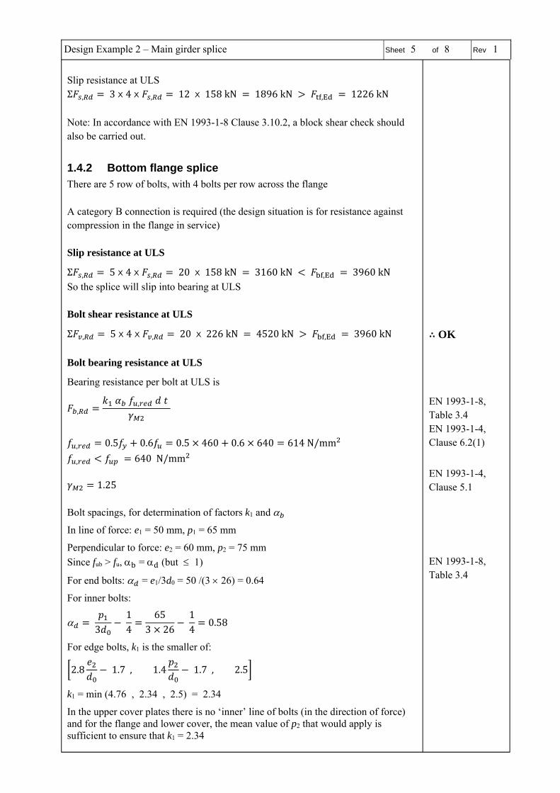
1.4.2 Bottom flange splice
There are 5 row of bolts, with 4 bolts per row across the flange A category B connection is required (the design situation is for resistance against compression in the flange in service)
Slip resistance at ULS
Σ , 5ⅹ4ⅹ , 20ⅹ158kN 3160 kN , 3960 kN
So the splice will slip into bearing at ULS Bolt shear resistance at ULS
Σ , 5ⅹ4ⅹ , 20ⅹ226kN 4520 kN , 3960 kN ∴ OK Bolt bearing resistance at ULS
Bearing resistance per bolt at ULS is
, ,
EN 1993-1-8, Table 3.4
EN 1993-1-4,
, 0.5 0.6 0.5 460 0.6 640 614 N/mm Clause 6.2(1)
, 640N/mm
1.25 EN 1993-1-4, Clause 5.1
Bolt spacings, for determination of factors k1 and
In line of force: e1 = 50 mm, p1 = 65 mm
Perpendicular to force: e2 = 60 mm, p2 = 75 mm
Since fub > fu, = (but 1)
For end bolts: = e1/3d0 = 50 /(3 26) = 0.64
For inner bolts:
3
14
653 26
14
0.58
EN 1993-1-8, Table 3.4
For edge bolts, k1 is the smaller of:
2.8 1.7, 1.4 1.7, 2.5
k1 = min (4.76 , 2.34 , 2.5) = 2.34
In the upper cover plates there is no ‘inner’ line of bolts (in the direction of force) and for the flange and lower cover, the mean value of p2 that would apply is sufficient to ensure that k1 = 2.34

Design Example 2 – Main girder splice Sheet 6 of 8 Rev 1
, 2.34 0.58 614 24 20
1.25320 kN
Bearing resistance of bolt group, with double covers Σ , 20 2 32012800kN , 3960kN
∴ OK
Slip resistance at SLS Σ , , 20ⅹ , , 20ⅹ180 kN 3600 kN , , 3168kN ∴ OK
1.4.3 Web splice
Note: The directions of the resultant forces are not parallel to a plate edge. Resistance is determined assuming the force is in the horizontal direction.
For end bolts (there is only a single row, transverse to the force): = = e1/3d0 = 50 /(3 26) = 0.64
EN 1993-1-8, Table 3.4
For edge bolts, k1 is the smaller of:
2.8 1.7, 1.4 1.7, 2.5
k1 = min (4.76 , 2.34 , 2.5) = 2.34
For inner bolts, k1 is the smaller of:
1.4 1.7, 2.5
k1 = min ( 2.34 , 2.5) = 2.34
, , 2.34 0.64 614 24 14
1.25247 kN
EN 1993-1-4, Clause 6.2(1)
where t is the minimum of the girder web thickness (14 mm) and the total cover plate thickness (20 mm).
The bearing resistance is greater than the resistance of the bolt in double shear (226 kN) so bolt double shear governs.
At ULS: , 158kN Fb,Ed = 169 kN
but , 226kN Fb,Ed = 169 kN
∴ OK
At SLS: , , 180 kN Fb,Ed,ser = 134 kN, there no slip at service limit ∴ OK Note: In accordance with EN 1993-1-8 Clause 3.10.2, a block shear check should also be carried out.
1.5 Resistance of cover plate
The cover plates are verified as members in tension or compression, in accordance with EN 1993-1-4.

Design Example 2 – Main girder splice Sheet 7 of 8 Rev 1
1.5.1 Top flange
The covers are in tension. Assume half of the load is carried in the lower cover plates. The force per cover plate thus 1226/4 307 kN
Area of gross cross section (A) = 195 10 = 1950 mm2
Area of net section (Anet) = 1950 − 2 26 10 = 1430 mm2 This is a Category C slip resistant connection, therefore the design tension resistance is given by:
, EN 1993-1-1, Clause 6.2.3(4)
1.1 EN 1993-1-4, Clause 5.1
,1430 460
1.110 598 kN 307 kN
The maximum spacing of bolts is 110 mm and the limiting spacing is given by Table 3.3 as the smaller of 14t (= 140 mm) and 200 mm. The spacing is satisfactory.
EN 1993-1-8, Table 3.3
1.5.2 Bottom flange
The covers are in compression. Assume half of the load is carried in the upper cover plates. The force per cover plate is 3960/4 990 kN.
= 0.698 for duplex 1.4462 EN 1993-1-4,
Table 5.2 c/t = 195/20 = 9.75 which is less than 14 = 9.77 and greater than 9 = 6.3 The cover plate section is Class 3 and for Class 1,2 or 3 cross-sections:
,
A = 1950 ⅹ20 = 3900 mm2
1.1
EN 1993-1-1, Clause 6.2.4 EN 1993-1-4, Clause 5.1
, 3900 460
1.110 1631 kN 990 kN
1.5.3 Web
Consider the stress in the cover plate on a line through the vertical row of bolts. The shear force VEd = 834/2 = 417 kN The axial force FL,Ed = 609/2 = 305 kN MEd = 201/2 = 101 kNm The stress at the bottom of the cover plate is thus
101 1010 925
6
305 10925 10
104 N/mm
The value of /t = 110/10=11, which is greater than 9 = 6.3 so buckling must be checked.
EN 1993-1-8, Table 3.3
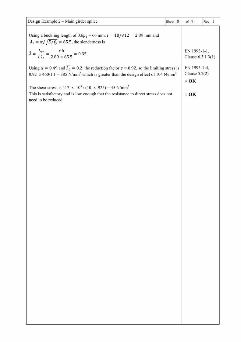
Design Example 2 – Main girder splice Sheet 8 of 8 Rev 1
Using a buckling length of 0.6 = 66 mm, 10/√12 2.89 mm and
/ / 65.5, the slenderness is
662.89 65.5
0.35 EN 1993-1-1, Clause 6.3.1.3(1)
Using 0.49 and 0.2, the reduction factor = 0.92, so the limiting stress is
0.92 ⅹ460/1.1 = 385 N/mm2 which is greater than the design effect of 104 N/mm2.
EN 1993-1-4, Clause 5.7(2)
∴ OK
The shear stress is 417 ⅹ 103 / (10 ⅹ 925) = 45 N/mm2
This is satisfactory and is low enough that the resistance to direct stress does not need to be reduced.
∴ OK