stainless steels jean-bernard vogtmmateng.eu/download/documents/presentations/2016-04... · •...
TRANSCRIPT

Modernization of two cycles (MA, BA) of competence-based curricula in Material
Engineering according to the best experience of Bologna Process
STAINLESS STEELS
Jean-Bernard VOGT
April 25, 2016 at NTUU-KPI, Kyiv, Ukraine

Jean-Bernard VOGT
Professor at ENSCL
Université Lille 1 Sciences et Technologies
Unité Matériaux Et Transformations (UMET) UMR CNRS 8207
Team Physical Metallurgy and Engineering Materials
Bâtiment C6
59655 Villeneuve d'Ascq Cedex – France
Phone: +33 3 20 43 40 35
Email : [email protected]
Lecturer Contact
J.B. VOGT26.04.2016 –NTUU-KPI – Kyiv - Ukraine

4
Lille

Very close to Lille

Located on the campus of Lille University of Sciences and Technologies
Founded in 1894
Master’s degree
400 students
3500 alumni students
140 professors and assistant professors
(40 from industry)
2 internationally recognized research laboratories
My Gradutae school: ENSCL: fact and figures

January 21, 2015 the MMATENG group at the main entrance of the school

21.01.2015 master classes, visit of laboratories and visit of Lille

Unité Matériaux et Transformations
Materials and Processing LaboratoryCNRS UMR 8207 –
Université Lille 1 et Ecole Nationale Supérieure de Chimie de Lille
umet.univ-lille1.fr
Director : Prof. Alexandre Legris
54 Assistant professors and professors, 12 researchers CNRS et 24 technicians

UMET
MMT
Molecular and therapeutic materials
PM
Physics of minerals
MPGM
Physical metallurgy and materials engineering
ISP
Engineering of polymeric systems
I – Modelling and simulation
II – Mechanical Properties and Effects of Environment
III – Microstructures
Team: Physical Metallurgy and Engineering Materials
17 professors and assistant professors, 4 technicians et administrative , 8 PhD
PIHM
Interface processes & hygiene of materials
Permanent staff 100
PhD + Postdoc 70

Jean-Bernard VOGT (prof.), Ingrid PRORIOL-SERRE (researcher),
Jérémie BOUQUEREL (ass. prof.) Jocelyn GOLEK (tech. eng.),
Damien CRETON (tech.)
PhD candidates: Claire SCHAYES, Carla CARLE,
Maxime DELBOVE, Hassine KACEM, Gulzar SEIDAMETOVA
II – Mechanical Properties and Effects of Environment
Environment-deformation interactions:
• Liquid metal embrittlement
• Liquid metal accelerated damage
• Hydrogen embrittlement (stainless steel single crystal)
• Oxidation effect on fatigue resistance
Industrial collaborations
CEA (nuclear), Valeo (Car equipment), ARC international (glass manufactory), BEKAERT, LBI, INOFORGE, EDF (electricity), ESRF
(synchrotron), ARCELOR MITTAL (steel), European Union (Gen IV)…
Mechanisms of cyclic plasticity of structural alloys:
• Role of nitrogen in stainless steels
• Partition of cyclic plasticity in dual phased microstructure steels
• Ultra fine grained stainless steels
• Fatigue induced phase transformation
• Fatigue of ODS copper
• Fatigue of coated material
TOPICS (Mechanical Properties and Effects of Environment group of UMET-MPGM)
Materials for energy and Materials for transportation

STAINLESS STEELS
INTRODUCTIONMICROSTRUCTURE vs ALLOYING ELEMENTSMAIN FAMILIES OF STAINLESS STEELSISSUES AND SOLUTIONSEXEMPLESIMPROVEMENT OF PROPERTIES

STAINLESS STEELS
INTRODUCTIONMICROSTRUCTURE vs ALLOYING ELEMENTSMAIN FAMILIES OF STAINLESS STEELSISSUES AND SOLUTIONSEXEMPLESIMPROVEMENT OF PROPERTIES
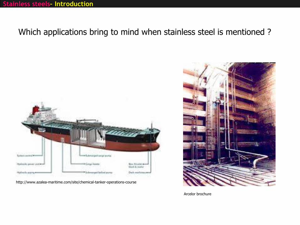
http://www.azalea-maritime.com/site/chemical-tanker-operations-course
Arcelor brochure
Which applications bring to mind when stainless steel is mentioned ?
Stainless steels– Introduction

Fe+Cr exposed to oxygen Cr reacts to form an oxide. • If high Cr content very thin layer of chromium(III) oxide as soon as the surface is exposed to the oxygen in the atmosphere
• Layer of oxide : very thin the metal can still shine through it, but it is thick enough to prevent the oxygen and water attacking the metal underneath no corrosion takes place
• Protection is permanent because even if the protective layer is scratched, the chromium in the steel will react with oxygen in the air to immediately re-form the protective layer.
1. Stainless steel • discovered by accident in 1913 by a Sheffield chemist - Harry Brearley when trying to
solve the problem of rapid wear tested a high Cr steel.Routine analysis of steel at that time involved dissolving it in nitric acid. The high Cr steel would not dissolve and also stayed shiny when left around in the lab
• Nevertheless already in 1820 Faraday (England) and Berthier (France) noticed the properties of Fe-Cr. They elaborated Fe-Cr alloys and noticed that these were more resistant to air environment than plain carbon steels
Stainless steels– Introduction
Criterion : stainless steel if %mass. Cr ≥ 10.5 and %mass.C ≤ 1.2
European standard: EN10088-1 (1995) 83 grades

Potential (V)
Inte
nsi
ty (
A)
Passivity Pitting
Anodic dissolution peak
Pitting resistance equivalent numbers (PREN): theoretical way of comparing the pitting corrosion resistance of various types of stainless steels, based on their chemical compositions.The most commonly used version of the formula isPREN = Cr + 3.3Mo + 16N or PREN = Cr + 3.3(Mo +0.5W) + 16N
Stainless steels– Introduction

STAINLESS STEELS
INTRODUCTION
MICROSTRUCTURE vs ALLOYING ELEMENTSMAIN FAMILIES OF STAINLESS STEELSISSUES AND SOLUTIONSEXEMPLESIMPROVEMENT OF PROPERTIES

2 INFLUENCE OF ALLOYING ELEMENTS ONMICROSTRUCTURES
Recall :a- Iron (BCC) : 0°C to 910°Cg- Iron (FCC) : 910°C to 1390°Cd- Iron (BCC) : 1390°C to 1539°C
Basic alloying elements in Fe : C, Cr, Ni
Stainless steels– Microstructure vs Alloying Elements

Effect of Cr : see Fe-Cr diagramme• ↓ Tf up to 25%Cr• stabilises a-phase, closes g domain• fully ferritic if Cr>13%• ordered phase: s (tetragonal) forms very slowly in the range
820°C 600°C for Cr≈30 à 60%s induces brittleness of the steel
Stainless steels– Microstructure vs Alloying Elements
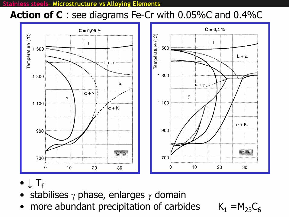
Action of C : see diagrams Fe-Cr with 0.05%C and 0.4%C
• ↓ Tf
• stabilises g phase, enlarges g domain• more abundant precipitation of carbides K1 =M23C6
Stainless steels– Microstructure vs Alloying Elements

Action of Ni: see diagrams Fe-Ni
• ↓ Tf
• considerably enlarges the austenitic domain : Ni: the base element for elaboration of austenitic stainless steels
Stainless steels– Microstructure vs Alloying Elements
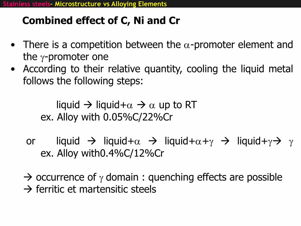
Combined effect of C, Ni and Cr
• There is a competition between the a-promoter element andthe g-promoter one
• According to their relative quantity, cooling the liquid metalfollows the following steps:
liquid liquid+a a up to RT
ex. Alloy with 0.05%C/22%Cr
or liquid liquid+a liquid+a+g liquid+g g
ex. Alloy with0.4%C/12%Cr
occurrence of g domain : quenching effects are possible ferritic et martensitic steels
Stainless steels– Microstructure vs Alloying Elements
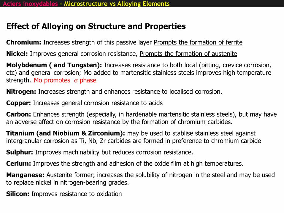
Effect of Alloying on Structure and Properties
Chromium: Increases strength of this passive layer Prompts the formation of ferrite
Nickel: Improves general corrosion resistance, Prompts the formation of austenite
Molybdenum ( and Tungsten): Increases resistance to both local (pitting, crevice corrosion, etc) and general corrosion; Mo added to martensitic stainless steels improves high temperature strength. Mo promotes s phase
Nitrogen: Increases strength and enhances resistance to localised corrosion.
Copper: Increases general corrosion resistance to acids
Carbon: Enhances strength (especially, in hardenable martensitic stainless steels), but may have an adverse affect on corrosion resistance by the formation of chromium carbides.
Titanium (and Niobium & Zirconium): may be used to stablise stainless steel against intergranular corrosion as Ti, Nb, Zr carbides are formed in preference to chromium carbide
Sulphur: Improves machinability but reduces corrosion resistance.
Cerium: Improves the strength and adhesion of the oxide film at high temperatures.
Manganese: Austenite former; increases the solubility of nitrogen in the steel and may be used to replace nickel in nitrogen-bearing grades.
Silicon: Improves resistance to oxidation
Aciers inoxydables – Microstructure vs Alloying Elements
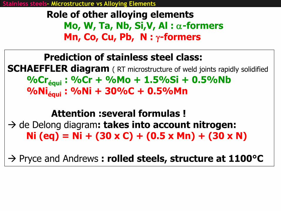
Role of other alloying elementsMo, W, Ta, Nb, Si,V, Al : a-formersMn, Co, Cu, Pb, N : g-formers
Prediction of stainless steel class:SCHAEFFLER diagram ( RT microstructure of weld joints rapidly solidified
%Créqui : %Cr + %Mo + 1.5%Si + 0.5%Nb%Niéqui : %Ni + 30%C + 0.5%Mn
Attention :several formulas ! de Delong diagram: takes into account nitrogen:
Ni (eq) = Ni + (30 x C) + (0.5 x Mn) + (30 x N)
Pryce and Andrews : rolled steels, structure at 1100°C
Stainless steels– Microstructure vs Alloying Elements

Role of other alloying elements
Mo, W, Ta, Nb, Si,V, Al : a-formersMn, Co, Cu, Pb, N : g-formers
Prediction of martensitic transformation temperature
Ms (°C): start temperature of martensitic transformation upon cooling
Ms(°C) : 1302 – 1667(C+N) – 33(Mn) – 42(Cr) –61(Ni) – 28(Si)
Md30 : temperature at which 50% of α’ martensite is obtained in a tension test for a true deformation of 0.3
Md30(°C) : 413 – 462(C+N) – 8.1(Mn) – 13.7(Cr) – 18.5(Mo) –9.2(Si)-9.5(Ni)
Stainless steels– Microstructure vs Alloying Elements

diagram SCHAEFFLER
Stainless steels– Microstructure vs Alloying Elements

ferriticAustenitic
austeno-ferritic (duplex) martensitic
Stainless steels– Microstructure vs Alloying Elements

STAINLESS STEELS
INTRODUCTIONMICROSTRUCTURE vs ALLOYING ELEMENTS
MAIN FAMILIES OF STAINLESS STEELSISSUES AND SOLUTIONSEXEMPLESIMPROVEMENT OF PROPERTIES

Group 1: 10-14%Cr type 409/410L): very basic steel
Group 2: 14-18%Cr, C<0,08%
e.g. AISI 430 the most widely used of ferritic steelsTo increase ductility, %C is in the range of 0.02% to 0.05
Group 3: 14-18%Cr + Ti, Zr, Nb as stabilization elem.
e.g. AISI 430Ti, 439, 441 fully ferritic steel
Group 4: 10-18%Cr and Mo> 0,5% e.g. AISI 434, 436, 444
For extra corrosion resistance fully ferritic steel and fully stabilizedThis grade is more sensitive to intermetallic precipitations (s, c)
Group 5: Cr>18% up to 30%Cr and Mo> 0.5%e.g. AISI 445, 447:25%<Cr<29% and 3%Mo, extra low C and N, 2%<Ni<4% superferritic
For extra corrosion resistance fully ferritic steel and fully stabilizedsensitive to embrittlement by intermetallic precipitations and difficult to weldFor most severe corrosion resistance to replace Ti alloys
Stainless steels– main families: ferritic stainless steels
3.1 Ferritic stainless steels: High Cr content
STANDARD FERRITIC STEELS SPECIAL FERRITIC STEELS
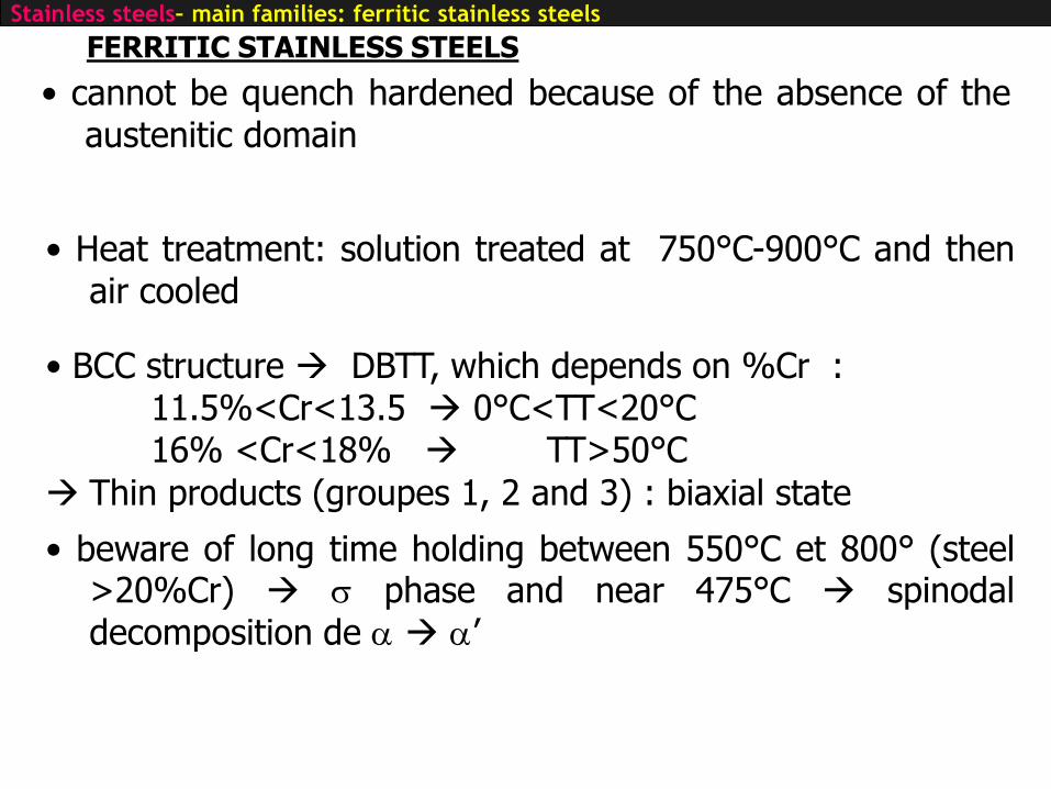
FERRITIC STAINLESS STEELS
• cannot be quench hardened because of the absence of theaustenitic domain
• BCC structure DBTT, which depends on %Cr : 11.5%<Cr<13.5 0°C<TT<20°C16% <Cr<18% TT>50°C
Thin products (groupes 1, 2 and 3) : biaxial state
• beware of long time holding between 550°C et 800° (steel>20%Cr) s phase and near 475°C spinodaldecomposition de a a’
• Heat treatment: solution treated at 750°C-900°C and thenair cooled
Stainless steels– main families: ferritic stainless steels

Ferritic stainless steelsfamily
Stainless steels– main families: ferritic stainless steels

3.2 Austentic stainless steels: High Cr, High Ni
Grade 18-10
X5CrNi18-10 Z6C18-09-AISI 304
Grade 17-12-Mo
X2CrNiMo17-12-2 Z2CND17-12- AISI 316L
Grade 25-20-Mo-Cu
superausténitique
X1NiCrMoCu31-27-4 Z2NCDU31-27
Sensitive to intergranular except if C is low (∼0.02%) or if Ti is added
Grades for severe corrosion
HNO3 (up to boiling ,
conc. 50%)
H3PO3
Sodium and Potassium hydroxide (NaOH and KOH)
Up to 100°C
HNO3 (up to boiling,
conc. 70%)
H3PO3, whatever conc. up to 80°C
HCl up to 2-3% at 20°C
HNO3 (up to boiling,
high concentration)
H3PO3, with presence of Cl-, HF, H6SiF6
HCl if conc.> 2-3%
Sodium and Potassium hydroxide (NaOH and KOH)
Up to 150°C
Stainless steels – main families: austenitic stainless steels

• FCC structure CFC at RT due to large amount of Ni
application in cryogenics
• Heat treatment: solution heat treatment at 1050°C-1150°C followed by quenching (hypertrempe)
• Possible destabilisation of g phase assisted by mechanical stressg e a’ or g a’
• g phase: non magnetic
Austenitic stainless steels
Stainless steels – main families: austenitic stainless steels
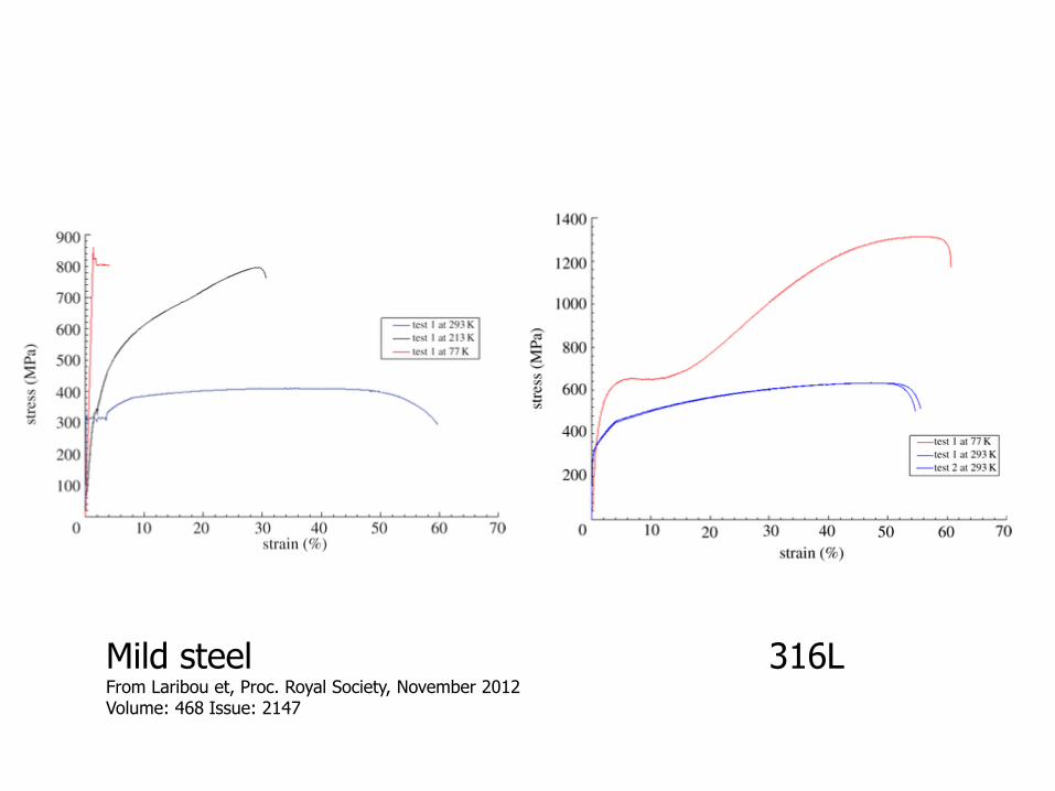
Mild steel 316LFrom Laribou et, Proc. Royal Society, November 2012Volume: 468 Issue: 2147

Austenitic stainlesssteels family
Stainless steels – main families: austenitic stainless steels
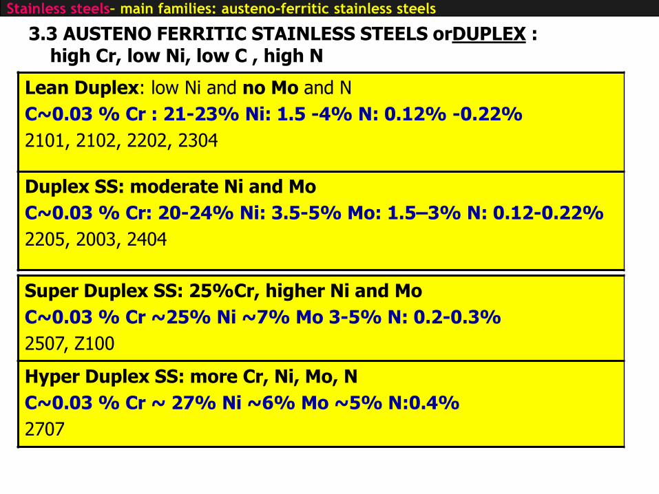
3.3 AUSTENO FERRITIC STAINLESS STEELS orDUPLEX :high Cr, low Ni, low C , high N
Lean Duplex: low Ni and no Mo and N
C~0.03 % Cr : 21-23% Ni: 1.5 -4% N: 0.12% -0.22%
2101, 2102, 2202, 2304
Duplex SS: moderate Ni and Mo
C~0.03 % Cr: 20-24% Ni: 3.5-5% Mo: 1.5–3% N: 0.12-0.22%
2205, 2003, 2404
Super Duplex SS: 25%Cr, higher Ni and Mo
C~0.03 % Cr ~25% Ni ~7% Mo 3-5% N: 0.2-0.3%
2507, Z100
Hyper Duplex SS: more Cr, Ni, Mo, N
C~0.03 % Cr ~ 27% Ni ~6% Mo ~5% N:0.4%
2707
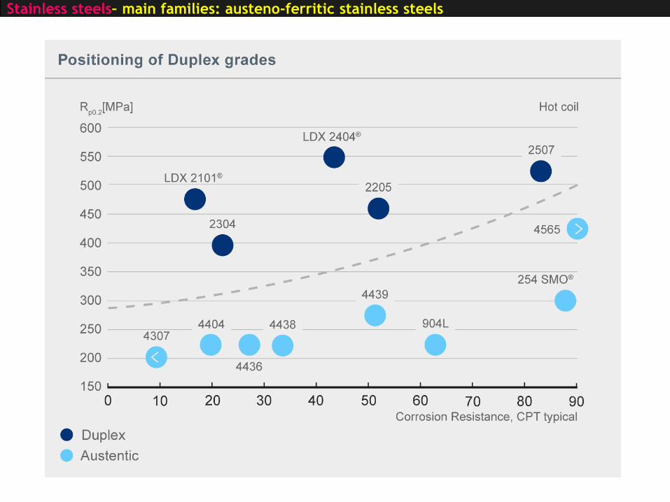
Stainless steels– main families: austeno-ferritic stainless steels

Stainless steels– main families: austeno-ferritic stainless steels

AUSTENO -FERRITIC STAINLESS STEELS or DUPLEX STEELS
• Cooling from a + g domain at 1050-1150°C : g phase contains enough g element promotors to avoid
transformationa phase is not affected
• Requires accurate control of chemical composition which ingeneral optimised to give rise to obtain 50%a-50%g
• Cooling must be rapid enough to avoid precipitation s phase
• Long term use: be aware of spinodal decomposition in ferrite(475°C embrittlement) working temperature limited to 350°C
• pay attention to partition of alloying elements in each phase:partitioning coefficient
Stainless steels– main families: austeno-ferritic stainless steels
Stainless steels– main families: austeno-ferritic stainless steels

3.4 MARTENSITIC STAINLESS STEELS : high Cr and high C
Group 1C~0.15% Cr : 11.5-13.5%
X12Cr13 - Z10C13 - AISI410
Rm= 600-900MPa
Limited Corrosion resistance
Weldable
Valves, fittings, scewand bolts …
Group 2C:0.2-0.4% Cr :12.5-14.5%
X20Cr13 - Z20C13 - AISI420
Rm=900-1500MPa
Medium corrosion resistance
Non easy weldable
Knives, forks, springs…
Group 3C : 0.6-1.2% Cr : 16-18
X105CrMo17 – Z100CD17-AISI440C
Very hard and brittle
Non soudable
Surgical tools
valves
Group 4C<0.1% Cr :16-18% Ni :2-4%
X5CrNiCu16-4 – Z7CNU17-4
Nuance haut de gamme
RE= 600-800MPa
Good corrosion resistance
weldable
Big wrought or castcomponents
Valves, pumps, turbines, propellershaft…
Stainless steels– main families: martensitic stainless steels

MARTENSITIC STAINLESS STEELS
• obtained by quench from austenitic domain and furthertempering Solution heat treated at: 950°C-1100°C cf equil. diag. Cooling rate: oil or water cf diag. TRC diag
tempering: 150°C-350°C : relaxation of residual stresses
550°C-750°C : softening tempering
Stainless steels– main families: martensitic stainless steels

Martensitic stainless steels family
Stainless steels– main families: martensitic stainless steels
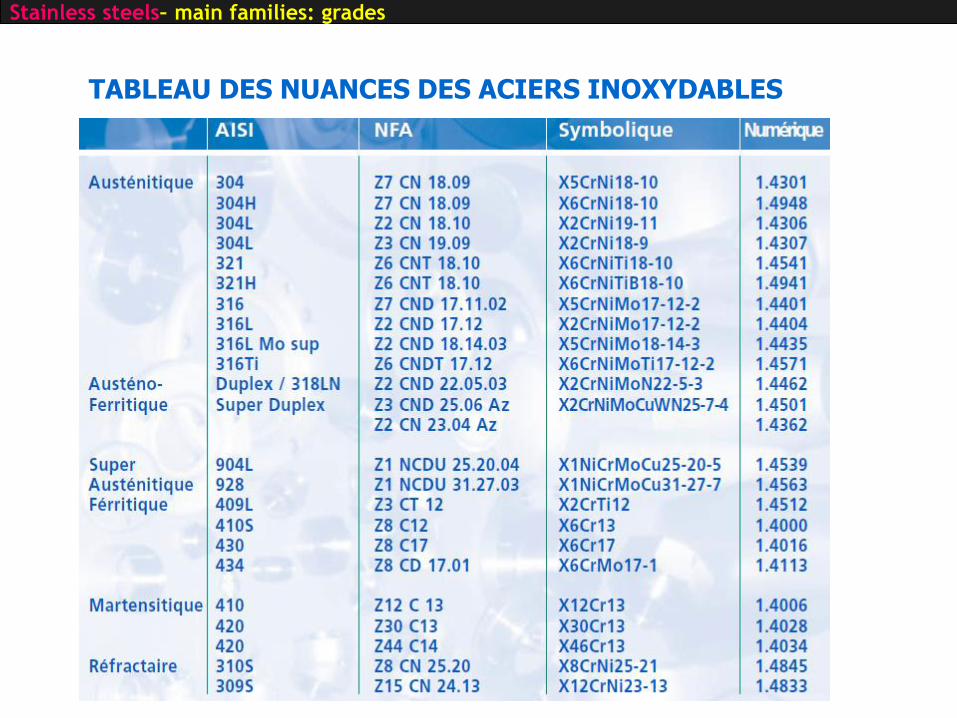
TABLEAU DES NUANCES DES ACIERS INOXYDABLES
Stainless steels– main families: grades

STAINLESS STEELS
INTRODUCTIONMICROSTRUCTURE vs ALLOYING ELEMENTSMAIN FAMILIES OF STAINLESS STEELS
ISSUES AND SOLUTIONSEXEMPLESIMPROVEMENT OF PROPERTIES

Metastability of austenitic stainless steels delayed cracking
Stainless steels – Issues
Delayed cracking: failure that may occur in certain materials after forming operations, e.g. deep drawing.Incubation time before fracture can be hours or days or even several weeks.Phenomenon related to coexistence of internal hydrogen, strain-induced α′-martensite and tensile residual stresses.The strain-induced martensitic phase makes the material more prone to delayed cracking, because it is harder and more brittle than austenite and because of high hydrogen diffusivity in bcc lattice
Deep drawn cups: (a) 301-2.0-S, (b) 201-2.0-S and (c) 204Cu-2.0-S. Inner diameter of the cups is 50 mm. ( Ortega et al, FFEMS 2014)

Secondary Phases of Concern in Stainless Steels (and Nickel Alloys)
(Cr,Fe,Mo)23C6 600 – 950° C Cubic
(Cr,Fe,Mo,Cb)6C 600 – 950° C Cubic
(Cr,Fe,Mo)7C6 950 - 1050° C Orthorhombic
Nitrides (Cr,Fe)2N 650 – 950° C Hexagonal
Sigma σ (Cr,Fe,Mo,Ni) 550 – 1050° C Tetragonal
Laves η (FeCr)2(Mo,Nb,Ti,Si) 550 – 900° C Hexagonal
Chi χ Fe36Cr12Mo10 600 – 900° C Cubic
Carbides
Phase Composition Temperature Range Structure
Stainless steels – Issues

Eun Joon Chuna et al M A T E R I A L S C H A R A C T E R I Z A T I O N 8 6 ( 2 0 1 3 ) 1 5 2 – 1 6 6
Stainless steels – Issues: σ phase
TEM micrographs and diffraction patterns of intermetallic phases (σ and χ phases).

σ phase:• often observed in various series of stainless steels and also in Ni alloys
• deterioration of stainless steels properties: mechanical property, corrosion resistance, and weldability
• can be precipitated under an elevated temperature environment 600°C <T<1 000°C e.g. casting, rolling, welding, forging, and aging precipitation
Stainless steels – Issues: σ phase
Microstructure of 2205 DSS after 850 °C-15 minutes M. V. Biezmaa Materials Research. 2013; 16(5): 965-969

σ phase:• The σ phase issues from the phase transformation of δ-ferrite to σ phase.
When δ → σ , the σ phase will precipitate in the high Cr-concentrated
region of δ-ferrite and is formed directly in δ-ferrite particles
• Cr < 20% no σ phase precipitation in austenitic stainless steels. However, σ phase can be formed quickly when Cr > 25%∼30% Difficult
to prevent when Cr > 20% in stainless steels
• Furthermore, σ phase can also precipitate from γ-austenite when there is no δ-ferrite in the stainless steels
Stainless steels – Issues: σ phase
Microstructure of 2205 DSS after 850 °C-15 minutes M. V. Biezmaa Materials Research. 2013; 16(5): 965-969

σ phase: can also precipitate from γ-austenite when there is no δ-ferrite in the stainless steels
Stainless steels – Issues: σ phase
Micrographs of the gauge portion of the tested sample (550 °C /150 MPa/85000 h), showing precipitation of sigma phase in AISI 316L(N),
from delta ferrite islands at austenite grain boundary and triple points
Ronald Lesley Plauta et al , Materials Research, Vol. 10, No. 4, 453-460, 2007
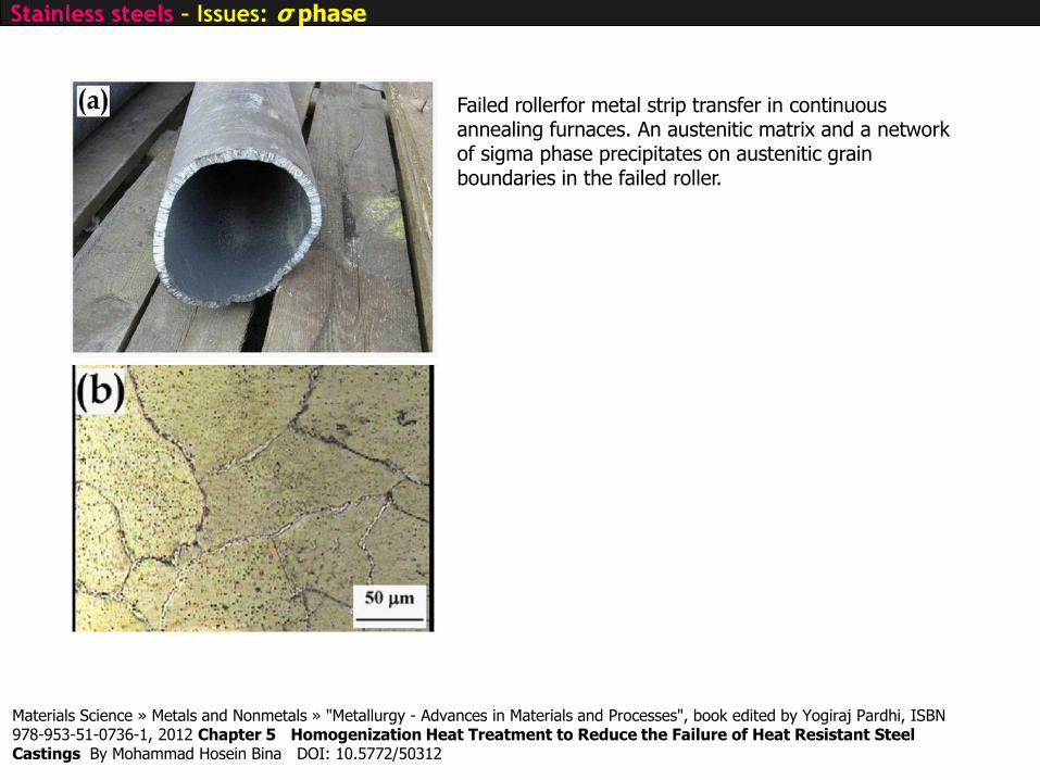
Failed rollerfor metal strip transfer in continuous annealing furnaces. An austenitic matrix and a network of sigma phase precipitates on austenitic grain boundaries in the failed roller.
Materials Science » Metals and Nonmetals » "Metallurgy - Advances in Materials and Processes", book edited by Yogiraj Pardhi, ISBN 978-953-51-0736-1, 2012 Chapter 5 Homogenization Heat Treatment to Reduce the Failure of Heat Resistant Steel Castings By Mohammad Hosein Bina DOI: 10.5772/50312
Stainless steels – Issues: σ phase

Sensitization of Stainless Steel
Stainless steels – Issues: sensitization of stainless steels
• Sensitization happens when SS held at an intermediate temperature (425°C – 815°C) Cr carbides precipitate at grain boundaries
• For the carbide to precipitate: must get Cr from the surrounding metal Cr depleted zone around the grain boundaries which will be less corrosion resistant, specifically to intergranular corrosion
• Sensitization particularly important in metals that are welded
unsensitized 304 stainless steell sensitized 304
CathodicCr23C6
Cr depleted zone(anodic)
grain(passiv)
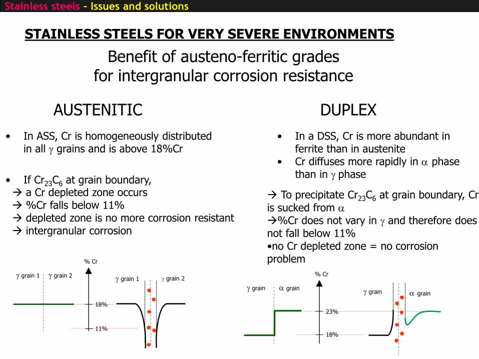
STAINLESS STEELS FOR VERY SEVERE ENVIRONMENTS
Benefit of austeno-ferritic grades for intergranular corrosion resistance
• In a DSS, Cr is more abundant in ferrite than in austenite
• Cr diffuses more rapidly in a phase than in g phase
• In ASS, Cr is homogeneously distributed in all g grains and is above 18%Cr
g grain 1 g grain 2
18%
11%
% Cr
• If Cr23C6 at grain boundary, a Cr depleted zone occurs %Cr falls below 11% depleted zone is no more corrosion resistant intergranular corrosion
g grain a grain
23%
18%
% Cr
g grain a grain
g grain 1 g grain 2
To precipitate Cr23C6 at grain boundary, Cr
is sucked from a%Cr does not vary in g and therefore does not fall below 11%•no Cr depleted zone = no corrosion problem
AUSTENITIC DUPLEX
Stainless steels – Issues and solutions

STAINLESS STEELS FOR HOSTILE ENVIRONNEMENTS
Stabilize as much as possible the protective oxide layer add Mo, W, N
H2S ? MnS
Avoid introduction of inclusions AOD and VOD
Avoid segregation S, P
Avoid precipitation of Cr23C6,
Maintain Cr in solid solution or precipitate TiC or NbC Add Ti and Nb
PI = %Cr + 3.3%Mo + X%N pitting indexX = 0 (ferritique), 16 (duplex), 30 (austénitique)
Stainless steels – Issues and solutions
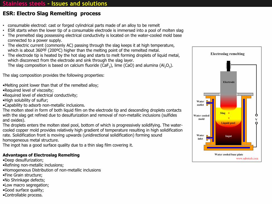
ESR: Electro Slag Remelting process
• consumable electrod: cast or forged cylindrical parts made of an alloy to be remelt• ESR starts when the lower tip of a consumable electrode is immersed into a pool of molten slag• The premelted slag possessing electrical conductivity is located on the water-cooled mold base
connected to a power supply.• The electric current (commonly AC) passing through the slag keeps it at high temperature,
which is about 360ºF (200ºC) higher than the melting point of the remelted metal.• The electrode tip is heated by the hot slag and starts to melt forming droplets of liquid metal,
which disconnect from the electrode and sink through the slag layer.The slag composition is based on calcium fluoride (CaF2), lime (CaO) and alumina (Al2O3).
The slag composition provides the following properties:
•Melting point lower than that of the remelted alloy;•Required level of viscosity;•Required level of electrical conductivity;•High solubility of sulfur;•Capability to adsorb non-metallic inclusions.The molten steel in form of both liquid film on the electrode tip and descending droplets contacts with the slag get refined due to desulfurization and removal of non-metallic inclusions (sulfidesand oxides).The droplets enters the molten steel pool, bottom of which is progressively solidifying. The water-cooled copper mold provides relatively high gradient of temperature resulting in high solidification rate. Solidification front is moving upwards (unidirectional solidification) forming sound homogeneous metal structure.The ingot has a good surface quality due to a thin slag film covering it.
Advantages of Electroslag Remelting•Deep desulfurization;•Refining non-metallic inclusions;•Homogeneous Distribution of non-metallic inclusions•Fine Grain structure;•No Shrinkage defects;•Low macro segregation;•Good surface quality;•Controllable process.
Stainless steels – Issues and solutions
STAINLESS STEELS
INTRODUCTIONMICROSTRUCTURE vs ALLOYING ELEMENTSMAIN FAMILIES OF STAINLESS STEELSISSUES AND SOLUTIONS
EXEMPLESIMPROVEMENT OF PROPERTIES


In 1969 a much smaller pier (left) was built using carbon steel rebar alongside the 1941 Progreso Pier (right).
In 2000, the smaller pier was no more visible
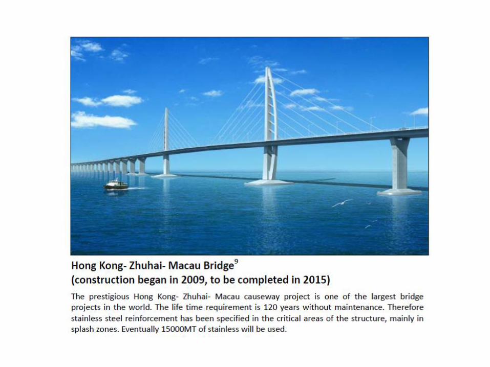

中国的巨型大桥香港新建的单跨斜拉桥寿命也许不像长城那样长,但其设计寿命也已长达120年。
Hong Kong stonecutter viaduc

STAINLESS STEELS
INTRODUCTIONMICROSTRUCTURE vs ALLOYING ELEMENTSMAIN FAMILIES OF STAINLESS STEELSISSUES AND SOLUTIONSEXEMPLES
IMPROVEMENT OF PROPERTIES
Improvement of mechanical properties
Research performed at UMET
Fatigue Behaviour of High Nitrogen
Austenitic and Duplex Stainless Steels
Work supported by USINOR (now ARCELOR),
European Community, VSG

Why Nitrogen in austenitic stainless steels ?
Small atoms : interstitials
Produces the most strongest solid solution hardening
Large number of sites in FCC : large variation in content
FREE !
Fatigue Behaviour of High Nitrogen Austenitic and Duplex Stainless Steel

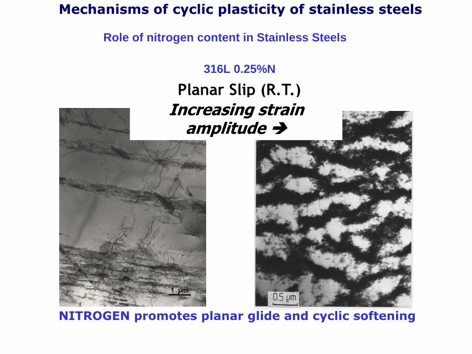
Mechanisms of cyclic plasticity of stainless steels
Role of nitrogen content in Stainless Steels
TYPE 316L : 0.03%N to 0.25%N
Nitrogen favours
cyclic softening
Nitrogen increases
cyclic stresses
Tests at R.T

Mechanisms of cyclic plasticity of stainless steels
Role of nitrogen content in Stainless Steels
TYPE 316L : 0.03%N to 0.25%N
Nitrogen increases
fatigue lives
Tests at R.T

Mechanisms of cyclic plasticity of stainless steels
Role of nitrogen content in Stainless Steels
316L 0.03%N
Increasing strain amplitude
Wavy Slip (R.T.)
Mechanisms of cyclic plasticity of stainless steels
Role of nitrogen content in Stainless Steels
316L 0.25%N
NITROGEN promotes planar glide and cyclic softening
Planar Slip (R.T.)
Increasing strain amplitude

Mechanisms of cyclic plasticity of stainless steels
CONCLUSIONS
Role of nitrogen content in Stainless Steels:
-Solid solution hardening
-Promotes planar slip INCREASES FATIGUE RESISTANCE
Better distribution of plastic deformation
Reduction of strain localisation
Delay in crack initiation
Low N steel
High N steelStress raiser

Improvement of mechanical properties
Research performed at UMET
Fatigue Behaviour of Fine Grained
Austenitic Stainless Steels

Fatigue behaviour of Ultra Fine Grained
austenitic stainless steels
Fatigue behaviour of UFG austenitic stainless steel
Work supported by ARCELOR and ADEME (agency for energy mastership)
In the frame of Stéphanie BROCHET PhD work

Motivation :
– Increase mechanical properties
– Reduce structure weight
– Decrease of material/production costs
Context

As
LNi100% g
80% a’, 20% cold worked
g
Coarse or fine ggrains, 100% recrystallized
Af ReversionCold rolling (80%)
Phase transformation
AnnealingT t
Optimization of experimental parameters (T, t) to obtain fine grains
HNi100% g
100% cold worked g
Coarse or fine g grains, 100%
recrystallized
Cold rolling (80%)
No phase transformation
T tAnnealing
Materials
11%Ni: HNi steel 9%Ni: LNi steel
Element C Mn Si Cr Cu Mo N
% (wt) 0,02 1,5 0,4 15,4 0,2 3,1 0,02

0
100
200
300
400
500
600
0,1 0,2 0,3 0,4 0,5 0,6 0,7 0,8
1/d0,5
(µm-0,5
)
Rp0,2
% (
MP
a)
10025 11,1 6,25 4
d (µm)
2,7 2,04 1,56
LNiC
LNiF
Choice of microstructures for fatigue tests : 2µm and 20µm
10µm
2µm
10µm
20µm
²
53.55052.153
%2,0
dR
p+
HNiC
HNiF
Materials
0
100
200
300
400
500
600
700
800
900
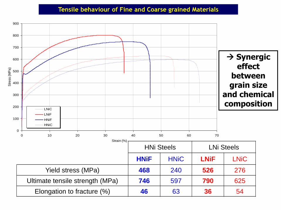
0 10 20 30 40 50 60 70
Strain (%)
Str
ess
(M
Pa
)
LNiC
LNiF
HNiF
HNiC
HNi Steels LNi Steels
HNiF HNiC LNiF LNiC
Yield stress (MPa) 468 240 526 276
Ultimate tensile strength (MPa) 746 597 790 625
Elongation to fracture (%) 46 63 36 54
Synergic
effect between grain size
and chemical composition
Tensile behaviour of Fine and Coarse grained Materials

Time (s)
Str
ain
(%
)
0
1
-1
- Total strain controlled (Re= -1)
- Strain rate 4.10-3s-1
Rolling direction
Sample thickness : 1 mm Aluminium stiffener
Fatigue testing : experimental
HN
iLN
i
0
100
200
300
400
500
600
700
800
1 10 100 1000 104
105
et=0,6%
et=0,8%
et=1,0%
et=1,2%
Str
ess
am
plit
ude (
MP
a)
Number of cycles
0
100
200
300
400
500
600
700
800
1 10 100 1000 104
105
et=0,6%
et=0,8%
et=1,0%
Str
ess
am
plit
ud
e (
MP
a)
Number of cycles
0
100
200
300
400
500
600
700
800
1 10 100 1000 104
105
et=0,6%
et=0,8%
et=1,0%
et=1,2%
Str
ess
am
plit
ude (
MP
a)
Number of cycles
0
100
200
300
400
500
600
700
800
1 10 100 1000 104
105
et=0,6%
et=0,8%
et=1,0%
et=1,2%
Str
ess
am
plit
ude (
MP
a)
Number of cycles
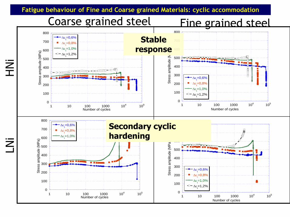
Coarse grained steel Fatigue behaviour of Fine and Coarse grained Materials: cyclic accommodation
Fine grained steel
Stable response
Secondary cyclic hardening

Origin of the secondary hardening :
Martensitic transformation quantification of a’
Fatigue behaviour of Fine and Coarse grained Materials: cyclic accommodation
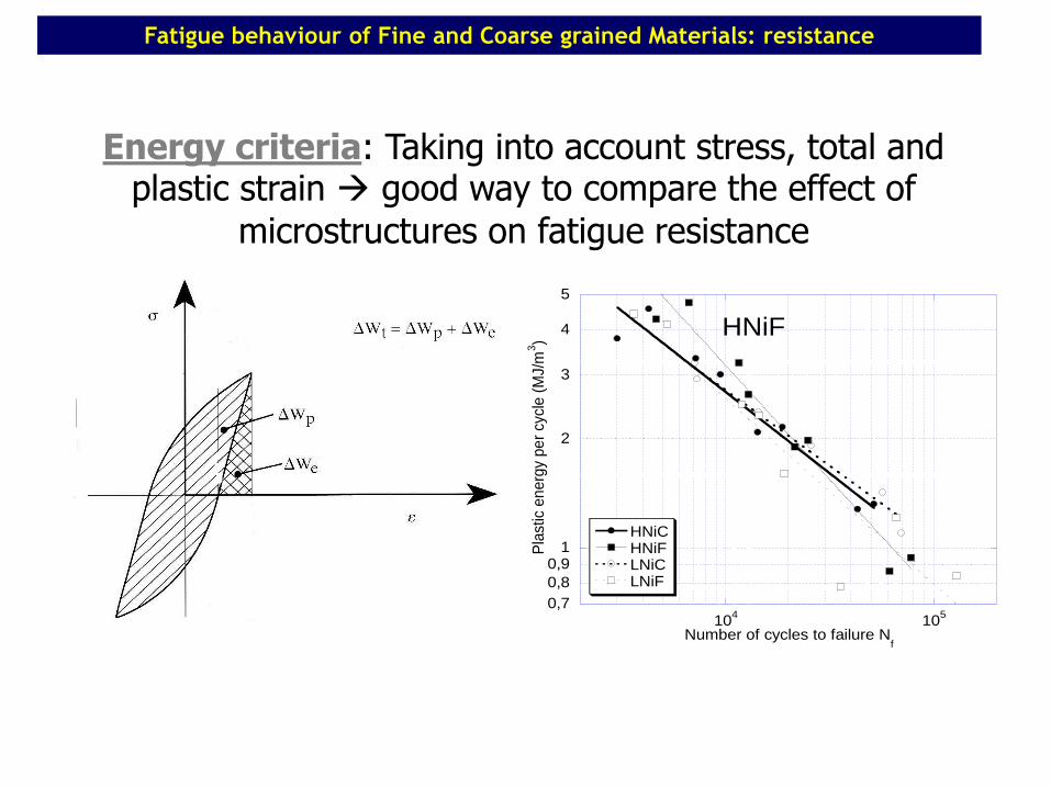
0,7
0,8
0,91
2
3
4
5
104
105
HNiCHNiFLNiCLNiF
Pla
stic
en
erg
y pe
r cy
cle
(M
J/m
3)
Number of cycles to failure Nf
HNiF
Energy criteria: Taking into account stress, total and plastic strain good way to compare the effect of
microstructures on fatigue resistance
Fatigue behaviour of Fine and Coarse grained Materials: resistance
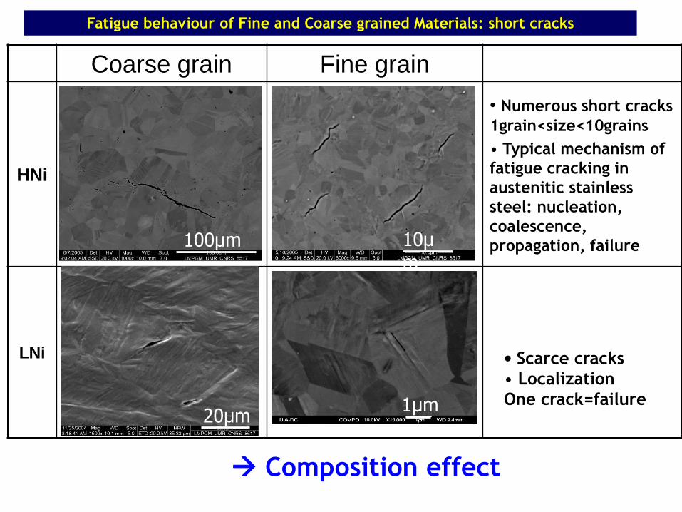
Coarse grain Fine grain
HNi
• Numerous short cracks
1grain<size<10grains
• Typical mechanism of
fatigue cracking in
austenitic stainless
steel: nucleation,
coalescence,
propagation, failure
LNi
Composition effect
100µm 10µm
1µm20µm
• Scarce cracks
• Localization
One crack=failure
Fatigue behaviour of Fine and Coarse grained Materials: short cracks
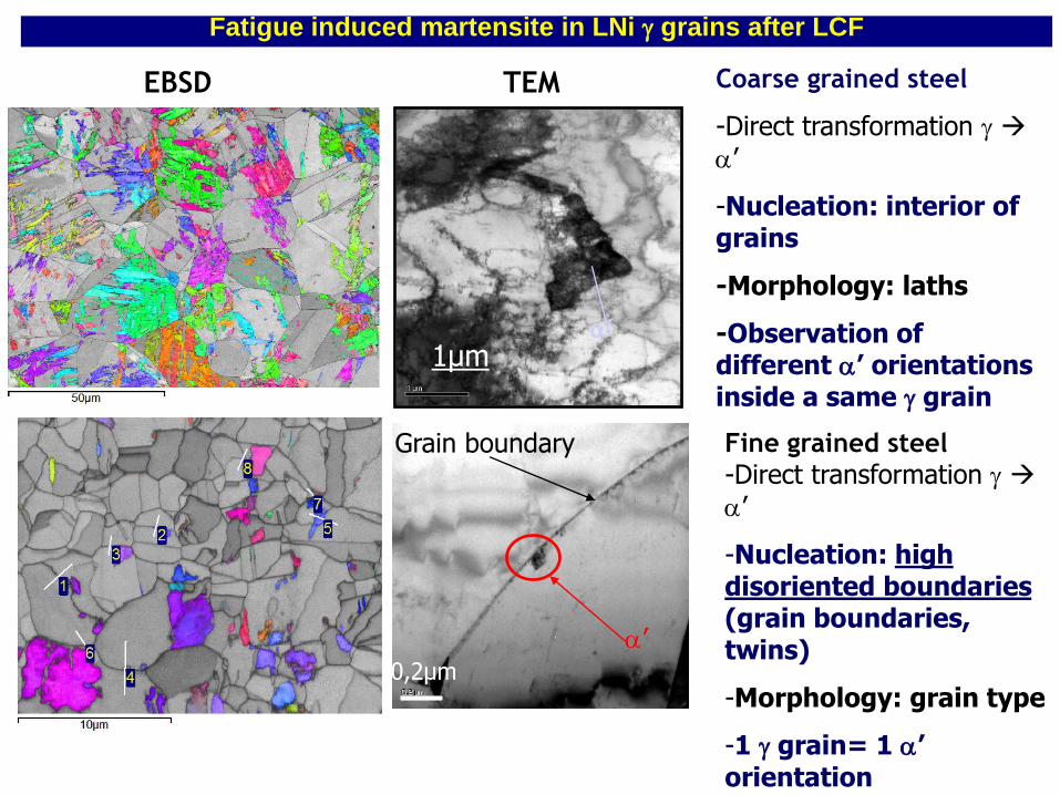
500nm
Fine grained steel
-Direct transformation g a’
-Nucleation: high disoriented boundaries(grain boundaries, twins)
-Morphology: grain type
-1 g grain= 1 a’ orientation
Grain boundary
a’0,2µm
Coarse grained steel
-Direct transformation g a’
-Nucleation: interior of grains
-Morphology: laths
-Observation of different a’ orientations inside a same g grain
1µma’
Fatigue induced martensite in LNi g grains after LCF
EBSD TEM
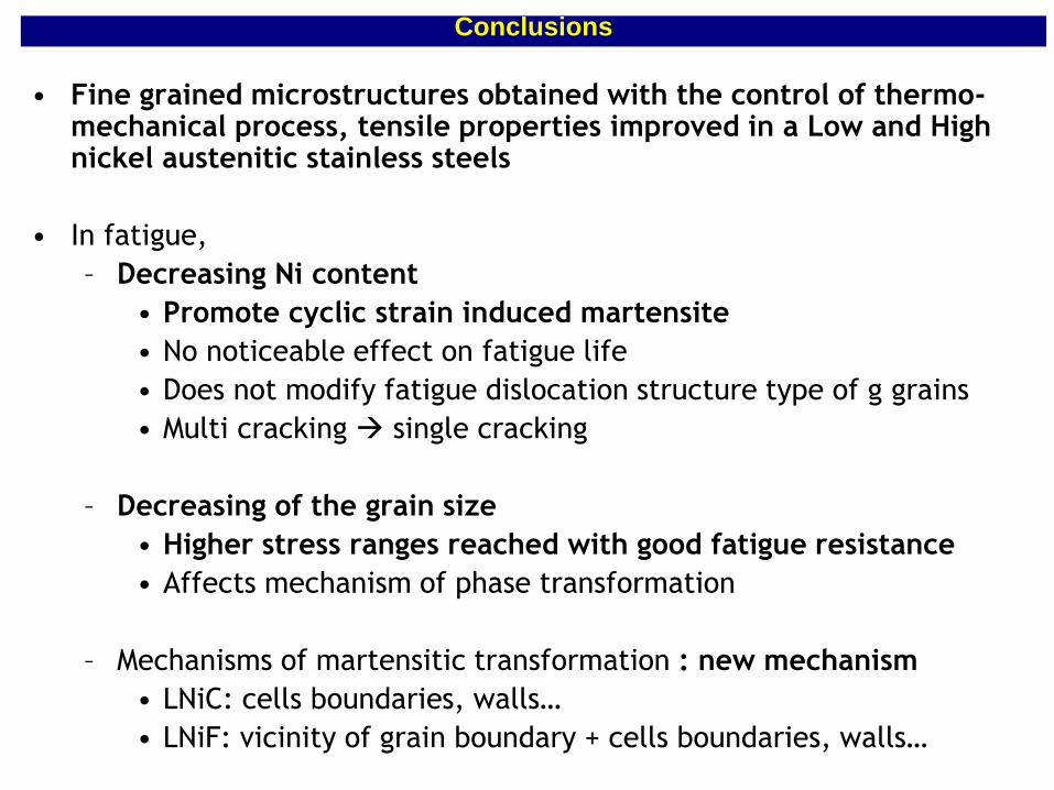
• Fine grained microstructures obtained with the control of thermo-mechanical process, tensile properties improved in a Low and High nickel austenitic stainless steels
• In fatigue,
– Decreasing Ni content
• Promote cyclic strain induced martensite
• No noticeable effect on fatigue life
• Does not modify fatigue dislocation structure type of g grains
• Multi cracking single cracking
– Decreasing of the grain size
• Higher stress ranges reached with good fatigue resistance
• Affects mechanism of phase transformation
– Mechanisms of martensitic transformation : new mechanism
• LNiC: cells boundaries, walls…
• LNiF: vicinity of grain boundary + cells boundaries, walls…
Conclusions
Final conclusion
With strong research activities in
metallurgy, stainless steels can be
produced conbining high mechanical and
high fatigue resistance with a reduced
cost
Final Conclusion

85
Дякуємо Вам за увагу