stamping colloidal photonic crystals: a facile way towards
TRANSCRIPT

Nanoscale
PAPER
Cite this: Nanoscale, 2015, 7, 1857
Received 9th October 2014,Accepted 9th December 2014
DOI: 10.1039/c4nr05934d
www.rsc.org/nanoscale
Stamping colloidal photonic crystals: a facile waytowards complex pixel colour patterns for sensingand displays†
Tao Ding,*a,b Stoyan K. Smoukovb and Jeremy J. Baumberg*a
Patterning of colloidal photonic crystals (CPCs) has been strongly investigated in recent years for sensing
and image displays. Rather than using traditional template-directed approaches, here microimprint litho-
graphy along with convective self-assembly is applied to generate complex CPC patterns that can be
adjusted to show single- or dual-colour patterns or composite CPC patterns possessing two different
colours. These composite CPC patterns show different wettability with water because of the surface
chemistry of the polymers and silica used. This dramatically transforms the structural colours upon liquid
infiltration. By mixing different ethanol concentrations with water, the infiltration efficiency can be further
improved and easily read out from changes in reflection intensity and spectral peak shifts. Integrating
these nano-architectures into devices can thus yield function as image displays and as sensors for
solvents.
Introduction
A colloidal photonic crystal (CPC) is a periodically arrangedarray of submicron particles that selectively inhibits the trans-mission of light, or traps certain optical wavelengths. TheseCPCs hold great promise for next-generation optical compu-tation and communication components, because of their scal-able, cost-effective and straightforward fabrication.1–5 Becauseof this, patterning of CPCs has also been intensively studiedover the last decade.6 However, unintentional defects andcracks along with incomplete bandgaps still leave CPCs farfrom being able to target such photonics devices.7–9 On theother hand, colour pattern generation that can respond toenvironmental changes or stimuli has been intensively investi-gated in the last few years for sensing and image displays.10–15
This integrated colour patterning system has unique advan-tages over competitive organic colour systems (as CPCs arenon-toxic, environmentally friendly and non-photo-bleaching)and can be actively tuned with external fields for displays orcombined with different materials for sensing applications.
The techniques that have been developed for patterningCPCs involve lithography,16–18 template-directed self-assembly19–28 and other less conventional approaches likecapillary assisted deposition29 and injet printing.30–32
However, the processes are either complicated and time con-suming or expensive. For example, lithography approachesrequire sophisticated mask alignment for UV exposuresand the procedure is quite complicated.16 The templatingapproaches require fabrication of pre-patterned chemical orphysical templates which can only be used once. The un-conventional approaches,29,33 though scalable, are only appli-cable to certain types of patterns with simple arrangements,and are thus not very versatile or generic. Therefore facile fab-rication of large-scale patterned CPCs still remains a greatchallenge but is strongly desirable.
Nano- and micro-imprinting techniques are prominent forlarge-scale surface patterning of polymer films but seldomhave been applied for patterning of CPCs.34 The group of Yanget al. attempted to apply microcontact printing35,36 to patterncolloidal crystal films but this resulted in only surface pat-terned morphologies with no distinctive structural colours.Key to the success of applying microimprinting techniques topattern CPCs is the control and modification of the mechan-ical stability of the CPC films, which is strongly dependent onthe imprinting temperature and pressure. Here, we fabricatecomplex pixel patterns of CPCs based on microimprint litho-graphy techniques which provide a highly facile and cost-effective way for large scale patterning of CPCs. Two scenariosare discussed here. If the CPCs made of poly(styrene-methyl
†Electronic supplementary information (ESI) available: SEM images of thestamps, optical image, reflection spectra, and table of peak wavelength andintensity. See DOI: 10.1039/c4nr05934d
aNanophotonics Centre, Cavendish Laboratory, University of Cambridge, CB3 0HE,
UK. E-mail: [email protected], [email protected]; Tel: +44 (0)1223 760945bDepartment of Materials Science and Metallurgy, 27 Charles Babbage Road;
University of Cambridge, CB3 0FS, UK. Fax: +44 (0)1223 762088;
Tel: +44 (0)1223 334435
This journal is © The Royal Society of Chemistry 2015 Nanoscale, 2015, 7, 1857–1863 | 1857
Ope
n A
cces
s A
rtic
le. P
ublis
hed
on 1
0 D
ecem
ber
2014
. Dow
nloa
ded
on 2
/23/
2022
1:3
8:08
PM
. T
his
artic
le is
lice
nsed
und
er a
Cre
ativ
e C
omm
ons
Attr
ibut
ion
3.0
Unp
orte
d L
icen
ce.
View Article OnlineView Journal | View Issue
methacrylate-acrylic acid) (Poly(St-MMA-AA)) are annealedbefore imprinting, the whole film maintains its integrity butcannot easily be lifted-off from the stamps. In this case thestructural colours of the printed regions are blue-shiftedbecause of the decreased lattice spacing along the film normaldue to compression. Therefore a second approach was alsoused, in which CPCs with dual colours are generated. Withoutany pre-annealing, the locally imprinted regions can beentirely lifted-off by the stamps, thus generating negative pat-terns on the substrate. Depositing another layer of silica CPCsin-between Poly(St-MMA-AA) CPC patterns leads to dual colourpatterns. Such pixel colour features of these CPC patterns canpotentially be applied in image display applications. Becauseof the hydrophobicity difference between silica and Poly(St-MMA-AA), the optical response of the two patterns is alsoquite different in different solvents. Therefore, these films canbe used as sensors with direct colour readout. The differentresponse of the patterns to solvents can also be applied inanti-counterfeiting applications.
Results and discussion
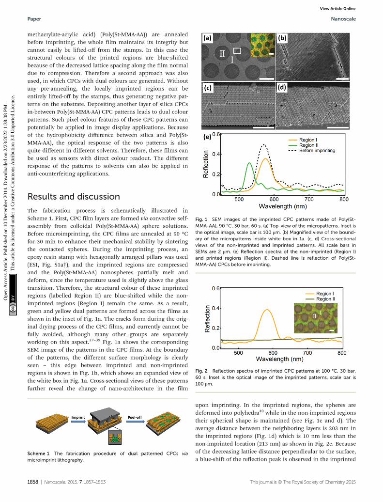
The fabrication process is schematically illustrated inScheme 1. First, CPC film layers are formed via convective self-assembly from colloidal Poly(St-MMA-AA) sphere solutions.Before microimprinting, the CPC films are annealed at 90 °Cfor 30 min to enhance their mechanical stability by sinteringthe contacted spheres. During the imprinting process, anepoxy resin stamp with hexagonally arranged pillars was used(ESI, Fig. S1a†), and the imprinted regions are compressedand the Poly(St-MMA-AA) nanospheres partially melt anddeform, since the temperature used is slightly above the glasstransition. Therefore, the structural colour of these imprintedregions (labelled Region II) are blue-shifted while the non-imprinted regions (Region I) remain the same. As a result,green and yellow dual patterns are formed across the films asshown in the inset of Fig. 1a. The cracks form during the orig-inal drying process of the CPC films, and currently cannot befully avoided, although many other groups are separatelyworking on this aspect.37–39 Fig. 1a shows the correspondingSEM image of the patterns in the CPC films. At the boundaryof the patterns, the different surface morphology is clearlyseen – this edge between imprinted and non-imprintedregions is shown in Fig. 1b, which shows an expanded view ofthe white box in Fig. 1a. Cross-sectional views of these patternsfurther reveal the change of nano-architecture in the film
upon imprinting. In the imprinted regions, the spheres aredeformed into polyhedra40 while in the non-imprinted regionstheir spherical shape is maintained (see Fig. 1c and d). Theaverage distance between the neighboring layers is 203 nm inthe imprinted regions (Fig. 1d) which is 10 nm less than thenon-imprinted location (213 nm) as shown in Fig. 2c. Becauseof the decreasing lattice distance perpendicular to the surface,a blue-shift of the reflection peak is observed in the imprinted
Fig. 1 SEM images of the imprinted CPC patterns made of Poly(St-MMA-AA), 90 °C, 30 bar, 60 s. (a) Top-view of the micropatterns. Inset isthe optical image, scale bar is 100 μm. (b) Magnified view of the bound-ary of the micropatterns inside white box in 1a. (c, d) Cross-sectionalviews of the non-imprinted and imprinted patterns. All scale bars inSEMs are 2 μm. (e) Reflection spectra of the non-imprinted (Region I)and printed regions (Region II). Dashed line is reflection of Poly(St-MMA-AA) CPCs before imprinting.
Fig. 2 Reflection spectra of imprinted CPC patterns at 100 °C, 30 bar,60 s. Inset is the optical image of the imprinted patterns, scale bar is100 μm.
Scheme 1 The fabrication procedure of dual patterned CPCs viamicroimprint lithography.
Paper Nanoscale
1858 | Nanoscale, 2015, 7, 1857–1863 This journal is © The Royal Society of Chemistry 2015
Ope
n A
cces
s A
rtic
le. P
ublis
hed
on 1
0 D
ecem
ber
2014
. Dow
nloa
ded
on 2
/23/
2022
1:3
8:08
PM
. T
his
artic
le is
lice
nsed
und
er a
Cre
ativ
e C
omm
ons
Attr
ibut
ion
3.0
Unp
orte
d L
icen
ce.
View Article Online

regions from 565 nm (dashed) to 535 nm (green solid line). Inthe non-imprinted region, the Poly(St-MMA-AA) nanospheresare also subject to lateral squeezing and partial melting fromproximity to the imprinted regions, however the reflectionpeak produced now slight red-shifts from 565 to 575 nm(orange solid line).
The colour patterns generated by microimprinting canfurther be tuned by adjusting the imprinting conditions. Themost critical factor is the imprinting temperature. If highertemperatures (100 °C) are applied during imprinting, meltingoccurs in the imprinted region, thus destroying any photonicstructure and colour after peeling off the stamp which leavesonly a single colour pattern (inset Fig. 2). The reflectionspectra (Fig. 2) show that the reflection peak disappears in theprinted region (Region II) while the non-imprinted region(Region I) maintains its light green structural colour withreflection peak at 580 nm. Further increasing the imprintingtemperature (110 °C) leads to complete loss of structuralcolour over the whole film as shown in ESI Fig. S2.†
A key factor to successful dual patterning is the pre-anneal-ing step of the CPCs before imprinting, which enhances themechanical stability of the Poly(St-MMA-AA) CPC on the sub-strate. Otherwise the weak contact between the hydrophobicPoly(St-MMA-AA) CPC films and the hydrophilic glass substratecauses the patterned regions to easily peel off, resulting in theimprinted regions being lifted off the substrate together withthe stamp, as schematically shown in Fig. 3a. The resultingCPCs left behind on the substrate, together with the invertedpatterns sticking to the stamp, are shown in the insets ofFig. 3b. The reflection spectra of these corresponding patterns(peaked at 540 and 574 nm) are almost fully consistent withthose in Fig. 1e.
Based on this type of patterning, we are able to colloidallyassemble another layer of any different type of CPC around
these lifted-off CPC pads, for example one which is insteadmade of silica nanospheres. The whole process is depicted inFig. 4a. The first CPC patterns are formed with a stamp madeof circular holes arranged on a square lattice (ESI, Fig. S1b†).After this, the SiO2 CPCs are deposited on the substrate via theconvective self-assembly method at low concentration (0.1 v/v%)thereby generating dual patterns formed of SiO2 and Poly-(St-MMA-AA) spheres (Fig. 4c). The SEM images in Fig. 4b–eshow the details of the micropatterns formed after these twosteps. The optical images of Fig. 4(b and c) demonstrate thatthe silica CPC patterns (blue structural colour) are well in-filtrated between the patterns of Poly(St-MMA-AA) CPCs (greenstructural colour). The SEM images of Fig. 4(d and e) clearlyshow that the empty space between Poly(St-MMA-AA) patternsis filled with silica CPCs after the deposition step. At theboundary between these two regions, clearly-resolved spheresizes of 190 and 241 nm can be identified (Fig. 4e). The reflec-tion spectra of the entire patterned films (ESI Fig. S3†) havetwo reflection peaks located at 419 and 564 nm, representingthe photonic bandgaps of Poly(St-MMA-AA) and SiO2 CPCs,respectively.
One unique advantage of the dual patterns made ofdifferent materials is that they have different hydrophobicities.This can result in different filling fractions when filled withaqueous liquid, thus resulting in different changes in reflec-tion intensity and peak wavelength. Here water and ethanolare used as two contrasting liquid fillers, which producedistinctive changes in the reflection spectra of patterns as sum-
Fig. 3 (a) Scheme of fabrication of CPC patterns by imprint lithography.(b) Reflection spectra of CPC patterns made by soft lithography. Insetsare the optical images of CPC patterns on the substrate (left) and on thestamp (right). Scale bars are 100 μm.
Fig. 4 (a) Scheme to fabricate composite dual CPC patterns made ofPoly(St-MMA-AA) and SiO2. (b) Optical image of Poly(St-MMA-AA) CPCpatterns and (c) dual patterns of Poly(St-MMA-AA) and SiO2. Scale barsare 100 μm. Insets are SEM images of the micropatterns, scale bars are10 μm. (d, e) Magnified view at the boundary of the CPC patterns in (b,c), red dashed lines in (e) show boundary between the two differentsized CPCs, scale bars are 1 μm.
Nanoscale Paper
This journal is © The Royal Society of Chemistry 2015 Nanoscale, 2015, 7, 1857–1863 | 1859
Ope
n A
cces
s A
rtic
le. P
ublis
hed
on 1
0 D
ecem
ber
2014
. Dow
nloa
ded
on 2
/23/
2022
1:3
8:08
PM
. T
his
artic
le is
lice
nsed
und
er a
Cre
ativ
e C
omm
ons
Attr
ibut
ion
3.0
Unp
orte
d L
icen
ce.
View Article Online

marized in Fig. 5. We selectively detect the spatially-localizedreflection spectra of the patterned regions of SiO2 and Poly-(St-MMA-AA) by using confocal microscopy, yielding reflectionpeaks at 423 nm for SiO2 and 562 nm for Poly(St-MMA-AA).After water infiltration, the colour of the silica patternsalmost fades away completely, while the colour of the Poly-(St-MMA-AA) patterns change from green to yellow (opticalimages in insets of Fig. 5a). The reflection peaks of SiO2 CPCsred-shift to 462 nm and the peak intensity decreases to 3.2%because the infiltration with water lowers the refractive indexcontrast and increases the average reflective index of the films.In contrast for the Poly(St-MMA-AA) CPC patterns, the reflec-tion peak only red-shifts to 575 nm while the intensity remainsabove 15%.
This much reduced shift compared to the silica CPC pat-terns is mainly attributed to different filling ratios of waterinto the CPCs, caused by the different surface tension ofhydrophilic silica and hydrophobic Poly(St-MMA-AA). Thesurface of Poly(St-MMA-AA) should be hydrophilic initially dueto the presence of poly(acrylate acid), but imprinting above Tgcan result in rearrangement of the polymer chains, whichmakes the surface hydrophobic. For the hydrophilic silica, thewater wets well within the interstices of the CPCs, producingmore infiltration and lower refractive index contrast. On theother hand, for the hydrophobic Poly(St-MMA-AA) CPCs, thewetting of water within the interstices is poor due to the highsurface tension, which results in lower filling ratios and lessshift of the reflection peak. If instead ethanol (EtOH) is usedas the infiltration solvent, the reflection peaks dramatically
red-shift from 563 to 614 nm and the colour of the Poly(St-MMA-AA) CPC patterns changes from green to red (insetFig. 5b). The reflection peak of silica CPC patterns now almostvanishes (Fig. 5b), due to the close match of refractive indicesbetween EtOH and silica. Such shifts of peak wavelength andchanges of intensity are fully reversible and can be repeatedmany times as shown in ESI Fig. S4.†
By changing the volume ratios of mixtures of H2O andEtOH, the surface tension of the liquid can be tuned, whichchanges their infiltration ratios within the CPCs. Hence thereflection peaks of both Poly(St-MMA-AA) and SiO2 CPCpatterns now red-shift gradually with increasing volume ratioof EtOH (Fig. 6a and b). Note, it is harder to identify the reflec-tion peaks from SiO2 CPC patterns above 50% v/v. The changeof reflection peak positions and intensity are summarized inFig. 6c. Noteworthy is that these two patterns show non-uniform shifts of the reflection peaks, from 575 to 611 nm (inPoly(St-MMA-AA) CPC patterns) and 462 to 465 nm (in SiO2
CPC patterns, before disappearing), when varying the solvent.These red-shifts have a contribution from the small
increase in the average refractive index expected when repla-cing water with EtOH. However the peak position for Poly(St-MMA-AA) CPCs is predicted to be 600 nm after full infiltrationof water, which is much larger than the experimental valueobtained here (shown in ESI Table S1†). Therefore, rather thanthe increase of overall refractive index of the liquid beingimportant for the red-shift, it is instead the improved fillingcaused by the lower surface tension which is produced as thecontent of EtOH is increased. It is apparent in Fig. 6d that thekink in the reflection peak tuning of Poly(St-MMA-AA) CPCs (atvolume fraction 50%) is at the expected point when the CPCsare fully infiltrated by the solvents (Fig. 7c). The slower rate ofred-shift observed after this point should then be caused solelyby the increase of the average refractive index. The wetting
Fig. 6 Reflection spectra of CPC patterns in response to liquid mixtureswith different ratios of ethanol and water. (a) SiO2 CPCs, (b) Poly(St-MMA-AA) CPCs. (c) Change of wavelength and intensity of the reflectionpeaks (background subtracted) of the SiO2 and Poly(St-MMA-AA) CPCpatterns. (d) Relative intensity and shift of reflection peaks for differentratios of solvents.
Fig. 5 The reflection spectra of dual CPC patterns made of Poly(St-MMA-AA) and SiO2 in response to different liquids, (a) H2O and (b)ethanol. Insets are optical images of the CPC patterns before and afterliquid infiltration. Scale bars are 100 μm.
Paper Nanoscale
1860 | Nanoscale, 2015, 7, 1857–1863 This journal is © The Royal Society of Chemistry 2015
Ope
n A
cces
s A
rtic
le. P
ublis
hed
on 1
0 D
ecem
ber
2014
. Dow
nloa
ded
on 2
/23/
2022
1:3
8:08
PM
. T
his
artic
le is
lice
nsed
und
er a
Cre
ativ
e C
omm
ons
Attr
ibut
ion
3.0
Unp
orte
d L
icen
ce.
View Article Online

profiles of the solvents with different volume fractions of EtOHare schematically shown in Fig. 7 to clarify this coupling tothe photonic tuning. Additional evidence for the infiltrationmechanism is that the intensity and peak position of Poly-(St-MMA-AA) CPC patterns depend strongly on solvent compo-sition while little change is seen for SiO2 CPC patterns(Fig. 6d). This indicates that changes of refractive index mostlyarise from solvent loading effects. Changes of surface tensioninducing changes of filling ratio play the dominant role incolour changes of this dual CPC pattern system.
The size feature of the patterns could be enlarged for anumber of potential applications. One is based on a counter-feit detection mechanism in which a film dipped into differentalcohols changes colour selectively to reveal different symbolsor text. This can be utilized in two ways. It can be used toverify the specific gravity or solvent concentration of commer-cial alcohols in a very quick and readily discernible measure-ment. It can also be simply used to verify a polymer-basedcurrency banknote or credit card, by immersion in water andvodka, and checking the different symbols that appear. A widevariety of optical effects can be developed from this patterningprotocol to extend the range of operations.
ExperimentalMicroimprint lithography of CPCs made of Poly(St-MMA-AA)
The Poly(St-MMA-AA) latex spheres of diameter 240 nm weresynthesized as in previous reports41 and self-assembled toform 3D CPCs via convective self-assembly.42 Typically 0.1 wt%of Poly(St-MMA-AA) beads were dispersed in water, and a verti-cally-oriented glass slide inserted and left to dry under con-stant temperature of 65 °C for 24 h. The CPCs of Poly(St-MMA-AA) are coated onto the surface of the glass slides duringthis drying process. Afterwards, the Poly(St-MMA-AA) CPCs canbe pre-annealed at 90 °C for 30 min.
The imprinting condition used mostly here is 90 °C, 20 barfor 30 s and is implemented and monitored with an ObducatNanoimprinter.
Fabrication of composite CPC patterns
For the composite patterns, the Poly(St-MMA-AA) CPC patternswere first created by imprint lithography of the non-annealedsamples of Poly(St-MMA-AA) CPCs. The substrate on which thePoly(St-MMA-AA) CPC patterns were laid down was immersedin an ethanol dispersion of silica beads (of diameter 185 nm,
at 0.1 wt%) and placed in an oven preheated to 36 °C. After24 h the dispersion was dried and the silica beads self-assembled around the Poly(St-MMA-AA) CPCs patterns, toform dual composite CPC patterns.
Characterisations
The samples were characterized using an optical microscope(BX51 Olympus) coupled with an optical fiber-coupled spectro-meter (QE65000 Ocean Optics) to provide reflection spectrarecorded at many spatial positions across the patterns. Themicromorphology of the CPC patterns was examined with aZeiss SEM (LEO 1530VP) at an accelerating voltage of 5 kV.
A mixture of ethanol and water with different ratios wasapplied to examine the different sensitivity of the compositedual patterns, which is related to the relative intensity andshift of the reflection peaks. The % change of the reflectionintensity is determined by from the reflection maximumbefore/after liquid infiltration. The fractional change ofthe reflection wavelength Δλ/λ is determined from the peakspectral shift.
The expected reflection peak position is estimated by usingthe formula43
mλ ¼ 2d111ffiffiffiffiffiffiffiffiffiffiffiffiffiffiffiffiffiffiffiffiffiffiffiffiffiffiffiffiffiffiffiffiffiffiffiffiffiffiffiffiffiffiffiffiffiffifnsphere2 þ ð1� f Þnfill2
q
where m is the order of Bragg diffraction, λ is the wavelength ofthe stop band maximum, d111 is the interlayer spacing of (111)crystalline planes, which is estimated as (2/3)1/2 D, where D isthe diameter of the spheres, and f is the volume fraction occu-pied by colloids, which is approximately 0.74 for close-packedspheres. Here nsphere is the refractive index of the colloids, andnfill is the average refractive index of the solvent which can beroughly estimated by
nfill ¼ffiffiffiffiffiffiffiffiffiffiffiffiffiffiffiffiffiffiffiffiffiffiffiffiffiffiffiffiffiffiffiffiffiffiffiffiffiffiffiffiffiffiffiffiffiffiffiffiffinEtOH2φþ nH2O
2ð1� φÞp
where φ is the volume fraction of EtOH in the mixture, andnEtOH and nwater are the refractive indices of ethanol and waterrespectively.
The reflection intensity is estimated with formula
I / Δnneff
where Δn is the difference of refractive index between spheresand the infiltrating medium, neff is the effective refractiveindex of the entire CPC film.
Conclusions
In this article, we introduced a facile way for large scalepatterning of CPCs via microimprint lithography. Two scen-arios were discussed. If the CPCs are pre-annealed, micro-imprinting leads to compression of the imprinted regionthereby changing the lattice separation normal to the surface,which results in dual colour patterns. If the CPCs are not pre-annealed, microimprinting selectively peels the contacted
Fig. 7 Infiltration profiles of the solvent mixtures within Poly(St-MMA-AA) CPCs. The volume fractions of EtOH are (a) 0% (b) 20%, and(c) 50%.
Nanoscale Paper
This journal is © The Royal Society of Chemistry 2015 Nanoscale, 2015, 7, 1857–1863 | 1861
Ope
n A
cces
s A
rtic
le. P
ublis
hed
on 1
0 D
ecem
ber
2014
. Dow
nloa
ded
on 2
/23/
2022
1:3
8:08
PM
. T
his
artic
le is
lice
nsed
und
er a
Cre
ativ
e C
omm
ons
Attr
ibut
ion
3.0
Unp
orte
d L
icen
ce.
View Article Online

region off the substrate, thus forming negative CPCs patternson the substrate. The Poly(St-MMA-AA) CPC patterns areshown to facilitate further assembly of other types of CPCs,here made of silica. In this way, we created dual CPCs patternswith different composition and different structural colours.Because the hydrophobicity of these two patterns differs dueto the chemical nature of the colloids, the silica CPC patternswere much more easily wetted by water than their Poly-(St-MMA-AA) counterparts, which produces different opticalresponse to solvents. Specifically, the red-shift and intensitydrop of the reflection peak from Poly(St-MMA-AA) CPC pat-terns are much smaller than those from SiO2 CPC patternsbecause of the lower filling of H2O into the hydrophobic inter-stices of Poly(St-MMA-AA) spheres. With increasing ratios ofEtOH in H2O, the surface tension of the liquid drops, hencethe filling ratio increases and the reflection peak graduallyred-shifts while its intensity decreases. Instead for silica CPCpatterns, the change of liquid composition does not stronglychange the filling ratio and only slightly increases the refrac-tive index of the filling liquid, leading to minimal colourchanges. Such a complex patterning system with differentcomponent sensitivities to solvent can potentially be used forsensing, image display and antifouling materials.
Acknowledgements
We acknowledge financial support from EPSRC grant EP/G060649/1, EP/I012060/1, EP/J007552/1, EP/L027151/1, ERCgrant LINASS 320503, EMATTER 280078.
Notes and references
1 A. Arsenault, S. B. Fournier-Bidoz, B. Hatton, H. Miguez,N. Tetrault, E. Vekris, S. Wong, S. M. Yang, V. Kitaev andG. A. Ozin, J. Mater. Chem., 2004, 14, 781–794.
2 J. D. Joannopoulos, P. R. Villeneuve and S. H. Fan, Nature,1997, 386, 143–149.
3 P. V. Braun and P. Wiltzius, Nature, 1999, 402, 603–604.4 G. Subramania, K. Constant, R. Biswas, M. M. Sigalas and
K.-M. Ho, Appl. Phys. Lett., 1999, 74, 3933–3935.5 J. E. G. J. Wijnhoven and W. L. Vos, Science, 1998, 281, 802–
804.6 S.-H. Kim, S. Y. Lee, S.-M. Yang and G.-R. Yi, NPG Asia
Mater., 2011, 3, 25–33.7 A. T. Skjeltorp and P. Meakin, Nature, 1988, 335, 424–426.8 E. Pavarini, L. C. Andreani, C. Soci, M. Galli, F. Marabelli
and D. Comoretto, Phys. Rev. B: Condens. Matter, 2005, 72,045102.
9 T. Ding, Y. Long, K. Zhong, K. Song, G. Yang andC.-H. Tung, J. Mater. Chem. C, 2014, 2, 4100–4111.
10 H. Hu, J. Tang, H. Zhong, Z. Xi, C. Chen and Q. Chen, Sci.Rep., 2013, 3, 1484.
11 H. Kim, J. Ge, J. Kim, S.-E. Choi, H. Lee, H. Lee, W. Park,Y. Yin and S. Kwon, Nat. Photonics, 2009, 3, 534–540.
12 I. B. Burgess, L. Mishchenko, B. D. Hatton, M. Kolle,M. Lončar and J. Aizenberg, J. Am. Chem. Soc., 2011, 133,12430–12432.
13 L. Wang, J. Wang, Y. Huang, M. Liu, M. Kuang, Y. Li,L. Jiang and Y. Song, J. Mater. Chem., 2012, 22, 21405–21411.
14 H. S. Lee, T. S. Shim, H. Hwang, S.-M. Yang and S.-H. Kim,Chem. Mater., 2013, 25, 2684–2690.
15 D. Yang, S. Ye and J. Ge, Adv. Funct. Mater., 2014, 24, 3197–3205.
16 S. Y. Lee, S.-H. Kim, H. Hwang, J. Y. Sim and S.-M. Yang,Adv. Mater., 2014, 26, 2391–2397.
17 J. H. Moon, A. Small, G.-R. Yi, S.-K. Lee, W.-S. Chang,D. J. Pine and S.-M. Yang, Synth. Met., 2005, 148,99–102.
18 S. K. Lee, G. R. Yi, J. H. Moon, S. M. Yang and D. J. Pine,Adv. Mater., 2006, 18, 2111–2116.
19 Z.-Z. Gu, A. Fujishima and O. Sato, Angew. Chem., Int. Ed.,2002, 114, 2171–2174.
20 C. A. Fustin, G. Glasser, H. W. Spiess and U. Jonas, Adv.Mater., 2003, 15, 1025–1028.
21 C.-A. Fustin, G. Glasser, H. W. Spiess and U. Jonas, Lang-muir, 2004, 20, 9114–9123.
22 A. van Blaaderen, R. Ruel and P. Wiltzius, Nature, 1997,385, 321–324.
23 J. Ye, R. Zentel, S. Arpiainen, J. Ahopelto, F. Jonsson,S. G. Romanov and C. M. Sotomayor Torres, Langmuir,2006, 22, 7378–7383.
24 T. Ding, L. Luo, H. Wang, L. Chen, K. Liang, K. Clays,K. Song, G. Yang and C.-H. Tung, J. Mater. Chem., 2011, 21,11330–11334.
25 S. M. Yang and G. A. Ozin, Chem. Commun., 2000, 2507–2508.
26 B. Varghese, F. C. Cheong, S. Sindhu, T. Yu, C.-T. Lim,S. Valiyaveettil and C.-H. Sow, Langmuir, 2006, 22, 8248–8252.
27 S. Arpiainen, F. Jonsson, J. R. Dekker, G. Kocher,W. Khunsin, C. M. S. Torres and J. Ahopelto, Adv. Funct.Mater., 2009, 19, 1247–1253.
28 A. M. Brozell, M. A. Muha and A. N. Parikh, Langmuir,2005, 21, 11588–11591.
29 H.-L. Li and F. Marlow, Chem. Mater., 2005, 17, 3809–3811.30 J. Park, J. Moon, H. Shin, D. Wang and M. Park, J. Colloid
Interface Sci., 2006, 298, 713–719.31 L. Cui, Y. Li, J. Wang, E. Tian, X. Zhang, Y. Zhang, Y. Song
and L. Jiang, J. Mater. Chem., 2009, 19, 5499–5502.32 J. Wang, L. Wang, Y. Song and L. Jiang, J. Mater. Chem. C,
2013, 1, 6048–6058.33 K. Burkert, T. Neumann, J. Wang, U. Jonas, W. Knoll and
H. Ottleben, Langmuir, 2007, 23, 3478–3484.34 (a) T. Ding, Q. Zhao, S. K. Smoukov and J. J. Baumberg,
Adv. Opt. Mater., 2014, 2, 1098–1104; (b) T. Ding, L. Chen,Y. Long and K. Song, RSC Advances, 2014, DOI: 10.1039/C4RA12958J.
35 X. Yan, J. Yao, G. Lu, X. Chen, K. Zhang and B. Yang, J. Am.Chem. Soc., 2004, 126, 10510–10511.
Paper Nanoscale
1862 | Nanoscale, 2015, 7, 1857–1863 This journal is © The Royal Society of Chemistry 2015
Ope
n A
cces
s A
rtic
le. P
ublis
hed
on 1
0 D
ecem
ber
2014
. Dow
nloa
ded
on 2
/23/
2022
1:3
8:08
PM
. T
his
artic
le is
lice
nsed
und
er a
Cre
ativ
e C
omm
ons
Attr
ibut
ion
3.0
Unp
orte
d L
icen
ce.
View Article Online

36 J. Yao, X. Yan, G. Lu, K. Zhang, X. Chen, L. Jiang andB. Yang, Adv. Mater., 2004, 16, 81–84.
37 B. Hatton, L. Mishchenko, S. Davis, K. H. Sandhage andJ. Aizenberg, Proc. Natl. Acad. Sci. U. S. A., 2010, 107,10354–10359.
38 J. Zhou, J. Wang, Y. Huang, G. Liu, L. Wang, S. Chen, X. Li,D. Wang, Y. Song and L. Jiang, NPG Asia Mater., 2012, 4,e21.
39 Y. Huang, J. Zhou, B. Su, L. Shi, J. Wang, S. Chen, L. Wang,J. Zi, Y. Song and L. Jiang, J. Am. Chem. Soc., 2012, 134,17053–17058.
40 Z. Q. Sun, X. Chen, J. H. Zhang, Z. M. Chen, K. Zhang,X. Yan, Y. F. Wang, W. Z. Yu and B. Yang, Langmuir, 2005,21, 8987–8991.
41 J. Wang, J. Hu, Y. Wen, Y. Song and L. Jiang, Chem. Mater.,2006, 18, 4984–4986.
42 (a) P. Jiang, J. F. Bertone, K. S. Hwang and V. L. Colvin,Chem. Mater., 1999, 11, 2132–2140; (b) N. D. Denkov,O. D. Velev, P. A. Kralchevsky, I. B. Ivanov, H. Yoshimuraand K. Nagayama, Langmuir, 1992, 8, 3183–3190.
43 G. Subramania, R. Biswas, K. Constant, M. M. Sigalas andK. M. Ho, Phys. Rev. B: Condens. Matter, 2001, 63, 235111.
Nanoscale Paper
This journal is © The Royal Society of Chemistry 2015 Nanoscale, 2015, 7, 1857–1863 | 1863
Ope
n A
cces
s A
rtic
le. P
ublis
hed
on 1
0 D
ecem
ber
2014
. Dow
nloa
ded
on 2
/23/
2022
1:3
8:08
PM
. T
his
artic
le is
lice
nsed
und
er a
Cre
ativ
e C
omm
ons
Attr
ibut
ion
3.0
Unp
orte
d L
icen
ce.
View Article Online