stanag 5066 test procedures for high frequency radio … · stanag 5066 test procedures for high...
TRANSCRIPT
DEFENSE INFORMATION SYSTEMS AGENCY
JOINT INTEROPERABILITY TEST COMMAND FORT HUACHUCA, ARIZONA
STANAG 5066 TEST PROCEDURES
FOR HIGH FREQUENCY RADIO DATA
COMMUNICATIONS
APRIL 2004

STANAG 5066 TEST PROCEDURES
FOR HIGH FREQUENCY RADIO DATA
COMMUNICATIONS
APRIL 2004
Submitted by: Bradley A. Clark
Chief Transport Systems Branch
Approved by: ____________________________
LESLIE CLAUDIO Chief Networks and Transport Division
Prepared Under the Direction Of:
Joseph Schulte Joint Interoperability Test Command Fort Huachuca, Arizona 85613-7051

(This page intentionally left blank.)

i
TABLE OF CONTENTS Page
INTRODUCTION............................................................................................................. 1 TEST PROCEDURES.................................................................................................... 3
SUBTEST 1. NON-EXPEDITED AUTOMATIC REPEAT-REQUEST RESPONSE DATA TRANSFER..................................................................... 3
SUBTEST 2. EXPEDITED AUTOMATIC REPEAT-REQUEST RESPONSE
DATA TRANSFER........................................................................................ 28 SUBTEST 3. RESET/RE-SYNCHRONIZATION PROTOCOLS ....................... 42 SUBTEST 4. MANAGEMENT CONTROL PROTOCOLS ................................ 64 SUBTEST 5. WARNING D_PDU PROTOCOLS............................................. 127
SUBTEST 6. NON-AUTOMATIC REPEAT-REQUEST RESPONSE DATA TRANSFER................................................................................................. 143
SUBTEST 7. DATA DELIVERY STRUCTURE............................................... 193 SUBTEST 8. MULTIPLE MESSAGE TRANSFER PROTOCOLS.................. 246 SUBTEST 9. LINK ESTABLISHMENT PROTOCOLS ................................... 259 SUBTEST 10. S_PRIMITIVES DATA TEST ................................................... 331 SUBTEST 11. COMMON D_PDU FIELDS ..................................................... 469 SUBTEST 12. SELECTIVE ACKNOWLEDGEMENTS................................... 575 SUBTEST 13. SYNCHRONIZATION TESTS.................................................. 593 SUBTEST 14. D_PDU FRAME STRUCTURES.............................................. 605 SUBTEST 15. HARD LINK PROTOCOLS...................................................... 621 SUBTEST 16. HIGH FREQUENCY MAIL TRANSFER PROTOCOL CLIENT ....................................................................................................... 653 SUBTEST 17. COMPRESSED FILE TRANSFER PROTOCOL CLIENT ....... 677 SUBTEST 18. UNTESTABLE PARAMETERS............................................... 711
ii
TABLE OF CONTENTS (continued)
Page APPENDICES
ACRONYMS ................................................................................................................A-1 STANAG 5066 REQUIREMENTS MATRIX .................................................................B-1 DATA COLLECTION FORMS .................................................................................... C-1 REFERENCES............................................................................................................ D-1
LIST OF FIGURES
1.1 Frame Format for DATA-ONLY D_PDU Type 0 ................................................... 4 1.2 Frame Format for ACK-ONLY D_PDU Type 1 ..................................................... 5 1.3 Frame Format for DATA-ACK D_PDU Type 2...................................................... 7 1.4 Equipment Configuration for Non-Expedited Automatic Repeat-Request Response Data Transfer .................................................................................. 9 2.1 Frame Format for Expedited DATA-ONLY D_PDU Type 4 ............................... 29 2.2 Frame Format for Expedited ACK-ONLY D_PDU Type 5 ................................. 30 2.3 Equipment Configuration for Expedited ARQ Response Data Transfer ............. 31 3.1 Frame Format for Reset/WIN Re-sync D_PDU Type 3 ..................................... 43 3.2 Equipment Configuration for Reset/Re-synchronization .................................... 46 4.1 Frame Format for Management D_PDU Type 6................................................. 65 4.2 Generic Format of EOW Messages.................................................................... 67 4.3 Format of Management Message Type 1........................................................... 68 4.4 Format of Type 2 Message................................................................................. 70 4.5 Format of Type 3 Message................................................................................. 71 4.6 Data Rate Change Procedure (Scenario 1) ........................................................ 73 4.7 Equipment Configuration for Single Computer Management Control ................. 78 4.8 Equipment Configuration for Type 3 EOW Messages ........................................ 78 4.9 Equipment Configuration for DRC with Multiple Nodes ...................................... 79 5.1 Frame Format for Warning D_PDU Type 15 .................................................... 127 5.2 Received Frame Type Field.............................................................................. 128 5.3 Received Frame Type Mapping Convention in D_PDU Header ....................... 128 5.4 Reason Warning Sent Field.............................................................................. 129 5.5 Reason Warning Sent Mapping Convention in D_PDU Header ....................... 129 5.6 Equipment Configuration for Warning D_PDU Protocols.................................. 130 6.1 Frame Format for Non-ARQ DATA D_PDU Type 7.......................................... 144 6.2 C_PDU ID Number Field .................................................................................. 145 6.3 C_PDU ID Number Mapping Convention in D_PDU Header............................ 146 6.4 C_PDU Size Field............................................................................................. 147 6.5 C_PDU Size Mapping Convention in D_PDU Header ...................................... 147 6.6 C_PDU Segment Offset Field........................................................................... 148 6.7 C_PDU Segment Offset Mapping Convention in D_PDU Header .................... 148 6.8 C_PDU Reception Window Field...................................................................... 149

iii
TABLE OF CONTENTS (continued)
LIST OF FIGURES (continued) Page
6.9 C_PDU Reception Window Mapping Convention in D_PDU Header ............... 149 6.10 Frame Format for Expedited Non-ARQ DATA D_PDU Type 8......................... 150 6.11 C_PDU Segmentation for Non-ARQ Delivery Services (Regular and Expedited) ............................................................................................ 151 6.12 C_PDU Re-assembly for Non-ARQ Delivery Services (Regular and Expedited) ............................................................................................ 152 6.13 Equipment Configuration for Non-ARQ Response Data Transfer..................... 153 6.14 Equipment Configuration for Non-ARQ Response Data Transfer with Errors ................................................................................................... 153 7.1 Segmented C_PDU Mapping Convention in D_PDU Structure........................ 194 7.2 Size of Segmented C_PDU Field ..................................................................... 195 7.3 C_PDU Segmentation for ARQ Delivery Service (Regular and Expedited) ............................................................................................ 198 7.4 C_PDU Re-assembly for ARQ Delivery Service (Regular and Expedited) ............................................................................................ 199 7.5 Equipment Configuration for Data Delivery Structure ....................................... 200 7.6 Equipment Configuration for Data Delivery Structure for Types 3 and 15 D_PDUs.......................................................................................... 201 8.1 Equipment Configuration for Multiple Message Transfer Protocols .................. 248 9.1 Generic Encoding and Bit-Field Map of the Data S_PDU................................. 261 9.2 Generic Encoding and Bit-Field Map of the Data Delivery Confirmation S_PDU .................................................................................... 262 9.3 Generic Encoding and Bit-Field Map of the Data Delivery Fail S_PDU.................................................................................................. 264 9.4 Generic Encoding and Bit-Field Map of the Hard Link Establishment Request S_PDU................................................................... 264 9.5 Generic Encoding and Bit-Field Map of the Hard Link Establishment Confirm S_PDU.................................................................... 265 9.6 Generic Encoding and Bit-Field Map of the Hard Link Establishment Rejected S_PDU.................................................................. 266 9.7 Generic Encoding and Bit-Field Map of the Hard Link Terminate S_PDU ....................................................................................... 267 9.8 Generic Encoding and Bit-Field Map of the Hard Link Terminate Confirm S_PDU.......................................................................... 268 9.9 Generic Encoding and Bit-Field Map of the Data C_PDU ................................ 272 9.10 Generic Encoding and Bit-Field Map of the Physical Link Request C_PDU .......................................................................................... 273 9.11 Generic Encoding and Bit-Field Map of the Physical Link Accepted C_PDU ........................................................................................ 274 9.12 Generic Encoding and Bit-Field Map of the Physical Link Rejected C_PDU ......................................................................................... 275

iv
TABLE OF CONTENTS (continued)
LIST OF FIGURES (continued) Page
9.13 Generic Encoding and Bit-Field Map of the Physical Link Break C_PDU.............................................................................................. 276 9.14 Generic Encoding and Bit-Field Map of the Physical Link Break Confirm C_PDU ................................................................................. 277 9.15 Equipment Configuration for Link Establishment Protocols .............................. 281 10.1 Element-Sequence Encoding of S_Primitives .................................................. 351 10.2 Encoding of Maury-Styles Preamble-Sequence S_Primitives .......................... 352 10.3 Encoding of Version Number in S_Primitives ................................................... 352 10.4 Encoding of Size_of_S_Primitive Element in S_Primitives............................... 353 10.5 Encoding of S_BIND_REQUEST Primitive....................................................... 354 10.6 Sub-field Attribute Encoding of S_BIND_REQUEST SERVICE_TYPE Field................................................................................. 354 10.7 Encoding of S_UNBIND_REQUEST Primitive.................................................. 356 10.8 Encoding of S_BIND_ACCEPT Primitive ......................................................... 356 10.9 Encoding of S_BIND_REJECTED Primitive ..................................................... 356 10.10 Encoding of S_UNBIND_INDICATION Primitive .............................................. 357 10.11 Encoding of S_HARD_LINK_ESTABLISH Primitive......................................... 357 10.12 Encoding of S_HARD_LINK_TERMINATE Primitive........................................ 358 10.13 Encoding of S_HARD_LINK_ESTABLISHED Primitive.................................... 358 10.14 Encoding of S_HARD_LINK_REJECTED Primitive.......................................... 359 10.15 Encoding of S_HARD_LINK_TERMINATED Primitive ..................................... 360 10.16 Encoding of S_HARD_LINK_INDICATION Primitive........................................ 361 10.17 Encoding of S_HARD_LINK_ACCEPT Primitive .............................................. 361 10.18 Encoding of S_HARD_LINK_REJECTED Primitive.......................................... 362 10.19 Encoding of S_KEEP_ALIVE Primitive............................................................. 362 10.20 Encoding of S_UNIDATA_REQUEST Primitive................................................ 363 10.21 Encoding of S_UNIDATA_INDICATION Primitive ............................................ 364 10.22 Encoding of S_UNIDATA_CONFIRM Primitive ................................................ 365 10.23 Encoding of S_UNIDATA_REJECTED Primitive .............................................. 366 10.24 Encoding of S_EXPEDITED_UNIDATA_REQUEST Primitive ......................... 367 10.25 Encoding of S_EXPEDITED_UNIDATA_INDICATION Primitive ...................... 368 10.26 Encoding of S_EXPEDITED_UNIDATA_CONFIRM Primitive .......................... 369 10.27 Encoding of S_EXPEDITED_UNIDATA_REJECTED Primitive........................ 370 10.28 Encoding of Address Fields in S_Primitives ..................................................... 370 10.29 Encoding of the Delivery Mode Field in the S_UNIDATA_REQUEST and S_EXPEDITED_UNIDATA_REQUEST Primitives ............................... 371 10.30 Encoding of Transmission Mode Field in S_UNIDATA_INDICATION and S_EXPEDITED_UNIDATA_REQUEST Primitives ............................... 372 10.31 Equipment Configuration for S_Primitives ........................................................ 380 11.1 Generic EOW Message Format........................................................................ 471 11.2 EOW Mapping Convention in D_PDU Header.................................................. 471
v
TABLE OF CONTENTS (continued)
LIST OF FIGURES (continued) Page
11.3 Address Mapping Convention in D_PDU Header, Assuming Address-Field Size is Odd. .......................................................................... 473 11.4 Address Mapping Convention in D_PDU Header, Assuming Address-Field Size is Even.......................................................................... 473 11.5 CRC Mapping Convention in D_PDU Header .................................................. 475 11.6 Format of Capabilities (Type 4) Management Messages ................................. 475 11.7 Equipment Configuration for Capturing Types 0, 1, 2, 4, 5, 7, and 8 D_PDUs............................................................................................. 477 11.8 Equipment Configuration for Capturing Type 6 D_PDU ................................... 477 11.9 Equipment Configuration for Capturing Types 3 and 15 D_PDU...................... 478 12.1 Construction of Selective ACK Field................................................................. 575 12.2 Selective ACK Mapping Convention................................................................. 576 12.3 Equipment Configuration for Validation of Selective ACKs............................... 577 13.1 Equipment Configuration for Synchronization Tests......................................... 595 14.1 Format for D_PDU C-Frame Types (1, 3, 5, 6, and 15).................................... 605 14.2 Format for D_PDU I and I+C-Frame Types (0, 2, 4, 7, and 8).......................... 606 14.3 Generic D_PDU C-Frame Structure ................................................................. 606 14.4 Generic D_PDU I and I+C-Frame Structure ..................................................... 607 15.1 Equipment Configuration for Hard Link Protocols............................................. 624 16.1 Equipment Configuration for HMTP Client........................................................ 657 17.1 Application Identifier for the File-Receipt Acknowledgement Protocol.............. 679 17.2 CFTP Operational Model .................................................................................. 680 17.3 Format for RCOP PDU Header used with CFTP.............................................. 681 17.4 Generic BFTPv1_PDU Structure ...................................................................... 681 17.5 Detailed BFTPv1_PDU Structure ..................................................................... 682 17.6 Gzip Header Format ......................................................................................... 684 17.7 Equipment Configuration for CFTP Client ........................................................ 687
LIST OF TABLES
1.1 Non-Expedited Automatic Repeat-Request Response Data Transfer Procedures ..................................................................................................... 9 1.2 Non-Expedited Automatic Repeat-Request Response Data Transfer Results .......................................................................................................... 19 2.1 Expedited ARQ Response Data Transfer Procedures........................................ 31 2.2 Expedited ARQ Response Data Transfer Results .............................................. 38 3.1 Reset/Re-synchronization Procedures ............................................................... 47 3.2 Reset/Re-synchronization Results...................................................................... 57 4.1 EOW Message Types......................................................................................... 67 4.2 Data Rate Parameter Message Type 1 .............................................................. 68 4.3 Interleaver Parameter Message Type 1 ............................................................. 69 4.4 Contents for Type 1 Message (Other Parameters)............................................. 69

vi
TABLE OF CONTENTS (continued)
LIST OF TABLES (continued) Page
4.5 Contents for Type 2 Message (Response) ......................................................... 70 4.6 Contents for Type 2 Message (Reason)............................................................. 70 4.7 Minimum Number of DRC Messages to Be Transmitted at Various Data Rates Using STANAG 4285 Modem...................................................... 73 4.8 DRC_Responses and Allowed DRC Master Actions .......................................... 75 4.9 Management Control Protocols Procedures....................................................... 79 4.10 Management Control Protocols Results ........................................................... 108 5.1 Encoding of Warning D_PDU Reason Field ..................................................... 128 5.2 Warning D_PDU Protocols Procedures............................................................ 131 5.3 Warning D_PDU Protocols Results .................................................................. 138 6.1 Non-ARQ Response Data Transfer Procedures............................................... 154 6.2 Non-ARQ Response Data Transfer Results ..................................................... 174 7.1 Data Delivery Structure Procedures ................................................................. 202 7.2 Data Delivery Structure Results........................................................................ 224 8.1 Multiple Message Transfer Protocols Procedures ............................................ 248 8.2 Multiple Message Transfer Protocols Results................................................... 256 9.1 S_PDU Types ...............................................................................................................260 9.2 Reason Codes for Type 5 S_PDU ............................................................................266 9.3 Reason Codes for Type 6 S_PDU ............................................................................267 9.4 C_PDU Types................................................................................................... 271 9.5 Reason Codes for Physical Link Rejected C_PDU........................................... 275 9.6 Reason Codes for Type 4 C_PDU.................................................................... 276 9.7 C_PDUs for Peer-to-Peer Protocol Control ...................................................... 277 9.8 Link Establishment Protocols Procedures ........................................................ 282 9.9 Link Establishment Protocols Results............................................................... 299 10.1 Primitives Exchanged with Clients.................................................................... 331 10.2 Reason Codes for S_BIND_REJECTED Primitive ........................................... 334 10.3 Reason Codes for S_UNBIND_INDICATION Primitive .................................... 335 10.4 Reason Codes for S_UNIDATA_REQUEST_REJECT Primitive...................... 337 10.5 Reason Codes for S_EXPEDITED_UNIDATA_REQUEST_REJECT Primitive ........................ 342 10.6 Values for Remote Node Status for S_HARD_LINK_ESTABLISHED Primitive................................................... 346 10.7 Reason Codes for S_HARD_LINK_REJECTED Primitive................................ 347 10.8 Reason Codes for S_HARD_LINK_TERMINATED Primitive ........................... 348 10.9 Values for Remote Node Status for S_HARD_LINK_INDICATION Primitive....................................................... 349 10.10 Identification of S_Primitives Procedures ......................................................... 380

vii
TABLE OF CONTENTS (continued)
LIST OF TABLES (continued) Page
10.11 Identification of S_Primitives Results................................................................ 413 10.12 Required Binary Values for SAP IDs ............................................................... 465 10.13 Required Binary Values for Priorities................................................................ 465 10.14 Required Values for Destination Node Address and Corresponding Fields ................................................................................. 466 10.15 Measured Binary Values for SAP IDs .............................................................. 467 10.16 Measured Binary Values for Priorities .............................................................. 467 10.17 Measured Values for Destination Node Address and Corresponding Fields ................................................................................. 468 11.1 Contents of Management Field for Management Message Type 4 .................. 475 11.2 Fields In Common Procedures ......................................................................... 478 11.3 Fields In Common Results ............................................................................... 542 11.4 Results for Address Fields for Types 0, 2, 4, 6, 7, 8, and 15 D_PDUs ............ 567 11.5 Results for Address Fields for Types 1, 3, and 5 D_PDUs .............................. 569 11.6 Required Values for Size-of-Field for Various D_PDU Types........................... 571 11.7 Measured Values for Address Fields for Types 0, 2, 4, 6, 7, 8, and 15 D_PDUs ................................................................................................. 572 11.8 Measured Values for Address Fields for Types 1, 3, and 5 D_PDUs .............. 573 11.9 Measured Values for Size-of-Field for Various D_PDU Types ......................... 574 12.1 Selective ACKs Procedures ............................................................................. 578 12.2 Selective ACKs Results ................................................................................... 588 13.1 Synchronization Procedures............................................................................. 596 13.2 Synchronization Results ................................................................................... 600 14.1 D_PDU Types................................................................................................... 608 14.2 D_PDU Frame Structures Procedures ............................................................. 609 14.3 D_PDU Frame Structures Results.................................................................... 616 15.1 Hard Link Protocol Procedures......................................................................... 625 15.2 Hard Link Protocol Results ............................................................................... 645 16.1 High Frequency Mail Transfer Protocol Procedures ......................................... 657 16.2 High Frequency Mail Transfer Protocol Results for STANAG 5066 Requirements .............................................................................................. 668 16.3 High Frequency Mail Transfer Protocol Results for RFC Requirements........... 670 16.4 Hex-to-ASCII-7 Conversion .............................................................................. 676 17.1 Application Identifier (APP_ID) Assignments.................................................... 677 17.2 Compressed File Transfer Protocol Procedures............................................... 687 17.3 Compressed File Transfer Protocol Results for STANAG 5066 Requirements .............................................................................................. 694 17.4 Compressed File Transfer Protocol Results for RFC Requirements ................ 704 18.1 Untestable Parameters..................................................................................... 711 B-1 STANAG 5066 Requirements Matrix.................................................................B-3 B-2 RFC Requirements Matrix ...............................................................................B-76

1
INTRODUCTION
The North Atlantic Treaty Organization Standardization Agreement (STANAG) 5066 defines the technical standards required to ensure conformance for networked, error-free communication over High Frequency (HF) radio channels. The STANAG 5066 contains the minimum conformance standards for HF Electronic Mail (e-mail) software. This document contains the test procedures that will be used to determine the level of compliance of HF e-mail software and supported hardware to the requirements established in STANAG 5066, annexes A, B, C, and D. The test procedures are generic and can be used to test any HF e-mail software that requires conformance to STANAG 5066, annexes A, B, C, and D. If test item performance does not meet a requirement, the failure and its potential operational impact will be discussed in a follow-on test report and/or certification letter. Any requirement capabilities that are not implemented will also be discussed. The Joint Interoperability Test Command will conduct the standards and conformance test at Fort Huachuca, Arizona.

2
(This page intentionally left blank.)
3
TEST PROCEDURES
SUBTEST 1. NON-EXPEDITED AUTOMATIC REPEAT-REQUEST RESPONSE DATA TRANSFER
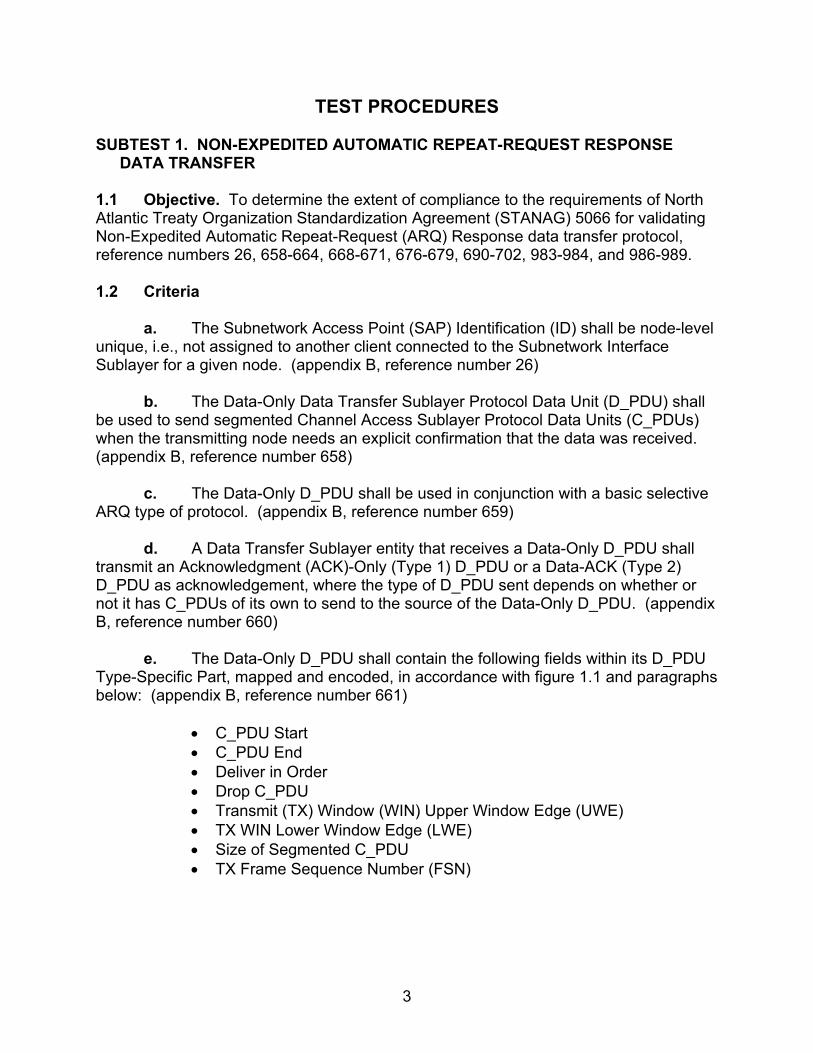
1.1 Objective. To determine the extent of compliance to the requirements of North Atlantic Treaty Organization Standardization Agreement (STANAG) 5066 for validating Non-Expedited Automatic Repeat-Request (ARQ) Response data transfer protocol, reference numbers 26, 658-664, 668-671, 676-679, 690-702, 983-984, and 986-989. 1.2 Criteria
a. The Subnetwork Access Point (SAP) Identification (ID) shall be node-level unique, i.e., not assigned to another client connected to the Subnetwork Interface Sublayer for a given node. (appendix B, reference number 26)
b. The Data-Only Data Transfer Sublayer Protocol Data Unit (D_PDU) shall
be used to send segmented Channel Access Sublayer Protocol Data Units (C_PDUs) when the transmitting node needs an explicit confirmation that the data was received. (appendix B, reference number 658)
c. The Data-Only D_PDU shall be used in conjunction with a basic selective ARQ type of protocol. (appendix B, reference number 659)
d. A Data Transfer Sublayer entity that receives a Data-Only D_PDU shall transmit an Acknowledgment (ACK)-Only (Type 1) D_PDU or a Data-ACK (Type 2) D_PDU as acknowledgement, where the type of D_PDU sent depends on whether or not it has C_PDUs of its own to send to the source of the Data-Only D_PDU. (appendix B, reference number 660)
e. The Data-Only D_PDU shall contain the following fields within its D_PDU Type-Specific Part, mapped and encoded, in accordance with figure 1.1 and paragraphs below: (appendix B, reference number 661)
• C_PDU Start • C_PDU End • Deliver in Order • Drop C_PDU • Transmit (TX) Window (WIN) Upper Window Edge (UWE) • TX WIN Lower Window Edge (LWE) • Size of Segmented C_PDU • TX Frame Sequence Number (FSN)

4
7 6 5 4 3 2 1 0
SYN
SYN
0
1
2
3
3+m
4+m
5+m
6+m
CRC
CRC
8+m
…
h+m+n
CRC
CRC
CRC
CRC
C_PDUSTART
1 0 0 1 0 0 0 0
1 1 1 0 1 0 1 1
0 0 0 0
ENGINEERING ORDERWIRE (EOW)
END OF TRANSMISSON (EOT)
SIZE OF ADDRESSFIELD IN BYTES (m)
SIZE OF HEADER IN BYTES(excluding size of address field) (h)
SOURCE & DESTINATION ADDRESS
C_PDUEND
DEL.IVERIN ORDER
DROPC_PDU
TX WINUWE
TX WINLWE
SIZE OF SEGMENTED C_PDU IN BYTES
TRANSMISSION FRAME SEQUENCE NUMBER
CRC ON HEADERMSB
LSB
MSB
MSB
LSB
LSB
MSB
LSB
32-bit CRC ON
SEGMENTED C_PDU ONLY
MSB LSB
Size
of H
eade
r (h)
Size
of S
egm
ente
d C
_PD
U (n
)
Legend: C_PDU—Channel AccessSublayer Protocol Data Unit, CRC—CyclicRedundancy Check, EOW—EngineeringOrderwire, EOT—End Of Transmission, LSB—Least Significant Bit, LWE—LowerWindow Edge, MSB—MostSignificant Bit, SYN—Synchronization, TX—Transmit, UWE—Upper WindowEdge
Figure 1.1. Frame Format for DATA-ONLY D_PDU Type 0
f. The C_PDU Start flag shall be set to indicate the start of a newly segmented C_PDU; the C_PDU segment contained within this D_PDU is the first segment of the C_PDU, in accordance with the C_PDU segmentation process described in STANAG 5066, section C.4. (appendix B, reference number 662)
g. The C_PDU End flag shall be set to indicate the end of a segmented
C_PDU. When a D_PDU is received with the C_PDU End flag set, it indicates the last D_PDU that was segmented from the C_PDU. (appendix B, reference number 663)
h. If the Deliver in Order flag is set on the D_PDUs composing a C_PDU, the
C_PDU shall be delivered to the upper layer when both the following conditions are met: (appendix B, reference number 664)
• The C_PDU is complete. • All C_PDUs received previously (that also had the Deliver in Order flag
set) have been delivered.
i. The TX WIN UWE flag shall be set when the TX FSN for the current D_PDU is equal to the TX WIN UWE of the transmit flow-control window. (appendix B, reference number 668)

5
j. Similarly, the TX WIN LWE flag shall be set when the TX FSN for the current D_PDU is equal to the TX LWE of the transmit flow-control window. (appendix B, reference number 669)
k. The Size of Segmented C_PDU field shall be encoded as specified in section C.3.2.10 of STANAG 5066. (appendix B, reference number 670)
l. The TX FSN field shall contain the sequence number of the current
D_PDU. (appendix B, reference number 671) m. The ACK-Only D_PDU shall be used to selectively acknowledge received
Data-Only or Data-Ack D_PDUs when the receiving Data Transfer Sublayer has no segmented C_PDUs of its own to send. (appendix B, reference number 676)
n. The ACK-Only D_PDU shall contain the following fields within its D_PDU
Type-Specific Part, mapped and encoded, in accordance with figure 1.2 and paragraphs below: (appendix B, reference number 677)
• Receive (RX) LWE • Selective ACK
Figure 1.2. Frame Format for ACK-ONLY D_PDU Type 1
Legend: CRC—Cyclic Redundancy Check, EOW—Engineering Orderwire, EOT—End Of Transmission, LSB—Least Significant Bit, LWE—Lower Window Edge, MSB—Most Significant Bit, RX-LWE—Receive Lower Window Edge, SYN—Synchronization

6
o. The value of the RX LWE field shall equal the D_PDU sequence number (modulo 256) of the RX LWE pointer associated with the node’s receive ARQ flow-control window. (appendix B, reference number 678)
p. The Selective ACK field can have a dynamic length of 0 to 16 bytes and
shall contain a bit-mapped representation of the status of all received D_PDUs with sequence numbers from the LWE to and including the UWE pointers of the receive flow-control window. (appendix B, reference number 679)
q. The Data-ACK D_PDU shall be used to send segmented C_PDUs when
the transmitting node needs an explicit confirmation that the data was received and has received D_PDUs to selectively acknowledge. (appendix B, reference number 690)
r. A Data Transfer Sublayer entity that receives a Data-ACK D_PDU shall
transmit an ACK-Only (Type 1) D_PDU or a Data-ACK (Type 2) D_PDU as acknowledgement, where the type of D_PDU sent depends on whether or not it has C_PDUs of its own to send to the source of the Data-ACK D_PDU. (appendix B, reference number 691)
s. The Data-ACK D_PDU shall contain the following fields within its D_PDU
Type-Specific Part, mapped and encoded, in accordance with figure 1.3 and referenced paragraphs of Annex C: (appendix B, reference number 692-702)
• C_PDU Start shall be as specified in section 3.3 of STANAG 5066 for
the Data-Only D_DPU. • C_PDU End shall be as specified in section 3.3 of STANAG 5066 for
the Data-Only D_DPU. • Deliver in Order shall be as specified in section 3.3 of STANAG 5066
for the Data-Only D_DPU. • DROP C_PDU shall be as specified in section 3.3 of STANAG 5066 for
the Data-Only D_DPU. • TX WIN UWE shall be as specified in section 3.3 of STANAG 5066 for
the Data-Only D_DPU. • TX WIN LWE shall be as specified in section 3.3 of STANAG 5066 for
the Data-Only D_DPU. • Size of Segmented C_PDU shall be as specified in section 3.3 of
STANAG 5066 for the Data-Only D_DPU. • TX FSN shall be as specified in section 3.3 of STANAG 5066 for the
Data-Only D_DPU.
7
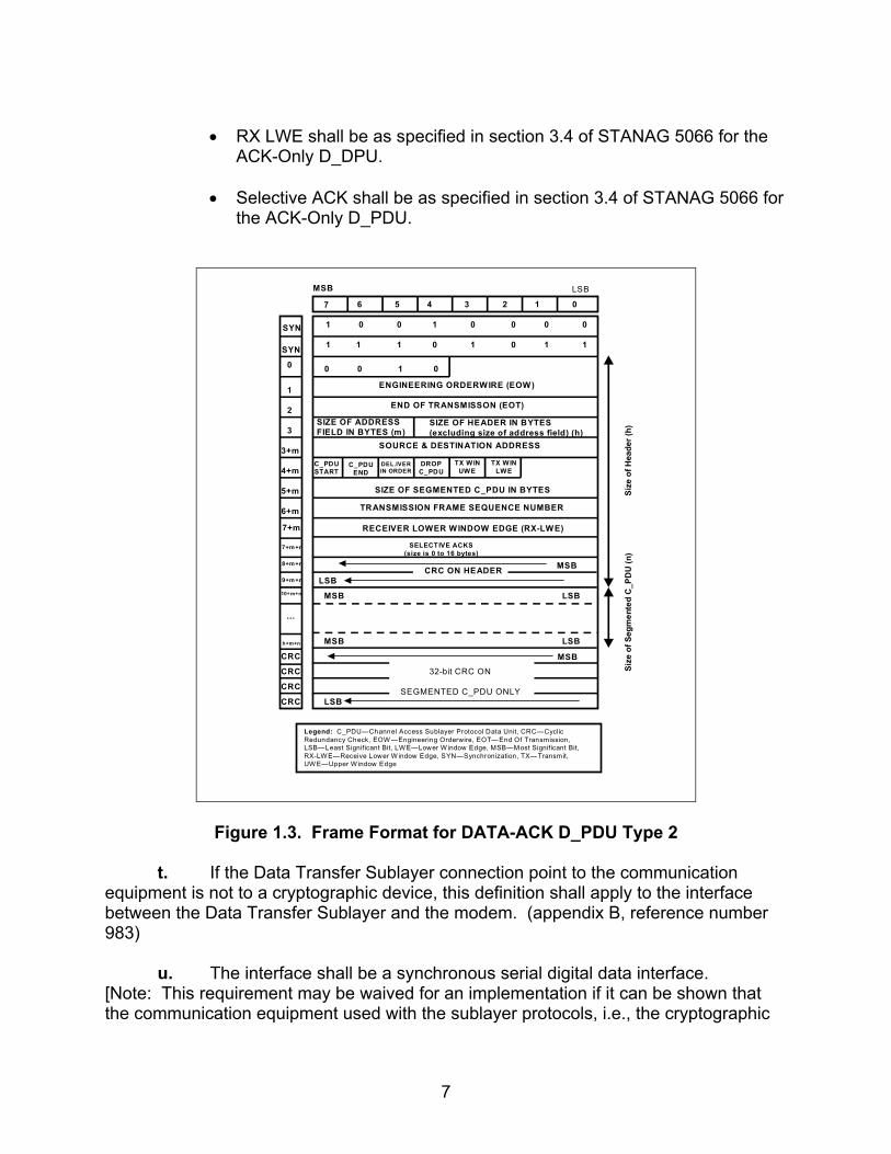
• RX LWE shall be as specified in section 3.4 of STANAG 5066 for the
ACK-Only D_DPU. • Selective ACK shall be as specified in section 3.4 of STANAG 5066 for
the ACK-Only D_PDU.
MSB
7 6 5 4 3 2 1 0
SYN
SYN
0
1
2
3
3+m
4+m
5+m
6+m
C_PDUSTART
1 0 0 1 0 0 0 0
1 1 1 0 1 0 1 1
0 0 1 0
ENGINEERING ORDERWIRE (EOW)
END OF TRANSMISSON (EOT)
SIZE OF ADDRESSFIELD IN BYTES (m)
SIZE OF HEADER IN BYTES(excluding size of address field) (h)
SOURCE & DESTINATION ADDRESS
C_PDUEND
DEL.IVERIN ORDER
DROPC_PDU
TX WINUWE
TX WINLWE
SIZE OF SEGMENTED C_PDU IN BYTES
TRANSMISSION FRAME SEQUENCE NUMBER
10+m+n
…
h+m+n
CRC
CRC
CRC
CRC
CRC ON HEADER MSB
LSB
MSB
MSB
LSB
LSB
MSB
LSB
32-bit CRC ON
SEGMENTED C_PDU ONLY
LSB
9+m+n
8+m+n
7+m+n
7+m RECEIVER LOWER WINDOW EDGE (RX-LWE)
SELECTIVE ACKS(size is 0 to 16 bytes)
Size
of H
eade
r (h)
Size
of S
egm
ente
d C
_PD
U (n
)
Legend: C_PDU—Channel Access Sublayer Protocol Data Unit, CRC—Cyclic Redundancy Check, EOW —Engineering Orderwire, EOT—End Of Transmission, LSB—Least Significant Bit, LW E—Lower W indow Edge, MSB—Most Significant Bit, RX-LW E—Receive Lower W indow Edge, SYN—Synchronization, TX—Transmit, UW E—Upper W indow Edge
Figure 1.3. Frame Format for DATA-ACK D_PDU Type 2 t. If the Data Transfer Sublayer connection point to the communication
equipment is not to a cryptographic device, this definition shall apply to the interface between the Data Transfer Sublayer and the modem. (appendix B, reference number 983)
u. The interface shall be a synchronous serial digital data interface.
[Note: This requirement may be waived for an implementation if it can be shown that the communication equipment used with the sublayer protocols, i.e., the cryptographic
8
equipment or modem, removes any start-bits, stop-bits, or other character-framing bits associated with the interface.
Many current implementations of the STANAG 4285 and Military Standard (MIL-STD)-188-110A waveforms transmit any start and end bits that are present on the asynchronous baseband digital interface to the modem, but there is no real requirement in these respective standards for this.
Modems may be implemented that allow independent specification of the character-framing and synchronization for the baseband interface and over-the-air gap. The real requirement for the STANAG 5066 sublayer interface is that no bits, other than those specified for valid protocol data units in the protocol sublayers STANAG 5066, shall be transmitted over-the-air gap between nodes.] With respect to functional roles on the interface, the Data Transfer Sublayer shall be hosted in a Data Terminal Equipment (DTE). (appendix B, reference numbers 984 and 986)
v. The clock source for the data output from the DTE (e.g., DTE data out) on
the interface shall be either configurable or from the Data Communications Equipment (DCE) (i.e., either the cryptographic equipment or the modem). (appendix B, reference number 987)
w. The clock source for the data input to the DTE (e.g., DTE data input) shall
be from the DCE (i.e., either the cryptographic equipment or the modem). (appendix B, reference number 988)
x. The interface shall provide full hardware-level handshaking for flow-
control, in accordance with any standard recommendations. (appendix B, reference number 989) 1.3 Test Procedures a. Test Equipment Required
(1) Computers (2 each [ea]) with STANAG 5066 Software (2) Modems (2 ea) (3) Protocol Analyzer (4) RS-232 Synchronous Serial Cards
b. Test Configuration. Figure 1.4 shows the equipment setup for this subtest.
c. Test Conduction. Table 1.1 lists procedures for this subtest, and table 1.2 lists the results for this subtest.

9
Computer Modem Modem Computer
LANAnalyzer
RS-232 RS-232
Figure 1.4. Equipment Configuration for Non-Expedited Automatic Repeat-Request Response Data Transfer
Table 1.1. Non-Expedited Automatic Repeat-Request Response Data Transfer
Procedures
Step Action Settings/Action Result The following procedures are for reference numbers 26, 983-984, and 986-989.
1
Set up equipment. See figure 1.4. Computers are connected to the modems by an RS-232 connection. The connection between modems shall be such that the receive and transmit pins on the modem are connected to the transmit and receive pins, respectively, of the other modem.
2
Identify digital interface type used. What type of digital interface is being used: asynchronous or synchronous?
Type of Interface used=
3
Verify hardware used provides full hadware-level handshaking.
Coordinate with vendor of hardware used for interfacing with STANAG 5066 software to verify that it provides handshaking on the hardware level.
Hardware-level handsha-king available? Y/N
4 Load STANAG 5066 software. Configure the SMTP and POP3 servers as
required by the STANAG 5066 software manual.

10
Table 1.1. Non-Expedited Automatic Repeat-Request Response Data Transfer Procedures (continued)
Step Action Settings/Action Result
5
Configure STANAG addresses for computers 1 and 2.
Set the size of the STANAG address field size to 7 bytes. Set the STANAG address to 1.1.0.0 and 1.2.0.0 as shown in figure 1.4. Configure the software to respond with an e-mail message to the sender once the e-mail has been successfully received.
6 Configure modems 1 and 2. Set modems 1 and 2 to transmit a
MIL-STD-188-110B signal at a data rate of 4800 bps with half duplex.
7
Identify client to be used. Configure both computers to use the same client type. (Use HMTP if available.) Record the client type used by computers.
Client type =
8 Identify client SAP ID of computer with STANAG address 1.2.0.0.
Record the SAP ID of the client used for the computer with STANAG address 1.2.0.0.
1.2.0.0 SAP ID =
9 Identify client SAP ID of computer with STANAG address 1.1.0.0.
Record the SAP ID of the client used for the computer with STANAG address 1.1.0.0.
1.1.0.0 SAP ID =
10 Verify that no other clients have the same SAP IDs as identified in steps 8 and 9.
Record SAP IDs of all other clients included in STANAG 5066 software.
11 Identify Max Time to Wait parameter. Is the client’s Max Time to Wait for a
response to Type 1 C_PDU a configurable parameter?
Y/N
12 Configure Deliver in Order. Set the Deliver in Order to “Yes” for both computers.
13 Configure delivery confirmation. Set the delivery confirmation to “Node” for both computers.
14 Configure rank. Set the rank of the client to “15” for both computers.
15 Configure priority level. Set the priority level to “0” for both computers.
Vendor’s Maximum C_PDU Segment Size = 16
Configure Maximum C_PDU Segment Size.
If the Maximum C_PDU Segment Size parameter is a configurable on the user interface, configure the Maximum C_PDU Segment Size to 1023 bytes. If this parameter is not configurable on the user interface, coordinate with the vendor to obtain the value of the Maximum C_PDU Segment Size and record the vendor’s Maximum C_PDU Segment Size. Also record whether or not the value obtained from the vendor is less than or equal to 1023 bytes.
Maximum C_PDU Segment Size ≤ 1023 bytes? Y/N

11
Table 1.1. Non-Expedited Automatic Repeat-Request Response Data Transfer Procedures (continued)
Step Action Settings/Action Result
Vendor’s MTU Size =
17
Configure MTU Size. If the MTU Size parameter is a configurable on the user interface, configure the MTU Size to 2048 bytes. If this parameter is not configurable on the user interface, coordinate with the vendor to obtain the value of the MTU Size and record the vendor’s MTU Size. Also record whether or not the value obtained from the vendor is less than or equal to 2048 bytes.
Maximum C_PDU Segment Size ≤ 2048 bytes? Y/N
18
Determine maximum number of D_PDUs to encapsulate an entire C_PDU.
Add 6 to the Vendor’s MTU Size and divide the result by the Maximum C_PDU Segment Size (round up) to determine the maximum number of D_PDUs needed to encapsulate an entire C_PDU Segment that is segmented across more than 1 D_PDU. If the above values were user configurable and the values specified were used, this value will be 3 D_PDUs. Note: The adding of 6 bytes takes into consideration the C_PDU and S_PDU headers that are not included in the MTU Size but are included in the Maximum C_PDU Segment Size. Record the Maximum Number of D_PDUs.
Maximum Number of D_PDUs =
19 Confirm that the communications equipment is not connected to a cryptographic device.
Make sure that the computers are not connected to any cryptographic devices.
20 Verify that the “Maximum Transmission
Window” is a configurable parameter within the STANAG 5066 software.
Y/N
21
Configure protocol analyzer. Configure the protocol analyzer to capture the transmitted data between the two computers and save it to a file. Configure the protocol analyzer to have a 4800-bps bit rate and to synchronize on “0x90EB” in hexadecimal (hex) format. Configure the protocol analyzer to drop sync after 20 “0xFFs” hex format. Configure the analyzer to time stamp each captured byte.
12
Table 1.1. Non-Expedited Automatic Repeat-Request Response Data Transfer Procedures (continued)
Step Action Settings/Action Result
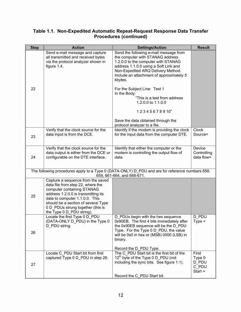
22
Send e-mail message and capture all transmitted and received bytes via the protocol analyzer shown in figure 1.4.
Send the following e-mail message from the computer with STANAG address 1.2.0.0 to the computer with STANAG address 1.1.0.0 using a Soft Link and Non-Expedited ARQ Delivery Method. Include an attachment of approximately 5 kbytes. For the Subject Line: Test 1 In the Body: “This is a test from address 1.2.0.0 to 1.1.0.0 1 2 3 4 5 6 7 8 9 10” Save the data obtained through the protocol analyzer to a file.
23
Verify that the clock source for the data input is from the DCE.
Identify if the modem is providing the clock for the input data from the computer DTE.
Clock Source=
24
Verify that the clock source for the data output is either from the DCE or configurable on the DTE interface.
Identify that either the computer or the modem is controlling the output flow of data.
Device Controlling data flow=
The following procedures apply to a Type 0 (DATA-ONLY) D_PDU and are for reference numbers 658, 659, 661-664, and 668-671.
25
Capture a sequence from the saved data file from step 22, where the computer containing STANAG address 1.2.0.0 is transmitting its data to computer 1.1.0.0. This should be a section of several Type 0 D_PDUs strung together (this is the Type 0 D_PDU string).
26
Locate the first Type 0 D_PDU (DATA-ONLY D_PDU) in the Type 0 D_PDU string.
D_PDUs begin with the hex sequence 0x90EB. The first 4 bits immediately after the 0x90EB sequence will be the D_PDU Type. For the Type 0 D_PDU, the value will be 0x0 in hex or (MSB) 0000 (LSB) in binary. Record the D_PDU Type.
D_PDU Type =
27
Locate C_PDU Start bit from first captured Type 0 D_PDU in step 26.
The C_PDU Start bit is the first bit of the 12th byte of the Type 0 D_PDU (not including the sync bits. See figure 1.1). Record the C_PDU Start bit.
First Type 0 D_PDU C_PDU Start =
13
Table 1.1. Non-Expedited Automatic Repeat-Request Response Data Transfer Procedures (continued)
Step Action Settings/Action Result
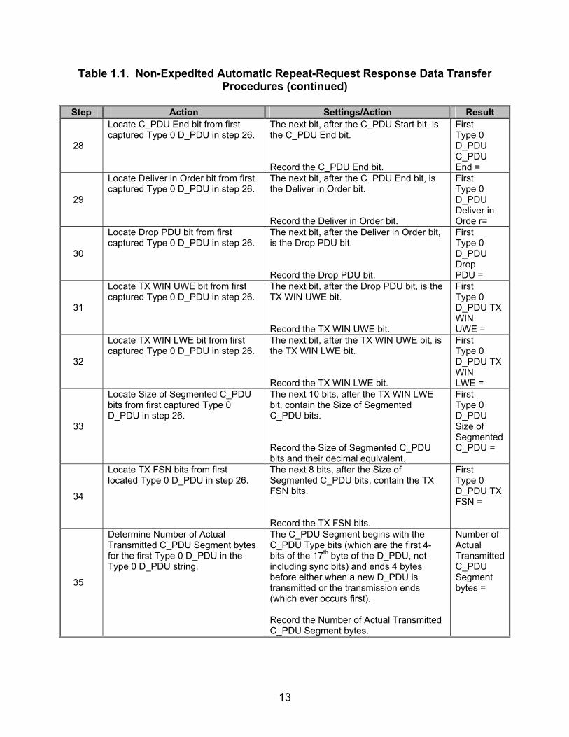
28
Locate C_PDU End bit from first captured Type 0 D_PDU in step 26.
The next bit, after the C_PDU Start bit, is the C_PDU End bit. Record the C_PDU End bit.
First Type 0 D_PDU C_PDU End =
29
Locate Deliver in Order bit from first captured Type 0 D_PDU in step 26.
The next bit, after the C_PDU End bit, is the Deliver in Order bit. Record the Deliver in Order bit.
First Type 0 D_PDU Deliver in Orde r=
30
Locate Drop PDU bit from first captured Type 0 D_PDU in step 26.
The next bit, after the Deliver in Order bit, is the Drop PDU bit. Record the Drop PDU bit.
First Type 0 D_PDU Drop PDU =
31
Locate TX WIN UWE bit from first captured Type 0 D_PDU in step 26.
The next bit, after the Drop PDU bit, is the TX WIN UWE bit. Record the TX WIN UWE bit.
First Type 0 D_PDU TX WIN UWE =
32
Locate TX WIN LWE bit from first captured Type 0 D_PDU in step 26.
The next bit, after the TX WIN UWE bit, is the TX WIN LWE bit. Record the TX WIN LWE bit.
First Type 0 D_PDU TX WIN LWE =
33
Locate Size of Segmented C_PDU bits from first captured Type 0 D_PDU in step 26.
The next 10 bits, after the TX WIN LWE bit, contain the Size of Segmented C_PDU bits. Record the Size of Segmented C_PDU bits and their decimal equivalent.
First Type 0 D_PDU Size of Segmented C_PDU =
34
Locate TX FSN bits from first located Type 0 D_PDU in step 26.
The next 8 bits, after the Size of Segmented C_PDU bits, contain the TX FSN bits. Record the TX FSN bits.
First Type 0 D_PDU TX FSN =
35
Determine Number of Actual Transmitted C_PDU Segment bytes for the first Type 0 D_PDU in the Type 0 D_PDU string.
The C_PDU Segment begins with the C_PDU Type bits (which are the first 4-bits of the 17th byte of the D_PDU, not including sync bits) and ends 4 bytes before either when a new D_PDU is transmitted or the transmission ends (which ever occurs first). Record the Number of Actual Transmitted C_PDU Segment bytes.
Number of Actual Transmitted C_PDU Segment bytes =
14
Table 1.1. Non-Expedited Automatic Repeat-Request Response Data Transfer Procedures (continued)
Step Action Settings/Action Result
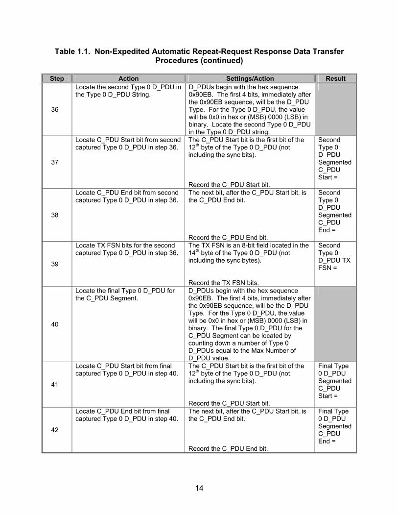
36
Locate the second Type 0 D_PDU in the Type 0 D_PDU String.
D_PDUs begin with the hex sequence 0x90EB. The first 4 bits, immediately after the 0x90EB sequence, will be the D_PDU Type. For the Type 0 D_PDU, the value will be 0x0 in hex or (MSB) 0000 (LSB) in binary. Locate the second Type 0 D_PDU in the Type 0 D_PDU string.
37
Locate C_PDU Start bit from second captured Type 0 D_PDU in step 36.
The C_PDU Start bit is the first bit of the 12th byte of the Type 0 D_PDU (not including the sync bits). Record the C_PDU Start bit.
Second Type 0 D_PDU Segmented C_PDU Start =
38
Locate C_PDU End bit from second captured Type 0 D_PDU in step 36.
The next bit, after the C_PDU Start bit, is the C_PDU End bit. Record the C_PDU End bit.
Second Type 0 D_PDU Segmented C_PDU End =
39
Locate TX FSN bits for the second captured Type 0 D_PDU in step 36.
The TX FSN is an 8-bit field located in the 14th byte of the Type 0 D_PDU (not including the sync bytes). Record the TX FSN bits.
Second Type 0 D_PDU TX FSN =
40
Locate the final Type 0 D_PDU for the C_PDU Segment.
D_PDUs begin with the hex sequence 0x90EB. The first 4 bits, immediately after the 0x90EB sequence, will be the D_PDU Type. For the Type 0 D_PDU, the value will be 0x0 in hex or (MSB) 0000 (LSB) in binary. The final Type 0 D_PDU for the C_PDU Segment can be located by counting down a number of Type 0 D_PDUs equal to the Max Number of D_PDU value.
41
Locate C_PDU Start bit from final captured Type 0 D_PDU in step 40.
The C_PDU Start bit is the first bit of the 12th byte of the Type 0 D_PDU (not including the sync bits). Record the C_PDU Start bit.
Final Type 0 D_PDU Segmented C_PDU Start =
42
Locate C_PDU End bit from final captured Type 0 D_PDU in step 40.
The next bit, after the C_PDU Start bit, is the C_PDU End bit. Record the C_PDU End bit.
Final Type 0 D_PDU Segmented C_PDU End =
15
Table 1.1. Non-Expedited Automatic Repeat-Request Response Data Transfer Procedures (continued)
Step Action Settings/Action Result
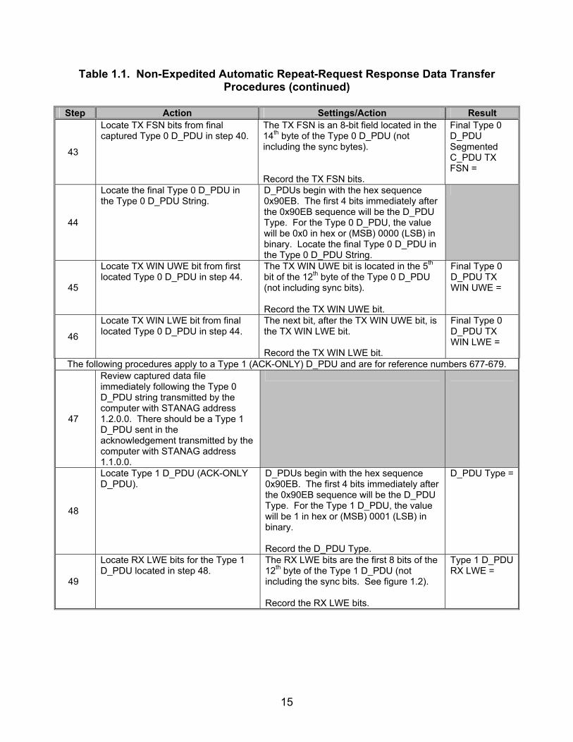
43
Locate TX FSN bits from final captured Type 0 D_PDU in step 40.
The TX FSN is an 8-bit field located in the 14th byte of the Type 0 D_PDU (not including the sync bytes). Record the TX FSN bits.
Final Type 0 D_PDU Segmented C_PDU TX FSN =
44
Locate the final Type 0 D_PDU in the Type 0 D_PDU String.
D_PDUs begin with the hex sequence 0x90EB. The first 4 bits immediately after the 0x90EB sequence will be the D_PDU Type. For the Type 0 D_PDU, the value will be 0x0 in hex or (MSB) 0000 (LSB) in binary. Locate the final Type 0 D_PDU in the Type 0 D_PDU String.
45
Locate TX WIN UWE bit from first located Type 0 D_PDU in step 44.
The TX WIN UWE bit is located in the 5th bit of the 12th byte of the Type 0 D_PDU (not including sync bits). Record the TX WIN UWE bit.
Final Type 0 D_PDU TX WIN UWE =
46
Locate TX WIN LWE bit from final located Type 0 D_PDU in step 44.
The next bit, after the TX WIN UWE bit, is the TX WIN LWE bit. Record the TX WIN LWE bit.
Final Type 0 D_PDU TX WIN LWE =
The following procedures apply to a Type 1 (ACK-ONLY) D_PDU and are for reference numbers 677-679.
47
Review captured data file immediately following the Type 0 D_PDU string transmitted by the computer with STANAG address 1.2.0.0. There should be a Type 1 D_PDU sent in the acknowledgement transmitted by the computer with STANAG address 1.1.0.0.
48
Locate Type 1 D_PDU (ACK-ONLY D_PDU).
D_PDUs begin with the hex sequence 0x90EB. The first 4 bits immediately after the 0x90EB sequence will be the D_PDU Type. For the Type 1 D_PDU, the value will be 1 in hex or (MSB) 0001 (LSB) in binary. Record the D_PDU Type.
D_PDU Type =
49
Locate RX LWE bits for the Type 1 D_PDU located in step 48.
The RX LWE bits are the first 8 bits of the 12th byte of the Type 1 D_PDU (not including the sync bits. See figure 1.2). Record the RX LWE bits.
Type 1 D_PDU RX LWE =

16
Table 1.1. Non-Expedited Automatic Repeat-Request Response Data Transfer Procedures (continued)
Step Action Settings/Action Result
50
Locate Selective ACK bits for the Type 1 D_PDU located in step 48.
The Selective ACK field follows the RX LWE field for the Type 1 D_PDU; to determine if the Type 1 D_PDU contains a Selective ACKs field use the following equation: Size of Header field – 7 > 0 bytes The Selective ACKs field will be located in the 10th byte of the D_PDU (not including the sync sequence bits). The Size of Header bits are the last 5 bits of the 4th byte of the D_PDU header (not including sync sequence bits). The total number of Selective ACKs bytes to be identified in the Type 1 D_PDU will be equal to the Size of Header field – 7 bytes. Record the Selective ACKs.
Type 1 D_PDU Selective ACK=
The following procedures are for reference numbers 692-702.
51
Locate Type 2 D_PDU (DATA-ACK D_PDU).
D_PDUs begin with the hex sequence 0x90EB. The first 4-bits immediately, after the 0x90EB sequence, will be the D_PDU Type. For the Type 2 D_PDU, the value will be 0x2 in hex or (MSB) 0010 (LSB) in binary. Record the D_PDU Type.
D_PDU Type =
52
Locate C_PDU Start bit for the Type 2 D_PDU located in step 51.
The C_PDU Start bit is the first bit of the 12th byte of the Type 2 D_PDU (not including the sync bits. See figure 1.3). Record the C_PDU Start bit.
Type 2 D_PDU C_PDU Start=
53
Locate C_PDU End bit for the Type 2 D_PDU located in step 51.
The next bit, after the C_PDU Start bit, is the C_PDU End bit. Record the C_PDU End bit.
Type 2 D_PDU C_PDU End =
54
Locate Deliver in Order bit for the Type 2 D_PDU located in step 51.
The next bit, after the C_PDU End bit, is the Deliver in Order bit. Record the Deliver in Order bit.
Type 2 D_PDU Deliver in Order =
55
Locate Drop PDU bit for the Type 2 D_PDU located in step 51.
The next bit, after the Deliver in Order bit, is the Drop PDU bit. Record the Drop PDU bit.
Type 2 D_PDU Drop PDU =
56
Locate TX WIN UWE bit for the Type 2 D_PDU located in step 51.
The next bit, after the Drop PDU bit, is the TX WIN UWE bit. Record the TX WIN UWE bit.
Type 2 D_PDU TX WIN UWE =
17
Table 1.1. Non-Expedited Automatic Repeat-Request Response Data Transfer Procedures (continued)
Step Action Settings/Action Result
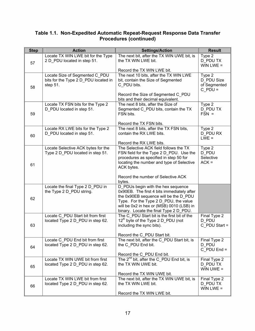
57
Locate TX WIN LWE bit for the Type 2 D_PDU located in step 51.
The next bit, after the TX WIN UWE bit, is the TX WIN LWE bit. Record the TX WIN LWE bit.
Type 2 D_PDU TX WIN LWE =
58
Locate Size of Segmented C_PDU bits for the Type 2 D_PDU located in step 51.
The next 10 bits, after the TX WIN LWE bit, contain the Size of Segmented C_PDU bits. Record the Size of Segmented C_PDU bits and their decimal equivalent.
Type 2 D_PDU Size of Segmented C_PDU =
59
Locate TX FSN bits for the Type 2 D_PDU located in step 51.
The next 8 bits, after the Size of Segmented C_PDU bits, contain the TX FSN bits. Record the TX FSN bits.
Type 2 D_PDU TX FSN =
60
Locate RX LWE bits for the Type 2 D_PDU located in step 51.
The next 8 bits, after the TX FSN bits, contain the RX LWE bits. Record the RX LWE bits.
Type 2 D_PDU RX LWE =
61
Locate Selective ACK bytes for the Type 2 D_PDU located in step 51.
The Selective ACK field follows the TX FSN field for the Type 2 D_PDU. Use the procedures as specified in step 50 for locating the number and type of Selective ACK bytes. Record the number of Selective ACK bytes.
Type 2 D_PDU Selective ACK =
62
Locate the final Type 2 D_PDU in the Type 2 D_PDU string.
D_PDUs begin with the hex sequence 0x90EB. The first 4 bits immediately after the 0x90EB sequence will be the D_PDU Type. For the Type 2 D_PDU, the value will be 0x2 in hex or (MSB) 0010 (LSB) in binary. Locate the final Type 2 D_PDU.
63
Locate C_PDU Start bit from first located Type 2 D_PDU in step 62.
The C_PDU Start bit is the first bit of the 12th byte of the Type 2 D_PDU (not including the sync bits). Record the C_PDU Start bit.
Final Type 2 D_PDU C_PDU Start =
64
Locate C_PDU End bit from first located Type 2 D_PDU in step 62.
The next bit, after the C_PDU Start bit, is the C_PDU End bit. Record the C_PDU End bit.
Final Type 2 D_PDU C_PDU End =
65
Locate TX WIN UWE bit from first located Type 2 D_PDU in step 62.
The 2nd bit, after the C_PDU End bit, is the TX WIN UWE bit. Record the TX WIN UWE bit.
Final Type 2 D_PDU TX WIN UWE =
66
Locate TX WIN LWE bit from first located Type 2 D_PDU in step 62.
The next bit, after the TX WIN UWE bit, is the TX WIN LWE bit. Record the TX WIN LWE bit.
Final Type 2 D_PDU TX WIN LWE =

18
Table 1.1. Non-Expedited Automatic Repeat-Request Response Data Transfer Procedures (continued)
Step Action Settings/Action Result
67
Locate TX FSN bits from first located Type 2 D_PDU in step 62.
The TX FSN is an 8-bit field located in the 14th byte of the Type 2 D_PDU (not including the sync bytes). Record the TX FSN bits.
Final Type 2 D_PDU TX FSN =
68
Determine Number of Actual Transmitted C_PDU Segment bytes for the first Type 2 D_PDU in the Type 2 D_PDU string.
The C_PDU Segment begins 4 bytes after the TX FSN (18th byte overall, not including sync bits). The C_PDU Segment ends 4 bytes either before a new D_PDU is transmitted or when the transmission ends (whichever occurs first). Record the Number of Actual Transmitted C_PDU Segment bytes.
Number of Actual Transmitted C_PDU Segment bytes =
The following procedures are for reference numbers 660, 676, 690, and 691.
69
Verify order of D_PDUs sent. Record the first D_PDU of each string transmitted from the file in step 22 in the order that they were transmitted.
D_PDU Types =
Legend: ACK—Acknowledgement ARQ—Automatic Repeat-Request bps—bits per second C_PDU—Channel Access Sublayer Protocol Data Unit D_PDU—Data Transfer Sublayer Protocol Data Unit DCE—Data Communications Equipment DTE—Data Terminal Equipment e-mail—Electronic Mail FSN—Frame Sequence Number hex—hexadecimal HMTP—High Frequency Mail Transfer Protocol ID—Identification kbyte—kilobyte LSB—Least Significant Bit
LWE—Lower Window Edge MIL-STD—Military Standard MSB—Most Significant Bit MTU—Maximum Transmission Unit POP3—Post Office Protocol 3 RX—Receive S_PDU—Subnetwork Interface Sublayer Protocol Data Unit SAP—Subnetwork Access Point SMTP—Simple Mail Transfer Protocol STANAG—Standardization Agreement sync—synchronization TX—Transmit UWE—Upper Window Edge WIN—Window

19
Table 1.2. Non-Expedited Automatic Repeat-Request Response Data Transfer Results
Result Finding Reference
Number STANAG
5066 Paragraph
Requirement Required Value
Measured Value Met Not
Met
26 A.2.1.1
The SAP ID shall be node-level unique, i.e., not assigned to another client connected to the Subnetwork Interface Sublayer for a given node.
Values from step 9 do not equal values from steps 7 and 8.
658 C.3.3
The Data-Only D_PDU shall be used to send segmented C_PDUs when the transmitting node needs an explicit confirmation that the data was received.
C_PDUs encapsul-ated within Type 0 D_PDU for Non-Expedited ARQ mode.
659 C.3.3
The Data-Only D_PDU shall be used in conjunction with a basic selective Automatic Repeat-Request type of protocol.
Type 0 D_PDUs sent for Non-Expedited ARQ Mode.
660 C.3.3
A Data Transfer Sublayer entity that receives a Data-Only D_PDU shall transmit an ACK-Only (Type 1) D_PDU or a Data-ACK (Type 2) D_PDU as acknowledgement, where the type of D_PDU sent depends on whether or not it has C_PDUs of its own to send to the source of the Data-Only D_PDU.
Type 1 or Type 2 D_PDU sent in response to Type 0 D_PDU.
661 C.3.3
The Data-Only D_PDU shall contain the following fields within its D_PDU Type-Specific Part, mapped and encoded, in accordance with figure C-9 and the paragraphs below:
• C_PDU START • C_PDU END • DELIVER IN ORDER • DROP C_PDU • TX WIN UWE • TX WIN LWE • SIZE OF SEGMENTED
C_PDU • TX FSN
Type 0 D_PDU encoded as shown in figure 1.1.

20
Table 1.2. Non-Expedited Automatic Repeat-Request Response Data Transfer Results (continued)
Result Finding Reference
Number STANAG
5066 Paragraph
Requirement Required Value
Measured Value Met Not
Met
662 C.3.3
The C_PDU Start flag shall be set to indicate the start of a newly segmented C_PDU; the C_PDU segment contained within this D_PDU is the first segment of the C_PDU, in accordance with the C_PDU segmentation process described in STANAG 5066, section C.4.
1st Type 0 D_PDU C_PDU START Flag = 1 Type 0 D_PDU
663 C.3.3
The C_PDU End flag shall be set to indicate the end of a segmented C_PDU; when a D_PDU is received with the C_PDU End flag set it indicates the last D_PDU that was segmented from the C_PDU.
Final Type 0 D_PDU Segmented C_PDU END Flag = 1
Type 0 D_PDU Deliver in Order bit = 1
664
C.3.3
If the Deliver in Order flag is set on the D_PDUs composing a C_PDU, the C_PDU shall be delivered to the upper layer when both the following conditions are met: 1) The C_PDU is complete. 2) All C_PDUs received previously that also had the Deliver in Order flag set have been delivered.
Type 2 D_PDU Deliver in Order bit = 1
First Type 0 D_PDU TX WIN UWE = 1
668 C.3.3
The TX WIN UWE flag shall be set when the TX FSN for the current D_PDU is equal to the TX UWE of the transmit flow-control window.
Final Type 0 D_PDU TX WIN UWE = 1
First Type 0 D_PDU TX WIN LWE = 1
669 C.3.3
Similarly, the TX WIN LWE flag shall be set when the TX FSN for the current D_PDU is equal to the TX LWE of the transmit flow-control window. Final Type
0 D_PDU TX WIN LWE = 0

21
Table 1.2. Non-Expedited Automatic Repeat-Request Response Data Transfer Results (continued)
Result Finding Reference
Number STANAG
5066 Paragraph
Requirement Required Value
Measured Value Met Not
Met Type 0 D_PDU Size of Segmented C_PDU = Actual number of transmitted.
C_PDU Segment bytes = Vendor’s Maximum C_PDU Segment Size.
670 C.3.3
The Size of Segmented C_PDU field shall be encoded as specified in STANAG 5066, section C.3.2.10.
Type 2 D_PDU Size of Segmented C_PDU = Actual number of transmitted C_PDU Segment bytes.
TX FSN of 1st Type 0 D_PDU Type 0 D_PDU string = 0
TX FSN of 2nd Type 0 D_PDU Type 0 D_PDU string = 1
671 C.3.3
The TX FSN field shall contain the sequence number of the current D_PDU.
TX FSN of final Type 0 D_PDU Segmented C_PDU = Max Number of D_PDUs-1.

22
Table 1.2. Non-Expedited Automatic Repeat-Request Response Data Transfer Results (continued)
Result Finding Reference
Number STANAG
5066 Paragraph
Requirement Required Value
Measured Value Met Not
Met
676 C.3.4
The ACK-Only D_PDU shall be used to selectively acknowledge received Data-Only or Data-ACK D_PDUs when the receiving Data Transfer Sublayer has no segmented C_PDUs of its own to send.
Type 1 D_PDU sent in response to Type 0 or Type 2 D_PDU.
677 C.3.4
The ACK-Only D_PDU shall contain the following fields within its D_PDU Type-Specific Part, mapped and encoded, in accordance with figure C-10 and the paragraphs below:
• RX LWE • SELECTIVE ACK
Type 1 D_PDU encoded as shown in figure 1.2.
678 C.3.4
The value of the RX LWE field shall equal the D_PDU sequence number (modulo 256) of the RX LWE pointer associated with the node’s receive ARQ flow-control window.
RX LWE = 1+ the TX FSN of the Final Type 0 D_PDU.
Type 1 D_PDU Selective ACK = 0 bytes
679 C.3.4
The Selective ACK field can have a dynamic length of 0 to 16 bytes and shall contain a bit-mapped representation of the status of all received D_PDUs with sequence numbers from the LWE to and including the UWE pointers of the receive flow-control window.
Type 2 D_PDU Selective ACK = 0 bytes

23
Table 1.2. Non-Expedited Automatic Repeat-Request Response Data Transfer Results (continued)
Result Finding Reference
Number STANAG
5066 Paragraph
Requirement Required Value
Measured Value Met Not
Met
690 C.3.5
The Data-ACK D_PDU shall be used to send segmented C_PDUs when the transmitting node needs an explicit confirmation that the data was received and has received D_PDUs to selectively acknowledge.
Type 2 D_PDU sent in response to Type 0 D_PDUs.
691 C.3.5
A Data Transfer Sublayer entity that receives a Data-ACK D_PDU shall transmit an ACK-Only (Type 1) D_PDU or a Data-ACK (Type 2) D_PDU as acknowledgement, where the type of D_PDU sent depends on whether or not it has C_PDUs of its own to send to the source of the Data-ACK D_PDU.
Computer 1.1.0.0 transmits a Type 2 D_PDU in response to the Type 0 D_PDU transmitted by computer 1.2.0.0 and computer 1.2.0.0 transmits a Type 1 D_PDU in respnse to the Type 2 D_PDU transmitted by computer 1.1.0.0.
692 C.3.5
The Data- ACK D_PDU shall contain the following fields within its D_PDU Type-Specific Part, mapped and encoded, in accordance with figure C-13 and the referenced paragraphs:
Type 2 D_PDU encoded as shown in figure 1.3.

24
Table 1.2. Non-Expedited Automatic Repeat-Request Response Data Transfer Results (continued)
Result Finding Reference
Number STANAG
5066 Paragraph
Requirement Required Value
Measured Value Met Not
Met C_PDU Start Flag = 1 for first Type 2 D_PDU sent in string.
693 C.3.5
C_PDU Start shall be as specified in STANAG 5066, section 3.3 for the Data-Only D_DPU;
C_PDU Start Flag = 0 for final Type 2 D_PDU sent in string.
C_PDU End Flag = 0 for first Type 2 D_PDU.
694 C.3.5
C_PDU End shall be as specified in STANAG 5066, section 3.3 for the Data-Only D_DPU;
Final Type 2 D_PDU C_PDU END Flag = 1
695 C.3.5 Deliver in Order shall be as specified in STANAG 5066, section 3.3 for the Data-Only D_DPU;
Deliver in Order = 1
696 C.3.5 Drop C_PDU shall be as specified in STANAG 5066, section 3.3 for the Data-Only D_DPU;
Drop C_PDU = 0
TX WIN UWE = 1 for first Type 2 D_PDU.
697 C.3.5
TX WIN UWE shall be as specified in STANAG 5066, section 3.3 for the Data-Only D_DPU;
Final Type 2 D_PDU TX WIN UWE = 1
TX WIN LWE = 1 for first Type 2 D_PDU.
698 C.3.5
TX WIN LWE shall be as specified in of STANAG 5066, section 3.3 for the Data-Only D_DPU;
Final Type 2 D_PDU TX WIN LWE = 0

25
Table 1.2. Non-Expedited Automatic Repeat-Request Response Data Transfer Results (continued)
Result Finding Reference
Number STANAG
5066 Paragraph
Requirement Required Value
Measured Value Met Not
Met
699 C.3.5
Size Of Segmented C_PDU shall be as specified in STANAG 5066, section 3.3 for the Data-Only D_DPU;
Type 2 D_PDU Size of Segmented C_PDU = Actual number of transmitted C_PDU Segment bytes.
700 C.3.5
TX FSN shall be as specified in STANAG 5066, section 3.3 for the Data-Only D_DPU;
TX FSN for Type 2 D_PDU in string = 0
701 C.3.5
RX LWE shall be as specified in STANAG 5066, section 3.4 for the ACK-Only D_DPU;
RX LWE = 1+ the TX FSN of the Final Type 0 D_PDU
702 C.3.5
SELECTIVE ACK shall be as specified in STANAG 5066, section 3.4 for the ACK-Only D_PDU.
No Type 2 Selective ACK transmit-ted.
983 D
If the Data Transfer Sublayer connection point to the communication equipment is not to a cryptographic device, this definition shall apply to the interface between the Data Transfer Sublayer and the modem.
Communi-cation equipment not connected to crypto-graphic device.

26
Table 1.2. Non-Expedited Automatic Repeat-Request Response Data Transfer Results (continued)
Result Finding Reference
Number STANAG
5066 Paragraph
Requirement Required Value
Measured Value Met Not
Met
984 D
The interface shall be a synchronous serial digital data interface. [Note: This requirement may be waived for an implementation if it can be shown that the communi-cation equipment used with the sublayer protocols, i.e., the crypto-graphic equipment or modem, removes any start-bits, stop-bits, or other character-framing bits associ-ated with the interface. Many current implementations of the STANAG 4285 and MIL-STD-188-110A waveforms transmit any start and end bits that are present on the asynchronous baseband digital interface to the modem, but there is no real requirement in these respective standards for this. Modems may be implemented that allow independent specification of the character-framing and sync for the baseband interface and over-the-air gap. The real requirement on the STANAG 5066 sublayer interface is that no bits other than those specified for valid protocol data units in the protocol sublayers STANAG 5066 shall be transmitted over-the-air gap between nodes.]
Synchron-ous serial digital interface used.
986 D
With respect to functional roles on the interface, the Data Transfer Sublayer shall be hosted in a Data Terminal Equipment (DTE).
STANAG Software installed on a DTE.
987 D
The clock source for the data output from the DTE (i.e., DTE data out) on the interface shall be either configurable or from the DCE (i.e., either the cryptographic equipment or the modem).
Clock source from DCE.
988 D
The clock source for the data input to the DTE (i.e., DTE data input) shall be from the DCE (i.e., either the cryptographic equipment or the modem).
Clock source from DCE.

27
Table 1.2. Non-Expedited Automatic Repeat-Request Response Data Transfer Results (continued)
Result Finding Reference
Number STANAG
5066 Paragraph
Requirement Required Value
Measured Value Met Not
Met
989 D
The interface shall provide full hardware-level handshaking for flow-control, in accordance with any standard recommendations.
Hardware-Level Handsha-king available.
Legend: ACK—Acknowledgement ARQ—Automatic Repeat-Request C_PDU—Channel Access Sublayer Protocol Data Unit D_PDU—Data Transfer Sublayer Protocol Data Unit DCE—Data Communications Equipment DTE—Data Terminal Equipment FSN—Frame Sequence Number ID—Identification LWE—Lower Window Edge
MIL-STD—Military Standard RX—Receive SAP—Subnetwork Access Point STANAG—Standardization Agreement sync—synchronization TX—Transmit UWE—Upper Window Edge WIN—Window

28
SUBTEST 2. EXPEDITED AUTOMATIC REPEAT-REQUEST RESPONSE DATA TRANSFER
2.1 Objective. To determine the extent of compliance to the requirements of STANAG 5066, reference numbers 724-734, 736-738, and 740-741. 2.2 Criteria a. The Expedited Data-Only (Type 4) D_PDU shall be used to send segmented C_PDUs that require Expedited Delivery Service when the transmitting node needs an explicit confirmation that the data was received. (appendix B, reference number 724)
b. A Data Transfer Sublayer entity that receives Expedited Data-Only (Type 4) D_PDU shall send an Expedited Data-Only (Type 5) D_PDU as a selective acknowledgement of all Expedited Data-Only (Type 4) D_PDUs received from the source node. (appendix B, reference number 725)
c. The Expedited Data-Only D_PDU is similar in structure to the Data-Only D_PDU. The Expedited Data-Only D_PDU shall contain the following fields within its D_PDU Type-Specific Part, mapped and encoded, in accordance with figure 2.1 and the paragraphs noted: (appendix B, reference numbers 726-731)
• C_PDU Start shall be as specified for the Data-Only D_PDU in section C.3.3 of STANAG 5066.
• C_PDU End shall be as specified for the Data-Only D_PDU in section
C.3.3 of STANAG 5066. • C_PDU ID Number shall be as specified in the paragraphs below. • Size of Segmented C_PDU shall be as specified in section C.3.2.10 of
STANAG 5066 for all D_PDUs that have a segmented C_PDU field. • TX FSN shall be as specified for the Data-Only D_PDU in section
C.3.3 of STANAG 5066 with additional requirements as noted in paragraphs d-g below.

29
SYN
SYN
3+m
4+m
5+m
6+m
CRC
CRC
8+m
h+m+n
CRC
CRC
CRC
CRC
7 6 5 4 3 2 1 0
0
1
2
3
…
C_PDUSTART
1 0 0 1 0 0 0 0
1 1 1 0 1 0 1 1
0 0 0 0
ENGINEERING ORDERWIRE (EOW)
END OF TRANSMISSON (EOT)
SIZE OF ADDRESSFIELD IN BYTES (m)
SIZE OF HEADER IN BYTES(excluding size of address field) (h)
SOURCE & DESTINATION ADDRESS
C_PDUEND
SIZE OF SEGMENTED C_PDU IN BYTES
TRANSMISSION FRAME SEQUENCE NUMBER
CRC ON HEADERMSB
LSB
MSB
MSB
LSB
LSB
MSB
LSB
32-bit CRC ON
SEGMENTED C_PDU ONLY
MSB LSB
C_PDU ID NUMBER
Size
of H
eade
r (h)
Size
of S
egm
ente
d C
_PD
U (n
)
Legend: C_PDU—Channel AccessSublayer Protocol Data Unit, CRC—CyclicRedundancy Check, EOW—EngineeringOrderwire, EOT—End Of Transmission, LSB—Least Significant Bit, LWE—LowerWindow Edge, MSB—MostSignificant Bit, SYN—Synchronization, TX—Transmit, UWE—Upper WindowEdge
Figure 2.1. Frame Format for Expedited DATA-ONLY D_PDU Type 4
d. The C_PDU ID Number field shall specify the C_PDU of which this expedited D_PDU is a part. (appendix B, reference number 732)
e. The value of the C_PDU ID Number field shall be an integer (modulo 16) assigned in an ascending (modulo 16) order to the C_PDU and shall not be released for reuse with another C_PDU until the entire C_PDU has been acknowledged. (appendix B, reference numbers 733 and 734)
f. The segmented C_PDU field is a field that is attached to the header structure defined in figure 2.1. The segmented Protocol Data Unit (PDU) shall immediately follow the D_PDU header. (appendix B, reference number 736)
g. The processing of Expedited D_PDUs in the Expedited Data state shall
differ from the processing of Data-Only or Data-ACK D_PDUs in the Data state: (appendix B, reference numbers 737 and 738)
• Data (e.g., C_PDUs) using the Expedited Delivery Service shall be
transferred using Expedited Data-Only and Expedited ACK-Only D_PDUs. If duplex communication is required, Expedited Data-Only

30
and Expedited ACK-Only D_PDUs may be placed together in a transmission interval.
h. The Expedited ACK-Only (Type 5) D_PDU shall be used to selectively acknowledge received Expedited Data-Only D_PDUs. (appendix B, reference number 740)
i. The Expedited ACK-Only (Type 5) D_PDU Type shall have the same format as the ACK-Only (Type 1) D_PDU, differing only in the value of the D_PDU Type field in byte 0, specified in figure 2.2. (appendix B, reference number 741)
Figure 2.2. Frame Format for Expedited ACK-ONLY D_PDU Type 5
2.3 Test Procedures
a. Test Equipment Required (1) Computers (2 ea) with STANAG 5066 Software (2) Modem (2 ea) (3) Protocol Analyzer
31
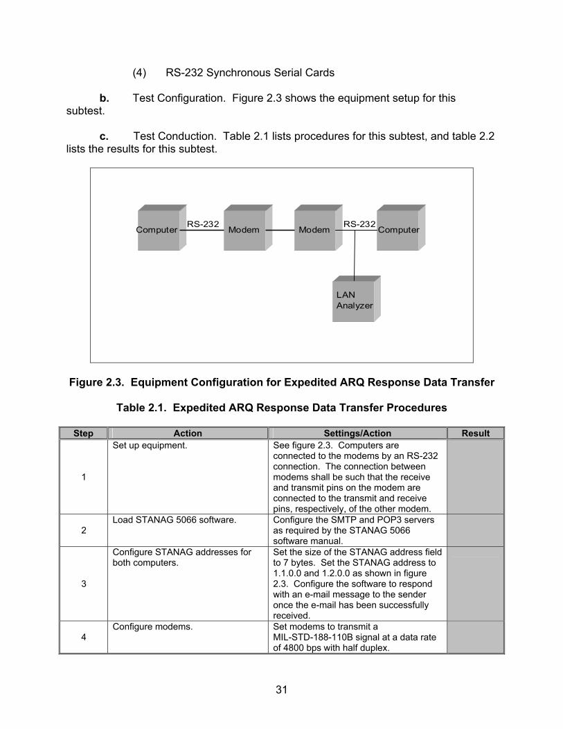
(4) RS-232 Synchronous Serial Cards b. Test Configuration. Figure 2.3 shows the equipment setup for this subtest.
c. Test Conduction. Table 2.1 lists procedures for this subtest, and table 2.2 lists the results for this subtest.
Computer Modem Modem Computer
LANAnalyzer
RS-232 RS-232
Figure 2.3. Equipment Configuration for Expedited ARQ Response Data Transfer
Table 2.1. Expedited ARQ Response Data Transfer Procedures
Step Action Settings/Action Result
1
Set up equipment. See figure 2.3. Computers are connected to the modems by an RS-232 connection. The connection between modems shall be such that the receive and transmit pins on the modem are connected to the transmit and receive pins, respectively, of the other modem.
2 Load STANAG 5066 software. Configure the SMTP and POP3 servers
as required by the STANAG 5066 software manual.
3
Configure STANAG addresses for both computers.
Set the size of the STANAG address field to 7 bytes. Set the STANAG address to 1.1.0.0 and 1.2.0.0 as shown in figure 2.3. Configure the software to respond with an e-mail message to the sender once the e-mail has been successfully received.
4 Configure modems. Set modems to transmit a
MIL-STD-188-110B signal at a data rate of 4800 bps with half duplex.

32
Table 2.1. Expedited ARQ Response Data Transfer Procedures (continued)
Step Action Settings/Action Result
5
Identify client to be used. Configure both computers to use the same client type. Record the client type used by computers.
Client Type =
6 Configure Deliver in Order. Set the Deliver in Order to “yes” for both computers.
7 Configure delivery confirmation. Set the delivery confirmation to “Node” for both computers.
8 Configure rank. Set the rank of the client to “15” for both computers.
9 Configure priority level. Set the priority level to “0” for both computers.
10
Configure Maximum C_PDU Segment Size.
If the Maximum C_PDU Segment Size parameter is a configurable on the user interface, configure the Maximum C_PDU Segment Size to 1023 bytes. If this parameter is not configurable on the user interface, coordinate with the vendor to obtain the value of the Maximum C_PDU Segment Size and record the vendor’s Maximum C_PDU Segment Size.
Vendor’s Maximum C_PDU Segment Size =
11
Configure MTU Size. If the MTU Size parameter is a configurable on the user interface, configure the MTU Size to 2048 bytes. If this parameter is not configurable on the user interface, coordinate with the vendor to obtain the value of the MTU Size and record the vendor’s MTU Size.
Vendor’s MTU Size =
12
Determine maximum number of D_PDUs to encapsulate an entire C_PDU.
Add 6 to the Vendor’s MTU Size and divide the result by the Maximum C_PDU Segment Size (round up) to determine the maximum number of D_PDUs needed to encapsulate an entire C_PDU Segment which is segmented across more than 1 D_PDU. If the above values were user configurable and the values specified were used, this value will be 3 D_PDUs. Note: The adding of 6 bytes takes into consideration the C_PDU and S_PDU headers which are not included in the MTU Size but are included in the Maximum C_PDU Segment Size. Record the Maximum Number of D_PDUs.
Max Number of D_PDUs =

33
Table 2.1. Expedited ARQ Response Data Transfer Procedures (continued)
Step Action Settings/Action Result
13
Configure protocol analyzer. Configure the protocol analyzer to capture the transmitted data between the two computers and save it to a file. Configure the protocol analyzer to have a 4800 bps bit rate and to synchronize on “0x90EB.” Configure the protocol analyzer to drop sync after 20 “0xFFs”. Configure the analyzer to time stamp each captured byte.
14
Send e-mail message and capture all transmitted and received bytes via the protocol analyzer shown in figure 2.3.
Send the following e-mail message from the computer with STANAG address 1.2.0.0 to the computer with STANAG address 1.1.0.0 using a Soft Link and Expedited ARQ Delivery Method. For the Subject Line: Test 1 In the Body: “This is a test from address 1.2.0.0 to 1.1.0.0. 1 2 3 4 5 6 7 8 9 10” Save the data obtained through the protocol analyzer to a file.
The following procedures apply to a Type 4 (Expedited DATA-ONLY ARQ) and are for reference numbers 724, 726-731, 734, and 736-738.
15
Capture a sequence from the saved data file, where the computer containing STANAG address 1.2.0.0 is transmitting its data to address 1.1.0.0. This should be a section of several Type 4 D_PDUs strung together (this is the Type 4 D_PDU string), immediately following the initial two Type 8 D_PDUs that were sent with Type 1 and 2 C_PDUs encapsulated within them.
16
Locate Type 4 (Expedited DATA-ONLY) D_PDU.
D_PDUs begin with the following sync in hex format: 0x90EB. The first 4 bits, immediately after the 0x90EB sequence, will be the D_PDU Type. For the Type 4 D_PDU, the value will be 0x4 in hex or 0100 in binary. Locate the second Type 4 D_PDU. Record the D_PDU Type.
D_PDU Type =
17
Locate C_PDU Start bit for the Type 4 D_PDU from step 16.
The C_PDU Start bit is the first bit of the 12th byte of the Type 4 D_PDU (not including the sync bits. See figure 2.1). Record the C_PDU Start bit.
Type 4 D_PDU C_PDU Start =

34
Table 2.1. Expedited ARQ Response Data Transfer Procedures (continued)
Step Action Settings/Action Result
18
Locate C_PDU End bit for the Type 4 D_PDU from step 16. .
The C_PDU End bit is the next bit, after the C_PDU Start bit. Record the C_PDU End bit.
Type 4 D_PDU C_PDU End =
19
Locate C_PDU ID Number bits for the Type 4 D_PDU from step 16.
The next 4 bits, after the C_PDU End bits, contain the C_PDU ID Number bits. Record the C_PDU ID Number bits and their decimal equivalent.
Type 4 D_PDU C_PDU ID Number =
20
Locate Size of Segmented C_PDU bits for the Type 4 D_PDU from step 16.
The next 10 bits, after the C_PDU ID Number bits, contain the Size of Segmented C_PDU bits. Record the Size of Segmented C_PDU bits and its decimal equivalent.
Type 4 D_PDU Size of Segmented C_PDU =
21
Locate TX FSN bits for the Type 4 D_PDU from step 16.
The next 8 bits, after the Size of Segmented C_PDU bits, contain the TX FSN bits. Record the TX FSN bits and its decimal equivalent.
Type 4 D_PDU TX FSN =
22
Locate Data C_PDU Type encapsulated within the Type 4 D_PDU from step 16.
The C_PDU Type is the first four MSBs of the 17th byte of the Type 4 D_PDU. Record the C_PDU Type bits.
C_PDU Type =
23
Determine number of actual transmitted C_PDU Segment bytes for the first Type 4 D_PDU in the Type 4 D_PDU string.
The C_PDU Segment begins with the C_PDU Type bits and ends 4 bytes either before a new D_PDU is transmitted or when the transmission ends (whichever occurs first). Record the number of actual transmitted C_PDU Segment bytes.
Number of Actual Transmitted C_PDU Segment bytes =
24
Locate the second Type 4 D_PDU in the Type 4 D_PDU string.
D_PDUs begin with the hex sequence 0x90EB. The first 4 bits, immediately after the 0x90EB sequence, will be the D_PDU Type. For the Type 4 D_PDU, the value will be 0x4 in hex or (MSB) 0100 (LSB) in binary. Locate the second Type 4 D_PDU in the Type 4 D_PDU string.
25
Locate C_PDU Start bit from second located Type 4 D_PDU in step 24.
The C_PDU Start bit is the first bit of the 12th byte of the Type 4 D_PDU (not including the sync bits). Record the C_PDU Start bit.
Second Type 4 D_PDU C_PDU Start =

35
Table 2.1. Expedited ARQ Response Data Transfer Procedures (continued)
Step Action Settings/Action Result
26
Locate C_PDU End bit from second located Type 4 D_PDU in step 24.
The next bit, after the C_PDU Start bit, is the C_PDU End bit. Record the C_PDU End bit.
Second Type 4 D_PDU C_PDU End =
27
Locate TX FSN bits for the second located Type 4 D_PDU in step 24.
The TX FSN is an 8-bit field located in the 14th byte of the Type 4 D_PDU (not including the sync bytes). Record the TX FSN bits.
Second Type 4 D_PDU TX FSN =
28
Locate the final Type 4 D_PDU for the C_PDU Segment.
D_PDUs begin with the hex sequence 0x90EB. The first 4 bits, immediately after the 0x90EB sequence, will be the D_PDU Type. For the Type 4 D_PDU, the value will be 0x4 in hex or (MSB) 0100 (LSB) in binary. The final Type 4 D_PDU for the C_PDU Segment can be located by counting down a number of Type 4 D_PDUs equal to the max number of D_PDU value.
29
Locate C_PDU Start bit from final located Type 4 D_PDU in step 28.
The C_PDU Start bit is the first bit of the 12th byte of the Type 4 D_PDU (not including the sync bits). Record the C_PDU Start bit.
Final Type 4 D_PDU C_PDU Start =
30
Locate C_PDU End bit from final located Type 4 D_PDU in step 28.
The next bit, after the C_PDU Start bit, is the C_PDU End bit. Record the C_PDU End bit.
Final Type 4 D_PDU C_PDU End =
31
Locate TX FSN bits from final located Type 4 D_PDU in step 28.
The TX FSN is an 8-bit field located in the 14th byte of the Type 4 D_PDU (not including the sync bytes). Record the TX FSN bits.
Final Type 4 D_PDU TX FSN =

36
Table 2.1. Expedited ARQ Response Data Transfer Procedures (continued)
Step Action Settings/Action Result The following procedures apply to a Type 5 (Expedited ACK-ONLY ARQ) and are for reference number
741.
32
Locate Type 5 (Expedited ACK-ONLY) D_PDU.
D_PDUs begin with the following sync in hex format: 0x90EB. The first 4 bits, immediately after the 0x90EB sequence, will be the D_PDU Type. For the Type 5 D_PDU, the value will be 0x5 in hex or 0101 in binary. Record the D_PDU Type.
D_PDU Type =
33
Locate RX LWE bits for the Type 5 D_PDU from step 32.
The RX LWE bits are the first 8 bits of the 12th byte of the Type 5 D_PDU (not including the sync bits. See figure 2.2). Record the RX LWE bits.
Type 5 D_PDU RX LWE =
34
Locate Selective ACK bytes for the Type 5 D_PDU from step 32.
The next 0-16 bytes, after the RX LWE bits, are the Selective ACK bytes. The size of this field may be determined by the Size of Header field. If the Size of Header field is greater than 7 bytes, then there are Selective ACKs included in this D_PDU. The number of bytes of Selective ACKs is equal to the Size of Header minus 7. Record the number of Selective ACK bytes.
Type 5 D_PDU Selective ACK bytes =
35
Locate CRC on Header bits for the Type 5 D_PDU from step 32.
The next 16 bits, after the Selective ACK bytes (or Receiver Lower Window Edge` bits if there are no Selective ACK bytes), contain the CRC on Header bits. Record the CRC on Header bits.
Type 5 D_PDU CRC on Header =
The following procedures are for reference numbers 725 and 740.
36
Verify order of D_PDUs sent. Record the first D_PDU of each string transmitted from the file in step 15 in the order that they were transmitted.
D_PDU Types =

37
Table 2.1. Expedited ARQ Response Data Transfer Procedures (continued)
Step Action Settings/Action Result The following procedures are for reference numbers 732 and 733.
37
Resend e-mail message. Send the following e-mail message from the computer with STANAG address 1.2.0.0 to the computer with STANAG address 1.1.0.0 using a Soft Link and Expedited ARQ Delivery Method. Include an attachment of approximately 20 kbytes in size. For the Subject Line: Test 1 In the Body: “This is a test from address 1.2.0.0 to 1.1.0.0. 1 2 3 4 5 6 7 8 9 10” Save the data obtained through the protocol analyzer to a file.
38
Locate all Type 4 D_PDU C_PDU ID Numbers in the order they are transmitted.
D_PDUs begin with the sync sequence 0x90EB. The next 4 bits, after the sync sequence, will be the D_PDU Type and for the Type 4 D_PDU will be (MSB) 0 1 0 0 (LSB) (0x4 hex). The C_PDU ID Number is located in bits (MSB) 5 through 2 (LSB) of the 12th byte of the Type 4 D_PDU. Record all Type 4 D_PDU C_PDU ID Numbers in the order that they are transmitted.
Type 4 D_PDU C_PDU ID Numbers =
Legend: ACK—Acknowledgement ARQ—Automatic Repeat-Request bps—bits per second C_PDU—Channel Access Sublayer Protocol Data Unit CRC—Cyclic Redundancy Check D_PDU—Data Transfer Sublayer Protocol Data Unit e-mail—Electronic Mail FSN—Frame Sequence Number hex—hexadecimal ID—Identification LSB—Least Significant Bit kbyte—kilobyte
LWE—Lower Window Edge MIL-STD—Military Standard MSB—Most Significant Bit MTU—Maximum Transmission Unit POP3—Post Office Protocol 3 RX—Receive S_PDU—Subnetwork Interface Sublayer Protocol Data Unit SMTP—Simple Mail Transfer Protocol STANAG—Standardization Agreement sync—synchronization TX—Transmit

38
Table 2.2. Expedited ARQ Response Data Transfer Results
Result Finding Reference Number
STANAG 5066
Paragraph Requirement Required
Value Measured
Value Met Not Met
724 C.3.7
The Expedited Data-Only (Type 4) D_PDU shall be used to send segmented C_PDUs that require Expedited Delivery Service when the transmitting node needs an explicit confirmation that the data was received.
C_PDUs encapsu-lated within Type 4 D_PDU.
725 C.3.7
A Data Transfer Sublayer entity that receives Expedited Data-Only (Type 4) D_PDU shall send an Expedited Data-Only (Type 5) D_PDU as a selective acknowledgement of all Expedited Data-Only (Type 4) D_PDUs received from the source node.
Type 5 D_PDU sent in response to Type 4 D_PDU.
726 C.3.7
The Expedited Data-Only D_PDU is similar in structure to the Data-Only D_PDU. The Expedited Data-Only D_PDU shall contain the following fields within its D_PDU Type-Specific Part, mapped and encoded, in accordance with figure C-15 and the paragraphs noted:
Type 4 D_PDU encoded as shown in figure 2.1.
C_PDU START Flag = 1 for first Type 4 D_PDU in Type 4 D_PDU string.
727 C.3.7
C_PDU START shall be as specified for the Data-Only D_PDU in STANAG 5066, section C.3.3
C_PDU START Flag = 0 for final Type 4 D_PDU in Type 4 Segmen-ted C_PDU.
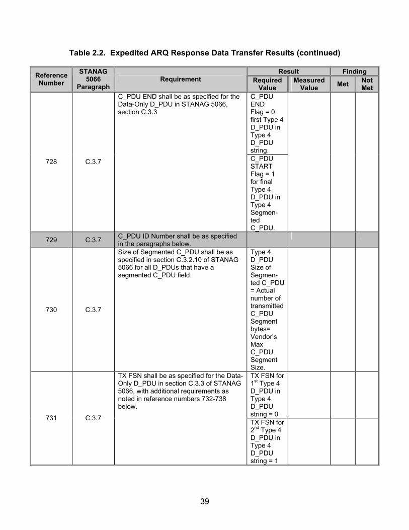
39
Table 2.2. Expedited ARQ Response Data Transfer Results (continued)
Result Finding Reference Number
STANAG 5066
Paragraph Requirement Required
Value Measured
Value Met Not Met
C_PDU END Flag = 0 first Type 4 D_PDU in Type 4 D_PDU string.
728 C.3.7
C_PDU END shall be as specified for the Data-Only D_PDU in STANAG 5066, section C.3.3
C_PDU START Flag = 1 for final Type 4 D_PDU in Type 4 Segmen-ted C_PDU.
729 C.3.7 C_PDU ID Number shall be as specified in the paragraphs below.
730 C.3.7
Size of Segmented C_PDU shall be as specified in section C.3.2.10 of STANAG 5066 for all D_PDUs that have a segmented C_PDU field.
Type 4 D_PDU Size of Segmen-ted C_PDU = Actual number of transmitted C_PDU Segment bytes= Vendor’s Max C_PDU Segment Size.
TX FSN for 1st Type 4 D_PDU in Type 4 D_PDU string = 0
731 C.3.7
TX FSN shall be as specified for the Data-Only D_PDU in section C.3.3 of STANAG 5066, with additional requirements as noted in reference numbers 732-738 below.
TX FSN for 2nd Type 4 D_PDU in Type 4 D_PDU string = 1

40
Table 2.2. Expedited ARQ Response Data Transfer Results (continued)
Result Finding Reference Number
STANAG 5066
Paragraph Requirement Required
Value Measured
Value Met Not Met
731 C.3.7
TX FSN for 3rd Type 4 D_PDU in Type 4 D_PDU string = 2
732 C.3.7
The C_PDU ID Number field shall specify the C_PDU of which this Expedited D_PDU is a part.
Type 4 C_PDU ID Number is ascending in modulo 16 order.
733 C.3.7
The value of the C_PDU ID Number field shall be an integer (modulo 16) assigned in an ascending (modulo 16) order to the C_PDU.
Type 4 C_PDU ID Number is ascending in modulo 16 order.
734 C.3.7
And shall not be released for reuse with another C_PDU until the entire C_PDU has been acknowledged.
No two Type 4 D_PDUs contain the same C_PDU ID Number.
736 C.3.7
The Segmented C_PDU field is a field that is attached to the header structure defined in figure C-15. The segmented PDU shall immediately follow the D_PDU header.
C_PDU immediate-ly followed Type 4 D_PDU Header. (see step 19)
737 C.3.7
The processing of Expedited D_PDUs in the Expedited Data state shall differ from the processing of Data-Only or Data-ACK D_PDUs in the Data state in the following way:
738 C.3.7
Data (i.e., C_PDUs) using the Expedited Delivery Service shall be transferred using Expedited Data-Only and Expedited ACK-Only D_PDUs. If duplex communication is required, Expedited Data-Only and Expedited ACK-Only D_PDUs may be placed together in a transmission interval.
Type 4 D_PDUs transmit-ted when expedited data transfer requested.

41
Table 2.2. Expedited ARQ Response Data Transfer Results (continued)
Result Finding Reference Number
STANAG 5066
Paragraph Requirement Required
Value Measured
Value Met Not Met
740 C.3.8
The Expedited ACK-Only (Type 5) D_PDU shall be used to selectively acknowledge received Expedited Data-Only D_PDUs.
Type 5 D_PDU sent in response to Type 4 D_PDU.
741 C.3.8
The Expedited ACK-Only (Type 5) D_PDU Type shall have the same format as the ACK-Only (Type 1) D_PDU, differing only in the value of the D_PDU Type field in byte 0, as specified in figure C-16.
Type 5 D_PDU in format of figure 2.2.
Legend: ACK—Acknowledgement C_PDU—Channel Access Sublayer Protocol Data Unit D_PDU—Data Transfer Sublayer Protocol Data Unit FSN—Frame Sequence Number
ID—Identification STANAG—Standardization Agreement TX—Transmit

42
SUBTEST 3. RESET/RE-SYNCHRONIZATION PROTOCOLS 3.1 Objective. To determine the extent of compliance to the requirements of STANAG 5066, for validating Warning D_PDUs, reference numbers 703, 706-723, and 963-981. 3.2 Criteria
a. The Reset/WIN Re-synchronization (Re-sync) D_PDU shall be used to
control the re-sync or re-initialization of the selective-repeat ARQ protocol, operating on the link between the source and destination nodes. (appendix B, reference number 703)
b. The reception of this D_PDU shall result in the transmission of an
acknowledgement D_PDU by the receiving node. For the Idle Repeat-Request (IRQ) protocol used with the Reset/WIN Re-sync D_PDU, the Reset/WIN Re-sync D_PDU is used for both data and acknowledgement, as specified below. (appendix B, reference number 706)
c. Transmission of D_PDUs supporting the regular-data service [i.e., of Data
(Type 0), ACK (Type 1), and Data-ACK (Type 2) D_PDUs] shall be suspended pending completion of any stop-and-wait protocol using the Reset/WIN Re-sync D_PDUs. (appendix B, reference number 707)
d. The Reset/WIN Re-sync D_PDU shall contain the following fields within its
D_PDU Type-Specific Part, mapped and encoded, in accordance with figure 3.1 and the paragraphs below: (appendix B, reference number 708)
• Full Reset Command (CMND) • Reset TX WIN Request (RQST) • Reset TX WIN CMND • Reset ACK • New RX LWE • Reset Frame ID Number
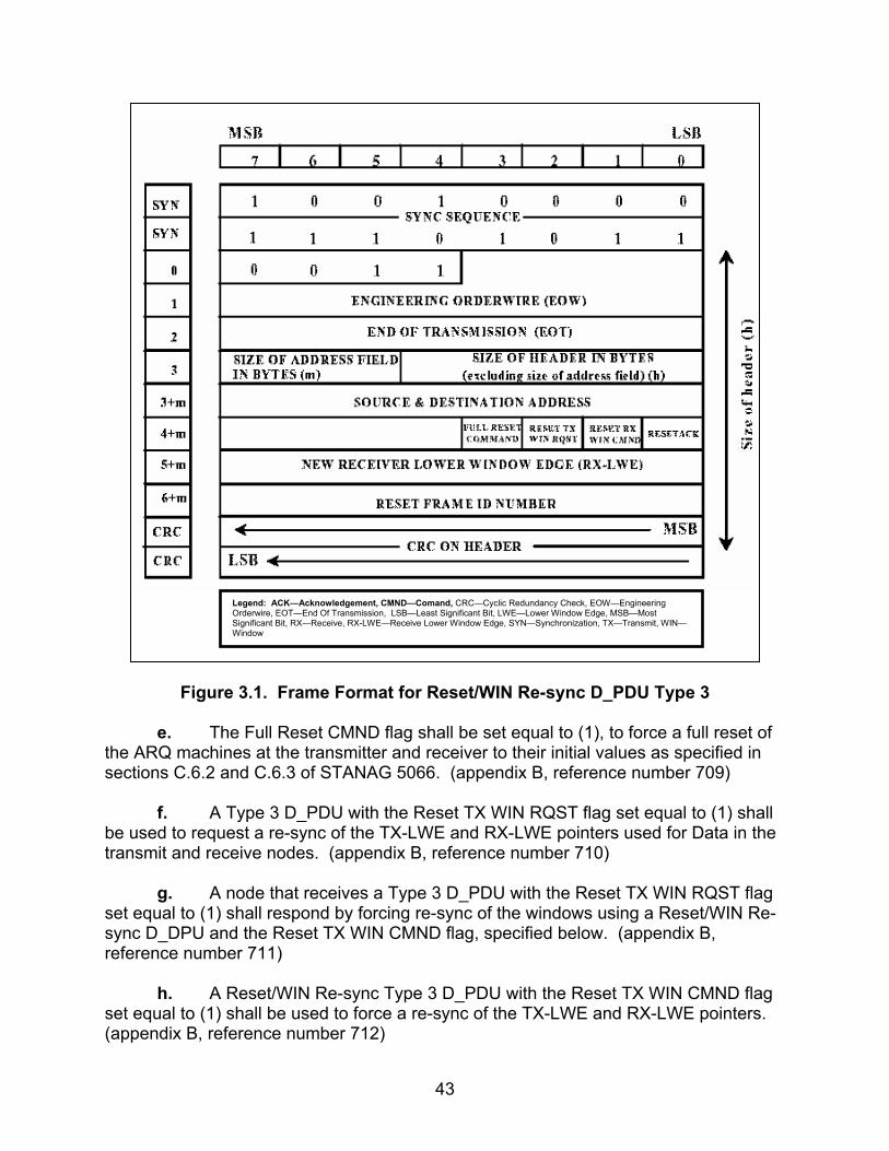
43
Figure 3.1. Frame Format for Reset/WIN Re-sync D_PDU Type 3
e. The Full Reset CMND flag shall be set equal to (1), to force a full reset of
the ARQ machines at the transmitter and receiver to their initial values as specified in sections C.6.2 and C.6.3 of STANAG 5066. (appendix B, reference number 709)
f. A Type 3 D_PDU with the Reset TX WIN RQST flag set equal to (1) shall
be used to request a re-sync of the TX-LWE and RX-LWE pointers used for Data in the transmit and receive nodes. (appendix B, reference number 710)
g. A node that receives a Type 3 D_PDU with the Reset TX WIN RQST flag
set equal to (1) shall respond by forcing re-sync of the windows using a Reset/WIN Re-sync D_DPU and the Reset TX WIN CMND flag, specified below. (appendix B, reference number 711)
h. A Reset/WIN Re-sync Type 3 D_PDU with the Reset TX WIN CMND flag
set equal to (1) shall be used to force a re-sync of the TX-LWE and RX-LWE pointers. (appendix B, reference number 712)
Legend: ACK—Acknowledgement, CMND—Comand, CRC—Cyclic Redundancy Check, EOW—Engineering Orderwire, EOT—End Of Transmission, LSB—Least Significant Bit, LWE—Lower Window Edge, MSB—Most Significant Bit, RX—Receive, RX-LWE—Receive Lower Window Edge, SYN—Synchronization, TX—Transmit, WIN—Window
44
i. A node that sends a Type 3 D_PDU with the Reset TX WIN CMND flag
set equal to (1) shall proceed as follows: (appendix B, reference numbers 713-715)
• The New Receive LWE field shall be set equal to the value of the sending node’s RX LWE.
• The sending node shall wait for a Reset/WIN Re-sync Type 3 D_PDU with the Reset ACK flag set equal to (1) as an acknowledgement that the re-sync has been performed.
j. A node that receives a Type 3 D_PDU with the Reset TX WIN CMND flag
set equal to (1) shall proceed as follows: (appendix B, reference numbers 716-718)
• The value of the node’s TX LWE shall be set equal to the value of the New RX LWE field in the Reset/WIN Re-sync D_PDU that was received.
• The node shall send a Reset/WIN Re-sync Type 3 D_PDU with the Reset ACK flag set equal to (1) as an acknowledgement that the re-sync has been performed.
k. Reset ACK flag shall be set equal to (1) to indicate an acknowledgement
of the most recently received Reset/WIN Re-sync Type 3 D_PDU. (appendix B, reference number 719)
l. The New Receive LWE field specifies the value of the new receiver ARQ
RX-LWE, as noted above and shall be valid only when the value of the Reset WIN CMND flag equals (1). (appendix B, reference number 720)
m. The value of the New Receive LWE field shall be ignored in any other
situation. (appendix B, reference number 721) n. The Data Transfer Sublayer shall use the Reset Frame ID Number field to
determine if a given Reset/WIN Re-sync D_PDU received is a copy of one already received. (appendix B, reference number 722)
o. The value of the Reset Frame ID Number field shall be a unique integer
(modulo 256) assigned in ascending order to Reset/WIN Re-sync D_PDUs and will not be released for reuse with another D_PDU until the D_PDU to which it was assigned has been acknowledged. (appendix B, reference number 723)
p. A Full Reset procedure shall by a node sending a Type 3 Reset/WIN Re-sync D_PDU with field values as follows: (appendix B, reference numbers 963-968)
• The Full Reset Command (CMD) flag shall be set to 1.

45
• The Reset Frame ID Number shall be selected from Reset Frame ID Number sequence.
• The New Receive LWE field shall be reset to zero. • The Reset TX WIN RQST flag shall be reset to zero. • The Reset RX WIN CMD flag shall be reset to zero.
q. The Type 3 D_PDU described immediately above is defined to be a Full
Reset CMD D_PDU. A node receiving a Full Reset CMD D_PDU shall proceed as follows: (appendix B, reference numbers 969-976)
• The node shall set the transmit and receive window pointers to initial values (as defined in STANAG 5066, section C.6.2).
• The node shall discard from its transmit queue any partially completed C_PDUs.
• The node shall flush its receive buffers. • The node shall respond to the originator of the Full-Reset-CMD
D_PDU by sending it a Reset/WIN Re-sync (Type 3) D_PDU with field values set as follows:
o The Reset ACK flag shall be set to 1. o The New Receive LWE and Reset Frame ID Number fields
shall be reset to zero. o The Reset TX WIN RQST, Full Reset CMD, and Reset RX
WIN CMD flags shall be reset to zero.
r. The D_PDU described immediately above is defined to be a Full Reset-ACK D_PDU. The Full Reset ACK D_PDU shall be sent only in response to the Full Reset CMD D_PDU: (appendix B, reference number 977)
s. On receiving the Full Reset-ACK D_PDU, the node initiating the Full Reset procedure shall proceed as follows: (appendix B, reference numbers 978)
t. The node shall set the transmit and receive window pointers to initial values
(as defined in STANAG 5066, section C.6.2). (appendix B, reference number 979-981)
• The node shall discard from its transmit queue any partially completed C_PDUs.
• The node shall flush its receive buffers.

46
3.3 Test Procedures
a. Test Equipment Required
(1) Computer with STANAG 5066 Software (2) Modem (2 ea) (3) Protocol Analyzer (2ea) (4) RS-232 Synchronous Serial Cards
b. Test Configuration. Figure 3.2 shows the equipment setup for this subtest.
c. Test Conduction. Table 3.1 lists the results for this subtest.
Computer Modem Modem Computer
LANAnalyzer
RS-232 RS-232
Figure 3.2. Equipment Configuration for Reset/Re-synchronization

47
Table 3.1. Reset/Re-synchronization Procedures
Step Action Settings/Action Result
1
Set up equipment. See figure 3.2. Computers are connected to the modems by an RS-232 connection. The connection between modems shall be such that the receive and transmit pins on the modem are connected to the transmit and receive pins, respectively, of the other modem.
2 Load STANAG 5066 software. Configure the SMTP and POP3 servers
as required by the STANAG 5066 software manual.
3 Configure rank. Set the rank of the client to “15” for the computer.
4 Configure priority level. Set the priority level to “0” for the computer.
5
Configure STANAG addresses for both computers.
Set the size of the STANAG address field to 7 bytes. Set the STANAG address to 0.0.1.1 as shown in figure 3.2. Configure protocol analyzer A, which is connected only to the modem, to simulate a computer with STANAG Node Address 0.0.1.2.
6 Configure modems. Set modems to transmit a
MIL-STD-188-110B signal at a data rate of 4800 bps with half duplex.
7 Identify client to be used. Configure the computer to use HMTP Client.
8
Configure protocol analyzer. Configure protocol analyzer B to capture the transmitted data between the two computers and save it to a file. Configure the protocol analyzer to have a 4800-bps bit rate and to synchronize on “0x90EB.” Configure the protocol analyzer to drop sync after 20 “0xFFs”. Configure the analyzer to time stamp each captured byte.
The following procedures are for reference numbers 703, 706-708, 710-711, 718-719, and 722-723.
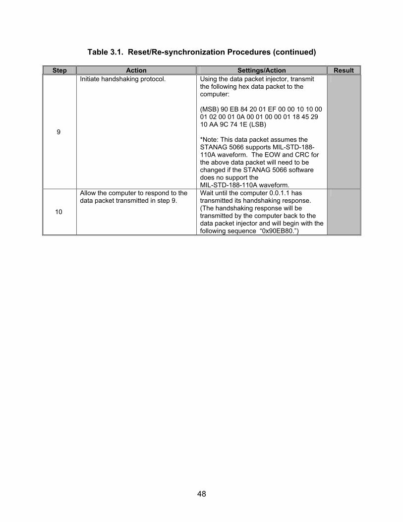
48
Table 3.1. Reset/Re-synchronization Procedures (continued)
Step Action Settings/Action Result
9
Initiate handshaking protocol.
Using the data packet injector, transmit the following hex data packet to the computer: (MSB) 90 EB 84 20 01 EF 00 00 10 10 00 01 02 00 01 0A 00 01 00 00 01 18 45 29 10 AA 9C 74 1E (LSB) *Note: This data packet assumes the STANAG 5066 supports MIL-STD-188-110A waveform. The EOW and CRC for the above data packet will need to be changed if the STANAG 5066 software does no support the MIL-STD-188-110A waveform.
10
Allow the computer to respond to the data packet transmitted in step 9.
Wait until the computer 0.0.1.1 has transmitted its handshaking response. (The handshaking response will be transmitted by the computer back to the data packet injector and will begin with the following sequence “0x90EB80.”)
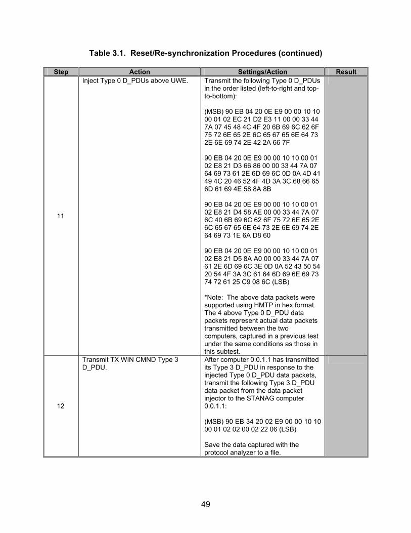
49
Table 3.1. Reset/Re-synchronization Procedures (continued)
Step Action Settings/Action Result
11
Inject Type 0 D_PDUs above UWE. Transmit the following Type 0 D_PDUs in the order listed (left-to-right and top-to-bottom): (MSB) 90 EB 04 20 0E E9 00 00 10 10 00 01 02 EC 21 D2 E3 11 00 00 33 44 7A 07 45 48 4C 4F 20 6B 69 6C 62 6F 75 72 6E 65 2E 6C 65 67 65 6E 64 73 2E 6E 69 74 2E 42 2A 66 7F 90 EB 04 20 0E E9 00 00 10 10 00 01 02 E8 21 D3 66 86 00 00 33 44 7A 07 64 69 73 61 2E 6D 69 6C 0D 0A 4D 41 49 4C 20 46 52 4F 4D 3A 3C 68 66 65 6D 61 69 4E 58 8A 8B 90 EB 04 20 0E E9 00 00 10 10 00 01 02 E8 21 D4 58 AE 00 00 33 44 7A 07 6C 40 6B 69 6C 62 6F 75 72 6E 65 2E 6C 65 67 65 6E 64 73 2E 6E 69 74 2E 64 69 73 1E 6A D8 60 90 EB 04 20 0E E9 00 00 10 10 00 01 02 E8 21 D5 8A A0 00 00 33 44 7A 07 61 2E 6D 69 6C 3E 0D 0A 52 43 50 54 20 54 4F 3A 3C 61 64 6D 69 6E 69 73 74 72 61 25 C9 08 6C (LSB) *Note: The above data packets were supported using HMTP in hex format. The 4 above Type 0 D_PDU data packets represent actual data packets transmitted between the two computers, captured in a previous test under the same conditions as those in this subtest.
12
Transmit TX WIN CMND Type 3 D_PDU.
After computer 0.0.1.1 has transmitted its Type 3 D_PDU in response to the injected Type 0 D_PDU data packets, transmit the following Type 3 D_PDU data packet from the data packet injector to the STANAG computer 0.0.1.1: (MSB) 90 EB 34 20 02 E9 00 00 10 10 00 01 02 02 00 02 22 06 (LSB) Save the data captured with the protocol analyzer to a file.

50
Table 3.1. Reset/Re-synchronization Procedures (continued)
Step Action Settings/Action Result
13
Identify D_DPUs. D_PDUs begin with the following sync in hex format: 0x90EB. The first 4 bits, immediately after the 0x90EB sequence, will be the D_PDU Type. Record all D_PDUs transmitted by computer 0.0.1.1 in the order they are transmitted.
D_PDU Types =
14
Locate Reset Frame ID bits. The Reset Frame ID bits field is 8 bits long and located in the 14th byte of the Type 3 D_PDU. The Type 3 D_PDU’s Type field will be (MSB) 0 10 1 1 (LSB) (0x3 hex). For all Type 3 D_PDUs captured in step 13, record the Reset Frame ID bits in the order they are transmitted.
Type 3 Reset Frame IDs =
15
Locate Type 3 (Reset/Re-sync) D_PDU.
D_PDUs begin with the following sync in hex format: 0x90EB. The first 4 bits, immediately after the 0x90EB sequence, will be the D_PDU Type. For the Type 3 D_PDU, the value will be 0x3 in hex or 0011 in binary. Locate the first Type 3 D_PDU transmitted by the STANAG computer 0.0.1.1. Record the D_PDU Type.
D_PDU Type =
16
Locate Reserved bits for the Type 3 D_PDU from step 15.
The Reserved bits are the first 4 bits of the 12th byte of the Type 3 D_PDU (not including the sync bits. See figure 3.1). Record the Reserved bits.
Type 3 Reserved bits =
17
Locate Full Reset CMND bit for the Type 3 D_PDU from step 15.
The next bit, after the Reserved bits, is the Full Reset CMND bit. Record the Full Reset CMND bit.
Type 3 Full Reset CMND =
18
Locate Reset TX WIN RQST bit for the Type 3 D_PDU from step 15.
The next bit, after the Full Reset CMND bit, is the Reset TX WIN RQST bit. Record the Reset TX WIN RQST bit.
Type 3 Reset TX WIN RQST =
19
Locate Reset TX WIN CMND bit for the Type 3 D_PDU from step 15.
The next bit, after the Reset TX WIN RQST bit, is the Reset TX WIN CMND bit. Record the Reset TX WIN CMND bit.
Type 3 Reset TX WIN CMND =
20
Locate Reset ACK bit for the Type 3 D_PDU from step 15.
The next bit, after the Reset TX WIN CMND bit, is the Reset ACK bit. Record the Reset ACK bit.
Type 3 Reset ACK =

51
Table 3.1. Reset/Re-synchronization Procedures (continued)
Step Action Settings/Action Result
21
Locate New RX LWE bits for the Type 3 D_PDU from step 15.
The next 8 bits, after the Reset ACK bit, are the New RX LWE bits. Record the New RX LWE bits.
Type 3 New RX LWE =
22
Locate Reset Frame ID Number bits for the Type 3 D_PDU from step 15.
The next 8 bits, after the New RX LWE bits, are the Reset Frame ID Number bits. Record the Reset Frame ID Number bits.
Type 3 Reset Frame ID Number =
23
Verify that computer 0.0.1.1 responded to the data packet injector’s Type 3 D_PDU with another Type 3 D_PDU.
D_PDUs begin with the following sync in hex format: 0x90EB. The first 4 bits, immediately after the 0x90EB sequence, will be the D_PDU Type. For the Type 3 D_PDU, the value will be 0x3 in hex or 0011 in binary. Locate the first Type 3 D_PDU transmitted after data packet injector’s Type 3 D_PDU is transmitted. Record the D_PDU Type.
D_PDU Type =
24
Locate Reset ACK bit for the Type 3 D_PDU from step 23.
The Reset ACK bit is located in the 8th bit of the 12th byte of the Type 3 D_PDU (not including sync sequence bits). Record the Reset ACK bit.
Type 3 Reset ACK =
25
Confirm no other D_PDUs transmitted until the Type 3 D_PDU in step 23 is transmitted.
Examine the Data Types from step 13, and verify that no other D_PDUs were transmitted after the Type 3 D_PDU from step 14 until the Type 3 D_PDU from step 23 was transmitted from computer 0.0.1.1. Rerord the D_PDUs transmitted before a Type 3D_PDU was transmitted.
D_PDUs transmitted before Type 3 D_PDU =
The following procedures are for reference numbers 712 and 715.
26
Send e-mail message. Send the following e-mail message from the STANAG computer 0.0.1.1 to the data packet injector using a Soft Link and Non-Expedited ARQ Delivery Method. Use the address 0.0.1.2 for the STANAG Destination Address of the data packet injector: For the Subject Line: Test 1 In the Body: “This is a test from address 0.0.1.1 to 0.0.1.2 1 2 3 4 5 6 7 8 9 10”

52
Table 3.1. Reset/Re-synchronization Procedures (continued)
Step Action Settings/Action Result
27
Transmit Link Accept Type 8 D_PDU data packet.
The first data packet to be transmitted by the computer will be to initiate a handshaking protocol. This will be a Type 8 D_PDU. After the computer has transmitted its Type 8 D_PDU, respond with the data packet injector by transmitting the following data packet: (MSB) 90 EB 84 A0 02 EF 00 00 10 10 00 01 02 00 01 01 00 01 00 00 01 18 25 7C 20 54 39 E9 3C (LSB)
28
Transmit RESET TX WIN RQST Re-sync Type 3 D_PDU.
The computer will then transmit a series of Type 0 D_PDUs after the handshaking has been completed. After the computer has paused in transmitting its Type 0 D_DPUs, transmit the following data packet from the data packet injector to the computer: (MSB) 90 EB 34 20 02 E9 00 00 10 10 00 01 02 04 00 02 47 41 (LSB)
29
Transmit Re-sync Type 3 D_PDU Acknowledgement.
The computer will then transmit a Type 3 D_PDU in response to the Type 3 D_PDU transmitted by the data packet injector. Upon completion of this Type 3 D_PDU, transmit the following data packet from the data packet injector to the computer: (MSB) 90 EB 34 20 02 E9 00 00 10 10 00 01 02 01 00 03 DB B9 (LSB) Save the data obtained through the protocol analyzer to a file.
30
Verify Re-sync Protocol completed, and the computer resumed, transmitting as normal.
After the final Type 3 D_PDU is transmitted from the data packet injector, the computer should resume transmitting Type 0 and/or Type 2 D_PDUs. D_PDUs begin with the sync sequence 0x90EB. The next 4 bits, after the sync sequence, are the D_PDU Type bits. Confirm that the computer resumed transmitting Type 0 and/or Type 2 D_PDUs after the final Type 3 D_PDU was transmitted by the data packet injector.
Re-sync Protocol Procedures completed? Y/N
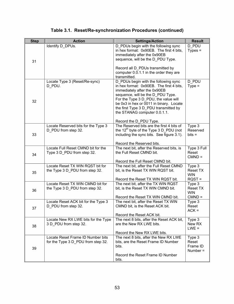
53
Table 3.1. Reset/Re-synchronization Procedures (continued)
Step Action Settings/Action Result
31
Identify D_DPUs. D_PDUs begin with the following sync in hex format: 0x90EB. The first 4 bits, immediately after the 0x90EB sequence, will be the D_PDU Type. Record all D_PDUs transmitted by computer 0.0.1.1 in the order they are transmitted.
D_PDU Types =
32
Locate Type 3 (Reset/Re-sync) D_PDU.
D_PDUs begin with the following sync in hex format: 0x90EB. The first 4 bits, immediately after the 0x90EB sequence, will be the D_PDU Type. For the Type 3 D_PDU, the value will be 0x3 in hex or 0011 in binary. Locate the first Type 3 D_PDU transmitted by the STANAG computer 0.0.1.1. Record the D_PDU Type.
D_PDU Type =
33
Locate Reserved bits for the Type 3 D_PDU from step 32.
The Reserved bits are the first 4 bits of the 12th byte of the Type 3 D_PDU (not including the sync bits. See figure 3.1). Record the Reserved bits.
Type 3 Reserved bits =
34
Locate Full Reset CMND bit for the Type 3 D_PDU from step 32.
The next bit, after the Reserved bits, is the Full Reset CMND bit. Record the Full Reset CMND bit.
Type 3 Full Reset CMND =
35
Locate Reset TX WIN RQST bit for the Type 3 D_PDU from step 32.
The next bit, after the Full Reset CMND bit, is the Reset TX WIN RQST bit. Record the Reset TX WIN RQST bit.
Type 3 Reset TX WIN RQST =
36
Locate Reset TX WIN CMND bit for the Type 3 D_PDU from step 32.
The next bit, after the TX WIN RQST bit, is the Reset TX WIN CMND bit. Record the Reset TX WIN CMND bit.
Type 3 Reset TX WIN CMND =
37
Locate Reset ACK bit for the Type 3 D_PDU from step 32.
The next bit, after the Reset TX WIN CMND bit, is the Reset ACK bit. Record the Reset ACK bit.
Type 3 Reset ACK =
38
Locate New RX LWE bits for the Type 3 D_PDU from step 32.
The next 8 bits, after the Reset ACK bit, are the New RX LWE bits. Record the New RX LWE bits.
Type 3 New RX LWE =
39
Locate Reset Frame ID Number bits for the Type 3 D_PDU from step 32.
The next 8 bits, after the New RX LWE bits, are the Reset Frame ID Number bits. Record the Reset Frame ID Number bits.
Type 3 Reset Frame ID Number =

54
Table 3.1. Reset/Re-synchronization Procedures (continued)
Step Action Settings/Action Result The following procedures are for reference numbers 709 and 963-981.
40
Initiate handshaking protocol.
Using the data packet injector, transmit the following hex data packet to the computer: (MSB) 90 EB 84 20 01 EF 00 00 10 10 00 01 02 00 01 0A 00 01 00 00 01 18 45 29 10 AA 9C 74 1E (LSB) *Note: This data packet assumes the STANAG 5066 supports waveform MIL-STD-188-110A. The EOW and CRC for the above data packet will need to be changed if the STANAG 5066 software does not support the MIL-STD-188-110A waveform.
41
Allow the computer to respond to the data packet transmitted in step 9.
Wait until the computer 0.0.1.1 has transmitted its handshaking response. (The handshaking response will be transmitted by the computer back to the data packet injector and will begin with the following sequence 0x90EB80.)
42
Inject data packets. Transmit the following Type 0 D_PDU in the order listed (left-to-right and top-to-bottom): (MSB) 90 EB 30 00 05 E9 00 00 10 10 00 01 02 08 00 01 B7 07 90 EB 30 00 03 E9 00 00 10 10 00 01 02 08 00 01 D4 EA 90 EB 30 00 01 E9 00 00 10 10 00 01 02 08 00 01 F5 B1 (LSB) Save the data obtained through the protocol analyzer to a file.
43
Locate Type 3 (Reset/Re-sync) D_PDU.
D_PDUs begin with the following sync in hex format: 0x90EB. The first 4 bits, immediately after the 0x90EB sequence, will be the D_PDU Type. For the Type 3 D_PDU, the value will be 0x3 in hex or 0011 in binary. Record the D_PDU Type transmitted by computer 0.0.1.1 in response to the data packet injector’s Type 3 D_PDU data packet.
D_PDU Type =
44
Locate Reserved bits for the Type 3 D_PDU from step 43.
The Reserved bits are the first 4 bits of the 12th byte of the Type 3 D_PDU (not including the sync bits. See figure 3.1). Record the Reserved bits.
Type 3 Reserved bits =

55
Table 3.1. Reset/Re-synchronization Procedures (continued)
Step Action Settings/Action Result
45
Locate Full Reset CMND bit for the Type 3 D_PDU from step 43.
The next bit, after the Reserved bits, is the Full Reset CMND bit. Record the Full Reset CMND bit.
Type 3 Full Reset CMND =
46
Locate Reset TX WIN RQST bit for the Type 3 D_PDU from step 43.
The next bit, after the Full Reset CMND bit, is the Reset TX WIN RQST bit. Record the Reset TX WIN RQST bit.
Type 3 Reset TX WIN RQST =
47
Locate Reset TX WIN CMND bit for the Type 3 D_PDU from step 43.
The next bit, after the TX WIN RQST bit, is the Reset TX WIN CMND bit. Record the Reset TX WIN CMND bit.
Type 3 Reset TX WIN CMND =
48
Locate Reset ACK bit for the Type 3 D_PDU from step 43.
The next bit, after the TX WIN CMND bit, is the Reset ACK bit. Record the Reset ACK bit.
Type 3 Reset ACK =
49
Locate New RX LWE bits for the Type 3 D_PDU from step 43.
The next 8 bits, after the Reset ACK bit, are the New RX LWE bits. Record the New RX LWE bits.
Type 3 New RX LWE =
50
Locate Reset Frame ID Number bits for the Type 3 D_PDU from step 43.
The next 8 bits, after the New RX LWE bits, are the Reset Frame ID Number bits. Record the Reset Frame ID Number bits.
Type 3 Reset Frame ID Number =
51
Locate Type 0 D_PDU. D_PDUs begin with the following sync in hex format: 0x90EB. The first 4 bits immediately after the 0x90EB sequence will be the D_PDU Type. For the Type 0 D_PDU, the value will be 0x0 in hex or 0000 in binary. Locate the first Type 0 D_PDU transmitted by computer 0.0.1.1 after the Full Reset protocol had completed.
52
Locate TX FSN of the first Type 0 D_PDU captured in step 51.
The TX FSN is an 8-bit field located in the 14th byte of the Type 0 D_PDU. Record the TX FSN.
Type 0 D_PDU TX FSN =

56
Table 3.1. Reset/Re-synchronization Procedures (continued)
Step Action Settings/Action Result Procedures for reference numbers 713-714, 720, and 721 are currently underdevelopment, and their
results are to be developed. Legend: ACK—Acknowledgement ARQ—Automatic Repeat-Request bps—bits per second CMND—Command CRC—Cyclic Redundancy Check D_PDU—Data Transfer Sublayer Protocol Data Unit e-mail—Electronic Mail EOW—Engineering Orderwire FSN—Frame Sequence Number hex—hexadecimal HMTP—High Frequency Mail Transfer Protocol ID—Identification LSB—Least Significant Bit
LWE—Lower Window Edge MIL-STD—Military Standard MSB—Most Significant Bit POP3—Post Office Protocol 3 Re-sync—Re-synchronization RQST—Request RX—Receive SMTP—Simple Mail Transfer Protocol STANAG—Standardization Agreement sync—synchronization TX—Transmit UWE—Upper Window Edge WIN—Window

57
Table 3.2. Reset/Re-synchronization Results
Result Finding Reference Number
STANAG 5066
Paragraph Requirement Required
Value Measured
Value Met Not Met
703 C.3.6
The Reset/WIN Re-synchronization (SYNC) D_PDU shall be used to control the re-sync or re-initialization of the selective-repeat ARQ protocol, operating on the link between the source and destination nodes.
Type 3 D_PDU transmitted in response to D_PDUs being out of sync.
706 C.3.6
The reception of this D_PDU shall result in the transmission of an acknowledgement D_PDU by the receiving node. For the IRQ protocol used with the Reset/WIN Re-sync D_PDU, the Reset/WIN Re-sync D_PDU is used for both data and acknowledgement, as specified below.
Type 3 D_PDU with Reset ACK = 1 sent in response to Type 3 D_PDU transmitted by Data Packet Injector.
707 C.3.6
Transmission of D_PDUs supporting the regular-data service, i.e., of Data (Type 0), ACK (Type 1) and Data-ACK (Type 2) D_PDUs, shall be suspended pending completion of any stop-and-wait protocol using the Reset/WIN Re-sync D_PDUs.
No Types 0, 1, or 2 D_PDUs transmitted during exchange sequence of Type 3 D_PDUs.
708 C.3.6
The Reset/WIN Re-sync D_PDU shall contain the following fields within its D_PDU Type-Specific Part, mapped and encoded, in accordance with figure C-14 and the paragraphs below:
• FULL RESET CMND • RESET TX WIN RQST • RESET TX WIN CMND • RESET ACK • NEW RX LWE • RESET FRAME ID NUMBER
Type 3 D_PDU structured as figure 3.1.
709 C.3.6
The Full Reset CMND flag shall be set equal to one (1) to force a full reset of the ARQ machines at the transmitter and receiver to their initial values as specified in STANAG 5066, sections C.6.2 and C.6.3.
Type 0 D_PDU TX FSN = 0 after Full Reset Protocol completed.

58
Table 3.2. Reset/Re-synchronization Results (continued)
Result Finding Reference Number
STANAG 5066
Paragraph Requirement Required
Value Measured
Value Met Not Met
710 C.3.6
A Type 3 D_PDU with the Reset TX WIN RQST flag set equal to one (1) shall be used to request a re-sync of the TX-LWE and RX-LWE pointers used for DATA in the transmit and receive nodes.
RESET TX WIN RQST = 1 when Type 0 D_PDUs transmitted above UWE.
711 C.3.6
A node that receives a Type 3 D_PDU with the Reset TX WIN RQST flag set equal to one shall respond by forcing re-sync of the windows using a Reset/WIN Re-sync D_DPU and the Reset TX WIN CMND flag, as specified below.
Computer responded with a Type 3 D_PDU with Reset TX WIN CMND = 1 after receiving a Type 3 D_DPU with RESET TX WIN RQST = 1.
712 C.3.6
A RESET/WIN Re-sync TYPE 3 D_PDU with the RESET TX WIN CMND flag set equal to one (1) shall be used to force a re-sync of the TX-LWE and RX-LWE pointers.
Type 3 D_PDU with Reset TX WIN CMND = 1 after receiving a Type 3 D_DPU with RESET TX WIN RQST = 1.
713 C.3.6 A node that sends a Type 3 D_PDU with the Reset TX WIN CMND flag set equal to one shall proceed as follows:
714 C.3.6 The New Receive LWE field shall be set equal to the value of the sending node’s RX LWE.
TBD N/A
715 C.3.6
The sending node shall wait for a Reset/WIN Re-sync Type 3 D_PDU with the Reset ACK flag set equal to one as an acknowledgement that the re-sync has been performed.
No further D_PDUs transmitted by computer 0.0.1.1 until after Type 3 D_PDU is transmitted with Reset ACK = 1.
716 C.3.6 A node that receives a Type 3 D_PDU with the Reset TX WIN CMND flag set equal to one shall proceed as follows:
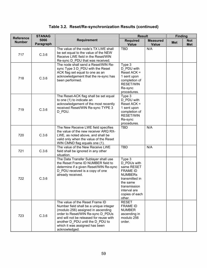
59
Table 3.2. Reset/Re-synchronization Results (continued)
Result Finding Reference Number
STANAG 5066
Paragraph Requirement Required
Value Measured
Value Met Not Met
717 C.3.6
The value of the node’s TX LWE shall be set equal to the value of the NEW Receive LWE field in the Reset/WIN Re-sync D_PDU that was received;
TBD N/A
718 C.3.6
The node shall send a Reset/WIN Re-sync Type 3 D_PDU with the Reset ACK flag set equal to one as an acknowledgement that the re-sync has been performed.
Type 3 D_PDU with Reset ACK = 1 sent upon completion of RESET/WIN Re-sync procedures.
719 C.3.6
The Reset-ACK flag shall be set equal to one (1) to indicate an acknowledgement of the most recently received Reset/WIN Re-sync TYPE 3 D_PDU.
Type 3 D_PDU with Reset ACK = 1 sent upon completion of RESET/WIN Re-sync procedures.
720 C.3.6
The New Receive LWE field specifies the value of the new receiver ARQ RX-LWE, as noted above, and shall be valid only when the value of the Reset WIN CMND flag equals one (1).
TBD N/A
721 C.3.6 The value of the New Receive LWE field shall be ignored in any other situation.
TBD N/A
722 C.3.6
The Data Transfer Sublayer shall use the Reset Frame ID NUMBER field to determine if a given Reset/WIN Re-sync D_PDU received is a copy of one already received.
Type 3 D_PDUs with same RESET FRAME ID NUMBERs transmitted in the same transmission interval are copies of each other.
723 C.3.6
The value of the Reset Frame ID Number field shall be a unique integer (modulo 256) assigned in ascending order to Reset/WIN Re-sync D_PDUs and will not be released for reuse with another D_PDU until the D_PDU to which it was assigned has been acknowledged.
RESET FRAME ID NUMBER ascending in modulo 256 order.

60
Table 3.2. Reset/Re-synchronization Results (continued)
Result Finding Reference Number
STANAG 5066
Paragraph Requirement Required
Value Measured
Value Met Not Met
963 C.6.5 A Full Reset procedure shall by a node sending a Type 3 Reset/WIN Re-sync D_PDU with field values as follows:
964
The Full Reset CMD flag shall be set to 1.
Type 3 D_PDU FULL RESET CMD Flag = 1 for initiating Full Reset.
965
The Reset Frame ID Number shall be selected from Reset Frame ID Number sequence.
Reset Frame ID Number is ascending modulo 256.
966
The New Receive LWE field shall be reset to zero.
NEW RX LWE = 0 for initiating Full Reset.
967
The Reset TX WIN RQST flag shall be reset to zero.
RESET TX WIN RQST Flag = 0 for initiating Full Reset.
968
The Reset RX WIN CMD flag shall be reset to zero.
RESET TX WIN CMD Flag = 0 for initiating Full Reset.
969
The Type 3 D_PDU described immediately above is defined to be a Full Reset CMD D_PDU. A node receiving a Full Reset CMD D_PDU shall proceed as follows:
970
The node shall set the transmit and receive window pointers to initial values (as defined in STANAG 5066, section C.6.2).
D_PDU’s TX FSN = 0 for Type 0 D_PDU immediately following a Full Reset protocol.
971 The node shall discard from its transmit queue any partially completed C_PDUs.
TBD N/A
972
C.6.5
The node shall flush its receive buffers. TBD N/A

61
Table 3.2. Reset/Re-synchronization Results (continued)
Result Finding Reference Number
STANAG 5066
Paragraph Requirement Required
Value Measured
Value Met Not Met
973
The node shall respond to the originator of the Full-Reset-CMD D_PDU by sending it a Reset/WIN Re-sync (Type 3) D_PDU with field values set as follows:
Type 3 D_PDU transmitted from computer receiving a Type 3 D_PDU with a Full Reset.
974
The Reset ACK flag shall be set to 1. Type 3 D_PDU RESET ACK = 1 for computer responding to a Full Reset.
975
The New Receive LWE and Reset Frame ID Number fields shall be reset to zero.
Type 3 D_PDU NEW RX LWE = 0 for computer responding to a Full Reset.
Type 3 D_PDU TX WIN RQST = 0 for computer responding to a Full Reset.
Type 3 D_PDU FULL RESET CMD = 0 for computer responding to a Full Reset.
976
C.6.5 The Reset TX WIN RQST, Full Reset CMD and Reset RX WIN CMD flags shall be reset to zero.
Type 3 D_PDU RESET TX WIN CMD = 0 for computer responding to a Full Reset.

62
Table 3.2. Reset/Re-synchronization Results (continued)
Result Finding Reference Number
STANAG 5066
Paragraph Requirement Required
Value Measured
Value Met Not Met
977
The D_PDU described immediately above is defined to be a Full-Reset-ACK D_PDU. The Full Reset ACK D_PDU shall be sent only in response to the Full Reset CMD D_PDU.
Type 3 D_PDU with ACK = 1 and all other fields = 0 transmitted only in response to Type 3 D_PDU with FULL RESET CMD =1.
978
On receiving the Full-Reset-ACK D_PDU, the node initiating the Full Reset procedure shall proceed as follows:
979
The node shall set the transmit and receive window pointers to initial values (as defined in STANAG 5066, section C.6.2).
TBD N/A
980 The node shall discard from its transmit queue any partially completed C_PDUs.
TBD N/A
981
C.6.5
The node shall flush its receive buffers. TBD N/A Note: Locating specific values of RX and TX UWE and LWEs are internal to the software and may be vendor specific,
and are therefore untestable at this time. Legend: ACK—Acknowledgement ARQ—Automatic Repeat-Request CMD—Command CMND—Command C_PDU—Channel Access Sublayer Protocol Data Unit D_PDU—Data Transfer Sublayer Protocol Data Unit FSN—Frame Sequence Number IRQ—Idle Repeat-Request ID—Identification LWE—Lower Window Edge
N/A—Not Available RQST—Request RX—Receive STANAG—Standardization Agreement sync—synchronization TBD—To Be Determined TX—Transmit UWE—Upper Window Edge WIN—Window

63
(This page intentionally left blank.)

64
SUBTEST 4. MANAGEMENT CONTROL PROTOCOLS 4.1 Objective. To determine the extent of compliance to the requirements of STANAG 5066, reference numbers 742-753, 759-761, 767-769, 844-861, 925, 927-931, 933-936, 938-943, and 947-962. 4.2 Criteria
a. The Management (Type 6) D_PDU shall be used to send Engineering Orderwire (EOW) Messages or Management Protocol Data Units when the transmitting node needs an explicit acknowledgement that they were received. (appendix B, reference number 742)
b. A Data Transfer Sublayer entity shall acknowledge receipt of a
Management (Type 6) D_PDU by sending a Management (Type 6) D_PDU with the ACK flag set to the value (1). (appendix B, reference number 743)
c. The processing and transmission of Management (Type 6) D_PDUs shall
take precedence over and bypass all other pending D_PDU Types in the Data Transfer Sublayer. (appendix B, reference number 744)
d. The exchange of Management D_PDUs is regulated by a stop-and-wait
protocol, i.e., there shall be only one unacknowledged Management D_PDU at any time. (appendix B, reference number 745)
e. The Management D_PDU shall contain the following fields within its
D_PDU Type-Specific Part, mapped and encoded, in accordance with figure 4.1 and the paragraphs below: (appendix B, reference number 746)
• Extended Message Flag • Valid Message • ACK • Management Frame ID Number • Extended Management Message
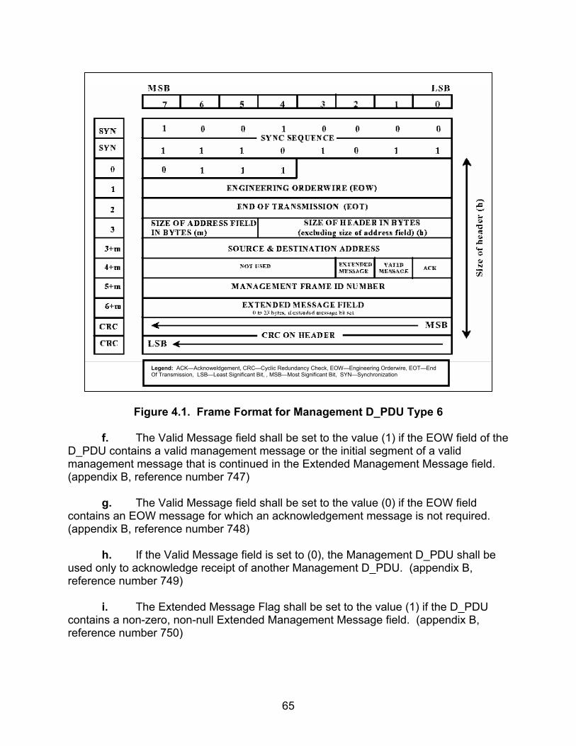
65
Figure 4.1. Frame Format for Management D_PDU Type 6
f. The Valid Message field shall be set to the value (1) if the EOW field of the
D_PDU contains a valid management message or the initial segment of a valid management message that is continued in the Extended Management Message field. (appendix B, reference number 747)
g. The Valid Message field shall be set to the value (0) if the EOW field
contains an EOW message for which an acknowledgement message is not required. (appendix B, reference number 748)
h. If the Valid Message field is set to (0), the Management D_PDU shall be
used only to acknowledge receipt of another Management D_PDU. (appendix B, reference number 749)
i. The Extended Message Flag shall be set to the value (1) if the D_PDU
contains a non-zero, non-null Extended Management Message field. (appendix B, reference number 750)
Legend: ACK—Acknoweldgement, CRC—Cyclic Redundancy Check, EOW—Engineering Orderwire, EOT—End Of Transmission, LSB—Least Significant Bit, , MSB—Most Significant Bit, SYN—Synchronization

66
j. If the Extended Message Flag is set to the value (0), the Extended Management Message field shall not be present in the Management D_PDU. (appendix B, reference number 751)
k. The Management Frame ID Number field shall contain an integer in the range [0,255] with which Management D_PDUs shall be identified. (appendix B, reference numbers 752 and 753)
l. The current value of the TX Management Frame ID Number shall be
placed in the appropriate field of each unique Management D_PDU transmitted. (appendix B, reference number 759)
m. The current value of the TX Management Frame ID Number shall be
incremented by one, modulo 256, after each use, unless transmission of repeated copies of the Management D_PDU are specified for its use, e.g., as in section C.6.4.2 of STANAG 5066. (appendix B, reference number 760)
n. Management D_PDUs that have been repeated (e.g., in accordance
section C.6.4.2 of STANAG 5066) shall have the same Management Frame ID Number. (appendix B, reference number 761)
o. There shall be a one-to-one correspondence between management
messages and Management D_PDUs; that is, each message is placed into a separate D_PDU (which may be repeated a number of times as specified in STANAG 5066, section C.6.4). (appendix B, reference number 767)
p. The 12-bit EOW section of the D_PDU shall carry the EOW (non-
extended) management message, as specified in STANAG 5066, section C.5. (appendix B, reference number 768)
q. The Extended Management Message field may be used to transmit other
implementation-specific messages that are beyond the scope of STANAG 5066. When the Extended Message field is present and in use, the Extended Message Flag shall be set to the value (1). (appendix B, reference number 769)
r. Implementation-Specific Extended Management messages shall be
identified and encoded through the use of the Extended Message Flag as specified in section C.3.9 of STANAG 5066 for the Management D_DPU. (appendix B, reference number 844)
s. The types of EOW messages shall be as defined in table 4.1. (appendix
B, reference number 845)
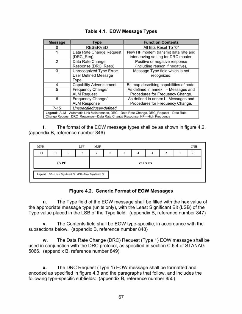
67
Table 4.1. EOW Message Types
Message Type Function Contents 0 RESERVED All Bits Reset To “0” 1 Data Rate Change Request
(DRC_Req) New HF modem transmit data rate and
interleaving setting for DRC master. 2 Data Rate Change
Response (DRC_Resp) Positive or negative response (including reason if negative).
3 Unrecognized Type Error: User Defined Message Type
Message Type field which is not recognized.
4 Capability Advertisement Bit map describing capabilities of node. 5 Frequency Change/
ALM Request As defined in annex I – Messages and
Procedures for Frequency Change. 6 Frequency Change/
ALM Response As defined in annex I - Messages and
Procedures for Frequency Change. 7-15 Unspecified/user-defined
Legend: ALM—Automatic Link Maintenance, DRC—Data Rate Change, DRC_Request—Data Rate Change Request, DRC_Response—Data Rate Change Response, HF—High Frequency
t. The format of the EOW message types shall be as shown in figure 4.2.
(appendix B, reference number 846)
Figure 4.2. Generic Format of EOW Messages
u. The Type field of the EOW message shall be filled with the hex value of
the appropriate message type (units only), with the Least Significant Bit (LSB) of the Type value placed in the LSB of the Type field. (appendix B, reference number 847)
v. The Contents field shall be EOW type-specific, in accordance with the
subsections below. (appendix B, reference number 848)
w. The Data Rate Change (DRC) Request (Type 1) EOW message shall be used in conjunction with the DRC protocol, as specified in section C.6.4 of STANAG 5066. (appendix B, reference number 849)
x. The DRC Request (Type 1) EOW message shall be formatted and
encoded as specified in figure 4.3 and the paragraphs that follow, and includes the following type-specific subfields: (appendix B, reference number 850)
Legend: LSB—Least Significant Bit, MSB—Most Significant Bit

68
• Data Rate • Interleaving • Other Parameters
Figure 4.3. Format of Management Message Type 1
y. The Data Rate Parameter shall be the rate at which the node originating the message (i.e., either the DRC Master or Advisee, as noted in section C.6.4 of STANAG 5066 specifying DRC procedures) wishes to transmit data, in accordance with the encoding defined in table 4.2. (appendix B, reference number 851)
Table 4.2. Data Rate Parameter Message Type 1
MSB-LSB Interpretation
0000 75 bps 0001 150 bps 0010 300 bps 0011 600 bps 0100 1200 bps 0101 2400 bps 0110 3200 bps 0111 3600 bps 1000 4800 bps 1001 6400 bps 1010 7200 bps 1011 9600 bps
Others Reserved Legend: bps—bits per second, LSB—Least Significant Bit, MSB—Most Significant Bit
z. The Interleaver Parameter field shall specify the interleaver requested for
use by the node producing the message (for that link, if multiple links/modems are in use) with respect to transmit and receive operation, in accordance with table 4.3. (appendix B, reference number 852)
Legend: LSB—Least Significant Bit, MSB—Most Significant Bit
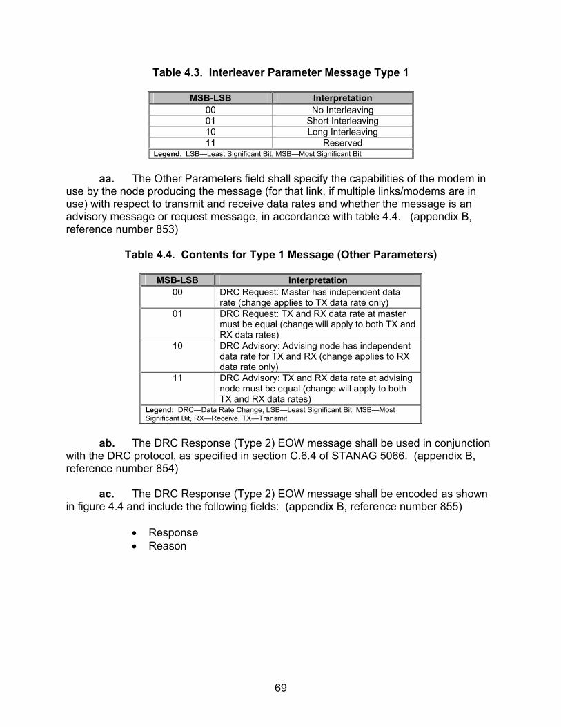
69
Table 4.3. Interleaver Parameter Message Type 1
MSB-LSB Interpretation 00 No Interleaving 01 Short Interleaving 10 Long Interleaving 11 Reserved
Legend: LSB—Least Significant Bit, MSB—Most Significant Bit
aa. The Other Parameters field shall specify the capabilities of the modem in
use by the node producing the message (for that link, if multiple links/modems are in use) with respect to transmit and receive data rates and whether the message is an advisory message or request message, in accordance with table 4.4. (appendix B, reference number 853)
Table 4.4. Contents for Type 1 Message (Other Parameters)
MSB-LSB Interpretation
00 DRC Request: Master has independent data rate (change applies to TX data rate only)
01 DRC Request: TX and RX data rate at master must be equal (change will apply to both TX and RX data rates)
10 DRC Advisory: Advising node has independent data rate for TX and RX (change applies to RX data rate only)
11 DRC Advisory: TX and RX data rate at advising node must be equal (change will apply to both TX and RX data rates)
Legend: DRC—Data Rate Change, LSB—Least Significant Bit, MSB—Most Significant Bit, RX—Receive, TX—Transmit
ab. The DRC Response (Type 2) EOW message shall be used in conjunction
with the DRC protocol, as specified in section C.6.4 of STANAG 5066. (appendix B, reference number 854)
ac. The DRC Response (Type 2) EOW message shall be encoded as shown
in figure 4.4 and include the following fields: (appendix B, reference number 855)
• Response • Reason

70
Figure 4.4. Format of Type 2 Message
ad. The Response field shall indicate the originator’s response to the last
DRC-related message it received, with possible responses and their encoding as defined in table 4.5. (appendix B, reference number 856)
Table 4.5. Contents for Type 2 Message (Response)
MSB-LSB Interpretation
000 Accept 001 Refuse 010 Cancel 011 Confirm
Legend: LSB—Least Significant Bit, MSB—Most Significant Bit
ae. The Reason field shall indicate the originator’s reason for its response,
with possible reasons and their encoding as defined in table 4.6. (appendix B, reference number 857)
Table 4.6. Contents for Type 2 Message (Reason)
MSB-LSB Interpretation
00000 No reason (used to indicate unconditional acceptance of DRC_Request)
00001 TX and RX parameters must be the same (conditionally accept)
00010 Not possible to change modem data rate 00011 Not possible to change modem interleaving 00100 Not possible to change modem data rate or
interleaving 00101 Not consistent with local conditions
Legend: DRC_Request—Data Rate Change Request, LSB—Least Significant Bit, MSB—Most Significant Bit, RX—Receive, TX—Transmit
af. The Unrecognized-Type Error (Type 3) EOW message shall be used to
declare an error related to receipt of EOW message. (appendix B, reference number 858)
Legend: LSB—Least Significant Bit, MSB—Most Significant Bit

71
ag. The Unrecognized-Type Error (Type 3) EOW message shall be encoded as shown in figure 4.5 and include the following fields: (appendix B, reference number 859)
• Response • Reason
Figure 4.5. Format of Type 3 Message
ah. The type of the unrecognized EOW message or the message that
triggered the error shall be mapped into the four LSBs of the Reason field. (appendix B, reference number 860)
ai. The unused Most Significant Bit (MSB) of the Reason field and all bits in
the Response field shall be reset to the value (0). (appendix B, reference number 861)
aj. If DRC is implemented, it shall be implemented as specified in the subsections below. (appendix B, reference numbers 925)
ak. All connections on which the data rate or other modem parameters can be
controlled shall be initiated at 300 bits per second (bps), using short interleaving. (appendix B, reference number 927)
al. The waveform shall be selected by the operator during node initialization.
(appendix B, reference number 928) am. Algorithms, to determine when or if the data rate change capability would
be exercised, are beyond the scope of STANAG 5066. At a minimum, systems implementing STANAG 5066 shall implement and support data rate changes in accordance with the procedures defined here. (appendix B, reference number 929)
an. On receiving an EOW Type 1 DRC message with the Other Parameters
field indicating that this is a request for a DRC, a node shall comply with the parameters specified in the message unless some specific reason prevents it doing so. Generally, this means that the node will initiate a DRC procedure. (appendix B, reference number 930)
Legend: LSB—Least Significant Bit, MSB—Most Significant Bit
72
ao. Following a decision to change the data rate, a node shall use Type 6 D_PDUs (i.e., Management D_PDUs) containing Type 1 and Type 2 EOW messages to implement and coordinate the change. (appendix B, reference number 931)
ap. DRCs shall be effective only for a single connection. (appendix B,
reference number 933) aq. If a node has a number of connections active with different nodes, the
DRC decisions and procedures shall be executed independently for each connection. (appendix B, reference number 934)
ar. The message numbered [1] in the figure indicates an EOW advisory
message. The DRC master shall send a DRC Request Message, i.e., a Management (Type 6) D_PDU containing a DRC Request (Type 1) EOW Message [2], with the parameters equal to the intended new transmit data rate for the DRC master. (appendix B, reference number 935)
as. The Other Parameters field of the Type 1 Management message shall be
set to indicate the data rate capabilities of the modem in use at the DRC master for this connection, to indicate that this is a request for a change and not an advisory message. In the scenario of figure 4.6, the modem at the DRC master has independent transmit and receive data rate. (appendix B, reference number 936)
at. Time-outs shall be set to allow a number of retransmissions before failure
is declared and the D_CONNECTION_LOST Primitive issued. The number of retransmissions before a time-out shall be configurable in the implementation with a default value of 3. (appendix B, reference numbers 938 and 939)
au. If this procedure was initiated in response to a DRC Request (Type 1)
Advisory message, the modem data rate and interleaving parameters shall be identical to the parameters in the EOW Type 1 DRC Advisory message, unless they specify a speed for which the DRC master is not equipped. (appendix B, reference number 940)

73
Node A Node B
state = Data state = Data
state = Management(DRC initiate)
Node A is DRC slave
state = Management(DRC initiate)
Node B is DRC master
state = Management(DRC confirm)
tx parameters = Poldrx parameters = Pnew
state = Management(DRC confirm)
tx parameters = Pnewrx parameters = Pold
state = Datatx parameters = Poldrx parameters = Pnew
state = Datatx parameters = Pnewrx parameters = Pold
DATA, DATA_ACK
ACK, DATA_ACK + EOW (Indep) [1]
DRC_Request(Indep) [2]
DRC_Response (unconditional) [3]
DT_ACK (only) [4]
DRC_Response (Confirm) [5]
DT_ACK (only) [6]
D_PDU
Legend: D_PDU—Data Transfer Sublayer Protocol Data Unit, DRC—Data Rate Change, DT_ACK—Data Acknowledgement, P—Parameter, tx—Transmit, rx—Receive
Figure 4.6. Data Rate Change Procedure (Scenario 1)
av. D_PDUs containing a DRC Request (Type 1) EOW message shall be repeated depending on the data rate at which it is transmitted, in accordance with the specification in table 4.7. (appendix B, reference number 941)
Table 4.7. Minimum Number of DRC Messages to Be Transmitted at Various Data
Rates Using STANAG 4285 Modem
Data Rate Repetitions w/ Short Interleave
Repetitions w/ Long Interleave
75 1 9 150 1 18 300 1 37 600 3 75 1200 7 150 2400 15 300
Legend: DRC—Data Rate Change, STANAG—Standarization Agreement
aw. Implementation Note: The number of transmissions in table 4.7 has been
specified to (nearly) fill the interleave buffer for the waveform specified by STANAG 4285. For waveforms and interleaver settings not shown, the number of transmissions

74
shall be adjusted as required to minimize the use of “stuff bits” to fill the modem interleave buffer. (appendix B, reference number 942)
ax. Repeated Management D_PDUs containing a DRC Request (Type 1)
management message shall have the same Frame ID Number in each of the copies. (appendix B, reference number 943)
ay. The DRC slave shall respond to the DRC_Request D_PDU with a
DRC_Response message, i.e., a Type 6 Management D_PDU containing a Type 2 DRC Response EOW message, as follows: (appendix B, reference numbers 947-951)
• The DRC Response message shall indicate either “accept” or “refuse,”
in accordance with the management message specifications of section C.3.5 of STANAG 5066, indicating the DRC slave’s capability to change the modem parameters or not.
• If the DRC slave accepts the DRC_Request, the Reason field shall indicate either “unconditional acceptance” or “TX and RX parameters must be the same.”
• If the DRC slave refuses the request, the Reason field shall indicate the reason for the refusal.
• The “Not consistent with local conditions” parameter shall only be used to refuse a DRC_Request which indicates a less robust mode (i.e., higher data rate or shorter interleaver) that cannot be supported with the node’s current local conditions for noise or error rate.
az. After receiving the DRC_Response message, the DRC master shall
review its contents and determine the appropriate response, e.g., the Data Acknowledgement (DT_ACK) (only) [4], in accordance with table 4.8. (appendix B, reference numbers 952-955)

75
Table 4.8. DRC_Responses and Allowed DRC Master Actions
DRC_Response DRC_Response Reason Action allowed by DRC master accept Unconditional a) Send DT_ACK
[DT_ACK = TYPE 6 D_PDU w/ ACK field set]
accept Transmit and receive parameters must be the same.
a) Send DT_ACK, or b) Send DRC_Response [cancel], or c) Send new DRC Request (note 1)
refuse Not possible to change modem data rate.
a) send DRC_Response [cancel] (note 2), or b) send DRC_Request (note 3) [with DT_ACK]
refuse Not possible to change modem interleave.
a) Send DRC_Response [cancel] (note 2), or b) Send DRC_Request (note 4) [with DT_ACK]
refuse Not possible to change modem data rate or interleave.
a) Send DRC_Response [cancel] (note 2) [with DT_ACK]
refuse Not consistent with local conditions (note 5).
a) Send DRC_Response [cancel] (note 2), or b) Send DRC_Request (note 6) [with DT_ACK]
Legend: ACK—Acknowledgement, DRC—Data Rate Change, D_PDU—Data Transfer Sublayer Protocol Data Unit, DT_ACK—Data Acknowledgment, DRC_Request—Data Rate Change Request, DRC_Response—Data Rate Change Response
Notes to table 4.8 and further DRC requirements are as follows: Note 1: If the procedure is initiated in response to EOW Type 1 message, the DRC master should already know that the DRC slave’s TX and RX parameters must be the same. Therefore, the DRC master shall reply with a DT_ACK, i.e., a Management (Type 6) D_PDU with the ACK field set equal to (1), accepting that the new parameters will apply to both transmit and receive. Note 2: A DRC slave that refused a change request shall acknowledge the DRC Response (cancel) message with a DT_ACK only and then terminate the DRC procedure. Note 3: If the DRC slave refused the change request because it is not possible to change its modem data rate, a new DRC_Request may be sent by the DRC master to request a different interleave setting at the same data rate. Note 4: If the DRC slave refused the change request because it is not possible to change its interleave setting, a new DRC_Request may be sent by the DRC master to request a different data rate setting at the same interleave setting. Note 5: As required by previous paragraphs, the DRC slave may refuse the request with “Reason = not consistent with local conditions” if and only if it is in response to a request for a less robust set of parameters. For example, a request for a higher data

76
rate and/or shorter interleaver, than currently in use, would be rejected by the DRC slave if it has determined that these cannot be supported by the current link conditions at the receiver. Note 6: If the nodes make use of the EOW Type 1 (Advisory) message to initiate the DRC procedure, the master shall send the DRC_Response (cancel) and await an updated EOW recommendation before initiating another DRC procedure. If EOW Type 1 messages are not used, DRC_Request may be sent by master to request different modem parameters that may be consistent with the local conditions. In the table and notes in the preceding paragraphs, a DT_ACK refers to a Data Transfer.
ba. If a DT_ACK (with no further management message) is sent in reply to a DRC_Response “accept” (as shown in figure 4.7), the nodes shall change their respective modem parameters and proceed to the “confirmation” phase. (appendix B, reference number 956)
bb. The DRC slave shall NOT change its modem parameters until it has
received a DT_ACK (with no further management message) from the DRC master. (appendix B, reference number 957)
bc. If a DT_ACK (with no further management message) is sent by the DRC
slave in reply to a DRC_Response “cancel,” both nodes shall abandon the procedure and return to the prior state without changing modem parameters. (appendix B, reference number 958)
bd. After abandoning a DRC procedure because of failure, if node A (formerly
the DRC slave) has no queued data or acknowledgements to send to node B, it shall send a Data D_PDU, Expedited Data D_PDU, or Non-ARQ D_PDU, with zero data attached. (appendix B, reference number 959)
be. On receiving the DRC Confirm message, the DRC master shall respond
with a DT_ACK and then return to the processing state it was in before executing the DRC procedure. (appendix B, reference number 960)
bf. After sending the DRC Confirm message [5] to the master and receiving
the DT_ACK from the master, the slave shall return to the processing state it was in before executing the DRC procedure and send any queued D_PDUs to node B. (appendix B, reference number 961)
bg. If node A (formerly the DRC slave) has no queued data to send to node B,
it shall send a Data D_PDU or Expedited Data D_PDU with zero data attached and the C_PDU Segment Size field set equal to (0). (appendix B, reference number 962)

77
4.3 Test Procedures
a. Test Equipment Required
(1) Computers (3 ea) with STANAG 5066 Software
(2) Modems (3 ea)
(3) Protocol Analyzer
(4) High Frequency (HF) Simulator (2 ea) (5) Two Position Switch (6) HF Radios (3 ea) (7) Data Packet Injector (8) RS-232 Synchronous Serial Cards (3 ea)
(9) Asynchronous Control Line
(10) Attenuated Network
b. Test Configuration. Figures 4.7, 4.8, and 4.9 shows the equipment setup for this subtest.
c. Test Conduction. Table 4.9 lists procedures for this subtest and table 4.10 lists the results for this subtest.

78
Computer Modem Modem Computer
LANAnalyzer
RS-232 RS-232
Figure 4.7. Equipment Configuration for Single Computer Management Control
Computer Modem Modem Computer
LANAnalyzer
RS-232 RS-232
Figure 4.8. Equipment Configuration for Type 3 EOW Messages
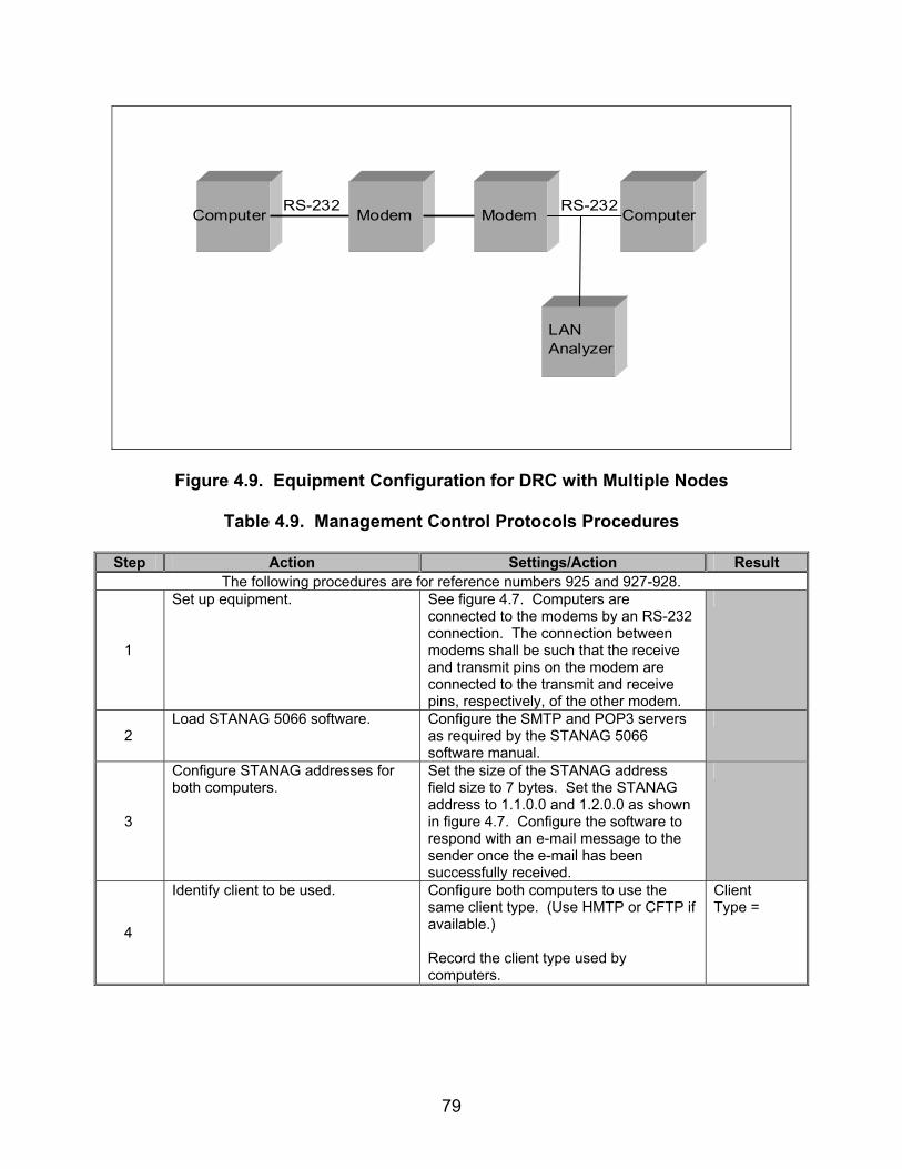
79
Computer Modem Modem Computer
LANAnalyzer
RS-232 RS-232
Figure 4.9. Equipment Configuration for DRC with Multiple Nodes
Table 4.9. Management Control Protocols Procedures
Step Action Settings/Action Result The following procedures are for reference numbers 925 and 927-928.
1
Set up equipment. See figure 4.7. Computers are connected to the modems by an RS-232 connection. The connection between modems shall be such that the receive and transmit pins on the modem are connected to the transmit and receive pins, respectively, of the other modem.
2 Load STANAG 5066 software. Configure the SMTP and POP3 servers
as required by the STANAG 5066 software manual.
3
Configure STANAG addresses for both computers.
Set the size of the STANAG address field size to 7 bytes. Set the STANAG address to 1.1.0.0 and 1.2.0.0 as shown in figure 4.7. Configure the software to respond with an e-mail message to the sender once the e-mail has been successfully received.
4
Identify client to be used. Configure both computers to use the same client type. (Use HMTP or CFTP if available.) Record the client type used by computers.
Client Type =

80
Table 4.9. Management Control Protocols Procedures (continued)
Step Action Settings/Action Result
5
Verify that the STANAG 5066 software allows for DRC with a STANAG 4285 waveform.
Configure both computers to use the STANAG 4285 waveform. Record if this waveform is available to be controlled by the STANAG 5066 software.
4285 waveform controllable? Y/N
6 Configure Deliver in Order. Set the Deliver in Order to “yes” for both computers.
7 Configure delivery confirmation. Set the delivery confirmation to “Node” for both computers.
8 Configure rank. Set the rank of the client to “15” for both computers.
9 Configure priority level. Set the priority level to “0” for both computers.
10
Configure DRC. Enable the data rate change for the STANAG 5066 software. Enable the software to increase the data rate to 2400 bps and short interleaver. Transmit using half-duplex.
11
Configure HF simulators.
Configure the HF “good” simulator to produce a 30-dB SNR along the RS-232 line, and the HF “bad” simulator to produce a –10 dB SNR along the RS-232 line as shown in figure 4.7.
12
Configure protocol analyzer. Configure the protocol analyzer to capture the transmitted data between the two computers and save it to a file. Configure the protocol analyzer to have a 4800-bps bit rate and to synchronize on “0x90EB.” Configure the protocol analyzer to drop sync after 20 “0xFFs”. Configure the analyzer to time stamp each captured byte.
13
Verify Initial Data Rate for modems is 300 bps.
Record the Initial Data Rate as listed on the modems.
Initial Data Rate =

81
Table 4.9. Management Control Protocols Procedures (continued)
Step Action Settings/Action Result
14
Send e-mail message and capture all transmitted and received bytes via the protocol analyzer shown in figure 4.7.
With the 2-position switch set to the “good” position, send the following e-mail message from the computer with STANAG address 1.2.0.0 to the computer with STANAG address 1.1.0.0 using a Soft Link and Non-Expedited ARQ Delivery Method. Include an attachment of approximately 15 kbytes. For the Subject Line: Test 1 In the Body: “This is a test from address 1.2.0.0 to 1.1.0.0 for DRC testing 1 2 3 4 5 6 7 8 9 10” Save the data obtained through the protocol analyzer to a file.
Data Rate Change? Y/N
15
Verify the data rate and interleaver changed.
Monitor the modems and verify that the data rate increased to 2400 bps the interleaver stayed at short. Record if the data rate change. Also record the value of the new data rate and interleaver.
New Data Rate and Interleaver =
16
Locate D_PDU Types. D_PDUs begin with the following sync in hex format: 0x90EB. The first 4 bits, immediately after the 0x90EB sequences, will be the D_PDU Type. Record all D_PDU Types in the order that they are transmitted.
D_PDU Types =
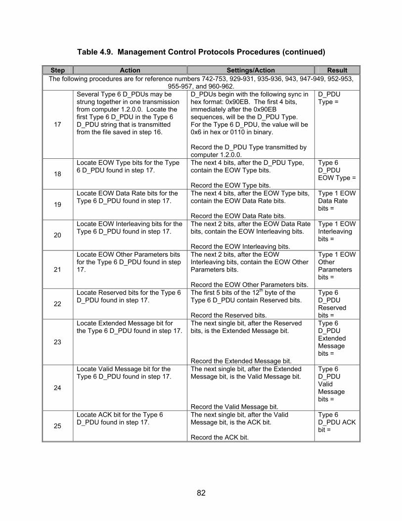
82
Table 4.9. Management Control Protocols Procedures (continued)
Step Action Settings/Action Result The following procedures are for reference numbers 742-753, 929-931, 935-936, 943, 947-949, 952-953,
955-957, and 960-962.
17
Several Type 6 D_PDUs may be strung together in one transmission from computer 1.2.0.0. Locate the first Type 6 D_PDU in the Type 6 D_PDU string that is transmitted from the file saved in step 16.
D_PDUs begin with the following sync in hex format: 0x90EB. The first 4 bits, immediately after the 0x90EB sequences, will be the D_PDU Type. For the Type 6 D_PDU, the value will be 0x6 in hex or 0110 in binary. Record the D_PDU Type transmitted by computer 1.2.0.0.
D_PDU Type =
18
Locate EOW Type bits for the Type 6 D_PDU found in step 17.
The next 4 bits, after the D_PDU Type, contain the EOW Type bits. Record the EOW Type bits.
Type 6 D_PDU EOW Type =
19
Locate EOW Data Rate bits for the Type 6 D_PDU found in step 17.
The next 4 bits, after the EOW Type bits, contain the EOW Data Rate bits. Record the EOW Data Rate bits.
Type 1 EOW Data Rate bits =
20
Locate EOW Interleaving bits for the Type 6 D_PDU found in step 17.
The next 2 bits, after the EOW Data Rate bits, contain the EOW Interleaving bits. Record the EOW Interleaving bits.
Type 1 EOW Interleaving bits =
21
Locate EOW Other Parameters bits for the Type 6 D_PDU found in step 17.
The next 2 bits, after the EOW Interleaving bits, contain the EOW Other Parameters bits. Record the EOW Other Parameters bits.
Type 1 EOW Other Parameters bits =
22
Locate Reserved bits for the Type 6 D_PDU found in step 17.
The first 5 bits of the 12th byte of the Type 6 D_PDU contain Reserved bits. Record the Reserved bits.
Type 6 D_PDU Reserved bits =
23
Locate Extended Message bit for the Type 6 D_PDU found in step 17.
The next single bit, after the Reserved bits, is the Extended Message bit. Record the Extended Message bit.
Type 6 D_PDU Extended Message bits =
24
Locate Valid Message bit for the Type 6 D_PDU found in step 17.
The next single bit, after the Extended Message bit, is the Valid Message bit. Record the Valid Message bit.
Type 6 D_PDU Valid Message bits =
25
Locate ACK bit for the Type 6 D_PDU found in step 17.
The next single bit, after the Valid Message bit, is the ACK bit. Record the ACK bit.
Type 6 D_PDU ACK bit =

83
Table 4.9. Management Control Protocols Procedures (continued)
Step Action Settings/Action Result
26
Locate Management Frame ID Number bits for the Type 6 D_PDU found in step 17.
The next 8 bits, after the ACK bit, contain the Management Frame ID Number bits. Record the Management Frame ID Number bits.
Type 6 D_PDU Management Frame ID Number =
27
Determine Extended Message field byte length for the Type 6 D_PDU found in step 17.
This field can be 0 to 23 bytes long. The length of this field can be determined by subtracting 10 (the size of the header without an Extended Message field) from the value obtained from the Size of Header field. Record the Extended Message field byte length.
Type 6 D_PDU Extended Message Field Byte Length =
28
Locate Extended Message field bits for the Type 6 D_PDU found in step 17.
Record the Extended Message field bits (if any). If there are no Extended Message field bits, record None.
Type 6 D_PDU Extended Message Field Length =
29
Locate Type 2 EOW encapsulated within Type 6 D_PDU transmitted by computer 1.1.0.0.
D_PDUs begin with the following sync in hex format: 0x90EB. The first 4 bits immediately after the 0x90EB sequences will be the D_PDU Type. For the Type 6 D_PDU, the value will be 0x6 in hex or 0110 in binary. The EOW bits are the next 12 bits, after the D_PDU Type bits. Record the EOW Type (should be Type 2 EOW).
Type 6 D_PDU EOW Type =
30
Locate EOW Response bits for the Type 2 EOW message sent in step 29.
The next 3 bits, after the EOW Type, contain the EOW Response bits. Record the EOW Response bits.
Type 2 EOW Response bits =
31
Locate EOW Reason bits for the Type 2 EOW message sent in step 29.
The next 5 bits, after the EOW Response bits, contain the EOW Reason bits. Record the EOW Reason bits.
Type 2 EOW Reason bits =
32
Locate Valid Message bit. The Valid Message bit is located in the 7th bit of the 12 byte of the Type 6 D_PDU (not including sync bits). Record the Valid Message bit.
Type 6 Valid Message bit =
33
Locate ACK bit for the Type 6 D_PDU for which the Type 2 EOW message in step 29 is encapsulated.
The next bit, after the Valid Message bit, is the ACK bit. Record the ACK Bit.
Type 6 D_PDU ACK bit =

84
Table 4.9. Management Control Protocols Procedures (continued)
Step Action Settings/Action Result
34
Locate EOW Type encapsulated within the Type 6 D_PDU transmitted in response to the Type 1 EOW Message.
Using step 17, locate the EOW Type encapsulated within the first Type 6 D_PDU sent by the computer that received the intial Type 6 D_PDU. Record the EOW Type.
Type 6 D_PDU EOW Type =
35
Locate Valid Message bit. The Valid Message bit is located in the 7th bit of the 12 byte of the Type 6 D_PDU (not including sync bits). Record the Valid Message bit.
Type 6 Valid Message bit =
36
Locate ACK bit. The next bit, after the Valid Message bit, is the ACK bit. Record the ACK bit.
Type 6 D_PDU ACK bit =
37
Locate Size of Segmented C_PDU bits for Type 0 D_PDU.
After the DRC has completed and all Type 6 D_PDUs have been exchanged between computers, there will be a Type 0 D_PDU transmitted after the final Type 6 D_PDU is transmitted. The Size of Segmented C_PDU field is a 10-bit field starting with the final 2 bits of the 12th byte of the Type 0 D_PDU. Record the Size of Segmented C_PDU bits.
Size of Segmented C_PDU bits =
The following procedures are for reference numbers 759-761, 767-769, 844-857, and 940-941.
38
Resend e-mail message. With the 2-position switch set to the “good” position, send the following e-mail message from the computer with STANAG address 1.2.0.0 to the computer with STANAG address 1.1.0.0 using a Soft Link and Non-Expedited ARQ Delivery Method. Include an attachment of approximately 15 kbytes. For the Subject Line: Test 1 In the Body: “This is a test from address 1.2.0.0 to 1.1.0.0 for DRC testing 1 2 3 4 5 6 7 8 9 10” Save the data obtained through the protocol analyzer to a file.
39 At what data rate do the modems begin transmitting data?
Record the initial data rate from the modems.
Initial Data Rate =

85
Table 4.9. Management Control Protocols Procedures (continued)
Step Action Settings/Action Result Data Rate Change? Y/N
40
Verify the data rate and interleaver changed.
Monitor the modems and verify that the data rate increased to 2400 bps and the interleaver stayed at short. Record if the data rate changed. Also record the value of the new data rate and interleaver.
New Data Rate and Interleaver =
41
Switch to “bad” HF Simulator channel.
After the DRC has occurred, computer 1.2.0.0 will resume transmitting its data. While computer 1.2.0.0 is transmitting its data, switch the 2-position switch to the “bad” position long enough to allow for a drop in the data rate to occur.
2400S Data Rate bits =
42
Locate Data Rate and Interleaving bits.
D_PDUs begin with the following sync in hex format: 0x90EB. The first 4 bits immediately after the 0x90EB sequences will be the D_PDU Type. For the Type 6 D_PDU, the value will be 0x6 in hex or 0110 in binary. There will be two sets of data exchanges using Type 6 D_PDUs. These will be separated by Type 0, 1, and 2 D_PDUs. Locate the second set of Type 6 D_PDUs. This will be the set when the data rate is dropping from 2400 bps. The EOW bits are the first 12 bits after the D_PDU Type bits. The Data Rate bits are the bits (MSB) 7-4 (LSB) of this field. The Interleaving bits are the next 2 bits following the Data Rate bits. For the first Type 6 D_PDU in the Type 6 D_PDU string created as a response to the first Type 6 D_PDU transmission interval, record the Data Rate bits and Interleaving bits.
2400S Interleaving bits =
43
Determine the number of retransmissions.
Count and record the number of times the same Type 6 D_PDU was retransmitted by the same computer for the Type 6 D_PDU string, found in step 42.
Number of Retransmis-sions =
44 Reconfigure DRC. Adjust the DRC configuration to increase
to 1200 bps with short interleaving for a “good” transmission.
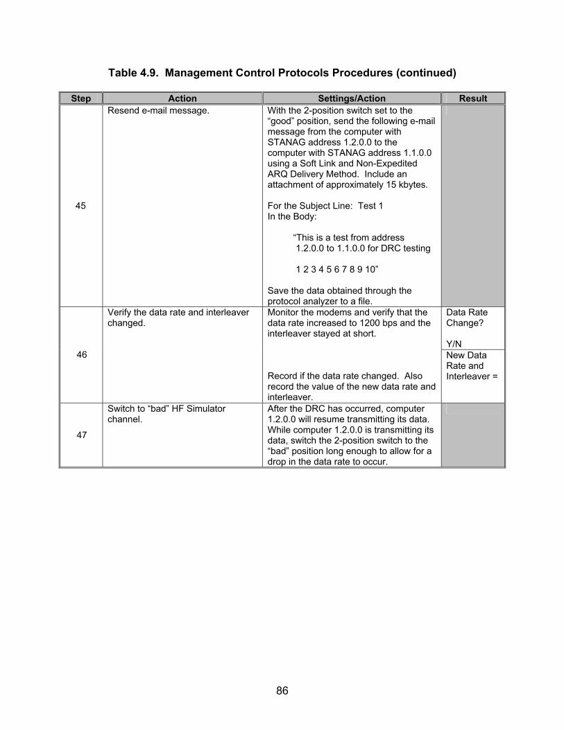
86
Table 4.9. Management Control Protocols Procedures (continued)
Step Action Settings/Action Result
45
Resend e-mail message. With the 2-position switch set to the “good” position, send the following e-mail message from the computer with STANAG address 1.2.0.0 to the computer with STANAG address 1.1.0.0 using a Soft Link and Non-Expedited ARQ Delivery Method. Include an attachment of approximately 15 kbytes. For the Subject Line: Test 1 In the Body: “This is a test from address 1.2.0.0 to 1.1.0.0 for DRC testing 1 2 3 4 5 6 7 8 9 10” Save the data obtained through the protocol analyzer to a file.
Data Rate Change? Y/N
46
Verify the data rate and interleaver changed.
Monitor the modems and verify that the data rate increased to 1200 bps and the interleaver stayed at short. Record if the data rate changed. Also record the value of the new data rate and interleaver.
New Data Rate and Interleaver =
47
Switch to “bad” HF Simulator channel.
After the DRC has occurred, computer 1.2.0.0 will resume transmitting its data. While computer 1.2.0.0 is transmitting its data, switch the 2-position switch to the “bad” position long enough to allow for a drop in the data rate to occur.

87
Table 4.9. Management Control Protocols Procedures (continued)
Step Action Settings/Action Result 1200S Data Rate bits =
48
Locate Data Rate and Interleaving bits.
D_PDUs begin with the following sync in hex format: 0x90EB. The first 4 bits, immediately after the 0x90EB sequences, will be the D_PDU Type. For the Type 6 D_PDU, the value will be 0x6 in hex or 0110 in binary. There will be two sets of data exchanges using Type 6 D_PDUs. These will be separated by Type 0, 1, and 2 D_PDUs. Locate the second set of Type 6 D_PDUs. This will be the set when the data rate is dropping from 1200 bps. The EOW bits are the first 12 bits after the D_PDU Type bits. The Data Rate bits are the bits (MSB) 7-4 (LSB) of this field. The Interleaving bits are the next 2 bits following the Data Rate bits. For the first Type 6 D_PDU in the Type 6 D_PDU string created as a response to the first Type 6 D_PDU transmission interval, record the Data Rate bits and Interleaving bits.
1200S Interleaving bits =
49
Determine the number of retransmissions.
Count and record the number of times the same Type 6 D_PDU was retransmitted by the same computer for the Type 6 D_PDU string found in step 48.
Number of Retransmis-sions =
50 Reconfigure DRC. Adjust the DRC configuration to increase
to 600 bps with short interleaving for a “good” transmission.

88
Table 4.9. Management Control Protocols Procedures (continued)
Step Action Settings/Action Result
51
Resend e-mail message. With the 2-position switch set to the “good” position, send the following e-mail message from the computer with STANAG address 1.2.0.0 to the computer with STANAG address 1.1.0.0 using a Soft Link and Non-Expedited ARQ Delivery Method. Include an attachment of approximately 15 kbytes. For the Subject Line: Test 1 In the Body: “This is a test from address 1.2.0.0 to 1.1.0.0 for DRC testing 1 2 3 4 5 6 7 8 9 10” Save the data obtained through the protocol analyzer to a file.
Data Rate Change? Y/N
52
Verify the data rate and interleaver changed.
Monitor the modems and verify that the data rate increased to 600 bps and the interleaver stayed at short. Record if the data rate changed. Also record the value of the new data rate and interleaver.
New Data Rate and Interleaver =
53
Switch to “bad” HF Simulator channel.
After the DRC has occurred, computer 1.2.0.0 will resume transmitting its data. While computer 1.2.0.0 is transmitting its data, switch the 2-position switch to the “bad” position long enough to allow for a drop in the data rate to occur.
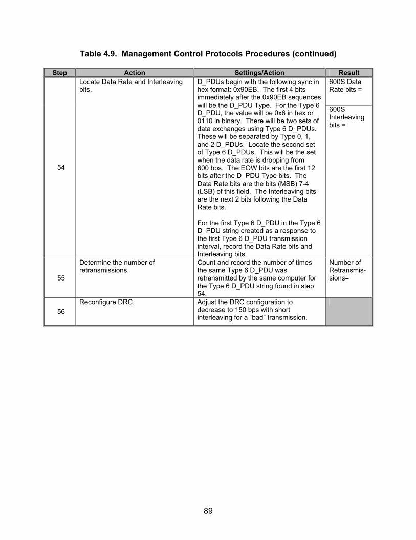
89
Table 4.9. Management Control Protocols Procedures (continued)
Step Action Settings/Action Result 600S Data Rate bits =
54
Locate Data Rate and Interleaving bits.
D_PDUs begin with the following sync in hex format: 0x90EB. The first 4 bits immediately after the 0x90EB sequences will be the D_PDU Type. For the Type 6 D_PDU, the value will be 0x6 in hex or 0110 in binary. There will be two sets of data exchanges using Type 6 D_PDUs. These will be separated by Type 0, 1, and 2 D_PDUs. Locate the second set of Type 6 D_PDUs. This will be the set when the data rate is dropping from 600 bps. The EOW bits are the first 12 bits after the D_PDU Type bits. The Data Rate bits are the bits (MSB) 7-4 (LSB) of this field. The Interleaving bits are the next 2 bits following the Data Rate bits. For the first Type 6 D_PDU in the Type 6 D_PDU string created as a response to the first Type 6 D_PDU transmission interval, record the Data Rate bits and Interleaving bits.
600S Interleaving bits =
55
Determine the number of retransmissions.
Count and record the number of times the same Type 6 D_PDU was retransmitted by the same computer for the Type 6 D_PDU string found in step 54.
Number of Retransmis-sions=
56 Reconfigure DRC. Adjust the DRC configuration to
decrease to 150 bps with short interleaving for a “bad” transmission.

90
Table 4.9. Management Control Protocols Procedures (continued)
Step Action Settings/Action Result
57
Resend e-mail message. With the 2-position switch set to the “good” position, send the following e-mail message from the computer with STANAG address 1.2.0.0 to the computer with STANAG address 1.1.0.0 using a Soft Link and Non-Expedited ARQ Delivery Method. Include an attachment of approximately 15 kbytes. For the Subject Line: Test 1 In the Body: “This is a test from address 1.2.0.0 to 1.1.0.0 for DRC testing 1 2 3 4 5 6 7 8 9 10” Save the data obtained through the protocol analyzer to a file.
58
Switch to “bad” position. While data is being transmitted and before a DRC attempt to increase the data rate is made, switch the 2-position switch to the “bad” channel long enough to cause a data rate drop to 150 bps.
Data Rate Change? Y/N
59
Verify the data rate and interleaver changed.
Monitor the modems and verify that the data rate increased to 150 bps and the interleaver stayed at short. Record if the data rate changed. Also record the value of the new data rate and interleaver.
New Data Rate and Interleaver =
60
Switch to “good” HF Simulator channel.
After the DRC has occurred, computer 1.2.0.0 will resume transmitting its data. While computer 1.2.0.0 is transmitting its data, switch the 2-position switch to the “good” position long enough to allow for an increase in the data rate to occur.

91
Table 4.9. Management Control Protocols Procedures (continued)
Step Action Settings/Action Result 150S Data Rate bits =
61
Locate Data Rate and Interleaving bits.
D_PDUs begin with the following sync in hex format: 0x90EB. The first 4 bits, immediately after the 0x90EB sequences, will be the D_PDU Type. For the Type 6 D_PDU, the value will be 0x6 in hex or 0110 in binary. There will be two sets of data exchanges using Type 6 D_PDUs. These will be separated by Type 0, 1, and 2 D_PDUs. Locate the second set of Type 6 D_PDUs. This will be the set when the data rate is increasing from 150 bps. The EOW bits are the first 12 bits after the D_PDU Type bits. The Data Rate bits are the bits (MSB) 7-4 (LSB) of this field. The Interleaving bits are the next 2 bits following the Data Rate bits. For the first Type 6 D_PDU in the Type 6 D_PDU string created as a response to the first Type 6 D_PDU transmission interval, record the Data Rate bits and Interleaving bits.
150S Interleaving bits =
62
Determine the number of retransmissions.
Count and record the number of times the same Type 6 D_PDU was retransmitted by the same computer for the Type 6 D_PDU string found in step 61.
Number of Retransmis-sions =
63 Reconfigure DRC. Adjust the DRC configuration to
decrease to 75 bps with short interleaving for a “bad” transmission.

92
Table 4.9. Management Control Protocols Procedures (continued)
Step Action Settings/Action Result
64
Resend e-mail message. With the 2-position switch set to the “good” position, send the following e-mail message from the computer with STANAG address 1.2.0.0 to the computer with STANAG address 1.1.0.0 using a Soft Link and Non-Expedited ARQ Delivery Method. Include an attachment of approximately 15 kbytes. For the Subject Line: Test 1 In the Body: “This is a test from address 1.2.0.0 to 1.1.0.0 for DRC testing 1 2 3 4 5 6 7 8 9 10” Save the data obtained through the protocol analyzer to a file.
65
Switch to “bad” position. While data is being transmitted and before a DRC attempt to increase the data rate is made, switch the 2-position switch to the “bad” channel long enough to cause a data rate drop to 75 bps.
Data Rate Change? Y/N
66
Verify the data rate and interleaver changed.
Monitor the modems and verify that the data rate increased to 75 bps and the interleaver stayed at short. Record if the data rate changed. Also record the value of the new data rate and interleaver.
New Data Rate and Interleaver =
67
Switch to “good” HF Simulator channel.
After the DRC has occurred, computer 1.2.0.0 will resume transmitting its data. While computer 1.2.0.0 is transmitting its data, switch the 2-position switch to the “good” position long enough to allow for an increase in the data rate to occur.

93
Table 4.9. Management Control Protocols Procedures (continued)
Step Action Settings/Action Result 75S Data Rate bits =
68
Locate Data Rate and Interleaving bits.
D_PDUs begin with the following sync in hex format: 0x90EB. The first 4 bits immediately after the 0x90EB sequences will be the D_PDU Type. For the Type 6 D_PDU, the value will be 0x6 in hex or 0110 in binary. There will be two sets of data exchanges using Type 6 D_PDUs. These will be separated by Type 0, 1, and 2 D_PDUs. Locate the second set of Type 6 D_PDUs. This will be the set when the data rate is increasing from 75 bps. The EOW bits are the first 12 bits after the D_PDU Type bits. The Data Rate bits are the bits (MSB) 7-4 (LSB) of this field. The Interleaving bits are the next 2 bits following the Data Rate bits. For the first Type 6 D_PDU in the Type 6 D_PDU string created as a response to the first Type 6 D_PDU transmission interval, record the Data Rate bits and Interleaving bits.
75S Interleaving bits =
69
Determine the number of retransmissions.
Count and record the number of times the same Type 6 D_PDU was retransmitted by the same computer for the Type 6 D_PDU string found in step 68.
Number of Retransmis-sions =
70 Reconfigure DRC. Adjust the DRC configuration to increase
to 2400 bps with long interleaving for a “good” transmission.
71
Resend e-mail message. With the 2-position switch set to the “good” position, send the following e-mail message from the computer with STANAG address 1.2.0.0 to the computer with STANAG address 1.1.0.0 using a Soft Link and Non-Expedited ARQ Delivery Method. Include an attachment of approximately 15 kbytes. For the Subject Line: Test 1 In the Body: “This is a test from address 1.2.0.0 to 1.1.0.0 for DRC testing 1 2 3 4 5 6 7 8 9 10” Save the data obtained through the protocol analyzer to a file.
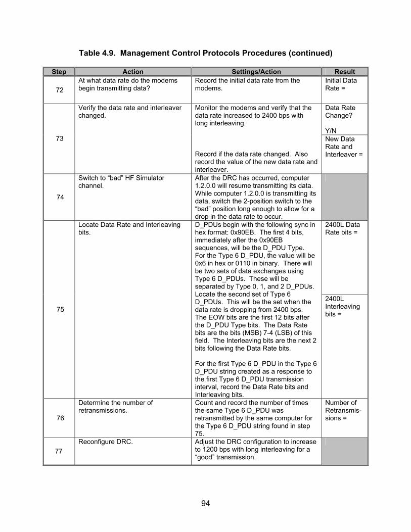
94
Table 4.9. Management Control Protocols Procedures (continued)
Step Action Settings/Action Result
72 At what data rate do the modems begin transmitting data?
Record the initial data rate from the modems.
Initial Data Rate =
Data Rate Change? Y/N
73
Verify the data rate and interleaver changed.
Monitor the modems and verify that the data rate increased to 2400 bps with long interleaving. Record if the data rate changed. Also record the value of the new data rate and interleaver.
New Data Rate and Interleaver =
74
Switch to “bad” HF Simulator channel.
After the DRC has occurred, computer 1.2.0.0 will resume transmitting its data. While computer 1.2.0.0 is transmitting its data, switch the 2-position switch to the “bad” position long enough to allow for a drop in the data rate to occur.
2400L Data Rate bits =
75
Locate Data Rate and Interleaving bits.
D_PDUs begin with the following sync in hex format: 0x90EB. The first 4 bits, immediately after the 0x90EB sequences, will be the D_PDU Type. For the Type 6 D_PDU, the value will be 0x6 in hex or 0110 in binary. There will be two sets of data exchanges using Type 6 D_PDUs. These will be separated by Type 0, 1, and 2 D_PDUs. Locate the second set of Type 6 D_PDUs. This will be the set when the data rate is dropping from 2400 bps. The EOW bits are the first 12 bits after the D_PDU Type bits. The Data Rate bits are the bits (MSB) 7-4 (LSB) of this field. The Interleaving bits are the next 2 bits following the Data Rate bits. For the first Type 6 D_PDU in the Type 6 D_PDU string created as a response to the first Type 6 D_PDU transmission interval, record the Data Rate bits and Interleaving bits.
2400L Interleaving bits =
76
Determine the number of retransmissions.
Count and record the number of times the same Type 6 D_PDU was retransmitted by the same computer for the Type 6 D_PDU string found in step 75.
Number of Retransmis-sions =
77 Reconfigure DRC. Adjust the DRC configuration to increase
to 1200 bps with long interleaving for a “good” transmission.
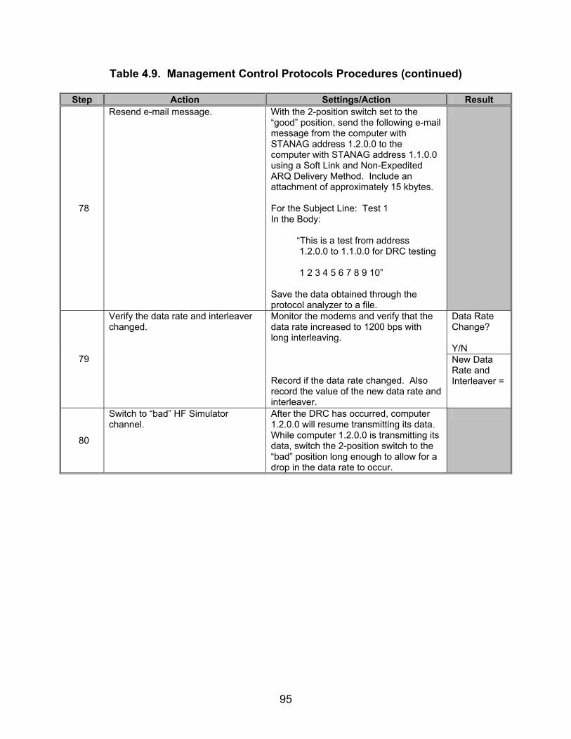
95
Table 4.9. Management Control Protocols Procedures (continued)
Step Action Settings/Action Result
78
Resend e-mail message. With the 2-position switch set to the “good” position, send the following e-mail message from the computer with STANAG address 1.2.0.0 to the computer with STANAG address 1.1.0.0 using a Soft Link and Non-Expedited ARQ Delivery Method. Include an attachment of approximately 15 kbytes. For the Subject Line: Test 1 In the Body: “This is a test from address 1.2.0.0 to 1.1.0.0 for DRC testing 1 2 3 4 5 6 7 8 9 10” Save the data obtained through the protocol analyzer to a file.
Data Rate Change? Y/N
79
Verify the data rate and interleaver changed.
Monitor the modems and verify that the data rate increased to 1200 bps with long interleaving. Record if the data rate changed. Also record the value of the new data rate and interleaver.
New Data Rate and Interleaver =
80
Switch to “bad” HF Simulator channel.
After the DRC has occurred, computer 1.2.0.0 will resume transmitting its data. While computer 1.2.0.0 is transmitting its data, switch the 2-position switch to the “bad” position long enough to allow for a drop in the data rate to occur.
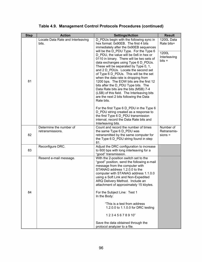
96
Table 4.9. Management Control Protocols Procedures (continued)
Step Action Settings/Action Result 1200L Data Rate bits=
81
Locate Data Rate and Interleaving bits.
D_PDUs begin with the following sync in hex format: 0x90EB. The first 4 bits immediately after the 0x90EB sequences will be the D_PDU Type. For the Type 6 D_PDU, the value will be 0x6 in hex or 0110 in binary. There will be two sets of data exchanges using Type 6 D_PDUs. These will be separated by Type 0, 1, and 2 D_PDUs. Locate the second set of Type 6 D_PDUs. This will be the set when the data rate is dropping from 1200 bps. The EOW bits are the first 12 bits after the D_PDU Type bits. The Data Rate bits are the bits (MSB) 7-4 (LSB) of this field. The Interleaving bits are the next 2 bits following the Data Rate bits. For the first Type 6 D_PDU in the Type 6 D_PDU string created as a response to the first Type 6 D_PDU transmission interval, record the Data Rate bits and Interleaving bits.
1200L Interleaving bits =
82
Determine the number of retransmissions.
Count and record the number of times the same Type 6 D_PDU was retransmitted by the same computer for the Type 6 D_PDU string found in step 81.
Number of Retransmis-sions =
83 Reconfigure DRC. Adjust the DRC configuration to increase
to 600 bps with long interleaving for a “good” transmission.
84
Resend e-mail message. With the 2-position switch set to the “good” position, send the following e-mail message from the computer with STANAG address 1.2.0.0 to the computer with STANAG address 1.1.0.0 using a Soft Link and Non-Expedited ARQ Delivery Method. Include an attachment of approximately 15 kbytes. For the Subject Line: Test 1 In the Body: “This is a test from address 1.2.0.0 to 1.1.0.0 for DRC testing 1 2 3 4 5 6 7 8 9 10” Save the data obtained through the protocol analyzer to a file.

97
Table 4.9. Management Control Protocols Procedures (continued)
Step Action Settings/Action Result Data Rate Change? Y/N
85
Verify the data rate and interleaver changed.
Monitor the modems and verify that the data rate increased to 600 bps with long interleaving. Record if the data rate changed. Also record the value of the new data rate and interleaver.
New Data Rate and Interleaver =
86
Switch to “bad” HF Simulator channel.
After the DRC has occurred, computer 1.2.0.0 will resume transmitting its data. While computer 1.2.0.0 is transmitting its data, switch the 2-position switch to the “bad” position long enough to allow for a drop in the data rate to occur.
600L Data Rate bits =
87
Locate Data Rate and Interleaving bits.
D_PDUs begin with the following sync in hex format: 0x90EB. The first 4 bits, immediately after the 0x90EB equences, will be the D_PDU Type. For the Type 6 D_PDU, the value will be 0x6 in hex or 0110 in binary. There will be two sets of data exchanges using Type 6 D_PDUs. These will be separated by Type 0, 1, and 2 D_PDUs. Locate the second set of Type 6 D_PDUs. This will be the set when the data rate is dropping from 600 bps. The EOW bits are the first 12 bits after the D_PDU Type bits. The Data Rate bits are the bits (MSB) 7-4 (LSB) of this field. The Interleaving bits are the next 2 bits following the Data Rate bits. For the first Type 6 D_PDU in the Type 6 D_PDU string created as a response to the first Type 6 D_PDU transmission interval, record the Data Rate bits and Interleaving bits.
600L Interleaving bits =
88
Determine the number of retransmissions.
Count and record the number of times the same Type 6 D_PDU was retransmitted by the same computer for the Type 6 D_PDU string found in step 87.
Number of Retransmis-sions =
89 Reconfigure DRC. Adjust the DRC configuration to
decrease to 150 bps with long interleaving for a “bad” transmission.

98
Table 4.9. Management Control Protocols Procedures (continued)
Step Action Settings/Action Result
90
Resend e-mail message. With the 2-position switch set to the “good” position, send the following e-mail message from the computer with STANAG address 1.2.0.0 to the computer with STANAG address 1.1.0.0 using a Soft Link and Non-Expedited ARQ Delivery Method. Include an attachment of approximately 15 kbytes. For the Subject Line: Test 1 In the Body: “This is a test from address 1.2.0.0 to 1.1.0.0 for DRC testing 1 2 3 4 5 6 7 8 9 10” Save the data obtained through the protocol analyzer to a file.
91
Switch to “bad” position. While data is being transmitted and before a DRC attempt to increase the data rate is made, switch the 2-position switch to the “bad” channel long enough to cause a data rate drop to 150 bps.
Data Rate Change? Y/N
92
Verify the data rate and interleaver changed.
Monitor the modems and verify that the data rate increased to 150 bps with long interleaving. Record if the data rate changed. Also record the value of the new data rate and interleaver.
New Data Rate and Interleaver =
93
Switch to “good” HF Simulator channel.
After the DRC has occurred, computer 1.2.0.0 will resume transmitting its data. While computer 1.2.0.0 is transmitting its data, switch the 2-position switch to the “good” position long enough to allow for an increase in the data rate to occur.

99
Table 4.9. Management Control Protocols Procedures (continued)
Step Action Settings/Action Result 150L Data Rate bits =
94
Locate Data Rate and Interleaving bits.
D_PDUs begin with the following sync in hex format: 0x90EB. The first 4 bits immediately after the 0x90EB sequences will be the D_PDU Type. For the Type 6 D_PDU, the value will be 0x6 in hex or 0110 in binary. There will be two sets of data exchanges using Type 6 D_PDUs. These will be separated by Type 0, 1, and 2 D_PDUs. Locate the second set of Type 6 D_PDUs. This will be the set when the data rate is increasing from 150 bps. The EOW bits are the first 12 bits after the D_PDU Type bits. The Data Rate bits are the bits (MSB) 7-4 (LSB) of this field. The Interleaving bits are the next 2 bits following the Data Rate bits. For the first Type 6 D_PDU in the Type 6 D_PDU string created as a response to the first Type 6 D_PDU transmission interval, record the Data Rate bits and Interleaving bits.
150L Interleaving bits =
95
Determine the number of retransmissions.
Count and record the number of times the same Type 6 D_PDU was retransmitted by the same computer for the Type 6 D_PDU string found in step 94.
Number of Retransmis-sions =
96 Reconfigure DRC. Adjust the DRC configuration to
decrease to 75 bps with long interleaving for a “bad” transmission.
97
Resend e-mail message. With the 2-position switch set to the “good” position, send the following e-mail message from the computer with STANAG address 1.2.0.0 to the computer with STANAG address 1.1.0.0 using a Soft Link and Non-Expedited ARQ Delivery Method. Include an attachment of approximately 15 kbytes. For the Subject Line: Test 1 In the Body: “This is a test from address 1.2.0.0 to 1.1.0.0 for DRC testing 1 2 3 4 5 6 7 8 9 10” Save the data obtained through the protocol analyzer to a file.

100
Table 4.9. Management Control Protocols Procedures (continued)
Step Action Settings/Action Result
98
Switch to “bad” position. While data is being transmitted and before a DRC attempt to increase the data rate is made, switch the 2-position switch to the “bad” channel long enough to cause a data rate drop to 75 bps.
Data Rate Change? Y/N
99
Verify the data rate and interleaver changed.
Monitor the modems and verify that the data rate increased to 75 bps with long interleaving. Record if the data rate changed. Also record the value of the new data rate and interleaver.
New Data Rate and Interleaver =
100
Switch to “good” HF Simulator channel.
After the DRC has occurred, computer 1.2.0.0 will resume transmitting its data. While computer 1.2.0.0 is transmitting its data, switch the 2-position switch to the “good” position long enough to allow for an increase in the data rate to occur.
75L Data Rate bits =
101
Locate Data Rate and Interleaving bits.
D_PDUs begin with the following sync in hex format: 0x90EB. The first 4 bits, immediately after the 0x90EB equences, will be the D_PDU Type. For the Type 6 D_PDU, the value will be 0x6 in hex or 0110 in binary. There will be two sets of data exchanges using Type 6 D_PDUs. These will be separated by Type 0, 1, and 2 D_PDUs. Locate the second set of Type 6 D_PDUs. This will be the set when the data rate is increasing from 75 bps. The EOW bits are the first 12 bits after the D_PDU Type bits. The Data Rate bits are the bits (MSB) 7-4 (LSB) of this field. The Interleaving bits are the next 2 bits following the Data Rate bits. For the first Type 6 D_PDU in the Type 6 D_PDU string created as a response to the first Type 6 D_PDU transmission interval, record the Data Rate bits and Interleaving bits.
75L Interleaving bits =
102
Determine the number of retransmissions.
Count and record the number of times the same Type 6 D_PDU was retransmitted by the same computer for the Type 6 D_PDU string found in step 101.
Number of Retransmis-sions =

101
Table 4.9. Management Control Protocols Procedures (continued)
Step Action Settings/Action Result
103
Reconfigure DRC. Adjust the DRC configuration to increase to 600 bps with long interleaving for a “good” transmission and to decrease to 300 bps with long interleaving for a “bad” transmission.
104
Resend e-mail message. With the 2-position switch set to the “good” position, send the following e-mail message from the computer with STANAG address 1.2.0.0 to the computer with STANAG address 1.1.0.0 using a Soft Link and Non-Expedited ARQ Delivery Method. Include an attachment of approximately 15 kbytes. For the Subject Line: Test 1 In the Body: “This is a test from address 1.2.0.0 to 1.1.0.0 for DRC testing 1 2 3 4 5 6 7 8 9 10” Save the data obtained through the protocol analyzer to a file.
105
Switch to “bad” HF Simulator channel.
After the DRC has occurred, computer 1.2.0.0 will resume transmitting its data. While computer 1.2.0.0 is transmitting its data, switch the 2-position switch to the “bad” position long enough to allow for a drop in the data rate to occur to 300 bps with long interleaving.
Data Rate Change? Y/N
106
Verify the data rate and interleaver changed.
Monitor the modems and verify that the data rate increased to 300 bps with long interleaving. Record if the data rate changed. Also record the value of the new data rate and interleaver.
New Data Rate and Interleaver =
107
Switch to “good” HF Simulator channel.
After the DRC has occurred, computer 1.2.0.0 will resume transmitting its data. While computer 1.2.0.0 is transmitting its data, switch the 2-position switch to the “good” position long enough to allow for an increase in the data rate to occur.

102
Table 4.9. Management Control Protocols Procedures (continued)
Step Action Settings/Action Result 300L Data Rate bits =
108
Locate Data Rate and Interleaving bits.
D_PDUs begin with the following sync in hex format: 0x90EB. The first 4 bits, immediately after the 0x90EB sequences, will be the D_PDU Type. For the Type 6 D_PDU, the value will be 0x6 in hex or 0110 in binary. There will be two sets of data exchanges using Type 6 D_PDUs. These will be separated by Type 0, 1, and 2 D_PDUs. Locate the second set of Type 6 D_PDUs. This will be the set when the data rate is dropping from 300 bps. The EOW bits are the first 12 bits after the D_PDU Type bits. The Data Rate bits are the bits (MSB) 7-4 (LSB) of this field. The Interleaving bits are the next 2 bits following the Data Rate bits. For the first Type 6 D_PDU in the Type 6 D_PDU string created as a response to the first Type 6 D_PDU transmission interval, record the Data Rate bits and Interleaving bits.
300L Interleaving bits =
109
Determine the number of retransmissions.
Count and record the number of times the same Type 6 D_PDU was retransmitted by the same computer for the Type 6 D_PDU string found in step 108.
Number of Retransmis-sions =
110 Reconfigure DRC. Adjust the DRC configuration to increase
to 2400 bps with zero interleaving for a “good” transmission.
111
Resend e-mail message. With the 2-position switch set to the “good” position, send the following e-mail message from the computer with STANAG address 1.2.0.0 to the computer with STANAG address 1.1.0.0 using a Soft Link and Non-Expedited ARQ Delivery Method. Include an attachment of approximately 15 kbytes. For the Subject Line: Test 1 In the Body: “This is a test from address 1.2.0.0 to 1.1.0.0 for DRC testing 1 2 3 4 5 6 7 8 9 10” Save the data obtained through the protocol analyzer to a file.
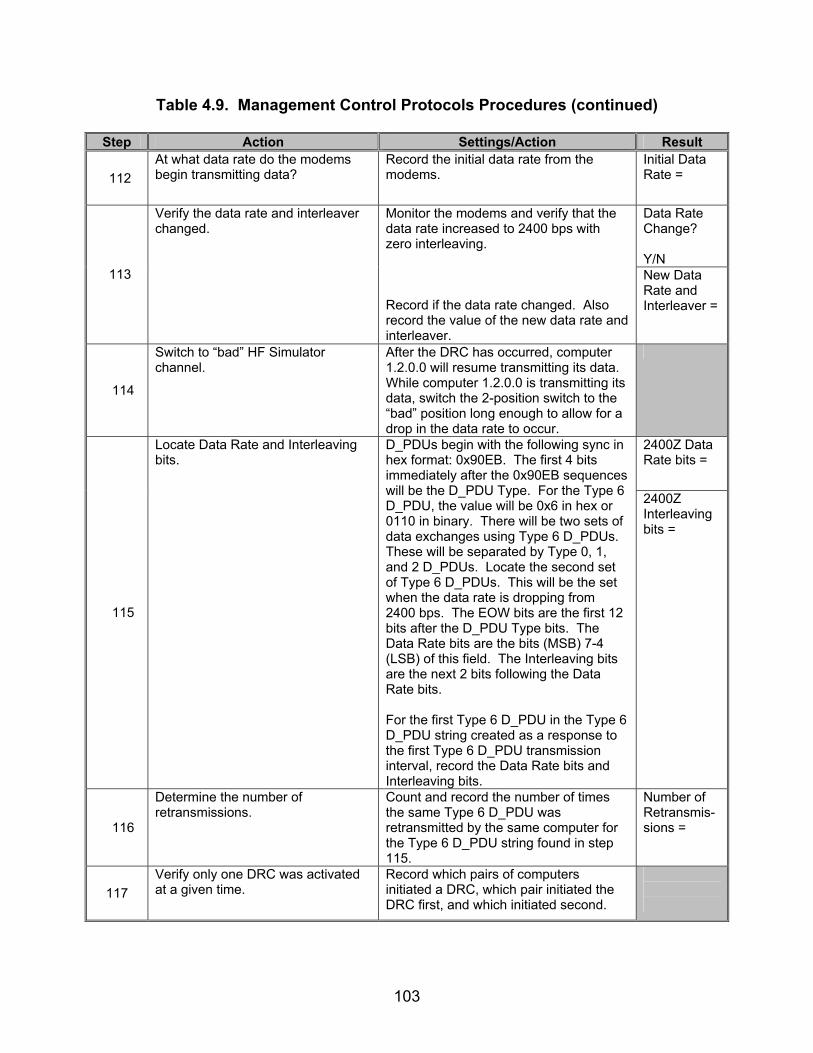
103
Table 4.9. Management Control Protocols Procedures (continued)
Step Action Settings/Action Result
112 At what data rate do the modems begin transmitting data?
Record the initial data rate from the modems.
Initial Data Rate =
Data Rate Change? Y/N
113
Verify the data rate and interleaver changed.
Monitor the modems and verify that the data rate increased to 2400 bps with zero interleaving. Record if the data rate changed. Also record the value of the new data rate and interleaver.
New Data Rate and Interleaver =
114
Switch to “bad” HF Simulator channel.
After the DRC has occurred, computer 1.2.0.0 will resume transmitting its data. While computer 1.2.0.0 is transmitting its data, switch the 2-position switch to the “bad” position long enough to allow for a drop in the data rate to occur.
2400Z Data Rate bits =
115
Locate Data Rate and Interleaving bits.
D_PDUs begin with the following sync in hex format: 0x90EB. The first 4 bits immediately after the 0x90EB sequences will be the D_PDU Type. For the Type 6 D_PDU, the value will be 0x6 in hex or 0110 in binary. There will be two sets of data exchanges using Type 6 D_PDUs. These will be separated by Type 0, 1, and 2 D_PDUs. Locate the second set of Type 6 D_PDUs. This will be the set when the data rate is dropping from 2400 bps. The EOW bits are the first 12 bits after the D_PDU Type bits. The Data Rate bits are the bits (MSB) 7-4 (LSB) of this field. The Interleaving bits are the next 2 bits following the Data Rate bits. For the first Type 6 D_PDU in the Type 6 D_PDU string created as a response to the first Type 6 D_PDU transmission interval, record the Data Rate bits and Interleaving bits.
2400Z Interleaving bits =
116
Determine the number of retransmissions.
Count and record the number of times the same Type 6 D_PDU was retransmitted by the same computer for the Type 6 D_PDU string found in step 115.
Number of Retransmis-sions =
117 Verify only one DRC was activated at a given time.
Record which pairs of computers initiated a DRC, which pair initiated the DRC first, and which initiated second.
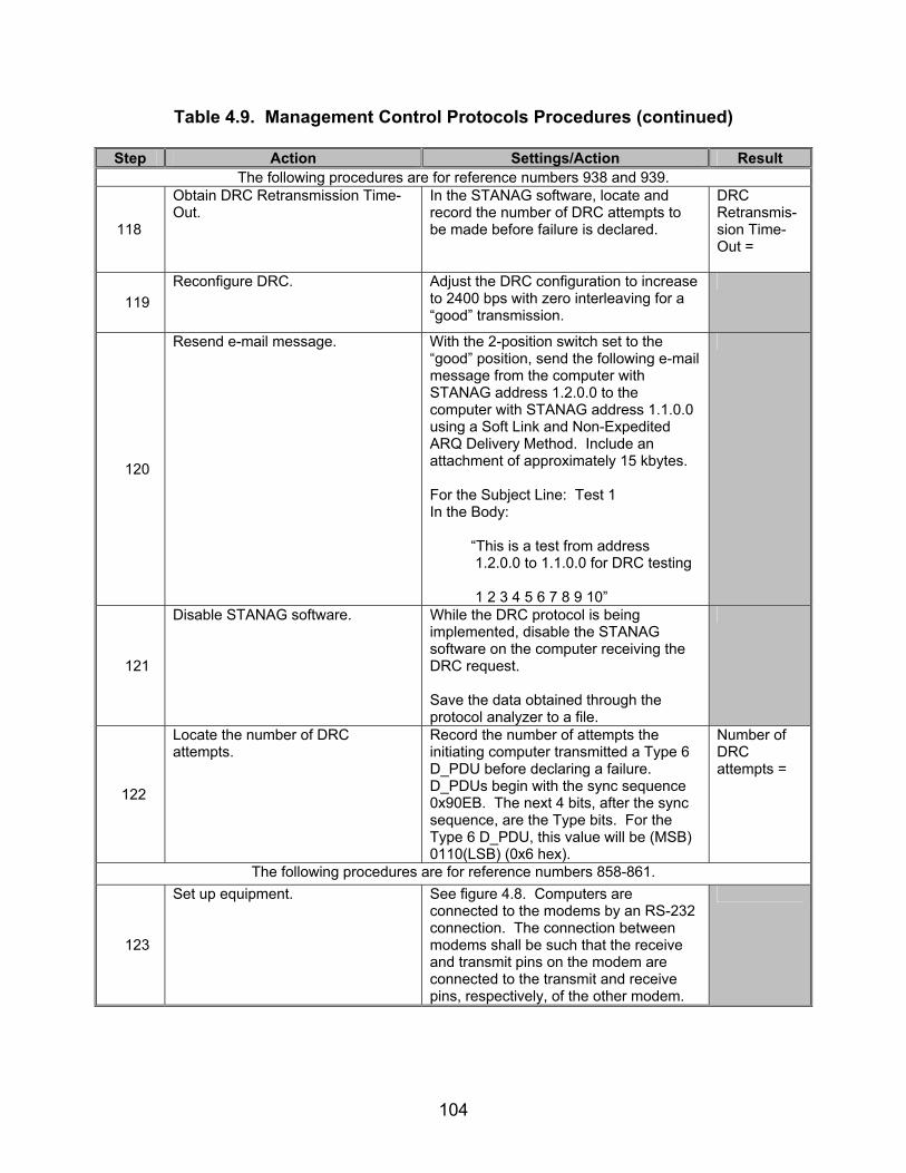
104
Table 4.9. Management Control Protocols Procedures (continued)
Step Action Settings/Action Result The following procedures are for reference numbers 938 and 939.
118
Obtain DRC Retransmission Time-Out.
In the STANAG software, locate and record the number of DRC attempts to be made before failure is declared.
DRC Retransmis-sion Time-Out =
119 Reconfigure DRC. Adjust the DRC configuration to increase
to 2400 bps with zero interleaving for a “good” transmission.
120
Resend e-mail message. With the 2-position switch set to the “good” position, send the following e-mail message from the computer with STANAG address 1.2.0.0 to the computer with STANAG address 1.1.0.0 using a Soft Link and Non-Expedited ARQ Delivery Method. Include an attachment of approximately 15 kbytes. For the Subject Line: Test 1 In the Body: “This is a test from address 1.2.0.0 to 1.1.0.0 for DRC testing 1 2 3 4 5 6 7 8 9 10”
121
Disable STANAG software. While the DRC protocol is being implemented, disable the STANAG software on the computer receiving the DRC request. Save the data obtained through the protocol analyzer to a file.
122
Locate the number of DRC attempts.
Record the number of attempts the initiating computer transmitted a Type 6 D_PDU before declaring a failure. D_PDUs begin with the sync sequence 0x90EB. The next 4 bits, after the sync sequence, are the Type bits. For the Type 6 D_PDU, this value will be (MSB) 0110(LSB) (0x6 hex).
Number of DRC attempts =
The following procedures are for reference numbers 858-861.
123
Set up equipment. See figure 4.8. Computers are connected to the modems by an RS-232 connection. The connection between modems shall be such that the receive and transmit pins on the modem are connected to the transmit and receive pins, respectively, of the other modem.

105
Table 4.9. Management Control Protocols Procedures (continued)
Step Action Settings/Action Result
124
Configure STANAG addresses for both computers.
Set the size of the STANAG address field size to 7 bytes. Set the STANAG address to 0.0.1.1 for the computer. Configure the computer to transmit to a STANAG address of 0.0.1.2.
125
Initiate handshaking protocol.
Using the data packet injector, transmit the following hex data packet to the STANAG computer 0.0.1.1: (MSB) 90 EB 84 20 01 EF 00 00 10 10 00 01 02 00 01 0A 00 01 00 00 01 18 45 29 10 AA 9C 74 1E (LSB) *Note: This data packet assumes the STANAG 5066 supports waveform MIL-STD-188-110A. The EOW and CRC for the above data packet will need to be changed if the STANAG 5066 software does not support the MIL-STD-188-110A waveform.
126
Inject undefined EOW data packet. After computer 0.0.1.1 has responded by transmitting its Type 8 D_PDU to the data packet injector, transmit the following data packet from the data packet injector to the STANAG computer 0.0.1.1: 90 EB 6A 14 05 E8 00 00 10 10 00 01 02 02 01 6B 01 90 EB 6A 14 03 E8 00 00 10 10 00 01 02 02 01 7B 42 90 EB 6A 14 01 E8 00 00 10 10 00 01 02 02 01 8B 7C Wait for the STANAG computer to respond to the data packet. Save the data obtained through the protocol analyzer to a file.
127
Locate Type 6 D_PDU. D_PDUs begin with the sync sequence 0x90EB. The next 4 bits, after the sync sequence are the type. Locate a D_DPU transmitted from STANAG computer 0.0.1.1 whose value is (MSB) 0 1 1 0 (LSB) (0x6 hex) that was transmitted immediately following the Type 6 D_PDU data packet injected in step 126. Record the D_PDU Type.
D_PDU Type =
128
Locate Type 3 EOW. The next 4 bits, after the D_PDU Type, is the EOW Type. Record the EOW Type.
EOW Type =

106
Table 4.9. Management Control Protocols Procedures(continued)
Step Action Settings/Action Result
129
Locate Response bits. The next 3 bits, after the EOW Type bits, are the Response bits. Record the Response bits.
Response bits =
130
Locate Reason bits. The next 5 bits, after the Response bits, are the Reason bits. Record the Reason bits.
Reason bits =
The following procedures are for reference numbers 933 and 934.
131 Set up equipment. See figure 4.9. Computers are
connected to the modems by an RS-232 connection.
132
Configure STANAG addresses for computers.
Set the size of the STANAG address field size to 7 bytes. Set the STANAG address to 1.1.0.0, 1.2.0.0, and 2.1.0.0 as shown in figure 4.9. Configure the software to respond with an e-mail message to the sender once the e-mail has been successfully received.
133
Send e-mail message.
Send the following e-mail message from the computer with STANAG address 1.2.0.0 to the computer with STANAG address 1.1.0.0 using a Soft Link and Non-Expedited ARQ Delivery Method. Include an attachment of approximately 15 kbytes. For the Subject Line: Test 1 In the Body: “This is a test from address 1.2.0.0 to 1.1.0.0 for DRC testing 1 2 3 4 5 6 7 8 9 10”
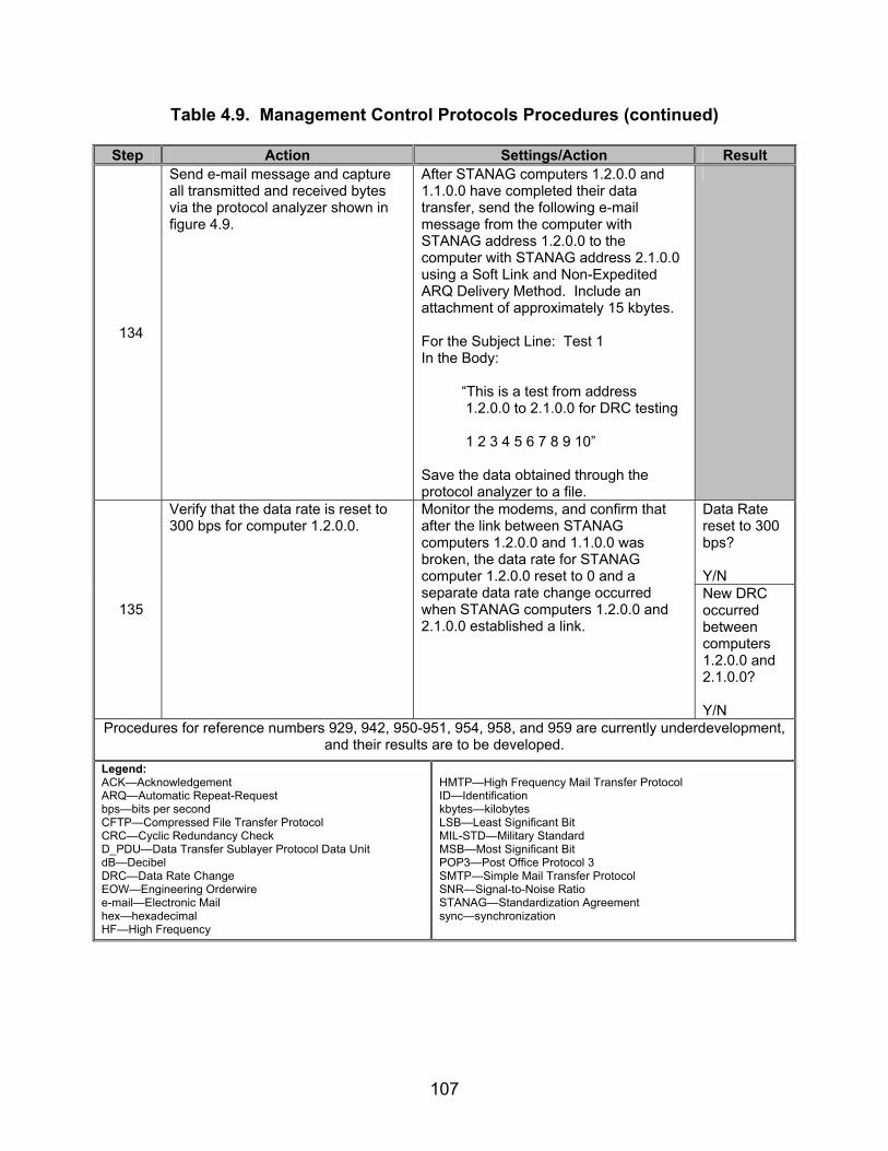
107
Table 4.9. Management Control Protocols Procedures (continued)
Step Action Settings/Action Result
134
Send e-mail message and capture all transmitted and received bytes via the protocol analyzer shown in figure 4.9.
After STANAG computers 1.2.0.0 and 1.1.0.0 have completed their data transfer, send the following e-mail message from the computer with STANAG address 1.2.0.0 to the computer with STANAG address 2.1.0.0 using a Soft Link and Non-Expedited ARQ Delivery Method. Include an attachment of approximately 15 kbytes. For the Subject Line: Test 1 In the Body: “This is a test from address 1.2.0.0 to 2.1.0.0 for DRC testing 1 2 3 4 5 6 7 8 9 10” Save the data obtained through the protocol analyzer to a file.
Data Rate reset to 300 bps? Y/N
135
Verify that the data rate is reset to 300 bps for computer 1.2.0.0.
Monitor the modems, and confirm that after the link between STANAG computers 1.2.0.0 and 1.1.0.0 was broken, the data rate for STANAG computer 1.2.0.0 reset to 0 and a separate data rate change occurred when STANAG computers 1.2.0.0 and 2.1.0.0 established a link.
New DRC occurred between computers 1.2.0.0 and 2.1.0.0? Y/N
Procedures for reference numbers 929, 942, 950-951, 954, 958, and 959 are currently underdevelopment, and their results are to be developed.
Legend: ACK—Acknowledgement ARQ—Automatic Repeat-Request bps—bits per second CFTP—Compressed File Transfer Protocol CRC—Cyclic Redundancy Check D_PDU—Data Transfer Sublayer Protocol Data Unit dB—Decibel DRC—Data Rate Change EOW—Engineering Orderwire e-mail—Electronic Mail hex—hexadecimal HF—High Frequency
HMTP—High Frequency Mail Transfer Protocol ID—Identification kbytes—kilobytes LSB—Least Significant Bit MIL-STD—Military Standard MSB—Most Significant Bit POP3—Post Office Protocol 3 SMTP—Simple Mail Transfer Protocol SNR—Signal-to-Noise Ratio STANAG—Standardization Agreement sync—synchronization

108
Table 4.10. Management Control Protocols Results
Result Finding Reference Number
STANAG 5066
Paragraph Requirement Required
Value Measured
Value Met Not Met
742 C.3.9
The Management (Type 6) D_PDU shall be used to send EOW Messages or Management Protocol Data Units (M_PDUs) when the transmitting node needs an explicit acknowledgement that they were received.
Type D_PDU used to transmit Manage-ment EOW messages.
743 C.3.9
A Data Transfer Sublayer entity shall acknowledge receipt of a Management (Type 6) D_PDU by sending a Management (Type 6) D_PDU with the ACK flag set to the value one (1).
Type 6 D_PDU with EOW Type = 0 and ACK = 1 sent in response to Type 6 D_PDU With Type 2 EOW Message.
744 C.3.9
The processing and transmission of Management (Type 6) D_PDUs shall take precedence over and bypass all other pending D_PDU Types in the Data Transfer Sublayer.
No other D_PDUs transmitted while Type 6 D_PDU is being transmitted by a computer.
745 C.3.9
The exchange of Management D_PDUs is regulated by a stop-and-wait protocol, i.e., there shall be only one unacknowledged Management D_PDU at any time.
No New Manage-ment data exchanges occur before a Type 6 D_PDU is transmitted with ACK = 1.

109
Table 4.10. Management Control Protocols Results (continued)
Result Finding Reference Number
STANAG 5066
Paragraph Requirement Required
Value Measured
Value Met Not Met
746 C.3.9
The Management D_PDU shall contain the following fields within its D_PDU Type-Specific Part, mapped and encoded, in accordance with figure 4.1 and the paragraphs below:
• EXTENDED MESSAGE Flag • VALID MESSAGE • ACK • MANAGEMENT FRAME ID
NUMBER • EXTENDED MANAGEMENT
MESSAGE
Type 6 D_PDU encoded as shown in figure 4.1.
747 C.3.9
The Valid Message field shall be set to the value one (1) if the EOW field of the D_PDU contains a valid management message or the initial segment of a valid management message that is continued in the Extended Management Message field.
Type 6 D_PDU with Type 2 EOW contains a Valid Message Field = 1
748 C.3.9
The Valid Message field shall be set to the value zero (0) if the EOW field contains an Engineering Orderwire Message for which an acknowledgement message is not required.
Type 6 D_PDU transmitted in response to Type 6 D_PDU with Type 2 EOW contains a Valid Message Field = 0.
749 C.3.9
If the Valid Message field is set to zero, the Management D_PDU shall be used only to acknowledge receipt of another Management D_PDU.
Type 6 D_PDU transmitted in response to Type 6 D_PDU with Type 2 EOW Valid Message Field = 0.

110
Table 4.10. Management Control Protocols Results (continued)
Result Finding Reference Number
STANAG 5066
Paragraph Requirement Required
Value Measured
Value Met Not Met
750 C.3.9
The Extended Message Flag shall be set to the value one (1) if the D_PDU contains a non-zero, non-null Extended Management Message field.
Valid Message field = 1 when Extended Manage-ment Message Field > 0 bytes in length.
751 C.3.9
If the Extended Message Flag is set to the value zero (0), the Extended Management Message field shall not be present in the Management D_PDU.
Valid Message field = 0 when Extended Manage-ment Message Field = 0 bytes in length.
752 C.3.9
The Management Frame ID Number field shall contain an integer in the range [0,255].
Manage-ment Frame ID Number an integer between 0 and 255.
753 C.3.9
With which Management D_PDUs shall be identified.
Manage-ment Frame ID Numbers located in Type 6 D_PDUs.
759 C.3.9
The current value of the TX Management Frame ID Number shall be placed in the appropriate field of each unique Management D_PDU transmitted.
Each unacknow-ledged Type 6 D_PDU contains a different Manage-ment Frame ID Number.

111
Table 4.10. Management Control Protocols Results (continued)
Result Finding Reference Number
STANAG 5066
Paragraph Requirement Required
Value Measured
Value Met Not Met
760 C.3.9
The current value of the TX Management Frame ID Number shall be incremented by one, modulo 256, after each use, unless transmission of repeated copies of the Management D_PDU are specified for its use, e.g., as in section C.6.4.2 of STANAG 5066.
Manage-ment Frame ID Numbers increment by one, modulo 256 for non-repeated Type 6 D_PDUs.
761 C.3.9
Management D_PDUs that have been repeated (e.g., in accordance section C.6.4.2 of STANAG 5066) shall have the same Management Frame ID Number.
Repeated Type 6 D_PDUs have the same Manage-ment Frame ID Number.
Each Type 6 D_PDU contain only 1 EOW message.
If interleaver= short and Data rate = 75 bps, repetitions ≥ 1 time.
If interleaver= long and Data Rate = 75 bps, repetitions ≥ 9 times.
767
C.3.9
There shall be a one-to-one correspondence between Management messages and Management D_PDUs; that is, each message is placed into a separate D_PDU (which may be repeated a number of times as specified in section C.6.4 of STANAG 5066). NOTE: Values listed for results come from table C-26 for the STANAG 4285 waveforms. All other waveforms should be approximately the same as the ones listed. NOTE: Currently this requirement is under review by NC3A and may be removed. Vendors will not be penalized for missing this requirement.
If interleaver= short and Data Rate = 150 bps, repetitions ≥ 1 time.

112
Table 4.10. Management Control Protocols Results (continued)
Result Finding Reference Number
STANAG 5066
Paragraph Requirement Required
Value Measured
Value Met Not Met
If interleaver= long and Data Rate = 150 bps, repetitions ≥ 18 times.
If interleaver= short and Data Rate = 300 bps, repetitions ≥ 1 time.
If interleaver= long and Data Rate = 300 bps, repetitions ≥ 37 times.
If interleaver= short and Data Rate = 600 bps, repetitions ≥ 3 times.
If interleaver= long and Data Rate = 600 bps, repetitions ≥ 75 times.
767
C.3.9
If interleaver= short and Data Rate = 1200 bps, repetitions ≥ 7 times.

113
Table 4.10. Management Control Protocols Results (continued)
Result Finding Reference Number
STANAG 5066
Paragraph Requirement Required
Value Measured
Value Met Not Met
If interleaver= long and Data rate = 1200 bps, repetitions ≥ 150 times.
If interleaver= short and Data Rate = 2400 bps, repetitions ≥ 3 times.
767 C.3.9
If interleaver= long and Data Rate = 2400 bps, repetitions ≥ 300 times.
768 C.3.9
The 12-bit EOW section of the D_PDU shall carry the EOW (non-extended) Management message, as specified in section C.5 of STANAG 5066.
769 C.3.9
The Extended Management Message field may be used to transmit other implementation-specific messages that are beyond the scope of this STANAG. When the Extended Message field is present and in use, the Extended Message Flag shall be set to the value one (1).
If Extended Manage-ment Message is to be used, then the Type 6 D_PDU Extended Message Flag = 1.

114
Table 4.10. Management Control Protocols Results (continued)
Result Finding Reference Number
STANAG 5066
Paragraph Requirement Required
Value Measured
Value Met Not Met
844 C.5
Implementation-Specific Extended Management Messages shall be identified and encoded through the use of the Extended Message Flag as specified in section C.3.9 of STANAG 5066 for the Management D_DPU.
If Extended Manage-ment Message is to be used, then the Type 6 D_PDU Extended Message Flag = 1.
845 C.5 The types of EOW messages shall be as defined in table C-4.
846 C.5
The format of the EOW message types shall be as shown in figure C-37.
EOW field encoded as in figure 4.2.
If computer is requesting a DRC (i.e., first Type 6 D_DPU to be transmit-ted) EOW Type = 1.
847 C.5
The TYPE field of the EOW message shall be filled with the hexadecimal value of the appropriate message type (units only), with the LSB of the TYPE value placed in the LSB of the TYPE field.
If computer is sending a response to the above Type 1 EOW message, EOW Type = 2 for the response.
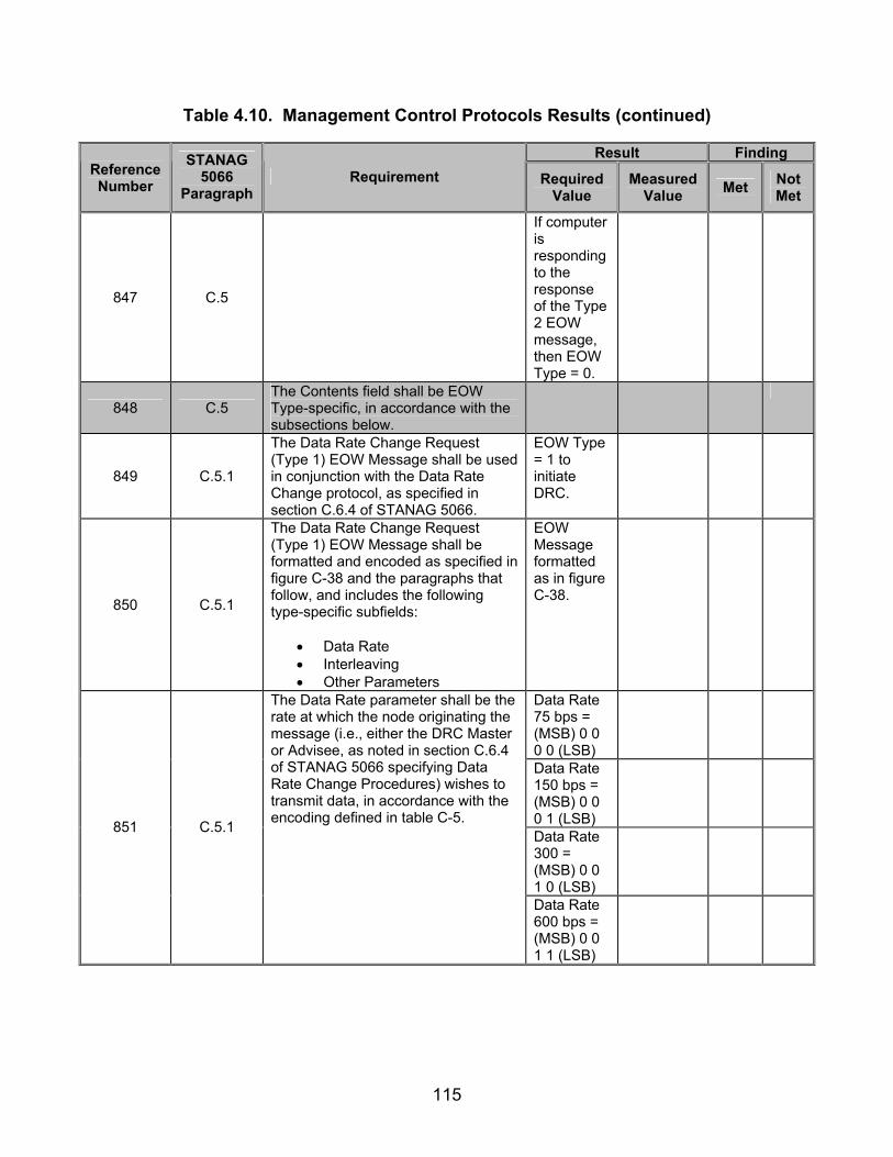
115
Table 4.10. Management Control Protocols Results (continued)
Result Finding Reference Number
STANAG 5066
Paragraph Requirement Required
Value Measured
Value Met Not Met
847 C.5
If computer is responding to the response of the Type 2 EOW message, then EOW Type = 0.
848 C.5 The Contents field shall be EOW Type-specific, in accordance with the subsections below.
849 C.5.1
The Data Rate Change Request (Type 1) EOW Message shall be used in conjunction with the Data Rate Change protocol, as specified in section C.6.4 of STANAG 5066.
EOW Type = 1 to initiate DRC.
850 C.5.1
The Data Rate Change Request (Type 1) EOW Message shall be formatted and encoded as specified in figure C-38 and the paragraphs that follow, and includes the following type-specific subfields:
• Data Rate • Interleaving • Other Parameters
EOW Message formatted as in figure C-38.
Data Rate 75 bps = (MSB) 0 0 0 0 (LSB)
Data Rate 150 bps = (MSB) 0 0 0 1 (LSB)
Data Rate 300 = (MSB) 0 0 1 0 (LSB)
851 C.5.1
The Data Rate parameter shall be the rate at which the node originating the message (i.e., either the DRC Master or Advisee, as noted in section C.6.4 of STANAG 5066 specifying Data Rate Change Procedures) wishes to transmit data, in accordance with the encoding defined in table C-5.
Data Rate 600 bps = (MSB) 0 0 1 1 (LSB)

116
Table 4.10. Management Control Protocols Results (continued)
Result Finding Reference Number
STANAG 5066
Paragraph Requirement Required
Value Measured
Value Met Not Met
Data Rate 1200 bps = (MSB) 0 1 0 0 (LSB)
Data Rate 2400 = (MSB) 0 1 0 1 (LSB)
Data Rate 3200 bps = (MSB) 0 1 1 0 (LSB)
Data Rate 3600 bps = (MSB) 0 1 1 1 (LSB)
Data Rate 4800 = (MSB) 1 0 0 0 (LSB)
Data Rate 6400 bps = (MSB) 1 0 0 1 (LSB)
Data Rate 7200 bps = (MSB) 1 0 1 0 (LSB)
851 C.5.1
Data Rate 9600 = (MSB) 1 0 1 1 (LSB)
No Interleaving = (MSB) 0 0 (LSB)
Short Interleaving = (MSB) 0 1 (LSB)
852 C.5.1
The Interleaver parameter field shall specify the interleaver requested for use by the node producing the message (for that link, if multiple links/modems are in use) with respect to transmit and receive operation, in accordance with table C-6.
Long Interleaving = (MSB) 1 0 (LSB)
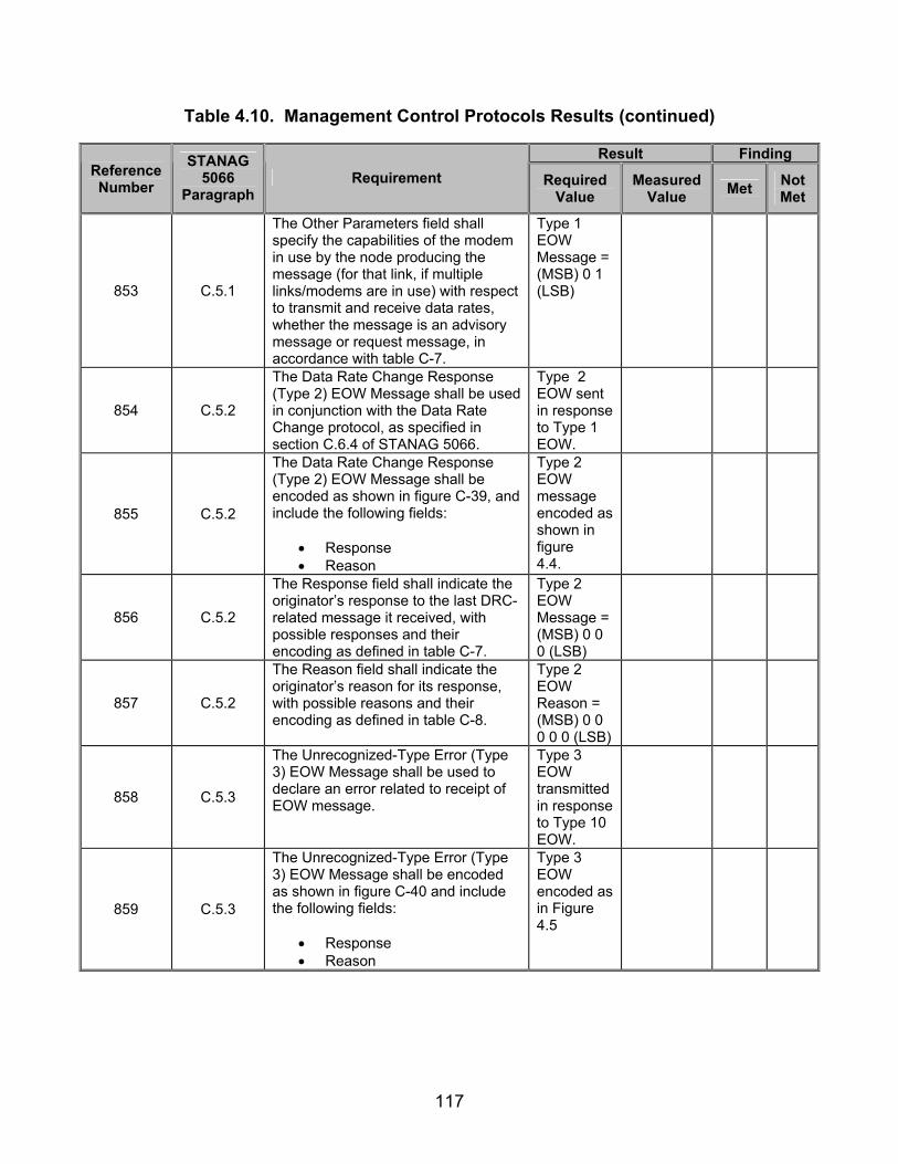
117
Table 4.10. Management Control Protocols Results (continued)
Result Finding Reference Number
STANAG 5066
Paragraph Requirement Required
Value Measured
Value Met Not Met
853 C.5.1
The Other Parameters field shall specify the capabilities of the modem in use by the node producing the message (for that link, if multiple links/modems are in use) with respect to transmit and receive data rates, whether the message is an advisory message or request message, in accordance with table C-7.
Type 1 EOW Message = (MSB) 0 1 (LSB)
854 C.5.2
The Data Rate Change Response (Type 2) EOW Message shall be used in conjunction with the Data Rate Change protocol, as specified in section C.6.4 of STANAG 5066.
Type 2 EOW sent in response to Type 1 EOW.
855 C.5.2
The Data Rate Change Response (Type 2) EOW Message shall be encoded as shown in figure C-39, and include the following fields:
• Response • Reason
Type 2 EOW message encoded as shown in figure 4.4.
856 C.5.2
The Response field shall indicate the originator’s response to the last DRC-related message it received, with possible responses and their encoding as defined in table C-7.
Type 2 EOW Message = (MSB) 0 0 0 (LSB)
857 C.5.2
The Reason field shall indicate the originator’s reason for its response, with possible reasons and their encoding as defined in table C-8.
Type 2 EOW Reason = (MSB) 0 0 0 0 0 (LSB)
858 C.5.3
The Unrecognized-Type Error (Type 3) EOW Message shall be used to declare an error related to receipt of EOW message.
Type 3 EOW transmitted in response to Type 10 EOW.
859 C.5.3
The Unrecognized-Type Error (Type 3) EOW Message shall be encoded as shown in figure C-40 and include the following fields:
• Response • Reason
Type 3 EOW encoded as in Figure 4.5

118
Table 4.10. Management Control Protocols Results (continued)
Result Finding Reference Number
STANAG 5066
Paragraph Requirement Required
Value Measured
Value Met Not Met
860 C.5.3
The type of the unrecognized EOW message or the message that triggered the error shall be mapped into the four least-significant bits of the “Reason” field.
Reason bits = (MSB) 0 1 0 1 0 (LSB) (0xA hex)
861 C.5.3
The unused MSB of the “Reason” field, and all bits in the “Response” field, shall be reset to the value zero (0).
Response bits = (MSB) 0 0 0 (LSB) (0x0 hex)
925 C.6.4 If Data Rate Control is implemented, it shall be implemented as specified in the subsections below.
Initial Data Rate = 300 bps for DRC trials.
927 C.6.4.1
All connections on which the data rate or other modem parameters can be controlled shall be initiated at 300 bps, using short interleaving.
Initial Interleaving= short
928 C.6.4.1
The waveform shall be selected by the operator during node initialization.
Operator able to select waveform.
929 C.6.4.2
Algorithms to determine when or if the data rate change capability would be exercised are beyond the scope of STANAG 5066. At a minimum, systems implementing STANAG 5066 shall implement and support data rate changes in accordance with the procedures defined here.
930 C.6.4.2
On receiving an EOW Type 1 Data Rate Change message with the “Other Parameters” field indicating that this is a request for a Data Rate Change, a node shall comply with the parameters specified in the message unless some specific reason prevents it doing so. Generally, this means that the node will initiate a data rate change (DRC) procedure.
Data Rate Change successful.

119
Table 4.10. Management Control Protocols Results (continued)
Result Finding Reference Number
STANAG 5066
Paragraph Requirement Required
Value Measured
Value Met Not Met
Type 1 EOW Message encapsu-lated within Type 6 D_PDU.
931 C.6.4.2
Following a decision to change data rate, a node shall use TYPE 6 D_PDUs (i.e., Management D_PDUs) containing Type 1 and Type 2 EOW messages to implement and coordinate the change.
Type 2 EOW Message encapsu-lated within Type 6 D_PDU.
933 C.6.4.2
Data rate changes shall be effective only for a single connection.
A separate DRC occurred between computers 1.2.0.0 and 1.1.0.0 then between computers 1.2.0.0 and 2.1.0.0.
934 C.6.4.2
If a node has a number of connections active with different nodes, the data rate change decisions and procedures shall be executed independently for each connection.
Each DRC activated independ-ently of each other.
935 C.6.4.2
The message numbered [1] in the figure indicates an EOW advisory message. The DRC master shall send a DRC Request Message, i.e., a Management (Type 6) D_PDU containing a DRC Request (Type 1) EOW Message [2], with the parameters equal to the intended new transmit data rate for the DRC master.
Type 6 D_PDU Transmit-ted with Type 1 EOW from computer initiating DRC.

120
Table 4.10. Management Control Protocols Results (continued)
Result Finding Reference Number
STANAG 5066
Paragraph Requirement Required
Value Measured
Value Met Not Met
Data Rate 150 bps = (MSB) 0 0 0 1 (LSB)
Data Rate 300 = (MSB) 0 0 1 0 (LSB)
Data Rate 600 bps = (MSB) 0 0 1 1 (LSB)
Data Rate 1200 bps = (MSB) 0 1 0 0 (LSB)
Data Rate 2400 = (MSB) 0 1 0 1 (LSB)
Data Rate 3200 bps = (MSB) 0 1 1 0 (LSB)
Data Rate 3600 bps = (MSB) 0 1 1 1 (LSB)
936 C.6.4.2
The “Other Parameters” field of the Type 1 management message shall be set to indicate the data rate capabilities of the modem in use at the DRC master for this connection, to indicate that this is a request for a change, and not an advisory message. In the scenario of figure C-50, the modem at the DRC master has independent transmit and receive data rate.
Data Rate 4800 = (MSB) 1 0 0 0 (LSB)
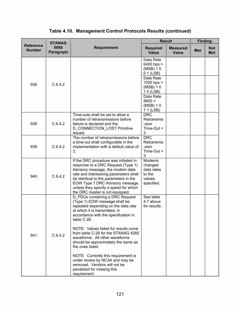
121
Table 4.10. Management Control Protocols Results (continued)
Result Finding Reference Number
STANAG 5066
Paragraph Requirement Required
Value Measured
Value Met Not Met
Data Rate 6400 bps = (MSB) 1 0 0 1 (LSB)
Data Rate 7200 bps = (MSB) 1 0 1 0 (LSB)
936 C.6.4.2
Data Rate 9600 = (MSB) 1 0 1 1 (LSB)
938 C.6.4.2
Time-outs shall be set to allow a number of retransmissions before failure is declared and the D_CONNECTION_LOST Primitive issued.
DRC Retransmis-sion Time-Out = 3
939 C.6.4.2
The number of retransmissions before a time-out shall configurable in the implementation with a default value of 3.
DRC Retransmis-sion Time-Out = 3
940 C.6.4.2
If the DRC procedure was initiated in response to a DRC Request (Type 1) Advisory message, the modem data rate and interleaving parameters shall be identical to the parameters in the EOW Type 1 DRC Advisory message, unless they specify a speed for which the DRC master is not equipped.
Modems changed data rates to the values specified.
941 C.6.4.2
D_PDUs containing a DRC Request (Type 1) EOW message shall be repeated depending on the data rate at which it is transmitted, in accordance with the specification in table C-26. NOTE: Values listed for results come from table C-26 for the STANAG 4285 waveforms. All other waveforms should be approximately the same as the ones listed. NOTE: Currently this requirement is under review by NC3A and may be removed. Vendors will not be penalized for missing this requirement.
See table 4.7 above for results.

122
Table 4.10. Management Control Protocols Results (continued)
Result Finding Reference Number
STANAG 5066
Paragraph Requirement Required
Value Measured
Value Met Not Met
942 C.6.4.2
Implementation Note: The number of transmissions in the table has been specified to (nearly) fill the interleave buffer for the waveform specified by STANAG 4285. For waveforms and interleaver settings not shown, the number of transmissions shall be adjusted as required to minimize the use of “stuff bits” to fill the modem interleave buffer.
TBD
N/A
943 C.6.4.2
Repeated Management D_PDUs containing a DRC Request (Type 1) Management message shall have the same FRAME ID NUMBER in each of the copies.
All Type 6 D_PDUs repeated have the same FRAME ID NUMBER.
947 C.6.4.2
The DRC slave shall respond to the DRC_Request D_PDU with a DRC_Response message, i.e., a TYPE 6 Management D_PDU containing a Type 2 DRC Response EOW message, as follows:
Type 6 D_PDU with a Type 2 EOW message transmitted in response to a Type 6 D_PDU with a Type 1 EOW message.
948 C.6.4.2
The DRC Response message shall indicate either “accept” or “refuse,” in accordance with the Management message specifications of section 3.5 of STANAG 5066, indicating the DRC Slave’s capability to change the modem parameters or not.
Type 2 EOW Response = 0 0 0
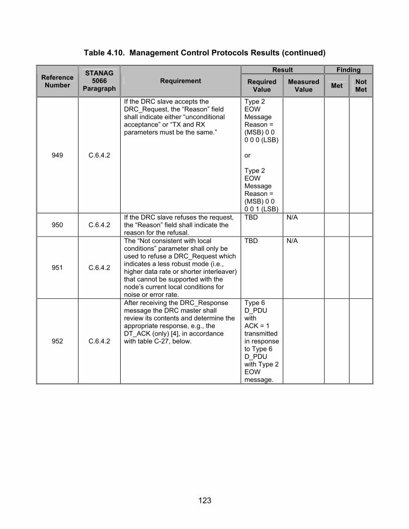
123
Table 4.10. Management Control Protocols Results (continued)
Result Finding Reference Number
STANAG 5066
Paragraph Requirement Required
Value Measured
Value Met Not Met
949 C.6.4.2
If the DRC slave accepts the DRC_Request, the “Reason” field shall indicate either “unconditional acceptance” or “TX and RX parameters must be the same.”
Type 2 EOW Message Reason = (MSB) 0 0 0 0 0 (LSB) or Type 2 EOW Message Reason = (MSB) 0 0 0 0 1 (LSB)
950 C.6.4.2 If the DRC slave refuses the request, the “Reason” field shall indicate the reason for the refusal.
TBD N/A
951 C.6.4.2
The “Not consistent with local conditions” parameter shall only be used to refuse a DRC_Request which indicates a less robust mode (i.e., higher data rate or shorter interleaver) that cannot be supported with the node’s current local conditions for noise or error rate.
TBD N/A
952 C.6.4.2
After receiving the DRC_Response message the DRC master shall review its contents and determine the appropriate response, e.g., the DT_ACK (only) [4], in accordance with table C-27, below.
Type 6 D_PDU with ACK = 1 transmitted in response to Type 6 D_PDU with Type 2 EOW message.

124
Table 4.10. Management Control Protocols Results (continued)
Result Finding Reference Number
STANAG 5066
Paragraph Requirement Required
Value Measured
Value Met Not Met
953 C.6.4.2
If the procedure is initiated in response to EOW Type 1 message, the DRC master should already know that the DRC slave’s transmit and receive parameters must be the same. Therefore, the DRC master shall reply with a DT_ACK, i.e., a Management (Type 6) D_PDU with the ACK field set equal to one, accepting that the new parameters will apply to both transmit and receive.
Type 6 D_PDU with ACK = 1 transmitted in response to Type 6 D_PDU with Type 2 EOW message.
954 C.6.4.2
A DRC slave that refused a change request shall acknowledge the DRC Response (cancel) message with a DT_ACK only and then terminate the DRC procedure.
TBD N/A
955 C.6.4.2
If the nodes make use of the EOW Type 1 (Advisory) message to initiate the DRC procedure, the master shall end the DRC_Response (cancel) and await an updated EOW recommendation before initiating another DRC procedure. If EOW Type 1 messages are not used, DRC_Request may be sent by master to request different modem parameters which may be consistent with the local conditions. In the table and notes in the preceding paragraphs, a DT_ACK refers to a Data Transfer.
Computer 1.1.0.0 transmits a Type 2 EOW with Response = 0 1 0.
956 C.6.4.2
If a DT_ACK (with no further management message) is sent in reply to a DRC_Response “accept” (as shown in figure C-50), the nodes shall change their respective modem parameters and proceed to the “confirmation” phase.
After a Type 6 D_PDU with ACK = 1 is transmit-ted, Computers change their data rate and continue transmitting data.

125
Table 4.10. Management Control Protocols Results (continued)
Result Finding Reference Number
STANAG 5066
Paragraph Requirement Required
Value Measured
Value Met Not Met
957 C.6.4.2
The DRC slave shall NOT change its modem parameters until it has received a DT_ACK (with no further management message) from the DRC master.
Modem does not change data rate or interleaver until a Type 6 D_PDU with ACK = 1 is transmit-ted.
958 C.6.4.2
If a DT_ACK (with no further management message) is sent by the DRC slave in reply to a DRC_Response “cancel,” both nodes shall abandon the procedure and return to the prior state without changing modem parameters.
TBD N/A
959 C.6.4.2
After abandoning a DRC procedure because of failure, if node A (formerly the DRC slave) has no queued data or acknowledgements to send to node B, it shall send a Data D_PDU, Expedited Data D_PDU, or Non-ARQ D_PDU, with zero data attached.
TBD N/A
960 C.6.4.2
On receiving the DRC Confirm message, the DRC Master shall respond with a DT_ACK and then return to the processing state it was in before executing the DRC procedure.
Type 6 D_PDU with ACK = 1 transmitted in response to Type 6 D_PDU with Type 2 EOW, and resumes transmitting data where it left off to begin DRC.

126
Table 4.10. Management Control Protocols Results (continued)
Result Finding Reference Number
STANAG 5066
Paragraph Requirement Required
Value Measured
Value Met Not Met
961 C.6.4.2
After sending the DRC Confirm message [5] to the master and receiving the DT_ACK from the master, the slave shall return to the processing state it was in before executing the DRC procedure and send any queued D_PDUs to node B.
If Type 6 D_PDUs interrupted transfer of Types 0, 2, or 4 D_PDUs, Types 0, 2, or 4 D_PDUs transmitted after DRC procedures completed.
962 C.6.4.2
If node A (formerly the DRC slave) has no queued data to send to node B, it shall send a Data D_PDU or Expedited Data D_PDU with zero data attached, and the C_PDU Segment Size field set equal to zero (0).
If no further data is needed to be sent, a Type 0 or 4 D_PDU is transmitted with 0 U_PDU bytes.
Legend: ACK—Acknowledgement ARQ—Automatic Repeat-Request bps—bits per second C_PDU—Channel Access Sublayer Protocol Data Unit D_PDU—Data Transfer Sublayer Protocol Data Unit DT_ACK—Data Acknowledgement DRC—Data Rate Change EOW—Engineering Orderwire TX—Transmit hex—hexadecimal ID—Identification
LSB—Least Significant Bit N/A—Not Available M_PDU—Management Protocol Data Unit MSB—Most Significant Bit NATO—North Atlantic Trade Organization NC3A—NATO Consultation, Command, and Control Agency RX—Receive STANAG—Standardization Agreement sync—synchronization TBD—To Be Determined U_PDU—User Protocol Data Unit

127
SUBTEST 5. WARNING D_PDU PROTOCOLS
5.1 Objective. To determine the extent of compliance to the requirements of STANAG 5066 for validating Warning D_PDUs reference numbers 801-810. 5.2 Criteria
a. A Data Transfer Sublayer shall be a Warning D_PDU to any remote node from which an unexpected or unknown D_PDU Type has been received. (appendix B, reference number 801)
b. The Warning D_PDU shall contain the following fields within its D_PDU
Type-Specific Part, mapped and encoded, in accordance with figure 5.1 and the paragraphs below: (appendix B, reference number 802)
• Received Frame Type • Reason Warning Sent
Figure 5.1. Frame Format for Warning D_PDU Type 15
c. The Received Frame Type shall indicate the frame type that caused the
warning to be sent. (appendix B, reference number 803)
Legend: CRC—Cyclic Redundancy Check, EOT—End of Tranmission, EOW—Engineering Orderwire, LSB—Least Significant Bit, MSB—Most Significant Bit , SYN—Synchronization

128
d. The value of the Received Frame Type field shall be encoded in 4 bits and located within the D_PDU as specified in figures 5.2 and 5.3. (appendix B, reference number 804)
Figure 5.2. Received Frame Type Field
Figure 5.3. Received Frame Type Mapping Convention in D_PDU Header
e. The Reason Warning Sent field shall indicate the reason the frame type
caused a warning, with values as specified in table 5.1. (appendix B, reference number 805)
Table 5.1. Encoding of Warning D_PDU Reason Field
Reason Field Value
Unrecognized D_PDU Type Received 0 Connection-Related D_PDU Received While Not Currently
Connected 1
Invalid D_PDU Received 2 Invalid D_PDU Received for Current State 3
Unspecified/Reserved 4-15 Legend: D_PDU—Data Transfer Sublayer Protocol Data Unit
f. The value of the Reason Warning Sent field shall be encoded in 4 bits and
located within the D_PDU as specified in figures 5.4 and 5.5. (appendix B, reference number 806)
Legend: LSB—Least Significant Bit, MSB—Most Significant Bit
Legend: LSB—Least Significant Bit, MSB—Most Significant Bit

129
Figure 5.4. Reason Warning Sent Field
Figure 5.5. Reason Warning Sent Mapping Convention in D_PDU Header
g. The transmission of Warning Type D_PDUs shall be initiated
independently by the Data Transfer Sublayer in response to certain D_PDUs and shall not be acknowledged explicitly. (appendix B, reference numbers 807 and 808)
h. A Warning D_PDU shall be sent in the following conditions: (appendix B,
reference number 809)
• A node receives a D_PDU Header addressed to itself with a valid Cyclic Redundancy Check (CRC) and an unrecognized D_PDU Type (value 0000).
• A node is not in the Idle/Broadcast state and it receives a D_PDU Header addressed to itself, from a node with which it is not currently connected (value 0001).
• A node is in Idle/Broadcast state and it receives a D_PDU Header addressed to itself, which is other than Type 7 or Type 8 D_PDU (value 0010).
• A node receives any D_PDU that is recognized but is not of the allowed type for the state which the receiving node is in (value 0011; this is the general case of the preceding).
Legend: LSB—Least Significant Bit, MSB—Most Significant Bit
Legend: LSB—Least Significant Bit, MSB—Most Significant Bit
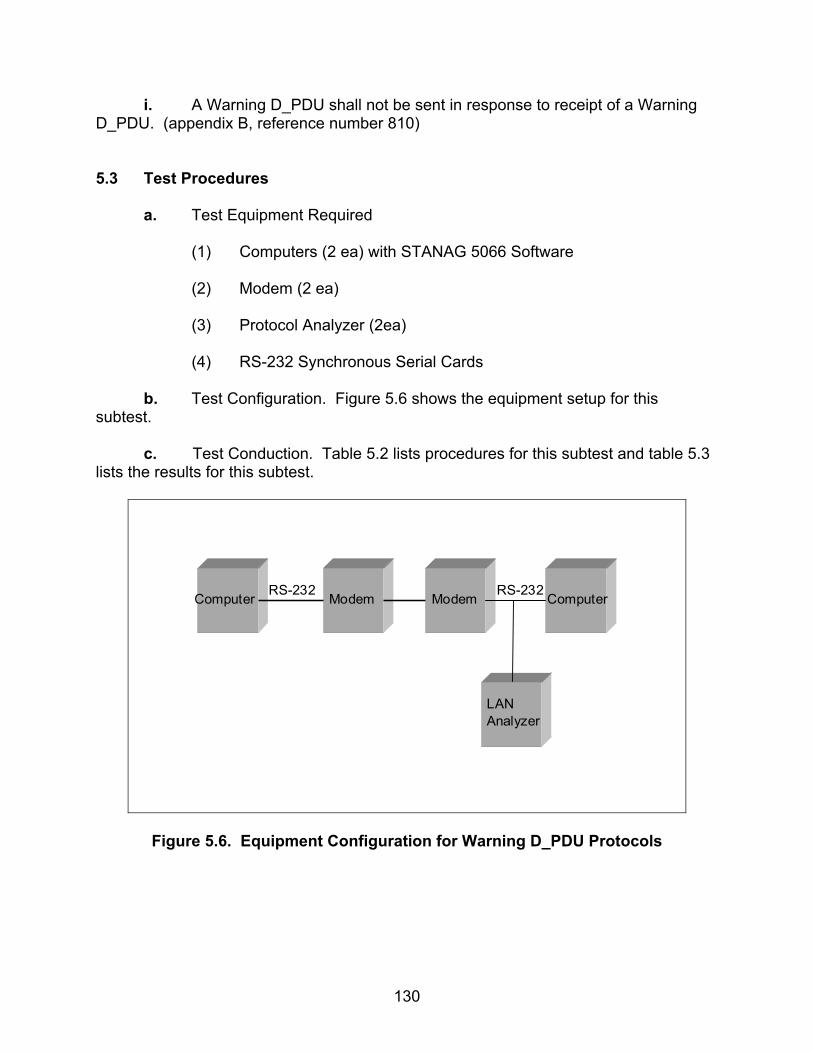
130
i. A Warning D_PDU shall not be sent in response to receipt of a Warning D_PDU. (appendix B, reference number 810)
5.3 Test Procedures a. Test Equipment Required
(1) Computers (2 ea) with STANAG 5066 Software (2) Modem (2 ea) (3) Protocol Analyzer (2ea) (4) RS-232 Synchronous Serial Cards
b. Test Configuration. Figure 5.6 shows the equipment setup for this subtest.
c. Test Conduction. Table 5.2 lists procedures for this subtest and table 5.3 lists the results for this subtest.
Computer Modem Modem Computer
LANAnalyzer
RS-232 RS-232
Figure 5.6. Equipment Configuration for Warning D_PDU Protocols
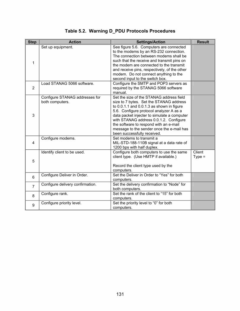
131
Table 5.2. Warning D_PDU Protocols Procedures
Step Action Settings/Action Result
1
Set up equipment. See figure 5.6. Computers are connected to the modems by an RS-232 connection. The connection between modems shall be such that the receive and transmit pins on the modem are connected to the transmit and receive pins, respectively, of the other modem. Do not connect anything to the second input to the switch box.
2 Load STANAG 5066 software. Configure the SMTP and POP3 servers as
required by the STANAG 5066 software manual.
3
Configure STANAG addresses for both computers.
Set the size of the STANAG address field size to 7 bytes. Set the STANAG address to 0.0.1.1 and 0.0.1.3 as shown in figure 5.6. Configure protocol analyzer A as a data packet injecter to simulate a computer with STANAG address 0.0.1.2. Configure the software to respond with an e-mail message to the sender once the e-mail has been successfully received.
4 Configure modems. Set modems to transmit a
MIL-STD-188-110B signal at a data rate of 1200 bps with half duplex.
5
Identify client to be used. Configure both computers to use the same client type. (Use HMTP if available.) Record the client type used by the computers.
Client Type =
6 Configure Deliver in Order. Set the Deliver in Order to “Yes” for both computers.
7 Configure delivery confirmation. Set the delivery confirmation to “Node” for both computers.
8 Configure rank. Set the rank of the client to “15” for both computers.
9 Configure priority level. Set the priority level to “0” for both computers.

132
Table 5.2. Warning D_PDU Protocols Procedures (continued)
Step Action Settings/Action Result
10
Configure protocol analyzer. Configure protocol analyzer B to capture the transmitted data between the two computers and save it to a file. Configure the protocol analyzer to have a 4800 bps bit rate and to synchronize on “0x90EB.” Configure protocol analyzer B to drop sync after 20 “0xFFs”. Configure the analyzer to time stamp each captured byte.
The following procedures are for reference numbers 801-807 and 809-810 for Type 2 Warning Reason.
11
Inject Type 0 D_PDUs.
Transmit the following Type 0 D_PDUs in the order listed (left-to-right and top-to-bottom) from the data packet injector to the computer with STANAG address 0.0.1.1: (MSB) 90 EB 04 20 0E E9 00 00 10 10 00 01 02 EC 21 00 2B A8 00 00 33 44 7A 07 45 48 4C 4F 20 6B 69 6C 62 6F 75 72 6E 65 2E 6C 65 67 65 6E 64 73 2E 6E 69 74 2E 42 2A 66 7F 00 00 00 (LSB) (MSB) 90 EB 04 20 0E E9 00 00 10 10 00 01 02 E8 21 01 AE 3F 00 00 33 44 7A 07 64 69 73 61 2E 6D 69 6C 0D 0A 4D 41 49 4C 20 46 52 4F 4D 3A 3C 68 66 65 6D 61 69 4E 58 8A 8B (LSB) (MSB) 90 EB 04 20 0E E9 00 00 10 10 00 01 02 E8 21 02 D8 2C 00 00 33 44 7A 07 6C 40 6B 69 6C 62 6F 75 72 6E 65 2E 6C 65 67 65 6E 64 73 2E 6E 69 74 2E 64 69 73 1E 6A D8 60 00 (LSB) (MSB) 90 EB 04 20 0E E9 00 00 10 10 00 01 02 E8 21 03 0A 22 00 00 33 44 7A 07 61 2E 6D 69 6C 3E 0D 0A 52 43 50 54 20 54 4F 3A 3C 61 64 6D 69 6E 69 73 74 72 61 25 C9 08 6C (LSB) Save the data captured in steps 8-10 with the protocol analyzer to a file. *Note: The above data packets were supported using HMTP in hex format.
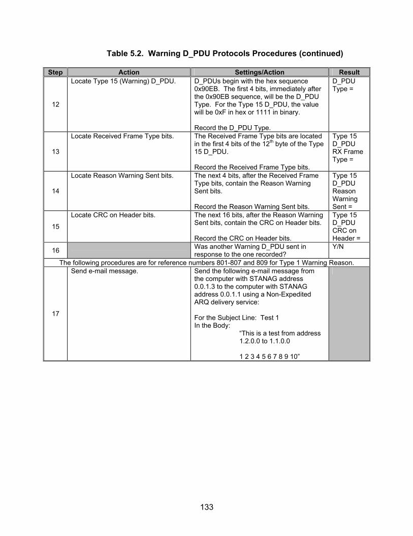
133
Table 5.2. Warning D_PDU Protocols Procedures (continued)
Step Action Settings/Action Result
12
Locate Type 15 (Warning) D_PDU. D_PDUs begin with the hex sequence 0x90EB. The first 4 bits, immediately after the 0x90EB sequence, will be the D_PDU Type. For the Type 15 D_PDU, the value will be 0xF in hex or 1111 in binary. Record the D_PDU Type.
D_PDU Type =
13
Locate Received Frame Type bits.
The Received Frame Type bits are located in the first 4 bits of the 12th byte of the Type 15 D_PDU. Record the Received Frame Type bits.
Type 15 D_PDU RX Frame Type =
14
Locate Reason Warning Sent bits.
The next 4 bits, after the Received Frame Type bits, contain the Reason Warning Sent bits. Record the Reason Warning Sent bits.
Type 15 D_PDU Reason Warning Sent =
15
Locate CRC on Header bits.
The next 16 bits, after the Reason Warning Sent bits, contain the CRC on Header bits. Record the CRC on Header bits.
Type 15 D_PDU CRC on Header =
16 Was another Warning D_PDU sent in response to the one recorded?
Y/N
The following procedures are for reference numbers 801-807 and 809 for Type 1 Warning Reason.
17
Send e-mail message. Send the following e-mail message from the computer with STANAG address 0.0.1.3 to the computer with STANAG address 0.0.1.1 using a Non-Expedited ARQ delivery service: For the Subject Line: Test 1 In the Body: “This is a test from address 1.2.0.0 to 1.1.0.0 1 2 3 4 5 6 7 8 9 10”
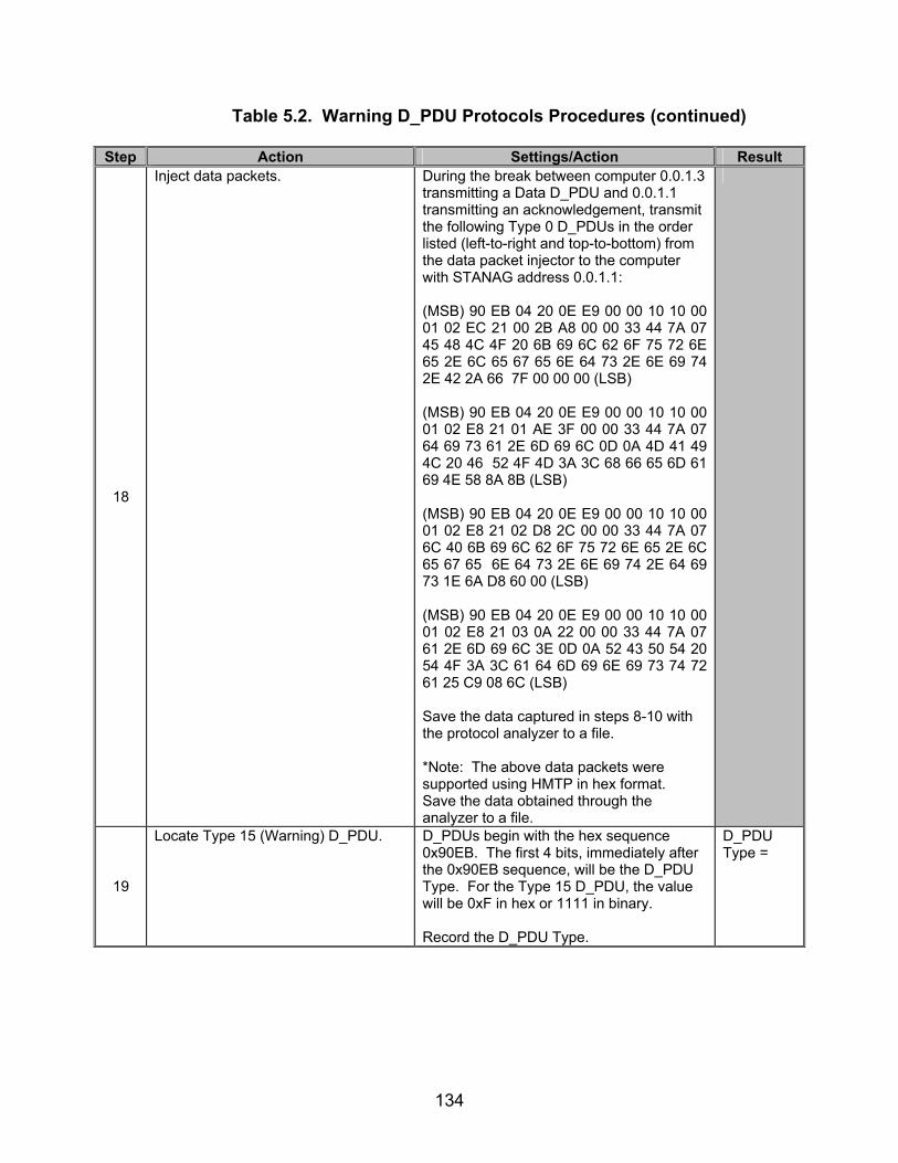
134
Table 5.2. Warning D_PDU Protocols Procedures (continued)
Step Action Settings/Action Result
18
Inject data packets. During the break between computer 0.0.1.3 transmitting a Data D_PDU and 0.0.1.1 transmitting an acknowledgement, transmit the following Type 0 D_PDUs in the order listed (left-to-right and top-to-bottom) from the data packet injector to the computer with STANAG address 0.0.1.1: (MSB) 90 EB 04 20 0E E9 00 00 10 10 00 01 02 EC 21 00 2B A8 00 00 33 44 7A 07 45 48 4C 4F 20 6B 69 6C 62 6F 75 72 6E 65 2E 6C 65 67 65 6E 64 73 2E 6E 69 74 2E 42 2A 66 7F 00 00 00 (LSB) (MSB) 90 EB 04 20 0E E9 00 00 10 10 00 01 02 E8 21 01 AE 3F 00 00 33 44 7A 07 64 69 73 61 2E 6D 69 6C 0D 0A 4D 41 49 4C 20 46 52 4F 4D 3A 3C 68 66 65 6D 61 69 4E 58 8A 8B (LSB) (MSB) 90 EB 04 20 0E E9 00 00 10 10 00 01 02 E8 21 02 D8 2C 00 00 33 44 7A 07 6C 40 6B 69 6C 62 6F 75 72 6E 65 2E 6C 65 67 65 6E 64 73 2E 6E 69 74 2E 64 69 73 1E 6A D8 60 00 (LSB) (MSB) 90 EB 04 20 0E E9 00 00 10 10 00 01 02 E8 21 03 0A 22 00 00 33 44 7A 07 61 2E 6D 69 6C 3E 0D 0A 52 43 50 54 20 54 4F 3A 3C 61 64 6D 69 6E 69 73 74 72 61 25 C9 08 6C (LSB) Save the data captured in steps 8-10 with the protocol analyzer to a file. *Note: The above data packets were supported using HMTP in hex format. Save the data obtained through the analyzer to a file.
19
Locate Type 15 (Warning) D_PDU. D_PDUs begin with the hex sequence 0x90EB. The first 4 bits, immediately after the 0x90EB sequence, will be the D_PDU Type. For the Type 15 D_PDU, the value will be 0xF in hex or 1111 in binary. Record the D_PDU Type.
D_PDU Type =
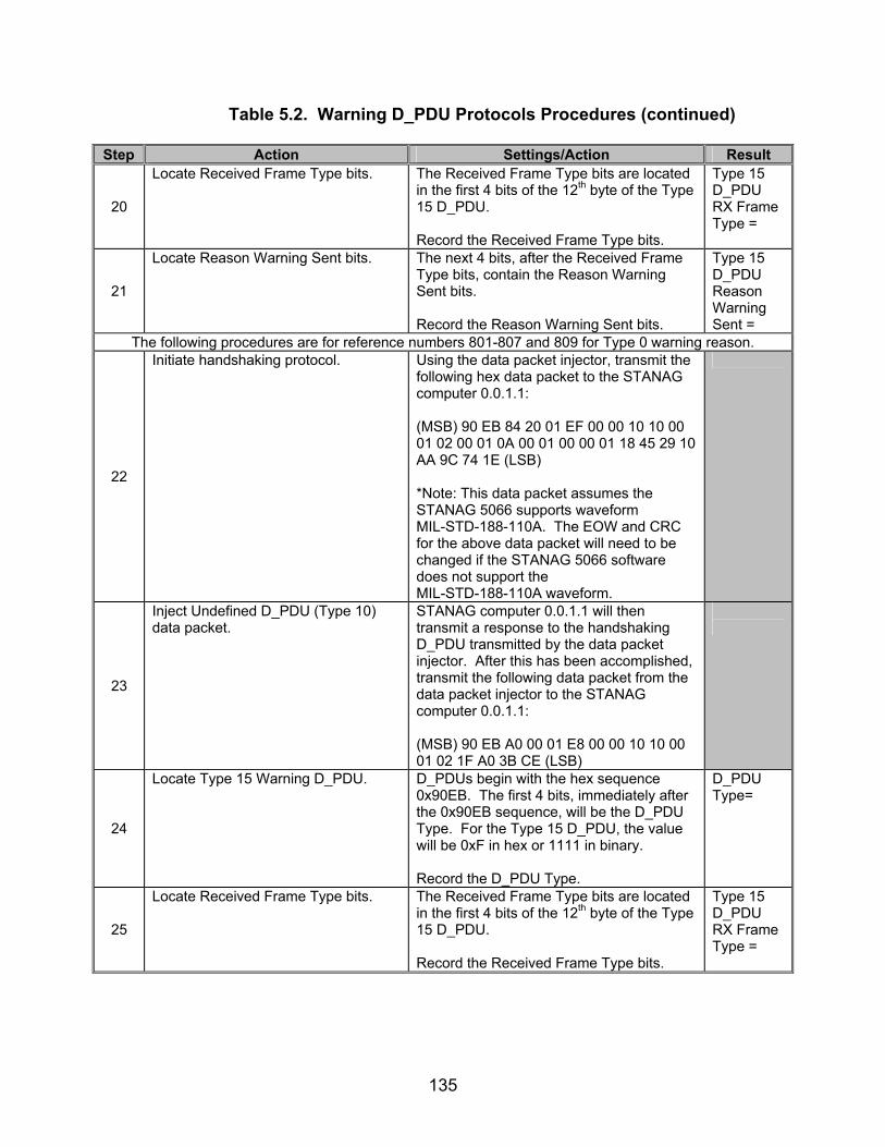
135
Table 5.2. Warning D_PDU Protocols Procedures (continued)
Step Action Settings/Action Result
20
Locate Received Frame Type bits.
The Received Frame Type bits are located in the first 4 bits of the 12th byte of the Type 15 D_PDU. Record the Received Frame Type bits.
Type 15 D_PDU RX Frame Type =
21
Locate Reason Warning Sent bits.
The next 4 bits, after the Received Frame Type bits, contain the Reason Warning Sent bits. Record the Reason Warning Sent bits.
Type 15 D_PDU Reason Warning Sent =
The following procedures are for reference numbers 801-807 and 809 for Type 0 warning reason.
22
Initiate handshaking protocol.
Using the data packet injector, transmit the following hex data packet to the STANAG computer 0.0.1.1: (MSB) 90 EB 84 20 01 EF 00 00 10 10 00 01 02 00 01 0A 00 01 00 00 01 18 45 29 10 AA 9C 74 1E (LSB) *Note: This data packet assumes the STANAG 5066 supports waveform MIL-STD-188-110A. The EOW and CRC for the above data packet will need to be changed if the STANAG 5066 software does not support the MIL-STD-188-110A waveform.
23
Inject Undefined D_PDU (Type 10) data packet.
STANAG computer 0.0.1.1 will then transmit a response to the handshaking D_PDU transmitted by the data packet injector. After this has been accomplished, transmit the following data packet from the data packet injector to the STANAG computer 0.0.1.1: (MSB) 90 EB A0 00 01 E8 00 00 10 10 00 01 02 1F A0 3B CE (LSB)
24
Locate Type 15 Warning D_PDU. D_PDUs begin with the hex sequence 0x90EB. The first 4 bits, immediately after the 0x90EB sequence, will be the D_PDU Type. For the Type 15 D_PDU, the value will be 0xF in hex or 1111 in binary. Record the D_PDU Type.
D_PDU Type=
25
Locate Received Frame Type bits.
The Received Frame Type bits are located in the first 4 bits of the 12th byte of the Type 15 D_PDU. Record the Received Frame Type bits.
Type 15 D_PDU RX Frame Type =
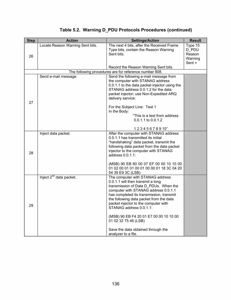
136
Table 5.2. Warning D_PDU Protocols Procedures (continued)
Step Action Settings/Action Result
26
Locate Reason Warning Sent bits.
The next 4 bits, after the Received Frame Type bits, contain the Reason Warning Sent bits. Record the Reason Warning Sent bits.
Type 15 D_PDU Reason Warning Sent =
The following procedures are for reference number 808.
27
Send e-mail message. Send the following e-mail message from the computer with STANAG address 0.0.1.1 to the data packet injector using the STANAG address 0.0.1.2 for the data packet injector; use Non-Expedited ARQ delivery service: For the Subject Line: Test 1 In the Body: “This is a test from address 0.0.1.1 to 0.0.1.2 1 2 3 4 5 6 7 8 9 10”
28
Inject data packet. After the computer with STANAG address 0.0.1.1 has transmitted its initial “handshaking” data packet, transmit the following data packet from the data packet injector to the computer with STANAG address 0.0.1.1: (MSB) 90 EB 80 00 07 EF 00 00 10 10 00 01 02 00 01 01 00 01 00 00 01 18 3C 04 20 54 39 E9 3C (LSB)
29
Inject 2nd data packet. The computer with STANAG address 0.0.1.1 will then transmit a long transmission of Data D_PDUs. When the computer with STANAG address 0.0.1.1 has completed its transmission, transmit the following data packet from the data packet injector to the computer with STANAG address 0.0.1.1: (MSB) 90 EB F4 20 01 E7 00 00 10 10 00 01 02 32 75 46 (LSB) Save the data obtained through the analyzer to a file.
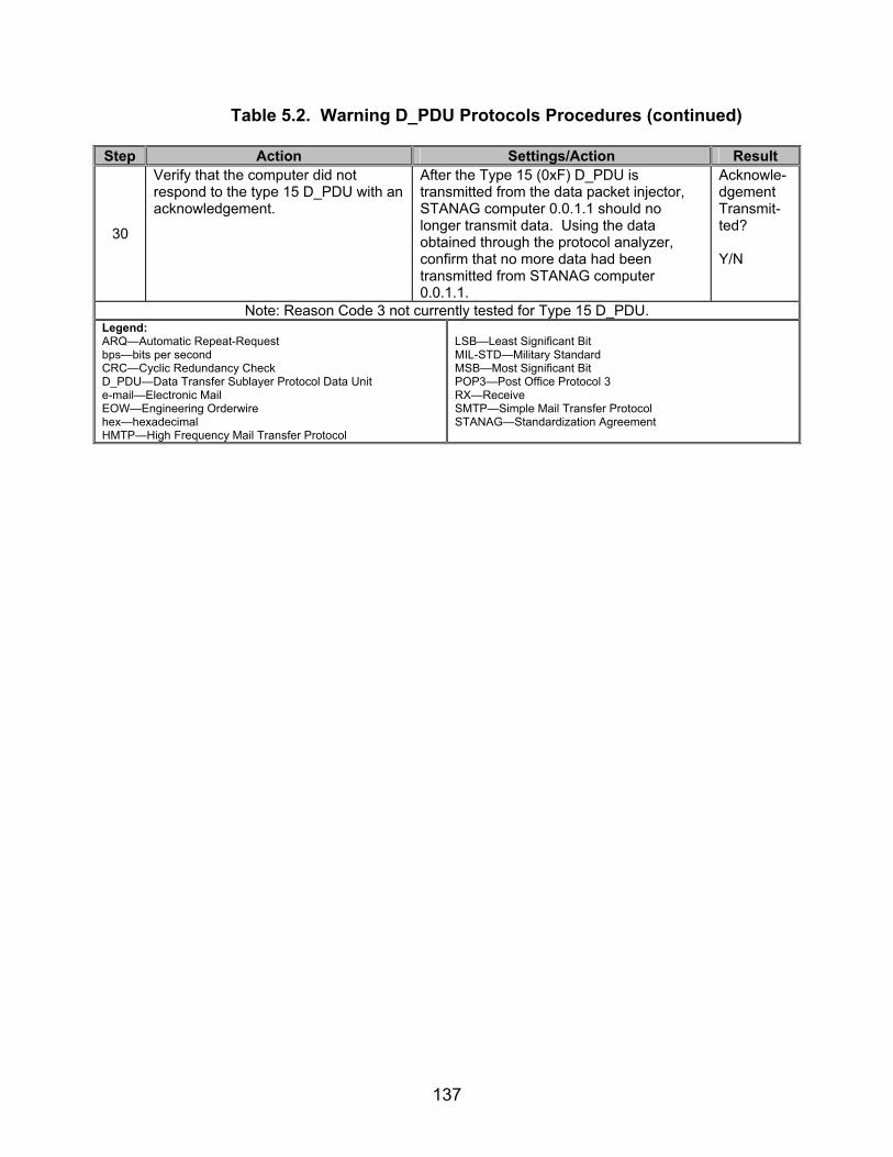
137
Table 5.2. Warning D_PDU Protocols Procedures (continued)
Step Action Settings/Action Result
30
Verify that the computer did not respond to the type 15 D_PDU with an acknowledgement.
After the Type 15 (0xF) D_PDU is transmitted from the data packet injector, STANAG computer 0.0.1.1 should no longer transmit data. Using the data obtained through the protocol analyzer, confirm that no more data had been transmitted from STANAG computer 0.0.1.1.
Acknowle-dgement Transmit-ted? Y/N
Note: Reason Code 3 not currently tested for Type 15 D_PDU. Legend: ARQ—Automatic Repeat-Request bps—bits per second CRC—Cyclic Redundancy Check D_PDU—Data Transfer Sublayer Protocol Data Unit e-mail—Electronic Mail EOW—Engineering Orderwire hex—hexadecimal HMTP—High Frequency Mail Transfer Protocol
LSB—Least Significant Bit MIL-STD—Military Standard MSB—Most Significant Bit POP3—Post Office Protocol 3 RX—Receive SMTP—Simple Mail Transfer Protocol STANAG—Standardization Agreement
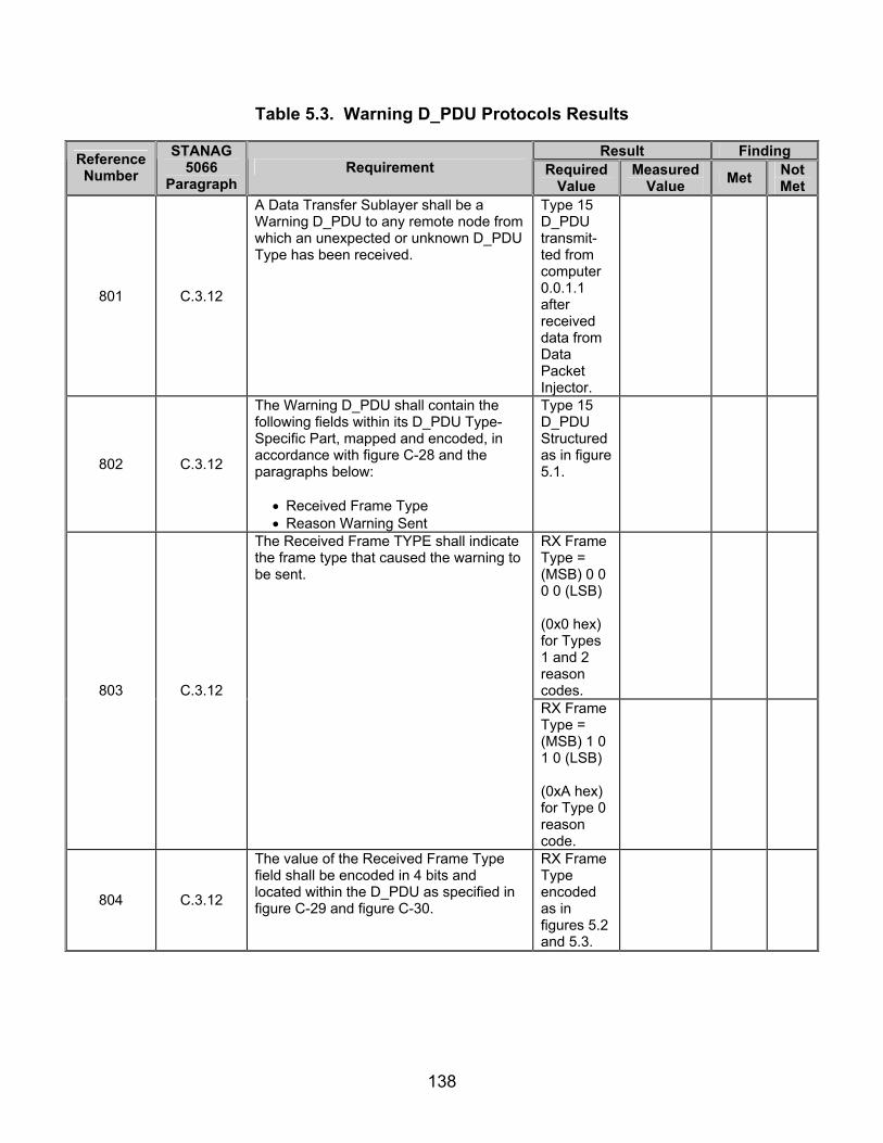
138
Table 5.3. Warning D_PDU Protocols Results
Result Finding Reference Number
STANAG 5066
Paragraph Requirement Required
Value Measured
Value Met Not Met
801 C.3.12
A Data Transfer Sublayer shall be a Warning D_PDU to any remote node from which an unexpected or unknown D_PDU Type has been received.
Type 15 D_PDU transmit-ted from computer 0.0.1.1 after received data from Data Packet Injector.
802 C.3.12
The Warning D_PDU shall contain the following fields within its D_PDU Type-Specific Part, mapped and encoded, in accordance with figure C-28 and the paragraphs below:
• Received Frame Type • Reason Warning Sent
Type 15 D_PDU Structured as in figure 5.1.
RX Frame Type = (MSB) 0 0 0 0 (LSB) (0x0 hex) for Types 1 and 2 reason codes.
803 C.3.12
The Received Frame TYPE shall indicate the frame type that caused the warning to be sent.
RX Frame Type = (MSB) 1 0 1 0 (LSB) (0xA hex) for Type 0 reason code.
804 C.3.12
The value of the Received Frame Type field shall be encoded in 4 bits and located within the D_PDU as specified in figure C-29 and figure C-30.
RX Frame Type encoded as in figures 5.2 and 5.3.

139
Table 5.3. Warning D_PDU Protocols Results (continued)
Result Finding Reference Number
STANAG 5066
Paragraph Requirement Required
Value Measured
Value Met Not Met
Reason Warning Sent = (MSB) 0 0 1 0 (LSB) (0x2 hex) when D_PDUs injected before link establi-shed.
Reason Warning Sent = (MSB) 0 0 0 1 (LSB) (0x1 hex) when D_PDUs injected while computer 0.0.1.1 linked with computer 0.0.1.3.
805 C.3.12
The Reason Warning Sent field shall indicate the reason the frame type caused a warning, with values as specified in table C-3.
Reason Warning Sent = (MSB) 0 0 0 0 (LSB) (0x0 hex) when an undefined (Type 10) D_PDU is injected.
806 C.3.12
The value of the Reason Warning Sent field shall be encoded in 4 bits and located within the D_PDU as specified in figure C-31 and figure C-32.
Reason Warning Sent field encoded as in figures 5.4 and 5.5.
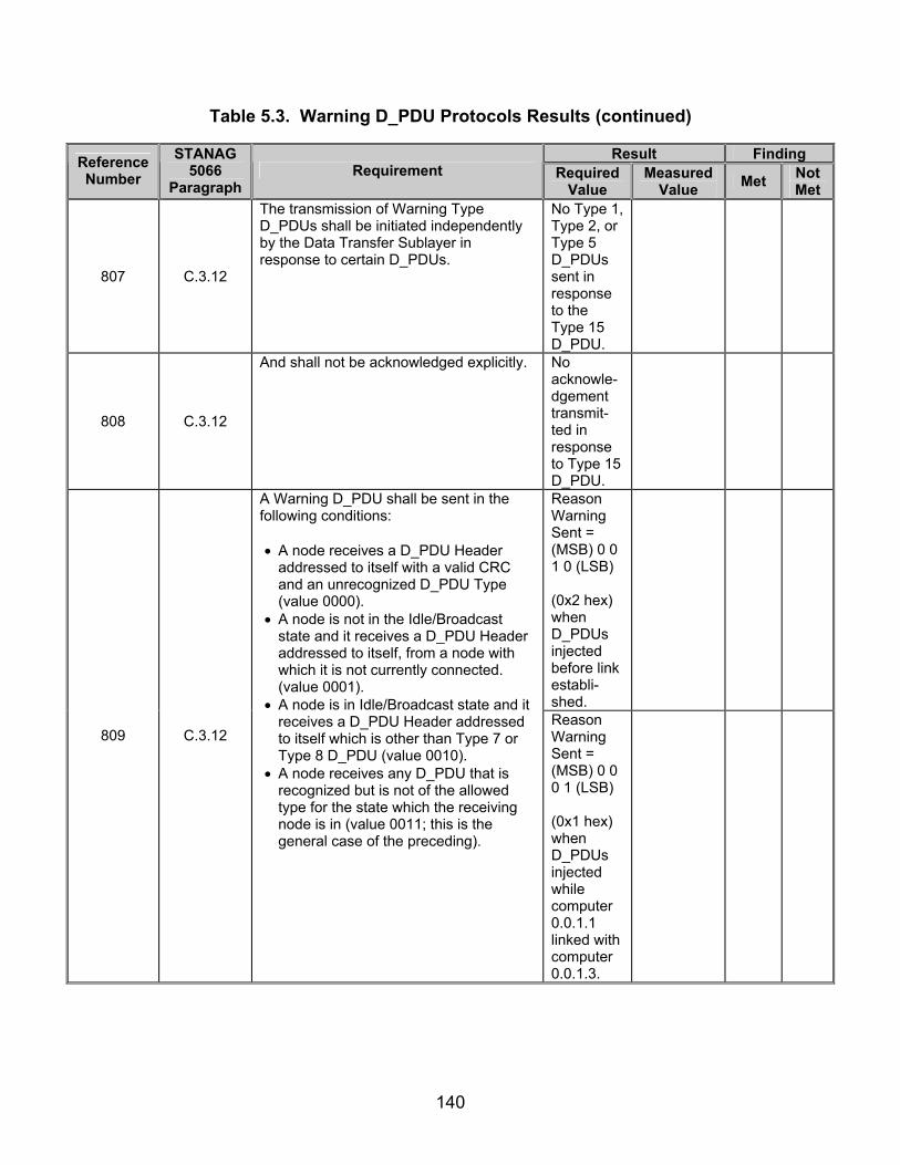
140
Table 5.3. Warning D_PDU Protocols Results (continued)
Result Finding Reference Number
STANAG 5066
Paragraph Requirement Required
Value Measured
Value Met Not Met
807 C.3.12
The transmission of Warning Type D_PDUs shall be initiated independently by the Data Transfer Sublayer in response to certain D_PDUs.
No Type 1, Type 2, or Type 5 D_PDUs sent in response to the Type 15 D_PDU.
808 C.3.12
And shall not be acknowledged explicitly. No acknowle-dgement transmit-ted in response to Type 15 D_PDU.
Reason Warning Sent = (MSB) 0 0 1 0 (LSB) (0x2 hex) when D_PDUs injected before link establi-shed.
809 C.3.12
A Warning D_PDU shall be sent in the following conditions:
• A node receives a D_PDU Header
addressed to itself with a valid CRC and an unrecognized D_PDU Type (value 0000).
• A node is not in the Idle/Broadcast state and it receives a D_PDU Header addressed to itself, from a node with which it is not currently connected. (value 0001).
• A node is in Idle/Broadcast state and it receives a D_PDU Header addressed to itself which is other than Type 7 or Type 8 D_PDU (value 0010).
• A node receives any D_PDU that is recognized but is not of the allowed type for the state which the receiving node is in (value 0011; this is the general case of the preceding).
Reason Warning Sent = (MSB) 0 0 0 1 (LSB) (0x1 hex) when D_PDUs injected while computer 0.0.1.1 linked with computer 0.0.1.3.

141
Table 5.3. Warning D_PDU Protocols Results (continued)
Result Finding Reference Number
STANAG 5066
Paragraph Requirement Required
Value Measured
Value Met Not Met
809 C.3.12
Reason Warning Sent = (MSB) 0 0 0 0 (LSB) (0x0 hex) when an undefined (Type 10) D_PDU is injected.
810 C.3.12
A Warning D_PDU shall not be sent in response to receipt of a Warning D_PDU.
A Type 15 D_PDU was not sent in response to the Type 15 D_PDU sent.
Legend: CRC—Cyclic Redundancy Check D_PDU—Data Transfer Sublayer Protocol Data Unit hex—hexadecimal LSB—Least Significant Bit
MSB—Most Significant Bit RX—Receive STANAG—Standardization Agreement

142
(This page intentionally left blank.)

143
SUBTEST 6. NON-AUTOMATIC REPEAT-REQUEST RESPONSE DATA TRANSFER
6.1 Objective. To determine the extent of compliance to the requirements of STANAG 5066, reference numbers 438, 570, 572-573, 591, 770-774, 776-780, 782-799, and 827-838. 6.2 Criteria
a. No explicit peer-to-peer communication shall be required to establish and terminate a Broadcast Data Exchange Session. A Broadcast Data Exchange Session is established and terminated either by a management process or unilaterally by the Subnetwork Interface Sublayer, based on a number of criteria as explained in section A.1.1.3 of STANAG 5066. (appendix B, reference number 438)
b. The Data Transfer Sublayer shall provide “sub-modes” for Non-ARQ and reliable selective ARQ delivery services, which influence the characteristics of the particular service, as specified below: (appendix B, reference numbers 570, and 572-573)
• Any D_PDUs that are found to contain transmission errors shall be discarded by the Data Transfer Sublayer protocol entity.
• A special mode of the Non-ARQ service shall be available to
reconstruct C_PDUs from D_PDUs in error and deliver them to the Channel Access Sublayer.
c. The Non-Repeat-Request (NRQ) protocol shall only operate in a simplex
mode since the local node, after sending information frames (I-Frames), does not wait for an indication from the remote node as to whether or not the I-Frames were correctly received. (appendix B, reference number 591)
d. The Non-ARQ Data (Type 7) D_PDU shall be used to send segmented
C_PDUs when the transmitting node needs no explicit confirmation that the data was received. (appendix B, reference number 770)
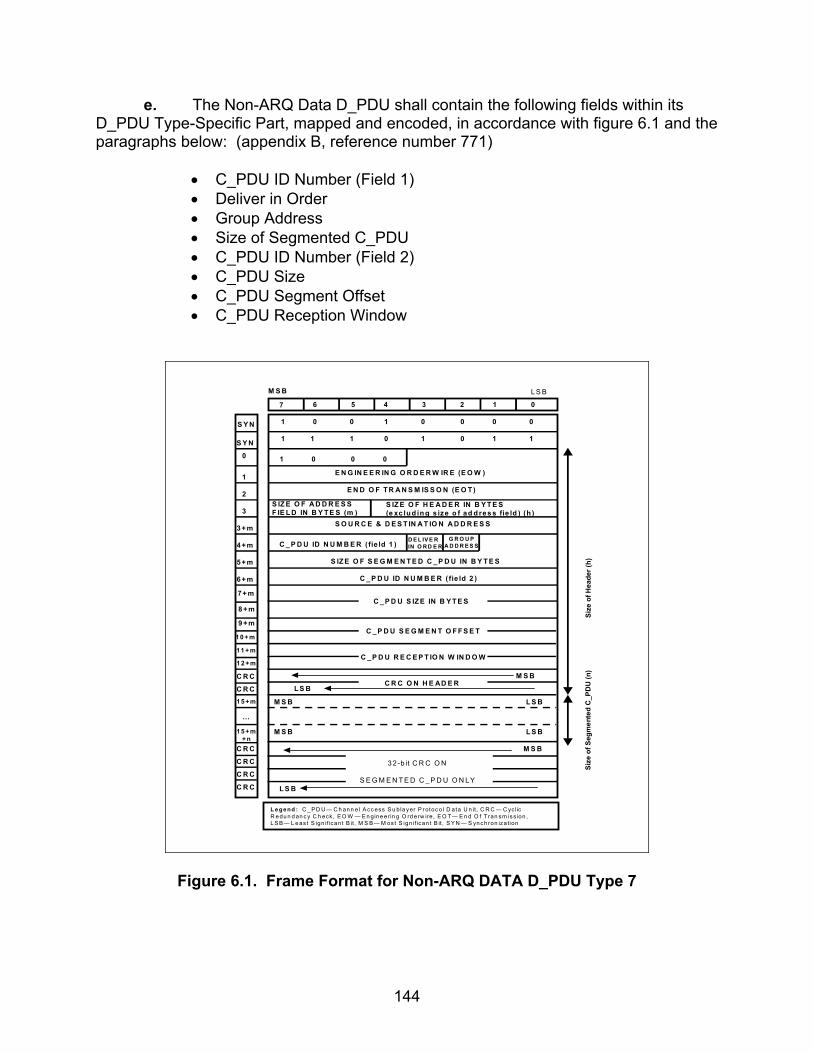
144
e. The Non-ARQ Data D_PDU shall contain the following fields within its D_PDU Type-Specific Part, mapped and encoded, in accordance with figure 6.1 and the paragraphs below: (appendix B, reference number 771)
• C_PDU ID Number (Field 1) • Deliver in Order • Group Address • Size of Segmented C_PDU • C_PDU ID Number (Field 2) • C_PDU Size • C_PDU Segment Offset • C_PDU Reception Window
M S B
7 6 5 4 3 2 1 0
S Y N
S Y N
0
1
2
3
3 +m
4 +m
5 +m
6 +m
1 0 0 1 0 0 0 0
1 1 1 0 1 0 1 1
1 0 0 0
E N G IN E E R IN G O R D E R W IR E (E O W )
E N D O F T R A N S M IS S O N (E O T )
S IZ E O F A D D R E S SF IE L D IN B Y T E S (m )
S IZ E O F H E A D E R IN B Y T E S(e xc lu d in g s ize o f ad d re s s fie ld ) (h )
S O U R C E & D E S T IN A T IO N A D D R E S S
S IZ E O F S E G M E N T E D C _ P D U IN B Y T E S
C _ P D U ID N U M B E R ( fie ld 2 )
1 1 + m
…
C R C O N H E AD E R
M S B
L S BM S B
M S B
L S B
L S B
M S B
L S B
C R C
C R C
C R C
C R C L S B
3 2-b it C R C O N
S E G M E N T E D C _ P D U O N LY
1 0 + m
9 +m
8 +m
7+ m
C _ P D U ID N U M B E R ( fie ld 1 )D E L IV E RIN O RD E R
G R O U PA D D R E S S
C _ P D U S IZ E IN B Y T E S
C _P D U S E G M E N T O F F S E T
C _P D U R E C E P T IO N W IN D O W1 2 + m
C R C
C R C1 5 + m
1 5 + m+ n
Size
of H
eade
r (h)
Size
of S
egm
ente
d C
_PD
U (n
)
L e ge nd : C _ P D U — C h an n el A cc ess S u b la yer P r otoc o l D ata U n it, C R C — C yc lic R e du n d an c y C h eck , E O W — E n gin e er in g O rd erw ire , E O T— E n d O f T ran sm iss ion , L S B — L e as t S ign if ican t B it, M S B — M os t S ign if ican t B it, S Y N — S yn ch ron iza tion
Figure 6.1. Frame Format for Non-ARQ DATA D_PDU Type 7
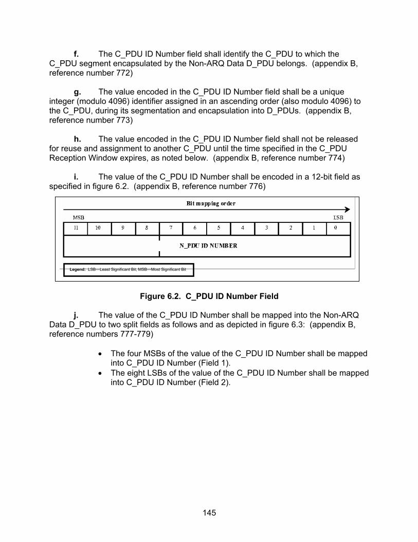
145
f. The C_PDU ID Number field shall identify the C_PDU to which the C_PDU segment encapsulated by the Non-ARQ Data D_PDU belongs. (appendix B, reference number 772)
g. The value encoded in the C_PDU ID Number field shall be a unique
integer (modulo 4096) identifier assigned in an ascending order (also modulo 4096) to the C_PDU, during its segmentation and encapsulation into D_PDUs. (appendix B, reference number 773)
h. The value encoded in the C_PDU ID Number field shall not be released
for reuse and assignment to another C_PDU until the time specified in the C_PDU Reception Window expires, as noted below. (appendix B, reference number 774)
i. The value of the C_PDU ID Number shall be encoded in a 12-bit field as
specified in figure 6.2. (appendix B, reference number 776)
Figure 6.2. C_PDU ID Number Field
j. The value of the C_PDU ID Number shall be mapped into the Non-ARQ
Data D_PDU to two split fields as follows and as depicted in figure 6.3: (appendix B, reference numbers 777-779)
• The four MSBs of the value of the C_PDU ID Number shall be mapped
into C_PDU ID Number (Field 1). • The eight LSBs of the value of the C_PDU ID Number shall be mapped
into C_PDU ID Number (Field 2).
Legend: LSB—Least Significant Bit, MSB—Most Significant Bit
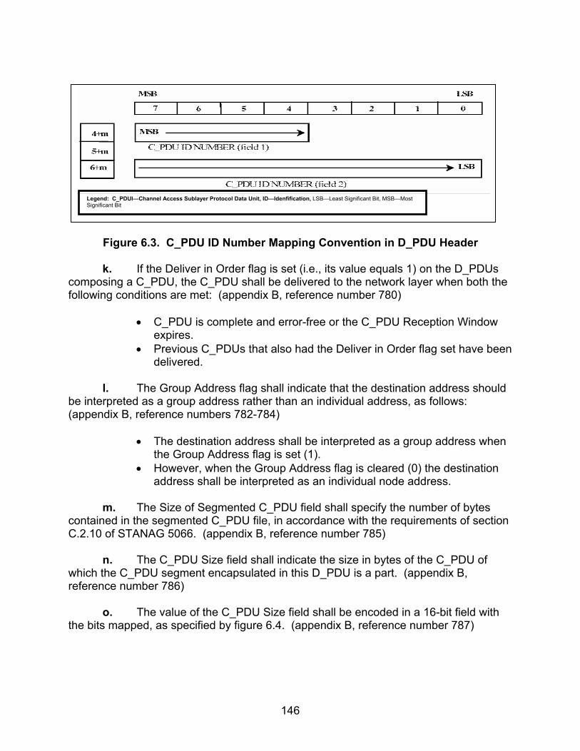
146
Figure 6.3. C_PDU ID Number Mapping Convention in D_PDU Header
k. If the Deliver in Order flag is set (i.e., its value equals 1) on the D_PDUs
composing a C_PDU, the C_PDU shall be delivered to the network layer when both the following conditions are met: (appendix B, reference number 780)
• C_PDU is complete and error-free or the C_PDU Reception Window
expires. • Previous C_PDUs that also had the Deliver in Order flag set have been
delivered.
l. The Group Address flag shall indicate that the destination address should be interpreted as a group address rather than an individual address, as follows: (appendix B, reference numbers 782-784)
• The destination address shall be interpreted as a group address when
the Group Address flag is set (1). • However, when the Group Address flag is cleared (0) the destination
address shall be interpreted as an individual node address.
m. The Size of Segmented C_PDU field shall specify the number of bytes contained in the segmented C_PDU file, in accordance with the requirements of section C.2.10 of STANAG 5066. (appendix B, reference number 785)
n. The C_PDU Size field shall indicate the size in bytes of the C_PDU of
which the C_PDU segment encapsulated in this D_PDU is a part. (appendix B, reference number 786)
o. The value of the C_PDU Size field shall be encoded in a 16-bit field with
the bits mapped, as specified by figure 6.4. (appendix B, reference number 787)
Legend: C_PDUI—Channel Access Sublayer Protocol Data Unit, ID—Idenfification, LSB—Least Significant Bit, MSB—Most Significant Bit

147
Figure 6.4. C_PDU Size Field
p. The number shall be mapped into the D_PDU by placing the MSB of the
field into the MSB of the first byte in the D_PDU, as can be seen in figure 6.5. (appendix B, reference number 788)
Figure 6.5. C_PDU Size Mapping Convention in D_PDU Header
q. The C_PDU Segment Offset field shall indicate the location of the first
byte of the segmented C_PDU with respect to the start of the C_PDU. (appendix B, reference number 789)
r. For the purpose of this field, the bytes of the C_PDU shall be numbered
consecutively starting with (0). (appendix B, reference number 790) s. The C_PDU Segment Offset field is a 16-bit field; the bits shall be mapped
as specified by figure 6.6. (appendix B, reference number 791)
Legend: LSB—Least Significant Bit, MSB—Most Significant Bit
Legend: LSB—Least Significant Bit, MSB—Most Significant Bit

148
Figure 6.6. C_PDU Segment Offset Field
t. The number shall be mapped into the D_PDU by placing the MSB of the
field into the MSB of the first byte in the D_PDU, as specified in figure 6.7. (appendix B, reference number 792)
Figure 6.7. C_PDU Segment Offset Mapping Convention in D_PDU Header
u. The C_PDU Reception Window field shall indicate the maximum
remaining time (in units of half-seconds) relative to the start of the D_PDU, during which portions of the associated C_PDU may be received. (appendix B, reference number 793)
v. The number shall be mapped into the D_PDU by placing the MSB of the
field into the MSB of the first byte in the D_PDU, as specified in figure 6.7. (appendix B, reference number 794)
w. The C_PDU Reception Window field shall indicate the maximum
remaining time in units of half-seconds relative to the start of the D_PDU, during which portions of the associated C_PDU may be received. (appendix B, reference number 795) x. As in the case of the End of Transmission (EOT) field, the C_PDU Reception Window shall be updated just prior to transmitting each D_PDU. (appendix B, reference number 796)
Legend: LSB—Least Significant Bit, MSB—Most Significant Bit
Legend: LSB—Least Significant Bit, MSB—Most Significant Bit
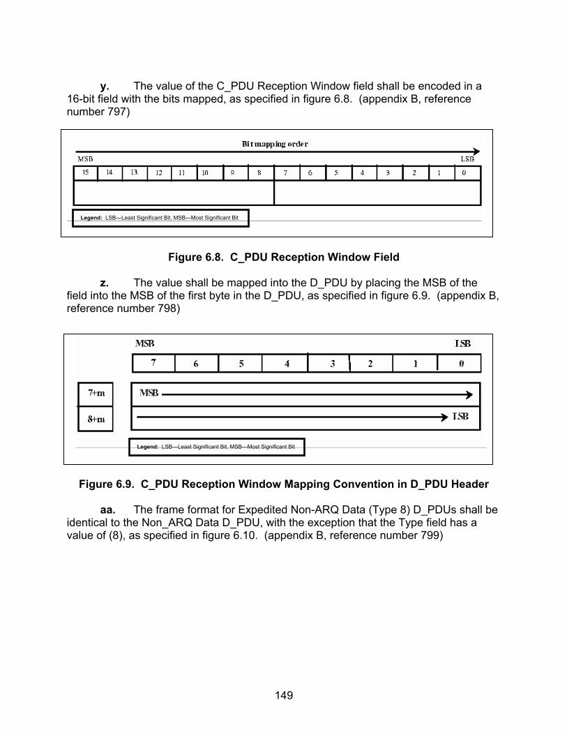
149
y. The value of the C_PDU Reception Window field shall be encoded in a
16-bit field with the bits mapped, as specified in figure 6.8. (appendix B, reference number 797)
Figure 6.8. C_PDU Reception Window Field
z. The value shall be mapped into the D_PDU by placing the MSB of the
field into the MSB of the first byte in the D_PDU, as specified in figure 6.9. (appendix B, reference number 798)
Figure 6.9. C_PDU Reception Window Mapping Convention in D_PDU Header
aa. The frame format for Expedited Non-ARQ Data (Type 8) D_PDUs shall be
identical to the Non_ARQ Data D_PDU, with the exception that the Type field has a value of (8), as specified in figure 6.10. (appendix B, reference number 799)
Legend: LSB—Least Significant Bit, MSB—Most Significant Bit
Legend: LSB—Least Significant Bit, MSB—Most Significant Bit

150
M S B
7 6 5 4 3 2 1 0
S Y N
S Y N
0
1
2
3
3 + m
4 + m
5 + m
6 + m
1 0 0 1 0 0 0 0
1 1 1 0 1 0 1 1
1 0 0 0
E N G IN E E R IN G O R D E R W IR E (E O W )
E N D O F T R A N S M IS S O N (E O T )
S IZ E O F A D D R E S SF IE L D IN B Y T E S (m )
S IZ E O F H E A D E R IN B Y T E S(e x c l u d in g s iz e o f a d d r e s s f ie ld ) ( h )
S O U R C E & D E S T IN A T IO N A D D R E S S
S IZ E O F S E G M E N T E D C _ P D U IN B Y T E S
C _ P D U ID N U M B E R ( f ie ld 2 )
1 1 + m
…
C R C O N H E A D E R
M S B
L S BM S B
M S B
L S B
L S B
M S B
L S B
C R C
C R C
C R C
C R C L S B
3 2 -b it C R C O N
S E G M E N T E D C _ P D U O N L Y
1 0 + m
9 + m
8 + m
7 + m
C _ P D U ID N U M B E R ( f ie ld 1 )D E L IV E RIN O R D E R
G R O U PA D D R E S S
C _ P D U S IZ E IN B Y T E S
C _ P D U S E G M E N T O F F S E T
C _ P D U R E C E P T IO N W IN D O W1 2 + m
C R C
C R C1 5 + m
1 5 + m+ n
Size
of H
eade
r (h)
Size
of S
egm
ente
d C
_PD
U (n
)
L e g e n d : C _ P D U — C h a n n e l A c c e s s S u b la y e r P r o t o c o l D a t a U n it , C R C — C y c lic R e d u n d a n c y C h e c k , E O W — E n g in e e r in g O r d e r w ire , E O T — E n d O f T ra n s m is s io n , L S B — L e a s t S ig n if ic a n t B it , M S B — M o s t S ig n if ic a n t B it , S Y N — S y n c h ro n iz a t io n
Figure 6.10. Frame Format for Expedited Non-ARQ DATA D_PDU Type 8
ab. Segmentation of a C_PDU into segments small enough to fit within a D_PDU for Non-ARQ delivery (i.e., a Non-ARQ Data, or Expedited Non-ARQ-Data D_PDU) shall be performed in accordance with the example shown in figure 6.11 and as follows: (appendix B, reference numbers 827-833)
• The Maximum C_PDU Segment size within a D_PDU for Non-ARQ
delivery services shall be a configurable parameter no greater than 1023 bytes in any implementation compliant with STANAG 5066.
• An entire C_PDU for Non-ARQ delivery that is smaller than the Maximum C_PDU Segment size shall be placed in the C_PDU segment of a single D_PDU.
• A unique C_PDU ID Number shall be assigned to the Non-ARQ C_PDU, in accordance with the requirements of section C.3.10 of STANAG 5066.
• All D_PDUs containing segments from the same C_PDU shall have the same C_PDU ID Number.
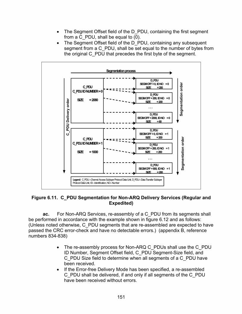
151
• The Segment Offset field of the D_PDU, containing the first segment from a C_PDU, shall be equal to (0).
• The Segment Offset field of the D_PDU, containing any subsequent segment from a C_PDU, shall be set equal to the number of bytes from the original C_PDU that precedes the first byte of the segment.
C_PDUC_PDU ID NUMBER = 0
SIZE = 2080
C_PDUC_PDU ID NUMBER = 1
SIZE = 1000
D_PDUSEGM OFF = 0, ID NO = 0
SIZE = 200
D_PDUSEGM OFF = 200, ID NO = 0
SIZE = 200
. . .
. . .
D_PDUSEGM OFF = 2000, ID NO = 0
SIZE = 80
D_PDUSEGM OFF = 0, ID NO = 1
SIZE = 200
D_PDUSEGM OFF = 200, ID NO = 1
SIZE = 200
D_PDUSEGM OFF = 800, ID NO = 1
SIZE = 200
Segm
enta
tion
orde
rSe
gmen
tatio
n or
der
Segmentation processC
_PD
U D
eliv
ery
orde
r
Legend: C_PDU—Channel Access Sublayer Protocol Data Unit, D_PDU—Data Transfer SublayerProtocol Data Unit, ID—Identification, NO—Number
Figure 6.11. C_PDU Segmentation for Non-ARQ Delivery Services (Regular and Expedited)
ac. For Non-ARQ Services, re-assembly of a C_PDU from its segments shall
be performed in accordance with the example shown in figure 6.12 and as follows: (Unless noted otherwise, C_PDU segments that are re-assembled are expected to have passed the CRC error-check and have no detectable errors.) (appendix B, reference numbers 834-838)
• The re-assembly process for Non-ARQ C_PDUs shall use the C_PDU
ID Number, Segment Offset field, C_PDU Segment-Size field, and C_PDU Size field to determine when all segments of a C_PDU have been received.
• If the Error-free Delivery Mode has been specified, a re-assembled C_PDU shall be delivered, if and only if all segments of the C_PDU have been received without errors.

152
• If the Deliver-w/-Errors Mode has been specified, the re-assembly process shall proceed as follows:
• C_PDU segments received without detected errors shall be collected as received in their D_PDUs and placed in order within the re-assembled C_PDU.
D_PDUSEGM OFF = 0, ID NO = 0TX SEQ NO = 0, SIZE = 200
D_PDUSEGM OFF = 200, ID NO = 0TX SEQ NO = 1, SIZE = 200
. . .
. . .
D_PDUSEGM OFF = 2000, ID NO = 0
TX SEQ NO = 10, SIZE = 80
D_PDUSEGM OFF = 0, ID NO = 1
TX SEQ NO = 11, SIZE = 200
D_PDUSEGM OFF = 200, ID NO = 1TX SEQ NO = 12, SIZE = 200
D_PDUSEGM OFF = 800, ID NO = 1TX SEQ NO = 15, SIZE = 200
Re-
asse
mbl
y or
der
Re-
asse
mbl
y or
der
Re-assembly process
C_PDUC_PDU ID NUMBER = 0
SIZE = 2080
C_PDUC_PDU ID NUMBER = 1
SIZE = 1000
PDU
Del
iver
y or
der
Legend: C_PDU—Channel Access Sublayer Protocol Data Unit, D_PDU—Data Transfer SublayerProtocol Data Unit, ID—Identification, NO—Number, OFF—Offset, PDU—Protocol Data Unit, SEGM—Segment, SEQ—Sequence, TX—Transmit
Figure 6.12. C_PDU Re-assembly for Non-ARQ Delivery Services (Regular and Expedited)
6.3 Test Procedures
a. Test Equipment Required
(1) Computers (2 ea) with STANAG 5066 Software (2) Modem (2 ea) (3) Protocol Analyzer (4) RS-232 Synchronous Serial Cards (5) Two Position Switch (5) HF Simulator (2 ea)
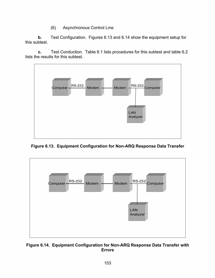
153
(6) Asynchronous Control Line
b. Test Configuration. Figures 6.13 and 6.14 show the equipment setup for this subtest.
c. Test Conduction. Table 6.1 lists procedures for this subtest and table 6.2 lists the results for this subtest.
Computer Modem Modem Computer
LANAnalyzer
RS-232 RS-232
Figure 6.13. Equipment Configuration for Non-ARQ Response Data Transfer
Computer Modem Modem Computer
LANAnalyzer
RS-232 RS-232
Figure 6.14. Equipment Configuration for Non-ARQ Response Data Transfer with Errors

154
Table 6.1. Non-ARQ Response Data Transfer Procedures
Step Action Settings/Action Result
1
Set up equipment. See figure 6.13. Computers are connected to the modems by an RS-232 connection. Make sure that the receive pins of one modem are connected to the transmit pins of the other modem.
2
Configure STANAG addresses for both computers.
Set the size of the STANAG address field size to 7 bytes. Set the STANAG address to 1.1.0.0 and 1.2.0.0 as shown in figure 6.13.
3 Identify client to be used. Record the client type to be tested under this subtest.
Client Type =
4 Configure modems. Set modems to transmit a
MIL-STD-188-110B signal at a data rate of 4800 bps with full duplex.
5 Configure rank. Set the rank of the client to “15” for both computers.
6 Configure priority level. Set the priority level to “0” for both computers.
7
Configure Maximum C_PDU Segment Size.
If the Maximum C_PDU Segment Size parameter is a configurable on the user interface, configure the Maximum C_PDU Segment Size to 1023 bytes. If this parameter is not configurable on the user interface, coordinate with the vendor to obtain the value of the Maximum C_PDU Segment Size and record the vendor’s Maximum C_PDU Segment Size.
Vendor’s Maximum C_PDU Segment Size =
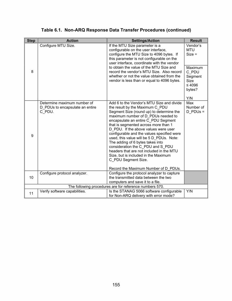
155
Table 6.1. Non-ARQ Response Data Transfer Procedures (continued)
Step Action Settings/Action Result Vendor’s MTU Size =
8
Configure MTU Size. If the MTU Size parameter is a configurable on the user interface, configure the MTU Size to 4096 bytes. If this parameter is not configurable on the user interface, coordinate with the vendor to obtain the value of the MTU Size and record the vendor’s MTU Size. Also record whether or not the value obtained from the vendor is less than or equal to 4096 bytes.
Maximum C_PDU Segment Size ≤ 4096 bytes? Y/N
9
Determine maximum number of D_PDUs to encapsulate an entire C_PDU.
Add 6 to the Vendor’s MTU Size and divide the result by the Maximum C_PDU Segment Size (round up) to determine the maximum number of D_PDUs needed to encapsulate an entire C_PDU Segment that is segmented across more than 1 D_PDU. If the above values were user configurable and the values specified were used, this value will be 5 D_PDUs. Note: The adding of 6 bytes takes into consideration the C_PDU and S_PDU headers that are not included in the MTU Size, but is included in the Maximum C_PDU Segment Size. Record the Maximum Number of D_PDUs.
Max Number of D_PDUs =
10 Configure protocol analyzer. Configure the protocol analyzer to capture
the transmitted data between the two computers and save it to a file.
The following procedures are for reference numbers 570.
11 Verify software capabilities. Is the STANAG 5066 software configurable for Non-ARQ delivery with error mode?
Y/N

156
Table 6.1. Non-ARQ Response Data Transfer Procedures (continued)
Step Action Settings/Action Result The following procedures are for Type 7 (Non-Expedited Non-ARQ) D_PDU and are for reference
numbers 438, 591, 770-782, 784, 785-798, 827, and 830-838.
12
Send e-mail message to obtain results for Non-Expedited ARQ Data Transfer.
Without making adjustments to steps 1-9, send the following e-mail message from the computer with STANAG address 1.2.0.0 to the computer with STANAG address 1.1.0.0 using an Expedited Non-ARQ delivery. Include an attachment of approximately 15 kbytes (after any compression algorithms including that which CFTP uses): For the Subject Line: Test 1 In the Body: “This is a test from address 1.2.0.0 to 1.1.0.0 1 2 3 4 5 6 7 8 9 10” Save the data obtained through the analyzer to a file.
13
From the captured file, locate sync bytes and D_PDU Type.
D_PDUs sync with the hex sequence 0x90EB, or (MSB) 1 0 0 1 0 0 0 0 1 1 1 0 1 0 1 1 (LSB) in binary.
14
Locate Type 7 D_PDU. D_PDUs begin with the hex sequence 0x90EB. The first 4 bits, immediately after the 0x90EB sequence, will be the D_PDU Type. For the Type 7 D_PDU, the value will be 7 in hex or (MSB) 0111 (LSB) in binary. Record the D_PDU Type.
D_PDU Type =
15
Locate C_PDU ID (Field 1) bits for the Type 7 D_PDU captured in step 14.
The C_PDU ID (Field 1) is a 4-bit field located within the 12th byte of the Type 7 D_PDU. Record the C_PDU ID (Field 1) bits.
Type 7 D_PDU C_PDU ID (Field 1) =
16
Locate Deliver in Order bit for the Type 7 D_PDU captured in step 14.
The next bit, after the C_PDU ID (Field 1) bits, contains the Deliver in Order bit. Record the Deliver in Order bit.
Type 7 D_PDU Deliver in Order bit =
17
Locate Group Address bit for the Type 7 D_PDU captured in step 14.
The next bit, after the Deliver in Order bit, contains the Group Address bit. Record the Group Address bit.
Type 7 D_PDU Group Address bit =
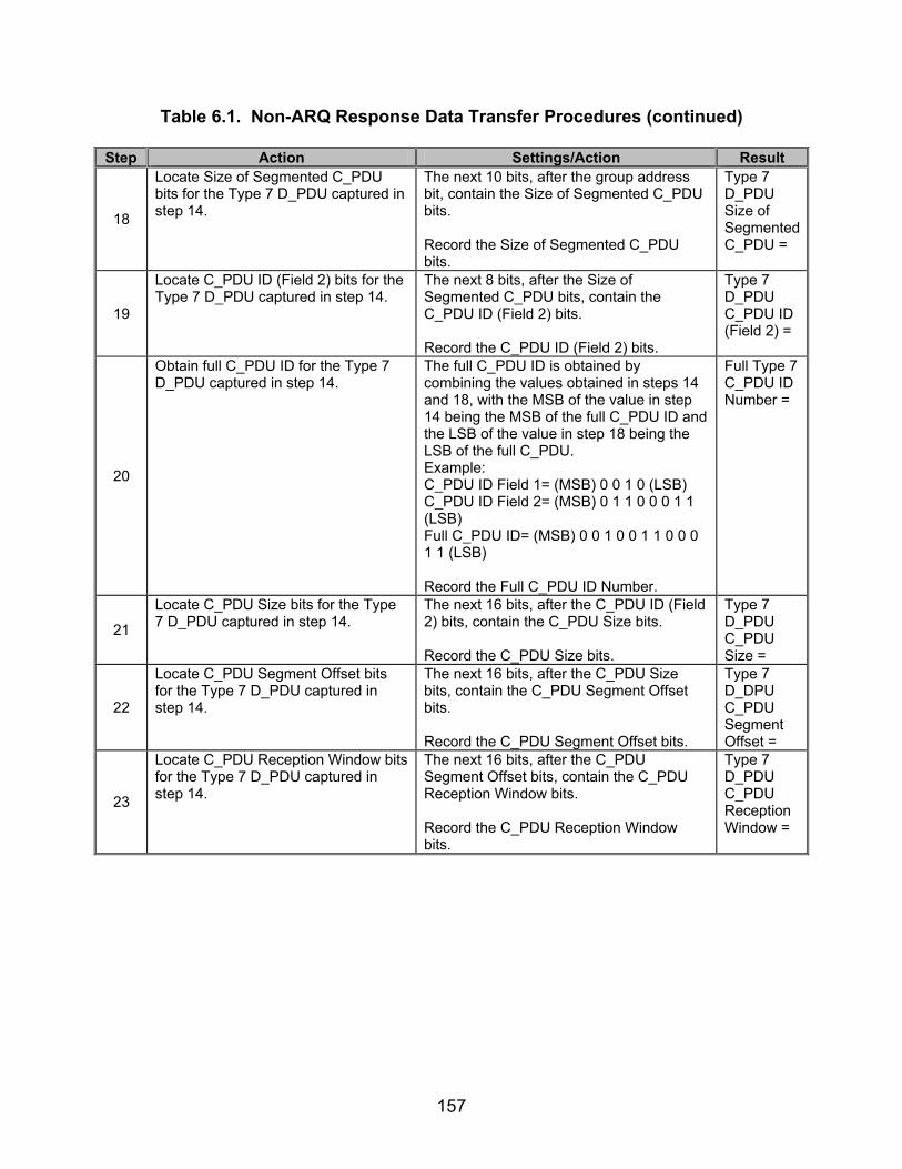
157
Table 6.1. Non-ARQ Response Data Transfer Procedures (continued)
Step Action Settings/Action Result
18
Locate Size of Segmented C_PDU bits for the Type 7 D_PDU captured in step 14.
The next 10 bits, after the group address bit, contain the Size of Segmented C_PDU bits. Record the Size of Segmented C_PDU bits.
Type 7 D_PDU Size of Segmented C_PDU =
19
Locate C_PDU ID (Field 2) bits for the Type 7 D_PDU captured in step 14.
The next 8 bits, after the Size of Segmented C_PDU bits, contain the C_PDU ID (Field 2) bits. Record the C_PDU ID (Field 2) bits.
Type 7 D_PDU C_PDU ID (Field 2) =
20
Obtain full C_PDU ID for the Type 7 D_PDU captured in step 14.
The full C_PDU ID is obtained by combining the values obtained in steps 14 and 18, with the MSB of the value in step 14 being the MSB of the full C_PDU ID and the LSB of the value in step 18 being the LSB of the full C_PDU. Example: C_PDU ID Field 1= (MSB) 0 0 1 0 (LSB) C_PDU ID Field 2= (MSB) 0 1 1 0 0 0 1 1 (LSB) Full C_PDU ID= (MSB) 0 0 1 0 0 1 1 0 0 0 1 1 (LSB) Record the Full C_PDU ID Number.
Full Type 7 C_PDU ID Number =
21
Locate C_PDU Size bits for the Type 7 D_PDU captured in step 14.
The next 16 bits, after the C_PDU ID (Field 2) bits, contain the C_PDU Size bits. Record the C_PDU Size bits.
Type 7 D_PDU C_PDU Size =
22
Locate C_PDU Segment Offset bits for the Type 7 D_PDU captured in step 14.
The next 16 bits, after the C_PDU Size bits, contain the C_PDU Segment Offset bits. Record the C_PDU Segment Offset bits.
Type 7 D_DPU C_PDU Segment Offset =
23
Locate C_PDU Reception Window bits for the Type 7 D_PDU captured in step 14.
The next 16 bits, after the C_PDU Segment Offset bits, contain the C_PDU Reception Window bits. Record the C_PDU Reception Window bits.
Type 7 D_PDU C_PDU Reception Window =

158
Table 6.1. Non-ARQ Response Data Transfer Procedures (continued)
Step Action Settings/Action Result
24
Convert C_PDU Reception Window to seconds.
Take the decimal value for the C_PDU Reception Window and divide by 2. This value is the C_PDU Reception Window Time in seconds. Record the C_PDU Reception Window Time.
Type 7 C_PDU Reception Window Time =
25
Obtain C_PDU Type for Type 7 D_PDU in step 14.
The 2 bytes that immediately follow the C_PDU Reception Window bytes are the CRC on Header bytes. The first 4 bits of the next byte, following the 2 byte CRC on Header bytes, contains the C_PDU Type. Record the C_PDU Type.
C_PDU Type =
26
Obtain all C_PDU ID bits. Locate the C_PDU bits for all Type 7 D_PDUs transmitted during the data transmission. The C_PDU ID (Field 1) is a 4-bit field located within the 12th byte of the Type 7 D_PDU. The C_PDU ID (Field 2) bits are the 8 bits located in the 14th byte of the Type 7 D_PDU. The full C_PDU ID is obtained by combining the values of the C_PDU ID (Field 1) and C_PDU ID (Field 2) bits, with the MSB of the C_PDU ID (Field 1) bits being the MSB of the full C_PDU ID and the LSB of the C_PDU ID (Field 2) bits being the LSB of the full C_PDU. Example: C_PDU ID Field 1= (MSB) 0 0 1 0 (LSB) C_PDU ID Field 2= (MSB) 0 1 1 0 0 0 1 1 (LSB) Full C_PDU ID= (MSB) 0 0 1 0 0 1 1 0 0 0 1 1 (LSB) Record the decimal equivalent of all C_PDU IDs for all captured Type 7 D_DPUs in the order they are transmitted.
C_PDU ID =

159
Table 6.1. Non-ARQ Response Data Transfer Procedures (continued)
Step Action Settings/Action Result
27
Obtain C_PDU Reception Window bits.
There will be several Type 7 D_PDUs with the same C_PDU ID in step 26. Locate the C_PDU Reception Window for each D_PDU that has the same C_PDU ID. The C_PDU Reception Window is a 16-bit field located starting with the 19th byte of the Type 7 D_PDU. After obtaining the hexadecimal value of the C_PDU Reception Window, convert the value to decimal and divide the result by 2. This will be the C_PDU Reception Window value in seconds. Record and match all of the C_PDU Reception Window bits in seconds to their corresponding C_PDU IDs recorded in step 26.
Type 7 C_PDU Reception Windows =
28
Obtain all C_PDU Segment Offset bits.
The C_PDU Segment Offset is a 16-bit field starting with the MSB of the 17th byte of the Type 7 D_PDU. Record the decimal equivalent of all Segment Offset for all captured Type 7 D_PDUs in the order they are received.
C_PDU Segment Offset =
29
Obtain all C_PDU Reception Window bits.
The next 16 bits, after the C_PDU Segment Offset bits, are the C_PDU Reception Window bits. Obtain the decimal equivalent of the 16-bit C_PDU Reception Window bits and multiply the result by 2. This new value is the C_PDU Reception Window in seconds. Record all of the C_PDU Reception Window value in seconds in the order they are transmitted.
C_PDU Reception Window =
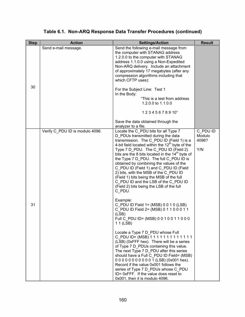
160
Table 6.1. Non-ARQ Response Data Transfer Procedures (continued)
Step Action Settings/Action Result
30
Send e-mail message.
Send the following e-mail message from the computer with STANAG address 1.2.0.0 to the computer with STANAG address 1.1.0.0 using a Non-Expedited Non-ARQ delivery. Include an attachment of approximately 17 megabytes (after any compression algorithms including that which CFTP uses): For the Subject Line: Test 1 In the Body: “This is a test from address 1.2.0.0 to 1.1.0.0 1 2 3 4 5 6 7 8 9 10” Save the data obtained through the analyzer to a file.
31
Verify C_PDU ID is modulo 4096. Locate the C_PDU bits for all Type 7 D_PDUs transmitted during the data transmission. The C_PDU ID (Field 1) is a 4-bit field located within the 12th byte of the Type 7 D_PDU. The C_PDU ID (Field 2) bits are the 8 bits located in the 14th byte of the Type 7 D_PDU. The full C_PDU ID is obtained by combining the values of the C_PDU ID (Field 1) and C_PDU ID (Field 2) bits, with the MSB of the C_PDU ID (Field 1) bits being the MSB of the full C_PDU ID and the LSB of the C_PDU ID (Field 2) bits being the LSB of the full C_PDU. Example: C_PDU ID Field 1= (MSB) 0 0 1 0 (LSB) C_PDU ID Field 2= (MSB) 0 1 1 0 0 0 1 1 (LSB) Full C_PDU ID= (MSB) 0 0 1 0 0 1 1 0 0 0 1 1 (LSB) Locate a Type 7 D_PDU whose Full C_PDU ID= (MSB) 1 1 1 1 1 1 1 1 1 1 1 1 1 (LSB) (0xFFF hex). There will be a series of Type 7 D_PDUs containing this value. The next Type 7 D_PDU after this series should have a Full C_PDU ID Field= (MSB) 0 0 0 0 0 0 0 0 0 0 0 1 (LSB) (0x001 hex). Record if the value 0x001 follows the series of Type 7 D_PDUs whose C_PDU ID= 0xFFF. If the value does reset to 0x001, then it is modulo 4096.
C_PDU ID Modulo 4096? Y/N
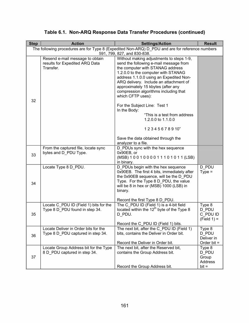
161
Table 6.1. Non-ARQ Response Data Transfer Procedures (continued)
Step Action Settings/Action Result The following procedures are for Type 8 (Expedited Non-ARQ) D_PDU and are for reference numbers
591, 799, 827, and 830-838.
32
Resend e-mail message to obtain results for Expedited ARQ Data Transfer.
Without making adjustments to steps 1-9, send the following e-mail message from the computer with STANAG address 1.2.0.0 to the computer with STANAG address 1.1.0.0 using an Expedited Non-ARQ delivery. Include an attachment of approximately 15 kbytes (after any compression algorithms including that which CFTP uses): For the Subject Line: Test 1 In the Body: “This is a test from address 1.2.0.0 to 1.1.0.0 1 2 3 4 5 6 7 8 9 10” Save the data obtained through the analyzer to a file.
33
From the captured file, locate sync bytes and D_PDU Type.
D_PDUs sync with the hex sequence 0x90EB, or (MSB) 1 0 0 1 0 0 0 0 1 1 1 0 1 0 1 1 (LSB) in binary.
34
Locate Type 8 D_PDU. D_PDUs begin with the hex sequence 0x90EB. The first 4 bits, immediately after the 0x90EB sequence, will be the D_PDU Type. For the Type 8 D_PDU, the value will be 8 in hex or (MSB) 1000 (LSB) in binary. Record the first Type 8 D_PDU.
D_PDU Type =
35
Locate C_PDU ID (Field 1) bits for the Type 8 D_PDU found in step 34.
The C_PDU ID (Field 1) is a 4-bit field located within the 12th byte of the Type 8 D_PDU. Record the C_PDU ID (Field 1) bits.
Type 8 D_PDU C_PDU ID (Field 1) =
36
Locate Deliver in Order bits for the Type 8 D_PDU captured in step 34.
The next bit, after the C_PDU ID (Field 1) bits, contains the Deliver in Order bit. Record the Deliver in Order bit.
Type 8 D_PDU Deliver in Order bit =
37
Locate Group Address bit for the Type 8 D_PDU captured in step 34.
The next bit, after the Reserved bit, contains the Group Address bit. Record the Group Address bit.
Type 8 D_PDU Group Address bit =

162
Table 6.1. Non-ARQ Response Data Transfer Procedures (continued)
Step Action Settings/Action Result
38
Locate Size of Segmented C_PDU bits for the Type 8 D_PDU captured in step 34.
The next 10 bits, after the group address bit, contain the Size of Segmented C_PDU bits. Record the Size of Segmented C_PDU bits.
Type 8 D_PDU Size of Segmented C_PDU =
39
Locate C_PDU ID (Field 2) bits for the Type 8 D_PDU captured in step 34.
The next 8 bits, after the Size of Segmented C_PDU bits, contain the C_PDU ID (Field 2) bits. Record the C_PDU ID (Field 2) bits.
Type 8 D_PDU C_PDU ID (Field 2) =
40
Obtain full C_PDU ID for the Type 8 D_PDU captured in step 34.
The full C_PDU ID is obtained by combining the values obtained in steps 35 and 39, with the MSB of the value in step 35 being the MSB of the full C_PDU ID and the LSB of the value in step 39 being the LSB of the full C_PDU. Example: C_PDU ID field 1= (MSB) 0 0 1 0 (LSB) C_PDU ID field 2= (MSB) 0 1 1 0 0 0 1 1 (LSB) Full C_PDU ID= (MSB) 0 0 1 0 0 1 1 0 0 0 1 1 (LSB) Record the Full Type 8 D_PDU C_PDU ID Number.
Full Type 8 D_PDU C_PDU ID Number =
41
Locate C_PDU Size bits for the Type 8 D_PDU captured in step 33.
The next 16 bits, after the C_PDU ID Number (Field 2) bits, contain the C_PDU Size bits. Record the C_PDU Size bits.
Type 8 D_PDU C_PDU Size =
42
Locate C_PDU Segment Offset bits for the Type 8 D_PDU found in step 33.
The next 16 bits, after the C_PDU Size bits, contain the C_PDU Segment Offset bits. Record the C_PDU Segment Offset bits.
Type 8 D_DPU C_PDU Segment Offset =
43
Locate C_PDU Reception Window bits for the Type 8 D_PDU found in step 33.
The next 16 bits, after the C_PDU Segment Offset bits, contain the C_PDU Reception Window bits. Record the C_PDU Reception Window bits.
Type 8 D_PDU C_PDU Reception Window =
44
Convert C_PDU Reception Window to seconds.
Take the decimal value for the C_PDU Reception Window and divide by 2. This value is the C_PDU Reception Window Time in seconds. Record the C_PDU Reception Window Value.
Type 8 C_PDU Reception Window Time =
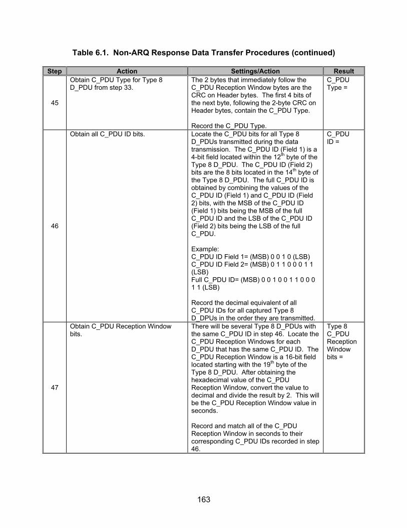
163
Table 6.1. Non-ARQ Response Data Transfer Procedures (continued)
Step Action Settings/Action Result
45
Obtain C_PDU Type for Type 8 D_PDU from step 33.
The 2 bytes that immediately follow the C_PDU Reception Window bytes are the CRC on Header bytes. The first 4 bits of the next byte, following the 2-byte CRC on Header bytes, contain the C_PDU Type. Record the C_PDU Type.
C_PDU Type =
46
Obtain all C_PDU ID bits. Locate the C_PDU bits for all Type 8 D_PDUs transmitted during the data transmission. The C_PDU ID (Field 1) is a 4-bit field located within the 12th byte of the Type 8 D_PDU. The C_PDU ID (Field 2) bits are the 8 bits located in the 14th byte of the Type 8 D_PDU. The full C_PDU ID is obtained by combining the values of the C_PDU ID (Field 1) and C_PDU ID (Field 2) bits, with the MSB of the C_PDU ID (Field 1) bits being the MSB of the full C_PDU ID and the LSB of the C_PDU ID (Field 2) bits being the LSB of the full C_PDU. Example: C_PDU ID Field 1= (MSB) 0 0 1 0 (LSB) C_PDU ID Field 2= (MSB) 0 1 1 0 0 0 1 1 (LSB) Full C_PDU ID= (MSB) 0 0 1 0 0 1 1 0 0 0 1 1 (LSB) Record the decimal equivalent of all C_PDU IDs for all captured Type 8 D_DPUs in the order they are transmitted.
C_PDU ID =
47
Obtain C_PDU Reception Window bits.
There will be several Type 8 D_PDUs with the same C_PDU ID in step 46. Locate the C_PDU Reception Windows for each D_PDU that has the same C_PDU ID. The C_PDU Reception Window is a 16-bit field located starting with the 19th byte of the Type 8 D_PDU. After obtaining the hexadecimal value of the C_PDU Reception Window, convert the value to decimal and divide the result by 2. This will be the C_PDU Reception Window value in seconds. Record and match all of the C_PDU Reception Window in seconds to their corresponding C_PDU IDs recorded in step 46.
Type 8 C_PDU Reception Window bits =

164
Table 6.1. Non-ARQ Response Data Transfer Procedures (continued)
Step Action Settings/Action Result
48
Obtain all C_PDU Segment Offset bits.
The C_PDU Segment Offset is a 16-bit field starting with the MSB of the 17th byte of the Type 8 D_PDU. Record the decimal equivalent of all Segment Offset for all captured Type 8 D_PDUs in the order that they are received.
C_PDU Segment Offset =
49
Obtain all C_PDU Reception Window bits.
The next 16 bits, after the C_PDU Segment Offset bits, are the C_PDU Reception Window bits. Obtain the decimal equivalent of the 16-bit C_PDU Reception Window bits and multiply the result by 2. This new value is the C_PDU Reception Window in seconds. Record all of the C_PDU Reception Window values in seconds in the order they are transmitted.
C_PDU Reception Window =
50
Send e-mail message.
Send the following e-mail message from the computer with STANAG address 1.2.0.0 to the computer with STANAG address 1.1.0.0 using a Non-Expedited Non-ARQ delivery. Include an attachment of approximately 17 megabytes (after any compression algorithms including that which CFTP uses): For the Subject Line: Test 1 In the Body: “This is a test from address 1.2.0.0 to 1.1.0.0 1 2 3 4 5 6 7 8 9 10” Save the data obtained through the analyzer to a file.

165
Table 6.1. Non-ARQ Response Data Transfer Procedures (continued)
Step Action Settings/Action Result
51
Verify C_PDU ID is modulo 4096. Locate the C_PDU bits for all Type 8 D_PDUs transmitted during the data transmission. The C_PDU ID (Field 1) is a 4-bit field located within the 12th byte of the Type 8 D_PDU. The C_PDU ID (Field 2) bits are the 8 bits located in the 14th byte of the Type 8 D_PDU. The full C_PDU ID is obtained by combining the values of the C_PDU ID (Field 1) and C_PDU ID (Field 2) bits, with the MSB of the C_PDU ID (Field 1) bits being the MSB of the full C_PDU ID and the LSB of the C_PDU ID (Field 2) bits being the LSB of the full C_PDU. Example: C_PDU ID Field 1= (MSB) 0 0 1 0 (LSB) C_PDU ID Field 2= (MSB) 0 1 1 0 0 0 1 1 (LSB) Full C_PDU ID= (MSB) 0 0 1 0 0 1 1 0 0 0 1 1 (LSB) Locate a Type 8 D_PDU whose Full C_PDU ID= (MSB) 1 1 1 1 1 1 1 1 1 1 1 1 1 (LSB) (0xFFF hex). There will be a series of Type 8 D_PDUs containing this value. The next Type 8 D_PDU after this series should have a Full C_PDU ID Field= (MSB) 0 0 0 0 0 0 0 0 0 0 0 1 (LSB) (0x001 hex). Record if the value 0x001 follows the series of Type 8 D_PDUs whose C_PDU ID= 0xFFF. If the value does reset to 0x001, then it is modulo 4096.
C_PDU ID Modulo 4096? Y/N
The following procedures are for Type 7 (Non-Expedited Non-ARQ) D_PDU and are for reference number 783.
52
Configure STANAG addresses for both computers.
Set the size of the STANAG address field size to 7 bytes. Set the STANAG address of the first computer to 1.222.123.001 and the STANAG address of the second computer to: 15.255.255.255 with the Group Address bit configured to 1 (i.e., designate this address to be a group address).
53
Configure modems. Set modems to transmit a MIL-STD-188-110B signal at a data rate of 4800 bps with full duplex and short interleaving.
54 Configure protocol analyzer. Configure the protocol analyzer to capture
the transmitted data between the two computers and save it to a file.

166
Table 6.1. Non-ARQ Response Data Transfer Procedures (continued)
Step Action Settings/Action Result
55
Send e-mail message.
Send the following e-mail message from the computer with STANAG address 1.222.123.001 to the computer with STANAG address 15.255.255.255 using a Non-Expedited Non-ARQ delivery: For the Subject Line: Test 1 In the Body: “This is a test from address
1.222.123.001 to 5.255.255.255
1 2 3 4 5 6 7 8 9 10” Save the data obtained through the analyzer to a file.
56
From the captured file, locate sync bytes and D_PDU Type.
D_PDUs sync with the hex sequence 0x90EB, or (MSB) 1 0 0 1 0 0 0 0 1 1 1 0 1 0 1 1 (LSB) in binary.
57
Locate Type 7 D_PDU. D_PDUs begin with the hex sequence 0x90EB. The first 4 bits, immediately after the 0x90EB sequence, will be the D_PDU Type. For the Type 7 D_PDU, the value will be 7 in hex or (MSB) 0111 (LSB) in binary. Record the first Type 7 D_PDU.
58
Locate Group Address bit for the Type 7 D_PDU found in step 57.
The Group Address bit is the 6th bit in the 12th byte of the Type 7 D_PDU. Record the Group Address bit.
Type 7 D_PDU Group Address bit =
The following procedures are for Type 8 (Expedited Non-ARQ) D_PDU and are for reference number 783.
59 Configure protocol analyzer. Configure the protocol analyzer to capture
the transmitted data between the two computers and save it to a file.
60
Configure STANAG addresses for both computers.
Set the size of the STANAG address field size to 7 bytes. Set the STANAG address of the first computer to 1.222.123.001 and the STANAG address of the second computer to 15.255.255.255 with the group address bit configured to 1 (i.e., designate this address to be a group address).
61
Configure modems. Set modems to transmit a MIL-STD-188-110B signal at a data rate of 4800 bps with full duplex and short interleaving.
62 Configure protocol analyzer. Configure the protocol analyzer to capture
the transmitted data between the two computers and save it to a file.

167
Table 6.1. Non-ARQ Response Data Transfer Procedures (continued)
Step Action Settings/Action Result
63
Send e-mail message.
Send the following e-mail message from the computer with STANAG address 1.222.123.001 to the computer with STANAG address 15.255.255.255 using a Expedited Non-ARQ delivery: For the Subject Line: Test 1 In the Body:
“This is a test from address 1.222.123.001 to 15.255.255.255 1 2 3 4 5 6 7 8 9 10”
Save the data obtained through the analyzer to a file.
64
Locate Type 8 D_PDU. D_PDUs begin with the hex sequence 0x90EB. The first 4 bits, immediately after the 0x90EB sequence, will be the D_PDU Type. For the Type 8 D_PDU, the value will be 8 in hex or (MSB) 1000 (LSB) in binary. Locate the first Type 8 D_PDU.
65
Locate Group Address bit for the Type 8 D_PDU found in step 64.
The Group Address bit is the 6th bit in the 12th byte of the Type 8 D_PDU. Record the Group Address bit.
Type 8 D_PDU Group Address bit =
The following procedures are for reference number 828.
66 Reconfigure max C_PDU Segment size.
Configure max C_PDU Segment size to 1024 bytes.
67 Disable group addressing. Disable the group addressing for the
computer with STANAG address 15.255.255.255.
68 Configure protocol analyzer. Configure the protocol analyzer to capture
the transmitted data between the two computers and save it to a file.

168
Table 6.1. Non-ARQ Response Data Transfer Procedures (continued)
Step Action Settings/Action Result
69
Send e-mail message.
Send the following e-mail message from the computer with STANAG address 1.222.123.001 to the computer with STANAG address 15.255.255.255 using a Non-Expedited Non-ARQ delivery along with an approximately 1.5 kbyte attachment: For the Subject Line: Test 1 In the Body: “This is a test from address
1.222.123.001 to 15.255.255.255
1 2 3 4 5 6 7 8 9 10” Save the data obtained through the analyzer to a file.
70
Determine size of C_PDU Segment. The Size of Segmented C_PDU field is 10 bits in length, beginning with the last 2 bits of the 12th byte of the Type 7 D_PDU. Record the Size of Segmented C_PDU for 1024-byte frame size.
Type 7 Size of Segmented C_PDU =
71
Send e-mail message.
Send the following e-mail message from the computer with STANAG address 1.222.123.001 to the computer with STANAG address 15.255.255.255 using an Expedited Non-ARQ delivery along with an approximately 1.5 kbyte attachment: For the Subject Line: Test 1 In the Body: “This is a test from address
1.222.123.001 to 15.255.255.255
1 2 3 4 5 6 7 8 9 10” Save the data obtained through the analyzer to a file.
72
Determine size of C_PDU Segment. The Size of Segmented C_PDU field is 10 bits in length, beginning with the last 2 bits of the 12th byte of the Type 9 D_PDU. Record the Size of Segmented C_PDU for 1024-byte frame size.
Type 8 Size of Segmented C_PDU =
The following procedures are for reference number 829.
73 Reconfigure max C_PDU Segment size and MTU Size.
Configure max C_PDU Segment size to 1023 bytes and MTU Size to 1000 bytes.
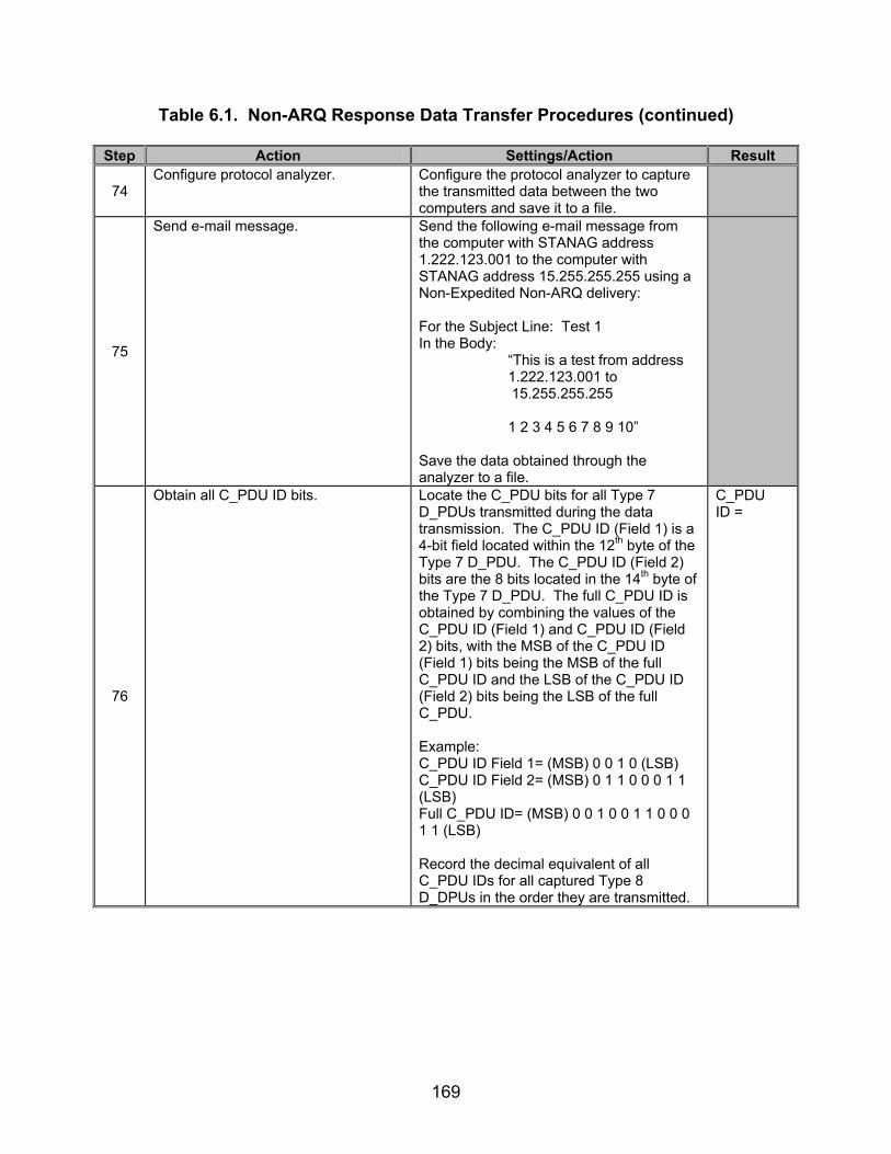
169
Table 6.1. Non-ARQ Response Data Transfer Procedures (continued)
Step Action Settings/Action Result
74 Configure protocol analyzer. Configure the protocol analyzer to capture
the transmitted data between the two computers and save it to a file.
75
Send e-mail message.
Send the following e-mail message from the computer with STANAG address 1.222.123.001 to the computer with STANAG address 15.255.255.255 using a Non-Expedited Non-ARQ delivery: For the Subject Line: Test 1 In the Body: “This is a test from address 1.222.123.001 to
15.255.255.255 1 2 3 4 5 6 7 8 9 10” Save the data obtained through the analyzer to a file.
76
Obtain all C_PDU ID bits. Locate the C_PDU bits for all Type 7 D_PDUs transmitted during the data transmission. The C_PDU ID (Field 1) is a 4-bit field located within the 12th byte of the Type 7 D_PDU. The C_PDU ID (Field 2) bits are the 8 bits located in the 14th byte of the Type 7 D_PDU. The full C_PDU ID is obtained by combining the values of the C_PDU ID (Field 1) and C_PDU ID (Field 2) bits, with the MSB of the C_PDU ID (Field 1) bits being the MSB of the full C_PDU ID and the LSB of the C_PDU ID (Field 2) bits being the LSB of the full C_PDU. Example: C_PDU ID Field 1= (MSB) 0 0 1 0 (LSB) C_PDU ID Field 2= (MSB) 0 1 1 0 0 0 1 1 (LSB) Full C_PDU ID= (MSB) 0 0 1 0 0 1 1 0 0 0 1 1 (LSB) Record the decimal equivalent of all C_PDU IDs for all captured Type 8 D_DPUs in the order they are transmitted.
C_PDU ID =

170
Table 6.1. Non-ARQ Response Data Transfer Procedures (continued)
Step Action Settings/Action Result
77
Obtain all C_PDU Segment Offset bits.
The C_PDU Segment Offset is a 16-bit field starting with the MSB of the 17th byte of the Type 7 D_PDU. Record the decimal equivalent of all C_PDU Segment Offset fields for all captured Type 8 D_PDUs in the order they are received.
C_PDU Segment Offset =
78
Send e-mail message.
Send the following e-mail message from the computer with STANAG address 1.222.123.001 to the computer with STANAG address 15.255.255.255 using an Expedited Non-ARQ delivery: For the Subject Line: Test 1 In the Body: “This is a test from address 1.222.123.001 to
15.255.255.255 1 2 3 4 5 6 7 8 9 10” Save the data obtained through the analyzer to a file.
79
Obtain all C_PDU ID bits. Locate the C_PDU bits for all Type 8 D_PDUs transmitted during the data transmission. The C_PDU ID (Field 1) is a 4-bit field located within the 12th byte of the Type 8 D_PDU. The C_PDU ID (Field 2) bits are the 8 bits located in the 14th byte of the Type 8 D_PDU. The full C_PDU ID is obtained by combining the values of the C_PDU ID (Field 1) and C_PDU ID (Field 2) bits, with the MSB of the C_PDU ID (Field 1) bits being the MSB of the full C_PDU ID and the LSB of the C_PDU ID (Field 2) bits being the LSB of the full C_PDU. Example: C_PDU ID Field 1= (MSB) 0 0 1 0 (LSB) C_PDU ID Field 2= (MSB) 0 1 1 0 0 0 1 1 (LSB) Full C_PDU ID= (MSB) 0 0 1 0 0 1 1 0 0 0 1 1 (LSB) Record the decimal equivalent of all C_PDU IDs for all captured Type 8 D_DPUs in the order they are transmitted.
C_PDU ID =

171
Table 6.1. Non-ARQ Response Data Transfer Procedures (continued)
Step Action Settings/Action Result
80
Obtain all C_PDU Segment Offset bits.
The C_PDU Segment Offset is a 16-bit field starting with the MSB of the 17th byte of the Type 8 D_PDU. Record the decimal equivalent of all C_PDU Segment Offset fields for all captured Type 8 D_PDUs in the order they are received.
C_PDU Segment Offset =
The following procedures are for reference number 572.
81
Set up equipment. See figure 6.14. Computers are connected to the modems by an RS-232 connection. Make sure the receive pins of one modem are connected to the transmit pins of the other modem.
82
Configure HF simulators. Configure the HF simulator “Good Channel” to produce a +30 dB SNR and the HF simulator “Bad Channel” to produce a +3 dB SNR.
83
Send e-mail message.
With the switch set to the “Good Channel,” send the following e-mail message from the computer with STANAG address 1.2.0.0 to the computer with STANAG address 1.1.0.0 using a Non-Expedited Non-ARQ delivery. Include a text attachment of approximately 15 kbytes. For the Subject Line: Test 1 In the Body: “This is a test from address 1.2.0.0 to 1.1.0.0 1 2 3 4 5 6 7 8 9 10”
84
Toggle switch. Approximately 4-5 seconds after computer 1.2.0.0 has begun transmitting its data, switch the switch to the HF simlator “Bad Channel” for 4-5 seconds, and then switch the switch back to the HF simulator “Good Channel.” After 4-5 seconds in the “Good Channel,” switch back to the “Bad Channel” for another 4-5 seconds. Continue toggling the switch between channels every 4-5 seconds until the transmission is completed. Save the data obtained through the analyzer to a file.
85
Compare text files. Open the text file attachment received on STANAG computer 1.1.0.0 and compare the received text file to the original text file transmitted from STANAG computer 1.2.0.0 (i.e., open both files on both computers and compare them).

172
Table 6.1. Non-ARQ Response Data Transfer Procedures (continued)
Step Action Settings/Action Result
86
Verify D_PDUs with errors were discarded.
Upon comparing the files, there should be some lines missing on computer 1.1.0.0’s copy of the file. These missing lines were contained in the D_PDUs with errors and were discarded. Verify that there are lines missing in computer 1.1.0.0’s copy of the text file.
Lines missing? Y/N
The following procedures are for reference number 573.
87 Reconfigure client type. Configure the client to Non-ARQ delivery with errors.
88
Send e-mail message.
With the switch set to the “Good Channel,” send the following e-mail message from the computer with STANAG address 1.2.0.0 to the computer with STANAG address 1.1.0.0 using a Non-Expedited Non-ARQ delivery. Include a text attachment of approximately 15 kbytes. For the Subject Line: Test 1 In the Body: “This is a test from address 1.2.0.0 to 1.1.0.0 1 2 3 4 5 6 7 8 9 10”
89
Toggle switch. Approximately 4-5 seconds after computer 1.2.0.0 has begun transmitting its data, switch the switch to the HF simlator “Bad Channel” for 4-5 seconds, and then switch the switch back to the HF simulator “Good Channel.” After 4-5 seconds in the “Good Channel,” switch back to the “Bad Channel” for another 4-5 seconds. Continue toggling the switch between channels every 4-5 seconds until the transmission is completed. Save the data obtained through the analyzer to a file.
90
Compare text files. Open the text file attachment received on STANAG computer 1.1.0.0 and compare the received text file to the original text file transmitted from STANAG computer 1.2.0.0 (i.e., open both files on both computers and compare them).

173
Table 6.1. Non-ARQ Response Data Transfer Procedures (continued)
Step Action Settings/Action Result
91
Verify D_PDUs with errors were discarded.
Upon comparing the files, there should be some lines that appear corrupted (i.e., the lines are all jumbled up) on computer 1.1.0.0’s copy of the file. These corrupted lines were contained in the D_PDUs with errors. Verify that there are corrupted lines in computer 1.1.0.0’s copy of the text file.
Corrupted Lines? Y/N
Legend: ARQ—Automatic Repeat-Request bps—bits per second C_PDU—Channel Access Sublayer Protocol Data Unit CFTP—Compressed File Transfer Protocol CRC—Cyclic Redundancy Check D_PDU—Data Transfer Sublayer Protocol Data Unit dB—Decibel e-mail—Electronic Mail kbyte—kilobyte hex—hexadecimal
HF—High Frequency ID—Identification LSB—Least Significant Bit MIL-STD—Military Standard MSB—Most Significant Bit MTU—Maximum Transmission Unit SNR—Singal-to-Noise Ratio STANAG—Standardization Agreement sync—synchronization

174
Table 6.2. Non-ARQ Response Data Transfer Results
Result Finding Reference
Number STANAG
5066 Paragraph
Requirement Required Value
Measured Value Met Not
Met
438 A.3.2.3
No explicit peer-to-peer communication shall be required to establish and terminate a Broadcast Data Exchange Session. A Broadcast Data Exchange Session is established and terminated either by a management process or unilaterally by the Subnetwork Interface Sublayer based on a number of criteria as explained in STANAG 5066, section A.1.1.3.
No Acknow-ledgements sent during transfer (i.e., no D_PDU Type sent other than 7 or 8).
570 C.1
The Data Transfer Sublayer shall provide “sub-modes” for Non ARQ and reliable selective ARQ delivery services, which influence the characteristics of the particular service, as specified below:
Delivery With Errors option available.
572 C.1.1
And any D_PDUs that are found to contain transmission errors shall be discarded by the Data Transfer Sublayer protocol entity.
Lines missing in compared files
573 C.1.1
A special mode of the Non-ARQ service shall be available to reconstruct C_PDUs from D_PDUs in error and deliver them to the Channel Access Sublayer.
Corrupted lines existing in compared files when Non-ARQ without Errors mode used.
591 C.3
The NRQ protocol shall only operate in a simplex mode since the local node, after sending I-Frames, does not wait for an indication from the remote node as to whether or not the I-Frames were correctly received.
Computer 1.1.0.0 did not send an ACK in response to the Types 7 and 8 D_PDUs transmitted from computer 1.2.0.0.
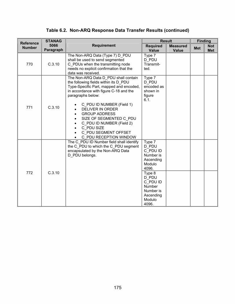
175
Table 6.2. Non-ARQ Response Data Transfer Results (continued)
Result Finding Reference Number
STANAG 5066
Paragraph Requirement Required
Value Measured
Value Met Not Met
770 C.3.10
The Non-ARQ Data (Type 7) D_PDU shall be used to send segmented C_PDUs when the transmitting node needs no explicit confirmation that the data was received.
Type 7 D_PDU Transmit-ted.
771 C.3.10
The Non-ARQ Data D_PDU shall contain the following fields within its D_PDU Type-Specific Part, mapped and encoded, in accordance with figure C-18 and the paragraphs below:
• C_PDU ID NUMBER (Field 1) • DELIVER IN ORDER • GROUP ADDRESS • SIZE OF SEGMENTED C_PDU • C_PDU ID NUMBER (Field 2) • C_PDU SIZE • C_PDU SEGMENT OFFSET • C_PDU RECEPTION WINDOW
Type 7 D_PDU encoded as shown in figure 6.1.
Type 7 D_PDU C_PDU ID Number is Ascending Modulo 4096.
772 C.3.10
The C_PDU ID Number field shall identify the C_PDU to which the C_PDU segment encapsulated by the Non-ARQ Data D_PDU belongs.
Type 8 D_PDU C_PDU ID Number Number is Ascending Modulo 4096.
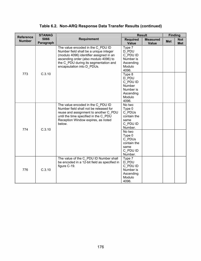
176
Table 6.2. Non-ARQ Response Data Transfer Results (continued)
Result Finding Reference Number
STANAG 5066
Paragraph Requirement Required
Value Measured
Value Met Not Met
Type 7 D_PDU C_PDU ID Number is Ascending Modulo 4096.
773 C.3.10
The value encoded in the C_PDU ID Number field shall be a unique integer (modulo 4096) identifier assigned in an ascending order (also modulo 4096) to the C_PDU during its segmentation and encapsulation into D_PDUs.
Type 8 D_PDU C_PDU ID Number Number is Ascending Modulo 4096.
No two Type 0 C_PDUs contain the same C_PDU ID Number.
774 C.3.10
The value encoded in the C_PDU ID Number field shall not be released for reuse and assignment to another C_PDU until the time specified in the C_PDU Reception Window expires, as noted below.
No two Type 0 C_PDUs contain the same C_PDU ID Number.
776 C.3.10
The value of the C_PDU ID Number shall be encoded in a 12-bit field as specified in figure C-19.
Type 7 D_PDU C_PDU ID Number is Ascending Modulo 4096.
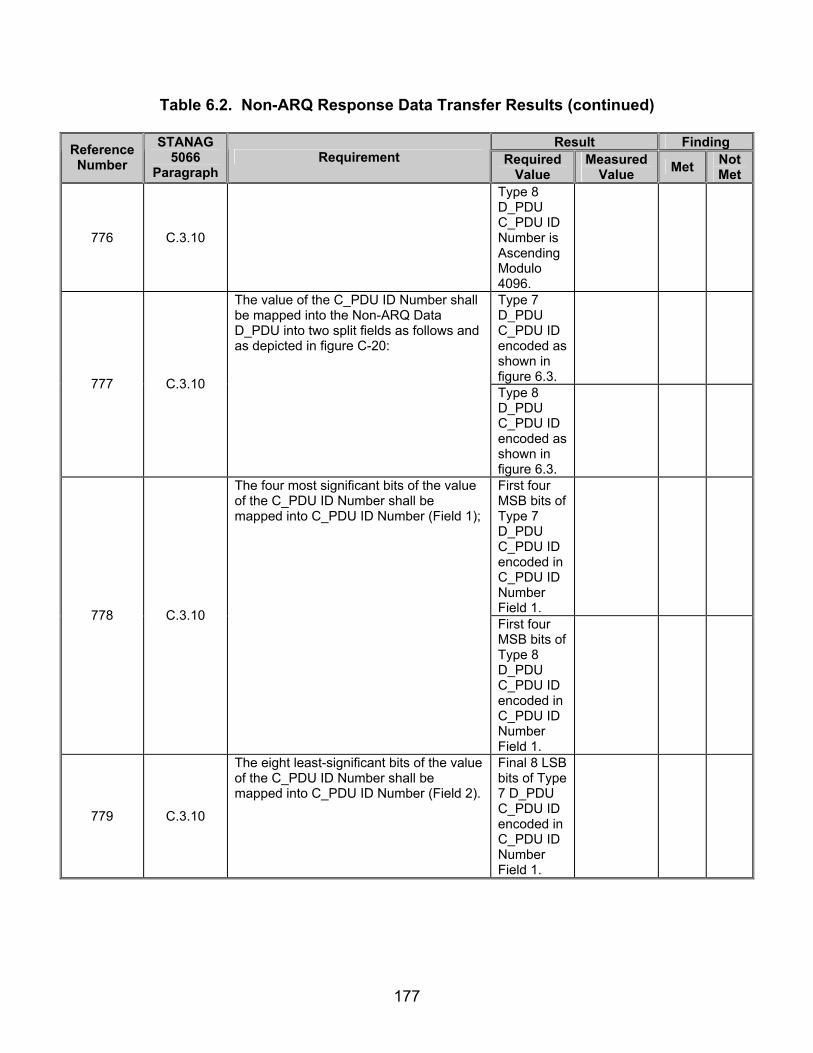
177
Table 6.2. Non-ARQ Response Data Transfer Results (continued)
Result Finding Reference Number
STANAG 5066
Paragraph Requirement Required
Value Measured
Value Met Not Met
776 C.3.10
Type 8 D_PDU C_PDU ID Number is Ascending Modulo 4096.
Type 7 D_PDU C_PDU ID encoded as shown in figure 6.3.
777 C.3.10
The value of the C_PDU ID Number shall be mapped into the Non-ARQ Data D_PDU into two split fields as follows and as depicted in figure C-20:
Type 8 D_PDU C_PDU ID encoded as shown in figure 6.3.
First four MSB bits of Type 7 D_PDU C_PDU ID encoded in C_PDU ID Number Field 1.
778 C.3.10
The four most significant bits of the value of the C_PDU ID Number shall be mapped into C_PDU ID Number (Field 1);
First four MSB bits of Type 8 D_PDU C_PDU ID encoded in C_PDU ID Number Field 1.
779 C.3.10
The eight least-significant bits of the value of the C_PDU ID Number shall be mapped into C_PDU ID Number (Field 2).
Final 8 LSB bits of Type 7 D_PDU C_PDU ID encoded in C_PDU ID Number Field 1.

178
Table 6.2. Non-ARQ Response Data Transfer Results (continued)
Result Finding Reference Number
STANAG 5066
Paragraph Requirement Required
Value Measured
Value Met Not Met
779 C.3.10
Final 8 LSB bits of Type 8 D_PDU C_PDU ID encoded in C_PDU ID Number Field 1.
Type 7 D_PDU Deliver in Order bit= 1
Type 8 D_PDU Deliver in Order bit= 1
780
C.3.10
If the Deliver in Order flag is set (i.e., its value equals 1) on the D_PDUs composing a C_PDU, the C_PDU shall be delivered to the network layer when both the following conditions are met: 1) C_PDU is complete and error-free or the C_PDU Reception Window expires. 2) Previous C_PDUs that also had the Deliver in Order flag set have been delivered.
Procedures for determin-ing if transmis-sion is error-free and delivered appropri-ately under develop-ment.
782 C.3.10
The Group Address flag shall indicate that the destination address should be interpreted as a group address rather than an individual address, as follows:
783 C.3.10
The destination address shall be interpreted as a group address when the Group Address flag is set (1).
Type 7 D_PDU Group Address = 1 when configured to transmit to group address.
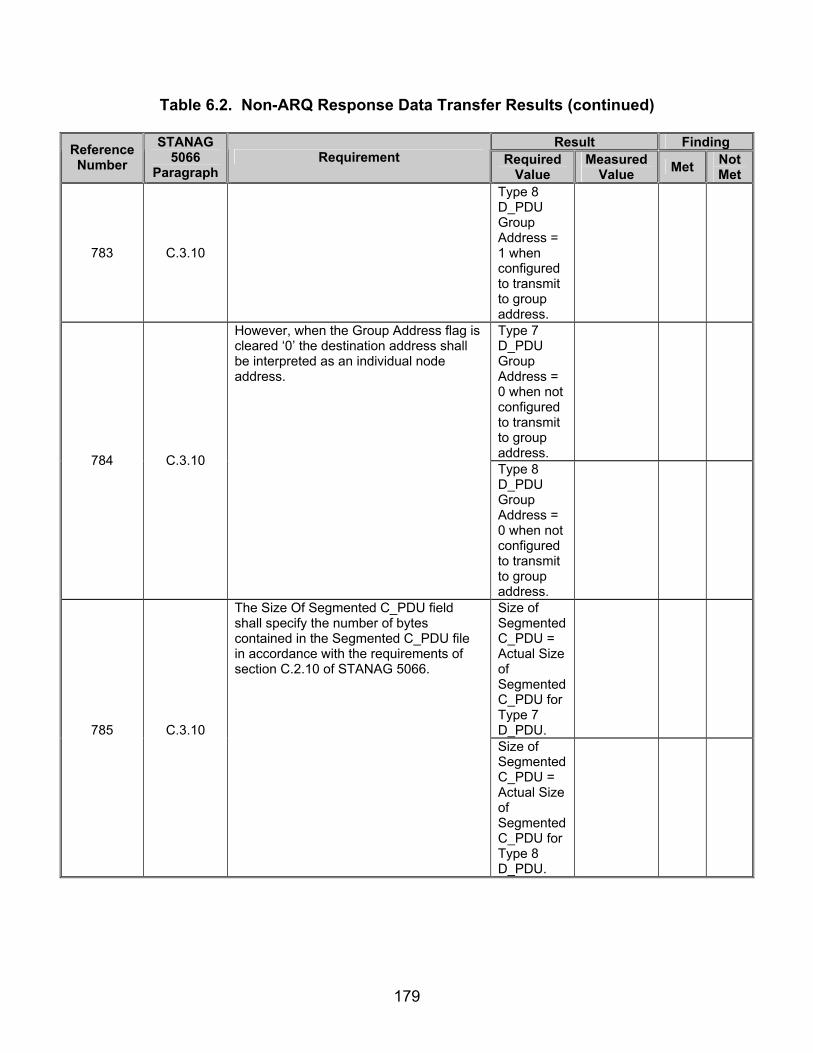
179
Table 6.2. Non-ARQ Response Data Transfer Results (continued)
Result Finding Reference Number
STANAG 5066
Paragraph Requirement Required
Value Measured
Value Met Not Met
783 C.3.10
Type 8 D_PDU Group Address = 1 when configured to transmit to group address.
Type 7 D_PDU Group Address = 0 when not configured to transmit to group address.
784 C.3.10
However, when the Group Address flag is cleared ‘0’ the destination address shall be interpreted as an individual node address.
Type 8 D_PDU Group Address = 0 when not configured to transmit to group address.
Size of Segmented C_PDU = Actual Size of Segmented C_PDU for Type 7 D_PDU.
785
C.3.10
The Size Of Segmented C_PDU field shall specify the number of bytes contained in the Segmented C_PDU file in accordance with the requirements of section C.2.10 of STANAG 5066.
Size of Segmented C_PDU = Actual Size of Segmented C_PDU for Type 8 D_PDU.

180
Table 6.2. Non-ARQ Response Data Transfer Results (continued)
Result Finding Reference Number
STANAG 5066
Paragraph Requirement Required
Value Measured
Value Met Not Met
Size of Segmented C_PDU = Actual Size of Segmented C_PDU for Type 7 D_PDU.
786 C.3.10
The C_PDU Size field shall indicate the size in bytes of the C_PDU of which the C_PDU segment encapsulated in this D_PDU is a part.
Size of Segmented C_PDU = Actual Size of Segmented C_PDU for Type 8 D_PDU.
Size of Segmented C_PDU = Actual Size of Segmented C_PDU for Type 7 D_PDU.
787 C.3.10
The value of the C_PDU Size field shall be encoded in a 16-bit field, with the bits mapped as specified by figure C-21.
Size of Segmented C_PDU = Actual Size of Segmented C_PDU for Type 8 D_PDU.

181
Table 6.2. Non-ARQ Response Data Transfer Results (continued)
Result Finding Reference Number
STANAG 5066
Paragraph Requirement Required
Value Measured
Value Met Not Met
Size of Segmented C_PDU = Actual Size of Segmented C_PDU for Type 7 D_PDU.
788 C.3.10
The number shall be mapped into the D_PDU by placing the MSB of the field into the MSB of the first byte in the D_PDU as can be seen in figure C-22.
Size of Segmented C_PDU = Actual Size of Segmented C_PDU for Type 8 D_PDU.
First Type 7 D_PDU C_PDU Segment Offset = (MSB) 0 0 0 0 0 0 0 0 (LSB) (0x00 hex)
789
C.3.10
The C_PDU Segment Offset field shall indicates the location of the first byte of the Segmented C_PDU with respect to the start of the C_PDU.
Second Type 7 D_PDU C_PDU Segment Offset = Actual Size of Segmented C_PDU for Type 7 D_PDU.
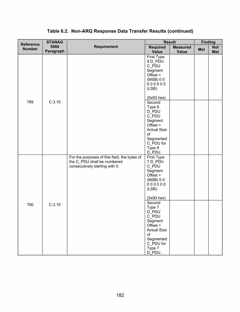
182
Table 6.2. Non-ARQ Response Data Transfer Results (continued)
Result Finding Reference Number
STANAG 5066
Paragraph Requirement Required
Value Measured
Value Met Not Met
First Type 8 D_PDU C_PDU Segment Offset = (MSB) 0 0 0 0 0 0 0 0 (LSB) (0x00 hex)
789
C.3.10
Second Type 8 D_PDU C_PDU Segment Offset = Actual Size of Segmented C_PDU for Type 8 D_PDU.
First Type 7 D_PDU C_PDU Segment Offset = (MSB) 0 0 0 0 0 0 0 0 (LSB) (0x00 hex)
790 C.3.10
For the purposes of this field, the bytes of the C_PDU shall be numbered consecutively starting with 0.
Second Type 7 D_PDU C_PDU Segment Offset = Actual Size of Segmented C_PDU for Type 7 D_PDU.

183
Table 6.2. Non-ARQ Response Data Transfer Results (continued)
Result Finding Reference Number
STANAG 5066
Paragraph Requirement Required
Value Measured
Value Met Not Met
First Type 8 D_PDU C_PDU Segment Offset = (MSB) 0 0 0 0 0 0 0 0 (LSB) (0x00 hex)
790 C.3.10
Second Type 8 D_PDU C_PDU Segment Offset= Actual Size of Segmented C_PDU for Type 8 D_PDU.
First Type 7 D_PDU C_PDU Segment Offset = (MSB) 0 0 0 0 0 0 0 0 (LSB) (0x00 hex)
791
C.3.10
The C_PDU Segment Offset field is a 16-bit field and the bits shall be mapped as specified by figure C-23.
Second Type 7 D_PDU C_PDU Segment Offset= Actual Size of Segmented C_PDU for Type 7 D_PDU.

184
Table 6.2. Non-ARQ Response Data Transfer Results (continued)
Result Finding Reference Number
STANAG 5066
Paragraph Requirement Required
Value Measured
Value Met Not Met
First Type 8 D_PDU C_PDU Segment Offset = (MSB) 0 0 0 0 0 0 0 0 (LSB) (0x00 hex)
791 C.3.10
second Type 8 D_PDU C_PDU Segment Offset = Actual Size of Segmented C_PDU for Type 8 D_PDU.
First Type 7 D_PDU C_PDU Segment Offset = (MSB) 0 0 0 0 0 0 0 0 (LSB) (0x00 hex)
792
C.3.10
The number shall be mapped into the D_PDU by placing the MSB of the field into the MSB of the first byte in the D_PDU as specified in figure C-24.
Second Type 7 D_PDU C_PDU Segment Offset = Actual Size of Segmented C_PDU for Type 7 D_PDU.

185
Table 6.2. Non-ARQ Response Data Transfer Results (continued)
Result Finding Reference Number
STANAG 5066
Paragraph Requirement Required
Value Measured
Value Met Not Met
First Type 8 D_PDU C_PDU Segment Offset = (MSB) 0 0 0 0 0 0 0 0 (LSB) (0x00 hex)
792
C.3.10
Second Type 8 D_PDU C_PDU Segment Offset = Actual Size of Segmented C_PDU for Type 8 D_PDU.
Type 7 D_PDU C_PDU Reception Windows count down in half-second intervals, beginning with each new C_PDU ID.
793 C.3.10
The C_PDU Reception Window field shall indicate the maximum remaining time in units of half-seconds relative to the start of the D_PDU, during which portions of the associated C_PDU may be received.
Type 8 D_PDU C_PDU Reception Windows count down in half-second intervals beginning with each new C_PDU ID.
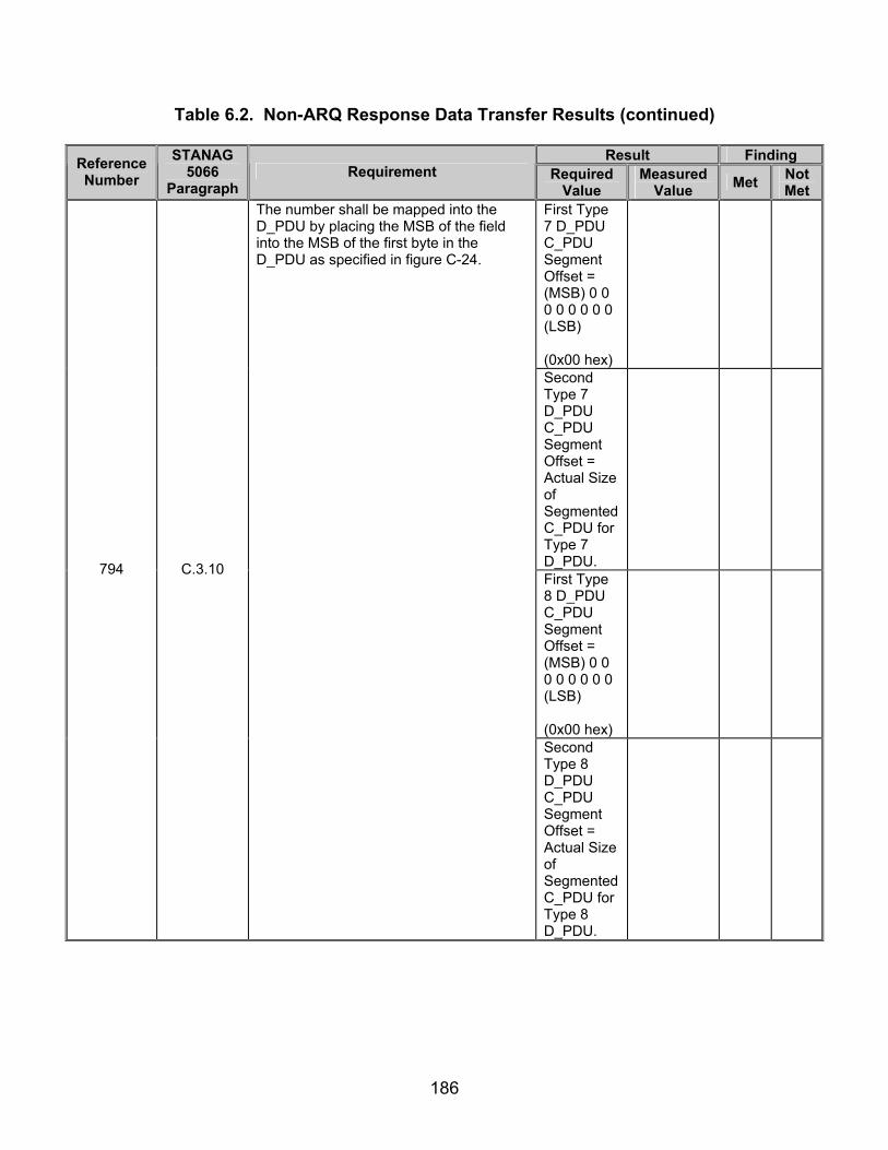
186
Table 6.2. Non-ARQ Response Data Transfer Results (continued)
Result Finding Reference Number
STANAG 5066
Paragraph Requirement Required
Value Measured
Value Met Not Met
First Type 7 D_PDU C_PDU Segment Offset = (MSB) 0 0 0 0 0 0 0 0 (LSB) (0x00 hex)
Second Type 7 D_PDU C_PDU Segment Offset = Actual Size of Segmented C_PDU for Type 7 D_PDU.
First Type 8 D_PDU C_PDU Segment Offset = (MSB) 0 0 0 0 0 0 0 0 (LSB) (0x00 hex)
794 C.3.10
The number shall be mapped into the D_PDU by placing the MSB of the field into the MSB of the first byte in the D_PDU as specified in figure C-24.
Second Type 8 D_PDU C_PDU Segment Offset = Actual Size of Segmented C_PDU for Type 8 D_PDU.
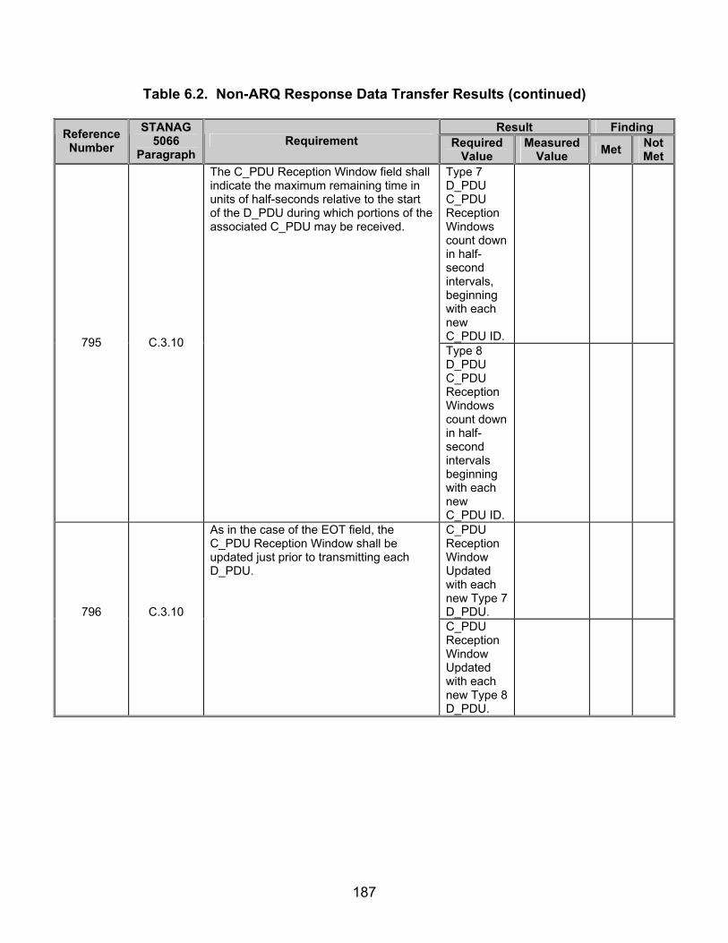
187
Table 6.2. Non-ARQ Response Data Transfer Results (continued)
Result Finding Reference Number
STANAG 5066
Paragraph Requirement Required
Value Measured
Value Met Not Met
Type 7 D_PDU C_PDU Reception Windows count down in half-second intervals, beginning with each new C_PDU ID.
795 C.3.10
The C_PDU Reception Window field shall indicate the maximum remaining time in units of half-seconds relative to the start of the D_PDU during which portions of the associated C_PDU may be received.
Type 8 D_PDU C_PDU Reception Windows count down in half-second intervals beginning with each new C_PDU ID.
C_PDU Reception Window Updated with each new Type 7 D_PDU.
796
C.3.10
As in the case of the EOT field, the C_PDU Reception Window shall be updated just prior to transmitting each D_PDU.
C_PDU Reception Window Updated with each new Type 8 D_PDU.

188
Table 6.2. Non-ARQ Response Data Transfer Results (continued)
Result Finding Reference Number
STANAG 5066
Paragraph Requirement Required
Value Measured
Value Met Not Met
Type 7 D_PDU C_PDU Reception Window mapped as specified in figure 6.8.
797
C.3.10
The value of the C_PDU Reception Window field shall be encoded in a 16-bit field with the bits be mapped as specified by figure C-25.
Type 8 D_PDU C_PDU Reception Window mapped as specified in figure 6.8.
Type 7 D_PDU C_PDU Reception Window mapped as specified in figure 6.9.
798
C.3.10
The value shall be mapped into the D_PDU by placing the MSB of the field into the MSB of the first byte in the D_PDU as specified in figure C-26.
Type 8 D_PDU C_PDU Reception Window mapped as specified in figure 6.9.
799 C.3.11
The frame format for Expedited Non-ARQ Data (Type 8) D_PDUs shall be identical to the NON_ARQ Data D_PDU with the exception that the TYPE field has a value of 8, as specified in figure C-27.
Type 8 D_PDU encoded as shown in figure 6.10.
827 C.4.1
Segmentation of a C_PDU into segments small enough to fit within a D_PDU for Non-ARQ-delivery (i.e., a Non-ARQ Data, or Expedited Non-ARQ-Data D_PDU) shall be performed in accordance with the example shown in figure C-35 and as follows:

189
Table 6.2. Non-ARQ Response Data Transfer Results (continued)
Result Finding Reference Number
STANAG 5066
Paragraph Requirement Required
Value Measured
Value Met Not Met
Type 7 D_PDU Maximum C_PDU Segement Size < 1024 bytes.
828 C.4.1
The Maximum C_PDU Segment size within a D_PDU for Non-ARQ-Delivery services shall be a configurable parameter no greater than 1023 bytes in any implementation compliant with STANAG 5066.
Type 8 D_PDU Maximum C_PDU Segement Size < 1024 bytes.
No 2 Type 7 D_PDUs have the same C_PDU ID Numbers and C_PDU Segment Offset = 0
829 C.4.1
An entire C_PDU for Non-ARQ delivery that is smaller than the Maximum C_PDU Segment size shall be placed in the C_PDU segment of a single D_PDU;
No 2 Type 8 D_PDUs have the same C_PDU ID Numbers and C_PDU Segment Offset = 0
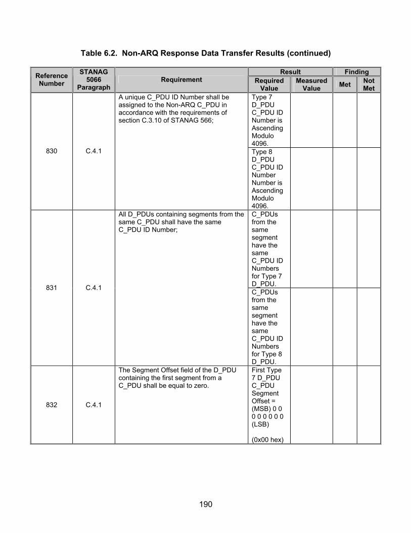
190
Table 6.2. Non-ARQ Response Data Transfer Results (continued)
Result Finding Reference Number
STANAG 5066
Paragraph Requirement Required
Value Measured
Value Met Not Met
Type 7 D_PDU C_PDU ID Number is Ascending Modulo 4096.
830 C.4.1
A unique C_PDU ID Number shall be assigned to the Non-ARQ C_PDU in accordance with the requirements of section C.3.10 of STANAG 566;
Type 8 D_PDU C_PDU ID Number Number is Ascending Modulo 4096.
C_PDUs from the same segment have the same C_PDU ID Numbers for Type 7 D_PDU.
831 C.4.1
All D_PDUs containing segments from the same C_PDU shall have the same C_PDU ID Number;
C_PDUs from the same segment have the same C_PDU ID Numbers for Type 8 D_PDU.
832 C.4.1
The Segment Offset field of the D_PDU containing the first segment from a C_PDU shall be equal to zero.
First Type 7 D_PDU C_PDU Segment Offset = (MSB) 0 0 0 0 0 0 0 0 (LSB) (0x00 hex)

191
Table 6.2. Non-ARQ Response Data Transfer Results (continued)
Result Finding Reference Number
STANAG 5066
Paragraph Requirement Required
Value Measured
Value Met Not Met
832 C.4.1
First Type 8 D_PDU C_PDU Segment Offset = (MSB) 0 0 0 0 0 0 0 0 (LSB) (0x00 hex)
Second Type 7 D_PDU C_PDU Segment Offset Decimal Value = Actual Size of Segmented C_PDU for Type 7 D_PDU.
833
C.4.1
The Segment Offset field of the D_PDU containing any subsequent segment from a C_PDU shall be set equal to the number of bytes from the original C_PDU that precede the first byte of the segment.
Second Type 8 D_PDU C_PDU Segment Offset Decimal Value = Actual Size of Segmented C_PDU for Type 8 D_PDU.
834 C.4.1
For Non-ARQ services, re-assembly of a C_PDU from its segments shall be performed in accordance with the example shown in figure C-36 and as follows (unless noted otherwise, C_PDU segments that are re-assembled are expected to have passed the CRC error-check and have no detectable errors):
C_PDUs re-assembled as specified by figure 6.12.

192
Table 6.2. Non-ARQ Response Data Transfer Results (continued)
Result Finding Reference Number
STANAG 5066
Paragraph Requirement Required
Value Measured
Value Met Not Met
Reference Numbers 786, 788, 829, and 831 are all correct for Type 7 D_PDU.
835 C.4.1
The re-assembly process for Non-ARQ C_PDUs shall use the C_PDU ID Number, Segment Offset field, C_PDU Segment-Size field, and C_PDU Size field to determine when all segments of a C_PDU have been received.
Reference Numbers 786, 788, 829, and 831 are all correct for Type 8 D_PDU.
836 C.4.1
If the Error-free Delivery Mode has been specified, a re-assembled C_PDU shall be delivered, if and only if all segments of the C_PDU have been received without errors;
C_PDU received is error-free.
837 C.4.1 If the Deliver-w/-Errors Mode has been specified, the re-assembly process shall proceed as follows:
838 C.4.1
C_PDU segments received without detected errors shall be collected as received in their D_PDUs and placed in order within the re-assembled C_PDU.
C_PDU without detected errors re-assembled correctly.
Legend: ACK—Acknowledgement ARQ—Automatic Repeat-Request C_PDU—Channel Access Sublayer Protocol Data Unit CRC—Cyclic Redundancy Check D_PDU—Data Transfer Sublayer Protocol Data Unit EOT—End Of Transmission hex—hexadecimal
I-Frame—Information Frame ID—Identification LSB—Least Significant Bit MSB—Most Significant Bit NRQ—Non-Repeat-Request STANAG—Standardization Agreement
193
SUBTEST 7. DATA DELIVERY STRUCTURE 7.1 Objective. To determine the extent of compliance to the requirements of STANAG 5066, reference numbers 498-500, 593, 617-620, 624-626, 649-656, 665-667, 672-675, 781, 811-821, 825, 843, 898, 900-901, and 944-945. 7.2 Criteria
a. For the Channel Access Sublayer request to the lower layers of the subnetwork to deliver a C_PDU, the delivery service requirements for a Data C_PDU shall be the same as the Subnetwork Interface Sublayer Protocol Data Unit (S_PDU) that it contains, i.e.: (appendix B, reference numbers 498-500)
• C_PDUs for which the Subnetwork Interface Sublayer requested Expedited Data Delivery service for the encapsulated S_PDU shall be sent using the Expedited Data Delivery service provided by the lower sublayer; otherwise,
• C_PDUs for which the Subnetwork Interface Sublayer requested the
normal Data Delivery service for the encapsulated S_PDU shall be sent using the normal Data Delivery service provided by the lower sublayer.
b. The IRQ protocol, also known as a stop-and-wait protocol, shall operate in
a half duplex mode; the local node, after sending an I-Frame, must wait until it receives an acknowledgement from the remote node as to whether or not the I-Frame was correctly received. (appendix B, reference number 593)
c. The number in the EOT field shall be a binary number expressing the
number of half-second (0.5 second) intervals remaining in the current transmission from the beginning of the current D_PDU, including sync bytes. (appendix B, reference number 617)
d. When operating in half duplex mode, a node shall not make a
transmission during a transmission by another node (i.e., before the EOT expires). (appendix B, reference number 618)
e. Once an EOT is sent, the EOT in each subsequent D_PDU (in that
transmission) shall contain a consistent calculation of the EOT that is monotonically decreasing in half-second intervals. (appendix B, reference number 619)
f. Calculations of the EOT by a transmitting node shall be rounded up to the
nearest half-second interval. (appendix B, reference number 620)

194
g. When a node is configured for and operating in full duplex mode, the EOT field shall be filled with all zeros. (appendix B, reference number 624)
h. When D_PDU Types are combined in a single transmission by the
sublayer, any previously advertised values of EOT shall not be violated or contradicted. (appendix B, reference number 625)
i. When D_PDU Types are combined in a single transmission by the
sublayer, advertised values for EOT shall refer to the end of the combined transmission and not to the EOT of the D_PDU that contains the EOT field. (appendix B, reference number 626)
j. For the I-Frame and for the Information and Control Frames (I+C)
D_PDUs Types, the octets of the segmented C_PDUs shall be transmitted in ascending numerical order, following the two-byte CRC on the D_PDU Header. (appendix B, reference number 649)
k. Within an octet, the LSB shall be the first bit to be transmitted as shown in
figure 7.1. (appendix B, reference number 650)
Figure 7.1. Segmented C_PDU Mapping Convention in D_PDU Structure
l. The Size of Segmented C_PDU field shall be used only with D_PDUs that
are I or I+C-Frame types, i.e., that have a Segmented C_PDU field (as shown in reference to figure 14.4). (appendix B, reference number 651)
Legend: LSB—Least Significant Bit, MSB—Most Significant Bit

195
m. The bit-value of the Size of Segmented C_PDU shall be encoded as a ten-bit field (as referenced by figure 7.2). (appendix B, reference number 652)
Figure 7.2. Size of Segmented C_PDU Field
n. The value in the Size of Segmented C_PDU field shall not include the 2-
bytes for the CRC following the Segmented C_PDU. The Segmented C_PDU field can hold a maximum of 1023 bytes from the segmented C_PDU. (appendix B, reference number 653)
o. The Size of Segmented C_PDU shall be mapped into consecutive bytes of
the D_PDU as indicated in figure 7.2, in the byte locations specified for the applicable D_PDU. (appendix B, reference number 654)
p. The last 4 bytes of any I or I+C-Frame D_PDUs shall contain a 32-bit CRC
field. (appendix B, reference number 655) q. The CRC shall be applied and computed on the contents of the
Segmented C_PDU using the following polynomial [See footnote 2 in STANAG 5066]: x^32 + x^27 + x^25 + x^23 + x^21 + x^18 + x^17 + x^16 + x^13 + x^10 + x^8 + x^7 + x^6 + x^3 + x^2 + x + 1 or, in hexadecimal notation: 0x10AA725CF, using the shift-register method similar to that shown by the figures in appendix I of Consultative Committee For International Telephone And Telegraph (CCITT) Recommendation V.41. (appendix B, reference number 656)
r. If the Deliver in Order flag is cleared on the D_PDUs composing a
C_PDU, the C_PDU shall be delivered to the upper layer when the following condition is met: (appendix B, reference number 665)
• The C_PDU is complete and error-free. s. When the DROP PDU flag is set by the D_PDU source, the receiving Data
Transfer Sublayer shall discard the contents of the segmented C_PDU field of the
Legend: LSB—Least Significant Bit, MSB—Most Significant Bit

196
current D_PDU and all other previously received segments of the C_PDU of which the current D_PDU is a part. (appendix B, reference number 666)
t. No segmented C_PDU data needs to be sent if the DROP PDU flag is set
and the Size of Segmented C_PDU field shall be zero in this case. (appendix B, reference number 667)
u. The value of the TX FSN field shall be a unique integer (modulo 256)
assigned to the D_PDU during the segmentation of the C_PDU and will not be released for reuse with another D_PDU until the receiving node has acknowledged the D_PDU. (appendix B, reference number 672)
v. Values for the TX FSN field shall be assigned in an ascending (modulo
256) order during the segmentation of the C_PDU. (appendix B, reference number 673) w. The segmented C_PDU field shall immediately follow the D_PDU header
as depicted in figure 1.17. (appendix B, reference number 674) x. Segmented C_PDUs shall be mapped according to the specification of
section C.3.2.9 of STANAG 5066. (appendix B, reference number 675) y. If the Deliver in Order flag is cleared ‘0’ on the D_PDUs composing a
C_PDU, the C_PDU shall be delivered to the network layer when the following condition is met: (appendix B, reference number 781)
• C_PDU is complete and error-free or the C_PDU Reception Window expires.
z. The process of C_PDU segmentation and re-assembly shall be defined in
the subsections that follow for ARQ and Non-ARQ delivery services provided to regular and expedited C_PDUs. (appendix B, reference number 811)
aa. Segmentation of a C_PDU into segments small enough to fit within a
D_PDU for ARQ delivery (i.e., a Data, Data-ACK, or Expedited Data D_PDU) shall be performed in accordance with the example shown in figure 7.3 and as follows: (appendix B, reference numbers 812-819)
• The Maximum C_PDU Segment size within a D_PDU for ARQ-
Delivery services shall be a configurable parameter no greater than 1023 bytes in any implementation compliant with STANAG 5066. An implementation may configure the Maximum C_PDU Segment size to match the interleaver size for optimum channel efficiency or other reasons.
• An entire C_PDU that is smaller than the Maximum C_PDU Segment
size shall be placed in the C_PDU segment of a single D_PDU.
197
• A Data or Data-ACK, or Expedited D_PDU that contain an entire
C_DPU shall be marked with the both C_PDU Start field and the C_PDU End field set equal to the value (1). (Note: An ‘only’ C_PDU segment is both the “first” and “last” segment of a sequence of one.)
• The Data Transfer Sublayer shall divide C_PDUs larger than the
Maximum C_PDU Segment size into segments that are no larger than the Maximum C_PDU Segment size.
• Only the last segment or the only segment taken from a C_PDU may
be smaller than the Maximum C_PDU Segment size. A C_PDU smaller than the Maximum C_PDU Segment size shall be placed only in the D_PDU that contains the last segment of the C_PDU, i.e., only in a D_PDU for which the C_PDU End field is set equal to (1).
• The bytes within a C_PDU segment shall be taken from the source as
a contiguous sequence of bytes, in the same order in which they occurred in the source C_PDU.
• D_PDUs containing C_PDU segments taken in sequence from the
source C_PDU shall have sequential TX FSN fields (modulo 256).

198
Figure 7.3. C_PDU Segmentation for ARQ Delivery Service (Regular and Expedited)
ab. Re-assembly of a C_PDU from its segments shall be performed in
accordance with the example shown in figure 7.4 and as follows (unless noted otherwise, C_PDU segments that are re-assembled are expected to have passed the CRC error-check and have no detectable errors): (appendix B, reference numbers 820, 821, and 825)
• The re-assembly process for C_PDUs receiving ARQ service shall use
the TX FSN field, C_PDU Start flag, and C_PDU End flag to determine when all segments of a C_PDU have been received.
• A segment from a C_PDU larger than the Maximum C_PDU Segment Size shall be combined in modulo 256 order with other segments whose D_PDU FSNs lie in the range defined by the FSNs of the “C_DPU Start” and “C_PDU End” segments.
Legend: CLR—Clear, C_PDU—Channel Access Sublayer Protocol Data Unit, D_PDU—Data Transfer Sublayer Protocol Data Unit, NO—Number, PDU—Protocol Data Unit, SEQ—Sequence, TX—Transmit

199
D_PDUPDU START = SET, PDU END = CLR
TX SEQ NO = 0, SIZE = 200
D_PDUPDU START = CLR, PDU END = CLR
TX SEQ NO = 1, SIZE = 200
. . .
. . .
D_PDUPDU START = CLR, PDU END = SET
TX SEQ NO = 10, SIZE = 80
D_PDUPDU START = SET, PDU END = CLR
*TX SEQ NO = 11, SIZE = 200
D_PDUPDU START = CLR, PDU END = CLR
*TX SEQ NO = 12, SIZE = 200
D_PDUPDU START = CLR, PDU END = SET
*TX SEQ NO = 15, SIZE = 200
Re-
asse
mbl
y or
der
Re-
asse
mbl
y or
der
Re-assembly process
C_PDU
SIZE = 2080
C_PDU
SIZE = 1000
PDU
Del
iver
y or
der
*TX Sequence Frame Number for Expedited C_PDUs are reset to zero for eachNew C_PDU; for Regular C_PDUs, they continue in modulo 256 order as shown
Legend: CLR—Clear, C_PDU—Channel Access Sublayer Protocol Data Unit, D_PDU—Data Transfer Sublayer Protocol Data Unit, NO—Number, PDU—Protocol Data Unit, SEQ—Sequence, TX—Transmit
Figure 7.4. C_PDU Re-assembly for ARQ Delivery Service (Regular and Expedited)
ac. Delivery of the re-assembled D_PDU shall be performed with the
D_Primitive appropriate for the type of data (i.e., regular or expedited) received. (appendix B, reference number 843)
ad. The Data Transfer Sublayer shall satisfy the following requirements for
D_PDU flow-control: (appendix B, reference number 898, and 900-901)
• The TX FSNs shall be assigned uniquely and sequentially in an ascending (modulo 256) order during the segmentation of the C_PDU into D_PDUs.
• The TX FSNs shall not be released for reuse with another D_PDU until the receiving node has acknowledged the D_PDU to which the number is assigned.
ae. Valid EOT information shall be supplied in each repeated D_PDU
containing a DRC Request (Type 1) Management message, updated as required to denote the end of transmission of all D_PDU messages in the transmission interval (and not the end of the individual D_PDU containing the EOT field). (appendix B, reference number 944)
af. The same EOT value shall not be transmitted in each repeated D_PDU
containing a DRC Request (Type 1) Management message unless necessary, due to
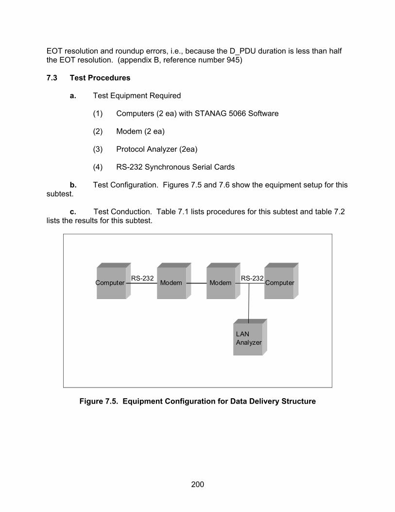
200
EOT resolution and roundup errors, i.e., because the D_PDU duration is less than half the EOT resolution. (appendix B, reference number 945) 7.3 Test Procedures
a. Test Equipment Required
(1) Computers (2 ea) with STANAG 5066 Software (2) Modem (2 ea) (3) Protocol Analyzer (2ea) (4) RS-232 Synchronous Serial Cards
b. Test Configuration. Figures 7.5 and 7.6 show the equipment setup for this subtest.
c. Test Conduction. Table 7.1 lists procedures for this subtest and table 7.2
lists the results for this subtest.
Computer Modem Modem Computer
LANAnalyzer
RS-232 RS-232
Figure 7.5. Equipment Configuration for Data Delivery Structure

201
Modem Modem
ComputerSTANAGAddress1.1.0.0
ProtocolAnalyzer
B
RS-232 RS-232ProtocolAnalyzer
A
Legend: STANAG—Standardization Agreement
Figure 7.6 Equipment Configuration for Data Delivery Structure for Types 3 and 15 D_PDUs
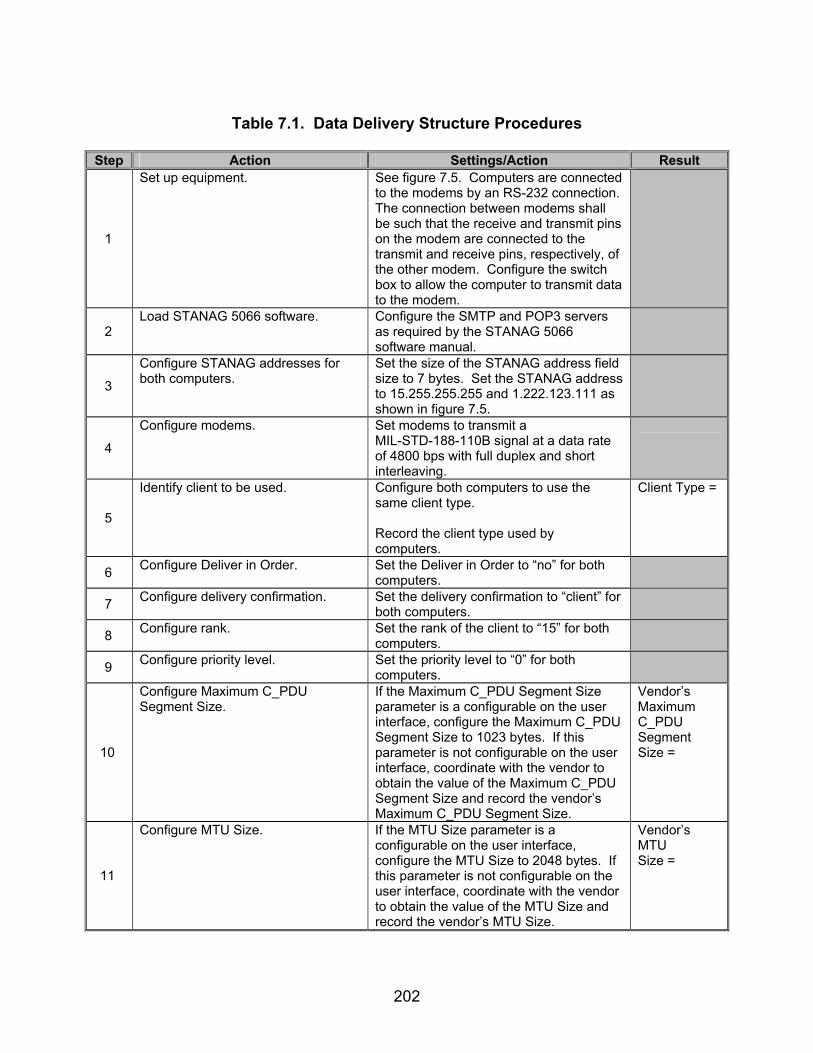
202
Table 7.1. Data Delivery Structure Procedures
Step Action Settings/Action Result
1
Set up equipment. See figure 7.5. Computers are connected to the modems by an RS-232 connection. The connection between modems shall be such that the receive and transmit pins on the modem are connected to the transmit and receive pins, respectively, of the other modem. Configure the switch box to allow the computer to transmit data to the modem.
2 Load STANAG 5066 software. Configure the SMTP and POP3 servers
as required by the STANAG 5066 software manual.
3
Configure STANAG addresses for both computers.
Set the size of the STANAG address field size to 7 bytes. Set the STANAG address to 15.255.255.255 and 1.222.123.111 as shown in figure 7.5.
4
Configure modems. Set modems to transmit a MIL-STD-188-110B signal at a data rate of 4800 bps with full duplex and short interleaving.
5
Identify client to be used. Configure both computers to use the same client type. Record the client type used by computers.
Client Type =
6 Configure Deliver in Order. Set the Deliver in Order to “no” for both computers.
7 Configure delivery confirmation. Set the delivery confirmation to “client” for both computers.
8 Configure rank. Set the rank of the client to “15” for both computers.
9 Configure priority level. Set the priority level to “0” for both computers.
10
Configure Maximum C_PDU Segment Size.
If the Maximum C_PDU Segment Size parameter is a configurable on the user interface, configure the Maximum C_PDU Segment Size to 1023 bytes. If this parameter is not configurable on the user interface, coordinate with the vendor to obtain the value of the Maximum C_PDU Segment Size and record the vendor’s Maximum C_PDU Segment Size.
Vendor’s Maximum C_PDU Segment Size =
11
Configure MTU Size. If the MTU Size parameter is a configurable on the user interface, configure the MTU Size to 2048 bytes. If this parameter is not configurable on the user interface, coordinate with the vendor to obtain the value of the MTU Size and record the vendor’s MTU Size.
Vendor’s MTU Size =

203
Table 7.1. Data Delivery Structure Procedures (continued)
Step Action Settings/Action Result
12
Determine maximum number of D_PDUs to encapsulate an entire C_PDU.
Add 6 to the Vendor’s MTU Size and divide the result by the Maximum C_PDU Segment Size (round up) to determine the maximum number of D_PDUs needed to encapsulate an entire C_PDU segment which is segmented across more than 1 D_PDU. If the above values were user configurable and the values specified were used, this value will be 3 D_PDUs. Note: The adding of 6 bytes takes into consideration the C_PDU and S_PDU headers that are not included in the MTU Size but are included in the Maximum C_PDU Segment Size.
Max Number of D_PDUs =
13
Configure protocol analyzer. Configure protocol analyzer B to capture the transmitted data between the two computers and save it to a file. Configure the protocol analyzer to have a 4800-bps bit rate and to synchronize on “0x90EB.” Configure protocol analyzer B to drop sync after 20 “0xFFs”. Configure the analyzer to time stamp each captured byte.
14
Send e-mail message.
Send the following e-mail message from the computer with STANAG address 1.222.123.111 to the computer with STANAG address 15.255.255.255 using a Soft Link and Non-Expedited ARQ Delivery Method. Include an attachment of approximately 5 kbytes. For the Subject Line: Test 1 In the Body: “This is a test from address 1.222.123.111 to 15.255.255.255 1 2 3 4 5 6 7 8 9 10” Save the data obtained through the analyzer to a file.
15
Verify message was successfully received on the receiving computer.
Observe the mailbox configured on the receiving computer (computer with STANAG address 15.255.255.255) and confirm that the message was successfully received by computer 15.255.255.255.
Message received successfully? Y/N

204
Table 7.1. Data Delivery Structure Procedures (continued)
Step Action Settings/Action Result The following procedures apply to a Type 0 (Non-Expedited DATA-ONLY ARQ) and are for reference numbers 498, 500, 617-620, 625, 626, 649-656, 672-675, 811, 816-821, 825, 843, 898, and 900-901.
16
From the captured file, locate sync bytes and D_PDU Type.
D_PDUs sync with the hex sequence 0x90EB, or (MSB) 1 0 0 1 0 0 0 0 1 1 1 0 1 0 1 1 (LSB) in binary.
17
Locate Type 0 D_PDU. D_PDUs begin with the hex sequence 0x90EB. The first 4 bits immediately after the 0x90EB sequence will be the D_PDU Type. For the Type 0 D_PDU, the value will be 0x0 in hex or (MSB) 0000 (LSB) in binary. Locate the first Type 0 D_PDU.
18
Obtain EOT bits for the first Type 0 D_PDU obtained in step 17.
The EOT field is the first 8 bits of the third byte of the D_PDU (not counting the sync sequence). Record the decimal value of the EOT bits.
First Type 0 D_PDU EOT =
First Type 0 C_PDU Start = 19
Locate C_PDU Start and End flags for the first Type 0 D_PDU located in step 17.
The C_PDU Start bit is the first bit of the 12th byte of the Type 0 D_PDU. The C_PDU End bit is the second bit of the 12th byte of the Type 0 D_PDU (not counting the sync sequence). Record the C_PDU Start and End bits.
First Type 0 C_PDU End =
20
Obtain Deliver in Order bit for Type 0 D_PDU found in step 17.
The next bit, after the C_PDU End bit, is the Deliver in Order bit. Record the Deliver in Order bit.
First Type 0 D_PDU Deliver in Order = First Type 0 TX UWE =
21
Locate TX UWE and TX LWE bits for the Type 0 D_PDU found in step 17.
The next bit, after the Deliver in Order bit, is the DROP C_PDU bit. The next 2 bits, after the DROP C_PDU bit, are the TX UWE and TX LWE bits (respectively). Record the TX UWE and TX LWE bits.
First Type 0 TX LWE=
22
Locate Size of Segmented C_PDU. The Size of Segmented C_PDU is the next 10 bits, after the TX LWE bit. Record the Size of Segmented C_PDU bits.
First Type 0 Size of Segmented C_PDU =
23
Locate TX FSN of the first Type 0 D_PDU found in step 17.
The TX FSN is an 8-bit field located in the 14th byte of the Type 0 D_PDU (not counting the sync sequence). Record the TX FSN.
First Type 0 TX FSN =

205
Table 7.1. Data Delivery Structure Procedures (continued)
Step Action Settings/Action Result
24
Using the time stamp from the protocol analyzer, locate the time length of Type 0 D_PDU string.
Record the time it takes for the entire D_PDU string that contains the complete message from step 14, from the start of the first Type 0 D_PDU to the end of the final Type 0 D_PDU in the string, to be transmitted.
Type 0 D_PDU string Time =
25
Identify the number of C_PDU bytes transmitted in the first Type 0 D_PDU located in step 17.
Starting with the 17th byte of the Type 0 D_PDU, count the number of bytes to the end of the Type 0 D_PDU. The end is reached when another D_PDU is encountered or at the end of the transmission. This value includes the 4-byte CRC field and must be subtracted from the total number of actual transmitted C_PDU bytes. Record the Number of Actual Transmitted C_PDU bytes.
Number of Actual Transmitted C_PDU Bytes =
26
Locate CRC on Segmented C_PDU bits.
The CRC on Segmented C_PDU is the final 4 bytes within the D_PDU. This can be obtained by using the Size of Segmented C_PDU field and counting the bytes down to the end of the Segmented C_PDU, which will also be the end of the D_PDU.
Type 0 CRC on Segmented C_PDU =
27
Compute actual CRC on Segmented C_PDU.
Using the Code Example C-2 from section C.3.2.8 in STANAG 5066 for a 32-bit CRC, compute the actual CRC for the Segmented C_PDU. The Segmented C_PDU begins with the 17th byte of the Type 0 D_PDU and ends with a number of bytes equal to the value of the Size of Segmented C_PDU field minus the last four CRC on Segmented C_PDU bytes.
Type 0 Actual CRC on Segmented C_PDU =
28 Locate the second Type 0 D_PDU in the Type 0 D_PDU string.
Using the method in step 17, locate the second Type 0 D_PDU in the Type 0 D_PDU string.
29
Locate EOT of second Type 0 D_PDU in the Type 0 D_PDU string.
The EOT field is the first 8 bits of the third byte of the D_PDU (not counting the sync sequence). Record the decimal value of the EOT bits.
Second Type 0 D_PDU EOT =
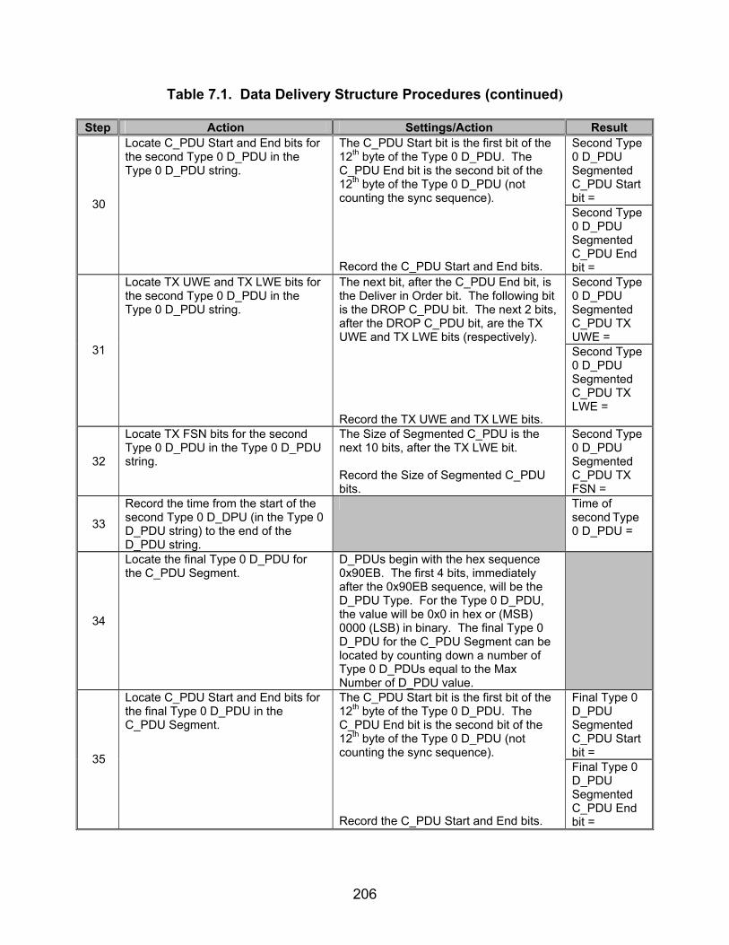
206
Table 7.1. Data Delivery Structure Procedures (continued)
Step Action Settings/Action Result Second Type 0 D_PDU Segmented C_PDU Start bit = 30
Locate C_PDU Start and End bits for the second Type 0 D_PDU in the Type 0 D_PDU string.
The C_PDU Start bit is the first bit of the 12th byte of the Type 0 D_PDU. The C_PDU End bit is the second bit of the 12th byte of the Type 0 D_PDU (not counting the sync sequence). Record the C_PDU Start and End bits.
Second Type 0 D_PDU Segmented C_PDU End bit = Second Type 0 D_PDU Segmented C_PDU TX UWE =
31
Locate TX UWE and TX LWE bits for the second Type 0 D_PDU in the Type 0 D_PDU string.
The next bit, after the C_PDU End bit, is the Deliver in Order bit. The following bit is the DROP C_PDU bit. The next 2 bits, after the DROP C_PDU bit, are the TX UWE and TX LWE bits (respectively). Record the TX UWE and TX LWE bits.
Second Type 0 D_PDU Segmented C_PDU TX LWE =
32
Locate TX FSN bits for the second Type 0 D_PDU in the Type 0 D_PDU string.
The Size of Segmented C_PDU is the next 10 bits, after the TX LWE bit. Record the Size of Segmented C_PDU bits.
Second Type 0 D_PDU Segmented C_PDU TX FSN =
33
Record the time from the start of the second Type 0 D_DPU (in the Type 0 D_PDU string) to the end of the D_PDU string.
Time of second Type 0 D_PDU =
34
Locate the final Type 0 D_PDU for the C_PDU Segment.
D_PDUs begin with the hex sequence 0x90EB. The first 4 bits, immediately after the 0x90EB sequence, will be the D_PDU Type. For the Type 0 D_PDU, the value will be 0x0 in hex or (MSB) 0000 (LSB) in binary. The final Type 0 D_PDU for the C_PDU Segment can be located by counting down a number of Type 0 D_PDUs equal to the Max Number of D_PDU value.
Final Type 0 D_PDU Segmented C_PDU Start bit = 35
Locate C_PDU Start and End bits for the final Type 0 D_PDU in the C_PDU Segment.
The C_PDU Start bit is the first bit of the 12th byte of the Type 0 D_PDU. The C_PDU End bit is the second bit of the 12th byte of the Type 0 D_PDU (not counting the sync sequence). Record the C_PDU Start and End bits.
Final Type 0 D_PDU Segmented C_PDU End bit =

207
Table 7.1. Data Delivery Structure Procedures (continued)
Step Action Settings/Action Result
36
Locate Size of Segmented C_PDU bits for the final Type 0 D_PDU in the C_PDU Segment.
The Size of Segmented C_PDU is a 10-bit field beginning with the final 2 bits (LSB) of the 12th byte and ending with the LSB of the 13th byte of the Type 0 D_PDU. Record the Size of Segmented C_PDU bits.
Final Type 0 D_PDU Size of Segmented C_PDU bits =
37
Locate TX FSN bits from final located Type 0 D_PDU in step 34.
The TX FSN is an 8-bit field located in the 14th byte of the Type 0 D_PDU (not including the sync bytes). Record the TX FSN bits.
Final Type 0 D_PDU Segmented C_PDU TX FSN =
38
Locate the final Type 0 D_PDU in the Type 0 D_PDU string.
D_PDUs begin with the hex sequence 0x90EB. The first 4 bits, immediately after the 0x90EB sequence, will be the D_PDU Type. For the Type 0 D_PDU, the value will be 0x0 in hex or (MSB) 0000 (LSB) in binary. Locate the final Type 0 D_PDU in the Type 0 D_PDU String.
39
Locate the EOT of final Type 0 D_PDU in the Type 0 D_PDU string.
The EOT field is the first 8 bits of the third byte of the D_PDU (not counting the sync sequence). Record the decimal value of the EOT bits.
Final Type 0 D_PDU EOT =
Final Type 0 D_PDU TX UWE = 40
Locate the TX UWE and TX LWE bits for the final Type 0 D_PDU in the Type 0 D_PDU string.
The next bit, after the Deliver in Order bit, is the DROP C_PDU bit. The next 2 bits, after the DROP C_PDU bit, are the TX UWE and TX LWE bits (respectively). Record the TX UWE and TX LWEs.
Final Type 0 D_PDU TX LWE =
41
Locate the time from the start of the final Type 0 D_DPU in the D_PDU string to the end of the D_PDU string.
Using the time stamps from step 14, measure the time from the start of the final Type 0 D_PDU to the end of the Type 0 D_PDU string.
Time of final Type 0 D_PDU =
42 Compare the TX FSNs from steps 23, 32, and 37.
Are any TX FSNs used more than once in the above string?
Y/N
43
Determine the number of total Type 0 D_PDUs transmitted from computer 1.222.123.111 before computer 15.255.255.255 tranmits its response.
Count the number of Type 0 D_PDUs in the Type 0 D_PDU string. Record the number of Type 0 D_PDUs in the Type 0 D_PDU string.
Total Number of Type 0 D_PDUs =

208
Table 7.1. Data Delivery Structure Procedures (continued)
Step Action Settings/Action Result Type 2 (Non-Expedited DATA_ACK ARQ) and are for reference numbers 617-620, 625, 626, 649-656,
672-675, 781, 811, and 816-821.
44
Locate Type 2 D_PDU (DATA-ACK D_PDU).
D_PDUs begin with the hex sequence 0x90EB. The first 4 bits, immediately after the 0x90EB sequence, will be the D_PDU Type. For the Type 2 D_PDU, the value will be 0x2 in hex or (MSB) 0010 (LSB) in binary.
45
Obtain EOT bits for the first Type 2 D_PDU obtained in step 39.
The EOT field is an 8-bit field and is located within the third byte of the D_PDU (not counting the sync sequence). Record the decimal value of the EOT bits.
First Type 2 D_PDU EOT =
First Type 2 C_PDU Start = 46
Locate C_PDU Start and End flags for the first Type 2 D_PDU located in step 39.
The C_PDU Start bit is the first bit of the 12th byte of the Type 2 D_PDU. The C_PDU End bit is the second bit of the 12th byte of the Type 2 D_PDU (not counting the sync sequence). Record the C_PDU Start and End bits.
First Type 2 C_PDU End =
47
Obtain Deliver in Order bit for Type 2 D_PDU found in step 39.
The next bit, after the C_PDU End bit, is the Deliver in Order bit. Record the Deliver in Order bit.
Type 2 D_PDU Deliver in Order = First Type 2 TX UWE = 48
Locate TX UWE and TX LWE bits for the Type 2 D_PDU found in step 39.
The next bit, after the Deliver in Order bit, is the DROP C_PDU bit. The next 2 bits, after the DROP C_PDU bit, are the TX UWE and TX LWE bits (respectively). Record the TX UWE and TX LWE bits.
First Type 2 TX LWE =
49
Locate TX FSN of the first Type 2 D_PDU found in step 39.
The TX FSN is an 8-bit field located in the 14th byte of the Type 2 D_PDU (not counting the sync sequence). Record the TX FSN.
First Type 2 TX FSN =
50
Using the time stamps from the protocol analyzer, locate the time length of Type 2 D_PDU string.
Record the time it takes for the entire Type 2 D_PDU string that contain the complete message, from the start of the first Type 2 D_PDU to the end of the final Type 2 D_PDU in the string, to be transmitted.
Type 2 D_PDU String Time =

209
Table 7.1. Data Delivery Structure Procedures (continued)
Step Action Settings/Action Result
51
Identify the Number of Actual C_PDU bytes transmitted in the first Type 2 D_PDU located in step 39.
Starting with the 18th byte of the Type 2 D_PDU (not including sync sequence), count the number of bytes to the end of the Type 2 D_PDU. The end is reached 4 bytes before another D_PDU is encountered or at the end of the transmission interval. Record the Number of Actual Transmitted C_PDU bytes.
Number of Actual Transmitted C_PDU bytes =
52
Locate CRC on Segmented C_PDU bits.
The CRC on Segmented C_PDU is the final 4 bytes within the D_PDU. This can be obtained by using the Size of Segmented C_PDU field and counting the bytes down to the end of the Segmented C_PDU, which will also be the end of the D_PDU.
Type 2 CRC on Segmented C_PDU =
53
Compute actual CRC on Segmented C_PDU.
Using the Code Example C-2 from section C.3.2.8 in STANAG 5066 for a 32-bit CRC, compute the actual CRC for the Segmented C_PDU. The Segmented C_PDU begins with the 18th byte of the Type 2 D_PDU and ends with a number of bytes equal to the value of the Size of Segmented C_PDU field, minus the last four CRC on Segmented C_PDU bytes.
Type 2 Actual CRC on Segmented C_PDU =
54
Locate the second Type 2 D_PDU in the Type 2 D_PDU string.
D_PDUs begin with the hex sequence 0x90EB. The first 4 bits, immediately after the 0x90EB sequence, will be the D_PDU Type. For the Type 2 D_PDU, the value will be 0x2 in hex or (MSB) 0010 (LSB) in binary.
55
Locate the EOT of second Type 2 D_PDU in the Type 2 D_PDU string.
The EOT field is an 8-bit field and is located within the third byte of the D_PDU (not counting the sync sequence). Record the decimal value of the EOT bits.
Second Type 2 D_PDU EOT =
Second Type 2 D_PDU C_PDU Start bit = 56
Locate the C_PDU Start and End bits for the second Type 2 D_PDU in the Type 2 D_PDU string.
The C_PDU Start bit is the first bit of the 12th byte of the Type 2 D_PDU. The C_PDU End bit is the second bit of the 12th byte of the Type 2 D_PDU (not counting the sync sequence). Record the C_PDU Start and End bits.
Second Type 2 D_PDU C_PDU End bit =

210
Table 7.1. Data Delivery Structure Procedures (continued)
Step Action Settings/Action Result Second Type 2 D_PDU TX UWE =
57
Locate the TX UWE and LWE bits for the second Type 2 D_PDU in the Type 2 D_PDU string.
The next 2 bits, after the C_PDU Start and End bits, are the Deliver in Order and DROP C_PDU bits. The next 2 bits, after the DROP C_PDU bit, are the TX UWE and TX LWE bits (respectively). Record the TX LWE and TX UWE bits for the second Type 2 D_PDU in the Type 2 D_PDU string.
Second Type 2 D_PDU TX LWE =
58
Locate the TX FSN bits for the second Type 2 D_PDU in the Type 2 D_PDU string.
The TX FSN is an 8-bit field located in the 14th byte of the Type 2 D_PDU (not counting the sync sequence). Record the TX FSN bit.
Second Type 2 D_PDU TX FSN =
59
Record the time from the start of the second Type 2 D_DPU (in the Type 2 D_PDU string) to the end of the D_PDU string.
Time of second Type 2 D_PDU =
60
Locate the final Type 2 D_PDU in the Type 2 D_PDU string.
D_PDUs begin with the hex sequence 0x90EB. The first 4 bits, immediately after the 0x90EB sequence, will be the D_PDU Type. For the Type 2 D_PDU, the value will be 0x2 in hex or (MSB) 0010 (LSB) in binary.
61
Locate the EOT of final Type 2 D_PDU in the Type 2 D_PDU string.
The EOT field is an 8-bit field and is located within the third byte of the D_PDU (not counting the sync sequence). Record the decimal value of the EOT bits.
Final Type 2 D_PDU EOT =
Final Type 2 D_PDU C_PDU Start bit = 62
Locate the C_PDU Start and End bits for the final Type 2 D_PDU in the Type 2 D_PDU string.
The C_PDU Start bit is the first bit of the 12th byte of the Type 2 D_PDU. The C_PDU End bit is the second bit of the 12th byte of the Type 2 D_PDU (not counting the sync sequence). Record the C_PDU Start and End bits.
Final Type 2 D_PDU C_PDU End bit = Final Type 2 D_PDU TX UWE bit=
63
Locate the TX UWE and TX LWE bits for the final Type 2 D_PDU in the Type 2 D_PDU string.
The next 2 bits, after the C_PDU Start and End bits, are the Deliver in Order and DROP C_PDU bits. The next 2 bits, after the DROP C_PDU bit, are the TX UWE and TX LWE bits (respectively). The TX UWE and TX LWE bits for the second Type 2 D_PDU in the Type 2 D_PDU string. Record the TX LWE and TX UWE bits.
Final Type 2 D_PDU TX LWE bit =

211
Table 7.1. Data Delivery Structure Procedures (continued)
Step Action Settings/Action Result
64
Locate Size of Segmented C_PDU bits for the final Type 2 D_PDU in the C_PDU Segment.
The Size of Segmented C_PDU is a 10-bit field beginning with the final 2 bits (LSB) of the 12th byte and ending with the LSB of the 13th byte of the Type 2 D_PDU. Record the Size of Segmented C_PDU bits.
Final Type 2 D_PDU Size of Segmented C_PDU bits =
65
Locate the TX FSN bits for the final Type 0 D_PDU in the Type 2 D_PDU string.
The TX FSN is an 8-bit field located in the 14th byte of the Type 2 D_PDU (not counting the sync sequence). Record the TX FSN.
Final Type 2 D_PDU TX FSN =
66
Locate the time from the start of the final Type 2 D_DPU in the D_PDU string to the end of the D_PDU string.
Using the time stamps from step 14, measure the time from the start of the final Type 2 D_PDU to the end of the Type 2 D_PDU string.
Time of Final Type 2 D_PDU =
67 Compare the TX FSNs from steps 49, 58, and 65.
Are any TX FSNs used more than once in the above string?
Y/N
68
Determine the number of Type 2 D_PDUs transmitted from computer 15.255.255.255 before Type 1 D_PDU is sent from computer 1.222.123.111.
Count the number of Type 2 D_PDUs in the Type 2 D_PDU string. Record the number of Type 2 D_PDUs in the Type 2 D_PDU string.
Total Number of Type 2 D_PDUs =
Type 8 (Expedited Non-ARQ) D_PDUs and are for reference numbers 617-620, 625, 626, 649-656, 672-675, 781, and 811.
69
Locate the first Type 8 D_PDU. D_PDUs begin with the hex sequence 0x90EB. The first 4 bits, immediately after the 0x90EB sequence, will be the D_PDU Type. For the Type 8 D_PDU, the value will be 0x8 in hex or (MSB) 1000 (LSB) in binary. Locate the first Type 8 D_PDU transmitted.
70
Obtain EOT bits for the Type 8 D_PDU obtained in step 69.
The EOT field is an 8-bit field and is located within the third byte of the D_PDU (not counting the sync sequence). Record the EOT bits.
Type 8 D_PDU EOT =
71
Obtain Type 8 D_PDU Deliver in Order bit for the Type 8 D_PDU found in step 69.
The Deliver in Order bit for the Type 8 D_PDU, transmitted by computer 1.222.123.111, is the fifth bit located in the 12th byte of the Type 8 D_PDU (not including sync sequence). Record the Deliver in Order bit.
Type 8 D_PDU Deliver in Order bit =
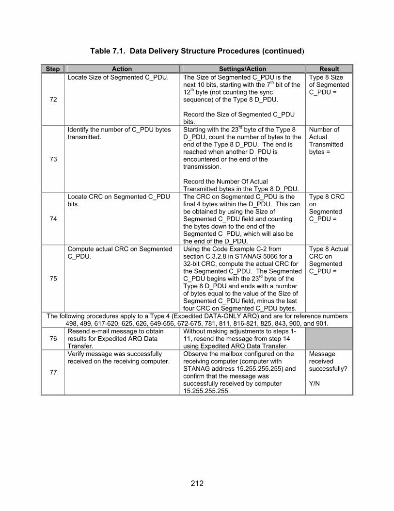
212
Table 7.1. Data Delivery Structure Procedures (continued)
Step Action Settings/Action Result
72
Locate Size of Segmented C_PDU. The Size of Segmented C_PDU is the next 10 bits, starting with the 7th bit of the 12th byte (not counting the sync sequence) of the Type 8 D_PDU. Record the Size of Segmented C_PDU bits.
Type 8 Size of Segmented C_PDU =
73
Identify the number of C_PDU bytes transmitted.
Starting with the 23rd byte of the Type 8 D_PDU, count the number of bytes to the end of the Type 8 D_PDU. The end is reached when another D_PDU is encountered or the end of the transmission. Record the Number Of Actual Transmitted bytes in the Type 8 D_PDU.
Number of Actual Transmitted bytes =
74
Locate CRC on Segmented C_PDU bits.
The CRC on Segmented C_PDU is the final 4 bytes within the D_PDU. This can be obtained by using the Size of Segmented C_PDU field and counting the bytes down to the end of the Segmented C_PDU, which will also be the end of the D_PDU.
Type 8 CRC on Segmented C_PDU =
75
Compute actual CRC on Segmented C_PDU.
Using the Code Example C-2 from section C.3.2.8 in STANAG 5066 for a 32-bit CRC, compute the actual CRC for the Segmented C_PDU. The Segmented C_PDU begins with the 23rd byte of the Type 8 D_PDU and ends with a number of bytes equal to the value of the Size of Segmented C_PDU field, minus the last four CRC on Segmented C_PDU bytes.
Type 8 Actual CRC on Segmented C_PDU =
The following procedures apply to a Type 4 (Expedited DATA-ONLY ARQ) and are for reference numbers 498, 499, 617-620, 625, 626, 649-656, 672-675, 781, 811, 816-821, 825, 843, 900, and 901.
76 Resend e-mail message to obtain results for Expedited ARQ Data Transfer.
Without making adjustments to steps 1-11, resend the message from step 14 using Expedited ARQ Data Transfer.
77
Verify message was successfully received on the receiving computer.
Observe the mailbox configured on the receiving computer (computer with STANAG address 15.255.255.255) and confirm that the message was successfully received by computer 15.255.255.255.
Message received successfully? Y/N
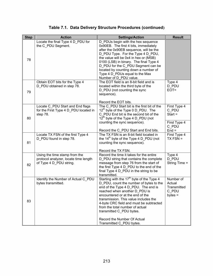
213
Table 7.1. Data Delivery Structure Procedures (continued)
Step Action Settings/Action Result
78
Locate the final Type 4 D_PDU for the C_PDU Segment.
D_PDUs begin with the hex sequence 0x90EB. The first 4 bits, immediately after the 0x90EB sequence, will be the D_PDU Type. For the Type 4 D_PDU, the value will be 0x4 in hex or (MSB) 0100 (LSB) in binary. The final Type 4 D_PDU for the C_PDU Segment can be located by counting down a number of Type 4 D_PDUs equal to the Max Number of D_PDU value.
79
Obtain EOT bits for the Type 4 D_PDU obtained in step 78.
The EOT field is an 8-bit field and is located within the third byte of the D_PDU (not counting the sync sequence). Record the EOT bits.
Type 4 D_PDU EOT=
First Type 4 C_PDU Start = 80
Locate C_PDU Start and End flags for the First Type 4 D_PDU located in step 78.
The C_PDU Start bit is the first bit of the 12th byte of the Type 0 D_PDU. The C_PDU End bit is the second bit of the 12th byte of the Type 4 D_PDU (not counting the sync sequence). Record the C_PDU Start and End bits.
First Type 4 C_PDU End =
81
Locate TX FSN of the first Type 4 D_PDU found in step 78.
The TX FSN is an 8-bit field located in the 14th byte of the Type 4 D_PDU (not counting the sync sequence). Record the TX FSN.
First Type 4 TX FSN =
82
Using the time stamp from the protocol analyzer, locate time length of Type 4 D_PDU string.
Record the time it takes for the entire D_PDU string that contains the complete message from step 76 from the start of the first Type 4 D_PDU to the end of the final Type 4 D_PDU in the string to be transmitted.
Type 4 D_PDU String Time =
83
Identify the Number of Actual C_PDU bytes transmitted.
Starting with the 17th byte of the Type 4 D_PDU, count the number of bytes to the end of the Type 4 D_PDU. The end is reached when another D_PDU is encountered or at the end of the transmission. This value includes the 4-byte CRC field and must be subtracted from the total number of actual transmitted C_PDU bytes. Record the Number Of Actual Transmitted C_PDU bytes.
Number of Actual Transmitted C_PDU bytes =
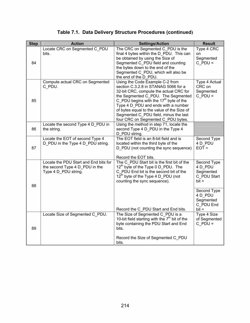
214
Table 7.1. Data Delivery Structure Procedures (continued)
Step Action Settings/Action Result
84
Locate CRC on Segmented C_PDU bits.
The CRC on Segmented C_PDU is the final 4 bytes within the D_PDU. This can be obtained by using the Size of Segmented C_PDU field and counting the bytes down to the end of the Segmented C_PDU, which will also be the end of the D_PDU.
Type 4 CRC on Segmented C_PDU =
85
Compute actual CRC on Segmented C_PDU.
Using the Code Example C-2 from section C.3.2.8 in STANAG 5066 for a 32-bit CRC, compute the actual CRC for the Segmented C_PDU. The Segmented C_PDU begins with the 17th byte of the Type 4 D_PDU and ends with a number of bytes equal to the value of the Size of Segmented C_PDU field, minus the last four CRC on Segmented C_PDU bytes.
Type 4 Actual CRC on Segmented C_PDU =
86 Locate the second Type 4 D_PDU in the string.
Using the method in step 71, locate the second Type 4 D_PDU in the Type 4 D_PDU string.
87
Locate the EOT of second Type 4 D_PDU in the Type 4 D_PDU string.
The EOT field is an 8-bit field and is located within the third byte of the D_PDU (not counting the sync sequence) Record the EOT bits.
Second Type 4 D_PDU EOT =
Second Type 4 D_PDU Segmented C_PDU Start bit = 88
Locate the PDU Start and End bits for the second Type 4 D_PDU in the Type 4 D_PDU string.
The C_PDU Start bit is the first bit of the 12th byte of the Type 0 D_PDU. The C_PDU End bit is the second bit of the 12th byte of the Type 4 D_PDU (not counting the sync sequence). Record the C_PDU Start and End bits.
Second Type 4 D_PDU Segmented C_PDU End bit =
89
Locate Size of Segmented C_PDU. The Size of Segmented C_PDU is a 10-bit field starting with the 7th bit of the byte containing the PDU Start and End bits. Record the Size of Segmented C_PDU bits.
Type 4 Size of Segmented C_PDU =

215
Table 7.1. Data Delivery Structure Procedures (continued)
Step Action Settings/Action Result
90
Locate the TX FSN bits for the second Type 4 D_PDU in the Type 4 D_PDU string.
The TX FSN is an 8-bit field located in the 14th byte of the Type 0 D_PDU (not counting the sync sequence). Record the TX FSN bits for the second Type 4 D_PDU in the Type 4 D_DPU string.
Second Type 4 D_PDU Segmented TX FSN =
91
Record the time from the start of the second Type 4 D_DPU in the Type 4 D_PDU string to the end of the D_PDU string.
Time of Second Type 4 D_PDU =
92
Locate the final Type 4 D_PDU for the C_PDU Segment.
D_PDUs begin with the hex sequence 0x90EB. The first 4 bits, immediately after the 0x90EB sequence, will be the D_PDU Type. For the Type 4 D_PDU, the value will be 0x4 in hex or (MSB) 0100 (LSB) in binary. The final Type 4 D_PDU for the C_PDU Segment can be located by counting down a number of Type 4 D_PDUs equal to the Max Number of D_PDU value.
Final Type 4 D_PDU Segmented C_PDU Start bit = 93
Locate the C_PDU Start and End bits for the final Type 4 D_PDU in the Type 4 D_PDU string.
The C_PDU Start bit is the first bit of the 12th byte of the Type 0 D_PDU. The C_PDU End bit is the second bit of the 12th byte of the Type 4 D_PDU (not counting the sync sequence). Record the C_PDU Start and End bits.
Final Type 4 D_PDU Segmented C_PDU End bit =
94
Locate Size of Segmented C_PDU bits for the final Type 4 D_PDU in the C_PDU Segment.
The Size of Segmented C_PDU is a 10-bit field beginning with the final 2 bits (LSB) of the 12th byte and ending with the LSB of the 13th byte of the Type 4 D_PDU. Record the Size of Segmented C_PDU bits.
Final Type 4 D_PDU Size of Segmented C_PDU bits =
95
Locate the TX FSN bits for the final Type 4 D_PDU in the Type 4 D_PDU string.
The TX FSN is an 8-bit field located in the 14th byte of the Type 4 D_PDU (not counting the sync sequence). Record the TX FSN for the final Type 4 D_PDU in the Type 4 D_DPU string.
Final Type 4 D_PDU Segmented TX FSN =

216
Table 7.1. Data Delivery Structure Procedures (continued)
Step Action Settings/Action Result
96
Locate the final Type 4 D_PDU in the Type 4 D_PDU string.
D_PDUs begin with the hex sequence 0x90EB. The first 4 bits, immediately after the 0x90EB sequence, will be the D_PDU Type. For the Type 4 D_PDU, the value will be 0x4 in hex or (MSB) 0100 (LSB) in binary. Locate the final Type 4 D_PDU in the Type 4 D_PDU string.
97
Locate the EOT of final Type 4 D_PDU in the Type 4 D_PDU string.
The EOT field is an 8-bit field and is located within the third byte of the D_PDU (not counting the sync sequence). Record the EOT bits.
Final Type 4 D_PDU EOT =
98
Locate the time from the start of the final Type 4 D_DPU in the D_PDU string to the end of the D_PDU string.
Using the time stamps from step 14, measure the time from the start of the final Type 4 D_PDU to the end of the Type 4 D_PDU string.
Time of Final Type 4 D_PDU =
99 Compare the TX FSNs from steps 81, 90, and 95.
Are any TX FSNs used more than once in the above string?
Y/N
100
Determine the number of Type 4 D_PDUs transmitted from computer 1.222.123.111 before a Type 5 D_PDU is sent from computer 15.255.255.255.
Count the number of Type 4 D_PDUs in the Type 4 D_PDU string. Record the number of Type 4 D_PDUs in the Type 4 D_PDU string.
Total Number of Type 4 D_PDUs =
The following procedures apply to a Type 6 (Management) D_PDU and are for reference numbers 593, 944 and 945.
101
Configure DRC. Enable the DRC for the STANAG 5066 software. Enable the software to drop the data rate to 75 bps and short interleaving for a “noisy” channel and 600 bps with short interleaving for a “clean” channel.
102 Enable STANAG for DRC capable. Configure STANAG so the DRC is enabled.
103
Resend e-mail message. Resend the e-mail from step 14 using Non-Expedited ARQ Delivery Method. Include an attachment of approximately 10 kbytes.
104
Locate EOT for the first Type 6 D_PDU.
The EOT field is an 8-bit field and is located within the third byte of the D_PDU (not counting the sync sequence). Obtain the EOT for the first Type 6 D_PDU transmitted by computer 1.222.123.111. Multiply the EOT value by 0.5 and record this value in seconds.
First Type 6 D_PDU EOT in seconds =
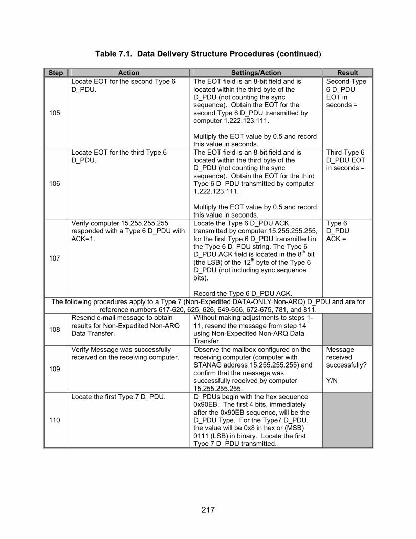
217
Table 7.1. Data Delivery Structure Procedures (continued)
Step Action Settings/Action Result
105
Locate EOT for the second Type 6 D_PDU.
The EOT field is an 8-bit field and is located within the third byte of the D_PDU (not counting the sync sequence). Obtain the EOT for the second Type 6 D_PDU transmitted by computer 1.222.123.111. Multiply the EOT value by 0.5 and record this value in seconds.
Second Type 6 D_PDU EOT in seconds =
106
Locate EOT for the third Type 6 D_PDU.
The EOT field is an 8-bit field and is located within the third byte of the D_PDU (not counting the sync sequence). Obtain the EOT for the third Type 6 D_PDU transmitted by computer 1.222.123.111. Multiply the EOT value by 0.5 and record this value in seconds.
Third Type 6 D_PDU EOT in seconds =
107
Verify computer 15.255.255.255 responded with a Type 6 D_PDU with ACK=1.
Locate the Type 6 D_PDU ACK transmitted by computer 15.255.255.255, for the first Type 6 D_PDU transmitted in the Type 6 D_PDU string. The Type 6 D_PDU ACK field is located in the 8th bit (the LSB) of the 12th byte of the Type 6 D_PDU (not including sync sequence bits). Record the Type 6 D_PDU ACK.
Type 6 D_PDU ACK =
The following procedures apply to a Type 7 (Non-Expedited DATA-ONLY Non-ARQ) D_PDU and are for reference numbers 617-620, 625, 626, 649-656, 672-675, 781, and 811.
108
Resend e-mail message to obtain results for Non-Expedited Non-ARQ Data Transfer.
Without making adjustments to steps 1-11, resend the message from step 14 using Non-Expedited Non-ARQ Data Transfer.
109
Verify Message was successfully received on the receiving computer.
Observe the mailbox configured on the receiving computer (computer with STANAG address 15.255.255.255) and confirm that the message was successfully received by computer 15.255.255.255.
Message received successfully? Y/N
110
Locate the first Type 7 D_PDU. D_PDUs begin with the hex sequence 0x90EB. The first 4 bits, immediately after the 0x90EB sequence, will be the D_PDU Type. For the Type7 D_PDU, the value will be 0x8 in hex or (MSB) 0111 (LSB) in binary. Locate the first Type 7 D_PDU transmitted.

218
Table 7.1. Data Delivery Structure Procedures (continued)
Step Action Settings/Action Result
111
Obtain EOT bits for the Type 7 D_PDU obtained in step 110.
The EOT field is an 8-bit field and is located within the third byte of the D_PDU (not counting the sync sequence). Record the EOT bits.
Type 7 D_PDU EOT =
112
Obtain Type 7 D_PDU Deliver in Order bit for the Type 7 D_PDU transmitted in step 110.
The Deliver in Order bit for the first Type 7 D_PDU transmitted by computer 1.222.123.111, is the fifth bit located in the 12th byte of the Type 7 D_PDU (not including sync sequence). Record the Deliver in Order bit.
Type 7 D_PDU Deliver in Order bit =
113
Locate Size of Segmented C_PDU for the Type 7 D_PDU transmitted in step 110.
The Size of Segmented C_PDU is the next 10 bits, starting with the 7th bit of the 12th byte byte (not counting the sync sequence) of the Type 7 D_PDU. Record the Size of Segmented C_PDU bits.
Type 7 Size of Segmented C_PDU =
114
Identify the number of C_PDU bytes transmitted for the Type 7 D_PDU transmitted in step 110.
Starting with the 23rd byte of the Type 7 D_PDU count the number of bytes to the end of the Type 7 D_PDU. The end is reached when either another D_PDU is encountered, or the end of the transmission. Record the number of actual transmitted bytes.
Number of Actual Transmitted bytes =
115
Locate CRC on Segmented C_PDU bits for the Type 7 D_PDU transmitted in step 110.
The CRC on Segmented C_PDU is the final 4 bytes within the D_PDU. This can be obtained by using the Size of Segmented C_PDU field and counting the bytes down to the end of the Segmented C_PDU, which will also be the end of the D_PDU.
Type 7 CRC on Segmented C_PDU =
116
Compute actual CRC on Segmented C_PDU for the Type 7 D_PDU transmitted in step 110.
Using the Code Example C-2 from section C.3.2.8 in STANAG 5066 for a 32-bit CRC, compute the actual CRC for the Segmented C_PDU. The Segmented C_PDU begins with the 23rd byte of the Type 7 D_PDU and ends with a number of bytes equal to the value of the Size of Segmented C_PDU field, minus the last four CRC on Segmented C_PDU bytes.
Type 7 Actual CRC on Segmented C_PDU =
The following procedures apply to Type 0-2, 4-8, and 15 D_PDUs and are for reference number 624 and 812-815.
117 Reconfigure STANAG 5066. Configure the STANAG 5066 to full
duplex mode and set the frame size to 1024 bytes.
118 Resend the e-mail from step 14 using Non-Expedited ARQ Delivery Method.

219
Table 7.1. Data Delivery Structure Procedures (continued)
Step Action Settings/Action Result
119
Locate D_PDUs. For steps 120-146, D_PDUs are located by first looking for the 0x90EB sync sequence. The next 4 bits, after the sync sequence, are the Type bits.
120
Locate EOT for the first Type 0 D_PDU transmitted.
The EOT field is an 8-bit field and is located within the third byte of the D_PDU (not counting the sync sequence). Obtain the EOT for the Type 0 D_PDU.
Full Duplex Type 0 EOT =
Type 0 C_PDU Start =
121
Locate C_PDU Start and End flags for the Type 0 D_PDU for the first Type 0 D_PDU transmitted.
The C_PDU Start bit is the first bit of the 12th byte of the Type 0 D_PDU. The C_PDU End bit is the second bit of the 12th byte of the Type 0 D_PDU (not counting the sync sequence). Record the C_PDU Start and End bits.
Type 0 C_PDU End =
122
Locate EOT for the Type 1 D_PDU. The EOT field is an 8-bit field and is located within the third byte of the D_PDU (not counting the sync sequence). Record the EOT for the Type 1 D_PDU.
Full Duplex Type 1 EOT =
123
Locate EOT for the Type 2 D_PDU. The EOT field is an 8-bit field and is located within the third byte of the D_PDU (not counting the sync sequence). Record the EOT for the Type 2 D_PDU.
Full Duplex Type 2 EOT =
124
Locate EOT for the Type 8 D_PDU. The EOT field is an 8-bit field and is located within the third byte of the D_PDU (not counting the sync sequence). Record the EOT for the Type 8 D_PDU.
Full Duplex Type 8 EOT =
125
Obtain Type 0 D_PDU Deliver in Order bit for the first Type 0 D_PDU transmitted.
The Deliver in Order bit for the first Type 0 D_PDU is the fifth bit located in the 12th byte of the Type 0 D_PDU (not including sync sequence). Record the Deliver in Order bit.
Type 0 D_PDU Deliver in Order bit =
126 Resend the e-mail from step 14 using Expedited ARQ Delivery Method.
127
Locate EOT for the Type 4 D_PDU. The EOT field is an 8-bit field and is located within the third byte of the D_PDU (not counting the sync sequence). Record the EOT for the Type 4 D_PDU.
Full Duplex Type 4 EOT =

220
Table 7.1. Data Delivery Structure Procedures (continued)
Step Action Settings/Action Result Type 4 C_PDU Start = 128
Locate C_PDU Start and End flags for the first Type 4 D_PDU transmitted.
The C_PDU Start bit is the first bit of the 12th byte of the Type 4 D_PDU. The C_PDU End bit is the second bit of the 12th byte of the Type 4 D_PDU (not counting the sync sequence). Record the C_PDU Start and End bits.
Type 4 C_PDU End =
129
Locate EOT for the Type 5 D_PDU. The EOT field is an 8-bit field and is located within the third byte of the D_PDU (not counting the sync sequence). Record the EOT for the Type 5 D_PDU.
Full Duplex Type 5 EOT =
130
Configure DRC. Enable the DRC for the STANAG 5066 software. Enable the software to drop the data rate to 75 bps and short interleaving for a “noisy” channel and 600 bps with short interleaving for a “clean” channel.
131 Enable STANAG for DRC capable. Configure STANAG so that the DRC is enabled.
132 Resend the e-mail from step 14 using Non-Expedited ARQ Delivery Method.
133
Locate EOT for the Type 6 D_PDU. The EOT field is an 8-bit field and is located within the third byte of the D_PDU (not counting the sync sequence). Record the EOT for the Type 6 D_PDU.
Full Duplex Type 6 EOT =
134 Resend the e-mail from step 14 using Non-Expedited Non-ARQ Delivery Method.
135
Locate EOT for the Type 7 D_PDU. The EOT field is an 8-bit field and is located within the third byte of the D_PDU (not counting the sync sequence). Record the EOT for the Type 7 D_PDU.
Full Duplex Type 7 EOT =
The following procedures apply to a Type 15 D_PDU and are for reference number 593 and 624.
136
Reconfigure equipment. See figure 7.6. Configure the protocol analyzer connected solely to the modem to inject data packets to the computer. The computer and protocol analyzer A configured to be a data injector is connected to the modems by an RS-232 connection. The connection between modems shall be such that the receive and transmit pins on the modem are connected to the transmit and receive pins, respectively, of the other modem.

221
Table 7.1. Data Delivery Structure Procedures (continued)
Step Action Settings/Action Result
137 Reconfigure STANAG address. Configure the STANAG address of the computer to 1.1.0.0.
138
Inject data packet. Transmit the following data packet from the data packet injector to the STANAG computer: 90 EB 04 2C 00 E9 00 00 10 10 00 01 02 EF CF 00 EB 1B 00 00 33 44 7A 07 45 48 4C 4F 20 6B 69 6C 62 6F 75 72 6E 65 2E 6C 65 67 65 6E 64 73 2E 6E 69 74 2E 42 2A 66 7F Save the data obtained through the analyzer to a file.
139
Locate EOT for the Type 15 D_PDU. The EOT field is an 8-bit field and is located within the third byte of the D_PDU (not counting the sync sequence). Record the EOT for the Type 15 D_PDU.
Full Duplex Type 15 EOT =
The following procedures apply to a Type 3 D_PDU and are for reference number 593 and 624.
140 Reconfigure STANAG 5066. Configure the STANAG 5066 to full
duplex mode and set the frame size to 1023 bytes.
141
Inject data packet. Transmit the following data packet from the data packet injector to the STANAG computer: 90 EB 80 00 00 EF 00 00 10 10 00 01 02 00 01 01 00 01 00 00 01 18 74 5A 10 AA 9C 74 1E
142
Inject Type 3 D_PDU data packet. After the STANAG computer transmits its response to the Type 8 D_PDU injected in step 141, transmit the following data packet from the data packet injector to the STANAG computer: 90 EB 34 2C 00 E9 00 00 10 10 00 01 02 02 00 01 0F 20 Save the data obtained through the analyzer to a file.
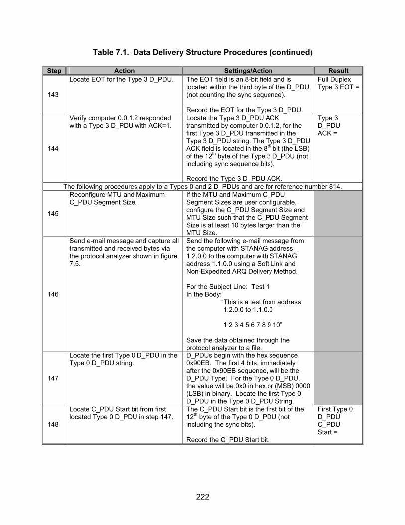
222
Table 7.1. Data Delivery Structure Procedures (continued)
Step Action Settings/Action Result
143
Locate EOT for the Type 3 D_PDU. The EOT field is an 8-bit field and is located within the third byte of the D_PDU (not counting the sync sequence). Record the EOT for the Type 3 D_PDU.
Full Duplex Type 3 EOT =
144
Verify computer 0.0.1.2 responded with a Type 3 D_PDU with ACK=1.
Locate the Type 3 D_PDU ACK transmitted by computer 0.0.1.2, for the first Type 3 D_PDU transmitted in the Type 3 D_PDU string. The Type 3 D_PDU ACK field is located in the 8th bit (the LSB) of the 12th byte of the Type 3 D_PDU (not including sync sequence bits). Record the Type 3 D_PDU ACK.
Type 3 D_PDU ACK =
The following procedures apply to a Types 0 and 2 D_PDUs and are for reference number 814.
145
Reconfigure MTU and Maximum C_PDU Segment Size.
If the MTU and Maximum C_PDU Segment Sizes are user configurable, configure the C_PDU Segment Size and MTU Size such that the C_PDU Segment Size is at least 10 bytes larger than the MTU Size.
146
Send e-mail message and capture all transmitted and received bytes via the protocol analyzer shown in figure 7.5.
Send the following e-mail message from the computer with STANAG address 1.2.0.0 to the computer with STANAG address 1.1.0.0 using a Soft Link and Non-Expedited ARQ Delivery Method. For the Subject Line: Test 1 In the Body: “This is a test from address 1.2.0.0 to 1.1.0.0 1 2 3 4 5 6 7 8 9 10” Save the data obtained through the protocol analyzer to a file.
147
Locate the first Type 0 D_PDU in the Type 0 D_PDU string.
D_PDUs begin with the hex sequence 0x90EB. The first 4 bits, immediately after the 0x90EB sequence, will be the D_PDU Type. For the Type 0 D_PDU, the value will be 0x0 in hex or (MSB) 0000 (LSB) in binary. Locate the first Type 0 D_PDU in the Type 0 D_PDU String.
148
Locate C_PDU Start bit from first located Type 0 D_PDU in step 147.
The C_PDU Start bit is the first bit of the 12th byte of the Type 0 D_PDU (not including the sync bits). Record the C_PDU Start bit.
First Type 0 D_PDU C_PDU Start =

223
Table 7.1. Data Delivery Structure Procedures (continued)
Step Action Settings/Action Result
149
Locate C_PDU End bit from first located Type 0 D_PDU in step 147.
The next bit, after the C_PDU Start bit, is the C_PDU End bit. Record the C_PDU End bit.
First Type 0 D_PDU C_PDU End =
The following procedures apply to a Type 4 D_PDU and are for reference number 814.
150
Send e-mail message and capture all transmitted and received bytes via the protocol analyzer shown in figure 7.5.
Send the following e-mail message from the computer with STANAG address 1.2.0.0 to the computer with STANAG address 1.1.0.0 using a Soft Link and Expedited ARQ Delivery Method. For the Subject Line: Test 1 In the Body: “This is a test from address 1.2.0.0 to 1.1.0.0 1 2 3 4 5 6 7 8 9 10” Save the data obtained through the protocol analyzer to a file.
151
Locate the first Type 4 D_PDU in the Type 4 D_PDU string.
D_PDUs begin with the hex sequence 0x90EB. The first 4 bits, immediately after the 0x90EB sequence, will be the D_PDU Type. For the Type 4 D_PDU, the value will be 0x0 in hex or (MSB) 0100 (LSB) in binary. Locate the first Type 4 D_PDU in the Type 4 D_PDU string.
152
Locate C_PDU Start bit from first located Type 4 D_PDU in step 151.
The C_PDU Start bit is the first bit of the 12th byte of the Type 4 D_PDU (not including the sync bits). Record the C_PDU Start bit.
First Type 4 D_PDU C_PDU Start =
153
Locate C_PDU End bit from first located Type 4 D_PDU in step 151.
The next bit, after the C_PDU Start bit, is the C_PDU End bit. Record the C_PDU End bit.
First Type 4 D_PDU C_PDU End =
Reference numbers 665-667 and 781 are currently underdevelopment, and their results are to be developed.
Legend: ACK—Acknowledgement ARQ—Automatic Repeat-Request bps—bits per second C_PDU—Channel Access Sublayer Protocol Data Unit CRC—Cyclic Redundancy Check D_PDU—Data Transfer Sublayer Protocol Data Unit DRC—Data Rate Change EOT—End of Transmission e-mail—Electronic Mail FSN—Frame Sequence Number hex—hexadecimal kbytes—kilobytes
LSB—Least Significant Bit LWE—Lower Window Edge MIL-STD—Military Standard MSB—Most Significant Bit MTU—Maximum Transmission Unit POP3—Post Office Protocol 3 S_PDU—Subnetwork Sublayer Protocol Data Unit SMTP—Simple Mail Transfer Protocol STANAG—Standardization Agreement sync—synchronization TX—Transmit UWE—Upper Window Edge
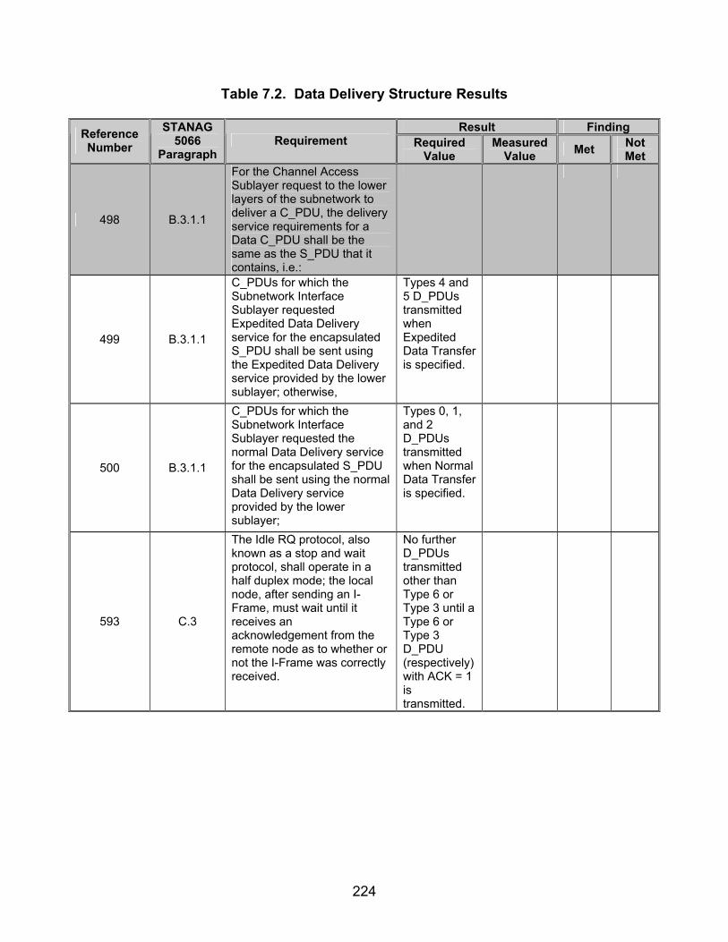
224
Table 7.2. Data Delivery Structure Results
Result Finding Reference Number
STANAG 5066
Paragraph Requirement Required
Value Measured
Value Met Not Met
498 B.3.1.1
For the Channel Access Sublayer request to the lower layers of the subnetwork to deliver a C_PDU, the delivery service requirements for a Data C_PDU shall be the same as the S_PDU that it contains, i.e.:
499 B.3.1.1
C_PDUs for which the Subnetwork Interface Sublayer requested Expedited Data Delivery service for the encapsulated S_PDU shall be sent using the Expedited Data Delivery service provided by the lower sublayer; otherwise,
Types 4 and 5 D_PDUs transmitted when Expedited Data Transfer is specified.
500 B.3.1.1
C_PDUs for which the Subnetwork Interface Sublayer requested the normal Data Delivery service for the encapsulated S_PDU shall be sent using the normal Data Delivery service provided by the lower sublayer;
Types 0, 1, and 2 D_PDUs transmitted when Normal Data Transfer is specified.
593 C.3
The Idle RQ protocol, also known as a stop and wait protocol, shall operate in a half duplex mode; the local node, after sending an I-Frame, must wait until it receives an acknowledgement from the remote node as to whether or not the I-Frame was correctly received.
No further D_PDUs transmitted other than Type 6 or Type 3 until a Type 6 or Type 3 D_PDU (respectively)with ACK = 1 is transmitted.
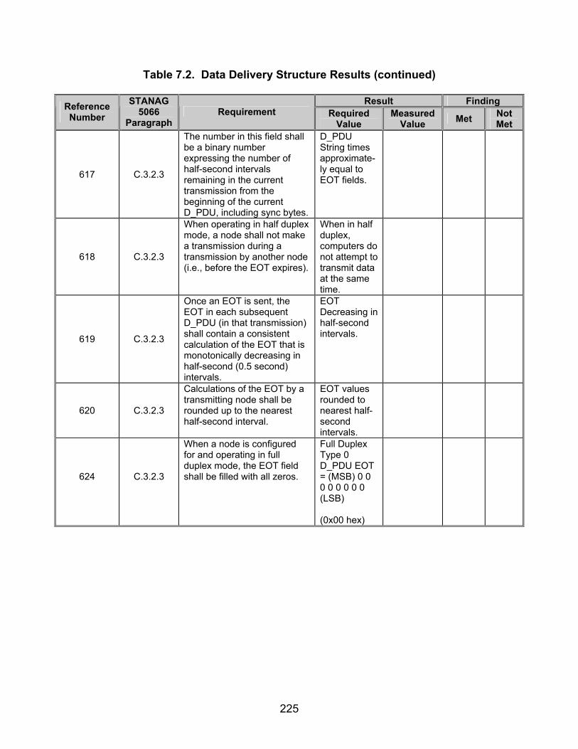
225
Table 7.2. Data Delivery Structure Results (continued)
Result Finding Reference Number
STANAG 5066
Paragraph Requirement Required
Value Measured
Value Met Not Met
617 C.3.2.3
The number in this field shall be a binary number expressing the number of half-second intervals remaining in the current transmission from the beginning of the current D_PDU, including sync bytes.
D_PDU String times approximate-ly equal to EOT fields.
618 C.3.2.3
When operating in half duplex mode, a node shall not make a transmission during a transmission by another node (i.e., before the EOT expires).
When in half duplex, computers do not attempt to transmit data at the same time.
619 C.3.2.3
Once an EOT is sent, the EOT in each subsequent D_PDU (in that transmission) shall contain a consistent calculation of the EOT that is monotonically decreasing in half-second (0.5 second) intervals.
EOT Decreasing in half-second intervals.
620 C.3.2.3
Calculations of the EOT by a transmitting node shall be rounded up to the nearest half-second interval.
EOT values rounded to nearest half-second intervals.
624
C.3.2.3
When a node is configured for and operating in full duplex mode, the EOT field shall be filled with all zeros.
Full Duplex Type 0 D_PDU EOT = (MSB) 0 0 0 0 0 0 0 0 (LSB) (0x00 hex)
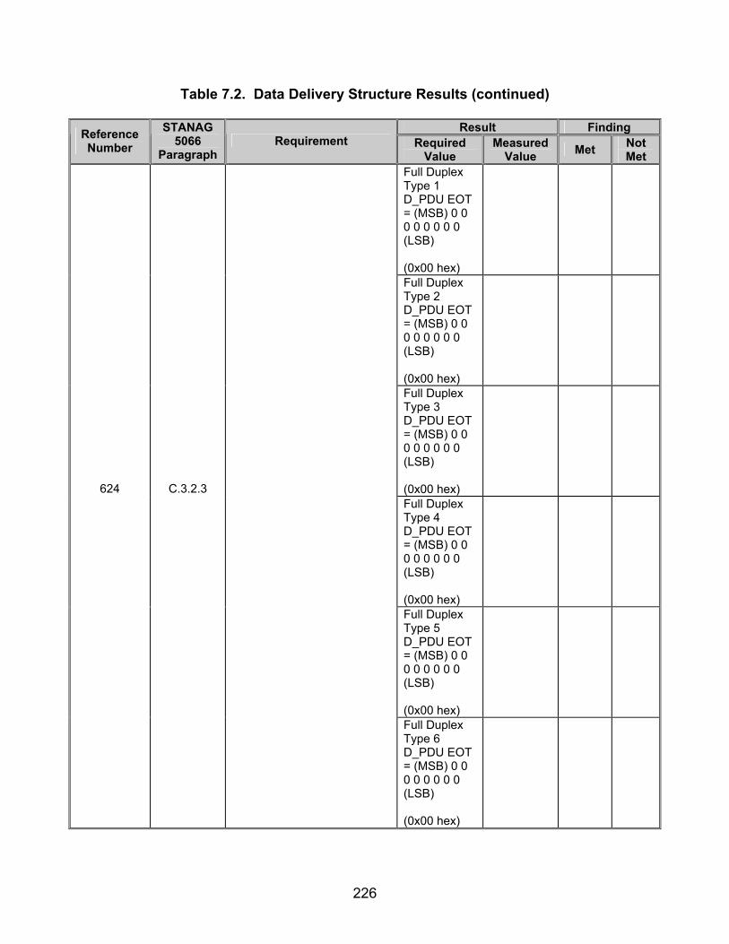
226
Table 7.2. Data Delivery Structure Results (continued)
Result Finding Reference Number
STANAG 5066
Paragraph Requirement Required
Value Measured
Value Met Not Met
Full Duplex Type 1 D_PDU EOT = (MSB) 0 0 0 0 0 0 0 0 (LSB) (0x00 hex)
Full Duplex Type 2 D_PDU EOT = (MSB) 0 0 0 0 0 0 0 0 (LSB) (0x00 hex)
Full Duplex Type 3 D_PDU EOT = (MSB) 0 0 0 0 0 0 0 0 (LSB) (0x00 hex)
Full Duplex Type 4 D_PDU EOT = (MSB) 0 0 0 0 0 0 0 0 (LSB) (0x00 hex)
Full Duplex Type 5 D_PDU EOT = (MSB) 0 0 0 0 0 0 0 0 (LSB) (0x00 hex)
624
C.3.2.3
Full Duplex Type 6 D_PDU EOT = (MSB) 0 0 0 0 0 0 0 0 (LSB) (0x00 hex)
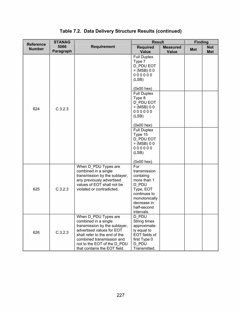
227
Table 7.2. Data Delivery Structure Results (continued)
Result Finding Reference Number
STANAG 5066
Paragraph Requirement Required
Value Measured
Value Met Not Met
Full Duplex Type 7 D_PDU EOT = (MSB) 0 0 0 0 0 0 0 0 (LSB) (0x00 hex)
Full Duplex Type 8 D_PDU EOT = (MSB) 0 0 0 0 0 0 0 0 (LSB) (0x00 hex)
624 C.3.2.3
Full Duplex Type 15 D_PDU EOT = (MSB) 0 0 0 0 0 0 0 0 (LSB) (0x00 hex)
625 C.3.2.3
When D_PDU Types are combined in a single transmission by the sublayer, any previously advertised values of EOT shall not be violated or contradicted.
For transmission contaiing more than 1 D_PDU Type, EOT continues to monotonically decrease in half-second intervals.
626 C.3.2.3
When D_PDU Types are combined in a single transmission by the sublayer, advertised values for EOT shall refer to the end of the combined transmission and not to the EOT of the D_PDU that contains the EOT field.
D_PDU String times approximate-ly equal to EOT fields of first Type 0 D_PDU Transmitted.

228
Table 7.2. Data Delivery Structure Results (continued)
Result Finding Reference Number
STANAG 5066
Paragraph Requirement Required
Value Measured
Value Met Not Met
D_PDU String times approximate-ly equal to EOT fields of first Type 1 D_PDU Transmitted.
D_PDU String times approximate-ly equal to EOT fields of first Type 2 D_PDU Transmitted.
D_PDU String times approximate-ly equal to EOT fields of first Type 3 D_PDU Transmitted.
D_PDU String times approximate-ly equal to EOT fields of first Type 4 D_PDU Transmitted.
D_PDU String times approximate-ly equal to EOT fields of first Type 5 D_PDU Transmitted.
626 C.3.2.3
D_PDU String times approximate-ly equal to EOT fields of first Type 6 D_PDU Transmitted.
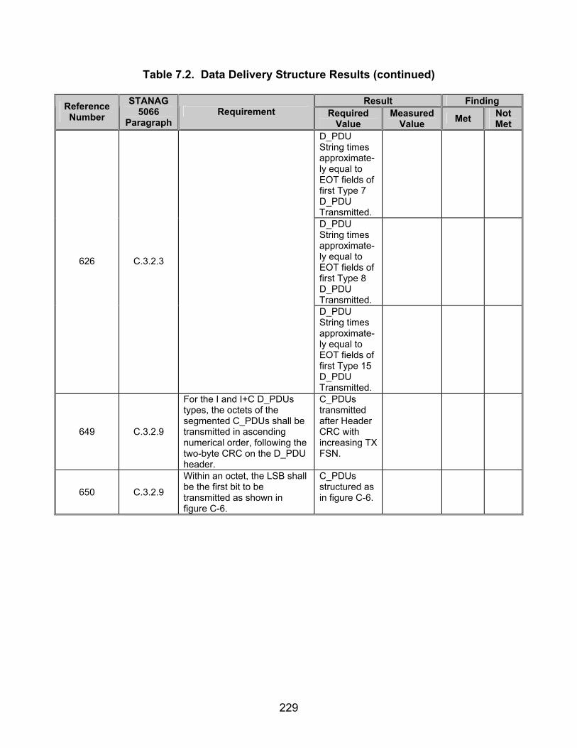
229
Table 7.2. Data Delivery Structure Results (continued)
Result Finding Reference Number
STANAG 5066
Paragraph Requirement Required
Value Measured
Value Met Not Met
D_PDU String times approximate-ly equal to EOT fields of first Type 7 D_PDU Transmitted.
D_PDU String times approximate-ly equal to EOT fields of first Type 8 D_PDU Transmitted.
626 C.3.2.3
D_PDU String times approximate-ly equal to EOT fields of first Type 15 D_PDU Transmitted.
649 C.3.2.9
For the I and I+C D_PDUs types, the octets of the segmented C_PDUs shall be transmitted in ascending numerical order, following the two-byte CRC on the D_PDU header.
C_PDUs transmitted after Header CRC with increasing TX FSN.
650 C.3.2.9
Within an octet, the LSB shall be the first bit to be transmitted as shown in figure C-6.
C_PDUs structured as in figure C-6.

230
Table 7.2. Data Delivery Structure Results (continued)
Result Finding Reference Number
STANAG 5066
Paragraph Requirement Required
Value Measured
Value Met Not Met
651 C.3.2.10
The Size Of Segmented C_PDU field shall be used only with D_PDUs that are I or I+C-Frame types, i.e., that have a Segmented C_PDU field as shown in figure C-2(b).
Only D_PDUs 0, 2, 4, 7, and 8 contain a Size of Segmented C_PDU field.
Size of Segmented C_PDU = Vendor’s Maximum Segmented C_PDU Size for Types 0, 4, and 7 D_PDUs.
Size of Sgmented C_PDU = 1 byte for Type 8 D_PDU.
652 C.3.2.10
The bit-value of the Size Of Segmented C_PDU shall be encoded as a ten-bit field as indicated by figure C-7.
The Size of Segmented C_PDU value for the Type 2 D_PDU will be variable depending on the vendor’s implimenta-tion as well as the client type used.
N/A
653 C.3.2.10
The value in the Size Of Segmented C_PDU field shall not include the two-bytes for the CRC following the Segmented C_PDU. The Segmented C_PDU field can hold a maximum of 1023 bytes from the segmented C_PDU.
For Type 0 D_PDU Number of bytes transmitted + Type 0 C_PDU and Type 0 S_PDU bytes = Size of Segmented C_PDU.
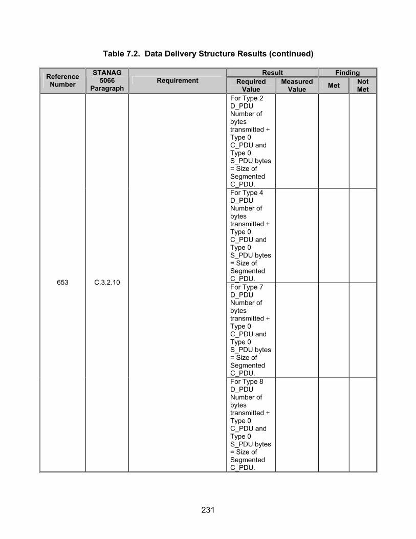
231
Table 7.2. Data Delivery Structure Results (continued)
Result Finding Reference Number
STANAG 5066
Paragraph Requirement Required
Value Measured
Value Met Not Met
For Type 2 D_PDU Number of bytes transmitted + Type 0 C_PDU and Type 0 S_PDU bytes = Size of Segmented C_PDU.
For Type 4 D_PDU Number of bytes transmitted + Type 0 C_PDU and Type 0 S_PDU bytes = Size of Segmented C_PDU.
For Type 7 D_PDU Number of bytes transmitted + Type 0 C_PDU and Type 0 S_PDU bytes = Size of Segmented C_PDU.
653 C.3.2.10
For Type 8 D_PDU Number of bytes transmitted + Type 0 C_PDU and Type 0 S_PDU bytes = Size of Segmented C_PDU.

232
Table 7.2. Data Delivery Structure Results (continued)
Result Finding Reference Number
STANAG 5066
Paragraph Requirement Required
Value Measured
Value Met Not Met
654 C.3.2.10
The Size Of Segmented C_PDU shall be mapped into consecutive bytes of the D_PDU as indicated in figure C-8, in the byte locations specified for the applicable D_PDU.
Size of Segmented C_PDU Mapped as specified in figure 7.2.
Use table 7.8.
655 C.3.2.11
The last four bytes of any I, or I+C D_PDU shall contain a 32-bit Cyclic Redundancy Check (CRC) field.
CRC contained in last 4 bytes for Types 0, 2, 4, 7, and 8 D_PDUs.
Type 0 D_PDU CRC on Segmented C_PDU = Actual CRC on Segmented C_PDU.
Type 2 D_PDU CRC on Segmented C_PDU = Actual CRC on Segmented C_PDU.
Type 4 D_PDU CRC on Segmented C_PDU = Actual CRC on Segmented C_PDU.
656
C.3.2.11
The CRC shall be applied and computed on the contents of the Segmented C_PDU using the following polynomial [See footnote 2 in STANAG 5066]: x^32 + x^27 + x^25 + x^23 + x^21 + x^18 + x^17 + x^16 + x^13 + x^10 + x^8 + x^7 + x^6 + x^3 + x^2 + x + 1, or in hexadecimal notation: 0x10AA725CF, using the shift-register method similar to that shown by the figures in appendix I of CCITT Recommendation V.41.
Type 7 D_PDU CRC on Segmented C_PDU = Actual CRC on Segmented C_PDU.
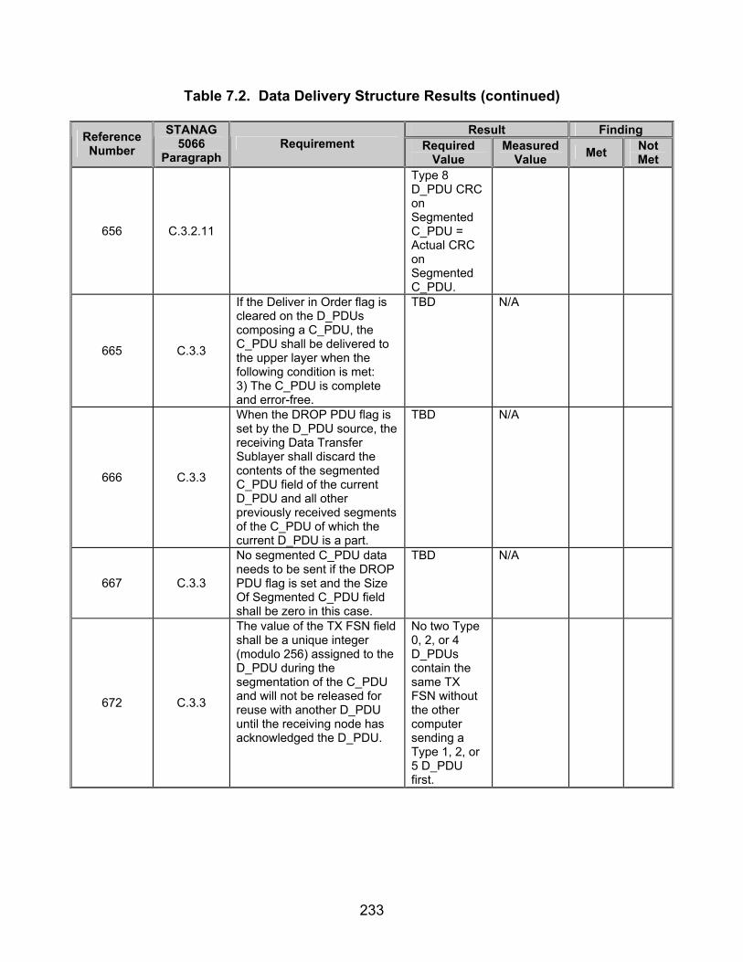
233
Table 7.2. Data Delivery Structure Results (continued)
Result Finding Reference Number
STANAG 5066
Paragraph Requirement Required
Value Measured
Value Met Not Met
656 C.3.2.11
Type 8 D_PDU CRC on Segmented C_PDU = Actual CRC on Segmented C_PDU.
665 C.3.3
If the Deliver in Order flag is cleared on the D_PDUs composing a C_PDU, the C_PDU shall be delivered to the upper layer when the following condition is met: 3) The C_PDU is complete and error-free.
TBD N/A
666 C.3.3
When the DROP PDU flag is set by the D_PDU source, the receiving Data Transfer Sublayer shall discard the contents of the segmented C_PDU field of the current D_PDU and all other previously received segments of the C_PDU of which the current D_PDU is a part.
TBD N/A
667 C.3.3
No segmented C_PDU data needs to be sent if the DROP PDU flag is set and the Size Of Segmented C_PDU field shall be zero in this case.
TBD N/A
672 C.3.3
The value of the TX FSN field shall be a unique integer (modulo 256) assigned to the D_PDU during the segmentation of the C_PDU and will not be released for reuse with another D_PDU until the receiving node has acknowledged the D_PDU.
No two Type 0, 2, or 4 D_PDUs contain the same TX FSN without the other computer sending a Type 1, 2, or 5 D_PDU first.
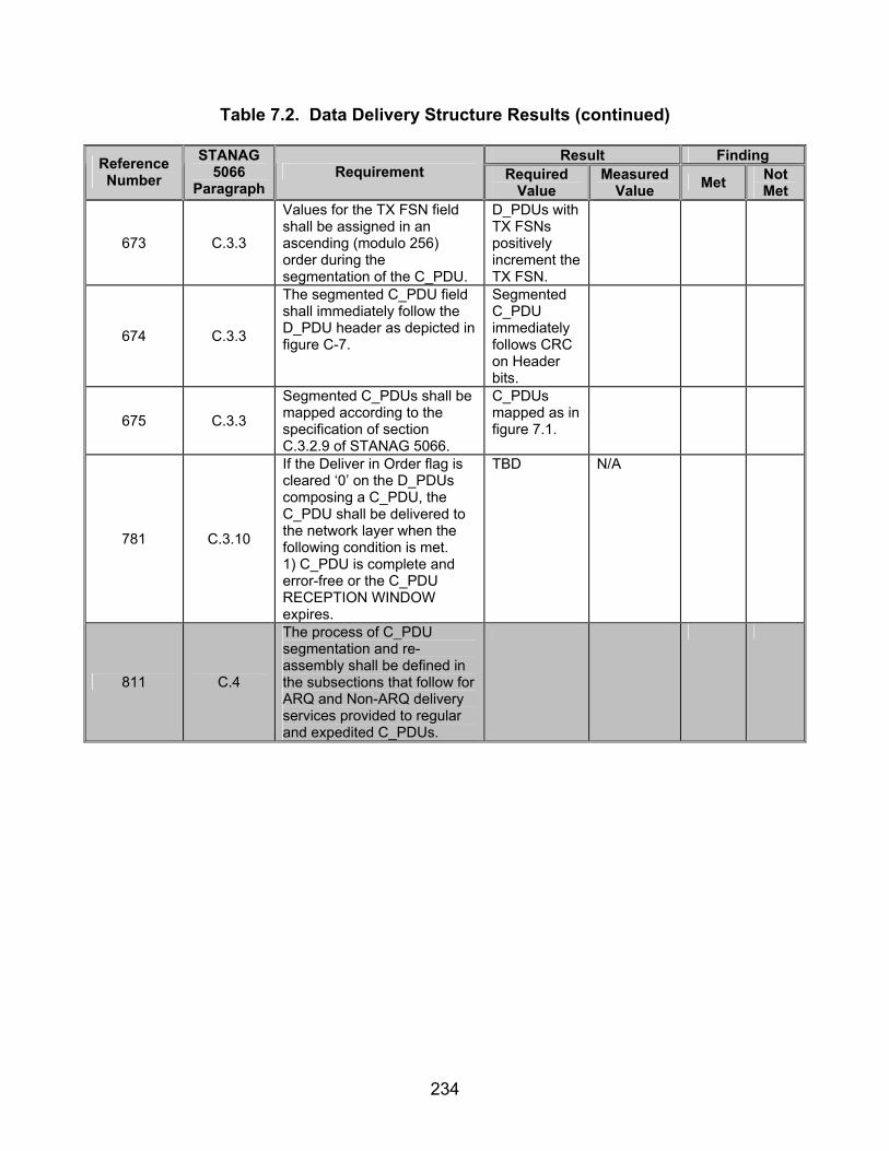
234
Table 7.2. Data Delivery Structure Results (continued)
Result Finding Reference Number
STANAG 5066
Paragraph Requirement Required
Value Measured
Value Met Not Met
673 C.3.3
Values for the TX FSN field shall be assigned in an ascending (modulo 256) order during the segmentation of the C_PDU.
D_PDUs with TX FSNs positively increment the TX FSN.
674 C.3.3
The segmented C_PDU field shall immediately follow the D_PDU header as depicted in figure C-7.
Segmented C_PDU immediately follows CRC on Header bits.
675 C.3.3
Segmented C_PDUs shall be mapped according to the specification of section C.3.2.9 of STANAG 5066.
C_PDUs mapped as in figure 7.1.
781 C.3.10
If the Deliver in Order flag is cleared ‘0’ on the D_PDUs composing a C_PDU, the C_PDU shall be delivered to the network layer when the following condition is met. 1) C_PDU is complete and error-free or the C_PDU RECEPTION WINDOW expires.
TBD N/A
811 C.4
The process of C_PDU segmentation and re-assembly shall be defined in the subsections that follow for ARQ and Non-ARQ delivery services provided to regular and expedited C_PDUs.
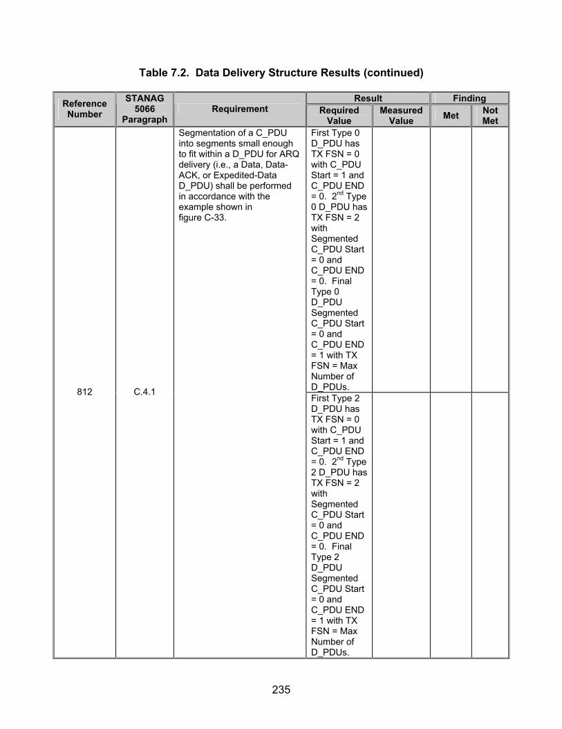
235
Table 7.2. Data Delivery Structure Results (continued)
Result Finding Reference Number
STANAG 5066
Paragraph Requirement Required
Value Measured
Value Met Not Met
First Type 0 D_PDU has TX FSN = 0 with C_PDU Start = 1 and C_PDU END = 0. 2nd Type 0 D_PDU has TX FSN = 2 with Segmented C_PDU Start = 0 and C_PDU END = 0. Final Type 0 D_PDU Segmented C_PDU Start = 0 and C_PDU END = 1 with TX FSN = Max Number of D_PDUs.
812 C.4.1
Segmentation of a C_PDU into segments small enough to fit within a D_PDU for ARQ delivery (i.e., a Data, Data-ACK, or Expedited-Data D_PDU) shall be performed in accordance with the example shown in figure C-33.
First Type 2 D_PDU has TX FSN = 0 with C_PDU Start = 1 and C_PDU END = 0. 2nd Type 2 D_PDU has TX FSN = 2 with Segmented C_PDU Start = 0 and C_PDU END = 0. Final Type 2 D_PDU Segmented C_PDU Start = 0 and C_PDU END = 1 with TX FSN = Max Number of D_PDUs.

236
Table 7.2. Data Delivery Structure Results (continued)
Result Finding Reference Number
STANAG 5066
Paragraph Requirement Required
Value Measured
Value Met Not Met
812 C.1.4
First Type 4 D_PDU has TX FSN = 0 with C_PDU Start = 1 and C_PDU END = 0. 2nd Type 4 D_PDU has TX FSN = 2 with Segmented C_PDU Start = 0 and C_PDU END = 0. Final Type 4 D_PDU Segmented C_PDU Start = 0 and C_PDU END = 1 with TX FSN = Max Number of D_PDUs.
813 C.4.1
The Maximum C_PDU Segment size within a D_PDU for ARQ-Delivery services shall be a configurable parameter no greater than 1023 bytes in any implementation compliant with this STANAG. An implementation may configure the Maximum C_PDU Segment size to match the interleaver size for optimum channel efficiency or other reasons.
Vendor’s Size of Segmented C_PDU < 1023 bytes for Type 0 C_PDU.
814 C.4.1
An entire C_PDU that is smaller than the Maximum C_PDU Segment size shall be placed in the C_PDU segment of a single D_PDU.
When MTU configured less than the Maximum C_PDU Segment Size, C_PDU Start and End flags = 1.

237
Table 7.2. Data Delivery Structure Results (continued)
Result Finding Reference Number
STANAG 5066
Paragraph Requirement Required
Value Measured
Value Met Not Met
When MTU configured less than the Maximum C_PDU Segment Size, C_PDU Start and End flags = 1 for Type 0 D_PDU.
When MTU configured less than the Maximum C_PDU Segment Size, C_PDU Start and End flags = 1 for Type 2 D_PDU.
815 C.4.1
A Data or Data-ACK, or Expedited D_PDU that contain an entire C_DPU shall be marked with the both C_PDU Start field and the C_PDU End field set equal to the value (1) (Note: An ‘only’ C_PDU segment is both the “first” and “last” segment of a sequence of one.)
When MTU configured less than the Maximum C_PDU Segment Size, C_PDU Start and End flags = 1 for Type 4 D_PDU.
816 C.4.1
The Data Transfer Sublayer shall divide C_PDUs larger than the Maximum C_PDU Segment size into segments that are no larger than the Maximum C_PDU Segment size.
All C_PDU Segments ≤ Maximum C_PDU Segment Size.
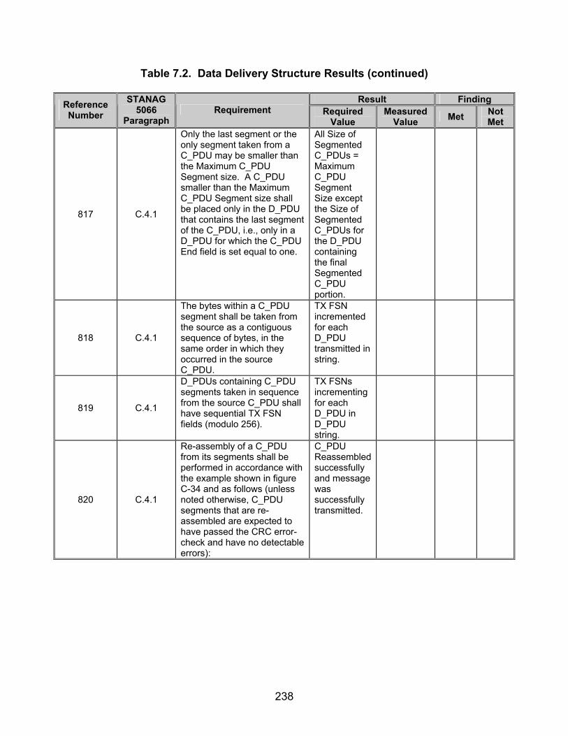
238
Table 7.2. Data Delivery Structure Results (continued)
Result Finding Reference Number
STANAG 5066
Paragraph Requirement Required
Value Measured
Value Met Not Met
817 C.4.1
Only the last segment or the only segment taken from a C_PDU may be smaller than the Maximum C_PDU Segment size. A C_PDU smaller than the Maximum C_PDU Segment size shall be placed only in the D_PDU that contains the last segment of the C_PDU, i.e., only in a D_PDU for which the C_PDU End field is set equal to one.
All Size of Segmented C_PDUs = Maximum C_PDU Segment Size except the Size of Segmented C_PDUs for the D_PDU containing the final Segmented C_PDU portion.
818 C.4.1
The bytes within a C_PDU segment shall be taken from the source as a contiguous sequence of bytes, in the same order in which they occurred in the source C_PDU.
TX FSN incremented for each D_PDU transmitted in string.
819 C.4.1
D_PDUs containing C_PDU segments taken in sequence from the source C_PDU shall have sequential TX FSN fields (modulo 256).
TX FSNs incrementing for each D_PDU in D_PDU string.
820 C.4.1
Re-assembly of a C_PDU from its segments shall be performed in accordance with the example shown in figure C-34 and as follows (unless noted otherwise, C_PDU segments that are re-assembled are expected to have passed the CRC error-check and have no detectable errors):
C_PDU Reassembled successfully and message was successfully transmitted.

239
Table 7.2. Data Delivery Structure Results (continued)
Result Finding Reference Number
STANAG 5066
Paragraph Requirement Required
Value Measured
Value Met Not Met
821 C.4.1
The re-assembly process for C_PDUs receiving ARQ service shall use the TX FSN field, C_PDU Start flag, and C_PDU End flag to determine when all segments of a C_PDU have been received.
First D_DPU in D_DPU string has C_PDU Start flag = 1 with C_PDU End Flag = 0 and the Final D_PDU in D_PDU string has C_PDU Start Flag = 0 with C_PDU End Flag = 1.
825 C.4.1
A segment from a C_PDU larger than the Maximum C_PDU Segment Size shall be combined in modulo 256 order with other segments whose D_PDU FSN lie in the range defined by the FSN of the C_DPU Start and C_PDU End segments;
With MTU > Maximum Segmented C_PDU Size, first Type 0 D_PDU Segmented C_PDU Start bit = 1, 2nd Type 0 D_PDU Segmented C_PDU Start bit = 0, and Final Type 0 D_PDU Segmented C_PDU Start bit = 0.
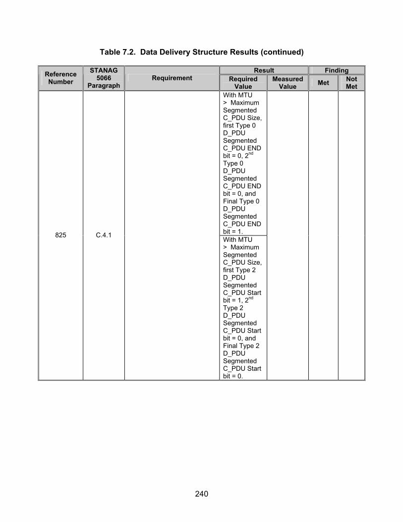
240
Table 7.2. Data Delivery Structure Results (continued)
Result Finding Reference Number
STANAG 5066
Paragraph Requirement Required
Value Measured
Value Met Not Met
With MTU > Maximum Segmented C_PDU Size, first Type 0 D_PDU Segmented C_PDU END bit = 0, 2nd Type 0 D_PDU Segmented C_PDU END bit = 0, and Final Type 0 D_PDU Segmented C_PDU END bit = 1. 825 C.4.1
With MTU > Maximum Segmented C_PDU Size, first Type 2 D_PDU Segmented C_PDU Start bit = 1, 2nd Type 2 D_PDU Segmented C_PDU Start bit = 0, and Final Type 2 D_PDU Segmented C_PDU Start bit = 0.

241
Table 7.2. Data Delivery Structure Results (continued)
Result Finding Reference Number
STANAG 5066
Paragraph Requirement Required
Value Measured
Value Met Not Met
With MTU > Maximum Segmented C_PDU Size, first Type 2 D_PDU Segmented C_PDU END bit = 0, 2nd Type 2 D_PDU Segmented C_PDU END bit = 0, and Final Type 2 D_PDU Segmented C_PDU END bit = 1. 825 C.4.1
With MTU > Maximum Segmented C_PDU Size, first Type 4 D_PDU Segmented C_PDU Start bit = 1, 2nd Type 4 D_PDU Segmented C_PDU Start bit = 0, and Final Type 4 D_PDU Segmented C_PDU Start bit = 0.

242
Table 7.2. Data Delivery Structure Results (continued)
Result Finding Reference Number
STANAG 5066
Paragraph Requirement Required
Value Measured
Value Met Not Met
825 C.4.1
With MTU > Maximum Segmented C_PDU Size, first Type 4 D_PDU Segmented C_PDU END bit = 0, 2nd Type 4 D_PDU Segmented C_PDU END bit = 0, and Final Type 4 D_PDU Segmented C_PDU END bit = 1.
843 C.4.1
Delivery of the re-assembled D_PDU shall be performed with the D_Primitive appropriate for the type of data (i.e., regular or expedited) received.
Type 0, 2, and 7 D_PDUs used to transmit regular data and Types 4 and 8 D_PDUs used to transmit expedited data.
898 C.6.2
The Data Transfer Sublayer shall satisfy the following requirements for D_PDU flow-control:
900 C.6.2
The TX FSNs shall be assigned uniquely and sequentially in an ascending (modulo 256) order during the segmentation of the C_PDU into D_PDUs.
D_PDUs with TX FSNs positively increment the TX FSN.
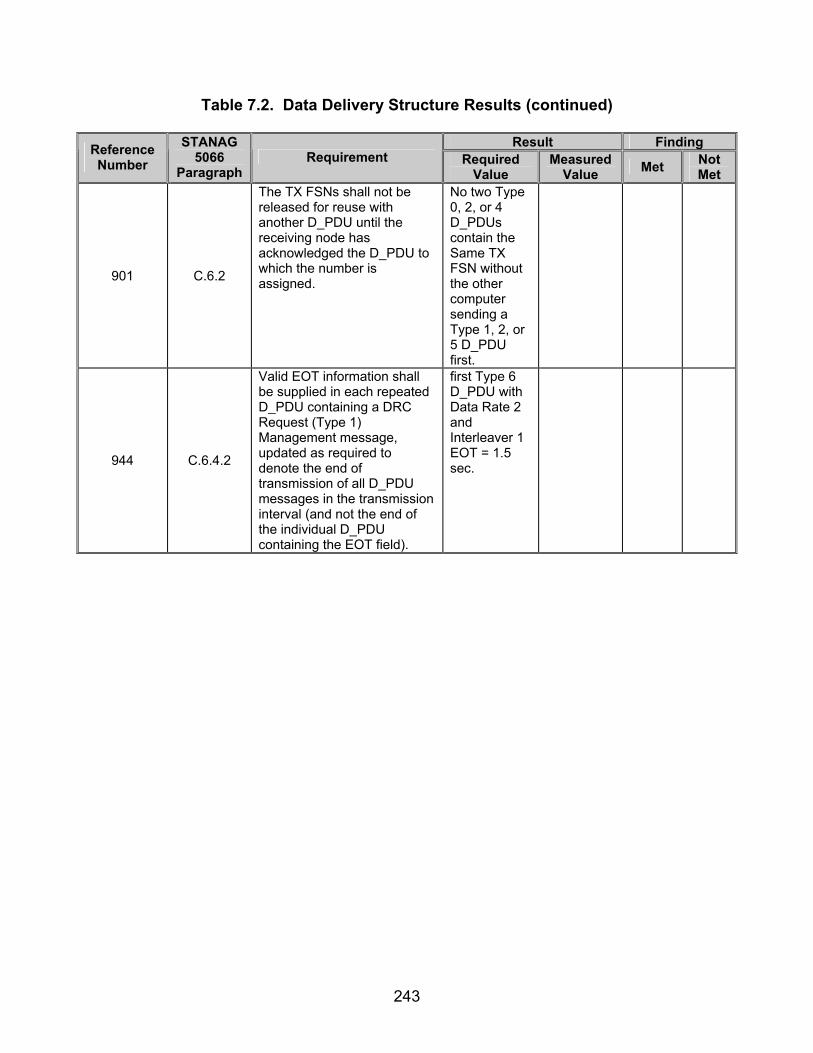
243
Table 7.2. Data Delivery Structure Results (continued)
Result Finding Reference Number
STANAG 5066
Paragraph Requirement Required
Value Measured
Value Met Not Met
901 C.6.2
The TX FSNs shall not be released for reuse with another D_PDU until the receiving node has acknowledged the D_PDU to which the number is assigned.
No two Type 0, 2, or 4 D_PDUs contain the Same TX FSN without the other computer sending a Type 1, 2, or 5 D_PDU first.
944 C.6.4.2
Valid EOT information shall be supplied in each repeated D_PDU containing a DRC Request (Type 1) Management message, updated as required to denote the end of transmission of all D_PDU messages in the transmission interval (and not the end of the individual D_PDU containing the EOT field).
first Type 6 D_PDU with Data Rate 2 and Interleaver 1 EOT = 1.5 sec.

244
Table 7.2. Data Delivery Structure Results (continued)
Result Finding Reference Number
STANAG 5066
Paragraph Requirement Required
Value Measured
Value Met Not Met
second Type 6 D_PDU with Data Rate 2 and Interleaver 1 EOT = 1.0 sec.
third Type 6 D_PDU with Data Rate 2 and Interleaver 1 EOT = 0.5 sec.
945 C.6.4.2
The same EOT value shall not be transmitted in each repeated D_PDU containing a DRC Request (Type 1) Management message unless necessary, due to EOT resolution and roundup errors, i.e., because the D_PDU duration is less than half the EOT resolution.
No 2 Type 6 D_PDUs in a string contain the same EOT.
Legend: ACK—Acknowledgement ARQ—Automatic Repeat-Request C_PDU—Channel Access Sublayer Protocol Data Unit CCITT—Consultative Committee For International Telephone And
Telegraph CRC—Cyclic Redundancy Check D_PDU—Data Transfer Sublayer Protocol Data Unit DRC—Data Rate Change EOT—End of Transmission FSN—Frame Sequnce Number hex—hexadecimal I-Frame—Information Frame I+C-Frame—Information and Control Frame
kbyte—kilobyte LSB—Least Significant Bit MSB—Most Significant Bit MTU—Maximum Transmission Unit N/A—Not Available RQ—Request S_PDU—Subnetwork Interface Sublayer Protocol Data Unit sec—Second STANAG—Standardization Agreement sync—synchronization TBD—To Be Determined TX—Transmit

245
(This page intentionally left blank.)

246
SUBTEST 8. MULTIPLE MESSAGE TRANSFER PROTOCOLS 8.1 Objective. To determine the extent of compliance to the requirements of STANAG 5066, for validating protocols for Multiple Message Transfers, reference numbers 550, 735, 739, 775, 800, 888-890, 892, 894, and 895. 8.2 Criteria a. If further Physical Link Request (Type 1) C_PDUs are received from the same address after the link is made, the Channel Access Sublayer shall again reply with a Physical Link Accepted (Type 2) C_PDU. (appendix B, reference number 550) b. As noted above, the TX FSN field in the Expedited Data-ONLY D_PDU is defined and used in the same manner as that specified for the Data-ONLY D_PDU. However, the Expedited Data-ONLY D_PDUs shall be assigned frame numbers from a TX FSN pool (0, 1 ...255) that is reserved exclusively for the transmission of Expedited Data-ONLY and Expedited ACK-ONLY D_PDUs. (appendix B, reference number 735) c. C_PDUs requiring Expedited Delivery Service and the associated Expedited D_PDUs shall not be queued for processing within the Data Transfer Sublayer, behind D_PDUs containing non-expedited data (i.e., Data_ONLY or Data-ACK D_PDUs). (appendix B, reference number 739) d. The C_PDU ID Number space (i.e., the set of ID numbers in the range [0…4095]) for Non-ARQ Data (Type 7) D_PDUs shall be different than the similarly-defined number space for Expedited Non-ARQ Data (Type 8) D_PDUs. (appendix B, reference number 775) e. The C_PDU ID Number space (i.e., the set of ID numbers in the range [0…4095]) for Expedited Non-ARQ Data (Type 8) D_PDUs shall be different than the similarly defined number space for Non-ARQ Data (Type 7) D_PDUs. (appendix B, reference number 800) f. A separate TX FSN counter shall be maintained for the transmission of ARQ Expedited Data, distinct from the counter with the same name used for regular-delivery service with D_PDU Types 0 and 2. (appendix B, reference number 888) g. A separate C_PDU ID counter shall be maintained for the transmission of ARQ Expedited Data, distinct from the counter with the same name used for regular Non-ARQ and expedited Non-ARQ delivery services with D_PDU Types 7 and 8. (appendix B, reference number 889)
h. Upon entering the Expedited Data (Connected) state, the Expedited Data D_PDU TX FSN counter shall be set to the value zero (1). (appendix B, reference number 890)
247
i. The processing of D_PDUs containing Expedited Data shall proceed according to a C_PDU level stop-and-wait protocol, as follows: (appendix B, reference numbers 892 and 894-895)
• Each time a D_EXPEDITED_UNIDATA_REQUEST Primitive is
accepted for service, the Expedited Data D_PDU TX FSN counter shall be reset to the value (0) and the C_PDU ID counter shall be incremented (modulo16).
8.3 Test Procedures a. Test Equipment Required
(1) Computers (2 ea) with STANAG 5066 Software (2) Modem (2 ea) (3) Protocol Analyzer (4) RS-232 Synchronous Serial Cards (5) Switch Box
b. Test Configuration. Figure 8.1 shows the equipment setup for this subtest.
c. Test Conduction. Table 8.1 lists procedures for this subtest and table 8.2
lists the results for this subtest.

248
Computer Modem Modem Computer
LANAnalyzer
RS-232 RS-232
Figure 8.1. Equipment Configuration for Multiple Message Transfer Protocols
Table 8.1. Multiple Message Transfer Protocols Procedures
Step Action Settings/Action Result
1
Set up equipment. See figure 8.1. Computers are connected to the modems by an RS-232 connection. The connection between modems shall be such that the receive and transmit pins on the modem are connected to the transmit and receive pins, respectively, of the other modem. Configure the switch box to be in the “closed” position, such that there is no break between computers 15.255.255.255 and 1.222.123.001.
2 Load STANAG 5066 software. Configure the SMTP and POP3 servers as
required by the STANAG 5066 software manual.
3
Configure STANAG addresses for both computers.
Set the size of the STANAG address field to 7 bytes. Set the STANAG address to 15.255.255.255 and 1.222.123.001 as shown in figure 8.1.
4 Configure modems. Set modems to transmit a
MIL-STD-188-110B signal at a data rate of 4800 bps with half duplex.
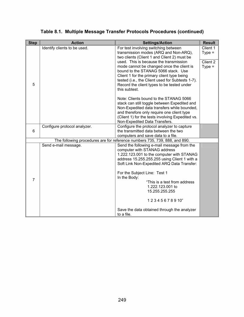
249
Table 8.1. Multiple Message Transfer Protocols Procedures (continued)
Step Action Settings/Action Result Client 1 Type =
5
Identify clients to be used. For test involving switching between transmission modes (ARQ and Non-ARQ), two clients (Client 1 and Client 2) must be used. This is because the transmission mode cannot be changed once the client is bound to the STANAG 5066 stack. Use Client 1 for the primary client type being tested (i.e., the Client used for Subtests 1-7). Record the client types to be tested under this subtest. Note: Clients bound to the STANAG 5066 stack can still toggle between Expedited and Non-Expedited data transfers while bounded, and therefore only require one client type (Client 1) for the tests involving Expedited vs. Non-Expedited Data Transfers.
Client 2 Type =
6 Configure protocol analyzer. Configure the protocol analyzer to capture
the transmitted data between the two computers and save data to a file.
The following procedures are for reference numbers 735, 739, 888, and 890.
7
Send e-mail message.
Send the following e-mail message from the computer with STANAG address 1.222.123.001 to the computer with STANAG address 15.255.255.255 using Client 1 with a Soft Link Non-Expedited ARQ Data Transfer: For the Subject Line: Test 1 In the Body: “This is a test from address
1.222.123.001 to 15.255.255.255
1 2 3 4 5 6 7 8 9 10” Save the data obtained through the analyzer to a file.

250
Table 8.1. Multiple Message Transfer Protocols Procedures (continued)
Step Action Settings/Action Result
8
Send a second e-mail message.
Send the following e-mail message immediately after sending the e-mail in step 7 from the computer with STANAG address 1.222.123.001 to the computer with STANAG address 15.255.255.255 using Client 2 with a Soft Link Expedited ARQ Data Transfer: For the Subject Line: Test 1 In the Body: “This is a test from address
1.222.123.001 to 15.255.255.255
1 2 3 4 5 6 7 8 9 10” Save the data obtained through the analyzer to a file.
9
Locate TX FSN for Non-Expedited Message.
The TX FSN is the first 8 bits of the 14th byte of the Type 0 D_PDU (not counting the sync bytes). Record the TX FSN for the Type 0 D_PDU.
Type 0 D_PDU TX FSN =
10
Locate TX FSN for Expedited Message. The TX FSN is the first 8 bits of the 14th byte of the Type 4 D_PDU (not counting the sync bytes). Record the TX FSN for the Type 4 D_PDU.
Type 4 D_PDU TX FSN =
11 Verify that the Expedited and Non-Expedited D_PDU TX FSNs come from different “number pools.”
Are the TX FSNs from steps 9 and 10 the same? (If the value is yes, the TX FSNs do come from different “number pools.”)
Y/N
12 Verify the Expedited Message from step 8 was queued before the Non-Expedited Message from step 7.
Was the Expedited Message queued before the Non-Expedited Message?
Y/N
The following procedures are for reference numbers 775 and 800.
13
Send e-mail message.
Send the following e-mail message from the computer with STANAG address 1.222.123.001 to the computer with STANAG address 15.255.255.255 using Client 1 with a Soft Link Non-Expedited Non-ARQ Data Transfer. Include an attachment of approximately 5 kbytes: For the Subject Line: Test 1 In the Body: “This is a test from address
1.222.123.001 to 15.255.255.255
1 2 3 4 5 6 7 8 9 10” Save the data obtained through the analyzer to a file.
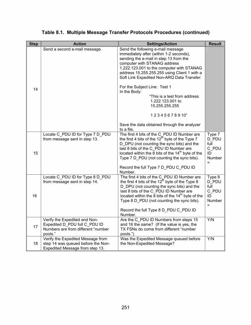
251
Table 8.1. Multiple Message Transfer Protocols Procedures (continued)
Step Action Settings/Action Result
14
Send a second e-mail message.
Send the following e-mail message immediately after (within 1-2 seconds), sending the e-mail in step 13 from the computer with STANAG address 1.222.123.001 to the computer with STANAG address 15.255.255.255 using Client 1 with a Soft Link Expedited Non-ARQ Data Transfer: For the Subject Line: Test 1 In the Body: “This is a test from address
1.222.123.001 to 15.255.255.255
1 2 3 4 5 6 7 8 9 10” Save the data obtained through the analyzer to a file.
15
Locate C_PDU ID for Type 7 D_PDU from message sent in step 13.
The first 4 bits of the C_PDU ID Number are the first 4 bits of the 12th byte of the Type 7 D_DPU (not counting the sync bits) and the last 8 bits of the C_PDU ID Number are located within the 8 bits of the 14th byte of the Type 7 D_PDU (not counting the sync bits). Record the full Type 7 D_PDU C_PDU ID Number.
Type 7 D_PDU full C_PDU ID Number =
16
Locate C_PDU ID for Type 8 D_PDU from message sent in step 14.
The first 4 bits of the C_PDU ID Number are the first 4 bits of the 12th byte of the Type 8 D_DPU (not counting the sync bits) and the last 8 bits of the C_PDU ID Number are located within the 8 bits of the 14th byte of the Type 8 D_PDU (not counting the sync bits). Record the full Type 8 D_PDU C_PDU ID Number.
Type 8 D_PDU full C_PDU ID Number =
17
Verify the Expedited and Non-Expedited D_PDU full C_PDU ID Numbers are from different “number pools.”
Are the C_PDU ID Numbers from steps 15 and 16 the same? (If the value is yes, the TX FSNs do come from different “number pools.”)
Y/N
18 Verify the Expedited Message from step 14 was queued before the Non-Expedited Message from step 13.
Was the Expedited Message queued before the Non-Expedited Message?
Y/N

252
Table 8.1. Multiple Message Transfer Protocols Procedures (continued)
Step Action Settings/Action Result The following procedures are for reference number 889.
19
Send e-mail message.
Send the following e-mail message from the computer with STANAG address 1.222.123.001 to the computer with STANAG address 15.255.255.255 using Client 1 with a Soft Link Expedited ARQ Data Transfer: For the Subject Line: Test 1 In the Body: “This is a test from address
1.222.123.001 to 15.255.255.255
1 2 3 4 5 6 7 8 9 10” Save the data obtained through the analyzer to a file.
20
Send a second e-mail message.
Send the following e-mail message immediately after sending the e-mail in step 19 from the computer with STANAG address 1.222.123.001 to the computer with STANAG address 15.255.255.255 using Client 2 with a Non-Expedited Non-ARQ Data Transfer: For the Subject Line: Test 1 In the Body:
“This is a test from address 1.222.123.001 to 15.255.255.255
1 2 3 4 5 6 7 8 9 10” Save the data obtained through the analyzer to a file.
21
Locate C_PDU ID for Type 7 D_PDU from message sent in step 20.
The first 4 bits of the C_PDU ID Number are the first 4 bits of the 12th byte of the Type 7 D_DPU (not counting the sync bits) and the last 8 bits of the C_PDU ID Number are located within the 8 bits of the 14th byte of the Type 7 D_PDU (not counting the sync bits). Record the full Type 7 D_PDU C_PDU ID Number.
Type 7 D_PDU full C_PDU ID Number =
22
Locate C_PDU ID Number for Type 4 D_PDU sent in message from step 19.
The C_PDU ID Number is the (MSB) 5th-2nd
(LSB) bits of the 12th byte of the Type 4 D_PDU (not including the sync bits). Record the C_PDU ID Number.
Type 4 D_PDU C_PDU ID Number =

253
Table 8.1. Multiple Message Transfer Protocols Procedures (continued)
Step Action Settings/Action Result
23
Verify the C_PDU ID Numbers from the Expedited ARQ and Non-Expedited Non-ARQ messages are from different “number pools.”
Were the values obtained in steps 21 and 22 equal? (If the value is yes, the TX FSNs do come from different “number pools.”)
Y/N
24
Send e-mail message.
Send the following e-mail message from the computer with STANAG address 1.222.123.001 to the computer with STANAG address 15.255.255.255 using Client 1 with a Expedited Non-ARQ Data Transfer: For the Subject Line: Test 1 In the Body: “This is a test from address
1.222.123.001 to 15.255.255.255
1 2 3 4 5 6 7 8 9 10”
Save the data obtained through the analyzer to a file.
25
Send a second e-mail message.
Send the following e-mail message immediately after sending the e-mail in step 24 from the computer with STANAG address 1.222.123.001 to the computer with STANAG address 15.255.255.255, using Client 2 with a Soft Link Expedited ARQ Data Transfer: For the Subject Line: Test 1 In the Body:
“This is a test from address 1.222.123.001 to 15.255.255.255 1 2 3 4 5 6 7 8 9 10”
Save the data obtained through the analyzer to a file.
26
Locate C_PDU ID for Type 8 D_PDU from message sent in step 24.
The first 4 bits of the C_PDU ID Number are the first 4 bits of the 12th byte of the Type 8 D_DPU (not counting the sync bits) and the last 8 bits of the C_PDU ID Number are located within the 8 bits of the 14th byte of the Type 8 D_PDU (not counting the sync bits). Record the full Type 8 D_PDU C_PDU ID Number.
Type 8 D_PDU full C_PDU ID Number =
27
Locate C_PDU ID Number for Type 4 D_PDU sent in message from step 25.
The C_PDU ID Number are the (MSB) 5th-2nd
(LSB) bits of the 12th byte of the Type 4 D_PDU (not including the sync bits). Record the C_PDU ID Number.
Type 4 D_PDU C_PDU ID Number =
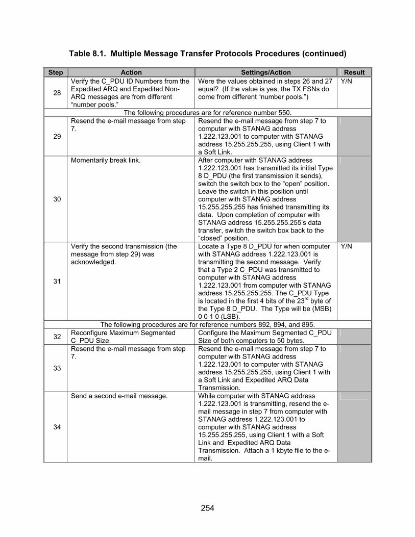
254
Table 8.1. Multiple Message Transfer Protocols Procedures (continued)
Step Action Settings/Action Result
28
Verify the C_PDU ID Numbers from the Expedited ARQ and Expedited Non-ARQ messages are from different “number pools.”
Were the values obtained in steps 26 and 27 equal? (If the value is yes, the TX FSNs do come from different “number pools.”)
Y/N
The following procedures are for reference number 550.
29
Resend the e-mail message from step 7.
Resend the e-mail message from step 7 to computer with STANAG address 1.222.123.001 to computer with STANAG address 15.255.255.255, using Client 1 with a Soft Link.
30
Momentarily break link. After computer with STANAG address 1.222.123.001 has transmitted its initial Type 8 D_PDU (the first transmission it sends), switch the switch box to the “open” position. Leave the switch in this position until computer with STANAG address 15.255.255.255 has finished transmitting its data. Upon completion of computer with STANAG address 15.255.255.255’s data transfer, switch the switch box back to the “closed” position.
31
Verify the second transmission (the message from step 29) was acknowledged.
Locate a Type 8 D_PDU for when computer with STANAG address 1.222.123.001 is transmitting the second message. Verify that a Type 2 C_PDU was transmitted to computer with STANAG address 1.222.123.001 from computer with STANAG address 15.255.255.255. The C_PDU Type is located in the first 4 bits of the 23rd byte of the Type 8 D_PDU. The Type will be (MSB) 0 0 1 0 (LSB).
Y/N
The following procedures are for reference numbers 892, 894, and 895.
32 Reconfigure Maximum Segmented C_PDU Size.
Configure the Maximum Segmented C_PDU Size of both computers to 50 bytes.
33
Resend the e-mail message from step 7.
Resend the e-mail message from step 7 to computer with STANAG address 1.222.123.001 to computer with STANAG address 15.255.255.255, using Client 1 with a Soft Link and Expedited ARQ Data Transmission.
34
Send a second e-mail message. While computer with STANAG address 1.222.123.001 is transmitting, resend the e-mail message in step 7 from computer with STANAG address 1.222.123.001 to computer with STANAG address 15.255.255.255, using Client 1 with a Soft Link and Expedited ARQ Data Transmission. Attach a 1 kbyte file to the e-mail.

255
Table 8.1. Multiple Message Transfer Protocols Procedures (continued)
Step Action Settings/Action Result
35
Obtain C_PDU ID Number of first Type 4 D_PDU from first transmission sent.
The C_PDU ID Number is the (MSB) 5th-2nd
(LSB) bits of the 12th byte of the Type 4 D_PDU (not including the sync bits). Record the C_PDU ID Number.
First TX Type 4 D_PDU C_PDU ID Number =
36
Obtain TX FSN of first Type 4 D_PDU from first transmission sent.
The TX FSN is the first 8 bits of the 14th byte of the Type 4 D_DPU (not counting the sync bytes). Record the TX FSN for the Type 4 D_PDU.
First TX Type 4 TX FSN =
37
Obtain C_PDU ID Number of first Type 4 D_PDU from second TX sent.
The C_PDU ID Number is the (MSB) 5th-2nd
(LSB) bits of the 12th byte of the Type 4 D_PDU (not including the sync bits). Record the C_PDU ID Number.
Second TX Type 4 D_PDU C_PDU ID Number =
38
Locate the remaining C_PDU ID Numbers for the Type 4 D_PDUs from second transmission sent.
The C_PDU ID Number is the (MSB) 5th-2nd
(LSB) bits of the 12th byte of the Type 4 D_PDU (not including the sync bits). Record the all C_PDU ID Numbers for all of the remaining Type 4 D_PDUs transmitted by computer with STANAG address 1.222.123.001 in the order that they are transmitted in hex format.
39 Determine if C_PDU IDs positively incremented starting from 0.
Compare the results from steps 37 and 38. Did the C_PDU IDs positively increment starting from 0x0?
Y/N
40 Determine if C_PDU IDs reset to 0 and began re-counting from 0.
Compare the results from step 38. Did the C_PDU ID reset to 0x0 once 0xF had been reached?
Y/N
41
Obtain TX FSN of first Type 4 D_PDU from second TX sent.
The TX FSN is the first 8 bits of the 14th byte of the Type 4 D_DPU (not counting the sync bytes). Record the TX FSN for the Type 4 D_PDU.
Second Type 4 TX FSN =
Legend: ARQ—Automatic Repeat-Request bps—bits per second C_PDU—Channel Access Sublayer Protocol Data Unit D_PDU—Data Transfer Sublayer Protocol Data Unit e-mail—Electronic Mail FSN—Frame Sequence Number hex—hexadecimal ID—Identification kbyte—kilobyte
LSB—Least Significant Bit MIL-STD—Military Standard MSB—Most Significant Bit POP3—Post Office Protocol 3 SMTP—Simple Mail Transfer Protocol STANAG—Standardization Agreement sync—synchronization TX—Transmit
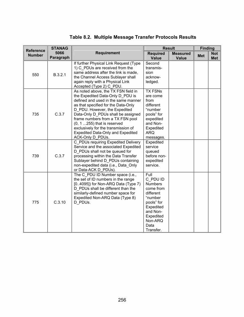
256
Table 8.2. Multiple Message Transfer Protocols Results
Result Finding Reference
Number STANAG
5066 Paragraph
Requirement Required Value
Measured Value Met Not
Met
550 B.3.2.1
If further Physical Link Request (Type 1) C_PDUs are received from the same address after the link is made, the Channel Access Sublayer shall again reply with a Physical Link Accepted (Type 2) C_PDU.
Second transmis-sion acknow-ledged.
735 C.3.7
As noted above, the TX FSN field in the Expedited Data-Only D_PDU is defined and used in the same manner as that specified for the Data-Only D_PDU. However, the Expedited Data-Only D_PDUs shall be assigned frame numbers from a TX FSN pool (0, 1 ...255) that is reserved exclusively for the transmission of Expedited Data-Only and Expedited ACK-Only D_PDUs.
TX FSNs are come from different “number pools” for expedited and Non-Expedited ARQ messages.
739 C.3.7
C_PDUs requiring Expedited Delivery Service and the associated Expedited D_PDUs shall not be queued for processing within the Data Transfer Sublayer behind D_PDUs containing non-expedited data (i.e., Data_Only or Data-ACK D_PDUs).
Expedited service queued before non-expedited service.
775 C.3.10
The C_PDU ID Number space (i.e., the set of ID numbers in the range [0..4095]) for Non-ARQ Data (Type 7) D_PDUs shall be different than the similarly-defined number space for Expedited Non-ARQ Data (Type 8) D_PDUs.
Full C_PDU ID Numbers come from different “number pools” for Expedited and Non-Expedited Non-ARQ Data Transfer.
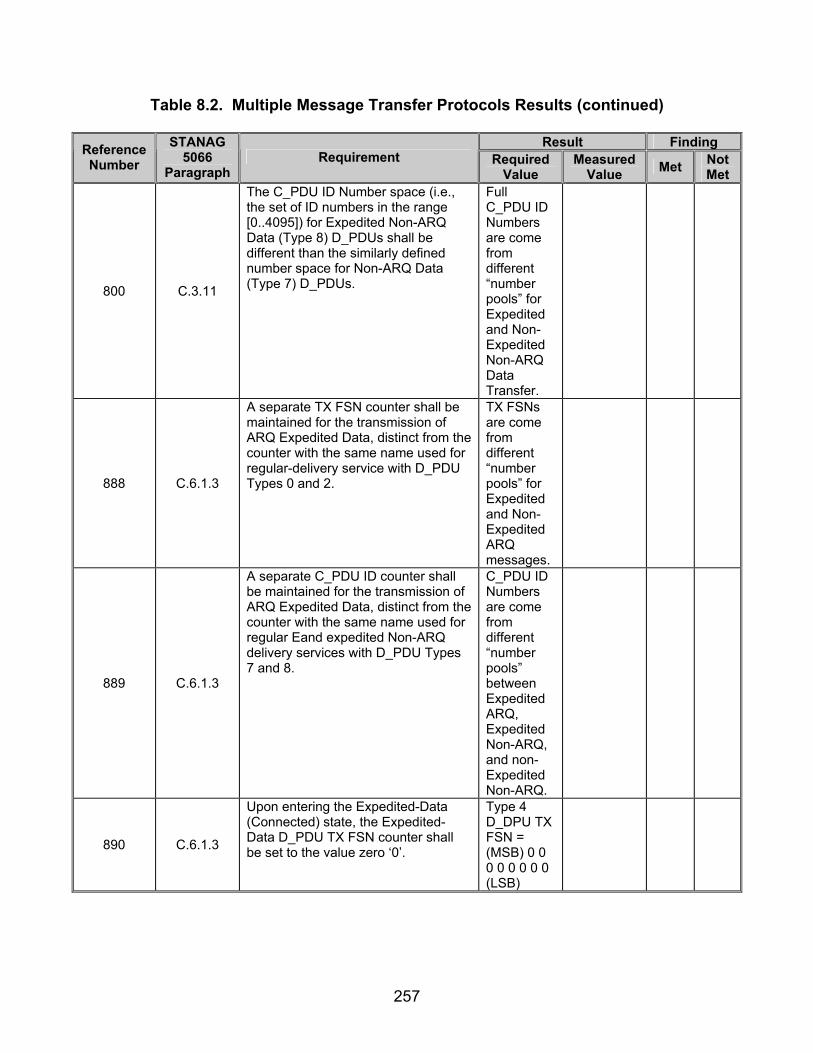
257
Table 8.2. Multiple Message Transfer Protocols Results (continued)
Result Finding Reference Number
STANAG 5066
Paragraph Requirement Required
Value Measured
Value Met Not Met
800 C.3.11
The C_PDU ID Number space (i.e., the set of ID numbers in the range [0..4095]) for Expedited Non-ARQ Data (Type 8) D_PDUs shall be different than the similarly defined number space for Non-ARQ Data (Type 7) D_PDUs.
Full C_PDU ID Numbers are come from different “number pools” for Expedited and Non-Expedited Non-ARQ Data Transfer.
888 C.6.1.3
A separate TX FSN counter shall be maintained for the transmission of ARQ Expedited Data, distinct from the counter with the same name used for regular-delivery service with D_PDU Types 0 and 2.
TX FSNs are come from different “number pools” for Expedited and Non-Expedited ARQ messages.
889 C.6.1.3
A separate C_PDU ID counter shall be maintained for the transmission of ARQ Expedited Data, distinct from the counter with the same name used for regular Eand expedited Non-ARQ delivery services with D_PDU Types 7 and 8.
C_PDU ID Numbers are come from different “number pools” between Expedited ARQ, Expedited Non-ARQ, and non-Expedited Non-ARQ.
890 C.6.1.3
Upon entering the Expedited-Data (Connected) state, the Expedited-Data D_PDU TX FSN counter shall be set to the value zero ‘0’.
Type 4 D_DPU TX FSN = (MSB) 0 0 0 0 0 0 0 0 (LSB)

258
Table 8.2. Multiple Message Transfer Protocols Results (continued)
Result Finding Reference Number
STANAG 5066
Paragraph Requirement Required
Value Measured
Value Met Not Met
892 C.6.1.3
The processing of D_PDUs containing Expedited Data shall proceed according to a C_PDU level stop-and-wait protocol, as follows:
First Type 4 TX FSN = (MSB) 0 0 0 0 0 0 0 0 (LSB) (0x0 hex)
894 C.6.1.3
Each time a D_EXPEDITED_UNIDATA_REQUEST Primitive is accepted for service, the Expedited Data D_PDU TX FSN counter shall be reset to the value zero.
Second Type 4 TX FSN = (MSB) 0 0 0 0 0 0 0 0 (LSB) (0x0 hex)
895 C.6.1.3
The C_PDU ID counter shall be incremented (modulo16).
Type 4 C_PDU ID incremen-ted (modulo 16).
Legend: ACK—Acknowledgement ARQ—Automatic Repeat-Request C_PDU—Channel Access Sublayer Protocol Data Unit D_PDU—Data Transfer Sublayer Protocol Data Unit FSN—Frame Sequence Number hex—hexadecimal
ID—Identification LSB—Least Significant Bit MSB—Most Significant Bit STANAG—Standardization Agreement TX—Transmit

259
SUBTEST 9. LINK ESTABLISHMENT PROTOCOLS 9.1 Objective. To determine the extent of compliance to the requirements of STANAG 5066 for validating Link Establishment Protocols, reference numbers 3-5, 7, 314-327, 329-330, 332-346, 348-354, 356-358, 360-365, 367-384, 386-388, 414-415, 422, 424-425, 428-429, 431-433, 440, 446-447, 467-469, 471-473, 479, 481, 487-497, 502-532, 536-537, 539-541, 543-548, 551-553, 555-561, 563-567, 575, 577, 584-586, and 985. 9.2 Criteria a. When all data has been transmitted to a node with which a Soft Link Data Exchange Session has been established, the Subnetwork Interface Sublayer shall terminate the Soft Link Data Exchange Session after a configurable and implementation-dependent time-out period; in accordance with the protocol specified in STANAG 5066, section A.3.2.1.2. (appendix B, reference number 3) b. Termination of the Soft Link Data Exchange Session shall be in accordance with the procedure specified in STANAG 5066, section A.3.2.1.3. The time-out period may be zero. The time-out period allows for the possibility of newly arriving User Protocol Data Units (U_PDUs) being serviced by an existing Soft Link Data Exchange Session prior to its termination. (appendix B, reference number 4)
c. In order to provide “balanced” servicing of the queued U_PDUs, a Soft Link Data Exchange Session shall not be maintained for a period which exceeds a specified maximum time if U_PDUs of appropriate priorities are queued for different node(s). (appendix B, reference number 5) d. The second type of data exchange session is the Hard Link Data Exchange Session. A Hard Link Data Exchange Session shall be initiated at the explicit request of a client, in accordance with the procedures for establishing and terminating Hard Link sessions specified in STANAG 5066, sections A.3.2.2.1 and A.3.2.2.2. (appendix B, reference number 7)
e. Peer Subnetwork Interface Sublayers, generally in different nodes, shall
communicate with each other by the exchange S_PDUs. (appendix B, reference number 314)
f. For the subnetwork configurations currently defined in STANAG 5066,
peer-to-peer communication shall be required for: (appendix B, reference number 315)
• Establishment and termination of Hard Link Data Exchange Sessions. • Exchange of client data.

260
g. Explicit peer-to-peer communication shall not be required for the establishment or termination of Soft Link or Broadcast Data Exchange Session. (appendix B, reference number 316)
h. S_PDUs and Encoding Requirements:
• The first encoded field shall be common to all S_PDUs. It is called “Type” and shall encode the type value of the S_PDU in table 9.1. (appendix B, reference numbers 317 and 318)
• The meaning and encoding of the remaining fields, if any, in an S_PDU shall be as specified in the subsection below corresponding to the S_PDU Type. (appendix B, reference number 319)
Table 9.1. S_PDU Types
S_PDU TYPE FIELD VALUE S_PDU NAME
0 DATA 1 DATA DELIVERY CONFIRM 2 DATA DELIVERY FAIL 3 HARD LINK ESTABLISHMENT REQUEST 4 HARD LINK ESTABLISHMENT CONFIRM 5 HARD LINK ESTABLISHMENT REJECTED 6 HARD LINK TERMINATE 7 HARD LINK TERMINATE CONFIRM
Legend: S_PDU—Subnetwork Interface Sublayer Protocol Data Unit
i. The DATA S_PDU shall be transmitted by the Subnetwork Interface Sublayer in order to send client data to a remote peer sublayer. (appendix B, reference number 320)
j. The DATA S_PDU shall be encoded as specified in figure 9.1 and in the
paragraphs below. This S_PDU shall consist of two parts: (appendix B, reference numbers 321-324)
• The first part shall be the Subnetwork Interface Sublayer Protocol
Control Information (S_PCI) and represents the overhead added by the sublayer.
• The second part shall be the actual client Data U_PDU.

261
Figure 9.1. Generic Encoding and Bit-Field Map of the Data S_PDU
k. The first field of 4 bits, the S_PCI part, shall be “Type.” Its value shall be
equal to (0) and identifies the S_PDU as being of type “Data.” (appendix B, reference numbers 325 and 326)
l. The second field of 4 bits shall be “Priority” and represents the priority of the client’s U_PDU. (appendix B, reference number 327)
m. The third field of 4 bits, the S_PCI part, shall be the “Source SAP ID” and identifies the client of the transmitting peer that sent the data. (appendix B, reference number 329)
n. The fourth field of 4 bits shall be “Destination SAP ID” and identifies the client of the receiving peer, which must take delivery of the data. (appendix B, reference number 330)
o. The fifth field of the S_PCI part shall be “Client Delivery Confirm Required”
and is encoded as a single bit that can take the value, “YES” (=1) or “NO” (=0). The value of this bit shall be set according to the service type requested by the sending client during binding (see S_BIND_REQUEST Primitive), or according to the delivery mode requested explicitly for this U_PDU (see S_UNIDATA_REQUEST Primitive). (appendix B, reference numbers 332 and 333)
p. The sixth field shall be the “Valid Time To Die” (VTTD) field and is
encoded as a single bit that can take the value, “YES” (=1) or “NO” (=0), indicating the presence of a VTTD within the S_PCI. (appendix B, reference number 334)
Legend: ID—Identification, LSB—Leat Signficant Bit, MSB—Most Significant Bit, RQRD—Required, S_PCI—Subnetwork Interface Sublayer Protocol Control Information, S_PDU—Subnetwork Interface Sublayer Protocol Data Unit, SAP—Subnetwork Access Point, TTD—Time To Die, U_PDU—User Protocol Data Unit

262
q. The seventh field of the S_PCI shall be two “unused” bits that are “reserved” for future use. (appendix B, reference number 335)
r. The eighth and last field of the S_PCI shall be “Time To Die” (TTD) and
represents the TTD for this U_PDU. The first 4 bits of this field shall have meaning, if and only if the VTTD field equals “YES.” (appendix B, reference numbers 336 and 337)
s. The remaining 16 bits of the field shall be present in the S_PCI, if and only
if the VTTD field equals “YES.” The TTD field encodes the Julian date (modulo 16) and the Greenwich Mean Time (GMT) in seconds, after which time the S_PDU must be discarded, if it has not yet been delivered to the client. The Julian date (modulo 16) part of the TTD shall be mapped into the first 4 bits of the TTD field (i.e., bits 0-3 of byte 2 of the S_PDU). (appendix B, reference numbers 338 and 339)
t. The Data Delivery Confirm S_PDU shall be transmitted in response to a
successful delivery to a client of a U_PDU, which was received in a Data Type S_PDU in which the Client Delivery Confirm Required field was set to “YES.” (appendix B, reference number 340)
u. The Data Delivery Confirm S_PDU shall be transmitted by the Subnetwork
Interface Sublayer to the peer sublayer that originated the Data Type S_PDU. (appendix B, reference number 341)
Figure 9.2. Generic Encoding and Bit-Field Maps of the Data Delivery
Confirmation S_PDU v. The first part of the Data Delivery Confirm S_PDU shall be the S_PCI,
while the second part shall be a full or partial copy of the U_PDU that was received and delivered to the destination client. (appendix B, reference numbers 342 and 343)
Legend: ID—Identification, LSB—Leat Signficant Bit, MSB—Most Significant Bit, S_PCI—Subnetwork Interface Sublayer Protocol Control Information, S_PDU—Subnetwork Interface Sublayer Protocol Data Unit, SAP—Subnetwork Access Point, U PDU—User Protocol Data Unit

263
w. The first field of the S_PCI part shall be “Type.” (appendix B, reference number 344)
x. Its value shall be equal to (1) and identifies the S_PDU as being of Type
Data Delivery Confirm. (appendix B, reference number 345)
y. The remaining fields and their values for the S_PCI part of the Data Delivery Confirm S_PDU shall be equal in value to the corresponding fields of the Data S_PDU, for which this Data Delivery Confirm S_PDU is a response. (appendix B, reference number 346)
z. The Data Delivery Fail S_PDU shall be transmitted in response to a failed
delivery to a client of a U_PDU that was received in a Data Type S_PDU with the Client Delivery Confirm Required field set to “YES.” (appendix B, reference number 348)
aa. The first part of this S_PDU shall be the S_PCI. (appendix B, reference number 349)
ab. The second part shall be a full or partial copy of the U_PDU that was received but not delivered to the destination client. (appendix B, reference number 350) ac. The first field of the S_PCI shall be “Type.” Its value shall be equal to (2) and identifies the S_PDU as being of Type Data Delivery Fail as shown in figure 9.3. (appendix B, reference numbers 351 and 352) ad. The second field shall be “Reason” and explains why the U_PDU failed to be delivered. It can take a value in the range 0 to 15 and valid reasons are defined in STANAG 5066 section A.3.1.3. (appendix B, reference number 353)
ae. The Source SAP ID and Destination SAP ID fields of the S_PCI shall be equal in value to the corresponding fields of the Data S_PDU for which the Data Delivery Fail S_PDU is a response. (appendix B, reference number 354)
af. The Hard Link Establishment Request S_PDU shall be transmitted, by a peer, in response to a client’s request for a Hard Link. (appendix B, reference number 356)

264
Figure 9.3. Generic Encoding and Bit-Field Map of the Data Delivery Fail S_PDU
ag. The first field of the S_PDU shall be “Type.” (appendix B, reference
number 357)
ah. It shall be equal to (3) and identifies the S_PDU as being of Type Hard Link Establishment Request as shown in figure 9.4. (appendix B, reference number 358)
Figure 9.4. Generic Encoding and Bit-Field Map of the Hard Link Establishment
Request S_PDU
ai. The Requesting SAP ID field shall be the SAP ID of the client that requested the Hard Link Establishment. (appendix B, reference number 360)
Legend: ID—Identification, LSB—Leat Signficant Bit, MSB—Most Significant Bit, S_PCI—Subnetwork Interface Sublayer Protocol Control Information, S_PDU—Subnetwork Interface Sublayer Protocol Data
Legend: ID—Identification, LSB—Leat Signficant Bit, MSB—Most Significant Bit, S_PDU—Subnetwork Interface Sublayer Protocol Data Unit, SAP—Subnetwork Access Point
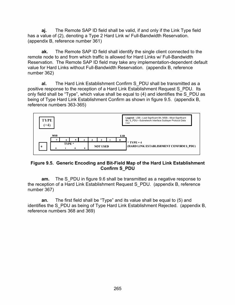
265
aj. The Remote SAP ID field shall be valid, if and only if the Link Type field has a value of (2), denoting a Type 2 Hard Link w/ Full-Bandwidth Reservation. (appendix B, reference number 361)
ak. The Remote SAP ID field shall identify the single client connected to the remote node to and from which traffic is allowed for Hard Links w/ Full-Bandwidth Reservation. The Remote SAP ID field may take any implementation-dependent default value for Hard Links without Full-Bandwidth Reservation. (appendix B, reference number 362)
al. The Hard Link Establishment Confirm S_PDU shall be transmitted as a positive response to the reception of a Hard Link Establishment Request S_PDU. Its only field shall be “Type”, which value shall be equal to (4) and identifies the S_PDU as being of Type Hard Link Establishment Confirm as shown in figure 9.5. (appendix B, reference numbers 363-365)
Figure 9.5. Generic Encoding and Bit-Field Map of the Hard Link Establishment
Confirm S_PDU
am. The S_PDU in figure 9.6 shall be transmitted as a negative response to the reception of a Hard Link Establishment Request S_PDU. (appendix B, reference number 367)
an. The first field shall be “Type” and its value shall be equal to (5) and identifies the S_PDU as being of Type Hard Link Establishment Rejected. (appendix B, reference numbers 368 and 369)
Legend: LSB—Leat Signficant Bit, MSB—Most Significant Bit, S_PDU—Subnetwork Interface Sublayer Protocol Data Unit
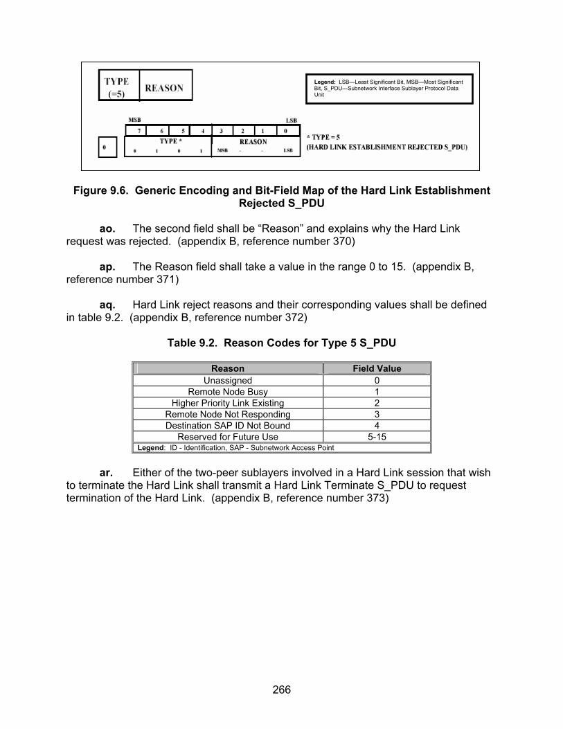
266
Figure 9.6. Generic Encoding and Bit-Field Map of the Hard Link Establishment
Rejected S_PDU
ao. The second field shall be “Reason” and explains why the Hard Link request was rejected. (appendix B, reference number 370)
ap. The Reason field shall take a value in the range 0 to 15. (appendix B, reference number 371)
aq. Hard Link reject reasons and their corresponding values shall be defined in table 9.2. (appendix B, reference number 372)
Table 9.2. Reason Codes for Type 5 S_PDU
Reason Field Value Unassigned 0
Remote Node Busy 1 Higher Priority Link Existing 2
Remote Node Not Responding 3 Destination SAP ID Not Bound 4
Reserved for Future Use 5-15 Legend: ID - Identification, SAP - Subnetwork Access Point
ar. Either of the two-peer sublayers involved in a Hard Link session that wish
to terminate the Hard Link shall transmit a Hard Link Terminate S_PDU to request termination of the Hard Link. (appendix B, reference number 373)
Legend: LSB—Least Significant Bit, MSB—Most Significant Bit, S_PDU—Subnetwork Interface Sublayer Protocol Data Unit

267
Figure 9.7. Generic Encoding and Bit-Field Map of the Hard Link Terminate
S_PDU as. The first 4-bit field shall be “Type” and its value shall be equal to (6) and identifies the S_PDU as being of Type Hard Link Terminate. (appendix B, reference numbers 374 and 375) at. The second 4-bit field shall be “Reason” and explains why the Hard Link is being terminated. (appendix B, reference number 376)
au. Hard Link termination reasons and their corresponding values shall be defined in table 9.3. (appendix B, reference number 377)
Table 9.3. Reason Codes for Type 6 S_PDU
Reason Field Value Unassigned 0
Client Request 1 Higher Priority Link Existing 2
Reserved 3 Destination SAP ID Not Bound 4
Reserved For Future Use 5-15 Legend: ID - Identification, SAP - Subnetwork Access Point
av. In order to ensure a graceful termination of the Hard Link, the peer which sent the Hard Link Terminate must await a time-out period for confirmation of its peer before it declares the link as terminated. This time-out period shall be configurable by the protocol implementation. (appendix B, reference number 378)
aw. The Hard Link Terminate Confirm S_PDU shall be transmitted in response to the reception of a Hard Link Terminate S_PDU. (appendix B, reference number 379)
Legend: LSB—Leat Signficant Bit, MSB—Most Significant Bit, S_PDU—Subnetwork Interface Sublayer Protocol Data Unit

268
Figure 9.8. Generic Encoding and Bit-Field Map of the Hard Link Terminate Confirm S_PDU
ax. The first 4-bit field of this S_PDU shall be “Type.” (appendix B, reference number 380)
ay. The value shall be equal to (7) and identifies the S_PDU as being of Type Hard Link Terminate Confirm. (appendix B, reference number 381)
az. The second 4-bit field of the S_PDU shall not be used in this implementation of the protocol. The values of these bits may be implementation dependent. (appendix B, reference number 382)
ba. In contrast with the establishment of a Hard Link session, the establishment of Soft Link Data Exchange Sessions shall not require explicit peer-to-peer handshaking within the Subnetwork Interface Sublayer. (appendix B, reference number 383) bb. The calling peer shall implicitly establish a Soft Link Data Exchange Session by requesting its Channel Access Sublayer to make a physical link to the required remote node, using the procedure for making physical links specified in STANAG 5066, annex B (appendix B, reference number 384) bc. No peer-to-peer communication by the Subnetwork Interface Sublayer shall be required to terminate a Soft Link Data Exchange Session. (appendix B, reference number 386)
bd. A Soft Link Data Exchange Session shall be terminated by either of the two peers by a request to its respective Channel Access Sublayer to break the physical link in accordance with the procedure specified in STANAG 5066, annex B. (appendix B, reference number 387) be. Since a called peer can terminate a Soft Link Data Exchange Session if it has higher priority data destined for a different node, called peers shall wait a
Legend: LSB—Leat Signficant Bit, MSB—Most Significant Bit, S_PDU—Subnetwork Interface Sublayer Protocol Data Unit
269
configurable minimum time before unilaterally terminating sessions, to prevent unstable operation of the protocol. (appendix B, reference number 388)
bf. After the physical link has been made, the caller’s Subnetwork Interface Sublayer shall send a Hard Link Establishment Request (Type 3) S_PDU to its called peer at the remote node. (appendix B, reference number 414) bg. To ensure that the S_PDU will overtake all routine Data S_PDUs which may be queued and in various stages of processing by the lower sublayers, the Hard Link Establishment Request S_PDU shall be sent to the Channel Access Sublayer using a C_EXPEDITED_UNIDATA_REQUEST primitive and use the subnetwork’s expedited data service. (appendix B, reference number 415) bh. If no client is bound to the called SAP ID and the caller’s request is for a Type 2 Hard Link, then the called sublayer shall reject the request, send a Hard Link Establishment Rejected (Type 5) S_PDU with REASON = “Destination SAP ID not bound” to the caller, and terminate the establishment protocol. (appendix B, reference number 422) bi. If the caller’s request cannot be accepted by the called peer, a Hard Link Establishment Rejected (Type 5) S_PDU shall be sent to the calling peer, with the Reason field set as follows: (appendix B, reference number 424)
• REASON = “Remote-Node-Busy” if the reason for rejection was the
existence of an existing Hard Link of equal rank and priority, or • REASON= “Higher-Priority Link Existing” if the reason for rejection was
the existing of a Hard Link with higher priority or rank. bj. If the caller’s Hard Link request can be accepted and the request is not a Type 2 Hard Link request, the called sublayer shall send a Hard Link Establishment Confirm (Type 4) S_PDU to the caller sublayer and terminate the protocol. (appendix B, reference number 425)
bk. Otherwise, the called sublayer shall send a Hard Link Establishment Rejected (Type 5) S_PDU to the caller sublayer and terminate the protocol. (appendix B, reference number 428)
bl. Whenever sent, either the Type 4 Hard Link Establishment Confirm S_PDU or the Type 5 Hard Link Establishment Rejected S_PDU shall be sent to the calling sublayer using the Expedited Data Service provided by lower sublayers in the profile. (appendix B, reference number 429)
bm. Any sublayer that must terminate a Hard Link for any of the specified conditions shall send a Hard Link Terminate (Type 6) S_PDU to its peer sublayer. (appendix B, reference number 431)
270
bn. A sublayer that receives a Hard Link Terminate (Type 6) S_PDU from its peer shall immediately respond with a Hard Link Terminate Confirm (Type 7) S_PDU, declare the Hard Link as terminated, and send a S_HARD_LINK_TERMINATED primitive to all clients using the Hard Link. (appendix B, reference number 432)
bo. After sending the “Hard Link Terminate” (Type 6) S_PDU, the initiating sublayer shall wait for a response for a configurable maximum time-out and proceed. (appendix B, reference number 433)
bp. After a data exchange session of any type has been established;
sublayers with client data to exchange shall exchange Data (Type 0) S_PDUs using the protocol specified below and in accordance with the service characteristics of the respective session. (appendix B, reference number 440)
bq. For U_PDUs that have been accepted for transmission, the sending
sublayer retrieves client U_PDUs and their associated implementation-dependent service attributes (such as the S_Primitive that encapsulated the U_PDU) from its queues (according to Priority and other implementation-dependent criteria) and proceeds as follows:
• The sending sublayer shall encode the retrieved U_PDU into a Data
(Type 0) S_PDU, transferring any service attributes associated with U_PDU to the S_PDU as required. (appendix B, reference number 446 and 447)
br. If the received S_PDU has the Client Delivery Confirm Required field set
equal to “YES,” then the sublayer shall provide delivery confirmation as follows: (appendix B, reference numbers 467-469)
• If a client was bound to the Destination SAP_ID, the sublayer shall encode as required and send a Data Delivery Confirm (Type 1) S_PDU to the sending sublayer.
• If a client was not bound to the Destination SAP_ID, the sublayer shall encode as required and send a Data Delivery Fail (Type 2) S_PDU to the sending sublayer: On completion of these actions by the receiving sublayer the Client Data Delivery Protocol terminates for the given Data (Type 0) S_PDU.
bs. In particular, the Subnetwork Interface Sublayer shall be capable of
sending a U_PDU, encapsulated in a Data (Type 0) S_PDU and C_Primitive as required, to the Channel Access Sublayer prior to receipt of the data delivery confirm response for a U_PDU sent earlier. (appendix B, reference number 471)
bt. The interface must support the service-definition for the Channel Access Sublayer, i.e.: (appendix B, reference numbers 472 and 473)

271
• The interface shall enable the Subnetwork Interface Sublayer to submit requests to change the state of a physical link, i.e., to make or break a physical link of a specified type (i.e., Exclusive or Nonexclusive, as specified in STANAG 5066, annex B) with a specified node address.
bu. The Type 1 Channel Access Protocol shall support the following
subnetwork configuration: (appendix B, reference numbers 479 and 481)
• The co-ordination of the making and breaking of physical links between two nodes (after a common frequency has already been selected by an external process) shall be performed solely by the Channel Access Sublayer.
bv. The Type 1 Channel Access Sublayer shall communicate with peer
sublayers in other nodes using the protocols defined below in order to: (appendix B, reference number 487)
• Make and break Physical Links • Deliver S_PDUs between Subnetwork Interface Sublayers at the local
node and remote node(s). bw. The C_PDUs in table 9.4 shall be used for peer-to-peer communication between Channel Access Sublayers in the local and remote node(s). (appendix B, reference number 488)
Table 9.4. C_PDU Types
C_PDU Name Type Code
Data C_PDU Type 0 Physical Link Request Type 1 Physical Link Accepted Type 2 Physical Link Rejected Type 3
Physical Link Break Type 4 Physical Link Break Confirm Type 5
Legend: C_PDU - Channel Access Sublayer Protocol Data Unit
bx. The first argument and encoded field of all C_PDUs shall be the C_PDU Type, the remaining format and content of these C_PDUs shall be as specified in the subsections that follow. (appendix B, reference numbers 489 and 490)
by. Unless noted otherwise, argument values encoded in the C_PDU bit fields
shall be mapped into the fields, in accordance with Consultative Committee for International Telephone and Telegraph (CCITT) V.42, 8.1.2.3. (appendix B, reference numbers 491-493)
• When a field is contained within a single octet, the lowest bit number of
the field shall represent the lowest-order (i.e., LSB) value.
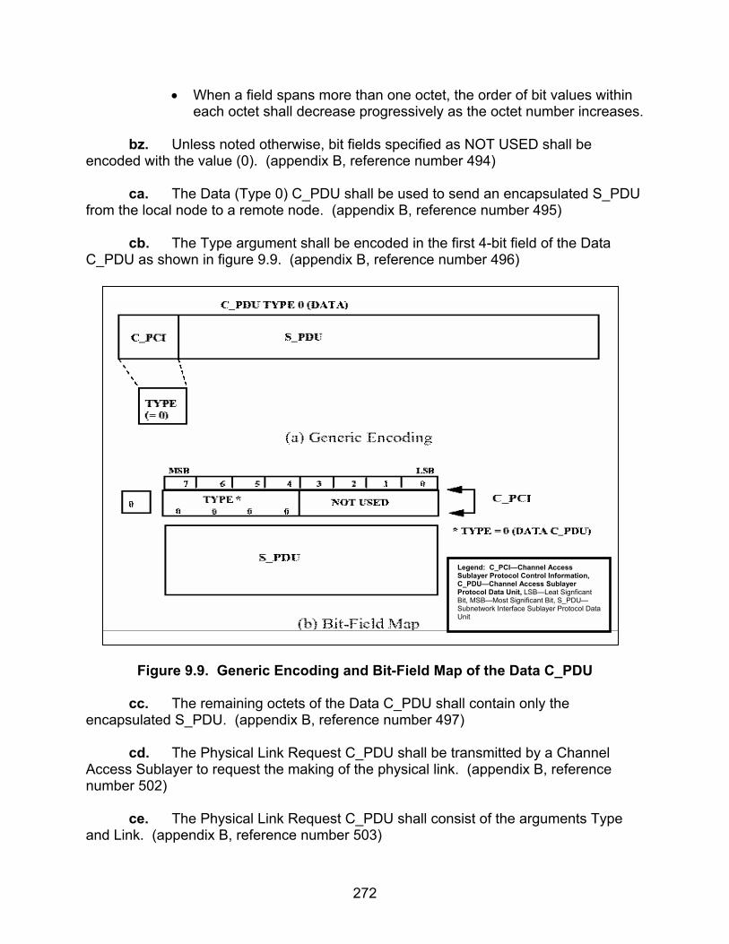
272
• When a field spans more than one octet, the order of bit values within each octet shall decrease progressively as the octet number increases.
bz. Unless noted otherwise, bit fields specified as NOT USED shall be
encoded with the value (0). (appendix B, reference number 494) ca. The Data (Type 0) C_PDU shall be used to send an encapsulated S_PDU
from the local node to a remote node. (appendix B, reference number 495) cb. The Type argument shall be encoded in the first 4-bit field of the Data C_PDU as shown in figure 9.9. (appendix B, reference number 496)
Figure 9.9. Generic Encoding and Bit-Field Map of the Data C_PDU
cc. The remaining octets of the Data C_PDU shall contain only the
encapsulated S_PDU. (appendix B, reference number 497) cd. The Physical Link Request C_PDU shall be transmitted by a Channel
Access Sublayer to request the making of the physical link. (appendix B, reference number 502)
ce. The Physical Link Request C_PDU shall consist of the arguments Type
and Link. (appendix B, reference number 503)
Legend: C_PCI—Channel Access Sublayer Protocol Control Information, C_PDU—Channel Access Sublayer Protocol Data Unit, LSB—Leat Signficant Bit, MSB—Most Significant Bit, S_PDU—Subnetwork Interface Sublayer Protocol Data Unit

273
cf. The value of the Type argument for the Physical Link Request C_PDU
shall be (1), encoded as a 4-bit field as shown in figure 9.10. (appendix B, reference number 504)
Figure 9.10. Generic Encoding and Bit-Field Map of the Physical Link Request
C_PDU
cg. The 3 bits not used in the encoding of the Physical Link Request C_PDU shall be reserved for future use and not used by any implementation. (appendix B, reference number 505)
ch. The value of the Link argument for the Physical Link Request C_PDU
shall be encoded as a one-bit field as shown in figure 9.10, with values as follows: (appendix B, reference numbers 506-508)
• A request for a Nonexclusive Physical Link shall be encoded with the value (0).
• A request for an Exclusive Physical Link shall be encoded with the value (1).
ci. The Physical Link Request C_PDU shall be sent by the Channel Access
Sublayer, requesting the lower layer Expedited Non-ARQ Data Service (i.e., transmission using Type 8 D_PDUs), in accordance with the STANAG 5066, annex C, specification of the Data Transfer Sublayer. (appendix B, reference number 509)
cj. A Channel Access Sublayer that receives a Physical Link Request C_PDU
shall respond with either a Physical Link Accepted (Type 2) C_PDU or a Physical Link Rejected (Type 3) C_PDU, as appropriate. (appendix B, reference number 510)
Legend: C_PDU—Channel Access Sublayer Protocol Data Unit, LSB—Leat Signficant Bit, MSB—Most Significant Bit
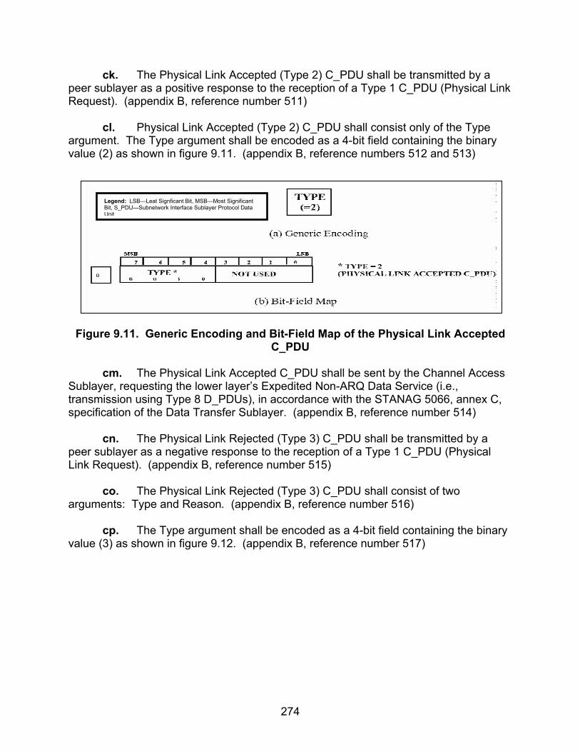
274
ck. The Physical Link Accepted (Type 2) C_PDU shall be transmitted by a peer sublayer as a positive response to the reception of a Type 1 C_PDU (Physical Link Request). (appendix B, reference number 511)
cl. Physical Link Accepted (Type 2) C_PDU shall consist only of the Type argument. The Type argument shall be encoded as a 4-bit field containing the binary value (2) as shown in figure 9.11. (appendix B, reference numbers 512 and 513)
Figure 9.11. Generic Encoding and Bit-Field Map of the Physical Link Accepted
C_PDU cm. The Physical Link Accepted C_PDU shall be sent by the Channel Access
Sublayer, requesting the lower layer’s Expedited Non-ARQ Data Service (i.e., transmission using Type 8 D_PDUs), in accordance with the STANAG 5066, annex C, specification of the Data Transfer Sublayer. (appendix B, reference number 514)
cn. The Physical Link Rejected (Type 3) C_PDU shall be transmitted by a
peer sublayer as a negative response to the reception of a Type 1 C_PDU (Physical Link Request). (appendix B, reference number 515)
co. The Physical Link Rejected (Type 3) C_PDU shall consist of two arguments: Type and Reason. (appendix B, reference number 516) cp. The Type argument shall be encoded as a 4-bit field containing the binary value (3) as shown in figure 9.12. (appendix B, reference number 517)
Legend: LSB—Leat Signficant Bit, MSB—Most Significant Bit, S_PDU—Subnetwork Interface Sublayer Protocol Data Unit
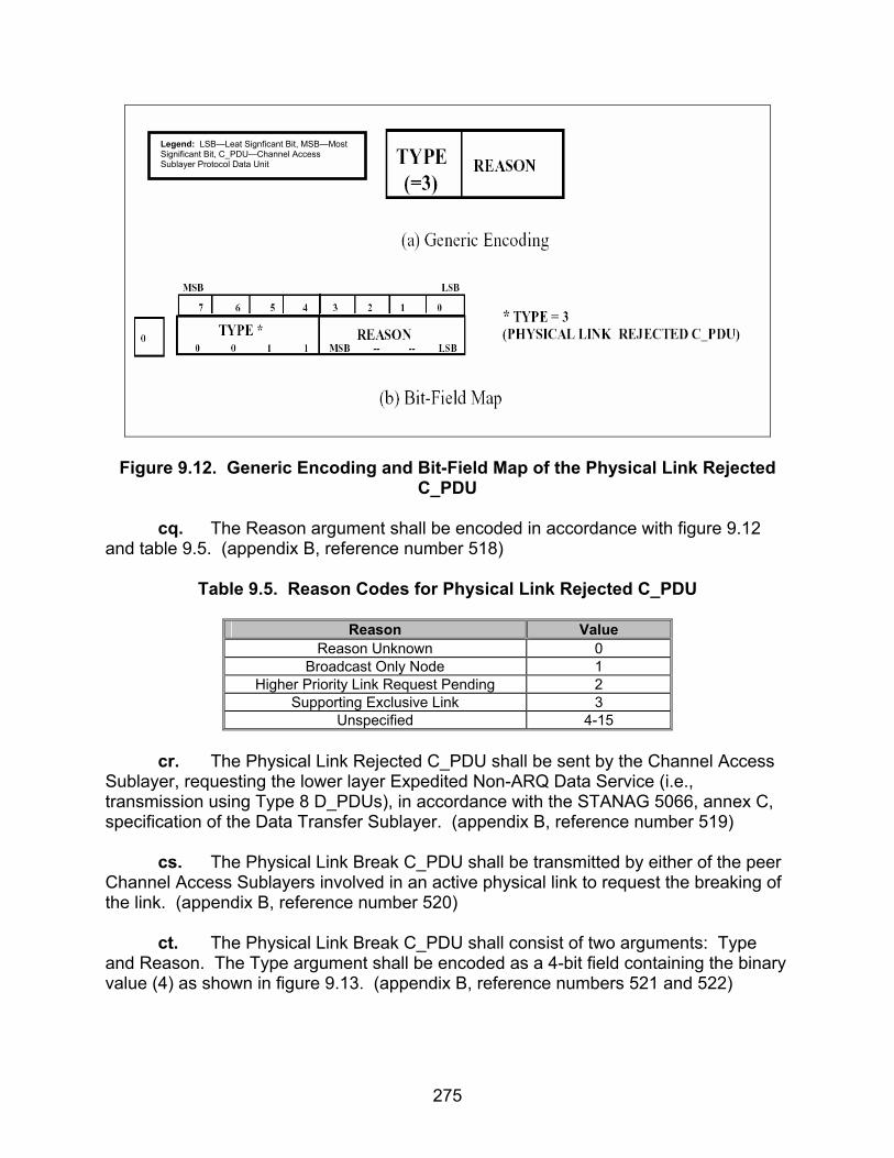
275
Figure 9.12. Generic Encoding and Bit-Field Map of the Physical Link Rejected C_PDU
cq. The Reason argument shall be encoded in accordance with figure 9.12 and table 9.5. (appendix B, reference number 518)
Table 9.5. Reason Codes for Physical Link Rejected C_PDU
Reason Value
Reason Unknown 0 Broadcast Only Node 1
Higher Priority Link Request Pending 2 Supporting Exclusive Link 3
Unspecified 4-15
cr. The Physical Link Rejected C_PDU shall be sent by the Channel Access Sublayer, requesting the lower layer Expedited Non-ARQ Data Service (i.e., transmission using Type 8 D_PDUs), in accordance with the STANAG 5066, annex C, specification of the Data Transfer Sublayer. (appendix B, reference number 519)
cs. The Physical Link Break C_PDU shall be transmitted by either of the peer
Channel Access Sublayers involved in an active physical link to request the breaking of the link. (appendix B, reference number 520)
ct. The Physical Link Break C_PDU shall consist of two arguments: Type
and Reason. The Type argument shall be encoded as a 4-bit field containing the binary value (4) as shown in figure 9.13. (appendix B, reference numbers 521 and 522)
Legend: LSB—Leat Signficant Bit, MSB—Most Significant Bit, C_PDU—Channel Access Sublayer Protocol Data Unit

276
Figure 9.13. Generic Encoding and Bit-Field Map of the Physical Link Break
C_PDU cu. The Reason argument shall be encoded in accordance with figure 9.13 and table 9.6. (appendix B, reference number 523)
Table 9.6. Reason Codes for Type 4 C_PDU
Reason Value
Reason Unknown 0 Higher Layer Request 1
Switching to Broadcast Data Exchange Session
2
Higher Priority Link Request Pending 3 Unspecified 4-15
cv. A peer sublayer, which receives the Physical Link Break C_PDU, shall
immediately declare the physical link as broken and respond with a Physical Link Break (Type 5) C_PDU, as specified in STANAG 5066, section B.3.1.6 (appendix B, reference number 524)
cw. The Physical Link Break C_PDU shall be sent by the Channel Access
Sublayer, requesting the lower layer Expedited Non-ARQ Data Service (i.e., transmission using Type 8 D_PDUs), in accordance with the STANAG 5066, annex C, specification of the Data Transfer Sublayer. (appendix B, reference number 525)
cx. The Physical Link Break Confirm (Type 5) C_PDU shall be transmitted by
a Channel Access Sublayer as a response to a Type 4 Physical Link Break C_PDU. (appendix B, reference number 526)
Legend: LSB—Leat Signficant Bit, MSB—Most Significant Bit, C_PDU—Channel Access Sublayer Protocol Data Unit

277
cy. The Physical Link Break Confirm (Type 5) C_PDU shall consist of the single Type argument. The Type argument shall be encoded as a 4-bit field containing the binary value (5) as shown in figure 9.14. (appendix B, reference numbers 527 and 528)
Figure 9.14. Generic Encoding and Bit-Field Map of the Physical Link Break
Confirm C_PDU
cz. Physical Link Break Confirm (Type 5) C_PDU shall be sent by the Channel Access Sublayer, requesting the lower layer Expedited Non-ARQ Data Service (i.e., transmission using Type 8 D_PDUs), in accordance with the STANAG 5066, annex C, specification of the Data Transfer Sublayer. (appendix B, reference number 529)
da. Upon receiving a Physical Link Break Confirm (Type 5) C_PDU, the peer that initiated the breaking of the link shall declare the link as broken. (appendix B, reference number 530) db. The Channel Access Sublayer shall perform all peer-to-peer communications for protocol control using the C_PDUs in table 9.7. (appendix B, reference number 531)
Table 9.7. C_PDUs for Peer-to-Peer Protocol Control
C_PDUs For Peer-to-Peer Protocol Control Type Code Physical Link Request Type 1 Physical Link Accept Type 2 Physical Link Rejected Type 3 Physical Link Break Type 4 Physical Link Break Confirm Type 5
Legend: C_PDU—Channel Access Sublayer Protocol Data Unit
Legend: LSB—Leat Signficant Bit, MSB—Most Significant Bit, C_PDU—Channel Access Sublayer Protocol Data Unit

278
dc. All peer-to-peer communications shall be done by the Channel Access Sublayer, requesting the lower layer Expedited Non-ARQ Data Service (i.e., transmission using Type 8 D_PDUs), in accordance with the STANAG 5066, annex C, specification of the Data Transfer Sublayer. (appendix B, reference number 532)
dd. The protocol for making the physical link shall consist of the following steps: (appendix B, reference numbers 536, 537 and 539)
Step 1: Caller
• The calling node’s Channel Access Sublayer shall send a Physical Link Request (Type 1) C_PDU, to initiate the protocol with the request’s Link argument set equal to the type of link (i.e., Exclusive or Nonexclusive) requested by the higher sublayer.
• The maximum time to wait for a response to a Physical Link Request (Type 1) C_PDU shall be a configurable parameter in the implementation of the protocol.
Step 2: Called
• On receiving a Physical Link Request (Type 1) C_PDU, a called node shall determine whether or not it can accept or reject the request as follows: (appendix B, reference numbers 540, 541, 543-545)
o Otherwise, the called node shall accept the request for a
Nonexclusive Physical Link. o If the request is for an Exclusive Physical Link and the called
node has either one or no active Exclusive Physical Link, the called node shall accept the request.
o Otherwise, the called node shall reject the request for an Exclusive Physical Link.
• After determining if it can accept or reject the Physical Link Request, a
called node shall respond as follows: (appendix B, reference numbers 546-548)
o If a called node accepts the Physical Link Request, it shall
respond with a Physical Link Accepted (Type 2) C_PDU. o When a called node rejects the Physical Link Request, it shall
respond with a Physical Link Rejected (Type 3) C_PDU.
• If at least one Data (Type 0) C_PDU is not received on a newly activated physical link after waiting for a specified maximum period of time, the called node shall abort the physical link and declare it inactive. (appendix B, reference number 551)

279
• The maximum period of time to wait for the first Data (Type 0) C_PDU, before aborting a newly activated physical link, shall be a configurable parameter in the implementation. (appendix B, reference number 552)
Step 3: Caller
• There are two possible outcomes to the protocol for making a physical link: success or failure. Upon receiving a Physical Link Accepted (Type 2) C_PDU, the calling Channel Access Sublayer shall proceed as follows: (appendix B, reference numbers 553, 555-559)
o The calling node shall declare the physical link as successfully
made; otherwise, o Upon receiving a Physical Link Rejected (Type 3) C_PDU, the
Channel Access Sublayer shall declare the physical link as failed.
o Upon expiration of its timer without any response having been received from the remote node, the Channel Access Sublayer shall repeat step 1 (i.e., send a Physical Link Request (Type 1) C_PDU and set a response time) and await again for a response from the remote node.
o The maximum number of times the caller sends the Physical Link Request (Type 1) C_PDU without a response from the called node of either kind shall be a configurable parameter in the implementation of the protocol.
o After having repeated step 1, the configurable maximum number of times without any response having been received from the remote node, the caller’s Channel Access Sublayer shall declare the protocol to make the physical link as failed.
de. The protocol for breaking the physical link shall consist of the following steps: (appendix B, reference number 560, 561 and 563-566)
Step 1: Initiator
• To start the protocol, the Initiator’s Channel Access Sublayer shall
send a Type 4 C_PDU (Physical Link Break). Step 2: Responder
• Upon receiving the Type 4 C_PDU, the Responder’s Channel Access
Sublayer shall declare the physical link as broken and send a Physical Link Break Confirm (Type 5) C_PDU.
Step 3: Initiator

280
• Upon receiving a Physical Link Break Confirm (Type 5) C_PDU, the Initiator’s Channel Access Sublayer shall declare the physical link as broken.
• Upon expiration of its timer without any response having been received from the remote node, the initiator’s Channel Access Sublayer shall repeat step 1 and wait again for a response from the remote node.
• After having repeated step 1, a maximum number of times (left as a configuration parameter) without any response having been received from the remote node, the Initiator’s Channel Access Sublayer shall declare the physical link as broken.
df. Protocol for Exchanging Data C_PDUs: The sending peer shall accept S_PDUs from the Subnetwork Interface Sublayer, envelop them in a DATA C_PDU (by adding the C_PCI), and send them to its receiving peer via its interface to the Data Transfer Sublayer. (appendix B, reference number 567) dg. The interface must support the service-definition for the Data Transfer Sublayer, i.e.: (appendix B, reference number 575)
• The interface shall allow the Data Transfer Sublayer to deliver C_PDUs to the Channel Access Sublayer. (appendix B, reference number 577)
• The interface shall permit the Channel Access Sublayer to notify the Data Transfer Sublayer that a connection (i.e., either an Exclusive or Nonexclusive Link) has been established with a given node. (appendix B, reference number 584)
• The interface shall permit the Channel Access Sublayer to notify the Data Transfer Sublayer that a connection (i.e., either an Exclusive or Nonexclusive Link) has been terminated with a given node. (appendix B, reference number 585)
• The interface shall permit the Data Transfer Sublayer to notify the Channel Access Sublayer that a connection (i.e., either an Exclusive or Nonexclusive Link) has been lost with a given node. (appendix B, reference number 586)
dh. The line-drivers and receivers for the interface shall be configurable for either balanced or unbalanced connection, in accordance with Electronic Industries Alliance (EIA)-232D/423 for unbalanced connections and EIA-422 for balanced connections. (appendix B, reference number 985)

281
9.3 Test Procedures
a. Test Equipment Required
(1) Computers (3 ea) with STANAG 5066 Software (2) Modem (3 ea) (3) Protocol Analyzer (4) RS-232 Synchronous Serial Cards (5) HF Radio (3 ea)
b. Test Configuration. Figure 9.15 shows the equipment setup for this subtest.
c. Test Conduction. Table 9.8 lists procedures for this subtest and table 9.9 lists the results for this subtest.
Computer Modem Modem Computer
LANAnalyzer
RS-232 RS-232
Figure 9.15. Equipment Configuration for Link Establishment Protocols

282
Table 9.8. Link Establishment Protocols Procedures
Step Action Settings/Action Result
1
Set up equipment. See figure 9.15. Computers are connected to the modems by an RS-232 connection. The connection between modems shall be such that the receive and transmit pins on the modem are connected to the transmit and receive pins, respectively, of the other modem.
2 Load STANAG 5066 software. Configure the SMTP and POP3 servers as
required by the STANAG 5066 software manual.
3
Configure STANAG addresses for all computers.
Set the size of the address field to 7 bytes. Set the STANAG address to 1.1.0.0, 1.2.0.0, and 2.1.0.0 as shown in figure 9.15. Configure the software to respond with an e-mail message to the sender once the e-mail has been successfully received.
4 Configure modems. Set modems to transmit a
MIL-STD-188-110B signal at a data rate of 4800 bps with half duplex.
5
Identify client to be used. Configure both computers to use the same client type. (Use HMTP if available.) Record the client type used by computers.
Client Type =
6
Configure protocol analyzer. Configure the protocol analyzer to capture the transmitted data between the computer with STANAG address 2.1.0.0 and its corresponding modem and save the data to a file. Configure the protocol analyzer to have a 4800-bps bit rate and to synchronize on “0x90EB.” Configure the protocol analyzer to drop sync after 20 “FF”s. Configure the analyzer to time stamp each captured byte.
7 Configure Deliver in Order. Set the Deliver in Order to “yes.” 8 Configure delivery confirmation. Set the delivery confirmation to “Node.” 9 Configure rank. Set the rank of the 3 computers to “15.”
10 Configure priority level. Set the priority of the 3 computers to “0.” The following procedures are for obtaining predicted values for reference numbers 3, 378, 388, 433, 539,
552, and 566.
11
Determine if the maximum period of time to wait for the first Data (Type 0) C_PDU before aborting a newly activated physical link is a configurable parameter in the STANAG 5066 software.
Locate in the STANAG 5066 application the Max Wait Time for Initial Type 0 C_PDU to be transmitted parameter. Record the Max Wait Time for Initial Type 0 C_PDU.
Max Wait Time for Initial Type 0 C_PDU =

283
Table 9.8. Link Establishment Protocols Procedures (continued)
Step Action Settings/Action Result
12
Determine if the maximum period of time after the computer transmits a Hard Link Terminate is a configurable parameter in the STANAG 5066 software (i.e., the STANAG 5066 contains a Hard Link Terminate Time-out configurable field).
Locate in the STANAG 5066 application the Max wait time after Hard Link Terminate is Transmitted parameter. Record the Max wait time after Hard Link Terminate is transmitted.
Max time after Hard Link Terminate is Transmitted =
13
Determine if the maximum number of times the computer will transmit a Physical Link Request C_PDU without a response from the receiving computer is configurable parameter in the STANAG 5066 software.
Locate in the STANAG 5066 application the Max Number of Times a Physical Link Request C_PDU parameter. Record the Max Number of Times a Physical Link Request C_PDU will be transmitted.
Max Number of Times Type 1 C_PDU Transmit- ting =
14
Determine if the maximum number of times the computer will transmit a Physical Link Break Request C_PDU without a response from the receiving computer is configurable parameter in the STANAG 5066 software.
Locate in the STANAG 5066 application the Max Number of Times a Physical Link Break Request C_PDU parameter. Record the Max Number of Times a Physical Link Break Request C_PDU will be transmitted.
Max Number of Times Type 4 C_PDU Transmit- ting =
15
Determine the minimum time for the called node to terminate a Soft Link before trying to establish a new link with a different node is a configurable parameter within the STANAG 5066 software.
Locate in the STANAG 5066 application Min Time to Terminate Soft Link parameter. Record the Min Time to Terminate Soft Link.
Min Time to Terminate Soft Link =
16
Determine the time for the node to terminate a Soft Link after the data had been transmitted.
Locate in the STANAG 5066 application the Soft Link Termination Time-Out parameter. Record the Soft Link Termination Time-Out.
Soft Link Termination Time-Out =
17
Determine that the max time to wait for a response to a Hard Link Terminate (Type 6) S_PDU is a configurable parameter.
Locate in the STANAG 5066 application the Max Time to wait for a response to a Hard Link Terminate S_PDU Time-Out. Record the max time to wait for a response to a Hard Link Terminate (Type 6) S_PDU Time-Out.
Type 6 S_PDU response Time-Out =

284
Table 9.8. Link Establishment Protocols Procedures (continued)
Step Action Settings/Action Result The following procedures are for Type 3-7 S_PDUs, reference numbers 7, 314, 315, 317-319, 356-358, 360-
365, 373-381, 414, 415, 425, 429, 431, 432, 540, and 544.
18
Send e-mail message.
Send the following e-mail message from the computer with STANAG address 1.1.0.0 to the computer with STANAG address 2.1.0.0 using a Type 0 Hard Link and Non-Expedited ARQ Delivery Method. For the Subject Line: Test 1 In the Body: “This is a test from address 1.1.0.0 to 2.1.0.0 1 2 3 4 5 6 7 8 9 10” Save the data obtained through the protocol analyzer to a file.
19
Locate all S_PDUs. The S_PDUs will be encapsulated within a Type 0 C_PDU, starting with the 2nd byte of the Type 0 C_PDU. The Type 0 C_PDU begins at the 17th byte of the D_PDU. D_PDUs begin with the hex sequence 0x90EB. The S_PDU type is the first 4 bits of the S_PDU. Record all S_PDUs and the direction they are transmitted/received.
S_PDU Types =
20
Locate all D_PDUs containing Types 3-7 S_PDUs.
D_PDUs begin with the hex sync, sequence 0x90EB, and the first 4 bits immediately following the sync sequence are the D_PDU type. For each of the Types 3-7 S_PDUs recorded in step 19, record their corresponding D_PDU Types.
D_PDU Types =
21
Locate to verify Handshaking for Hard Link Establishment the Type 3 S_PDU within the message from step 18.
The Type 3 S_PDU will be encapsulated within a Type 0 C_PDU, starting with the 2nd byte of the Type 0 C_PDU. The Type 0 C_PDU will be encapsulated within the first Type 4 D_PDU sent by computer with STANAG addresses 1.1.0.0 and will start at the 17th byte of the Type 4 D_PDU.
22
Determine S_PDU Type. The first 4 bits of the S_PDU are the S_PDU Type bits. Record the S_PDU Type bits.
S_PDU Type =
23
Locate Link Type bits encapsulated within the Type 3 S_PDU in step 21 for the Type 0 Hard Link.
The next 2 bits, after the S_PDU Type bits, are the Link Type bits. Record the Link Type bits.
Type 3 S_PDU Type 0 Hard Link Link Type =

285
Table 9.8. Link Establishment Protocols Procedures (continued)
Step Action Settings/Action Result
24
Locate Link Priority bits encapsulated within the Type 3 S_PDU in step 21 for Priority 0.
The next 2 bits, after the Link Type bits, are the Link Priority bits. Record the Link Priority bits.
Type 3 S_PDU Priority 0 Link Priority =
25
Locate Requesting SAP ID bits for the Type 3 S_PDU in step 21.
The next 4 bits, after the Link Priority bits, are the Requesting SAP ID bits. Record the Requesting SAP ID bits.
Type 3 S_PDU Requesting SAP ID =
26
Locate Remote SAP ID bits for the Type 3 S_PDU in step 21.
The next 4 bits, after the Requesting SAP ID bits, are the Remote SAP ID bits. Record the Remote SAP ID bits.
Type 3 S_PDU Remote SAP ID =
27
Locate Type 4 S_PDU. The Type 4 S_PDU will be encapsulated within a Type 0 C_PDU, starting with the 2nd byte of the Type 0 C_PDU. The Type 0 C_PDU will be encapsulated within the first Type 4 D_PDU sent by the computer that first establishes a Hard Link with computer 2.1.0.0 and will start at the 17th byte of the Type 4 D_PDU.
28
Locate S_PDU Type. The first 4 bits of the S_PDU are the S_PDU Type bits. Record the S_PDU Type bits.
S_PDU Type =
29
Locate Reserved bits. The next 4 bits, after the S_PDU Type bits, are the Reserved bits. Record the Reserved bits.
Type 4 S_PDU Reserved =
30
Locate Reason bits. The next 4 bits, after the Reserved bits, are the Reason bits. Record the Reason bits.
Type 6 Reason bits =
31
Locate Type 7 S_PDU. The Type 7 S_PDU will be encapsulated within a Type 0 C_PDU, starting with the 2nd byte of the Type 0 C_PDU. The Type 0 C_PDU will be encapsulated within the first Type 4 D_PDU sent by computer 2.1.0.0 to whichever computer first established a link and will start at the 17th byte of the Type 4 D_PDU.
32
Locate S_PDU Type. The first 4 bits of the S_PDU are the S_PDU Type bits. Record the S_PDU Type bits.
S_PDU Type =
33
Locate Reserved bits. The next 4 bits, after the S_PDU Type bits, are the Reserved bits. Record Reserved bits.
Type 7 Reserved bits =
34 Reconfigure priority. Reconfigure the priority of computer 1.1.0.0 to “1.”
35 Resend e-mail message. Resend the message transmitted in step 18 using a Type 1 Hard Link instead of Type 0.
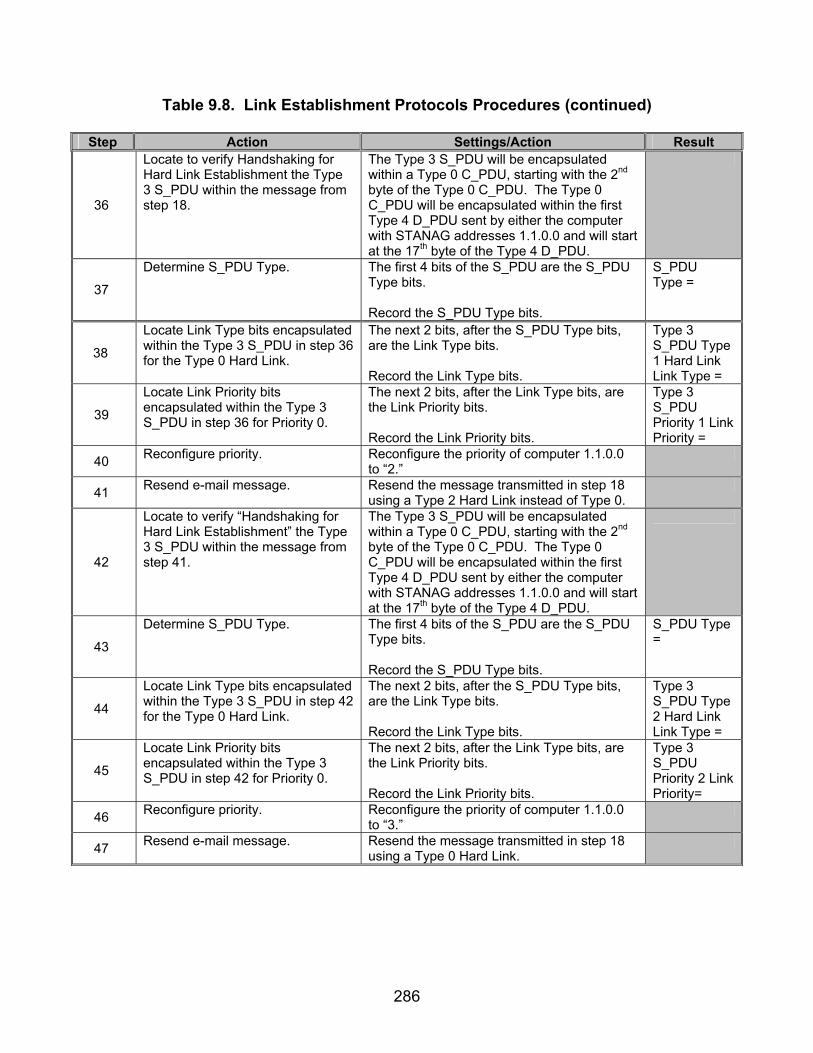
286
Table 9.8. Link Establishment Protocols Procedures (continued)
Step Action Settings/Action Result
36
Locate to verify Handshaking for Hard Link Establishment the Type 3 S_PDU within the message from step 18.
The Type 3 S_PDU will be encapsulated within a Type 0 C_PDU, starting with the 2nd byte of the Type 0 C_PDU. The Type 0 C_PDU will be encapsulated within the first Type 4 D_PDU sent by either the computer with STANAG addresses 1.1.0.0 and will start at the 17th byte of the Type 4 D_PDU.
37
Determine S_PDU Type. The first 4 bits of the S_PDU are the S_PDU Type bits. Record the S_PDU Type bits.
S_PDU Type =
38
Locate Link Type bits encapsulated within the Type 3 S_PDU in step 36 for the Type 0 Hard Link.
The next 2 bits, after the S_PDU Type bits, are the Link Type bits. Record the Link Type bits.
Type 3 S_PDU Type 1 Hard Link Link Type =
39
Locate Link Priority bits encapsulated within the Type 3 S_PDU in step 36 for Priority 0.
The next 2 bits, after the Link Type bits, are the Link Priority bits. Record the Link Priority bits.
Type 3 S_PDU Priority 1 Link Priority =
40 Reconfigure priority. Reconfigure the priority of computer 1.1.0.0 to “2.”
41 Resend e-mail message. Resend the message transmitted in step 18 using a Type 2 Hard Link instead of Type 0.
42
Locate to verify “Handshaking for Hard Link Establishment” the Type 3 S_PDU within the message from step 41.
The Type 3 S_PDU will be encapsulated within a Type 0 C_PDU, starting with the 2nd byte of the Type 0 C_PDU. The Type 0 C_PDU will be encapsulated within the first Type 4 D_PDU sent by either the computer with STANAG addresses 1.1.0.0 and will start at the 17th byte of the Type 4 D_PDU.
43
Determine S_PDU Type. The first 4 bits of the S_PDU are the S_PDU Type bits. Record the S_PDU Type bits.
S_PDU Type =
44
Locate Link Type bits encapsulated within the Type 3 S_PDU in step 42 for the Type 0 Hard Link.
The next 2 bits, after the S_PDU Type bits, are the Link Type bits. Record the Link Type bits.
Type 3 S_PDU Type 2 Hard Link Link Type =
45
Locate Link Priority bits encapsulated within the Type 3 S_PDU in step 42 for Priority 0.
The next 2 bits, after the Link Type bits, are the Link Priority bits. Record the Link Priority bits.
Type 3 S_PDU Priority 2 Link Priority=
46 Reconfigure priority. Reconfigure the priority of computer 1.1.0.0 to “3.”
47 Resend e-mail message. Resend the message transmitted in step 18 using a Type 0 Hard Link.
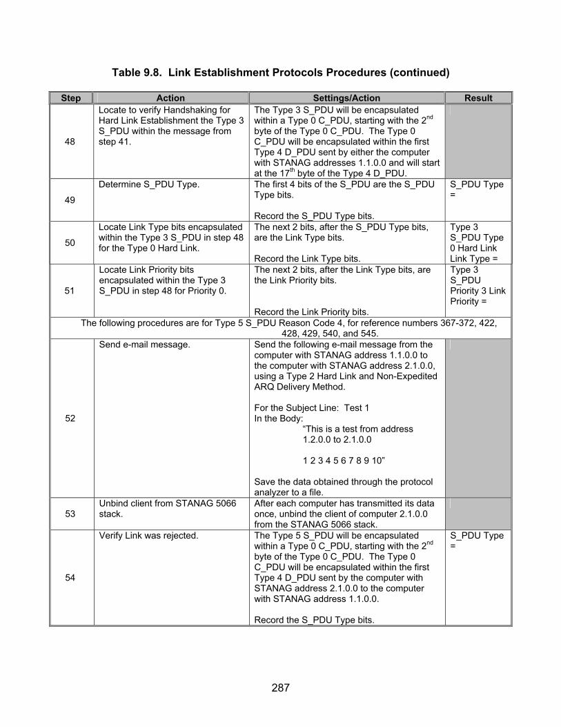
287
Table 9.8. Link Establishment Protocols Procedures (continued)
Step Action Settings/Action Result
48
Locate to verify Handshaking for Hard Link Establishment the Type 3 S_PDU within the message from step 41.
The Type 3 S_PDU will be encapsulated within a Type 0 C_PDU, starting with the 2nd byte of the Type 0 C_PDU. The Type 0 C_PDU will be encapsulated within the first Type 4 D_PDU sent by either the computer with STANAG addresses 1.1.0.0 and will start at the 17th byte of the Type 4 D_PDU.
49
Determine S_PDU Type. The first 4 bits of the S_PDU are the S_PDU Type bits. Record the S_PDU Type bits.
S_PDU Type =
50
Locate Link Type bits encapsulated within the Type 3 S_PDU in step 48 for the Type 0 Hard Link.
The next 2 bits, after the S_PDU Type bits, are the Link Type bits. Record the Link Type bits.
Type 3 S_PDU Type 0 Hard Link Link Type =
51
Locate Link Priority bits encapsulated within the Type 3 S_PDU in step 48 for Priority 0.
The next 2 bits, after the Link Type bits, are the Link Priority bits. Record the Link Priority bits.
Type 3 S_PDU Priority 3 Link Priority =
The following procedures are for Type 5 S_PDU Reason Code 4, for reference numbers 367-372, 422, 428, 429, 540, and 545.
52
Send e-mail message.
Send the following e-mail message from the computer with STANAG address 1.1.0.0 to the computer with STANAG address 2.1.0.0, using a Type 2 Hard Link and Non-Expedited ARQ Delivery Method. For the Subject Line: Test 1 In the Body: “This is a test from address 1.2.0.0 to 2.1.0.0 1 2 3 4 5 6 7 8 9 10” Save the data obtained through the protocol analyzer to a file.
53 Unbind client from STANAG 5066 stack.
After each computer has transmitted its data once, unbind the client of computer 2.1.0.0 from the STANAG 5066 stack.
54
Verify Link was rejected. The Type 5 S_PDU will be encapsulated within a Type 0 C_PDU, starting with the 2nd byte of the Type 0 C_PDU. The Type 0 C_PDU will be encapsulated within the first Type 4 D_PDU sent by the computer with STANAG address 2.1.0.0 to the computer with STANAG address 1.1.0.0. Record the S_PDU Type bits.
S_PDU Type =

288
Table 9.8. Link Establishment Protocols Procedures (continued)
Step Action Settings/Action Result
55
Locate Reason bits for the Type 5 S_PDU found in step 54.
The next 4 bits, after the S_PDU Type bits, are the Reason bits. Record the Reason bits.
Type 5 Reason bits =
The following procedures are for reference numbers 316, 383, 384, 386, 387, 472, 473, 479, 481, 487-494, 502-514, 546, 547, 553, 555, 560, 561, 563, 564, 567, 575, 577, 584, and 585.
56 Resend e-mail message. Resend the e-mail message in step 18 from
computer 1.1.0.0 to 2.1.0.0 using an ARQ Non-Expedited Soft Link Data Transfer.
57 From the captured file, locate sync bytes and D_PDU Type.
D_PDUs sync with the hex sequence 0x90EB, or (MSB) 1 0 0 1 0 0 0 0 1 1 1 0 1 0 1 1 (LSB) in binary.
58
For initial handshaking, locate the first Type 8 D_PDU from file captured in step 56 transmitted by the computer with STANAG address 1.1.0.0.
D_PDUs begin with the hex sequence 0x90EB. The first 4 bits, immediately after the 0x90EB sequence, will be the D_PDU Type. For the Type 8 D_PDU, the value will be 8 in hex or (MSB) 1000 (LSB) in binary. Locate the first Type 8 D_PDU transmitted by the computer with STANAG address 1.1.0.0.
59
Locate the C_PDU that is encapsulated within the Type 8 D_PDU.
The Type 8 D_PDU header is 22 bytes in length (excluding the bytes used for the sync sequence), for this case. The byte immediately following the Type 8 D_PDU header contains the C_PDU Type. The first 4 bits, beginning with the MSB, is the C_PDU Type. Verify that a Type (MSB) 0 0 0 1 (LSB) C_PDU has been encapsulated.
C_PDU Type =
60
Locate Reserved bits. For the Type 1 C_PDU identified in step 59, record the next 3 bits after the C_PDU Type. These 3 bits are the Reserved bits. Record the Reserved bits.
Reserve bits =
61
Locate Link bit. For the Type 1 C_PDU identified in step 59, record the eighth bit in the byte containing the C_PDU Type. This is the Link bit. Record the Link bit.
Link =
62
For initial handshaking, locate the first Type 8 D_PDU from file captured in step 56 transmitted by the computer with STANAG address 2.1.0.0.
D_PDUs begin with the hex sequence 0x90EB. The first 4 bits, immediately after the 0x90EB sequence, will be the D_PDU Type. For the Type 8 D_PDU, the value will be 8 in hex or (MSB) 1000 (LSB) in binary. Locate the first Type 8 D_PDU transmitted by the computer with STANAG address 2.1.0.0.

289
Table 9.8. Link Establishment Protocols Procedures (continued)
Step Action Settings/Action Result
63
Locate the C_PDU that is encapsulated within the Type 8 D_PDU from step 62.
The Type 8 D_PDU header is 22 bytes in length (excluding the bytes used for the sync sequence). The byte immediately following the Type 8 D_PDU header contains the C_PDU Type. The first 4 bits, beginning with the MSB, is the C_PDU Type. Verify that a Type (MSB) 0 0 1 0 (LSB) C_PDU has been encapsulated.
C_PDU Type=
64
Locate Reserve bits for the Type 2 C_PDU captured in step 63.
The next 4 bits, after the C_PCU Type bits, are the Reserve bits. Rcord the Reserve bits.
Reserve bits =
65
For initial message completion handshaking, locate the second Type 8 D_PDU from file captured in step 56 transmitted by the computer with STANAG address 1.1.0.0.
D_PDUs begin with the hex sequence 0x90EB. The first 4 bits immediately after the 0x90EB sequence will be the D_PDU Type. For the Type 8 D_PDU, the value will be 0x8 in hex or (MSB) 1000 (LSB) in binary. Locate the second Type 8 D_PDU transmitted by the computer with STANAG address 1.1.0.0.
66
Locate the C_PDU that is encapsulated within the Type 8 D_PDU from step 65.
The Type 8 D_PDU header is 22 bytes in length (excluding the bytes used for the sync sequence). The byte immediately following the Type 8 D_PDU header contains the C_PDU Type. The first 4 bits, beginning with the MSB, is the C_PDU Type. This value should be (MSB) 0 1 0 0 (LSB) (0x4 hex). Record the C_PDU Type.
C_PDU Type =
67
Obtain Reason bits. The next 4 bits, after the C_PDU Type, are the Reason bits. Record the Reason bits.
Type 4 C_PDU Reason bits =
68
For initial message completion handshaking, locate the second Type 8 D_PDU from file captured in step 56 transmitted by the computer with STANAG address 2.1.0.0.
D_PDUs begin with the hex sequence 0x90EB. The first 4 bits immediately after the 0x90EB sequence will be the D_PDU Type. For the Type 8 D_PDU, the value will be 0x8 in hex or (MSB) 1000 (LSB) in binary. Locate the second Type 8 D_PDU transmitted by the computer with STANAG address 2.1.0.0.
69
Locate the C_PDU that is encapsulated within the Type 8 D_PDU from step 68.
The Type 8 D_PDU header is 22 bytes in length (excluding the bytes used for the sync sequence). The byte immediately following the Type 8 D_PDU header contains the C_PDU Type. The first 4 bits, beginning with the MSB, is the C_PDU Type. This value should be (MSB) 0 1 0 1 (LSB) (0x5 hex). Record the C_PDU Type.
C_PDU Type =

290
Table 9.8. Link Establishment Protocols Procedures (continued)
Step Action Settings/Action Result
70
Locate Reason bits. The next 4 bits, after the C_PDU Type bits, are the Reason bits. Record the Reason bits.
Type 5 C_PDU Reason bits =
The following procedures are for obtaining tested values for reference numbers 3, 4, and 388.
71
Locate the time for Type 4 C_PDU to be sent.
Using the time stamps from the protocol analyzer, record the time from when the last Type 1 or 2 D_PDU is sent by computer 2.1.0.0 until the first Type 4 C_PDU is sent (encapsulated within a Type 8 D_PDU) by computer 1.1.0.0.
Time to break link =
72
Verify that no further bytes, other than “0xFFs,” are being sent after the Type 5 C_PDU is transmitted from the computer with STANAG address 2.1.0.0.
Allow the modems to run for another three seconds. Verify that during this time frame only “0xFF” bytes are being sent (this action will denote that the physical link has been broken).
Number of consecutive “0xFFs” =
The following procedures are for Type 0 S_PDUs, for reference numbers 315, 317-327, 329, 330, 332-339, 440, 447, 471, 487-498, 500, 520-532, 536, 537, 540, and 543.
73
Locate C_PDU Type from the first Type 0 D_PDU transferred by computer 1.1.0.0 from the file in step 56.
The Type 0 C_PDU will be encapsulated within the first 4 bits of the 17th byte of the first Type 0 D_PDU sent by the computer with STANAG address 1.1.0.0. Record the C_PDU Type.
C_PDU Type =
74
Locate Reserved bits. The next 4 bits, after the C_PDU Type, contain the Reserved bits. Record the Reserved bits.
Type 0 C_PDU Reserved bits=
75
Locate S_PDU Type encapsulated within the C_PDU found in step 73.
The following 4 bits, after the reserved bits of the Type 0 C_PDU, contain the S_PDU Type (this is also the S_PCI type) bits. Record the S_PDU Type. Note: The S_PCI Type and S_PDU Types are the same.
S_PDU Type =
76
Locate Priority bits for the S_PDU in step 75.
The next 4 bits, after the S_PDU Type bits, contain the Priority bits. Record the Priority bits and their decimal equivalent.
Type 0 S_PDU Priority =
77
Locate Source SAP ID bits for the S_PDU in step 75.
The next 4 bits, after the Priority bits, contain the Source SAP ID bits. Record the Source SAP ID bits.
Type 0 S_PDU Source SAP ID =

291
Table 9.8. Link Establishment Protocols Procedures (continued)
Step Action Settings/Action Result
78
Locate Destination SAP ID bits for the S_PDU located in step 75.
The next 4 bits, after the Source SAP ID bits, contain the Destination SAP ID bits. Record the Destination SAP ID bits.
Type 0 S_PDU Destination SAP ID =
79
Locate Client Delivery Confirm Required bit for the S_PDU located in step 75.
The next bit, after the Destination SAP ID bits, contains the Client Delivery Confirm Required bit. Record the Client Delivery Confirm Required bit.
Type 0 S_PDU Client Delivery Confirm Required =
80
Locate VTTD bit.
The next bit, after the Client Delivery Confirm Required bit, contains the VTTD bit. Record the VTTD bit.
Type 0 S_PDU VTTD =
81
Locate Reserved bits for the S_PDU located in step 75.
The next 2 bits, after the VTTD bit, are the Reserved bits. Record the Reserved bits.
Type 0 S_PDU Reserved bits =
82
Locate TTD bits for the S_PDU located in step 75.
The 20 bits, after the Reserved bits, contain the TTD bits. Record the TTD bits.
Type 0 S_PDU TTD =
83
Locate Julian date for the S_PDU located in step 75.
The first 4 bits of the TTD field is the Julian date. Record the Julian date’s decimal value.
Type 0 S_PDU Julian date =
84
Locate Time To Die in hours, minutes, and seconds for the S_PDU located in step 75.
The next 16 bits of the TTD field is the value of the TTD in seconds. Take the decimal value of the TTD field and convert the seconds to hours. Any partial hours, convert to minutes and any partial minutes convert to seconds (the form: h:m:s, where h=hour, m=minute, and s=second). This conversion can be done by taking the seconds and dividing by 3600. If there’s a fractional portion, leave the whole part and multiply the fractional part by 60 to get minutes. If there is a fractional part of the minutes, multiply the fractional part (leaving the whole part) by 60 to get the seconds. Record the TTD in hours:minutes:seconds.
Type 0 S_PDU TTD Time in hours:minutes: seconds =
85
Locate the number of bytes of actual user data transmitted for the S_PDU located in step 75.
The next long sequence of bytes are the user data bytes. Count the number of bytes starting with the 17th byte of the Type 0 D_PDU (not including sync sequence bits) to the end of the Type 0 D_PDU minus the last 4 bytes of the D_PDU, and record the actual data length. The D_PDU ends when either a string of “0xFFs” appears or another sync string, “0x90EB,” is located.
Number of User Data Bytes Actually Transmitted =

292
Table 9.8. Link Establishment Protocols Procedures (continued)
Step Action Settings/Action Result The following procedures are for Type 1 S_PDUs, for reference numbers 340-346, 467, 468, and 471.
86 Reconfigure Data Delivery Confirm.
Configure Data Delivery Confirm to “Client.”
87
Resend e-mail message. Resend the message from step 16 using Non-Expedited ARQ Soft Link Data Transfer. Transmit the message from computer 1.1.0.0 to computer 2.1.0.0.
88
Capture Type 0 S_PDU. Locate a Type 0 S_PDU with the Delivery Confirmation Required field equal to (1). This S_PDU will be encapsulated within a Type 0 C_PDU which will be encapsulated within a Type 0 D_PDU. The Type 0 S_PDU will begin at the 18th byte of the Type 0 D_PDU (not including the sync bits). The Delivery Confirmation field is the first bit of the third byte of the Type 0 S_PDU. The Type 0 D_PDU will be transmitted from computer 1.1.0.0 to computer 2.1.0.0. Record the Type 0 S_PDU Data Delivery Confirmation bit.
Type 0 S_PDU Data Delivery Confirmation =
89
Locate Type 1 S_PDU. After computer 1.1.0.0 has completed sending its data, computer 2.1.0.0 will respond with a Type 2 D_DPU. The Type 1 S_PDU will begin at the 16th byte of the Type 2 D_PDU. The S_PDU Type will be the first 4 bits of the first byte of the S_PDU. Record and verify the S_PDU Transmitted by computer 1.1.0.0.
S_PDU Type =
90
Locate Reserved bits. The next 4 bits of the S_PDU, after the S_PDU Type, are the Reserved bits. Record the Reserved bits.
Type 1 Reserved bits =
91
Locate Source SAP ID bits. The next 4 bits, after the Reserved bits, are the Source SAP ID bits. Record the Source SAP ID bits.
Type 1 Source SAP ID =
92
Locate Destination SAP ID bits. The next 4 bits, after the Source SAP ID bits, are the Destination SAP ID bits. Record the Destination SAP ID bits.
Type 1 Destination SAP ID =
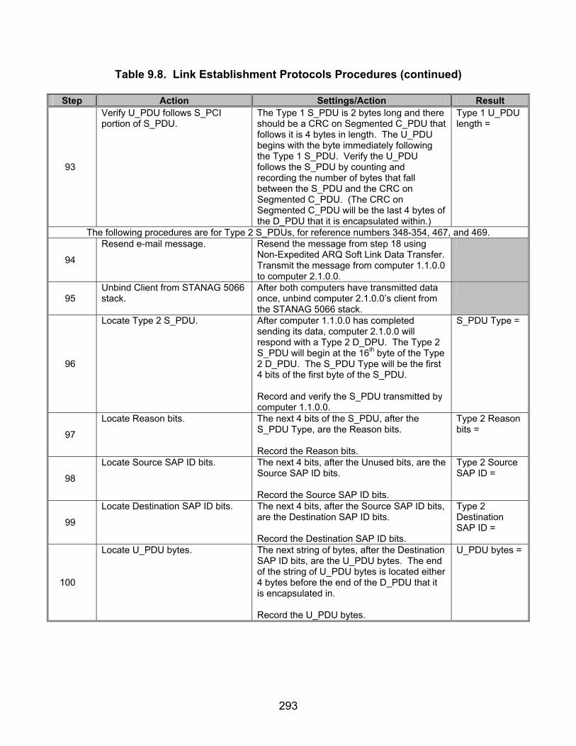
293
Table 9.8. Link Establishment Protocols Procedures (continued)
Step Action Settings/Action Result
93
Verify U_PDU follows S_PCI portion of S_PDU.
The Type 1 S_PDU is 2 bytes long and there should be a CRC on Segmented C_PDU that follows it is 4 bytes in length. The U_PDU begins with the byte immediately following the Type 1 S_PDU. Verify the U_PDU follows the S_PDU by counting and recording the number of bytes that fall between the S_PDU and the CRC on Segmented C_PDU. (The CRC on Segmented C_PDU will be the last 4 bytes of the D_PDU that it is encapsulated within.)
Type 1 U_PDU length =
The following procedures are for Type 2 S_PDUs, for reference numbers 348-354, 467, and 469.
94
Resend e-mail message. Resend the message from step 18 using Non-Expedited ARQ Soft Link Data Transfer. Transmit the message from computer 1.1.0.0 to computer 2.1.0.0.
95 Unbind Client from STANAG 5066 stack.
After both computers have transmitted data once, unbind computer 2.1.0.0’s client from the STANAG 5066 stack.
96
Locate Type 2 S_PDU. After computer 1.1.0.0 has completed sending its data, computer 2.1.0.0 will respond with a Type 2 D_DPU. The Type 2 S_PDU will begin at the 16th byte of the Type 2 D_PDU. The S_PDU Type will be the first 4 bits of the first byte of the S_PDU. Record and verify the S_PDU transmitted by computer 1.1.0.0.
S_PDU Type =
97
Locate Reason bits. The next 4 bits of the S_PDU, after the S_PDU Type, are the Reason bits. Record the Reason bits.
Type 2 Reason bits =
98
Locate Source SAP ID bits. The next 4 bits, after the Unused bits, are the Source SAP ID bits. Record the Source SAP ID bits.
Type 2 Source SAP ID =
99
Locate Destination SAP ID bits. The next 4 bits, after the Source SAP ID bits, are the Destination SAP ID bits. Record the Destination SAP ID bits.
Type 2 Destination SAP ID =
100
Locate U_PDU bytes. The next string of bytes, after the Destination SAP ID bits, are the U_PDU bytes. The end of the string of U_PDU bytes is located either 4 bytes before the end of the D_PDU that it is encapsulated in. Record the U_PDU bytes.
U_PDU bytes =

294
Table 9.8. Link Establishment Protocols Procedures (continued)
Step Action Settings/Action Result The following procedures are for Type 3 C_PDUs, for reference numbers 510, 515-519, 546, 548, 553, 556, 567,
and 586.
101
Resend e-mail message. Resend the message from step 16 using Non-Expedited ARQ Soft Link Data Transfer. Transmit the message from computer 1.1.0.0 to computer 2.1.0.0.
102
Transmit message from computer 1.2.0.0.
After each of the computers in step 98 have transmitted their data once, resend the message in step 16 using Non-Expedited ARQ Soft Link Data Transfer from computer 1.2.0.0 to 1.1.0.0.
103
Locate Type 3 C_PDU. The Type 8 D_PDU header is 22 bytes in length (excluding the bytes used for the sync sequence). The byte immediately following the Type 8 D_PDU header contains the C_PDU Type. The first 4 bits, beginning with the MSB, is the C_PDU Type. Also using the procedures from step 25, identify the computer that transmitted the C_PDU. Verify that a Type (MSB) 0 0 1 1 (LSB) C_PDU has been encapsulated.
C_PDU Type =
104
Locate Reason bits. The next 4 bits, after the C_PDU Type, are the Reason bits. Record the Reason bits.
Type 3 C_PDU Reason bits =
The following procedures are for reference number 5.
105
Resend e-mail message. Resend the message from step 16 using Non-Expedited ARQ Soft Link Data Transfer. Transmit the message from computer 1.1.0.0 to computer 2.1.0.0.
106
Transmit message from computer 1.2.0.0.
After each of the computers in step 98 have transmitted their data once, resend the message in step 16 using Non-Expedited ARQ Soft Link Data Transfer from computer 1.1.0.0 to 1.2.0.0.
107
Verify that the Soft Link established in step 105 was broken before the Soft Link in step 106 was established.
D_PDUs begin with the sync sequence 0x90EB. The type field is the first 4 bits after the sync sequence. Locate a D_PDU whose Type is (MSB) 1 0 0 0 (LSB) (0x8 hex). The Type 8 D_PDU header is 22 bytes in length (excluding the bytes used for the sync sequence). The byte immediately following the Type 8 D_PDU header contains the C_PDU Type. The first 4 bits, beginning with the MSB, is the C_PDU Type. Verify that Types 4 and 5 C_PDUs were transmitted to break the link in step 105, before Types 1 and 2 D_PDUs were transmitted to establish the link in step 106.
Link broken before new link established? Y/N

295
Table 9.8. Link Establishment Protocols Procedures (continued)
Step Action Settings/Action Result The following procedures are for reference number 551.
108
Resend e-mail message. Resend the message from step 18 using Non-Expedited ARQ Soft Link Data Transfer. Transmit the message from computer 1.1.0.0 to computer 2.1.0.0.
109
Disconnect STANAG 5066 stack. After each computer has transmitted its computer once (i.e., handshaking has completed), disconnect computer 1.1.0.0 from its STANAG 5066 stack.
Link broken? Y/N
110
Verify link was broken. Utilizing the STANAG 5066 log files, verify that computer 2.1.0.0 broke its link with computer 1.1.0.0. Also record how long it took computer 2.1.0.0 to break its link with computer 1.1.0.0.
Time to break link with no transmitted Type 0 C_PDUs =
The following procedures are for Type 1 C_PDUs, for reference numbers 539, 553, 557, and 559.
111 Disconnect STANAG 5066 stack. Disconnect computer 2.1.0.0 from its STANAG 5066 stack.
112
Resend e-mail message. Resend the message from step 18 using Non-Expedited ARQ Soft Link Data Transfer. Transmit the message from computer 1.1.0.0 to computer 2.1.0.0. Allow computer 1.1.0.0 to continue attempting to establish a link with computer 2.1.0.0 until it stops attempting to establish a link.
113
Locate the C_PDUs that are encapsulated within the Type 8 D_PDU.
The Type 8 D_PDU header is 22 bytes in length (excluding the bytes used for the sync sequence) for this case. The byte immediately following the Type 8 D_PDU header contains the C_PDU Type. The first 4 bits, beginning with the MSB, is the C_PDU Type. Record all C_PDU types transmitted.
C_PDU Types =
114
Locate the number of times a Type 1 C_PDU was transmitted.
Using the data collected in step 113, record the total number of times a Type 1 C_PDU was transmitted from computer 1.1.0.0.
Number of Type 1 C_PDUs Transmitted =
115
Locate the time to resend Type 8 D_PDUs.
Using the time stamps from step 112, record the time it takes for computer 1.1.0.0 to resend a Type 8 D_PDU.
Time to retransmit Type 8 D_PDU =

296
Table 9.8. Link Establishment Protocols Procedures (continued)
Step Action Settings/Action Result The following procedures are for Type 4 C_PDUs, for reference numbers 565 and 566.
116
Resend e-mail message. Resend the message from step 18 using Non-Expedited ARQ Soft Link Data Transfer. Transmit the message from computer 1.1.0.0 to computer 2.1.0.0. Allow computer 1.1.0.0 to continue attempting to establish a link with computer 2.1.0.0 until it stops attempting to establish a link.
117
Disconnect STANAG 5066 stack. After computer 1.1.0.0 has completed transmitting its data (computer 1.1.0.0 will complete the data transfer by transmitting Type 1 D_PDUs in response to computer 2.1.0.0’s Type 2 D_PDUs), disconnect computer 2.1.0.0 from its STANAG 5066 stack.
118
Locate the C_PDUs that are encapsulated within the Type 8 D_PDU.
The Type 8 D_PDU header is 22 bytes in length (excluding the bytes used for the sync sequence), for this case. The byte immediately following the Type 8 D_PDU header contains the C_PDU Type. The first 4 bits, beginning with the MSB, is the C_PDU Type. Record all C_PDU Types transmitted.
C_PDU Types =
119
Locate the number of times a Type 4 C_PDU was transmitted.
Using the data collected in step 118, record the total number of times a Type 4 C_PDU was transmitted from computer 1.1.0.0.
Number of Type 4 C_PDUs Transmitted =
120
Locate the time to resend Type 8 D_PDUs.
Using the time stamps from step 117, record the time it takes for computer 1.1.0.0 to resend a Type 8 D_PDU containing a Type 4 C_PDU.
Time to retransmit Type 4 C_PDU =
The following procedures are for Type 5 S_PDU Reason Code 1, for reference numbers 370-372 and 424.
121
Resend e-mail message. Resend the message from step 18 using Non-Expedited ARQ Type 0 Hard Link Data Transfer. Transmit the message from computer 2.1.0.0 to computer 1.1.0.0.
122
Resend e-mail message. After each computer has transmitted its data once, resend the message from step 18 using Non-Expedited ARQ Type 0 Hard Link Data Transfer. Transmit the message from computer 1.2.0.0 to computer 2.1.0.0.

297
Table 9.8. Link Establishment Protocols Procedures (continued)
Step Action Settings/Action Result
123
Locate Type 5 S_PDU. D_PDUs begin with the sync sequence 0x90EB. The next 4 bits, after the sync sequence, are the Type bits. The Type 5 S_PDU will be located in a D_PDU whose Type value equals (MSB) 0 1 0 0 (LSB) (0x4 hex). The S_PDU begins with the 18th byte of the Type 4 D_PDU (not including sync bits). The first 4 bits of the S_PDU are the Type bits. Verify that a Type 5 S_PDU was sent in response to computer 1.2.0.0 attempting to link with computer 2.1.0.0. Record the S_PDU Type bits.
S_PDU Type =
124
Locate Reason bits. The next 4 bits, after the S_PDU Type, are the Reason bits. Record the Reason bits.
Type 5 S_PDU Reason bits =
The following procedures are for Type 5 S_PDU Reason Code 2, for reference numbers 370-372 and 424.
125 Re-configure priority. Configure the priority of computer 2.1.0.0 to “2.”
126
Resend e-mail message. Resend the message from step 18 using Non-Expedited ARQ Type 0 Hard Link Data Transfer. Transmit the message from computer 2.1.0.0 to computer 1.1.0.0.
127
Resend e-mail message. After each computer has transmitted its data once, resend the message from step 18 using Non-Expedited ARQ Type 0 Hard Link Data Transfer. Transmit the message from computer 1.2.0.0 to computer 2.1.0.0.
128
Locate Type 5 S_PDU. D_PDUs begin with the sync sequence 0x90EB. The next 4 bits, after the sync sequence, are the Type bits. The Type 5 S_PDU will be located in a D_PDU whose Type value equals (MSB) 0 1 0 0 (LSB) (0x4 hex). The S_PDU begins with the 18th byte of the Type 4 D_PDU (not including sync bits). The first 4 bits of the S_PDU are the Type bits. Verify that a Type 5 S_PDU was sent in response to computer 1.2.0.0 attempting to link with computer 2.1.0.0. Record the S_PDU Type bits.
S_PDU Type=
129
Locate Reason bits. The next 4 bits, after the S_PDU Type, are the Reason bits. Record the Reason bits.
Type 5 S_PDU Reason bits =

298
Table 9.8. Link Establishment Protocols Procedures (continued)
Step Action Settings/Action Result The following procedures are for reference number 985.
Modem: Balanced (RS-232)—Y/N 130
Confirm the line-drivers and receivers for the interface can be configured for both balanced and unbalanced connections.
Verify that the hardware can be configured for either balanced or unbalanced connections.
Modem: Unbalanced (RS-232)—Y/N
Legend: ARQ—Automatic Repeat-Request bps—bits per second C_PDU—Channel Access Sublayer Protocol Data Unit CRC—Cyclic Redundancy Check D_PDU—Data Transfer Sublayer Protocol Data Unit e-mail—Electronic Mail hex—hexadecimal HMTP—High Frequency Mail Transfer Protocol ID—Identification LSB—Least Significant Bit MIL-STD—Military Standard
MSB—Most Significant Bit POP3—Post Office Protocol 3 S_PCI—Subnetwork Interface Sublayer Protocol Control Information S_PDU—Subnetwork Sublayer Protocol Data Unit SAP—Subnetwork Access Point SMTP—Simple Mail Transfer Protocol STANAG—Standardization Agreement sync—synchronization TTD—Time To Die U_PDU—User Protocol Data Units VTTD—Valid Time To Die
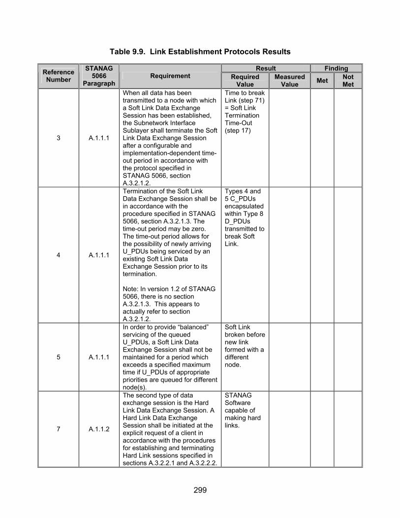
299
Table 9.9. Link Establishment Protocols Results
Result Finding Reference Number
STANAG 5066
Paragraph Requirement Required
Value Measured
Value Met Not Met
3 A.1.1.1
When all data has been transmitted to a node with which a Soft Link Data Exchange Session has been established, the Subnetwork Interface Sublayer shall terminate the Soft Link Data Exchange Session after a configurable and implementation-dependent time-out period in accordance with the protocol specified in STANAG 5066, section A.3.2.1.2.
Time to break Link (step 71) = Soft Link Termination Time-Out (step 17)
4 A.1.1.1
Termination of the Soft Link Data Exchange Session shall be in accordance with the procedure specified in STANAG 5066, section A.3.2.1.3. The time-out period may be zero. The time-out period allows for the possibility of newly arriving U_PDUs being serviced by an existing Soft Link Data Exchange Session prior to its termination. Note: In version 1.2 of STANAG 5066, there is no section A.3.2.1.3. This appears to actually refer to section A.3.2.1.2.
Types 4 and 5 C_PDUs encapsulated within Type 8 D_PDUs transmitted to break Soft Link.
5 A.1.1.1
In order to provide “balanced” servicing of the queued U_PDUs, a Soft Link Data Exchange Session shall not be maintained for a period which exceeds a specified maximum time if U_PDUs of appropriate priorities are queued for different node(s).
Soft Link broken before new link formed with a different node.
7 A.1.1.2
The second type of data exchange session is the Hard Link Data Exchange Session. A Hard Link Data Exchange Session shall be initiated at the explicit request of a client in accordance with the procedures for establishing and terminating Hard Link sessions specified in sections A.3.2.2.1 and A.3.2.2.2.
STANAG Software capable of making hard links.

300
Table 9.9. Link Establishment Protocols Results (continued)
Result Finding Reference Number
STANAG 5066
Paragraph Requirement Required
Value Measured
Value Met Not Met
314 A.3
Peer Subnetwork Interface Sublayers, generally in different nodes, shall communicate with each other by the exchange of Subnetwork Interface Sublayer Protocol Data Units (S_PDUs).
U_PDUs encapsulated within Type 0 S_PDUs and Type 3-7 S_PDUs used for making and breaking Hard Links.
315 A.3
For the subnetwork configurations currently defined in STANAG 5066, peer-to-peer communication shall be required for the: 1. Establishment and termination of Hard Link Data Exchange Sessions. 2. Exchange of Client Data.
Types 3-7 S_PDUs used to establish Hard Links and U_PDU encapsulated within Type 0 S_PDU.
316 A.3
Explicit peer-to-peer communication shall not be required for the establishment or termination of Soft Link or Broadcast Data Exchange Sessions.
No Types 3-7 S_PDUs transmitted for Soft Link for “Handshak-ing” for ARQ and Non-ARQ Transmission Modes.
317 A.3.1
Subnetwork Interface Sublayer Protocol Data Units (S_PDUS) and Encoding Requirements: The first encoded field shall be common to all S_PDUs.
All S_PDUs contain Type field.
318 A.3.1 It is called “TYPE” and shall encode the type value of the S_PDU as follows:
S_PDU Type = 0
319 A.3.1
The meaning and encoding of the remaining fields, if any, in an S_PDU shall be as specified in the subsection below corresponding to the S_PDU Type.
S_PDUs encoded as specified by their corresponding sections.
320 A.3.1.1
The Data S_PDU shall be transmitted by the Subnetwork Interface Sublayer in order to send client data to a remote peer sublayer.
U_PDUs encapsulated within Type 0 S_PDU.

301
Table 9.9. Link Establishment Protocols Results (continued)
Result Finding Reference Number
STANAG 5066
Paragraph Requirement Required
Value Measured
Value Met Not Met
321 A.3.1.1
The Data S_PDU shall be encoded as specified in figure A-32 and in the paragraphs below.
S_PDU encoded as shown in figure 9.1.
322 A.3.1.1 This S_PDU shall consist of two parts:
323 A.3.1.1
The first part shall be the S_PCI (Subnetwork Interface Sublayer Protocol Control Information) and represents the overhead added by the sublayer;
S_PDU contains S_PCI information.
324 A.3.1.1
The second part shall be the actual client data (U_PDU).
U_PDU encapsulated within S_PDU.
325 A.3.1.1 The first field of 4 bits the S_PCI part shall be “TYPE.”
S_PCI Type = 0
326 A.3.1.1 Its value shall be equal to (0) and identifies the S_PDU as being of type Data.
S_PCI Type = 0
327 A.3.1.1 The second field of 4 bits shall be “PRIORITY” and represents the priority of the client’s U_PDU.
Type 0 Priority = 7
329 A.3.1.1
The third field of 4 bits of the S_PCI shall be the “SOURCE SAP ID” and identifies the client of the transmitting peer that sent the data.
Source SAP ID = (MSB) 0 0 1 1 (LSB) (0x3 hex) (This value taken from annex F.4 of STANAG 5066 for HMTP Client.)
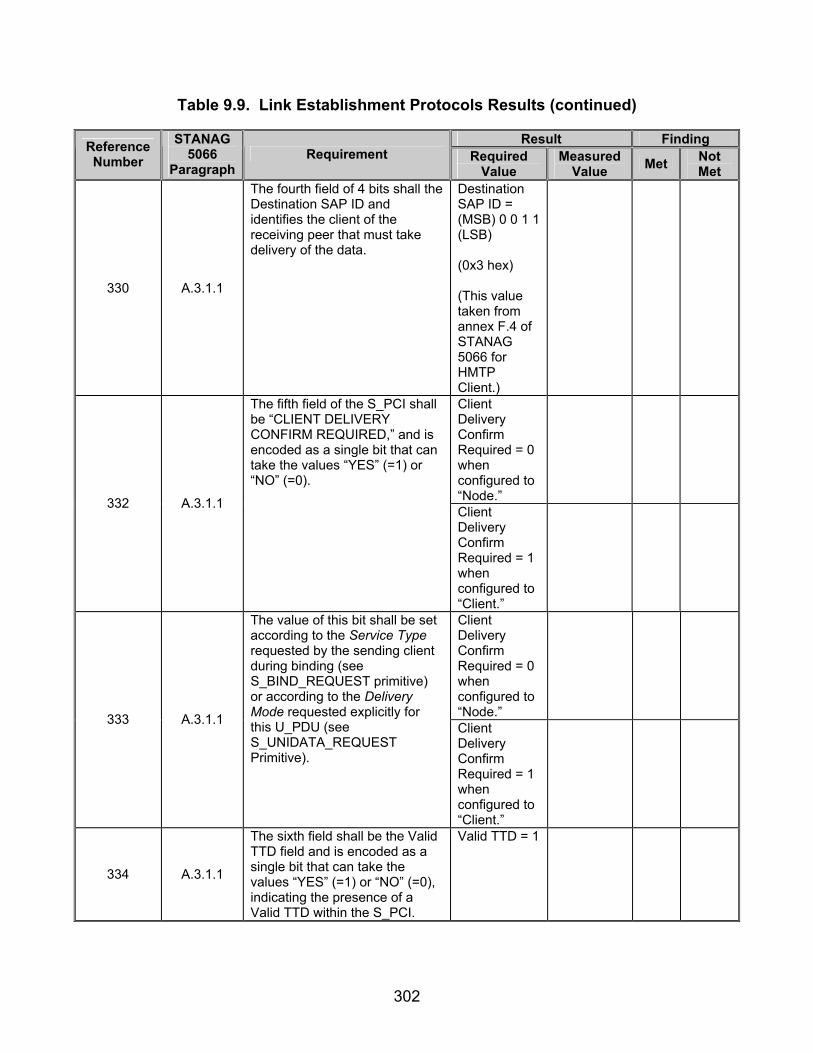
302
Table 9.9. Link Establishment Protocols Results (continued)
Result Finding Reference Number
STANAG 5066
Paragraph Requirement Required
Value Measured
Value Met Not Met
330 A.3.1.1
The fourth field of 4 bits shall the Destination SAP ID and identifies the client of the receiving peer that must take delivery of the data.
Destination SAP ID = (MSB) 0 0 1 1 (LSB) (0x3 hex) (This value taken from annex F.4 of STANAG 5066 for HMTP Client.)
Client Delivery Confirm Required = 0 when configured to “Node.”
332 A.3.1.1
The fifth field of the S_PCI shall be “CLIENT DELIVERY CONFIRM REQUIRED,” and is encoded as a single bit that can take the values “YES” (=1) or “NO” (=0).
Client Delivery Confirm Required = 1 when configured to “Client.”
Client Delivery Confirm Required = 0 when configured to “Node.”
333 A.3.1.1
The value of this bit shall be set according to the Service Type requested by the sending client during binding (see S_BIND_REQUEST primitive) or according to the Delivery Mode requested explicitly for this U_PDU (see S_UNIDATA_REQUEST Primitive).
Client Delivery Confirm Required = 1 when configured to “Client.”
334 A.3.1.1
The sixth field shall be the Valid TTD field and is encoded as a single bit that can take the values “YES” (=1) or “NO” (=0), indicating the presence of a Valid TTD within the S_PCI.
Valid TTD = 1

303
Table 9.9. Link Establishment Protocols Results (continued)
Result Finding Reference Number
STANAG 5066
Paragraph Requirement Required
Value Measured
Value Met Not Met
335 A.3.1.1
The seventh field of the S_PCI shall be two unused bits that are reserved for future use.
Reserved bits = (MSB) 0 0 (LSB) (hex = 0x00)
336 A.3.1.1
The eighth and last field of the S_PCI shall be “TTD” and represents the Time To Die for this U_PDU.
The value of this field > 0.
337 A.3.1.1 The first 4 bits of this field shall have meaning, if and only if the Valid TTD field equals “YES.”
First 4 bits have a value.
338 A.3.1.1
The remaining 16 bits of the field shall be present in the S_PCI, if and only if the Valid TTD field equals “YES.” The TTD field encodes the Julian date (modulo 16) and the GMT in seconds after which time the S_PDU must be discarded if it has not yet been delivered to the client.
Remaining 16 bits have a value and could be expressed in hours, minutes, and seconds.
339 A.3.1.1
The Julian date (modulo 16) part of the TTD shall be mapped into the first 4 bits of the TTD field (i.e., bits 0-3 of byte 2 of the S_PDU).
Julian date = (MSB) 0 0 0 0 (LSB) (hex = 0x0)
340 A.3.1.2
The Data Delivery Confirm S_PDU shall be transmitted in response to a successful delivery to a client of a U_PDU, which was received in a DATA type S_PDU in which the Client Delivery Confirm Required field was set to “YES.”
Type 1 S_PDU sent in response to Type 0 S_PDU whose Data Delivery Confirm Request = 1.

304
Table 9.9. Link Establishment Protocols Results (continued)
Result Finding Reference Number
STANAG 5066
Paragraph Requirement Required
Value Measured
Value Met Not Met
341 A.3.1.2
The Data Delivery Confirm S_PDU shall be transmitted by the Subnetwork Interface Sublayer to the peer sublayer which originated the DATA Type S_PDU.
Type 1 S_PDU sent from computer 1.1.0.0 to computer 1.2.0.0 when Data Delivery Confirmation set to Node.
342 A.3.1.2
The first part of the Data Delivery Confirm S_PDU shall be the S_PCI.
Type 1 S_PDU 2 bytes in length.
343 A.3.1.2
While the second part shall be a full or partial copy of the U_PDU that was received and delivered to the destination client.
Type 1 U_PDU length > 0.
344 A.3.1.2 The first field of the S_PCI part shall be “TYPE.”
S_PDU Type = 1
345 A.3.1.2
Its value shall equal 1 to identify the S_PDU as being of type DATA Delivery Confirm.
S_PDU Type = (MSB) 0 0 0 1 (LSB) (0x1 hex)
Type 1 Reserved bits = (MSB) 0 0 0 0 (LSB) (0x0 hex)
346
A.3.1.2
The remaining fields and their values for the S_PCI part of the Data Delivery Confirm S_PDU, shall be equal in value to the corresponding fields of the Data S_PDU, for which this Data Delivery Confirm S_PDU is a response.
Source SAP ID = (MSB) 0 0 1 1 (LSB) (0x3 hex) (This value taken from Annex F.4 of STANAG 5066 for HMTP Client.)
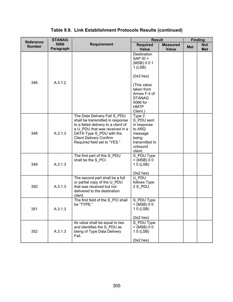
305
Table 9.9. Link Establishment Protocols Results (continued)
Result Finding Reference Number
STANAG 5066
Paragraph Requirement Required
Value Measured
Value Met Not Met
346 A.3.1.2
Destination SAP ID = (MSB) 0 0 1 1 (LSB) (0x3 hex) (This value taken from Annex F.4 of STANAG 5066 for HMTP Client.)
348 A.3.1.3
The Data Delivery Fail S_PDU shall be transmitted in response to a failed delivery to a client of a U_PDU that was received in a DATA Type S_PDU with the Client Delivery Confirm Required field set to “YES.”
Type 2 S_PDU sent in response to ARQ message being transmitted to unbound client.
349 A.3.1.3
The first part of this S_PDU shall be the S_PCI .
S_PDU Type = (MSB) 0 0 1 0 (LSB) (0x2 hex)
350 A.3.1.3
The second part shall be a full or partial copy of the U_PDU that was received but not delivered to the destination client.
U_PDU follows Type 2 S_PDU.
351 A.3.1.3
The first field of the S_PCI shall be “TYPE.”
S_PDU Type = (MSB) 0 0 1 0 (LSB) (0x2 hex)
352 A.3.1.3
Its value shall be equal to two and identifies the S_PDU as being of Type Data Delivery Fail.
S_PDU Type = (MSB) 0 0 1 0 (LSB) (0x2 hex)

306
Table 9.9. Link Establishment Protocols Results (continued)
Result Finding Reference Number
STANAG 5066
Paragraph Requirement Required
Value Measured
Value Met Not Met
353 A.3.1.3
The second field shall be “REASON” and explains why the U_PDU failed to be delivered. It can take a value in the range 0 to 15 and valid reasons are defined in section A.3.1.3 of STANAG 5066.
Type 2 Reason = (MSB) 0 0 1 0 (LSB) (0x2 hex)
Source SAP ID = (MSB) 0 0 1 1 (LSB) (0x3 hex) (This value taken from annex F.4 of STANAG 5066 for HMTP Client.)
354 A.3.1.3
The Source SAP ID and Destination SAP ID fields of the S_PCI shall be equal in value to the corresponding fields of the Data S_PDU for which the Data Delivery Fail S_PDU is a response.
Destination SAP ID = (MSB) 0 0 1 1 (LSB) (0x3 hex) (This value taken from annex F.4 of STANAG 5066 for HMTP Client.)
Type 3 S_PDU sent for a Type 0 Hard Link.
Type 3 S_PDU sent for a Type 1 Hard Link.
356 A.3.1.4
The Hard Link Establishment Request S_PDU shall be transmitted, by a peer, in response to a client’s request for a Hard Link.
Type 3 S_PDU sent for a Type 2 Hard Link.
357 A.3.1.4 The first field of the S_PDU shall be “TYPE.”
Type 3 S_PDU sent.

307
Table 9.9. Link Establishment Protocols Results (continued)
Result Finding Reference Number
STANAG 5066
Paragraph Requirement Required
Value Measured
Value Met Not Met
358 A.3.1.4
It shall be equal to 3 and identifies the S_PDU as being of Type Hard Link Establishment Request.
Type 3 S_PDU sent.
360 A.3.1.4
The “REQUESTING SAP ID” field shall be the SAP ID of the client that requested the Hard Link Establishment.
Type 3 S_PDU Source SAP ID = 3 (This value taken from annex F.4 of STANAG 5066 for HMTP Client.)
Type 3 S_PDU Destination SAP ID = 0 for Type 0 and 1 Hard Links.
361 A.3.1.4
This “REMOTE SAP ID” field shall be valid, if and only if the “LINK TYPE” field has a value of 2, denoting a Type 2 Hard Link w/ Full-Bandwidth Reservation.
Type 3 S_PDU Destination SAP ID = 3 For Type 2 Hard Link. (This value taken from annex F.4 of STANAG 5066 for HMTP client.)
362 A.3.1.4
The “REMOTE SAP ID” field shall identify the single client connected to the remote node to and from which traffic is allowed for Hard Links w/ Full-Bandwidth Reservation. The Remote SAP ID field may take any implementation-dependent default value for Hard Links without Full-Bandwidth Reservation.
Type 3 S_PDU Destination SAP ID = 3 For Type 2 Hard Link. (This value taken from annex F.4 of STANAG 5066 for HMTP client.)
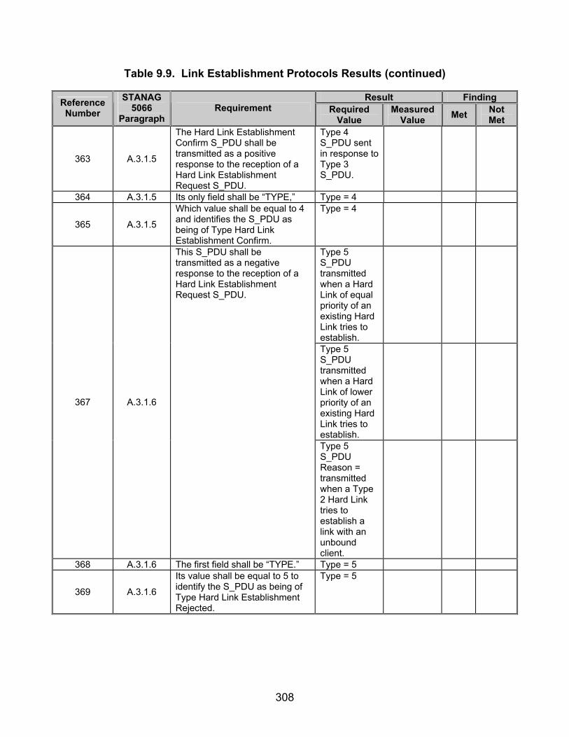
308
Table 9.9. Link Establishment Protocols Results (continued)
Result Finding Reference Number
STANAG 5066
Paragraph Requirement Required
Value Measured
Value Met Not Met
363 A.3.1.5
The Hard Link Establishment Confirm S_PDU shall be transmitted as a positive response to the reception of a Hard Link Establishment Request S_PDU.
Type 4 S_PDU sent in response to Type 3 S_PDU.
364 A.3.1.5 Its only field shall be “TYPE,” Type = 4
365 A.3.1.5
Which value shall be equal to 4 and identifies the S_PDU as being of Type Hard Link Establishment Confirm.
Type = 4
Type 5 S_PDU transmitted when a Hard Link of equal priority of an existing Hard Link tries to establish.
Type 5 S_PDU transmitted when a Hard Link of lower priority of an existing Hard Link tries to establish.
367 A.3.1.6
This S_PDU shall be transmitted as a negative response to the reception of a Hard Link Establishment Request S_PDU.
Type 5 S_PDU Reason = transmitted when a Type 2 Hard Link tries to establish a link with an unbound client.
368 A.3.1.6 The first field shall be “TYPE.” Type = 5
369 A.3.1.6
Its value shall be equal to 5 to identify the S_PDU as being of Type Hard Link Establishment Rejected.
Type = 5
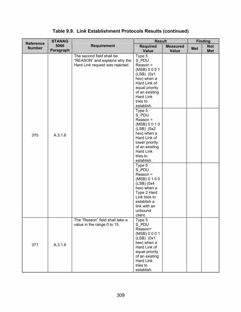
309
Table 9.9. Link Establishment Protocols Results (continued)
Result Finding Reference Number
STANAG 5066
Paragraph Requirement Required
Value Measured
Value Met Not Met
Type 5 S_PDU Reason = (MSB) 0 0 0 1 (LSB) (0x1 hex) when a Hard Link of equal priority of an existing Hard Link tries to establish.
Type 5 S_PDU Reason = (MSB) 0 0 1 0 (LSB) (0x2 hex) when a Hard Link of lower priority of an existing Hard Link tries to establish.
370 A.3.1.6
The second field shall be “REASON” and explains why the Hard Link request was rejected.
Type 5 S_PDU Reason = (MSB) 0 1 0 0 (LSB) (0x4 hex) when a Type 2 Hard Link tries to establish a link with an unbound client.
371 A.3.1.6
The “Reason” field shall take a value in the range 0 to 15.
Type 5 S_PDU Reason= (MSB) 0 0 0 1 (LSB) (0x1 hex) when a Hard Link of equal priority of an existing Hard Link tries to establish.
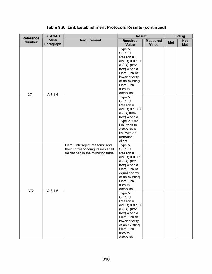
310
Table 9.9. Link Establishment Protocols Results (continued)
Result Finding Reference Number
STANAG 5066
Paragraph Requirement Required
Value Measured
Value Met Not Met
Type 5 S_PDU Reason = (MSB) 0 0 1 0 (LSB) (0x2 hex) when a Hard Link of lower priority of an existing Hard Link tries to establish.
371 A.3.1.6
Type 5 S_PDU Reason = (MSB) 0 1 0 0 (LSB) (0x4 hex) when a Type 2 Hard Link tries to establish a link with an unbound client.
Type 5 S_PDU Reason = (MSB) 0 0 0 1 (LSB) (0x1 hex) when a Hard Link of equal priority of an existing Hard Link tries to establish.
372 A.3.1.6
Hard Link “reject reasons” and their corresponding values shall be defined in the following table.
Type 5 S_PDU Reason = (MSB) 0 0 1 0 (LSB) (0x2 hex) when a Hard Link of lower priority of an existing Hard Link tries to establish.

311
Table 9.9. Link Establishment Protocols Results (continued)
Result Finding Reference Number
STANAG 5066
Paragraph Requirement Required
Value Measured
Value Met Not Met
372 A.3.1.6
Type 5 S_PDU Reason = (MSB) 0 1 0 0 (LSB) (0x4 hex) when a Type 2 Hard Link tries to establish a link with an unbound client.
373 A.3.1.7
Either of the two peer sublayers involved in a Hard Link session and that wishes to terminate the Hard Link shall transmit a Hard Link Terminate S_PDU to request termination of the Hard Link.
Either computer sends a Type 6 S_PDU and TX data is complete.
374 A.3.1.7 The first 4-bit field shall be “TYPE.”
Type = 6
375 A.3.1.7 Is value shall be set equal to 6 to identify the S_PDU as being of Type Hard Link Terminate.
Type = 6
376 A.3.1.7
The second 4-bit field shall be “REASON” and explains why the Hard Link is being terminated.
Type 6 S_PDU reason = (MSB) 0 0 0 1 (LSB)
377 A.3.1.7
Hard Link Terminate reasons and their corresponding values shall be defined in the following table.
378 A.3.1.7
In order to ensure a graceful termination of the Hard Link, the peer which sent the Hard Link Terminate must await a Time-Out period for confirmation of its peer before it declares the link as terminated. This Time-Out period shall be configurable by the protocol implementation.
Hard Link Terminate Time-out is configurable in STANAG 5066 software.
379 A.3.1.8
The Hard Link Terminate Confirm S_PDU shall be transmitted in response to the reception of a Hard Link Terminate S_PDU.
Type 7 S_PDU sent in response to Type 6 S_PDU.

312
Table 9.9. Link Establishment Protocols Results (continued)
Result Finding Reference Number
STANAG 5066
Paragraph Requirement Required
Value Measured
Value Met Not Met
380 A.3.1.8 The first 4-bit field of this S_PDU shall be “TYPE.”
Type = 7
381 A.3.1.8 A value of 7 shall identify that the S_PDU is of Type Hard Link Terminate Confirm.
Type = 7
382 A.3.1.8
The second 4-bit field of this S_PDU shall be not used in this implementation of the protocol. The values of these bits may be implementation dependent.
Type 7 S_PDU Reserved bits = (MSB) 0 0 0 0 (LSB)
383 A.3.2.1.1
In contrast with the establishment of a Hard Link session, the establishment of Soft Link Data Exchange Sessions shall not require explicit peer-to-peer handshaking within the Subnetwork Interface Sublayer.
No Types 3-7 S_PDUs transmitted for Soft Link for “Handshak-ing” for ARQ and Non-ARQ Transmission Modes.
384 A.3.2.1.1
The calling peer shall implicitly establish a Soft Link Data Exchange Session by requesting its Channel Access Sublayer to make a physical link to the required remote node, using the procedure for making physical links specified in annex B of STANAG 5066.
Types 1-5 C_PDUs transmitted during Soft Links for “Handshak-ing.”
386 A.3.2.1.2
No peer-to-peer communication by the Subnetwork Interface Sublayer shall be required to terminate a Soft Link Data Exchange Session.
No Types 3-7 S_PDUs transmitted for Soft Link for “Handshak-ing” for ARQ Transmission Modes.
387 A.3.2.1.2
A Soft Link Data Exchange Session shall be terminated by either of the two peers by a request to its respective Channel Access Sublayer to break the Physical Link in accordance with the procedure specified in annex B.
Types 4 and 5 C_PDUs sent to end transmissions for Soft Links.
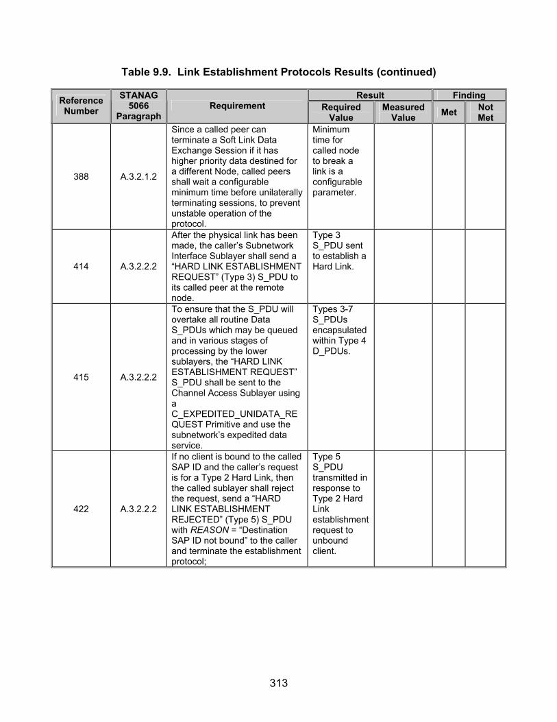
313
Table 9.9. Link Establishment Protocols Results (continued)
Result Finding Reference Number
STANAG 5066
Paragraph Requirement Required
Value Measured
Value Met Not Met
388 A.3.2.1.2
Since a called peer can terminate a Soft Link Data Exchange Session if it has higher priority data destined for a different Node, called peers shall wait a configurable minimum time before unilaterally terminating sessions, to prevent unstable operation of the protocol.
Minimum time for called node to break a link is a configurable parameter.
414 A.3.2.2.2
After the physical link has been made, the caller’s Subnetwork Interface Sublayer shall send a “HARD LINK ESTABLISHMENT REQUEST” (Type 3) S_PDU to its called peer at the remote node.
Type 3 S_PDU sent to establish a Hard Link.
415 A.3.2.2.2
To ensure that the S_PDU will overtake all routine Data S_PDUs which may be queued and in various stages of processing by the lower sublayers, the “HARD LINK ESTABLISHMENT REQUEST” S_PDU shall be sent to the Channel Access Sublayer using a C_EXPEDITED_UNIDATA_REQUEST Primitive and use the subnetwork’s expedited data service.
Types 3-7 S_PDUs encapsulated within Type 4 D_PDUs.
422 A.3.2.2.2
If no client is bound to the called SAP ID and the caller’s request is for a Type 2 Hard Link, then the called sublayer shall reject the request, send a “HARD LINK ESTABLISHMENT REJECTED” (Type 5) S_PDU with REASON = “Destination SAP ID not bound” to the caller and terminate the establishment protocol;
Type 5 S_PDU transmitted in response to Type 2 Hard Link establishment request to unbound client.
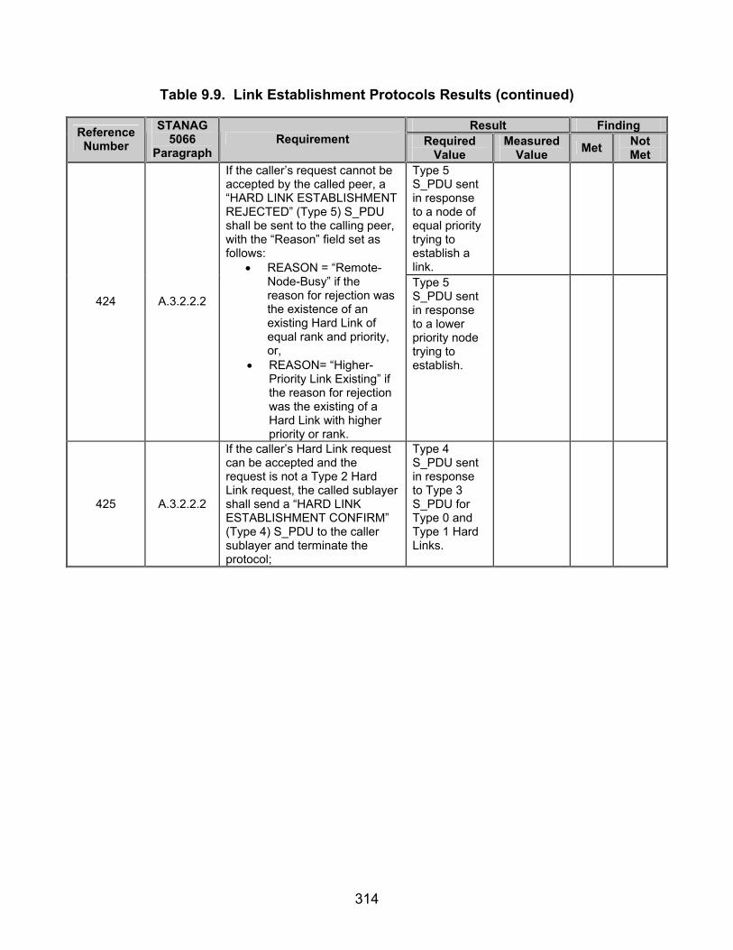
314
Table 9.9. Link Establishment Protocols Results (continued)
Result Finding Reference Number
STANAG 5066
Paragraph Requirement Required
Value Measured
Value Met Not Met
Type 5 S_PDU sent in response to a node of equal priority trying to establish a link.
424 A.3.2.2.2
If the caller’s request cannot be accepted by the called peer, a “HARD LINK ESTABLISHMENT REJECTED” (Type 5) S_PDU shall be sent to the calling peer, with the “Reason” field set as follows:
• REASON = “Remote-Node-Busy” if the reason for rejection was the existence of an existing Hard Link of equal rank and priority, or,
• REASON= “Higher-Priority Link Existing” if the reason for rejection was the existing of a Hard Link with higher priority or rank.
Type 5 S_PDU sent in response to a lower priority node trying to establish.
425 A.3.2.2.2
If the caller’s Hard Link request can be accepted and the request is not a Type 2 Hard Link request, the called sublayer shall send a “HARD LINK ESTABLISHMENT CONFIRM” (Type 4) S_PDU to the caller sublayer and terminate the protocol;
Type 4 S_PDU sent in response to Type 3 S_PDU for Type 0 and Type 1 Hard Links.

315
Table 9.9. Link Establishment Protocols Results (continued)
Result Finding Reference Number
STANAG 5066
Paragraph Requirement Required
Value Measured
Value Met Not Met
Type 5 S_PDU sent in response to a node of equal priority trying to establish a link.
428 A.3.2.2.2
Otherwise, the called sublayer shall send a “HARD LINK ESTABLISHMENT REJECTED” (Type 5) S_PDU to the caller sublayer and terminate the protocol.
Type 5 S_PDU sent in response to a lower priority node trying to establish.
429 A.3.2.2.2
Whenever sent, either the Type 4 (Hard Link Establishment Confirm) S_PDU or the Type 5 (Hard Link Establishment Rejected) S_PDU shall be sent to the calling sublayer using the Expedited Data Service provided by lower sublayers in the profile.
Types 4 and 5 S_PDUs encapsulated within Type 4 D_PDUs.
431 A.3.2.2.3
Any sublayer that must terminate a Hard Link for any of the specified conditions shall send a “HARD LINK TERMINATE” (Type 6) S_PDU to its peer sublayer.
Type 6 S_PDU sent to break Hard Link.
432 A.3.2.2.3
A sublayer that receives a “HARD LINK TERMINATE” (Type 6) S_PDU from its peer shall immediately respond with a “HARD LINK TERMINATE CONFIRM” (Type 7) S_PDU, declare the Hard Link as terminated and send a S_HARD_LINK_TERMINATED Primitive to all clients using the Hard Link.
Type 7 S_PDU sent in response to Type 6 S_PDU.
433 A.3.2.2.3
After sending the “HARD LINK TERMINATE” (Type 6) S_PDU, the initiating sublyaer shall wait for a response for a configurable maximum time out and proceed.
Time to wait for a response to a Type 6 S_PDU is a configurable parameter.
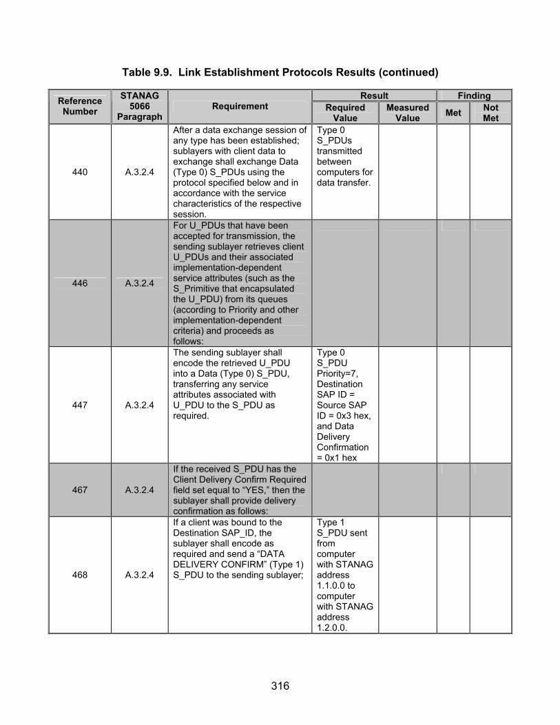
316
Table 9.9. Link Establishment Protocols Results (continued)
Result Finding Reference Number
STANAG 5066
Paragraph Requirement Required
Value Measured
Value Met Not Met
440 A.3.2.4
After a data exchange session of any type has been established; sublayers with client data to exchange shall exchange Data (Type 0) S_PDUs using the protocol specified below and in accordance with the service characteristics of the respective session.
Type 0 S_PDUs transmitted between computers for data transfer.
446 A.3.2.4
For U_PDUs that have been accepted for transmission, the sending sublayer retrieves client U_PDUs and their associated implementation-dependent service attributes (such as the S_Primitive that encapsulated the U_PDU) from its queues (according to Priority and other implementation-dependent criteria) and proceeds as follows:
447 A.3.2.4
The sending sublayer shall encode the retrieved U_PDU into a Data (Type 0) S_PDU, transferring any service attributes associated with U_PDU to the S_PDU as required.
Type 0 S_PDU Priority=7, Destination SAP ID = Source SAP ID = 0x3 hex, and Data Delivery Confirmation= 0x1 hex
467 A.3.2.4
If the received S_PDU has the Client Delivery Confirm Required field set equal to “YES,” then the sublayer shall provide delivery confirmation as follows:
468 A.3.2.4
If a client was bound to the Destination SAP_ID, the sublayer shall encode as required and send a “DATA DELIVERY CONFIRM” (Type 1) S_PDU to the sending sublayer;
Type 1 S_PDU sent from computer with STANAG address 1.1.0.0 to computer with STANAG address 1.2.0.0.
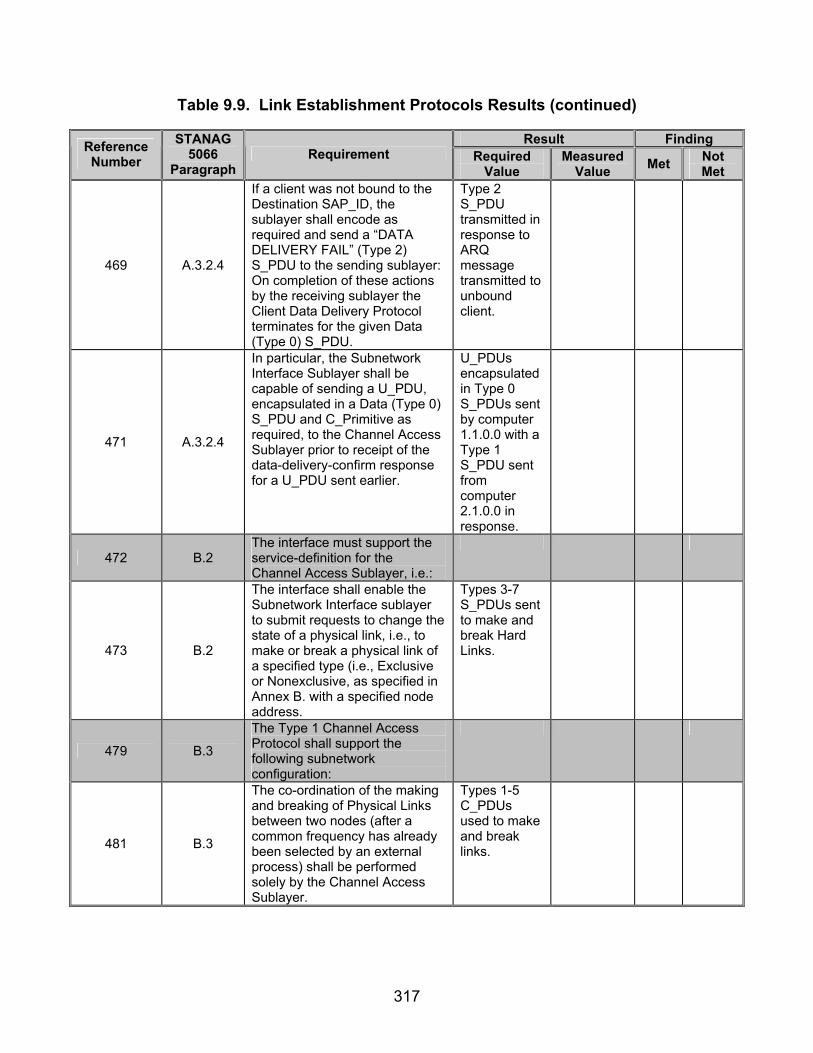
317
Table 9.9. Link Establishment Protocols Results (continued)
Result Finding Reference Number
STANAG 5066
Paragraph Requirement Required
Value Measured
Value Met Not Met
469 A.3.2.4
If a client was not bound to the Destination SAP_ID, the sublayer shall encode as required and send a “DATA DELIVERY FAIL” (Type 2) S_PDU to the sending sublayer: On completion of these actions by the receiving sublayer the Client Data Delivery Protocol terminates for the given Data (Type 0) S_PDU.
Type 2 S_PDU transmitted in response to ARQ message transmitted to unbound client.
471 A.3.2.4
In particular, the Subnetwork Interface Sublayer shall be capable of sending a U_PDU, encapsulated in a Data (Type 0) S_PDU and C_Primitive as required, to the Channel Access Sublayer prior to receipt of the data-delivery-confirm response for a U_PDU sent earlier.
U_PDUs encapsulated in Type 0 S_PDUs sent by computer 1.1.0.0 with a Type 1 S_PDU sent from computer 2.1.0.0 in response.
472 B.2 The interface must support the service-definition for the Channel Access Sublayer, i.e.:
473 B.2
The interface shall enable the Subnetwork Interface sublayer to submit requests to change the state of a physical link, i.e., to make or break a physical link of a specified type (i.e., Exclusive or Nonexclusive, as specified in Annex B. with a specified node address.
Types 3-7 S_PDUs sent to make and break Hard Links.
479 B.3
The Type 1 Channel Access Protocol shall support the following subnetwork configuration:
481 B.3
The co-ordination of the making and breaking of Physical Links between two nodes (after a common frequency has already been selected by an external process) shall be performed solely by the Channel Access Sublayer.
Types 1-5 C_PDUs used to make and break links.
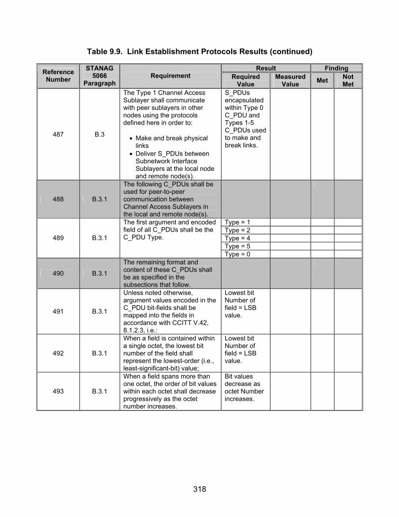
318
Table 9.9. Link Establishment Protocols Results (continued)
Result Finding Reference Number
STANAG 5066
Paragraph Requirement Required
Value Measured
Value Met Not Met
487 B.3
The Type 1 Channel Access Sublayer shall communicate with peer sublayers in other nodes using the protocols defined here in order to: • Make and break physical
links • Deliver S_PDUs between
Subnetwork Interface Sublayers at the local node and remote node(s).
S_PDUs encapsulated within Type 0 C_PDU and Types 1-5 C_PDUs used to make and break links.
488 B.3.1
The following C_PDUs shall be used for peer-to-peer communication between Channel Access Sublayers in the local and remote node(s).
Type = 1 Type = 2 Type = 4 Type = 5
489 B.3.1
The first argument and encoded field of all C_PDUs shall be the C_PDU Type.
Type = 0
490 B.3.1
The remaining format and content of these C_PDUs shall be as specified in the subsections that follow.
491 B.3.1
Unless noted otherwise, argument values encoded in the C_PDU bit-fields shall be mapped into the fields in accordance with CCITT V.42, 8.1.2.3, i.e.:
Lowest bit Number of field = LSB value.
492 B.3.1
When a field is contained within a single octet, the lowest bit number of the field shall represent the lowest-order (i.e., least-significant-bit) value;
Lowest bit Number of field = LSB value.
493 B.3.1
When a field spans more than one octet, the order of bit values within each octet shall decrease progressively as the octet number increases.
Bit values decrease as octet Number increases.

319
Table 9.9. Link Establishment Protocols Results (continued)
Result Finding Reference Number
STANAG 5066
Paragraph Requirement Required
Value Measured
Value Met Not Met
Type 0 C_PDU Reserved bits = (MSB) 0 0 (LSB)
Type 1 C_PDU Reserved bits = (MSB) 0 0 0 (LSB)
Type 2 C_PDU Reserved bits = (MSB) 0 0 0 (LSB)
494
B.3.1
Unless noted otherwise, bit-fields specified as NOT USED shall be encoded with the value ‘0’ (i.e., zero).
Type 5 C_PDU Reserved bits = (MSB) 0 0 0 0 (LSB)
495 B.3.1.1
The Data (Type 0) C_PDU shall be used to send an encapsulated S_PDU from the local node to a remote node.
S_PDU encapsulated within Type 0 C_PDU.
496 B.3.1.1
The Type argument shall be encoded in the first 4-bit field of the DATA C_PDU as shown in figure B-1.
Type = 0
497 B.3.1.1
The remaining octets of the Data C_PDU shall contain the encapsulated S_PDU and only the encapsulated S_PDU.
Only 1 S_PDU encapsulated within a Type 0 C_PDU.
502 B.3.1.2
The Physical Link Request C_PDU shall be transmitted by a Channel Access Sublayer to request the making of the physical link.
Type 1 C_PDU sent for initial handshaking to establish link.
Type = (MSB) 0 0 0 1 (LSB)
503 B.3.1.2
The Physical Link Request C_PDU shall consist of the arguments Type and Link. Link = 0
504 B.3.1.2
The value of the Type argument for the Physical Link Request C_PDU shall be ‘1’ (i.e., one), encoded as a 4-bit field as shown in figure B-2.
Type = (MSB) 0 0 0 1 (LSB)
505 B.3.1.2
The three bits not used in the encoding of the Physical Link Request C_PDU shall be reserved for future use and not used by any implementation.
Reserve bits = (MSB) 0 0 0 (LSB)
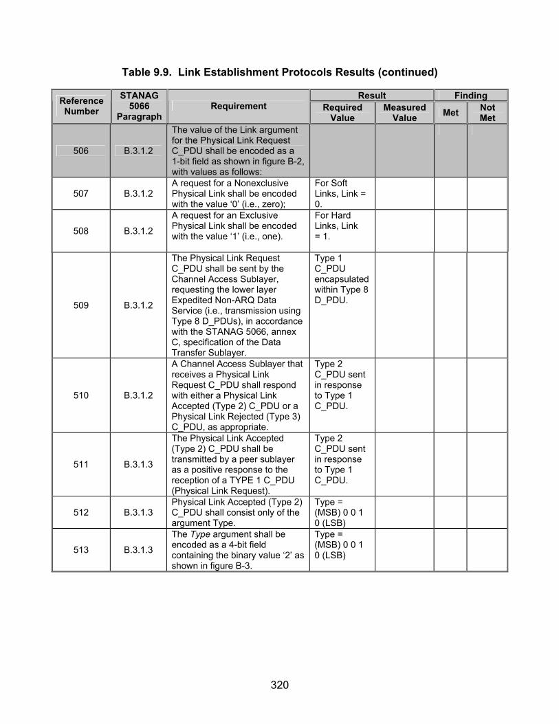
320
Table 9.9. Link Establishment Protocols Results (continued)
Result Finding Reference Number
STANAG 5066
Paragraph Requirement Required
Value Measured
Value Met Not Met
506 B.3.1.2
The value of the Link argument for the Physical Link Request C_PDU shall be encoded as a 1-bit field as shown in figure B-2, with values as follows:
507 B.3.1.2 A request for a Nonexclusive Physical Link shall be encoded with the value ‘0’ (i.e., zero);
For Soft Links, Link = 0.
508 B.3.1.2
A request for an Exclusive Physical Link shall be encoded with the value ‘1’ (i.e., one).
For Hard Links, Link = 1.
509 B.3.1.2
The Physical Link Request C_PDU shall be sent by the Channel Access Sublayer, requesting the lower layer Expedited Non-ARQ Data Service (i.e., transmission using Type 8 D_PDUs), in accordance with the STANAG 5066, annex C, specification of the Data Transfer Sublayer.
Type 1 C_PDU encapsulated within Type 8 D_PDU.
510 B.3.1.2
A Channel Access Sublayer that receives a Physical Link Request C_PDU shall respond with either a Physical Link Accepted (Type 2) C_PDU or a Physical Link Rejected (Type 3) C_PDU, as appropriate.
Type 2 C_PDU sent in response to Type 1 C_PDU.
511 B.3.1.3
The Physical Link Accepted (Type 2) C_PDU shall be transmitted by a peer sublayer as a positive response to the reception of a TYPE 1 C_PDU (Physical Link Request).
Type 2 C_PDU sent in response to Type 1 C_PDU.
512 B.3.1.3 Physical Link Accepted (Type 2) C_PDU shall consist only of the argument Type.
Type = (MSB) 0 0 1 0 (LSB)
513 B.3.1.3
The Type argument shall be encoded as a 4-bit field containing the binary value ‘2’ as shown in figure B-3.
Type = (MSB) 0 0 1 0 (LSB)
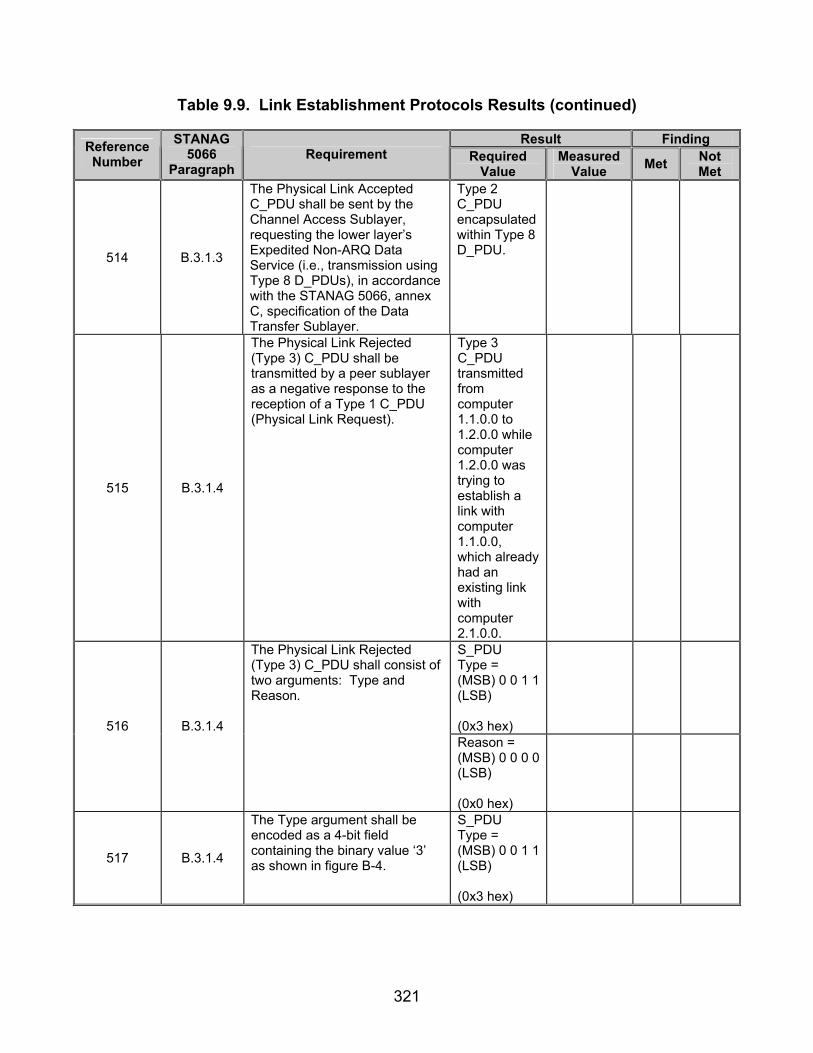
321
Table 9.9. Link Establishment Protocols Results (continued)
Result Finding Reference Number
STANAG 5066
Paragraph Requirement Required
Value Measured
Value Met Not Met
514 B.3.1.3
The Physical Link Accepted C_PDU shall be sent by the Channel Access Sublayer, requesting the lower layer’s Expedited Non-ARQ Data Service (i.e., transmission using Type 8 D_PDUs), in accordance with the STANAG 5066, annex C, specification of the Data Transfer Sublayer.
Type 2 C_PDU encapsulated within Type 8 D_PDU.
515 B.3.1.4
The Physical Link Rejected (Type 3) C_PDU shall be transmitted by a peer sublayer as a negative response to the reception of a Type 1 C_PDU (Physical Link Request).
Type 3 C_PDU transmitted from computer 1.1.0.0 to 1.2.0.0 while computer 1.2.0.0 was trying to establish a link with computer 1.1.0.0, which already had an existing link with computer 2.1.0.0.
S_PDU Type = (MSB) 0 0 1 1 (LSB) (0x3 hex)
516 B.3.1.4
The Physical Link Rejected (Type 3) C_PDU shall consist of two arguments: Type and Reason.
Reason = (MSB) 0 0 0 0 (LSB) (0x0 hex)
517 B.3.1.4
The Type argument shall be encoded as a 4-bit field containing the binary value ‘3’ as shown in figure B-4.
S_PDU Type = (MSB) 0 0 1 1 (LSB) (0x3 hex)

322
Table 9.9. Link Establishment Protocols Results (continued)
Result Finding Reference Number
STANAG 5066
Paragraph Requirement Required
Value Measured
Value Met Not Met
518 B.3.1.4
The Reason argument shall be encoded in accordance with figure B-4 and Table 3.1.
Reason = (MSB) 0 0 0 0 (LSB) (0x0 hex)
519 B.3.1.4
The Physical Link Rejected C_PDU shall be sent by the Channel Access Sublayer, requesting the lower layer Expedited Non-ARQ Data Service (i.e., transmission using Type 8 D_PDUs), in accordance with the STANAG 5066, annex C, specification of the Data Transfer Sublayer.
Type 3 C_PDU encapsulated within Type 8 D_PDU.
520 B.3.1.5
The Physical Link Break C_PDU shall be transmitted by either of the peer Channel Access Sublayers involved in an active Physical Link to request the breaking of the link.
Type 4 C_PDU sent when link is to be terminated. (steps 88-90)
Type = (MSB) 0 1 0 0 (LSB)
521 B.3.1.5
The Physical Link Break C_PDU shall consist of two arguments: Type and Reason. Reason =
(MSB) 0 0 0 1 (LSB)
522 B.3.1.5
The Type argument shall be encoded as a 4-bit field containing the binary value ‘4’ as shown in figure B-5.
Type = (MSB) 0 1 0 0 (LSB)
523 B.3.1.5 The Reason argument shall be encoded in accordance with figure B-5 and table 1.3
Reason = (MSB) 0 0 0 1 (LSB)
Physical Link broken when Type 4 C_PDU sent.
524 B.3.1.5
A peer sublayer that receives the Physical Link Break C_PDU, shall immediately declare the Physical Link as broken and respond with a Physical Link Break (Type 5) C_PDU as specified in STANAG 5066, section B.3.1.6.
Type 5 C_PDU sent in response to Type 4 C_PDU.
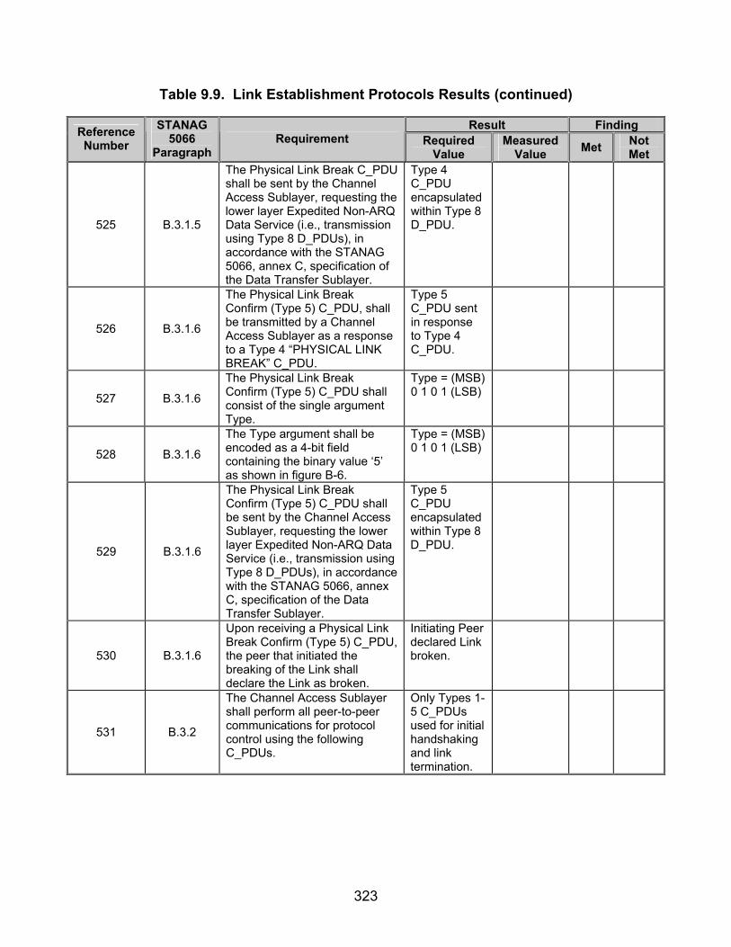
323
Table 9.9. Link Establishment Protocols Results (continued)
Result Finding Reference Number
STANAG 5066
Paragraph Requirement Required
Value Measured
Value Met Not Met
525 B.3.1.5
The Physical Link Break C_PDU shall be sent by the Channel Access Sublayer, requesting the lower layer Expedited Non-ARQ Data Service (i.e., transmission using Type 8 D_PDUs), in accordance with the STANAG 5066, annex C, specification of the Data Transfer Sublayer.
Type 4 C_PDU encapsulated within Type 8 D_PDU.
526 B.3.1.6
The Physical Link Break Confirm (Type 5) C_PDU, shall be transmitted by a Channel Access Sublayer as a response to a Type 4 “PHYSICAL LINK BREAK” C_PDU.
Type 5 C_PDU sent in response to Type 4 C_PDU.
527 B.3.1.6
The Physical Link Break Confirm (Type 5) C_PDU shall consist of the single argument Type.
Type = (MSB) 0 1 0 1 (LSB)
528 B.3.1.6
The Type argument shall be encoded as a 4-bit field containing the binary value ‘5’ as shown in figure B-6.
Type = (MSB) 0 1 0 1 (LSB)
529 B.3.1.6
The Physical Link Break Confirm (Type 5) C_PDU shall be sent by the Channel Access Sublayer, requesting the lower layer Expedited Non-ARQ Data Service (i.e., transmission using Type 8 D_PDUs), in accordance with the STANAG 5066, annex C, specification of the Data Transfer Sublayer.
Type 5 C_PDU encapsulated within Type 8 D_PDU.
530 B.3.1.6
Upon receiving a Physical Link Break Confirm (Type 5) C_PDU, the peer that initiated the breaking of the Link shall declare the Link as broken.
Initiating Peer declared Link broken.
531 B.3.2
The Channel Access Sublayer shall perform all peer-to-peer communications for protocol control using the following C_PDUs.
Only Types 1-5 C_PDUs used for initial handshaking and link termination.
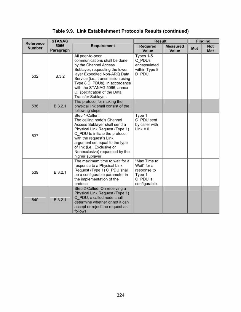
324
Table 9.9. Link Establishment Protocols Results (continued)
Result Finding Reference Number
STANAG 5066
Paragraph Requirement Required
Value Measured
Value Met Not Met
532 B.3.2
All peer-to-peer communications shall be done by the Channel Access Sublayer, requesting the lower layer Expedited Non-ARQ Data Service (i.e., transmission using Type 8 D_PDUs), in accordance with the STANAG 5066, annex C, specification of the Data Transfer Sublayer.
Types 1-5 C_PDUs encapsulated within Type 8 D_PDU.
536 B.3.2.1 The protocol for making the physical link shall consist of the following steps:
537
Step 1-Caller: The calling node’s Channel Access Sublayer shall send a Physical Link Request (Type 1) C_PDU to initiate the protocol, with the request’s Link argument set equal to the type of link (i.e., Exclusive or Nonexclusive) requested by the higher sublayer,
Type 1 C_PDU sent by caller with Link = 0.
539 B.3.2.1
The maximum time to wait for a response to a Physical Link Request (Type 1) C_PDU shall be a configurable parameter in the implementation of the protocol.
“Max Time to Wait” for a response to Type 1 C_PDU is configurable.
540 B.3.2.1
Step 2-Called: On receiving a Physical Link Request (Type 1) C_PDU, a called node shall determine whether or not it can accept or reject the request as follows:

325
Table 9.9. Link Establishment Protocols Results (continued)
Result Finding Reference Number
STANAG 5066
Paragraph Requirement Required
Value Measured
Value Met Not Met
541 B.3.2.1
If the request is for a Nonexclusive Physical Link and the called node has an active Exclusive Physical Link, the called node shall reject the request,
Soft Link rejected.
543 B.3.2.1 Otherwise, the called node shall accept the request for a Nonexclusive Physical Link.
Soft Links established.
544 B.3.2.1
If the request is for an Exclusive Physical Link and the called node has either one or no active Exclusive Physical Link, the called node shall accept the request,
Hard Links established when no Hard Links existed.
Type 5 S_PDU sent in response to a node of equal priority trying to establish a link.
545 B.3.2.1
Otherwise, the called node shall reject the request for an Exclusive Physical Link.
Type 5 S_PDU sent in response to a lower priority node trying to establish.
546 B.3.2.1
After determining if it can accept or reject the Physical Link Request, a called node shall respond as follows:
547 B.3.2.1
If a called node accepts the physical link request, it shall respond with a Physical Link Accepted (Type 2) C_PDU.
Type 2 C_PDU sent in response to Type 1 C_PDU.
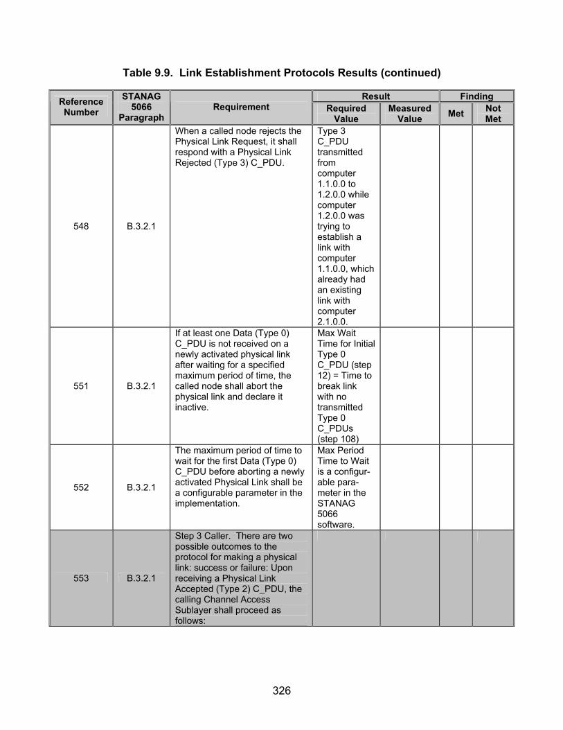
326
Table 9.9. Link Establishment Protocols Results (continued)
Result Finding Reference Number
STANAG 5066
Paragraph Requirement Required
Value Measured
Value Met Not Met
548 B.3.2.1
When a called node rejects the Physical Link Request, it shall respond with a Physical Link Rejected (Type 3) C_PDU.
Type 3 C_PDU transmitted from computer 1.1.0.0 to 1.2.0.0 while computer 1.2.0.0 was trying to establish a link with computer 1.1.0.0, which already had an existing link with computer 2.1.0.0.
551 B.3.2.1
If at least one Data (Type 0) C_PDU is not received on a newly activated physical link after waiting for a specified maximum period of time, the called node shall abort the physical link and declare it inactive.
Max Wait Time for Initial Type 0 C_PDU (step 12) = Time to break link with no transmitted Type 0 C_PDUs (step 108)
552 B.3.2.1
The maximum period of time to wait for the first Data (Type 0) C_PDU before aborting a newly activated Physical Link shall be a configurable parameter in the implementation.
Max Period Time to Wait is a configur-able para-meter in the STANAG 5066 software.
553 B.3.2.1
Step 3 Caller. There are two possible outcomes to the protocol for making a physical link: success or failure: Upon receiving a Physical Link Accepted (Type 2) C_PDU, the calling Channel Access Sublayer shall proceed as follows:

327
Table 9.9. Link Establishment Protocols Results (continued)
Result Finding Reference Number
STANAG 5066
Paragraph Requirement Required
Value Measured
Value Met Not Met
555 B.3.2.1 The calling node shall declare the physical link as “successfully made,” otherwise,
Data able to be transmitted.
556 B.3.2.1
Upon receiving a Physical Link Rejected (Type 3) C_PDU, the Channel Access Sublayer shall declare the physical link as failed.
Physical link was broken after Type 3 C_PDU was transmitted.
557 B.3.2.1
Upon expiration of its timer without any response having been received from the remote node, the Channel Access Sublayer shall repeat step 1 (i.e., send a Physical Link Request (Type 1) C_PDU and set a response time) and await again a response from the remote node.
Type 1 C_PDU retransmitted by computer 1.1.0.0 when no Type 2 C_PDU received by computer 2.1.0.0.
558 B.3.2.1
The maximum number of times the caller sends the Physical Link Request (Type 1) C_PDU without a response from the called node of either kind shall be a configurable parameter in the implementation of the protocol.
There is a configurable parameter for the maximum number of times a Type 1 C_PDU will be sent without a response.
559 B.3.2.1
After having repeated step 1 a maximum number of times (left as a configuration parameter) without any response having been received from the remote node, the Initiator’s Channel Access Sublayer shall declare the physical link as failed.
Max Number of Times Type 1 C_PDU Transmitting (step 14) = Number of Type 1 C_PDUs Transmitted
560 B.3.2.2 The protocol for breaking the physical link shall consists of the following steps:
561 B.3.2.2
Step 1: Initiator
To start the protocol, the Initiator’s Channel Access Sublayer shall send a Type 4 C_PDU (Physical Link Break).
Type 4 C_PDU sent by computer 2.1.0.0 or 1.1.0.0 to end transmission.
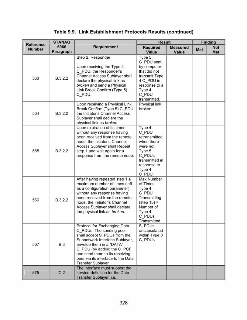
328
Table 9.9. Link Establishment Protocols Results (continued)
Result Finding Reference Number
STANAG 5066
Paragraph Requirement Required
Value Measured
Value Met Not Met
563 B.3.2.2
Step 2: Responder
Upon receiving the Type 4 C_PDU, the Responder’s Channel Access Sublayer shall declare the physical link as broken and send a Physical Link Break Confirm (Type 5) C_PDU.
Type 5 C_PDU sent by computer that did not transmit Type 4 C_PDU in response to a Type 4 C_PDU transmitted.
564 B.3.2.2
Upon receiving a Physical Link Break Confirm (Type 5) C_PDU, the Initiator’s Channel Access Sublayer shall declare the physical link as broken
Physical link broken.
565 B.3.2.2
Upon expiration of its timer without any response having been received from the remote node, the initiator’s Channel Access Sublayer shall Repeat step 1 and wait again for a response from the remote node.
Type 4 C_PDU retransmitted when there were not Type 5 C_PDUs transmitted in response to Type 4 C_PDU.
566 B.3.2.2
After having repeated step 1 a maximum number of times (left as a configuration parameter) without any response having been received from the remote node, the Initiator’s Channel Access Sublayer shall declare the physical link as broken.
Max Number of Times Type 4 C_PDU Transmitting (step 15) = Number of Type 4 C_PDUs Transmitted
567 B.3
Protocol for Exchanging Data C_PDUs: The sending peer shall accept S_PDUs from the Subnetwork Interface Sublayer, envelop them in a “DATA” C_PDU (by adding the C_PCI) and send them to its receiving peer via its interface to the Data Transfer Sublayer
S_PDUs encapsulated within Type 0 C_PDUs.
575 C.2 The interface must support the service-definition for the Data Transfer Sublayer, i.e.:
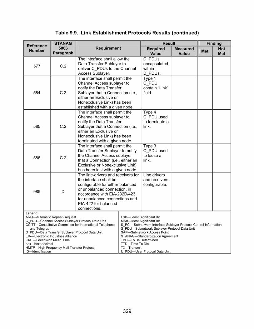
329
Table 9.9. Link Establishment Protocols Results (continued)
Result Finding Reference Number
STANAG 5066
Paragraph Requirement Required
Value Measured
Value Met Not Met
577 C.2
The interface shall allow the Data Transfer Sublayer to deliver C_PDUs to the Channel Access Sublayer.
C_PDUs encapsulated within D_PDUs.
584 C.2
The interface shall permit the Channel Access sublayer to notify the Data Transfer Sublayer that a Connection (i.e., either an Exclusive or Nonexclusive Link) has been established with a given node.
Type 1 C_PDU contain “Link” field.
585 C.2
The interface shall permit the Channel Access sublayer to notify the Data Transfer Sublayer that a Connection (i.e., either an Exclusive or Nonexclusive Link) has been terminated with a given node.
Type 4 C_PDU used to terminate a link.
586 C.2
The interface shall permit the Data Transfer Sublayer to notify the Channel Access sublayer that a Connection (i.e., either an Exclusive or Nonexclusive Link) has been lost with a given node.
Type 3 C_PDU used to loose a link.
985 D
The line-drivers and receivers for the interface shall be configurable for either balanced or unbalanced connection, in accordance with EIA-232D/423 for unbalanced connections and EIA-422 for balanced connections.
Line drivers and receivers configurable.
Legend: ARQ—Automatic Repeat-Request C_PDU—Channel Access Sublayer Protocol Data Unit CCITT—Consultative Committee for International Telephone
and Telegraph D_PDU—Data Transfer Sublayer Protocol Data Unit EIA—Electronic Industries Alliance GMT—Greenwich Mean Time hex—hexadecimal HMTP—High Frequency Mail Transfer Protocol ID—Identification
LSB—Least Significant Bit MSB—Most Significant Bit S_PCI—Subnetwork Interface Sublayer Protocol Control Information S_PDU—Subnetwork Sublayer Protocol Data Unit SAP—Subnetwork Access Point STANAG—Standardization Agreement TBD—To Be Determined TTD—Time To Die TX—Transmit U_PDU—User Protocol Data Unit

330
(This page intentionally left blank.)
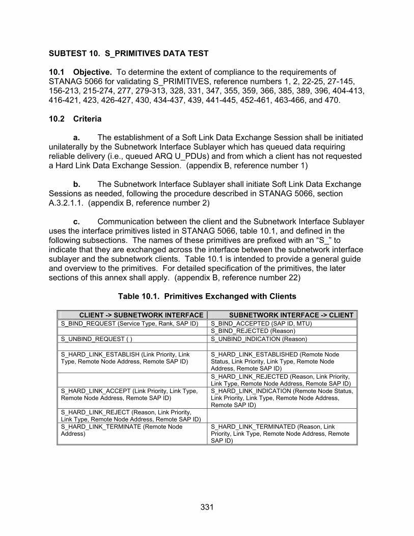
331
SUBTEST 10. S_PRIMITIVES DATA TEST 10.1 Objective. To determine the extent of compliance to the requirements of STANAG 5066 for validating S_PRIMITIVES, reference numbers 1, 2, 22-25, 27-145, 156-213, 215-274, 277, 279-313, 328, 331, 347, 355, 359, 366, 385, 389, 396, 404-413, 416-421, 423, 426-427, 430, 434-437, 439, 441-445, 452-461, 463-466, and 470. 10.2 Criteria
a. The establishment of a Soft Link Data Exchange Session shall be initiated unilaterally by the Subnetwork Interface Sublayer which has queued data requiring reliable delivery (i.e., queued ARQ U_PDUs) and from which a client has not requested a Hard Link Data Exchange Session. (appendix B, reference number 1) b. The Subnetwork Interface Sublayer shall initiate Soft Link Data Exchange Sessions as needed, following the procedure described in STANAG 5066, section A.3.2.1.1. (appendix B, reference number 2) c. Communication between the client and the Subnetwork Interface Sublayer uses the interface primitives listed in STANAG 5066, table 10.1, and defined in the following subsections. The names of these primitives are prefixed with an “S_” to indicate that they are exchanged across the interface between the subnetwork interface sublayer and the subnetwork clients. Table 10.1 is intended to provide a general guide and overview to the primitives. For detailed specification of the primitives, the later sections of this annex shall apply. (appendix B, reference number 22)
Table 10.1. Primitives Exchanged with Clients
CLIENT -> SUBNETWORK INTERFACE SUBNETWORK INTERFACE -> CLIENT S_BIND_REQUEST (Service Type, Rank, SAP ID) S_BIND_ACCEPTED (SAP ID, MTU) S_BIND_REJECTED (Reason) S_UNBIND_REQUEST ( ) S_UNBIND_INDICATION (Reason) S_HARD_LINK_ESTABLISH (Link Priority, Link Type, Remote Node Address, Remote SAP ID)
S_HARD_LINK_ESTABLISHED (Remote Node Status, Link Priority, Link Type, Remote Node Address, Remote SAP ID)
S_HARD_LINK_REJECTED (Reason, Link Priority, Link Type, Remote Node Address, Remote SAP ID)
S_HARD_LINK_ACCEPT (Link Priority, Link Type, Remote Node Address, Remote SAP ID)
S_HARD_LINK_INDICATION (Remote Node Status, Link Priority, Link Type, Remote Node Address, Remote SAP ID)
S_HARD_LINK_REJECT (Reason, Link Priority, Link Type, Remote Node Address, Remote SAP ID)
S_HARD_LINK_TERMINATE (Remote Node Address)
S_HARD_LINK_TERMINATED (Reason, Link Priority, Link Type, Remote Node Address, Remote SAP ID)
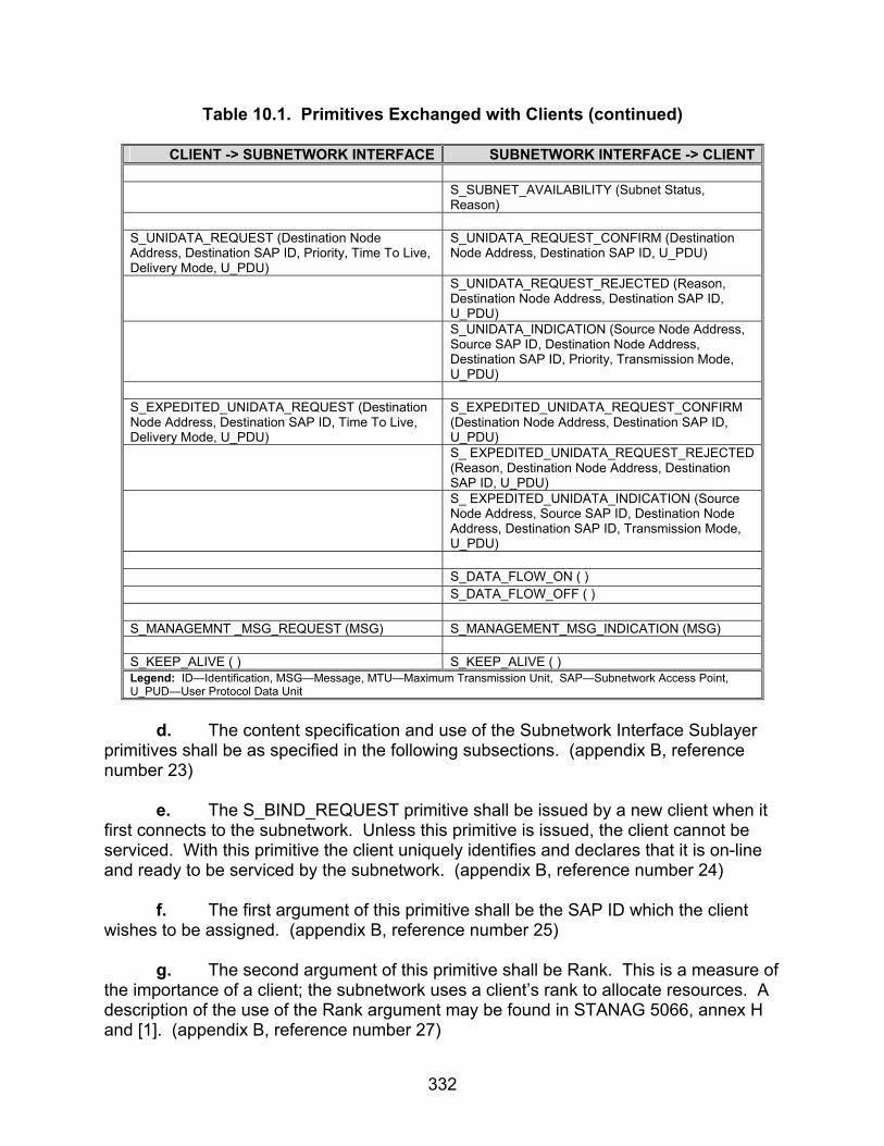
332
Table 10.1. Primitives Exchanged with Clients (continued)
CLIENT -> SUBNETWORK INTERFACE SUBNETWORK INTERFACE -> CLIENT S_SUBNET_AVAILABILITY (Subnet Status,
Reason) S_UNIDATA_REQUEST (Destination Node Address, Destination SAP ID, Priority, Time To Live, Delivery Mode, U_PDU)
S_UNIDATA_REQUEST_CONFIRM (Destination Node Address, Destination SAP ID, U_PDU)
S_UNIDATA_REQUEST_REJECTED (Reason, Destination Node Address, Destination SAP ID, U_PDU)
S_UNIDATA_INDICATION (Source Node Address, Source SAP ID, Destination Node Address, Destination SAP ID, Priority, Transmission Mode, U_PDU)
S_EXPEDITED_UNIDATA_REQUEST (Destination Node Address, Destination SAP ID, Time To Live, Delivery Mode, U_PDU)
S_EXPEDITED_UNIDATA_REQUEST_CONFIRM (Destination Node Address, Destination SAP ID, U_PDU)
S_ EXPEDITED_UNIDATA_REQUEST_REJECTED (Reason, Destination Node Address, Destination SAP ID, U_PDU)
S_ EXPEDITED_UNIDATA_INDICATION (Source Node Address, Source SAP ID, Destination Node Address, Destination SAP ID, Transmission Mode, U_PDU)
S_DATA_FLOW_ON ( ) S_DATA_FLOW_OFF ( ) S_MANAGEMNT _MSG_REQUEST (MSG) S_MANAGEMENT_MSG_INDICATION (MSG) S_KEEP_ALIVE ( ) S_KEEP_ALIVE ( ) Legend: ID—Identification, MSG—Message, MTU—Maximum Transmission Unit, SAP—Subnetwork Access Point, U_PUD—User Protocol Data Unit
d. The content specification and use of the Subnetwork Interface Sublayer primitives shall be as specified in the following subsections. (appendix B, reference number 23) e. The S_BIND_REQUEST primitive shall be issued by a new client when it first connects to the subnetwork. Unless this primitive is issued, the client cannot be serviced. With this primitive the client uniquely identifies and declares that it is on-line and ready to be serviced by the subnetwork. (appendix B, reference number 24) f. The first argument of this primitive shall be the SAP ID which the client wishes to be assigned. (appendix B, reference number 25) g. The second argument of this primitive shall be Rank. This is a measure of the importance of a client; the subnetwork uses a client’s rank to allocate resources. A description of the use of the Rank argument may be found in STANAG 5066, annex H and [1]. (appendix B, reference number 27)
333
h. The range of values for the Rank argument shall be from 0 to 15. (appendix B, reference number 28) i. Clients that are not authorized to make changes to a node or subnetwork configuration shall not bind with rank of 15. (appendix B, reference number 29) j. The last argument of this primitive shall be Service Type and identifies the default type of service requested by the client. (appendix B, reference number 30) k. The Service Type argument shall apply to all data units submitted by the client, unless explicitly overridden by client request when submitting a U_PDU to the subnetwork. The Service Type argument is a complex argument and has a number of attributes that are encoded as specified in STANAG 5066, section A.2.2.3. (appendix B, reference number 31) l. The S_UNBIND_REQUEST primitive shall be issued by a client in order to declare itself off-line. (appendix B, reference number 32) m. The Subnetwork Interface Sublayer shall release the SAP ID allocated to the client from which it receives the S_UNBIND_REQUEST. (appendix B, reference number 33) n. The SAP_ID allocated to this client shall then be available for allocation to another client that may request it. (appendix B, reference number 34) o. The S_BIND_ACCEPTED primitive shall be issued by the Subnetwork Interface Sublayer as a positive response to a client’s S_BIND_REQUEST. (appendix B, reference number 35) p. The SAP ID argument of the S_BIND_ACCEPTED primitive shall be the SAP ID assigned to the client and shall be equal to the SAP ID argument of the S_BIND_REQUEST to which this primitive is a response. (appendix B, reference numbers 36 and 37) q. The Maximum Transmission Unit (MTU) argument shall be used by the Subnetwork Interface Sublayer to inform the client of the maximum size U_PDU (in bytes or octets), that will be accepted as an argument of the S_UNIDATA_REQUEST primitive. (appendix B, reference number 38) r. The MTU will be accepted as an argument of the S_UNIDATA_REQUEST primitive. S_UNIDATA_REQUEST primitives containing U_PDUs larger than the MTU shall be rejected by the subnetwork interface. (appendix B, reference number 39) s. Note that this restriction applies only to U_PDUs received through the subnetwork interface. U_PDUs that are received from the lower HF sublayers (i.e.,
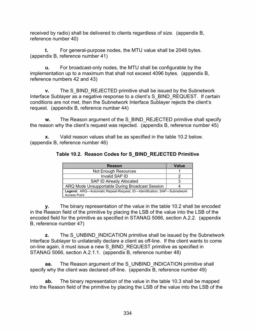
334
received by radio) shall be delivered to clients regardless of size. (appendix B, reference number 40) t. For general-purpose nodes, the MTU value shall be 2048 bytes. (appendix B, reference number 41) u. For broadcast-only nodes, the MTU shall be configurable by the implementation up to a maximum that shall not exceed 4096 bytes. (appendix B, reference numbers 42 and 43) v. The S_BIND_REJECTED primitive shall be issued by the Subnetwork Interface Sublayer as a negative response to a client’s S_BIND_REQUEST. If certain conditions are not met, then the Subnetwork Interface Sublayer rejects the client’s request. (appendix B, reference number 44) w. The Reason argument of the S_BIND_REJECTED primitive shall specify the reason why the client’s request was rejected. (appendix B, reference number 45) x. Valid reason values shall be as specified in the table 10.2 below. (appendix B, reference number 46)
Table 10.2. Reason Codes for S_BIND_REJECTED Primitive
Reason Value Not Enough Resources 1
Invalid SAP ID 2 SAP ID Already Allocated 3
ARQ Mode Unsupportable During Broadcast Session 4 Legend: ARQ—Automatic Repeat-Request, ID—Identification, SAP—Subnetwork Access Point
y. The binary representation of the value in the table 10.2 shall be encoded in the Reason field of the primitive by placing the LSB of the value into the LSB of the encoded field for the primitive as specified in STANAG 5066, section A.2.2. (appendix B, reference number 47) z. The S_UNBIND_INDICATION primitive shall be issued by the Subnetwork Interface Sublayer to unilaterally declare a client as off-line. If the client wants to come on-line again, it must issue a new S_BIND_REQUEST primitive as specified in STANAG 5066, section A.2.1.1. (appendix B, reference number 48) aa. The Reason argument of the S_UNBIND_INDICATION primitive shall specify why the client was declared off-line. (appendix B, reference number 49) ab. The binary representation of the value in the table 10.3 shall be mapped into the Reason field of the primitive by placing the LSB of the value into the LSB of the
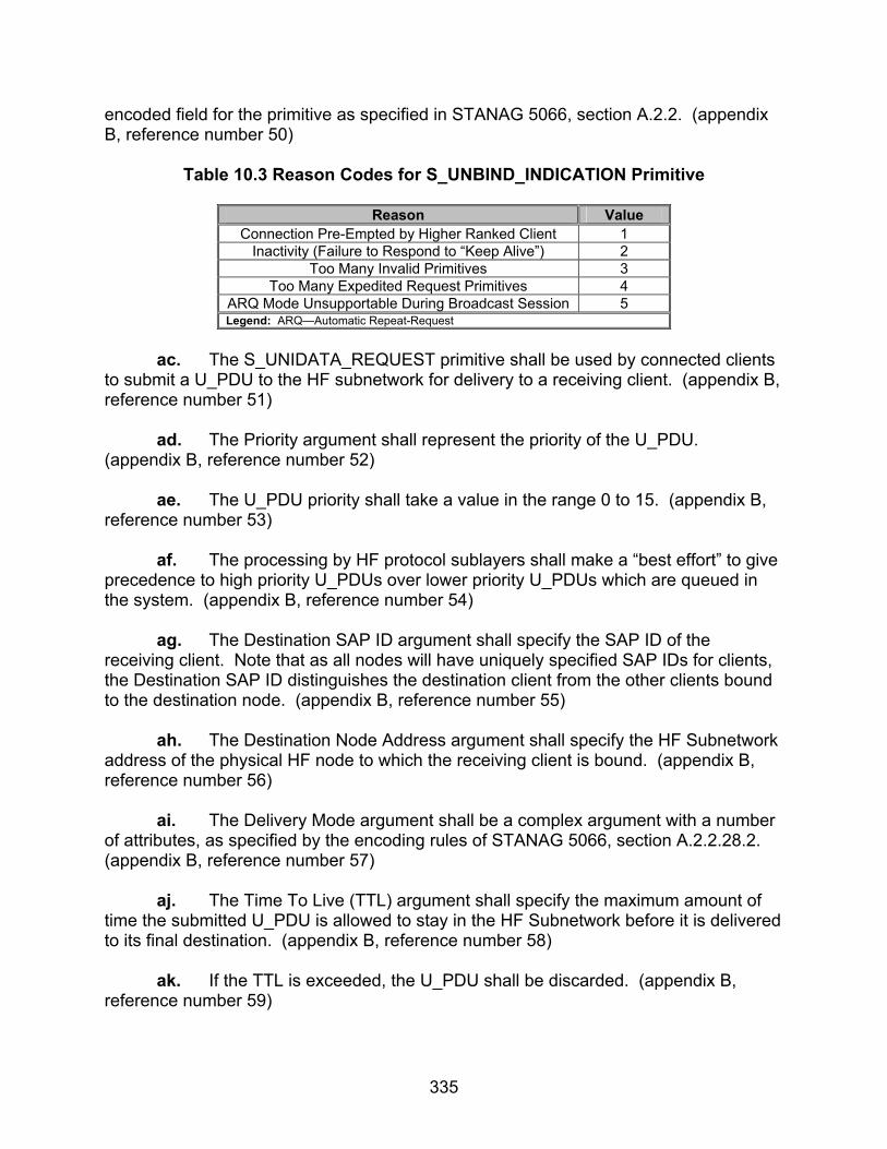
335
encoded field for the primitive as specified in STANAG 5066, section A.2.2. (appendix B, reference number 50)
Table 10.3 Reason Codes for S_UNBIND_INDICATION Primitive
Reason Value Connection Pre-Empted by Higher Ranked Client 1
Inactivity (Failure to Respond to “Keep Alive”) 2 Too Many Invalid Primitives 3
Too Many Expedited Request Primitives 4 ARQ Mode Unsupportable During Broadcast Session 5 Legend: ARQ—Automatic Repeat-Request
ac. The S_UNIDATA_REQUEST primitive shall be used by connected clients to submit a U_PDU to the HF subnetwork for delivery to a receiving client. (appendix B, reference number 51) ad. The Priority argument shall represent the priority of the U_PDU. (appendix B, reference number 52) ae. The U_PDU priority shall take a value in the range 0 to 15. (appendix B, reference number 53) af. The processing by HF protocol sublayers shall make a “best effort” to give precedence to high priority U_PDUs over lower priority U_PDUs which are queued in the system. (appendix B, reference number 54) ag. The Destination SAP ID argument shall specify the SAP ID of the receiving client. Note that as all nodes will have uniquely specified SAP IDs for clients, the Destination SAP ID distinguishes the destination client from the other clients bound to the destination node. (appendix B, reference number 55) ah. The Destination Node Address argument shall specify the HF Subnetwork address of the physical HF node to which the receiving client is bound. (appendix B, reference number 56) ai. The Delivery Mode argument shall be a complex argument with a number of attributes, as specified by the encoding rules of STANAG 5066, section A.2.2.28.2. (appendix B, reference number 57) aj. The Time To Live (TTL) argument shall specify the maximum amount of time the submitted U_PDU is allowed to stay in the HF Subnetwork before it is delivered to its final destination. (appendix B, reference number 58) ak. If the TTL is exceeded, the U_PDU shall be discarded. (appendix B, reference number 59)

336
al. A TTL value of (0) shall define an infinite TTL, i.e., the subnetwork should try forever to deliver the U_PDU. (appendix B, reference number 60) am. The subnetwork shall have a default maximum TTL. (appendix B, reference number 61) an. The default maximum TTL shall be configurable as an implementation-dependent value. (appendix B, reference number 62) ao. As soon as the Subnetwork Interface Sublayer accepts an S_UNIDATA_REQUEST primitive, it shall immediately calculate its TTD by adding the specified TTL (or the default maximum value if the specified TTL is equal to (0)) to the current Time of Day, e.g., GMT. (appendix B, reference number 63) ap. The TTD attribute of a U_PDU shall accompany it during its transit within the subnetwork. (Note that the TTD is an absolute time while the TTL is a time interval relative to the instant of the U_PDU submission.) (appendix B, reference number 64) aq. The Size of U_PDU argument shall be the size of the U_PDU that is included in this S_UNIDATA_REQUEST primitive. (appendix B, reference number 65) ar. The final argument, U_PDU, shall be the actual User Data Unit submitted by the client to the HF Subnetwork. (appendix B, reference number 66) as. The S_UNIDATA_REQUEST_CONFIRM primitive shall be issued by the Subnetwork Interface Sublayer to acknowledge the successful delivery of an S_UNIDATA_REQUEST submitted by the client. (appendix B, reference number 67) at. This primitive shall be issued only if the client has requested Data Delivery Confirmation (either during binding or for this particular data unit). (appendix B, reference number 68) au. The Destination Node Address argument in the S_UNIDATA_REQUEST_CONFIRM primitive shall have the same meaning and be equal in value to the Destination Node Address argument of the S_UNIDATA_REQUEST primitive for which the S_UNIDATA_REQUEST_ CONFIRM primitive is the response. (appendix B, reference number 69) av. The Destination SAP_ID argument in the S_UNIDATA_REQUEST_ CONFIRM primitive shall have the same meaning and be equal in value to the Destination SAP_ID argument of the S_UNIDATA_REQUEST primitive for which the S_UNIDATA_REQUEST_CONFIRM primitive is the response. (appendix B, reference number 70)

337
aw. The Size of Confirmed U_PDU argument shall be the size of the U_PDU or part that is included in this S_UNIDATA_REQUEST_CONFIRM primitive. (appendix B, reference number 71) ax. The U_PDU argument in the S_UNIDATA_CONFIRM primitive shall be a copy of the whole or a fragment of the U_PDU argument of the S_UNIDATA_REQUEST primitive for which the S_UNIDATA_REQUEST_CONFIRM primitive is the response. (appendix B, reference number 72) ay. Using these arguments, the client shall be able to uniquely identify the U_PDU that is being acknowledged. Depending on the implementation of the protocol, the last argument, U_PDU, may not be a complete copy of the original U_PDU but only a partial copy, i.e., only the first X bytes are copied for some value of (X). (appendix B, reference number 73) az. If a partial U_PDU is returned, U_PDU_Response_Frag_Size bytes shall be returned to the client starting with the first byte of the U_PDU so that the client will have the U_PDU segment information. (appendix B, reference number 74) ba. The number of bytes returned, U_PDU_Response_Frag_Size, shall be a configurable parameter in the implementation. (appendix B, reference number 75) bb. The S_UNIDATA_REQUEST_REJECTED primitive shall be issued by the Subnetwork Interface Sublayer to inform a client that a S_UNIDATA_REQUEST was not delivered successfully. (appendix B, reference number 76) bc. This primitive shall be issued if the client has requested Data Delivery Confirmation (either during binding or for this particular U_PDU) and the data was unsuccessfully delivered. (appendix B, reference number 77) bd. This primitive also shall be issued to a client if a U_PDU larger than the MTU is submitted. (appendix B, reference number 78) be. The Reason argument shall specify why the delivery failed, using the encoding given in the table 10.4: (appendix B, reference number 79)
Table 10.4. Reason Codes for S_UNIDATA_REQUEST_REJECT Primitive
Reason Value TTL Expired 1
Destination SAP ID Not Bound 2 Destination Node Not Responding 3
U_PDU Larger Than MTU 4 TX Mode Not Specified 5
Legend: ID—Identification, MTU—Maximum Transmission Unit, SAP—Subnetwork Access Point, TTL—Time To Live, TX—Transmit, U_PDU—User Protocol Data Unit,
338
bf. The binary representation of the value in the table shall be mapped into the Reason argument of the primitive by placing the LSB of the value into the LSB of the encoded argument for the primitive, as specified in STANAG 5066, section A.2.2. (appendix B, reference number 80) bg. The Destination Node Address argument in the S_UNIDATA_REQUEST_REJECTED primitive shall have the same meaning and be equal in value to the Destination Node Address argument of the S_UNIDATA_REQUEST primitive for which the S_UNIDATA_REQUEST_REJECTED primitive is the response. (appendix B, reference number 81) bh. The Destination SAP_ID argument in the S_UNIDATA_REQUEST_REJECTED primitive shall have the same meaning and be equal in value to the Destination SAP_ID argument of the S_UNIDATA_REQUEST primitive for which the S_UNIDATA_REQUEST_REJECTED primitive is the response. (appendix B, reference number 82) bi. The Size of Rejected U_PDU argument shall be the size of the U_PDU or part that is included in this S_UNIDATA_REQUEST_REJECTED primitive. (appendix B, reference number 83) bj. If a partial U_PDU is returned, U_PDU_Response_Frag_Size bytes shall be returned to the client starting with the first byte of the U_PDU, so that the client will have the U_PDU segment information. (appendix B, reference number 84) bk. The number of bytes returned, U_PDU_Response_Frag_Size, shall be a configurable parameter in the implementation. (appendix B, reference number 85) bl. The S_UNIDATA_INDICATION primitive shall be used by the Subnetwork Interface Sublayer to deliver a received U_PDU to the client. (appendix B, reference number 86) bm. The Priority argument shall be the priority of the PDU. (appendix B, reference number 87) bn. The Destination SAP ID argument shall be the SAP ID of the client to which this primitive is delivered. (appendix B, reference number 88) bo. The Destination Node Address argument shall be the address assigned by the sending node to the U_PDU contained within this primitive. This normally will be the address of the local (i.e., receiving) node. It may, however, be a Group Address to which the local node has subscribed (Group Addresses and their subscribers are defined during configuration) and to which the source node addressed the U_PDU. (appendix B, reference number 89)

339
bp. The Transmission Mode argument shall be the mode by which the U_PDU was transmitted by the remote node and received by the local node; i.e., ARQ, Non-ARQ (Broadcast) Transmission, Non-ARQ w/ Errors, etc. (appendix B, reference number 90) bq. The Source SAP ID shall be SAP ID of the client that sent the U_PDU. (appendix B, reference number 91) br. The Source Node Address shall represent the node address of the client that sent the U_PDU. (appendix B, reference number 92) bs. The Size of U_PDU argument shall be the size of the U_PDU that was sent and delivered in this S_UNIDATA_INDICATION S_Primitive. (appendix B, reference number 93) bt. The following four arguments shall be present in the S_UNIDATA_INDICATION S_Primitive if, and only if, the Transmission Mode for the U_PDU is equal to Non-ARQ w/ Errors. (appendix B, reference number 94) bu. The Number of Blocks in Error argument shall equal the number of data blocks in the U_PDU that were received in error by the lower layers of the subnetwork and that were passed on to the Subnetwork Interface Sublayer. (appendix B, reference number 95) bv. This argument shall specify the number of ordered pairs in the Array of Block-Error Pointers argument. (appendix B, reference number 96) bw. The Array of Block-Error Pointers argument shall consist of an array of ordered pairs, the first element in the pair equal to the location within the U_PDU of the data block with errors and the second element equal to the size of the data block with errors. (appendix B, reference number 97) bx. The Number of Non-Received Blocks argument shall equal the number of data blocks missing from the U_PDU because they were not received. (appendix B, reference number 98) by. This argument shall specify the number of ordered pairs in the Array of Non-Received Block Pointers argument. (appendix B, reference number 99) bz. The Array of Non-Received Block Pointers shall consist of an array of ordered pairs, the first element in the pair equal to the location of the missing data block in the U_PDU and the second element equal to the size of the missing data block. (appendix B, reference number 100) ca. The final argument, U_PDU, shall contain the actual received user data for delivery to the client. (appendix B, reference number 101)

340
cb. The S_EXPEDITED_UNIDATA_REQUEST primitive shall be used to submit a U_PDU to the HF Subnetwork for Expedited Delivery to a receiving client. (appendix B, reference number 102) cc. The Destination SAP ID argument shall specify the SAP ID of the receiving client. Note that as all nodes will have uniquely specified SAP IDs for clients, the Destination SAP ID distinguishes the destination client from the other clients bound to the destination node. (appendix B, reference number 103) cd. The Destination Node Address argument shall specify the HF Subnetwork address of the physical HF node to which the receiving client is bound. (appendix B, reference number 104) ce. The Delivery Mode argument shall be a complex argument with a number of attributes, as specified by the encoding rules of STANAG 5066, section A.2.2.28.2. (appendix B, reference number 105) cf. The TTL argument shall specify the maximum amount of time the submitted U_PDU is allowed to stay in the HF Subnetwork before it is delivered to its final destination. (appendix B, reference number 106) cg. If the TTL is exceeded, the U_PDU shall be discarded. (appendix B, reference number 107) ch. A TTL value of 0 shall define an infinite TTL, i.e., the subnetwork should try forever to deliver the U_PDU. (appendix B, reference number 108) ci. As soon as the Subnetwork Interface Sublayer accepts an S_EXPEDITED_UNIDATA_REQUEST primitive, it shall immediately calculate its TTD by adding the specified TTL (or the default maximum TTL value if the specified TTL is equal to 0) to the current Time of Day, e.g., GMT. (appendix B, reference number 109) cj. The TTD attribute of a U_PDU shall accompany it during its transit within the subnetwork. (Note that the TTD is an absolute time while the TTL is a time interval relative to the instant of the U_PDU submission.) (appendix B, reference number 110) ck. The Size of U_PDU argument shall be the size of the U_PDU that is included in this S_UNIDATA_REQUEST primitive. (appendix B, reference number 111) cl. The final argument, U_PDU, shall be the actual User Data Unit (U_PDU) submitted by the client to the HF Subnetwork for expedited delivery service. (appendix B, reference number 112)

341
cm. The STANAG 5066 node management shall track the number of S_EXPEDITED_UNIDATA_REQUEST primitives submitted by various clients. (appendix B, reference number 113) cn. If the number of S_EXPEDITED_UNIDATA_REQUEST primitives, for any client, exceeds a configurable implementation dependent parameter, node management shall unilaterally disconnect the client using an S_UNBIND_INDICATION primitive with REASON = 4 = “Too many expedited-data request primitives.” (appendix B, reference number 114) co. The S_EXPEDITED_UNIDATA_REQUEST_CONFIRM primitive shall be issued by the Subnetwork Interface Sublayer to acknowledge the successful delivery of an S_EXPEDITED_UNIDATA_REQUEST primitive. (appendix B, reference number 115) cp. This primitive shall be issued only if the client has requested Data Delivery Confirmation (either during binding or for this particular U_PDU). (appendix B, reference number 116) cq. The Destination Node Address argument in the S_EXPEDITED_UNIDATA_REQUEST_CONFIRM primitive shall have the same meaning and be equal in value to the Destination Node Address argument of the S_EXPEDITED_UNIDATA_REQUEST primitive for which the S_EXPEDITED_UNIDATA_REQUEST_CONFIRM primitive is the response. (appendix B, reference number 117) cr. The Destination SAP_ID argument in the S_EXPEDITED_UNIDATA_REQUEST_CONFIRM primitive shall have the same meaning and be equal in value to the Destination SAP_ID argument of the S_EXPEDITED_UNIDATA_REQUEST primitive for which the S_EXPEDITED_UNIDATA_REQUEST_CONFIRM primitive is the response. (appendix B, reference number 118) cs. The Size of Rejected U_PDU argument shall be the size of the U_PDU or part that is included in the S_EXPEDITED_UNIDATA_REQUEST_CONFIRM primitive. (appendix B, reference number 119) ct. If a partial U_PDU is returned, U_PDU_Response_Frag_Size bytes shall be returned to the client starting with the first byte of the U_PDU so that the client will have the U_PDU segment information. (appendix B, reference number 120) cu. The number of bytes returned, U_PDU_Response_Frag_Size, shall be a configurable parameter in the implementation. (appendix B, reference number 121) cv. The S_EXPEDITED_UNIDATA_REQUEST_REJECTED primitive shall be issued by the Subnetwork Interface Sublayer to inform a client that an

342
S_EXPEDITED_UNIDATA_REQUEST was not delivered successfully. (appendix B, reference number 122) cw. This primitive shall be issued if the client has requested Data Delivery Confirmation (either during binding or for this particular U_PDU), or if a U_PDU larger than the MTU is submitted. (appendix B, reference number 123) cx. The Reason argument shall specify why the delivery failed with values defined for this field as specified the table 10.5. (appendix B, reference number 124)
Table 10.5. Reason Codes for S_EXPEDITED_UNIDATA_REQUEST_REJECT Primitive
Reason Value
TTL Expired 1 Destination SAP ID Not Bound 2
Destination Node Not Responding 3 U_PDU Larger Than MTU 4
Legend: ID—Identification, MTU—Maximum Transmission Unit, SAP—Subnetwork Access Point, TTL—Time To Live, U_PDU—User Protocol Data Unit
cy. The binary representation of the value in the table 10.5 shall be mapped into the Reason field of the primitive by placing the LSB of the value into the LSB of the encoded field for the primitive as specified in STANAG 5066, section A.2.2.1. (appendix B, reference number 125) cz. The Destination Node Address argument in the S_EXPEDITED_UNIDATA_REQUEST_REJECTED primitive shall have the same meaning and be equal in value to the Destination Node Address argument of the S_EXPEDITED_UNIDATA_REQUEST primitive for which the S_EXPEDITED_UNIDATA_REQUEST_REJECTED primitive is the response. (appendix B, reference number 126) da. The Destination SAP_ID argument in the S_EXPEDITED_UNIDATA_REQUEST_REJECTED primitive shall have the same meaning and be equal in value to the Destination SAP_ID argument of the S_EXPEDITED_UNIDATA_REQUEST primitive for which the S_EXPEDITED_UNIDATA_REQUEST_REJECTED primitive is the response. (appendix B, reference number 127) db. The Size of Rejected U_PDU argument shall be the size of the U_PDU or part that is included in the S_EXPEDITED_UNIDATA_REQUEST_REJECTED primitive. (appendix B, reference number 128) dc. If a partial U_PDU is returned, U_PDU_Response_Frag_Size bytes shall be returned to the client starting, with the first byte of the U_PDU, so that the client will have the U_PDU segment information. (appendix B, reference number 129)

343
dd. The number of bytes returned, U_PDU_Response_Frag_Size, shall be a configurable parameter in the implementation. (appendix B, reference number 130) de. The S_EXPEDITED_UNIDATA_INDICATION primitive shall be used by the Subnetwork Interface Sublayer to deliver an Expedited U_PDU to a client. (appendix B, reference number 131) df. The Destination SAP ID argument shall be the SAP ID of the client to which this primitive is delivered. (appendix B, reference number 132) dg. The Destination Node Address argument shall be the address assigned by the sending node to the U_PDU contained within this primitive. This normally will be the address of the local (i.e., receiving) node. It may, however, be a Group Address to which the local node has subscribed (Group Addresses and their subscribers are defined during configuration) and to which the source node addressed the U_PDU. (appendix B, reference number 133) dh. The Transmission Mode argument shall be the mode by which the U_PDU was transmitted by the remote node and received by the local node; i.e., ARQ, Non-ARQ (Broadcast) Transmission, Non-ARQ w/ Errors, etc. (appendix B, reference number 134) di. The Source SAP ID shall be SAP ID of the client that sent the U_PDU. (appendix B, reference number 135) dj. The Source Node Address shall represent the node address of the client that sent the U_PDU. (appendix B, reference number 136) dk. The Size of U_PDU argument shall be the size of the U_PDU that was sent and delivered in this S_UNIDATA_INDICATION S_Primitive. (appendix B, reference number 137) dl. The following four arguments shall be present in the S_UNIDATA_INDICATION S_Primitive if and only if the Transmission Mode for the U_PDU is equal to Non-ARQ w/ Errors: (appendix B, reference numbers 138-145)
• The Number of Blocks in Error argument shall equal the number of data blocks in the U_PDU that were received in error by the lower layers of the subnetwork and that were passed on to the Subnetwork Interface Sublayer. This argument shall specify the number of ordered pairs in the Array of Block-Error Pointers argument.
• The Array of Block-Error Pointers argument shall consist of an array of ordered pairs, the first element in the pair equal to the location within the U_PDU of the data block with errors, and the second element equal to the size of the data block with errors.

344
• The Number of Non-Received Blocks argument shall equal the number of data blocks missing from the U_PDU because they were not received. This argument shall specify the number of ordered pairs in the Array of Non-Received Block Pointers argument. The Array of Non-Received Block Pointers shall consist of an array of ordered pairs, the first element in the pair equal to the location of the missing data block in the U_PDU and the second element equal to the size of the missing data block.
• The final argument, U_PDU, shall contain the actual received user data for delivery to the client.
dm. The S_KEEP_ALIVE primitive can be issued as required (e.g., during periods of inactivity) by the clients and/or the subnetwork interface to sense whether the physical connection between the client and the subnetwork is alive or broken. When the S_KEEP_ALIVE primitive is received, the recipient (i.e., client or subnetwork interface) shall respond with the same primitive within 10 seconds. (appendix B, reference number 156) dn. If a reply is not sent within 10 seconds, no reply shall be sent. (appendix B, reference number 157) do. A client or subnetwork interface shall not send the S_KEEP_ALIVE primitive more frequently than once every 120 seconds to the same destination. (appendix B, reference number 158) dp. The S_HARD_LINK_ESTABLISH primitive shall be used by a client to request the establishment of a Hard Link between the local node to which it is connected and a specified remote node. (appendix B, reference number 159) dq. The Link Priority argument shall define the priority of the link. It shall take a value in the range 0-3. (appendix B, reference numbers 160 and 161) dr. An S_HARD_LINK_ESTABLISH primitive with a higher Link Priority value shall take precedence over a Hard Link established with a lower Link Priority value submitted by a client of the same Rank. (appendix B, reference number 162) ds. Hard Link requests made by clients with higher rank shall take precedence over requests of lower ranked clients regardless of the value of the Link Priority argument, in accordance with the requirements of STANAG 5066, section A.3.2.2.1. (appendix B, reference number 163) dt. The Link Type argument shall be used by the requesting client to fully or partially reserve the bandwidth of the link. (appendix B, reference number 164)

345
du. It shall take a value in the range 0-2, as specified in STANAG 5066, section A.1.1.2, specifying this primitive as one for a Type 0 Hard Link, Type 1 Hard Link, or Type 2 Hard Link, respectively. (appendix B, reference number 165) dv. The Remote Node Address argument shall specify the physical HF Node Address to which the connection must be established and maintained. (appendix B, reference number 166) dw. The Remote SAP ID argument shall identify the single client connected to the remote node, to and from which traffic is allowed. (appendix B, reference number 167) dx. This argument shall be valid only if the Link Type argument has a value of 2 (i.e., only if the Hard Link request reserves the full bandwidth of the link for the local and remote client, as specified in STANAG 5066, section A.1.1.2.3). (appendix B, reference number 168) dy. The S_HARD_LINK_TERMINATE primitive shall be issued by a client to terminate an existing Hard Link. (appendix B, reference number 169) dz. The subnetwork shall terminate an existing Hard Link on receipt of this primitive only if the primitive was generated by the client that requested the establishment of the Hard Link. (appendix B, reference number 170) ea. The single Remote Node Address argument shall specify the address of the node at the remote end of the Hard Link. (Note: The Remote Node Address argument is redundant in that Hard Links can exist with only one remote node at any time. It may, however, be used by the subnetwork implementation receiving the primitive to check its validity.) (appendix B, reference number 171) eb. Upon receiving this primitive, the subnetwork shall take all necessary steps to terminate the Hard Link, as specified in STANAG 5066, section A.3.2.2.32. (appendix B, reference number 172) ec. The S_HARD_LINK_ESTABLISHED primitive shall be issued by the Subnetwork Interface Sublayer as a positive response to a client’s S_HARD_LINK_ESTABLISH primitive. (appendix B, reference number 173) ed. This primitive shall be issued only after all the negotiations and protocols between the appropriate peer sublayers of the local and remote nodes have been completed and the remote node has accepted the establishment of the Hard Link, in accordance with the protocol specified in STANAG 5066, section A.3.2.2.2. (appendix B, reference number 174) ee. The first argument, Remote Node Status, shall inform the requesting client of any special status of the remote node (e.g., Remote Node in EMCON, etc.) Valid

346
arguments for Remote Node Status are given in table 6.6). (appendix B, reference number 175)
Table 10.6. Values for Remote Node Status for S_HARD_LINK_ESTABLISHED Primitive
Remote Node Status Value
Error 0 Ok >= 1
ef. Successful establishment of a Hard Link shall always imply a status of (OK) for the remote node; the value (OK) shall be indicated by any positive non-zero value in the Remote Node Status field. (appendix B, reference numbers 176 and 177) eg. The Link Priority argument shall have the same meaning and be equal in value to the argument of the S_HARD_LINK_ESTABLISH primitive for which this S_HARD_LINK_ESTABLISHED primitive is the response. (appendix B, reference number 178) eh. The Link Type argument shall have the same meaning and be equal in value to the argument of the S_HARD_LINK_ESTABLISH primitive for which this S_HARD_LINK_ESTABLISHED primitive is the response. (appendix B, reference number 179) ei. The Remote Node Address argument shall have the same meaning and be equal in value to the argument of the S_HARD_LINK_ESTABLISH primitive for which this S_HARD_LINK_ESTABLISHED primitive is the response. (appendix B, reference number 180) ej. The Remote SAP ID argument shall have the same meaning and be equal in value to the argument of the S_HARD_LINK_ESTABLISH primitive for which this S_HARD_LINK_ESTABLISHED primitive is the response. (appendix B, reference number 181) ek. The S_HARD_LINK_REJECTED primitive shall be issued by the Subnetwork Interface Sublayer as a negative response to a client’s S_HARD_LINK_ESTABLISH primitive. (appendix B, reference number 182) el. The Reason argument shall specify why the Hard Link Request was rejected, with values defined for this argument as specified in table 10.7. (appendix B, reference number 183)

347
Table 10.7. Reason Codes for S_HARD_LINK_REJECTED Primitive
Reason Value
Remote Node Busy 1 Higher Priority Link Existing 2
Remote Node Not Responding 3 Destination SAP ID Not Bound 4 Requested Type 0 Link Exists 5
Legend: ID—Identification, SAP—Subnetwork Access Point
em. The Link Priority argument shall have the same meaning and be equal in value to the argument of the S_HARD_LINK_ESTABLISH primitive for which this S_HARD_LINK_ REJECTED primitive is the response. (appendix B, reference number 184) en. The Link Type argument shall have the same meaning and be equal in value to the argument of the S_HARD_LINK_ESTABLISH primitive for which this S_HARD_LINK_ REJECTED primitive is the response. (appendix B, reference number 185) eo. The Remote Node Address argument shall have the same meaning and be equal in value to the argument of the S_HARD_LINK_ESTABLISH primitive for which this S_HARD_LINK_ REJECTED primitive is the response. (appendix B, reference number 186) ep. The Remote SAP ID argument shall have the same meaning and be equal in value to the argument of the S_HARD_LINK_ESTABLISH primitive for which this S_HARD_LINK_ REJECTED primitive is the response. (appendix B, reference number 187) eq. The S_HARD_LINK_TERMINATED primitive shall be issued by the Subnetwork Interface Sublayer to inform a client that has been granted a Hard Link that the link has been terminated unilaterally by the subnetwork. (appendix B, reference number 188) er. For Hard Link Types 0 and 1, only the client that originally requested the Hard Link shall receive this primitive. Other clients sharing the link with Soft Link Data Exchange Sessions may have the link broken without notification. For Type 2 Hard Links, both called and calling clients shall receive this primitive. (appendix B, reference numbers 189 and 190) es. The Reason argument shall specify why the Hard Link was terminated, with values defined for this argument as specified in table 10.8. (appendix B, reference number 191)

348
Table 10.8. Reason Codes for S_HARD_LINK_TERMINATED Primitive
Reason Value
Link Terminated By Remote Node 1 Higher Priority Link Requested 2
Remote Node Not Responding (Time Out) 3 Destination SAP ID Unbound 4
Physical Link Broken 5 Legend: ID—Identification, SAP—Subnetwork Access Point
et. The Link Priority argument shall have the same meaning and be equal in value to the argument of the S_HARD_LINK_ESTABLISH primitive for which this S_HARD_LINK_ TERMINATED primitive is the response. (appendix B, reference number 192) eu. The Link Type argument shall have the same meaning and be equal in value to the argument of the S_HARD_LINK_ESTABLISH primitive for which this S_HARD_LINK_ TERMINATED primitive is the response. (appendix B, reference number 193) ev. The Remote Node Address argument shall have the same meaning and be equal in value to the argument of the S_HARD_LINK_ESTABLISH primitive for which this S_HARD_LINK_ TERMINATED primitive is the response. (appendix B, reference number 194) ew. The Remote SAP ID argument shall have the same meaning and be equal in value to the argument of the S_HARD_LINK_ESTABLISH primitive for which this S_HARD_LINK_ TERMINATED primitive is the response. (appendix B, reference number 195) ex. The S_HARD_LINK_INDICATION primitive shall be used only for Hard Link Type 2. (appendix B, reference number 196) ey. With this primitive the Subnetwork Interface Sublayer shall signal to one of its local clients that a client at a remote node requested a Hard Link of Type 2 to be established between them. (appendix B, reference number 197) ez. The first argument, Remote Node Status, shall inform the local client of any special status of the remote node (e.g., Remote Node in EMCON, etc.) Valid arguments currently defined for Remote Node Status are given in table 10.9. (appendix B, reference number 198)

349
Table 10.9. Values for Remote Node Status for S_HARD_LINK_INDICATION
Primitive
Remote Node Status Value Error 0 Ok >= 1
fa. The Link Priority argument shall have the same meaning and be equal in value to the argument of the S_HARD_LINK_ESTABLISH primitive generated by the remote-client and for which this S_HARD_LINK_ INDICATION primitive is the result. (appendix B, reference number 199) fb. The Link Type argument shall have the same meaning and be equal in value to the argument of the S_HARD_LINK_ESTABLISH primitive generated by the remote-client and for which this S_HARD_LINK_ INDICATION primitive is the result. (appendix B, reference number 200) fc. The Remote Node Address argument shall be equal in value to the HF Subnetwork address of the node to which the remote-client is bound and that originated the S_HARD_LINK_ESTABLISH primitive for which this S_HARD_LINK_INDICATION primitive is the response. (appendix B, reference number 201) fd. The Remote SAP ID argument shall be equal in value to the SAP_ID that is bound to the remote-client that originated the S_HARD_LINK_ESTABLISH primitive for which this S_HARD_LINK_ INDICATION primitive is the result. (appendix B, reference number 202) fe. The S_HARD_LINK_ACCEPT primitive shall be issued by a client as a positive response to an S_HARD_LINK_INDICATION primitive. With this primitive the client tells the Subnetwork Interface Sublayer that it accepts the Hard Link of Type 2 requested by a client at a remote node. (appendix B, reference number 203) ff. The Link Priority argument shall have the same meaning and be equal in value to the Link Priority argument of the S_HARD_LINK_ INDICATION primitive received by the client from the subnetwork for which this S_HARD_LINK_ ACCEPT primitive is the response. (appendix B, reference number 204) fg. The Link Type argument shall have the same meaning and be equal in value to the Link Type argument of the S_HARD_LINK_ INDICATION primitive received by the client from the subnetwork for which this S_HARD_LINK_ ACCEPT primitive is the response. (appendix B, reference number 205) fh. The Remote Node Address argument shall have the same meaning and be equal in value to the Remote Node Address argument of the S_HARD_LINK_ INDICATION primitive received by the client from the subnetwork for which this
350
S_HARD_LINK_ACCEPT primitive is the response. (appendix B, reference number 206) fi. The Remote SAP ID argument shall have the same meaning and be equal in value to the Remote SAP ID argument of the S_HARD_LINK_ INDICATION primitive received by the client from the subnetwork for which this S_HARD_LINK_ ACCEPT primitive is the response. (appendix B, reference number 207) fj. The S_HARD_LINK_REJECT primitive shall be issued by a client as a negative response to an S_HARD_LINK_INDICATION primitive. With this primitive the client tells the Subnetwork Interface Sublayer that it rejects the Hard Link of Type 2 requested by a client at a remote node. (appendix B, reference number 208) fk. The Reason argument shall specify why the Hard Link is rejected. Possible values of this argument are Mode-Not-Supported (for Link Type 2), I-Have-Higher-Priority-Data, etc. (appendix B, reference number 209) fl. The Link Priority argument shall have the same meaning and be equal in value to the Link Priority argument of the S_HARD_LINK_ INDICATION primitive received by the client from the subnetwork for which this S_HARD_LINK_REJECT primitive is the response. (appendix B, reference number 210) fm. The Link Type argument shall have the same meaning and be equal in value to the Link Type argument of the S_HARD_LINK_ INDICATION primitive received by the client from the subnetwork for which this S_HARD_LINK_REJECT primitive is the response. (appendix B, reference number 211) fn. The Remote Node Address argument shall have the same meaning and be equal in value to the Remote Node Address argument of the S_HARD_LINK_ INDICATION primitive received by the client from the subnetwork for which this S_HARD_LINK_REJECT primitive is the response. (appendix B, reference number 212) fo. The Remote SAP ID argument shall have the same meaning and be equal in value to the Remote SAP ID argument of the S_HARD_LINK_ INDICATION primitive received by the client from the subnetwork for which this S_HARD_LINK_ ACCEPT primitive is the response. (appendix B, reference number 213) fp. The encoding of the S_Primitives for communication across the Subnetwork Interface Sublayer shall be in accordance with text and figures in the subsections below. (appendix B, reference number 215) fq. Unless noted otherwise, the bit representation for argument values in an S_Primitive shall be encoded into their corresponding fields in accordance with CCITT V.42, 8.1.2.3, which states that: (appendix B, reference numbers 216 -218)

351
• When a field is contained within a single octet (i.e., 8-bit group), the lowest bit number of the field shall represent the lowest-order (i.e., LSB) value.
• When a field spans more than one octet, the order of bit values within each octet shall progressively decrease as the octet number increases. The lowest bit number associated with the field represents the lowest-order value.
fr. The 4-byte address field in the S_Primitives shall carry the 3.5-byte address defined in STANAG 5066, section C.3.1.4. The lowest-order bit of the address shall be placed in the lowest-order bit position of the field (generally bit 0 of the highest byte number of the field), consistent with the mapping specified in STANAG 5066, annex C for D_PDUs. (appendix B, reference number 219) fs. As shown in figure 10.1, all primitives shall be encoded as the following sequence of elements: (appendix B, reference number 220)
• A 2-byte S_Primitive preamble field, whose value is specified by the 16-bit Maury-Styles sequence below:
o A 1-byte version-number field. o A 2-byte Size_of_Primitive field. o A multi-byte field that contain the encoded S_Primitive.
Figure 10.1. Element-Sequence Encoding of S_Primitives
Legend: LSB—Least Significant Bit, MSB—Most Significant Bit

352
ft. The S_Primitive preamble field shall be encoded as the 16-bit Maury-Styles sequence shown below, with the LSB transmitted first over the interface: (appendix B, reference number 221) (MSB) 1 1 1 0 1 0 1 1 1 0 0 1 0 0 0 0 (LSB) fu. With the multi-byte S_Primitive field represented in hex form as 0xEB90, the LSB of the sequence shall be encoded in the first byte (i.e., byte number 0) of the preamble field and the MSB of the sequence shall be encoded in the second byte (i.e., byte number 1) of the preamble field as in figure 10.2. (appendix B, reference numbers 222 and 223)
Figure 10.2. Encoding of Maury-Styles Preamble-Sequence S_Primitives
fv. Following the Maury-Styles sequence, the next 8-bit (1-byte) field shall encode the STANAG 5066 version number. (appendix B, reference number 224)
fw. For this version of STANAG 5066, the version number shall be all zeros, i.e., the hex value 0x00, as in figure 10.3. (appendix B, reference number 225)
Figure 10.3. Encoding of Version Number in S_Primitives
fx. The next 16-bit (2-byte) field shall encode the size in bytes of the S_Primitive-dependent field to follow, exclusive of the Maury-Styles sequence, version field, and this size field. (appendix B, reference number 226)
Legend: LSB—Least Significant Bit, MSB—Most Significant Bit
Legend: LSB—Least Significant Bit, MSB—Most Significant Bit
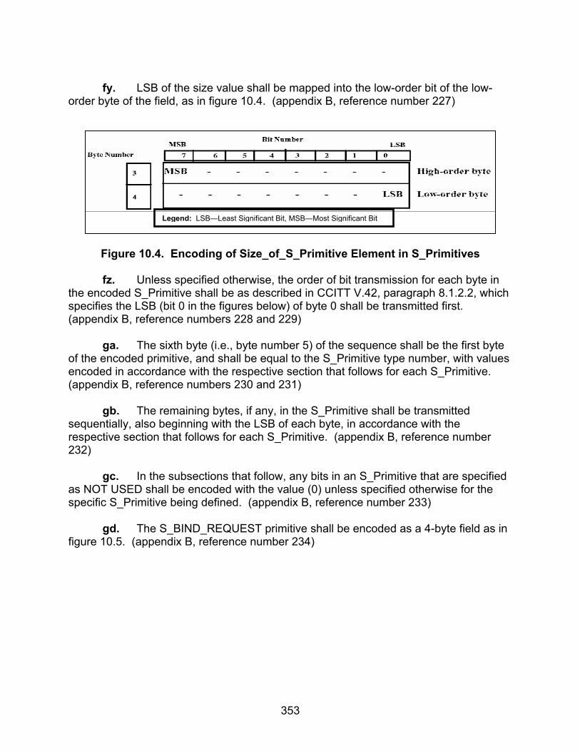
353
fy. LSB of the size value shall be mapped into the low-order bit of the low-order byte of the field, as in figure 10.4. (appendix B, reference number 227)
Figure 10.4. Encoding of Size_of_S_Primitive Element in S_Primitives
fz. Unless specified otherwise, the order of bit transmission for each byte in the encoded S_Primitive shall be as described in CCITT V.42, paragraph 8.1.2.2, which specifies the LSB (bit 0 in the figures below) of byte 0 shall be transmitted first. (appendix B, reference numbers 228 and 229) ga. The sixth byte (i.e., byte number 5) of the sequence shall be the first byte of the encoded primitive, and shall be equal to the S_Primitive type number, with values encoded in accordance with the respective section that follows for each S_Primitive. (appendix B, reference numbers 230 and 231) gb. The remaining bytes, if any, in the S_Primitive shall be transmitted sequentially, also beginning with the LSB of each byte, in accordance with the respective section that follows for each S_Primitive. (appendix B, reference number 232) gc. In the subsections that follow, any bits in an S_Primitive that are specified as NOT USED shall be encoded with the value (0) unless specified otherwise for the specific S_Primitive being defined. (appendix B, reference number 233) gd. The S_BIND_REQUEST primitive shall be encoded as a 4-byte field as in figure 10.5. (appendix B, reference number 234)
Legend: LSB—Least Significant Bit, MSB—Most Significant Bit

354
Figure 10.5. Encoding of S_BIND_REQUEST Primitive
ge. The S_BIND_REQUEST Service Type field shall be encoded as five subfields as in figure 10.6. (appendix B, reference number 235)
Figure 10.6. Sub-Field Attribute Encoding of S_BIND_REQUEST SERVICE_TYPE
Field
gf. The Service Type argument shall specify the default type of service requested by the client. (appendix B, reference number 236) gg. This type of service shall apply to any U_PDU submitted by the client until the client unbinds itself from the node, unless overridden by the Delivery Mode argument of the U_PDU. (appendix B, reference number 237)
Legend: ID—Identification, LSB—Least Significant Bit, MSB—Most Significant Bit, SAP—Subnetwork Access Point
Legend: ARQ—Automatic Repeat Request, Conf—Confirmation, LSB—Least Significant Bit, MIN No OF RETXS—Mininum Number of Re-Transmissions, MSB—Most Significant Bit
355
gh. A client shall change the default service type only by unbinding and binding again with a new S_BIND_REQUEST. (appendix B, reference number 238) gi. Transmission Mode for the Service ARQ or Non-ARQ Transmission Mode shall be specified with one of the Non-ARQ submodes, if Non-ARQ was requested. (appendix B, reference number 239) gj. A value of (0) for this attribute shall be invalid for the Service Type argument when binding. Non-ARQ transmission can have submodes such as: Error-Free-Only delivery to destination client, delivery to destination client even with some errors. (appendix B, reference number 240) gk. Data Delivery Confirmation for the service. The client shall request one of the Data Delivery Confirmation modes for the service. There are three types of data delivery confirmation: (appendix B, reference number 241)
• None • Node-to-Node Delivery Confirmation • Client-to-Client Delivery Confirmation
gl. Explicit delivery confirmation shall be requested only in combination with ARQ delivery. (appendix B, reference number 242) gm. Order of delivery of any U_PDU to the receiving client. A client shall request that its U_PDUs are delivered to the destination client “in-order” (as they are submitted) or in the order they are received by the destination node. (appendix B, reference number 243) gn. Extended Field. Denotes if additional fields in the Service Type argument are following; at present this capability of the Service Type is undefined, and the value of the Extended Field Attribute shall be set to (0). (appendix B, reference number 244)
go. Minimum Number of Retransmissions. This argument shall be valid if and only if the Transmission Mode is a Non-ARQ Type. (appendix B, reference number 245)
gp. If the Transmission Mode is a Non-ARQ Type, then the subnetwork shall retransmit each U_PDU the number of times specified by this argument. This argument may be (0), in which case the U_PDU is sent only once. (appendix B, reference number 246)
gq. The S_UNBIND_REQUEST primitive shall be encoded as a 1-byte field as in figure 10.7. (appendix B, reference number 247)
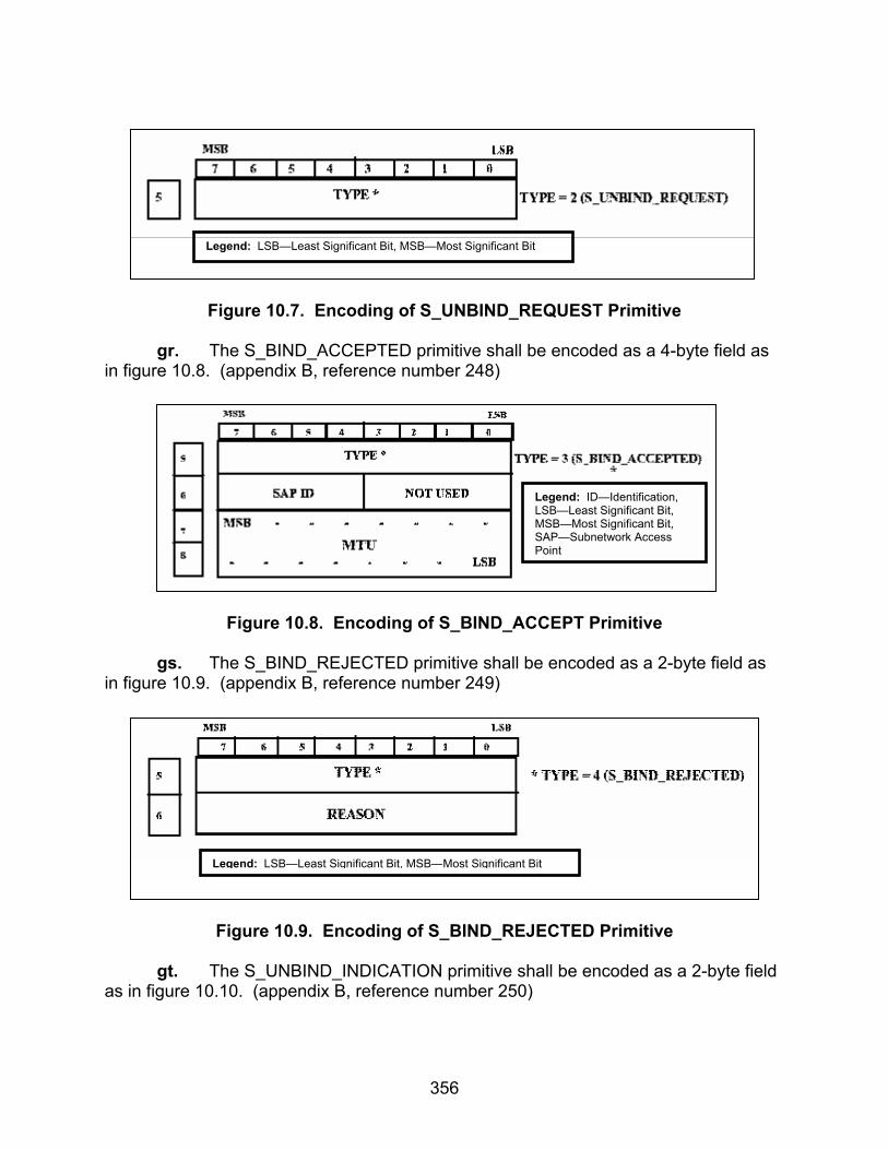
356
Figure 10.7. Encoding of S_UNBIND_REQUEST Primitive
gr. The S_BIND_ACCEPTED primitive shall be encoded as a 4-byte field as in figure 10.8. (appendix B, reference number 248)
Figure 10.8. Encoding of S_BIND_ACCEPT Primitive
gs. The S_BIND_REJECTED primitive shall be encoded as a 2-byte field as in figure 10.9. (appendix B, reference number 249)
Figure 10.9. Encoding of S_BIND_REJECTED Primitive
gt. The S_UNBIND_INDICATION primitive shall be encoded as a 2-byte field as in figure 10.10. (appendix B, reference number 250)
Legend: LSB—Least Significant Bit, MSB—Most Significant Bit
Legend: ID—Identification, LSB—Least Significant Bit, MSB—Most Significant Bit, SAP—Subnetwork Access Point
Legend: LSB—Least Significant Bit, MSB—Most Significant Bit

357
Figure 10.10. Encoding of S_UNBIND_INDICATION Primitive
gu. The S_HARD_LINK_ESTABLISH primitive shall be encoded as a 6-byte field as in figure 10.11. (appendix B, reference number 251)
Figure 10.11. Encoding of S_HARD_LINK_ESTABLISH Primitive
gv. The Remote Node Address field shall be encoded as specified in STANAG 5066, section A.2.2.28.1. (appendix B, reference number 252) gw. The Link Type field shall be encoded as specified in STANAG 5066, section A.2.2.28.4. (appendix B, reference number 253) gx. The S_HARD_LINK_TERMINATE primitive shall be encoded as a 5-byte field as shown in figure 10.12. (appendix B, reference number 254)
Legend: LSB—Least Significant Bit MSB—Most Significant Bit
Legend: ID—Identification, LSB—Least Significant Bit, MSB—Most Significant Bit, SAP—Subnetwork Access Point

358
Figure 10.12. Encoding of S_HARD_LINK_TERMINATE Primitive
gy. The Remote Node Address field shall be encoded as specified in STANAG 5066, section A.2.2.28.1. (appendix B, reference number 255) gz. The Link Type field shall be encoded as specified in STANAG 5066, section A.2.2.28.4. (appendix B, reference number 256) ha. The S_HARD_LINK_ESTABLISHED primitive shall be encoded as a 7-byte field as in figure 10.13. (appendix B, reference number 257)
Figure 10.13. Encoding of S_HARD_LINK_ESTABLISHED Primitive
hb. The Remote Node Address field shall be encoded as specified in STANAG 5066, section A.2.2.28.1. (appendix B, reference number 258)
Legend: LSB—Least Significant Bit, MSB—Most Significant Bit
Legend: ID—Identification, LSB—Least Significant Bit, MSB—Most Significant Bit, SAP—Subnetwork Access Point

359
hc. The Link Type field shall be encoded as specified in STANAG 5066, section A.2.2.28.4. (appendix B, reference number 259) hd. The S_HARD_LINK_REJECTED primitive shall be encoded as a 7-byte field as in figure 10.14. (appendix B, reference number 260)
Figure 10.14. Encoding of S_HARD_LINK_REJECTED Primitive
he. The Remote Node Address field shall be encoded as specified in STANAG 5066, section A.2.2.28.1. (appendix B, reference number 261) hf. The Link Type field shall be encoded as specified in STANAG 5066, section A.2.2.28.4. (appendix B, reference number 262) hg. The S_HARD_LINK_TERMINATED primitive shall be encoded as a 7-byte field as in figure 10.15. (appendix B, reference number 263)
Legend: ID—Identification, LSB—Least Significant Bit, MSB—Most Significant Bit, SAP—Subnetwork Access Point

360
Figure 10.15. Encoding of S_HARD_LINK_TERMINATED Primitive
hh. The Remote Node Address field shall be encoded as specified in STANAG 5066, section A.2.2.28.1. (appendix B, reference number 264) hi. The Link Type field shall be encoded as specified in STANAG 5066, section A.2.2.28.4. (appendix B, reference number 265) hj. The S_HARD_LINK_INDICATION primitive shall be encoded as a 7-byte field as in figure in 10.16. (appendix B, reference number 266)
Legend: ID—Identification, LSB—Least Significant Bit, MSB—Most Significant Bit, SAP—Subnetwork Access Point
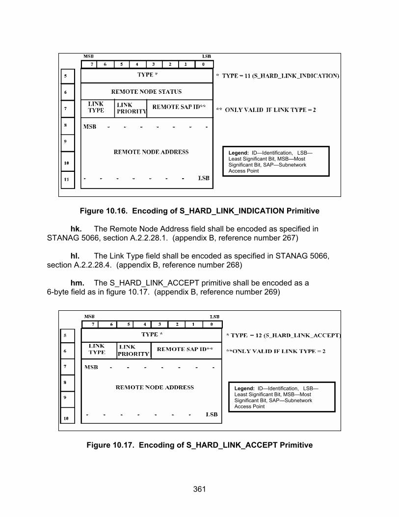
361
Figure 10.16. Encoding of S_HARD_LINK_INDICATION Primitive
hk. The Remote Node Address field shall be encoded as specified in STANAG 5066, section A.2.2.28.1. (appendix B, reference number 267) hl. The Link Type field shall be encoded as specified in STANAG 5066, section A.2.2.28.4. (appendix B, reference number 268) hm. The S_HARD_LINK_ACCEPT primitive shall be encoded as a 6-byte field as in figure 10.17. (appendix B, reference number 269)
Figure 10.17. Encoding of S_HARD_LINK_ACCEPT Primitive
Legend: ID—Identification, LSB—Least Significant Bit, MSB—Most Significant Bit, SAP—Subnetwork Access Point
Legend: ID—Identification, LSB—Least Significant Bit, MSB—Most Significant Bit, SAP—Subnetwork Access Point

362
hn. The Remote Node Address field shall be encoded as specified in STANAG 5066, section A.2.2.28.1. (appendix B, reference number 270) ho. The Link Type field shall be encoded as specified in STANAG 5066, section A.2.2.28.4. (appendix B, reference number 271)
hp. The S_HARD_LINK_REJECT primitive shall be encoded as a 7-byte field as in figure 10.18. (appendix B, reference number 272)
Figure 10.18. Encoding of S_HARD_LINK_REJECTED Primitive
hq. The Remote Node Address field shall be encoded as specified in STANAG 5066, section A.2.2.28.1. (appendix B, reference number 273) hr. The Link Type field shall be encoded as specified in STANAG 5066, section A.2.2.28.4. (appendix B, reference number 274)
hs. The S_KEEP_ALIVE primitive shall be encoded as a 1-byte field as in figure 10.19. (appendix B, reference number 277)
Figure 10.19. Encoding of S_KEEP_ALIVE Primitive
Legend: ID—Identification, LSB—Least Significant Bit, MSB—Most Significant Bit, SAP—Subnetwork Access Point
Legend: LSB—Least Significant Bit, MSB—Most Significant Bit

363
ht. The S_UNIDATA_REQUEST primitive shall be encoded as a variable-length field as in figure 10.20. (appendix B, reference number 279)
Figure 10.20. Encoding of S_UNIDATA_REQUEST Primitive
hu. The Source Node Address and Destination Node Address fields shall be encoded as specified in STANAG 5066, section A.2.2.28. (appendix B, reference number 280) hv. The Delivery Mode field shall be encoded as specified in STANAG 5066, section A.2.2.28.2. (appendix B, reference number 281) hw. The S_UNIDATA_INDICATION primitive shall be encoded as a variable-length field as in figure 10.21. (appendix B, reference number 282)
Legend: ID—Identification, LSB—Least Significant Bit, MSB—Most Significant Bit, SAP—Subnetwork Access Point, TTL—Time To Live, U_PDU—User Protocol Data Unit

364
MSB7 6 5 4 3 2 1 0
TYPE*
MSBLSB
LSB
22+4K……
21+4K+4L
19+4K
21+4K
PRIORITY DESTINATION SAP ID
SOURCE NODE ADDRESSMSB
LSB
TRANSMISSION MODE SOURCE SAP ID
1314
19
20+4K
18171615
20……
5
678
9101112
MSB
LSBDESTINATION NODE ADDRESS
SIZE (N) OF U_PDUMSB
LSB
NUMBER (K) of ERRORED BLOCKS**MSB
LSB
POINTERS AND SIZES OF ERRORED BLOCKS**
NUMBER (L) OF NON_RECEIVED BLOCKS**
POINTERS AND SIZES OF NON_RECEIVED BLOCKS**
22+4K+4L……
21+4K+4L+N
U_PDU
2021222324252627
---
19+4K
22+4K
23+4K24+4K
25+4K
26+4K
27+4K28+4K29+4K
---
21+4K+4L
SIZE OF ERRORED BLOCK #1
POINTER TO ERRORED BLOCK #2
POINTER TO ERRORED BLOCK #1MSB
LSBMSB
LSBMSB
LSBSIZE OF ERRORED BLOCK #2MSB
LSB
POINTER TO ERRORED BLOCK #KMSBLSB
SIZE OF ERRORED BLOCK #KMSBLSB
POINTER TO NON-RECEIVED BLOCK #1MSB
LSB
SIZE OF NON-RECEIVED BLOCK #1MSB
LSB
POINTER TO NON-RECEIVED BLOCK #2MSB
LSB
SIZE OF NON-RECEIVED BLOCK #2MSBLSB
POINTER TO NON-RECEIVED BLOCK #LMSB
LSB
SIZE OF NON-RECEIVED BLOCK #LMSB
LSB
*TYPE = 21 (S_UNIDATA_INDICATION)
**THESE FIELDS SHALL BE PRESENT ONLY IF THETRANSMISSION MODE IS “NON-ARQ W/ERRORS”
Legend: ID—Identification, LSB—Least Significant Bit, MSB—Most Significant Bit, SAP—Subnetwork Access Point
Figure 10.21. Encoding of S_UNIDATA_INDICATION Primitive hx. The Source Node Address and Destination Node Address fields shall be encoded as specified in STANAG 5066, section A.2.2.28.1. (appendix B, reference number 283) hy. The Transmission Mode field shall be encoded as specified in STANAG 5066, section A.2.2.28.3. (appendix B, reference number 284)
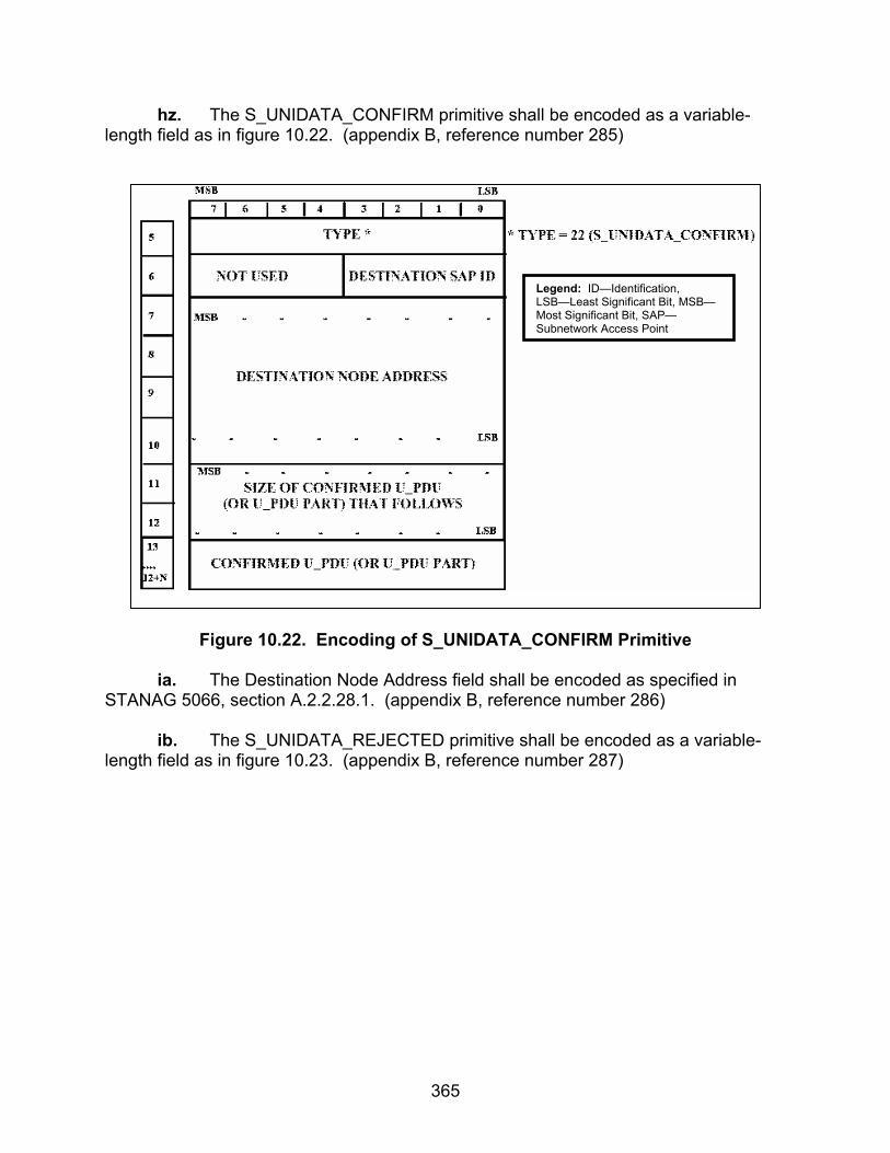
365
hz. The S_UNIDATA_CONFIRM primitive shall be encoded as a variable-length field as in figure 10.22. (appendix B, reference number 285)
Figure 10.22. Encoding of S_UNIDATA_CONFIRM Primitive
ia. The Destination Node Address field shall be encoded as specified in STANAG 5066, section A.2.2.28.1. (appendix B, reference number 286) ib. The S_UNIDATA_REJECTED primitive shall be encoded as a variable-length field as in figure 10.23. (appendix B, reference number 287)
Legend: ID—Identification, LSB—Least Significant Bit, MSB—Most Significant Bit, SAP—Subnetwork Access Point

366
Figure 10.23. Encoding of S_UNIDATA_REJECTED Primitive
ic. The Destination Node Address field shall be encoded as specified in STANAG 5066, section A.2.2.28.1. (appendix B, reference number 288) id. The S_EXPEDITED_UNIDATA_REQUEST primitive shall be encoded as a variable-length field as in figure 10.24. (appendix B, reference number 289)
Legend: ID—Identification, LSB—Least Significant Bit, MSB—Most Significant Bit, SAP—Subnetwork Access Point

367
Figure 10.24. Encoding of S_EXPEDITED_UNIDATA_REQUEST Primitive
ie. The Destination Node Address field shall be encoded as specified in STANAG 5066, section A.2.2.28.1. (appendix B, reference number 290) if. The Delivery Mode field shall be encoded as specified in STANAG 5066, section A.2.2.28.2. (appendix B, reference number 291) ig. The S_EXPEDITED_UNIDATA_INDICATION primitive shall be encoded as a variable length field as in figure 10.25. (appendix B, reference number 292)
Legend: ID—Identification, LSB—Least Significant Bit, MSB—Most Significant Bit, SAP—Subnetwork Access Point, TTL—Time To Live, U_PDU—User Protocol Data Unit

368
MSB7 6 5 4 3 2 1 0
TYPE*
MSBLSB
LSB
22+4K……
21+4K+4L
19+4K
21+4K
NOT-USED** DESTINATION SAP ID
SOURCE NODE ADDRESSMSB
LSB
TRANSMISSION MODE SOURCE SAP ID
1314
19
20+4K
18171615
20……
5
6
78
9101112
MSB
LSB
DESTINATION NODE ADDRESS
SIZE (N) OF U_PDUMSB
LSB
NUMBER (K) of ERRORED BLOCKS***MSB
LSB
POINTERS AND SIZES OF ERRORED BLOCKS***
NUMBER (L) OF NON_RECEIVED BLOCKS***
POINTERS AND SIZES OF NON_RECEIVED BLOCKS***
22+4K+4L……
21+4K+4L+N
U_PDU
2021222324252627
---
19+4K
22+4K
23+4K24+4K
25+4K
26+4K
27+4K28+4K29+4K
---
21+4K+4L
SIZE OF ERRORED BLOCK #1
POINTER TO ERRORED BLOCK #2
POINTER TO ERRORED BLOCK #1MSB
LSBMSB
LSBMSB
LSB
SIZE OF ERRORED BLOCK #2MSBLSB
POINTER TO ERRORED BLOCK #KMSBLSB
SIZE OF ERRORED BLOCK #KMSBLSB
POINTER TO NON-RECEIVED BLOCK #1MSB
LSB
SIZE OF NON-RECEIVED BLOCK #1MSB
LSB
POINTER TO NON-RECEIVED BLOCK #2MSB
LSB
SIZE OF NON-RECEIVED BLOCK #2MSBLSB
POINTER TO NON-RECEIVED BLOCK #LMSB
LSB
SIZE OF NON-RECEIVED BLOCK #LMSB
LSB
***THESE FIELDS SHALL BE PRESENT ONLY IF THETRANSMISSION MODE IS “NON-ARQ W/ERRORS”
*TYPE = 21 (S_UNIDATA_INDICATION)**THIS FIELD CORRESPONDS TO THE PRIORITY FIELD OFTHE S_UNIDATA_INDICATION PRIMITIVE AND IS UNUSEDIN THE EXPEDITED FORM
Legend: ID—Identification, LSB—Least Significant Bit, MSB—Most Significant Bit, SAP—Subnetwork Access Point
Figure 10.25. Encoding of S_EXPEDITED_UNIDATA_INDICATION Primitive
ih. The Source Node Address and Destination Node Address fields shall be encoded as specified in STANAG 5066, section A.2.2.28.1. (appendix B, reference number 293) ii. The Transmission Mode field shall be encoded as specified in STANAG 5066, section A.2.2.28.3. (appendix B, reference number 294) ij. The S_EXPEDITED_UNIDATA_CONFIRM primitive shall be encoded as a variable-length field as in figure 10.26. (appendix B, reference number 295)

369
Figure 10.26. Encoding of S_EXPEDITED_UNIDATA_CONFIRM Primitive
ik. The Destination Node Address field shall be encoded as specified in STANAG 5066, section A.2.2.28.1. (appendix B, reference number 296) il. The S_EXPEDITED_UNIDATA_REJECTED primitive shall be encoded as a variable-length field as in figure 10.27. (appendix B, reference number 297)
Legend: ID—Identification, LSB—Least Significant Bit, MSB—Most Significant Bit, SAP—Subnetwork Access Point, U PDU—User Protocol Data Unit

370
Figure 10.27. Encoding of S_EXPEDITED_UNIDATA_REJECTED Primitive
im. The Destination Node Address field shall be encoded as specified in STANAG 5066, section A.2.2.28.1. (appendix B, reference number 298)
in. For reduced overhead in transmission, node addresses shall be encoded in one of several formats that are multiples of 4-bits (“half-bytes”) in length, as specified in figure 10.28. (appendix B, reference number 299)
Figure 10.28. Encoding of Address Fields in S_Primitive
Legend: ID—Identification, LSB—Least Significant Bit, MSB—Most Significant Bit, SAP—Subnetwork Access Point, U PDU—User Protocol Data Unit
Legend: ADR—Address, ARQ—Automatic Repeat-Request, LSB—Least Significant Bit, Max—Maximum, MSB—Most Significant Bit, PDU—Protocol Data Unit

371
io. Addresses that are encoded as Group Node Addresses shall only be specified as the Destination Node Address of Non-ARQ PDUs. (appendix B, reference number 300) ip. Destination SAP IDs and destination node addresses of ARQ PDUs and source SAP IDs and source node addresses of all PDUs shall be individual SAP IDs and individual node addresses respectively. (appendix B, reference number 301) iq. Remote node addresses and remote SAP IDs of all S_HARD_LINK primitives shall be individual SAP IDs and individual node addresses, respectively. (appendix B, reference number 302)
ir. The Delivery Mode is a complex argument consisting of a number of attributes, as specified here. The Delivery Mode argument shall be encoded as shown in figure 10.29. (appendix B, reference number 303)
Figure 10.29. Encoding of the Delivery Mode Field in the S_UNIDATA_REQUEST and S_EXPEDITED_UNIDATA_REQUEST Primitives
is. The value of the Delivery Mode argument can be Default, as encoded by the Transmission Mode attribute. With a value of (Default), the delivery mode for this U_PDU shall be the delivery mode specified in the Service Type argument of the S_BIND_REQUEST. (appendix B, reference number 304) it. A Non-Default value shall override the default settings of the Service Type for this U_PDU. (appendix B, reference number 305) iu. The attributes of this argument are similar to those described in the Service Type argument of the S_BIND_REQUEST: Transmission Mode of this U_PDU.
Legend: ARQ—Automatic Repeat-Request, LSB—Least Significant Bit, MIN No OF RETXS—Minimum Number of Retransmissions, MSB—Most Significant Bit

372
ARQ or Non-ARQ Transmission can be requested. A value of “0” for this attribute shall equal the value Default for the Delivery Mode. (appendix B, reference number 306) iv. If the Delivery Mode is Default, all other attributes encoded in the argument shall be ignored. (appendix B, reference number 307) iw. Extended Field. Denotes if additional fields in the Delivery Mode argument are following; at present this capability of the Delivery Mode is undefined, and the value of the Extended Field Attribute shall be set to (0). (appendix B, reference number 308) ix. Minimum Number of Retransmissions. This argument shall be valid if and only if the Transmission Mode is a Non-ARQ type or subtype. (appendix B, reference number 309) iy. If the Transmission Mode is a Non-ARQ type or subtype, then the subnetwork shall retransmit each U_PDU the number of times specified by this argument. This argument may be (0), in which case the U_PDU is sent only once. (appendix B, reference number 310)
iz. The Transmission Mode argument in the S_UNIDATA_INDICATION and S_EXPEDITED_UNIDATA_INDICATION primitives shall be encoded as shown in figure 10.30. (appendix B, reference number 311)
Figure 10.30. Encoding of Transmission Mode Field in S_UNIDATA_INDICATION
and S_EXPEDITED_UNIDATA_INDICATION Primitives
Legend: ARQ—Automatic Repeat-Request, LSB—Least Significant Bit, Max—Maximum, MSB—Most Significant Bit
373
ja. A client uses the Link Type argument to reserve partially or fully the capacity of the Hard Link. This argument can have three values: (appendix B, reference numbers 312 and 313)
• A value of (0) shall indicate that the physical link to the specified node address is a Type 0 Hard Link. The Type 0 Hard Link must be maintained, but all clients connected to the two nodes can make use of the link capacity according to normal procedures (i.e., there is no bandwidth reservation).
• A value of (1) shall indicate that the physical link to the specified node address is a Type 1 Hard Link. The Type 1 Hard Link must be maintained and traffic is only allowed between the requesting client and any of the clients on the remote node, (i.e., there is partial bandwidth reservation).
• A value of (2) indicates that the physical link to the specified node address must be maintained and traffic is only allowed between the requesting client and the specific client on the remote node specified by the Remote SAP ID argument, (i.e., full bandwidth reservation.)
jc. The Priority field shall be equal in value to the corresponding argument of the S_UNIDATA_REQUEST primitive submitted by the client. (appendix B, reference number 328) jd. The Destination SAP ID shall be equal in value to the corresponding argument of the S_UNIDATA_REQUEST primitive submitted by the client. (appendix B, reference number 331) je. The peer sublayer that receives the Data Delivery Confirm shall inform the delivered to its destination by issuing an S_UNIDATA_REQUEST_CONFIRM or an S_EXPEDITED_UNIDATA_REQUEST_CONFIRM in accordance with the data exchange protocol of STANAG 5066, section A.3.2.4. (appendix B, reference number 347)
jf. The peer sublayer that receives the Data Delivery Fail S_PDU, shall inform the client which originated the U_PDU that its data was not delivered to the destination by issuing an S_UNIDATA_REQUEST_REJECTED Primitive or an S_EXPEDITED_UNIDATA_REQUEST_REJECTED Primitive, in accordance with the data exchange protocol of STANAG 5066, section A.3.2.4. (appendix B, reference number 355) jg. The Link Type and Link Priority fields shall be equal in value to the corresponding arguments of the S_HARD_LINK_ESTABLISH primitive submitted by the client to request the link. (appendix B, reference number 359) jh. The peer, that receives this S_PDU, shall inform its appropriate client accordingly with an S_HARD_LINK_ESTABLISHED primitive in accordance with the

374
Hard Link Establishment Protocol specified in STANAG 5066, section A.3.2.2.2. (appendix B, reference number 366) ji. After the physical link is made, both peer Subnetwork Interface Sublayers shall declare that the Soft Link Data Exchange Session has been established between the respective source and destination nodes. (appendix B, reference number 385) jj. After the Subnetwork Interface Sublayer has been notified that the physical link has been broken, the Subnetwork Interface Sublayer shall declare the Soft Link Exchange Session as terminated. (appendix B, reference number 389) jk. If an existing Type 0 Hard Link can satisfy a request that has been rejected, the sublayer shall note this as the reason for rejecting the request; the requesting client may then submit data for transmission using a Soft Link Data Exchange Session. (appendix B, reference number 396) jl. Upon receiving an S_HARD_LINK_ESTABLISH primitive from a client, the Subnetwork Interface Sublayer shall first check that it can accept the request from the client in accordance with the precedence and priority rules of STANAG 5066, section A.3.2.2.1. (appendix B, reference number 404) jm. If the Hard Link request is of lower precedence than any existing Hard Link, then the establishment protocol proceeds as follows: (appendix B, reference numbers 405-408)
• The request shall be denied by the Subnetwork Interface Sublayer. • The sublayer shall issue an S_HARD_LINK_REJECTED primitive to
the requesting client with REASON = “Higher Priority Link Existing.” • The sublayer shall terminate the Hard Link establishment protocol.
jn. Otherwise, if a Type 0 Hard Link request is of the same priority, same client-rank, and with the same set of source and destination nodes as an existing Hard Link, then the establishment protocol proceeds as follows: (appendix B, reference number 409)
• The Subnetwork Interface Sublayer shall reject the Type 0 Hard Link
request with the REASON = “Requested Type 0 Hard Link Exists;” a client receiving this rejection may submit data requests for transmission using a Soft Link Data Exchange Session to the remote peer.
jo. The sublayer shall take no further action to establish or change the status of the existing Type 0 Hard Link (since the sublayer has already determined that the existing link satisfies the requirements of the request) and the sublayer shall terminate the Hard Link establishment protocol. (appendix B, reference numbers 410 and 411)

375
jp. If the Subnetwork Interface Sublayer can accept the Hard Link request it shall first terminate any existing Hard Link of lower precedence using the peer-to-peer communication protocol for terminating an existing Hard Link specified in STANAG 5066, section A.3.2.2.3. (appendix B, reference number 412)
jq. The Subnetwork Interface Sublayer then shall request the Channel
Access Sublayer to make a physical link to the node specified by the client, following procedure for making the physical link specified in annex B of STANAG 5066. After it sends the “Hard Link Establishment Request” (Type 3) S_PDU, the caller’s Subnetwork Interface Sublayer shall wait a configurable time-out period for a response from the called peer, and proceed as follows: (appendix B, reference numbers 413, 416-419)
• During the waiting period for the response: o If the caller’s sublayer receives a Hard Link Establishment Rejected
(Type 5) S_PDU from the called peer, the sublayer shall notify the requesting client that the Hard Link request has failed by sending the client an S_HARD_LINK_REJECTED primitive to the requesting client with the REASON field of the primitive set to the corresponding value received in the S_PDU’s Reason field.
o If the caller’s sublayer receives a Hard Link Establishment Confirm (Type 4) S_PDU from the called peer, the sublayer shall notify the requesting client that the Hard Link request has succeeded by sending the client an S_HARD_LINK_ESTABLISHED primitive.
• Otherwise, if the waiting period for the response expires without receipt
of a valid response from called node, the caller’s sublayer shall notify the requesting client that the Hard Link request has failed by sending the client an S_HARD_LINK_REJECTED primitive to the requesting client with REASON =“Remote Node Not Responding.”
jr. The caller’s establishment protocol shall terminate on receipt during the waiting of a valid response from the called node and notification of the client, or on expiration of the waiting period. (appendix B, reference number 420) js. For the called Subnetwork Access Sublayer, the Hard Link establishment protocol shall be initiated on receipt of a Hard Link Establishment Request (Type 3) S_PDU and proceeds as follows: (appendix B, reference number 421) jt. Otherwise, the called sublayer shall evaluate the precedence of the caller’s request in accordance with the precedence and priority rules of STANAG 5066, section A.3.2.2.1, using as the client rank either a configurable default rank for the called SAP_ID for Type 0 and Type 1 Hard Link requests, or the actual rank of the bound client with the called SAP_ID for Type 2 Hard Link requests. (appendix B, reference number 423)
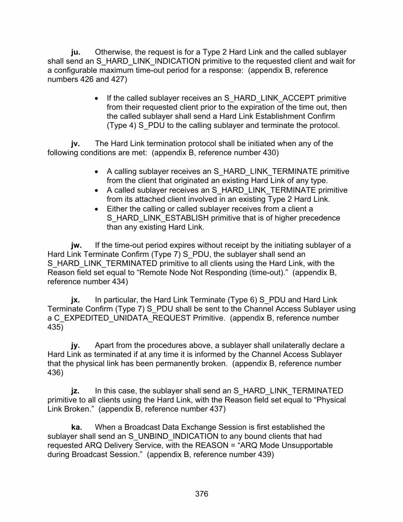
376
ju. Otherwise, the request is for a Type 2 Hard Link and the called sublayer shall send an S_HARD_LINK_INDICATION primitive to the requested client and wait for a configurable maximum time-out period for a response: (appendix B, reference numbers 426 and 427)
• If the called sublayer receives an S_HARD_LINK_ACCEPT primitive from their requested client prior to the expiration of the time out, then the called sublayer shall send a Hard Link Establishment Confirm (Type 4) S_PDU to the calling sublayer and terminate the protocol.
jv. The Hard Link termination protocol shall be initiated when any of the following conditions are met: (appendix B, reference number 430)
• A calling sublayer receives an S_HARD_LINK_TERMINATE primitive from the client that originated an existing Hard Link of any type.
• A called sublayer receives an S_HARD_LINK_TERMINATE primitive from its attached client involved in an existing Type 2 Hard Link.
• Either the calling or called sublayer receives from a client a S_HARD_LINK_ESTABLISH primitive that is of higher precedence than any existing Hard Link.
jw. If the time-out period expires without receipt by the initiating sublayer of a Hard Link Terminate Confirm (Type 7) S_PDU, the sublayer shall send an S_HARD_LINK_TERMINATED primitive to all clients using the Hard Link, with the Reason field set equal to “Remote Node Not Responding (time-out).” (appendix B, reference number 434) jx. In particular, the Hard Link Terminate (Type 6) S_PDU and Hard Link Terminate Confirm (Type 7) S_PDU shall be sent to the Channel Access Sublayer using a C_EXPEDITED_UNIDATA_REQUEST Primitive. (appendix B, reference number 435) jy. Apart from the procedures above, a sublayer shall unilaterally declare a Hard Link as terminated if at any time it is informed by the Channel Access Sublayer that the physical link has been permanently broken. (appendix B, reference number 436) jz. In this case, the sublayer shall send an S_HARD_LINK_TERMINATED primitive to all clients using the Hard Link, with the Reason field set equal to “Physical Link Broken.” (appendix B, reference number 437) ka. When a Broadcast Data Exchange Session is first established the sublayer shall send an S_UNBIND_INDICATION to any bound clients that had requested ARQ Delivery Service, with the REASON = “ARQ Mode Unsupportable during Broadcast Session.” (appendix B, reference number 439)

377
kb. The sublayer shall discard any U_PDU submitted by a client where the U_PDU is greater in size than the MTU size assigned to the client by the S_BIND_ACCEPTED primitive issued during the client-bind protocol. (appendix B, reference number 441) kc. If a U_PDU is discarded because it exceeded the MTU size limit and if the Delivery Confirmation field for the U_PDU specifies Client Delivery Confirm or Node Delivery Confirm, the sublayer shall notify the client that submitted the U_PDU as follows: (appendix B, reference numbers 442-445)
• If the U_PDU was submitted by an S_UNIDATA_REQUEST primitive
the sublayer shall send an S_UNIDATA_REQUEST_REJECT primitive to the client.
• Otherwise, if the U_PDU was submitted by an S_EXPEDITED_UNIDATA_REQUEST primitive, the sublayer shall send an S_EXPEDITED_UNIDATA_REQUEST_REJECT primitive to the client.
• For either form of the reject primitive, the Reason field shall be equal to “U_PDU larger than MTU.”
kd. If the service attributes for the U_PDU require Node Delivery Confirmation, the sublayer shall wait for a configurable time for a response as follows: (appendix B, reference number 452-461 and 463-466)
• If the sublayer receives a C_UNIDATA_REQUEST_CONFIRM primitive or a C_EXPEDITED_UNIDATA_REQUEST_CONFIRM primitive prior to the end of the waiting time, the sublayer shall send to the client either an S_UNIDATA_REQUEST_CONFIRM primitive or S_EXPEDITED_UNIDATA_REQUEST_CONFIRM primitive, respectively, where the type of C_Primitive expected and S_Primitive sent corresponds to the type of U_PDU delivery service requested.
• Otherwise, if the sublayer receives a C_UNIDATA_REQUEST_REJECT primitive or a C_EXPEDITED_UNIDATA_REQUEST_REJECT primitive prior to the end of the waiting time, the sublayer shall send to the client either an S_UNIDATA_REQUEST_REJECT primitive or S_EXPEDITED_UNIDATA_REQUEST_CONFIRM REJECT, respectively, where the type of C_Primitive expected and S_Primitive sent corresponds to the type of U_PDU delivery service requested.
• Otherwise, if the waiting time ends prior to receipt of any response indication from the Channel Access sublayer, the Subnetwork Interface Sublayer shall send to the client either an S_UNIDATA_REQUEST_REJECT primitive; if the U_PDU was submitted by an S_UNIDATA_REQUEST primitive, or an S_EXPEDITED_UNIDATA_REQUEST_REJECT primitive; if the U_PDU was submitted by an S_EXPEDITED_UNIDATA_REQUEST

378
primitive. For either reject S_Primitive, the Reason field shall be set equal to “Destination Node Not Responding.”
• If the service attributes for the U_PDU require Client Delivery Confirmation, the sending sublayer shall wait for a configurable time for a response as follows:
• If the Subnetwork Interface Sublayer receives a C_Primitive confirming no node delivery (i.e., either a C_UNIDATA_REQUEST_CONFIRM primitive or a C_EXPEDITED_UNIDATA_REQUEST_CONFIRM primitive) and a Data Delivery Confirm (Type 1) S_PDU is received from the remote sublayer prior to the end of the waiting time, the Subnetwork Interface Sublayer shall send to the client either an S_UNIDATA_REQUEST_CONFIRM primitive; if the U_PDU was submitted by an S_UNIDATA_REQUEST primitive, or an S_EXPEDITED_UNIDATA_REQUEST_CONFIRM primitive; if the U_PDU was submitted by an S_EXPEDITED_UNIDATA_REQUEST primitive.
• Otherwise, if the Subnetwork Interface Sublayer receives either a “reject” C_Primitive from the Channel Access Sublayer or a Data Delivery Fail (Type 2) S_PDU from the remote peer prior to the end of the waiting time, the Subnetwork Interface Sublayer shall send to the client either an S_UNIDATA_REQUEST_REJECT primitive; if the U_PDU was submitted by an S_UNIDATA_REQUEST primitive or an S_EXPEDITED_UNIDATA_REQUEST_REJECT primitive, if the U_PDU was submitted by an S_EXPEDITED_UNIDATA_REQUEST primitive. For either form of the primitive, the Reason field shall be taken from the Data Delivery Fail (Type 2) S_PDU or the reject C_Primitive that was received.
• Otherwise, if the waiting time ends prior to receipt of a response message, the sublayer shall send to the client either an S_UNIDATA_REQUEST_REJECT primitive; if the U_PDU was submitted by an S_UNIDATA_REQUEST primitive, or an S_EXPEDITED_UNIDATA_REQUEST_REJECT primitive; if the U_PDU was submitted by an S_EXPEDITED_UNIDATA_REQUEST primitive. For either primitive, the Reason field shall be set equal to “Destination Node Not Responding.”
• On completion of these actions by the sending sublayer the client data delivery protocol terminates for the given Data (Type 0) S_PDU.
• The receiving sublayer shall extract the U_PDU, Destination SAP_ID, and the other associated service attributes from the Data (Type 0) S_PDUs as required.
• If there is no client bound to the Destination SAP_ID, the receiving sublayer shall discard the U_PDU by otherwise:
o If the Data (Type 0) S_PDU was encoded within a
C_UNIDATA_INDICATION primitive, the sublayer shall deliver the

379
extracted U_PDU to the destination client bound to Destination SAP_ID using an S_UNIDATA_INDICATION primitive.
o If the DATA (Type 0) S_PDU was encoded within a C_EXPEDITED_UNIDATA_INDICATION primitive, the sublayer shall deliver the extracted U_PDU to the destination client bound to Destination SAP_ID using an S_EXPEDITED_UNIDATA_INDICATION primitive.
ke. Implementation-dependent queuing disciplines, flow-control procedures, or other characteristics in the sublayer shall not preclude the possibility of managing the data exchange protocol for more than one U_PDU at a time. (appendix B, reference number 470) 10.3 Test Procedures
a. Test Equipment Required
(1) Computers (2 ea) with Local Area Network (LAN) Interface Cards and RS-232 Interface Cards
(2) Computers (2 ea) with LAN Interface Cards
(3) Protocol Analyzer (2 ea)
(4) Hub
(5) Modems (2 ea)
b. Test Configuration. Figure 10.31 shows the equipment setup for this
subtest.
c. Test Conduction. Table 10.10 lists procedures for this subtest and table 10.11 lists the results for this subtest.
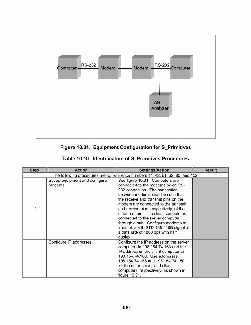
380
Computer Modem Modem Computer
LANAnalyzer
RS-232 RS-232
Figure 10.31. Equipment Configuration for S_Primitives
Table 10.10. Identification of S_Primitives Procedures
Step Action Settings/Action Result The following procedures are for reference numbers 41, 42, 61, 62, 85, and 452.
1
Set up equipment and configure modems.
See figure 10.31. Computers are connected to the modems by an RS-232 connection. The connection between modems shall be such that the receive and transmit pins on the modem are connected to the transmit and receive pins, respectively, of the other modem. The client computer is connected to the server computer through a hub. Configure modems to transmit a MIL-STD-188-110B signal at a data rate of 4800 bps with half duplex.
2
Configure IP addresses. Configure the IP address on the server computer) to 198.154.74.163 and the IP address on the client computer to 198.154.74.160. Use addresses 198.154.74.153 and 198.154.74.150 for the other server and client computers, respectively, as shown in figure 10.31.
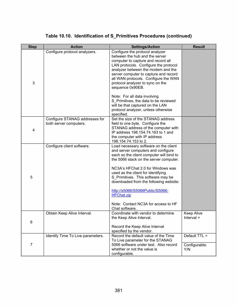
381
Table 10.10. Identification of S_Primitives Procedures (continued)
Step Action Settings/Action Result
3
Configure protocol analyzers. Configure the protocol analyzer between the hub and the server computer to capture and record all LAN protocols. Configure the protocol analyzer between the modem and the server computer to capture and record all WAN protocols. Configure the WAN protocol analyzer to sync on the sequence 0x90EB. Note: For all data involving S_Primitives, the data to be reviewed will be that captured on the LAN protocol analyzer, unless otherwise specified.
4
Configure STANAG addresses for both server computers.
Set the size of the STANAG address field to one byte. Configure the STANAG address of the computer with IP address 198.154.74.163 to 1 and the computer with IP address 198.154.74.153 to 2.
5
Configure client software. Load necessary software on the client and server computers and configure each so the client computer will bind to the 5066 stack on the server computer. NC3A’s HFChat 2.0 for Windows was used as the client for identifying S_Primitives. This software may be downloaded from the following website: http://s5066/S5066Public/S5066-HFChat.zip Note: Contact NC3A for access to HF Chat software.
6
Obtain Keep Alive Interval. Coordinate with vendor to determine the Keep Alive Interval. Record the Keep Alive Interval specified by the vendor.
Keep Alive Interval =
Default TTL =
7
Identify Time To Live parameters. Record the default value of the Time To Live parameter for the STANAG 5066 software under test. Also record whether or not the value is configurable.
Configurable: Y/N

382
Table 10.10. Identification of S_Primitives Procedures (continued)
Step Action Settings/Action Result Default MTU =
8
Verify MTU is a configurable parameter.
Locate the MTU field in the STANAG 5066 software. Record the default value of the MTU for the STANAG 5066 software under test. Also record whether or not the value is configurable.
Configurable: Y/N
9
Verify the STANAG 5066 client is configurable to broadcast-only (Non-ARQ) transmission mode.
Locate the options in the STANAG 5066 software available for the Transmission Mode. Record whether the STANAG 5066 is configurable for broadcast-only (Non-ARQ mode).
Configurable: Y/N
Max Time to Wait for Response to Type 6 S_PDU =
10
Verify Maximum Time to Wait for a response to a Hard Link Terminate (Type 6) S_PDU is a configurable parameter.
Record the Maximum Time to Wait for a response to a Hard Link Terminate (Type 6) S_PDU. Also record whether or not the value is configurable.
Configurable: Y/N
11 Configure SAP ID. Allow the client software from step 5 to
bind to the STANAG 5066 stack with an SAP ID of “0.”
12
Verify that no other clients are bound to SAP ID “0.”
Locate SAP IDs of all other clients connected to the STANAG 5066 stack. Are any other clients bound to the STANAG 5066 stack using a SAP ID of “0”?
Number of Other Clients with SAP ID equal to “0” =
13 Configure rank. Configure the rank of the client to “0” for the client computer.
14 Configure priority level. Set the priority level to “0” for both computers.
15 Configure delivery confirmation. Set the delivery confirmation to “client.”
16 Configure number of retransmissions.
Configure the number of retransmissions to “0.”
17
Verify U_PDU_Response_Frag_Size is a configurable parameter.
Record whether or not the STANAG 5066 software allows for the U_PDU_Response_Frag_Size field to be a configurable parameter within the STANAG 5066 software.
Y/N
The following procedures are for reference numbers 1, 2, 22, 24-28, 30, 31, 50-53, 55-58, 65, 66, 76, 77, 79-84, 215, 234, 239-246, 279-281, 287, 288, 298-301, 303, 304, 306-311, 454, 455, 464, 465, and 158-233 for
Types 1, 20, and 23 S_Primitives.
18
Bind to server. Have the client computer 198.154.74.160 bind to the server computer 198.154.74.163 with a ARQ link. Only bind one client computer to its server computer. Leave the other end unbound.
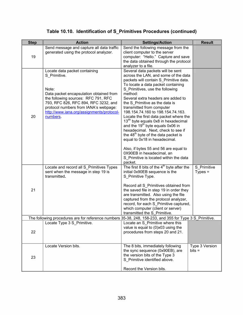
383
Table 10.10. Identification of S_Primitives Procedures (continued)
Step Action Settings/Action Result
19
Send message and capture all data traffic generated using the protocol analyzer.
Send the following message from the client computer to the server computer: “Hello.” Capture and save the data obtained through the protocol analyzer to a file.
20
Locate data packet containing S_Primitive. Note: Data packet encapsulation obtained from the following sources: RFC 791, RFC 793, RFC 826, RFC 894, RFC 3232, and protocol numbers from IANA’s webpage: http://www.iana.org/assignments/protocol-numbers.
Several data packets will be sent across the LAN, and some of the data packets will contain S_Primitive data. To locate a data packet containing S_Primitives, use the following method: Several extra headers are added to the S_Primitive as the data is transmitted from computer 198.154.74.160 to 198.154.74.163. Locate the first data packet where the 13tth byte equals 0x8 in hexadecimal and the 19th byte equals 0x06 in hexadecimal. Next, check to see if the 48th byte of the data packet is equal to 0x18 in hexadecimal. Also, if bytes 55 and 56 are equal to 0X90EB in hexadecimal, an S_Primitive is located within the data packet.
21
Locate and record all S_Primitives Types sent when the message in step 19 is transmitted.
The first 8 bits of the 4th byte after the initial 0x90EB sequence is the S_Primitive Type. Record all S_Primitives obtained from the saved file in step 19 in order they are transmitted. Also using the file captured from the protocol analyzer, record, for each S_Primitive captured, which computer (client or server) transmitted the S_Primitive.
S_Primitive Types =
The following procedures are for reference numbers 35-38, 248, 158-233, and 355 for Type 3 S_Primitive.
22
Locate Type 3 S_Primitive. Locate an S_Primitive where this value is equal to (0)x03 using the procedures from steps 20 and 21.
23
Locate Version bits. The 8 bits, immediately following the sync sequence (0x90EB), are the version bits of the Type 3 S_Primitive identified above. Record the Version bits.
Type 3 Version bits =

384
Table 10.10. Identification of S_Primitives Procedures (continued)
Step Action Settings/Action Result
24
Locate Size of S_Primitive bits. The next 16 bits, after the Version bits, are the Size of S_Primitive bits. Record the Size of S_Primitive bits.
Type 3 Size of S_Primitive =
25
Locate SAP ID bits for the Type 3 S_Primitive obtained in step 22.
The next 4 bits, after the S_Primitive type, contain the SAP ID. Record the SAP ID bits for the Type 3 S_Primitive.
Type 3 SAP ID =
26
Locate Reserved bits for the Type 3 S_Primitive obtained in step 22.
The next 4 bits, after the SAP ID bits, are the Reserved bits. Record the Reserved bits.
Type 3 Reserved bits =
27
Locate Maximum Transmission Unit bits for the Type 3 S_Primitive obtained in step 22.
The next 16 bits, after the Reserved bits, are the Maximum Transmission Unit bits. Record the Maximum Transmission Unit bits.
Type 3 MTU bits =
28
Verify that the Type 3 S_Primitive was transmitted in response to the Type 2 S_Primitive transmitted in step 21.
By observing the order of S_Primitives transmitted in step 21, determine if a Type 3 S_Primitive was the next S_Primitive transmitted by the server computer in after the client computer transmitted a Type 1 S_Primitive?
Type 3 S_Primitive transmitted in response to Type 1 S_Primitive? Y/N
29
Verify that no data was accepted by the destination computer.
Visually check to see if data appeared on the screen of the destination computer. Did the word “Hello” appear on the destination computer?
Y/N
30
Locate Type 23 S_Primitive. The first 8 bits of the 4th byte, after the initial 0x90EB sequence, is the S_Primitive Type. Locate an S_Primitive whose value is (MSB) 0 0 0 1 0 1 1 1 (LSB) (0x17 hex).
31
Locate Version bits. The 8 bits, immediately following the sync sequence (0x90EB), are the version bits of the Type 23 S_Primitive identified above. Record the Version bits.
Type 23 Version bits =
32
Locate Size of S_Primitive bits. The next 16 bits, after the Version bits, are the Size of S_Primitive bits. Record the Size of S_Primitive bits.
Type 23 Size of S_Primitive =
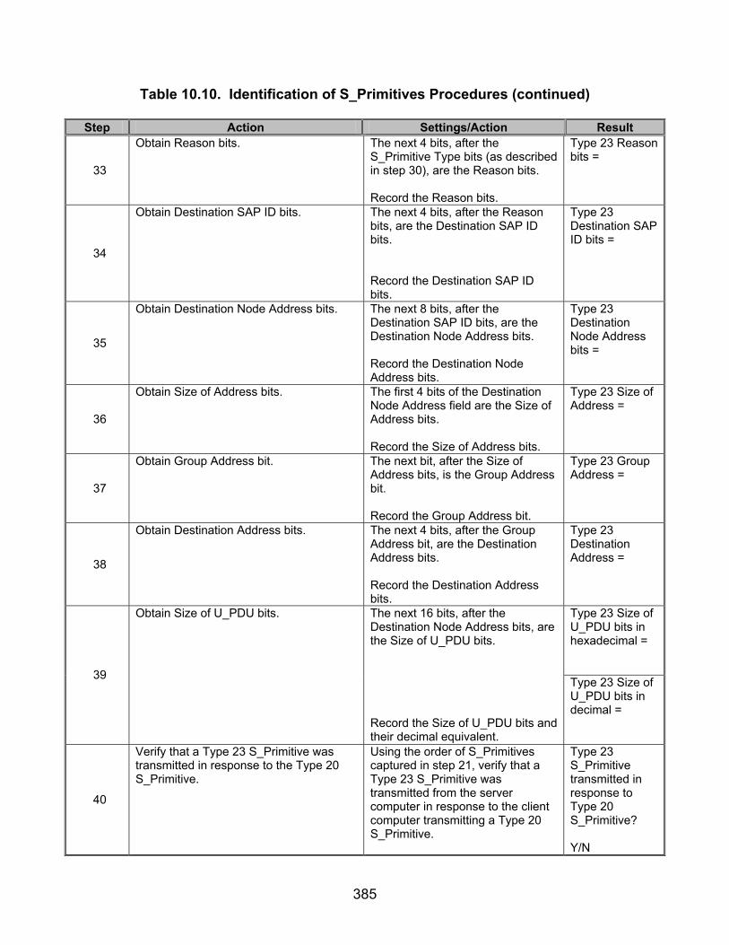
385
Table 10.10. Identification of S_Primitives Procedures (continued)
Step Action Settings/Action Result
33
Obtain Reason bits. The next 4 bits, after the S_Primitive Type bits (as described in step 30), are the Reason bits. Record the Reason bits.
Type 23 Reason bits =
34
Obtain Destination SAP ID bits. The next 4 bits, after the Reason bits, are the Destination SAP ID bits. Record the Destination SAP ID bits.
Type 23 Destination SAP ID bits =
35
Obtain Destination Node Address bits. The next 8 bits, after the Destination SAP ID bits, are the Destination Node Address bits. Record the Destination Node Address bits.
Type 23 Destination Node Address bits =
36
Obtain Size of Address bits. The first 4 bits of the Destination Node Address field are the Size of Address bits. Record the Size of Address bits.
Type 23 Size of Address =
37
Obtain Group Address bit. The next bit, after the Size of Address bits, is the Group Address bit. Record the Group Address bit.
Type 23 Group Address =
38
Obtain Destination Address bits. The next 4 bits, after the Group Address bit, are the Destination Address bits. Record the Destination Address bits.
Type 23 Destination Address =
Type 23 Size of U_PDU bits in hexadecimal = 39
Obtain Size of U_PDU bits. The next 16 bits, after the Destination Node Address bits, are the Size of U_PDU bits. Record the Size of U_PDU bits and their decimal equivalent.
Type 23 Size of U_PDU bits in decimal =
40
Verify that a Type 23 S_Primitive was transmitted in response to the Type 20 S_Primitive.
Using the order of S_Primitives captured in step 21, verify that a Type 23 S_Primitive was transmitted from the server computer in response to the client computer transmitting a Type 20 S_Primitive.
Type 23 S_Primitive transmitted in response to Type 20 S_Primitive? Y/N
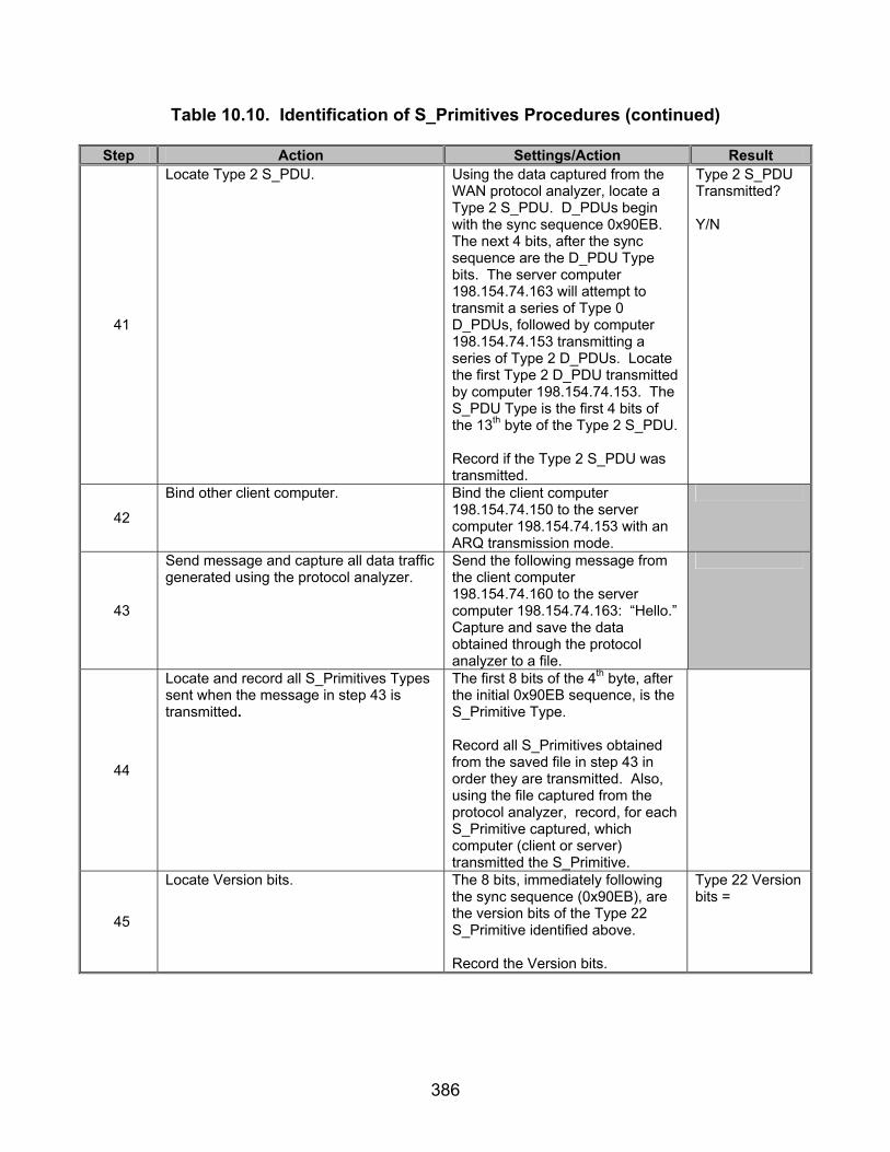
386
Table 10.10. Identification of S_Primitives Procedures (continued)
Step Action Settings/Action Result
41
Locate Type 2 S_PDU. Using the data captured from the WAN protocol analyzer, locate a Type 2 S_PDU. D_PDUs begin with the sync sequence 0x90EB. The next 4 bits, after the sync sequence are the D_PDU Type bits. The server computer 198.154.74.163 will attempt to transmit a series of Type 0 D_PDUs, followed by computer 198.154.74.153 transmitting a series of Type 2 D_PDUs. Locate the first Type 2 D_PDU transmitted by computer 198.154.74.153. The S_PDU Type is the first 4 bits of the 13th byte of the Type 2 S_PDU. Record if the Type 2 S_PDU was transmitted.
Type 2 S_PDU Transmitted? Y/N
42
Bind other client computer. Bind the client computer 198.154.74.150 to the server computer 198.154.74.153 with an ARQ transmission mode.
43
Send message and capture all data traffic generated using the protocol analyzer.
Send the following message from the client computer 198.154.74.160 to the server computer 198.154.74.163: “Hello.” Capture and save the data obtained through the protocol analyzer to a file.
44
Locate and record all S_Primitives Types sent when the message in step 43 is transmitted.
The first 8 bits of the 4th byte, after the initial 0x90EB sequence, is the S_Primitive Type. Record all S_Primitives obtained from the saved file in step 43 in order they are transmitted. Also, using the file captured from the protocol analyzer, record, for each S_Primitive captured, which computer (client or server) transmitted the S_Primitive.
45
Locate Version bits. The 8 bits, immediately following the sync sequence (0x90EB), are the version bits of the Type 22 S_Primitive identified above. Record the Version bits.
Type 22 Version bits =
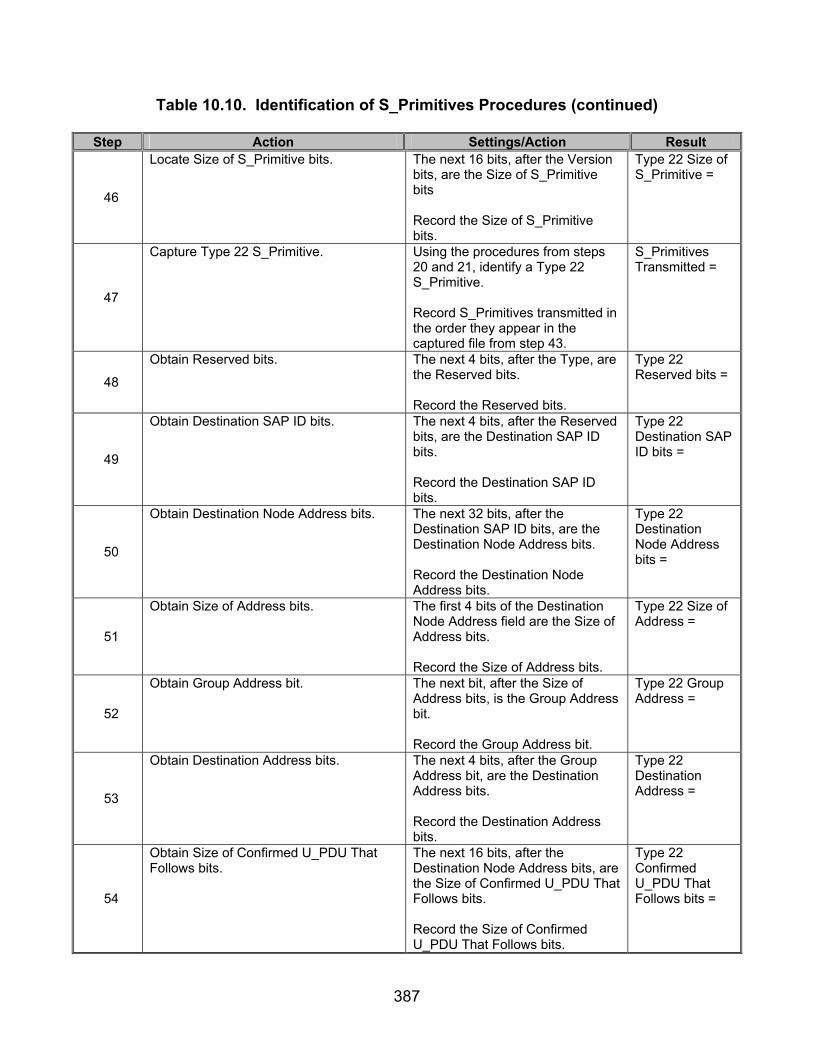
387
Table 10.10. Identification of S_Primitives Procedures (continued)
Step Action Settings/Action Result
46
Locate Size of S_Primitive bits. The next 16 bits, after the Version bits, are the Size of S_Primitive bits Record the Size of S_Primitive bits.
Type 22 Size of S_Primitive =
47
Capture Type 22 S_Primitive. Using the procedures from steps 20 and 21, identify a Type 22 S_Primitive. Record S_Primitives transmitted in the order they appear in the captured file from step 43.
S_Primitives Transmitted =
48
Obtain Reserved bits. The next 4 bits, after the Type, are the Reserved bits. Record the Reserved bits.
Type 22 Reserved bits =
49
Obtain Destination SAP ID bits. The next 4 bits, after the Reserved bits, are the Destination SAP ID bits. Record the Destination SAP ID bits.
Type 22 Destination SAP ID bits =
50
Obtain Destination Node Address bits. The next 32 bits, after the Destination SAP ID bits, are the Destination Node Address bits. Record the Destination Node Address bits.
Type 22 Destination Node Address bits =
51
Obtain Size of Address bits. The first 4 bits of the Destination Node Address field are the Size of Address bits. Record the Size of Address bits.
Type 22 Size of Address =
52
Obtain Group Address bit. The next bit, after the Size of Address bits, is the Group Address bit. Record the Group Address bit.
Type 22 Group Address =
53
Obtain Destination Address bits. The next 4 bits, after the Group Address bit, are the Destination Address bits. Record the Destination Address bits.
Type 22 Destination Address =
54
Obtain Size of Confirmed U_PDU That Follows bits.
The next 16 bits, after the Destination Node Address bits, are the Size of Confirmed U_PDU That Follows bits. Record the Size of Confirmed U_PDU That Follows bits.
Type 22 Confirmed U_PDU That Follows bits =

388
Table 10.10. Identification of S_Primitives Procedures (continued)
Step Action Settings/Action Result
55
Locate the Number of Confirmed U_PDU bytes.
Count and record the number of Confirmed U_PDU bytes (i.e., the number of bytes that follow the Size of Confirmed U_PDU that follows bits for the current transmission).
Number of Confirmed U_PDU Bytes =
56
Verify that a Type 22 S_Primitive was transmitted in response to a Type 20 S_Primitive submitted by the HF Chat client.
Using the list of S_Primitives located in step 44, verify that the server computer 198.154.74.163 submitted a Type 22 S_Primitive to the client computer 198.154.74.160 in response to the Type 20 S_Primitive subimitted by the client computer 198.154.74.160.
Type 22 submitted in response to Type 20? Y/N
57
Verify that data was accepted by the destination computer.
Visually check to see if data appeared on the screen of the destination computer. Did the word “Hello” appear on the destination computer?
Y/N
58
Repeat steps 18-21 for SAP ID, Priority, Number of Retransmissions, and Rank = 1. Set the Size of Address field to 2 bytes and the STANAG Destination Node Address to 255.
59
Bind to server. Have the client computer 198.154.74.160 bind to the server computer 198.154.74.163 with an ARQ link. Only bind one client computer to its server computer. Leave the other end unbound.
60
Send message and capture all data traffic generated using the protocol analyzer.
Send the following message from the client computer to the server computer: “Hello.” Capture and save the data obtained through the protocol analyzer to a file.
61
Locate Type 23 S_Primitive. The first 8 bits of the 4th byte after the initial 0x90EB sequence is the S_Primitive Type. Locate an S_Primitive whose value is (MSB) 0 0 0 1 0 1 1 1 (LSB) (0x17 hex).
62
Obtain Destination SAP ID bits. The SAP ID bits are the last 4 bits of the byte, immediately following the S_Primitive Type field. Record the Destination SAP ID bits.
Type 23 Destination SAP ID bits =

389
Table 10.10. Identification of S_Primitives Procedures (continued)
Step Action Settings/Action Result
63
Obtain Destination Node Address bits. The next 8 bits, after the Destination SAP ID bits, are the Destination Node Address bits. Record the Destination Node Address bits.
Type 23 Destination Node Address bits =
64
Obtain Size of Address bits. The first 4 bits of the Destination Node Address field are the Size of Address bits. Record the Size of Address bits.
Type 23 Size of Address =
65
Obtain Group Address bit. The next bit, after the Size of Address bits, is the Group Address bit. Record the Group Address bit.
Type 23 Group Address =
66
Obtain Destination Address bits. The next 4 bits, after the Group Address bit, are the Destination Address bits. Record the Destination Address bits.
Type 23 Destination Address =
67
Bind other client computer. Bind the client computer 198.154.74.150 to the server computer 198.154.74.153 with an ARQ transmission mode.
68
Send message and capture all data traffic generated using the protocol analyzer.
Send the following message from the client computer 198.154.74.160 to the server computer 198.154.74.163: “Hello.” Capture and save the data obtained through the protocol analyzer to a file.
69
Locate Type 22 S_Primitive. The first 8 bits of the 4th byte after the initial 0x90EB sequence is the S_Primitive Type. Locate an S_Primitive whose value is (MSB) 0 0 0 1 0 1 1 0 (LSB) (0x16 hex).
70
Obtain Destination SAP ID bits. The SAP ID bits are the last 4 bits of the byte immediately following the S_Primitive Type field. Record the Destination SAP ID bits.
Type 22 Destination SAP ID bits =
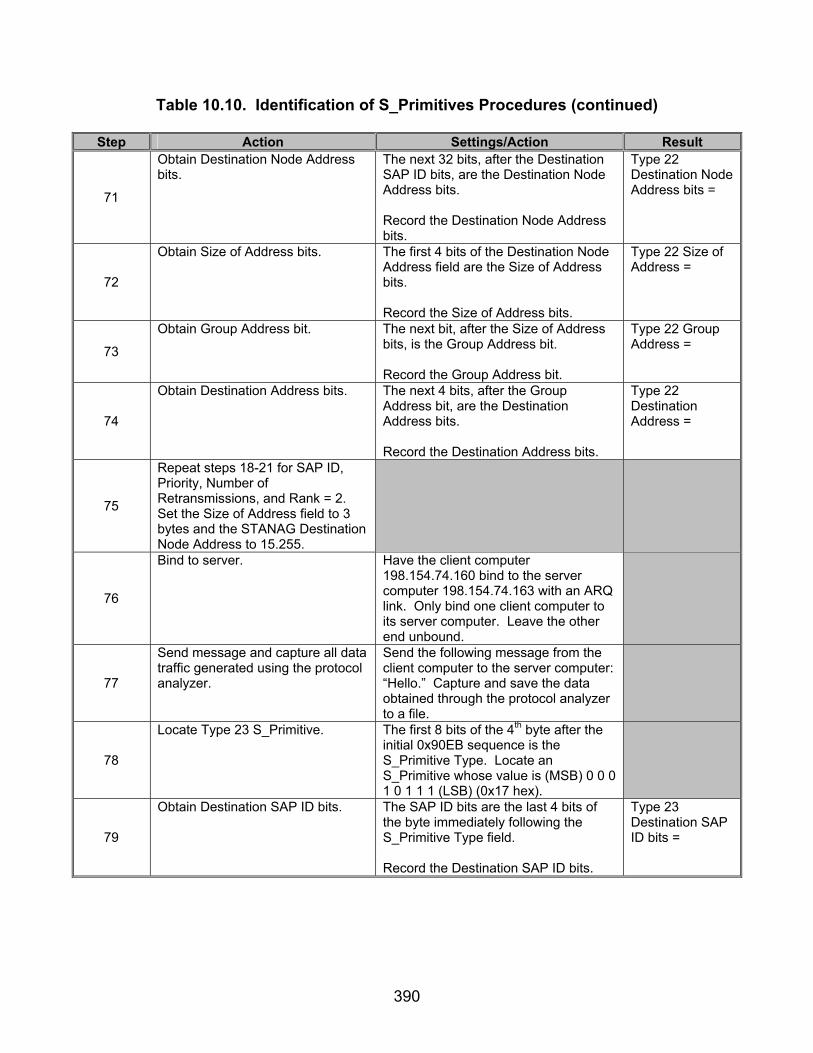
390
Table 10.10. Identification of S_Primitives Procedures (continued)
Step Action Settings/Action Result
71
Obtain Destination Node Address bits.
The next 32 bits, after the Destination SAP ID bits, are the Destination Node Address bits. Record the Destination Node Address bits.
Type 22 Destination Node Address bits =
72
Obtain Size of Address bits. The first 4 bits of the Destination Node Address field are the Size of Address bits. Record the Size of Address bits.
Type 22 Size of Address =
73
Obtain Group Address bit. The next bit, after the Size of Address bits, is the Group Address bit. Record the Group Address bit.
Type 22 Group Address =
74
Obtain Destination Address bits. The next 4 bits, after the Group Address bit, are the Destination Address bits. Record the Destination Address bits.
Type 22 Destination Address =
75
Repeat steps 18-21 for SAP ID, Priority, Number of Retransmissions, and Rank = 2. Set the Size of Address field to 3 bytes and the STANAG Destination Node Address to 15.255.
76
Bind to server. Have the client computer 198.154.74.160 bind to the server computer 198.154.74.163 with an ARQ link. Only bind one client computer to its server computer. Leave the other end unbound.
77
Send message and capture all data traffic generated using the protocol analyzer.
Send the following message from the client computer to the server computer: “Hello.” Capture and save the data obtained through the protocol analyzer to a file.
78
Locate Type 23 S_Primitive. The first 8 bits of the 4th byte after the initial 0x90EB sequence is the S_Primitive Type. Locate an S_Primitive whose value is (MSB) 0 0 0 1 0 1 1 1 (LSB) (0x17 hex).
79
Obtain Destination SAP ID bits. The SAP ID bits are the last 4 bits of the byte immediately following the S_Primitive Type field. Record the Destination SAP ID bits.
Type 23 Destination SAP ID bits =
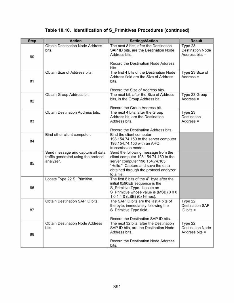
391
Table 10.10. Identification of S_Primitives Procedures (continued)
Step Action Settings/Action Result
80
Obtain Destination Node Address bits.
The next 8 bits, after the Destination SAP ID bits, are the Destination Node Address bits. Record the Destination Node Address bits.
Type 23 Destination Node Address bits =
81
Obtain Size of Address bits. The first 4 bits of the Destination Node Address field are the Size of Address bits. Record the Size of Address bits.
Type 23 Size of Address =
82
Obtain Group Address bit. The next bit, after the Size of Address bits, is the Group Address bit. Record the Group Address bit.
Type 23 Group Address =
83
Obtain Destination Address bits. The next 4 bits, after the Group Address bit, are the Destination Address bits. Record the Destination Address bits.
Type 23 Destination Address =
84
Bind other client computer. Bind the client computer 198.154.74.150 to the server computer 198.154.74.153 with an ARQ transmission mode.
85
Send message and capture all data traffic generated using the protocol analyzer.
Send the following message from the client computer 198.154.74.160 to the server computer 198.154.74.163: “Hello.” Capture and save the data obtained through the protocol analyzer to a file.
86
Locate Type 22 S_Primitive. The first 8 bits of the 4th byte after the initial 0x90EB sequence is the S_Primitive Type. Locate an S_Primitive whose value is (MSB) 0 0 0 1 0 1 1 0 (LSB) (0x16 hex).
87
Obtain Destination SAP ID bits. The SAP ID bits are the last 4 bits of the byte, immediately following the S_Primitive Type field. Record the Destination SAP ID bits.
Type 22 Destination SAP ID bits =
88
Obtain Destination Node Address bits.
The next 32 bits, after the Destination SAP ID bits, are the Destination Node Address bits. Record the Destination Node Address bits.
Type 22 Destination Node Address bits =
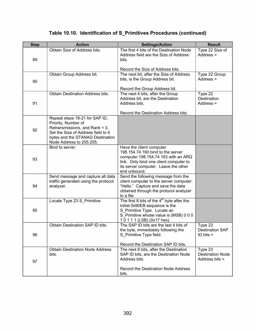
392
Table 10.10. Identification of S_Primitives Procedures (continued)
Step Action Settings/Action Result
89
Obtain Size of Address bits. The first 4 bits of the Destination Node Address field are the Size of Address bits. Record the Size of Address bits.
Type 22 Size of Address =
90
Obtain Group Address bit. The next bit, after the Size of Address bits, is the Group Address bit. Record the Group Address bit.
Type 22 Group Address =
91
Obtain Destination Address bits. The next 4 bits, after the Group Address bit, are the Destination Address bits. Record the Destination Address bits.
Type 22 Destination Address =
92
Repeat steps 18-21 for SAP ID, Priority, Number of Retransmissions, and Rank = 3. Set the Size of Address field to 4 bytes and the STANAG Destination Node Address to 255.255.
93
Bind to server. Have the client computer 198.154.74.160 bind to the server computer 198.154.74.163 with an ARQ link. Only bind one client computer to its server computer. Leave the other end unbound.
94
Send message and capture all data traffic generated using the protocol analyzer.
Send the following message from the client computer to the server computer: “Hello.” Capture and save the data obtained through the protocol analyzer to a file.
95
Locate Type 23 S_Primitive. The first 8 bits of the 4th byte after the initial 0x90EB sequence is the S_Primitive Type. Locate an S_Primitive whose value is (MSB) 0 0 0 1 0 1 1 1 (LSB) (0x17 hex).
96
Obtain Destination SAP ID bits. The SAP ID bits are the last 4 bits of the byte, immediately following the S_Primitive Type field. Record the Destination SAP ID bits.
Type 23 Destination SAP ID bits =
97
Obtain Destination Node Address bits.
The next 8 bits, after the Destination SAP ID bits, are the Destination Node Address bits. Record the Destination Node Address bits.
Type 23 Destination Node Address bits =

393
Table 10.10. Identification of S_Primitives Procedures (continued)
Step Action Settings/Action Result
98
Obtain Size of Address bits. The first 4 bits of the Destination Node Address field are the Size of Address bits. Record the Size of Address bits.
Type 23 Size of Address =
99
Obtain Group Address bit. The next bit, after the Size of Address bits, is the Group Address bit. Record the Group Address bit.
Type 23 Group Address =
100
Obtain Destination Address bits. The next 4 bits, after the Group Address bit, are the Destination Address bits. Record the Destination Address bits.
Type 23 Destination Address =
101
Bind other client computer. Bind the client computer 198.154.74.150 to the server computer 198.154.74.153 with an ARQ transmission mode.
102
Send message and capture all data traffic generated using the protocol analyzer.
Send the following message from the client computer 198.154.74.160 to the server computer 198.154.74.163: “Hello.” Capture and save the data obtained through the protocol analyzer to a file.
103
Locate Type 22 S_Primitive. The first 8 bits of the 4th byte after the initial 0x90EB sequence is the S_Primitive Type. Locate an S_Primitive whose value is (MSB) 0 0 0 1 0 1 1 0 (LSB) (0x16 hex).
104
Obtain Destination SAP ID bits. The SAP ID bits are the last 4 bits of the byte, immediately following the S_Primitive Type field. Record the Destination SAP ID bits.
Type 22 Destination SAP ID bits =
105
Obtain Destination Node Address bits.
The next 32 bits, after the Destination SAP ID bits, are the Destination Node Address bits. Record the Destination Node Address bits.
Type 22 Destination Node Address bits =
106
Obtain Size of Address bits. The first 4 bits of the Destination Node Address field are the Size of Address bits. Record the Size of Address bits.
Type 22 Size of Address=
107
Obtain Group Address bit. The next bit, after the Size of Address bits, is the Group Address bit. Record the Group Address bit.
Type 22 Group Address =

394
Table 10.10. Identification of S_Primitives Procedures (continued)
Step Action Settings/Action Result
108
Obtain Destination Address bits. The next 4 bits, after the Group Address bit, are the Destination Address bits. Record the Destination Address bits.
Type 22 Destination Address =
109
Repeat steps 18-21 for SAP ID, Priority, Number of Retransmissions, and Rank = 4. Set the Size of Address field to 5 bytes and the STANAG Destination Node Address to 15.255.255
110
Bind to server. Have the client computer 198.154.74.160 bind to the server computer 198.154.74.163 with an ARQ link. Only bind one client computer to its server computer. Leave the other end unbound.
111
Send message and capture all data traffic generated using the protocol analyzer.
Send the following message from the client computer to the server computer: “Hello.” Capture and save the data obtained through the protocol analyzer to a file.
112
Locate Type 23 S_Primitive. The first 8 bits of the 4th byte, after the initial 0x90EB sequence, is the S_Primitive Type. Locate an S_Primitive whose value is (MSB) 0 0 0 1 0 1 1 1 (LSB) (0x17 hex).
113
Obtain Destination SAP ID bits. The SAP ID bits are the last 4 bits of the byte, immediately following the S_Primitive Type field. Record the Destination SAP ID bits.
Type 23 Destination SAP ID bits =
114
Obtain Destination Node Address bits.
The next 8 bits, after the Destination SAP ID bits, are the Destination Node Address bits. Record the Destination Node Address bits.
Type 23 Destination Node Address bits =
115
Obtain Size of Address bits. The first 4 bits of the Destination Node Address field are the Size of Address bits. Record the Size of Address bits.
Type 23 Size of Address =
116
Obtain Group Address bit. The next bit, after the Size of Address bits, is the Group Address bit. Record the Group Address bit.
Type 23 Group Address =
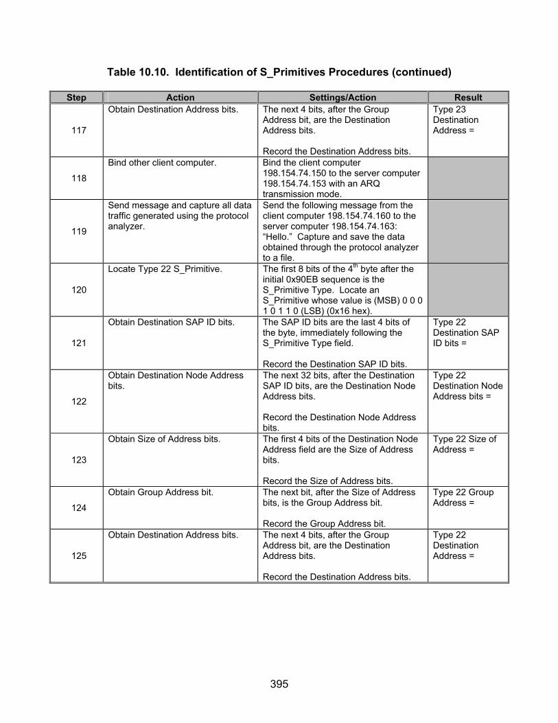
395
Table 10.10. Identification of S_Primitives Procedures (continued)
Step Action Settings/Action Result
117
Obtain Destination Address bits. The next 4 bits, after the Group Address bit, are the Destination Address bits. Record the Destination Address bits.
Type 23 Destination Address =
118
Bind other client computer. Bind the client computer 198.154.74.150 to the server computer 198.154.74.153 with an ARQ transmission mode.
119
Send message and capture all data traffic generated using the protocol analyzer.
Send the following message from the client computer 198.154.74.160 to the server computer 198.154.74.163: “Hello.” Capture and save the data obtained through the protocol analyzer to a file.
120
Locate Type 22 S_Primitive. The first 8 bits of the 4th byte after the initial 0x90EB sequence is the S_Primitive Type. Locate an S_Primitive whose value is (MSB) 0 0 0 1 0 1 1 0 (LSB) (0x16 hex).
121
Obtain Destination SAP ID bits. The SAP ID bits are the last 4 bits of the byte, immediately following the S_Primitive Type field. Record the Destination SAP ID bits.
Type 22 Destination SAP ID bits =
122
Obtain Destination Node Address bits.
The next 32 bits, after the Destination SAP ID bits, are the Destination Node Address bits. Record the Destination Node Address bits.
Type 22 Destination Node Address bits =
123
Obtain Size of Address bits. The first 4 bits of the Destination Node Address field are the Size of Address bits. Record the Size of Address bits.
Type 22 Size of Address =
124
Obtain Group Address bit. The next bit, after the Size of Address bits, is the Group Address bit. Record the Group Address bit.
Type 22 Group Address =
125
Obtain Destination Address bits. The next 4 bits, after the Group Address bit, are the Destination Address bits. Record the Destination Address bits.
Type 22 Destination Address =
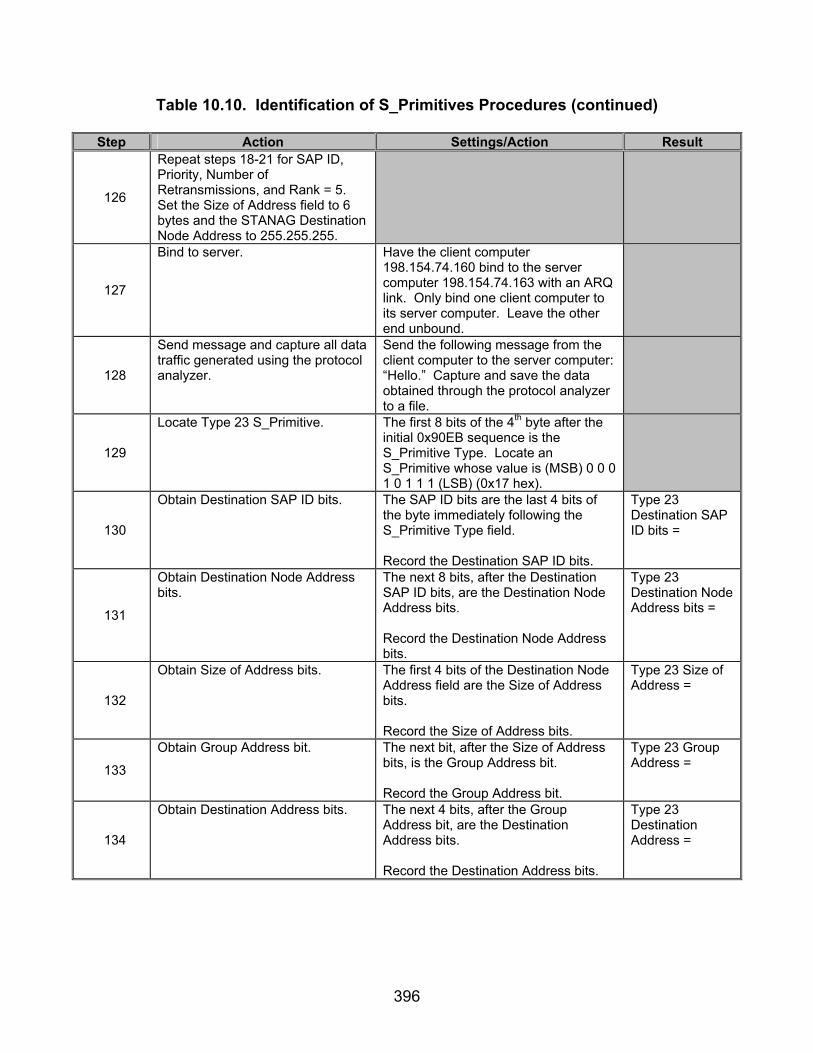
396
Table 10.10. Identification of S_Primitives Procedures (continued)
Step Action Settings/Action Result
126
Repeat steps 18-21 for SAP ID, Priority, Number of Retransmissions, and Rank = 5. Set the Size of Address field to 6 bytes and the STANAG Destination Node Address to 255.255.255.
127
Bind to server. Have the client computer 198.154.74.160 bind to the server computer 198.154.74.163 with an ARQ link. Only bind one client computer to its server computer. Leave the other end unbound.
128
Send message and capture all data traffic generated using the protocol analyzer.
Send the following message from the client computer to the server computer: “Hello.” Capture and save the data obtained through the protocol analyzer to a file.
129
Locate Type 23 S_Primitive. The first 8 bits of the 4th byte after the initial 0x90EB sequence is the S_Primitive Type. Locate an S_Primitive whose value is (MSB) 0 0 0 1 0 1 1 1 (LSB) (0x17 hex).
130
Obtain Destination SAP ID bits. The SAP ID bits are the last 4 bits of the byte immediately following the S_Primitive Type field. Record the Destination SAP ID bits.
Type 23 Destination SAP ID bits =
131
Obtain Destination Node Address bits.
The next 8 bits, after the Destination SAP ID bits, are the Destination Node Address bits. Record the Destination Node Address bits.
Type 23 Destination Node Address bits =
132
Obtain Size of Address bits. The first 4 bits of the Destination Node Address field are the Size of Address bits. Record the Size of Address bits.
Type 23 Size of Address =
133
Obtain Group Address bit. The next bit, after the Size of Address bits, is the Group Address bit. Record the Group Address bit.
Type 23 Group Address =
134
Obtain Destination Address bits. The next 4 bits, after the Group Address bit, are the Destination Address bits. Record the Destination Address bits.
Type 23 Destination Address =

397
Table 10.10. Identification of S_Primitives Procedures (continued)
Step Action Settings/Action Result
135
Bind other client computer. Bind the client computer 198.154.74.150 to the server computer 198.154.74.153 with an ARQ transmission mode.
136
Send message and capture all data traffic generated using the protocol analyzer.
Send the following message from the client computer 198.154.74.160 to the server computer 198.154.74.163: “Hello.” Capture and save the data obtained through the protocol analyzer to a file.
137
Locate Type 22 S_Primitive. The first 8 bits of the 4th byte after the initial 0x90EB sequence is the S_Primitive Type. Locate an S_Primitive whose value is (MSB) 0 0 0 1 0 1 1 0 (LSB) (0x16 hex).
138
Obtain Destination SAP ID bits. The SAP ID bits are the last 4 bits of the byte immediately following the S_Primitive Type field. Record the Destination SAP ID bits.
Type 22 Destination SAP ID bits =
139
Obtain Destination Node Address bits.
The next 32 bits, after the Destination SAP ID bits, are the Destination Node Address bits. Record the Destination Node Address bits.
Type 22 Destination Node Address bits =
140
Obtain Size of Address bits. The first 4 bits of the Destination Node Address field are the Size of Address bits. Record the Size of Address bits.
Type 22 Size of Address =
141
Obtain Group Address bit. The next bit, after the Size of Address bits, is the Group Address bit. Record the Group Address bit.
Type 22 Group Address =
142
Obtain Destination Address bits. The next 4 bits, after the Group Address bit, are the Destination Address bits. Record the Destination Address bits.
Type 22 Destination Address =
143
Repeat steps 18-21 for SAP ID, Priority, Number of Retransmissions, and Rank = 6. Set the Size of Address field to 7 bytes and the STANAG Destination Node Address to 15.255.255.255.
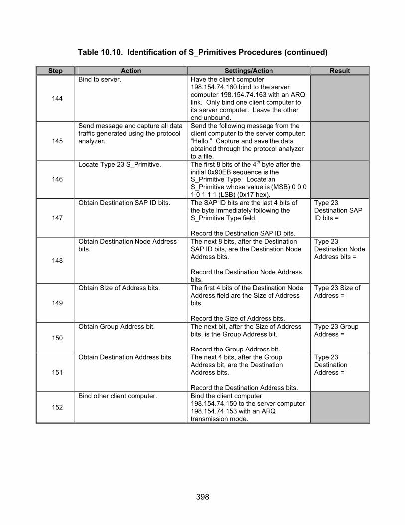
398
Table 10.10. Identification of S_Primitives Procedures (continued)
Step Action Settings/Action Result
144
Bind to server. Have the client computer 198.154.74.160 bind to the server computer 198.154.74.163 with an ARQ link. Only bind one client computer to its server computer. Leave the other end unbound.
145
Send message and capture all data traffic generated using the protocol analyzer.
Send the following message from the client computer to the server computer: “Hello.” Capture and save the data obtained through the protocol analyzer to a file.
146
Locate Type 23 S_Primitive. The first 8 bits of the 4th byte after the initial 0x90EB sequence is the S_Primitive Type. Locate an S_Primitive whose value is (MSB) 0 0 0 1 0 1 1 1 (LSB) (0x17 hex).
147
Obtain Destination SAP ID bits. The SAP ID bits are the last 4 bits of the byte immediately following the S_Primitive Type field. Record the Destination SAP ID bits.
Type 23 Destination SAP ID bits =
148
Obtain Destination Node Address bits.
The next 8 bits, after the Destination SAP ID bits, are the Destination Node Address bits. Record the Destination Node Address bits.
Type 23 Destination Node Address bits =
149
Obtain Size of Address bits. The first 4 bits of the Destination Node Address field are the Size of Address bits. Record the Size of Address bits.
Type 23 Size of Address =
150
Obtain Group Address bit. The next bit, after the Size of Address bits, is the Group Address bit. Record the Group Address bit.
Type 23 Group Address =
151
Obtain Destination Address bits. The next 4 bits, after the Group Address bit, are the Destination Address bits. Record the Destination Address bits.
Type 23 Destination Address =
152
Bind other client computer. Bind the client computer 198.154.74.150 to the server computer 198.154.74.153 with an ARQ transmission mode.

399
Table 10.10. Identification of S_Primitives Procedures (continued)
Step Action Settings/Action Result
153
Send message and capture all data traffic generated using the protocol analyzer.
Send the following message from the client computer 198.154.74.160 to the server computer 198.154.74.163: “Hello.” Capture and save the data obtained through the protocol analyzer to a file.
154
Locate Type 22 S_Primitive. The first 8 bits of the 4th byte after the initial 0x90EB sequence is the S_Primitive Type. Locate an S_Primitive whose value is (MSB) 0 0 0 1 0 1 1 0 (LSB) (0x16 hex).
155
Obtain Destination SAP ID bits. The SAP ID bits are the last 4 bits of the byte immediately following the S_Primitive Type field. Record the Destination SAP ID bits.
Type 22 Destination SAP ID bits =
156
Obtain Destination Node Address bits.
The next 32 bits, after the Destination SAP ID bits, are the Destination Node Address bits. Record the Destination Node Address bits.
Type 22 Destination Node Address bits =
157
Obtain Size of Address bits. The first 4 bits of the Destination Node Address field are the Size of Address bits. Record the Size of Address bits.
Type 22 Size of Address =
158
Obtain Group Address bit. The next bit, after the Size of Address bits, is the Group Address bit. Record the Group Address bit.
Type 22 Group Address =
159
Obtain Destination Address bits. The next 4 bits, after the Group Address bit, are the Destination Address bits. Record the Destination Address bits.
Type 22 Destination Address =
160 Repeat steps 18-21 for SAP ID, Priority, Number of Retransmissions, and Rank = 7.
161
Bind to server. Have the client computer 198.154.74.160 bind to the server computer 198.154.74.163 with an ARQ link. Only bind one client computer to its server computer. Leave the other end unbound.
162
Send message and capture all data traffic generated using the protocol analyzer.
Send the following message from the client computer to the server computer: “Hello.” Capture and save the data obtained through the protocol analyzer to a file.

400
Table 10.10. Identification of S_Primitives Procedures (continued)
Step Action Settings/Action Result
163
Locate Type 23 S_Primitive. The first 8 bits of the 4th byte after the initial 0x90EB sequence is the S_Primitive Type. Locate an S_Primitive whose value is (MSB) 0 0 0 1 0 1 1 1 (LSB) (0x17 hex).
164
Obtain Destination SAP ID bits. The SAP ID bits are the last 4 bits of the byte immediately following the S_Primitive Type field. Record the Destination SAP ID bits.
Type 23 Destination SAP ID bits =
165
Bind other client computer. Bind the client computer 198.154.74.150 to the server computer 198.154.74.153 with an ARQ transmission mode.
166
Send message and capture all data traffic generated using the protocol analyzer.
Send the following message from the client computer 198.154.74.160 to the server computer 198.154.74.163: “Hello.” Capture and save the data obtained through the protocol analyzer to a file.
167
Locate Type 22 S_Primitive. The first 8 bits of the 4th byte after the initial 0x90EB sequence is the S_Primitive Type. Locate an S_Primitive whose value is (MSB) 0 0 0 1 0 1 1 0 (LSB) (0x16 hex).
168
Obtain Destination SAP ID bits. The SAP ID bits are the last 4 bits of the byte immediately following the S_Primitive Type field. Record the Destination SAP ID bits.
Type 22 Destination SAP ID bits =
169 Repeat steps 18-21 for SAP ID, Priority, Number of Retransmissions, and Rank = 8.
170
Bind to server. Have the client computer 198.154.74.160 bind to the server computer 198.154.74.163 with an ARQ link. Only bind one client computer to its server computer. Leave the other end unbound.
171
Send message and capture all data traffic generated using the protocol analyzer.
Send the following message from the client computer to the server computer: “Hello.” Capture and save the data obtained through the protocol analyzer to a file.
172
Locate Type 23 S_Primitive. The first 8 bits of the 4th byte after the initial 0x90EB sequence is the S_Primitive Type. Locate an S_Primitive whose value is (MSB) 0 0 0 1 0 1 1 1 (LSB) (0x17 hex).
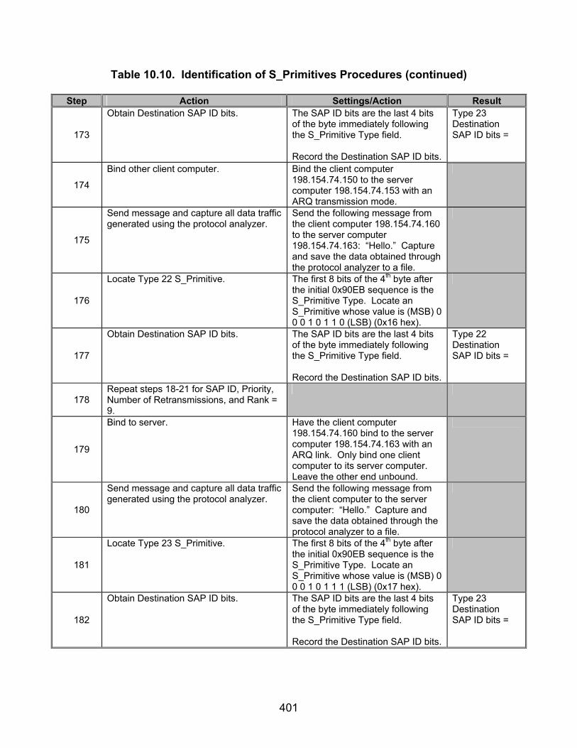
401
Table 10.10. Identification of S_Primitives Procedures (continued)
Step Action Settings/Action Result
173
Obtain Destination SAP ID bits. The SAP ID bits are the last 4 bits of the byte immediately following the S_Primitive Type field. Record the Destination SAP ID bits.
Type 23 Destination SAP ID bits =
174
Bind other client computer. Bind the client computer 198.154.74.150 to the server computer 198.154.74.153 with an ARQ transmission mode.
175
Send message and capture all data traffic generated using the protocol analyzer.
Send the following message from the client computer 198.154.74.160 to the server computer 198.154.74.163: “Hello.” Capture and save the data obtained through the protocol analyzer to a file.
176
Locate Type 22 S_Primitive. The first 8 bits of the 4th byte after the initial 0x90EB sequence is the S_Primitive Type. Locate an S_Primitive whose value is (MSB) 0 0 0 1 0 1 1 0 (LSB) (0x16 hex).
177
Obtain Destination SAP ID bits. The SAP ID bits are the last 4 bits of the byte immediately following the S_Primitive Type field. Record the Destination SAP ID bits.
Type 22 Destination SAP ID bits =
178 Repeat steps 18-21 for SAP ID, Priority, Number of Retransmissions, and Rank = 9.
179
Bind to server. Have the client computer 198.154.74.160 bind to the server computer 198.154.74.163 with an ARQ link. Only bind one client computer to its server computer. Leave the other end unbound.
180
Send message and capture all data traffic generated using the protocol analyzer.
Send the following message from the client computer to the server computer: “Hello.” Capture and save the data obtained through the protocol analyzer to a file.
181
Locate Type 23 S_Primitive. The first 8 bits of the 4th byte after the initial 0x90EB sequence is the S_Primitive Type. Locate an S_Primitive whose value is (MSB) 0 0 0 1 0 1 1 1 (LSB) (0x17 hex).
182
Obtain Destination SAP ID bits. The SAP ID bits are the last 4 bits of the byte immediately following the S_Primitive Type field. Record the Destination SAP ID bits.
Type 23 Destination SAP ID bits =
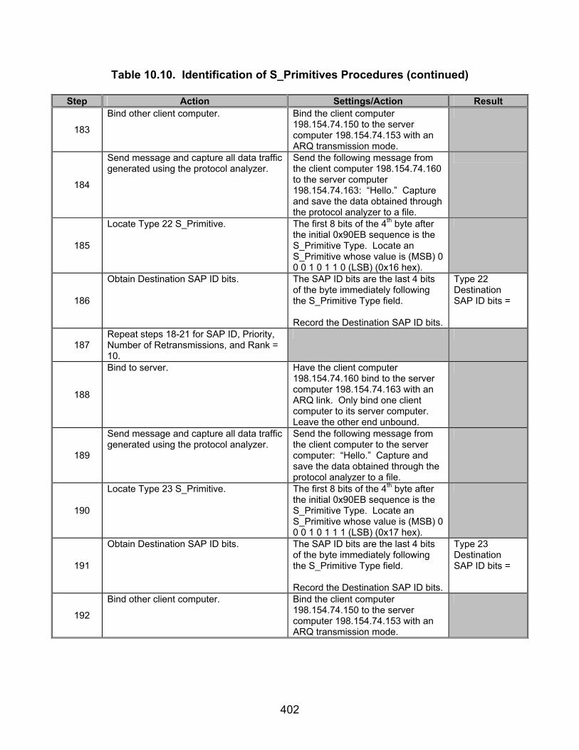
402
Table 10.10. Identification of S_Primitives Procedures (continued)
Step Action Settings/Action Result
183
Bind other client computer. Bind the client computer 198.154.74.150 to the server computer 198.154.74.153 with an ARQ transmission mode.
184
Send message and capture all data traffic generated using the protocol analyzer.
Send the following message from the client computer 198.154.74.160 to the server computer 198.154.74.163: “Hello.” Capture and save the data obtained through the protocol analyzer to a file.
185
Locate Type 22 S_Primitive. The first 8 bits of the 4th byte after the initial 0x90EB sequence is the S_Primitive Type. Locate an S_Primitive whose value is (MSB) 0 0 0 1 0 1 1 0 (LSB) (0x16 hex).
186
Obtain Destination SAP ID bits. The SAP ID bits are the last 4 bits of the byte immediately following the S_Primitive Type field. Record the Destination SAP ID bits.
Type 22 Destination SAP ID bits =
187 Repeat steps 18-21 for SAP ID, Priority, Number of Retransmissions, and Rank = 10.
188
Bind to server. Have the client computer 198.154.74.160 bind to the server computer 198.154.74.163 with an ARQ link. Only bind one client computer to its server computer. Leave the other end unbound.
189
Send message and capture all data traffic generated using the protocol analyzer.
Send the following message from the client computer to the server computer: “Hello.” Capture and save the data obtained through the protocol analyzer to a file.
190
Locate Type 23 S_Primitive. The first 8 bits of the 4th byte after the initial 0x90EB sequence is the S_Primitive Type. Locate an S_Primitive whose value is (MSB) 0 0 0 1 0 1 1 1 (LSB) (0x17 hex).
191
Obtain Destination SAP ID bits. The SAP ID bits are the last 4 bits of the byte immediately following the S_Primitive Type field. Record the Destination SAP ID bits.
Type 23 Destination SAP ID bits =
192
Bind other client computer. Bind the client computer 198.154.74.150 to the server computer 198.154.74.153 with an ARQ transmission mode.
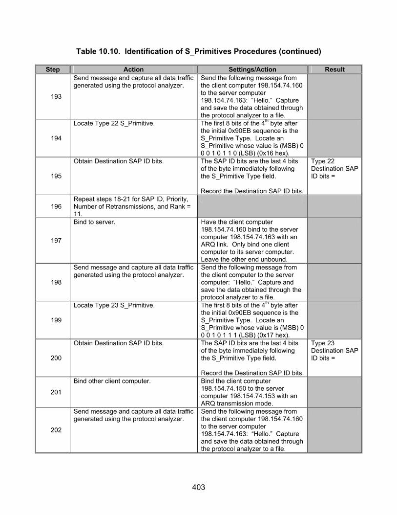
403
Table 10.10. Identification of S_Primitives Procedures (continued)
Step Action Settings/Action Result
193
Send message and capture all data traffic generated using the protocol analyzer.
Send the following message from the client computer 198.154.74.160 to the server computer 198.154.74.163: “Hello.” Capture and save the data obtained through the protocol analyzer to a file.
194
Locate Type 22 S_Primitive. The first 8 bits of the 4th byte after the initial 0x90EB sequence is the S_Primitive Type. Locate an S_Primitive whose value is (MSB) 0 0 0 1 0 1 1 0 (LSB) (0x16 hex).
195
Obtain Destination SAP ID bits. The SAP ID bits are the last 4 bits of the byte immediately following the S_Primitive Type field. Record the Destination SAP ID bits.
Type 22 Destination SAP ID bits =
196 Repeat steps 18-21 for SAP ID, Priority, Number of Retransmissions, and Rank = 11.
197
Bind to server. Have the client computer 198.154.74.160 bind to the server computer 198.154.74.163 with an ARQ link. Only bind one client computer to its server computer. Leave the other end unbound.
198
Send message and capture all data traffic generated using the protocol analyzer.
Send the following message from the client computer to the server computer: “Hello.” Capture and save the data obtained through the protocol analyzer to a file.
199
Locate Type 23 S_Primitive. The first 8 bits of the 4th byte after the initial 0x90EB sequence is the S_Primitive Type. Locate an S_Primitive whose value is (MSB) 0 0 0 1 0 1 1 1 (LSB) (0x17 hex).
200
Obtain Destination SAP ID bits. The SAP ID bits are the last 4 bits of the byte immediately following the S_Primitive Type field. Record the Destination SAP ID bits.
Type 23 Destination SAP ID bits =
201
Bind other client computer. Bind the client computer 198.154.74.150 to the server computer 198.154.74.153 with an ARQ transmission mode.
202
Send message and capture all data traffic generated using the protocol analyzer.
Send the following message from the client computer 198.154.74.160 to the server computer 198.154.74.163: “Hello.” Capture and save the data obtained through the protocol analyzer to a file.

404
Table 10.10. Identification of S_Primitives Procedures (continued)
Step Action Settings/Action Result
203
Locate Type 22 S_Primitive. The first 8 bits of the 4th byte after the initial 0x90EB sequence is the S_Primitive Type. Locate an S_Primitive whose value is (MSB) 0 0 0 1 0 1 1 0 (LSB) (0x16 hex).
204
Obtain Destination SAP ID bits. The SAP ID bits are the last 4 bits of the byte immediately following the S_Primitive Type field. Record the Destination SAP ID bits.
Type 22 Destination SAP ID bits =
205 Repeat steps 18-21 for SAP ID, Priority, Number of Retransmissions, and Rank = 12.
206
Bind to server. Have the client computer 198.154.74.160 bind to the server computer 198.154.74.163 with an ARQ link. Only bind one client computer to its server computer. Leave the other end unbound.
207
Send message and capture all data traffic generated using the protocol analyzer.
Send the following message from the client computer to the server computer: “Hello.” Capture and save the data obtained through the protocol analyzer to a file.
208
Locate Type 23 S_Primitive. The first 8 bits of the 4th byte after the initial 0x90EB sequence is the S_Primitive Type. Locate an S_Primitive whose value is (MSB) 0 0 0 1 0 1 1 1 (LSB) (0x17 hex).
209
Obtain Destination SAP ID bits. The SAP ID bits are the last 4 bits of the byte immediately following the S_Primitive Type field. Record the Destination SAP ID bits.
Type 23 Destination SAP ID bits =
210
Bind other client computer. Bind the client computer 198.154.74.150 to the server computer 198.154.74.153 with an ARQ transmission mode.
211
Send message and capture all data traffic generated using the protocol analyzer.
Send the following message from the client computer 198.154.74.160 to the server computer 198.154.74.163: “Hello.” Capture and save the data obtained through the protocol analyzer to a file.
212
Locate Type 22 S_Primitive. The first 8 bits of the 4th byte after the initial 0x90EB sequence is the S_Primitive Type. Locate an S_Primitive whose value is (MSB) 0 0 0 1 0 1 1 0 (LSB) (0x16 hex).

405
Table 10.10. Identification of S_Primitives Procedures (continued)
Step Action Settings/Action Result
213
Obtain Destination SAP ID bits. The SAP ID bits are the last 4 bits of the byte immediately following the S_Primitive Type field. Record the Destination SAP ID bits.
Type 22 Destination SAP ID bits =
214 Repeat steps 18-21 for SAP ID, Priority, Number of Retransmissions, and Rank = 13.
215
Bind to server. Have the client computer 198.154.74.160 bind to the server computer 198.154.74.163 with an ARQ link. Only bind one client computer to its server computer. Leave the other end unbound.
216
Send message and capture all data traffic generated using the protocol analyzer.
Send the following message from the client computer to the server computer: “Hello.” Capture and save the data obtained through the protocol analyzer to a file.
217
Locate Type 23 S_Primitive. The first 8 bits of the 4th byte after the initial 0x90EB sequence is the S_Primitive Type. Locate an S_Primitive whose value is (MSB) 0 0 0 1 0 1 1 1 (LSB) (0x17 hex).
218
Obtain Destination SAP ID bits. The SAP ID bits are the last 4 bits of the byte immediately following the S_Primitive Type field. Record the Destination SAP ID bits.
Type 23 Destination SAP ID bits =
219
Bind other client computer. Bind the client computer 198.154.74.150 to the server computer 198.154.74.153 with an ARQ transmission mode.
220
Send message and capture all data traffic generated using the protocol analyzer.
Send the following message from the client computer 198.154.74.160 to the server computer 198.154.74.163: “Hello.” Capture and save the data obtained through the protocol analyzer to a file.
221
Locate Type 22 S_Primitive. The first 8 bits of the 4th byte after the initial 0x90EB sequence is the S_Primitive Type. Locate an S_Primitive whose value is (MSB) 0 0 0 1 0 1 1 0 (LSB) (0x16 hex).

406
Table 10.10. Identification of S_Primitives Procedures (continued)
Step Action Settings/Action Result
222
Obtain Destination SAP ID bits. The SAP ID bits are the last 4 bits of the byte immediately following the S_Primitive Type field. Record the Destination SAP ID bits.
Type 22 Destination SAP ID bits =
223 Repeat steps 18-21 for SAP ID, Priority, Number of Retransmissions, and Rank = 14.
224
Bind to server. Have the client computer 198.154.74.160 bind to the server computer 198.154.74.163 with an ARQ link. Only bind one client computer to its server computer. Leave the other end unbound.
225
Send message and capture all data traffic generated using the protocol analyzer.
Send the following message from the client computer to the server computer: “Hello.” Capture and save the data obtained through the protocol analyzer to a file.
226
Locate Type 23 S_Primitive. The first 8 bits of the 4th byte after the initial 0x90EB sequence is the S_Primitive Type. Locate an S_Primitive whose value is (MSB) 0 0 0 1 0 1 1 1 (LSB) (0x17 hex).
227
Obtain Destination SAP ID bits. The SAP ID bits are the last 4 bits of the byte immediately following the S_Primitive Type field. Record the Destination SAP ID bits.
Type 23 Destination SAP ID bits =
228
Bind other client computer. Bind the client computer 198.154.74.150 to the server computer 198.154.74.153 with an ARQ transmission mode.
229
Send message and capture all data traffic generated using the protocol analyzer.
Send the following message from the client computer 198.154.74.160 to the server computer 198.154.74.163: “Hello.” Capture and save the data obtained through the protocol analyzer to a file.
230
Locate Type 22 S_Primitive. The first 8 bits of the 4th byte after the initial 0x90EB sequence is the S_Primitive Type. Locate an S_Primitive whose value is (MSB) 0 0 0 1 0 1 1 0 (LSB) (0x16 hex).
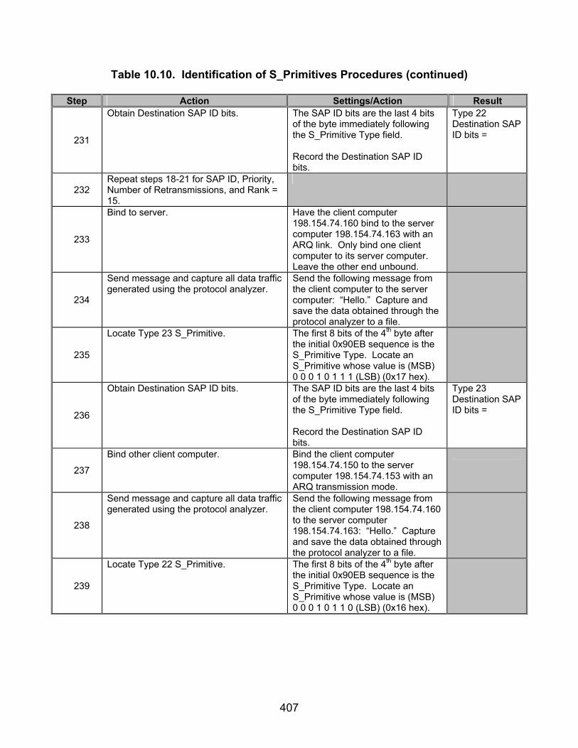
407
Table 10.10. Identification of S_Primitives Procedures (continued)
Step Action Settings/Action Result
231
Obtain Destination SAP ID bits. The SAP ID bits are the last 4 bits of the byte immediately following the S_Primitive Type field. Record the Destination SAP ID bits.
Type 22 Destination SAP ID bits =
232 Repeat steps 18-21 for SAP ID, Priority, Number of Retransmissions, and Rank = 15.
233
Bind to server. Have the client computer 198.154.74.160 bind to the server computer 198.154.74.163 with an ARQ link. Only bind one client computer to its server computer. Leave the other end unbound.
234
Send message and capture all data traffic generated using the protocol analyzer.
Send the following message from the client computer to the server computer: “Hello.” Capture and save the data obtained through the protocol analyzer to a file.
235
Locate Type 23 S_Primitive. The first 8 bits of the 4th byte after the initial 0x90EB sequence is the S_Primitive Type. Locate an S_Primitive whose value is (MSB) 0 0 0 1 0 1 1 1 (LSB) (0x17 hex).
236
Obtain Destination SAP ID bits. The SAP ID bits are the last 4 bits of the byte immediately following the S_Primitive Type field. Record the Destination SAP ID bits.
Type 23 Destination SAP ID bits =
237
Bind other client computer. Bind the client computer 198.154.74.150 to the server computer 198.154.74.153 with an ARQ transmission mode.
238
Send message and capture all data traffic generated using the protocol analyzer.
Send the following message from the client computer 198.154.74.160 to the server computer 198.154.74.163: “Hello.” Capture and save the data obtained through the protocol analyzer to a file.
239
Locate Type 22 S_Primitive. The first 8 bits of the 4th byte after the initial 0x90EB sequence is the S_Primitive Type. Locate an S_Primitive whose value is (MSB) 0 0 0 1 0 1 1 0 (LSB) (0x16 hex).

408
Table 10.10. Identification of S_Primitives Procedures (continued)
Step Action Settings/Action Result
240
Obtain Destination SAP ID bits. The SAP ID bits are the last 4 bits of the byte immediately following the S_Primitive Type field. Record the Destination SAP ID bits.
Type 22 Destination SAP ID bits =
The following procedures are for reference numbers 48-50, 250, and 158-233 for Type 5 S_Primitive.
241 Bind to server with software from server computer.
Using the software on the server computer, bind the server computer to the server.
242
Locate data packet containing S_Primitive.
Using the procedures from steps 18-21, locate the S_Primitives transmitted from the server computer to the client computer in response to the server computer binding to the server. Record the S_Primitives transmitted.
S_Primitives Transmitted =
243
Locate Version bits. The 8 bits immediately following the sync sequence (0x90EB) are the version bits of the Type 5 S_Primitive identified above. Record the Version bits.
Type 5 Version bits =
244
Locate Size of S_Primitive bits. The next 16 bits, after the Version bits, are the Size of S_Primitive bits. For the Type 5 S_Primitive identified above, record the Size of S_Primitive bits.
Type 5 Size of S_Primitive =
245 Locate Type 5 S_Primitive. Locate an S_Primitive where this value is equal to 0x05.
246
Locate Reason bits. The next 8 bits, after the S_Primitive Type, are the Reason bits. Record the Reason bits.
Type 5 Reason bits =
The following procedures are for reference numbers 44-47, 249, and 158-233 for Type 4 S_Primitive.
247 Rebind with the client computer. Attempt to rebind the software from
the client computer back to the server computer.
248
Locate data packet containing S_Primitive.
Using the procedures from steps 18-21, locate the S_Primitives transmitted from the server computer to the client computer in response to the server computer binding to the server. Record the S_Primitives transmitted.
S_Primitives Transmitted =

409
Table 10.10. Identification of S_Primitives Procedures (continued)
Step Action Settings/Action Result
249
Locate Version bits. The 8 bits immediately following the sync sequence (0x90EB) are the Version bits of the Type 4 S_Primitive identified above. Record the Version bits.
Type 4 Version bits =
250
Locate Size of S_Primitive bits. The next 16 bits, after the Version bits, are the Size of S_Primitive bits. For the Type 4 S_Primitive identified above. Record the Size of S_Primitive bits.
Type 4 Size of S_Primitive =
251 Locate Type 4 S_Primitive. Locate an S_Primitive where this value is equal to 0x04.
252
Locate Reason bits. The next 8 bits, after the S_Primitive Type, are the Reason bits. Record the Reason bits.
Type 4 Reason bits =
The following procedures are for reference numbers 32-34, 247, 277, and 158-233 for Type 2 and 17 S_Primitive.
253 Unbind the server computer from the server.
Unbind the server computer from the server.
254 Rebind the client computer to the server computer.
Rebind the client computer to the server computer.
255 Obtain Keep Alive S_Primitives. Allow the computers to sit idle for at least 2 minutes.
256
Verify Keep Alive S_Primitives were transmitted.
Using the procedures from steps 18-21, locate a Type 17 (Keep Alive) S_Primitive. Two of these should be transmitted (one from the server computer, and one that is a response from the client computer). Using the data file captured from the protocol analyzer, record which computers transmitted a Type 17 S_Primitive and in which order they were transmitted and which computer (server or client) transmitted the Type 17 S_Primitive.
257
Locate Version bits. The 8 bits immediately following the sync sequence (0x90EB) are the version bits of the Type 17 S_Primitive identified above. Record the Version bits.
Type 17 Version bits =
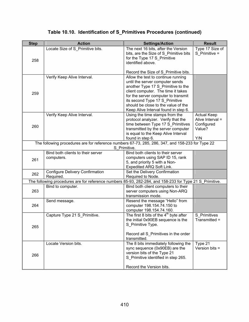
410
Table 10.10. Identification of S_Primitives Procedures (continued)
Step Action Settings/Action Result
258
Locate Size of S_Primitive bits. The next 16 bits, after the Version bits, are the Size of S_Primitive bits for the Type 17 S_Primitive identified above. Record the Size of S_Primitive bits.
Type 17 Size of S_Primitive =
259
Verify Keep Alive Interval. Allow the test to continue running until the server computer sends another Type 17 S_Primitive to the client computer. The time it takes for the server computer to transmit its second Type 17 S_Primitive should be close to the value of the Keep Alive Interval found in step 6.
260
Verify Keep Alive Interval. Using the time stamps from the protocol analyzer. Verify that the time between Type 17 S_Primitives transmitted by the server computer is equal to the Keep Alive Interval found in step 6.
Actual Keep Alive Interval = Configured Value? Y/N
The following procedures are for reference numbers 67-73, 285, 286, 347, and 158-233 for Type 22 S_Primitive.
261
Bind both clients to their server computers.
Bind both clients to their server computers using SAP ID 15, rank 5, and priority 5 with a Non-Expedited ARQ Soft Link.
262 Configure Delivery Confirmation Required.
Set the Delivery Confirmation Required to Node.
The following procedures are for reference numbers 85-93, 282-284, and 158-233 for Type 21 S_Primitive.
263 Bind to computer. Bind both client computers to their
server computers using Non-ARQ transmission mode.
264 Send message. Resend the message “Hello” from
computer 198.154.74.150 to computer 198.154.74.160.
265
Capture Type 21 S_Primitive. The first 8 bits of the 4th byte after the initial 0x90EB sequence is the S_Primitive Type. Record all S_Primitives in the order transmitted.
S_Primitives Transmitted =
266
Locate Version bits. The 8 bits immediately following the sync sequence (0x90EB) are the version bits of the Type 21 S_Primitive identified in step 265. Record the Version bits.
Type 21 Version bits =
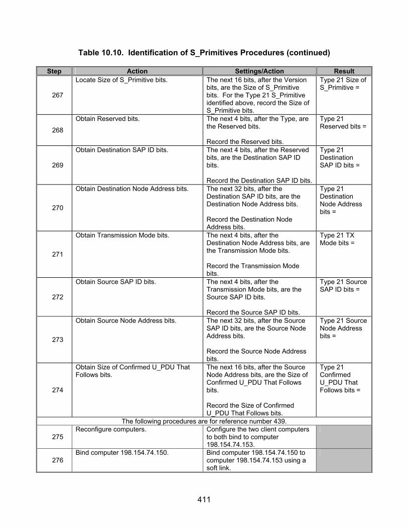
411
Table 10.10. Identification of S_Primitives Procedures (continued)
Step Action Settings/Action Result
267
Locate Size of S_Primitive bits. The next 16 bits, after the Version bits, are the Size of S_Primitive bits. For the Type 21 S_Primitive identified above, record the Size of S_Primitive bits.
Type 21 Size of S_Primitive =
268
Obtain Reserved bits. The next 4 bits, after the Type, are the Reserved bits. Record the Reserved bits.
Type 21 Reserved bits =
269
Obtain Destination SAP ID bits. The next 4 bits, after the Reserved bits, are the Destination SAP ID bits. Record the Destination SAP ID bits.
Type 21 Destination SAP ID bits =
270
Obtain Destination Node Address bits. The next 32 bits, after the Destination SAP ID bits, are the Destination Node Address bits. Record the Destination Node Address bits.
Type 21 Destination Node Address bits =
271
Obtain Transmission Mode bits. The next 4 bits, after the Destination Node Address bits, are the Transmission Mode bits. Record the Transmission Mode bits.
Type 21 TX Mode bits =
272
Obtain Source SAP ID bits. The next 4 bits, after the Transmission Mode bits, are the Source SAP ID bits. Record the Source SAP ID bits.
Type 21 Source SAP ID bits =
273
Obtain Source Node Address bits. The next 32 bits, after the Source SAP ID bits, are the Source Node Address bits. Record the Source Node Address bits.
Type 21 Source Node Address bits =
274
Obtain Size of Confirmed U_PDU That Follows bits.
The next 16 bits, after the Source Node Address bits, are the Size of Confirmed U_PDU That Follows bits. Record the Size of Confirmed U_PDU That Follows bits.
Type 21 Confirmed U_PDU That Follows bits =
The following procedures are for reference number 439.
275 Reconfigure computers. Configure the two client computers
to both bind to computer 198.154.74.153.
276 Bind computer 198.154.74.150. Bind computer 198.154.74.150 to
computer 198.154.74.153 using a soft link.
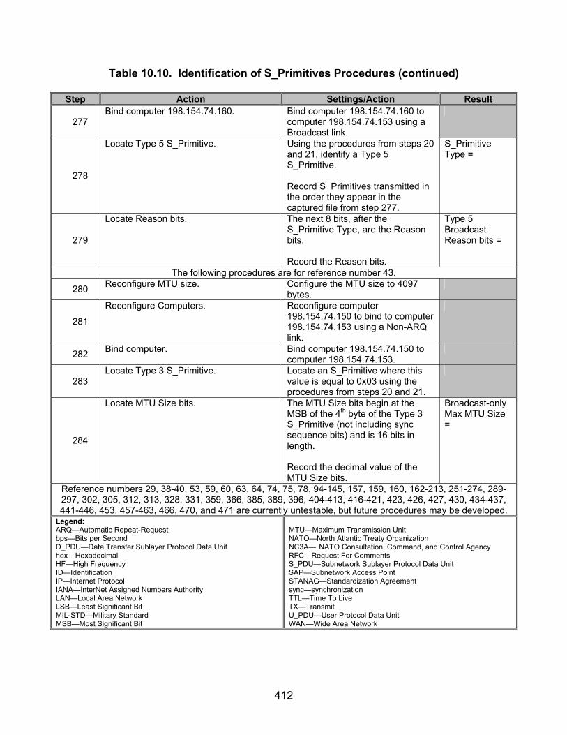
412
Table 10.10. Identification of S_Primitives Procedures (continued)
Step Action Settings/Action Result
277 Bind computer 198.154.74.160. Bind computer 198.154.74.160 to
computer 198.154.74.153 using a Broadcast link.
278
Locate Type 5 S_Primitive. Using the procedures from steps 20 and 21, identify a Type 5 S_Primitive. Record S_Primitives transmitted in the order they appear in the captured file from step 277.
S_Primitive Type =
279
Locate Reason bits. The next 8 bits, after the S_Primitive Type, are the Reason bits. Record the Reason bits.
Type 5 Broadcast Reason bits =
The following procedures are for reference number 43.
280 Reconfigure MTU size. Configure the MTU size to 4097 bytes.
281
Reconfigure Computers. Reconfigure computer 198.154.74.150 to bind to computer 198.154.74.153 using a Non-ARQ link.
282 Bind computer. Bind computer 198.154.74.150 to computer 198.154.74.153.
283 Locate Type 3 S_Primitive. Locate an S_Primitive where this
value is equal to 0x03 using the procedures from steps 20 and 21.
284
Locate MTU Size bits. The MTU Size bits begin at the MSB of the 4th byte of the Type 3 S_Primitive (not including sync sequence bits) and is 16 bits in length. Record the decimal value of the MTU Size bits.
Broadcast-only Max MTU Size =
Reference numbers 29, 38-40, 53, 59, 60, 63, 64, 74, 75, 78, 94-145, 157, 159, 160, 162-213, 251-274, 289-297, 302, 305, 312, 313, 328, 331, 359, 366, 385, 389, 396, 404-413, 416-421, 423, 426, 427, 430, 434-437, 441-446, 453, 457-463, 466, 470, and 471 are currently untestable, but future procedures may be developed.
Legend: ARQ—Automatic Repeat-Request bps—Bits per Second D_PDU—Data Transfer Sublayer Protocol Data Unit hex—Hexadecimal HF—High Frequency ID—Identification IP—Internet Protocol IANA—InterNet Assigned Numbers Authority LAN—Local Area Network LSB—Least Significant Bit MIL-STD—Military Standard MSB—Most Significant Bit
MTU—Maximum Transmission Unit NATO—North Atlantic Treaty Organization NC3A— NATO Consultation, Command, and Control Agency RFC—Request For Comments S_PDU—Subnetwork Sublayer Protocol Data Unit SAP—Subnetwork Access Point STANAG—Standardization Agreement sync—synchronization TTL—Time To Live TX—Transmit U_PDU—User Protocol Data Unit WAN—Wide Area Network

413
Table 10.11. Identification of S_Primitives Results
Result Finding Reference Number
STANAG 5066
Paragraph Requirement Required
Value Measured
Value Met Not Met
1 A.1.1.1
The establishment of a Soft Link Data Exchange Session shall be initiated unilaterally by the Subnetwork Interface Sublayer which has queued data requiring reliable delivery (i.e., queued ARQ U_PDUs) and from which a client has not requested a Hard Link Data Exchange Session.
Only Soft Links established.
2 A.1.1.1
The Subnetwork Interface Sublayer shall initiate Soft Link Data Exchange Sessions as needed, following the procedure described in section A.3.2.1.1.
Subnetwork Interface Sublayer sends S_Primitives to establish links.
22 A.2
Communication between the client and the Subnetwork Interface Sublayer uses the interface primitives listed in table A-1 and defined in the following subsections. The names of these primitives are prefixed with an “S_” to indicate that they are exchanged across the interface between the subnetwork interface sublayer and the subnetwork clients. This table is intended to provide a general guide and overview to the primitives. For detailed specification of the primitives, the later sections of this annex shall apply.
23 A.2.1
The content specification and use of the Subnetwork Interface Sublayer primitives shall be as specified in the following subsections.
24 A.2.1.1
The S_BIND_REQUEST primitive shall be issued by a new client when it first connects to the subnetwork. Unless this primitive is issued the client cannot be serviced. With this primitive the client uniquely identifies and declares that it is on-line and ready to be serviced by the subnetwork.
TBD N/A

414
Table 10.11. Identification of S_Primitives Results (continued)
Result Finding Reference Number
STANAG 5066
Paragraph Requirement Required
Value Measured
Value Met Not Met
26 A.2.1.1
The SAP ID shall be node-level unique, i.e., not assigned to another client connected to the Subnetwork Interface Sublayer for a given node.
No other clients bound to STANAG 5066 stack with a SAP ID of “5.”
27 A.2.1.1
The second argument of this primitive shall be “Rank.” This is a measure of the importance of a client; the subnetwork uses a client’s rank to allocate resources. A description of the use of the Rank argument may be found in annex H and [1].
TBD N/A
28 A.2.1.1 The range of values for the Rank argument shall be from “0” to “15.”
TBD N/A
29 A.2.1.1
Clients that are not authorized to make changes to a node or subnetwork configuration shall not bind with rank of “15.”
TBD N/A
30 A.2.1.1
The last argument of this primitive shall be “Service Type” and identifies the default type of service requested by the client.
TBD N/A
31 A.2.1.1
The Service Type argument shall apply to all data units submitted by the client unless explicitly overridden by client request when submitting a U_PDU to the subnetwork. The Service Type argument is a complex argument and has a number of attributes that are encoded as specified in section A.2.2.3.
TBD N/A
32 A.2.1.2 The S_UNBIND_REQUEST primitive shall be issued by a client in order to declare itself off-line.
TBD N/A

415
Table 10.11. Identification of S_Primitives Results (continued)
Result Finding Reference Number
STANAG 5066
Paragraph Requirement Required
Value Measured
Value Met Not Met
33 A.2.1.2
The Subnetwork Interface Sublayer shall release the SAP ID allocated to the client from which it receives the S_UNBIND_REQUEST.
Client computer able to send a Type 1 S_Primitive after server computer unbinds from STANAG 5066.
34 A.2.1.2
The SAP_ID allocated to this client shall then be available for allocation to another client that may request it.
Client computer able to send a Type 1 S_Primitive after server computer unbinds from STANAG 5066.
35 A.2.1.3
The S_BIND_ACCEPTED primitive shall be issued by the Subnetwork Interface Sublayer as a positive response to a client’s S_BIND_REQUEST.
Type 3 S_Primitive sent in response to Type 1 S_Primitive.
36 A.2.1.3
The SAP ID argument of the S_BIND_ACCEPTED primitive shall be the SAP ID assigned to the client,
SAP ID = (MSB) 1 1 1 1 (LSB) (0xf hex)
37 A.2.1.3
and shall be equal to the SAP ID argument of the S_BIND_REQUEST to which this primitive is a response.
SAP ID = (MSB) 1 1 1 1 (LSB) (0xf hex)
38 A.2.1.3
The MTU argument shall be used by the subnetwork interface sublayer to inform the client of the maximum size U_PDU (in bytes or octets), which will be accepted as an argument of the S_UNIDATA_REQUEST primitive.
Type 3 S_Primitive MTU = Default MTU Size.
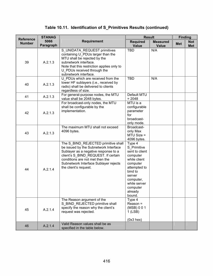
416
Table 10.11. Identification of S_Primitives Results (continued)
Result Finding Reference Number
STANAG 5066
Paragraph Requirement Required
Value Measured
Value Met Not Met
39 A.2.1.3
S_UNIDATA_REQUEST primitives containing U_PDUs larger than the MTU shall be rejected by the subnetwork interface. Note that this restriction applies only to U_PDUs received through the subnetwork interface.
TBD N/A
40 A.2.1.3
U_PDUs which are received from the lower HF sublayers (i.e., received by radio) shall be delivered to clients regardless of size.
TBD N/A
41 A.2.1.3 For general-purpose nodes, the MTU value shall be 2048 bytes.
Default MTU = 2048
42 A.2.1.3
For broadcast-only nodes, the MTU shall be configurable by the implementation.
MTU is a configurable parameter for broadcast-only mode.
43 A.2.1.3
The maximum MTU shall not exceed 4096 bytes.
Broadcast-only Max MTU Size = 4096 bytes.
44 A.2.1.4
The S_BIND_REJECTED primitive shall be issued by the Subnetwork Interface Sublayer as a negative response to a client’s S_BIND_REQUEST. If certain conditions are not met then the Subnetwork Interface Sublayer rejects the client’s request.
Type 4 S_Primitive sent to client computer while client computer attempted to bind to server computer, while server computer already bound.
45 A.2.1.4
The Reason argument of the S_BIND_REJECTED primitive shall specify the reason why the client’s request was rejected.
Type 4 Reason = (MSB) 0 0 1 1 (LSB) (0x3 hex)
46 A.2.1.4 Valid Reason values shall be as specified in the table below.

417
Table 10.11. Identification of S_Primitives Results (continued)
Result Finding Reference Number
STANAG 5066
Paragraph Requirement Required
Value Measured
Value Met Not Met
47 A.2.1.4
The binary representation of the value in the table shall be encoded in the Reason field of the primitive by placing the LSB of the value into the LSB of the encoded field for the primitive as specified in section A.2.2.
Type 4 S_Primitive Reason bits = (MSB) 0 0 1 1 (LSB) (0x3 hex)
48 A.2.1.5
The S_UNBIND_INDICATION primitive shall be issued by the Subnetwork Interface Sublayer to unilaterally declare a client as off-line. If the client wants to come on-line again, it must issue a new a S_BIND_REQUEST primitive as specified in section A.2.1.1.
Type 5 S_Primitive sent as server computer bound to STANAG Stack, while client computer was already bound to the STANAG Stack.
49 A.2.1.5
The Reason argument of the S_UNBIND_INDICATION primitive shall specify why the client was declared off-line.
Type 5 Reason = (MSB) 0 0 0 1(LSB) (0x1 hex)
50 A.2.1.5
The binary representation of the value in the table shall be mapped into the Reason field of the primitive by placing the LSB of the value into the LSB of the encoded field for the primitive as specified in section A.2.2.
Type 5 Reason = (MSB) 0 0 0 1(LSB) (0x1 hex)
51 A.2.1.6
The S_UNIDATA_REQUEST primitive shall be used by connected clients to submit a U_PDU to the HF subnetwork for delivery to a receiving client.
Type 20 S_Primitive sent when message was sent from client computer.
52 A.2.1.6
The Priority argument shall represent the priority of the U_PDU.
Priority of Type 20 S_Primitive = Priority of Type 1 S_Primitive
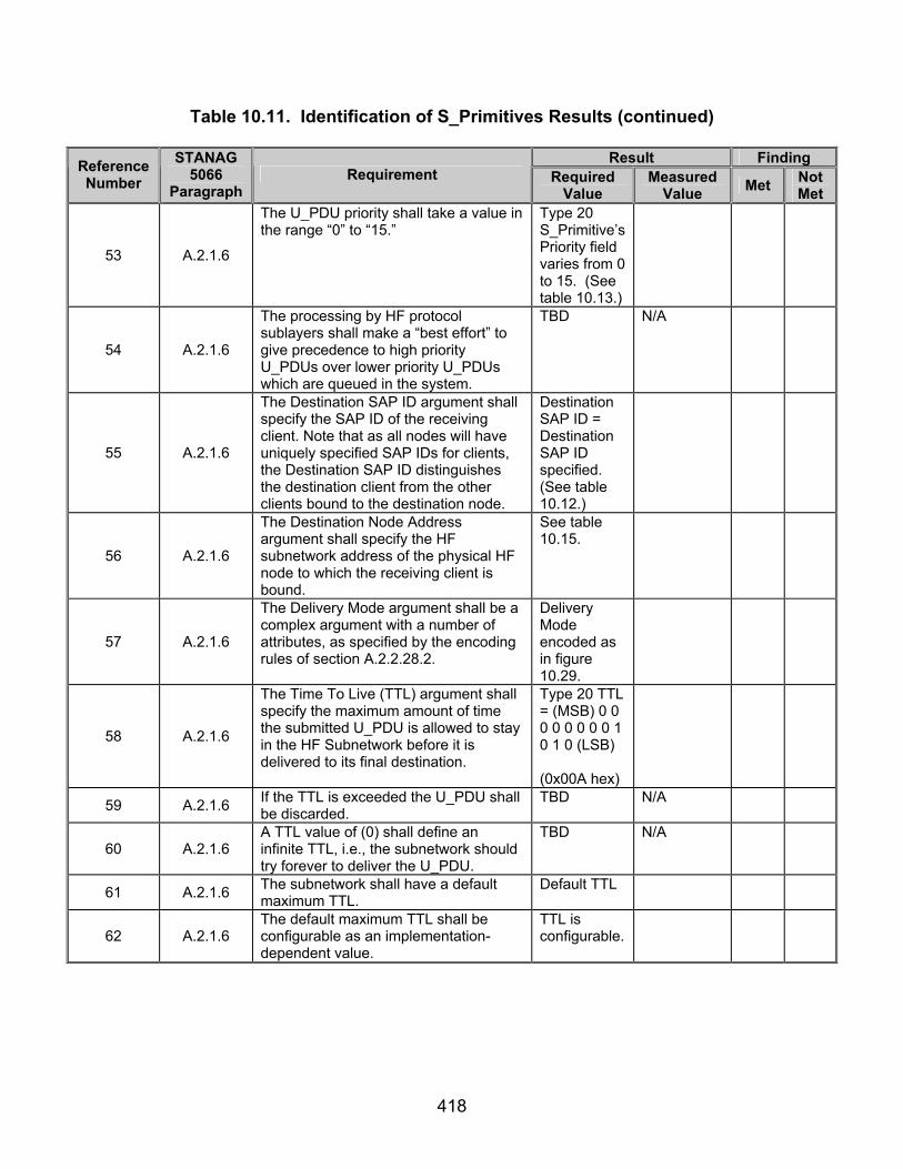
418
Table 10.11. Identification of S_Primitives Results (continued)
Result Finding Reference Number
STANAG 5066
Paragraph Requirement Required
Value Measured
Value Met Not Met
53 A.2.1.6
The U_PDU priority shall take a value in the range “0” to “15.”
Type 20 S_Primitive’s Priority field varies from 0 to 15. (See table 10.13.)
54 A.2.1.6
The processing by HF protocol sublayers shall make a “best effort” to give precedence to high priority U_PDUs over lower priority U_PDUs which are queued in the system.
TBD N/A
55 A.2.1.6
The Destination SAP ID argument shall specify the SAP ID of the receiving client. Note that as all nodes will have uniquely specified SAP IDs for clients, the Destination SAP ID distinguishes the destination client from the other clients bound to the destination node.
Destination SAP ID = Destination SAP ID specified. (See table 10.12.)
56 A.2.1.6
The Destination Node Address argument shall specify the HF subnetwork address of the physical HF node to which the receiving client is bound.
See table 10.15.
57 A.2.1.6
The Delivery Mode argument shall be a complex argument with a number of attributes, as specified by the encoding rules of section A.2.2.28.2.
Delivery Mode encoded as in figure 10.29.
58 A.2.1.6
The Time To Live (TTL) argument shall specify the maximum amount of time the submitted U_PDU is allowed to stay in the HF Subnetwork before it is delivered to its final destination.
Type 20 TTL = (MSB) 0 0 0 0 0 0 0 0 1 0 1 0 (LSB) (0x00A hex)
59 A.2.1.6 If the TTL is exceeded the U_PDU shall be discarded.
TBD N/A
60 A.2.1.6 A TTL value of (0) shall define an infinite TTL, i.e., the subnetwork should try forever to deliver the U_PDU.
TBD N/A
61 A.2.1.6 The subnetwork shall have a default maximum TTL.
Default TTL
62 A.2.1.6 The default maximum TTL shall be configurable as an implementation-dependent value.
TTL is configurable.

419
Table 10.11. Identification of S_Primitives Results (continued)
Result Finding Reference Number
STANAG 5066
Paragraph Requirement Required
Value Measured
Value Met Not Met
63 A.2.1.6
As soon as the Subnetwork Interface Sublayer accepts a S_UNIDATA_REQUEST primitive, it shall immediately calculate its Time To Die (TTD) by adding the specified TTL (or the default maximum value if the specified TTL is equal to (0)) to the current Time of Day, e.g. GMT.
TBD N/A
64 A.2.1.6
The TTD attribute of a U_PDU shall accompany it during its transit within the subnetwork. [Note that the TTD is an absolute time while the TTL is a time interval relative to the instant of the U_PDU submission.]
TBD N/A
65 A.2.1.6
The Size of U_PDU argument shall be the size of the U_PDU that is included in this S_UNIDATA_REQUEST Primitive.
Type 20 Confirmed U_PDU That Follows bits = Number of Confirmed U_PDU Bytes.
66 A.2.1.6
The final argument, U_PDU, shall be the actual Data Unit submitted by the client to the HF Subnetwork.
Number of U_PDU bytes = Size of U_PDU.
67 A.2.1.7
The S_UNIDATA_REQUEST_CONFIRM primitive shall be issued by the Subnetwork Interface Sublayer to acknowledge the successful delivery of a S_UNIDATA_REQUEST submitted by the client.
Type 22 S_Primitive sent in response to Type 20 S_Primitive when both client computers were bounded to their server computers.
68 A.2.1.7
This primitive shall be issued only if the client has requested Data Delivery Confirmation (either during binding or for this particular data unit).
Type 22 S_Primitive sent only when Data Delivery Confirmation was set to Node.

420
Table 10.11. Identification of S_Primitives Results (continued)
Result Finding Reference Number
STANAG 5066
Paragraph Requirement Required
Value Measured
Value Met Not Met
69 A.2.1.7
The Destination Node Address argument in the S_UNIDATA_REQUEST_CONFIRM Primitive shall have the same meaning and be equal in value to the Destination Node Address argument of the S_UNIDATA_REQUEST Primitive for which the S_UNIDATA_REQUEST_ CONFIRM Primitive is the response.
Type 22 Destination Node Address = (MSB) 1 1 1 1 0 1 0 0 1 1 1 1 1 1 1 1 1 1 1 1 1 1 1 1 1 1 1 1 (LSB)
(0xE4FFFFFF hex)
70 A.2.1.7
The Destination SAP_ID argument in the S_UNIDATA_REQUEST_ CONFIRM Primitive shall have the same meaning and be equal in value to the Destination SAP_ID argument of the S_UNIDATA_REQUEST Primitive for which the S_UNIDATA_REQUEST_CONFIRM Primitive is the response.
Type 22 Destination Node Address = (MSB) 1 1 1 1 0 1 0 0 1 1 1 1 1 1 1 1 1 1 1 1 1 1 1 1 1 1 1 1 (LSB)
(0xE4FFFFFF hex)
71 A.2.1.7
The Size of Confirmed U_PDU argument shall be the size of the U_PDU or part that is included in this S_UNIDATA_REQUEST_CONFIRM Primitive.
Type 22 Confirmed U_PDU That Follows bits = Number of Confirmed U_PDU Bytes.
72 A.2.1.7
The U_PDU argument in the S_UNIDATA_CONFIRM Primitive shall be a copy of the whole or a fragment of the U_PDU argument of the S_UNIDATA_REQUEST Primitive for which the S_UNIDATA_REQUEST_CONFIRM Primitive is the response.
Type 22 Confirmed U_PDU That Follows bits = Number of Confirmed U_PDU Bytes.

421
Table 10.11. Identification of S_Primitives Results (continued)
Result Finding Reference Number
STANAG 5066
Paragraph Requirement Required
Value Measured
Value Met Not Met
73 A.2.1.7
Using these arguments, the client shall be able to uniquely identify the U_PDU that is being acknowledged. Depending on the implementation of the protocol, the last argument, U_PDU, may not be a complete copy of the original U_PDU but only a partial copy, i.e., only the first X bytes are copied for some value of X.
Type 20 Confirmed U_PDU That Follows bits = Number of Confirmed U_PDU Bytes.
74 A.2.1.7
If a partial U_PDU is returned, U_PDU_Response_Frag_Size bytes shall be returned to the client starting with the first byte of the U_PDU so that the client will have the U_PDU segment information.
TBD N/A
75 A.2.1.7
The number of bytes returned, U_PDU_Response_Frag_Size, shall be a configurable parameter in the implementation.
TBD N/A
76 A.2.1.8
The S_UNIDATA_REQUEST_REJECTED primitive shall be issued by the Subnetwork Interface Sublayer to inform a client that a S_UNIDATA_REQUEST was not delivered successfully.
Type 23 S_Primitive sent in response to Type 20 S_Primitive.
77 A.2.1.8
This primitive shall be issued if the client has requested Data Delivery Confirmation (either during Binding or for this particular U_PDU) and the data was unsuccessfully delivered.
Type 23 S_Primitive transmitted for trials where Data Delivery Confirm = 0 1, but not when Data Delivery Confirm = 0 0.
78 A.2.1.8 This primitive also shall be issued to a client if a U_PDU larger than the MTU is submitted.
TBD N/A
79 A.2.1.8
The Reason argument shall specify why the delivery failed, using the encoding given in the table below:
Type 23 Reason = (MSB) 0 0 1 1 (LSB) (0x3 hex)
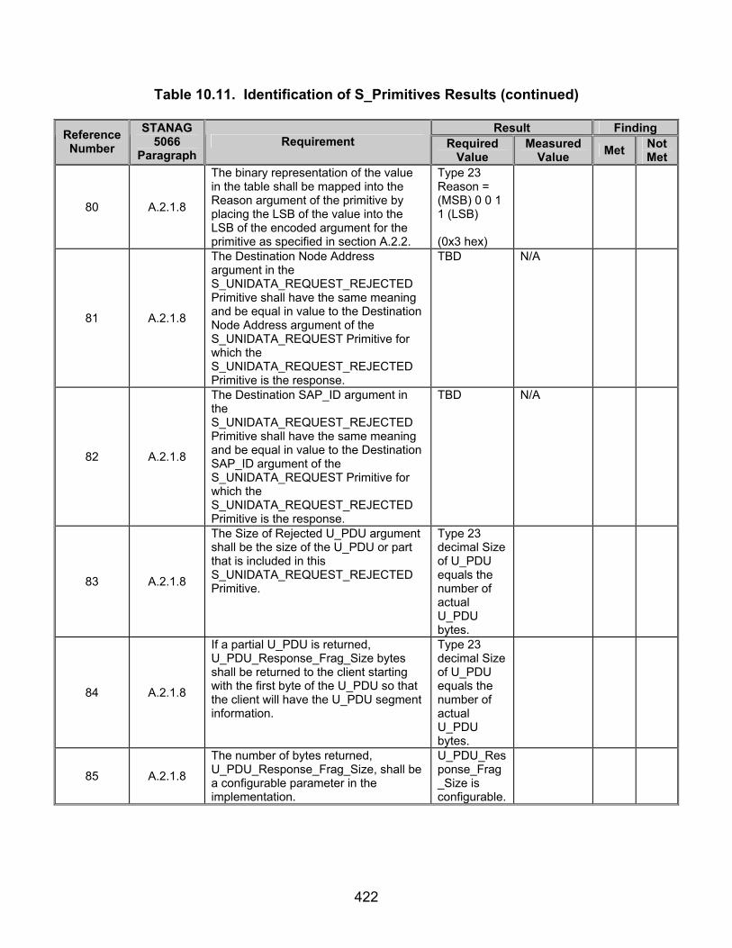
422
Table 10.11. Identification of S_Primitives Results (continued)
Result Finding Reference Number
STANAG 5066
Paragraph Requirement Required
Value Measured
Value Met Not Met
80 A.2.1.8
The binary representation of the value in the table shall be mapped into the Reason argument of the primitive by placing the LSB of the value into the LSB of the encoded argument for the primitive as specified in section A.2.2.
Type 23 Reason = (MSB) 0 0 1 1 (LSB) (0x3 hex)
81 A.2.1.8
The Destination Node Address argument in the S_UNIDATA_REQUEST_REJECTED Primitive shall have the same meaning and be equal in value to the Destination Node Address argument of the S_UNIDATA_REQUEST Primitive for which the S_UNIDATA_REQUEST_REJECTED Primitive is the response.
TBD N/A
82 A.2.1.8
The Destination SAP_ID argument in the S_UNIDATA_REQUEST_REJECTED Primitive shall have the same meaning and be equal in value to the Destination SAP_ID argument of the S_UNIDATA_REQUEST Primitive for which the S_UNIDATA_REQUEST_REJECTED Primitive is the response.
TBD N/A
83 A.2.1.8
The Size of Rejected U_PDU argument shall be the size of the U_PDU or part that is included in this S_UNIDATA_REQUEST_REJECTED Primitive.
Type 23 decimal Size of U_PDU equals the number of actual U_PDU bytes.
84 A.2.1.8
If a partial U_PDU is returned, U_PDU_Response_Frag_Size bytes shall be returned to the client starting with the first byte of the U_PDU so that the client will have the U_PDU segment information.
Type 23 decimal Size of U_PDU equals the number of actual U_PDU bytes.
85 A.2.1.8
The number of bytes returned, U_PDU_Response_Frag_Size, shall be a configurable parameter in the implementation.
U_PDU_Response_Frag_Size is configurable.
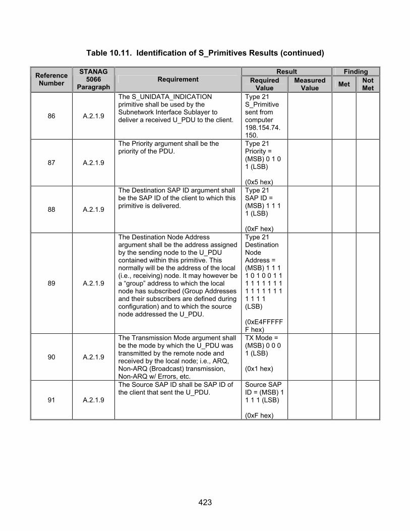
423
Table 10.11. Identification of S_Primitives Results (continued)
Result Finding Reference Number
STANAG 5066
Paragraph Requirement Required
Value Measured
Value Met Not Met
86 A.2.1.9
The S_UNIDATA_INDICATION primitive shall be used by the Subnetwork Interface Sublayer to deliver a received U_PDU to the client.
Type 21 S_Primitive sent from computer 198.154.74.150.
87 A.2.1.9
The Priority argument shall be the priority of the PDU.
Type 21 Priority = (MSB) 0 1 0 1 (LSB) (0x5 hex)
88 A.2.1.9
The Destination SAP ID argument shall be the SAP ID of the client to which this primitive is delivered.
Type 21 SAP ID = (MSB) 1 1 1 1 (LSB) (0xF hex)
89 A.2.1.9
The Destination Node Address argument shall be the address assigned by the sending node to the U_PDU contained within this primitive. This normally will be the address of the local (i.e., receiving) node. It may however be a “group” address to which the local node has subscribed (Group Addresses and their subscribers are defined during configuration) and to which the source node addressed the U_PDU.
Type 21 Destination Node Address = (MSB) 1 1 1 1 0 1 0 0 1 1 1 1 1 1 1 1 1 1 1 1 1 1 1 1 1 1 1 1 (LSB)
(0xE4FFFFFF hex)
90 A.2.1.9
The Transmission Mode argument shall be the mode by which the U_PDU was transmitted by the remote node and received by the local node; i.e., ARQ, Non-ARQ (Broadcast) transmission, Non-ARQ w/ Errors, etc.
TX Mode = (MSB) 0 0 0 1 (LSB) (0x1 hex)
91 A.2.1.9
The Source SAP ID shall be SAP ID of the client that sent the U_PDU.
Source SAP ID = (MSB) 1 1 1 1 (LSB) (0xF hex)

424
Table 10.11. Identification of S_Primitives Results (continued)
Result Finding Reference Number
STANAG 5066
Paragraph Requirement Required
Value Measured
Value Met Not Met
92 A.2.1.9
The Source Node Address shall represent the node address of the client that sent the U_PDU.
Type 21 Source Node Address = (MSB) 1 1 1 0 0 0 0 1 0 0 0 0 0 0 0 0 0 0 0 0 0 0 0 0 0 0 0 0 0 0 0 0 (0xF1000000 hex)
93 A.2.1.9
The Size of U_PDU argument shall be the size of the U_PDU that was sent and delivered in this S_UNIDATA_INDICATION S_Primitive.
Type 21 Confirmed U_PDU That Follows bits = Number of Confirmed U_PDU Bytes.
94 A.2.1.9
The following four arguments shall be present in the S_UNIDATA_INDICATION S_Primitive if and only if the Transmission Mode for the U_PDU is equal to Non-ARQ w/ Errors:
TBD N/A
95 A.2.1.9
The Number of Blocks in Error argument shall equal the number of data blocks in the U_PDU that were received in error by the lower layers of the subnetwork and that were passed on to the Subnetwork Interface Sublayer.
TBD N/A
96 A.2.1.9 This argument shall specify the number of ordered pairs in the Array of Block-Error Pointers argument.
TBD N/A
97 A.2.1.9
The Array of Block-Error Pointers argument shall consist of a an array of ordered pairs, the first element in the pair equal to the location within the U_PDU of the data block with errors, and the second element equal to the size of the data block with errors.
TBD N/A
98 A.2.1.9
The Number of Non-Received Blocks argument shall equal the number of data blocks missing from the U_PDU because they were not received.
TBD N/A

425
Table 10.11. Identification of S_Primitives Results (continued)
Result Finding Reference Number
STANAG 5066
Paragraph Requirement Required
Value Measured
Value Met Not Met
99 A.2.1.9 This argument shall specify the number of ordered pairs in the Array of Non-Received-Block Pointers argument.
TBD N/A
100 A.2.1.9
The Array of Non-Received-Block Pointers shall consist of an array of ordered pairs, the first element in the pair equal to the location of the missing data block in the U_PDU and the second element equal to the size of the missing data block.
TBD N/A
101 A.2.1.9 The final argument, U_PDU, shall contain the actual received user data for delivery to the client.
TBD N/A
102 A.2.1.10
The S_EXPEDITED_UNIDATA_REQUEST primitive shall be used to submit a U_PDU to the HF Subnetwork for Expedited Delivery to a receiving client.
TBD N/A
103 A.2.1.10
The Destination SAP ID argument shall specify the SAP ID of the receiving client. Note that as all nodes will have uniquely specified SAP IDs for clients, the Destination SAP ID distinguishes the destination client from the other clients bound to the destination node.
TBD N/A
104 A.2.1.10
The Destination Node Address argument shall specify the HF subnetwork address of the physical HF node to which the receiving client is bound.
TBD N/A
105 A.2.1.10
The Delivery Mode argument shall be a complex argument with a number of attributes, as specified by the encoding rules of section A.2.2.28.2.
TBD N/A
106 A.2.1.10
The Time To Live (TTL) argument shall specify the maximum amount of time the submitted U_PDU is allowed to stay in the HF Subnetwork before it is delivered to its final destination.
TBD N/A
107 A.2.1.10 If the TTL is exceeded the U_PDU shall be discarded.
TBD N/A
108 A.2.1.10 A TTL value of (0) shall define an infinite TTL, i.e., the subnetwork should try forever to deliver the U_PDU.
TBD N/A
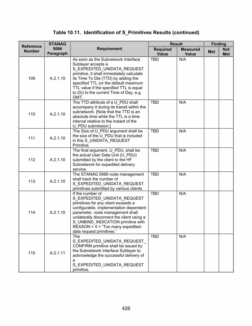
426
Table 10.11. Identification of S_Primitives Results (continued)
Result Finding Reference Number
STANAG 5066
Paragraph Requirement Required
Value Measured
Value Met Not Met
109 A.2.1.10
As soon as the Subnetwork Interface Sublayer accepts a S_EXPEDITED_UNIDATA_REQUEST primitive, it shall immediately calculate its Time To Die (TTD) by adding the specified TTL (or the default maximum TTL value if the specified TTL is equal to (0)) to the current Time of Day, e.g. GMT.
TBD N/A
110 A.2.1.10
The TTD attribute of a U_PDU shall accompany it during its transit within the subnetwork. [Note that the TTD is an absolute time while the TTL is a time interval relative to the instant of the U_PDU submission.]
TBD N/A
111 A.2.1.10
The Size of U_PDU argument shall be the size of the U_PDU that is included in this S_UNIDATA_REQUEST Primitive.
TBD N/A
112 A.2.1.10
The final argument, U_PDU, shall be the actual User Data Unit (U_PDU) submitted by the client to the HF Subnetwork for expedited delivery service.
TBD N/A
113 A.2.1.10
The STANAG 5066 node management shall track the number of S_EXPEDITED_UNIDATA_REQUEST primitives submitted by various clients.
TBD N/A
114 A.2.1.10
If the number of S_EXPEDITED_UNIDATA_REQUEST primitives for any client exceeds a configurable, implementation dependent parameter, node management shall unilaterally disconnect the client using a S_UNBIND_INDICATION primitive with REASON = 4 = “Too many expedited-data request primitives.”
TBD N/A
115 A.2.1.11
The S_EXPEDITED_UNIDATA_REQUEST_CONFIRM primitive shall be issued by the Subnetwork Interface Sublayer to acknowledge the successful delivery of a S_EXPEDITED_UNIDATA_REQUEST primitive.
TBD N/A

427
Table 10.11. Identification of S_Primitives Results (continued)
Result Finding Reference Number
STANAG 5066
Paragraph Requirement Required
Value Measured
Value Met Not Met
116 A.2.1.11
This primitive shall be issued only if the client has requested Data Delivery Confirmation (either during Binding or for this particular U_PDU).
TBD N/A
117 A.2.1.11
The Destination Node Address argument in the S_EXPEDITED_UNIDATA_REQUEST_CONFIRM Primitive shall have the same meaning and be equal in value to the Destination Node Address argument of the S_EXPEDITED_UNIDATA_REQUEST Primitive for which the S_EXPEDITED_UNIDATA_REQUEST_CONFIRM Primitive is the response.
TBD N/A
118 A.2.1.11
The Destination SAP_ID argument in the S_EXPEDITED_UNIDATA_REQUEST_CONFIRM Primitive shall have the same meaning and be equal in value to the Destination SAP_ID argument of the S_EXPEDITED_UNIDATA_REQUEST Primitive for which the S_EXPEDITED_UNIDATA_REQUEST_CONFIRM Primitive is the response.
TBD N/A
119 A.2.1.11
The Size of Rejected U_PDU argument shall be the size of the U_PDU or part that is included in the S_EXPEDITED_UNIDATA_REQUEST_CONFIRM Primitive.
TBD N/A
120 A.2.1.11
If a partial U_PDU is returned, U_PDU_Response_Frag_Size bytes shall be returned to the client starting with the first byte of the U_PDU so that the client will have the U_PDU segment information.
TBD N/A
121 A.2.1.11
The number of bytes returned, U_PDU_Response_Frag_Size, shall be a configurable parameter in the implementation.
TBD N/A
122 A.2.1.12
The S_EXPEDITED_UNIDATA_REQUEST_REJECTED primitive shall be issued by the Subnetwork Interface Sublayer to inform a client that a S_EXPEDITED_UNIDATA_REQUEST was not delivered successfully.
TBD N/A
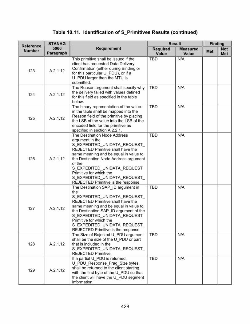
428
Table 10.11. Identification of S_Primitives Results (continued)
Result Finding Reference Number
STANAG 5066
Paragraph Requirement Required
Value Measured
Value Met Not Met
123 A.2.1.12
This primitive shall be issued if the client has requested Data Delivery Confirmation (either during Binding or for this particular U_PDU), or if a U_PDU larger than the MTU is submitted.
TBD N/A
124 A.2.1.12
The Reason argument shall specify why the delivery failed with values defined for this field as specified in the table below.
TBD N/A
125 A.2.1.12
The binary representation of the value in the table shall be mapped into the Reason field of the primitive by placing the LSB of the value into the LSB of the encoded field for the primitive as specified in section A.2.2.1.
TBD N/A
126 A.2.1.12
The Destination Node Address argument in the S_EXPEDITED_UNIDATA_REQUEST_REJECTED Primitive shall have the same meaning and be equal in value to the Destination Node Address argument of the S_EXPEDITED_UNIDATA_REQUEST Primitive for which the S_EXPEDITED_UNIDATA_REQUEST_REJECTED Primitive is the response.
TBD N/A
127 A.2.1.12
The Destination SAP_ID argument in the S_EXPEDITED_UNIDATA_REQUEST_REJECTED Primitive shall have the same meaning and be equal in value to the Destination SAP_ID argument of the S_EXPEDITED_UNIDATA_REQUEST Primitive for which the S_EXPEDITED_UNIDATA_REQUEST_REJECTED Primitive is the response.
TBD N/A
128 A.2.1.12
The Size of Rejected U_PDU argument shall be the size of the U_PDU or part that is included in the S_EXPEDITED_UNIDATA_REQUEST_REJECTED Primitive.
TBD N/A
129 A.2.1.12
If a partial U_PDU is returned, U_PDU_Response_Frag_Size bytes shall be returned to the client starting with the first byte of the U_PDU so that the client will have the U_PDU segment information.
TBD N/A

429
Table 10.11. Identification of S_Primitives Results (continued)
Result Finding Reference Number
STANAG 5066
Paragraph Requirement Required
Value Measured
Value Met Not Met
130 A.2.1.12
The number of bytes returned, U_PDU_Response_Frag_Size, shall be a configurable parameter in the implementation.
TBD N/A
131 A.2.1.13
The S_EXPEDITED_UNIDATA_INDICATION primitive shall be used by the Subnetwork Interface Sublayer to deliver an Expedited U_PDU to a client.
TBD N/A
132 A.2.1.13 The Destination SAP ID argument shall be the SAP ID of the client to which this primitive is delivered.
TBD N/A
133 A.2.1.13
The Destination Node Address argument shall be the address assigned by the sending node to the U_PDU contained within this primitive. This normally will be the address of the local (i.e., receiving) node. It may however be a “group” address to which the local node has subscribed (Group Addresses and their subscribers are defined during configuration) and to which the source node addressed the U_PDU.
TBD N/A
134 A.2.1.13
The Transmission Mode argument shall be the mode by which the U_PDU was transmitted by the remote node and received by the local node; i.e., ARQ, Non-ARQ (Broadcast) transmission, Non-ARQ w/ Errors, etc.
TBD N/A
135 A.2.1.13 The Source SAP ID shall be SAP ID of the client that sent the U_PDU.
TBD N/A
136 A.2.1.13 The Source Node Address shall represent the node address of the client that sent the U_PDU.
TBD N/A
137 A.2.1.13
The Size of U_PDU argument shall be the size of the U_PDU that was sent and delivered in this S_UNIDATA_INDICATION S_Primitive.
TBD N/A
138 A.2.1.13
The following four arguments shall be present in the S_UNIDATA_INDICATION S_Primitive if and only if the Transmission Mode for the U_PDU is equal to Non-ARQ w/ Errors:
TBD N/A

430
Table 10.11. Identification of S_Primitives Results (continued)
Result Finding Reference Number
STANAG 5066
Paragraph Requirement Required
Value Measured
Value Met Not Met
139 A.2.1.13
The Number of Blocks in Error argument shall equal the number of data blocks in the U_PDU that were received in error by the lower layers of the subnetwork and that were passed on to the Subnetwork Interface Sublayer.
TBD N/A
140 A.2.1.13 This argument shall specify the number of ordered pairs in the Array of Block-Error Pointers argument.
TBD N/A
141 A.2.1.13
The Array of Block-Error Pointers argument shall consist of a an array of ordered pairs, the first element in the pair equal to the location within the U_PDU of the data block with errors, and the second element equal to the size of the data block with errors.
TBD N/A
142 A.2.1.13
The Number of Non-Received Blocks argument shall equal the number of data blocks missing from the U_PDU because they were not received.
TBD N/A
143 A.2.1.13 This argument shall specify the number of ordered pairs in the Array of Non-Received-Block Pointers argument.
TBD N/A
144 A.2.1.13
The Array of Non-Received-Block Pointers shall consist of an array of ordered pairs, the first element in the pair equal to the location of the missing data block in the U_PDU and the second element equal to the size of the missing data block.
TBD N/A
145 A.2.1.13 The final argument, U_PDU, shall contain the actual received user data for delivery to the client.
TBD N/A
Type 17 S_Primitive sent after the Keep Alive Interval specified by the vendor.
156 A.2.1.17
The S_KEEP_ALIVE primitive can be issued as required (e.g. during periods of inactivity) by the clients and/or the Subnetwork Interface to sense whether the physical connection between the client and the Subnetwork is alive or broken. When the S_KEEP_ALIVE Primitive is received, the recipient (i.e., client or Subnetwork Interface) shall respond with the same primitive within 10 seconds.
Recipient responds within 10 seconds with another Type 17 S_Primitive.

431
Table 10.11. Identification of S_Primitives Results (continued)
Result Finding Reference Number
STANAG 5066
Paragraph Requirement Required
Value Measured
Value Met Not Met
157 A.2.1.17 If a reply is not sent within 10 seconds, no reply shall be sent.
TBD N/A
158 A.2.1.17
A client or Subnetwork Interface shall not send the S_KEEP_ALIVE Primitive more frequently than once every 120 seconds to the same destination.
Keep Alive Interval specified by vendor is not less than 120 seconds.
159 A.2.1.18
The S_HARD_LINK_ESTABLISH primitive shall used by a client to request the establishment of a Hard Link between the local Node to which it is connected and a specified remote Node.
TBD N/A
160 A.2.1.18 The Link Priority argument shall define the priority of the Link.
TBD N/A
161 A.2.1.18 It shall take a value in the range 0-3. TBD N/A
162 A.2.1.18
An S_HARD_LINK_ESTABLISH primitive with a higher Link Priority value shall take precedence over a Hard Link established with a lower Link Priority value submitted by a client of the same Rank.
TBD N/A
163 A.2.1.18
Hard Link requests made by clients with higher Rank shall take precedence over requests of lower-Ranked clients regardless of the value of the Link Priority argument, in accordance with the requirements of section A.3.2.2.1.
TBD N/A
164 A.2.1.18
The Link Type argument shall be used by the requesting client to fully or partially reserve the bandwidth of the Link.
TBD N/A
165 A.2.1.18
It shall take a value in the range 0-2, as specified in section A.1.1.2, specifying this primitive as one for a Type 0 Hard Link, Type 1 Hard Link, or Type 2 Hard Link, respectively.
TBD N/A
166 A.2.1.18
The Remote Node Address argument shall specify the physical HF Node Address to which the connection must be established and maintained.
TBD N/A
167 A.2.1.18
The Remote SAP ID argument shall identify the single client connected to the remote Node, to and from which traffic is allowed.
TBD N/A

432
Table 10.11. Identification of S_Primitives Results (continued)
Result Finding Reference Number
STANAG 5066
Paragraph Requirement Required
Value Measured
Value Met Not Met
168 A.2.1.18
This argument shall be valid only if the Link Type argument has a value of 2 (i.e., only if the Hard Link request reserves the full bandwidth of the link for the local and remote client, as specified in section A.1.1.2.3).
TBD N/A
169 A.2.1.19 The S_HARD_LINK_TERMINATE primitive shall be issued by a client to terminate an existing Hard Link.
TBD N/A
170 A.2.1.19
The subnetwork shall terminate an existing Hard Link on receipt of this primitive only if the primitive was generated by the client which requested the establishment of the Hard Link.
TBD N/A
171 A.2.1.19
The single Remote Node Address argument shall specify the Address of the Node at the remote end of the Hard Link. [Note: The Remote Node Address argument is redundant in that Hard Links can exist with only one remote node at any time. It may, however, be used by the subnetwork implementation receiving the primitive to check its validity.]
TBD N/A
172 A.2.1.19
Upon receiving this primitive, the subnetwork shall take all necessary steps to terminate the Hard Link, as specified in section A.3.2.2.32.
TBD N/A
173 A.2.1.20
The S_HARD_LINK_ESTABLISHED primitive shall be issued by the Subnetwork Interface Sublayer as a positive response to a client’s S_HARD_LINK_ESTABLISH primitive.
TBD N/A
174 A.2.1.20
This primitive shall be issued only after all the negotiations and protocols between the appropriate peer sublayers of the local and remote nodes have been completed and the remote node has accepted the establishment of the Hard Link, in accordance with the protocol specified in STANAG 5066, section A.3.2.2.2.
TBD N/A
175 A.2.1.20
The first argument, Remote Node Status, shall inform the requesting client of any special status of the remote node, e.g., Remote Node in EMCON, etc., Valid arguments for Remote Node Status are given in the table below.
TBD N/A

433
Table 10.11. Identification of S_Primitives Results (continued)
Result Finding Reference Number
STANAG 5066
Paragraph Requirement Required
Value Measured
Value Met Not Met
176 A.2.1.20 Successful establishment of a Hard Link shall always imply a status of “OK” for the remote node.
TBD N/A
177 A.2.1.20 The value OK shall be indicated by any positive non-zero value in the Remote Node Status field.
TBD N/A
178 A.2.1.20
The Link Priority argument shall have the same meaning and be equal in value to the argument of the S_HARD_LINK_ESTABLISH Primitive for which this S_HARD_LINK_ESTABLISHED Primitive is the response.
TBD N/A
179 A.2.1.20
The Link Type argument shall have the same meaning and be equal in value to the argument of the S_HARD_LINK_ESTABLISH Primitive for which this S_HARD_LINK_ESTABLISHED Primitive is the response.
TBD N/A
180 A.2.1.20
The Remote Node Address argument shall have the same meaning and be equal in value to the argument of the S_HARD_LINK_ESTABLISH Primitive for which this S_HARD_LINK_ESTABLISHED Primitive is the response.
TBD N/A
181 A.2.1.20
The Remote SAP ID argument shall have the same meaning and be equal in value to the argument of the S_HARD_LINK_ESTABLISH Primitive for which this S_HARD_LINK_ESTABLISHED Primitive is the response.
TBD N/A
182 A.2.1.21
The S_HARD_LINK_REJECTED primitive shall be issued by the Subnetwork Interface Sublayer as a negative response to a client’s S_HARD_LINK_ESTABLISH primitive.
TBD N/A
183 A.2.1.21 The Reason argument shall specify why the Hard Link Request was rejected, with values defined for this argument as specified in the table below:
TBD N/A

434
Table 10.11. Identification of S_Primitives Results (continued)
Result Finding Reference Number
STANAG 5066
Paragraph Requirement Required
Value Measured
Value Met Not Met
184 A.2.1.21
The Link Priority argument shall have the same meaning and be equal in value to the argument of the S_HARD_LINK_ESTABLISH Primitive for which this S_HARD_LINK_ REJECTED Primitive is the response.
TBD N/A
185 A.2.1.21
The Link Type argument shall have the same meaning and be equal in value to the argument of the S_HARD_LINK_ESTABLISH Primitive for which this S_HARD_LINK_ REJECTED Primitive is the response.
TBD N/A
186 A.2.1.21
The Remote Node Address argument shall have the same meaning and be equal in value to the argument of the S_HARD_LINK_ESTABLISH Primitive for which this S_HARD_LINK_ REJECTED Primitive is the response.
TBD N/A
187 A.2.1.21
The Remote SAP ID argument shall have the same meaning and be equal in value to the argument of the S_HARD_LINK_ESTABLISH Primitive for which this S_HARD_LINK_ REJECTED Primitive is the response.
TBD N/A
188 A.2.1.22
The S_HARD_LINK_TERMINATED primitive shall be issued by the Subnetwork Interface Sublayer to inform a client that has been granted a Hard Link that the link has been terminated unilaterally by the subnetwork.
TBD N/A
189 A.2.1.22
For Hard Link Types 0 and 1, only the client that originally requested the Hard Link shall receive this primitive. Other clients sharing the link with Soft Link Data Exchange Sessions may have the link broken without notification.
TBD N/A
190 A.2.1.22 For Type 2 Hard Links, both called and calling clients shall receive this primitive.
TBD N/A
191 A.2.1.22 The Reason argument shall specify why the Hard Link was terminated, with values defined for this argument as specified in the table below:
TBD N/A

435
Table 10.11. Identification of S_Primitives Results (continued)
Result Finding Reference Number
STANAG 5066
Paragraph Requirement Required
Value Measured
Value Met Not Met
192 A.2.1.22
The Link Priority argument shall have the same meaning and be equal in value to the argument of the S_HARD_LINK_ESTABLISH Primitive for which this S_HARD_LINK_ TERMINATED Primitive is the response.
TBD N/A
193 A.2.1.22
The Link Type argument shall have the same meaning and be equal in value to the argument of the S_HARD_LINK_ESTABLISH Primitive for which this S_HARD_LINK_ TERMINATED Primitive is the response.
TBD N/A
194 A.2.1.22
The Remote Node Address argument shall have the same meaning and be equal in value to the argument of the S_HARD_LINK_ESTABLISH Primitive for which this S_HARD_LINK_ TERMINATED Primitive is the response.
TBD N/A
195 A.2.1.22
The Remote SAP ID argument shall have the same meaning and be equal in value to the argument of the S_HARD_LINK_ESTABLISH Primitive for which this S_HARD_LINK_ TERMINATED Primitive is the response.
TBD N/A
196 A.2.1.23 The S_HARD_LINK_INDICATION primitive shall be used only for Hard Link Type 2.
TBD N/A
197 A.2.1.23
With this primitive the Subnetwork Interface Sublayer shall signal to one of its local clients that a client at a remote node requested a Hard Link of Type 2 to be established between them.
TBD N/A
198 A.2.1.23
The first argument, Remote Node Status, shall inform the local client of any special status of the remote node, e.g., Remote Node in EMCON, etc. Valid arguments currently defined for Remote Node Status are given in the table below.
TBD N/A

436
Table 10.11. Identification of S_Primitives Results (continued)
Result Finding Reference Number
STANAG 5066
Paragraph Requirement Required
Value Measured
Value Met Not Met
199 A.2.1.23
The Link Priority argument shall have the same meaning and be equal in value to the argument of the S_HARD_LINK_ESTABLISH Primitive generated by the remote-client and for which this S_HARD_LINK_ INDICATION Primitive is the result.
TBD N/A
200 A.2.1.23
The Link Type argument shall have the same meaning and be equal in value to the argument of the S_HARD_LINK_ESTABLISH Primitive generated by the remote-client and for which this S_HARD_LINK_ INDICATION Primitive is the result.
TBD N/A
201 A.2.1.23
The Remote Node Address argument shall be equal in value to the HF subnetwork address of the node to which the remote-client is bound and that originated the S_HARD_LINK_ESTABLISH Primitive for which this S_HARD_LINK_INDICATION Primitive is the response.
TBD N/A
202 A.2.1.23
The Remote SAP ID argument shall be equal in value to the SAP_ID that is bound to the remote client that originated the S_HARD_LINK_ESTABLISH Primitive for which this S_HARD_LINK_ INDICATION Primitive is the result.
TBD N/A
203 A.2.1.24
The S_HARD_LINK_ACCEPT primitive shall be issued by a client as a positive response to a S_HARD_LINK_INDICATION primitive. With this primitive the client tells the Subnetwork Interface Sublayer that it accepts the Hard Link of Type 2 requested by a client at a remote node.
TBD N/A
204 A.2.1.24
The Link Priority argument shall have the same meaning and be equal in value to the Link Priority argument of the S_HARD_LINK_ INDICATION Primitive received by the client from the subnetwork for which this S_HARD_LINK_ ACCEPT Primitive is the response.
TBD N/A
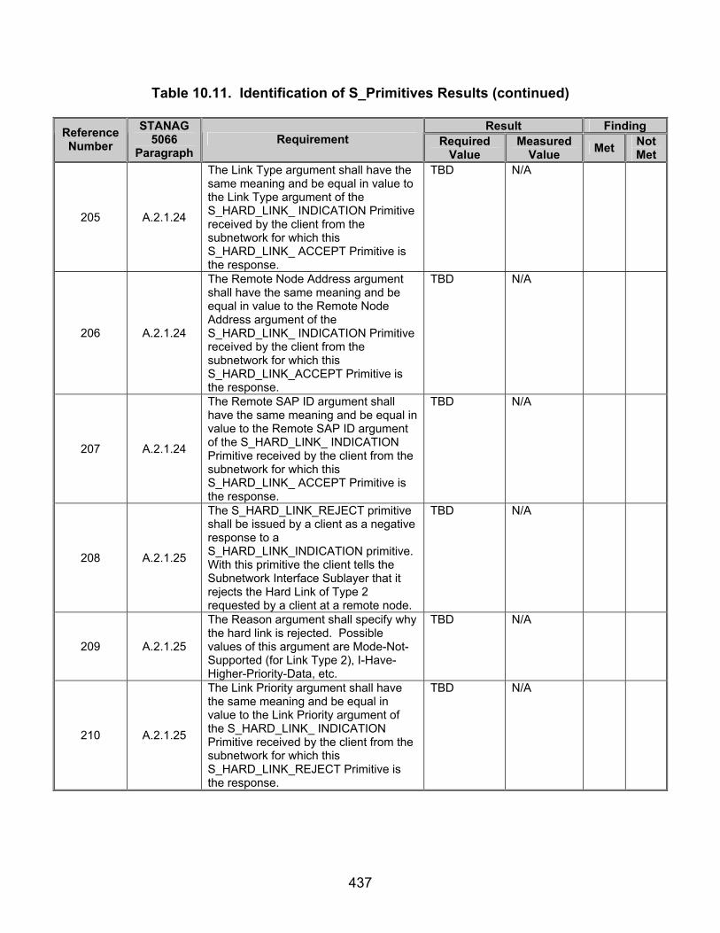
437
Table 10.11. Identification of S_Primitives Results (continued)
Result Finding Reference Number
STANAG 5066
Paragraph Requirement Required
Value Measured
Value Met Not Met
205 A.2.1.24
The Link Type argument shall have the same meaning and be equal in value to the Link Type argument of the S_HARD_LINK_ INDICATION Primitive received by the client from the subnetwork for which this S_HARD_LINK_ ACCEPT Primitive is the response.
TBD N/A
206 A.2.1.24
The Remote Node Address argument shall have the same meaning and be equal in value to the Remote Node Address argument of the S_HARD_LINK_ INDICATION Primitive received by the client from the subnetwork for which this S_HARD_LINK_ACCEPT Primitive is the response.
TBD N/A
207 A.2.1.24
The Remote SAP ID argument shall have the same meaning and be equal in value to the Remote SAP ID argument of the S_HARD_LINK_ INDICATION Primitive received by the client from the subnetwork for which this S_HARD_LINK_ ACCEPT Primitive is the response.
TBD N/A
208 A.2.1.25
The S_HARD_LINK_REJECT primitive shall be issued by a client as a negative response to a S_HARD_LINK_INDICATION primitive. With this primitive the client tells the Subnetwork Interface Sublayer that it rejects the Hard Link of Type 2 requested by a client at a remote node.
TBD N/A
209 A.2.1.25
The Reason argument shall specify why the hard link is rejected. Possible values of this argument are Mode-Not-Supported (for Link Type 2), I-Have-Higher-Priority-Data, etc.
TBD N/A
210 A.2.1.25
The Link Priority argument shall have the same meaning and be equal in value to the Link Priority argument of the S_HARD_LINK_ INDICATION Primitive received by the client from the subnetwork for which this S_HARD_LINK_REJECT Primitive is the response.
TBD N/A

438
Table 10.11. Identification of S_Primitives Results (continued)
Result Finding Reference Number
STANAG 5066
Paragraph Requirement Required
Value Measured
Value Met Not Met
211 A.2.1.25
The Link Type argument shall have the same meaning and be equal in value to the Link Type argument of the S_HARD_LINK_ INDICATION Primitive received by the client from the subnetwork for which this S_HARD_LINK_REJECT Primitive is the response.
TBD N/A
212 A.2.1.25
The Remote Node Address argument shall have the same meaning and be equal in value to the Remote Node Address argument of the S_HARD_LINK_ INDICATION Primitive received by the client from the subnetwork for which this S_HARD_LINK_REJECT Primitive is the response.
TBD N/A
213 A.2.1.25
The Remote SAP ID argument shall have the same meaning and be equal in value to the Remote SAP ID argument of the S_HARD_LINK_ INDICATION Primitive received by the client from the subnetwork for which this S_HARD_LINK_ ACCEPT Primitive is the response.
TBD N/A
215 A.2.2.2
The encoding of the S_Primitives for communication across the Subnetwork Interface Sublayer shall be in accordance with text and figures in the subsections below.
216 A.2.2.1
Unless noted otherwise, the bit representation for argument values in an S_Primitive shall be encoded into their corresponding fields in accordance with CCITT V.42, 8.1.2.3, which states that:
S_Primitives encoded as specified in their subsections.
217 A.2.2.1
When a field is contained within a single octet (i.e., eight bit group), the lowest bit number of the field shall represent the lowest-order (i.e., least-significant-bit) value;
S_Primitives encoded as specified in their subsections.
218 A.2.2.1
When a field spans more than one octet, the order of bit values within each octet shall progressively decrease as the octet number increases. The lowest bit number associated with the field represents the lowest-order value.
S_Primitives encoded as specified in their subsections.

439
Table 10.11. Identification of S_Primitives Results (continued)
Result Finding Reference Number
STANAG 5066
Paragraph Requirement Required
Value Measured
Value Met Not Met
219
A.2.2.1
The 4-byte address field in the S_primitives shall carry the 3.5-byte address defined in C.3.1.4. The lowest-order bit of the address shall be placed in the lowest-order bit position of the field (generally bit 0 of the highest byte number of the field), consistent with the mapping specified in annex C for D_PDUs.
See table 10.15.
220 A.2.2.2
As shown in figure A-1 (a), all primitives shall be encoded as the following sequence of elements:
A two-byte S_Primitive preamble field, whose value is specified by the 16-bit Maury-Styles sequence below; A one-byte version-number field; A two-byte Size_of_Primitive field; A multi-byte field that contains the encoded S_Primitive.
All S_Primitives Recorded begin with (MSB) 1 0 0 1 0 0 0 0 1 1 1 0 1 0 1 1 (LSB) (0x90EB hex)
221 A.2.2.2
The S_Primitive preamble field shall be encoded as the 16-bit Maury-Styles sequence shown below, with the least significant bit (LSB) transmitted first over the interface:
(MSB) 1 1 1 0 1 0 1 1 1 0 0 1 0 0 0 0 (LSB) i.e., with the multi-byte S_Primitive field represented in hexadecimal form as 0xEB90,
All S_Primitives Recorded begin with (MSB) 1 0 0 1 0 0 0 0 1 1 1 0 1 0 1 1 (LSB) (0x90EB hex)
222 A.2.2.2
The least significant bits of the sequence shall be encoded in the first byte (i.e., byte number 0) of the preamble field,
second byte of S_Primitive = (MSB) 1 0 0 1 0 0 0 0 (LSB) (0x90)
223 A.2.2.2
And the most significant bits of the sequence shall be encoded in the second byte (i.e., byte number 1) of the preamble field as follows:
first byte of S_Primitive = (MSB) 1 1 1 0 1 0 1 1 (LSB) (0xEB hex)
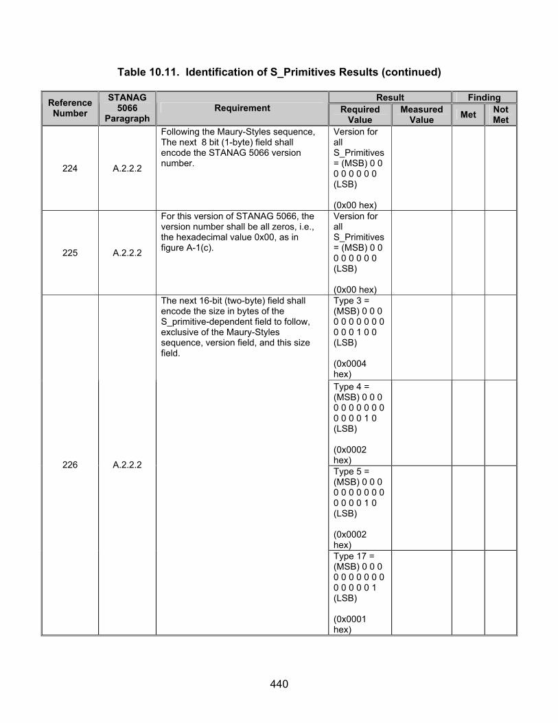
440
Table 10.11. Identification of S_Primitives Results (continued)
Result Finding Reference Number
STANAG 5066
Paragraph Requirement Required
Value Measured
Value Met Not Met
224 A.2.2.2
Following the Maury-Styles sequence, The next 8 bit (1-byte) field shall encode the STANAG 5066 version number.
Version for all S_Primitives= (MSB) 0 0 0 0 0 0 0 0 (LSB) (0x00 hex)
225 A.2.2.2
For this version of STANAG 5066, the version number shall be all zeros, i.e., the hexadecimal value 0x00, as in figure A-1(c).
Version for all S_Primitives= (MSB) 0 0 0 0 0 0 0 0 (LSB) (0x00 hex)
Type 3 = (MSB) 0 0 0 0 0 0 0 0 0 0 0 0 0 1 0 0 (LSB) (0x0004 hex)
Type 4 = (MSB) 0 0 0 0 0 0 0 0 0 0 0 0 0 0 1 0 (LSB) (0x0002 hex)
Type 5 = (MSB) 0 0 0 0 0 0 0 0 0 0 0 0 0 0 1 0 (LSB) (0x0002 hex)
226 A.2.2.2
The next 16-bit (two-byte) field shall encode the size in bytes of the S_primitive-dependent field to follow, exclusive of the Maury-Styles sequence, version field, and this size field.
Type 17 = (MSB) 0 0 0 0 0 0 0 0 0 0 0 0 0 0 0 1 (LSB) (0x0001 hex)

441
Table 10.11. Identification of S_Primitives Results (continued)
Result Finding Reference Number
STANAG 5066
Paragraph Requirement Required
Value Measured
Value Met Not Met
TBD for Type 21
N/A
Type 22 = (MSB) 0 0 0 0 0 0 0 0 0 0 0 1 0 0 1 1 (LSB) (0x0013 hex)
226 A.2.2.2
Type 23 = (MSB) 0 0 0 0 0 0 0 0 0 0 0 1 0 0 1 1 (LSB) (0x0013 hex)

442
Table 10.11. Identification of S_Primitives Results (continued)
Result Finding Reference Number
STANAG 5066
Paragraph Requirement Required
Value Measured
Value Met Not Met
Type 3 = (MSB) 0 0 0 0 0 0 0 0 0 0 0 0 0 1 0 0 (LSB) (0x0004 hex)
Type 4 = (MSB) 0 0 0 0 0 0 0 0 0 0 0 0 0 0 1 0 (LSB) (0x0002 hex)
Type 5 = (MSB) 0 0 0 0 0 0 0 0 0 0 0 0 0 0 1 0 (LSB) (0x0002 hex)
Type 17 = (MSB) 0 0 0 0 0 0 0 0 0 0 0 0 0 0 0 1 (LSB) (0x0001 hex)
227 A.2.2.2
LSB of the size value shall be mapped into the low-order bit of the low-order byte of the field, as follows: figure A-1(c).
TBD for Type 21
N/A
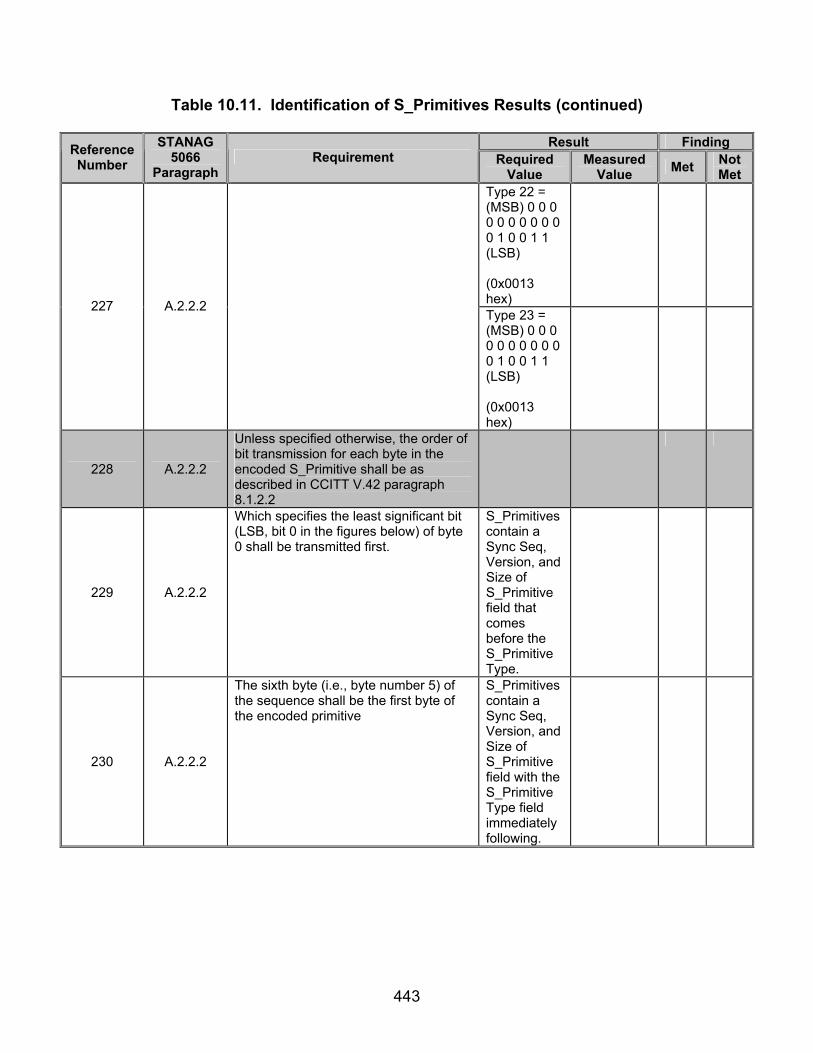
443
Table 10.11. Identification of S_Primitives Results (continued)
Result Finding Reference Number
STANAG 5066
Paragraph Requirement Required
Value Measured
Value Met Not Met
Type 22 = (MSB) 0 0 0 0 0 0 0 0 0 0 0 1 0 0 1 1 (LSB) (0x0013 hex)
227 A.2.2.2
Type 23 = (MSB) 0 0 0 0 0 0 0 0 0 0 0 1 0 0 1 1 (LSB) (0x0013 hex)
228 A.2.2.2
Unless specified otherwise, the order of bit transmission for each byte in the encoded S_Primitive shall be as described in CCITT V.42 paragraph 8.1.2.2
229 A.2.2.2
Which specifies the least significant bit (LSB, bit 0 in the figures below) of byte 0 shall be transmitted first.
S_Primitives contain a Sync Seq, Version, and Size of S_Primitive field that comes before the S_Primitive Type.
230 A.2.2.2
The sixth byte (i.e., byte number 5) of the sequence shall be the first byte of the encoded primitive
S_Primitives contain a Sync Seq, Version, and Size of S_Primitive field with the S_Primitive Type field immediately following.

444
Table 10.11. Identification of S_Primitives Results (continued)
Result Finding Reference Number
STANAG 5066
Paragraph Requirement Required
Value Measured
Value Met Not Met
Type 3 = (MSB) 0 0 0 0 0 0 1 1 (LSB) (0x03 hex)
Type 4 = (MSB) 0 0 0 0 0 1 0 0 (LSB) (0x01 hex)
Type 5 = (MSB) 0 0 0 0 0 1 0 1 (LSB) (0x05 hex)
Type 17 = (MSB) 0 0 0 1 0 0 0 1 (LSB) (0x11 hex)
Type 21 = (MSB) 0 0 0 1 0 1 0 1 (LSB) (0x15 hex)
231 A.2.2.2
And shall be equal to the S_Primitive type number, with values encoded in accordance with the respective section that follows for each S_primitive.
Type 22 = (MSB) 0 0 0 1 0 1 1 0 (LSB) (0x16 hex)

445
Table 10.11. Identification of S_Primitives Results (continued)
Result Finding Reference Number
STANAG 5066
Paragraph Requirement Required
Value Measured
Value Met Not Met
231 A.2.2.2
Type 23 = (MSB) 0 0 0 1 0 1 1 1 (LSB) (0x17 hex)
232 A.2.2.2
The remaining bytes, if any, in the S_Primitive shall be transmitted sequentially, also beginning with the LSB of each byte, in accordance with the respective section that follows for each S_primitive.
S_Primitives specified as in figures 10.5 and 10.7-10.30.
233 A.2.2.2
In the subsections that follow, any bits in a S_Primitive that are specified as NOT USED shall be encoded with the value (0) unless specified otherwise for the specific S_Primitive being defined.
Type 3 Unused bits = 0 0 0 0
234 A.2.2.3
The S_BIND_REQUEST primitive shall be encoded as a four-byte field as in figure A-2.
Type 1 S_Primitive specified as in figure 10.5.
235 A.2.2.3
The S_BIND_REQUEST SERVICE-TYPE field shall be encoded as five subfields as in figure A-3.
Service Type as specified as in figure 10.6.
236 A.2.2.3 The Service Type argument shall specify the default type of service requested by the client.
See table 10.14.
237 A.2.2.3
This type of service shall apply to any U_PDU submitted by the client until the client unbinds itself from the node, unless overridden by the Delivery Mode argument of the U_PDU.
Delivery Modes for Type 20 S_Primitive = Service Types for Type 1 S_Primitive.
238 A.2.2.3
A client shall change the default service type only by unbinding and binding again with a new S_BIND_REQUEST.
Configurable parameters are unchange-able while client is bounded to server computer.
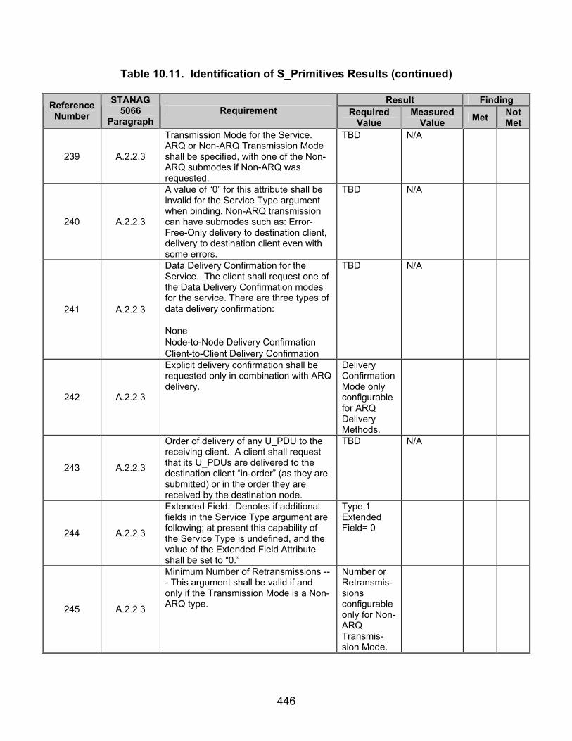
446
Table 10.11. Identification of S_Primitives Results (continued)
Result Finding Reference Number
STANAG 5066
Paragraph Requirement Required
Value Measured
Value Met Not Met
239 A.2.2.3
Transmission Mode for the Service. ARQ or Non-ARQ Transmission Mode shall be specified, with one of the Non-ARQ submodes if Non-ARQ was requested.
TBD N/A
240 A.2.2.3
A value of “0” for this attribute shall be invalid for the Service Type argument when binding. Non-ARQ transmission can have submodes such as: Error-Free-Only delivery to destination client, delivery to destination client even with some errors.
TBD N/A
241 A.2.2.3
Data Delivery Confirmation for the Service. The client shall request one of the Data Delivery Confirmation modes for the service. There are three types of data delivery confirmation:
None Node-to-Node Delivery Confirmation Client-to-Client Delivery Confirmation
TBD N/A
242 A.2.2.3
Explicit delivery confirmation shall be requested only in combination with ARQ delivery.
Delivery Confirmation Mode only configurable for ARQ Delivery Methods.
243 A.2.2.3
Order of delivery of any U_PDU to the receiving client. A client shall request that its U_PDUs are delivered to the destination client “in-order” (as they are submitted) or in the order they are received by the destination node.
TBD N/A
244 A.2.2.3
Extended Field. Denotes if additional fields in the Service Type argument are following; at present this capability of the Service Type is undefined, and the value of the Extended Field Attribute shall be set to “0.”
Type 1 Extended Field= 0
245 A.2.2.3
Minimum Number of Retransmissions --- This argument shall be valid if and only if the Transmission Mode is a Non-ARQ type.
Number or Retransmis-sions configurable only for Non-ARQ Transmis-sion Mode.

447
Table 10.11. Identification of S_Primitives Results (continued)
Result Finding Reference Number
STANAG 5066
Paragraph Requirement Required
Value Measured
Value Met Not Met
246 A.2.2.3
If the Transmission Mode is a Non-ARQ type, then the subnetwork shall retransmit each U_PDU the number of times specified by this argument. This argument may be “0”, in which case the U_PDU is sent only once.
U_PDUs retransmit-ted a number of times equal to the value of the configured number of retransmis-sion field.
247 A.2.2.4
The S_UNBIND_REQUEST primitive shall be encoded as a one-byte field as in figure A-4.
Type 2 S_Primitive encoded as in figure 10.7.
248 A.2.2.5
The S_BIND_ACCEPTED primitive shall be encoded as a four-byte field as in figure A-5.
Type 3 S_Primitive encoded as in figure 10.8.
249 A.2.2.6
The S_BIND_REJECTED primitive shall be encoded as a two-byte field as in figure A-6.
Type 4 S_Primitive encoded as in figure 10.9.
250 A.2.2.7
The S_UNBIND_INDICATION primitive shall be encoded as a two-byte field as in figure A-7.
Type 5 S_Primitive encoded as in figure 10.10.
251 A.2.2.8 The S_HARD_LINK_ESTABLISH primitive shall be encoded as a six-byte field as in figure A-8.
TBD N/A
252 A.2.2.8 The Remote Node Address field shall be encoded as specified in STANAG 5066, section A.2.2.28.1.
TBD N/A
253 A.2.2.8 The Link Type field shall be encoded as specified in STANAG 5066, section A.2.2.28.4.
TBD N/A
254 A.2.2.9 The S_HARD_LINK_TERMINATE primitive shall be encoded as a 5-byte field as shown in figure A-9.
TBD N/A
255 A.2.2.9 The Remote Node Address field shall be encoded as specified in STANAG 5066, section A.2.2.28.1
TBD N/A

448
Table 10.11. Identification of S_Primitives Results (continued)
Result Finding Reference Number
STANAG 5066
Paragraph Requirement Required
Value Measured
Value Met Not Met
256 A.2.2.9 The Link Type field shall be encoded as specified in STANAG 5066, section A.2.2.28.4.
TBD N/A
257 A.2.2.10 The S_HARD_LINK_ESTABLISHED primitive shall be encoded as a 7-byte field as in figure A-10.
TBD N/A
258 A.2.2.10 The Remote Node Address field shall be encoded as specified in STANAG 5066, section A.2.2.28.1.
TBD N/A
259 A.2.2.10 The Link Type field shall be encoded as specified in STANAG 5066, section A.2.2.28.4.
TBD N/A
260 A.2.2.11 The S_HARD_LINK_REJECTED primitive shall be encoded as a 7-byte field as in figure A-11.
TBD N/A
261 A.2.2.11 The Remote Node Address field shall be encoded as specified in STANAG 5066, section A.2.2.28.1.
TBD N/A
262 A.2.2.11 The Link Type field shall be encoded as specified in STANAG 5066, section A.2.2.28.4.
TBD N/A
263 A.2.2.12 The S_HARD_LINK_TERMINATED primitive shall be encoded as a 7-byte field as in figure A-12.
TBD N/A
264 A.2.2.12 The Remote Node Address field shall be encoded as specified in STANAG 5066, section A.2.2.28.1.
TBD N/A
265 A.2.2.12 The Link Type field shall be encoded as specified in STANAG 5066, section A.2.2.28.4.
TBD N/A
266 A.2.2.13 The S_HARD_LINK_INDICATION primitive shall be encoded as a 7-byte field as in figure in A-13.
TBD N/A
267 A.2.2.13 The Remote Node Address field shall be encoded as specified in STANAG 5066, section A.2.2.28.1.
TBD N/A
268 A.2.2.13 The Link Type field shall be encoded as specified in STANAG 5066, section A.2.2.28.4.
TBD N/A
269 A.2.2.14 The S_HARD_LINK_ACCEPT primitive shall be encoded as a 6-byte field as in figure A-14.
TBD N/A
270 A.2.2.14 The Remote Node Address field shall be encoded as specified in STANAG 5066, section A.2.2.28.1.
TBD N/A
271 A.2.2.14 The Link Type field shall be encoded as specified in STANAG 5066, section A.2.2.28.4.
TBD N/A

449
Table 10.11. Identification of S_Primitives Results (continued)
Result Finding Reference Number
STANAG 5066
Paragraph Requirement Required
Value Measured
Value Met Not Met
272 A.2.2.15 The S_HARD_LINK_REJECT primitive shall be encoded as a 7-byte field as in figure A-15.
TBD N/A
273 A.2.2.15 The Remote Node Address field shall be encoded as specified in STANAG 5066, section A.2.2.28.1
TBD N/A
274 A.2.2.15 The Link Type field shall be encoded as specified in STANAG 5066, section A.2.2.28.4.
TBD N/A
277 A.2.2.18
The S_KEEP_ALIVE primitive shall be encoded as a one-byte field as in figure A-18.
Type 17 S_Primitive encoded as in figure 10.21.
279 A.2.2.20
The S_UNIDATA_REQUEST primitive shall be encoded as a variable-length field as in figure A-19.
Type 20 S_Primitive encoded as in figure 10.23.
280 A.2.2.20
The Source Node Address and Destination Node Address fields shall be encoded as specified in section A.2.2.28.1.
See table 10.15.
281 A.2.2.20
The Delivery Mode field shall be encoded as specified in section A.2.2.28.2.
Delivery Mode encoded as in figure 10.29.
282 A.2.2.21
The S_UNIDATA_INDICATION primitive shall be encoded as a variable-length field as in figure A-21.
Type 21 S_Primitive encoded as in figure 10.24.
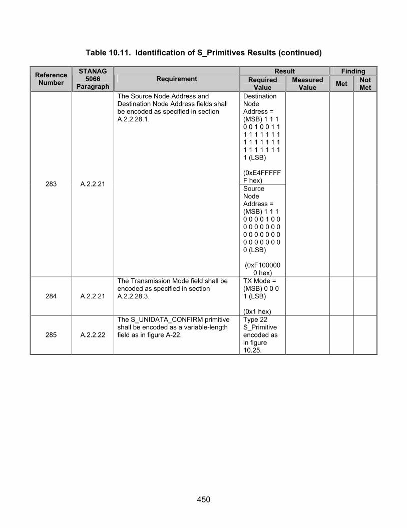
450
Table 10.11. Identification of S_Primitives Results (continued)
Result Finding Reference Number
STANAG 5066
Paragraph Requirement Required
Value Measured
Value Met Not Met
Destination Node Address = (MSB) 1 1 1 0 0 1 0 0 1 1 1 1 1 1 1 1 1 1 1 1 1 1 1 1 1 1 1 1 1 1 1 1 (LSB)
(0xE4FFFFFF hex) 283 A.2.2.21
The Source Node Address and Destination Node Address fields shall be encoded as specified in section A.2.2.28.1.
Source Node Address = (MSB) 1 1 1 0 0 0 0 1 0 0 0 0 0 0 0 0 0 0 0 0 0 0 0 0 0 0 0 0 0 0 0 0 (LSB) (0xF100000
0 hex)
284 A.2.2.21
The Transmission Mode field shall be encoded as specified in section A.2.2.28.3.
TX Mode = (MSB) 0 0 0 1 (LSB) (0x1 hex)
285 A.2.2.22
The S_UNIDATA_CONFIRM primitive shall be encoded as a variable-length field as in figure A-22.
Type 22 S_Primitive encoded as in figure 10.25.
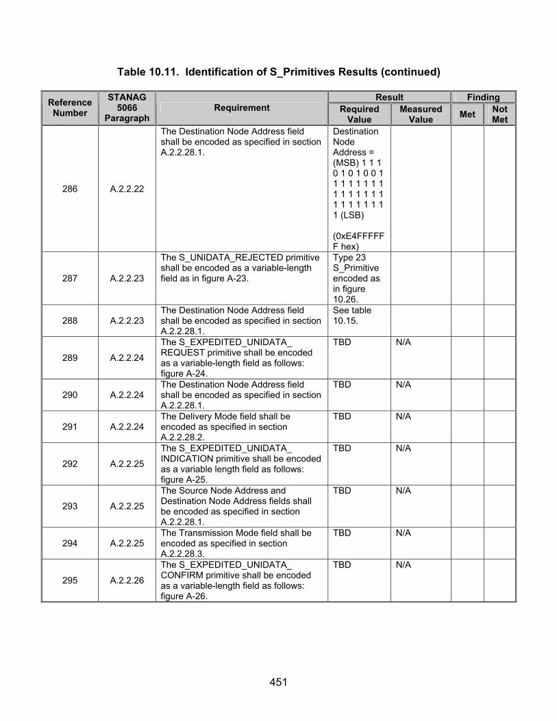
451
Table 10.11. Identification of S_Primitives Results (continued)
Result Finding Reference Number
STANAG 5066
Paragraph Requirement Required
Value Measured
Value Met Not Met
286 A.2.2.22
The Destination Node Address field shall be encoded as specified in section A.2.2.28.1.
Destination Node Address = (MSB) 1 1 1 0 1 0 1 0 0 1 1 1 1 1 1 1 1 1 1 1 1 1 1 1 1 1 1 1 1 1 1 1 (LSB)
(0xE4FFFFFF hex)
287 A.2.2.23
The S_UNIDATA_REJECTED primitive shall be encoded as a variable-length field as in figure A-23.
Type 23 S_Primitive encoded as in figure 10.26.
288 A.2.2.23 The Destination Node Address field shall be encoded as specified in section A.2.2.28.1.
See table 10.15.
289 A.2.2.24
The S_EXPEDITED_UNIDATA_ REQUEST primitive shall be encoded as a variable-length field as follows: figure A-24.
TBD N/A
290 A.2.2.24 The Destination Node Address field shall be encoded as specified in section A.2.2.28.1.
TBD N/A
291 A.2.2.24 The Delivery Mode field shall be encoded as specified in section A.2.2.28.2.
TBD N/A
292 A.2.2.25
The S_EXPEDITED_UNIDATA_ INDICATION primitive shall be encoded as a variable length field as follows: figure A-25.
TBD N/A
293 A.2.2.25
The Source Node Address and Destination Node Address fields shall be encoded as specified in section A.2.2.28.1.
TBD N/A
294 A.2.2.25 The Transmission Mode field shall be encoded as specified in section A.2.2.28.3.
TBD N/A
295 A.2.2.26
The S_EXPEDITED_UNIDATA_ CONFIRM primitive shall be encoded as a variable-length field as follows: figure A-26.
TBD N/A

452
Table 10.11. Identification of S_Primitives Results (continued)
Result Finding Reference Number
STANAG 5066
Paragraph Requirement Required
Value Measured
Value Met Not Met
296 A.2.2.26 The Destination Node Address field shall be encoded as specified in section A.2.2.28.1.
TBD N/A
297 A.2.2.27
The S_EXPEDITED_UNIDATA_ REJECTED primitive shall be encoded as a variable-length field as follows: figure A-27
TBD N/A
298 A.2.2.27 The Destination Node Address field shall be encoded as specified in section A.2.2.28.1.
See table 10.15.
299 A.2.2.28.1
For reduced overhead in transmission, node addresses shall be encoded in one of several formats that are multiples of 4 bits (“half-bytes”) in length, as specified in figure A-28.
See table 10.15.
300 A.2.2.28.1
Addresses that are encoded as Group node addresses shall only be specified as the Destination Node address of Non-ARQ PDUs.
Only Non-ARQ transmission mode used with group address.
301 A.2.2.28.1
Destination SAP IDs and destination node addresses of ARQ PDUs and source SAP IDs and source node addresses of all PDUs shall be individual SAP IDs and individual node addresses respectively.
Each node has its own SAP ID and node address.
302 A.2.2.28.1
Remote node addresses and remote SAP IDs of all “S_HARD_LINK” primitives shall be individual SAP IDs and individual node addresses respectively.
TBD N/A
303 A.2.2.28.2
The Delivery Mode is a complex argument consisting of a number of attributes, as specified here. The Delivery Mode argument shall be encoded as shown in figure A-29.
Delivery Mode encoded as in figure 10.29.
304 A.2.2.28.2
The value of the Delivery Mode argument can be “DEFAULT,” as encoded by the Transmission Mode attribute. With a value of “DEFAULT,” the delivery mode for this U_PDU shall be the delivery mode specified in the Service Type argument of the S_BIND_REQUEST.
Values of Delivery mode = Values for Service Type from Type 1 S_Primitive.
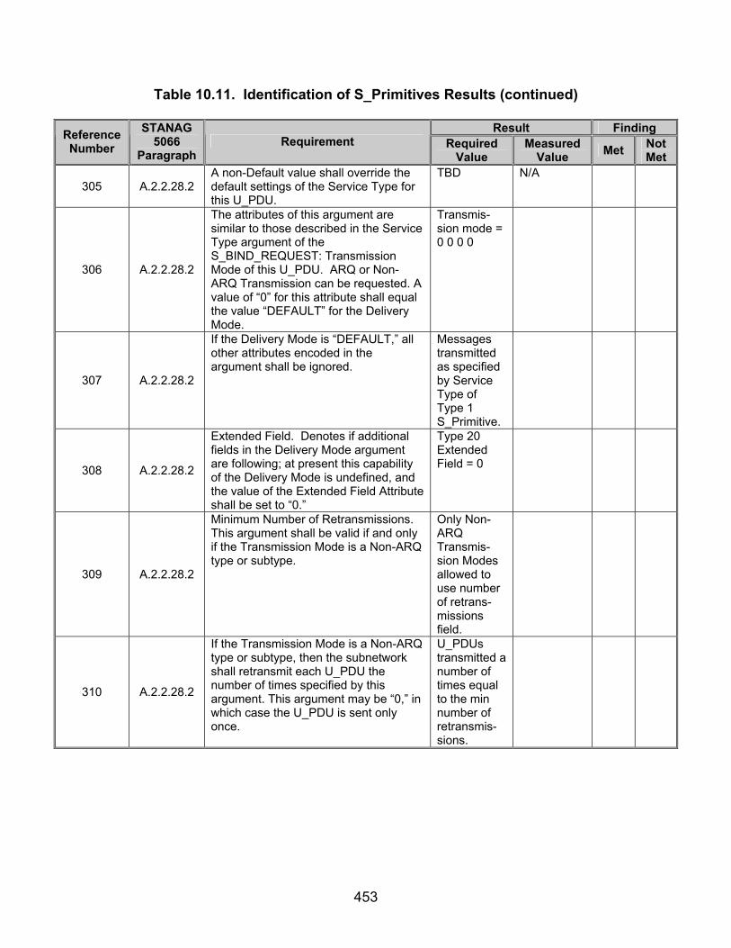
453
Table 10.11. Identification of S_Primitives Results (continued)
Result Finding Reference Number
STANAG 5066
Paragraph Requirement Required
Value Measured
Value Met Not Met
305 A.2.2.28.2 A non-Default value shall override the default settings of the Service Type for this U_PDU.
TBD N/A
306 A.2.2.28.2
The attributes of this argument are similar to those described in the Service Type argument of the S_BIND_REQUEST: Transmission Mode of this U_PDU. ARQ or Non-ARQ Transmission can be requested. A value of “0” for this attribute shall equal the value “DEFAULT” for the Delivery Mode.
Transmis-sion mode = 0 0 0 0
307 A.2.2.28.2
If the Delivery Mode is “DEFAULT,” all other attributes encoded in the argument shall be ignored.
Messages transmitted as specified by Service Type of Type 1 S_Primitive.
308 A.2.2.28.2
Extended Field. Denotes if additional fields in the Delivery Mode argument are following; at present this capability of the Delivery Mode is undefined, and the value of the Extended Field Attribute shall be set to “0.”
Type 20 Extended Field = 0
309 A.2.2.28.2
Minimum Number of Retransmissions. This argument shall be valid if and only if the Transmission Mode is a Non-ARQ type or subtype.
Only Non-ARQ Transmis-sion Modes allowed to use number of retrans-missions field.
310 A.2.2.28.2
If the Transmission Mode is a Non-ARQ type or subtype, then the subnetwork shall retransmit each U_PDU the number of times specified by this argument. This argument may be “0,” in which case the U_PDU is sent only once.
U_PDUs transmitted a number of times equal to the min number of retransmis-sions.

454
Table 10.11. Identification of S_Primitives Results (continued)
Result Finding Reference Number
STANAG 5066
Paragraph Requirement Required
Value Measured
Value Met Not Met
311 A.2.2.28.3
The Transmission-Mode argument in the S_UNIDATA_INDICATION and S_EXPEDITED_UNIDATA_ INDICATION Primitives shall be encoded as shown in figure A-30.
TX Mode = (MSB) 0 0 0 1 (LSB) for Type 21 S_Primitive (0x1 hex)
312 A.2.2.28.4
A client uses the Link-Type argument to reserve partially or fully the capacity of the Hard Link. This argument can have three values: A value of (0) shall indicate that the physical link to the specified node address is a Type 0 Hard Link. The Type 0 Hard Link must be maintained, but all clients connected to the two nodes can make use of the link capacity according to normal procedures, i.e., there is no bandwidth reservation.
TBD N/A
313 A.2.2.28.4
A value of 1 shall indicate that the physical link to the specified node address is a Type 1 Hard Link. The Type 1 Hard Link must be maintained and traffic is only allowed between the requesting client and any of the clients on the remote Node, i.e., there is partial bandwidth reservation. A value of 2 indicates that the physical link to the specified node address must be maintained and traffic is only allowed between the requesting Client and the specific Client on the remote node specified by the Remote SAP ID argument, i.e., full bandwidth reservation.
TBD N/A
328 A.3.1.1
The “PRIORITY” field shall be equal in value to the corresponding argument of the S_UNIDATA_REQUEST primitive submitted by the client.
TBD N/A
331 A.3.1.1
The Destination SAP ID shall be equal in value to the corresponding argument of the S_UNIDATA_REQUEST primitive submitted by the client.
TBD N/A
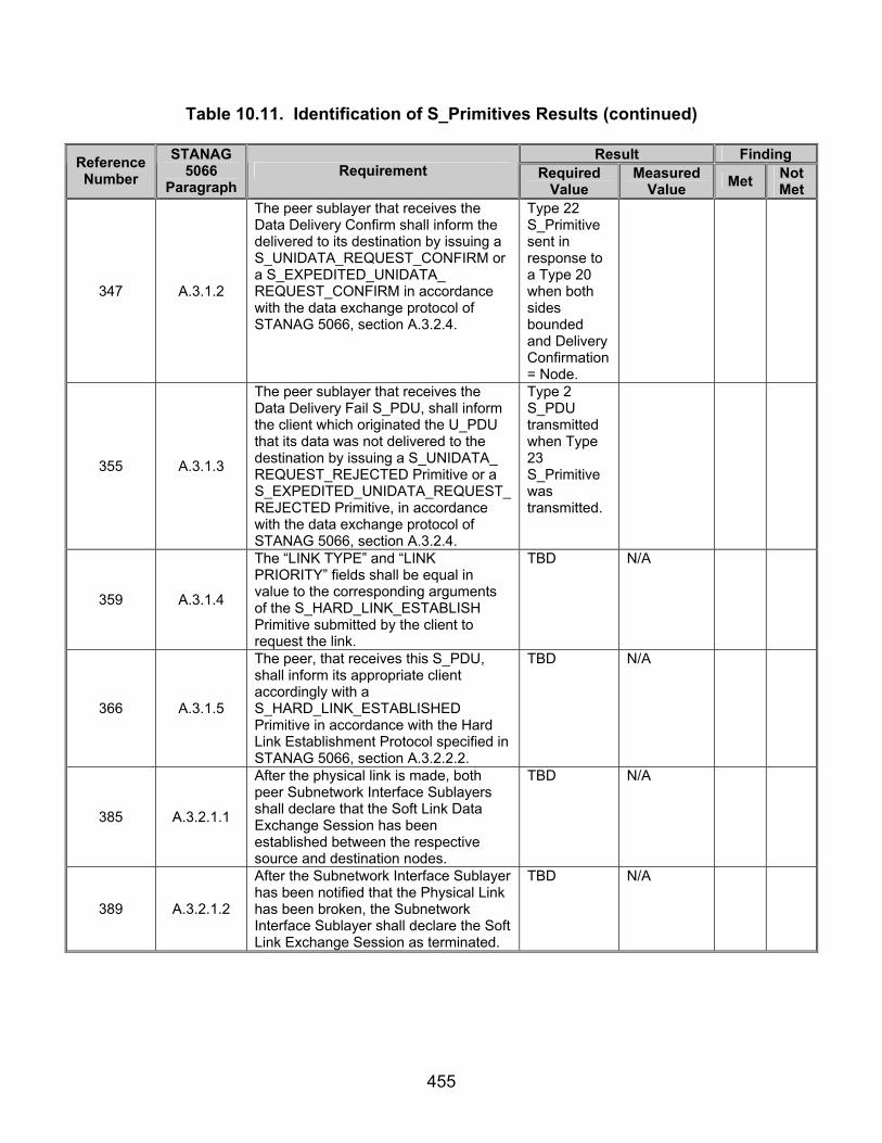
455
Table 10.11. Identification of S_Primitives Results (continued)
Result Finding Reference Number
STANAG 5066
Paragraph Requirement Required
Value Measured
Value Met Not Met
347 A.3.1.2
The peer sublayer that receives the Data Delivery Confirm shall inform the delivered to its destination by issuing a S_UNIDATA_REQUEST_CONFIRM or a S_EXPEDITED_UNIDATA_ REQUEST_CONFIRM in accordance with the data exchange protocol of STANAG 5066, section A.3.2.4.
Type 22 S_Primitive sent in response to a Type 20 when both sides bounded and Delivery Confirmation= Node.
355 A.3.1.3
The peer sublayer that receives the Data Delivery Fail S_PDU, shall inform the client which originated the U_PDU that its data was not delivered to the destination by issuing a S_UNIDATA_ REQUEST_REJECTED Primitive or a S_EXPEDITED_UNIDATA_REQUEST_REJECTED Primitive, in accordance with the data exchange protocol of STANAG 5066, section A.3.2.4.
Type 2 S_PDU transmitted when Type 23 S_Primitive was transmitted.
359 A.3.1.4
The “LINK TYPE” and “LINK PRIORITY” fields shall be equal in value to the corresponding arguments of the S_HARD_LINK_ESTABLISH Primitive submitted by the client to request the link.
TBD N/A
366 A.3.1.5
The peer, that receives this S_PDU, shall inform its appropriate client accordingly with a S_HARD_LINK_ESTABLISHED Primitive in accordance with the Hard Link Establishment Protocol specified in STANAG 5066, section A.3.2.2.2.
TBD N/A
385 A.3.2.1.1
After the physical link is made, both peer Subnetwork Interface Sublayers shall declare that the Soft Link Data Exchange Session has been established between the respective source and destination nodes.
TBD N/A
389 A.3.2.1.2
After the Subnetwork Interface Sublayer has been notified that the Physical Link has been broken, the Subnetwork Interface Sublayer shall declare the Soft Link Exchange Session as terminated.
TBD N/A

456
Table 10.11. Identification of S_Primitives Results (continued)
Result Finding Reference Number
STANAG 5066
Paragraph Requirement Required
Value Measured
Value Met Not Met
396 A.3.2.1.2
If an existing Type 0 Hard Link can satisfy a request that has been rejected, the sublayer shall note this as the reason for rejecting the request; the requesting client may then submit data for transmission using a Soft Link Data Exchange Session.
TBD N/A
404 A.3.2.2.2
Upon receiving a S_HARD_LINK_ESTABLISH Primitive from a client, the Subnetwork Interface Sublayer shall first check that it can accept the request from the client in accordance with the precedence and priority rules of section A.3.2.2.1.
TBD N/A
405 A.3.2.2.2
If the Hard Link request is of lower precedence than any existing Hard Link, then the establishment protocol proceeds as follows:
TBD N/A
406 A.3.2.2.2 The request shall be denied by the Subnetwork Interface Sublayer,
TBD N/A
407 A.3.2.2.2
The sublayer shall issue a S_HARD_LINK_REJECTED Primitive to the requesting client with REASON = “Higher-Priority-Link-Existing”
TBD N/A
408 A.3.2.2.2 The sublayer shall terminate the Hard Link establishment protocol.
TBD N/A
409 A.3.2.2.2
Otherwise, if a Type 0 Hard Link request is of the same priority, same client-rank, and with the same set of source and destination nodes as an existing Hard Link, then the establishment protocol proceeds as follows:
The Subnetwork Interface Sublayer shall reject the Type 0 Hard Link request with the Reason = “Requested Type 0 Hard Link Exists”; a client receiving this rejection may submit data requests for transmission using a Soft Link Data Exchange Session to the remote peer;
TBD N/A
410 A.3.2.2.2
The sublayer shall take no further action to establish or change the status of the existing Type 0 Hard Link (Note: since the sublayer has already determined that the existing link satisfies the requirements of the request),
TBD N/A
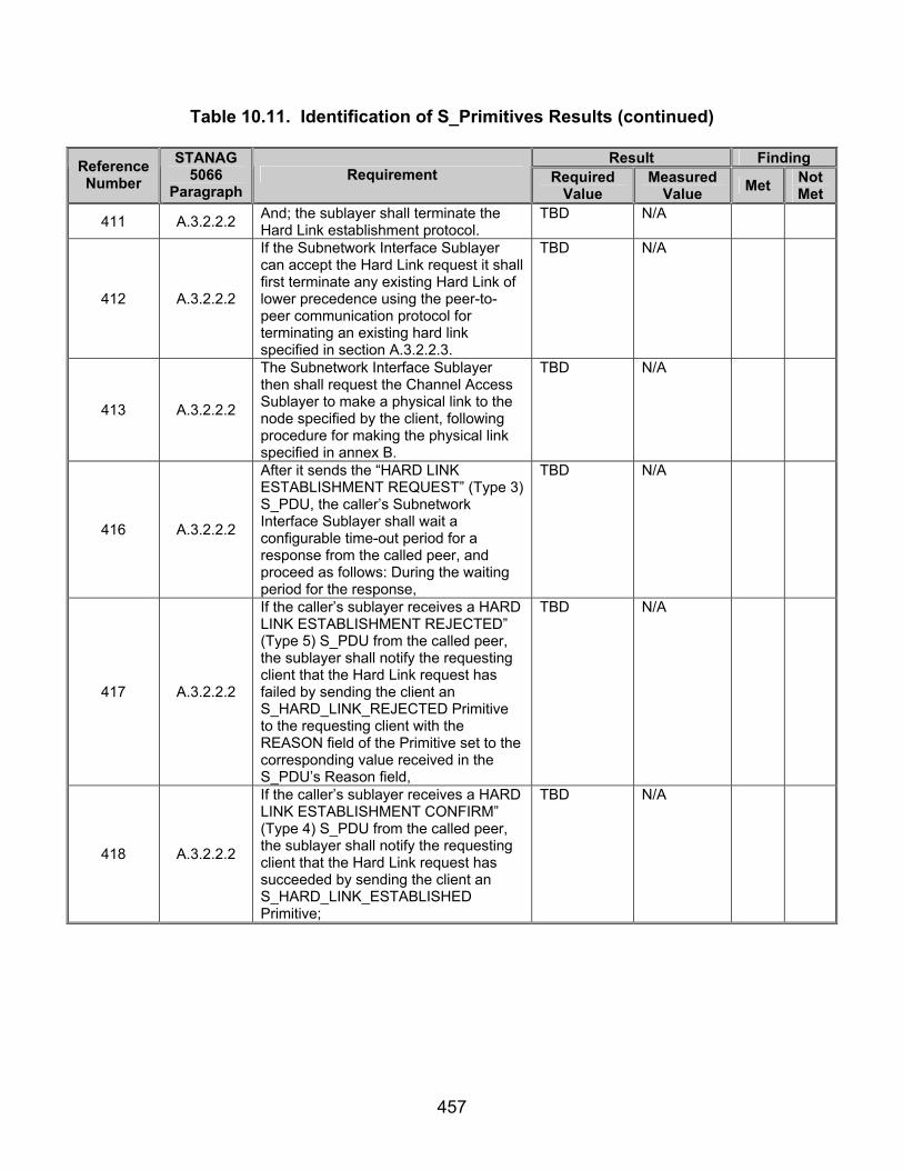
457
Table 10.11. Identification of S_Primitives Results (continued)
Result Finding Reference Number
STANAG 5066
Paragraph Requirement Required
Value Measured
Value Met Not Met
411 A.3.2.2.2 And; the sublayer shall terminate the Hard Link establishment protocol.
TBD N/A
412 A.3.2.2.2
If the Subnetwork Interface Sublayer can accept the Hard Link request it shall first terminate any existing Hard Link of lower precedence using the peer-to-peer communication protocol for terminating an existing hard link specified in section A.3.2.2.3.
TBD N/A
413 A.3.2.2.2
The Subnetwork Interface Sublayer then shall request the Channel Access Sublayer to make a physical link to the node specified by the client, following procedure for making the physical link specified in annex B.
TBD N/A
416 A.3.2.2.2
After it sends the “HARD LINK ESTABLISHMENT REQUEST” (Type 3) S_PDU, the caller’s Subnetwork Interface Sublayer shall wait a configurable time-out period for a response from the called peer, and proceed as follows: During the waiting period for the response,
TBD N/A
417 A.3.2.2.2
If the caller’s sublayer receives a HARD LINK ESTABLISHMENT REJECTED” (Type 5) S_PDU from the called peer, the sublayer shall notify the requesting client that the Hard Link request has failed by sending the client an S_HARD_LINK_REJECTED Primitive to the requesting client with the REASON field of the Primitive set to the corresponding value received in the S_PDU’s Reason field,
TBD N/A
418 A.3.2.2.2
If the caller’s sublayer receives a HARD LINK ESTABLISHMENT CONFIRM” (Type 4) S_PDU from the called peer, the sublayer shall notify the requesting client that the Hard Link request has succeeded by sending the client an S_HARD_LINK_ESTABLISHED Primitive;
TBD N/A

458
Table 10.11. Identification of S_Primitives Results (continued)
Result Finding Reference Number
STANAG 5066
Paragraph Requirement Required
Value Measured
Value Met Not Met
419 A.3.2.2.2
Otherwise, if the waiting-period for the response expires without receipt of a valid response from called node, the caller’s sublayer shall notify the requesting client that the Hard Link request has failed by sending the client an S_HARD_LINK_REJECTED Primitive to the requesting client with: REASON =“Remote-Node-Not Responding.”
TBD N/A
420 A.3.2.2.2
The caller’s establishment protocol shall terminate on receipt during the waiting of a valid response from the called node and notification of the client, or on expiration of the waiting period.
TBD N/A
421 A.3.2.2.2
For the called Subnetwork Access Sublayer, the Hard Link establishment protocol shall be initiated on receipt of a “HARD LINK ESTABLISHMENT REQUEST” (Type 3) S_PDU, and proceeds as follows:
TBD N/A
423 A.3.2.2.2
Otherwise, the called sublayer shall evaluate the precedence of the caller’s request in accordance with the precedence and priority rules of section A.3.2.2.1, using as the client rank either a configurable default rank for the called SAP_ID for Type 0 and Type 1 Hard Link requests, or the actual rank of the bound client with the called SAP_ID for Type 2 Hard Link requests.
TBD N/A
426 A.3.2.2.2
Otherwise, the request is for a Type 2 Hard Link and the called sublayer shall send a S_HARD_LINK_INDICATION Primitive to the requested client, and wait for a configurable maximum time-out period for a response:
TBD N/A
427 A.3.2.2.2
If the called sublayer receives a S_HARD_LINK_ACCEPT Primitive from the requested client prior to the expiration of the time-out, then the called sublayer shall send a “HARD LINK ESTABLISHMENT CONFIRM” (Type 4) S_PDU to the calling sublayer, and terminate the protocol;
TBD N/A

459
Table 10.11. Identification of S_Primitives Results (continued)
Result Finding Reference Number
STANAG 5066
Paragraph Requirement Required
Value Measured
Value Met Not Met
430 A.3.2.2.3
The Hard Link termination protocol shall be initiated when any of the following conditions are met:
A calling sublayer receives a
S_HARD_LINK_TERMINATE Primitive from the client that originated an existing hard link of any type,
A called sublayer receives a S_HARD_LINK_TERMINATE Primitive from its attached client involved in an existing Type 2 Hard Link,
Either the calling or called sublayer receives from a client a S_HARD_LINK_ESTABLISH Primitive that is of higher precedence than any existing Hard Link.
TBD N/A
434 A.3.2.2.3
If the time-out-period expires without receipt by the initiating sublayer of a “HARD LINKTERMINATE CONFIRM” (Type 7) S_PDU, the sublayer shall send a S_HARD_LINK_TERMINATED Primitive to all clients using the Hard Link, with the REASON field set equal to “Remote Node Not Responding (time-out).”
TBD N/A
435 A.3.2.2.3
In particular, the “HARD LINK TERMINATE” (Type 6) S_PDU and “HARD LINK TERMINATE CONFIRM” (Type 7) S_PDU shall be sent to the Channel Access Sublayer using a C_EXPEDITED_UNIDATA_REQUEST Primitive.
TBD N/A
436 A.3.2.2.3
Apart from the procedures above, a sublayer shall unilaterally declare a Hard Link as terminated if at any time it is informed by the Channel Access Sublayer that the physical link has been permanently broken.
TBD N/A
437 A.3.2.2.3
In this case, the sublayer shall send a S_HARD_LINK_TERMINATED Primitive to all clients using the Hard Link, with the REASON field set equal to “Physical Link Broken.”
TBD N/A
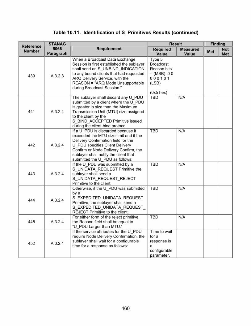
460
Table 10.11. Identification of S_Primitives Results (continued)
Result Finding Reference Number
STANAG 5066
Paragraph Requirement Required
Value Measured
Value Met Not Met
439 A.3.2.3
When a Broadcast Data Exchange Session is first established the sublayer shall send an S_UNBIND_INDICATION to any bound clients that had requested ARQ Delivery Service, with the REASON = “ARQ Mode Unsupportable during Broadcast Session.”
Type 5 Broadcast Reason bits = (MSB) 0 0 0 0 0 1 0 1 (LSB) (0x5 hex)
441 A.3.2.4
The sublayer shall discard any U_PDU submitted by a client where the U_PDU is greater in size than the Maximum Transmission Unit (MTU) size assigned to the client by the S_BIND_ACCEPTED Primitive issued during the client-bind protocol.
TBD N/A
442 A.3.2.4
If a U_PDU is discarded because it exceeded the MTU size limit and if the Delivery Confirmation field for the U_PDU specifies Client Delivery Confirm or Node Delivery Confirm, the sublayer shall notify the client that submitted the U_PDU as follows:
TBD N/A
443 A.3.2.4
If the U_PDU was submitted by a S_UNIDATA_REQUEST Primitive the sublayer shall send a S_UNIDATA_REQUEST_REJECT Primitive to the client;
TBD N/A
444 A.3.2.4
Otherwise, if the U_PDU was submitted by a S_EXPEDITED_UNIDATA_REQUEST Primitive, the sublayer shall send a S_EXPEDITED_UNIDATA_REQUEST_REJECT Primitive to the client;
TBD N/A
445 A.3.2.4 For either form of the reject primitive, the Reason field shall be equal to “U_PDU Larger than MTU.”
TBD N/A
452 A.3.2.4
If the service attributes for the U_PDU require Node Delivery Confirmation, the sublayer shall wait for a configurable time for a response as follows:
Time to wait for a response is a configurable parameter.

461
Table 10.11. Identification of S_Primitives Results (continued)
Result Finding Reference Number
STANAG 5066
Paragraph Requirement Required
Value Measured
Value Met Not Met
453 A.3.2.4
If the sublayer receives a C_UNIDATA_REQUEST_CONFIRM Primitive or a C_EXPEDITED_ UNIDATA_ REQUEST_CONFIRM Primitive prior to the end of the waiting time, the sublayer shall send to the client either a S_UNIDATA_ REQUEST_CONFIRM Primitive or S_EXPEDITED_UNIDATA_REQUEST_CONFIRM Primitive, respectively, where the type of C_Primitive expected and S_Primitive sent corresponds to the type of U_PDU delivery service requested;
TBD N/A
454 A.3.2.4
Otherwise, if the sublayer receives a C_UNIDATA_REQUEST_REJECT Primitive or a C_EXPEDITED_ UNIDATA_REQUEST_REJECT Primitive prior to the end of the waiting time, the sublayer shall send to the client a either a S_UNIDATA_ REQUEST_REJECT Primitive or S_EXPEDITED_UNIDATA_REQUEST_CONFIRM REJECT, respectively, where the type of C_Primitive expected and S_Primitive sent corresponds to the type of U_PDU delivery service requested;
Type 23 S_Primitive sent with response = 0x3
455
A.3.2.4
Otherwise, if the waiting time ends prior to receipt of any response indication from the Channel Access sublayer, the Subnetwork Interface sublayer shall send to the client either a S_UNIDATA_REQUEST_REJECT Primitive, if the U_PDU was submitted by a S_UNIDATA_REQUEST Primitive, or a S_EXPEDITED_UNIDATA_ REQUEST_REJECT Primitive, if the U_PDU was submitted by a S_EXPEDITED_UNIDATA_REQUEST Primitive; for either reject S_Primitive, the REASON field shall be set equal to “Destination Node Not Responding.”
Type 23 S_Primitive sent
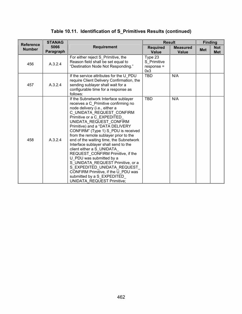
462
Table 10.11. Identification of S_Primitives Results (continued)
Result Finding Reference Number
STANAG 5066
Paragraph Requirement Required
Value Measured
Value Met Not Met
456 A.3.2.4
For either reject S_Primitive, the Reason field shall be set equal to “Destination Node Not Responding.”
Type 23 S_Primitive response = 0x3
457 A.3.2.4
If the service attributes for the U_PDU require Client Delivery Confirmation, the sending sublayer shall wait for a configurable time for a response as follows:
TBD N/A
458 A.3.2.4
If the Subnetwork Interface sublayer receives a C_Primitive confirming no node delivery (i.e., either a C_UNIDATA_REQUEST_CONFIRM Primitive or a C_EXPEDITED_ UNIDATA_REQUEST_CONFIRM Primitive) and a “DATA DELIVERY CONFIRM” (Type 1) S_PDU is received from the remote sublayer prior to the end of the waiting time, the Subnetwork Interface sublayer shall send to the client either a S_UNIDATA_ REQUEST_CONFIRM Primitive, if the U_PDU was submitted by a S_UNIDATA_REQUEST Primitive, or a S_EXPEDITED_UNIDATA_REQUEST_CONFIRM Primitive, if the U_PDU was submitted by a S_EXPEDITED_ UNIDATA_REQUEST Primitive;
TBD N/A

463
Table 10.11. Identification of S_Primitives Results (continued)
Result Finding Reference Number
STANAG 5066
Paragraph Requirement Required
Value Measured
Value Met Not Met
459 A.3.2.4
Otherwise, if the Subnetwork Interface sublayer receives either a “reject” C_Primitive from the Channel Access Sublayer or a “DATA DELIVERY FAIL” (Type 2) S_PDU from the remote peer prior to the end of the waiting time, the Subnetwork Interface sublayer shall send to the client either a S_UNIDATA_REQUEST_REJECT Primitive, if the U_PDU was submitted by a S_UNIDATA_REQUEST Primitive or a S_EXPEDITED_UNIDATA_ REQUEST_REJECT Primitive, if the U_PDU was submitted by a S_EXPEDITED_UNIDATA_REQUEST Primitive; for either form of the primitive, the Reason field shall (459) be taken from the “DATA DELIVERY FAIL” (Type 2) S_PDU or the reject C_Primitive that was received;
TBD N/A
460 A.3.2.4
Otherwise, if the waiting time ends prior to receipt of a response message, the sublayer shall send to the client either a S_UNIDATA_REQUEST_REJECT Primitive, if the U_PDU was submitted by a S_UNIDATA_REQUEST Primitive, or a S_EXPEDITED_UNIDATA_ REQUEST_REJECT Primitive, if the U_PDU was submitted by a S_EXPEDITED_UNIDATA_REQUESTPrimitive; for either Primitive, the REASON field shall (461) be set equal to “Destination Node Not Responding.”
TBD N/A
461 A.3.2.4
On completion of these actions by the sending sublayer the client data delivery protocol terminates for the given Data (Type 0) S_PDU.
TBD N/A
463 A.3.2.4
The receiving sublayer shall extract the U_PDU, Destination SAP_ID and the other associated service attributes from the Data (Type 0) S_PDUs as required;
TBD N/A
464 A.3.2.4
If there is no client bound to the destination SAP_ID, the receiving sublayer shall discard the U_PDU by; otherwise,
U_PDU not delivered.

464
Table 10.11. Identification of S_Primitives Results (continued)
Result Finding Reference Number
STANAG 5066
Paragraph Requirement Required
Value Measured
Value Met Not Met
465 A.3.2.4
If the Data (Type 0) S_PDU was encoded within a C_UNIDATA_INDICATION Primitive, the sublayer shall deliver the extracted U_PDU to the destination client bound to Destination SAP_ID using a S_UNIDATA_INDICATION Primitive;
Type 21 S_Primitive transmitted to computer 198.154.74.160.
466 A.3.2.4
If the DATA (Type 0) S_PDU was encoded within a C_EXPEDITED_ UNIDATA_INDICATION Primitive, the sublayer shall deliver the extracted U_PDU to the destination client bound to Destination SAP_ID using a S_EXPEDITED_UNIDATA_ INDICATION Primitive.
TBD N/A
470 A.3.2.4
Implementation-dependent queuing disciplines, flow-control procedures, or other characteristics in the sublayer shall not preclude the possibility of managing the data exchange protocol for more than one U_PDU at a time.
TBD N/A
Legend: ARQ—Automatic Repeat-Request CCITT—Consultative Committee for International Telephone and Telegraph D_PDU—Data Transfer Sublayer Protocol Data Unit EMCON—Emission Control GMT---Greenwich Mean Time hex—hexadecimal HF—High Frequency ID—Identification LSB—Least Significant Bit MSB—Most Significant Bit
MTU—Maximum Transmission Unit PDU—Protocol Data Unit S_PDU—Subnetwork Interface Sublayer Protocol Data Unit SAP—Subnetwork Access Point seq—sequence STANAG—Standardization Agreement sync—synchronization TBD—To Be Determined TTD—Time To Die TTL—Time To Live U_PDU—User Protocol Data Unit

465
Table 10.12. Required Binary Values for SAP IDs
SAP ID Binary Value (MSB) to (LSB)
0 0 0 0 0 1 0 0 0 1 2 0 0 1 0 3 0 0 1 1 4 0 1 0 0 5 0 1 0 1 6 0 1 1 0 7 0 1 1 1 8 1 0 0 0 9 1 0 0 1 10 1 0 1 0 11 1 0 1 1 12 1 1 0 0 13 1 1 0 1 14 1 1 1 0 15 1 1 1 1
Legend: ID—Identification, LSB—Least Significant Bit, MSB—Most Significant Bit, SAP—Subnetwork Access Point
Table 10.13. Required Binary Values for Priorities
Priority Binary Value (MSB) to (LSB)
0 0 0 0 0 1 0 0 0 1 2 0 0 1 0 3 0 0 1 1 4 0 1 0 0 5 0 1 0 1 6 0 1 1 0 7 0 1 1 1 8 1 0 0 0 9 1 0 0 1 10 1 0 1 0 11 1 0 1 1 12 1 1 0 0 13 1 1 0 1 14 1 1 1 0 15 1 1 1 1
Legend: LSB—Least Significant Bit, MSB—Most Significant Bit

466
Table 10.14. Required Values for Destination Node Address and Corresponding Fields
Trial/Node Address
Size
Destination Node
Address
Binary Node Address Size
Group Address
Destination Address
1
(MSB) 0 0 1 0 0 0 1 0 (LSB)
(0x22 hex)
(MSB) 0 0 1 (LSB)
0 (MSB) 0 0 1 0 (LSB)
(0x2 hex)
2
(MSB) 0 1 0 0 1 1 1 1 1 1 1 1
(LSB)
(0x4FF hex)
(MSB) 0 1 0 (LSB)
0 (MSB) 1 1 1 1 1 1 1 1 (LSB)
(0xFF hex)
3
(MSB) 0 1 1 0 1 1 1 1 1 1 1 1 1 1 1 1(LSB)
(0x6FFF hex)
(MSB) 0 1 1 (LSB)
0 (MSB) 1 1 1 1 1 1 1 1 1 1 1 1(LSB)
(0xFFF hex)
4
(MSB) 1 0 0 0 1 1 1 1 1 1 1 1 1 1 1 1 1 1 1 1
(LSB)
(0x8FFFF hex)
(MSB) 1 0 0 (LSB)
0 (MSB) 1 1 1 1 1 1 1 1 1 1 1 1 1 1 1 1 (LSB)
(0xFFFF hex)
5
(MSB) 1 0 1 0 1 1 1 1 1 1 1 1 1 1 1 1 1 1 1 1 1 1 1 1 (LSB)
(0xAFFFFF
hex)
(MSB) 1 0 1 (LSB)
0 (MSB) 1 1 1 1 1 1 1 1 1 1 1 1 1 1 1 1 1 1 1
1 (LSB)
(0xFFFFF hex)
6
(MSB) 1 1 0 0 1 1 1 1 1 1 1 1 1 1 1 1 1 1 1 1 1 1 1 1 1 1 1 1
(LSB)
(0xCFFFFFF hex)
(MSB) 1 1 0 (LSB)
0 (MSB) 1 1 1 1 1 1 1 1 1 1 1 1 1 1 1 1 1 1 1
1 1 1 1 1 (LSB)
(0xFFFFFF hex)
7
(MSB) 1 1 1 1 0 1 0 0 1 1 1 1 1 1 1 1 1 1 1 1 1 1 1 1 1 1 1 1
(LSB)
(0xE4FFFFFF hex)
(MSB) 1 1 1 (LSB)
1 (MSB) 0 1 0 0 1 1 1 1 1 1 1 1 1 1 1 1 1 1 1
1 1 1 1 1 (LSB) (0x4FFFFFF hex)
Legend: hex—hexadecimal, LSB—Least Significant Bit, MSB—Most Significant Bit

467
Table 10.15. Measured Binary Values for SAP IDs
SAP ID Binary Value (MSB) to (LSB)
Legend: ID—Identification, LSB—Least Significant Bit, MSB—Most Significant Bit, SAP—Subnetwork Access Point
Table 10.16. Measured Binary Values for Priorities
Priority Binary Value (MSB) to (LSB)
Legend: LSB—Least Significant Bit, MSB—Most Significant Bit
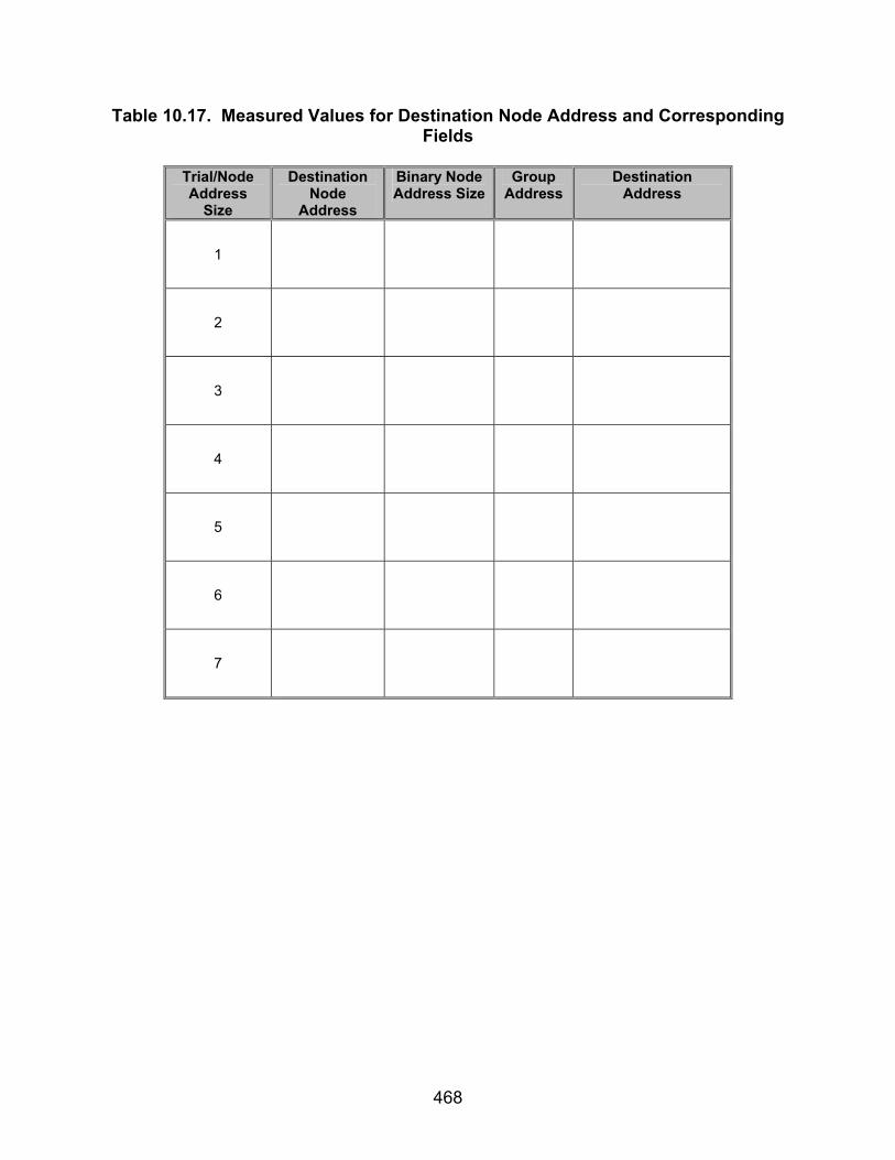
468
Table 10.17. Measured Values for Destination Node Address and Corresponding Fields
Trial/Node Address
Size
Destination Node
Address
Binary Node Address Size
Group Address
Destination Address
1
2
3
4
5
6
7

469
SUBTEST 11. COMMON D_PDU FIELDS 11.1 Objective. To determine the extent of compliance to the requirements of STANAG 5066, for validating the Common Data Transfer Sublayer Protocol Data Unit (D_DPU) Fields, reference numbers 501, 569, 571, 575-576, 579, 581, 588-589, 599-606, 608-609, 611, 613-616, 622-623, 627-641, 643-644, 646-648, 862-863, and 926. 11.2 Criteria
a. The delivery mode specified by the Subnetwork Interface Sublayer for the encapsulated S_PDU (i.e., ARQ, Non-ARQ, etc.) also shall be assigned to the C_PDU by the Channel Access Sublayer as the delivery mode to be provided by the lower sublayer. (appendix B, reference number 501)
b. Depending on the application and service-type requested by higher sublayers, the user-service provided by the Data Transfer Sublayer shall be either a simple Non-ARQ service, commonly known as broadcast mode, or a reliable selective ARQ service, as specified herein. (appendix B, reference number 569)
c. In the Non-ARQ service error-check bits (i.e., CRC bits) applied to the D_DPU shall be used to detect errors. (appendix B, reference number 571) d. The interface must support the service-definition for the Data Transfer Sublayer, i.e.: (appendix B, reference numbers 575-576, 579, and 581)
• The interface shall allow the Channel Access Sublayer to submit protocol data units (i.e., C_PDUs) for transmission using the regular and expedited delivery services provided by the Data Transfer Sublayer.
• The interface shall permit the Data Transfer Sublayer to specify the delivery services that were used by received C_PDUs when it submits them to the Channel Access Sublayer.
• The interface shall permit the Data Transfer Sublayer to specify the source address from which C_PDUs are received and the destination address to which they had been sent.
e. In order to provide the data transfer services specified herein, the Data Transfer Sublayer shall exchange protocol data units (D_PDUs) with its peer(s). (appendix B, reference number 588) f. The Data Transfer Sublayer shall use the D_PDU Types (Note: D_PDU Types displayed as referenced in table 14.1) to support the Selective ARQ service and Non-ARQ service, including the several data transfer submodes defined herein. (appendix B, reference number 589)

470
g. All D_PDUs, regardless of type, shall begin with the same 16-bit sync sequence. (appendix B, reference number 599)
h. The 16-bit sequence shall be the 16-bit Maury-Styles (0xEB90) sequence
shown below, with the LSB transmitted first: (appendix B, reference number 600)
(MSB) 1 1 1 0 1 0 1 1 1 0 0 1 0 0 0 0 (LSB)
i. The first 4 bytes of all D_PDU headers shall contain the same fields: (appendix B, reference numbers 601-605)
• A 4-bit D_PDU Type field that shall identify the type of D_PDU. • A 12-bit field that shall contain an EOW message. • An 8-bit field that shall contain the EOT information. • A 1-byte field that shall contain both a Size of Address field (3 bits) and
a Size of Header (5 bits) field.
j. The next 1 to 7 bytes of every header, as specified in the Size of Address field, shall contain source and destination address information for the D_PDU. (appendix B, reference number 606)
k. The last 2 bytes of every header shall contain the CRC calculated in
accordance with STANAG 5066, section C.3.2.8 (appendix B, reference number 608) l. The bits in any field in a D_PDU that is specified as NOT USED shall
contain the value zero (0). (appendix B, reference number 609) m. The value of the D_PDU Type number shall be used to indicate the
D_PDU Type. The 4 bits available allow for 16 D_PDU Types. (appendix B, reference number 611)
n. The 12-bit EOW field shall carry management messages for the EOW.
EOW messages may not be explicitly acknowledged, although the D_PDU of which they are a part may be. EOW messages can be explicitly acknowledged when they are contained in the Management Type 6 D_PDU through which management-level acknowledgement services are provided in the Data Transfer Sublayer. (appendix B, reference number 613)
o. Figure 11.1 shows the generic 12-bit EOW structure. The first 4 bits of the
EOW shall contain the EOW-type field, which identifies the type of EOW message. (appendix B, reference number 614)
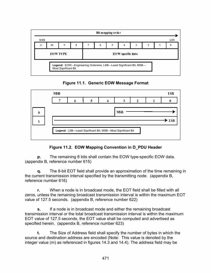
471
Figure 11.1. Generic EOW Message Format
Figure 11.2. EOW Mapping Convention in D_PDU Header
p. The remaining 8 bits shall contain the EOW type-specific EOW data.
(appendix B, reference number 615) q. The 8-bit EOT field shall provide an approximation of the time remaining in
the current transmission interval specified by the transmitting node. (appendix B, reference number 616)
r. When a node is in broadcast mode, the EOT field shall be filled with all zeros, unless the remaining broadcast transmission interval is within the maximum EOT value of 127.5 seconds. (appendix B, reference number 622)
s. If a node is in broadcast mode and either the remaining broadcast transmission interval or the total broadcast transmission interval is within the maximum EOT value of 127.5 seconds, the EOT value shall be computed and advertised as specified herein. (appendix B, reference number 623)
t. The Size of Address field shall specify the number of bytes in which the source and destination address are encoded (Note: This value is denoted by the integer value (m) as referenced in figures 14.3 and 14.4). The address field may be
Legend: EOW—Engineering Orderwire, LSB—Least Significant Bit, MSB—Most Significant Bit
Legend: LSB—Least Significant Bit, MSB—Most Significant Bit
472
from 1 to 7 bytes in length, with the source and destination address of equal length. (appendix B, reference number 627)
u. Since the D_PDU header must be made up of an integer number of bytes, addresses shall be available in 4-bit increments of size: 4 bits (or 0.5 bytes), 1 byte, 1.5 bytes, 2 bytes, 2.5 bytes, 3 bytes, and 3.5 bytes. (appendix B, reference number 628)
v. The Size of Header field shall specify the number of bytes in which the
D_PDU is encoded. (Note: This value is denoted by the integer value (h), as referenced in figures 14.3 and 14.4), and its value includes the sizes of the following fields and elements: (appendix B, reference number 629)
• D_PDU Type • EOW • EOT • Size of Address Field • Size of Header Field • D_PDU Type-Specific Header • CRC Field
w. The value of the Size-of-Header field shall not include the size of the
source and destination address field. (appendix B, reference number 630) x. Each D_PDU transmitted by a node shall contain the source and
destination address. Half of the bits are assigned to the source and the other half to the destination. (appendix B, reference number 631)
y. The first half shall be the destination address, and the second half shall be
the source address as displayed nominally in figure 11.3 (which assumes an odd-number as the address-field size) or figure 11.4 (which assumes an even-number as the address-field size). (appendix B, reference numbers 632 and 633)

473
Figure 11.3. Address Mapping Convention in D_PDU Header, Assuming Address-
Field Size is Odd
Figure 11.4. Address Mapping Convention in D_PDU Header, Assuming Address-
Field Size is Even
z. Addresses shall be in the form of a binary number. With 7 bytes available for each of the user and the destination, the smallest possible address field is 4 bits and the largest possible is 3.5 bytes, or 28 bits. This allows more than 268 million addresses, if the maximum field size is used. (appendix B, reference number 634)
aa. A decimal number shall represent each byte or fractional byte of an
address, and the binary equivalent shall be mapped into the corresponding byte. (appendix B, reference numbers 635 and 636)
ab. Any fractional-byte elements in the address shall be mapped into the first
(leftmost) nonzero number in the decimal representation of the address. (appendix B, reference number 637)
Legend: D_PDU—Data Transfer Sublayer Protocl Data Unit, LSB—Least Significant Bit, MSB—Most Significant Bit
Legend: D_PDU—Data Transfer Sublayer Protocl Data Unit, LSB—Least Significant Bit, MSB—Most Significant Bit

474
ac. The remaining numbers in the decimal representation of the address shall
refer to byte-sized elements in the address field. (appendix B, reference number 638) ad. The address bits shall be mapped into the address field by placing the
MSB of the address into the MSB of the first byte of the address field and the LSB into the LSB of the last byte of the field, in accordance with figure 11.3, for addresses with length of 0.5, 1.5, 2.5, or 3.5 bytes, and figure 11.4, for addresses with length of 1, 2, or 3 bytes. (appendix B, reference number 639)
ae. When a field spans more than one octet, the order of the bit values within
each octet shall decrease progressively as the octet number increases. (appendix B, reference number 640)
af. Trailing address bytes that are zero shall be sent. (appendix B, reference
number 641) ag. The 2 bytes following the D_PDU Type-Specific Header shall contain a
16-bit CRC field. (appendix B, reference number 643) ah. The header CRC error-check field shall be calculated using the following
polynomial: x^16 + x^15 + x^12 + x^11 + x^8 + x^6 + x^3 + 1, or in hex format 0x19949, using the shift-register method shown by the figures in appendix I of CCITT, Recommendation V.41 (or equivalent method in software; an example is given below). (appendix B, reference number 644)
ai. The header CRC shall be calculated over all bits in the header, excluding
the Maury-Styles sync sequence and including the following fields and elements: (appendix B, reference number 646)
• D_PDU Type • EOW • EOT • Size of Address Field • Size of Header Field • Source and Destination Address • D_PDU Type-Specific Header
aj. A node shall process the information contained in a header with a valid CRC, regardless of the result of the CRC error-check over any segmented C_PDU that may be a part of the D_PDU. (appendix B, reference number 647).
ak. The CRC bits shall be mapped (see figure 11.5) into the CRC octets by placing the MSB of the CRC into the LSB of the first byte of the CRC field and the LSB of the CRC into the MSB of the last byte of the CRC field. (appendix B, reference number 648)

475
Figure 11.5. CRC Mapping Convention in D_PDU Header
al. The EOW Message Type 4 shall be encoded as shown in figure 11.6 and
contain a single field, Content. (appendix B, reference number 862)
Figure 11.6. Format of Capabilities (Type 4) Management Messages
am. The Content field shall be encoded as the bit-mapped specification of
capabilities defined in table 11.1. (appendix B, reference number 863)
Table 11.1. Contents of Management Field for Management Message Type 4
Bit Meaning 7 (MSB) Adaptive modem parameters (DRC) capable note 1 (0 = no, 1 =yes)
6 STANAG 4529 available note 2 (0 = no, 1 = yes) 5 MIL-STD-188-110A available note 2 (0 = no, 1 = yes) 4 Extended data rate capable note 3 (0 = no, 1 = yes) 3 Full duplex supported note 4 (0 = no, 1 = yes) 2 Split frequency supported note 4 (0 = no, 1 = yes) 1 Non-ARCS ALE capable
0 (LSB) ARCS capable (0 = no, 1 = yes) Legend: ALE—Automatic Link Establishment, ARCS—Acquisition Radar Control System, DRC—Data Rate Change Capable, LSB—Least Significant Bit, MIL-STD—Military Standard, MSB—Most Significant Bit, STANAG—Standardization Agreement
. an. Nodes that do not implement Data Rate Control shall use the appropriate
EOW and Management message types specified in STANAG 5066, section 3.5, and the
Legend: CRC—Cyclic Redundancy Check, D_PDU—Data Transfer Sublayer Protocl Data Unit LSB—Least Significant Bit MSB—Most Significant Bit
Legend: LSB—Least Significant Bit, MSB—Most Significant Bit
476
protocol defined below to signal this condition to other nodes. (appendix B, reference number 926) 11.3 Test Procedures
a. Test Equipment Required (1) Computers (2 ea) with STANAG 5066 Software
(2) Modems (2 ea)
(3) Protocol Analyzer (4) Two Position Switch
(5) HF Simulator (2 ea)
(6) Data Packet Injector
b. Test Configuration. Figures 11.7, 11.8, and 11.9 show the equipment setup for this subtest.
c. Test Conduction. Table 11.2 lists procedures for this subtest and table 11.3 lists the results for this subtest.

477
Computer Modem Modem Computer
LANAnalyzer
RS-232 RS-232
Figure 11.7. Equipment Configuration for Capturing Types 0, 1, 2, 4, 5, 7, and 8 D_PDUs
Computer Modem Modem Computer
LANAnalyzer
RS-232 RS-232
Figure 11.8. Equipment Configuration for Capturing Type 6 D_PDU

478
Computer Modem Modem Computer
LANAnalyzer
RS-232 RS-232
Figure 11.9. Equipment Configuration for Capturing Types 3 and 15 D_PDUs
Table 11.2. Fields in Common Procedures
Step Action Settings/Action Result
1
Set up equipment and configure modems.
See figure 11.7. Computers are connected to the modems by an RS-232 connection. The connection between modems shall be such that the receive and transmit pins on the modem are connected to the transmit and receive pins, respectively, of the other modem. Configure modems to transmit a MIL-STD-188-110B signal at a data rate of 4800 bps with half duplex.
2 Load STANAG 5066 software. Configure the SMTP and POP3 servers
as required by the STANAG 5066 software manual.
3 Configure delivery confirmation. Configure the delivery confirmation to “Client” for both computers.
4
Determine STANAG 5066 capabilities.
Verify which of the following eight capabilities are supported by the STANAG 5066 software under test. (Note: These capabilities are optional and the STANAG 5066 software may not support all of the listed capabilities.)
5 Data rate change capable? Y/N 6 STANAG 4529 available? Y/N 7 MIL-STD-188-110A available? Y/N 8 Extended data rate capable? Y/N 9 Full duplex supported? Y/N
10 Split frequency supported? Y/N 11 Non-ARCS ALE capable? Y/N 12 ARCS capable? Y/N

479
Table 11.2. Fields in Common Procedures (continued)
Step Action Settings/Action Result
13
Determine expected EOW. The first 4 bits of the expected EOW will be the EOW Type field and will be encoded as (MSB) 0 1 0 0 (LSB) (0x4 hex), for all D_PDUs except the Type 6 D_PDU. (The Type 6 D_PDU EOW is reserved for Data Rate Change control and therefore is variable.) The remaining 8 bits within the EOW field are interpreted as follows for all D_PDUs except the Type 6: The entire EOW field is 12 bits in length with the first 4 bits equal to the field “Type.” The remaining 8 bits correspond to one of each of the above capabilities. Each of the eight capabilities specified above shall have a value of either 1 (for ‘yes’) or 0 (for ‘no’) when tested. The order of the bits is the same as the order of the capabilities listed in steps 5-12, starting with step 5 as the MSB and step 12 as the LSB. Record the values in terms of 1s and 0s for the eight fields (including the first 4 bits, the 0 1 0 0 sequence). This will be a total of 12 bits in length. Note: Even though the Type 6 D_PDU’s EOW is variable, this subtest is used to validate that an EOW field exists for the Type 6 D_PDU. The specific interpretations of the EOW field for the Type 6 D_PDU are addressed in Subtest 4.
Expected EOW =
14
Identify client to be used. Configure both computers to use the same client type. Record the client type utilized by the computers.
Client Type =
The following procedures are for Types 0-2 and 8 D_PDUs for reference numbers 501, 569, 571, 575-576, 579, 581, 588-589, 599-606, 608-609, 611, 613-616, 622-623, 627-641, 643-644, 646-648, 862-863, and
926.
15
Configure protocol analyzer. Configure protocol analyzer B to capture the transmitted data between the two computers and save it to a file. Configure the protocol analyzer to have a 4800-bps bit rate and to synchronize on “0xEB90.” Configure protocol analyzer B to drop sync after 20 “0xFFs”. Configure the analyzer to time stamp each captured byte.

480
Table 11.2. Fields in Common Procedures (continued)
Step Action Settings/Action Result
16
Send e-mail message and capture all transmitted and received bytes via the protocol analyzer.
Set the STANAG Node Address Size to 1 byte with the following STANAG addresses: 1 and 15, as shown in figure 11.7. Send the following e-mail message from computer with STANAG address 1 to computer with STANAG address 15, using a Soft Link and Non-Expedited ARQ Delivery Method. For the Subject Line: Test 1 In the Body: “This is a test from address 1 to 15 1 2 3 4 5 6 7 8 9 10” Save the data obtained through the protocol analyzer to a file.
17
Use the following methodology to locate size of address and address fields within any type D_PDU. Identify values for each STANAG Node Address Size and STANAG address listed.
The following address fields are identified and decoded in the following order: The Size of Node Address field is the first 3 bits of the 4th byte within any type D_PDU (not including the initial 2 byte sync sequence). The Node Address field is variable in length, 1 to 7 bytes, and is located 5 bits after the Size of Address field, which is the 5th byte within the D_PDU (not including the sync sequence). The Destination and Source Node Addresses are dependent on the Size of Node Address field and are the values contained within the Node Address field. The first half of the Node Address bits is the Destination Node Address, and the second half is the Source Node Address bits, i.e., if the Size of Node Address= 3 bytes, then the Destination Node Address is the first 12 bits of the Node Address bits and the Source Node Address is the final 12 bits of the Node Address bits. The Decimal Equivalent values for the Destination and Source Node Addresses are computed as follows:
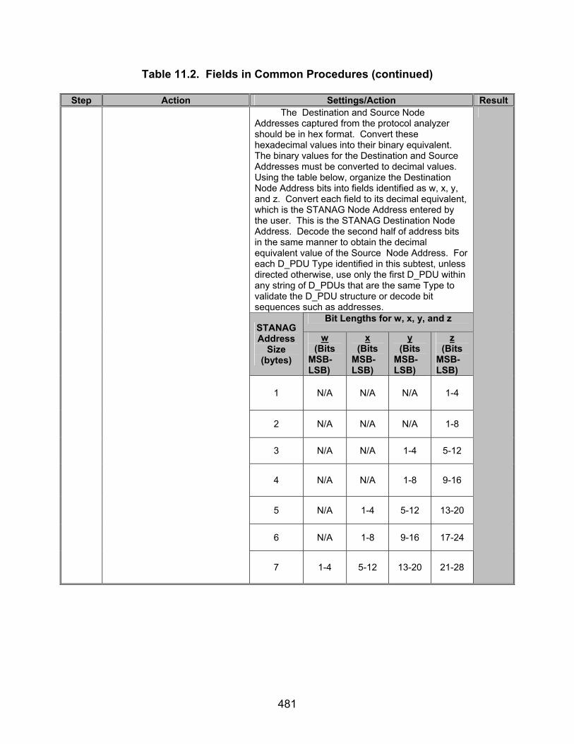
481
Table 11.2. Fields in Common Procedures (continued)
Step Action Settings/Action Result The Destination and Source Node Addresses captured from the protocol analyzer should be in hex format. Convert these hexadecimal values into their binary equivalent. The binary values for the Destination and Source Addresses must be converted to decimal values. Using the table below, organize the Destination Node Address bits into fields identified as w, x, y, and z. Convert each field to its decimal equivalent, which is the STANAG Node Address entered by the user. This is the STANAG Destination Node Address. Decode the second half of address bits in the same manner to obtain the decimal equivalent value of the Source Node Address. For each D_PDU Type identified in this subtest, unless directed otherwise, use only the first D_PDU within any string of D_PDUs that are the same Type to validate the D_PDU structure or decode bit sequences such as addresses.
Bit Lengths for w, x, y, and z STANAG Address
Size (bytes)
w (Bits
MSB-LSB)
x (Bits
MSB-LSB)
y (Bits
MSB-LSB)
z (Bits
MSB-LSB)
1 N/A N/A N/A 1-4
2 N/A N/A N/A 1-8
3 N/A N/A 1-4 5-12
4 N/A N/A 1-8 9-16
5 N/A 1-4 5-12 13-20
6 N/A 1-8 9-16 17-24
7 1-4 5-12 13-20 21-28

482
Table 11.2. Fields in Common Procedures (continued)
Step Action Settings/Action Result
18
Methods to identify the Maury-Styles sync sequence, D_PDU Type, and identify the EOT, EOW, Size of Header, Header CRC, and the Calculated Header CRC for the specified D_PDU Types.
The Maury-Styles sync sequence is the first 16 bits of the D_PDU. This value should be “0x90EB” in hex. The D_PDU Type is encapsulated within the next 4 bits, after the Maury-Styles sync sequence. The EOW bits are the next 12 bits, after the D_PDU Type. The EOT bits are the next 8 bits, after the EOW bits. The Size of Address bits are the next 3 bits after the EOT bits. The Size of Header bits are the next 5 bits, after the Size of Address bits. The CRC bits are the final 16 bits in the header. Use the Size of Header bits to determine where the Header CRC bits begin. Beginning from the byte containing the D_PDU Type, count down a number of bytes equal to the Size of Header plus the Size of Address. The Header CRC bytes are the last 2 bytes counted. Use the following procedure to compute the Calculated Header CRC: Take the bits from the following to calculate the Header CRC: • D_PDU Type • EOW • EOT • Size of Address Field • Size of Header Field • Source and Destination Address • D_PDU Type-Specific Header
Utilizing the Code Example C-1 from in STANAG 5066, section C.3.2.8 for a 16-bit CRC, compute the Calculated CRC for the header. The above bit fields in the header are listed in the order that they will be obtained during the data transfer, so the string of bits starting at D_PDU Type field to the D_PDU Type-Specific Header will be used in the CRC calculation. The D_PDU Type-Specific Header bits include all of the bits between (but not including) the Source and Destination Node Address bits and the CRC bits.

483
Table 11.2. Fields in Common Procedures (continued)
Step Action Settings/Action Result Sync Seq =
Type =
EOW =
EOT =
Size of
Address =
Size of Header =
Node Address =
Split Node Address to its Destination Address. (binary or hexadecimal)
Destination Address =
Split Node Address to its Source Address. (binary or hexadecimal)
Source Address =
Convert Destination Address to its Decimal Destination Address.
Decimal Destination Address =
Convert Source Address to its Decimal Source Address.
Decimal Source Address =
Header CRC =
19
Locate and record the Maury-Styles sync sequence, D_PDU Type, EOW, EOT, Size of Address, Size of Header, Node Address, and Header CRC for the first Type 0 D_PDU located in the file in step 16.
Compute the Calculated Header CRC. Calculated Header CRC =

484
Table 11.2. Fields in Common Procedures (continued)
Step Action Settings/Action Result Sync Seq =
Type =
EOW =
EOT =
Size of
Address =
Size of Header =
Node Address =
Split Node Address to its Destination Address. (binary or hexadecimal)
Destination Address =
Split Node Address to its Source Address. (binary or hexadecimal)
Source Address =
Convert Destination Address to its Decimal Destination Address.
Decimal Destination Address =
Convert Source Address to its Decimal Source Address.
Decimal Source Address =
Header CRC =
20
Locate and record the Maury-Styles Sync Sequence, D_PDU Type, EOW, EOT, Size of Address, Size of Header, Node Address, and Header CRC for the first Type 1 D_PDU located in the file in step 16.
Compute the Calculated Header CRC. Calculated Header CRC =

485
Table 11.2. Fields in Common Procedures (continued)
Step Action Settings/Action Result Sync Seq =
Type =
EOW =
EOT =
Size of
Address =
Size of Header =
Node Address =
Split Node Address to its Destination Address. (binary or hexadecimal)
Destination Address =
Split Node Address to its Source Address. (binary or hexadecimal)
Source Address =
Convert Destination Address to its Decimal Destination Address.
Decimal Destination Address =
Convert Source Address to its Decimal Source Address.
Decimal Source Address=
Header CRC =
21
Locate and record the Maury-Styles Sync Sequence, D_PDU Type, EOW, EOT, Size of Address, Size of Header, Node Address, and Header CRC for the first Type 2 D_PDU located in the file in step 16.
Compute the Calculated Header CRC. Calculated Header CRC =
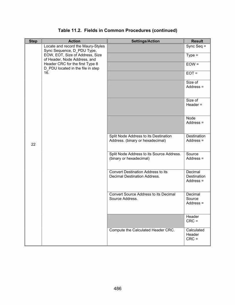
486
Table 11.2. Fields in Common Procedures (continued)
Step Action Settings/Action Result Sync Seq =
Type =
EOW =
EOT =
Size of
Address =
Size of Header =
Node Address =
Split Node Address to its Destination Address. (binary or hexadecimal)
Destination Address =
Split Node Address to its Source Address. (binary or hexadecimal)
Source Address =
Convert Destination Address to its Decimal Destination Address.
Decimal Destination Address =
Convert Source Address to its Decimal Source Address.
Decimal Source Address =
Header CRC =
22
Locate and record the Maury-Styles Sync Sequence, D_PDU Type, EOW, EOT, Size of Address, Size of Header, Node Address, and Header CRC for the first Type 8 D_PDU located in the file in step 16.
Compute the Calculated Header CRC. Calculated Header CRC =
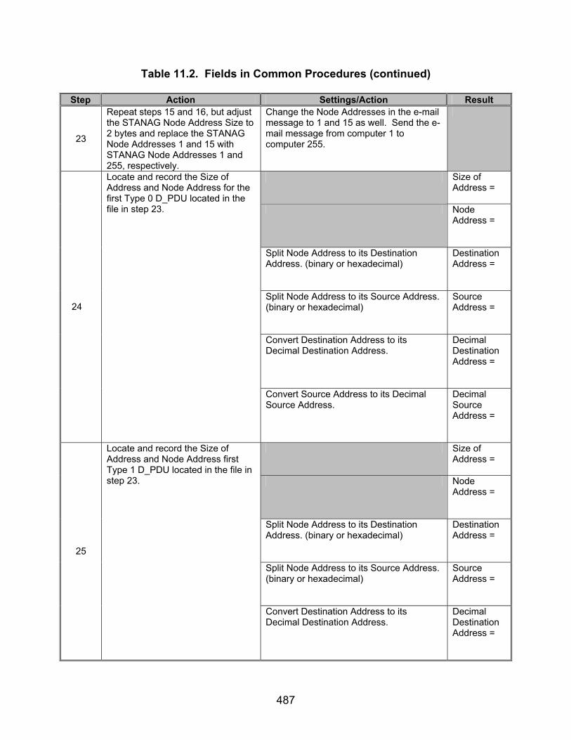
487
Table 11.2. Fields in Common Procedures (continued)
Step Action Settings/Action Result
23
Repeat steps 15 and 16, but adjust the STANAG Node Address Size to 2 bytes and replace the STANAG Node Addresses 1 and 15 with STANAG Node Addresses 1 and 255, respectively.
Change the Node Addresses in the e-mail message to 1 and 15 as well. Send the e-mail message from computer 1 to computer 255.
Size of Address =
Node Address =
Split Node Address to its Destination Address. (binary or hexadecimal)
Destination Address =
Split Node Address to its Source Address. (binary or hexadecimal)
Source Address =
Convert Destination Address to its Decimal Destination Address.
Decimal Destination Address =
24
Locate and record the Size of Address and Node Address for the first Type 0 D_PDU located in the file in step 23.
Convert Source Address to its Decimal Source Address.
Decimal Source Address =
Size of Address =
Node Address =
Split Node Address to its Destination Address. (binary or hexadecimal)
Destination Address =
Split Node Address to its Source Address. (binary or hexadecimal)
Source Address =
25
Locate and record the Size of Address and Node Address first Type 1 D_PDU located in the file in step 23.
Convert Destination Address to its Decimal Destination Address.
Decimal Destination Address =

488
Table 11.2. Fields in Common Procedures (continued)
Step Action Settings/Action Result Convert Source Address to its Decimal
Source Address. Decimal Source Address =
Size of Address =
Node Address =
Split Node Address to its Destination Address. (binary or hexadecimal)
Destination Address =
Split Node Address to its Source Address. (binary or hexadecimal)
Source Address =
Convert Destination Address to its Decimal Destination Address.
Decimal Destination Address =
26
Locate and record the Size of Address and Node Address first Type 2 D_PDU located in the file in step 23.
Convert Source Address to its Decimal Source Address.
Decimal Source Address =
Size of Address =
Node Address =
Split Node Address to its Destination Address. (binary or hexadecimal)
Destination Address =
Split Node Address to its Source Address. (binary or hexadecimal)
Source Address =
27
Locate and record the Size of Address and Node Address first Type 8 D_PDU located in the file in step 23.
Convert Destination Address to its Decimal Destination Address.
Decimal Destination Address =

489
Table 11.2. Fields in Common Procedures (continued)
Step Action Settings/Action Result Convert Source Address to its Decimal
Source Address. Decimal Source Address =
28
Repeat steps 15 and 16, but adjust the STANAG Node Address Size to 3 bytes and replace the STANAG Node Addresses 1 and 255 with STANAG Node Addresses 1.2 and 15.255, respectively.
Change the Node Addresses in the e-mail message to 1.2 and 15.255 as well. Send the e-mail message from computer 1.2 to computer 15.255.
Size of Address =
Node Address =
Split Node Address to its Destination Address. (binary or hexadecimal)
Destination Address =
Split Node Address to its Source Address. (binary or hexadecimal)
Source Address =
Convert Destination Address to its Decimal Destination Address.
Decimal Destination Address =
29
Locate and record the Size of Address and Node Address for the first Type 0 D_PDU located in the file in step 28.
Convert Source Address to its Decimal Source Address.
Decimal Source Address =
Size of Address =
Node Address =
Split Node Address to its Destination Address. (binary or hexadecimal)
Destination Address =
30
Locate and record the Size of Address and Node Address for the first Type 1 D_PDU located in the file in step 28.
Split Node Address to its Source Address. (binary or hexadecimal)
Source Address =
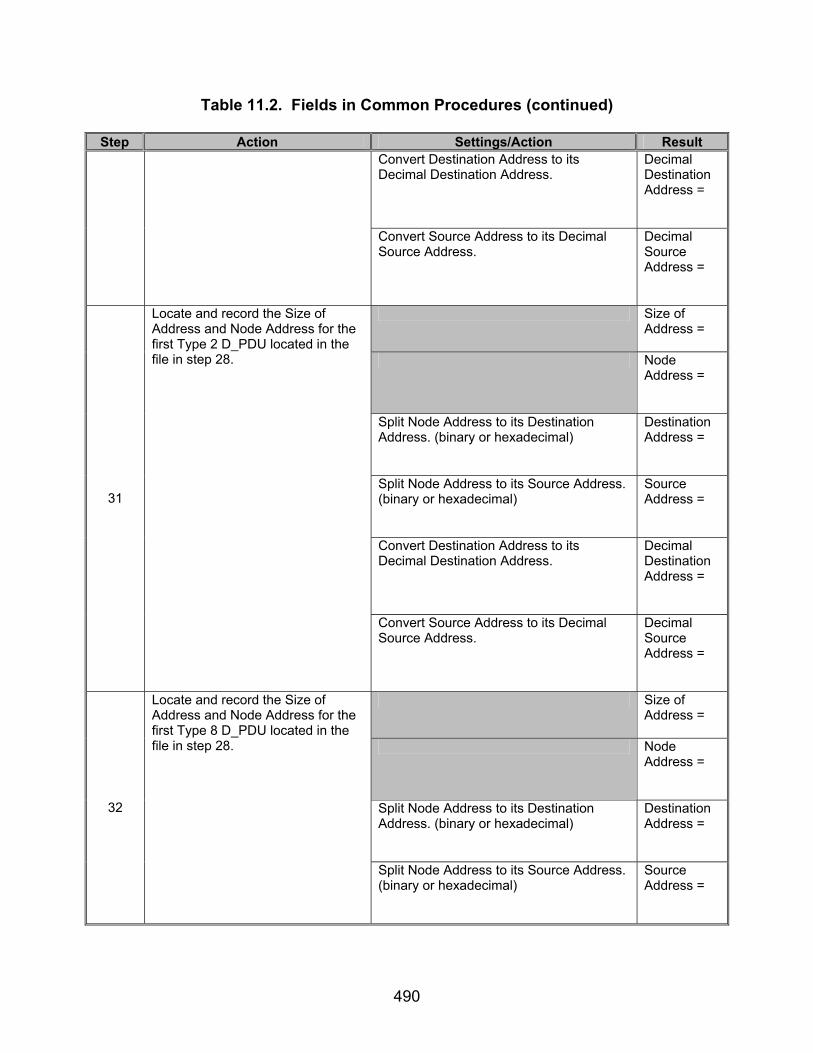
490
Table 11.2. Fields in Common Procedures (continued)
Step Action Settings/Action Result Convert Destination Address to its Decimal Destination Address.
Decimal Destination Address =
Convert Source Address to its Decimal Source Address.
Decimal Source Address =
Size of Address =
Node Address =
Split Node Address to its Destination Address. (binary or hexadecimal)
Destination Address =
Split Node Address to its Source Address. (binary or hexadecimal)
Source Address =
Convert Destination Address to its Decimal Destination Address.
Decimal Destination Address =
31
Locate and record the Size of Address and Node Address for the first Type 2 D_PDU located in the file in step 28.
Convert Source Address to its Decimal Source Address.
Decimal Source Address =
Size of Address =
Node Address =
Split Node Address to its Destination Address. (binary or hexadecimal)
Destination Address =
32
Locate and record the Size of Address and Node Address for the first Type 8 D_PDU located in the file in step 28.
Split Node Address to its Source Address. (binary or hexadecimal)
Source Address =

491
Table 11.2. Fields in Common Procedures (continued)
Step Action Settings/Action Result Convert Destination Address to its Decimal Destination Address.
Decimal Destination Address =
Convert Source Address to its Decimal Source Address.
Decimal Source Address =
33
Repeat steps 15 and 16, but adjust the STANAG Node Address Size to 4 bytes and replace the STANAG Node Addresses 1.2 and 15.255 with STANAG Node Addresses 1.222 and 255.255, respectively.
Change the Node Addresses in the e-mail message to 1.222 and 255.255 as well. Send the e-mail message from computer 1.222 to computer 255.255.
Size of Address =
Node Address =
Split Node Address to its Destination Address. (binary or hexadecimal)
Destination Address =
Split Node Address to its Source Address. (binary or hexadecimal)
Source Address =
Convert Destination Address to its Decimal Destination Address.
Decimal Destination Address =
34
Locate and record the Size of Address and Node Address for the first Type 0 D_PDU in the file located in step 33.
Convert Source Address to its Decimal Source Address.
Decimal Source Address =
Size of Address =
Node Address =
35
Locate and record the Size of Address and Node Address for the first Type 1 D_PDU in the file located in step 33.
Split Node Address to its Destination Address. (binary or hexadecimal)
Destination Address =
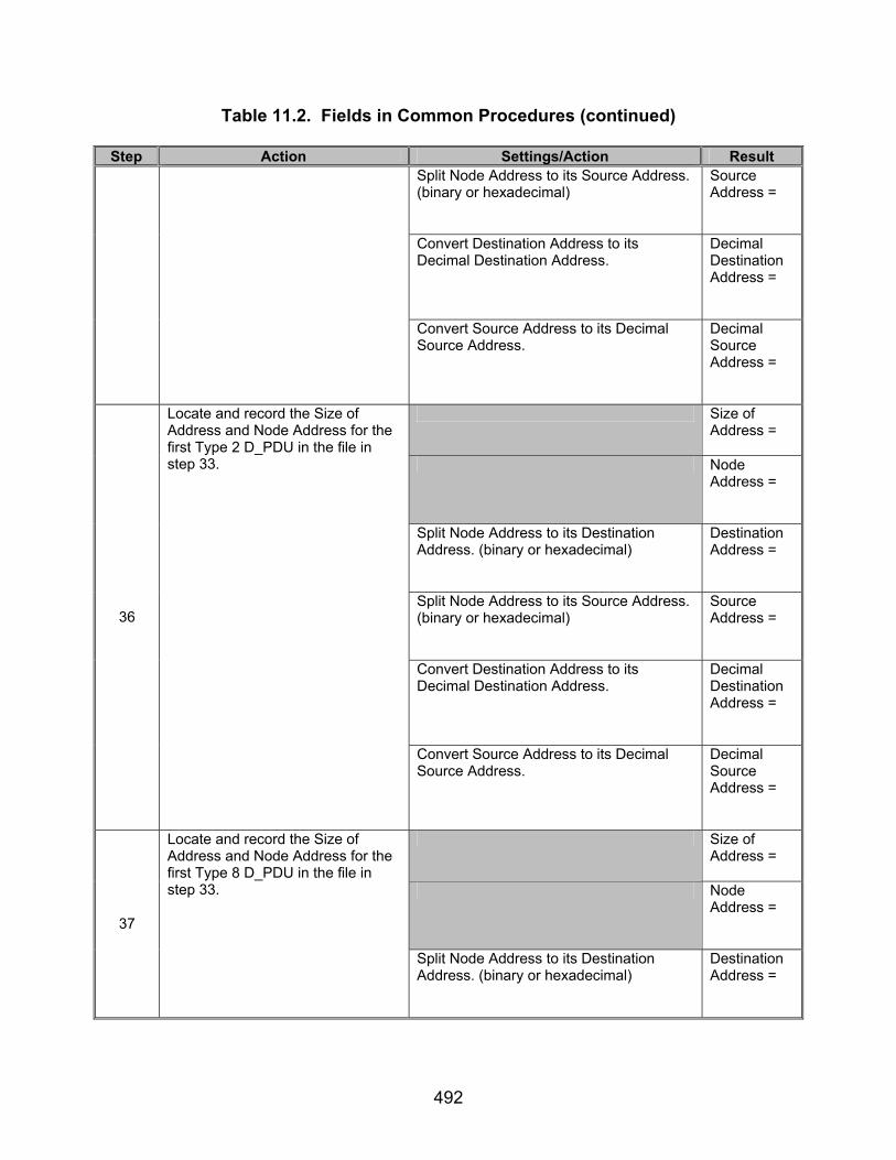
492
Table 11.2. Fields in Common Procedures (continued)
Step Action Settings/Action Result Split Node Address to its Source Address. (binary or hexadecimal)
Source Address =
Convert Destination Address to its Decimal Destination Address.
Decimal Destination Address =
Convert Source Address to its Decimal Source Address.
Decimal Source Address =
Size of Address =
Node Address =
Split Node Address to its Destination Address. (binary or hexadecimal)
Destination Address =
Split Node Address to its Source Address. (binary or hexadecimal)
Source Address =
Convert Destination Address to its Decimal Destination Address.
Decimal Destination Address =
36
Locate and record the Size of Address and Node Address for the first Type 2 D_PDU in the file in step 33.
Convert Source Address to its Decimal Source Address.
Decimal Source Address =
Size of Address =
Node Address =
37
Locate and record the Size of Address and Node Address for the first Type 8 D_PDU in the file in step 33.
Split Node Address to its Destination Address. (binary or hexadecimal)
Destination Address =
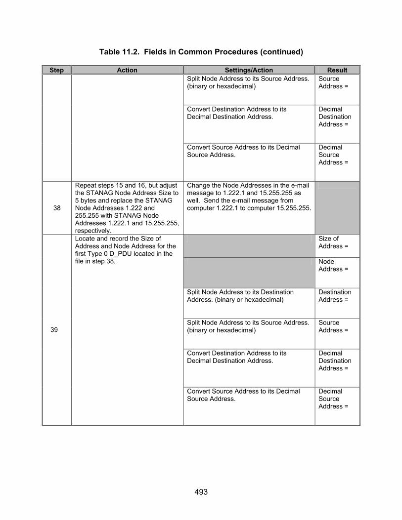
493
Table 11.2. Fields in Common Procedures (continued)
Step Action Settings/Action Result Split Node Address to its Source Address. (binary or hexadecimal)
Source Address =
Convert Destination Address to its Decimal Destination Address.
Decimal Destination Address =
Convert Source Address to its Decimal Source Address.
Decimal Source Address =
38
Repeat steps 15 and 16, but adjust the STANAG Node Address Size to 5 bytes and replace the STANAG Node Addresses 1.222 and 255.255 with STANAG Node Addresses 1.222.1 and 15.255.255, respectively.
Change the Node Addresses in the e-mail message to 1.222.1 and 15.255.255 as well. Send the e-mail message from computer 1.222.1 to computer 15.255.255.
Size of Address =
Node Address =
Split Node Address to its Destination Address. (binary or hexadecimal)
Destination Address =
Split Node Address to its Source Address. (binary or hexadecimal)
Source Address =
Convert Destination Address to its Decimal Destination Address.
Decimal Destination Address =
39
Locate and record the Size of Address and Node Address for the first Type 0 D_PDU located in the file in step 38.
Convert Source Address to its Decimal Source Address.
Decimal Source Address =

494
Table 11.2. Fields in Common Procedures (continued)
Step Action Settings/Action Result Size of
Address =
Node Address =
Split Node Address to its Destination Address. (binary or hexadecimal)
Destination Address =
Split Node Address to its Source Address. (binary or hexadecimal)
Source Address =
Convert Destination Address to its Decimal Destination Address.
Decimal Destination Address =
40
Locate and record the Size of Address and Node Address for the first Type 1 D_PDU located in the file in step 38.
Convert Source Address to its Decimal Source Address.
Decimal Source Address =
Size of Address =
Node Address =
Split Node Address to its Destination Address. (binary or hexadecimal)
Destination Address =
Split Node Address to its Source Address. (binary or hexadecimal)
Source Address =
Convert Destination Address to its Decimal Destination Address.
Decimal Destination Address =
41
Locate and record the Size of Address and Node Address for the first Type 2 D_PDU located in the file in step 38.
Convert Source Address to its Decimal Source Address.
Decimal Source Address =

495
Table 11.2. Fields in Common Procedures (continued)
Step Action Settings/Action Result Size of
Address =
Node Address =
Split Node Address to its Destination Address. (binary or hexadecimal)
Destination Address =
Split Node Address to its Source Address. (binary or hexadecimal)
Source Address =
Convert Destination Address to its Decimal Destination Address.
Decimal Destination Address =
42
Locate and record the Size of Address and Node Address for the first Type 8 D_PDU located in the file in step 38.
Convert Source Address to its Decimal Source Address.
Decimal Source Address =
43
Repeat steps 15 and 16, but adjust the STANAG Node Address Size to 6 bytes and replace the STANAG Node Addresses 1.222.1 and 15.255.255 with 1.222.123 and 255.255.255, respectively.
Change the Node Addresses in the e-mail message to 1.222.123 and 255.255.255 as well. Send the e-mail message from computer 1.222.123 to computer 255.255.255.
Size of Address =
Address = 44
Locate and record the Size of Address and Node Address for the first Type 0 D_PDU. Located in the file in step 43.
Split Node Address to its Destination Address. (binary or hexadecimal)
Destination Address =
Size of Address =
Node Address =
45
Locate and record the Size of Address and Node Address for the first Type 1 D_PDU. Located in the file in step 43.
Split Node Address to its Destination Address. (binary or hexadecimal)
Destination Address =

496
Table 11.2. Fields in Common Procedures (continued)
Step Action Settings/Action Result Split Node Address to its Source Address. (binary or hexadecimal)
Source Address =
Convert Destination Address to its Decimal Destination Address.
Decimal Destination Address =
Convert Source Address to its Decimal Source Address.
Decimal Source Address =
Size of Address =
Node Address =
Split Node Address to its Destination Address. (binary or hexadecimal)
Destination Address =
Split Node Address to its Source Address. (binary or hexadecimal)
Source Address =
Convert Destination Address to its Decimal Destination Address.
Decimal Destination Address =
46
Locate and record the Size of Address and Node Address for the first Type 2 D_PDU. Located in the file in step 43.
Convert Source Address to its Decimal Source Address.
Decimal Source Address =
Size of Address =
Node Address =
47
Locate and record the Size of Address and Node Address for the first Type 8 D_PDU. Located in the file in step 43.
Split Node Address to its Destination Address. (binary or hexadecimal)
Destination Address =

497
Table 11.2. Fields in Common Procedures (continued)
Step Action Settings/Action Result Split Node Address to its Source Address. (binary or hexadecimal)
Source Address =
Convert Destination Address to its Decimal Destination Address.
Decimal Destination Address =
Convert Source Address to its Decimal Source Address.
Decimal Source Address =
Split Node Address to its Source Address. (binary or hexadecimal)
Source Address =
Convert Destination Address to its Decimal Destination Address.
Decimal Destination Address =
Convert Source Address to its Decimal Source Address.
Decimal Source Address =
48
Repeat steps 15 and 16, but adjust the STANAG Node Address Size to 7 bytes and replace the STANAG Node Addresses 1.222.123 and 255.255.255 with 1.222.123.1 and 15.255.255.255, respectively.
Change the Node Addresses in the e-mail message to 1.222.123.1 and 15.255.255.255 as well. Send the e-mail message from computer 1.222.123.1 to computer 15.255.255.255.
Size of Address =
Node Address =
Split Node Address to its Destination Address. (binary or hexadecimal)
Destination Address =
49
Locate and record the Size of Address and Node Address for the first Type 0 D_PDU located in the file in step 48.
Split Node Address to its Source Address. (binary or hexadecimal)
Source Address =

498
Table 11.2. Fields in Common Procedures (continued)
Step Action Settings/Action Result Convert Destination Address to its Decimal Destination Address.
Decimal Destination Address =
Convert Source Address to its Decimal Source Address.
Decimal Source Address =
Size of Address =
Node Address =
Split Node Address to its Destination Address. (binary or hexadecimal)
Destination Address =
Split Node Address to its Source Address. (binary or hexadecimal)
Source Address =
Convert Destination Address to its Decimal Destination Address.
Decimal Destination Address =
50
Locate and record the Size of Address and Node Address for the first Type 1 D_PDU located in the file in step 48.
Convert Source Address to its Decimal Source Address.
Decimal Source Address =
Size of Address =
Node Address =
Split Node Address to its Destination Address. (binary or hexadecimal)
Destination Address =
51
Locate and record the Size of Address and Node Address for the first Type 2 D_PDU located in the file in step 48.
Split Node Address to its Source Address. (binary or hexadecimal)
Source Address =
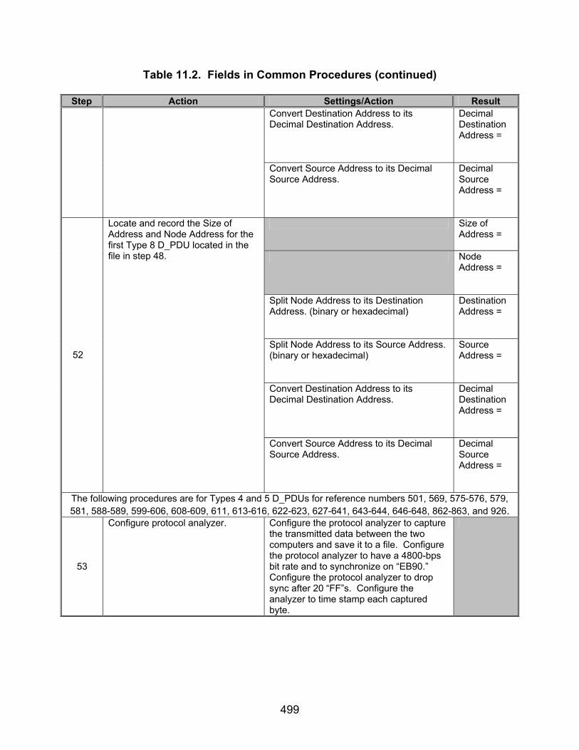
499
Table 11.2. Fields in Common Procedures (continued)
Step Action Settings/Action Result Convert Destination Address to its Decimal Destination Address.
Decimal Destination Address =
Convert Source Address to its Decimal Source Address.
Decimal Source Address =
Size of Address =
Node Address =
Split Node Address to its Destination Address. (binary or hexadecimal)
Destination Address =
Split Node Address to its Source Address. (binary or hexadecimal)
Source Address =
Convert Destination Address to its Decimal Destination Address.
Decimal Destination Address =
52
Locate and record the Size of Address and Node Address for the first Type 8 D_PDU located in the file in step 48.
Convert Source Address to its Decimal Source Address.
Decimal Source Address =
The following procedures are for Types 4 and 5 D_PDUs for reference numbers 501, 569, 575-576, 579, 581, 588-589, 599-606, 608-609, 611, 613-616, 622-623, 627-641, 643-644, 646-648, 862-863, and 926.
53
Configure protocol analyzer. Configure the protocol analyzer to capture the transmitted data between the two computers and save it to a file. Configure the protocol analyzer to have a 4800-bps bit rate and to synchronize on “EB90.” Configure the protocol analyzer to drop sync after 20 “FF”s. Configure the analyzer to time stamp each captured byte.

500
Table 11.2. Fields in Common Procedures (continued)
Step Action Settings/Action Result
54
Send e-mail message and capture all transmitted and received bytes via the protocol analyzer shown in figure 11.7.
Configure the STANAG Node Address Size to 1 byte with the following STANAG addresses: 1 and 15, as shown in figure 11.7. Send the following e-mail message from the computer with STANAG address 1 to the computer with STANAG address 15, using a Soft Link and Expedited ARQ Delivery Method . For the Subject Line: Test 1 In the Body: “This is a test from address 1 to 15 1 2 3 4 5 6 7 8 9 10” Save the data obtained through the protocol analyzer to a file.
55
Locate and record values for each STANAG Node Address Size and STANAG address Listed.
Utilize the instructions specified in step 17 to identify and record the Size of Address, Node Address, Destination and Source Addresses, and the Decimal Destination and Source Addresses.
56
Verify the Maury-Styles Sync Sequence D_PDU Type, and identify the EOT, EOW, Size of Header, Header CRC, and Calculated Header CRC for the specified D_PDU Types.
Utilize the methods specified in step 18 to identify and record the Maury-Styles sync sequence, D_PDU Type, and identify the EOT, EOW, Size of Header, and Header CRC.
Sync Seq =
Type =
EOW =
EOT =
Size of Address =
Size of Header =
57
Locate and record the Maury-Styles Sync Sequence, D_PDU Type, EOW, EOT, Size of Address, Size of Header, Node Address, and Header CRC for the first Type 4 D_PDU located in the file in step 54.
Node Address =

501
Table 11.2. Fields in Common Procedures (continued)
Step Action Settings/Action Result Split Node Address to its Destination Address. (binary or hexadecimal)
Destination Address =
Split Node Address to its Source Address. (binary or hexadecimal)
Source Address =
Convert Destination Address to its Decimal Destination Address.
Decimal Destination Address =
Convert Source Address to its Decimal Source Address.
Decimal Source Address =
Header CRC =
Compute the Calculated Header CRC. Calculated Header CRC =
Sync Seq =
Type =
EOW =
EOT =
Size of Address =
Size of Header =
Node Address =
58
Locate and record the Maury-Styles Sync Sequence, D_PDU Type, EOW, EOT, Size of Address, Size of Header, Node Address, and Header CRC for the first Type 5 D_PDU located in the file in step 54.
Split Node Address to its Destination Address. (binary or hexadecimal)
Destination Address =

502
Table 11.2. Fields in Common Procedures (continued)
Step Action Settings/Action Result Split Node Address to its Source Address. (binary or hexadecimal)
Source Address =
Convert Destination Address to its Decimal Destination Address.
Decimal Destination Address =
Convert Source Address to its Decimal Source Address.
Decimal Source Address =
Header CRC =
59
Compute the Calculated Header CRC. Calculated Header CRC =
60
Repeat steps 53 and 54, but use a 2-byte Node Address field and replace the STANAG Node Addresses 1 and 15 with STANAG Node Addresses 1 and 255, respectively.
Change the Node Addresses in the e-mail message to 1 and 255 as well. Send the e-mail message from computer 1 to computer 255.
Size of Address =
Node Address =
Split Node Address to its Destination Address. (binary or hexadecimal)
Destination Address =
Split Node Address to its Source Address. (binary or hexadecimal)
Source Address =
61
Locate and record the Size of Address and Node Address for the first Type 4 D_PDU located in the file in step 60.
Convert Destination Address to its Decimal Destination Address.
Decimal Destination Address =

503
Table 11.2. Fields in Common Procedures (continued)
Step Action Settings/Action Result Convert Source Address to its Decimal
Source Address. Decimal Source Address =
Size of Address =
Node Address =
Split Node Address to its Destination Address. (binary or hexadecimal)
Destination Address =
Split Node Address to its Source Address. (binary or hexadecimal)
Source Address =
Convert Destination Address to its Decimal Destination Address.
Decimal Destination Address =
62
Locate and record the Size of Address and Node Address for the first Type 5 D_PDU located in the in step 60.
Convert Source Address to its Decimal Source Address.
Decimal Source Address =
63
Repeat steps 53 and 54, but use a 3-byte Node Address field and replace the STANAG Node Addresses 1 and 255 with STANAG Node Addresses 1.2 and 15.255, respectively.
Change the Node Addresses in the e-mail message to 1.2 and 15.255 as well. Send the e-mail message from computer 1.2 to computer 15.255.
Size of Address =
Node Address =
64
Locate and record the Size of Address and Node Address for the first Type 4 D_PDU located in the file in step 63.
Split Node Address to its Destination Address. (binary or hexadecimal)
Destination Address =

504
Table 11.2. Fields in Common Procedures (continued)
Step Action Settings/Action Result Split Node Address to its Source Address. (binary or hexadecimal)
Source Address =
Convert Destination Address to its Decimal Destination Address.
Decimal Destination Address =
Convert Source Address to its Decimal Source Address.
Decimal Source Address =
Size of Address =
Node Address =
Split Node Address to its Destination Address. (binary or hexadecimal)
Destination Address =
Split Node Address to its Source Address. (binary or hexadecimal)
Source Address =
Convert Destination Address to its Decimal Destination Address.
Decimal Destination Address =
65
Locate and record the Size of Address and Node Address for the first Type 5 D_PDU located in the in step 63.
Convert Source Address to its Decimal Source Address.
Decimal Source Address =
66
Repeat steps 53 and 54, but use a 4-byte Node Address field and replace the STANAG Node Addresses 1.2 and 15.255 with STANAG Node Addresses 1.222 and 255.255, respectively.
Change the Node Addresses in the e-mail message to 1.222 and 255.255 as well. Send the e-mail message from computer 1.222 to computer 255.255.

505
Table 11.2. Fields in Common Procedures (continued)
Step Action Settings/Action Result Size of
Address =
Node Address =
Split Node Address to its Destination Address. (binary or hexadecimal)
Destination Address =
Split Node Address to its Source Address. (binary or hexadecimal)
Source Address =
Convert Destination Address to its Decimal Destination Address.
Decimal Destination Address =
67
Locate and record the Size of Address and Node Address for the first Type 4 D_PDU located in the file in step 66.
Convert Source Address to its Decimal Source Address.
Decimal Source Address =
Size of Address =
Node Address =
Split Node Address to its Destination Address. (binary or hexadecimal)
Destination Address =
Split Node Address to its Source Address. (binary or hexadecimal)
Source Address =
Convert Destination Address to its Decimal Destination Address.
Decimal Destination Address =
68
Locate and record the Size of Address and Node Address for the first Type 5 D_PDU located in the in step 66.
Convert Source Address to its Decimal Source Address.
Decimal Source Address =

506
Table 11.2. Fields in Common Procedures (continued)
Step Action Settings/Action Result
69
Repeat steps 53 and 54, but use a 5-byte Node Address field and replace the STANAG Node Addresses 1.222 and 255.255 with STANAG Node Addresses 1.222.1 and 15.255.255, respectively.
Change the Node Addresses in the e-mail message to 1.222.1 and 15.255.255 as well. Send the e-mail message from computer 1.222.1 to computer 15.255.255.
Size of Address =
Node Address =
Split Node Address to its Destination Address. (binary or hexadecimal)
Destination Address =
Split Node Address to its Source Address. (binary or hexadecimal)
Source Address =
Convert Destination Address to its Decimal Destination Address.
Decimal Destination Address =
70
Locate and record the Size of Address and Node Address for the first Type 4 D_PDU located in the file in step 69.
Convert Source Address to its Decimal Source Address.
Decimal Source Address =
Size of Address =
Node Address =
Split Node Address to its Destination Address. (binary or hexadecimal)
Destination Address =
71
Locate and record the Size of Address and Node Address for the first Type 5 D_PDU located in the in step 69.
Split Node Address to its Source Address. (binary or hexadecimal)
Source Address =

507
Table 11.2. Fields in Common Procedures (continued)
Step Action Settings/Action Result Convert Destination Address to its Decimal Destination Address.
Decimal Destination Address =
Convert Source Address to its Decimal Source Address.
Decimal Source Address =
72
Repeat steps 53 and 54, but use a 6-byte Node Address field and replace the STANAG Node Addresses 1.222.1 and 15.255.255 with 1.222.123 and 255.255.255, respectively.
Change the Node Addresses in the e-mail message to 1.222.123 and 255.255.255 as well. Send the e-mail message from computer 1.222.123 to computer 255.255.255.
Size of Address =
Node Address =
Split Node Address to its Destination Address. (binary or hexadecimal)
Destination Address =
Split Node Address to its Source Address. (binary or hexadecimal)
Source Address =
Convert Destination Address to its Decimal Destination Address.
Decimal Destination Address =
73
Locate and record the Size of Address and Node Address for the first Type 4 D_PDU located in the file in step 72.
Convert Source Address to its Decimal Source Address.
Decimal Source Address =
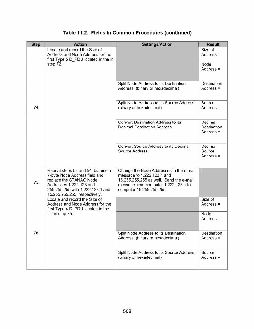
508
Table 11.2. Fields in Common Procedures (continued)
Step Action Settings/Action Result Size of
Address =
Node Address =
Split Node Address to its Destination Address. (binary or hexadecimal)
Destination Address =
Split Node Address to its Source Address. (binary or hexadecimal)
Source Address =
Convert Destination Address to its Decimal Destination Address.
Decimal Destination Address =
74
Locate and record the Size of Address and Node Address for the first Type 5 D_PDU located in the in step 72.
Convert Source Address to its Decimal Source Address.
Decimal Source Address =
75
Repeat steps 53 and 54, but use a 7-byte Node Address field and replace the STANAG Node Addresses 1.222.123 and 255.255.255 with 1.222.123.1 and 15.255.255.255, respectively.
Change the Node Addresses in the e-mail message to 1.222.123.1 and 15.255.255.255 as well. Send the e-mail message from computer 1.222.123.1 to computer 15.255.255.255.
Size of Address =
Node Address =
Split Node Address to its Destination Address. (binary or hexadecimal)
Destination Address =
76
Locate and record the Size of Address and Node Address for the first Type 4 D_PDU located in the file in step 75.
Split Node Address to its Source Address. (binary or hexadecimal)
Source Address =

509
Table 11.2. Fields in Common Procedures (continued)
Step Action Settings/Action Result Convert Destination Address to its Decimal Destination Address.
Decimal Destination Address =
Convert Source Address to its Decimal Source Address.
Decimal Source Address =
Size of Address =
Node Address =
Split Node Address to its Destination Address. (binary or hexadecimal)
Destination Address =
Split Node Address to its Source Address. (binary or hexadecimal)
Source Address =
Convert Destination Address to its Decimal Destination Address.
Decimal Destination Address =
77
Locate and record the Size of Address and Node Address for the first Type 5 D_PDU located in the in step 75.
Convert Source Address to its Decimal Source Address.
Decimal Source Address =
The following procedures are for Type 6 D_PDUs for reference numbers 501, 569, 575-576, 579, 581, 588-589, 599-606, 608-609, 611, 613-616, 622-623, 627-641, 643-644, 646-648, 862-863, and 926.
78
Set up equipment. See figure 11.8. Computers are connected to the modems by an RS-232 connection. The connection between modems shall be such that the receive and transmit pins on the modem are connected to the transmit and receive pins, respectively, of the other modem.

510
Table 11.2. Fields in Common Procedures (continued)
Step Action Settings/Action Result
79
Configure protocol analyzer. Configure the protocol analyzer to capture the transmitted data between the two computers and save it to a file. Configure the protocol analyzer to have a 4800-bps bit rate and to synchronize on “0x90EB.” Configure the protocol analyzer to drop sync after 20 “FF”s. Configure the analyzer to time stamp each captured byte.
80
Enable the STANAG 5066 software for DRC capable.
Configure STANAG 5066 software so the Data Rate Change is Enabled. Configure the Data Rate Change to switch to 75 bps with no interleaving for a “bad” channel (0 dB) and increase to 2400 bps for a “good” channel (30 dB). Use the 4285 waveform.
81
Send e-mail message and capture all transmitted and received bytes via the protocol analyzer shown in figure 11.8.
Set the STANAG Node Address Size to 1 byte with the following STANAG addresses: 1 and 15, as shown in figure 11.8. With the switch set to the “good” channel, send the following e-mail message from computer with STANAG address 1 to computer with STANAG address 15, using a Soft Link and Non-Expedited ARQ Delivery Method. Include an attachment of approximately 15 kbytes in size. For the Subject Line: Test 1 In the Body: “This is a test from address 1 to 15. 1 2 3 4 5 6 7 8 9 10” Save the data obtained through the protocol analyzer to a file.
82
Locate and record values for each STANAG Node Address Size and STANAG address Listed.
Utilize the methods specified in step 17 to identify and record the Size of Address, Node Address, Destination and Source Addresses, and the Decimal Destination and Source Addresses.
83
Verify the Maury-Styles Sync Sequence, D_PDU Type, and identify the EOT, EOW, Size of Header, Header CRC, and Calculated Header CRC for the specified D_PDU Types.
Utilize the methods specified in step 18 to identify and record the Maury-Styles Sync Sequence, and D_PDU Type, and identify the EOT, EOW, Size of Header, Header CRC, and Calculated Header CRC.
84
Method to identify Reserved bits. For the Type 6 D_PDU, also obtain the Reserved bits. These are contained within the first 5 bits of the 6th byte (not including the sync sequence) of the Type 6 D_PDU.

511
Table 11.2. Fields in Common Procedures (continued)
Step Action Settings/Action Result Sync Seq =
Type =
EOW =
EOT =
Size of
Address =
Size of Header =
Node Address =
Split Node Address to its Destination Address. (binary or hexadecimal)
Destination Address =
Split Node Address to its Source Address. (binary or hexadecimal)
Source Address =
Convert Destination Address to its Decimal Destination Address.
Decimal Destination Address =
Convert Source Address to its Decimal Source Address.
Decimal Source Address =
Reserved bits =
Header CRC =
85
Locate and record the Maury-Styles Sync Sequence, D_PDU Type, EOW, EOT, Size of Address, Size of Header, Node Address, and Header CRC for the first Type 6 D_PDU located in the file in step 81.
Compute the Calculated Header CRC. Calculated Header CRC =
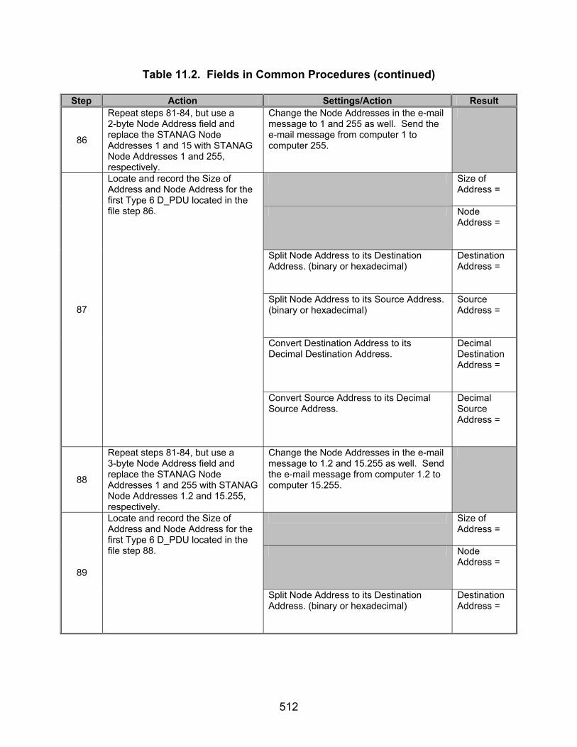
512
Table 11.2. Fields in Common Procedures (continued)
Step Action Settings/Action Result
86
Repeat steps 81-84, but use a 2-byte Node Address field and replace the STANAG Node Addresses 1 and 15 with STANAG Node Addresses 1 and 255, respectively.
Change the Node Addresses in the e-mail message to 1 and 255 as well. Send the e-mail message from computer 1 to computer 255.
Size of Address =
Node Address =
Split Node Address to its Destination Address. (binary or hexadecimal)
Destination Address =
Split Node Address to its Source Address. (binary or hexadecimal)
Source Address =
Convert Destination Address to its Decimal Destination Address.
Decimal Destination Address =
87
Locate and record the Size of Address and Node Address for the first Type 6 D_PDU located in the file step 86.
Convert Source Address to its Decimal Source Address.
Decimal Source Address =
88
Repeat steps 81-84, but use a 3-byte Node Address field and replace the STANAG Node Addresses 1 and 255 with STANAG Node Addresses 1.2 and 15.255, respectively.
Change the Node Addresses in the e-mail message to 1.2 and 15.255 as well. Send the e-mail message from computer 1.2 to computer 15.255.
Size of Address =
Node Address =
89
Locate and record the Size of Address and Node Address for the first Type 6 D_PDU located in the file step 88.
Split Node Address to its Destination Address. (binary or hexadecimal)
Destination Address =
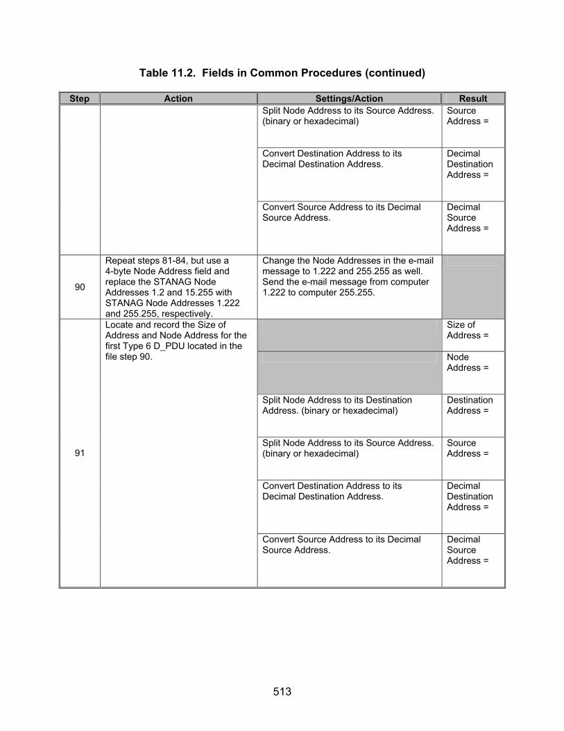
513
Table 11.2. Fields in Common Procedures (continued)
Step Action Settings/Action Result Split Node Address to its Source Address. (binary or hexadecimal)
Source Address =
Convert Destination Address to its Decimal Destination Address.
Decimal Destination Address =
Convert Source Address to its Decimal Source Address.
Decimal Source Address =
90
Repeat steps 81-84, but use a 4-byte Node Address field and replace the STANAG Node Addresses 1.2 and 15.255 with STANAG Node Addresses 1.222 and 255.255, respectively.
Change the Node Addresses in the e-mail message to 1.222 and 255.255 as well. Send the e-mail message from computer 1.222 to computer 255.255.
Size of Address =
Node Address =
Split Node Address to its Destination Address. (binary or hexadecimal)
Destination Address =
Split Node Address to its Source Address. (binary or hexadecimal)
Source Address =
Convert Destination Address to its Decimal Destination Address.
Decimal Destination Address =
91
Locate and record the Size of Address and Node Address for the first Type 6 D_PDU located in the file step 90.
Convert Source Address to its Decimal Source Address.
Decimal Source Address =

514
Table 11.2. Fields in Common Procedures (continued)
Step Action Settings/Action Result
92
Repeat steps 81-84, but use a 5-byte Node Address field and replace the STANAG Node Addresses 1.222 and 255.255 with STANAG Node Addresses 1.222.1 and 15.255.255, respectively.
Change the Node Addresses in the e-mail message to 1.222.1 and 15.255.255 as well. Send the e-mail message from computer 1.222.1 to computer 15.255.255.
Size of Address =
Node Address =
Split Node Address to its Destination Address. (binary or hexadecimal)
Destination Address =
Split Node Address to its Source Address. (binary or hexadecimal)
Source Address =
Convert Destination Address to its Decimal Destination Address.
Decimal Destination Address =
93
Locate and record the Size of Address and Node Address for the first Type 6 D_PDU located in the file step 92.
Convert Source Address to its Decimal Source Address.
Decimal Source Address =
94
Repeat steps 81-84, but use a 6-byte Node Address field and replace the STANAG Node Addresses 1.222.1 and 15.255.255 with 1.222.123 and 255.255.255, respectively.
Change the Node Addresses in the e-mail message to 1.222.123 and 255.255.255 as well. Send the e-mail message from computer 1.222.123 to computer 255.255.255.
Size of Address =
Node Address =
95
Locate and record the Size of Address and Node Address for the first Type 6 D_PDU located in the file step 94.
Split Node Address to its Destination Address. (binary or hexadecimal)
Destination Address =

515
Table 11.2. Fields in Common Procedures (continued)
Step Action Settings/Action Result Split Node Address to its Source Address. (binary or hexadecimal)
Source Address =
Convert Destination Address to its Decimal Destination Address.
Decimal Destination Address =
Convert Source Address to its Decimal Source Address.
Decimal Source Address =
96
Repeat steps 81-84, but use a 7-byte Node Address field and replace the STANAG Node Addresses 1.222.123 and 255.255.255 with 1.222.123.1 and 15.255.255.255, respectively.
Change the Node Addresses in the e-mail message to 1.222.123.1 and 15.255.255.255 as well. Send the e-mail message from computer 1.222.123.1 to computer 15.255.255.255.
Size of Address =
Node Address =
Split Node Address to its Destination Address. (binary or hexadecimal)
Destination Address =
Split Node Address to its Source Address. (binary or hexadecimal)
Source Address =
Convert Destination Address to its Decimal Destination Address.
Decimal Destination Address =
97
Locate and record the Size of Address and Node Address for the first Type 6 D_PDU located in the file step 96.
Convert Source Address to its Decimal Source Address.
Decimal Source Address =
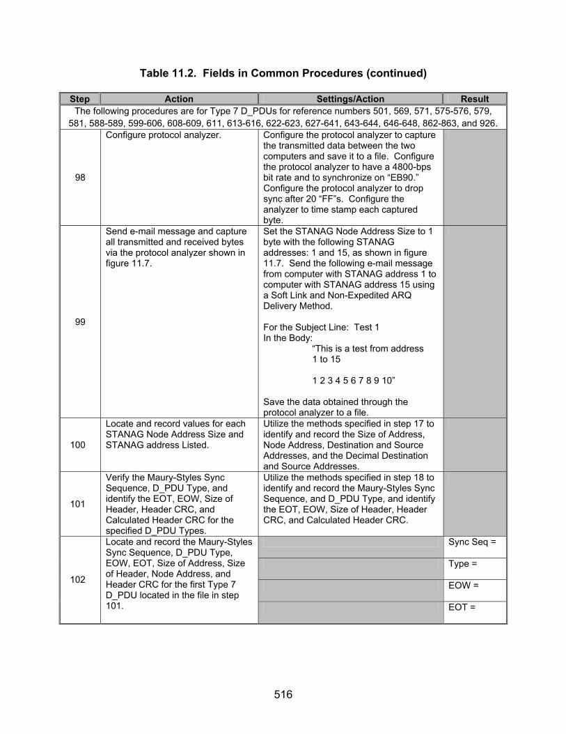
516
Table 11.2. Fields in Common Procedures (continued)
Step Action Settings/Action Result The following procedures are for Type 7 D_PDUs for reference numbers 501, 569, 571, 575-576, 579,
581, 588-589, 599-606, 608-609, 611, 613-616, 622-623, 627-641, 643-644, 646-648, 862-863, and 926.
98
Configure protocol analyzer. Configure the protocol analyzer to capture the transmitted data between the two computers and save it to a file. Configure the protocol analyzer to have a 4800-bps bit rate and to synchronize on “EB90.” Configure the protocol analyzer to drop sync after 20 “FF”s. Configure the analyzer to time stamp each captured byte.
99
Send e-mail message and capture all transmitted and received bytes via the protocol analyzer shown in figure 11.7.
Set the STANAG Node Address Size to 1 byte with the following STANAG addresses: 1 and 15, as shown in figure 11.7. Send the following e-mail message from computer with STANAG address 1 to computer with STANAG address 15 using a Soft Link and Non-Expedited ARQ Delivery Method. For the Subject Line: Test 1 In the Body: “This is a test from address 1 to 15 1 2 3 4 5 6 7 8 9 10” Save the data obtained through the protocol analyzer to a file.
100
Locate and record values for each STANAG Node Address Size and STANAG address Listed.
Utilize the methods specified in step 17 to identify and record the Size of Address, Node Address, Destination and Source Addresses, and the Decimal Destination and Source Addresses.
101
Verify the Maury-Styles Sync Sequence, D_PDU Type, and identify the EOT, EOW, Size of Header, Header CRC, and Calculated Header CRC for the specified D_PDU Types.
Utilize the methods specified in step 18 to identify and record the Maury-Styles Sync Sequence, and D_PDU Type, and identify the EOT, EOW, Size of Header, Header CRC, and Calculated Header CRC.
Sync Seq =
Type =
EOW =
102
Locate and record the Maury-Styles Sync Sequence, D_PDU Type, EOW, EOT, Size of Address, Size of Header, Node Address, and Header CRC for the first Type 7 D_PDU located in the file in step 101. EOT =

517
Table 11.2. Fields in Common Procedures (continued)
Step Action Settings/Action Result Size of
Address =
Size of Header =
Node Address =
Split Node Address to its Destination Address. (binary or hexadecimal)
Destination Address =
Split Node Address to its Source Address. (binary or hexadecimal)
Source Address =
Convert Destination Address to its Decimal Destination Address.
Decimal Destination Address =
Convert Source Address to its Decimal Source Address.
Decimal Source Address =
Header CRC =
Compute the Calculated Header CRC. Calculated Header CRC =
103
Repeat steps 99-101, but use a 2-byte Node Address field and replace the STANAG Node Addresses 1 and 15 with STANAG Node Addresses 1 and 255, respectively.
Change the Node Addresses in the e-mail message to 1 and 255 as well. Send the e-mail message from computer 1 to computer 255.

518
Table 11.2. Fields in Common Procedures (continued)
Step Action Settings/Action Result Size of
Address =
Node Address =
Split Node Address to its Destination Address. (binary or hexadecimal)
Destination Address =
Split Node Address to its Source Address. (binary or hexadecimal)
Source Address =
Convert Destination Address to its Decimal Destination Address.
Decimal Destination Address =
104
Locate and record the Size of Address and Node Address for the first Type 7 D_PDU located in the file in step 103.
Convert Source Address to its Decimal Source Address.
Decimal Source Address =
105
Repeat steps 99-101, but use a 3-byte Node Address field and replace the STANAG Node Addresses 1 and 255 with STANAG Node Addresses 1.2 and 15.255, respectively.
Change the Node Addresses in the e-mail message to 1.2 and 15.255 as well. Send the e-mail message from computer 1.2 to computer 15.255.
Size of Address =
Node Address =
Split Node Address to its Destination Address. (binary or hexadecimal)
Destination Address =
106
Locate and record the Size of Address and Node Address for the first Type 7 D_PDU located in the file in step 105.
Split Node Address to its Source Address. (binary or hexadecimal)
Source Address =

519
Table 11.2. Fields in Common Procedures (continued)
Step Action Settings/Action Result Convert Destination Address to its Decimal Destination Address.
Decimal Destination Address =
Convert Source Address to its Decimal Source Address.
Decimal Source Address =
107
Repeat steps 99-101, but use a 4-byte Node Address field and replace the STANAG Node Addresses 1.2 and 15.255 with STANAG Node Addresses 1.222 and 255.255, respectively.
Change the Node Addresses in the e-mail message to 1.222 and 255.255 as well. Send the e-mail message from computer 1.222 to computer 255.255.
Size of Address =
Node Address =
Split Node Address to its Destination Address. (binary or hexadecimal)
Destination Address =
Split Node Address to its Source Address. (binary or hexadecimal)
Source Address =
Convert Destination Address to its Decimal Destination Address.
Decimal Destination Address =
108
Locate and record the Size of Address and Node Address for the first Type 7 D_PDU captured in the file in step 107.
Convert Source Address to its Decimal Source Address.
Decimal Source Address =
109
Repeat steps 99-101, but use a 5-byte Node Address field and replace the STANAG Node Addresses 1.222 and 255.255 with STANAG Node Addresses 1.222.1 and 15.255.255, respectively.
Change the Node Addresses in the e-mail message to 1.222.1 and 15.255.255 as well. Send the e-mail message from computer 1.222.1 to computer 15.255.255.
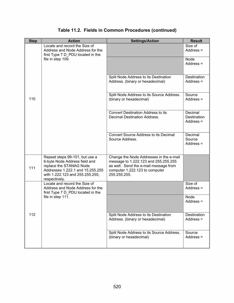
520
Table 11.2. Fields in Common Procedures (continued)
Step Action Settings/Action Result Size of
Address =
Node Address =
Split Node Address to its Destination Address. (binary or hexadecimal)
Destination Address =
Split Node Address to its Source Address. (binary or hexadecimal)
Source Address =
Convert Destination Address to its Decimal Destination Address.
Decimal Destination Address =
110
Locate and record the Size of Address and Node Address for the first Type 7 D_PDU located in the file in step 109.
Convert Source Address to its Decimal Source Address.
Decimal Source Address =
111
Repeat steps 99-101, but use a 6-byte Node Address field and replace the STANAG Node Addresses 1.222.1 and 15.255.255 with 1.222.123 and 255.255.255, respectively.
Change the Node Addresses in the e-mail message to 1.222.123 and 255.255.255 as well. Send the e-mail message from computer 1.222.123 to computer 255.255.255.
Size of Address =
Node Address =
Split Node Address to its Destination Address. (binary or hexadecimal)
Destination Address =
112
Locate and record the Size of Address and Node Address for the first Type 7 D_PDU located in the file in step 111.
Split Node Address to its Source Address. (binary or hexadecimal)
Source Address =
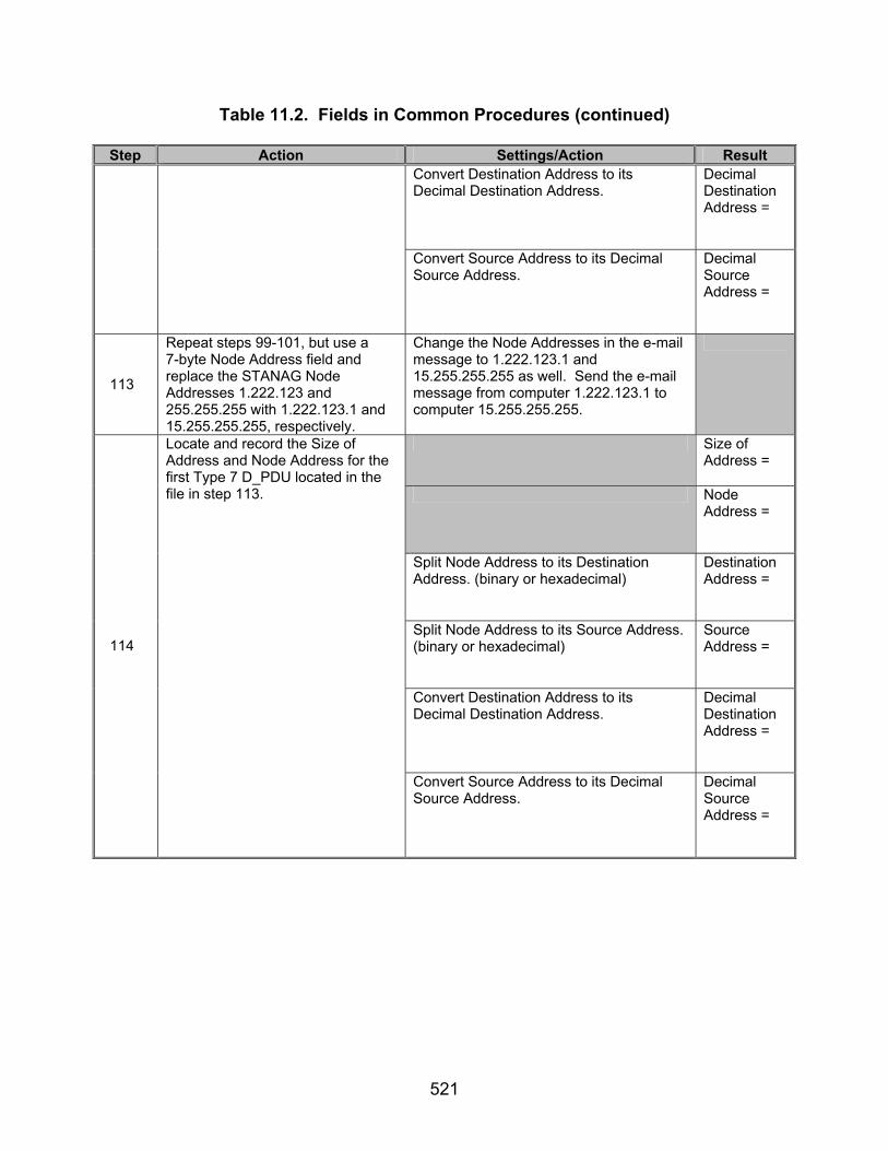
521
Table 11.2. Fields in Common Procedures (continued)
Step Action Settings/Action Result Convert Destination Address to its Decimal Destination Address.
Decimal Destination Address =
Convert Source Address to its Decimal Source Address.
Decimal Source Address =
113
Repeat steps 99-101, but use a 7-byte Node Address field and replace the STANAG Node Addresses 1.222.123 and 255.255.255 with 1.222.123.1 and 15.255.255.255, respectively.
Change the Node Addresses in the e-mail message to 1.222.123.1 and 15.255.255.255 as well. Send the e-mail message from computer 1.222.123.1 to computer 15.255.255.255.
Size of Address =
Node Address =
Split Node Address to its Destination Address. (binary or hexadecimal)
Destination Address =
Split Node Address to its Source Address. (binary or hexadecimal)
Source Address =
Convert Destination Address to its Decimal Destination Address.
Decimal Destination Address =
114
Locate and record the Size of Address and Node Address for the first Type 7 D_PDU located in the file in step 113.
Convert Source Address to its Decimal Source Address.
Decimal Source Address =

522
Table 11.2. Fields in Common Procedures (continued)
Step Action Settings/Action Result The following procedures are for Type 15 D_PDUs for reference numbers 501, 569, 575-576, 579, 581,
588-589, 599-606, 608-609, 611, 613-616, 622-623, 627-641, 643-644, 646-648, 862-863, and 926.
115
Set up equipment. See figure 11.9. The computer is connected to the modems by an RS-232 connection. Configure the computer to have a STANAG address of 15. Configure protocol analyzer A as a data packet injector to simulate a computer with STANAG address 1. The connection between modems shall be such that the receive and transmit pins on the modem are connected to the transmit and receive pins, respectively, of the other modem.
116
Configure protocol analyzer. Configure protocol analyzer B to capture the transmitted data between the two computers and save it to a file. Configure the protocol analyzer to have a 4800-bps bit rate and to synchronize on “0xEB90.” Configure protocol analyzer B to drop sync after 20 “FF”s. Configure the analyzer to time stamp each captured byte.
117 Configure Maximum Number of Transmissions.
Configure the Maximum Number of Retransmissions to 1.
118 Reconfigure modems. Configure modems to transmit a
MIL-STD-188-110B signal at a data rate of 1200 bps with half duplex.
119
Inject Type 0 D_PDUs. Transmit the following Type 0 D_PDUs in the order listed from STANAG computer 1 to 15 without first initiating a handshaking protocol: 90 EB 90 EB 04 20 0E 29 F1 EC 21 00 8D F5 00 00 33 44 7A 07 45 48 4C 4F 20 6B 69 6C 62 6F 75 72 6E 65 2E 6C 65 67 65 6E 64 73 2E 6E 69 74 2E 42 2A 66 7F 90 EB 04 20 0E 29 F1 E8 21 01 08 62 00 00 33 44 7A 07 64 69 73 61 2E 6D 69 6C 0D 0A 4D 41 49 4C 20 46 52 4F 4D 3A 3C 68 66 65 6D 61 69 4E 58 8A 8B 90 EB 04 20 0E 29 F1 E8 21 02 7E 71 00 00 33 44 7A 07 6C 40 6B 69 6C 62 6F 75 72 6E 65 2E 6C 65 67 65 6E 64 73 2E 6E 69 74 2E 64 69 73 1E 6A D8 60 90 EB 04 20 0E 29 F1 E8 21 03 AC 7F 00 00 33 44 7A 07 61 2E 6D 69 6C 3E 0D 0A 52 43 50 54 20 54 4F 3A 3C 61 64 6D 69 6E 69 73 74 72 61 25 C9 08 6C
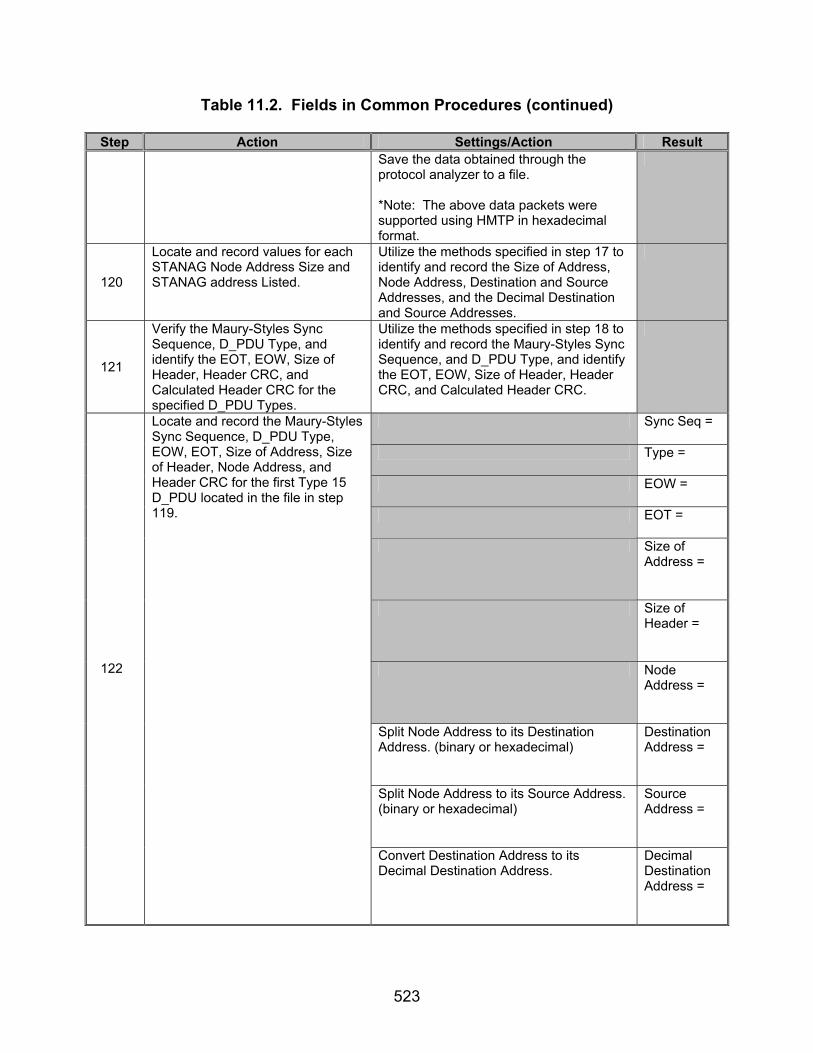
523
Table 11.2. Fields in Common Procedures (continued)
Step Action Settings/Action Result
Save the data obtained through the protocol analyzer to a file. *Note: The above data packets were supported using HMTP in hexadecimal format.
120
Locate and record values for each STANAG Node Address Size and STANAG address Listed.
Utilize the methods specified in step 17 to identify and record the Size of Address, Node Address, Destination and Source Addresses, and the Decimal Destination and Source Addresses.
121
Verify the Maury-Styles Sync Sequence, D_PDU Type, and identify the EOT, EOW, Size of Header, Header CRC, and Calculated Header CRC for the specified D_PDU Types.
Utilize the methods specified in step 18 to identify and record the Maury-Styles Sync Sequence, and D_PDU Type, and identify the EOT, EOW, Size of Header, Header CRC, and Calculated Header CRC.
Sync Seq =
Type =
EOW =
EOT =
Size of Address =
Size of Header =
Node Address =
Split Node Address to its Destination Address. (binary or hexadecimal)
Destination Address =
Split Node Address to its Source Address. (binary or hexadecimal)
Source Address =
122
Locate and record the Maury-Styles Sync Sequence, D_PDU Type, EOW, EOT, Size of Address, Size of Header, Node Address, and Header CRC for the first Type 15 D_PDU located in the file in step 119.
Convert Destination Address to its Decimal Destination Address.
Decimal Destination Address =
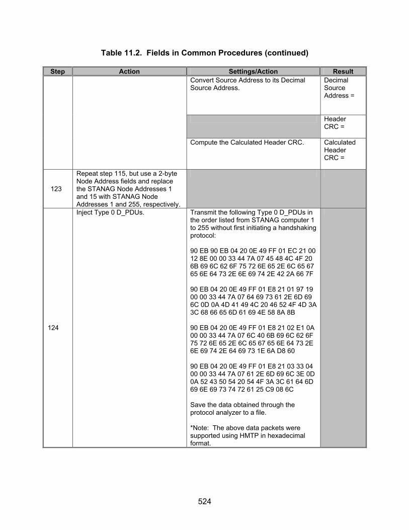
524
Table 11.2. Fields in Common Procedures (continued)
Step Action Settings/Action Result Convert Source Address to its Decimal Source Address.
Decimal Source Address =
Header CRC =
Compute the Calculated Header CRC. Calculated Header CRC =
123
Repeat step 115, but use a 2-byte Node Address fields and replace the STANAG Node Addresses 1 and 15 with STANAG Node Addresses 1 and 255, respectively.
124
Inject Type 0 D_PDUs. Transmit the following Type 0 D_PDUs in the order listed from STANAG computer 1 to 255 without first initiating a handshaking protocol: 90 EB 90 EB 04 20 0E 49 FF 01 EC 21 00 12 8E 00 00 33 44 7A 07 45 48 4C 4F 20 6B 69 6C 62 6F 75 72 6E 65 2E 6C 65 67 65 6E 64 73 2E 6E 69 74 2E 42 2A 66 7F 90 EB 04 20 0E 49 FF 01 E8 21 01 97 19 00 00 33 44 7A 07 64 69 73 61 2E 6D 69 6C 0D 0A 4D 41 49 4C 20 46 52 4F 4D 3A 3C 68 66 65 6D 61 69 4E 58 8A 8B 90 EB 04 20 0E 49 FF 01 E8 21 02 E1 0A 00 00 33 44 7A 07 6C 40 6B 69 6C 62 6F 75 72 6E 65 2E 6C 65 67 65 6E 64 73 2E 6E 69 74 2E 64 69 73 1E 6A D8 60 90 EB 04 20 0E 49 FF 01 E8 21 03 33 04 00 00 33 44 7A 07 61 2E 6D 69 6C 3E 0D 0A 52 43 50 54 20 54 4F 3A 3C 61 64 6D 69 6E 69 73 74 72 61 25 C9 08 6C Save the data obtained through the protocol analyzer to a file. *Note: The above data packets were supported using HMTP in hexadecimal format.

525
Table 11.2. Fields in Common Procedures (continued)
Step Action Settings/Action Result Size of
Address =
Node Address =
Split Node Address to its Destination Address. (binary or hexadecimal)
Destination Address =
Split Node Address to its Source Address. (binary or hexadecimal)
Source Address =
Convert Destination Address to its Decimal Destination Address.
Decimal Destination Address =
125
Locate and record the Size of Address and Node Address for the first Type 15 D_PDU located in the file in step 124.
Convert Source Address to its Decimal Source Address.
Decimal Source Address =
126
Repeat step 115, but use a 3-byte Node Address field and replace the STANAG Node Addresses 1 and 255 with STANAG Node Addresses 1.2 and 15.255, respectively.
127
Inject Type 0 D_PDUs. Transmit the following Type 0 D_PDUs in the order listed from STANAG computer 1.2 to 15.255 without first initiating a handshaking protocol: 90 EB 90 EB 04 20 0E 69 FF F1 02 EC 21 00 1F 4A 00 00 33 44 7A 07 45 48 4C 4F 20 6B 69 6C 62 6F 75 72 6E 65 2E 6C 65 67 65 6E 64 73 2E 6E 69 74 2E 42 2A 66 7F 90 EB 04 20 0E 69 FF F1 02 E8 21 01 9A DD 00 00 33 44 7A 07 64 69 73 61 2E 6D 69 6C 0D 0A 4D 41 49 4C 20 46 52 4F 4D 3A 3C 68 66 65 6D 61 69 4E 58 8A 8B 90 EB 04 20 0E 69 FF F1 02 E8 21 02 EC CE 00 00 33 44 7A 07 6C 40 6B 69 6C 62 6F 75 72 6E 65 2E 6C 65 67 65 6E 64 73 2E 6E 69 74 2E 64 69 73 1E 6A D8 60

526
Table 11.2. Fields in Common Procedures (continued)
Step Action Settings/Action Result
90 EB 04 20 0E 69 FF F1 02 E8 21 03 3E C0 00 00 33 44 7A 07 61 2E 6D 69 6C 3E 0D 0A 52 43 50 54 20 54 4F 3A 3C 61 64 6D 69 6E 69 73 74 72 61 25 C9 08 6C Save the data obtained through the protocol analyzer to a file. *Note: The above data packets were supported using HMTP in hexadecimal format.
Size of Address =
Node Address =
Split Node Address to its Destination Address. (binary or hexadecimal)
Destination Address =
Split Node Address to its Source Address. (binary or hexadecimal)
Source Address =
Convert Destination Address to its Decimal Destination Address.
Decimal Destination Address =
128
Locate and record the Size of Address and Node Address for the first Type 15 D_PDU located in the file in step 127.
Convert Source Address to its Decimal Source Address.
Decimal Source Address =
129
Repeat step 115, but use a 4-byte Node Address field and replace the STANAG Node Addresses 1.2 and 15.255 with STANAG Node Addresses 1.222 and 255.255, respectively.

527
Table 11.2. Fields in Common Procedures (continued)
Step Action Settings/Action Result
130
Inject Type 0 D_PDUs. Transmit the following Type 0 D_PDUs in the order listed from STANAG computer 1.222 to 255.255 without first initiating a handshaking protocol: 90 EB 90 EB 04 20 0E 89 FF FF 01 DE EC 21 00 6D EF 00 00 33 44 7A 07 45 48 4C 4F 20 6B 69 6C 62 6F 75 72 6E 65 2E 6C 65 67 65 6E 64 73 2E 6E 69 74 2E 42 2A 66 7F 90 EB 04 20 0E 89 FF FF 01 DE E8 21 01 E8 78 00 00 33 44 7A 07 64 69 73 61 2E 6D 69 6C 0D 0A 4D 41 49 4C 20 46 52 4F 4D 3A 3C 68 66 65 6D 61 69 4E 58 8A 8B 90 EB 04 20 0E 89 FF FF 01 DE E8 21 02 9E 6B 00 00 33 44 7A 07 6C 40 6B 69 6C 62 6F 75 72 6E 65 2E 6C 65 67 65 6E 64 73 2E 6E 69 74 2E 64 69 73 1E 6A D8 60 90 EB 04 20 0E 89 FF FF 01 DE E8 21 03 4C 65 00 00 33 44 7A 07 61 2E 6D 69 6C 3E 0D 0A 52 43 50 54 20 54 4F 3A 3C 61 64 6D 69 6E 69 73 74 72 61 25 C9 08 6C Save the data obtained through the protocol analyzer to a file. *Note: The above data packets were supported using HMTP in hexadecimal format.
Size of Address =
Node Address =
Split Node Address to its Destination Address. (binary or hexadecimal)
Destination Address =
Split Node Address to its Source Address. (binary or hexadecimal)
Source Address =
131
Locate and record the Size of Address and Node Address for the first Type 15 D_PDU located in the file in step 130.
Convert Destination Address to its Decimal Destination Address.
Decimal Destination Address =

528
Table 11.2. Fields in Common Procedures (continued)
Step Action Settings/Action Result Convert Source Address to its Decimal
Source Address. Decimal Source Address =
132
Repeat step 115, but use a 5-byte Node Address field and replace the STANAG Node Addresses 1.222 and 255.255 with STANAG Node Addresses 1.222.1 and 15.255.255, respectively.
133
Inject Type 0 D_PDUs. Transmit the following Type 0 D_PDUs in the order listed from STANAG computer 1.222.1 to 15.255.255 without first initiating a handshaking protocol: 90 EB 90 EB 04 20 0E A9 FF FF F1 DE 01 EC 21 00 7C BA 00 00 33 44 7A 07 45 48 4C 4F 20 6B 69 6C 62 6F 75 72 6E 65 2E 6C 65 67 65 6E 64 73 2E 6E 69 74 2E 42 2A 66 7F 90 EB 04 20 0E A9 FF FF F1 DE 01 E8 21 01 F9 2D 00 00 33 44 7A 07 64 69 73 61 2E 6D 69 6C 0D 0A 4D 41 49 4C 20 46 52 4F 4D 3A 3C 68 66 65 6D 61 69 4E 58 8A 8B 90 EB 04 20 0E A9 FF FF F1 DE 01 E8 21 02 8F 3E 00 00 33 44 7A 07 6C 40 6B 69 6C 62 6F 75 72 6E 65 2E 6C 65 67 65 6E 64 73 2E 6E 69 74 2E 64 69 73 1E 6A D8 60 90 EB 04 20 0E A9 FF FF F1 DE 01 E8 21 03 5D 30 00 00 33 44 7A 07 61 2E 6D 69 6C 3E 0D 0A 52 43 50 54 20 54 4F 3A 3C 61 64 6D 69 6E 69 73 74 72 61 25 C9 08 6C Save the data obtained through the protocol analyzer to a file. *Note: The above data packets were supported using HMTP in hexadecimal format.

529
Table 11.2. Fields in Common Procedures (continued)
Step Action Settings/Action Result Size of
Address =
Node Address =
Split Node Address to its Destination Address. (binary or hexadecimal)
Destination Address =
Split Node Address to its Source Address. (binary or hexadecimal)
Source Address =
Convert Destination Address to its Decimal Destination Address.
Decimal Destination Address =
134
Locate and record the Size of Address and Node Address for the first Type 15 D_PDU located in the file in step 133
Convert Source Address to its Decimal Source Address.
Decimal Source Address =
135
Repeat step 115, but use a 6-byte Node Address field and replace the STANAG Node Addresses 1.222.1 and 15.255.255 with 1.222.123 and 255.255.255, respectively.
136
Inject Type 0 D_PDUs. Transmit the following Type 0 D_PDUs in the order listed from STANAG computer 1.222.123 to 255.255.255 without first initiating a handshaking protocol: 90 EB 90 EB 04 20 0E C9 FF FF FF 01 DE 7B EC 21 00 B4 34 00 00 33 44 7A 07 45 48 4C 4F 20 6B 69 6C 62 6F 75 72 6E 65 2E 6C 65 67 65 6E 64 73 2E 6E 69 74 2E 42 2A 66 7F 90 EB 04 20 0E C9 FF FF FF 01 DE 7B E8 21 01 31 A3 00 00 33 44 7A 07 64 69 73 61 2E 6D 69 6C 0D 0A 4D 41 49 4C 20 46 52 4F 4D 3A 3C 68 66 65 6D 61 69 4E 58 8A 8B 90 EB 04 20 0E C9 FF FF FF 01 DE 7B E8 21 02 47 B0 00 00 33 44 7A 07 6C 40 6B 69 6C 62 6F 75 72 6E 65 2E 6C 65 67 65 6E 64 73 2E 6E 69 74 2E 64 69 73 1E 6A D8 60
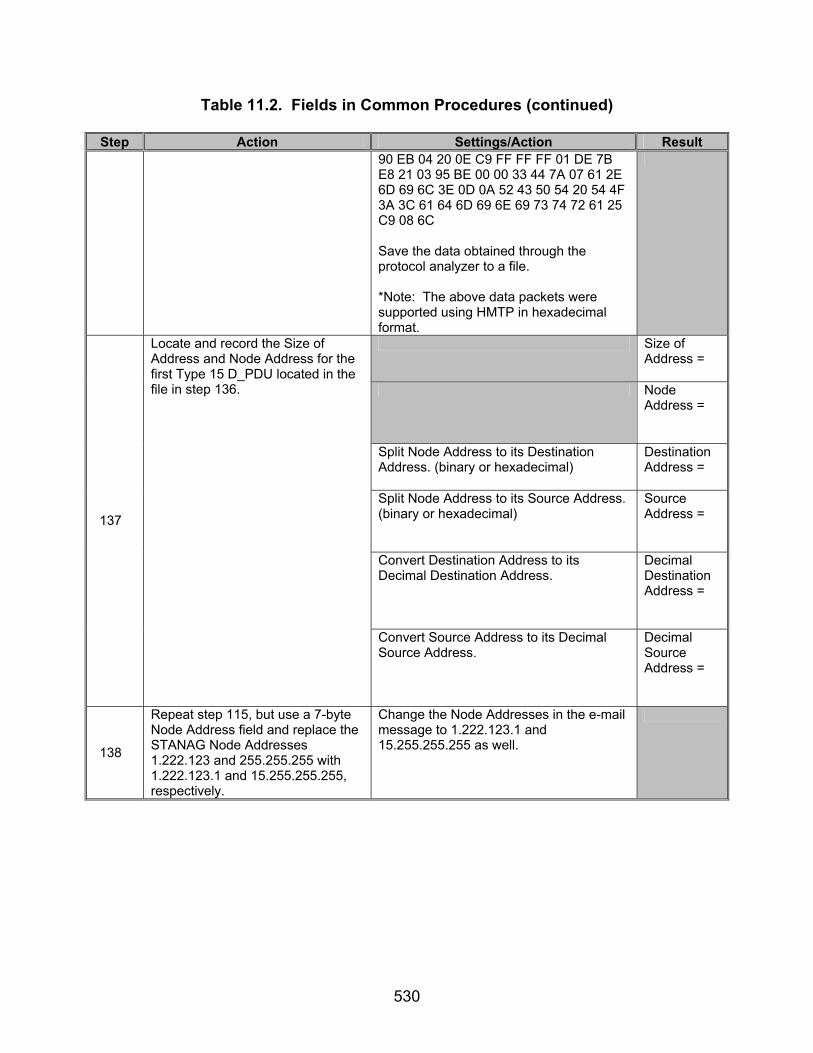
530
Table 11.2. Fields in Common Procedures (continued)
Step Action Settings/Action Result
90 EB 04 20 0E C9 FF FF FF 01 DE 7B E8 21 03 95 BE 00 00 33 44 7A 07 61 2E 6D 69 6C 3E 0D 0A 52 43 50 54 20 54 4F 3A 3C 61 64 6D 69 6E 69 73 74 72 61 25 C9 08 6C Save the data obtained through the protocol analyzer to a file. *Note: The above data packets were supported using HMTP in hexadecimal format.
Size of Address =
Node Address =
Split Node Address to its Destination Address. (binary or hexadecimal)
Destination Address =
Split Node Address to its Source Address. (binary or hexadecimal)
Source Address =
Convert Destination Address to its Decimal Destination Address.
Decimal Destination Address =
137
Locate and record the Size of Address and Node Address for the first Type 15 D_PDU located in the file in step 136.
Convert Source Address to its Decimal Source Address.
Decimal Source Address =
138
Repeat step 115, but use a 7-byte Node Address field and replace the STANAG Node Addresses 1.222.123 and 255.255.255 with 1.222.123.1 and 15.255.255.255, respectively.
Change the Node Addresses in the e-mail message to 1.222.123.1 and 15.255.255.255 as well.

531
Table 11.2. Fields in Common Procedures (continued)
Step Action Settings/Action Result
139
Inject Type 0 D_PDUs. Transmit the following Type 0 D_PDUs in the order listed from STANAG computer 1.222.123.1 to 15.255.255.255 without first initiating a handshaking protocol: 90 EB 90 EB 04 20 0E E9 FF FF FF F1 DE 7B 01 EC 21 00 13 2E 00 00 33 44 7A 07 45 48 4C 4F 20 6B 69 6C 62 6F 75 72 6E 65 2E 6C 65 67 65 6E 64 73 2E 6E 69 74 2E 42 2A 66 7F 90 EB 04 20 0E E9 FF FF FF F1 DE 7B 01 E8 21 01 96 B9 00 00 33 44 7A 07 64 69 73 61 2E 6D 69 6C 0D 0A 4D 41 49 4C 20 46 52 4F 4D 3A 3C 68 66 65 6D 61 69 4E 58 8A 8B 90 EB 04 20 0E E9 FF FF FF F1 DE 7B 01 E8 21 02 E0 AA 00 00 33 44 7A 07 6C 40 6B 69 6C 62 6F 75 72 6E 65 2E 6C 65 67 65 6E 64 73 2E 6E 69 74 2E 64 69 73 1E 6A D8 60 90 EB 04 20 0E E9 FF FF FF F1 DE 7B 01 E8 21 03 32 A4 00 00 33 44 7A 07 61 2E 6D 69 6C 3E 0D 0A 52 43 50 54 20 54 4F 3A 3C 61 64 6D 69 6E 69 73 74 72 61 25 C9 08 6C Save the data obtained through the protocol analyzer to a file. *Note: The above data packets were supported using HMTP in hexadecimal format.
Size of Address =
Node Address =
Split Node Address to its Destination Address. (binary or hexadecimal)
Destination Address =
140
Locate and record the Size of Address and Node Address for the first Type 15 D_PDU located in the file in step 140.
Split Node Address to its Source Address. (binary or hexadecimal)
Source Address =

532
Table 11.2. Fields in Common Procedures (continued)
Step Action Settings/Action Result Convert Destination Address to its Decimal Destination Address.
Decimal Destination Address =
Convert Source Address to its Decimal Source Address.
Decimal Source Address =
The following procedures are for Type 3 D_PDUs for reference numbers 501, 569, 575-576, 579, 581, 588-589, 599-606, 608-609, 611, 613-616, 622-623, 627-641, 643-644, 646-648, 862-863, and 926.
141
Set up equipment. See figure 11.9. Computers are connected to the modems by an RS-232 connection. The connection between modems shall be such that the receive and transmit pins on the modem are connected to the transmit and receive pins, respectively, of the other modem.
142
Configure STANAG Node Addresses.
Configure the STANAG Node Address Size to 1 byte for the computer with the following STANAG addresses: 15, as shown in figure 11.10. Configure protocol analyzer A as a data packet injector to simulate a computer with STANAG address 1.
143
Configure protocol analyzer. Configure protocol analyzer B to capture the transmitted data between the two computers and save it to a file. Configure protocol analyzer B to have a 4800-bps bit rate and to synchronize on “0xEB90.” Configure the protocol analyzer to drop sync after 20 “0xFFs”. Configure the analyzer to time stamp each captured byte.
144
Initiate handshaking protocol. Using the data packet injector, transmit the following hex data packet to the computer: 90 EB 80 00 01 4F 0F 01 00 01 01 00 01 00 00 01 18 84 95 10 AA 9C 74 1E *Note: This data packet assumes the STANAG 5066 supports waveform MIL-STD-188-110A. The EOW and CRC for the above data packet may need to be adjusted for STANAG 5066 software that does not meet this assumption.

533
Table 11.2. Fields in Common Procedures (continued)
Step Action Settings/Action Result
145
Allow the computer to respond to the data packet transmitted in step 145.
Wait until the computer has transmitted its handshaking response. (The handshaking response will be transmitted by the computer back to the data packet injector and will begin with the following sequence “0x90EB80.”)
146
Inject Type 1 D_PDU. Transmit the following Type 1 D_PDU: 90 EB 14 20 02 27 F1 01 DD D8 Save the data obtained through the protocol analyzer to a file.
147
Locate and record values for each STANAG Node Address Size and STANAG address Listed.
Utilize the methods specified in step 17 to identify and record the Size of Address, Node Address, Destination and Source Addresses, and the Decimal Destination and Source Addresses.
148
Verify the Maury-Styles Sync Sequence, D_PDU Type, and identify the EOT, EOW, Size of Header, Header CRC, and Calculated Header CRC for the specified D_PDU Types.
Utilize the methods specified in step 18 to identify and record the Maury-Styles Sync Sequence, and D_PDU Type; also identify the EOT, EOW, Size of Header, Header CRC, and Calculated Header CRC.
Sync Seq =
Type =
EOW =
EOT =
Size of Address =
Size of Header =
Node Address =
Split Node Address to its Destination Address. (binary or hexadecimal)
Destination Address =
149
Locate and record the Maury-Styles Sync Sequence, D_PDU Type, EOW, EOT, Size of Address, Size of Header, Node Address, and Header CRC for the first Type 3 D_PDU located in the file in step 149.
Split Node Address to its Source Address. (binary or hexadecimal)
Source Address =

534
Table 11.2. Fields in Common Procedures (continued)
Step Action Settings/Action Result Convert Destination Address to its Decimal Destination Address.
Decimal Destination Address =
Convert Source Address to its Decimal Source Address.
Decimal Source Address =
Header CRC =
Compute the Calculated Header CRC. Calculated Header CRC =
150 Reconfigure STANAG Node Address.
Configure the STANAG Node Address size to 2 bytes and change the Node Address to 255 as well for the computer.
151
Initiate handshaking protocol.
Using the data packet injector, transmit the following hex data packet to the computer: 90 EB 80 00 01 4F FF 01 00 01 01 00 01 00 00 01 18 C9 A9 10 AA 9C 74 1E *Note: This data packet assumes the STANAG 5066 supports waveform MIL-STD-188-110A. The EOW and CRC for the above data packet may need to be adjusted for STANAG 5066 software that does not meet this assumption.
152
Allow the computer to respond to the data packet transmitted in step 152.
Wait until the computer has transmitted its handshaking response. (The handshaking response will be transmitted by the computer back to the data packet injector and will begin with the following sequence “0x90EB80.”)
153
Inject Type 1 D_PDU. Transmit the following Type 1 D_PDU: 90 EB 14 20 02 47 FF 01 01 17 8B Save the data obtained through the protocol analyzer to a file.
Size of Address =
154
Locate and record the Size of Address and Node Address for the first Type 3 D_PDU located in the file in step 154. Node
Address =
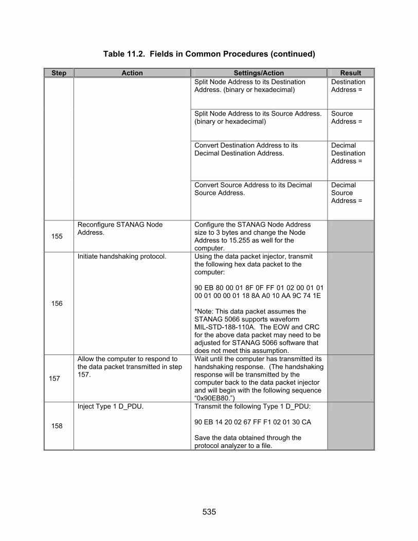
535
Table 11.2. Fields in Common Procedures (continued)
Step Action Settings/Action Result Split Node Address to its Destination Address. (binary or hexadecimal)
Destination Address =
Split Node Address to its Source Address. (binary or hexadecimal)
Source Address =
Convert Destination Address to its Decimal Destination Address.
Decimal Destination Address =
Convert Source Address to its Decimal Source Address.
Decimal Source Address =
155
Reconfigure STANAG Node Address.
Configure the STANAG Node Address size to 3 bytes and change the Node Address to 15.255 as well for the computer.
156
Initiate handshaking protocol.
Using the data packet injector, transmit the following hex data packet to the computer: 90 EB 80 00 01 8F 0F FF 01 02 00 01 01 00 01 00 00 01 18 8A A0 10 AA 9C 74 1E *Note: This data packet assumes the STANAG 5066 supports waveform MIL-STD-188-110A. The EOW and CRC for the above data packet may need to be adjusted for STANAG 5066 software that does not meet this assumption.
157
Allow the computer to respond to the data packet transmitted in step 157.
Wait until the computer has transmitted its handshaking response. (The handshaking response will be transmitted by the computer back to the data packet injector and will begin with the following sequence “0x90EB80.”)
158
Inject Type 1 D_PDU. Transmit the following Type 1 D_PDU: 90 EB 14 20 02 67 FF F1 02 01 30 CA Save the data obtained through the protocol analyzer to a file.

536
Table 11.2. Fields in Common Procedures (continued)
Step Action Settings/Action Result Size of
Address =
Node Address =
Split Node Address to its Destination Address. (binary or hexadecimal)
Destination Address =
Split Node Address to its Source Address. (binary or hexadecimal)
Source Address =
Convert Destination Address to its Decimal Destination Address.
Decimal Destination Address =
159
Locate and record the Size of Address and Node Address for the first Type 3 D_PDU located in the file in step 159.
Convert Source Address to its Decimal Source Address.
Decimal Source Address =
160
Reconfigure STANAG Node Address.
Configure the STANAG Node Address size to 4 bytes and change the Node Address to 255.255 as well for the computer.
161
Initiate handshaking protocol.
Using the data packet injector, transmit the following hex data packet to the computer: 90 EB 80 00 01 8F FF FF 01 DE 00 01 01 00 01 00 00 01 18 6C 50 10 AA 9C 74 1E *Note: This data packet assumes the STANAG 5066 supports waveform MIL-STD-188-110A. The EOW and CRC for the above data packet may need to be adjusted for STANAG 5066 software that does not meet this assumption.
162
Allow the computer to respond to the data packet transmitted in step 162.
Wait until the computer has transmitted its handshaking response. (The handshaking response will be transmitted by the computer back to the data packet injector and will begin with the following sequence “0x90EB80.”)

537
Table 11.2. Fields in Common Procedures (continued)
Step Action Settings/Action Result
163
Inject Type 1 D_PDU. Transmit the following Type 1 D_PDU: 90 EB 14 20 02 87 FF FF 01 DE 01 1C 80 Save the data obtained through the protocol analyzer to a file.
Size of Address =
Node Address =
Split Node Address to its Destination Address. (binary or hexadecimal)
Destination Address =
Split Node Address to its Source Address. (binary or hexadecimal)
Source Address =
Convert Destination Address to its Decimal Destination Address.
Decimal Destination Address =
164
Locate and record the Size of Address and Node Address for the first Type 3 D_PDU located in the file in step 164.
Convert Source Address to its Decimal Source Address.
Decimal Source Address =
165
Reconfigure STANAG Node Address.
Configure the STANAG Node Address size to 5 bytes and change the Node Address to 15.255.255 as well for the computer.
166
Initiate handshaking protocol.
Using the data packet injector, transmit the following hex data packet to the computer: 90 EB 80 00 01 CF 0F FF FF 01 DE 01 00 01 01 00 01 00 00 01 18 CC 17 10 AA 9C 74 1E *Note: This data packet assumes the STANAG 5066 supports waveform MIL-STD-188-110A. The EOW and CRC for the above data packet may need to be adjusted for STANAG 5066 software that does not meet this assumption.

538
Table 11.2. Fields in Common Procedures (continued)
Step Action Settings/Action Result
167
Allow the computer to respond to the data packet transmitted in step 167.
Wait until the computer has transmitted its handshaking response. (The handshaking response will be transmitted by the computer back to the data packet injector and will begin with the following sequence “0x90EB80.”)
168
Inject Type 1 D_PDU. Transmit the following Type 1 D_PDU: 90 EB 14 20 02 A7 FF FF F1 DE 01 01 C7 D6 Save the data obtained through the protocol analyzer to a file.
Size of Address =
Node Address =
Split Node Address to its Destination Address. (binary or hexadecimal)
Destination Address =
Split Node Address to its Source Address. (binary or hexadecimal)
Source Address =
Convert Destination Address to its Decimal Destination Address.
Decimal Destination Address =
169
Locate and record the Size of Address and Node Address for the first Type 3 D_PDU located in the file in step 169.
Convert Source Address to its Decimal Source Address.
Decimal Source Address =
170
Reconfigure STANAG Node Address.
Configure the STANAG Node Address size to 6 bytes and change the Node Address to 255.255.255 as well for the computer.
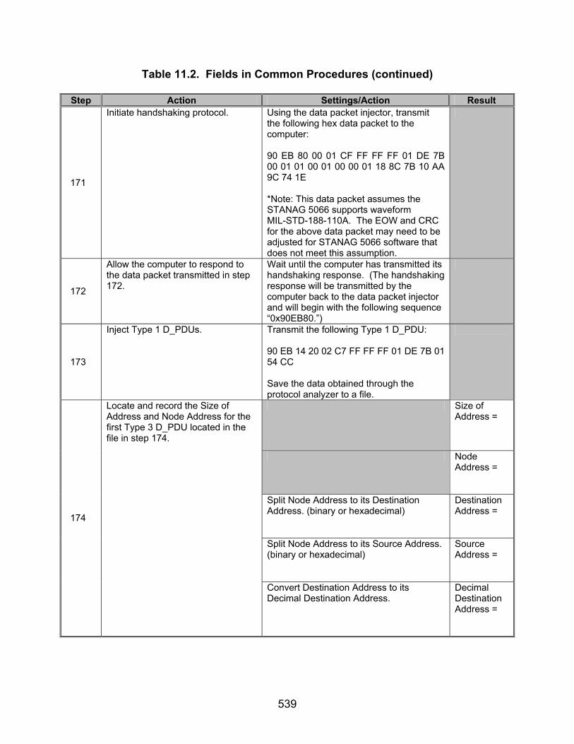
539
Table 11.2. Fields in Common Procedures (continued)
Step Action Settings/Action Result
171
Initiate handshaking protocol.
Using the data packet injector, transmit the following hex data packet to the computer: 90 EB 80 00 01 CF FF FF FF 01 DE 7B 00 01 01 00 01 00 00 01 18 8C 7B 10 AA 9C 74 1E *Note: This data packet assumes the STANAG 5066 supports waveform MIL-STD-188-110A. The EOW and CRC for the above data packet may need to be adjusted for STANAG 5066 software that does not meet this assumption.
172
Allow the computer to respond to the data packet transmitted in step 172.
Wait until the computer has transmitted its handshaking response. (The handshaking response will be transmitted by the computer back to the data packet injector and will begin with the following sequence “0x90EB80.”)
173
Inject Type 1 D_PDUs. Transmit the following Type 1 D_PDU: 90 EB 14 20 02 C7 FF FF FF 01 DE 7B 01 54 CC Save the data obtained through the protocol analyzer to a file.
Size of Address =
Node Address =
Split Node Address to its Destination Address. (binary or hexadecimal)
Destination Address =
Split Node Address to its Source Address. (binary or hexadecimal)
Source Address =
174
Locate and record the Size of Address and Node Address for the first Type 3 D_PDU located in the file in step 174.
Convert Destination Address to its Decimal Destination Address.
Decimal Destination Address =
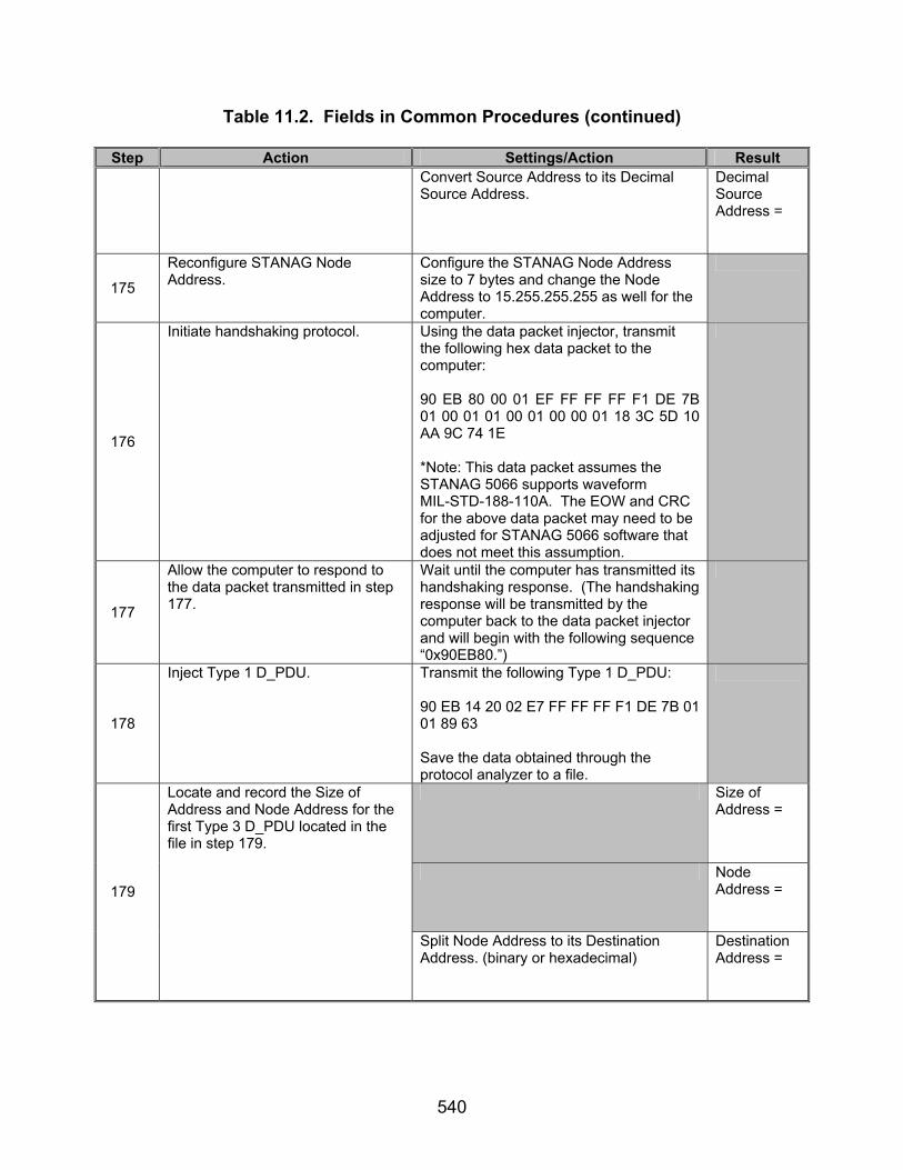
540
Table 11.2. Fields in Common Procedures (continued)
Step Action Settings/Action Result Convert Source Address to its Decimal
Source Address. Decimal Source Address =
175
Reconfigure STANAG Node Address.
Configure the STANAG Node Address size to 7 bytes and change the Node Address to 15.255.255.255 as well for the computer.
176
Initiate handshaking protocol.
Using the data packet injector, transmit the following hex data packet to the computer: 90 EB 80 00 01 EF FF FF FF F1 DE 7B 01 00 01 01 00 01 00 00 01 18 3C 5D 10 AA 9C 74 1E *Note: This data packet assumes the STANAG 5066 supports waveform MIL-STD-188-110A. The EOW and CRC for the above data packet may need to be adjusted for STANAG 5066 software that does not meet this assumption.
177
Allow the computer to respond to the data packet transmitted in step 177.
Wait until the computer has transmitted its handshaking response. (The handshaking response will be transmitted by the computer back to the data packet injector and will begin with the following sequence “0x90EB80.”)
178
Inject Type 1 D_PDU. Transmit the following Type 1 D_PDU: 90 EB 14 20 02 E7 FF FF FF F1 DE 7B 01 01 89 63 Save the data obtained through the protocol analyzer to a file.
Size of Address =
Node Address =
179
Locate and record the Size of Address and Node Address for the first Type 3 D_PDU located in the file in step 179.
Split Node Address to its Destination Address. (binary or hexadecimal)
Destination Address =
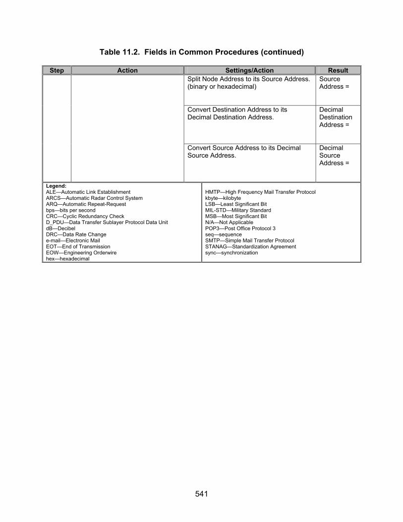
541
Table 11.2. Fields in Common Procedures (continued)
Step Action Settings/Action Result Split Node Address to its Source Address. (binary or hexadecimal)
Source Address =
Convert Destination Address to its Decimal Destination Address.
Decimal Destination Address =
Convert Source Address to its Decimal Source Address.
Decimal Source Address =
Legend: ALE—Automatic Link Establishment ARCS—Automatic Radar Control System ARQ—Automatic Repeat-Request bps—bits per second CRC—Cyclic Redundancy Check D_PDU—Data Transfer Sublayer Protocol Data Unit dB—Decibel DRC—Data Rate Change e-mail—Electronic Mail EOT—End of Transmission EOW—Engineering Orderwire hex—hexadecimal
HMTP—High Frequency Mail Transfer Protocol kbyte—kilobyte LSB—Least Significant Bit MIL-STD—Military Standard MSB—Most Significant Bit N/A—Not Applicable POP3—Post Office Protocol 3 seq—sequence SMTP—Simple Mail Transfer Protocol STANAG—Standardization Agreement sync—synchronization

542
Table 11.3. Fields In Common Results
Result Finding Reference Number
STANAG 5066
Paragraph Requirement Required
Value Measured
Value Met Not Met
501 B.3.1.1
The Delivery mode specified by the Subnetwork Interface Sublayer for the encapsulated S_PDU (i.e., ARQ, Non-ARQ, etc.) also shall be assigned to the C_PDU by the Channel Access sublayer as the delivery mode to be provided by the lower sublayer.
Types 0,1,2,4, and 5 D_PDUs transmitted when ARQ Data Transfer specified, and Types 7 and 8 D_PDUs transfered when Non-ARQ Data Transfer specified.
569 C.1
Depending on the application and service-type requested by higher sublayers, the user service provided by the Data Transfer Sublayer shall be either a simple non ARQ service, commonly known as broadcast mode, or a reliable selective ARQ service, as specified herein.
Non-ARQ and ARQ data delivery modes available.
Type 7 D_PDU contain CRC.
571 C.1.1
In the Non-ARQ service error-check bits (i.e., Cyclic Redundancy Check or CRC bits) applied to the D_DPU shall be used to detect errors.
Type 8 D_PDU contain CRC.
575 C.2 The interface must support the service-definition for the Data Transfer Sublayer, i.e.:
576 C.2
The interface shall allow the Channel Access Sublayer to submit protocol data units (i.e., C_PDUs) for transmission using the regular and expedited delivery services provided by the Data Transfer Sublayer.
Expedited and Non-Expedited modes available.

543
Table 11.3. Fields In Common Results (continued)
Result Finding Reference Number
STANAG 5066
Paragraph Requirement Required
Value Measured
Value Met Not Met
579 C.2
The interface shall permit the Data Transfer Sublayer to specify the delivery services that were used by received C_PDUs when it submits them to the Channel Access Sublayer.
Types 0,1, and 2 D_PDUs transmitted for Non-expedited ARQ Data Transfer, Types 4 and 5 D_PDUs transmitted for Expedited ARQ Data Transfer, Type 7 D_PDU transmitted for Non-expedited Non-ARQ Data Transfer, and Type 8 D_PDU transmitted for Expedited Non-ARQ Data Transfer.

544
Table 11.3. Fields In Common Results (continued)
Result Finding Reference Number
STANAG 5066
Paragraph Requirement Required
Value Measured
Value Met Not Met
581 C.2
The interface shall permit the Data Transfer Sublayer to specify the source address from which C_PDUs are received, and the destination address to which they had been sent.
STANAG Source and Destination Addresses encapsu-lated in D_PDUs.
588 C.3
In order to provide the data transfer services specified herein, the Data Transfer Sublayer shall exchange protocol data units (D_PDUs) with its peer(s).
D_PDUs transmitted between the two computers.
589 C.3
The Data Transfer Sublayer shall use the D_PDU Types displayed in table C-2 to support the Selective ARQ service and Non ARQ service, including the several data transfer submodes defined herein.
Types 0,1, and 2 D_PDUs transmitted for Non-expedited ARQ Data Transfer, Types 4 and 5 D_PDUs transmitted for Expedited ARQ Data Transfer, Type 7 D_PDU transmitted for Non-expedited Non-ARQ Data Transfer, and Type 8 D_PDU transmitted for Expedited Non-ARQ Data Transfer.

545
Table 11.3. Fields In Common Results (continued)
Result Finding Reference Number
STANAG 5066
Paragraph Requirement Required
Value Measured
Value Met Not Met
599 C.3.2
All D_PDUs, regardless of type, shall begin with the same 16-bit synchronization (sync) sequence.
All D_PDUs tested begin with (MSB) 1 0 0 1 0 0 0 0 1 1 1 0 1 0 1 1 (LSB) (0x90EB in hex)
600 C.3.2
The 16-bit sequence shall be the 16-bit Maury-Styles (0xEB90) sequence shown below, with the least significant bit (LSB) transmitted first: (MSB) 1 1 1 0 1 0 1 1 1 0 0 1 0 0 0 0 (LSB)
All D_PDUs tested begin with (MSB) 1 0 0 1 0 0 0 0 1 1 1 0 1 0 1 1 (LSB) (0x90EB in hex)
601 C.3.2
The first 4 bytes of all D_PDU headers shall contain the same fields:
All D_PDUs Tested contain Type, EOW, EOT, Size-of-Header, and Size-of-Address.
Type 0 D_PDU Type = (MSB) 0 0 0 0 (LSB) (0x0 hex)
602 C.3.2
A 4 bit D_PDU Type field that shall identify the type of D_PDU;
Type 1 D_PDU Type = (MSB) 0 0 0 1 (LSB) (0x1 hex)

546
Table 11.3. Fields In Common Results (continued)
Result Finding Reference Number
STANAG 5066
Paragraph Requirement Required
Value Measured
Value Met Not Met
Type 2 D_PDU Type = (MSB) 0 0 1 0 (LSB) (0x2 hex)
Type 3 D_PDU Type = (MSB) 0 0 1 1 (LSB) (0x3 hex)
Type 4 D_PDU Type = (MSB) 0 1 0 0 (LSB) (0x4 hex)
Type 5 D_PDU Type = (MSB) 0 1 0 1 (LSB) (0x5 hex)
Type 6 D_PDU Type = (MSB) 0 1 1 0 (LSB) (0x6 hex)
602 C.3.2
Type 7 D_PDU Type = (MSB) 0 1 1 1 (LSB) (0x7 hex)

547
Table 11.3. Fields In Common Results (continued)
Result Finding Reference Number
STANAG 5066
Paragraph Requirement Required
Value Measured
Value Met Not Met
Type 8 D_PDU Type = (MSB) 1 0 0 0 (LSB) (0x8 hex)
602 C.3.2
Type 15 D_PDU Type = (MSB) 1 1 1 1 (LSB) (0xF hex)
Type 0 D_DPU EOW = Expected EOW
Type 1 D_DPU EOW = Expected EOW
Type 2 D_DPU EOW = Expected EOW
Type 3 D_DPU EOW = Expected EOW
Type 4 D_DPU EOW = Expected EOW
603 C.3.2
A 12-bit field that shall contain an Engineering Order Wire (EOW) message;
Type 5 D_DPU EOW = Expected EOW

548
Table 11.3. Fields In Common Results (continued)
Result Finding Reference Number
STANAG 5066
Paragraph Requirement Required
Value Measured
Value Met Not Met
Type 6 D_PDU EOW = (MSB) 0 0 0 1 0 0 0 0 0 0 0 1 (LSB) (0x101 hex)
Type 7 D_DPU EOW = Expected EOW
Type 8 D_DPU EOW = Expected EOW
603 C.3.2
Type 15 D_DPU EOW = Expected EOW
Type 0 D_PDU EOT = (MSB) 0 0 0 0 0 1 0 0 (LSB) (hex= 0x04)
604 C.3.2
An 8-bit field that shall contain the End Of Transmission (EOT) information;
Type 1 D_PDU EOT = (MSB) 0 0 0 0 0 0 0 1 (LSB) (hex = 0x01)

549
Table 11.3. Fields In Common Results (continued)
Result Finding Reference Number
STANAG 5066
Paragraph Requirement Required
Value Measured
Value Met Not Met
Type 2 D_PDU EOT = (MSB) 0 0 0 0 0 0 0 1 (LSB) (hex = 0x01)
Type 3 D_PDU EOT = (MSB) 0 0 0 0 0 0 0 1 (LSB) (hex = 0x01)
Type 4 D_PDU EOT = (MSB) 0 0 0 0 0 1 0 0 (LSB) (hex = 0x04)
Type 5 D_PDU EOT = (MSB) 0 0 0 0 0 0 0 1 (LSB) (hex = 0x01)
604 C.3.2
Type 6 D_PDU EOT = (MSB) 0 0 0 0 0 0 0 1 (LSB) (hex = 0x01)
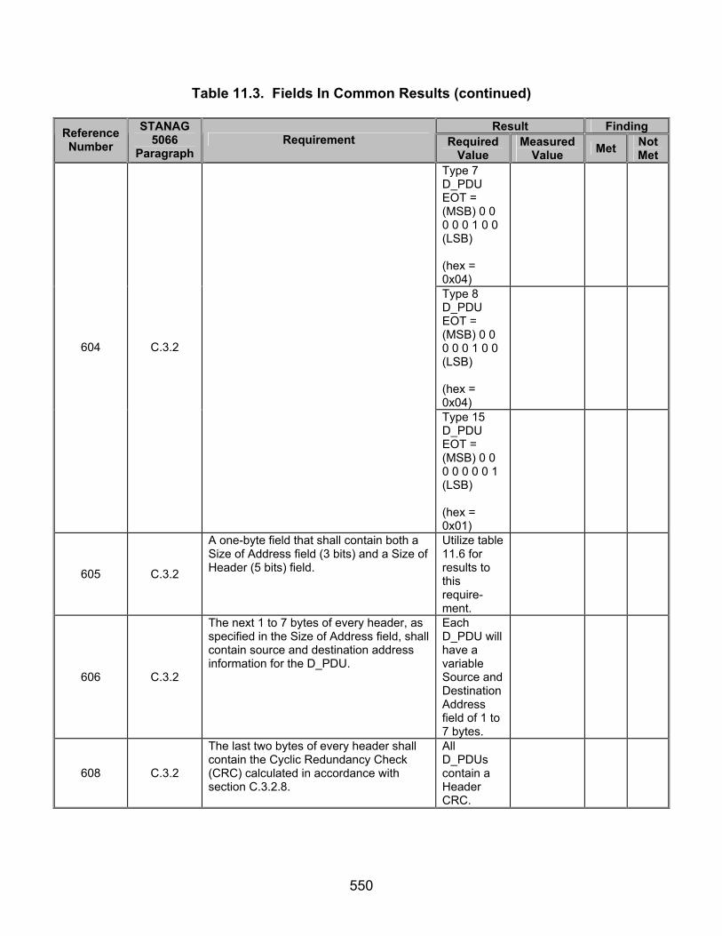
550
Table 11.3. Fields In Common Results (continued)
Result Finding Reference Number
STANAG 5066
Paragraph Requirement Required
Value Measured
Value Met Not Met
Type 7 D_PDU EOT = (MSB) 0 0 0 0 0 1 0 0 (LSB) (hex = 0x04)
Type 8 D_PDU EOT = (MSB) 0 0 0 0 0 1 0 0 (LSB) (hex = 0x04)
604 C.3.2
Type 15 D_PDU EOT = (MSB) 0 0 0 0 0 0 0 1 (LSB) (hex = 0x01)
605 C.3.2
A one-byte field that shall contain both a Size of Address field (3 bits) and a Size of Header (5 bits) field.
Utilize table 11.6 for results to this require-ment.
606 C.3.2
The next 1 to 7 bytes of every header, as specified in the Size of Address field, shall contain source and destination address information for the D_PDU.
Each D_PDU will have a variable Source and Destination Address field of 1 to 7 bytes.
608 C.3.2
The last two bytes of every header shall contain the Cyclic Redundancy Check (CRC) calculated in accordance with section C.3.2.8.
All D_PDUs contain a Header CRC.

551
Table 11.3. Fields In Common Results (continued)
Result Finding Reference Number
STANAG 5066
Paragraph Requirement Required
Value Measured
Value Met Not Met
Type 3 D_PDU Reserved bits = (MSB) 0 0 0 0 (LSB)
609 C.3.2
The bits in any field in a D_PDU that is specified as NOT USED shall contain the value zero (0).
Type 6 D_PDU Reserved bits = (MSB) 0 0 0 0 0 (LSB)
611 C.3.2.1
The value of the D_PDU Type number shall be used to indicate the D_PDU Type. The four bits available allow for 16 D_PDU Types.
Only D_PDUs obtained are Types 0, 1, 2, 3, 4, 5, 6, 7, 8, or 15.
Type 0 D_DPU EOW = Expected EOW
Type 1 D_DPU EOW = Expected EOW
Type 2 D_DPU EOW = Expected EOW
613 C.3.2.2
The 12-bit EOW field shall carry management messages for the Engineering Orderwire (EOW). EOW messages may not be explicitly acknowledged; although, the D_PDU of which they are a part may be. EOW messages can be explicitly acknowledged when they are contained in the Management Type 6 D_PDU through which management-level acknowledgement services are provided in the Data Transfer Sublayer.
Type 3 D_DPU EOW = Expected EOW

552
Table 11.3. Fields In Common Results (continued)
Result Finding Reference Number
STANAG 5066
Paragraph Requirement Required
Value Measured
Value Met Not Met
Type 4 D_DPU EOW = Expected EOW
Type 5 D_DPU EOW = Expected EOW
Type 6 D_PDU EOW = (MSB) 0 0 0 1 0 0 0 0 0 0 0 1 (LSB) (0x101 hex)
Type 7 D_DPU EOW = Expected EOW
Type 8 D_DPU EOW = Expected EOW
613 C.3.2.2
Type 15D_DPU EOW = Expected EOW
First 4 bits for Type 0 = (MSB) 0 1 0 0 (LSB) (0x4 hex)
614 C.3.2.2
Figure C-3 (a) shows the generic 12-bit EOW structure. The first 4 bits of the EOW shall contain the EOW-type field, which identifies the type of EOW message.
First 4 bits for Type 1 = (MSB) 0 1 0 0 (LSB) (0x4 hex)
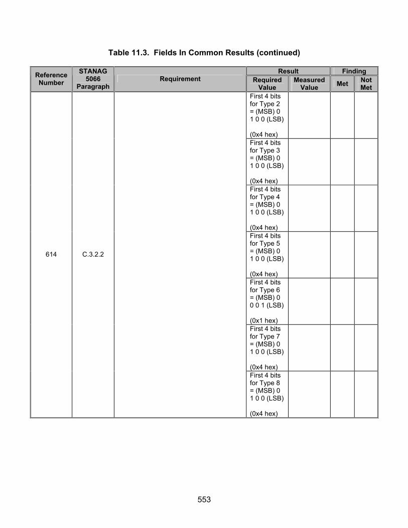
553
Table 11.3. Fields In Common Results (continued)
Result Finding Reference Number
STANAG 5066
Paragraph Requirement Required
Value Measured
Value Met Not Met
First 4 bits for Type 2 = (MSB) 0 1 0 0 (LSB) (0x4 hex)
First 4 bits for Type 3 = (MSB) 0 1 0 0 (LSB) (0x4 hex)
First 4 bits for Type 4 = (MSB) 0 1 0 0 (LSB) (0x4 hex)
First 4 bits for Type 5 = (MSB) 0 1 0 0 (LSB) (0x4 hex)
First 4 bits for Type 6 = (MSB) 0 0 0 1 (LSB) (0x1 hex)
First 4 bits for Type 7 = (MSB) 0 1 0 0 (LSB) (0x4 hex)
614 C.3.2.2
First 4 bits for Type 8 = (MSB) 0 1 0 0 (LSB) (0x4 hex)
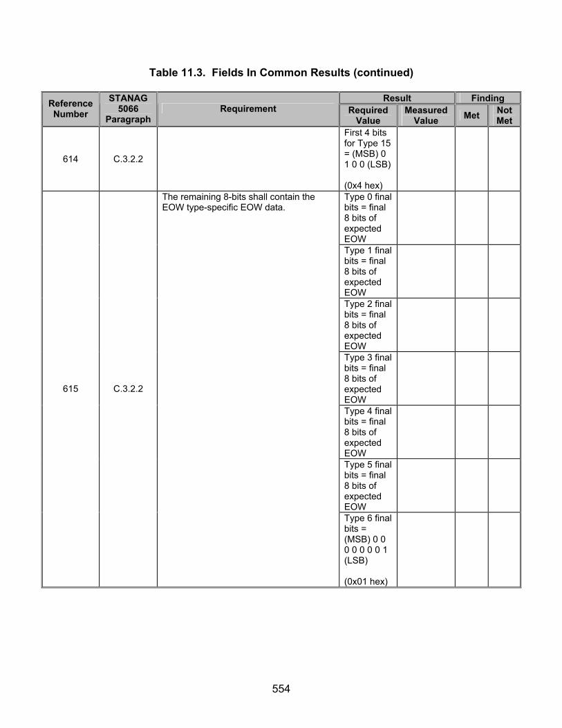
554
Table 11.3. Fields In Common Results (continued)
Result Finding Reference Number
STANAG 5066
Paragraph Requirement Required
Value Measured
Value Met Not Met
614 C.3.2.2
First 4 bits for Type 15 = (MSB) 0 1 0 0 (LSB) (0x4 hex)
Type 0 final bits = final 8 bits of expected EOW
Type 1 final bits = final 8 bits of expected EOW
Type 2 final bits = final 8 bits of expected EOW
Type 3 final bits = final 8 bits of expected EOW
Type 4 final bits = final 8 bits of expected EOW
Type 5 final bits = final 8 bits of expected EOW
615 C.3.2.2
The remaining 8-bits shall contain the EOW type-specific EOW data.
Type 6 final bits = (MSB) 0 0 0 0 0 0 0 1 (LSB) (0x01 hex)

555
Table 11.3. Fields In Common Results (continued)
Result Finding Reference Number
STANAG 5066
Paragraph Requirement Required
Value Measured
Value Met Not Met
Type 7 final bits = final 8 bits of expected EOW
Type 8 final bits = final 8 bits of expected EOW
615 C.3.2.2
Type 15 final bits = final 8 bits of expected EOW
Type 0 D_PDU EOT = (MSB) 0 0 0 0 0 1 0 0 (LSB) (hex = 0x04)
Type 1 D_PDU EOT = (MSB) 0 0 0 0 0 0 0 1 (LSB) (hex = 0x01)
616 C.3.2.3
The 8-bit EOT field shall provide an approximation of the time remaining in the current transmission interval specified by the transmitting node.
Type 2 D_PDU EOT = (MSB) 0 0 0 0 0 0 0 1 (LSB) (hex = 0x01)
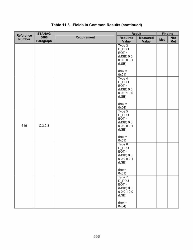
556
Table 11.3. Fields In Common Results (continued)
Result Finding Reference Number
STANAG 5066
Paragraph Requirement Required
Value Measured
Value Met Not Met
Type 3 D_PDU EOT = (MSB) 0 0 0 0 0 0 0 1 (LSB) (hex = 0x01)
Type 4 D_PDU EOT = (MSB) 0 0 0 0 0 1 0 0 (LSB) (hex = 0x04)
Type 5 D_PDU EOT = (MSB) 0 0 0 0 0 0 0 1 (LSB) (hex = 0x01)
Type 6 D_PDU EOT = (MSB) 0 0 0 0 0 0 0 1 (LSB) (hex= 0x01)
616 C.3.2.3
Type 7 D_PDU EOT = (MSB) 0 0 0 0 0 1 0 0 (LSB) (hex = 0x04)
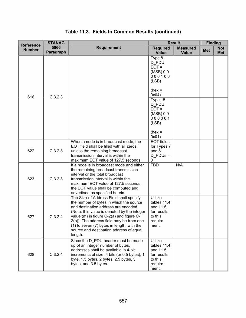
557
Table 11.3. Fields In Common Results (continued)
Result Finding Reference Number
STANAG 5066
Paragraph Requirement Required
Value Measured
Value Met Not Met
Type 8 D_PDU EOT = (MSB) 0 0 0 0 0 1 0 0 (LSB) (hex = 0x04)
616 C.3.2.3
Type 15 D_PDU EOT = (MSB) 0 0 0 0 0 0 0 1 (LSB) (hex = 0x01)
622 C.3.2.3
When a node is in broadcast mode, the EOT field shall be filled with all zeros, unless the remaining broadcast transmission interval is within the maximum EOT value of 127.5 seconds.
EOT fields for Types 7 and 8 D_PDUs = 0
623 C.3.2.3
If a node is in broadcast mode and either the remaining broadcast transmission interval or the total broadcast transmission interval is within the maximum EOT value of 127.5 seconds, the EOT value shall be computed and advertised as specified herein.
TBD N/A
627 C.3.2.4
The Size-of-Address Field shall specify the number of bytes in which the source and destination address are encoded (Note: this value is denoted by the integer value (m) in figure C-2(a) and figure C-2(b)). The address field may be from one (1) to seven (7) bytes in length, with the source and destination address of equal length.
Utilize tables 11.4 and 11.5 for results to this require-ment.
628 C.3.2.4
Since the D_PDU header must be made up of an integer number of bytes, addresses shall be available in 4-bit increments of size: 4 bits (or 0.5 bytes), 1 byte, 1.5 bytes, 2 bytes, 2.5 bytes, 3 bytes, and 3.5 bytes.
Utilize tables 11.4 and 11.5 for results to this require-ment.
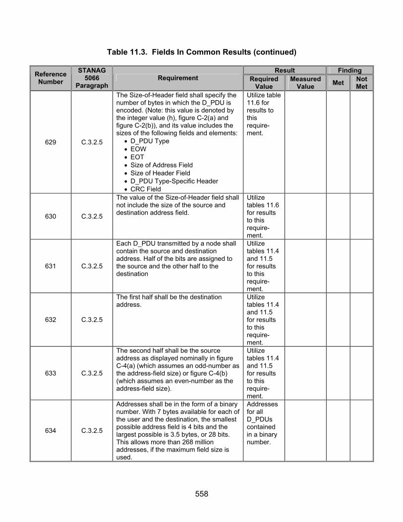
558
Table 11.3. Fields In Common Results (continued)
Result Finding Reference Number
STANAG 5066
Paragraph Requirement Required
Value Measured
Value Met Not Met
629 C.3.2.5
The Size-of-Header field shall specify the number of bytes in which the D_PDU is encoded. (Note: this value is denoted by the integer value (h), figure C-2(a) and figure C-2(b)), and its value includes the sizes of the following fields and elements:
• D_PDU Type • EOW • EOT • Size of Address Field • Size of Header Field • D_PDU Type-Specific Header • CRC Field
Utilize table 11.6 for results to this require-ment.
630 C.3.2.5
The value of the Size-of-Header field shall not include the size of the source and destination address field.
Utilize tables 11.6 for results to this require-ment.
631 C.3.2.5
Each D_PDU transmitted by a node shall contain the source and destination address. Half of the bits are assigned to the source and the other half to the destination
Utilize tables 11.4 and 11.5 for results to this require-ment.
632 C.3.2.5
The first half shall be the destination address.
Utilize tables 11.4 and 11.5 for results to this require-ment.
633 C.3.2.5
The second half shall be the source address as displayed nominally in figure C-4(a) (which assumes an odd-number as the address-field size) or figure C-4(b) (which assumes an even-number as the address-field size).
Utilize tables 11.4 and 11.5 for results to this require-ment.
634 C.3.2.5
Addresses shall be in the form of a binary number. With 7 bytes available for each of the user and the destination, the smallest possible address field is 4 bits and the largest possible is 3.5 bytes, or 28 bits. This allows more than 268 million addresses, if the maximum field size is used.
Addresses for all D_PDUs contained in a binary number.

559
Table 11.3. Fields In Common Results (continued)
Result Finding Reference Number
STANAG 5066
Paragraph Requirement Required
Value Measured
Value Met Not Met
635 C.3.2.5
A decimal number shall represent each byte or fractional byte of an address.
Utilize tables 11.4 and 11.5 for results to this require-ment.
636 C.3.2.5
The binary equivalent shall be mapped into the corresponding byte.
Utilize tables 11.4 and 11.5 for results to this require-ment.
637 C.3.2.5
Any fractional-byte elements in the address shall be mapped into the first (leftmost) nonzero number in the in the decimal representation of the address.
Utilize tables 11.4 and 11.5 for results to this require-ment.
638 C.3.2.6
The remaining numbers in the decimal representation of the address shall refer to byte-sized elements in the address field.
Utilize tables 11.4 and 11.5 for results to this require-ment.
639 C.3.2.6
The address bits shall be mapped into the address field by placing the MSB of the address into the MSB of the first byte of the address field, and the LSB into the LSB of the last byte of the field, in accordance with figure C-4(a), for addresses with length of 0.5, 1.5, 2.5, or 3.5 bytes, and figure C-4(b), for addresses with length of 1, 2, or 3 bytes.
Utilize tables 11.4 and 11.5 for results to this require-ment.
640 C.3.2.6
When a field spans more than one octet, the order of the bit values within each octet shall decrease progressively as the octet number increases.
Utilize tables 11.4 and 11.5 for results to this require-ment.

560
Table 11.3. Fields In Common Results (continued)
Result Finding Reference Number
STANAG 5066
Paragraph Requirement Required
Value Measured
Value Met Not Met
641 C.3.2.6
Trailing address bytes that are zero shall be sent.
Utilize tables 11.4 and 11.5 for results to this require-ment.
643 C.3.2.8
The two-bytes following the D_PDU Type-Specific Header shall contain a 16-bit Cyclic Redundancy Check (CRC) field.
Header CRC comes at the end of each D_PDU.
Type 0 D_PDU Header CRC = Calculated Header CRC
Type 1 D_PDU Header CRC = Calculated Header CRC
Type 2 D_PDU Header CRC = Calculated Header CRC
Type 3 D_PDU Header CRC = Calculated Header CRC
644
C.3.2.8
The header CRC error-check field shall be calculated using the following polynomial: x^16 + x^15 + x^12 + x^11 + x^8 + x^6 + x^3 + 1 , or in hexadecimal format 0x19949, using the shift-register method shown by the figures in appendix I of CCITT Recommendation V.41 (or equivalent method in software; an example is given below).
Type 4 D_PDU Header CRC = Calculated Header CRC
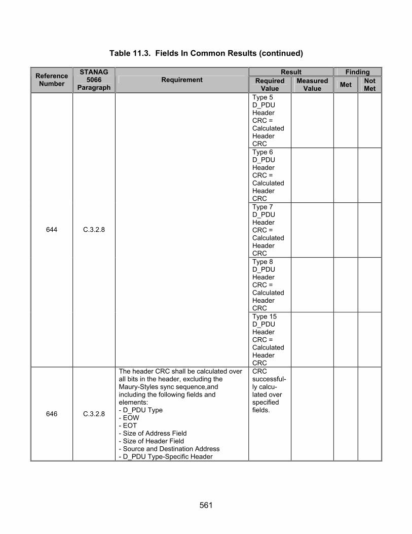
561
Table 11.3. Fields In Common Results (continued)
Result Finding Reference Number
STANAG 5066
Paragraph Requirement Required
Value Measured
Value Met Not Met
Type 5 D_PDU Header CRC = Calculated Header CRC
Type 6 D_PDU Header CRC = Calculated Header CRC
Type 7 D_PDU Header CRC = Calculated Header CRC
Type 8 D_PDU Header CRC = Calculated Header CRC
644 C.3.2.8
Type 15 D_PDU Header CRC = Calculated Header CRC
646 C.3.2.8
The header CRC shall be calculated over all bits in the header, excluding the Maury-Styles sync sequence,and including the following fields and elements: - D_PDU Type - EOW - EOT - Size of Address Field - Size of Header Field - Source and Destination Address - D_PDU Type-Specific Header
CRC successful-ly calcu-lated over specified fields.

562
Table 11.3. Fields In Common Results (continued)
Result Finding Reference Number
STANAG 5066
Paragraph Requirement Required
Value Measured
Value Met Not Met
647 C.3.2.8
A node shall process the information contained in a header with a valid CRC, regardless of the result of the CRC error-check over any segmented C_PDU that may be a part of the D_PDU.
TBD N/A
For Type 0 D_PDU first byte of recorded CRC = last byte of calculated CRC and last byte of recorded CRC = first byte of calculated CRC.
For Type 1 D_PDU first byte of recorded CRC = last byte of calculated CRC and last byte of recorded CRC = first byte of calculated CRC.
648 C.3.2.8
The CRC bits shall be mapped (see figure C-5) into the CRC octets by placing the MSB of the CRC into the LSB of the first byte of the CRC field, and the LSB of the CRC into the MSB of the last byte of the CRC field.
For Type 2 D_PDU first byte of recorded CRC = last byte of calculated CRC and last byte of recorded CRC = first byte of calculated CRC.

563
Table 11.3. Fields In Common Results (continued)
Result Finding Reference Number
STANAG 5066
Paragraph Requirement Required
Value Measured
Value Met Not Met
For Type 3 D_PDU first byte of recorded CRC = last byte of calculated CRC and last byte of recorded CRC = first byte of calculated CRC.
For Type 4 D_PDU first byte of recorded CRC = last byte of calculated CRC and last byte of recorded CRC = first byte of calculated CRC.
648 C.3.2.8
For Type 5 D_PDU first byte of recorded CRC = last byte of calculated CRC and last byte of recorded CRC = first byte of calculated CRC.

564
Table 11.3. Fields In Common Results (continued)
Result Finding Reference Number
STANAG 5066
Paragraph Requirement Required
Value Measured
Value Met Not Met
For Type 6 D_PDU first byte of recorded CRC = last byte of calculated CRC and last byte of recorded CRC = first byte of calculated CRC.
For Type 7 D_PDU first byte of recorded CRC = last byte of calculated CRC and last byte of recorded CRC = first byte of calculated CRC.
648 C.3.2.8
For Type 8 D_PDU first byte of recorded CRC = last byte of calculated CRC and last byte of recorded CRC = first byte of calculated CRC.

565
Table 11.3. Fields In Common Results (continued)
Result Finding Reference Number
STANAG 5066
Paragraph Requirement Required
Value Measured
Value Met Not Met
648 C.3.2.8
For Type 15 D_PDU first byte of recorded CRC = last byte of calculated CRC and last byte of recorded CRC = first byte of calculated CRC.
862 C.5.4
The EOW Message Type 4 shall be encoded as shown in figure C-41 and contain a single field, Content.
Type 4 EOW used for Types 0-5, 7, 8, and 15 D_PDUs.
Type 0 D_DPU EOW = Expected EOW
Type 1 D_DPU EOW = Expected EOW
Type 2 D_DPU EOW = Expected EOW
Type 3 D_DPU EOW = Expected EOW
863 C.5.4
The Content field shall be encoded as the bit-mapped specification of capabilities defined in table C-9.
Type 4 D_DPU EOW = Expected EOW
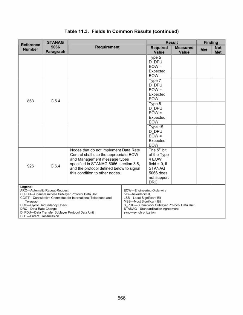
566
Table 11.3. Fields In Common Results (continued)
Result Finding Reference Number
STANAG 5066
Paragraph Requirement Required
Value Measured
Value Met Not Met
Type 5 D_DPU EOW = Expected EOW
Type 7 D_DPU EOW = Expected EOW
Type 8 D_DPU EOW = Expected EOW
863 C.5.4
Type 15 D_DPU EOW = Expected EOW
926 C.6.4
Nodes that do not implement Data Rate Control shall use the appropriate EOW and Management message types specified in STANAG 5066, section 3.5, and the protocol defined below to signal this condition to other nodes.
The 5th bit of the Type 4 EOW field = 0, if STANAG 5066 does not support DRC.
Legend: ARQ—Automatic Repeat-Request C_PDU—Channel Access Sublayer Protocol Data Unit CCITT—Consultative Committee for International Telephone and
Telegraph CRC—Cyclic Redundancy Check DRC—Data Rate Change D_PDU—Data Transfer Sublayer Protocol Data Unit EOT—End of Transmission
EOW—Engineering Orderwire hex—hexadecimal LSB—Least Significant Bit MSB—Most Significant Bit S_PDU—Subnetwork Sublayer Protocol Data Unit STANAG—Standardization Agreement sync—synchronization

567
Table 11.4. Results for Address Fields for Types 0, 2, 4, 6, 7, 8, and 15 D_PDUs
Con- figured Node
Address Size
Node Address
Size Node
Address Destina-
tion Address
Source Address
Decimal Destina-
tion Address
Decimal Source
Address
Number of Bytes Reser-ved for each
Address
1
(MSB) 0 0 1 (LSB)
(0x1 hex)
(MSB) 1 1 1 1 0
0 0 1 (LSB) (0xF1 hex)
(MSB) 1 1 1 1 (LSB)
(0xF hex)
(MSB) 0 0 0 1 (LSB)
(0x1 hex)
F 1 0.5
2
(MSB) 0 1 0 (LSB)
(0x2 hex)
(MSB) 1 1 1 1 1 1 1 1 0 0 0 0 0 0 0 1 (LSB) (0xFF01
hex)
(MSB) 1 1 1 1 1
1 1 1 (LSB)
(0xFF hex)
(MSB) 0 0 0 0 0
0 0 1 (LSB)
(0x01 hex)
255 1 1.0
3
(MSB) 0 1 1 (LSB)
(0x3 hex)
(MSB) 1 1 1 1 1 1 1 1 1 1 1 1 0 0 0 1 0 0 0 0 0 0 1 0 (LSB)
(0xFFF102 hex)
(MSB) 1 1 1 1 1 1 1 1 1 1 1 1 (LSB)
(0xFFF
hex)
(MSB) 0 0 0 1 0 0 0 0 0 0 1 0 (LSB)
(0x102
hex)
15.255 1.2 1.5
4
(MSB) 1 0 0 (LSB)
(0x4 hex)
(MSB) 1 1 1 1 1 1 1 1 1 1 1 1 1 1 1 1 0 0 0 0 0 0 0 1 1 1 0 1 1 1 1 0 (LSB)
(0xFFFF01DE hex)
(MSB) 1 1 1 1 1 1 1 1 1 1 1 1 1 1 1 1
(LSB)
(0xFFFF hex)
(MSB) 0 0 0 0 0 0 0 1 1 1 0 1 1 1 1 0
(LSB)
(0x01DE hex)
255.255 1.222 2.0
5
(MSB) 1 0 1 (LSB)
(0x5 hex)
(MSB) 1 1 1 1 1 1 1 1 1 1 1 1 1 1 1 1 1 1 1 1 0 0 0 1 1 1 0 1 1 1 1 0 0 0 0 0 0 0 0 1
(LSB) (0x
FFFFF 1DE01
hex)
(MSB) 1 1 1 1 1 1 1 1 1 1 1 1 1 1 1 1 1 1 1 1
(LSB)
(0xFFFFF hex)
(MSB) 0 0 0 1 1 1 0 1 1 1 1 0 0 0 0 0 0 0 0 1
(LSB)
(0x1DE01 hex)
15.255. 255
1.222.1 2.5
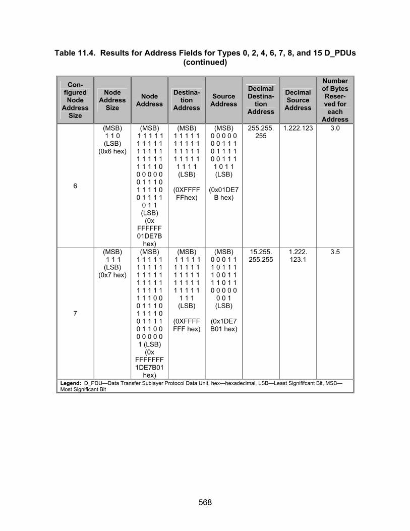
568
Table 11.4. Results for Address Fields for Types 0, 2, 4, 6, 7, 8, and 15 D_PDUs (continued)
Con-
figured Node
Address Size
Node Address
Size Node
Address Destina-
tion Address
Source Address
Decimal Destina-
tion Address
Decimal Source
Address
Number of Bytes Reser-ved for each
Address
6
(MSB) 1 1 0 (LSB)
(0x6 hex)
(MSB) 1 1 1 1 1 1 1 1 1 1 1 1 1 1 1 1 1 1 1 1 1 1 1 1 0 0 0 0 0 0 0 1 1 1 0 1 1 1 1 0 0 1 1 1 1
0 1 1 (LSB)
(0x FFFFFF 01DE7B
hex)
(MSB) 1 1 1 1 1 1 1 1 1 1 1 1 1 1 1 1 1 1 1 1 1 1 1 1 (LSB)
(0XFFFFFFhex)
(MSB) 0 0 0 0 0 0 0 1 1 1 0 1 1 1 1 0 0 1 1 1 1 0 1 1 (LSB)
(0x01DE7
B hex)
255.255. 255
1.222.123 3.0
7
(MSB) 1 1 1 (LSB)
(0x7 hex)
(MSB) 1 1 1 1 1 1 1 1 1 1 1 1 1 1 1 1 1 1 1 1 1 1 1 1 1 1 1 1 0 0 0 1 1 1 0 1 1 1 1 0 0 1 1 1 1 0 1 1 0 0 0 0 0 0 0 1 (LSB)
(0x FFFFFFF 1DE7B01
hex)
(MSB) 1 1 1 1 1 1 1 1 1 1 1 1 1 1 1 1 1 1 1 1 1 1 1 1 1
1 1 1 (LSB)
(0XFFFFFFF hex)
(MSB) 0 0 0 1 1 1 0 1 1 1 1 0 0 1 1 1 1 0 1 1 0 0 0 0 0
0 0 1 (LSB)
(0x1DE7B01 hex)
15.255. 255.255
1.222. 123.1
3.5
Legend: D_PDU—Data Transfer Sublayer Protocol Data Unit, hex—hexadecimal, LSB—Least Signififcant Bit, MSB—Most Significant Bit

569
Table 11.5. Results for Address Fields for Types 1, 3, and 5 D_PDUs
Con-figured Node
Address Size
Node Address
Size Node
Address Destina-
tion Address
Source Address
Decimal Destina-
tion Address
Decimal Source
Address
Number of Bytes Reserved for each Address
1
(MSB) 0 0 1 (LSB)
(0x1 hex)
(MSB) 0 0 0 1 1
1 1 1 (LSB) (0x1F hex)
(MSB) 0 0 0 1 (LSB)
(0x1 hex)
(MSB) 1 1 1 1 (LSB)
(0xF hex)
1 F 0.5
2
(MSB) 0 1 0 (LSB)
(0x2 hex)
(MSB) 0 0 0 0 0 0 0 1 1 1 1 1 1 1 1 1 (LSB)
(0x 01FF hex)
(MSB) 1 1 1 1 1
1 1 1 (LSB)
(0xFF hex)
(MSB) 0 0 0 1 0
0 0 0 (LSB)
(0x10 hex)
1 255 1.0
3
(MSB) 0 1 1 (LSB)
(0x3 hex)
(MSB) 0 0 0 1 0 0 0 0 0 0 1 0 1 1 1 1 1 1 1 1 1 1 1 1 (LSB) (0x102
FFF hex)
(MSB) 0 0 0 1 0 0 0 0 0 0 1 0 (LSB)
(0x102
hex)
(MSB) 1 1 1 1 1 1 1 1 1 1 1 1 (LSB)
(0xFFF
hex)
1.2
15.255 1.5
4
(MSB) 1 0 0 (LSB)
(0x4 hex)
(MSB) 0 0 0 0 0 0 0 1 1 1 0 1 1 1 1 0 1 1 1 1 1 1 1 1 1 1 1 1 1 1
1 1 (LSB)
(0x FFFF 01DE hex)
(MSB) 0 0 0 0 0 0 0 1 1 1 0 1 1 1 1 0 (LSB)
(0x01DE
hex)
(MSB) 1 1 1 1 1 1 1 1 1 1 1 1 1 1 1 1 (LSB)
(0xFFFF)
1.222
255.255 2.0
5
(MSB) 1 0 1 (LSB)
(0x5 hex)
(MSB) 0 0 0 1 1 1 0 1 1 1 1 0 0 0 0 0 0 0 0 1 1 1 1 1 1 1 1 1 1 1 1 1 1 1 1 1 1 1 1 1
(LSB) (0x1DE01FFFFF
hex)
(MSB) 0 0 0 1 1 1 0 1 1 1 1 0 0 0 0 0 0 0 0 1
(LSB)
(0x1DE01 hex)
(MSB) 1 1 1 1 1 1 1 1 1 1 1 1 1 1 1 1 1 1 1 1
(LSB)
(0xFFFFF hex)
1.222.1
15.255. 255
2.5

570
Table 11.5. Results for Address Fields for Types 1, 3, and 5 D_PDUs (continued)
Con-
figured Node
Address Size
Node Address
Size Node
Address Destina-
tion Address
Source Address
Decimal Destina-
tion Address
Decimal Source
Address
Number of Bytes
Reserved for each Address
6
(MSB) 1 1 0 (LSB)
(0x6 hex)
(MSB) 0 0 0 0 0 0 0 1 1 1 0 1 1 1 1 0 0 1 1 1 1 0 1 1 1 1 1 1 1 1 1 1 1 1 1 1 1 1 1 1 1 1 1 1 1
1 1 1 (LSB)
(0xFFFFF01DE7B
F hex)
(MSB) 0 0 0 0 0 0 0 1 1 1 0 1 1 1 1 0 0 1 1 1 1 0 1 1 (LSB)
(0x01DE7B hex)
(MSB) 1 1 1 1 1 1 1 1 1 1 1 1 1 1 1 1 1 1 1 1 1 1 1 1 (LSB)
(0XFFFFFFhex)
1.222. 123
255.255. 255
3.0
7
(MSB) 1 1 1 (LSB)
(0x7 hex)
(MSB) 0 0 0 1 1 1 0 1 1 1 1 0 0 1 1 1 1 0 1 1 0 0 0 0 0 0 0 1 1 1 1 1 1 1 1 1 1 1 1 1 1 1 1 1 1 1 1 1 1 1 1 1 1 1 1 1 (LSB)
(0x 1DE7B01FFFFFFF
hex)
(MSB) 0 0 0 1 1 1 0 1 1 1 1 0 0 1 1 1 1 0 1 1 0 0 0 0 0
0 0 1 (LSB)
(0x1DE7B01 hex)
(MSB) 1 1 1 1 1 1 1 1 1 1 1 1 1 1 1 1 1 1 1 1 1 1 1 1 1
1 1 1 (LSB)
(0XFFFFFFF hex)
1.222.123.1
15.255.255.255
3.5
Legend: D_PDU—Data Transfer Sublayer Protocol Data Unit, hex—hexadecimal, LSB—Least Signififcant Bit, MSB—Most Significant Bit

571
Table 11.6. Required Values for Size-of Field for Various D_PDU Types
D_PDU Type Configure Node
Address Size
0 1 2 3 4 5 6 7 8 15
1
(MSB) 0 0 1 0 1 0 0 1 (LSB) (0x29 hex)
(MSB) 0 0 1 0 0 1 1 1
(LSB) (0x27 hex)
(MSB) 0 0 1 0 1 0 1 0
(LSB) (0x2A hex)
(MSB) 0 0 1 0 1 0 0 1
(LSB) (0x29 hex)
(MSB) 0 0 1 0 1 0 0 1
(LSB) (0x29 hex)
(MSB) 0 0 1 0 0 1 1 1
(LSB) (0x27 hex)
(MSB) 0 0 1 0 1 0 0 1
(LSB) (0x29 hex)
(MSB) 0 0 1 0 1 1 1 1
(LSB) (0x2F hex)
(MSB) 0 0 1 0 1 1 1 1
(LSB) (0x2F hex)
(MSB) 0 0 1 0 0 1 1 1
(LSB) (0x27 hex)
2
(MSB) 0 1 0 0 1 0 0 1 (LSB) (0x49 hex)
(MSB) 0 1 0 0 0 1 1 1
(LSB) (0x47 hex)
(MSB) 0 1 0 0 1 0 1 0
(LSB) (0x4A hex)
(MSB) 0 1 0 0 1 0 0 1
(LSB) (0x49 hex)
(MSB) 0 1 0 0 1 0 0 1
(LSB) (0x49 hex)
(MSB) 0 1 0 0 0 1 1 1
(LSB) (0x47 hex)
(MSB) 0 1 0 0 1 0 0 1
(LSB) (0x49 hex)
(MSB) 0 1 0 0 1 1 1 1
(LSB) (0x4F hex)
(MSB) 0 1 0 0 1 1 1 1
(LSB) (0x4F hex)
(MSB) 0 1 0 0 0 1 1 1
(LSB) (0x47 hex)
3
(MSB) 0 1 1 0 1 0 0 1 (LSB) (0x69 hex)
(MSB) 0 1 1 0 0 1 1 1
(LSB) (0x67 hex)
(MSB) 0 1 1 0 1 0 1 0
(LSB) (0x6A hex)
(MSB) 0 1 1 0 1 0 0 1
(LSB) (0x69 hex)
(MSB) 0 1 1 0 1 0 0 1
(LSB) (0x69 hex)
(MSB) 0 1 1 0 0 1 1 1
(LSB) (0x67 hex)
(MSB) 0 1 1 0 1 0 0 1
(LSB) (0x69 hex)
(MSB) 0 1 1 0 1 1 1 1
(LSB) (0x6F hex)
(MSB) 0 1 1 0 1 1 1 1
(LSB) (0x6F hex)
(MSB) 0 1 1 0 0 1 1 1
(LSB) (0x67 hex)
4
(MSB) 1 0 0 0 1 0 0 1 (LSB) (0x89 hex)
(MSB) 1 0 0 0 0 1 1 1
(LSB) (0x87 hex)
(MSB) 1 0 0 0 1 0 1 0
(LSB) (0x8A hex)
(MSB) 1 0 0 0 1 0 0 1
(LSB) (0x89 hex)
(MSB) 1 0 0 0 1 0 0 1
(LSB) (0x89 hex)
(MSB) 1 0 0 0 0 1 1 1
(LSB) (0x87 hex)
(MSB) 1 0 0 0 1 0 0 1
(LSB) (0x89 hex)
(MSB) 1 0 0 0 1 1 1 1
(LSB) (0x8F hex)
(MSB) 1 0 0 0 1 1 1 1
(LSB) (0x8F hex)
(MSB) 1 0 0 0 0 1 1 1
(LSB) (0x87 hex)
5
(MSB) 1 0 10 1 0 0 1 (LSB) (0xA9 hex)
(MSB) 1 0 1 0 0 1 1 1
(LSB) (0xA7 hex)
(MSB) 1 0 1 0 1 0 1 0
(LSB) (0xAA hex)
(MSB) 1 0 10 1 0 0
1 (LSB) (0xA9 hex)
(MSB) 1 0 10 1 0 0
1 (LSB) (0xA9 hex)
(MSB) 1 0 1 0 0 1 1 1
(LSB) (0xA7 hex)
(MSB) 1 0 10 1 0 0
1 (LSB) (0xA9 hex)
(MSB) 1 0 1 0 1 1 1 1
(LSB) (0xAF hex)
(MSB) 1 0 1 0 1 1 1 1
(LSB) (0xAF hex)
(MSB) 1 0 1 0 0 1 1 1
(LSB) (0xA7 hex)
6
(MSB) 1 1 0 0 1 0 0 1 (LSB) (0xC9 hex)
(MSB) 1 1 0 0 0 1 1 1
(LSB) (0xC7 hex)
(MSB) 1 1 0 0 1 0 1 0
(LSB) (0xCA hex)
(MSB) 1 1 0 0 1 0 0 1
(LSB) (0xC9 hex)
(MSB) 1 1 0 0 1 0 0 1
(LSB) (0xC9 hex)
(MSB) 1 1 0 0 0 1 1 1
(LSB) (0xC7 hex)
(MSB) 1 1 0 0 1 0 0 1
(LSB) (0xC9 hex)
(MSB) 1 1 0 0 1 1 1 1
(LSB) (0xCF hex)
(MSB) 1 1 0 0 1 1 1 1
(LSB) (0xCF hex)
(MSB) 1 1 0 0 0 1 1 1
(LSB) (0xC7 hex)

572
Table 11.6. Required Values for Size-of Field for Various D_PDU Types (continued)
D_PDU Type Configure
Node Address
Size 0 1 2 3 4 5 6 7 8 15
7
(MSB) 1 1 1 0 1 0 0 1 (LSB) (0xE9 hex)
(MSB) 1 1 1 0 0 1 1 1
(LSB) (0xE7 hex)
(MSB) 1 1 1 0 1 0 1 0
(LSB) (0xEA hex)
(MSB) 1 1 1 0 1 0 0 1
(LSB) (0xE9 hex)
(MSB) 1 1 1 0 1 0 0 1
(LSB) (0xE9 hex)
(MSB) 1 1 1 0 0 1 1 1
(LSB) (0xE7 hex)
(MSB) 1 1 1 0 1 0 0 1
(LSB) (0xE9 hex)
(MSB) 1 1 1 0 1 1 1 1
(LSB) (0xEF hex)
(MSB) 1 1 1 0 1 1 1 1
(LSB) (0xEF hex)
(MSB) 1 1 1 0 0 1 1 1
(LSB) (0xE7 hex)
Size-of-Header:
(MSB) 0 1 0 0 1 (LSB) (hex= 0x9)
(MSB) 0 0 1 1 1 (LSB) (hex= 0x7)
(MSB) 0 1 0 1 0 (LSB) (hex= 0xA)
(MSB) 0 1 0 0 1 (LSB) (hex= 0x9)
(MSB) 0 1 0 0 1 (LSB) (hex= 0x9)
(MSB) 0 0 1 1 1 (LSB) (hex= 0x7)
(MSB) 0 1 0 0 1 (LSB) (hex= 0x9)
(MSB) 0 1 1 1 1 (LSB) (hex= 0xF)
(MSB) 0 1 1 1 1 (LSB) (hex= 0xF)
(MSB) 0 0 1 1 1 (LSB) (hex= 0x7)
Legend: D_PDU—Data Transfer Sublayer Protocol Data Unit, hex—hexadecimal, LSB—Least Significant Bit, MSB—Most Significant Bit
Table 11.7. Measured Values for Address Fields for Types 0, 2, 4, 6, 7, 8, and 15
D_PDUs
Con- figured Node
Address Size
Node Address
Size Node
Address Destina-
tion Address
Source Address
Decimal Destina-
tion Address
Decimal Source
Address
Number of Bytes Reser-ved for each
Address
1
2
3
4
5
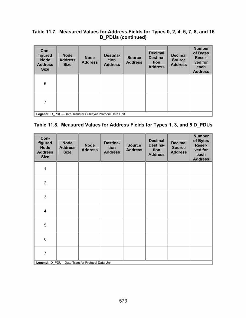
573
Table 11.7. Measured Values for Address Fields for Types 0, 2, 4, 6, 7, 8, and 15 D_PDUs (continued)
Con-
figured Node
Address Size
Node Address
Size Node
Address Destina-
tion Address
Source Address
Decimal Destina-
tion Address
Decimal Source
Address
Number of Bytes Reser-ved for each
Address
6
7
Legend: D_PDU—Data Transfer Sublayer Protocol Data Unit
Table 11.8. Measured Values for Address Fields for Types 1, 3, and 5 D_PDUs
Con-
figured Node
Address Size
Node Address
Size Node
Address Destina-
tion Address
Source Address
Decimal Destina-
tion Address
Decimal Source
Address
Number of Bytes Reser-ved for each
Address
1
2
3
4
5
6
7
Legend: D_PDU—Data Transfer Protocol Data Unit

574
Table 11.9. Measured Values for Size-of Field for Various D_PDU Types
D_PDU Type Configure Node
Address Size
0 1 2 3 4 5 6 7 8 15
1
2
3
4
5
6
7
Size-of-Header:
Legend: D_PDU—Data Transfer Sublayer Protocol Data Unit

575
SUBTEST 12. SELECTIVE ACKNOWLEDGEMENTS 12.1 Objective. To determine the extent of compliance to the requirements of STANAG 5066, for validating Selective Acknowledgements (ACKs), reference numbers 574, 592, 680-681, 683-689, and 924. 12.2 Criteria
a. The reliable Selective ARQ service shall use CRC check-bits and flow-
control procedures, such as requests for retransmission of D_PDUs in which errors have been detected to provide a reliable data transfer service. (appendix B, reference number 574)
b. The Selective ARQ protocol shall operate in a half or full duplex mode
since the local node, after sending I-Frames, waits for an indication in the form of a selective acknowledgement from the remote node as to whether the I-Frames were correctly received or not. (appendix B, reference number 592)
c. A set (1) bit within the Selective ACKs field shall indicate a positive
acknowledgement (ACK), i.e., that the D_PDU with the corresponding FSN was received correctly. (appendix B, reference number 680)
d. Only D_PDU frames with a correct segmented C_PDU CRC shall be acknowledged positively even if the header CRC is correct. (appendix B, reference number 681)
e. A cleared (0) bit within the Selective ACKs field shall indicate a negative acknowledgement (NACK), i.e., that the D_PDU with the corresponding FSN was received incorrectly or not at all. (appendix B, reference number 683)
f. The construction of the Selective ACK field and the mapping of D_PDU FSNs to bits within the Selective ACK field shall be in accordance with figures 12.1, 12.2, and the paragraphs below. (appendix B, reference number 684)
L S B
0 . . . . . . .
M S B
0001
. . . . . . . X 00ZY
L W E + 1 U W E
B y t e 1 B y t e a
S e l e c t i v e A C K B i t M a p
R e c e i v e r S l i d i n g W i n d o w
B i t O r d e r o f T r a n s m i s s i o n
L e g e n d : A C K — A c k n o w le d g e m e n t , L S B — L e a s t S i g n i f i c a n t B i t , L W E — L o w e r W i n d o w E d g e , M S B — M o s t S i g n i f i c a n t B i t , U W E — U p p e r W in d o w E d g e
Figure 12.1. Construction of Selective ACK Field
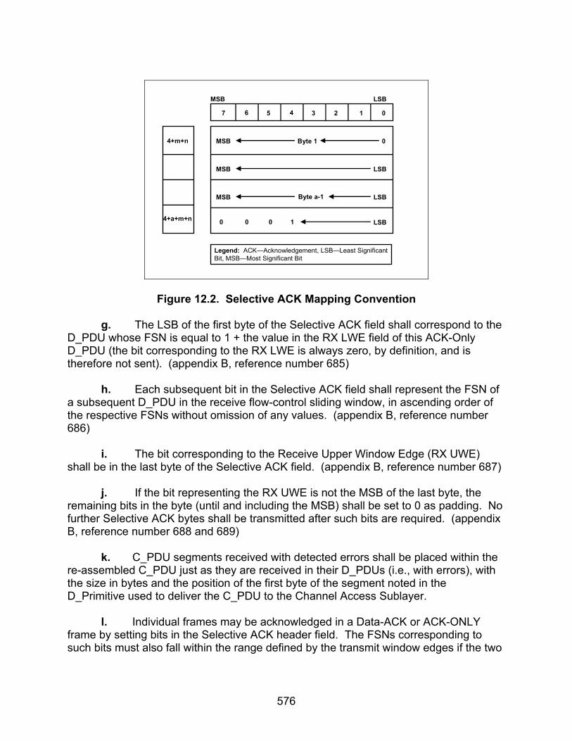
576
7 6 5 4 3 2 1 0
4+a+m+n
4+m+n 0Byte 1MSB
LSBMSB
LSBByte a-1MSB
0 0 0 1 LSB
LSBMSB
Legend: ACK—Acknowledgement, LSB—Least SignificantBit, MSB—Most Significant Bit
Figure 12.2. Selective ACK Mapping Convention
g. The LSB of the first byte of the Selective ACK field shall correspond to the D_PDU whose FSN is equal to 1 + the value in the RX LWE field of this ACK-Only D_PDU (the bit corresponding to the RX LWE is always zero, by definition, and is therefore not sent). (appendix B, reference number 685)
h. Each subsequent bit in the Selective ACK field shall represent the FSN of a subsequent D_PDU in the receive flow-control sliding window, in ascending order of the respective FSNs without omission of any values. (appendix B, reference number 686)
i. The bit corresponding to the Receive Upper Window Edge (RX UWE) shall be in the last byte of the Selective ACK field. (appendix B, reference number 687)
j. If the bit representing the RX UWE is not the MSB of the last byte, the remaining bits in the byte (until and including the MSB) shall be set to 0 as padding. No further Selective ACK bytes shall be transmitted after such bits are required. (appendix B, reference number 688 and 689)
k. C_PDU segments received with detected errors shall be placed within the re-assembled C_PDU just as they are received in their D_PDUs (i.e., with errors), with the size in bytes and the position of the first byte of the segment noted in the D_Primitive used to deliver the C_PDU to the Channel Access Sublayer.
l. Individual frames may be acknowledged in a Data-ACK or ACK-ONLY frame by setting bits in the Selective ACK header field. The FSNs corresponding to such bits must also fall within the range defined by the transmit window edges if the two
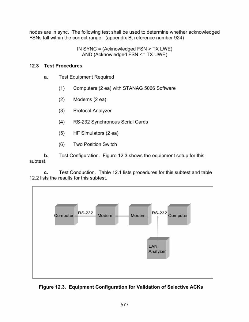
577
nodes are in sync. The following test shall be used to determine whether acknowledged FSNs fall within the correct range. (appendix B, reference number 924)
IN SYNC = (Acknowledged FSN > TX LWE)
AND (Acknowledged FSN <= TX UWE) 12.3 Test Procedures a. Test Equipment Required
(1) Computers (2 ea) with STANAG 5066 Software (2) Modems (2 ea) (3) Protocol Analyzer (4) RS-232 Synchronous Serial Cards (5) HF Simulators (2 ea) (6) Two Position Switch
b. Test Configuration. Figure 12.3 shows the equipment setup for this subtest.
c. Test Conduction. Table 12.1 lists procedures for this subtest and table 12.2 lists the results for this subtest.
Computer Modem Modem Computer
LANAnalyzer
RS-232 RS-232
Figure 12.3. Equipment Configuration for Validation of Selective ACKs
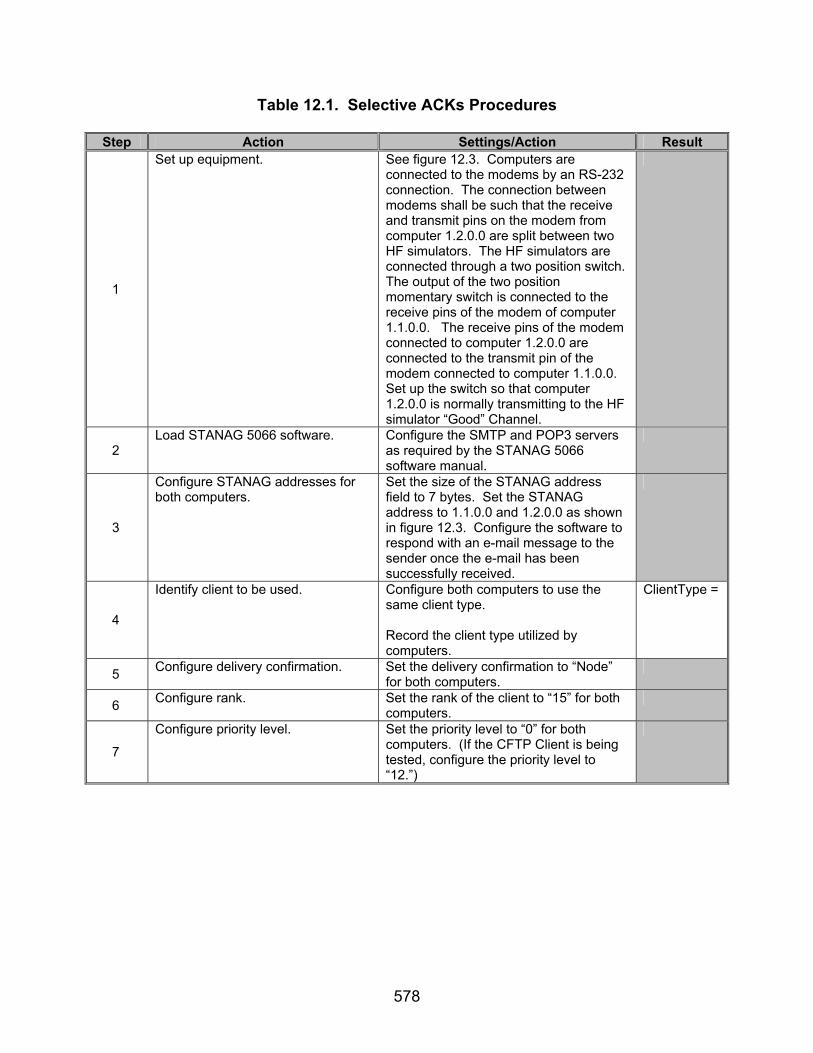
578
Table 12.1. Selective ACKs Procedures
Step Action Settings/Action Result
1
Set up equipment. See figure 12.3. Computers are connected to the modems by an RS-232 connection. The connection between modems shall be such that the receive and transmit pins on the modem from computer 1.2.0.0 are split between two HF simulators. The HF simulators are connected through a two position switch. The output of the two position momentary switch is connected to the receive pins of the modem of computer 1.1.0.0. The receive pins of the modem connected to computer 1.2.0.0 are connected to the transmit pin of the modem connected to computer 1.1.0.0. Set up the switch so that computer 1.2.0.0 is normally transmitting to the HF simulator “Good” Channel.
2 Load STANAG 5066 software. Configure the SMTP and POP3 servers
as required by the STANAG 5066 software manual.
3
Configure STANAG addresses for both computers.
Set the size of the STANAG address field to 7 bytes. Set the STANAG address to 1.1.0.0 and 1.2.0.0 as shown in figure 12.3. Configure the software to respond with an e-mail message to the sender once the e-mail has been successfully received.
4
Identify client to be used. Configure both computers to use the same client type. Record the client type utilized by computers.
ClientType =
5 Configure delivery confirmation. Set the delivery confirmation to “Node” for both computers.
6 Configure rank. Set the rank of the client to “15” for both computers.
7
Configure priority level. Set the priority level to “0” for both computers. (If the CFTP Client is being tested, configure the priority level to “12.”)

579
Table 12.1. Selective ACKs Procedures (continued)
Step Action Settings/Action Result The following procedures are for Types 1 and 2 D_PDUs for reference numbers 574, 592, 680-681, 683-
689, and 924.
8
Configure HF simulators.
Configure the HF simulator “Bad” Channel to produce a 0-dB SNR and the HF simulator “Good” Channel to produce a 20-dB SNR.
9
Configure protocol analyzer. Configure the protocol analyzer to capture the transmitted data between the two computers and save it to a file. Configure the protocol analyzer to have a 2400-bps bit rate and to synchronize on “0xEB90.” Configure the protocol analyzer to drop sync after 20 “FF”s. Configure the analyzer to time stamp each captured byte.
10
Send e-mail message and capture all transmitted and received bytes via the protocol analyzer shown in figure 12.3.
Send the following e-mail message from the computer with STANAG address 1.2.0.0 to the computer with STANAG address 1.1.0.0 using a Soft Link and Non-Expedited ARQ Delivery Method. For the Subject Line: Test 1 In the Body: “This is a test from address 1.2.0.0 to 1.1.0.0 1 2 3 4 5 6 7 8 9 10” Save the data obtained through the protocol analyzer to a file.
11
Generate data errors. Both computers will each transmit handshaking data initially. After the handshaking is completed, and as computer 1.2.0.0 is transmitting its data, wait approximately 4 seconds and then switch the switch into position so that the data is now being transmitted through the HF simulator “Bad” Channel. After approximately 6 seconds, return the switch back to the HF simulator “Good” Channel position.
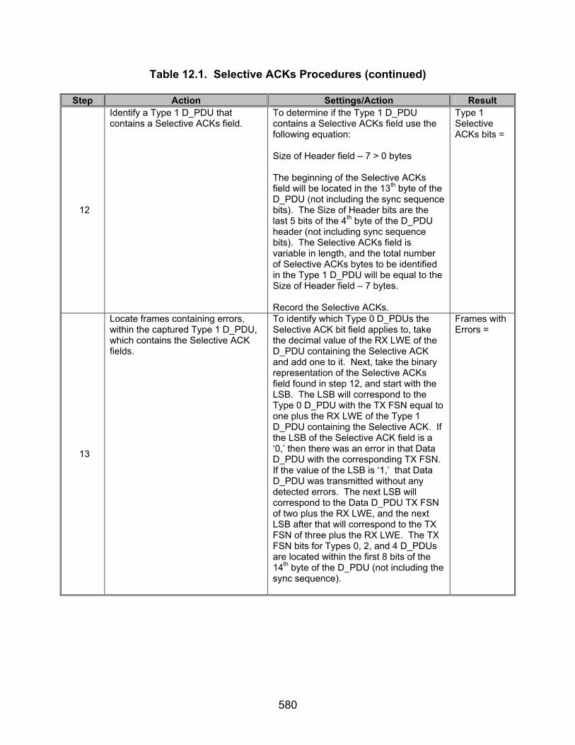
580
Table 12.1. Selective ACKs Procedures (continued)
Step Action Settings/Action Result
12
Identify a Type 1 D_PDU that contains a Selective ACKs field.
To determine if the Type 1 D_PDU contains a Selective ACKs field use the following equation: Size of Header field – 7 > 0 bytes The beginning of the Selective ACKs field will be located in the 13th byte of the D_PDU (not including the sync sequence bits). The Size of Header bits are the last 5 bits of the 4th byte of the D_PDU header (not including sync sequence bits). The Selective ACKs field is variable in length, and the total number of Selective ACKs bytes to be identified in the Type 1 D_PDU will be equal to the Size of Header field – 7 bytes. Record the Selective ACKs.
Type 1 Selective ACKs bits =
13
Locate frames containing errors, within the captured Type 1 D_PDU, which contains the Selective ACK fields.
To identify which Type 0 D_PDUs the Selective ACK bit field applies to, take the decimal value of the RX LWE of the D_PDU containing the Selective ACK and add one to it. Next, take the binary representation of the Selective ACKs field found in step 12, and start with the LSB. The LSB will correspond to the Type 0 D_PDU with the TX FSN equal to one plus the RX LWE of the Type 1 D_PDU containing the Selective ACK. If the LSB of the Selective ACK field is a ‘0,’ then there was an error in that Data D_PDU with the corresponding TX FSN. If the value of the LSB is ‘1,’ that Data D_PDU was transmitted without any detected errors. The next LSB will correspond to the Data D_PDU TX FSN of two plus the RX LWE, and the next LSB after that will correspond to the TX FSN of three plus the RX LWE. The TX FSN bits for Types 0, 2, and 4 D_PDUs are located within the first 8 bits of the 14th byte of the D_PDU (not including the sync sequence).
Frames with Errors =

581
Table 12.1. Selective ACKs Procedures (continued)
Step Action Settings/Action Result The RX LWE bits for Types 1 and 5
D_PDUs are located within the first 8 bits of the 12th byte of the D_PDU (not including the sync sequence). If a Type 2 D_PDU is generated with a Selective ACKs field greater than 0, the Type 2 D_PDU RX LWE is located within the first 8 bits of the 15th byte of the D_PDU (not including the sync sequence). Note: Any bits corresponding to TX FSNs of Type 0 D_PDUs greater than the TX FSN of the last Type 0 D_PDU transmitted are padded with ‘0’s. For example: If 8 Type 0 D_PDUs are transmitted and the Type 1 D_PDU contains the following: Selective ACKs = 0x06 = (MSB) 0 0 0 0 0 1 1 0 (LSB) RX LWE=0x3 This would mean Type 0 D_PDUs with TX FSNs 4 and 7 were not received correctly, while Type 0 D_PDUs with TX FSNs 5 and 6 were received correctly. (The LSB of the Selective ACK corresponds to TX FSN 4. The next LSB of the Selective ACK corresponds to TX FSN 5, the third LSB of the Selective ACK corresponds to TX FSN 6, and the fourth LSB of the Selective ACK corresponds to TX FSN 7.) The 4 left- most bits are used for padding and set to ‘0’ in this case, since only 7 Data D_PDUs were transmitted.
RX LWE =
14
Identify correctly transmitted D_PDUs.
The TX FSN for the Type 0 D_PDU is the 14th byte of the Type 0 D_PDU. Record the TX FSNs of all Type 0 D_PDUs transmitted by computer 1.2.0.0.
Correctly Transmitted D_PDUs =
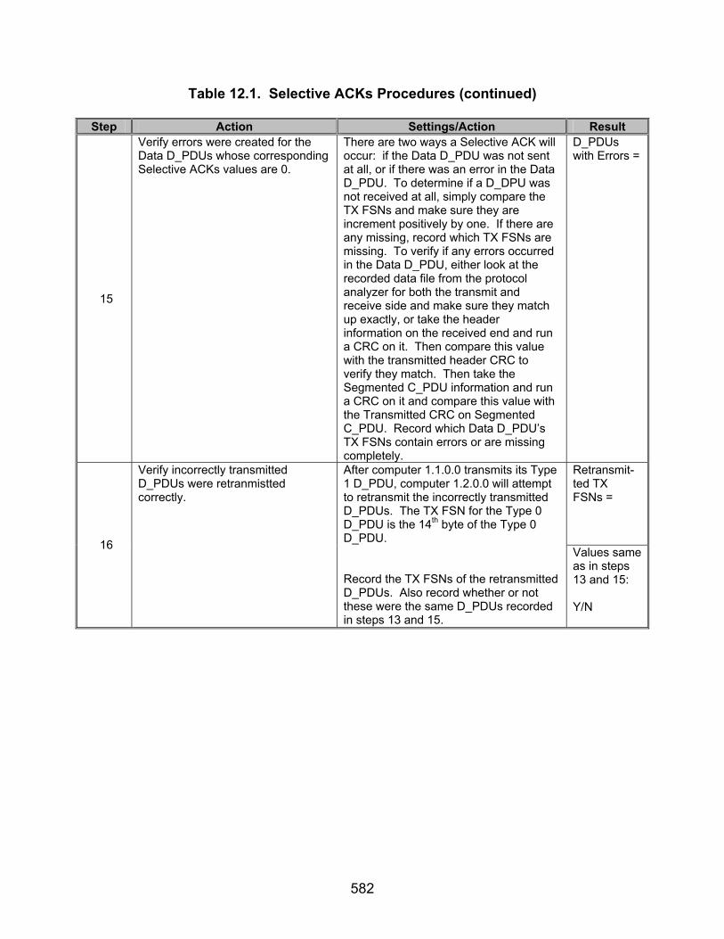
582
Table 12.1. Selective ACKs Procedures (continued)
Step Action Settings/Action Result
15
Verify errors were created for the Data D_PDUs whose corresponding Selective ACKs values are 0.
There are two ways a Selective ACK will occur: if the Data D_PDU was not sent at all, or if there was an error in the Data D_PDU. To determine if a D_DPU was not received at all, simply compare the TX FSNs and make sure they are increment positively by one. If there are any missing, record which TX FSNs are missing. To verify if any errors occurred in the Data D_PDU, either look at the recorded data file from the protocol analyzer for both the transmit and receive side and make sure they match up exactly, or take the header information on the received end and run a CRC on it. Then compare this value with the transmitted header CRC to verify they match. Then take the Segmented C_PDU information and run a CRC on it and compare this value with the Transmitted CRC on Segmented C_PDU. Record which Data D_PDU’s TX FSNs contain errors or are missing completely.
D_PDUs with Errors =
Retransmit-ted TX FSNs =
16
Verify incorrectly transmitted D_PDUs were retranmistted correctly.
After computer 1.1.0.0 transmits its Type 1 D_PDU, computer 1.2.0.0 will attempt to retransmit the incorrectly transmitted D_PDUs. The TX FSN for the Type 0 D_PDU is the 14th byte of the Type 0 D_PDU. Record the TX FSNs of the retransmitted D_PDUs. Also record whether or not these were the same D_PDUs recorded in steps 13 and 15.
Values same as in steps 13 and 15: Y/N
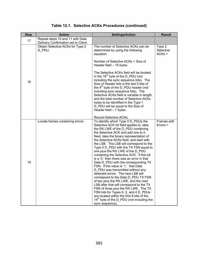
583
Table 12.1. Selective ACKs Procedures (continued)
Step Action Settings/Action Result
17 Repeat steps 10 and 11 with Data Delivery Confirmation set to Client.
18
Obtain Selective ACKs for Type 2 D_PDU.
The number of Selective ACKs can be determined by using the following equation: Number of Selective ACKs = Size of Header field – 10 bytes The Selective ACKs field will be located in the 16th byte of the D_PDU (not including the sync sequence bits). The Size of Header bits is the last 5 bits of the 4th byte of the D_PDU header (not including sync sequence bits). The Selective ACKs field is variable in length, and the total number of Selective ACKs bytes to be identified in the Type 1 D_PDU will be equal to the Size of Header field – 7 bytes. Record Selective ACKs.
Type 2 Selective ACKs =
19
Locate frames containing errors. To identify which Type 0 D_PDUs the Selective ACK bit field applies to, take the RX LWE of the D_PDU containing the Selective ACK and add one to it. Next, take the binary representation of the Selective ACKs field, and start with the LSB. The LSB will correspond to the Type 0 D_PDU with the TX FSN equal to one plus the RX LWE of the D_PDU containing the Selective ACK. If this bit is a ‘0,’ then there was an error in that Data D_PDU with the corresponding TX FSN. If the value is ‘1,’ that Data D_PDU was transmitted without any detected errors. The next LSB will correspond to the Data D_PDU TX FSN of two plus the RX LWE, and the next LSB after that will correspond to the TX FSN of three plus the RX LWE. The TX FSN bits for Types 0, 2, and 4 D_PDUs are located within the first 8 bits of the 14th byte of the D_PDU (not including the sync sequence).
Frames with Errors =
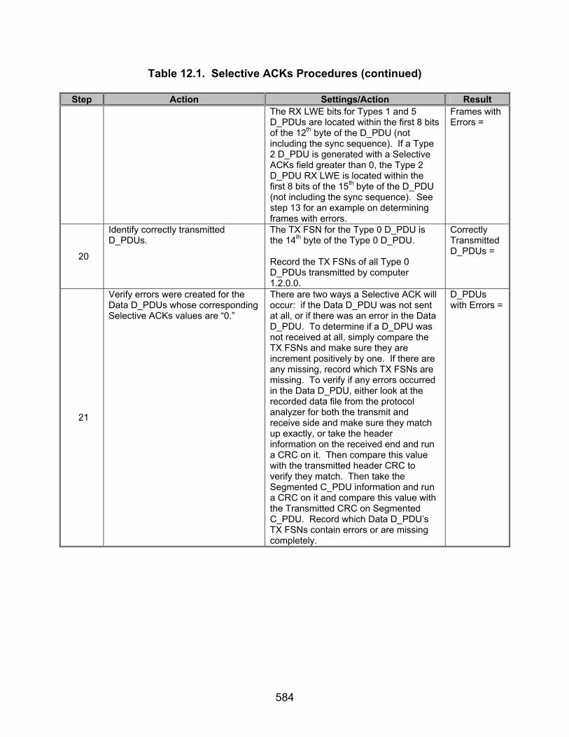
584
Table 12.1. Selective ACKs Procedures (continued)
Step Action Settings/Action Result
The RX LWE bits for Types 1 and 5 D_PDUs are located within the first 8 bits of the 12th byte of the D_PDU (not including the sync sequence). If a Type 2 D_PDU is generated with a Selective ACKs field greater than 0, the Type 2 D_PDU RX LWE is located within the first 8 bits of the 15th byte of the D_PDU (not including the sync sequence). See step 13 for an example on determining frames with errors.
Frames with Errors =
20
Identify correctly transmitted D_PDUs.
The TX FSN for the Type 0 D_PDU is the 14th byte of the Type 0 D_PDU. Record the TX FSNs of all Type 0 D_PDUs transmitted by computer 1.2.0.0.
Correctly Transmitted D_PDUs =
21
Verify errors were created for the Data D_PDUs whose corresponding Selective ACKs values are “0.”
There are two ways a Selective ACK will occur: if the Data D_PDU was not sent at all, or if there was an error in the Data D_PDU. To determine if a D_DPU was not received at all, simply compare the TX FSNs and make sure they are increment positively by one. If there are any missing, record which TX FSNs are missing. To verify if any errors occurred in the Data D_PDU, either look at the recorded data file from the protocol analyzer for both the transmit and receive side and make sure they match up exactly, or take the header information on the received end and run a CRC on it. Then compare this value with the transmitted header CRC to verify they match. Then take the Segmented C_PDU information and run a CRC on it and compare this value with the Transmitted CRC on Segmented C_PDU. Record which Data D_PDU’s TX FSNs contain errors or are missing completely.
D_PDUs with Errors =
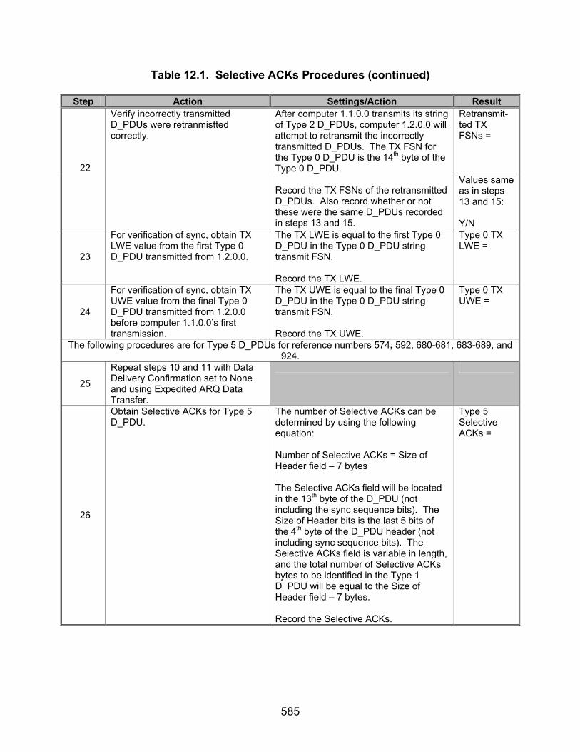
585
Table 12.1. Selective ACKs Procedures (continued)
Step Action Settings/Action Result Retransmit-ted TX FSNs = 22
Verify incorrectly transmitted D_PDUs were retranmistted correctly.
After computer 1.1.0.0 transmits its string of Type 2 D_PDUs, computer 1.2.0.0 will attempt to retransmit the incorrectly transmitted D_PDUs. The TX FSN for the Type 0 D_PDU is the 14th byte of the Type 0 D_PDU. Record the TX FSNs of the retransmitted D_PDUs. Also record whether or not these were the same D_PDUs recorded in steps 13 and 15.
Values same as in steps 13 and 15: Y/N
23
For verification of sync, obtain TX LWE value from the first Type 0 D_PDU transmitted from 1.2.0.0.
The TX LWE is equal to the first Type 0 D_PDU in the Type 0 D_PDU string transmit FSN. Record the TX LWE.
Type 0 TX LWE =
24
For verification of sync, obtain TX UWE value from the final Type 0 D_PDU transmitted from 1.2.0.0 before computer 1.1.0.0’s first transmission.
The TX UWE is equal to the final Type 0 D_PDU in the Type 0 D_PDU string transmit FSN. Record the TX UWE.
Type 0 TX UWE =
The following procedures are for Type 5 D_PDUs for reference numbers 574, 592, 680-681, 683-689, and 924.
25
Repeat steps 10 and 11 with Data Delivery Confirmation set to None and using Expedited ARQ Data Transfer.
26
Obtain Selective ACKs for Type 5 D_PDU.
The number of Selective ACKs can be determined by using the following equation: Number of Selective ACKs = Size of Header field – 7 bytes The Selective ACKs field will be located in the 13th byte of the D_PDU (not including the sync sequence bits). The Size of Header bits is the last 5 bits of the 4th byte of the D_PDU header (not including sync sequence bits). The Selective ACKs field is variable in length, and the total number of Selective ACKs bytes to be identified in the Type 1 D_PDU will be equal to the Size of Header field – 7 bytes. Record the Selective ACKs.
Type 5 Selective ACKs =
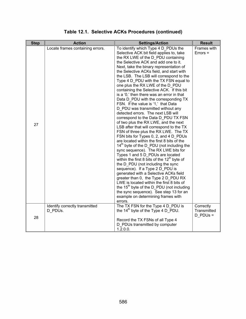
586
Table 12.1. Selective ACKs Procedures (continued)
Step Action Settings/Action Result
27
Locate frames containing errors. To identify which Type 4 D_PDUs the Selective ACK bit field applies to, take the RX LWE of the D_PDU containing the Selective ACK and add one to it. Next, take the binary representation of the Selective ACKs field, and start with the LSB. The LSB will correspond to the Type 4 D_PDU with the TX FSN equal to one plus the RX LWE of the D_PDU containing the Selective ACK. If this bit is a ‘0,’ then there was an error in that Data D_PDU with the corresponding TX FSN. If the value is ‘1,’ that Data D_PDU was transmitted without any detected errors. The next LSB will correspond to the Data D_PDU TX FSN of two plus the RX LWE, and the next LSB after that will correspond to the TX FSN of three plus the RX LWE. The TX FSN bits for Types 0, 2, and 4 D_PDUs are located within the first 8 bits of the 14th byte of the D_PDU (not including the sync sequence). The RX LWE bits for Types 1 and 5 D_PDUs are located within the first 8 bits of the 12th byte of the D_PDU (not including the sync sequence). If a Type 2 D_PDU is generated with a Selective ACKs field greater than 0, the Type 2 D_PDU RX LWE is located within the first 8 bits of the 15th byte of the D_PDU (not including the sync sequence). See step 13 for an example on determining frames with errors.
Frames with Errors =
28
Identify correctly transmitted D_PDUs.
The TX FSN for the Type 4 D_PDU is the 14th byte of the Type 4 D_PDU. Record the TX FSNs of all Type 4 D_PDUs transmitted by computer 1.2.0.0.
Correctly Transmitted D_PDUs =

587
Table 12.1. Selective ACKs Procedures (continued)
Step Action Settings/Action Result
29
Verify errors were created for the Data D_PDUs whose corresponding Selective ACKs values are 0.
There are two ways a Selective ACK will occur: if the Data D_PDU was not sent at all, or if there was an error in the Data D_PDU. To determine if a D_DPU was not received at all, simply compare the TX FSNs and make sure they are increment positively by one. If there are any missing, record which TX FSNs are missing. To verify if any errors occurred in the Data D_PDU, either look at the recorded data file from the protocol analyzer for both the transmit and receive side and make sure they match up exactly, or take the header information on the received end and run a CRC on it. Then compare this value with the transmitted header CRC to verify they match. Then take the Segmented C_PDU information and run a CRC on it and compare this value with the Transmitted CRC on Segmented C_PDU. Record which Data D_PDU’s TX FSNs contain errors or are missing completely.
D_PDUs with Errors =
Retransmit-ted TX FSNs = 30
Verify incorrectly transmitted D_PDUs were retranmistted correctly.
After computer 1.1.0.0 transmits its Type 5 D_PDU, computer 1.2.0.0 will attempt to retransmit the incorrectly transmitted D_PDUs. The TX FSN for the Type 4 D_PDU is the 14th byte of the Type 4 D_PDU. Record the TX FSNs of the retransmitted D_PDUs. Also record whether or not these were the same D_PDUs recorded in steps 13 and 15.
Values same as in steps 13 and 15: Y/N
Legend: ACK—Acknowledgement ARQ—Automatic Repeat-Request bps—bits per second C_PDU—Channel Access Sublayer Protocol Data Units CFTP—Compressed File Transfer Protocol CRC—Cyclic Redundancy Check D_PDU—Data Transfer Sublayer Protocol Data Unit dB—decibel e-mail—Electronic Mail FSN—Frame Sequence Number HF—High Frequency I-Frame—Information Frame
LSB—Least Significant Bit LWE—Lower Window Edge MSB—Most Significant Bit POP3—Post Office Protocol 3 RX—Receive SMTP—Simple Mail Transfer Protocol SNR—Signal-to-Noise Ratio STANAG—Standardization Agreement sync—synchronization TX—Transmit UWE—Upper Window Edge

588
Table 12.2. Selective ACKs Results
Result Finding Reference Number
STANAG 5066
Paragraph Requirement Required
Value Measured
Value Met Not Met
574 C.1.2
The reliable Selective ARQ service shall use CRC check bits and flow-control procedures, such as requests for retransmission of D_PDUs in which errors have been detected to provide a reliable data transfer service.
Incorrect Data D_PDUs acknowle-ged as “0’s” for Selective ACKs.
592 C.3
The Selective RQ protocol shall operate in a half or full duplex mode since the local node, after sending I-Frames, waits for an indication in the form of a selective acknowledgement from the remote node as to whether the I-Frames were correctly received or not.
Type 1 and 5 D_PDUs contain Selective ACKs in response to Type 0 and 4 D_PDUs (respecti-vely) transmitted
680 C.3.4
A set (1) bit within the Selective ACKs field shall indicate a positive acknowledgement (ACK), i.e., that the D_PDU with the corresponding Frame Sequence Number was received correctly.
Correctly transmitted D_PDUs have a value of (1) for their correspon-ding FSN.
681 C.3.4
Only D_PDU frames with a correct segmented C_PDU CRC shall be acknowledged positively even if the header CRC is correct.
Correct Data D_PDUs acknowle-ged as “1’s” for Selective ACKs.
683 C.3.4
A cleared (0) bit within the Selective ACKS field shall indicate a negative acknowledgement (NACK), i.e., that the D_PDU with the corresponding Frame Sequence Number was received incorrectly or not at all.
Incorrectly transmitted D_PDUs have a value of (0) for their correspon-ding FSN.

589
Table 12.2. Selective ACKs Results (continued)
Result Finding Reference Number
STANAG 5066
Paragraph Requirement Required
Value Measured
Value Met Not Met
684 C.3.4
The construction of the Selective ACK field and the mapping of D_PDU frame-sequence numbers to bits within the Selective ACK field shall be in accordance with figure C-11 and figure C-12 and the paragraphs below.
Correctly transmitted D_PDUs have a value of (1) for their correspon-ding FSN and incorrectly transmitted D_PDUs have a value of (0) for their correspon-ding FSN.
685 C.3.4
The LSB of the first byte of the Selective ACK field shall correspond to the D_PDU whose frame sequence number is equal to 1 + the value in the RX LWE field of this ACK-Only D_PDU [the bit corresponding to the RX LWE is always zero, by definition, and is therefore not sent].
If the LSB of the Selective ACKs = 1, then the TX FSN = RX LWE +1 was transmitted correctly If the LSB of the Selective ACKs = 0, then the TX FSN = RX LWE +1 was transmitted correctly.
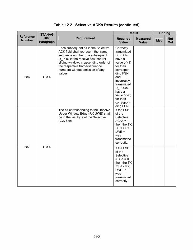
590
Table 12.2. Selective ACKs Results (continued)
Result Finding Reference Number
STANAG 5066
Paragraph Requirement Required
Value Measured
Value Met Not Met
686 C.3.4
Each subsequent bit in the Selective ACK field shall represent the frame sequence number of a subsequent D_PDU in the receive flow-control sliding window, in ascending order of the respective frame-sequence numbers without omission of any values.
Correctly transmitted D_PDUs have a value of (1) for their correspon-ding FSN and incorrectly transmitted D_PDUs have a value of (0) for their correspon-ding FSN.
If the LSB of the Selective ACKs = 1, then the TX FSN = RX LWE +1 was transmitted correctly.
687 C.3.4
The bit corresponding to the Receive Upper Window Edge (RX UWE) shall be in the last byte of the Selective ACK field.
If the LSB of the Selective ACKs = 0, then the TX FSN = RX LWE +1 was transmitted correctly.

591
Table 12.2. Selective ACKs Results (continued)
Result Finding Reference Number
STANAG 5066
Paragraph Requirement Required
Value Measured
Value Met Not Met
688 C.3.4
If the bit representing the RX UWE is not the MSB of the last byte, the remaining bits in the byte (until and including the MSB) shall be set to 0 as padding.
All extra bits beyond those needed for the TX FSNs are equal to (0).
689 C.3.4
No further Selective ACK bytes shall be transmitted after such bits are required.
Number of bits used for Selective ACKs = the value of Last TX FSN - (RX LWE +1).
924 C.6.3.2.2
Individual frames may be acknowledged in a Data-ACK or ACK-Only frame by setting bits in the selective ACK header field. The frame sequence numbers (FSNs) corresponding to such bits must also fall within the range defined by the transmit window edges if the two nodes are in sync. The following test shall be used to determine whether acknowledged FSNs fall within the correct range. IN SYNC = (Acknowledged FSN > TX LWE) AND (Acknowledged FSN <= TX UWE)
(Acknow-ledged FSN > TX LWE) AND (Acknowle-dged FSN <= TX UWE)
Legend: ACK—Acknowledgement C_PDU—Channel Access Sublayer Protocol Data Unit CRC—Cyclic Redundancy Check D_PDU—Data Transfer Sublayer Protocol Data Unit FSN—Frame Sequence Number LSB—Least Significant Bit LWE—Lower Window Edge MSB—Most Significant Bit
NACK—Negative Acknowledgment RQ—Repeat-Request RX—Receive STANAG—Standardization Agreement sync—synchronization TX—Transmit UWE—Upper Window Edge

592
(This page intentionally left blank.)

593
SUBTEST 13. SYNCHRONIZATION TESTS 13.1 Objective. To determine the extent of compliance to the requirements of STANAG 5066 for validating Synchronization Tests, reference numbers 704, 898-899, 905-910, 912-913, and 918-923. 13.2 Criteria
a. Reset and re-sync operations shall be performed with respect to the TX
LWE and the RX LWE for the flow-control sliding windows at the sending node and receiving node, as specified in STANAG 5066, section C.6.2. (appendix B, reference number 704)
b. The Data Transfer Sublayer shall satisfy the following requirements for
D_PDU flow-control: (appendix B, reference number 898-899, 905-910, and 912-913)
• Each node shall maintain a transmit and a receive flow-control window buffer for each connection supported.
• The Maximum Window Size shall equal 128. The Maximum Allowable Window Size may be a node-configurable parameter (this is recommended) and shall not exceed the Maximum Window Size.
• The Current Transmitter Window Size at any moment is variable as a function of the current TX UWE and TX LWE and shall not exceed the Maximum Allowable Window Size. This allows for no more than 128 (Maximum Window Size) outstanding unacknowledged D_PDUs in any circumstance.
• If the Current Transmitter Window Size equals the Maximum Allowable Window Size, no additional new D_PDUs shall be transmitted until the TX LWE has been advanced and the newly computed difference (modulo 256) between the TX UWE and the TX LWE – 1 is less than the maximum allowable window size.
• The RX LWE shall indicate the oldest D_PDU number that has not been received (lowest D_PDU number allowing for [modulo 256] arithmetic operations).
• The RX LWE shall not be decreased when retransmitted D_PDUs are received that are copies of D_PDUs received previously.
• D_PDUs with TX FSN falling outside the Maximum Window Size of 128 shall not be accepted or acknowledged by the receiver node.
• If the value of the RX LWE field in any ACK Type 1 or DATA-ACK Type 2 D_PDU is greater than the TX LWE, the Data Transfer Sublayer shall declare all D_PDUs with transmit FSNs between the TX LWE and the RX LWE value as acknowledged.
c. The following sync verification procedure shall be used to verify on an
ongoing basis if the peer ARQ processes are in sync and, if required, to affect a reset or re-sync of the peer ARQ window pointers. (appendix B, reference number 918)
594
d. The following tests shall be used to detect loss of sync. (appendix B,
reference numbers 919-923)
• The purpose of this test is to ensure that the TX UWE of the originating node is within the valid range defined by the destination node window edge pointers. This test shall be carried out whenever a D_PDU is received with its TX UWE flag set. If the TX UWE passes this test, then the two nodes are in sync.
IN SYNC = (TX UWE >= RX UWE) AND (TX UWE <= MAX WIN SIZE –1 + RX LWE)
• The purpose of this test is to ensure that the TX LWE of the originating
node is within the valid range defined by the destination node window edge pointers. This test shall be carried out whenever a D_PDU is received with its TX LWE flag set. If the TX LWE passes this test, then the two nodes are in sync.
IN SYNC = (TX LWE >= RX UWE – [MAX WIN SIZE –1]) AND (TX LWE <= RX LWE)
• The purpose of this test is to ensure that the transmit FSN of a frame
received from the originating node is within the valid range defined by the destination node window edge pointers. This test shall be carried out on every Data and Data-ACK frame received. If the transmit FSN of the incoming frame passes this test, then the two nodes are in sync.
IN SYNC = (TX FSN <= RX LWE + [MAX WIN SIZE – 1]) AND (TX FSN >= RX UWE – (MAX WIN SIZE – 1))
• The purpose of tests carried out at the originating node is to ensure that the transmit FSNs of acknowledged frames are within the range defined by the transmit window edge pointers. These tests shall be applied whenever a Data-ACK or ACK-Only frame is received.
IN SYNC = (RX LWE >= TX LWE) AND (RX LWE <= TX UWE +1)

595
13.3 Test Procedures a. Test Equipment Required
(1) Computers (2 ea) with STANAG 5066 Software (2) Modems (2 ea) (3) Protocol Analyzer (4) RS-232 Synchronous Serial Cards
b. Test Configuration. Figure 13.1 shows the equipment setup for this subtest.
c. Test Conduction. Table 13.1 lists procedures for this subtest and table 13.2 lists the results for this subtest.
Computer Modem Modem Computer
LANAnalyzer
RS-232 RS-232
Figure 13.1. Equipment Configuration for Synchronization Tests

596
Table 13.1. Synchronization Procedures
Step Action Settings/Action Result
1
Set up equipment. See figure 13.1. Computers are connected to the modems by an RS-232 connection. The connection between modems shall be such that the receive and transmit pins on the modem are connected to the transmit and receive pins, respectively, of the other modem.
2
Verify the maximum window size. The maximum allowable window size will be a variable parameter in the STANAG 5066 software. Record the configured value of the “maximum allowable window size.”
Maximum window size =
3 Load STANAG 5066 software. Configure the SMTP and POP3 servers as
required by the STANAG 5066 software manual.
4
Configure STANAG addresses for computers 1 and 2.
Set the size of the STANAG address field size to 7 bytes. Set the STANAG address of both computers to 1.1.0.0 and 1.2.0.0 as shown in figure 13.1. Configure the software to respond with an e-mail message to the sender once the e-mail has been successfully received.
5 Configure modems 1 and 2. Set modems 1 and 2 to transmit a
MIL-STD-188-110B signal at a data rate of 4800 bps with half duplex.
6
Identify client to be used. Configure both computers to use the same client type. Record the client type utilized by computers.
Client Type =
7
Configure protocol analyzer. Configure the protocol analyzer to capture the transmitted data between the two computers and save it to a file. Configure the protocol analyzer to have a 4800-bps bit rate and to synchronize on “0x90EB” in hexadecimal. Configure the protocol analyzer to drop sync after 20 “0xFFs” (hex format). Configure the analyzer to time stamp each captured byte.
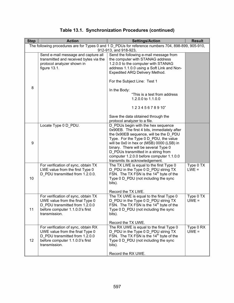
597
Table 13.1. Synchronization Procedures (continued)
Step Action Settings/Action Result The following procedures are for Types 0 and 1 D_PDUs for reference numbers 704, 898-899, 905-910,
912-913, and 918-923.
8
Send e-mail message and capture all transmitted and received bytes via the protocol analyzer shown in figure 13.1.
Send the following e-mail message from the computer with STANAG address 1.2.0.0 to the computer with STANAG address 1.1.0.0 using a Soft Link and Non-Expedited ARQ Delivery Method. For the Subject Line: Test 1 In the Body: “This is a test from address 1.2.0.0 to 1.1.0.0 1 2 3 4 5 6 7 8 9 10” Save the data obtained through the protocol analyzer to a file.
9
Locate Type 0 D_PDU. D_PDUs begin with the hex sequence 0x90EB. The first 4 bits, immediately after the 0x90EB sequence, will be the D_PDU Type. For the Type 0 D_PDU, the value will be 0x0 in hex or (MSB) 0000 (LSB) in binary. There will be several Type 0 D_PDUs transmitted in a string from computer 1.2.0.0 before computer 1.1.0.0 transmits its acknowledgement.
10
For verification of sync, obtain TX LWE value from the first Type 0 D_PDU transmitted from 1.2.0.0.
The TX LWE is equal to the first Type 0 D_PDU in the Type 0 D_PDU string TX FSN. The TX FSN is the 14th byte of the Type 0 D_PDU (not including the sync bits). Record the TX LWE.
Type 0 TX LWE =
11
For verification of sync, obtain TX UWE value from the final Type 0 D_PDU transmitted from 1.2.0.0 before computer 1.1.0.0’s first transmission.
The TX UWE is equal to the final Type 0 D_PDU in the Type 0 D_PDU string TX FSN. The TX FSN is the 14th byte of the Type 0 D_PDU (not including the sync bits). Record the TX UWE.
Type 0 TX UWE =
12
For verification of sync, obtain RX UWE value from the final Type 0 D_PDU transmitted from 1.2.0.0 before computer 1.1.0.0’s first transmission.
The RX UWE is equal to the final Type 0 D_PDU in the Type 0 D_PDU string TX FSN. The TX FSN is the 14th byte of the Type 0 D_PDU (not including the sync bits). Record the RX UWE.
Type 0 RX UWE =

598
Table 13.1. Synchronization Procedures (continued)
Step Action Settings/Action Result
13
Obtain RX LWE. The RX LWE is located in the first 8 bits of the 12th byte of the Type 1 D_PDU transmitted by computer 1.1.0.0 immediately following the first string of Type 0 D_PDUs. Record the RX LWE.
Type 1 RX LWE =
The following procedures are for Types 4 and 5 D_PDUs for reference numbers 704, 899, 905-910, 912, and 918-924.
14
Send e-mail message and capture all transmitted and received bytes via the protocol analyzer shown in figure 13.1.
Send the following e-mail message from the computer with STANAG address 1.2.0.0 to the computer with STANAG address 1.1.0.0 using a Soft Link and Non-Expedited ARQ Delivery Method. For the Subject Line: Test 1 In the Body: “This is a test from address 1.2.0.0 to 1.1.0.0 1 2 3 4 5 6 7 8 9 10” Save the data obtained through the protocol analyzer to a file.
15
Locate Type 4 D_PDU. D_PDUs begin with the hex sequence 0x90EB. The first 4 bits, immediately after the 0x90EB sequence, will be the D_PDU Type. For the Type 4 D_PDU, the value will be 0x4 in hex or (MSB) 0100 (LSB) in binary. There will be several Type 0 D_PDUs transmitted in a string from computer 1.2.0.0 before computer 1.1.0.0 transmits its acknowledgement.
16
For verification of sync, obtain TX LWE value from the first Type 4 D_PDU transmitted from 1.2.0.0.
The TX LWE is equal to the first Type 4 D_PDU in the Type 4 D_PDU string TX FSN. The TX FSN is the 14th byte of the Type 4 D_PDU (not including the sync bits). Record the TX LWE.
Type 4 TX LWE =
17
For verification of sync, obtain TX UWE value from the final Type 4 D_PDU transmitted from 1.2.0.0 before computer 1.1.0.0’s first transmission.
The TX UWE is equal to the final Type 4 D_PDU in the Type 4 D_PDU string TX FSN. The TX FSN is the 14th byte of the Type 4 D_PDU (not including the sync bits). Record the TX UWE.
Type 4 TX UWE =

599
Table 13.1. Synchronization Procedures (continued)
Step Action Settings/Action Result
18
For verification of sync, obtain RX UWE value from the final Type 4 D_PDU transmitted from 1.2.0.0 before computer 1.1.0.0’s first transmission.
The RX UWE is equal to the final Type 4 D_PDU in the Type 4 D_PDU string TX FSN. The TX FSN is the 14th byte of the Type 4 D_PDU (not including the sync bits). Record the RX UWE.
Type 4 RX UWE =
19
Obtain RX LWE. The RX LWE is located in the first 8 bits of the 12th byte of the Type 5 D_PDU transmitted by computer 1.1.0.0, immediately following the first string of Type 4 D_PDUs. Record the RX LWE.
Type 5 RX LWE =
Note: Reference numbers 910 and 912 are currently under development. These test procedures assume that the RX UWE being equal to the final DATA_ONLY D_PDU’s TX FSN is correct, which is equal to the TX UWE and that the TX LWE is equal to the first DATA_ONLY D_PDU’s TX FSN. These requirements are specified in section C.6.2 of STANAG 5066, but are internal to the software, and therefore untestable. Legend: ARQ—Automatic Repeat-Request bps—bits per second D_PDU—Data Transfer Sublayer Protocol Data Unit e-mail—Electronic Mail FSN—Frame Sequence Number hex—hexadecimal LSB—Least Significant Bit LWE—Lower Window Edge MIL-STD—Military Standard
MSB—Most Significant Bit POP3—Post Office Protocol 3 RX—Receive SMTP—Simple Mail Transfer Protocol STANAG—Standardization Agreement Sync—Synchronization TX—Transmit UWE—Upper Window Edge
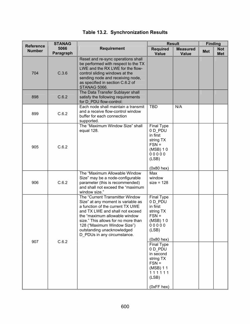
600
Table 13.2. Synchronization Results
Result Finding Reference Number
STANAG 5066
Paragraph Requirement Required
Value Measured
Value Met Not Met
704 C.3.6
Reset and re-sync operations shall be performed with respect to the TX LWE and the RX LWE for the flow-control sliding windows at the sending node and receiving node, as specified in section C.6.2 of STANAG 5066.
898 C.6.2 The Data Transfer Sublayer shall satisfy the following requirements for D_PDU flow-control:
899 C.6.2
Each node shall maintain a transmit and a receive flow-control window buffer for each connection supported.
TBD N/A
905 C.6.2
The “Maximum Window Size” shall equal 128.
Final Type 0 D_PDU in first string TX FSN = (MSB) 1 0 0 0 0 0 0 (LSB) (0x80 hex)
906 C.6.2
The “Maximum Allowable Window Size” may be a node-configurable parameter (this is recommended) and shall not exceed the “maximum window size.”
Max window size = 128
Final Type 0 D_PDU in first string TX FSN = (MSB) 1 0 0 0 0 0 0 (LSB) (0x80 hex)
907 C.6.2
The “Current Transmitter Window Size” at any moment is variable as a function of the current TX UWE and TX LWE and shall not exceed the “maximum allowable window size.” This allows for no more than 128 (“Maximum Window Size”) outstanding unacknowledged D_PDUs in any circumstance.
Final Type 0 D_PDU in second string TX FSN = (MSB) 1 1 1 1 1 1 1 1 (LSB) (0xFF hex)
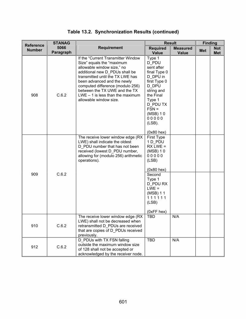
601
Table 13.2. Synchronization Results (continued)
Result Finding Reference Number
STANAG 5066
Paragraph Requirement Required
Value Measured
Value Met Not Met
908 C.6.2
If the “Current Transmitter Window Size” equals the “maximum allowable window size,” no additional new D_PDUs shall be transmitted until the TX LWE has been advanced and the newly computed difference (modulo 256) between the TX UWE and the TX LWE – 1 is less than the maximum allowable window size.
Type 1 D_PDU sent after final Type 0 D_DPU in first Type 0 D_DPU string and the Final Type 1 D_PDU TX FSN = (MSB) 1 0 0 0 0 0 0 (LSB). (0x80 hex)
First Type 1 D_PDU RX LWE = (MSB) 1 0 0 0 0 0 0 (LSB) (0x80 hex)
909 C.6.2
The receive lower window edge (RX LWE) shall indicate the oldest D_PDU number that has not been received (lowest D_PDU number, allowing for (modulo 256) arithmetic operations).
Second Type 1 D_PDU RX LWE = (MSB) 1 1 1 1 1 1 1 1 (LSB) (0xFF hex)
910 C.6.2
The receive lower window edge (RX LWE) shall not be decreased when retransmitted D_PDUs are received that are copies of D_PDUs received previously.
TBD
N/A
912 C.6.2
D_PDUs with TX FSN falling outside the maximum window size of 128 shall not be accepted or acknowledged by the receiver node.
TBD N/A

602
Table 13.2. Synchronization Results (continued)
Result Finding Reference Number
STANAG 5066
Paragraph Requirement Required
Value Measured
Value Met Not Met
913 C.6.2
If the value of the RX LWE field in any ACK Type 1 or Data-ACK Type 2 D_PDU is greater than the TX LWE, the Data Transfer Sublayer shall declare all D_PDUs with transmit FSNs between the TX LWE and the RX LWE value as acknowledged.
All D_PDUs in transmis-sion acknow-ledged.
918 C.6.3.2
The following sync verification procedure shall be used to verify on an ongoing basis if the peer ARQ processes are in sync and, if required, to affect a reset or re-sync of the peer ARQ window pointers.
919 C.6.3.2.1 The following tests shall be used to detect loss of sync.
920 C.6.3.2.1
The purpose of this test is to ensure that the TX UWE of the originating node is within the valid range defined by the destination node window edge pointers. This test shall be carried out whenever a D_PDU is received with its TX UWE flag set. If the TX UWE passes this test then the two nodes are in sync. IN SYNC = (TX UWE >= RX UWE) AND (TX UWE <= MAX WIN SIZE –1 + RX LWE)
TX UWE >= RX UWE) AND (TX UWE <= MAX WIN SIZE – 1 + RX LWE)
921 C.6.3.2.1
The purpose of this test is to ensure that the TX LWE of the originating node is within the valid range defined by the destination node window edge pointers. This test shall be carried out whenever a D_PDU is received with its TX LWE flag set. If the TX LWE passes this test then the two nodes are in sync. IN SYNC = (TX LWE >= RX UWE – (MAX WIN SIZE –1)) AND (TX LWE <= RX LWE)
TX LWE >= RX UWE – (MAX WIN SIZE – 1)) AND (TX LWE <= RX LWE)

603
Table 13.2. Synchronization Results (continued)
Result Finding Reference Number
STANAG 5066
Paragraph Requirement Required
Value Measured
Value Met Not Met
922 C.6.3.2.1
The purpose of this test is to ensure that the TX FSN of a frame received from the originating node is within the valid range defined by the destination node window edge pointers. This test shall be carried out on every Data and Data-ACK frame received. If the TX FSN of the incoming frame passes this test then the two nodes are in sync. IN SYNC = (TX FSN <= RX LWE + (MAX WIN SIZE – 1)) AND (TX FSN >= RX UWE – (MAX WIN SIZE – 1))
(TX FSN <= RX LWE + (MAX WIN SIZE – 1)) AND (TX FSN >= RX UWE – (MAX WIN SIZE – 1))
923 C.6.3.2.2
The purpose of tests carried out at the originating node is to ensure that the TX FSNs of acknowledged frames are within the range defined by the transmit window edge pointers. These tests shall be applied whenever a Data-ACK or ACK-Only frame is received. IN SYNC = (RX LWE >= TX LWE) AND (RX LWE <= TX UWE + 1)
RX LWE >= TX LWE) AND (RX LWE <= TX UWE + 1)
Legend: ACK—Acknowledgement ARQ—Automatic Repeat-Request D_PDU—Data Transfer Sublayer Protocol Data Unit FSN—Frame Sequence Number hex—hexadecimal LSB—Least Significant Bit LWE—Lower Window Edge Max—Maximum MSB—Most Significant Bit
N/A—Not Available RX—Receive STANAG—Standardization Agreement sync—synchronization TBD—To Be Determined TX—Transmit UWE—Upper Window Edge Win—Window

604
(This page intentionally left blank.)

605
SUBTEST 14. D_PDU FRAME STRUCTURES 14.1 Objective. To determine the extent of compliance to the requirements of STANAG 5066 for validating D_PDU Frame Structures, reference numbers 590, 594-598, 607, 610, 642, and 705. 14.2 Criteria
a. There are basically three different types of D_PDUs, or frames, noted by the Frame Type field in table 14.1. (appendix B, reference number 590)
• C (Control) Frames • I (Information) Frames • Combined I+C-Frame
The Protocol Type field in table 14.1 indicates the type of data-transfer-service protocol with which the D_PDU frame shall be used, as follows:
• Non-Repeat-Request (NRQ) (i.e., Non-ARQ) Protocol • Selective Repeat-Request (SRQ) Protocol • Idle Repeat-Request Protocol (IRQ)
b. All D_PDU Types that cannot carry segmented C_PDUs shall be of the
structure shown in figure 14.1. (appendix B, reference number 594)
S Y N C(1 6 b its )
H E A D E R(M A X 3 8 b y te s )
H E A D E R C R C(1 6 b its )
L e g e n d : C -F ra m e — C o n tro l F ra m e , C R C — C yc lic R e d u n d a n c y C h e c k , D _ P D U — D a ta T ra n s fe r S u b la ye r P ro to co l D a ta U n it
Figure 14.1. Format for D_PDU C-Frame Types (1, 3, 5, 6, and 15) c. D_PDU Types that can carry segmented C_PDUs shall be structured
according to figure 14.2. (appendix B, reference number 595)
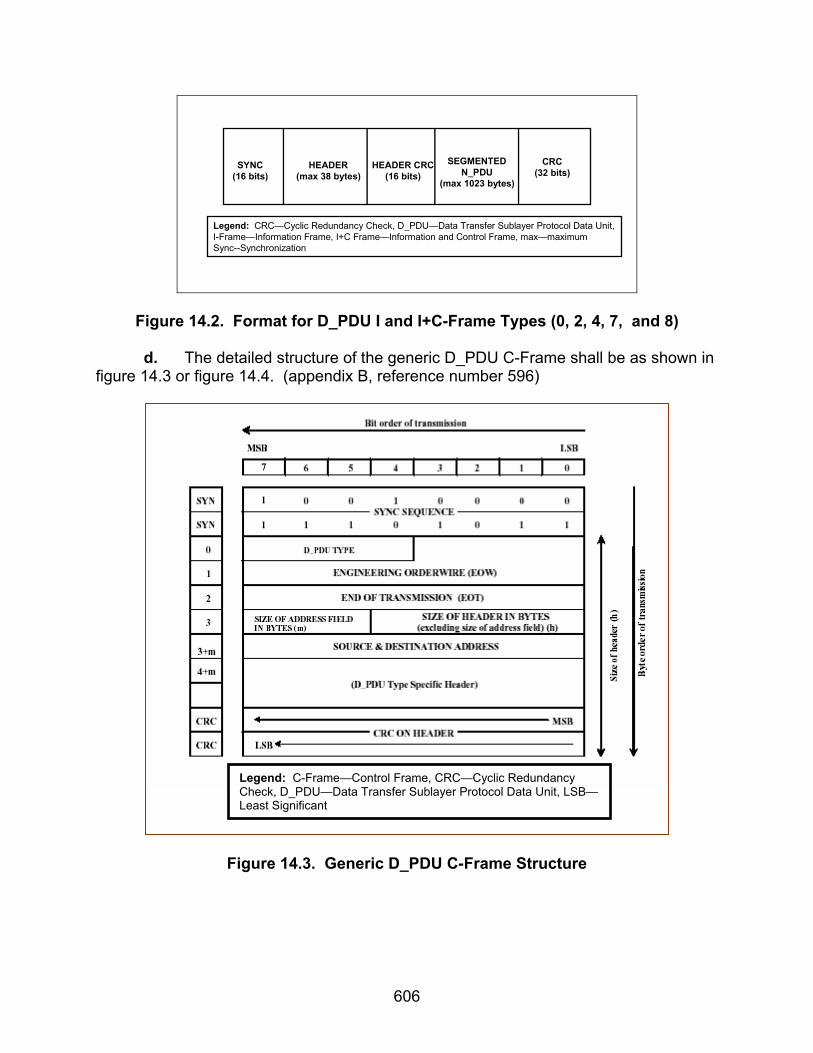
606
SYNC(16 bits)
HEADER(max 38 bytes)
HEADER CRC(16 bits)
SEGMENTEDN_PDU
(max 1023 bytes)
CRC(32 bits)
Legend: CRC—Cyclic Redundancy Check, D_PDU—Data Transfer Sublayer Protocol Data Unit,I-Frame—Information Frame, I+C Frame—Information and Control Frame, max—maximumSync--Synchronization
Figure 14.2. Format for D_PDU I and I+C-Frame Types (0, 2, 4, 7, and 8)
d. The detailed structure of the generic D_PDU C-Frame shall be as shown in figure 14.3 or figure 14.4. (appendix B, reference number 596)
Figure 14.3. Generic D_PDU C-Frame Structure
Legend: C-Frame—Control Frame, CRC—Cyclic Redundancy Check, D_PDU—Data Transfer Sublayer Protocol Data Unit, LSB—Least Significant
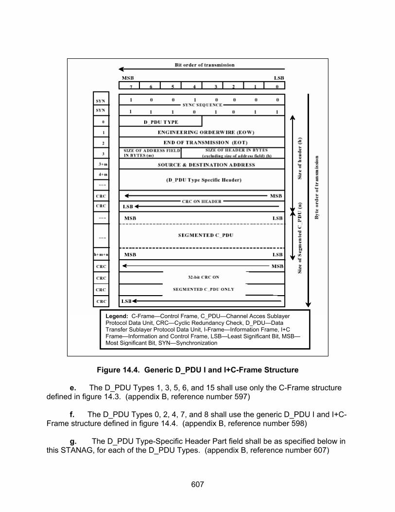
607
Figure 14.4. Generic D_PDU I and I+C-Frame Structure
e. The D_PDU Types 1, 3, 5, 6, and 15 shall use only the C-Frame structure
defined in figure 14.3. (appendix B, reference number 597) f. The D_PDU Types 0, 2, 4, 7, and 8 shall use the generic D_PDU I and I+C-
Frame structure defined in figure 14.4. (appendix B, reference number 598) g. The D_PDU Type-Specific Header Part field shall be as specified below in
this STANAG, for each of the D_PDU Types. (appendix B, reference number 607)
Legend: C-Frame—Control Frame, C_PDU—Channel Acces Sublayer Protocol Data Unit, CRC—Cyclic Redundancy Check, D_PDU—Data Transfer Sublayer Protocol Data Unit, I-Frame—Information Frame, I+C Frame—Information and Control Frame, LSB—Least Significant Bit, MSB—Most Significant Bit, SYN—Synchronization

608
h. The D_PDU Types shall be as defined in table 14.1 and the D_PDU figures as shown in subtests 1-6. (appendix B, reference number 610)
Table 14.1. D_PDU Types
D_PDU FRAME
TYPES D_PDU TYPE
Number FUNCTION PROTOCOL
TYPE FRAME TYPE
DATA-ONLY 0 Simplex data transfer SRQ I ACK-ONLY 1 Acknowledgement of Type 0
and 2 data transfer - C
DATA-ACK 2 Duplex data transfer SRQ I+C RESET/WIN-RE-SYNC
3 Reset/Re-synchronize peer protocol entities
IRQ C
EXP-DATA-ONLY 4 Expedited simplex data transfer
SRQ I
EXP-ACK-ONLY 5 Acknowledgement of Type 4 data transfer
- C
MANAGEMENT 6 Management message transfer
IRQ C
NON-ARQ DATA 7 Non-ARQ data transfer NRQ I EXP-NON-ARQ DATA
8 Expedited Non-ARQ Data Transfer
NRQ I
- 9-14 Reserved for future extensions
- -
WARNING 15 Unexpected or unrecognized D_PDU Type
- C
Legend: ACK—Acknowledgement, ARQ—Automatic Repeat-Request, C—Control Frame, D_PDU—Data Transfer Sublayer Protocol Data Unit, EXP—Expedited, I—Information Frame, I+C—Information and Control Frame, IRQ—Idle Repeat-Request, NRQ—Non-Repeat-Request, Re-sync—Re-synchronization, SRQ—Selective Repeat-Request, WIN—Window
i. The bytes immediately following the address field shall encode the D_PDU
Type-Specific Header, as specified in the corresponding section below from STANAG 5066, sections C.3.3 through C.3.12. (appendix B, reference number 642)
j. The Reset/WIN Re-sync D_PDU shall use a basic stop-and-wait type of
protocol (denoted as the IRQ protocol elsewhere in this STANAG). (appendix B, reference number 705)
14.3 Test Procedures a. Test Equipment Required No equipment required. b. Test Configuration. This subtest refers to procedures for all other subtests in this conformance plan and does not have an equipment configuration.
c. Test Conduction. Table 14.2 lists procedures for this subtest and table 14.3 lists the results for this subtest.

609
Table 14.2. D_PDU Frame Structures Procedures
Step Action Settings/Action Result
1
For the following captured D_PDUs identify the Size of Synchronization, Size of Header, Size of CRC, Size of Segmented C_PDU, and Size of CRC on Segmented C_PDU. Also identify the frame structures as a C-Frame (Control Frame), I-Frame (Information Frame), or I+C Frame (Information and Control Frame).
The requirements for this subtest, with the exception of the CRC on Segmented C_PDU and frame structure type, are validated using subtests 1-6 and 11 as specified in each of the steps.
The following procedures are for Type 0 D_PDUs for reference numbers 595-596, 598, 607, 610, and 642. The sync sequence bytes were recorded in subtest 11, step 19, for a Type 0 D_PDU. Record the number of bytes of the sync sequence.
Size of Synchroniza-tion =
The value of the Size of Header is located in subtest 11, step 19, for a Type 0 D_PDU.
Size of Header=
The Header CRC is located in subtest 11, step 19, for a Type 0 D_PDU. Record the number of bytes of the Header CRC.
Size of Header CRC =
The value of the Size of Segmented C_PDU can be located in subtest 1, step 33, for a Type 0 D_PDU. Record the value of the Size of Segmented C_PDU.
Size of Segmented C_PDU =
The CRC on Segmented C_PDU is the final 4 bytes within the D_PDU. This can be obtained by using the Size of Segmented C_PDU field and counting the bytes down to the end of the Segmented C_PDU. Verify and record the CRC on Segmented C_PDU bits.
Size of CRC on Segmented C_PDU =
2
Locate and record the values for the Size of Synchronization, Size of Header, Size of CRC, Size of Segmented C_PDU, and Size of CRC on Segmented C_PDU for the Type 0 D_PDU.
If the above Type 0 D_PDU contains a C_PDU, it is an I-Frame type. If the D_PDU does not contain a C_PDU, it is a C-Frame type. If the D_PDU contains both a C_PDU and an RX LWE, the D_PDU is an I+C Frame. Record which Frame Type the above D_DPU is.
Frame Structure Type= I / C / I+C
The following procedures are for Type 1 D_PDUs for reference numbers 594, 596-597, 607, 610, and 642.
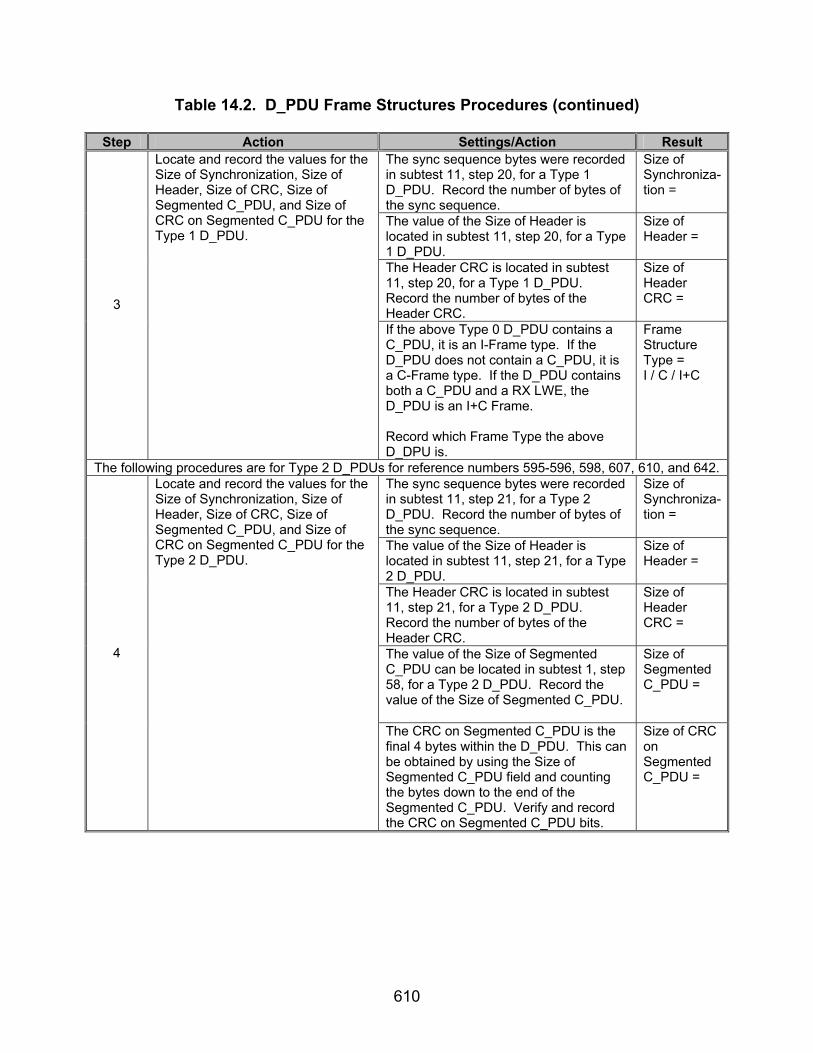
610
Table 14.2. D_PDU Frame Structures Procedures (continued)
Step Action Settings/Action Result The sync sequence bytes were recorded in subtest 11, step 20, for a Type 1 D_PDU. Record the number of bytes of the sync sequence.
Size of Synchroniza-tion =
The value of the Size of Header is located in subtest 11, step 20, for a Type 1 D_PDU.
Size of Header =
The Header CRC is located in subtest 11, step 20, for a Type 1 D_PDU. Record the number of bytes of the Header CRC.
Size of Header CRC =
3
Locate and record the values for the Size of Synchronization, Size of Header, Size of CRC, Size of Segmented C_PDU, and Size of CRC on Segmented C_PDU for the Type 1 D_PDU.
If the above Type 0 D_PDU contains a C_PDU, it is an I-Frame type. If the D_PDU does not contain a C_PDU, it is a C-Frame type. If the D_PDU contains both a C_PDU and a RX LWE, the D_PDU is an I+C Frame. Record which Frame Type the above D_DPU is.
Frame Structure Type = I / C / I+C
The following procedures are for Type 2 D_PDUs for reference numbers 595-596, 598, 607, 610, and 642. The sync sequence bytes were recorded in subtest 11, step 21, for a Type 2 D_PDU. Record the number of bytes of the sync sequence.
Size of Synchroniza-tion =
The value of the Size of Header is located in subtest 11, step 21, for a Type 2 D_PDU.
Size of Header =
The Header CRC is located in subtest 11, step 21, for a Type 2 D_PDU. Record the number of bytes of the Header CRC.
Size of Header CRC =
The value of the Size of Segmented C_PDU can be located in subtest 1, step 58, for a Type 2 D_PDU. Record the value of the Size of Segmented C_PDU.
Size of Segmented C_PDU =
4
Locate and record the values for the Size of Synchronization, Size of Header, Size of CRC, Size of Segmented C_PDU, and Size of CRC on Segmented C_PDU for the Type 2 D_PDU.
The CRC on Segmented C_PDU is the final 4 bytes within the D_PDU. This can be obtained by using the Size of Segmented C_PDU field and counting the bytes down to the end of the Segmented C_PDU. Verify and record the CRC on Segmented C_PDU bits.
Size of CRC on Segmented C_PDU =

611
Table 14.2. D_PDU Frame Structures Procedures (continued)
Step Action Settings/Action Result If the above Type 0 D_PDU contains a
C_PDU, it is an I-Frame type. If the D_PDU does not contain a C_PDU, it is a C-Frame type. If the D_PDU contains both a C_PDU and it has a RX LWE, the D_PDU is an I+C Frame. Record which Frame Type the above D_DPU is.
Frame Structure Type = I / C / I+C
The following procedures are for Type 3 D_PDUs for reference numbers 595-596, 598, 607, 610, 642, and 705.
The sync sequence bytes were recorded in subtest 11, step 151, for a Type 3 D_PDU. Record the number of bytes of the sync sequence.
Size of Synchroniza-tion =
The value of the Size of Header is located in subtest 11, step 151, for a Type 3 D_PDU.
Size of Header =
The Header CRC is located in subtest 11, step 151, for a Type 3 D_PDU. Record the number of bytes of the Header CRC.
Size of Header CRC = 5
Locate and record the values for the Size of Synchronization, Size of Header, Size of CRC, Size of Segmented C_PDU, and Size of CRC on Segmented C_PDU for the Type 3 D_PDU.
If the above Type 0 D_PDU contains a C_PDU, it is an I-Frame type. If the D_PDU does not contain a C_PDU, it is a C-Frame type. If the D_PDU contains both a C_PDU and a RX LWE, the D_PDU is an I+C Frame. Record which Frame Type the above D_DPU is.
Frame Structure Type = I / C / I+C
The following procedures are for Type 4 D_PDUs for reference numbers 595-596, 598, 607, 610, and 642. The sync sequence bytes were recorded in subtest 11, step 57, for a Type 4 D_PDU. Record the number of bytes of the sync sequence.
Size of Synchroniza-tion =
The value of the Size of Header is located in subtest 11, step 57, for a Type 4 D_PDU.
Size of Header =
The Header CRC is located in subtest 11, step 57, for a Type 4 D_PDU. Record the number of bytes of the Header CRC.
Size of Header CRC =
6
Locate and record the values for the Size of Synchronization, Size of Header, Size of CRC, Size of Segmented C_PDU, and Size of CRC on Segmented C_PDU for the Type 4 D_PDU.
The value of the Size of Segmented C_PDU can be located in subtest 2, step 20, for a Type 4 D_PDU. Record the value of the Size of Segmented C_PDU.
Size of Segmented C_PDU =

612
Table 14.2. D_PDU Frame Structures Procedures (continued)
Step Action Settings/Action Result The CRC on Segmented C_PDU is the final 4 bytes within the D_PDU. This can be obtained by using the Size of Segmented C_PDU field and counting the bytes down to the end of the Segmented C_PDU. Verify and record the CRC on Segmented C_PDU bits.
Size of CRC on Segmented C_PDU =
If the above Type 0 D_PDU contains a C_PDU, it is an I-Frame type. If the D_PDU does not contain a C_PDU, it is a C-Frame type. If the D_PDU contains both a C_PDU and a RX LWE, the D_PDU is an I+C Frame. Record which Frame Type the above D_DPU is.
Frame Structure Type = I / C / I+C
The following procedures are for Type 5 D_PDUs for reference numbers 594, 596-597, 607, 610, and 642. The sync sequence bytes were recorded in subtest 11, step 58, for a Type 5 D_PDU. Record the number of bytes of the sync sequence.
Size of Synchroniza-tion =
The value of the Size of Header is located in subtest 11, step 58, for a Type 5 D_PDU.
Size of Header =
The Header CRC is located in subtest 11, step 58, for a Type 5 D_PDU. Record the number of bytes of the Header CRC.
Size of Header CRC = 7
Locate and record the values for the Size of Synchronization, Size of Header, Size of CRC, Size of Segmented C_PDU, and Size of CRC on Segmented C_PDU for the Type 5 D_PDU.
If the above Type 0 D_PDU contains a C_PDU, it is an I-Frame type. If the D_PDU does not contain a C_PDU, it is a C-Frame type. If the D_PDU contains both a C_PDU and a RX LWE, the D_PDU is an I+C Frame. Record which Frame Type the above D_DPU is.
Frame Structure Type = I / C / I+C
The following procedures are for Type 6 D_PDUs for reference numbers 594, 596-597, 607, 610, and 642.
The sync sequence bytes were recorded in subtest 11, step 86, for a Type 6 D_PDU. Record the number of bytes of the sync sequence.
Size of Synchroniza-tion =
The value of the Size of Header is located in subtest 11, step 86, for a Type 6 D_PDU.
Size of Header =
8
Locate and record the values for the Size of Synchronization, Size of Header, Size of CRC, Size of Segmented C_PDU, and Size of CRC on Segmented C_PDU for the Type 6 D_PDU.
The Header CRC is located in subtest 11, step 86, for a Type 6 D_PDU. Record the number of bytes of the Header CRC.
Size of Header CRC =

613
Table 14.2. D_PDU Frame Structures Procedures (continued)
Step Action Settings/Action Result If the above Type 0 D_PDU contains a
C_PDU, it is an I-Frame type. If the D_PDU does not contain a C_PDU, it is a C-Frame type. If the D_PDU contains both a C_PDU and a RX LWE, the D_PDU is an I+C Frame. Record which Frame Type the above D_DPU is.
Frame Structure Type = I / C / I+C
The following procedures are for Type 7 D_PDUs for reference numbers 595-596, 598, 607, 610, and 642. The sync sequence bytes were recorded in subtest 11, step 103, for a Type 7 D_PDU. Record the number of bytes of the sync sequence.
Size of Synchroniza-tion =
The value of the Size of Header is located in subtest 11, step 103, for a Type 7 D_PDU.
Size of Header =
The Header CRC is located in subtest 11, step 103, for a Type 7 D_PDU. Record the number of bytes of the Header CRC.
Size of Header CRC =
The value of the Size of Segmented C_PDU can be located in subtest 6, step 16, for a Type 7 D_PDU. Record the value of the Size of Segmented C_PDU.
Size of Segmented C_PDU =
The CRC on Segmented C_PDU is the final 4 bytes within the D_PDU. This can be obtained by using the Size of Segmented C_PDU field and counting the bytes down to the end of the Segmented C_PDU. Verify and record the CRC on Segmented C_PDU bits.
Size of CRC on Segmented C_PDU=
9
Locate and record the values for the Size of Synchronization, Size of Header, Size of CRC, Size of Segmented C_PDU, and Size of CRC on Segmented C_PDU for the Type 7 D_PDU.
If the above Type 0 D_PDU contains a C_PDU, it is an I-Frame type. If the D_PDU does not contain a C_PDU, it is a C-Frame type. If the D_PDU contains both a C_PDU and a RX LWE, the D_PDU is an I+C Frame. Record which Frame Type the above D_DPU is.
Frame Structure Type = I / C / I+C

614
Table 14.2. D_PDU Frame Structures Procedures (continued)
Step Action Settings/Action Result The following procedures are for Type 8 D_PDUs for reference numbers 595-596, 598, 607, 610, and 642.
The sync sequence bytes were recorded in subtest 11, step 22, for a Type 8 D_PDU. Record the number of bytes of the sync sequence.
Size of Synchroniza-tion =
The value of the Size of Header is located in subtest 11, step 22, for a Type 8 D_PDU.
Size of Header =
The Header CRC is located in subtest 11, step 22, for a Type 8 D_PDU. Record the number of bytes of the Header CRC.
Size of Header CRC =
The value of the Size of Segmented C_PDU can be located in subtest 6, step 35, for a Type 8 D_PDU. Record the value of the Size of Segmented C_PDU.
Size of Segmented C_PDU =
The CRC on Segmented C_PDU is the final 4 bytes within the D_PDU. This can be obtained by using the Size of Segmented C_PDU field and counting the bytes down to the end of the Segmented C_PDU. Verify and record the CRC on Segmented C_PDU bits.
Size of CRC on Segmented C_PDU =
10
Locate and record the values for the Size of Synchronization, Size of Header, Size of CRC, Size of Segmented C_PDU, and Size of CRC on Segmented C_PDU for the Type 8 D_PDU.
If the above Type 0 D_PDU contains a C_PDU, it is an I-Frame type. If the D_PDU does not contain a C_PDU, it is a C-Frame type. If the D_PDU contains both a C_PDU and a RX LWE, the D_PDU is an I+C Frame. Record which Frame Type the above D_DPU is.
Frame Structure Type = I / C / I+C
The following procedures are for Type 15 D_PDUs for reference numbers 594, 596-597, 607, 610, and 642.
The sync sequence bytes were recorded in subtest 11, step 126, for a Type 15 D_PDU. Record the number of bytes of the sync sequence.
Size of Synchroniza-tion =
The value of the Size of Header is located in subtest 11, step 126, for a Type 15 D_PDU.
Size of Header =
11
Locate and record the values for the Size of Synchronization, Size of Header, Size of CRC, Size of Segmented C_PDU, and Size of CRC on Segmented C_PDU for the Type 15 D_PDU.
The Header CRC is located in subtest 11, step 126, for a Type 15 D_PDU. Record the number of bytes of the Header CRC.
Size of Header CRC =

615
Table 14.2. D_PDU Frame Structures Procedures (continued)
Step Action Settings/Action Result If the above Type 0 D_PDU contains a
C_PDU, it is an I-Frame type. If the D_PDU does not contain a C_PDU, it is a C-Frame type. If the D_PDU contains both a C_PDU and a RX LWE, the D_PDU is an I+C Frame. Record which Frame Type the above D_DPU is.
Frame Structure Type = I / C / I+C
The following procedures are for reference numbers 590. Type 1 SRQ Protocol = Y/N
12
Verify Type 0 and 2 D_PDUs were transmitted using SRQ protocol.
Using the D_PDU order results in subtest 1, step 69, verify that Type 0 and 2 D_PDUs were transmitted for Non-Expedited ARQ data Transfer and a Type 1 D_PDU was sent in response to the Type 0 and Type 2 D_PDUs . If both requirements are met, the Type 0 and 2 D_PDUs were transmitted using SRQ protocol.
Type 2 SRQ Protocol = Y/N
13
Verify Type 4 D_PDU was transmitted using SRQ protocol.
Using the D_PDU order results in subtest 2, step 36, verify that Type 4 D_PDU was transmitted for Expedited ARQ data Transfer and a Type 5 D_PDU was sent in response to the Type 4 D_PDU. If both requirements are met, the Type 4 D_PDU was transmitted using SRQ protocol.
SRQ Protocol = Y/N
14
Verify Type 7 and 8 D_PDU transmitted for Non-ARQ data transfer.
Using the resuts in steps 12 and 31 from subtest 6, verify that Type 7 and Type 8 D_PDUs were transmitted when the delivery mode was specified as Non-ARQ delivery mode.
Non-ARQ = Y/N
15
Verify Type 3 D_PDU transmitted using IRQ protocol.
Using steps 13, 23, and 24, from subtest 3, verify that a Type 3 D_PDU was transmitted in response to the Type 0 D_PDUs being out of sync and a second Type 3 D_PDU was transmitted in response to the first Type 3 D_PDU with Reset ACK=1. If both requirements are met, the Type 3 D_PDU was transmitted using IRQ protocol.
IRQ Protocol = Y/N
16
Verify Type 6 D_PDU transmitted using IRQ protocol.
Using steps 16, 34, and 36, from subtest 4, verify that a Type 6 D_PDU was transmitted in response to the DRC being initiated and a second Type 6 D_PDU was transmitted in response to the first Type 6 D_PDU with ACK=1. If both requirements are met, the Type 6 D_PDU was transmitted using IRQ protocol.
IRQ Protocol = Y/N

616
Table 14.2. D_PDU Frame Structures Procedures (continued)
Step Action Settings/Action Result Legend: ACK—Acknowledgement ARQ—Automatic Repeat-Request C-Frame—Control Frame C_PDU—Channel Access Sublayer Protocol Data Unit CRC—Cyclic Redundancy Check D_PDU—Data Transfer Sublayer Protocol Data Unit DRC—Data Rate Change I-Frame—Information Frame
I+C-Frame—Information and Control Frame IRQ—Idle Repeat-Request LWE—Lower Window Edge RX—Receive SRQ—Selective Repeat-Request sync—synchronization
Table 14.3. D_PDU Frame Structures Results
Result Finding
Reference Number
STANAG 5066
Paragraph Requirement Required
Value Measured
Value Met Not Met
Types 0, 2, and 4 D_PDUs used for SRQ Data Transfer.
Types 7 and 8 D_PDUs used for Non-ARQ Data Transfer.
Type 3 D_PDU transmitted when Type 0 D_PDUs used for IRQ Data Transfer.
590 C.3
There are basically three different types of D_PDUs, or frames, noted by the Frame-Type field in table C-2.
• C (Control) Frames, • I (Information) Frames, • And a combined I+C-Frame.
The Protocol Type field in table C-2 indicates the type of data-transfer-service protocol with which the D_PDU frame shall be used, as follows:
• NRQ Non-Repeat-Request.(i.e.,
Non-ARQ) Protocol • SRQ Selective Repeat-Request
Protocol • IRQ Idle Repeat-Request Protocol
Type 6 D_PDU used for IRQ Data Transfer.
594 C.3.1
All D_PDU Types that cannot carry segmented C_PDUs shall be of the structure shown in figure C-1 (a).
Type 1, 3, 5, 6, and 15 D_PDUs structured as specified by figure 14.1.

617
Table 14.3. D_PDU Frame Structures Results (continued)
Result Finding Reference Number
STANAG 5066
Paragraph Requirement Required
Value Measured
Value Met Not Met
595 C.3.1
D_PDU Types that can carry segmented C_PDUs shall be structured according to figure C-1 (b).
Type 0, 2, 4, 7 and 8 D_PDUs structured as specified by figure 14.2.
Type 1, 3, 5, 6, and 15 D_PDUs structured as specified by figure 14.3.
596
C.3.2
The detailed structure of the generic D_PDU C-Frame shall be as shown in figure C-2 (a) or figure C-2 (b).
Type 0, 2, 4, 7 and 8 D_PDUs structured as specified by figure 14.4.
597 C.3.2
The D_PDU Types 1, 3, 5, 6, and 15 shall use only the C-Frame structure defined in figure C-2 (a).
Type 1, 5, 6, and 15 D_PDUs structured as specified by figure 14.3.
598 C.3.2
The D_PDU Types 0, 2, 4, 7, and 8 shall use the generic D_PDU I and I+C-Frame structure defined in figure C-2 (b).
Type 0, 2, 4, 7 and 8 D_PDUs structured as specified by figure 14.4.
607 C.3.2
The D_PDU Type-Specific Header Part field shall be as specified below in this STANAG, for each of the D_PDU Types.
D_PDUs contain all parts as specified by their correspon-ding subtests.

618
Table 14.3. D_PDU Frame Structures Results (continued)
Result Finding Reference Number
STANAG 5066
Paragraph Requirement Required
Value Measured
Value Met Not Met
Type 0 D_PDU transmits data for ARQ, Non-Expedited Transmis-sion.
Type 1 D_PDU transmits Ack for ARQ, Non-Expedited Transmis-sion.
Type 2 D_PDU transmits data and ACK for ARQ, Non-Expedited Transmis-sion.
Type 3 D_PDU transmitted for Type 0 D_DPUs transmitted out of order.
610 C.3.2.1
The D_PDU Types shall be as defined in table C-2 and the D_PDU figures below.
Type 4 D_PDU transmits data for ARQ, Expedited Transmis-sion.

619
Table 14.3. D_PDU Frame Structures Results (continued)
Result Finding Reference Number
STANAG 5066
Paragraph Requirement Required
Value Measured
Value Met Not Met
Type 5 D_PDU transmits ACK for ARQ, Expedited Transmis-sion.
Type 6 D_PDU transmits for DRC.
Type 7 D_PDU transmits data for Non-ARQ, Non- Expedited Transmis-sion.
Type 8 D_PDU transmits data for Non-ARQ, Expedited Transmis-sion.
610 C.3.2.1
Type 15 D_PDU transmits data for a transmis-sion error.
642 C.3.2.7
The bytes immediately following the address field shall encode the D_PDU Type-Specific Header, as specified in the corresponding section below from STANAG 5066, sections C.3.3 through C.3.12.
Type-specific parts come immedi- ately after address fields for D_PDUs.

620
Table 14.3. D_PDU Frame Structures Results (continued)
Result Finding Reference Number
STANAG 5066
Paragraph Requirement Required
Value Measured
Value Met Not Met
705 C.3.6
The Reset/WIN Re-sync D_PDU shall use a basic stop-and-wait type of protocol (denoted as the IRQ protocol elsewhere in this STANAG).
Type 3 D_PDU uses IRQ protocol.
Legend: ACK—Acknowledgement ARQ—Automatic Repeat-Request C-Frame—Control Frame C_PDU—Channel Access Sublayer Protocol Data Unit D_PDU—Data Transfer Sublayer Protocol Data Unit DRC—Data Rate Change I-Frame—Information Frame
I+C-Frame—Information and Control Frame IRQ—Idle Repeat-Request NRQ—Non-Repeat-Request SRQ—Selective Repeat-Request STANAG—Standardization Agreement WIN—Window

621
SUBTEST 15. HARD LINK PROTOCOLS 15.1 Objective. To determine the extent of compliance to the requirements of STANAG 5066 for validating Hard Link Protocols, reference numbers 6, 8-21, 390-395, 397-403, 482-485, 533, 535, and 553-554. 15.2 Criteria a. The specified maximum time-out period shall be a configurable parameter for the protocol implementation. The specific values of the parameters governing the establishment and termination of Soft Link Data Exchange Sessions (e.g., time-out periods, etc.) must be chosen in the context of a particular configuration (i.e., size of network, etc). (appendix B, reference number 6) b. A Hard Link of Type 0, also called a Hard Link with Link Reservation, shall maintain a physical link between two nodes. (appendix B, reference number 8) c. The Type 0 Hard Link capacity shall not be reserved for any given client on the two nodes. (appendix B, reference number 9) d. Any client on nodes connected by a Hard Link of Type 0 shall be permitted to exchange data over the Hard Link. (appendix B, reference number 10)
e. Any client on either node other than the client that requested the Hard Link shall gain access to the link only as a Soft Link Data Exchange Session and may lose the link when the originating client terminates its Hard Link Data Exchange Session. (appendix B, reference number 11) f. A Type 1 Hard Link, also called a Hard Link with Partial-Bandwidth Reservation, shall maintain a physical link between two nodes. (appendix B, reference number 12) g. The Type 1 Hard Link capacity shall be reserved only for the client that requested the Type 1 Hard Link between the two nodes. The requesting client may send user data to any client on the remote node and may receive user data from any client on the remote node only as a Soft Link Data Exchange Session. (appendix B, reference number 13) h. Clients that are not sending data to or receiving data from the client that requested the Type 1 Hard Link shall be unable to use the Hard Link. Any client using the link may lose the link when the originating client terminates its Hard Link session. (appendix B, reference number 14) i. A Hard Link of Type 2, also called a Hard Link with Full-Bandwidth Reservation, shall maintain a physical link between two nodes. (appendix B, reference number 15)
622
j. The Type 2 Hard Link capacity shall be reserved only for the client that
requested the Type 2 Hard Link and a specified remote client. (appendix B, reference number 16)
k. No clients other than the requesting client and its specified remote client
shall exchange data on a Type 2 Hard Link. (appendix B, reference number 17)
l. The third type of data exchange session (the first two types of data exchange sessions being Soft Link and Hard Link) is the Broadcast Data Exchange Session. The subnetwork shall service only clients with service requirements for Non-ARQ U_PDUs during a Broadcast Data Exchange Session. (appendix B, reference number 18)
m. The procedures that initiate and terminate Broadcast Data Exchange Sessions shall be as specified in STANAG 5066, annex C. (appendix B, reference number 19)
n. A node configured to be a broadcast-only node shall use a “permanent” Broadcast Data Exchange Session, during which the Subnetwork Interface Sublayer shall service no Hard Link requests or ARQ Data U_PDUs. Alternatively, the Subnetwork Interface Sublayer can unilaterally initiate and terminate Broadcast Data Exchange Sessions. (appendix B, reference numbers 20 and 21)
o. The STANAG 5066 assumes a simple model for the management of Hard Links based on maintenance of, at most, a single Hard Link between nodes, while still allowing Type 0 and Type 1 Hard Links between the nodes to be shared by other clients using Soft Link Data Exchange. The management model satisfies the following requirements: (appendix B, reference numbers 390-395)
• A node’s sublayer shall maintain, at most, one Hard Link at any time. • A sublayer shall accept a Hard Link request when no Hard Link
currently exists. • The comparative precedence of new requests and any existing Hard
Link shall be evaluated in accordance with STANAG 5066, section A.3.2.2.1, to determine if the new request can be accepted or rejected by the sublayer.
• Requests of higher precedence shall be accepted and will result in the termination of an existing Hard Link.
• An existing Hard Link of higher precedence shall result in the rejection of the request.
p. Establishment and termination of Hard Links shall be controlled in accordance with the following set of precedence rules: (appendix B, reference numbers 397-403)

623
• A Hard Link request for a client with greater rank shall take precedence over an existing or requested Hard Link established for a client of lower rank, regardless of other factors.
• A Hard Link request of greater priority shall take precedence over an existing or requested Hard Link of lower priority, regardless of other factors.
• For Hard Links of equal priority and rank and with different sets of source and destination nodes, the Hard Link request processed first by the Subnetwork Interface Sublayer (i.e., the Hard Link currently established) shall take precedence.
• For Hard Links (i.e., requests and existing Hard Links) from clients of equal priority and rank and with equal sets of source and destination nodes:
o A Hard Link with greater link type value shall take precedence over
one with lower value. o An existing Hard Link shall take precedence over subsequent Hard
Link requests of equal link type. q. Physical links shall be of either two types, Exclusive or Nonexclusive, with properties and service features defined as follows: (appendix B, reference numbers 482-485)
• A node shall use an Exclusive Physical Link to support control and
data exchange for Hard Link Data Exchange Sessions as requested by the Subnetwork Interface Sublayer.
• A node shall use a Nonexclusive Physical Link to support control and data exchange for Soft Link Data Exchange Sessions as requested by the Subnetwork Interface Sublayer.
• A node shall establish, at most, two Exclusive Physical Links with other nodes.
r. The criteria for accepting or rejecting Physical Links Requests shall be as follows: (appendix B, reference numbers 533 and 535)
• At most, one new request to establish an Exclusive Physical Link shall
be accepted if the resulting number of active Exclusive Physical Links is no greater than two.
s. There are two possible outcomes to the protocol for making a physical
link: success or failure. Upon receiving a Physical Link Accepted (Type 2) C_PDU, the calling Channel Access Sublayer shall proceed as follows: (appendix B, reference numbers 553 and 554)
• If the request made an Exclusive Physical Link, the calling node shall
break any existing Nonexclusive Physical Links.

624
15.3 Test Procedures
a. Test Equipment Required
(1) Computers (2 ea) with STANAG 5066 Software (2) Modem (2 ea) (3) Protocol Analyzer (4) RS-232 Synchronous Serial Cards
b. Test Configuration. Figure 15.1 shows the equipment setup for this subtest.
c. Test Conduction. Table 15.1 lists procedures for this subtest and table
15.2 lists the results for this subtest
Computer Modem Modem Computer
LANAnalyzer
RS-232 RS-232
Figure 15.1. Equipment Configuration for Hard Link Protocols
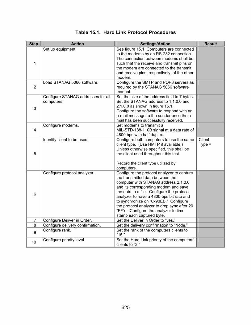
625
Table 15.1. Hard Link Protocol Procedures
Step Action Settings/Action Result
1
Set up equipment. See figure 15.1 Computers are connected to the modems by an RS-232 connection. The connection between modems shall be such that the receive and transmit pins on the modem are connected to the transmit and receive pins, respectively, of the other modem.
2 Load STANAG 5066 software. Configure the SMTP and POP3 servers as
required by the STANAG 5066 software manual.
3
Configure STANAG addresses for all computers.
Set the size of the address field to 7 bytes. Set the STANAG address to 1.1.0.0 and 2.1.0.0 as shown in figure 15.1. Configure the software to respond with an e-mail message to the sender once the e-mail has been successfully received.
4 Configure modems. Set modems to transmit a
MIL-STD-188-110B signal at a data rate of 4800 bps with half duplex.
5
Identify client to be used. Configure both computers to use the same client type. (Use HMTP if available.) Unless otherwise specified, this shall be the client used throughout this test. Record the client type utilized by computers.
Client Type =
6
Configure protocol analyzer. Configure the protocol analyzer to capture the transmitted data between the computer with STANAG address 2.1.0.0 and its corresponding modem and save the data to a file. Configure the protocol analyzer to have a 4800-bps bit rate and to synchronize on “0x90EB.” Configure the protocol analyzer to drop sync after 20 “FF”s. Configure the analyzer to time stamp each captured byte.
7 Configure Deliver in Order. Set the Deliver in Order to “yes.” 8 Configure delivery confirmation. Set the delivery confirmation to “Node.”
9 Configure rank. Set the rank of the computers clients to “15.”
10 Configure priority level. Set the Hard Link priority of the computers’ clients to “3.”

626
Table 15.1. Hard Link Protocol Procedures (continued)
Step Action Settings/Action Result The following procedures are for reference number 6.
11
Determine if the Maximum Time to Maintain a Soft Link While Other Data Is Queued, is a configurable parameter in the STANAG 5066 software.
Locate in the STANAG 5066 application Maximum Time to Maintain a Soft Link While Other Data Is Queued parameter. Record the value of the Maximum Time to Maintain a Soft Link While Other Data Is Queued Will Be Transmitted (Max Time to Keep Soft Link) parameter.
Max Time to Keep Soft Link =
The following procedures are for reference numbers 8-11, 390, 392, and 482-484.
12
Send e-mail message.
Send the following e-mail message from the computer with STANAG address 1.1.0.0 to the computer with STANAG address 2.1.0.0 using a Type 0 Hard Link and Non-Expedited Delivery Method. Attach a file of approximately 10 kbytes to the message. For the Subject Line: Client A Test In the Body: “This is a test from address 1.1.0.0 to 2.1.0.0 1 2 3 4 5 6 7 8 9 10”
13
Re-send e-mail message.
Upon completion of the “handshaking” which occurred between computers in step 13 and before the message has been transmitted, send the following e-mail message from the computer with STANAG address 1.1.0.0 to the computer with STANAG address 2.1.0.0 using a Non-Expedited ARQ Data Transfer. Use a client that is not utilizing the Hard Link established in step 12. Attach a file of approximately 10 kbytes to the message. For the Subject Line: Client B Test In the Body: “This is a test from address 1.1.0.0 to 2.1.0.0 1 2 3 4 5 6 7 8 9 10” Capture and save the data sent in this step and in step 12 with the protocol analyzer to a file.

627
Table 15.1. Hard Link Protocol Procedures (continued)
Step Action Settings/Action Result SAP ID used for Hard Link = 14
Locate and record the SAP ID of client used.
Locate within the STANAG 5066 software the SAP ID of the client used in steps 12 (Hard Link) and 13 (Soft Link). Record the values of the SAP IDs.
SAP ID used for Soft Link =
15
Locate and record the SAP ID of the client that established the Hard Link.
D_PDUs begin with the sync sequence 0x90EB. The next 4 bits, after the sync sequence, are the D_PDU Type bits. Locate a D_PDU whose value is (MSB) 0 1 0 0 (LSB) (0x4 hex). This should be the first D_PDU transmitted after the initial two Type 8 “handshaking” D_PDUs. The S_PDU starts with the 18th byte of the Type 4 D_PDU (not including the sync sequence). The first 4 bits of this byte is the type and should be (MSB) 0 0 1 1 (LSB) (0x3 hex). The requesting SAP ID is the first 4 bits of the 2nd byte of the Type 3 S_PDU (19th byte overall). Record the requesting SAP ID bits.
Requesting Hard Link SAP ID bits =
16
Locate and record the SAP ID of the client that established the Soft Link.
D_PDUs begin with the sync sequence 0x90EB. The next 4 bits, after the sync sequence, are the D_PDU Type bits. Locate a D_PDU whose value is (MSB) 0 0 0 0 (LSB) (0x0 hex). The S_PDU starts with the 18th byte of the Type 0 D_PDU (not including the sync sequence). The first 4 bits of this byte is the type and should be (MSB) 0 0 0 0 (LSB) (0x0 hex). The source SAP ID is the first 4 bits of the 2nd byte of the Type 0 S_PDU (19th byte overall). Locate the source SAP ID bits that equal the value of the Soft Link Client’s SAP ID found in step 15. Record the source SAP ID bits.
Source Soft Link SAP ID =

628
Table 15.1. Hard Link Protocol Procedures (continued)
Step Action Settings/Action Result The following procedures are for reference numbers 12 and 14.
17
Send e-mail message.
Send the following e-mail message from the computer with STANAG address 1.1.0.0 to the computer with STANAG address 2.1.0.0 using a Type 1 Hard Link and Non-Expedited Delivery Method. Attach a file of approximately 10 kbytes to the message. For the Subject Line: Client A Test In the Body: “This is a test from address 1.1.0.0 to 2.1.0.0 1 2 3 4 5 6 7 8 9 10”
18
Re-send e-mail message.
Upon completion of the “handshaking” which occurred between computers in step 17 and before the message has completed its transmission, send the following e-mail message from the computer with STANAG address 1.1.0.0 to the computer with STANAG address 2.1.0.0 using a Non-Expedited ARQ Data Transfer. Use a client that is not utilizing the Hard Link established in step 17. Attach a file of approximately 10 kbytes to the message. For the Subject Line: Client B Test In the Body: “This is a test from address 1.1.0.0 to 2.1.0.0 1 2 3 4 5 6 7 8 9 10” Capture and save the data that is transmitted in this step and in step 17 with the protocol analyzer to a file.
SAP ID used for Hard Link = 19
Locate SAP ID of client used. Locate within the STANAG 5066 software the SAP ID of the client used in steps 17 (Hard Link) and 18 (Soft Link). Record the values of the SAP IDs.
SAP ID used for Soft Link =

629
Table 15.1. Hard Link Protocol Procedures (continued)
Step Action Settings/Action Result
20
Locate and record the SAP ID of the client that established the Hard Link.
D_PDUs begin with the sync sequence 0x90EB. The next 4 bits, after the sync sequence, are the D_PDU Type bits. Locate a D_PDU whose value is (MSB) 0 1 0 0 (LSB) (0x4 hex). This should be the first D_PDU transmitted after the initial two Type 8 “handshaking” D_PDUs. The S_PDU starts with the 18th byte of the Type 4 D_PDU (not including the sync sequence). The first 4 bits of this byte is the type and should be (MSB) 0 0 1 1 (LSB) (0x3 hex). The requesting SAP ID is the first 4 bits of the 2nd byte of the Type 3 S_PDU (19th byte overall). Record the requesting SAP ID bits.
Requesting Hard Link SAP ID bits =
21
Verify that no Soft Link was established by the second client.
D_PDUs begin with the sync sequence 0x90EB. The next 4 bits, after the sync sequence, are the D_PDU Type bits. Locate a D_PDU whose value is (MSB) 0 0 0 0 (LSB) (0x0 hex). The S_PDU starts with the 18th byte of the Type 0 D_PDU (not including the sync sequence). The first 4 bits of this byte is the type and should be (MSB) 0 0 0 0 (LSB) (0x0 hex). The source SAP ID is the first 4 bits of the 2nd byte of the Type 0 S_PDU (19th byte overall). Record if there was any data transmitted by the 2nd client while the 1st client was still connected during a Hard Link.
Soft Link established? Y/N
The following procedures are for reference numbers 13 and 390.
22
Send e-mail message.
Send the following e-mail message from the computer with STANAG address 1.1.0.0 to the computer with STANAG address 2.1.0.0 using a Type 1 Hard Link and Non-Expedited Delivery Method. Attach a file of approximately 10 kbytes to the message. For the Subject Line: Client A Test In the Body: “This is a test from address 1.1.0.0 to 2.1.0.0 1 2 3 4 5 6 7 8 9 10”

630
Table 15.1. Hard Link Protocol Procedures (continued)
Step Action Settings/Action Result
23
Re-send e-mail message.
Upon completion of the “handshaking” which occurred between computers in step 22 and before the message has completed its transmission, send the following e-mail message from the computer with STANAG address 2.1.0.0 to the computer with STANAG address 1.1.0.0 using a Non-Expedited ARQ Data Transfer. Use the same client that is utilizing the Hard Link established in step 22. Attach a file of approximately 10 kbytes to the message. For the Subject Line: Client B Test In the Body: “This is a test from address 1.1.0.0 to 2.1.0.0 1 2 3 4 5 6 7 8 9 10” Capture and save the data that is transmitted in this and in step 22 with the protocol analyzer to a file.
24
Verify that both messages were received.
Locate the e-mails that were transferred in steps 22 and 23. Verify that both were successfully received.
Messages received? Y/N
The following procedures are for reference numbers 15-17.
25
Send e-mail message.
Send the following e-mail message from the computer with STANAG address 1.1.0.0 to the computer with STANAG address 2.1.0.0 using a Type 2 Hard Link and Non-Expedited Delivery Method. Attach a file of approximately 10 kbytes to the message. For the Subject Line: Client A Test In the Body: “This is a test from address 1.1.0.0 to 2.1.0.0 1 2 3 4 5 6 7 8 9 10”

631
Table 15.1. Hard Link Protocol Procedures (continued)
Step Action Settings/Action Result
26
Re-send e-mail message.
Upon completion of the “handshaking” which occurred between computers in step 25 and before the message has been transmitted, send the following e-mail message from the computer with STANAG address 1.1.0.0 to the computer with STANAG address 2.1.0.0 using a Non-Expedited ARQ Data Transfer. Use a client that is not utilizing the Hard Link established in step 25. Attach a file of approximately 10 kbytes to the message. For the Subject Line: Client B Test In the Body: “This is a test from address 1.1.0.0 to 2.1.0.0 1 2 3 4 5 6 7 8 9 10” Capture and save the data that is transmitted in this and in step 25 with the protocol analyzer to a file.
SAP ID used for Hard Link = 27
Locate SAP ID of client used. Locate within the STANAG 5066 software the SAP ID of the client used in steps 25 (Hard Link) and 26 (Soft Link). Record the values of the SAP IDs.
SAP ID used for Soft Link =
28
Locate the SAP ID of the client that established the Hard Link.
D_PDUs begin with the sync sequence 0x90EB. The next 4 bits, after the sync sequence, are the D_PDU Type bits. Locate a D_PDU whose value is (MSB) 0 1 0 0 (LSB) (0x4 hex). This should be the first D_PDU transmitted after the initial two Type 8 “handshaking” D_PDUs. The S_PDU starts with the 18th byte of the Type 4 D_PDU (not including the sync sequence). The first 4 bits of this byte is the type and should be (MSB) 0 0 1 1 (LSB) (0x3 hex). The requesting SAP ID is the first 4 bits of the 2nd byte of the Type 3 S_PDU (19th byte overall). Record the requesting SAP ID bits.
Requesting Hard Link SAP ID bits =
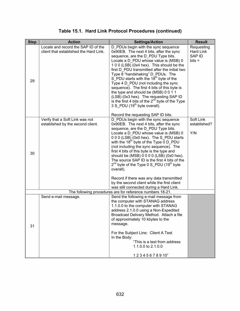
632
Table 15.1. Hard Link Protocol Procedures (continued)
Step Action Settings/Action Result
29
Locate and record the SAP ID of the client that established the Hard Link.
D_PDUs begin with the sync sequence 0x90EB. The next 4 bits, after the sync sequence, are the D_PDU Type bits. Locate a D_PDU whose value is (MSB) 0 1 0 0 (LSB) (0x4 hex). This should be the first D_PDU transmitted after the initial two Type 8 “handshaking” D_PDUs. The S_PDU starts with the 18th byte of the Type 4 D_PDU (not including the sync sequence). The first 4 bits of this byte is the type and should be (MSB) 0 0 1 1 (LSB) (0x3 hex). The requesting SAP ID is the first 4 bits of the 2nd byte of the Type 3 S_PDU (19th byte overall). Record the requesting SAP ID bits.
Requesting Hard Link SAP ID bits =
30
Verify that a Soft Link was not established by the second client.
D_PDUs begin with the sync sequence 0x90EB. The next 4 bits, after the sync sequence, are the D_PDU Type bits. Locate a D_PDU whose value is (MSB) 0 0 0 0 (LSB) (0x0 hex). The S_PDU starts with the 18th byte of the Type 0 D_PDU (not including the sync sequence). The first 4 bits of this byte is the type and should be (MSB) 0 0 0 0 (LSB) (0x0 hex). The source SAP ID is the first 4 bits of the 2nd byte of the Type 0 S_PDU (19th byte overall). Record if there was any data transmitted by the second client while the first client was still connected during a Hard Link.
Soft Link established? Y/N
The following procedures are for reference numbers 18-21.
31
Send e-mail message.
Send the following e-mail message from the computer with STANAG address 1.1.0.0 to the computer with STANAG address 2.1.0.0 using a Non-Expedited Broadcast Delivery Method. Attach a file of approximately 10 kbytes to the message. For the Subject Line: Client A Test In the Body: “This is a test from address 1.1.0.0 to 2.1.0.0 1 2 3 4 5 6 7 8 9 10”

633
Table 15.1. Hard Link Protocol Procedures (continued)
Step Action Settings/Action Result
32
Re-send e-mail message.
Upon completion of the “handshaking” which occurred between computers in step 31 and before the message has completed its transmission, send the following e-mail message from the computer with STANAG address 1.1.0.0 to the computer with STANAG address 2.1.0.0 using a Non-Expedited ARQ Data Transfer. Attach a file of approximately 10 kbytes to the message. For the Subject Line: Client B Test In the Body: “This is a test from address 1.1.0.0 to 2.1.0.0 1 2 3 4 5 6 7 8 9 10” Capture and save the data that is transmitted in this step and in step 31 with the protocol analyzer to a file.
33
Locate D_PDUs transmitted. D_PDUs begin with the sync sequence 0x90EB. The next 4 bits following the sync sequence are the D_PDU Type bits. Record all D_PDU Types transmitted.
D_PDU Types =
34
Send e-mail message.
Send the following e-mail message from the computer with STANAG address 1.1.0.0 to the computer with STANAG address 2.1.0.0 using a Non-Expedited Broadcast Delivery Method. Attach a file of approximately 10 kbytes to the message. For the Subject Line: Client A Test In the Body: “This is a test from address 1.1.0.0 to 2.1.0.0 1 2 3 4 5 6 7 8 9 10”

634
Table 15.1. Hard Link Protocol Procedures (continued)
Step Action Settings/Action Result
35
Re-send e-mail message.
Upon completion of the “handshaking” which occurred between computers in step 34 and before the message has completed its transmission, send the following e-mail message from the computer with STANAG address 1.1.0.0 to the computer with STANAG address 2.1.0.0 using a Type 1 Hard Link with Non-Expedited Data Transfer. Attach a file of approximately 10 kbytes to the message. For the Subject Line: Client B Test In the Body: “This is a test from address 1.1.0.0 to 2.1.0.0 1 2 3 4 5 6 7 8 9 10” Capture and save the data that is transmitted in this step and in step 34 and 35 with the protocol analyzer to a file.
36
Locate D_PDUs transmitted. D_PDUs begin with the sync sequence 0x90EB. The next 4 bits following the sync sequence are the D_PDU Type bits. Record all D_PDU Types transmitted.
D_PDU Types =
The following procedures are for reference numbers 391, 400, 401, 403, 485, 533, 535.
37
Send e-mail message.
Send the following e-mail message from the computer with STANAG address 2.1.0.0 to the computer with STANAG address 1.1.0.0, using a Type 0 Hard Link and Non-Expedited ARQ Delivery Method. Attach a file of approximately 10 kbytes to the message. For the Subject Line: Client A Test In the Body: “This is a test from address 2.1.0.0 to 1.1.0.0 1 2 3 4 5 6 7 8 9 10” Save the data obtained through the protocol analyzer to a file.

635
Table 15.1. Hard Link Protocol Procedures (continued)
Step Action Settings/Action Result
38
Send e-mail message from the second computer.
Upon completion of the “handshaking” which occurred between computers in step 37 and before the message has completed its transmission, send the following e-mail message from the computer with STANAG address 2.1.0.0 to the computer with STANAG address 1.1.0.0 using a Type 0 Hard Link and Non-Expedited ARQ Delivery Method. Use a client that is not utilizing the Hard Link established in step 37. Attach a file of approximately 10 kbytes to the message. For the Subject Line: Client B Test In the Body: “This is a test from address 2.1.0.0 to 1.1.0.0 1 2 3 4 5 6 7 8 9 10” Capture and save the data that is transmitted in this step and in step 37 with the protocol analyzer to a file.
39
Verify that the first message was transmitted before the second message.
Locate the e-mail messages that were transferred in steps 37 and 38. Record the order in which the messages were received.
Message order =
40
Verify that the second message was not transmitted while computer 2.1.0.0 was still linked to computer 1.1.0.0.
D_PDUs begin with the sync sequence 0x90EB. The first 4 bits immediately following the sync sequence are the Type bits. Locate a D_PDU whose Type value is (MSB) 0 1 0 0 (LSB) (0x4 hex). The first 4 bits of the 18th byte of the Type 4 D_PDU is the S_PDU Type. Verify that a Type 6 and Type 7 S_PDUs (link breaking protocols) were transmitted after the data was transfer was completed before another Type 3 and Type 4 S_PDU were transmitted to establish a new link.
Original Link broken before new one formed? Y/N

636
Table 15.1. Hard Link Protocol Procedures (continued)
Step Action Settings/Action Result The following procedures are for reference numbers 395, 401, and 402.
41
Send e-mail message.
Send the following e-mail message from the computer with STANAG address 2.1.0.0 to the computer with STANAG address 1.1.0.0 using a Type 0 Hard Link and Non-Expedited ARQ Delivery Method. Attach a file of approximately 10 kbytes to the message. For the Subject Line: Client A Test In the Body: “This is a test from address 2.1.0.0 to 1.1.0.0 1 2 3 4 5 6 7 8 9 10” Save the data obtained through the protocol analyzer to a file.
42
Send e-mail message from the third computer.
Upon completion of the “handshaking” which occurred between computers in step 41 and before the message has completed its transmission, send the following e-mail message from the computer with STANAG address 2.1.0.0 to the computer with STANAG address 1.1.0.0 using a Type 1 Hard Link and Non-Expedited ARQ Delivery Method. Use a client that is not utilizing the Hard Link established in step 41. Attach a file of approximately 10 kbytes to the message. For the Subject Line: Client B Test In the Body: “This is a test from address 2.1.0.0 to 1.1.0.0 1 2 3 4 5 6 7 8 9 10” Capture and save the data that is transmitted in this step and in step 41 and 42 with the protocol analyzer to a file.
43
Verify that the second message was transmitted before the first message.
Locate the e-mail messages that were transferred in steps 41 and 42. Record the order in which the messages were received.
Message order =
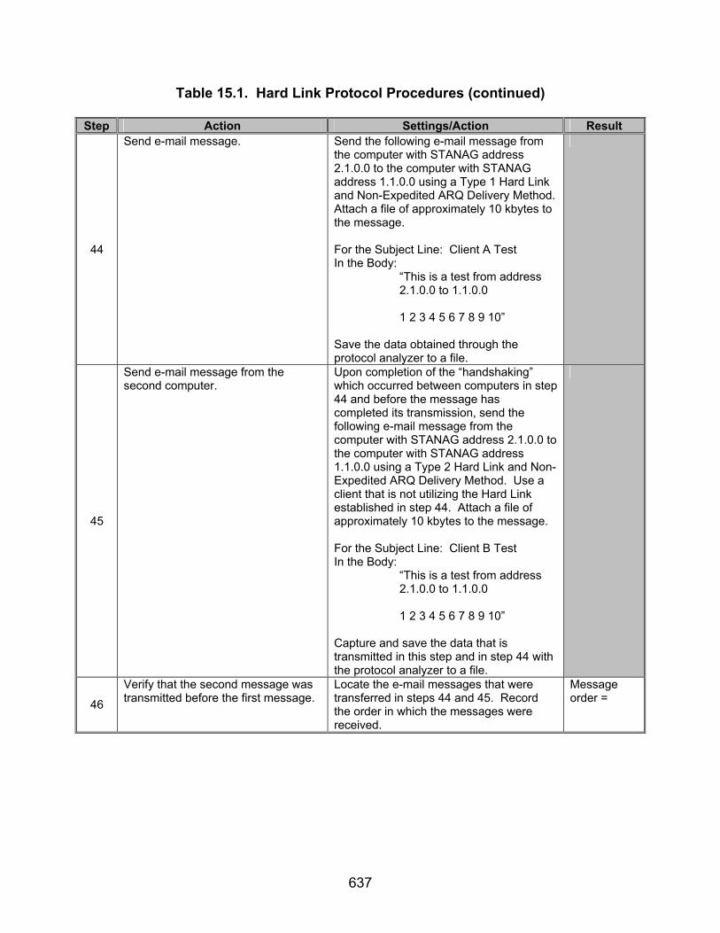
637
Table 15.1. Hard Link Protocol Procedures (continued)
Step Action Settings/Action Result
44
Send e-mail message.
Send the following e-mail message from the computer with STANAG address 2.1.0.0 to the computer with STANAG address 1.1.0.0 using a Type 1 Hard Link and Non-Expedited ARQ Delivery Method. Attach a file of approximately 10 kbytes to the message. For the Subject Line: Client A Test In the Body: “This is a test from address 2.1.0.0 to 1.1.0.0 1 2 3 4 5 6 7 8 9 10” Save the data obtained through the protocol analyzer to a file.
45
Send e-mail message from the second computer.
Upon completion of the “handshaking” which occurred between computers in step 44 and before the message has completed its transmission, send the following e-mail message from the computer with STANAG address 2.1.0.0 to the computer with STANAG address 1.1.0.0 using a Type 2 Hard Link and Non-Expedited ARQ Delivery Method. Use a client that is not utilizing the Hard Link established in step 44. Attach a file of approximately 10 kbytes to the message. For the Subject Line: Client B Test In the Body: “This is a test from address 2.1.0.0 to 1.1.0.0 1 2 3 4 5 6 7 8 9 10” Capture and save the data that is transmitted in this step and in step 44 with the protocol analyzer to a file.
46
Verify that the second message was transmitted before the first message.
Locate the e-mail messages that were transferred in steps 44 and 45. Record the order in which the messages were received.
Message order =

638
Table 15.1. Hard Link Protocol Procedures (continued)
Step Action Settings/Action Result
47
Send e-mail message.
Send the following e-mail message from the computer with STANAG address 2.1.0.0 to the computer with STANAG address 1.1.0.0, using a Type 0 Hard Link and Non-Expedited ARQ Delivery Method. Attach a file of approximately 10 kbytes to the message. For the Subject Line: Client A Test In the Body: “This is a test from address 2.1.0.0 to 1.1.0.0 1 2 3 4 5 6 7 8 9 10”
48
Send e-mail message from the third computer.
Upon completion of the “handshaking” which occurred between computers in step 47 and before the message has completed its transmission, send the following e-mail message from the computer with STANAG address 2.1.0.0 to the computer with STANAG address 1.1.0.0 using a Type 2 Hard Link and Non-Expedited ARQ Delivery Method. Use a client that is not utilizing the Hard Link established in step 47. Attach a file of approximately 10 kbytes to the message. For the Subject Line: Client B Test In the Body: “This is a test from address 2.1.0.0 to 1.1.0.0 1 2 3 4 5 6 7 8 9 10” Capture and save the data that is transmitted in this step and in step 47 and 48 with the protocol analyzer to a file.
49
Verify that the second message was transmitted before the first message.
Locate the e-mail messages that were transferred in steps 47 and 48. Record the order in which the messages were received.
Message order =
The following procedures are for reference numbers 393-395, 397, and 399.
50 Reconfigure Hard Link priority. Configure the Hard Link priority of the client type recorded in step 5 to “0.”
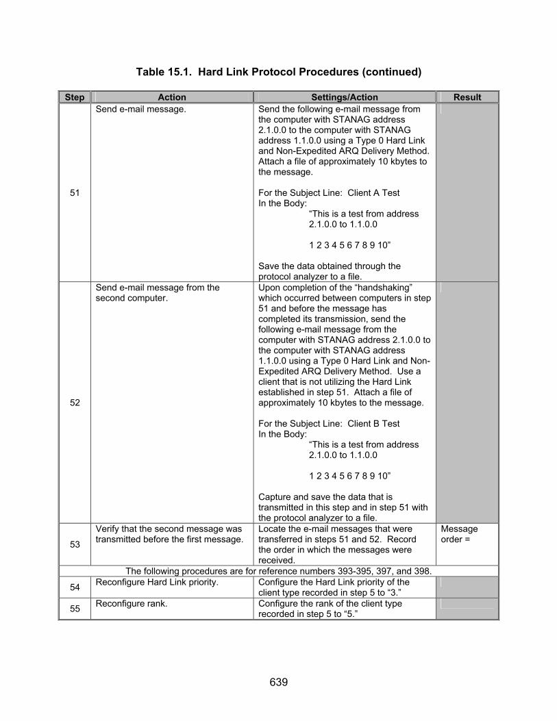
639
Table 15.1. Hard Link Protocol Procedures (continued)
Step Action Settings/Action Result
51
Send e-mail message.
Send the following e-mail message from the computer with STANAG address 2.1.0.0 to the computer with STANAG address 1.1.0.0 using a Type 0 Hard Link and Non-Expedited ARQ Delivery Method. Attach a file of approximately 10 kbytes to the message. For the Subject Line: Client A Test In the Body: “This is a test from address 2.1.0.0 to 1.1.0.0 1 2 3 4 5 6 7 8 9 10” Save the data obtained through the protocol analyzer to a file.
52
Send e-mail message from the second computer.
Upon completion of the “handshaking” which occurred between computers in step 51 and before the message has completed its transmission, send the following e-mail message from the computer with STANAG address 2.1.0.0 to the computer with STANAG address 1.1.0.0 using a Type 0 Hard Link and Non-Expedited ARQ Delivery Method. Use a client that is not utilizing the Hard Link established in step 51. Attach a file of approximately 10 kbytes to the message. For the Subject Line: Client B Test In the Body: “This is a test from address 2.1.0.0 to 1.1.0.0 1 2 3 4 5 6 7 8 9 10” Capture and save the data that is transmitted in this step and in step 51 with the protocol analyzer to a file.
53
Verify that the second message was transmitted before the first message.
Locate the e-mail messages that were transferred in steps 51 and 52. Record the order in which the messages were received.
Message order =
The following procedures are for reference numbers 393-395, 397, and 398.
54 Reconfigure Hard Link priority. Configure the Hard Link priority of the client type recorded in step 5 to “3.”
55 Reconfigure rank. Configure the rank of the client type recorded in step 5 to “5.”

640
Table 15.1. Hard Link Protocol Procedures (continued)
Step Action Settings/Action Result
56
Send e-mail message.
Send the following e-mail message from the computer with STANAG address 2.1.0.0 to the computer with STANAG address 1.1.0.0 using a Type 0 Hard Link and Non-Expedited ARQ Delivery Method. Attach a file of approximately 10 kbytes to the message. For the Subject Line: Client A Test In the Body: “This is a test from address 2.1.0.0 to 1.1.0.0 1 2 3 4 5 6 7 8 9 10” Save the data obtained through the protocol analyzer to a file.
57
Send e-mail message from the second computer.
Upon completion of the “handshaking” which occurred between computers in step 56 and before the message has completed its transmission, send the following e-mail message from the computer with STANAG address 2.1.0.0 to the computer with STANAG address 1.1.0.0 using a Type 0 Hard Link and Non-Expedited ARQ Delivery Method. Use a client that is not utilizing the Hard Link established in step 56. Attach a file of approximately 10 kbytes to the message. For the Subject Line: Client B Test In the Body: “This is a test from address 2.1.0.0 to 1.1.0.0 1 2 3 4 5 6 7 8 9 10” Capture and save the data that is transmitted in this step and in step 56 with the protocol analyzer to a file.
58
Verify that the second message was transmitted before the first message.
Locate the e-mail messages that were transferred in steps 56 and 57. Record the order in which the messages were received.
Message order =
The following procedures are for reference numbers 393, 395, 397, and 398.
59 Re-configure Hard Link priority. Configure the Hard Link priority of the client type recorded in step 5 to “0.”
60 Re-configure rank. Configure the rank of the client type recorded in step 5 to “15.”
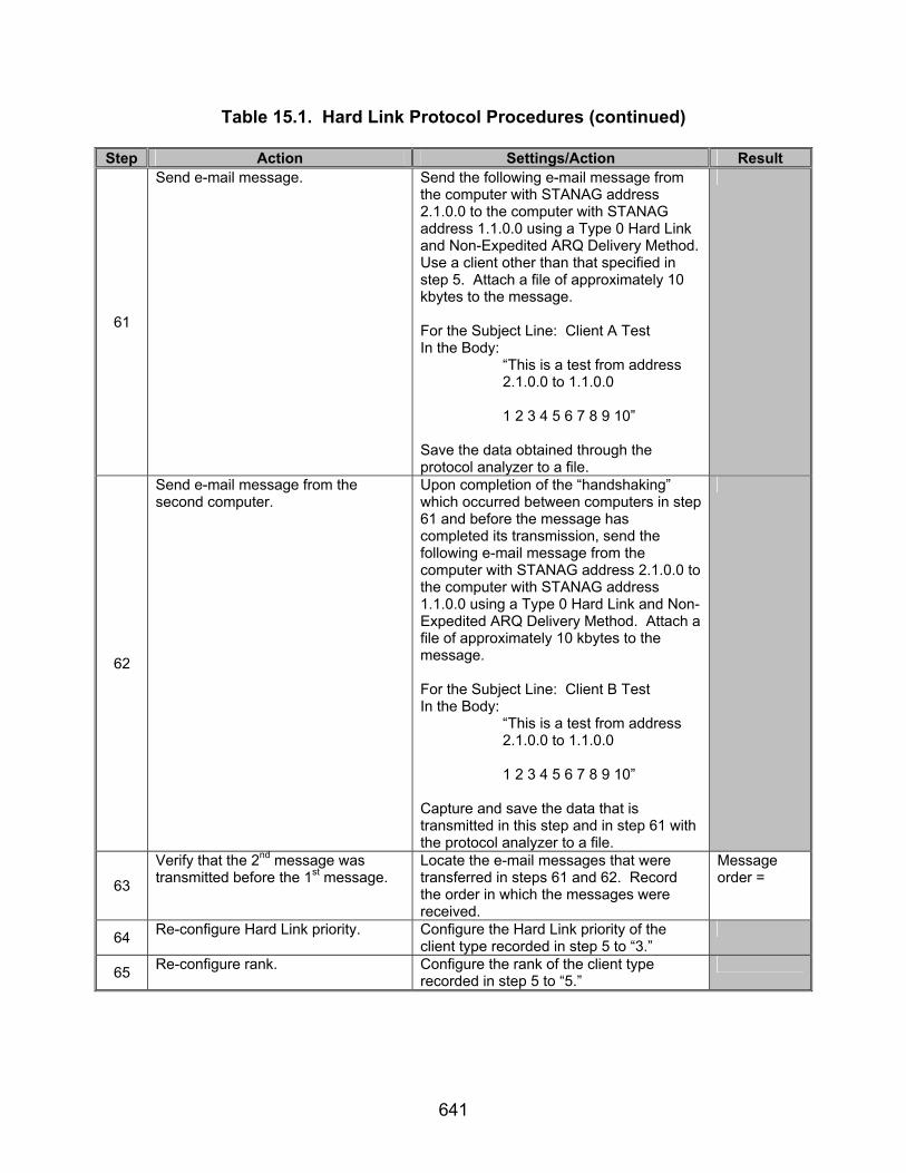
641
Table 15.1. Hard Link Protocol Procedures (continued)
Step Action Settings/Action Result
61
Send e-mail message.
Send the following e-mail message from the computer with STANAG address 2.1.0.0 to the computer with STANAG address 1.1.0.0 using a Type 0 Hard Link and Non-Expedited ARQ Delivery Method. Use a client other than that specified in step 5. Attach a file of approximately 10 kbytes to the message. For the Subject Line: Client A Test In the Body: “This is a test from address 2.1.0.0 to 1.1.0.0 1 2 3 4 5 6 7 8 9 10” Save the data obtained through the protocol analyzer to a file.
62
Send e-mail message from the second computer.
Upon completion of the “handshaking” which occurred between computers in step 61 and before the message has completed its transmission, send the following e-mail message from the computer with STANAG address 2.1.0.0 to the computer with STANAG address 1.1.0.0 using a Type 0 Hard Link and Non-Expedited ARQ Delivery Method. Attach a file of approximately 10 kbytes to the message. For the Subject Line: Client B Test In the Body: “This is a test from address 2.1.0.0 to 1.1.0.0 1 2 3 4 5 6 7 8 9 10” Capture and save the data that is transmitted in this step and in step 61 with the protocol analyzer to a file.
63
Verify that the 2nd message was transmitted before the 1st message.
Locate the e-mail messages that were transferred in steps 61 and 62. Record the order in which the messages were received.
Message order =
64 Re-configure Hard Link priority. Configure the Hard Link priority of the client type recorded in step 5 to “3.”
65 Re-configure rank. Configure the rank of the client type recorded in step 5 to “5.”
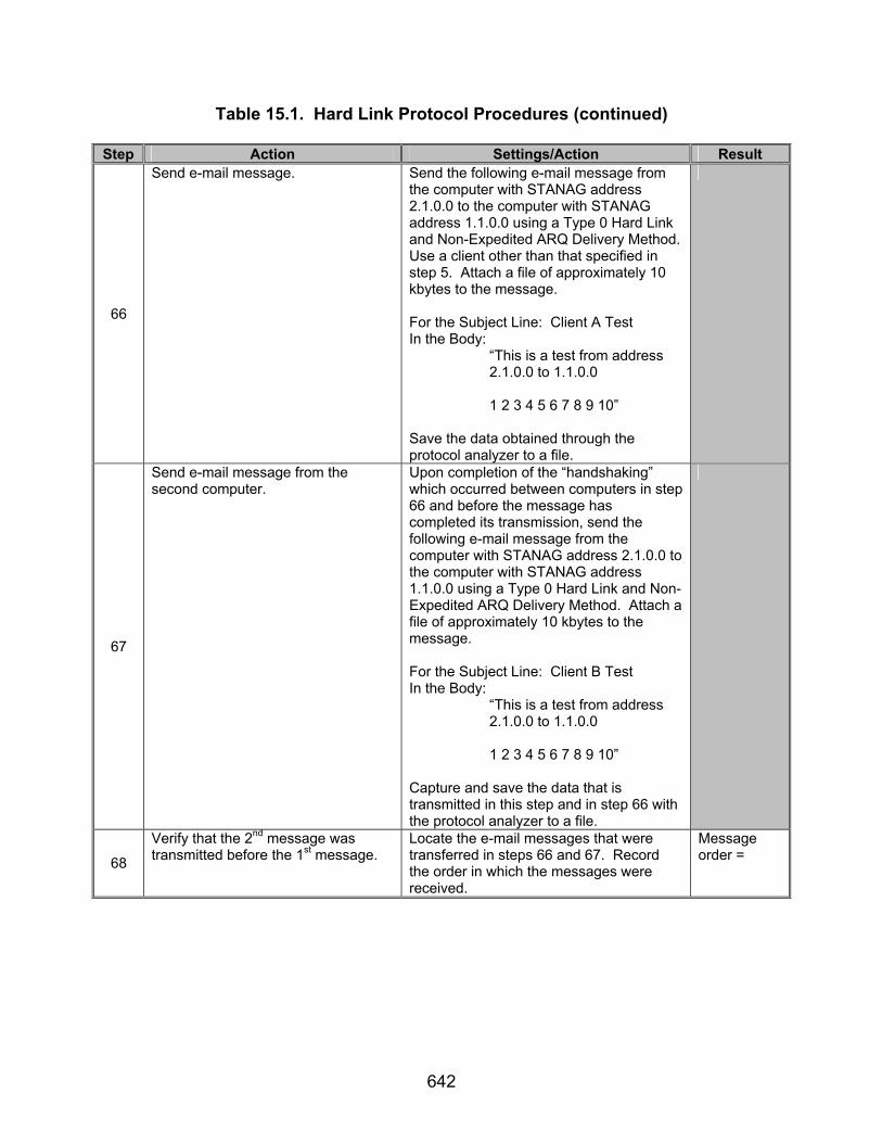
642
Table 15.1. Hard Link Protocol Procedures (continued)
Step Action Settings/Action Result
66
Send e-mail message.
Send the following e-mail message from the computer with STANAG address 2.1.0.0 to the computer with STANAG address 1.1.0.0 using a Type 0 Hard Link and Non-Expedited ARQ Delivery Method. Use a client other than that specified in step 5. Attach a file of approximately 10 kbytes to the message. For the Subject Line: Client A Test In the Body: “This is a test from address 2.1.0.0 to 1.1.0.0 1 2 3 4 5 6 7 8 9 10” Save the data obtained through the protocol analyzer to a file.
67
Send e-mail message from the second computer.
Upon completion of the “handshaking” which occurred between computers in step 66 and before the message has completed its transmission, send the following e-mail message from the computer with STANAG address 2.1.0.0 to the computer with STANAG address 1.1.0.0 using a Type 0 Hard Link and Non-Expedited ARQ Delivery Method. Attach a file of approximately 10 kbytes to the message. For the Subject Line: Client B Test In the Body: “This is a test from address 2.1.0.0 to 1.1.0.0 1 2 3 4 5 6 7 8 9 10” Capture and save the data that is transmitted in this step and in step 66 with the protocol analyzer to a file.
68
Verify that the 2nd message was transmitted before the 1st message.
Locate the e-mail messages that were transferred in steps 66 and 67. Record the order in which the messages were received.
Message order =
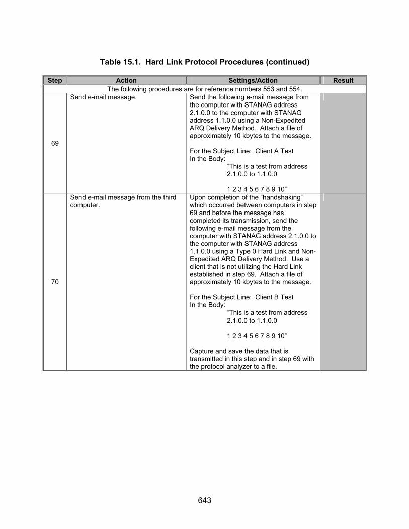
643
Table 15.1. Hard Link Protocol Procedures (continued)
Step Action Settings/Action Result
The following procedures are for reference numbers 553 and 554.
69
Send e-mail message.
Send the following e-mail message from the computer with STANAG address 2.1.0.0 to the computer with STANAG address 1.1.0.0 using a Non-Expedited ARQ Delivery Method. Attach a file of approximately 10 kbytes to the message. For the Subject Line: Client A Test In the Body: “This is a test from address 2.1.0.0 to 1.1.0.0 1 2 3 4 5 6 7 8 9 10”
70
Send e-mail message from the third computer.
Upon completion of the “handshaking” which occurred between computers in step 69 and before the message has completed its transmission, send the following e-mail message from the computer with STANAG address 2.1.0.0 to the computer with STANAG address 1.1.0.0 using a Type 0 Hard Link and Non-Expedited ARQ Delivery Method. Use a client that is not utilizing the Hard Link established in step 69. Attach a file of approximately 10 kbytes to the message. For the Subject Line: Client B Test In the Body: “This is a test from address 2.1.0.0 to 1.1.0.0 1 2 3 4 5 6 7 8 9 10” Capture and save the data that is transmitted in this step and in step 69 with the protocol analyzer to a file.

644
Table 15.1. Hard Link Protocol Procedures (continued)
Step Action Settings/Action Result
71
Verify that the second message was not transmitted while computer 2.1.0.0 was still linked to computer 1.1.0.0.
D_PDUs begin with the sync sequence 0x90EB. The first 4 bits, immediately following the sync sequence, are the Type bits. Locate a D_PDU whose Type value is (MSB) 1 0 0 0 (LSB) (0x8 hex). The first 4 bits of the 23rd byte of the Type 8 D_PDU is the C_PDU Type. Verify that Type 4 and Type 5 C_PDUs (Link Breaking protocols) were transmitted after the data was transfer was completed before Type 3 and Type 4 S_PDUs were transmitted to establish a new link. (The Type 3 and Type 4 S_PDUs can be found as follows: Locate a D_PDU whose Type value is (MSB) 0 1 0 0 (LSB) (0x4 hex). The first 4 bits of the 18th byte of the Type 4 D_PDU is the S_PDU Type.)
Original Soft Link broken before Hard Link formed? Y/N
Legend: ARQ—Automatic Repeat-Request bps—bits per second C_PDU—Channel Access Sublayer Protocol Data Unit D_PDU—Data Transfer Sublayer Protocol Data Unit e-mail—Electronic Mail hex—hexadecimal HMTP—High Frequency Mail Transfer Protocol ID—Identification kbyte—kilobyte LSB—Least Significant Bit
MIL-STD—Military Standard MSB—Most Significant Bit POP3—Post Office Protocol 3 S_PDU—Subnetwork Sublayer Protocol Data Unit SAP—Subnetwork Access Point SMTP—Simple Mail Transfer Protocol STANAG—Standardization Agreement sync—synchronization

645
Table 15.2. Hard Link Protocol Results
Result Finding Reference Number
STANAG 5066
Paragraph Requirement Required
Value Measured
Value Met Not Met
6 A.1.1.1
The specified maximum time-out period shall be a configurable parameter for the protocol implementation. The specific values of the parameters governing the establishment and termination of Soft Link Data Exchange Sessions (e.g., time-out periods etc.) must be chosen in the context of a particular configuration (i.e., size of network, etc).
Maximum Time-out is a configurable parameter. (step 15)
8 A.1.1.2.1
A Hard Link of Type 0, also called a Hard Link with Link Reservation, shall maintain a physical link between two nodes.
Type 0 Hard Link Established between computers 1.1.0.0 and 2.1.0.0.
9 A.1.1.2.1
The Type 0 Hard Link capacity shall not be reserved for any given client on the two nodes.
Another client may make a Soft Link while, Type 0 Hard Link is established.
10 A.1.1.2.1
Any client on nodes connected by a Hard Link of Type 0 shall be permitted to exchange data over the Hard Link.
Data transferred while Type 0 Hard Link is established.
11 A.1.1.2.1
Any client on either node other than the client that requested the Hard Link shall gain access to the link only as a Soft Link Data Exchange Session and may lose the link when the originating client terminates its Hard Link Data Exchange Session.
Another client may make a Soft Link while, Type 0 Hard Link is established.
12 A.1.1.2.2
A Hard Link of Type 1, also called a Hard Link with Partial Bandwidth Reservation, shall maintain a physical link between two nodes.
Type 1 Hard Link establish-ed between computers 1.1.0.0 and 2.1.0.0.

646
Table 15.2. Hard Link Protocol Results (continued)
Result Finding Reference Number
STANAG 5066
Paragraph Requirement Required
Value Measured
Value Met Not Met
13 A.1.1.2.2
The Type 1 Hard Link capacity shall be reserved only for the client that requested the Type 1 Hard Link between the two nodes. The requesting client may send user data to any client on the remote node and may receive user data from any client on the remote node only as a Soft Link Data Exchange Session.
The same client that has established a Type 1 Hard Link is able to transmit data as a Soft Link during the same link.
14 A.1.1.2.2
Clients that are not sending data to or receiving data from the client that requested the Type 1 Hard Link shall be unable to use the Hard Link. Any client using the link may lose the link when the originating client terminates its Hard Link session.
A different client than the one that has established a Type 1 Hard Link is not able to transmit data as a Soft Link during the same link.
15 A.1.1.2.3
A Hard Link of Type 2, also called a Hard Link with Full Bandwidth Reservation, shall maintain a physical link between two nodes.
A Type 2 Hard Link Link establish-ed between computers 1.1.0.0 and 2.1.0.0.
16 A.1.1.2.3
The Type 2 Hard Link capacity shall be reserved only for the client that requested the Type 2 Hard Link and a specified remote client.
No other client able to transmit data across Hard Link.
17 A.1.1.2.3
No clients other than the requesting client and its specified remote client shall exchange data on a Type 2 Hard Link.
No other client able to transmit data across Hard Link.

647
Table 15.2. Hard Link Protocol Results (continued)
Result Finding Reference Number
STANAG 5066
Paragraph Requirement Required
Value Measured
Value Met Not Met
18 A.1.1.3
The third type of data exchange session is the Broadcast Data Exchange Session. The subnetwork shall service only clients with service requirements for Non-ARQ U_PDUs during a Broadcast Data Exchange Session.
Type 7 D_PDUs sent for Non-ARQ Data Exchange or Broadcast Data Exchange.
19 A.1.1.3
The procedures that initiate and terminate Broadcast Data Exchange Session shall be as specified in annex C.
20 A.1.1.3
A node configured to be a broadcast-only node shall use a “permanent” Broadcast Data Exchange Session
No Type 0-2,4 or 5 D_PDUs transmitted for Non-ARQ Transmis-sion Mode.
21 A.1.1.3
During which the Subnetwork Interface Sublayer shall service no Hard Link requests or ARQ DATA U_PDUs. Alternatively the Subnetwork Interface Sublayer can unilaterally initiate and terminate Broadcast Data Exchange Sessions.
No Hard Links or Soft Links established during Broadcast Data Transfer (i.e. not D_PDUs other than Type 7 transmitted until broadcast data transfer was completed.)
390 A.3.2.1.2
This STANAG assumes a simple model for the management of Hard Links based on maintenance of at most a single Hard Link between nodes, while still allowing Type 0 and Type 1 Hard Links between the nodes to be shared by other clients using Soft Link Data Exchange. This management model satisfies the following requirements:
Soft Link still accepted while Types 0 and 1 Hard Links established.

648
Table 15.2. Hard Link Protocol Results (continued)
Result Finding Reference Number
STANAG 5066
Paragraph Requirement Required
Value Measured
Value Met Not Met
391 A.3.2.1.2
A node’s sublayer shall maintain at most one Hard Link at any time;
Only one Hard Link established at a time.
392 A.3.2.1.2 A sublayer shall accept a Hard Link request when no Hard Link currently exists;
Initial Hard Links accepted.
393 A.3.2.1.2
The comparative precedence of new requests and any existing Hard Link shall be evaluated in accordance with section A.3.2.2.1 of STANAG 5066 to determine if the new request can be accepted or rejected by the sublayer;
394 A.3.2.1.2
Requests of higher precedence shall be accepted and will result in the termination of an existing Hard Link;
Computers requesting a Hard Link with higher rank and priority send their message before a computer with an existing Hard Link with lower rank and priority.
395 A.3.2.1.2
An existing Hard Link of higher precedence shall result in the rejection of the request;
Computers with an existing Hard Link with a higher rank and priority send their message before a computer with a newly requested Hard Link with lower rank and priority.
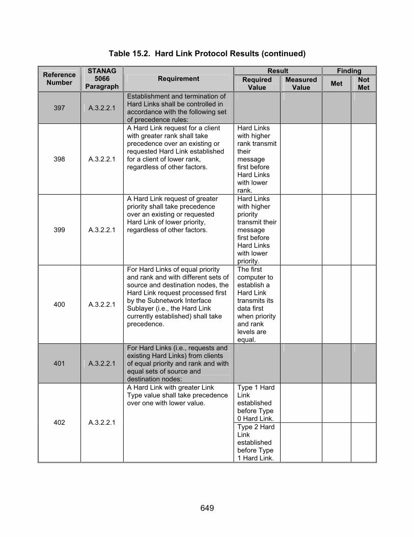
649
Table 15.2. Hard Link Protocol Results (continued)
Result Finding Reference Number
STANAG 5066
Paragraph Requirement Required
Value Measured
Value Met Not Met
397 A.3.2.2.1
Establishment and termination of Hard Links shall be controlled in accordance with the following set of precedence rules:
398 A.3.2.2.1
A Hard Link request for a client with greater rank shall take precedence over an existing or requested Hard Link established for a client of lower rank, regardless of other factors.
Hard Links with higher rank transmit their message first before Hard Links with lower rank.
399 A.3.2.2.1
A Hard Link request of greater priority shall take precedence over an existing or requested Hard Link of lower priority, regardless of other factors.
Hard Links with higher priority transmit their message first before Hard Links with lower priority.
400 A.3.2.2.1
For Hard Links of equal priority and rank and with different sets of source and destination nodes, the Hard Link request processed first by the Subnetwork Interface Sublayer (i.e., the Hard Link currently established) shall take precedence.
The first computer to establish a Hard Link transmits its data first when priority and rank levels are equal.
401 A.3.2.2.1
For Hard Links (i.e., requests and existing Hard Links) from clients of equal priority and rank and with equal sets of source and destination nodes:
Type 1 Hard Link established before Type 0 Hard Link.
402 A.3.2.2.1
A Hard Link with greater Link Type value shall take precedence over one with lower value.
Type 2 Hard Link established before Type 1 Hard Link.

650
Table 15.2. Hard Link Protocol Results (continued)
Result Finding Reference Number
STANAG 5066
Paragraph Requirement Required
Value Measured
Value Met Not Met
402 A.3.2.2.1
Type 2 Hard Link established before Type 0 Hard Link.
403 A.3.2.2.1
An existing Hard Link shall take precedence over subsequent Hard Link requests of equal Link Type.
The first computer to establish a Hard Link transmits its data first when Hard Link types are equal.
482 B.3
Physical Links shall be of either of two types, Exclusive or Nonexclusive, with properties and service features defined as follows:
483 B.3
A node shall use an Exclusive Physical Link to support control and data exchange for Hard Link Data Exchange Sessions as requested by the Subnetwork Interface Sublayer;
Exclusive link used for Hard Link Data Exchange Session.
484 B.3
A node shall use a Nonexclusive Physical Link to support control and data exchange for Soft Link Data Exchange Sessions as requested by the Subnetwork Interface Sublayer.
Nonexclusive Link used for Soft Link Data Exchange Session.
485 B.3
A node shall establish at most two Exclusive Physical Links with other nodes.
No more than 1 Hard Link established and STANAG is able to make link adjustments based on ranks and priority level.
533 B.3.2 The criteria for accepting or rejecting Physical Links Requests shall be as follows:
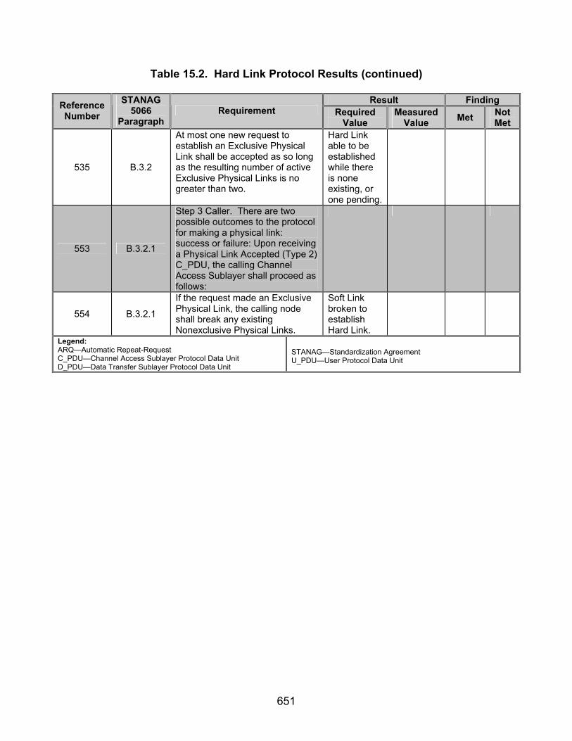
651
Table 15.2. Hard Link Protocol Results (continued)
Result Finding Reference Number
STANAG 5066
Paragraph Requirement Required
Value Measured
Value Met Not Met
535 B.3.2
At most one new request to establish an Exclusive Physical Link shall be accepted as so long as the resulting number of active Exclusive Physical Links is no greater than two.
Hard Link able to be established while there is none existing, or one pending.
553 B.3.2.1
Step 3 Caller. There are two possible outcomes to the protocol for making a physical link: success or failure: Upon receiving a Physical Link Accepted (Type 2) C_PDU, the calling Channel Access Sublayer shall proceed as follows:
554 B.3.2.1
If the request made an Exclusive Physical Link, the calling node shall break any existing Nonexclusive Physical Links.
Soft Link broken to establish Hard Link.
Legend: ARQ—Automatic Repeat-Request C_PDU—Channel Access Sublayer Protocol Data Unit D_PDU—Data Transfer Sublayer Protocol Data Unit
STANAG—Standardization Agreement U_PDU—User Protocol Data Unit

652
(This page intentionally left blank.)

653
SUBTEST 16. HIGH FREQUENCY MAIL TRANSFER PROTOCOL CLIENT 16.1 Objective. To determine the extent of compliance to the requirements of STANAG 5066 and Request For Comments (RFC) 2821 and 2920 for validating the High Frequency Mail Transfer Protocol (HMTP) Client, STANAG 5066 reference numbers 990-996 and RFC reference numbers 1026-1053 . (Note: This subtest does not attempt to validate all requirements from STANAG 5066, RFC2821, and RFC2920, just those basic requirements necessary to confirm the HMTP client is accurate enough to be used as the primary client for the subtests within this test plan.) 16.2 Criteria
a. A HMTP client or server shall use the HF subnetwork protocol stack
directly, without intervening transport or network protocol is, by encapsulating the Simple Mail Transfer Protocol (SMTP) commands, replies, and mail objects within the S_Primitives defined in STANAG 5066 annex A. (appendix B, reference number 990)
b. The HMTP mail model and mail objects, including the commands,
responses, and semantics of the HMTP protocol, shall be defined by the following standards:
• The Internet Standard 10 for the Simple Mail Transfer Protocol [RFC 821].
• The proposed consolidated SMTP standard defined in RFC 2821 (intended as the replacement for, and with precedence in requirements over, RFC 821).
• The Internet Standard 60 defining the SMTP Service Extension for Command Pipelining [RFC 2920], and the amendments defined herein that mandate certain SMTP options for efficiency in use over the HF channel.
• In particular: An HMTP server shall implement the SMTP pipelining service, in accordance with RFC 2920. (appendix B, reference numbers 991 and 992)
c. Clients and servers for the HMTP shall bind to the HF Subnetwork at SAP
ID 3. (appendix B, reference number 993) Requirements defined as follows:
Transmission Mode = Automatic Repeat-Request (ARQ) Delivery Confirmation = NODE DELIVERY or CLIENT DELIVERY Deliver in Order = In-Order Delivery
d. The encoded data for commands, replies, and mail-object data in HMTP
shall be bit- and byte-aligned with the octets in an S_Primitive’s U_PDU, with the LSB of each character aligned with the LSB of the octet. (appendix B, reference number 994)
654
e. Message data encoded as seven-bit symbols (e.g., International
Telegraph Alphabet [ITA] 5 or the American Standard Code for Information Interchange [ASCII] character sets) shall be bit-aligned, LSB to LSB, with the octets of the S_Primitive. The unused eighth bit (i.e., MSB) of the octet shall be set to (0) in compliance with RFC 2821. (appendix B, reference numbers 995 and 996)
f. SMTP commands and, unless altered by a service extension, message
data, are transmitted in “lines.” Lines consist of zero or more data characters terminated by the sequence ASCII character “CR” (hex value 0D) followed immediately by ASCII character “LF” (hex value 0A). This termination sequence is denoted as <CRLF> in this document. (appendix B, reference number 1026)
g. Once the server has sent the welcoming message and the client has
received it, the client normally sends the EHLO command to the server, indicating the client’s identity. (appendix B, reference number 1027)
h. The first step in the procedure is the MAIL command.
MAIL FROM:<reverse-path> [SP <mail-parameters> ] <CRLF> This command tells the SMTP receiver that a new mail transaction is starting and to reset all its state tables and buffers, including any recipients or mail data. (appendix B, reference number 1028)
i. The second step in the procedure is the RCPT command. RCPT TO:<forward-path> [ SP <rcpt-parameters> ] <CRLF> The first or only argument to this command includes a Forward-Path (normally a mailbox and domain, always surrounded by “<“ and “>“ brackets) identifying one recipient. If accepted, the SMTP server returns a 250 (OK) reply and stores the Forward-Path. If the recipient is known not to be a deliverable address, the SMTP server returns a 550 reply, typically with a string such as “no such user - “ and the mailbox name (other circumstances and reply codes are possible). This step of the procedure can be repeated any number of times. (appendix B, reference numbers 1029-1031)
j. The third step in the procedure is the DATA command (or some alternative specified in a service extension). DATA <CRLF> If accepted, the SMTP server returns a 354 (Intermediate) reply and considers all succeeding lines up to but not including the End Of Mail Data Indicator to be the message text. When the end of text is successfully received and stored, the SMTP receiver sends a 250 (OK) reply. (appendix B, reference numbers 1032-1034)

655
k. Mail transaction commands MUST be used in the order discussed above.
(appendix B, reference number 1035)
l. If an SMTP server has accepted the task of relaying the mail and later finds that the destination is incorrect or that the mail cannot be delivered for some other reason, then it MUST construct an “undeliverable mail” notification message and send it to the originator of the undeliverable mail (as indicated by the Reverse-Path). (appendix B, reference number 1036)
m. In any event, a client MUST issue HELO or EHLO before starting a mail transaction. (appendix B, reference number 1037)
n. The mail data is terminated by a line containing only a period, that is, the character sequence “<CRLF>.<CRLF>“ (RFC 2821, section 4.5.2). This is the end of mail data indication. Note that the first <CRLF> of this terminating sequence is also the <CRLF> that ends the final line of the data (message text) or, if there was no data, ends the DATA command itself. An extra <CRLF> MUST NOT be added, as that would cause an empty line to be added to the message. (appendix B, reference numbers 1038 and 1039)
o. The QUIT command specifies that the receiver MUST send an (OK) reply, and then close the transmission channel. (appendix B, reference number 1040)
p. A session that will contain mail transactions MUST first be initialized by the use of the EHLO command. (appendix B, reference number 1041)
q. The last command in a session MUST be the QUIT command. (appendix
B, reference number 1042) r. Unless extended, using the mechanisms described in RFC 2821, section
2.2, SMTP servers MUST NOT transmit reply codes to an SMTP client that are other than three digits or that do not start in a digit between 2 and 5 inclusive. (appendix B, reference number 1043)
s. When an SMTP server receives a message for delivery or further
processing, it MUST insert trace (“Time Stamp” or “Received”) information at the beginning of the message content, as discussed in RFC 2821, section 4.1.1.4. (appendix B, reference numbers 1044-1046) This line MUST be structured as follows:
• The FROM field, which MUST be supplied in an SMTP environment, SHOULD contain both (1) the name of the source host as presented in the EHLO command and (2) an address literally containing the Internet

656
Protocol (IP) address of the source, determined from the Transmission Control Protocol (TCP) connection.
t. A server SMTP implementation that offers the pipelining extension:
(appendix B, reference numbers 1047-1053)
• MUST respond to commands in the order they are received from the client.
• MUST NOT, after issuing a positive response to a DATA command with no valid recipients and subsequently receiving an empty message, send any message whatsoever to anybody.
• MUST NOT buffer responses to EHLO, DATA, VRFY, EXPN, TURN, QUIT, and NOOP.
• MUST NOT buffer responses to unrecognized commands. • MUST send all pending responses immediately, whenever the local
TCP input buffer is emptied. • MUST NOT flush or otherwise lose the contents of the TCP input
buffer under any circumstances whatsoever.
16.3 Test Procedures a. Test Equipment Required
(1) Computers (2 ea) with STANAG 5066 Software
(2) Modems (2 ea)
(3) Protocol Analyzer
(4) RS-232 Synchronous Serial Cards
b. Test Configuration. Figure 16.1 shows the equipment setup for this subtest.
c. Test Conduction. Table 16.1 lists procedures for this subtest and tables 16.2 and 16.3 list the results for this subtest.

657
Computer Modem Modem Computer
LANAnalyzer
RS-232 RS-232
Figure 16.1. Equipment Configuration for HMTP Client
Table 16.1. High Frequency Mail Transfer Protocol Procedures Step Action Settings/Action Result
The following procedures are for reference number 993.
1
Set up equipment. See figure 16.1. Computers are connected to the modems by an RS-232 connection. The connection between modems shall be such that the receive and transmit pins on the modem are connected to the transmit and receive pins, respectively, of the other modem.
2 Load STANAG 5066 software. Configure the SMTP and POP3 servers as
required by the STANAG 5066 software manual.
3
Configure STANAG addresses for computers 1 and 2.
Set the size of the STANAG address field size to 7 bytes. Set the STANAG address of computer number 1 to 1.1.0.0 and the STANAG address of computer number 2 to 1.2.0.0. Configure the software to respond with an e-mail message to the sender once the e-mail has been successfully received.
4 Configure modems 1 and 2. Set modems 1 and 2 to transmit a
MIL-STD-188-110B signal at a data rate of 4800 bps with half duplex.
5 Configure client Type. Configure both computers to use the HMTP client.
6 Identify client SAP ID of computer with STANAG address 1.2.0.0.
Record the SAP ID of the client used for the computer with STANAG address 1.2.0.0.
1.2.0.0 SAP ID =
7 Configure rank and priority level. Set the priority level to “0” for both
computers. Set the rank to “15” for both computers.
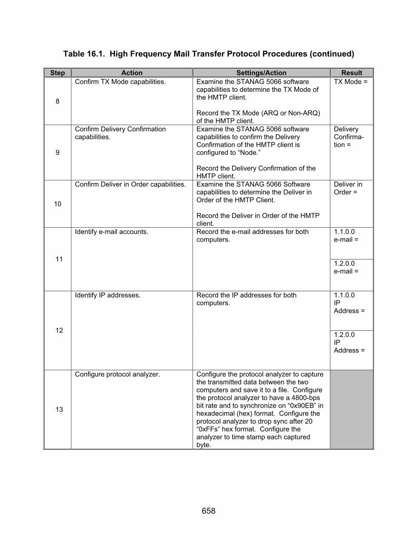
658
Table 16.1. High Frequency Mail Transfer Protocol Procedures (continued) Step Action Settings/Action Result
8
Confirm TX Mode capabilities. Examine the STANAG 5066 software capabilities to determine the TX Mode of the HMTP client. Record the TX Mode (ARQ or Non-ARQ) of the HMTP client.
TX Mode =
9
Confirm Delivery Confirmation capabilities.
Examine the STANAG 5066 software capabilities to confirm the Delivery Confirmation of the HMTP client is configured to “Node.” Record the Delivery Confirmation of the HMTP client.
Delivery Confirma-tion =
10
Confirm Deliver in Order capabilities. Examine the STANAG 5066 Software capabilities to determine the Deliver in Order of the HMTP Client. Record the Deliver in Order of the HMTP client.
Deliver in Order =
1.1.0.0 e-mail = 11
Identify e-mail accounts. Record the e-mail addresses for both computers.
1.2.0.0 e-mail = 1.1.0.0 IP Address = 12
Identify IP addresses. Record the IP addresses for both computers. 1.2.0.0
IP Address =
13
Configure protocol analyzer. Configure the protocol analyzer to capture the transmitted data between the two computers and save it to a file. Configure the protocol analyzer to have a 4800-bps bit rate and to synchronize on “0x90EB” in hexadecimal (hex) format. Configure the protocol analyzer to drop sync after 20 “0xFFs” hex format. Configure the analyzer to time stamp each captured byte.
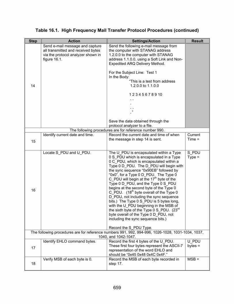
659
Table 16.1. High Frequency Mail Transfer Protocol Procedures (continued) Step Action Settings/Action Result
14
Send e-mail message and capture all transmitted and received bytes via the protocol analyzer shown in figure 16.1.
Send the following e-mail message from the computer with STANAG address 1.2.0.0 to the computer with STANAG address 1.1.0.0, using a Soft Link and Non-Expedited ARQ Delivery Method. For the Subject Line: Test 1 In the Body: “This is a test from address 1.2.0.0 to 1.1.0.0 1 2 3 4 5 6 7 8 9 10
..
.
..
.”
Save the data obtained through the protocol analyzer to a file.
The following procedures are for reference number 990.
15
Identify current date and time. Record the current date and time of when the message in step 14 is sent.
Current Time =
16
Locate S_PDU and U_PDU. The U_PDU is encapsulated within a Type 0 S_PDU which is encapsulated in a Type 0 C_PDU, which is encapsulated within a Type 0 D_PDU. The D_PDU will begin with the sync sequence “0x90EB” followed by “0x0”, for a Type 0 D_PDU. The Type 0 C_PDU will begin at the 17th byte of the Type 0 D_PDU, and the Type 0 S_PDU begins at the second byte of the Type 0 C_PDU. (18th byte overall of the Type 0 D_PDU, not including the sync sequence bits.) The Type 0 S_PDU is 5 bytes long, with the U_PDU beginning in the MSB of the sixth byte of the Type 0 S_PDU. (23rd byte overall of the Type 0 D_PDU, not including the sync sequence bits.) Record the S_PDU Type.
S_PDU Type =
The following procedures are for reference numbers 991, 992, 994-996, 1026-1028, 1031-1034, 1037, 1040, and 1042-1047.
17
Identify EHLO command bytes. Record the first 4 bytes of the U_PDU. These first four bytes represent the ASCII-7 representation of the word EHLO and should be “0x45 0x48 0x4C 0x4F.”
U_PDU bytes =
18 Verify MSB of each byte is 0. Record the MSB of each byte recorded in
step 17. MSB =
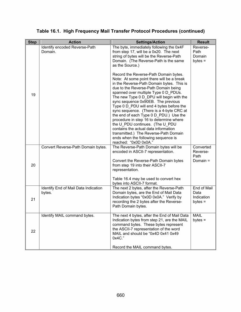
660
Table 16.1. High Frequency Mail Transfer Protocol Procedures (continued) Step Action Settings/Action Result
19
Identify encoded Reverse-Path Domain.
The byte, immediately following the 0x4F from step 17, will be a 0x20. The next string of bytes will be the Reverse-Path Domain. (The Reverse-Path is the same as the Source.) Record the Reverse-Path Domain bytes. Note: At some point there will be a break in the Reverse-Path Domain bytes. This is due to the Reverse-Path Domain being spanned over multiple Type 0 D_PDUs. The new Type 0 D_DPU will begin with the sync sequence 0x90EB. The previous Type 0 D_PDU will end 4 bytes before the sync sequence. (There is a 4-byte CRC at the end of each Type 0 D_PDU.) Use the procedure in step 16 to determine where the U_PDU continues. (The U_PDU contains the actual data information transmitted.) The Reverse-Path Domain ends when the following sequence is reached: “0x0D 0x0A.”
Reverse-Path Domain bytes =
20
Convert Reverse-Path Domain bytes. The Reverse-Path Domain bytes will be encoded in ASCII-7 representation. Convert the Reverse-Path Domain bytes from step 19 into their ASCII-7 representation. Table 16.4 may be used to convert hex bytes into ASCII-7 format.
Converted Reverse-Path Domain =
21
Identify End of Mail Data Indication bytes.
The next 2 bytes, after the Reverse-Path Domain bytes, are the End of Mail Data Indication bytes “0x0D 0x0A.” Verify by recording the 2 bytes after the Reverse-Path Domain bytes.
End of Mail Data Indication bytes =
22
Identify MAIL command bytes. The next 4 bytes, after the End of Mail Data Indication bytes from step 21, are the MAIL command bytes. These bytes represent the ASCII-7 representation of the word MAIL and should be “0x4D 0x41 0x49 0x4C.” Record the MAIL command bytes.
MAIL bytes =

661
Table 16.1. High Frequency Mail Transfer Protocol Procedures (continued) Step Action Settings/Action Result
23
Identify FROM command bytes. The byte, immediately following the 0x0A from step 21 will be a 0x20. The next 4 bytes, after the MAIL command bytes, are the FROM command bytes. These bytes represent the ASCII-7 representation of the word FROM and should be “0x46 0x52 0x4F 0x4D.” Record the FROM command bytes. Note: The FROM is not case sensitive and may not appear as all capitals. Consult table 16.4 if FROM section is not “0x46 0x52 0x4DF 0x4D.”
FROM bytes =
24
Identify encoded Reverse-Path Domain.
The byte, immediately following the 0x4D from step 23, will be the sequence “0x3A 0x3C” (representing “:” and “<“ in ASCII-7, respectively). The next string of bytes will be the Reverse-Path Domain. (The Reverse-Path is the same as the Source.) A binary representation of the ASCII-7 character “>“ (0x3E) is appended to the end of the Reverse-Path Domain and before the End of Mail Data Indication. Record the Reverse-Path Domain bytes. Note: At some point there will be a break in the Reverse-Path Domain bytes. This is due to the Reverse-Path Domain being spanned over multiple Type 0 D_PDUs. The new Type 0 D_DPU will begin with the sync sequence 0x90EB. The previous Type 0 D_PDU will end 4-bytes before the sync sequence. (There is a 4 byte CRC at the end of each Type 0 D_PDU.) Use the procedure in step 15 to determine where the U_PDU continues. (The U_PDU contains the actual data information transmitted.) The Reverse-Path Domain ends when the following sequence is reached: “0x0D 0x0A.”
Reverse-Path Domain bytes =
25
Convert Reverse-Path Domain bytes. The Reverse-Path Domain bytes will be encoded in ASCII-7 representation. Convert the Reverse-Path Domain bytes from step 24 into their ASCII-7 representation. Table 16.4 may be used to convert hex bytes into ASCII-7 format.
Converted Reverse-Path Domain =
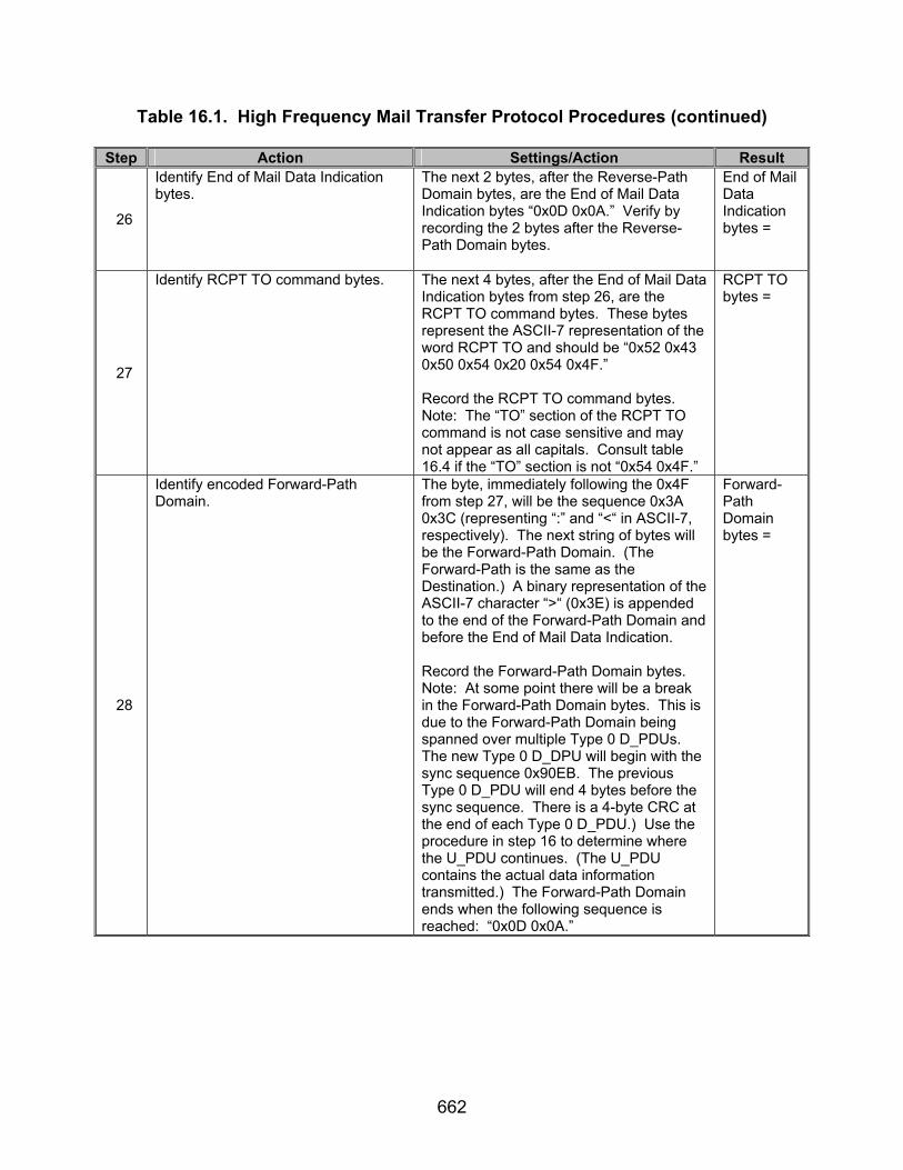
662
Table 16.1. High Frequency Mail Transfer Protocol Procedures (continued) Step Action Settings/Action Result
26
Identify End of Mail Data Indication bytes.
The next 2 bytes, after the Reverse-Path Domain bytes, are the End of Mail Data Indication bytes “0x0D 0x0A.” Verify by recording the 2 bytes after the Reverse-Path Domain bytes.
End of Mail Data Indication bytes =
27
Identify RCPT TO command bytes. The next 4 bytes, after the End of Mail Data Indication bytes from step 26, are the RCPT TO command bytes. These bytes represent the ASCII-7 representation of the word RCPT TO and should be “0x52 0x43 0x50 0x54 0x20 0x54 0x4F.” Record the RCPT TO command bytes. Note: The “TO” section of the RCPT TO command is not case sensitive and may not appear as all capitals. Consult table 16.4 if the “TO” section is not “0x54 0x4F.”
RCPT TO bytes =
28
Identify encoded Forward-Path Domain.
The byte, immediately following the 0x4F from step 27, will be the sequence 0x3A 0x3C (representing “:” and “<“ in ASCII-7, respectively). The next string of bytes will be the Forward-Path Domain. (The Forward-Path is the same as the Destination.) A binary representation of the ASCII-7 character “>“ (0x3E) is appended to the end of the Forward-Path Domain and before the End of Mail Data Indication. Record the Forward-Path Domain bytes. Note: At some point there will be a break in the Forward-Path Domain bytes. This is due to the Forward-Path Domain being spanned over multiple Type 0 D_PDUs. The new Type 0 D_DPU will begin with the sync sequence 0x90EB. The previous Type 0 D_PDU will end 4 bytes before the sync sequence. There is a 4-byte CRC at the end of each Type 0 D_PDU.) Use the procedure in step 16 to determine where the U_PDU continues. (The U_PDU contains the actual data information transmitted.) The Forward-Path Domain ends when the following sequence is reached: “0x0D 0x0A.”
Forward-Path Domain bytes =

663
Table 16.1. High Frequency Mail Transfer Protocol Procedures (continued) Step Action Settings/Action Result
29
Convert Forward-Path Domain bytes. The Forward-Path Domain bytes will be encoded in ASCII-7 representation. Convert the Forward-Path Domain bytes from step 28 into their ASCII-7 representation. Table 16.4 may be used to convert hex bytes into ASCII-7 format.
Converted Forward-Path Domain =
30
Identify End of Mail Data Indication bytes.
The next 2 bytes, after the Forward-Path Domain bytes, are the End of Mail Data Indication bytes “0x0D 0x0A.” Verify by recording the 2 bytes after the Forward-Path Domain bytes.
End of Mail Data Indication bytes =
31
Identify DATA command bytes The next 4 bytes, after the End of Mail Data Indication bytes, are the DATA command bytes. These bytes represent the ASCII-7 representation of the word DATA and should be “0x44 0x41 0x54 0x41.” Record the DATA command bytes.
DATA bytes =
32
Identify “Time Stamp” or “Received” line bytes.
Following the DATA bytes will be the bytes “0x0D 0x0A.” The next 9 or 11 bytes will be the ASCII-7 representation of either the words “Time Stamp” or “Received.” The hexadecimal equivalent of these lines are “0x74 0x69 0x6D 0x65 0x20 0x73 0x74 0x61 0x6D 0x70 0x3A and 0x52 0x65 0x63 0x65 0x69 0x76 0x65 0x64 0x3A” (respectively). Record the “Time Stamp” or “Received” bytes.
“Time Stamp” or “Received” bytes =
33
Identify FROM bytes. The next byte, after the “Time Stamp” or “Received” line, will be the hex sequence 0x20. The next 4 bytes will be the ASCII-7 representation of the word FROM and should be “0x46 0x52 0x4F 0x4D.” Record the FROM bytes. Note: FROM is not case sensitive and may not appear as all capitals. Consult table 16.4 if FROM is not “0x46 0x52 0x4F 0x4D.”
FROM bytes =
34
Identify End of Mail Data Indication bytes.
The next 2 bytes, after the DATA command bytes, are the End of Mail Data Indication bytes “0x0D 0x0A.” Verify by recording the 2 bytes after the DATA bytes.
End of Mail Data Indication bytes =
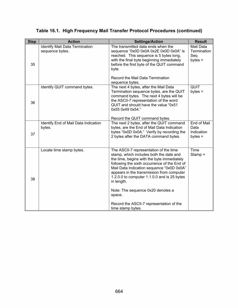
664
Table 16.1. High Frequency Mail Transfer Protocol Procedures (continued) Step Action Settings/Action Result
35
Identify Mail Data Termination sequence bytes.
The transmitted data ends when the sequence “0x0D 0x0A 0x2E 0x0D 0x0A” is reached. This sequence is 5 bytes long, with the final byte beginning immediately before the first byte of the QUIT command byte. Record the Mail Data Termination sequence bytes.
Mail Data Termination Seq bytes =
36
Identify QUIT command bytes. The next 4 bytes, after the Mail Data Termination sequence bytes, are the QUIT command bytes. The next 4 bytes will be the ASCII-7 representation of the word QUIT and should have the value “0x51 0x55 0x49 0x54.” Record the QUIT command bytes.
QUIT bytes =
37
Identify End of Mail Data Indication bytes.
The next 2 bytes, after the QUIT command bytes, are the End of Mail Data Indication bytes “0x0D 0x0A.” Verify by recording the 2 bytes after the DATA command bytes.
End of Mail Data Indication bytes =
38
Locate time stamp bytes. The ASCII-7 representation of the time stamp, which includes both the date and the time, begins with the byte immediately following the sixth occurrence of the End of Mail Data Indication sequence “0x0D 0x0A” appears in the transmission from computer 1.2.0.0 to computer 1.1.0.0 and is 25 bytes in length. Note: The sequence 0x20 denotes a space. Record the ASCII-7 representation of the time stamp bytes.
Time Stamp =
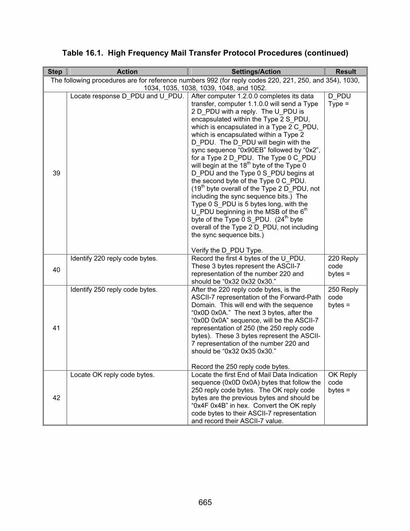
665
Table 16.1. High Frequency Mail Transfer Protocol Procedures (continued) Step Action Settings/Action Result The following procedures are for reference numbers 992 (for reply codes 220, 221, 250, and 354), 1030,
1034, 1035, 1038, 1039, 1048, and 1052.
39
Locate response D_PDU and U_PDU. After computer 1.2.0.0 completes its data transfer, computer 1.1.0.0 will send a Type 2 D_PDU with a reply. The U_PDU is encapsulated within the Type 2 S_PDU, which is encapsulated in a Type 2 C_PDU, which is encapsulated within a Type 2 D_PDU. The D_PDU will begin with the sync sequence “0x90EB” followed by “0x2”, for a Type 2 D_PDU. The Type 0 C_PDU will begin at the 18th byte of the Type 0 D_PDU and the Type 0 S_PDU begins at the second byte of the Type 0 C_PDU. (19th byte overall of the Type 2 D_PDU, not including the sync sequence bits.) The Type 0 S_PDU is 5 bytes long, with the U_PDU beginning in the MSB of the 6th byte of the Type 0 S_PDU. (24th byte overall of the Type 2 D_PDU, not including the sync sequence bits.) Verify the D_PDU Type.
D_PDU Type =
40
Identify 220 reply code bytes. Record the first 4 bytes of the U_PDU. These 3 bytes represent the ASCII-7 representation of the number 220 and should be “0x32 0x32 0x30.”
220 Reply code bytes =
41
Identify 250 reply code bytes. After the 220 reply code bytes, is the ASCII-7 representation of the Forward-Path Domain. This will end with the sequence “0x0D 0x0A.” The next 3 bytes, after the “0x0D 0x0A” sequence, will be the ASCII-7 representation of 250 (the 250 reply code bytes). These 3 bytes represent the ASCII-7 representation of the number 220 and should be “0x32 0x35 0x30.” Record the 250 reply code bytes.
250 Reply code bytes =
42
Locate OK reply code bytes. Locate the first End of Mail Data Indication sequence (0x0D 0x0A) bytes that follow the 250 reply code bytes. The OK reply code bytes are the previous bytes and should be “0x4F 0x4B” in hex. Convert the OK reply code bytes to their ASCII-7 representation and record their ASCII-7 value.
OK Reply code bytes =

666
Table 16.1. High Frequency Mail Transfer Protocol Procedures (continued) Step Action Settings/Action Result
43
Identify 354 reply code bytes. After the 250 reply code bytes, will be the ASCII-7 representation of the Reverse-Path e-mail address followed by a “0x0D 0x0A” sequence, followed by another 250 reply code. After the second 250 reply code is the ASCII-7 representation of the Forward-Path e-mail address. The end of the Forward-Path e-mail address is denoted by the “0x0D 0x0A” sequence. The next 3 bytes, after the “0x0D 0x0A” sequence, will be the ASCII-7 representation of 354 (the 354 reply code bytes). These 3 bytes represent the ASCII-7 representation of the number 354 and should be “0x33 0x35 0x34.” Record the 354 reply code bytes.
354 Reply code bytes =
44
Identify 221 reply code bytes. After the data that follows the 354 reply code bytes, which will end in the sequence “0x0D 0x0A,” are the 221 reply code bytes. These 3 bytes represent the ASCII-7 representation of the number 221 and should be “0x32 0x32 0x31.” Record the 221 reply code bytes.
221 Reply code bytes =
45
Verify message was received correctly.
Verify on the receiving side (computer 1.1.0.0) that the following message was received: For the Subject Line: Test 1 In the Body: “This is a test from address 1.2.0.0 to 1.1.0.0 1 2 3 4 5 6 7 8 9 10
..
.
..
.”
Message Correctly received = Y/N
The following procedures are for reference numbers 992 (for reply codes 500, 503, and 550), 1025, 1036, and 1041.
46
Re-send e-mail message. Re-send the e-mail message from step 14. Send the message using computer 1.2.0.0 to computer 1.1.0.0. For the e-mail address, choose an account that does not exist on computer 1.1.0.0, but uses the domain name of computer 1.1.0.0.

667
Table 16.1. High Frequency Mail Transfer Protocol Procedures (continued) Step Action Settings/Action Result
47
Identify 550 reply code bytes. The 550 reply code bytes immediately follow the third occurrence of the End of Mail Data Indication sequence “0x0D 0x0A” and is transmitted from computer 1.1.0.0 (destination computer) to computer 1.2.0.0 (source computer). The 550 reply code is 3 bytes in length. These 3 bytes represent the ASCII-7 representation of the number 550 and should be “0x35 0x35 0x30.” Record the 550 reply code bytes.
550 Reply code bytes =
48
Identify 503 reply code bytes. The 503 reply code may be utilized by the HMTP server. The 503 reply code bytes immediately follow the fourth occurrence of the End of Mail Data Indication sequence “0x0D 0x0A” appears in the transmission from computer 1.1.0.0 to computer 1.2.0.0 and is 3 bytes in length. These three bytes represent the ASCII-7 representation of the number “503” and should be “0x35 0x30 0x33.” Record the 503 reply code bytes (if they exist).
503 reply code bytes =
49
Identify 500 reply code bytes. The 500 reply code bytes immediately follow the fourth occurrence of the End of Mail Data Indication sequence “0x0D 0x0A” appears in the transmission from computer 1.1.0.0 to computer 1.2.0.0 and is 3 bytes in length. (This will be the 5th instead of 4th occurrence if the 503 reply code is being used). These 3 bytes represent the ASCII-7 representation of the number 500 and should be “0x35 0x30 0x30.” Record the 500 reply code bytes.
500 reply code bytes =
50
Verify Undeliverable Mail Notification sent from computer 1.1.0.0 to computer 1.2.0.0.
Using the e-mail software in box, record if an e-mail was received on computer 1.2.0.0 from computer 1.1.0.0 with the subject line Undeliverable Mail Notification.
Y/N
Reference numbers 1049, 1051, and 1053 are currently untestable, future procedures may be developed. Legend: ARQ—Automatic Repeat-Request ASCII—American Standard Code for Information Interchange bps—Bits Per Second C_PDU—Channel Access Sublayer Protocol Data Unit CRC—Cyclic Redundancy Check D_PDU—Data Transfer Sublayer Protocol Data Unit e-mail—Electronic Mail hex—hexadecimal HMTP—High Frequency Mail Transfer Protocol ID—Identification IP—Internet Protocol
MIL-STD—Military Standard MSB—Most Significant Bit POP3—Post Office Protocol 3 SAP—Subnetwork Access Point S_PDU—Subnetwork Interface Sublayer Protocol Data Unit SMTP—Simple Mail Transfer Protocol STANAG—Standardization Agreement sync—synchronization TX—Transmit U_PDU—User Protocol Data Unit.

668
Table 16.2. High Frequency Mail Transfer Protocol Results for STANAG 5066
Requirements
Result Finding Reference Number
STANAG 5066
Paragraph Requirement Required
Value Measured
Value Met Not Met
990 F.5.1
A HMTP client or server shall use the HF subnetwork protocol stack directly, without intervening transport or network protocol, by encapsulating the SMTP commands, replies, and mail objects within the S_Primitives defined in STANAG 5066, annex A.
Messages encapsula-ted within Type 0 S_PDUs.
991 F.5.1
The HMTP mail model and mail-objects, including the commands, responses, and semantics of the HMTP protocol, shall be defined by the following standards: The Internet Standard 10 for the Simple Mail Transfer Protocol [RFC 821], The proposed consolidated SMTP standard defined in RFC 2821 (intended as the replacement for, and with precedence in requirements over, RFC 821), The Internet Standard 60 defining the SMTP Service Extension for Command Pipelining [RFC 2920], and The amendments defined herein that mandate certain SMTP options for efficiency in use over the HF channel.
992 F.5.1
In particular: An HMTP server shall implement the SMTP PIPELINING Service, in accordance with RFC 2920.
All Command Codes transmitted in a single Transmis-sion interval.

669
Table 16.2. High Frequency Mail Transfer Protocol Results for STANAG 5066 Requirements (continued)
Result Finding Reference
Number STANAG
5066 Paragraph
Requirement Required Value
Measured Value Met Not
Met
992 F.5.1
All Reply codes transmitted in a single Transmis-sion interval.
SAP ID = 3
TX Mode = ARQ
Delivery Confirma-tion = NODE DELIVERY or CLIENT DELIVERY
993 F.5.3
Clients and Servers for the HF Mail Transfer Protocol shall bind to the HF Subnetwork at SAP ID 3. requirements defined as follows: Transmission Mode = ARQ Delivery Confirmation = NODE DELIVERY or CLIENT DELIVERY Deliver in Order = IN-ORDER DELIVERY.
Deliver in Order = IN-ORDER DELIVERY
994 F.5.3
The encoded data for commands, replies, and mail-object data in HMTP shall be bit- and byte-aligned with the octets in an S_Primitive’s U_PDU, with the least-significant bit (LSB) of each character aligned with the LSB of the octet.
MSB Transmit-ted first and LSB transmit-ted last.
995 F.5.3
Message data encoded as seven-bit symbols (e.g., ITA5 or the ASCII character sets) shall be bit-aligned, LSB to LSB, with the octets of the S_Primitive.
Data encoded as eight bit bytes with the 8th
(MSB) bit = 0.
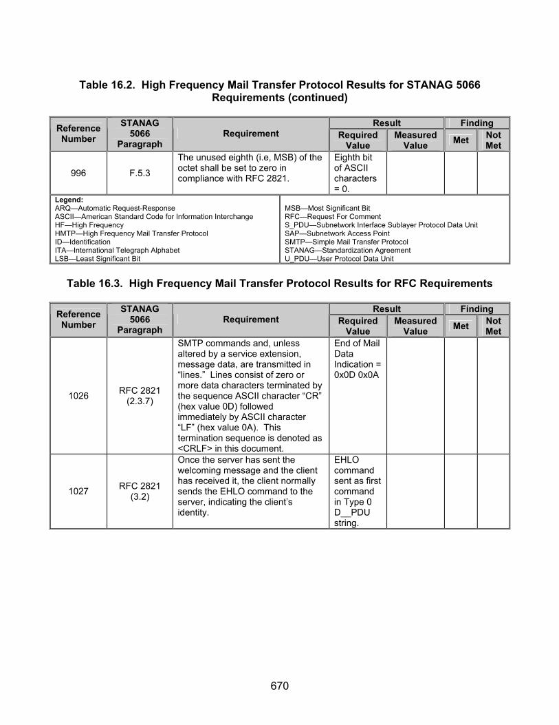
670
Table 16.2. High Frequency Mail Transfer Protocol Results for STANAG 5066
Requirements (continued)
Result Finding Reference Number
STANAG 5066
Paragraph Requirement Required
Value Measured
Value Met Not Met
996 F.5.3
The unused eighth (i.e, MSB) of the octet shall be set to zero in compliance with RFC 2821.
Eighth bit of ASCII characters= 0.
Legend: ARQ—Automatic Request-Response ASCII—American Standard Code for Information Interchange HF—High Frequency HMTP—High Frequency Mail Transfer Protocol ID—Identification ITA—International Telegraph Alphabet LSB—Least Significant Bit
MSB—Most Significant Bit RFC—Request For Comment S_PDU—Subnetwork Interface Sublayer Protocol Data Unit SAP—Subnetwork Access Point SMTP—Simple Mail Transfer Protocol STANAG—Standardization Agreement U_PDU—User Protocol Data Unit
Table 16.3. High Frequency Mail Transfer Protocol Results for RFC Requirements
Result Finding Reference
Number STANAG
5066 Paragraph
Requirement Required Value
Measured Value Met Not
Met
1026 RFC 2821 (2.3.7)
SMTP commands and, unless altered by a service extension, message data, are transmitted in “lines.” Lines consist of zero or more data characters terminated by the sequence ASCII character “CR” (hex value 0D) followed immediately by ASCII character “LF” (hex value 0A). This termination sequence is denoted as <CRLF> in this document.
End of Mail Data Indication = 0x0D 0x0A
1027 RFC 2821 (3.2)
Once the server has sent the welcoming message and the client has received it, the client normally sends the EHLO command to the server, indicating the client’s identity.
EHLO command sent as first command in Type 0 D__PDU string.

671
Table 16.3. High Frequency Mail Transfer Protocol Results for RFC Requirements (continued)
Result Finding Reference
Number STANAG
5066 Paragraph
Requirement Required Value
Measured Value Met Not
Met
1028 RFC 2821 (3.3)
The first step in the procedure is the MAIL command. MAIL FROM:<reverse-path> [SP <mail-parameters> ] <CRLF> This command tells the SMTP-receiver that a new mail transaction is starting and to reset all its state tables and buffers, including any recipients or mail data.
MAIL command is second command transmitted in Type 0 D_PDU string, contains a Reverse-Path field, and ends in 0x0D 0x0A.
1029 RFC 2821 (3.3)
The second step in the procedure is the RCPT command. RCPT TO:<forward-path> [ SP <rcpt-parameters> ] <CRLF> The first or only argument to this command includes a Forward-Path (normally a mailbox and domain, always surrounded by “<“ and “>“ brackets) identifying one recipient.
RCPT command is third command transmitted in Type 0 D_PDU string, contains a Forward-Path field, and ends in 0x0D 0x0A.
1030 RFC 2821 (3.3)
If accepted, the SMTP server returns a 250 OK reply and stores the Forward-Path.
250 OK reply code transmitted by computer 1.1.0.0 for message transmitted in step 14.
1031 RFC 2821 (3.3)
If the recipient is known not to be a deliverable address, the SMTP server returns a 550 reply, typically with a string such as “no such user -“ and the mailbox name (other circumstances and reply codes are possible). This step of the procedure can be repeated any number of times.
550 OK reply code transmitted by computer 1.1.0.0 for message transmitted in step 81.

672
Table 16.3. High Frequency Mail Transfer Protocol Results for RFC Requirements (continued)
Result Finding Reference
Number STANAG
5066 Paragraph
Requirement Required Value
Measured Value Met Not
Met
1032 RFC 2821 (3.3)
The third step in the procedure is the DATA command (or some alternative specified in a service extension). DATA <CRLF>
DATA command is fourth command transmitted in Type 0 D_PDU string and ends in 0x0D 0x0A.
1033 RFC 2821 (3.3)
If accepted, the SMTP server returns a 354 Intermediate reply and considers all succeeding lines up to but not including the end of mail data indicator to be the message text.
354 reply code transmitted by computer 1.1.0.0 for message transmitted in step 14.
1034 RFC 2821 (3.3)
When the end of text is successfully received and stored, the SMTP-receiver sends a 250 OK reply.
250 reply code transmitted after 354 reply code.
1035 RFC 2821 (3.3)
Mail transaction commands MUST be used in the order discussed above.
Command transmitted in following order: EHLO MAIL RCPT DATA QUIT
1036 RFC 2821 (3.7)
If an SMTP server has accepted the task of relaying the mail and later finds that the destination is incorrect or that the mail cannot be delivered for some other reason, then it MUST construct an “undeliverable mail” notification message and send it to the originator of the undeliverable mail (as indicated by the Reverse-Path).
Undeliver-able mail notification message transmitted to computer 1.2.0.0 from computer 1.1.0.0.

673
Table 16.3. High Frequency Mail Transfer Protocol Results for RFC Requirements (continued)
Result Finding Reference
Number STANAG
5066 Paragraph
Requirement Required Value
Measured Value Met Not
Met
1037 RFC 2821 (4.1.1.1)
In any event, a client MUST issue HELO or EHLO before starting a mail transaction.
EHLO command first command to be transmit-ted.
1038 RFC 2821 (4.1.1.4)
The mail data is terminated by a line containing only a period, that is, the character sequence “<CRLF>.<CRLF>“ (see section 4.5.2). This is the end of mail data indication.
Mail Data Termina-tion Sequence = 0x0D 0x0A 0x2E 0x0D 0x0A.
1039 RFC 2821 (4.1.1.4)
Note that the first <CRLF> of this terminating sequence is also the <CRLF> that ends the final line of the data (message text) or, if there was no data, ends the DATA command itself. An extra <CRLF> MUST NOT be added, as that would cause an empty line to be added to the message.
No additional 0x0D 0x0A transmitted after Mail Data Termina-tion Sequence Transmit-ted.
1040 RFC 2821 (4.1.1.10)
QUIT (QUIT) This command specifies that the receiver MUST send an OK reply, and then close the transmission channel.
QUIT command final command transmitted by computer 1.2.0.0.
1041 RFC 2821 (4.1.4)
A session that will contain mail transactions MUST first be initialized by the use of the EHLO command.
EHLO first command transmit-ted.
1042 RFC 2821 (4.1.4)
The last command in a session MUST be the QUIT command.
QUIT command, last command transmit-ted.
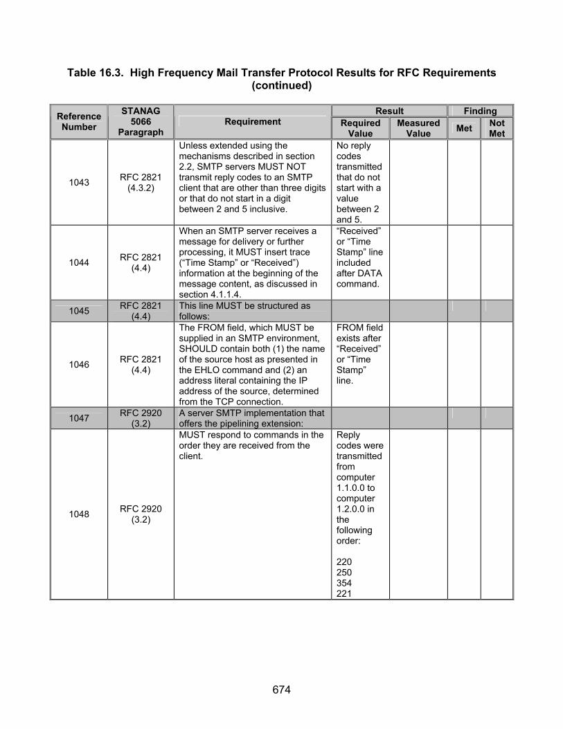
674
Table 16.3. High Frequency Mail Transfer Protocol Results for RFC Requirements (continued)
Result Finding Reference
Number STANAG
5066 Paragraph
Requirement Required Value
Measured Value Met Not
Met
1043 RFC 2821 (4.3.2)
Unless extended using the mechanisms described in section 2.2, SMTP servers MUST NOT transmit reply codes to an SMTP client that are other than three digits or that do not start in a digit between 2 and 5 inclusive.
No reply codes transmitted that do not start with a value between 2 and 5.
1044 RFC 2821 (4.4)
When an SMTP server receives a message for delivery or further processing, it MUST insert trace (“Time Stamp” or “Received”) information at the beginning of the message content, as discussed in section 4.1.1.4.
“Received” or “Time Stamp” line included after DATA command.
1045 RFC 2821 (4.4)
This line MUST be structured as follows:
1046 RFC 2821 (4.4)
The FROM field, which MUST be supplied in an SMTP environment, SHOULD contain both (1) the name of the source host as presented in the EHLO command and (2) an address literal containing the IP address of the source, determined from the TCP connection.
FROM field exists after “Received” or “Time Stamp” line.
1047 RFC 2920 (3.2)
A server SMTP implementation that offers the pipelining extension:
1048 RFC 2920 (3.2)
MUST respond to commands in the order they are received from the client.
Reply codes were transmitted from computer 1.1.0.0 to computer 1.2.0.0 in the following order: 220 250 354 221

675
Table 16.3. High Frequency Mail Transfer Protocol Results for RFC Requirements (continued)
Result Finding Reference
Number STANAG
5066 Paragraph
Requirement Required Value
Measured Value Met Not
Met
1049 RFC 2920 (3.2)
MUST NOT, after issuing a positive response to a DATA command with no valid recipients and subsequently receiving an empty message, send any message whatsoever to anybody.
N/A TBD
1050 RFC 2920 (3.2)
MUST NOT buffer responses to EHLO, DATA, VRFY, EXPN, TURN, QUIT, and NOOP.
Command Codes were transmitted in the following order from computer 1.2.0.0 to computer 1.1.0.0: EHLO DATA QUIT
1051 RFC 2920 (3.2)
MUST NOT buffer responses to unrecognized commands.
N/A TBD
1052 RFC 2920 (3.2)
MUST send all pending responses immediately whenever the local TCP input buffer is emptied.
Computer 1.1.0.0 sent a Type 2 D_PDU immedia-tely after computer 1.2.0.0 completed transmis-sion of its data.
1053 RFC 2920 (3.2)
MUST NOT flush or otherwise lose the contents of the TCP input buffer under any circumstances whatsoever.
N/A TBD
Legend: ASCII—American Standard Code for Information Interchange D_PDU—Data Transfer Sublayer Protocol Data Unit hex—hexadecimal N/A—Not Available
RFC—Request For Comment SMTP—Simple Mail Transfer Protocol STANAG—Standardization Agreement TBD—To be determined TCP—Transmission Control Protocol
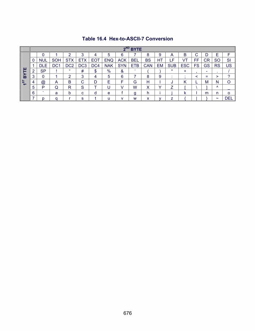
676
Table 16.4 Hex-to-ASCII-7 Conversion
2ND BYTE
0 1 2 3 4 5 6 7 8 9 A B C D E F 0 NUL SOH STX ETX EOT ENQ ACK BEL BS HT LF VT FF CR SO SI 1 DLE DC1 DC2 DC3 DC4 NAK SYN ETB CAN EM SUB ESC FS GS RS US 2 SP ! “ # $ % & ‘ ( ) * + , - . / 3 0 1 2 3 4 5 6 7 8 9 : ; < = > ? 4 @ A B C D E F G H I J K L M N O 5 P Q R S T U V W X Y Z [ \ ] ^ _ 6 ` a b c d e f g h i j k l m n o
1ST B
YTE
7 p q r s t u v w x y z { | } ~ DEL
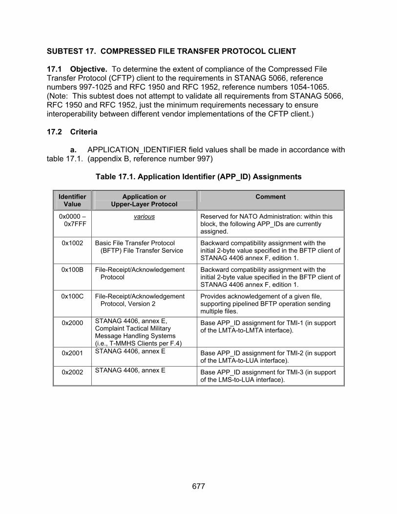
677
SUBTEST 17. COMPRESSED FILE TRANSFER PROTOCOL CLIENT 17.1 Objective. To determine the extent of compliance of the Compressed File Transfer Protocol (CFTP) client to the requirements in STANAG 5066, reference numbers 997-1025 and RFC 1950 and RFC 1952, reference numbers 1054-1065. (Note: This subtest does not attempt to validate all requirements from STANAG 5066, RFC 1950 and RFC 1952, just the minimum requirements necessary to ensure interoperability between different vendor implementations of the CFTP client.) 17.2 Criteria
a. APPLICATION_IDENTIFIER field values shall be made in accordance with table 17.1. (appendix B, reference number 997)
Table 17.1. Application Identifier (APP_ID) Assignments
Identifier
Value Application or
Upper-Layer Protocol Comment
0x0000 – 0x7FFF
various Reserved for NATO Administration: within this block, the following APP_IDs are currently assigned.
0x1002 Basic File Transfer Protocol (BFTP) File Transfer Service
Backward compatibility assignment with the initial 2-byte value specified in the BFTP client of STANAG 4406 annex F, edition 1.
0x100B File-Receipt/Acknowledgement Protocol
Backward compatibility assignment with the initial 2-byte value specified in the BFTP client of STANAG 4406 annex F, edition 1.
0x100C File-Receipt/Acknowledgement Protocol, Version 2
Provides acknowledgement of a given file, supporting pipelined BFTP operation sending multiple files.
0x2000 STANAG 4406, annex E, Complaint Tactical Military Message Handling Systems (i.e., T-MMHS Clients per F.4)
Base APP_ID assignment for TMI-1 (in support of the LMTA-to-LMTA interface).
0x2001 STANAG 4406, annex E Base APP_ID assignment for TMI-2 (in support of the LMTA-to-LUA interface).
0x2002 STANAG 4406, annex E Base APP_ID assignment for TMI-3 (in support of the LMS-to-LUA interface).

678
Table 17.1. Application Identifier (APP_ID) Assignments (continued)
Identifier Value
Application or Upper-Layer Protocol
Comment
0x2003 STANAG 4406, annex E Base APP_ID assignment for TMI-4 (in support of the LUA-to-LUA interface).
0x2004 STANAG 4406, annex E, ACP-127 Access Unit
Base APP_ID assignment for TMI-5 (in support of the ACP-127 AU interface).
0x8000 – 0xFFFF
Available for User-defined applications; uniqueness of Application ID values in this range cannot be guaranteed.
Legend: APP—Application, BFTP—Basic File Transfer Protocol, ID—Identification, NATO—North Atlantic Trade Organiazation, STANAG—Standardization Agreement.
b. An “Extended Client” is a client of the STANAG 5066 HF Subnetwork that
uses Reliable Connection-Oriented Protocol (RCOP) (or Unreliable Datagram-Oriented Protocol [UDOP]) as its basic end-to-end transport protocol. Implementations of STANAG 5066 may provide any of these extended clients. If provided, the client shall be implemented in accordance with the requirements defined herein. The extended clients presented here are the following: (appendix B, reference number 998 and 999)
• File-Receipt Acknowledgment Protocol (FRAP) - FRAP may be used to
provide an acknowledgement of file receipt for files sent over the STANAG 5066 subnetwork using some other protocol, such as Basic File Transfer Protocol (BFTP) or CFTP (see below). If provided, the FRAP extended client shall conform to the requirements in STANAG 5066, annex F. Edition 1-Amendment 1, section F.10.2.3.
c. Files sent over STANAG 5066 using a BFTP extended client shall be
acknowledged using the FRAP. (appendix B, reference number 1000)
d. Implementations of STANAG 5066 shall provide support for the FRAP protocol if they also provide a BFTP (see STANAG 5066, annex F, Edition 1-Amendment 1, section F.10.2.2) or CTFP client (see STANAG 5066, annex F, Edition 1-Amendment 1, section F.14). The header diagram for the FRAP protocol is shown in figure 17.1. (appendix B, reference number 1001)
e. On receiving the last byte of a file sent using BFTP, the receiving client shall send an Reliable Connection-Oriented Protocol Protocol Data Unit (RCOP_PDU) Header part with an Application Identification field value = 0x100B; the RCOP_PDU Body part is null. (appendix B, reference number 1002)
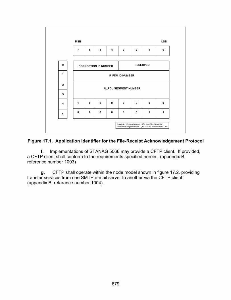
679
7 6 5 4 3 2 1 0
U_PDU ID NUMBER
U_PDU SEGMENT NUMBER
MSB LSB
0
1
2
3
4
5
CONNECTION ID NUMBER RESERVED
1 0 0 0 0 0 0 0
0 0 0 0 1 0 1 1
Legend: ID-Identification; LSB-Least Significant Bit;MSB-Most Significant Bit; U_PDU-User Protocol Data Unit
Figure 17.1. Application Identifier for the File-Receipt Acknowledgement Protocol
f. Implementations of STANAG 5066 may provide a CFTP client. If provided, a CFTP client shall conform to the requirements specified herein. (appendix B, reference number 1003)
g. CFTP shall operate within the node model shown in figure 17.2, providing
transfer services from one SMTP e-mail server to another via the CFTP client. (appendix B, reference number 1004)

680
SIS Interface
Network Layer
STANAG 5066 Subnetwork
IP Port 5066 on ‘Localhost’
Synchronous SerialPort to HF Modem
CFTP Client
SMTP E-mail Server
IP Port (SMTP)
E-mail Client (Outlook, Netscape, etc.)
IP Port 110(POP3)
Legend: CFTP—Compressed File Transfer Protocol, E-mail—Electronic Mail, HF—High Frequency, IP—Internet Protocol, POP—Post Office Protocol, SIS—Subnetwork Interface Sublayer, SMTP—Simple Mail Transfer Protocol, STANAG—Standardization Agreement.
Figure 17.2. CFTP Operation Model
h. CFTP clients shall bind to the HF Subnetwork at SAP ID 12. (appendix B,
reference number 1005) i. The CFTP application shall use the original form of the RCOP Protocol
Data Unit (RCOPv1) defined in figure 17.3. (appendix B, reference number 1006)
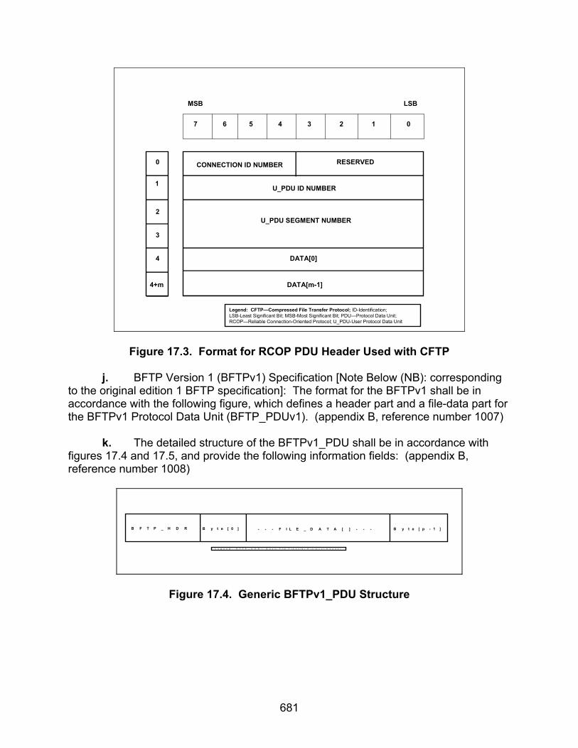
681
7 6 5 4 3 2 1 0
U_PDU ID NUMBER
U_PDU SEGMENT NUMBER
DATA[0]
MSB LSB
0
1
2
3
4
4+m
CONNECTION ID NUMBER RESERVED
DATA[m-1]
Legend: CFTP—Compressed File Transfer Protocol; ID-Identification;LSB-Least Significant Bit; MSB-Most Significant Bit; PDU—Protocol Data Unit; RCOP—Reliable Connection-Oriented Protocol; U_PDU-User Protocol Data Unit
Figure 17.3. Format for RCOP PDU Header Used with CFTP
j. BFTP Version 1 (BFTPv1) Specification [Note Below (NB): corresponding to the original edition 1 BFTP specification]: The format for the BFTPv1 shall be in accordance with the following figure, which defines a header part and a file-data part for the BFTPv1 Protocol Data Unit (BFTP_PDUv1). (appendix B, reference number 1007)
k. The detailed structure of the BFTPv1_PDU shall be in accordance with
figures 17.4 and 17.5, and provide the following information fields: (appendix B, reference number 1008)
B F T P _ H D R B y t e [ 0 ] - - - F I L E _ D A T A [ ] - - - B y t e [ p - 1 ]
L e g e n d : B F T P _ H D R — B a s i c F i l e T r a n s f e r P r o t o c o l H e a d e r
Figure 17.4. Generic BFTPv1_PDU Structure

682
BFTPv1_PDU Header Part:
o Synchronization - two bytes corresponding to the control bytes DLE (Data Link Escape) and STX (Start of Text).
o SIZE_OF_FILENAME - one octet in size. o FILENAME - a variable length field, equal in size to the value
specified by the SIZE_OF_FILENAME field. o SIZE_OF_FILE - a four-octet field.
BFTPv1_PDU Body Part:
o FILE_DATA[ ] - a variable length field, equal in size to the value
specified by the SIZE_OF_FILE field.
RCOPv1Body
7 6 5 4 3 2 1 0
MSB LSB
0
1
2
3
3+n
4+n
5+n
6+n
7+n
8+n
8+n+p
0 00 1 0 0 0 0
0 0 0 0 0 0 1 0
SIZE_OF_FILENAME = n
FILENAME[0]
FILENAME[n-1]
SIZE_OF_FILE = p
FILE_DATA[0]
FILE_DATA[p-1]
BFTPv1Header
BFTPv1Body
Legend: BFTPv1-Basic File Transfer Protocol Version 1; LSB-Least Significant Bit; MSB-Most Significant Bit;RCOPv1-Reliable Connection-Oriented Protocol Version 1
Figure 17.5. Detailed BFTPv1_PDU Structure
l. The SIZE_OF_FILENAME field shall be a 1-octet fixed-length field whose
value (n) shall equal the number of octets used to encode the Filename field. (appendix B, reference number 1009 and 1010)
m. The Filename field is shall be a variable-length field, the size of which shall be specified by the value (n) of the field SIZE_OF_FILENAME. This field represents the name of the file sent using the BFTP. The first byte of the filename shall

683
be placed in the first byte of this field, with the remaining bytes placed in order. (appendix B, reference number 1011-1013)
n. The SIZE_OF_FILE field shall be a 4-octet fixed-length field whose value shall specify the size (p) in octets of the file to be sent. The first octet of the SIZE_OF_FILE field shall be the highest order byte and the last byte the lowest order byte of the field’s binary value. (appendix B, reference number 1014-1016)
o. BFTPv1 Segmentation and Reassembly Requirements: (appendix B, reference number 1017-1019)
• If the BFTPv1_PDU exceeds the maximum size of the data field permitted in the RCOPv1 PDU (i.e, if the CTFP_PDU is larger than the MTU_Size less 4 octets (i.e., MTU-4) ), the CFTP client shall segment the BFTPv1 PDU, placing successive segments in RCOPv1 PDUs (original edition 1 format) with consecutive U_PDU sequence numbers.
• When received, the CFTP client shall reassemble the BFTPv1 PDU if it
determines that the BFTPv1 PDU has been segmented. Subject to local-host file naming conventions, the CFTP client shall store the received file with the name transmitted in the header with the file. [i.e., there is no guarantee therefore that the file will be stored on the destination host with the same name that it was sent.]
p. The compressed file shall be created and decompressed in accordance
with RFCs 1950, 1951, and 1952. (appendix B, reference number 1020-1025)
• The CFTP message (including header) shall be compressed in accordance with RFCs 1950, 1951, and 1952 using an application such as Gzip.
• The compressed CFTP message shall be encapsulated within a
BFTPv1 PDU (i.e., it has a BFTPv1 header prepended to it, and the CFTP message shall be byte-aligned within the FILE_DATA[ ] field of the BFTPv1 PDU.
• The BFTPv1 message (i.e., BFTPv1 PDU) shall be segmented if necessary.
• Each BFTPv1 PDU segment shall have an RCOPv1 header added (in
accordance with annex F.14.3). • On reception, the BFTPv1 message shall be reassembled, if required
and decompressed using a method compliant with RFC 1952 and the CFTP message reconstructed.

684
q. The compressor and the decompressor MUST use exactly the same dictionary. (appendix B, reference number 1054)
r. Member format. Each member has the following structure as shown in figure 17.6: (appendix B, reference number 1055)
7 6 5 4 3 2 1 0
Identification 1
Identification 2
Compression Method
FTEXT FHCRC FEXTRA FNAMEFCOM-MENT Reserved Reserved Reserved
eXtra FLags
Modification TIME
Operating System
Compressed Blocks
CRC-32
Input SIZE
MSB LSB
0
1
2
3
4
5
6
7
8
9
9+m
h+m
10+h+m
11+h+m
12+h+m
13+h+m
14+h+m
15+h+m
16+h+m
17+h+m
Legend: CRC—Cyclic Redundancy Check; F—Flag; LSB-Least Significant Bit; MSB-Most Significant Bit
Figure 17.6. Gzip Header Format
s. Member header and trailer:
Identification 1 (ID1) Identification 2 (ID2)
These have the fixed values ID1 = 31 (0x1f, \037), ID2 = 139 (0x8b, \213), to identify the file as being in Gzip format. (appendix B, reference number 1056)
t. Compression Method (CM):
This identifies the compression method used in the file. CM = 0-7 are reserved. CM = 8 denotes the “deflate” compression method, which is the one customarily used by Gzip and which is documented elsewhere. (appendix B, reference number 1057)
u. FLaGs (FLG):

685
This flag byte is divided into individual bits as follows: (appendix B, reference number 1058):
• bit 0 FTEXT • bit 1 FHCRC • bit 2 FEXTRA • bit 3 FNAME • bit 4 FCOMMENT • bit 5 Reserved • bit 6 Reserved • bit 7 Reserved
v. Modification TIME (MTIME): This gives the most recent modification time of the original file being compressed. The time is in Unix format, i.e., seconds since 00:00:00 GMT, Jan. 1, 1970. (Note that this may cause problems for MS-DOS and other systems that use local rather than Universal time.) If the compressed data did not come from a file, MTIME is set to the time at which compression started. MTIME = 0 means no time stamp is available. (appendix B, reference number 1059)
w. eXtra FLags (XFL):
These flags are available for use by specific compression methods. The “deflate” method (CM = 8) sets these flags as follows: (appendix B, reference number 1060)
• XFL = 2 - Compressor used maximum compression, slowest algorithm • XFL = 4 - Compressor used fastest algorithm
x. Operating System (OS):
This identifies the type of file system on which compression took place. This may be useful in determining end-of-line convention for text files. The currently defined values are as follows: (appendix B, reference number 1061)
• 0 - FAT filesystem (MS-DOS, OS/2, NT/Win32) • 1 - Amiga • 2 - VMS (or OpenVMS) • 3 - Unix • 4 - VM/CMS • 5 - Atari TOS • 6 - HPFS filesystem (OS/2, NT)

686
• 7 - Macintosh • 8 - Z-System • 9 - CP/M • 10 - TOPS-20 • 11 - NTFS filesystem (NT) • 12 - QDOS • 13 - Acorn RISCOS • 255 - Unknown
y. CRC32:
This contains a Cyclic Redundancy Check value of the uncompressed data computed according to CRC-32 algorithm used in the The International Organization for Standardization (ISO) 3309 standard and in International Telecommunication Union Telecommunication Standardization Sector (ITU-T) Recommendation V.42, section 8.1.1.6.2. (See http://www.iso.ch for ordering ISO documents. See gopher://info.itu.ch for an online version of ITU-T V.42.) (appendix B, reference number 1062)
z. Input SIZE (ISIZE):
This contains the size of the original (uncompressed) input data modulo 2^32. (appendix B, reference number 1063)
aa. A compliant compressor MUST produce files with correct ID1, ID2, CM, CRC32, and ISIZE, but may set all the other fields in the fixed-length part of the header to default values (255 for OS, 0 for all others). The compressor MUST set all reserved bits to zero. (appendix B, reference number 1064 and 1065)
17.3 Test Procedures a. Test Equipment Required
(1) Computers (2 ea) with STANAG 5066 Software
(2) Modems (2 ea) (3) Protocol Analyzer (4) RS-232 Synchronous Serial Cards
b. Test Configuration. Figure 17.7 shows the equipment setup for this subtest.
c. Test Conduction. Table 17.2 lists procedures for this subtest, and tables 17.3 and 17.4 list the results for this subtest.

687
Computer Modem Modem Computer
LANAnalyzer
RS-232 RS-232
Figure 17.7. Equipment Configuration for CFTP Client
Table 17.2. Compressed File Transfer Protocol Procedures Step Action Settings/Action Result
The following procedures are for reference number 1005.
1
Set up equipment. See figure 17.7. Computers are connected to the modems by an RS-232 connection. The connection between modems shall be such that the receive and transmit pins on the modem are connected to the transmit and receive pins, respectively, of the other modem.
2
Determine Operating System (OS). Record the OS configuration: NTFS or FAT. A system administrator may need to be contacted to obtain this information. Note: At this time procedures have been developed to validate STANAG 5066 software only for MS Windows based OSs.
OS =
3 Load STANAG 5066 software. Configure the SMTP and POP3 servers as
required by the STANAG 5066 software manual.
4
Configure STANAG addresses for computers 1.1.0.0 and 1.2.0.0.
Set the size of the STANAG address field size to 7 bytes. Set the STANAG address of computer number 1 to 1.1.0.0 and the STANAG address of computer number 2 to 1.2.0.0. Configure the software to respond with an e-mail message to the sender once the e-mail has been successfully received.
5 Configure modems 1 and 2. Set modems 1 and 2 to transmit a
MIL-STD-188-110B signal at a data rate of 4800 bps with half duplex.
6 Configure client type. Configure both computers to use the CFTP client.

688
Table 17.2. Compressed File Transfer Protocol Procedures (continued) Step Action Settings/Action Result
7 Identify client SAP ID of computer with STANAG address 1.2.0.0.
Record the SAP ID of the client used for the computer with STANAG address 1.2.0.0.
1.2.0.0 SAP ID =
8 Configure priority level. Set the priority level to “12” for both computers.
9 Configure rank level. Set the rank level to “15” for both computers.
1.1.0.0 e-mail = 10
Identify e-mail accounts. Record the e-mail addresses for both computers.
1.2.0.0 e-mail =
11
Configure protocol analyzer. Configure the protocol analyzer to capture the transmitted data between the two computers and save it to a file. Configure the protocol analyzer to have a 4800-bps bit rate and to synchronize on “0x90EB” in hexadecimal (hex) format. Configure the protocol analyzer to drop sync after 20 “0xFFs” hex format. Configure the analyzer to time stamp each captured byte.
The following procedures are for reference numbers 997, 1003, 1004, 1006, and 1024.
12
Send e-mail message and capture all transmitted and received bytes via the protocol analyzer shown in figure 17.7.
Send the following e-mail message from the computer with STANAG address 1.2.0.0 to the computer with STANAG address 1.1.0.0 using a Soft Link and Non-Expedited ARQ Delivery Method. For the Subject Line: Test 1 In the Body: “This is a test from address 1.2.0.0 to 1.1.0.0 1 2 3 4 5 6 7 8 9 10
..
.
..
.” Save the data obtained through the protocol analyzer to a file.
13
Locate first Type 0 D_PDU transmitted by computer 1.2.0.0.
D_PDUs begin with the hexadecimal sync sequence 0x90EB. The first 4 bits of the byte immediately, following the 0x90EB sequence, is the D_PDU Type. Locate the first occurrence of when the type value is 0x0.
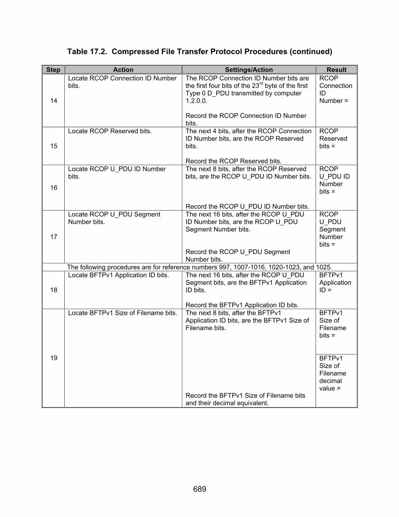
689
Table 17.2. Compressed File Transfer Protocol Procedures (continued) Step Action Settings/Action Result
14
Locate RCOP Connection ID Number bits.
The RCOP Connection ID Number bits are the first four bits of the 23rd byte of the first Type 0 D_PDU transmitted by computer 1.2.0.0. Record the RCOP Connection ID Number bits.
RCOP Connection ID Number =
15
Locate RCOP Reserved bits. The next 4 bits, after the RCOP Connection ID Number bits, are the RCOP Reserved bits. Record the RCOP Reserved bits.
RCOP Reserved bits =
16
Locate RCOP U_PDU ID Number bits.
The next 8 bits, after the RCOP Reserved bits, are the RCOP U_PDU ID Number bits. Record the RCOP U_PDU ID Number bits.
RCOP U_PDU ID Number bits =
17
Locate RCOP U_PDU Segment Number bits.
The next 16 bits, after the RCOP U_PDU ID Number bits, are the RCOP U_PDU Segment Number bits. Record the RCOP U_PDU Segment Number bits.
RCOP U_PDU Segment Number bits =
The following procedures are for reference numbers 997, 1007-1016, 1020-1023, and 1025.
18
Locate BFTPv1 Application ID bits. The next 16 bits, after the RCOP U_PDU Segment bits, are the BFTPv1 Application ID bits. Record the BFTPv1 Application ID bits.
BFTPv1 Application ID =
BFTPv1 Size of Filename bits =
19
Locate BFTPv1 Size of Filename bits. The next 8 bits, after the BFTPv1 Application ID bits, are the BFTPv1 Size of Filename bits. Record the BFTPv1 Size of Filename bits and their decimal equivalent.
BFTPv1 Size of Filename decimal value =
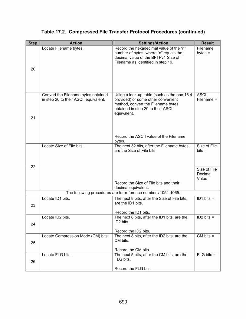
690
Table 17.2. Compressed File Transfer Protocol Procedures (continued) Step Action Settings/Action Result
20
Locate Filename bytes. Record the hexadecimal value of the “n” number of bytes, where “n” equals the decimal value of the BFTPv1 Size of Filename as identified in step 19.
Filename bytes =
21
Convert the Filename bytes obtained in step 20 to their ASCII equivalent.
Using a look-up table (such as the one 16.4 provided) or some other convenient method, convert the Filename bytes obtained in step 20 to their ASCII equivalent. Record the ASCII value of the Filename bytes.
ASCII Filename = Size of File bits = 22
Locate Size of File bits. The next 32 bits, after the Filename bytes, are the Size of File bits. Record the Size of File bits and their decimal equivalent.
Size of File Decimal Value =
The following procedures are for reference numbers 1054-1065.
23
Locate ID1 bits. The next 8 bits, after the Size of File bits, are the ID1 bits. Record the ID1 bits.
ID1 bits =
24
Locate ID2 bits. The next 8 bits, after the ID1 bits, are the ID2 bits. Record the ID2 bits.
ID2 bits =
25
Locate Compression Mode (CM) bits. The next 8 bits, after the ID2 bits, are the CM bits. Record the CM bits.
CM bits =
26
Locate FLG bits. The next 5 bits, after the CM bits, are the FLG bits. Record the FLG bits.
FLG bits =

691
Table 17.2. Compressed File Transfer Protocol Procedures (continued) Step Action Settings/Action Result
27
Locate Reserved bits. The next 3 bits, after the FLG bits, are the Reserved bits. Record the Reserved bits.
Reserved bits =
28
Locate MTIME bits. The next 32 bits, after the Reserved bits, are the MTIME bits. Record the MTIME bits.
MTIME bits =
29
Locate XFL bits. The next 8 bits, after the MTIME bits, are the XFL bits. Record the XFL bits.
XFL bits =
30
Locate OS bits. The next 8 bits, after the XFL bits, are the OS bits. Record the OS bits.
OS bits =
31
Locate ISIZE bits. Using the procedures from step 13, locate the U_PDU encapsulated within the final Type 2 D_PDU in the string of Type 2 D_PDUs sent by computer 1.2.0.0. The ISIZE bits are a 32-bit (4-byte) field beginning with the 8th byte from the end (LSB) of the U_PDU. Record the ISIZE bits.
ISIZE bits =
32
Locate CRC32 bits. The CRC32 bits begin 4 bytes back from the starting byte of the ISIZE bytes (i.e., 12 bytes from the end of the U_PDU). Record the CRC32 bits.
CRC32 bits =
The following procedures are for reference numbers 1017 and 1018.
33
Locate the 2nd Type 0 D_PDU transmitted by computer 1.2.0.0.
D_PDUs begin with the hexadecimal sync sequence 0x90EB. The first 4 bits of the byte immediately following the 0x90EB sequence is the D_PDU Type. Locate the first occurrence of when the type value is 0x0. Locate the 2nd Type 0 D_PDU transmitted by computer 1.2.0.0.
34
Locate RCOP U_PDU ID Number bits for the 2nd Type 0 D_PDU transmitted by computer 1.2.0.0.
The RCOP U_PDU ID Number is 8 bits long, starting with the 24th byte of the Type 0 D_PDU (not including sync bits). Record the RCOP U_PDU ID Number bits.
2nd Type 0 RCOP U_PDU ID Number bits =
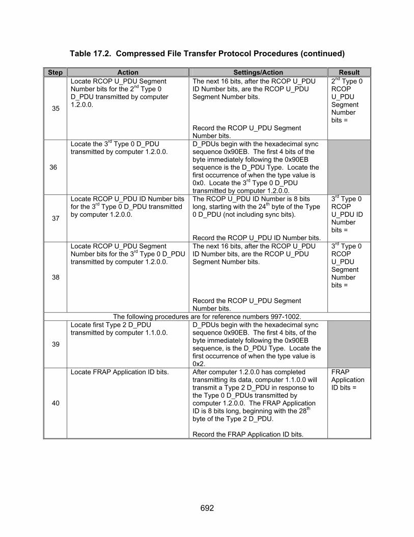
692
Table 17.2. Compressed File Transfer Protocol Procedures (continued) Step Action Settings/Action Result
35
Locate RCOP U_PDU Segment Number bits for the 2nd Type 0 D_PDU transmitted by computer 1.2.0.0.
The next 16 bits, after the RCOP U_PDU ID Number bits, are the RCOP U_PDU Segment Number bits. Record the RCOP U_PDU Segment Number bits.
2nd Type 0 RCOP U_PDU Segment Number bits =
36
Locate the 3rd Type 0 D_PDU transmitted by computer 1.2.0.0.
D_PDUs begin with the hexadecimal sync sequence 0x90EB. The first 4 bits of the byte immediately following the 0x90EB sequence is the D_PDU Type. Locate the first occurrence of when the type value is 0x0. Locate the 3rd Type 0 D_PDU transmitted by computer 1.2.0.0.
37
Locate RCOP U_PDU ID Number bits for the 3rd Type 0 D_PDU transmitted by computer 1.2.0.0.
The RCOP U_PDU ID Number is 8 bits long, starting with the 24th byte of the Type 0 D_PDU (not including sync bits). Record the RCOP U_PDU ID Number bits.
3rd Type 0 RCOP U_PDU ID Number bits =
38
Locate RCOP U_PDU Segment Number bits for the 3rd Type 0 D_PDU transmitted by computer 1.2.0.0.
The next 16 bits, after the RCOP U_PDU ID Number bits, are the RCOP U_PDU Segment Number bits. Record the RCOP U_PDU Segment Number bits.
3rd Type 0 RCOP U_PDU Segment Number bits =
The following procedures are for reference numbers 997-1002.
39
Locate first Type 2 D_PDU transmitted by computer 1.1.0.0.
D_PDUs begin with the hexadecimal sync sequence 0x90EB. The first 4 bits, of the byte immediately following the 0x90EB sequence, is the D_PDU Type. Locate the first occurrence of when the type value is 0x2.
40
Locate FRAP Application ID bits. After computer 1.2.0.0 has completed transmitting its data, computer 1.1.0.0 will transmit a Type 2 D_PDU in response to the Type 0 D_PDUs transmitted by computer 1.2.0.0. The FRAP Application ID is 8 bits long, beginning with the 28th byte of the Type 2 D_PDU. Record the FRAP Application ID bits.
FRAP Application ID bits =
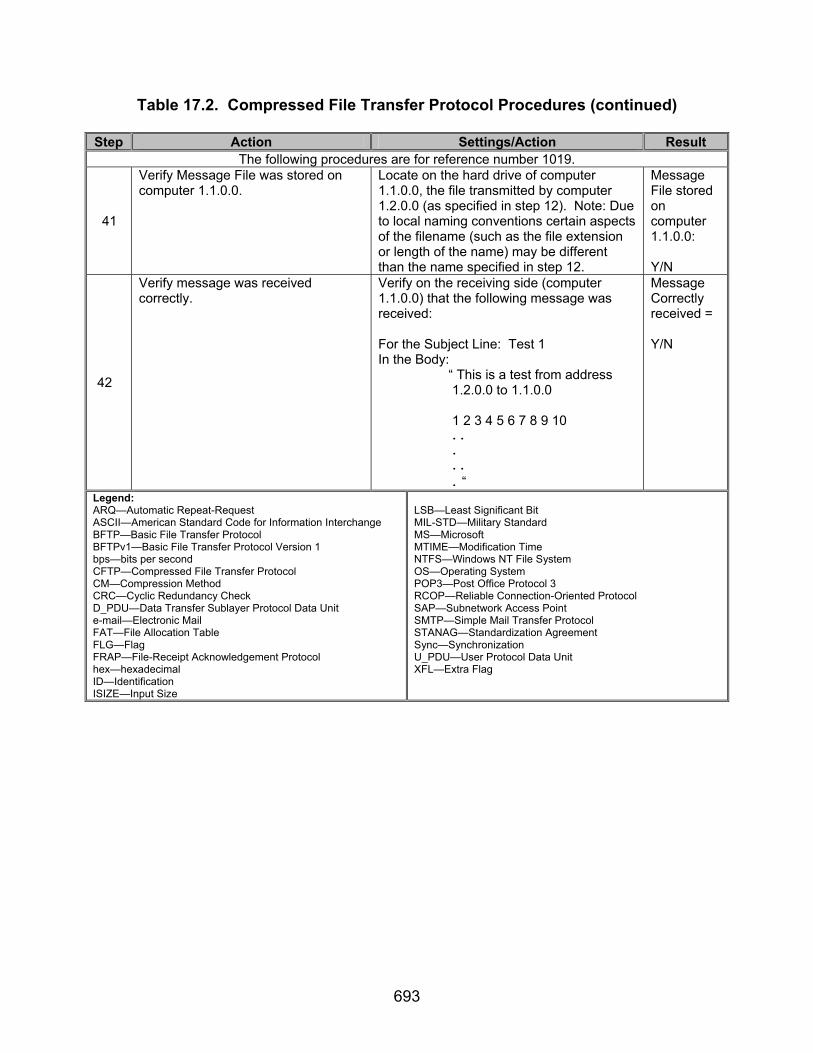
693
Table 17.2. Compressed File Transfer Protocol Procedures (continued) Step Action Settings/Action Result
The following procedures are for reference number 1019.
41
Verify Message File was stored on computer 1.1.0.0.
Locate on the hard drive of computer 1.1.0.0, the file transmitted by computer 1.2.0.0 (as specified in step 12). Note: Due to local naming conventions certain aspects of the filename (such as the file extension or length of the name) may be different than the name specified in step 12.
Message File stored on computer 1.1.0.0: Y/N
42
Verify message was received correctly.
Verify on the receiving side (computer 1.1.0.0) that the following message was received: For the Subject Line: Test 1 In the Body: “ This is a test from address 1.2.0.0 to 1.1.0.0 1 2 3 4 5 6 7 8 9 10
..
.
..
. “
Message Correctly received = Y/N
Legend: ARQ—Automatic Repeat-Request ASCII—American Standard Code for Information Interchange BFTP—Basic File Transfer Protocol BFTPv1—Basic File Transfer Protocol Version 1 bps—bits per second CFTP—Compressed File Transfer Protocol CM—Compression Method CRC—Cyclic Redundancy Check D_PDU—Data Transfer Sublayer Protocol Data Unit e-mail—Electronic Mail FAT—File Allocation Table FLG—Flag FRAP—File-Receipt Acknowledgement Protocol hex—hexadecimal ID—Identification ISIZE—Input Size
LSB—Least Significant Bit MIL-STD—Military Standard MS—Microsoft MTIME—Modification Time NTFS—Windows NT File System OS—Operating System POP3—Post Office Protocol 3 RCOP—Reliable Connection-Oriented Protocol SAP—Subnetwork Access Point SMTP—Simple Mail Transfer Protocol STANAG—Standardization Agreement Sync—Synchronization U_PDU—User Protocol Data Unit XFL—Extra Flag
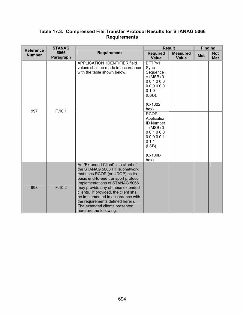
694
Table 17.3. Compressed File Transfer Protocol Results for STANAG 5066 Requirements
Result Finding Reference
Number STANAG
5066 Paragraph
Requirement Required Value
Measured Value Met Not
Met BFTPv1 Sync Sequence = (MSB) 0 0 0 1 0 0 0 0 0 0 0 0 0 0 1 0 (LSB). (0x1002 hex)
997 F.10.1
APPLICATION_IDENTIFIER field values shall be made in accordance with the table shown below.
RCOP Application ID Number = (MSB) 0 0 0 1 0 0 0 0 0 0 0 0 1 0 1 1 (LSB). (0x100B hex)
998 F.10.2
An “Extended Client” is a client of the STANAG 5066 HF subnetwork that uses RCOP (or UDOP) as its basic end-to-end transport protocol. Implementations of STANAG 5066 may provide any of these extended clients. If provided, the client shall be implemented in accordance with the requirements defined herein. The extended clients presented here are the following:

695
Table 17.3. Compressed File Transfer Protocol Results for STANAG 5066 Requirements
Result Finding Reference
Number STANAG
5066 Paragraph
Requirement Required Value
Measured Value Met Not
Met
999 F.10.2
File-Receipt Acknowledgment Protocol (FRAP) - FRAP may be used to provide an acknowledgement of file receipt for files sent over the STANAG 5066 subnetwork using some other protocol, such as BFTP or CFTP (see below). If provided, the FRAP extended client shall conform to the requirements section F.10.2.3 below.
Type 2 D_DPU Transmit-ted with the RCOP Application ID = (MSB) 0 0 0 1 0 0 0 0 0 0 0 0 1 0 1 1 (LSB). (0x100B hex) By computer 1.1.0.0 in response to computer 1.2.0.0 transmitting Type 0 D_PDUs with RCOP Application ID = 0x1002.

696
Table 17.3. Compressed File Transfer Protocol Results for STANAG 5066 Requirements (continued)
Result Finding Reference
Number STANAG
5066 Paragraph
Requirement Required Value
Measured Value Met Not
Met
1000 F.10.2.3
Files sent over STANAG 5066 using a BFTP extended client shall be acknowledged using the File-Receipt Acknowledgement Protocol (FRAP).
Type 2 D_DPU Transmit-ted with the RCOP Application ID = (MSB) 0 0 0 1 0 0 0 0 0 0 0 0 1 0 1 1 (LSB). (0x100B hex) By computer 1.1.0.0 in response to computer 1.2.0.0 transmitting Type 0 D_PDUs with RCOP Application ID = 0x1002.
1001 F.10.2.3
Implementations of STANAG 5066 shall provide support for the FRAP protocol if they also provide a BFTP (see section F.10.2.2) or CTFP client (see section F.14).
Type 2 D_DPU Transmit-ted with the RCOP Application ID = (MSB) 0 0 0 1 0 0 0 0 0 0 0 0 1 0 1 1 (LSB). (0x100B hex)

697
Table 17.3. Compressed File Transfer Protocol Results for STANAG 5066 Requirements (continued)
Result Finding Reference
Number STANAG
5066 Paragraph
Requirement Required Value
Measured Value Met Not
Met
1002 F.10.2.3
On receiving the last byte of a file sent using BFTP, the receiving client shall send an RCOP_PDU Header Part with an Application Identifier field value = 0x100B; the RCOP_PDU Body Part is null.
Type 2 D_DPU Transmit-ted with the RCOP Application ID = (MSB) 0 0 0 1 0 0 0 0 0 0 0 0 1 0 1 1 (LSB). (0x100B hex) By computer 1.1.0.0 in response to computer 1.2.0.0 transmitting its final Type 0 D_PDUs with RCOP Application ID = 0x1002.
1003 F.14.1
Implementations of STANAG 5066 may provide a CFTP client. If provided, a CFTP client shall conform to the requirements specified herein.
1004 F.14.1
CFTP shall operate within the node model shown, providing transfer services from one SMTP e-mail server to another via the CFTP client.
Both computers operating with CFTP client.
1005 F.14.2 CFTP clients shall bind to the HF Subnetwork at SAP ID 12.
SAP ID = 12
1006 F.14.3
The CFTP application shall use the original form of the RCOP Protocol Data Unit (“RCOPv1”) defined in the figure below.
RCOP structured as in figure 17.3.

698
Table 17.3. Compressed File Transfer Protocol Results for STANAG 5066 Requirements (continued)
Result Finding Reference
Number STANAG
5066 Paragraph
Requirement Required Value
Measured Value Met Not
Met
1007 F.14.3.1.1
BFTPv1 Specification [NB: corresponding to the original Edition 1 BFTP specification] The format for the basic-file-transfer-protocol data unit Version 1 (BFTPv1) shall be in accordance with the following figure, which defines a header part and a file-data part for the BFTP_PDUv1.
BFTPv1 header structured as in figure 17.4.
1008 F.14.3.1.1
The detailed structure of the BFTPv1_PDU shall be in accordance with the following figure, and provide the following information fields: 1. BFTPv1_PDU Header Part:
• SYNCHRONIZATION - two bytes corresponding to the control bytes DLE (Data Link Escape) and STX (Start of Text). • SIZE_OF_FILENAME - one octet in size. • FILE_NAME - a variable length field, equal in size to the value specified by the SIZE_OF_FILENAME field. • SIZE_OF_FILE - a four-octet field.
2. BFTPv1_PDU Body Part: • FILE_DATA[ ] - a variable length field, equal in size to the value specified by the SIZE_OF_FILE field.
BFTPv1 header structured as in figure 17.5.
1009 F.14.3.1.1
The SIZE_OF_FILENAME field shall be a 1-octet fixed-length field.
Size of Filename = actual length of Filename.

699
Table 17.3. Compressed File Transfer Protocol Results for STANAG 5066 Requirements (continued)
Result Finding Reference
Number STANAG
5066 Paragraph
Requirement Required Value
Measured Value Met Not
Met
1010 F.14.3.1.1
Whose value (n) shall equal the number of octets used to encode the FILENAME field.
Filename encoded after the Size Of Filename containing “n” number of bytes.
1011 F.14.3.1.1 The FILENAME field is shall be a variable-length field.
Filename is variable in length.
1012 F.14.3.1.1
The size of which shall be specified by the value (n) of the field SIZE_OF_FILENAME. This field represents the name of the file sent using the Basic File Transfer Protocol.
Size of Filename = actual length of Filename.
1013 F.14.3.1.1
The first byte of the filename shall be placed in the first byte of this field, with the remaining bytes placed in order.
Filename begins immediate-ly after the Size of Filename field with each subsequent byte correspon-ding to each subsequent letter (or character) in the ASCII equivalent of the filename.
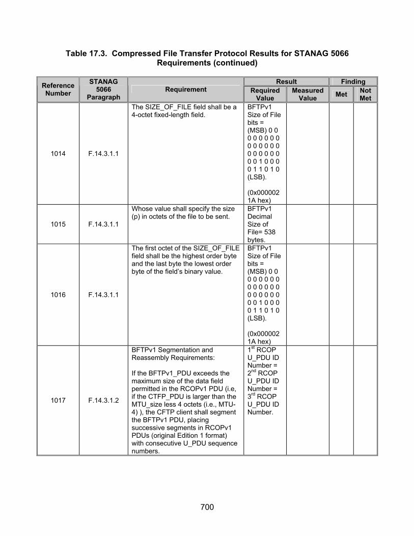
700
Table 17.3. Compressed File Transfer Protocol Results for STANAG 5066 Requirements (continued)
Result Finding Reference
Number STANAG
5066 Paragraph
Requirement Required Value
Measured Value Met Not
Met
1014 F.14.3.1.1
The SIZE_OF_FILE field shall be a 4-octet fixed-length field.
BFTPv1 Size of File bits = (MSB) 0 0 0 0 0 0 0 0 0 0 0 0 0 0 0 0 0 0 0 0 0 0 1 0 0 0 0 1 1 0 1 0 (LSB). (0x0000021A hex)
1015 F.14.3.1.1
Whose value shall specify the size (p) in octets of the file to be sent.
BFTPv1 Decimal Size of File= 538 bytes.
1016 F.14.3.1.1
The first octet of the SIZE_OF_FILE field shall be the highest order byte and the last byte the lowest order byte of the field’s binary value.
BFTPv1 Size of File bits = (MSB) 0 0 0 0 0 0 0 0 0 0 0 0 0 0 0 0 0 0 0 0 0 0 1 0 0 0 0 1 1 0 1 0 (LSB). (0x0000021A hex)
1017 F.14.3.1.2
BFTPv1 Segmentation and Reassembly Requirements: If the BFTPv1_PDU exceeds the maximum size of the data field permitted in the RCOPv1 PDU (i.e, if the CTFP_PDU is larger than the MTU_size less 4 octets (i.e., MTU-4) ), the CFTP client shall segment the BFTPv1 PDU, placing successive segments in RCOPv1 PDUs (original Edition 1 format) with consecutive U_PDU sequence numbers.
1st RCOP U_PDU ID Number = 2nd RCOP U_PDU ID Number = 3rd RCOP U_PDU ID Number.
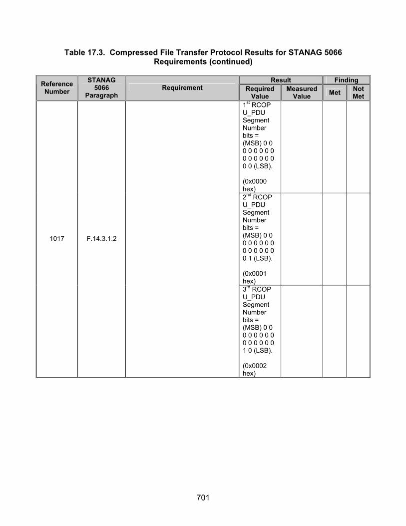
701
Table 17.3. Compressed File Transfer Protocol Results for STANAG 5066 Requirements (continued)
Result Finding Reference
Number STANAG
5066 Paragraph
Requirement Required Value
Measured Value Met Not
Met 1st RCOP U_PDU Segment Number bits = (MSB) 0 0 0 0 0 0 0 0 0 0 0 0 0 0 0 0 (LSB). (0x0000 hex)
2nd RCOP U_PDU Segment Number bits = (MSB) 0 0 0 0 0 0 0 0 0 0 0 0 0 0 0 1 (LSB). (0x0001 hex)
1017 F.14.3.1.2
3rd RCOP U_PDU Segment Number bits = (MSB) 0 0 0 0 0 0 0 0 0 0 0 0 0 0 1 0 (LSB). (0x0002 hex)

702
Table 17.3. Compressed File Transfer Protocol Results for STANAG 5066 Requirements (continued)
Result Finding Reference
Number STANAG
5066 Paragraph
Requirement Required Value
Measured Value Met Not
Met
1018 F.14.3.1.2
When received, the CFTP client shall reassemble the BFTPv1 PDU if it determines that the BFTPv1 PDU has been segmented.
Message received on computer 1.1.0.0 successful-ly.
1019 F.14.3.1.2
Subject to local-host file naming conventions, the CFTP client shall store the received file with the name transmitted in the header with the file. [i.e., there is no guarantee therefore that the file will be stored on the destination host with the same name that it was sent.]
Compres-sed file stored on computer 1.1.0.0’s hard drive.
1020 F.14.4
The compressed file shall be created and decompressed in accordance with RFCs 1950, 1951, and 1952.
Compres-sed Data was successful-ly recovered on TX side.
1021 F.14.6
The CFTP message (including header) shall be compressed in accordance with RFCs 1950, 1951, and 1952 using an application such as gzip.
Data is compres-sed.
1022 F.14.6
The compressed CFTP message shall be encapsulated within a BFTPv1 PDU (i.e., it has a BFTPv1 header prepended to it, and the CFTP message shall be byte aligned within the FILE_DATA[ ] field of the BFTPv1 PDU.
Message contained within BFTPv1 Header.
1023 F.14.6
The BFTPv1 message (i.e., BFTPv1 PDU) shall be segmented if necessary.
1st RCOP U_PDU ID Number = 2nd RCOP U_PDU ID Number = 3rd RCOP U_PDU ID Number.

703
Table 17.3. Compressed File Transfer Protocol Results for STANAG 5066 Requirements (continued)
Result Finding Reference
Number STANAG
5066 Paragraph
Requirement Required Value
Measured Value Met Not
Met 1st RCOP U_PDU Segment Number bits = (MSB) 0 0 0 0 0 0 0 0 0 0 0 0 0 0 0 0 (LSB). (0x0000 hex)
2nd RCOP U_PDU Segment Number bits = (MSB) 0 0 0 0 0 0 0 0 0 0 0 0 0 0 0 1 (LSB). (0x0001 hex)
1023 F.14.6
3rd RCOP U_PDU Segment Number bits = (MSB) 0 0 0 0 0 0 0 0 0 0 0 0 0 0 1 0 (LSB). (0x0002 hex)
1024 F.14.6
Each BFTPv1 PDU segment shall have an RCOPv1 header added (in accordance with annex F.14.3).
Each BFTPv1 Segment contains a RCOPv1 Header.

704
Table 17.3. Compressed File Transfer Protocol Results for STANAG 5066 Requirements (continued)
Result Finding Reference
Number STANAG
5066 Paragraph
Requirement Required Value
Measured Value Met Not
Met
1025 F.14.6
On reception the BFTPv1 message shall be reassembled, if required, and decompressed using a method compliant with RFC 1952 and the CFTP message reconstructed.
Data is decomp- ressed.
Legend: ASCII—American Standard Code for Information Interchange BFTP—Basic File Transfer Protocol BFTPv1_PDU—Basic File Transfer Protocol Protocol Data Unit
Version 1 BFTPv1—Basic File Transfer Protocol Version 1 CFTP—Compressed File Transfer Protocol D_PDU—Data Transfer Sublayer Protocol Data Unit DLE—Data Link Escape FRAP—File-Receipt Acknowledgment Protocol hex—hexadecimal HF—High Frequency ID—Identification LSB—Least Significant Bit MSB—Most Significant Bit MTU—Maximum Transmission Unit
NB—Note Below PDU—Protocol Data Unit RCOP—Reliable Connection-Oriented Protocol RCOP_PDU—Reliable Connection-Oriented Protocol Protocol Data Unit RCOPv1—Reliable Connection-Oriented Protocol Version 1 RFC—Request For Comment SAP—Subnetwork Access Point SMTP—Simple Mail Transfer Protocol STANAG—Standardized Agreement STX—Start Of Text sync—synchronization TX—Transmitted U_PDU—User Protocol Data Unit UDOP—Unreliable Datagram-Oriented Protocol
Table 17.4. Compressed File Transfer Protocol Results for RFC Requirements
Result Finding Reference
Number STANAG
5066 Paragraph
Requirement Required Value
Measured Value Met Not
Met
1054 RFC 1950 (8.1)
The compressor and the decompressor MUST use exactly the same dictionary.
Compres-sed Data was successful-ly recovered on TX side.
1055 RFC 1952 (2.3)
Member format. Each member has the structure as shown in RFC 1952 section 2.3.
Member header structured as shown in figure 16.2.
1056
RFC 1952 (2.3.1)
Member header and trailer:
Identification 1 (ID1) Identification 2 (ID2)
These have the fixed values ID1 = 31 (0x1f, \037), ID2 = 139 (0x8b, \213), to identify the file as being in gzip format.
ID1 = (MSB) 0 0 0 1 1 1 1 1 (LSB) (0x1f hex)
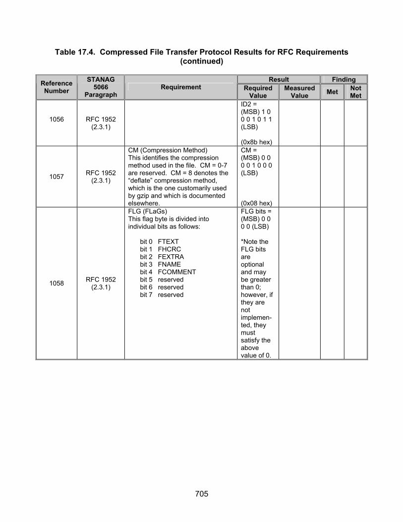
705
Table 17.4. Compressed File Transfer Protocol Results for RFC Requirements (continued)
Result Finding Reference
Number STANAG
5066 Paragraph
Requirement Required Value
Measured Value Met Not
Met
1056
RFC 1952 (2.3.1)
ID2 = (MSB) 1 0 0 0 1 0 1 1 (LSB) (0x8b hex)
1057 RFC 1952 (2.3.1)
CM (Compression Method) This identifies the compression method used in the file. CM = 0-7 are reserved. CM = 8 denotes the “deflate” compression method, which is the one customarily used by gzip and which is documented elsewhere.
CM = (MSB) 0 0 0 0 1 0 0 0 (LSB) (0x08 hex)
1058 RFC 1952 (2.3.1)
FLG (FLaGs) This flag byte is divided into individual bits as follows:
bit 0 FTEXT bit 1 FHCRC bit 2 FEXTRA bit 3 FNAME bit 4 FCOMMENT bit 5 reserved bit 6 reserved bit 7 reserved
FLG bits = (MSB) 0 0 0 0 (LSB) *Note the FLG bits are optional and may be greater than 0; however, if they are not implemen-ted, they must satisfy the above value of 0.

706
Table 17.4. Compressed File Transfer Protocol Results for RFC Requirements (continued)
Result Finding Reference
Number STANAG
5066 Paragraph
Requirement Required Value
Measured Value Met Not
Met
1058 RFC 1952 (2.3.1)
Reserved bits = (MSB) 0 0 0 (LSB)
1059 RFC 1952 (2.3.1)
MTIME (Modification TIME) This gives the most recent modification time of the original file being compressed. The time is in Unix format, i.e., seconds since 00:00:00 GMT, Jan. 1, 1970. (Note that this may cause problems for MS-DOS and other systems that use local rather than Universal time.) If the compressed data did not come from a file, MTIME is set to the time at which compression started. MTIME = 0 means no time stamp is available.
MTIME = (MSB) 0 0 0 0 0 0 0 0 0 0 0 0 0 0 0 0 0 0 0 0 0 0 0 0 0 0 0 0 0 0 0 0 (LSB) (0x00000000 hex)
1060 RFC 1952 (2.3.1)
XFL (eXtra FLags) These flags are available for use by specific compression methods. The “deflate” method (CM = 8) sets these flags as follows: XFL = 2 - compressor used maximum compression, slowest algorithm XFL = 4 - compressor used fastest algorithm
XFL = (MSB) 0 0 0 0 0 0 0 0 (LSB) (0x00 hex) *Note the XFL bits are optional and may be greater than 0; however, if they are not implemen-ted, they must satisfy the above value of 0.

707
Table 17.4. Compressed File Transfer Protocol Results for RFC Requirements (continued)
Result Finding Reference
Number STANAG
5066 Paragraph
Requirement Required Value
Measured Value Met Not
Met
1061 RFC 1952 (2.3.1)
OS (Operating System) This identifies the type of file system on which compression took place. This may be useful in determining end-of-line convention for text files. The currently defined values are as follows: 0 - FAT filesystem (MS-
DOS, OS/2, NT/Win32) 1 - Amiga 2 - VMS (or OpenVMS) 3 - Unix 4 - VM/CMS 5 - Atari TOS 6 - HPFS filesystem (OS/2,
NT) 7 - Macintosh 8 - Z-System 9 - CP/M 10 - TOPS-20 11 - NTFS filesystem (NT) 12 - QDOS 13 - Acorn RISCOS 255 - Unknown
OS bits = (MSB) 0 0 0 0 1 0 1 1 (LSB) (0x0B hex) if NTFS file system being used, or (MSB) 0 0 0 0 0 0 0 0 (LSB) (0x00 hex) if FAT file System being used.
1062 RFC 1952 (2.3.1)
CRC32 (CRC-32) This contains a Cyclic Redundancy Check value of the uncompressed data computed according to CRC-32 algorithm used in the ISO 3309 standard and in section 8.1.1.6.2 of ITU-T recommendation V.42. (See http://www.iso.ch for ordering ISO documents. See gopher://info.itu.ch for an online version of ITU-T V.42.)
A CRC32 was located 4 bytes back from the ISIZE bytes.
1063 RFC 1952 (2.3.1)
ISIZE (Input SIZE) This contains the size of the original (uncompressed) input data modulo 2^32.
ISIZE bytes = 0xBA030000 binary = (LSB) 1 0 1 1 1 0 1 0 0 0 0 0 0 1 1 0 0 0 0 0 0 0 0 0 0 0 0 0 0 0 0 (MSB)
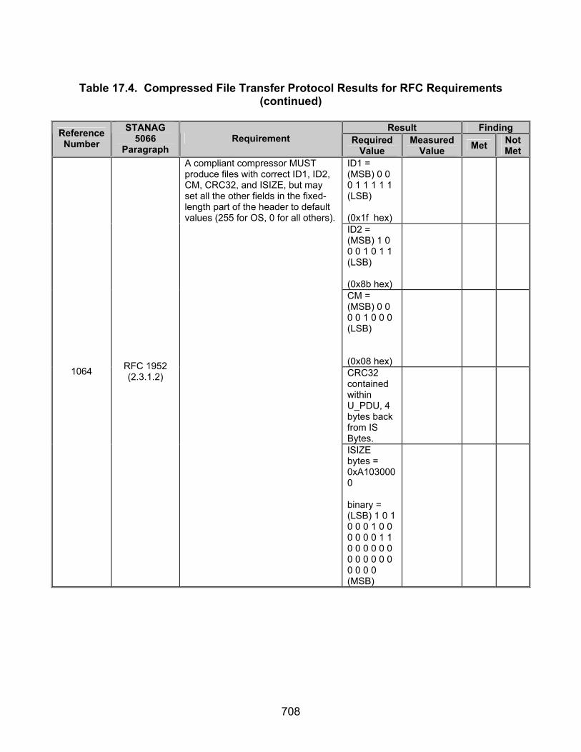
708
Table 17.4. Compressed File Transfer Protocol Results for RFC Requirements
(continued)
Result Finding Reference Number
STANAG 5066
Paragraph Requirement Required
Value Measured
Value Met Not Met
ID1 = (MSB) 0 0 0 1 1 1 1 1 (LSB) (0x1f hex)
ID2 = (MSB) 1 0 0 0 1 0 1 1 (LSB) (0x8b hex)
CM = (MSB) 0 0 0 0 1 0 0 0 (LSB) (0x08 hex)
CRC32 contained within U_PDU, 4 bytes back from IS Bytes.
1064 RFC 1952 (2.3.1.2)
A compliant compressor MUST produce files with correct ID1, ID2, CM, CRC32, and ISIZE, but may set all the other fields in the fixed-length part of the header to default values (255 for OS, 0 for all others).
ISIZE bytes = 0xA1030000 binary = (LSB) 1 0 1 0 0 0 1 0 0 0 0 0 0 1 1 0 0 0 0 0 0 0 0 0 0 0 0 0 0 0 0 (MSB)

709
Table 17.4. Compressed File Transfer Protocol Results for RFC Requirements (continued)
Result Finding Reference
Number STANAG
5066 Paragraph
Requirement Required Value
Measured Value Met Not
Met
1065 RFC 1952 (2.3.1.2)
The compressor MUST set all reserved bits to zero.
Reserved bits = 0
Legend: CM—Compression Method CRC—Cyclic Redundancy Check DOS—Disc Operating System e-mail—Electronic Mail FAT—File Allocation Table FLG—Flag GMT—Greenwich Mean Time hex—hexadecimal ID—Identification ISIZE—Input Size ISO—International Organization for Standardization ITU-T—International Telecommunications Union- Telecommunications Standardization Sector
LSB—Least Significant Bit MS—Microsoft MSB—Most Significant Bit MTIME—Modification Time NTFS—Windows NT File System OS—Operating System RFC—Request For Quote STANAG—Standardization Agreement TX—Transmitted U_PDU—User Protocol Data Unit XFL—Extra Flag

710
(This page intentionally left blank.)

711
SUBTEST 18. UNTESTABLE PARAMETERS
18.1 Objective. Table 18.1 provides a list of requirements outlined by STANAG 5066 that are currently considered to be untestable and will not be used to validate conformance to the STANAG 5066.
Table 18.1. Untestable Parameters
Reference Number
STANAG Paragraph Requirement
146 A.2.1.14
Interface Flow Control Primitives: S_DATA_FLOW_ON and S_DATA_FLOW_OFF. The S_DATA_FLOW_ON and S_DATA_FLOW_OFF primitives shall be issued by the Subnetwork Interface Sublayer to control the transfer of U_PDUs submitted by a client.
147 A.2.1.14 On receipt of an S_FLOW_DATA_OFF primitive, the client shall cease transferring U_PDUs over the interface.
148 A.2.1.14 Transfer over the interface of U_PDUs by the client shall be enabled following receipt of an S_FLOW_DATA_ON primitive.
149 A.2.1.14 A client shall not control the flow of data from the subnetwork by any mechanism, explicit or implicit.
150 A.2.1.14 All clients shall be ready to accept at all times data received by the HF Node to which it is bound; clients not following this rule may be disconnected by the node.
151 A.2.1.14 The S_MANAGEMENT_MSG_REQUEST primitive shall be issued by a client to submit a “Management” message to the Subnetwork.
152 A.2.1.14
The complex argument MSG may be implementation dependent and is not specified in this version of STANAG 5066. At present, a minimally compliant HF subnetwork implementation shall be capable of receiving this primitive, without further requirement to process its contents.
153 A.2.1.14 The subnetwork shall accept this primitive only from clients which have bound with a rank of 15.
154 A.2.1.14 The S_MANAGEMENT_MSG_INDICATION primitive shall be issued by the subnetwork to send a “Management” message to a client.
155 A.2.1.14 The complex argument MSG may be implementation dependent and is not specified in this version of STANAG 5066. At present, a minimally compliant client shall be capable of receiving this primitive, without further requirement to process its contents.
214 A.2.1.26
The S_SUBNET_AVAILABILITY primitive may be sent asynchronously to all or selected clients connected to the Subnetwork Interface Sublayer to inform them of changes in the status of the node to which they are attached. At present, a minimally compliant client implementation shall be capable of receiving this primitive, without further requirement to process its contents.
275 A.2.2.16 The S_SUBNET_AVAILABILITY primitive shall be encoded as a three-byte field as in figure A-16.
276 A.2.2.17 The S_DATA_FLOW_ON and S_DATA_FLOW_OFF primitives shall be encoded as one-byte fields as in figure A-17.
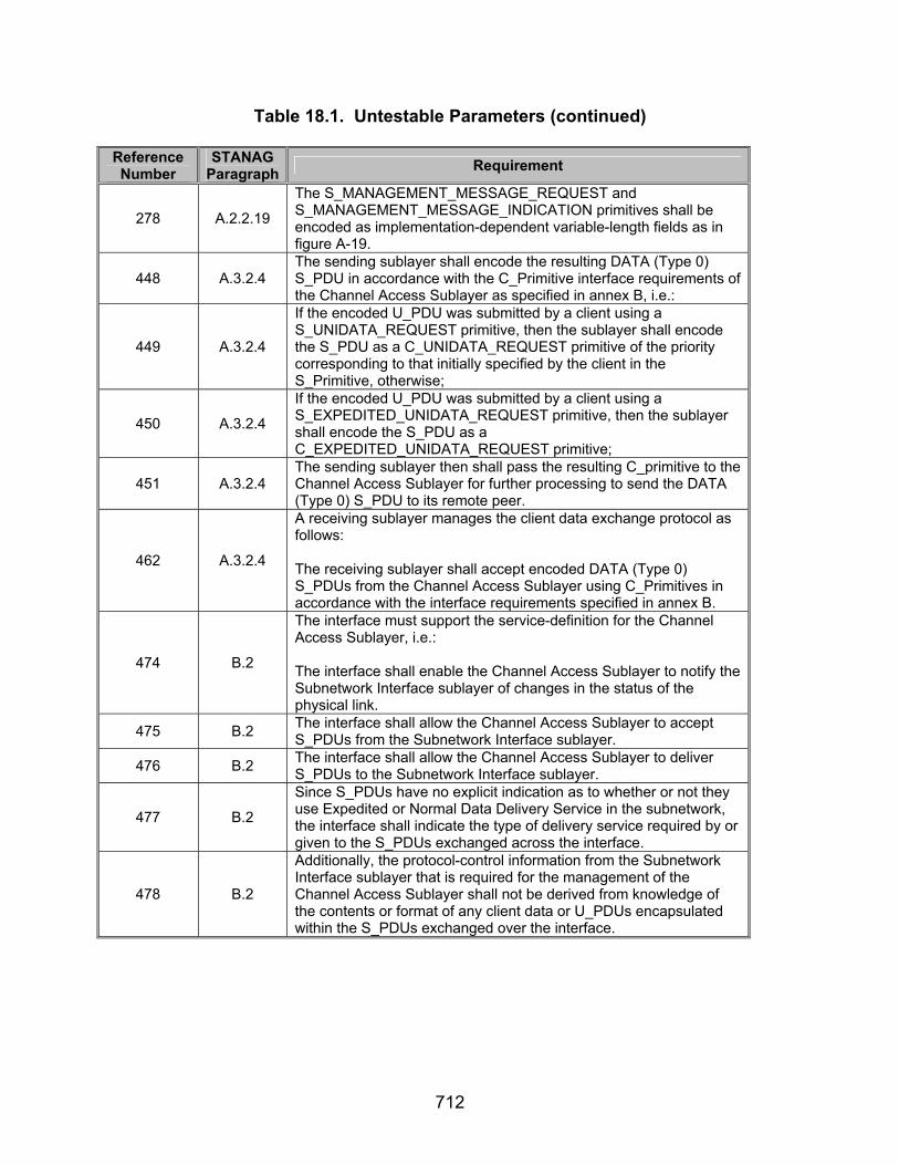
712
Table 18.1. Untestable Parameters (continued) Reference Number
STANAG Paragraph Requirement
278 A.2.2.19
The S_MANAGEMENT_MESSAGE_REQUEST and S_MANAGEMENT_MESSAGE_INDICATION primitives shall be encoded as implementation-dependent variable-length fields as in figure A-19.
448 A.3.2.4 The sending sublayer shall encode the resulting DATA (Type 0) S_PDU in accordance with the C_Primitive interface requirements of the Channel Access Sublayer as specified in annex B, i.e.:
449 A.3.2.4
If the encoded U_PDU was submitted by a client using a S_UNIDATA_REQUEST primitive, then the sublayer shall encode the S_PDU as a C_UNIDATA_REQUEST primitive of the priority corresponding to that initially specified by the client in the S_Primitive, otherwise;
450 A.3.2.4 If the encoded U_PDU was submitted by a client using a S_EXPEDITED_UNIDATA_REQUEST primitive, then the sublayer shall encode the S_PDU as a C_EXPEDITED_UNIDATA_REQUEST primitive;
451 A.3.2.4 The sending sublayer then shall pass the resulting C_primitive to the Channel Access Sublayer for further processing to send the DATA (Type 0) S_PDU to its remote peer.
462 A.3.2.4
A receiving sublayer manages the client data exchange protocol as follows:
The receiving sublayer shall accept encoded DATA (Type 0) S_PDUs from the Channel Access Sublayer using C_Primitives in accordance with the interface requirements specified in annex B.
474 B.2
The interface must support the service-definition for the Channel Access Sublayer, i.e.: The interface shall enable the Channel Access Sublayer to notify the Subnetwork Interface sublayer of changes in the status of the physical link.
475 B.2 The interface shall allow the Channel Access Sublayer to accept S_PDUs from the Subnetwork Interface sublayer.
476 B.2 The interface shall allow the Channel Access Sublayer to deliver S_PDUs to the Subnetwork Interface sublayer.
477 B.2 Since S_PDUs have no explicit indication as to whether or not they use Expedited or Normal Data Delivery Service in the subnetwork, the interface shall indicate the type of delivery service required by or given to the S_PDUs exchanged across the interface.
478 B.2
Additionally, the protocol-control information from the Subnetwork Interface sublayer that is required for the management of the Channel Access Sublayer shall not be derived from knowledge of the contents or format of any client data or U_PDUs encapsulated within the S_PDUs exchanged over the interface.

713
Table 18.1. Untestable Parameters (continued) Reference Number
STANAG Paragraph Requirement
480 B.3
The Type 1 Channel Access Protocol shall support the following subnetwork configuration: Pairs of Nodes shall be linked “point-to-point” on a “common” HF frequency channel or on dedicated frequency channels selected from a pool of assigned frequencies by an external process to which is not under the control of any of the sublayers. (Note: an ALE sublayer is not present or not used in STANAG 5066.)
486 B.3 There shall be no explicit peer-to-peer communication required to switch from use of one Nonexclusive Physical Link to another.
534 B.3
A request to establish a Nonexclusive Physical Link shall be accepted if there are no Exclusive Hard Links (active or with requests pending) and as long as the resulting total number of Nonexclusive Physical Links does not exceed the maximum number of Nonexclusive Physical Links allowed by the current subnetwork configuration.
538 B.3.2.1
Upon sending the Physical Link Request (Type 1) C_PDU the Channel Access Sublayer shall start a timer which is set to a value greater than or equal to the maximum time required by the Called Node to send its response (this time depends on the modem parameters, number of re-transmissions, etc.).
542 B.3.2.1 Otherwise, if the request is for a Nonexclusive Physical Link and the Called node has the maximum number of active Nonexclusive Physical Links, the called node shall reject the request.
562 B.3.2.2
Upon sending this C_PDU the Channel Access Sublayer shall start a timer which is set to a value greater than or equal to the maximum time required by the Called Node to send its response (this time depends on the modem parameters, number of re-transmissions, etc.).
578 C.2
The interface must support the service-definition for the Data Transfer Sublayer, i.e.:
The interface shall permit the Channel Access Sublayer to specify the delivery services, priority, and Time To Die required by the C_PDUs when it submits them to the Data Transfer Sublayer.
580 C.2 The interface shall permit the Channel Access Sublayer to specify the destination address to which C_PDUs are to be sent.
582 C.2
The interface shall permit the Data Transfer Sublayer to notify the Channel Access Sublayer when a warning indication (i.e., a Warning D_PDU) has been received from a remote peer, the source and destination address associated with the warning, the reason for the warning, and the event (i.e., message type) that triggered the warning message.
583 C.2
The interface shall permit the Data Transfer Sublayer to notify the Channel Access Sublayer that a warning indication (i.e., a Warning D_PDU) has been sent to a remote peer, the destination address associated with the warning, the reason for the warning, and the event (i.e., message type) that triggered the warning message.

714
Table 18.1. Untestable Parameters (continued) Reference Number
STANAG Paragraph Requirement
587 C.2
Additionally, the protocol-control information from the Channel Access Sublayer that is required for the management of the Data Transfer Sublayer shall not be derived from knowledge of the contents or format of any client data or U_PDUs encapsulated within the C_PDUs exchanged over the interface.
621 C.3.2.3 A half-duplex node shall stop transmitting and shift to receive mode when the EOT becomes zero.
645 C.3.2.8 When calculating the header CRC field, the shift-registers shall be initially set to all ‘0’ zeros.
657 C.3.2.11 When calculating the CRC on Segmented C_PDU field, the shift-registers shall be initially set to all ‘0’ zeros.
682 C.3.4 Frames with the DROP C_PDU flag set shall be acknowledged positively regardless of the results of the CRC check on the segmented C_PDU.
755 C.3.9 The Data Transfer Sublayer shall maintain variables to manage the frame ID numbers associated with this D_PDU:
754 C.3.9 The TX Management Frame ID Number shall maintain the value of the Frame ID Number for Management D_PDUs that are transmitted;
756 C.3.9 The RX Management Frame ID Number shall maintain the value of the Frame ID Number for the most recently received Management D_PDUs.
757 C.3.9 On initialization (such as a new connection), a node’s Data Transfer Sublayer shall set its current TX Management Frame ID Number to zero.
758 C.3.9 And shall set its current RX Management Frame ID Number to an out-of-range value (i.e., a value greater than 255).
762 C.3.9 The Data Transfer Sublayer shall compare the Management Frame ID Number of received Management D_PDUs to the current RX Management Frame ID Number, and process them as follows:
763 C.3.9 If the Management Frame ID Number in the received D_PDU differs from the current RX Management Frame ID Number value, the D_PDU shall be treated as a new D_PDU.
764 C.3.9 And the Data Transfer Sublayer shall set the current RX Management Frame ID Number value equal to the value of the received Management Frame ID Number.
765 C.3.9 If the value in the received D_PDU is equal to the current RX Management Frame ID Number value, the node shall assume that the frame is a repetition of a Management D_PDU that has already been received.
766 C.3.9 And the value of the current RX Management Frame ID Number shall be left unchanged.
822 C.4.1 A C_PDU segment taken from a D_PDU whose C_PDU Start and C_PDU End flags are both set to the value (1) shall be taken as a single C_PDU and processed as follows:
823 C.4.1 If the D_PDU is for a regular (unexpedited) data type, the C_PDU shall be delivered to the Channel Access Sublayer using a D_UNIDATA_INDICATION primitive;

715
Table 18.1. Untestable Parameters (continued) Reference Number
STANAG Paragraph Requirement
824 C.4.1 If the D_PDU is for an unexpedited data type, the C_PDU shall be delivered to the Channel Access Sublayer using a D_EXPEDITED_UNIDATA_INDICATION primitive;
826 C.4.1 A completely reassembled C_PDU shall be delivered to the Channel Access Sublayer using the appropriate D_Primitive.
839 C.4.1
If the Deliver-w/-Errors Mode has been specified, the re-assembly process shall proceed as follows: C_PDU segments received with detected errors shall be placed within the re-assembled C_PDU just as they are received in their D_PDUs (i.e., with errors), with the size in bytes and the position of the first byte of the segment noted in the D_Primitive used to deliver the C_PDU to the Channel Access Sublayer.
840 C.4.1
At the end of a specified and configurable time-out-interval the size in bytes and the position of the first byte of any C_PDU segments that have been lost or still not received shall be noted in the D_Primitive that delivers the C_PDU to the Channel Access Sublayer.
841 C.4.1 If the Deliver in Order Mode has been specified (with or without the Deliver with-Errors Mode specified), C_PDUs shall be delivered to the Channel Access Sublayer only if C_PDUs with lower-numbered C_PDU ID Numbers have already been delivered.
842 C.4.1 If the Deliver out of Order Mode has been specified, C_PDUs shall be delivered to the Channel Access Sublayer as soon as all segments have been received (in Error-Free Mode) or received and accounted for (in Deliver with-Errors Mode).
864 C.6.1 The Data Transfer Sublayer interactions with peers shall be defined with respect to the states shown in figure C-42 and as follows:
865 C.6.1.1 The transitions between DTS States and the actions that arise from given events shall be as defined in the tables presented in the subsections that follow.
866 C.6.1.1 DTS states, transitions, and actions shall be defined and maintained with respect to a specified remote node address.
867 C.6.1.1 Action and transitions rules shall not occur based on PDUs addressed to other nodes or from a node other than the specified remote node for which the states are maintained.
868 C.6.1.1 Action and transitions rules shall not occur based on D_Primitives that reference nodes other than the specified remote node.
869 C.6.1.1 DTS states shall be maintained for each specified node for which a connection or ARQ protocol must be maintained.
870 C.6.1.1.1 When in the IDLE (UNCONNECTED) State, the Data Transfer Sublayer shall respond to reception of a D_Primitive from the Channel Access Sublayer as specified in the table C-10.
871 C.6.1.1.1 When in the IDLE (UNCONNECTED) State, the Data Transfer Sublayer shall respond to reception of a D_PDU from the lower layers as specified in the table C-11.
872 C.6.1.1.2 When in the DATA (UNCONNECTED) State, the Data Transfer Sublayer shall respond to reception of a D_Primitive from the Channel Access Sublayer as specified in the table C-12.

716
Table 18.1. Untestable Parameters (continued) Reference Number
STANAG Paragraph Requirement
873 C.6.1.1.2 When in the DATA (UNCONNECTED) State, the Data Transfer Sublayer shall respond to reception of a D_PDU from the lower layers as specified in the table C-13.
874 C.6.1.1.3 When in the EXPEDITED-DATA (UNCONNECTED) State, the Data Transfer Sublayer shall respond to reception of a D_Primitive from the Channel Access Sublayer as specified in the table C-14.
875 C.6.1.1.3 When in the EXPEDITED-DATA (UNCONNECTED) State, the Data Transfer Sublayer shall respond to reception of a D_PDU from the lower layers as specified in the table C-15.
876 C.6.1.1.4 When in the MANAGEMEN T(UNCONNECTED) State, the Data Transfer Sublayer shall respond to reception of a D_Primitive from the Channel Access Sublayer as specified in the table C-16.
877 C.6.1.1.4 When in the MANAGEMENT (UNCONNECTED) State, the Data Transfer Sublayer shall respond to reception of a D_PDU from the lower layers as specified in the table C-17.
878 C.6.1.1.5 When in the IDLE (CONNECTED) State, the Data Transfer Sublayer shall respond to reception of a D_Primitive from the Channel Access Sublayer as specified in the table C-18.
879 C.6.1.1.5 When in the IDLE (CONNECTED) State, the Data Transfer Sublayer shall respond to reception of a D_PDU from the lower layers as specified in the following table C-19.
880 C.6.1.1.6 When in the DATA (CONNECTED) State, the Data Transfer Sublayer shall respond to reception of a D_Primitive from the Channel Access Sublayer as specified in the table C-20.
881 C.6.1.1.6 When in the DATA (CONNECTED) State, the Data Transfer Sublayer shall respond to reception of a D_PDU from the lower layers as specified in the following table C-21.
882 C.6.1.1.7 When in the EXPEDITED-DATA (CONNECTED) State, the Data Transfer Sublayer shall respond to reception of a D_Primitive from the Channel Access Sublayer as specified in the table C-22.
883 C.6.1.1.7 When in the EXPEDITED-DATA (CONNECTED) State, the Data Transfer Sublayer shall respond to reception of a D_PDU from the lower layers as specified in the table C-23.
884 C.6.1.1.8 When in the MANAGEMENT (CONNECTED) State, the Data Transfer Sublayer shall respond to reception of a D_Primitive from the Channel Access Sublayer as specified in the table C-24.
885 C.6.1.1.8 When in the MANAGEMENT (CONNECTED) State, the Data Transfer Sublayer shall respond to reception of a D_PDU from the lower layers as specified in the following table C-25.
886 C.6.1.2 A node shall transmit only those D_PDUs which are allowed for its current state as follows:
887 C.6.1.3
A node shall receive and process all valid D_PDUs regardless of its current state. Transmission of responses to a received D_PDU may be immediate or deferred, as appropriate for the current state and as specified in STANAG 5066, section 6.1.1.
891 C.6.1.3
Starting or restarting another ARQ machine (i.e., establishing a link with a new node or reestablishing link with a previously connected node) shall reset the ARQ machine for the EXPEDITED DATA-state.
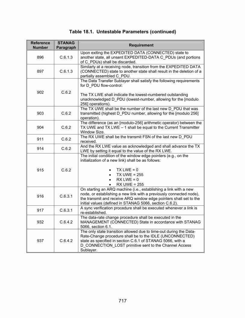
717
Table 18.1. Untestable Parameters (continued) Reference Number
STANAG Paragraph Requirement
896 C.6.1.3 Upon exiting the EXPEDITED DATA (CONNECTED) state to another state, all unsent EXPEDITED-DATA C_PDUs (and portions of C_PDUs) shall be discarded.
897 C.6.1.3 Similarly at a receiving node, transition from the EXPEDITED DATA (CONNECTED) state to another state shall result in the deletion of a partially assembled C_PDU.
902 C.6.2
The Data Transfer Sublayer shall satisfy the following requirements for D_PDU flow-control: The TX LWE shall indicate the lowest-numbered outstanding unacknowledged D_PDU (lowest-number, allowing for the [modulo 256] operations).
903 C.6.2 The TX UWE shall be the number of the last new D_PDU that was transmitted (highest D_PDU number, allowing for the [modulo 256] operation).
904 C.6.2 The difference (as an [modulo-256] arithmetic operator) between the TX UWE and TX LWE – 1 shall be equal to the Current Transmitter Window Size.
911 C.6.2 The RX UWE shall be the transmit FSN of the last new D_PDU received.
914 C.6.2 And the RX LWE value as acknowledged and shall advance the TX LWE by setting it equal to the value of the RX LWE.
915 C.6.2
The initial condition of the window edge pointers (e.g., on the initialization of a new link) shall be as follows:
• TX LWE = 0 • TX UWE = 255 • RX LWE = 0 • RX UWE = 255
916 C.6.3.1
On starting an ARQ machine (i.e., establishing a link with a new node, or establishing a new link with a previously connected node), the transmit and receive ARQ window edge pointers shall set to the initial values (defined in STANAG 5066, section C.6.2).
917 C.6.3.1 A sync verification procedure shall be executed whenever a link is re-established.
932 C.6.4.2 The data-rate change procedure shall be executed in the MANAGEMENT (CONNECTED) State in accordance with STANAG 5066, section 6.1.
937 C.6.4.2
The only state transition allowed due to time-out during the Data-Rate-Change procedure shall be to the IDLE (UNCONNECTED) state as specified in section C.6.1 of STANAG 5066, with a D_CONNECTION_LOST primitive sent to the Channel Access Sublayer.
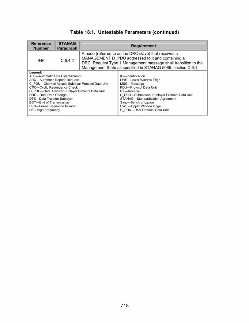
718
Table 18.1. Untestable Parameters (continued) Reference Number
STANAG Paragraph Requirement
946 C.6.4.2
A node (referred to as the DRC slave) that receives a MANAGEMENT D_PDU addressed to it and containing a DRC_Request Type 1 Management message shall transition to the Management State as specified in STANAG 5066, section C.6.1.
Legend: ALE—Automatic Link Establishment ARQ—Automatic Repeat-Request C_PDU—Channel Access Sublayer Protocol Data Unit CRC—Cyclic Redundancy Check D_PDU—Data Transfer Sublayer Protocol Data Unit DRC—Data Rate Change DTS—Data Transfer Sublayer EOT—End of Transmission FSN—Frame Sequence Number HF—High Frequency
ID—Identification LWE—Lower Window Edge MSG—Message PDU—Protocol Data Unit RX—Receive S_PDU—Subnetwork Sublayer Protocol Data Unit STANAG—Standardization Agreement Sync—Synchronization UWE—Upper Window Edge U_PDU—User Protocol Data Unit

A-1
APPENDIX A
ACRONYMS
ACK ARQ ASCII BFTP BFTPv1 BFTPv1_PDU bps C_PDU CCITT C-Frame CFTP CFTP_PDU CM CMD CMND CRC D_PDU dB DCE DLE DRC DTE e-mail EIA EMCON EOT EOW FLG FRAP FSN GMT hex HF
Acknowledgement Automatic Repeat-Request American Standard Code for Information Interchange Basic File Transfer Protocol Basic File Transfer Protocol Version 1 Basic File Transfer Protocol Protocol Version 1 Data Unit bits per second Channel Access Sublayer Protocol Data Unit Consultative Committee for International Telephone and
Telegraph Control Frame Compressed File Transfer Protocol Compressed File Transfer Protocol Protocol Data Unit Compression Method Command Command Cyclic Redundancy Check Data Transfer Sublayer Protocol Data Unit Decibel Data Communications Equipment Data Link Escape Data Rate Change Data Terminal Equipment Electronic Mail Electronic Industries Alliance Emission Control End of Transmission Engineering Orderwire Flag File-Receipt Acknowledgment Protocol Frame Sequence Number Greenwich Mean Time Hexadecimal High Frequency

A-2
ACRONYMS
ID I-Frame I+C-Frame IP IRQ ISIZE ISO ITA ITU-T LAN LSB LWE MIL-STD MSB MSG MTIME MTU NATO NB NC3A NRQ OS PDU RCOP RCOP_PDU RCOPv1 RFC RQST RQ RX S_PCI S_PDU SAP
ACRONYMS (continued) Identification Information Frame Information and Control Frame Internet Protocol Idle Repeat-Request Protocol Input Size International Organization for Standardization International Telegraph Alphabet International Telecommunication Union
Telecommunications Standardization Sector Local Area Network Least Significant Bit Lower Window Edge Military Standard Most Significant Bit Message Modification Time Maximum Transmission Unit North Atlantic Treaty Organization Note Below NATO Consultation, Command, and Control Agency Non-Repeat-Request (i.e., Non-ARQ) Protocol Operating System Protocol Data Unit Reliable Connection-Oriented Protocol Reliable Connection-Oriented Protocol Protocol Data Unit Reliable Connection-Oriented Protocol Version 1 Request for Comment Request Request Receive Subnetwork Interface Sublayer Protocol Control InformationSubnetwork Interface Sublayer Protocol Data Unit Subnetwork Access Point

A-3
SNR SRQ STANAG STX Sync TCP TTD TTL TX U_PDU UDOP UWE VTTD WAN WIN XFL
ACRONYMS (continued) Signal-to-Noise Ratio Selective Repeat-Request Protocol Standardization Agreement Start of Text Synchronization Transmission Control Protocol Time To Die Time To Live Transmit User Protocol Data Unit Unreliable Datagram-Oriented Protocol Upper Window Edge Valid Time To Die Wide Area Network Window Extra Flag

A-4
(This page intentionally left blank.)

B-1
APPENDIX B
STANAG 5066 REQUIREMENTS MATRIX

B-2
(This page intentionally left blank.)
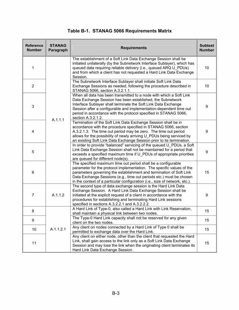
B-3
Table B-1. STANAG 5066 Requirements Matrix
Reference Number
STANAG Paragraph Requirements Subtest
Number
1
The establishment of a Soft Link Data Exchange Session shall be initiated unilaterally (by the Subnetwork Interface Sublayer), which has queued data requiring reliable delivery (i.e., queued ARQ U_PDUs) and from which a client has not requested a Hard Link Data Exchange Session.
10
2 The Subnetwork Interface Sublayer shall initiate Soft Link Data Exchange Sessions as needed, following the procedure described in STANAG 5066, section A.3.2.1.1.
10
3
When all data has been transmitted to a node with which a Soft Link Data Exchange Session has been established, the Subnetwork Interface Sublayer shall terminate the Soft Link Data Exchange Session after a configurable and implementation-dependent time out period in accordance with the protocol specified in STANAG 5066, section A.3.2.1.2.
9
4
Termination of the Soft Link Data Exchange Session shall be in accordance with the procedure specified in STANAG 5066, section A.3.2.1.3. The time out period may be zero. The time out period allows for the possibility of newly arriving U_PDUs being serviced by an existing Soft Link Data Exchange Session prior to its termination.
9
5
In order to provide “balanced” servicing of the queued U_PDUs, a Soft Link Data Exchange Session shall not be maintained for a period that exceeds a specified maximum time if U_PDUs of appropriate priorities are queued for different node(s).
9
6
A.1.1.1
The specified maximum time out period shall be a configurable parameter for the protocol implementation. The specific values of the parameters governing the establishment and termination of Soft Link Data Exchange Sessions (e.g., time out periods etc.) must be chosen in the context of a particular configuration (i.e., size of network, etc.).
15
7 A.1.1.2
The second type of data exchange session is the Hard Link Data Exchange Session. A Hard Link Data Exchange Session shall be initiated at the explicit request of a client in accordance with the procedures for establishing and terminating Hard Link sessions specified in sections A.3.2.2.1 and A.3.2.2.2.
9
8 A Hard Link of Type-0, also called a Hard Link with Link Reservation, shall maintain a physical link between two nodes. 15
9 The Type-0 Hard Link capacity shall not be reserved for any given client on the two nodes. 15
10 Any client on nodes connected by a Hard Link of Type 0 shall be permitted to exchange data over the Hard Link. 15
11
A.1.1.2.1
Any client on either node, other than the client that requested the Hard Link, shall gain access to the link only as a Soft Link Data Exchange Session and may lose the link when the originating client terminates its Hard Link Data Exchange Session.
15

B-4
Table B-1. STANAG 5066 Requirements Matrix (continued)
Reference Number
STANAG Paragraph Requirements Subtest
Number
12 A Hard Link of Type 1, also called a Hard Link with Partial Bandwidth Reservation, shall maintain a physical link between two nodes. 15
13
The Type 1 Hard Link capacity shall be reserved only for the client that requested the Type 1 Hard Link between the two nodes. The requesting client may send user data to any client on the remote node and may receive user data from any client on the remote node only as a Soft Link Data Exchange Session.
15
14
A.1.1.2.2
Clients that are not sending data to or receiving data from the client that requested the Type 1 Hard Link shall be unable to use the Hard Link. Any client using the link may lose the link when the originating client terminates its Hard Link session.
15
15 A Hard Link of Type 2, also called a Hard Link with Full Bandwidth Reservation, shall maintain a physical link between two nodes. 15
16 The Type 2 Hard Link capacity shall be reserved only for the client that requested the Type 1 Hard Link and a specified remote client. 15
17
A.1.1.2.3
No clients other than the requesting client and its specified remote client shall exchange data on a Type-2 Hard Link. 15
18
The third type of data exchange session is the Broadcast Data Exchange Session. The subnetwork shall service only clients with service requirements for Non-ARQ U_PDUs during a Broadcast Data Exchange Session.
15
19 The procedures that initiate and terminate Broadcast Data Exchange Sessions shall be as specified in annex C. 15
20 A node configured to be a broadcast-only node shall use a “permanent” Broadcast Data Exchange Session. 15
21
A.1.1.3
During which the Subnetwork Interface Sublayer shall service no Hard Link requests or ARQ DATA U_PDUs. Alternatively the Subnetwork Interface Sublayer can unilaterally initiate and terminate Broadcast Data Exchange Sessions.
15
22 A.2
Communication between the client and the Subnetwork Interface Sublayer uses the interface primitives listed in table A-1 and defined in the following subsections. The names of these primitives are prefixed with an “S_” to indicate that they are exchanged across the interface between the Subnetwork Interface Sublayer and the subnetwork clients. This table is intended to provide a general guide and overview to the primitives. For detailed specification of the primitives, the later sections of this annex shall apply.
10
23 A.2.1 The content specification and use of the Subnetwork Interface Sublayer primitives shall be as specified in the following subsections. 10
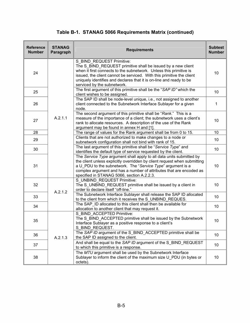
B-5
Table B-1. STANAG 5066 Requirements Matrix (continued)
Reference Number
STANAG Paragraph Requirements Subtest
Number
24
S_BIND_REQUEST Primitive: The S_BIND_REQUEST primitive shall be issued by a new client when it first connects to the subnetwork. Unless this primitive is issued, the client cannot be serviced. With this primitive the client uniquely identifies and declares that it is on-line and ready to be serviced by the subnetwork.
10
25 The first argument of this primitive shall be the “SAP ID” which the client wishes to be assigned. 10
26 The SAP ID shall be node-level unique, i.e., not assigned to another client connected to the Subnetwork Interface Sublayer for a given node.
1
27
The second argument of this primitive shall be “Rank.” This is a measure of the importance of a client; the subnetwork uses a client’s rank to allocate resources. A description of the use of the Rank argument may be found in annex H and [1].
10
28 The range of values for the Rank argument shall be from 0 to 15. 10 29 Clients that are not authorized to make changes to a node or
subnetwork configuration shall not bind with rank of 15. 10
30 The last argument of this primitive shall be “Service Type” and identifies the default type of service requested by the client. 10
31
A.2.1.1
The Service Type argument shall apply to all data units submitted by the client unless explicitly overridden by client request when submitting a U_PDU to the subnetwork. The “Service Type” argument is a complex argument and has a number of attributes that are encoded as specified in STANAG 5066, section A.2.2.3.
10
32 S_UNBIND_REQUEST Primitive: The S_UNBIND_REQUEST primitive shall be issued by a client in order to declare itself “off-line.”
10
33 The Subnetwork Interface Sublayer shall release the SAP ID allocated to the client from which it receives the S_UNBIND_REQUES. 10
34
A.2.1.2
The SAP_ID allocated to this client shall then be available for allocation to another client that may request it. 10
35
S_BIND_ACCEPTED Primitive: The S_BIND_ACCEPTED primitive shall be issued by the Subnetwork Interface Sublayer as a positive response to a client’s S_BIND_REQUEST.
10
36 The SAP ID argument of the S_BIND_ACCEPTED primitive shall be the SAP ID assigned to the client. 10
37 And shall be equal to the SAP ID argument of the S_BIND_REQUEST to which this primitive is a response. 10
38
A.2.1.3
The MTU argument shall be used by the Subnetwork Interface Sublayer to inform the client of the maximum size U_PDU (in bytes or octets).
10

B-6
Table B-1. STANAG 5066 Requirements Matrix (continued)
Reference Number
STANAG Paragraph Requirements Subtest
Number
39
Which will be accepted as an argument of the S_UNIDATA_REQUEST primitive. S_UNIDATA_REQUEST primitives containing U_PDUs larger than the MTU shall be rejected by the subnetwork interface.
10
40
Note that this restriction applies only to U_PDUs received through the subnetwork interface. U_PDUs which are received from the lower HF sublayers (i.e., received by radio) shall be delivered to clients regardless of size.
10
41 For general-purpose nodes, the MTU value shall be 2048 bytes. 10 42 For broadcast-only nodes, the MTU shall be configurable by the
implementation. 10 43
A.2.1.3
Up to a maximum that shall not exceed 4096 bytes. 10
44
S_BIND_REJECTED ( ): The S_BIND_REJECTED ( ) primitive shall be issued by the Subnetwork Interface Sublayer as a negative response to a client’s S_BIND_REQUEST. If certain conditions are not met, then the Subnetwork Interface Sublayer rejects the client’s request.
10
45 The Reason argument of the S_BIND_REJECTED primitive shall specify the reason why the client’s request was rejected. 10
46 Valid Reason values shall be as specified in the table below. 10
47
A.2.1.4
The binary representation of the value in the table shall be encoded in the “Reason” field of the primitive by placing the LSB of the value into the LSB of the encoded field for the primitive as specified in STANAG 5066, section A.2.2.
10
48
S_UNBIND_INDICATION ( ): The S_UNBIND_INDICATION primitive shall be issued by the Subnetwork Interface Sublayer to unilaterally declare a client as off-line. If the client wants to come on-line again, it must issue a new S_BIND_REQUEST primitive as specified in STANAG 5066, section A.2.1.1.
10
49 The Reason argument of the S_UNBIND_INDICATION primitive shall specify why the client was declared off-line. 10
50
A.2.1.5
The binary representation of the value in the table shall be mapped into the “Reason” field of the primitive by placing the LSB of the value into the LSB of the encoded field for the primitive as specified in STANAG 5066, section A.2.2.
10
51
S_UNIDATA_REQUEST Primitive: The S_UNIDATA_REQUEST primitive shall be used by connected clients to submit a U_PDU to the HF subnetwork for delivery to a receiving client.
10
52 The Priority argument shall represent the priority of the U_PDU. 10 53 The U_PDU priority shall take a value in the range 0 to 15. 10
54
A.2.1.6
The processing by HF protocol sublayers shall make a “best effort” to give precedence to high priority U_PDUs over lower priority U_PDUs which are queued in the system.
10

B-7
Table B-1. STANAG 5066 Requirements Matrix (continued)
Reference Number
STANAG Paragraph Requirements Subtest
Number
55
The argument Destination SAP ID shall specify the SAP ID of the receiving client. Note that as all nodes will have uniquely specified SAP IDs for clients, the Destination SAP ID distinguishes the destination client from the other clients bound to the destination node.
10
56 The argument Destination Node Address shall specify the HF subnetwork address of the physical HF node to which the receiving client is bound.
10
57 The argument Delivery Mode shall be a complex argument with a number of attributes, as specified by the encoding rules of STANAG 5066, section A.2.2.28.2.
10
58 The argument Time To Live (TTL) shall specify the maximum amount of time the submitted U_PDU is allowed to stay in the HF subnetwork before it is delivered to its final destination.
10
59 If the TTL is exceeded, the U_PDU shall be discarded. 10 60 A TTL value of (0) shall define an infinite TTL, i.e., the subnetwork
should try forever to deliver the U_PDU. 10 61 The subnetwork shall have a default maximum TTL. 10 62 The default maximum TTL shall be configurable as an implementation-
dependent value. 10
63
As soon as the Subnetwork Interface Sublayer accepts a S_UNIDATA_REQUEST primitive, it shall immediately calculate its Time To Die (TTD) by adding the specified TTL (or the default maximum value if the specified TTL is equal to (0)) to the current Time of Day, e.g., GMT.
10
64 The TTD attribute of a U_PDU shall accompany it during its transit within the subnetwork. [Note that the TTD is an absolute time while the TTL is a time interval relative to the instant of the U_PDU submission.]
10
65 The Size of U_PDU argument shall be the size of the U_PDU that is included in this S_UNIDATA_REQUEST primitive. 10
66
A.2.1.6
The final argument, U_PDU, shall be the actual Data Unit submitted by the client to the HF subnetwork. 10
67
S_UNIDATA_REQUEST_CONFIRM Primitive: The S_UNIDATA_REQUEST_CONFIRM primitive shall be issued by the Subnetwork Interface Sublayer to acknowledge the successful delivery of a S_UNIDATA_REQUEST submitted by the client.
10
68 This primitive shall be issued only if the client has requested Data Delivery Confirmation (either during binding or for this particular data unit).
10
69
A.2.1.7
The Destination Node Address argument in the S_UNIDATA_REQUEST_CONFIRM primitive shall have the same meaning and be equal in value to the Destination Node Address argument of the S_UNIDATA_REQUEST primitive for which the S_UNIDATA_REQUEST_CONFIRM primitive is the response.
10

B-8
Table B-1. STANAG 5066 Requirements Matrix (continued)
Reference Number
STANAG Paragraph Requirements Subtest
Number
70
The Destination SAP_ID argument in the S_UNIDATA_REQUEST_CONFIRM primitive shall have the same meaning and be equal in value to the Destination SAP_ID argument of the S_UNIDATA_REQUEST Primitive for which the S_UNIDATA_REQUEST_CONFIRM Primitive is the response.
10
71 The Size of Confirmed U_PDU argument shall be the size of the U_PDU or part that is included in this S_UNIDATA_REQUEST_CONFIRM primitive.
10
72
The U_PDU argument in the S_UNIDATA_CONFIRM primitive shall be a copy of the whole or a fragment of the U_PDU argument of the S_UNIDATA_REQUEST primitive for which the S_UNIDATA_REQUEST_CONFIRM primitive is the response.
10
73
Using these arguments, the client shall be able to uniquely identify the U_PDU that is being acknowledged. Depending on the implementation of the protocol, the last argument, U_PDU, may not be a complete copy of the original U_PDU but only a partial copy, i.e., only the first X bytes are copied for some value of X.
10
74 If a partial U_PDU is returned, U_PDU_Response_Frag_Size bytes shall be returned to the client starting with the first byte of the U_PDU so that the client will have the U_PDU segment information.
10
75
A.2.1.7
The number of bytes returned, U_PDU_Response_Frag_Size, shall be a configurable parameter in the implementation. 10
76
S_UNIDATA_REQUEST_REJECTED Primitive: The S_UNIDATA_REQUEST_REJECTED primitive shall be issued by the Subnetwork Interface Sublayer to inform a client that a S_UNIDATA_REQUEST was not delivered successfully.
10
77 This primitive shall be issued if the client has requested Data Delivery Confirmation (either during Binding or for this particular U_PDU) and the data was unsuccessfully delivered.
10
78 This primitive also shall be issued to a client if a U_PDU larger than the MTU is submitted. 10
79 The argument Reason shall specify why the delivery failed, using the encoding given in the table in STANAG 5066, section A.2.1.8. 10
80
The binary representation of the value in the table in STANAG 5066, section A.2.1.8 shall be mapped into the Reason argument of the primitive by placing the LSB of the value into the LSB of the encoded argument for the primitive as specified in STANAG 5066, section A.2.2.
10
81
A.2.1.8
The Destination Node Address argument in the S_UNIDATA_REQUEST_REJECTED primitive shall have the same meaning and be equal in value to the Destination Node Address argument of the S_UNIDATA_REQUEST Primitive for which the S_UNIDATA_REQUEST_REJECTED primitive is the response.
10
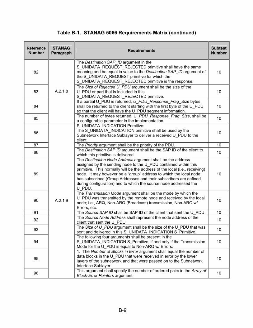
B-9
Table B-1. STANAG 5066 Requirements Matrix (continued)
Reference Number
STANAG Paragraph Requirements Subtest
Number
82
The Destination SAP_ID argument in the S_UNIDATA_REQUEST_REJECTED primitive shall have the same meaning and be equal in value to the Destination SAP_ID argument of the S_UNIDATA_REQUEST primitive for which the S_UNIDATA_REQUEST_REJECTED primitive is the response.
10
83 The Size of Rejected U_PDU argument shall be the size of the U_PDU or part that is included in this S_UNIDATA_REQUEST_REJECTED primitive.
10
84 If a partial U_PDU is returned, U_PDU_Response_Frag_Size bytes shall be returned to the client starting with the first byte of the U_PDU so that the client will have the U_PDU segment information.
10
85
A.2.1.8
The number of bytes returned, U_PDU_Response_Frag_Size, shall be a configurable parameter in the implementation. 10
86
S_UNIDATA_INDICATION Primitive: The S_UNIDATA_INDICATION primitive shall be used by the Subnetwork Interface Sublayer to deliver a received U_PDU to the client.
10
87 The Priority argument shall be the priority of the PDU. 10 88 The Destination SAP ID argument shall be the SAP ID of the client to
which this primitive is delivered. 10
89
The Destination Node Address argument shall be the address assigned by the sending node to the U_PDU contained within this primitive. This normally will be the address of the local (i.e., receiving) node. It may however be a “group” address to which the local node has subscribed (Group Addresses and their subscribers are defined during configuration) and to which the source node addressed the U_PDU.
10
90
The Transmission Mode argument shall be the mode by which the U_PDU was transmitted by the remote node and received by the local node; i.e., ARQ, Non-ARQ (Broadcast) transmission, Non-ARQ w/ Errors, etc.
10
91 The Source SAP ID shall be SAP ID of the client that sent the U_PDU. 10 92 The Source Node Address shall represent the node address of the
client that sent the U_PDU. 10
93 The Size of U_PDU argument shall be the size of the U_PDU that was sent and delivered in this S_UNIDATA_INDICATION S_Primitive. 10
94 The following four arguments shall be present in the S_UNIDATA_INDICATION S_Primitive, if and only if the Transmission Mode for the U_PDU is equal to Non-ARQ w/ Errors:
10
95
1. The Number of Blocks in Error argument shall equal the number of data blocks in the U_PDU that were received in error by the lower layers of the subnetwork and that were passed on to the Subnetwork Interface Sublayer.
10
96
A.2.1.9
This argument shall specify the number of ordered pairs in the Array of Block-Error Pointers argument. 10

B-10
Table B-1. STANAG 5066 Requirements Matrix (continued)
Reference Number
STANAG Paragraph Requirements Subtest
Number
97
2. The Array of Block-Error Pointers argument shall consist of an array of ordered pairs, the first element in the pair equal to the location within the U_PDU of the data block with errors, and the second element equal to the size of the data block with errors.
10
98 3. The Number of Non-Received Blocks argument shall equal the number of data blocks missing from the U_PDU because they were not received.
10
99 This argument shall specify the number of ordered pairs in the Array of Non-Received-Block Pointers argument. 10
100
The Array of Non-Received-Block Pointers shall consist of an array of ordered pairs, the first element in the pair equal to the location of the missing data block in the U_PDU and the second element equal to the size of the missing data block.
10
101
A.2.1.9
4. The final argument, U_PDU, shall contain the actual received user data for delivery to the client. 10
102
S_EXPEDITED_UNIDATA_REQUEST Primitive: The S_EXPEDITED_UNIDATA_REQUEST primitive shall be used to submit a U_PDU to the HF Subnetwork for Expedited Delivery to a receiving client.
10
103
The argument Destination SAP ID shall specify the SAP ID of the receiving client. Note that as all nodes will have uniquely specified SAP IDs for clients, the Destination SAP ID distinguishes the destination client from the other clients bound to the destination node.
10
104 The argument Destination Node Address shall specify the HF subnetwork address of the physical HF node to which the receiving client is bound.
10
105 The argument Delivery Mode shall be a complex argument with a number of attributes, as specified by the encoding rules of STANAG 5066, section A.2.2.28.2.
10
106 The argument Time To Live (TTL) shall specify the maximum amount of time the submitted U_PDU is allowed to stay in the HF Subnetwork before it is delivered to its final destination.
10
107 If the TTL is exceeded the U_PDU shall be discarded. 10 108 A TTL value of (0) shall define an infinite TTL, i.e., the subnetwork
should try forever to deliver the U_PDU. 10
109
As soon as the Subnetwork Interface Sublayer accepts a S_EXPEDITED_UNIDATA_REQUEST primitive, it shall immediately calculate its Time To Die (TTD) by adding the specified TTL (or the default maximum TTL value if the specified TTL is equal to (0)) to the current Time of Day, e.g., GMT.
10
110
The TTD attribute of a U_PDU shall accompany it during its transit within the subnetwork. [Note that the TTD is an absolute time while the TTL is a time interval relative to the instant of the U_PDU submission.]
10
111
A.2.1.10
The Size of U_PDU argument shall be the size of the U_PDU that is included in this S_UNIDATA_REQUEST primitive. 10

B-11
Table B-1. STANAG 5066 Requirements Matrix (continued)
Reference Number
STANAG Paragraph Requirements Subtest
Number
112 The final argument, U_PDU, shall be the actual User Data Unit (U_PDU) submitted by the client to the HF Subnetwork for expedited delivery service.
10
113 The STANAG 5066 node management shall track the number of S_EXPEDITED_UNIDATA_REQUEST primitives submitted by various clients.
10
114
A.2.1.10 If the number of S_EXPEDITED_UNIDATA_REQUEST primitives for any client exceeds a configurable, implementation dependent parameter, node management shall unilaterally disconnect the client using an S_UNBIND_INDICATION primitive with REASON = 4 = “Too many expedited-data request primitives.”
10
115
S_EXPEDITED_UNIDATA_REQUEST_CONFIRM Primitive: The S_EXPEDITED_UNIDATA_REQUEST_CONFIRM primitive shall be issued by the Subnetwork Interface Sublayer to acknowledge the successful delivery of a S_EXPEDITED_UNIDATA_REQUEST primitive.
10
116 This primitive shall be issued only if the client has requested Data Delivery Confirmation (either during Binding or for this particular U_PDU).
10
117
The Destination Node Address argument in the S_EXPEDITED_UNIDATA_REQUEST_CONFIRM primitive shall have the same meaning and be equal in value to the Destination Node Address argument of the S_EXPEDITED_UNIDATA_REQUEST primitive for which the S_EXPEDITED_UNIDATA_REQUEST_CONFIRM primitive is the response.
10
118
The Destination SAP_ID argument in the S_EXPEDITED_UNIDATA_REQUEST_CONFIRM primitive shall have the same meaning and be equal in value to the Destination SAP_ID argument of the S_EXPEDITED_UNIDATA_REQUEST primitive for which the S_EXPEDITED_UNIDATA_REQUEST_CONFIRM primitive is the response.
10
119 The Size of Rejected U_PDU argument shall be the size of the U_PDU or part that is included in the S_EXPEDITED_UNIDATA_REQUEST_CONFIRM primitive.
10
120 If a partial U_PDU is returned, U_PDU_Response_Frag_Size bytes shall be returned to the client starting with the first byte of the U_PDU so that the client will have the U_PDU segment information.
10
121
A.2.1.11
The number of bytes returned, U_PDU_Response_Frag_Size, shall be a configurable parameter in the implementation. 10
122 A.2.1.12
S_EXPEDITED_UNIDATA_REQUEST_REJECTED Primitive: The S_EXPEDITED_UNIDATA_REQUEST_REJECTED primitive shall be issued by the Subnetwork Interface Sublayer to inform a client that a S_EXPEDITED_UNIDATA_REQUEST was not delivered successfully.
10
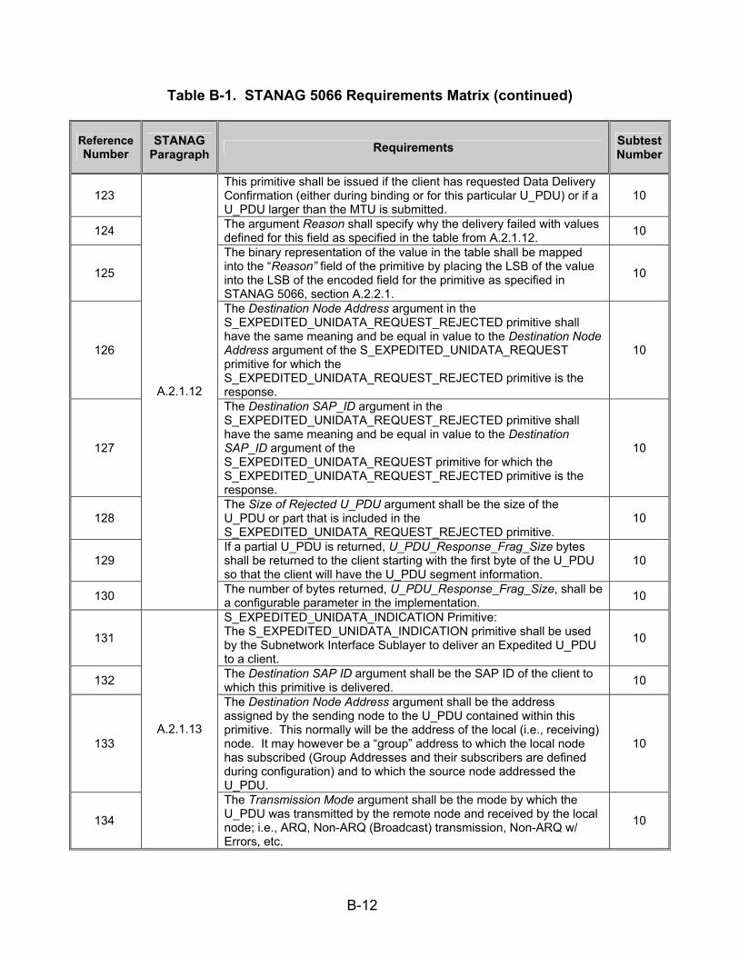
B-12
Table B-1. STANAG 5066 Requirements Matrix (continued)
Reference Number
STANAG Paragraph Requirements Subtest
Number
123 This primitive shall be issued if the client has requested Data Delivery Confirmation (either during binding or for this particular U_PDU) or if a U_PDU larger than the MTU is submitted.
10
124 The argument Reason shall specify why the delivery failed with values defined for this field as specified in the table from A.2.1.12. 10
125
The binary representation of the value in the table shall be mapped into the “Reason” field of the primitive by placing the LSB of the value into the LSB of the encoded field for the primitive as specified in STANAG 5066, section A.2.2.1.
10
126
The Destination Node Address argument in the S_EXPEDITED_UNIDATA_REQUEST_REJECTED primitive shall have the same meaning and be equal in value to the Destination Node Address argument of the S_EXPEDITED_UNIDATA_REQUEST primitive for which the S_EXPEDITED_UNIDATA_REQUEST_REJECTED primitive is the response.
10
127
The Destination SAP_ID argument in the S_EXPEDITED_UNIDATA_REQUEST_REJECTED primitive shall have the same meaning and be equal in value to the Destination SAP_ID argument of the S_EXPEDITED_UNIDATA_REQUEST primitive for which the S_EXPEDITED_UNIDATA_REQUEST_REJECTED primitive is the response.
10
128 The Size of Rejected U_PDU argument shall be the size of the U_PDU or part that is included in the S_EXPEDITED_UNIDATA_REQUEST_REJECTED primitive.
10
129 If a partial U_PDU is returned, U_PDU_Response_Frag_Size bytes shall be returned to the client starting with the first byte of the U_PDU so that the client will have the U_PDU segment information.
10
130
A.2.1.12
The number of bytes returned, U_PDU_Response_Frag_Size, shall be a configurable parameter in the implementation. 10
131
S_EXPEDITED_UNIDATA_INDICATION Primitive: The S_EXPEDITED_UNIDATA_INDICATION primitive shall be used by the Subnetwork Interface Sublayer to deliver an Expedited U_PDU to a client.
10
132 The Destination SAP ID argument shall be the SAP ID of the client to which this primitive is delivered. 10
133
The Destination Node Address argument shall be the address assigned by the sending node to the U_PDU contained within this primitive. This normally will be the address of the local (i.e., receiving) node. It may however be a “group” address to which the local node has subscribed (Group Addresses and their subscribers are defined during configuration) and to which the source node addressed the U_PDU.
10
134
A.2.1.13
The Transmission Mode argument shall be the mode by which the U_PDU was transmitted by the remote node and received by the local node; i.e., ARQ, Non-ARQ (Broadcast) transmission, Non-ARQ w/ Errors, etc.
10

B-13
Table B-1. STANAG 5066 Requirements Matrix (continued)
Reference Number
STANAG Paragraph Requirements Subtest
Number
135 The Source SAP ID shall be the SAP ID of the client that sent the U_PDU. 10
136 The Source Node Address shall represent the node address of the client that sent the U_PDU. 10
137 The Size of U_PDU argument shall be the size of the U_PDU that was sent and delivered in this S_UNIDATA_INDICATION S_Primitive. 10
138 The following four arguments shall be present in the S_UNIDATA_INDICATION S_Primitive, if and only if the Transmission Mode for the U_PDU is equal to Non-ARQ w/ Errors:
10
139
1. The Number of Blocks in Error argument shall equal the number of data blocks in the U_PDU that were received in error by the lower layers of the subnetwork and that were passed on to the Subnetwork Interface Sublayer.
10
140 This argument shall specify the number of ordered pairs in the Array of Block-Error Pointers argument. 10
141
2. The Array of Block-Error Pointers argument shall consist of an array of ordered pairs, the first element in the pair equal to the location within the U_PDU of the data block with errors, and the second element equal to the size of the data block with errors.
10
142 3. The Number of Non-Received Blocks argument shall equal the number of data blocks missing from the U_PDU because they were not received.
10
143 This argument shall specify the number of ordered pairs in the Array of Non-Received-Block Pointers argument. 10
144
The Array of Non-Received-Block Pointers shall consist of an array of ordered pairs, the first element in the pair equal to the location of the missing data block in the U_PDU and the second element equal to the size of the missing data block.
10
145
A.2.1.13
4. The final argument, U_PDU, shall contain the actual received user data for delivery to the client. 10
146
Interface Flow-control Primitives--S_DATA_FLOW_ON and S_DATA_FLOW_OFF: The S_DATA_FLOW_ON and S_DATA_FLOW_OFF primitives shall be issued by the Subnetwork Interface Sublayer to control the transfer of U_PDUs submitted by a client.
18
147 On receipt of an S_FLOW_DATA_OFF primitive, the client shall cease transferring U_PDUs over the interface. 18
148 Data transfer over the interface of U_PDUs by the client shall be enabled following receipt of an S_FLOW_DATA_ON primitive. 18
149 A client shall not control the flow of data from the subnetwork by any mechanism, explicit or implicit. 18
150
A.2.1.14
All clients shall be ready to accept at all times data received by the HF Node to which it is bound; clients not following this rule may be disconnected by the node.
18

B-14
Table B-1. STANAG 5066 Requirements Matrix (continued)
Reference Number
STANAG Paragraph Requirements Subtest
Number
151 S_MANAGEMENT_MSG_REQUEST Primitive: The S_MANAGEMENT_MSG_REQUEST primitive shall be issued by a client to submit a “Management” message to the subnetwork.
18
152
The complex argument MSG may be implementation dependent and is not specified in this version of STANAG 5066. At present, a minimally compliant HF subnetwork implementation shall be capable of receiving this primitive, without further requirement to process its contents.
18
153
A.2.1.15
The subnetwork shall accept this primitive only from clients which have bound with a rank of 15. 18
154 S_MANAGEMENT_MSG_INDICATION Primitive: The S_MANAGEMENT_MSG_INDICATION primitive shall be issued by the subnetwork to send a “Management” message to a client.
18
155
A.2.1.16 The complex argument MSG may be implementation dependent and is not specified in this version of STANAG 5066. At present, a minimally compliant client shall be capable of receiving this primitive, without further requirement to process its contents.
18
156
S_KEEP_ALIVE Primitive: The S_KEEP_ALIVE primitive can be issued as required (e.g., during periods of inactivity) by the clients and/or the subnetwork interface to sense whether the physical connection between the client and the subnetwork is alive or broken. When the S_KEEP_ALIVE primitive is received, the recipient (i.e., client or subnetwork interface) shall respond with the same primitive within 10 seconds.
10
157 If a reply is not sent within 10 seconds, no reply shall be sent. 10
158
A.2.1.17
A client or subnetwork interface shall not send the S_KEEP_ALIVE primitive more frequently than once every 120 seconds to the same destination.
10
159
S_HARD_LINK_ESTABLISH Primitive: The S_HARD_LINK_ESTABLISH primitive shall be used by a client to request the establishment of a Hard Link between the local node to which it is connected and a specified remote node.
10
160 The argument Link Priority shall define the priority of the link. 10 161 It shall take a value in the range 0 to 3. 10
162 An S_HARD_LINK_ESTABLISH primitive with a higher Link Priority value shall take precedence over a Hard Link established with a lower Link Priority value submitted by a client of the same Rank.
10
163
Hard Link requests made by clients with higher Rank shall take precedence over requests of lower-Ranked clients regardless of the value of the Link Priority argument, in accordance with the requirements of STANAG 5066, section A.3.2.2.1.
10
164 The Link Type argument shall be used by the requesting client to fully or partially reserve the bandwidth of the link. 10
165
A.2.1.18
It shall take a value in the range 0 to 2, as specified in STANAG 5066, section A.1.1.2, specifying this primitive as one for a Type 0 Hard Link, Type 1 Hard Link, or Type 2 Hard Link, respectively.
10

B-15
Table B-1. STANAG 5066 Requirements Matrix (continued)
Reference Number
STANAG Paragraph Requirements Subtest
Number
166 The Remote Node Address argument shall specify the physical HF Node Address to which the connection must be established and maintained.
10
167 The Remote SAP ID argument shall identify the single client connected to the remote node, to and from which traffic is allowed. 10
168
A.2.1.18 This argument shall be valid only if the Link Type argument has a value of 2 (i.e., only if the Hard Link request reserves the full bandwidth of the link for the local and remote client, as specified in STANAG 5066, section A.1.1.2.3).
10
169 S_HARD_LINK_TERMINATE Primitive: The S_HARD_LINK_TERMINATE primitive shall be issued by a client to terminate an existing Hard Link.
10
170 The subnetwork shall terminate an existing Hard Link on receipt of this primitive only if the primitive was generated by the client which requested the establishment of the Hard Link.
10
171
The single argument Remote Node Address shall specify the Address of the node at the remote end of the Hard Link. [Note: The Remote Node Address argument is redundant in that Hard Links can exist with only one remote node at any time. It may however be used by the subnetwork implementation receiving the primitive to check its validity.]
10
172
A.2.1.19
Upon receiving this primitive, the subnetwork shall take all necessary steps to terminate the Hard Link, as specified in STANAG 5066, section A.3.2.2.32.
10
173
S_HARD_LINK_ESTABLISHED Primitive: The S_HARD_LINK_ESTABLISHED primitive shall be issued by the Subnetwork Interface Sublayer as a positive response to a client’s S_HARD_LINK_ESTABLISH Primitive.
10
174
This primitive shall be issued only after all the negotiations and protocols between the appropriate peer sublayers of the local and remote nodes have been completed and the remote node has accepted the establishment of the Hard Link, in accordance with the protocol specified in STANAG 5066, section A.3.2.2.2.
10
175
The first argument, Remote Node Status, shall inform the requesting client of any special status of the remote node, e.g. Remote Node in EMCON, etc. Valid arguments for Remote Node Status are given in the table from STANAG 5066, section A.2.1.20.
10
176 Successful establishment of a Hard Link shall always imply a status of “OK” for the remote node. 10
177 The value OK shall be indicated by any positive non-zero value in the Remote Node Status field. 10
178
A.2.1.20
The argument Link Priority shall have the same meaning and be equal in value to the argument of the S_HARD_LINK_ESTABLISH primitive for which this S_HARD_LINK_ESTABLISHED primitive is the response.
10
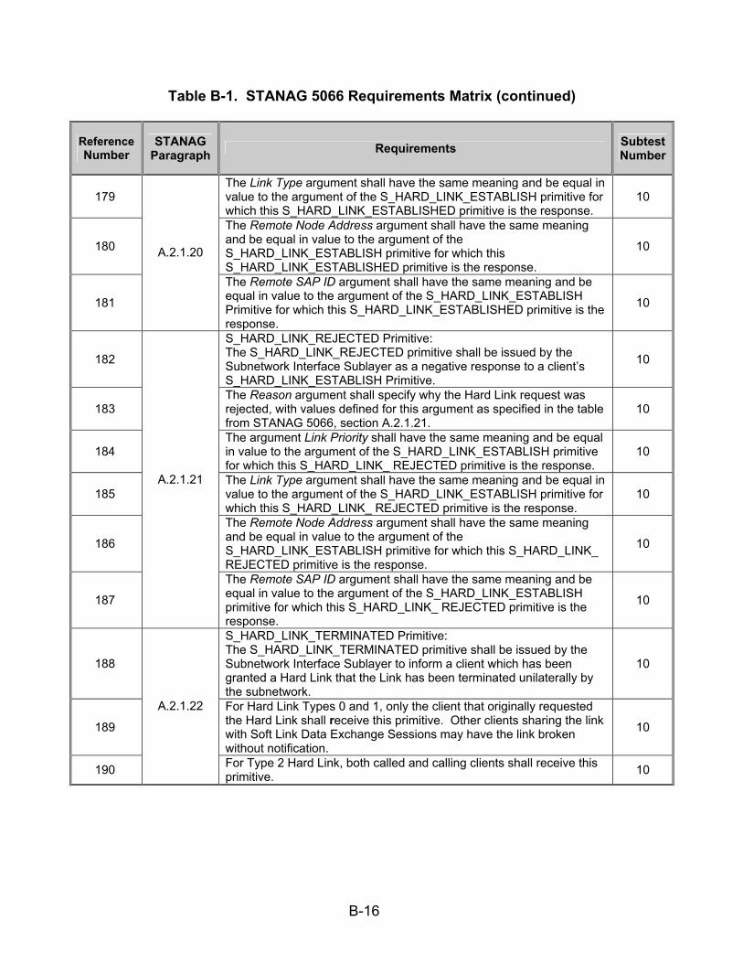
B-16
Table B-1. STANAG 5066 Requirements Matrix (continued)
Reference Number
STANAG Paragraph Requirements Subtest
Number
179 The Link Type argument shall have the same meaning and be equal in value to the argument of the S_HARD_LINK_ESTABLISH primitive for which this S_HARD_LINK_ESTABLISHED primitive is the response.
10
180
The Remote Node Address argument shall have the same meaning and be equal in value to the argument of the S_HARD_LINK_ESTABLISH primitive for which this S_HARD_LINK_ESTABLISHED primitive is the response.
10
181
A.2.1.20
The Remote SAP ID argument shall have the same meaning and be equal in value to the argument of the S_HARD_LINK_ESTABLISH Primitive for which this S_HARD_LINK_ESTABLISHED primitive is the response.
10
182
S_HARD_LINK_REJECTED Primitive: The S_HARD_LINK_REJECTED primitive shall be issued by the Subnetwork Interface Sublayer as a negative response to a client’s S_HARD_LINK_ESTABLISH Primitive.
10
183 The Reason argument shall specify why the Hard Link request was rejected, with values defined for this argument as specified in the table from STANAG 5066, section A.2.1.21.
10
184 The argument Link Priority shall have the same meaning and be equal in value to the argument of the S_HARD_LINK_ESTABLISH primitive for which this S_HARD_LINK_ REJECTED primitive is the response.
10
185 The Link Type argument shall have the same meaning and be equal in value to the argument of the S_HARD_LINK_ESTABLISH primitive for which this S_HARD_LINK_ REJECTED primitive is the response.
10
186
The Remote Node Address argument shall have the same meaning and be equal in value to the argument of the S_HARD_LINK_ESTABLISH primitive for which this S_HARD_LINK_ REJECTED primitive is the response.
10
187
A.2.1.21
The Remote SAP ID argument shall have the same meaning and be equal in value to the argument of the S_HARD_LINK_ESTABLISH primitive for which this S_HARD_LINK_ REJECTED primitive is the response.
10
188
S_HARD_LINK_TERMINATED Primitive: The S_HARD_LINK_TERMINATED primitive shall be issued by the Subnetwork Interface Sublayer to inform a client which has been granted a Hard Link that the Link has been terminated unilaterally by the subnetwork.
10
189
For Hard Link Types 0 and 1, only the client that originally requested the Hard Link shall receive this primitive. Other clients sharing the link with Soft Link Data Exchange Sessions may have the link broken without notification.
10
190
A.2.1.22
For Type 2 Hard Link, both called and calling clients shall receive this primitive. 10
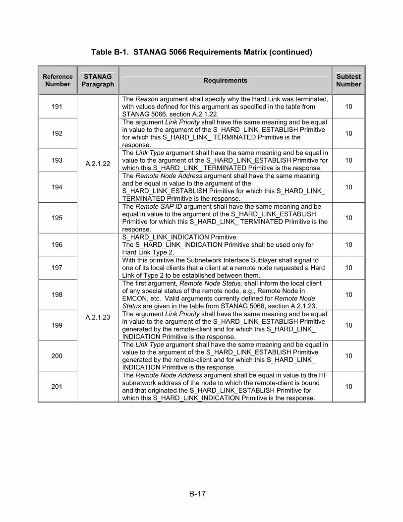
B-17
Table B-1. STANAG 5066 Requirements Matrix (continued)
Reference Number
STANAG Paragraph Requirements Subtest
Number
191 The Reason argument shall specify why the Hard Link was terminated, with values defined for this argument as specified in the table from STANAG 5066, section A.2.1.22.
10
192
The argument Link Priority shall have the same meaning and be equal in value to the argument of the S_HARD_LINK_ESTABLISH Primitive for which this S_HARD_LINK_ TERMINATED Primitive is the response.
10
193 The Link Type argument shall have the same meaning and be equal in value to the argument of the S_HARD_LINK_ESTABLISH Primitive for which this S_HARD_LINK_ TERMINATED Primitive is the response.
10
194
The Remote Node Address argument shall have the same meaning and be equal in value to the argument of the S_HARD_LINK_ESTABLISH Primitive for which this S_HARD_LINK_ TERMINATED Primitive is the response.
10
195
A.2.1.22
The Remote SAP ID argument shall have the same meaning and be equal in value to the argument of the S_HARD_LINK_ESTABLISH Primitive for which this S_HARD_LINK_ TERMINATED Primitive is the response.
10
196 S_HARD_LINK_INDICATION Primitive: The S_HARD_LINK_INDICATION Primitive shall be used only for Hard Link Type 2.
10
197 With this primitive the Subnetwork Interface Sublayer shall signal to one of its local clients that a client at a remote node requested a Hard Link of Type 2 to be established between them.
10
198
The first argument, Remote Node Status, shall inform the local client of any special status of the remote node, e.g., Remote Node in EMCON, etc. Valid arguments currently defined for Remote Node Status are given in the table from STANAG 5066, section A.2.1.23.
10
199
The argument Link Priority shall have the same meaning and be equal in value to the argument of the S_HARD_LINK_ESTABLISH Primitive generated by the remote-client and for which this S_HARD_LINK_ INDICATION Primitive is the response.
10
200
The Link Type argument shall have the same meaning and be equal in value to the argument of the S_HARD_LINK_ESTABLISH Primitive generated by the remote-client and for which this S_HARD_LINK_ INDICATION Primitive is the response.
10
201
A.2.1.23
The Remote Node Address argument shall be equal in value to the HF subnetwork address of the node to which the remote-client is bound and that originated the S_HARD_LINK_ESTABLISH Primitive for which this S_HARD_LINK_INDICATION Primitive is the response.
10

B-18
Table B-1. STANAG 5066 Requirements Matrix (continued)
Reference Number
STANAG Paragraph Requirements Subtest
Number
202 A.2.1.23
The Remote SAP ID argument shall be equal in value to the SAP_ID that is bound to the remote client that originated the S_HARD_LINK_ESTABLISH Primitive for which this S_HARD_LINK_ INDICATION Primitive is the result.
10
203
S_HARD_LINK_ACCEPT Primitive: The S_HARD_LINK_ACCEPT Primitive shall be issued by a client as a positive response to an S_HARD_LINK_INDICATION Primitive. With this primitive the client tells the Subnetwork Interface Sublayer that it accepts the Hard Link of Type 2 requested by a client at a remote node.
10
204
The argument Link Priority shall have the same meaning and be equal in value to the Link Priority argument of the S_HARD_LINK_ INDICATION Primitive received by the client from the subnetwork for which this S_HARD_LINK_ ACCEPT Primitive is the response.
10
205
The Link Type argument shall have the same meaning and be equal in value to the Link Type argument of the S_HARD_LINK_ INDICATION Primitive received by the client from the subnetwork for which this S_HARD_LINK_ ACCEPT Primitive is the response.
10
206
The Remote Node Address argument shall have the same meaning and be equal in value to the Remote Node Address argument of the S_HARD_LINK_ INDICATION Primitive received by the client from the subnetwork for which this S_HARD_LINK_ACCEPT Primitive is the response.
10
207
A.2.1.24
The Remote SAP ID argument shall have the same meaning and be equal in value to the Remote SAP ID argument of the S_HARD_LINK_ INDICATION Primitive received by the client from the subnetwork for which this S_HARD_LINK_ ACCEPT Primitive is the response.
10
208
S_HARD_LINK_REJECT Primitive: The S_HARD_LINK_REJECT Primitive shall be issued by a client as a negative response to an S_HARD_LINK_INDICATION Primitive. With this primitive the client tells the Subnetwork Interface Sublayer that it rejects the Hard Link of Type 2 requested by a client at a remote node.
10
209 The Reason argument shall specify why the Hard Link is rejected. Possible values of this argument are Mode-Not-Supported (for Link Type 2), I-Have-Higher-Priority-Data, etc.
10
210
The argument Link Priority shall have the same meaning and be equal in value to the Link Priority argument of the S_HARD_LINK_ INDICATION Primitive received by the client from the subnetwork for which this S_HARD_LINK_REJECT Primitive is the response.
10
211
A.2.1.25
The Link Type argument shall have the same meaning and be equal in value to the Link Type argument of the S_HARD_LINK_ INDICATION Primitive received by the client from the subnetwork for which this S_HARD_LINK_REJECT Primitive is the response.
10

B-19
Table B-1. STANAG 5066 Requirements Matrix (continued)
Reference Number
STANAG Paragraph Requirements Subtest
Number
212
The Remote Node Address argument shall have the same meaning and be equal in value to the Remote Node Address argument of the S_HARD_LINK_ INDICATION Primitive received by the client from the subnetwork for which this S_HARD_LINK_REJECT Primitive is the response.
10
213
A.2.1.25 The Remote SAP ID argument shall have the same meaning and be equal in value to the Remote SAP ID argument of the S_HARD_LINK_ INDICATION Primitive received by the client from the subnetwork for which this S_HARD_LINK_ ACCEPT Primitive is the response.
10
214 A.2.1.26
S_SUBNET_AVAILABILITY Primitive: The S_SUBNET_AVAILABILITY primitive may be sent asynchronously to all or selected clients connected to the Subnetwork Interface Sublayer to inform them of changes in the status of the node to which they are attached. At present, a minimally compliant client implementation shall be capable of receiving this primitive, without further requirement to process its contents.
18
215 A.2.2 The encoding of the S_Primitives for communication across the Subnetwork Interface Sublayer shall be in accordance with text and figures in the subsections below.
10
216 Unless noted otherwise, the bit representation for argument values in an S_Primitive shall be encoded into their corresponding fields in accordance with CCITT V.42, paragraph 8.1.2.3, which states:
10
217 That when a field is contained within a single octet (i.e., eight bit group), the lowest bit number of the field shall represent the lowest-order (i.e., least-significant-bit) value.
10
218
When a field spans more than one octet, the order of bit values within each octet shall progressively decrease as the octet number increases. The lowest bit number associated with the field represents the lowest-order value.
10
219
A.2.2.1
The 4-byte address field in the S_Primitives shall carry the 3.5-byte address defined in C.3.1.4. The lowest-order bit of the address shall be placed in the lowest-order bit position of the field (generally bit 0 of the highest byte number of the field), consistent with the mapping specified in annex C for D_PDUs.
10
220
As shown in figure A-1(a), all primitives shall be encoded as the following sequence of elements: - a two-byte S_Primitive preamble field, whose value is specified by the 16-bit Maury-Styles sequence below: - a one-byte version-number field. - a two-byte Size_of_Primitive field. - a multi-byte field that contains the encoded S_Primitive.
10
221
A.2.2.2
The S_Primitive preamble field shall be encoded as the 16-bit Maury-Styles sequence shown below, with the least significant bit (LSB) transmitted first over the interface: (MSB) 1 1 1 0 1 0 1 1 1 0 0 1 0 0 0 0 (LSB)
10

B-20
Table B-1. STANAG 5066 Requirements Matrix (continued)
Reference Number
STANAG Paragraph Requirements Subtest
Number
222 With the multi-byte S_Primitive field represented in hex form as 0xEB90, the least significant bits of the sequence shall be encoded in the first byte (i.e., byte number 0) of the preamble field.
10
223 And the most significant bits of the sequence shall be encoded in the second byte (i.e., byte number 1) of the preamble field as in figure A-1(b).
10
224 Following the Maury-Styles sequence, The next 8-bit (1-byte) field shall encode the STANAG 5066 version number. 10
225 For this version of STANAG 5066, the version number shall be all zeros, i.e., the hex value 0x00, as in figure A-1(c). 10
226 The next 16-bit (two-byte) field shall encode the size in bytes of the S_Primitive-dependent field to follow, exclusive of the Maury-Styles sequence, version field, and this size field.
10
227 LSB of the of the size value shall be mapped into the low-order bit of the low-order byte of the field, as in figure A-1(c). 10
228 Unless specified otherwise, the order of bit transmission for each byte in the encoded S_Primitive shall be as described in CCITT V.42 paragraph 8.1.2.2.
10
229 Which specifies the least significant bit (LSB, bit 0 in the figures below) of byte 0 shall be transmitted first. 10
230 The sixth byte (i.e., byte number 5) of the sequence shall be the first byte of the encoded primitive. 10
231 And shall be equal to the S_Primitive type number, with values encoded in accordance with the respective section that follows for each S_Primitive.
10
232 The remaining bytes, if any, in the S_Primitive shall be transmitted sequentially, also beginning with the LSB of each byte, in accordance with the respective section that follows for each S_Primitive.
10
233
A.2.2.2
In the subsections that follow, any bits in a S_Primitive that are specified as NOT USED shall be encoded with the value ‘0’ unless specified otherwise for the specific S_Primitive being defined.
10
234 The S_BIND_REQUEST primitive shall be encoded as a 4-byte field as in figure A-2. 10
235 The S_BIND_REQUEST SERVICE-TYPE field shall be encoded as five subfields as in figure A-3. 10
236 The Service Type argument shall specify the default type of service requested by the client. 10
237 This type of service shall apply to any U_PDU submitted by the client until the client unbinds itself from the node, unless overridden by the DELIVERY MODE argument of the U_PDU.
10
238 A client shall change the default service type only by unbinding and binding again with a new S_BIND_REQUEST. 10
239
A.2.2.3
Transmission Mode for the Service --- ARQ or Non-ARQ Transmission Mode shall be specified, with one of the Non-ARQ submodes if Non-ARQ was requested.
10

B-21
Table B-1. STANAG 5066 Requirements Matrix (continued)
Reference Number
STANAG Paragraph Requirements Subtest
Number
240
A value of ‘0’ for this attribute shall be invalid for the Service Type argument when binding. Non-ARQ transmission can have submodes such as: Error-free-Only delivery to destination client, delivery to destination client even with some errors.
10
241
Data Delivery Confirmation for the Service --- The client shall request one of the Data Delivery Confirmation modes for the service. There are three types of data delivery confirmation:
• None • Node-to-Node Delivery Confirmation • Client-to-Client Delivery Confirmation
10
242 Explicit delivery confirmation shall be requested only in combination with ARQ delivery. 10
243
Order of delivery of any U_PDU to the receiving client --- A client shall request that its U_PDUs are delivered to the destination client “in-order” (as they are submitted) or in the order they are received by the destination node.
10
244
Extended Field --- Denotes if additional fields in the Service Type argument are following; at present this capability of the Service Type is undefined and the value of the Extended Field Attribute shall be set to “0.”
10
245 Minimum Number of Retransmissions --- This argument shall be valid only if the Transmission Mode is a Non-ARQ type. 10
246
A.2.2.3
If the Transmission Mode is a Non-ARQ type, then the subnetwork shall retransmit each U_PDU the number of times specified by this argument. This argument may be “0,” in which case the U_PDU is sent only once.
10
247 A.2.2.4 The S_UNBIND_REQUEST Primitive shall be encoded as a 1-byte field as in figure A-4. 10
248 A.2.2.5 The S_BIND_ACCEPTED Primitive shall be encoded as a 4-byte field as in figure A-5. 10
249 A.2.2.6 The S_BIND_REJECTED Primitive shall be encoded as a 2-byte field as in figure A-6. 10
250 A.2.2.7 The S_UNBIND_INDICATION Primitive shall be encoded as a 2-byte field as in figure A-7. 10
251 The S_HARD_LINK_ESTABLISH Primitive shall be encoded as a 6-byte field as in figure A-8. 10
252 The Remote Node Address field shall be encoded as specified in STANAG 5066, section A.2.2.28.1. 10
253
A.2.2.8
The LINK TYPE field shall be encoded as specified in STANAG 5066, section A.2.2.28.4. 10
254 The S_HARD_LINK_TERMINATE Primitive shall be encoded as a 5-byte field as in figure A-9. 10
255 The Remote Node Address field shall be encoded as specified in STANAG 5066, section A.2.2.28.1. 10
256
A.2.2.9
The LINK TYPE field shall be encoded as specified in STANAG 5066, section A.2.2.28.4. 10

B-22
Table B-1. STANAG 5066 Requirements Matrix (continued)
Reference Number
STANAG Paragraph Requirements Subtest
Number
257 The S_HARD_LINK_ESTABLISHED Primitive shall be encoded as a 7-byte field as in figure A-10. 10
258 The Remote Node Address field shall be encoded as specified in STANAG 5066, section A.2.2.28.1. 10
259
A.2.2.10
The LINK TYPE field shall be encoded as specified in STANAG 5066, section A.2.2.28.4. 10
260 The S_HARD_LINK_REJECTED Primitive shall be encoded as a 7-byte field as in figure A-11. 10
261 The Remote Node Address field shall be encoded as specified in STANAG 5066, section A.2.2.28.1. 10
262
A.2.2.11
The LINK TYPE field shall be encoded as specified in STANAG 5066, section A.2.2.28.4. 10
263 The S_HARD_LINK_TERMINATED Primitive shall be encoded as a 7-byte field as in figure A-12. 10
264 The Remote Node Address field shall be encoded as specified in STANAG 5066, section A.2.2.28.1. 10
265
A.2.2.12
The LINK TYPE field shall be encoded as specified in STANAG 5066, section A.2.2.28.4. 10
266 The S_HARD_LINK_INDICATION Primitive shall be encoded as a 7-byte field as in figure A-13. 10
267 The Remote Node Address field shall be encoded as specified in STANAG 5066, section A.2.2.28.1. 10
268
A.2.2.13
The LINK TYPE field shall be encoded as specified in STANAG 5066, section A.2.2.28.4. 10
269 The S_HARD_LINK_ACCEPT Primitive shall be encoded as a 6-byte field as in figure A-14. 10
270 The Remote Node Address field shall be encoded as specified in STANAG 5066, section A.2.2.28.1. 10
271
A.2.2.14
The LINK TYPE field shall be encoded as specified in STANAG 5066, section A.2.2.28.4. 10
272 The S_HARD_LINK_REJECT Primitive shall be encoded as a 7-byte field as in figure A-15. 10
273 The Remote Node Address field shall be encoded as specified in STANAG 5066, section A.2.2.28.1. 10
274
A.2.2.15
The LINK TYPE field shall be encoded as specified in STANAG 5066, section A.2.2.28.4. 10
275 A.2.2.16 The S_SUBNET_AVAILABILITY Primitive shall be encoded as a 3-byte field as in figure A-16. 18
276 A.2.2.17 The S_DATA_FLOW_ON and S_DATA_FLOW_OFF Primitives shall be encoded as 1-byte fields as in figure A-17. 18
277 A.2.2.18 The S_KEEP_ALIVE Primitive shall be encoded as a 1-byte field as in figure A-18. 10
278 A.2.2.19
The S_MANAGEMENT_MESSAGE_REQUEST and S_MANAGEMENT_MESSAGE_INDICATION Primitives shall be encoded as implementation-dependent variable-length fields as in figure A-19.
18
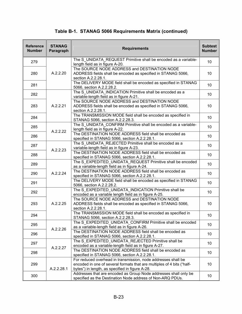
B-23
Table B-1. STANAG 5066 Requirements Matrix (continued)
Reference Number
STANAG Paragraph Requirements Subtest
Number
279 The S_UNIDATA_REQUEST Primitive shall be encoded as a variable-length field as in figure A-20. 10
280 The SOURCE NODE ADDRESS and DESTINATION NODE ADDRESS fields shall be encoded as specified in STANAG 5066, section A.2.2.28.1.
10
281
A.2.2.20
The DELIVERY MODE field shall be encoded as specified in STANAG 5066, section A.2.2.28.2. 10
282 The S_UNIDATA_INDICATION Primitive shall be encoded as a variable-length field as in figure A-21. 10
283 The SOURCE NODE ADDRESS and DESTINATION NODE ADDRESS fields shall be encoded as specified in STANAG 5066, section A.2.2.28.1.
10
284
A.2.2.21
The TRANSMISSION MODE field shall be encoded as specified in STANAG 5066, section A.2.2.28.3. 10
285 The S_UNIDATA_CONFIRM Primitive shall be encoded as a variable-length field as in figure A-22. 10
286 A.2.2.22 The DESTINATION NODE ADDRESS field shall be encoded as
specified in STANAG 5066, section A.2.2.28.1. 10
287 The S_UNIDATA_REJECTED Primitive shall be encoded as a variable-length field as in figure A-23. 10
288 A.2.2.23 The DESTINATION NODE ADDRESS field shall be encoded as
specified in STANAG 5066, section A.2.2.28.1. 10
289 The S_EXPEDITED_UNIDATA_REQUEST Primitive shall be encoded as a variable-length field as in figure A-24. 10
290 The DESTINATION NODE ADDRESS field shall be encoded as specified in STANAG 5066, section A.2.2.28.1. 10
291
A.2.2.24
The DELIVERY MODE field shall be encoded as specified in STANAG 5066, section A.2.2.28.2. 10
292 The S_EXPEDITED_UNIDATA_INDICATION Primitive shall be encoded as a variable length field as in figure A-25. 10
293 The SOURCE NODE ADDRESS and DESTINATION NODE ADDRESS fields shall be encoded as specified in STANAG 5066, section A.2.2.28.1.
10
294
A.2.2.25
The TRANSMISSION MODE field shall be encoded as specified in STANAG 5066, section A.2.2.28.3. 10
295 The S_EXPEDITED_UNIDATA_CONFIRM Primitive shall be encoded as a variable-length field as in figure A-26. 10
296 A.2.2.26 The DESTINATION NODE ADDRESS field shall be encoded as
specified in STANAG 5066, section A.2.2.28.1. 10
297 The S_EXPEDITED_UNIDATA_REJECTED Primitive shall be encoded as a variable-length field as in figure A-27. 10
298 A.2.2.27 The DESTINATION NODE ADDRESS field shall be encoded as
specified in STANAG 5066, section A.2.2.28.1. 10
299 For reduced overhead in transmission, node addresses shall be encoded in one of several formats that are multiples of 4 bits (“half-bytes”) in length, as specified in figure A-28.
10
300
A.2.2.28.1 Addresses that are encoded as Group Node addresses shall only be specified as the Destination Node address of Non-ARQ PDUs. 10

B-24
Table B-1. STANAG 5066 Requirements Matrix (continued)
Reference Number
STANAG Paragraph Requirements Subtest
Number
301 Destination SAP IDs and destination node addresses of ARQ PDUs and source SAP IDs and source node addresses of all PDUs shall be individual SAP IDs and individual node addresses respectively.
10
302
A.2.2.28.1 Remote node addresses and remote SAP IDs of all “S_HARD_LINK” Primitives shall be individual SAP IDs and individual node addresses respectively.
10
303 The DELIVERY MODE is a complex argument consisting of a number of attributes, as specified here. The DELIVERY MODE argument shall be encoded as shown in figure A-29.
10
304
The value of the DELIVERY MODE argument can be “DEFAULT,” as encoded by the Transmission Mode attribute. With a value of “DEFAULT,” the delivery mode for this U_PDU shall be the delivery mode specified in the Service Type argument of the S_BIND_REQUEST.
10
305 A non-DEFAULT value shall override the default settings of the Service Type for this U_PDU. 10
306
The attributes of this argument are similar to those described in the Service Type argument of the S_BIND_REQUEST: Transmission Mode of this U_PDU --- ARQ or Non-ARQ Transmission can be requested. A value of ‘0’ for this attribute shall equal the value “DEFAULT” for the Delivery Mode.
10
307 If the DELIVERY MODE is “DEFAULT,” all other attributes encoded in the argument shall be ignored. 10
308
Extended Field --- Denotes if additional fields in the DELIVERY MODE argument are following; at present this capability of the DELIVERY MODE is undefined and the value of the Extended Field Attribute shall be set to “0.”
10
309 Minimum Number of Retransmissions --- This argument shall be valid, if and only if the Transmission Mode is a Non-ARQ type or sub-type. 10
310
A.2.2.28.2
If the Transmission Mode is a Non-ARQ type or subtype, then the subnetwork shall retransmit each U_PDU the number of times specified by this argument. This argument may be “0,” in which case the U_PDU is sent only once.
10
311 A.2.2.28.3
The TRANSMISSION-MODE argument in the S_UNIDATA_INDICATION and S_EXPEDITED_UNIDATA_INDICATION Primitives shall be encoded as shown in figure A-30.
10
312 A.2.2.28.4
A client uses the Link-Type argument to reserve partially or fully the capacity of the Hard Link. This argument can have three values: A value of (0) shall indicate that the physical link to the specified node address is a Type 0 Hard Link. The Type 0 Hard Link must be maintained, but all clients connected to the two nodes can make use of the link capacity according to normal procedures, i.e., there is no bandwidth reservation.
10

B-25
Table B-1. STANAG 5066 Requirements Matrix (continued)
Reference Number
STANAG Paragraph Requirements Subtest
Number
313 A.2.2.28.4
A value of 1 shall indicate that the physical link to the specified node address is a Type 1 Hard Link. The Type 1 Hard Link must be maintained and traffic is only allowed between the requesting client and any of the clients on the remote node, i.e., there is partial bandwidth reservation. A value of 2 indicates that the physical link to the specified node address must be maintained and traffic is only allowed between the requesting Client and the specific Client on the remote node specified by the remote SAP ID argument, i.e., full bandwidth reservation.
10
314 Peer Subnetwork Interface Sublayers, generally in different nodes, shall communicate with each other by the exchange of Subnetwork Interface Sublayer Protocol Data Units (S_PDUs).
9
315
For the Subnetwork configurations currently defined in STANAG 5066, Peer-to-Peer Communication shall be required for the: 1. Establishment and termination of Hard Link Data Exchange Sessions. 2. Exchange of Client Data.
9
316
A.3
Explicit peer-to-peer communication shall not be required for the establishment or termination of Soft Link or Broadcast Data Exchange Sessions.
9
317 A.3.1 Subnetwork Interface Sublayer Protocol Data Units (S_PDUS) and Encoding Requirements. The first encoded field shall be common to all S_PDUs.
9
318 A.3.1 It is called “TYPE” and shall encode the type value of the S_PDU as follows: 9
319 A.3.1 The meaning and encoding of the remaining fields, if any, in an S_PDU shall be as specified in the subsection below corresponding to the S_PDU Type.
9
320 The DATA S_PDU shall be transmitted by the Subnetwork Interface Sublayer in order to send client data to a remote peer sublayer. 9
321 The DATA S_PDU shall be encoded as specified in figure A-32 and in the paragraphs below. 9
322 This S_PDU shall consist of two parts: 9
323 The first part shall be the S_PCI (Subnetwork Interface Sublayer Protocol Control Information) and represents the overhead added by the sublayer;
9
324 The second part shall be the actual client data (U_PDU). 9 325 The first field of 4 bits of the S_PCI part shall be “TYPE.” 9 326 Its value shall be equal to (0) and identifies the S_PDU as being of
type DATA. 9
327 The second field of 4 bits shall be “PRIORITY” and represents the priority of the client’s U_PDU. 9
328
A.3.1.1
The “PRIORITY” field shall be equal in value to the corresponding argument of the S_UNIDATA_REQUEST Primitive submitted by the client.
10
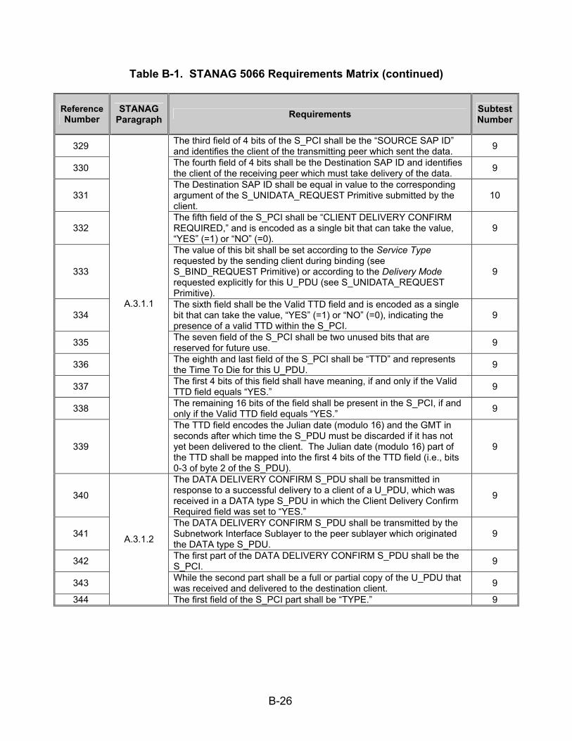
B-26
Table B-1. STANAG 5066 Requirements Matrix (continued)
Reference Number
STANAG Paragraph Requirements Subtest
Number
329 The third field of 4 bits of the S_PCI shall be the “SOURCE SAP ID” and identifies the client of the transmitting peer which sent the data. 9
330 The fourth field of 4 bits shall be the Destination SAP ID and identifies the client of the receiving peer which must take delivery of the data. 9
331 The Destination SAP ID shall be equal in value to the corresponding argument of the S_UNIDATA_REQUEST Primitive submitted by the client.
10
332 The fifth field of the S_PCI shall be “CLIENT DELIVERY CONFIRM REQUIRED,” and is encoded as a single bit that can take the value, “YES” (=1) or “NO” (=0).
9
333
The value of this bit shall be set according to the Service Type requested by the sending client during binding (see S_BIND_REQUEST Primitive) or according to the Delivery Mode requested explicitly for this U_PDU (see S_UNIDATA_REQUEST Primitive).
9
334 The sixth field shall be the Valid TTD field and is encoded as a single bit that can take the value, “YES” (=1) or “NO” (=0), indicating the presence of a valid TTD within the S_PCI.
9
335 The seven field of the S_PCI shall be two unused bits that are reserved for future use. 9
336 The eighth and last field of the S_PCI shall be “TTD” and represents the Time To Die for this U_PDU. 9
337 The first 4 bits of this field shall have meaning, if and only if the Valid TTD field equals “YES.” 9
338 The remaining 16 bits of the field shall be present in the S_PCI, if and only if the Valid TTD field equals “YES.” 9
339
A.3.1.1
The TTD field encodes the Julian date (modulo 16) and the GMT in seconds after which time the S_PDU must be discarded if it has not yet been delivered to the client. The Julian date (modulo 16) part of the TTD shall be mapped into the first 4 bits of the TTD field (i.e., bits 0-3 of byte 2 of the S_PDU).
9
340
The DATA DELIVERY CONFIRM S_PDU shall be transmitted in response to a successful delivery to a client of a U_PDU, which was received in a DATA type S_PDU in which the Client Delivery Confirm Required field was set to “YES.”
9
341 The DATA DELIVERY CONFIRM S_PDU shall be transmitted by the Subnetwork Interface Sublayer to the peer sublayer which originated the DATA type S_PDU.
9
342 The first part of the DATA DELIVERY CONFIRM S_PDU shall be the S_PCI. 9
343 While the second part shall be a full or partial copy of the U_PDU that was received and delivered to the destination client. 9
344
A.3.1.2
The first field of the S_PCI part shall be “TYPE.” 9

B-27
Table B-1. STANAG 5066 Requirements Matrix (continued)
Reference Number
STANAG Paragraph Requirements Subtest
Number
345 Its value shall equal 1 to identify the S_PDU as being of type DATA DELIVERY CONFIRM. 9
346
The remaining fields and their values for the S_PCI part of the DATA DELIVERY CONFIRM S_PDU shall be equal in value to the corresponding fields of the DATA S_PDU for which this DATA DELIVERY CONFIRM S_PDU is a response.
9
347
A.3.1.2 The peer sublayer that receives the DATA DELIVERY CONFIRM shall inform the delivered to its destination by issuing an S_UNIDATA_REQUEST_CONFIRM or an S_EXPEDITED_UNIDATA_REQUEST_CONFIRM in accordance with the data exchange protocol of STANAG 5066, section A.3.2.4.
10
348
The DATA DELIVERY FAIL S_PDU shall be transmitted in response to a failed delivery to a client of a U_PDU that was received in a DATA type S_PDU with the Client Delivery Confirm Required field set to “YES.”
9
349 The first part of this S_PDU shall be the S_PCI. 9 350 The second part shall be a full or partial copy of the U_PDU that was
received but not delivered to the destination client. 9 351 The first field of the S_PCI shall be “TYPE.” 9 352 Its value shall be equal to 2 and identifies the S_PDU as being of type
DATA DELIVERY FAIL. 9
353 The second field shall be “REASON” and explains why the U_PDU failed to be delivered. It can take a value in the range 0 to 15; valid reasons are defined in the table from STANAG 5066, section A.3.1.3.
9
354 The SOURCE SAP_ID and DESTINATION SAP_ID fields of the S_PCI shall be equal in value to the corresponding fields of the DATA S_PDU for which the DATA DELIVERY FAIL S_PDU is a response.
9
355
A.3.1.3
The peer sublayer that receives the DATA DELIVERY FAIL S_PDU, shall inform the client which originated the U_PDU that its data was not delivered to the destination by issuing an S_UNIDATA_REQUEST_REJECTED Primitive or an S_EXPEDITED_UNIDATA_REQUEST_REJECTED Primitive, in accordance with the data exchange protocol of STANAG 5066, section A.3.2.4.
10
356 The HARD LINK ESTABLISHMENT REQUEST S_PDU shall be transmitted by a peer in response to a client’s request for a Hard Link. 9
357 The first field of the S_PDU shall be “TYPE.” 9
358 It shall be equal to 3 and identifies the S_PDU as being of type HARD LINK ESTABLISHMENT REQUEST. 9
359 The “LINK TYPE” and “LINK PRIORITY” fields shall be equal in value to the corresponding arguments of the S_HARD_LINK_ESTABLISH Primitive submitted by the client to request the link.
10
360
A.3.1.4
The “REQUESTING SAP ID” field shall be the SAP ID of the client that requested the Hard Link Establishment. 9
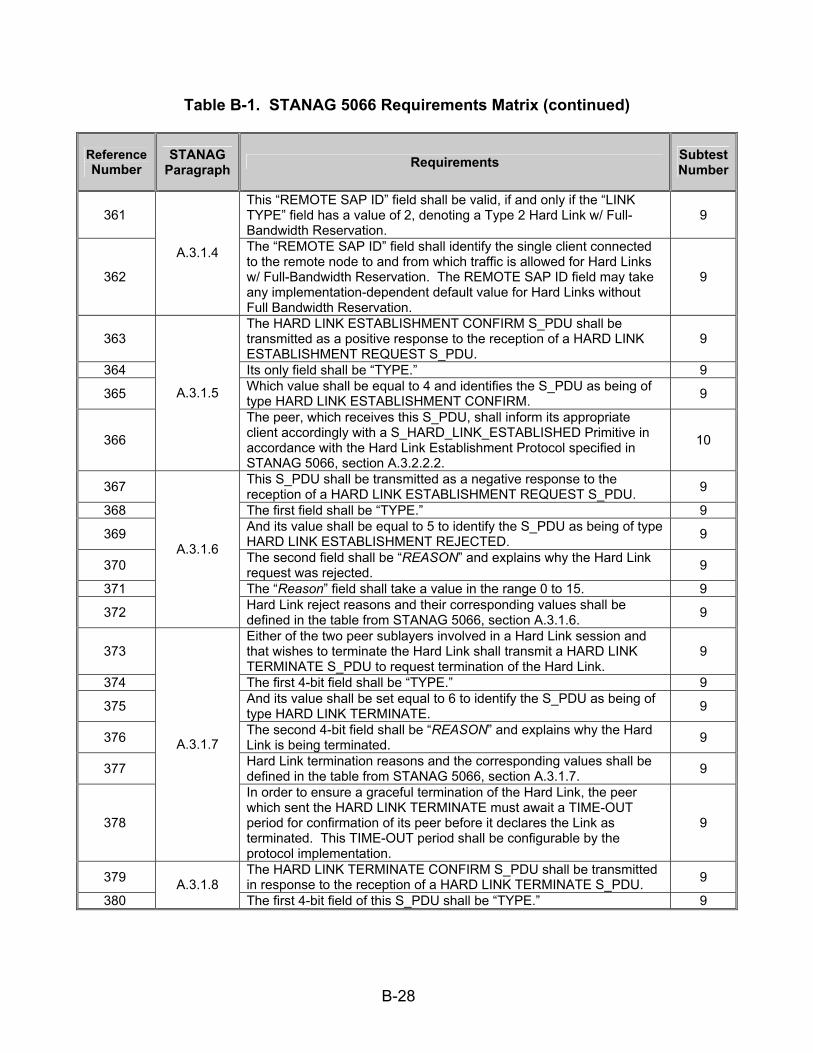
B-28
Table B-1. STANAG 5066 Requirements Matrix (continued)
Reference Number
STANAG Paragraph Requirements Subtest
Number
361 This “REMOTE SAP ID” field shall be valid, if and only if the “LINK TYPE” field has a value of 2, denoting a Type 2 Hard Link w/ Full-Bandwidth Reservation.
9
362
A.3.1.4 The “REMOTE SAP ID” field shall identify the single client connected to the remote node to and from which traffic is allowed for Hard Links w/ Full-Bandwidth Reservation. The REMOTE SAP ID field may take any implementation-dependent default value for Hard Links without Full Bandwidth Reservation.
9
363 The HARD LINK ESTABLISHMENT CONFIRM S_PDU shall be transmitted as a positive response to the reception of a HARD LINK ESTABLISHMENT REQUEST S_PDU.
9
364 Its only field shall be “TYPE.” 9 365 Which value shall be equal to 4 and identifies the S_PDU as being of
type HARD LINK ESTABLISHMENT CONFIRM. 9
366
A.3.1.5
The peer, which receives this S_PDU, shall inform its appropriate client accordingly with a S_HARD_LINK_ESTABLISHED Primitive in accordance with the Hard Link Establishment Protocol specified in STANAG 5066, section A.3.2.2.2.
10
367 This S_PDU shall be transmitted as a negative response to the reception of a HARD LINK ESTABLISHMENT REQUEST S_PDU. 9
368 The first field shall be “TYPE.” 9 369 And its value shall be equal to 5 to identify the S_PDU as being of type
HARD LINK ESTABLISHMENT REJECTED. 9
370 The second field shall be “REASON” and explains why the Hard Link request was rejected. 9
371 The “Reason” field shall take a value in the range 0 to 15. 9 372
A.3.1.6
Hard Link reject reasons and their corresponding values shall be defined in the table from STANAG 5066, section A.3.1.6. 9
373 Either of the two peer sublayers involved in a Hard Link session and that wishes to terminate the Hard Link shall transmit a HARD LINK TERMINATE S_PDU to request termination of the Hard Link.
9
374 The first 4-bit field shall be “TYPE.” 9 375 And its value shall be set equal to 6 to identify the S_PDU as being of
type HARD LINK TERMINATE. 9
376 The second 4-bit field shall be “REASON” and explains why the Hard Link is being terminated. 9
377 Hard Link termination reasons and the corresponding values shall be defined in the table from STANAG 5066, section A.3.1.7. 9
378
A.3.1.7
In order to ensure a graceful termination of the Hard Link, the peer which sent the HARD LINK TERMINATE must await a TIME-OUT period for confirmation of its peer before it declares the Link as terminated. This TIME-OUT period shall be configurable by the protocol implementation.
9
379 The HARD LINK TERMINATE CONFIRM S_PDU shall be transmitted in response to the reception of a HARD LINK TERMINATE S_PDU. 9
380 A.3.1.8
The first 4-bit field of this S_PDU shall be “TYPE.” 9

B-29
Table B-1. STANAG 5066 Requirements Matrix (continued)
Reference Number
STANAG Paragraph Requirements Subtest
Number
381 A value of 7 shall identify that the S_PDU is of type HARD LINK TERMINATE CONFIRM. 9
382 A.3.1.8 The second 4-bit field of this S_PDU shall be not used in this
implementation of the protocol. The values of these bits may be implementation dependent.
9
383
In contrast with the establishment of a Hard Link session, the establishment of Soft Link Data Exchange Sessions shall not require explicit peer-to-peer handshaking within the Subnetwork Interface Sublayer.
9
384
The calling peer shall implicitly establish a Soft Link Data Exchange Session by requesting its Channel Access Sublayer to make a physical link to the required remote node, using the procedure for making physical links specified in annex B.
9
385
A.3.2.1.1
After the physical link is made, both peer Subnetwork Interface Sublayers shall declare that the Soft Link Data Exchange Session has been established between the respective source and destination nodes.
10
386 No peer-to-peer communication by the Subnetwork Interface Sublayer shall be required to terminate a Soft Link Data Exchange Session. 9
387
A Soft Link Data Exchange Session shall be terminated by either of the two peers by a request to its respective Channel Access Sublayer to break the Physical Link in accordance with the procedure specified in annex B.
9
388
Since a called peer can terminate a Soft Link Data Exchange Session if it has higher priority data destined for a different node, called peers shall wait a configurable minimum time before unilaterally terminating sessions, to prevent unstable operation of the protocol.
9
389 After the Subnetwork Interface Sublayer has been notified that the physical link has been broken, the Subnetwork Interface Sublayer shall declare the Soft Link Exchange Session as terminated.
10
390
This STANAG assumes a simple model for the management of Hard Links based on maintenance of, at most, a single Hard Link between nodes, while still allowing Type 0 and Type 1 Hard Links between the nodes to be shared by other clients using Soft Link Data Exchange. This management model satisfies the following requirements:
15
391 A node’s sublayer shall maintain at most one Hard Link at any time; 15
392 A sublayer shall accept a Hard Link request when no Hard Link currently exists. 15
393
The comparative precedence of new requests and any existing Hard Link shall be evaluated in accordance with STANAG 5066, section A.3.2.2.1 to determine if the new request can be accepted or rejected by the sublayer.
15
394
A.3.2.1.2
Requests of higher precedence shall be accepted and will result in the termination of an existing Hard Link. 15
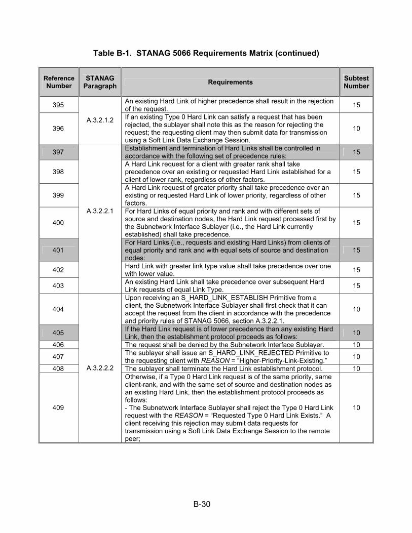
B-30
Table B-1. STANAG 5066 Requirements Matrix (continued)
Reference Number
STANAG Paragraph Requirements Subtest
Number
395 An existing Hard Link of higher precedence shall result in the rejection of the request. 15
396 A.3.2.1.2 If an existing Type 0 Hard Link can satisfy a request that has been
rejected, the sublayer shall note this as the reason for rejecting the request; the requesting client may then submit data for transmission using a Soft Link Data Exchange Session.
10
397 Establishment and termination of Hard Links shall be controlled in accordance with the following set of precedence rules: 15
398 A Hard Link request for a client with greater rank shall take precedence over an existing or requested Hard Link established for a client of lower rank, regardless of other factors.
15
399 A Hard Link request of greater priority shall take precedence over an existing or requested Hard Link of lower priority, regardless of other factors.
15
400
For Hard Links of equal priority and rank and with different sets of source and destination nodes, the Hard Link request processed first by the Subnetwork Interface Sublayer (i.e., the Hard Link currently established) shall take precedence.
15
401 For Hard Links (i.e., requests and existing Hard Links) from clients of equal priority and rank and with equal sets of source and destination nodes:
15
402 Hard Link with greater link type value shall take precedence over one with lower value. 15
403
A.3.2.2.1
An existing Hard Link shall take precedence over subsequent Hard Link requests of equal Link Type. 15
404
Upon receiving an S_HARD_LINK_ESTABLISH Primitive from a client, the Subnetwork Interface Sublayer shall first check that it can accept the request from the client in accordance with the precedence and priority rules of STANAG 5066, section A.3.2.2.1.
10
405 If the Hard Link request is of lower precedence than any existing Hard Link, then the establishment protocol proceeds as follows: 10
406 The request shall be denied by the Subnetwork Interface Sublayer. 10 407 The sublayer shall issue an S_HARD_LINK_REJECTED Primitive to
the requesting client with REASON = “Higher-Priority-Link-Existing.” 10 408 The sublayer shall terminate the Hard Link establishment protocol. 10
409
A.3.2.2.2 Otherwise, if a Type 0 Hard Link request is of the same priority, same client-rank, and with the same set of source and destination nodes as an existing Hard Link, then the establishment protocol proceeds as follows: - The Subnetwork Interface Sublayer shall reject the Type 0 Hard Link request with the REASON = “Requested Type 0 Hard Link Exists.” A client receiving this rejection may submit data requests for transmission using a Soft Link Data Exchange Session to the remote peer;
10
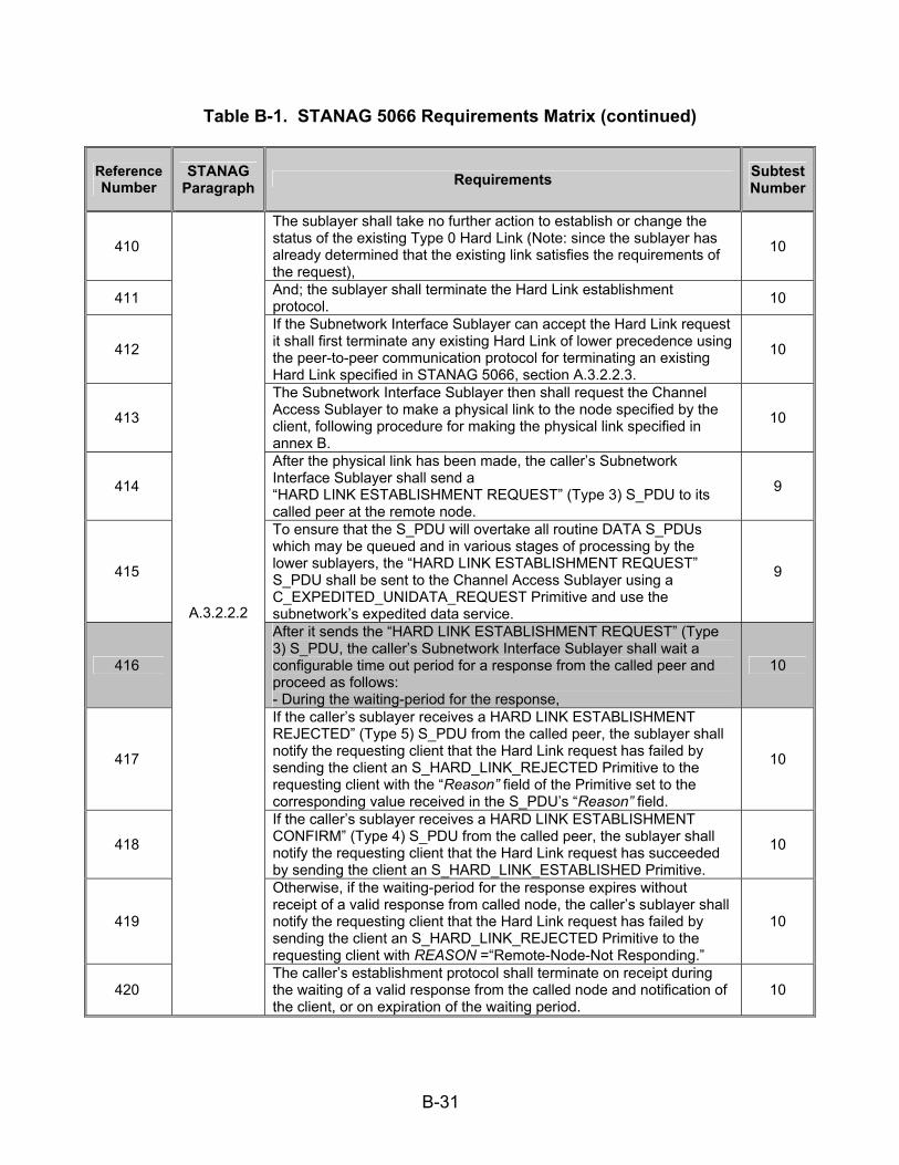
B-31
Table B-1. STANAG 5066 Requirements Matrix (continued)
Reference Number
STANAG Paragraph Requirements Subtest
Number
410
The sublayer shall take no further action to establish or change the status of the existing Type 0 Hard Link (Note: since the sublayer has already determined that the existing link satisfies the requirements of the request),
10
411 And; the sublayer shall terminate the Hard Link establishment protocol. 10
412
If the Subnetwork Interface Sublayer can accept the Hard Link request it shall first terminate any existing Hard Link of lower precedence using the peer-to-peer communication protocol for terminating an existing Hard Link specified in STANAG 5066, section A.3.2.2.3.
10
413
The Subnetwork Interface Sublayer then shall request the Channel Access Sublayer to make a physical link to the node specified by the client, following procedure for making the physical link specified in annex B.
10
414
After the physical link has been made, the caller’s Subnetwork Interface Sublayer shall send a “HARD LINK ESTABLISHMENT REQUEST” (Type 3) S_PDU to its called peer at the remote node.
9
415
To ensure that the S_PDU will overtake all routine DATA S_PDUs which may be queued and in various stages of processing by the lower sublayers, the “HARD LINK ESTABLISHMENT REQUEST” S_PDU shall be sent to the Channel Access Sublayer using a C_EXPEDITED_UNIDATA_REQUEST Primitive and use the subnetwork’s expedited data service.
9
416
After it sends the “HARD LINK ESTABLISHMENT REQUEST” (Type 3) S_PDU, the caller’s Subnetwork Interface Sublayer shall wait a configurable time out period for a response from the called peer and proceed as follows: - During the waiting-period for the response,
10
417
If the caller’s sublayer receives a HARD LINK ESTABLISHMENT REJECTED” (Type 5) S_PDU from the called peer, the sublayer shall notify the requesting client that the Hard Link request has failed by sending the client an S_HARD_LINK_REJECTED Primitive to the requesting client with the “Reason” field of the Primitive set to the corresponding value received in the S_PDU’s “Reason” field.
10
418
If the caller’s sublayer receives a HARD LINK ESTABLISHMENT CONFIRM” (Type 4) S_PDU from the called peer, the sublayer shall notify the requesting client that the Hard Link request has succeeded by sending the client an S_HARD_LINK_ESTABLISHED Primitive.
10
419
Otherwise, if the waiting-period for the response expires without receipt of a valid response from called node, the caller’s sublayer shall notify the requesting client that the Hard Link request has failed by sending the client an S_HARD_LINK_REJECTED Primitive to the requesting client with REASON =“Remote-Node-Not Responding.”
10
420
A.3.2.2.2
The caller’s establishment protocol shall terminate on receipt during the waiting of a valid response from the called node and notification of the client, or on expiration of the waiting period.
10

B-32
Table B-1. STANAG 5066 Requirements Matrix (continued)
Reference Number
STANAG Paragraph Requirements Subtest
Number
421
For the called Subnetwork Access Sublayer, the Hard Link establishment protocol shall be initiated on receipt of a “HARD LINK ESTABLISHMENT REQUEST” (Type 3) S_PDU and proceeds as follows:
10
422
If no client is bound to the called SAP ID and the caller’s request is for a Type 2 Hard Link, then the called sublayer shall reject the request, send a “HARD LINK ESTABLISHMENT REJECTED” (Type 5) S_PDU with REASON = “Destination SAP ID not bound” to the caller and terminate the establishment protocol.
9
423
Otherwise, the called sublayer shall evaluate the precedence of the caller’s request in accordance with the precedence and priority rules of STANAG 5066, section A.3.2.2.1, using as the client rank either a configurable default rank for the called SAP_ID for Type 0 and Type 1 Hard Link requests or the actual rank of the bound client with the called SAP_ID for Type 2 Hard Link requests.
10
424
If the caller’s request cannot be accepted by the called peer, a “HARD LINK ESTABLISHMENT REJECTED” (Type 5) S_PDU shall be sent to the calling peer, with the “Reason” field set as follows: - REASON = “Remote-Node-Busy” if the reason for rejection was the existence of an existing Hard Link of equal rank and priority or - REASON= “Higher-Priority Link Existing” if the reason for rejection was the exisence of a Hard Link with higher priority or rank.
9
425
If the caller’s Hard Link request can be accepted and the request is not a Type 2 Hard Link request, the called sublayer shall send a “HARD LINK ESTABLISHMENT CONFIRM” (Type 4) S_PDU to the caller sublayer and terminate the protocol;
9
426
Otherwise, the request is for a Type 2 Hard Link and the called sublayer shall send an S_HARD_LINK_INDICATION Primitive to the requested client and wait for a configurable maximum time out period for a response:
10
427
If the called sublayer receives an S_HARD_LINK_ACCEPT Primitive from the requested client prior to the expiration of the time-out, then the called sublayer shall send a “HARD LINK ESTABLISHMENT CONFIRM” (Type 4) S_PDU to the calling sublayer and terminate the protocol;
10
428 Otherwise, the called sublayer shall send a “HARD LINK ESTABLISHMENT REJECTED” (Type 5) S_PDU to the caller sublayer and terminate the protocol.
9
429
A.3.2.2.2
Whenever sent, either the TYPE 4 (HARD LINK ESTABLISHMENT CONFIRM) S_PDU or the TYPE 5 (HARD LINK ESTABLISHMENT REJECTED) S_PDU shall be sent to the calling sublayer using the Expedited Data Service provided by lower sublayers in the profile.
9
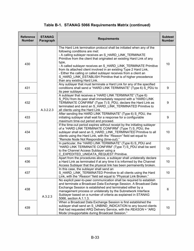
B-33
Table B-1. STANAG 5066 Requirements Matrix (continued)
Reference Number
STANAG Paragraph Requirements Subtest
Number
430
The Hard Link termination protocol shall be initiated when any of the following conditions are met: - A calling sublayer receives an S_HARD_LINK_TERMINATE Primitive from the client that originated an existing Hard Link of any type, - A called sublayer receives an S_HARD_LINK_TERMINATE Primitive from its attached client involved in an existing Type 2 Hard Link, - Either the calling or called sublayer receives from a client an S_HARD_LINK_ESTABLISH Primitive that is of higher precedence than any existing Hard Link.
10
431 Any sublayer that must terminate a Hard Link for any of the specified conditions shall send a “HARD LINK TERMINATE” (Type 6) S_PDU to its peer sublayer.
9
432
A sublayer that receives a “HARD LINK TERMINATE” (Type 6) S_PDU from its peer shall immediately respond with a “HARD LINK TERMINATE CONFIRM” (Type 7) S_PDU, declare the Hard Link as terminated and send an S_HARD_LINK_TERMINATED Primitive to all clients using the Hard Link.
9
433 After sending the HARD LINK TERMINATE” (Type 6) S_PDU, the initiating sublayer shall wait for a response for a configurable maximum time-out period and proceed.
9
434
If the time-out period expires without receipt by the initiating sublayer of a “HARD LINK TERMINATE CONFIRM” (Type 7) S_PDU, the sublayer shall send an S_HARD_LINK_TERMINATED Primitive to all clients using the Hard Link, with the “Reason” field set equal to “Remote Node Not Responding (time-out).”
10
435
In particular, the “HARD LINK TERMINATE” (Type 6) S_PDU and “HARD LINK TERMINATE CONFIRM” (Type 7) S_PDU shall be sent to the Channel Access Sublayer using a C_EXPEDITED_UNIDATA_REQUEST Primitive.
10
436 Apart from the procedures above, a sublayer shall unilaterally declare a Hard Link as terminated if at any time it is informed by the Channel Access Sublayer that the physical link has been permanently broken.
10
437
A.3.2.2.3
In this case, the sublayer shall send an S_HARD_LINK_TERMINATED Primitive to all clients using the Hard Link, with the “Reason” field set equal to “Physical Link Broken.”
10
438
No explicit peer-to-peer communication shall be required to establish and terminate a Broadcast Data Exchange Session. A Broadcast Data Exchange Session is established and terminated either by a management process or unilaterally by the Subnetwork Interface Sublayer based on a number of criteria as explained in STANAG 5066, section A.1.1.3.
6
439
A.3.2.3
When a Broadcast Data Exchange Session is first established the sublayer shall send an S_UNBIND_INDICATION to any bound clients that had requested ARQ Delivery Service, with the REASON = “ARQ Mode Unsupportable during Broadcast Session.”
10

B-34
Table B-1. STANAG 5066 Requirements Matrix (continued)
Reference Number
STANAG Paragraph Requirements Subtest
Number
440
After a Data Exchange Session of any type has been established, sublayers with client data to exchange shall exchange DATA (Type 0) S_PDUs using the protocol specified below and in accordance with the service characteristics of th respective session.
9
441
The sublayer shall discard any U_PDU submitted by a client where the U_PDU is greater in size than the Maximum Transmission Unit (MTU) size assigned to the client by the S_BIND_ACCEPTED Primitive issued during the client-bind protocol.
10
442
If a U_PDU is discarded because it exceeded the MTU size limit and if the DELIVERY CONFIRMATION field for the U_PDU specifies CLIENT DELIVERY CONFIRM or NODE DELIVERY CONFIRM, the sublayer shall notify the client that submitted the U_PDU as follows:
10
443 If the U_PDU was submitted by an S_UNIDATA_REQUEST Primitive the sublayer shall send an S_UNIDATA_REQUEST_REJECT Primitive to the client;
10
444
Otherwise, if the U_PDU was submitted by an S_EXPEDITED_UNIDATA_REQUEST Primitive, the sublayer shall send an S_EXPEDITED_UNIDATA_REQUEST_REJECT Primitive to the client;
10
445 For either form of the reject primitive, the “Reason” field shall be equal to “U_PDU Larger than MTU.” 10
446
For U_PDUs that have been accepted for transmission, the sending sublayer retrieves client U_PDUs and their associated implementation-dependent service attributes (such as the S_Primitive that encapsulated the U_PDU) from its queues (according to Priority and other implementation-dependent criteria) and proceeds as follows:
9
447 The sending sublayer shall encode the retrieved U_PDU into a DATA (Type 0) S_PDU, transferring any service attributes associated with U_PDU to the S_PDU as required;
9
448 The sending sublayer shall encode the resulting DATA (Type 0) S_PDU in accordance with the C_Primitive interface requirements of the Channel Access Sublayer as specified in annex B, i.e.:
18
449
If the encoded U_PDU was submitted by a client using a S_UNIDATA_REQUEST Primitive, then the sublayer shall encode the S_PDU as a C_UNIDATA_REQUEST Primitive of the priority corresponding to that initially specified by the client in the S_Primitive, otherwise;
18
450
If the encoded U_PDU was submitted by a client using an S_EXPEDITED_UNIDATA_REQUEST Primitive, then the sublayer shall encode the S_PDU as a C_EXPEDITED_UNIDATA_REQUEST Primitive;
18
451 The sending sublayer then shall pass the resulting C_Primitive to the Channel Access Sublayer for further processing to send the DATA (Type 0) S_PDU to its remote peer.
18
452
A.3.2.4
If the service attributes for the U_PDU require NODE DELIVERY CONFIRMATION, the sublayer shall wait for a configurable time for a response as follows:
10
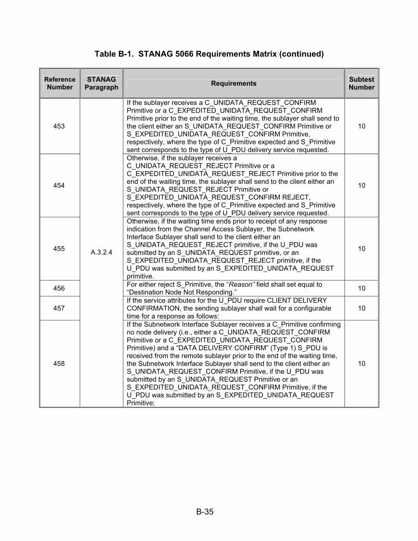
B-35
Table B-1. STANAG 5066 Requirements Matrix (continued)
Reference Number
STANAG Paragraph Requirements Subtest
Number
453
If the sublayer receives a C_UNIDATA_REQUEST_CONFIRM Primitive or a C_EXPEDITED_UNIDATA_REQUEST_CONFIRM Primitive prior to the end of the waiting time, the sublayer shall send to the client either an S_UNIDATA_REQUEST_CONFIRM Primitive or S_EXPEDITED_UNIDATA_REQUEST_CONFIRM Primitive, respectively, where the type of C_Primitive expected and S_Primitive sent corresponds to the type of U_PDU delivery service requested.
10
454
Otherwise, if the sublayer receives a C_UNIDATA_REQUEST_REJECT Primitive or a C_EXPEDITED_UNIDATA_REQUEST_REJECT Primitive prior to the end of the waiting time, the sublayer shall send to the client either an S_UNIDATA_REQUEST_REJECT Primitive or S_EXPEDITED_UNIDATA_REQUEST_CONFIRM REJECT, respectively, where the type of C_Primitive expected and S_Primitive sent corresponds to the type of U_PDU delivery service requested.
10
455
Otherwise, if the waiting time ends prior to receipt of any response indication from the Channel Access Sublayer, the Subnetwork Interface Sublayer shall send to the client either an S_UNIDATA_REQUEST_REJECT primitive, if the U_PDU was submitted by an S_UNIDATA_REQUEST primitive, or an S_EXPEDITED_UNIDATA_REQUEST_REJECT primitive, if the U_PDU was submitted by an S_EXPEDITED_UNIDATA_REQUEST primitive.
10
456 For either reject S_Primitive, the “Reason” field shall set equal to “Destination Node Not Responding.” 10
457 If the service attributes for the U_PDU require CLIENT DELIVERY CONFIRMATION, the sending sublayer shall wait for a configurable time for a response as follows:
10
458
A.3.2.4
If the Subnetwork Interface Sublayer receives a C_Primitive confirming no node delivery (i.e., either a C_UNIDATA_REQUEST_CONFIRM Primitive or a C_EXPEDITED_UNIDATA_REQUEST_CONFIRM Primitive) and a “DATA DELIVERY CONFIRM” (Type 1) S_PDU is received from the remote sublayer prior to the end of the waiting time, the Subnetwork Interface Sublayer shall send to the client either an S_UNIDATA_REQUEST_CONFIRM Primitive, if the U_PDU was submitted by an S_UNIDATA_REQUEST Primitive or an S_EXPEDITED_UNIDATA_REQUEST_CONFIRM Primitive, if the U_PDU was submitted by an S_EXPEDITED_UNIDATA_REQUEST Primitive;
10
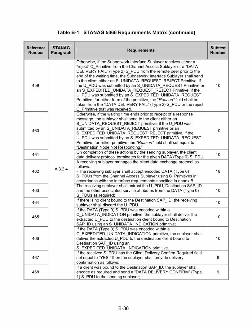
B-36
Table B-1. STANAG 5066 Requirements Matrix (continued)
Reference Number
STANAG Paragraph Requirements Subtest
Number
459
Otherwise, if the Subnetwork Interface Sublayer receives either a “reject” C_Primitive from the Channel Access Sublayer or a “DATA DELIVERY FAIL” (Type 2) S_PDU from the remote peer prior to the end of the waiting time, the Subnetwork Interface Sublayer shall send to the client either an S_UNIDATA_REQUEST_REJECT Primitive, if the U_PDU was submitted by an S_UNIDATA_REQUEST Primitive or an S_EXPEDITED_UNIDATA_REQUEST_REJECT Primitive, if the U_PDU was submitted by an S_EXPEDITED_UNIDATA_REQUEST Primitive; for either form of the primitive, the “Reason” field shall be taken from the “DATA DELIVERY FAIL” (Type 2) S_PDU or the reject C_Primitive that was received.
10
460
Otherwise, if the waiting time ends prior to receipt of a response message, the sublayer shall send to the client either an S_UNIDATA_REQUEST_REJECT primitive, if the U_PDU was submitted by an S_UNIDATA_REQUEST primitive or an S_EXPEDITED_UNIDATA_REQUEST_REJECT primitive, if the U_PDU was submitted by an S_EXPEDITED_UNIDATA_REQUEST Primitive; for either primitive, the “Reason” field shall set equal to “Destination Node Not Responding.”
10
461 On completion of these actions by the sending sublayer, the client data delivery protocol terminates for the given DATA (Type 0) S_PDU. 10
462
A receiving sublayer manages the client data exchange protocol as follows: - The receiving sublayer shall accept encoded DATA (Type 0) S_PDUs from the Channel Access Sublayer using C_Primitives in accordance with the interface requirements specified in annex B.
18
463 The receiving sublayer shall extract the U_PDU, Destination SAP_ID and the other associated service attributes from the DATA (Type 0) S_PDUs as required;
10
464 If there is no client bound to the Destination SAP_ID, the receiving sublayer shall discard the U_PDU. 10
465
If the DATA (Type 0) S_PDU was encoded within a C_UNIDATA_INDICATION primitive, the sublayer shall deliver the extracted U_PDU to the destination client bound to Destination SAP_ID using an S_UNIDATA_INDICATION primitive;
10
466
If the DATA (Type 0) S_PDU was encoded within a C_EXPEDITED_UNIDATA_INDICATION primitive, the sublayer shall deliver the extracted U_PDU to the destination client bound to Destination SAP_ID using an S_EXPEDITED_UNIDATA_INDICATION primitive.
10
467 If the received S_PDU has the Client Delivery Confirm Required field set equal to “YES,” then the sublayer shall provide delivery confirmation as follows:
9
468
A.3.2.4
If a client was bound to the Destination SAP_ID, the sublayer shall encode as required and send a “DATA DELIVERY CONFIRM” (Type 1) S_PDU to the sending sublayer;
9
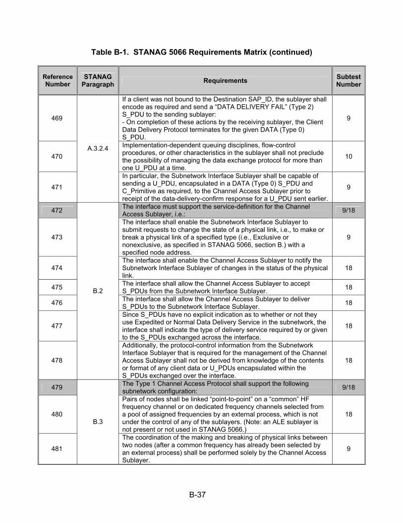
B-37
Table B-1. STANAG 5066 Requirements Matrix (continued)
Reference Number
STANAG Paragraph Requirements Subtest
Number
469
If a client was not bound to the Destination SAP_ID, the sublayer shall encode as required and send a “DATA DELIVERY FAIL” (Type 2) S_PDU to the sending sublayer: - On completion of these actions by the receiving sublayer, the Client Data Delivery Protocol terminates for the given DATA (Type 0) S_PDU.
9
470
Implementation-dependent queuing disciplines, flow-control procedures, or other characteristics in the sublayer shall not preclude the possibility of managing the data exchange protocol for more than one U_PDU at a time.
10
471
A.3.2.4
In particular, the Subnetwork Interface Sublayer shall be capable of sending a U_PDU, encapsulated in a DATA (Type 0) S_PDU and C_Primitive as required, to the Channel Access Sublayer prior to receipt of the data-delivery-confirm response for a U_PDU sent earlier.
9
472 The interface must support the service-definition for the Channel Access Sublayer, i.e.: 9/18
473
The interface shall enable the Subnetwork Interface Sublayer to submit requests to change the state of a physical link, i.e., to make or break a physical link of a specified type (i.e., Exclusive or nonexclusive, as specified in STANAG 5066, section B.) with a specified node address.
9
474 The interface shall enable the Channel Access Sublayer to notify the Subnetwork Interface Sublayer of changes in the status of the physical link.
18
475 The interface shall allow the Channel Access Sublayer to accept S_PDUs from the Subnetwork Interface Sublayer. 18
476 The interface shall allow the Channel Access Sublayer to deliver S_PDUs to the Subnetwork Interface Sublayer. 18
477
Since S_PDUs have no explicit indication as to whether or not they use Expedited or Normal Data Delivery Service in the subnetwork, the interface shall indicate the type of delivery service required by or given to the S_PDUs exchanged across the interface.
18
478
B.2
Additionally, the protocol-control information from the Subnetwork Interface Sublayer that is required for the management of the Channel Access Sublayer shall not be derived from knowledge of the contents or format of any client data or U_PDUs encapsulated within the S_PDUs exchanged over the interface.
18
479 The Type 1 Channel Access Protocol shall support the following subnetwork configuration: 9/18
480
Pairs of nodes shall be linked “point-to-point” on a “common” HF frequency channel or on dedicated frequency channels selected from a pool of assigned frequencies by an external process, which is not under the control of any of the sublayers. (Note: an ALE sublayer is not present or not used in STANAG 5066.)
18
481
B.3
The coordination of the making and breaking of physical links between two nodes (after a common frequency has already been selected by an external process) shall be performed solely by the Channel Access Sublayer.
9

B-38
Table B-1. STANAG 5066 Requirements Matrix (continued)
Reference Number
STANAG Paragraph Requirements Subtest
Number
482 Physical links shall be of either of two types, Exclusive or Nonexclusive, with properties and service features defined as follows: 15
483 A node shall use an Exclusive Physical Link to support control and data exchange for Hard Link Data Exchange Sessions as requested by the Subnetwork Interface Sublayer;
15
484 A node shall use a Nonexclusive Physical Link to support control and data exchange for Soft Link Data Exchange Sessions as requested by the Subnetwork Interface Sublayer.
15
485 A node shall establish, at most, two Exclusive Physical Links with other nodes. 15
486 There shall be no explicit peer-to-peer communication required to switch from use of one Nonexclusive Physical Link to another. 18
487
B.3
The Type 1 Channel Access Sublayer shall communicate with peer sublayers in other nodes using the protocols defined here in order to: 1. Make and break physical links. 2. Deliver S_PDUs between Subnetwork Interface Sublayers at the local node and remote node(s).
9
488 The following C_PDUs shall be used for peer-to-peer communication between Channel Access Sublayers in the local and remote node(s): 9
489 The first argument and encoded field of all C_PDUs shall be the C_PDU Type. 9
490 The remaining format and content of these C_PDUs shall be as specified in the subsections that follow. 9
491 Unless noted otherwise, argument values encoded in the C_PDU bit-fields shall be mapped into the fields in accordance with CCITT V.42, paragraph 8.1.2.3, i.e.:
9
492 When a field is contained within a single octet, the lowest bit number of the field shall represent the lowest-order (i.e., least-significant-bit) value;
9
493 When a field spans more than one octet, the order of bit values within each octet shall decrease progressively as the octet number increases.
9
494
B.3.1
Unless noted otherwise, bit-fields specified as NOT USED shall be encoded with the value ‘0’ (zero). 9
495 The DATA (Type 0) C_PDU shall be used to send an encapsulated S_PDU from the local node to a remote node. 9
496 The Type argument shall be encoded in the first 4-bit field of the DATA C_PDU as shown in figure B-1. 9
497 The remaining octets of the DATA C_PDU shall contain the encapsulated S_PDU and only the encapsulated S_PDU. 9
498 For the Channel Access Sublayer request to the lower layers of the subnetwork to deliver a C_PDU, the delivery service requirements for a DATA C_PDU shall be the same as the S_PDU that it contains, i.e.:
7
499
B.3.1.1
C_PDUs for which the Subnetwork Interface Sublayer requested Expedited Data Delivery service for the encapsulated S_PDU shall be sent using the Expedited Data Delivery service provided by the lower sublayer; otherwise,
7
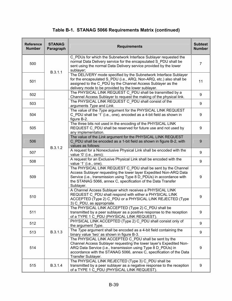
B-39
Table B-1. STANAG 5066 Requirements Matrix (continued)
Reference Number
STANAG Paragraph Requirements Subtest
Number
500
C_PDUs for which the Subnetwork Interface Sublayer requested the normal Data Delivery service for the encapsulated S_PDU shall be sent using the normal Data Delivery service provided by the lower sublayer;
7
501
B.3.1.1 The DELIVERY mode specified by the Subnetwork Interface Sublayer for the encapsulated S_PDU (i.e., ARQ, Non-ARQ, etc.) also shall be assigned to the C_PDU by the Channel Access Sublayer as the delivery mode to be provided by the lower sublayer.
11
502 The PHYSICAL LINK REQUEST C_PDU shall be transmitted by a Channel Access Sublayer to request the making of the physical link. 9
503 The PHYSICAL LINK REQUEST C_PDU shall consist of the arguments Type and Link. 9
504 The value of the Type argument for the PHYSICAL LINK REQUEST C_PDU shall be ‘1’ (i.e., one), encoded as a 4-bit field as shown in figure B-2.
9
505 The three bits not used in the encoding of the PHYSICAL LINK REQUEST C_PDU shall be reserved for future use and not used by any implementation.
9
506 The value of the Link argument for the PHYSICAL LINK REQUEST C_PDU shall be encoded as a 1-bit field as shown in figure B-2, with values as follows:
9
507 A request for a Nonexclusive Physical Link shall be encoded with the value ‘0’ (i.e., zero); 9
508 A request for an Exclusive Physical Link shall be encoded with the value ‘1’ (i.e., one). 9
509
The PHYSICAL LINK REQUEST C_PDU shall be sent by the Channel Access Sublayer requesting the lower layer Expedited Non-ARQ Data Service (i.e., transmission using Type 8 D_PDUs) in accordance with the STANAG 5066, annex C, specification of the Data Transfer Sublayer.
9
510
B.3.1.2
A Channel Access Sublayer which receives a PHYSICAL LINK REQUEST C_PDU shall respond with either a PHYSICAL LINK ACCEPTED (Type 2) C_PDU or a PHYSICAL LINK REJECTED (Type 3) C_PDU, as appropriate.
9
511 The PHYSICAL LINK ACCEPTED (Type 2) C_PDU shall be transmitted by a peer sublayer as a positive response to the reception of a TYPE 1 C_PDU (PHYSICAL LINK REQUEST).
9
512 PHYSICAL LINK ACCEPTED (Type 2) C_PDU shall consist only of the argument Type. 9
513 The Type argument shall be encoded as a 4-bit field containing the binary value ‘two’ as shown in figure B-3. 9
514
B.3.1.3
The PHYSICAL LINK ACCEPTED C_PDU shall be sent by the Channel Access Sublayer requesting the lower layer’s Expedited Non-ARQ Data Service (i.e., transmission using Type 8 D_PDUs) in accordance with the STANAG 5066, annex C, specification of the Data Transfer Sublayer.
9
515 B.3.1.4 The PHYSICAL LINK REJECTED (Type 3) C_PDU shall be transmitted by a peer sublayer as a negative response to the reception of a TYPE 1 C_PDU (PHYSICAL LINK REQUEST).
9

B-40
Table B-1. STANAG 5066 Requirements Matrix (continued)
Reference Number
STANAG Paragraph Requirements Subtest
Number
516 The PHYSICAL LINK REJECTED (Type 3) C_PDU shall consist of two arguments: Type and Reason. 9
517 The Type argument shall be encoded as a 4-bit field containing the binary value ‘three’ as shown in figure B-4. 9
518 The Reason argument shall be encoded in accordance with figure B-4 and the table from STANAG 5066, section B.3.1.4. 9
519
B.3.1.4 The PHYSICAL LINK REJECTED C_PDU shall be sent by the Channel Access Sublayer requesting the lower layer Expedited Non-ARQ Data Service (i.e., transmission using Type 8 D_PDUs) in accordance with the STANAG 5066, annex C, specification of the Data Transfer Sublayer.
9
520 The PHYSICAL LINK BREAK C_PDU shall be transmitted by either of the peer Channel Access Sublayers involved in an active physical link to request the breaking of the link.
9
521 The PHYSICAL LINK BREAK C_PDU shall consists of two arguments: Type and Reason. 9
522 The Type argument shall be encoded as a 4-bit field containing the binary value ‘4’ as shown in figure B-5. 9
523 The Reason argument shall be encoded in accordance with figure B-5 and the table from STANAG 5066, section B.3.1.5. 9
524
A peer sublayer which receives the PHYSICAL LINK BREAK C_PDU shall immediately declare the physical link as broken and respond with a PHYSICAL LINK BREAK (Type 5) C_PDU as specified in STANAG 5066, section B.3.1.6 below.
9
525
B.3.1.5
The PHYSICAL LINK BREAK C_PDU shall be sent by the Channel Access Sublayer requesting the lower layer Expedited Non-ARQ Data Service (i.e., transmission using Type 8 D_PDUs) in accordance with the STANAG 5066, annex C, specification of the Data Transfer Sublayer.
9
526 The PHYSICAL LINK BREAK CONFIRM (Type 5) C_PDU shall be transmitted by a Channel Access Sublayer as a response to a TYPE 4 “PHYSICAL LINK BREAK” C_PDU.
9
527 The PHYSICAL LINK BREAK CONFIRM (Type 5) C_PDU shall consist of the single argument Type. 9
528 The Type argument shall be encoded as a 4-bit field containing the binary value ‘five’ as shown in figure B-6. 9
529
The PHYSICAL LINK BREAK CONFIRM (Type 5) C_PDU shall be sent by the Channel Access Sublayer requesting the lower layer Expedited Non-ARQ Data Service (i.e., transmission using Type 8 D_PDUs) in accordance with the STANAG 5066, annex C, specification of the Data Transfer Sublayer.
9
530
B.3.1.6
Upon receiving a PHYSICAL LINK BREAK CONFIRM (Type 5) C_PDU, the peer which initiated the breaking of the link shall declare the link as broken.
9
531 B.3.2 The Channel Access Sublayer shall perform all peer-to-peer communications for protocol control using the following C_PDUs: 9
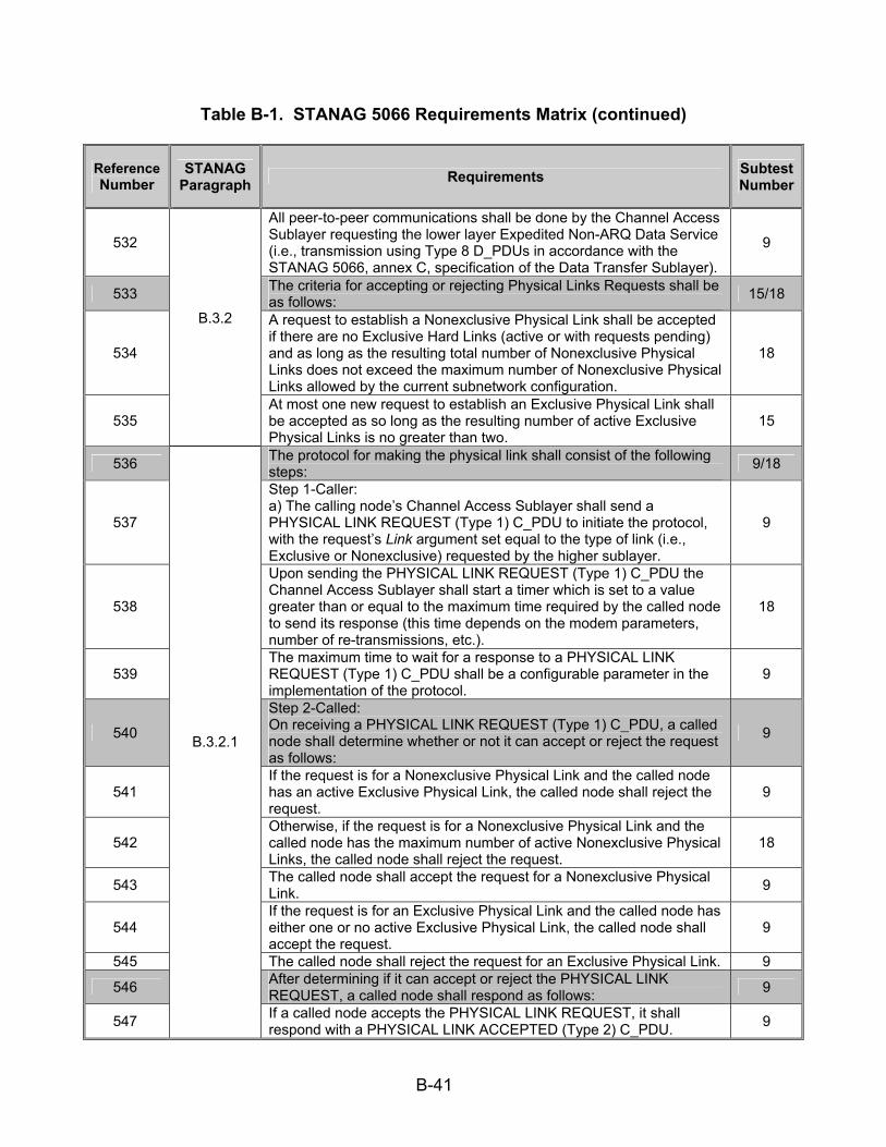
B-41
Table B-1. STANAG 5066 Requirements Matrix (continued)
Reference Number
STANAG Paragraph Requirements Subtest
Number
532
All peer-to-peer communications shall be done by the Channel Access Sublayer requesting the lower layer Expedited Non-ARQ Data Service (i.e., transmission using Type 8 D_PDUs in accordance with the STANAG 5066, annex C, specification of the Data Transfer Sublayer).
9
533 The criteria for accepting or rejecting Physical Links Requests shall be as follows: 15/18
534
A request to establish a Nonexclusive Physical Link shall be accepted if there are no Exclusive Hard Links (active or with requests pending) and as long as the resulting total number of Nonexclusive Physical Links does not exceed the maximum number of Nonexclusive Physical Links allowed by the current subnetwork configuration.
18
535
B.3.2
At most one new request to establish an Exclusive Physical Link shall be accepted as so long as the resulting number of active Exclusive Physical Links is no greater than two.
15
536 The protocol for making the physical link shall consist of the following steps: 9/18
537
Step 1-Caller: a) The calling node’s Channel Access Sublayer shall send a PHYSICAL LINK REQUEST (Type 1) C_PDU to initiate the protocol, with the request’s Link argument set equal to the type of link (i.e., Exclusive or Nonexclusive) requested by the higher sublayer.
9
538
Upon sending the PHYSICAL LINK REQUEST (Type 1) C_PDU the Channel Access Sublayer shall start a timer which is set to a value greater than or equal to the maximum time required by the called node to send its response (this time depends on the modem parameters, number of re-transmissions, etc.).
18
539 The maximum time to wait for a response to a PHYSICAL LINK REQUEST (Type 1) C_PDU shall be a configurable parameter in the implementation of the protocol.
9
540
Step 2-Called: On receiving a PHYSICAL LINK REQUEST (Type 1) C_PDU, a called node shall determine whether or not it can accept or reject the request as follows:
9
541 If the request is for a Nonexclusive Physical Link and the called node has an active Exclusive Physical Link, the called node shall reject the request.
9
542 Otherwise, if the request is for a Nonexclusive Physical Link and the called node has the maximum number of active Nonexclusive Physical Links, the called node shall reject the request.
18
543 The called node shall accept the request for a Nonexclusive Physical Link. 9
544 If the request is for an Exclusive Physical Link and the called node has either one or no active Exclusive Physical Link, the called node shall accept the request.
9
545 The called node shall reject the request for an Exclusive Physical Link. 9 546 After determining if it can accept or reject the PHYSICAL LINK
REQUEST, a called node shall respond as follows: 9
547
B.3.2.1
If a called node accepts the PHYSICAL LINK REQUEST, it shall respond with a PHYSICAL LINK ACCEPTED (Type 2) C_PDU. 9
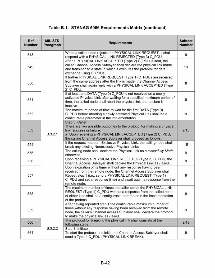
B-42
Table B-1. STANAG 5066 Requirements Matrix (continued)
Ref Number
MIL-STD Paragraph Requirements Subtest
Number
548 When a called node rejects the PHYSICAL LINK REQUEST, it shall respond with a PHYSICAL LINK REJECTED (Type 3) C_PDU. 9
549
After a PHYSICAL LINK ACCEPTED (Type 2) C_PDU is sent, the called Channel Access Sublayer shall declare the physical link made and transition to a state in which it executes the protocol for data exchange using C_PDUs.
13
550
If further PHYSICAL LINK REQUEST (Type 1) C_PDUs are received from the same address after the link is made, the Channel Access Sublayer shall again reply with a PHYSICAL LINK ACCEPTED (Type 2) C_PDU.
8
551
If at least one DATA (Type 0) C_PDU is not received on a newly activated Physical Link after waiting for a specified maximum period of time, the called node shall abort the physical link and declare it inactive.
9
552 The maximum period of time to wait for the first DATA (Type 0) C_PDU before aborting a newly activated Physical Link shall be a configurable parameter in the implementation.
9
553
Step 3. Caller There are two possible outcomes to the protocol for making a physical link: success or failure: a) Upon receiving a PHYSICAL LINK ACCEPTED (Type 2) C_PDU, the calling Channel Access Sublayer shall proceed as follows:
9/15
554 If the request made an Exclusive Physical Link, the calling node shall break any existing Nonexclusive Physical Links. 15
555 The calling node shall declare the Physical Link as successfully Made, otherwise, 9
556 Upon receiving a PHYSICAL LINK REJECTED (Type 3) C_PDU, the Channel Access Sublayer shall declare the Physical Link as Failed. 9
557
Upon expiration of its timer without any response having been received from the remote node, the Channel Access Sublayer shall Repeat step 1 (i.e., send a PHYSICAL LINK REQUEST (Type 1) C_PDU and set a response time) and await again a response from the remote node.
9
558
The maximum number of times the caller sends the PHYSICAL LINK REQUEST (Type 1) C_PDU without a response from the called node of either kind shall be a configurable parameter in the implementation of the protocol.
9
559
B.3.2.1
After having repeated step 1 the configurable maximum number of times without any response having been received from the remote node, the caller’s Channel Access Sublayer shall declare the protocol to make the physical link as Failed.
9
560 The protocol for breaking the physical link shall consists of the following steps: 9/18
561 B.3.2.2 Step 1: Initiator
To start the protocol, the initiator’s Channel Access Sublayer shall send a Type 4 C_PDU (PHYSICAL LINK BREAK).
9

B-43
Table B-1. STANAG 5066 Requirements Matrix (continued)
Reference Number
STANAG Paragraph Requirements Subtest
Number
562
Upon sending this C_PDU the Channel Access Sublayer shall start a timer which is set to a value greater than or equal to the maximum time required by the called node to send its response (this time depends on the modem parameters, number of re-transmissions, etc.).
18
563
Step 2: Responder c) Upon receiving the Type 4 C_PDU the responder’s Channel Access Sublayer shall declare the Physical link as broken and send a PHYSICAL LINK BREAK CONFIRM (Type 5) C_PDU.
9
564
Step 3: Initiator d) Upon receiving a PHYSICAL LINK BREAK CONFIRM (Type 5) C_PDU, the Initiator’s Channel Access Sublayer shall declares the physical link as broken.
9
565
Upon expiration of its timer without any response having been received from the remote node, the initiator’s Channel Access Sublayer shall repeat step 1 and wait again for a response from the remote node.
9
566
B.3.2.2
After having repeated step 1 a maximum number of times (left as a configuration parameter) without any response having been received from the remote node, the Initiator’s Channel Access Sublayer shall declare the physical link as broken.
9
567
Protocol for Exchanging Data C_PDUs: The sending peer shall accept S_PDUs from the Subnetwork Interface Sublayer, encapsulate them in a “DATA” C_PDU (by adding the C_PCI) and send them to its receiving peer via its interface to the Data Transfer Sublayer.
9
568
B.3 The receiving peer shall receive DATA C_PDUs from the Data Transfer Sublayer interface, check them for validity, strip off the C_PCI, and deliver the enveloped S_PDU to the Subnetwork Interface Sublayer.
10
569
Depending on the application and service-type requested by higher sublayers, the user service provided by the Data Transfer Sublayer shall be either a simple non ARQ service - commonly known as broadcast mode - or a reliable selective ARQ service, as specified herein.
11
570
C.1
The Data Transfer Sublayer shall provide “sub-modes” for non ARQ and reliable selective ARQ delivery services, which influence the characteristics of the particular service, as specified below.
6
571 In the Non-ARQ service error-check bits (i.e., Cyclic Redundancy Check or CRC bits) applied to the D_DPU shall be used to detect errors.
11
572 And any D_PDUs that are found to contain transmission errors shall be discarded by the Data Transfer Sublayer protocol entity. 6
573
C.1.1
A special mode of the Non-ARQ service shall be available to reconstruct C_PDUs from D_PDUs in error and deliver them to the Channel Access Sublayer.
6
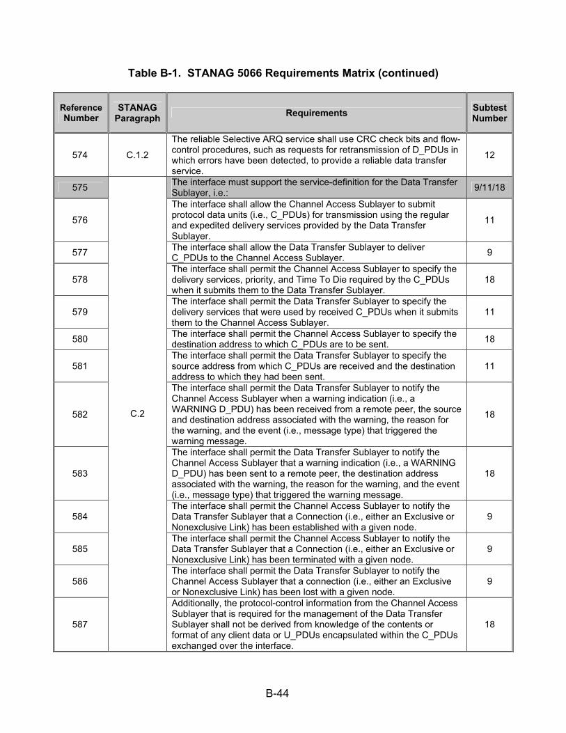
B-44
Table B-1. STANAG 5066 Requirements Matrix (continued)
Reference Number
STANAG Paragraph Requirements Subtest
Number
574 C.1.2
The reliable Selective ARQ service shall use CRC check bits and flow-control procedures, such as requests for retransmission of D_PDUs in which errors have been detected, to provide a reliable data transfer service.
12
575 The interface must support the service-definition for the Data Transfer Sublayer, i.e.: 9/11/18
576
The interface shall allow the Channel Access Sublayer to submit protocol data units (i.e., C_PDUs) for transmission using the regular and expedited delivery services provided by the Data Transfer Sublayer.
11
577 The interface shall allow the Data Transfer Sublayer to deliver C_PDUs to the Channel Access Sublayer. 9
578 The interface shall permit the Channel Access Sublayer to specify the delivery services, priority, and Time To Die required by the C_PDUs when it submits them to the Data Transfer Sublayer.
18
579 The interface shall permit the Data Transfer Sublayer to specify the delivery services that were used by received C_PDUs when it submits them to the Channel Access Sublayer.
11
580 The interface shall permit the Channel Access Sublayer to specify the destination address to which C_PDUs are to be sent. 18
581 The interface shall permit the Data Transfer Sublayer to specify the source address from which C_PDUs are received and the destination address to which they had been sent.
11
582
The interface shall permit the Data Transfer Sublayer to notify the Channel Access Sublayer when a warning indication (i.e., a WARNING D_PDU) has been received from a remote peer, the source and destination address associated with the warning, the reason for the warning, and the event (i.e., message type) that triggered the warning message.
18
583
The interface shall permit the Data Transfer Sublayer to notify the Channel Access Sublayer that a warning indication (i.e., a WARNING D_PDU) has been sent to a remote peer, the destination address associated with the warning, the reason for the warning, and the event (i.e., message type) that triggered the warning message.
18
584 The interface shall permit the Channel Access Sublayer to notify the Data Transfer Sublayer that a Connection (i.e., either an Exclusive or Nonexclusive Link) has been established with a given node.
9
585 The interface shall permit the Channel Access Sublayer to notify the Data Transfer Sublayer that a Connection (i.e., either an Exclusive or Nonexclusive Link) has been terminated with a given node.
9
586 The interface shall permit the Data Transfer Sublayer to notify the Channel Access Sublayer that a connection (i.e., either an Exclusive or Nonexclusive Link) has been lost with a given node.
9
587
C.2
Additionally, the protocol-control information from the Channel Access Sublayer that is required for the management of the Data Transfer Sublayer shall not be derived from knowledge of the contents or format of any client data or U_PDUs encapsulated within the C_PDUs exchanged over the interface.
18

B-45
Table B-1. STANAG 5066 Requirements Matrix (continued)
Reference Number
STANAG Paragraph Requirements Subtest
Number
588 In order to provide the data transfer services specified herein, the Data Transfer Sublayer shall exchange protocol data units (D_PDUs) with its peer(s).
11
589 The Data Transfer Sublayer shall use the D_PDU Types displayed in table C-2 to support the Selective ARQ service and Non-ARQ service, including the several data transfer submodes defined herein.
11
590
There are basically three different types of D_PDUs, or frames, noted by the Frame-Type field in table C-2: 1. C (Control) Frames, 2. I (Information) Frames, 3. And a combined I+C-Frame. The Protocol Type field in table C–2 indicates the type of data-transfer-service protocol with which the D_PDU frame shall be used, as follows: 4. NRQ Non-Repeat-Request (i.e., Non-ARQ) Protocol. 5. SRQ Selective Repeat-Request Protocol. 6. IRQ Idle Repeat-Request Protocol.
14
591
The NRQ protocol shall only operate in a simplex mode since the local node, after sending I-Frames, does not wait for an indication from the remote node as to whether or not the I-Frames were correctly received.
6
592
The Selective RQ protocol shall operate in a half or full duplex mode since the local node, after sending I-Frames, waits for an indication in the form of a selective acknowledgement from the remote node as to whether the I-Frames were correctly received or not.
12
593
C.3
The Idle RQ protocol, also known as a stop and wait protocol, shall operate in a half duplex mode; the local node, after sending an I-Frame, must wait until it receives an acknowledgement from the remote node as to whether or not the I-Frame was correctly received.
7
594 All D_PDU Types that cannot carry segmented C_PDUs shall be of the structure shown in figure C-1 (a). 14
595 C.3.1 D_PDU Types that can carry segmented C_PDUs shall be structured
according to figure C-1 (b). 14
596 The detailed structure of the generic D_PDU C-Frame shall be as shown in figure C-2 (a) or figure C-2 (b). 14
597 The D_PDU Types 1, 3, 5, 6, and 15 shall use only the C-Frame structure defined in figure C-2 (a). 14
598 The D_PDU Types 0, 2, 4, 7, and 8 shall use the generic D_PDU I and I+C-Frame structure defined in figure C-2 (b). 14
599 All D_PDUs, regardless of type, shall begin with the same 16-bit synchronization (sync) sequence. 11
600
The 16-bit sequence shall be the 16-bit Maury-Styles (0xEB90) sequence shown below, with the least significant bit (LSB) transmitted first: (MSB) 1 1 1 0 1 0 1 1 1 0 0 1 0 0 0 0 (LSB)
11
601 The first 4 bytes of all D_PDU headers shall contain the same fields: 11 602 A 4-bit D_PDU Type field that shall identify the type of D_PDU; 11 603 A 12-bit field that shall contain an EOW message; 11 604
C.3.2
An 8-bit field that shall contain the EOT information; and 11
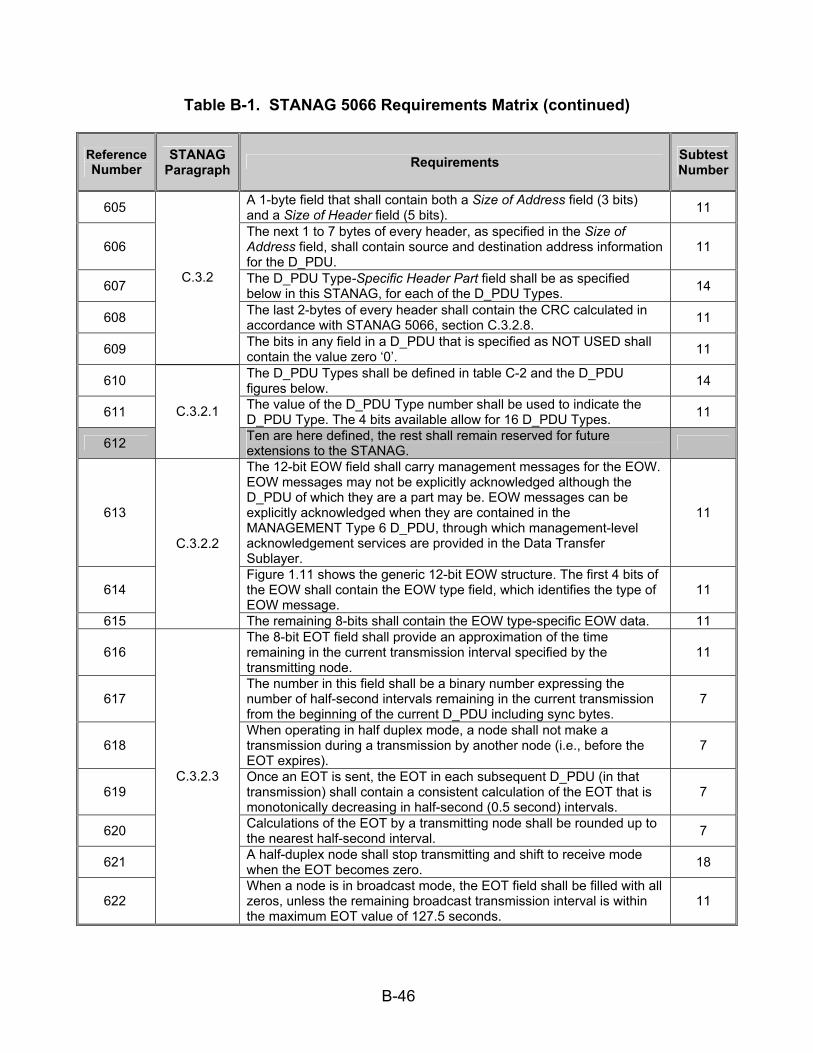
B-46
Table B-1. STANAG 5066 Requirements Matrix (continued)
Reference Number
STANAG Paragraph Requirements Subtest
Number
605 A 1-byte field that shall contain both a Size of Address field (3 bits) and a Size of Header field (5 bits). 11
606 The next 1 to 7 bytes of every header, as specified in the Size of Address field, shall contain source and destination address information for the D_PDU.
11
607 The D_PDU Type-Specific Header Part field shall be as specified below in this STANAG, for each of the D_PDU Types. 14
608 The last 2-bytes of every header shall contain the CRC calculated in accordance with STANAG 5066, section C.3.2.8. 11
609
C.3.2
The bits in any field in a D_PDU that is specified as NOT USED shall contain the value zero ‘0’. 11
610 The D_PDU Types shall be defined in table C-2 and the D_PDU figures below. 14
611 The value of the D_PDU Type number shall be used to indicate the D_PDU Type. The 4 bits available allow for 16 D_PDU Types. 11
612
C.3.2.1
Ten are here defined, the rest shall remain reserved for future extensions to the STANAG.
613
The 12-bit EOW field shall carry management messages for the EOW. EOW messages may not be explicitly acknowledged although the D_PDU of which they are a part may be. EOW messages can be explicitly acknowledged when they are contained in the MANAGEMENT Type 6 D_PDU, through which management-level acknowledgement services are provided in the Data Transfer Sublayer.
11
614 Figure 1.11 shows the generic 12-bit EOW structure. The first 4 bits of the EOW shall contain the EOW type field, which identifies the type of EOW message.
11
615
C.3.2.2
The remaining 8-bits shall contain the EOW type-specific EOW data. 11
616 The 8-bit EOT field shall provide an approximation of the time remaining in the current transmission interval specified by the transmitting node.
11
617 The number in this field shall be a binary number expressing the number of half-second intervals remaining in the current transmission from the beginning of the current D_PDU including sync bytes.
7
618 When operating in half duplex mode, a node shall not make a transmission during a transmission by another node (i.e., before the EOT expires).
7
619 Once an EOT is sent, the EOT in each subsequent D_PDU (in that transmission) shall contain a consistent calculation of the EOT that is monotonically decreasing in half-second (0.5 second) intervals.
7
620 Calculations of the EOT by a transmitting node shall be rounded up to the nearest half-second interval. 7
621 A half-duplex node shall stop transmitting and shift to receive mode when the EOT becomes zero. 18
622
C.3.2.3
When a node is in broadcast mode, the EOT field shall be filled with all zeros, unless the remaining broadcast transmission interval is within the maximum EOT value of 127.5 seconds.
11
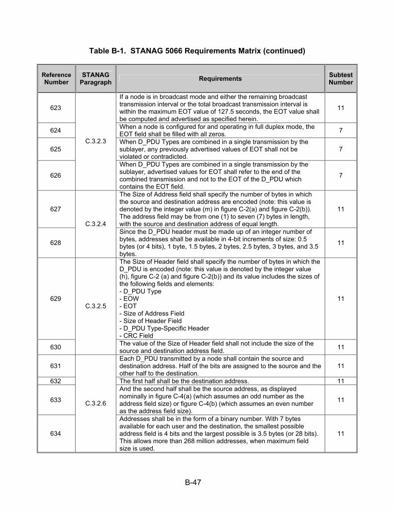
B-47
Table B-1. STANAG 5066 Requirements Matrix (continued)
Reference Number
STANAG Paragraph Requirements Subtest
Number
623
If a node is in broadcast mode and either the remaining broadcast transmission interval or the total broadcast transmission interval is within the maximum EOT value of 127.5 seconds, the EOT value shall be computed and advertised as specified herein.
11
624 When a node is configured for and operating in full duplex mode, the EOT field shall be filled with all zeros. 7
625 When D_PDU Types are combined in a single transmission by the sublayer, any previously advertised values of EOT shall not be violated or contradicted.
7
626
C.3.2.3
When D_PDU Types are combined in a single transmission by the sublayer, advertised values for EOT shall refer to the end of the combined transmission and not to the EOT of the D_PDU which contains the EOT field.
7
627
The Size of Address field shall specify the number of bytes in which the source and destination address are encoded (note: this value is denoted by the integer value (m) in figure C-2(a) and figure C-2(b)). The address field may be from one (1) to seven (7) bytes in length, with the source and destination address of equal length.
11
628
C.3.2.4 Since the D_PDU header must be made up of an integer number of bytes, addresses shall be available in 4-bit increments of size: 0.5 bytes (or 4 bits), 1 byte, 1.5 bytes, 2 bytes, 2.5 bytes, 3 bytes, and 3.5 bytes.
11
629
The Size of Header field shall specify the number of bytes in which the D_PDU is encoded (note: this value is denoted by the integer value (h), figure C-2 (a) and figure C-2(b)) and its value includes the sizes of the following fields and elements: - D_PDU Type - EOW - EOT - Size of Address Field - Size of Header Field - D_PDU Type-Specific Header - CRC Field
11
630
C.3.2.5
The value of the Size of Header field shall not include the size of the source and destination address field. 11
631 Each D_PDU transmitted by a node shall contain the source and destination address. Half of the bits are assigned to the source and the other half to the destination.
11
632 The first half shall be the destination address. 11
633
And the second half shall be the source address, as displayed nominally in figure C-4(a) (which assumes an odd number as the address field size) or figure C-4(b) (which assumes an even number as the address field size).
11
634
C.3.2.6
Addresses shall be in the form of a binary number. With 7 bytes available for each user and the destination, the smallest possible address field is 4 bits and the largest possible is 3.5 bytes (or 28 bits). This allows more than 268 million addresses, when maximum field size is used.
11
B-48
Table B-1. STANAG 5066 Requirements Matrix (continued)
Reference Number
STANAG Paragraph Requirements Subtest
Number
635 A decimal number shall represent each byte or fractional byte of an address. 11
636 And the binary equivalent shall be mapped into the corresponding byte. 11
637 Any fractional-byte elements in the address shall be mapped into the first (leftmost) nonzero number in the in the decimal representation of the address.
11
638 The remaining numbers in the decimal representation of the address shall refer to byte-sized elements in the address field. 11
639
The address bits shall be mapped into the address field by placing the MSB of the address into the MSB of the first byte of the address field and the LSB into the LSB of the last byte of the field, in accordance with figure C-4(a), for addresses with length of 0.5, 1.5, 2.5, or 3.5 bytes, and figure C-4(b), for addresses with length of 1, 2, or 3 bytes.
11
640 When a field spans more than one octet, the order of the bit values within each octet shall decrease progressively as the octet number increases.
11
641
C.3.2.6
Trailing address bytes that are zero shall be sent. 11
642 C.3.2.7 The bytes immediately following the address field shall encode the D_PDU Type-Specific Header, as specified in the corresponding section below from STANAG 5066, sections C.3.3 through C.3.12.
14
643 The 2-bytes following the D_PDU Type-Specific Header shall contain a 16-bit CRC field. 11
644
The header CRC error-check field shall be calculated using the following polynomial: x^16 + x^15 + x^12 + x^11 + x^8 + x^6 + x^3 + 1; or in hex format: 0x19949, also using the shift-register method shown by the figures in appendix I of CCITT Recommendation V.41 (or equivalent method in software; an example is given below).
11
645 When calculating the header CRC field, the shift-registers shall be initially set to all ‘0’ zeros. 18
646
The header CRC shall be calculated over all bits in the header, excluding the Maury-Styles Sync Sequence and including the following fields and elements: - D_PDU Type - EOW - EOT - Size of Address Field - Size of Header Field - Source and Destination Address - D_PDU Type-Specific Header
11
647 A node shall process the information contained in a header with a valid CRC, regardless of the result of the CRC error-check over any segmented C_PDU that may be a part of the D_PDU.
11
648
C.3.2.8
The CRC bits shall be mapped (see figure 1.15) into the CRC octets by placing the MSB of the CRC into the LSB of the first byte of the CRC field and the LSB of the CRC into the MSB of the last byte of the CRC field.
11

B-49
Table B-1. STANAG 5066 Requirements Matrix (continued)
Reference Number
STANAG Paragraph Requirements Subtest
Number
649 For the I and I+C-Frame D_PDUs types, the octets of the segmented C_PDUs shall be transmitted in ascending numerical order, following the 2-byte CRC on the D_PDU header.
7
650
C.3.2.9 Within an octet, the LSB shall be the first bit to be transmitted as shown in figure C-6. 7
651 The SIZE OF SEGMENTED C_PDU field shall be used only with D_PDUs that are I or I+C-Frame types, i.e., that have a segmented C_PDU field as shown in figure C-2(b).
7
652 The bit-value of the SIZE OF SEGMENTED C_PDU shall be encoded as a 10-bit field as indicated by figure C-7. 7
653
The value in the SIZE OF SEGMENTED C_PDU field shall not include the 2-bytes for the CRC following the segmented C_PDU. The segmented C_PDU field can hold a maximum of 1023 bytes from the segmented C_PDU.
7
654
C.3.2.10
The SIZE OF SEGMENTED C_PDU shall be mapped into consecutive bytes of the D_PDU as indicated in figure C-8, in the byte locations specified for the applicable D_PDU.
7
655 The last 4 bytes of any I or I+C-Frame D_PDU shall contain a 32-bit CRC field. 7
656
The CRC shall be applied and computed on the contents of the segmented C_PDU using the following polynomial [see footnote 2 below]: x^32 + x^27 + x^25 + x^23 + x^21 + x^18 + x^17 + x^16 + x^13 + x^10 + x^8 + x^7 + x^6 + x^3 + x^2 + x + 1; or in hex format: 0x10AA725CF, also using the shift-register method similar to that shown by the figures in appendix I of CCITT Recommendation V.41.
7
657
C.3.2.11
When calculating the header CRC field, the shift-registers shall be initially set to all ‘0’ zeros. 18
658 The DATA-ONLY D_PDU shall be used to send segmented C_PDUs when the transmitting node needs an explicit confirmation that the data was received.
1
659 The DATA-ONLY D_PDU shall be used in conjunction with a basic selective Automatic Repeat-Request type of protocol. 1
660
C.3.3 A Data Transfer Sublayer entity that receives a DATA-ONLY D_PDU shall transmit an ACK-ONLY (Type 1) D_PDU or a DATA-ACK (Type 2) D_PDU as acknowledgement, where the type of D_PDU sent depends on whether or not it has C_PDUs of its own to send to the source of the DATA-ONLY D_PDU.
1

B-50
Table B-1. STANAG 5066 Requirements Matrix (continued)
Reference Number
STANAG Paragraph Requirements Subtest
Number
661
The DATA-ONLY D_PDU shall contain the following fields within its D_PDU Type-Specific Part, mapped and encoded, in accordance with figure C-9 and the paragraphs below:
• C_PDU START • C_PDU END • DELIVER IN ORDER • DROP C_PDU • TX WIN UWE • TX WIN LWE • SIZE OF SEGMENTED C_PDU • TX FSN
1
662
The C_PDU Start flag shall be set to indicate the start of a newly segmented C_PDU; the C_PDU segment contained within this D_PDU is the first segment of the C_PDU, in accordance with the C_PDU segmentation process described in STANAG 5066, section C.4.
1
663 The C_PDU End flag shall be set to indicate the end of a segmented C_PDU; when a D_PDU is received with the C_PDU End flag set it indicates the last D_PDU that was segmented from the C_PDU.
1
664
If the DELIVER IN ORDER flag is set on the D_PDUs composing a C_PDU, the C_PDU shall be delivered to the upper layer when both the following conditions are met: 1) The C_PDU is complete. 2) All C_PDUs received previously that also had the DELIVER IN ORDER flag set have been delivered.
1
665
If the DELIVER IN ORDER flag is cleared on the D_PDUs composing a C_PDU, the C_PDU shall be delivered to the upper layer when the following condition is met: 3) The C_PDU is complete and error-free.
7
666
When the DROP PDU flag is set by the D_PDU source, the receiving Data Transfer Sublayer shall discard the contents of the segmented C_PDU field of the current D_PDU and all other previously received segments of the C_PDU of which the current D_PDU is a part.
7
667 No segmented C_PDU data needs to be sent if the DROP PDU flag is set and the SIZE OF SEGMENTED C_PDU field shall be zero in this case.
7
668 The TX WIN UWE flag shall be set when the TX FSN for the current D_PDU is equal to the TX UWE of the transmit flow-control window. 1
669 Similarly, the TX WIN LWE flag shall be set when the TX FSN for the current D_PDU is equal to the TX LWE of the transmit flow-control window.
1
670 The SIZE OF SEGMENTED C_PDU field shall be encoded as specified in STANAG 5066, section C.3.2.10. 1
671
C.3.3
The TX FSN field shall contain the sequence number of the current D_PDU. 1
B-51
Table B-1. STANAG 5066 Requirements Matrix (continued)
Reference Number
STANAG Paragraph Requirements Subtest
Number
672
The value of the TX FSN field shall be a unique integer (modulo 256) assigned to the D_PDU during the segmentation of the C_PDU and will not be released for reuse with another D_PDU until the receiving node has acknowledged the D_PDU.
7
673 Values for the TX FSN field shall be assigned in an ascending (modulo 256) order during the segmentation of the C_PDU. 7
674 The segmented C_PDU field shall immediately follow the D_PDU header as depicted in figure C-7. 7
675
C.3.3
Segmented C_PDUs shall be mapped according to the specification of STANAG 5066, section C.3.2.9. 7
676
The ACK-ONLY D_PDU shall be used to selectively acknowledge received DATA-ONLY or DATA-ACK D_PDUs when the receiving Data Transfer Sublayer has no segmented C_PDUs of its own to send.
1
677
The ACK-ONLY D_PDU shall contain the following fields within its D_PDU Type-Specific Part, mapped and encoded, in accordance with figure C-10 and the paragraphs below:
• RX LWE • SELECTIVE ACK
1
678 The value of the RX LWE field shall equal the D_PDU sequence number (modulo 256) of the RX LWE pointer associated with the node’s receive ARQ flow-control window.
1
679
The SELECTIVE ACK field can have a dynamic length of 0 to 16 bytes and shall contain a bit-mapped representation of the status of all received D_PDUs with sequence numbers from the LWE to and including the UWE pointers of the receive flow-control window.
1
680 A set (1) bit within the SELECTIVE ACK field shall indicate a positive acknowledgement (ACK), i.e., that the D_PDU with the corresponding TX FSN was received correctly.
12
681 Only D_PDU frames with a correct segmented C_PDU CRC shall be acknowledged positively even if the header CRC is correct. 12
682 Frames with the DROP C_PDU flag set shall be acknowledged positively regardless of the results of the CRC check on the segmented C_PDU.
18
683 A cleared ‘0’ bit within the SELECTIVE ACK field shall indicate a negative acknowledgement (NACK), i.e., that the D_PDU with the corresponding TX FSN was received incorrectly or not at all.
12
684
The construction of the Selective ACK field and the mapping of D_PDU frame-sequence numbers to bits within the Selective ACK field shall be in accordance with figure C-11 and figure C-12 and the paragraphs below.
12
685
C.3.4
The LSB of the first byte of the Selective ACK field shall correspond to the D_PDU whose TX FSN is equal to 1 + the value in the RX LWE field of this ACKONLY D_PDU [the bit corresponding to the RX LWE is always zero, by definitionand is therefore not sent].
12
B-52
Table B-1. STANAG 5066 Requirements Matrix (continued)
Reference Number
STANAG Paragraph Requirements Subtest
Number
686
Each subsequent bit in the Selective ACK field shall represent the TX FSN of a subsequent D_PDU in the receive flow-control sliding window, in ascending order of the respective frame-sequence numbers without omission of any values.
12
687 The bit corresponding to the Receive Upper Window Edge (RX UWE) shall be in the last byte of the Selective ACK field. 12
688 If the bit representing the RX UWE is not the MSB of the last byte, the remaining bits in the byte (until and including the MSB) shall be set to 0 as padding.
12
689
C.3.4
No further Selective ACK bytes shall be transmitted after such bits are required. 12
690 The DATA-ACK D_PDU shall be used to send segmented C_PDUs when the transmitting node needs an explicit confirmation that the data was received and has received D_PDUs to selectively acknowledge.
1
691
A Data Transfer Sublayer entity that receives a DATA-ACK D_PDU shall transmit an ACK-ONLY (Type 1) D_PDU or a DATA-ACK (Type 2) D_PDU as acknowledgement, where the type of D_PDU sent depends on whether or not it has C_PDUs of its own to send to the source of the DATA-ACK D_PDU.
1
692 The DATA-ACK D_PDU shall contain the following fields within its D_PDU Type-Specific Part, mapped and encoded, in accordance with figure C-13 and the referenced paragraphs:
1
693 C_PDU START – shall be as specified in STANAG 5066, section 3.3 for the DATA-ONLY D_DPU; 1
694 C_PDU END – shall be as specified in STANAG 5066, section 3.3 for the DATA-ONLY D_DPU; 1
695 DELIVER IN ORDER – shall be as specified in STANAG 5066, section 3.3 for the DATA-ONLY D_DPU; 1
696 DROP C_PDU – shall be as specified in STANAG 5066, section 3.3 for the DATA-ONLY D_DPU; 1
697 TX WIN UWE – shall be as specified in STANAG 5066, section 3.3 for the DATA-ONLY D_DPU; 1
698 TX WIN LWE – shall be as specified in STANAG 5066, section 3.3 for the DATA-ONLY D_DPU; 1
699 SIZE OF SEGMENTED C_PDU – shall be as specified in STANAG 5066, section 3.3 for the DATA-ONLY D_DPU; 1
700 TX FSN – shall be as specified in STANAG 5066, section 3.3 for the DATA-ONLY D_DPU; 1
701 RX LWE – shall be as specified in STANAG 5066, section 3.4 for the ACK-ONLY D_DPU; 1
702
C.3.5
SELECTIVE ACK – shall be as specified in STANAG 5066, section 3.4 for the ACK-ONLY D_DPU; 1
703 C.3.6 The RESET/WIN Re-sync D_PDU shall be used to control the re-sync or re-initialization of the selective-repeat ARQ protocol operating on the link between the source and destination nodes.
3

B-53
Table B-1. STANAG 5066 Requirements Matrix (continued)
Reference Number
STANAG Paragraph Requirements Subtest
Number
704
Reset and re-sync operations shall be performed with respect to the transmit lower-window edge (TX LWE) and the receive lower-window edge (RX LWE) for the flow-control sliding windows at the sending node and receiving node, as specified in STANAG 5066, section C.6.2.
13
705 The RESET/WIN Re-sync D_PDU shall use a basic stop and wait type of protocol (denoted as the IRQ protocol elsewhere in this STANAG). 14
706
The reception of this D_PDU shall result in the transmission of an acknowledgement D_PDU by the receiving node. For the IRQ protocol used with the RESET/WIN Re-sync D_PDU, the RESET/WIN Re-sync D_PDU is used for both data and acknowledgement, as specified below.
3
707
Transmission of D_PDUs supporting the regular-data service, i.e., of DATA (Type 0), ACK (Type 1) and DATA-ACK (Type 2) D_PDUs, shall be suspended pending completion of any stop-and-wait protocol using the RESET/WIN Re-sync D_PDUs.
3
708
The RESET/WIN Re-sync D_PDU shall contain the following fields within its D_PDU Type-Specific Part, mapped and encoded, in accordance with figure C-14 and the paragraphs below:
• FULL RESET CMND • RESET TX WIN RQST • RESET TX WIN CMND • RESET ACK • NEW RX LWE • RESET FRAME ID NUMBER
3
709 The FULL RESET CMND flag shall be set equal to one (1) to force a full reset of the ARQ machines at the transmitter and receiver to their initial values as specified in sections C.6.2 and C.6.3.
3
710 A Type 3 D_PDU with the RESET TX WIN RQST flag set equal to one (1) shall be used to request a re-sync of the TX-LWE and RX-LWE pointers used for DATA in the transmit and receive nodes.
3
711
A node that receives a Type 3 D_PDU with the RESET TX WIN RQST flag set equal to one shall respond by forcing re-sync of the windows using a RESET/WIN Re-sync D_DPU and the RESET TX WIN CMND flag, as specified below.
3
712 A RESET/WIN Re-sync TYPE 3 D_PDU with the RESET TX WIN CMND flag set equal to one (1) shall be used to force a re-sync of the TX-LWE and RX-LWE pointers.
3
713 A node that sends a Type 3 D_PDU with the RESET TX WIN CMND flag set equal to one shall proceed as follows: 3
714 The NEW RECEIVE LWE field shall be set equal to the value of the sending node’s RX-LWE. 3
715 The sending node shall wait for a RESET/WIN Re-sync Type 3 D_PDU with the RESET ACK flag set equal to one as an acknowledgement that the re-sync has been performed.
3
716
C.3.6
A node that receives a Type 3 D_PDU with the RESET TX WIN CMND flag set equal to one shall proceed as follows: 3
B-54
Table B-1. STANAG 5066 Requirements Matrix (continued)
Reference Number
STANAG Paragraph Requirements Subtest
Number
717 The value of the node’s TX LWE shall be set equal to the value of the NEW RECEIVE LWE field in the RESET/WIN R2-sync D_PDU that was received;
3
718 The node shall send a RESET/WIN Re-sync Type 3 D_PDU with the RESET ACK flag set equal to one as an acknowledgement that the re-sync has been performed.
3
719 RESET ACK flag shall be set equal to one (1) to indicate an acknowledgement of the most recently received RESET/WIN Re-sync TYPE 3 D_PDU.
3
720 The NEW RECEIVE LWE field specifies the value of the new receiver ARQ RX-LWE, as noted above and shall be valid only when the value of the RESET WIN CMND flag equals one (1).
3
721 The value of the NEW RECEIVE LWE field shall be ignored in any other situation. 3
722 The Data Transfer Sublayer shall use the RESET FRAME ID NUMBER field to determine if a given RESET/WIN Re-sync D_PDU received is a copy of one already received.
3
723
C.3.6
The value of the RESET FRAME ID NUMBER field shall be a unique integer (modulo 256) assigned in ascending order to RESET/WIN Re-sync D_PDUs and will not be released for reuse with another D_PD U until the D_PDU to which it was assigned has been acknowledged.
3
724
The EXPEDITED DATA-ONLY (Type 4) D_PDU shall be used to send segmented C_PDUs that require Expedited Delivery Service when the transmitting node needs an explicit confirmation that the data was received.
2
725
A Data Transfer Sublayer entity that receives EXPEDITED DATA-ONLY (Type 4) D_PDU shall send an EXPEDITED DATA-ONLY (Type 5) D_PDU as a selective acknowledgement of all EXPEDITED DATA-ONLY (Type 4) D_PDUs received from the source node.
2
726
The EXPEDITED DATA-ONLY D_PDU is similar in structure to the DATA-ONLY D_PDU. The EXPEDITED DATA-ONLY D_PDU shall contain the following fields within its D_PDU Type-Specific Part, mapped and encoded, in accordance with figure C-15 and the paragraphs noted:
2
727 C_PDU START – shall be as specified for the DATA-ONLY D_PDU in STANAG 5066, section C.3.3 2
728 C_PDU END – shall be as specified for the DATA-ONLY D_PDU in STANAG 5066, section C.3.3 2
729 C_PDU ID NUMBER – shall be as specified in the paragraphs below. 2
730 SIZE OF SEGMENTED C_PDU – shall be as specified in STANAG 5066, section C.3.2.10 for all D_PDUs that have a segmented C_PDU field.
2
731 TX FSN – shall be as specified for the DATA-ONLY D_PDU in STANAG 5066, section C.3.3, with additional requirements as noted below.
2
732
C.3.7
The C_PDU ID NUMBER field shall specify the C_PDU of which this Expedited D_PDU is a part. 2

B-55
Table B-1. STANAG 5066 Requirements Matrix (continued)
Reference Number
STANAG Paragraph Requirements Subtest
Number
733 The value of the C_PDU ID NUMBER field shall be an integer (modulo 16) assigned in an ascending (modulo 16) order to the C_PDU, 2
734 And shall not be released for reuse with another C_PDU until the entire C_PDU has been acknowledged. 2
735
As noted above, the TX FSN field in the EXPEDITED DATA-ONLY D_PDU is defined and used in the same manner as that specified for the DATA-ONLY D_PDU. However, the EXPEDITED DATA-ONLY D_PDUs shall be assigned frame numbers from a TX FSN pool (0, 1 ...255) that is reserved exclusively for the transmission of EXPEDITED DATA-ONLY and EXPEDITED ACK-ONLY D_PDUs.
8
736 The segmented C_PDU field is a field that is attached to the header structure defined in figure C-15. The segmented PDU shall immediately follow the D_PDU header.
2
737 The processing of EXPEDITED D_PDUs in the EXPEDITED DATA state shall differ from the processing of DATA-ONLY or DATA-ACK D_PDUs in the DATA state in the following ways:
2
738
Data (i.e., C_PDUs) using the Expedited Delivery Service shall be transferred using EXPEDITED DATA-ONLY and EXPEDITED ACK-ONLY D_PDUs. If duplex communication is required, EXPEDITED DATA-ONLY and EXPEDITED ACK-ONLY D_PDUs may be placed together in a transmission interval.
2
739
C.3.7
C_PDUs requiring Expedited Delivery Service and the associated EXPEDITED D_PDUs shall not be queued for processing within the Data Transfer Sublayer behind D_PDUs containing non-expedited data (i.e., DATA-ONLY or DATA-ACK D_PDUs).
8
740 The EXPEDITED ACK-ONLY (Type 5) D_PDU shall be used to selectively acknowledge received EXPEDITED DATA-ONLY D_PDUs. 2
741 C.3.8 The EXPEDITED ACK-ONLY (Type 5) D_PDU Type shall have the
same format as the ACK-ONLY (Type 1) D_PDU, differing only in the value of the D_PDU Type field in byte 0, as specified in figure C-16.
2
742
The Management (Type 6) D_PDU shall be used to send EOW Messages or Management Protocol Data Units (M_PDUs) when the transmitting node needs an explicit acknowledgement that they were received.
4
743 A Data Transfer Sublayer entity shall acknowledge receipt of a Management (Type 6) D_PDU by sending a Management (Type 6) D_PDU with the ACK flag set to the value one (1).
4
744 The processing and transmission of Management (Type 6) D_PDUs shall take precedence over and bypass all other pending D_PDU Types in the Data Transfer Sublayer.
4
745
C.3.9
The exchange of MANAGEMENT D_PDUs is regulated by a stop-and-wait protocol, i.e., there shall be only one unacknowledged MANAGEMENT D_PDU at any time.
4
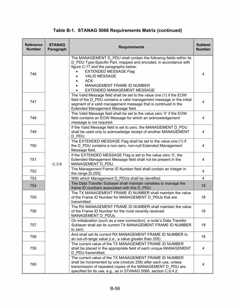
B-56
Table B-1. STANAG 5066 Requirements Matrix (continued)
Reference Number
STANAG Paragraph Requirements Subtest
Number
746
The MANAGEMENT D_PDU shall contain the following fields within its D_PDU Type-Specific Part, mapped and encoded, in accordance with figure C-17 and the paragraphs below:
• EXTENDED MESSAGE Flag • VALID MESSAGE • ACK • MANAGEMENT FRAME ID NUMBER • EXTENDED MANAGEMENT MESSAGE
4
747
The Valid Message field shall be set to the value one (1) if the EOW field of the D_PDU contains a valid management message or the initial segment of a valid management message that is continued in the Extended Management Message field.
4
748 The Valid Message field shall be set to the value zero ‘0’ if the EOW field contains an EOW Message for which an acknowledgement message is not required.
4
749 If the Valid Message field is set to zero, the MANAGEMENT D_PDU shall be used only to acknowledge receipt of another MANAGEMENT D_PDU.
4
750 The EXTENDED MESSAGE Flag shall be set to the value one (1) if the D_PDU contains a non-zero, non-null Extended Management Message field.
4
751 If the EXTENDED MESSAGE Flag is set to the value zero ‘0’, the Extended Management Message field shall not be present in the MANAGEMENT D_PDU.
4
752 The Management Frame ID Number field shall contain an integer in the range [0,255]. 4
753 With which Management D_PDUs shall be identified. 4 754 The Data Transfer Sublayer shall maintain variables to manage the
frame ID numbers associated with this D_PDU: 18
755 The TX MANAGEMENT FRAME ID NUMBER shall maintain the value of the Frame ID Number for MANAGEMENT D_PDUs that are transmitted;
18
756 The RX MANAGEMENT FRAME ID NUMBER shall maintain the value of the Frame ID Number for the most recently received MANAGEMENT D_PDUs.
18
757 On initialization (such as a new connection), a node’s Data Transfer Sublayer shall set its current TX MANAGEMENT FRAME ID NUMBER to zero;
18
758 And shall set its current RX MANAGEMENT FRAME ID NUMBER to an out-of-range value (i.e., a value greater than 255). 18
759 The current value of the TX MANAGEMENT FRAME ID NUMBER shall be placed in the appropriate field of each unique MANAGEMENT D_PDU transmitted.
4
760
C.3.9
The current value of the TX MANAGEMENT FRAME ID NUMBER shall be incremented by one (modulo 256) after each use, unless transmission of repeated copies of the MANAGEMENT D_PDU are specified for its use, e.g., as in STANAG 5066, section C.6.4.2.
4

B-57
Table B-1. STANAG 5066 Requirements Matrix (continued)
Reference Number
STANAG Paragraph Requirements Subtest
Number
761 MANAGEMENT D_PDUs that have been repeated (e.g., in accordance with STANAG 5066, section C.6.4.2) shall have the same MANAGEMENT FRAME ID NUMBER.
4
762
The Data Transfer Sublayer shall compare the MANAGEMENT FRAME ID NUMBER of received MANAGEMENT D_PDUs to the current RX MANAGEMENT FRAME ID NUMBER and process them as follows:
18
763 If the MANAGEMENT FRAME ID NUMBER in the received D_PDU differs from the current RX MANAGEMENT FRAME ID NUMBER value, the D_PDU shall be treated as a new D_PDU.
18
764 And the Data Transfer Sublayer shall set the current RX MANAGEMENT FRAME ID NUMBER value equal to the value of the received MANAGEMENT FRAME ID NUMBER.
18
765
If the value in the received D_PDU is equal to the current RX MANAGEMENT FRAME ID NUMBER value, the node shall assume that the frame is a repetition of a MANAGEMENT D_PDU that has already been received.
18
766 And the value of the current RX MANAGEMENT FRAME ID NUMBER shall be left unchanged. 18
767
There shall be a one-to-one correspondence between management messages and MANAGEMENT D_PDUs; that is, each message is placed into a separate D_PDU (which may be repeated a number of times as specified in STANAG 5066, section C.6.4).
4
768 The 12-bit EOW section of the D_PDU shall carry the EOW (non-extended) MANAGEMENT message, as specified in STANAG 5066, section C.5.
4
769
C.3.9
The Extended Management Message field may be used to transmit other implementation-specific messages that are beyond the scope of this STANAG. When the EXTENDED MESSAGE field is present and in use, the EXTENDED MESSAGE flag shall be set to the value one (1).
4
770 The Non-ARQ DATA (Type 7) D_PDU shall be used to send segmented C_PDUs when the transmitting node needs no explicit confirmation that the data was received.
6
771
The Non-ARQ DATA D_PDU shall contain the following fields within its D_PDU Type-Specific Part, mapped and encoded, in accordance with figure C-18 and the paragraphs below:
• C_PDU ID NUMBER (Field 1) • DELIVER IN ORDER • GROUP ADDRESS • SIZE OF SEGMENTED C_PDU • C_PDU ID NUMBER (Field 2) • C_PDU SIZE • C_PDU SEGMENT OFFSET • C_PDU RECEPTION WINDOW
6
772
C.3.10
The C_PDU ID NUMBER field shall identify the C_PDU to which the C_PDU segment encapsulated by the Non-ARQ DATA D_PDU belongs.
6
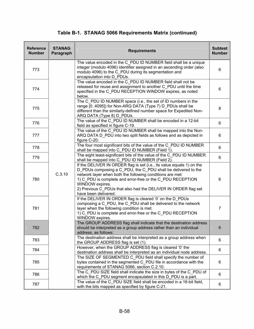
B-58
Table B-1. STANAG 5066 Requirements Matrix (continued)
Reference Number
STANAG Paragraph Requirements Subtest
Number
773
The value encoded in the C_PDU ID NUMBER field shall be a unique integer (modulo 4096) identifier assigned in an ascending order (also modulo 4096) to the C_PDU during its segmentation and encapsulation into D_PDUs.
6
774
The value encoded in the C_PDU ID NUMBER field shall not be released for reuse and assignment to another C_PDU until the time specified in the C_PDU RECEPTION WINDOW expires, as noted below.
6
775
The C_PDU ID NUMBER space (i.e., the set of ID numbers in the range [0..4095]) for Non-ARQ DATA (Type 7) D_PDUs shall be different than the similarly-defined number space for Expedited Non-ARQ DATA (Type 8) D_PDUs.
8
776 The value of the C_PDU ID NUMBER shall be encoded in a 12-bit field as specified in figure C-19. 6
777 The value of the C_PDU ID NUMBER shall be mapped into the Non-ARQ DATA D_PDU into two split fields as follows and as depicted in figure C-20:
6
778 The four most significant bits of the value of the C_PDU ID NUMBER shall be mapped into C_PDU ID NUMBER (Field 1). 6
779 The eight least-significant bits of the value of the C_PDU ID NUMBER shall be mapped into C_PDU ID NUMBER (Field 2). 6
780
If the DELIVER IN ORDER flag is set (i.e., its value equals 1) on the D_PDUs composing a C_PDU, the C_PDU shall be delivered to the network layer when both the following conditions are met: 1) C_PDU is complete and error-free or the C_PDU RECEPTION WINDOW expires. 2) Previous C_PDUs that also had the DELIVER IN ORDER flag set have been delivered.
6
781
If the DELIVER IN ORDER flag is cleared ‘0’ on the D_PDUs composing a C_PDU, the C_PDU shall be delivered to the network layer when the following condition is met. 1) C_PDU is complete and error-free or the C_PDU RECEPTION WINDOW expires.
7
782 The GROUP ADDRESS flag shall indicate that the destination address should be interpreted as a group address rather than an individual address, as follows:
6
783 The destination address shall be interpreted as a group address when the GROUP ADDRESS flag is set (1). 6
784 However, when the GROUP ADDRESS flag is cleared ‘0’ the destination address shall be interpreted as an individual node address. 6
785 The SIZE OF SEGMENTED C_PDU field shall specify the number of bytes contained in the segmented C_PDU file in accordance with the requirements of STANAG 5066, section C.2.10.
6
786 The C_PDU SIZE field shall indicate the size in bytes of the C_PDU of which the C_PDU segment encapsulated in this D_PDU is a part. 6
787
C.3.10
The value of the C_PDU SIZE field shall be encoded in a 16-bit field, with the bits mapped as specified by figure C-21. 6
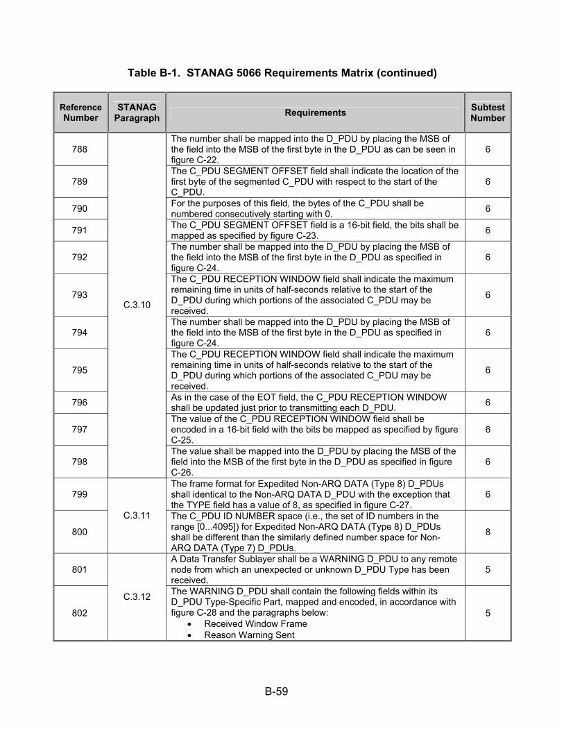
B-59
Table B-1. STANAG 5066 Requirements Matrix (continued)
Reference Number
STANAG Paragraph Requirements Subtest
Number
788 The number shall be mapped into the D_PDU by placing the MSB of the field into the MSB of the first byte in the D_PDU as can be seen in figure C-22.
6
789 The C_PDU SEGMENT OFFSET field shall indicate the location of the first byte of the segmented C_PDU with respect to the start of the C_PDU.
6
790 For the purposes of this field, the bytes of the C_PDU shall be numbered consecutively starting with 0. 6
791 The C_PDU SEGMENT OFFSET field is a 16-bit field, the bits shall be mapped as specified by figure C-23. 6
792 The number shall be mapped into the D_PDU by placing the MSB of the field into the MSB of the first byte in the D_PDU as specified in figure C-24.
6
793
The C_PDU RECEPTION WINDOW field shall indicate the maximum remaining time in units of half-seconds relative to the start of the D_PDU during which portions of the associated C_PDU may be received.
6
794 The number shall be mapped into the D_PDU by placing the MSB of the field into the MSB of the first byte in the D_PDU as specified in figure C-24.
6
795
The C_PDU RECEPTION WINDOW field shall indicate the maximum remaining time in units of half-seconds relative to the start of the D_PDU during which portions of the associated C_PDU may be received.
6
796 As in the case of the EOT field, the C_PDU RECEPTION WINDOW shall be updated just prior to transmitting each D_PDU. 6
797 The value of the C_PDU RECEPTION WINDOW field shall be encoded in a 16-bit field with the bits be mapped as specified by figure C-25.
6
798
C.3.10
The value shall be mapped into the D_PDU by placing the MSB of the field into the MSB of the first byte in the D_PDU as specified in figure C-26.
6
799 The frame format for Expedited Non-ARQ DATA (Type 8) D_PDUs shall identical to the Non-ARQ DATA D_PDU with the exception that the TYPE field has a value of 8, as specified in figure C-27.
6
800
C.3.11 The C_PDU ID NUMBER space (i.e., the set of ID numbers in the range [0...4095]) for Expedited Non-ARQ DATA (Type 8) D_PDUs shall be different than the similarly defined number space for Non-ARQ DATA (Type 7) D_PDUs.
8
801 A Data Transfer Sublayer shall be a WARNING D_PDU to any remote node from which an unexpected or unknown D_PDU Type has been received.
5
802
C.3.12 The WARNING D_PDU shall contain the following fields within its D_PDU Type-Specific Part, mapped and encoded, in accordance with figure C-28 and the paragraphs below:
• Received Window Frame • Reason Warning Sent
5

B-60
Table B-1. STANAG 5066 Requirements Matrix (continued)
Reference Number
STANAG Paragraph Requirements Subtest
Number
803 The Received Frame Type shall indicate the frame type that caused the warning to be sent. 5
804 The value of the RECEIVED FRAME TYPE field shall be encoded in 4 bits and located within the D_PDU as specified in figure C-29 and figure C-30.
5
805 The REASON WARNING SENT field shall indicate the reason the frame type caused a warning, with values as specified in table C-3: 5
806 The value of the REASON WARNING SENT field shall be encoded in 4 bits and located within the D_PDU as specified in figure C-31 and figure C-32.
5
807 The transmission of WARNING type D_PDUs shall be initiated independently by the Data Transfer Sublayer in response to certain D_PDUs;
5
808 And shall not be acknowledged explicitly. 5
809
A WARNING D_PDU shall be sent in the following conditions: 1. A node receives a D_PDU header addressed to itself with a valid CRC and an unrecognized D_PDU Type (value 0000). 2. A node is not in the IDLE/BROADCAST state and it receives a D_PDU header addressed to itself, from a node with which it is not currently connected. (value 0001). 3. A node is in IDLE/BROADCAST state and it receives a D_PDU header addressed to itself which is other than Type 7 or Type 8 D_PDU (value 0010). 4. A node receives any D_PDU which is recognized but is not of the allowed type for the state which the receiving node is in (value 0011; this is the general case of the preceding).
5
810
C.3.12
A WARNING D_PDU shall not be sent in response to receipt of a WARNING D_PDU. 5
811 C.4 The process of C_PDU segmentation and re-assembly shall be defined in the subsections that follow for ARQ and Non-ARQ delivery services provided to regular and expedited C_PDUs.
7
812
Segmentation of a C_PDU into segments small enough to fit within a D_PDU for ARQ delivery (i.e., a DATA, DATA-ACK, or EXPEDITED-DATA D_PDU) shall be performed in accordance with the example shown in figure C-33 and as follows:
7
813
The Maximum C_PDU Segment size within a D_PDU for ARQ-Delivery services shall be a configurable parameter no greater than 1023 bytes in any implementation compliant with this STANAG. An implementation may configure the Maximum C_PDU Segment size to match the interleaver size for optimum channel efficiency or other reasons.
7
814 An entire C_PDU that is smaller than the Maximum C_PDU Segment size shall be placed in the C_PDU segment of a single D_PDU. 7
815
C.4.1
A DATA or DATA-ACK, or EXPEDITED D_PDU that contains an entire C_DPU shall be marked with both the C_PDU Start field and the C_PDU End field set equal to the value (1). (Note: An ‘only’ C_PDU segment is both the “first” and “last” segment of a sequence of one.)
7
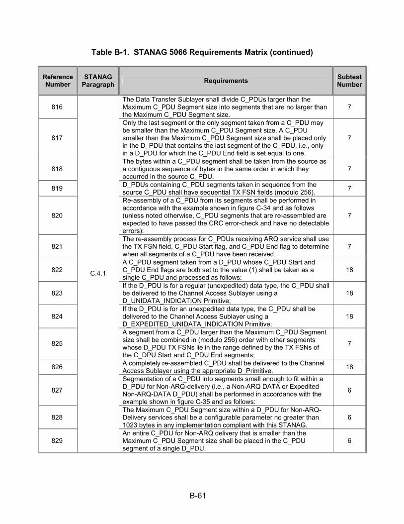
B-61
Table B-1. STANAG 5066 Requirements Matrix (continued)
Reference Number
STANAG Paragraph Requirements Subtest
Number
816 The Data Transfer Sublayer shall divide C_PDUs larger than the Maximum C_PDU Segment size into segments that are no larger than the Maximum C_PDU Segment size.
7
817
Only the last segment or the only segment taken from a C_PDU may be smaller than the Maximum C_PDU Segment size. A C_PDU smaller than the Maximum C_PDU Segment size shall be placed only in the D_PDU that contains the last segment of the C_PDU, i.e., only in a D_PDU for which the C_PDU End field is set equal to one.
7
818 The bytes within a C_PDU segment shall be taken from the source as a contiguous sequence of bytes in the same order in which they occurred in the source C_PDU.
7
819 D_PDUs containing C_PDU segments taken in sequence from the source C_PDU shall have sequential TX FSN fields (modulo 256). 7
820
Re-assembly of a C_PDU from its segments shall be performed in accordance with the example shown in figure C-34 and as follows (unless noted otherwise, C_PDU segments that are re-assembled are expected to have passed the CRC error-check and have no detectable errors):
7
821 The re-assembly process for C_PDUs receiving ARQ service shall use the TX FSN field, C_PDU Start flag, and C_PDU End flag to determine when all segments of a C_PDU have been received.
7
822 A C_PDU segment taken from a D_PDU whose C_PDU Start and C_PDU End flags are both set to the value (1) shall be taken as a single C_PDU and processed as follows:
18
823 If the D_PDU is for a regular (unexpedited) data type, the C_PDU shall be delivered to the Channel Access Sublayer using a D_UNIDATA_INDICATION Primitive;
18
824 If the D_PDU is for an unexpedited data type, the C_PDU shall be delivered to the Channel Access Sublayer using a D_EXPEDITED_UNIDATA_INDICATION Primitive;
18
825
A segment from a C_PDU larger than the Maximum C_PDU Segment size shall be combined in (modulo 256) order with other segments whose D_PDU TX FSNs lie in the range defined by the TX FSNs of the C_DPU Start and C_PDU End segments;
7
826 A completely re-assembled C_PDU shall be delivered to the Channel Access Sublayer using the appropriate D_Primitive. 18
827
Segmentation of a C_PDU into segments small enough to fit within a D_PDU for Non-ARQ-delivery (i.e., a Non-ARQ DATA or Expedited Non-ARQ-DATA D_PDU) shall be performed in accordance with the example shown in figure C-35 and as follows:
6
828 The Maximum C_PDU Segment size within a D_PDU for Non-ARQ-Delivery services shall be a configurable parameter no greater than 1023 bytes in any implementation compliant with this STANAG.
6
829
C.4.1
An entire C_PDU for Non-ARQ delivery that is smaller than the Maximum C_PDU Segment size shall be placed in the C_PDU segment of a single D_PDU.
6

B-62
Table B-1. STANAG 5066 Requirements Matrix (continued)
Reference Number
STANAG Paragraph Requirements Subtest
Number
830 A unique C_PDU ID Number shall be assigned to the Non-ARQ C_PDU in accordance with the requirements of STANAG 5066, section C.3.10.
6
831 All D_PDUs containing segments from the same C_PDU shall have the same C_PDU ID Number. 6
832 The Segment Offset field of the D_PDU containing the first segment from a C_PDU shall be equal to zero. 6
833 The Segment Offset field of the D_PDU containing any subsequent segment from a C_PDU shall be set equal to the number of bytes from the original C_PDU that precede the first byte of the segment.
6
834
For Non-ARQ services, re-assembly of a C_PDU from its segments shall be performed in accordance with the example shown in figure C-36 and as follows (unless noted otherwise, C_PDU segments that are re-assembled are expected to have passed the CRC error-check and have no detectable errors):
6
835
The re-assembly process for Non-ARQ C_PDUs shall use the C_PDU ID Number field, Segment Offset field, C_PDU Segment-Size field, and C_PDU Size field to determine when all segments of a C_PDU have been received.
6
836 If the Error-free Delivery Mode has been specified, a re-assembled C_PDU shall be delivered, if and only if all segments of the C_PDU have been received without errors.
6
837 If the Deliver-with-Errors Mode has been specified, the re-assembly process shall proceed as follows: 6/18
838 C_PDU segments received without detected errors shall be collected as received in their D_PDUs and placed in order within the re-assembled C_PDU.
6
839
C_PDU segments received with detected errors shall be placed within the re-assembled C_PDU just as they are received in their D_PDUs (i.e., with errors), with the size in bytes and the position of the first byte of the segment noted in the D_Primitive used to deliver the C_PDU to the Channel Access Sublayer;
18
840
At the end of a specified and configurable time-out interval, the size in bytes and the position of the first byte of any C_PDU segments that have been lost or still not received shall be noted in the D_Primitive that delivers the C_PDU to the Channel Access Sublayer.
18
841
If the Deliver-In-Order Mode has been specified (with or without the Deliver-with-Errors Mode specified), C_PDUs shall be delivered to the Channel Access Sublayer only if C_PDUs with lower-numbered C_PDU ID Numbers have already been delivered.
18
842
If the Deliver-out-of-Order Mode has been specified, C_PDUs shall be delivered to the Channel Access Sublayer as soon as all segments have been received (in Error-free Mode) or received and accounted for (in Deliver-with-Errors Mode).
18
843
C.4.1
Delivery of the re-assembled D_PDU shall be performed with the D_Primitive appropriate for the type of data (i.e., regular or expedited) received.
7
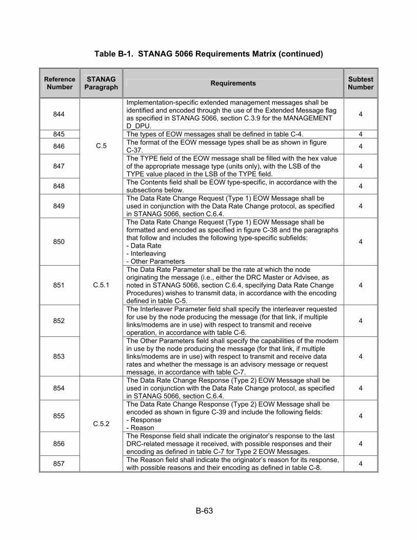
B-63
Table B-1. STANAG 5066 Requirements Matrix (continued)
Reference Number
STANAG Paragraph Requirements Subtest
Number
844
Implementation-specific extended management messages shall be identified and encoded through the use of the Extended Message flag as specified in STANAG 5066, section C.3.9 for the MANAGEMENT D_DPU.
4
845 The types of EOW messages shall be defined in table C-4. 4 846 The format of the EOW message types shall be as shown in figure
C-37. 4
847 The TYPE field of the EOW message shall be filled with the hex value of the appropriate message type (units only), with the LSB of the TYPE value placed in the LSB of the TYPE field.
4
848
C.5
The Contents field shall be EOW type-specific, in accordance with the subsections below. 4
849 The Data Rate Change Request (Type 1) EOW Message shall be used in conjunction with the Data Rate Change protocol, as specified in STANAG 5066, section C.6.4.
4
850
The Data Rate Change Request (Type 1) EOW Message shall be formatted and encoded as specified in figure C-38 and the paragraphs that follow and includes the following type-specific subfields: - Data Rate - Interleaving - Other Parameters
4
851
The Data Rate Parameter shall be the rate at which the node originating the message (i.e., either the DRC Master or Advisee, as noted in STANAG 5066, section C.6.4, specifying Data Rate Change Procedures) wishes to transmit data, in accordance with the encoding defined in table C-5.
4
852
The Interleaver Parameter field shall specify the interleaver requested for use by the node producing the message (for that link, if multiple links/modems are in use) with respect to transmit and receive operation, in accordance with table C-6.
4
853
C.5.1
The Other Parameters field shall specify the capabilities of the modem in use by the node producing the message (for that link, if multiple links/modems are in use) with respect to transmit and receive data rates and whether the message is an advisory message or request message, in accordance with table C-7.
4
854 The Data Rate Change Response (Type 2) EOW Message shall be used in conjunction with the Data Rate Change protocol, as specified in STANAG 5066, section C.6.4.
4
855
The Data Rate Change Response (Type 2) EOW Message shall be encoded as shown in figure C-39 and include the following fields: - Response - Reason
4
856 The Response field shall indicate the originator’s response to the last DRC-related message it received, with possible responses and their encoding as defined in table C-7 for Type 2 EOW Messages.
4
857
C.5.2
The Reason field shall indicate the originator’s reason for its response, with possible reasons and their encoding as defined in table C-8. 4

B-64
Table B-1. STANAG 5066 Requirements Matrix (continued)
Reference Number
STANAG Paragraph Requirements Subtest
Number
858 The UNRECOGNIZED-TYPE ERROR (Type 3) EOW Message shall be used to declare an error related to receipt of EOW message. 4
859
The UNRECOGNIZED-TYPE ERROR (Type 3) EOW Message shall be encoded as shown in figure C.40 and include the following fields: - Response - Reason
4
860 The type of the unrecognized EOW message or the message that triggered the error shall be mapped into the four least-significant bits of the Reason field.
4
861
C.5.3
The unused MSB of the Reason field and all bits in the Response field shall be reset to the value zero ‘0’. 4
862 The EOW Message Type 4 shall be encoded as shown in figure C-41 and contains a single field, Content. 11
863
C.5.4 The Content field shall be encoded as the bit-mapped specification of
capabilities defined in table C-9. 11
864 C.6.1 The Data Transfer Sublayer interactions with peers shall be defined with respect to the states shown in figure C-42 and as follows: 18
865 The transitions between DTS States and the actions that arise from given events shall be defined in the tables presented in the subsections that follow:
18
866 DTS states, transitions, and actions shall be defined and maintained with respect to a specified remote node address. 18
867 Action and transitions rules shall not occur based on PDUs addressed to other nodes or from a node other than the specified remote node for which the states are maintained.
18
868 Action and transitions rules shall not occur based on D_Primitives that reference nodes other than the specified remote node. 18
869
C.6.1.1
DTS states shall be maintained for each specified node for which a connection or ARQ protocol must be maintained. 18
870 When in the IDLE (UNCONNECTED) State, the Data Transfer Sublayer shall respond to reception of a D_Primitive from the Channel Access Sublayer as specified in table C-10.
18
871
C.6.1.1.1. When in the IDLE (UNCONNECTED) State, the Data Transfer Sublayer shall respond to reception of a D_PDU from the lower layers as specified in table C-11.
18
872 When in the DATA (UNCONNECTED) State, the Data Transfer Sublayer shall respond to reception of a D_Primitive from the Channel Access Sublayer as specified in table C-12.
18
873
C.6.1.1.2 When in the DATA (UNCONNECTED) State, the Data Transfer Sublayer shall respond to reception of a D_PDU from the lower layers as specified in table C-13.
18
874 When in the EXPEDITED-DATA (UNCONNECTED) State, the Data Transfer Sublayer shall espond to reception of a D_Primitive from the Channel Access Sublayer as specified in the following table C-14.
18
875
C.6.1.1.3 When in the EXPEDITED-DATA (UNCONNECTED) State, the Data Transfer Sublayer shall respond to reception of a D_PDU from the lower layers as specified in table C-15.
18

B-65
Table B-1. STANAG 5066 Requirements Matrix (continued)
Reference Number
STANAG Paragraph Requirements Subtest
Number
876 When in the MANAGEMENT (UNCONNECTED) State, the Data Transfer Sublayer shall respond to reception of a D_Primitive from the Channel Access Sublayer as specified in table C-16.
18
877
C.6.1.1.4 When in the MANAGEMENT (UNCONNECTED) State, the Data Transfer Sublayer shall respond to reception of a D_PDU from the lower layers as specified in table C-17.
18
878 When in the IDLE (CONNECTED) State, the Data Transfer Sublayer shall respond to reception of a D_Primitive from the Channel Access Sublayer as specified in table C-18.
18
879
C.6.1.1.5 When in the IDLE (CONNECTED) State, the Data Transfer Sublayer shall respond to reception of a D_PDU from the lower layers as specified in table C-19.
18
880 When in the DATA (CONNECTED) State, the Data Transfer Sublayer shall respond to reception of a D_Primitive from the Channel Access Sublayer as specified in table C-20.
18
881
C.6.1.1.6 When in the DATA(CONNECTED) State, the Data Transfer Sublayer shall respond to reception of a D_PDU from the lower layers as specified in table C-21.
18
882 When in the EXPEDITED-DATA (CONNECTED) State, the Data Transfer Sublayer shall respond to reception of a D_Primitive from the Channel Access Sublayer as specified in table C-22.
18
883
C.6.1.1.7 When in the EXPEDITED-DATA (CONNECTED) State, the Data Transfer Sublayer shall respond to reception of a D_PDU from the lower layers as specified in table C-23.
18
884 When in the MANAGEMENT (CONNECTED) State, the Data Transfer Sublayer shall respond to reception of a D_Primitive from the Channel Access Sublayer as specified in table C-24.
18
885
C.6.1.1.8 When in the MANAGEMENT(CONNECTED) State, the Data Transfer Sublayer shall respond to reception of a D_PDU from the lower layers as specified in table C-25.
18
886 A node shall transmit only those D_PDUs which are allowed for its current state as follows: 18
887 C.6.1.2 A node shall receive and process all valid D_PDUs regardless of its
current state. Transmission of responses to a received D_PDU may be immediate or deferred, as appropriate for the current state and as specified in STANAG 5066, section 6.1.1.
18
888 A separate TX FSN counter shall be maintained for the transmission of ARQ Expedited Data, distinct from the counter with the same name used for regular-delivery service with D_PDU Types 0 and 2.
8
889
A separate C_PDU ID counter shall be maintained for the transmission of ARQ Expedited Data, distinct from the counter with the same name used for regular Non-ARQ and expedited Non-ARQ delivery services with D_PDU Types 7 and 8.
8
890 Upon entering the EXPEDITED-DATA (CONNECTED) State, the EXPEDITED-DATA D_PDU TX FSN counter shall be set to the value zero ‘0’.
8
891
C.6.1.3
Starting or restarting another ARQ machine (i.e., establishing a link with a new node or reestablishing link with a previously connected node) shall reset the ARQ machine for the EXPEDITED DATA-State.
18

B-66
Table B-1. STANAG 5066 Requirements Matrix (continued)
Reference Number
STANAG Paragraph Requirements Subtest
Number
892 The processing of D_PDUs containing Expedited Data shall proceed according to a C_PDU level stop-and-wait protocol, as follows: 2
893 C.6.1.3
No new expedited C_PDUs shall be accepted for service until the last D_PDU of a prior expedited C_PDU has been acknowledged. 2
894 Each time a D_EXPEDITED_UNIDATA_REQUEST Primitive is accepted for service, the Expedited Data D_PDU TX FSN counter shall be reset to the value zero.
8
895 And the C_PDU ID counter shall be incremented (modulo 16). 8
896 Upon exiting the EXPEDITED DATA (CONNECTED) State to another state, all unsent EXPEDITED-DATA C_PDUs (and portions of C_PDUs) shall be discarded.
18
897
C.6.1.3
Similarly at a receiving node, transition from the EXPEDITED DATA (CONNECTED) State to another state shall result in the deletion of a partially assembled C_PDU.
18
898 The Data Transfer Sublayer shall satisfy the following requirements for D_PDU flow-control: 7/13/18
899 Each node shall maintain a transmit and a receive flow-control window buffer for each connection supported. 13
900 The TX FSNs shall be assigned uniquely and sequentially in an ascending (modulo 256) order during the segmentation of the C_PDU into D_PDUs.
7
901 The TX FSNs shall not be released for reuse with another D_PDU until the receiving node has acknowledged the D_PDU to which the number is assigned.
7
902 The TX LWE shall indicate the lowest-numbered outstanding unacknowledged D_PDU (lowest numbered allowing for the (modulo 256) operations).
18
903 The transmit upper window edge (TX UWE) shall be the number of the last new D_PDU that was transmitted (highest D_PDU number, allowing for the (modulo 256) operation).
18
904 The difference (as a modulo-256 arithmetic operator) between the TX UWE and TX LWE – 1 shall be equal to the “current transmitter window size.”
18
905 The “maximum window size” shall equal 128. 13
906 The “maximum allowable window size” may be a node-configurable parameter (this is recommended) and shall not exceed the “maximum window size.”
13
907
The “current transmitter window size” at any moment is variable as a function of the current TX UWE and TX LWE and shall not exceed the “maximum allowable window size.” This allows for no more than 128 “maximum window size” outstanding unacknowledged D_PDUs in any circumstance.
13
908
C.6.2
If the “current transmitter window size” equals the “maximum allowable window size,” no additional new D_PDUs shall be transmitted until the TX LWE has been advanced and the newly computed difference (modulo 256) between the TX UWE and the TX LWE – 1 is less than the maximum allowable window size.
13
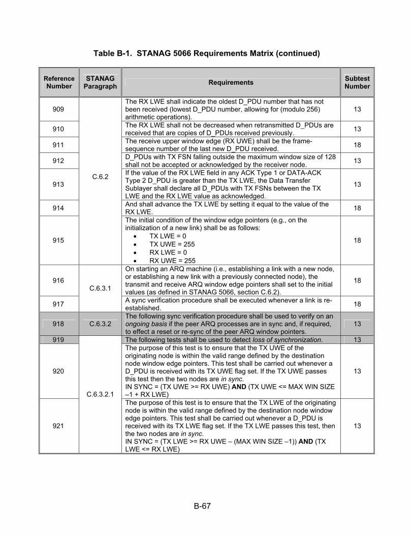
B-67
Table B-1. STANAG 5066 Requirements Matrix (continued)
Reference Number
STANAG Paragraph Requirements Subtest
Number
909 The RX LWE shall indicate the oldest D_PDU number that has not been received (lowest D_PDU number, allowing for (modulo 256) arithmetic operations).
13
910 The RX LWE shall not be decreased when retransmitted D_PDUs are received that are copies of D_PDUs received previously. 13
911 The receive upper window edge (RX UWE) shall be the frame-sequence number of the last new D_PDU received. 18
912 D_PDUs with TX FSN falling outside the maximum window size of 128 shall not be accepted or acknowledged by the receiver node. 13
913
If the value of the RX LWE field in any ACK Type 1 or DATA-ACK Type 2 D_PDU is greater than the TX LWE, the Data Transfer Sublayer shall declare all D_PDUs with TX FSNs between the TX LWE and the RX LWE value as acknowledged.
13
914 And shall advance the TX LWE by setting it equal to the value of the RX LWE. 18
915
C.6.2
The initial condition of the window edge pointers (e.g., on the initialization of a new link) shall be as follows:
• TX LWE = 0 • TX UWE = 255 • RX LWE = 0 • RX UWE = 255
18
916
On starting an ARQ machine (i.e., establishing a link with a new node, or establishing a new link with a previously connected node), the transmit and receive ARQ window edge pointers shall set to the initial values (as defined in STANAG 5066, section C.6.2).
18
917
C.6.3.1
A sync verification procedure shall be executed whenever a link is re-established. 18
918 C.6.3.2 The following sync verification procedure shall be used to verify on an ongoing basis if the peer ARQ processes are in sync and, if required, to effect a reset or re-sync of the peer ARQ window pointers.
13
919 The following tests shall be used to detect loss of synchronization. 13
920
The purpose of this test is to ensure that the TX UWE of the originating node is within the valid range defined by the destination node window edge pointers. This test shall be carried out whenever a D_PDU is received with its TX UWE flag set. If the TX UWE passes this test then the two nodes are in sync. IN SYNC = (TX UWE >= RX UWE) AND (TX UWE <= MAX WIN SIZE –1 + RX LWE)
13
921
C.6.3.2.1 The purpose of this test is to ensure that the TX LWE of the originating node is within the valid range defined by the destination node window edge pointers. This test shall be carried out whenever a D_PDU is received with its TX LWE flag set. If the TX LWE passes this test, then the two nodes are in sync. IN SYNC = (TX LWE >= RX UWE – (MAX WIN SIZE –1)) AND (TX LWE <= RX LWE)
13

B-68
Table B-1. STANAG 5066 Requirements Matrix (continued)
Reference Number
STANAG Paragraph Requirements Subtest
Number
922 C.6.3.2.1
The purpose of this test is to ensure that the TX FSN of a frame received from the originating node is within the valid range defined by the destination node window edge pointers. This test shall be carried out on every DATA and DATA-ACK frame received. If the TX FSN of the incoming frame passes this test then the two nodes are in sync. IN SYNC = (TX FSN <= RX LWE + (MAX WIN SIZE – 1)) AND (TX FSN >= RX UWE – (MAX WIN SIZE – 1))
13
923
The purpose of tests carried out at the originating node is to ensure that the TX FSNs of acknowledged frames are within the range defined by the transmit window edge pointers. These tests shall be applied whenever a DATA-ACK or ACK-ONLY frame is received. IN SYNC = (RX LWE >= TX LWE) AND (RX LWE <= TX UWE +1)
13
924
C.6.3.2.2 Individual frames may be acknowledged in a DATA-ACK or ACK-ONLY frame by setting bits in the Selective ACK header field. The TX FSNs corresponding to such bits must also fall within the range defined by the transmit window edges if the two nodes are in sync. The following test shall be used to determine whether acknowledged FSNs fall within the correct range. IN SYNC = (Acknowledged FSN > TX LWE) AND (Acknowledged FSN <= TX UWE)
12
925 If Data Rate Control is implemented, it shall be implemented as specified in the subsections below. 4
926 C.6.4 Nodes that do not implement Data Rate Control shall use the
appropriate EOW and Management message types specified in STANAG 5066, section 3.5 and the protocol defined below to signal this condition to other nodes.
11
927 All connections on which the data rate or other modem parameters can be controlled shall be initiated at 300 bps, using short interleaving. 4
928 C.6.4.1 The waveform shall be selected by the operator during node
initialization. 4
929
Algorithms to determine when or if the data rate change capability would be exercised are beyond the scope of this STANAG. At a minimum, systems implementing STANAG 5066 shall implement and support data rate changes in accordance with the procedures defined here.
4
930
On receiving an EOW Type 1 Data Rate Change message with the Other Parameters field indicating that this is a request for a Data Rate Change, a node shall comply with the parameters specified in the message unless some specific reason prevents it doing so. Generally this means that the node will initiate a data rate change (DRC) procedure.
4
931 Following a decision to change data rate, a node shall use TYPE 6 D_PDUs (i.e., MANAGEMENT D_PDUs) containing Type 1 and Type 2 EOW messages to implement and coordinate the change.
4
932 The data-rate change procedure shall be executed in the MANAGEMENT (CONNECTED) State in accordance with STANAG 5066, section 6.1.
18
933
C.6.4.2
Data rate changes shall be effective only for a single connection. 4

B-69
Table B-1. STANAG 5066 Requirements Matrix (continued)
Reference Number
STANAG Paragraph Requirements Subtest
Number
934 If a node has a number of connections active with different nodes, the data rate change decisions and procedures shall be executed independently for each connection.
4
935
The message numbered (1) in the figure indicates an EOW advisory message. The DRC master shall send a DRC Request Message, i.e., a Management (Type 6) D_PDU containing a DRC Request (Type 1) EOW Message (2), with the parameters equal to the intended new transmit data rate for the DRC master.
4
936
The Other Parameters field of the Type 1 Management message shall be set to indicate the data rate capabilities of the modem in use at the DRC master for this connection and to indicate that this is a request for a change and not an advisory message. In the scenario of figure C-50, the modem at the DRC master has independent transmit and receive data rate.
4
937
The only state transition allowed due to time-out during the Data-Rate-Change procedure shall be to the IDLE (UNCONNECTED) State as specified in STANAG 5066, section C.6.1, with a D_CONNECTION_LOST primitive sent to the Channel Access Sublayer.
18
938 Time-outs shall be set to allow a number of retransmissions before failure is declared and the D_CONNECTION_LOST Primitive issued. 4
939 The number of retransmissions before a time-out shall be configurable in the implementation with a default value of 3. 4
940
If this procedure was initiated in response to a DRC Request (Type 1) Advisory message, the modem data rate and interleaving parameters shall (12) be identical to the parameters in the EOW Type 1 DRC Advisory message, unless they specify a speed for which the DRC master is not equipped.
4
941 D_PDUs containing a DRC Request (Type 1) EOW message shall be repeated depending on the data rate at which it is transmitted, in accordance with the specification in table C-26:
4
942
Implementation Note: The number of transmissions in table C-26 has been specified to (nearly) fill the interleave buffer for the waveform specified by STANAG 4285. For waveforms and interleaver settings not shown, the number of transmissions shall be adjusted as required to minimize the use of “stuff bits” to fill the modem interleave buffer.
4
943 Repeated MANAGEMENT D_PDUs containing a DRC Request (Type 1) Management message shall have the same Frame ID Number in each of the copies.
4
944
Valid EOT information shall be supplied in each repeated D_PDU containing a DRC Request (Type 1) Management message, updated as required to denote the EOT of all D_PDU messages in the transmission interval (and not the end of the individual D_PDU containing the EOT field).
7
945
C.6.4.2
The same EOT value shall not be transmitted in each repeated D_PDU containing a DRC Request (Type 1) Management message unless necessary due to EOT resolution and roundup errors, i.e., because the D_PDU duration is less than half the EOT resolution.
7

B-70
Table B-1. STANAG 5066 Requirements Matrix (continued)
Reference Number
STANAG Paragraph Requirements Subtest
Number
946
A node (referred to as the DRC slave) that receives a MANAGEMENT D_PDU addressed to it and containing a DRC_Request Type 1 Management message shall transition to the Management State as specified in STANAG 5066, section C.6.1.
18
947 The DRC slave shall respond to the DRC_Request D_PDU with a DRC_Response message, i.e., a TYPE 6 MANAGEMENT D_PDU containing a Type 2 DRC Response EOW message, as follows:
4
948
The DRC Response message shall indicate either “accept” or “refuse,” in accordance with the MANAGEMENT message specifications of STANAG 5066, section 3.5, indicating the DRC Slave’s capability to change the modem parameters or not.
4
949 If the DRC slave accepts the DRC_Request, the “Reason” field shall indicate either “unconditional acceptance” or “TX and RX parameters must be the same.”
4
950 If the DRC slave refuses the request, the “Reason” field shall indicate the reason for the refusal. 4
951
The “Not consistent with local conditions” parameter shall only be used to refuse a DRC_Request which indicates a less robust mode (i.e., higher data rate or shorter interleaver) that cannot be supported with the node’s current local conditions for noise or error rate.
4
952 After receiving the DRC_Response message the DRC master shall review its contents and determine the appropriate response, e.g., the DT_ACK(only) (4), in accordance with table C-27.
4
953
Note 1: If the procedure is initiated in response to EOW Type 1 message, the DRC master should already know that the DRC slave’s transmit and receive parameters must be the same. Therefore, the DRC master shall reply with a DT_ACK, i.e., a Management (Type 6) D_PDU with the ACK field set equal to one, accepting that the new parameters will apply to both transmit and receive.
4
954 Note 2: A DRC slave that refused a change request shall acknowledge the DRC Response (cancel) message with a DT_ACK only and then terminate the DRC procedure.
4
955
Note 6: If the nodes make use of the EOW Type 1 (Advisory) message to initiate the DRC procedure, the master shall send the DRC_Response (cancel) and await an updated EOW recommendation before initiating another DRC procedure. If EOW Type 1 messages are not used, DRC_Request may be sent by the master to request different modem parameters, which may be consistent with the local conditions.
4
956
If a DT_ACK (with no further management message) is sent in reply to a DRC_Response “accept” (as shown in figure C-50), the nodes shall change their respective modem parameters and proceed to the “confirmation” phase.
4
957
C.6.4.2
The DRC slave shall NOT change its modem parameters until it has received a DT_ACK (with no further management message) from the DRC master.
4

B-71
Table B-1. STANAG 5066 Requirements Matrix (continued)
Reference Number
STANAG Paragraph Requirements Subtest
Number
958
If a DT_ACK (with no further management message) is sent by the DRC slave in reply to a DRC_Response “cancel,” both nodes shall abandon the procedure and return to the prior state without changing modem parameters.
4
959
After abandoning a DRC procedure because of failure, if node A (formerly the DRC slave) has no queued data or acknowledgements to send to node B, it shall send a data D_PDU, expedited data D_PDU, or Non-ARQ D_PDU, with zero data attached.
4
960 On receiving the DRC Confirm message, the DRC Master shall respond with a DT_ACK and then return to the processing state it was in before executing the DRC procedure.
4
961
After sending the DRC Confirm message [5] to the master and receiving the DT_ACK from the master, the slave shall return to the processing state it was in before executing the DRC procedure and send any queued D_PDUs to node B.
4
962
C.6.4.2
If node A (formerly the DRC slave) has no queued data to send to node B, it shall send a DATA D_PDU or EXPEDITED DATA D_PDU with zero data attached and the C_PDU Segment size field set equal to zero ‘0’.
4
963 A FULL RESET procedure shall by a node sending a Type 3 RESET/WIN Re-sync D_PDU with field values as follows: 3
964 The FULL RESET CMD flag shall be set to 1. 3 965 The RESET FRAME ID NUMBER shall be selected from RESET
FRAME ID NUMBER sequence. 3 966 The NEW RECEIVE LWE field shall be reset to zero. 3 967 The RESET TX WIN RQST flag shall be reset to zero. 3 968 The RESET RX WIN CMD flag shall be reset to zero. 3
969 The Type 3 D_PDU described immediately above is defined to be a FULL RESET CMD D_PDU. A node receiving a FULL RESET CMD D_PDU shall proceed as follows:
3
970 The node shall set the transmit and receive window pointers to initial values (as defined in STANAG 5066, section C.6.2). 3
971 The node shall discard from its transmit queue any partially completed C_PDUs. 3
972 The node shall flush its receive buffers. 3
973 The node shall respond to the originator of the FULL-RESET-CMD D_PDU by sending it a RESET/WIN Re-sync (Type 3) D_PDU with field values set as follows:
3
974 The RESET ACK flag shall be set to 1; 3 975 The NEW RECEIVE LWE and RESET FRAME ID NUMBER fields
shall be reset to zero; 3
976 The RESET TX WIN RQST, FULL RESET CMD and RESET RX WIN CMD flags shall be reset to zero. 3
977 The D_PDU described immediately above is defined to be a FULL-RESET-ACK D_PDU. The FULL RESET ACK D_PDU shall be sent only in response to the FULL RESET CMD D_PDU.
3
978
C.6.5
On receiving the FULL-RESET-ACK D_PDU, the node initiating the FULL RESET procedure shall proceed as follows: 3
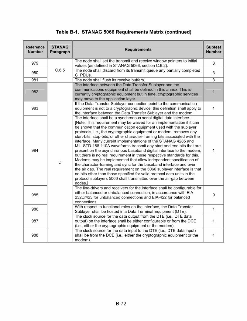
B-72
Table B-1. STANAG 5066 Requirements Matrix (continued)
Reference Number
STANAG Paragraph Requirements Subtest
Number
979 The node shall set the transmit and receive window pointers to initial values (as defined in STANAG 5066, section C.6.2). 3
980 The node shall discard from its transmit queue any partially completed C_PDUs. 3
981
C.6.5
The node shall flush its receive buffers. 3
982
The interface between the Data Transfer Sublayer and the communications equipment shall be defined in this annex. This is currently cryptographic equipment but in time, cryptographic services may move to the application layer.
1
983 If the Data Transfer Sublayer connection point to the communication equipment is not to a cryptographic device, this definition shall apply to the interface between the Data Transfer Sublayer and the modem.
1
984
The interface shall be a synchronous serial digital data interface. [Note: This requirement may be waived for an implementation if it can be shown that the communication equipment used with the sublayer protocols, i.e., the cryptographic equipment or modem, removes any start-bits, stop-bits, or other character-framing bits associated with the interface. Many current implementations of the STANAG 4285 and MIL-STD-188-110A waveforms transmit any start and end bits that are present on the asynchronous baseband digital interface to the modem, but there is no real requirement in these respective standards for this. Modems may be implemented that allow independent specification of the character-framing and sync for the baseband interface and over the air gap. The real requirement on the 5066 sublayer interface is that no bits other than those specified for valid protocol data units in the protocol sublayers 5066 shall transmitted over the air-gap between nodes.]
1
985
The line-drivers and receivers for the interface shall be configurable for either balanced or unbalanced connection, in accordance with EIA-232D/423 for unbalanced connections and EIA-422 for balanced connections.
9
986 With respect to functional roles on the interface, the Data Transfer Sublayer shall be hosted in a Data Terminal Equipment (DTE). 1
987 The clock source for the data output from the DTE (i.e., DTE data output) on the interface shall be either configurable or from the DCE (i.e., either the cryptographic equipment or the modem).
1
988
D
The clock source for the data input to the DTE (i.e., DTE data input) shall be from the DCE (i.e., either the cryptographic equipment or the modem).
1

B-73
Table B-1. STANAG 5066 Requirements Matrix (continued)
Reference Number
STANAG Paragraph Requirements Subtest
Number
989 D The interface shall provide full hardware-level handshaking for flow-control, in accordance with any standard recommendations. 1
990
A High Frequency Mail Transfer Protocol (HMTP) client or server shall use the High Frequency (HF) subnetwork protocol stack directly, without intervening transport or network protocol, by encapsulating the Simple Mail Transfer Protocol (SMTP) commands, replies, and mail objects within the S_Primitives defined in STANAG 5066, annex A.
16
991
The HMTP mail model and mail objects, including the commands, responses, and semantics of the HMTP protocol, shall be defined by the following standards: (reference number 983)
The Internet Standard 10 for the Simple Mail Transfer Protocol [RFC821], The proposed consolidated SMTP standard defined in RFC2821 (intended as the replacement for, and with precedence in requirements over, RFC821). The Internet Standard 60 defining the SMTP Service Extension for Command Pipelining [RFC2920], and the amendments defined herein that mandate certain SMTP options for efficiency in use over the HF channel.
16
992
F.5.1
In particular:
An HMTP server shall implement the SMTP pipelining service, in accordance with RFC2920.
16
993
Clients and servers for the HF Mail Transfer Protocol shall bind to the HF Subnetwork at Subnet Access Point (SAP) Identification (ID) 3. Requirements defined as follows:
Transmission Mode = Automatic Repeat-Request (ARQ) Delivery Confirmation = NODE DELIVERY or CLIENT DELIVERY Deliver in Order = IN-ORDER DELIVERY
16
994
The encoded data for commands, replies, and mail-object data in HMTP shall be bit- and byte-aligned with the octets in an S_Primitive’s User Protocol Data Unit (U_PDU), with the least significant bit (LSB) of each character aligned with the LSB of the octet.
16
995 Message data encoded as seven-bit symbols (e.g., ITA5 or the ASCII character sets) shall be bit-aligned, LSB to LSB, with the octets of the S_Primitive.
16
996
F.5.3
The unused eighth (i.e., most significant bit (MSB)) of the octet shall be set to zero in compliance with RFC2821. 16
997 F.10.1 APPLICATION_IDENTIFIER field values shall be made in accordance with the Table shown below. 17
998 F.10.2
An “Extended Client” is a client of the STANAG 5066 HF subnetwork that uses RCOP (or UDOP) as its basic end-to-end transport protocol. Implementations of STANAG 5066 may provide any of these extended clients. If provided, the client shall be implemented in accordance with the requirements defined herein. The extended clients presented here are the following:
17
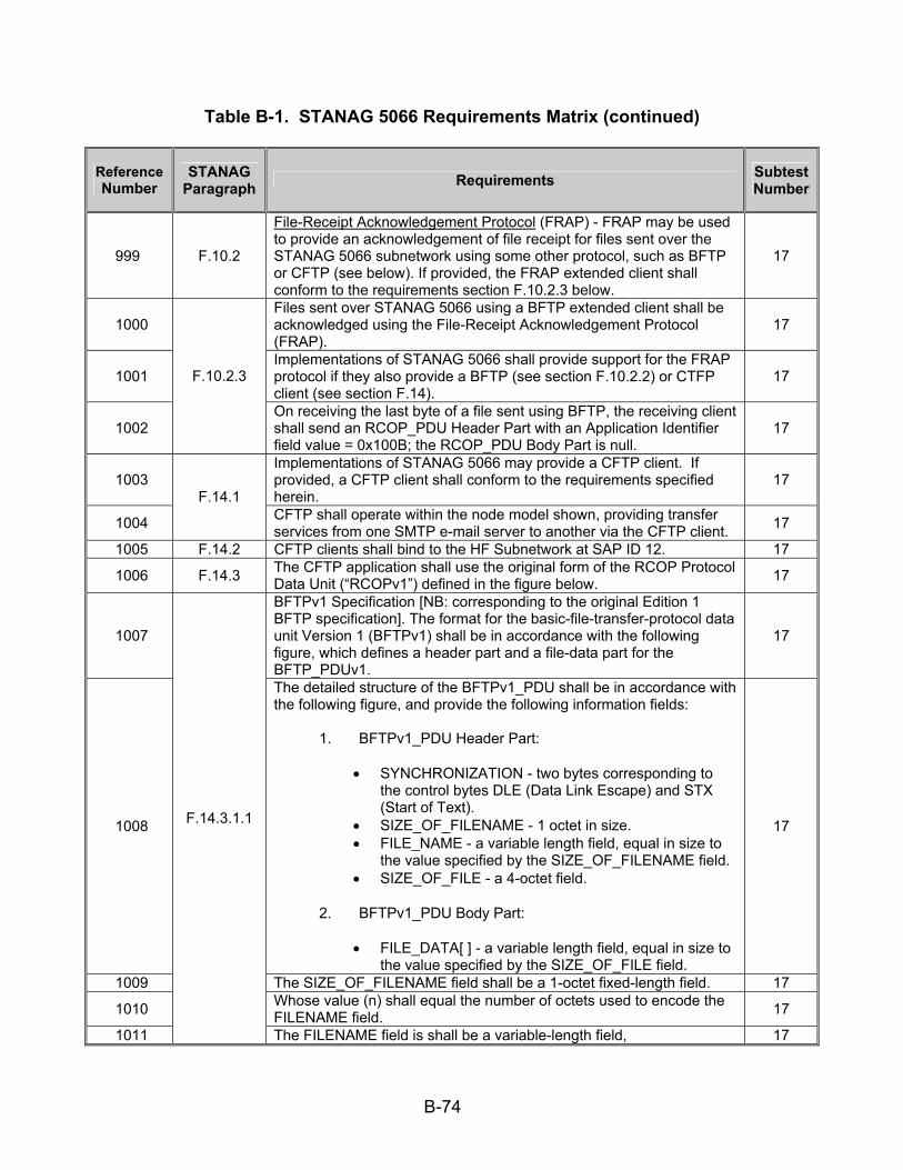
B-74
Table B-1. STANAG 5066 Requirements Matrix (continued)
Reference Number
STANAG Paragraph Requirements Subtest
Number
999 F.10.2
File-Receipt Acknowledgement Protocol (FRAP) - FRAP may be used to provide an acknowledgement of file receipt for files sent over the STANAG 5066 subnetwork using some other protocol, such as BFTP or CFTP (see below). If provided, the FRAP extended client shall conform to the requirements section F.10.2.3 below.
17
1000 Files sent over STANAG 5066 using a BFTP extended client shall be acknowledged using the File-Receipt Acknowledgement Protocol (FRAP).
17
1001 Implementations of STANAG 5066 shall provide support for the FRAP protocol if they also provide a BFTP (see section F.10.2.2) or CTFP client (see section F.14).
17
1002
F.10.2.3
On receiving the last byte of a file sent using BFTP, the receiving client shall send an RCOP_PDU Header Part with an Application Identifier field value = 0x100B; the RCOP_PDU Body Part is null.
17
1003 Implementations of STANAG 5066 may provide a CFTP client. If provided, a CFTP client shall conform to the requirements specified herein.
17
1004
F.14.1 CFTP shall operate within the node model shown, providing transfer services from one SMTP e-mail server to another via the CFTP client. 17
1005 F.14.2 CFTP clients shall bind to the HF Subnetwork at SAP ID 12. 17 1006 F.14.3 The CFTP application shall use the original form of the RCOP Protocol
Data Unit (“RCOPv1”) defined in the figure below. 17
1007
BFTPv1 Specification [NB: corresponding to the original Edition 1 BFTP specification]. The format for the basic-file-transfer-protocol data unit Version 1 (BFTPv1) shall be in accordance with the following figure, which defines a header part and a file-data part for the BFTP_PDUv1.
17
1008
The detailed structure of the BFTPv1_PDU shall be in accordance with the following figure, and provide the following information fields:
1. BFTPv1_PDU Header Part:
• SYNCHRONIZATION - two bytes corresponding to the control bytes DLE (Data Link Escape) and STX (Start of Text).
• SIZE_OF_FILENAME - 1 octet in size. • FILE_NAME - a variable length field, equal in size to
the value specified by the SIZE_OF_FILENAME field. • SIZE_OF_FILE - a 4-octet field.
2. BFTPv1_PDU Body Part:
• FILE_DATA[ ] - a variable length field, equal in size to the value specified by the SIZE_OF_FILE field.
17
1009 The SIZE_OF_FILENAME field shall be a 1-octet fixed-length field. 17 1010 Whose value (n) shall equal the number of octets used to encode the
FILENAME field. 17 1011
F.14.3.1.1
The FILENAME field is shall be a variable-length field, 17

B-75
Table B-1. STANAG 5066 Requirements Matrix (continued)
Reference Number
STANAG Paragraph Requirements Subtest
Number
1012 The size of which shall be specified by the value (n) of the field SIZE_OF_FILENAME. This field represents the name of the file sent using the Basic File Transfer Protocol.
17
1013 The first byte of the filename shall be placed in the first byte of this field, with the remaining bytes placed in order. 17
1014 The SIZE_OF_FILE field shall be a 4-octet fixed-length field. 17 1015 Whose value shall specify the size (p) in octets of the file to be sent. 17 1016
F.14.3.1.1
The first octet of the SIZE_OF_FILE field shall be the highest order byte and the last byte the lowest order byte of the field’s binary value. 17
1017
BFTPv1 Segmentation and Reassembly Requirements:
If the BFTPv1_PDU exceeds the maximum size of the data field permitted in the RCOPv1 PDU (i.e, if the CFTP_PDU is larger than the MTU_size less 4 octets (i.e., MTU-4) ), the CFTP client shall segment the BFTPv1 PDU, placing successive segments in RCOPv1 PDUs (original Edition 1 format) with consecutive U_PDU sequence numbers.
17
1018 When received, the CFTP client shall reassemble the BFTPv1 PDU if it determines that the BFTPv1 PDU has been segmented. 17
1019
F.14.3.1.2
Subject to local-host file naming conventions, the CFTP client shall store the received file with the name transmitted in the header with the file. [NB: there is no guarantee therefore that the file will be stored on the destination host with the same name that it was sent.]
17
1020 F.14.4 The compressed file shall be created and decompressed in accordance with RFCs 1950, 1951, and 1952. 17
1021 The CFTP message (including header) shall be compressed in accordance with RFCs 1950, 1951, and 1952 using an application such as “gzip.”
17
1022
The compressed CFTP message shall be encapsulated within a BFTPv1 PDU (i.e., it has a BFTPv1 header prepended to it, and the CFTP message shall be byte aligned within the FILE_DATA [ ] field of the BFTPv1 PDU.
17
1023 The BFTPv1 message (i.e., BFTPv1 PDU) shall be segmented if necessary. 17
1024
F.14.6
Each BFTPv1 PDU segment shall have an RCOPv1 header added (in accordance with annex F.14.3). 17

B-76
Table B-1. STANAG 5066 Requirements Matrix (continued)
Reference Number
STANAG Paragraph Requirements Subtest
Number
1025 F.14.6 On reception the BFTPv1 message shall be reassembled, if required, and decompressed using a method compliant with RFC 1952 and the CFTP message reconstructed.
17
LEGEND: ACK—Acknowledgement ARQ—Automatic Repeat-Request BFTP—Basic File Transfer Protocol BFTPv1—Basic File Transfer Protocol
Version 1 bps—bits per second C_PDU—Channel Access Sublayer
Protocol Data Unit C-Frame—Control Frame CCITT—Consultative Committee for International Telephone and Telegraph CFTP—Compressed File Transfer Protocol CMND—Command CMD—Command CRC—Cyclic Redundancy Check D_PDU—Data Transfer Sublayer Protocol Data Unit DCE—Data Communications Equipment DLE—Data Link Escape DRC—Data Rate Change DTE—Data Terminal Equipment DTS—Data Transfer Sublayer EIA—Electronic Industries Alliance EMCON—Emission Control
EOT—End of Transmission EOW—Engineering Orderwire FRAP—File-Receipt Acknowledgement
Protocol FSN—Frame Sequence Number GMT—Greenwich Mean Time hex—hexadecimal HF—High Frequency HMTP—High Frequency Mail Transfer
Protocol ID—Identification I-Frame—Information Frame I+C-Frame—Information and Control
Frame IRQ—Idle Repeat-Request Protocol LSB—Least Significant Bit LWE—Lower Window Edge M_PDU—Management Protocol Data Unit MSB—Most Significant Bit MSG—Message MTU—Maximum Transmission Unit NB—Note Below NRQ—Non-Repeat-Request (i.e., Non-
ARQ) Protocol
PDU—Protocol Data Unit RFC—Request for Comment RQ—Repeat Request RQST—Request RX—Receive S_PCI—Subnetwork Interface Sublayer
Protocol Control Information S_PDU—Subnetwork Interface Sublayer
Protocol Data Unit SAP—Subnetwork Access Point SMTP—Simple Mail Transfer Protocol SRQ—Selective Repeat-Request STANAG—Standardization Agreement STX—Start of Text Sync—Synchronization UWE—Upper Window Edge TTD—Time To Die TTL—Time To Live TX—Transmit U_PDU—User Protocol Data Unit UDOP—Unreliable Datagram-Oriented
Protocol WIN—Window
Table B-2. RFC Requirements Matrix
Reference Number
RFC (Paragraph) Requirements Subtest
Number
1026 RFC 2821 (2.3.7)
SMTP commands and, unless altered by a service extension, message data, are transmitted in “lines.” Lines consist of zero or more data characters terminated by the sequence American Standard Code for Information Interchange (ASCII) character “CR” (hexadecimal [hex] value 0D) followed immediately by ASCII character “LF” (hex value 0A). This termination sequence is denoted as <CRLF> in this document.
16
1027 RFC 2821 (3.2)
Once the server has sent the welcoming message and the client has received it, the client normally sends the EHLO command to the server, indicating the client’s identity.
16

B-77
Table B-2. RFC Requirements Matrix (continued)
Reference Number
RFC (Paragraph) Requirements Subtest
Number
1028 RFC 2821
(3.3)
The first step in the procedure is the MAIL command. MAIL FROM:<reverse-path> [SP <mail-parameters> ] <CRLF> This command tells the SMTP receiver that a new mail transaction is starting and to reset all its state tables and buffers, including any recipients or mail data.
16
1029 RFC 2821
(3.3)
The second step in the procedure is the RCPT command. RCPT TO:<forward-path> [ SP <rcpt-parameters> ] <CRLF> The first or only argument to this command includes a Forward-Path (normally a mailbox and domain, always surrounded by “<“ and “>“ brackets) identifying one recipient.
16
1030 If accepted, the SMTP server returns a 250 OK reply and stores the Forward-Path. 16
1031
If the recipient is known not to be a deliverable address, the SMTP server returns a 550 reply, typically with a string such as “no such user -” and the mailbox name (other circumstances and reply codes are possible). This step of the procedure can be repeated any number of times.
16
1032
The third step in the procedure is the DATA command (or some alternative specified in a service extension). (reference #)
DATA <CRLF>
16
1033 If accepted, the SMTP server returns a 354 Intermediate reply and considers all succeeding lines up to but not including the end of mail data indicator to be the message text.
16
1034 When the end of text is successfully received and stored, the SMTP receiver sends a 250 OK reply. 16
1035
RFC 2821 (3.3)
Mail transaction commands MUST be used in the order discussed above. 16
1036 RFC 2821 (3.7)
If an SMTP server has accepted the task of relaying the mail and later finds that the destination is incorrect or that the mail cannot be delivered for some other reason, then it MUST construct an “undeliverable mail” notification message and send it to the originator of the undeliverable mail (as indicated by the Reverse-Path).
16
1037 RFC 2821 (4.1.1.1)
In any event, a client MUST issue HELO or EHLO before starting a mail transaction. 16
1038 The mail data is terminated by a line containing only a period, that is, the character sequence “<CRLF>.<CRLF>“ (see section 4.5.2 of RFC 2821). This is the end of mail data indication.
16
1039
RFC 2821 (4.1.1.4)
Note that the first <CRLF> of this terminating sequence is also the <CRLF> that ends the final line of the data (message text) or, if there was no data, ends the DATA command itself. An extra <CRLF> MUST NOT be added, as that would cause an empty line to be added to the message.
16
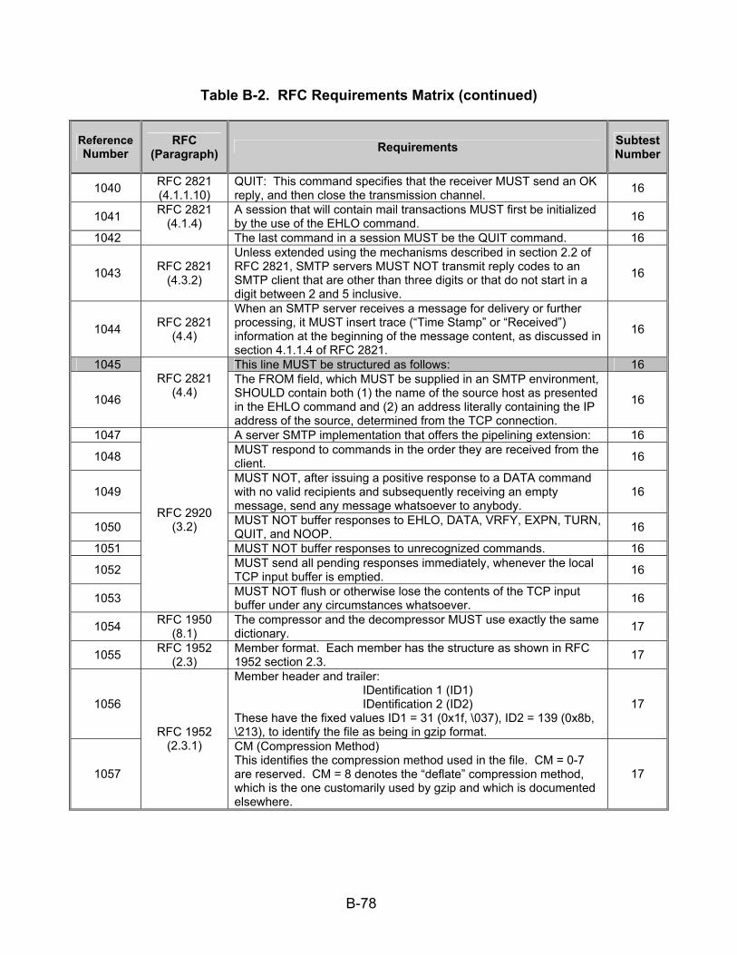
B-78
Table B-2. RFC Requirements Matrix (continued)
Reference Number
RFC (Paragraph) Requirements Subtest
Number
1040 RFC 2821 (4.1.1.10)
QUIT: This command specifies that the receiver MUST send an OK reply, and then close the transmission channel. 16
1041 A session that will contain mail transactions MUST first be initialized by the use of the EHLO command. 16
1042
RFC 2821 (4.1.4)
The last command in a session MUST be the QUIT command. 16
1043 RFC 2821 (4.3.2)
Unless extended using the mechanisms described in section 2.2 of RFC 2821, SMTP servers MUST NOT transmit reply codes to an SMTP client that are other than three digits or that do not start in a digit between 2 and 5 inclusive.
16
1044 RFC 2821 (4.4)
When an SMTP server receives a message for delivery or further processing, it MUST insert trace (“Time Stamp” or “Received”) information at the beginning of the message content, as discussed in section 4.1.1.4 of RFC 2821.
16
1045 This line MUST be structured as follows: 16
1046
RFC 2821 (4.4)
The FROM field, which MUST be supplied in an SMTP environment, SHOULD contain both (1) the name of the source host as presented in the EHLO command and (2) an address literally containing the IP address of the source, determined from the TCP connection.
16
1047 A server SMTP implementation that offers the pipelining extension: 16 1048 MUST respond to commands in the order they are received from the
client. 16
1049 MUST NOT, after issuing a positive response to a DATA command with no valid recipients and subsequently receiving an empty message, send any message whatsoever to anybody.
16
1050 MUST NOT buffer responses to EHLO, DATA, VRFY, EXPN, TURN, QUIT, and NOOP. 16
1051 MUST NOT buffer responses to unrecognized commands. 16 1052 MUST send all pending responses immediately, whenever the local
TCP input buffer is emptied. 16
1053
RFC 2920 (3.2)
MUST NOT flush or otherwise lose the contents of the TCP input buffer under any circumstances whatsoever. 16
1054 RFC 1950 (8.1)
The compressor and the decompressor MUST use exactly the same dictionary. 17
1055 RFC 1952 (2.3)
Member format. Each member has the structure as shown in RFC 1952 section 2.3. 17
1056
Member header and trailer: IDentification 1 (ID1) IDentification 2 (ID2)
These have the fixed values ID1 = 31 (0x1f, \037), ID2 = 139 (0x8b, \213), to identify the file as being in gzip format.
17
1057
RFC 1952 (2.3.1) CM (Compression Method)
This identifies the compression method used in the file. CM = 0-7 are reserved. CM = 8 denotes the “deflate” compression method, which is the one customarily used by gzip and which is documented elsewhere.
17

B-79
Table B-2. RFC Requirements Matrix (continued)
Reference Number
RFC (Paragraph) Requirements Subtest
Number
1058
FLG (FLaGs) This flag byte is divided into individual bits as follows: bit 0 FTEXT bit 1 FHCRC bit 2 FEXTRA bit 3 FNAME bit 4 FCOMMENT bit 5 reserved bit 6 reserved
bit 7 reserved
17
1059
MTIME (Modification TIME) This gives the most recent modification time of the original file being compressed. The time is in UNIX format, i.e., seconds since 00:00:00 GMT, Jan. 1, 1970. (Note that this may cause problems for MS-DOS and other systems that use local rather than Universal time.) If the compressed data did not come from a file, MTIME is set to the time at which compression started. MTIME = 0 means no time stamp is available.
17
1060
XFL (eXtra FLags) These flags are available for use by specific compression methods. The “deflate” method (CM = 8) sets these flags as follows: XFL = 2 - compressor used maximum compression, slowest algorithm XFL = 4 - compressor used fastest algorithm
17
1061
RFC 1952 (2.3.1)
OS (Operating System) This identifies the type of file system on which compression took place. This may be useful in determining end-of-line convention for text files. The currently defined values are as follows: 0 - FAT filesystem (MS-DOS, OS/2, NT/Win32) 1 - Amiga 2 - VMS (or OpenVMS) 3 - Unix 4 - VM/CMS 5 - Atari TOS 6 - HPFS filesystem (OS/2, NT) 7 - Macintosh 8 - Z-System 9 - CP/M 10 - TOPS-20 11 - NTFS filesystem (NT) 12 - QDOS 13 - Acorn RISCOS 255 - unknown
17
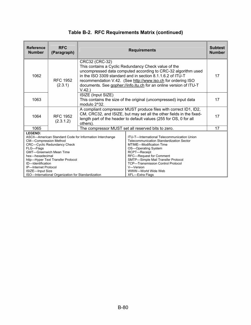
B-80
Table B-2. RFC Requirements Matrix (continued)
Reference Number
RFC (Paragraph) Requirements Subtest
Number
1062
CRC32 (CRC-32) This contains a Cyclic Redundancy Check value of the uncompressed data computed according to CRC-32 algorithm used in the ISO 3309 standard and in section 8.1.1.6.2 of ITU-T recommendation V.42. (See http://www.iso.ch for ordering ISO documents. See gopher://info.itu.ch for an online version of ITU-T V.42.)
17
1063
RFC 1952 (2.3.1)
ISIZE (Input SIZE) This contains the size of the original (uncompressed) input data modulo 2^32.
17
1064
A compliant compressor MUST produce files with correct ID1, ID2, CM, CRC32, and ISIZE, but may set all the other fields in the fixed-length part of the header to default values (255 for OS, 0 for all others).
17
1065
RFC 1952 (2.3.1.2)
The compressor MUST set all reserved bits to zero. 17 LEGEND: ASCII—American Standard Code for Information Interchange CM—Compression Method CRC—Cyclic Redundancy Check FLG—Flags GMT—Greenwich Mean Time hex—hexadecimal http—Hyper Text Transfer Protocol ID—Identification IP—Internet Protocol ISIZE—Input Size ISO—International Organization for Standardization
ITU-T—International Telecommunication Union Telecommunication Standardization Sector MTIME—Modification Time OS—Operating System RCPT—Receipt RFC—Request for Comment SMTP—Simple Mail Transfer Protocol TCP—Transmission Control Protocol V—Version WWW—World Wide Web XFL—Extra Flags
C-1
APPENDIX C
DATA COLLECTION FORMS

C-2
(This page intentionally left blank.)

C-3
CONTROL NUMBER: STANAG 5066
CONFORMANCE TEST Event Log Form
DATE: (DD/MM/YY)
Form Number Serial Number Equipment
Nomenclature Call Sign Remarks
DATA ENTRY TECHNICIAN: TEST DIRECTOR:
SIGNATURE: SIGNATURE:

C-4
(This page intentionally left blank.)

C-5
CONTROL NUMBER:
STANAG 5066 CONFORMANCE TEST
Equipment Configuration Diagram Form
DATE: (DD/MM/YY)
TEST TECHNICIAN:
DATA ENTRY TECHNICIAN:
TEST DIRECTOR:

C-6
(This page intentionally left blank.)

C-7
CONTROL NUMBER:
STANAG 5066 CONFORMANCE TEST
Event Log Form DATE: (DD/MM/YY)
Time (Local) Initials Event
TEST TECHNICIAN:
DATA ENTRY TECHNICIAN:
TEST DIRECTOR:

C-8
(This page intentionally left blank.)

C-9
CONTROL NUMBER:
STANAG 5066 High Frequency E-Mail
Test Plan Form
DATE: ________________ (DD/MM/YY)
Equipment: Serial Number:
Description:
Remarks
TEST TECHNICIAN:
DATA ENTRY TECHNICIAN:
TEST DIRECTOR:

C-10
(This page intentionally left blank.)
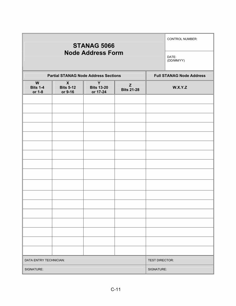
C-11
CONTROL NUMBER: STANAG 5066
Node Address Form
DATE: (DD/MM/YY)
Partial STANAG Node Address Sections Full STANAG Node Address
W Bits 1-4 or 1-8
X Bits 5-12 or 9-16
Y Bits 13-20 or 17-24
Z Bits 21-28 W.X.Y.Z
DATA ENTRY TECHNICIAN: TEST DIRECTOR:
SIGNATURE: SIGNATURE:

C-12
(This page intentionally left blank.)

C-13
CONTROL NUMBER:
STANAG 5066 CONFORMANCE TEST
Additional Remarks Form DATE: (DD/MM/YY)
Remarks
TEST TECHNICIAN:
DATA ENTRY TECHNICIAN:
TEST DIRECTOR:

C-14
(This page intentionally left blank.)

D-1
APPENDIX D
REFERENCES

D-2
(This page intentionally left blank.)
D-3
APPENDIX D
REFERENCES
CONSULTATIVE COMMITTEE FOR INTERNATIONAL TELEPHONE AND TELEGRAPH (CCITT) D-1 CCITT V.41, “Code Independent Error Control System” D-2 CCITT V.42, “Error-Correcting Procedures for DCES Using
Asynchronous-To-Synchronous Conversion” ELECTRONIC INDUSTRIES ALLIANCE (EIA) D-3 EIA-232D/423, “Electrical Characteristics of Unbalanced Voltage Digital
Interface Circuits” D-4 EIA-422, “Electrical Characteristics of Balanced Voltage Digital Interface
Circuits” INTERNATIONAL ORGANIZATION FOR STANDARDIZATION (ISO) D-5 ISO 3309, “Information Processing Systems—Data Communication High-
Level Data Link Control Procedure—Frame Structure” INTERNATIONAL TELECOMMUNICATION UNION TELECOMMUNICATION
STANDARDIZATION SECTOR (ITU-T) D-6 ITU-T Recommendation V.42, “Error-Correcting Procedures for DCEs
Using Asynchronous-to-Synchronous Conversion” MILITARY STANDARD (MIL-STD) D-7 MIL-STD-188-110A, “Interoperability and Performance Standards for
Data Modems” D-8 MIL-STD-188-141B, “Performance Standard for Medium and High
Frequency Radio System” STANDARDIZATION AGREEMENT (STANAG) D-9 STANAG 4203, “Technical Standards for Single Channel HF Radio
Equipment”
D-4
REFERENCES (continued) D-10 STANAG 4285, “Characteristics of 1200/2400/3600 Bits Per Second
Single Tone Modulators/Demodulators for HF Radio Links” D-11 STANAG 4406, “Object Identifiers Used for Military Messaging” D-12 STANAG 4529, “Characteristics of Single Tone Modulators/Demodulators
for HF Radio Links With 1240 Hz Bandwidth” D-13 STANAG 5066, “Profile for High Frequency Radio Data Communications” REQUEST FOR COMMENT (RFC) D-14 RFC 791, “Internet Protocol” D-15 RFC 793, “Transmission Control Protocol” D-16 RFC 821, “Simple Mail Transfer Protocol” D-17 RFC 826, “Ethernet Address Resolution Protocol: Or Converting Network
Protocol Addresses to 48 Bit Ethernet Address for Transmission on Ethernet Hardware”
D-18 RFC 894, “Standard for the Transmission of IP Datagrams Over Ethernet
Networks” D-19 RFC 1950, “ZLIB Compressed Data Format Specification Version 3.3” D-20 RFC 1951, “DEFLATE Compressed Data Format Specification Version
1.3” D-21 RFC 1952, “GZIP file format specification Version 4.3” D-22 RFC 2821, “Simple Mail Transfer Protocol” D-23 RFC 2920, “SMTP Service Extension for Command Pipelining” D-24 RFC 3232, “Assigned Numbers: RFC 1700 is Replaced by an On-line
Database”

D-5
REFERENCES (continued) WEBPAGES D-25 North Atlantic Treaty Organization (NATO) Consultation, Command, and
Control Agency, http://s5066/S5066Public/S5066-HFChat.zip D-26 InterNet Assigned Number Authority,
http://www.iana.org/assignments/protocol-numbers

D-6
(This page intentionally left blank.)