standard guide for painting inspectors ... – 07.pdfsspc-vis 1 guide and reference photographs for...
TRANSCRIPT

Designation: D 3276 – 07
Standard Guide forPainting Inspectors (Metal Substrates)1
This standard is issued under the fixed designation D 3276; the number immediately following the designation indicates the year oforiginal adoption or, in the case of revision, the year of last revision. A number in parentheses indicates the year of last reapproval. Asuperscript epsilon (e) indicates an editorial change since the last revision or reapproval.
1. Scope
1.1 This guide is intended as an information aid to paintinginspectors in carrying out their task efficiently. It includes thekey elements of surface preparation, coatings application, andfinal approval for both field and shop work. The items shouldbe selected that are pertinent to the specification of a particularjob.
NOTE 1—For additional helpful information, refer to the followingdocuments:
Manual of Coating Work for Light-Water Nuclear Power Plant PrimaryContainment and Other Safety-Related Facilities 2
New Concepts for Coating Protection of Steel Structures 3
D 16 Terminology for Paint, Related Coatings, Materials, and Applica-tions 4
D 4538 Terminology Relating to Protective Coatings and Lining Workfor Power Generation Facilities 4
SSPC-PA Guide 3 A Guide to Safety in Paint Application 5
Steel Structures Painting Manual Vol 1 Good Painting Practice 5
Steel Structures Painting Manual Vol 2 Systems and Specifications 5
Manufacturers Specifications and Instructions (made available to theinspector for reference to special requirements for proper application)
Material Safety Data Sheets (needed to ensure that personnel takenecessary precautions in handling hazardous materials). Available fromMaterials manufacturer.
1.2 Certain industries or owners may require certified in-spection personnel. See Guide D 4537 for establishing proce-dures to certify inspectors for coatings work in nuclearfacilities.
1.3 The values stated in SI units are to be regarded as thestandard. The values given in parentheses are for informationonly.
1.4 This standard does not purport to address all of thesafety concerns, if any, associated with its use. It is the
responsibility of the user of this standard to establish appro-priate safety and health practices and determine the applica-bility of regulatory limitations prior to use.
1.5 This guide is arranged in the following order:Section
Referenced Documents 2ASTM Standards 2.1OSHA Standards 2.2Steel Structures Painting Council Publications 2.3International Standards Organization (ISO) 2.4
Significance and Use 3Preparation for Inspection 4Surface Preparation Methods and Requirements 5
Surface Preparation 5.1Pictorial Standard D 2200 5.1.1Factors Affecting Coating Performance 5.2Cleanliness 5.2.1Mill Scale 5.2.2Surface Profile 5.2.3Cleaning Procedures 5.3Chemical Cleaning 5.3.1Solvent Vapor Cleaning 5.3.1.1Hand Tool Cleaning 5.3.2Power Tool Cleaning 5.3.3Power Tool Cleaning to Bare Metal 5.3.4Blast Cleaning 5.3.5Pressurized Water Cleaning 5.3.6
Cleaning and Preparation of Various Surfaces 5.4Steel Surfaces 5.4.1Galvanized Surfaces 5.4.2Aluminum Surfaces 5.4.3
Precautions in Preparing Unpainted and PreviouslyPainted Surfaces 5.4.4
Inspection of Surfaces Prior to Field Painting 5.5New Construction 5.5.1Maintenance Repainting 5.5.2
Coating Storage and Handling 6Storage of Coating and Thinner 6.1Mixing of Coatings 6.2Thinning 6.3Initial Samples 6.3.1Thinning of Coating 6.3.2Sampling of Thinned Coating 6.3.3Heating of Coating 6.4
Weather Considerations 7Drying 7.1Low Temperature 7.2High Temperature 7.3Moisture 7.4Wind 7.5
Coating Application 8Residual Contaminants 8.1Quality Assurance 8.2Film Defects 8.2.1Brush Application 8.3Spray Application 8.4Roller Application 8.5
1 This guide is under the jurisdiction of ASTM Committee D01 on Paint andRelated Coatings, Materials, and Applications and is the direct responsibility ofSubcommittee D01.46 on Industrial Protective Coatings.
Current edition approved Feb. 1, 2007. Published March 2007. Originallyapproved in 1973. Last previous edition approved in 2005 as D 3276 – 05.
2 ASTM, 1979.3 ASTM STP 841, ASTM, 1984.4 For referenced ASTM standards, visit the ASTM website, www.astm.org, or
contact ASTM Customer Service at [email protected]. For Annual Book of ASTMStandards volume information, refer to the standard’s Document Summary page onthe ASTM website.
5 Available from Society for Protective Coatings (SSPC), 40 24th St., 6th Floor,Pittsburgh, PA 15222-4656, http://www.sspc.org.
1
Copyright © ASTM International, 100 Barr Harbor Drive, PO Box C700, West Conshohocken, PA 19428-2959, United States.
www.polyma.ir
Miscellaneous Methods 8.6Rate of Application 8.7
Additional Considerations 9Ventilation 9.1Shopcoat Repair 9.2Painting Schedule 9.3Film Integrity 9.4Recoat Time 9.5Coating System Failure 9.6
Inspection Equipment 10General 10.1Surface Profile Gauges 10.1.1Adhesion of Existing Coating 10.1.2Portable Pull-Off Adhesion Testers 10.1.3Field Inspection Equipment 10.2Drying and Curing Times 10.2.1Thermometers 10.2.1.1Relative Humidity and Dew Point 10.2.1.2Viscosity Cups 10.2.2Weight-per-Gallon Cup 10.2.3Wet-Film Thickness Gauges 10.2.4Interchemical Gauge 10.2.4.1Notched Gauge 10.2.4.2Dry-Film Thickness Gauges 10.2.5Nondestructive Film Thickness Gauges 10.2.5.1Magnetic-Type Gauges 10.2.5.2Current-Type Gauges 10.2.5.3Tooke Gauge 10.2.5.4Holiday Detectors 10.2.6
Comparison of Surface PreparationSpecifications Table 1
Inspection Checklist AppendixX1
2. Referenced Documents
2.1 ASTM Standards: 4
D 16 Terminology for Paint, Related Coatings, Materials,and Applications
D 1212 Test Methods for Measurement of Wet Film Thick-ness of Organic Coatings
D 1475 Test Method For Density of Liquid Coatings, Inks,and Related Products
D 1730 Practices for Preparation of Aluminum andAluminum-Alloy Surfaces for Painting
D 2092 Guide for Preparation of Zinc-Coated (Galvanized)Steel Surfaces for Painting
D 2200 Standard Pictorial Surface Preparation Standardsfor Painting Steel Surfaces
D 3359 Test Methods for Measuring Adhesion by Tape TestD 4138 Test Methods for Measurement of Dry Film Thick-
ness of Protective Coating Systems by Destructive MeansD 4212 Test Method for Viscosity by Dip-Type Viscosity
CupsD 4285 Test Method for Indicating Oil or Water in Com-
pressed AirD 4414 Practice for Measurement of Wet Film Thickness by
Notch GagesD 4417 Test Methods for Field Measurement of Surface
Profile of Blast Cleaned SteelD 4537 Guide for Establishing Procedures to Qualify and
Certify Personnel Performing Coating Work Inspection inNuclear Facilities
D 4538 Terminology Relating to Protective Coating andLining Work for Power Generation Facilities
D 4541 Test Method for Pull-Off Strength of CoatingsUsing Portable Adhesion Testers
D 5064 Practice for Conducting a Patch Test to AssessCoating Compatibility
D 5162 Practice for Discontinuity (Holiday) Testing ofNonconductive Protective Coating on Metallic Substrates
D 6677 Test Method for Evaluating Adhesion by KnifeD 7091 Practice for Nondestructive Measurement of Dry
Film Thickness of Nonmagnetic Coatings Applied toFerrous Metals and Nonmagnetic, Nonconductive Coat-ings Applied to Non-Ferrous Metals
2.2 Occupational Safety and Health Administration(OSHA) Standard:
29 CFR 1926.59 Hazard Communication6
2.3 SSPC: The Society for Protective Coatings (SSPC)Standards:5
SSPC-SP 1 Solvent CleaningSSPC-SP 2 Hand Tool CleaningSSPC-SP 3 Power Tool CleaningSSPC-SP 5/NACE No. 1 White Metal Blast CleaningSSPC-SP 6/NACE No. 3 Commercial Blast CleaningSSPC-SP 7/NACE No. 4 Brush-off Blast CleaningSSPC-SP 10/NACE No. 2 Near-White Blast CleaningSSPC-SP 11 Power Tool Cleaning to Bare MetalSSPC-SP 12/NACE No. 5 Surface Preparation and Cleaning
of Metals by Water Jetting Prior to RecoatingSSPC-SP 14/NACE No. 8 Industrial Blast CleaningSSPC-SP 15 Commercial Grade Power Tool CleanerSSPC-PA 1 Shop, Field and Maintenance Painting of SteelSSPC-PA 2 Measurement of Dry Coating Thickness with
Magnetic GagesSSPC-VIS 1 Guide and Reference Photographs for Steel
Surfaces Prepared by Dry Abrasive BlastingSSPC-VIS 1-89 Visual Standard for Abrasion Blast Cleaned
SteelSSPC-VIS 3 Guide and Reference Photographs for Steel
Surfaces Prepared by Hand and Power Tool CleaningSSPC-VIS 4/NACE No. 7 Visual Standard for Steel
Cleaned by Water JettingSSPC Paint 27 Basic Zinc Chromate-Vinyl Butyral Wash
PrimerSSPC Guide 6 Guide for Containing Debris Generated
During Paint Removal OperationsSSPC Guide 7 Guide for the Disposal of Lead Contami-
nated Surface Preparation Debris2.4 ASTM Adjuncts:Pictorial Surface Preparation Standards for Painting Steel
Surfaces 7
3. Significance and Use
3.1 This guide is intended as a reference for those concernedwith the inspection of industrial coating work. Many of thedetails covered may be in a specification for a particular
6 Available from Standardization Documents Order Desk, DODSSP, Bldg. 4,Section D, 700 Robbins Ave., Philadelphia, PA 19111-5098, http://www.dodssp.daps.mil.
7 The pictorial surface preparation standard Method A (ISO/Swedish Standard) isavailable from ASTM International Headquarters. Request Adjunct No. ADJD2200.
D 3276 – 07
2
www.polyma.ir
project. A specification for coating projects should include thecoatings to be used. A checklist for use in the field is includedas an appendix.
4. Preparation for Inspection
4.1 The guide describes the duties of the inspector anddiscusses inspection methods, both visual and instrumental,that can be used to determine that the specification require-ments have been met by the painting contractor.
4.2 Before painting is started the project engineer shouldprovide the inspector with information from the official plansand specifications as to coating type, thinner to be used, mixingratios to be used, specified application thickness, primer, tiecoat, topcoat, time between coats, surface preparation, methodof application, and any special precautions to be followed suchas limits on ambient conditions. These details should berecorded in an inspector’s record book to eliminate anymisunderstanding between the inspector and the contractor.
4.3 The inspector should obtain copies of Materials SafetyData Sheets for all products that will be used on the project,review any hazard communications program in accordancewith 29 CFR 1926.59 that will apply to the project, and reviewother safety information related to the work that will beperformed by the contractor. The inspector should examinethese materials and be supplied with appropriate protectiveequipment and devices.
5. Surface Preparation Methods and Requirements
5.1 Surface Preparation is one of the most important fac-tors affecting the performance of coatings. The specifierdetermines the proper level in accordance with the expectedservice life and type of coating specified.
5.1.1 Pictorial Standard D 2200 (SSPC-VIS 1) should beprovided to the inspector on a job involving blast cleaning ofstructural steel. The standard is used by the inspector to assistin determining whether the degree of surface preparationspecified in a contract has been attained by the contractor. Forlarge jobs it is recommended that before work starts, an actualsteel sample of adequate size be blasted to the satisfaction ofthe project engineer. This blasted surface should be protectedby a clear acrylic coating or encased in plastic and used forreference purposes as the work progresses.
5.2 Factors Affecting Coating Performance—There are anumber of factors that should be considered to ensure a properpainting job.
5.2.1 Cleanliness—Many materials, if not removed fromthe surface, will affect the life of the coating. These include oil,grease, soil, weld spatter, and slag, that make it impossible toobtain proper adhesion to the metal surface. Deposits of salt(such as chlorides and sulfates) should be removed, or long-term coating performance will be seriously affected. SSPCissues detailed surface preparation specifications that covermethods for solvent cleaning, hand and power tool cleaning, aswell as the various methods of blast cleaning.
5.2.2 Mill Scale, the bluish-black oxide resulting from thehot-rolling process, is a constant source of trouble leading tocoating failure. This scale is very brittle and can crack orloosen due to temperature changes (both in fabricating andweathering in the field) leading to failure of the coating.
5.2.3 Surface Profile—The texture of the metal surface hasa significant effect on the performance of coatings, since itincreases the surface area to which the coating can developadhesion. In fact, the term “anchor pattern” is sometimes usedto describe the depth of profile. Profile varies both with thetype and size of the abrasive used. Coarser abrasives generallyproduce a coarser and deeper profile. Deep profiles are advan-tageous for adhesion, but require more coating to fill in thevalleys and cover the peaks of the profile; they cannot be usedwith low-build coatings that do not cover the peaks even whenseveral coats are applied. A general recommendation is that thesurface profile should be one quarter to one third of the dry filmthickness of the coating system. This recommendation does notapply if the resulting profile would be too great. The angularity(sharpness) and density of the profile may affect adhesion.Methods for measuring surface profile can be found in TestMethods D 4417.
5.3 Cleaning Procedures—Safety precautions are not ad-dressed separately for each of the following cleaning methods.Each has its own safety-related hazards, and U.S. OccupationalHealth and Safety Administration regulations should be fol-lowed. Materials Safety Data Sheets (MSDS) for the solventsand cleaning compounds provided by the manufacturer shouldalso be consulted for proper worker protection.
5.3.1 Chemical Cleaning—Solvents are used to remove oil,grease, and related materials. The solvent is applied to thesurface by wiping or scrubbing with rags or brushes. Thecontaminants should be removed (not simply spread out) by athorough wiping of the affected areas with cloths saturated withclean solvent. Contaminated cloths should not be dipped intoclean solvent. The cleaning should be repeated with clean ragsand fresh clean solvent. Emulsions, cleaning compounds,steam cleaning, or similar methods and materials may also beused. Where emulsion cleaners, soaps, or detergents are used,they should be removed completely by washing with clean hotwater. SSPC-SP 1 covers cleaning procedures using thesematerials.
5.3.1.1 Solvent Vapor Cleaning is a procedure that can beadapted to a production line or piecework operation. Vaporcleaning removes all soluble contaminants but does not disturbthe natural oxide film. If this film should be removed, mechani-cal cleaning will be necessary as well. The part to be cleanedis placed in the saturated vapor above the heated solvent so thatthe solvent vapor condenses on the metal surface. Vapordegreasing does not remove particulate matter, so parts shouldbe wiped to remove any insoluble soils. Vapor degreasing hasthe advantages over solvent wiping in that hot solvents are usedand the solvent condensation removes oils without recontami-nation.
5.3.2 Hand Tool Cleaning is the method used for theremoval of loose mill scale, loose rust, loose or otherwisedefective coating, weld flux, slag and spatter from metalsurfaces by hand brushing, hand sanding, hand chipping orscraping using wire, fiber or bristle brushes, sandpaper, steelwool, hand scrapers or chisels, and chipping hammers. Mate-rial is considered tightly adherent if it cannot be lifted with adull putty knife. SSPC provides a detailed specification,
D 3276 – 07
3
www.polyma.ir
SSPC-SP 2. A visual standard, SSPC-VIS 3, may be used toassist in determining compliance.
5.3.2.1 Hand tool cleaning requires that all weld flux, tar, oiland grease, and other greasy contaminants be removed first bysolvent cleaning (5.3.1).
5.3.2.2 Wire brushes should be rigid enough to clean thesurface thoroughly, and shaped to penetrate into all corners andjoints. Brushes should be kept free of all materials that mayclog the wires of the brush.
5.3.2.3 Hand scrapers should be made of tool steel, tem-pered and ground to a sharp edge, and should be of the propersize and shape to enable cleaning to be done as specified.Scrapers should be kept sharp at all times.
5.3.3 Power Tool Cleaning is a method used for the re-moval of loose mill scale, loose rust, loose or otherwisedefective coating, and weld flux from metal surfaces by powerwire brushes, power impact tools, power grinders, powersanders, or by a combination of these methods. Material isconsidered tightly adherent if it cannot be lifted with a dullputty knife. SSPC-SP 3 is the detailed specification for powertool cleaning. A visual standard, SSPC-VIS 3, may be used toassist in determining compliance.
5.3.3.1 Power Tool Cleaning requires that all oil, grease,weld flux, and other contaminants be removed first by solventcleaning (5.3.1). Hand tool cleaning in accordance with 5.3.2may be used prior to power tool cleaning.
5.3.3.2 All equipment should be suitable for the configura-tion of the work to be cleaned and maintained free of materialthat clogs the wire or disks making them ineffective. All impacttools should be kept sharp.
5.3.4 Power Tool Cleaning to Bare Metal is a method usedfor the total removal of coating, rust, and mill scale. It alsorequires a minimum of 1-mil anchor profile. Surface cleaning,power tools, and surface profile producing media are used toobtain the specified finish. Surface cleaning power tools consistof non-woven abrasive wheels and discs, coated abrasive discsor sanding pads, coated abrasive fly wheels, and coatedabrasive bands. Surface profile producing media consist ofrotary impact flap wheel assemblies and needle guns. SSPC-SP11 is the detailed specification for power tool cleaning to baremetal.
5.3.4.1 Depending on the initial condition of the surface andexisting profile conditions, it may be necessary to use one orboth of the types of power tools. All oil, grease, weld flux, andother contaminants should be removed first by solvent cleaning(5.3.1). Hand tool cleaning (5.3.2) or power tool cleaning(5.3.3) may be used prior to power tool cleaning to bare metal.
5.3.4.2 All equipment should be suitable for the configura-tion of the work to be cleaned and maintained free of materialthat clogs the wire or discs making them ineffective. Needleguns require 2-mm diameter needles to produce a suitablesurface profile.
5.3.4.3 The finished surface should be bare, bright metal.Slight residues of rust and paint may remain in the lowerportions of pits if the original surface was pitted. SSPC-VIS 3is a visual standard to assist in determining compliance.Surface profile is determined by procedures in 6.1.1.
5.3.4.4 Commercial Grade Power Tool Cleaning, SSPC-SP15 is performed in a manner similar to SSPC-SP 11. Thefinished surface should be bare, bright metal. Staining isallowed on 33 percent of the evaluation unit area, and slightresidues of rust and paint may remain in the lower portions ofpits if the initial surface was pitted.
5.3.5 Blast Cleaning is used to remove coating, rust andmill scale from a metal surface and to provide a roughenedsurface by striking the surface with a stream of small, hardabrasive particles such as (dry) sand, grit, or shot.
5.3.5.1 One method utilizes compressed air, special blastnozzles, and abrasive. Water may be injected into the air streamto control dust, and a rust inhibitor may be needed. In anothermethod used primarily in fabricating shop, wheels propel theabrasive centrifugally against the work. The minimum andmaximum particle size of the abrasive may be specified as ameans of controlling the surface profile.
5.3.5.2 Blast cleaning requires that all oil, grease, and weldflux be removed by solvent cleaning (5.3.1). The compressedair used for blast cleaning should be free of condensed water oroil by making certain that separators and traps are in workingorder. Test the compressed air supply in accordance with TestMethod D 4285.
5.3.5.3 Blast-cleaning operations should be performed sothat no damage is done to the completed portion of the work.Blast cleaning is often performed from the top to bottom of thestructure and should only be carried on downwind from anyrecently painted areas. Dry blast cleaning operations should notbe conducted on surfaces that will be wet after blasting andbefore painting. Steel temperature should be at least 3°C (5°F)above the dew point temperature.
5.3.5.4 The degree of blast cleaning required should be atleast equal to the appropriate surface preparation specificationand the applicable visual standard. Standards from ASTM,SSPC, and National Association of Corrosion Engineers(NACE) are listed in Table 1. Note that Pictorial SurfacePreparation Standards D 2200 is divided into two methods forabrasive blasting. Method A describes photographic standardsavailable from International Standards Organization (ISO)Pictorial Surface Preparation Standards. Method B describesphotographic standards available from SSPC. The two sets ofphotographs are not directly comparable.
5.3.5.5 Blast cleaned surfaces should be examined for anytraces of oil, grease, or smudges; where present, the contami-nants should be removed by solvent cleaning (5.3.1). Surfaces
TABLE 1 Comparison of Surface Preparation Standards
Preparation Guide SSPC
ASTM D 2200
NACEMethodAA
MethodBB
Blast clean to white metal SSPC-SP 5 Sa 3 SP 5 1Blast clean to near-white metal SSPC-SP 10 Sa 21⁄2 SP 10 2Commercial blast cleaning SSPC-SP 6 Sa 2C SP 6 3Brush-off blast cleaning SSPC-SP 7 Sa 1 SP 7 4Industrial blast cleaning SSPC-SP14 ... ... 8
A Method A is ISO/Swedish Standard.B Method B is SSPC- VIS-1.C Pictorial Standard Sa 2 shows mill scale and conflicts with SSPC definition of
commercial blast (SP 6 ), which does not allow mill scale.
D 3276 – 07
4
--`,``,`,`,,,``,`,```,,`,`,,,-`-`,,`,,`,`,,`---
www.polyma.ir
that have been dry blasted should be brushed with cleanbrushes, blown with compressed air free of oil and moisture, orvacuum cleaned to eliminate any traces of blast products, dust,or dirt from the surface. This also serves to remove abrasivefrom pockets and corners.
5.3.5.6 Blast cleaned surfaces should be further treated,primed or painted on the same day they are blasted, preferablywithin 8 h, or in any event before any visible flash rustingoccurs. Reblasting will be necessary on any surface if rustbloom forms before coating can be applied.
5.3.6 Pressurized Water Cleaning—A high-pressure waterblast using potable water, either with or without an abrasiveinjected into the stream, is used as an alternative to openblasting, since it reduces the release of dust into the atmo-sphere. Pressures over 137 900 KPa (20 000 psi) are needed toachieve total coating removal when using only water. Pressur-ized water alone will not remove mill scale efficiently, orimpart an anchor profile. Inhibitors may be added to the waterto prevent flash rusting. The surface should be dried or allowedto dry before coating. SSPC-SP 12/NACE No. 5 defines thevarious levels of cleanliness that can be achieved with pres-surized water. SSPC-VIS 4/NACE No. 7 is a visual standard toassist in determining compliance. It includes photographs withthree levels of rustback, if allowed by the specification.
5.4 Cleaning and Preparation of Various Surfaces—Beforeapplication of any coating, all surfaces to be coated should bethoroughly cleaned and properly prepared to the requirementsof the specification. All dust, dirt, oil, grease, moisture, soot,tar, or other contaminants should be removed from unpaintedsurfaces. Previously painted surfaces should be similarlycleaned of all foreign matter; all deteriorated coating should beremoved as well. Mortar or cement drippings from earlierrepairs should be removed by mechanical or chemical means.Tree limbs or other growth obstructing the structure should becut away to provide ready access.
5.4.1 Steel Surfaces—Removal of rust and scale should bedone in the manner and to the degree specified, that is, hand,power tool, or blast cleaned.
5.4.1.1 On complex structures, all dirt and debris should beremoved from pockets, crevices, obstructed areas such asgusset plates and connections, and tops of horizontal surfaces.Blasting debris that accumulates on horizontal surfaces shouldbe removed. Special attention should be placed on examininghard to reach areas, the back side of nuts and bolts, sides ofmembers in close proximity to other members or walls, andundersides of members.
5.4.2 Galvanized Surfaces that are to be painted should becleaned and then treated in accordance with the specifiedmethod in Guide D 2092. Alternatively, the surface may beallowed to weather a minimum of 6 months before cleaningand painting.
5.4.3 Aluminum Surfaces:5.4.3.1 Complete removal of oil and grease and, for unan-
odized aluminum, treatment is essential. Vapor degreasing orimmersion in an alkaline or acid cleaning solution are com-monly used in shop work. In the field, water wash followed bysolvent, steam or detergent cleaning is a good starting point.
5.4.3.2 Vinyl wash primer is one of the metal pretreatmentscommonly used on unanodized aluminum. The material isdescribed in Practices D 1730, Type B, Method 8 and iscovered by SSPC in Paint 27. Lead pigmented primers shouldnever be used over aluminum surfaces. The minimum treat-ment for aluminum is Type B, Method 3 of Practices D 1730,which describes the use of an alcoholic phosphoric acidcleaner.
5.4.4 Precautions in Preparing Unpainted and PreviouslyPainted Surfaces—Cleaning should proceed by sections, bays,or other readily identifiable parts of the work. The cleaning ofeach section, bay, or part of the work should be entirelycompleted, inspected, and accepted before any coating isapplied. The specification should contain limits on the amountor area that can be cleaned and painted at one time. The systemof alternately cleaning and painting short sections by oneworkman is not good practice since this can lead to surface orintercoat contamination.
5.4.4.1 If traffic, or any other source, produces an objection-able amount of dust, it is customary to control the dust by usingtarpaulins, etc., for a sufficient distance around the structureand take any other precaution necessary to prevent dust and dirtfrom coming into contact with the cleaned or freshly paintedsurfaces. It may sometimes be necessary to clean newly coatedsurfaces using some of the specified methods between thevarious coats.
5.4.4.2 Some areas to be painted or repainted may beexposed to chemical fumes and, if so, should be washed withwater before painting. Washing may also be necessary betweencoats of paint. Be aware that standing water on uncured paintcan result in early failure.
5.4.4.3 Residual contaminants present on pitted steel can bea problem. Chloride from deicing salts or a marine environ-ment, and sulfate contamination from air pollution have beenrecognized as main factors in premature breakdown of existingcoating systems. High-pressure water blasting is often used toremove these contaminants.
5.4.4.4 Current regulations require containment and collec-tion of surface preparation debris for disposal. When theexisting coating contains regulated heavy metals such as leador chromium, or other regulated compounds such as organotin,special precautions and handling of debris may be necessary.Inspection of contaminant and disposal requirements, espe-cially site storage requirements, are part of a Coating Inspec-tor’s activities. SSPC Guides 6 5 and 7 5 present informationuseful to the inspector and sections of these guides may bereferenced in the specification. On lead removal projects,inspectors should be familiar with OSHA requirements fortheir own health and safety.
5.5 Inspection of Surfaces Prior to Field Painting:5.5.1 New Construction—It should be emphasized that the
first coat should be applied to the cleaned surfaces before anysoiling or deterioration can occur. If painting is done outside,the cleaned areas should receive the first protective coat wellbefore nightfall brings lower temperatures and possible mois-ture condensation on the surfaces. When surface preparation
D 3276 – 07
5
www.polyma.ir
and painting are carried on indoors, overnight delays betweencoating and painting may be permissible except on blast-cleaned surfaces.
5.5.1.1 Shop-coated steel that has been shipped to theerection site should be stored on blocks to prevent contact withthe ground, and where it is least likely to be marred, scratched,or subjected to harmful contamination by grease, oil, salt, etc.Insofar as practicable, the steel should be stored to avoid theformation of waterholding pockets. If outdoor storage lasts forseveral months, the inspector should check the integrity of thecoating from time to time and verify that deficiencies arecorrected in accordance with the contract document. Thelength of time between shop priming and erection and subse-quent topcoating should be kept to a minimum to avoid theproblem of intercoat adhesion.
5.5.1.2 Immediately before applying the first field coat, theshop-coated surfaces should be cleaned of dust. If necessary toremove grime and oil substances, they can be wiped, steamcleaned, power washed with detergents or cleaned with sol-vents selected so as not to soften the film appreciably.Miscellaneous scratches and breaks in the shop coat, includingthose occasioned by field welds, bolts, or rivets, should becleaned, feathered and touched-up as specified before the steelreceives the first overall field coat.
5.5.1.3 The inspector should ensure that field rivets havebeen cleaned of slag and weld spatter. It is important that everycoat of the system be applied over dry, soil-free surfaces, andthat all previous coats be free of mechanical damage. Greatcare should be exercised to prevent trapping corrosive saltsunder or between coats.
5.5.1.4 The inspector should determine whether the speci-fications are being followed with reference to the painting orprohibition of painting of contact surfaces in bolted or rivetedsurfaces of construction. He should ensure that surfaces not incontact but that will be made inaccessible by assembly orerection, have received the full number of specified coatsbefore they become inaccessible.
5.5.2 Maintenance Repainting—In most cases, maintenancerepainting will consist of spot-cleaning and priming of smallisolated areas of deterioration, followed by application of oneoverall new finish coat to all surfaces of the structure. Theinspector of maintenance repainting should be alert for severalconditions not encountered in the painting of new work.
5.5.2.1 Sound coating not intended to be removed shouldnot be damaged by cleaning operations on adjacent areas. Thisis particularly important with spot-blast cleaning.
5.5.2.2 The junctions between sound coating and spot-cleaned areas should present a smooth, feathered appearance.The application of coating to spot-cleaned areas should overlapthe old, adjacent coating to a slight extent to ensure fullcoverage of the cleaned areas. Before the overall finish coat isapplied, the inspector should ensure that oil, grime, dust, andother contaminants are cleaned from the old coating surfaces.
5.5.2.3 Adhesion of the newly applied coat to the oldcoating should be carefully checked. Practice D 5064 presentsthe procedure for evaluating adhesion of maintenance coatings.
5.5.2.4 Under the direction of the engineer, the inspectormay explore beneath the surface of the existing or new coating
film for covered-over rust or loosening of the old film, andwhere he discovers such conditions, require that the surface becleaned and repainted.
5.5.2.5 The effect of the newly applied coating on the oldunderlying coating should be noted. Any coating that showscurling, lifting, or wrinkling should be reported to the engineerimmediately since it may have to be removed and the arearepainted. If the defects are general, rather than existing in afew isolated areas, use of a different type of coating may benecessary.
6. Coating Storage and Handling
6.1 Storage of Coating and Thinner—All coatings andthinners should be stored in areas or structures that arewell-ventilated and not subject to excessive heat, open flames,electrical discharge, or direct rays of the sun. Storage should bein compliance with applicable regulations and the manufactur-er’s written instructions. Materials susceptible to damage atlow temperatures should be stored to prevent freezing, such asin heated areas. Too high a storage temperature reduces theshelf life of the coating. If a coating is stocked for aconsiderable length of time (several months), it is desirable toinvert the containers at monthly intervals. This will preventhard settling and thus make mixing quicker and easier when thecoating is to be used.
6.1.1 Coating containers should remain unopened untilneeded, and the oldest should be used first. The manufacturer’swritten instructions should be followed regarding shelf life.Coatings that have livered, gelled, or otherwise deterioratedduring storage should not be used. If a particular material is inquestion, do not use it until it has been tested by themanufacturer or independent laboratory and found to besatisfactory.
6.1.2 Where a skin has formed in the container, the skinshould be cut loose from the sides of the container, removed,and discarded. If it is felt that the skins are thick enough tohave a practical effect on the composition, the remaining paintshould not be used until it has been tested and found to besatisfactory.
6.2 Mixing of Coatings—All coatings should be thoroughlyand completely mixed in clean containers before use. Wherethere is noticeable settling, and mixing is done either by poweragitators or by hand, most of the vehicle should be poured offinto a clean container. The pigment is then lifted from thebottom of the container with a clean, broad, flat paddle, lumpsbroken up and the pigment thoroughly mixed with the vehiclepresent. The poured-off vehicle should be returned slowly tothe original container with simultaneous agitation. It is alsouseful at this point to mix or pour repeatedly from onecontainer to another (boxing) until the composition is uniform.The bottom of the original container should be inspected forthe unmixed pigment. Two component paints should be mixedby agitation only, and not with boxing. After the individualcomponents are homogenous, they are intermixed with agita-tion in the order stated in the manufacturer’s instructions, thatis, add Part B to Part A. The coating should not be mixed orkept in suspension by means of an air stream bubbling underthe coating surface.
D 3276 – 07
6
www.polyma.ir
6.2.1 Some coatings may require straining after mixing, toensure homogeneity and to remove skins and foreign matter.The strainers should be of a type to remove only skins, etc., butnot to remove pigment. For example, a 297-µm (50-mesh)strainer is normally satisfactory for most coatings, unless somespecific size is required in the specification. Containers shouldbe covered when not in use, to reduce volatile losses andskinning.
6.2.2 Coatings should be agitated enough during applicationto ensure homogeneity. Some materials may even requireconstant agitation during use.
6.3 Thinning—Some specifications permit field thinning oflaboratory-accepted coatings while others do not. This sectiondescribes some commonly accepted procedures when thinningis permitted.
6.3.1 Initial Samples—When thinning on the job site ispermitted and unless other arrangements have been made, (forexample using manufacturer-supplied thinner from unopenedcontainers and complying with the manufacturer’s writtenthinning instructions), the painting inspector may need tosubmit to an agreed-upon testing laboratory a 1-L (1-qt) samplefrom each batch to be thinned, together with a 1-L (1-qt)sample of the thinner to be used, using clean sample containersin both cases. A request is submitted with these samples foradvice on the proper thinning rate for the conditions prevailingand the consistency limits of the thinned coating.
6.3.2 Thinning of Coating—All additions of thinner shouldbe made in the presence of the inspector, and only amounts ortypes of thinner permitted by the specification or manufacturer,or both, should be added. Thinning is carried out by pouringabout half of the thoroughly mixed coating into an empty, cleancontainer. The required thinner is then added and the twoportions are remixed to obtain a homogenous mixture.
6.3.3 Sampling of Thinned Coating—During the work, ad-ditional samples need not be submitted for testing unless adeviation is noted in the coating consistency, or if it issuspected that there has been a change in the thinner.
6.3.3.1 When an inspector is qualified and has the necessaryequipment available at the field office, arrangements may bemade for on-site inspection of thinning and of the thinnedcoating. This speeds acceptance of a coating. The inspectorshould keep a record of all paint modifications, amount ofthinning, weight per gallon, and viscosity. Where dry-filmthickness is specified, the inspector should verify the new wetfilm thickness necessary to obtain the desired dried thicknesswith the thinned coating. Compliance with the specificationshould be based on dry-film thickness when specified.
6.3.3.2 To estimate the wet-film thickness of the thinnedcoating required to obtain the specified dried-film thickness,the percent volume of the nonvolatile (solids) in the originalcoating must be known. This figure is readily obtained from themanufacturer. With this information the calculation may bemade as follows:
W 5D~1.0 1 T!
S (1)
where:W = wet-film thickness,
D = desired dry-film thickness,S = percent by volume (expressed as a fraction) of coat-
ing solids, andT = percent by volume (expressed as a fraction) of thinner
added.6.4 Heating of Coating—Coating as delivered in the manu-
facturer’s containers and mixed thoroughly are ready for useunless the specification permits on-site thinning of high-viscosity material. When the temperature of the liquid coatingis low (below 10°C (50°F)) the consistency (viscosity) mayincrease to the point that application is difficult. When thinningis not permitted, the coating may be heated. Should thecontractor wish to reduce the viscosity by heating, to makeapplication easier, the containers may be warmed in hot water,on steam radiators, by storing in a warm room, or by otheracceptable indirect heating processes. In-line heaters are alsoavailable for application equipment. Direct application offlame to the containers is forbidden by fire regulations. Itshould be noted, however, that heating of the coating alone willnot compensate for ambient or surface temperatures, or both, ifthey are below the minimum specified for that material.
7. Weather Considerations
7.1 Drying—It is well known that most coatings, particu-larly those for structures, will not dry properly at low tempera-tures and high relative humidities, nor will they perform well ifapplied over wet surfaces. Temperature limitations presented inthe specification or manufacturer’s product data sheet aremandatory.
7.2 Low Temperature—Many specifications indicate tem-perature limits between which painting may be undertaken.The typical minimum temperature (air, material and surface) isusually 5°C (40°F), but may be as low as −18°C (0°F) for“cold-curing” one or two component systems or 10°C (50°F)for conventional two component systems. The requirementsmay state further that painting should not be undertaken whenthe temperature is dropping and within 3°C (5°F) of the lowerlimit. However, some authorities believe that some coatingsmay be applied at (or below) 0°C (32°F) without adverseeffects. Within the limitations of the composition of thecoating, this may be satisfactory, depending upon the type ofcoating and providing the surface is dry. Painting over ice orfrost will result in early adhesion failure of the coating.
7.3 High Temperature—The maximum reasonable surfacetemperature for application is 50°C (125°F) unless clearlyspecified otherwise. A surface that is too hot may cause thecoating solvents to evaporate so fast that application is difficult,blistering takes place, or a porous film results. To keep thetemperature down it may be desirable, where practical, to paintunder cover at a shop or to protect the surface from the sunwith tarpaulins.
7.4 Moisture—Painting should not be performed in rain,snow, fog, or mist, or when the temperature of the surface isless than 3°C (5°F) above the dew point. This is especially truein spring and fall when days are warm and nights are cool. Wetsurfaces should not be painted unless the coatings are specifi-cally designed for that condition. Relative humidity is usuallyan indicator of condensing conditions. High humidity can alsoaffect the cure of some coatings. Specifications often contain
D 3276 – 07
7
www.polyma.ir
an 85 % upper limit. If it is suspected that the temperature andhumidity conditions are such that moisture is condensing uponthe surface, measure the relative humidity and dew point asdescribed in 10.2.1.2.
7.4.1 When coatings must be applied in damp or coldweather, the substrate should be painted under cover, orprotected from the surrounding air, and the steel heated to asatisfactory temperature. The steel should remain under coveruntil the applied coating is dry or until weather conditionspermit its exposure in the open.
7.4.2 Newly applied coatings improperly exposed to freez-ing temperatures, excessive humidity, rain, snow, or conden-sation should be removed, the surface again prepared andpainted with the same number of coats as the undamaged area.
7.5 Wind—The wind direction and velocity should be con-sidered when applying coatings in areas where airborne over-spray could damage automobiles, boats, and structures nearby.Heavy winds result in considerable loss of coating and exces-sive drying of the droplets reaching the surface. This results inan inability of the film to flow together (dry spray). Ifuncorrected, dry spray may create holidays, leading to poorperformance, and it can interfere with adhesion of the appliedor subsequent coat. Thinning with slower evaporating solventsmay reduce or eliminate dry spray and produce a smoothsurface. These problems can be avoided by utilizing brush orroller application methods instead of spray, scheduling thework at the less windy times of day, changing materials to thefast-dry types that do not adhere or damage adjacent property,or scheduling the work when the wind is blowing in a directionwhere dry spray will not cause damage.
8. Coating Application
8.1 Residual Contaminants—Visually inspect the surfaceimmediately prior to painting to ensure that spent abrasive,dust, and debris have been completely removed. Dust removalshould be considered satisfactory when the path left by agloved hand wiped over the surface is barely discernable whenviewed from a distance of 1 m (3 ft). During the inspection,also ensure that any oil or grease contamination that may havebecome deposited on the surface is completely removed. Thisis accomplished by solvent, steam, or detergent cleaning inaccordance with SSPC-SP 1.
8.2 Quality Assurance—The inspector should consult themanufacturer’s product data sheet and ensure that (1) coatingsreceived meet the description of the products acceptable underthe requirements of the specification; (2) they are properlymixed and thinned (where allowed); (3) colors match a visualstandard provided; (4) that proper precautions have been takento prevent damage to adjacent areas from cleaning and paintingoperations; (5) working practices are so scheduled that damageto newly applied coating is minimized; (6) application equip-ment (brushes, spray) is acceptable for type, cleanliness, andusability; (7) weather conditions are acceptable under therequirements of the specification; (8) field-testing equipmenton hand is in satisfactory working order ready for use; and (9)only the methods of application permitted under the specifica-tion are used, and that their use is in accordance with 8.3-8.7.SSPC-PA 1 is a specification for application of coating.
8.2.1 Film Defects—All coats should have nearly smoothsurfaces relatively free of dry spray, overspray, orange peel,fish eyes, pinholes, craters, bubbles, or other significant de-fects. Bleed-through, insufficient hiding, skips, and misses arenot acceptable. Runs and sags should be brushed out duringapplication or removed by sanding if the coating has cured.Abrasive, dirt, or other debris that becomes embedded in thepaint film should be removed prior to the application ofsubsequent coats.
8.3 Brush Application—Painting by brush should be done ina neat, workmanlike manner to produce a smooth coat asuniform in thickness as possible. The technique is from dry towet, with the coating applied to the surface and spread back tothe wet edge of the previous strokes. Coating should be workedinto all irregularities in the surface, crevices, and corners.Runs, sags, or curtains should be brushed out. Surfaces that areinaccessible for painting with brushes and on which spraying isnot permitted should have coating applied by means ofsheepskin daubers. The specification may require “stripe coat-ing” to provide adequate film thickness on places prone topremature breakdown. Edges and corners of all metal work, nutheads, bolts and nuts, and all individual members, bars, shapes,and plates should be striped by brush painting in advance of theapplication of coating to other parts.
8.3.1 Brushes should be of good quality, with pliablebristles that are compatible with the coating, and of suitablesize to match the area being coated. They should not exceed100 mm (4 in.) in width, and bristle length should be no lessthan 90 mm (31⁄2 in.). The brushes should be kept in a clean,acceptable condition when not in use. The inspector shouldprohibit the use of any brush not in an acceptable condition.
8.4 Spray Application—Spray application may or may notbe allowed. Often it is acceptable in fabricating shops, butbecause of the possibility of damaging surrounding property orcoating films overspray, it may not be permitted in the field.The inspector should be familiar with the different kinds ofspraying, which are compressed air spray, airless spray, air-assisted airless spray, electrostatic spray, and high-volumelow-pressure spray.
8.4.1 The equipment should be suitable for the intendedpurpose, capable of properly atomizing the coating to beapplied, and be equipped with suitable pressure regulators andgauges. The equipment should be kept in a suitably cleancondition to permit proper coating application without depos-iting dirt, dried coating, and other foreign materials in the film.The air supply for conventional and hot spray applicationshould be free of moisture or oil. This can be verified byperforming the white blotter test in accordance with TestMethod D 4285. Airless spray equipment should be properlygrounded. Any solvents left in the equipment should becompletely removed before applying coating to the surfacebeing painted.
8.4.2 Coating ingredients should be kept properly mixed inspray pots or containers during coating application, either bycontinuous mechanical agitation or by intermittent agitation.Coating should be applied in a uniform layer, with overlappingat the edge of the spray pattern. The spray pattern should beadjusted so that the coating is deposited uniformly. During
D 3276 – 07
8
--`,``,`,`,,,``,`,```,,`,`,,,-`-`,,`,,`,`,,`---
www.polyma.ir

application the gun should be held at right angles (perpendicu-lar) to the surface (not arced or fanned) and at a distance thatwill ensure that a wet layer of coating is deposited on thesurface. The trigger of the gun should be released at the end ofeach stroke. Poor spray technique resulting in excessiveoverspray (a sand-like finish) should not be tolerated. All runs,sags, or curtains should be brushed out immediately or sandedout if the coating has cured.
8.4.3 Brush striping of edges and other vulnerable locationsmay be specified. Brush or sheepskin daubers are used to coatall areas inaccessible to the spray gun and brushes are used towork coating into cracks, crevices, and blind spots that cannotbe adequately spray painted.
8.4.4 Particular care should be observed with respect to typeand amount of thinner, coating temperature, and operatingtechniques in order to avoid depositing coating that is tooviscous, too dry, or too thin when it reaches the surface.
8.5 Roller Application—Rollers that are clean and of amaterial not soluble in the coating to be applied should be used.Roller covers are available in a variety of diameters, lengths,types of fabric, and fiber lengths. The nap (length) used onmetal surfaces, generally varies from 6 to 19 mm (1⁄4 to 3⁄4 in.).The longer fibers hold more coating but do not provide assmooth a finish. Therefore their use is generally restricted torougher surfaces such as the substrate and faster dryingcoatings. Short nap rollers give a smoother finish and aregenerally used for applying the top coat. There are alsospecialized rollers available for use on pipes and fences, andeven pressure rollers that continually feed the coating to theroller cover.
8.5.1 The roller cover should be dipped into the coatinguntil it is saturated and then rolled along the tray ramp until thecoating is completely wetted in. The first load of coating on theroller should be applied to scrap material to force out airbubbles trapped in the nap. Proper roller technique requiresapplication in the form of a V or W depending on the size of thearea involved. The coating should then be cross-rolled to fill inthe square created by the boundaries of the initial application.Only moderate pressure should be used, as heavy pressure cancause foaming and possible cratering by entrapped air. Appli-cation should be finished with light perpendicular strokes inone direction (usually vertical) to provide the smoothest, mostuniform finish.
8.6 Miscellaneous Methods—Methods such as pads, mitts,and squeegees or trowels are used for specialized products orin situations where the conventional methods are not suitabledue to the location or configuration of the work.
8.6.1 Painter’s pads generally consist of a roller-type syn-thetic fabric attached to a foam pad. The size is generally 100by 175 mm (4 by 7 in.) and the fiber length is 5 mm (3⁄16 in.).Application technique with a pad on large surface areas issimilar to that used with a roller.
8.6.2 Painter’s mitts are lamb skin gloves that are dippedinto the coating and are rubbed across the surface. They areideal for application of coatings to small, odd-shaped surfaces.
8.6.3 Squeegee or trowel application is generally used forheavy-bodied thick-film coatings that cannot be applied byspray.
8.7 Rate of Application—Properly written specificationsrequire certain minimum and maximum dry-film thicknessesfor each coat. Wet-film thickness measurements are useful tocheck as the work progresses to determine reasonably well thatthe desired amount of coating is being applied. Later, when thefilms are dry, the inspector may make spot checks with adry-film measuring gauge to ascertain acceptability of thecoatings. Film thickness measurements are more informativethan visual inspection, which may show only obvious nonuni-form application. Instruments for measuring film thickness andthe procedures for their use are described in 10.2.5 and 10.2.6.Nondestructive dry-film thickness gauges and measurementsare preferred, and applicable to metal substrates only.
8.7.1 Thickness or coverage requirements apply to thewhole structure, not some specific part. It is important to notethat the painting inspector check all areas and determine thefilm thickness for each coat. For instance, if the “shop coat”requires a minimum of 50 µm (2 mils) dry-film thickness, theinspector should ensure that it is obtained within the tolerancepermitted in SSPC-PA 2. The areas tested should be identifiedand recorded so that the dry-film thickness of added coatingcan also be determined. With nondestructive measuring instru-ments a 15-m (50-ft) long and 1.8-m (6-ft) high I-beam can betested in 30 min, and low areas if any, properly marked andrecorded in the inspector’s book. Because the shop prime coatinspector may not be the person doing the field coat applicationinspection, it is very important to record test results and send acopy to the field inspector in order to better determinethicknesses of subsequently applied coats.
9. Additional Considerations
9.1 Ventilation—It is essential when performing surfacepreparation or painting in enclosed spaces that adequateventilation is provided for removal of dust and solvents.
9.2 Shopcoat Repair—Normally after erection work, suchas riveting, bolting, welding, straightening, etc., has beencompleted satisfactorily, areas of the shopcoat will be found tohave been damaged. Damaged or bare areas should be thor-oughly cleaned, prepared, feathered and repainted with onenew coat of shop or field primer. In addition, crevices and smallcracks should be thoroughly cleaned and spot-primed. Afterdrying, the crevices and cracks can be filled with an acceptablecaulking compound as required by the specification. Thespecified field coats should then be applied over the entirestructure.
9.3 Painting Schedule—As indicated in 5.4.4, paintingshould proceed by sections, bays, or parts of the work, andeach coat in each section should be applied entirely andaccepted by the inspector before a succeeding coat is applied.Except for any shop coat touch-ups made necessary bywelding, etc., none of the metal that will be exposed to view inthe completed structure should be field-painted until all asso-ciated concrete has been placed. Care should be taken by thecontractor during painting operations to protect adjacent sur-faces from being stained by the coating being applied. Anystained surface will need to be restored to its original conditionwithout damage to that surface.
9.4 Film Integrity—Each coat should be applied as a con-tinuous film of uniform thickness, free of holidays and pores.
D 3276 – 07
9
www.polyma.ir
Any thin spots or areas missed in the application should berepainted and permitted to dry before the next coat is applied.
9.5 Recoat Time—Each coat should be dried throughout thefull thickness of the film before application of the nextsucceeding coat. Coating is considered dry for recoating whenthe next coat can be applied without the development of anydetrimental film irregularities such as wrinkling, lifting, or lossof adhesion of the previous coat. For most coatings the time todry for recoat, even under optimum conditions varies with theircomposition and that of the subsequent coat. Thus, an oil-basedcoating may take 2 to 3 days to harden sufficiently to beovercoated with a coating of the same type. However, it maytake 3 or 4 months to harden to be satisfactorily overcoatedwith a vinyl coating or other type of coating containing strongsolvents. Some coatings have maximum recoat times. Thecoating manufacturer’s written instructions should be followedfor recoat times.
9.6 Coating System Failure—Defective coatings should beremoved in their entirety, the surface recleaned, and thespecified coatings, or their alternatives, applied.
10. Inspection Equipment
10.1 General—Visual observation is the most importantpart of inspecting the coating application. There are, however,instruments and mechanical aids that help the inspector. Theymake the painter aware that his work can be checked duringprogress and even after completion. The different instrumentsthat can be used are described in this section.
10.1.1 Surface Profile Gauges—The inspector can deter-mine the surface profile of blast-cleaned steel substrates usingTest Methods D 4417 to ensure the proper profile is obtainedfor the specified material. Some of the common instrumentsare:
10.1.1.1 Surface profile comparator for visual comparisonsof the profile against a reference disk for sand, grit, and shotblast-cleaned steel.
10.1.1.2 Depth micrometres with conical points to projectinto the valleys to determine profile depth.
10.1.1.3 Tape, to create an exact replica of the profile on aspecial material. The tape is measured in the field using aspring micrometer to determine average maximum profileheight.
10.1.2 Adhesion of Existing Coating—The inspectorsshould carry a pocket knife that can be used to determine thesoundness of existing paint where there might be blisteringunderfilm corrosion. This is a subjective test and its valuedepends upon the inspector’s experience. The cross-cut test,Test Methods D 3359, and knife adhesion test, Test MethodD 6677, are more reproducible.
10.1.3 Portable Pull-Off Adhesion Testers are available asdescribed in Test Method D 4541. The testers measure theforce required to remove a metal stud that has been cementedto the coated surface.
10.2 Field Inspection Equipment in good working ordershould be available to the inspector so that he may perform hisfunction properly.
10.2.1 Drying and Curing Times—These are both importantconsiderations, since dry time and cure time can both beaffected. Minimum temperatures are required for reactive and
water-borne coatings while too high a temperature can makeapplication difficult or cause film defects such as pinholing.Inorganic zinc-rich primers and moisture-cure urethanes re-quire certain minimum humidity conditions for proper cure.The manufacturer’s recommendations should be followed.
10.2.1.1 Thermometers—The paint inspector may need sev-eral types of thermometers and should have at least an accuratepocket thermometer with a range from about −18 to 65°C (0 to150°F) for measuring the air temperature. The same thermom-eter or a floating dairy thermometer may be used to determinethe temperature. The same thermometer or a floating dairythermometer may be used to determine the temperature ofliquid coating, solvent, etc. Flat surface-temperature thermom-eters are also available for measuring the substrate tempera-ture, as in an infrared gun.
10.2.1.2 Relative Humidity and Dew Point— A psychrom-eter containing a wet and dry-bulb thermometer for determin-ing relative humidity and a dew point chart is a usefulinspection tool. Hand-held sling or electrical types are avail-able as well as a direct-reading digital type. Atmosphericconditions, including air temperature, relative humidity, dewpoint, and surface temperature should be measured and re-corded at the location where work is being performed.
10.2.2 Viscosity Cups—There are occasions, such as on-sitethinning, when it is necessary to check paint consistencyduring field application. While giving only partial informationabout the viscosity of the coating, the Zahn cup is a portabledevice for checking quickly the approximate consistency ofcoatings and other liquids. It consists of a bullet-shaped,stainless steel cup with an orifice in the bottom. Attached to thecup is a looped handle with a small opening at the top to alignthe cup in a vertical position when withdrawing it from theliquid being tested. To operate, the cup is completely immersedin the liquid to fill it and is then withdrawn rapidly andcompletely. The time in seconds for the liquid to escapethrough the orifice is an expression of viscosity, that is ZahnCup No. ( ) seconds. It should be noted that Zahn cups are notsuitable for all coatings and have poor reproducibility (agree-ment between different cups is poor – see Test MethodD 4212).
10.2.3 Weight-per-Gallon Cup—There are times when theinspector may wish to check the weight-per-gallon of the paintin the field. If the value is low compared to the paintspecification or manufacturer’s data sheets, it indicates that thematerial may not have been properly manufactured or thatunauthorized thinning may have been done, while differingvalues from the same container show that the coating has notbeen thoroughly mixed for application. The weight-per-galloncup holds a given volume when filled at 25°C (77°F) or otherspecified temperature. It has a closely fitted lid with a smallhole in it. In use, the cup is filled with a liquid slightly belowthe specified temperature. As the contents warm up, the excessescapes through the hole and is removed. The filled cup iswiped clean on the outside and weighed. A relatively inexpen-sive balance having a sensitivity of 0.1 g provides sufficientaccuracy. The difference between the full and the emptyweights divided by 10 is the weight in pounds of 1 gal of the
D 3276 – 07
10
www.polyma.ir
paint. Multiply by 119.8 to convert to grams per litre. Completeinstructions for the procedure are given in Test MethodD 1475.
10.2.4 Wet-Film Thickness Gauges—This type of instru-ment is used to measure the thickness of a wet film of paintimmediately after it is applied to a surface. Note that erroneousreadings may result when using the gauge on fast-drying paintssuch as inorganic zinc or vinyl. If a wet-film gauge is used todetermine the thickness of coats subsequent to the first, greatcare must be taken that partially hardened undercoats are notindented by the gauge, thus giving high readings. If the coatbeing measured has an appreciable softening effect on theprevious coat, a wet-film thickness gauge cannot be used withaccuracy. It is very important to record and retain test results.
10.2.4.1 Interchemical Gauge—This instrument is rolledover the newly applied wet film on a smooth flat portion of thesurface and the thickness read directly in mils (micrometers).Complete details are given in Method A of Test MethodsD 1212.
10.2.4.2 Notched Gauge—This device has a series of cali-brated steps for measuring thin to heavy coats. This gauge withthe proper face is placed squarely on the fresh, wet film. It isthen withdrawn perpendicularly without a sliding movement.The true wet-film thickness lies between the highest stepcoated and the next highest, which was not coated. Theprocedure is described in Practice D 4414.
10.2.5 Dry-Film Thickness Gauges—Dry-film thicknessmeasurements are of great importance because the protectionof the substrate is directly related to the thickness of thecoating. There are two ways of making the measurements,nondestructively or destructively. Nondestructive dry-filmthickness gauges are preferred, as they do not damage thecoating. Destructive gauges involve penetrating or cuttingthrough the film to the substrate with a needle or blade andmeasuring by some means the distance between the top andbottom of the film. This type of gauge destroys the film,necessitating touch up with primer and finish to preventcorrosion at these spots. One kind of cutting device is de-scribed in 10.2.5.4.
10.2.5.1 Nondestructive Film Thickness Gauges are widelyused for field and shop inspection. For ferrous metals they arebased on magnetism, and for nonmagnetic metals on induc-tance and eddy currents. All of the different types requireverification of accuracy on standards, the thickness of which isknown and in the same range as the coating to be measured.Gauge adjustment can be made on metal of the same kind,temper, thickness, and contour as that beneath the coating.Practice D 7091 describes the procedures. Measurements onrough surfaces, such as a blast-cleaned surface, may bemisleading unless the instrument is adjusted to an identicalsurface.
10.2.5.2 Magnetic-Type Gauges use either an electromagnetrequiring a permanent power supply or a permanent magnet.Practice D 7091 describes the procedure for using magneticgauges. SSPC-PA 2, includes instructions on the number ofmeasurements for different areas and tolerances on the requiredfilm thickness.
10.2.5.3 Eddy-Current-Type Gauges are based on induc-tance and eddy current techniques, and are described inPractice D 7901.
10.2.5.4 Destructive Thickness Gauge—This inspectiongauge is designed to measure coating film thickness bymicroscopic observation of a cut into the film. A tungstencarbide cutting tip is specially shaped to slice a precise narrowgroove or cone through a film into the substrate. Thickness ofcoating on any type of stable substrate may be determined, andindividual coats may be measured separately providing theyare distinguishable, for example, by color. The coating cannotbe too brittle or soft, otherwise the cutting tip will tear ratherthan precisely cut through the coating, making accurate read-ings impossible. Test Methods D 4138 presents the procedurefor using this type of gauge.
10.2.6 Holiday Detectors—Pinholes and holidays are dis-continuities in a coating film that may be invisible to the nakedeye. They allow moisture to penetrate to the substrate. Holidaytesting is usually performed on coatings intended for immer-sion service. Holiday testing is performed before final cure ofthe coating has occurred so that a successful repair can be madeif any are detected. Pinhole and holiday detectors are either lowvoltage or high voltage. Their use and operation is presented inPractice D 5162.
10.2.6.1 Low voltage holiday detectors consist of a spongeattached to a battery and alarm. A ground wire is attached to thebare substrate. The sponge is wetted and moved across theentire surface. If a pinhole or holiday is present, an electricalcircuit is completed and the alarm sounds. When a holiday isfound, it should be marked, then wiped dry of any moisture toavoid telegraphing back to this holiday. Low voltage holidaydetectors are suitable on coatings up to 508 µm (20 mil) inthickness.
10.2.6.2 High voltage holiday detectors function on thesame operating principle as low voltage holiday detectorsexcept a sponge is not used. The electrode is moved over thesurface and a spark jumps from the electrode to the substrate atpinholes, holidays, or excessively thin areas. High voltageholiday detectors are capable of producing various voltageoutputs. The voltage used is usually 3.9 V per micrometre (100V per mil), unless otherwise specified by the coatings manu-facturer. High voltage holiday testing is suitable for coatingsystems greater than 508 µm (20 mil).
11. Keywords
11.1 industrial structures; metal substrates; painting
D 3276 – 07
11
www.polyma.ir
APPENDIX
(Nonmandatory Information)
X1. INSPECTION CHECKLIST
X1.1 The checklist in Fig. X1.1 lists the key elements to beused for inspection of industrial coating work. Many of thedetails covered may be in a specification for a particular
project. A job specification for painting should include thecoatings to be used. The various items are explained in detailin the text of this guide.
D 3276 – 07
12
www.polyma.ir
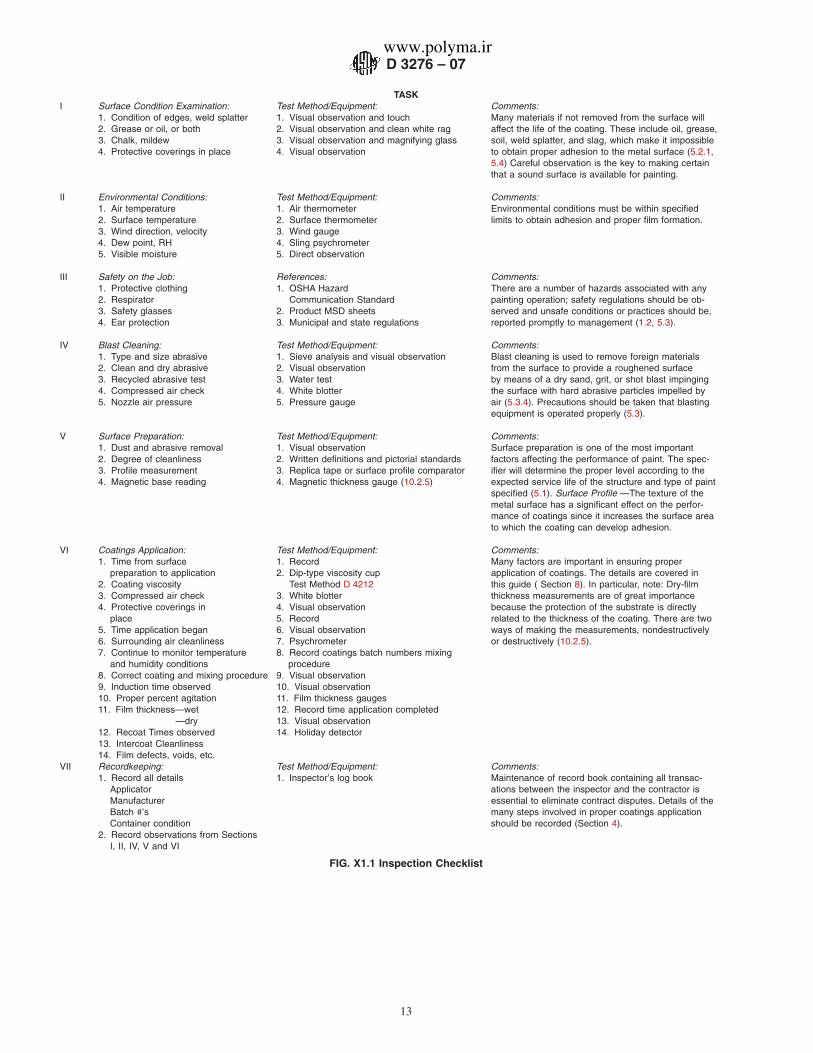
TASKI Surface Condition Examination: Test Method/Equipment: Comments:
1. Condition of edges, weld splatter 1. Visual observation and touch Many materials if not removed from the surface will2. Grease or oil, or both 2. Visual observation and clean white rag affect the life of the coating. These include oil, grease,3. Chalk, mildew 3. Visual observation and magnifying glass soil, weld splatter, and slag, which make it impossible4. Protective coverings in place 4. Visual observation to obtain proper adhesion to the metal surface (5.2.1,
5.4) Careful observation is the key to making certainthat a sound surface is available for painting.
II Environmental Conditions: Test Method/Equipment: Comments:1. Air temperature 1. Air thermometer Environmental conditions must be within specified2. Surface temperature 2. Surface thermometer limits to obtain adhesion and proper film formation.3. Wind direction, velocity 3. Wind gauge4. Dew point, RH 4. Sling psychrometer5. Visible moisture 5. Direct observation
III Safety on the Job: References: Comments:1. Protective clothing 1. OSHA Hazard There are a number of hazards associated with any2. Respirator Communication Standard painting operation; safety regulations should be ob-3. Safety glasses 2. Product MSD sheets served and unsafe conditions or practices should be,4. Ear protection 3. Municipal and state regulations reported promptly to management (1.2, 5.3).
IV Blast Cleaning: Test Method/Equipment: Comments:1. Type and size abrasive 1. Sieve analysis and visual observation Blast cleaning is used to remove foreign materials2. Clean and dry abrasive 2. Visual observation from the surface to provide a roughened surface3. Recycled abrasive test 3. Water test by means of a dry sand, grit, or shot blast impinging4. Compressed air check 4. White blotter the surface with hard abrasive particles impelled by5. Nozzle air pressure 5. Pressure gauge air (5.3.4). Precautions should be taken that blasting
equipment is operated properly (5.3).
V Surface Preparation: Test Method/Equipment: Comments:1. Dust and abrasive removal 1. Visual observation Surface preparation is one of the most important2. Degree of cleanliness 2. Written definitions and pictorial standards factors affecting the performance of paint. The spec-3. Profile measurement 3. Replica tape or surface profile comparator ifier will determine the proper level according to the4. Magnetic base reading 4. Magnetic thickness gauge (10.2.5) expected service life of the structure and type of paint
specified (5.1). Surface Profile —The texture of themetal surface has a significant effect on the perfor-mance of coatings since it increases the surface areato which the coating can develop adhesion.
VI Coatings Application: Test Method/Equipment: Comments:1. Time from surface 1. Record Many factors are important in ensuring proper
preparation to application 2. Dip-type viscosity cup application of coatings. The details are covered in2. Coating viscosity Test Method D 4212 this guide ( Section 8). In particular, note: Dry-film3. Compressed air check 3. White blotter thickness measurements are of great importance4. Protective coverings in 4. Visual observation because the protection of the substrate is directly
place 5. Record related to the thickness of the coating. There are two5. Time application began 6. Visual observation ways of making the measurements, nondestructively6. Surrounding air cleanliness 7. Psychrometer or destructively (10.2.5).7. Continue to monitor temperature 8. Record coatings batch numbers mixing
and humidity conditions procedure8. Correct coating and mixing procedure 9. Visual observation9. Induction time observed 10. Visual observation10. Proper percent agitation 11. Film thickness gauges11. Film thickness—wet 12. Record time application completed
—dry 13. Visual observation12. Recoat Times observed 14. Holiday detector13. Intercoat Cleanliness14. Film defects, voids, etc.
VII Recordkeeping: Test Method/Equipment: Comments:1. Record all details 1. Inspector’s log book Maintenance of record book containing all transac-
Applicator ations between the inspector and the contractor isManufacturer essential to eliminate contract disputes. Details of theBatch #’s many steps involved in proper coatings applicationContainer condition should be recorded (Section 4).
2. Record observations from SectionsI, II, IV, V and VI
FIG. X1.1 Inspection Checklist
D 3276 – 07
13
www.polyma.ir

ASTM International takes no position respecting the validity of any patent rights asserted in connection with any item mentionedin this standard. Users of this standard are expressly advised that determination of the validity of any such patent rights, and the riskof infringement of such rights, are entirely their own responsibility.
This standard is subject to revision at any time by the responsible technical committee and must be reviewed every five years andif not revised, either reapproved or withdrawn. Your comments are invited either for revision of this standard or for additional standardsand should be addressed to ASTM International Headquarters. Your comments will receive careful consideration at a meeting of theresponsible technical committee, which you may attend. If you feel that your comments have not received a fair hearing you shouldmake your views known to the ASTM Committee on Standards, at the address shown below.
This standard is copyrighted by ASTM International, 100 Barr Harbor Drive, PO Box C700, West Conshohocken, PA 19428-2959,United States. Individual reprints (single or multiple copies) of this standard may be obtained by contacting ASTM at the aboveaddress or at 610-832-9585 (phone), 610-832-9555 (fax), or [email protected] (e-mail); or through the ASTM website(www.astm.org).
D 3276 – 07
14
www.polyma.ir