standard item - naval sea systems command · 2.6 s9086-kn-stm-010/ch-310, electric power generators...
TRANSCRIPT

1 of 25 ITEM NO: 009-17 FY-21
NAVSEA STANDARD ITEM
FY-21 ITEM NO: 009-17 DATE: 01 OCT 2019 CATEGORY: II
1. SCOPE:
1.1 Title: Rotating Electrical Equipment; repair
2. REFERENCES:
2.1 Standard Items
2.2 Equipment Technical Manual
2.3 S9086-DA-STM-010/CH-100, Hull Structures
2.4 S9086-KC-STM-010/CH-300, Electric Plant - General
2.5 S9086-KE-STM-010/CH-302, Electric Motors and Controllers
2.6 S9086-KN-STM-010/CH-310, Electric Power Generators and Conversion Equipment
2.7 S9086-HN-STM-010/CH-244, Propulsion Bearings and Seals
2.8 S6260-BJ-GTP-010, Electrical Machinery Repair, Electric Motor, Shop Procedures
Manual
2.9 MIL-DTL-17060, MOTORS, ALTERNATING CURRENT, INTEGRAL-
HORSEPOWER, SHIPBOARD USE
2.10 S9310-AC-HBK-010, Commutator/Slip Ring Maintenance Handbook
2.11 MIL-STD-1310, Shipboard Bonding, Grounding, and Other Techniques for
Electromagnetic Compatibility, Electromagnetic Pulse (EMP) Mitigation, and Safety
2.12 407-5291780, Standard Electromagnetic Interference (EMI) Survey Procedures
3. REQUIREMENTS:
3.1 Disconnect equipment mechanically and remove, including rotating components
connected directly to the shaft, using 2.2 for guidance.

2 of 25 ITEM NO: 009-17 FY-21
3.1.1 Accomplish the following prior to disconnecting: measure air gap readings;
measure bearing clearances for sleeve bearing equipment only; measure alignment readings;
inspect couplings for cracks, broken segments, wear, and misalignment in excess of tolerances
specified in 2.2; measure shaft thrust and run out readings; identify associated cables/wiring and
hook-up data. Record data in Attachment B-2 or equivalent form that contains the
requirements of Attachment B-2.
3.1.2 Identify associated cables and wiring. Disconnect equipment mechanically,
using 2.2 for guidance. Record list of accessories in Attachment B-2 or equivalent form that
contains the requirements of Attachment B-2.
3.1.3 Remove entire vaneaxial and tubeaxial fan assemblies from the duct system
and transport to the shop for repair.
3.2 Accomplish a structural inspection of each foundation in accordance with 2.3. Record
data. Record data in Attachment B-2 or equivalent form that contains the requirements of
Attachment B-2.
3.2.1 Accomplishment of cleaning and painting requirements for foundations of
equipment must be in accordance with NAVSEA Standard Items (See 4.9).
3.3 Matchmark, disassemble, inspect, measure, and test the equipment removed in 3.1,
using 2.2 and 2.4 through 2.8 for guidance.
3.3.1 Inspect and dimensionally measure end bells, frame, rabbet fits, shaft, sleeve
and pedestal bearings, keyways, fan and running surfaces for wear, eccentricity, and other
defects, using 2.2 for accept or reject criteria, and 2.7 for location and type of measurements to
be taken. Record data in Attachment C or equivalent form that contains the requirements of
Attachment C.
3.3.2 Accomplish a 500-volt megger insulation resistance test, using Paragraphs
300-3.2.2 through 300-3.2.3, 300-3.4.8, 300-3.4.11, and 300-
5.3.7.1 of 2.4 for guidance. Record data in Attachment B-1 or equivalent form that contains the
requirements of Attachment B-1.
3.3.2.1 Disconnect solid-state devices and ground temperature-sensing
leads prior to measuring insulation resistance of windings.
3.3.3 Accomplish a phase resistance balance test of windings, using a Wheatstone
or Kelvin bridge, or with an ohmmeter capable of resolving one milliohm (0.001 ohm). Record
phase balance for multi-phase equipment, using Paragraph 5.21 of 2.8 and 3.6.1 of 2.9 for
guidance. Record data.
3.3.4 Accomplish a voltage surge test in accordance with Paragraphs 300-3.5.4
through 300-3.5.5 of 2.4. Record data in Attachment B-1 or equivalent form that contains the
requirements of Attachment B-1.
3 of 25 ITEM NO: 009-17 FY-21
3.3.5 Accomplish a DC HI POT test in accordance with Paragraph 300-3.5.2
through 300-3.5.2.3.4 of 2.4. Added another sentence to paragraph.. Record data in Attachment
B-1 or equivalent form that contains the requirements of Attachment B-1.
3.3.6 Accomplish a Polarization Index Test in accordance with Paragraph 300-
3.4.12 of 2.4. Record data in Attachment B-1 or equivalent form that contains the
requirements of Attachment B-1.
3.3.7 Measure resistance value of each winding temperature detector, heater, and
heater strip using low voltage ohmmeter. Record data in Attachment B-1 or equivalent form
that contains the requirements of Attachment B-1.
3.4 Clean, dry, and test the equipment and windings.
3.4.1 Clean in accordance with Paragraphs 300-4.5.1 through 300-4.5.5 of 2.4.
3.4.2 Dry by placing in an oven in accordance with Paragraph 300-5.3.2.3 of 2.4.
Allow to cool to ambient temperature.
3.4.3 Repeat 3.3.2 and 3.3.5 tests. Record data in Attachment B-1 or equivalent
form that contains the requirements of Attachment B-1.
3.4.4 Repeat cleaning, drying, and testing in 3.4.1 through 3.4.3 if DC HI POT test
readings are questionable, or if insulation resistance readings (minimum of 500 Meg Ohms for
motors with a VPI Sealed Insulation System) are not in accordance with the following: DC
generators and motors (except propulsion and auxiliary generators for submarines) including
exciters, Table 300-3-64 of 2.4; DC propulsion generators and motors and DC auxiliary
generators for submarines, Table 300-3-7 of 2.4; AC generators and motors other than
propulsion, Table 300-3-8 of 2.4; AC propulsion generators and motors, Table 300-3-9 of 2.4.
Record data in Attachment B-1 or equivalent form that contains the requirements of
Attachment B-1. (See 4.5)
3.4.5 Repeat 3.4.1 through 3.4.3 if satisfactory readings are not obtained after the
second cleaning. Record data in Attachment B-1 or equivalent form that contains the
requirements of Attachment B-1. (See 4.5)
3.4.6 Notify the SUPERVISOR if satisfactory readings are not obtained after a
third cleaning.
3.4.7 Repeat 3.3.3 and 3.3.4 tests. Record data in Attachment B-1 or equivalent
form that contains the requirements of Attachment B-1. (See 4.5)

4 of 25 ITEM NO: 009-17 FY-21
3.5 Protect the windings and machined surfaces.Accomplishment of cleaning and
painting requirements for equipment housing exterior, including fan(s) and interior and exterior
of each end bell must be in accordance with NAVSEA Standard Items. (See 4.9)
3.6 Inspect and test non-wound rotors for loose or cracked bars, localized overheating,
and rubbing in accordance with 2.8. Inspect wound rotors, slip ring leads, and armatures for
insulation damage and burns/hot spots. Inspect for loose coils and slot wedges. Inspect slip rings
and commutators for damage and for wear limits, using 2.2 for criteria. Inspect brush rigging for
cracks, chips, worn areas, distortion, spring condition, and insulating material for cracks and arc
paths. Inspect leads and terminal lugs for damage and defects. Identify and tag leads with
aluminum wrap-around bands with metal stamped or embossed markings. Record data in
Attachment B-1 or equivalent form that contains the requirements of Attachment B-1.
(V) "VARNISH TEMPERATURE, VISCOSITY, AND GEL TIME TESTS"
3.7 Select the proper insulating process based on winding insulation classifications and to
meet state or local air pollution standards. Select varnish methods and material, using Paragraphs
300-4.5.8 through 300-4.5.8.2 of 2.4 for guidance. Maintain the varnish in accordance with
Paragraphs 300-4.5.8.3 through 300-4.5.8.3.3 of 2.4 and the varnish manufacturer's instructions.
Maintain a current revision of the varnish manufacturer's instructions on storage, maintenance,
and use of the type of varnish to be applied. Maintain a record of varnish temperature, viscosity
and, for solventless varnish, gel time tests. Tests must show varnish is within varnish
manufacturer's recommendations and have been accomplished in the intervals specified by the
varnish manufacturer. The record must also show that the varnish is being stored as
recommended by the varnish manufacturer. (See 4.5)
3.8 Varnish and bake windings in accordance with Paragraphs 300-4.5.8.4 of 2.4 and the
varnish manufacturer's instructions. Do not immerse the leads. Wipe surfaces that affect
assembly, such as rabbet fits and mounting flanges, with a cloth moistened with a solvent after
draining and before baking. Remove excess varnish run-off from surfaces that affect assembly
after baking. Apply a thin coat of air-dry varnish to metal surfaces exposed by the removal
process in accordance with Paragraph 300-4.5.8.5 and 300-4.5.8.6 of 2.4. (See 4.5)
3.9 Repeat tests described in 3.3.2 through 3.3.5. Record data in Attachment B-1 or
equivalent form that contains the requirements of Attachment B-1. (See 4.5)
3.10 Accomplish an AC HI POT test in accordance with Paragraphs 300-3.5.3 through
300-3.5.3.2.9 of 2.4. Record data in Attachment B-1 or equivalent form that contains the
requirements of Attachment B-1. (See 4.5)
3.11 Repeat measurements described in 3.3.7. Record data in Attachment B-1 or
equivalent form that contains the requirements of Attachment B-1.
3.12 True the commutator or collector rings. Eccentricity must not exceed the
requirements of 2.10. Resurface or machine each individual collector ring to the same exact
diameter to allow symmetrical brush holder to ring clearance spacing. Ensure metal shavings are
5 of 25 ITEM NO: 009-17 FY-21
not permitted to contaminate the rotor or stator assembly. Each cut must not exceed 0.010 inch.
Finish thickness must not be less than design wear tolerance as shown in 2.2. Undercut the mica
between the commutator bars with the edge of the mica not exceeding a depth of 5/64-inch
below the bars. Chamfer the bar edges and remove rough surfaces in accordance with Paragraph
7-4.1.3 of 2.10. Burnish the commutator with a very fine commercial burnishing stone
conforming to A-A-58052. Polish collector rings to a mirror finish.
3.13 Accomplishment of the balancing requirement for each rotating assembly must be in
accordance with NAVSEA Standard Items. (See 4.8)
3.14 Disassemble the brush rigging. Remove foreign matter. Replace existing cadmium-
plated parts with zinc in accordance with ASTM A 153. Recondition threads of plated parts.
Assemble brush rigging.
3.15 Repair lightly scored areas of frame, end bells, and shaft by manual methods.
Recondition threads and fit key to keyway. Visually inspect keyway for deformed, cracked or
chipped edges or high spots. Verify that fit between key and key-seat sides has a minimum
clearance of 0.002 inch or maximum interference of 0.0005 inch. High spots in keyway may be
removed by machining or grinding. Do not unnecessarily repair any keyway; instead, use a step
key up to a maximum of 0.010 inch oversize and, where possible, include a radius in step. If key
tightness cannot be corrected with a step key, machine worn/damaged keyways to |
recommended over-sizes as follows: Maximum of 0.015 inch oversize for a 1/8-inch key and
increasing oversize allowance of 0.010 inch for each 1/8-inch increase in key size up to a
maximum of 0.075 inch. If key tightness cannot be corrected by keyway repair, replace part
involved. Apply a thin coat of petrolatum to unpainted mating surfaces except for explosion-
proof motors, which must have clean, dry mating surfaces.
3.16 Prepare and refinish equipment. Protect machine surfaces, windings, and nameplates
from being painted or otherwise damaged.
3.16.1 Accomplishment of cleaning and painting requirements for housing, fan, and
interior and exterior of each end bell must be in accordance with NAVSEA Standard Items (See
4.9).
3.17 Accomplish the following on equipment having other than sleeve-type bearings
unless otherwise specified in the invoking Work Item, using 2.8 for guidance.
3.17.1 Install new bearings, seals, fittings, lock washers, and locknuts conforming
to 2.2, using 2.7 and Chapter 6 of 2.8 for guidance, except as indicated in 3.17.1.1 (utilizing
Attachment A for guidance).
3.17.1.1 Install Type 111, Class 8 (double seal), bearings in motors
meeting the criteria identified in Chapter 6 of 2.8. Only double seal bearings identified in
Chapter 6 of 2.8 are acceptable for use.

6 of 25 ITEM NO: 009-17 FY-21
3.17.1.2 Install Type 111, Class 8 (double seal), bearings with a C3
(greater than normal) radial internal clearance, if not originally furnished or already
accomplished during previous repair, in place of the Type 111 bearing originally furnished, for
vaneaxial and tubeaxial fan motors not meeting the criteria of Chapter 6 of 2.8. Install Type 120
bearings in vaneaxial and tubeaxial fan motors originally furnished with Type 120 bearings.
3.17.1.3 Install new label plates with the inscription "DO NOT
LUBRICATE" on equipment using double seal bearings (Type 111, Class 8, or Type 120).
3.17.1.4 Install pipe plugs on all grease fills and drains, for equipment
converted from re-lubricable bearings to double seal bearings.
3.17.1.5 Prepare a report that reflects the change in the maintenance
requirements for the converted motor, for equipment converted from lubricated bearings to
double seal bearings. Record data in Attachment B-1 or equivalent form that contains the
requirements of Attachment B-1.
3.17.2 Lubricate bearings with grease conforming to DOD-G-24508 in accordance
with Paragraphs 244-1.7.7.2 and 244-1.7.7.3 of 2.7, for equipment not using double seal
bearings.
3.18 Assemble the equipment using 2.2 and 2.4 through 2.8 for guidance. Do not use
materials containing silicone in the repair and assembly of equipment with commutator or
collector rings. Install new gaskets on covers, inspection plates, and between the external
connection box and the frame. Gaskets must conform to MIL-PRF-1149 unless otherwise
specified in 2.2. Set brush holders not less than 1/16-inch or more than 1/8-inch from
commutator or collector rings unless otherwise specified in 2.2; set in electrical neutral plane and
stagger brushes for maximum coverage of the commutator, in accordance with Paragraph 300-
4.7.7.1.10 of 2.4; center over the collector rings; ensure the brushes do not extend beyond the
edge of the collector rings; install new brushes in accordance with 2.2; sand new brushes to fit
curvature of the commutator or collector rings in accordance with Paragraph 6-3.5 through 6-
3.5.4 of 2.10; ensure brushes have a surface contact of 100 percent and are not chipped, cracked,
or broken; remove sand, carbon, and other foreign matter resulting from fitting new brushes;
adjust spring tension of brushes in accordance with 2.2. Adjust air gap as specified in 2.2, plus or
minus 10 percent. Rotate shaft by hand a minimum of 3 revolutions. Rubbing or binding of
rotating assembly must not be allowed.
3.18.1 Install label plates conforming to MIL-DTL-15024 for those identified to be
missing or damaged.
3.18.2 Install identification markers on wiring in the external connection box.
Ensure markers must be aluminum wrap-around type with metal stamped or embossed markings.
3.18.3 Inspect equipment for applicable electromagnetic interference (EMI) fixes
using Shipboard Electromagnetic Compatibility Improvement Program (SEMCIP) Technical
7 of 25 ITEM NO: 009-17 FY-21
Assistance Network (STAN) in accordance with 2.12. Record data in Attachment B-1 or
equivalent form that contains the requirements of Attachment B-1.
3.19 Accomplish a no-load shop test of the motor for a minimum of one-half hour. Verify
proper direction of rotation. After one-half hour, measure current and voltage in each phase,
speed and bearing temperature rise measured on the equipment's exterior near each bearing.
Record data in Attachment B-1 or equivalent form that contains the requirements of
Attachment B-1.
3.20 Accomplish an operational test, of the assembled vaneaxial/tubeaxial fan for one hour
after bearing and stator temperatures stabilize within one degree Celsius for 3 consecutive 15-
minute intervals. Verify proper direction of rotation. Measure current, voltage, frame and bearing
temperature rise and speed at 15-minute intervals. Bearing temperatures must not exceed 180
degrees Fahrenheit, unless otherwise specified in the invoking Work Item or equipment technical
manual. Measure hot insulation resistances of winding to ground immediately upon completion
of the operational shop test, using a 500-volt megger. Record data in Attachment B-1 or
equivalent form that contains the requirements of Attachment B-1.
3.21 Submit one legible copy, in approved transferrable media, of a report listing results of
the requirements of 3.3 through 3.3.7, 3.4.3, 3.4.4, 3.4.5, 3.4.7, 3.6, 3.9, through 3.11, 3.17.1.5, |
3.18.3, 3.19 and 3.20 to the SUPERVISOR.
3.22 Install equipment. Install new gaskets conforming to MIL-PRF-900 on disturbed
ventilation. Align in accordance with 2.2. Measure and record facial and peripheral coupling
data. Install chocks, shims, shock mounts, sound damping pads, and other accessories. Connect
electrical cables/wiring. Bond and ground equipment in accordance with 2.11, using new ground
straps. Rotate shaft by hand a minimum of 3 revolutions. Rubbing or binding of rotating
assembly must not be allowed. Measure the air gap and bearing clearance (sleeve bearing
equipment only), insulation resistance (at 500 volts DC), and thrust. Record data in Attachment
B-2 and C or equivalent form that contains the requirements of Attachment B-2 and C.
3.22.1 Accomplishment of pump and driver shaft alignment must be in accordance
with NAVSEA Standard Items. (See 4.10)
(V)(G) "OPERATIONAL TEST"
3.23 Accomplish an operational test of the assembled equipment at full system capacity for
one hour after bearing and stator temperatures stabilize within one degree Celsius for 3
consecutive 15-minute intervals, unless otherwise specified in the invoking Work Item. When
temperatures do not stabilize in four hours, stop test and contact the SUPERVISOR. Verify
proper direction of rotation. Verify/establish oxide film coating of the commutator/collector
rings, using 2.10 for guidance. Measure current, voltage, frame and bearing temperature rise, and
speed at 15-minute intervals. Frame and bearing temperature rise and speed is not required for
vaneaxial and tubeaxial fan assemblies. Bearing temperatures must not exceed 180 degrees
Fahrenheit, unless otherwise specified in the invoking Work Item or equipment technical Record
data in Attachment B-2 or equivalent form that contains the requirements of Attachment B-2.

8 of 25 ITEM NO: 009-17 FY-21
3.23.1 Accomplish the requirements of 3.23 twice for two speed motors, once while
operating at low speed, and once while operating at high speed. Record data in Attachment B-2
or equivalent form that contains the requirements of Attachment B-2.
3.23.2 Accomplish the requirements of 3.23 for limited duty motors, for a
period of time equal to the duty cycle of the motor. For motors with a duty cycle equal to or less
than 30 minutes, measure data every 10 minutes. Record data in Attachment B-2 or equivalent
form that contains the requirements of Attachment B-2.
3.23.3 Measure hot insulation resistances of windings to ground immediately
upon completion of test, using a 500-volt megger. Record data in Attachment B-2 or equivalent
form that contains the requirements of Attachment B-2.
3.24 Submit one legible copy, in hard copy or approved transferrable media, of a report
listing results of requirements and data recorded in 3.1.1, 3.1.2, 3.2, 3.22, and 3.23 through
3.23.3 to the SUPERVISOR.
4. NOTES:
4.1 Equipment technical manual, Allowance Parts List (APL) (if applicable) and
drawings will be listed in the invoking Work Item.
4.2 Shop test of generator will be addressed in the invoking Work Item.
4.3 The purpose of 3.4.4, 3.4.5, 3.4.7, 3.7, 3.8, 3.9, and 3.10 is to ensure the integrity of
motors with a VPI Sealed Insulation System.
4.4 Utilize Attachment A for determination if the Navy’s motor bearing conversion
program for Extended-Life Double Seal (ELDS) ball bearings is permissible).
4.5 Not required for motors with a VPI Sealed Insulation System.
4.6 MIL-B-17931 (Bearings, Ball, Annular, for Quiet Operation) bearings are considered
to be Long Lead Time (LLT) material. It is recommended these bearings be provided as
Government Furnished Material (GFM).
4.7 Data received in 3.17.1.5 must be used by the SUPERVISOR for the purpose of
initiating action ensuring shipboard databases such as the Equipment Guidance List (EGL) are
updated to reflect the change in maintenance requirements for converted motors. Additionally,
where APL changes are initiated to convert to ELDS bearings, a COSAL feedback report must
be submitted, providing the NSN and part number for the ELDS bearing by the SUPERVISOR.
Utilize the following website to initiate changes to Technical Manuals, APLs, etc.:
http://www.navy311.navy.mil.
9 of 25 ITEM NO: 009-17 FY-21
4.8 If balancing of rotating equipment of 3.13 is required; the use of Category II Standard
Item 009-15 “Rotating Machinery; balance” of 2.1 will be specified in the Work Item.
4.9 If cleaning and painting of 3.2.1, 3.5, or 3.16.1 is required, the use of Category II
Standard Item 009-32 “Cleaning and Painting Requirements; accomplish” of 2.1 will be
specified in the Work Item.
4.10 If pump and driver shaft alignment of 3.22.1 is required, the use of Category II
Standard Item 009-58 “Pump and Driver Shaft Alignment; accomplish” of 2.1 will be specified
in the Work Item.
4.11 Shipboard Electromagnetic Compatibility Improvement Program (SEMCIP)
Technical Assistance Network (STAN) referred to in 3.18.3 is available at
https://semcip.nswc.navy.mil/stan/modules/stan/default.asp .

10 of 25 ITEM NO: 009-17 FY-21
ATTACHMENT A
1. To reduce motor maintenance and repair costs, the NAVY has implemented a program that
allows for the use of Extended Life Double Seal (ELDS) bearings.
2. LIMITATIONS: The ELDS program does NOT apply to motors that are under the
cognizance of NAVSEA 08.
3. APLs for motors meeting the conversion criteria requirements have been modified to identify
ELDS bearings. In these cases, the APL bearing criteria will override any specifications
delineated in the equipment technical manual or the motor "Original Equipment Manufacturer
(OEM)" drawings. If ELDS bearings are not indicated in an APL, the following motor criteria
must meet the applicability specifications for motors to undergo conversion to ELDS bearings:
3.a Motor must be installed on a surface ship and must NOT be under the cognizance
of NAVSEA 08.
3.b Commercial motors are not eligible. Motors must have been furnished to the
NAVY in accordance with MIL-DTL-17060 (Motors, Alternating Current, Integral Horsepower,
Shipboard use), MIL-M-17413 (Motors, Direct Current, Integral H.P., Naval Shipboard
[NAVY]) or MIL-M-17059 (Motors, 60 Cycle, Alternating Current Fractional H.P. [Shipboard
Use]).
3.c Motors using one or more noise-quiet bearings per MIL-B-17931 (Bearings, Ball,
Annular, For Quiet Operation) are NOT eligible for ELDS conversion.
3.d Bearings originally furnished with the motor must be Type 111 bearings per FF-
B-171. Motors are NOT to be considered as candidates for ELDS conversion in situations where
the equipment technical manual and/or the OEM motor drawings originally specified FF-B-171
bearings but have notes indicating that replacement bearings are to be in accordance with MIL-
B-17931 (Bearings, Ball, Annular, For Quiet Operation).
3.e The use of ELDS bearings is limited to motors where the full load speed and the
size of both bearings are as follows:
1. Maximum bearing size 306 or 206 and full load rpm between 1,801 and 3,600 rpm.
2. Maximum bearing size 313 or 213 and full load rpm between 1,201 and 1,800 rpm.
3. Maximum bearing size 318 or 218 and full load rpm less than 1200 rpm.
4. The repair process using ELDS bearings includes the following requirements:
4.a Only ELDS bearings, in accordance with the following table (Attachment A /
Table 1), can be used. Other double seal bearings will not provide an acceptable bearing life.

11 of 25 ITEM NO: 009-17 FY-21
Attachment A / Table 1
ELDS Bearings NSNs and Part Numbers
SIZE P/N NSN
201 6201-2RS1C3/GHY 3110-01-492-0221
202 6202-2RS1C3/GHY 3110-01-491-0233
203 6203-2RS1C3/GHY 3110-01-491-0234
204 6204-2RS1C3/GHY 3110-01-491-6636
205 6205-2RS1C3/GHY 3110-01-451-9166
206 6206-2RS1C3/GHY 3110-01-451-9165
207 6207-2RS1C3/GHY 3110-01-451-9164
208 6208-2RS1C3/GHY 3110-01-451-9170
209 6209-2RS1C3/GHY 3110-01-451-9252
210 6210-2RS1C3/GHY 3110-01-492-1831
211 6211-2RS1C3/GHY 3110-01-518-0937
303 6303-2RS1C3/GHY 3110-01-493-3750
304 6304-2RS1C3/GHY 3110-01-451-9153
305 6305-2RS1C3/GHY 3110-01-451-9158
306 6306-2RS1C3/GHY 3110-01-451-9159
607 6307-2RS1C3/GHY 3110-01-451-9161
308 6308-2RS1C3/GHY 3110-01-451-9167
309 6309-2RS1C3/GHY 3110-01-451-9168
310 6310-2RS1C3/GHY 3110-01-490-6683
311 6311-2RS1C3/GHY 3110-01-492-0223
312 6312-2RS1C3/GHY 3110-01-490-6848
313 6313-2RS1C3/GHY 3110-01-492-0191
314 6314-2RS1C3GHY 3110-01-492-0226
315 6315-2RS1C3/GHY 3110-01-494-0993
316 6316-2RS1C3/GHY 3110-01-492-0188
317 6317-2RS1C3/GHY 3110-01-492-0219
318 6318-2RS1C3/GHY 3110-01-493-3749
4.b Both bearings of each converted motor must be ELDS bearings.
4.c A label plate must be permanently attached to the motor indicating "Do Not
Lubricate".
4.d Grease fills and drains, if present, must be fitted with a pipe plug, securely
fastened. Fittings to accommodate grease guns must be replaced with pipe plugs."
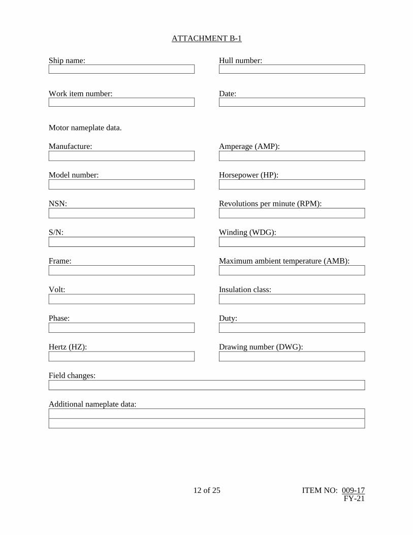
ATTACHMENT B-1
12 of 25 ITEM NO: 009-17 FY-21
Ship name:
Hull number:
Work item number:
Date:
Motor nameplate data.
Manufacture:
Model number:
NSN:
S/N:
Frame:
Volt:
Phase:
Hertz (HZ):
Amperage (AMP):
Horsepower (HP):
Revolutions per minute (RPM):
Winding (WDG):
Maximum ambient temperature (AMB):
Insulation class:
Duty:
Drawing number (DWG):
Field changes:
Additional nameplate data:

ATTACHMENT B-1
13 of 25 ITEM NO: 009-17 FY-21
3.3.2 500-volt megger insulation resistance test.
Lead Acceptance Criteria Measured SAT UNSAT
MΩ MΩ
MΩ MΩ
MΩ MΩ
Findings:
3.3.3 Phase resistance balance test.
Phase Acceptance Criteria Measured SAT UNSAT
Ω Ω
Ω Ω
Ω Ω
Findings:
3.3.4 Voltage surge test.
Circuit Tested Test Voltage Error Ratio SAT UNSAT
V %
V %
V %
Findings:
3.3.5 DC HI POT test.
Circuit Tested Test Voltage Leakage Current SAT UNSAT
V uA
V uA
V uA
Findings:
3.3.6 Polarization Index Test.
Circuit Tested One Minute 10 Minute PI Ratio SAT UNSAT
MΩ MΩ
MΩ MΩ
MΩ MΩ
Findings:

ATTACHMENT B-1
14 of 25 ITEM NO: 009-17 FY-21
3.3.7 Resistance value of each winding temperature detector, heater, and heater strip.
Circuit Tested Acceptance Criteria Measured SAT UNSAT
Ω Ω
Ω Ω
Ω Ω
Findings:
3.4.3 Post cleaning test.
500-volt megger insulation resistance test.
Lead Acceptance Criteria Measured SAT UNSAT
MΩ MΩ
MΩ MΩ
MΩ MΩ
Findings:
Phase resistance balance test.
Phase Acceptance Criteria Measured SAT UNSAT
Ω Ω
Ω Ω
Ω Ω
Findings:
Voltage surge test.
Circuit Tested Test Voltage Error Ratio SAT UNSAT
V %
V %
V %
Findings:
DC HI POT test.
Circuit Tested Test Voltage Leakage Current SAT UNSAT
V uA
V uA
V uA
Findings:

ATTACHMENT B-1
15 of 25 ITEM NO: 009-17 FY-21
3.4.4 Post second cleaning test.
500-volt megger insulation resistance test.
Lead Acceptance Criteria Measured SAT UNSAT
MΩ MΩ
MΩ MΩ
MΩ MΩ
Findings:
Phase resistance balance test.
Phase Acceptance Criteria Measured SAT UNSAT
Ω Ω
Ω Ω
Ω Ω
Findings:
Voltage surge test.
Circuit Tested Test Voltage Error Ratio SAT UNSAT
V %
V %
V %
Findings:
DC HI POT test.
Circuit Tested Test Voltage Leakage Current SAT UNSAT
V uA
V uA
V uA
Findings:

ATTACHMENT B-1
16 of 25 ITEM NO: 009-17 FY-21
3.4.5 Post third cleaning test.
500-volt megger insulation resistance test.
Lead Acceptance Criteria Measured SAT UNSAT
MΩ MΩ
MΩ MΩ
MΩ MΩ
Findings:
Phase resistance balance test.
Phase Acceptance Criteria Measured SAT UNSAT
Ω Ω
Ω Ω
Ω Ω
Findings:
Voltage surge test.
Circuit Tested Test Voltage Error Ratio SAT UNSAT
V %
V %
V %
Findings:
DC HI POT test.
Circuit Tested Test Voltage Leakage Current SAT UNSAT
V uA
V uA
V uA
Findings:

ATTACHMENT B-1
17 of 25 ITEM NO: 009-17 FY-21
3.4.7 Phase resistance balance and voltage surge test.
Phase resistance balance test.
Phase Acceptance Criteria Measured SAT UNSAT
Ω Ω
Ω Ω
Ω Ω
Findings:
Voltage surge test.
Circuit Tested Test Voltage Error Ratio SAT UNSAT
V %
V %
V %
Findings:
3.6 Inspection of motor internal components.
SAT UNSAT
Findings:
3.9 Post varnish and bake test.
500-volt megger insulation resistance test.
Lead Acceptance Criteria Measured SAT UNSAT
MΩ MΩ
MΩ MΩ
MΩ MΩ
Findings:
Phase resistance balance test.
Phase Acceptance Criteria Measured SAT UNSAT
Ω Ω
Ω Ω
Ω Ω
Findings:

ATTACHMENT B-1
18 of 25 ITEM NO: 009-17 FY-21
Voltage surge test.
Circuit Tested Test Voltage Error Ratio SAT UNSAT
V %
V %
V %
Findings:
DC HI POT test.
Circuit Tested Test Voltage Leakage Current SAT UNSAT
V uA
V uA
V uA
Findings:
3.10 AC HI POT test.
Circuit Tested Test Voltage Leakage Current SAT UNSAT
V mA
V mA
V mA
Findings:
3.11 Post varnish and bake resistance value of each winding temperature detector, heater,
and heater strip.
Circuit Tested Acceptance Criteria Measured SAT UNSAT
Ω Ω
Ω Ω
Ω Ω
Findings:
3.17.1.5 Maintenance requirement change for double seal bearing conversion.
Findings:

ATTACHMENT B-1
19 of 25 ITEM NO: 009-17 FY-21
3.18.3 Inspection for EMI fixes.
Findings:
3.19 No-load shop test.
Direction of Rotation CW CCW
Speed RPM
Current Volts
T1 A T1 V
T2 A T2 V
T3 A T3 V
Bearing Temperature
Coupled End °F
Free End °F
3.20 Operational shop test of assembled vaneaxial/tubeaxial fan.
Direction of Rotation CW CCW
Speed RPM
Current Volts
T1 A T1 V
T2 A T2 V
T3 A T3 V
Bearing Temperature
Coupled End °F
Free End °F
500-volt megger insulation resistance test
Lead Acceptance Criteria Measured SAT UNSAT
MΩ MΩ
MΩ MΩ
MΩ MΩ

ATTACHMENT B-2
20 of 25 ITEM NO: 009-17 FY-21
Ship name:
Hull number:
Work item number:
Date:
Motor nameplate data.
Manufacture:
Model number:
NSN:
S/N:
Frame:
Volt:
Phase:
Hertz (HZ):
Amperage (AMP):
Horsepower (HP):
Revolutions per minute (RPM):
Winding (WDG):
Maximum ambient temperature (AMB):
Insulation class:
Duty:
Drawing number (DWG):
Field changes:
Additional nameplate data:
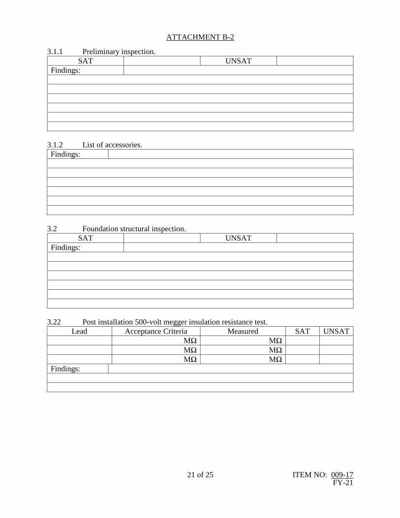
ATTACHMENT B-2
21 of 25 ITEM NO: 009-17 FY-21
3.1.1 Preliminary inspection.
SAT UNSAT
Findings:
3.1.2 List of accessories.
Findings:
3.2 Foundation structural inspection.
SAT UNSAT
Findings:
3.22 Post installation 500-volt megger insulation resistance test.
Lead Acceptance Criteria Measured SAT UNSAT
MΩ MΩ
MΩ MΩ
MΩ MΩ
Findings:

ATTACHMENT B-2
22 of 25 ITEM NO: 009-17 FY-21
3.23 Operational test of the assembled equipment at full system capacity.
Direction of Rotation CW CCW
Speed RPM
15 Minutes
Current Volts
T1 A T1 V
T2 A T2 V
T3 A T3 V
Bearing Temperature
Coupled End °F
Free End °F
30 Minutes
Current Volts
T1 A T1 V
T2 A T2 V
T3 A T3 V
Bearing Temperature
Coupled End °F
Free End °F
45 Minutes
Current Volts
T1 A T1 V
T2 A T2 V
T3 A T3 V
Bearing Temperature
Coupled End °F
Free End °F
One Hour
Current Volts
T1 A T1 V
T2 A T2 V
T3 A T3 V
Bearing Temperature
Coupled End °F
Free End °F

ATTACHMENT B-2
23 of 25 ITEM NO: 009-17 FY-21
3.23.1 Operational test of the assembled equipment at full system capacity, two speed motor.
Direction of Rotation CW CCW
Speed RPM
15 Minutes
Current Volts
T4 A T4 V
T5 A T5 V
T6 A T6 V
Bearing Temperature
Coupled End °F
Free End °F
30 Minutes
Current Volts
T4 A T4 V
T5 A T5 V
T9 A T6 V
Bearing Temperature
Coupled End °F
Free End °F
45 Minutes
Current Volts
T4 A T4 V
T5 A T5 V
T6 A T6 V
Bearing Temperature
Coupled End °F
Free End °F
One Hour
Current Volts
T4 A T4 V
T5 A T5 V
T6 A T6 V
Bearing Temperature
Coupled End °F
Free End °F

ATTACHMENT B-2
24 of 25 ITEM NO: 009-17 FY-21
3.23.2 Operational test of the assembled equipment at full system capacity, limited duty
motor.
Direction of Rotation CW CCW
Speed RPM
Duty Cycle or 10 Minutes as applicable.
Current Volts
T1 A T1 V
T2 A T2 V
T3 A T3 V
Bearing Temperature
Coupled End °F
Free End °F
20 Minutes as applicable.
Current Volts
T1 A T1 V
T2 A T2 V
T3 A T3 V
Bearing Temperature
Coupled End °F
Free End °F
30 Minutes as applicable.
Current Volts
T1 A T1 V
T2 A T2 V
T3 A T3 V
Bearing Temperature
Coupled End °F
Free End °F
3.23.3 Post installation 500-volt megger hot insulation resistance test.
Lead Acceptance Criteria Measured SAT UNSAT
MΩ MΩ
MΩ MΩ
MΩ MΩ
Findings:

25 of 25 ITEM NO: 009-17
FY-21
ATTACHMENT C
/ /
SHIP NAME & HULL NUMBER MONTH/DAY/YEAR
MOTOR LOCATION (i.e., NO.2 MAIN FEED PUMP, etc.)
HOUSING DIAMETERS
OUTER INNER
SHAFT DIAMETERS
1 A B C
A. SHAFT RADIAL RUNOUT
B. FACE RUNOUT, BEARING INNER RING
DRIVE END
OUTER END
C. FACE RUNOUT, BEARING OUTER RING
DRIVE END
OUTER END
MECHANICAL CONDITION
(LOSS OF LUBE, BURNED ETC.)
DRIVE END
A B C
1
2
3
OUTER END
A B C
1
2
3
DRIVE END OUTER
END
A B C A B C
1
2
3
1 2
3
A B C
2
3
B
C
A