standard operating procedure for the rigaku … operating procedure for the rigaku smartlab xrd...
TRANSCRIPT
Standard Operating Procedure for the Rigaku Smartlab XRD
Gaoyuan Ouyang, Ph.D
PI: Prof. Scott Chumbley
Materials Science Department Teaching Laboratory
Iowa State University
SOP Version: 8/1/16
Contact Gaoyuan Ouyang for questions and help in the XRD lab

1. Training
a. In-person training is needed to become an authorized user of this XRD. Contact Gaoyuan Ouyang (Office: 515-294-3304, email: [email protected]) to acquire the training.
b. Completion of X-Ray Safety Fundamentals online course and X-ray/radiation producing device worker application form are required before in-person training. The course can be accessed from EH&S website. Proof of course completion must be presented at the time of training.
c. Completion of Rigaku Smartlab XRD user registration form is required after the in-person training.
d. Schedule online in cypoint for equipment use and sign logbook for each experiment. e. This training allows you to do a basic x-ray scan using Bragg-Brentano (BB) or Parallel beam
(PB) focusing. Additional trainings are required for small incident angle XRD, residual stress measurement, texture/pole figure measurement using the Eulerian cradle, micron diffraction and x-y mapping.
2. General introduction
a. Figure 1 shows the XRD main unit. The X-ray warning lamp (#4) will light if the equipment is
energized. To open the door, press the door-lock button, wait for 5 seconds, then slide the door open. Click the button again when the door is closed.
6.
Figure 1. XRD main unit. 1. Main panel; 2.
Operating panel; 3. Door; 4. X-ray warning
lamp; 5. Door-lock button; 6. Storage box
(inside the chamber by the window)
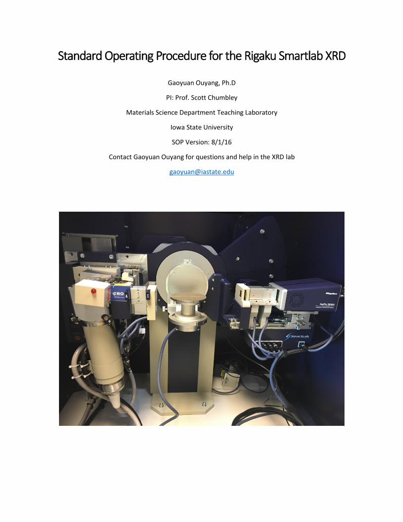
b. There is an indication light on the X-ray tube as shown in Figure 2. When it is on, it means
the shutter is open and that an experiment is in progress. Please refer to the online scheduler in order to reserve a time to use the XRD.
Figure 2. X-ray tube with the shutter open light circled.
3. Starting the XRD
(You may skip step a. c. d if the system and X-ray is already on. When the X-ray light on top the system is
lit, it means the X-ray was left on, you don’t need to turn it on again.)
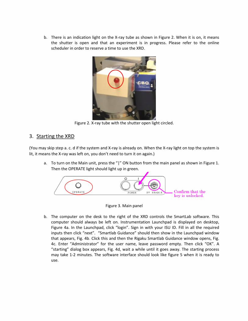
a. To turn on the Main unit, press the “|” ON button from the main panel as shown in Figure 1.
Then the OPERATE light should light up in green.
Figure 3. Main panel
b. The computer on the desk to the right of the XRD controls the SmartLab software. This
computer should always be left on. Instrumentation Launchpad is displayed on desktop, Figure 4a. In the Launchpad, click “login”. Sign in with your ISU ID. Fill in all the required inputs then click “next”. “Smartlab Guidance” should then show in the Launchpad window that appears, Fig. 4b. Click this and then the Rigaku Smartlab Guidance window opens, Fig. 4c. Enter “Administrator” for the user name, leave password empty. Then click “OK”. A “starting” dialog box appears, Fig. 4d, wait a while until it goes away. The starting process may take 1-2 minutes. The software interface should look like figure 5 when it is ready to use.

a. b.
c. d.
Figure 4. Starting the software. a) ISU Launchpad before log-in. b) after login. c) Smartlab login. d) Software startup.
administrator
Wait until this window
goes away before using
the software.
No password

a.
a
a b.
Figure 5. a. Illustration of the Smartlab guidance software, b. Hardware control window that appears when a step is being execute. It goes away when a step is completed successfully. Any error will also
display in this window.
c. Turn on the Haskris water chiller located to the left of the XRD unit by flipping the ON/Off button. Wait for at least 30 minutes before turning on X-ray Tube. THIS IS VERY IMPORTANT! DO NOT FORGET THIS STEP!
Flow chart section.
You will be using this section very often.
When data is collected, a profile
window will pop up here
displaying the pattern. It auto
refreshes with new data. Click here to choose packages.
When a step is being executed,
hardware control window will
appear here.

Figure 6. on/off switch on the Haskris cooler unit.
d. The X-ray tube may be turned on after the 30 minutes wait. From the flow chart section of
the software as indicated in Figure 5, click “Startup”. In the new window that appears (see Figure 7b) click “execute” to start the X-ray tube. There is no need to change any parameters in this window. This process may take 5 minutes.
a. b.
Figure 7. Startup of the X-ray tube. a) Enlarged view of the startup command in the flow chart shown in Figure 5. B) new window that appears once “Startup” is clicked.
4. Selecting the measurement package
a. Click the “Package” tab on the up right corner of the software as shown in Figure 5, The “Package” option now expands and will look like Figure 8.
b. There will be several option tabs in the menu including Preinstalled, User defined, Wizard, and Option. From the “User defined” tab, choose “Training – General (Bragg-Brentano focusing)”, Figure 8.
c. Choose “General (medium resolution PB/PSA)” for parallel beam focusing, Figure 8.

Figure 8. choose the experiment package
5. Optics setup and alignment
a. From the flow chart section on the left of the software (Figure 5), click the “Optics Alignment”, then click “execute” in the window that appears.
Figure 9. optics alignment
b. After you click “Execute” The software prompts you to change to the correct optics setup.
Depending on what optics are already in the system, you may need to change the optics. c. Insert the BB slit in the tube side and install PSA_open in the detector side for Bragg-
Bretano (BB) focusing. Change to the PB slit in the tube side and replace PSA_open with PSA_0.5deg in the detector side for medium resolution Parallel beam (PB) focusing. The BB/PB slit should easily slide in/out of the CBO unit as shown (Figure 10 for BB, Figure 11 for PB). You will need to use the screw driver provided (it is stored in the Storage Box, #6, Fig. 1) to loosen the set screw before removing PSA-open or PSA_0.5deg from the receiving optical device (ROD) adaptor. THE PSA_0.5DEG IS VERY DELICATE, DO NOT DROP IT. Leave a gap of

roughly one A4 paper thickness between PSA and the box to its left. Be careful when removing/installing optics in the detector side as the detector screen is very delicate. DO NOT POKE THE DETECTOR SCREEN. Install the screen shield when needed (you will only need the shield when removing the soller slit for micro-diffraction). When not in use, BB/PB slit and the screw driver should be placed in the storage box inside the chamber as indicated in Figure 1. Place the PSA-open on the enclosure floor directly under the ROD in the main unit when not in use.
a. b. Figure 10. Optics needed for BB focusing. a) Tube side showing cross beam optics unit (CBO) b) detector
side showing the receiving optical device (ROD) adaptor unit.
a. b. Figure 11. Optics needed for PB focusing. a) Tube side showing cross beam optics unit (CBO) b) detector
side showing the receiving optical device (ROD) adaptor unit.
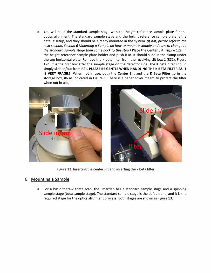
d. You will need the standard sample stage with the height reference sample plate for the
optics alignment. The standard sample stage and the height reference sample plate is the default setup, and they should be already mounted in the system. (If not, please refer to the next section, Section 6 Mounting a Sample on how to mount a sample and how to change to the standard sample stage then come back to this step.) Place the Center Slit, Figure 12a, in the height reference sample plate holder and push it in. It should slide in the clamp under the top horizontal plate. Remove the K beta filter from the receiving slit box 1 (RS1), Figure 12b. It is the first box after the sample stage on the detector side. The K beta filter should simply slide in/out from RS1. PLEASE BE GENTLE WHEN HANDLING THE K BETA FILTER AS IT IS VERY FRAGILE. When not in use, both the Center Slit and the K Beta Filter go in the storage box, #6 as indicated in Figure 1. There is a paper cover meant to protect the filter when not in use.
Figure 12. Inserting the center slit and inserting the k beta filter
6. Mounting a Sample
a. For a basic theta-2 theta scan, the Smartlab has a standard sample stage and a spinning sample stage (beta sample stage). The standard sample stage is the default one, and it is the required stage for the optics alignment process. Both stages are shown in Figure 13.
filter
Slide in/out
Slide in/out

Figure 13. Left: standard sample stage; Right: beta sample stage
i. To change the sample stage you must both remove the stage itself and disconnect
the cable that runs to it. To remove a stage, loosen the thumb screw as pointed to by the arrow in Figure 14a, then carefully slide the stage out from the rail. Set the stage down inside the chamber, then flip open the plug cover on the front side panel inside the chamber and disconnect the cable. You may now remove the stage entirely. Slide the new stage onto the rail, secure it using the thumb screw, and connect the cable. Make sure you close the plug cover after connecting the cable. See Figure 14 for details.
a. b.
Figure 14. Changing the sample state. a) schematics showing the dovetail and the location of the thumb screw. b) image of the cable cover.
Cover is closed
Cable goes in here
Thumb screw
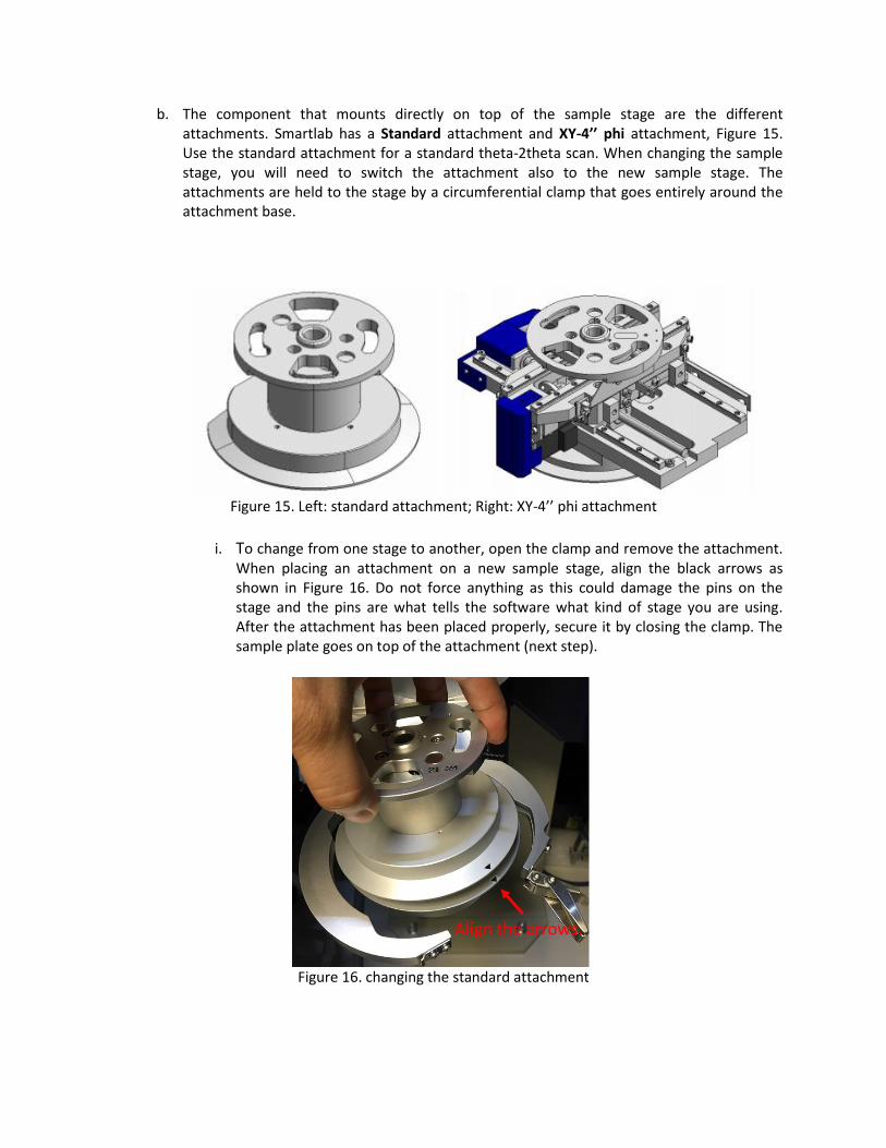
b. The component that mounts directly on top of the sample stage are the different attachments. Smartlab has a Standard attachment and XY-4’’ phi attachment, Figure 15. Use the standard attachment for a standard theta-2theta scan. When changing the sample stage, you will need to switch the attachment also to the new sample stage. The attachments are held to the stage by a circumferential clamp that goes entirely around the attachment base.
Figure 15. Left: standard attachment; Right: XY-4’’ phi attachment
i. To change from one stage to another, open the clamp and remove the attachment.
When placing an attachment on a new sample stage, align the black arrows as shown in Figure 16. Do not force anything as this could damage the pins on the stage and the pins are what tells the software what kind of stage you are using. After the attachment has been placed properly, secure it by closing the clamp. The sample plate goes on top of the attachment (next step).
Figure 16. changing the standard attachment

c. The sample plate is mounted on top of the attachment. Various Sample Plate options are shown in Figure 17. The Sample holder / sample is placed on the sample plate. The height reference sample plate and wafer sample plates are typically used for standard scans and sample spacers are provided for bulk samples (See Section ii below).
Figure 17. Sample plates
i. The height reference sample plate is used for the Center Slit and the
glass/aluminum sample holders, Figure 18. The glass sample holders accommodate mostly powder samples and the aluminum sample holders are for small size bulk samples, which typically are secured level to the surface f the holder with clay. Make sure the sample surface is flat and level with the top surface of the sample holder. The sample holder should slide in the clamp under the top horizontal plate of the height reference sample plate.
Figure 18. From left to right: center slit; glass sample holder; aluminum sample holder, picture showing
how sample holder is mounted in sample plate.
ii. The wafer sample plate is used for larger size bulk samples or a wafer sample. When
using the holders for larger samples you must measure your sample thickness and use the correct sample spacer under the wafer sample plate. Note down the thickness value as you will also need it for the sample alignment. Place you sample on the center of the wafer sample plate. SAMPLES WIDER THAN THE WAFER SAMPLE PLATE ARE NOT ALLOWED IN THIS XRD. Choose the correct spacer based on the measured thickness of your sample. The Smartlab can accommodate samples with thicknesses in the ranges of 0-24mm or 0-3mm, 12-15mm and 21-24mm using the various spacers available. The values corresponding to each spacer are marked in black on the spacer. For samples having a thickness between these values, you may need to add a customized block under your sample.
iii. The spacer mount using a pin and twist mechanism. To mount a spacer, align the
screws (which serve as pins) indicated by the arrows in Figure 19, then turn the
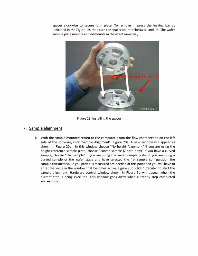
spacer clockwise to secure it in place. To remove it, press the locking bar as indicated in the Figure 19, then turn the spacer counterclockwise and lift. The wafer sample plate mounts and dismounts in the exact same way.
Figure 19. Installing the spacer
7. Sample alignment
a. With the sample mounted return to the computer. From the flow chart section on the left side of the software, click “Sample Alignment”, Figure 20a. A new window will appear as shown in Figure 20b. In this window choose “No height Alignment” if you are using the height reference sample plate; choose “curved sample (Z scan only)” if you have a curved sample; choose “Flat sample” if you are using the wafer sample plate. If you are using a curved sample or the wafer stage and have selected the flat sample configuration the sample thickness value you previous measured are needed at this point and you will have to enter the value in the window that becomes active, Figure 20b. Click “Execute” to start the sample alignment. Hardware control window shown in Figure 5b will appear when the current step is being executed. This window goes away when currently step completed successfully.
Press here for release.

a. b.
Figure 20. Sample alignment. a) Enlarged view of flow chart showing the next step b.) Sample alignment window that opens with alignment choices.
8. Set up measurement parameters and run the scan
a. The options “Quick Theta/2-theta Meas” or “General measurement” are available in the flow chart selections. You will only need one of them, and they are described in turn below in step b or step c.
b. “Quick Theta/2-Theta Meas”
i. If you select “Quick Theta/2-Theta Meas” from the flow chart (See Fig. 20a) Figure 21 shows you the window that opens with the recommended setting for BB focusing if you want to conduct a quick survey scan, while Figure 22 shows the same window with parameters set for PB focusing. Click the “…” tab on the right side of the File name box to specify the path where you will save the data and enter the file name. Save your data under “computer”, “XRD” drive, so that your data can be accessed later. Create a folder with your PI’s name, then a folder with your name. Your data should be saved in the folder with your name. Under the “Sample:” heading choose the type of sample from the pull-down choices, then select step and speed using he radio buttons. In quick scan, you can only choose from the predefined step and speed choices from fine, standard or coarse. Clicking “OK” will save the parameters. Clicking “Execute” will start the scan.

Figure 21. Quick scan for BB focusing

Figure 22. Quick scan for PB focusing
c. General Measurement:
i. If you choose “General Measure” from the flow chart section on the software you have different windows appear with many more choices that let you manually change some of the scan parameters. Refer to Figure 23 for BB focusing and Figure 24 for PB focusing for recommended settings under the “General Measurement” selection. Note that here you have complete control over your scan. Once again you need to click the “…” tab to the right of the File name entry box to specify the path for saving data. Save your data under “computer”, “XRD” drive, so that your data can be accessed later. Create a folder with your PI’s name, then a folder with your name. Your data should be saved in the folder with your name.
ii. If using the “General Measure” choice you need to have the software read what the
slit configuration is. Click “Read current slits” (See Fig. 23 and 24). Under “Data Acquisition mode” (on the right of the window) you must make a choice. You may choose to use 0D or 1D mode for BB focusing; use 0D for PB focusing. On Line 1 select “theta/2-theta scan” in continuous mode in absolute range; Choose your start and end angles, step and speed depending on your experiment. The calculated scan duration should display in the lower left corner.

Figure 23. General measurement example for BB focusing
Figure 24. General measurement example for PB focusing
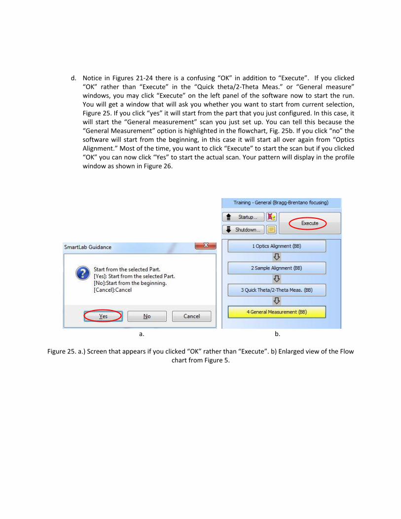
d. Notice in Figures 21-24 there is a confusing “OK” in addition to “Execute”. If you clicked “OK” rather than “Execute” in the “Quick theta/2-Theta Meas.” or “General measure” windows, you may click “Execute” on the left panel of the software now to start the run. You will get a window that will ask you whether you want to start from current selection, Figure 25. If you click “yes” it will start from the part that you just configured. In this case, it will start the “General measurement” scan you just set up. You can tell this because the “General Measurement” option is highlighted in the flowchart, Fig. 25b. If you click “no” the software will start from the beginning, in this case it will start all over again from “Optics Alignment.” Most of the time, you want to click “Execute” to start the scan but if you clicked “OK” you can now click “Yes” to start the actual scan. Your pattern will display in the profile window as shown in Figure 26.
a. b.
Figure 25. a.) Screen that appears if you clicked “OK” rather than “Execute”. b) Enlarged view of the Flow
chart from Figure 5.

Figure 26. Data collection window
9. Finishing Up Follow the steps below to end your scan and stop the billing software. Please shutdown the tube only if
you are the last user of the day. Go to step b only if you are not the last user of the day. You need to
check and see if anybody is using it after you by checking the online XRD scheduler in cypoint (here is
the link: https://www.cypoint.iastate.edu/service/InstrumentationFacilities/MSE/labs/sem-xrd-3365).
a. Click “Shutdown” at the top of the flowchart in the software as shown in Figure 27. A new window opens and if you are the last user of the day click “execute.” Skip this step if you are not the last user of the day.

a. b.
Figure 27. Shutting down the x-ray tube. a) Location in the flowchart where “Shutdown” is found. b) Window that opens.
b. Exit the software by clicking the “x” on the top right corner of the Smartlab guidance
software. Fill in all the information required from the window that appears as shown in Figure 28 then click “Submit.” Click “End Session” to end the billing software.
Figure 27. logging out of Launchpad

c. Wait for 30 minutes, then turn off the Haskris cooler by flipping the on/off button as shown
in Figure 6. Turn off the light in the chamber by press the “lamp” button on the operating panel as shown in figure 1. Skip this step if you are not the last user of the day.
10. Data Access
a. Flash drives are not permitted in the computer in this room. Your raw data can be access from the computer next door Figure 29. Your data is saved under “This PC” on the “XRD” drive. You may copy your data from here to your flash drive.
Figure 28. computer next door for data analysis
b. Use the “RAS data converter” if you would like to convert your data to another format. The
“RAS data converter” can be found on the desktop of the XRD control computer. The window you see when you open the RAS data converter is shown in Figure 30.

Figure 30. RAS data converter software interface
c. From the computer in the adjacent room you may view and process your data using the
PDXL2 software. Use “administrator” for password and leave the password blank. We also have several PDXL2 software key to check out if you would like to use the software in your office. The PDXL2 software can be downloaded to your computer from this link: http://www.rigaku.com/en/service/software/pdxl, however, the software key is required to install and use the software. See Gaoyuan for instructions concerning this and to checkout a key.