standard operation manual - oregon.gov
TRANSCRIPT
STANDARD OPERATION MANUAL
for
Water Quality Biofiltration Swales Implemented April 2017
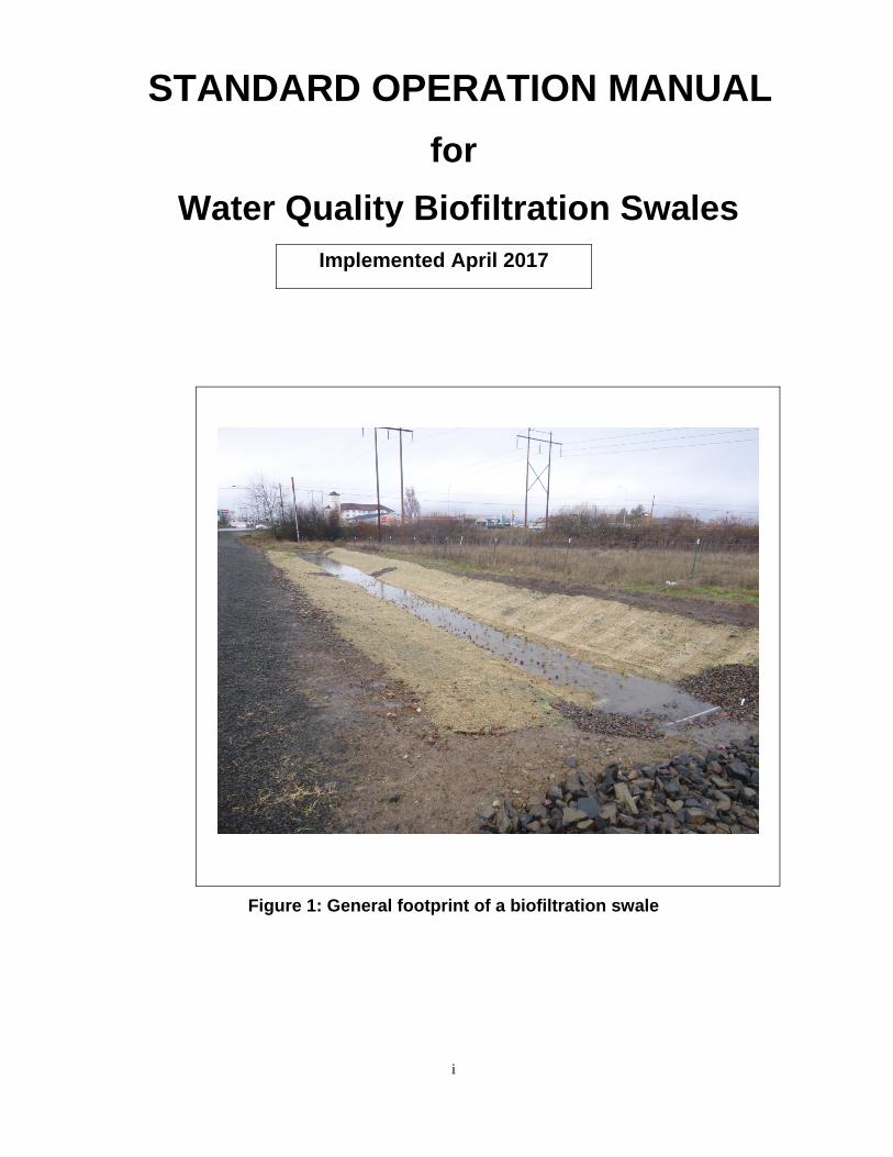
Figure 1: General footprint of a biofiltration swale
i

INDEX
1. INTRODUCTION AND PURPOSE ........................................................... 1
2. DEFINITIONS ........................................................................................... 1
3. OVERVIEW .............................................................................................. 1
4. FACILITY COMPONENTS ....................................................................... 5
5. FIELD MARKERS .................................................................................. 31
6. OPERATIONAL PLAN ........................................................................... 33
APPENDIX A: Standard Operational Plan Drawings
List of Figures
Figure 1: General footprint of a biofiltration swale ................................................................. i Figure 2: Type S2 Stormwater facility marker ....................................................................... 2 Figure 3: Flow splitter example ............................................................................................. 4 Figure 4: Swale inlet example ............................................................................................... 5 Figure 5: Swale outlet example ............................................................................................ 5
ii

1. Introduction and Purpose
The purpose of this Operation Manual is to:
describe what is a water quality swale, how to identify a swale, and how does a swale operate
2. Definitions
Drainage Facility Identification (DFI) – A unique number assigned to ODOT stormwater treatment and storage facilities. The DFI is used to link the stormwater facility to an O&M manual and asset management systems. ODOT’s Geo-Environmental’s Hydraulic Engineering Program Lead assigns DFI numbers.
Online Swale – A swale that does not include a high flow bypass; all flow drains into and through the facility. The swale treats water during low/small flows and functions as a drainage channel during high flow conditions. An online swale does not have a flow splitter and bypass piping (see operational plans A or B for additional details).
Offline Swale – A swale that treats low/small flows and diverts high flows. Low/small flows drain through the facility for treatment. The high flows are routed around the swale using a flow splitter and storm piping (see Photo 2 and operational plan C for additional details).
Swale Inlet – The upstream point/location where stormwater runoff enters or drains into a swale
Swale Outlet – The downstream point/location where stormwater runoff drains from the swale to an outfall
Outfall – The point/location where stormwater runoff exits the outlet pipe or channel and drains into a waterbody, ditch, or storm drain system
3. Overview What is a swale?
ODOT utilizes water quality biofiltration swales to remove sediment and other pollutants from highway stormwater runoff.
A water quality biofiltration swale is a flat-bottomed drainage channel. The typical ground cover is usually grass for swales installed in western Oregon. The ground cover can be grass, river rock, and plantings for central and eastern Oregon installations. The Oregon Climate Zone
1

map (Appendix B, Figure B-10) would be used to determine specific vegetation to use within a facility.
Swales can be located along a highway median, shoulder, open spaces around on-ramps/off-ramps, and within landscaped spaces in urban areas. Swales are usually located at the end of a storm drain piping system but prior to the outfall into a waterbody such as a stream.
The standard operational plan for a swale is provided in Appendix A. The plan illustrates and describes the typical footprint, configuration, and components associated with a swale.
How to identify a swale?
ODOT’s Geo-Environmental Section maintains a stormwater facility inventory. Facilities locations are listed by highway and milepost. Constructed swales should be field marked with metal paddles (see Photo 1). The paddle is white with a blue stripe and the drainage facility identification (DFI) number.
Reference the standard operational plan for swales provided in Appendix A for assistance identifying swale components and the field marker figures in Appendix B for additional field marking details.
Figure 2: Type S2 Stormwater facility marker
TransGIS may also be used to locate swales. TransGIS is a web-based, interactive mapping tool. The facility location (highway, milepoint, district, region), type of facility, DFI number, and electronic copy of O&M manuals
2
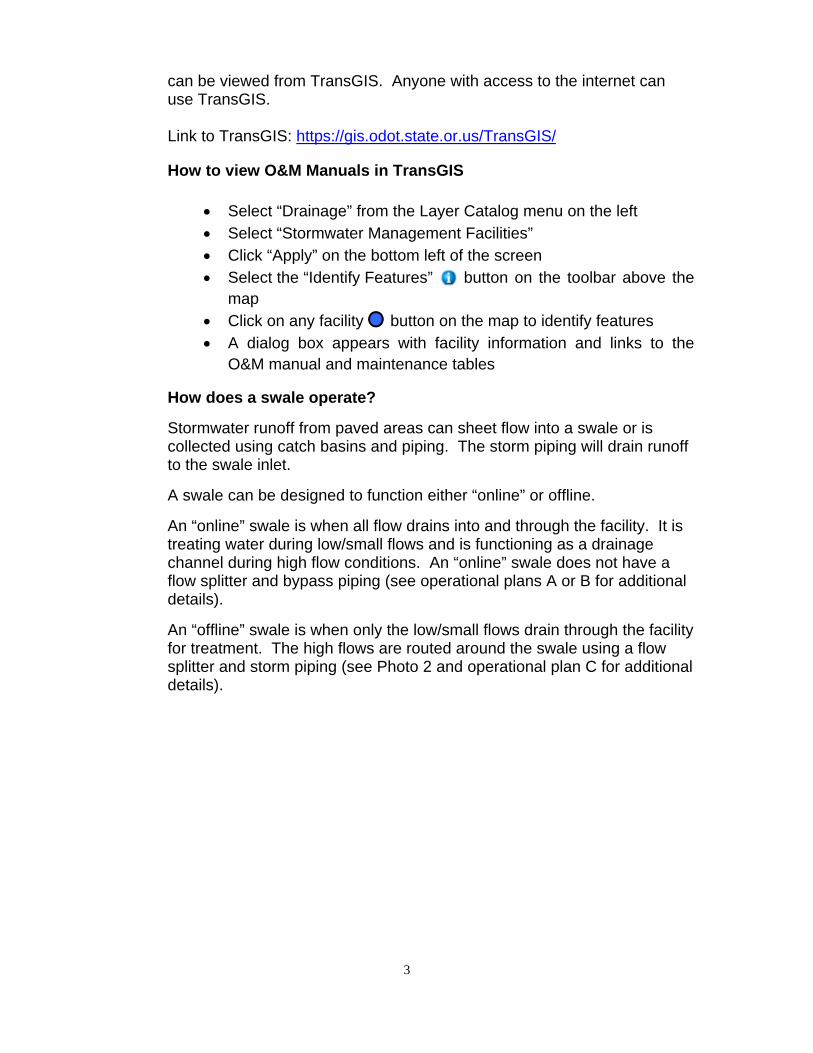
can be viewed from TransGIS. Anyone with access to the internet can use TransGIS.
Link to TransGIS: https://gis.odot.state.or.us/TransGIS/
How to view O&M Manuals in TransGIS
Select “Drainage” from the Layer Catalog menu on the left Select “Stormwater Management Facilities” Click “Apply” on the bottom left of the screen Select the “Identify Features” button on the toolbar above the
map Click on any facility button on the map to identify features A dialog box appears with facility information and links to the
O&M manual and maintenance tables
How does a swale operate?
Stormwater runoff from paved areas can sheet flow into a swale or is collected using catch basins and piping. The storm piping will drain runoff to the swale inlet.
A swale can be designed to function either “online” or offline.
An “online” swale is when all flow drains into and through the facility. It is treating water during low/small flows and is functioning as a drainage channel during high flow conditions. An “online” swale does not have a flow splitter and bypass piping (see operational plans A or B for additional details).
An “offline” swale is when only the low/small flows drain through the facility for treatment. The high flows are routed around the swale using a flow splitter and storm piping (see Photo 2 and operational plan C for additional details).
3

High flows drain over the metal plate and
into a storm drain pipe Low/small flows
stay on this side of metal plate
drain into swale Flow splitter feature is a metal plate
installed across manhole.
Figure 3: Flow splitter example
Stormwater should flow along the swale in a shallow and level manner because the bottom width is level from side to side and the bottom has a mild slope from inlet to outlet. Pollutants are filtered from the water as it flows through the grass or as water infiltrates into the soil. Water that does not infiltrate into the ground will drain to the outlet end of the swale. In most installations a catch basin and storm piping is installed at the swale outlet to drain stormwater to the nearby waterbody or nearby storm drain system. See photos 3 and 4.
Shallow uniform flow is the drainage pattern goal. A facility component known as a flow spreader is used to achieve the drainage pattern goal. A flow spreader is usually installed at the inlet and swale channel midpoint or in 50 foot spacing increments when a swale is longer than 100 feet.
4

Inlet pipe to swale and riprap
Swale
Swale bottom (treatment area)
Figure 4: Swale inlet example
Catch basin installed at
outlet
Flow spreader board and riprap
(riprap installed as needed)
Swale
Figure 5: Swale outlet example
5

4. Facility Components
The following summary outlines the common swale facility components that are used to help with:
removal of sediments, metals, and other pollutants from stormwater,
conveyance, and reduce flow velocities to minimize erosion.
An “ID” number is assigned to each facility component and is used to identify and define these components
The swale components are organized by the following sub-categories:
(1) Manholes/structures
(2) Swale inlet
(3) Ground cover
(4) Underground components
(5) Flow spreader
(6) Swale Outlet
(7) Outfall type
(8) Outfall components.
All components are defined below along with an example/figure and/or noted on the operational plans provided in Appendix A.
6

Table 1: Manholes/Structures
Swale Component ID # Description
Manhole/Structures
Pretreatment manholes
S1
A manhole with a sump is placed upstream of the swale. The purpose of the manhole sump is to allow for coarse sediment and debris to be captured in the sump rather than draining into the swale.
There are several pre-treatment manhole options including: A non-proprietary structure called a pollution control
manhole A proprietary structure called “Continuous Deflective
Separation” (CDS) A proprietary structure called a “Stormceptor “ A proprietary structure called a “First Defense”
A proprietary structure called a “Downstream Defender”
Weir type flow splitter/flow
splitter manhole S2
A manhole installed before the swale inlet with built in components to route water in multiple directions. The splitter routes low/small flows into the swale but allow High flows to bypass (drain around) the swale through a storm piping system. A flow splitter is only used when a swale is designed to be an “offline” facility.
Orifice type flow splitter/flow
splitter manhole S3
A manhole installed before the swale inlet with built in components to route water in multiple directions. The splitter routes low/small flows into the swale but allow High flows to bypass (drain around) the swale through a storm piping system. A flow splitter is only used when a swale is designed to be an “offline” facility.
Standard manhole
S4
A concrete structure provided to access a storm drainage system for inspection and maintenance. A standard manhole is circular, 4 feet in diameter, and a cast iron lid/cover. Typically used when two or more storm drain pipes come together, change in pipe sizes, and changes to horizontal alignments.
7
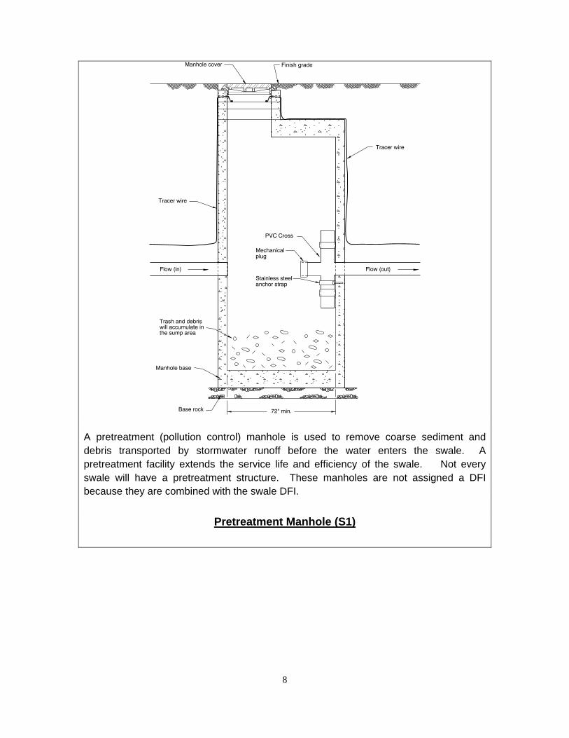
A pretreatment (pollution control) manhole is used to remove coarse sediment and debris transported by stormwater runoff before the water enters the swale. A pretreatment facility extends the service life and efficiency of the swale. Not every swale will have a pretreatment structure. These manholes are not assigned a DFI because they are combined with the swale DFI.
Pretreatment Manhole (S1)
8

Separation Structure examples (source: NCHRP Report 728)
The “CDS” System and “Stormceptor” are proprietary structures used to remove coarse sediment and debris transported by stormwater runoff before the water enters a swale. These structures are produced and sold under exclusive legal right of the inventor or maker. Proprietary structures are assigned a DFI and a separate O&M manual would be provided to explain how the structure operates and details the maintenance actions.
Pretreatment Manhole (S1)
9

First Defense
The “First Defense” proprietary structure is used to remove coarse sediment and debris transported by stormwater runoff before the water enters a swale. This structure is produced and sold under exclusive legal right of the inventor or maker. Proprietary structures are assigned a DFI and a separate O&M manual would be provided to explain how the structure operates and details the maintenance actions.
Pretreatment Manhole (S1)
10

Downstream Defender
The “First Defense” proprietary structure is used to remove coarse sediment and debris transported by stormwater runoff before the water enters a swale. This structure is produced and sold under exclusive legal right of the inventor or maker. Proprietary structures are assigned a DFI and a separate O&M manual would be provided to explain how the structure operates and details the maintenance actions.
Pretreatment Manhole (S1)
11

A manhole installed before the swale inlet with built in components to route water in multiple directions. The splitter routes low/small flows into the swale but allow High flows to bypass (drain around) the swale through a storm piping system. A flow splitter is only used when a swale is designed to be an “offline” facility.
Weir type flow splitter/flow splitter manhole (S2)
12

A manhole installed before the swale inlet with built in components to route water in multiple directions. The splitter routes low/small flows into the swale but allow High flows to bypass (drain around) the swale through a storm piping system. A flow splitter is only used when a swale is designed to be an “offline” facility.
Orifice type flow splitter/flow splitter manhole (S3)
13

A concrete structure provided to access a storm drainage system for inspection and maintenance. A standard manhole is circular, 4 feet in diameter, and a cast iron lid/cover. Typically used when two or more storm drain pipes come together, change in pipe sizes, and changes to horizontal alignments.
Standard Manhole (S4)
14

Swale Inlet
Swale Component ID # Description
Swale Inlet
Pavement sheet flow
S5
Pavement runoff can drain directly into a swale from the adjacent and nearby roadside pavement. There is usually no storm drain piping system that collects and drains runoff into the swale.
An example of this component is provided in Operational Plan A, Appendix A.
Storm drain inlet pipe
S6
One or more storm drain pipes are used to drain pavement runoff into the swale. The inlet pipe is always located at the beginning of the swale.
An example of this component is provided in Operational Plan B and C.
Open channel inlet
S7 Stormwater can enter the swale via an open channel or ditch.
An example of this component is provided in Operational Plan A.
Riprap pad S8
Riprap rock placed at the end of a storm drain pipe or along the bottom of a drainage channel to reduce water flow velocities and minimize soil erosion. The riprap pad shape is usually square or rectangular. The length and depth of the riprap pad depends on ground slope, water flow velocity, and size of rock used to create the rock pad.
15

Stormwater runoff
Riprap Pad
Riprap Pad
Riprap rock placed at the end of a storm drain pipe or along the bottom of a drainage channel to reduce water flow velocities and minimize soil erosion. The riprap pad shape is usually square or rectangular. The length and depth of the riprap pad depends on ground slope, water flow velocity, and size of rock used to create the rock pad.
Riprap Pad (S8)
16
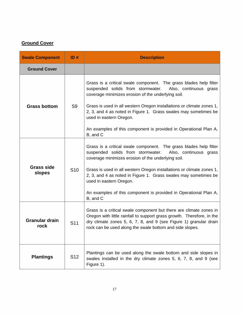
Ground Cover
Swale Component ID # Description
Ground Cover
Grass bottom S9
Grass is a critical swale component. The grass blades help filter suspended solids from stormwater. Also, continuous grass coverage minimizes erosion of the underlying soil.
Grass is used in all western Oregon installations or climate zones 1, 2, 3, and 4 as noted in Figure 1. Grass swales may sometimes be used in eastern Oregon.
An examples of this component is provided in Operational Plan A, B, and C
Grass side slopes
S10
Grass is a critical swale component. The grass blades help filter suspended solids from stormwater. Also, continuous grass coverage minimizes erosion of the underlying soil.
Grass is used in all western Oregon installations or climate zones 1, 2, 3, and 4 as noted in Figure 1. Grass swales may sometimes be used in eastern Oregon.
An examples of this component is provided in Operational Plan A, B, and C
Granular drain rock
S11
Grass is a critical swale component but there are climate zones in Oregon with little rainfall to support grass growth. Therefore, in the dry climate zones 5, 6, 7, 8, and 9 (see Figure 1) granular drain rock can be used along the swale bottom and side slopes.
Plantings S12 Plantings can be used along the swale bottom and side slopes in swales installed in the dry climate zones 5, 6, 7, 8, and 9 (see Figure 1).
17

Grass is used in all western Oregon installations or climate zones 1, 2, 3, and 4 as noted in Figure 1. Grass swales may sometimes be used in eastern Oregon.
Grass bottom and side slopes (S9 and S10)
18

Figure 1: Oregon Climate Zones
19
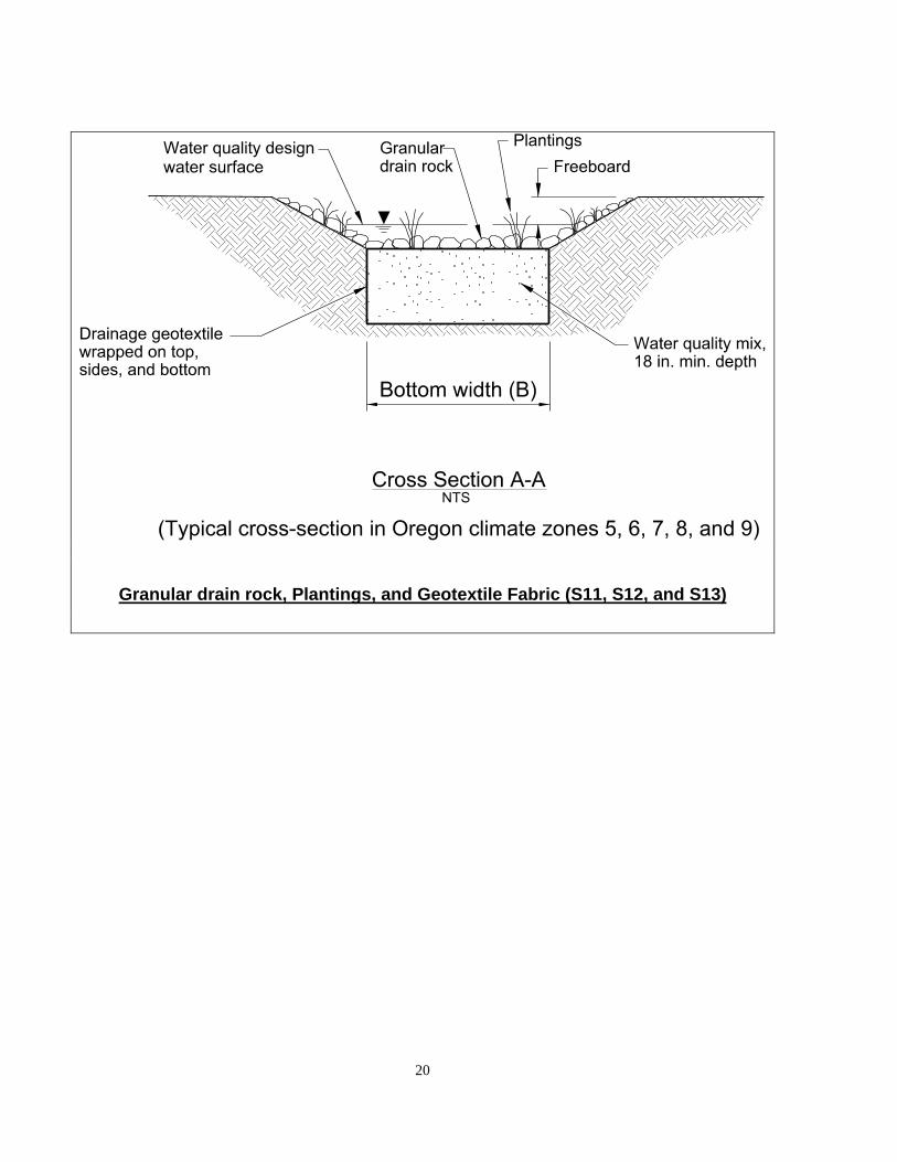
Granular drain rock, Plantings, and Geotextile Fabric (S11, S12, and S13)
20

Underground Components
Swale Component ID # Description
Underground Components
Geotextile fabric S13
Woven or non-woven fabric. It is wrapped around the water quality mix to keep it in place.
Water quality mix S14
At least 18-inches deep of fine graded soil blended with compost. Pollutants are removed from any stormwater runoff infiltrating through the water quality mix. Refer to Special Provision 1012.12 Blend the medium compost and soil so that the mixture is composed of between 20 percent and 25 percent medium compost material and between 75 percent and 80 percent soil material.
Perforated pipe S15
A perforated pipe has small holes along the pipe that allows groundwater to enter the pipe and drains it away from the area below the swale.
Porous pavers (access grid)
S16
An open cell grid system made of durable plastic or concrete. They prevent soil erosion and can support wheel loads to prevent sinking of maintenance equipment
21

Geotextile Fabric (S13)
22

Water quality mix (S14)
23
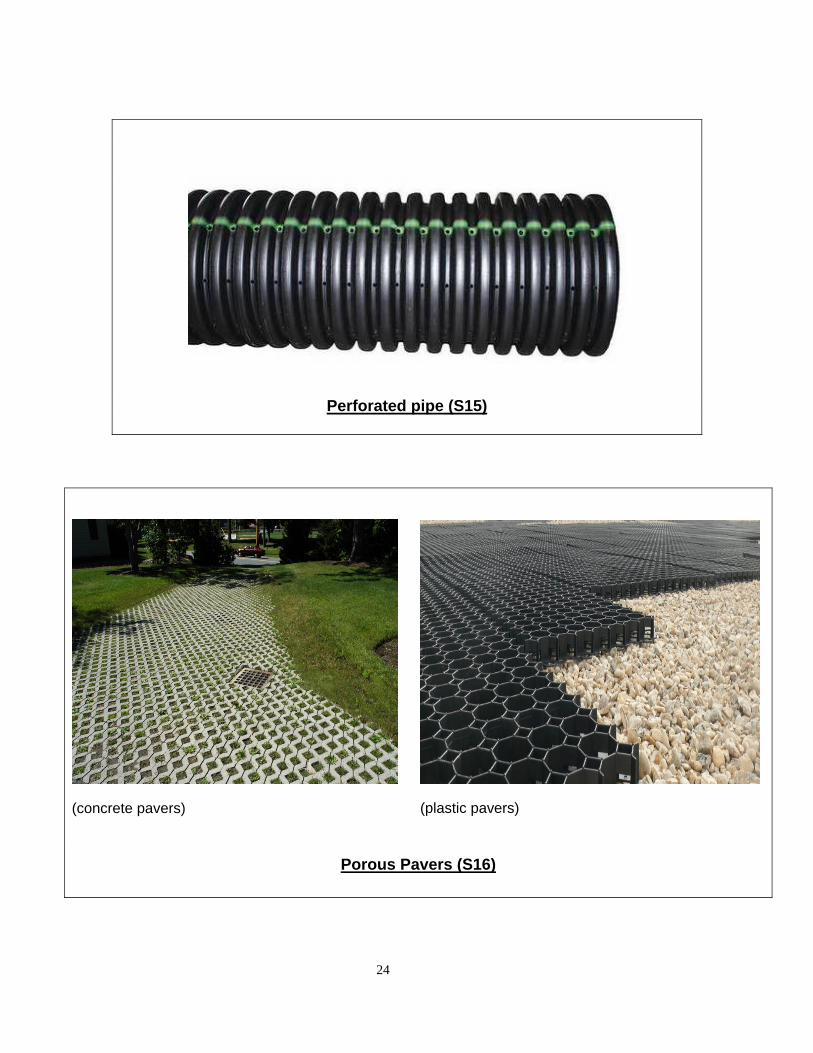
Perforated pipe (S15)
(concrete pavers) (plastic pavers)
Porous Pavers (S16)
24

Flow Spreader
Swale Component ID # Description
Flow Spreader
Rock basin
S17
It is installed at the swale inlet. Stormwater from the inlet pipe drains into the rock basin. The layer of rock covers the underlying soils to avoid erosion and the rock roughness slows down the water draining into the swale.
Anchored board S18
A component used on the bottom of the swale to increase treatment efficiency by reducing erosion and channeling. An anchored board is typically used along the swale to help keep the water evenly spread as it drains along and through the swale.
Other S19
Other flow spreader components could be used as long as it is coordinated between the District, Region, and Geo-Environmental.
25

Rock Basin Flow Spreader (S17)
26

Anchored Board Flow Spreader (S18)
27

Swale Outlet
Swale Component ID # Description
Swale Outlet
Catch basin with grate
S20 Stormwater runoff from a swale will drain into a catch basin with grate installed at the outlet. The catch basin is connected to a storm drain outlet pipe that will convey the water to an outfall.
Storm drain outlet pipe
S21
It is the component that transports stormwater runoff from the swale to an outfall. An outlet pipe is used most of the time but an open channel outlet can also be used to transport runoff from the swale to an outfall. An outlet pipe may also be designed as a bypass pipe to transport high flows around a swale and directly to the outfall.
Open channel outlet
S22 It is the component that transports stormwater runoff from the swale to an outfall.
Auxiliary Outlet S23 A secondary outlet feature that catches high flow in the event that stormwater exceeds the facility’s capacity.
Outfall Type
Swale Component ID # Description
Outfall Type
Waterbody S24 Stormwater draining from a swale can drain directly into a waterbody. The waterbody can be a creek, lake or ocean.
Ditch S25
Stormwater draining from a swale can drain directly into a nearby ditch. The nearby ditch could be an existing ODOT ditch or an adjacent property ditch as long as ODOT’s runoff has always drained into the neighboring ditch.
Storm drain system
S26 Stormwater draining from a swale can drain directly into an ODOT storm drain system and in some cases into a local agency storm drain system.
28
Outfall Components
Swale Component ID # Description
Outfall Components
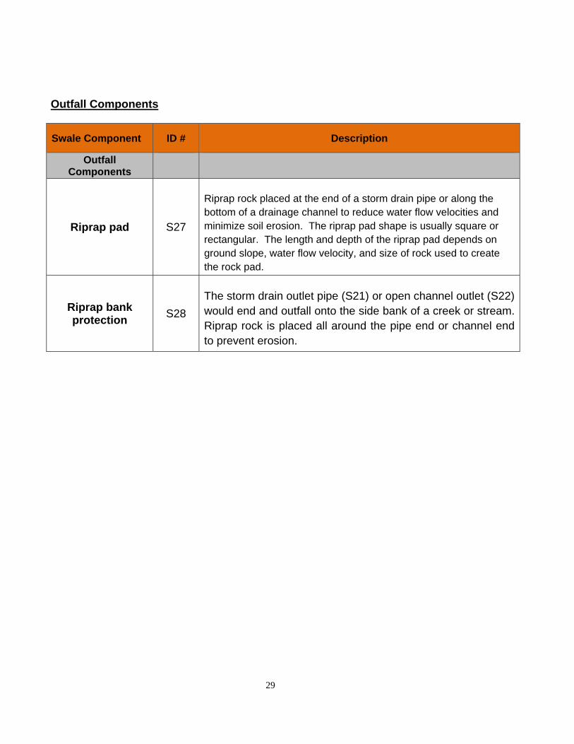
Riprap pad S27
Riprap rock placed at the end of a storm drain pipe or along the bottom of a drainage channel to reduce water flow velocities and minimize soil erosion. The riprap pad shape is usually square or rectangular. The length and depth of the riprap pad depends on ground slope, water flow velocity, and size of rock used to create the rock pad.
Riprap bank protection
S28
The storm drain outlet pipe (S21) or open channel outlet (S22) would end and outfall onto the side bank of a creek or stream. Riprap rock is placed all around the pipe end or channel end to prevent erosion.
29

Outlet and Outfall components (S20 – S27)
30
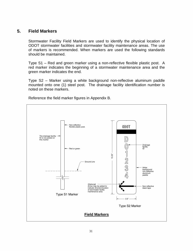
5. Field Markers
Stormwater Facility Field Markers are used to identify the physical location of ODOT stormwater facilities and stormwater facility maintenance areas. The use of markers is recommended. When markers are used the following standards should be maintained.
Type S1 – Red and green marker using a non-reflective flexible plastic post. A red marker indicates the beginning of a stormwater maintenance area and the green marker indicates the end.
Type S2 – Marker using a white background non-reflective aluminum paddle mounted onto one (1) steel post. The drainage facility identification number is noted on these markers.
Reference the field marker figures in Appendix B.
Field Markers
31

Field Marker Locations: Swales
32

6. Operational Plan
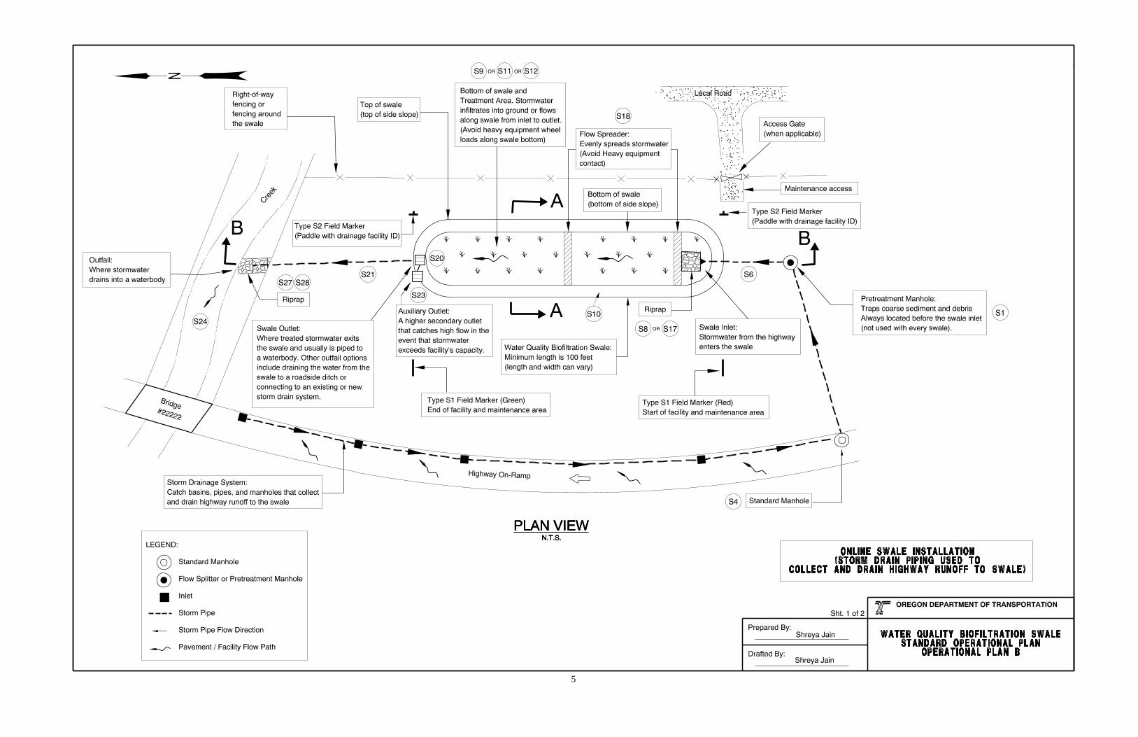
Three standard operational plans for a water quality biofiltration swale are provided in Appendix A. These are the most common installations.
1. Operational Plan A: Illustrates an Online installation with no storm drain piping
2. Operational Plan B: Illustrates an Online installation using storm drain piping to route water into the swale
3. Operational Plan C: Illustrates an Offline installation
The purpose of an operational plan is to illustrate and provide the following general information:
typical footprint configuration (flat bottom channel with average side slopes)
standard swale components used to treat stormwater, minimize erosion, or convey stormwater
general field marking types and where they are placed, and
how stormwater drains into, along, and out of a swale
Notes are included on each sheet to help explain how a swale operates.
33

Appendix A
Content:
Standard Operational Plans
1

2

3

(BLANK)
4
5

6

7

8

(BLANK)
9

10