standard programme clamping technology - tgs€¦ · standard programme clamping technology ......
TRANSCRIPT

Standard ProgrammeClamping Technology
The tool specialists for the trade.

2
EhrenfriedersdorfWTE
4
7295
Chemnitz
DirectionDresden
DirectionErfurt
DirectionErfurt
DirectionNürnberg
DirectionLeipzig
T he t oo l spec ia l i s t s f o r t he t r ade .
WTE Präzisionstechnik GmbH in Kempten and Ehrenfriedersdorf, Germany, is a member of the „tool-traders-partner“ association and takes the advantages of this strong community to the benefi t of its customers and the quality of its products. For further information see the last pages of this catalogue or visit us on the inter-net at www.tool-traders-partner.com.

3
WTE Präzisionstechnik GmbH, an internationally active company, is a technology-oriented opera-tions that develops and produces innovations for the field of clamping technology in their Design and Development Department.
Core competences are in the precision chuck technology, in the hydraulic expansion field and in shrink technology. We have reached the top market position in Europe in the field of precision chucks. More products in high-precision clamping technology will follow.
We rely on highly qualified and engaged employees. Presently, there are approximately
120 employees in our company, who enjoy in-house continuous training in order to meet the high quality demands.
Not only continuing development and innova-tions for solving production-specific problems, but also the sustained expansion of the Germany location is extremely important to us.
With the construction of a second production hall we have laid the cornerstone for strengthening the Germany production location and thus are creating more employment opportunities in the region.
High precision from the Ore Mountains with courage to innovate!
Photo (top) : The production facility of our company in Ehrenfriedersdorf, Germany
Photo (left): Since September 2012 the production area of WTE in Ehrenfriedersdorf has been expanded by a new production hall.

4
We live the philosophy of WTE Präzisionstechnik GmbH every day!
We stand for innovation, precision, competence, service. We are your partner for the future! In other words, this means that only products of the highest µ-range quality leave our facilities and our expertise, training and on-site supervision are available to our customers.
We have been certified since 2001 and are pleased to have ISO 9001:2008 Quality Management Standard. Our customers can rely on flexible and fast service!
High flexibility and fast reaction to customer requests is the motto of our company. Our company philosophy is based on high process reliability, production in Germany, and 100 % reliable employees.
Strategically planned and precisely implemented on the tool!

5
• Machining centres• CNC lathes• HSC machining (35,000 rpm)• Drilling• Counter boring• Reaming• Thread cutting• Tapping • Thread milling• Roughing• Milling• Heavy machining• HPC• Hard machining • Wood processing
Our high precision solutions are used in numerous areas.
Only high quality and precisely set machining centres are used in our production centre in Ehrenfriedersdorf.
The diverse and respected know-how in grinding and turning has an especially high value in our production processes.
Additionally, we guarantee continuous quality control during the entire production process to always supply our customers precise and high-quality products.

6
Technical consulting and expertise
The continually increasing range of high-quality product solutions requires optimal consulting. Our employees are competent contact persons and are always available to offer support in consulting and project supervision - worldwide!
Employee training
Our specially offered training is customised to your personal requirements. Here your employees learn everything they need to know to use the products, for servicing and maintenance, exactly there where this knowledge is needed: In your company!
Our services: Competent consultation, simple ordering, reliable delivery

7
Repair service
We offer 24-hour turnaround time repair service for our tools in case of collisions and faulty operation in daily use.
Warehousing and logistics
Fast availability and reliable delivery are required by our customers, therefore we have optimised our warehousing and the logistic prerequisites to meet these demands.

8
WTE Clamping Technology - The foundation for high-quality and reliable machining processes in the metal and wood industry!
Hydraulic Chucks
Available shank forms:SK, HSK-A, HSK-C, HSK-E, HSK-F, BT
Maximum speed:Up to 40,000 rpm
Available accessory parts:Reducing sleeves, shrink extensions, hydraulic expansion extensions, stop screws, pressure screws, coolant transfer pipe, misc. keys for adjustments
In the catalogue starting on page 16
HPH – High Performance Holder
Available shank forms:SK, HSK-A, HSK-C, HSK-E, HSK-F, BT
Maximum speed:Up to 40,000 rpm
Available accessory parts:Reducing sleeves, shrink extensions, hydraulic expansion extensions, stop screws, pressure screws, coolant transfer pipe, misc. keys for adjustments
In the catalogue starting on page 72
Shrink Chucks
Available shank forms:SK, HSK-A, HSK-C, HSK-E, HSK-F, BT
Maximum speed:Up to 40,000 rpm
Available accessory parts:Shrink extensions, coolant transfer pipe, misc. keys for adjustments
In the catalogue starting on page 94

9
CNC Precision Drill Chucks
Available shank forms:SK, HSK-A, HSK-E, B12, BT, Wohlhaupter, 1835 B, VDI, MORI-SEIKI, ABS Komet, MK, MAZAK, UTS Widia, PSC, Deckel, Chiron
Maximum speed:Up to 35,000 rpm
Available accessory parts:Chuck assembly available as individual part, coolant transfer pipe, misc. keys for adjustments
In the catalogue starting on page 168
NC Standard Drill Chucks
Available shank forms:SK, BT
Maximum speed:Up to 7,000 rpm
Available accessory parts:Chuck assembly available as individual part, coolant transfer pipe, misc. keys for adjustments
In the catalogue starting on page 222
MICRO Universal Chucks
Available shank forms:SK, HSK-A, HSK-E, BT, cylinder shank
Maximum speed:Up to 60,000 rpm
Available accessory parts:Please contact our Customer Service
In the catalogue starting on page 230
WTE Clamping Technology - The foundation for high-quality and reliable machining processes in the metal and wood industry!

10
Shrink ChucksWTE Shrink Chucks offer the possibility for clamping tools for almost all machining. Precise accuracy of fit combined with the highest clamping force and very high torque transmission and outstanding values in the radial stiffness are the characteristics of our Shrink Chucks. Our tools guarantee the best run-out accuracy under 0.003 mm and thus offer the highest dimensional accuracy on the workpiece. Our Shrink Chucks come finely balanced as standard and are suitable for use in numerous areas of application by using shrink extensions.
Information on the program starts on page 94
Hydraulic ChucksHigh run-out accuracy and outstanding vibrational damping are the main characteristics of our Hydraulic Chucks. By using WTE Hydraulic Chucks, we guarantee optimum workpiece surfaces, longer service life of the tools used and economic optimisation of production processes.
WTE Hydraulic Chucks are available both with axial and radial length adjustment and are manufactured in the standard range in the most common shank forms. In addition, the use of reducing sleeves or special Hydraulic Chucks give additional flexibility to these tools.
Information on the program starts on page 16
HPH – High Performance HolderThe technological advanced development of conventional clamping technology is presented to you
by our HPH - High Performance Holder. Ultimate holding forces combined with outstanding damping properties and high bending stiffness with normally higher run-out accuracy put these chucks in the
top class of clamping products and guarantee an especially high surface quality in practical use.
Other outstanding properties are sturdy construction, insensitivity to dirt and high cost effectiveness in regards to the shortening of machining times due to significantly higher machining speeds.
Information on the program starts on page 72
Our product range:High precision, innovative and future oriented

11
NC Standard Drill ChucksOur Standard Drill Chucks, as all WTE products, are impressive due to their precision, high-quality processing and outstanding labour value, which impress our customers every day.
Our products from the "Standard Chucks" sector have been designated the CE mark since September 1994. On the market we stand for quality, reliability and a good price-performance ratio.
Information on the program starts on page 222
CNC Precision Drill ChucksOur Precision Drill Chucks are attractive due to the professional uniformity from mechanical function
and simple handling in innovative technology concepts.Our main focus here is on parameters, such as secure clamping regardless of direction of rotation,
short clamping and changeover times, special short design and use at high speeds. The modular design of our Precision Drill Chucks guarantees that you can choose our Drill Chucks in
any base body shape.
Information on the program starts on page 168
MICRO Universal Chucks 340 & 640To meet the demands for continually smaller components we have expanded our Precision Drill
Chuck program to include a new family – MICRO Universal Chucks. These chucks were developed especially for the micro clamping market.
The chucks cover a large clamping range from 0.2 to 6.4 mm. This enables shanks with small diameters to be clamped with high precision and reliability. Reliable process machining in medical
technology, the watch industry, and precision and electrical engineering are possible at speeds of up to 60,000 rpm and a concentricity < 0.005 mm.
Information on the program starts on page 230

12
1 5 5 0 7 4 0 0 6 Z 1 2 0/
Notes on the technical specifi cation (Order designation)
Chuck shank *
15 = SK16 = HSK-A17 = HSK-F18 = HSK-E22 = BT23 = HSK-C
Nominal size shank Clamp diameter d1
Cantilever length l1
* The numbers shown for clamping chuck shanks and product families stand for the standard areas included in the program:
Special shanks and further designations within the product families can deviate in the numerical designation.
Product family *
501 = Hydraulic Chucks, extra short 507 = Hydraulic Chucks, narrow508 = Hydraulic Chucks, heavy duty509 = Hydraulic Chucks for grinding machines510 = Hydraulic Chucks with radial adjustment
407 = HPH – High Performance Holder, narrow408 = HPH – High Performance Holder, heavy duty
304 = Shrink Chucks, 3° narrow305 = Shrink Chucks with side coolant duct hole306 = Standard Shrink Chucks
296 = CNC Precision Drill Chucks
297 = NC Standard Drill Chucks
236 = MICRO Universal Chucks
Coolant supply
Z = Internal coolant supply and coolant supply via the collar
For tools without coolant supply this identifi er is omitted!

13
ISO7388-1
Form
AD
Form
AD/B
Form
A
Form
C
EForm
Form
F
3 µm
3 µm
h6
15.000min
G 6,3
General informationExplanations of available pictograms
Explanation of the corresponding standard
Internal coolant supply taper shank
Internal coolant supply taper shank or coolant supply via collar
Hollow shank taper, Form A
Hollow shank taper, Form C for manual tool change
Hollow shank taper, Form E
Hollow shank taper, Form F
Internal coolant supply
Without internal coolant supply
Run-out variation with HSK shanks
Run-out variation with SK/ISO shanks
Shank tolerance
Balance quality
Bore for data carrier/chip acc. to DIN 69873-E10 (Balluf)
All dimensions in mm.
Custom designs of the products shown in this catalogue are always available on request.
Symbol � Delivery time upon request.
Symbol �These products are available in stock.
Technical specifications are subject to change .
Prices: Please find the corresponding prices and surcharges in our current valid price list.
Our General Terms and Conditions apply (see next to the last page in the catalogue).
Manufacturer's instructions: Symbol explanations:

14
Table of Contents
Hydraulic Chucks 16
Spare Parts & Accessories 63
HPH – High Performance Holder 72
Spare Parts & Accessories 84
Shrink Chucks 94
Spare Parts & Accessories 162
CNC Precision Drill Chucks 168
Spare Parts & Accessories 207
NC Standard Drill Chucks 222
Spare Parts & Accessories 227
MICRO Universal Chucks 230
Spare Parts & Accessories 239
Technical Information 240
General Terms and Conditions 253

15

16

17
Hydraulic ChucksWith radial or axial length adjustment
Shank form SK 30 Page 18
Shank form SK 40 Page 19-25
Shank form SK 50 Page 26-29
Shank form HSK-A 32 Page 30
Shank form HSK-A 40 Page 31-32
Shank form HSK-A 50 Page 33-34
Shank form HSK-A 63 Page 35-41
Shank form HSK-A 80 Page 42
Shank form HSK-A 100 Page 43-44
Shank form HSK-C 40 Page 45
Shank form HSK-C 50 Page 46
Shank form HSK-C 63 Page 47
Shank form HSK-E 40 Page 48
Shank form HSK-E 50 Page 49
Shank form HSK-F 63 Page 50
Shank form BT 30 Page 51
Shank form BT 40 Page 52-55
Shank form BT 50 Page 56-58
Module and Adapter SK, HSK, BT Page 59-62
Spare Parts & Accessories Page 63-71
Hydr
aulic
Chu
cks

18
ISO7388-1
Form
ADh6
3 µm
25.000min
G 2,5
l1
l4
d2
d3d1
l 2
l3
G
30 6 26 45 55 37 10 20,0 M5 2,5 0,6 15.507.30.06.Z 30336701 �
30 8 28 45 55 37 10 20,0 M6 3 0,6 15.507.30.08.Z 30336702 �
30 10 30 45 55 41 10 21,0 M8x1 3 0,6 15.507.30.10.Z 30336703 �
30 12 32 45 55 46 10 22,0 M8x1 3 0,6 15.507.30.12.Z 30336704 �
30 14 34 45 90 46 10 42,0 M8x1 3 0,7 15.507.30.14.Z 30336705 �
30 16 38 45 90 49 10 50,0 M8x1 3 0,7 15.507.30.16.Z 30336706 �
30 18 40 45 90 49 10 50,0 M8x1 3 0,7 15.507.30.18.Z 30336707 �
30 20 42 45 90 51 10 50,0 M8x1 3 0,7 15.507.30.20.Z 30336708 �
Hydraulic ChuckISO 7388-1, Form AD (prev. DIN 69871-AD)Short narrow design
Design & Main Characteristics:
• High run-out accuracy• Vibration damping effect• High radial stiffness• Clamping without additional devices• Quick setup times• Flexible clamping range using reducing sleeves
Nominal size
SK/ISO
Dimensions G Wrench size Weightkg
Order designation Order No. In stock
d1 d2 d3 l1 l2 l3 l4
SK 30
All dimensions in mm.
For spare parts & accessories, see end of chapter. Custom designs available on request.
� Delivery time upon request.
� These products are available in stock.

19
ISO7388-1
h63 µm
25.000min
G 2,5
l1
l4
d3
d2
d1
l 2
l3
G
40 6 26 49,5 80 37 10 29 M5 2,5 1,8 14.507.40.06 30336691 �
40 8 28 49,5 80 37 10 30 M6 3 1,8 14.507.40.08 30336692 �
40 10 30 49,5 80 41 10 35 M6 3 1,8 14.507.40.10 30336693 �
40 12 32 49,5 80 46 10 40 M10x1 5 1,8 14.507.40.12 30336694 �
40 14 34 49,5 80 46 10 40 M10x1 5 1,8 14.507.40.14 30336695 �
40 16 38 49,5 80 49 10 45 M10x1 5 1,9 14.507.40.16 30336696 �
40 18 40 49,5 80 49 10 46 M10x1 5 1,8 14.507.40.18 30336697 �
40 20 42 49,5 80 51 10 47 M10x1 5 1,8 14.507.40.20 30336698 �
40 25 55 49,5 95 57 10 54 M10x1 5 2,3 14.507.40.25 30336699 �
40 32 63 49,5 95 61 10 48 M10x1 5 2,4 14.507.40.32 30336700 �
Hydraulic ChuckISO 7388-1, Form A (prev. DIN 69871-A)Short narrow design for wood processing
Design & Main Characteristics:
• High run-out accuracy• Vibration damping effect• High radial stiffness• Clamping without additional devices• Quick setup times• Flexible clamping range using reducing sleeves
All dimensions in mm.
For spare parts & accessories, see end of chapter. Custom designs available on request.
SK 40
� Delivery time upon request.
� These products are available in stock.
Hydr
aulic
Chu
cks
Nominal size
SK/ISO
Dimensions G Wrench size Weightkg
Order designation Order No. In stock
d1 d2 d3 l1 l2 l3 l4

20
ISO7388-1
Form
ADh6
3 µm
25.000min
G 2,5
l1
d2
d3d1
l2
l3
G
40 20 34 48 24,5 51 10 M16x1 8 0,6 15.501.40.20.Z 30349264 �
Hydraulic ChuckISO 7388-1, Form AD (prev. DIN 69871-AD)Extra short design
Design & Main Characteristics:
• High run-out accuracy• Vibration damping effect• High radial stiffness• Clamping without additional devices• Quick setup times• Flexible clamping range using reducing sleeves
SK 40
Nominal size
SK/ISO
Dimensions G Wrench size Weightkg
Order designation Order No. In stock
d1 d2 d3 l1 l2 l3
All dimensions in mm.
For spare parts & accessories, see end of chapter. Custom designs available on request.
� Delivery time upon request.
� These products are available in stock.

21
ISO7388-1
Form
AD/AFh6
3 µm
25.000min
G 2,5
d2
d3
d1
l2
l3
G
l4
l1
40 6 26 49,5 80,5 37 10 29,5 M5 2,5 1,3 15.507.40.06.Z 30336709 �
40 8 28 49,5 80,5 37 10 30,0 M6 3 1,3 15.507.40.08.Z 30336712 �
40 10 30 49,5 80,5 41 10 35,0 M8x1 3 1,3 15.507.40.10.Z 30336715 �
40 12 32 49,5 80,5 46 10 40,0 M10x1 5 1,3 15.507.40.12.Z 30336719 �
40 14 34 49,5 80,5 46 10 40,0 M10x1 5 1,3 15.507.40.14.Z 30336723 �
40 16 38 49,5 80,5 49 10 45,0 M12x1 5 1,4 15.507.40.16.Z 30336726 �
40 18 40 49,5 80,5 49 10 46,0 M12x1 5 1,3 15.507.40.18.Z 30336729 �
40 20 42 49,5 80,5 51 10 47,0 M16x1 8 1,3 15.507.40.20.Z 30336732 �
40 25 55 63 80,5 57 10 28,0 M16x1 8 1,6 15.507.40.25.Z 30336736 �
40 32 63 70 80,5 61 10 25,5 M16x1 8 1,7 15.507.40.32.Z 30336739 �
Hydraulic ChuckISO 7388-1, Form AD/AF (prev. DIN 69871-AD/B)Short narrow design
Design & Main Characteristics:
• High run-out accuracy• Vibration damping effect• High radial stiffness• Clamping without additional devices• Quick setup times• Flexible clamping range using reducing sleeves
Nominal size
SK/ISO
Dimensions G Wrench size Weightkg
Order designation Order No. In stock
d1 d2 d3 l1 l2 l3 l4
SK 40
All dimensions in mm.
Basic setting Form AD. If Form AF (prev. B) is desired,
please indicate when ordering.
For spare parts & accessories, see end of chapter.
Custom designs available on request.
� Delivery time upon request.
� These products are available in stock.
Hydr
aulic
Chu
cks

22
l4
l1
d1
d2
d3
l 2
l3
G
ISO7388-1
Form
AD/AFh6
3 µm
25.000min
G 2,5
40 6 26 49,5 110 37 10 29 M5 2,5 1,7 15.507.40.06.Z/110 30336711 �
40 8 28 49,5 110 37 10 30 M6 3 1,8 15.507.40.08.Z/110 30336714 �
40 10 30 49,5 110 41 10 35 M8x1 3 1,8 15.507.40.10.Z/110 30336717 �
40 12 32 49,5 110 46 10 40 M10x1 5 1,8 15.507.40.12.Z/110 30336722 �
40 14 34 49,5 110 46 10 40 M10x1 5 1,8 15.507.40.14.Z/110 30336725 �
40 16 38 49,5 110 49 10 45 M12x1 5 1,8 15.507.40.16.Z/110 30336728 �
40 18 40 49,5 110 49 10 46 M12x1 5 1,9 15.507.40.18.Z/110 30336731 �
40 20 42 49,5 110 51 10 47 M16x1 8 1,9 15.507.40.20.Z/110 30336735 �
40 25 55 63 110 57 10 28 M16x1 8 2,3 15.507.40.25.Z/110 30336738 �
40 32 63 59 110 61 10 59 M16x1 8 2,4 15.507.40.32.Z/110 30336741 �
Hydraulic ChuckISO 7388-1, Form AD/AF (prev. DIN 69871-AD/B)Long narrow design
Design & Main Characteristics:
• High run-out accuracy• Vibration damping effect• High radial stiffness• Clamping without additional devices• Quick setup times• Flexible clamping range using reducing sleeves
All dimensions in mm.
Basic setting Form AD. If Form AF (prev. B) is desired,
please indicate when ordering.
For spare parts & accessories, see end of chapter.
Custom designs available on request.
SK 40
� Delivery time upon request.
� These products are available in stock.
Nominal size
SK/ISO
Dimensions G Wrench size Weightkg
Order designation Order No. In stock
d1 d2 d3 l1 l2 l3 l4

23
ISO7388-1
Form
AD/AFh6
3 µm
25.000min
G 2,5
l1
d1
d2
l2
l3
G
40 20 49,5 64,5 51 10 M16x1 8 1,3 15.508.40.20.Z 30337087 �
Hydraulic ChuckISO 7388-1, Form AD/AF (prev. DIN 69871-AD/B)Short heavy duty design
Design & Main Characteristics:
• High run-out accuracy• Vibration damping effect• High radial stiffness• Clamping without additional devices• Quick setup times• Flexible clamping range using reducing sleeves
SK 40
All dimensions in mm.
Basic setting Form AD. If Form AF (prev. B) is desired,
please indicate when ordering.
For spare parts & accessories, see end of chapter.
Custom designs available on request.
� Delivery time upon request.
� These products are available in stock.
Hydr
aulic
Chu
cks
Nominal size
SK/ISO
Dimensions G Wrench size Weightkg
Order designation Order No. In stock
d1 d2 l1 l2 l3

24
d 1
l2
l3
d 3
l1
d 2
l4
G
ISO7388-1
Form
AD/AFh6
3 µm
25.000min
G 2,5
40 6 26 49,5 80,5 37 10 29,5 M5 2,5 1,3 15.507.40.06.KKB 30595958 �
40 8 28 49,5 80,5 37 10 30 M6 3 1,3 15.507.40.08.KKB 30595959 �
40 10 30 49,5 80,5 41 10 35 M8x1 3 1,3 15.507.40.10.KKB 30595961 �
40 12 32 49,5 80,5 46 10 40 M10x1 5 1,3 15.507.40.12.KKB 30532100 �
40 14 34 49,5 80,5 46 10 40 M10x1 5 1,3 15.507.40.14.KKB 30595962 �
40 16 38 49,5 80,5 49 10 45 M12x1 5 1,4 15.507.40.16.KKB 30595964 �
40 18 40 49,5 80,5 49 10 46 M12x1 5 1,3 15.507.40.18.KKB 30595966 �
40 20 42 49,5 80,5 51 10 47 M16x1 8 1,3 15.507.40.20.KKB 30595967 �
40 25 55 63 80,5 57 10 28 M16x1 8 1,6 15.507.40.25.KKB 30595969 �
40 32 63 70 80,5 61 10 25,5 M16x1 8 1,7 15.507.40.32.KKB 30595970 �
Hydraulic ChuckISO 7388-1, Form AD/AF (prev. DIN 69871-AD/B)Short narrow design with resealable coolant duct holes
Design & Main Characteristics:
• High run-out accuracy• Vibration damping effect• High radial stiffness• Clamping without additional devices• Quick setup times• Flexible clamping range using reducing sleeves
All dimensions in mm.
Basic setting Form AD. If Form AF (prev. B) is desired,
please indicate when ordering.
For spare parts & accessories, see end of chapter.
Custom designs available on request.
SK 40
� Delivery time upon request.
� These products are available in stock.
Nominal size
SK/ISO
Dimensions G Wrench size Weightkg
Order designation Order No. In stock
d1 d2 d3 l1 l2 l3 l4

25
ISO7388-1
Form
AD/AFh6
3 µm
25.000min
G 2,5
d 1
l2
l3
d 3
l1
d 2
l4
G
40 6 26 49,5 110 37 10 29 M5 2,5 1,7 15.507.40.06.110/KKB 30596252 �
40 8 28 49,5 110 37 10 30 M6 3 1,7 15.507.40.08.110/KKB 30596254 �
40 10 30 49,5 110 41 10 35 M8x1 3 1,8 15.507.40.10.110/KKB 30596257 �
40 12 32 49,5 110 46 10 40 M10x1 5 1,8 15.507.40.12.110/KKB 30596286 �
40 14 34 49,5 110 46 10 40 M10x1 5 1,8 15.507.40.14.110/KKB 30596293 �
40 16 38 49,5 110 49 10 45 M12x1 5 1,8 15.507.40.16.110/KKB 30596295 �
40 18 40 49,5 110 49 10 46 M12x1 5 1,9 15.507.40.18.110/KKB 30596296 �
40 20 42 49,5 110 51 10 47 M16x1 8 1,9 15.507.40.20.110/KKB 30596297 �
40 25 55 63 110 57 10 28 M16x1 8 2,1 15.507.40.25.110/KKB 30596299 �
40 32 63 59 110 61 10 59 M16x1 8 2,2 15.507.40.32.110/KKB 30596301 �
Hydraulic ChuckISO 7388-1, Form AD/AF (prev. DIN 69871-AD/B)Long narrow design with resealable coolant duct holes
Design & Main Characteristics:
• High run-out accuracy• Vibration damping effect• High radial stiffness• Clamping without additional devices• Quick setup times• Flexible clamping range using reducing sleeves
SK 40
All dimensions in mm.
Basic setting Form AD. If Form AF (prev. B) is desired,
please indicate when ordering.
For spare parts & accessories, see end of chapter.
Custom designs available on request.
� Delivery time upon request.
� These products are available in stock.
Hydr
aulic
Chu
cks
Nominal size
SK/ISO
Dimensions G Wrench size Weightkg
Order designation Order No. In stock
d1 d2 d3 l1 l2 l3 l4
26
ISO7388-1
Form
AD/AFh6
3 µm
25.000min
G 2,5
l1
l4
d3
d2
d1
l2
l3
G
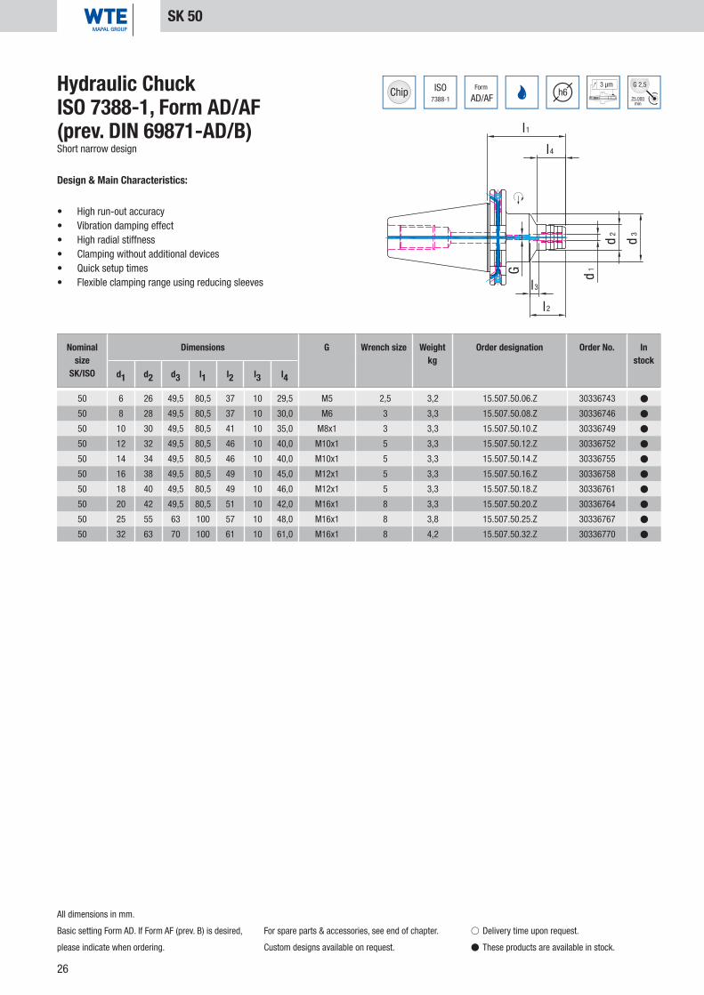
50 6 26 49,5 80,5 37 10 29,5 M5 2,5 3,2 15.507.50.06.Z 30336743 �
50 8 28 49,5 80,5 37 10 30,0 M6 3 3,3 15.507.50.08.Z 30336746 �
50 10 30 49,5 80,5 41 10 35,0 M8x1 3 3,3 15.507.50.10.Z 30336749 �
50 12 32 49,5 80,5 46 10 40,0 M10x1 5 3,3 15.507.50.12.Z 30336752 �
50 14 34 49,5 80,5 46 10 40,0 M10x1 5 3,3 15.507.50.14.Z 30336755 �
50 16 38 49,5 80,5 49 10 45,0 M12x1 5 3,3 15.507.50.16.Z 30336758 �
50 18 40 49,5 80,5 49 10 46,0 M12x1 5 3,3 15.507.50.18.Z 30336761 �
50 20 42 49,5 80,5 51 10 42,0 M16x1 8 3,3 15.507.50.20.Z 30336764 �
50 25 55 63 100 57 10 48,0 M16x1 8 3,8 15.507.50.25.Z 30336767 �
50 32 63 70 100 61 10 61,0 M16x1 8 4,2 15.507.50.32.Z 30336770 �
Hydraulic ChuckISO 7388-1, Form AD/AF (prev. DIN 69871-AD/B)Short narrow design
Design & Main Characteristics:
• High run-out accuracy• Vibration damping effect• High radial stiffness• Clamping without additional devices• Quick setup times• Flexible clamping range using reducing sleeves
All dimensions in mm.
Basic setting Form AD. If Form AF (prev. B) is desired,
please indicate when ordering.
For spare parts & accessories, see end of chapter.
Custom designs available on request.
SK 50
� Delivery time upon request.
� These products are available in stock.
Nominal size
SK/ISO
Dimensions G Wrench size Weightkg
Order designation Order No. In stock
d1 d2 d3 l1 l2 l3 l4

27
ISO7388-1
Form
AD/AFh6
3 µm
25.000min
G 2,5
l1
l4
d3
d2
d1
l2
l3
G
50 6 26 49,5 110 37 10 29 M5 2,5 4,1 15.507.50.06.Z/110 30336745 �
50 8 28 49,5 110 37 10 30 M6 3 4,1 15.507.50.08.Z/110 30336748 �
50 10 30 49,5 110 41 10 35 M8x1 3 4,1 15.507.50.10.Z/110 30336751 �
50 12 32 49,5 110 46 10 40 M10x1 5 4,3 15.507.50.12.Z/110 30336754 �
50 14 34 49,5 110 46 10 40 M10x1 5 4,3 15.507.50.14.Z/110 30336757 �
50 16 38 49,5 110 49 10 45 M12x1 5 4,3 15.507.50.16.Z/110 30336760 �
50 18 40 49,5 110 49 10 46 M12x1 5 4,5 15.507.50.18.Z/110 30336763 �
50 20 42 49,5 110 51 10 42 M16x1 8 4,5 15.507.50.20.Z/110 30336766 �
50 25 55 63 110 57 10 48 M16x1 8 4,7 15.507.50.25.Z/110 30336769 �
50 32 63 70 110 61 10 61 M16x1 8 4,8 15.507.50.32.Z/110 30336772 �
Hydraulic ChuckISO 7388-1, Form AD/AF (prev. DIN 69871-AD/B)Long narrow design
Design & Main Characteristics:
• High run-out accuracy• Vibration damping effect• High radial stiffness• Clamping without additional devices• Quick setup times• Flexible clamping range using reducing sleeves
All dimensions in mm.
Basic setting Form AD. If Form AF (prev. B) is desired,
please indicate when ordering.
For spare parts & accessories, see end of chapter.
Custom designs available on request.
SK 50
� Delivery time upon request.
� These products are available in stock.
Nominal size
SK/ISO
Dimensions G Wrench size Weightkg
Order designation Order No. In stock
d1 d2 d3 l1 l2 l3 l4
Hydr
aulic
Chu
cks

28
ISO7388-1
Form
AD/AFh6
3 µm
25.000min
G 2,5
l1
d2d1
l3
l2
G
50 32 72 81 61 10 M16x1 8 3,9 15.508.50.32.Z 30337089 �
Hydraulic ChuckISO 7388-1, Form AD/AF (prev. DIN 69871-AD/B)Short heavy duty design
Design & Main Characteristics:
• High run-out accuracy• Vibration damping effect• High radial stiffness• Clamping without additional devices• Quick setup times• Flexible clamping range using reducing sleeves
SK 50
All dimensions in mm.
Basic setting Form AD. If Form AF (prev. B) is desired,
please indicate when ordering.
For spare parts & accessories, see end of chapter.
Custom designs available on request.
� Delivery time upon request.
� These products are available in stock.
Nominal size
SK/ISO
Dimensions G Wrench size Weightkg
Order designation Order No. In stock
d1 d2 l1 l2 l3

29
ISO7388-1
Form
ADh6
3 µm
25.000min
G 2,5
l1
l4
d1
d2
d3
l2
G
50 6 32 60 110 43 45 M5 2,5 3,6 15.509.50.06 30336773 �
50 8 33,5 60 110 43 50 M6 3 3,6 15.509.50.08 30336774 �
50 10 35 60 110 43 50 M8x1 3 3,7 15.509.50.10 30336775 �
50 12 36,5 60 110 50 55 M10x1 5 3,7 15.509.50.12 30336776 �
50 14 38 60 110 50 60 M10x1 5 3,7 15.509.50.14 30336777 �
50 16 39,5 60 110 53 60 M12x1 5 3,8 15.509.50.16 30336778 �
50 18 41 60 110 53 60 M12x1 5 3,8 15.509.50.18 30336779 �
50 20 42 70 110 95 41 M16x1 8 3,9 15.509.50.20 30336780 �
50 22 44 70 110 95 43 M16x1 8 3,9 15.509.50.22 30336781 �
50 25 47 70 110 95 40 M16x1 8 3,9 15.509.50.25 30336782 �
50 32 54 70 110 95 56 M16x1 8 4,0 15.509.50.32 30336783 �
Hydraulic ChuckISO 7388-1, Form AD (prev. DIN 69871-AD)For tool grinders and grinding machines
Design & Main Characteristics:
• High run-out accuracy• Vibration damping effect• High radial stiffness• Clamping without additional devices• Quick setup times• Flexible clamping range using reducing sleeves
SK 50
All dimensions in mm.
For spare parts & accessories, see end of chapter. Custom designs available on request.
� Delivery time upon request.
� These products are available in stock.
Hydr
aulic
Chu
cks
Nominal size
SK/ISO
Dimensions G Wrench size Weightkg
Order designation Order No. In stock
d1 d2 d3 l1 l2 l4

30
DIN69893
Form
A
3 µmh6
25.000min
G 2,5
l1
l4
d3
d2d1
l2
l3
G
32 6 26 40 80 37 10 29 M5 2,5 0,5 16.507.32.06.Z 30336816 �
32 8 28 40 80 37 10 29 M6 3 0,5 16.507.32.08.Z 30336817 �
32 10 30 40 85 41 10 35 M6 3 0,5 16.507.32.10.Z 30336818 �
32 12 32 40 90 46 10 40 M6 3 0,5 16.507.32.12.Z 30336819 �
Hydraulic ChuckDIN 69893-AShort narrow design
Design & Main Characteristics:
• High run-out accuracy• Vibration damping effect• High radial stiffness• Clamping without additional devices• Quick setup times• Flexible clamping range using reducing sleeves
All dimensions in mm.
For spare parts & accessories, see end of chapter.
MQL-capable design possible on request.
Custom designs available on request.
HSK-A 32
� Delivery time upon request.
� These products are available in stock.
Nominal size
HSK-A
Dimensions G Wrench size Weightkg
Order designation Order No. In stock
d1 d2 d3 l1 l2 l3 l4

31
DIN69893
Form
A
3 µmh6
25.000min
G 2,5
l1
l4
d1 d2
d3
l 3
l2
G
40 6 26 33,5 70 37 10 36 M5 2,5 0,4 16.507.40.06.Z 30336820 �
40 8 28 33,5 70 37 10 36 M6 3 0,5 16.507.40.08.Z 30336821 �
40 10 30 33,5 75 41 10 42 M6 3 0,5 16.507.40.10.Z 30336822 �
40 12 32 33,5 85 46 10 48 M6 3 0,6 16.507.40.12.Z 30336823 �
Hydraulic ChuckDIN 69893-AShort narrow design
Design & Main Characteristics:
• High run-out accuracy• Vibration damping effect• High radial stiffness• Clamping without additional devices• Quick setup times• Flexible clamping range using reducing sleeves
HSK-A 40
All dimensions in mm.
For spare parts & accessories, see end of chapter.
MQL-capable design possible on request.
Custom designs available on request.
� Delivery time upon request.
� These products are available in stock.
Hydr
aulic
Chu
cks
Nominal size
HSK-A
Dimensions G Wrench size Weightkg
Order designation Order No. In stock
d1 d2 d3 l1 l2 l3 l4

32
40 6 26 34 80 37 10 36 0,5 16.510.40.06.Z 30349328 �
40 8 28 34 80 37 10 36 0,5 16.510.40.08.Z 30349329 �
40 10 30 34 85 41 10 43 0,6 16.510.40.10.Z 30349330 �
40 12 32 34 90 46 10 48 0,6 16.510.40.12.Z 30349331 �
DIN69893
Form
A
3 µmh6
25.000min
G 2,5
l1
l4
l3
l2
d1
d2
d3
Nominal size
HSK-A
Dimensions Weightkg
Order designation Order No. In stock
d1 d2 d3 l1 l2 l3 l4
Hydraulic ChuckDIN 69893-AShort narrow design, with radial length adjustment
Design & Main Characteristics:
• High run-out accuracy• Vibration damping effect• High radial stiffness• Clamping without additional devices• Quick setup times• Flexible clamping range using reducing sleeves
All dimensions in mm.
For spare parts & accessories, see end of chapter.
MQL-capable design possible on request.
Custom designs available on request.
HSK-A 40
� Delivery time upon request.
� These products are available in stock.
Radial

33
DIN69893
Form
A
3 µmh6
25.000min
G 2,5
d2
d3d1
l 4
l1
l3
G
l2
50 6 26 40 70 37 10 28 M5 2,5 0,9 16.507.50.06.Z 30336824 �
50 8 28 40 70 37 10 28 M6 3 0,9 16.507.50.08.Z 30336825 �
50 10 30 40 75 41 10 34 M8x1 3 0,9 16.507.50.10.Z 30336826 �
50 12 32 40 85 46 10 44 M10x1 5 1,0 16.507.50.12.Z 30336827 �
50 14 34 40 85 46 10 44 M10x1 5 1,0 16.507.50.14.Z 30336828 �
50 16 38 53 90 49 10 30 M12x1 5 1,2 16.507.50.16.Z 30336829 �
50 18 40 53 90 49 10 30 M12x1 5 1,2 16.507.50.18.Z 30336830 �
50 20 42 57 90 51 10 29 M16x1 5 1,2 16.507.50.20.Z 30336831 �
Hydraulic ChuckDIN 69893-AShort narrow design
Design & Main Characteristics:
• High run-out accuracy• Vibration damping effect• High radial stiffness• Clamping without additional devices• Quick setup times• Flexible clamping range using reducing sleeves
HSK-A 50
All dimensions in mm.
For spare parts & accessories, see end of chapter.
MQL-capable design possible on request.
Custom designs available on request.
� Delivery time upon request.
� These products are available in stock.
Hydr
aulic
Chu
cks
Nominal size
HSK-A
Dimensions G Wrench size Weightkg
Order designation Order No. In stock
d1 d2 d3 l1 l2 l3 l4

34
50 6 26 40 80 37 10 35 0,7 16.510.50.06.Z 30349332 �
50 8 28 40 80 37 10 36 0,7 16.510.50.08.Z 30349333 �
50 10 30 40 85 41 10 38 0,8 16.510.50.10.Z 30349334 �
50 12 32 40 90 46 10 40 0,8 16.510.50.12.Z 30349335 �
50 14 34 40 90 46 10 46 0,8 16.510.50.14.Z 30349336 �
50 16 38 53 95 49 10 36 1,0 16.510.50.16.Z 30349337 �
50 18 40 53 95 49 10 36 1,1 16.510.50.18.Z 30349338 �
50 20 42 57 100 51 10 37 1,2 16.510.50.20.Z 30349339 �
DIN69893
Form
A
3 µmh6
25.000min
G 2,5
l1
l4
l3
l2
d1
d2
d3
Nominal size
HSK-A
Dimensions Weightkg
Order designation Order No. In stock
d1 d2 d3 l1 l2 l3 l4
Hydraulic ChuckDIN 69893-AShort narrow design, with radial length adjustment
Design & Main Characteristics:
• High run-out accuracy• Vibration damping effect• High radial stiffness• Clamping without additional devices• Quick setup times• Flexible clamping range using reducing sleeves
All dimensions in mm.
For spare parts & accessories, see end of chapter.
MQL-capable design possible on request.
Custom designs available on request.
HSK-A 50
� Delivery time upon request.
� These products are available in stock.
Radial

35
DIN69893
Form
A
3 µmh6
25.000min
G 2,5
l1
d2d1
l2
l3
G
63 20 51,5 80 51 10 M8x1 3 1,5 16.508.63.20.Z 30337091 �
Hydraulic ChuckDIN 69893-AShort heavy duty design
Design & Main Characteristics:
• High run-out accuracy• Vibration damping effect• High radial stiffness• Clamping without additional devices• Quick setup times• Flexible clamping range using reducing sleeves
HSK-A 63
All dimensions in mm.
For spare parts & accessories, see end of chapter.
MQL-capable design possible on request.
Custom designs available on request.
� Delivery time upon request.
� These products are available in stock.
Hydr
aulic
Chu
cks
Nominal size
HSK-A
Dimensions G Wrench size Weightkg
Order designation Order No. In stock
d1 d2 l1 l2 l3

36
DIN69893
Form
A
3 µmh6
25.000min
G 2,5
l1
l4
d3
d2d1
l2
l3
G
63 6 26 50 70 37 10 24 M5 2,5 0,9 16.507.63.06.Z 30336832 �
63 8 28 50 70 37 10 25 M6 3 0,9 16.507.63.08.Z 30336837 �
63 10 30 50 80 41 10 35 M8x1 3 1,0 16.507.63.10.Z 30336842 �
63 12 32 50 85 46 10 40 M10x1 5 1,0 16.507.63.12.Z 30336847 �
63 14 34 50 85 46 10 40 M10x1 5 1,1 16.507.63.14.Z 30336852 �
63 16 38 50 90 49 10 46 M12x1 5 1,2 16.507.63.16.Z 30336857 �
63 18 40 50 90 49 10 47 M12x1 5 1,2 16.507.63.18.Z 30336862 �
63 20 42 50 90 51 10 48 M16x1 5 1,2 16.507.63.20.Z 30336867 �
63 25 57 53 120 57 10 63 M16x1 5 2,1 16.507.63.25.Z 30336873 �
63 32 63 59 125 61 10 61 M16x1 5 2,3 16.507.63.32.Z 30336875 �
Hydraulic ChuckDIN 69893-AShort narrow design
Design & Main Characteristics:
• High run-out accuracy• Vibration damping effect• High radial stiffness• Clamping without additional devices• Quick setup times• Flexible clamping range using reducing sleeves
HSK-A 63
All dimensions in mm.
For spare parts & accessories, see end of chapter.
MQL-capable design possible on request.
Custom designs available on request.
� Delivery time upon request.
� These products are available in stock.
Nominal size
HSK-A
Dimensions G Wrench size Weightkg
Order designation Order No. In stock
d1 d2 d3 l1 l2 l3 l4

37
DIN69893
Form
A
3 µmh6
25.000min
G 2,5
l1
l4
G
l2
l3
d3
d2d1
63 6 26 50 150 37 10 103 M5 2,5 1,7 16.507.63.06.Z/150 30336835 �
63 6 26 50 200 37 10 153 M5 2,5 1,9 16.507.63.06.Z/200 30336836 �
63 8 28 50 150 37 10 104 M6 3 1,7 16.507.63.08.Z/150 30336840 �
63 8 28 50 200 37 10 154 M6 3 1,9 16.507.63.08.Z/200 30336841 �
63 10 30 50 150 41 10 104 M8x1 3 1,7 16.507.63.10.Z/150 30336845 �
63 10 30 50 200 41 10 154 M8x1 3 1,9 16.507.63.10.Z/200 30336846 �
63 12 32 50 150 46 10 105 M10x1 5 1,7 16.507.63.12.Z/150 30336850 �
63 12 32 50 200 46 10 155 M10x1 5 1,9 16.507.63.12.Z/200 30336851 �
63 14 34 50 150 46 10 105 M10x1 5 1,9 16.507.63.14.Z/150 30336855 �
63 14 34 50 200 46 10 155 M10x1 5 2,1 16.507.63.14.Z/200 30336856 �
63 16 38 50 150 49 10 106 M12x1 5 2,0 16.507.63.16.Z/150 30336860 �
63 16 38 50 200 49 10 156 M12x1 5 2,3 16.507.63.16.Z/200 30336861 �
63 18 40 50 150 49 10 107 M12x1 5 2,1 16.507.63.18.Z/150 30336865 �
63 18 40 50 200 49 10 157 M12x1 5 2,4 16.507.63.18.Z/200 30336866 �
63 20 42 50 150 51 10 108 M16x1 5 2,1 16.507.63.20.Z/150 30336871 �
63 20 42 50 200 51 10 158 M16x1 5 2,4 16.507.63.20.Z/200 30336872 �
Hydraulic ChuckDIN 69893-ALong narrow design
Design & Main Characteristics:
• High run-out accuracy• Vibration damping effect• High radial stiffness• Clamping without additional devices• Quick setup times• Flexible clamping range using reducing sleeves
All dimensions in mm.
For spare parts & accessories, see end of chapter.
MQL-capable design possible on request.
Custom designs available on request.
HSK-A 63
� Delivery time upon request.
� These products are available in stock.
Hydr
aulic
Chu
cks
Nominal size
HSK-A
Dimensions G Wrench size Weightkg
Order designation Order No. In stock
d1 d2 d3 l1 l2 l3 l4

38
DIN69893
Form
A
3 µmh6
25.000min
G 2,5
d 1
l2
l3
d 3
l1
d 2
l4
G
63 6 26 50 70 37 10 24 M5_KKB 2,5 0,9 16.507.63.06.KKB 30596222 �
63 8 28 50 70 37 10 25 M6_KKB 3 0,9 16.507.63.08.KKB 30596227 �
63 10 30 50 80 41 10 35 M8x1 3 1 16.507.63.10.KKB 30532104 �
63 12 32 50 85 46 10 40 M10x1 5 1 16.507.63.12.KKB 30596229 �
63 14 34 50 85 46 10 40 M10x1 5 1,1 16.507.63.14.KKB 30596235 �
63 16 38 50 90 49 10 46 M12x1 5 1,2 16.507.63.16.KKB 30596237 �
63 18 40 50 90 49 10 47 M12x1 5 1,2 16.507.63.18.KKB 30596239 �
63 20 42 50 90 51 10 48 M16x1 5 1,2 16.507.63.20.KKB 30596242 �
63 25 57 53 120 57 10 63 M16x1 5 2,2 16.507.63.25.KKB 30596243 �
63 32 63 59 125 61 10 61 M16x1 5 2,4 16.507.63.32.KKB 30596245 �
Hydraulic ChuckDIN 69893-AShort narrow design with resealable coolant duct holes
Design & Main Characteristics:
• High run-out accuracy• Vibration damping effect• High radial stiffness• Clamping without additional devices• Quick setup times• Flexible clamping range using reducing sleeves
HSK-A 63
All dimensions in mm.
For spare parts & accessories, see end of chapter.
MQL-capable design possible on request.
Custom designs available on request.
� Delivery time upon request.
� These products are available in stock.
Nominal size
HSK-A
Dimensions G Wrench size Weightkg
Order designation Order No. In stock
d1 d2 d3 l1 l2 l3 l4

39
DIN69893
Form
A
3 µmh6
25.000min
G 2,5
d 1
l2
l3
d 3
l1
d 2
l4
G
63 6 26 50 150 37 10 103 M5 2,5 1,3 16.507.63.06.150/KKB 30596356 �
63 8 28 50 150 37 10 104 M6 3 1,3 16.507.63.08.150/KKB 30596357 �
63 10 30 50 150 41 10 104 M8x1 3 1,4 16.507.63.10.150/KKB 30596358 �
63 12 32 50 150 46 10 105 M10x1 5 1,6 16.507.63.12.150/KKB 30596361 �
63 14 34 50 150 46 10 105 M10x1 5 1,7 16.507.63.14.150/KKB 30596363 �
63 16 38 50 150 49 10 106 M12x1 5 1,8 16.507.63.16.150/KKB 30596366 �
63 18 40 50 150 49 10 107 M12x1 5 1,9 16.507.63.18.150/KKB 30596368 �
63 20 42 50 150 51 10 108 M16x1 5 1,9 16.507.63.20.150/KKB 30596369 �
Hydraulic ChuckDIN 69893-ALong narrow design with resealable coolant duct holes
Design & Main Characteristics:
• High run-out accuracy• Vibration damping effect• High radial stiffness• Clamping without additional devices• Quick setup times• Flexible clamping range using reducing sleeves
All dimensions in mm.
For spare parts & accessories, see end of chapter.
MQL-capable design possible on request.
Custom designs available on request.
HSK-A 63
� Delivery time upon request.
� These products are available in stock.
Hydr
aulic
Chu
cks
Nominal size
HSK-A
Dimensions G Wrench size Weightkg
Order designation Order No. In stock
d1 d2 d3 l1 l2 l3 l4

40
63 6 26 50 80 37 10 33 1,0 16.510.63.06.Z 30349340 �
63 8 28 50 80 37 10 33 1,1 16.510.63.08.Z 30349342 �
63 10 30 50 85 41 10 38 1,1 16.510.63.10.Z 30349343 �
63 12 32 50 90 46 10 40 1,2 16.510.63.12.Z 30349344 �
63 14 34 50 90 46 10 46 1,2 16.510.63.14.Z 30349345 �
63 16 38 50 95 49 10 51 1,3 16.510.63.16.Z 30349346 �
63 18 40 50 95 49 10 52 1,3 16.510.63.18.Z 30349347 �
63 20 42 50 100 51 10 51 1,4 16.510.63.20.Z 30349348 �
63 25 57 53 120 57 10 55 2,1 16.510.63.25.Z 30349349 �
63 32 63 53 125 61 10 61 2,4 16.510.63.32.Z 30349350 �
DIN69893
Form
A
3 µmh6
25.000min
G 2,5
l1
l4
d3
d2d1
l3
l2
Hydraulic ChuckDIN 69893-AShort narrow design, with radial length adjustment
Design & Main Characteristics:
• High run-out accuracy• Vibration damping effect• High radial stiffness• Clamping without additional devices• Quick setup times• Flexible clamping range using reducing sleeves
Nominal size
HSK-A
Dimensions Weightkg
Order designation Order No. In stock
d1 d2 d3 l1 l2 l3 l4
HSK-A 63
All dimensions in mm.
For spare parts & accessories, see end of chapter.
MQL-capable design possible on request.
Custom designs available on request.
� Delivery time upon request.
� These products are available in stock.
Radial

41
63 6 26 50 150 37 10 102 1,3 16.510.63.06.Z/150 30460203 �
63 6 32 50 200 37 10 150 1,9 16.510.63.06.Z/200 30460211 �
63 8 28 50 150 37 10 102 1,4 16.510.63.08.Z/150 30386771 �
63 8 34 50 200 37 10 150 2,0 16.510.63.08.Z/200 30460212 �
63 10 30 50 150 41 10 104 1,5 16.510.63.10.Z/150 30384694 �
63 10 34 50 200 41 10 155 1,9 16.510.63.10.Z/200 30460213 �
63 12 32 50 150 46 10 105 1,5 16.510.63.12.Z/150 30384697 �
63 12 34 50 200 46 10 155 1,9 16.510.63.12.Z/200 30460214 �
63 14 34 50 150 46 10 105 1,6 16.510.63.14.Z/150 30386770 �
63 14 34 50 200 46 10 155 1,9 16.510.63.14.Z/200 30460215 �
63 16 38 50 150 49 10 105 1,7 16.510.63.16.Z/150 30460204 �
63 16 38 50 200 49 10 157 2,2 16.510.63.16.Z/200 30460216 �
63 18 40 50 150 49 10 107 1,8 16.510.63.18.Z/150 30384699 �
63 18 40 50 200 49 10 157 2,3 16.510.63.18.Z/200 30460217 �
63 20 42 50 150 51 10 107 1,9 16.510.63.20.Z/150 30412673 �
63 20 42 50 200 51 10 155 2,4 16.510.63.20.Z/200 30460218 �
63 25 57 53 150 57 10 63 2,6 16.510.63.25.Z/150 30460206 �
63 25 57 53 200 57 10 63 3,5 16.510.63.25.Z/200 30460220 �
63 32 63 53 150 61 10 63 2,7 16.510.63.32.Z/150 30460208 �
63 32 63 53 200 61 10 63 3,6 16.510.63.32.Z/200 30460221 �
DIN69893
Form
A
3 µmh6
25.000min
G 2,5
l1
l4
d1
d2
d3
l3
l2
Nominal size
HSK-A
Dimensions Weightkg
Order designation Order No. In stock
d1 d2 d3 l1 l2 l3 l4
Hydraulic ChuckDIN 69893-ALong narrow design, with radial length adjustment
Design & Main Characteristics:
• High run-out accuracy• Vibration damping effect• High radial stiffness• Clamping without additional devices• Quick setup times• Flexible clamping range using reducing sleeves
All dimensions in mm.
For spare parts & accessories, see end of chapter.
MQL-capable design possible on request.
Custom designs available on request.
HSK-A 63
� Delivery time upon request.
� These products are available in stock.
Hydr
aulic
Chu
cks
Radial
42
DIN69893
Form
A
3 µmh6
25.000min
G 2,5
d 1
l2
l3
d 3
l1
d 2
l4
G
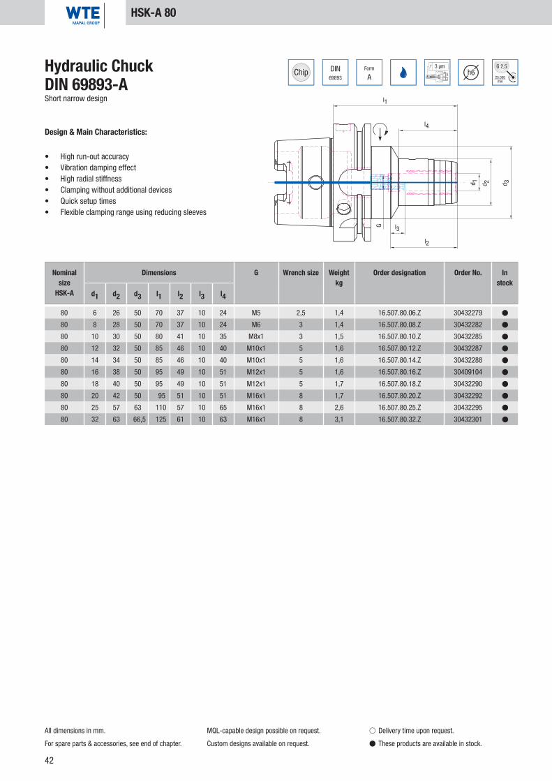
80 6 26 50 70 37 10 24 M5 2,5 1,4 16.507.80.06.Z 30432279 �
80 8 28 50 70 37 10 24 M6 3 1,4 16.507.80.08.Z 30432282 �
80 10 30 50 80 41 10 35 M8x1 3 1,5 16.507.80.10.Z 30432285 �
80 12 32 50 85 46 10 40 M10x1 5 1,6 16.507.80.12.Z 30432287 �
80 14 34 50 85 46 10 40 M10x1 5 1,6 16.507.80.14.Z 30432288 �
80 16 38 50 95 49 10 51 M12x1 5 1,6 16.507.80.16.Z 30409104 �
80 18 40 50 95 49 10 51 M12x1 5 1,7 16.507.80.18.Z 30432290 �
80 20 42 50 95 51 10 51 M16x1 8 1,7 16.507.80.20.Z 30432292 �
80 25 57 63 110 57 10 65 M16x1 8 2,6 16.507.80.25.Z 30432295 �
80 32 63 66,5 125 61 10 63 M16x1 8 3,1 16.507.80.32.Z 30432301 �
Hydraulic ChuckDIN 69893-AShort narrow design
Design & Main Characteristics:
• High run-out accuracy• Vibration damping effect• High radial stiffness• Clamping without additional devices• Quick setup times• Flexible clamping range using reducing sleeves
HSK-A 80
All dimensions in mm.
For spare parts & accessories, see end of chapter.
MQL-capable design possible on request.
Custom designs available on request.
� Delivery time upon request.
� These products are available in stock.
Nominal size
HSK-A
Dimensions G Wrench size Weightkg
Order designation Order No. In stock
d1 d2 d3 l1 l2 l3 l4

43
DIN69893
Form
A
3 µmh6
25.000min
G 2,5
l4
l1
d1
d2
d3
l2
l3
G
100 6 26 50 75 37 10 26 M5 2,5 2,3 16.507.100.06.Z 30336784 �
100 8 28 50 75 37 10 26 M6 3 2,3 16.507.100.08.Z 30336788 �
100 10 30 50 90 41 10 42 M8x1 3 2,5 16.507.100.10.Z 30336792 �
100 12 32 50 95 46 10 47 M10x1 5 2,5 16.507.100.12.Z 30336796 �
100 14 34 50 95 46 10 47 M10x1 5 2,5 16.507.100.14.Z 30336800 �
100 16 38 50 100 49 10 53 M12x1 5 2,6 16.507.100.16.Z 30336802 �
100 18 40 50 100 49 10 53 M12x1 5 2,6 16.507.100.18.Z 30336806 �
100 20 42 50 105 51 10 59 M16x1 8 2,7 16.507.100.20.Z 30336808 �
100 25 57 63 110 57 10 62 M16x1 8 3,3 16.507.100.25.Z 30336812 �
100 32 63 67 110 61 10 60 M16x1 8 3,5 16.507.100.32.Z 30336814 �
Hydraulic ChuckDIN 69893-AShort narrow design
Design & Main Characteristics:
• High run-out accuracy• Vibration damping effect• High radial stiffness• Clamping without additional devices• Quick setup times• Flexible clamping range using reducing sleeves
All dimensions in mm.
For spare parts & accessories, see end of chapter.
MQL-capable design possible on request.
Custom designs available on request.
HSK-A 100
� Delivery time upon request.
� These products are available in stock.
Nominal size
HSK-A
Dimensions G Wrench size Weightkg
Order designation Order No. In stock
d1 d2 d3 l1 l2 l3 l4
Hydr
aulic
Chu
cks

44
100 6 26 63 85 37 10 33 2,5 16.510.100.06.Z 30349351 �
100 8 28 63 85 37 10 33 2,6 16.510.100.08.Z 30349352 �
100 10 30 63 90 41 10 36 2,7 16.510.100.10.Z 30349353 �
100 12 32 63 95 46 10 40 2,7 16.510.100.12.Z 30349354 �
100 14 34 63 95 46 10 41 2,7 16.510.100.14.Z 30349355 �
100 16 38 63 100 49 10 46 2,8 16.510.100.16.Z 30349356 �
100 18 40 63 100 49 10 46 2,9 16.510.100.18.Z 30349357 �
100 20 42 75 105 51 10 51 3,1 16.510.100.20.Z 30349358 �
100 25 57 75 115 57 10 55 3,8 16.510.100.25.Z 30349359 �
100 32 63 75 120 61 10 63 4,0 16.510.100.32.Z 30349360 �
DIN69893
Form
A
3 µmh6
25.000min
G 2,5
l1
l4
l2
l3
d1
d2
d3
Hydraulic ChuckDIN 69893-AShort narrow design, with radial length adjustment
Design & Main Characteristics:
• High run-out accuracy• Vibration damping effect• High radial stiffness• Clamping without additional devices• Quick setup times• Flexible clamping range using reducing sleeves
Nominal size
HSK-A
Dimensions Weightkg
Order designation Order No. In stock
d1 d2 d3 l1 l2 l3 l4
HSK-A 100
All dimensions in mm.
For spare parts & accessories, see end of chapter.
MQL-capable design possible on request.
Custom designs available on request.
� Delivery time upon request.
� These products are available in stock.
Radial

45
DIN69893
Form
C
3 µmh6
25.000min
G 2,5
l1
l4
d2d1
d3
l 3
l2
G
40 6 26 40 60 37 10 35 M5 2,5 0,5 23.507.40.06.Z 30337045 �
40 8 28 40 60 37 10 36 M6 3 0,5 23.507.40.08.Z 30337046 �
40 10 30 40 65 41 10 41 M6 3 0,6 23.507.40.10.Z 30337047 �
40 12 32 40 70 46 10 47 M6 3 0,6 23.507.40.12.Z 30337048 �
Hydr
aulic
Chu
cks
Hydraulic ChuckDIN 69893-CShort narrow design for manual change
Design & Main Characteristics:
• High run-out accuracy• Vibration damping effect• High radial stiffness• Clamping without additional devices• Quick setup times• Flexible clamping range using reducing sleeves
HSK-C 40
All dimensions in mm.
For spare parts & accessories, see end of chapter. Custom designs available on request.
� Delivery time upon request.
� These products are available in stock.
Nominal size
HSK-C
Dimensions G Wrench size Weightkg
Order designation Order No. In stock
d1 d2 d3 l1 l2 l3 l4

46
DIN69893
Form
C
3 µmh6
25.000min
G 2,5
l1
l4
d2d1
d3
l2
l3
G
50 6 26 50 60 37 10 30 M5 2,5 0,7 23.507.50.06.Z 30337049 �
50 8 28 50 60 37 10 30 M6 3 0,7 23.507.50.08.Z 30337050 �
50 10 30 50 65 41 10 35 M8x1 3 1,0 23.507.50.10.Z 30337051 �
50 12 32 50 75 46 10 40 M10x1 5 0,9 23.507.50.12.Z 30337052 �
50 14 34 50 75 46 10 40 M10x1 5 0,8 23.507.50.14.Z 30337053 �
50 16 38 50 80 49 10 50 M12x1 5 1,1 23.507.50.16.Z 30337054 �
50 18 40 50 80 49 10 50 M12x1 5 1,4 23.507.50.18.Z 30337055 �
50 20 42 50 80 51 10 50 M16x1 5 1,2 23.507.50.20.Z 30337056 �
50 25 49,5 50 90 57 10 59 M16x1 5 1,1 23.507.50.25.Z 30337057 �
Hydraulic ChuckDIN 69893-CShort narrow design for manual change
Design & Main Characteristics:
• High run-out accuracy• Vibration damping effect• High radial stiffness• Clamping without additional devices• Quick setup times• Flexible clamping range using reducing sleeves
All dimensions in mm.
For spare parts & accessories, see end of chapter. Custom designs available on request.
HSK-C 50
� Delivery time upon request.
� These products are available in stock.
Nominal size
HSK-C
Dimensions G Wrench size Weightkg
Order designation Order No. In stock
d1 d2 d3 l1 l2 l3 l4

47
DIN69893
Form
C
3 µmh6
25.000min
G 2,5
l1
l4
G
l3
l2
d3d1 d2
63 6 26 63 60 37 10 25 M5 2,5 1,0 23.507.63.06.Z 30337058 �
63 8 28 63 60 37 10 25 M6 3 1,0 23.507.63.08.Z 30337059 �
63 10 30 63 65 41 10 31 M8x1 3 1,0 23.507.63.10.Z 30337060 �
63 12 32 63 75 46 10 41 M10x1 5 1,1 23.507.63.12.Z 30337061 �
63 14 34 63 75 46 10 42 M10x1 5 1,1 23.507.63.14.Z 30337062 �
63 16 38 63 80 49 10 48 M12x1 5 1,1 23.507.63.16.Z 30337063 �
63 18 40 63 80 49 10 48 M12x1 5 1,2 23.507.63.18.Z 30337064 �
63 20 42 63 80 51 10 49 M16x1 5 1,2 23.507.63.20.Z 30337065 �
63 25 58 63 95 57 10 63 M16x1 5 2,0 23.507.63.25.Z 30337066 �
63 32 62 63 100 61 10 60 M16x1 5 2,1 23.507.63.32.Z 30337067 �
Hydr
aulic
Chu
cks
Hydraulic ChuckDIN 69893-CShort narrow design for manual change
Design & Main Characteristics:
• High run-out accuracy• Vibration damping effect• High radial stiffness• Clamping without additional devices• Quick setup times• Flexible clamping range using reducing sleeves
All dimensions in mm.
For spare parts & accessories, see end of chapter. Custom designs available on request.
HSK-C 63
� Delivery time upon request.
� These products are available in stock.
Nominal size
HSK-C
Dimensions G Wrench size Weightkg
Order designation Order No. In stock
d1 d2 d3 l1 l2 l3 l4

48
DIN69893 E
Form 3 µmh6
25.000min
G 2,5
d2d1 d3
l 3
l2
G
l1
l4
40 6 26 33,5 70 37 10 36 M5 2,5 0,5 18.507.40.06.Z 30336886 �
40 8 28 33,5 70 37 10 36 M6 3 0,5 18.507.40.08.Z 30336887 �
40 10 30 33,5 75 41 10 42 M6 3 0,6 18.507.40.10.Z 30336888 �
40 12 32 33,5 80 46 10 48 M6 3 0,6 18.507.40.12.Z 30336889 �
Hydraulic ChuckDIN 69893-EShort narrow design for automatic change
Design & Main Characteristics:
• High run-out accuracy• Vibration damping effect• High radial stiffness• Clamping without additional devices• Quick setup times• Flexible clamping range using reducing sleeves
HSK-E 40
All dimensions in mm.
For spare parts & accessories, see end of chapter. Custom designs available on request.
� Delivery time upon request.
� These products are available in stock.
Nominal size
HSK-E
Dimensions G Wrench size Weightkg
Order designation Order No. In stock
d1 d2 d3 l1 l2 l3 l4

49
DIN69893 E
Form 3 µmh6
25.000min
G 2,5
l4
l1
d3
d2d1
l2
G l3
50 6 26 40 70 37 10 28 M5 2,5 0,9 18.507.50.06.Z 30336892 �
50 8 28 40 70 37 10 28 M6 3 0,9 18.507.50.08.Z 30336893 �
50 10 30 40 75 41 10 34 M8x1 3 1,0 18.507.50.10.Z 30336894 �
50 12 32 40 85 46 10 44 M10x1 5 1,0 18.507.50.12.Z 30336895 �
50 14 34 40 85 46 10 44 M10x1 5 1,0 18.507.50.14.Z 30336896 �
50 16 38 42 90 49 10 30 M12x1 5 1,0 18.507.50.16.Z 30336897 �
50 18 40 42 90 49 10 29 M12x1 5 1,2 18.507.50.18.Z 30336898 �
50 20 42 42 90 51 10 29 M16x1 5 1,2 18.507.50.20.Z 30336899 �
Hydr
aulic
Chu
cks
Hydraulic ChuckDIN 69893-EShort narrow design for automatic change
Design & Main Characteristics:
• High run-out accuracy• Vibration damping effect• High radial stiffness• Clamping without additional devices• Quick setup times• Flexible clamping range using reducing sleeves
All dimensions in mm.
For spare parts & accessories, see end of chapter. Custom designs available on request.
HSK-E 50
� Delivery time upon request.
� These products are available in stock.
Nominal size
HSK-E
Dimensions G Wrench size Weightkg
Order designation Order No. In stock
d1 d2 d3 l1 l2 l3 l4

50
DIN69893
Form
F
3 µmh6
25.000min
G 2,5
d 1
l2
l3
d 3
l1
d 2
l4
G
63 6 26 50 70 37 10 24 M5 2,5 1,0 17.507.63.06 30336877 �
63 8 28 50 70 37 10 25 M6 3 1,0 17.507.63.08 30336878 �
63 10 30 50 80 41 10 35 M8x1 3 1,1 17.507.63.10 30336879 �
63 12 32 50 85 46 10 40 M10x1 5 1,1 17.507.63.12 30336880 �
63 14 34 50 85 46 10 40 M10x1 5 1,2 17.507.63.14 30336881 �
63 16 38 50 90 49 10 46 M12x1 5 1,2 17.507.63.16 30336882 �
63 18 40 50 90 49 10 47 M12x1 5 1,4 17.507.63.18 30336883 �
63 20 42 50 90 51 10 48 M16x1 5 1,4 17.507.63.20 30336884 �
63 25 57 53 120 57 10 63 M16x1 5 2,1 17.507.63.25 30336885 �
Hydraulic ChuckDIN 69893-FShort narrow design for automatic change
Design & Main Characteristics:
• High run-out accuracy• Vibration damping effect• High radial stiffness• Clamping without additional devices• Quick setup times• Flexible clamping range using reducing sleeves
HSK-F 63
All dimensions in mm.
For spare parts & accessories, see end of chapter. Custom designs available on request.
� Delivery time upon request.
� These products are available in stock.
Nominal size
HSK-F
Dimensions G Wrench size Weightkg
Order designation Order No. In stock
d1 d2 d3 l1 l2 l3 l4

51
7388-2
ISO Form
ADh6
3 µm
25.000min
G 2,5
l1
l4
d3
d2d1
l3
l2
G
30 6 26 45 50,8 37 10 12,0 M5 2,5 0,7 22.507.30.06.Z 30336900 �
30 8 28 45 50,8 37 10 12,5 M6 3 0,7 22.507.30.08.Z 30336905 �
30 10 30 45 50,8 41 10 13,0 M8x1 3 0,7 22.507.30.10.Z 30336910 �
30 12 32 45 50,8 46 10 14,0 M8x1 3 0,7 22.507.30.12.Z 30336915 �
30 14 34 45 90,0 46 10 45,0 M8x1 3 1,0 22.507.30.14.Z 30336920 �
30 16 38 45 90,0 49 10 50,0 M8x1 3 1,0 22.507.30.16.Z 30336921 �
30 18 40 45 90,0 49 10 50,0 M8x1 3 1,0 22.507.30.18.Z 30336924 �
30 20 42 45 90,0 51 10 50,0 M8x1 3 1,0 22.507.30.20.Z 30336925 �
Hydr
aulic
Chu
cks
Hydraulic ChuckISO 7388-2 (JIS B6339)Short slim design, coolant supply as per ISO 7388-1, Form AD
Design & Main Characteristics:
• High run-out accuracy• Vibration damping effect• High radial stiffness• Clamping without additional devices• Quick setup times• Flexible clamping range using reducing sleeves
BT 30
Nominal sizeBT
Dimensions G Wrench size Weightkg
Order designation Order No. In stock
d1 d2 d3 l1 l2 l3 l4
All dimensions in mm.
For spare parts & accessories, see end of chapter. Custom designs available on request.
� Delivery time upon request.
� These products are available in stock.

52
7388-2
ISO Form
ADh6
3 µm
25.000min
G 2,5
d1
d2
d3
l 2
l3
l1
G
40 20 34 48 32,5 51 10 M16x1 8 0,7 22.501.40.20.Z 30411484 �
Hydraulic ChuckISO 7388-2 (JIS B6339)Ultra short design, coolant supply as per ISO 7388-1, Form AD
Design & Main Characteristics:
• High run-out accuracy• Vibration damping effect• High radial stiffness• Clamping without additional devices• Quick setup times• Flexible clamping range using reducing sleeves
All dimensions in mm.
For spare parts & accessories, see end of chapter. Custom designs available on request.
BT 40
� Delivery time upon request.
� These products are available in stock.
Nominal sizeBT
Dimensions G Wrench size Weightkg
Order designation Order No. In stock
d1 d2 d3 l1 l2 l3

53
7388-2
ISO Form
AD/AFh6
3 µm
25.000min
G 2,5
G
l 4
l1
d3
d2
d1
l 2
l3
40 6 26 49,5 90 37 10 29 M5 2,5 1,5 22.507.40.06.Z 30336927 �
40 8 28 49,5 90 37 10 30 M6 3 1,6 22.507.40.08.Z 30336933 �
40 10 30 49,5 90 41 10 35 M8x1 3 1,6 22.507.40.10.Z 30336939 �
40 12 32 49,5 90 46 10 40 M10x1 5 1,6 22.507.40.12.Z 30336946 �
40 14 34 49,5 90 46 10 40 M10x1 5 1,6 22.507.40.14.Z 30336953 �
40 16 38 49,5 90 49 10 45 M12x1 5 1,6 22.507.40.16.Z 30336958 �
40 18 40 49,5 90 49 10 46 M12x1 5 1,6 22.507.40.18.Z 30336964 �
40 20 42 49,5 90 51 10 47 M16x1 8 1,6 22.507.40.20.Z 30336969 �
40 25 55 52 90 57 10 50 M16x1 8 1,9 22.507.40.25.Z 30336975 �
40 32 63 62 90 61 10 48 M16x1 8 2,1 22.507.40.32.Z 30336982 �
Hydr
aulic
Chu
cks
Hydraulic ChuckISO 7388-2 (JIS B6339)Short slim design, coolant supply as per ISO 7388-1, Form AD/AF
Design & Main Characteristics:
• High run-out accuracy• Vibration damping effect• High radial stiffness• Clamping without additional devices• Quick setup times• Flexible clamping range using reducing sleeves
BT 40
Nominal sizeBT
Dimensions G Wrench size Weightkg
Order designation Order No. In stock
d1 d2 d3 l1 l2 l3 l4
All dimensions in mm.
Basic setting Form AD. If Form AF (prev. B) is desired,
please indicate when ordering.
For spare parts & accessories, see end of chapter.
Custom designs available on request.
� Delivery time upon request.
� These products are available in stock.

54
7388-2
ISO Form
AD/AFh6
3 µm
25.000min
G 2,5
G
l 4
l1
d3
d2
d1
l 2
l3
40 6 26 49,5 140 37 10 29 M5 2,5 2,1 22.507.40.06.Z/140 30336930 �
40 8 28 49,5 140 37 10 30 M6 3 2,1 22.507.40.08.Z/140 30336936 �
40 10 30 49,5 140 41 10 35 M8x1 3 2,1 22.507.40.10.Z/140 30336943 �
40 12 32 49,5 140 46 10 40 M10x1 5 2,1 22.507.40.12.Z/140 30336950 �
40 14 34 49,5 140 46 10 40 M10x1 5 2,1 22.507.40.14.Z/140 30336956 �
40 16 38 49,5 140 49 10 45 M12x1 5 2,1 22.507.40.16.Z/140 30336961 �
40 18 40 49,5 140 49 10 46 M12x1 5 2,1 22.507.40.18.Z/140 30336967 �
40 20 42 49,5 140 51 10 47 M16x1 8 2,1 22.507.40.20.Z/140 30336973 �
40 25 55 52 140 57 10 75 M16x1 8 2,8 22.507.40.25.Z/140 30336979 �
40 32 63 59 140 61 10 61 M16x1 8 2,9 22.507.40.32.Z/140 30336987 �
Hydraulic ChuckISO 7388-2 (JIS B6339)Long slim design, coolant supply as per ISO 7388-1, Form AD/AF
Design & Main Characteristics:
• High run-out accuracy• Vibration damping effect• High radial stiffness• Clamping without additional devices• Quick setup times• Flexible clamping range using reducing sleeves
BT 40
Nominal sizeBT
Dimensions G Wrench size Weightkg
Order designation Order No. In stock
d1 d2 d3 l1 l2 l3 l4
All dimensions in mm.
Basic setting Form AD. If Form AF (prev. B) is desired,
please indicate when ordering.
For spare parts & accessories, see end of chapter.
Custom designs available on request.
� Delivery time upon request.
� These products are available in stock.

55
7388-2
ISO Form
AD/AFh6
3 µm
25.000min
G 2,5
l1
d2d1
l2
l3
G
40 20 49,5 72,5 51 10 M16x1 8 1,5 22.508.40.20.Z 30337093 �
Hydr
aulic
Chu
cks
Hydraulic ChuckISO 7388-2 (JIS B6339)Short heavy duty design, coolant supply as per ISO 7388-1, Form AD/AF
Design & Main Characteristics:
• High run-out accuracy• Vibration damping effect• High radial stiffness• Clamping without additional devices• Quick setup times• Flexible clamping range using reducing sleeves
BT 40
Nominal sizeBT
Dimensions G Wrench size Weightkg
Order designation Order No. In stock
d1 d2 l1 l2 l3
All dimensions in mm.
Basic setting Form AD. If Form AF (prev. B) is desired,
please indicate when ordering.
For spare parts & accessories, see end of chapter.
Custom designs available on request.
� Delivery time upon request.
� These products are available in stock.

56
7388-2
ISO Form
AD/AFh6
3 µm
25.000min
G 2,5
l1
l4
d3
d2
d1
l2
l3
G
50 6 26 49,5 90 37 10 29 M5 2,5 4,2 22.507.50.06.Z 30336989 �
50 8 28 49,5 90 37 10 30 M6 3 4,2 22.507.50.08.Z 30336995 �
50 10 30 49,5 90 41 10 34 M8x1 3 4,2 22.507.50.10.Z 30337001 �
50 12 32 49,5 90 46 10 34 M10x1 5 4,2 22.507.50.12.Z 30337007 �
50 14 34 49,5 90 46 10 34 M10x1 5 4,2 22.507.50.14.Z 30337013 �
50 16 38 49,5 90 49 10 35 M12x1 5 4,2 22.507.50.16.Z 30337017 �
50 18 40 49,5 90 49 10 35 M12x1 5 4,2 22.507.50.18.Z 30337023 �
50 20 42 49,5 90 51 10 35 M16x1 8 4,2 22.507.50.20.Z 30337027 �
50 25 55 63 110 57 10 48 M16x1 8 4,6 22.507.50.25.Z 30337033 �
50 32 63 70 110 61 10 50 M16x1 8 5,0 22.507.50.32.Z 30337039 �
Hydraulic ChuckISO 7388-2 (JIS B6339)Short slim design, coolant supply as per ISO 7388-1, Form AD/AF
Design & Main Characteristics:
• High run-out accuracy• Vibration damping effect• High radial stiffness• Clamping without additional devices• Quick setup times• Flexible clamping range using reducing sleeves
BT 50
Nominal sizeBT
Dimensions G Wrench size Weightkg
Order designation Order No. In stock
d1 d2 d3 l1 l2 l3 l4
All dimensions in mm.
Basic setting Form AD. If Form AF (prev. B) is desired,
please indicate when ordering.
For spare parts & accessories, see end of chapter.
Custom designs available on request.
� Delivery time upon request.
� These products are available in stock.

57
7388-2
ISO Form
AD/AFh6
3 µm
25.000min
G 2,5
l1
l4
d3
d2
d1
l2
l3
G
50 6 26 49,5 140 37 10 29 M5 2,5 5,0 22.507.50.06.Z/140 30336993 �
50 8 28 49,5 140 37 10 30 M6 3 5,0 22.507.50.08.Z/140 30336999 �
50 10 30 49,5 140 41 10 35 M8x1 3 5,0 22.507.50.10.Z/140 30337005 �
50 12 32 49,5 140 46 10 40 M10x1 5 5,0 22.507.50.12.Z/140 30337011 �
50 14 34 49,5 140 46 10 40 M10x1 5 5,0 22.507.50.14.Z/140 30337016 �
50 16 38 49,5 140 49 10 45 M12x1 5 5,0 22.507.50.16.Z/140 30337021 �
50 18 40 49,5 140 49 10 46 M12x1 5 5,1 22.507.50.18.Z/140 30337026 �
50 20 42 49,5 140 51 10 42 M16x1 8 5,1 22.507.50.20.Z/140 30337031 �
50 25 55 63 140 57 10 48 M16x1 8 5,5 22.507.50.25.Z/140 30337036 �
50 32 63 70 140 61 10 50 M16x1 8 5,7 22.507.50.32.Z/140 30337042 �
Hydr
aulic
Chu
cks
Hydraulic ChuckISO 7388-2 (JIS B6339)Long slim design, coolant supply as per ISO 7388-1, Form AD/AF
Design & Main Characteristics:
• High run-out accuracy• Vibration damping effect• High radial stiffness• Clamping without additional devices• Quick setup times• Flexible clamping range using reducing sleeves
BT 50
Nominal sizeBT
Dimensions G Wrench size Weightkg
Order designation Order No. In stock
d1 d2 d3 l1 l2 l3 l4
All dimensions in mm.
Basic setting Form AD. If Form AF (prev. B) is desired,
please indicate when ordering.
For spare parts & accessories, see end of chapter.
Custom designs available on request.
� Delivery time upon request.
� These products are available in stock.

58
7388-2
ISO Form
AD/AFh6
3 µm
25.000min
G 2,5
l1
G
l3
l2
d1
d2
50 32 72 90 61 10 M16x1 8 4,7 22.508.50.32.Z 30337095 �
Hydraulic ChuckISO 7388-2 (JIS B6339)Short heavy duty design, coolant supply as per ISO 7388-1, Form AD/AF
Design & Main Characteristics:
• High run-out accuracy• Vibration damping effect• High radial stiffness• Clamping without additional devices• Quick setup times• Flexible clamping range using reducing sleeves
BT 50
Nominal sizeBT
Dimensions G Wrench size Weightkg
Order designation Order No. In stock
d1 d2 l1 l2 l3
All dimensions in mm.
Basic setting Form AD. If Form AF (prev. B) is desired,
please indicate when ordering.
For spare parts & accessories, see end of chapter.
Custom designs available on request.
� Delivery time upon request.
� These products are available in stock.

59
h616.000
min
G 2,5
80 12 32 50 77,5 60,5 10 47,5 41,5 M10x1 1,2 68.507.80.12.Z 30338153 �
80 16 38 50 82,5 65,5 10 52,5 47,5 M12x1 1,3 68.507.80.16.Z 30338154 �
80 20 42 50 82,5 65,5 10 52,5 49,5 M16x1 1,4 68.507.80.20.Z 30338155 �
100 25 57 63 100 79 10 61,5 61 M16x1 2,8 68.507.100.25.Z 30492397 �
117 32 64 75 103 82 10 65 60 M16x1 3,7 68.507.117.32.Z 30492399 �
80 4 M6x20 – 12.9 10003619 89.122.112 � 10040108 89.122.113 � 10075074 89.122.114 �
100 4 M8x25 – 12.9 10003637 89.122.154 � 10075116 89.122.153 � 10075100 89.122.152 �
117 4 M8x25 – 12.9 10003637 89.122.154 � 10075116 89.122.153 � 10075100 89.122.152 �
l1
l2
l4 max.
l5
l3
D G d 1 d 2 d 3
1
2 + 3 Hydr
aulic
Chu
cks
Hydraulic Chuckwith radial and angular orientationModule connection dimensions as per MN5000-14
Design & Main Characteristics:
• Maximal tool service life and production quality when using smooth cylinder shanks as per DIN 1835 Form A and DIN 6535 Form HA
• Run-out accuracy 0.003 mm (cantilever length of 2.5 x D – max. 50 mm)• Can be adjusted precisely in run-out using grub screws• Can be adjusted precisely in axial run-out using thrust piece and grub screw• When using cylinder shanks with angled clamping surface
(Form E and Form HE), accuracy may be impacted.
Nominal sizeBT
Dimensions G Weightkg
Order designation Order No. In stock
d1 d2 d3 l1 l2 l3 l4 max. l5
Module
Spare parts for Hydraulic Chuck with radial and angular orientation
Module diameter
D
Qty. required
Cylinder head screwas per ISO 4762
Thrust piece Grub screw
Size Order No. Order desig. Stock Order No. Order desig. Stock Order No. Order desig. Stock
All dimensions in mm.
For spare parts & accessories, see end of chapter.
Custom designs available on request.
� Delivery time upon request.
� These products are available in stock.
Use: For clamping of tools with smooth cylinder shanks as per DIN 6535 Form HA up to ø 32 mm and with recesses as per DIN 1835 Form B, E
and DIN 6535 Form HB, HE directly and without intermediate sleeves in the clamping diameter. The clamping diameter is designed for a shank tolerance h6.
Scope of supply: Complete with length adjustment screw, cylinder screws (for fastening the chuck) and alignment screws (thrust piece and grub screw).
Instructions: Chuck with axial tool length adjustment. Coolant supply via central through bore.
When using the intermediate sleeve an impairment of accuracy is possible.
l1
l2
l4 max.
l5
l3
D G d 1 d 2 d 3
1
2 + 3

60
30* 60 50 M5 M8x1 AD 0,8 15.150.30.AD.60.Z 30584676 �
30* 70 50 M6 M8x1 AD 0,9 15.150.30.AD.70.Z 30584681 �
40 60 50 M5 M8x1 AD/AF 1,3 15.150.40.60.Z 30584684 �
40 70 50 M6 M8x1 AD/AF 1,4 15.150.40.70.Z 30584685 �
40 80 55 M6 M8x1 AD/AF 1,7 15.150.40.80.Z 30584686 �
40 100 60 M8 M10x1 AD/AF 2,2 15.150.40.100.Z 30584689 �
45 60 50 M5 M8x1 AD/AF 2,8 15.150.45.60.Z 30584690 �
45 70 50 M6 M8x1 AD/AF 2,9 15.150.45.70.Z 30584692 �
45 80 55 M6 M8x1 AD/AF 3,1 15.150.45.80.Z 30584694 �
45 100 60 M8 M10x1 AD/AF 3,3 15.150.45.100.Z 30584697 �
45 117 60 M8 M10x1 AD/AF 3,5 15.150.45.117.Z 30584698 �
50 60 50 M5 M8x1 AD/AF 3,2 15.150.50.60.Z 30584700 �
50 70 50 M6 M8x1 AD/AF 3,4 15.150.50.70.Z 30584701 �
50 80 50 M6 M8x1 AD/AF 3,6 15.150.50.80.Z 30584720 �
50 100 60 M8 M10x1 AD/AF 4,4 15.150.50.100.Z 30584721 �
50 117 60 M8 M10x1 AD/AF 4,5 15.150.50.117.Z 30584723 �
50 140 60 M10 M10x1 AD/AF 4,7 15.150.50.140.Z 30584724 �
60-80 4 10075355
100-140 4 10075099
40, 45, 50 2 M5x5 10036757
ISO7388-1
Form
AD/AFh6
3 µm
16.000min
G 2,5
G1
l1
G
D
21
Nominal sizeSK
DimensionsOrder designation Order No. In
stockD l1 G G1 Form Weight kg
Modular Short Taper AdapterShank SK as per ISO 7388-1, Form AD/AF (DIN 69871-AD/B)
Module Adapter SK
Design & Main Characteristics:
• Maximal tool service life and production quality when using smooth cylinder shanks as per DIN 1835 Form A and DIN 6535 Form HA
• Run-out accuracy 0.003 mm (cantilever length of 2.5 x D – max. 50 mm)• Can be adjusted precisely in axial run-out using thrust piece and grub screw• When using cylinder shanks with angled clamping surface
(Form E and Form HE), accuracy may be impacted.
Use: For clamping of tools with smooth cylinder shanks as per DIN 1835 Form A, DIN 535 Form HA up to ø 20 mm and with recesses as per DIN 1835 Form B, E
and DIN 6535 Form HB, HE directly and without intermediate sleeve in the clamping diameter. The clamping diameter is designed for a shank tolerance h6.
Scope of supply: With length adjustment screw including hexagon screwdriver with T-handle without pull studs.
Instructions: Chuck with axial tool length adjustment. Intermediate sleeve for reduction of clamping diameter, see section Accessories and Spare Parts.
When using the intermediate sleeve an impairment of accuracy is possible.
All dimensions in mm.
Basic setting Form AD. If Form AF (prev. B) is desired,
please indicate when ordering.
* Short taper size SK 30 is not available in the
combination design AD/AF!
For spare parts & accessories, see end of chapter.
Custom designs available on request.
� Delivery time upon request.
� These products are available in stock.
For Module diameterD Qty. required Grub screw
Order No.
Spare parts: Grub screws as per ISO 4026
For nominal sizeSK Qty. required
Grub screw as per ISO 4026
Size Order No.
Spare parts: Grub screws
G1
l1
G
D
21

61
40 60 60 M5 M8x1 0,7 16.150.40.60.Z 30615827 �
50 60 60 M5 M8x1 0,9 16.150.50.60.Z 30584456 �
50 70 60 M6 M8x1 1 16.150.50.70.Z 30584465 �
50 80 60 M6 M8x1 1,1 16.150.50.80.Z 30584469 �
63 60 60 M5 M8x1 1,3 16.150.63.60.Z 30584473 �
63 70 60 M6 M8x1 1,4 16.150.63.70.Z 30584477 �
63 80 60 M6 M8x1 1,5 16.150.63.80.Z 30584478 �
63 100 65 M8 M10x1 2,1 16.150.63.100.Z 30584481 �
63 117 65 M8 M10x1 2,5 16.150.63.117.Z 30584482 �
80 60 50 M5 M8x1 1,6 16.150.80.60.Z 30584487 �
80 70 60 M6 M8x1 2 16.150.80.70.Z 30584489 �
80 80 60 M6 M8x1 2,1 16.150.80.80.Z 30584490 �
80 100 65 M8 M10x1 2,6 16.150.80.100.Z 30584491 �
80 117 65 M8 M10x1 3,1 16.150.80.117.Z 30584492 �
80 140 75 M10 M10x1 4,2 16.150.80.140.Z 30584493 �
100 60 55 M5 M8x1 2,8 16.150.100.60.Z 30584495 �
100 70 55 M6 M8x1 2,8 16.150.100.70.Z 30584497 �
100 80 55 M6 M8x1 3 16.150.100.80.Z 30584498 �
100 100 65 M8 M10x1 3,7 16.150.100.100.Z 30584499 �
100 117 65 M8 M10x1 4 16.150.100.117.Z 30584500 �
100 140 75 M10 M10x1 5,2 16.150.100.140.Z 30584502 �
60-80 4 0,001 M8x1x16 89.122.685 10075355 �
100-140 4 0,001 M10x1x20 89.122.684 10075099 �
1
G1
G
l1
D
DIN69893
Form
A
3 µmh6
16.000min
G 2,5
All dimensions in mm.
For spare parts & accessories, see end of chapter.
Custom designs available on request.
� Delivery time upon request.
� These products are available in stock.
Nominal sizeHSK-A
DimensionsOrder designation Order No. In
stockD l1 G G1 Weight kg
Modular Short Taper AdapterShank HSK-A as per DIN 69893-A
Design & Main Characteristics:
• Maximal tool service life and production quality when using smooth cylinder shanks as per DIN 1835 Form A and DIN 6535 Form HA
• Run-out accuracy 0.003 mm (cantilever length of 2.5 x D – max. 50 mm)• Can be adjusted precisely in axial run-out using thrust piece and grub screw• When using cylinder shanks with angled clamping surface
(Form E and Form HE), accuracy may be impacted.
Module Adapter HSK-A
Spare parts
Modulediameter
DQty. required
Cylinder head screw as per ISO 4762
Weight kg Size Order designation Order No. Stock
Scope of supply: Complete with grub screws for aligning the run-out, without coolant pipe.
Hydr
aulic
Chu
cks
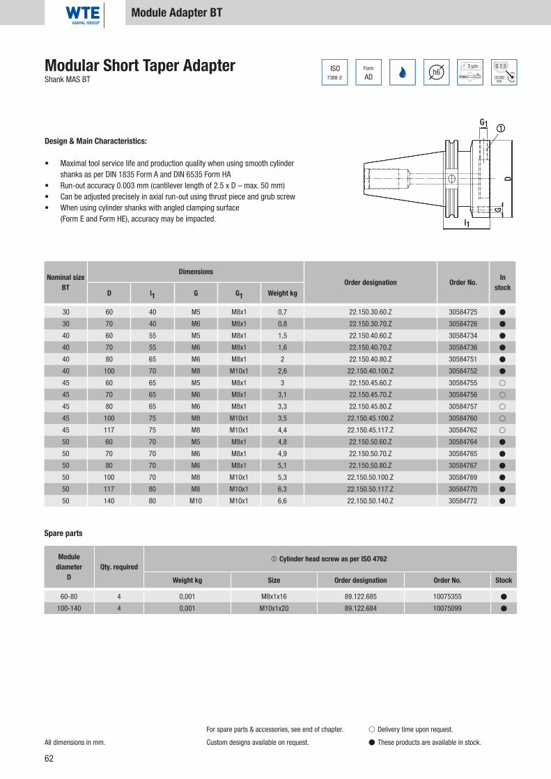
62
30 60 40 M5 M8x1 0,7 22.150.30.60.Z 30584725 �
30 70 40 M6 M8x1 0,8 22.150.30.70.Z 30584726 �
40 60 55 M5 M8x1 1,5 22.150.40.60.Z 30584734 �
40 70 55 M6 M8x1 1,6 22.150.40.70.Z 30584736 �
40 80 65 M6 M8x1 2 22.150.40.80.Z 30584751 �
40 100 70 M8 M10x1 2,6 22.150.40.100.Z 30584752 �
45 60 65 M5 M8x1 3 22.150.45.60.Z 30584755 �
45 70 65 M6 M8x1 3,1 22.150.45.70.Z 30584756 �
45 80 65 M6 M8x1 3,3 22.150.45.80.Z 30584757 �
45 100 75 M8 M10x1 3,5 22.150.45.100.Z 30584760 �
45 117 75 M8 M10x1 4,4 22.150.45.117.Z 30584762 �
50 60 70 M5 M8x1 4,8 22.150.50.60.Z 30584764 �
50 70 70 M6 M8x1 4,9 22.150.50.70.Z 30584765 �
50 80 70 M6 M8x1 5,1 22.150.50.80.Z 30584767 �
50 100 70 M8 M10x1 5,3 22.150.50.100.Z 30584769 �
50 117 80 M8 M10x1 6,3 22.150.50.117.Z 30584770 �
50 140 80 M10 M10x1 6,6 22.150.50.140.Z 30584772 �
60-80 4 0,001 M8x1x16 89.122.685 10075355 �
100-140 4 0,001 M10x1x20 89.122.684 10075099 �
7388-2
ISO Form
ADh6
3 µm
16.000min
G 2,5
G1
l1
GD
1
Modular Short Taper AdapterShank MAS BT
Module Adapter BT
Design & Main Characteristics:
• Maximal tool service life and production quality when using smooth cylinder shanks as per DIN 1835 Form A and DIN 6535 Form HA
• Run-out accuracy 0.003 mm (cantilever length of 2.5 x D – max. 50 mm)• Can be adjusted precisely in axial run-out using thrust piece and grub screw• When using cylinder shanks with angled clamping surface
(Form E and Form HE), accuracy may be impacted.
All dimensions in mm.
For spare parts & accessories, see end of chapter.
Custom designs available on request.
� Delivery time upon request.
� These products are available in stock.
Nominal sizeBT
DimensionsOrder designation Order No. In
stockD l1 G G1 Weight kg
Spare parts
Modulediameter
DQty. required
Cylinder head screw as per ISO 4762
Weight kg Size Order designation Order No. Stock
G1
l1
GD
1

63
12 1 16 40 44 20 0,04 40.456.12.01.Z 30503691 �
12 1,5 16 40 44 20 0,04 40.456.12.015.Z 30503718 �
12 2 16 40 44 20 0,04 40.456.12.02.Z 30503725 �
12 2,5 16 40 44 20 0,04 40.456.12.025.Z 30503728 �
12 3 16 40 44 29 0,03 40.456.12.03.Z 30251059 �
12 4 16 40 44 29 0,03 40.456.12.04.Z 30251060 �
12 5 16 40 44 29 0,03 40.456.12.05.Z 30251061 �
12 6 16 40 44 36 0,03 40.456.12.06.Z 30251062 �
12 7 16 40 44 37 0,03 40.456.12.07.Z 30251063 �
12 8 16 40 44 37 0,02 40.456.12.08.Z 30251064 �
12 9 16 40 44 37 0,02 40.456.12.09.Z 30251065 �
12 10 16 40 44 40 0,01 40.456.12.10.Z 30251066 �
20 3 25 50 54 28 0,1 40.456.20.03.Z 30251067 �
20 4 25 50 54 28 0,1 40.456.20.04.Z 30251068 �
20 5 25 50 54 28 0,1 40.456.20.05.Z 30251069 �
20 6 25 50 54 36 0,1 40.456.20.06.Z 30251070 �
20 7 25 50 54 38 0,1 40.456.20.07.Z 30251071 �
20 8 25 50 54 37 0,09 40.456.20.08.Z 30251072 �
20 9 25 50 54 38 0,09 40.456.20.09.Z 30251073 �
20 10 25 50 54 40 0,09 40.456.20.10.Z 30251074 �
20 11 25 50 54 40 0,08 40.456.20.11.Z 30251075 �
20 12 25 50 54 45 0,08 40.456.20.12.Z 30251076 �
20 13 25 50 54 45 0,07 40.456.20.13.Z 30251077 �
20 14 25 50 54 45 0,07 40.456.20.14.Z 30251078 �
20 15 25 50 54 45 0,06 40.456.20.15.Z 30251079 �
20 16 25 50 54 48 0,05 40.456.20.16.Z 30251080 �
l
l1
d d1
l2
d2
Dimensions Order designation Order No. In stock
d d1 d2 l l1 l2 Weight kg
Reducing Sleeve, sealed against coolantWith slits, for fl exible diameter application
Design & Main Characteristics:
• Coolant seal up to 80 bar• High-quality, hardened spring steel• Increase of torque transfer• Special for Hydraulic Chucks• Fits all WTE HPH Chucks
and WTE Hydraulic Chucks
All dimensions in mm.
Spare Parts & Accessories
� Delivery time upon request.
� These products are available in stock.
Caution: Never clamp without tool - the reducing sleeve will be damaged!
Hydr
aulic
Chu
cks

64
25 3 30 56 60 29 0,18 40.456.25.03.Z 30251081 �
25 4 30 56 60 29 0,18 40.456.25.04.Z 30251082 �
25 5 30 56 60 29 0,18 40.456.25.05.Z 30251083 �
25 6 30 56 60 37 0,18 40.456.25.06.Z 30251084 �
25 7 30 56 60 37 0,18 40.456.25.07.Z 30251085 �
25 8 30 56 60 37 0,17 40.456.25.08.Z 30251086 �
25 9 30 56 60 38 0,17 40.456.25.09.Z 30251087 �
25 10 30 56 60 40 0,16 40.456.25.10.Z 30251088 �
25 12 30 56 60 46 0,15 40.456.25.12.Z 30251089 �
25 14 30 56 60 47 0,14 40.456.25.14.Z 30251090 �
25 16 30 56 60 48 0,13 40.456.25.16.Z 30251091 �
25 18 30 56 60 48 0,11 40.456.25.18.Z 30251092 �
25 20 30 56 60 50 0,09 40.456.25.20.Z 30251093 �
32 6 36 60 64 36 0,31 40.456.32.06.Z 30251094 �
32 7 36 60 64 37 0,31 40.456.32.07.Z 30251095 �
32 8 36 60 64 36 0,3 40.456.32.08.Z 30251096 �
32 9 36 60 64 37 0,3 40.456.32.09.Z 30251097 �
32 10 36 60 64 40 0,29 40.456.32.10.Z 30251098 �
32 11 36 60 64 40 0,28 40.456.32.11.Z 30251099 �
32 12 36 60 64 45 0,28 40.456.32.12.Z 30251100 �
32 13 36 60 64 45 0,28 40.456.32.13.Z 30251101 �
32 14 36 60 64 46 0,27 40.456.32.14.Z 30251102 �
32 15 36 60 64 46 0,26 40.456.32.15.Z 30251103 �
32 16 36 60 64 48 0,26 40.456.32.16.Z 30251104 �
32 17 36 60 64 48 0,25 40.456.32.17.Z 30251105 �
32 18 36 60 64 49 0,24 40.456.32.18.Z 30251106 �
32 19 36 60 64 49 0,23 40.456.32.19.Z 30251107 �
32 20 36 60 64 50 0,22 40.456.32.20.Z 30251108 �
32 22 36 60 64 50 0,19 40.456.32.22.Z 30251109 �
32 25 36 60 64 56 0,15 40.456.32.25.Z 30251110 �
l
l1
d d1
l2
d2
Dimensions Order designation Order No. In stock
d d1 d2 l l1 l2 Weight kg
Reducing Sleeve, sealed against coolantWith slits, for fl exible diameter application
Design & Main Characteristics:
• Coolant seal up to 80 bar• High-quality, hardened spring steel• Increase of torque transfer• Special for Hydraulic Chucks• Fits all WTE HPH Chucks
and WTE Hydraulic Chucks
All dimensions in mm.
Spare Parts & Accessories
� Delivery time upon request.
� These products are available in stock.
Caution: Never clamp without tool - the reducing sleeve will be damaged!

65
12 3 16 40 44 29 0,03 40.456.12.03.KKB 30557343 �
12 4 16 40 44 29 0,03 40.456.12.04.KKB 30557344 �
12 5 16 40 44 29 0,03 40.456.12.05.KKB 30557345 �
12 6 16 40 44 36 0,03 40.456.12.06.KKB 30557346 �
12 8 16 40 44 37 0,02 40.456.12.08.KKB 30557347 �
20 3 25 50 54 28 0,1 40.456.20.03.KKB 30557348 �
20 4 25 50 54 28 0,1 40.456.20.04.KKB 30557350 �
20 5 25 50 54 28 0,1 40.456.20.05.KKB 30557351 �
20 6 25 50 54 36 0,1 40.456.20.06.KKB 30557352 �
20 8 25 50 54 37 0,09 40.456.20.08.KKB 30557353 �
20 10 25 50 54 40 0,09 40.456.20.10.KKB 30557354 �
20 12 25 50 54 45 0,08 40.456.20.12.KKB 30557355 �
20 14 25 50 54 45 0,07 40.456.20.14.KKB 30557356 �
20 16 25 50 54 48 0,05 40.456.20.16.KKB 30557358 �
l
l1
d
l2
d1 d232 6 36 60 64 36 0,31 40.456.32.06.KKB 30557359 �
32 8 36 60 64 36 0,3 40.456.32.08.KKB 30557360 �
32 10 36 60 64 40 0,29 40.456.32.10.KKB 30557361 �
32 12 36 60 64 45 0,28 40.456.32.12.KKB 30557362 �
32 14 36 60 64 46 0,27 40.456.32.14.KKB 30557364 �
32 16 36 60 64 48 0,26 40.456.32.16.KKB 30557365 �
32 18 36 60 64 49 0,24 40.456.32.18.KKB 30557366 �
32 20 36 60 64 50 0,22 40.456.32.20.KKB 30557367 �
32 25 36 60 64 56 0,15 40.456.32.25.KKB 30557369 �
Hydr
aulic
Chu
cks
Dimensions Order designation Order No. In stock
d d1 d2 l l1 l2 Weight kg
Reducing Sleeve, KKBWith coolant duct holes, for fl exible diameter application
Design & Main Characteristics:
• Coolant seal up to 80 bar• High-quality, hardened spring steel• Increase of torque transfer• Special for Hydraulic Chucks• Fits all WTE HPH Chucks
and WTE Hydraulic Chucks
All dimensions in mm.
Spare Parts & Accessories
� Delivery time upon request.
� These products are available in stock.
Caution: Never clamp without tool - the reducing sleeve will be damaged!

66
d2
d3
l4
l2
l3
G
4.5°
l1
d1
h63 µm
12 3 8 150 12 0,1 40.357.12.03.Z 30344729 �
12 4 8 150 16 0,1 40.357.12.04.Z 30344730 �
12 5 10 150 20 0,1 40.357.12.05.Z 30344731 �
12 6 10 150 36 10 26 M5 2,5 0,1 40.357.12.06.Z 30344732 �
16 3 10 150 12 0,2 40.357.16.03.Z 30344733 �
16 4 10 150 16 0,2 40.357.16.04.Z 30344734 �
16 5 10 150 20 0,2 40.357.16.05.Z 30344735 �
16 6 10 150 36 10 26 M5 2,5 0,2 40.357.16.06.Z 30344736 �
16 8 12 150 36 10 26 M6 3 0,2 40.357.16.08.Z 30344737 �
20 3 10 150 12 0,3 40.357.20.03.Z 30344738 �
20 4 10 150 16 0,3 40.357.20.04.Z 30344739 �
20 5 10 150 20 0,3 40.357.20.05.Z 30344740 �
20 6 10 150 36 10 26 M5 2,5 0,3 40.357.20.06.Z 30344741 �
20 8 12 150 36 10 26 M6 3 0,3 40.357.20.08.Z 30344742 �
20 10 14 150 42 10 32 M8x1 3 0,3 40.357.20.10.Z 30344743 �
20 12 16 150 47 10 37 M10x1 5 0,3 40.357.20.12.Z 30344744 �
Shrink ExtensionAs flexible adaptation
Design & Main Characteristics:
• Increase of torque transfer• Special for Hydraulic Chucks• Fits all WTE HPH Chucks
and WTE Hydraulic Chucks
All dimensions in mm. Custom designs available on request.
Spare Parts & Accessories
� Delivery time upon request.
� These products are available in stock.
Dimensions G Wrench size
Weightkg
Order designation Order No. In stock
d1 d2 d3 l1 l2 l3 l4
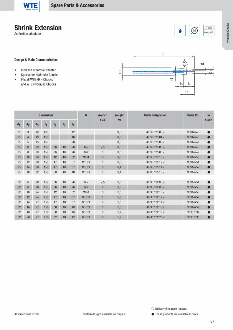
67
d2
d3
l4
l2
l3
G
4.5°
l1
d1
h63 µm
25 3 10 150 12 0,5 40.357.25.03.Z 30344745 �
25 4 10 150 16 0,5 40.357.25.04.Z 30344746 �
25 5 15 150 20 0,5 40.357.25.05.Z 30344747 �
25 6 20 150 36 10 26 M5 2,5 0,5 40.357.25.06.Z 30344748 �
25 8 20 150 36 10 26 M6 3 0,5 40.357.25.08.Z 30344749 �
25 10 20 150 42 10 32 M8x1 3 0,5 40.357.25.10.Z 30344750 �
25 12 20 150 47 10 37 M10x1 5 0,5 40.357.25.12.Z 30344751 �
25 14 20 150 47 10 37 M10x1 5 0,4 40.357.25.14.Z 30344752 �
25 16 22 150 50 10 40 M10x1 5 0,4 40.357.25.16.Z 30344753 �
32 6 20 150 36 10 26 M5 2,5 0,8 40.357.32.06.Z 30344754 �
32 8 20 150 36 10 26 M6 3 0,8 40.357.32.08.Z 30344755 �
32 10 24 150 42 10 32 M8x1 3 0,8 40.357.32.10.Z 30344756 �
32 12 24 150 47 10 37 M10x1 5 0,8 40.357.32.12.Z 30344757 �
32 14 27 150 47 10 37 M10x1 5 0,8 40.357.32.14.Z 30344758 �
32 16 27 150 50 10 40 M10x1 5 0,8 40.357.32.16.Z 30344759 �
32 18 27 150 50 10 40 M10x1 5 0,7 40.357.32.18.Z 30337832 �
32 20 27 150 52 10 42 M10x1 5 0,7 40.357.32.20.Z 30337833 �
Hydr
aulic
Chu
cks
Shrink ExtensionAs flexible adaptation
Design & Main Characteristics:
• Increase of torque transfer• Special for Hydraulic Chucks• Fits all WTE HPH Chucks
and WTE Hydraulic Chucks
All dimensions in mm. Custom designs available on request.
Spare Parts & Accessories
� Delivery time upon request.
� These products are available in stock.
Dimensions G Wrench size
Weightkg
Order designation Order No. In stock
d1 d2 d3 l1 l2 l3 l4

68
l2
l3
G
d2
d3
l1
l4
d1
6 µm 3 µm
25.000min
G 2,5
l
SWSWG
20 12 25 150 46 10 100 M10x1 5 0,5 40.557.20.12.Z 30479021 �
20 20 31,5 150 51 10 100 M16x1 5 0,6 40.557.20.20.Z 30479022 �
32 20 31,5 150 51 10 90 M16x1 5 0,7 40.557.32.20.Z 30479024 �
32 20 31,5 200 51 10 90 M16x1 5 0,8 40.557.32.20.Z/200 30479025 �
M5 2,5 12,5 0,001 89.122.88 30252539 �
M6 3 12,5 0,002 89.122.89 30252540 �
M8x1 3 13,5 0,004 89.122.23 30252541 �
M10x1 5 13,5 0,006 89.122.90 30252542 �
M12x1 5 13,5 0,011 89.122.24 30252543 �
M16x1 5 13,5 0,017 89.122.19 30252544 �
M16x1 8 13,5 0,021 89.122.91 30252547 �
Dimensions G Wrench size
Weightkg
Order designation Order No. In stock
d1 d2 d3 l1 l2 l3 l4
Hydraulic Expansion ExtensionAs fl exible adaptation
Design & Main Characteristics:
• Increase of torque transfer• Special for Hydraulic Chucks• Fits all WTE HPH Chucks
and WTE Hydraulic Chucks
All dimensions in mm.
Spare Parts & Accessories
� Delivery time upon request.
� These products are available in stock.
G Wrench size l Weightkg Order designation Order No. In
stock
Stop Screw, Direct ClampingFor axial length adjustment

69
M10x1 2,5 16 0,002 89.122.103 30308896 �
M4x0,5 1,5 26 0,001 89.122.101 30308901 �
M16x1 5 16 0,002 89.122.99 30308897 �
M8x1 2,5 19 0,002 89.122.100 30308899 �
M4x0,5 1,5 26 0,001 89.122.101 30308901 �
M16x1 5 20 0,002 89.122.104 30308904 �
M8x1 2,5 19 0,002 89.122.100 30308899 �
M4x0,5 1,5 26 0,001 89.122.101 30308901 �
M16x1 5 20 0,002 89.122.104 30308904 �
M8x1 2,5 19 0,002 89.122.100 30308899 �
l
G SW
Hydr
aulic
Chu
cks
All dimensions in mm.
Spare Parts & Accessories
� Delivery time upon request.
� These products are available in stock.
AAS Stop ScrewWith the use of WTE reducing sleeves for axial length adjustment
Design & Main Characteristics:
• Low warpage, hardened special steel• Secure axial stop• Optimum coolant supply• Can be operated from two sides• Optimum run-out of the stop system
G Wrench size l Weightkg Order designation Order No. In
stock
AAS 12 for Art. No. 40.456.12.xx
G Wrench size l Weightkg Order designation Order No. In
stock
AAS 20 for Art. No. 40.456.20.xx
G Wrench size l Weightkg Order designation Order No. In
stock
AAS 25 for Art. No. 40.456.25.xx
G Wrench size l Weightkg Order designation Order No. In
stock
AAS 32 for Art. No. 40.456.32.xx

70
HS 12 24,6 100 89.206.26 30251198 �
HS 20 38,0 160 89.206.27 30251199 �
HS 25 51,0 180 89.206.28 30251200 �
HS 32 63,0 200 89.206.29 30251201 �
32 0,01 89.220.72 30326003 �
40 0,01 89.220.73 30326004 �
50 0,02 89.220.74 30326005 �
63 0,02 89.220.75 30326006 �
80 0,02 89.220.76 30326007 �
100 0,03 89.220.77 30326008 �
2,5 150 0,02 89.206.01 10034540 �
3 150 0,02 89.206.02 10013347 �
5 150 0,06 89.206.03 10041807 �
8 150 0,10 89.206.04 10041808 �
All dimensions in mm.
Spare Parts & Accessories
� Delivery time upon request.
� These products are available in stock.
Extraction WrenchFor easy extraction of the reducing sleeves from the WTE Hydraulic Chuck
Wrench size l Weightkg Order designation Order No. In
stock
Hexagonal T-keyFor axial length adjustment
Coolant Transfer PipeFor DIN 69893-A/E
HSK Weightkg Order designation Order No. In
stock
For A B Order designation Order No. In stock

71
4 100 0,03 89.206.07 10006235 �
5 100 0,06 89.206.15 10006236 �
32 0,01 89.206.20 10074750 �
40 0,01 89.206.21 10074751 �
50 0,01 89.206.22 10074752 �
63 0,01 89.206.23 10040110 �
80 0,02 89.206.24 10074774 �
100 0,02 89.206.25 10074775 �
Hydr
aulic
Chu
cks
Assembly ToolFor coolant transfer pipe
Spare Parts & Accessories
Hexagonal T-keyFor pressure input
Wrench size l Weightkg Order designation Order No. In
stock
Wrench size Weightkg Order designation Order No. In
stock

72

73
HPH – High Performance Holder
Shank form SK 40 Page 74-75
Shank form SK 50 Page 76
Shank form HSK-A 63 Page 77-78
Shank form HSK-A 100 Page 79-80
Shank form BT 40 Page 81-82
Shank form BT 50 Page 83
Spare Parts & Accessories Page 84-93
HPH
– Hi
gh P
erfo
rman
ce H
olde
r

74
ISO7388-1
Form
AD/AF
3 µmh6
25.000min
G 2,5
l1
l4
d1
d2
d3
l 3
l2
G
40 6 32 50 75 37 10 26 M5x15 2,5 1,4 15.407.40.06.Z 30339747 �
40 8 34 50 75 37 10 27 M6x15 3 1,4 15.407.40.08.Z 30339749 �
40 10 36 50 80 41 10 32 M8x1x15,5 3 1,4 15.407.40.10.Z 30339750 �
40 12 38 50 85 46 10 37 M10x1x9,8 5 1,5 15.407.40.12.Z 30339751 �
40 14 40 50 85 46 10 37 M10x1x13 5 1,6 15.407.40.14.Z 30339752 �
40 16 42 50 90 49 10 42 M12x1x15 5 1,6 15.407.40.16.Z 30339753 �
40 18 44 50 90 49 10 42 M12x1x17 5 1,7 15.407.40.18.Z 30339754 �
40 20 48 50 95 51 10 45 M16x1x15,8 5 1,7 15.407.40.20.Z 30339755 �
40 25 57 50 110 57 10 60 M16x1x19,8 5 2,2 15.407.40.25.Z 30339756 �
40 32 63 50 120 61 10 65 M16x1x25,8 5 2,5 15.407.40.32.Z 30339758 �
HPH – High Performance Holder ISO 7388-1, Form AD/AF (prev. DIN 69871-AD/B)Short narrow design
Design & Main Characteristics:
• Very high holding forces• Vibration damping effect• Very high transmissible torques• All commercially available shanks can be clamped
SK 40
All dimensions in mm.
Basic setting Form AD. If Form AF (prev. B) is desired,
please indicate when ordering.
For spare parts & accessories, see end of chapter.
Custom designs available on request.
� Delivery time upon request.
� These products are available in stock.
Nominal size
SK/ISO
Dimensions G Wrench size Weightkg
Order designation Order No. In stock
d1 d2 d3 l1 l2 l3 l4

75
ISO7388-1
Form
AD/AF
3 µmh6
25.000min
G 2,5
l1
d1
d2
l2
l3
G
40 12 42 50 46 10 M8x1x13,5 3 1,0 15.408.40.12.Z 30494111 �
40 20 49 64,5 51 10 M16x1x13,5 8 1,4 15.408.40.20.Z 30372360 �
HPH – High Performance Holder ISO 7388-1, Form AD/AF (prev. DIN 69871-AD/B)Short heavy duty design
Design & Main Characteristics:
• Very high holding forces• Vibration damping effect• Very high transmissible torques• All commercially available shanks can be clamped
All dimensions in mm.
Basic setting Form AD. If Form AF (prev. B) is desired,
please indicate when ordering.
For spare parts & accessories, see end of chapter.
Custom designs available on request.
SK 40
� Delivery time upon request.
� These products are available in stock.
HPH
– Hi
gh P
erfo
rman
ce H
olde
r
Nominal size
SK/ISO
Dimensions G Wrench size Weightkg
Order designation Order No. In stock
d1 d2 l1 l2 l3
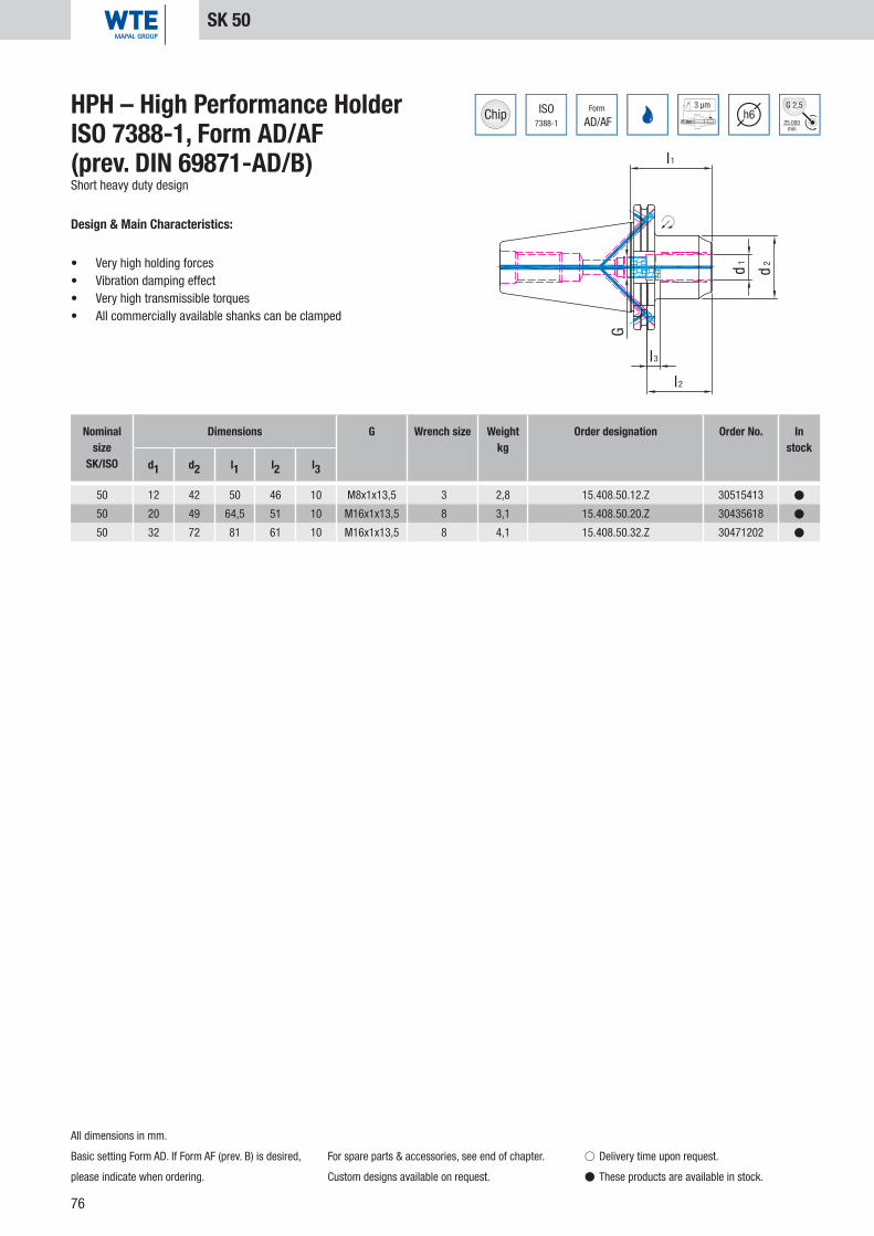
76
ISO7388-1
Form
AD/AF
3 µmh6
25.000min
G 2,5
l1
d2d1
l3
l2
G
50 12 42 50 46 10 M8x1x13,5 3 2,8 15.408.50.12.Z 30515413 �
50 20 49 64,5 51 10 M16x1x13,5 8 3,1 15.408.50.20.Z 30435618 �
50 32 72 81 61 10 M16x1x13,5 8 4,1 15.408.50.32.Z 30471202 �
HPH – High Performance Holder ISO 7388-1, Form AD/AF (prev. DIN 69871-AD/B)Short heavy duty design
Design & Main Characteristics:
• Very high holding forces• Vibration damping effect• Very high transmissible torques• All commercially available shanks can be clamped
SK 50
All dimensions in mm.
Basic setting Form AD. If Form AF (prev. B) is desired,
please indicate when ordering.
For spare parts & accessories, see end of chapter.
Custom designs available on request.
� Delivery time upon request.
� These products are available in stock.
Nominal size
SK/ISO
Dimensions G Wrench size Weightkg
Order designation Order No. In stock
d1 d2 l1 l2 l3

77
l1
l4
d3
d2d1
l2
l3
G
DIN69893
Form
A
3 µmh6
25.000min
G 2,5
63 6 32 50 80 37 10 26 M5x15 2,5 1,1 16.407.63.06.Z 30339759 �
63 8 34 50 80 37 10 27 M6x15 3 1,1 16.407.63.08.Z 30339760 �
63 10 36 50 85 41 10 32 M8x1x15,5 3 1,2 16.407.63.10.Z 30339761 �
63 12 38 52,5 90 46 10 37 M10x1x9,8 5 1,3 16.407.63.12.Z 30339762 �
63 14 40 52,5 90 46 10 37 M10x1x13 5 1,3 16.407.63.14.Z 30339763 �
63 16 42 52,5 95 49 10 42 M12x1x15 5 1,5 16.407.63.16.Z 30339764 �
63 18 44 52,5 95 49 10 42 M12x1x17 5 1,5 16.407.63.18.Z 30339765 �
63 20 48 52,5 100 51 10 45 M16x1x15,8 5 1,5 16.407.63.20.Z 30339766 �
63 25 57 53 120 57 10 62 M16x1x19,8 5 2,1 16.407.63.25.Z 30339767 �
63 32 63 53 125 61 10 62 M16x1x25,8 5 2,3 16.407.63.32.Z 30339768 �
HPH – High Performance HolderDIN 69893-AShort narrow design
Design & Main Characteristics:
• Very high holding forces• Vibration damping effect• Very high transmissible torques• All commercially available shanks can be clamped
All dimensions in mm.
For spare parts & accessories, see end of chapter.
MQL-capable design possible on request.
Custom designs available on request.
HSK-A 63
� Delivery time upon request.
� These products are available in stock.
HPH
– Hi
gh P
erfo
rman
ce H
olde
r
Nominal size
HSK-A
Dimensions G Wrench size Weightkg
Order designation Order No. In stock
d1 d2 d3 l1 l2 l3 l4

78
DIN69893
Form
A
3 µmh6
25.000min
G 2,5
G
l 2
l3
d1
d2
d3
l 4
l1
63 12 42 52,5 80 46 10 34 M8x1 3 1,1 16.408.63.12.Z 30494132 �
63 20 49 52,5 80 51 10 36 M8x1 3 1,3 16.408.63.20.Z 30372363 �
HPH - High Performance HolderDIN 69893-AShort heavy duty design
Design & Main Characteristics:
• Very high holding forces• Vibration damping effect• Very high transmissible torques• All commercially available shanks can be clamped
HSK-A 63
All dimensions in mm.
For spare parts & accessories, see end of chapter.
MQL-capable design possible on request.
Custom designs available on request.
� Delivery time upon request.
� These products are available in stock.
Nominal size
HSK-A
Dimensions G Wrench size Weightkg
Order designation Order No. In stock
d1 d2 d3 l1 l2 l3 l4
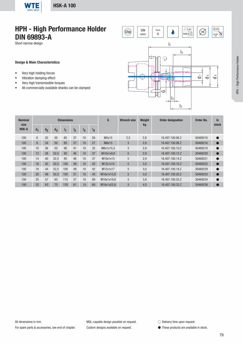
79
DIN69893
Form
A
3 µmh6
25.000min
G 2,5
l2
l3
G
d3
d2d1
l1
l4
100 6 32 50 85 37 10 26 M5x15 2,5 2,8 16.407.100.06.Z 30469210 �
100 8 34 50 85 37 10 27 M6x15 3 2,8 16.407.100.08.Z 30469216 �
100 10 36 50 90 41 10 32 M8x1x15,5 3 2,9 16.407.100.10.Z 30469218 �
100 12 38 52,5 95 46 10 37 M10x1x9,8 5 2,9 16.407.100.12.Z 30469220 �
100 14 40 52,5 95 46 10 37 M10x1x13 5 2,9 16.407.100.14.Z 30469221 �
100 16 42 52,5 100 49 10 42 M12x1x15 5 3,0 16.407.100.16.Z 30469222 �
100 18 44 52,5 100 49 10 42 M12x1x17 5 3,0 16.407.100.18.Z 30469229 �
100 20 48 52,5 105 51 10 45 M16x1x15,8 5 3,0 16.407.100.20.Z 30469233 �
100 25 57 63 115 57 10 60 M16x1x19,8 5 3,8 16.407.100.25.Z 30469234 �
100 32 63 75 120 61 10 60 M16x1x25,8 5 4,0 16.407.100.32.Z 30469236 �
HPH - High Performance HolderDIN 69893-AShort narrow design
Design & Main Characteristics:
• Very high holding forces• Vibration damping effect• Very high transmissible torques• All commercially available shanks can be clamped
All dimensions in mm.
For spare parts & accessories, see end of chapter.
MQL-capable design possible on request.
Custom designs available on request.
HSK-A 100
� Delivery time upon request.
� These products are available in stock.
HPH
– Hi
gh P
erfo
rman
ce H
olde
r
Nominal size
HSK-A
Dimensions G Wrench size Weightkg
Order designation Order No. In stock
d1 d2 d3 l1 l2 l3 l4

80
l1
l4
d3
d2d1
G
l3
l2
DIN69893
Form
A
3 µmh6
25.000min
G 2,5
100 12 42 52,5 85 46 10 34 M8x1 3 2,1 16.408.100.12.Z 30515435 �
100 20 49 52,5 85 51 10 36 M8x1 3 2,6 16.408.100.20.Z 30436113 �
100 32 70 75 100 61 10 51 M8x1 3 3,8 16.408.100.32.Z 30471219 �
HPH - High Performance HolderDIN 69893-AShort heavy duty design
Design & Main Characteristics:
• Very high holding forces• Vibration damping effect• Very high transmissible torques• All commercially available shanks can be clamped
HSK-A 100
All dimensions in mm.
For spare parts & accessories, see end of chapter.
MQL-capable design possible on request.
Custom designs available on request.
� Delivery time upon request.
� These products are available in stock.
Nominal size
HSK-A
Dimensions G Wrench size Weightkg
Order designation Order No. In stock
d1 d2 d3 l1 l2 l3 l4

81
l1
l4
d1
d2
d3
l2
l3
G
7388-2
ISO Form
AD/AF
3 µmh6
25.000min
G 2,5
40 6 32 50 80 37 10 26 M5x12,5 2,5 1,6 22.407.40.06.Z 30466220 �
40 8 34 50 80 37 10 27 M6x12,5 3 1,6 22.407.40.08.Z 30466222 �
40 10 36 50 85 41 10 32 M8x1x13,5 3 1,6 22.407.40.10.Z 30466224 �
40 12 38 50 90 46 10 37 M10x1x13,5 5 1,7 22.407.40.12.Z 30466234 �
40 14 40 50 90 46 10 37 M10x1x13,5 5 1,8 22.407.40.14.Z 30466239 �
40 16 42 50 95 49 10 42 M12x1x13,5 5 1,8 22.407.40.16.Z 30466242 �
40 18 44 50 95 49 10 42 M12x1x13,5 5 1,9 22.407.40.18.Z 30466244 �
40 20 48 50 100 51 10 45 M16x1x13,5 8 1,9 22.407.40.20.Z 30466246 �
40 25 57 52 110 57 10 60 M16x1x13,5 8 2,4 22.407.40.25.Z 30466250 �
40 32 63 62 120 61 10 65 M16x1x13,5 8 2,7 22.407.40.32.Z 30466252 �
HPH – High Performance Holder ISO 7388-2 (JIS 6339)Short slim design, coolant supply as per ISO 7388-1, Form AD/AF
Design & Main Characteristics:
• Very high holding forces• Vibration damping effect• Very high transmissible torques• All commercially available shanks can be clamped
All dimensions in mm.
Basic setting Form AD. If Form AF (prev. B) is desired,
please indicate when ordering.
For spare parts & accessories, see end of chapter.
Custom designs available on request.
BT 40
� Delivery time upon request.
� These products are available in stock.
HPH
– Hi
gh P
erfo
rman
ce H
olde
r
Nominal sizeBT
Dimensions G Wrench size Weightkg
Order designation Order No. In stock
d1 d2 d3 l1 l2 l3 l4

82
7388-2
ISO Form
AD/AF
3 µmh6
25.000min
G 2,5
l1
d2d1
l2
l3
G
40 12 42 58 46 10 M8x1x13,5 3 1,1 22.408.40.12.Z 30494128 �
40 20 49 72,5 51 10 M16x1x13,5 8 1,4 22.408.40.20.Z 30372364 �
HPH – High Performance Holder ISO 7388-2 (JIS 6339)Short heavy duty design, coolant supply as per ISO 7388-1, Form AD/AF
Design & Main Characteristics:
• Very high holding forces• Vibration damping effect• Very high transmissible torques• All commercially available shanks can be clamped
BT 40
Nominal sizeBT
Dimensions G Wrench size Weightkg
Order designation Order No. In stock
d1 d2 l1 l2 l3
All dimensions in mm.
Basic setting Form AD. If Form AF (prev. B) is desired,
please indicate when ordering.
For spare parts & accessories, see end of chapter.
Custom designs available on request.
� Delivery time upon request.
� These products are available in stock.

83
7388-2
ISO Form
AD/AF
3 µmh6
25.000min
G 2,5
l1
d1
d2
l2
l3
G
50 12 42 69 46 10 M8x1x13,5 3 3,4 22.408.50.12.Z 30515438 �
50 20 49 83,5 51 10 M16x1x13,5 8 4,0 22.408.50.20.Z 30435871 �
50 32 72 90 61 10 M16x1x13,5 8 4,6 22.408.50.32.Z 30471206 �
BT 50
HPH – High Performance Holder ISO 7388-2 (JIS 6339)Short heavy duty design, coolant supply as per ISO 7388-1, Form AD/AF
Design & Main Characteristics:
• Very high holding forces• Vibration damping effect• Very high transmissible torques• All commercially available shanks can be clamped
HPH
– Hi
gh P
erfo
rman
ce H
olde
r
Nominal sizeBT
Dimensions G Wrench size Weightkg
Order designation Order No. In stock
d1 d2 l1 l2 l3
All dimensions in mm.
Basic setting Form AD. If Form AF (prev. B) is desired,
please indicate when ordering.
For spare parts & accessories, see end of chapter.
Custom designs available on request.
� Delivery time upon request.
� These products are available in stock.

84
SW G
l
M10 5 10 0,006 89.122.288 10003470 �
M10 5 14 0,009 89.122.287 10070217 �
89.122.288 10003470 M10 5 1016.408.63.20.Z; 16.408.100.20.Z;
16.408.63.12.Z; 16.408.100.12.Z
89.122.287 10070217 M10 5 14 alle weiteren
All dimensions in mm.
Spare Parts & Accessories
� Delivery time upon request.
� These products are available in stock.
Pressure Screw HPHFor pressure input
G Wrench size l Weightkg Order designation Order No. In
stock
Allocation of Pressure Screw HPHHigh-strength pressure screws - for safe acceptance of high clamping forcesCoated pressure screws DLC - for optimum wear protection and long service life
Order designation Order No. G Wrench size l For high performance holder
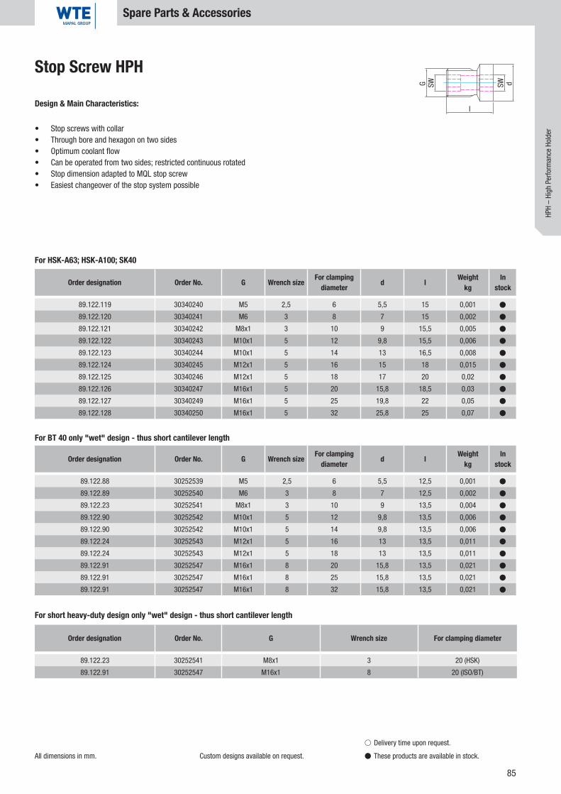
85
SWG
l
SW d
89.122.23 30252541 M8x1 3 20 (HSK)
89.122.91 30252547 M16x1 8 20 (ISO/BT)
89.122.119 30340240 M5 2,5 6 5,5 15 0,001 �
89.122.120 30340241 M6 3 8 7 15 0,002 �
89.122.121 30340242 M8x1 3 10 9 15,5 0,005 �
89.122.122 30340243 M10x1 5 12 9,8 15,5 0,006 �
89.122.123 30340244 M10x1 5 14 13 16,5 0,008 �
89.122.124 30340245 M12x1 5 16 15 18 0,015 �
89.122.125 30340246 M12x1 5 18 17 20 0,02 �
89.122.126 30340247 M16x1 5 20 15,8 18,5 0,03 �
89.122.127 30340249 M16x1 5 25 19,8 22 0,05 �
89.122.128 30340250 M16x1 5 32 25,8 25 0,07 �
89.122.88 30252539 M5 2,5 6 5,5 12,5 0,001 �
89.122.89 30252540 M6 3 8 7 12,5 0,002 �
89.122.23 30252541 M8x1 3 10 9 13,5 0,004 �
89.122.90 30252542 M10x1 5 12 9,8 13,5 0,006 �
89.122.90 30252542 M10x1 5 14 9,8 13,5 0,006 �
89.122.24 30252543 M12x1 5 16 13 13,5 0,011 �
89.122.24 30252543 M12x1 5 18 13 13,5 0,011 �
89.122.91 30252547 M16x1 8 20 15,8 13,5 0,021 �
89.122.91 30252547 M16x1 8 25 15,8 13,5 0,021 �
89.122.91 30252547 M16x1 8 32 15,8 13,5 0,021 �
All dimensions in mm. Custom designs available on request.
Spare Parts & Accessories
� Delivery time upon request.
� These products are available in stock.
Stop Screw HPH
Design & Main Characteristics:
• Stop screws with collar• Through bore and hexagon on two sides • Optimum coolant flow• Can be operated from two sides; restricted continuous rotated• Stop dimension adapted to MQL stop screw• Easiest changeover of the stop system possible
Order designation Order No. G Wrench size For clamping diameter
For HSK-A63; HSK-A100; SK40
For BT 40 only "wet" design - thus short cantilever length
For short heavy-duty design only "wet" design - thus short cantilever length
HPH
– Hi
gh P
erfo
rman
ce H
olde
r
Order designation Order No. G Wrench size For clamping diameter d l Weight
kgIn
stock
Order designation Order No. G Wrench size For clamping diameter d l Weight
kgIn
stock

86
12 1 16 40 44 20 0,04 40.456.12.01.Z 30503691 �
12 1,5 16 40 44 20 0,04 40.456.12.015.Z 30503718 �
12 2 16 40 44 20 0,04 40.456.12.02.Z 30503725 �
12 2,5 16 40 44 20 0,04 40.456.12.025.Z 30503728 �
12 3 16 40 44 29 0,03 40.456.12.03.Z 30251059 �
12 4 16 40 44 29 0,03 40.456.12.04.Z 30251060 �
12 5 16 40 44 29 0,03 40.456.12.05.Z 30251061 �
12 6 16 40 44 36 0,03 40.456.12.06.Z 30251062 �
12 7 16 40 44 37 0,03 40.456.12.07.Z 30251063 �
12 8 16 40 44 37 0,02 40.456.12.08.Z 30251064 �
12 9 16 40 44 37 0,02 40.456.12.09.Z 30251065 �
12 10 16 40 44 40 0,01 40.456.12.10.Z 30251066 �
20 3 25 50 54 28 0,10 40.456.20.03.Z 30251067 �
20 4 25 50 54 28 0,10 40.456.20.04.Z 30251068 �
20 5 25 50 54 28 0,10 40.456.20.05.Z 30251069 �
20 6 25 50 54 36 0,10 40.456.20.06.Z 30251070 �
20 7 25 50 54 38 0,10 40.456.20.07.Z 30251071 �
20 8 25 50 54 37 0,09 40.456.20.08.Z 30251072 �
20 9 25 50 54 38 0,09 40.456.20.09.Z 30251073 �
20 10 25 50 54 40 0,09 40.456.20.10.Z 30251074 �
20 11 25 50 54 40 0,08 40.456.20.11.Z 30251075 �
20 12 25 50 54 45 0,08 40.456.20.12.Z 30251076 �
20 13 25 50 54 45 0,07 40.456.20.13.Z 30251077 �
20 14 25 50 54 45 0,07 40.456.20.14.Z 30251078 �
20 15 25 50 54 45 0,06 40.456.20.15.Z 30251079 �
20 16 25 50 54 48 0,05 40.456.20.16.Z 30251080 �
l
l1
d d1
l2
d2
Dimensions Weightkg
Order designation Order No. In stock
d d1 d2 l l1 l2
Reducing Sleeve, sealed against coolantWith slits, for fl exible diameter application
Design & Main Characteristics:
• Coolant seal up to 80 bar• High-quality, hardened spring steel• Increase of torque transfer• Special for Hydraulic Chucks• Fits all WTE HPH Chucks
and WTE Hydraulic Chucks
All dimensions in mm.
Spare Parts & Accessories
� Delivery time upon request.
� These products are available in stock.
Caution: Never clamp without tool - the reducing sleeve will be damaged!

87
25 3 30 56 60 29 0,18 40.456.25.03.Z 30251081 �
25 4 30 56 60 29 0,18 40.456.25.04.Z 30251082 �
25 5 30 56 60 29 0,18 40.456.25.05.Z 30251083 �
25 6 30 56 60 37 0,18 40.456.25.06.Z 30251084 �
25 7 30 56 60 37 0,18 40.456.25.07.Z 30251085 �
25 8 30 56 60 37 0,17 40.456.25.08.Z 30251086 �
25 9 30 56 60 38 0,17 40.456.25.09.Z 30251087 �
25 10 30 56 60 40 0,16 40.456.25.10.Z 30251088 �
25 12 30 56 60 46 0,15 40.456.25.12.Z 30251089 �
25 14 30 56 60 47 0,14 40.456.25.14.Z 30251090 �
25 16 30 56 60 48 0,13 40.456.25.16.Z 30251091 �
25 18 30 56 60 48 0,11 40.456.25.18.Z 30251092 �
25 20 30 56 60 50 0,09 40.456.25.20.Z 30251093 �
32 6 36 60 64 36 0,31 40.456.32.06.Z 30251094 �
32 7 36 60 64 37 0,31 40.456.32.07.Z 30251095 �
32 8 36 60 64 36 0,30 40.456.32.08.Z 30251096 �
32 9 36 60 64 37 0,30 40.456.32.09.Z 30251097 �
32 10 36 60 64 40 0,29 40.456.32.10.Z 30251098 �
32 11 36 60 64 40 0,28 40.456.32.11.Z 30251099 �
32 12 36 60 64 45 0,28 40.456.32.12.Z 30251100 �
32 13 36 60 64 45 0,28 40.456.32.13.Z 30251101 �
32 14 36 60 64 46 0,27 40.456.32.14.Z 30251102 �
32 15 36 60 64 46 0,26 40.456.32.15.Z 30251103 �
32 16 36 60 64 48 0,26 40.456.32.16.Z 30251104 �
32 17 36 60 64 48 0,25 40.456.32.17.Z 30251105 �
32 18 36 60 64 49 0,24 40.456.32.18.Z 30251106 �
32 19 36 60 64 49 0,23 40.456.32.19.Z 30251107 �
32 20 36 60 64 50 0,22 40.456.32.20.Z 30251108 �
32 22 36 60 64 50 0,19 40.456.32.22.Z 30251109 �
32 25 36 60 64 56 0,15 40.456.32.25.Z 30251110 �
l
l1
d d1
l2
d2
Reducing Sleeve, sealed against coolantWith slits, for fl exible diameter application
Design & Main Characteristics:
• Coolant seal up to 80 bar• High-quality, hardened spring steel• Increase of torque transfer• Special for Hydraulic Chucks• Fits all WTE HPH Chucks
and WTE Hydraulic Chucks
All dimensions in mm.
Spare Parts & Accessories
� Delivery time upon request.
� These products are available in stock.
HPH
– Hi
gh P
erfo
rman
ce H
olde
r
Dimensions Weightkg
Order designation Order No. In stock
d d1 d2 l l1 l2
Caution: Never clamp without tool - the reducing sleeve will be damaged!

88
12 3 16 40 44 29 0,03 40.456.12.03.KKB 30557343 �
12 4 16 40 44 29 0,03 40.456.12.04.KKB 30557344 �
12 5 16 40 44 29 0,03 40.456.12.05.KKB 30557345 �
12 6 16 40 44 36 0,03 40.456.12.06.KKB 30557346 �
12 8 16 40 44 37 0,02 40.456.12.08.KKB 30557347 �
20 3 25 50 54 28 0,1 40.456.20.03.KKB 30557348 �
20 4 25 50 54 28 0,1 40.456.20.04.KKB 30557350 �
20 5 25 50 54 28 0,1 40.456.20.05.KKB 30557351 �
20 6 25 50 54 36 0,1 40.456.20.06.KKB 30557352 �
20 8 25 50 54 37 0,09 40.456.20.08.KKB 30557353 �
20 10 25 50 54 40 0,09 40.456.20.10.KKB 30557354 �
20 12 25 50 54 45 0,08 40.456.20.12.KKB 30557355 �
20 14 25 50 54 45 0,07 40.456.20.14.KKB 30557356 �
20 16 25 50 54 48 0,05 40.456.20.16.KKB 30557358 �
32 6 36 60 64 36 0,31 40.456.32.06.KKB 30557359 �
32 8 36 60 64 36 0,3 40.456.32.08.KKB 30557360 �
32 10 36 60 64 40 0,29 40.456.32.10.KKB 30557361 �
32 12 36 60 64 45 0,28 40.456.32.12.KKB 30557362 �
32 14 36 60 64 46 0,27 40.456.32.14.KKB 30557364 �
32 16 36 60 64 48 0,26 40.456.32.16.KKB 30557365 �
32 18 36 60 64 49 0,24 40.456.32.18.KKB 30557366 �
32 20 36 60 64 50 0,22 40.456.32.20.KKB 30557367 �
32 25 36 60 64 56 0,15 40.456.32.25.KKB 30557369 �
l
l1
d
l2
d1 d2
Dimensions Order designation Order No. In stock
d d1 d2 l l1 l2 Weight kg
Reducing Sleeve, KKBWith coolant duct holes, for fl exible diameter application
Design & Main Characteristics:
• Coolant seal up to 80 bar• High-quality, hardened spring steel• Increase of torque transfer• Special for Hydraulic Chucks• Fits all WTE HPH Chucks
and WTE Hydraulic Chucks
All dimensions in mm.
Spare Parts & Accessories
� Delivery time upon request.
� These products are available in stock.
Caution: Never clamp without tool - the reducing sleeve will be damaged!
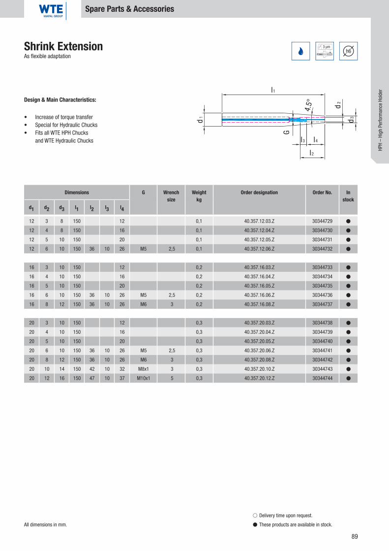
89
d2
d3
l4
l2
l3
G
4.5°
l1
d1
3 µmh6
12 3 8 150 12 0,1 40.357.12.03.Z 30344729 �
12 4 8 150 16 0,1 40.357.12.04.Z 30344730 �
12 5 10 150 20 0,1 40.357.12.05.Z 30344731 �
12 6 10 150 36 10 26 M5 2,5 0,1 40.357.12.06.Z 30344732 �
16 3 10 150 12 0,2 40.357.16.03.Z 30344733 �
16 4 10 150 16 0,2 40.357.16.04.Z 30344734 �
16 5 10 150 20 0,2 40.357.16.05.Z 30344735 �
16 6 10 150 36 10 26 M5 2,5 0,2 40.357.16.06.Z 30344736 �
16 8 12 150 36 10 26 M6 3 0,2 40.357.16.08.Z 30344737 �
20 3 10 150 12 0,3 40.357.20.03.Z 30344738 �
20 4 10 150 16 0,3 40.357.20.04.Z 30344739 �
20 5 10 150 20 0,3 40.357.20.05.Z 30344740 �
20 6 10 150 36 10 26 M5 2,5 0,3 40.357.20.06.Z 30344741 �
20 8 12 150 36 10 26 M6 3 0,3 40.357.20.08.Z 30344742 �
20 10 14 150 42 10 32 M8x1 3 0,3 40.357.20.10.Z 30344743 �
20 12 16 150 47 10 37 M10x1 5 0,3 40.357.20.12.Z 30344744 �
Shrink ExtensionAs flexible adaptation
Design & Main Characteristics:
• Increase of torque transfer• Special for Hydraulic Chucks• Fits all WTE HPH Chucks
and WTE Hydraulic Chucks
All dimensions in mm.
Spare Parts & Accessories
� Delivery time upon request.
� These products are available in stock.
Dimensions G Wrench size
Weightkg
Order designation Order No. In stock
d1 d2 d3 l1 l2 l3 l4
HPH
– Hi
gh P
erfo
rman
ce H
olde
r

90
25 3 10 150 12 0,5 40.357.25.03.Z 30344745 �
25 4 10 150 16 0,5 40.357.25.04.Z 30344746 �
25 5 15 150 20 0,5 40.357.25.05.Z 30344747 �
25 6 20 150 36 10 26 M5 2,5 0,5 40.357.25.06.Z 30344748 �
25 8 20 150 36 10 26 M6 3 0,5 40.357.25.08.Z 30344749 �
25 10 20 150 42 10 32 M8x1 3 0,5 40.357.25.10.Z 30344750 �
25 12 20 150 47 10 37 M10x1 5 0,5 40.357.25.12.Z 30344751 �
25 14 20 150 47 10 37 M10x1 5 0,4 40.357.25.14.Z 30344752 �
25 16 22 150 50 10 40 M10x1 5 0,4 40.357.25.16.Z 30344753 �
32 6 20 150 36 10 26 M5 2,5 0,8 40.357.32.06.Z 30344754 �
32 8 20 150 36 10 26 M6 3 0,8 40.357.32.08.Z 30344755 �
32 10 24 150 42 10 32 M8x1 3 0,8 40.357.32.10.Z 30344756 �
32 12 24 150 47 10 37 M10x1 5 0,8 40.357.32.12.Z 30344757 �
32 14 27 150 47 10 37 M10x1 5 0,8 40.357.32.14.Z 30344758 �
32 16 27 150 50 10 40 M10x1 5 0,8 40.357.32.16.Z 30344759 �
32 18 27 150 50 10 40 M10x1 5 0,7 40.357.32.18.Z 30337832 �
32 20 27 150 52 10 42 M10x1 5 0,7 40.357.32.20.Z 30337833 �
d2
d3
l4
l2
l3
G
4.5°
l1
d1
3 µmh6Shrink Extension
As flexible adaptation
Design & Main Characteristics:
• Increase of torque transfer• Special for Hydraulic Chucks• Fits all WTE HPH Chucks
and WTE Hydraulic Chucks
All dimensions in mm.
Spare Parts & Accessories
� Delivery time upon request.
� These products are available in stock.
Dimensions G Wrench size
Weightkg
Order designation Order No. In stock
d1 d2 d3 l1 l2 l3 l4

91
M10x1 2,5 16 0,002 89.122.103 30308896 �
M4x0,5 1,5 26 0,001 89.122.101 30308901 �
M16x1 5 16 0,002 89.122.99 30308897 �
M8x1 2,5 19 0,002 89.122.100 30308899 �
M4x0,5 1,5 26 0,001 89.122.101 30308901 �
M16x1 5 20 0,002 89.122.104 30308904 �
M8x1 2,5 19 0,002 89.122.100 30308899 �
M4x0,5 1,5 26 0,001 89.122.101 30308901 �
M16x1 5 20 0,002 89.122.104 30308904 �
M8x1 2,5 19 0,002 89.122.100 30308899 �
l
G SW
HPH
– Hi
gh P
erfo
rman
ce H
olde
r
All dimensions in mm.
Spare Parts & Accessories
� Delivery time upon request.
� These products are available in stock.
AAS Stop ScrewWith the use of WTE reducing sleeves for axial length adjustment
Design & Main Characteristics:
• Low warpage, hardened special steel• Secure axial stop• Optimum coolant supply• Can be operated from two sides• Optimum run-out of the stop system
G Wrench size l Weightkg Order designation Order No. In
stock
AAS 12 for Art. No. 40.456.12.xx
G Wrench size l Weightkg Order designation Order No. In
stock
AAS 20 for Art. No. 40.456.20.xx
G Wrench size l Weightkg Order designation Order No. In
stock
AAS 25 for Art. No. 40.456.25.xx
G Wrench size l Weightkg Order designation Order No. In
stock
AAS 32 for Art. No. 40.456.32.xx

92
20 12 25 150 46 10 100 M6 0,5 40.557.20.12.Z 30479021 �
20 20 31,5 150 51 10 100 M10x1 0,6 40.557.20.20.Z 30479022 �
32 20 31,5 150 51 10 90 M10x1 0,7 40.557.32.20.Z 30479024 �
32 20 31,5 200 51 10 90 M10x1 0,8 40.557.32.20.Z/200 30479025 �
6 µmh6
25.000min
G 2,5
32 0,01 89.220.72 30326003 �
40 0,01 89.220.73 30326004 �
50 0,02 89.220.74 30326005 �
63 0,02 89.220.75 30326006 �
80 0,02 89.220.76 30326007 �
100 0,03 89.220.77 30326008 �
l2
l3
G
d2
d3
l1
l4
d1
5 100 0,06 89.206.15 10006236 �
Dimensions G Weightkg
Order designation Order No. In stock
d1 d2 d3 l1 l2 l3 l4
Hydraulic Expansion ExtensionAs fl exible adaptation
Design & Main Characteristics:
• Increase of torque transfer• Special for Hydraulic Chucks• Fits all WTE HPH Chucks
and WTE Hydraulic Chucks
All dimensions in mm.
Spare Parts & Accessories
� Delivery time upon request.
� These products are available in stock.
Coolant Transfer PipeFor DIN 69893-A/E
HSK Weightkg Order designation Order No. In
stock
Hexagonal T-keyFor pressure input
Wrench size l Weightkg Order designation Order No. In
stock

93
HS 12 24,6 100 89.206.26 30251198 �
HS 20 38,0 160 89.206.27 30251199 �
HS 25 51,0 180 89.206.28 30251200 �
HS 32 63,0 200 89.206.29 30251201 �
32 0,01 89.206.20 10074750 �
40 0,01 89.206.21 10074751 �
50 0,01 89.206.22 10074752 �
63 0,01 89.206.23 10040110 �
80 0,02 89.206.24 10074774 �
100 0,02 89.206.25 10074775 �
2,5 150 0,02 89.206.01 10034540 �
3 150 0,02 89.206.02 10013347 �
5 150 0,06 89.206.03 10041807 �
8 150 0,10 89.206.04 10041808 �
HPH
– Hi
gh P
erfo
rman
ce H
olde
r
All dimensions in mm.
Spare Parts & Accessories
� Delivery time upon request.
� These products are available in stock.
Extraction WrenchFor easy extraction of the reducing sleeves from the HPH - High Performance Holder
Assembly ToolFor coolant transfer pipes
Wrench size Weightkg Order designation Order No. In
stock
For A B Order designation Order No. In stock
Wrench size l Weightkg Order designation Order No. In
stock
Hexagonal T-keyFor axial length adjustment

94

95
Shrin
k Ch
ucks
Shrink Chucks
Shank form SK 30 Page 96-97
Shank form SK 40 Page 98-105
Shank form SK 50 Page 106-107
Shank form HSK-A 32 Page 108
Shank form HSK-A 40 Page 109-110
Shank form HSK-A 50 Page 111-112
Shank form HSK-A 63 Page 113-119
Shank form HSK-A 80 Page 120-121
Shank form HSK-A 100 Page 122-125
Shank form HSK-C 32 Page 126
Shank form HSK-C 40 Page 127-128
Shank form HSK-C 50 Page 129-130
Shank form HSK-C 63 Page 131-132
Shank form HSK-E 32 Page 133
Shank form HSK-E 40 Page 134-136
Shank form HSK-E 50 Page 137-139
Shank form HSK-E 63 Page 140-143
Shank form HSK-F 40 Page 144
Shank form HSK-F 63 Page 145-148
Shank form BT 30 Page 149
Shank form BT 40 Page 150-155
Shank form BT 50 Page 156-157
Module and Adapter SK, HSK, BT Page 158-161
Spare Parts & Accessories Page 162-166

96
d1
d3
d2
l3 l4
l2
G
4.5°
l1
ISO7388-1
3 µm
25.000min
G 2,5
30 3 10 17 80 28 16 12 M6 2 0,5 14.306.30.03 30337133 �
30 4 15 22 80 28 12 16 M6 2 0,5 14.306.30.04 30337134 �
30 5 15 22 80 30 10 20 M6 2 0,5 14.306.30.05 30337135 �
30 6 21 27 80 36 10 26 M5 2,5 0,6 14.306.30.06 30337136 �
30 8 21 27 80 36 10 26 M6 3 0,6 14.306.30.08 30337137 �
30 10 24 32 80 41 10 31 M8x1 3 0,6 14.306.30.10 30337138 �
30 12 24 32 80 47 10 37 M10x1 5 0,7 14.306.30.12 30337139 �
30 14 27 34 80 47 10 37 M10x1 5 0,7 14.306.30.14 30337140 �
30 16 27 34 80 50 10 40 M12x1 5 0,7 14.306.30.16 30337141 �
30 18 33 42 80 50 10 40 M12x1 5 0,8 14.306.30.18 30337142 �
30 20 33 42 80 52 10 42 M16x1 5 0,8 14.306.30.20 30337143 �
Shrink Chuck ISO 7388-1 (prev. DIN 69871-AD)For wood processing
Design & Main Characteristics:
• High transmissible torques• High run-out accuracies• 4.5° programme• High flexibility in contours• Creep resistant workable steel
SK 30
All dimensions in mm.
Shrink extensions, see end of chapter.
For spare parts & accessories, see end of chapter.
Custom designs available on request.
� Delivery time upon request.
� These products are available in stock.
Nominal size
SK/ISO
Dimensions G Wrench size Weightkg
Order designation Order No. In stock
d1 d2 d3 l1 l2 l3 l4

97
ISO7388-1
Form
AD
3 µm
25.000min
G 2,5
4.5°
G
l3 l4
l2
d3
d1
d2
l1
30 3 10 17 80 28 16 12 M6 2 0,5 15.306.30.03.Z 30337201 �
30 4 15 22 80 28 12 16 M6 2 0,5 15.306.30.04.Z 30337202 �
30 5 15 22 80 30 10 20 M6 2 0,5 15.306.30.05.Z 30337203 �
30 6 21 27 80 36 10 26 M5 2,5 0,6 15.306.30.06.Z 30337204 �
30 8 21 27 80 36 10 26 M6 3 0,6 15.306.30.08.Z 30337205 �
30 10 24 32 80 41 10 31 M8x1 3 0,6 15.306.30.10.Z 30337206 �
30 12 24 32 80 47 10 37 M10x1 5 0,7 15.306.30.12.Z 30337207 �
30 14 27 34 80 47 10 37 M10x1 5 0,7 15.306.30.14.Z 30337208 �
30 16 27 34 80 50 10 40 M12x1 5 0,7 15.306.30.16.Z 30337209 �
30 18 33 42 80 50 10 40 M12x1 5 0,8 15.306.30.18.Z 30337210 �
30 20 33 42 80 52 10 42 M16x1 5 0,8 15.306.30.20.Z 30337211 �
Shrink Chuck ISO 7388-1, Form AD (prev. DIN 69871-AD)
Design & Main Characteristics:
• High transmissible torques• High run-out accuracies• 4.5° programme• High flexibility in contours• Creep resistant workable steel• Side coolant duct hole possible
All dimensions in mm.
Shrink extensions, see end of chapter.
For spare parts & accessories, see end of chapter.
Custom designs available on request.
SK 30
� Delivery time upon request.
� These products are available in stock.
Shrin
k Ch
ucks
Nominal size
SK/ISO
Dimensions G Wrench size Weightkg
Order designation Order No. In stock
d1 d2 d3 l1 l2 l3 l4

98
l1
d1
d2
d3
l3 l4
l2
4.5°
G
ISO7388-1
3 µm
25.000min
G 2,5
40 3 10 17 80 28 16 12 M6 2 0,9 14.306.40.03 30337144 �
40 4 15 22 80 28 12 16 M6 2 0,9 14.306.40.04 30337147 �
40 5 15 22 80 30 10 20 M6 2 0,9 14.306.40.05 30337150 �
40 6 21 27 80 36 10 26 M5 2,5 1 14.306.40.06 30337153 �
40 8 21 27 80 36 10 26 M6 3 1 14.306.40.08 30337156 �
40 10 24 32 80 41 10 31 M8x1 3 1 14.306.40.10 30337159 �
40 12 24 32 80 47 10 37 M10x1 5 1 14.306.40.12 30337162 �
40 14 27 34 80 47 10 37 M10x1 5 1 14.306.40.14 30337165 �
40 16 27 34 80 50 10 40 M12x1 5 1 14.306.40.16 30337168 �
40 18 33 42 80 50 10 40 M12x1 5 1,1 14.306.40.18 30337171 �
40 20 33 42 80 52 10 42 M16x1 8 1,1 14.306.40.20 30337174 �
40 25 44 53 100 58 10 48 M16x1 8 1,6 14.306.40.25 30337177 �
40 32 44 53 100 62 10 52 M16x1 8 1,4 14.306.40.32 30337180 �
Shrink Chuck ISO 7388-1 (prev. DIN 69871-AD)For wood processing
Design & Main Characteristics:
• High transmissible torques• High run-out accuracies• 4.5° programme• High flexibility in contours• Creep resistant workable steel
SK 40
All dimensions in mm.
Shrink extensions, see end of chapter.
For spare parts & accessories, see end of chapter.
Custom designs available on request.
� Delivery time upon request.
� These products are available in stock.
Nominal size
SK/ISO
Dimensions G Wrench size Weightkg
Order designation Order No. In stock
d1 d2 d3 l1 l2 l3 l4
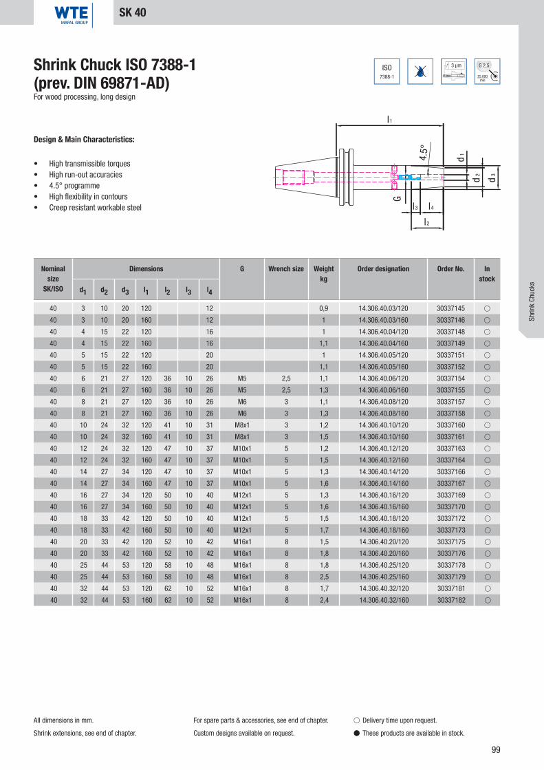
99
ISO7388-1
3 µm
25.000min
G 2,5
4.5°
G
l1
d1
d2
d3
l3 l4
l2
40 3 10 20 120 12 0,9 14.306.40.03/120 30337145 �
40 3 10 20 160 12 1 14.306.40.03/160 30337146 �
40 4 15 22 120 16 1 14.306.40.04/120 30337148 �
40 4 15 22 160 16 1,1 14.306.40.04/160 30337149 �
40 5 15 22 120 20 1 14.306.40.05/120 30337151 �
40 5 15 22 160 20 1,1 14.306.40.05/160 30337152 �
40 6 21 27 120 36 10 26 M5 2,5 1,1 14.306.40.06/120 30337154 �
40 6 21 27 160 36 10 26 M5 2,5 1,3 14.306.40.06/160 30337155 �
40 8 21 27 120 36 10 26 M6 3 1,1 14.306.40.08/120 30337157 �
40 8 21 27 160 36 10 26 M6 3 1,3 14.306.40.08/160 30337158 �
40 10 24 32 120 41 10 31 M8x1 3 1,2 14.306.40.10/120 30337160 �
40 10 24 32 160 41 10 31 M8x1 3 1,5 14.306.40.10/160 30337161 �
40 12 24 32 120 47 10 37 M10x1 5 1,2 14.306.40.12/120 30337163 �
40 12 24 32 160 47 10 37 M10x1 5 1,5 14.306.40.12/160 30337164 �
40 14 27 34 120 47 10 37 M10x1 5 1,3 14.306.40.14/120 30337166 �
40 14 27 34 160 47 10 37 M10x1 5 1,6 14.306.40.14/160 30337167 �
40 16 27 34 120 50 10 40 M12x1 5 1,3 14.306.40.16/120 30337169 �
40 16 27 34 160 50 10 40 M12x1 5 1,6 14.306.40.16/160 30337170 �
40 18 33 42 120 50 10 40 M12x1 5 1,5 14.306.40.18/120 30337172 �
40 18 33 42 160 50 10 40 M12x1 5 1,7 14.306.40.18/160 30337173 �
40 20 33 42 120 52 10 42 M16x1 8 1,5 14.306.40.20/120 30337175 �
40 20 33 42 160 52 10 42 M16x1 8 1,8 14.306.40.20/160 30337176 �
40 25 44 53 120 58 10 48 M16x1 8 1,8 14.306.40.25/120 30337178 �
40 25 44 53 160 58 10 48 M16x1 8 2,5 14.306.40.25/160 30337179 �
40 32 44 53 120 62 10 52 M16x1 8 1,7 14.306.40.32/120 30337181 �
40 32 44 53 160 62 10 52 M16x1 8 2,4 14.306.40.32/160 30337182 �
Shrink Chuck ISO 7388-1 (prev. DIN 69871-AD)For wood processing, long design
Design & Main Characteristics:
• High transmissible torques• High run-out accuracies• 4.5° programme• High flexibility in contours• Creep resistant workable steel
SK 40
All dimensions in mm.
Shrink extensions, see end of chapter.
For spare parts & accessories, see end of chapter.
Custom designs available on request.
� Delivery time upon request.
� These products are available in stock.
Shrin
k Ch
ucks
Nominal size
SK/ISO
Dimensions G Wrench size Weightkg
Order designation Order No. In stock
d1 d2 d3 l1 l2 l3 l4
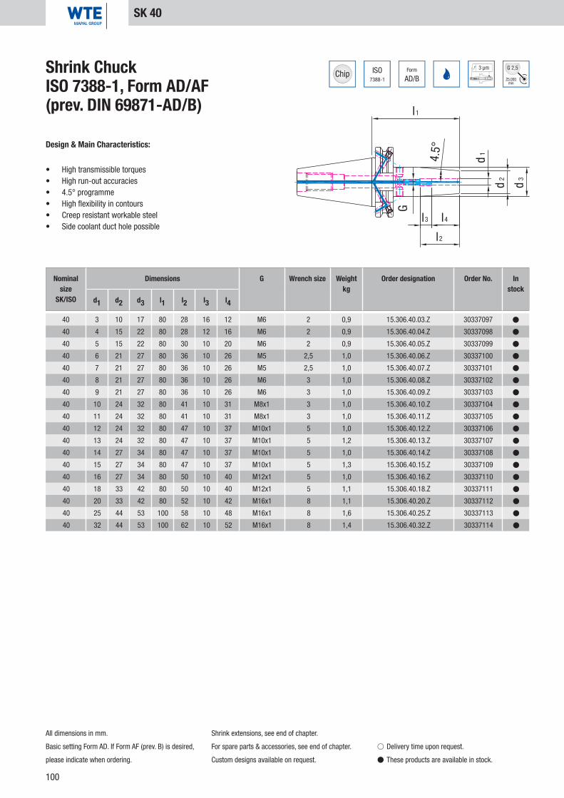
100
ISO7388-1
Form
AD/B
3 µm
25.000min
G 2,5
d1
d2
d3
l 4
l2
l3
l1
G
4.5°
40 3 10 17 80 28 16 12 M6 2 0,9 15.306.40.03.Z 30337097 �
40 4 15 22 80 28 12 16 M6 2 0,9 15.306.40.04.Z 30337098 �
40 5 15 22 80 30 10 20 M6 2 0,9 15.306.40.05.Z 30337099 �
40 6 21 27 80 36 10 26 M5 2,5 1,0 15.306.40.06.Z 30337100 �
40 7 21 27 80 36 10 26 M5 2,5 1,0 15.306.40.07.Z 30337101 �
40 8 21 27 80 36 10 26 M6 3 1,0 15.306.40.08.Z 30337102 �
40 9 21 27 80 36 10 26 M6 3 1,0 15.306.40.09.Z 30337103 �
40 10 24 32 80 41 10 31 M8x1 3 1,0 15.306.40.10.Z 30337104 �
40 11 24 32 80 41 10 31 M8x1 3 1,0 15.306.40.11.Z 30337105 �
40 12 24 32 80 47 10 37 M10x1 5 1,0 15.306.40.12.Z 30337106 �
40 13 24 32 80 47 10 37 M10x1 5 1,2 15.306.40.13.Z 30337107 �
40 14 27 34 80 47 10 37 M10x1 5 1,0 15.306.40.14.Z 30337108 �
40 15 27 34 80 47 10 37 M10x1 5 1,3 15.306.40.15.Z 30337109 �
40 16 27 34 80 50 10 40 M12x1 5 1,0 15.306.40.16.Z 30337110 �
40 18 33 42 80 50 10 40 M12x1 5 1,1 15.306.40.18.Z 30337111 �
40 20 33 42 80 52 10 42 M16x1 8 1,1 15.306.40.20.Z 30337112 �
40 25 44 53 100 58 10 48 M16x1 8 1,6 15.306.40.25.Z 30337113 �
40 32 44 53 100 62 10 52 M16x1 8 1,4 15.306.40.32.Z 30337114 �
Shrink Chuck ISO 7388-1, Form AD/AF (prev. DIN 69871-AD/B)
Design & Main Characteristics:
• High transmissible torques• High run-out accuracies• 4.5° programme• High flexibility in contours• Creep resistant workable steel• Side coolant duct hole possible
SK 40
All dimensions in mm.
Basic setting Form AD. If Form AF (prev. B) is desired,
please indicate when ordering.
Shrink extensions, see end of chapter.
For spare parts & accessories, see end of chapter.
Custom designs available on request.
� Delivery time upon request.
� These products are available in stock.
Nominal size
SK/ISO
Dimensions G Wrench size Weightkg
Order designation Order No. In stock
d1 d2 d3 l1 l2 l3 l4

101
ISO7388-1
Form
AD/AF
3 µm
25.000min
G 2,5
d1
d2
d3
l 4
l2
l3
l1
G
4.5°
40 3 10 20 120 12 0,9 15.306.40.03.Z/120 30337212 �
40 3 10 20 160 12 1 15.306.40.03.Z/160 30337213 �
40 3 10 20 200 12 1,1 15.306.40.03.Z/200 30562522 �
40 4 15 22 120 16 1 15.306.40.04.Z/120 30337214 �
40 4 15 22 160 16 1,1 15.306.40.04.Z/160 30337215 �
40 4 15 22 200 16 1,2 15.306.40.04.Z/200 30562523 �
40 5 15 22 120 20 1 15.306.40.05.Z/120 30337216 �
40 5 15 22 160 20 1,1 15.306.40.05.Z/160 30337217 �
40 5 15 22 200 20 1,2 15.306.40.05.Z/200 30562524 �
40 6 21 27 120 36 10 26 M5 2,5 1,1 15.306.40.06.Z/120 30337218 �
40 6 21 27 160 36 10 26 M5 2,5 1,3 15.306.40.06.Z/160 30337219 �
40 6 21 27 200 36 10 26 M5 2,5 1,4 15.306.40.06.Z/200 30562525 �
40 8 21 27 120 36 10 26 M6 3 1,1 15.306.40.08.Z/120 30337220 �
40 8 21 27 160 36 10 26 M6 3 1,3 15.306.40.08.Z/160 30337221 �
40 8 21 27 200 36 10 26 M6 3 1,4 15.306.40.08.Z/200 30562526 �
40 10 24 32 120 41 10 31 M8x1 3 1,2 15.306.40.10.Z/120 30337222 �
40 10 24 32 160 41 10 31 M8x1 3 1,5 15.306.40.10.Z/160 30337223 �
40 10 24 32 200 41 10 31 M8x1 3 1,7 15.306.40.10.Z/200 30562527 �
40 12 24 32 120 47 10 37 M10x1 5 1,2 15.306.40.12.Z/120 30337224 �
40 12 24 32 160 47 10 37 M10x1 5 1,5 15.306.40.12.Z/160 30337225 �
40 12 24 32 200 47 10 37 M10x1 5 1,7 15.306.40.12.Z/200 30337226 �
40 14 27 34 120 47 10 37 M10x1 5 1,3 15.306.40.14.Z/120 30337227 �
40 14 27 34 160 47 10 37 M10x1 5 1,6 15.306.40.14.Z/160 30337228 �
40 14 27 34 200 47 10 37 M10x1 5 1,8 15.306.40.14.Z/200 30562530 �
40 16 27 34 120 50 10 40 M12x1 5 1,3 15.306.40.16.Z/120 30337229 �
40 16 27 34 160 50 10 40 M12x1 5 1,6 15.306.40.16.Z/160 30337230 �
40 16 27 34 200 50 10 40 M12x1 5 1,8 15.306.40.16.Z/200 30562531 �
40 18 33 42 120 50 10 40 M12x1 5 1,5 15.306.40.18.Z/120 30337231 �
40 18 33 42 160 50 10 40 M12x1 5 1,7 15.306.40.18.Z/160 30337232 �
40 18 33 42 200 50 10 40 M12x1 5 1,9 15.306.40.18.Z/200 30562534 �
40 20 33 42 120 52 10 42 M16x1 8 1,5 15.306.40.20.Z/120 30337233 �
40 20 33 42 160 52 10 42 M16x1 8 1,8 15.306.40.20.Z/160 30337234 �
40 20 33 42 200 52 10 42 M16x1 8 2 15.306.40.20.Z/200 30562535 �
40 25 44 53 120 58 10 48 M16x1 8 1,8 15.306.40.25.Z/120 30337235 �
40 25 44 53 160 58 10 48 M16x1 8 2,5 15.306.40.25.Z/160 30337236 �
40 25 44 53 200 58 10 48 M16x1 8 2,8 15.306.40.25.Z/200 30562536 �
40 32 44 53 120 62 10 52 M16x1 8 1,7 15.306.40.32.Z/120 30337237 �
40 32 44 53 160 62 10 52 M16x1 8 2,4 15.306.40.32.Z/160 30337238 �
40 32 44 53 200 62 10 52 M16x1 8 3,2 15.306.40.32.Z/200 30562537 �
Shrink ChuckISO 7388-1, Form AD/AF (prev. DIN 69871-AD/B)Long design
Design & Main Characteristics:
• High transmissible torques• High run-out accuracies• 4.5° programme• High flexibility in contours• Creep resistant workable steel• Side coolant duct hole possible
SK 40
All dimensions in mm.
Basic setting Form AD. If Form AF (prev. B) is desired,
please indicate when ordering.
Shrink extensions, see end of chapter.
For spare parts & accessories, see end of chapter.
Custom designs available on request.
� Delivery time upon request.
� These products are available in stock.
Shrin
k Ch
ucks
Nominal size
SK/ISO
Dimensions G Wrench size Weightkg
Order designation Order No. In stock
d1 d2 d3 l1 l2 l3 l4

102
d1
d2
d3
3°
l1
G
l3 l4
l2
ISO7388-1
Form
AD/AF
3 µm
25.000min
G 2,5
40 3 9 14 80 28 16 12 M6 2 0,9 15.304.40.03.Z 30385321 �
40 4 10 15 80 28 12 16 M6 2 0,9 15.304.40.04.Z 30385324 �
40 5 11 16 80 30 10 20 M6 2 0,9 15.304.40.05.Z 30385327 �
40 6 12 17 80 36 10 26 M5 2,5 0,9 15.304.40.06.Z 30385330 �
40 8 14 19 80 36 10 26 M6 3 0,9 15.304.40.08.Z 30385333 �
40 10 16 21 80 41 10 31 M8x1 3 0,9 15.304.40.10.Z 30385336 �
40 12 18 23 80 47 10 37 M10x1 5 0,9 15.304.40.12.Z 30385339 �
40 14 20 26 80 47 10 37 M10x1 5 0,9 15.304.40.14.Z 30385342 �
40 16 22 28 80 50 10 40 M12x1 5 1,0 15.304.40.16.Z 30385345 �
40 18 24 30 80 50 10 40 M12x1 5 1,0 15.304.40.18.Z 30385348 �
40 20 26 32 80 52 10 42 M16x1 8 1,0 15.304.40.20.Z 30385351 �
Shrink ChuckISO 7388-1, Form AD/AF (prev. DIN 69871-AD/B)Narrow design, 3°
Design & Main Characteristics:
• High transmissible torques• High run-out accuracies• 3° programme• High fl exibility in contours• Creep resistant workable steel• Side coolant duct hole possible
SK 40
All dimensions in mm.
Basic setting Form AD. If Form AF (prev. B) is desired,
please indicate when ordering.
Shrink extensions, see end of chapter.
For spare parts & accessories, see end of chapter.
Custom designs available on request.
� Delivery time upon request.
� These products are available in stock.
Nominal size
SK/ISO
Dimensions G Wrench size Weightkg
Order designation Order No. In stock
d1 d2 d3 l1 l2 l3 l4
(prev. DIN 69871-AD/B)
3° programme
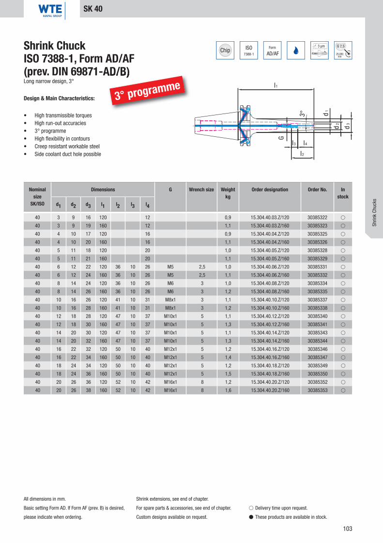
103
d1
d2
d3
3°
l1
G
l3 l4
l2
ISO7388-1
Form
AD/AF
3 µm
25.000min
G 2,5
40 3 9 16 120 12 0,9 15.304.40.03.Z/120 30385322 �
40 3 9 19 160 12 1,1 15.304.40.03.Z/160 30385323 �
40 4 10 17 120 16 0,9 15.304.40.04.Z/120 30385325 �
40 4 10 20 160 16 1,1 15.304.40.04.Z/160 30385326 �
40 5 11 18 120 20 1,0 15.304.40.05.Z/120 30385328 �
40 5 11 21 160 20 1,1 15.304.40.05.Z/160 30385329 �
40 6 12 22 120 36 10 26 M5 2,5 1,0 15.304.40.06.Z/120 30385331 �
40 6 12 24 160 36 10 26 M5 2,5 1,1 15.304.40.06.Z/160 30385332 �
40 8 14 24 120 36 10 26 M6 3 1,0 15.304.40.08.Z/120 30385334 �
40 8 14 26 160 36 10 26 M6 3 1,2 15.304.40.08.Z/160 30385335 �
40 10 16 26 120 41 10 31 M8x1 3 1,1 15.304.40.10.Z/120 30385337 �
40 10 16 28 160 41 10 31 M8x1 3 1,2 15.304.40.10.Z/160 30385338 �
40 12 18 28 120 47 10 37 M10x1 5 1,1 15.304.40.12.Z/120 30385340 �
40 12 18 30 160 47 10 37 M10x1 5 1,3 15.304.40.12.Z/160 30385341 �
40 14 20 30 120 47 10 37 M10x1 5 1,1 15.304.40.14.Z/120 30385343 �
40 14 20 32 160 47 10 37 M10x1 5 1,3 15.304.40.14.Z/160 30385344 �
40 16 22 32 120 50 10 40 M12x1 5 1,2 15.304.40.16.Z/120 30385346 �
40 16 22 34 160 50 10 40 M12x1 5 1,4 15.304.40.16.Z/160 30385347 �
40 18 24 34 120 50 10 40 M12x1 5 1,2 15.304.40.18.Z/120 30385349 �
40 18 24 36 160 50 10 40 M12x1 5 1,5 15.304.40.18.Z/160 30385350 �
40 20 26 36 120 52 10 42 M16x1 8 1,2 15.304.40.20.Z/120 30385352 �
40 20 26 38 160 52 10 42 M16x1 8 1,6 15.304.40.20.Z/160 30385353 �
Shrink ChuckISO 7388-1, Form AD/AF (prev. DIN 69871-AD/B)Long narrow design, 3°
Design & Main Characteristics:
• High transmissible torques• High run-out accuracies• 3° programme• High fl exibility in contours• Creep resistant workable steel• Side coolant duct hole possible
SK 40
All dimensions in mm.
Basic setting Form AD. If Form AF (prev. B) is desired,
please indicate when ordering.
Shrink extensions, see end of chapter.
For spare parts & accessories, see end of chapter.
Custom designs available on request.
� Delivery time upon request.
� These products are available in stock.
Shrin
k Ch
ucks
Nominal size
SK/ISO
Dimensions G Wrench size Weightkg
Order designation Order No. In stock
d1 d2 d3 l1 l2 l3 l4
(prev. DIN 69871-AD/B)
3° programme

104
ISO7388-1
Form
AD/AF
3 µm
25.000min
G 2,5
d 1
l2
l3
d 3
l1
d 2
l4G
4.5°
40 3 10 17 80 28 16 12 M6 2 0,9 15.306.40.03.KKB 30590786 �
40 4 15 22 80 28 12 16 M6 2 0,9 15.306.40.04.KKB 30590787 �
40 5 15 22 80 30 10 20 M6 2 0,9 15.306.40.05.KKB 30590789 �
40 6 21 27 80 36 10 26 M5 2,5 1 15.306.40.06.KKB 30589845 �
40 8 21 27 80 36 10 26 M6 3 1 15.306.40.08.KKB 30589849 �
40 10 24 32 80 41 10 31 M8x1 3 1 15.306.40.10.KKB 30589850 �
40 12 24 32 80 47 10 37 M10x1 5 1 15.306.40.12.KKB 30589852 �
40 14 27 34 80 47 10 37 M10x1 5 1 15.306.40.14.KKB 30589853 �
40 16 27 34 80 50 10 40 M12x1 5 1 15.306.40.16.KKB 30589855 �
40 18 33 42 80 50 10 40 M12x1_KKB 5 1,1 15.306.40.18.KKB 30589857 �
40 20 33 42 80 52 10 42 M16x1_KKB 5 1,1 15.306.40.20.KKB 30589858 �
40 25 44 53 100 58 10 48 M16x1 8 1,6 15.306.40.25.KKB 30589870 �
40 32 44 53 100 62 10 52 M16x1_KKB 5 1,4 15.306.40.32.KKB 30589872 �
Shrink ChuckISO 7388-1, Form AD/AF (prev. DIN 69871-AD/B)With additional resealable coolant duct holes
Design & Main Characteristics:
• High transmissible torques• High run-out accuracies• 4.5° programme• High flexibility in contours• Creep resistant workable steel• Side coolant duct hole
SK 40
All dimensions in mm.
Basic setting Form AD. If Form AF (prev. B) is desired,
please indicate when ordering.
Standard design with two coolant duct holes.
Other coolant duct holes on request
Shrink extensions, see end of chapter.
For spare parts & accessories, see end of chapter.
Custom designs available on request.
� Delivery time upon request.
� These products are available in stock.
Nominal size
SK/ISO
Dimensions G Wrench size Weightkg
Order designation Order No. In stock
d1 d2 d3 l1 l2 l3 l4

105
d 1
l2
l3
d 3
l1
d 2
l4
G
4.5°
40 3 9 16 120 12 0,9 15.306.40.03.120.KKB 30590790 �
40 4 10 17 120 16 1 15.306.40.04.120.KKB 30590793 �
40 5 11 18 120 20 1 15.306.40.05.120.KKB 30590794 �
40 6 12 22 120 36 10 26 M5 2,5 1,1 15.306.40.06.120.KKB 30589873 �
40 8 14 24 120 36 10 26 M6 3 1,1 15.306.40.08.120.KKB 30589874 �
40 10 16 26 120 41 10 31 M8x1 3 1,2 15.306.40.10.120.KKB 30589875 �
40 12 18 28 120 47 10 37 M10x1 5 1,2 15.306.40.12.120.KKB 30589876 �
40 14 20 30 120 47 10 37 M10x1 5 1,3 15.306.40.14.120.KKB 30589877 �
40 16 22 32 120 50 10 40 M12x1_KKB 5 1,3 15.306.40.16.120.KKB 30589879 �
40 18 24 34 120 50 10 40 M12x1_KKB 5 1,5 15.306.40.18.120.KKB 30589880 �
40 20 26 36 120 52 10 42 M16x1_KKB 5 1,5 15.306.40.20.120.KKB 30589881 �
40 25 44 53 120 58 10 48 M16x1 8 1,8 15.306.40.25.120.KKB 30589882 �
40 32 44 53 120 62 10 52 M16x1_KKB 5 1,7 15.306.40.32.120.KKB 30589883 �
ISO7388-1
Form
AD/AF
3 µm
25.000min
G 2,5Shrink ChuckISO 7388-1, Form AD/AF (prev. DIN 69871-AD/B)Long design, with additional resealable coolant duct holes
Design & Main Characteristics:
• High transmissible torques• High run-out accuracies• 4.5° programme• High flexibility in contours• Creep resistant workable steel• Side coolant duct hole
SK 40
All dimensions in mm.
Basic setting Form AD. If Form AF (prev. B) is desired,
please indicate when ordering.
Standard design with two coolant duct holes.
Other coolant duct holes on request.
Shrink extensions, see end of chapter.
For spare parts & accessories, see end of chapter.
Custom designs available on request.
� Delivery time upon request.
� These products are available in stock.
Nominal size
SK/ISO
Dimensions G Wrench size Weightkg
Order designation Order No. In stock
d1 d2 d3 l1 l2 l3 l4
Shrin
k Ch
ucks

106
ISO7388-1
Form
AD/AF
3 µm
25.000min
G 2,5
l1
4.5°
d2
d3
d1
l 2
l3 l4
G
50 3 10 17 80 12 2,7 15.306.50.03.Z 30337239 �
50 4 15 22 80 16 2,7 15.306.50.04.Z 30337242 �
50 5 15 22 80 20 2,7 15.306.50.05.Z 30337245 �
50 6 21 27 80 36 10 26 M5 2,5 2,8 15.306.50.06.Z 30337248 �
50 8 21 27 80 36 10 26 M6 3 2,8 15.306.50.08.Z 30337251 �
50 10 24 32 80 41 10 31 M8x1 3 2,8 15.306.50.10.Z 30337254 �
50 12 24 32 80 47 10 37 M10x1 5 2,8 15.306.50.12.Z 30337257 �
50 14 27 34 80 47 10 37 M10x1 5 2,9 15.306.50.14.Z 30337260 �
50 16 27 34 80 50 10 40 M12x1 5 2,9 15.306.50.16.Z 30337263 �
50 18 33 42 80 50 10 40 M12x1 5 3,0 15.306.50.18.Z 30337266 �
50 20 33 42 80 52 10 42 M16x1 8 3,0 15.306.50.20.Z 30337269 �
50 25 44 53 100 58 10 48 M16x1 8 3,5 15.306.50.25.Z 30337272 �
50 32 44 53 100 62 10 52 M16x1 8 3,3 15.306.50.32.Z 30337275 �
Shrink ChuckISO 7388-1, Form AD/AF (prev. DIN 69871-AD/B)
Design & Main Characteristics:
• High transmissible torques• High run-out accuracies• 4.5° programme• High flexibility in contours• Creep resistant workable steel• Side coolant duct hole possible
SK 50
All dimensions in mm.
Basic setting Form AD. If Form AF (prev. B) is desired,
please indicate when ordering.
Shrink extensions, see end of chapter.
For spare parts & accessories, see end of chapter.
Custom designs available on request.
� Delivery time upon request.
� These products are available in stock.
Nominal size
SK/ISO
Dimensions G Wrench size Weightkg
Order designation Order No. In stock
d1 d2 d3 l1 l2 l3 l4

107
ISO7388-1
Form
AD/AF
3 µm
25.000min
G 2,5
l1
4.5°
d2
d3
d1
l 2
l3 l4
G
50 3 10 20 120 12 2,8 15.306.50.03.Z/120 30337240 �
50 3 10 20 160 12 3,0 15.306.50.03.Z/160 30337241 �
50 4 15 22 120 16 2,8 15.306.50.04.Z/120 30337243 �
50 4 15 22 160 16 3,0 15.306.50.04.Z/160 30337244 �
50 5 15 22 120 20 2,8 15.306.50.05.Z/120 30337246 �
50 5 15 22 160 20 3,0 15.306.50.05.Z/160 30337247 �
50 6 21 27 120 36 10 26 M5 2,5 2,9 15.306.50.06.Z/120 30337249 �
50 6 21 27 160 36 10 26 M5 2,5 3,1 15.306.50.06.Z/160 30337250 �
50 8 21 27 120 36 10 26 M6 3 3,0 15.306.50.08.Z/120 30337252 �
50 8 21 27 160 36 10 26 M6 3 3,1 15.306.50.08.Z/160 30337253 �
50 10 24 32 120 41 10 31 M8x1 3 3,0 15.306.50.10.Z/120 30337255 �
50 10 24 32 160 41 10 31 M8x1 3 3,3 15.306.50.10.Z/160 30337256 �
50 12 24 32 120 47 10 37 M10x1 5 3,0 15.306.50.12.Z/120 30337258 �
50 12 24 32 160 47 10 37 M10x1 5 3,3 15.306.50.12.Z/160 30337259 �
50 14 27 34 120 47 10 37 M10x1 5 3,1 15.306.50.14.Z/120 30337261 �
50 14 27 34 160 47 10 37 M10x1 5 3,4 15.306.50.14.Z/160 30337262 �
50 16 27 34 120 50 10 40 M12x1 5 3,1 15.306.50.16.Z/120 30337264 �
50 16 27 34 160 50 10 40 M12x1 5 3,5 15.306.50.16.Z/160 30337265 �
50 18 33 42 120 50 10 40 M12x1 5 3,3 15.306.50.18.Z/120 30337267 �
50 18 33 42 160 50 10 40 M12x1 5 3,7 15.306.50.18.Z/160 30337268 �
50 20 33 42 120 52 10 42 M16x1 8 3,3 15.306.50.20.Z/120 30337270 �
50 20 33 42 160 52 10 42 M16x1 8 3,7 15.306.50.20.Z/160 30337271 �
50 25 44 53 120 58 10 48 M16x1 8 3,8 15.306.50.25.Z/120 30337273 �
50 25 44 53 160 58 10 48 M16x1 8 4,0 15.306.50.25.Z/160 30337274 �
50 32 44 53 120 62 10 52 M16x1 8 3,8 15.306.50.32.Z/120 30337276 �
50 32 44 53 160 62 10 52 M16x1 8 4,0 15.306.50.32.Z/160 30337277 �
Shrink ChuckISO 7388-1, Form AD/AF (prev. DIN 69871-AD/B)Long design
Design & Main Characteristics:
• High transmissible torques• High run-out accuracies• 4.5° programme• High flexibility in contours• Creep resistant workable steel• Side coolant duct hole possible
SK 50
All dimensions in mm.
Basic setting Form AD. If Form AF (prev. B) is desired,
please indicate when ordering.
Shrink extensions, see end of chapter.
For spare parts & accessories, see end of chapter.
Custom designs available on request.
� Delivery time upon request.
� These products are available in stock.
Nominal size
SK/ISO
Dimensions G Wrench size Weightkg
Order designation Order No. In stock
d1 d2 d3 l1 l2 l3 l4
Shrin
k Ch
ucks

108
DIN69893
Form
A
3 µm
25.000min
G 2,5
l1
4.5°
G
l3 l4
l2
d3
d2d1
32 3 10 15 60 28 16 12 M5 2 0,2 16.306.32.03.Z 30337360 �
32 4 10 15 60 28 12 16 M5 2 0,2 16.306.32.04.Z 30337361 �
32 5 10 15 60 30 10 20 M6 2 0,2 16.306.32.05.Z 30337362 �
32 6 21 25 70 36 10 26 M5 2,5 0,3 16.306.32.06.Z 30337363 �
32 8 21 25 70 36 10 26 M6 3 0,3 16.306.32.08.Z 30337364 �
32 10 24 29 75 41 10 31 M8x1 3 0,4 16.306.32.10.Z 30337365 �
32 12 24 29 80 47 10 37 M10x1 5 0,4 16.306.32.12.Z 30337366 �
Shrink ChuckDIN 69893-A
Design & Main Characteristics:
• High transmissible torques• High run-out accuracies• 4.5° programme• High flexibility in contours• Creep resistant workable steel• Side coolant duct hole possible
HSK-A 32
All dimensions in mm.
MQL-capable design possible on request.
Shrink extensions, see end of chapter.
For spare parts & accessories, see end of chapter.
Custom designs available on request.
� Delivery time upon request.
� These products are available in stock.
Nominal size
HSK-A
Dimensions G Wrench size Weightkg
Order designation Order No. In stock
d1 d2 d3 l1 l2 l3 l4

109
DIN69893
Form
A
3 µm
25.000min
G 2,5
l1
4.5°
d1 d2
d3
l 4
l2
l3
G
40 3 10 15 60 28 16 12 M6 2 0,3 16.306.40.03.Z 30337367 �
40 4 10 15 60 28 12 16 M6 2 0,3 16.306.40.04.Z 30337370 �
40 5 10 15 60 30 10 20 M6 2 0,3 16.306.40.05.Z 30337373 �
40 6 21 27 80 36 10 26 M5 2,5 0,4 16.306.40.06.Z 30337376 �
40 8 21 27 80 36 10 26 M6 3 0,4 16.306.40.08.Z 30337379 �
40 10 24 32 80 41 10 31 M8x1 3 0,5 16.306.40.10.Z 30337382 �
40 12 24 32 90 47 10 37 M10x1 5 0,5 16.306.40.12.Z 30337385 �
40 14 27 33,5 90 47 10 37 M10x1 5 0,6 16.306.40.14.Z 30337388 �
40 16 27 33,5 90 50 10 40 M12x1 5 0,5 16.306.40.16.Z 30337391 �
Shrink ChuckDIN 69893-A
Design & Main Characteristics:
• High transmissible torques• High run-out accuracies• 4.5° programme• High flexibility in contours• Creep resistant workable steel• Side coolant duct hole possible
HSK-A 40
Nominal size
HSK-A
Dimensions G Wrench size Weightkg
Order designation Order No. In stock
d1 d2 d3 l1 l2 l3 l4
All dimensions in mm.
MQL-capable design possible on request.
Shrink extensions, see end of chapter.
For spare parts & accessories, see end of chapter.
Custom designs available on request.
� Delivery time upon request.
� These products are available in stock.
Shrin
k Ch
ucks

110
DIN69893
Form
A
3 µm
25.000min
G 2,5
l1
4.5°
d1
d2
d3
l 4
l2
l3
G
40 3 10 20 120 12 0,4 16.306.40.03.Z/120 30337368 �
40 3 10 20 160 12 0,5 16.306.40.03.Z/160 30337369 �
40 4 15 22 120 16 0,4 16.306.40.04.Z/120 30337371 �
40 4 15 22 160 16 0,5 16.306.40.04.Z/160 30337372 �
40 5 15 22 120 20 0,4 16.306.40.05.Z/120 30337374 �
40 5 15 22 160 20 0,5 16.306.40.05.Z/160 30337375 �
40 6 21 27 120 36 10 26 M5 2,5 0,6 16.306.40.06.Z/120 30337377 �
40 6 21 27 160 36 10 26 M5 2,5 0,7 16.306.40.06.Z/160 30337378 �
40 8 21 27 120 36 10 26 M6 3 0,6 16.306.40.08.Z/120 30337380 �
40 8 21 27 160 36 10 26 M6 3 0,7 16.306.40.08.Z/160 30337381 �
40 10 24 32 120 41 10 31 M8x1 3 0,7 16.306.40.10.Z/120 30337383 �
40 10 24 32 160 41 10 31 M8x1 3 0,8 16.306.40.10.Z/160 30337384 �
40 12 24 32 120 47 10 37 M10x1 5 0,7 16.306.40.12.Z/120 30337386 �
40 12 24 32 160 47 10 37 M10x1 5 0,8 16.306.40.12.Z/160 30337387 �
40 14 27 33,5 120 47 10 37 M10x1 5 0,8 16.306.40.14.Z/120 30337389 �
40 14 27 33,5 160 47 10 37 M10x1 5 0,9 16.306.40.14.Z/160 30337390 �
40 16 27 33,5 120 50 10 40 M12x1 5 0,7 16.306.40.16.Z/120 30337392 �
40 16 27 33,5 160 50 10 40 M12x1 5 0,8 16.306.40.16.Z/160 30337393 �
Shrink ChuckDIN 69893-ALong design
Design & Main Characteristics:
• High transmissible torques• High run-out accuracies• 4.5° programme• High flexibility in contours• Creep resistant workable steel• Side coolant duct hole possible
HSK-A 40
Nominal size
HSK-A
Dimensions G Wrench size Weightkg
Order designation Order No. In stock
d1 d2 d3 l1 l2 l3 l4
All dimensions in mm.
MQL-capable design possible on request.
Shrink extensions, see end of chapter.
For spare parts & accessories, see end of chapter.
Custom designs available on request.
� Delivery time upon request.
� These products are available in stock.

111
DIN69893
Form
A
3 µm
25.000min
G 2,5
l1
4.5°
G
d3
d2d1
l3 l4
l2
50 3 10 15 80 28 16 12 M6 2 0,4 16.306.50.03.Z 30337394 �
50 4 15 22 80 28 12 16 M6 2 0,5 16.306.50.04.Z 30337397 �
50 5 15 22 80 30 10 20 M6 2 0,5 16.306.50.05.Z 30337400 �
50 6 21 27 80 36 10 26 M5 2,5 0,7 16.306.50.06.Z 30337403 �
50 8 21 27 80 36 10 26 M6 3 0,6 16.306.50.08.Z 30337407 �
50 10 24 32 85 41 10 31 M8x1 3 0,7 16.306.50.10.Z 30337410 �
50 12 24 32 90 47 10 37 M10x1 5 0,7 16.306.50.12.Z 30337413 �
50 14 27 34 90 47 10 37 M10x1 5 0,7 16.306.50.14.Z 30337416 �
50 16 27 34 95 50 10 40 M12x1 5 0,7 16.306.50.16.Z 30337419 �
50 18 33 42 95 50 10 40 M12x1 5 0,9 16.306.50.18.Z 30337422 �
50 20 33 42 100 52 10 42 M16x1 5 0,9 16.306.50.20.Z 30337425 �
Shrink ChuckDIN 69893-A
Design & Main Characteristics:
• High transmissible torques• High run-out accuracies• 4.5° programme• High flexibility in contours• Creep resistant workable steel• Side coolant duct hole possible
HSK-A 50
Nominal size
HSK-A
Dimensions G Wrench size Weightkg
Order designation Order No. In stock
d1 d2 d3 l1 l2 l3 l4
All dimensions in mm.
MQL-capable design possible on request.
Shrink extensions, see end of chapter.
For spare parts & accessories, see end of chapter.
Custom designs available on request.
� Delivery time upon request.
� These products are available in stock.
Shrin
k Ch
ucks

112
DIN69893
Form
A
3 µm
25.000min
G 2,5
l1
4.5°
G
d3
d2d1
l3 l4
l2
50 3 10 20 120 12 0,5 16.306.50.03.Z/120 30337395 �
50 3 10 20 160 12 0,6 16.306.50.03.Z/160 30337396 �
50 4 15 22 120 16 0,6 16.306.50.04.Z/120 30337398 �
50 4 15 22 160 16 0,7 16.306.50.04.Z/160 30337399 �
50 5 15 22 120 20 0,6 16.306.50.05.Z/120 30337401 �
50 5 15 22 160 20 0,7 16.306.50.05.Z/160 30337402 �
50 6 21 27 120 36 10 26 M5 2,5 0,8 16.306.50.06.Z/120 30337404 �
50 6 21 27 160 36 10 26 M5 2,5 0,9 16.306.50.06.Z/160 30337405 �
50 8 21 27 120 36 10 26 M6 3 0,8 16.306.50.08.Z/120 30337408 �
50 8 21 27 160 36 10 26 M6 3 0,9 16.306.50.08.Z/160 30337409 �
50 10 24 32 120 41 10 31 M8x1 3 0,8 16.306.50.10.Z/120 30337411 �
50 10 24 32 160 41 10 31 M8x1 3 0,9 16.306.50.10.Z/160 30337412 �
50 12 24 32 120 47 10 37 M10x1 5 0,8 16.306.50.12.Z/120 30337414 �
50 12 24 32 160 47 10 37 M10x1 5 0,9 16.306.50.12.Z/160 30337415 �
50 14 27 34 120 47 10 37 M10x1 5 0,8 16.306.50.14.Z/120 30337417 �
50 14 27 34 160 47 10 37 M10x1 5 0,9 16.306.50.14.Z/160 30337418 �
50 16 27 34 120 50 10 40 M12x1 5 0,8 16.306.50.16.Z/120 30337420 �
50 16 27 34 160 50 10 40 M12x1 5 0,9 16.306.50.16.Z/160 30337421 �
50 18 33 42 120 50 10 40 M12x1 5 1,0 16.306.50.18.Z/120 30337423 �
50 18 33 42 160 50 10 40 M12x1 5 1,1 16.306.50.18.Z/160 30337424 �
50 20 33 42 120 52 10 42 M16x1 5 1,0 16.306.50.20.Z/120 30337426 �
50 20 33 42 160 52 10 42 M16x1 5 1,1 16.306.50.20.Z/160 30337427 �
Shrink ChuckDIN 69893-ALong design
Design & Main Characteristics:
• High transmissible torques• High run-out accuracies• 4.5° programme• High flexibility in contours• Creep resistant workable steel• Side coolant duct hole possible
HSK-A 50
Nominal size
HSK-A
Dimensions G Wrench size Weightkg
Order designation Order No. In stock
d1 d2 d3 l1 l2 l3 l4
All dimensions in mm.
MQL-capable design possible on request.
Shrink extensions, see end of chapter.
For spare parts & accessories, see end of chapter.
Custom designs available on request.
� Delivery time upon request.
� These products are available in stock.

113
DIN69893
Form
A
3 µm
25.000min
G 2,5
l1
4.5°
G
d1 d2
d3
l3 l4
l2
63 3 10 15 80 28 16 12 M6 2 0,7 16.306.63.03.Z 30337115 �
63 4 15 22 80 28 12 16 M6 2 0,7 16.306.63.04.Z 30337116 �
63 5 15 22 80 30 10 20 M6 2 0,7 16.306.63.05.Z 30337117 �
63 6 21 27 80 36 10 26 M5 2,5 0,8 16.306.63.06.Z 30337118 �
63 7 21 27 80 36 10 26 M5 2,5 0,8 16.306.63.07.Z 30337119 �
63 8 21 27 80 36 10 26 M6 3 0,8 16.306.63.08.Z 30337120 �
63 9 21 27 80 36 10 26 M6 3 0,9 16.306.63.09.Z 30337121 �
63 10 24 32 85 41 10 31 M8x1 3 0,9 16.306.63.10.Z 30337122 �
63 11 24 32 85 41 10 31 M8x1 3 0,9 16.306.63.11.Z 30337123 �
63 12 24 32 90 47 10 37 M10x1 5 0,9 16.306.63.12.Z 30337124 �
63 13 24 32 90 47 10 37 M10x1 5 0,9 16.306.63.13.Z 30337125 �
63 14 27 34 90 47 10 37 M10x1 5 0,9 16.306.63.14.Z 30337126 �
63 15 27 34 90 47 10 37 M10x1 5 1,0 16.306.63.15.Z 30337127 �
63 16 27 34 95 50 10 40 M12x1 5 1,0 16.306.63.16.Z 30337128 �
63 18 33 42 95 50 10 40 M12x1 5 1,1 16.306.63.18.Z 30337129 �
63 20 33 42 100 52 10 42 M16x1 5 1,1 16.306.63.20.Z 30337130 �
63 25 44 53 115 58 10 48 M16x1 5 1,6 16.306.63.25.Z 30337131 �
63 32 44 53 120 62 10 52 M16x1 5 1,6 16.306.63.32.Z 30337132 �
Shrink ChuckDIN 69893-A
Design & Main Characteristics:
• High transmissible torques• High run-out accuracies• 4.5° programme• High flexibility in contours• Creep resistant workable steel• Side coolant duct hole possible
HSK-A 63
Nominal size
HSK-A
Dimensions G Wrench size Weightkg
Order designation Order No. In stock
d1 d2 d3 l1 l2 l3 l4
All dimensions in mm.
MQL-capable design possible on request.
Shrink extensions, see end of chapter.
For spare parts & accessories, see end of chapter.
Custom designs available on request.
� Delivery time upon request.
� These products are available in stock.
Shrin
k Ch
ucks
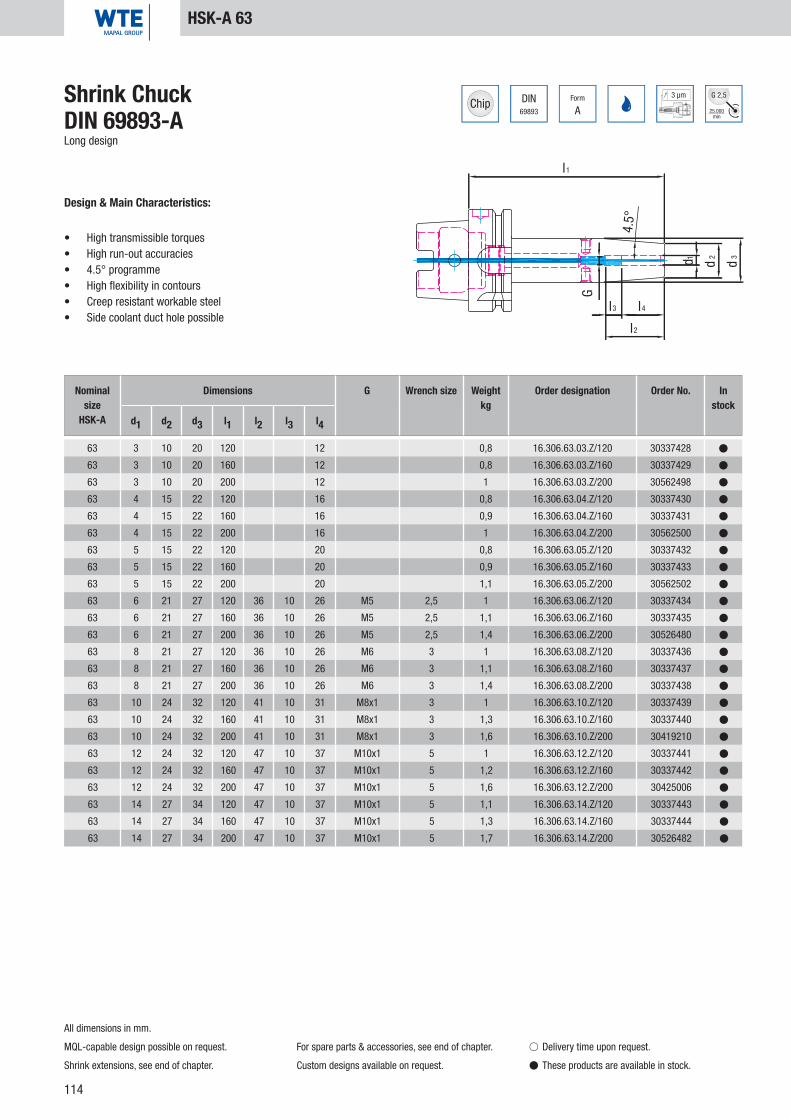
114
DIN69893
Form
A
3 µm
25.000min
G 2,5
l1
4.5°
G
d1 d2
d3
l3 l4
l2
63 3 10 20 120 12 0,8 16.306.63.03.Z/120 30337428 �
63 3 10 20 160 12 0,8 16.306.63.03.Z/160 30337429 �
63 3 10 20 200 12 1 16.306.63.03.Z/200 30562498 �
63 4 15 22 120 16 0,8 16.306.63.04.Z/120 30337430 �
63 4 15 22 160 16 0,9 16.306.63.04.Z/160 30337431 �
63 4 15 22 200 16 1 16.306.63.04.Z/200 30562500 �
63 5 15 22 120 20 0,8 16.306.63.05.Z/120 30337432 �
63 5 15 22 160 20 0,9 16.306.63.05.Z/160 30337433 �
63 5 15 22 200 20 1,1 16.306.63.05.Z/200 30562502 �
63 6 21 27 120 36 10 26 M5 2,5 1 16.306.63.06.Z/120 30337434 �
63 6 21 27 160 36 10 26 M5 2,5 1,1 16.306.63.06.Z/160 30337435 �
63 6 21 27 200 36 10 26 M5 2,5 1,4 16.306.63.06.Z/200 30526480 �
63 8 21 27 120 36 10 26 M6 3 1 16.306.63.08.Z/120 30337436 �
63 8 21 27 160 36 10 26 M6 3 1,1 16.306.63.08.Z/160 30337437 �
63 8 21 27 200 36 10 26 M6 3 1,4 16.306.63.08.Z/200 30337438 �
63 10 24 32 120 41 10 31 M8x1 3 1 16.306.63.10.Z/120 30337439 �
63 10 24 32 160 41 10 31 M8x1 3 1,3 16.306.63.10.Z/160 30337440 �
63 10 24 32 200 41 10 31 M8x1 3 1,6 16.306.63.10.Z/200 30419210 �
63 12 24 32 120 47 10 37 M10x1 5 1 16.306.63.12.Z/120 30337441 �
63 12 24 32 160 47 10 37 M10x1 5 1,2 16.306.63.12.Z/160 30337442 �
63 12 24 32 200 47 10 37 M10x1 5 1,6 16.306.63.12.Z/200 30425006 �
63 14 27 34 120 47 10 37 M10x1 5 1,1 16.306.63.14.Z/120 30337443 �
63 14 27 34 160 47 10 37 M10x1 5 1,3 16.306.63.14.Z/160 30337444 �
63 14 27 34 200 47 10 37 M10x1 5 1,7 16.306.63.14.Z/200 30526482 �
Shrink ChuckDIN 69893-ALong design
Design & Main Characteristics:
• High transmissible torques• High run-out accuracies• 4.5° programme• High flexibility in contours• Creep resistant workable steel• Side coolant duct hole possible
HSK-A 63
Nominal size
HSK-A
Dimensions G Wrench size Weightkg
Order designation Order No. In stock
d1 d2 d3 l1 l2 l3 l4
All dimensions in mm.
MQL-capable design possible on request.
Shrink extensions, see end of chapter.
For spare parts & accessories, see end of chapter.
Custom designs available on request.
� Delivery time upon request.
� These products are available in stock.
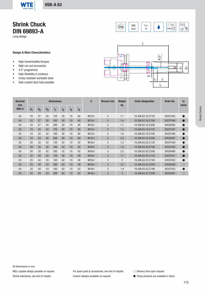
115
DIN69893
Form
A
3 µm
25.000min
G 2,5
l1
4.5°
G
d1 d2
d3
l3 l4
l2
63 16 27 34 120 50 10 40 M12x1 5 1,1 16.306.63.16.Z/120 30337445 �
63 16 27 34 160 50 10 40 M12x1 5 1,4 16.306.63.16.Z/160 30337446 �
63 16 27 34 200 50 10 40 M12x1 5 1,7 16.306.63.16.Z/200 30526485 �
63 18 33 42 120 50 10 40 M12x1 5 1,3 16.306.63.18.Z/120 30337447 �
63 18 33 42 160 50 10 40 M12x1 5 1,6 16.306.63.18.Z/160 30337448 �
63 18 33 42 200 50 10 40 M12x1 5 2,3 16.306.63.18.Z/200 30526487 �
63 20 33 42 120 52 10 42 M16x1 5 1,3 16.306.63.20.Z/120 30337449 �
63 20 33 42 160 52 10 42 M16x1 5 1,6 16.306.63.20.Z/160 30337450 �
63 20 33 42 200 52 10 42 M16x1 5 2,3 16.306.63.20.Z/200 30526488 �
63 25 44 53 120 58 10 48 M16x1 5 1,7 16.306.63.25.Z/120 30337451 �
63 25 44 53 160 62 10 48 M16x1 5 2 16.306.63.25.Z/160 30337452 �
63 25 44 53 200 62 10 48 M16x1 5 3,2 16.306.63.25.Z/200 30526489 �
63 32 44 53 160 62 10 52 M16x1 5 1,9 16.306.63.32.Z/160 30337453 �
63 32 44 53 200 62 10 52 M16x1 5 3 16.306.63.32.Z/200 30526491 �
Shrink ChuckDIN 69893-ALong design
Design & Main Characteristics:
• High transmissible torques• High run-out accuracies• 4.5° programme• High flexibility in contours• Creep resistant workable steel• Side coolant duct hole possible
Nominal size
HSK-A
Dimensions G Wrench size Weightkg
Order designation Order No. In stock
d1 d2 d3 l1 l2 l3 l4
HSK-A 63
All dimensions in mm.
MQL-capable design possible on request.
Shrink extensions, see end of chapter.
For spare parts & accessories, see end of chapter.
Custom designs available on request.
� Delivery time upon request.
� These products are available in stock.
Shrin
k Ch
ucks

116
DIN69893
Form
A
3 µm
25.000min
G 2,5
l1
d1
d2
d3
3°
l3 l4
l2
G
63 3 9 14 80 28 16 12 M6 2 0,7 16.304.63.03.Z 30385288 �
63 4 10 15 80 28 12 16 M6 2 0,7 16.304.63.04.Z 30385291 �
63 5 11 16 80 30 10 20 M6 2 0,7 16.304.63.05.Z 30385294 �
63 6 12 17 80 36 10 26 M5 2,5 0,7 16.304.63.06.Z 30385297 �
63 8 14 19 80 36 10 26 M6 3 0,7 16.304.63.08.Z 30385300 �
63 10 16 21 85 41 10 31 M8x1 3 0,8 16.304.63.10.Z 30385303 �
63 12 18 24 90 47 10 37 M10x1 5 0,8 16.304.63.12.Z 30385306 �
63 14 20 26 90 47 10 37 M10x1 5 0,8 16.304.63.14.Z 30385309 �
63 16 22 28 95 50 10 40 M12x1 5 0,8 16.304.63.16.Z 30385312 �
63 18 24 30 95 50 10 40 M12x1 5 0,9 16.304.63.18.Z 30385315 �
63 20 26 33 100 52 10 42 M16x1 5 0,9 16.304.63.20.Z 30385318 �
Shrink ChuckDIN 69893-ANarrow design, 3°
Design & Main Characteristics:
• High transmissible torques• High run-out accuracies• 3° programme• High fl exibility in contours• Creep resistant workable steel• Side coolant duct hole possible
HSK-A 63
Nominal size
HSK-A
Dimensions G Wrench size Weightkg
Order designation Order No. In stock
d1 d2 d3 l1 l2 l3 l4
All dimensions in mm.
MQL-capable design possible on request.
Shrink extensions, see end of chapter.
For spare parts & accessories, see end of chapter.
Custom designs available on request.
� Delivery time upon request.
� These products are available in stock.
3° programme

117
DIN69893
Form
A
3 µm
25.000min
G 2,5
l1
d1
d2
d3
3°
l3 l4
l2
G
63 3 9 16 120 12 0,8 16.304.63.03.Z/120 30385289 �
63 3 9 19 160 12 0,8 16.304.63.03.Z/160 30385290 �
63 4 10 17 120 16 0,8 16.304.63.04.Z/120 30385292 �
63 4 10 20 160 16 0,9 16.304.63.04.Z/160 30385293 �
63 5 11 18 120 20 0,8 16.304.63.05.Z/120 30385295 �
63 5 11 21 160 20 0,9 16.304.63.05.Z/160 30385296 �
63 6 12 21 120 36 10 26 M5 2,5 0,8 16.304.63.06.Z/120 30385298 �
63 6 12 24 160 36 10 26 M5 2,5 0,9 16.304.63.06.Z/160 30385299 �
63 8 14 23 120 36 10 26 M6 3 0,8 16.304.63.08.Z/120 30385301 �
63 8 14 26 160 36 10 26 M6 3 1,0 16.304.63.08.Z/160 30385302 �
63 10 16 25 120 41 10 31 M8x1 3 0,9 16.304.63.10.Z/120 30385304 �
63 10 16 28 160 41 10 31 M8x1 3 1,0 16.304.63.10.Z/160 30385305 �
63 12 18 27 120 47 10 37 M10x1 5 0,9 16.304.63.12.Z/120 30385307 �
63 12 18 30 160 47 10 37 M10x1 5 1,1 16.304.63.12.Z/160 30385308 �
63 14 20 29 120 47 10 37 M10x1 5 1,0 16.304.63.14.Z/120 30385310 �
63 14 20 32 160 47 10 37 M10x1 5 1,2 16.304.63.14.Z/160 30385311 �
63 16 22 31 120 50 10 40 M12x1 5 1,0 16.304.63.16.Z/120 30385313 �
63 16 22 34 160 50 10 40 M12x1 5 1,2 16.304.63.16.Z/160 30385314 �
63 18 24 33 120 50 10 40 M12x1 5 1,0 16.304.63.18.Z/120 30385316 �
63 18 24 36 160 50 10 40 M12x1 5 1,3 16.304.63.18.Z/160 30385317 �
63 20 26 35 120 52 10 42 M16x1 5 1,1 16.304.63.20.Z/120 30385319 �
63 20 26 38 160 52 10 42 M16x1 5 1,4 16.304.63.20.Z/160 30385320 �
Shrink ChuckDIN 69893-ALong narrow design, 3°
Design & Main Characteristics:
• High transmissible torques• High run-out accuracies• 3° programme• High fl exibility in contours• Creep resistant workable steel• Side coolant duct hole possible
HSK-A 63
Nominal size
HSK-A
Dimensions G Wrench size Weightkg
Order designation Order No. In stock
d1 d2 d3 l1 l2 l3 l4
All dimensions in mm.
MQL-capable design possible on request.
Shrink extensions, see end of chapter.
For spare parts & accessories, see end of chapter.
Custom designs available on request.
� Delivery time upon request.
� These products are available in stock.
Shrin
k Ch
ucks
3° programme

118
DIN69893
Form
A
3 µm
25.000min
G 2,5
d 1
l2
l3
d 3
l1
d 2
l4
G
4.5°
63 3 10 15 80 28 16 12 M6 2 0,7 16.306.63.03.KKB 30590796 �
63 4 15 22 80 28 12 16 M6 2 0,7 16.306.63.04.KKB 30590797 �
63 5 15 22 80 30 10 20 M6 2 0,7 16.306.63.05.KKB 30590798 �
63 6 21 27 80 36 10 26 M5 2,5 0,8 16.306.63.06.KKB 30589885 �
63 8 21 27 80 36 10 26 M6 3 0,8 16.306.63.08.KKB 30589886 �
63 10 24 32 85 41 10 31 M8x1 3 0,9 16.306.63.10.KKB 30589887 �
63 12 24 32 90 47 10 37 M10x1 5 0,9 16.306.63.12.KKB 30589888 �
63 14 27 34 90 47 10 37 M10x1 5 0,9 16.306.63.14.KKB 30589889 �
63 16 27 34 95 50 10 40 M12x1_KKB 5 1 16.306.63.16.KKB 30589890 �
63 18 33 42 95 50 10 40 M12x1_KKB 5 1,1 16.306.63.18.KKB 30589891 �
63 20 33 42 100 52 10 42 M16x1_KKB 5 1,1 16.306.63.20.KKB 30589892 �
63 25 44 53 115 58 10 48 M16x1_KKB 5 1,6 16.306.63.25.KKB 30589894 �
63 32 44 53 120 62 10 52 M16x1_KKB 5 1,6 16.306.63.32.KKB 30589895 �
Shrink ChuckDIN 69893-AWith additional resealable coolant duct holes
Design & Main Characteristics:
• High transmissible torques• High run-out accuracies• 4.5° programme• High flexibility in contours• Creep resistant workable steel• Side coolant duct hole
HSK-A 63
All dimensions in mm.
MQL-capable design possible on request.
Standard design with two coolant duct holes.
Other coolant duct holes on request.
Shrink extensions, see end of chapter.
For spare parts & accessories, see end of chapter.
Custom designs available on request.
� Delivery time upon request.
� These products are available in stock.
Nominal size
HSK-A
Dimensions G Wrench size Weightkg
Order designation Order No. In stock
d1 d2 d3 l1 l2 l3 l4

119
DIN69893
Form
A
3 µm
25.000min
G 2,5
d 1
l2
l3
d 3
l1
d 2
l4
G
4.5°
63 3 10 20 120 12 0,8 16.306.63.03.120.KKB 30590800 �
63 4 15 22 120 16 0,8 16.306.63.04.120.KKB 30590801 �
63 5 15 22 120 20 0,8 16.306.63.05.120.KKB 30590802 �
63 6 21 27 120 36 10 26 M5 2,5 1 16.306.63.06.120.KKB 30589896 �
63 8 21 27 120 36 10 26 M6 3 1 16.306.63.08.120.KKB 30589899 �
63 10 24 32 120 41 10 31 M8x1 3 1 16.306.63.10.120.KKB 30589900 �
63 12 24 32 120 47 10 37 M10x1 5 1 16.306.63.12.120.KKB 30589901 �
63 14 27 34 120 47 10 37 M10x1 5 1,1 16.306.63.14.120.KKB 30589902 �
63 16 27 34 120 50 10 40 M12x1_KKB 5 1,1 16.306.63.16.120.KKB 30589907 �
63 18 33 42 120 50 10 40 M12x1_KKB 5 1,3 16.306.63.18.120.KKB 30589908 �
63 20 33 42 120 52 10 42 M16x1_KKB 5 1,3 16.306.63.20.120.KKB 30589909 �
63 25 44 53 120 58 10 48 M16x1_KKB 5 1,7 16.306.63.25.120.KKB 30589910 �
Shrink ChuckDIN 69893-ALong design, with additional resealable coolant duct holes
Design & Main Characteristics:
• High transmissible torques• High run-out accuracies• 4.5° programme• High flexibility in contours• Creep resistant workable steel• Side coolant duct hole
HSK-A 63
All dimensions in mm.
MQL-capable design possible on request.
Standard design with two coolant duct holes.
Other coolant duct holes on request.
Shrink extensions, see end of chapter.
For spare parts & accessories, see end of chapter.
Custom designs available on request.
� Delivery time upon request.
� These products are available in stock.
Nominal size
HSK-A
Dimensions G Wrench size Weightkg
Order designation Order No. In stock
d1 d2 d3 l1 l2 l3 l4
Shrin
k Ch
ucks

120
DIN69893
Form
A
3 µm
25.000min
G 2,5
G
l3 l4
l2
d2
d1
d3
4.5°
l1
80 6 21 27 85 36 10 26 M5 2,5 1,2 16.306.80.06.Z 30337454 �
80 8 21 27 85 36 10 26 M6 3 1,2 16.306.80.08.Z 30337457 �
80 10 24 32 90 41 10 31 M8x1 3 1,3 16.306.80.10.Z 30337460 �
80 12 24 32 95 47 10 37 M10x1 5 1,3 16.306.80.12.Z 30337463 �
80 14 27 34 95 47 10 37 M10x1 5 1,4 16.306.80.14.Z 30337466 �
80 16 27 34 100 50 10 40 M12x1 5 1,5 16.306.80.16.Z 30337469 �
80 18 33 42 100 50 10 40 M12x1 5 1,5 16.306.80.18.Z 30337472 �
80 20 33 42 105 52 10 42 M16x1 8 1,7 16.306.80.20.Z 30337475 �
80 25 44 53 115 58 10 48 M16x1 8 2,5 16.306.80.25.Z 30337478 �
80 32 44 53 120 62 10 52 M16x1 8 2,9 16.306.80.32.Z 30337481 �
Shrink ChuckDIN 69893-A
Design & Main Characteristics:
• High transmissible torques• High run-out accuracies• 4.5° programme• High flexibility in contours• Creep resistant workable steel• Side coolant duct hole possible
HSK-A 80
Nominal size
HSK-A
Dimensions G Wrench size Weightkg
Order designation Order No. In stock
d1 d2 d3 l1 l2 l3 l4
All dimensions in mm.
MQL-capable design possible on request.
Shrink extensions, see end of chapter.
For spare parts & accessories, see end of chapter.
Custom designs available on request.
� Delivery time upon request.
� These products are available in stock.

121
DIN69893
Form
A
3 µm
25.000min
G 2,5
G
l3 l4
l2
d2
d1
d3
4.5°
l1
80 6 21 27 120 36 10 26 M5 2,5 1,5 16.306.80.06.Z/120 30337455 �
80 6 21 27 160 36 10 26 M5 2,5 1,8 16.306.80.06.Z/160 30337456 �
80 6 21 27 200 36 10 26 M5 2,5 1,8 16.306.80.06.Z/200 30595858 �
80 8 21 27 120 36 10 26 M6 3 1,5 16.306.80.08.Z/120 30337458 �
80 8 21 27 160 36 10 26 M6 3 1,8 16.306.80.08.Z/160 30337459 �
80 8 21 27 200 36 10 26 M6 3 1,8 16.306.80.08.Z/200 30595861 �
80 10 24 32 120 41 10 31 M8x1 3 1,6 16.306.80.10.Z/120 30337461 �
80 10 24 32 160 41 10 31 M8x1 3 2 16.306.80.10.Z/160 30337462 �
80 10 24 32 200 41 10 31 M8x1 3 2 16.306.80.10.Z/200 30595864 �
80 12 24 32 120 47 10 36 M10x1 5 1,6 16.306.80.12.Z/120 30337464 �
80 12 24 32 160 47 10 36 M10x1 5 2 16.306.80.12.Z/160 30337465 �
80 12 24 32 200 47 10 36 M10x1 5 2 16.306.80.12.Z/200 30595871 �
80 14 27 34 120 47 10 36 M10x1 5 1,7 16.306.80.14.Z/120 30337467 �
80 14 27 34 160 47 10 36 M10x1 5 2,1 16.306.80.14.Z/160 30337468 �
80 14 27 34 200 47 10 36 M10x1 5 2,1 16.306.80.14.Z/200 30595873 �
80 16 27 34 120 50 10 39 M12x1 5 1,8 16.306.80.16.Z/120 30337470 �
80 16 27 34 160 50 10 39 M12x1 5 2,1 16.306.80.16.Z/160 30337471 �
80 16 27 34 200 50 10 39 M12x1 5 2,1 16.306.80.16.Z/200 30595874 �
80 18 33 42 120 50 10 39 M12x1 5 1,9 16.306.80.18.Z/120 30337473 �
80 18 33 42 160 50 10 39 M12x1 5 2,2 16.306.80.18.Z/160 30337474 �
80 18 33 42 200 50 10 39 M12x1 5 2,6 16.306.80.18.Z/200 30595876 �
80 20 33 42 120 52 10 41 M16x1 8 2 16.306.80.20.Z/120 30337476 �
80 20 33 42 160 52 10 41 M16x1 8 2,3 16.306.80.20.Z/160 30337477 �
80 20 33 42 200 52 10 41 M16x1 8 2,7 16.306.80.20.Z/200 30595877 �
80 25 44 53 120 58 10 47 M16x1 8 2,6 16.306.80.25.Z/120 30337479 �
80 25 44 53 160 58 10 47 M16x1 8 2,9 16.306.80.25.Z/160 30337480 �
80 25 44 53 200 58 10 47 M16x1 8 3,6 16.306.80.25.Z/200 30595880 �
80 32 44 53 160 62 10 51 M16x1 8 3,2 16.306.80.32.Z/160 30337482 �
80 32 44 53 200 62 10 51 M16x1 8 3,5 16.306.80.32.Z/200 30595882 �
Shrink ChuckDIN 69893-ALong design
Design & Main Characteristics:
• High transmissible torques• High run-out accuracies• 4.5° programme• High flexibility in contours• Creep resistant workable steel• Side coolant duct hole possible
HSK-A 80
Nominal size
HSK-A
Dimensions G Wrench size Weightkg
Order designation Order No. In stock
d1 d2 d3 l1 l2 l3 l4
All dimensions in mm.
MQL-capable design possible on request.
Shrink extensions, see end of chapter.
For spare parts & accessories, see end of chapter.
Custom designs available on request.
� Delivery time upon request.
� These products are available in stock.
Shrin
k Ch
ucks

122
DIN69893
Form
A
3 µm
25.000min
G 2,5
l1
4.5°
d1
d2
d3
l4
l2
l3
G
100 6 21 27 85 36 10 26 M5 2,5 2,2 16.306.100.06.Z 30337331 �
100 8 21 27 85 36 10 26 M6 3 2,2 16.306.100.08.Z 30337334 �
100 10 24 32 90 41 10 31 M8x1 3 2,3 16.306.100.10.Z 30337337 �
100 12 24 32 95 47 10 37 M10x1 5 2,2 16.306.100.12.Z 30337340 �
100 14 27 34 95 47 10 37 M10x1 5 2,3 16.306.100.14.Z 30337343 �
100 16 27 34 100 50 10 40 M12x1 5 2,3 16.306.100.16.Z 30337346 �
100 18 33 42 100 50 10 40 M12x1 5 2,5 16.306.100.18.Z 30337349 �
100 20 33 42 105 52 10 42 M16x1 8 2,5 16.306.100.20.Z 30337352 �
100 25 44 53 115 58 10 48 M16x1 8 3,1 16.306.100.25.Z 30337355 �
100 32 44 53 120 62 10 52 M16x1 8 3,0 16.306.100.32.Z 30337358 �
Shrink ChuckDIN 69893-A
Design & Main Characteristics:
• High transmissible torques• High run-out accuracies• 4.5° programme• High flexibility in contours• Creep resistant workable steel• Side coolant duct hole possible
HSK-A 100
Nominal size
HSK-A
Dimensions G Wrench size Weightkg
Order designation Order No. In stock
d1 d2 d3 l1 l2 l3 l4
All dimensions in mm.
MQL-capable design possible on request.
Shrink extensions, see end of chapter.
For spare parts & accessories, see end of chapter.
Custom designs available on request.
� Delivery time upon request.
� These products are available in stock.

123
DIN69893
Form
A
3 µm
25.000min
G 2,5
l1
4.5°
d1
d2
d3
l4
l2
l3
G
100 6 21 27 120 36 10 26 M5 2,5 2,4 16.306.100.06.Z/120 30337332 �
100 6 21 27 160 36 10 26 M5 2,5 2,6 16.306.100.06.Z/160 30337333 �
100 6 21 27 200 36 10 26 M5 2,5 2,7 16.306.100.06.Z/200 30530904 �
100 8 21 27 120 36 10 26 M6 3 2,4 16.306.100.08.Z/120 30337335 �
100 8 21 27 160 36 10 26 M6 3 2,6 16.306.100.08.Z/160 30337336 �
100 8 21 27 200 36 10 26 M6 3 2,7 16.306.100.08.Z/200 30530906 �
100 10 24 32 120 41 10 31 M8x1 3 2,5 16.306.100.10.Z/120 30337338 �
100 10 24 32 160 41 10 31 M8x1 3 2,7 16.306.100.10.Z/160 30337339 �
100 10 24 32 200 41 10 31 M8x1 3 2,9 16.306.100.10.Z/200 30408832 �
100 12 24 32 120 47 10 37 M10x1 5 2,5 16.306.100.12.Z/120 30337341 �
100 12 24 32 160 47 10 37 M10x1 5 2,7 16.306.100.12.Z/160 30337342 �
100 12 24 32 200 47 10 37 M10x1 5 2,7 16.306.100.12.Z/200 30530907 �
100 14 27 34 120 47 10 37 M10x1 5 2,5 16.306.100.14.Z/120 30337344 �
100 14 27 34 160 47 10 37 M10x1 5 2,7 16.306.100.14.Z/160 30337345 �
100 14 27 34 200 47 10 37 M10x1 5 3,0 16.306.100.14.Z/200 30530909 �
100 16 27 34 120 50 10 40 M12x1 5 2,6 16.306.100.16.Z/120 30337347 �
100 16 27 34 160 50 10 40 M12x1 5 2,9 16.306.100.16.Z/160 30337348 �
100 16 27 34 200 50 10 40 M12x1 5 3,0 16.306.100.16.Z/200 30530910 �
100 18 33 42 120 50 10 40 M12x1 5 2,7 16.306.100.18.Z/120 30337350 �
100 18 33 42 160 50 10 40 M12x1 5 3,0 16.306.100.18.Z/160 30337351 �
100 18 33 42 200 50 10 40 M12x1 5 3,6 16.306.100.18.Z/200 30530911 �
100 20 33 42 120 52 10 42 M16x1 8 3,0 16.306.100.20.Z/120 30337353 �
100 20 33 42 160 52 10 42 M16x1 8 3,4 16.306.100.20.Z/160 30337354 �
100 20 33 42 200 52 10 42 M16x1 8 3,6 16.306.100.20.Z/200 30530912 �
100 25 44 53 120 58 10 48 M16x1 8 3,2 16.306.100.25.Z/120 30337356 �
100 25 44 53 160 58 10 48 M16x1 8 3,6 16.306.100.25.Z/160 30337357 �
100 25 44 53 200 58 10 48 M16x1 8 4,5 16.306.100.25.Z/200 30530913 �
100 32 44 53 160 62 10 52 M16x1 8 3,3 16.306.100.32.Z/160 30337359 �
100 32 44 53 200 62 10 52 M16x1 8 4,4 16.306.100.32.Z/200 30530916 �
Shrink ChuckDIN 69893-ALong design
Design & Main Characteristics:
• High transmissible torques• High run-out accuracies• 4.5° programme• High flexibility in contours• Creep resistant workable steel• Side coolant duct hole possible
HSK-A 100
Nominal size
HSK-A
Dimensions G Wrench size Weightkg
Order designation Order No. In stock
d1 d2 d3 l1 l2 l3 l4
All dimensions in mm.
MQL-capable design possible on request.
Shrink extensions, see end of chapter.
For spare parts & accessories, see end of chapter.
Custom designs available on request.
� Delivery time upon request.
� These products are available in stock.
Shrin
k Ch
ucks

124
DIN69893
Form
A
3 µm
25.000min
G 2,5
l1
3°
d2
d3
G
l4
l2
l3
d1
100 6 12 17 85 36 10 26 M5 2,5 2,1 16.304.100.06.Z 30597883 �
100 8 14 19 85 36 10 26 M6 3 2,1 16.304.100.08.Z 30597886 �
100 10 16 21 90 41 10 31 M8x1 3 2,1 16.304.100.10.Z 30597889 �
100 12 18 24 95 47 10 36 M10x1 5 2,1 16.304.100.12.Z 30597890 �
100 14 20 26 95 47 10 36 M10x1 5 2,2 16.304.100.14.Z 30597891 �
100 16 22 28 100 50 10 39 M12x1 5 2,2 16.304.100.16.Z 30597892 �
100 18 24 30 100 50 10 39 M12x1 5 2,3 16.304.100.18.Z 30597894 �
100 20 27 34 105 52 10 41 M16x1 8 2,3 16.304.100.20.Z 30597896 �
Shrink ChuckDIN 69893-ASlim design
Design & Main Characteristics:
• High transmissible torques• High run-out accuracies• 3° programme• High fl exibility in contours• Creep resistant workable steel• Side coolant duct hole possible
HSK-A 100
Nominal size
HSK-A
Dimensions G Wrench size Weightkg
Order designation Order No. In stock
d1 d2 d3 l1 l2 l3 l4
All dimensions in mm.
MQL-capable design possible on request.
Shrink extensions, see end of chapter.
For spare parts & accessories, see end of chapter.
Custom designs available on request.
� Delivery time upon request.
� These products are available in stock.
3° programme
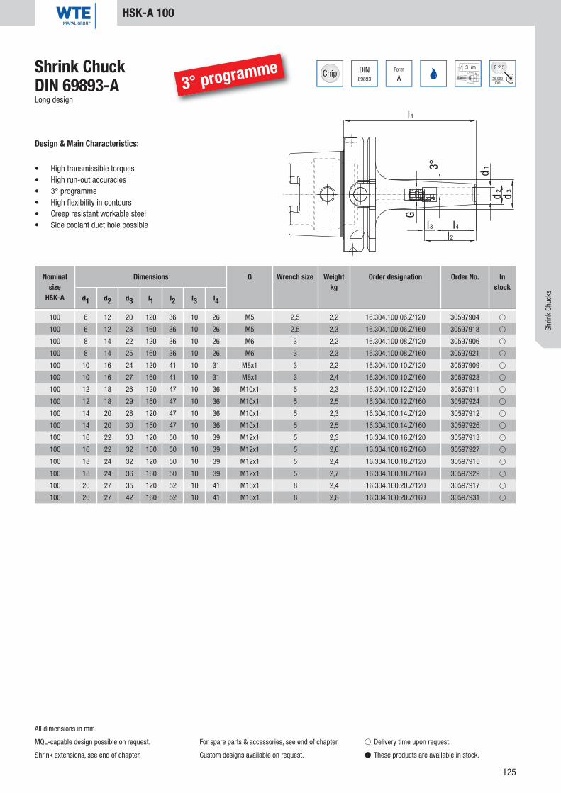
125
DIN69893
Form
A
3 µm
25.000min
G 2,5
l1
3° d1
d2
d3
G
l4
l2
l3
100 6 12 20 120 36 10 26 M5 2,5 2,2 16.304.100.06.Z/120 30597904 �
100 6 12 23 160 36 10 26 M5 2,5 2,3 16.304.100.06.Z/160 30597918 �
100 8 14 22 120 36 10 26 M6 3 2,2 16.304.100.08.Z/120 30597906 �
100 8 14 25 160 36 10 26 M6 3 2,3 16.304.100.08.Z/160 30597921 �
100 10 16 24 120 41 10 31 M8x1 3 2,2 16.304.100.10.Z/120 30597909 �
100 10 16 27 160 41 10 31 M8x1 3 2,4 16.304.100.10.Z/160 30597923 �
100 12 18 26 120 47 10 36 M10x1 5 2,3 16.304.100.12.Z/120 30597911 �
100 12 18 29 160 47 10 36 M10x1 5 2,5 16.304.100.12.Z/160 30597924 �
100 14 20 28 120 47 10 36 M10x1 5 2,3 16.304.100.14.Z/120 30597912 �
100 14 20 30 160 47 10 36 M10x1 5 2,5 16.304.100.14.Z/160 30597926 �
100 16 22 30 120 50 10 39 M12x1 5 2,3 16.304.100.16.Z/120 30597913 �
100 16 22 32 160 50 10 39 M12x1 5 2,6 16.304.100.16.Z/160 30597927 �
100 18 24 32 120 50 10 39 M12x1 5 2,4 16.304.100.18.Z/120 30597915 �
100 18 24 36 160 50 10 39 M12x1 5 2,7 16.304.100.18.Z/160 30597929 �
100 20 27 35 120 52 10 41 M16x1 8 2,4 16.304.100.20.Z/120 30597917 �
100 20 27 42 160 52 10 41 M16x1 8 2,8 16.304.100.20.Z/160 30597931 �
Shrink ChuckDIN 69893-ALong design
Design & Main Characteristics:
• High transmissible torques• High run-out accuracies• 3° programme• High fl exibility in contours• Creep resistant workable steel• Side coolant duct hole possible
HSK-A 100
Nominal size
HSK-A
Dimensions G Wrench size Weightkg
Order designation Order No. In stock
d1 d2 d3 l1 l2 l3 l4
All dimensions in mm.
MQL-capable design possible on request.
Shrink extensions, see end of chapter.
For spare parts & accessories, see end of chapter.
Custom designs available on request.
� Delivery time upon request.
� These products are available in stock.
Shrin
k Ch
ucks
3° programme

126
DIN69893
Form
C
3 µm
25.000min
G 2,5
d3
d2d1
G
l 2
l4l3
4.5°
l1
32 3 10 15 60 22 10 12 M5 2 0,2 23.306.32.03.Z 30337760 �
32 4 10 15 60 26 10 16 M5 2 0,2 23.306.32.04.Z 30337761 �
32 5 10 15 60 30 10 20 M6 2 0,2 23.306.32.05.Z 30337762 �
32 6 21 26 65 36 10 26 M5 2,5 0,3 23.306.32.06.Z 30337763 �
32 8 21 26 65 36 10 26 M6 3 0,3 23.306.32.08.Z 30337764 �
32 10 24 30 65 41 10 31 M8x1 3 0,4 23.306.32.10.Z 30337765 �
32 12 24 32 75 47 10 37 M10x1 5 0,4 23.306.32.12.Z 30337766 �
Shrink ChuckDIN 69893-C
Design & Main Characteristics:
• High transmissible torques• High run-out accuracies• 4.5° programme• High flexibility in contours• Creep resistant workable steel• Side coolant duct hole possible
HSK-C 32
All dimensions in mm.
Shrink extensions, see end of chapter.
For spare parts & accessories, see end of chapter.
Custom designs available on request.
� Delivery time upon request.
� These products are available in stock.
Nominal size
HSK-C
Dimensions G Wrench size Weightkg
Order designation Order No. In stock
d1 d2 d3 l1 l2 l3 l4

127
DIN69893
Form
C
3 µm
25.000min
G 2,5
d2d1
d3
G
l 3 l4
l2
4.5°
l1
40 3 10 15 60 28 16 12 M6 2 0,3 23.306.40.03.Z 30385045 �
40 4 10 15 60 28 12 16 M6 2 0,3 23.306.40.04.Z 30385046 �
40 5 10 15 60 30 10 20 M6 2 0,3 23.306.40.05.Z 30385047 �
40 6 21 30 70 36 10 26 M5 2,5 0,4 23.306.40.06.Z 30337767 �
40 8 21 30 70 36 10 26 M6 3 0,4 23.306.40.08.Z 30337768 �
40 10 24 33,5 70 41 10 31 M8x1 3 0,5 23.306.40.10.Z 30337769 �
40 12 24 35 80 47 10 37 M10x1 5 0,5 23.306.40.12.Z 30337770 �
40 14 27 38 80 47 10 37 M10x1 5 0,5 23.306.40.14.Z 30337771 �
40 16 27 38 80 50 10 40 M12x1 5 0,6 23.306.40.16.Z 30337772 �
Shrink ChuckDIN 69893-C
Design & Main Characteristics:
• High transmissible torques• High run-out accuracies• 4.5° programme• High flexibility in contours• Creep resistant workable steel• Side coolant duct hole possible
HSK-C 40
All dimensions in mm.
Shrink extensions, see end of chapter.
For spare parts & accessories, see end of chapter.
Custom designs available on request.
� Delivery time upon request.
� These products are available in stock.
Nominal size
HSK-C
Dimensions G Wrench size Weightkg
Order designation Order No. In stock
d1 d2 d3 l1 l2 l3 l4
Shrin
k Ch
ucks

128
DIN69893
Form
C
3 µm
25.000min
G 2,5
d2d1 d3
G
l 3 l4
l2
4.5°
l1
40 3 10 20 120 12 0,4 23.306.40.03.Z/120 30385049 �
40 3 10 20 160 12 0,5 23.306.40.03.Z/160 30385064 �
40 4 15 22 120 16 0,4 23.306.40.04.Z/120 30385051 �
40 4 15 22 160 16 0,5 23.306.40.04.Z/160 30385072 �
40 5 15 22 120 20 0,4 23.306.40.05.Z/120 30385053 �
40 5 15 22 160 20 0,5 23.306.40.05.Z/160 30385077 �
40 6 21 30 120 36 10 26 M5 2,5 0,5 23.306.40.06.Z/120 30385055 �
40 6 21 30 160 36 10 26 M5 2,5 0,6 23.306.40.06.Z/160 30385078 �
40 8 21 30 120 36 10 26 M6 3 0,5 23.306.40.08.Z/120 30385056 �
40 8 21 30 160 36 10 26 M6 3 0,6 23.306.40.08.Z/160 30385081 �
40 10 24 33,5 120 41 10 31 M8x1 3 0,6 23.306.40.10.Z/120 30385057 �
40 10 24 33,5 160 41 10 31 M8x1 3 0,7 23.306.40.10.Z/160 30385086 �
40 12 24 35 120 47 10 37 M10x1 5 0,6 23.306.40.12.Z/120 30385058 �
40 12 24 35 160 47 10 37 M10x1 5 0,7 23.306.40.12.Z/160 30385088 �
40 14 27 38 120 47 10 37 M10x1 5 0,6 23.306.40.14.Z/120 30385059 �
40 14 27 38 160 47 10 37 M10x1 5 0,7 23.306.40.14.Z/160 30385089 �
40 16 27 38 120 50 10 40 M12x1 5 0,7 23.306.40.16.Z/120 30385061 �
40 16 27 38 160 50 10 40 M12x1 5 0,8 23.306.40.16.Z/160 30385090 �
Shrink ChuckDIN 69893-CLong design
Design & Main Characteristics:
• High transmissible torques• High run-out accuracies• 4.5° programme• High flexibility in contours• Creep resistant workable steel• Side coolant duct hole possible
HSK-C 40
All dimensions in mm.
Shrink extensions, see end of chapter.
For spare parts & accessories, see end of chapter.
Custom designs available on request.
� Delivery time upon request.
� These products are available in stock.
Nominal size
HSK-C
Dimensions G Wrench size Weightkg
Order designation Order No. In stock
d1 d2 d3 l1 l2 l3 l4

129
DIN69893
Form
C
3 µm
25.000min
G 2,5
d3
d2d1
4.5°
l1
l4
l2
l3
G
50 3 10 15 70 28 16 12 M6 2 0,4 23.306.50.03.Z 30385096 �
50 4 15 22 70 28 12 16 M6 2 0,4 23.306.50.04.Z 30385098 �
50 5 15 22 70 30 10 20 M6 2 0,4 23.306.50.05.Z 30385101 �
50 6 21 30 70 36 10 26 M5 2,5 0,6 23.306.50.06.Z 30337773 �
50 8 21 30 70 36 10 26 M6 3 0,6 23.306.50.08.Z 30337776 �
50 10 24 33 75 41 10 31 M8x1 3 0,6 23.306.50.10.Z 30337777 �
50 12 24 34 80 47 10 37 M10x1 5 0,7 23.306.50.12.Z 30337778 �
50 14 27 37 80 47 10 37 M10x1 5 0,7 23.306.50.14.Z 30337779 �
50 16 27 38,5 85 50 10 40 M12x1 5 0,7 23.306.50.16.Z 30337780 �
50 18 33 44,5 85 50 10 40 M12x1 5 0,8 23.306.50.18.Z 30337781 �
50 20 33 45 90 52 10 42 M16x1 5 0,8 23.306.50.20.Z 30337782 �
Shrink ChuckDIN 69893-C
Design & Main Characteristics:
• High transmissible torques• High run-out accuracies• 4.5° programme• High flexibility in contours• Creep resistant workable steel• Side coolant duct hole possible
HSK-C 50
All dimensions in mm.
Shrink extensions, see end of chapter.
For spare parts & accessories, see end of chapter.
Custom designs available on request.
� Delivery time upon request.
� These products are available in stock.
Nominal size
HSK-C
Dimensions G Wrench size Weightkg
Order designation Order No. In stock
d1 d2 d3 l1 l2 l3 l4
Shrin
k Ch
ucks

130
DIN69893
Form
C
3 µm
25.000min
G 2,5
d3
d2d1
4.5°
l1
l4
l2
l3
G
50 3 10 20 120 12 0,5 23.306.50.03.Z/120 30385103 �
50 3 10 20 160 12 0,5 23.306.50.03.Z/160 30385130 �
50 4 15 22 120 16 0,5 23.306.50.04.Z/120 30385105 �
50 4 15 22 160 16 0,5 23.306.50.04.Z/160 30385132 �
50 5 15 22 120 20 0,5 23.306.50.05.Z/120 30385106 �
50 5 15 22 160 20 0,5 23.306.50.05.Z/160 30385138 �
50 6 21 30 120 36 10 26 M5 2,5 0,7 23.306.50.06.Z/120 30337774 �
50 6 21 30 160 36 10 26 M5 2,5 0,8 23.306.50.06.Z/160 30337775 �
50 8 21 30 120 36 10 26 M6 3 0,7 23.306.50.08.Z/120 30385108 �
50 8 21 30 160 36 26 M6 3 0,8 23.306.50.08.Z/160 30385140 �
50 10 24 33 120 41 10 31 M8x1 3 0,7 23.306.50.10.Z/120 30385110 �
50 10 24 33 160 41 10 31 M8x1 3 0,8 23.306.50.10.Z/160 30385141 �
50 12 24 34 120 47 10 37 M10x1 5 0,8 23.306.50.12.Z/120 30385112 �
50 12 24 34 160 47 10 37 M10x1 5 0,9 23.306.50.12.Z/160 30385142 �
50 14 27 37 120 47 10 37 M10x1 5 0,8 23.306.50.14.Z/120 30385113 �
50 14 27 37 160 47 10 37 M10x1 5 0,9 23.306.50.14.Z/160 30385254 �
50 16 27 38,5 120 50 10 40 M12x1 5 0,8 23.306.50.16.Z/120 30385120 �
50 16 27 38,5 160 50 10 40 M12x1 5 0,9 23.306.50.16.Z/160 30385255 �
50 18 33 44,5 120 50 10 40 M12x1 5 0,9 23.306.50.18.Z/120 30385124 �
50 18 33 44,5 160 50 10 40 M12x1 5 1,0 23.306.50.18.Z/100 30385257 �
50 20 33 45 120 52 10 42 M16x1 5 0,9 23.306.50.20.Z/120 30385126 �
50 20 33 45 160 52 10 42 M16x1 5 1,0 23.306.50.20.Z/160 30385258 �
Shrink ChuckDIN 69893-CLong design
Design & Main Characteristics:
• High transmissible torques• High run-out accuracies• 4.5° programme• High flexibility in contours• Creep resistant workable steel• Side coolant duct hole possible
HSK-C 50
All dimensions in mm.
Shrink extensions, see end of chapter.
For spare parts & accessories, see end of chapter.
Custom designs available on request.
� Delivery time upon request.
� These products are available in stock.
Nominal size
HSK-C
Dimensions G Wrench size Weightkg
Order designation Order No. In stock
d1 d2 d3 l1 l2 l3 l4
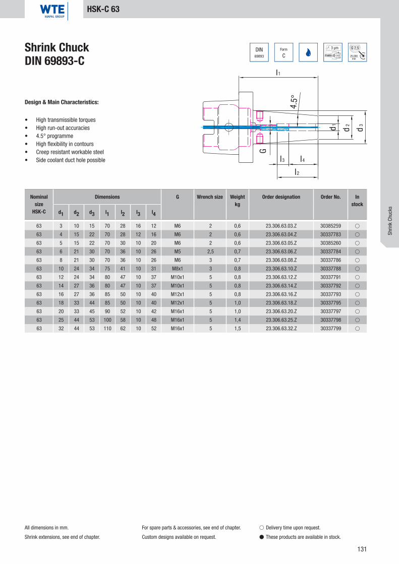
131
DIN69893
Form
C
3 µm
25.000min
G 2,5
l1
d2d1 d3
4.5°
G
l3 l4
l2
63 3 10 15 70 28 16 12 M6 2 0,6 23.306.63.03.Z 30385259 �
63 4 15 22 70 28 12 16 M6 2 0,6 23.306.63.04.Z 30337783 �
63 5 15 22 70 30 10 20 M6 2 0,6 23.306.63.05.Z 30385260 �
63 6 21 30 70 36 10 26 M5 2,5 0,7 23.306.63.06.Z 30337784 �
63 8 21 30 70 36 10 26 M6 3 0,7 23.306.63.08.Z 30337786 �
63 10 24 34 75 41 10 31 M8x1 3 0,8 23.306.63.10.Z 30337788 �
63 12 24 34 80 47 10 37 M10x1 5 0,8 23.306.63.12.Z 30337791 �
63 14 27 36 80 47 10 37 M10x1 5 0,8 23.306.63.14.Z 30337792 �
63 16 27 36 85 50 10 40 M12x1 5 0,8 23.306.63.16.Z 30337793 �
63 18 33 44 85 50 10 40 M12x1 5 1,0 23.306.63.18.Z 30337795 �
63 20 33 45 90 52 10 42 M16x1 5 1,0 23.306.63.20.Z 30337797 �
63 25 44 53 100 58 10 48 M16x1 5 1,4 23.306.63.25.Z 30337798 �
63 32 44 53 110 62 10 52 M16x1 5 1,5 23.306.63.32.Z 30337799 �
Shrink ChuckDIN 69893-C
Design & Main Characteristics:
• High transmissible torques• High run-out accuracies• 4.5° programme• High flexibility in contours• Creep resistant workable steel• Side coolant duct hole possible
HSK-C 63
All dimensions in mm.
Shrink extensions, see end of chapter.
For spare parts & accessories, see end of chapter.
Custom designs available on request.
� Delivery time upon request.
� These products are available in stock.
Nominal size
HSK-C
Dimensions G Wrench size Weightkg
Order designation Order No. In stock
d1 d2 d3 l1 l2 l3 l4
Shrin
k Ch
ucks

132
DIN69893
Form
C
3 µm
25.000min
G 2,5
l1
d2d1 d3
4.5°
G
l3 l4
l2
63 3 10 20 120 12 0,7 23.306.63.03.Z/120 30385261 �
63 3 10 20 160 12 0,8 23.306.63.03.Z/160 30386160 �
63 4 15 22 120 16 0,7 23.306.63.04.Z/120 30385262 �
63 4 15 22 160 16 0,8 23.306.63.04.Z/160 30386161 �
63 5 15 22 120 20 0,7 23.306.63.05.Z/120 30385263 �
63 5 15 22 160 20 0,8 23.306.63.05.Z/160 30386164 �
63 6 21 30 120 36 10 26 M5 2,5 0,8 23.306.63.06.Z/120 30337785 �
63 6 21 30 160 36 10 26 M5 2,5 0,9 23.306.63.06.Z/160 30386167 �
63 8 21 30 120 36 10 26 M6 3 0,8 23.306.63.08.Z/120 30337787 �
63 8 21 27 160 36 10 26 M6 3 0,9 23.306.63.08.Z/160 30386168 �
63 10 24 34 120 41 10 31 M8x1 3 0,9 23.306.63.10.Z/120 30337789 �
63 10 24 34 160 41 10 31 M8x1 3 1,0 23.306.63.10.Z/160 30337790 �
63 12 24 34 120 47 10 37 M10x1 5 0,9 23.306.63.12.Z/120 30385264 �
63 12 24 34 160 47 10 37 M10x1 5 1,0 23.306.63.12.Z/160 30386169 �
63 14 27 36 120 47 10 37 M10x1 5 0,9 23.306.63.14.Z/120 30385265 �
63 14 27 36 160 47 10 37 M10x1 5 1,0 23.306.63.14.Z/160 30386172 �
63 16 27 36 120 50 10 40 M12x1 5 0,9 23.306.63.16.Z/120 30337794 �
63 16 27 36 160 50 10 40 M12x1 5 1,0 23.306.63.16.Z/160 30386173 �
63 18 33 44 120 50 10 40 M12x1 5 1,1 23.306.63.18.Z/120 30337796 �
63 18 33 44 160 50 10 40 M12x1 5 1,2 23.306.63.18.Z.160 30386176 �
63 20 33 45 120 52 10 42 M16x1 5 1,1 23.306.63.20.Z/120 30385266 �
63 20 33 45 160 52 10 42 M16x1 5 1,2 23.306.63.20.Z/160 30386178 �
63 25 44 53 120 58 10 48 M16x1 5 1,5 23.306.63.25.Z/120 30385267 �
63 25 44 53 160 58 10 48 M16x1 5 1,7 23.306.63.25.Z/160 30386180 �
63 32 44 53 160 62 10 52 M16x1 5 1,7 23.306.63.32.Z/160 30386183 �
Shrink ChuckDIN 69893-CLong design
Design & Main Characteristics:
• High transmissible torques• High run-out accuracies• 4.5° programme• High flexibility in contours• Creep resistant workable steel• Side coolant duct hole possible
HSK-C 63
All dimensions in mm.
Shrink extensions, see end of chapter.
For spare parts & accessories, see end of chapter.
Custom designs available on request.
� Delivery time upon request.
� These products are available in stock.
Nominal size
HSK-C
Dimensions G Wrench size Weightkg
Order designation Order No. In stock
d1 d2 d3 l1 l2 l3 l4

133
DIN69893 E
Form 3 µm
25.000min
G 2,5
d1
d2
d3
l3
l2
l4
G
4.5°
l1
32 3 10 15 60 28 16 12 M5 2 0,2 18.306.32.03.Z 30337540 �
32 4 10 15 60 28 12 16 M5 2 0,2 18.306.32.04.Z 30337541 �
32 5 10 15 60 30 10 20 M6 2 0,2 18.306.32.05.Z 30337542 �
32 6 21 25 70 36 10 26 M5 2,5 0,3 18.306.32.06.Z 30337543 �
32 8 21 25 70 36 10 26 M6 3 0,3 18.306.32.08.Z 30337544 �
32 10 24 29 75 41 10 31 M8x1 3 0,4 18.306.32.10.Z 30337545 �
32 12 24 29 80 47 10 37 M10x1 5 0,4 18.306.32.12.Z 30337546 �
Shrink ChuckDIN 69893-E
Design & Main Characteristics:
• High transmissible torques• High run-out accuracies• 4.5° programme• High flexibility in contours• Creep resistant workable steel• Side coolant duct hole possible
HSK-E 32
All dimensions in mm.
Shrink extensions, see end of chapter.
For spare parts & accessories, see end of chapter.
Custom designs available on request.
� Delivery time upon request.
� These products are available in stock.
Nominal size
HSK-E
Dimensions G Wrench size Weightkg
Order designation Order No. In stock
d1 d2 d3 l1 l2 l3 l4
Shrin
k Ch
ucks

134
DIN69893 E
Form 3 µm
25.000min
G 2,5
d1 d3
d2
l 3
l2
l4
G
4.5°
l1
40 3 10 15 60 28 16 12 M6 2 0,3 18.306.40.03.Z 30337547 �
40 4 10 15 60 28 12 16 M6 2 0,3 18.306.40.04.Z 30337550 �
40 5 10 15 60 30 10 20 M6 2 0,3 18.306.40.05.Z 30337553 �
40 6 21 27 80 36 10 26 M5 2,5 0,4 18.306.40.06.Z 30337556 �
40 8 21 27 80 36 10 26 M6 3 0,4 18.306.40.08.Z 30337559 �
40 10 24 32 80 41 10 31 M8x1 3 0,5 18.306.40.10.Z 30337562 �
40 12 24 32 90 47 10 37 M10x1 5 0,5 18.306.40.12.Z 30337565 �
40 14 27 33,5 90 47 10 37 M10x1 5 0,6 18.306.40.14.Z 30337568 �
40 16 27 33,5 90 50 10 40 M12x1 5 0,5 18.306.40.16.Z 30337571 �
Shrink ChuckDIN 69893-E
Design & Main Characteristics:
• High transmissible torques• High run-out accuracies• 4.5° programme• High flexibility in contours• Creep resistant workable steel• Side coolant duct hole possible
HSK-E 40
All dimensions in mm.
Shrink extensions, see end of chapter.
For spare parts & accessories, see end of chapter.
Custom designs available on request.
� Delivery time upon request.
� These products are available in stock.
Nominal size
HSK-E
Dimensions G Wrench size Weightkg
Order designation Order No. In stock
d1 d2 d3 l1 l2 l3 l4
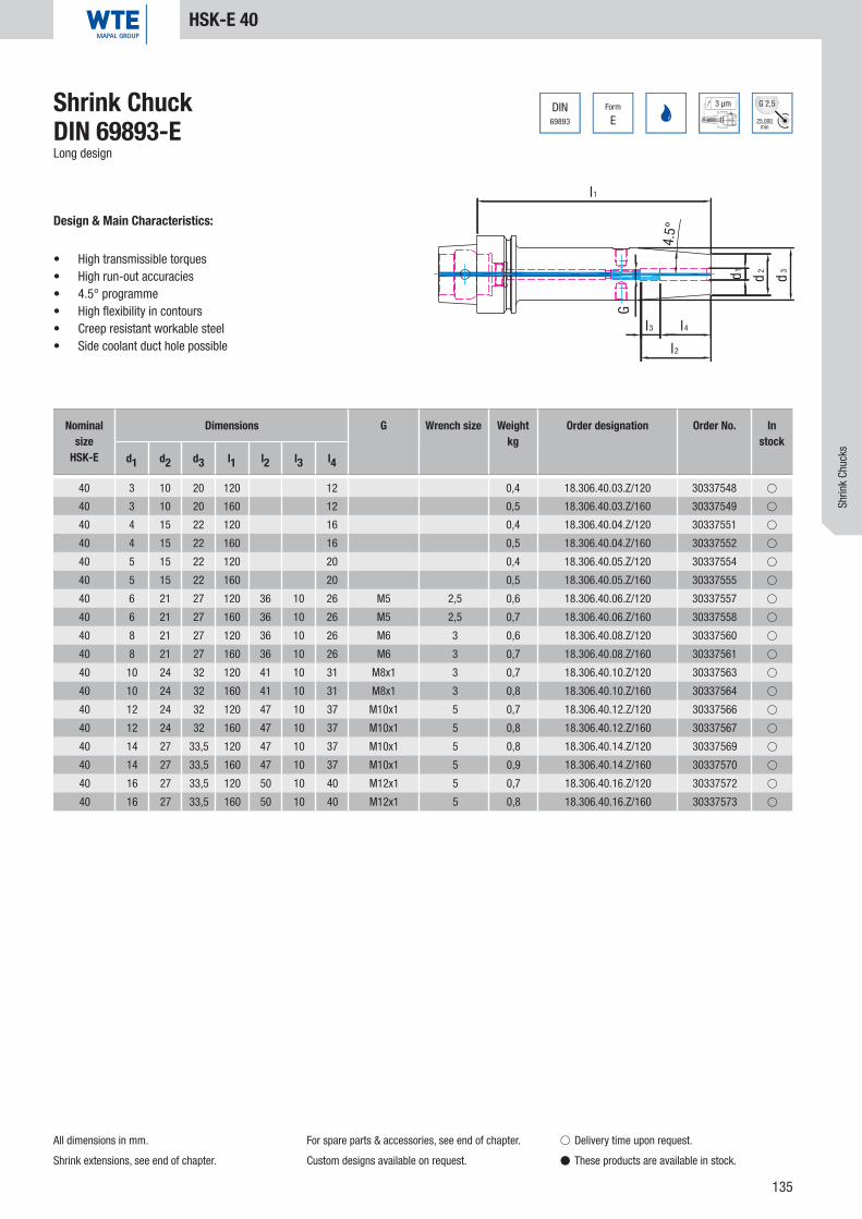
135
DIN69893 E
Form 3 µm
25.000min
G 2,5
d1 d3
d2
l 3
l2
l4
G
4.5°
l1
40 3 10 20 120 12 0,4 18.306.40.03.Z/120 30337548 �
40 3 10 20 160 12 0,5 18.306.40.03.Z/160 30337549 �
40 4 15 22 120 16 0,4 18.306.40.04.Z/120 30337551 �
40 4 15 22 160 16 0,5 18.306.40.04.Z/160 30337552 �
40 5 15 22 120 20 0,4 18.306.40.05.Z/120 30337554 �
40 5 15 22 160 20 0,5 18.306.40.05.Z/160 30337555 �
40 6 21 27 120 36 10 26 M5 2,5 0,6 18.306.40.06.Z/120 30337557 �
40 6 21 27 160 36 10 26 M5 2,5 0,7 18.306.40.06.Z/160 30337558 �
40 8 21 27 120 36 10 26 M6 3 0,6 18.306.40.08.Z/120 30337560 �
40 8 21 27 160 36 10 26 M6 3 0,7 18.306.40.08.Z/160 30337561 �
40 10 24 32 120 41 10 31 M8x1 3 0,7 18.306.40.10.Z/120 30337563 �
40 10 24 32 160 41 10 31 M8x1 3 0,8 18.306.40.10.Z/160 30337564 �
40 12 24 32 120 47 10 37 M10x1 5 0,7 18.306.40.12.Z/120 30337566 �
40 12 24 32 160 47 10 37 M10x1 5 0,8 18.306.40.12.Z/160 30337567 �
40 14 27 33,5 120 47 10 37 M10x1 5 0,8 18.306.40.14.Z/120 30337569 �
40 14 27 33,5 160 47 10 37 M10x1 5 0,9 18.306.40.14.Z/160 30337570 �
40 16 27 33,5 120 50 10 40 M12x1 5 0,7 18.306.40.16.Z/120 30337572 �
40 16 27 33,5 160 50 10 40 M12x1 5 0,8 18.306.40.16.Z/160 30337573 �
Shrink ChuckDIN 69893-ELong design
Design & Main Characteristics:
• High transmissible torques• High run-out accuracies• 4.5° programme• High flexibility in contours• Creep resistant workable steel• Side coolant duct hole possible
HSK-E 40
All dimensions in mm.
Shrink extensions, see end of chapter.
For spare parts & accessories, see end of chapter.
Custom designs available on request.
� Delivery time upon request.
� These products are available in stock.
Nominal size
HSK-E
Dimensions G Wrench size Weightkg
Order designation Order No. In stock
d1 d2 d3 l1 l2 l3 l4
Shrin
k Ch
ucks

136
DIN69893 E
Form 3 µm
25.000min
G 2,5
d1 d2
d3
3°
l1
G
l2
l3 l4
40 3 9 13 60 28 16 12 M6 2 0,3 18.304.40.03.Z/60 30407142 �
40 3 9 14 70 28 16 12 M6 2 0,3 18.304.40.03.Z/70 30456361 �
40 3 9 15 80 28 16 12 M6 2 0,3 18.304.40.03.Z/80 30456373 �
40 4 10 14 60 28 12 16 M6 2 0,3 18.304.40.04.Z/60 30407144 �
40 4 10 15 70 28 12 16 M6 2 0,3 18.304.40.04.Z/70 30456362 �
40 4 10 16 80 28 12 16 M6 2 0,3 18.304.40.04.Z/80 30456374 �
40 5 11 15 60 30 10 20 M6 2 0,3 18.304.40.05.Z/60 30407146 �
40 5 11 16 70 30 10 20 M6 2 0,3 18.304.40.05.Z/70 30456364 �
40 5 11 17 80 30 10 20 M6 2 0,3 18.304.40.05.Z/80 30456376 �
40 6 12 16 60 36 10 26 M5 2,5 0,3 18.304.40.06.Z/60 30456341 �
40 6 12 17 70 36 10 26 M5 2,5 0,3 18.304.40.06.Z/70 30456365 �
40 6 12 18 80 36 10 26 M5 2,5 0,3 18.304.40.06.Z/80 30407149 �
40 8 14 18 60 36 10 26 M5 2,5 0,3 18.304.40.08.Z/60 30456343 �
40 8 14 19 70 36 10 26 M5 2,5 0,3 18.304.40.08.Z/70 30456366 �
40 8 14 20 80 36 10 26 M6 3 0,3 18.304.40.08.Z/80 30407150 �
40 10 16 20 60 38 7 31 M5 2,5 0,3 18.304.40.10.Z/60 30456344 �
40 10 16 21 70 41 10 31 M5 2,5 0,3 18.304.40.10.Z/70 30456368 �
40 10 16 22 80 41 10 31 M8x1 3 0,3 18.304.40.10.Z/80 30407152 �
40 12 18 22 60 40 3 37 M5 2,5 0,3 18.304.40.12.Z/60 30456347 �
40 12 18 23 70 47 10 37 M5 2,5 0,3 18.304.40.12.Z/70 30456370 �
40 12 18 24 80 47 10 37 M5 2,5 0,4 18.304.40.12.Z/80 30456377 �
Shrink ChuckDIN 69893-ENarrow design, 3°
Design & Main Characteristics:
• High transmissible torques• High run-out accuracies• 3° programme• High fl exibility in contours• Creep resistant workable steel• Side coolant duct hole possible
HSK-E 40
All dimensions in mm.
Shrink extensions, see end of chapter.
For spare parts & accessories, see end of chapter.
Custom designs available on request.
� Delivery time upon request.
� These products are available in stock.
Nominal size
HSK-E
Dimensions G Wrench size Weightkg
Order designation Order No. In stock
d1 d2 d3 l1 l2 l3 l4
3° programme

137
DIN69893 E
Form 3 µm
25.000min
G 2,5
l1
4.5°
G
d3
d2d1
l3 l4
l2
50 3 10 15 80 28 16 12 M6 2 0,4 18.306.50.03.Z 30337574 �
50 4 15 22 80 28 12 16 M6 2 0,5 18.306.50.04.Z 30337577 �
50 5 15 22 80 30 10 20 M6 2 0,5 18.306.50.05.Z 30337580 �
50 6 21 27 80 36 10 26 M5 2,5 0,7 18.306.50.06.Z 30337583 �
50 8 21 27 80 36 10 26 M6 3 0,6 18.306.50.08.Z 30337586 �
50 10 24 32 85 41 10 31 M8x1 3 0,7 18.306.50.10.Z 30337589 �
50 12 24 32 90 47 10 37 M10x1 5 0,7 18.306.50.12.Z 30337592 �
50 14 27 34 90 47 10 37 M10x1 5 0,7 18.306.50.14.Z 30337595 �
50 16 27 34 95 50 10 40 M12x1 5 0,7 18.306.50.16.Z 30337598 �
50 18 33 42 95 50 10 40 M12x1 5 0,9 18.306.50.18.Z 30337601 �
50 20 33 42 100 52 10 42 M16x1 5 0,9 18.306.50.20.Z 30337604 �
Shrink ChuckDIN 69893-E
Design & Main Characteristics:
• High transmissible torques• High run-out accuracies• 4.5° programme• High flexibility in contours• Creep resistant workable steel• Side coolant duct hole possible
HSK-E 50
All dimensions in mm.
Shrink extensions, see end of chapter.
For spare parts & accessories, see end of chapter.
Custom designs available on request.
� Delivery time upon request.
� These products are available in stock.
Nominal size
HSK-E
Dimensions G Wrench size Weightkg
Order designation Order No. In stock
d1 d2 d3 l1 l2 l3 l4
HSK-E 40
Shrin
k Ch
ucks

138
DIN69893 E
Form 3 µm
25.000min
G 2,5
l1
4.5°
G
d3
d2d1
l3 l4
l2
50 3 10 20 120 12 0,5 18.306.50.03.Z/120 30337575 �
50 3 10 20 160 12 0,6 18.306.50.03.Z/160 30337576 �
50 4 15 22 120 16 0,6 18.306.50.04.Z/120 30337578 �
50 4 15 22 160 16 0,7 18.306.50.04.Z/160 30337579 �
50 5 15 22 120 20 0,6 18.306.50.05.Z/120 30337581 �
50 5 15 22 160 20 0,7 18.306.50.05.Z/160 30337582 �
50 6 21 27 120 36 10 26 M5 2,5 0,8 18.306.50.06.Z/120 30337584 �
50 6 21 27 160 36 10 26 M5 2,5 0,9 18.306.50.06.Z/160 30337585 �
50 8 21 27 120 36 10 26 M6 3 0,8 18.306.50.08.Z/120 30337587 �
50 8 21 27 160 36 10 26 M6 3 0,9 18.306.50.08.Z/160 30337588 �
50 10 24 32 120 41 10 31 M8x1 3 0,8 18.306.50.10.Z/120 30337590 �
50 10 24 32 160 41 10 31 M8x1 3 0,9 18.306.50.10.Z/160 30337591 �
50 12 24 32 120 47 10 37 M10x1 5 0,8 18.306.50.12.Z/120 30337593 �
50 12 24 32 160 47 10 37 M10x1 5 0,9 18.306.50.12.Z/160 30337594 �
50 14 27 34 120 47 10 37 M10x1 5 0,8 18.306.50.14.Z/120 30337596 �
50 14 27 34 160 47 10 37 M10x1 5 0,9 18.306.50.14.Z/160 30337597 �
50 16 27 34 120 50 10 40 M12x1 5 0,8 18.306.50.16.Z/120 30337599 �
50 16 27 34 160 50 10 40 M12x1 5 0,9 18.306.50.16.Z/160 30337600 �
50 18 33 42 120 50 10 40 M12x1 5 1,0 18.306.50.18.Z/120 30337602 �
50 18 33 42 160 50 10 40 M12x1 5 1,1 18.306.50.18.Z.160 30337603 �
50 20 33 42 120 52 10 42 M16x1 5 1,0 18.306.50.20.Z/120 30337605 �
50 20 33 42 160 52 10 42 M16x1 5 1,1 18.306.50.20.Z/160 30337606 �
Shrink ChuckDIN 69893-ELong design
Design & Main Characteristics:
• High transmissible torques• High run-out accuracies• 4.5° programme• High flexibility in contours• Creep resistant workable steel• Side coolant duct hole possible
HSK-E 50
All dimensions in mm.
Shrink extensions, see end of chapter.
For spare parts & accessories, see end of chapter.
Custom designs available on request.
� Delivery time upon request.
� These products are available in stock.
Nominal size
HSK-E
Dimensions G Wrench size Weightkg
Order designation Order No. In stock
d1 d2 d3 l1 l2 l3 l4

139
DIN69893 E
Form 3 µm
25.000min
G 2,5
d1 d2
d3
3°
l1
G
l2
l3 l4
50 3 9 14 70 28 16 12 M6 2 0,5 18.304.50.03.Z/70 30456842 �
50 3 9 15 80 28 16 12 M6 2 0,5 18.304.50.03.Z/80 30456961 �
50 3 9 17 100 28 16 12 M6 2 0,5 18.304.50.03.Z/100 30456972 �
50 4 10 15 70 28 12 16 M6 2 0,5 18.304.50.04.Z/70 30456846 �
50 4 10 16 80 28 12 16 M6 2 0,5 18.304.50.04.Z/80 30456964 �
50 4 10 18 100 28 12 16 M6 2 0,5 18.304.50.04.Z/100 30456973 �
50 5 11 16 70 30 10 20 M6 2 0,5 18.304.50.05.Z/70 30456850 �
50 5 11 17 80 30 10 20 M6 2 0,5 18.304.50.05.Z/80 30456965 �
50 5 11 19 100 30 10 20 M6 2 0,5 18.304.50.05.Z/100 30456975 �
50 6 12 17 70 36 10 26 M5 2,5 0,5 18.304.50.06.Z/70 30456852 �
50 6 12 18 80 36 10 26 M5 2,5 0,5 18.304.50.06.Z/80 30656966 �
50 6 12 20 100 36 10 26 M5 2,5 0,5 18.304.50.06.Z/100 30456977 �
50 8 14 19 70 36 10 26 M5 2,5 0,5 18.304.50.08.Z/70 30456855 �
50 8 14 20 80 36 10 26 M6 3 0,5 18.304.50.08.Z/80 30456968 �
50 8 14 22 100 36 10 26 M6 3 0,6 18.304.50.08.Z/100 30456979 �
50 10 16 21 70 41 10 31 M5 2,5 0,5 18.304.50.10.Z/70 30456857 �
50 10 16 22 80 41 10 31 M5 2,5 0,5 18.304.50.10.Z/80 30456969 �
50 10 16 24 100 41 10 31 M8x1 3 0,6 18.304.50.10.Z/100 30456980 �
50 12 18 23 70 44 7 37 M5 2,5 0,5 18.304.50.12.Z/70 30456858 �
50 12 18 24 80 47 10 37 M5 2,5 0,5 18.304.50.12.Z/80 30456970 �
50 12 18 26 100 47 10 37 M10x1 5 0,6 18.304.50.12.Z/100 30456981 �
Shrink ChuckDIN 69893-ENarrow design, 3°
Design & Main Characteristics:
• High transmissible torques• High run-out accuracies• 3° programme• High fl exibility in contours• Creep resistant workable steel• Side coolant duct hole possible
HSK-E 50
All dimensions in mm.
Shrink extensions, see end of chapter.
For spare parts & accessories, see end of chapter.
Custom designs available on request.
� Delivery time upon request.
� These products are available in stock.
Nominal size
HSK-E
Dimensions G Wrench size Weightkg
Order designation Order No. In stock
d1 d2 d3 l1 l2 l3 l4
Shrin
k Ch
ucks
3° programme

140
DIN69893 E
Form 3 µm
25.000min
G 2,5
l1
4.5°
G
d1 d2
d3
l3 l4
l2
63 3 10 15 80 28 16 12 M6 2 0,7 18.306.63.03.Z 30337607 �
63 4 15 22 80 28 12 16 M6 2 0,7 18.306.63.04.Z 30337610 �
63 5 15 22 80 30 10 20 M6 2 0,7 18.306.63.05.Z 30337613 �
63 6 21 27 80 36 10 26 M5 2,5 0,8 18.306.63.06.Z 30337616 �
63 8 21 27 80 36 10 26 M6 3 0,8 18.306.63.08.Z 30337619 �
63 10 24 32 85 41 10 31 M8x1 3 0,9 18.306.63.10.Z 30337622 �
63 12 24 32 90 47 10 37 M10x1 5 0,9 18.306.63.12.Z 30337625 �
63 14 27 34 90 47 10 37 M10x1 5 1,0 18.306.63.14.Z 30337628 �
63 16 27 34 95 50 10 40 M12x1 5 1,0 18.306.63.16.Z 30337631 �
63 18 33 42 95 50 10 40 M12x1 5 1,1 18.306.63.18.Z 30337634 �
63 20 33 42 100 52 10 42 M16x1 5 1,1 18.306.63.20.Z 30337637 �
63 25 44 53 115 58 10 48 M16x1 5 1,6 18.306.63.25.Z 30337640 �
63 32 44 53 120 62 10 52 M16x1 5 1,6 18.306.63.32.Z 30337643 �
Shrink ChuckDIN 69893-E
Design & Main Characteristics:
• High transmissible torques• High run-out accuracies• 4.5° programme• High flexibility in contours• Creep resistant workable steel• Side coolant duct hole possible
HSK-E 63
All dimensions in mm.
Shrink extensions, see end of chapter.
For spare parts & accessories, see end of chapter.
Custom designs available on request.
� Delivery time upon request.
� These products are available in stock.
Nominal size
HSK-E
Dimensions G Wrench size Weightkg
Order designation Order No. In stock
d1 d2 d3 l1 l2 l3 l4

141
DIN69893 E
Form 3 µm
25.000min
G 2,5
l1
4.5°
G
d1 d2
d3
l3 l4
l2
63 3 10 20 120 12 0,8 18.306.63.03.Z/120 30337608 �
63 3 10 20 160 12 0,9 18.306.63.03.Z/160 30337609 �
63 4 15 22 120 16 0,8 18.306.63.04.Z/120 30337611 �
63 4 15 22 160 16 0,9 18.306.63.04.Z/160 30337612 �
63 5 15 22 120 20 0,8 18.306.63.05.Z/120 30337614 �
63 5 15 22 160 20 0,9 18.306.63.05.Z/160 30337615 �
63 6 21 27 120 36 10 26 M5 2,5 0,9 18.306.63.06.Z/120 30337617 �
63 6 21 27 160 36 10 26 M5 2,5 1,0 18.306.63.06.Z/160 30337618 �
63 8 21 27 120 36 10 26 M6 3 0,9 18.306.63.08.Z/120 30337620 �
63 8 21 27 160 36 10 26 M6 3 1,0 18.306.63.08.Z/160 30337621 �
63 10 24 32 120 41 10 31 M8x1 3 1,0 18.306.63.10.Z/120 30337623 �
63 10 24 32 160 41 10 31 M8x1 3 1,1 18.306.63.10.Z/160 30337624 �
63 12 24 32 120 47 10 37 M10x1 5 1,0 18.306.63.12.Z/120 30337626 �
63 12 24 32 160 47 10 37 M10x1 5 1,1 18.306.63.12.Z/160 30337627 �
63 14 27 34 120 47 10 37 M10x1 5 1,1 18.306.63.14.Z/120 30337629 �
63 14 27 34 160 47 10 37 M10x1 5 1,2 18.306.63.14.Z/160 30337630 �
63 16 27 34 120 50 10 40 M12x1 5 1,2 18.306.63.16.Z/120 30337632 �
63 16 27 34 160 50 10 40 M12x1 5 1,4 18.306.63.16.Z/160 30337633 �
63 18 33 42 120 50 10 40 M12x1 5 1,3 18.306.63.18.Z/120 30337635 �
63 18 33 42 160 50 10 40 M12x1 5 1,5 18.306.63.18.Z.160 30337636 �
63 20 33 42 120 52 10 42 M16x1 5 1,3 18.306.63.20.Z/120 30337638 �
63 20 33 42 160 52 10 42 M16x1 5 1,5 18.306.63.20.Z/160 30337639 �
63 25 44 53 120 58 10 48 M16x1 5 1,6 18.306.63.25.Z/120 30337641 �
63 25 44 53 160 58 10 48 M16x1 5 1,8 18.306.63.25.Z/160 30337642 �
63 32 44 53 160 62 10 52 M16x1 5 1,7 18.306.63.32.Z/160 30337644 �
Shrink ChuckDIN 69893-ELong design
Design & Main Characteristics:
• High transmissible torques• High run-out accuracies• 4.5° programme• High flexibility in contours• Creep resistant workable steel• Side coolant duct hole possible
HSK-E 63
All dimensions in mm.
Shrink extensions, see end of chapter.
For spare parts & accessories, see end of chapter.
Custom designs available on request.
� Delivery time upon request.
� These products are available in stock.
Nominal size
HSK-E
Dimensions G Wrench size Weightkg
Order designation Order No. In stock
d1 d2 d3 l1 l2 l3 l4
Shrin
k Ch
ucks

142
DIN69893 E
Form 3 µm
25.000min
G 2,5
l1
d1
d2
d3
3°
l3 l4
l2
G
63 6 12 18 80 36 10 26 M5 2,5 0,8 18.304.63.06.Z/80 30456806 �
63 8 14 20 80 36 10 26 M6 3 0,8 18.304.63.08.Z/80 30456812 �
63 10 16 22 80 41 10 31 M5 2,5 0,8 18.304.63.10.Z/80 30456817 �
63 12 18 24 80 47 10 37 M5 2,5 0,8 18.304.63.12.Z/80 30456821 �
Shrink ChuckDIN 69893-ENarrow design, 3°
Design & Main Characteristics:
• High transmissible torques• High run-out accuracies• 3° programme• High fl exibility in contours• Creep resistant workable steel• Side coolant duct hole possible
HSK-E 63
All dimensions in mm.
Shrink extensions, see end of chapter.
For spare parts & accessories, see end of chapter.
Custom designs available on request.
� Delivery time upon request.
� These products are available in stock.
Nominal size
HSK-E
Dimensions G Wrench size Weightkg
Order designation Order No. In stock
d1 d2 d3 l1 l2 l3 l4
3° programme

143
DIN69893 E
Form 3 µm
25.000min
G 2,5
l1
d1
d2
d3
3°
l3 l4
l2
G
63 6 12 22 120 36 10 26 M5 2,5 0,9 18.304.63.06.Z/120 30456828 �
63 8 14 24 120 36 10 26 M6 3 0,9 18.304.63.08.Z/120 30456832 �
63 10 16 26 120 41 10 31 M8x1 3 0,9 18.304.63.10.Z/120 30456835 �
63 12 18 28 120 47 10 37 M10x1 5 1,0 18.304.63.12.Z/120 30456839 �
Shrink ChuckDIN 69893-ELong narrow design, 3°
Design & Main Characteristics:
• High transmissible torques• High run-out accuracies• 3° programme• High fl exibility in contours• Creep resistant workable steel• Side coolant duct hole possible
HSK-E 63
All dimensions in mm.
Shrink extensions, see end of chapter.
For spare parts & accessories, see end of chapter.
Custom designs available on request.
� Delivery time upon request.
� These products are available in stock.
Nominal size
HSK-E
Dimensions G Wrench size Weightkg
Order designation Order No. In stock
d1 d2 d3 l1 l2 l3 l4
Shrin
k Ch
ucks
3° programme

144
DIN69893
Form
F
3 µm
25.000min
G 2,5
l1
d2d1 d3
l3 l4
l2
G
4.5°
40 3 10 15 60 28 16 12 M6 2 0,6 17.306.40.03 30337483 �
40 4 10 15 60 28 12 16 M6 2 0,7 17.306.40.04 30337484 �
40 5 10 15 60 30 10 20 M6 2 0,7 17.306.40.05 30337485 �
40 6 21 27 80 36 10 26 M5 2,5 0,8 17.306.40.06 30337486 �
40 8 21 27 80 36 10 26 M6 3 0,8 17.306.40.08 30337487 �
40 10 24 32 80 41 10 31 M8x1 3 0,9 17.306.40.10 30337488 �
40 12 24 32 90 47 10 37 M10x1 5 0,9 17.306.40.12 30337489 �
Shrink ChuckDIN 69893-F
Design & Main Characteristics:
• High transmissible torques• High run-out accuracies• 4.5° programme• High flexibility in contours• Creep resistant workable steel
HSK-F 40
All dimensions in mm.
Shrink extensions, see end of chapter.
For spare parts & accessories, see end of chapter.
Custom designs available on request.
� Delivery time upon request.
� These products are available in stock.
Nominal size
HSK-F
Dimensions G Wrench size Weightkg
Order designation Order No. In stock
d1 d2 d3 l1 l2 l3 l4

145
DIN69893
Form
F
3 µm
25.000min
G 2,5
l1
4.5°
G
d1 d2
d3
l3 l4
l2
63 3 10 15 80 28 16 12 M6 2 0,6 17.306.63.03 30337490 �
63 4 15 22 80 28 12 16 M6 2 0,7 17.306.63.04 30337493 �
63 5 15 22 80 30 10 20 M6 2 0,7 17.306.63.05 30337496 �
63 6 21 27 80 36 10 26 M5 2,5 0,8 17.306.63.06 30337499 �
63 8 21 27 80 36 10 26 M6 3 0,8 17.306.63.08 30337502 �
63 10 24 32 85 41 10 31 M8x1 3 0,9 17.306.63.10 30337505 �
63 12 24 32 90 47 10 37 M10x1 5 0,9 17.306.63.12 30337508 �
63 14 27 34 90 47 10 37 M10x1 5 0,9 17.306.63.14 30337511 �
63 16 27 34 95 50 10 40 M12x1 5 1,0 17.306.63.16 30337514 �
63 18 33 42 95 50 10 40 M12x1 5 1,1 17.306.63.18 30337517 �
63 20 33 42 100 52 10 42 M16x1 5 1,1 17.306.63.20 30337520 �
63 25 44 53 115 58 10 48 M16x1 5 1,6 17.306.63.25 30337523 �
63 32 44 53 120 62 10 52 M16x1 5 1,6 17.306.63.32 30337526 �
Shrink ChuckDIN 69893-F
Design & Main Characteristics:
• High transmissible torques• High run-out accuracies• 4.5° programme• High flexibility in contours• Creep resistant workable steel
HSK-F 63
All dimensions in mm.
Shrink extensions, see end of chapter.
For spare parts & accessories, see end of chapter.
Custom designs available on request.
� Delivery time upon request.
� These products are available in stock.
Nominal size
HSK-F
Dimensions G Wrench size Weightkg
Order designation Order No. In stock
d1 d2 d3 l1 l2 l3 l4
Shrin
k Ch
ucks

146
DIN69893
Form
F
3 µm
25.000min
G 2,5
l1
4.5°
G
d1 d2
d3
l3 l4
l2
63 3 10 20 120 12 0,7 17.306.63.03/120 30337491 �
63 3 10 20 160 12 0,8 17.306.63.03/160 30337492 �
63 4 15 22 120 16 0,8 17.306.63.04/120 30337494 �
63 4 15 22 160 16 0,8 17.306.63.04/160 30337495 �
63 5 15 22 120 20 0,8 17.306.63.05/120 30337497 �
63 5 15 22 160 20 0,8 17.306.63.05/160 30337498 �
63 6 21 27 120 36 10 26 M5 2,5 1,0 17.306.63.06/120 30337500 �
63 6 21 27 160 36 10 26 M5 2,5 1,1 17.306.63.06/160 30337501 �
63 8 21 27 120 36 10 26 M6 3 1,0 17.306.63.08/120 30337503 �
63 8 21 27 160 36 10 26 M6 3 1,1 17.306.63.08/160 30337504 �
63 10 24 32 120 41 10 31 M8x1 3 1,1 17.306.63.10/120 30337506 �
63 10 24 32 160 41 10 31 M8x1 3 1,3 17.306.63.10/160 30337507 �
63 12 24 32 120 47 10 37 M10x1 5 1,1 17.306.63.12/120 30337509 �
63 12 24 32 160 47 10 37 M10x1 5 1,3 17.306.63.12/160 30337510 �
63 14 27 34 120 47 10 37 M10x1 5 1,1 17.306.63.14/120 30337512 �
63 14 27 34 160 47 10 37 M10x1 5 1,3 17.306.63.14/160 30337513 �
63 16 27 34 120 50 10 40 M12x1 5 1,1 17.306.63.16/120 30337515 �
63 16 27 34 160 50 10 40 M12x1 5 1,4 17.306.63.16/160 30337516 �
63 18 33 42 120 50 10 40 M12x1 5 1,3 17.306.63.18/120 30337518 �
63 18 33 42 160 50 10 40 M12x1 5 1,6 17.306.63.18/160 30337519 �
63 20 33 42 120 52 10 42 M16x1 5 1,3 17.306.63.20/120 30337521 �
63 20 33 42 160 52 10 42 M16x1 5 1,6 17.306.63.20/160 30337522 �
63 25 44 53 120 58 10 48 M16x1 5 1,7 17.306.63.25/120 30337524 �
63 25 44 53 160 58 10 48 M16x1 5 2,0 17.306.63.25/160 30337525 �
Shrink ChuckDIN 69893-FLong design
Design & Main Characteristics:
• High transmissible torques• High run-out accuracies• 4.5° programme• High flexibility in contours• Creep resistant workable steel
HSK-F 63
All dimensions in mm.
Shrink extensions, see end of chapter.
For spare parts & accessories, see end of chapter.
Custom designs available on request.
� Delivery time upon request.
� These products are available in stock.
Nominal size
HSK-F
Dimensions G Wrench size Weightkg
Order designation Order No. In stock
d1 d2 d3 l1 l2 l3 l4

147
DIN69893
Form
F
3 µm
25.000min
G 2,5
l1
d1
d2
d3
3°
l3 l4
l2
G
63 3 9 14 80 28 16 12 M6 2 0,7 17.304.63.03 30407202 �
63 4 10 15 80 28 12 16 M6 2 0,7 17.304.63.04 30407205 �
63 5 11 16 80 30 10 20 M6 2 0,8 17.304.63.05 30407209 �
63 6 12 17 80 36 10 26 M5 2,5 0,8 17.304.63.06 30407237 �
63 8 14 19 80 36 10 26 M6 3 0,8 17.304.63.08 30407239 �
63 10 16 22 85 41 10 31 M8x1 3 0,8 17.304.63.10 30407241 �
63 12 18 24 90 47 10 37 M10x1 5 0,8 17.304.63.12 30407243 �
63 14 20 26 90 47 10 37 M10x1 5 0,8 17.304.63.14 30407245 �
63 16 22 29 95 50 10 40 M12x1 5 0,9 17.304.63.16 30407247 �
63 18 24 31 95 50 10 40 M12x1 5 0,9 17.304.63.18 30407248 �
63 20 27 34 100 52 10 42 M16x1 5 1,0 17.304.63.20 30407249 �
Shrink ChuckDIN 69893-FNarrow design, 3°
Design & Main Characteristics:
• High transmissible torques• High run-out accuracies• 3° programme• High fl exibility in contours• Creep resistant workable steel
HSK-F 63
All dimensions in mm.
Shrink extensions, see end of chapter.
For spare parts & accessories, see end of chapter.
Custom designs available on request.
� Delivery time upon request.
� These products are available in stock.
Nominal size
HSK-F
Dimensions G Wrench size Weightkg
Order designation Order No. In stock
d1 d2 d3 l1 l2 l3 l4
Shrin
k Ch
ucks
3° programme

148
DIN69893
Form
F
3 µm
25.000min
G 2,5
l1
d1
d2
d3
3°
l3 l4
l2
G
63 3 9 16 120 12 0,8 17.304.63.03/120 30407251 �
63 3 9 19 160 12 0,9 17.304.63.03/160 30407265 �
63 4 10 17 120 16 0,8 17.304.63.04/120 30407253 �
63 4 10 20 160 16 0,9 17.304.63.04/160 30407268 �
63 5 11 18 120 20 0,8 17.304.63.05/120 30407254 �
63 5 11 21 160 20 0,9 17.304.63.05/160 30407269 �
63 6 12 21 120 36 10 26 M5 2,5 0,9 17.304.63.06/120 30407255 �
63 6 12 24 160 36 10 26 M5 2,5 1,0 17.304.63.06/160 30407270 �
63 8 14 23 120 36 10 26 M6 3 0,9 17.304.63.08/120 30407256 �
63 8 14 24 160 36 10 26 M6 3 1,0 17.304.63.08/160 30407271 �
63 10 16 25 120 41 10 31 M8x1 3 0,9 17.304.63.10/120 30407257 �
63 10 16 28 160 41 10 31 M8x1 3 1,0 17.304.63.10/160 30407272 �
63 12 18 27 120 47 10 37 M10x1 5 1,0 17.304.63.12/120 30407258 �
63 12 18 30 160 47 10 37 M10x1 5 1,2 17.304.63.12/160 30407273 �
63 14 20 29 120 47 10 37 M10x1 5 1,0 17.304.63.14/120 30407259 �
63 14 20 32 160 47 10 37 M10x1 5 1,2 17.304.63.14/160 30407274 �
63 16 22 31 120 50 10 40 M12x1 5 1,0 17.304.63.16/120 30407260 �
63 16 22 34 160 50 10 40 M12x1 5 1,3 17.304.63.16/160 30407275 �
63 18 24 33 120 50 10 40 M12x1 5 1,0 17.304.63.18/120 30407263 �
63 18 24 36 160 50 10 40 M12x1 5 1,4 17.304.63.18/160 30407276 �
63 20 27 36 120 52 10 42 M16x1 5 1,0 17.304.63.20/120 30407264 �
63 20 27 38 160 52 10 42 M16x1 5 1,5 17.304.63.20/160 30407277 �
Shrink ChuckDIN 69893-FLong narrow design, 3°
Design & Main Characteristics:
• High transmissible torques• High run-out accuracies• 3° programme• High fl exibility in contours• Creep resistant workable steel
HSK-F 63
All dimensions in mm.
Shrink extensions, see end of chapter.
For spare parts & accessories, see end of chapter.
Custom designs available on request.
� Delivery time upon request.
� These products are available in stock.
Nominal size
HSK-F
Dimensions G Wrench size Weightkg
Order designation Order No. In stock
d1 d2 d3 l1 l2 l3 l4
3° programme

149
7388-2
ISO Form
AD
3 µm
25.000min
G 2,5
l3 l4
l2
d3
d2
d14.5°
l1
G
30 3 10 17 85 28 16 12 M6 2 0,7 22.306.30.03.Z 30337666 �
30 4 15 22 85 28 12 16 M6 2 0,7 22.306.30.04.Z 30337667 �
30 5 15 22 85 30 10 20 M6 2 0,7 22.306.30.05.Z 30337668 �
30 6 21 27 85 36 10 26 M5 2,5 0,8 22.306.30.06.Z 30337669 �
30 8 21 27 85 36 10 26 M6 3 0,8 22.306.30.08.Z 30337670 �
30 10 24 32 85 41 10 31 M8x1 3 0,8 22.306.30.10.Z 30337671 �
30 12 24 32 85 47 10 37 M10x1 5 0,9 22.306.30.12.Z 30337672 �
30 14 27 34 85 47 10 37 M10x1 5 0,9 22.306.30.14.Z 30337673 �
30 16 27 34 85 50 10 40 M12x1 5 0,9 22.306.30.16.Z 30337674 �
30 18 33 42 85 50 10 40 M12x1 5 1,0 22.306.30.18.Z 30337675 �
30 20 33 42 85 52 10 42 M16x1 5 1,0 22.306.30.20.Z 30337676 �
Shrink ChuckISO 7388-2 (JIS B6339)Coolant supply as per ISO 7388-1, Form AD
Design & Main Characteristics:
• High transmissible torques• High run-out accuracies• 4.5° programme• High flexibility in contours• Creep resistant workable steel• Side coolant duct hole possible
BT 30
All dimensions in mm.
Shrink extensions, see end of chapter.
For spare parts & accessories, see end of chapter.
Custom designs available on request.
� Delivery time upon request.
� These products are available in stock.
Nominal sizeBT
Dimensions G Wrench size Weightkg
Order designation Order No. In stock
d1 d2 d3 l1 l2 l3 l4
Shrin
k Ch
ucks

150
7388-2
ISO Form
AD/AF
3 µm
25.000min
G 2,5
d2
d1
d3
l3 l4
l2
4.5°
l1
G
40 3 10 17 90 28 16 12 M6 2 1,0 22.306.40.03.Z 30337677 �
40 4 15 22 90 28 12 16 M6 2 1,1 22.306.40.04.Z 30337680 �
40 5 15 22 90 30 10 20 M6 2 1,1 22.306.40.05.Z 30337683 �
40 6 21 27 90 36 10 26 M5 2,5 1,1 22.306.40.06.Z 30337686 �
40 7 21 27 90 36 10 26 M5 2,5 22.306.40.07.Z 30337689 �
40 8 21 27 90 36 10 26 M6 3 1,1 22.306.40.08.Z 30337690 �
40 9 21 27 90 36 10 26 M6 3 22.306.40.09.Z 30337693 �
40 10 24 32 90 41 10 31 M8x1 3 1,2 22.306.40.10.Z 30337694 �
40 11 24 32 90 41 10 31 M8x1 3 22.306.40.11.Z 30337698 �
40 12 24 32 90 47 10 37 M10x1 5 1,2 22.306.40.12.Z 30337699 �
40 13 24 32 90 47 10 37 M10x1 5 22.306.40.13.Z 30337702 �
40 14 27 34 90 47 10 37 M10x1 5 1,2 22.306.40.14.Z 30337703 �
40 15 27 34 90 47 10 37 M10x1 5 22.306.40.15.Z 30337705 �
40 16 27 34 90 50 10 40 M12x1 5 1,2 22.306.40.16.Z 30337706 �
40 18 33 42 90 50 10 40 M12x1 5 1,3 22.306.40.18.Z 30337709 �
40 20 33 42 90 52 10 42 M16x1 8 1,3 22.306.40.20.Z 30337712 �
40 25 44 53 100 58 10 48 M16x1 8 1,7 22.306.40.25.Z 30337715 �
40 32 44 53 100 62 10 52 M16x1 8 1,5 22.306.40.32.Z 30337718 �
BT 40
Shrink ChuckISO 7388-2 (JIS B6339)Coolant supply as per ISO 7388-1, Form AD/AF
Design & Main Characteristics:
• High transmissible torques• High run-out accuracies• 4.5° programme• High flexibility in contours• Creep resistant workable steel• Side coolant duct hole possible
Nominal sizeBT
Dimensions G Wrench size Weightkg
Order designation Order No. In stock
d1 d2 d3 l1 l2 l3 l4
All dimensions in mm.
Basic setting Form AD. If Form AF (prev. B) is desired,
please indicate when ordering.
Shrink extensions, see end of chapter.
For spare parts & accessories, see end of chapter.
Custom designs available on request.
� Delivery time upon request.
� These products are available in stock.

151
7388-2
ISO Form
AD/AF
3 µm
25.000min
G 2,5
d2
d1
d3
l3 l4
l2
4.5°
l1
G
40 3 10 20 120 12 1,2 22.306.40.03.Z/120 30337678 �
40 3 10 20 160 12 1,4 22.306.40.03.Z/160 30337679 �
40 4 15 22 120 16 1,3 22.306.40.04.Z/120 30337681 �
40 4 15 22 160 16 1,5 22.306.40.04.Z/160 30337682 �
40 5 15 22 120 20 1,3 22.306.40.05.Z/120 30337684 �
40 5 15 22 160 20 1,5 22.306.40.05.Z/160 30337685 �
40 6 21 27 120 36 10 26 M5 2,5 1,3 22.306.40.06.Z/120 30337687 �
40 6 21 27 160 36 10 26 M5 2,5 1,5 22.306.40.06.Z/160 30337688 �
40 8 21 27 120 36 10 26 M6 3 1,3 22.306.40.08.Z/120 30337691 �
40 8 21 27 160 36 10 26 M6 3 1,5 22.306.40.08.Z/160 30337692 �
40 10 24 32 120 41 10 31 M8x1 3 1,4 22.306.40.10.Z/120 30337695 �
40 10 24 32 160 41 10 31 M8x1 3 1,6 22.306.40.10.Z/160 30337696 �
40 12 24 32 120 47 10 37 M10x1 5 1,4 22.306.40.12.Z/120 30337700 �
40 12 24 32 160 47 10 37 M10x1 5 1,6 22.306.40.12.Z/160 30337701 �
40 14 27 34 120 47 10 37 M10x1 5 1,4 22.306.40.14.Z/120 30337704 �
40 14 27 34 160 47 10 37 M10x1 5 1,6 22.306.40.14.Z/160 30342696 �
40 16 27 34 120 50 10 40 M12x1 5 1,4 22.306.40.16.Z/120 30337707 �
40 16 27 34 160 50 10 40 M12x1 5 1,6 22.306.40.16.Z/160 30337708 �
40 18 33 42 120 50 10 40 M12x1 5 1,6 22.306.40.18.Z/120 30337710 �
40 18 33 42 160 50 10 40 M12x1 5 1,9 22.306.40.18.Z.160 30337711 �
40 20 33 42 120 52 10 42 M16x1 8 1,6 22.306.40.20.Z/120 30337713 �
40 20 33 42 160 52 10 42 M16x1 8 1,9 22.306.40.20.Z/160 30337714 �
40 25 44 53 120 58 10 48 M16x1 8 2,0 22.306.40.25.Z/120 30337716 �
40 25 44 53 160 58 10 48 M16x1 8 2,3 22.306.40.25.Z/160 30337717 �
40 32 44 53 120 62 10 52 M16x1 8 1,8 22.306.40.32.Z/120 30337719 �
40 32 44 53 160 62 10 52 M16x1 8 2,0 22.306.40.32.Z/160 30337720 �
Shrink ChuckISO 7388-2 (JIS B6339)Long design, coolant supply as per ISO 7388-1, Form AD/AF
Design & Main Characteristics:
• High transmissible torques• High run-out accuracies• 4.5° programme• High flexibility in contours• Creep resistant workable steel• Side coolant duct hole possible
BT 40
Nominal sizeBT
Dimensions G Wrench size Weightkg
Order designation Order No. In stock
d1 d2 d3 l1 l2 l3 l4
All dimensions in mm.
Basic setting Form AD. If Form AF (prev. B) is desired,
please indicate when ordering.
Shrink extensions, see end of chapter.
For spare parts & accessories, see end of chapter.
Custom designs available on request.
� Delivery time upon request.
� These products are available in stock.
Shrin
k Ch
ucks

152
ISO7388-2
Form
AD/AF
3 µm
25.000min
G 2,5
d 1
l2
l3
d 3
l1
d 2
l4
G
4.5°
40 3 10 17 90 28 16 12 M6 2 1 22.306.40.03.KKB 30591188 �
40 4 15 22 90 28 12 16 M6 2 1,1 22.306.40.04.KKB 30591191 �
40 5 15 22 90 30 10 20 M6 2 1,1 22.306.40.05.KKB 30591192 �
40 6 21 27 90 36 10 26 M5 2,5 1,1 22.306.40.06.KKB 30591197 �
40 8 21 27 90 36 10 26 M6 3 1,1 22.306.40.08.KKB 30591198 �
40 10 24 32 90 41 10 31 M8x1 3 1,2 22.306.40.10.KKB 30591199 �
40 12 24 32 90 47 10 37 M10x1_KKB 5 1,2 22.306.40.12.KKB 30591203 �
40 14 27 34 90 47 10 37 M10x1_KKB 5 1,2 22.306.40.14.KKB 30591204 �
40 16 27 34 90 50 10 40 M12x1_KKB 5 1,2 22.306.40.16.KKB 30591206 �
40 18 33 42 90 50 10 40 M12x1_KKB 5 1,3 22.306.40.18.KKB 30591208 �
40 20 33 42 90 52 10 42 M16x1_KKB 5 1,3 22.306.40.20.KKB 30591211 �
40 25 44 53 100 58 10 48 M16x1_KKB 5 1,7 22.306.40.25.KKB 30591212 �
40 32 44 53 100 62 10 52 M16x1_KKB 5 1,5 22.306.40.32.KKB 30591213 �
BT 40
Shrink ChuckISO 7388-2 (JIS B6339)Coolant supply as per ISO 7388-1, Form AD/AF, with resealable coolant duct holes
Design & Main Characteristics:
• High transmissible torques• High run-out accuracies• 4.5° programme• High flexibility in contours• Creep resistant workable steel• Side coolant duct hole possible
Nominal sizeBT
Dimensions G Wrench size Weightkg
Order designation Order No. In stock
d1 d2 d3 l1 l2 l3 l4
All dimensions in mm.
Basic setting Form AD. If Form AF (prev. B) is desired,
please indicate when ordering.
Shrink extensions, see end of chapter.
For spare parts & accessories, see end of chapter.
Custom designs available on request.
� Delivery time upon request.
� These products are available in stock.

153
ISO7388-2
Form
AD/AF
3 µm
25.000min
G 2,5
d 1
l2
l3
d 3
l1
d 2
l4
G
4.5°
40 3 10 20 120 12 1,2 22.306.40.03.120.KKB 30591241 �
40 4 15 22 120 16 1,3 22.306.40.04.120.KKB 30591242 �
40 5 15 22 120 20 1,3 22.306.40.05.120.KKB 30591243 �
40 6 21 27 120 36 10 26 M5 2,5 1,3 22.306.40.06.120.KKB 30591244 �
40 8 21 27 120 36 10 26 M6 3 1,3 22.306.40.08.120.KKB 30591245 �
40 10 24 32 120 41 10 31 M8x1 3 1,4 22.306.40.10.120.KKB 30591247 �
40 12 24 32 120 47 10 37 M10x1_KKB 5 1,4 22.306.40.12.120.KKB 30591249 �
40 14 27 34 120 47 10 37 M10x1_KKB 5 1,4 22.306.40.14.120.KKB 30591250 �
40 16 27 34 120 50 10 40 M12x1_KKB 5 1,4 22.306.40.16.120.KKB 30591252 �
40 18 33 42 120 50 10 40 M12x1_KKB 5 1,6 22.306.40.18.120.KKB 30591253 �
40 20 33 42 120 52 10 42 M16x1_KKB 5 1,6 22.306.40.20.120.KKB 30591254 �
40 25 44 53 120 58 10 48 M16x1_KKB 5 2 22.306.40.25.120.KKB 30591255 �
40 32 44 53 120 62 10 52 M16x1_KKB 5 1,8 22.306.40.32.120.KKB 30591258 �
Shrink ChuckISO 7388-2 (JIS B6339)Long design, coolant supply as per ISO 7388-1, Form AD/AF, with resealable coolant duct holes
Design & Main Characteristics:
• High transmissible torques• High run-out accuracies• 4.5° programme• High flexibility in contours• Creep resistant workable steel• Side coolant duct hole possible
BT 40
Nominal sizeBT
Dimensions G Wrench size Weightkg
Order designation Order No. In stock
d1 d2 d3 l1 l2 l3 l4
All dimensions in mm.
Basic setting Form AD. If Form AF (prev. B) is desired,
please indicate when ordering.
Shrink extensions, see end of chapter.
For spare parts & accessories, see end of chapter.
Custom designs available on request.
� Delivery time upon request.
� These products are available in stock.
Shrin
k Ch
ucks

154
7388-2
ISO Form
AD/AF
3 µm
25.000min
G 2,5
l1
d1
d2
d3
l2
l3 l4
G
3°
40 3 9 15 90 28 16 12 M6 2 1,0 22.304.40.03.Z 30385354 �
40 4 10 16 90 28 12 16 M6 2 1,0 22.304.40.04.Z 30385357 �
40 5 11 17 90 30 10 20 M6 2 1,1 22.304.40.05.Z 30385360 �
40 6 12 18 90 36 10 26 M5 2,5 1,1 22.304.40.06.Z 30385363 �
40 8 14 20 90 36 10 26 M6 3 1,1 22.304.40.08.Z 30385366 �
40 10 16 22 90 41 10 31 M8x1 3 1,1 22.304.40.10.Z 30385369 �
40 12 18 24 90 47 10 37 M10x1 5 1,1 22.304.40.12.Z 30385372 �
40 14 20 26 90 47 10 37 M10x1 5 1,1 22.304.40.14.Z 30385375 �
40 16 22 28 90 50 10 40 M12x1 5 1,2 22.304.40.16.Z 30385378 �
40 18 24 30 90 50 10 40 M12x1 5 1,2 22.304.40.18.Z 30385381 �
40 20 26 32 90 52 10 42 M16x1 8 1,2 22.304.40.20.Z 30385384 �
Shrink ChuckISO 7388-2 (JIS B6339)Slim design coolant supply as per ISO 7388-1, Form AD/AF, 3°
Design & Main Characteristics:
• High transmissible torques• High run-out accuracies• 3° programme• High fl exibility in contours• Creep resistant workable steel• Side coolant duct hole possible
BT 40
Nominal sizeBT
Dimensions G Wrench size Weightkg
Order designation Order No. In stock
d1 d2 d3 l1 l2 l3 l4
All dimensions in mm.
Basic setting Form AD. If Form AF (prev. B) is desired,
please indicate when ordering.
Shrink extensions, see end of chapter.
For spare parts & accessories, see end of chapter.
Custom designs available on request.
� Delivery time upon request.
� These products are available in stock.
Slim design coolant supply as per ISO 7388-1, Form AD/AF, 3°
3° programme

155
7388-2
ISO Form
AD/AF
3 µm
25.000min
G 2,5
l1
d1
d2 d3
l2
l3 l4
G
3°
40 3 9 16 120 12 1,1 22.304.40.03.Z/120 30385355 �
40 3 9 19 160 12 1,2 22.304.40.03.Z/160 30385356 �
40 4 10 17 120 16 1,1 22.304.40.04.Z/120 30385358 �
40 4 10 20 160 16 1,2 22.304.40.04.Z/160 30385359 �
40 5 11 18 120 20 1,1 22.304.40.05.Z/120 30385361 �
40 5 11 21 160 20 1,2 22.304.40.05.Z/160 30385362 �
40 6 12 21 120 36 10 26 M5 2,5 1,1 22.304.40.06.Z/120 30385364 �
40 6 12 24 160 36 10 26 M5 2,5 1,2 22.304.40.06.Z/160 30385365 �
40 8 14 23 120 36 10 26 M6 3 1,2 22.304.40.08.Z/120 30385367 �
40 8 14 26 160 36 10 26 M6 3 1,3 22.304.40.08.Z/160 30385368 �
40 10 16 25 120 41 10 31 M8x1 3 1,2 22.304.40.10.Z/120 30385370 �
40 10 16 28 160 41 10 31 M8x1 3 1,3 22.304.40.10.Z/160 30385371 �
40 12 18 27 120 47 10 37 M10x1 5 1,2 22.304.40.12.Z/120 30385373 �
40 12 18 30 160 47 10 37 M10x1 5 1,4 22.304.40.12.Z/160 30385374 �
40 14 20 29 120 47 10 37 M10x1 5 1,3 22.304.40.14.Z/120 30385376 �
40 14 20 32 160 47 10 37 M10x1 5 1,5 22.304.40.14.Z/160 30385377 �
40 16 22 31 120 50 10 40 M12x1 5 1,3 22.304.40.16.Z/120 30385379 �
40 16 22 34 160 50 10 40 M12x1 5 1,5 22.304.40.16.Z/160 30385380 �
40 18 24 33 120 50 10 40 M12x1 5 1,3 22.304.40.18.Z/120 30385382 �
40 18 24 36 160 50 10 40 M12x1 5 1,6 22.304.40.18.Z.160 30385383 �
40 20 26 35 120 52 10 42 M16x1 8 1,3 22.304.40.20.Z/120 30385385 �
40 20 26 38 160 52 10 42 M16x1 8 1,7 22.304.40.20.Z/160 30385386 �
Shrink ChuckISO 7388-2 (JIS B6339)Long slim design coolant supply as per ISO 7388-1, Form AD/AF, 3°
Design & Main Characteristics:
• High transmissible torques• High run-out accuracies• 3° programme• High fl exibility in contours• Creep resistant workable steel• Side coolant duct hole possible
BT 40
Nominal sizeBT
Dimensions G Wrench size Weightkg
Order designation Order No. In stock
d1 d2 d3 l1 l2 l3 l4
All dimensions in mm.
Basic setting Form AD. If Form AF (prev. B) is desired,
please indicate when ordering.
Shrink extensions, see end of chapter.
For spare parts & accessories, see end of chapter.
Custom designs available on request.
� Delivery time upon request.
� These products are available in stock.
Shrin
k Ch
ucks
Long slim design coolant supply as per ISO 7388-1, Form AD/AF, 3°
3° programme

156
7388-2
ISO Form
AD/AF
3 µm
25.000min
G 2,5
d2
d1
d3
4.5°
l1
l3 l4
l2
G
50 3 10 17 100 12 3,6 22.306.50.03.Z 30337721 �
50 4 15 22 100 16 3,7 22.306.50.04.Z 30337724 �
50 5 15 22 100 20 3,7 22.306.50.05.Z 30337727 �
50 6 21 27 100 36 10 26 M5 2,5 3,7 22.306.50.06.Z 30337730 �
50 8 21 27 100 36 10 26 M6 3 3,7 22.306.50.08.Z 30337733 �
50 10 24 32 100 41 10 31 M8x1 3 3,8 22.306.50.10.Z 30337736 �
50 12 24 32 100 47 10 37 M10x1 5 3,8 22.306.50.12.Z 30337739 �
50 14 27 34 100 47 10 37 M10x1 5 3,8 22.306.50.14.Z 30337742 �
50 16 27 34 100 50 10 40 M12x1 5 3,8 22.306.50.16.Z 30337745 �
50 18 33 42 100 50 10 40 M12x1 5 3,9 22.306.50.18.Z 30337748 �
50 20 33 42 100 52 10 42 M16x1 8 3,8 22.306.50.20.Z 30337751 �
50 25 44 53 110 58 10 48 M16x1 8 4,2 22.306.50.25.Z 30337754 �
50 32 44 53 110 62 10 52 M16x1 8 4,1 22.306.50.32.Z 30337757 �
Shrink ChuckISO 7388-2 (JIS B6339)Short design, coolant supply as per ISO 7388-1, Form AD/AF
Design & Main Characteristics:
• High transmissible torques• High run-out accuracies• 4.5° programme• High flexibility in contours• Creep resistant workable steel• Side coolant duct hole possible
BT 50
Nominal sizeBT
Dimensions G Wrench size Weightkg
Order designation Order No. In stock
d1 d2 d3 l1 l2 l3 l4
All dimensions in mm.
Basic setting Form AD. If Form AF (prev. B) is desired,
please indicate when ordering.
Shrink extensions, see end of chapter.
For spare parts & accessories, see end of chapter.
Custom designs available on request.
� Delivery time upon request.
� These products are available in stock.

157
7388-2
ISO Form
AD/AF
3 µm
25.000min
G 2,5
d2
d1
d3
4.5°
l1
l3 l4
l2
G
50 3 10 20 120 12 3,7 22.306.50.03.Z/120 30337722 �
50 3 10 20 160 12 3,9 22.306.50.03.Z/160 30337723 �
50 4 15 22 120 16 3,8 22.306.50.04.Z/120 30337725 �
50 4 15 22 160 16 4,0 22.306.50.04.Z/160 30337726 �
50 5 15 22 120 20 3,8 22.306.50.05.Z/120 30337728 �
50 5 15 22 160 20 4,0 22.306.50.05.Z/160 30337729 �
50 6 21 27 120 36 10 26 M5 2,5 3,8 22.306.50.06.Z/120 30337731 �
50 6 21 27 160 36 10 26 M5 2,5 4,0 22.306.50.06.Z/160 30337732 �
50 8 21 27 120 36 10 26 M6 3 3,8 22.306.50.08.Z/120 30337734 �
50 8 21 27 160 36 10 26 M6 3 4,0 22.306.50.08.Z/160 30337735 �
50 10 24 32 120 41 10 31 M8x1 3 4,0 22.306.50.10.Z/120 30337737 �
50 10 24 32 160 41 10 31 M8x1 3 4,2 22.306.50.10.Z/160 30337738 �
50 12 24 32 120 47 10 37 M10x1 5 4,0 22.306.50.12.Z/120 30337740 �
50 12 24 32 160 47 10 37 M10x1 5 4,2 22.306.50.12.Z/160 30337741 �
50 14 27 34 120 47 10 37 M10x1 5 4,0 22.306.50.14.Z/120 30337743 �
50 14 27 34 160 47 10 37 M10x1 5 4,2 22.306.50.14.Z/160 30337744 �
50 16 27 34 120 50 10 40 M12x1 5 4,0 22.306.50.16.Z/120 30337746 �
50 16 27 34 160 50 10 40 M12x1 5 4,2 22.306.50.16.Z/160 30337747 �
50 18 33 42 120 50 10 40 M12x1 5 4,2 22.306.50.18.Z/120 30337749 �
50 18 33 42 160 50 10 40 M12x1 5 4,6 22.306.50.18.Z/160 30337750 �
50 20 33 42 120 52 10 42 M16x1 8 4,2 22.306.50.20.Z/120 30337752 �
50 20 33 42 160 52 10 42 M16x1 8 4,6 22.306.50.20.Z/160 30337753 �
50 25 44 53 120 58 10 48 M16x1 8 4,5 22.306.50.25.Z/120 30337755 �
50 25 44 53 160 58 10 48 M16x1 8 4,8 22.306.50.25.Z/160 30337756 �
50 32 44 53 120 62 10 52 M16x1 8 4,4 22.306.50.32.Z/120 30337758 �
50 32 44 53 160 62 10 52 M16x1 8 4,6 22.306.50.32.Z/160 30337759 �
Shrink ChuckISO 7388-2 (JIS B6339)Long design, coolant supply as per ISO 7388-1, Form AD/AF
Design & Main Characteristics:
• High transmissible torques• High run-out accuracies• 4.5° programme• High flexibility in contours• Creep resistant workable steel• Side coolant duct hole possible
BT 50
Nominal sizeBT
Dimensions G Wrench size Weightkg
Order designation Order No. In stock
d1 d2 d3 l1 l2 l3 l4
All dimensions in mm.
Basic setting Form AD. If Form AF (prev. B) is desired,
please indicate when ordering.
Shrink extensions, see end of chapter.
For spare parts & accessories, see end of chapter.
Custom designs available on request.
� Delivery time upon request.
� These products are available in stock.
Shrin
k Ch
ucks
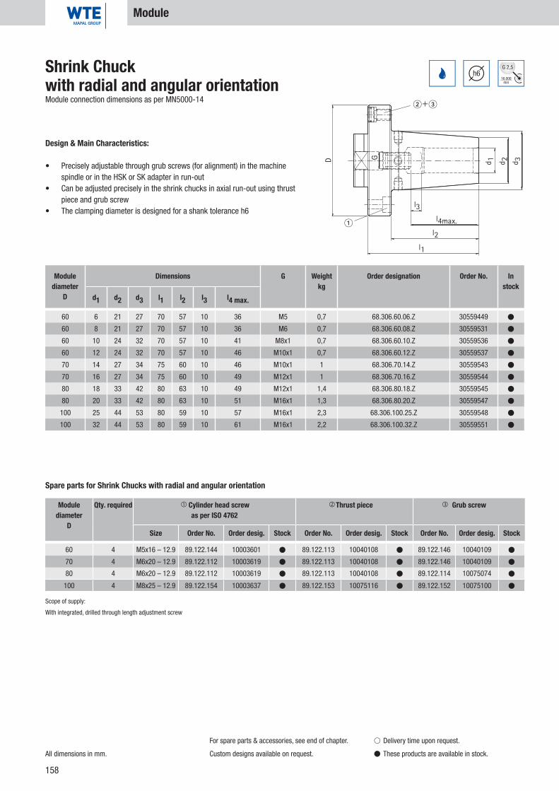
158
60 6 21 27 70 57 10 36 M5 0,7 68.306.60.06.Z 30559449 �
60 8 21 27 70 57 10 36 M6 0,7 68.306.60.08.Z 30559531 �
60 10 24 32 70 57 10 41 M8x1 0,7 68.306.60.10.Z 30559536 �
60 12 24 32 70 57 10 46 M10x1 0,7 68.306.60.12.Z 30559537 �
70 14 27 34 75 60 10 46 M10x1 1 68.306.70.14.Z 30559543 �
70 16 27 34 75 60 10 49 M12x1 1 68.306.70.16.Z 30559544 �
80 18 33 42 80 63 10 49 M12x1 1,4 68.306.80.18.Z 30559545 �
80 20 33 42 80 63 10 51 M16x1 1,3 68.306.80.20.Z 30559547 �
100 25 44 53 80 59 10 57 M16x1 2,3 68.306.100.25.Z 30559548 �
100 32 44 53 80 59 10 61 M16x1 2,2 68.306.100.32.Z 30559551 �
60 4 M5x16 – 12.9 89.122.144 10003601 � 89.122.113 10040108 � 89.122.146 10040109 �
70 4 M6x20 – 12.9 89.122.112 10003619 � 89.122.113 10040108 � 89.122.146 10040109 �
80 4 M6x20 – 12.9 89.122.112 10003619 � 89.122.113 10040108 � 89.122.114 10075074 �
100 4 M8x25 – 12.9 89.122.154 10003637 � 89.122.153 10075116 � 89.122.152 10075100 �
d 1D
l3
l1
l4max.l2
�
���
G
d 2 d 3
h616.000
min
G 2,5Shrink Chuckwith radial and angular orientationModule connection dimensions as per MN5000-14
Design & Main Characteristics:
• Precisely adjustable through grub screws (for alignment) in the machine spindle or in the HSK or SK adapter in run-out
• Can be adjusted precisely in the shrink chucks in axial run-out using thrust piece and grub screw
• The clamping diameter is designed for a shank tolerance h6
Module diameter
D
Dimensions G Weightkg
Order designation Order No. In stock
d1 d2 d3 l1 l2 l3 l4 max.
Module
Spare parts for Shrink Chucks with radial and angular orientation
Module diameter
D
Qty. required Cylinder head screwas per ISO 4762
Thrust piece Grub screw
Size Order No. Order desig. Stock Order No. Order desig. Stock Order No. Order desig. Stock
All dimensions in mm.
For spare parts & accessories, see end of chapter.
Custom designs available on request.
� Delivery time upon request.
� These products are available in stock.
Scope of supply:
With integrated, drilled through length adjustment screw

159
30* 60 50 M5 M8x1 AD 0,8 15.150.30.AD.60.Z 30584676 �
30* 70 50 M6 M8x1 AD 0,9 15.150.30.AD.70.Z 30584681 �
40 60 50 M5 M8x1 AD/AF 1,3 15.150.40.60.Z 30584684 �
40 70 50 M6 M8x1 AD/AF 1,4 15.150.40.70.Z 30584685 �
40 80 55 M6 M8x1 AD/AF 1,7 15.150.40.80.Z 30584686 �
40 100 60 M8 M10x1 AD/AF 2,2 15.150.40.100.Z 30584689 �
45 60 50 M5 M8x1 AD/AF 2,8 15.150.45.60.Z 30584690 �
45 70 50 M6 M8x1 AD/AF 2,9 15.150.45.70.Z 30584692 �
45 80 55 M6 M8x1 AD/AF 3,1 15.150.45.80.Z 30584694 �
45 100 60 M8 M10x1 AD/AF 3,3 15.150.45.100.Z 30584697 �
45 117 60 M8 M10x1 AD/AF 3,5 15.150.45.117.Z 30584698 �
50 60 50 M5 M8x1 AD/AF 3,2 15.150.50.60.Z 30584700 �
50 70 50 M6 M8x1 AD/AF 3,4 15.150.50.70.Z 30584701 �
50 80 50 M6 M8x1 AD/AF 3,6 15.150.50.80.Z 30584720 �
50 100 60 M8 M10x1 AD/AF 4,4 15.150.50.100.Z 30584721 �
50 117 60 M8 M10x1 AD/AF 4,5 15.150.50.117.Z 30584723 �
50 140 60 M10 M10x1 AD/AF 4,7 15.150.50.140.Z 30584724 �
60-80 4 10075355
100-140 4 10075099
40, 45, 50 2 M5x5 10036757
G1
l1
G
D
21
ISO7388-1
Form
AD/AFh6
3 µm
16.000min
G 2,5
Nominal sizeSK
DimensionsOrder designation Order No. In
stockD l1 G G1 Form Weight kg
Modular Short Taper AdapterShank SK with coolant supply as per ISO 7388-1, Form AD/AF (prev. DIN 69871-AD/B)
Module Adapter SK
Design & Main Characteristics:
• Maximal tool service life and production quality when using smooth cylinder shanks as per DIN 1835 Form A and DIN 6535 Form HA.
• Run-out accuracy 0.003 mm (cantilever length of 2.5 x D – max. 50 mm)• Can be adjusted precisely in axial run-out using thrust piece and grub screw• When using cylinder shanks with angled clamping surface
(Form E and Form HE), accuracy may be impacted.
Use: For clamping of tools with smooth cylinder shanks as per DIN 1835 Form A, DIN 535 Form HA up to ø 20 mm and with recesses as per DIN 1835 Form B, E and
DIN 6535 Form HB, HE directly and without intermediate sleeve in the clamping diameter. The clamping diameter is designed for a shank tolerance h6.
Scope of supply: With length adjustment screw including hexagon screwdriver with T-handle Without pull studs.
Instructions: Chuck with axial tool length adjustment. Intermediate sleeve for reduction of clamping diameter, see section Accessories.
When using the intermediate sleeve an impairment of accuracy is possible.
All dimensions in mm.
Basic setting Form AD. If Form AF (prev. B) is desired,
please indicate when ordering.
* Short taper size SK 30 is not available in the
combination design AD/AF!
For spare parts & accessories, see end of chapter.
Custom designs available on request.
� Delivery time upon request.
� These products are available in stock.
For module diameterD Qty. required Grub screw
Order No.
Spare parts: Grub screws as per ISO 4026
For nominal sizeSK Qty. required
Grub screw as per ISO 4026
Size Order No.
Spare parts: Grub screwsSh
rink
Chuc
ks

160
40 60 60 M5 M8x1 0,7 16.150.40.60.Z 30615827 �
50 60 60 M5 M8x1 0,9 16.150.50.60.Z 30584456 �
50 70 60 M6 M8x1 1 16.150.50.70.Z 30584465 �
50 80 60 M6 M8x1 1,1 16.150.50.80.Z 30584469 �
63 60 60 M5 M8x1 1,3 16.150.63.60.Z 30584473 �
63 70 60 M6 M8x1 1,4 16.150.63.70.Z 30584477 �
63 80 60 M6 M8x1 1,5 16.150.63.80.Z 30584478 �
63 100 65 M8 M10x1 2,1 16.150.63.100.Z 30584481 �
63 117 65 M8 M10x1 2,5 16.150.63.117.Z 30584482 �
80 60 50 M5 M8x1 1,6 16.150.80.60.Z 30584487 �
80 70 60 M6 M8x1 2 16.150.80.70.Z 30584489 �
80 80 60 M6 M8x1 2,1 16.150.80.80.Z 30584490 �
80 100 65 M8 M10x1 2,6 16.150.80.100.Z 30584491 �
80 117 65 M8 M10x1 3,1 16.150.80.117.Z 30584492 �
80 140 75 M10 M10x1 4,2 16.150.80.140.Z 30584493 �
100 60 55 M5 M8x1 2,8 16.150.100.60.Z 30584495 �
100 70 55 M6 M8x1 2,8 16.150.100.70.Z 30584497 �
100 80 55 M6 M8x1 3 16.150.100.80.Z 30584498 �
100 100 65 M8 M10x1 3,7 16.150.100.100.Z 30584499 �
100 117 65 M8 M10x1 4 16.150.100.117.Z 30584500 �
100 140 75 M10 M10x1 5,2 16.150.100.140.Z 30584502 �
60-80 4 0,001 M8x1x16 89.122.685 10075355 �
100-140 4 0,001 M10x1x20 89.122.684 10075099 �
1
G1
G
l1
D
DIN69893
Form
A
3 µmh6
16.000min
G 2,5
All dimensions in mm.
For spare parts & accessories, see end of chapter.
Custom designs available on request.
� Delivery time upon request.
� These products are available in stock.
Nominal sizeHSK-A
DimensionsOrder designation Order No. In
stockD l1 G G1 Weight kg
Modular Short Taper AdapterShank HSK-A as per DIN 69893-A
Design & Main Characteristics:
• Maximal tool service life and production quality when using smooth cylinder shanks as per DIN 1835 Form A and DIN 6535 Form HA.
• Run-out accuracy 0.003 mm (cantilever length of 2.5 x D – max. 50 mm)• Can be adjusted precisely in axial run-out using thrust piece and grub screw• When using cylinder shanks with angled clamping surface
(Form E and Form HE), accuracy may be impacted.
Module Adapter HSK-A
Spare parts
Module diameter
DQty. required
Cylinder head screw as per ISO 4762
Weight kg Size Order designation Order No. Stock
Scope of supply: Complete with grub screws for aligning the run-out, without coolant pipe.

161
30 60 40 M5 M8x1 0,7 22.150.30.60.Z 30584725 �
30 70 40 M6 M8x1 0,8 22.150.30.70.Z 30584726 �
40 60 55 M5 M8x1 1,5 22.150.40.60.Z 30584734 �
40 70 55 M6 M8x1 1,6 22.150.40.70.Z 30584736 �
40 80 65 M6 M8x1 2 22.150.40.80.Z 30584751 �
40 100 70 M8 M10x1 2,6 22.150.40.100.Z 30584752 �
45 60 65 M5 M8x1 3 22.150.45.60.Z 30584755 �
45 70 65 M6 M8x1 3,1 22.150.45.70.Z 30584756 �
45 80 65 M6 M8x1 3,3 22.150.45.80.Z 30584757 �
45 100 75 M8 M10x1 3,5 22.150.45.100.Z 30584760 �
45 117 75 M8 M10x1 4,4 22.150.45.117.Z 30584762 �
50 60 70 M5 M8x1 4,8 22.150.50.60.Z 30584764 �
50 70 70 M6 M8x1 4,9 22.150.50.70.Z 30584765 �
50 80 70 M6 M8x1 5,1 22.150.50.80.Z 30584767 �
50 100 70 M8 M10x1 5,3 22.150.50.100.Z 30584769 �
50 117 80 M8 M10x1 6,3 22.150.50.117.Z 30584770 �
50 140 80 M10 M10x1 6,6 22.150.50.140.Z 30584772 �
60-80 4 0,001 M8x1x16 89.122.685 10075355 �
100-140 4 0,001 M10x1x20 89.122.684 10075099 �
G1
l1
GD
1
7388-2
ISO Form
ADh6
3 µm
16.000min
G 2,5Modular Short Taper AdapterShank MAS BT
Module Adapter BT
Design & Main Characteristics:
• Maximal tool service life and production quality when using smooth cylinder shanks as per DIN 1835 Form A and DIN 6535 Form HA.
• Run-out accuracy 0.003 mm (cantilever length of 2.5 x D – max. 50 mm)• Can be adjusted precisely in axial run-out using thrust piece and grub screw• When using cylinder shanks with angled clamping surface
(Form E and Form HE), accuracy may be impacted.
All dimensions in mm.
For spare parts & accessories, see end of chapter.
Custom designs available on request.
� Delivery time upon request.
� These products are available in stock.
Nominal sizeBT
DimensionsOrder designation Order No. In
stockD l1 G G1 Weight kg
Spare parts
Module diameter
DQty. required
Cylinder head screw as per ISO 4762
Weight kg Size Order designation Order No. Stock
Shrin
k Ch
ucks

162
d2
d3
l4
l2
l3
G
4.5°
l1
d1
3 µmh6
12 3 8 150 12 0,1 40.357.12.03.Z 30344729 �
12 4 8 150 16 0,1 40.357.12.04.Z 30344730 �
12 5 10 150 20 0,1 40.357.12.05.Z 30344731 �
12 6 10 150 36 10 26 M5 2,5 0,1 40.357.12.06.Z 30344732 �
16 3 10 150 12 0,2 40.357.16.03.Z 30344733 �
16 4 10 150 16 0,2 40.357.16.04.Z 30344734 �
16 5 10 150 20 0,2 40.357.16.05.Z 30344735 �
16 6 10 150 36 10 26 M5 2,5 0,2 40.357.16.06.Z 30344736 �
16 8 12 150 36 10 26 M6 3 0,2 40.357.16.08.Z 30344737 �
20 3 10 150 12 0,3 40.357.20.03.Z 30344738 �
20 4 10 150 16 0,3 40.357.20.04.Z 30344739 �
20 5 10 150 20 0,3 40.357.20.05.Z 30344740 �
20 6 10 150 36 10 26 M5 2,5 0,3 40.357.20.06.Z 30344741 �
20 8 12 150 36 10 26 M6 3 0,3 40.357.20.08.Z 30344742 �
20 10 14 150 42 10 32 M8x1 3 0,3 40.357.20.10.Z 30344743 �
20 12 16 150 47 10 37 M10x1 5 0,3 40.357.20.12.Z 30344744 �
Dimensions G Wrench size
Weightkg
Order designation Order No. In stock
d1 d2 d3 l1 l2 l3 l4
Shrink ExtensionAs flexible adaptation
Design & Main Characteristics:
• Increase of torque transfer• Special for WTE Shrink Chucks• Fits as extension for all WTE HPH Chucks
and WTE Hydraulic Chucks
All dimensions in mm.
� Delivery time upon request.
� These products are available in stock.
Spare Parts & Accessories

163
d2
d3
l4
l2
l3
G
4.5°
l1
d1
3 µmh6
25 3 10 150 12 0,5 40.357.25.03.Z 30344745 �
25 4 10 150 16 0,5 40.357.25.04.Z 30344746 �
25 5 15 150 20 0,5 40.357.25.05.Z 30344747 �
25 6 20 150 36 10 26 M5 2,5 0,5 40.357.25.06.Z 30344748 �
25 8 20 150 36 10 26 M6 3 0,5 40.357.25.08.Z 30344749 �
25 10 20 150 42 10 32 M8x1 3 0,5 40.357.25.10.Z 30344750 �
25 12 20 150 47 10 37 M10x1 5 0,5 40.357.25.12.Z 30344751 �
25 14 20 150 47 10 37 M10x1 5 0,4 40.357.25.14.Z 30344752 �
25 16 22 150 50 10 40 M10x1 5 0,4 40.357.25.16.Z 30344753 �
32 6 20 150 36 10 26 M5 2,5 0,8 40.357.32.06.Z 30344754 �
32 8 20 150 36 10 26 M6 3 0,8 40.357.32.08.Z 30344755 �
32 10 24 150 42 10 32 M8x1 3 0,8 40.357.32.10.Z 30344756 �
32 12 24 150 47 10 37 M10x1 5 0,8 40.357.32.12.Z 30344757 �
32 14 27 150 47 10 37 M10x1 5 0,8 40.357.32.14.Z 30344758 �
32 16 27 150 50 10 40 M10x1 5 0,8 40.357.32.16.Z 30344759 �
32 18 27 150 50 10 40 M10x1 5 0,7 40.357.32.18.Z 30337832 �
32 20 27 150 52 10 42 M10x1 5 0,7 40.357.32.20.Z 30337833 �
Shrink ExtensionAs flexible adaptation
Design & Main Characteristics:
• Increase of torque transfer• Special for WTE Shrink Chucks• Fits as extension for all WTE HPH Chucks
and WTE Hydraulic Chucks
All dimensions in mm.
� Delivery time upon request.
� These products are available in stock.
Spare Parts & Accessories
Dimensions G Wrench size
Weightkg
Order designation Order No. In stock
d1 d2 d3 l1 l2 l3 l4
Shrin
k Ch
ucks

164
2 200 0,02 89.206.09 10034235 �
2,5 150 0,02 89.206.01 10034540 �
3 150 0,02 89.206.02 10013347 �
5 150 0,06 89.206.03 10041807 �
8 150 0,10 89.206.04 10041808 �
32 0,01 89.220.72 30326003 �
40 0,01 89.220.73 30326004 �
50 0,02 89.220.74 30326005 �
63 0,02 89.220.75 30326006 �
80 0,02 89.220.76 30326007 �
100 0,03 89.220.77 30326008 �
l
SWSWG
M5 2 14 0,001 89.122.102 30336661 �
M5 2,5 12,5 0,001 89.122.88 30252539 �
M6 2 14 0,001 89.122.98 30525237 �
M6 3 12,5 0,002 89.122.89 30252540 �
M8x1 3 13,5 0,004 89.122.23 30252541 �
M10x1 5 13,5 0,006 89.122.90 30252542 �
M12x1 5 13,5 0,011 89.122.24 30252543 �
M16x1 5 13,5 0,017 89.122.19 30252544 �
M16x1 8 13,5 0,021 89.122.91 30252547 �
All dimensions in mm.
Spare Parts & Accessories
� Delivery time upon request.
� These products are available in stock.
G Wrench size l Weightkg Order designation Order No. In
stock
Stop Screw Direct ClampingFor axial length adjustment
Wrench size l Weightkg Order designation Order No. In
stock
Hexagonal T-keyFor axial length adjustment
Coolant Transfer PipeFor DIN 69893-A/E
HSK Weightkg Order designation Order No. In
stock

165
0,20 98.100.040 30336681 �
Weightkg Order designation Order No. In
stock
ISO Protective Gloves
Spare Parts & Accessories
Shrin
k Ch
ucks
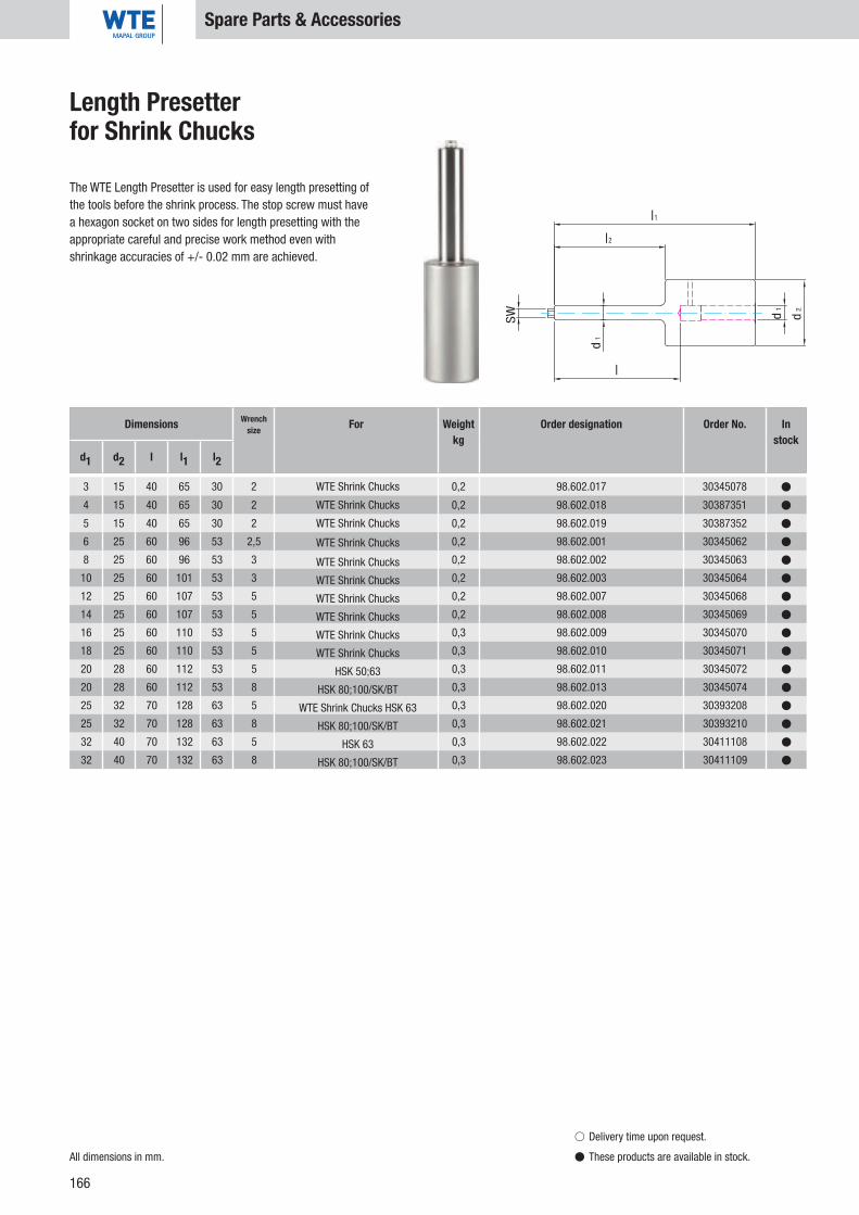
166
3 15 40 65 30 2 0,2 98.602.017 30345078 �
4 15 40 65 30 2 0,2 98.602.018 30387351 �
5 15 40 65 30 2 0,2 98.602.019 30387352 �
6 25 60 96 53 2,5 0,2 98.602.001 30345062 �
8 25 60 96 53 3 0,2 98.602.002 30345063 �
10 25 60 101 53 3 0,2 98.602.003 30345064 �
12 25 60 107 53 5 0,2 98.602.007 30345068 �
14 25 60 107 53 5 0,2 98.602.008 30345069 �
16 25 60 110 53 5 0,3 98.602.009 30345070 �
18 25 60 110 53 5 0,3 98.602.010 30345071 �
20 28 60 112 53 5 0,3 98.602.011 30345072 �
20 28 60 112 53 8 0,3 98.602.013 30345074 �
25 32 70 128 63 5 0,3 98.602.020 30393208 �
25 32 70 128 63 8 0,3 98.602.021 30393210 �
32 40 70 132 63 5 0,3 98.602.022 30411108 �
32 40 70 132 63 8 0,3 98.602.023 30411109 �
d2
d1
l 1
l2
l
d1
SW
All dimensions in mm.
Spare Parts & Accessories
� Delivery time upon request.
� These products are available in stock.
Length Presetter for Shrink Chucks
The WTE Length Presetter is used for easy length presetting of the tools before the shrink process. The stop screw must have a hexagon socket on two sides for length presetting with the appropriate careful and precise work method even with shrinkage accuracies of +/- 0.02 mm are achieved.
Dimensions Wrenchsize For Weight
kgOrder designation Order No. In
stockd1 d2 l l1 l2
WTE Shrink Chucks
WTE Shrink Chucks
WTE Shrink Chucks
WTE Shrink Chucks
WTE Shrink Chucks
WTE Shrink Chucks
WTE Shrink Chucks
WTE Shrink Chucks
WTE Shrink Chucks
WTE Shrink Chucks
HSK 50;63
HSK 80;100/SK/BT
WTE Shrink Chucks HSK 63
HSK 80;100/SK/BT
HSK 63
HSK 80;100/SK/BT

167
Notes:
Shrin
k Ch
ucks

168

169
CNC Precision Drill Chucks
Shank form SK 30/40 Page 170
Shank form SK 30/40/50 Page 171
Shank form SK 30/40/45/50 Page 172
Shank form SK 40/50 Page 173-174
Shank form SK 40/45/50 Page 175-176
Shank form HSK-A 32/40/50/63/80/100 Page 177-179
Shank form HSK-E 40 / 50 / 63 Page 180-181
Shank form HSK-F 40/50/63 Page 182
Shank form B 12/16/18 Page 183
Shank form BT 30/35/40/50 Page 184
BT 40/50 Page 185-186
Chiron Page 187-188
MK Page 189-190
1,835 B Page 191-192
VDI Page 193-194
Wohlhaupter Page 195-196
Cover S20x2 Page 197
ABS Komet Page 198
UTS Widia Page 199-200
MAZAK Page 201
PSC Page 202-203
Chiron FZ 08 Page 204
MORI-SEIKI Page 205
VDI DIN 69871 Page 206
Spare Parts & Accessories Page 207-221
CNC
Prec
isio
n Dr
ill C
huck
s

170
ISO7388-1
20 µm
25.000min
G 6,3
d1
D
L
L 1 max
30 WTE 13 0,5 - 13 50 90 96 1,2 14.296.30.13/90 30335966 �
30 WTE 13 0,5 - 13 50 111 117 1,5 14.296.30.13 30335965 �
30 WTE 16 2,5 - 16 57 95 101 1,4 14.296.30.16/90 30335968 �
30 WTE 16 2,5 - 16 57 116 122 1,4 14.296.30.16 30335967 �
40 WTE 13 0,5 - 13 50 90 96 1,6 14.296.40.13 30335969 �
40 WTE 16 2,5 - 16 57 95 101 1,8 14.296.40.16 30335970 �
CNC Precision Drill Chuck ISO 7388-1 (prev. DIN 69871)
Design & Main Characteristics:
• Speed range up to 35,000 rpm• Various clamping ranges possible• Reliable pinion-bevel gear drive• Clockwise and counter-clockwise rotation possible• Slim construction
Nominal size
SK/ISO
WTEStandard
Clamping range Dimensions Weightkg
Order designation Order No. In stock
d1 D L L1max
SK 30/40
All dimensions in mm.
CNC Precision Drill Chucks without key block slot for
the woodworking industry.
For spare parts & accessories, see end of chapter.
Custom designs available on request.
� Delivery time upon request.
� These products are available in stock.

171
d1
D
L
L 1 max
20 µm
25.000min
G 6,3
30 WTE 08 0,3 - 8 36 60 63 0,6 10.296.30.08 30335939 �
40 WTE 08 0,3 - 8 36 62 65 1,3 10.296.40.08 30335942 �
30 WTE 13 0,5 - 13 50 98 104 1,3 10.296.30.13 30335940 �
40 WTE 13 0,5 - 13 50 83 89 1,6 10.296.40.13 30335944 �
50 WTE 13 0,5 - 13 50 100 106 3,9 10.296.50.13 30335947 �
40 WTE 16 2,5 - 16 57 88 94 1,8 10.296.40.16 30335945 �
50 WTE 16 2,5 - 16 57 105 111 4,1 10.296.50.16 30335948 �
DIN2080
CNC Precision Drill Chuck DIN 2080, Form A
Design & Main Characteristics:
• Speed range up to 35,000 rpm• Various clamping ranges possible• Reliable pinion-bevel gear drive• Clockwise and counter-clockwise rotation possible• Slim construction
Nominal size
SK/ISO
WTEStandard
Clamping range Dimensions Weightkg
Order designation Order No. In stock
d1 D L L1max
SK 30/40/50
All dimensions in mm.
SK 30 as per DIN 2080, Form A.
SK 40 and SK 50 in accordance with DIN 2080 with
ring.
For spare parts & accessories, see end of chapter.
Custom designs available on request.
� Delivery time upon request.
� These products are available in stock.
CNC
Prec
isio
n Dr
ill C
huck
s

172
d1
D
L
L 1 max
30 WTE 08 0,3 - 8 36 70 73 0,7 11.296.30.08 30335949 �
40 WTE 08 0,3 - 8 36 70 73 1,3 11.296.40.08 30335952 �
30 WTE 13 0,5 - 13 50 111 117 1,5 11.296.30.13 30335950 �
40 WTE 13 0,5 - 13 50 90 96 1,6 11.296.40.13 30335953 �
45 WTE 13 0,5 - 13 50 90 96 2,4 11.296.45.13 30335955 �
50 WTE 13 0,5 - 13 50 106 112 4,1 11.296.50.13 30335959 �
40 WTE 16 2,5 - 16 57 95 101 1,8 11.296.40.16 30335954 �
45 WTE 16 2,5 - 16 57 95 101 2,6 11.296.45.16 30335957 �
50 WTE 16 2,5 - 16 57 111 117 4,3 11.296.50.16 30335962 �
ISO7388-1
20 µm
25.000min
G 6,3CNC Precision Drill Chuck ISO 7388-1, Form A (prev. DIN 69871-A)
Design & Main Characteristics:
• Speed range up to 35,000 rpm• Various clamping ranges possible• Reliable pinion-bevel gear drive• Clockwise and counter-clockwise rotation possible• Slim construction
Nominal size
SK/ISO
WTEStandard
Clamping range Dimensions Weightkg
Order designation Order No. In stock
d1 D L L1max
SK 30/40/45/50
All dimensions in mm.
For spare parts & accessories, see end of chapter. Custom designs available on request.
� Delivery time upon request.
� These products are available in stock.

173
20 µm
25.000min
G 6,3
L
L1 max
d1
D
40 WTE 13 0,5 - 13 50 109 115 1,8 30.296.40.13 30336091 �
50 WTE 13 0,5 - 13 50 106 112 4,1 30.296.50.13 30336093 �
40 WTE 16 2,5 - 16 57 114 120 2,0 30.296.40.16 30336092 �
50 WTE 16 2,5 - 16 57 111 117 4,3 30.296.50.16 30336094 �
CNC Precision Drill Chuck ANSI-CAT
Design & Main Characteristics:
• Speed range up to 35,000 rpm• Various clamping ranges possible• Reliable pinion-bevel gear drive• Clockwise and counter-clockwise rotation possible• Slim construction
Nominal size
SK/ISO
WTEStandard
Clamping range Dimensions Weightkg
Order designation Order No. In stock
d1 D L L1max
SK 40/50
All dimensions in mm.
For spare parts & accessories, see end of chapter. Custom designs available on request.
� Delivery time upon request.
� These products are available in stock.
CNC
Prec
isio
n Dr
ill C
huck
s

174
20 µm
25.000min
G 6,3
L
L1 max
d1
D
40 WTE 13 IK 0,5 - 13 50 109 115 2,0 31.296.40.13.Z 30336097 �
50 WTE 13 IK 0,5 - 13 50 106 112 3,9 31.296.50.13.Z 30336099 �
40 WTE 16 IK 2,5 - 16 57 114 120 2,2 31.296.40.16.Z 30336098 �
50 WTE 16 IK 2,5 - 16 57 111 117 4,1 31.296.50.16.Z 30336100 �
(1)
(2)
CNC Precision Drill ChuckANSI-CAT
Design & Main Characteristics:
• Speed range up to 35,000 rpm• Various clamping ranges possible• Reliable pinion-bevel gear drive• Clockwise and counter-clockwise rotation possible• Slim construction
Nominal size
SK/ISO
WTEStandard
Clamping range Dimensions Weightkg
Order designation Order No. In stock
d1 D L L1max
SK 40/50
All dimensions in mm.
Installation tool for sealing disk, see end of chapter.
For spare parts & accessories, see end of chapter.
Custom designs available on request.
� Delivery time upon request.
� These products are available in stock.
(1) WTE 13 sealing disk (Ø 4.2 mm) integrated into the drill chuck head, for inner coolant drills Ø 6-13 mm with smooth shank acc. to DIN 6535, Form HA.
(2) WTE 13 sealing disk (Ø 2.05 mm) included in scope of supply, for inner coolant drills Ø 3-6 mm with smooth shank acc. to DIN 6535, Form HA.
(1) WTE 16 sealing disk (Ø 4.2 mm) integrated into the drill chuck head, for inner coolant drills Ø 6-16 mm with smooth shank acc. to DIN 6535, Form HA.
(2) WTE 16 sealing disk (Ø 2.05 mm) included in scope of supply, for inner coolant drills Ø 3-6 mm with smooth shank acc. to DIN 6535, Form HA.

175
Form
AD/AF
20 µm
25.000min
G 6,3
d1
D
L
L 1 max
40 WTE 08 IK 0,3 - 8 36 73 76 1,3 15.296.40.08 30335971 �
40 WTE 13 IK 0,5 - 13 50 90 96 1,7 15.296.40.13 30335973 �
45 WTE 13 IK 0,5 - 13 50 96 102 2,5 15.296.45.13 30335979 �
50 WTE 13 IK 0,5 - 13 50 106 112 3,9 15.296.50.13 30335984 �
40 WTE 16 IK 2,5 - 16 57 95 101 1,9 15.296.40.16 30335976 �
45 WTE 16 IK 2,5 - 16 57 101 107 2,7 15.296.45.16 30335981 �
50 WTE 16 IK 2,5 - 16 57 111 117 4,1 15.296.50.16 30335986 �
(1)
(2)
ISO7388-1
CNC Precision Drill Chuck ISO 7388-1, Form AD/AF (prev. DIN 69871-AD/B)
Design & Main Characteristics:
• Speed range up to 35,000 rpm• Various clamping ranges possible• Reliable pinion-bevel gear drive• Clockwise and counter-clockwise rotation possible• Slim construction
Nominal size
SK/ISO
WTEStandard
Clamping range Dimensions Weightkg
Order designation Order No. In stock
d1 D L L1max
SK 40/45/50
All dimensions in mm.
Basic setting Form AD. If Form AF (prev. B) is desired,
please indicate when ordering.
Installation tool for sealing disk, see end of chapter.
For spare parts & accessories, see end of chapter.
Custom designs available on request.
� Delivery time upon request.
� These products are available in stock.
CNC
Prec
isio
n Dr
ill C
huck
s
(1) WTE 08 sealing disk (Ø 3.2 mm) integrated into the drill chuck head, for inner coolant drills Ø 4-8 mm with smooth shank acc. to DIN 6535, Form HA.
(2) WTE 08 sealing disk (Ø 1.8mm) included in scope of supply, for inner coolant drills Ø 2-4 mm with smooth shank acc. to DIN 6535, Form HA.
(1) WTE 13 sealing disk (Ø 4.2 mm) integrated into the drill chuck head, for inner coolant drills Ø 6-13 mm with smooth shank acc. to DIN 6535, Form HA.
(2) WTE 13 sealing disk (Ø 2.05 mm) included in scope of supply, for inner coolant drills Ø 3-6 mm with smooth shank acc. to DIN 6535, Form HA.
(1) WTE 16 sealing disk (Ø 4.2 mm) integrated into the drill chuck head, for inner coolant drills Ø 6-16 mm with smooth shank acc. to DIN 6535, Form HA.
(2) WTE 16 sealing disk (Ø 2.05 mm) included in scope of supply, for inner coolant drills Ø 3-6 mm with smooth shank acc. to DIN 6535, Form HA.
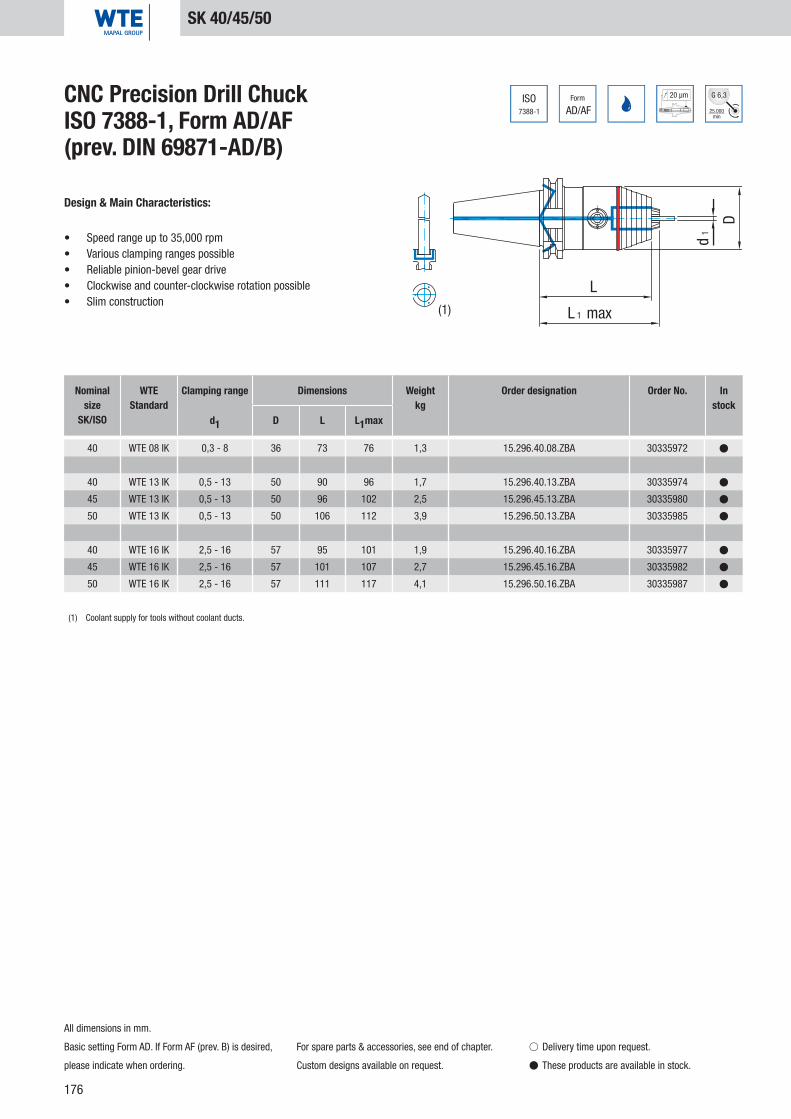
176
d1
D
L
L 1 max
40 WTE 08 IK 0,3 - 8 36 73 76 1,3 15.296.40.08.ZBA 30335972 �
40 WTE 13 IK 0,5 - 13 50 90 96 1,7 15.296.40.13.ZBA 30335974 �
45 WTE 13 IK 0,5 - 13 50 96 102 2,5 15.296.45.13.ZBA 30335980 �
50 WTE 13 IK 0,5 - 13 50 106 112 3,9 15.296.50.13.ZBA 30335985 �
40 WTE 16 IK 2,5 - 16 57 95 101 1,9 15.296.40.16.ZBA 30335977 �
45 WTE 16 IK 2,5 - 16 57 101 107 2,7 15.296.45.16.ZBA 30335982 �
50 WTE 16 IK 2,5 - 16 57 111 117 4,1 15.296.50.16.ZBA 30335987 �
ISO7388-1
Form
AD/AF 25.000min
G 6,3
(1)
20 µmCNC Precision Drill Chuck ISO 7388-1, Form AD/AF (prev. DIN 69871-AD/B)
Design & Main Characteristics:
• Speed range up to 35,000 rpm• Various clamping ranges possible• Reliable pinion-bevel gear drive• Clockwise and counter-clockwise rotation possible• Slim construction
Nominal size
SK/ISO
WTEStandard
Clamping range Dimensions Weightkg
Order designation Order No. In stock
d1 D L L1max
SK 40/45/50
All dimensions in mm.
Basic setting Form AD. If Form AF (prev. B) is desired,
please indicate when ordering.
For spare parts & accessories, see end of chapter.
Custom designs available on request.
� Delivery time upon request.
� These products are available in stock.
(1) Coolant supply for tools without coolant ducts.

177
DIN69893
Form
A
20 µm
25.000min
G 6,3
d1
D
L1 max
L
32 WTE 08 0,3 - 8 36 90 93 0,5 16.296.32.08 30335995 �
40 WTE 08 0,3 - 8 36 91 94 0,5 16.296.40.08 30335998 �
50 WTE 08 0,3 - 8 36 95 98 0,7 16.296.50.08 30336001 �
63 WTE 08 0,3 - 8 36 96 99 1,1 16.296.63.08 30336010 �
50 WTE 13 0,5 - 13 50 116 122 1,4 16.296.50.13 30336004 �
63 WTE 13 0,5 - 13 50 104 110 1,7 16.296.63.13 30336013 �
80 WTE 13 0,5 - 13 50 109 115 2,1 16.296.80.13 30336021 �
100 WTE 13 0,5 - 13 50 111 117 3,1 16.296.100.13 30335988 �
50 WTE 16 2,5 - 16 57 121 127 1,7 16.296.50.16 30336007 �
63 WTE 16 2,5 - 16 57 109 115 1,9 16.296.63.16 30336017 �
80 WTE 16 2,5 - 16 57 114 120 2,3 16.296.80.16 30336024 �
100 WTE 16 2,5 - 16 57 116 122 3,3 16.296.100.16 30335992 �
CNC Precision Drill Chuck DIN 69893-A
Design & Main Characteristics:
• Speed range up to 35,000 rpm• Various clamping ranges possible• Reliable pinion-bevel gear drive• Clockwise and counter-clockwise rotation possible• Slim construction
Nominal size
HSK-A
WTEStandard
Clamping range Dimensions Weightkg
Order designation Order No. In stock
d1 D L L1max
HSK-A 32/40/50/63/80/100
All dimensions in mm.
For spare parts & accessories, see end of chapter. Custom designs available on request.
� Delivery time upon request.
� These products are available in stock.
CNC
Prec
isio
n Dr
ill C
huck
s

178
DIN69893
Form
A
20 µm
25.000min
G 6,3
d1
D
L 1 max
L
32 WTE 08 IK 0,3 - 8 36 90 93 0,5 16.296.32.08.Z 30335996 �
40 WTE 08 IK 0,3 - 8 36 91 94 0,5 16.296.40.08.Z 30335999 �
50 WTE 08 IK 0,3 - 8 36 95 98 0,7 16.296.50.08.Z 30336002 �
63 WTE 08 IK 0,3 - 8 36 96 99 1,1 16.296.63.08.Z 30336011 �
50 WTE 13 IKT 0,5 - 13 50 116 122 1,4 16.296.50.13.Z 30336005 �
63 WTE 13 IKT 0,5 - 13 50 104 110 1,7 16.296.63.13.Z 30336014 �
80 WTE 13 IK 0,5 - 13 50 109 115 2,1 16.296.80.13.Z 30336022 �
100 WTE 13 IK 0,5 - 13 50 111 117 3,1 16.296.100.13.Z 30335989 �
50 WTE 16 IKT 2,5 - 16 57 121 127 1,7 16.296.50.16.Z 30336008 �
63 WTE 16 IKT 2,5 - 16 57 109 115 1,9 16.296.63.16.Z 30336018 �
80 WTE 16 IK 2,5 - 16 57 114 120 2,3 16.296.80.16.Z 30336025 �
100 WTE 16 IK 2,5 - 16 57 116 122 3,3 16.296.100.16.Z 30335993 �
(1)
(2)
CNC Precision Drill Chuck DIN 69893-A
Design & Main Characteristics:
• Speed range up to 35,000 rpm• Various clamping ranges possible• Reliable pinion-bevel gear drive• Clockwise and counter-clockwise rotation possible• Slim construction
Nominal size
HSK-A
WTEStandard
Clamping range Dimensions Weightkg
Order designation Order No. In stock
d1 D L L1max
HSK-A 32/40/50/63/80/100
All dimensions in mm.
Coolant pipe not included in scope of supply.
For spare parts & accessories, see end of chapter.
Custom designs available on request.
� Delivery time upon request.
� These products are available in stock.
(1) WTE 08 sealing disk (Ø 3.2 mm) integrated into the drill chuck head, for inner coolant drills Ø 4-8 mm with smooth shank acc. to DIN 6535, Form HA.
(2) WTE 08 sealing disk (Ø 1.8mm) included in scope of supply, for inner coolant drills Ø 2-4 mm with smooth shank acc. to DIN 6535, Form HA.
(1) WTE 13 sealing disk (Ø 4.2 mm) integrated into the drill chuck head, for inner coolant drills Ø 6-13 mm with smooth shank acc. to DIN 6535, Form HA.
(2) WTE 13 sealing disk (Ø 2.05 mm) included in scope of supply, for inner coolant drills Ø 3-6 mm with smooth shank acc. to DIN 6535, Form HA.
(1) WTE 16 sealing disk (Ø 4.2 mm) integrated into the drill chuck head, for inner coolant drills Ø 6-16 mm with smooth shank acc. to DIN 6535, Form HA.
(2) WTE 16 sealing disk (Ø 2.05 mm) included in scope of supply, for inner coolant drills Ø 3-6 mm with smooth shank acc. to DIN 6535, Form HA.

179
DIN69893
Form
A
20 µm
25.000min
G 6,3
d1
D
L 1 max
L
32 WTE 08 0,3 - 8 36 90 93 0,5 16.296.32.08.ZBA 30335997 �
40 WTE 08 0,3 - 8 36 91 94 0,5 16.296.40.08.ZBA 30336000 �
50 WTE 08 0,3 - 8 36 95 98 0,7 16.296.50.08.ZBA 30336003 �
63 WTE 08 0,3 - 8 36 96 99 1,1 16.296.63.08.ZBA 30336012 �
50 WTE 13 0,5 - 13 50 116 122 1,4 16.296.50.13.ZBA 30336006 �
63 WTE 13 0,5 - 13 50 104 110 1,7 16.296.63.13.ZBA 30336016 �
80 WTE 13 0,5 - 13 50 109 115 2,1 16.296.80.13.ZBA 30336023 �
100 WTE 13 0,5 - 13 50 111 117 3,1 16.296.100.13.ZBA 30335990 �
50 WTE 16 2,5 - 16 57 121 127 1,7 16.296.50.16.ZBA 30336009 �
63 WTE 16 2,5 - 16 57 109 115 1,9 16.296.63.16.ZBA 30336020 �
80 WTE 16 2,5 - 16 57 114 120 2,3 16.296.80.16.ZBA 30336026 �
100 WTE 16 2,5 - 16 57 116 122 3,3 16.296.100.16.ZBA 30335994 �
(1)
CNC Precision Drill Chuck DIN 69893-A
Design & Main Characteristics:
• Speed range up to 35,000 rpm• Various clamping ranges possible• Reliable pinion-bevel gear drive• Clockwise and counter-clockwise rotation possible• Slim construction
Nominal size
HSK-A
WTEStandard
Clamping range Dimensions Weightkg
Order designation Order No. In stock
d1 D L L1max
HSK-A 32/40/50/63/80/100
All dimensions in mm.
Coolant pipe not included in scope of supply.
For spare parts & accessories, see end of chapter.
Custom designs available on request.
� Delivery time upon request.
� These products are available in stock.
CNC
Prec
isio
n Dr
ill C
huck
s
(1) Coolant supply for tools without coolant ducts.
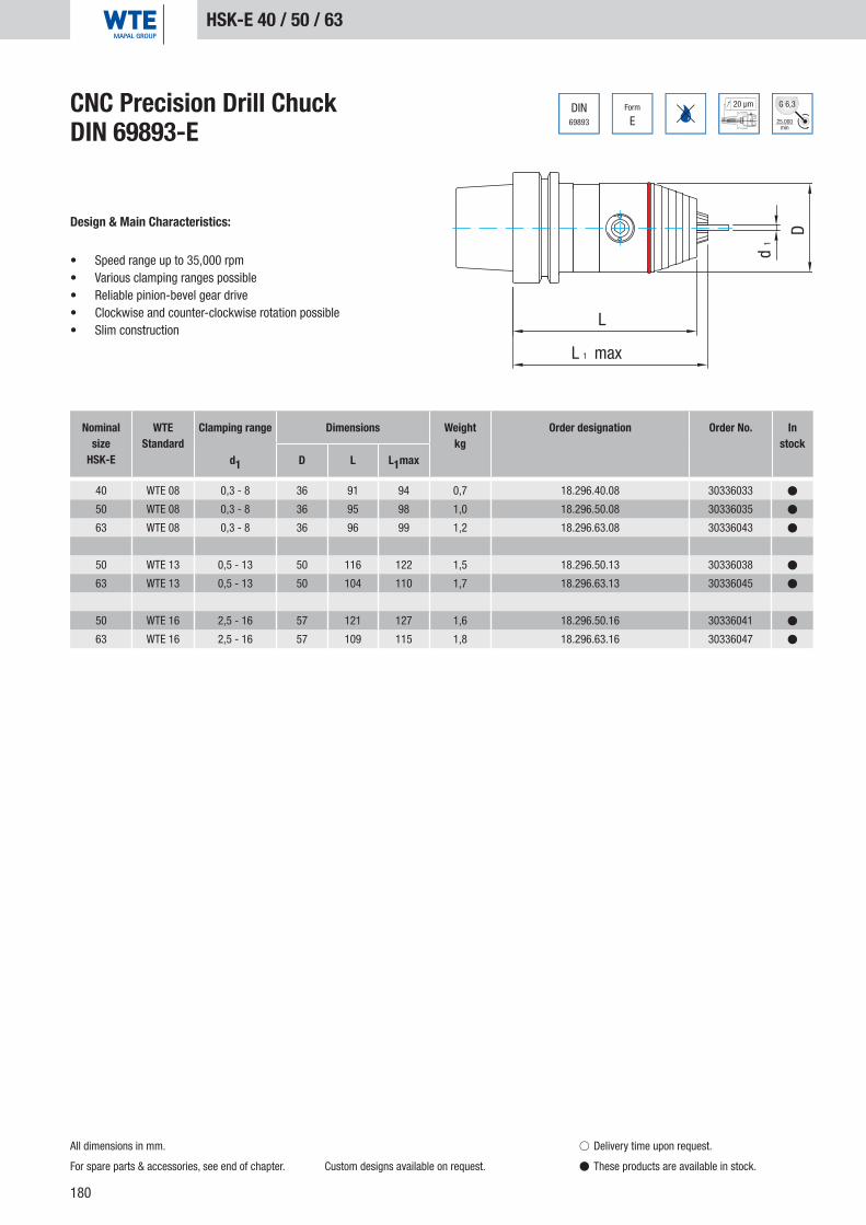
180
DIN69893 E
Form 20 µm
25.000min
G 6,3
d1
D
L 1 max
L
40 WTE 08 0,3 - 8 36 91 94 0,7 18.296.40.08 30336033 �
50 WTE 08 0,3 - 8 36 95 98 1,0 18.296.50.08 30336035 �
63 WTE 08 0,3 - 8 36 96 99 1,2 18.296.63.08 30336043 �
50 WTE 13 0,5 - 13 50 116 122 1,5 18.296.50.13 30336038 �
63 WTE 13 0,5 - 13 50 104 110 1,7 18.296.63.13 30336045 �
50 WTE 16 2,5 - 16 57 121 127 1,6 18.296.50.16 30336041 �
63 WTE 16 2,5 - 16 57 109 115 1,8 18.296.63.16 30336047 �
CNC Precision Drill Chuck DIN 69893-E
Design & Main Characteristics:
• Speed range up to 35,000 rpm• Various clamping ranges possible• Reliable pinion-bevel gear drive• Clockwise and counter-clockwise rotation possible• Slim construction
Nominal size
HSK-E
WTEStandard
Clamping range Dimensions Weightkg
Order designation Order No. In stock
d1 D L L1max
HSK-E 40 / 50 / 63
All dimensions in mm.
For spare parts & accessories, see end of chapter. Custom designs available on request.
� Delivery time upon request.
� These products are available in stock.

181
DIN69893 E
Form 20 µm
25.000min
G 6,3
d1
D
L 1 max
L
40 WTE 08 IK 0,3 - 8 36 91 94 0,7 18.296.40.08.Z 30336034 �
50 WTE 08 IK 0,3 - 8 36 95 98 1,0 18.296.50.08.Z 30336036 �
63 WTE 08 IK 0,3 - 8 36 96 99 1,2 18.296.63.08.Z 30336044 �
50 WTE 13 IKT 0,5 - 13 50 116 122 1,5 18.296.50.13.Z 30336039 �
63 WTE 13 IKT 0,5 - 13 50 104 110 1,7 18.296.63.13.Z 30336046 �
50 WTE 16 IKT 2,5 - 16 57 121 127 1,6 18.296.50.16.Z 30336042 �
63 WTE 16 IKT 2,5 - 16 57 109 115 1,8 18.296.63.16.Z 30336048 �
(1)
(2)
CNC Precision Drill Chuck DIN 69893-E
Design & Main Characteristics:
• Speed range up to 35,000 rpm• Various clamping ranges possible• Reliable pinion-bevel gear drive• Clockwise and counter-clockwise rotation possible• Slim construction
Nominal size
HSK-E
WTEStandard
Clamping range Dimensions Weightkg
Order designation Order No. In stock
d1 D L L1max
HSK-E 40 / 50 / 63
All dimensions in mm.
Coolant pipe not included in scope of supply.
Installation tool for sealing disk, see end of chapter.
For spare parts & accessories, see end of chapter.
Custom designs available on request.
� Delivery time upon request.
� These products are available in stock.
CNC
Prec
isio
n Dr
ill C
huck
s
(1) WTE 08 sealing disk (Ø 3.2 mm) integrated into the drill chuck head, for inner coolant drills Ø 4-8 mm with smooth shank acc. to DIN 6535, Form HA.
(2) WTE 08 sealing disk (Ø 1.8mm) included in scope of supply, for inner coolant drills Ø 2-4 mm with smooth shank acc. to DIN 6535, Form HA.
(1) WTE 13 sealing disk (Ø 4.2 mm) integrated into the drill chuck head, for inner coolant drills Ø 6-13 mm with smooth shank acc. to DIN 6535, Form HA.
(2) WTE 13 sealing disk (Ø 2.05 mm) included in scope of supply, for inner coolant drills Ø 3-6 mm with smooth shank acc. to DIN 6535, Form HA.
(1) WTE 16 sealing disk (Ø 4.2 mm) integrated into the drill chuck head, for inner coolant drills Ø 6-16 mm with smooth shank acc. to DIN 6535, Form HA.
(2) WTE 16 sealing disk (Ø 2.05 mm) included in scope of supply, for inner coolant drills Ø 3-6 mm with smooth shank acc. to DIN 6535, Form HA.

182
DIN69893
Form
F
20 µm
D
d1
L 1 max
L
40 WTE 08 0,3 - 8 36 87 90 0,6 17.296.40.08 30336027 �
50 WTE 13 0,5 - 13 50 116 122 1,5 17.296.50.13 30336028 �
63 WTE 13 0,5 - 13 50 97 103 1,7 17.296.63.13 30336031 �
50 WTE 16 2,5 - 16 57 121 127 1,6 17.296.50.16 30336029 �
63 WTE 16 2,5 - 16 57 102 108 1,8 17.296.63.16 30336032 �
CNC Precision Drill Chuck DIN 69893-F
Design & Main Characteristics:
• Speed range up to 35,000 rpm• Various clamping ranges possible• Reliable pinion-bevel gear drive• Clockwise and counter-clockwise rotation possible• Slim construction
Nominal size
HSK-F
WTEStandard
Clamping range Dimensions Weightkg
Order designation Order No. In stock
d1 D L L1max
HSK-F 40/50/63
All dimensions in mm.
For spare parts & accessories, see end of chapter. Custom designs available on request.
� Delivery time upon request.
� These products are available in stock.

183
DIN238
20 µm
D
d1
L
L 1 max
B
B 12 WTE 08 0,3 - 8 36 76 79 0,4 12.296.B12.08 30344488 �
B 12 WTE 13 0,5 - 13 50 98 104 1,1 12.296.B12.13 30344489 �
B 16 WTE 08 0,3 - 8 36 82 85 0,5 12.296.B16.08 30344490 �
B 16 WTE 13 0,5 - 13 50 102 108 1,1 12.296.B16.13 30344491 �
B 16 WTE 16 2,5 - 16 57 107 113 1,3 12.296.B16.16 30344492 �
B 18 WTE 13 0,5 - 13 50 110 116 1,2 12.296.B18.13 30344493 �
B 18 WTE 16 2,5 - 16 57 115 121 1,4 12.296.B18.16 30344494 �
CNC Precision Drill Chuck WTE PlusAs per DIN 238
Design & Main Characteristics:
• Speed range up to 35,000 rpm• Various clamping ranges possible• Reliable pinion-bevel gear drive• Clockwise and counter-clockwise rotation possible• Slim construction
Nominal size
B
WTEStandard
Clamping range Dimensions Weightkg
Order designation Order No. In stock
d1 D L L1max
B 12/16/18
All dimensions in mm.
For spare parts & accessories, see end of chapter. Custom designs available on request.
� Delivery time upon request.
� These products are available in stock.
CNC
Prec
isio
n Dr
ill C
huck
s

184
20 µm
25.000min
G 6,3
D
d1
L
L1 max
30 WTE 08 0,3 - 8 36 74 77 0,7 20.296.30.08 30336049 �
35 WTE 08 0,3 - 8 36 75 78 1,0 20.296.35.08 30336052 �
40 WTE 08 0,3 - 8 36 78 81 1,4 20.296.40.08 30336055 �
30 WTE 13 0,5 - 13 50 96 102 1,3 20.296.30.13 30336050 �
35 WTE 13 0,5 - 13 50 95 101 1,4 20.296.35.13 30336053 �
40 WTE 13 0,5 - 13 50 98 104 1,8 20.296.40.13 30336056 �
50 WTE 13 0,5 - 13 50 110 116 4,4 20.296.50.13 30336060 �
40 WTE 16 2,5 - 16 57 103 109 2,0 20.296.40.16 30336057 �
50 WTE 16 2,5 - 16 57 115 121 4,7 20.296.50.16 30336061 �
7388-2
ISOCNC Precision Drill Chuck ISO 7388-2 (JIS B6339)
Design & Main Characteristics:
• Speed range up to 35,000 rpm• Various clamping ranges possible• Reliable pinion-bevel gear drive• Clockwise and counter-clockwise rotation possible• Slim construction
Nominal sizeBT
WTEStandard
Clamping range Dimensions Weightkg
Order designation Order No. In stock
d1 D L L1max
BT 30/35/40/50
All dimensions in mm.
For spare parts & accessories, see end of chapter. Custom designs available on request.
� Delivery time upon request.
� These products are available in stock.

185
7388-2
ISO Form
AD/AF
20 µm
25.000min
G 6,3
D
d1
L
L1 max
40 WTE 08 IK 0,3 - 8 36 81 84 1,3 22.296.40.08 30336062 �
40 WTE 13 IK 0,5 - 13 50 98 104 1,8 22.296.40.13 30336064 �
50 WTE 13 IK 0,5 - 13 50 110 116 4,4 22.296.50.13 30336070 �
40 WTE 16 IK 2,5 - 16 57 103 109 2,0 22.296.40.16 30336067 �
50 WTE 16 IK 2,5 - 16 57 115 121 4,7 22.296.50.16 30336072 �
(1)
(2)
CNC Precision Drill Chuck ISO 7388-2 (JIS B6339)Coolant supply as per ISO 7388-1, Form AD/AF
Design & Main Characteristics:
• Speed range up to 35,000 rpm• Various clamping ranges possible• Reliable pinion-bevel gear drive• Clockwise and counter-clockwise rotation possible• Slim construction
Nominal sizeBT
WTEStandard
Clamping range Dimensions Weightkg
Order designation Order No. In stock
d1 D L L1max
BT 40/50
CNC
Prec
isio
n Dr
ill C
huck
s
All dimensions in mm.
Basic setting Form AD. If Form AF (prev. B) is desired,
please indicate when ordering.
For spare parts & accessories, see end of chapter.
Custom designs available on request.
� Delivery time upon request.
� These products are available in stock.
(1) WTE 08 sealing disk (Ø 3.2 mm) integrated into the drill chuck head, for inner coolant drills Ø 4-8 mm with smooth shank acc. to DIN 6535, Form HA.
(2) WTE 08 sealing disk (Ø 1.8mm) included in scope of supply, for inner coolant drills Ø 2-4 mm with smooth shank acc. to DIN 6535, Form HA.
(1) WTE 13 sealing disk (Ø 4.2 mm) integrated into the drill chuck head, for inner coolant drills Ø 6-13 mm with smooth shank acc. to DIN 6535, Form HA.
(2) WTE 13 sealing disk (Ø 2.05 mm) included in scope of supply, for inner coolant drills Ø 3-6 mm with smooth shank acc. to DIN 6535, Form HA.
(1) WTE 16 sealing disk (Ø 4.2 mm) integrated into the drill chuck head, for inner coolant drills Ø 6-16 mm with smooth shank acc. to DIN 6535, Form HA.
(2) WTE 16 sealing disk (Ø 2.05 mm) included in scope of supply, for inner coolant drills Ø 3-6 mm with smooth shank acc. to DIN 6535, Form HA.

186
7388-2
ISO Form
AD/AF
20 µm
25.000min
G 6,3
D
d1
L
L 1 max
40 WTE 08 IK 0,3 - 8 36 81 84 1,3 22.296.40.08.ZBA 30336063 �
40 WTE 13 IK 0,5 - 13 50 98 104 1,8 22.296.40.13.ZBA 30336065 �
50 WTE 13 IK 0,5 - 13 50 110 116 4,4 22.296.50.13.ZBA 30336071 �
40 WTE 16 IK 2,5 - 16 57 103 109 2,0 22.296.40.16.ZBA 30336068 �
50 WTE 16 IK 2,5 - 16 57 115 121 4,7 22.296.50.16.ZBA 30336073 �
(1)
CNC Precision Drill Chuck ISO 7388-2 (JIS B6339)Coolant supply as per ISO 7388-1, Form AD/AF
Design & Main Characteristics:
• Speed range up to 35,000 rpm• Various clamping ranges possible• Reliable pinion-bevel gear drive• Clockwise and counter-clockwise rotation possible• Slim construction
Nominal sizeBT
WTEStandard
Clamping range Dimensions Weightkg
Order designation Order No. In stock
d1 D L L1max
BT 40/50
(1) Coolant supply for tools without coolant ducts.
All dimensions in mm.
Basic setting Form AD. If Form AF (prev. B) is desired,
please indicate when ordering.
For spare parts & accessories, see end of chapter.
Custom designs available on request.
� Delivery time upon request.
� These products are available in stock.

187
20 µm
d1
D
L
L1 max
30 WTE 08 0,3 - 8 36 85 88 0,8 25.296.30.08 30336083 �
30 WTE 13 0,5 - 13 50 105 111 1,4 25.296.30.13 30336085 �
30 WTE 16 2,5 - 16 57 110 116 1,6 25.296.30.16 30336087 �
CNC Precision Drill Chuck Chiron
Design & Main Characteristics:
• Speed range up to 35,000 rpm• Various clamping ranges possible• Reliable pinion-bevel gear drive• Clockwise and counter-clockwise rotation possible• Slim construction
Nominal size
WTEStandard
Clamping range Dimensions Weightkg
Order designation Order No. In stock
d1 D L L1max
Chiron
All dimensions in mm.
Ball bearing (Chiron) not included in scope of supply.
For spare parts & accessories, see end of chapter.
Custom designs available on request.
� Delivery time upon request.
� These products are available in stock.
CNC
Prec
isio
n Dr
ill C
huck
s

188
D
d1
L
L1 max
20 µm
30 WTE 08 IK 0,3 - 8 36 89 92 0,9 25.296.30.08.Z 30336084 �
30 WTE 13 IKT 0,5 - 13 50 110 116 1,5 25.296.30.13.Z 30336086 �
30 WTE 16 IKT 2,5 - 16 57 115 121 1,6 25.296.30.16.Z 30336088 �
(1)
(2)
CNC Precision Drill Chuck Chiron
Design & Main Characteristics:
• Speed range up to 35,000 rpm• Various clamping ranges possible• Reliable pinion-bevel gear drive• Clockwise and counter-clockwise rotation possible• Slim construction
Nominal size
WTEStandard
Clamping range Dimensions Weightkg
Order designation Order No. In stock
d1 D L L1max
Chiron
All dimensions in mm.
Installation tool for sealing disk, see end of chapter.
Ball bearing (Chiron) not included in scope of supply.
For spare parts & accessories, see end of chapter.
Custom designs available on request.
� Delivery time upon request.
� These products are available in stock.
(1) WTE 08 sealing disk (Ø 3.2 mm) integrated into the drill chuck head, for inner coolant drills Ø 4-8 mm with smooth shank acc. to DIN 6535, Form HA.
(2) WTE 08 sealing disk (Ø 1.8mm) included in scope of supply, for inner coolant drills Ø 2-4 mm with smooth shank acc. to DIN 6535, Form HA.
(1) WTE 13 sealing disk (Ø 4.2 mm) integrated into the drill chuck head, for inner coolant drills Ø 6-13 mm with smooth shank acc. to DIN 6535, Form HA.
(2) WTE 13 sealing disk (Ø 2.05 mm) included in scope of supply, for inner coolant drills Ø 3-6 mm with smooth shank acc. to DIN 6535, Form HA.
(1) WTE 16 sealing disk (Ø 4.2 mm) integrated into the drill chuck head, for inner coolant drills Ø 6-16 mm with smooth shank acc. to DIN 6535, Form HA.
(2) WTE 16 sealing disk (Ø 2.05 mm) included in scope of supply, for inner coolant drills Ø 3-6 mm with smooth shank acc. to DIN 6535, Form HA.
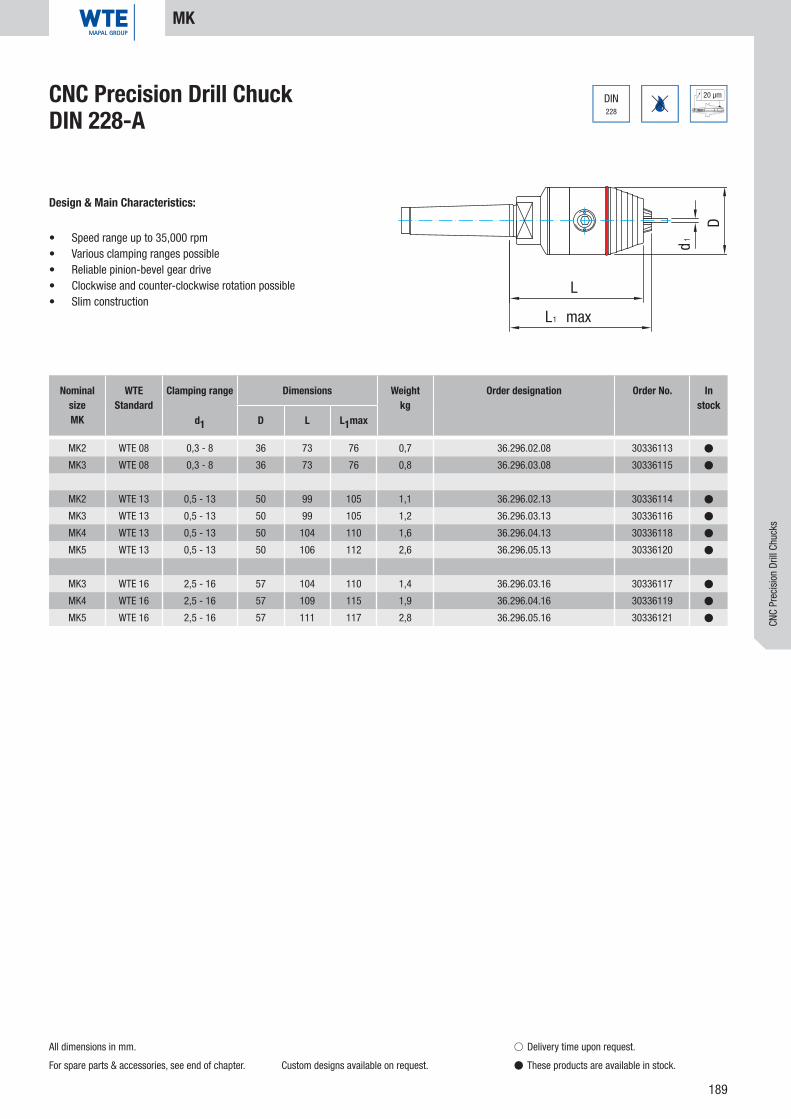
189
DIN228
20 µm
D
d1
L1 max
L
MK2 WTE 08 0,3 - 8 36 73 76 0,7 36.296.02.08 30336113 �
MK3 WTE 08 0,3 - 8 36 73 76 0,8 36.296.03.08 30336115 �
MK2 WTE 13 0,5 - 13 50 99 105 1,1 36.296.02.13 30336114 �
MK3 WTE 13 0,5 - 13 50 99 105 1,2 36.296.03.13 30336116 �
MK4 WTE 13 0,5 - 13 50 104 110 1,6 36.296.04.13 30336118 �
MK5 WTE 13 0,5 - 13 50 106 112 2,6 36.296.05.13 30336120 �
MK3 WTE 16 2,5 - 16 57 104 110 1,4 36.296.03.16 30336117 �
MK4 WTE 16 2,5 - 16 57 109 115 1,9 36.296.04.16 30336119 �
MK5 WTE 16 2,5 - 16 57 111 117 2,8 36.296.05.16 30336121 �
CNC Precision Drill Chuck DIN 228-A
Design & Main Characteristics:
• Speed range up to 35,000 rpm• Various clamping ranges possible• Reliable pinion-bevel gear drive• Clockwise and counter-clockwise rotation possible• Slim construction
Nominal sizeMK
WTEStandard
Clamping range Dimensions Weightkg
Order designation Order No. In stock
d1 D L L1max
MK
All dimensions in mm.
For spare parts & accessories, see end of chapter. Custom designs available on request.
� Delivery time upon request.
� These products are available in stock.
CNC
Prec
isio
n Dr
ill C
huck
s

190
20 µm
d1
D
LL1 max
MK2 WTE 08 0,3 - 8 36 73 76 0,7 37.296.02.08 30336122 �
MK3 WTE 08 0,3 - 8 36 73 76 0,8 37.296.03.08 30336125 �
MK2 WTE 13 0,5 - 13 50 99 105 1,1 37.296.02.13 30336123 �
MK3 WTE 13 0,5 - 13 50 99 105 1,2 37.296.03.13 30336126 �
MK4 WTE 13 0,5 - 13 50 104 110 1,6 37.296.04.13 30336128 �
MK5 WTE 13 0,5 - 13 50 106 112 2,6 37.296.05.13 30336130 �
MK3 WTE 16 2,5 - 16 57 104 110 1,4 37.296.03.16 30336127 �
MK4 WTE 16 2,5 - 16 57 109 115 1,9 37.296.04.16 30336129 �
MK5 WTE 16 2,5 - 16 57 111 117 2,8 37.296.05.16 30336131 �
DIN228
CNC Precision Drill Chuck DIN 228-B
Design & Main Characteristics:
• Speed range up to 35,000 rpm• Various clamping ranges possible• Reliable pinion-bevel gear drive• Clockwise and counter-clockwise rotation possible• Slim construction
Nominal sizeMK
WTEStandard
Clamping range Dimensions Weightkg
Order designation Order No. In stock
d1 D L L1max
MK
All dimensions in mm.
For spare parts & accessories, see end of chapter. Custom designs available on request.
� Delivery time upon request.
� These products are available in stock.

191
DIN1835
20 µm
d1
D
L
L1 max
l
d
20x50 WTE 08 0,3 - 8 36 59 62 0,8 40.296.20.08 30336132 �
25x56 WTE 08 0,3 - 8 36 52 55 0,9 40.296.25.08 30336135 �
32x60 WTE 08 0,3 - 8 36 52 55 1,0 40.296.32.08 30336138 �
20x50 WTE 13 0,5 - 13 50 82 88 1,1 40.296.20.13 30336133 �
25x56 WTE 13 0,5 - 13 50 82 88 1,2 40.296.25.13 30336136 �
32x60 WTE 13 0,5 - 13 50 82 88 1,3 40.296.32.13 30336139 �
40x70 WTE 13 0,5 - 13 50 80 86 1,6 40.296.40.13 30336141 �
50x80 WTE 13 0,5 - 13 50 80 86 2,2 40.296.50.13 30336143 �
25x56 WTE 16 2,5 - 16 57 87 93 1,4 40.296.25.16 30336137 �
32x60 WTE 16 2,5 - 16 57 87 93 1,5 40.296.32.16 30336140 �
40x70 WTE 16 2,5 - 16 57 85 91 1,8 40.296.40.16 30336142 �
50x80 WTE 16 2,5 - 16 57 85 91 2,4 40.296.50.16 30336144 �
CNC Precision Drill Chuck DIN 1835-B
Design & Main Characteristics:
• Speed range up to 35,000 rpm• Various clamping ranges possible• Reliable pinion-bevel gear drive• Clockwise and counter-clockwise rotation possible• Slim construction
Nominal sized x l
WTEStandard
Clamping range Dimensions Weightkg
Order designation Order No. In stock
d1 D L L1max
1,835 B
All dimensions in mm.
For spare parts & accessories, see end of chapter. Custom designs available on request.
� Delivery time upon request.
� These products are available in stock.
CNC
Prec
isio
n Dr
ill C
huck
s

192
20 µm
d1D
LL1 max
l
d20x50 WTE 08 IK 0,3 - 8 36 59 62 0,8 41.296.20.08.Z 30336145 �
25x56 WTE 08 IK 0,3 - 8 36 52 55 0,9 41.296.25.08.Z 30336148 �
32x60 WTE 08 IK 0,3 - 8 36 52 55 1,0 41.296.32.08.Z 30336154 �
20x50 WTE 13 IK 0,5 - 13 50 82 88 1,1 41.296.20.13.Z 30336146 �
25x56 WTE 13 IK 0,5 - 13 50 82 88 1,2 41.296.25.13.Z 30336150 �
32x60 WTE 13 IK 0,5 - 13 50 82 88 1,3 41.296.32.13.Z 30336155 �
40x70 WTE 13 IK 0,5 - 13 50 80 86 1,6 41.296.40.13.Z 30336158 �
50x80 WTE 13 IK 0,5 - 13 50 80 86 2,2 41.296.50.13.Z 30336162 �
25x56 WTE 16 IK 2,5 - 16 57 87 93 1,4 41.296.25.16.Z 30336152 �
32x60 WTE 16 IK 2,5 - 16 57 87 93 1,5 41.296.32.16.Z 30336157 �
40x70 WTE 16 IK 2,5 - 16 57 85 91 1,8 41.296.40.16.Z 30336160 �
50x80 WTE 16 IK 2,5 - 16 57 85 91 2,4 41.296.50.16.Z 30336163 �
(1)
(2)
DIN1835
CNC Precision Drill Chuck DIN 1835-B
Design & Main Characteristics:
• Speed range up to 35,000 rpm• Various clamping ranges possible• Reliable pinion-bevel gear drive• Clockwise and counter-clockwise rotation possible• Slim construction
Nominal sized x l
WTEStandard
Clamping range Dimensions Weightkg
Order designation Order No. In stock
d1 D L L1max
1,835 B
All dimensions in mm.
For spare parts & accessories, see end of chapter. Custom designs available on request.
� Delivery time upon request.
� These products are available in stock.
(1) WTE 08 sealing disk (Ø 3.2 mm) integrated into the drill chuck head, for inner coolant drills Ø 4-8 mm with smooth shank acc. to DIN 6535, Form HA.
(2) WTE 08 sealing disk (Ø 1.8mm) included in scope of supply, for inner coolant drills Ø 2-4 mm with smooth shank acc. to DIN 6535, Form HA.
(1) WTE 13 sealing disk (Ø 4.2 mm) integrated into the drill chuck head, for inner coolant drills Ø 6-13 mm with smooth shank acc. to DIN 6535, Form HA.
(2) WTE 13 sealing disk (Ø 2.05 mm) included in scope of supply, for inner coolant drills Ø 3-6 mm with smooth shank acc. to DIN 6535, Form HA.
(1) WTE 16 sealing disk (Ø 4.2 mm) integrated into the drill chuck head, for inner coolant drills Ø 6-16 mm with smooth shank acc. to DIN 6535, Form HA.
(2) WTE 16 sealing disk (Ø 2.05 mm) included in scope of supply, for inner coolant drills Ø 3-6 mm with smooth shank acc. to DIN 6535, Form HA.

193
DIN69880
20 µm
16x32 WTE 08 VDI 0,3 - 8 40 60 63 0,6 47.296.16.08 30336165 �
20x40 WTE 08 VDI 0,3 - 8 40 60 63 0,7 47.296.20.08 30336166 �
25x48 WTE 08 VDI 0,3 - 8 40 60 63 0,8 47.296.25.08 30336168 �
30x55 WTE 08 VDI 0,3 - 8 40 60 63 1,0 47.296.30.08 30336171 �
40x63 WTE 08 VDI 0,3 - 8 40 65 68 1,7 47.296.40.08 30336174 �
20x40 WTE 13 VDI 0,5 - 13 57 82 88 1,7 47.296.20.13 30336167 �
25x48 WTE 13 VDI 0,5 - 13 57 82 88 1,7 47.296.25.13 30336169 �
30x55 WTE 13 VDI 0,5 - 13 57 82 88 2,1 47.296.30.13 30336172 �
40x63 WTE 13 VDI 0,5 - 13 57 85 91 2,6 47.296.40.13 30336175 �
50x78 WTE 13 VDI 0,5 - 13 57 85 91 3,4 47.296.50.13 30336177 �
30x55 WTE 16 VDI 2,5 - 16 57 82 93 2,1 47.296.30.16 30336173 �
40x63 WTE 16 VDI 2,5 - 16 57 85 96 2,6 47.296.40.16 30336176 �
50x78 WTE 16 VDI 2,5 - 16 57 85 96 3,4 47.296.50.16 30336178 �
60x94 WTE 16 VDI 2,5 - 16 57 93 104 4,9 47.296.60.16 30336179 �
D
d1
Ll
L1 max
d
CNC Precision Drill Chuck DIN 69880Coolant feet using ball nozzles
Design & Main Characteristics:
• Speed range up to 35,000 rpm• Various clamping ranges possible• Reliable pinion-bevel gear drive• Clockwise and counter-clockwise rotation possible• Slim construction
Nominal sized x l
WTEStandard
Clamping range Dimensions Weightkg
Order designation Order No. In stock
d1 D L L1max
VDI
All dimensions in mm.
For spare parts & accessories, see end of chapter. Custom designs available on request.
� Delivery time upon request.
� These products are available in stock.
CNC
Prec
isio
n Dr
ill C
huck
s

194
D
d1
L
L1 max
l
d
DIN69880
20 µm
16x32 WTE 08 IK 0,3 - 8 36 68 71 0,6 48.296.16.08 30336180 �
20x40 WTE 08 IK 0,3 - 8 36 68 71 0,7 48.296.20.08 30336181 �
25x48 WTE 08 IK 0,3 - 8 36 68 71 0,8 48.296.25.08 30336185 �
30x55 WTE 08 IK 0,3 - 8 36 68 71 1,1 48.296.30.08 30336187 �
40x63 WTE 08 IK 0,3 - 8 36 68 71 1,5 48.296.40.08 30336194 �
20x40 WTE 13 IK 0,5 - 13 50 90 96 1,7 48.296.20.13 30336183 �
25x48 WTE 13 IK 0,5 - 13 50 90 96 1,7 48.296.25.13 30336186 �
30x55 WTE 13 IK 0,5 - 13 50 90 96 1,8 48.296.30.13 30336189 �
40x63 WTE 13 IK 0,5 - 13 50 90 96 2,3 48.296.40.13 30336195 �
50x78 WTE 13 IK 0,5 - 13 50 90 96 3,0 48.296.50.13 30336201 �
30x55 WTE 16 IK 2,5 - 16 57 95 101 2,0 48.296.30.16 30336192 �
40x63 WTE 16 IK 2,5 - 16 57 95 101 2,5 48.296.40.16 30336198 �
50x78 WTE 16 IK 2,5 - 16 57 95 101 3,3 48.296.50.16 30336202 �
60x94 WTE 16 IK 2,5 - 16 57 95 101 4,9 48.296.60.16 30336203 �
(1)
(2)
CNC Precision Drill Chuck DIN 69880Internal coolant supply
Design & Main Characteristics:
• Speed range up to 35,000 rpm• Various clamping ranges possible• Reliable pinion-bevel gear drive• Clockwise and counter-clockwise rotation possible• Slim construction
Nominal sized x l
WTEStandard
Clamping range Dimensions Weightkg
Order designation Order No. In stock
d1 D L L1max
VDI
All dimensions in mm.
For spare parts & accessories, see end of chapter. Custom designs available on request.
� Delivery time upon request.
� These products are available in stock.
(1) WTE 08 sealing disk (Ø 3.2 mm) integrated into the drill chuck head, for inner coolant drills Ø 4-8 mm with smooth shank acc. to DIN 6535, Form HA.
(2) WTE 08 sealing disk (Ø 1.8mm) included in scope of supply, for inner coolant drills Ø 2-4 mm with smooth shank acc. to DIN 6535, Form HA.
(1) WTE 13 sealing disk (Ø 4.2 mm) integrated into the drill chuck head, for inner coolant drills Ø 6-13 mm with smooth shank acc. to DIN 6535, Form HA.
(2) WTE 13 sealing disk (Ø 2.05 mm) included in scope of supply, for inner coolant drills Ø 3-6 mm with smooth shank acc. to DIN 6535, Form HA.
(1) WTE 16 sealing disk (Ø 4.2 mm) integrated into the drill chuck head, for inner coolant drills Ø 6-16 mm with smooth shank acc. to DIN 6535, Form HA.
(2) WTE 16 sealing disk (Ø 2.05 mm) included in scope of supply, for inner coolant drills Ø 3-6 mm with smooth shank acc. to DIN 6535, Form HA.

195
20 µm
25.000min
G 6,3
D
d1
L 1 max
L
d
28 WTE 13 0,5 - 13 50 80 86 1,1 61.296.28.13 30336205 �
36 WTE 13 0,5 - 13 50 80 86 1,3 61.296.36.13 30336210 �
28 WTE 16 2,5 - 16 57 85 91 1,3 61.296.28.16 30336207 �
36 WTE 16 2,5 - 16 57 85 91 1,5 61.296.36.16 30336212 �
CNC Precision Drill Chuck Wohlhaupter
Design & Main Characteristics:
• Speed range up to 35,000 rpm• Various clamping ranges possible• Reliable pinion-bevel gear drive• Clockwise and counter-clockwise rotation possible• Slim construction
Nominal size
d
WTEStandard
Clamping range Dimensions Weightkg
Order designation Order No. In stock
d1 D L L1max
Wohlhaupter
All dimensions in mm.
For spare parts & accessories, see end of chapter. Custom designs available on request.
� Delivery time upon request.
� These products are available in stock.
CNC
Prec
isio
n Dr
ill C
huck
s

196
20 µm
25.000min
G 6,3
Dd1
L1 maxL
d28 WTE 13 IKT 0,5 - 13 50 80 86 1,2 61.296.28.13.Z 30336206 �
36 WTE 13 IKT 0,5 - 13 50 80 86 1,4 61.296.36.13.Z 30336211 �
28 WTE 16 IKT 2,5 - 16 57 85 91 1,4 61.296.28.16.Z 30336208 �
36 WTE 16 IKT 2,5 - 16 57 85 91 1,6 61.296.36.16.Z 30336213 �
(1)
(2)
CNC Precision Drill Chuck Wohlhaupter
Design & Main Characteristics:
• Speed range up to 35,000 rpm• Various clamping ranges possible• Reliable pinion-bevel gear drive• Clockwise and counter-clockwise rotation possible• Slim construction
Nominal size
d
WTEStandard
Clamping range Dimensions Weightkg
Order designation Order No. In stock
d1 D L L1max
Wohlhaupter
All dimensions in mm.
Installation tool for sealing disk, see end of chapter.
For spare parts & accessories, see end of chapter.
Custom designs available on request.
� Delivery time upon request.
� These products are available in stock.
(1) WTE 13 sealing disk (Ø 4.2 mm) integrated into the drill chuck head, for inner coolant drills Ø 6-13 mm with smooth shank acc. to DIN 6535, Form HA.
(2) WTE 13 sealing disk (Ø 2.05 mm) included in scope of supply, for inner coolant drills Ø 3-6 mm with smooth shank acc. to DIN 6535, Form HA.
(1) WTE 16 sealing disk (Ø 4.2 mm) integrated into the drill chuck head, for inner coolant drills Ø 6-16 mm with smooth shank acc. to DIN 6535, Form HA.
(2) WTE 16 sealing disk (Ø 2.05 mm) included in scope of supply, for inner coolant drills Ø 3-6 mm with smooth shank acc. to DIN 6535, Form HA.

197
20 µm
d1
D
L
L1 max
40 WTE 08 0,3 - 8 36 62 65 1,2 62.296.40.08 30336214 �
40 WTE 13 0,5 - 13 50 83 89 1,6 62.296.40.13 30336215 �
40 WTE 16 2,5 - 16 57 88 94 1,8 62.296.40.16 30336216 �
CNC Precision Drill Chuck S20x2 (Cover) For cover machines with exterior buttress threads
Design & Main Characteristics:
• Speed range up to 35,000 rpm• Various clamping ranges possible• Reliable pinion-bevel gear drive• Clockwise and counter-clockwise rotation possible• Slim construction
Nominal size
WTEStandard
Clamping range Dimensions Weightkg
Order designation Order No. In stock
d1 D L L1max
Cover
All dimensions in mm.
For spare parts & accessories, see end of chapter. Custom designs available on request.
� Delivery time upon request.
� These products are available in stock.
CNC
Prec
isio
n Dr
ill C
huck
s

198
20 µm
50 WTE 13 IKT 0,5 - 13 50 85 91 1,2 63.296.50.13.Z 30336217 �
63 WTE 13 IKT 0,5 - 13 50 90 96 1,5 63.296.63.13.Z 30336219 �
50 WTE 16 IKT 2,5 - 16 57 90 96 1,4 63.296.50.16.Z 30336218 �
63 WTE 16 IKT 2,5 - 16 57 95 101 1,5 63.296.63.16.Z 30336220 �
d1D
L1 maxL
(1)
(2)
CNC Precision Drill Chuck ABSLicense Komet
Design & Main Characteristics:
• Speed range up to 35,000 rpm• Various clamping ranges possible• Reliable pinion-bevel gear drive• Clockwise and counter-clockwise rotation possible• Slim construction
Nominal sizeABS
WTEStandard
Clamping range Dimensions Weightkg
Order designation Order No. In stock
d1 D L L1max
ABS Komet
All dimensions in mm.
Installation tool for sealing disk, see end of chapter.
For spare parts & accessories, see end of chapter.
Custom designs available on request.
� Delivery time upon request.
� These products are available in stock.
(1) WTE 13 sealing disk (Ø 4.2 mm) integrated into the drill chuck head, for inner coolant drills Ø 6-13 mm with smooth shank acc. to DIN 6535, Form HA.
(2) WTE 13 sealing disk (Ø 2.05 mm) included in scope of supply, for inner coolant drills Ø 3-6 mm with smooth shank acc. to DIN 6535, Form HA.
(1) WTE 16 sealing disk (Ø 4.2 mm) integrated into the drill chuck head, for inner coolant drills Ø 6-16 mm with smooth shank acc. to DIN 6535, Form HA.
(2) WTE 16 sealing disk (Ø 2.05 mm) included in scope of supply, for inner coolant drills Ø 3-6 mm with smooth shank acc. to DIN 6535, Form HA.

199
20 µm
d1
D
L
L 1 max
63 WTE 08 0,3 - 8 36 78 81 1,0 65.296.63.08 30336221 �
63 WTE 13 0,5 - 13 50 98 104 1,7 65.296.63.13 30336223 �
63 WTE 16 2,5 - 16 57 103 109 1,9 65.296.63.16 30336225 �
CNC Precision Drill Chuck UTSLicense Widia
Design & Main Characteristics:
• Speed range up to 35,000 rpm• Various clamping ranges possible• Reliable pinion-bevel gear drive• Clockwise and counter-clockwise rotation possible• Slim construction
Nominal sizeUTS
WTEStandard
Clamping range Dimensions Weightkg
Order designation Order No. In stock
d1 D L L1max
UTS Widia
All dimensions in mm.
Please make a special request for MAZAK and MORI-
SEIKI machines.
For spare parts & accessories, see end of chapter.
Custom designs available on request.
� Delivery time upon request.
� These products are available in stock.
CNC
Prec
isio
n Dr
ill C
huck
s

200
20 µm
d1
D
L
L 1 max
63 WTE 08 IK 0,3 - 8 36 78 81 1,0 65.296.63.08.Z 30336222 �
63 WTE 13 IKT 0,5 - 13 50 98 104 1,7 65.296.63.13.Z 30336224 �
63 WTE 16 IKT 2,5 - 16 57 103 109 1,9 65.296.63.16.Z 30336226 �
(1)
(2)
CNC Precision Drill Chuck UTSLicense Widia, internal coolant supply
Design & Main Characteristics:
• Speed range up to 35,000 rpm• Various clamping ranges possible• Reliable pinion-bevel gear drive• Clockwise and counter-clockwise rotation possible• Slim construction
Nominal sizeUTS
WTEStandard
Clamping range Dimensions Weightkg
Order designation Order No. In stock
d1 D L L1max
UTS Widia
All dimensions in mm.
Please make a special request for MAZAK and MORI-
SEIKI machines.
Installation tool for sealing disk, see end of chapter.
For spare parts & accessories, see end of chapter.
Custom designs available on request.
� Delivery time upon request.
� These products are available in stock.
(1) WTE 08 sealing disk (Ø 3.2 mm) integrated into the drill chuck head, for inner coolant drills Ø 4-8 mm with smooth shank acc. to DIN 6535, Form HA.
(2) WTE 08 sealing disk (Ø 1.8mm) included in scope of supply, for inner coolant drills Ø 2-4 mm with smooth shank acc. to DIN 6535, Form HA.
(1) WTE 13 sealing disk (Ø 4.2 mm) integrated into the drill chuck head, for inner coolant drills Ø 6-13 mm with smooth shank acc. to DIN 6535, Form HA.
(2) WTE 13 sealing disk (Ø 2.05 mm) included in scope of supply, for inner coolant drills Ø 3-6 mm with smooth shank acc. to DIN 6535, Form HA.
(1) WTE 16 sealing disk (Ø 4.2 mm) integrated into the drill chuck head, for inner coolant drills Ø 6-16 mm with smooth shank acc. to DIN 6535, Form HA.
(2) WTE 16 sealing disk (Ø 2.05 mm) included in scope of supply, for inner coolant drills Ø 3-6 mm with smooth shank acc. to DIN 6535, Form HA.

201
20 µm
d1
D
L
L1 max
63 WTE 08 IK 0,3 - 8 36 78 81 1,0 66.296.63.08.Z 30336227 �
63 WTE 13 IKT 0,5 - 13 50 98 104 1,7 66.296.63.13.Z 30336228 �
63 WTE 16 IKT 2,5 - 16 57 103 109 1,9 66.296.63.16.Z 30336229 �
(1)
(2)
CNC Precision Drill Chuck INTEGREXWith MAZAK shank, 100, 200, 300, 400 (Y/SY)
Design & Main Characteristics:
• Speed range up to 35,000 rpm• Various clamping ranges possible• Reliable pinion-bevel gear drive• Clockwise and counter-clockwise rotation possible• Slim construction
Nominal size
MAZAK
WTEStandard
Clamping range Dimensions Weightkg
Order designation Order No. In stock
d1 D L L1max
MAZAK 63
All dimensions in mm.
Corresponding to the specification "KM63 XMZ".
Installation tool for sealing disk, see end of chapter.
For spare parts & accessories, see end of chapter.
Custom designs available on request.
� Delivery time upon request.
� These products are available in stock.
CNC
Prec
isio
n Dr
ill C
huck
s
(1) WTE 08 sealing disk (Ø 3.2 mm) integrated into the drill chuck head, for inner coolant drills Ø 4-8 mm with smooth shank acc. to DIN 6535, Form HA.
(2) WTE 08 sealing disk (Ø 1.8mm) included in scope of supply, for inner coolant drills Ø 2-4 mm with smooth shank acc. to DIN 6535, Form HA.
(1) WTE 13 sealing disk (Ø 4.2 mm) integrated into the drill chuck head, for inner coolant drills Ø 6-13 mm with smooth shank acc. to DIN 6535, Form HA.
(2) WTE 13 sealing disk (Ø 2.05 mm) included in scope of supply, for inner coolant drills Ø 3-6 mm with smooth shank acc. to DIN 6535, Form HA.
(1) WTE 16 sealing disk (Ø 4.2 mm) integrated into the drill chuck head, for inner coolant drills Ø 6-16 mm with smooth shank acc. to DIN 6535, Form HA.
(2) WTE 16 sealing disk (Ø 2.05 mm) included in scope of supply, for inner coolant drills Ø 3-6 mm with smooth shank acc. to DIN 6535, Form HA.
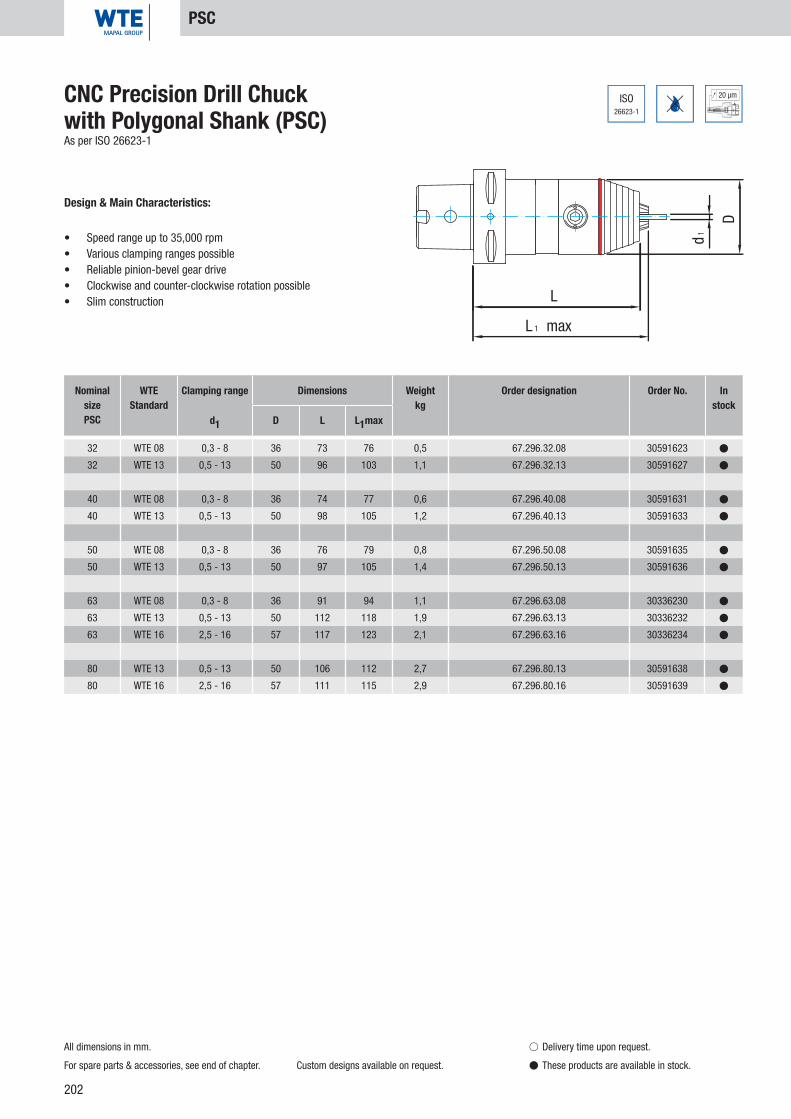
202
20 µm
d1
D
L
L 1 max
32 WTE 08 0,3 - 8 36 73 76 0,5 67.296.32.08 30591623 �
32 WTE 13 0,5 - 13 50 96 103 1,1 67.296.32.13 30591627 �
40 WTE 08 0,3 - 8 36 74 77 0,6 67.296.40.08 30591631 �
40 WTE 13 0,5 - 13 50 98 105 1,2 67.296.40.13 30591633 �
50 WTE 08 0,3 - 8 36 76 79 0,8 67.296.50.08 30591635 �
50 WTE 13 0,5 - 13 50 97 105 1,4 67.296.50.13 30591636 �
63 WTE 08 0,3 - 8 36 91 94 1,1 67.296.63.08 30336230 �
63 WTE 13 0,5 - 13 50 112 118 1,9 67.296.63.13 30336232 �
63 WTE 16 2,5 - 16 57 117 123 2,1 67.296.63.16 30336234 �
80 WTE 13 0,5 - 13 50 106 112 2,7 67.296.80.13 30591638 �
80 WTE 16 2,5 - 16 57 111 115 2,9 67.296.80.16 30591639 �
ISO26623-1
CNC Precision Drill Chuck with Polygonal Shank (PSC)As per ISO 26623-1
Design & Main Characteristics:
• Speed range up to 35,000 rpm• Various clamping ranges possible• Reliable pinion-bevel gear drive• Clockwise and counter-clockwise rotation possible• Slim construction
Nominal sizePSC
WTEStandard
Clamping range Dimensions Weightkg
Order designation Order No. In stock
d1 D L L1max
PSC
All dimensions in mm.
For spare parts & accessories, see end of chapter. Custom designs available on request.
� Delivery time upon request.
� These products are available in stock.

203
20 µm
d1
D
L
L 1 max
32 WTE 08 IK 0,3 - 8 36 73 76 0,5 67.296.32.08.Z 30591641 �
32 WTE 13 IK 0,5 - 13 50 96 103 1,1 67.296.32.13.Z 30591645 �
40 WTE 08 IK 0,3 - 8 36 74 77 0,6 67.296.40.08.Z 30591647 �
40 WTE 13 IK 0,5 - 13 50 98 105 1,2 67.296.40.13.Z 30591650 �
50 WTE 08 IK 0,3 - 8 36 76 79 0,8 67.296.50.08.Z 30591669 �
50 WTE 13 IK 0,5 - 13 50 97 105 1,4 67.296.50.13.Z 30591670 �
63 WTE 08 IK 0,3 - 8 36 91 94 1,1 67.296.63.08.Z 30336231 �
63 WTE 13 IK 0,5 - 13 50 112 118 1,9 67.296.63.13.Z 30336233 �
63 WTE 16 IK 2,5 - 16 57 117 123 2,1 67.296.63.16.Z 30336235 �
80 WTE 13 IK 0,5 - 13 50 106 112 2,7 67.296.80.13.Z 30591673 �
80 WTE 16 IK 2,5 - 16 57 111 115 2,9 67.296.80.16.Z 30591674 �
(1)
(2)
ISO26623-1
CNC Precision Drill Chuck with Polygonal Shank (PSC)As per ISO 26623-1, with interior coolant supply
Design & Main Characteristics:
• Speed range up to 35,000 rpm• Various clamping ranges possible• Reliable pinion-bevel gear drive• Clockwise and counter-clockwise rotation possible• Slim construction
Nominal sizePSC
WTEStandard
Clamping range Dimensions Weightkg
Order designation Order No. In stock
d1 D L L1max
PSC
All dimensions in mm.
Installation tool for sealing disk, see end of chapter.
For spare parts & accessories, see end of chapter.
Custom designs available on request.
� Delivery time upon request.
� These products are available in stock.
CNC
Prec
isio
n Dr
ill C
huck
s
(1) WTE 08 sealing disk (Ø 3.2 mm) integrated into the drill chuck head, for inner coolant drills Ø 4-8 mm with smooth shank acc. to DIN 6535, Form HA.
(2) WTE 08 sealing disk (Ø 1.8mm) included in scope of supply, for inner coolant drills Ø 2-4 mm with smooth shank acc. to DIN 6535, Form HA.
(1) WTE 13 sealing disk (Ø 4.2 mm) integrated into the drill chuck head, for inner coolant drills Ø 6-13 mm with smooth shank acc. to DIN 6535, Form HA.
(2) WTE 13 sealing disk (Ø 2.05 mm) included in scope of supply, for inner coolant drills Ø 3-6 mm with smooth shank acc. to DIN 6535, Form HA.
(1) WTE 16 sealing disk (Ø 4.2 mm) integrated into the drill chuck head, for inner coolant drills Ø 6-16 mm with smooth shank acc. to DIN 6535, Form HA.
(2) WTE 16 sealing disk (Ø 2.05 mm) included in scope of supply, for inner coolant drills Ø 3-6 mm with smooth shank acc. to DIN 6535, Form HA.

204
20 µm
25.000min
G 6,3
d1
D
L
L1 max
32 WTE 08 0,3 - 8 36 82 85 0,6 93.296.0012.08 30336239 �
CNC Precision Drill Chuck Chiron FZ 08For basket changer with 12 tool places
Design & Main Characteristics:
• Speed range up to 35,000 rpm• Various clamping ranges possible• Reliable pinion-bevel gear drive• Clockwise and counter-clockwise rotation possible• Slim construction
Nominal size
WTEStandard
Clamping range Dimensions Weightkg
Order designation Order No. In stock
d1 D L L1max
Chiron
All dimensions in mm.
For spare parts & accessories, see end of chapter. Custom designs available on request.
� Delivery time upon request.
� These products are available in stock.

205
20 µm
Dd1
L1 maxLl
d32x53 WTE 08 IK 0,3 - 8 36 54 57 0,7 93.296.0014.08 30336241 �
32x53 WTE 13 IK 0,5 - 13 50 74 80 1,1 93.296.0015.13 30336242 �
32x53 WTE 16 IK 2,5 - 16 57 79 85 1,3 93.296.0015.16 30336243 �
40x53 WTE 13 IK 0,5 - 13 50 74 80 1,3 93.296.0018.13 30336244 �
40x53 WTE 16 IK 2,5 - 16 57 79 85 1,5 93.296.0018.16 30336245 �
(1)
(2)
CNC Precision Drill Chuck MORI-SEIKI
Design & Main Characteristics:
• Speed range up to 35,000 rpm• Various clamping ranges possible• Reliable pinion-bevel gear drive• Clockwise and counter-clockwise rotation possible• Slim construction
Nominal sized x l
WTEStandard
Clamping range Dimensions Weightkg
Order designation Order No. In stock
d1 D L L1max
MORI-SEIKI
All dimensions in mm.
Installation tool for sealing disk, see end of chapter.
For spare parts & accessories, see end of chapter.
Custom designs available on request.
� Delivery time upon request.
� These products are available in stock.
CNC
Prec
isio
n Dr
ill C
huck
s
(1) WTE 08 sealing disk (Ø 3.2 mm) integrated into the drill chuck head, for inner coolant drills Ø 4-8 mm with smooth shank acc. to DIN 6535, Form HA.
(2) WTE 08 sealing disk (Ø 1.8mm) included in scope of supply, for inner coolant drills Ø 2-4 mm with smooth shank acc. to DIN 6535, Form HA.
(1) WTE 13 sealing disk (Ø 4.2 mm) integrated into the drill chuck head, for inner coolant drills Ø 6-13 mm with smooth shank acc. to DIN 6535, Form HA.
(2) WTE 13 sealing disk (Ø 2.05 mm) included in scope of supply, for inner coolant drills Ø 3-6 mm with smooth shank acc. to DIN 6535, Form HA.
(1) WTE 16 sealing disk (Ø 4.2 mm) integrated into the drill chuck head, for inner coolant drills Ø 6-16 mm with smooth shank acc. to DIN 6535, Form HA.
(2) WTE 16 sealing disk (Ø 2.05 mm) included in scope of supply, for inner coolant drills Ø 3-6 mm with smooth shank acc. to DIN 6535, Form HA.

206
L 1 max
L
D
d1
40 WTE 13 VDI 0,5 - 13 57 113 119 1,7 93.296.0022.13 30336248 �
40 WTE 16 VDI 2,5 - 16 57 113 124 1,9 93.296.0022.16 30336249 �
DIN69871
20 µm
25.000min
G 6,3CNC Precision Drill Chuck DIN 69871 VDICoolant feet using ball nozzles
Design & Main Characteristics:
• Speed range up to 35,000 rpm• Various clamping ranges possible• Reliable pinion-bevel gear drive• Clockwise and counter-clockwise rotation possible• Slim construction
Nominal size
WTEStandard
Clamping range Dimensions Weightkg
Order designation Order No. In stock
d1 D L L1max
VDI
All dimensions in mm.
For spare parts & accessories, see end of chapter. Custom designs available on request.
� Delivery time upon request.
� These products are available in stock.

207
1 89.208.01 30266093 �
2 89.208.02 30266130 �
3 89.208.03 30266138 �
4 89.208.04 30266107 �
5 89.208.05 30266141 �
6 89.208.06 30266194 �
7 89.208.07 30266164 �
8 89.208.08 30266192 �
9 89.208.09 30266152 �
10 89.208.10 30266156 �
11 89.208.11 10072512 �
12 89.208.39 30263594 �
All dimensions in mm.
Spare Parts & Accessories
� Delivery time upon request.
� These products are available in stock.
Spare Parts for CNC Precision Drill Chucks For design WTE 08
No. Description Order designation Order No. In stock
CNC
Prec
isio
n Dr
ill C
huck
s
Sleeve
Expansion cone
Clamping jaws (1 set = 3 pieces)
Spindle
Pinion
Bevel gear
Thrust piece
Pinion screw
Cover
Stop disc
O-ring 24 x 1
O-ring, red

208
1 89.208.01 30266093 �
2 89.208.02 30266130 �
3 89.208.03 30266138 �
4 89.208.13 30266108 �
5 89.208.05 30266141 �
6 89.208.06 30266194 �
7 89.208.07 30266164 �
8 89.208.08 30266192 �
9 89.208.09 30266152 �
10 89.208.10 30266156 �
11 89.208.11 10072512 �
12 89.208.39 30263594 �
13 89.208.14 10015675 �
14 89.208.15 30266123 �
15 89.208.16 30266125 �
19 89.213.20 10015676 �
All dimensions in mm.
Spare Parts & Accessories
� Delivery time upon request.
� These products are available in stock.
Spare Parts for CNC Precision Drill Chucks For design WTE 08 IK
No. Description Order designation Order No. In stock
Sleeve
Expansion cone
Clamping jaws (1 set = 3 pieces)
Spindle
Pinion
Bevel gear
Thrust piece
Pinion screw
Cover
Stop disc
O-ring 24 x 1
O-ring, red
O-ring 8 x 1
Gasket Ø 1.8 - 4
Gasket Ø 3.2 - 8
O-ring 8 x 1.5

209
1 89.208.17 30266094 �
2 89.208.02 30266130 �
3 89.208.03 30266138 �
4 89.208.04 30266107 �
5 89.208.05 30266141 �
6 89.208.06 30266194 �
7 89.208.07 30266164 �
8 89.208.08 30266192 �
10 89.208.10 30266156 �
11 89.208.11 10072512 �
12 89.208.39 30263594 �
20 89.208.18 30266161 �
21 89.208.19 10003770 �
All dimensions in mm.
Spare Parts & Accessories
� Delivery time upon request.
� These products are available in stock.
Spare Parts for CNC Precision Drill Chucks For design WTE 08 VDI
No. Description Order designation Order No. In stock
CNC
Prec
isio
n Dr
ill C
huck
s
Sleeve
Expansion cone
Clamping jaws (1 set = 3 pieces)
Spindle
Pinion
Bevel gear
Thrust piece
Pinion screw
Stop disc
O-ring 24 x 1
O-ring, red
Ball Ø 5.5
Countersunk screw

210
1 89.213.01 30266096 �
2 89.213.02 30266133 �
3 89.213.03 30266139 �
4 89.213.04 30266111 �
5 89.213.05 30266142 �
6 89.213.06 30266195 �
7 89.213.07 30266165 �
8 89.213.08 30266193 �
9 89.213.09 30266153 �
10 89.213.10 30266155 �
11 89.213.11 10019664 �
12 89.213.39 30346068 �
All dimensions in mm.
Spare Parts & Accessories
� Delivery time upon request.
� These products are available in stock.
Spare Parts for CNC Precision Drill Chucks For design WTE 13
No. Description Order designation Order No. In stock
Sleeve
Expansion cone
Clamping jaws (1 set = 3 pieces)
Spindle
Pinion
Bevel gear
Thrust piece
Pinion screw
Cover
Stop disc
O-ring 38x1.5
O-ring, red

211
1 89.213.01 30266096 �
2 89.213.02 30266133 �
3 89.213.03 30266139 �
4 89.213.13 30266112 �
5 89.213.05 30266142 �
6 89.213.06 30266195 �
7 89.213.07 30266165 �
8 89.213.08 30266193 �
9 89.213.09 30266153 �
10 89.213.10 30266155 �
11 89.213.11 10019664 �
12 89.213.39 30346068 �
13 89.213.14 10002538 �
14 89.213.15 30266126 �
15 89.213.16 30266127 �
19 89.213.20 10015676 �
All dimensions in mm.
Spare Parts & Accessories
� Delivery time upon request.
� These products are available in stock.
Spare Parts for CNC Precision Drill Chucks For design WTE 13 IK
No. Description Order designation Order No. In stock
CNC
Prec
isio
n Dr
ill C
huck
s
Sleeve
Expansion cone
Clamping jaws (1 set = 3 pieces)
Spindle
Pinion
Bevel gear
Thrust piece
Pinion screw
Cover
Stop disc
O-ring 38x1.5
O-ring, red
O-ring 13x1.5
Gasket Ø 3-6
Gasket Ø 6-13
O-ring 8 x 1.5

212
1 89.213.01 30266096 �
2 89.213.02 30266133 �
3 89.213.03 30266139 �
4 89.213.28 30266114 �
5 89.213.05 30266142 �
6 89.213.06 30266195 �
7 89.213.07 30266165 �
8 89.213.08 30266193 �
9 89.213.09 30266153 �
10 89.213.10 30266155 �
11 89.213.11 10019664 �
12 89.213.39 30346068 �
13 89.213.14 10002538 �
14 89.213.15 30266126 �
15 89.213.16 30266127 �
16 89.213.29 30266167 �
17 89.213.30 30266168 �
18 89.213.36 10002608 �
19 89.213.20 10015676 �
All dimensions in mm.
Spare Parts & Accessories
� Delivery time upon request.
� These products are available in stock.
Spare Parts for CNC Precision Drill Chucks For design WTE 13 IKT
No. Description Order designation Order No. In stock
Sleeve
Expansion cone
Clamping jaws (1 set = 3 pieces)
Spindle
Pinion
Bevel gear
Thrust piece
Pinion screw
Cover
Stop disc
O-ring 38x1.5
O-ring, red
O-ring 13x1.5
Gasket Ø 3-6
Gasket Ø 6-13
Coolant pipe
Spacer
O-ring 6 x 1.5
O-ring 8 x 1.5

213
1 89.213.17 30266097 �
2 89.213.02 30266133 �
3 89.213.03 30266139 �
4 89.213.04 30266111 �
5 89.213.05 30266142 �
6 89.216.06 30266196 �
7 89.213.07 30266165 �
8 89.213.08 30266193 �
10 89.213.10 30266155 �
11 89.213.11 10019664 �
12 89.216.12 30269069 �
20 89..213.18 30266163 �
21 89..213.19 30336466 �
CNC
Prec
isio
n Dr
ill C
huck
s
All dimensions in mm.
Spare Parts & Accessories
� Delivery time upon request.
� These products are available in stock.
Spare Parts for CNC Precision Drill Chucks For design WTE 13 VDI
No. Description Order designation Order No. In stock
Sleeve
Expansion cone
Clamping jaws (1 set = 3 pieces)
Spindle
Pinion
Bevel gear
Thrust piece
Pinion screw
Stop disc
O-ring 38x1.5
O-ring, red
Ball Ø 7
Countersunk screw

214
1 89.216.72 30266099 �
2 89.216.71 30266134 �
3 89.213.03 30266139 �
4 89.216.04 30266146 �
5 89.216.05 30266143 �
6 89.216.06 30266196 �
7 89.213.07 30266165 �
8 89.213.08 30266193 �
9 89.213.09 30266153 �
10 89.213.10 30266155 �
11 89.213.11 10019664 �
12 89.216.39 30263595 �
All dimensions in mm.
Spare Parts & Accessories
� Delivery time upon request.
� These products are available in stock.
Spare Parts for CNC Precision Drill Chucks For design WTE 16
No. Description Order designation Order No. In stock
Sleeve
Expansion cone
Clamping jaws (1 set = 3 pieces)
Spindle
Pinion
Bevel gear
Thrust piece
Pinion screw
Cover
Stop disc
O-ring 38x1.5
O-ring, red

215
1 89.216.72 30266099 �
2 89.216.71 30266134 �
3 89.213.03 30266139 �
4 89.216.13 30266147 �
5 89.216.05 30266143 �
6 89.216.06 30266196 �
7 89.213.07 30266165 �
8 89.213.08 30266193 �
9 89.213.09 30266153 �
10 89.213.10 30266155 �
11 89.213.11 10019664 �
12 89.216.39 30263595 �
13 89.216.14 10002547 �
14 89.216.15 30266128 �
15 89.216.16 30266129 �
19 89.213.20 10015676 �
CNC
Prec
isio
n Dr
ill C
huck
s
All dimensions in mm.
Spare Parts & Accessories
� Delivery time upon request.
� These products are available in stock.
Spare Parts for CNC Precision Drill Chucks For design WTE 16 IK
No. Description Order designation Order No. In stock
Sleeve
Expansion cone
Clamping jaws (1 set = 3 pieces)
Spindle
Pinion
Bevel gear
Thrust piece
Pinion screw
Cover
Stop disc
O-ring 38x1.5
O-ring, red
O-ring 16 x 1.5
Gasket Ø 3-6
Gasket Ø 6-16
O-ring 8 x 1.5

216
1 89.216.72 30266099 �
2 89.216.71 30266134 �
3 89.213.03 30266139 �
4 89.216.13 30266147 �
5 89.216.05 30266143 �
6 89.216.06 30266196 �
7 89.213.07 30266165 �
8 89.213.08 30266193 �
9 89.213.09 30266153 �
10 89.213.10 30266155 �
11 89.213.11 10019664 �
12 89.216.39 30263595 �
13 89.216.14 10002547 �
14 89.216.15 30266128 �
15 89.216.16 30266129 �
16 89.213.29 30266167 �
17 89.213.30 30266168 �
18 89.213.36 10002608 �
19 89.213.20 10015676 �
All dimensions in mm.
Spare Parts & Accessories
� Delivery time upon request.
� These products are available in stock.
Spare Parts for CNC Precision Drill Chucks For design WTE 16 IKT
No. Description Order designation Order No. In stock
Sleeve
Expansion cone
Clamping jaws (1 set = 3 pieces)
Spindle
Pinion
Bevel gear
Thrust piece
Pinion screw
Cover
Stop disc
O-ring 38x1.5
O-ring, red
O-ring 16 x 1.5
Gasket Ø 3-6
Gasket Ø 6-16
Coolant pipe v
Spacer v
O-ring 6 x 1.5 v
O-ring 8 x 1.5

217
1 89.216.17 30266100 �
2 89.216.10 30336482 �
3 89.213.03 30266139 �
4 89.216.04 30266146 �
5 89.216.05 30266143 �
6 89.216.06 30266196 �
7 89.213.07 30266165 �
8 89.213.08 30266193 �
10 89.213.10 30266155 �
11 89.213.11 10019664 �
12 89.216.12 30269069 �
20 89.213.18 30266163 �
21 89.213.19 30336466 �
CNC
Prec
isio
n Dr
ill C
huck
s
All dimensions in mm.
Spare Parts & Accessories
� Delivery time upon request.
� These products are available in stock.
Spare Parts for CNC Precision Drill Chucks For design WTE 16 VDI
No. Description Order designation Order No. In stock
Sleeve
Expansion cone
Clamping jaws (1 set = 3 pieces)
Spindle
Pinion
Bevel gear
Thrust piece
Pinion screw
Stop disc
O-ring 38x1.5
O-ring, red
Ball Ø 7
Countersunk screw

218
1 WTE 08/08 IK 0,3 89.208.22 30266169 �
2 WTE 08 VDI 0,3 89.208.23 30266170 �
3 WTE 13/13 IK/13 IKT 0,4 89.213.23 30266171 �
4 WTE 13 VDI/16/16 IK/16 IKT/16 VDI 0,5 89.216.25 30336487 �
All dimensions in mm.
Spare Parts & Accessories
� Delivery time upon request.
� These products are available in stock.
No. Fits Weightkg Order designation Order No. In
stock
Assembly SocketIncluding retaining pins
Overview of the installation tools For CNC Precision Drill Chucks
Torque wrench
Mounting rod
Drill chuck
Retaining pins
Assembly socket
Socket spanner insert

219
SW 19 1/2 “ 89.208.34 30266180 �
N° 1 / N° 2 0,3 89.208.26 30336449 �
N° 3 / N° 4 0,3 89.213.26 30266176 �
20 - 200 Nm 1/2 “ 89.208.35 30266178 �
All dimensions in mm.
Spare Parts & Accessories
� Delivery time upon request.
� These products are available in stock.
Hexagon Square drive Order designation Order No. In stock
Socket Spanner Insert
Retaining PinsFor assembly sockets
Fits Weightkg Order designation Order No. In
stock
Torque Wrench
Tightening value Square drive Order designation Order No. In stock
CNC
Prec
isio
n Dr
ill C
huck
s

220
WTE 08 0,03 89.208.44 30266184 �
WTE 13 / 16 0,03 89.213.44 30336476 �
1,0 89.208.30 30266181 �
WTE 08 0,04 89.208.24 30266182 �
WTE 13 / 16 0,04 89.213.21 30266183 �
All dimensions in mm.
Spare Parts & Accessories
� Delivery time upon request.
� These products are available in stock.
WTE Standard Weightkg Order designation Order No. In
stock
Installation ToolFor gaskets
Mounting RodFits all assembly sockets
Weight kg Order designation Order No. In stock
Pinion Screwdriver
WTE Standard Weightkg Order designation Order No. In
stock

221
32 0,01 89.220.72 30326003 �
40 0,01 89.220.73 30326004 �
50 0,02 89.220.74 30326005 �
63 0,02 89.220.75 30326006 �
80 0,02 89.220.76 30326007 �
100 0,03 89.220.77 30326008 �
32 0,01 89.206.20 30336671 �
40 0,01 89.206.21 30336672 �
50 0,01 89.206.22 30336673 �
63 0,01 89.206.23 30336675 �
80 0,02 89.206.24 10074774 �
100 0,02 89.206.25 30336676 �
4 100 0,03 WTE 08 89.206.07 10006235 �
6 100 0,03 WTE 13 / 16 89.206.06 10006237 �
All dimensions in mm.
Spare Parts & Accessories
� Delivery time upon request.
� These products are available in stock.
Coolant Transfer PipeFor DIN 69893-A/E
HSK Weightkg Order designation Order No. In
stock
Assembly ToolFor coolant pipe
Wrench size Weightkg Order designation Order No. In
stock
CNC
Prec
isio
n Dr
ill C
huck
sHexagonal T-keyFor pinion activation
Wrench size l Weightkg WTE Order designation Order No. In
stock

222

223
NC Standard Drill Chucks
Shank form SK 40 Page 224-225
Shank form BT 40 Page 226
Spare Parts & Accessories Page 227-228
NC S
tand
ard
Drill
Chu
cks

224
50 µm
L 1 max
L
D
d1
40 WTE 13 0,5 - 13 50 78 84 1,5 10.297.40.13 30342426 �
40 WTE 16 2,5 - 16 57 78 86 1,7 10.297.40.16 30342427 �
DIN2080
NC Standard Drill Chuck DIN 2080, Form A
Design & Main Characteristics:
• 2 different clamping ranges possible• Clockwise and counter-clockwise rotation possible• Slim construction
Nominal size
SK/ISO
WTEStandard
Clamping range Dimensions Weightkg
Order designation Order No. In stock
d1 D L L1max
SK 40
All dimensions in mm.
For spare parts & accessories, see end of chapter. Custom designs available on request.
� Delivery time upon request.
� These products are available in stock.

225
D
d1
L 1 max
L
ISO7388-1
50 µm
40 WTE 13 0,5 - 13 50 84 90 1,5 11.297.40.13 30342428 �
40 WTE 16 2,5 - 16 57 84 92 1,7 11.297.40.16 30342429 �
NC Standard Drill Chuck ISO 7388-1, Form A (prev. DIN 69871-A)
Design & Main Characteristics:
• 2 different clamping ranges possible• Clockwise and counter-clockwise rotation possible• Slim construction
Nominal size
SK/ISO
WTEStandard
Clamping range Dimensions Weightkg
Order designation Order No. In stock
d1 D L L1max
SK 40
All dimensions in mm.
For spare parts & accessories, see end of chapter. Custom designs available on request.
� Delivery time upon request.
� These products are available in stock.
NC S
tand
ard
Drill
Chu
cks

226
d1
D
L
L 1 max
40 WTE 13 0,5 - 13 50 94 100 1,8 20.297.40.13 30342430 �
40 WTE 16 2,5 - 16 57 94 102 2,0 20.297.40.16 30342431 �
50 µm
7388-2
ISONC Standard Drill Chuck ISO 7388-2 (JIS 6339)
Design & Main Characteristics:
• 2 different clamping ranges possible• Clockwise and counter-clockwise rotation possible• Slim construction
Nominal sizeBT
WTEStandard
Clamping range Dimensions Weightkg
Order designation Order No. In stock
d1 D L L1max
BT 40
All dimensions in mm.
For spare parts & accessories, see end of chapter. Custom designs available on request.
� Delivery time upon request.
� These products are available in stock.

227
2 89.213.10 30266155 �
3 89.213.06 30266195 �
4 89.213.103 30336465 �
5 89.213.101 30336463 �
6 89.213.102 30336464 �
7 89.213.08 30266193 �
8 89.213.03 30266139 �
9 89.213.100 30336462 �
10 89.213.39 30346068 �
2 89.213.10 30266155 �
3 89.213.06 30266195 �
4 89.216.103 30336485 �
5 89.216.101 30336484 �
6 89.213.102 30336464 �
7 89.213.08 30266193 �
8 89.213.03 30266139 �
9 89.216.100 30336483 �
10 89.216.39 30263595 �
All dimensions in mm.
Spare Parts & Accessories
� Delivery time upon request.
� These products are available in stock.
Spare Parts for NC Standard Drill Chuck
No. Description Order designation Order No. In stock
For design WTE 16
No. Description Order designation Order No. In stock
For design WTE 13
NC S
tand
ard
Drill
Chu
cks
Stop disc
Bevel gear
Spindle
Expansion cone
Pinion
Pinion screw
Clamping jaws (1 set = 3 pieces)
Sleeve
O-ring, red
Stop disc
Bevel gear
Spindle
Expansion cone
Pinion
Pinion screw
Clamping jaws (1 set = 3 pieces)
Sleeve
O-ring, red

228
6 100 0,03 89.206.06 10006237 �
All dimensions in mm.
Spare Parts & Accessories
� Delivery time upon request.
� These products are available in stock.
Hexagonal T-keyFor pinion activation
Wrench size l Weightkg Order designation Order No. In
stock

229
Notes:
NC S
tand
ard
Drill
Chu
cks

230

231
MICRO Universal Chucks 340
Shank form SK 30 Page 232
Shank form BT 30 Page 232
Shank form HSK-A 32 / 40 / 50 Page 233
Shank form HSK-E 25 / 32 / 40 Page 234
Cylinder Shank Page 235
Spare Parts & Accessories Page 239
MIC
RO U
nive
rsal
Chu
cks
MICRO Universal Chucks 640
Shank form SK 30 Page 236
Shank form BT 30 Page 236
Shank form HSK-A 32 / 40 / 50 Page 237
Shank form HSK-E 25 / 32 / 40 Page 238
Cylinder Shank Page 239
Spare Parts & Accessories Page 239

232
SK 30 WTE 03 0.2-3.4 19 45 48 0.41 15.236.30.03.Z 30439744 �
BT 30 WTE 03 0.2-3.4 19 48 51 0.47 22.236.30.03.Z 30439751 �
ISO7388-1
Form
AD
5 µm
25.000min
G 2,5
L
L 1max
D
d1
(1)
SK 30 / BT 30
7388-2
ISO
SK 30 SK 30 BT 30
MICRO Universal Chuck 340DIN 7388-1, Form AD I ISO 7388-2 (JIS6339)
Nominal size shank
WTEStandard
Clamping ranged1
DimensionsWeight
kg Order designation Order No. Instock
D L L1 max
(1) WTE 03 sealing disk (diameter 0.5 mm) included in scope of supply, for inner coolant drills diameter 0.7-3.4 mm with smooth shank acc. to DIN 6535 Form HA.
All dimensions in mm. Custom designs available on request.
� Delivery time upon request.
� These products are available in stock.
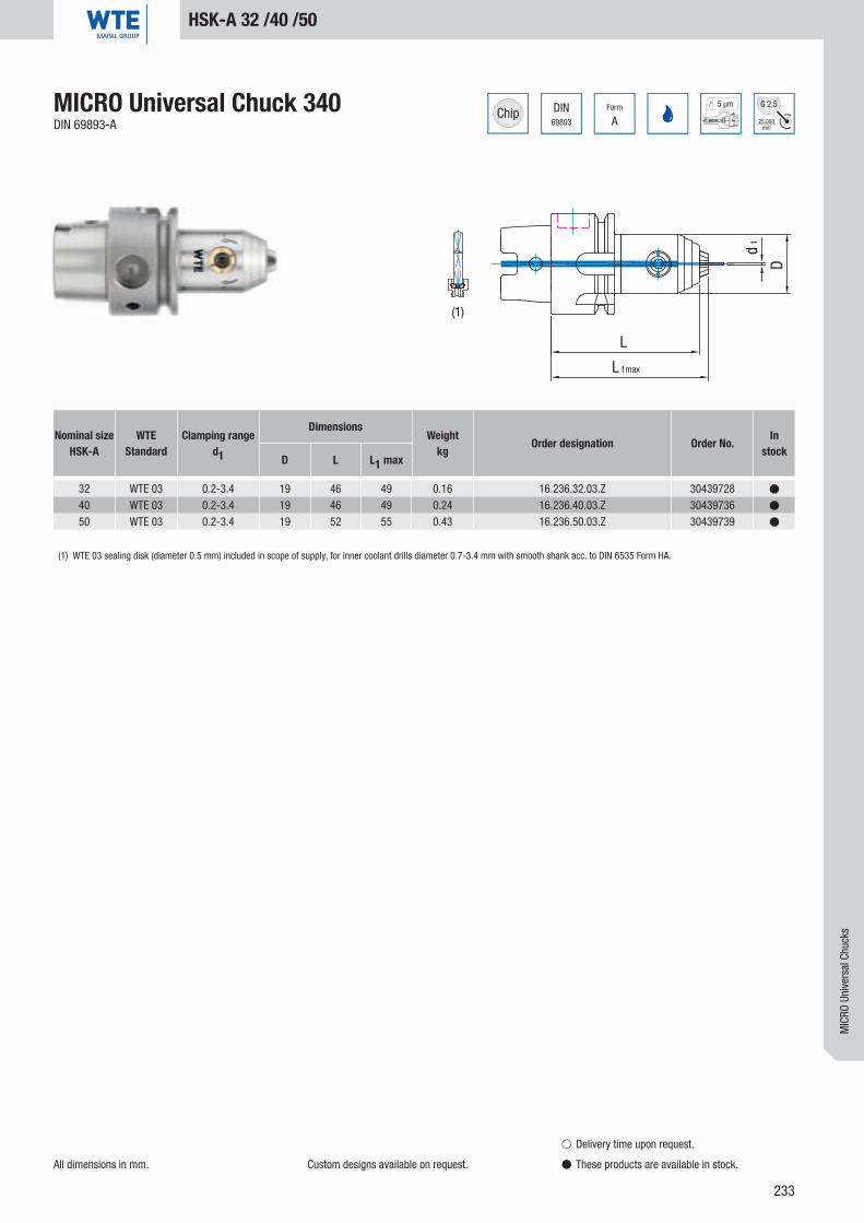
233
32 WTE 03 0.2-3.4 19 46 49 0.16 16.236.32.03.Z 30439728 �
40 WTE 03 0.2-3.4 19 46 49 0.24 16.236.40.03.Z 30439736 �
50 WTE 03 0.2-3.4 19 52 55 0.43 16.236.50.03.Z 30439739 �
DIN69893
Form
A
5 µm
25.000min
G 2,5
L
L 1max
d1
D
(1)
HSK-A 32 /40 /50
MICRO Universal Chuck 340DIN 69893-A
Nominal sizeHSK-A
WTEStandard
Clamping ranged1
DimensionsWeight
kg Order designation Order No. Instock
D L L1 max
(1) WTE 03 sealing disk (diameter 0.5 mm) included in scope of supply, for inner coolant drills diameter 0.7-3.4 mm with smooth shank acc. to DIN 6535 Form HA.
All dimensions in mm. Custom designs available on request.
� Delivery time upon request.
� These products are available in stock.
MIC
RO U
nive
rsal
Chu
cks

234
DIN69893 E
Form 5 µm
25.000min
G 2,5
L
L 1max
d1
D
25 WTE 03 0.2-3.4 19 37 40 0.1 18.236.25.03.Z 30439663 �
32 WTE 03 0.2-3.4 19 46 49 0.17 18.236.32.03.Z 30439686 �
40 WTE 03 0.2-3.4 19 46 49 0.25 18.236.40.03.Z 30439722 �
(1)
HSK-E 25 / 32 / 40
MICRO Universal Chuck 340DIN 69893-E
Nominal sizeHSK-E
WTEStandard
Clamping ranged1
DimensionsWeight
kg Order designation Order No. Instock
D L L1 max
(1) WTE 03 sealing disk (diameter 0.5 mm) included in scope of supply, for inner coolant drills diameter 0.7-3.4 mm with smooth shank acc. to DIN 6535 Form HA.
All dimensions in mm. Custom designs available on request.
� Delivery time upon request.
� These products are available in stock.

235
d2
d1
D
L 1max
L
l
10 WTE 03 0.2-3.4 19 10 70 73 40 0.08 40.257.10.03.Z 30500299 �
10 WTE 03 0.2-3.4 19 10 100 103 70 0.09 40.257.10.03.Z/100 30500301 �
10 WTE 03 0.2-3.4 19 10 160 163 130 0.13 40.257.10.03.Z/160 30500302 �
16 WTE 03 0.2-3.4 19 16 80 83 50 0.13 40.257.16.03.Z 30439821 �
16 WTE 03 0.2-3.4 19 16 100 103 70 0.16 40.257.16.03.Z/100 30439832 �
16 WTE 03 0.2-3.4 19 16 160 163 130 0.26 40.257.16.03.Z/160 30439837 �
20 WTE 03 0.2-3.4 19 20 80 83 52 0.17 40.257.20.03.Z 30439755 �
20 WTE 03 0.2-3.4 19 20 100 103 72 0.21 40.257.20.03.Z/100 30439758 �
20 WTE 03 0.2-3.4 19 20 160 163 132 0.36 40.257.20.03.Z/160 30439763 �
5 µm
25.000min
G 2,5h6MICRO Universal Chuck 340
With cylinder shank, diameter 10 / 16 / 20 mm, for WTE Standard 03
Nominal sizeShank
WTEStandard
Clamping ranged1
DimensionsWeight
kg Order designation Order No. Instock
D d2 L L1 max I
All dimensions in mm. Custom designs available on request.
� Delivery time upon request.
� These products are available in stock.
MIC
RO U
nive
rsal
Chu
cks
Cylinder Shank

236
L 1 max
L
Dd
1
ISO7388-1
Form
AD
5 µm
25.000min
G 2,5
SK 30 WTE 06 0.2-6.4 25 55 59 0.8 15.266.30.06.Z 30564796 �
BT 30 WTE 06 0.2-6.4 25 58 62 0.9 22.266.30.06.Z 30564869 �
(1)
SK 30 / BT 30
7388-2
ISO
SK 30 SK 30 BT 30
MICRO Universal Chuck 640ISO 7388-1, Form AD I ISO 7388-2 (JIS6339)
All dimensions in mm. Custom designs available on request.
� Delivery time upon request.
� These products are available in stock.
Nominal sizeShank
WTEStandard
Clamping ranged1
DimensionsWeight
kg Order designation Order No. Instock
D L L1 max
(1) WTE 06 sealing disk (diameter 0.5 mm) included in scope of supply, for inner coolant drills diameter 0.7-6.4 mm with smooth shank acc. to DIN 6535 Form HA.

237
L 1 max
L
D
d1
DIN69893
Form
A
5 µm
25.000min
G 2,5
32 WTE 06 0.2-6.4 25 54 58 0.3 16.266.32.06.Z 30564811 �
40 WTE 06 0.2-6.4 25 54 58 0.4 16.266.40.06.Z 30564819 �
50 WTE 06 0.2-6.4 25 61 65 0.4 16.266.50.06.Z 30564823 �
(1)
HSK-A 32 / 40 / 50
MICRO Universal Chuck 640DIN 69893-A
All dimensions in mm. Custom designs available on request.
� Delivery time upon request.
� These products are available in stock.
Nominal sizeHSK-A
WTEStandard
Clamping ranged1
DimensionsWeight
kg Order designation Order No. Instock
D L L1 max
(1) WTE 06 sealing disk (diameter 0.5 mm) included in scope of supply, for inner coolant drills diameter 0.7-6.4 mm with smooth shank acc. to DIN 6535 Form HA.
MIC
RO U
nive
rsal
Chu
cks

238
L 1 max
L
D
d1
DIN69893 E
Form 5 µm
25.000min
G 2,5
25 WTE 06 0.2-6.4 25 57 61 0.3 18.266.25.06.Z 30564833 �
32 WTE 06 0.2-6.4 25 54 58 0.3 18.266.32.06.Z 30564839 �
40 WTE 06 0.2-6.4 25 54 58 0.4 18.266.40.06.Z 30564844 �
(1)
HSK-E 25 / 32 / 40
MICRO Universal Chuck 640DIN 69893-E
All dimensions in mm. Custom designs available on request.
� Delivery time upon request.
� These products are available in stock.
Nominal sizeHSK-E
WTEStandard
Clamping ranged1
DimensionsWeight
kg Order designation Order No. Instock
D L L1 max
(1) WTE 06 sealing disk (diameter 0.5 mm) included in scope of supply, for inner coolant drills diameter 0.7-6.4 mm with smooth shank acc. to DIN 6535 Form HA.

239
002010DINISO
L 1 max
L
D
d1
l
d2
16 WTE 06 0.2-6.4 25 16 100 104 60 0.3 40.257.16.06.Z 30564901 �
16 WTE 06 0.2-6.4 25 16 150 154 110 0.5 40.257.16.06.Z/150 30564903 �
16 WTE 06 0.2-6.4 25 16 200 204 160 0.7 40.257.16.06.Z/200 30564905 �
20 WTE 06 0.2-6.4 25 20 100 104 60 0.4 40.257.20.06.Z 30564907 �
20 WTE 06 0.2-6.4 25 20 150 154 110 0.6 40.257.20.06.Z/150 30565004 �
20 WTE 06 0.2-6.4 25 20 200 204 160 0.8 40.257.20.06.Z/200 30565008 �
5 µm
25.000min
G 2,5
2 60 0.01 WTE 03 89.206.08 30435838 �
2.5 60 0.01 WTE 06 89.106.10 10098110 �
h6MICRO Universal Chuck 640With cylinder shank, diameter 16 / 20 mm, for WTE Standard 06
All dimensions in mm. Custom designs available on request.
� Delivery time upon request.
� These products are available in stock.
Nominal sizeShank
WTEStandard
Clamping ranged1
DimensionsWeight
kg Order designation Order No. Instock
D d2 L L1 max I
Hexagonal T-keyFor pinion activation
Wrench size l Weightkg WTE standard Order designation Order No. In
stock
MIC
RO U
nive
rsal
Chu
cks
Cylinder Shank / Accessories

240

241
Technical Information
In the following chapter, you will find technical information and handling instructions for our chucks. In addition to the fundamental technical information regarding different chuck types, you will get important information on maintenance and service topics. You will also find information on handling, areas of applications and functional principles.
Tech
nica
l Inf
orm
atio
n

242
Application of WTE Hydraulic Clamping Technologies
Basic Technical Information - Hydraulic Clamping Technologies
Our Hydraulic Chucks or HPH - High Performance Holder with axial and radial activated length adjustment can be used on wood and metal processing machines with rotating tools. There are different designs depending on the type of use, for example
Chucks for automatic tool change as per:ISO 7388-1 (DIN 69871); DIN 69893-A, DIN 69893-F, DIN 69893-E and ISO 7388-2 (JIS B6339)
Chucks for manual tool change as per:DIN 69893-C
Advantages of the WTE Hydraulic Clamping Chuck Technologies• Extremely fast tool change• High run-out accuracy• Vibration damping tool clamping• Increase of tool service life• Reduction of micro-breakouts on the tool cutting edge• Improvement of surface quality• Can be used flexibly by using reducing sleeves• Low maintenance costs due to closed clamping system• Simple operation• High torque transfer• Design conforms to DIN 69882-7• High positioning accuracy and repeatability
• Tool clamping with maximum run-out accuracy (maximum 3 µm)
• Continuous development• Certified products as per DIN EN ISO 9001:2008
manufactured in Germany
Components and Functional Principle of Current WTE Hydraulic Clamping Technologyies1. The pressure screw (2) is screwed in with a hexagonal T-key (1)
to the stop.
2. Pressure is increased in the entire hydraulic system (5) using a hydraulic clamping set (3,4).
3. The resulting pressure causes a deformation of the hydraulic sleeve (6), which uniformly encloses the tool shank found in it. Through this the tool shank is first centred and then clamped with high holding strength.
4. Leaking hydraulic fluid or releasing of the tool clamping is prevented by a special sealing element (4), which ensures a high service life of the tool.
1) T-key2) Pressure Screw3) Pressure Pin4) Sealing5) Hydraulic Oil6) Hydraulic Sleeve

243
Basic Technical Information - Hydraulic Clamping Technologies
NEW: Radial Length Adjustment• µ-precision length setting through compact setting gears• No changes to the tools caused by construction or machining
through self-locking adjustment screw• 10 mm adjustment travel for all clamping diameters with rear
stop of adjustment screw• Not sensitive to dirt• Durable mechanical system with long service life• Coolant seal up to 100 bar• User friendly and process reliable
Safe Clamping / Maintenance and ServiceFor proper operation all Hydraulic Chucks or HPH - High Performance Holders should be checked according to the operating manual for each clamping process for functionality and functional safety.If any deviations are found during this, then reliable transferable torques cannot be achieved.It is recommended for our repair service to check the expansion chuck if this has occurred.
Before using our hydraulic clamping technology, the corresponding fixture holes and bevel faces must be thoroughly cleaned. The chuck pressure screw must be cleaned and lubricated regularly, appropriate to the use and environmental conditions.
Storage of the clamping fixture should be done exclusively in the released condition, where corrosion protection must be ensured.
Tech
nica
l Inf
orm
atio
n

244
1
Application & Characteristics of WTE Drill Chuck Technologies
Basic Technical Information - Drill Chucks
Our NC Standard Drill Chucks or CNC Precision Drill Chucks are used in almost all machining areas of the metal and machining industries.
Here they excel with their precision manufacturing, by the individual com-ponents made of high-quality, hardened material and through their varia-ble application possibilities. Speed range up to 35,000 rpm is possible, depending on the design.
High clamping strengths and improved run-out accuracies are also outstanding characteristics of our Drill Chucks.
Depending on the model and type of application our Drill Chucks are suitable for use without coolant supply or for wet machining with internal or collar fed coolant supply.
Advantages of the WTE Drill Chucks in CNC Precision and NC Standard.
• Reliable mechanical function• Simple handling• Secure clamping independent of the direction of rotation• Short clamping and changeover times• Short construction• Delivery of all possible shapes of machine-side base
bodies through special modular WTE interface• High torque transfer
Components and Functional Principle of WTE Drill Chucks1. Open the chuck counter-clockwise to insert the respective cutting tool.
2. The cutting tool must be inserted to the stop so that the tool shank al-ways is placed over the entire chuck. :(Caution: Do not clamp tapered shanks. Risk of accidents!)
3. Turn the spanner with the indicated tightening torque (see table) clock-wise, to clamp the tool properly. Extensions or tightening aids must not be used, as the bevel gear drive can be damaged due to too high tight-ening torque. The pinion is then used as a predetermined breaking point to prevent greater damage to the drill clamp.
4. After successively checking the correct clamping and the centred align-ment of the cutting tool, the drill chuck is ready for operation.
To adjust the drill chuck from the basic settings to Form B, the grub screw is rotated completely to the rear of the hole using a hexagon spanner SW 2.5.

245
2 3
Basic Technical Information - Drill Chucks
Safe Clamping / Maintenance and ServiceAll WTE Drill Chucks are tightened using a hexagon T-key on the side via a taper drive. Here the spanner is turned clockwise to clamp the drill chuck. Opening the drill chuck is done counter-clockwise (see mark on the pinion bore). Step-by-step instructions are found in the respective operating manual. Our drill chucks are maintenance free. After using the drill chuck, it should be cleaned with a clean cloth. The drill chuck should be oiled be-fore storage for corrosion protection.
Caution: Never use compressed air to clean the drill chuck, as fine shavings can get into the clamping mechanism. The drill chucks must not be cleaned with solvent or solvent-containing cleaners, as these cause corrosion.
Tech
nica
l Inf
orm
atio
n
This permits the grub screw to open the coolant supply. On the machine side, the coolant is sealed by the pull studs without a coolant duct hole.
To set the drill chuck back to Form AD, the grub screw is unscrewed. Thus, the grub screw blocks the duct hole. On the machine side the coolant supply is done through the pull studs with coolant duct hole.

246
Application & Characteristics of WTE Shrink Technologies
Basic Technical Information - Shrink Chucks
Our Shrink Chucks are used on wood processing and metal machining equipment with rotating tools. Shrink chucks use heat-related expansion for tool clamping. The area of application for these clamping products in-cludes a wide variety of milling jobs, heavy machining wood processing and also drilling applications. The WTE Shrink Chucks are in principle fabricated with internal coolant supply.
Selected product groups are additionally in the program with collar cooling Custom production based on the application of side cooling duct holes are available at any time on request.
Our Shrink Chucks are available in the designs ISO 7388-1 (DIN 69871), DIN 69893-A, DIN 69893-E, DIN 69893-F and ISO 7388-2 (JIS B6339) for automatic tool change. For manual tool change in design DIN 69893-C.
Advantages of the WTE Shrink Chucks• Simple attachment of the tool holder• High run-out accuracy during tool clamping• Secure force transfer• Slim construction• Cost effectiveness• High torque transferable• Long service life and temperature resistance by
using high-strength hot-working steel• Warpage-free due to optimum heat treatment• Optimum balance quality• From standard clamping diameter 6 mm
with balance threaded hole
Components and Functional Principle of WTE Shrink ChucksThrough the addition of heat the fixture hole diameter of the shrink chuck is enlarged so that the tool shank can be inserted. There is a very tight connection after cooling.
1. The chuck (1) is heated locally on the clamping location using the most up-to-date induction technology. An induction coil generates quickly al-ternating eddy currents, which warms the material exactly at the point (2), at which the tool shank sits. The hole - widens.
2. The cold tool shank (3) is inserted in the warmed shrink chuck.
3. The shrink chuck is cooled (4), the clamping diameter returns to its ini-tial dimension and clamps the tool shank. By fast cooling within 30 seconds there is no warming of the cone and and the data chip.
• Design conforms to DIN 69882-8• High positioning accuracy and repeatability• Guaranteed highest run-out accuracy – maximum 3 µm• Laser inscription for reliable product tracking• Continuous development and repair service• Certified products as per DIN EN ISO 9001:2008 -
manufactured in Germany• Flexible shrink system using WTE Shrink Extensions• Stop screw adjustable from two sides
(1)
(2)
(3)
(4)

247
A
0.003 A BØd1
B
-
Lv
60
L=Lv
-60
(4)
(3)
(2)(1)
Basic Technical Information - Shrink Chucks
Reliable Clamping & Length AdjustmentThe WTE Shrink Chucks are designed for the transfer of larger torques (holding strengths). This is achieved by fixture holes and shrink lengths optimally matched to the material and the WTE shrink devices.
The length adjustment of the WTE Shrink Chucks is done by an adjustment screw with hexagon socket on two sides. The screw is bored through the centre, so that internal coolant supply is ensured. The length adjustment can be done from two sides.
Length adjustment description1. Before the shrinking process, connect the tool (4), WTE Length
Presetter (3) and WTE Shrink Chuck (1) with WTE Stop Screw (2).
2. Set the length end dimension of the tool by turning the length pre-setter (sets the stop screw to the desired dimension). The desired length (L) after shrinking results with the presetting length (Lv) from L = Lv-60 mm.
3. Remove length presetter and shrink tool. The tool must sit on the stop screw.
Customer serviceBalance quality
All WTE Shrink Chucks are balanced as standard. Please take the balance quality from the individual item descriptions. If you require other balance qualities, you can balance the WTE Shrink Chucks according to your re-quirements.
Custom Shrink Chucks
Through our many years of experience in the area of development, design and production of shrink chucks, we have the possibility to develop shrink chucks to your requirements and produce them in record time. We are happy to answer your questions about this.
Shrink Chucks - Heavy Duty Design
For induction shrink devices with 20 KVA on request.
Tech
nica
l Inf
orm
atio
n
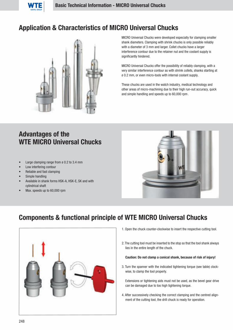
248
Application & Characteristics of MICRO Universal Chucks
Basic Technical Information - MICRO Universal Chucks
MICRO Universal Chucks were developed especially for clamping smaller shank diameters. Clamping with shrink chucks is only possible reliably with a diameter of 3 mm and larger. Collet chucks have a larger interference contour due to the retainer nut and the coolant supply is significantly hindered.
MICRO Universal Chucks offer the possibility of reliably clamping, with a very similar interference contour as with shrink collets, shanks starting at Ø 0.2 mm, or even micro-tools with internal coolant supply.
These chucks are used in the watch industry, medical technology and other areas of micro-machining due to their high run-out accuracy, quick and simple handling and speeds up to 60,000 rpm..
Advantages of the WTE MICRO Universal Chucks
• Large clamping range from Ø 0.2 to 3.4 mm • Low interfering contour• Reliable and fast clamping• Simple handling• Available in shank forms HSK-A, HSK-E, SK and with
cylindrical shaft • Max. speeds up to 60,000 rpm
Components & functional principle of WTE MICRO Universal Chucks1. Open the chuck counter-clockwise to insert the respective cutting tool.
2. The cutting tool must be inserted to the stop so that the tool shank always lies in the entire length of the chuck.
Caution: Do not clamp a conical shank, because of risk of injury!
3. Turn the spanner with the indicated tightening torque (see table) clock-wise, to clamp the tool properly.
Extensions or tightening aids must not be used, as the bevel gear drive can be damaged due to too high tightening torque.
4. After successively checking the correct clamping and the centred align-ment of the cutting tool, the drill chuck is ready for operation.
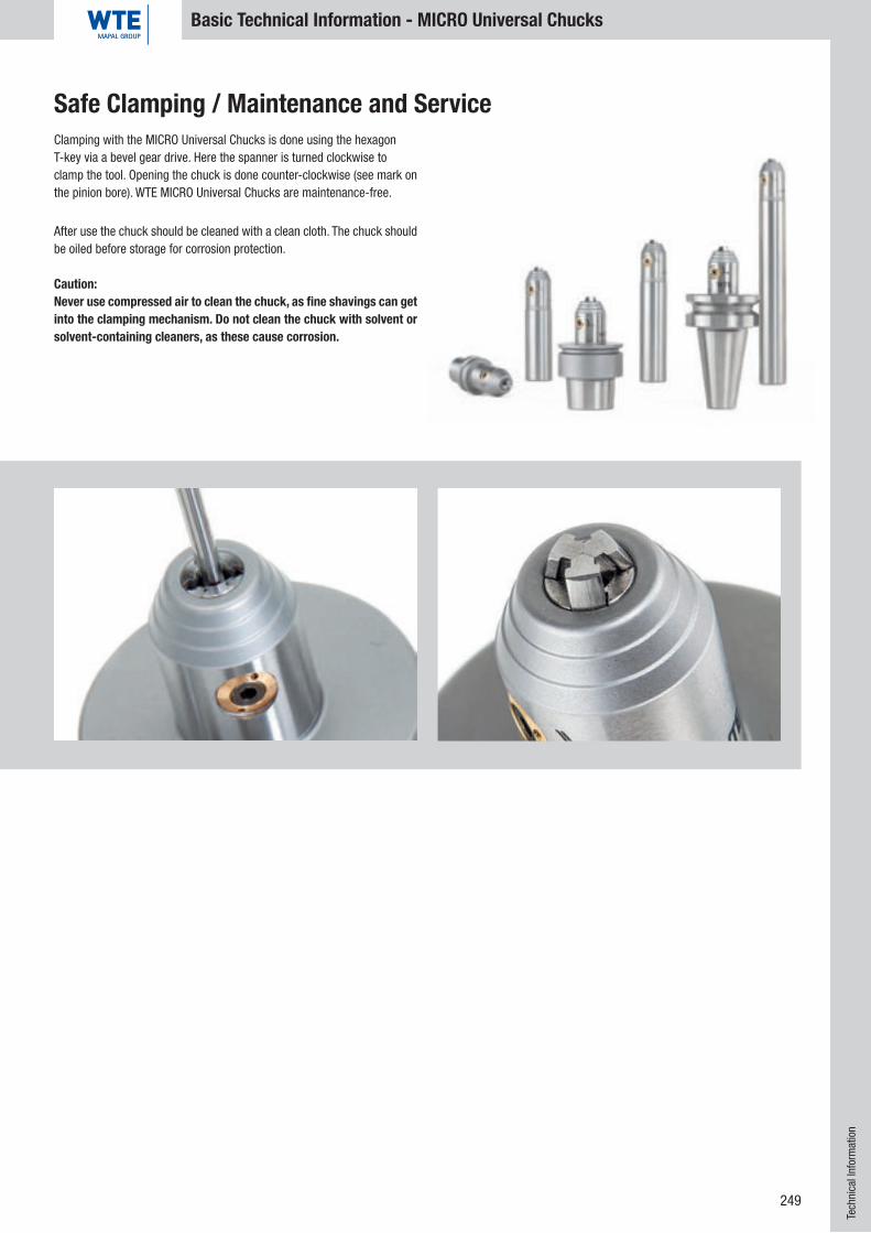
249
Basic Technical Information - MICRO Universal Chucks
Tech
nica
l Inf
orm
atio
n
Safe Clamping / Maintenance and ServiceClamping with the MICRO Universal Chucks is done using the hexagon T-key via a bevel gear drive. Here the spanner is turned clockwise to clamp the tool. Opening the chuck is done counter-clockwise (see mark on the pinion bore). WTE MICRO Universal Chucks are maintenance-free.
After use the chuck should be cleaned with a clean cloth. The chuck should be oiled before storage for corrosion protection.
Caution: Never use compressed air to clean the chuck, as fine shavings can get into the clamping mechanism. Do not clean the chuck with solvent or solvent-containing cleaners, as these cause corrosion.

250
Technical Data
Transferable torques with direct clamping (torque specification in Nm)Clamping diameter in mm 6 8 10 12 14 16 18 20 25 32
Minimum clamping depth in mm 27 27 31 36 36 39 39 41 47 51
Shank smallest dimension h6 20 30 47 80 100 160 200 330 400 650
Shank largest dimension h6 30 45 85 140 160 230 270 400 470 730
Transferable torques for WTE Hydraulic Chucks, clamping diameter 32 mm with reducing sleeve (torque specification in Nm)Clamping diameter in mm 6 8 10 12 14 16 18 20 25
Shank smallest dimension h6 30 45 60 120 120 180 220 250 360
Shank largest dimension h6 45 65 110 170 170 230 300 320 440
Transferable torques for WTE Hydraulic Chucks, clamping diameter 20 mm with reducing sleeve (torque specification in Nm)Clamping diameter in mm 3 4 5 6 8 10 12 14 16
Shank smallest dimension h6 6 9 16 30 55 90 120 135 190
Shank largest dimension h6 10 12 22 40 75 120 150 170 260
Transferable torques for WTE Hydraulic Chucks, clamping diameter 12 mm with reducing sleeve (torque specification in Nm)Clamping diameter in mm 3 4 5 6 8
Shank smallest dimension h6 3 4 7 12 18
Shank largest dimension h6 4 8 12 20 26
• Material 1600-1800 N/mm2 tension strength• Hardness 52 + 2HRc• Holder balanced• Laser inscription• Max. speed 40,000 rpm (Observe spindle speed limit,
interface, fine balancing recommended!)• Working temperature 20-50 °C; higher temperatures
on request, do not use over 80 °C• Coolant pressure max. 80 bar• Adjustment travel 10 mm• Clampable shanks (tolerance h6) with and without reducing sleeves:
- DIN 1835 Form A, B, C, D - DIN 6535 Form H, HB, HE
Technical Data WTE Hydraulic Chucks
Allowable Transferable Torques WTE Hydraulic Chucks
• Material 1600-1800 N/mm2 tension strength• Hardness 52 + 2HRc• Holder balanced• Laser inscription• Max. speed 40,000 rpm (Observe spindle speed limit,
interface, fine balancing recommended!)• Application temperature 20-80 °C; do not use over 100 °C• Coolant pressure max. 80 bar• Adjustment travel 10 mm• Clampable shanks (tolerance h6) with and without reducing sleeves:
- DIN 1835 Form A, B, C, D - DIN 6535 Form H, HB, HE
Technical Data WTE HPH - High Performance Holder

251
Technical Data Technical Data
Transferable torques with direct clamping (torque specification in Nm)Clamping diameter in mm 6 8 10 12 14 16 18 20 25 32
Minimum clamping depth in mm 27 27 31 36 36 39 39 41 47 51
Shank smallest dimension h6 30 50 100 150 210 280 360 550 650 800
Shank largest dimension h6 40 65 135 190 280 380 450 650 750 890
Allowable Transferable Torques HPH - High Performance Holder
Transferable torques with direct clamping (torque specification in Nm)Clamping diameter in mm 3 4 5 6 8 10 12 14 16 18 20 25 32
Minimum clamping depth in mm 12 16 20 26 26 31 37 37 40 40 42 48 52
Torque 4 11 17 24 45 82 145 190 200 290 450 530 700
• Material 1600-1800 N/mm²• Hardness 52 + 2HRc• Holder balanced as standard• Laser inscription • Max. speed 40,000 rpm (Observe spindle speed limit,
interface, fine balancing recommended)• Shrink temperature 100-420 °C• Maximum shrink temperature 500 °C• Coolant pressure max. 80 bar• Adjustment travel 10 mm, adjustable from two sides• Clampable: Cylinder shanks tolerance outside diameter h6• Shrinking in and out of HM and HSS tools when using
the appropriate shrink devices
Technical Data WTE Shrink Chucks
Allowable Transferable Torques WTE Shrink Chucks
Tech
nica
l Inf
orm
atio
n
Drill Chuck
WTE Standard WTE 08 WTE 13 WTE 16
Clamping range 0.3 - 8.0 mm 0.5 - 13.0 mm 2.5 - 16 mm
Run-out deviation, maximum < 0.02 mm (*) < 0.02 mm (*) < 0.02 mm (*)
Tightening torque in reference to run-out deviation 8 Nm 15 Nm 15 Nm
Transferable torque 18 Nm (**) 40 Nm (**) 45 Nm (**)
Maximum permissible tightening torque 10 Nm 20 Nm 20 Nm
Transferable torque with maximum permissible tight-
ening torque 30 Nm (**) 80 Nm (**) 90 Nm (**)
Maximum permissible speed 35,000 rpm (***) 35,000 rpm (***) 35,000 rpm (***)
Technical Data WTE Drill Chucks
(*) Check the run-out deviation according to the test protocol
"Precision".
(**) All CNC Drill Chucks are clamped using a hexagon T-key
on the side via a cone operation (see operating manual). For
the use of the drill chuck, a tightening torque of 8 Nm or
15 Nm is sufficient on the hexagon T-key. The high holding
torques achieved with the CNC Drill Chucks are intended to
be for additional safety and are not necessary for normal use.
(***) The CNC Chucks are "unbalanced", suitable for use up
to 7,000 rpm. For application with speeds over 7,000 rpm to
max 35,000 rpm as for example in aluminium machining or
wood processing, the chucks must additionally be balanced
acc. to the balance classes, taking into consideration the
speed and balance quality.

252
Technical Data
Technical Data MICRO Universal Chuck
WTE Standard WTE 03 WTE 06Clamping range 0.2-3.4 mm 0.2-6.4 mmRun-out deviation, maximum < 0.005 mm (*) < 0.005 mm (*)Tightening torque in reference to run-out deviation 1.5 Nm 3 NmTransferable torque 4.5 Nm (**) 9 Nm (**)Maximum permissible tightening torque 2 Nm 4 NmTransferable torque with maximum permissible tightening torque 7 Nm (**) 12 Nm (**)Maximum permissible speed 60,000 rpm (***) 60,000 rpm (***)
(*) Check the run-out deviation according to the test protocol "MICRO Universal Chuck".
(**) All MICRO Universal Chucks are tightened using a hexagon T-key on the side via a taper drive. For the use of the MICRO Universal Chuck a tightening torque of 1.5 Nm (WTE 03) or 3
Nm (WTE 06) is sufficient on the hexagon T-key. The high holding torques achieved with the MICRO Universal Chuck are intended to be for additional safety and are not necessary for
normal use.
(***) The MICRO Universal Chucks are "unbalanced", suitable for use up to 18,000 rpm. For application with speeds over 18,000 rpm to 60,000 rpm (e.g, in aluminium or wood machining),
the MICRO Universal Chuck must additionally be balanced acc. to the balance classes– taking into consideration the speed and balance quality.

253
I. OFFER
1. Any and all information pertaining to weights, dimensions, performance and other technical data contained in Supplier’s il-lustrations and drawings shall be deemed to be only approximate unless stipulated as being defini-tive. The Supplier reserves all rights of title, ownership and copyright to any and all illustrations, sketches, dra-wings, gauges, samples etc. included with his quotations and deliveries; said items shall not be made available third parties without Supplier’s express consent. 2. Purchaser shall be solely responsible for the documentation, plans, samples etc. to be provided by Purchaser. Purchaser shall be responsible for ensuring that design drawings submitted by Purchaser do not infringe upon the industrial property rights of third parties. Supplier shall be under no obligation to Purchaser to review whe-ther anly industrial property rights of third parties may be infringed upon though the submittal of quotations. Should liability nevertheless arise, Purchaser shall save and hold Supplier harmless thereof. This will not be va-lid with in-tention or culpable negligence of the owner or responsible employee.3. Samples shall be supplied only against invoice.
II. DELIVERY SCOPE
1. The written order confirmation of the supplier is authritative for the delivery scope, in case he has submitted an offer containing a binding time and an acceptance in due time, if no written order confirmation is sent in due time. Alterations and oral agreements have to be confirmed by the supplier in written form.2. If ordering special tooling the order quantity may be reduced or exceeded by 10% but at least 2 units. The delivered quantity will be charged.
III. PRICING AND PAYMENT
1. If not specially agreed, the pricing is ex factory, excluding packing, freight and/or postage and transport insu-rance and value added tax. 2. The prices are charged in Euro. 3. Invoices are payable cash, without any deduction, free WTE, within 14 days from date of invoice with 2% dis-count, but at least with 30 days net. This is also valid for partial deliveries. Repairs and pay work are payable immediately after receipt of invoice. 4. Packing and despatch will be done to best estimation but without any obligation from our part. 5. The minimum purchase order value is € 20,-- net. In case of lower order value we charge a lower quantity surcharge of € 20,--. 6. Price changes are reserved according to alterations of production costs. 7. The right to retain payments or to balance them with counterclaims is entitled to the customer only in this re-spect that his counterclaims are determined to be undisputed or legally valid. 8. A bill of exchange or cheque will be accepted just for payment, but fees for debit and banking will be charged to Purchaser. 9. For a return caused by the customer (e.g. wrong or double order) we have to charge you with freight costs and dan administration expense of 10% of goods value, but at least € 10,--.
IV. DELIVERY TIMES
1. The delivery time shall commence upon dispatch of order confirmation, however not prior to provision of all documentaton, permits, approvals etc. which are to be obtained by Purchaser, and not prior to receipt of any down payment which may have been agreed to. 2. The delivery time shall be deemed to have been maintained, if the item(s) to be delivered has left the plant, or of notification has been made that said item is ready for shipment. 3. Supplier shall not be responsible for delays or defaults in deliveries, if occasioned by decisions of public au-thorities, or by other causes beyond the reasonable control of Supplier or his subsuppliers, such as Acts of God, war, insurrection, strikes, lockouts, shortage of coal or raw materials, break downs, transportation difficulties or theft, and Supplier will be released from his liability arising from his failure to deliver within the stipulated peri-od. Supplier will notify Purchaser immediately of such events. 4. In case the dispatch will be delayed upon request of the Purchaser, the Supplier is allowed, after having fixed an appropriate delay and the fruitless ending of the same, to dispose of the matter being delivered and supply the Purchaser with another reasonable delay. 5. Compliance with the delivery term shall presume satisfaction of Purchaser’s obligations under the contract. 6. The Purchaser has no claim on compensation for delayed delivery.
V. PASSING OF RISK AND ACCEPTANCE
1. The risk shall pass to Purchaser not later than upon shipment of the item(s) to be delivered, even in cases of partial delivery of if Supplier shall have assumed such additional performances as, for example, shipping costs or haulage and erection. 2. Should shipment be delayed as a result of circumstances for which Purchaser is responsible, the risk shall pass to Purchaser on the day on which notification is made that the consigment is ready for shipment; however Supplier shall be obligated, at Purchaser’s request and expense, to provide such insurance coverage as may be desired by Purchaser. 3. Notwithstanding the rights set forth in section X hereof, delivered items shall be accepted by Purchaser, even in the evnt that they shall contain insignificant defects. 4. Partial deliveries are allowed. 5. Purchaser shall inform Supplier immediately after acceptance of goods in written form about discrepancies on delivery note or invoice.
VI. RETENTION OF TITLE AND OWNERSHIP
1. Supplier reserves the right to retain title to and ownership of the item(s) to be delivered until such time as any and all of Supplier’s account receivable from Purchaser arising from the business relationship, including fu-ture accounts receivable, even those arising from contracts entered into at the same time or subsequently, have been satisfied. Supplier‘s retention of title and ownership shall also apply in the event that any of all of his ac-counts receivable have been included in a current account and the balance has been drawn upon and acknow-ledged. 2. Purchaser shall be entitled to resell the goods subject of Supplier’s retention of title and ownership only in the course of his usual and customary business operations. Purchaser now hereby assigns to Supplier Purchaser’s accounts receivable for the purchase price of for compensation for work arising from the resale of the goods subject to Supplier‘’ retention of title and ownership in the amount of the value of Supplier’s invoices therefor, until such time as Supplier’s accounts receivable from Purchaser have been settled. The authorization of the Supplier to draw the claims by himself remains untouched from this, however the Supplier is commited not to draw the claims, as long as the Purchaser does not fail to fulfil his obligations of payment.
The Supplier has the right of: - being informed by the Purchaser about the ceded claims and their debtors, - getting all details which are necessary to draw the claims receiving all documents related to the claims.
The Purchaser has to inform the debtors about the cede. If the item(s) being delivered is sold together with other goods that are not belonging to the Supplier, the claim amount of the purchase against the buyer and cor-responding to the agreed delivery price between Supplier and Purchaser is ceded. 3. Supplier hereby agrees to release the collateral to which he is entitled insofar as the value thereof shall ex-ceed the value of the accounts receivable which are to be secured by more then 25% (twentyfive percent). 4. Supplier shall be entitled to insure the consignement on Purchaser’s expense against theft, breakage, trans-port, fire and water damage, or against other insurable hazards, inasmuch as the Purchaser is not in the positi-on to proof that he already has insured the goods by himself 5. The Purchaser has neither the right to put the item(s) being delivered in pawn, nor to transfer it to a third par-ty as collateral. The Purchaser has to inform the Supplier immediately in written form about any distraint or other intervention by a third party. 6. In case the Purchaser presents a bill of exchange for payment regarding the outstanding purchasing price, the reservation of title, including the agreed special forms and other collaterals for payment of the Supplier do not become void, unless the bill of exchange has been cashed by the Purchaser. 7. The request for opening the insolvency procedure entitles the supplier to withdraw from contract and to claim the immediate return of the delivery item.
WTE Präzisionstechnik GmbH - Delivery and Payment ConditionsVII. LIABILITY FOR DEFECTS OF THE DELIVERY
Notwithstanding the provisions set forth in section IX hereof, Supplier shall be liable as follows for defects, which shall be deemed to include the lack of warranted characteristics, of which we have been notified within the prescribed time: 1. Any and all components which shall prove to be more than insignificantly impaired within 6 (six) months (within 3 (three) months in the case of multipleshift operation) as a result of a circumstance – in particuar as a result of a defective design, poor materials or faulty workmanship – which existed prior to the passing of risk shall be repaired or replaced, as the Supplier may resonably deem fit, free of charge. The Purchaser shall wit-hout delay notify the Supplier of any defect which apprears. Any and all replaced components shall become the property of the Supplier. The Supplier shall only be liable for defects in materials supplied by Purchaser, if the defect could be descerned under proper employment. Should shipment be delayed without the fault of Supplier, the liability becomes void latest 12 months from date of passing of risk. In the case of significant thirdparts pro-ducts, the liability of the Supplier shall be limited to assignment of those liability claims which the Supplier en-joys against the vendor of the thirdparty product. In the case of goods manufactured to Purchaser‘s drawings, the Supplier shall liable only for proper werkman ship in compliance with said drawings. 2. The Purchaser‘s right for warranty claims is limited in any case 6 months from date of notice within the prescribed time, however at the earliest at expiration of period of warranty, 3. No warranty shall be assumed for damages, resulting from the following causes: Unsuitable or improper employment, improper erection, installation and/or commissioning by Purchaser or by third parties, natural war and tear, improper or negligent handling, unsuitable fuels, lubricants etc,, chemical, electrochemical or electri-cal in-fluences, insofar as they shall not have been caused though the Supplier‘s fault. 4. Purchaser shall, after agreement has been reached with Supplier, provide the necessary time and opportunity to perform any and all repair and replacement work which the Supplier may rea-sonably deem to be necessary; otherwise the Supplier shall be released from his liability to rectify defects. Only in urgent cases or risks to the safety and dependability of operations or to prevent unreasonably great damage, of which the Supplier shall be notified immediately, of if the Supplier falls behind with the rectification of the defect, shall Purchaser be en-titled to rectify the defect himself or to have the defect rectified by a third party and to demand indemnification by the Supplier for the costs arising therefrom. 5. The direct costs for repair or replacement, including fees of transport shall be borne by the Supplier - insofar the claim is justified - all other costs will be borne by the Purchaser. 6. The duration of warranty for repair or replacement is 3 (three) months, however at least until the expiry of the initial period of warranty for the part(s) being delivered. 7. The Supplier shall be released from his warranty obligation, if repairs, damages or modifications which relate to the defect as-serted shall be made by Purchaser or third parties without the Supplier‘s consent. 8. Further claims of the Purchaser, insofar claims for indemnification for damage other than damage to the part(s) being delivered, are excluded. This exclusion of lability is not valid in cases of gross negligence or willful intent on the part of the owner or his executive. Furthermore, the exclusion shall not be valid in cases the law of product liability for defects part(s) being delivered comes into force for injury to persons or damage to property on privately used objects. The exclusion of liability is also no valid if liability for lack of warranted characteristics is mandatory, insofar the aim of assurance was to protect the Purchaser against damage other than damage to the part(s) being delivered.
VIII. SPECIAL CONDITIONS FOR LABOUR CONTRACTS (COMPLETION, REFURBISH, MODIFICATION OR THE REPROCESSING OF TOOLS)
Additionally or unlike to the above Conditions of Sale and Delivery the following will be applied for that kind of Labour Contract: 1. Invoices are to be paid immediately, net without any deduction. 2. The processing company shall not be liable for the behaviour of the materials supplied. This pertains in no way the right of compensation. The processing company shall not be compensated as well as the Purchaser will not be entitled to claim if the material becomes of no use due to the fault of the processing company. This exclusion of liability is not valid in cases of gross negligence or willful intend on the part of the owner or his executive.
IX. OTHER LIABILITY
Insofar as the Supplier shall be liable, regardless of the legal grounds therefor, said liability shall be limited to not more than 5% (five percent) of the value of the respective part(s) or service(s) provided. This limitation of liability is not valid in cases of gross negligence or wilful intent on the part of the owner or his executive. Fur-thermore, the limitation shall not be valid in cases the law of product liability for defects part(s) being delivered comes into force for injury to persons or damage to property on privately used objects.
X. PLACE AND PERFORMANCE OF VENUE
1. Place of performance and payment as well as settlements of legal disputes is Annaberg-Bucholz. 2. Any and all disputes arising from the contractual relationship, incl. disputes of bill of exchange, shall be brought before the court having jurisdiction for the Supplier.
XI. CONTRACTUAL BINDINGS
1. Should any provision of Purchaser’s Terms and Conditions of Sale and Supply being contradictory to these conditions, the Supplier shall consider them as without obligation, even without having particulary expressed a contradiction. 2. Should any provision of these General Terms and Conditions of Sale and Supply become void or voidable by a different provision given in offer or order confirmation, the validity of the remaining provisions thereof shall re-main unaffected thereby. The laws of the Federal Republic of Germany (FRG) shall be applied.
For tools, special tools, machines in accordance with the directives and conditions of the VDMA and of the precision tools specialist community

Innovation, precision, variety!Three specialists deliver the perfect tools for success in your retail business.
Best in reaming and countersinkingThe competence and experience from more than 100 years make BECK a dependable partner in demand for bore machining. The comprehensive standard programme includes reaming and countersinking tools and covers the complete cutting material spectrum from HSS to PCD and PcBN.This programme is supplemented by high performance reamers and custom tools that offer users thatcrucial performance plus.
Innovative drilling and millingOne of the largest and most modern factories for solid carbide tools in Europe produces drills and milling cutters that have yet to fi nd their equal. Because when it comes to high-precision standard solutions for drilling and milling, MILLER is the acknowledged specialist. The diverse program line consists of solid carbide tools for almost any application. Know-how, quality and focus on retail business are the features that best describe our company and our products.
Reliable clamping technologyWTE is the specialist in innovative tool adapters. The extensive product line of Precision Drill Chucks,Hydraulic Chucks, Shrink Chucks, HPH Universal Chucks and MICRO Chucks fi lls every need for modern high-precision machining. WTE stands for precision and quality combined with high competence as a reliable clamping systems partner for your retail business. the retail market.
tool-traders-partner:three strong brands

1
2
3
Three good reasonsfor more success
For further information,please visit our Internet site atwww.tool-traders-partner.com
"Made in Germany" – top services and top productsWe are convinced that the high demands of precision-dependent industries are met only by products developed and
manufactured in Germany. The most modern manufacturing processes, production systems and infrastructure as well as quali-fi ed and dedicated employees make it possible to achieve very high performance standards. That means the highest quality
features in the micron range for our products, combined with an attractive price-to-performance ratio. All companies in “tool-traders-partner” have active quality management systems and are certifi ed in accordance with ISO 9001.
Technical competence – available worldwideAll the companies in “tool-traders-partner” are technology leaders and their brands enjoy a high level of familiarity internation-ally and an excellent image. With our practically oriented tool specialists, we have access to a pool of information from decades
of experience and collective specialist knowledge. We stand for continuity, technological competence and innovative strength. For retail business this means: Always being in touch with the latest in tool technology and know-how.
Optimum customer serviceOur extensive range of products available from stock, effi cient logistics and high fl exibility guarantee very high availability of
products for retail. As part of our strategic alignment with retail business, we offer a whole package of services such as sales consulting, support from application specialists, training courses and marketing support. This makes it possible for you to
continuously expand your competence while ensuring unparalleled service for you and your customers.
The tool specialists for the trade.

V2.0.0 V2.0.0
WTE Präzisionstechnik GmbH
Fischerstraße 19 / Zwingerstraße I D-87435 KemptenTel.: + 49 (0)831 57012-0Fax: + 49 (0)831 [email protected] I www.wte-tools.de
Orde
r No.
303
4491
0 I
V2.
0.0
SPA-
EN-A
C-30
-001
0-10
14-H
D P
rinte
d in
Ger
man
y. P
rodu
cts
and
tech
nica
l spe
cifi c
atio
ns a
re s
ubje
ct to
cha
nge .
Within our Shrink Chuck product line we can deliver every standard shank, each custom length or custom contour. For more questions, please contact our sales team. Telephone 0049 (0)831 570120.
WTE Präzisionstechnik GmbH: The specialist forHigh-Precision Chucks
Hydraulic Chucks HPH - High Performance Holder Shrink Chucks CNC Precision Drill Chucks NC Standard Drill Chucks MICRO Universal Chucks