standard site operation guide to the indoor installation of the ne40e-8 v1_0.pdf
TRANSCRIPT

NE40E-8 Indoor InstallationStandard Site Operation Guide
Huawei Technologies Co., Ltd.

Copyright © Huawei Technologies Co., Ltd. 2009. All rights reserved.No part of this document may be reproduced or transmitted in any form or by any means without prior written consent of Huawei Technologies Co., Ltd.
Trademarks and Permissions and other Huawei trademarks are the property of Huawei Technologies Co., Ltd.
All other trademarks and trade names mentioned in this document are the property of their respective holders.
NoticeThe information in this document is subject to change without notice. Every effort has been made in the preparation of this document to ensure accuracy of the contents, but all statements, information, and recommendations in this document do not constitut
Version Prepared by Reviewed by Approved by
Issued on June 22, 2009 Implemented on xx xx, 2009
XXX
XXX
Revision History
This is the first release.
XXX
V1.0 Sun Minmin/ZhaoZihan/Gao Jikun XXX
V1.1 XXX XXX

Typical configuration: one N68E cabinet, one NE40E-8 chassis (containing two fan modules and two DC power modules), twoSRUs, two SFUs, two LPUs, four FPICs, twenty-four optical interfaces, four 20-meter power cables, one 20-meter groundingcable, and forty-eight 20-meter optical fibers
Typical Indoor Installation Scenario of the NE40E-8Applicable environment: installation of the NE40E-8 in the 19-inch N68E cabinet on the antistatic floor, adopting upward cablingand one cabinet for one chassis
华为机密,未经许可不得扩散 第3页,共18页

0:00 0:05 0:05 0:25 0:25 1:15 1:15 1:50 1:50 2:40 2:40 4:00Installation personnelAB Installation personnelAB Installation personnelAB Installation personnelAB Installation personnelAB Installation personnelA
2:40 4:30Installation personnelB
4:00 4:20 4:20 4:30 4:30 5:00 5:00 5:10 5:10 5:20 5:20 5:30Installation personnelA Installation personnelA Installation personnelAB Installation personnelAB Installation personnelAB Installation personnelAB
Standard Indoor Installation Procedure of the NE40E-8
1.12Ending work
and site
1.11Check power-
on of the device
1.5
1.9Make and
paste labelsCheck device
installationPrepare for
making labels
1.6.2Install optical
1.4Install and bind
the power
1.2 1.3 1.6.1Install the
device
The site installation brigade consisting of two personnel A and B spend five and a half hour to finish the indoor installation of the NE40E-8 on the antistatic floor.
Crimp terminalsfor the power
1.1
1.8
Prepare for theinstallation
Unpack andinspect the
Install thecabinet
1.7Install boardsand optical
1.10
I
开 始
结 束
II
I
II
华为机密,未经许可不得扩散 第4页,共18页

Installation DurationNo. Procedure A B
ABABABABAB
1.6.1Install and bind thepower cables andPGND cable
A
1.6.2 Install optical fibers B
1.7 Install boards andoptical modules A
1.8 Prepare for makinglabels A
ABABABAB
Constitutional Diagram of the NE40E-8 Installation###
Crimp terminals forthe power cables andPGND cable and lay
0:00 0:25 0:50
Unpack and inspectthe delivery
Installation Personnel1:15 1:40 2:05 2:30 4:35 5:002:55 3:20 3:45 4:10
1.11 Check power-on of thedevice
Make and paste labels1.9
1.10 Check deviceinstallation
Ending work and siteclearing1.12
1.1 Prepare for the installation
1.2
1.4
1.5
1.3 Install the cabinet
Install the device
华为机密,未经许可不得扩散 第5页,共18页
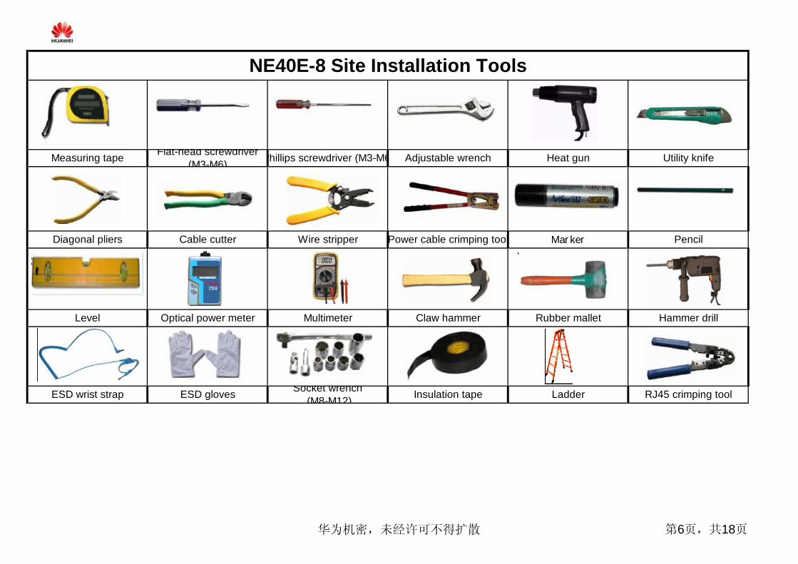
NE40E-8 Site Installation Tools
Measuring tape Flat-head screwdriver(M3-M6) Phillips screwdriver (M3-M6) Adjustable wrench
Marker
Heat gun Utility knife
PencilDiagonal pliers Cable cutter Wire stripper Power cable crimping tool
Hammer drillClaw hammer Rubber malletLevel Optical power meter Multimeter
RJ45 crimping toolESD wrist strap ESD gloves Socket wrench (M8-M12) Insulation tape Ladder
华为机密,未经许可不得扩散 第6页,共18页
1
2
3
4
5
123
1 2 34 5 6
1 2
3 45 6
Installation Duration
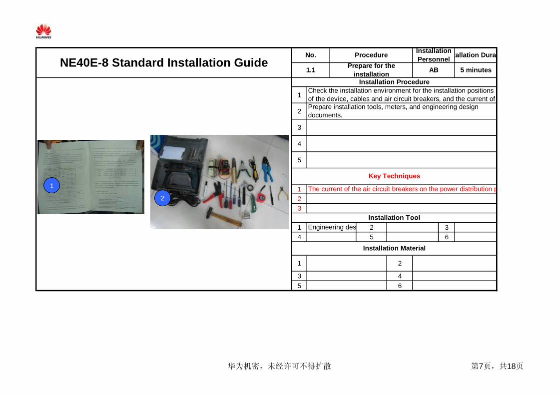
1.1 Prepare for theinstallation 5 minutes
Installation ProcedureCheck the installation environment for the installation positionsof the device, cables and air circuit breakers, and the current ofPrepare installation tools, meters, and engineering designdocuments.
NE40E-8 Standard Installation GuideNo. Procedure Installation
PersonnelAB
Key Techniques
The current of the air circuit breakers on the power distribution panel are not smaller than 100 A.
Installation ToolEngineering design document
Installation Material
1
2
华为机密,未经许可不得扩散 第7页,共18页

1
2
3
4
5
1
2
3
1 2 33 4 6
1 2
3 45 6
Installation Material
Installation Duration
During the transportation, moving and installation, preventproduct components from colliding with doors, walls, orAnytime when you intend to touch boards or metalcomponents, wear ESD gloves and touch only the edges of theboards during operations.
Installation Tool
Unpack and inspect thedelivery AB 15 minutes
Count materials. The quantities of the materials need to beconfirmed by the customer and Huawei.
Key Techniques
1.2
Flat-head screwdriver
NE40E-8 Standard Installation GuideNo. Procedure
Record in time the short shipment, wrong shipment, overshipment, or damages, and take photos to send them back to
Check the total number of packaging boxes based on the CaseCarton No. on each box. Inspect the packaging boxes. If thepackages are severely damaged or soaked, stop unpacking.Unpack the cartons, check that the number and type of boardsand installation related materials are consistent with those
InstallationPersonnel
Installation Procedure
Utility knife ESD-gloves PencialDiagonal pliers
华为机密,未经许可不得扩散 第8页,共18页

1
2
3
4
5
6
1
2
3
1 2 3
4 5 6
1 2
3 4
5 6
Adjust the height of the supports to ensure that the supportsare as high as the antistatic floor. Install the slide rails on theRemove the cabinet doors. Place the cabinet in position, put aninsulating plate on the cabinet bottom, and level the cabinet.
NE40E-8 Standard Installation GuideNo. Procedure Installation
PersonnelInstallation Duration
1.3 Install the cabinet on theantistatic floor AB 50 minutes
Installation Procedure
Lay out the marking-off plate and use a marker to mark theinstallation position according to the engineering design
Use a multimeter to measure the resistance between the boltand the grounding bolt of the rack. The resistance must be
Fix the front and rear support brackets on the supports.
Install the side panels of the cabinet.
Key Techniques
Installation Material
Level the cabinet.
N68E cabinet Expansion bolt
Socket wrench Rubber mallet Clawhammer
Marking-off plate
In the cabinet, the slide rails on which the device is installedmust be 2 U high from the cabinet bottom.
Installation Tool
Marker
Supports
Hammer drill Screwdriver
4 5 6
1
3
2
3
2
华为机密,未经许可不得扩散 第9页,共18页

1
2
3
4
5
6
1
2
3
1 2 3
4 5 6
1 2
3 4
5 6
Install the device to the cabinet and fix the device.
Install the side-hang fiber management trays.
Installation Material
When carrying the device to the cabinet, do not hold the handle onthe back of the device, because the handle is used for removing the
Installation ToolPhillipsscrewdriver Marker Wrench
NE40E-8 Standard Installation GuideNo. Procedure Installation
Personnel
Key Techniques
Installation Duration
1.4 Install the device AB 35 minutes
Installation ProcedureUse the rack-mounting ear to locate the installation holes of thecaptive nuts on the front column of the cabinet.
Fix the rack mounting ears to both sides of the device.
NE40E-8device
Rack-mounting ear12 captivenuts - M6Side-hangfiber
12 panelscrews -24 panelscrews - M4
2
4
3
1
华为机密,未经许可不得扩散 第10页,共18页
1
2
3
4
5
6
1
2
3
1 2 34 5 6
1 23 45 6
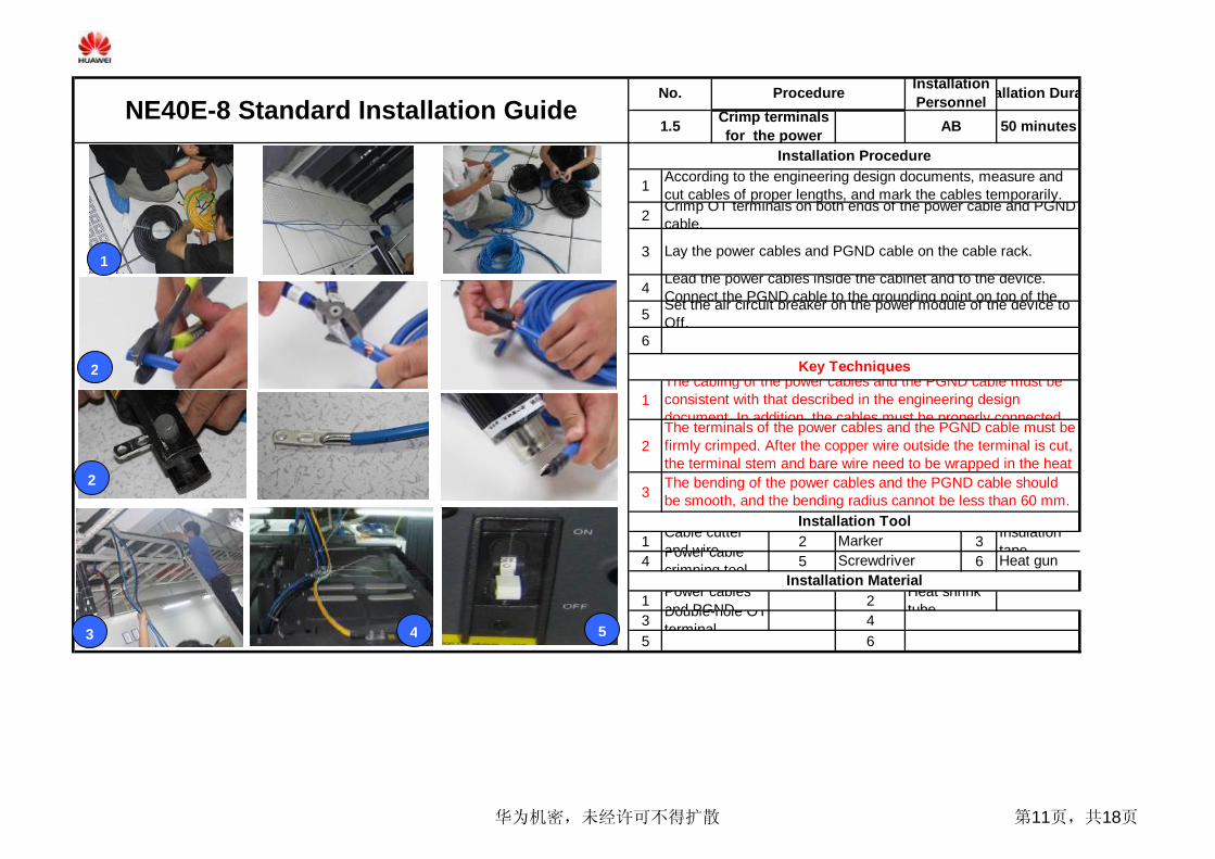
Lead the power cables inside the cabinet and to the device.Connect the PGND cable to the grounding point on top of the
The cabling of the power cables and the PGND cable must beconsistent with that described in the engineering designdocument. In addition, the cables must be properly connectedThe terminals of the power cables and the PGND cable must befirmly crimped. After the copper wire outside the terminal is cut,the terminal stem and bare wire need to be wrapped in the heatThe bending of the power cables and the PGND cable shouldbe smooth, and the bending radius cannot be less than 60 mm.
Installation Tool
Installation ProcedureAccording to the engineering design documents, measure andcut cables of proper lengths, and mark the cables temporarily.
NE40E-8 Standard Installation GuideNo. Procedure Installation
PersonnelInstallation Duration
1.5 AB 50 minutesCrimp terminalsfor the power
Crimp OT terminals on both ends of the power cable and PGNDcable.
Lay the power cables and PGND cable on the cable rack.
Set the air circuit breaker on the power module of the device toOff.
Key Techniques
Cable cutterand wire Marker Insulation
tapePower cablecrimping tool Screwdriver Heat gun
Installation MaterialPower cablesand PGNDDouble-hole OTterminal
Heat shrinktube
1
2
3
2
54
华为机密,未经许可不得扩散 第11页,共18页
1
2
3
4
5
6
1
2
3
1 2 3
4 5 6
1 2
3 4
5 6
Installation Material
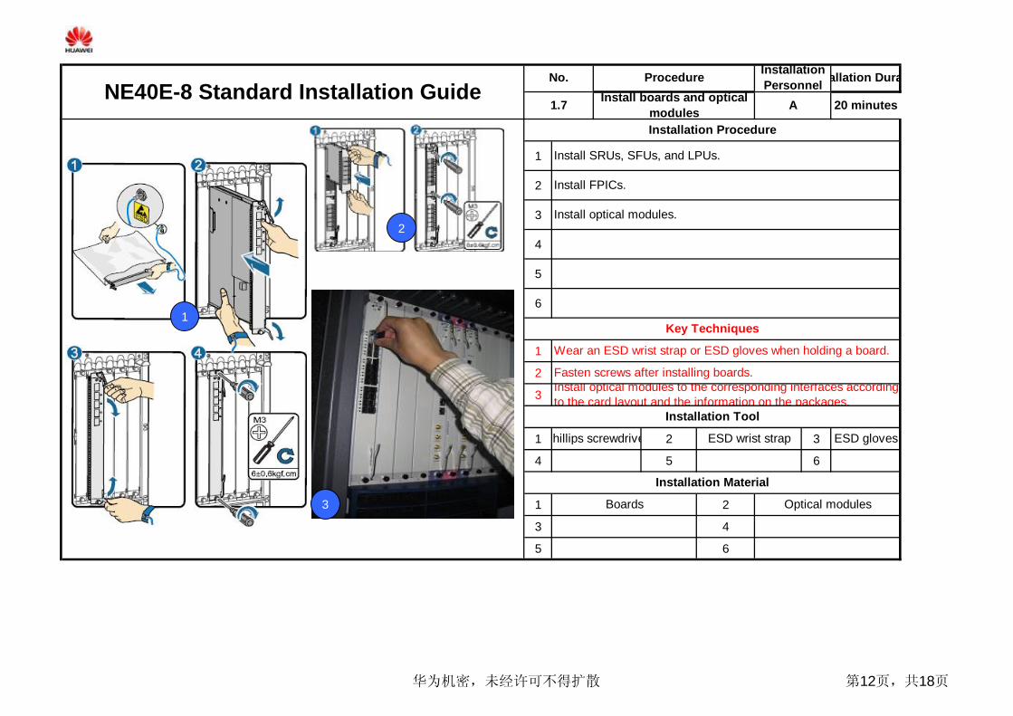
Install optical modules to the corresponding interfaces accordingto the card layout and the information on the packages.
Phillips screwdriver ESD wrist strap ESD gloves
Installation Procedure
Install SRUs, SFUs, and LPUs.
Install FPICs.
Install optical modules.
Fasten screws after installing boards.
NE40E-8 Standard Installation GuideNo. Procedure Installation
PersonnelInstallation Duration
1.7 Install boards and opticalmodules A 20 minutes
Key Techniques
Wear an ESD wrist strap or ESD gloves when holding a board.
Installation Tool
Boards Optical modules
1
2
3
华为机密,未经许可不得扩散 第12页,共18页

1
2
345678
1
2
3
4
1 2 3
4 5 6
1 2
3 4
5 6
The black/red power cable is connected to RTN (+); the blue power cableis connected to NEG (-).
Cable cutter Insulation tapeInstallation Tool
MultimeterSocketwrench/wrench Screwdriver
Power cable -blue
Power cable- black
NE40E-8 Standard Installation GuideNo. Procedure
Installation Material
80 minutes
Installation Procedure
To ensure safety, the power cable terminals connected to the powerdistribution cabinet must be wrapped in insulation tapes.
InstallationPersonnelInstallation Duration
On the cable rack, tidy and bind the power cables from the cabinetto the power distribution cabinet.Use a multimeter to measure the resistance between the externalinput power and the ground to ensure that there is no short circuit.
1.6.1 AInstall and bind the powercables and PGND cable
Connect the terminals to the power modules and bind the powercables to the cabinet with tie wraps.
Lead the power cables to the power distribution cabinet and wrapthe power cables in insulation tapes.
The power cables are laid smoothly and bound with proper strength, withtie wraps tidy and evenly distributed. The redundancies of the tie wrapsshould be cut, not leaving any burrs.
Switch off the corresponding air circuit breaker, remove the fuse,and disconnect the circuit.
PGND cable -yellow and Tie wrap
Connect the power cables to the power distribution cabinet andbind the cables with tie wraps.Connect one end of the PGND cable to the grounding point on topof the cabinet and the other end to the grounding copper bar in theGround the device by connecting the PGND cable of the cabinet tothe grounding point in the lower right corner on the back of the
Before power on the NE40E-8, use a multimeter to measure theresistance between the grounding point on the device and the groundingpoint of the cabinet. If the resistance is 0 ohms, it indicates that the
Key Techniques
34
7
1
5
6
1 2
5
7
4
8
华为机密,未经许可不得扩散 第13页,共18页

1
2
3
4
5
6
1
2
3
1 2 3
4 5 6
1 2
3 4
5 6
NE40E-8 Standard Installation GuideNo. Procedure Installation
PersonnelInstallation Duration
1.6.2 Install optical fibers B 110minutes
Installation ProcedureTake out optical fibers from the carton, remove the packages,and use a marker to mark on both ends of each optical fiber.Manage the optical fibers, spread them, and lay them straighton the floor in bundles.Cut the PVC bellows of a proper length and insert the opticalfibers into the bellows.Lay the optical fibers on the cable rack and bind them to thecable rack.Lead the optical fibers into the cabinet, manage them, and bindthem to the cabinet.Connect the other end of each optical fiber to the correspondingplace on the ODF.
Key TechniquesLay the power cables, PGND cable, and optical fibers separatelyand bind them with proper strength, with tie wraps tidy andThe bending radius of the optical fibers should not be less than40 mm.
Installation Tool
Cable cutter Marker Insulationtape
Installation Material
Optical fibers PVC bellow
Tie wrap
11
34
5
2
6
华为机密,未经许可不得扩散 第14页,共18页

1
2
3
4
5
6
1
2
3
1 2 3
4 5 6
1 2
3 4
5 6
NE40E-8 Standard Installation GuideNo. Procedure Installation
PersonnelInstallation Duration
1.9 Make and paste labels AB 40 minutes
diagonal pliers Marker Label printer
Installation ProcedurePaste printed labels (permanent labels) or written labels(temporary labels) to corresponding places on devices, boards,
Installation Material
Engineering label - signal cable labelEngineering label - power cable label
Cabinet doorhead label
Key TechniquesTie wraps are used to bind the identification plates to powercables. All the identification plates need to be of the same
Installation Tool
By default, a label is pasted 2 cm from the connector.
1
2
华为机密,未经许可不得扩散 第15页,共18页

1
2
3
4
5
1
2
3
4
1 2 34 5 6
1 2
3 4
5 6
NE40E-8 Standard Installation GuideNo. Procedure Installation
PersonnelInstallation Duration
1.10 Check the deviceinstallation AB 10 minutes
Installation ProcedureCheck the appearance and installation position of the N68Ecabinet against the Device Installation Checklist.Check that the cabling route of the NE40E-8 signal cables iscorrect, connectors are tight and firm, and labels are pasted andCheck that the cabling route of the NE40E-8 power cables andPGND cable is correct and cable connectors are tight and firmCheck that no tie wraps or other debris are left inside thecabinet against the NE40E Installation Environment Checklist.
Key TechniquesThe horizontal error and the vertical error of the cabinet shouldbe less than 3 mm.Cable connectors must be tight and firm, and labels on both ends of a cable must be clear.The cabinet surface must be tidy and clean, with intact paint. Allidentifiers are correct, clear, and complete.The switches on the power distribution cabinet and switches on the device must be set to Off.
Installation ToolLevel
Installation Material
华为机密,未经许可不得扩散 第16页,共18页

1
2
3
4
5
6
1
2
3
1 2 3
3 4 6
1 2
3 4
5 6
Multimeter
NE40E-8 Standard Installation Guide
Use a multimeter to measure whether the output voltage of thepower distribution cabinet is within the required range.
Installation Duration
1.11 Check the power-on of thedevice AB 10 minutes
No. Procedure InstallationPersonnel
Installation Procedure
Installation Tool
Use a multimeter to measure whether the input voltage of thedevice is within the required range.Switch on the power modules of the device. After the boards areregistered, the RUN indicator blinks.
Key TechniquesBefore powering on the device, use a multimeter to measurethe DC voltage.Check whether the input cable of the DC power module iscorrectly connected. Use a multimeter to measure that the inputIf the ALM indicator is on or the RUN indicator is blinking at afrequency of 2 Hz, the device is in the abnormal state. If the
Installation Material
1
3
2
华为机密,未经许可不得扩散 第17页,共18页
1
2
3
4
5
6
1
2
3
1 2 3
3 4 6
1 2
3 4
5 6
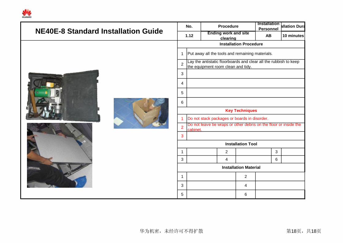
Installation Procedure
Put away all the tools and remaining materials.
Lay the antistatic floorboards and clear all the rubbish to keepthe equipment room clean and tidy.
NE40E-8 Standard Installation GuideNo. Procedure Installation
PersonnelInstallation Duration
1.12 Ending work and siteclearing AB 10 minutes
Key Techniques
Do not stack packages or boards in disorder.
Installation Tool
Installation Material
Do not leave tie wraps or other debris on the floor or inside thecabinet.
华为机密,未经许可不得扩散 第18页,共18页