standard specifications for … for construction of trails and ... 101.03 of the standard...
TRANSCRIPT
STANDARD SPECIFICATIONS FOR CONSTRUCTION OF TRAILS AND TRAIL
BRIDGES ON FOREST SERVICE
PROJECTS U.S. Customary Units
National Technology and Development Program
10/30/2014
Supersedes the 1996 Standard Specification for Construction and Maintenance of Trails

Table of Contents Section 900. General Requirements 901. Terms, Format, Abbreviations, and Definitions 902. Intent of Contract 903. Control of Work 904. Control of Materials 905. Quality Assurance and Quantity of Measurement 906. Measurement and Payment 907. Mobilization 908. Construction Survey, Staking, Flagging and Cleanup 909. Maintenance for Traffic and Temporary Construction Access
909.10 Maintenance for Traffic 909.20 Temporary Construction Access
Construction Specifications
910. Trailway 911.00. Tread and Prism
911.10. Excavation and Embankment 911.20. Borrow 911.30. Existing Trail Restoration 911.40. Slide Maintenance 911.50. Slough and Berm Removal 911.60. Obliteration of Abandoned Trails 911.70. Retainers
912.00. Clearing Limits 912.10. Clearing and Grubbing 912.20. Brush Cutting 912.30. Logging Out 912.40. Hazard Tree Removal 912.50. Loose Rock Removal 912.60. Rock and Root Removal
913.00. Surfacing 913.10. Aggregate Surfacing and Base Course 913.20. Hot Asphalt Surfacing 913.30. Cold Asphalt Surfacing 913.40. Grid Unit Surfacing 913.50. Riprap Surfacing 913.60. Chunk Wood Surfacing 913.70. Imported Clay Surfacing 913.80. Surface Maintenance
10/30/2014 Trail Specifications-1

914.00. Climbing Turn 914.10. Climbing Turn 914.20. Climbing Turn Maintenance
915.00. Talus Section 915.10. Talus Section 915.20. Talus Section Maintenance
916.00. Turnout and Passing Section 916.10. Turnout and Passing Section 916.20. Turnout and Passing Section Maintenance
917.00. Fords 917.10. Natural Ford 917.20. Constructed Ford with Rock Structure 917.30. Constructed Ford with Log Structure 917.40. Stepping Stones 917.50. Ford Maintenance
918.00. Foundations 918.10. Rock Foundations 918.20. Gabion Basket Foundations 918.30. Crib Foundations 918.40. Geosynthetic Foundations 918.50. Corduroy Foundations 918.60. Foundation Maintenance
919. Reserved for Trailway Special Project Specifications
920. Drainage Structures 921.00. Culverts
921.10. Standard Culvert 921.20. Standard Culvert with Headwalls 921.30. Rock Culvert 921.40. Treated Timber Box Culvert 921.50. Open-Top Drain 921.60. Bottomless Arch Culvert 921.70. Log Culvert 921.80. Culvert Maintenance
922.00. Waterbars 922.10. Rock Waterbar 922.20. Log or Treated Timber Waterbar 922.30. Belted Waterbar 922.40. Waterbar Maintenance
923.00. Spillways 923.10. Rock Spillway 923.20. Rock Spillway Maintenance
924.00. Underdrains 924.10. Rock Underdrain 924.20. Sheet Underdrain 924.30 Underdrain Maintenance
10/30/2014 Trail Specifications-2

925.00. Ditches 925.10. Side Ditch 925.20. Leadoff Ditch 925.30. Ditch Maintenance
926.00. Berms 926.10. Berm 926.20. Berm Maintenance
927.00. Drain Dips 927.10. Drain Dip 927.20. Drain Dip Maintenance
928.00. Check Dams 928.10. Check Dam 928.20. Check Dam Maintenance
929. Reserved for Drainage Structures Special Project Specifications
930. Trail Structures 931.00. Switchbacks
931.10. Type 1 – Radius Switchback 931.20. Type 2 – Circular Landing Switchback 931.30. Type 3 – Rectangular Landing Switchback 931.40. Switchback Maintenance
932.00. Turnpikes 932.10. Type 1 – Standard Turnpike 932.20. Type 2 – Standard Turnpike with Foundation 932.30. Turnpike Maintenance
933.00. Side Barriers 933.10. Stacked Rock Barrier 933.20. Masonry Rock Barrier 933.30. Barrier Rail on Grade 933.40. Barrier Rail on Post 933.50. Curbs 933.60. Guardrail 933.70. Side Barrier Maintenance
934.00. Puncheons 934.10. Standard Puncheon 934.20. Puncheon Without Decking 934.30. Puncheon Maintenance
935.00. Retaining Walls 935.10. Log Crib 935.20. Stacked Rock Retaining Wall 935.30. Wire Basket Retaining Wall 935.40. Masonry Rock Retaining Wall 935.50. Cast-in-place Concrete Retaining Wall 935.60. Retaining Wall Maintenance
10/30/2014 Trail Specifications-3

936.00. Stairways 936.10. Individual Steps 936.20. Overlapping Steps 936.30. Crib Ladder 936.40. Staircase 936.50. Ladder 936.60. Stairway Maintenance
937.00. Railing System 937.10. Railing System 937.20. Railing System Maintenance
938.00. Boardwalks 938.10. Standard Boardwalk 938.20. Elevated Boardwalk 938.30. Step and Run 938.40. Boardwalk Maintenance
939. Reserved for Trail Structures Special Project Specifications
940. Restriction Devices 941.00. Fences
941.10. Post and Wire Fence 941.20. Post and Rail Fence 941.30. Woven Wire Fence 941.40. Jack Leg Fence 941.50. Stacked Rail (Worm) Fence 941.60. Remove and Reset Fence 941.70. Fence Maintenance
942.00. Gates 942.10. Wire Gate 942.20. Swing Gate 942.30. Loose Rail Gate 942.40. Accessible Gate – Kissing Gates 942.50. Accessible Gate – Chicanes 942.60. Gate Maintenance
943.00. Cattle Guards 943.10. Standard Cattle Guard 943.20. Above Ground Cattle Guard 943.30. Cattle Guard Maintenance
944.00. Stiles 944.10. Stiles 944.20. Stile Maintenance
945.00. Bollards 945.10. Bollards 945.20. Bollard Maintenance
949. Reserved for Restriction Devices Special Project Specifications
10/30/2014 Trail Specifications-4

950. Signs and Markers 951.00. Signs
951.10. Signs 951.20. Sign Repair and Replacement Maintenance
952.00. Route Markers 952.10. Route Markers 952.20. Route Marker Maintenance
953.00. Reassurance Markers 953.10. Standard Forest Service Blaze 953.20. Manufactured Blazer 953.30. Reassurance Marker Maintenance
954.00. Mileage Markers 952.10. Mile Markers 952.20. Mileage Marker Maintenance
955.00. Cairns 955.10. Cairns 955.20. Cairn Maintenance
959. Reserved for Route Markers and Signs Special Project Specifications
960. Trail Bridges 961.00. Log Stringer Trail Bridge
961.10. Single Log Stringer Trail Bridge 961.20. Multiple Log Stringer Trail Bridge
962.00. Sawn Timber Trail Bridge 962.10. Sawn Timber Stringer Trail Bridge 962.20. Longitudinal Nail-Laminated Timber Trail Bridge 963.00 Glulam Trail Bridge 963.10. Glulam Stringer Trail Bridge 963.20. Longitudinal Glulam Deck Panel Trail Bridge 964.00. Prefabricated Steel Trail Bridge 965.00. Trail Bridge Substructures
965.10. Timber Sill on Geocell Pad 965.20. Timber Sill on Gabion Basket 965.30. Timber Sill on Timber Cribbing 965.40. Concrete Leveling Pad on Bedrock 966.00. Trail Bridge Maintenance 969. Reserved for Trail Bridge Special Project Specifications
970. Specialty Structures 971. Reserved for Snow Sheds 972. Reserved for Tunnels 979. Reserved for Specialty Structures Special Project Specifications
10/30/2014 Trail Specifications-5

980. Incidentals 981.00. Seeding, Fertilizing and Mulching 982.00. Erosion Control Blankets 983.00. Removal of Structures and Obstructions 989.00. Reserved for Incidentals Special Project Specifications
990. Material 991.00. Rock, Grid Pavement Unit, Aggregate and Asphalt
991.01 Rock 991.02 Gabion and Revet Mattress Rock 991.03 Grid Pavement Unit 991.04 Pit-Run Aggregate 991.05 Screened Aggregate 991.06 Crushed Aggregate for Base or Surface Course 991.07 Asphalt 991.08 Cement
992.00. Pipe Material 993.00. Fence Material 994.00. Geosynthetic Material
994.01 Geotextile 994.02 Geonet 994.03 Geogrid 994.04 Geocell 994.05 Sheet Drains
995.00. Material for Timber Structures 996.00. Gabion and Revet Mattress Material
10/30/2014 Trail Specifications-6

Section 900 General Specifications
10/30/2014 Trail Specifications-7

Section 901—Terms, Format, Abbreviations and Definitions 901.01 Meaning of Terms. These specifications are generally written in the imperative mood. In sentences using the imperative mood, the subject “the Contractor,” is implied. Also implied in this language is “shall,” “shall be,” or similar words or phrases. In material specifications, the subject may also be the supplier, fabricator, or manufacturer supplying material, products, or equipment for use on the project.
Wherever “directed,” “required,” “prescribed,” or similar words are used, the “direction,” “requirement,” or “order” of the Contracting Officer is intended. Similarly, wherever “approved,” “acceptable,” suitable,” “satisfactory,” or similar words are used, they mean “approved by,” “acceptable to,” or “satisfactory to” the Contracting Officer.
The word “will” generally pertains to decisions or actions of the Contracting Officer.
Whenever in these specifications, or in other contract documents, the following terms (or pronouns in place of them) are used, the intent and meaning shall be interpreted as follows: reference to a specific standard, test, testing method, or specification shall mean the latest published edition or amendment that is in effect at the solicitation issue date for the public works contracts.
901.02 Specification Format These specifications are divided into Sections.
Sections 900 through 906, 908 and 909 consist of general contract requirements for which no direct payment is made. The requirements contained in Sections 900 through 906 are applicable to all contracts.
Sections 907, 908, 909 and 910 through 989 consist of construction contract requirements for specific items of work. Work under these Sections is paid for directly or indirectly according to Subsection 906.04 and the Section ordering the work. When there is no pay item in the bid schedule, no direct payment is made.
Sections 990 through 999 contain the material requirements for Sections 910 through 989. No direct payment is made in Sections 990 through 999. Payment for material is included as part of the work required in Sections 910 through 989.
The first three digits of the pay item number identify the Section under which the work is performed.
901.03 Abbreviations. Whenever these abbreviations are used in the specifications, they represent the following:
(a) Acronyms
AASHTO American Association Of State Highway And Transportation Officials ABS Acrylonitrile-Butadiene-Styrene
10/30/2014 Trail Specifications-8

AITC American Institute of Timber Construction ANSI American National Standards Institute AQ Actual Quantities APA American Plywood Association ASTM American Society For Testing And Material AWPA American Wood Protection Association CO Contracting Officer C.F. Cubic Feet C.Y. Cubic Yard DQ Design Quantities EA Each FAR Federal Acquisition Regulation g Grams HDPE High-Density Polyethylene hr Hour kg Kilogram kN Kilonewtons lb Pound L.F. Linear Feet LS Lump Sum LSQ Lump Sum Quantities m Meter m2 Square Meter m3 Cubic Meter mi Mile mm Millimeter MPa Megapascals MSE Mechanically Stabilized Earth N Newton NBS National Bureau Of Standards NCMA National Concrete Masonry Association OSHA Occupational Safety & Health Administration Pa Pascal PE Polyethylene PS Product Standard Issued By The U.S. Department Of Commerce psi Pounds Per Square Inch PVC Polyvinyl Chloride S.F. Square Feet SQ Staked Quantities S.Y. Square Yard WCLIB West Coast Lumber Inspection Bureau WWPA Western Wood Products Association WWPI Western Wood Preservers Institute
10/30/2014 Trail Specifications-9
Additional abbreviations may be found in Section 101.03 of the Standard Specifications for Construction of Roads and Bridges on Federal Highway Projects (FP-03).
(b) Slope notation (vertical: horizontal). For slopes flatter than 1:1, express the slope as the ratio of one unit vertical to a number of units horizontal. For slopes steeper than 1:1, express the slope as the ratio of a number of units vertical to one unit horizontal.
901.04 Definitions The following terms, or pronouns in place of them, are used in these specifications or in other contract documents, the intent and meaning are as follows:
Barriers. A fence or other obstacle that prevents movement or access. Base Course. The layer or layers of specified material of designed thickness placed on a trailbed to support surfacing.
Batter. A backward and upward slope of the face of a wall.
Berm. The ridge of material formed on the outer edge of the trail that projects higher than the tread.
Borrow. Suitable materials taken from approved sources designated on the plans or on the ground, to be used for embankments and backfilling.
Bridge. A trail structure, including supports, erected over a depression or obstruction such as a body of water, a road, a trail, or a railroad that provides a continuous pathway and that has a deck for carrying traffic or other loads.
Cap Rock. Rock placed in the top or uppermost layer in a constructed rock structure, such as a talus or rubble rock section or rock retaining wall.
Catch Point. The outer limits of a trailway where the excavation and/or embankment intersect with the ground line.
Clearing Limit. The area over and beside the trail that is cleared of trees, limbs, and other obstructions.
Climbing Turn. A reverse in direction of trail grade without a level landing used to change elevation on a steep slope.
Compacted. Consolidation that is obtained by tamping or rolling suitable material until no noticeable displacement of material is observed.
Contracting Officer (CO). An official of the Government with the authority to enter into, administer, and/or terminate contracts and make related determinations and findings. The term includes certain authorized representatives of the CO acting within the limits of their authority as delegated by the CO.
Culvert. Any structure with a bottom, regardless of the fill depth, the depth of invert, or the presence of a horizontal driving surface, or any bottomless (natural
10/30/2014 Trail Specifications-10

channel) structure with footings that does not have wheel loads in direct contact with the top of the structure.
Curb. A border defining the edge of the trail or trail bridge.
Cushion Material. Native or imported material generally placed over rocky section of unsurfaced trail to provide a usable and maintained traveled way.
Designated on the Ground. The location of materials, work areas, and construction items, including lines and grades, marked on the ground with stakes, flagging, tags, or paint.
Drawings. Design sheets or fabrication, erection, or construction details submitted to the Government by the Contractor according to FAR Clause 52.236-21 Specifications and Drawings for Construction. Also refers to submissions and submittals.
Duff. Organic material overlying rock or mineral soil.
Embankment. A structure of suitable material placed on the prepared ground surface and constructed to the trailbed elevation.
Excess Excavation. Material in the trailway in excess of that needed for construction of designed trailways.
Falsework. Temporary construction work on which a main work is wholly or partly built and supported until the main work is strong enough to support itself.
Ford. A water-level stream crossing constructed to provide a level surface for safe traffic passage. Full Bench. Trailbed constructed entirely on undisturbed material.
Gabion Basket. Rectangular wire baskets filled with rock used as pervious, semiflexible building blocks for slope and foundation stabilization.
Grade. The vertical distance of ascent or descent of the trail expressed as a percentage of the horizontal distance.
Hazard Tree. An unstable tree that is likely to fall across the trail. Header Rock. Rock laid with the narrow end towards the face of the wall.
Inslope. Where the trails tread is sloped downward toward the backslope.
Leave Tree. Trees designated to be left or to remain undisturbed after trail construction. Mineral Soil. Soil or aggregate that is free from organic substances and contains no particles larger than 2 inches at their greatest dimension.
Outslope. Where the trail tread is sloped downward toward the embankment or daylight side of the trailway.
Plans. The contract plans furnished by the Government showing the location, type, dimensions, and details of work.
10/30/2014 Trail Specifications-11

Retainers. Embedded border of wood or rock used to retain fill and/or surface material. Sideslope. The natural slope of the ground, usually expressed as a percentage.
Slough. That material from the backslope or the area of the backslope that has raveled onto the trailbed.
Slump. Where the trailbed material has moved downward, causing a dip in the trail grade.
Special Contract Requirements. Specifications that detail the conditions and requirements peculiar to an individual project, including additions and revisions to the standard specifications.
Standard Plans. Detailed plans approved for repetitive use and included as part of the plans.
Standard Specifications. The Standard Specifications for Construction of Trails on Federal Projects approved for general application and repetitive use.
Surfacing. Material placed on top of the trailbed or base course that provides the desired tread.
Suitable Material. Rock that can be accommodated in the trail structure, and soil free of duff with a recognizable granular texture.
Switchback. A reverse in direction of trail grade with a level landing used to change elevation on a steep slope, usually involving special treatment of the approaches, barriers, and drainages.
Trailbed. The finished surface on which base course or surfacing may be constructed. For trails without surfacing the trailbed is the tread.
Trailway. The portion of the trail within the limits of the excavation and embankment.
Tread. The surface portion of the trail upon which traffic moves.
Turnout. A short section of extra trail width to provide for passage of trail users.
Waterbar. A structure used for turning water off the trail, usually made of logs or stones.
Water Courses. Any natural or constructed channel where water naturally flows or will collect and flow during spring runoff, rainstorms, etc.
Additional definitions may be found in Section 101.03 of the Standard Specifications for Construction of Roads and Bridges on Federal Highway Projects (FP-03).
10/30/2014 Trail Specifications-12

Section 902—Intent of Contract 902.01 Intent of Contract. The intent of the contract is to provide for the construction and completion of the work described. The precise details of performing the work are not stipulated except as considered essential for the successful completion of the work. Furnish all labor, material, equipment, tools, transportation, and supplies necessary to complete the work according to the contract.
10/30/2014 Trail Specifications-13
Section 903—Control of Work
903.01 Specifications and Drawings. Follow the requirements of FAR Clause 52.236-21 Specifications and Drawings for Construction.
(a) General. Prepare drawings as necessary to construct the work. Drawings include, but are not limited to, layouts that show the relative position (vertical and horizontal as appropriate) of work to be performed, fabrication details for manufactured items and assemblies, installation and erection procedures, details of post-tensioning and other systems, detailed trench and excavation procedures that conform to OSHA requirements, traffic control implementation drawings, and methods for performing work near existing structures or other areas to be protected. Show all the drawing dimensions in United States customary units.
Drawings shall be a minimum size of 11 by 17 inches and a maximum size of 24 by 36 inches. All text should have a minimum height of 1/8 inch for 24 by 36 inch drawings (D size sheets). Include on each drawing and calculation sheet, the project number, name, and other identification as shown in the contract.
Furnish 5 sets of drawings and supporting calculations for acceptance before performing work covered by the drawings. If drawings are returned for revision, correct and resubmit for acceptance. Allow 40 days per submission for railroad structures and 30 days per submission for all other structures. The review time as specified is applied separately to each drawing submitted. The CO may request additional specific drawings for unique situations in order to clarify layout, construction details, or methodology. If drawings must be resubmitted, the time for acceptance starts over. Obtain written approval before changing or deviating from the accepted drawings.
(b) Specific requirements for concrete and miscellaneous structures.
(1) Furnish drawings for the following:
(a) Site-specific layouts for all wall types and gabion installations;
(b) Gabion and revet mattress details and installation procedures;
(c) Forms and falsework for reinforced concrete box culverts less than or equal to 6 feet in height;
10/30/2014 Trail Specifications-14

(d) Fabrication drawings for bridge railings and parapets;
(e) Fabrication drawings for prestressed members;
(f) Fabrication and installation drawings for expansion joint assemblies;
(g) Fabrication drawings for bearing assemblies;
(h) Construction joint location and concrete deck placement sequences not shown on the plans;
(i) Erection diagrams for Soil-Corrugated Metal Structure interaction systems (multi-plate structures);
(j) Structural steel fabrication drawings;
(k) Utility hangar details; and
(l) Fabrication and installation drawings for precast items.
(2) Furnish drawings that bear the seal and signature of a professional engineer proficient in the pertinent design field for the following:
(a) Erection plans;
(b) Reinforced soil slopes details;
(c) MSE wall and crib wall details;
(d) Details and installation procedures for proprietary wall systems;
(e) Temporary bridge structures for public use;
(f) All bridge forms except for railings, parapets, and components less than 6 feet in height;
(g) Shoring systems and cofferdams greater than 6 feet in height;
(h) All shoring systems that support traffic loadings;
(i) Forms and falsework for all structures greater than 6 feet in height;
(j) Post-tensioning systems;
(k) Ground anchors, soil nail, and rock bolt assembly details, layout, and installation and testing procedures;
(l) Tie back wall details; and
(m) Alternate retaining wall details.
(3) Furnish drawings that bear the seal and signature of a professional engineer who is proficient in forms and falsework
10/30/2014 Trail Specifications-15

design and licensed in the state where the project will be constructed for the following:
(a) Falsework for any structure with a span exceeding 16 feet;
(b) Falsework for any structure with a height exceeding 14 feet; and
(c) Falsework for structures where traffic, other than workers involved in constructing the structure, will travel under the structure.
10/30/2014 Trail Specifications-16

Section 904—Control of Materials 904.01 Handling Materials. Transport and handle all materials to preserve their quality and fitness for the work. Stockpile, load, and transport aggregates in a manner that will preserve specified gradation and avoid contamination.
Store materials to assure the preservation of their quality and fitness for the work. Locate stored materials to facilitate their prompt inspection. Sites on Government-administered land that are not already designated may be used for storage purposes and for placing of equipment only when approved in advance by the CO. Restore all storage sites in accordance with requirements SHOWN ON THE PLANS or as otherwise specified. Arrangements for storage on other than designated sites are the responsibility of the contractor.
904.02 Material Sources (a) Designated Sources. Sources for materials such as, but not limited to, soil, rock, or logs that are not available from trailway excavation or clearing operations will be designated. Sources of local materials designated in the SPECIAL CONTRACT REQUIREMENTS or SHOWN ON THE PLANS are guaranteed by the Government for the quality and quantity of material in the source.
Use all needed suitable material from the source. The designation of a source includes the right to use areas SHOWN ON THE PLANS for the purposes designated (such as plant sites, stockpiles, and haul roads). Operations are restricted to the confines of the area(s) designated.
Comply with the requirements of 30 CFR 56, subparts B and H. When required, re-establish vegetation in disturbed areas according to section 981.
(b) Contractor-Furnished Sources. Furnish material that produces an end product equivalent in performance to that specified.
904.03 Restoration. Shape and grade borrow areas on Government-administered land to make them stable and to minimize future erosion. Dispose of debris resulting from development of material sources by scattering, unless otherwise specified. Do not scatter debris within the clearing limits of trails or within roadsides. Cut off stumps to less than 12 inches above the ground as measured on the uphill side of the stump.
10/30/2014 Trail Specifications-17

Section 905—Quality Assurance and Quantity Measurement
Description 905.01 This work consists of providing certification that the quality and quantity of construction conform to the plans, specifications, and requirements of the contract.
Construction 905.02 Certification and Measurements (a) Offsite-Produced Materials. Furnish signed certificates executed by the manufacturer, supplier, or vendor, stipulating that all offsite-produced materials incorporated in the work meet applicable requirements SHOWN ON THE PLANS or stated in the specifications. Furnish a certificate for each commodity or invoice.
(b) Quantity Measurements. Submit quantities to the CO for periodic progress payments, and the CO will compute payments. Quantities are subject to verification.
905.03 Records. Maintain a set of contract plans depicting as-built conditions resulting from approved changes. Maintain the plans in a current condition and indicate changes from the original contract plans in red. Give the plans to the CO upon the completion of the contract work.
Measurement 905.04 Method. There will be no separate measurement for this item.
Payment 905.05 Payment will be considered incidental to other pay items in this contract.
10/30/2014 Trail Specifications-18

Section 906—Measurement and Payment
906.01 General. Measurement and payment for contract work will be made only for and under those pay items included in the SCHEDULE OF ITEMS. All other work and materials will be considered incidental and included in the payment of the PAY ITEMS in the SCHEDULE OF ITEMS.
When more than one class, size, or thickness is specified in the SCHEDULE OF ITEMS for any PAY ITEM, suffixes will be added to the item number to differentiate between the items.
906.02 Determination of Quantities. The following measurements and calculations are to be used to determine contract quantities for payment:
Make measurements for seeding, geotextiles, and erosion control blankets along slope lines.
For retaining walls, measure by the square foot of front wall face.
Measure structures according to neat lines SHOWN ON THE PLANS or as altered by the CO in writing to fit field conditions. Make measurements along the centerline and parallel to the specified grade or foundation or as SHOWN ON THE PLANS.
Deduct lengths for stairways, turnpike, puncheon, retaining walls, wire baskets, switchbacks, bridges, and bridge approaches from the measurement of excavation in Section 911 unless these items are specified as incidental to excavation in Section 911.
For standard manufactured items, such as fence, wire, plates, rolled shapes, and pipe conduits identified by gage, weight, section dimensions, and the like, such identification shall be considered the nominal weights or dimensions. Manufacturer’s tolerances will be accepted unless controlled by tolerances in the cited specifications.
906.03 Units of Measurement. Payment will be made by units defined and determined according to U.S. Customary measure and by the following:
(a) Cubic Yard. A measurement computed by one of the following methods:
(1) Excavation, embankment, or borrow. The measurement computed by the average-end-area method from measurements made longitudinally along a centerline or other reference line.
(2) Material in place or stockpiled. The measurement computed with the dimensions of the in-place material using average-end-area method or prismodial formula.
(3) Material in the Delivery Vehicle. The measurement computed using measurements of material in the hauling vehicles at the point of delivery.
10/30/2014 Trail Specifications-19

Vehicles shall be loaded to at least their water-level capacity. Leveling of the loads may be required when vehicles arrive at the delivery point.
(b) Each (EA). One complete unit, which may consist of one or more parts.
(c) Lump Sum (LS). The quantities that denote one complete unit of work as required by or described in the contract, including necessary materials, equipment, and labor to complete the job.
906.04 Methods of Measurement. One of the following methods of measurement for determining final payment is DESIGNATED ON THE SCHEDULE OF ITEMS for each PAY ITEM:
(a) Designed Quantities. These quantities denote the final number of units to be paid for under the terms of the contract. They are based upon the original design data available prior to advertising the project. Original design data include the preliminary survey information, design assumptions, calculations, and plans. Changes in the number of units DESIGNATED IN THE SCHEDULE OF ITEMS may be authorized under the following conditions:
(1) As a result of changes in the work approved by the CO.
(2) As a result of the CO determining that errors exist in the original design that cause a PAY ITEM quantity to change by 15 percent or more.
(3) As a result of the contractor submitting to the CO a written request showing evidence of errors in the original design that cause a PAY ITEM quantity to change by 15 percent or more. The evidence must be verifiable and consist of calculations, plans, or other data that show how the designed quantity is believed to be in error.
(b) Staked Quantities (SQ). These quantities are determined from staked measurements prior to the construction.
(c) Actual Quantities (AQ). These quantities are determined from measurement of completed work.
(d) Vehicle Quantities. These quantities are measured or weighed in hauling vehicles.
(e) Lump Sum Quantities (LSQ). These quantities denote one complete unit of work as required by or described in the contract, including necessary materials, equipment, and labor to complete the job.
906.05 Government-Furnished Materials. When materials are furnished by the Forest Service, the note “Government-Furnished Materials” will be added to the description of the PAY ITEM.
10/30/2014 Trail Specifications-20
Section 907—Mobilization Description
907.01 This work consists of moving personnel, equipment, material, and incidentals to the project and performing all work necessary before beginning work at the project site. Mobilization includes the costs associated with obtaining permits, insurance, and bonds. Mobilization is not intended to pay for the costs of materials before they are used on the project site.
Payment 907.02 The accepted quantity, measured as provided in Subsection 906.02, will be paid at the contract price per unit of measurement for the Section 907 pay item shown in the bid schedule. Payment will be full compensation for the work prescribed in this Section.
Progress payments for mobilization lump sum will be paid as follows:
(a) Bond premiums will be reimbursed according to FAR Clause 52.232-5, Payments Under Fixed-Price Construction Contracts, after receipt of the evidence of payment. Reimburse for bond premiums before issuing the Notice to Proceed if evidence of payment is received.
(b) When 5 percent of the original contract amount is earned from other bid items, 50 percent of the mobilization item, or 5 percent of the original contract amount, whichever is less, will be paid.
(c) When 10 percent of the original contract amount is earned from other bid items, 100 percent of the mobilization item, or 10 percent of the original contract amount, whichever is less, will be paid.
(d) Any portion of the mobilization item in excess of 10 percent of the original contract amount will be paid after final acceptance. Pay any unpaid amount for mobilization upon final acceptance of all work items.
10/30/2014 Trail Specifications-21

Section 908—Construction Staking, Flagging, and Cleanup Description
908.01 This work consists of establishing any control points needed in addition to existing staking, and removing and disposing of all construction stakes, tags, flagging, and plastic ribbon from the project area.
Construction 908.02 General. The Government will set initial construction stakes or flagging, and control points, and furnish the contractor with all necessary information relating to lines, slopes, and grades. These stakes and flagging constitute the field control.
Furnish and maintain additional stakes, flagging, templates, batter boards, and other materials and supplies necessary for marking and maintaining points and lines established. Do not perform work in the absence of control points. If any construction control points are destroyed, displaced, or erroneous, notify the CO. Uniformly contour alignment and construct grade from control point to control point.
Remove all construction stakes, tags, flagging, and plastic ribbon from the project area within 7 days after the final inspection of all other work on the project. Dispose of all stakes, tags, flagging, and plastic ribbon off Government-administered lands unless otherwise designated.
Measurement 908.03 There will be no separate measurement for this item.
Payment 908.04 Trail staking, flagging, and cleanup will be considered incidental to other pay items in this contract, and additional payment will not be made.
10/30/2014 Trail Specifications-22

Section 909— Maintenance for Traffic and Temporary Construction Access Description
909.00.01 This work consists of maintaining existing trails that are undergoing improvements open and maintained in such a condition as to safely accommodate traffic and providing temporary construction access to the site. Maintaining the trail for traffic and temporary access may be covered by subsection:
909.10 Maintenance for Traffic 909.20 Temporary Construction Access
Measurement
909.00.02 There will be no separate measurement for these items.
Payment 909.00.03 Maintaining the trail for public access and providing temporary construction access will be considered incidental to other pay items in this contract, and additional payment will not be made.
909.10 - Maintenance for Traffic Description
909.10.01 Keep existing trails that are undergoing improvements open and maintained in such a condition as to safely accommodate traffic. Provide and maintain temporary detours, approaches, or crossings and intersections with trails, roads, businesses, parking lots, and campgrounds in a safe and passable condition. Perform no work that interferes or conflicts with traffic until a plan for handling traffic has been submitted and approved. Specific requirements for detours or closures are SHOWN ON THE PLANS or in the SPECIAL CONTRACT REQUIREMENTS.
Before any suspension of work, take precautions necessary to prevent damage to the project, such as temporary detours, approaches, crossings, or intersections, and make provisions for normal drainage and to minimize erosion. Leave all trailways in a condition suitable for traffic unless otherwise specified.
The Government may permit use of portions of the project during periods when operations are shut down. All maintenance attributable to permitted use during periods of work suspension will be provided by the Government. The contractor is responsible for any maintenance that is not attributable to use or that is necessary during suspensions resulting from fault or negligence of the contractor.
10/30/2014 Trail Specifications-23

909.20 - Temporary Construction Access Description
909.20.01 The government may provide temporary access for the contractor from another route or trail other than the trail being constructed. The contractor will be responsible for maintaining the temporary access, removing and rehabilitating the temporary access route and any damaged area after construction is completed.
10/30/2014 Trail Specifications-24

Section 910—Trailways Section 911 - Trail and Prism
Description 911.00.01 This work consists of constructing trails, restoration of existing trails or obliteration of abandoned trails. The earthwork and associated trail tread and prism work may be covered by one or more of the following subsections:
911.10. Excavation and Embankment 911.20. Borrow 911.30. Existing Trail Restoration 911.40. Slide Maintenance 911.50. Slough and Berm Removal 911.60. Obliteration of Abandoned Trails 911.70. Retainers
Measurement
911.00.02 Measure the section 911 items listed in the bid schedule according to subsection 906.
Payment 911.00.03 The accepted quantities will be paid at the contract price per unit of measurement for the section 911 pay items listed in the bid schedule. Payment will be full compensation for the work prescribed in this section. See Subsection 906.04.
911.10 - Excavation and Embankment Description
911.10.01 This work consists of the excavation and placement of excavated material, regardless of its nature, from within the trailway or from other sources, except for material included under other pay items SHOWN IN THE SCHEDULE OF ITEMS.
Includes excavation, embankment, and backfill construction required to shape and finish the trailbed, ditches, backslopes, fill slopes, drainage dips, trail passing sections, and turnouts. Also includes excavation and embankment work required to construct culverts, trail bridges, shallow stream fords and gully crossings, talus and rubble rock sections, and climbing turns.
Materials 911.10.02 Materials. Use materials meeting the requirements of the following sections:
Rock, Grid Pavement Units, and Aggregate 991 Geosynthetics 994 Material for Timber Structures 995
10/30/2014 Trail Specifications-25

Construction 911.10.03 Use and Disposal of Excavated Material. Conserve and use all suitable material for specified work. Conserve excess excavated rock suitable for specified project work and use in place of materials from designated sources.
Remove all duff and debris from within trailway limits and uniformly spread outside the clearing limits, not more than 4 inches in depth (unless otherwise SHOWN ON THE PLANS). Do not obstruct drainage or create piles, berms, or windrows of debris.
Place excess and unsuitable excavation beyond the downslope edge of the trailbed Do not obstruct drainage and spread to a depth not exceeding 4 inches. This includes any material removed in the grubbing operation and deposited in the same area.
Place rocks over 4 inches in greatest dimension not used in construction beyond the hinge point on the downslope side. Place rocks so that the tops are at least 6 inches lower than the trailbed surface. Ensure that no blockage of drainage or creation of a windrow effect occurs.
911.10.04 Trailway Excavation and Embankment. Minor deviations of ± 12 inches in vertical alignment and 36 inches in horizontal alignment with smooth transitions of at least 30 feet on each side of the deviation are acceptable unless otherwise SHOWN ON THE PLANS.
Construct embankments with suitable compacted material. Compact all disturbed soil within the trailbed area.
Remove any rock within or above the backslopes that is unstable. Use or dispose of rock in accordance with Subsection 912.03.
Leave the finished slope in a uniform and roughened condition.
Make necessary adjustments of horizontal or vertical alignment, within the tolerances specified in this subsection, to produce the designed trailway section and balance earthwork. Such adjustments shall not be considered as changes.
911.10.05 Trailbed Finish. Fill holes with suitable material, compact, and cut high points to provide a uniform trailbed finish.
911.10.07 Ditches. Construct ditches to be free of loose rocks, roots, sticks, and other obstructions.
911.10.08 Geosynthetics. Where SHOWN ON THE PLANS, place geosynthetics flat and parallel to centerline of the trail before placing embankment. Overlap geosynthetics a minimum of 24 inches. Install anchors or fasteners as recommended by the geosynthetic manufacturer.
10/30/2014 Trail Specifications-26
911.20 - Borrow Description
911.20.01 This work consists of placing select borrow material on the trailbed.
Materials 911.20.02 Requirements. Obtain borrow materials from locations SHOWN ON THE PLANS or DESIGNATED ON THE GROUND. Obtain CO's approval before using borrow from other locations. Suitable material from slough and berm removal may also be used as borrow material. Use suitable borrow material and aggregate under 2 inches in the greatest dimension.
Construction 911.20.03 General. On sideslopes where water can drain away from the trailbed, provide a sufficient depth of borrow material to obtain the outslope as SHOWN ON THE PLANS.
Across meadows and on turnpike sections, provide a sufficient depth of borrow material to produce a crowned trailbed as SHOWN ON THE PLANS.
Compact all material placed. Compact borrow material placed on the approaches of bridges and puncheon to provide a smooth surface and a smooth transition from the structure to the adjoining trail tread surface.
Cover any culvert surfaces that have become exposed with a minimum depth of 6 inches of suitable material over the full length of the exposed culvert and of sufficient length along the trail to present a uniform trail grade.
Provide free-draining borrow sites and backslopes no steeper than 1 1/3:1.
911.30-Existing Trail Restoration
Description 911.30.01 This work consists of restoring the original trail template, including clearing, removing slough and berm, borrow, filling ruts and troughs, reshaping backslopes, excavation, reshaping trail tread, restoring drainage and other trail structures, constructing check dams, and removing protruding rocks, roots, stumps, slough, and berms.
Construction 911.30.03 Clearing and Grubbing. Clear and grub in accordance with the requirements of section 912 and as SHOWN ON THE PLANS.
10/30/2014 Trail Specifications-27

911.30.04 Excavation and Embankment. Excavate and place all excavated material in accordance with the requirements of section 911.10.04 and as SHOWN ON THE PLANS.
911.30.05 Rock and Root Removal. Uniformly scatter the removed rocks and roots below the trailway and distribute to ensure no blockage of watercourses or creation of a windrow. Fill holes with suitable material and compact.
911.30.06 Slough and Berm Removal and Excess Material. Use suitable slough and berm material within the trailway to restore the trailbed as SHOWN ON THE PLANS. Place all unsuitable and excess material beyond the downslope edge of the trailbed and uniformly spread to a depth not exceeding 4 inches and so as not to obstruct drainage or interfere with the drainage of outsloped tread.
Remove berm when daylight can be obtained within a distance of 5 feet from the outslope edge of finished tread unless otherwise DESIGNATED ON THE GROUND or SHOWN ON THE PLANS.
911.30.07 Fill Material and Borrow. Use suitable material to fill ruts, troughs, and potholes in the tread that cannot be leveled and outsloped through performance of work in Subsection 915.06. Compact and shape as SHOWN ON THE PLANS.
Obtain borrow from areas SHOWN ON THE PLANS or DESIGNATED ON THE GROUND.
911.30.08 Drainage. Restore drainage dips and ditches to reestablish drainage as SHOWN ON THE PLANS by removing obstructions such as rocks, roots, and sticks to make ditches and culverts free draining.
Restore rock spillways in accordance with section 923 and as SHOWN ON THE PLANS.
911.30.09 Stream Channel Cleaning. Clean channel of obstructions in areas SHOWN ON THE PLANS. Remove debris and rocks from the stream channel and scatter outside of the side slopes of the stream channel and beyond the clearing limits.
911.30.10 Check Dams. When constructing check dams for gullies, use dimensional lumber, sound peeled logs, or a row of stones placed across the gully in the subgrade with the ends securely embedded in the banks as SHOWN ON THE PLANS and at locations STAKED ON THE GROUND.
Use suitable material for backfill as SHOWN ON THE PLANS. Place and compact backfill to meet the density of the existing trailbed and to form a smooth tread.
911.30.11 Switchbacks. Restore switchbacks in accordance with section 914 and as SHOWN ON THE PLANS.
10/30/2014 Trail Specifications-28

911.30.12 Waterbars. Restore waterbars in accordance with section 922 and as SHOWN ON THE PLANS. Reestablish drainage by removing accumulated material and replacing loose or missing rocks, unsuitable logs, and deteriorated rubber belting.
911.30.13 Turnpikes. Restore turnpikes in accordance with section 913 and as SHOWN ON THE PLANS by replacing missing, rotten, or loose retainer logs and stakes, or missing or loose retainer rocks. Backfill with suitable material.
911.30.14 Trail Structures. Restore all trail structures at locations SHOWN ON THE PLANS or DESIGNATED ON THE GROUND.
911.30.15 Reshaping and Finishing Trailbed and Backslopes. Provide a firm and uniformly finished trailbed in accordance with cross-sections SHOWN ON THE PLANS.
Provide a uniform and roughened surface on disturbed backslopes in accordance with cross-sections SHOWN ON THE PLANS. Cut all roots flush.
911.40 - Slide Maintenance
Description 911.40.01 This work consists of the removal and disposal of slide material from the trailbed and the restoration of all sections of trail that have been damaged.
Maintenance 911.40.02 General. Conserve and use suitable material from the slide on the trailbed for tread surfacing. Spread this material at a maximum depth of 3 inches for a distance not exceeding 100 feet in each direction from the site of the slide unless otherwise SHOWN ON THE PLANS.
Place all excess and unsuitable material beyond the downslope edge of the trailbed. Uniformly spread unsuitable material to a depth not exceeding 4 inches and do not obstruct drainage.
Reshape the backslope that contributed to the slide to reduce future sloughing and to conform to adjacent undamaged sections unless otherwise SHOWN ON THE PLANS.
Re-grade sections of trailbed that have been damaged to a width and finish that conform to adjacent undamaged sections unless otherwise SHOWN ON THE PLANS.
10/30/2014 Trail Specifications-29

911.50 - Slough and Berm Removal Description
911.50.01 This work consists of the removal and disposal of slough and berm material that has accumulated on the trailway.
Construction 911.50.02 Slough and Berm Removal and Excess Material. Remove all slough material within the trailway. Remove all material from the trailbed when daylight can be obtained within a distance of 4 feet from the outsloped edge of the finished tread unless otherwise DESIGNATED ON THE GROUND or SHOWN ON THE PLANS. Conserve and use suitable material to restore the trail tread as SHOWN ON THE PLANS.
Place all excess and unsuitable material beyond the downslope edge of the trailbed. Uniformly spread to a depth not exceeding 4 inches and do not obstruct drainage or interfere with the drainage of outsloped tread.
911.60 - Obliteration of Abandoned Trails Description
911.60.01 This work consists of removal and disposal of existing structures, including turnpikes, walkways, bridges, culverts, signs and posts, and other material within the trailway, above or below ground. Work also includes salvaging DESIGNATED materials and backfilling the resulting trenches, holes, and pits.
Construction 911.60.02 Removal of Culverts and Bridges. Remove existing culverts within embankment areas at locations SHOWN ON THE PLANS.
Remove existing structures down to the natural stream bottom, and remove parts outside the water course to at least 12 inches below natural ground surface or finish ground surface, whichever is lower. Where portions of an existing structure lie wholly, or in part, within the limits of a new structure, remove parts to accommodate the installation of the proposed structure.
Avoid damage to bridges being dismantled for salvage. Match mark steel and/or wood members and prepare drawings showing the structural location of each member.
911.60.03 Signs and Posts. Remove signs, posts, and associated hardware at locations SHOWN ON THE PLANS or DESIGNATED ON THE GROUND. Backfill post hole, compact, and contour area to match existing ground.
10/30/2014 Trail Specifications-30

911.60.04 Removal of Other Obstructions. Remove other obstructions at locations SHOWN ON THE PLANS or DESIGNATED ON THE GROUND.
911.60.05 Disposal. Dispose of native log and rock material by scattering below the trailway and outside clearing limits. Do not place debris in water courses, snow ponds, lakes, meadows, or locations where it could impede the flow to, through, or from the drainage structures. Dispose of metal, treated timber, and other manufactured products by removing from Government-administered lands and placing in approved waste disposal sites.
911.70 - Retainers
Description 911.70.01 This work consists of furnishing and installing log, sawn timber and rock retainers, including excavation and backfill, wood stakes and/or metal anchors and selecting and hauling of retainer materials.
Materials 911.70.02 Materials. Use materials meeting the requirements of the following sections:
Rock, Grid Pavement Units, and Aggregate 991 Material for Timber Structures 995
Construction 911.70.03 General. Place log, sawn timber, or rock retainers in continuous rows. Bed retainers along their entire length and so they are stable. When retainers are constructed of logs or sawn timber use lengths greater than or equal to 10 feet.
Section 912 - Clearing Limits
Description 912.00.01 This work consists of clearing, grubbing, trimming, removing, and treating trees, logs, limbs, branches, brush, plants, and other vegetation along with removal of rocks, undermined roots and hazard trees within the clearing limits. Clearing and removal of trees, vegetation and rocks may be covered by one or more of the following subsections:
912.10. Clearing and Grubbing 912.20. Brush Cutting 912.30. Logging Out 912.40. Hazard Tree Removal 912.50. Loose Rock Removal 912.60. Rock and Root Removal
10/30/2014 Trail Specifications-31
Measurement 912.00.02 Measure the section 912 items listed in the bid schedule according to subsection 906.
Payment 912.00.03 The accepted quantities will be paid at the contract price per unit of measurement for the section 911 pay items listed in the bid schedule. Payment will be full compensation for the work prescribed in this section. See Subsection 906.04.
912.10 - Clearing and Grubbing Description
912.10.01 This work consists of clearing, grubbing, trimming, removing, and treating trees, logs, limbs, branches, brush, plants, and other vegetation within the clearing limits. Work includes the felling and treatment of designated trees outside the clearing limits. Also, included are the protection from injury or defacement of trees and other objects not designated for removal and treatment of damaged trees.
Construction 912.10.02 Clearing Limits. Clear to the dimensions SHOWN ON THE PLANS or 12 inches beyond the fill and backslope catch points, whichever is greater.
912.10.03 Material to Be Cleared. Remove and dispose of trees, logs, limbs, branches, brush, herbaceous plants, and other vegetation within the clearing limits, except for the following:
a) Live, sound, and firmly rooted trees of the size SHOWN ON THE PLANS.
b) Live brush, herbaceous plants, and trees between the trailway and the clearing limits that are less than 12 inches in height and less than ½ inch in diameter at ground line.
Except as provided above, cut all limbs and branches more than ½ inch in diameter that extend into the clearing limits. Cut limbs flush with the tree trunks or stems or cut at the ground surface as SHOWN ON THE PLANS.
Fall and limb designated trees.
912.10.04 Damaged Trees. When felling, cutting, or trimming, do not cause bark damage to standing timber. If damage does occur to standing trees, treat the injured trees as SHOWN ON THE PLANS. Remove and dispose of trees with major roots exposed by construction that are rendered unstable.
10/30/2014 Trail Specifications-32

912.10.05 Removal of Stumps. Remove all stumps within the trailbed. Remove stumps located between the edge of the trailbed and the edge of the trailway that cannot be cut flush with the finished slope or that are not tightly rooted.
912.20 - Brush Cutting
Description 912.20.01 This work consists of removing brush, trees less than 4 inches in diameter, and shrubs within the clearing limits.
Construction 912.20.02 General. Remove all limbs of shrubs and trees that extend across or into the clearing limits as SHOWN ON THE PLANS. Saw or cut limbs flush with the tree trunk. Make cuts in a manner that will not tear or strip bark from the trees.
Cut and remove from the clearing limits all woody plants exceeding ½ inch in stem diameter or 12 inches in height. The maximum size material to be cut under this specification is 4 inches in diameter when measured at a height of 6 inches above the ground on the uphill side of the stump.
Cut all brush and small, woody plants as near flush to the ground surface as possible. When impractical to cut plants flush, the maximum stem length shall be 2 inches.
Remove all woody material for a minimum of 3 inches below the trail tread surface. Fill holes in the trail tread caused by removing woody material with suitable material.
Scatter the clearing debris removed from the clearing limits outside and below the clearing limits. Do not place materials in stream channels, drainage ways, ditches, culvert inlets, or other locations where they would prevent the free flow of water away from the trailbed.
912.30 - Logging Out
Description 912.30.01 This work consists of removing brush, logs, and down trees from the clearing limits.
Construction 912.30.02 Clearing Out. Cut and remove all logs that extend across or into the clearing limits. The portions of cut logs that remain on the upper side of the trail shall be either firmly anchored to prevent sliding or rolling onto the trailway or moved across the trail to the lower side and scattered outside the clearing limits.
10/30/2014 Trail Specifications-33

Fell all trees over 4 inches in diameter that are leaning into the clearing limits and that are within 10 feet above the trailbed. Stump height of leaning trees that are cut outside the clearing limits shall not exceed 12 inches as measured on the uphill side of the stump. Disposal and payment for the leaning trees described above will be the same as for down logs and trees. Remove roots and stumps from trees within the trailway that have been uprooted.
Rerouting the trail around windfalls, uprooted trees, and other obstacles will not be permitted. Ramp or reroute sections of the trail tread that have been damaged by uprooted stumps as necessary to provide safe passage on the trail. Payment for such work will be incidental to the specified work item, and no extra payment will be made.
Remove sticks or wood chunks exceeding 2 inches in diameter and 12 inches in length that have fallen onto the trailbed.
Scatter the down trees on the lower side of the trailway outside the clearing limits. Do not place such materials in stream channels, drainage ways, ditches, culvert catch basins or other locations where they would prevent the free flow of water away from the trailbed. 912.40 - Hazard Tree Removal
Description 912.40.01 This work consists of felling, bucking, and limbing trees and scattering slash.
Construction 912.40.02 Hazard Trees. Remove trees and snags that are broken off or that are in a leaning, unstable position over the trailway to designated areas as SHOWN ON THE PLANS. Cut designated danger trees so that stump heights do not exceed 12 inches as measured on the uphill side of the stump. Maximum stump height of designated trees within 4 feet of the trail centerline is 4 inches. Do not leave felled trees parallel with the trail unless there are sufficient barriers to keep them from rolling or sliding onto the trail. Lop limbs to reduce slash concentration and scatter the clearing debris outside and below the clearing limits. If the trunk or a portion thereof, falls within the trailway, remove that portion within 4 feet of either side of the trail centerline and scatter a minimum distance of 4 feet beyond and below the trail centerline.
10/30/2014 Trail Specifications-34

912.50 - Loose Rock Removal Description
912.50.01 This work consists of removal and disposal of loose rock from the trail tread.
Construction 912.50.02 General. Remove loose rocks that are larger than 2 inches at their greatest dimension from the trailbed. Remove any loose rock in drainage dips or ditches that may impede water flow off the trail. Loose rocks are rocks that are not firmly embedded in the trail and can be removed by hand. Where the trailbed consists predominantly of rock with little or no soil present, remove all loose rock larger than 3 inches.
Fill any holes remaining from rock removal with suitable material and compact. If the rock removed is not needed for other items of maintenance work, scatter the rock by side-casting to the lower side of trailway beyond the clearing limits, and distribute rock to ensure that no blockage of drainage or creation of a windrow occurs. Do not dispose of waste materials in water courses.
912.60 - Rock and Root Removal
Description 912.60.01 This work consists of removal and disposal of rocks and roots from the tread.
Construction 912.60.02 Rock Removal. Remove surface rocks that are larger than 2 inches at their greatest dimension, and rocks that project more than 2 inches above the surface of the trail tread, when removal can be accomplished by hand or when rocks can be pried out with a pick mattock, shovel, pry bar, or similar tool. Where the trailbed consists predominantly of rock with little or no soil present, remove loose rock in excess of 3 inches.
Shatter any protruding rocks in trail tread that are too large to be pried out with a pick and bar by using either a rock sledge or explosives. Remove the protrusion down to the level of the tread surface. Fill any resulting depressions with suitable material and compact by tamping. If rock removed is not needed for other items of maintenance work, scatter the rock by side-casting to the lower side of the trailway and beyond the clearing limits and distribute rock to ensure that no blockage of drainage
10/30/2014 Trail Specifications-35
or creation of windrow occurs. Do not dispose any waste material in water courses.
912.60.03 Root Removal. Remove exposed tree roots on or in the trail tread that are greater than 1 inch in diameter. Cut embedded roots that project more than 2 inches above the trail tread flush with the trail tread. Scatter removed roots on the lower side of the trailway beyond the clearing limits and outside of water courses.
Fill holes caused by rock and root removal with suitable material and compact to form a smooth trail tread.
Maintain trail tread to the width as SHOWN ON THE PLANS or DESIGNATED ON THE GROUND.
Section 913 – Surfacing
Description 913.00.01 This work consists of furnishing, hauling, watering, placing, and compacting surfacing and other associated work. Trail surfacing may be covered by one or more of the following subsections:
913.10. Aggregate Surfacing and Base Course 913.20. Hot Asphalt Plant Mix Trail Surfacing 913.30. Cold Asphalt Mix Trail Surfacing 913.40. Grid Unit Surfacing 913.50. Riprap Surfacing 913.60. Chunk Wood Surfacing 913.70. Imported Clay Surfacing 913.80. Geosynthetic Surfacing 913.90. Surface Maintenance
Materials 913.00.02 Materials. Use materials meeting the requirements of the following sections:
Rock, Grid Pavement Units, and Aggregate 991 Geosynthetics 994 Material for Timber Structures 995
Construction
913.00.02 Preparation of Subgrade. Prepare and finish trailbed as required under section 911. Obtain written approval of the CO before placing aggregate.
913.00.03 Retainers. Construct retainers in accordance with Section 911.70 and as SHOWN ON THE PLANS.
10/30/2014 Trail Specifications-36
Measurement 913.00.04 Measure the section 913 items listed in the bid schedule according to subsection 906.
Payment 913.00.05 The accepted quantities will be paid at the contract price per unit of measurement for the section 913 pay items listed in the bid schedule. Payment will be full compensation for the work prescribed in this section. See Subsection 906.04.
913.10 - Aggregate Surfacing and Base Course Description
913.10.01 This work consists of furnishing, hauling, watering, placing, and compacting aggregate surfacing or base course; furnishing and installing retainers; and geosynthetics.
Materials 913.10.02 Materials. Produce aggregate by pit run, screening, or crushing. Obtain materials from sources SHOWN ON THE PLANS or other sources approved by the CO in writing.
913.10.03 Handling Materials. Stockpile, remove, transport, and spread aggregates in a manner that will preserve specified gradation and avoid contamination. Do not intermingle stockpiles of aggregate having different gradations.
913.10.04 Sampling Aggregate. Submit test results and a Certificate of Compliance verifying that aggregate gradation meets contract requirements.
Sample the material before incorporation into the work as follows:
(a) for onsite-produced materials at crushing or screening plants, after additions of any necessary blending material.
(b) for commercially produced aggregates, at the producer's plant or stockpile.
The sampling will not be considered a final acceptance and will not preclude later sampling and testing after final processing of the material. Such sampling does not relieve the contractor of responsibility of providing quality control measures to ensure compliance with contract requirements.
Construction 913.10.05 Preparation of Subgrade. Prepare and finish trailbed as required under section 912. Obtain written approval of the CO before placing aggregate.
10/30/2014 Trail Specifications-37

913.10.06 Spreading and Compacting. Use aggregate that is uniformly mixed at optimum moisture content and spread and compact in layers to the final thickness and width SHOWN ON THE PLANS. The maximum thickness of any one layer shall be 3 inches. Obtain compaction by one of the following methods as SHOWN IN THE SCHEDULE OF ITEMS:
(a) by hand, using non-mechanized compaction tools over the full area of each layer until visual displacement ceases;
(b) by mechanical vibratory compactors over the full area of each layer until visual displacement ceases, but not fewer than three complete passes;
(c) by using a roller or mechanical hand tamper until the density is at least 90 percent of the maximum density, as determined by AASHTO T 99, Method C or D.
Immediately following final spreading, smoothing, and compacting, correct any irregularities or depressions that develop by adding or removing material until the surface is smooth, uniform, and compacted.
913.10.07 Acceptance, Testing, Sampling, and Tolerances. Do not vary the total compacted thickness of the aggregate by more or less than ¾ inch from the specified thickness or place it consistently below or above the specified depth.
Do not vary the aggregate width by more than ± 3 inches from the specified width or place it consistently narrower or wider than the specified width.
913.20 - Hot Asphalt Plant Mix Trail Surfacing
Description 913.20.01 This work consists of constructing a single course of hot asphalt plant mix on a prepared base course or trailbed and furnishing or installing retainers and geosynthetics.
Materials 913.20.02 Materials. Use hot plant mix design that is currently in use by the local State department of transportation, the county, or city, and submit a certificate of compliance that the mix meets their requirements. Certify the locations of past projects for the CO's inspection prior to approval.
Construction 913.20.03 Weather Limitations. Do not place the asphalt mixture when weather conditions prevent the proper compaction of the mixture, the base course is frozen, or the average temperature of the underlying surface upon
10/30/2014 Trail Specifications-38

which the asphalt mixture is to be placed is less than 55°F. Do not place when it is raining or snowing.
913.20.04 Mixing. Do not allow the temperature of the mix to exceed 320°F when discharging from the mixer.
913.20.05 Surface Preparation. Remove loose aggregate, soil, or other deleterious materials from the surface to be paved. Prepare base or trailbed by shaping, watering, and compacting before placing plant mix. Obtain the CO's approval before placing plant mix on prepared base.
913.20.06 Placement and Compaction. Place and compact plant mix to meet the lines, grades, and thicknesses SHOWN ON THE PLANS. Avoid segregation of the mix. Hand or small machine placement of mix is permitted, except where the use of asphalt paving machines is required for areas SHOWN ON THE PLANS. Use only self-contained, power-propelled paving machine units, provided with an adjustable activated screed or strike-off assembly, heated if necessary, and capable of spreading and finishing courses of asphalt plant mix to the required widths and thicknesses.
Start compaction when the mix is above 230°F. Compact the mix with at least three passes over the entire trail surface. Use a steel wheel power roller that is of a minimum weight of 1 ton. Use vibratory plate compactors in areas that are not accessible to rollers. Continue compaction over the full width of the layer until visible deformation of the layer ceases.
913.20.07 Thickness. Do not vary the thickness of the compacted hot mix by more or less than 15 percent from the thickness SHOWN ON THE PLANS and not consistently above or below the specified thickness.
913.30 - Cold Asphalt Mix Trail Surfacing
Description 913.30.01 This work consists of constructing a single course of cold bituminous mix on a prepared base course or trailbed and furnishing and installing retainers.
Materials 913.30.02 Requirements. Use cold bituminous mix design that is currently in use by the local State department of transportation, the county, or city, and submit a certificate of compliance that the mix meets their requirements. Certify the locations of past projects for the CO's inspection prior to approval.
Use either MC250 liquid asphalt that conforms to AASHTO M 82 or CMS-2 emulsion that conforms to AASHTO M 208.
For the cold bituminous mix, use aggregate with a maximum size of ¾ inch and no more than 10 percent by weight passing the No. 200 sieve.
10/30/2014 Trail Specifications-39

Construction 913.30.03 Weather Limitations. Place cold asphalt concrete on an unfrozen, reasonably dry surface. Place when the air temperature in the shade is above 50°F, the temperature of the road surface is above 40°F, and it is not raining or snowing or predicted to rain or snow within 24 hours after placement.
913.30.04 Surface Preparation. Clean the surface to be paved of all loose aggregate, soil, or other deleterious materials. Shape, water, and compact the base course or trailbed with a compactor to prepare the base and subgrade just before placing cold mix. Obtain the CO's approval before placing mix on prepared bases.
913.30.05 Mixing. If liquid asphalt is used, use aggregate that contains no more than 3 percent moisture and is at a temperature between 60 and 220°F during mixing. If emulsified asphalt is used, use aggregate that is at a temperature between 60 and 175°F during mixing.
Mix the aggregate and bituminous material until the aggregates are thoroughly coated and the mass is a uniform color.
913.30.06 Placement and Compaction. Place and compact the mix to meet the lines, grades, and cross-section SHOWN ON THE PLANS. Avoid segregation of the mix. Hand or small machine placement of mix is permitted, except where the use of bituminous paving machines is required for areas SHOWN ON THE PLANS. Use self-contained, power-propelled paving machine units, provided with an adjustable activated screed or strike off assembly, heated if necessary, and capable of spreading and finishing courses of bituminous plant mix to the required widths and thicknesses.
Compact the mix with at least three passes over the entire trail surface. Use a steel wheel power roller that is of a minimum weight of 1 ton. Use vibratory plate compactors in areas that are not accessible to rollers. Continue compaction over the full width of the layer until visible deformation of the layer ceases.
913.30.07 Thickness. Do not vary the thickness of the compacted hot mix by more or less than 15 percent from the thickness SHOWN ON THE PLANS and not consistently above or below the specified thickness.
913.40 - Grid Unit Surfacing
Description 913.40.01 This work consists of furnishing and installing grid pavement units, including excavation, backfilling, and geosynthetics.
10/30/2014 Trail Specifications-40

Construction 913.40.02 Excavation and Embankment. Perform excavation and embankment in accordance with section 911 and as SHOWN ON THE PLANS.
Excavate to the depth of the grid pavement units to be installed after first removing all duff and debris.
Stockpile all excavated suitable material adjacent to the trail for later use as backfill.
Obtain approval before placing grid pavement units.
913.40.03 Laying Grid Block. Place and bed blocks so they rest firmly against adjacent blocks, are stable, and form a smooth and uniform tread surface. Blocks designed to be interlocked must be interconnected. Fill void areas to full depth with fractured or cut pieces of block on curves or where needed to establish the grid pavement units in which native surface areas are no larger than 6 inches in greatest dimension. Bury beginning and ending blocks at a 30° angle to the tread.
Dispose of unused block material by removing from Government-administered lands to an appropriate site or by burying it at a location DESIGNATED ON THE GROUND.
913.40.04 Backfilling. After approval of the grid block installation by the CO, place and compact suitable material into holes between and around grid pavement units. For block surfacing used in shallow stream fords and gully crossings, substitute native gravels for suitable materials.
913.50 - Riprap Surfacing
Description 913.50.01 This work consists of construction of riprap surfacing, including excavation, furnishing, hauling, and placing rock and aggregate, compacting surfacing, and associated barriers, ditches, retaining walls, and approach sections.
Construction 913.50.02 Construct riprap surfacing as required under the construction section of 914.00. and/or as SHOWN ON THE PLANS.
10/30/2014 Trail Specifications-41

913.60 - Chunk Wood Surfacing
Description 913.60.01 This work consists of construction of chunk wood surfacing, including excavation, furnishing, hauling, and placing chuck wood, compacting surfacing, and associated barriers, ditches, retaining walls, and approach sections.
Construction 913.60.02 Construct chunk wood surfacing as required under the construction section of 914.00. and/or as SHOWN ON THE PLANS.
913.70 - Imported Clay Surfacing
Description 913.70.01 This work consists of construction of imported clay surfacing, including excavation, furnishing, hauling, and placing clay, compacting surfacing, and associated barriers, ditches, retaining walls, and approach sections.
Construction 913.70.02 Construct imported clay surfacing as required under the construction section of 914.00. and/or as SHOWN ON THE PLANS.
913.80 - Geosynthetic Surfacing
Description 913.80.01 This work consists of construction of geosynthetic surfacing, including excavation, furnishing, hauling, and placing geosynthetics and aggregate, compacting surfacing, and associated barriers, ditches, retaining walls, and approach sections.
Construction 913.80.02 Construct geosynthetic surfacing as required under the construction section of 914.00. and/or as SHOWN ON THE PLANS.
10/30/2014 Trail Specifications-42

913.90 – Surface Maintenance
Description 913.90.01 This work consists of maintenance of surfacing, including excavation, furnishing, hauling, and placing rock, aggregate and other surfacing, compacting surfacing, and associated barriers, ditches, and retaining walls to bring surface up to good condition.
Maintenance 913.90.02 Perform maintenance of surfacing as required under the construction section of 914.00. and/or as SHOWN ON THE PLANS.
914 - Climbing Turn
Description 914.00.01 This work consists of construction or maintenance of climbing turns, including excavation, furnishing, hauling, and placing rock and aggregate, compacting aggregate surfacing, and associated barriers, ditches, retaining walls, and approach sections. Construction or maintenance of the climbing turn may be covered by one or more of the following subsections:
914.10. Climbing Turn 914.20. Climbing Turn Maintenance
Materials
914.00.02 Materials. Use materials meeting the requirements of the following sections:
Rock, Grid Pavement Units, and Aggregate 991 Geosynthetics 994 Material for Timber Structures 995
Construction
914.00.03 Preparation of Subgrade. Prepare and finish trailbed as required under section 911 and/or as SHOWN ON THE PLANS. Obtain written approval of the CO before placing aggregate.
914.00.04 Retaining Walls. When SHOWN ON THE PLANS, construct retaining walls in accordance with section 935.
914.00.05 Barriers. When SHOWN ON THE PLANS, construct barriers at each climbing turn in accordance with section 933.
10/30/2014 Trail Specifications-43

914.00.06 Ditches. When SHOWN ON THE PLANS, construct ditches in accordance with section 925.
Measurement 914.00.07 Measure the section 914 items listed in the bid schedule according to subsection 906.
Payment 914.00.08 The accepted quantities will be paid at the contract price per unit of measurement for the section 914 pay items listed in the bid schedule. Payment will be full compensation for the work prescribed in this section. See Subsection 906.04.
914.10 - Climbing Turn
Description 914.10.01 This work consists of construction of climbing turns, including excavation, furnishing, hauling, and placing rock and aggregate, compacting aggregate surfacing, and associated barriers, ditches, retaining walls, and approach sections.
Construction 914.10.02 Construct climbing turn as required under the construction section of 914.00. and/or as SHOWN ON THE PLANS.
914.20 - Climbing Turn Maintenance
Description 914.20.01 This work consists of maintenance of climbing turns, including excavation, furnishing, hauling, and placing rock and aggregate, compacting aggregate surfacing, and associated barriers, ditches, retaining walls, and approach sections to bring the climbing turn up to good condition.
Maintenance 914.20.02 Perform maintenance of climbing turn as required under the construction section of 914.00. and/or as SHOWN ON THE PLANS.
10/30/2014 Trail Specifications-44
915 - Talus Section
Description 915.00.01 This work consists of furnishing, hauling, and placing rock and aggregate, and compacting aggregate surfacing and through talus or rubble rock sections of trail. Construction or maintenance of the talus section may be covered by one or more of the following subsections:
915.10. Talus Section 915.20. Talus Section Maintenance
Materials
915.00.02 Materials. Use materials meeting the requirements of the following sections:
Rock, Grid Pavement Units, and Aggregate 991 Geosynthetics 994 Material for Timber Structures 995
Construction
915.00.03 Preparation of Subgrade. Prepare and finish trailbed as required under section 911. Obtain written approval of the CO before placing aggregate
915.00.04 Talus or Rubble Rock Sections. Through talus or rubble rock slide areas, fill all voids with suitable material to the depth SHOWN ON THE PLANS. Use cap rocks that weigh a minimum of 130 lbs and have a length of at least twice their width. At least 50 percent of all hand-placed outer rocks should weigh a minimum of 130 lbs. Construct tread by building out rather than by removing material from the inner bank.
Measurement 915.00.05 Measure the section 915 items listed in the bid schedule according to subsection 906.
Payment 915.00.06 The accepted quantities will be paid at the contract price per unit of measurement for the section 915 pay items listed in the bid schedule. Payment will be full compensation for the work prescribed in this section. See Subsection 906.04.
915.10 - Talus Section Description
915.10.01 This work consists of construction of talus section, including furnishing, hauling, and placing rock and aggregate, and compacting aggregate surfacing and through talus or rubble rock sections of trail.
10/30/2014 Trail Specifications-45

Construction 915.10.02 Construct talus section as required under the construction section 915.00., and and/or as SHOWN ON THE PLANS.
915.20 - Talus Section Maintenance
Description 915.10.01 This work consists of maintenance of talus section, including furnishing, hauling, and placing rock and aggregate, and compacting aggregate surfacing and through talus or rubble rock sections of trail.
Maintenance 915.10.02 Perform maintenance of talus section as required under the construction section 915.00., and/or as SHOWN ON THE PLANS.
916 - Turnout and Passing Section
Description 916.00.01 This work consists of construction or maintenance of turnout and passing sections, including excavation, furnishing, hauling, and placing rock and aggregate, compacting aggregate surfacing, and associated barriers, ditches, retaining walls, and approach sections. Construction or maintenance of the turnout and passing section may be covered by one or more of the following subsections:
916.10. Turnout and Passing Section 916.20. Turnout and Passing Section Maintenance
Materials
916.00.02 Materials. Use materials meeting the requirements of the following sections:
Rock, Grid Pavement Units, and Aggregate 991 Geosynthetics 994 Material for Timber Structures 995
Construction 916.00.03 Preparation of Subgrade. Prepare and finish trailbed as required under section 911 and/or as SHOWN ON THE PLANS. Obtain written approval of the CO before placing aggregate.
916.00.04 Retaining Walls. When SHOWN ON THE PLANS, construct retaining walls in accordance with section 935.
10/30/2014 Trail Specifications-46

916.00.05 Barriers. When SHOWN ON THE PLANS, construct barriers at each switchback in accordance with section 933.
916.00.06 Ditches. When SHOWN ON THE PLANS, construct ditches in accordance with section 925.
Measurement 916.00.07 Measure the section 916 items listed in the bid schedule according to subsection 906.
Payment 916.00.08 The accepted quantities will be paid at the contract price per unit of measurement for the section 916 pay items listed in the bid schedule. Payment will be full compensation for the work prescribed in this section. See Subsection 906.04.
916.10 - Turnout and Passing Area Description
916.10.01 This work consists of construction of turnout and passing sections, including furnishing, hauling, and placing rock and aggregate, and compacting aggregate surfacing and through talus or rubble rock sections of trail.
Construction 916.10.02 Construct turnout and passing sections as required under the construction section 916.00., and/or as SHOWN ON THE PLANS.
916.20 - Turnout and Passing Area Maintenance
Description 916.10.01 This work consists of maintenance of turnout and passing sections, including furnishing, hauling, and placing rock and aggregate, and compacting aggregate surfacing and through talus or rubble rock sections of trail.
Maintenance 916.10.02 Perform maintenance of turnout and passing sections as required under the construction section 916.00., and /or as SHOWN ON THE PLANS.
10/30/2014 Trail Specifications-47

917 – Fords Description
917.00.01 This work consists of construction or maintenance of fords or stepping stones, including excavation, furnishing, hauling, and placing rock and aggregate, compacting aggregate surfacing, and associated barriers, ditches, retaining walls, and approach sections. Construction or maintenance of the ford or stepping stones may be covered by one or more of the following subsections:
917.10. Natural Ford 917.20. Constructed Ford 917.30. Stepping Stones 917.40. Ford Maintenance
Materials
917.00.02 Materials. Use materials meeting the requirements of the following sections:
Rock, Grid Pavement Units, and Aggregate 991 Geosynthetics 994 Material for Timber Structures 995
Construction
917.00.03 Preparation of Subgrade. Prepare and finish trailbed as required under section 911 and 912 and/or as SHOWN ON THE PLANS. Obtain written approval of the CO before placing aggregate.
917.00.04 Retaining Walls. When SHOWN ON THE PLANS, construct retaining walls in accordance with section 935.
917.00.05 Barriers. When SHOWN ON THE PLANS, construct barriers at each ford in accordance with section 933.
917.00.06 Ditches. When SHOWN ON THE PLANS, construct ditches in accordance with section 925.
Measurement 917.00.07 Measure the section 917 items listed in the bid schedule according to subsection 906.
Payment 917.00.08 The accepted quantities will be paid at the contract price per unit of measurement for the Section 917 pay items listed in the bid schedule. Payment will be full compensation for the work prescribed in this section. See Subsection 906.04.
10/30/2014 Trail Specifications-48

917.10 - Natural Ford Description
917.10.01 This work consists of construction of natural ford, approaches and surfacing, including excavation, furnishing, hauling, and placing rock and aggregate, compacting aggregate surfacing, and associated barriers, ditches, retaining walls, and approach sections.
Construction 917.10.02 Construct natural ford, approaches and surfacing as required under the construction section 917.00., and/or as SHOWN ON THE PLANS.
917.20 - Constructed Ford
Description 917.20.01 This work consists of construction of ford, approaches and surfacing, including excavation, furnishing, hauling, and placing rock and aggregate, compacting aggregate surfacing, and associated barriers, ditches, retaining walls, and approach sections.
Construction 917.20.02 Construct ford, approaches and surfacing as required under the construction section 917.00., and/or as SHOWN ON THE PLANS.
917.30 - Stepping Stones
Description 917.30.01 This work consists of construction of stepping stones and approaches, including excavation, furnishing, hauling, and placing rock and aggregate, compacting aggregate surfacing, and associated barriers, ditches, retaining walls, and approach sections.
Construction 917.30.02 Construct stepping stones and approaches as required under the construction section 917.00., and/or as SHOWN ON THE PLANS.
917.40 – Ford Maintenance
Description 917.40.01 This work consists of maintenance of fords and approaches, including excavation, furnishing, hauling, and placing rock and aggregate, compacting aggregate surfacing, and associated barriers, retaining walls, and approach sections to bring the ford up to good condition.
10/30/2014 Trail Specifications-49

Maintenance 917.40.02 Maintain stream fords and gully crossings as SHOWN ON THE PLANS. Remove debris and loose rocks over 3 inches from existing stream crossings to provide the tread width. Maintain and replace missing or rotted log or rock barriers that form the dam at fords and gully crossings. Level and smooth the stream bottom with gravel or rock less than 3 inches in greatest dimension to provide a crossing.
Re-grade or fill the approaches to the stream fords and gully crossings to provide for safe use. Replace missing stepping stones.
918.00. – Foundations
Description 918.00.01 This work consists of construction or maintenance of foundations for trailways, including excavation, furnishing, hauling, placing and compacting rock, aggregate, geosynthetics, wire baskets and timber materials, and associated barriers, ditches, retaining walls, and approach sections. Construction or maintenance of the foundations may be covered by one or more of the following subsections:
918.10. Rock 918.20. Geosynthetics 918.30. Gabion Basket 918.40. Crib Foundation 918.50. Corduroy Foundation 918.60. Foundation Maintenance
Materials
918.00.02 Materials. Use materials meeting the requirements of the following sections:
Rock, Grid Pavement Units, and Aggregate 991 Geosynthetics 994 Material for Timber Structures 995 Wire Basket Materials 996
Construction 918.00.03 Preparation of Subgrade. Prepare and finish subgrade as required under section 911 and/or as SHOWN ON THE PLANS. Obtain written approval of the CO before placing rock, geosynthetics, gabion baskets or crib foundations.
918.00.03 Foundation Construction. Construction foundation as SHOWN ON THE PLANS, construct with approved backfill material in accordance with section 911 and 912.
918.00.04 Retaining Walls. When SHOWN ON THE PLANS, construct retaining walls in accordance with section 935.
10/30/2014 Trail Specifications-50

918.00.05 Barriers. When SHOWN ON THE PLANS, construct barriers at each switchback in accordance with section 933.
918.00.06 Ditches. When SHOWN ON THE PLANS, construct ditches in accordance with section 925.
Measurement 918.00.07 Measure the section 918 items listed in the bid schedule according to subsection 906.
Payment 918.00.08 The accepted quantities will be paid at the contract price per unit of measurement for the Section 918 pay items listed in the bid schedule. Payment will be full compensation for the work prescribed in this section. See Subsection 906.04.
918.10. – Rock
Description 918.10.01 This work consists of construction of rock foundation for trailways, including excavation, furnishing, hauling, and placing rock, aggregate, and geosynthetics.
Construction 918.10.02 Construct foundation as required under the construction section 918.00. and/or as SHOWN ON THE PLANS.
918.20. – Geosynthetics
Description 918.20.01 This work consists of utilizing geosynthetics for foundation construction for trailways, including excavation, furnishing, hauling, and placing rock, aggregate, and geosynthetics.
Construction 918.20.02 Construct foundation as required under the construction section 918.00. and/or as SHOWN ON THE PLANS.
918.30. - Gabion Basket
Description 918.30.01 This work consists of utilizing wire baskets for foundation construction for trailways, including excavation, furnishing, hauling, and placing rock, aggregate and wire baskets.
10/30/2014 Trail Specifications-51

Construction 918.30.02 Construct foundation as required under the construction section 918.00. and/or as SHOWN ON THE PLANS.
918.40. - Crib Foundation
Description 918.40.01 This work consists of utilizing timber cribs for foundation construction for trailways, including excavation, furnishing, hauling, and placing rock, aggregate and timber cribs.
Construction 918.40.02 Construct foundation as required under the construction section 918.00. and/or as SHOWN ON THE PLANS.
918.50. – Corduroy Foundation
Description 918.50.01 This work consists of utilizing corduroy for foundation construction for trailways, including excavation, furnishing, hauling, and placing logs, aggregate and geosynthetics.
Construction 918.50.02 Construct foundation as required under the construction section 918.00. and/or as SHOWN ON THE PLANS.
918.60. - Foundation Maintenance
Description 918.60.01 This work consists of maintenance of foundation for trailways, including excavation, furnishing, hauling, placing and compacting rock, aggregate, geosynthetics, wire baskets and timber materials, and associated barriers, ditches, retaining walls, and approach sections.
Maintenance 918.60.02 Perform maintenance on foundation as required under the construction section 918.00. and/or as SHOWN ON THE PLANS.
10/30/2014 Trail Specifications-52

Section 920—Drainage Structures 921 – Culverts
Description 921.00.01. This work consists of furnishing and installing culverts, including excavation and backfill, selecting and hauling of log and rock materials, and constructing catch basins, and headwalls. Construction of culverts may be covered by one or more of the following subsections:
921.10. Standard Culvert 921.20. Standard Culvert with Headwall 921.30. Rock Culvert 921.40. Treated Timber Box Culvert 921.50. Open-Top Drain 921.60. Bottomless Arch Culvert 921.70. Culvert Maintenance
Materials 921.00.02 Materials. Use materials meeting the requirements of the following sections:
Rock, Grid Pavement Units, and Aggregate 991 Drainage Pipe 992 Geosynthetics 994 Material for Timber Structures 995
Construction 921.00.03 Excavation and Embankment. Perform excavation and embankment in accordance with Section 911.
921.00.04 Placement. Place culverts to provide for unobstructed inlet and outlet flow. Remove logs, debris, soil, rock, and other obstructions above and below the culvert that would impede flow into the culvert or away from the trailway. Minimize disturbance to streambeds.
Construct a catch basin to facilitate flow from trail ditches into the culvert.
921.00.05 Installation. Install culverts of the types and at the locations SHOWN ON THE PLANS or as DESIGNATED ON THE GROUND.
(a) Placing. Skew ditch relief culverts as staked to provide a downgrade equal to or greater than the uphill ditch. Place culverts at stream crossings in the natural streambed on stream grade.
Attach end sections to the pipe by connecting bands or other means as recommended by the manufacturer.
(b) Bedding. Excavate and remove all unsuitable material and rocks over 3 inches to a minimum depth of 6 inches below the pipe invert and to a minimum width of 1.5 pipe diameters. Bed pipe with compacted suitable material free of
10/30/2014 Trail Specifications-53

rocks larger than 3 inches and in a stable foundation of undisturbed or compacted soil. Make the bed shaped to fit the lower quadrant of the pipe exterior and provide uniform continuous support along the entire length of the pipe.
921.00.06 Backfilling. Backfill and compact around culverts with suitable material that is free of rocks over 3 inches. Provide for the cover height as SHOWN ON THE PLANS.
Measurement 921.00.07 Measure the section 921 items listed in the bid schedule according to section 906.
Payment 921.00.08 The accepted quantities will be paid at the contract price per unit of measurement for the Section 921 pay items listed in the bid schedule. Payment will be full compensation for the work prescribed in this Section. See Subsection 906.04.
921.10 - Standard Culvert Description
921.10.01 This work consists of furnishing and installing culverts without headwalls, including excavation and backfill, selecting and hauling of log and rock materials, and constructing catch basins.
Construction 921.10.02 Install culverts as required under construction section 921.00 and/or as SHOWN ON THE PLANS.
921.20 - Standard Culvert with Headwalls Description
921.20.01 This work consists of furnishing and installing culverts with headwalls, including excavation and backfill, selecting and hauling of log and rock materials, and constructing catch basins.
Construction 921.20.02 Install culverts and headwalls as required under construction section 921.00 and/or as SHOWN ON THE PLANS.
921.20.03 Headwalls. Install headwalls at the locations SHOWN ON THE PLANS or as DESIGNATED ON THE GROUND.
Provide a compacted bench as a foundation for the wall.
10/30/2014 Trail Specifications-54

Select rocks that have a general rectangular shape with flat top and bottom faces. Place the largest rocks on the bottom. Lay each rock stable on the course that supports it, interlocking with surrounding rocks. Do not break, jar, or displace rocks already set. Place the exposed face of each rock parallel to the face of the wall. Stagger vertical joints a minimum of 4 inches horizontally from vertical joints in adjoining courses.
921.30 - Rock Culvert
Description 921.30.01 This work consists of furnishing and installing rock culverts, including excavation and backfill, selecting and hauling of rock material, and constructing catch basins.
Construction 921.30.02 Install culverts as required under construction section 921.00 and/or as SHOWN ON THE PLANS.
921.30.03 Rock Culverts. Install rock culverts at the locations SHOWN ON THE PLANS or as DESIGNATED ON THE GROUND.
Firmly embed selected sidewall rocks below the natural ground or streambed as SHOWN ON THE PLANS. Use flat cover rocks long enough to bridge between outside faces of the sidewalls. Select and place rocks so as to fit snugly with firm bearing on underlying rocks. Fill voids with small rock to prevent entry of soil into the culvert.
921.40 – Treated Timber Box Culvert
Description 921.40.01 This work consists of furnishing and installing treated timber box culverts, including excavation and backfill, and constructing catch basins.
Construction 921.40.02 Install culverts as required under construction section 921.00 and/or as SHOWN ON THE PLANS.
921.40.03 Treated Timber Box Culverts. Install treated timber box culverts at the locations SHOWN IN THE PLANS or as DESIGNATED ON THE GROUND.
Place the box culvert walls on a firm foundation of undisturbed or compacted suitable material shaped to fit the bottom of the culvert walls and free of rocks larger than 3 inches in size.
10/30/2014 Trail Specifications-55
921.50 - Open-Top Drain Description
921.50.01 This work consists of furnishing and installing open-top drains, including excavation and backfill, and constructing catch basins.
Construction 921.50.02 Install open-top drains as required under construction section 921.00 and/or as SHOWN ON THE PLANS.
921.60 - Bottomless Arch Culvert
Description 921.50.01 This work consists of furnishing and installing bottomless arch culverts, including excavation and backfill, selecting and hauling of log and rock materials for headwalls, and constructing catch basins.
Construction 921.50.02 Install culverts as required under construction section 921.00 and as SHOWN ON THE PLANS.
921.70. - Culvert Maintenance
Description 921.50.01 This work consists of maintenance of culverts, including excavation and backfill, selecting and hauling of log and rock materials, and constructing catch basins, and headwalls.
Maintenance 921.50.02 General. Where trail drainage facilities have been plugged and the water has been diverted from the intended channel, remove the debris causing the diversion and return the drainage to the channel. Divert water off and away from the trailbed. If washing or ponding of water has been or is occurring, dig a shallow ditch sloped 2 percent to 5 percent to the downstream side of the trail and 3 inches minimum deep and 12 inches minimum wide across the trail at the point where water enters the trail.
Clean ditches to permit the free flow of water into culverts and away from the trail.
Scatter all unusable or unneeded material that is cleared from the drainage structures 3 feet or more beyond and below the trail or drainage facility and out of water courses.
10/30/2014 Trail Specifications-56

921.50.03 Remove debris and soil from catch basins and inlet and outlet ditches and inside culverts to permit the unobstructed flow of water into, through and away from the culvert. Replace any missing or loose rocks or logs in culvert headwalls. Fit replacement rocks for rock culverts so that they have a firm bearing on adjacent and underlying rocks. Place rocks snugly and fill voids with small rocks to prevent material from sifting into the drain. Fill and compact with suitable material all disturbed areas in the trail tread over or adjacent to rock culverts.
922 - Waterbars
Description 922.00.01 This work consists of installing and maintaining waterbars, including excavation and backfill; selecting and hauling of log and rock materials; and furnishing treated timber, belting, and other materials. Construction and maintenance of waterbars may be covered by one or more of the following subsections:
922.10. Rock Waterbar 922.20. Log or Treated Timber Waterbars 922.30. Belted Waterbar 922.40. Waterbar Maintenance
Materials 922.00.02 Materials. Use materials meeting the requirements of the following sections:
Rock, Grid Pavement Units, and Aggregate 991 Drainage Pipe 992 Geosynthetics 994 Material for Timber Structures 995
Use rubber belting that is single-ply, non-reinforced material 3/8 inch to 1/2 inch thick.
Construction 922.00.03 General. Install waterbars of the types and at the locations SHOWN ON THE PLANS or as DESIGNATED ON THE GROUND.
922.00.04 Excavation and Embankment. Perform excavation and embankment in accordance with Section 911. Around waterbars, backfill and compact suitable material that is free of rocks larger than 3 inches in size. Compact material on the downgrade side of rock, log, and treated timber waterbars, flush with the top of waterbars.
10/30/2014 Trail Specifications-57

Outslope the trailbed on the upgrade side of the waterbar with a slope equal to or greater than the trail grade leading into the waterbar. Provide a uniform outsloped plane that forms a gutter against the waterbar.
Measurement 922.00.05 Measure the Section 922 items listed in the bid schedule according to section 906.
Payment 922.00.06 The accepted quantities will be paid at the contract price per unit of measurement for the Section 922 pay items listed in the bid schedule. Payment will be full compensation for the work prescribed in this Section. See Subsection 906.04.
922.10 - Rock Waterbar Description
922.10.01 This work consists of installing rock waterbars, including excavation and backfill; selecting and hauling of rock materials; and other materials.
Construction 922.10.02 Install rock waterbars as required under construction section 922.00 and/or as SHOWN ON THE PLANS.
922.10.03 Rock Waterbar. Tightly embed selected rocks into the trailbed. Place waterbar rocks with tops relatively even, with no sharp points. Use rocks with lengths greater than or equal to 1.5 times the width.
922.20 - Log or Treated Timber Waterbars
Description 922.20.01 This work consists of installing log or treated timber waterbars, including excavation and backfill; selecting and hauling of log materials or furnishing treated timbers and other materials.
Construction 922.20.02 Install waterbars per as required under construction section 922.00 and/or as SHOWN ON THE PLANS.
922.20.03 Log or Treated Timber Waterbars. Embed peeled native logs or treated timbers into the trailbed to form a waterbar across the trail. Use anchor methods as SHOWN ON THE PLANS at log or treated timber ends outside the trail tread. Pre-drill pilot holes (for steel pins) through timbers prior to treatment. Anchor stakes firmly in the ground, and tightly nail to the log without splitting. In the absence of a backslope, anchor the upgrade end of the log or timber waterbar in the same manner as the downgrade end.
10/30/2014 Trail Specifications-58

922.30 - Belted Waterbar Description
922.30.01 This work consists of installing belted waterbars, including excavation and backfill; furnishing treated timbers and other materials.
Construction 922.30.02 Install waterbars as required under construction section 922.00 and/or as SHOWN ON THE PLANS.
922.30.03 Rubber Belting Waterbars. Tightly secure one continuous piece of rubber belting between treated timbers as SHOWN ON THE PLANS.
922.40. - Waterbar Maintenance
Description 922.40.01 This work consists of maintenance of waterbars, including excavation and backfill, selecting and hauling of log and rock materials, and constructing catch basins, and headwalls.
Maintenance 922.40.02 General. Where trail drainage facilities have been plugged and the water has been diverted from the intended channel, remove the debris causing the diversion and return the drainage to the channel. Divert water off and away from the trailbed. If washing or ponding of water has been or is occurring, dig a shallow ditch sloped 2 percent to 5 percent to the downstream side of the trail and 3 inches minimum deep and 12 inches minimum wide across the trail at the point where water enters the trail.
Clean ditches to permit the free flow of water into culverts and away from the trail.
Scatter all unusable or unneeded material that is cleared from the drainage structures 3 feet or more beyond and below the trail or drainage facility and out of water courses.
922.40.03. Clean the upgrade side of all existing waterbars and maintain them as SHOWN ON THE PLANS. Remove material accumulated against rubber belting waterbars. Use and compact suitable material removed from the upgrade side of all waterbars to bring the trail tread flush with the top of those waterbars on the downgrade side. Remove all debris from the lead-off area of all waterbars that restricts the free flow of water away from the trail. Firmly embed replacement rocks for rock waterbars into the trailbed and fit the rocks together. Make the tops of the rocks even, with no sharp points. Peel native replacement logs before using them. Anchor stakes tightly in the ground without splits and nail tightly to the log.
10/30/2014 Trail Specifications-59

923 – Rock Spillways Description
923.01 This work consists of constructing or maintenance of spillways, including selecting, excavating, and placing geotextile and rock material. Construction and maintenance of spillways may be covered by one or more of the following subsections:
923.10. Rock Spillway 923.20. Rock Spillway Maintenance
Materials
923.02 Requirements. Use materials meeting the requirements of the following sections:
Rock, Grid Pavement Units, and Aggregate 991 Drainage Pipe 992 Geosynthetics 994 Material for Timber Structures 995
Construction
923.03 General. Construct rock spillways at locations SHOWN ON THE PLANS or DESIGNATED ON THE GROUND. Construct spillways so the flow of water from the facility being drained is centered on and flows down the full length of the spillway.
923.04 Excavation. Excavate for the spillway in accordance with Section 911. Construct a horizontal bench into undisturbed material and compact it as a foundation for the toe of the rock spillway.
923.05 Geotextile Placement. Place geotextile under the rock as required or as SHOWN ON THE PLANS.
923.06 Rock Placement. Construct the spillway by hand-placing rock, with the larger rock in the bottom layers. Place each rock to provide a stable course. Interlock each rock with adjacent rocks, and minimize voids. Use small rocks to fill voids. Do not break, jar, or displace rocks already set.
Measurement 923.06 Measure the Section 923 items listed in the bid schedule according to section 906.
Payment 923.07 The accepted quantities will be paid at the contract price per unit of measurement for the Section 923 pay items listed in the bid schedule. Payment will be full compensation for the work prescribed in this Section. See Subsection 906.04.
10/30/2014 Trail Specifications-60

923.10. – Rock Spillway Description
923.10.01 This work consists of constructing or maintenance of spillways, including selecting, excavating, and placing rock material.
Construction 923.10.02 Install rock spillway as required under construction section 923.00 and/or as SHOWN ON THE PLANS.
923.20. – Rock Spillway Maintenance
Description 923.20.01 This work consists of maintenance of spillways, including excavation and backfill, selecting and hauling of log and rock materials, and constructing catch basins, and headwalls.
Maintenance 923.20.02 General. Where trail drainage facilities have been plugged and the water has been diverted from the intended channel, remove the debris causing the diversion and return the drainage to the channel. Divert water off and away from the trailbed. If washing or ponding of water has been or is occurring, dig a shallow ditch sloped 2 percent to 5 percent to the downstream side of the trail and 3 inches minimum deep and 12 inches minimum wide across the trail at the point where water enters the trail.
Clean ditches to permit the free flow of water into culverts and away from the trail.
Scatter all unusable or unneeded material that is cleared from the drainage structures 3 feet or more beyond and below the trail or drainage facility and out of water courses.
923.20.03. Maintain rock spillways to conform as SHOWN ON THE PLANS. Replace missing rocks, interlocking each rock with adjacent rocks. Place the rocks to ensure that the water flows down the spillway and away from the facility being drained. Use small rocks to fill voids. Clean all material from the spillway that restricts the flow of water away from the trail.
10/30/2014 Trail Specifications-61

924 – Underdrains Description
924.00.01 This work consists of constructing or maintaining underdrains, including excavation and backfill and obtaining and installing filter rock, geosynthetics, and drainpipe with necessary fittings. Construction and maintenance of underdrains may be covered by one or more of the following subsections:
924.10. Rock Underdrain 924.20. Sheet Underdrain 924.30. Underdrain Maintenance
Materials
924.00.02 Materials. Use materials meeting the requirements of the following sections:
Rock, Grid Pavement Units, and Aggregate 991 Drainage Pipe 992 Geosynthetics 994 Material for Timber Structures 995
Construction
924.00.03 General. Construct underdrains at locations SHOWN ON THE PLANS or DESIGNATED ON THE GROUND.
924.00.04 Excavation and Embankment. Perform excavation and embankment in accordance with Section 911.
924.00.05 Trench Construction. Grade underdrain trenches to provide complete drainage of the underdrain system. Obtain CO approval of the trench system prior to placement of underdrain materials.
924.00.06 Pipe Installation. Ensure positive drainage from the underdrain pipes and drainage system. Place pipe in the trench with the perforations down.
Measurement 924.00.07 Measure the Section 924 items listed in the bid schedule according to section 906.
Payment 924.00.08 The accepted quantities will be paid at the contract price per unit of measurement for the Section 924 pay items listed in the bid schedule. Payment will be full compensation for the work prescribed in this Section. See Subsection 906.04.
10/30/2014 Trail Specifications-62

924.10 - Rock Underdrain Description
924.10.01 This work consists of constructing rock underdrains and associated drainage ditches, including excavation and backfill and obtaining and installing filter rock, geosynthetics, and drainpipe with necessary fittings.
Construction 924.10.02 Install underdrain as required under construction section 924.00 and/or as SHOWN ON THE PLANS.
924.20 - Sheet Underdrain
Description 924.20.01 This work consists of constructing sheet underdrains or sheet drains, including excavation and backfill and obtaining and installing filter rock, geosynthetics, and drain pipe with necessary fittings.
Construction 924.20.02 Install underdrain as required under construction section 924.00 and/or as SHOWN ON THE PLANS.
924.30. - Underdrain Maintenance
Description 924.30.01 This work consists of maintenance of rock and sheet underdrains and associated drainage ditches, including excavation and backfill and obtaining and installing filter rock, geosynthetics, and drainpipe with necessary fittings.
Maintenance 924.30.02 Perform maintenance on underdrains and associated ditches as required under construction section 924.00 and/or as SHOWN ON THE PLANS.
Where ditches have been plugged and the water has been diverted from the intended underdrain, remove the debris causing the diversion and return the drainage to the ditch.
10/30/2014 Trail Specifications-63

925 – Ditches Description
925.00.01 This work consists of construction and maintenance of ditches, including excavation and backfill. Construction and maintenance of ditches may be covered by one or more of the following subsections:
925.10. Side Ditch 925.20. Leadoff Ditch 925.30. Ditch Maintenance
Construction 925.00.02 General. Construct ditches at locations SHOWN ON THE PLANS or DESIGNATED ON THE GROUND.
925.00.03 Excavation and Embankment. Perform excavation and embankment in accordance with Section 911.
Measurement 925.00.04 Measure the Section 925 items listed in the bid schedule according to section 906.
Payment 925.00.05 The accepted quantities will be paid at the contract price per unit of measurement for the Section 925 pay items listed in the bid schedule. Payment will be full compensation for the work prescribed in this Section. See Subsection 906.04.
925.10. - Side Ditch
Description 925.10.01 This work consists of construction of side ditches, including excavation and backfill.
Construction 925.10.02 Construct side ditches as required under construction section 925.00 and/or as SHOWN ON THE PLANS.
925.20. - Leadoff Ditch
Description 925.20.01 This work consists of construction of leadoff ditches, including excavation and backfill.
Construction
10/30/2014 Trail Specifications-64

925.20.02 Construct leadoff ditches as required under construction section 925.00 and/or as SHOWN ON THE PLANS.
925.30. - Ditch Maintenance Description
925.30.01 This work consists of maintenance of leadoff ditches, including excavation and backfill.
Maintenance 925.30.02 General. Where ditches have been plugged and the water has been diverted from the intended ditch, remove the debris causing the diversion and return the drainage to the ditch. Clean deposited material and restore ditches as SHOWN ON THE PLANS. Remove all debris from the lead-off ditches that restricts the free flow of water away from the trail.
Clean ditches to permit the free flow of water into culverts and away from the trail.
Scatter all unusable or unneeded material that is cleared from the drainage structures 3 feet or more beyond and below the trail or drainage facility and out of water courses.
926 – Berms Description
926.00.01 This work consists of construction and maintenance of berms and associated drainage ditches, including excavation and backfill. Construction of berms may be covered by one or more of the following subsections:
926.10. Berms 926.20. Berm Maintenance
Construction 926.00.02 General. Construct berms at locations SHOWN ON THE PLANS or DESIGNATED ON THE GROUND.
926.00.03 Excavation and Embankment. Perform excavation and embankment in accordance with Section 911.
Measurement 926.00.04 Measure the Section 926 items listed in the bid schedule according to section 906.
10/30/2014 Trail Specifications-65

Payment 926.00.05 The accepted quantities will be paid at the contract price per unit of measurement for the Section 926 pay items listed in the bid schedule. Payment will be full compensation for the work prescribed in this Section. See Subsection 906.04.
926.10. – Berms Description
926.10.01 This work consists of constructing berms and associated drainage ditches, including excavation and backfill.
Construction 926.10.02 Construct berms as required under construction section 926.00 and/or as SHOWN ON THE PLANS.
926.20. - Berm Maintenance
Description 926.10.01 This work consists of maintaining berms, including excavation and backfill.
Maintenance 926.10.02 Perform maintenance of berms as required under construction section 926.00 and/or as SHOWN ON THE PLANS.
927 - Drain Dips Description
927.00.01 This work consists of construction and maintenance of drainage dips, including excavation and backfill. Construction and maintenance of drainage dips may be covered by one or more of the following subsections:
924.10. Drain Dip 924.20. Drain Dip Maintenance
Materials
927.00.02 Materials. Use materials meeting the requirements of the following sections:
Rock, Grid Pavement Units, and Aggregate 991 Geosynthetics 994 Material for Timber Structures 995
10/30/2014 Trail Specifications-66

Construction 927.00.03 General. Construct drainage dips at locations SHOWN ON THE PLANS or DESIGNATED ON THE GROUND.
927.00.04 Excavation and Embankment. Perform excavation and embankment in accordance with Section 911.
Measurement 927.00.05 Measure the Section 924 items listed in the bid schedule according to section 906.
Payment 927.00.06 The accepted quantities will be paid at the contract price per unit of measurement for the Section 924 pay items listed in the bid schedule. Payment will be full compensation for the work prescribed in this Section. See Subsection 906.04.
927.10. - Drain Dip
Description 926.10.01 This work consists of constructing drain dips and associated drainage ditches, including excavation and backfill.
Construction 926.10.02 Construct drain dips as required under construction section 927.00 and/or as SHOWN ON THE PLANS.
927.20. - Drain Dip Maintenance
Description 927.20.01 This work consists of maintenance of drain dips, including excavation and backfill, selecting and hauling of log and rock materials, and constructing catch basins, and headwalls.
Maintenance 927.20.02 General. Where trail drainage facilities have been plugged and the water has been diverted from the intended channel, remove the debris causing the diversion and return the drainage to the channel. Divert water off and away from the trailbed. If washing or ponding of water has been or is occurring, dig a shallow ditch sloped 2 percent to 5 percent to the downstream side of the trail and 3 inches minimum deep and 12 inches minimum wide across the trail at the point where water enters the trail.
Clean ditches to permit the free flow of water into culverts and away from the trail.
10/30/2014 Trail Specifications-67

Scatter all unusable or unneeded material that is cleared from the drainage structures 3 feet or more beyond and below the trail or drainage facility and out of water courses.
927.20.03 Clean deposited material and restore drainage dips as SHOWN ON THE PLANS. Remove all debris from the lead-off area of dips that restricts the free flow of water away from the trail. Use suitable material obtained by cleaning dips for fill on the downgrade side, removing rock more than 3 inches at its greatest dimension. Compact all material placed in the trail tread.
928 - Check Dams
Description 928.00.01 This work consists of construction and maintenance of check dams, including excavation and backfill, and obtaining and installing of log and rock materials. Construction and maintenance of check dam may be covered by one or more of the following subsections:
928.10. Check Dam 928.20. Check Dam Maintenance
Materials
928.00.02 Materials. Use materials meeting the requirements of the following sections:
Rock, Grid Pavement Units, and Aggregate 991 Geosynthetics 994 Material for Timber Structures 995
Construction 928.00.03 General. Construct check dams at locations SHOWN ON THE PLANS or DESIGNATED ON THE GROUND.
928.00.04 Excavation and Embankment. Perform excavation and embankment in accordance with Section 911.
Measurement 928.00.05 Measure the Section 928 items listed in the bid schedule according to section 906.
Payment 928.00.06 The accepted quantities will be paid at the contract price per unit of measurement for the Section 928 pay items listed in the bid schedule. Payment will be full compensation for the work prescribed in this Section. See Subsection 906.04.
10/30/2014 Trail Specifications-68

928.10. - Check Dams Description
928.00.01 This work consists of construction of check dams, including excavation and backfill and obtaining and installing rocks.
Construction 928.10.02 Construct check dams as required under construction section 928.00 and/or as SHOWN ON THE PLANS.
928.20. - Check Dam Maintenance
Description 928.20.01 This work consists of maintenance of check dams, including excavation and backfill and obtaining and installing rocks.
Maintenance 928.20.02 General. Where check dams have been plugged and the water has been diverted from the intended channel, remove the debris causing the diversion and return the drainage to the channel. Divert water off and away from the trailbed. If washing or ponding of water has been or is occurring, dig a shallow ditch sloped 2 percent to 5 percent to the downstream side of the trail and 3 inches minimum deep and 12 inches minimum wide across the trail at the point where water enters the trail.
Clean ditches to permit the free flow of water into culverts and away from the trail.
Scatter all unusable or unneeded material that is cleared from the drainage structures 3 feet or more beyond and below the trail or drainage facility and out of water courses.
928.20.03 Clean deposited material and restore check dams as SHOWN ON THE PLANS. Remove all debris from the lead-off area of dips that restricts the free flow of water away from the trail. Use suitable material obtained by cleaning dips for fill on the downgrade side, removing rock more than 3 inches at its greatest dimension. Compact all material placed in the trail tread.
10/30/2014 Trail Specifications-69

Section 930 – Trail Structures Section 931 – Switchbacks
Description 931.00.01 This work consists of construction and maintenance of switchbacks, including excavation, associated barriers, ditches, retaining walls, and approach sections. Construction and maintenance of switchbacks may be covered by one or more of the following subsections:
931.10. Type 1 – Radius Switchback 931.20. Type 2 – Circular Landing Switchback 931.30. Type 3 – Rectangular Landing Switchback 931.40. Switchback Maintenance
Materials 931.00.02 Materials. Conform to the following Sections and Subsections:
Rock, Grid Pavement Units, and Aggregate 991 Material for Timber Structures 995
Construction
931.00.03 Excavation and Embankment. Perform excavation and embankment in accordance with Section 911.
931.00.04 Retaining Walls. When SHOWN ON THE PLANS, construct retaining walls in accordance with Section 935.
931.00.05 Barriers. When SHOWN ON THE PLANS, construct barriers at each switchback in accordance with Section 933.
931.00.06 Ditches. When SHOWN ON THE PLANS, construct ditches in accordance with Section 925.
931.00.07 Limits of Switchback. Beginning and ending of switchback will be as SHOWN ON THE PLAN or as DESIGNATED ON THE GROUND.
Measurement 931.00.08 Measure the Section 931 items listed in the bid schedule according to section 906.
Payment 931.00.09 The accepted quantities will be paid at the contract price per unit of measurement for the Section 931 pay items listed in the bid schedule. Payment will be full compensation for the work prescribed in this Section. See Subsection 906.04.
10/30/2014 Trail Specifications-70

931.10 - Type 1 – Radius Switchbacks Description
931.10.01 This work consists of construction of radius switchbacks, including excavation, associated barriers, ditches, retaining walls, and approach sections.
Construction 931.10.02 Construct radius switchback as required under construction section 931.00 and/or as SHOWN ON THE PLANS.
931.20 - Type 2 – Circular Landing Switchbacks
Description 931.20.01 This work consists of construction of circular landing switchbacks, including excavation, associated barriers, ditches, retaining walls, and approach sections.
Construction 931.20.02 Construct circular landing switchback as required under construction section 931.00 and/or as SHOWN ON THE PLANS.
931.30 - Type 3 – Rectangular Landing Switchbacks
Description 931.30.01 This work consists of construction of rectangular landing switchbacks, including excavation, associated barriers, ditches, retaining walls, and approach sections.
Construction 931.30.02 Construct rectangular landing switchback as required under construction section 931.00 and/or as SHOWN ON THE PLANS. 931.40 - Switchback Maintenance
Description 931.40.01 This work consists of replacing or maintaining retaining walls, trail tread, barriers, and drain ditches on existing switchbacks.
Maintenance 931.40.02 General. Perform maintenance on switchbacks as required under construction section 931.00 and/or as SHOWN ON THE PLANS. 931.40.03 Retaining Walls. When needed in rock retaining wall maintenance, use replacement rock that is sound, durable, and free from rifts, seams, laminations, and minerals that could cause deterioration through weathering.
10/30/2014 Trail Specifications-71

931.40.04 Barriers. Perform barrier maintenance where needed. Use the same type of materials as in the original construction.
931.40.05 Ditches. Clear switchback ditches to permit the free flow of water. Construct ditches as SHOWN ON THE PLANS.
931.40.06 Tread. Maintain trail tread to the original designed tread width.
Section 932 – Turnpikes
Description 932.00.01 This work consists of construction and maintenance of turnpike sections, including excavation, embankment, retainers, geosynthetics, backfill, and drainage features. Construction and maintenance of turnpike sections may be covered by one or more of the following subsections:
932.10. Type 1 – Standard Turnpike 932.20. Type 2 – Standard Turnpike with Foundation 932.30. Turnpike Maintenance
Materials
932.00.02 Materials. Conform to the following Sections and Subsections:
Rock, Grid Pavement Units, and Aggregate 991 Geosynthetics materials 994 Material for Timber Structures 995
Construction
932.00.03 Excavation and Embankment. Perform excavation and embankment in accordance with Section 911.
932.00.04 Retainers. Construct retainers in accordance with Section 911.70 and as SHOWN ON THE PLANS. Place retainers in a continuous row along each shoulder of the turnpike section as SHOWN ON THE PLANS. Bed the parallel retainers so they are stable and at approximately the same top elevation.
932.00.05 Geosynthetics. Where SHOWN ON THE PLANS, place geosynthetics flat and parallel to centerline of the trail before placing embankment. Overlap geosynthetics a minimum of 2 feet. Install anchors or fasteners as recommended by the geosynthetic manufacturer.
932.00.06 Backfill. Backfill and compact with suitable material.
932.00.07 Drainage. Construct side ditches, cross-drainage, and culverts at locations SHOWN ON THE PLANS and/or DESIGNATED ON THE GROUND. Provide leadoff ditches from side ditches on the lower side of trail at points DESIGNATED ON THE GROUND or SHOWN ON THE PLANS.
10/30/2014 Trail Specifications-72

Measurement 932.00.08 Measure the Section 932 items listed in the bid schedule according to section 906.
Payment 932.00.09 The accepted quantities will be paid at the contract price per unit of measurement for the Section 932 pay items listed in the bid schedule. Payment will be full compensation for the work prescribed in this Section. See Subsection 906.04.
932.10 - Type 1 – Standard Turnpikes Description
932.10.01 This work consists of construction of standard turnpike sections, including excavation, embankment, retainers, geosynthetics, backfill, and drainage features.
Construction 932.10.02 Construct standard turnpike sections as required under construction section 932.00. and/or as SHOWN ON THE PLANS.
932.20 - Type 2 – Standard Turnpikes with Foundation Description
932.20.01 This work consists of construction of standard turnpike sections with foundation, including excavation, embankment, retainers, geosynthetics, rocks, backfill, and drainage features.
Construction 932.20.02 Standard turnpike sections with foundation as required under construction section 932.00. and/or as SHOWN ON THE PLANS.
932.30 - Turnpike Maintenance
Description 932.30.01 This work consists of maintaining turnpike sections.
Maintenance 932.30.02 General. Perform maintenance on turnpikes as required under construction section 932.00. and/or as SHOWN ON THE PLANS.
932.30.03 Obtain logs, staking material, and suitable material for backfill from locations SHOWN ON THE PLANS or DESIGNATED ON THE GROUND.
932.30.04 Replace missing rocks, or missing or decayed retaining logs or lumber, with rocks, logs, or dimensional lumber as SHOWN ON THE
10/30/2014 Trail Specifications-73
PLANS. Secure loose or dislocated retainers. Drive stakes 2-3 inches in diameter and 18-24 inches in length along the outside edge of each log or lumber retainer to hold them in place at a maximum of 3 feet.
932.30.05 Clear all drainage structures of obstructions, silt, and debris so as to permit the free flow of water away from the trail.
932.30.06 If necessary, use suitable material removed from the drainage structures to build up the crown. Shape the tread with suitable material to provide a 2 inch crown measured from the top of the crown at the centerline to the top of the retainers.
Section 933 – Side Barriers
Description 933.00.01 This work consists of construction and maintenance of side barriers, including excavation, embankment, widening, debris disposal and backfill. Construction and maintenance of side barriers may be covered by one or more of the following subsections:
933.10. Stacked Rock Barrier 933.20. Masonry Rock Barrier 933.30. Barrier Rail on Grade 933.40. Barrier Rail on Posts 933.50. Curb 933.60. Guardrail
Materials
933.00.02 Materials. Conform to the following Sections and Subsections:
Rock, Grid Pavement Units, and Aggregate 991 Material for Timber Structures 995
Construction 933.00.03 General. Construct barriers of the type and at the locations SHOWN ON THE PLANS or DESIGNATED ON THE GROUND.
Use logs in which the true centerline deviates no more than 2 inches from the line between the centers of the ends of the log.
933.00.04 Excavation and Embankment. Perform excavation and embankment in accordance with Section 911.
933.00.05 Backfill. Backfill and compact with suitable material.
Measurement 933.00.06 Measure the Section 933 items listed in the bid schedule according to section 906.
10/30/2014 Trail Specifications-74

Payment 933.00.07 The accepted quantities will be paid at the contract price per unit of measurement for the Section 933 pay items listed in the bid schedule. Payment will be full compensation for the work prescribed in this Section. See Subsection 906.04.
933.10. – Stacked Rock Barrier Description
933.10.01 This work consists of construction of stacked rock barrier, including excavation, embankment, widening, debris disposal and backfill.
Construction 933.10.02 Construct stacked rock barrier as required under construction section 933.00. and/or as SHOWN ON THE PLANS.
933.20. – Masonry Rock Barrier
Description 933.20.01 This work consists of construction of masonry rock barrier, including excavation, embankment, widening, debris disposal and backfill.
Construction 933.20.02 Construct masonry rock barrier as required under construction section 933.00. and/or as SHOWN ON THE PLANS.
933.30. – Barrier Rail on Grade
Description 933.30.01 This work consists of construction of barrier rail on grade, including excavation, embankment, widening, debris disposal and backfill.
Construction 933.30.02 Construct barrier rail on grade as required under construction section 933.00. and/or as SHOWN ON THE PLANS.
933.40. – Barrier Rail on Posts
Description 933.40.01 This work consists of construction of barrier rail on posts, including excavation, embankment, widening, debris disposal and backfill.
Construction
10/30/2014 Trail Specifications-75

933.40.02 Construct barrier rail on posts as required under construction section 933.00. and/or as SHOWN ON THE PLANS.
933.50. – Curb
Description 933.50.01 This work consists of construction of curbing, including excavation, embankment, debris disposal and backfill.
Construction 933.50.02 Construct curbing as required under construction section 933.00. and/or as SHOWN ON THE PLANS.
933.60. – Guardrail
Description 933.60.01 This work consists of construction of guardrail, including excavation, embankment, widening, debris disposal and backfill.
Construction 933.60.02 Construct guard as required under construction section 933.00. and/or as SHOWN ON THE PLANS.
933.70 – Side Barrier Maintenance
Description 933.70.01 Work consists of maintaining rock, log, and timber barriers.
Maintenance 933.70.02 General. Perform maintenance on barriers as required under construction section 933.00. and/or as SHOWN ON THE PLANS.
933.70.03 Restore rock, log, and timber barriers to their original lines and grades unless otherwise SHOWN ON THE PLANS.
933.70.04 Rock Barriers. Replace missing rocks, using rocks of general rectangular shape between 45 lbs and 120 lbs, with the larger rocks placed on the bottom. Use rock chips to wedge larger rocks in place to form a stable wall. Stagger all vertical joints.
Stabilize and reset loose rocks.
Form a continuous grade with the top of the restored barrier consistent with adjacent segments of the barrier.
10/30/2014 Trail Specifications-76

933.70.05 Log or Timber Barriers. Replace missing, damaged, and unsound logs or timbers using material similar to that used in the original barrier unless otherwise SHOWN ON THE PLANS. The location of trees for native timber materials will be DESIGNATED ON THE GROUND.
Stabilize and re-attach loose logs or timbers that are in sound condition.
Section 934 – Puncheons
Description 934.00.01 This work consists of construction and maintenance of puncheon, including excavation, embankment, backfill, and drainage features. Construction and maintenance of puncheon may be covered by one or more of the following subsections:
934.10. Standard Puncheon 934.20. No Deck Puncheon 934.30. Puncheon Maintenance
Materials
934.00.02 Materials. Conform to the following Sections and Subsections:
Rock, Grid Pavement Units, and Aggregate 991 Material for Timber Structures 995
The location of trees for native timber materials will be SHOWN ON THE PLANS and DESIGNATED ON THE GROUND.
Construction 934.00.03 General. Construct puncheon at locations SHOWN ON THE PLANS or DESIGNATED ON THE GROUND. Pre-drill holes for fasteners when necessary to prevent splitting and drive spikes flush.
934.00.04 Excavation and Embankment. Perform excavation and embankment in accordance with the requirements of Section 911 and as SHOWN ON THE PLANS.
934.00.05 Mud Sills. Bury mud sills to a depth that provides a finished walking surface that is less than or equal to 3 feet above the surrounding ground. Hew sill logs to provide a bearing surface for the log stringers and to provide the log stringers with a level top surface. Do not hew sill logs more than one-third their diameter. Do not level the top surfaces of the log stringers by shimming or notching their ends.
934.00.06 Log Stringers. Use logs greater than or equal to 10 feet in length. Use logs greater than or equal to 8 inches in diameter before the top is flattened. Fasten each stringer to each mud sill with drift pins that penetrate a minimum of 4 inches into the mud sill unless otherwise SHOWN ON THE PLANS.
When plank decking is used, hew the top surfaces of log stringers up to 2 inches deep, as necessary, to provide bearing surfaces for deck planks.
10/30/2014 Trail Specifications-77

934.00.07 Sawn Timber Stringers. Use sawn timber greater than or equal to 10 feet in length. Fasten each stringer to each mud sill with drift pins that penetrate a minimum of 4 inches into the mud sill unless otherwise SHOWN ON THE PLANS.
934.00.08 Finished Walkway. Construct abutting ends of sections of log or plank puncheon flush with each other. Do not slope the surface of the completed walkway to either side. Construct the puncheon with a grade that does not exceed 5 percent and where no change in grade exceeds 6 percent unless otherwise SHOWN ON THE PLANS or DESIGNATED ON THE GROUND. Construct the finished walking surface of the puncheon flush with the trail grade at each end of the structure.
934.00.09 Decking. Spike decking evenly at right angles to each stringer.
Lay split log decking alternately flat side down first, then round side down, ending with a flat side down. When round side is down, notch round log decking to provide 2 inches wide bearing surface.
Lay split and sawn deck planks on the stringer to provide bearing for the full width of the plank.
Trim protruding ends of the decking to give a straight-line appearance to the edges of the structure or as SHOWN ON THE PLANS.
934.00.10 Curbs. Construct curbs with logs or sawn timber as SHOWN ON THE PLANS. Use lengths greater than or equal to 10 feet and splice with a 6 inches half-lap joint at a spacer location. Match diameters of logs at lap joints and trim excess to provide a smooth transition between logs.
Counter bore lag screws in curbs so that heads are flush with the surface.
Finish curbs smooth and free from splinters and sharp projections.
934.00.11 Approach Fills. Construct the approach fills with compacted suitable material.
Measurement 934.00.12 Measure the Section 934 items listed in the bid schedule according to section 906.
Payment 934.00.13 The accepted quantities will be paid at the contract price per unit of measurement for the Section 934 pay items listed in the bid schedule. Payment will be full compensation for the work prescribed in this Section. See Subsection 906.04.
934.10. – Standard Puncheon
Description 934.10.01 This work consists of construction of standard puncheon, including excavation, embankment, backfill, and drainage features.
10/30/2014 Trail Specifications-78

Construction 934.10.02 Construct standard puncheon as required under construction section 934.00. and/or as SHOWN ON THE PLANS.
934.20. – No Deck Puncheon
Description 934.20.01 This work consists of construction of no deck puncheon, including excavation, embankment, backfill, and drainage features.
Construction 934.20.02 Construct no deck puncheon as required under construction section 934.00. and/or as SHOWN ON THE PLANS.
934.30. – Puncheon Maintenance
Description 934.30.01 This work consists of maintaining puncheon sections.
Maintenance 934.30.02 General. Perform maintenance on puncheon as required under construction section 934.00. and/or as SHOWN ON THE PLANS.
934.30.03 Obtain logs, staking material, and suitable material for backfill from locations SHOWN ON THE PLANS or DESIGNATED ON THE GROUND.
934.30.04 Replace missing rocks, or missing or decayed retaining logs or lumber, with rocks, logs, or dimensional lumber as SHOWN ON THE PLANS. Secure loose or dislocated retainers. Drive stakes 2-3 inches in diameter and 18-24 inches in length along the outside edge of each log or lumber retainer to hold them in place at a maximum of 3 feet.
934.30.05 Clear all drainage structures of obstructions, silt, and debris so as to permit the free flow of water away from the trail.
934.30.06 If necessary, use suitable material removed from the drainage structures to build up the crown. Shape the tread with suitable material to provide a 2 inch crown measured from the top of the crown at the centerline to the top of the retainers.
10/30/2014 Trail Specifications-79

935 - Retaining Walls Description
935.00.01 Work consists of construction or maintenance of retaining walls, including excavating, placing borrow, backfilling, geosynthetics, trailbed construction and slope finishing. Construction and maintenance of retaining walls may be covered by one or more of the following subsections:
935.10. Log Crib 935.20. Stacked Rock Retaining Wall 935.30. Wire Basket Retaining Wall 935.40. Masonry Rock Retaining Wall 935.50. Cast-in-place Concrete Retaining Wall 935.60. Post and Plank Retaining Wall (Soldier Pile) 935.70. Retaining Wall Maintenance
Materials 935.00.02 Requirements. Use materials meeting the requirements of the following section:
Rock, Grid Pavement Units, and Aggregate 991 Geosynthetics Materials 994 Material for Timber Structures 995 Wire Basket Material 996
The location of trees for native timber materials is SHOWN ON THE PLANS or DESIGNATED ON THE GROUND.
Construction 935.00.03 Installation. Install retaining walls of the types and at the locations SHOWN ON THE PLANS or as DESIGNATED ON THE GROUND.
935.00.04 Excavation. Excavate in accordance with Section 911 to provide a full bench foundation of stable undisturbed soil or compacted suitable material. Construct the finished foundation grade parallel with the trail profile grade.
935.00.05 Backfill. Place geosynthetics before backfilling and compaction. Backfill and compact with suitable material.
Measurement 935.00.06 Measure the Section 935 items listed in the bid schedule according to section 906.
10/30/2014 Trail Specifications-80

Payment 935.00.07 The accepted quantities will be paid at the contract price per unit of measurement for the Section 935 pay items listed in the bid schedule. Payment will be full compensation for the work prescribed in this Section. See Subsection 906.04.
935.10 - Log Crib Description
935.10.01 This work consists of constructing log or split timber retaining walls. Work includes excavation, notching, pre-drilling, pinning, borrow, backfilling, tread and slope finishing.
Construction 935.10.02 Install retaining walls as required under construction section 935.00. and/or as SHOWN ON THE PLANS. 935.10.03 Log Notching. Notch logs only on bottom side.
Do not notch sill and filler logs. Individually notch all face, rear, and header logs to fit as the wall construction proceeds vertically. Do not pre-notch.
Provide a notch depth between one-fourth and one-third the log diameter. Vary notching depth and width as required to obtain a snug fit between interlocking logs of varying diameter. Do not exceed 1/2 inch of space between filler and face logs.
935.20 - Stacked Rock Retaining Wall
Description 935.20.01 This work consists of constructing stacked rock retaining walls, including excavating, placing borrow, backfilling, tread and slope finishing.
Construction 935.20.02 Install retaining walls as required under construction section 935.00. and/or as SHOWN ON THE PLANS. 935.20.03 Wall Construction. Construct rock retaining walls at locations SHOWN ON THE PLANS and DESIGNATED ON THE GROUND. Stagger vertical joints a minimum of 4 inches horizontally from vertical joints in adjoining courses.
Use uniformly distributed header rocks for at least 25 percent of the rocks in the front and rear faces of the wall each having a length at least 2.5 times its width. Place all header rocks with the greatest dimension extending into the wall (at right angle to trail centerline), except at corners. At corners, lay alternating courses containing headers with greatest dimension parallel with wall.
10/30/2014 Trail Specifications-81

Place the exposed face of each rock parallel to the face of the wall in which it is set.
Stabilize each rock on the course that supports it. Do not break, loosen, or displace rocks already set.
Use rocks of a general rectangular shape. Fill voids with small rock fragments or fine aggregate.
935.30 - Wire Basket Retaining Wall
Description 935.30.01 Work consists of furnishing and constructing wire basket structures, including excavating, placing borrow, backfilling, tread and slope finishing.
Construction 935.30.02 Install retaining walls as required under construction section 935.00. and/or as SHOWN ON THE PLANS. 935.30.03 Basket Assembly. Do not damage wire coatings during basket assembly, structure erection, cell filling, or backfilling. Rotate the basket panels into position and join the vertical edges with fasteners. Where lacing wire is used, wrap the wire with alternating single and double loops every other mesh opening. Where spiral binders are used, crimp the ends to secure the binders in place. Where alternate fasteners are used, space the fasteners in every other mesh opening.
Rotate the diaphragms into position and join the vertical edges with fasteners, lacing wire, or spiral binders as specified above.
935.30.04 Structure Erection. Place the empty baskets on the foundation and interconnect the adjacent baskets along the top and vertical edges using fasteners.
Where lacing wire is used, wrap the wire with alternating single and double loops every other mesh opening. Install the other fasteners according to Subsection 935.30.03, but space alternate fasteners in every other mesh opening.
In the same manner, interconnect each horizontal layer of baskets to the underlying layer of baskets along the front, back, and sides. Stagger the vertical joints between the baskets of adjacent rows and layers by at least one cell length.
935.30.05 Cell Filling. Remove all kinks and folds in the wire mesh and properly align all the baskets. Place rock carefully in the basket cells to prevent the baskets from bulging and to minimize voids in the rock fill.
10/30/2014 Trail Specifications-82

Maintain the basket alignment and shape by placing the basket in tension during the filling operation.
Place internal connecting wires in each unrestrained exterior basket cell greater than 12 inches in height. This includes interior basket cells left temporarily unrestrained. Place internal connecting wires concurrently with rock placement.
Fill the cells in any row or layer so that no cell is filled more than 12 inches above an adjacent cell. Repeat this process until the basket is full and the lid bears on the final rock layer.
Secure the lid to the sides, ends, and diaphragms according to Subsection 935.00.04. Make all exposed basket surfaces smooth and neat, with no sharp rock edges projecting through the wire mesh.
935.30.06 Geotextile Installation. Place the geotextile as SHOWN ON THE PLANS. Ensure that the surfaces upon which geotextile is to be placed have a uniform slope and are reasonably smooth and free of obstructions, depressions, and debris that could damage the geotextile. Have the surface approved by the CO before placing geotextile.
Loosely lay the geotextile without wrinkles or creases. Sew or overlap adjacent strips a minimum of 12 inches at joints.
Insert securing pins through both strips of overlapped geotextile at maximum intervals of 36 inches, but no closer than 2 inches to each edge, to prevent the geotextile from being displaced.
935.30.07 Basket Mattresses. Construct wire baskets for mattresses less than 12 inches thick according to Subsections 935.30.03 through 935.30.05. Note that alternate fasteners for basket assembly may be used for structure erection. Anchor the mattress in place as SHOWN ON THE PLANS. Place geotextile against the vertical edges of the mattress and backfill against the geotextile, using structural backfill material or other approved material.
935.40. – Masonry Rock Retaining Wall
Description 935.40.01 This work consists of constructing masonry rock retaining walls. Work includes excavation, borrow, backfilling, tread and slope finishing.
Construction 935.40.02 Install masonry rock retaining walls as required under construction section 935.00. and/or as SHOWN ON THE PLANS.
10/30/2014 Trail Specifications-83

935.50. – Cast-in-place Concrete Retaining Wall Description
935.50.01 This work consists of constructing cast-in-place concrete retaining walls. Work includes excavation, borrow, backfilling, tread and slope finishing.
Construction 935.50.02 Construct cast-in-place concrete retaining walls as required under construction section 935.00. and/or as SHOWN ON THE PLANS.
935.60. – Post and Plank Retaining Wall (Soldier Pile)
Description 935.60.01 This work consists of constructing post and plank retaining walls. Work includes excavation, borrow, backfilling, tread and slope finishing.
Construction 935.60.02 Install post and plank retaining walls as required under construction section 935.00. and/or as SHOWN ON THE PLANS.
935.70 - Retaining Wall Maintenance
Description 935.70.01 This work consists of maintenance and repair of retaining wall sections.
Maintenance 935.70.02 General. Perform maintenance on retaining walls as required under construction section 935.00. and/or as SHOWN ON THE PLANS.
935.70.03 Obtain logs, rocks, and suitable material for backfill from locations SHOWN ON THE PLANS or DESIGNATED ON THE GROUND.
935.70.04 Replace missing rocks, or missing or decayed logs or lumber, with rocks, logs, or dimensional lumber as SHOWN ON THE PLANS. Secure loose or dislocated rocks and logs.
935.70.05 Repair walls back to a height that will provide a uniform grade consistent with segments of trail adjacent to each side of the damaged wall.
10/30/2014 Trail Specifications-84

Section 936 – Trail Stairways Description
936.00.01 This work consists of construction and maintenance of stairways, including excavation and placing embankment and constructing rock, log and treated timber riser, crib-ladder, stairways and railing systems. Construction and maintenance of stairways may be covered by one or more of the following subsections:
936.10. Individual Steps 936.20. Overlapping Steps 936.30. Crib Ladder 936.40. Staircase 936.50. Ladder 936.60. Stairway Maintenance
Materials 936.00.02 Requirements. Use materials meeting the requirements of the following sections:
Rock, Grid Pavement Units, and Aggregate 991 Geosynthetics Materials 994 Material for Timber Structures 995
Construction
936.00.03 General. Construct stairways of the type and at locations SHOWN ON THE PLANS or DESIGNATED ON THE GROUND.
936.00.04 Excavation and Embankment. Excavate and place embankment in accordance with Section 911. Backfill with suitable compacted material after stairs are constructed.
Measurement 936.00.05 Measure the Section 936 items listed in the bid schedule according to section 906.
Payment 936.00.06 The accepted quantities will be paid at the contract price per unit of measurement for the Section 936 pay items listed in the bid schedule. Payment will be full compensation for the work prescribed in this Section. See Subsection 906.04.
10/30/2014 Trail Specifications-85

936.10. – Individual Steps Description
936.10.01 This work consists of construction of individual steps, including excavation and placing embankment and constructing rock, log and treated timber steps.
Construction 936.10.02 Install steps as required under construction section 936.00. and/or as SHOWN ON THE PLANS. 936.10.03 Log or Treated Timber Steps. Use single logs or timbers for the entire riser.
936.10.04 Rock Steps. Lay rock with the greatest dimension horizontally and embed a minimum of one-third the height of the rock. Use single rocks to form the entire riser, unless otherwise DESIGNATED ON THE GROUND.
936.10.05 Pinned Steps. Provide a rock base clean of loose materials, roots, soil, and other obstructions.
Drill two 3/4 inch holes into the treads from the bottom side to match the positions of the holes in the rock and provide for the correct position of the step. Do not allow holes to penetrate the top of the tread. Hew the bottom of the tread to provide a firm, solid contact with the rock base. This contact does not need to be continuous but must provide a firm solid bearing.
Place the timber tread on the reinforcing bars and drive the tread down to its solid position.
936.20. – Overlapping Steps
Description 936.20.01 This work consists of construction of overlapping steps, including excavation and placing embankment and constructing rock steps.
Construction 936.20.02 Install overlapping steps as required under construction section 936.00. and/or as SHOWN ON THE PLANS. 936.20.03 Overlapping Rock Stairways. Construct steps starting with the bottom rock. Form the entire tread and riser with single rocks and provide two or more contact points for stability.
10/30/2014 Trail Specifications-86

936.30. – Crib Ladder Description
936.30.01 This work consists of construction of crib ladders, including excavation and placing embankment and constructing log and treated timber risers.
Construction 936.30.02 Install crib ladder as required under construction section 936.00. and/or as SHOWN ON THE PLANS.
936.30.03 Crib Ladder Stairway. Construct by laying two carriages parallel to each other. Construct sills and risers between carriages. Excavate location for crib ladder so that the ladder is firmly supported for their entire length. Backfill around carriages and behind the risers with suitable compacted material.
936.40. – Staircase
Description 936.40.01 This work consists of construction of staircases, including excavation and placing embankment and constructing log and treated timber riser.
Construction 936.40.02 Install staircase as required under construction section 936.00. and/or as SHOWN ON THE PLANS. 936.40.03 Plank Staircase. Construct plank staircase by laying two continuous and parallel carriages. Firmly embed the bottom of each carriage in the ground. Support each carriage by a sill at each end. Construct carriages and steps as SHOWN ON THE PLANS.
936.50. – Ladder
Description 936.50.01 This work consists of construction of ladders, including excavation and placing embankment and constructing log and treated timber riser.
Construction 936.50.02 Install ladders as required under construction section 936.00. and/or as SHOWN ON THE PLANS.
10/30/2014 Trail Specifications-87
936.60. – Stairway Maintenance Description
936.60.01 This work consists of maintaining stairways and ladders.
Maintenance 936.60.02 Perform maintenance on stairways and ladders as required under construction section 936.00. and/or as SHOWN ON THE PLANS.
Replace missing, broken or decayed logs or lumber with logs or dimensional lumber as SHOWN ON THE PLANS. Secure loose or dislocated stairs and steps.
Section 937— Railing System
Description 937.00.01 This work consists of construction and maintenance of railing system, including fasteners, posts and railing. Construction and maintenance of railing systems may be covered by one or more of the following subsections:
937.10. Site-built Railing System 937.20. Modular Railing System 937.30. Railing System Maintenance
Materials
937.00.02 Materials. Conform to the following Sections and Subsections:
Material for Timber Structures 995 Steel FP-03, Section 555
Construction 937.00.03 General. Construct Railing Systems at locations SHOWN ON THE PLANS or DESIGNATED ON THE GROUND.
937.00.04 Excavation and Embankment. Perform excavation and embankment in accordance with the requirements of Section 911 and as SHOWN ON THE PLANS.
937.00.05 Log Rails and Posts. Use logs greater than or equal to 10 feet in length. Use logs greater than or equal to 4 inches in diameter for rails and posts. Fasten each rail to posts with spikes that penetrate a minimum of 4 inches into the posts unless otherwise SHOWN ON THE PLANS.
937.00.06 Sawn Timber Rails and Posts. Use sawn timber rails greater than or equal to 10 feet in length. Use posts greater than or equal to 4 inches x 4 inches and rails greater than 2 inches by 4 inches. Fasten each rail to posts with spikes or fasteners as SHOWN ON THE PLANS that penetrate a minimum of 3 inches into the posts unless otherwise SHOWN ON THE PLANS. Pre-drill holes for fasteners to prevent splitting and drive spikes flush.
10/30/2014 Trail Specifications-88

937.00.07 Metal Rails and Posts. Construct metal railing systems as SHOWN ON THE PLANS.
937.00.08 Finish railing systems smooth and free from splinters and sharp projections.
Measurement 937.00.09 Measure the Section 937 items listed in the bid schedule according to section 906.
Payment 937.00.10 The accepted quantities will be paid at the contract price per unit of measurement for the Section 937 pay items listed in the bid schedule. Payment will be full compensation for the work prescribed in this Section. See Subsection 906.04.
937.10. — Site-Built Railing System Description
937.10.01 This work consists of construction of site–built railing system, including fasteners, posts and rails.
Construction 937.10.02 Construct site-built railing system as required under construction section 937.00 and/or as SHOWN ON THE PLANS.
937.20. — Modular Railing System
Description 937.20.01 This work consists of installation of modular railing systems, including fasteners, and modular railing systems.
Construction 937.20.02 Install modular railing systems as required under construction section 937.00 and/or as SHOWN ON THE PLANS.
937.30. — Railing System Maintenance
Description 937.30.01 This work consists of maintaining railing systems.
Maintenance 937.30.02 General. Perform maintenance on railing systems as required under construction section 937.00 and/or as SHOWN ON THE PLANS.
10/30/2014 Trail Specifications-89

Replace missing, broken or decayed logs or lumber with logs or dimensional lumber as SHOWN ON THE PLANS. Secure loose or dislocated curbing and railing systems.
Section 938—Boardwalks
Description 938.00.01 This work consists of construction and maintenance of boardwalks, including excavation, embankment, backfill, curbs and railing systems. Construction and maintenance of boardwalks may be covered by one or more of the following subsections:
938.10. Standard Boardwalk 938.20. Elevated Boardwalk 938.30. Step and Run 938.40. Boardwalk Maintenance
Materials
938.00.02 Materials. Conform to the following Sections and Subsections:
Material for Timber Structures 995
Construction 938.00.03 General. Construct boardwalks of the type and at locations SHOWN ON THE PLANS or DESIGNATED ON THE GROUND.
938.00.04 Excavation and Embankment. Perform excavation and embankment in accordance with the requirements of Section 911 and as SHOWN ON THE PLANS.
938.00.05 Mud Sills. Bury mud sills to a depth that provides a uniform walking surface as SHOWN ON THE PLANS.
938.00.06 Piers. Construct piers as SHOWN ON THE PLANS.
938.00.06 Approach Fills. Construct the approach fills with compacted suitable material.
Measurement 938.00.07 Measure the Section 938 items listed in the bid schedule according to section 906.
Payment 938.00.08 The accepted quantities will be paid at the contract price per unit of measurement for the Section 938 pay items listed in the bid schedule. Payment will be full compensation for the work prescribed in this Section. See Subsection 906.04.
10/30/2014 Trail Specifications-90

938.10.—Standard Boardwalk Description
938.10.01 This work consists of construction of standard boardwalks, including excavation, embankment, backfill, curbs and/or railing system.
Construction 938.10.02 Construct standard boardwalks as required under construction section 938.00 and/or as SHOWN ON THE PLANS.
938.10.03 Sawn Timber Stringers. Use sawn timbers that are continuous over 2 or more spans. Fasten each stringer to each mud sill with fasteners as SHOWN ON THE PLANS that penetrate a minimum of 4 inches into the mud sill unless otherwise SHOWN ON THE PLANS. Pre-drill holes for fasteners to prevent splitting and drive spikes flush.
938.10.04 Finished Walkway. Construct abutting ends of sections of boardwalk flush with each other. Do not slope the surface of the completed walkway to either side. Construct the boardwalk with a grade that does not exceed 5 percent and where no change in grade exceeds 5 percent unless otherwise SHOWN ON THE PLANS or DESIGNATED ON THE GROUND. Construct the finished walking surface of the boardwalk flush with the trail grade at each end of the structure.
938.10.05 Decking. Lay sawn deck planks on the stringer to provide bearing for the full width of the plank. Fasten decking evenly at right angles to each stringer. Trim protruding ends of the decking to give a straight-line appearance to the edges of the structure or as SHOWN ON THE PLANS.
938.10.06 Curbs and Railing Systems. Construct curbs and railing systems with sawn timber as SHOWN ON THE PLANS. Use lengths greater than or equal to 10 feet and splice with a 6 inch half-lap joint at a spacer location. Finish curbs and railing systems smooth and free from splinters and sharp projections.
938.20.—Elevated Boardwalk
Description 938.20.01 This work consists of construction of elevated boardwalks, including excavation, embankment, backfill, curbs and/or railing system.
Construction 938.20.02 Construct elevated boardwalks as required under construction section 938.00 and/or as SHOWN ON THE PLANS.
938.20.03 Sawn Timber Stringers. Use sawn timbers that are continuous over 2 or more spans. Fasten each stringer to each mud sill with fasteners as SHOWN ON THE PLANS that penetrate a minimum of 4 inches into the
10/30/2014 Trail Specifications-91

mud sill unless otherwise SHOWN ON THE PLANS. Pre-drill holes for fasteners to prevent splitting and drive spikes flush.
938.20.04 Finished Walkway. Construct abutting ends of sections of boardwalk flush with each other. Do not slope the surface of the completed walkway to either side. Construct the boardwalk with a grade that does not exceed 5 percent and where no change in grade exceeds 5 percent unless otherwise SHOWN ON THE PLANS or DESIGNATED ON THE GROUND. Construct the finished walking surface of the boardwalk flush with the trail grade at each end of the structure.
938.20.05 Decking. Lay sawn deck planks on the stringer to provide bearing for the full width of the plank. Fasten decking evenly at right angles to each stringer. Trim protruding ends of the decking to give a straight-line appearance to the edges of the structure or as SHOWN ON THE PLANS.
938.20.06 Curbs and Railing Systems. Construct curbs and railing systems with sawn timber as SHOWN ON THE PLANS. Use lengths greater than or equal to 10 feet and splice with a 6 inch half-lap joint at a spacer location. Finish curbs and railing systems smooth and free from splinters and sharp projections.
938.30.—Step and Run Description
938.30.01 This work consists of construction of step and runs, including excavation, embankment, and backfill.
Construction 938.30.02 Construct standard step and runs as required under construction section 938.00 and/or as SHOWN ON THE PLANS.
938.40.—Boardwalk Maintenance
Description 938.40.01 This work consists of maintaining boardwalks.
Maintenance 938.40.02 General. Perform maintenance on boardwalks as required under construction section 938.00 and/or as SHOWN ON THE PLANS.
Replace missing, broken or decayed lumber with dimensional lumber as SHOWN ON THE PLANS. Secure loose or dislocated decking, curbing and railing systems.
10/30/2014 Trail Specifications-92

Clear boardwalk of obstructions, silt, and debris so as to permit the free flow of water away under the boardwalk. Clean decking of all dirt and debris.
10/30/2014 Trail Specifications-93

940 – Restriction Devices
Section 941 – Fences Description
941.00.01 This work consists of construction and maintenance of fences, including excavation, backfill, and associated hardware. Construction and maintenance of fences may be covered by one or more of the following subsections:
941.10. Post and Wire Fence 941.20. Post and Rail Fence 941.30. Woven Wire Fence 941.40. Jackleg Fence 941.50. Stacked Rail (Worm) Fence 941.60. Remove and Reset Fence 941.70. Fence Maintenance
Material 941.00.02 Conform to the following Sections and Subsections:
Concrete FP-03, Section 601 Fence Material 993
Construction Requirements 941.00.03 General. Clear along the fence line. Remove and dispose of trees, brush, logs, upturned stumps, roots of downed trees, rubbish, and debris according to section 912. Clear a 3 feet width for wire fence.
Grubbing is not required except where short and abrupt changes in the ground contour require removal of stumps to properly grade the fence line. Remove or close cut stumps within the clearing limits.
Perform clearing and leveling with minimum disturbance to the terrain outside the fence line.
Schedule the fence installation, provide temporary fence, or other adequate means to prevent livestock from entering the project right-of-way, easements, or adjoining properties.
At bridges, cattle underpasses, and culverts, connect new fence to structure to permit free passage of livestock under or through the structure.
941.00.04 Posts. Excavate holes for posts, footings, and anchors as SHOWN ON THE PLANS. Space posts at intervals SHOWN ON THE PLANS for the type of fence being installed. Measure post spacing interval parallel to the existing ground slope. Set posts in a vertical position. Backfill post holes in 6 inch lifts. Tamp and compact each lift.
Wood posts may be driven in place if the method of driving does not damage the
10/30/2014 Trail Specifications-94

post. Metal posts may be driven. Set metal corner, gate, end, and pull posts in concrete.
Where solid rock is encountered without overburden, drill line post holes at least 14 inches deep, and end, corner, gate, and pull posts at least 20 inches deep in the solid rock. Make the hole width or diameter at least 1 inch greater than the post width or diameter. Cut the post to the required length before installation or drill the hole deep enough to set the post at the required height. Set and plumb the post and fill the hole with grout. Thoroughly work the grout into the hole to eliminate voids. Crown the grout to drain water away from the post. Metal posts set in this manner do not require anchor plates and concrete footings.
Where solid rock is covered with soil or loose rock overburden, set posts to the plan depth or to the minimum depth into the solid rock as specified above, whichever is less. When the depth of overburden is greater than 12 inches, use an anchor plate on steel line posts and backfill steel end, corner, gate, and pull posts with concrete from the solid rock to top of the ground. When the depth of overburden is 12 inches or less, anchor plates and concrete backfill are not required. Grout the portion of the post in solid rock.
Install corner posts at changes in alignment of 30 degrees or more. Where new fence joins an existing fence, set end or corner posts, as necessary, and attach in a manner satisfactory to the CO.
941.00.05 Braces. Limit fence runs to no more than 650 feet between adjacent corner braces, gate braces, end braces, or line braces. Install line braces at uniform intervals so the distance between any two braces is 650 feet or less. Construct braces before placing the fence fabric and wires on posts.
(a) Metal braces. Provide corner posts and pull posts with two braces, one each direction from the post in the main fence line. Provide end posts and gate posts with one brace in the line of the fence. Attach metal braces to the metal end, corner, pull, and gate posts and set in concrete as SHOWN ON THE PLANS.
(b) Wood braces. Tap the posts to receive the braces. Anchor the brace to the post with three 16d nails or a 3/8 inch by 4 inches dowel. Install brace wires as SHOWN ON THE PLANS and twist together until the entire assembly is taut and firm. Lightly notch the posts to position the brace wire. Drive three staples at each notch to secure wire.
Measurement 941.00.06 Measure the Section 941 items listed in the bid schedule according to section 906.
Payment 941.00.07 The accepted quantities will be paid at the contract price per unit of measurement for the Section 941 pay items listed in the bid schedule. Payment will
10/30/2014 Trail Specifications-95
be full compensation for the work prescribed in this Section. See Subsection 906.04.
941.10. - Post and Wire Fence
Description 941.10.01 This work consists of furnishing and installing post and wire fence, including excavation, backfill, and any associated materials.
Construction 941.10.02 General. Construct post and wire fence as required under construction section 911 and 941.00 and/or as SHOWN ON THE PLANS.
941.10.03 Placement. Place barbed wire on the side of the post face away from the trail. On curved alignment, place the barbed wire on the post face on the outside of the curve. Tightly stretch and fasten barbed wire to the posts.
Apply tension according to the manufacturer's recommendations using a mechanical stretcher or other device designed for such use. Do not use a motor vehicle to stretch the wire.
Splicing of barbed wire between posts is permitted provided not more than two splices, spaced a minimum of 50 feet apart, occur in any one run of fence. Use wrap or telephone type splices for barbed wire with each end wrapped around the other wire for not less than six complete turns.
941.10.04 Fastening. Terminate the barbed wire at each end, corner, gate, and pull post. Wrap each line of barbed around the post and then itself with at least four turns. Where wood posts are used, staple the wires tightly to the posts.
Fasten each strand of barbed wire to each line post. Use wire ties or clamps to fasten the wires to metal posts. Securely splice tie wires to the fence on both sides of the post so there are two loops behind the post and one loop in front. On wood line posts, drive U-shaped staples diagonally across the wood grain so that both points do not enter between the same grain. In depressions where wire uplift occurs, drive staples with points slightly upward. On level ground and over knolls, slope the points slightly downward. Drive the staples just short of actual contact with the wires to permit free longitudinal movement of those lines and to prevent damage to the protective coating.
At grade depressions, alignment angles, and other locations where stresses tending to pull posts from the ground or out of alignment are created, snub or guy the wire fence. Attach the guy wire to each strand of barbed wire in a manner to maintain the entire fence in its normal shape. Attach the guy wire to a deadman anchor buried not less than 24 inches in the ground or to an approved anchor at a point that best serves to resist the pull of the wire
10/30/2014 Trail Specifications-96

fence. If necessary to guy the fence in solid rock, grout the guy wire in a hole 2 inches in diameter and 10 inches deep. Deadman may also be fastened to posts. Place the deadman anchors at locations as directed.
Where required, install vertical cinch stays as SHOWN ON THE PLANS. Twist the wire to permit weaving into the horizontal fence wires to provide rigid spacing. Weave barbed wires and the top, middle, and bottom wire of the woven wire, as applicable, into the cinch stay.
Where existing fence intersects the new fence, cut the existing fence materials or, splice in kind, new material as necessary, and fasten each strand of the barbed wire to a new end post in line with or immediately adjacent to the new fence line.
941.20. – Post and Rail Fence
Description 941. 20.01 This work consists of furnishing and installing post and rail fence, including any associated materials.
Construction 941. 20.02 General. Construct post and rail fence as required under construction section 911 and 941.00 and/or as SHOWN ON THE PLANS.
941.30. – Woven Wire Fence
Description 941.30.01 This work consists of furnishing and installing woven wire fence including any associated materials.
Construction 941.30.02 General. Construct woven wire fence as required under construction section 911 and 941.00 and/or as SHOWN ON THE PLANS.
941.40. – Jackleg Fence
Description 941.40.01 This work consists of furnishing and installing jackleg fence including any associated materials.
Construction 941.40.02 General. Construct jackleg fence as required under construction section 911 and 941.00 and/or as SHOWN ON THE PLANS.
10/30/2014 Trail Specifications-97
941.50. – Stacked Rail (Worm) Fence Description
941.50.01 This work consists of furnishing and installing stacked rail (worm) fence including any associated materials.
Construction 941.50.02 General. Construct stacked rail (worm) fence as required under construction section 911 and 941.00 and/or as SHOWN ON THE PLANS.
941.60. – Remove and Reset Fences
Description 941.60.01 This work consists of removing and resetting of fencing, including excavation and backfill, including any associated materials.
Construction 941.60.02 General. Remove and reset fencing at locations SHOWN ON THE PLANS or DESIGNATED ON THE GROUND.
941.60.03 Remove and Reset Fence. Remove existing fence and reset to approximately the same condition as the original fence. Salvage material in the existing fence and incorporate the material into the reset fence. When posts are set in concrete, remove concrete from old post and reset in concrete. Replace fence material damaged beyond reuse. Firmly reset posts on new alignment. Space posts and attach the horizontal members or wires to posts the same as the original fence. Furnish and use new material to fasten members or wires to posts.
941.70. – Fence Maintenance
Description 941.70.01 This work consists of maintenance of fences including any associated materials.
Maintenance 941.70.02 General. Perform maintenance on fences as required under construction section 911 and 941.00 and/or as SHOWN ON THE PLANS.
10/30/2014 Trail Specifications-98

Section 942 – Gates Description
942.00.01 This work consists of construction and maintenance of gates, including excavation, embankment, backfill and rails. Construction and maintenance of gates may be covered by one or more of the following subsections:
942.10. Wire Gate 942.20. Swing Gate 942.30. Loose Rail Gate 942.40. Accessible Gate – Kissing Gate 942.50. Accessible Gate - Chicane 942.60. Gate Maintenance
Material 942.00.02 Conform to the following Sections and Subsections:
Concrete FP-03, Section 601 Fence Material 993
Construction Requirements 942.00.03 General. Construct gates at locations SHOWN ON THE PLANS or DESIGNATED ON THE GROUND. Provide minimum 10 feet clear width along the fence line for gate construction and operation.
Remove and dispose of trees, brush, logs, roots of downed trees, rubbish, and debris according to section 912. All stumps and roots shall be removed to allow for unhindered operation of the gate.
Schedule the gate installation, provide temporary fence, or other adequate means to prevent livestock from entering the project right-of-way, easements, or adjoining properties.
942.00.04 Posts. Excavate holes for posts and install posts at locations as SHOWN ON PLANS. Set posts in a vertical position. Backfill post holes in 6 inch lifts. Tamp and compact each lift.
Wood posts may be driven in place if the method of driving does not damage the post. Metal posts may be driven.
Where solid rock is encountered without overburden, drill gate post holes at least 20 inches deep in the solid rock. Make the hole width or diameter at least 1 inch greater than the post width or diameter. Cut the post to the required length before installation or drill the hole deep enough to set the post at the required height. Set and plumb the post and fill the hole with grout. Thoroughly work the grout into the hole to eliminate voids. Crown the grout to drain water away from the post. Metal posts set in this manner do not require anchor plates and concrete footings.
Where solid rock is covered with soil or loose rock overburden, set posts to the
10/30/2014 Trail Specifications-99

plan depth or to the minimum depth into the solid rock as specified above, whichever is less. When the depth of overburden is greater than 12 inches, use an anchor plate on steel line posts and backfill steel end, corner, gate, and pull posts with concrete from the solid rock to top of the ground. When the depth of overburden is 12 inches or less, anchor plates and concrete backfill are not required. Grout the portion of the post in solid rock.
Measurement 942.00.06 Measure the Section 942 items listed in the bid schedule according to section 906.
Payment 942.00.07 The accepted quantities will be paid at the contract price per unit of measurement for the Section 942 pay items listed in the bid schedule. Payment will be full compensation for the work prescribed in this Section. See Subsection 906.04.
942.10 – Wire Gates
Description 942.10.01 This work consists of furnishing and installing gates, including any associated hardware and materials.
Material 942.10.02 Wire gates to be constructed of the same material as the fence.
Construction 942.10.03 Construct gates as required under construction section 911 and 942.00 and/or as SHOWN ON THE PLANS.
Provide a taut and well-aligned closure of the opening, capable of being readily opened and closed by hand.
942.20 – Swing Gates Description
942.20.01 This work consists of furnishing and installing gates, including any associated hardware and materials.
Material 942.20.02 Swing gates to be constructed from the material SHOWN ON THE PLANS.
Construction
10/30/2014 Trail Specifications-100
942.20.03 Construct gates as required under construction section 911 and 942.00 and/or as SHOWN ON THE PLANS.
Install metal gates and fittings to gate posts previously set as SHOWN ON THE PLANS. Firmly attach the fittings to the posts and gates. Hinge each single gate to prevent removal of the gate without tools. Set the gate in an approximately horizontal plane. Set the gate so it swings freely inward and outward and fastens securely in its latch holder, or in the case of double gates, in its latch holder and gate stops. Set gates to swing open at least 90 degrees in each direction.
Install wood gates similar to metal gates and as SHOWN ON THE PLANS.
942.30 – Loose Rail Gates
Description 942.30.01 This work consists of furnishing and installing gates, including any associated hardware and materials.
Material 942.30.02 Loose rail gates to be constructed of the same material as the fence.
Construction 942.30.03 Construct gates as required under construction section 911 and 942.00 and/or as SHOWN ON THE PLANS.
942.40 – Accessible Gate – Kissing Gate
Description 942.40.01 This work consists of furnishing and installing gates, including any associated hardware and materials.
Material 942.40.02 Gates to be constructed from the material SHOWN ON THE PLANS.
Construction 942.40.03 Construct kissing gates as required under construction section 911 and 942.00 and/or as SHOWN ON THE PLANS.
10/30/2014 Trail Specifications-101

942.50 – Accessible Gate – Chicanes Description
942.50.01 This work consists of furnishing and installing gates, including any associated hardware and materials.
Material 942.50.02 Gates to be constructed from the material SHOWN ON THE PLANS.
Construction 942.50.03 Construct chicanes as required under construction section 911 and 942.00 and/or as SHOWN ON THE PLANS.
942.60 – Gate Maintenance
Description 942.60.01 This work consists of maintenance of gates and latches including any associated materials.
Maintenance 942.60.02 Perform maintenance on gates and latches as required under construction section 911 and 942.00 and/or as SHOWN ON THE PLANS.
Replace missing, broken or decayed logs or lumber as SHOWN ON THE PLANS. Adjust gate hinges to allow gate to open and close and gate latches to function properly.
Section 943 - Cattle Guard
Description 943.00.01 This work consists of construction and maintenance of cattle guards, including excavation, embankment, and backfill. Construction and maintenance of cattle guards may be covered by one or more of the following subsections:
943.10. Standard Cattle Guard 943.20. Above Ground Cattle Guard 943.30. Cattle Guard Maintenance
Materials 943.00.02 Materials. Conform to the following Sections and Subsections:
Steel FP-03, Section 555 Material for Timber Structures 995
10/30/2014 Trail Specifications-102

Construction 943.00.03 General. Construct cattle guards at locations SHOWN ON THE PLANS or DESIGNATED ON THE GROUND.
943.00.04 Excavation and Embankment. Perform excavation and embankment in accordance with the requirements of Section 911 and as SHOWN ON THE PLANS. Excavate foundation to depth with sufficient space for proper installation of formwork.
When the cattle guard is to be installed on new embankment, complete and compact the embankment according to Section 911 before excavating for footing.
943.00.05 Concrete foundation. Construct concrete foundations according to FP-03, Section 601. Concrete units may be cast-in-place or precast.
Finish stringer bearings to allow full bearing under each stringer. The cattle guard shall rest on the concrete without rocking.
943.00.06 Cattle guard. Fabricate cattle guard as SHOWN ON THE PLANS. Assemble and place guards as shown on the plans. Securely fasten the cattle guard to the foundation. Fasten the metal wings to the cattle guard as shown on the plans. Connect fences and gates according to the plans. Weld according to ANSI/AASHTO/AWS D1.5.
Standard manufactured cattle guards may be used if approved. Designs shall provide for AASHTO loading H-10. Provide suitable cleanouts. Prepare and submit drawings according to Subsection 903.01. Acceptance of the drawings covers the requirements for strength and detail only. No responsibility is assumed for errors in dimensions.
943.00.07 Painting. All metal parts shall receive one shop coat. Two additional coats are required and may be applied in the shop or in the field. Paint according to FP-03, Section 563.
943.00.08 Approach Fills. Construct the approach fills with compacted suitable material.
Measurement 943.00.09 Measure the Section 943 items listed in the bid schedule according to section 906.
Payment 943.00.10 The accepted quantities will be paid at the contract price per unit of measurement for the Section 943 pay items listed in the bid schedule. Payment will be full compensation for the work prescribed in this Section. See Subsection 906.04.
10/30/2014 Trail Specifications-103

943.10. - Standard Cattle Guard Description
943.10.01 This work consists of furnishing and installing cattle guards, including excavation, embankment, backfill, and any associated materials.
Construction 943.10.02 Construct standard cattle guards as required under construction section 943.00 and/or as SHOWN ON THE PLANS.
943.20. – Above Ground Cattle Guard
Description 943.20.01 This work consists of furnishing and installing cattle guards, including excavation, embankment, backfill, and any associated materials.
Construction 943.20.02 Construct standard cattle guards as required under construction section 943.00 and/or as SHOWN ON THE PLANS.
943.30.—Cattle Guard Maintenance
Description 943.30.01 This work consists of maintaining cattle guards.
Maintenance 943.30.02 Perform maintenance on cattle guards as required under construction section 943.00 and/or as SHOWN ON THE PLANS.
Replace missing, broken or decayed rails as SHOWN ON THE PLANS. Secure loose or dislocated rails.
944.00. – Stiles
Description 944.00.01 This work consists of construction and maintenance of stiles, including excavation, embankment, backfill and rails. Construction and maintenance of stiles may be covered by one or more of the following subsections:
944.10. Stile 944.20. Stile Maintenance
10/30/2014 Trail Specifications-104

Materials 944.00.02 Materials. Conform to the following Sections and Subsections:
Material for Timber Structures 995
Construction 944.00.03 General. Construct stiles at locations SHOWN ON THE PLANS or DESIGNATED ON THE GROUND.
944.00.04 Excavation and Embankment. Perform excavation and embankment in accordance with the requirements of Section 911 and as SHOWN ON THE PLANS.
Measurement 944.00.05 Measure the Section 944 items listed in the bid schedule according to section 906.
Payment 944.00.06 The accepted quantities will be paid at the contract price per unit of measurement for the Section 944 pay items listed in the bid schedule. Payment will be full compensation for the work prescribed in this Section. See Subsection 906.04.
944.10. – Stiles Description
944.10.01 This work consists of furnishing and installing stile, including excavation, embankment, backfill, timbers and any associated hardware materials.
Construction 944.10.02 Construct stile as required under construction section 944.00. and/or as SHOWN ON THE PLANS.
944.20. – Stiles Maintenance
Description 944.20.01 This work consists of maintaining stiles.
Maintenance 944.20.02 General. Perform maintenance on stiles as required under construction section 944.00. and/or as SHOWN ON THE PLANS.
Replace missing or broken steps and rails as SHOWN ON THE PLANS. Secure loose or dislocated steps and rails.
10/30/2014 Trail Specifications-105

Section 945 – Bollards Description
945.00.01 This work consists of construction and maintenance of bollards, including excavation, embankment, and backfill. Construction and maintenance of bollards may be covered by one or more of the following subsections:
945.10. Bollards 945.20. Bollard Maintenance
Materials
945.00.02 Materials. Conform to the following Sections and Subsections:
Material for Timber Structures 995 Steel 555
Construction 945.00.03 General. Construct bollards of the type and at locations as SHOWN ON THE PLANS or DESIGNATED ON THE GROUND.
945.00.04 Bollards. Drill holes for bollards. Set posts plumb, backfill with approved material, and compact or as SHOWN ON THE PLANS.
Measurement 945.00.05 Measure the Section 945 items listed in the bid schedule according to section 906.
Payment 945.00.06 The accepted quantities will be paid at the contract price per unit of measurement for the Section 945 pay items listed in the bid schedule. Payment will be full compensation for the work prescribed in this Section. See Subsection 906.04.
945.10. – Bollards Description
945.10.01 This work consists of furnishing and installing bollards, including excavation, embankment, backfill, and any associated hardware materials.
Construction 945.10.02 Construct bollards as required under construction section 945.00 and/or as SHOWN ON THE PLANS.
10/30/2014 Trail Specifications-106

945.20. – Bollard Maintenance Description
945.20.01 This work consists of maintaining bollards.
Maintenance 945.20.02 General. Perform maintenance on bollards as required under construction section 945.00 and/or as SHOWN ON THE PLANS.
Replace missing, broken or decayed bollards as SHOWN ON THE PLANS. Secure loose or dislocated bollards as SHOWN ON THE PLANS.
Section 949 – Reserved for Restriction Devices Special Project Specifications
10/30/2014 Trail Specifications-107

950. Signs and Markers Section 951 - Signs
Description 951.00.01 This work consists of furnishing and installing or maintaining signs and posts, including excavation, backfill, and associated materials and hardware. Construction and maintenance of signs and posts may be covered by one or more of the following subsections:
951.10. Signs 951.20. Sign Repair and Replacement Maintenance
Material 951.00.02 All materials shall conform to Forest Service EM-7100-15, Sign and Poster Guidelines for the Forest Service or as SHOWN ON THE PLANS.
Construction 951.00.03 General. Erect signs and posts of the type and at the locations as SHOWN ON THE PLANS or DESIGNATED ON THE GROUND.
951.00.04 Post Installation. Excavate post hole to the depth as SHOWN ON THE PLANS. The hole width should not be more than three times the width of the post. If necessary because of obstacles, the post hole may be moved within the tolerances as SHOWN ON THE PLANS.
Set posts in a plumb position. Backfill the post holes with suitable material in 6 inch layers and compact material to produce a solid installation. Stabilize the post with concrete or rock mounds built in accordance with rock cairn specifications when approved by the CO.
951.00.05 Sign Installation. Pre-drill signs before mounting. Tighten hardware snug, but do not damage the sign panel surface.
For signs mounted on trees, remove obstructing limbs and notch the outer bark to provide a flat surface at the sign mounting position as necessary. Avoid removing the inner bark or cutting the cambium. Use 50-penny galvanized nails or spikes to fasten signs to trees and leave 1 inch of nail exposed to allow for tree to grow without impacting the sign.
Measurement 951.00.06 Measure the Section 951 items listed in the bid schedule according to section 906.
Rock cairns built to support posts will be considered incidental to the PAY ITEM for signs, and separate payment will not be made.
10/30/2014 Trail Specifications-108

Payment 951.00.07 The accepted quantities will be paid at the contract price per unit of measurement for the Section 951 pay items listed in the bid schedule. Payment will be full compensation for the work prescribed in this Section. See Subsection 906.04.
951.10 – Signs Description
951.10.01 This work consists of furnishing and installing signs and posts, including excavation, backfill, and associated materials and hardware.
Construction 951.10.02 Install signs and posts as required under construction section 911 and 951.00 and/or as SHOWN ON THE PLANS.
951.20 – Sign Repair and Replacement Maintenance
Description 951.20.01 This work consists of repairing existing damaged signs, refastening existing signs to existing sign posts and resetting existing sign posts and furnishing and installing new replacement signs and new sign posts.
Maintenance 951.20.02 General. Repair signs at locations SHOWN ON THE PLANS or DESIGNATED ON THE GROUND. Reattach designated signs that are out of their original position so that the lines of the sign legend are horizontal. Reset sign support posts to a plumb position and firmly tamp in place. Set sign posts designated for replacement in the ground to a depth as SHOWN ON THE PLANS at the approximate location of the original post.
Reset existing posts that are out of plumb and firmly tamp in place. Set posts that need to be reset and new replacement posts in a plumb position and to a depth of as SHOWN ON THE PLANS. Backfill and tamp holes from which posts are removed.
Pre-drill replacement signs before mounting. Tighten sign mounting bolts or lag screws to hold the sign snugly in place. Do not damage sign surface.
For signs mounted on trees, remove obstructing limbs and notch the outer bark to provide a flat surface at the sign mounting position as necessary. Avoid removing the inner bark or cutting the cambium. Use 50-penny galvanized nails or spikes to refasten signs to trees and leave 1 inch of nail exposed to allow for tree to grow without impacting the sign.
10/30/2014 Trail Specifications-109

Section 952 – Route Markers Description
952.00.01 This work consists of furnishing and installing or maintaining route markers or route markers on supports, including excavation, backfill, and associated materials and hardware. Construction and maintenance of route markers may be covered by one or more of the following subsections:
952.10. Route Markers 952.20. Route Marker Maintenance
Material 952.00.02 All materials shall conform to Forest Service EM 7100-15, Sign and Poster Guidelines for the Forest Service or as SHOWN ON THE PLANS.
Construction 952.00.03 General. Erect route markers of the type and at the locations as SHOWN ON THE PLANS or DESIGNATED ON THE GROUND.
Measurement 952.00.04 Measure the Section 952 items listed in the bid schedule according to section 906.
Rock cairns built to support route marker posts will be considered incidental to the PAY ITEM for route markers, and separate payment will not be made.
Payment 952.00.05 The accepted quantities will be paid at the contract price per unit of measurement for the Section 952 pay items listed in the bid schedule. Payment will be full compensation for the work prescribed in this Section. See Subsection 906.04.
952.10 – Route Markers
Description 952.10.01 This work consists of furnishing and installing route markers or route markers on supports, including associated materials and hardware.
Construction 952.10.02 Construct route markers as required under construction section 952.00 and/or as SHOWN ON THE PLANS.
952.10.03 Post Installation. Excavate post hole to the depth as SHOWN ON THE PLANS. The hole width should not be more than three times the width of the post. If necessary because of obstacles, the post hole may be moved within the tolerances as SHOWN ON THE PLANS.
10/30/2014 Trail Specifications-110

Set posts in a plumb position. Backfill the post holes with suitable material in 6 inch layers and compact material to produce a solid installation. Stabilize the post with concrete or rock mounds built in accordance with rock cairn specifications when approved by the CO.
952.10.04 Tree Installation. Remove obstructing limbs and notch the outer bark to provide a flat surface at the manufactured blaze mounting position as necessary. Avoid removing the inner bark or cutting the cambium.
952.10.05 Route Marker Installation. Pre-drill route markers before mounting. Tighten hardware snug, but do not damage the route marker surface. Use 50-penny galvanized nails or spikes to fasten route markers to trees and leave 1 inch of nail exposed to allow for tree to grow without impacting the markers.
952.20 – Route Marker Maintenance Description
952.20.01 This work consists of refastening existing route markers to existing marker supports, resetting existing marker support posts, and furnishing and installing new replacement route markers and new route marker supports.
Maintenance 952.20.02 General. Repair route markers at locations SHOWN ON THE PLANS or DESIGNATED ON THE GROUND.
Reattach designated route markers that are out of their original position so that the lines of the marker legend are vertical. Reset route marker support posts to a plumb position and firmly tamp in place. Set route marker posts designated for replacement in the ground to a depth as SHOWN ON THE PLANS at the approximate location of the original post.
Reset existing supports that are out of plumb and firmly tamp in place. Set supports that need to be reset and new replacement supports in a plumb position and to a depth as SHOWN ON THE PLANS. Backfill and tamp holes from which posts are removed.
Tighten route marker mounting bolts or lag screws to hold the marker snugly in place. Do not damage route marker surface.
For route markers mounted on trees, remove obstructing limbs and notch the outer bark to provide a flat surface at the marker mounting position as necessary. Avoid removing the inner bark or cutting the cambium. Use 50-penny galvanized nails or spikes to refasten markers to trees and leave 1 inch of nail exposed to allow for tree to grow without impacting the marker.
10/30/2014 Trail Specifications-111

Section 953 – Reassurance Markers Description
953.00.01 This work consists of blazing trees, furnishing and installing manufactured blazers on supports, or maintaining blazed trees, manufactured blazers and/or supports, including excavation, backfill, and associated materials and hardware. Construction and maintenance of reassurance markers may be covered by one or more of the following subsections:
953.10. Standard Forest Service Blaze 953.20. Manufactured Blazer 953.30. Reassurance Marker Maintenance
Material 953.00.02 All materials shall conform to Forest Service EM-7100-15, Sign and Poster Guidelines for the Forest Service or AS SHOWN ON THE PLANS.
Construction 953.00.03 General. Construct a reassurance marker of the type and at the locations as SHOWN ON THE PLANS or DESIGNATED ON THE GROUND.
Measurement 953.00.04 Measure the Section 953 items listed in the bid schedule according to section 906.
Rock cairns built to reassurance marker posts will be considered incidental to the PAY ITEM for markers, and separate payment will not be made.
Payment 953.00.05 The accepted quantities will be paid at the contract price per unit of measurement for the Section 953 pay items listed in the bid schedule. Payment will be full compensation for the work prescribed in this Section. See Subsection 906.04.
953.10 – Standard Forest Service Blaze Description
953.10.01 This work consists of cutting, painting, branding or routing and/or scorching blazes on trees or rocks.
Construction 953.10.02 Cut, paint, brand or router and/or scorch blazes on trees or rocks as required under construction section 953.00 and/or as SHOWN ON THE PLANS.
10/30/2014 Trail Specifications-112

953.20 – Manufactured Blazer Description
953.20.01 This work consists of furnishing and installing manufactured blazers on supports.
Construction 953.20.02 Install the manufactured blazer on supports as required under construction section 953.00 and/or as SHOWN ON THE PLANS.
953.20.03 Tree Installation. Remove obstructing limbs and notch the outer bark to provide a flat surface at the manufactured blazer mounting position as necessary. Avoid removing the inner bark or cutting the cambium.
953.20.04 Post Installation. Excavate post hole to the depth as SHOWN ON THE PLANS. The hole width should not be more than three times the width of the post. If necessary because of obstacles, the post hole may be moved within the tolerances as SHOWN ON THE PLANS.
Backfill the post holes with suitable material in 6 inch layers and compact material to produce a solid and plumb installation. Stabilize the post with concrete or rock mounds built in accordance with rock cairn specifications when approved by the CO.
953.20.05 Blazer Installation. Pre-drill blazers before mounting manufactured blazers on supports. Use 50-penny galvanized nails or spikes to fasten manufactured blazers to trees and leave 1 inch of nail exposed to allow for tree to grow without impacting the manufactured blazers. Tighten hardware snug for posts, but do not damage the manufactured blazer surface.
953.30 – Reassurance Marker Maintenance
Description 953.30.01 This work consists of maintaining manufactured blazers or blazed trees, including resetting supports, refastening or replacing manufactured blazers or re-blazing trees with an axe or paint.
Maintenance 953.30.02 General. Repair reassurance markers at locations SHOWN ON THE PLANS or DESIGNATED ON THE GROUND and as required under construction section 953.
Reattach designated reassurance markers that are out of their original position so that the marker is vertical. Reset reassurance markers support posts to a plumb position and firmly tamp in place. Set reassurance marker supports designated for replacement in the ground to a depth as SHOWN ON THE PLANS at the approximate location of the original post.
10/30/2014 Trail Specifications-113

Reset existing supports that are out of plumb and firmly tamp in place. Set supports that need to be reset and new replacement supports in a plumb position and to a depth as SHOWN ON THE PLANS. Backfill and tamp holes from which posts are removed.
Tighten route marker mounting bolts or lag screws to hold the marker snugly in place. Do not damage route marker surface.
For reassurance markers mounted on trees, remove obstructing limbs and notch the outer bark to provide a flat surface at the marker mounting position as necessary. Avoid removing the inner bark or cutting the cambium. Use 50-penny galvanized nails or spikes to refasten markers to trees and leave 1 inch of nail exposed to allow for tree to grow without impacting the marker.
Section 954 – Mileage Markers
Description 954.00.01 This work consists of furnishing and installing or maintaining mileage markers or mileage markers on supports, including excavation, backfill, and associated materials and hardware. Construction and maintenance of mileage markers may be covered by one or more of the following subsections:
954.10 Mileage Markers 954.20 Mileage Marker Maintenance
Material 954.00.02 All materials shall conform to Forest Service EM 7100-15, Sign and Poster Guidelines for the Forest Service or as SHOWN ON THE PLANS.
Construction 954.00.03 General. Erect mileage markers of the type and at the locations as SHOWN ON THE PLANS or DESIGNATED ON THE GROUND.
Measurement 954.00.04 Method. Measure the Section 954 items listed in the bid schedule according to section 906.
Rock cairns built to support mileage marker posts will be considered incidental to the PAY ITEM for markers, and separate payment will not be made.
Payment 954.00.05 The accepted quantities will be paid at the contract price per unit of measurement for the Section 954 pay items listed in the bid schedule. Payment will be full compensation for the work prescribed in this Section. See Subsection 906.04.
10/30/2014 Trail Specifications-114
954.10 – Mileage Markers Description
954.10.01 This work consists of furnishing and installing mileage markers or mileage markers on supports, including associated materials and hardware.
Construction 954.10.02 Construct mileage markers as required under construction section 954.00 and/or as SHOWN ON THE PLANS.
954.10.03 Post Installation. Excavate post hole to the depth as SHOWN ON THE PLANS. The hole width should not be more than three times the width of the post. If necessary because of obstacles, the post hole may be moved within the tolerances as SHOWN ON THE PLANS.
Set posts in a plumb position. Backfill the post holes with suitable material in 6 inch layers and compact material to produce a solid installation. Stabilize the post with concrete or rock mounds built in accordance with rock cairn specifications when approved by the CO.
954.10.04 Tree Installation. Remove obstructing limbs and notch the outer bark to provide a flat surface at the mileage marker mounting position as necessary. Avoid removing the inner bark or cutting the cambium.
954.10.05 Mileage Marker Installation. Pre-drill mileage markers before mounting. Tighten hardware snug, but do not damage the route marker surface. Use 50-penny galvanized nails or spikes to fasten mileage markers to trees and leave 1 inch of nail exposed to allow for tree to grow without impacting the markers.
954.20 – Mileage Marker Maintenance Description
954.20.01 This work consists of refastening existing mileage markers to existing marker supports, resetting existing marker supports, and furnishing and installing new replacement mileage markers and new mileage marker supports.
Maintenance 954.20.02 General. Repair mileage markers at locations SHOWN ON THE PLANS or DESIGNATED ON THE GROUND. Reattach designated mileage markers that are out of their original position so that the lines of the marker legend are vertical. Reset route marker support posts to a plumb position and firmly tamp in place. Set route marker posts designated for replacement in the ground to a depth as SHOWN ON THE PLANS at the approximate location of the original post.
10/30/2014 Trail Specifications-115

Reset existing supports that are out of plumb and firmly tamp in place. Set supports that need to be reset and new replacement supports in a plumb position and to a depth as SHOWN ON THE PLANS. Backfill and tamp holes from which posts are removed.
Tighten route marker mounting bolts or lag screws to hold the marker snugly in place. Do not damage marker surface.
For mileage markers mounted on trees, remove obstructing limbs and notch the outer bark to provide a flat surface at the marker mounting position as necessary. Avoid removing the inner bark or cutting the cambium. Use 50-penny galvanized nails or spikes to refasten markers to trees and leave 1 inch of nail exposed to allow for tree to grow without impacting the marker.
Section 955 – Cairns Description
955.00.01 This work consists of furnishing and installing or maintaining cairns. Construction and maintenance of cairns may be covered by one or more of the following subsections:
955.10. Cairns 955.20. Cairn Maintenance
Material 955.00.02 Conform to the following Sections and Subsections:
Rock, Grid Pavement Units, and Aggregate 991
Construction 955.00.03 General. Erect cairns of the type and at the locations as SHOWN ON THE PLANS or DESIGNATED ON THE GROUND.
955.00.04 Rock Cairn Construction. Slope each rock layer toward the center. Place each rock with at least three points of contact. Do not wedge small rocks into cracks between large rocks to stabilize the large rocks.
Measurement 955.00.05 Measure the Section 955 items listed in the bid schedule according to section 906.
10/30/2014 Trail Specifications-116

Payment 955.00.06 The accepted quantities will be paid at the contract price per unit of measurement for the Section 955 pay items listed in the bid schedule. Payment will be full compensation for the work prescribed in this Section. See Subsection 906.04.
955.10 – Cairns Description
955.10.01 This work consists of furnishing and installing cairns.
Construction 955.10.02 Construct cairns as required under construction section 955.00 and/or as SHOWN ON THE PLANS.
955.20 – Cairn Maintenance Description
955.20.01 This work consists of maintenance of cairns.
Maintenance 955.20.02 Perform maintenance on cairns as required under construction section 955.00 and/or as SHOWN ON THE PLANS.
Section 959 – Reserved for Route Markers and Signs Special Project Specifications
10/30/2014 Trail Specifications-117

960. Trail Bridges Section 961- Native Log Stringer Trail Bridge
Description 961.00.01 This work consists of constructing native log stringer bridges, including mud sills, bulkheads, rail systems, curbs, decking, excavation, backfill, and approach fills as SHOWN ON THE PLANS. Construction of native log stringer trail bridges may be covered by one or more of the following subsections:
961.10. Single Log Stringer Trail Bridge 961.20. Multiple Log Stringer Trail Bridge
Materials
961.00.02 Materials. Conform to the following Sections and Subsections:
Rock, Grid Pavement Units, and Aggregate 991 Material for Timber Structures 995
The location of trees for native timber materials will be SHOWN ON THE PLANS and DESIGNATED ON THE GROUND.
Construction
961.00.03 General. Construct native log stringer trail bridges at locations SHOWN ON THE PLANS or DESIGNATED ON THE GROUND.
Pre-drill holes for fasteners when necessary to prevent splitting and drive spikes flush. Use washers with lag screws and bolts.
961.00.04 Excavation and Embankment. Perform excavation and embankment in accordance with Section 911.
961.00.05 Hardware. Furnish and install hardware as SHOWN ON THE PLANS.
961.00.06 Mud Sills. Construct mud sills at each end of the span in the location staked on the ground. Construct mud sills to be level, bedded evenly, and buried to the depth necessary for the bottom of the log stringers to clear the ground surface by a minimum of 6 inches.
Hew sill logs to provide a bearing surface for the log stringers and to provide the log stringers with a level top surface. Do not hew sill logs more than one-third their diameter. Do not level the top surfaces of the log stringers by shimming or notching their ends.
961.00.07 Stringers. Fasten log stringer to each mud sill with a drift pin that penetrates a minimum of 8 inches into the mud sill.
When plank decking is used, hew the top surfaces of log stringers up to 2 inches deep, as necessary, to provide bearing surfaces for deck planks.
10/30/2014 Trail Specifications-118
961.00.08 Decking. Spike decking evenly at right angles to each stringer, unless otherwise SHOWN ON THE PLANS.
Lay split log decking alternately flat side down first, then round side down, ending with a flat side down. When the round side is down, provide a bearing surface that is between 1½ inches and 2 inches wide.
Lay split and sawn deck planks on the stringer to provide bearing for the full width of the plank.
Trim protruding ends of the decking to give a straight-line appearance to the edges of the structure, except for decking that extends out to provide handrail support.
961.00.09 Curbs. Construct curbs with logs or sawn timber as SHOWN ON THE PLANS. Use lengths greater than or equal to 10 feet and splice with a 24 inch half-lap joint at a curb block location. Match diameters of logs at lap joints and trim excess to provide a smooth transition between logs.
Finish curbs smooth and free from splinters and sharp projections.
961.00.10 Rail Systems. Construct rail systems with logs or sawn timber as SHOWN ON THE PLANS and use lengths greater than or equal to 10 feet.
When rail systems are constructed of logs, splice them with a 6 inch half-lap joint at a post location. Notch surfaces of posts and rails 5/8 inch at connections. Match diameters of rails at lap joints and trim excess to provide a smooth transition between rails. Use timber bolts for fastening rails to posts as SHOWN ON THE PLANS.
When rail systems are constructed of sawn timber, splice them with a diagonal butt joint at a post location. Use S4S sawn timber, for all rails, posts, and top caps. Fasten each rail and top rail to each post with wood screws as SHOWN ON THE PLANS. Finish handrails and posts smooth and free from splinters and sharp projections.
961.00.11 Approach Fills. Construct the approach fills with compacted suitable material.
Measurement 961.00.12 Measure the Section 961 items listed in the bid schedule according to section 906.
Payment 961.00.13 The accepted quantities will be paid at the contract price per unit of measurement for the Section 961 pay items listed in the bid schedule. Payment will be full compensation for the work prescribed in this Section. See Subsection 906.04.
10/30/2014 Trail Specifications-119
961.10 – Single Log Stringer Trail Bridge Description
961.10.01 This work consists of construction of a single log stringer bridge, including excavation, embankment, backfill, curbs and/or railing system.
Construction 961.10.02 Construct single log stringer bridge as required under construction section 961.00 and as SHOWN ON THE PLANS.
961.20 – Multiple Log Stringer Trail Bridge Description
961.20.01 This work consists of construction of a multiple log stringer bridge, including excavation, embankment, backfill, curbs and/or railing system.
Construction 961.20.02 Construct multiple log stringer bridge as required under construction section 961.00 and as SHOWN ON THE PLANS.
10/30/2014 Trail Specifications-120

Section 962 - Sawn Timber Trail Bridge
Description 962.00.01 This work consists of furnishing, fabricating, constructing sawn timber trail bridges, including all required lumber, hardware, sills, backwalls, rail systems, curbs, decking, excavation, backfill, and approach fills as SHOWN ON THE PLANS. Construction of sawn timber trail bridges may be covered by one or more of the following subsections:
962.10. Sawn Timber Stringer Trail Bridge 962.20. Longitudinal Nail-Laminated Trail Bridge
Materials
962.00.02 Materials. Conform to the following Sections and Subsections:
Rock, Grid Pavement Units, and Aggregate 991 Material for Timber Structures 995
Furnish the following compliance certificates to the CO upon delivery of the materials to the jobsite:
(a) Verification of compliance with grading rules and species of timber and lumber. Provide certification by an agency accepted as competent by the American Lumber Standards Committee (ALSC).
(b) Lot certification of each charge for preservative, penetration in inches, and retention in pounds per cubic foot (assay method) by a qualified independent inspection and testing agency. In addition, have the producer of the treated products provide written certification that Best Management Practices (BMP's) in accordance with "Best Management Practices for Treated Wood in Western Aquatic Environments," published by the Western Wood Preservers Institute (WWPI) and Canadian Institute of Treated Wood, were followed, including a description and appropriate documentation of the applicable BMP's used.
(c) Such other certifications as SHOWN ON THE PLANS or called for in the SPECIAL PROJECT SPECIFICATIONS.
Provide shop drawings in accordance with section 903 for all timber bridges 30 days in advance of fabrication when SHOWN ON THE PLANS or in the SPECIAL PROJECT SPECIFICATIONS. Show all dimensions and fabrication details for all cut, framed, or bored timbers.
Construction 962.00.03 General. Construct sawn timber trail bridges at locations SHOWN ON THE PLANS or DESIGNATED ON THE GROUND.
Furnish structural lumber and timber of the required stress grade as SHOWN ON THE PLANS.
10/30/2014 Trail Specifications-121
Clear stacks of weeds, rubbish, or other objectionable material from the ground under and in the vicinity of all stored material. Place the bottom layer of material at least 8 inches above the ground level. Provide sufficient support to prevent sagging.
Open-stack untreated material to shed water. Stack material in layers on spacers (stickers) that extend across the full width of the stack to allow for free air circulation. Align all stickers vertically and space them at regular intervals.
Close-stack treated material to shed water.
Protect material from the weather. If covered, used sheet material such as water-resistant paper or opaque polyethylene film. Do not cover with impervious membranes, such as polyethylene film, during dry weather. Slit individual wrappings full length or puncture on the lower side to permit drainage of water.
Use slings or other devices to protect corners of heavy construction timbers and banded packages of heavy construction timber
962.00.04 Excavation and Embankment. Perform excavation and embankment in accordance with Section 911.
962.00.05 Hardware. Furnish and install hardware as SHOWN ON THE PLANS 962.00.06 Workmanship. Cut and form all lumber and construction timbers so all joints will have even bearing over the entire contact surface. Do not use shims in making joints. Construct all joints to be closed. Drive nails and spikes to set the heads flush with the wood surface. Use the same end, face, and edge of the timber member for all layout dimensions. Bore all holes from mating faces.
962.00.06 Mud Sills. Construct mud sills at each end of the span in the location staked on the ground. Construct mud sills to be level, bedded evenly, and buried to the depth necessary for the bottom of the log stringers to clear the ground surface by a minimum of 6 inches.
962.00.07 Stringers. Stringers shall be size matched at bearings and shall be positioned so that knots near the edge will be in the top portion of the stringers. Bridging between stringers shall be neatly and accurately framed and securely fastened.
962.00.08 Curbs. Construct curbs with logs or sawn timber as SHOWN ON THE PLANS. Use lengths greater than or equal to 10 feet and splice with a 24 inch half-lap joint at a curb block location. Match diameters of logs at lap joints and trim excess to provide a smooth transition between logs.
Finish curbs smooth and free from splinters and sharp projections.
962.00.09 Rail Systems. Construct rail systems with logs or sawn timber as SHOWN ON THE PLANS and use lengths greater than or equal to 10 feet.
When rail systems are constructed of logs, splice them with a 6 inch half-lap joint at a post location. Notch surfaces of posts and rails 5/8 inch at connections. Match
10/30/2014 Trail Specifications-122

diameters of rails at lap joints and trim excess to provide a smooth transition between rails. Use timber bolts for fastening rails to posts as SHOWN ON THE PLANS.
When rail systems are constructed of sawn timber, splice them with a diagonal butt joint at a post location. Use S4S sawn timber, for all rails, posts, and top caps. Fasten each rail and top rail to each post with wood screws as SHOWN ON THE PLANS. Finish handrails and posts smooth and free from splinters and sharp projections.
962.00.10 Approach Fills. Construct the approach fills with compacted suitable material.
Measurement 962.00.11 Measure the Section 962 items listed in the bid schedule according to section 906.
Payment 962.00.12 The accepted quantities will be paid at the contract price per unit of measurement for the Section 962 pay items listed in the bid schedule. Payment will be full compensation for the work prescribed in this Section. See Subsection 906.04.
962.10 – Sawn Timber Stringer Trail Bridge Description
962.10.01 This work consists of construction of a sawn timber stringer trail bridge, including excavation, embankment, backfill, curbs and/or railing system.
Construction 962.10.02 Construct a sawn timber stringer trail bridge as required under construction section 962.00 and as SHOWN ON THE PLANS.
962.20 – Longitudinal Nail-Laminated Trail Bridge Description
962.20.01 This work consists of construction of a longitudinal nail-laminated trail bridge, including excavation, embankment, backfill, curbs and/or railing system.
Construction 962.20.02 Construct a longitudinal nail-laminated trail bridge as required under construction section 962.00 and as SHOWN ON THE PLANS.
10/30/2014 Trail Specifications-123

Section 963 - Glulam Trail Bridge
Description 963.00.01 Work. This work consists of furnishing, fabricating, constructing glulam trail bridges, including all required lumber, hardware, sills, backwalls, rail systems, curbs, decking, excavation, backfill, and approach fills as SHOWN ON THE PLANS. Construction of glulam trail bridges may be covered by one or more of the following subsections:
963.10. Glulam Stringer Trail Bridge 963.20. Longitudinal Glulam Deck Panel Trail Bridge
Materials
963.00.02 Materials. Conform to the following Sections and Subsections:
Rock, Grid Pavement Units, and Aggregate 991 Material for Timber Structures 995
Furnish the following compliance certificates to the CO upon delivery of the materials to the jobsite:
(a) Verification of compliance with grading rules and species of timber and lumber. Provide certification by an agency accepted as competent by the American Lumber Standards Committee (ALSC).
(b) Lot certification of each charge for preservative, penetration in inches, and retention in pounds per cubic foot (assay method) by a qualified independent inspection and testing agency. In addition, have the producer of the treated products provide written certification that Best Management Practices (BMP's) in accordance with "Best Management Practices for Treated Wood in Western Aquatic Environments," published by the Western Wood Preservers Institute (WWPI) and Canadian Institute of Treated Wood, were followed, including a description and appropriate documentation of the applicable BMP's used.
(c) Certification from a qualified inspection and testing agency indicating that all glued laminated members are in accordance with the requirements of American National Standard, "Standard for Wood Products - Structural Glued Laminated Timber" (ANSI A190.1) modified as SHOWN ON THE PLANS.
(d) Such other certifications as SHOWN ON THE PLANS or called for in the SPECIAL PROJECT SPECIFICATIONS.
Provide shop drawings in accordance with section 903 for all timber bridges 30 days in advance of fabrication when SHOWN ON THE PLANS or in the SPECIAL PROJECT SPECIFICATIONS. Show all dimensions and fabrication details for all cut, framed, or bored timbers.
10/30/2014 Trail Specifications-124

Construction 963.00.03 General. Construct glulam trail bridges at locations SHOWN ON THE PLANS or DESIGNATED ON THE GROUND.
Furnish glulams and lumber of the required stress grade.
Clear stacks of weeds, rubbish, or other objectionable material from the ground under and in the vicinity of all stored material. Place the bottom layer of material at least 8 inches above the ground level. Provide sufficient support to prevent sagging.
Store and protect glued laminated timber in accordance with the recommendations for Loading and Handling, Job Site Storage, and Erection in "Recommended Practice for Protection of Structural Glued Laminated Timber During Transit, Storage, and Erection," published by the American Institute of Timber Construction, AITC 111.
Open-stack untreated material to shed water. Stack material in layers on spacers (stickers) that extend across the full width of the stack to allow for free air circulation. Align all stickers vertically and space them at regular intervals.
Close-stack treated material to shed water.
Protect material from the weather. If covered, used sheet material such as water-resistant paper or opaque polyethylene film. Do not cover with impervious membranes, such as polyethylene film, during dry weather. Slit individual wrappings full length or puncture on the lower side to permit drainage of water.
Use slings or other devices to protect corners of heavy construction timbers and banded packages of heavy construction timber.
963.00.04 Excavation and Embankment. Perform excavation and embankment in accordance with Section 911.
963.00.05 Hardware. Furnish and install hardware as SHOWN ON THE PLANS. 963.00.06 Workmanship. Cut and form all lumber and construction timbers so all joints will have even bearing over the entire contact surface. Do not use shims in making joints. Construct all joints to be closed. Drive nails and spikes to set the heads flush with the wood surface. Use the same end, face, and edge of the timber member for all layout dimensions. Bore all holes from mating faces.
963.00.07 Mud Sills. Construct mud sills at each end of the span in the location staked on the ground. Construct mud sills to be level, bedded evenly, and buried to the depth necessary for the bottom of the log stringers to clear the ground surface by a minimum of 6 inches.
963.00.08 Glulam Stringers. Do not drag or skid stringers. Stringers shall be size matched at bearings and shall be positioned so that the camber is up. Bridging between stringers shall be neatly and accurately framed and securely fastened.
10/30/2014 Trail Specifications-125
963.00.09 Glued Laminated Panel Decks. Do not drag or skid panels. When lifted, support panels in the weak-moment plane at a sufficient number of points to avoid overstressing, and protect the edges from damage.
When dowels are SHOWN ON THE PLANS between deck panels, use a template or drilling jig to ensure that dowel holes are accurately spaced and drilled parallel to one another and to the horizontal surfaces of the panel. Drill holes to a depth 1/4 inch greater than one-half the dowel length, and a diameter that is 3/32 greater than the dowel, unless otherwise SHOWN ON THE PLANS. Use a temporary dowel as a check for snug fit prior to production drilling. Use dowels of the size SHOWN ON THE PLANS, with the tips slightly tapered or rounded. Use an approved lubricant to facilitate the connection process.
Start the tips of all dowels partially and equally into the holes of the two panels being joined. Draw the panels together keeping the edges parallel, until the panels abut tightly. Securely fasten each panel to each stringer as SHOWN ON THE PLANS.
Assemble and match-mark panels prior to delivery to the construction site when SHOWN ON THE PLANS or called for in the SPECIAL PROJECT SPECIFICATIONS. Follow erection procedures given in FPL-263, Forest Service, Forest Products Laboratory (FPL), Madison, Wisconsin.
963.00.010 Curbs. Construct curbs with sawn timber as SHOWN ON THE PLANS. Use lengths greater than or equal to 10 feet and splice with a 24 inches half-lap joint at a curb block location. Match diameters of logs at lap joints and trim excess to provide a smooth transition between logs.
Finish curbs smooth and free from splinters and sharp projections.
963.00.11 Rail Systems. Construct rail systems with sawn timber as SHOWN ON THE PLANS and use lengths greater than or equal to 10 feet.
When rail systems are constructed of sawn timber, splice them with a diagonal butt joint at a post location. Use S4S sawn timber, for all rails, posts, and top caps. Fasten each rail and top rail to each post with wood screws as SHOWN ON THE PLANS. Finish handrails and posts smooth and free from splinters and sharp projections.
963.00.12 Approach Fills. Construct the approach fills with compacted suitable material.
Measurement 963.00.13 Measure the Section 963 items listed in the bid schedule according to section 906.
Payment 963.00.14 The accepted quantities will be paid at the contract price per unit of measurement for the Section 963 pay items listed in the bid schedule. Payment will be full compensation for the work prescribed in this Section. See Subsection 906.04.
10/30/2014 Trail Specifications-126

963.10 – Glulam Stringer Trail Bridge Description
963.10.01 This work consists of construction of a glulam stringer trail bridge, including excavation, embankment, backfill, curbs and/or railing system.
Construction 963.10.02 Construct a glulam stringer trail bridge as required under construction section 963.00 and as SHOWN ON THE PLANS.
963.20 – Longitudinal Glulam Deck Panel Trail Bridge Description
963.20.01 This work consists of construction of a longitudinal glulam deck panel trail bridge, including excavation, embankment, backfill, curbs and/or railing system.
Construction 963.20.02 Construct a longitudinal glulam deck panel trail bridge as required under construction section 963.00 and as SHOWN ON THE PLANS.
10/30/2014 Trail Specifications-127

Section 964 - Prefabricated Steel Trail Bridges 964.00.01 This work consists of designing, furnishing, fabricating, and constructing prefabricated steel trail bridges, including all required materials, hardware, sills, backwalls, rail systems, curbs, decking, excavation, backfill, and approach fills as SHOWN ON THE PLANS. Work includes all other incidental work necessary to complete the bridge installation. These specifications are for a fully engineered clear span bridge and shall be regarded as minimum standards for design and construction.
Design
964.00.02 Engineering Requirements. Structural design of the bridge structure(s) shall be performed by or under the direct supervision of a licensed professional engineer and done in accordance with recognized engineering practices and principles. The engineer shall be licensed to practice in the State in which the bridge is fabricated. The design shall be in accordance with AASHTO LRFD Bridge Design Specifications, Current Edition and as recommended in AASHTO’s LRFD Guide Specifications for Design of Pedestrian Bridges, Current Edition.The design shall meet the following requirements unless otherwise SHOWN ON THE PLANS:
1. Pedestrian Load – Main supporting members shall be designed for a pedestrian live load of 90 psf.
2. Vehicle Load – When the clear deck width between railings is greater than 7 ft and less than 10 ft the bridge shall be designed for an occasional single maintenance vehicle of 10,000 lbs (H5 Design Vehicle). When clear deck width is greater than 10 feet, the bridge shall be designed for an occasional single maintenance vehicle of 20,000 lbs (H10 Design Vehicle). The vehicle load shall not be placed in combination with the pedestrian live load or snow load. A vehicle impact allowance is not required.
3. Other Loads– Other loads such as snow, equestrian, wind and fatigue loads and load combinations shall be designed for as specified in AASHTO LRFD and as SHOWN ON THE PLANS. When a snow load greater than the 90 psf pedestrian load is SHOWN ON THE PLANS the bridge shall be analyzed and designed for the controlling load.
4. Deflection – Pedestrian live load deflection shall not exceed L/360 for steel or as SHOWN ON THE PLANS.
5. Vibration – The fundamental frequency of the pedestrian bridge without live load shall be greater than 3.0 hertz in the vertical direction and 1.3 hertz in the lateral direction for steel bridges. The minimum fundamental frequency for loads other than pedestrian loads, such as equestrian and mule trains shall be determined by the design engineer.
10/30/2014 Trail Specifications-128

6. Camber - The bridge shall have a vertical camber dimension at midspan equal to 100% of the full dead load deflection plus 1% of the full length of the bridge or as SHOWN ON THE PLANS.
964.00.03 General Features of Design. The following are the required minimum design features unless otherwise SHOWN ON THE PLANS.
1. Span -The required bridge span shall be as SHOWN ON THE PLANS.
2. Deck Width -The required bridge width between railing elements as SHOWN ON THE PLANS.
3. Truss Type - Bridge(s) shall be designed as a through (or box) "Pratt" truss with one (1) diagonal per panel and square end vertical members.
4. Through truss bridges will be designed utilizing underhung floor beams.
5. The top of the top chord shall not be less than 42 inches above the deck (measured from the high point of the riding surface) unless otherwise SHOWN ON THE PLANS.
6. Safety Rails - Horizontal safety rails shall be placed on the structure so as to prevent a 4 inch sphere from passing through the truss or as SHOWN ON THE PLANS. The safety rail system shall be designed for 50 pounds per linear foot transversely and vertically, acting simultaneously on each rail.
964.00.04 Design Drawings and Calculations. Provide design drawings and calculations for the prefabricated bridge including wind, seismic and bearing forces. The Contractor is responsible for preparing all shop drawings necessary for erection of the bridge. All design drawings and calculations shall have the signature and seal of a registered professional engineer.
The Contractor shall submit all design drawings and calculations in accordance with section 903 at least 30 days in advance of the start of fabrication to allow time for review by the CO and correction of any changes. Include plan, elevation, and section views of the pedestrian bridge superstructure, dimensions of all components, connection details, and general and specific notes regarding design and construction.
The Contractor and COR shall be provided with detailed installation instructions.
Materials
964.00.05 Materials. Conform to the following Sections:
Steel Structures FP-03, Section 555 Rock, Grid Pavement Units, and Aggregate 991 Material for Timber Structures 995
10/30/2014 Trail Specifications-129

Furnish materials that meet the following requirements:
1. Unpainted Steel - Bridges which are not to be painted shall be fabricated from high strength, low alloy, atmospheric corrosion resistant ASTM A847 cold-formed welded square and rectangular tubing and/or ASTM A588, or ASTM A242, ASTM A606 plate and structural steel shapes (Fy = 50,000 psi). The minimum corrosion index of atmospheric corrosion resistant steel, as determined in accordance with ASTM G101, shall be 5.8.
2. Minimum Metal Thickness – The minimum nominal metal thickness of closed structural tubular metal members shall 0.25 inches.
3. 3/8 inch weep holes are required at all low points for bottom and top chords, verticals, and diagonals for closed structural tubular metal members.
4. Hardware – All fasteners and hardware shall be in compliance with FP-03, Section 717 and as SHOWN ON THE PLANS.
5. Wood Decking - Wood decking shall be West Coast Regional Douglas Fir or Southern Pine as SHOWN ON THE PLANS. Treated wood shall meet the requirements as SHOWN ON THE PLANS.
964.00.06 Welding
1. Welding Process - Welding and weld qualification tests shall conform to the provisions of the ANSI/AWS D1.5 Structural Welding Code.
2. Welders - Welders shall be properly accredited experienced operators, each of whom shall submit certification of satisfactorily passing AWS standard qualification tests for all positions, satisfactory evidence of experience and skill in welding structural steel with the kind of welding to be used in the work, and who has demonstrated the ability to make uniform, sound welds of the type required.
964.00.07 Submittals
1. Welder certifications showing compliance with Section 964.00.06(2)
2. Welding procedures in compliance with Section 964.00.06(1)
3. Steel Certification - All certified mill test reports shall be furnished upon request. Mill test reports shall show the chemical analysis and physical test results for each heat of steel used in the work. All steel shall be produced in the United States of America and be AISC certified.
4. Bolt Certification - All certified mill test reports shall be furnished upon request. Mill test reports shall show the chemical analysis and physical test results for each heat of steel used in the work. All bolts shall be produced in the United States of America.
5. Wood Certifications - Furnish the following compliance certificates to the CO upon delivery of the wood materials to the jobsite:
10/30/2014 Trail Specifications-130
(a) Verification of compliance with grading rules and species of timber and lumber. Provide certification by an agency accepted as competent by the American Lumber Standards Committee (ALSC).
(b) Lot certification of each charge for preservative, penetration in inches, and retention in pounds per cubic foot (assay method) by a qualified independent inspection and testing agency. In addition, have the producer of the treated products provide written certification that Best Management Practices (BMP's) in accordance with "Best Management Practices for Treated Wood in Western Aquatic Environments," published by the Western Wood Preservers Institute (WWPI) and Canadian Institute of Treated Wood, were followed, including a description and appropriate documentation of the applicable BMP's used.
(c) Such other certifications as SHOWN ON THE PLANS or called for in the SPECIAL PROJECT SPECIFICATIONS.
Provide shop drawings in accordance with section 903 for all bridges 30 days in advance of fabrication when SHOWN ON THE PLANS or in the SPECIAL PROJECT SPECIFICATIONS. Show all dimensions and fabrication details for all cut, framed, or bored timbers.
Construction 964.00.08 General Construct a prefabricated steel trail bridge as required under construction section 964.00. and as SHOWN ON THE PLANS.
964.00.09 Excavation and Embankment. Perform all excavation and embankment work in accordance with Section 911.
964.00.10 Installation. All construction and installation shall be performed in conformance with manufacturer’s recommendations and the approved shop drawings. Unprotected steel chains shall not be used as a sling for installation.
964.00.11 Performance. Provide 14 day notice prior to delivery and/or installation of prefabricated bridge.
If the prefabricated superstructure is not installed immediately upon delivery to the project site, provide appropriate equipment and labor to unload and stack, support, and store all material at the delivery point designated by the COR. Support and stack all components to prevent damage. Furnish and install blocking such that all components are supported at least 8 inches above the ground.
Measurement 964.00.12 Measure the section 964 items listed in the bid schedule according to section 906.
10/30/2014 Trail Specifications-131

Payment 964.00.13 The accepted quantities will be paid at the contract price per unit of measurement for the Section 964 pay items listed in the bid schedule. Payment will be full compensation for the work prescribed in this Section. See Subsection 906.04.
10/30/2014 Trail Specifications-132

Section 965 – Trail Bridge Substructures
Description 965.00.01 This work consists of furnishing, fabricating, constructing trail bridge substructures, including all required geosynthetics, gabion baskets, concrete, lumber, hardware, excavation, and backfill as SHOWN ON THE PLANS. Construction of trail bridge substructure may be covered by one or more of the following subsections:
965.10. Timber Sill on Geocell Pad 965.20. Timber Sill on Gabion Baskets 965.30. Timber Sill on Timber Cribbing 965.40. Concrete Leveling Pad on Bedrock
Materials
965.00.02 Materials. Conform to the following Sections:
Concrete FP-03, Section 552 Reinforcing Steel FP-03, Section 554 Rock, Grid Pavement Units, and Aggregate 991 Geosynthetic Materials 994 Material for Timber Structures 995 Wire Basket Materials (Gabion Baskets) 996
Furnish the following compliance certificates to the CO upon delivery of the materials to the jobsite:
(a) Verification of compliance with grading rules and species of timber and lumber. Provide certification by an agency accepted as competent by the American Lumber Standards Committee (ALSC).
(b) Lot certification of each charge for preservative, penetration in inches, and retention in pounds per cubic foot (assay method) by a qualified independent inspection and testing agency. In addition, have the producer of the treated products provide written certification that Best Management Practices (BMP's) in accordance with "Best Management Practices for Treated Wood in Western Aquatic Environments," published by the Western Wood Preservers Institute (WWPI) and Canadian Institute of Treated Wood, were followed, including a description and appropriate documentation of the applicable BMP's used.
(c) Such other certifications as SHOWN ON THE PLANS or called for in the SPECIAL PROJECT SPECIFICATIONS.
Provide shop drawings in accordance with section 903 for all timber bridge substructures 30 days in advance of fabrication when SHOWN ON THE PLANS or in the SPECIAL PROJECT SPECIFICATIONS. Show all dimensions and fabrication details for all cut, framed, or bored timbers.
10/30/2014 Trail Specifications-133

Construction 965.00.03 General. Construct trail bridge substructure at locations SHOWN ON THE PLANS or DESIGNATED ON THE GROUND.
Furnish structural lumber and timber of the required stress grade as SHOWN ON THE PLANS.
Clear stacks of weeds, rubbish, or other objectionable material from the ground under and in the vicinity of all stored material. Place the bottom layer of material at least 8 inches above the ground level. Provide sufficient support to prevent sagging.
Open-stack untreated material to shed water. Stack material in layers on spacers (stickers) that extend across the full width of the stack to allow for free air circulation. Align all stickers vertically and space them at regular intervals.
Close-stack treated material to shed water.
Protect material from the weather. If covered, used sheet material such as water-resistant paper or opaque polyethylene film. Do not cover with impervious membranes, such as polyethylene film, during dry weather. Slit individual wrappings full length or puncture on the lower side to permit drainage of water.
Use slings or other devices to protect corners of heavy construction timbers and banded packages of heavy construction timber
965.00.04 Excavation and Embankment. Perform excavation and embankment in accordance with Section 911.
965.00.05 Hardware. Furnish and install hardware as SHOWN ON THE PLANS. 965.00.06 Workmanship. Cut and form all lumber and construction timbers so all joints will have even bearing over the entire contact surface. Do not use shims in making joints. Construct all joints to be closed. Drive nails and spikes to set the heads flush with the wood surface. Use the same end, face, and edge of the timber member for all layout dimensions. Bore all holes from mating faces.
Measurement 965.00.07 Measure the Section 965 items listed in the bid schedule according to section 906.
Payment 965.00.08 The accepted quantities will be paid at the contract price per unit of measurement for the Section 965 pay items listed in the bid schedule. Payment will be full compensation for the work prescribed in this Section. See Subsection 906.04.
10/30/2014 Trail Specifications-134

965.10 – Timber Sill on Geocell Pad Description
965.10.01 This work consists of construction of a timber sill on geocell pad including excavation, embankment, backfill, curbs and/or railing system.
Construction 965.10.02 Construct a timber sill on geocell pad as required under construction section 965.00 and as SHOWN ON THE PLANS.
965.20 – Timber Sill on Gabion Baskets Description
965.20.01 This work consists of construction of a timber sill on gabion baskets including excavation, embankment, backfilling.
Construction 965.20.02 Construct a timber sill on gabion baskets as required under construction section 965.00 and as SHOWN ON THE PLANS.
965.30 – Timber Sill on Timber Cribbing
Description 965.30.01 This work consists of construction of a timber sill on timber cribbing including excavation, embankment, and backfilling.
Construction 965.30.02 Construct a timber sill on timber cribbing as required under construction section 965.00 and as SHOWN ON THE PLANS.
965.40 – Concrete Leveling Pad on Bedrock Description
965.40.01 This work consists of construction of a concrete leveling pad on bedrock including rock excavation, embankment and backfilling.
Construction 965.40.02 Construct a concrete leveling pad on bedrock as required under construction section 965.00 and as SHOWN ON THE PLANS.
10/30/2014 Trail Specifications-135

Section 966 - Trail Bridge Maintenance Description
966.01 This work consists of maintenance of trail bridges, including replacing or reconstructing rail systems, curbs, decking, sills, stringers and approach fills as SHOWN ON THE PLANS.
Materials 966.02 Materials. Conform to the following Sections:
Rock, Grid Pavement Units, and Aggregate 991 Material for Timber Structures 995
Furnish the following compliance certificates to the CO upon delivery of the materials to the jobsite:
(a) Verification of compliance with grading rules and species of timber and lumber. Provide certification by an agency accepted as competent by the American Lumber Standards Committee (ALSC).
(b) Lot certification of each charge for preservative, penetration in inches, and retention in pounds per cubic foot (assay method) by a qualified independent inspection and testing agency. In addition, have the producer of the treated products provide written certification that Best Management Practices (BMP's) in accordance with "Best Management Practices for Treated Wood in Western Aquatic Environments," published by the Western Wood Preservers Institute (WWPI) and Canadian Institute of Treated Wood, were followed, including a description and appropriate documentation of the applicable BMP's used.
(c) Certification from a qualified inspection and testing agency indicating that all glued laminated members are in accordance with the requirements of American National Standard, "Standard for Wood Products - Structural Glued Laminated Timber" (ANSI A190.1) modified as SHOWN ON THE PLANS.
(d) Such other certifications as SHOWN ON THE PLANS or called for in the SPECIAL PROJECT SPECIFICATIONS.
Maintenance 966.03 General. Maintenance of trail bridges at locations SHOWN ON THE PLANS.
Furnish structural lumber and timber of the required stress grade as SHOWN ON THE PLANS.
Clear stacks of weeds, rubbish, or other objectionable material from the ground under and in the vicinity of all stored material. Place the bottom layer of material at least 8 inches above the ground level. Provide sufficient support to prevent sagging.
10/30/2014 Trail Specifications-136
Open-stack untreated material to shed water. Stack material in layers on spacers (stickers) that extend across the full width of the stack to allow for free air circulation. Align all stickers vertically and space them at regular intervals.
Close-stack treated material to shed water.
Protect material from the weather. If covered, used sheet material such as water-resistant paper or opaque polyethylene film. Do not cover with impervious membranes, such as polyethylene film, during dry weather. Slit individual wrappings full length or puncture on the lower side to permit drainage of water.
Use slings or other devices to protect corners of heavy construction timbers and banded packages of heavy construction timber
966.04 Excavation and Embankment. Perform excavation and embankment in accordance with Section 911.
963.05 Hardware. Furnish and install hardware as SHOWN ON THE PLANS. 966.06 Workmanship. Cut and form all lumber and construction timbers so all joints will have even bearing over the entire contact surface. Do not use shims in making joints. Construct all joints to be closed. Drive nails and spikes to set the heads flush with the wood surface. Use the same end, face, and edge of the timber member for all layout dimensions. Bore all holes from mating faces.
966.07 Stringers. Stringers shall be size matched at bearings and shall be positioned so that the camber is up and if possible, so that knots near the edge will be in the top portion of the stringers. Bridging between stringers shall be neatly and accurately framed and securely fastened.
Measurement 966.08 Measure the Section 966 items listed in the bid schedule according to section 906.
Payment 966.09 The accepted quantities will be paid at the contract price per unit of measurement for the Section 966 pay items listed in the bid schedule. Payment will be full compensation for the work prescribed in this Section. See Subsection 906.04.
10/30/2014 Trail Specifications-137

970. Specialty Specifications Section 971 – Reserved for Snow Shed Section 972 – Reserved for Tunnels Section 979 – Reserved for Specialty Structures Special Project Specifications
10/30/2014 Trail Specifications-138

980. Incidentals Section 981 – Seeding, Fertilizing and Mulching
Description 981.01 This work consists of preparing seedbeds and furnishing and placing required seed, fertilizer, and mulch.
Materials 981.02 Seed. Conform to the Federal Seed Act, the Federal Noxious Weed Act, and applicable State and local seed and noxious weed laws. Do not use wet, moldy, or otherwise contaminated or damaged seed. Furnish each seed type in separate sealed container. Clearly label each container with the following:
(a) Name and type of seed
(b) Lot number
(c) Net mass
(d) Percent of purity, germination, and hard seed
(e) Percent of maximum weed seed content
(f) Seed Origin
(g) Noxious weeds present
(h) Other crop seed
(i) Inert matter
(j) Name and address of seed distributor
(k) Mixture percent of each component
Inoculate legume seed with approved cultures according to the manufacturer's instructions.
Certify that seed meets the type as SHOWN ON THE PLANS. Furnish the CO with duplicate copies of a statement by the vendor certifying that each lot of seed has been tested by a recognized laboratory for seed testing within 6 months of the date of delivery.
Include in the certificate:
(1) Name and address of the laboratory
(2) Date of test
(3) Lot number for each kind of seed
(4) Percent of purity and germination for each kind of seed
(5) Percent of weed seed content for each kind of seed
(6) Mixture percent of each component
10/30/2014 Trail Specifications-139

981.03 Fertilizer. Furnish standard commercial grade dry formulated fertilizer conforming to the standards of the Association of Official Analytical Chemists International, applicable State and Federal regulations, and required minimum percentages of available nutrients. Supply fertilizer in new, clean, sealed, and properly labeled containers with name, mass, and guaranteed analysis of contents clearly marked. Use fertilizer with the minimum percentage of available nutrients as SHOWN ON THE PLANS.
981.04 Mulch. Use commercially produced mulch as SHOWN ON THE PLANS.
(a) Straw. Furnish certified weed free straw from oats, wheat, rye, or other grain crops that is free from mold or other objectionable material. Furnish straw in an air-dry condition suitable for placing with mulch blower equipment.
(b) Wood fiber. Furnish processed wood fiber from wood chips conforming to the following:
(1) Colored with a green dye noninjurious to plant growth
(2) Readily dispersible in water
(3) Nontoxic to seed or other plant material
(4) Free of growth or germination inhibiting substances
(5) Free of weed seed
(6) Air dried to an equilibrium moisture content of 12±3 percent
(7) Packaged in new labeled containers
(8) Packaged in a condition appropriate for mixing in a homogeneous slurry suitable for application with power spray equipment
(c) Grass straw cellulose fiber. Furnish processed grass straw fiber conforming to the following:
(1) Colored with a green dye noninjurious to plant growth
(2) Readily dispersible in water
(3) Nontoxic to seed or other plant material
(4) Free of growth or germination inhibiting substances
(5) Free of weed seed
(6) Air dried to a moisture content of 10±0.2 percent
(7) Air dried to a uniform mass of ±5 percent
(8) Packaged in new containers labeled with the manufacturer's name and air-dry mass
(9) Packaged in a condition appropriate for mixing in a homogeneous slurry suitable for application with power spray equipment
10/30/2014 Trail Specifications-140

Construction 981.05 Seeding Seasons. Seed during the seeding dates as SHOWN ON THE PLANS. Do not apply seeding materials during windy weather or when the ground is excessively wet or frozen.
981.06 Soil Preparation. Shape and finish cut slopes, fill slopes, embankments, or other areas to be seeded as required by other applicable sections or as SHOWN ON THE PLANS. Prepare soil as specified in other sections.
981.07 Mulch. Spread mulch immediately after seeding, or after seeding and fertilizing, to a loose depth of 1 1/2 inches to 3 inches at locations SHOWN ON THE PLANS.
Measurement 981.08 Measure the section 981 items listed in the bid schedule according to subsection 906.
Payment 981.09 The accepted quantities will be paid at the contract price per unit of measurement for the Section 981 pay items listed in the bid schedule. Payment will be full compensation for the work prescribed in this Section. See Subsection 906.04.
Section 982 – Erosion Control Blankets
Description 982.01 This work consists of furnishing and installing erosion control blankets.
Material 982.02 Erosion Control Blanket. Use erosion control materials of the type and in the locations SHOWN ON THE PLANS.
(a) Burlap. Use burlap of standard weave with a weight of 4, ±1/2 oz/SY.
(b) Excelsior Blanket. Use excelsior blanket consisting of a machine-produced mat or curled wood excelsior of 80-percent, 8 inches or longer fiber length with consistent thickness and the fiber evenly distributed over the entire area of the blanket. Use blanket with mesh dimensions of 1 inch by 2 inches ±25 percent. Provide blanket with average weight of 8 oz/SY ±10 percent at time of manufacture.
Construction 982.03 General. Install erosion control blankets in accordance with manufacturer's recommendations at locations SHOWN ON THE PLANS.
Make the soil surface stable, firm, and free of rocks and other obstructions. Install erosion control blankets to the following minimum guidelines.
10/30/2014 Trail Specifications-141

(a) Slope Installations. At the top of slope, anchor the erosion control blankets by one of the following methods:
(1) Staples. Install the erosion control blankets 3 feet over the shoulder of the slope onto flat final grade. Secure with a single row of staples on 1 foot centers.
(2) Anchor trench. Construct a 6 inch by 6 inch trench. Extend the upslope terminal end of the erosion control blankets 10 feet past the trench. Use staples on 1 foot centers to fasten the erosion control blankets into the trench. Backfill the trench and compact the soil. Secure the terminal end with a single row of staples on 1 foot centers and cover the end with soil. Apply turf establishment.
(3) Check slot. Install two rows of staples 4 inch apart on 4 inch centers across the top edge of the erosion control blankets. Drive all staple heads flush with soil surface.
Securely fasten all erosion control blankets to the soil by installing staples at a minimum rate of 1.5 per square yard.
(b) Channel Installations. At the beginning of the channel, construct a full width anchor trench according to paragraph (a)(2) above. Construct additional anchor trenches or check slots at intervals along the channel reach and at the channel end according to paragraph (a)(2) or (a)(3) and the manufacturer’s installation guidelines.
Securely fasten all erosion control blankets to the soil by installing staples at a minimum rate of 2.0 per square yard. Significantly higher anchor rates may be necessary in sandy, loose, or wet soils and in severe applications.
Repair all damaged areas immediately by restoring soil to finished grade, re-applying turf establishment, and replacing the erosion control blankets.
Measurement 982.04 Measure the section 982 items listed in the bid schedule according to subsection 906.
Payment 982.05 The accepted quantities will be paid at the contract price per unit of measurement for the Section 982 pay items listed in the bid schedule. Payment will be full compensation for the work prescribed in this Section. See Subsection 906.04.
10/30/2014 Trail Specifications-142

Section 983 – Removal of Structures and Obstructions Description
983.01 Work. Work consists of removal and disposal of existing structures, including turnpikes, walkways, bridges, culverts, signs and posts, and other material within the trailway, above or below ground. Work also includes salvaging DESIGNATED materials and backfilling the resulting trenches, holes, and pits.
Construction 983.02 Removal of Culverts and Bridges. Remove existing culverts within embankment areas at locations SHOWN ON THE PLANS.
Remove existing structures down to the natural stream bottom, and remove parts outside the water course to at least 1inch below natural ground surface or finish ground surface, whichever is lower. Where portions of an existing structure lie wholly, or in part, within the limits of a new structure, remove parts to accommodate the installation of the proposed structure.
Avoid damage to bridges being dismantled for salvage. Match mark steel and/or wood members and prepare drawings showing the structural location of each member.
983.03 Removal of Signs and Posts. Remove signs, posts, and associated hardware at locations SHOWN ON THE PLANS or DESIGNATED ON THE GROUND. Backfill post hole, compact, and contour area to match existing ground.
983.04 Removal of Other Obstructions. Remove other obstructions at locations SHOWN ON THE PLANS or DESIGNATED ON THE GROUND.
983.05 Disposal. Dispose of native log and rock material by scattering below the trailway and outside clearing limits. Do not place debris in water courses, snow ponds, lakes, meadows, or locations where it could impede the flow to, through, or from the drainage structures. Dispose of metal, treated timber, and other manufactured products by removing from Government-administered lands and placing in approved waste disposal sites.
Measurement 983.06 Measure the section 983 items listed in the bid schedule according to subsection 906.
Payment 983.07 The accepted quantities will be paid at the contract price per unit of measurement for the Section 983 pay items listed in the bid schedule. Payment will be full compensation for the work prescribed in this Section. See Subsection 906.04.
Section 989 – Reserved for Incidentals Special Project Specifications
10/30/2014 Trail Specifications-143

990. Materials Section 990 - Materials 990.01 General. Materials specification not found in this section will be covered by the most current version of Standard Specifications for Construction of Roads and Bridges on Federal Highway Projects, U.S. Department of Transportation, Federal Highway Administration.
Section 991 - Rock, Grid Pavement Units, Aggregate and Asphalt 991.01 Rock. Use sound, durable rock free of rifts, seams, laminations, and minerals that could deteriorate as a result of weathering. Dress rock to remove thin or weak portions before use.
Furnish rock of the size, shape, weight, and face area necessary to produce the general characteristics and appearance SHOWN ON THE PLANS.
991.02 Gabion and Revet Mattress Rock. Ensure that rock conforms to the requirements of Section 991.01 and the following specifications.
(a) Coarse durability index, AASHTO T 210 52 min.
(b) Unit weight of a filled basket 100 pounds per cubic foot min.
(c) Gradation:
(1) Baskets 12 inches or greater in the vertical dimension:
Maximum dimension of rock .................…. 8 inch
Minimum dimension of rock ...................... 4 inch
(d) (2) Baskets less than 12 inches in the vertical dimension:
Maximum dimension of rock ..................... 6 inch
Minimum dimension of rock ..................... 3 inch
991.03 Grid Pavement Units. Use concrete grid pavement units with a minimum compressive strength of 4495 lbs/in2 that meet the National Concrete Masonry Association (NCMA) Designation: A-15-82: Specifications for Grid Pavers.
991.04 Pit-Run Aggregate. Use pit-run aggregates consisting of native materials that can be placed on the trail without crushing or screening. No gradation, other than a maximum size, will be required. Provide pit-run aggregate with a maximum size as SHOWN IN THE SCHEDULE OF ITEMS.
991.05 Screened Aggregate. Use screened material consisting of gravel, talus, rock, sand, shale, or other suitable material that is reasonably hard, durable, and free of organic material, mica, clay lumps, or other deleterious material. Use screened aggregate meeting the gradation requirements shown in table 961-1 and of the grading SHOWN IN THE SCHEDULE OF ITEMS.
10/30/2014 Trail Specifications-144
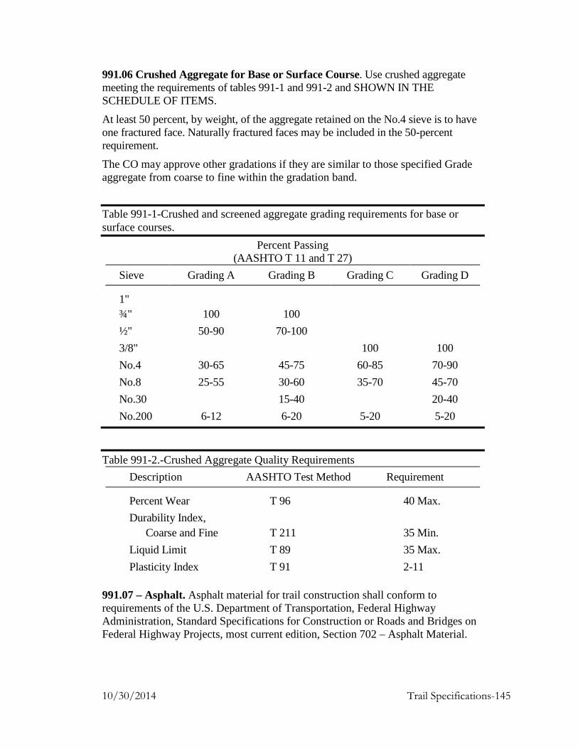
991.06 Crushed Aggregate for Base or Surface Course. Use crushed aggregate meeting the requirements of tables 991-1 and 991-2 and SHOWN IN THE SCHEDULE OF ITEMS.
At least 50 percent, by weight, of the aggregate retained on the No.4 sieve is to have one fractured face. Naturally fractured faces may be included in the 50-percent requirement.
The CO may approve other gradations if they are similar to those specified Grade aggregate from coarse to fine within the gradation band.
Table 991-1-Crushed and screened aggregate grading requirements for base or surface courses.
Percent Passing (AASHTO T 11 and T 27)
Sieve Grading A Grading B Grading C Grading D
1" ¾" 100 100 ½" 50-90 70-100 3/8" 100 100 No.4 30-65 45-75 60-85 70-90 No.8 25-55 30-60 35-70 45-70 No.30 15-40 20-40 No.200 6-12 6-20 5-20 5-20
Table 991-2.-Crushed Aggregate Quality Requirements Description AASHTO Test Method Requirement
Percent Wear T 96 40 Max. Durability Index, Coarse and Fine T 211 35 Min. Liquid Limit T 89 35 Max. Plasticity Index T 91 2-11
991.07 – Asphalt. Asphalt material for trail construction shall conform to requirements of the U.S. Department of Transportation, Federal Highway Administration, Standard Specifications for Construction or Roads and Bridges on Federal Highway Projects, most current edition, Section 702 – Asphalt Material.
10/30/2014 Trail Specifications-145

991.08 – Cement. Cement material for trail construction shall conform to requirements of the U.S. Department of Transportation, Federal Highway Administration, Standard Specifications for Construction or Roads and Bridges on Federal Highway Projects, most current edition, Section 701 – Cement.
Section 992 – Pipe Material
992.01 General. Use pipe, coupling bands, and special sections such as elbows, tees, and wyes made of the same material and of the same thickness as the conduit to which they are joined, unless otherwise specified.
992.02 Corrugated Steel Pipe, Pipe Arches and Underdrains (a) Riveted Pipe and Pipe Arches. Use pipes meeting the requirements of AASHTO M 36.
(b) Welded Pipe and Pipe Arches. Use corrugated metal pipe and pipe arches fabricated by resistance spot welding meeting the applicable requirements of AASHTO M 36.
(c) Helical Pipe. Use un-perforated helically corrugated pipe with continuous lock or welded seams meeting the applicable requirements of AASHTO M 36.
(d) Coupling Bands. Use coupling bands meeting the requirements of AASHTO M 36.
(e) Special Sections. Use special sections such as elbows, tees, and wyes meeting the same thickness as the conduit to which they are joined and meeting the applicable requirements of AASHTO M 36.
(f) Flared-End Sections. Use flared-end sections for inlet and outlet ends of pipe and pipe arch culverts meeting the applicable requirements of AASHTO M 36.
(g) Corrugated Steel Pipe for Underdrains. Use perforated galvanized pipe meeting the requirements of AASHTO M 36. Use polymer-precoated perforated underdrains meeting the requirements of AASHTO M 245
992.03 Corrugated Aluminum Alloy Culvert Pipe, Pipe Arches, and Underdrains. Use pipe meeting the requirements of AASHTO M 196.
992.05 Aluminum-Coated (Aluminized Type 2). Use pipe and coupling bands meeting the requirements of AASHTO M 36 except that they must be made from material meeting the requirements of AASHTO M 274.
992.06 Concrete Pipe and Pipe Arches (a) Non-Reinforced Concrete Pipe. Conform to AASHTO M 86M for the diameters and strength classes specified.
10/30/2014 Trail Specifications-146

(b) Reinforced Concrete Pipe. Conform to AASHTO M 170M for the diameters and strength classes specified. For precast reinforced concrete end sections, conform to cited specifications to the extent they apply.
(c) Perforated Concrete Pipe. Conform to AASHTO M 175M type 1 or 2 and AASHTO M 86M for the diameters and strength classes specified.
(d) Reinforced Arch-Shaped Concrete Pipe. Conform to AASHTO M 206M for the diameters and strength classes specified.
(e) Reinforced Elliptically-Shaped Concrete Pipe. Conform to AASHTO M 207M for the diameters, placement design (horizontal or vertical), and strength classes specified.
992.07 Precast Reinforced Concrete Box Sections. Conform to AASHTO M 259M or M 273M, as applicable, for dimensions and loading conditions specified.
992.08 Plastic Pipe. Furnish perforated and non-perforated plastic pipe conforming to the following for the sizes and types specified. For watertight joints, conform to ASTM D 3212.
(a) Smooth wall polyethylene pipe. Furnish 12 to 42-inch diameter pipe conforming to ASTM F 714 and minimum cell class, ASTM D 3350, 335434C.
(b) Corrugated polyethylene pipe. Furnish 12 to 42-inch diameter pipe conforming to AASHTO M 294M. For sanitary sewer applications, furnish AASHTO M 294M type S pipe with watertight joints.
(c) Profile wall (ribbed) polyethylene pipe. Furnish 18 to 48-inch diameter pipe conforming to ASTM F 894 and minimum cell class, ASTM D 3350, 334433C or 335434C.
(d) Corrugated polyethylene drainage tubing. Furnish 3 to 10-inch diameter tubing conforming to AASHTO M 252M.
(e) Smooth wall polyvinyl chloride pipe. Furnish 4 to 15-inch diameter pipe conforming to AASHTO M 278 and minimum cell class, ASTM D 1784, 12454B or 12364C. For sanitary sewer applications, conform to ASTM D 3034.
(f) Profile wall (ribbed) polyvinyl chloride pipe. Furnish 4 to 48-inch diameter pipe conforming to AASHTO M 304M and minimum cell class, ASTM D 1784, 12454C or 12364C. For sanitary sewer applications, conform to ASTM F 794 or F 949.
(g) Acrylonitrile-butadiene-styrene (ABS) pipe. Conform to AASHTO M 264. For perforations, conform to AASHTO M 278.
10/30/2014 Trail Specifications-147

Section 993 - Fence Material
993.01 Barbed Wire. Furnish galvanized wire conforming to AASHTO M 280 or aluminum coated wire conforming to AASHTO M 305 type I.
993.02 Woven Wire. Furnish galvanized fabric conforming to AASHTO M 279 or aluminum coated fabric conforming to ASTM A 584.
993.04 Fence Posts. (a) Wood. Conform to AASHTO M 168 and as SHOWN ON THE PLANS.
Peel all bark, except for red cedar posts and bracing which do not require peeling. Trim all knots flush with the surface and season the wood.
For dimension lumber for fences or gates, use timber that is sound, straight, and reasonably free from knots, splits, and shakes. Provide S4S finish.
(b) Concrete. Conform to FP-03, Section 601.
(c) Steel. For line fence posts, conform to AASHTO M 281.
993.05 Fence Gates. Furnish wood gates conforming to conforming to AASHTO M 168 and as SHOWN ON THE PLANS. For dimension lumber for gates, use timber that is sound, straight, and reasonably free from knots, splits, and shakes. Provide S4S finish.
993.06 Metal Beam Rail. Conform to AASHTO-AGC-ARTBA A Guide to Standardized Highway Barrier Hardware.
(a) Galvanized steel rail. Furnish W-beam or thrie beam rail elements fabricated from corrugated sheet steel conforming to AASHTO M 180 for the designated shape, class, type, and mass of coating specified.
(b) Corrosion resistant steel rail. Furnish W-beam or thrie beam rail elements and associated weathering steel hardware conforming to the following:
(1) Shapes and plates ASTM A 242 (2) Rail elements AASHTO M 180 (3) Fasteners AASHTO M 180
993.07 Guardrail Posts. Conform to AASHTO-AGC-ARTBA “A Guide to Standardized Highway Barrier Hardware.”
Do not use a wood guardrail post that has a thorough check, shake, or end slit in the same plane as, or a plane parallel to the bolt hole and extending from the top of the post to within 3 inches or the bolt hole.
For steel-backed timber rail posts, furnish 10 by 12-inch posts conforming to Subsection 710.08.
993.08 Guardrail Hardware. Conform to the AASHTO-AGC-ARTBA A Guide to Standardized Highway Barrier Hardware.
10/30/2014 Trail Specifications-148
For angles, channels, wide flanges, and plates not contained in the above standard, conform to ASTM A 36M. For structural tubing for short steel posts, conform to ASTM A 500 or ASTM A 513 grade 1008. Galvanize soil plates and structural tubing according to AASHTO M 111. Do not punch, drill, cut, or weld the metal after galvanizing.
993.09 Temporary Plastic Fence. Furnish plastic noncorrosive fence fabricated from polyethylene (HDPE) and UV stabilized for outdoor weathering. Conform to the following:
(a) Height 48 inch min. (b) Mesh openings 3 to 3.5 inches (c) Color International orange (d) Mass 0.168 lb/ft min.
10/30/2014 Trail Specifications-149

Section 994 - Geosynthetics 994.01 Geotextiles (a) Use geotextiles, alone or in combination with other geosynthetics that meet the
following Class B requirements for subsurface drainage as specified in AASHTO M288.
(1) Grab Strength at 50 percent elongation ASTM D4632-91 ................…….. 355 N min. (2) Seam Strength, ASTM D 4632 ....................……... 310 N min. (3) Puncture Strength, ASTM D4833-88 ................…….. 110 N min. (4) Mullen Burst, ASTM D 3786-87 ......................... 900 kPa min. (5) Trap Tear Strength, ASTM D4533-91 ................…….. 110 N min.
(b) Use geotextile meeting the following critical physical properties, unless otherwise SHOWN ON THE PLANS.
(1) Material Structure ................…….. Nonwoven (all purposes) or Slit Film (for reinforcement or separation) (2) Polymer Composition ..........……. Polypropylene (3) Apparent Opening, ASTM D 4751-87 ........…………. .30 mm max. (4) Permittivity, ASTM D4491-92 .............................…….. 4060 liters/minute/m2 min. (5) Ultraviolet Degradation .......…….. 70 at150 hours
994.02 Geonet. Use geonet meeting the following critical physical proper-ties unless otherwise SHOWN ON THE PLANS.
(a) Polymer Composition of Core (Net or Mesh)............................…….. Medium PE or HDPE (b) Permeability……………………….... 0.001cm/second min. (c) Geotextile ......…………..………..…. Must meet all Section 994.01 requirements (d) Compressive Strength of Core, ASTM D1621......…………. 500 kPa min. (e) Transmissivity with Gradient at 0.1, Pressure at 10 kPa.....……....... 0.0009 m2/second min.
10/30/2014 Trail Specifications-150

994.03 Geogrids. Use geogrids made from polypropylene or coated polyester that meets the following critical physical properties.
(a) Polymer Type ..............................……… HDPE, Polypropylene, or Polyester with Acrylic or PVC
coating (b) Mass per Unit Area, ASTM D5261-92... 175 g/m2 min. (c) Maximum Aperture Size
(1) Direction (MD) ....………………… 100 mm (2) Cross-Direction (XD) ..........……… 75 mm
(d) Wide-Width Strip Tensile Strength at 5 percent Strain, ASTM D4595-86
(1) Machine Direction (MD) ....……… 8 kN/m min. (2) Cross-Direction (XD) .........……… 6 kN/m max.
994.04 Geocells. Use geocells meeting the following physical properties.
(a) Composition ...............................……. PE or HDPE (b) Geocell Weight expanded: ............….. 1.70 kg/m2 min. (c) Minimum Cell Seam Peel Strength, U.S. Army Corps of Engineers Technical Report G:-86-19, Appendix A .................................…… 800 N min. (d) Expanded Dimensional Properties…... AS SHOWN ON PLANS
994.05 Sheet Drains. Use sheet drains meeting the following critical physical properties.
(a) Core Polymer Composition ....……… Polystyrene, HDPE, or polypropylene attached (b) Geotextile ............................………… Nonwoven on one side if core solid; on both sides if core perforated. Must meet all Section 994.01 requirements (c) Core Thickness, ASTM D5199 .…… 10 mm min. (d) Core Compressive Strength at Yield, ASTM D1621 .................…… 650 kPa max.
994.06 Fasteners. Use anchors or fasteners of the design recommended by the manufacturer, and install per manufacturer's specifications.
994.07 Certification. Furnish a certificate or affidavit signed by an official from the company manufacturing the geosynthetic, verifying that the geosynthetic meets specifications.
994.08 Delivery, Storage, and Handling. During shipment and storage, wrap all geosynthetics to protect them from sunlight. When storing geosynthetics, protect them from mud, soil, dust, and debris. If materials are not installed immediately after delivery to site, do not store them in direct sunlight.
10/30/2014 Trail Specifications-151

Section 995 - Material for Timber Structures 995.01 Untreated Structural Timber and Lumber. Conform to AASHTO M 168. Furnish an inspection certification from an agency accredited by the American Lumber Standards Committee for the species and grade. Mark all pieces with the inspection service, grade designation, species, and inspector identity.
Season and dry all structural timber and lumber before fabrication. Do not use material that is twisted, curved, or otherwise distorted.
Do not use boxed-heart pieces of Douglas fir or redwood in outside stringers, floor beams, caps, posts, sills, or rail posts. Boxed-heart pieces are defined as timber so sawed that at any point in the length of a sawed piece the pith lies entirely inside the four faces.
Select native log stringers from designated sites on Government-administered land. Select the species and sizes of materials as SHOWN ON THE PLANS. Select native log stringers that are straight, sound, and free of defects. Obtain CO approval of logs and trees before felling or moving them to the site. Fell trees to prevent damage to standing timber and to minimize breakage of trees to be used. Buck logs from felled trees in such a way to minimize waste and to obtain the required length and diameter.
Peel logs, square the ends, and trim the knots and limbs flush unless otherwise SHOWN ON THE PLANS. Scatter the debris from the processing of timber away from the trail and so it will not block the trail or plug water courses.
Field treat the following untreated timber surfaces in accordance with AWPA standard M4.
(a) All ends and tops, and all contact surfaces of posts, sills, and caps.
(b) All ends, joints, and contact surfaces of bracing and truss members.
(c) All surfaces of timber bumpers and the back faces of bulkheads.
(d) All other timber that will be in contact with earth.
(e) All ends of log stringers.
995.02 Holes for Bolts, Dowels, Rods & Lag Screws. Bore all holes before preservative treating the wood.
Bore holes for round drift bolts and dowels 1/16 inch smaller in diameter than that of the bolt or dowel to be used. Ensure that the diameter of holes for square drift bolts or dowels is equal to the side dimension of the bolt or dowel.
Bore holes for machine bolts 1/16 inch larger than the diameter, except when galvanized bolts are specified. In this case, drill all holes 1/8 inch greater than the bolt size.
10/30/2014 Trail Specifications-152

Bore holes for lag screws 1/16 inch larger for the shank portion of the lag screw and drill the remainder of the hole approximately 75 percent of the shank diameter to a depth of 1 inch less than the length of the screw.
995.03 Hardware. Use nails of standard form (ASTM F 1667), wood screws (ANSI/ASME B 18.6.1), hex headed bolts and nuts (ASTM A307), lag screws (ASTM A307 and ANSI/ASME B18.2.1), carriage bolts (ASTM A307), and drift pins and dowels (ASTM A307) as SHOWN ON THE PLANS.
Fabricate washers from gray iron or malleable iron castings unless structural washers are specified. Use malleable iron washers with a diameter approximately four times the bolt diameter under all bolt heads or nuts in contact with wood, unless otherwise SHOWN ON THE PLANS.
Galvanize all hardware according to AASHTO M 232 or cadmium plate all hardware according to ASTM B 766 class 12, type III, unless otherwise SHOWN ON THE PLANS, except for the glued laminated deck panel dowels. Ensure that all fasteners, including nails, spikes, bolts, washers, and timber connectors, other than malleable iron, are galvanized.
Final tighten all nuts to provide proper bearing and snug tight condition. Snug tight is defined as sufficient tightness to bring faces of members into firm contact with each other. Cut off excess bolt lengths of more than 1 inch. After final tightening, check or burr all bolts effectively with a pointing tool to prevent loosening of the nuts.
995.04 Treated Structural Timber and Lumber. Furnish wood according to Subsection 995.01. Incise all wood and make all dimensional cuts and holes in the wood before pressure treatment. Use wood preservative treatment methods meeting the requirements of AASHTO M 133 as SHOWN ON THE PLANS. Treat dimensional lumber, sawn timber and glued laminated timber members according to AWPA Standards as SHOWN ON THE PLANS.
All treated stringers, decking, running planks, and handrails shall be treated after fabrication in accordance with AWPA U1, Use Category System, using Pentachlorophenol or Copper Naphthenate (CuN) in Light Oil, (Type C Solvent) for Use Category UC3B.
All treated substructures (sills, backing planks, cribs, timber walls, etc.) shall be treated after fabrication in accordance with AWPA U1 Use Category System, using Pentachlorophenol or Copper Naphthenate (CuN) in Heavy Oil (Type A Solvent) for Use Category UC4B.
Treat timber members shall comply with the requirements of the current edition of WWPI’s Best Management Practices for the Use of Treated Wood in Aquatic Environments. Except for pine, incise before treatment all surfaces greater than 2 inches in width and all Douglas fir and western larch surfaces. Field treat all cuts, abrasions, drilled
10/30/2014 Trail Specifications-153

holes, and recesses that occur after initial preservative treatment in accordance with the requirements specified in AWPA standard M4, Standard for the Care of Pressure-Treated Wood Products. Plug all unused holes with preservative-treated plugs. Perform all field-applied preservation treatment with necessary precautions so as to prevent soil and/or water contamination.
All treated timber members must have an approved American Lumber Standards Committee quality mark, individually or sealed pallets, assuring that treatment conforms to the appropriate AWPA standards.
Submit a certified copy of the lot certification, by a qualified independent inspection and testing agency, to the CO for each charge of preservative, stating penetration in inches and retention in pounds per cubic foot (assay method). In addition, provide a written certification from the producer of the treated products that "Best Management Practices for Treated Wood in Western Aquatic Environments," published by the Western Wood Preservers Institute and Canadian Institute of Treated Wood, were utilized. Include a description and appropriate documentation of the Best Management Practices used.
Handle treated timber according to the Consumer Information Sheet published by AWPA. Do not cut, frame, or bore treated timber after treatment unless approved by the CO. Handle treated timbers carefully and do not drop, damage outer fibers, or penetrate the surface with tools. Do not use cant dogs, hooks or pike poles. In coastal waters, do not cut or bore timber below the highwater mark.
995.05 Structural Glued Laminated Timber. Furnish structural glued laminated timber according to American National Standard, "Standard Specifications for Structural Glued Laminated Timber of Softwood Species" (ANSI 117). Fabricate according to the combination and grade as indicated in the contract. Fabricate structural glued laminated members according to American National Standard, "Standard for Wood Products - Structural Glued Laminated Timber" (ANSI A190.1).
Manufacture members as industrial appearance grade for wet use conditions, using a phenol-resorcinol resin type of adhesive throughout. Use only single- or multiple-piece laminations with bonded edge joints.
10/30/2014 Trail Specifications-154

Section 996 - Gabion and Revet Mattress Material. 996.01 Basket Mesh. Twist or weld the mesh from galvanized steel wire conforming to ASTM A 641, class 3 or aluminized steel wire conforming to ASTM A 809. Use wire with a minimum tensile strength of 60,000 pounds per square inch when tested according to AASHTO T 244. The galvanized or aluminized coating may be applied after mesh fabrication. Make the mesh openings with a maximum dimension less than 4½ inches, an area less than 10 square inches, and a size less than the gabion or revet mattress rock to be used with the mesh.
(a) Gabion baskets (1 foot or greater in the vertical dimension). Fabricate the mesh for galvanized or aluminized coated baskets from nominal-sized 0.12-inch or greater diameter wire and fabricate the mesh for polyvinyl chloride coated baskets from nominal-sized 0.11-inch or greater diameter wire.
(1) Twisted wire mesh. Form the mesh in a uniform hexagonal pattern with non-raveling double twists. For galvanized or aluminized coated baskets, tie the perimeter edges of the mesh for each panel to a 0.15-inch or greater diameter selvedge wire. For polyvinyl chloride coated baskets, tie the perimeter edges of the mesh for each panel to a 0.13-inch or greater diameter selvedge wire. Make the selvedge at least the same strength as the body of the mesh. Furnish selvedge wire from the same type of material used for the wire mesh.
(2) Welded wire mesh. For galvanized or aluminized coated baskets, weld each connection to obtain minimum average weld shear strength of 585 pounds with no value less than 450 pounds. For polyvinyl chloride coated baskets, weld each connection to obtain minimum average weld shear strength of 472 pounds with no value less than 360 pounds.
Fabricate gabion baskets in the dimensions required with a dimension tolerance of ±5 percent. Where the length of the basket exceeds 1.5 times its width, equally divide the basket into cells less than or equal to the basket width using diaphragms of the same type and size mesh as the basket panels. Prefabricate each basket with the necessary panels and diaphragms secured so they rotate into place.
(b) Revet mattresses (less than 1 foot in the vertical dimension). Fabricate the mesh from nominal-sized 0.086-inch or greater diameter wire.
(1) Twisted wire mesh. Form the mesh in a uniform hexagonal pattern with non-raveling double twists. Tie the perimeter edges of the mesh for each panel to a 0.11-inch or greater diameter selvedge wire. Make the selvedge at least the same strength as the body of the mesh. Furnish selvedge wire from the same type of material used for the wire mesh.
10/30/2014 Trail Specifications-155

(2) Welded wire mesh. Weld each connection to obtain minimum average weld shear strength of 292 pounds with no value less than 225 pounds.
Fabricate revet baskets in the dimensions required with a dimension tolerance of ±5 percent in length and width and ±10 percent in height. Where the length of the basket exceeds 0.5 times its width, equally divide the basket into cells less than or equal to 0.5 times the basket width using diaphragms of the same type and size mesh as the mattress panels. Prefabricate each basket with the necessary panels and diaphragms secured so they rotate into place.
(c) Epoxy or Polyvinyl chloride coated baskets. Use either a fusion bonded or extruded coating to coat the galvanized or aluminized mesh.
Make the coating at least 0.0625 inches in thickness for epoxy and 0.125 inch thickness for PVC. Make the color black or gray and conform to the following:
(1) For epoxy coating meet:
• Abrasion resistance, ASTM D 1242, maximum weight loss 0.19 g.
• Salt crock, ASTM G 8, maximum disbondment diameter 1.75 inch, and at 90 days, 1.5 volts, and 3 percent solution.
• Chemical resistance, ASTM G 20, with 45 days at 70°F, 3 molar CaCl, 3 molar NaOH, saturate Ca(OH)2, and no coating loss.
• Weatherometer, ASTM G 23, with a surface chalk and 2,000 hours.
(2) For polyvinyl coating meet:
Specific gravity, ASTM D 792 1.20 to 1.40 Tensile strength, ASTM D 638 2,300 pounds
per square inch min. Modulus of elasticity, ASTM D 638 2,000 pounds
per square inch min. at 100 strain Hardness — shore "A", ASTM D 2240 75 min. Brittleness temperature, ASTM D 746 16 ºF max. Abrasion resistance, ASTM D 1242, 12% max.
method B at 200 cycles, mass loss CSI-A abrader tape, 80 grit
Salt spray (ASTM B 117) and No visual effect ultraviolet light exposure (c) ∆< 6% (ASTM D 1499 and G 23 using (d) ∆< 25% apparatus type E and 145 ºF) (e) ∆< 25%
10/30/2014 Trail Specifications-156

for 3000 hours (h) ∆< 10% Mandrel bend, 360º bend at 0 ºF No breaks or
around a mandrel 10 times the wire cracks in diameter coating
996.02 Permanent fasteners.
(1) Lacing wire. Furnish nominal-sized 0.086-inch diameter wire of the same type, strength, and coating as the basket mesh.
(2) Spiral binders. Form with wire having at least the same diameter, type, strength, and coating as the basket mesh.
(3) Alternate fasteners. Furnish fasteners according to the basket manufacturer's specification that remain closed when subjected to a 585-pound tensile force while confining the maximum number of wires to be confined in the gabion structure or revet mattress. Submit installation procedures and fastener test results.
996.03 Internal connecting wire. Furnish lacing wire as described in (b)(1) above or alternate stiffeners according to the basket manufacturer's specification.
10/30/2014 Trail Specifications-157