standard tehnica liniara
TRANSCRIPT

Linear motionstandard range
® SKF is a registered trademark of the SKF Group.
© SKF 2005The contents of this publication are the copyright of the publisher and may not be reproduced (even extracts) unless prior written permission is granted.Every care has been taken to ensure the accuracy of the information contained in this publication but no liability can be accepted for any loss or damagewhether direct, indirect or consequential arising out of the use of the information contained herein.
Publication 4664/5 EN Printed in Italy
Copy price: 10 ¤
Linear motion from SKFwww.linearmotion.skf.com
Represented by:
Lin
ear
motio
n sta
ndard
range

Made by SKF® stands for excellence. It symbolises our
consistent endeavour to achieve total quality in everything we
do. For those who use our products, “Made by SKF” implies
three main benefits:
Reliability – based on modern, efficient products, our
worldwide application know-how, optimised materials,
forward-looking designs and the most advanced production
techniques.
Cost effectiveness – resulting from the favourable ratio
between our product quality plus service facilities, and the
purchase price of the product.
Market lead – which you can achieve by taking advantage of
our products and services. Increased operating time and
reduced downtime, as well as improved output and product
quality are the keys to a successful partnership.
© SKF 2005
1 General 11
2 Guiding systems 15
Shaft guidings . . . . . . . . . . . . . . . . . . . . . . . . . . . . . . . . . . . . . . . . . . . . . . . . . . . . . 16
Ordering key for LBBR - compact series . . . . . . . . . . . . . . . . . . . . . . . . 20
LBBR Compact series . . . . . . . . . . . . . . . . . . . . . . . . . . . . . . . . . . . . . . . . . . . . . 21
LBBR ../HV6 Corrosion resistant type . . . . . . . . . . . . . . . . . . . . . . . . . . 21
LPBR Linear plain bearings . . . . . . . . . . . . . . . . . . . . . . . . . . . . . . . . . . . . . . 22
LUHR Linear ball bearing units . . . . . . . . . . . . . . . . . . . . . . . . . . . . . . . . . . 22
LUHR PB Linear plain bearing units . . . . . . . . . . . . . . . . . . . . . . . . . . . . 23
LUJR Linear ball bearing units . . . . . . . . . . . . . . . . . . . . . . . . . . . . . . . . . . . 23
LTBR Tandem linear ball bearing units . . . . . . . . . . . . . . . . . . . . . . . . . 23
LSHS Shaft blocks for compact series . . . . . . . . . . . . . . . . . . . . . . . . . . 24
LTDR Duo linear ball bearing units . . . . . . . . . . . . . . . . . . . . . . . . . . . . . . 24
LQBR Quadro linear ball bearing units . . . . . . . . . . . . . . . . . . . . . . . . . 24
LEBS Tandem shaft blocks . . . . . . . . . . . . . . . . . . . . . . . . . . . . . . . . . . . . . . . 25
Appropriate special seals . . . . . . . . . . . . . . . . . . . . . . . . . . . . . . . . . . . . . . . . . . 25
Ordering key for LBBR - standard series . . . . . . . . . . . . . . . . . . . . . . . 26
LBCD Standard series 3, closed type . . . . . . . . . . . . . . . . . . . . . . . . . . . 28
LBCR Standard series 3, closed type . . . . . . . . . . . . . . . . . . . . . . . . . . . 28
LPAR Linear plain bearings, closed type . . . . . . . . . . . . . . . . . . . . . . . 29
LUCD Single units, self-aligning, closed type . . . . . . . . . . . . . . . . . . 29
LUCE Single units, self-aligning, closed type . . . . . . . . . . . . . . . . . . 30
LUCR Single units, closed type . . . . . . . . . . . . . . . . . . . . . . . . . . . . . . . . . . 30
LUCR PA Single plain bearing units, closed type . . . . . . . . . . . . . . 31
LUCS Single units, closed type . . . . . . . . . . . . . . . . . . . . . . . . . . . . . . . . . . . 31
LUND Single units, self-aligning, closed type . . . . . . . . . . . . . . . . . . 32
LUNE Single units, self-aligning, closed type . . . . . . . . . . . . . . . . . . 32
LVCD Flanged self-aligning units . . . . . . . . . . . . . . . . . . . . . . . . . . . . . . . . 33
LVCR Flanged units . . . . . . . . . . . . . . . . . . . . . . . . . . . . . . . . . . . . . . . . . . . . . . . . 33
LSCS Shaft blocks . . . . . . . . . . . . . . . . . . . . . . . . . . . . . . . . . . . . . . . . . . . . . . . . . 34
LSNS Shaft blocks . . . . . . . . . . . . . . . . . . . . . . . . . . . . . . . . . . . . . . . . . . . . . . . . . 34
LTCD Tandem units, self-aligning, closed type . . . . . . . . . . . . . . . . 35
LTCR Tandem units, closed type . . . . . . . . . . . . . . . . . . . . . . . . . . . . . . . . . 35
LQCD Quadro units, self-aligning, closed type . . . . . . . . . . . . . . . . . 36
LQCR Quadro units, closed type . . . . . . . . . . . . . . . . . . . . . . . . . . . . . . . . . 36
LEAS Tandem shaft blocks, closed type . . . . . . . . . . . . . . . . . . . . . . . . 37
LBCF Standard series 3, open type . . . . . . . . . . . . . . . . . . . . . . . . . . . . . 38
LBCT Standard series 3, open type . . . . . . . . . . . . . . . . . . . . . . . . . . . . . 38
LBHT Heavy-load type, open type . . . . . . . . . . . . . . . . . . . . . . . . . . . . . . 39
LPAT Linear plain bearings, open type . . . . . . . . . . . . . . . . . . . . . . . . . 39
LUCF Single units, self-aligning, open type . . . . . . . . . . . . . . . . . . . . 40
LUCT Single units, open type . . . . . . . . . . . . . . . . . . . . . . . . . . . . . . . . . . . . 40
LUCT BH Single heavy-load units, open type . . . . . . . . . . . . . . . . . 41
LUCT ..PA Single units, open type . . . . . . . . . . . . . . . . . . . . . . . . . . . . . . . 41
LUNF Single units, self-aligning, open type . . . . . . . . . . . . . . . . . . . . 42
LTCF Tandem units, self-aligning, open type . . . . . . . . . . . . . . . . . . 42
LTCT Tandem units, open type . . . . . . . . . . . . . . . . . . . . . . . . . . . . . . . . . . . 43
Contents(by chapters)
2

© SKF 2005 3
LQCF Quadro units, self-aligning, open type . . . . . . . . . . . . . . . . . . 43
LQCT Quadro units, open type . . . . . . . . . . . . . . . . . . . . . . . . . . . . . . . . . . . 44
LRCB/LRCC Shaft supports, open type . . . . . . . . . . . . . . . . . . . . . . . . . 44
Precision shafts . . . . . . . . . . . . . . . . . . . . . . . . . . . . . . . . . . . . . . . . . . . . . . . . . . . 46
LJM Precision shafts, steel . . . . . . . . . . . . . . . . . . . . . . . . . . . . . . . . . . . . . . . 47
LJMH Hard chromium plated precision shafts . . . . . . . . . . . . . . . . 47
LJMR Precision shafts, stainless steel . . . . . . . . . . . . . . . . . . . . . . . . . . 47
LJMS Precision shafts, stainless steel . . . . . . . . . . . . . . . . . . . . . . . . . . 47
LJT Hollow shafts, high grade steel . . . . . . . . . . . . . . . . . . . . . . . . . . . . . 47
Ordering key for precision shafts . . . . . . . . . . . . . . . . . . . . . . . . . . . . . . . . . 48
ESSC 1 Precision shaft configurations . . . . . . . . . . . . . . . . . . . . . . . . . . 49
ESSC 2 Precision shaft configurations . . . . . . . . . . . . . . . . . . . . . . . . . . 49
ESSC 3 Precision shaft configurations . . . . . . . . . . . . . . . . . . . . . . . . . . 49
ESSC 4 Precision shaft configurations . . . . . . . . . . . . . . . . . . . . . . . . . . 49
ESSC 5 Precision shaft configurations . . . . . . . . . . . . . . . . . . . . . . . . . . 50
ESSC 6 Precision shaft configurations . . . . . . . . . . . . . . . . . . . . . . . . . . 50
ESSC 7 Precision shaft configurations . . . . . . . . . . . . . . . . . . . . . . . . . . 50
ESSC 8 Precision shaft configurations . . . . . . . . . . . . . . . . . . . . . . . . . . 51
ESSC 9 Precision shaft configurations . . . . . . . . . . . . . . . . . . . . . . . . . . 51
ESSC 10 Precision shaft configurations . . . . . . . . . . . . . . . . . . . . . . . . 51
Design and basic data . . . . . . . . . . . . . . . . . . . . . . . . . . . . . . . . . . . . . . . . . . . . . 52
Linear ball bearing table without drive . . . . . . . . . . . . . . . . . . . . . . . 54
Ordering key for linear ball bearing table without drive . . . . . . 55
LZBU ..A-2LS Quadro linear tables . . . . . . . . . . . . . . . . . . . . . . . . . . . . . 56
LZBU ..B-2LS Quadro linear tables . . . . . . . . . . . . . . . . . . . . . . . . . . . . . 57
LZAU ..2LS Quadro linear tables . . . . . . . . . . . . . . . . . . . . . . . . . . . . . . . . 58
Linear guiding system Speedi-Roll . . . . . . . . . . . . . . . . . . . . . . . . . . . . 60
Ordering key for Speedi-Roll . . . . . . . . . . . . . . . . . . . . . . . . . . . . . . . . . . . . . 61
LLEHR Rails . . . . . . . . . . . . . . . . . . . . . . . . . . . . . . . . . . . . . . . . . . . . . . . . . . . . . . . . 62
LLEHC ..HZ/HC Standard carriages . . . . . . . . . . . . . . . . . . . . . . . . . . . . . 62
LLEHC ..LZ/LC Long carriages . . . . . . . . . . . . . . . . . . . . . . . . . . . . . . . . . . . 63
LLEHM End stops . . . . . . . . . . . . . . . . . . . . . . . . . . . . . . . . . . . . . . . . . . . . . . . . . . 63
LLEHX Roller covers . . . . . . . . . . . . . . . . . . . . . . . . . . . . . . . . . . . . . . . . . . . . . . . 63
LLEHE ..Z Rollers . . . . . . . . . . . . . . . . . . . . . . . . . . . . . . . . . . . . . . . . . . . . . . . . . . 64
Profile rail guides . . . . . . . . . . . . . . . . . . . . . . . . . . . . . . . . . . . . . . . . . . . . . . . . . 65
Ordering key for profile rail guides . . . . . . . . . . . . . . . . . . . . . . . . . . . . . . . 66
Accessories for profile rail guides . . . . . . . . . . . . . . . . . . . . . . . . . . . . . . . . 67
LLRHS ..SA . . . . . . . . . . . . . . . . . . . . . . . . . . . . . . . . . . . . . . . . . . . . . . . . . . . . . . . . . . 68
LLRHS ..A . . . . . . . . . . . . . . . . . . . . . . . . . . . . . . . . . . . . . . . . . . . . . . . . . . . . . . . . . . . . 68
LLRRS ..LA . . . . . . . . . . . . . . . . . . . . . . . . . . . . . . . . . . . . . . . . . . . . . . . . . . . . . . . . . . 68
LLRHS ..SU . . . . . . . . . . . . . . . . . . . . . . . . . . . . . . . . . . . . . . . . . . . . . . . . . . . . . . . . . . 70
LLRHS ..U . . . . . . . . . . . . . . . . . . . . . . . . . . . . . . . . . . . . . . . . . . . . . . . . . . . . . . . . . . . 70
LLRHS ..LU . . . . . . . . . . . . . . . . . . . . . . . . . . . . . . . . . . . . . . . . . . . . . . . . . . . . . . . . . . 70
LLRHS ..R . . . . . . . . . . . . . . . . . . . . . . . . . . . . . . . . . . . . . . . . . . . . . . . . . . . . . . . . . . . 72
LLRHS ..LR . . . . . . . . . . . . . . . . . . . . . . . . . . . . . . . . . . . . . . . . . . . . . . . . . . . . . . . . . . 72
Miniature profile rail guides . . . . . . . . . . . . . . . . . . . . . . . . . . . . . . . . . . . . 74
Ordering key for miniature profile rail guides . . . . . . . . . . . . . . . . . . 77
LLMHR Standard rails . . . . . . . . . . . . . . . . . . . . . . . . . . . . . . . . . . . . . . . . . . . . 78
LLMWR Wide rails . . . . . . . . . . . . . . . . . . . . . . . . . . . . . . . . . . . . . . . . . . . . . . . . . 78
LLMHC ..TA Standard carriages . . . . . . . . . . . . . . . . . . . . . . . . . . . . . . . . . 78
LLMWC ..TA Carriages for wide rails . . . . . . . . . . . . . . . . . . . . . . . . . . . . 79
LLMHC ..LA Long carriages . . . . . . . . . . . . . . . . . . . . . . . . . . . . . . . . . . . . . . 79
LLMWC ..LA Long carriages for wide rails . . . . . . . . . . . . . . . . . . . . . 79
Precision rail guides . . . . . . . . . . . . . . . . . . . . . . . . . . . . . . . . . . . . . . . . . . . . . . 80
ACS Anti-creeping-system for LWRE . . . . . . . . . . . . . . . . . . . . . . . . . . . 80
Ordering key for precision rail guides . . . . . . . . . . . . . . . . . . . . . . . . . . . . 81
LWR Precision rail guides . . . . . . . . . . . . . . . . . . . . . . . . . . . . . . . . . . . . . . . . . 82
LWRB Precision rail guides . . . . . . . . . . . . . . . . . . . . . . . . . . . . . . . . . . . . . . . 82
LWAL Crossed roller assemblies, aluminium cages . . . . . . . . . . . 82
LWJK Ball assemblies, plastics cages . . . . . . . . . . . . . . . . . . . . . . . . . . . 82
LWAK Crossed roller assemblies, plastics cages . . . . . . . . . . . . . . . 82
LWERA End pieces . . . . . . . . . . . . . . . . . . . . . . . . . . . . . . . . . . . . . . . . . . . . . . . . . 82
LWGD Special attachment screws . . . . . . . . . . . . . . . . . . . . . . . . . . . . . . . 82
LWR 3/6 .. Kit Precision rail guide kits . . . . . . . . . . . . . . . . . . . . . . . . . . 83
LWRB 1 Precision rail guides . . . . . . . . . . . . . . . . . . . . . . . . . . . . . . . . . . . . 84
LWRB 2 Precision rail guides . . . . . . . . . . . . . . . . . . . . . . . . . . . . . . . . . . . . 84
LWR 3 Precision rail guides . . . . . . . . . . . . . . . . . . . . . . . . . . . . . . . . . . . . . . 85
LWR 6 Precision rail guides . . . . . . . . . . . . . . . . . . . . . . . . . . . . . . . . . . . . . . 85
LWR 9 Precision rail guides . . . . . . . . . . . . . . . . . . . . . . . . . . . . . . . . . . . . . . 86
LWR 12 Precision rail guides . . . . . . . . . . . . . . . . . . . . . . . . . . . . . . . . . . . . . 86
LWRE Precision rail guides . . . . . . . . . . . . . . . . . . . . . . . . . . . . . . . . . . . . . . . 87
LWAKE Crossed roller assemblies, plastics cage . . . . . . . . . . . . . . . 87
LWERE End pieces . . . . . . . . . . . . . . . . . . . . . . . . . . . . . . . . . . . . . . . . . . . . . . . . . 87
LWGD Special attachment screws . . . . . . . . . . . . . . . . . . . . . . . . . . . . . . . 87
LWRE 3/4/6 .. Kit Precision rail guide kits . . . . . . . . . . . . . . . . . . . . . . 88
LWRE 3/4/6 .. ACS - Kit Precision rail guide kits
with ACS . . . . . . . . . . . . . . . . . . . . . . . . . . . . . . . . . . . . . . . . . . . . . . . . . . . . . . . . . . . . . 89
LWRE 3 Precision rail guides . . . . . . . . . . . . . . . . . . . . . . . . . . . . . . . . . . . . . 90
LWRE 2211 Precision rail guides . . . . . . . . . . . . . . . . . . . . . . . . . . . . . . . . 90
LWRE 4 Precision rail guides . . . . . . . . . . . . . . . . . . . . . . . . . . . . . . . . . . . . . 91
LWRE 6 Precision rail guides . . . . . . . . . . . . . . . . . . . . . . . . . . . . . . . . . . . . . 91
LWRE 9 Precision rail guides . . . . . . . . . . . . . . . . . . . . . . . . . . . . . . . . . . . . . 92
LWRE 3 ACS Precision rail guides with ACS . . . . . . . . . . . . . . . . . . . 92
LWRE 2211 ACS Precision rail guides with ACS . . . . . . . . . . . . . . . 93
LWRE 4 ACS Precision rail guides with ACS . . . . . . . . . . . . . . . . . . . 93
LWRE 6 ACS Precision rail guides with ACS . . . . . . . . . . . . . . . . . . . 94
LWRE 9 ACS Precision rail guides with ACS . . . . . . . . . . . . . . . . . . . 94
LWRM Precision rail guides . . . . . . . . . . . . . . . . . . . . . . . . . . . . . . . . . . . . . . 95
LWRV Precision rail guides . . . . . . . . . . . . . . . . . . . . . . . . . . . . . . . . . . . . . . . 95
LWHW Needle roller assemblies, aluminium cage . . . . . . . . . . . . 95
LWEARM End pieces . . . . . . . . . . . . . . . . . . . . . . . . . . . . . . . . . . . . . . . . . . . . . . . 95
LWEARV End pieces . . . . . . . . . . . . . . . . . . . . . . . . . . . . . . . . . . . . . . . . . . . . . . . . 95
LWGD Special attachment screws . . . . . . . . . . . . . . . . . . . . . . . . . . . . . . . 95

4 © SKF 2005
LWRM 6 Precision rail guides . . . . . . . . . . . . . . . . . . . . . . . . . . . . . . . . . . . . 96
LWRV 6 Precision rail guides . . . . . . . . . . . . . . . . . . . . . . . . . . . . . . . . . . . . . 96
LWRM 9 Precision rail guides . . . . . . . . . . . . . . . . . . . . . . . . . . . . . . . . . . . . 96
LWRV 9 Precision rail guides . . . . . . . . . . . . . . . . . . . . . . . . . . . . . . . . . . . . . 96
LWM / LWV Precision rail guides . . . . . . . . . . . . . . . . . . . . . . . . . . . . . . . . 97
LWHW Needle roller assemblies, aluminium cages . . . . . . . . . . . 97
LWEAM End pieces . . . . . . . . . . . . . . . . . . . . . . . . . . . . . . . . . . . . . . . . . . . . . . . . 97
LWEAV End pieces . . . . . . . . . . . . . . . . . . . . . . . . . . . . . . . . . . . . . . . . . . . . . . . . . 97
LWGD Special attachment screws . . . . . . . . . . . . . . . . . . . . . . . . . . . . . . . 97
LWM 3015 / LWV 3015 Precision rail guides . . . . . . . . . . . . . . . . . 98
M3 DIN 84 . . . . . . . . . . . . . . . . . . . . . . . . . . . . . . . . . . . . . . . . . . . . . . . . . . . . . . . . . . 98
LWM 4020 / LWV 4020 Precision rail guides . . . . . . . . . . . . . . . . . 98
M5 DIN 84 . . . . . . . . . . . . . . . . . . . . . . . . . . . . . . . . . . . . . . . . . . . . . . . . . . . . . . . . . . 98
LWM 5025 / LWV 5025 Precision rail guides . . . . . . . . . . . . . . . . . 99
M6 DIN 84 . . . . . . . . . . . . . . . . . . . . . . . . . . . . . . . . . . . . . . . . . . . . . . . . . . . . . . . . . . 99
LWM 6035 / LWV 6035 Precision rail guides . . . . . . . . . . . . . . . . . 99
M6 DIN 84 . . . . . . . . . . . . . . . . . . . . . . . . . . . . . . . . . . . . . . . . . . . . . . . . . . . . . . . . . . 99
LWM 7040 / LWV 7040 Precision rail guides . . . . . . . . . . . . . . . . . 100
M6 DIN 84 . . . . . . . . . . . . . . . . . . . . . . . . . . . . . . . . . . . . . . . . . . . . . . . . . . . . . . . . . . 100
LWM 8050 / LWV 8050 Precision rail guides . . . . . . . . . . . . . . . . . 100
M6 DIN 84 . . . . . . . . . . . . . . . . . . . . . . . . . . . . . . . . . . . . . . . . . . . . . . . . . . . . . . . . . . 100
3 Driving systems 103
Ball and roller screws . . . . . . . . . . . . . . . . . . . . . . . . . . . . . . . . . . . . . . . . . . . . 103
How to orientate your choice . . . . . . . . . . . . . . . . . . . . . . . . . . . . . . . . . . . 104
Ball screws . . . . . . . . . . . . . . . . . . . . . . . . . . . . . . . . . . . . . . . . . . . . . . . . . . . . . . . . . 105
Ordering key for ball screw . . . . . . . . . . . . . . . . . . . . . . . . . . . . . . . . . . . . . . . 106
SD/BD Miniature screws . . . . . . . . . . . . . . . . . . . . . . . . . . . . . . . . . . . . . . . . . . 107
SH Miniature screws . . . . . . . . . . . . . . . . . . . . . . . . . . . . . . . . . . . . . . . . . . . . . . 107
SX/BX Universal screws . . . . . . . . . . . . . . . . . . . . . . . . . . . . . . . . . . . . . . . . . . 108
FHRF Round flanges (for SX nuts only) . . . . . . . . . . . . . . . . . . . . . . . . . 109
FHSF Square flanges (for SX nuts only) . . . . . . . . . . . . . . . . . . . . . . . . 109
SN/BN Precision screw . . . . . . . . . . . . . . . . . . . . . . . . . . . . . . . . . . . . . . . . . . . 110
SND/BND Precision screw, DIN standard . . . . . . . . . . . . . . . . . . . . . . 110
PN Precision screw, preloaded . . . . . . . . . . . . . . . . . . . . . . . . . . . . . . . . . . . 111
PND Precision screw, DIN standard, preloaded . . . . . . . . . . . . . . . 111
SL/BL Long lead screws . . . . . . . . . . . . . . . . . . . . . . . . . . . . . . . . . . . . . . . . . . 112
SLD/BLD Long lead screws, DIN standard . . . . . . . . . . . . . . . . . . . . . 112
Rotating nut . . . . . . . . . . . . . . . . . . . . . . . . . . . . . . . . . . . . . . . . . . . . . . . . . . . . . . . . . 114
Shaft and combinations for rolled ball screws . . . . . . . . . . . . . . . . . . 116
PLBU Plummer bearing units . . . . . . . . . . . . . . . . . . . . . . . . . . . . . . . . . . . 120
FLBU Flanged bearing units . . . . . . . . . . . . . . . . . . . . . . . . . . . . . . . . . . . . . 120
BUF End bearing units . . . . . . . . . . . . . . . . . . . . . . . . . . . . . . . . . . . . . . . . . . . . 121
FBS – Q Support bearing cartridge units
(4 bearings matched in set) . . . . . . . . . . . . . . . . . . . . . . . . . . . . . . . . . . . . . . . 121
FBS – D Support bearing cartridge units
(2 bearings matched in set) . . . . . . . . . . . . . . . . . . . . . . . . . . . . . . . . . . . . . . . 121
Ground ball screws . . . . . . . . . . . . . . . . . . . . . . . . . . . . . . . . . . . . . . . . . . . . . . . . . 122
Ordering key for ground ball screws . . . . . . . . . . . . . . . . . . . . . . . . . . . . . 123
PGFE screw with DIN double flanged preloaded nuts . . . . . . . . 124
PGFJ screw with DIN flanged nuts with internal preload . . . . . 124
Roller screws . . . . . . . . . . . . . . . . . . . . . . . . . . . . . . . . . . . . . . . . . . . . . . . . . . . . . . . 126
Planetary roller screws: principle . . . . . . . . . . . . . . . . . . . . . . . . . . . . . . . . 128
Recirculating roller screws: principle . . . . . . . . . . . . . . . . . . . . . . . . . . . . . 129
Ordering key for roller screws . . . . . . . . . . . . . . . . . . . . . . . . . . . . . . . . . . . . 131
Planetary roller screws . . . . . . . . . . . . . . . . . . . . . . . . . . . . . . . . . . . . . . . . . . 132
BRC Range . . . . . . . . . . . . . . . . . . . . . . . . . . . . . . . . . . . . . . . . . . . . . . . . . . . . . . . . . 132
FLRBU/BRC Range . . . . . . . . . . . . . . . . . . . . . . . . . . . . . . . . . . . . . . . . . . . . . . . . 133
SRC Range . . . . . . . . . . . . . . . . . . . . . . . . . . . . . . . . . . . . . . . . . . . . . . . . . . . . . . . . . . 134
SRF Range . . . . . . . . . . . . . . . . . . . . . . . . . . . . . . . . . . . . . . . . . . . . . . . . . . . . . . . . . . 136
TRU / PRU Range . . . . . . . . . . . . . . . . . . . . . . . . . . . . . . . . . . . . . . . . . . . . . . . . . . 138
TRK / PRK Range . . . . . . . . . . . . . . . . . . . . . . . . . . . . . . . . . . . . . . . . . . . . . . . . . . 141
Recirculating roller screws . . . . . . . . . . . . . . . . . . . . . . . . . . . . . . . . . . . . . . 144
BVC Range . . . . . . . . . . . . . . . . . . . . . . . . . . . . . . . . . . . . . . . . . . . . . . . . . . . . . . . . . . 144
FLRBU/BVC . . . . . . . . . . . . . . . . . . . . . . . . . . . . . . . . . . . . . . . . . . . . . . . . . . . . . . . . . 145
SVC Range . . . . . . . . . . . . . . . . . . . . . . . . . . . . . . . . . . . . . . . . . . . . . . . . . . . . . . . . . . 146
PVU Range . . . . . . . . . . . . . . . . . . . . . . . . . . . . . . . . . . . . . . . . . . . . . . . . . . . . . . . . . 147
PVK Range . . . . . . . . . . . . . . . . . . . . . . . . . . . . . . . . . . . . . . . . . . . . . . . . . . . . . . . . . . 148
FLRBU Accessories for roller screws . . . . . . . . . . . . . . . . . . . . . . . . . . . . 149
Symbols . . . . . . . . . . . . . . . . . . . . . . . . . . . . . . . . . . . . . . . . . . . . . . . . . . . . . . . . . . . . . 151
4 Actuation systems 153
About actuation systems . . . . . . . . . . . . . . . . . . . . . . . . . . . . . . . . . . . . . . . . 153
Selection guide . . . . . . . . . . . . . . . . . . . . . . . . . . . . . . . . . . . . . . . . . . . . . . . . . . . . . 154
Combinations of actuators, control units and
operating units . . . . . . . . . . . . . . . . . . . . . . . . . . . . . . . . . . . . . . . . . . . . . . . . . . . . . . 165
Telescopic pillars . . . . . . . . . . . . . . . . . . . . . . . . . . . . . . . . . . . . . . . . . . . . . . . . . . 167
TELEMAG: principle . . . . . . . . . . . . . . . . . . . . . . . . . . . . . . . . . . . . . . . . . . . . . . . . 167
TGC . . . . . . . . . . . . . . . . . . . . . . . . . . . . . . . . . . . . . . . . . . . . . . . . . . . . . . . . . . . . . . . . . . . 168
THC . . . . . . . . . . . . . . . . . . . . . . . . . . . . . . . . . . . . . . . . . . . . . . . . . . . . . . . . . . . . . . . . . . . 169
THG . . . . . . . . . . . . . . . . . . . . . . . . . . . . . . . . . . . . . . . . . . . . . . . . . . . . . . . . . . . . . . . . . . 170
TLC . . . . . . . . . . . . . . . . . . . . . . . . . . . . . . . . . . . . . . . . . . . . . . . . . . . . . . . . . . . . . . . . . . . 171
TLG . . . . . . . . . . . . . . . . . . . . . . . . . . . . . . . . . . . . . . . . . . . . . . . . . . . . . . . . . . . . . . . . . . . 172
TLT . . . . . . . . . . . . . . . . . . . . . . . . . . . . . . . . . . . . . . . . . . . . . . . . . . . . . . . . . . . . . . . . . . . 173
TMS . . . . . . . . . . . . . . . . . . . . . . . . . . . . . . . . . . . . . . . . . . . . . . . . . . . . . . . . . . . . . . . . . . 174
TELESMART: principle . . . . . . . . . . . . . . . . . . . . . . . . . . . . . . . . . . . . . . . . . . . . . 176
TMD . . . . . . . . . . . . . . . . . . . . . . . . . . . . . . . . . . . . . . . . . . . . . . . . . . . . . . . . . . . . . . . . . . 177
TMA . . . . . . . . . . . . . . . . . . . . . . . . . . . . . . . . . . . . . . . . . . . . . . . . . . . . . . . . . . . . . . . . . . 178
TXG . . . . . . . . . . . . . . . . . . . . . . . . . . . . . . . . . . . . . . . . . . . . . . . . . . . . . . . . . . . . . . . . . . . 179
Maggear . . . . . . . . . . . . . . . . . . . . . . . . . . . . . . . . . . . . . . . . . . . . . . . . . . . . . . . . . . . . . 180
Linear actuators . . . . . . . . . . . . . . . . . . . . . . . . . . . . . . . . . . . . . . . . . . . . . . . . . . . 182
CAT: principle . . . . . . . . . . . . . . . . . . . . . . . . . . . . . . . . . . . . . . . . . . . . . . . . . . . . . . . . 182
CAT 21B . . . . . . . . . . . . . . . . . . . . . . . . . . . . . . . . . . . . . . . . . . . . . . . . . . . . . . . . . . . . . 183
CAT 33H . . . . . . . . . . . . . . . . . . . . . . . . . . . . . . . . . . . . . . . . . . . . . . . . . . . . . . . . . . . . . 184
CAT 33 . . . . . . . . . . . . . . . . . . . . . . . . . . . . . . . . . . . . . . . . . . . . . . . . . . . . . . . . . . . . . . . 186
CAT 32B . . . . . . . . . . . . . . . . . . . . . . . . . . . . . . . . . . . . . . . . . . . . . . . . . . . . . . . . . . . . . 188
Page with all detailed drawings of CAT 32B, CAT 33
and CAT 33H . . . . . . . . . . . . . . . . . . . . . . . . . . . . . . . . . . . . . . . . . . . . . . . . . . . . . . . . 190
CAP: principle . . . . . . . . . . . . . . . . . . . . . . . . . . . . . . . . . . . . . . . . . . . . . . . . . . . . . . . 192
CAP 32 . . . . . . . . . . . . . . . . . . . . . . . . . . . . . . . . . . . . . . . . . . . . . . . . . . . . . . . . . . . . . . . 193
CAP 43A . . . . . . . . . . . . . . . . . . . . . . . . . . . . . . . . . . . . . . . . . . . . . . . . . . . . . . . . . . . . . 194
CAP 43B . . . . . . . . . . . . . . . . . . . . . . . . . . . . . . . . . . . . . . . . . . . . . . . . . . . . . . . . . . . . . 195
Detailed drawings of attachments and motor options
for CAP 43 and motor options for CAP 32 . . . . . . . . . . . . . . . . . . . . . . 196
CAR: principle . . . . . . . . . . . . . . . . . . . . . . . . . . . . . . . . . . . . . . . . . . . . . . . . . . . . . . . 197
CAR 22 . . . . . . . . . . . . . . . . . . . . . . . . . . . . . . . . . . . . . . . . . . . . . . . . . . . . . . . . . . . . . . . 198
© SKF 2005 5
CAR 32 . . . . . . . . . . . . . . . . . . . . . . . . . . . . . . . . . . . . . . . . . . . . . . . . . . . . . . . . . . . . . . . 199
CAR 40 . . . . . . . . . . . . . . . . . . . . . . . . . . . . . . . . . . . . . . . . . . . . . . . . . . . . . . . . . . . . . . . 200
CARN 32 . . . . . . . . . . . . . . . . . . . . . . . . . . . . . . . . . . . . . . . . . . . . . . . . . . . . . . . . . . . . . 201
CCBR 32 . . . . . . . . . . . . . . . . . . . . . . . . . . . . . . . . . . . . . . . . . . . . . . . . . . . . . . . . . . . . . 202
MAGFORCE: principle . . . . . . . . . . . . . . . . . . . . . . . . . . . . . . . . . . . . . . . . . . . . . . 203
GTD . . . . . . . . . . . . . . . . . . . . . . . . . . . . . . . . . . . . . . . . . . . . . . . . . . . . . . . . . . . . . . . . . . . 204
WSP . . . . . . . . . . . . . . . . . . . . . . . . . . . . . . . . . . . . . . . . . . . . . . . . . . . . . . . . . . . . . . . . . . 205
ASM . . . . . . . . . . . . . . . . . . . . . . . . . . . . . . . . . . . . . . . . . . . . . . . . . . . . . . . . . . . . . . . . . . 206
DSP . . . . . . . . . . . . . . . . . . . . . . . . . . . . . . . . . . . . . . . . . . . . . . . . . . . . . . . . . . . . . . . . . . 207
SKG . . . . . . . . . . . . . . . . . . . . . . . . . . . . . . . . . . . . . . . . . . . . . . . . . . . . . . . . . . . . . . . . . . . 208
SKD . . . . . . . . . . . . . . . . . . . . . . . . . . . . . . . . . . . . . . . . . . . . . . . . . . . . . . . . . . . . . . . . . . . 209
STW . . . . . . . . . . . . . . . . . . . . . . . . . . . . . . . . . . . . . . . . . . . . . . . . . . . . . . . . . . . . . . . . . . 210
STG . . . . . . . . . . . . . . . . . . . . . . . . . . . . . . . . . . . . . . . . . . . . . . . . . . . . . . . . . . . . . . . . . . . 211
STD . . . . . . . . . . . . . . . . . . . . . . . . . . . . . . . . . . . . . . . . . . . . . . . . . . . . . . . . . . . . . . . . . . . 212
SKS/SKA . . . . . . . . . . . . . . . . . . . . . . . . . . . . . . . . . . . . . . . . . . . . . . . . . . . . . . . . . . . . . 213
SLS . . . . . . . . . . . . . . . . . . . . . . . . . . . . . . . . . . . . . . . . . . . . . . . . . . . . . . . . . . . . . . . . . . . 214
ECOMAG: principle . . . . . . . . . . . . . . . . . . . . . . . . . . . . . . . . . . . . . . . . . . . . . . . . . . 216
ECO . . . . . . . . . . . . . . . . . . . . . . . . . . . . . . . . . . . . . . . . . . . . . . . . . . . . . . . . . . . . . . . . . . . 216
CALA 36: principle . . . . . . . . . . . . . . . . . . . . . . . . . . . . . . . . . . . . . . . . . . . . . . . . . . 218
CALA 36A . . . . . . . . . . . . . . . . . . . . . . . . . . . . . . . . . . . . . . . . . . . . . . . . . . . . . . . . . . . . 219
MATRIX: principle . . . . . . . . . . . . . . . . . . . . . . . . . . . . . . . . . . . . . . . . . . . . . . . . . . . 220
MAX1 . . . . . . . . . . . . . . . . . . . . . . . . . . . . . . . . . . . . . . . . . . . . . . . . . . . . . . . . . . . . . . . . . 221
MAX3 . . . . . . . . . . . . . . . . . . . . . . . . . . . . . . . . . . . . . . . . . . . . . . . . . . . . . . . . . . . . . . . . . 222
MAX6 . . . . . . . . . . . . . . . . . . . . . . . . . . . . . . . . . . . . . . . . . . . . . . . . . . . . . . . . . . . . . . . . . 223
CARE 33: principle . . . . . . . . . . . . . . . . . . . . . . . . . . . . . . . . . . . . . . . . . . . . . . . . . 224
CARE 33 . . . . . . . . . . . . . . . . . . . . . . . . . . . . . . . . . . . . . . . . . . . . . . . . . . . . . . . . . . . . . 224
RUNNER: principle . . . . . . . . . . . . . . . . . . . . . . . . . . . . . . . . . . . . . . . . . . . . . . . . . 226
RU20 / RU21 /RU22 . . . . . . . . . . . . . . . . . . . . . . . . . . . . . . . . . . . . . . . . . . . . . . . . 227
CAFM: principle . . . . . . . . . . . . . . . . . . . . . . . . . . . . . . . . . . . . . . . . . . . . . . . . . . . . . 228
CAFM . . . . . . . . . . . . . . . . . . . . . . . . . . . . . . . . . . . . . . . . . . . . . . . . . . . . . . . . . . . . . . . . . 228
CAFS: principle . . . . . . . . . . . . . . . . . . . . . . . . . . . . . . . . . . . . . . . . . . . . . . . . . . . . . . 230
CAFS . . . . . . . . . . . . . . . . . . . . . . . . . . . . . . . . . . . . . . . . . . . . . . . . . . . . . . . . . . . . . . . . . 230
MAGPUSH: principle . . . . . . . . . . . . . . . . . . . . . . . . . . . . . . . . . . . . . . . . . . . . . . . 232
GC 84 UB . . . . . . . . . . . . . . . . . . . . . . . . . . . . . . . . . . . . . . . . . . . . . . . . . . . . . . . . . . . . 233
LC .. UB . . . . . . . . . . . . . . . . . . . . . . . . . . . . . . . . . . . . . . . . . . . . . . . . . . . . . . . . . . . . . . 233
GC 84 TL . . . . . . . . . . . . . . . . . . . . . . . . . . . . . . . . . . . . . . . . . . . . . . . . . . . . . . . . . . . . . 234
HC 85 UB . . . . . . . . . . . . . . . . . . . . . . . . . . . . . . . . . . . . . . . . . . . . . . . . . . . . . . . . . . . . 235
MAGTOP CS: principle . . . . . . . . . . . . . . . . . . . . . . . . . . . . . . . . . . . . . . . . . . . . . 236
CS10 . . . . . . . . . . . . . . . . . . . . . . . . . . . . . . . . . . . . . . . . . . . . . . . . . . . . . . . . . . . . . . . . . 237
CS20 . . . . . . . . . . . . . . . . . . . . . . . . . . . . . . . . . . . . . . . . . . . . . . . . . . . . . . . . . . . . . . . . . 238
CS31 . . . . . . . . . . . . . . . . . . . . . . . . . . . . . . . . . . . . . . . . . . . . . . . . . . . . . . . . . . . . . . . . . 239
CS40 . . . . . . . . . . . . . . . . . . . . . . . . . . . . . . . . . . . . . . . . . . . . . . . . . . . . . . . . . . . . . . . . . 240
CS50 . . . . . . . . . . . . . . . . . . . . . . . . . . . . . . . . . . . . . . . . . . . . . . . . . . . . . . . . . . . . . . . . . 241
CS60 . . . . . . . . . . . . . . . . . . . . . . . . . . . . . . . . . . . . . . . . . . . . . . . . . . . . . . . . . . . . . . . . . 242
CS70 . . . . . . . . . . . . . . . . . . . . . . . . . . . . . . . . . . . . . . . . . . . . . . . . . . . . . . . . . . . . . . . . . 243
VARIMAG CC: principle . . . . . . . . . . . . . . . . . . . . . . . . . . . . . . . . . . . . . . . . . . . . . 244
CC10 . . . . . . . . . . . . . . . . . . . . . . . . . . . . . . . . . . . . . . . . . . . . . . . . . . . . . . . . . . . . . . . . . 245
CC20 . . . . . . . . . . . . . . . . . . . . . . . . . . . . . . . . . . . . . . . . . . . . . . . . . . . . . . . . . . . . . . . . . 246
CC30 . . . . . . . . . . . . . . . . . . . . . . . . . . . . . . . . . . . . . . . . . . . . . . . . . . . . . . . . . . . . . . . . . 247
CC40 . . . . . . . . . . . . . . . . . . . . . . . . . . . . . . . . . . . . . . . . . . . . . . . . . . . . . . . . . . . . . . . . . 248
CC50 . . . . . . . . . . . . . . . . . . . . . . . . . . . . . . . . . . . . . . . . . . . . . . . . . . . . . . . . . . . . . . . . . 249
MAGRACK CK: principle . . . . . . . . . . . . . . . . . . . . . . . . . . . . . . . . . . . . . . . . . . . . 250
CK.. . . . . . . . . . . . . . . . . . . . . . . . . . . . . . . . . . . . . . . . . . . . . . . . . . . . . . . . . . . . . . . . . . . . 250
CK - 24 VDC . . . . . . . . . . . . . . . . . . . . . . . . . . . . . . . . . . . . . . . . . . . . . . . . . . . . . . . . 251
CK - 230 VAC . . . . . . . . . . . . . . . . . . . . . . . . . . . . . . . . . . . . . . . . . . . . . . . . . . . . . . . 252
Rotary actuators . . . . . . . . . . . . . . . . . . . . . . . . . . . . . . . . . . . . . . . . . . . . . . . . . . 254
CRAB 17: principle . . . . . . . . . . . . . . . . . . . . . . . . . . . . . . . . . . . . . . . . . . . . . . . . . 254
CRAB 17 . . . . . . . . . . . . . . . . . . . . . . . . . . . . . . . . . . . . . . . . . . . . . . . . . . . . . . . . . . . . . 257
CRAB 05: principle . . . . . . . . . . . . . . . . . . . . . . . . . . . . . . . . . . . . . . . . . . . . . . . . . 256
CRAB 05 . . . . . . . . . . . . . . . . . . . . . . . . . . . . . . . . . . . . . . . . . . . . . . . . . . . . . . . . . . . . . 255
Control units: principle . . . . . . . . . . . . . . . . . . . . . . . . . . . . . . . . . . . . . . . . . . . 258
KOM1 . . . . . . . . . . . . . . . . . . . . . . . . . . . . . . . . . . . . . . . . . . . . . . . . . . . . . . . . . . . . . . . . 259
KOM2 . . . . . . . . . . . . . . . . . . . . . . . . . . . . . . . . . . . . . . . . . . . . . . . . . . . . . . . . . . . . . . . . 260
KOM3 . . . . . . . . . . . . . . . . . . . . . . . . . . . . . . . . . . . . . . . . . . . . . . . . . . . . . . . . . . . . . . . . 261
KOM6 . . . . . . . . . . . . . . . . . . . . . . . . . . . . . . . . . . . . . . . . . . . . . . . . . . . . . . . . . . . . . . . . 262
MCU . . . . . . . . . . . . . . . . . . . . . . . . . . . . . . . . . . . . . . . . . . . . . . . . . . . . . . . . . . . . . . . . . . 263
LD . . . . . . . . . . . . . . . . . . . . . . . . . . . . . . . . . . . . . . . . . . . . . . . . . . . . . . . . . . . . . . . . . . . . 264
SEM . . . . . . . . . . . . . . . . . . . . . . . . . . . . . . . . . . . . . . . . . . . . . . . . . . . . . . . . . . . . . . . . . . 265
CAFC 04 . . . . . . . . . . . . . . . . . . . . . . . . . . . . . . . . . . . . . . . . . . . . . . . . . . . . . . . . . . . . . 266
CAFCM . . . . . . . . . . . . . . . . . . . . . . . . . . . . . . . . . . . . . . . . . . . . . . . . . . . . . . . . . . . . . . . 267
CAEN15 . . . . . . . . . . . . . . . . . . . . . . . . . . . . . . . . . . . . . . . . . . . . . . . . . . . . . . . . . . . . . . 267
CAEN10R . . . . . . . . . . . . . . . . . . . . . . . . . . . . . . . . . . . . . . . . . . . . . . . . . . . . . . . . . . . . 268
CAEV . . . . . . . . . . . . . . . . . . . . . . . . . . . . . . . . . . . . . . . . . . . . . . . . . . . . . . . . . . . . . . . . . 268
CAED ANR . . . . . . . . . . . . . . . . . . . . . . . . . . . . . . . . . . . . . . . . . . . . . . . . . . . . . . . . . . . 268
CAED . . . . . . . . . . . . . . . . . . . . . . . . . . . . . . . . . . . . . . . . . . . . . . . . . . . . . . . . . . . . . . . . . 269
CAEP . . . . . . . . . . . . . . . . . . . . . . . . . . . . . . . . . . . . . . . . . . . . . . . . . . . . . . . . . . . . . . . . . 269
CAEL . . . . . . . . . . . . . . . . . . . . . . . . . . . . . . . . . . . . . . . . . . . . . . . . . . . . . . . . . . . . . . . . . 269
BCU . . . . . . . . . . . . . . . . . . . . . . . . . . . . . . . . . . . . . . . . . . . . . . . . . . . . . . . . . . . . . . . . . . 270
Hand switches: principle . . . . . . . . . . . . . . . . . . . . . . . . . . . . . . . . . . . . . . . . . 271
EHA1 . . . . . . . . . . . . . . . . . . . . . . . . . . . . . . . . . . . . . . . . . . . . . . . . . . . . . . . . . . . . . . . . . 272
EHA2 . . . . . . . . . . . . . . . . . . . . . . . . . . . . . . . . . . . . . . . . . . . . . . . . . . . . . . . . . . . . . . . . . 273
EHA3 . . . . . . . . . . . . . . . . . . . . . . . . . . . . . . . . . . . . . . . . . . . . . . . . . . . . . . . . . . . . . . . . . 274
IHA1 . . . . . . . . . . . . . . . . . . . . . . . . . . . . . . . . . . . . . . . . . . . . . . . . . . . . . . . . . . . . . . . . . . 275
EHE1 / 3 . . . . . . . . . . . . . . . . . . . . . . . . . . . . . . . . . . . . . . . . . . . . . . . . . . . . . . . . . . . . . . 276
EHE6 . . . . . . . . . . . . . . . . . . . . . . . . . . . . . . . . . . . . . . . . . . . . . . . . . . . . . . . . . . . . . . . . . 277
PHC . . . . . . . . . . . . . . . . . . . . . . . . . . . . . . . . . . . . . . . . . . . . . . . . . . . . . . . . . . . . . . . . . . 278
CAFH . . . . . . . . . . . . . . . . . . . . . . . . . . . . . . . . . . . . . . . . . . . . . . . . . . . . . . . . . . . . . . . . . 278
CAES . . . . . . . . . . . . . . . . . . . . . . . . . . . . . . . . . . . . . . . . . . . . . . . . . . . . . . . . . . . . . . . . . 278
Foot switch: principle . . . . . . . . . . . . . . . . . . . . . . . . . . . . . . . . . . . . . . . . . . . . . 279
ST . . . . . . . . . . . . . . . . . . . . . . . . . . . . . . . . . . . . . . . . . . . . . . . . . . . . . . . . . . . . . . . . . . . . . 280
PFP . . . . . . . . . . . . . . . . . . . . . . . . . . . . . . . . . . . . . . . . . . . . . . . . . . . . . . . . . . . . . . . . . . . 281
CAFHF . . . . . . . . . . . . . . . . . . . . . . . . . . . . . . . . . . . . . . . . . . . . . . . . . . . . . . . . . . . . . . . 281
Desk switches: principle . . . . . . . . . . . . . . . . . . . . . . . . . . . . . . . . . . . . . . . . . 282
ST . . . . . . . . . . . . . . . . . . . . . . . . . . . . . . . . . . . . . . . . . . . . . . . . . . . . . . . . . . . . . . . . . . . . . 283
LD . . . . . . . . . . . . . . . . . . . . . . . . . . . . . . . . . . . . . . . . . . . . . . . . . . . . . . . . . . . . . . . . . . . . 284
CAFHT . . . . . . . . . . . . . . . . . . . . . . . . . . . . . . . . . . . . . . . . . . . . . . . . . . . . . . . . . . . . . . . 285
PAM . . . . . . . . . . . . . . . . . . . . . . . . . . . . . . . . . . . . . . . . . . . . . . . . . . . . . . . . . . . . . . . . . . 285
Junction box . . . . . . . . . . . . . . . . . . . . . . . . . . . . . . . . . . . . . . . . . . . . . . . . . . . . . . . . 286
CAFR . . . . . . . . . . . . . . . . . . . . . . . . . . . . . . . . . . . . . . . . . . . . . . . . . . . . . . . . . . . . . . . . . 286
Easy3: principle . . . . . . . . . . . . . . . . . . . . . . . . . . . . . . . . . . . . . . . . . . . . . . . . . . . . 287
EASY3-02 In-line actuator package . . . . . . . . . . . . . . . . . . . . . . . . . . . . 288
EASY3-03 Low-noise actuator package . . . . . . . . . . . . . . . . . . . . . . . . 288
EASY3-04 Low-noise actuation system . . . . . . . . . . . . . . . . . . . . . . . . 289
EASY3-05 Low-noise actuation system . . . . . . . . . . . . . . . . . . . . . . . . 289
EASY3-10 Integrated actuation system . . . . . . . . . . . . . . . . . . . . . . . . 290
EASY3-11 Integrated actuation system . . . . . . . . . . . . . . . . . . . . . . . . 290
EASY3-12 Flexible actuation system . . . . . . . . . . . . . . . . . . . . . . . . . . . 291
EASY3-13 Flexible actuation system . . . . . . . . . . . . . . . . . . . . . . . . . . . 291
Guiding tube sets FRE: principle . . . . . . . . . . . . . . . . . . . . . . . . . . . . . . . 292
FRE . . . . . . . . . . . . . . . . . . . . . . . . . . . . . . . . . . . . . . . . . . . . . . . . . . . . . . . . . . . . . . . . . . . 293

6 © SKF 2005
Spare parts . . . . . . . . . . . . . . . . . . . . . . . . . . . . . . . . . . . . . . . . . . . . . . . . . . . . . . . . . 294
Type codes for accessories and spare parts;
CAR 22 . . . . . . . . . . . . . . . . . . . . . . . . . . . . . . . . . . . . . . . . . . . . . . . . . . . . . . . . . . . . . . . 294
CAR 32 . . . . . . . . . . . . . . . . . . . . . . . . . . . . . . . . . . . . . . . . . . . . . . . . . . . . . . . . . . . . . . . 294
CAR 40 . . . . . . . . . . . . . . . . . . . . . . . . . . . . . . . . . . . . . . . . . . . . . . . . . . . . . . . . . . . . . . . 295
CAP 32 . . . . . . . . . . . . . . . . . . . . . . . . . . . . . . . . . . . . . . . . . . . . . . . . . . . . . . . . . . . . . . . 295
CARN 32 . . . . . . . . . . . . . . . . . . . . . . . . . . . . . . . . . . . . . . . . . . . . . . . . . . . . . . . . . . . . . 296
CCBR 32 . . . . . . . . . . . . . . . . . . . . . . . . . . . . . . . . . . . . . . . . . . . . . . . . . . . . . . . . . . . . . 296
CAT 33 . . . . . . . . . . . . . . . . . . . . . . . . . . . . . . . . . . . . . . . . . . . . . . . . . . . . . . . . . . . . . . . 296
CAT 33H . . . . . . . . . . . . . . . . . . . . . . . . . . . . . . . . . . . . . . . . . . . . . . . . . . . . . . . . . . . . . 297
CAT 32B . . . . . . . . . . . . . . . . . . . . . . . . . . . . . . . . . . . . . . . . . . . . . . . . . . . . . . . . . . . . . 298
CAT 43 . . . . . . . . . . . . . . . . . . . . . . . . . . . . . . . . . . . . . . . . . . . . . . . . . . . . . . . . . . . . . . . 298
Drawings spare parts . . . . . . . . . . . . . . . . . . . . . . . . . . . . . . . . . . . . . . . . . . . . . . 299
Glossary and definitions . . . . . . . . . . . . . . . . . . . . . . . . . . . . . . . . . . . . . . . . . 302
5 Positioning systems 307
General . . . . . . . . . . . . . . . . . . . . . . . . . . . . . . . . . . . . . . . . . . . . . . . . . . . . . . . . . . . . . . 307
LZM miniature slides: principle . . . . . . . . . . . . . . . . . . . . . . . . . . . . . . . . . . . 307
GCL Standard slides: principle . . . . . . . . . . . . . . . . . . . . . . . . . . . . . . . . . . . 308
GCLA Standard slides: principle . . . . . . . . . . . . . . . . . . . . . . . . . . . . . . . . . 308
RM Standard slides: principle . . . . . . . . . . . . . . . . . . . . . . . . . . . . . . . . . . . . 308
SSM / SSK Dovetail slides: principle . . . . . . . . . . . . . . . . . . . . . . . . . . . . . 308
TO / TS Compact cross tables: principle . . . . . . . . . . . . . . . . . . . . . . . . . 308
RSM / RSK Precision slides: principle . . . . . . . . . . . . . . . . . . . . . . . . . . . 308
RSS Precision slides: principle . . . . . . . . . . . . . . . . . . . . . . . . . . . . . . . . . . . 309
LZBB / LZAB Linear ball bearing tables: principle . . . . . . . . . . . . . 309
LTP Linear axes, type PICO: principle . . . . . . . . . . . . . . . . . . . . . . . . . . . 309
LTB Profile rail guide slides: principle . . . . . . . . . . . . . . . . . . . . . . . . . . . 309
Ordering key for miniature slides . . . . . . . . . . . . . . . . . . . . . . . . . . . . . . . . 312
LZM Miniature slides . . . . . . . . . . . . . . . . . . . . . . . . . . . . . . . . . . . . . . . . . . . . . . 313
Ordering key for standard slides . . . . . . . . . . . . . . . . . . . . . . . . . . . . . . . . . 315
GCL Standard slides, steel version . . . . . . . . . . . . . . . . . . . . . . . . . . . . . . 316
GCLA Standard slides, aluminium version . . . . . . . . . . . . . . . . . . . . . 318
RM Standard slides . . . . . . . . . . . . . . . . . . . . . . . . . . . . . . . . . . . . . . . . . . . . . . . . 320
Ordering key for slides, tables and compact cross tables . . . . . . . . 321
SSM / SSK Dovetail slides . . . . . . . . . . . . . . . . . . . . . . . . . . . . . . . . . . . . . . . . . 322
TO / TS Compact cross tables . . . . . . . . . . . . . . . . . . . . . . . . . . . . . . . . . . . . 325
RSM / RSK Precision slides . . . . . . . . . . . . . . . . . . . . . . . . . . . . . . . . . . . . . . . 326
RSS Precision slides . . . . . . . . . . . . . . . . . . . . . . . . . . . . . . . . . . . . . . . . . . . . . . . 328
Ordering key for linear ball bearing table with drive . . . . . . . . . . 331
LZBB Linear ball bearing tables, ball screw . . . . . . . . . . . . . . . . . . . 332
LZAB Linear ball bearing tables, ball screw . . . . . . . . . . . . . . . . . . . . 333
Ordering key for linear axes, type PICO . . . . . . . . . . . . . . . . . . . . . . . . . 334
Technical informations . . . . . . . . . . . . . . . . . . . . . . . . . . . . . . . . . . . . . . . . . . . . . 335
LTP 60 . . . . . . . . . . . . . . . . . . . . . . . . . . . . . . . . . . . . . . . . . . . . . . . . . . . . . . . . . . . . . . . 336
LTP 80 . . . . . . . . . . . . . . . . . . . . . . . . . . . . . . . . . . . . . . . . . . . . . . . . . . . . . . . . . . . . . . . 336
Drive concepts . . . . . . . . . . . . . . . . . . . . . . . . . . . . . . . . . . . . . . . . . . . . . . . . . . . . . . 338
Ordering key for profile rail guide slides . . . . . . . . . . . . . . . . . . . . . . . . . 341
LTB Profile rail guide slides . . . . . . . . . . . . . . . . . . . . . . . . . . . . . . . . . . . . . . 342
SKF – The knowledge engineering company . . . . . . . . . . . . . . . . . 348

© SKF 2005 7
A
About actuation systems . . . . . . . . . . . . . . . . . . . . . . . . . . . . . . . . . . . . . . . . . . . 153
Accessories for profile rail guides . . . . . . . . . . . . . . . . . . . . . . . . . . . . . . . . . . . .67
Actuation systems . . . . . . . . . . . . . . . . . . . . . . . . . . . . . . . . . . . . . . . . . . . . . . . . . . . 153
Anti-creeping-system (ACS) . . . . . . . . . . . . . . . . . . . . . . . . . . . . . . . . . . . . . . . . 80
Appropriate special seals . . . . . . . . . . . . . . . . . . . . . . . . . . . . . . . . . . . . . . . . . . . . 25
ASM . . . . . . . . . . . . . . . . . . . . . . . . . . . . . . . . . . . . . . . . . . . . . . . . . . . . . . . . . . . . . . . . . . . 206
B
Ball and roller screws . . . . . . . . . . . . . . . . . . . . . . . . . . . . . . . . . . . . . . . . . . . . . . 103
Ball screws . . . . . . . . . . . . . . . . . . . . . . . . . . . . . . . . . . . . . . . . . . . . . . . . . . . . . . . . . . . 105
BCU . . . . . . . . . . . . . . . . . . . . . . . . . . . . . . . . . . . . . . . . . . . . . . . . . . . . . . . . . . . . . . . . . . . 270
BRC . . . . . . . . . . . . . . . . . . . . . . . . . . . . . . . . . . . . . . . . . . . . . . . . . . . . . . . . . . . . . . . . . . . 132
BUF . . . . . . . . . . . . . . . . . . . . . . . . . . . . . . . . . . . . . . . . . . . . . . . . . . . . . . . . . . . . . . . . . . . 121
BVC . . . . . . . . . . . . . . . . . . . . . . . . . . . . . . . . . . . . . . . . . . . . . . . . . . . . . . . . . . . . . . . . . . . 144
C
CAED . . . . . . . . . . . . . . . . . . . . . . . . . . . . . . . . . . . . . . . . . . . . . . . . . . . . . . . . . . . . . . . . . . 269
CAED ANR . . . . . . . . . . . . . . . . . . . . . . . . . . . . . . . . . . . . . . . . . . . . . . . . . . . . . . . . . . . . 268
CAEL . . . . . . . . . . . . . . . . . . . . . . . . . . . . . . . . . . . . . . . . . . . . . . . . . . . . . . . . . . . . . . . . . . 269
CAEN10R . . . . . . . . . . . . . . . . . . . . . . . . . . . . . . . . . . . . . . . . . . . . . . . . . . . . . . . . . . . . 268
CAEN15 . . . . . . . . . . . . . . . . . . . . . . . . . . . . . . . . . . . . . . . . . . . . . . . . . . . . . . . . . . . . . . 267
CAEP . . . . . . . . . . . . . . . . . . . . . . . . . . . . . . . . . . . . . . . . . . . . . . . . . . . . . . . . . . . . . . . . . . 269
CAES . . . . . . . . . . . . . . . . . . . . . . . . . . . . . . . . . . . . . . . . . . . . . . . . . . . . . . . . . . . . . . . . . . 278
CAEV . . . . . . . . . . . . . . . . . . . . . . . . . . . . . . . . . . . . . . . . . . . . . . . . . . . . . . . . . . . . . . . . . . 268
CAFC 04 . . . . . . . . . . . . . . . . . . . . . . . . . . . . . . . . . . . . . . . . . . . . . . . . . . . . . . . . . . . . . . 266
CAFCM . . . . . . . . . . . . . . . . . . . . . . . . . . . . . . . . . . . . . . . . . . . . . . . . . . . . . . . . . . . . . . . . 267
CAFH . . . . . . . . . . . . . . . . . . . . . . . . . . . . . . . . . . . . . . . . . . . . . . . . . . . . . . . . . . . . . . . . . . 278
CAFHF . . . . . . . . . . . . . . . . . . . . . . . . . . . . . . . . . . . . . . . . . . . . . . . . . . . . . . . . . . . . . . . . 281
CAFHT . . . . . . . . . . . . . . . . . . . . . . . . . . . . . . . . . . . . . . . . . . . . . . . . . . . . . . . . . . . . . . . . 285
CAFM: principle . . . . . . . . . . . . . . . . . . . . . . . . . . . . . . . . . . . . . . . . . . . . . . . . . . . . . . 228
CAFM . . . . . . . . . . . . . . . . . . . . . . . . . . . . . . . . . . . . . . . . . . . . . . . . . . . . . . . . . . . . . . . . . 228
CAFR . . . . . . . . . . . . . . . . . . . . . . . . . . . . . . . . . . . . . . . . . . . . . . . . . . . . . . . . . . . . . . . . . . 286
CAFS: principle . . . . . . . . . . . . . . . . . . . . . . . . . . . . . . . . . . . . . . . . . . . . . . . . . . . . . . 230
CAFS . . . . . . . . . . . . . . . . . . . . . . . . . . . . . . . . . . . . . . . . . . . . . . . . . . . . . . . . . . . . . . . . . . 230
CALA 36: principle . . . . . . . . . . . . . . . . . . . . . . . . . . . . . . . . . . . . . . . . . . . . . . . . . . 218
CALA 36A . . . . . . . . . . . . . . . . . . . . . . . . . . . . . . . . . . . . . . . . . . . . . . . . . . . . . . . . . . . . 219
CAP: principle . . . . . . . . . . . . . . . . . . . . . . . . . . . . . . . . . . . . . . . . . . . . . . . . . . . . . . . . 192
CAP 32 . . . . . . . . . . . . . . . . . . . . . . . . . . . . . . . . . . . . . . . . . . . . . . . . . . . . . . . . . 193, 295
CAP 43A . . . . . . . . . . . . . . . . . . . . . . . . . . . . . . . . . . . . . . . . . . . . . . . . . . . . . . . 194, 298
CAP 43B . . . . . . . . . . . . . . . . . . . . . . . . . . . . . . . . . . . . . . . . . . . . . . . . . . . . . . . 195, 298
CAR: principle . . . . . . . . . . . . . . . . . . . . . . . . . . . . . . . . . . . . . . . . . . . . . . . . . . . . . . . . 197
CAR 22 . . . . . . . . . . . . . . . . . . . . . . . . . . . . . . . . . . . . . . . . . . . . . . . . . . . . . . . . . 198, 294
CAR 32 . . . . . . . . . . . . . . . . . . . . . . . . . . . . . . . . . . . . . . . . . . . . . . . . . . . . . . . . . 199, 294
Contents(by alphabetical order)
CAR 40 . . . . . . . . . . . . . . . . . . . . . . . . . . . . . . . . . . . . . . . . . . . . . . . . . . . . . . . . . 200, 295
CARE 33: principle . . . . . . . . . . . . . . . . . . . . . . . . . . . . . . . . . . . . . . . . . . . . . . . . . . 224
CARE 33 . . . . . . . . . . . . . . . . . . . . . . . . . . . . . . . . . . . . . . . . . . . . . . . . . . . . . . . . . . . . . . 224
CARN 32 . . . . . . . . . . . . . . . . . . . . . . . . . . . . . . . . . . . . . . . . . . . . . . . . . . . . . . . 201, 296
CAT: principle . . . . . . . . . . . . . . . . . . . . . . . . . . . . . . . . . . . . . . . . . . . . . . . . . . . . . . . . 182
CAT 21B . . . . . . . . . . . . . . . . . . . . . . . . . . . . . . . . . . . . . . . . . . . . . . . . . . . . . . . . . . . . . . 183
CAT 32B . . . . . . . . . . . . . . . . . . . . . . . . . . . . . . . . . . . . . . . . . . . . . . . . . . . . . . . 188, 298
CAT 33 . . . . . . . . . . . . . . . . . . . . . . . . . . . . . . . . . . . . . . . . . . . . . . . . . . . . . . . . . 186, 296
CAT 33H . . . . . . . . . . . . . . . . . . . . . . . . . . . . . . . . . . . . . . . . . . . . . . . . . . . . . . . 184, 297
CC10 . . . . . . . . . . . . . . . . . . . . . . . . . . . . . . . . . . . . . . . . . . . . . . . . . . . . . . . . . . . . . . . . . . 245
CC20 . . . . . . . . . . . . . . . . . . . . . . . . . . . . . . . . . . . . . . . . . . . . . . . . . . . . . . . . . . . . . . . . . . 246
CC30 . . . . . . . . . . . . . . . . . . . . . . . . . . . . . . . . . . . . . . . . . . . . . . . . . . . . . . . . . . . . . . . . . . 247
CC40 . . . . . . . . . . . . . . . . . . . . . . . . . . . . . . . . . . . . . . . . . . . . . . . . . . . . . . . . . . . . . . . . . . 248
CC50 . . . . . . . . . . . . . . . . . . . . . . . . . . . . . . . . . . . . . . . . . . . . . . . . . . . . . . . . . . . . . . . . . . 249
CCBR 32 . . . . . . . . . . . . . . . . . . . . . . . . . . . . . . . . . . . . . . . . . . . . . . . . . . . . . . . 202, 296
CK . . . . . . . . . . . . . . . . . . . . . . . . . . . . . . . . . . . . . . . . . . . . . . . . . . . . . . . . . . . . . . . . . . . . . 250
CK - 230 VDC . . . . . . . . . . . . . . . . . . . . . . . . . . . . . . . . . . . . . . . . . . . . . . . . . . . . . . . . 251
CK - 24 VAC . . . . . . . . . . . . . . . . . . . . . . . . . . . . . . . . . . . . . . . . . . . . . . . . . . . . . . . . . . 252
Combination of actuators, control unit and
operating units . . . . . . . . . . . . . . . . . . . . . . . . . . . . . . . . . . . . . . . . . . . . . . . . . . . . . . 165
Control units: principle . . . . . . . . . . . . . . . . . . . . . . . . . . . . . . . . . . . . . . . . . . . . . 258
CRAB 05 . . . . . . . . . . . . . . . . . . . . . . . . . . . . . . . . . . . . . . . . . . . . . . . . . . . . . . . . . . . . . 257
CRAB 05: principle . . . . . . . . . . . . . . . . . . . . . . . . . . . . . . . . . . . . . . . . . . . . . . . . . . 256
CRAB 17 . . . . . . . . . . . . . . . . . . . . . . . . . . . . . . . . . . . . . . . . . . . . . . . . . . . . . . . . . . . . . . 254
CRAB 17: principle . . . . . . . . . . . . . . . . . . . . . . . . . . . . . . . . . . . . . . . . . . . . . . . . . . 254
CS10 . . . . . . . . . . . . . . . . . . . . . . . . . . . . . . . . . . . . . . . . . . . . . . . . . . . . . . . . . . . . . . . . . . 237
CS10 . . . . . . . . . . . . . . . . . . . . . . . . . . . . . . . . . . . . . . . . . . . . . . . . . . . . . . . . . . . . . . . . . . . .245
CS20 . . . . . . . . . . . . . . . . . . . . . . . . . . . . . . . . . . . . . . . . . . . . . . . . . . . . . . . . . . . . . . . . . . . .246
CS30 . . . . . . . . . . . . . . . . . . . . . . . . . . . . . . . . . . . . . . . . . . . . . . . . . . . . . . . . . . . . . . . . . . . .247
CS40 . . . . . . . . . . . . . . . . . . . . . . . . . . . . . . . . . . . . . . . . . . . . . . . . . . . . . . . . . . . . . . . . . . . .248
CS50 . . . . . . . . . . . . . . . . . . . . . . . . . . . . . . . . . . . . . . . . . . . . . . . . . . . . . . . . . . . . . . . . . . . .249
D
Design and basic data . . . . . . . . . . . . . . . . . . . . . . . . . . . . . . . . . . . . . . . . . . . . . . . . 52
Desk switches: principle . . . . . . . . . . . . . . . . . . . . . . . . . . . . . . . . . . . . . . . . . . . . 282
Detailed drawings of attachments and motor options
for CAP 43 and motor options for CAP 32 . . . . . . . . . . . . . . . . . . . . . . . .196
Drawings spare parts . . . . . . . . . . . . . . . . . . . . . . . . . . . . . . . . . . . . . . . . . . . . . . . 299
Drive concepts . . . . . . . . . . . . . . . . . . . . . . . . . . . . . . . . . . . . . . . . . . . . . . . . . . . . . . . 338
Driving systems . . . . . . . . . . . . . . . . . . . . . . . . . . . . . . . . . . . . . . . . . . . . . . . . . . . . . 103
DSP . . . . . . . . . . . . . . . . . . . . . . . . . . . . . . . . . . . . . . . . . . . . . . . . . . . . . . . . . . . . . . . . . . . 207
E
Easy3: principle . . . . . . . . . . . . . . . . . . . . . . . . . . . . . . . . . . . . . . . . . . . . . . . . . . . . . . 287
EASY3-02 . . . . . . . . . . . . . . . . . . . . . . . . . . . . . . . . . . . . . . . . . . . . . . . . . . . . . . . . . . . . 288

8 © SKF 2005
EASY3-03 . . . . . . . . . . . . . . . . . . . . . . . . . . . . . . . . . . . . . . . . . . . . . . . . . . . . . . . . . . . . 288
EASY3-04 . . . . . . . . . . . . . . . . . . . . . . . . . . . . . . . . . . . . . . . . . . . . . . . . . . . . . . . . . . . . 289
EASY3-05 . . . . . . . . . . . . . . . . . . . . . . . . . . . . . . . . . . . . . . . . . . . . . . . . . . . . . . . . . . . . 289
EASY3-10 . . . . . . . . . . . . . . . . . . . . . . . . . . . . . . . . . . . . . . . . . . . . . . . . . . . . . . . . . . . . 290
EASY3-11 . . . . . . . . . . . . . . . . . . . . . . . . . . . . . . . . . . . . . . . . . . . . . . . . . . . . . . . . . . . . 290
EASY3-12 . . . . . . . . . . . . . . . . . . . . . . . . . . . . . . . . . . . . . . . . . . . . . . . . . . . . . . . . . . . . 291
EASY3-13 . . . . . . . . . . . . . . . . . . . . . . . . . . . . . . . . . . . . . . . . . . . . . . . . . . . . . . . . . . . . 291
ECO . . . . . . . . . . . . . . . . . . . . . . . . . . . . . . . . . . . . . . . . . . . . . . . . . . . . . . . . . . . . . . . . . . . 216
ECOMAG: principle . . . . . . . . . . . . . . . . . . . . . . . . . . . . . . . . . . . . . . . . . . . . . . . . . . 216
EHA1 . . . . . . . . . . . . . . . . . . . . . . . . . . . . . . . . . . . . . . . . . . . . . . . . . . . . . . . . . . . . . . . . . . 272
EHA2 . . . . . . . . . . . . . . . . . . . . . . . . . . . . . . . . . . . . . . . . . . . . . . . . . . . . . . . . . . . . . . . . . . 273
EHA3 . . . . . . . . . . . . . . . . . . . . . . . . . . . . . . . . . . . . . . . . . . . . . . . . . . . . . . . . . . . . . . . . . . 274
EHE1/3 . . . . . . . . . . . . . . . . . . . . . . . . . . . . . . . . . . . . . . . . . . . . . . . . . . . . . . . . . . . . . . . 276
EHE6 . . . . . . . . . . . . . . . . . . . . . . . . . . . . . . . . . . . . . . . . . . . . . . . . . . . . . . . . . . . . . . . . . . 277
ESSC 1 . . . . . . . . . . . . . . . . . . . . . . . . . . . . . . . . . . . . . . . . . . . . . . . . . . . . . . . . . . . . . . . . . 49
ESSC 2 . . . . . . . . . . . . . . . . . . . . . . . . . . . . . . . . . . . . . . . . . . . . . . . . . . . . . . . . . . . . . . . . . 49
ESSC 3 . . . . . . . . . . . . . . . . . . . . . . . . . . . . . . . . . . . . . . . . . . . . . . . . . . . . . . . . . . . . . . . . . 49
ESSC 4 . . . . . . . . . . . . . . . . . . . . . . . . . . . . . . . . . . . . . . . . . . . . . . . . . . . . . . . . . . . . . . . . . 49
ESSC 5 . . . . . . . . . . . . . . . . . . . . . . . . . . . . . . . . . . . . . . . . . . . . . . . . . . . . . . . . . . . . . . . . . 50
ESSC 6 . . . . . . . . . . . . . . . . . . . . . . . . . . . . . . . . . . . . . . . . . . . . . . . . . . . . . . . . . . . . . . . . . 50
ESSC 7 . . . . . . . . . . . . . . . . . . . . . . . . . . . . . . . . . . . . . . . . . . . . . . . . . . . . . . . . . . . . . . . . . 50
ESSC 8 . . . . . . . . . . . . . . . . . . . . . . . . . . . . . . . . . . . . . . . . . . . . . . . . . . . . . . . . . . . . . . . . . 51
ESSC 9 . . . . . . . . . . . . . . . . . . . . . . . . . . . . . . . . . . . . . . . . . . . . . . . . . . . . . . . . . . . . . . . . . 51
ESSC 10 . . . . . . . . . . . . . . . . . . . . . . . . . . . . . . . . . . . . . . . . . . . . . . . . . . . . . . . . . . . . . . . . 51
F
FBS – D . . . . . . . . . . . . . . . . . . . . . . . . . . . . . . . . . . . . . . . . . . . . . . . . . . . . . . . . . . . . . . . 121
FBS – Q . . . . . . . . . . . . . . . . . . . . . . . . . . . . . . . . . . . . . . . . . . . . . . . . . . . . . . . . . . . . . . . 121
FHRF . . . . . . . . . . . . . . . . . . . . . . . . . . . . . . . . . . . . . . . . . . . . . . . . . . . . . . . . . . . . . . . . . . 109
FHSF . . . . . . . . . . . . . . . . . . . . . . . . . . . . . . . . . . . . . . . . . . . . . . . . . . . . . . . . . . . . . . . . . . 109
FLBU . . . . . . . . . . . . . . . . . . . . . . . . . . . . . . . . . . . . . . . . . . . . . . . . . . . . . . . . . . . . . . . . . . 120
FLRBU . . . . . . . . . . . . . . . . . . . . . . . . . . . . . . . . . . . . . . . . . . . . . . . . . . . . . . . . . . . . . . . . 149
FLRBU/BRC . . . . . . . . . . . . . . . . . . . . . . . . . . . . . . . . . . . . . . . . . . . . . . . . . . . . . . . . . . 133
FLRBU/BVC . . . . . . . . . . . . . . . . . . . . . . . . . . . . . . . . . . . . . . . . . . . . . . . . . . . . . . . . . . 145
Foot switch: principle . . . . . . . . . . . . . . . . . . . . . . . . . . . . . . . . . . . . . . . . . . . . . . . 279
FRE . . . . . . . . . . . . . . . . . . . . . . . . . . . . . . . . . . . . . . . . . . . . . . . . . . . . . . . . . . . . . . . . . . . . 293
G
GC 84 TL . . . . . . . . . . . . . . . . . . . . . . . . . . . . . . . . . . . . . . . . . . . . . . . . . . . . . . . . . . . . . 234
GC 84 UB . . . . . . . . . . . . . . . . . . . . . . . . . . . . . . . . . . . . . . . . . . . . . . . . . . . . . . . . . . . . 233
GCL . . . . . . . . . . . . . . . . . . . . . . . . . . . . . . . . . . . . . . . . . . . . . . . . . . . . . . . . . . . . . . . . . . . 316
GCL: principle . . . . . . . . . . . . . . . . . . . . . . . . . . . . . . . . . . . . . . . . . . . . . . . . . . . . . . . . 308
GCLA . . . . . . . . . . . . . . . . . . . . . . . . . . . . . . . . . . . . . . . . . . . . . . . . . . . . . . . . . . . . . . . . . . 318
GCLA: principle . . . . . . . . . . . . . . . . . . . . . . . . . . . . . . . . . . . . . . . . . . . . . . . . . . . . . . 308
General . . . . . . . . . . . . . . . . . . . . . . . . . . . . . . . . . . . . . . . . . . . . . . . . . . . . . . . . . . . . . . . . . 11
Glossary and definitions . . . . . . . . . . . . . . . . . . . . . . . . . . . . . . . . . . . . . . . . . . . . 302
Ground ball screws . . . . . . . . . . . . . . . . . . . . . . . . . . . . . . . . . . . . . . . . . . . . . . . . . 122
GTD . . . . . . . . . . . . . . . . . . . . . . . . . . . . . . . . . . . . . . . . . . . . . . . . . . . . . . . . . . . . . . . . . . . 204
Guiding systems . . . . . . . . . . . . . . . . . . . . . . . . . . . . . . . . . . . . . . . . . . . . . . . . . . . . . . 15
Guiding tube sets FRE: principle . . . . . . . . . . . . . . . . . . . . . . . . . . . . . . . . . . . 292
H
Hand switches: principle . . . . . . . . . . . . . . . . . . . . . . . . . . . . . . . . . . . . . . . . . . . 271
HC 85 UB . . . . . . . . . . . . . . . . . . . . . . . . . . . . . . . . . . . . . . . . . . . . . . . . . . . . . . . . . . . . 235
How to orientate your choice . . . . . . . . . . . . . . . . . . . . . . . . . . . . . . . . . . . . . . 104
I
IHA1 . . . . . . . . . . . . . . . . . . . . . . . . . . . . . . . . . . . . . . . . . . . . . . . . . . . . . . . . . . . . . . . . . . 275
J
Junction box . . . . . . . . . . . . . . . . . . . . . . . . . . . . . . . . . . . . . . . . . . . . . . . . . . . . . . . . . 286
K
KOM1 . . . . . . . . . . . . . . . . . . . . . . . . . . . . . . . . . . . . . . . . . . . . . . . . . . . . . . . . . . . . . . . . . 259
KOM2 . . . . . . . . . . . . . . . . . . . . . . . . . . . . . . . . . . . . . . . . . . . . . . . . . . . . . . . . . . . . . . . . . 260
KOM3 . . . . . . . . . . . . . . . . . . . . . . . . . . . . . . . . . . . . . . . . . . . . . . . . . . . . . . . . . . . . . . . . . 261
KOM6 . . . . . . . . . . . . . . . . . . . . . . . . . . . . . . . . . . . . . . . . . . . . . . . . . . . . . . . . . . . . . . . . . 262
L
LBBR . . . . . . . . . . . . . . . . . . . . . . . . . . . . . . . . . . . . . . . . . . . . . . . . . . . . . . . . . . . . . . . . . . . 21
LBBR ../HV6 . . . . . . . . . . . . . . . . . . . . . . . . . . . . . . . . . . . . . . . . . . . . . . . . . . . . . . . . . . . 21
LBCD . . . . . . . . . . . . . . . . . . . . . . . . . . . . . . . . . . . . . . . . . . . . . . . . . . . . . . . . . . . . . . . . . . . 28
LBCF . . . . . . . . . . . . . . . . . . . . . . . . . . . . . . . . . . . . . . . . . . . . . . . . . . . . . . . . . . . . . . . . . . . . 38
LBCR . . . . . . . . . . . . . . . . . . . . . . . . . . . . . . . . . . . . . . . . . . . . . . . . . . . . . . . . . . . . . . . . . . . 28
LBCT . . . . . . . . . . . . . . . . . . . . . . . . . . . . . . . . . . . . . . . . . . . . . . . . . . . . . . . . . . . . . . . . . . . 38
LBHT . . . . . . . . . . . . . . . . . . . . . . . . . . . . . . . . . . . . . . . . . . . . . . . . . . . . . . . . . . . . . . . . . . . 39
LC .. UB . . . . . . . . . . . . . . . . . . . . . . . . . . . . . . . . . . . . . . . . . . . . . . . . . . . . . . . . . . . . . . . 233
LD . . . . . . . . . . . . . . . . . . . . . . . . . . . . . . . . . . . . . . . . . . . . . . . . . . . . . . . . . . . . . . . 264, 284
LEAS . . . . . . . . . . . . . . . . . . . . . . . . . . . . . . . . . . . . . . . . . . . . . . . . . . . . . . . . . . . . . . . . . . . . 37
LEBS . . . . . . . . . . . . . . . . . . . . . . . . . . . . . . . . . . . . . . . . . . . . . . . . . . . . . . . . . . . . . . . . . . . 25
Linear actuators . . . . . . . . . . . . . . . . . . . . . . . . . . . . . . . . . . . . . . . . . . . . . . . . . . . . . 182
Linear ball bearing table without drive . . . . . . . . . . . . . . . . . . . . . . . . . . . . 54
Linear guiding system Speedi-Roll . . . . . . . . . . . . . . . . . . . . . . . . . . . . . . . . . 60
LJM . . . . . . . . . . . . . . . . . . . . . . . . . . . . . . . . . . . . . . . . . . . . . . . . . . . . . . . . . . . . . . . . . . . . . 47
LJMH . . . . . . . . . . . . . . . . . . . . . . . . . . . . . . . . . . . . . . . . . . . . . . . . . . . . . . . . . . . . . . . . . . . 47
LJMR . . . . . . . . . . . . . . . . . . . . . . . . . . . . . . . . . . . . . . . . . . . . . . . . . . . . . . . . . . . . . . . . . . . 47
LJMS . . . . . . . . . . . . . . . . . . . . . . . . . . . . . . . . . . . . . . . . . . . . . . . . . . . . . . . . . . . . . . . . . . . 47
LJT . . . . . . . . . . . . . . . . . . . . . . . . . . . . . . . . . . . . . . . . . . . . . . . . . . . . . . . . . . . . . . . . . . . . . 47
LLEHC ..HZ/HC . . . . . . . . . . . . . . . . . . . . . . . . . . . . . . . . . . . . . . . . . . . . . . . . . . . . . . . . 62
LLEHC ..LZ/LC . . . . . . . . . . . . . . . . . . . . . . . . . . . . . . . . . . . . . . . . . . . . . . . . . . . . . . . . . 63
LLEHE ..Z . . . . . . . . . . . . . . . . . . . . . . . . . . . . . . . . . . . . . . . . . . . . . . . . . . . . . . . . . . . . . . 64
LLEHM . . . . . . . . . . . . . . . . . . . . . . . . . . . . . . . . . . . . . . . . . . . . . . . . . . . . . . . . . . . . . . . . . 63
LLEHR . . . . . . . . . . . . . . . . . . . . . . . . . . . . . . . . . . . . . . . . . . . . . . . . . . . . . . . . . . . . . . . . . . 62
LLEHX . . . . . . . . . . . . . . . . . . . . . . . . . . . . . . . . . . . . . . . . . . . . . . . . . . . . . . . . . . . . . . . . . . 63
LLMHC ..LA . . . . . . . . . . . . . . . . . . . . . . . . . . . . . . . . . . . . . . . . . . . . . . . . . . . . . . . . . . . . 79
LLMHC ..TA . . . . . . . . . . . . . . . . . . . . . . . . . . . . . . . . . . . . . . . . . . . . . . . . . . . . . . . . . . . . 78
LLMHR . . . . . . . . . . . . . . . . . . . . . . . . . . . . . . . . . . . . . . . . . . . . . . . . . . . . . . . . . . . . . . . . . 78
LLMWC ..LA . . . . . . . . . . . . . . . . . . . . . . . . . . . . . . . . . . . . . . . . . . . . . . . . . . . . . . . . . . . 79
LLMWC ..TA . . . . . . . . . . . . . . . . . . . . . . . . . . . . . . . . . . . . . . . . . . . . . . . . . . . . . . . . . . . . 79
LLMWR . . . . . . . . . . . . . . . . . . . . . . . . . . . . . . . . . . . . . . . . . . . . . . . . . . . . . . . . . . . . . . . . 78
LLRHS ..A . . . . . . . . . . . . . . . . . . . . . . . . . . . . . . . . . . . . . . . . . . . . . . . . . . . . . . . . . . . . . . 68
LLRHS ..LR . . . . . . . . . . . . . . . . . . . . . . . . . . . . . . . . . . . . . . . . . . . . . . . . . . . . . . . . . . . . 72
LLRHS ..LU . . . . . . . . . . . . . . . . . . . . . . . . . . . . . . . . . . . . . . . . . . . . . . . . . . . . . . . . . . . . 70
LLRHS ..R . . . . . . . . . . . . . . . . . . . . . . . . . . . . . . . . . . . . . . . . . . . . . . . . . . . . . . . . . . . . . . 72

© SKF 2005 9
LLRHS ..SA . . . . . . . . . . . . . . . . . . . . . . . . . . . . . . . . . . . . . . . . . . . . . . . . . . . . . . . . . . . . 68
LLRHS ..SU . . . . . . . . . . . . . . . . . . . . . . . . . . . . . . . . . . . . . . . . . . . . . . . . . . . . . . . . . . . . 70
LLRHS ..U . . . . . . . . . . . . . . . . . . . . . . . . . . . . . . . . . . . . . . . . . . . . . . . . . . . . . . . . . . . . . . 70
LLRRS ..LA . . . . . . . . . . . . . . . . . . . . . . . . . . . . . . . . . . . . . . . . . . . . . . . . . . . . . . . . . . . . 68
LPAR . . . . . . . . . . . . . . . . . . . . . . . . . . . . . . . . . . . . . . . . . . . . . . . . . . . . . . . . . . . . . . . . . . . . 29
LPAT . . . . . . . . . . . . . . . . . . . . . . . . . . . . . . . . . . . . . . . . . . . . . . . . . . . . . . . . . . . . . . . . . . . . 39
LPBR . . . . . . . . . . . . . . . . . . . . . . . . . . . . . . . . . . . . . . . . . . . . . . . . . . . . . . . . . . . . . . . . . . . 22
LQBR . . . . . . . . . . . . . . . . . . . . . . . . . . . . . . . . . . . . . . . . . . . . . . . . . . . . . . . . . . . . . . . . . . . 24
LQCD . . . . . . . . . . . . . . . . . . . . . . . . . . . . . . . . . . . . . . . . . . . . . . . . . . . . . . . . . . . . . . . . . . . 36
LQCF . . . . . . . . . . . . . . . . . . . . . . . . . . . . . . . . . . . . . . . . . . . . . . . . . . . . . . . . . . . . . . . . . . . . 43
LQCR . . . . . . . . . . . . . . . . . . . . . . . . . . . . . . . . . . . . . . . . . . . . . . . . . . . . . . . . . . . . . . . . . . . 36
LQCT . . . . . . . . . . . . . . . . . . . . . . . . . . . . . . . . . . . . . . . . . . . . . . . . . . . . . . . . . . . . . . . . . . . . 44
LRCB/LRCC . . . . . . . . . . . . . . . . . . . . . . . . . . . . . . . . . . . . . . . . . . . . . . . . . . . . . . . . . . . . 44
LSCS . . . . . . . . . . . . . . . . . . . . . . . . . . . . . . . . . . . . . . . . . . . . . . . . . . . . . . . . . . . . . . . . . . . . 34
LSHS . . . . . . . . . . . . . . . . . . . . . . . . . . . . . . . . . . . . . . . . . . . . . . . . . . . . . . . . . . . . . . . . . . . 24
LSNS . . . . . . . . . . . . . . . . . . . . . . . . . . . . . . . . . . . . . . . . . . . . . . . . . . . . . . . . . . . . . . . . . . . 34
LTB: principle . . . . . . . . . . . . . . . . . . . . . . . . . . . . . . . . . . . . . . . . . . . . . . . . . . . . . . . . 309
LTB . . . . . . . . . . . . . . . . . . . . . . . . . . . . . . . . . . . . . . . . . . . . . . . . . . . . . . . . . . . . . . . . . . . . 342
LTBR . . . . . . . . . . . . . . . . . . . . . . . . . . . . . . . . . . . . . . . . . . . . . . . . . . . . . . . . . . . . . . . . . . . . 23
LTCD . . . . . . . . . . . . . . . . . . . . . . . . . . . . . . . . . . . . . . . . . . . . . . . . . . . . . . . . . . . . . . . . . . . . 35
LTCF . . . . . . . . . . . . . . . . . . . . . . . . . . . . . . . . . . . . . . . . . . . . . . . . . . . . . . . . . . . . . . . . . . . . 42
LTCR . . . . . . . . . . . . . . . . . . . . . . . . . . . . . . . . . . . . . . . . . . . . . . . . . . . . . . . . . . . . . . . . . . . . 35
LTCT . . . . . . . . . . . . . . . . . . . . . . . . . . . . . . . . . . . . . . . . . . . . . . . . . . . . . . . . . . . . . . . . . . . . 43
LTDR . . . . . . . . . . . . . . . . . . . . . . . . . . . . . . . . . . . . . . . . . . . . . . . . . . . . . . . . . . . . . . . . . . . . 24
LTP: principle . . . . . . . . . . . . . . . . . . . . . . . . . . . . . . . . . . . . . . . . . . . . . . . . . . . . . . . . 309
LTP 60 . . . . . . . . . . . . . . . . . . . . . . . . . . . . . . . . . . . . . . . . . . . . . . . . . . . . . . . . . . . . . . . . 336
LTP 80 . . . . . . . . . . . . . . . . . . . . . . . . . . . . . . . . . . . . . . . . . . . . . . . . . . . . . . . . . . . . . . . . 336
LTP Capacity . . . . . . . . . . . . . . . . . . . . . . . . . . . . . . . . . . . . . . . . . . . . . . . . . . . . . . . . . 335
LUCD . . . . . . . . . . . . . . . . . . . . . . . . . . . . . . . . . . . . . . . . . . . . . . . . . . . . . . . . . . . . . . . . . . . 29
LUCE . . . . . . . . . . . . . . . . . . . . . . . . . . . . . . . . . . . . . . . . . . . . . . . . . . . . . . . . . . . . . . . . . . . . 30
LUCF . . . . . . . . . . . . . . . . . . . . . . . . . . . . . . . . . . . . . . . . . . . . . . . . . . . . . . . . . . . . . . . . . . . . 40
LUCR PA . . . . . . . . . . . . . . . . . . . . . . . . . . . . . . . . . . . . . . . . . . . . . . . . . . . . . . . . . . . . . . . 31
LUCR . . . . . . . . . . . . . . . . . . . . . . . . . . . . . . . . . . . . . . . . . . . . . . . . . . . . . . . . . . . . . . . . . . . 30
LUCS . . . . . . . . . . . . . . . . . . . . . . . . . . . . . . . . . . . . . . . . . . . . . . . . . . . . . . . . . . . . . . . . . . . 31
LUCT . . . . . . . . . . . . . . . . . . . . . . . . . . . . . . . . . . . . . . . . . . . . . . . . . . . . . . . . . . . . . . . . . . . . 40
LUCT ..PA . . . . . . . . . . . . . . . . . . . . . . . . . . . . . . . . . . . . . . . . . . . . . . . . . . . . . . . . . . . . . . 41
LUCT BH . . . . . . . . . . . . . . . . . . . . . . . . . . . . . . . . . . . . . . . . . . . . . . . . . . . . . . . . . . . . . . . 41
LUHR PB . . . . . . . . . . . . . . . . . . . . . . . . . . . . . . . . . . . . . . . . . . . . . . . . . . . . . . . . . . . . . . . 23
LUHR . . . . . . . . . . . . . . . . . . . . . . . . . . . . . . . . . . . . . . . . . . . . . . . . . . . . . . . . . . . . . . . . . . . 22
LUJR . . . . . . . . . . . . . . . . . . . . . . . . . . . . . . . . . . . . . . . . . . . . . . . . . . . . . . . . . . . . . . . . . . . . 23
LUND . . . . . . . . . . . . . . . . . . . . . . . . . . . . . . . . . . . . . . . . . . . . . . . . . . . . . . . . . . . . . . . . . . . 32
LUNE . . . . . . . . . . . . . . . . . . . . . . . . . . . . . . . . . . . . . . . . . . . . . . . . . . . . . . . . . . . . . . . . . . . 32
LUNF . . . . . . . . . . . . . . . . . . . . . . . . . . . . . . . . . . . . . . . . . . . . . . . . . . . . . . . . . . . . . . . . . . . 42
LVCD . . . . . . . . . . . . . . . . . . . . . . . . . . . . . . . . . . . . . . . . . . . . . . . . . . . . . . . . . . . . . . . . . . . . 33
LVCR . . . . . . . . . . . . . . . . . . . . . . . . . . . . . . . . . . . . . . . . . . . . . . . . . . . . . . . . . . . . . . . . . . . . 33
LWAK . . . . . . . . . . . . . . . . . . . . . . . . . . . . . . . . . . . . . . . . . . . . . . . . . . . . . . . . . . . . . . . . . . . 82
LWAKE . . . . . . . . . . . . . . . . . . . . . . . . . . . . . . . . . . . . . . . . . . . . . . . . . . . . . . . . . . . . . . . . . 87
LWAL . . . . . . . . . . . . . . . . . . . . . . . . . . . . . . . . . . . . . . . . . . . . . . . . . . . . . . . . . . . . . . . . . . . 82
LWEAM . . . . . . . . . . . . . . . . . . . . . . . . . . . . . . . . . . . . . . . . . . . . . . . . . . . . . . . . . . . . . . . . . 97
LWEARM . . . . . . . . . . . . . . . . . . . . . . . . . . . . . . . . . . . . . . . . . . . . . . . . . . . . . . . . . . . . . . . 95
LWEARV . . . . . . . . . . . . . . . . . . . . . . . . . . . . . . . . . . . . . . . . . . . . . . . . . . . . . . . . . . . . . . . . 95
LWEAV . . . . . . . . . . . . . . . . . . . . . . . . . . . . . . . . . . . . . . . . . . . . . . . . . . . . . . . . . . . . . . . . . . 97
LWERA . . . . . . . . . . . . . . . . . . . . . . . . . . . . . . . . . . . . . . . . . . . . . . . . . . . . . . . . . . . . . . . . . 82
LWERE . . . . . . . . . . . . . . . . . . . . . . . . . . . . . . . . . . . . . . . . . . . . . . . . . . . . . . . . . . . . . . . . . 87
LWGD . . . . . . . . . . . . . . . . . . . . . . . . . . . . . . . . . . . . . . . . . . . . . . . . . . . . 82, 87, 95, 97
LWHW . . . . . . . . . . . . . . . . . . . . . . . . . . . . . . . . . . . . . . . . . . . . . . . . . . . . . . . . . . . . . 95, 97
LWJK . . . . . . . . . . . . . . . . . . . . . . . . . . . . . . . . . . . . . . . . . . . . . . . . . . . . . . . . . . . . . . . . . . . . 82
LWM/LWV . . . . . . . . . . . . . . . . . . . . . . . . . . . . . . . . . . . . . . . . . . . . . . . . . . . . . . . . . . . . . . 97
LWM 3015/LWV 3015 . . . . . . . . . . . . . . . . . . . . . . . . . . . . . . . . . . . . . . . . . . . . . . . 98
LWM 4020/LWV 4020 . . . . . . . . . . . . . . . . . . . . . . . . . . . . . . . . . . . . . . . . . . . . . . . 98
LWM 5025/LWV 5025 . . . . . . . . . . . . . . . . . . . . . . . . . . . . . . . . . . . . . . . . . . . . . . . 99
LWM 6035/LWV 6035 . . . . . . . . . . . . . . . . . . . . . . . . . . . . . . . . . . . . . . . . . . . . . . . 99
LWM 7040/LWV 7040 . . . . . . . . . . . . . . . . . . . . . . . . . . . . . . . . . . . . . . . . . . . . . 100
LWM 8050/LWV 8050 . . . . . . . . . . . . . . . . . . . . . . . . . . . . . . . . . . . . . . . . . . . . . 100
LWR . . . . . . . . . . . . . . . . . . . . . . . . . . . . . . . . . . . . . . . . . . . . . . . . . . . . . . . . . . . . . . . . . . . . . 82
LWR 3 . . . . . . . . . . . . . . . . . . . . . . . . . . . . . . . . . . . . . . . . . . . . . . . . . . . . . . . . . . . . . . . . . . 85
LWR 3/6 .. . . . . . . . . . . . . . . . . . . . . . . . . . . . . . . . . . . . . . . . . . . . . . . . . . . . . . . . . . . . . . 83
LWR 6 . . . . . . . . . . . . . . . . . . . . . . . . . . . . . . . . . . . . . . . . . . . . . . . . . . . . . . . . . . . . . . . . . . 85
LWR 9 . . . . . . . . . . . . . . . . . . . . . . . . . . . . . . . . . . . . . . . . . . . . . . . . . . . . . . . . . . . . . . . . . . 86
LWR 12 . . . . . . . . . . . . . . . . . . . . . . . . . . . . . . . . . . . . . . . . . . . . . . . . . . . . . . . . . . . . . . . . 86
LWRB . . . . . . . . . . . . . . . . . . . . . . . . . . . . . . . . . . . . . . . . . . . . . . . . . . . . . . . . . . . . . . . . . . . 82
LWRB 1 . . . . . . . . . . . . . . . . . . . . . . . . . . . . . . . . . . . . . . . . . . . . . . . . . . . . . . . . . . . . . . . . 84
LWRB 2 . . . . . . . . . . . . . . . . . . . . . . . . . . . . . . . . . . . . . . . . . . . . . . . . . . . . . . . . . . . . . . . . 84
LWRE 2211 . . . . . . . . . . . . . . . . . . . . . . . . . . . . . . . . . . . . . . . . . . . . . . . . . . . . . . . 90, 93
LWRE 3 . . . . . . . . . . . . . . . . . . . . . . . . . . . . . . . . . . . . . . . . . . . . . . . . . . . . . . . 87, 90, 92
LWRE 3/4/6 .. . . . . . . . . . . . . . . . . . . . . . . . . . . . . . . . . . . . . . . . . . . . . . . . . . . . . . . . . . 88
LWRE 3/4/6 .. ACS . . . . . . . . . . . . . . . . . . . . . . . . . . . . . . . . . . . . . . . . . . . . . . . . . . . . 89
LWRE 4 . . . . . . . . . . . . . . . . . . . . . . . . . . . . . . . . . . . . . . . . . . . . . . . . . . . . . . . . . . . . 91, 94
LWRE 6 . . . . . . . . . . . . . . . . . . . . . . . . . . . . . . . . . . . . . . . . . . . . . . . . . . . . . . . . . . . . 91, 94
LWRE 9 . . . . . . . . . . . . . . . . . . . . . . . . . . . . . . . . . . . . . . . . . . . . . . . . . . . . . . . . . . . . 92, 94
LWRM . . . . . . . . . . . . . . . . . . . . . . . . . . . . . . . . . . . . . . . . . . . . . . . . . . . . . . . . . . . . . . . . . . 95
LWRM 6 . . . . . . . . . . . . . . . . . . . . . . . . . . . . . . . . . . . . . . . . . . . . . . . . . . . . . . . . . . . . . . . . 96
LWRM 9 . . . . . . . . . . . . . . . . . . . . . . . . . . . . . . . . . . . . . . . . . . . . . . . . . . . . . . . . . . . . . . . . 96
LWRV . . . . . . . . . . . . . . . . . . . . . . . . . . . . . . . . . . . . . . . . . . . . . . . . . . . . . . . . . . . . . . . . . . . 95
LWRV 6 . . . . . . . . . . . . . . . . . . . . . . . . . . . . . . . . . . . . . . . . . . . . . . . . . . . . . . . . . . . . . . . . 96
LWRV 9 . . . . . . . . . . . . . . . . . . . . . . . . . . . . . . . . . . . . . . . . . . . . . . . . . . . . . . . . . . . . . . . . 96
LZAB . . . . . . . . . . . . . . . . . . . . . . . . . . . . . . . . . . . . . . . . . . . . . . . . . . . . . . . . . . . . . . . . . . 333
LZAU ..2LS . . . . . . . . . . . . . . . . . . . . . . . . . . . . . . . . . . . . . . . . . . . . . . . . . . . . . . . . . . . . 58
LZBB . . . . . . . . . . . . . . . . . . . . . . . . . . . . . . . . . . . . . . . . . . . . . . . . . . . . . . . . . . . . . . . . . . 332
LZBB/LZAB: principle . . . . . . . . . . . . . . . . . . . . . . . . . . . . . . . . . . . . . . . . . . . . . . 309
LZBU ..A-2LS . . . . . . . . . . . . . . . . . . . . . . . . . . . . . . . . . . . . . . . . . . . . . . . . . . . . . . . . . 56
LZBU ..B-2LS . . . . . . . . . . . . . . . . . . . . . . . . . . . . . . . . . . . . . . . . . . . . . . . . . . . . . . . . . 57
LZM . . . . . . . . . . . . . . . . . . . . . . . . . . . . . . . . . . . . . . . . . . . . . . . . . . . . . . . . . . . . . . . . . . . 313
LZM: principle . . . . . . . . . . . . . . . . . . . . . . . . . . . . . . . . . . . . . . . . . . . . . . . . . . . . . . . 307
M
M3 DIN 84 . . . . . . . . . . . . . . . . . . . . . . . . . . . . . . . . . . . . . . . . . . . . . . . . . . . . . . . . . . . . . 98
M5 DIN 84 . . . . . . . . . . . . . . . . . . . . . . . . . . . . . . . . . . . . . . . . . . . . . . . . . . . . . . . . . . . . . 98
M6 DIN 84 . . . . . . . . . . . . . . . . . . . . . . . . . . . . . . . . . . . . . . . . . . . . . . . . . . . . . . 99, 100
MAGFORCE: principle . . . . . . . . . . . . . . . . . . . . . . . . . . . . . . . . . . . . . . . . . . . . . . . 203
MAGGEAR . . . . . . . . . . . . . . . . . . . . . . . . . . . . . . . . . . . . . . . . . . . . . . . . . . . . . . . . . . . . 180
MAGPUSH: principle . . . . . . . . . . . . . . . . . . . . . . . . . . . . . . . . . . . . . . . . . . . . . . . . 232
MAGRACK CK: principle . . . . . . . . . . . . . . . . . . . . . . . . . . . . . . . . . . . . . . . . . . . . 250
MAGTOP CS: principle . . . . . . . . . . . . . . . . . . . . . . . . . . . . . . . . . . . . . . . . . . . . . . 236
MATRIX: principle . . . . . . . . . . . . . . . . . . . . . . . . . . . . . . . . . . . . . . . . . . . . . . . . . . . 220
MAX1 . . . . . . . . . . . . . . . . . . . . . . . . . . . . . . . . . . . . . . . . . . . . . . . . . . . . . . . . . . . . . . . . . 221
MAX3 . . . . . . . . . . . . . . . . . . . . . . . . . . . . . . . . . . . . . . . . . . . . . . . . . . . . . . . . . . . . . . . . . 222
MAX6 . . . . . . . . . . . . . . . . . . . . . . . . . . . . . . . . . . . . . . . . . . . . . . . . . . . . . . . . . . . . . . . . . 223
MCU . . . . . . . . . . . . . . . . . . . . . . . . . . . . . . . . . . . . . . . . . . . . . . . . . . . . . . . . . . . . . . . . . . . 263
Miniature profile rail guides . . . . . . . . . . . . . . . . . . . . . . . . . . . . . . . . . . . . . . . . . 74
O
Ordering key
Ball screw . . . . . . . . . . . . . . . . . . . . . . . . . . . . . . . . . . . . . . . . . . . . . . . . . . . . . . . . 106

10 © SKF 2005
Ground ball screws . . . . . . . . . . . . . . . . . . . . . . . . . . . . . . . . . . . . . . . . . . . . . 123
LBBR - compact series . . . . . . . . . . . . . . . . . . . . . . . . . . . . . . . . . . . . . . . . . . 20
LBBR - standard series . . . . . . . . . . . . . . . . . . . . . . . . . . . . . . . . . . . . . . . . . . 26
Linear axes, type PICO . . . . . . . . . . . . . . . . . . . . . . . . . . . . . . . . . . . . . . . . . 334
Linear ball bearing table with drive . . . . . . . . . . . . . . . . . . . . . . . . . . 331
Linear ball bearing table without drive . . . . . . . . . . . . . . . . . . . . . . . . 55
Miniature profile rail guides . . . . . . . . . . . . . . . . . . . . . . . . . . . . . . . . . . . . . 77
Miniature slides . . . . . . . . . . . . . . . . . . . . . . . . . . . . . . . . . . . . . . . . . . . . . . . . . 312
Precision rail guides . . . . . . . . . . . . . . . . . . . . . . . . . . . . . . . . . . . . . . . . . . . . . . 81
Precision shafts . . . . . . . . . . . . . . . . . . . . . . . . . . . . . . . . . . . . . . . . . . . . . . . . . . . 48
Profile rail guide slides . . . . . . . . . . . . . . . . . . . . . . . . . . . . . . . . . . . . . . . . . 341
Profile rail guides . . . . . . . . . . . . . . . . . . . . . . . . . . . . . . . . . . . . . . . . . . . . . . . . . 66
Roller screws . . . . . . . . . . . . . . . . . . . . . . . . . . . . . . . . . . . . . . . . . . . . . . . . . . . . 131
Slides, tables and compact cross tables . . . . . . . . . . . . . . . . . . . . . . 321
Speedi-Roll . . . . . . . . . . . . . . . . . . . . . . . . . . . . . . . . . . . . . . . . . . . . . . . . . . . . . . . . 61
Standard slides . . . . . . . . . . . . . . . . . . . . . . . . . . . . . . . . . . . . . . . . . . . . . . . . . . 315
P
Page with all detailed drawings of CAT 32B, CAT 33
and CAT 33H . . . . . . . . . . . . . . . . . . . . . . . . . . . . . . . . . . . . . . . . . . . . . . . . . . . . . . . . 190
PAM . . . . . . . . . . . . . . . . . . . . . . . . . . . . . . . . . . . . . . . . . . . . . . . . . . . . . . . . . . . . . . . . . . . 285
PFP . . . . . . . . . . . . . . . . . . . . . . . . . . . . . . . . . . . . . . . . . . . . . . . . . . . . . . . . . . . . . . . . . . . 281
PGFE . . . . . . . . . . . . . . . . . . . . . . . . . . . . . . . . . . . . . . . . . . . . . . . . . . . . . . . . . . . . . . . . . . 124
PGFJ . . . . . . . . . . . . . . . . . . . . . . . . . . . . . . . . . . . . . . . . . . . . . . . . . . . . . . . . . . . . . . . . . . 124
PHC . . . . . . . . . . . . . . . . . . . . . . . . . . . . . . . . . . . . . . . . . . . . . . . . . . . . . . . . . . . . . . . . . . . 278
Planetary roller screws . . . . . . . . . . . . . . . . . . . . . . . . . . . . . . . . . . . . . . . . . . . . . 132
Planetary roller screws: principle . . . . . . . . . . . . . . . . . . . . . . . . . . . . . . . . . 128
PLBU . . . . . . . . . . . . . . . . . . . . . . . . . . . . . . . . . . . . . . . . . . . . . . . . . . . . . . . . . . . . . . . . . 120
PN . . . . . . . . . . . . . . . . . . . . . . . . . . . . . . . . . . . . . . . . . . . . . . . . . . . . . . . . . . . . . . . . . . . . . 111
PND . . . . . . . . . . . . . . . . . . . . . . . . . . . . . . . . . . . . . . . . . . . . . . . . . . . . . . . . . . . . . . . . . . . 111
Positioning systems . . . . . . . . . . . . . . . . . . . . . . . . . . . . . . . . . . . . . . . . . . . . . . . . . 307
Precision rail guides . . . . . . . . . . . . . . . . . . . . . . . . . . . . . . . . . . . . . . . . . . . . . . . . . . 80
Precision shafts . . . . . . . . . . . . . . . . . . . . . . . . . . . . . . . . . . . . . . . . . . . . . . . . . . . . . . . 46
Profile rail guides . . . . . . . . . . . . . . . . . . . . . . . . . . . . . . . . . . . . . . . . . . . . . . . . . . . . . 65
PVK . . . . . . . . . . . . . . . . . . . . . . . . . . . . . . . . . . . . . . . . . . . . . . . . . . . . . . . . . . . . . . . . . . . 148
PVU . . . . . . . . . . . . . . . . . . . . . . . . . . . . . . . . . . . . . . . . . . . . . . . . . . . . . . . . . . . . . . . . . . . 147
R
Recirculating roller screws . . . . . . . . . . . . . . . . . . . . . . . . . . . . . . . . . . . . . . . . . 144
Recirculating roller screws: principle . . . . . . . . . . . . . . . . . . . . . . . . . . . . . 129
RM . . . . . . . . . . . . . . . . . . . . . . . . . . . . . . . . . . . . . . . . . . . . . . . . . . . . . . . . . . . . . . . . . . . . 320
RM: principle . . . . . . . . . . . . . . . . . . . . . . . . . . . . . . . . . . . . . . . . . . . . . . . . . . . . . . . . . 308
Roller screws . . . . . . . . . . . . . . . . . . . . . . . . . . . . . . . . . . . . . . . . . . . . . . . . . . . . . . . . 126
Rotary actuators . . . . . . . . . . . . . . . . . . . . . . . . . . . . . . . . . . . . . . . . . . . . . . . . . . . . 254
Rotating nut . . . . . . . . . . . . . . . . . . . . . . . . . . . . . . . . . . . . . . . . . . . . . . . . . . . . . . . . . 114
RSM/RSK . . . . . . . . . . . . . . . . . . . . . . . . . . . . . . . . . . . . . . . . . . . . . . . . . . . . . . . . . . . . . 326
RSM/RSK: principle . . . . . . . . . . . . . . . . . . . . . . . . . . . . . . . . . . . . . . . . . . . . . . . . . 308
RSS . . . . . . . . . . . . . . . . . . . . . . . . . . . . . . . . . . . . . . . . . . . . . . . . . . . . . . . . . . . . . . . . . . . 328
RSS: principle . . . . . . . . . . . . . . . . . . . . . . . . . . . . . . . . . . . . . . . . . . . . . . . . . . . . . . . . 309
RU20/RU21/RU22 . . . . . . . . . . . . . . . . . . . . . . . . . . . . . . . . . . . . . . . . . . . . . . . . . . 227
RUNNER: principle . . . . . . . . . . . . . . . . . . . . . . . . . . . . . . . . . . . . . . . . . . . . . . . . . . 226
S
Selection guide . . . . . . . . . . . . . . . . . . . . . . . . . . . . . . . . . . . . . . . . . . . . . . . . . . . . . . 154
SEM . . . . . . . . . . . . . . . . . . . . . . . . . . . . . . . . . . . . . . . . . . . . . . . . . . . . . . . . . . . . . . . . . . . 265
SD/BD . . . . . . . . . . . . . . . . . . . . . . . . . . . . . . . . . . . . . . . . . . . . . . . . . . . . . . . . . . . . . . . . 107
SH . . . . . . . . . . . . . . . . . . . . . . . . . . . . . . . . . . . . . . . . . . . . . . . . . . . . . . . . . . . . . . . . . . . . . 107
Shaft and combinations for rolled ball screws . . . . . . . . . . . . . . . . . . 116
Shaft guiding . . . . . . . . . . . . . . . . . . . . . . . . . . . . . . . . . . . . . . . . . . . . . . . . . . . . . . . . . . 16
SKD . . . . . . . . . . . . . . . . . . . . . . . . . . . . . . . . . . . . . . . . . . . . . . . . . . . . . . . . . . . . . . . . . . . 209
SKG . . . . . . . . . . . . . . . . . . . . . . . . . . . . . . . . . . . . . . . . . . . . . . . . . . . . . . . . . . . . . . . . . . . . 208
SKS/SKA . . . . . . . . . . . . . . . . . . . . . . . . . . . . . . . . . . . . . . . . . . . . . . . . . . . . . . . . . . . . . . 213
SL/BL . . . . . . . . . . . . . . . . . . . . . . . . . . . . . . . . . . . . . . . . . . . . . . . . . . . . . . . . . . . . . . . . . 112
SLD/BLD . . . . . . . . . . . . . . . . . . . . . . . . . . . . . . . . . . . . . . . . . . . . . . . . . . . . . . . . . . . . . 112
SLS . . . . . . . . . . . . . . . . . . . . . . . . . . . . . . . . . . . . . . . . . . . . . . . . . . . . . . . . . . . . . . . . . . . . 214
SN/BN . . . . . . . . . . . . . . . . . . . . . . . . . . . . . . . . . . . . . . . . . . . . . . . . . . . . . . . . . . . . . . . . 110
SND/BND . . . . . . . . . . . . . . . . . . . . . . . . . . . . . . . . . . . . . . . . . . . . . . . . . . . . . . . . . . . . 110
Spare parts . . . . . . . . . . . . . . . . . . . . . . . . . . . . . . . . . . . . . . . . . . . . . . . . . . . . . . . . . . 294
SRC . . . . . . . . . . . . . . . . . . . . . . . . . . . . . . . . . . . . . . . . . . . . . . . . . . . . . . . . . . . . . . . . . . . 134
SRF . . . . . . . . . . . . . . . . . . . . . . . . . . . . . . . . . . . . . . . . . . . . . . . . . . . . . . . . . . . . . . . . . . . 136
SSM/SSK . . . . . . . . . . . . . . . . . . . . . . . . . . . . . . . . . . . . . . . . . . . . . . . . . . . . . . . . . . . . . 322
SSM/SSK: principle . . . . . . . . . . . . . . . . . . . . . . . . . . . . . . . . . . . . . . . . . . . . . . . . . 308
ST . . . . . . . . . . . . . . . . . . . . . . . . . . . . . . . . . . . . . . . . . . . . . . . . . . . . . . . . . . . . . . . 280, 283
STD . . . . . . . . . . . . . . . . . . . . . . . . . . . . . . . . . . . . . . . . . . . . . . . . . . . . . . . . . . . . . . . . . . . 212
STG . . . . . . . . . . . . . . . . . . . . . . . . . . . . . . . . . . . . . . . . . . . . . . . . . . . . . . . . . . . . . . . . . . . 211
STW . . . . . . . . . . . . . . . . . . . . . . . . . . . . . . . . . . . . . . . . . . . . . . . . . . . . . . . . . . . . . . . . . . . 210
SVC . . . . . . . . . . . . . . . . . . . . . . . . . . . . . . . . . . . . . . . . . . . . . . . . . . . . . . . . . . . . . . . . . . . . 146
SX/BX . . . . . . . . . . . . . . . . . . . . . . . . . . . . . . . . . . . . . . . . . . . . . . . . . . . . . . . . . . . . . . . . . 108
Symbols . . . . . . . . . . . . . . . . . . . . . . . . . . . . . . . . . . . . . . . . . . . . . . . . . . . . . . . . . . . . . . 151
T
TELEMAG: principle . . . . . . . . . . . . . . . . . . . . . . . . . . . . . . . . . . . . . . . . . . . . . . . . . 167
Telescopic pillars . . . . . . . . . . . . . . . . . . . . . . . . . . . . . . . . . . . . . . . . . . . . . . . . . . . . 167
TELESMART: principle . . . . . . . . . . . . . . . . . . . . . . . . . . . . . . . . . . . . . . . . . . . . . . 176
TGC . . . . . . . . . . . . . . . . . . . . . . . . . . . . . . . . . . . . . . . . . . . . . . . . . . . . . . . . . . . . . . . . . . . 168
THC . . . . . . . . . . . . . . . . . . . . . . . . . . . . . . . . . . . . . . . . . . . . . . . . . . . . . . . . . . . . . . . . . . . 169
THG . . . . . . . . . . . . . . . . . . . . . . . . . . . . . . . . . . . . . . . . . . . . . . . . . . . . . . . . . . . . . . . . . . . 170
TL . . . . . . . . . . . . . . . . . . . . . . . . . . . . . . . . . . . . . . . . . . . . . . . . . . . . . . . . . . . . . . . . . . . . . 111
TLC . . . . . . . . . . . . . . . . . . . . . . . . . . . . . . . . . . . . . . . . . . . . . . . . . . . . . . . . . . . . . . . . . . . . 171
TLD . . . . . . . . . . . . . . . . . . . . . . . . . . . . . . . . . . . . . . . . . . . . . . . . . . . . . . . . . . . . . . . . . . . 111
TLG . . . . . . . . . . . . . . . . . . . . . . . . . . . . . . . . . . . . . . . . . . . . . . . . . . . . . . . . . . . . . . . . . . . . 172
TLT . . . . . . . . . . . . . . . . . . . . . . . . . . . . . . . . . . . . . . . . . . . . . . . . . . . . . . . . . . . . . . . . . . . . 173
TMA . . . . . . . . . . . . . . . . . . . . . . . . . . . . . . . . . . . . . . . . . . . . . . . . . . . . . . . . . . . . . . . . . . . 178
TMD . . . . . . . . . . . . . . . . . . . . . . . . . . . . . . . . . . . . . . . . . . . . . . . . . . . . . . . . . . . . . . . . . . . 177
TMS . . . . . . . . . . . . . . . . . . . . . . . . . . . . . . . . . . . . . . . . . . . . . . . . . . . . . . . . . . . . . . . . . . . 174
TN . . . . . . . . . . . . . . . . . . . . . . . . . . . . . . . . . . . . . . . . . . . . . . . . . . . . . . . . . . . . . . . . . . . . . 107
TND . . . . . . . . . . . . . . . . . . . . . . . . . . . . . . . . . . . . . . . . . . . . . . . . . . . . . . . . . . . . . . . . . . . 108
TO/TS . . . . . . . . . . . . . . . . . . . . . . . . . . . . . . . . . . . . . . . . . . . . . . . . . . . . . . . . . . . . . . . . . 325
TO/TS: principle . . . . . . . . . . . . . . . . . . . . . . . . . . . . . . . . . . . . . . . . . . . . . . . . . . . . . 308
TRK/PRK . . . . . . . . . . . . . . . . . . . . . . . . . . . . . . . . . . . . . . . . . . . . . . . . . . . . . . . . . . . . . 141
TRU/PRU . . . . . . . . . . . . . . . . . . . . . . . . . . . . . . . . . . . . . . . . . . . . . . . . . . . . . . . . . . . . . 138
TXG . . . . . . . . . . . . . . . . . . . . . . . . . . . . . . . . . . . . . . . . . . . . . . . . . . . . . . . . . . . . . . . . . . . 179
Type codes for accessories and spare parts . . . . . . . . . . . . . . . . . . . . . 294
V
VARIMAG CC: principle . . . . . . . . . . . . . . . . . . . . . . . . . . . . . . . . . . . . . . . . . . . . . 244
W
WSP . . . . . . . . . . . . . . . . . . . . . . . . . . . . . . . . . . . . . . . . . . . . . . . . . . . . . . . . . . . . . . . . . . 205

© SKF 2005 11
1
Linear Motion from SKF
Linear Motion from SKF is a business unit
specialised in manufacturing and sales of a
wide range of high precision components,
units and systems for linear movements,
providing solutions for guiding, driving,
actuation and positioning.
SKF Linear Motion provides products
and assistance through a specialised sales
companies network all around the world, in
order to be always close to customers,
supporting them in their everyday needs
and making Linear Motion’s technology
totally meet their requests for any
application use.
Such an organised support network and
technological knowledge are available 24
hours a day on www.linearmotion.skf.com
and the whole wide standard product range
is by customers’ hands with Standard
delivery range catalogue.
SKF Group
SKF is the leading global supplier of products,
customer solutions and services in the
business of rolling bearings and seals. The
Group’s position and its very strong brand
awareness are due to its own competence
in providing products and services able to
create value for all customers. SKF’s main
skills include technical support, maintenance
services, condition monitoring and training.
SKF also holds an increasingly important
position in the market for linear motion
products, as well as high precision bearings,
spindles and spindle services for the machine
tool industry, lubrication systems, and is an
established producer of bearing steel.
The SKF business is organized into five
divisions: Industrial, Automotive, Electrical,
Service and Aero and Steel. Each division
serves a global market, focusing on its
specific customer segments.
To successfully create added value for all
customer belonging to these different
General
communities, SKF holds a deep and full
understanding of what customers specifically
require and need, regarding to products
and services. Original and most valuable
equipment manufacturers value how SKF’s
knowledge and technology can make their
own products more competitive. For end-
users, the aim is to ensure the maximum
utilization of their assets in order to
increase their productivity and profitability.
In the aftermarket, the most important
elements are to exactly know what kind of
products the customer needs and to have
these products always and immediately
available.
The key factor is one only: “Knowledge”.
Learning and competence developing is a
never-ending journey and SKF’s competitive
advantage is directly linked to its own
technological know-how increased
throughout decades.

12 © SKF 2005
1 General
Electronic Price List
For a simple and immediate price
calculation and for the configuration of the
desired solution, the “Electronic Price list”
CD-ROM , realized in four languages, is the
ideal tool: quick, precise and efficient.
Linear Motion Website
To find the whole Linear Motion products
and services range, it is only to connect to:
www.linearmotion.skf.com.
All the information that customers can
desire, all the “customer communities” and
a wide range of functionalities: all
rigorously on-line.
Easy Tools
Selecting, defining and purchasing Linear
Motion from SKF products has never been
so simple. Four tools to satisfy all selection
requests of SKF solutions, with the aim to
make all of our proposals “easy to buy, easy
to sell.”
Standard delivery range
The encyclopedia of the Linear Motion.
The Standard delivery range catalogue
introduces over three hundred pages dense
of information on all the standard products,
with the related very clearly structured
tables, to help the customer to select the
right solution and the correct definition of
the product to order.
Defining
Selection
Configuration
Accessibility
Customization
Ordering
Linear Motion Webshop
Do product configuring and ordering ask for
too much time? No more, with the Linear
Motion Webshop. Thanks to this precious
tool, the ordering and delivery time is
reduced to the least. Then, less time means
less costs.
PDF catalogues online
In addition to this Standard delivery dange
catalogue we have all product brochures
available as pdf document on the internet.
www.linearmotion.skf.com/doc

© SKF 2005 13
1How to handle
This publication consists of 4 chapters
divided as follows:
Guiding systems
Driving systems
Actuation systems
Positioning systems
The chapters are arranged from the most
simple, the guiding, through to the most
complex, the positioning, which consists of
parts of the other components.
Each linear solution is introduced
by a overview, which makes it easy to select
the right product.
The different subjects are contained in
the separate chapters, starting with a brief
general description followed by the specific
ordering key and the drawings with the
data tables.
If a subject is divided into several
sections, the corresponding ordering key is
located at the beginning of each section,
followed by the pages with tables and
pictures of that section (for example, on
page 20 and on page 26 there are two
ordering keys for the Linear ball bearings
but they belong to different families:
compact series and standard series).
The composition of the ordering keys is
not univocal, due to the structural
difference of the products, instead it follows
the type of the individual product.
The procedure to determine the product
code to be indicated on the order is as
follows:
After identifying the type of product
required by examining the relevant pages
containing the main data, it is necessary to
prepare the code for the order. This may
consist of pre-set options, ordering key
boxes already filled in (for example: type,
colour, etc.) and options that can be
selected from several items, empty boxes
(for example: design, bearing, nut type,
stroke, length, etc.).
In the ordering key the options are set out
under the associated subjects, with the
indication of the code or the information to
be entered (with the measurement
restrictions contained in the associated
table), the sequence of the ordering key is
defined by the thin guiding lines that select
the corresponding box.
The individual ordering key may contain
indications or special notes.
Examples to show how to fill in are
given at the end of each ordering key.
In the chapter for the actuators the
selection of the items dynamic load/speed,
motor option, is through a further table
with several options, located above the
ordering key.
An example is given below to show how
to prepare the order code for an LZ long
linear table.
Length of linear
table in mm,
value to be found
from the tables
Example of an
ordering key that
has been filled in
Other option both
sides sealed fixing
selection
Selection design type for
element, open (AU) or
closed (BU)
After the type of product has been
identified, in some cases it can be
selected from several items, but
the order is always alphabetical
Options,
alphanumeric
identity code of
the required item,
are to be written in
the corresponding
box of the
ordering key
Features
for selection
(highlighted in
bold type)
Selection value nominal
diameter Ø in mm, see
pages 56 - 58 for table data
Selection shaft
support type
Type
Design:Open design. . . . . . . . . . . . . . . . . . . . . . . . . . . . . . . AUClosed design . . . . . . . . . . . . . . . . . . . . . . . . . . . . . BU
Nominal diameter Ø in mm:For AU . . . . . . . . . . . . . . . . . . . . . . . . . . . . . . . . . . . Ø 12 - 50For BU . . . . . . . . . . . . . . . . . . . . . . . . . . . . . . . . . . . Ø 8 - 50
Option:LZAU with LRCB shaft supports . . . . . . . . . . . . . . . . . . . . . . no signLEAS A, high shaft position . . . . . . . . . . . . . . . . . . . . . . . . . . . . . . . ALEAS B, low shaft position . . . . . . . . . . . . . . . . . . . . . . . . . . . . . . . B
Other option:Both sides sealed. . . . . . . . . . . . . . . . . . . . . . . . . . . . . . . . . . . . . . . . . . -2LS
Length in mm
Example:
—–LZ
—– —–
LZ BU 40
—
B
×—–—-2LS
-2LS
—–——
× 1500

Light, steadyand always on the run.
The hummingbird is not only the world’s smallest bird but it is also the most
stable, thanks to the incredible speed of its wings (eighty pulsations per sec-
ond) that allow it to be suspended in flight, so allowing itself to feed on the
delicious nectar from many of the flowers in Latin America.
The lightness and stability are among the features that have given SKF the
inspiration to create lightweight linear ball bearings which are capable of
accommodating loads with the greatest efficiency.
The potential derived from such lightness is truly impressive.
Linear motion from SKFwww.linearmotion.skf.com

© SKF 2005 15
2
Guiding systems
Linear ball bearings ( figure 1), cam
roller guides (Speedi-Roll) ( figure 2),
profile rail guides ( figure 3), precision
Operating precision ( Table 1)
Comparison of the different positioning
components and systems.
rail guides ( figure 4): limited stroke, very
high precision and performance capabilities.
Operating Guiding systems Driving systems Actuation Positioning
precision (µm) systems systems
0.1 – 1
1 – 10
10 – 100
100 – 1000
Lin
ear
ball b
eari
ngs
Pre
cisi
on r
ail
guid
es
Pro
file
rail
guid
es
Sta
ndard
slid
es
Cam
rolle
rguid
es
Rolle
rsc
rew
s
Ball s
crew
s
Lin
ear
moto
rs
Ele
ctro
-m
ech
anic
al
act
uato
rs
Sta
ndard
dri
ves
or
linear
moto
rs
with a
ll g
uid
ing s
yste
ms
Figure 1 Figure 2
Figure 4Figure 3
Table 1

16 © SKF 2005
2 Guiding systems
Shaft guidings
Type Basic dynamic Stiffness Speed Precision
load rating
Linear ball bearings
Compact LBBR
Standard LBCR
LBCD
LBCT
LBCF
LBHT
Linear plain bearings
Compact LPBR
Standard LPAR
LPAT
Shafts
LJM Standard CF 53
LJMH Hard chromium-plated
LJMR Corrosion resistant
LJT Hollow
LJMS Corrosion resistant
Shaft guidings
Linear ball bearings ( figures 5, 6 and 7)
are bushings with recirculating ball tracks
which provide low friction movement and
the possibility of unlimited stroke. With the
range of linear ball bearings, plain bearings
and accessories it is possible to design and
build economical and simple linear guiding
systems to suit a wide range of
applications. The bearings are available in
two size ranges: the compact ISO 1 series
and the heavy duty by standard ISO 3
series ( Table 2).
Figure 5 Figure 6 Figure 7
Table 2

© SKF 2005 17
2
Compact range
LBBR
Compact linear ball bearings available in
standard or corrosion resistant versions
LUHR / LUJR
Linear ball bearing units with either integral
seals or G-type seals mounted in the
housing
LTBR
Tandem linear ball bearing units with seals
LSHS
Shaft blocks for compact series
LEBS
Tandem shaft blocks suitable for LQBR and
LTDR
LTDR
Duo linear ball bearing units with seals
LQBR
Quadro linear ball bearing units with seals
Figure 8 Figure 9 Figure 10
Figure 11
NB:
In addition to this catalogue we have all
product brochures available as pdf
document on the internet.
www.linearmotion.skf.com/doc

18 ©SKF 2005
2 Guiding systems
Shaft guidings
LUCD / LUCE
Self-aligning linear ball bearing units with
adjustable preload
LUCF
Open self-aligning linear ball bearing units
with adjustable preload
LUCT / BH
Heavy-load linear ball bearing units with
adjustable preload
LUND / LUNE
Self-aligning linear ball bearing units with
adjustable preload
LUNF
Self-aligning linear ball bearing units, open
type with adjustable preload
LTCD / LTCF
Open or closed self-aligning tandem linear
ball bearing units
Standard range
LBCR
Closed linear ball bearings without
self-aligning feature
LBCT
Open linear ball bearings, not self-aligning
LBHT
Heavy-load linear ball bearings, open type
LBCD
Self-aligning linear ball bearings, closed
type
LBCF
Self-aligning linear ball bearings, open type
NB:
All LBC and LBH Linear ball bearings
available in corrosion resistant!
Figure 12 Figure 13
Figure 14 Figure 15 Figure 16

© SKF 2005 19
2
LSCS
Standard shaft blocks suitable for use with
all linear bearing units
LSNS
Shaft blocks suitable for use with all linear
bearing units
LQCD / LQCF
Open or closed self-aligning quadro linear
ball bearing units
LVCR
Flanged linear ball bearing units
Figure 17 Figure 18 Figure 19
Table 3
1) Linear bearing units without seals are available on request only.
Designation ISO serie I ISO serie III
Compact Standard
Type LBBR LPBR LBCD .. A LBCF .. A LBHT .. A LBCR .. A LBCT . .A LPAR LPAT – –
Linear bearing unit 1) LUHR LUHR PB LUCD LUCF LUCT BH LUCR LUCT LUCR PA LUCT PA – LUCT
LUJR LUCE LUNF LUCS
LUCR
LUND LUCS
LUNE
LUBR LUBR PB
LUER
Flanged unit 1) – – LVCD – – LVCR – – LVCR –
Tandem unit 1) LTBR LTCD LTCF LTCR LTCT
Duo unit LTDR
Quadro unit 1) LQBR LQCD LQCF LQCR LQCT LQCR
Shaft blocks LSHS LSHS LSCS – – LSCS – LSCS – LSCS –
LSNS – – LSNS – LSNS – –
Tandem shaft block LEBS – LEAS – – LEAS – – – LEAS –
Shaft supports – – – LRCB LRCB – LRCB – LRCB – LRAB
– – – LRCC LRCC – LRCC – LRCC – LRAC
Standard: available from stock (changes reserved)
Non-standard: price and delivery time on request
Linear ball bearings / Linear bearing units

20 © SKF 2005
2 Guiding systems
Shaft guidings - compact series
Type
Bearing, units, shaft blocks:Linear plain bearing . . . . . . . . . . . . . . . . . . . . . . . . . . . . . . . . . . . . . . . . . . . . . . . . . . . . . . . . . . . . . . . . . . . PLinear ball bearing. . . . . . . . . . . . . . . . . . . . . . . . . . . . . . . . . . . . . . . . . . . . . . . . . . . . . . . . . . . . . . . . . . . . BSingle unit, closed design . . . . . . . . . . . . . . . . . . . . . . . . . . . . . . . . . . . . . . . . . . . . . . . . . . . . . . . . . . . . . . UTandem or duo unit . . . . . . . . . . . . . . . . . . . . . . . . . . . . . . . . . . . . . . . . . . . . . . . . . . . . . . . . . . . . . . . . . . . TQuadro unit . . . . . . . . . . . . . . . . . . . . . . . . . . . . . . . . . . . . . . . . . . . . . . . . . . . . . . . . . . . . . . . . . . . . . . . . . QShaft block . . . . . . . . . . . . . . . . . . . . . . . . . . . . . . . . . . . . . . . . . . . . . . . . . . . . . . . . . . . . . . . . . . . . . . . . . . STandem shaft block . . . . . . . . . . . . . . . . . . . . . . . . . . . . . . . . . . . . . . . . . . . . . . . . . . . . . . . . . . . . . . . . . . . E
Design (for seals on side see table at end page):For P (12 - 50). . . . . . . . . . . . . . . . . . . . . . . . . . . . . . . . . . . . . . . . . . . . . . . . . . . . . . . . . . . . . . . . . . . . . . . BRFor B Closed design (3 - 50) . . . . . . . . . . . . . . . . . . . . . . . . . . . . . . . . . . . . . . . . . . . . . . . . . . . . . . . . . . . . BR
Non standard (12 - 50) . . . . . . . . . . . . . . . . . . . . . . . . . . . . . . . . . . . . . . . . . . . . . . . . . . . . . . . . . . . BRNon standard (12 - 50) . . . . . . . . . . . . . . . . . . . . . . . . . . . . . . . . . . . . . . . . . . . . . . . . . . . . . . . . . . . ERStandard (12 - 50). . . . . . . . . . . . . . . . . . . . . . . . . . . . . . . . . . . . . . . . . . . . . . . . . . . . . . . . . . . . . . . HR
For U With shaft seals (12 - 50). . . . . . . . . . . . . . . . . . . . . . . . . . . . . . . . . . . . . . . . . . . . . . . . . . . . . . . . . . JRSelf-aligning, clearance adjustable, closed design, relubricatable (12 - 50) . . . . . . . . . . . . . . . . . . . CESelf-aligning, closed design, relubricatable (12 - 50) . . . . . . . . . . . . . . . . . . . . . . . . . . . . . . . . . . . . NDSelf-aligning, clearance adjustable, closed design, relubricatable (12 - 50) . . . . . . . . . . . . . . . . . . . NE
For T(12 - 50); tandem unit . . . . . . . . . . . . . . . . . . . . . . . . . . . . . . . . . . . . . . . . . . . . . . . . . . . . . . . . . . . . BR(12 - 50); duo unit . . . . . . . . . . . . . . . . . . . . . . . . . . . . . . . . . . . . . . . . . . . . . . . . . . . . . . . . . . . . . . . DR
For Q (12 - 50). . . . . . . . . . . . . . . . . . . . . . . . . . . . . . . . . . . . . . . . . . . . . . . . . . . . . . . . . . . . . . . . . . . . . . . BRFor S (12 - 50). . . . . . . . . . . . . . . . . . . . . . . . . . . . . . . . . . . . . . . . . . . . . . . . . . . . . . . . . . . . . . . . . . . . . . . HSFor E (12 - 50). . . . . . . . . . . . . . . . . . . . . . . . . . . . . . . . . . . . . . . . . . . . . . . . . . . . . . . . . . . . . . . . . . . . . . . BS
Nominal diameter:Ø in mm
Option(s):Without seals . . . . . . . . . . . . . . . . . . . . . . . . . . . . . . . . . . . . . . . . . . . . . . . . . . . . . . . . . . . . . . . . . . . . . . . . . . . . . . . . . . . . no signOne side sealed . . . . . . . . . . . . . . . . . . . . . . . . . . . . . . . . . . . . . . . . . . . . . . . . . . . . . . . . . . . . . . . . . . . . . . . . . . . . . . . . . . . . . -LSBoth sides sealed . . . . . . . . . . . . . . . . . . . . . . . . . . . . . . . . . . . . . . . . . . . . . . . . . . . . . . . . . . . . . . . . . . . . . . . . . . . . . . . . . . 2-LSOnly valid for LBBR:Without seals, corrosion resistant. . . . . . . . . . . . . . . . . . . . . . . . . . . . . . . . . . . . . . . . . . . . . . . . . . . . . . . . . . . . . . . . . . . . . . /HV6One side sealed, corrosion resistant . . . . . . . . . . . . . . . . . . . . . . . . . . . . . . . . . . . . . . . . . . . . . . . . . . . . . . . . . . . . . . . . . -LS/HV6Both sides sealed, corrosion resistant . . . . . . . . . . . . . . . . . . . . . . . . . . . . . . . . . . . . . . . . . . . . . . . . . . . . . . . . . . . . . . -2LS/HV6Only valid for LUBR, LUHR . . . . . . . . . . . . . . . . . . . . . . . . . . . . . . . . . . . . . . . . . . . . . . . . . . . . . . . . . . . . . . . . . . . . . . . . . . . . . PBOnly valid for LEBS . . . . . . . . . . . . . . . . . . . . . . . . . . . . . . . . . . . . . . . . . . . . . . . . . . . . . . . . . . . . . . . . . . . . . . . . . . . . . . . . . . . . A
Only valid for LBBR:Cassettes of 4 pieces for LBBR Ø 3 - 5 only! . . . . . . . . . . . . . . . . . . . . . . . . . . . . . . . . . . . . . . . . . . . . . . . . . . . . . . . . . . . . . . . . . . . . . . (CAS4)
Ordering key
Example: 4L B -2LS/HV6 (CAS4)BR
L
— — ———–————–—–—–
Seals on LPBR LBBR LUBR LUER LUHR LUJR LUCE LUND LUNE LTBR LTDR LQBR LSHS LEBS
… side(s)
No X X X X X X X X X X X X X X
One – X X X X X X X X X X X – –
Both – X X X X X X X X X X X – –
Other options – /HV6 PB – PB – – – – – – – – A
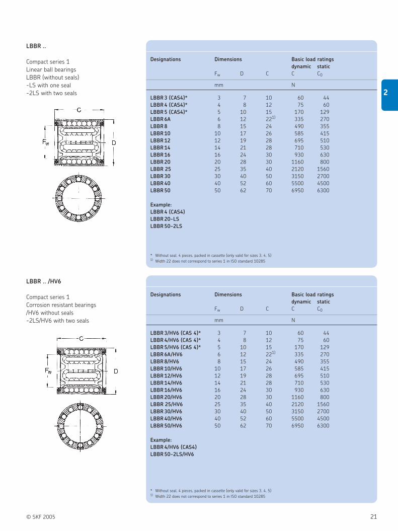
© SKF 2005 21
2
Designations Dimensions Basic load ratings
dynamic static
Fw D C C C0
mm N
LBBR 3 (CAS4)* 3 7 10 60 44
LBBR 4 (CAS4)* 4 8 12 75 60
LBBR 5 (CAS4)* 5 10 15 170 129
LBBR 6A 6 12 221) 335 270
LBBR 8 8 15 24 490 355
LBBR 10 10 17 26 585 415
LBBR 12 12 19 28 695 510
LBBR 14 14 21 28 710 530
LBBR 16 16 24 30 930 630
LBBR 20 20 28 30 1160 800
LBBR 25 25 35 40 2120 1560
LBBR 30 30 40 50 3150 2700
LBBR 40 40 52 60 5500 4500
LBBR 50 50 62 70 6950 6300
Example:
LBBR 4 (CAS4)
LBBR 20-LS
LBBR 50-2LS
LBBR ..
Compact series 1
Linear ball bearings
LBBR (without seals)
-LS with one seal
-2LS with two seals
LBBR .. /HV6
Compact series 1
Corrosion resistant bearings
/HV6 without seals
-2LS/HV6 with two seals
* Without seal, 4 pieces, packed in cassette (only valid for sizes 3, 4, 5)1) Width 22 does not correspond to series 1 in ISO standard 10285
Designations Dimensions Basic load ratings
dynamic static
Fw D C C C0
mm N
LBBR 3/HV6 (CAS 4)* 3 7 10 60 44
LBBR 4/HV6 (CAS 4)* 4 8 12 75 60
LBBR 5/HV6 (CAS 4)* 5 10 15 170 129
LBBR 6A/HV6 6 12 221) 335 270
LBBR 8/HV6 8 15 24 490 355
LBBR 10/HV6 10 17 26 585 415
LBBR 12/HV6 12 19 28 695 510
LBBR 14/HV6 14 21 28 710 530
LBBR 16/HV6 16 24 30 930 630
LBBR 20/HV6 20 28 30 1160 800
LBBR 25/HV6 25 35 40 2120 1560
LBBR 30/HV6 30 40 50 3150 2700
LBBR 40/HV6 40 52 60 5500 4500
LBBR 50/HV6 50 62 70 6950 6300
Example:
LBBR 4/HV6 (CAS4)
LBBR 50-2LS/HV6
* Without seal, 4 pieces, packed in cassette (only valid for sizes 3, 4, 5)1) Width 22 does not correspond to series 1 in ISO standard 10285

Designations Dimensions Basic load ratings
dynamic static
Fw D C C4 C C C0
0.1 m/s 4 m/s
mm N
LPBR 12 12 19.19 28 10 965 24 3350
LPBR 16 16 24.23 30 12 1530 38 5400
LPBR 20 20 28.24 30 13 2080 52 7350
LPBR 25 25 35.25 40 17 3400 85 12000
LPBR 30 30 40.27 50 20 4800 120 17000
LPBR 40 40 52.32 60 24 7650 193 27000
LPBR 50 50 62.35 70 27 10800 270 38000
22 © SKF 2005
2 Guiding systems
Shaft guidings - compact series
LPBR
Linear plain bearings
LUHR ..
Linear ball bearing units
LUHR (without seals)
-2LS with 2 seals
Designations Dimensions Basic load ratings
dynamic static
Fw A H H1 L C C0
± 0.01
mm N
LUHR 12 12 28 17 33 40 695 510
LUHR 16 16 30 19 38 45 930 630
LUHR 20 20 30 23 45 53 1160 800
LUHR 25 25 40 27 54 62 2120 1560
LUHR 30 30 50 30 60 67 3150 2700
LUHR 40 40 60 39 76 87 5500 4500
LUHR 50 50 70 47 92 103 6950 6300
Example:
LUHR 16
LUHR 30-2LS
A
Fw

© SKF 2005 23
2
LUJR
Linear ball bearing units with shaft seals
A1
Fw
LUHR .. PB
Linear plain bearing units without seals
LTBR ..
Tandem linear ball bearing units
LTBR (without seals)
-2LS with two seals
Fw
A
Designations Dimensions Basic load ratings
dynamic static
Fw A H H1 L C C C0
± 0.01 0.1 m/s 4 m/s
mm N
LUHR 12 PB 12 28 17 33 40 965 24 3350
LUHR 16 PB 16 30 19 38 45 1530 38 5400
LUHR 20 PB 20 30 23 45 53 2080 52 7350
LUHR 25 PB 25 40 27 54 62 3400 85 12000
LUHR 30 PB 30 50 30 60 67 4800 120 17000
LUHR 40 PB 40 60 39 76 87 7650 193 27000
LUHR 50 PB 50 70 47 92 103 10800 270 38000
Designations Dimensions Basic load ratings
dynamic static
Fw A1 H H1 L C C0
± 0.01
mm N
LUJR 12 12 35 17 33 40 695 510
LUJR 16 16 37 19 38 45 930 630
LUJR 20 20 39 23 45 53 1160 800
LUJR 25 25 49 27 54 62 2120 1560
LUJR 30 30 59 30 60 67 3150 2700
LUJR 40 40 71 39 76 87 5500 4500
LUJR 50 50 81 47 92 103 6950 6300
Designations Dimensions Basic load ratings
dynamic static
Fw A H H1 L C C0
± 0.01
mm N
LTBR 12 12 60 17 33 40 1140 1020
LTBR 16 16 65 19 38 45 1530 1270
LTBR 20 20 65 23 45 53 1900 1600
LTBR 25 25 85 27 54 62 3450 3150
LTBR 30 30 105 30 60 67 5200 5400
LTBR 40 40 125 39 76 87 9000 9000
LTBR 50 50 145 47 92 103 11400 12700
Example:
LTBR 16
LTBR 30-2LS

24 © SKF 2005
2 Guiding systems
Shaft guidings - compact series
LSHS
Shaft block for compact series
LTDR ..
Duo linear ball bearing units
LTDR (without seals)
-2LS with four seals
Fw
A
LQBR ..
Quadro linear ball bearing units
LQBR (without seals)
-2LS with four seals
Fw
A
Designations Dimensions
Fw A H H2 L
± 0.01
mm
LSHS 12 12 18 19 33 40
LSHS 16 16 20 22 38 45
LSHS 20 20 24 25 45 53
LSHS 25 25 28 31 54 62
LSHS 30 30 30 34 60 67
LSHS 40 40 40 42 76 87
LSHS 50 50 50 50 92 103
Designations Dimensions Basic load ratings
dynamic static
Fw A H H1 L L1 C C0
± 0.01
mm N
LTDR 12 12 28 15 30 80 40 1140 1020
LTDR 16 16 30 17.5 35 96 52 1530 1270
LTDR 20 20 30 20 40 115 63 1900 1600
LTDR 25 25 40 25 50 136 75 3450 3150
LTDR 30 30 50 28 56 146 80 5200 5400
LTDR 40 40 60 35 70 184 97 9000 9000
LTDR 50 50 70 40 80 210 107 11400 12700
Example:
LTDR 12
LTDR 25-2LS
Designations Dimensions Basic load ratings
dynamic static
Fw A H H1 L L1 C C0
± 0.01
mm N
LQBR 12 12 70 15 30 80 40 1860 2040
LQBR 16 16 80 17.5 35 96 52 2500 2550
LQBR 20 20 85 20 40 115 63 3100 3200
LQBR 25 25 100 25 50 136 75 5600 6300
LQBR 30 30 130 28 56 146 80 8500 10800
LQBR 40 40 150 35 70 184 97 14600 18000
LQBR 50 50 175 40 80 210 107 18600 25500
Example:
LQBR 40
LQBR 30-2LS

© SKF 2005 25
2
LEBS
Tandem shaft blocks suitable for LQBR and
LTDR
Appropriate special seals
A
L
H1
L1
HA
da
Designations Dimensions
da A HA H1 L L1
± 0.01
mm
LEBS 12 A 12 15 17 30 80 40
LEBS 16 A 16 15 19.5 35 96 52
LEBS 20 A 20 18 22 40 115 63
LEBS 25 A 25 20 27 50 136 75
LEBS 30 A 30 20 31 56 146 80
LEBS 40 A 40 25 38 70 184 97
LEBS 50 A 50 30 43 80 210 107
Designations Dimensions
Fw D B1
mm
SP - 6 ×12 ×2 6 12 2
SP - 8 ×15 ×3 8 15 3
SP - 10 ×17 ×3 10 17 3
SP - 12 ×19 ×3 12 19 3
SP - 14 ×21 ×3 14 21 3
SP - 16 ×24 ×3 16 24 3
SP - 20 ×28 ×4 20 28 4
SP - 25 ×35 ×4 25 35 4
SP - 30 ×40 ×4 30 40 4
SP - 40 ×52 ×5 40 52 5
SP - 50 ×62 ×5 50 62 5

26 © SKF 2005
2 Guiding systems
Shaft guidings - standard series
Type
Bearings, units, components:Linear plain bearing . . . . . . . . . . . . . . . . . . . . . . . . . . . . . . . . . . . . . . . . . . . . . . . . . . . . . . . . . . . . . . . . . . . . . . . . . . PLinear ball bearing . . . . . . . . . . . . . . . . . . . . . . . . . . . . . . . . . . . . . . . . . . . . . . . . . . . . . . . . . . . . . . . . . . . . . . . . . . . BSingle unit . . . . . . . . . . . . . . . . . . . . . . . . . . . . . . . . . . . . . . . . . . . . . . . . . . . . . . . . . . . . . . . . . . . . . . . . . . . . . . . . . UFlanged unit . . . . . . . . . . . . . . . . . . . . . . . . . . . . . . . . . . . . . . . . . . . . . . . . . . . . . . . . . . . . . . . . . . . . . . . . . . . . . . . . VTandem unit . . . . . . . . . . . . . . . . . . . . . . . . . . . . . . . . . . . . . . . . . . . . . . . . . . . . . . . . . . . . . . . . . . . . . . . . . . . . . . . . TQuadro unit . . . . . . . . . . . . . . . . . . . . . . . . . . . . . . . . . . . . . . . . . . . . . . . . . . . . . . . . . . . . . . . . . . . . . . . . . . . . . . . . QShaft block . . . . . . . . . . . . . . . . . . . . . . . . . . . . . . . . . . . . . . . . . . . . . . . . . . . . . . . . . . . . . . . . . . . . . . . . . . . . . . . . . STandem shaft block . . . . . . . . . . . . . . . . . . . . . . . . . . . . . . . . . . . . . . . . . . . . . . . . . . . . . . . . . . . . . . . . . . . . . . . . . . EShaft support . . . . . . . . . . . . . . . . . . . . . . . . . . . . . . . . . . . . . . . . . . . . . . . . . . . . . . . . . . . . . . . . . . . . . . . . . . . . . . . R
Design (for seals on side see table at end page):
For PClosed design (5 - 80). . . . . . . . . . . . . . . . . . . . . . . . . . . . . . . . . . . . . . . . . . . . . . . . . . . . . . . . . . . . . . . . . . . AROpen design (5 - 80) . . . . . . . . . . . . . . . . . . . . . . . . . . . . . . . . . . . . . . . . . . . . . . . . . . . . . . . . . . . . . . . . . . . . ATSelf-aligning, closed design (12 - 50) . . . . . . . . . . . . . . . . . . . . . . . . . . . . . . . . . . . . . . . . . . . . . . . . . . . . . . . CDSelf-aligning, open design (12 - 50) . . . . . . . . . . . . . . . . . . . . . . . . . . . . . . . . . . . . . . . . . . . . . . . . . . . . . . . . CF
For B* Closed design (5 - 80). . . . . . . . . . . . . . . . . . . . . . . . . . . . . . . . . . . . . . . . . . . . . . . . . . . . . . . . . . . . . . . . . . . CROpen design (12 - 80). . . . . . . . . . . . . . . . . . . . . . . . . . . . . . . . . . . . . . . . . . . . . . . . . . . . . . . . . . . . . . . . . . . CTHeavy load, open design (20 - 50) . . . . . . . . . . . . . . . . . . . . . . . . . . . . . . . . . . . . . . . . . . . . . . . . . . . . . . . . HTSelf-aligning, closed design, relubricatable (12 - 50). . . . . . . . . . . . . . . . . . . . . . . . . . . . . . . . . . . . . . . . . . . CDSelf-aligning, radial adjustable, slotted design, relubricatable (12 - 50) . . . . . . . . . . . . . . . . . . . . . . . . . . . . CESelf-aligning, clearance adjustable, open design, relubricatable (12 - 50). . . . . . . . . . . . . . . . . . . . . . . . . . . CFClosed design, (relubricatable) (8 - 80). . . . . . . . . . . . . . . . . . . . . . . . . . . . . . . . . . . . . . . . . . . . . . . . . . . . . . CR
For U Clearance adjustable, closed design, relubricatable (8 - 80). . . . . . . . . . . . . . . . . . . . . . . . . . . . . . . . . . . . . . CSClearance adjustable, open design, relubricatable (12 - 80). . . . . . . . . . . . . . . . . . . . . . . . . . . . . . . . . . . . . . CTSelf-aligning, clearance adjustable, closed design, relubricatable (12 - 50) . . . . . . . . . . . . . . . . . . . . . . . . . NDSelf-aligning, clearance adjustable, slotted design, relubricatable (12 - 50) . . . . . . . . . . . . . . . . . . . . . . . . . NESelf-aligning, clearance adjustable, open design, relubricatable (12 - 50) . . . . . . . . . . . . . . . . . . . . . . . . . . NF
Nominal diameter:Ø in mm
New bearing series* (for linear ball bearings only) . . . . . . . . . . . . . . . . . . . . . . . . . . . . . . . . . . . . . . . . . . . . . . . . . . . . . . . . . . . . . . A
Option(s):Without seals . . . . . . . . . . . . . . . . . . . . . . . . . . . . . . . . . . . . . . . . . . . . . . . . . . . . . . . . . . . . . . . . . . . . . . . . . . . . . . . . . . . . . . . . . . . no signOne side sealed . . . . . . . . . . . . . . . . . . . . . . . . . . . . . . . . . . . . . . . . . . . . . . . . . . . . . . . . . . . . . . . . . . . . . . . . . . . . . . . . . . . . . . . . . . . . -LSBoth sides sealed . . . . . . . . . . . . . . . . . . . . . . . . . . . . . . . . . . . . . . . . . . . . . . . . . . . . . . . . . . . . . . . . . . . . . . . . . . . . . . . . . . . . . . . . . . -2LS
Without seals, corrosion resistant (for linear ball bearings only) . . . . . . . . . . . . . . . . . . . . . . . . . . . . . . . . . . . . . . . . . . . . . . /HV6For B* One side sealed, corrosion resistant (for linear ball bearings only) . . . . . . . . . . . . . . . . . . . . . . . . . . . . . . . . . . . . . . . . . . -LS/HV6
Both sides sealed, corrosion resistant (for linear ball bearings only) . . . . . . . . . . . . . . . . . . . . . . . . . . . . . . . . . . . . . . . -2LS/HV6
Other option:Only valid for LUCR, LUCT:With plain bearing, without seals . . . . . . . . . . . . . . . . . . . . . . . . . . . . . . . . . . . . . . . . . . . . . . . . . . . . . . . . . . . . . . . . . . . . . . . . . . . . . . . . . . . . PAOnly valid for LUCT:With heavy-load bearing, without seals . . . . . . . . . . . . . . . . . . . . . . . . . . . . . . . . . . . . . . . . . . . . . . . . . . . . . . . . . . . . . . . . . . . . . . . . . . . . . . . BHWith heavy-load bearing, both sides sealed . . . . . . . . . . . . . . . . . . . . . . . . . . . . . . . . . . . . . . . . . . . . . . . . . . . . . . . . . . . . . . . . . . . . . . . . BH-2LSOnly valid for LEAS:Tandem shaft block, high shaft position . . . . . . . . . . . . . . . . . . . . . . . . . . . . . . . . . . . . . . . . . . . . . . . . . . . . . . . . . . . . . . . . . . . . . . . . . . . . . . . . . ATandem shaft block, low shaft position . . . . . . . . . . . . . . . . . . . . . . . . . . . . . . . . . . . . . . . . . . . . . . . . . . . . . . . . . . . . . . . . . . . . . . . . . . . . . . . . . B
Ordering key
Continued
Example:
— — —– —————–
30L U A BH-2LSCT
L
—
NB:
All LBC .. A and LBH .. A Linear ball
bearings available in corrosion resistant!
Seals on LPAR LPAT LBCD LBCF LBCR LBCT LBHT LUCD LUCE LUCF LUCR LUCS LUCT LUND LUNE LUNF
… side(s)
No X X X X X X X X X X X X X X X X
One – – X X X X X X X X X X X X X X
Both – – X X X X X X X X X X X X X X
Other – – – – – – – – – – PA – BH – – –
options or PA

© SKF 2005 27
2
Type
Bearings, units, components:Linear plain bearing . . . . . . . . . . . . . . . . . . . . . . . . . . . . . . . . . . . . . . . . . . . . . . . . . . . . . . . . . . . . . . . . . . . . . . . . . . . . . PLinear ball bearing . . . . . . . . . . . . . . . . . . . . . . . . . . . . . . . . . . . . . . . . . . . . . . . . . . . . . . . . . . . . . . . . . . . . . . . . . . . . . . BSingle unit . . . . . . . . . . . . . . . . . . . . . . . . . . . . . . . . . . . . . . . . . . . . . . . . . . . . . . . . . . . . . . . . . . . . . . . . . . . . . . . . . . . . UFlanged unit . . . . . . . . . . . . . . . . . . . . . . . . . . . . . . . . . . . . . . . . . . . . . . . . . . . . . . . . . . . . . . . . . . . . . . . . . . . . . . . . . . . VTandem unit . . . . . . . . . . . . . . . . . . . . . . . . . . . . . . . . . . . . . . . . . . . . . . . . . . . . . . . . . . . . . . . . . . . . . . . . . . . . . . . . . . . TQuadro unit . . . . . . . . . . . . . . . . . . . . . . . . . . . . . . . . . . . . . . . . . . . . . . . . . . . . . . . . . . . . . . . . . . . . . . . . . . . . . . . . . . . QShaft block . . . . . . . . . . . . . . . . . . . . . . . . . . . . . . . . . . . . . . . . . . . . . . . . . . . . . . . . . . . . . . . . . . . . . . . . . . . . . . . . . . . . STandem shaft block . . . . . . . . . . . . . . . . . . . . . . . . . . . . . . . . . . . . . . . . . . . . . . . . . . . . . . . . . . . . . . . . . . . . . . . . . . . . . EShaft support . . . . . . . . . . . . . . . . . . . . . . . . . . . . . . . . . . . . . . . . . . . . . . . . . . . . . . . . . . . . . . . . . . . . . . . . . . . . . . . . . . R
Design (for seals on side see table at end page):
For VSelf-aligning, closed design (12 - 50). . . . . . . . . . . . . . . . . . . . . . . . . . . . . . . . . . . . . . . . . . . . . . . . . . . . . . . . . . CDClosed design (12 - 80) . . . . . . . . . . . . . . . . . . . . . . . . . . . . . . . . . . . . . . . . . . . . . . . . . . . . . . . . . . . . . . . . . . . . . CRSelf-aligning, closed design, relubricatable (12 - 50) . . . . . . . . . . . . . . . . . . . . . . . . . . . . . . . . . . . . . . . . . . . . . . CD
For TSelf-aligning, open design, relubricatable (12 - 50) . . . . . . . . . . . . . . . . . . . . . . . . . . . . . . . . . . . . . . . . . . . . . . . CFClosed design, relubricatable (12 - 50) . . . . . . . . . . . . . . . . . . . . . . . . . . . . . . . . . . . . . . . . . . . . . . . . . . . . . . . . . CROpen design, relubricatable (12 - 50) . . . . . . . . . . . . . . . . . . . . . . . . . . . . . . . . . . . . . . . . . . . . . . . . . . . . . . . . . . CTSelf-aligning, closed design, relubricatable (12 - 50) . . . . . . . . . . . . . . . . . . . . . . . . . . . . . . . . . . . . . . . . . . . . . . CD
For QSelf-aligning, open design, relubricatable (12 - 50) . . . . . . . . . . . . . . . . . . . . . . . . . . . . . . . . . . . . . . . . . . . . . . . CFClosed design, relubricatable (8 - 50) . . . . . . . . . . . . . . . . . . . . . . . . . . . . . . . . . . . . . . . . . . . . . . . . . . . . . . . . . . CROpen design, relubricatable (12 - 50) . . . . . . . . . . . . . . . . . . . . . . . . . . . . . . . . . . . . . . . . . . . . . . . . . . . . . . . . . . CT
For S(8 - 80) . . . . . . . . . . . . . . . . . . . . . . . . . . . . . . . . . . . . . . . . . . . . . . . . . . . . . . . . . . . . . . . . . . . . . . . . . . . . . . . . . CS(12 - 50) . . . . . . . . . . . . . . . . . . . . . . . . . . . . . . . . . . . . . . . . . . . . . . . . . . . . . . . . . . . . . . . . . . . . . . . . . . . . . . . . NS
For E (8 - 50) . . . . . . . . . . . . . . . . . . . . . . . . . . . . . . . . . . . . . . . . . . . . . . . . . . . . . . . . . . . . . . . . . . . . . . . . . . . . . . . . . AS
For RWithout bore holes (12 - 80) . . . . . . . . . . . . . . . . . . . . . . . . . . . . . . . . . . . . . . . . . . . . . . . . . . . . . . . . . . . . . . . . CBWith bore holes (12 - 80) . . . . . . . . . . . . . . . . . . . . . . . . . . . . . . . . . . . . . . . . . . . . . . . . . . . . . . . . . . . . . . . . . . . CC
Nominal diameter:Ø in mm
Option(s):Without seals . . . . . . . . . . . . . . . . . . . . . . . . . . . . . . . . . . . . . . . . . . . . . . . . . . . . . . . . . . . . . . . . . . . . . . . . . . . . . . . . . . . . . . . . . . . no signOne side sealed . . . . . . . . . . . . . . . . . . . . . . . . . . . . . . . . . . . . . . . . . . . . . . . . . . . . . . . . . . . . . . . . . . . . . . . . . . . . . . . . . . . . . . . . . . . . -LSBoth sides sealed . . . . . . . . . . . . . . . . . . . . . . . . . . . . . . . . . . . . . . . . . . . . . . . . . . . . . . . . . . . . . . . . . . . . . . . . . . . . . . . . . . . . . . . . . . -2LS
Other option:Only valid for LUCR, LUCT:With plain bearing, without seals . . . . . . . . . . . . . . . . . . . . . . . . . . . . . . . . . . . . . . . . . . . . . . . . . . . . . . . . . . . . . . . . . . . . . . . . . . . . . . . . . . . . PAOnly valid for LUCT:With heavy-load bearing, without seals . . . . . . . . . . . . . . . . . . . . . . . . . . . . . . . . . . . . . . . . . . . . . . . . . . . . . . . . . . . . . . . . . . . . . . . . . . . . . . . BHWith heavy-load bearing, both sides sealed . . . . . . . . . . . . . . . . . . . . . . . . . . . . . . . . . . . . . . . . . . . . . . . . . . . . . . . . . . . . . . . . . . . . . . . . BH-2LSOnly valid for LEAS:Tandem shaft block, high shaft position . . . . . . . . . . . . . . . . . . . . . . . . . . . . . . . . . . . . . . . . . . . . . . . . . . . . . . . . . . . . . . . . . . . . . . . . . . . . . . . . . ATandem shaft block, low shaft position . . . . . . . . . . . . . . . . . . . . . . . . . . . . . . . . . . . . . . . . . . . . . . . . . . . . . . . . . . . . . . . . . . . . . . . . . . . . . . . . . B
Ordering key (Continued)
————
Example: 16L Q -2LSCR
— — —– —–L
Seals on LVCD LVCR LTCD LTCF LTCR LTCT LQCD LQCF LQCR LQCT LSCS LSNS LEAS LRCB LRCC
… side(s)
No X X X X X X X X X X X X X X XOne X X X X X X X X X X – – – – –Both X X X X X X X X X X – – – – –Other
– – – – – – – – – – – –B
– –options or A

Designations Dimensions Basic load ratings
dynamic static
Fw D C C3 C C0
mm N
LBCD 12 A 12 22 32 20 1080 815
LBCD 16 A 16 26 36 22 1320 865
LBCD 20 A 20 32 45 28 2000 1370
LBCD 25 A 25 40 58 40 2900 2040
LBCD 30 A 30 47 68 48 4650 3250
LBCD 40 A 40 62 80 56 7800 5200
LBCD 50 A 50 75 100 72 11200 6950
Example:
LBCD 25 A
LBCD 16 A-LS
LBCD 40 A-2LS
Designations Dimensions Basic load ratings
dynamic static
Fw D C C3 C C0
mm N
LBCR 5 A 5 12 22 12 280 210
LBCR 8 A 8 16 25 14 490 355
LBCR 12 A 12 22 32 20 1160 980
LBCR 16 A 16 26 36 22 1500 1290
LBCR 20 A 20 32 45 28 2240 2040
LBCR 25 A 25 40 58 40 3350 3350
LBCR 30 A 30 47 68 48 5600 5700
LBCR 40 A 40 62 80 56 9000 8150
LBCR 50 A 50 75 100 72 13400 12200
LBCR 60 A 60 90 125 95 20400 18000
LBCR 80 A 80 120 165 125 37500 32000
Example:
LBCR 30 A
LBCR 80 A-LS
LBCR 60 A-2LS
28 © SKF 2005
2 Guiding systems
Shaft guidings - standard series, closed types
LBCD ..
Standard series 3
Linear ball bearings self-aligning, closed
type
LBCD .. A (without seals)
-LS with one seal
-2LS with two seals
LBCR ..
Standard series 3
Linear ball bearings, closed type
LBCR .. A (without seals)
-LS with one seal
-2LS with two seals
NB:
All LBC .. A and LBH .. A Linear ball
bearings available in corrosion resistant!

© SKF 2005 29
2
LPAR
Linear plain bearings without seals, closed
type
LUCD ..
Single units, self-aligning, closed type,
relubricatable
LUCD (without seals)
-2LS with two seals
Designations Dimensions Basic load ratings
dynamic static
Fw D C C3 C C C0
0.1 m/s 4 m/s
mm N
LPAR 5 5 12 22 12 280 7 980
LPAR 8 8 16 25 14 510 13 1800
LPAR 12 12 22 32 20 965 24 3350
LPAR 16 16 26 36 22 1530 38 5400
LPAR 20 20 32 45 28 2400 60 8300
LPAR 25 25 40 58 40 4000 100 14000
LPAR 30 30 47 68 48 5500 137 19300
LPAR 40 40 62 80 56 8000 200 28000
LPAR 50 50 75 100 72 12000 300 41500
LPAR 60 60 90 125 95 16600 415 60000
LPAR 80 80 120 165 125 29000 720 100000
Designations Dimensions Basic load ratings
dynamic static
Fw C H H2 L C C0
± 0.01
mm N
LUCD 12 12 32 18 34.5 52 1080 815
LUCD 16 16 36 22 40.5 56 1320 865
LUCD 20 20 45 25 48 70 2000 1370
LUCD 25 25 58 30 58 80 2900 2040
LUCD 30 30 68 35 67 88 4650 3250
LUCD 40 40 80 45 85 108 7800 5200
LUCD 50 50 100 50 99 135 11200 6950
Example:
LUCD 40
LUCD 12-2LS

30 © SKF 2005
2 Guiding systems
Shaft guidings - standard series, closed types
LUCE ..
Single units, self-aligning, clearance
adjustable, closed type, relubricatable
LUCE (without seals)
-2LS with two seals
LUCR ..
Single units, closed type, relubricatable
LUCR (without seals)
-2LS with two seals
Designations Dimensions Basic load ratings
dynamic static
Fw C H H2 L C C0
± 0.01
mm N
LUCE 12 12 32 18 34.5 52 1080 815
LUCE 16 16 36 22 40.5 56 1320 865
LUCE 20 20 45 25 48 70 2000 1370
LUCE 25 25 58 30 58 80 2900 2040
LUCE 30 30 68 35 67 88 4650 3250
LUCE 40 40 80 45 85 108 7800 5200
LUCE 50 50 100 50 99 135 11200 6950
Example:
LUCE 25
LUCE 50-2LS
Designations Dimensions Basic load ratings
dynamic static
Fw C H H2 L C C0
± 0.01
mm N
LUCR 8* 8 25 15 28 45 365 285
LUCR 12 12 32 18 34.5 52 1080 815
LUCR 16 16 36 22 40.5 56 1320 865
LUCR 20 20 45 25 48 70 2000 1370
LUCR 25 25 58 30 58 80 2900 2040
LUCR 30 30 68 35 67 88 4650 3250
LUCR 40 40 80 45 85 108 7800 5200
LUCR 50 50 100 50 99 135 11200 6950
LUCR 60 60 125 60 118 160 20400 18000
LUCR 80 80 165 80 158 205 37500 32000
Example:
LUCR 80
LUCR 8-2LS
* Linear ball bearings fitted to these units are secured with snap rings according to DIN 471 and cannot be relubricated.
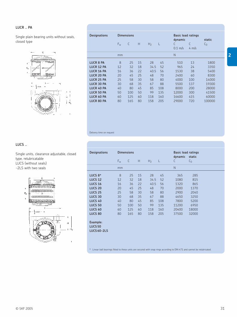
© SKF 2005 31
2
LUCS ..
Single units, clearance adjustable, closed
type, relubricatable
LUCS (without seals)
-2LS with two seals
LUCR .. PA
Single plain bearing units without seals,
closed type
Designations Dimensions Basic load ratings
dynamic static
Fw C H H2 L C C C0
0.1 m/s 4 m/s
mm N
LUCR 8 PA 8 25 15 28 45 510 13 1800
LUCR 12 PA 12 32 18 34.5 52 965 24 3350
LUCR 16 PA 16 36 22 40.5 56 1530 38 5400
LUCR 20 PA 20 45 25 48 70 2400 60 8300
LUCR 25 PA 25 58 30 58 80 4000 100 14000
LUCR 30 PA 30 68 35 67 88 5500 137 19300
LUCR 40 PA 40 80 45 85 108 8000 200 28000
LUCR 50 PA 50 100 50 99 135 12000 300 41500
LUCR 60 PA 60 125 60 118 160 16600 415 60000
LUCR 80 PA 80 165 80 158 205 29000 720 100000
Delivery time on request
Designations Dimensions Basic load ratings
dynamic static
Fw C H H2 L C C0
mm N
LUCS 8* 8 25 15 28 45 365 285
LUCS 12 12 32 18 34.5 52 1080 815
LUCS 16 16 36 22 40.5 56 1320 865
LUCS 20 20 45 25 48 70 2000 1370
LUCS 25 25 58 30 58 80 2900 2040
LUCS 30 30 68 35 67 88 4650 3250
LUCS 40 40 80 45 85 108 7800 5200
LUCS 50 50 100 50 99 135 11200 6950
LUCS 60 60 125 60 118 160 20400 18000
LUCS 80 80 165 80 158 205 37500 32000
Example:
LUCS 50
LUCS 60-2LS
* Linear ball bearings fitted to these units are secured with snap rings according to DIN 471 and cannot be relubricated.

32 © SKF 2005
2 Guiding systems
Shaft guidings - standard series, closed types
LUND ..
Single units, self-aligning, closed type,
relubricatable
LUND (without seals)
-2LS with two seals
LUNE ..
Single units, self-aligning, clearance
adjustable, closed type, relubricatable
LUNE (without seals)
-2LS with two seals
Designations Dimensions Basic load ratings
dynamic static
Fw A H H1 L C C0
± 0.01
mm N
LUND 12 12 32 18 35 43 1080 815
LUND 16 16 37 22 42 53 1320 865
LUND 20 20 45 25 50 60 2000 1370
LUND 25 25 58 30 61 78 2900 2040
LUND 30 30 68 35 70 87 4650 3250
LUND 40 40 80 45 90 108 7800 5200
LUND 50 50 100 50 105 132 11200 6950
Example:
LUND 12
LUND 30-2LS
Designations Dimensions Basic load ratings
dynamic static
Fw A H H1 L C C0
± 0.01
mm N
LUNE 12 12 32 18 35 43 1080 815
LUNE 16 16 37 22 42 53 1320 865
LUNE 20 20 45 25 50 60 2000 1370
LUNE 25 25 58 30 61 78 2900 2040
LUNE 30 30 68 35 70 87 4650 3250
LUNE 40 40 80 45 90 108 7800 5200
LUNE 50 50 100 50 105 132 11200 6950
Example:
LUNE 40
LUNE 16-2LS

© SKF 2005 33
2
LVCD ..
Flanged self-aligning units
LVCD (without seals)
-2LS with two seals
LVCR ..
Flanged units
LVCR (without seals)
-2LS with two seals
Designations Dimensions Basic load ratings
dynamic static
Fw A C L D2 C C0
mm N
LVCR 12 12 20 32 42 32 1160 980
LVCR 16 16 22 36 50 38 1500 1290
LVCR 20 20 28 45 60 46 2240 2040
LVCR 25 25 40 58 74 58 3350 3350
LVCR 30 30 48 68 84 66 5600 5700
LVCR 40 40 56 80 108 90 9000 8150
LVCR 50 50 72 100 130 110 13400 12200
LVCR 60 60 95 125 160 135 20400 18000
LVCR 80 80 125 165 200 180 37500 32000
Example:
LVCR 20
LVCR 60-2LS
Delivery time on request
Designations Dimensions Basic load ratings
dynamic static
Fw A C L D2 C C0
mm N
LVCD 12 12 20 32 42 32 1080 815
LVCD 16 16 22 36 50 38 1320 865
LVCD 20 20 28 45 60 46 2000 1370
LVCD 25 25 40 58 74 58 2900 2040
LVCD 30 30 48 68 84 66 4650 3250
LVCD 40 40 56 80 108 90 7800 5200
LVCD 50 50 72 100 130 110 11200 6950
Example:
LVCD 12
LVCD 30-2LS

34 © SKF 2005
2 Guiding systems
Shaft guidings - standard series, closed types
LSCS
Shaft blocks
LSNS
Shaft blocks
Designations Dimensions
da A H H2 L
± 0.01
mm
LSCS 8 8 10 15 25 45
LSCS 12 12 12 20 32.5 52
LSCS 16 16 15 20 35.5 56
LSCS 20 20 20 25 43.5 70
LSCS 25 25 28 30 53 80
LSCS 30 30 30 35 63 88
LSCS 40 40 36 45 81 108
LSCS 50 50 49 50 92.5 135
LSCS 60 60 62 60 112 160
LSCS 80 80 85 80 147.5 205
Designations Dimensions
da A H H2 L
± 0.01
mm
LSNS 12 12 20 20 35 43
LSNS 16 16 24 25 42 53
LSNS 20 20 30 30 50 60
LSNS 25 25 38 35 61 78
LSNS 30 30 40 40 70 87
LSNS 40 40 48 50 90 108
LSNS 50 50 58 60 105 132

© SKF 2005 35
2
LTCD ..
Tandem units, self-aligning, closed type,
relubricatable
LTCD (without seals)
-2LS with two seals
LTCR ..
Tandem units, closed type, relubricatable
LTCR (without seals)
-2LS with two seals
Designations Dimensions Basic load ratings
dynamic static
Fw A H H1 L C C0
± 0.01
mm N
LTCD 12 12 76 18 35 42 1760 1630
LTCD 16 16 84 22 41.5 50 2160 1730
LTCD 20 20 104 25 49.5 60 3200 2750
LTCD 25 25 130 30 59.5 74 4750 4150
LTCD 30 30 152 35 69.5 84 7500 6550
LTCD 40 40 176 45 89.5 108 12700 10400
LTCD 50 50 224 50 99.5 130 18300 14000
Example:
LTCD 30
LTCD 12-2LS
Designations Dimensions Basic load ratings
dynamic static
Fw A H H1 L C C0
± 0.01
mm N
LTCR 12 12 76 18 35 42 1900 1960
LTCR 16 16 84 22 41.5 50 2450 2600
LTCR 20 20 104 25 49.5 60 3650 4150
LTCR 25 25 130 30 59.5 74 5500 6700
LTCR 30 30 152 35 69.5 84 9150 11400
LTCR 40 40 176 45 89.5 108 15000 16300
LTCR 50 50 224 50 99.5 130 22000 24500
Example:
LTCR 50
LTCR 20-2LS

36 © SKF 2005
2 Guiding systems
Shaft guidings - standard series, closed types
LQCD ..
Quadro units, self-aligning, closed type,
relubricatable
LQCD (without seals)
-2LS with four seals
LQCR ..
Quadro units, closed type, relubricatable
LQCR (without seals)
-2LS with four seals
Designations Dimensions Basic load ratings
dynamic static
Fw A H H1 L C C0
± 0.01
mm N
LQCD 12 12 32 16 32 85 2850 3250
LQCD 16 16 36 18 36 100 3450 3450
LQCD 20 20 45 23 46 130 5200 5500
LQCD 25 25 58 28 56 160 7650 8150
LQCD 30 30 68 32 64 180 12200 12900
LQCD 40 40 80 40 80 230 20800 20800
LQCD 50 50 100 48 96 280 30000 28000
Example:
LQCD 40
LQCD 16-2LS
Designations Dimensions Basic load ratings
dynamic static
Fw C H H1 L L1 C C0
± 0.01
mm N
LQCR 8 8 25 11.5 23 65 32 965 1140
LQCR 12 12 32 16 32 85 42 3100 4000
LQCR 16 16 36 18 36 100 54 4000 5200
LQCR 20 20 45 23 46 130 72 6000 8300
LQCR 25 25 58 28 56 160 88 9000 13400
LQCR 30 30 68 32 64 180 96 15000 22800
LQCR 40 40 80 40 80 230 122 24000 33500
LQCR 50 50 100 48 96 280 152 35500 49000
Example:
LQCR 25
LQCR 12-2LS

© SKF 2005 37
2
LEAS ..
Tandem shaft blocks, closed type, suitable
for LQCD / LQCR
LEAS .. A high shaft position
LEAS .. B low shaft position
.. A
.. B
Designations Dimensions
for types A and B for type A for type B
da A L L1 HA H1A HB H1B
± 0.015 ± 0.015
mm
LEAS 8 8 12 65 32 12.5 23 11 22
LEAS 12 12 15 85 42 18 32 14 28
LEAS 16 16 18 100 54 20 37 17 34
LEAS 20 20 20 130 72 25 46 21 42
LEAS 25 25 25 160 88 30 56 26 52
LEAS 30 30 25 180 96 35 64 29 58
LEAS 40 40 30 230 122 44 80 36 72
LEAS 50 50 30 280 152 52 96 44 88
Example:
LEAS 50 A
LEAS 30 B

38 © SKF 2005
2 Guiding systems
Shaft guidings - standard series, open types
LBCT ..
Standard series 3
Linear ball bearings, open type
LBCT .. A (without seals)
-LS with one seal
-2LS with two seals
Eα
NB:
All LBC .. A and LBH .. A Linear ball
bearings available in corrosion resistant!
Designations Dimensions Basic load ratings
dynamic static
Fw D C C3 E α C C0
mm deg. N
LBCF 12 A 12 22 32 20 7.6 78 1080 815
LBCF 16 A 16 26 36 22 10.4 78 1320 865
LBCF 20 A 20 32 45 28 10.8 60 2000 1370
LBCF 25 A 25 40 58 40 13.2 60 2900 2040
LBCF 30 A 30 47 68 48 14.2 50 4650 3250
LBCF 40 A 40 62 80 56 18.7 50 7800 5200
LBCF 50 A 50 75 100 72 23.6 50 11200 6950
Example:
LBCF 40 A
LBCF 25 A-LS
LBCF 16 A-2LS
Designations Dimensions Basic load ratings
dynamic static
Fw D C C3 E α C C0
mm deg. N
LBCT 12 A 12 22 32 20 7.6 78 1160 980
LBCT 16 A 16 26 36 22 10.4 78 1500 1290
LBCT 20 A 20 32 45 28 10.8 60 2240 2040
LBCT 25 A 25 40 58 40 13.2 60 3350 3350
LBCT 30 A 30 47 68 48 14.2 50 5600 5700
LBCT 40 A 40 62 80 56 18.7 50 9000 8150
LBCT 50 A 50 75 100 72 23.6 50 13400 12220
LBCT 60 A 60 90 125 95 29.6 54 20400 18000
LBCT 80 A 80 120 165 125 38.4 54 37500 32000
Example:
LBCT 20 A
LBCT 80 A-LS
LBCT 50 A-2LS
LBCF ..
Standard series 3
Linear ball bearings, self-aligning, open
type
LBCF ..A (without seals)
-LS with one seal
-2LS with two seals

© SKF 2005 39
2
LBHT ..
Standard series 3
Heavy-load linear ball bearings, open type
LBHT .. A (without seals)
-LS with one seal
-2LS with two seals
E
α
LPAT
Linear plain bearings, without seals, open
design
E
α
NB:
All LBC .. A and LBH .. A Linear ball
bearings available in corrosion resistant!
Designations Dimensions Basic load ratings
dynamic static
Fw D C C3 E α C C0
mm deg. N
LBHT 20 A 20 32 45 28 10.8 60 2650 2650
LBHT 25 A 25 40 58 40 13.2 60 4900 5100
LBHT 30 A 30 47 68 48 14.2 50 7200 8000
LBHT 40 A 40 62 80 56 18.7 50 11600 11400
LBHT 50 A 50 75 100 72 23.6 50 17300 17000
Example:
LBHT 40 A
LBHT 25 A-LS
LBHT 20 A-2LS
Designations Dimensions Basic load ratings
dynamic static
Fw D C C3 E α C C C0
0.1 m/s 4 m/s
mm deg. N
LPAT 12 12 22 32 20 7.6 78 965 24 3350
LPAT 16 16 26 36 22 10.4 78 1530 38 5400
LPAT 20 20 32 45 28 10.8 60 2400 60 8300
LPAT 25 25 40 58 40 13.2 60 4000 100 14000
LPAT 30 30 47 68 48 14.2 50 5500 137 19300
LPAT 40 40 62 80 56 18.7 50 8000 200 28000
LPAT 50 50 75 100 72 23.6 50 12000 300 41500
LPAT 60 60 90 125 95 29.6 54 16600 415 60000
LPAT 80 80 120 165 125 38.4 54 29000 720 100000
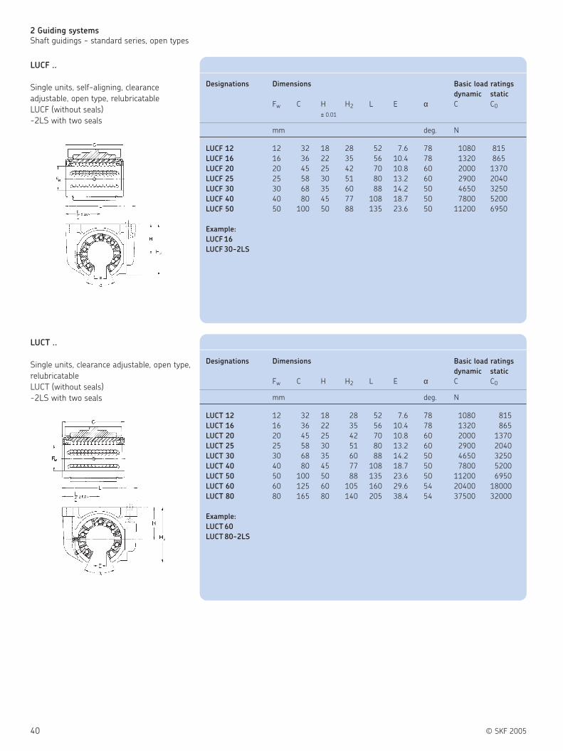
40 © SKF 2005
2 Guiding systems
Shaft guidings - standard series, open types
LUCT ..
Single units, clearance adjustable, open type,
relubricatable
LUCT (without seals)
-2LS with two seals
LUCF ..
Single units, self-aligning, clearance
adjustable, open type, relubricatable
LUCF (without seals)
-2LS with two seals
Designations Dimensions Basic load ratings
dynamic static
Fw C H H2 L E α C C0
± 0.01
mm deg. N
LUCF 12 12 32 18 28 52 7.6 78 1080 815
LUCF 16 16 36 22 35 56 10.4 78 1320 865
LUCF 20 20 45 25 42 70 10.8 60 2000 1370
LUCF 25 25 58 30 51 80 13.2 60 2900 2040
LUCF 30 30 68 35 60 88 14.2 50 4650 3250
LUCF 40 40 80 45 77 108 18.7 50 7800 5200
LUCF 50 50 100 50 88 135 23.6 50 11200 6950
Example:
LUCF 16
LUCF 30-2LS
Designations Dimensions Basic load ratings
dynamic static
Fw C H H2 L E α C C0
mm deg. N
LUCT 12 12 32 18 28 52 7.6 78 1080 815
LUCT 16 16 36 22 35 56 10.4 78 1320 865
LUCT 20 20 45 25 42 70 10.8 60 2000 1370
LUCT 25 25 58 30 51 80 13.2 60 2900 2040
LUCT 30 30 68 35 60 88 14.2 50 4650 3250
LUCT 40 40 80 45 77 108 18.7 50 7800 5200
LUCT 50 50 100 50 88 135 23.6 50 11200 6950
LUCT 60 60 125 60 105 160 29.6 54 20400 18000
LUCT 80 80 165 80 140 205 38.4 54 37500 32000
Example:
LUCT 60
LUCT 80-2LS

© SKF 2005 41
2
LUCT .. BH
Single heavy load units, clearance
adjustable, open type, relubricatable
LUCT .. BH (without seals)
-2LS with two seals
LUCT .. PA
Single units without seals, open type
Designations Dimensions Basic load ratings
dynamic static
Fw C H H2 L E α C C0
± 0.01
mm deg. N
LUCT 20 BH 20 45 25 42 70 10.8 60 2650 2650
LUCT 25 BH 25 58 30 51 80 13.2 60 4900 5100
LUCT 30 BH 30 68 35 60 88 14.2 50 7200 8000
LUCT 40 BH 40 80 45 77 108 18.7 50 11600 11400
LUCT 50 BH 50 100 50 88 135 23.6 50 17300 17000
Example:
LUCT BH 30
LUCT BH 20-2LS
Designations Dimensions Basic load ratings
dynamic static
Fw C H H2 L E α C C C0
0.1 m/s 4 m/s
mm deg. N
LUCT 12 PA 12 32 18 28 52 7.6 78 965 24 3350
LUCT 16 PA 16 36 22 35 56 10.4 78 1530 38 5400
LUCT 20 PA 20 45 25 42 70 10.8 60 2400 60 8300
LUCT 25 PA 25 58 30 51 80 13.2 60 4000 100 14000
LUCT 30 PA 30 68 35 60 88 14.2 50 5500 137 19300
LUCT 40 PA 40 80 45 77 108 18.7 50 8000 200 28000
LUCT 50 PA 50 100 50 88 135 23.6 50 12000 300 41500
LUCT 60 PA 60 125 60 105 160 29.6 54 16600 415 60000
LUCT 80 PA 80 165 80 140 205 38.4 54 29000 720 100000

42 © SKF 2005
2 Guiding systems
Shaft guidings - standard series, open types
LUNF ..
Single units, self-aligning, clearance
adjustable, open type, relubricatable
LUNF (without seals)
-2LS with two seals
LTCF ..
Tandem units, self-aligning, open type,
relubricatable
LTCF (without seals)
-2LS with two seals
Designations Dimensions Basic load ratings
dynamic static
Fw C H H1 L E α C C0
± 0.01
mm deg. N
LUNF 12 12 32 18 28 43 7.6 78 1160 980
LUNF 16 16 37 22 35 53 10.4 78 1500 1290
LUNF 20 20 45 25 42 60 10.8 60 2240 2040
LUNF 25 25 58 30 51 78 13.2 60 3350 3350
LUNF 30 30 68 35 60 87 14.2 50 5600 5700
LUNF 40 40 80 45 77 108 18.7 50 9000 8150
LUNF 50 50 100 50 88 132 23.6 50 13400 12200
Example:
LUNF 20
LUNF 16-2LS
Designations Dimensions Basic load ratings
dynamic static
Fw C H H1 L E α C C0
± 0.01
mm deg. N
LTCF 12 12 76 18 29 42 7.6 78 1760 1630
LTCF 16 16 84 22 35 50 10.4 78 2160 1730
LTCF 20 20 104 25 42 60 10.8 60 3200 2750
LTCF 25 25 130 30 51 74 13.2 60 4750 4150
LTCF 30 30 152 35 60 84 14.2 50 7500 6550
LTCF 40 40 176 45 77 108 18.7 50 12700 10400
LTCF 50 50 224 50 88 130 23.6 50 18300 14000
Example:
LTCF 50
LTCF 12-2LS

© SKF 2005 43
2
LTCT ..
Tandem units, open type, relubricatable
LTCT (without seals)
-2LS with two seals
LQCF ..
Quadro units, self-aligning, open type,
relubricatable
LQCF (without seals)
-2LS with four seals
Designations Dimensions Basic load ratings
dynamic static
Fw A H H1 L E α C C0
mm deg. N
LTCT 12 12 76 18 29 42 7.6 78 1900 1960
LTCT 16 16 84 22 35 50 10.4 78 2450 2600
LTCT 20 20 104 25 42 60 10.8 60 3650 4150
LTCT 25 25 130 30 51 74 13.2 60 5500 6700
LTCT 30 30 152 35 60 84 14.2 50 9150 11400
LTCT 40 40 176 45 77 108 18.7 50 15000 16300
LTCT 50 50 224 50 88 130 23.6 50 22000 24500
Example:
LTCT 16
LTCT 30-2LS
Designations Dimensions Basic load ratings
dynamic static
Fw C H H1 L L1 E α C C0
± 0.01
mm deg. N
LQCF 12 12 32 18 30 85 42 7.6 78 2850 3250
LQCF 16 16 36 22 35 100 54 10.4 78 3450 3450
LQCF 20 20 45 25 42 130 72 10.8 60 5200 5500
LQCF 25 25 58 30 51 160 88 13.2 60 7650 8150
LQCF 30 30 68 35 60 180 96 14.2 50 12200 12900
LQCF 40 40 80 45 77 230 122 18.7 50 20800 20800
LQCF 50 50 100 55 93 280 152 23.6 50 30000 28000
Example:
LQCF 12
LQCF 40-2LS

44 © SKF 2005
2 Guiding systems
Shaft guidings - standard series, open types
LRCB/LRCC
Shaft supports
LRCB with bore holes
LRCC without bore holes
L
LQCT ..
Quadro units, open type, relubricatable
LQCT (without seals)
-2LS with four seals
Designations Dimensions Basic load ratings
dynamic static
Fw C H H1 L L1 E α C C0
± 0.01
mm deg. N
LQCT 12 12 32 18 30 85 42 7.6 78 3100 4000
LQCT 16 16 36 22 35 100 54 10.4 78 4000 5200
LQCT 20 20 45 25 42 130 72 10.8 60 6000 8300
LQCT 25 25 58 30 51 160 88 13.2 60 9000 13400
LQCT 30 30 68 35 60 180 96 14.2 50 15000 22800
LQCT 40 40 80 45 77 230 122 18.7 50 24000 33500
LQCT 50 50 100 55 93 280 152 23.6 50 35500 49000
Example:
LQCT 42
LQCT 16-2LS
Designations Dimensions
d A H L
± 0.02
mm
LRCB 12 LRCC 12 12 40 22 600
LRCB 16 LRCC 16 16 45 26 600
LRCB 20 LRCC 20 20 52 32 600
LRCB 25 LRCC 25 25 57 36 600
LRCB 30 LRCC 30 30 69 42 600
LRCB 40 LRCC 40 40 73 50 600
LRCB 50 LRCC 50 50 84 60 600
LRCB 60 LRCC 60 60 94 68 600
LRCB 80 LRCC 80 80 116 86 600
Example:
LRCB 80
LRCC 80
© SKF 2005 45
2
Notes

46 © SKF 2005
2 Guiding systems
Precision shafts
Precision shafts
SKF precision shafts ( figure 20) can be
supplied either as solid or hollow shafts.
The solid shafts are available in all
dimensions required to fit SKF linear
ball bearings; the hollow shafts have a
minimum outside diameter of 16 mm.
They are induction hardened and
ground (see table on next page). SKF
shafts have exceptionally high dimensional
stability and long service life.
Yet at the end of shafts of normal
production length, deviations of hardness
and dimensional stability can occur.
For special applications, solid shafts
of stainless steel or hard chromium plated
shafts having a chromium layer
approximately 10 µm thick can be supplied.
When using stainless steel shafts, it must
be taken into account that the surface is not
as hard as that of shafts made of high-
grade steel. The case depth may also be
greater than indicated in Table 5 and this
may have an influence on the machinability
of the shafts.
Because of the benefits they offer, SKF
precision shafts are not only used in
combination with SKF linear ball bearings
for linear guides, but also for other
purposes, for instance axles or column
sleeves.
Tolerances
SKF precision steel shafts are available as
standard with a diameter machined
to tolerance h6 or h7. Other tolerances on
request. Shafts cut to special lengths have
a length tolerance to DIN 7168 “medium”.
The relevant values are given in Table 4.
Shafts with radial holes
For linear guides requiring support, shafts
with threaded radial holes are needed.
These can be supplied by SKF. The radial
holes can be positioned either in a way that
they accommodate SKF shaft supports or
as specified in the customer drawing.
Composite shafts
Composite shafts can be supplied to
customer drawings, either with screwed
joints or with “plug and socket” joints,
depending on the application.
Accurately centred trunnions and
sockets guarantee smooth transitions at the
butt joint. To ensure correct assembly, the
relative positions of the shaft sections and
of the shaft ends are marked. Composite
Case depth of SKF shafts.
Length tolerances for shafts to DIN 7168,
medium series.
Figure 20
Nominal length Deviation
over incl.
mm
– 120 ± 0.3
120 400 ± 0.5
400 1000 ± 0.8
1000 2000 ± 1.2
2000 4000 ± 2
4000 8000 ± 3
Table 4
Shaft diameter Case depth
over incl. min
mm
– 10 0.5
10 18 0.8
18 30 1.2
30 50 1.5
50 80 2.2
80 100 3.0
Table 5

© SKF 2005 47
2
shafts should be fastened to a support at
the butt joints, particularly when these are
of the “plug and socket” type. The radial
holes should be positioned as closely to the
joint as possible and the shaft length
selected in a way that bending of the shaft
will not result in a gap forming at the joint.
Materials
SKF precision steel shafts are available as
shown in Tables 6 and 7.
SKF precision shafts are made from the
non-alloyed high-grade steels Cf53
(Material No.1.1213), Ck53 (Material
No.1.1210), Ck60 (Material No.1.1221) and
100Cr6 (Material No.12067).
The surface hardness is between
approximately 60 and 64 HRC. The solid
shafts of stainless steel are made from the
steel X90CrMoV18 (Material No.1.4112) or
X46Cr13 (Material No.1.4034). In this case
the surface hardness lies between
approximately 52 and 56 HRC.
Shafts made from other materials
can be supplied to special order.
Standard shaft lengths
Designation Type
LJM Precision shaft, steel Ck53/Cf53, 60-64HRC, h6
LJMH Hard chromium plated precision shaft, steel Ck53/Cf53, min. 60HRC, h7
LJMR Precision shaft, corrosion resistant, X90CrMoV18, 52-56HRC, h6
LJMS Precision shaft, corrosion resistant, X46Cr13, 52-56HRC, h6
LJT Hollow shaft, high-grade steel, Ck60 or 100Cr6, 60-66HRC, h6
Table 6
Shaft Standard length*
diameter
LJM LJMH LJMR LJT
LJMS
mm mm
3/4** 100
200
300
400
500
5 2800 - 4100
6 2800 - 4100
8 3500 - 4100 3500 - 4100 3500 - 4100
10 3500 - 4100 3500 - 4100 3500 - 4100
12 5100 - 6200 5100 - 6200 3500 - 4100
14 5100 - 6200 5100 - 6200
16 5100 - 6200 5100 - 6200 3500 - 4100 5100 - 6200
20 5100 - 6200 5100 - 6200 3500 - 4100 5100 - 6200
25 5100 - 6200 5100 - 6200 3500 - 4100 5100 - 6200
30 5100 - 6200 5100 - 6200 3500 - 4100 5100 - 6200
40 5100 - 6200 5100 - 6200 3500 - 4100 5100 - 6200
50 5100 - 6200 5100 - 6200 on request 5100 - 6200
60 5100 - 6200 5100 - 6200 on request 5100 - 6200
80 5100 - 6200 5100 - 6200 on request 5100 - 6200
* Different diameters and lengths on request
** Only available as ESSC 2
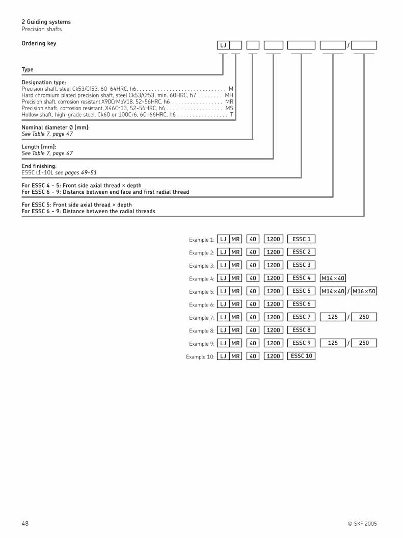
48 © SKF 2005
2 Guiding systems
Precision shafts
Type
Designation type:Precision shaft, steel Ck53/Cf53, 60-64HRC, h6. . . . . . . . . . . . . . . . . . . . . . . . . . . . . . MHard chromium plated precision shaft, steel Ck53/Cf53, min. 60HRC, h7 . . . . . . . . MHPrecision shaft, corrosion resistant X90CrMoV18, 52-56HRC, h6 . . . . . . . . . . . . . . . . . MRPrecision shaft, corrosion resistant, X46Cr13, 52-56HRC, h6 . . . . . . . . . . . . . . . . . . . MSHollow shaft, high-grade steel, Ck60 or 100Cr6, 60-66HRC, h6 . . . . . . . . . . . . . . . . . T
Nominal diameter Ø [mm]:See Table 7, page 47
Length [mm]:See Table 7, page 47
End finishing:ESSC (1-10), see pages 49-51
For ESSC 4 - 5: Front side axial thread × depthFor ESSC 6 - 9: Distance between end face and first radial thread
For ESSC 5: Front side axial thread × depthFor ESSC 6 - 9: Distance between the radial threads
Ordering key
Example 1:
—–LJ
—– —– —–— —–——/
LJ MR 40 1200
—–——
ESSC 1
—–——
Example 2: LJ MR 40 1200 ESSC 2
Example 3: LJ MR 40 1200 ESSC 3
Example 4: LJ MR 40 1200 M14 ×40ESSC 4
Example 5: LJ MR 40 1200 M14 ×40ESSC 5 M16 ×50/
Example 6: LJ MR 40 1200 ESSC 6
Example 7: LJ MR 40 1200 125ESSC 7 250/
Example 8: LJ MR 40 1200 ESSC 8
Example 9: LJ MR 40 1200 125ESSC 9 250/
Example 10: LJ MR 40 1200 ESSC 10

© SKF 2005 49
2
ESSC 3
Cut, 25° machined chamfer, end faces cut at
right angles for limited length tolerance or
chamfered according to customer
specification
Length tolerance +/− 0.1 mm to a total
length of 3000 mm
ESSC 4
Cut, 25° machined chamfer, end
faces cut at right angles, one front-
side (axial) hole
Length tolerance as ESSC 3
( Table 8)
ESSC 2
Cut, with chamfer
Length tolerance as ESSC 1
ESSC 1
Cut, without chamfer, only deburred Length
tolerance according to DIN 7168 medium
rangeFree from burrs
Diameter Thread Depth
Ø G L5
mm
5
8 M4 10
10 M4 10
12 M5 12.5
14 M5 12.5
16 M6 15
20 M8 20
25 M10 25
30 M10 25
40 M12 30
50 M16 40
60 M20 50
80 M24 60
Table 8

50 © SKF 2005
2 Guiding systems
Precision shafts
ESSC 5
As ESSC 4 with two front
side (axial) holes
( Table 9)
ESSC 6
Cut and chamfered as ESSC 2
• with radial holes for LRCB
• first radial hole at Jx = J/2
• H1 according to hardening
depth
( Table 10)
ESSC 7
As ESSC 6
• radial holes with J and Jx
according to customer
specification
( Table 11)
Diameter Thread Depth
Ø G L5
mm
5
8 M4 10
10 M4 10
12 M5 12.5
14 M5 12.5
16 M6 15
20 M8 20
25 M10 25
30 M10 25
40 M12 30
50 M16 40
60 M20 50
80 M24 60
Table 9
Ø Thread G G1 J JX
mm mm
5 – – – – –
8 – – – – –
12 M4 5 8 75 37.5
16 M5 6 9.5 100 50
20 M6 7 13 100 50
25 M8 9 14 120 60
30 M10 11 18 150 75
40 M10 11 20 200 100
50 M12 13 23 200 100
60 M14 15 28 300 150
80 M16 16 33 300 150
Table 10
Ø Thread G G1 J JX
mm mm
5 – – – – –
8 – – – – –
12 M4 5 8 – –
16 M5 6 9.5 – –
20 M6 7 13 – –
25 M8 9 14 – –
30 M10 11 18 – –
40 M10 11 20 – –
50 M12 13 23 – –
60 M14 15 28 – –
80 M16 16 33 – –
Table 11

© SKF 2005 51
2
ESSC 9
As ESSC 8
• shaft mounted on LRCC
• radial holes with J and Jx
according to customer
specification
( Table 13)
ESSC 10
Shaft according to customer
specification
• manufacture only according to
customer drawing
ESSC 8
Cut and chamfer as ESSC 2
• shaft mounted on LRCB
• first radial hole with Jx = J/2
• H1 according to hardness depth
( Table 12)
Ø Thread G G1 J JX
mm mm
5 – – – – –
8 – – – – –
12 M4 5 8 75 37.5
16 M5 6 9.5 100 50
20 M6 7 13 100 50
25 M8 9 14 120 60
30 M10 11 18 150 75
40 M10 11 20 200 100
50 M12 13 23 200 100
60 M14 15 28 300 150
80 M16 16 33 300 150
Table 12
Ø Thread G G1 J JX
mm mm
5 – – – – –
8 – – – – –
12 M4 5 8 – –
16 M5 6 9.5 – –
20 M6 7 13 – –
25 M8 9 14 – –
30 M10 11 18 – –
40 M10 11 20 – –
50 M12 13 23 – –
60 M14 15 28 – –
80 M16 16 33 – –
Table 13

52 © SKF 2005
2 Guiding systems
Precision shafts
Standard designs
Designs for fixed length without chamfer
Table 14 shows basic data for the various models for the precision shafts.
Designs for fixed length with chamfer
Attention:
d1 can deviate from the value quoted. Please enquire if necessary.
Different shaft diameters and types on request.
The static load capacity has to be decreased by 8% and the dynamic
load capacity by 18% when using the non-rusting types (HV6) in
conjunction with precision steel shafts made of stainless steel.
Shafts cut to special length with flat turned ends. The length
tolerance of these shafts corresponds to DIN 7168, medium. The
designation for a shaft with 20 mm diameter cut to a length of 1.5
m is, for example, LJM 20×1500.
Dimension Mass Moment Cross sectional Designations
of inertia area
Solid Hollow Solid Hollow Solid Hollow Solid shaft Solid shaft of stainless Solid shaft Hollow shaft
shaft shaft shaft shaft shaft shaft of precision steel with high high grade
steel X90CrMoV18 X46Cr13 grade steel steel C60
Ck53 (1.1210) (1.4112) (1.4034) chromium (1.1221)
Cf53 (1.1213) Ck53 (1.1210) plated
Cf53 (1.1213)
d d1 rmin
mm kg/m cm4 mm2
3 – 0.4 0.06 – 0.0004 – 7.1 – LJM 3
4 – 0.4 0.1 – 0.0013 – 12.6 – LJM 4
5 – 0.8 0.15 – 0.0031 – 19.6 – LJM 5
6 – 0.8 0.22 – 0.0064 – 28.3 – LJM 6
8 – 0.8 0.39 – 0.020 – 50.3 – LJM 8 LJMR 8 LJMS 8 LJMH 8
10 – 0.8 0.62 – 0.049 – 78.5 – LJM 10 LJMR 10 LJMS 10 LJMH 10
12 – 1 0.89 – 0.102 – 113 – LJM 12 LJMR 12 LJMS 12 LJMH 12
14 – 1 1.21 – 0.189 – 154 – LJM 14 LJMH 14
16 7 1 1.57 1.28 0.322 0.310 201 163 LJM 16 LJMR 16 LJMS 16 LJMH 16 LJT 16
20 12 1.5 2.45 1.26 0.785 0.597 314 160 LJM 20 LJMR 20 LJMS 20 LJMH 20 LJT 20
25 14 1.5 3.83 2.40 1.92 1.64 491 305 LJM 25 LJMR 25 LJMS 25 LJMH 25 LJT 25
30 19 1.5 5.51 3.55 3.98 3.46 707 453 LJM 30 LJMR 30 LJMS 30 LJMH 30 LJT 30
40 26 2 9.80 5.40 12.6 9.96 1260 685 LJM 40 LJMR 40 LJMS 40 LJMH 40 LJT 40
50 35 2 15.3 10.6 30.7 27.7 1960 1350 LJM 50 LJMR 50 LJMS 50 LJMH 50 LJT 50
60 36 2.5 22.1 15.1 63.6 57.1 2830 1920 LJM 60 LJMH 60 LJT 60
80 53 2.5 39.2 20.1 201 153 5030 2565 LJM 80 LJMH 80 LJT 80
Table 14

Shaft Accuracy of dimension and form
Nominal Shafts to tolerance h6 Shafts to tolerance h7
diameter Diameter Circularity Cylindricity Straightness1) Diameter Circularity Cylindricity Straightness1)
deviation deviation
d high low t1 t2 t3 high low t1 t2 t3
mm µm
3 0 – 6 3 4 150 0 – 10 4 6 150
4 0 – 8 4 5 150 0 – 12 5 8 150
5 0 – 8 4 5 150 0 – 12 5 8 150
6 0 – 8 4 5 150 0 – 12 5 8 150
8 0 – 9 4 6 120 0 – 15 6 9 120
10 0 – 9 5 7 120 0 – 15 7 10 120
12 0 – 11 5 8 100 0 – 18 8 11 100
14 0 – 11 5 8 100 0 – 18 8 11 100
16 0 – 11 5 8 100 0 – 18 8 11 100
20 0 – 13 6 9 100 0 – 21 9 13 100
25 0 – 13 6 9 100 0 – 21 9 13 100
30 0 – 13 6 9 100 0 – 21 9 13 100
40 0 – 16 7 11 100 0 – 25 11 16 100
50 0 – 16 7 11 100 0 – 25 11 16 100
60 0 – 19 8 13 100 0 – 30 13 19 100
80 0 – 19 8 13 100 0 – 30 13 19 100
Table 15
© SKF 2005 53
2
Table 15 shows basic data for the various models for the precision shafts of high-grade steel.
1) Shafts with straightness 50 mm/1000 mm to order

54 © SKF 2005
2 Guiding systems
Linear ball bearing table without drive
LZBU quadro-linear tables ( figure 21)
The closed LZBU quadro-linear table
consists of a closed quadro linear bearing
unit, two tandem shaft blocks and two
shafts of the required length.
The bearing unit is fitted with four
LBCD .. A-LS self-aligning linear ball
bearings each sealed on one side. The
LZBU .. A design permits axial movement of
the linear bearing unit, i.e. the shafts are
fixed, to the machine bed via the LEAS .. A
shaft blocks. The LZBU .. B design is
provided with LEAS .. B shaft blocks. This
combination allows the shafts to travel with
the shaft blocks in applications where the
linear bearing unit is fixed. LZBU quadro-
linear tables can be supplied in sizes 8 to
50 mm. Size 8 tables are however not self-
aligning and they are not designed for
relubrication.
The description of the closed quadro-
linear tables also applies to the combination
of LQBR .. 2LS quadro-linear bearing units
of Series 1 with twin LEBS tandem shaft
blocks and shafts with a diameter of 12 to
50 mm.
LZAU quadro-linear tables
The open LZAU quadro-linear comprises
the open quadro-linear unit and two high
precision shafts with shaft supports. The
Linear ball bearing tablewithout drive
bearing unit is fitted with four LBCF .. A-LS
self aligning linear ball bearings, each
sealed at one side. The standard lengths of
these tables is dictated by the pitch of the
attachment holes in the LRCB shaft
supports. The total length should always be
a multiple of this distance.
LZAU quadro-linear tables are available
in sizes 12 to 50 mm.
Figure 21

© SKF 2005 55
2
Type
Design:Open design . . . . . . . . . . . . . . . . . . . . . . . . . . . . . . . . . . . . . . . . . . . . . . . . . . . . . . . . . . . . . . . . . . . . . . . . . AUClosed design . . . . . . . . . . . . . . . . . . . . . . . . . . . . . . . . . . . . . . . . . . . . . . . . . . . . . . . . . . . . . . . . . . . . . . . . BU
Nominal diameter Ø in mm:For AU . . . . . . . . . . . . . . . . . . . . . . . . . . . . . . . . . . . . . . . . . . . . . . . . . . . . . . . . . . . . . . . . . . . . . . . . . . . . . . Ø 12 - 50For BU . . . . . . . . . . . . . . . . . . . . . . . . . . . . . . . . . . . . . . . . . . . . . . . . . . . . . . . . . . . . . . . . . . . . . . . . . . . . . . Ø 8 - 50
Option:LZAU with LRCB shaft supports . . . . . . . . . . . . . . . . . . . . . . . . . . . . . . . . . . . . . . . . . . . . . . . . . . . . . . . . . . . . . . . . . no signLEAS A, high shaft position. . . . . . . . . . . . . . . . . . . . . . . . . . . . . . . . . . . . . . . . . . . . . . . . . . . . . . . . . . . . . . . . . . . . . . . . . . ALEAS B, low shaft position . . . . . . . . . . . . . . . . . . . . . . . . . . . . . . . . . . . . . . . . . . . . . . . . . . . . . . . . . . . . . . . . . . . . . . . . . . B
Other option:Both sides sealed . . . . . . . . . . . . . . . . . . . . . . . . . . . . . . . . . . . . . . . . . . . . . . . . . . . . . . . . . . . . . . . . . . . . . . . . . . . . . . . . . . . . -2LS
Length in mm:
Ordering key
Example:
—–LZ
—– —–
LZ BU 40
—
B
×—–—-2LS
-2LS
—–——
× 1500

56 © SKF 2005
2 Guiding systems
Linear ball bearing table without drive
LZBU .. A-2LS
Quadro linear tables, consisting of LQCD,
LEAS A and shafts
Designations Dimensions Basic load ratings
dynamic static
d HRA H1A L1 L2 L3 J2 J3 C C0
mm N
LZBU 8 A-2LS 8 24 23 600 65 32 55 52 965 1140
LZBU 12 A-2LS 12 34 32 900 85 42 73 70 2850 3250
LZBU 16 A-2LS 16 38 37 1500 100 54 88 82 3450 3450
LZBU 20 A-2LS 20 48 46 1800 130 72 115 108 5200 5500
LZBU 25 A-2LS 25 58 56 1800 160 88 140 132 7650 8150
LZBU 30 A-2LS 30 67 64 2400 180 96 158 150 12200 12900
LZBU 40 A-2LS 40 84 80 3000 230 122 202 190 20800 20800
LZBU 50 A-2LS 50 100 96 3000 280 152 250 240 30000 28000
Dimensions
Standard length
d L
mm Length increments in mm
8 300 600 900 – – – – – – –
12 300 600 900 1200 1500 1800 2100 2400 2700 3000
16 300 600 900 1200 1500 1800 2100 2400 2700 3000
20 300 600 900 1200 1500 1800 2100 2400 2700 3000
25 300 600 900 1200 1500 1800 2100 2400 2700 3000
30 300 600 900 1200 1500 1800 2100 2400 2700 3000
40 300 600 900 1200 1500 1800 2100 2400 2700 3000
50 — 600 900 1200 1500 1800 2100 2400 2700 3000

© SKF 2005 57
2
LZBU .. B-2LS
Quadro linear tables, consisting of LQCD,
LEAS B and shafts
Designations Dimensions Basic load ratings
dynamic static
d HRB H1A L1 L2 L3 J2 J3 C C0
± 0.01
mm N
LZBU 8 B-2LS 8 22.5 22 600 65 32 55 52 965 1140
LZBU 12 B-2LS 12 30 28 900 85 42 73 70 2850 3250
LZBU 16 B-2LS 16 35 34 1500 100 54 88 82 3450 3450
LZBU 20 B-2LS 20 44 42 1800 130 72 115 108 5200 5200
LZBU 25 B-2LS 25 54 52 1800 160 88 140 132 7650 8150
LZBU 30 B-2LS 30 61 58 2400 180 96 158 150 12200 12900
LZBU 40 B-2LS 40 76 72 3000 230 122 202 190 20800 20800
LZBU 50 B-2LS 50 92 88 3000 280 152 250 240 30000 28000
Dimensions
Standard length
d L
mm Length increments in mm
8 300 600 900 – – – – – – –
12 300 600 900 1200 1500 1800 2100 2400 2700 3000
16 300 600 900 1200 1500 1800 2100 2400 2700 3000
20 300 600 900 1200 1500 1800 2100 2400 2700 3000
25 300 600 900 1200 1500 1800 2100 2400 2700 3000
30 300 600 900 1200 1500 1800 2100 2400 2700 3000
40 300 600 900 1200 1500 1800 2100 2400 2700 3000
50 — 600 900 1200 1500 1800 2100 2400 2700 3000

58 © SKF 2005
2 Guiding systems
Linear ball bearing table without drive
LZAU .. -2LS
Quadro linear tables, consisting of LQCF
and supported shafts
Designations Dimensions Basic load ratings
dynamic static
d HT J L L2 L3 J2 C C0
± 0.03 ± 0.015
mm N
LZAU 12-2LS 12 40 75 900 85 42 73 2850 3250
LZAU 16-2LS 16 48 100 1500 100 54 88 3450 3450
LZAU 20-2LS 20 57 100 1800 130 72 115 5200 5500
LZAU 25-2LS 25 66 120 1800 160 88 140 7650 8150
LZAU 30-2LS 30 77 150 2400 180 96 158 12200 12900
LZAU 40-2LS 40 95 200 3000 230 122 202 20800 20800
LZAU 50-2LS 50 115 200 3000 280 152 250 30000 28000
Dimensions
Standard length
d L
mm Length increments in mm
8 300 600 900 – – – – – – –
12 300 600 900 1200 1500 1800 2100 2400 2700 3000
16 300 600 900 1200 1500 1800 2100 2400 2700 3000
20 300 600 900 1200 1500 1800 2100 2400 2700 3000
25 300 600 900 1200 1500 1800 2100 2400 2700 3000
30 300 600 900 1200 1500 1800 2100 2400 2700 3000
40 300 600 900 1200 1500 1800 2100 2400 2700 3000
50 — 600 900 1200 1500 1800 2100 2400 2700 3000

More precisionfor more performance.
Have you ever wondered how a bird’s nest, which appears to be so fragile, can
withstand the heaviest rain and strong winds? Birds can weave even the small-
est twigs with great precision to form the supporting structure of the nest for
the protection of their eggs and new-born chicks from the weather.
This small miracle of nature gives SKF the inspiration to create solutions to
satisfy a wide variety of requests for precision with micrometer accuracy.
Products like precision rail guides, also available with the state-of-the-art
Anti-creep system, and the precision slides are high quality tools for linear
motion which are ideally suited for uses in a wide range of applications where
close tolerances are demanded.
SKF products are created to build the future.
Linear motion from SKFwww.linearmotion.skf.com

60 © SKF 2005
2 Guiding systems
Linear guiding system Speedi-Roll
To complement its versatile range of linear
motion products, SKF has introduced the
LLE linear guiding system ( figure 22), a
highly efficient unit marketed under the
name “Speedi-Roll”. In response to current
market demands, this product was
developed giving high priority to lightweight
construction and ease of installation.
Speedi-Roll is a linear guiding system
with high load-carrying capacity, rigidity
and torque resistance, consisting of a guide
rail and a carriage with either four or six
rollers. The rail consists of a drawn and
anodised aluminium profile with hardened
steel angle raceways fitted to both sides.
The aluminium base plate of the
carriage, which is also anodised, houses the
factory-fitted rollers. A special feature of this
roller design is the presence of elastic
elements around the threaded bolt
adjusting the rollers and fixing them in the
base plate. This unique patented system
avoids the risk of mounting errors, thus
contributing to a more efficient and cost
effective installation.
As standard, the units are supplied with
light preload. In order to cover a wide range
of applications, SKF offers three sizes: LLE
15, 25 and 35. This allows flexibility when
selecting a system to meet the design
parameters.
Speedi-Roll guides operate effortlessly
and quietly. The high linear speed rating
permits shorter cycle times, and the low
friction between rail and rollers allows less
Linear guiding systemSpeedi-Roll
power input for driving the system. The
hollow centre of size 25 and 35 rails helps
to reduce the mass of the entire system. In
addition, these “bores” can serve as wire or
cable channels. The rollers are lubricated
for life, greatly reducing the need for
service.
Roller covers and end stops are available
to complete the product range. It is possible
to produce customer specific configurations
using the standard rollers and steel angle
raceways in addition to the catalogue
range.
Figure 22

© SKF 2005 61
2
Type
Guide rail type:. . . . . . . . . . . . . . . . . . . . . . . . . . . . . . . . . . . . . . . . . . . . . . . . . . . . . . . . . . . . . . . . . . . . . . . . H
System key:Guide rail and carriage (system) . . . . . . . . . . . . . . . . . . . . . . . . . . . . . . . . . . . . . . . . . . . . . . . . . SCarriage . . . . . . . . . . . . . . . . . . . . . . . . . . . . . . . . . . . . . . . . . . . . . . . . . . . . . . . . . . . . . . . . . . . . CGuide rail . . . . . . . . . . . . . . . . . . . . . . . . . . . . . . . . . . . . . . . . . . . . . . . . . . . . . . . . . . . . . . . . . . . RRoller . . . . . . . . . . . . . . . . . . . . . . . . . . . . . . . . . . . . . . . . . . . . . . . . . . . . . . . . . . . . . . . . . . . . . . ERoller cover . . . . . . . . . . . . . . . . . . . . . . . . . . . . . . . . . . . . . . . . . . . . . . . . . . . . . . . . . . . . . . . . . XEnd stop . . . . . . . . . . . . . . . . . . . . . . . . . . . . . . . . . . . . . . . . . . . . . . . . . . . . . . . . . . . . . . . . . . . M
Size:(18 mm) . . . . . . . . . . . . . . . . . . . . . . . . . . . . . . . . . . . . . . . . . . . . . . . . . . . . . . . . . . . . . . . . . . . . . . . . 15(23 mm) . . . . . . . . . . . . . . . . . . . . . . . . . . . . . . . . . . . . . . . . . . . . . . . . . . . . . . . . . . . . . . . . . . . . . . . . 25(36 mm) . . . . . . . . . . . . . . . . . . . . . . . . . . . . . . . . . . . . . . . . . . . . . . . . . . . . . . . . . . . . . . . . . . . . . . . . 35
Carriage type:Standard (4 rollers) . . . . . . . . . . . . . . . . . . . . . . . . . . . . . . . . . . . . . . . . . . . . . . . . . . . . . . . . . . . . . . . . . . . . . HLong (6 rollers) . . . . . . . . . . . . . . . . . . . . . . . . . . . . . . . . . . . . . . . . . . . . . . . . . . . . . . . . . . . . . . . . . . . . . . . . . L
Sealing:Without roller covers . . . . . . . . . . . . . . . . . . . . . . . . . . . . . . . . . . . . . . . . . . . . . . . . . . . . . . . . . . . . . . . . . . . . . . . ZWith roller covers . . . . . . . . . . . . . . . . . . . . . . . . . . . . . . . . . . . . . . . . . . . . . . . . . . . . . . . . . . . . . . . . . . . . . . . . . . C
Number of carriages per guide rail: . . . . . . . . . . . . . . . . . . . . . . . . . . . . . . . . . . . . . . . . . . . . . . . . . . . . . . . . 1, 2, …, n
Length of guide rail [mm]
Special design:Joint rail. . . . . . . . . . . . . . . . . . . . . . . . . . . . . . . . . . . . . . . . . . . . . . . . . . . . . . . . . . . . . . . . . . . . . . . . . . . . . . . . . . . . . . . . . . . . . . . . . . . AGuide rails as specified . . . . . . . . . . . . . . . . . . . . . . . . . . . . . . . . . . . . . . . . . . . . . . . . . . . . . . . . . . . . . . . . . . . . . . . . . . . . . . . . . . . . . . . DSystem with one end stop . . . . . . . . . . . . . . . . . . . . . . . . . . . . . . . . . . . . . . . . . . . . . . . . . . . . . . . . . . . . . . . . . . . . . . . . . . . . . . . . . . . M1System with two end stops . . . . . . . . . . . . . . . . . . . . . . . . . . . . . . . . . . . . . . . . . . . . . . . . . . . . . . . . . . . . . . . . . . . . . . . . . . . . . . . . . . M2Hard chromium plated . . . . . . . . . . . . . . . . . . . . . . . . . . . . . . . . . . . . . . . . . . . . . . . . . . . . . . . . . . . . . . . . . . . . . . . . . . . . . . . . . . . . . . . H
Distance between end face and the first hole [mm]:Symmetric holes as standard . . . . . . . . . . . . . . . . . . . . . . . . . . . . . . . . . . . . . . . . . . . . . . . . . . . . . . . . . . . . . . . . . . . . . . . . . . . . . . . . . . . . . . E = 0
Ordering key
Example:
—–LLE
—H
—– — —— —–—/
—–
LLE H
—
S 15 H 2Z 300 /
-
- M1
—––E = 0
E = 0

62 © SKF 2005
2 Guiding systems
Linear guiding system Speedi-Roll
LLEHR ..
Rails in standard length
LLEHC .. HZ /.. HC
Standard carriages
LLEHC .. HZ without roller covers
LLEHC .. HC with roller covers
E E
F
W
H
W1
W
L1
H
W1
W
HZ
HC
Designations Dimensions
W F E
mm
LLEHR 15 18 62.5 31.25
LLEHR 25 23 125.0 62.5
LLEHR 35 36 250.0 125.0
Designations Dimensions
W W1 H L1
mm
LLEHR 15 HZ HC 18 65 25.0 70
LLEHR 25 HZ HC 23 80 35.5 90
LLEHR 35 HZ HC 36 120 54.3 100

© SKF 2005 63
2
LLEHC .. LZ / .. LC
Long carriages
LLEHC .. LZ without roller covers
LLEHC .. LC with roller covers
LLEHM
End stops
L1
H
W1
Le
He
We
W
H
W1
W
LC
LZ
LLEHX
Roller covers
Ld
d1
h3
Wd
h2
Designations Dimensions
W W1 H L1
mm
LLEHC 15 LZ LC 18 65 25.0 105
LLEHC 25 LZ LC 23 80 35.5 120
LLEHC 35 LZ LC 36 120 54.3 140
Designations Dimensions
We He Le
mm
LLEHM 15 38 24.5 11.1
LLEHM 25 48 34.1 16.6
LLEHM 35 65 52.0 16.6
Designations Dimensions
Ld Wd h2 h3 d1
mm
LLEHX 15 29.2 25.1 1.65 10.75 2
LLEHX 25 29.2 25.1 5.60 14.70 2
LLEHX 35 31.8 27.8 10.95 22.75 2

64 © SKF 2005
2 Guiding systems
Linear guiding system Speedi-Roll / Profile rail guides
LLEHE .. Z
Rollers
D
A1
A
D1
Designations Dimensions
D D1 A A1
mm
LLEHE 15 Z 20.5 17.75 14.00 8.2
LLEHE 25 Z 22.0 19.25 14.00 9.0
LLEHE 35 Z 24.5 21.75 20.25 12.1
System with Designations Basic load ratings
dynamic static*
C C0
N
Standard carriage LLEHS 15 H 2000 1200
Long carriage LLEHS 15 L 2600 1800
Roller only LLEHE 15 2850 1400
Standard carriage LLEHS 25 H 4000 2700
Long carriage LLEHS 25 L 5200 4000
Roller only LLEHE 25 2850 1400
Standard carriage LLEHS 35 H 6000 4250
Long carriage LLEHS 35 L 8000 6350
Roller only LLEHE 35 4400 2200
* Data for radial direction, load angle 90° or 270°, with load centrally applied to the carriage

© SKF 2005 65
2
Profile rail guides
Profile rail guides from SKF are modern
machine components used in the
production of linear guiding systems
with unlimited travel ( figure 23). They
usually consist of a profile rail with four
precision-ground raceways and a slide unit
with four ball circulation paths. This design
offers numerous benefits. The square
configuration of the raceways results in a
guidance system with good rigidity, capable
of withstanding moment loads in all
directions. The load-carrying capacity is
equal in all four directions ( figure 24).
Ready-to-mount units guarantee economy
and simplicity of mounting. Installation and
adjustment procedures are reduced to a
minimum. The design of the system is such
that inaccuracies of the adjacent
components can be accommodated. SKF
profile rail guides are noted for their ease
of maintenance and reliability. As standard,
they are provided with grease nipple and
seals on all sides. The two-point contact of
the rolling elements with the raceways
permits high operational speeds with quiet
running and a low coefficient of friction.
Good running accuracy is assured
throughout the operational life of the
system. Guides with specific preload can be
supplied for special requirements. This is
achieved through selection. Preload
selection depends on the load and stiffness
specifications.
Figure 23
Figure 24

66 © SKF 2005
2 Guiding systems
Profile rail guides
Type
Product code:Bellows (for bellows only) . . . . . . . . . . . . . . . . . . . . . . . . . . . . . . . . . . . . . . HBCarriage (carriage only) . . . . . . . . . . . . . . . . . . . . . . . . . . . . . . . . . . . . . . . . HCRail (rail only) . . . . . . . . . . . . . . . . . . . . . . . . . . . . . . . . . . . . . . . . . . . . . . . . HRSystem (carriage and rail) . . . . . . . . . . . . . . . . . . . . . . . . . . . . . . . . . . . . . . HSAccessories, if order separately . . . . . . . . . . . . . . . . . . . . . . . . . . . . . . . . . . HZ
Size:. . . . . . . . . . . . . . . . . . . . . . . . . . . . . . . . . . . . . . . . . . . . . . . . . 15, 20, 25, 30, 35, 45
Carriage type:Carriage, standard width . . . . . . . . . . . . . . . . . . . . . . . . . . . . . . . . . . . . . . . . . . . . . . . . . . . . ACarriage, standard width, short . . . . . . . . . . . . . . . . . . . . . . . . . . . . . . . . . . . . . . . . . . . . . SACarriage, standard width, long . . . . . . . . . . . . . . . . . . . . . . . . . . . . . . . . . . . . . . . . . . . . . . LACarriage, slim line . . . . . . . . . . . . . . . . . . . . . . . . . . . . . . . . . . . . . . . . . . . . . . . . . . . . . . . . . UCarriage, slim line, short. . . . . . . . . . . . . . . . . . . . . . . . . . . . . . . . . . . . . . . . . . . . . . . . . . . SUCarriage, slim line, long. . . . . . . . . . . . . . . . . . . . . . . . . . . . . . . . . . . . . . . . . . . . . . . . . . . . LUCarriage, slim line, high. . . . . . . . . . . . . . . . . . . . . . . . . . . . . . . . . . . . . . . . . . . . . . . . . . . . . RCarriage, slim line, high, long . . . . . . . . . . . . . . . . . . . . . . . . . . . . . . . . . . . . . . . . . . . . . . . LR
Ball retainer:Carriage with ball retainer . . . . . . . . . . . . . . . . . . . . . . . . . . . . . . . . . . . . . . . . . . . . . . . . . . . . . BCarriage without ball retainer . . . . . . . . . . . . . . . . . . . . . . . . . . . . . . . . . . . . . . . . . . . . . . no sign
Number of carriages per rail track: . . . . . . . . . . . . . . . . . . . . . . . . . . . . . . . . . . . . . . . . . . . . 1, 2, …, n
Preload classes:Up to 10 µm clearance, play . . . . . . . . . . . . . . . . . . . . . . . . . . . . . . . . . . . . . . . . . . . . . . . . . . . . . . . . . . . . . . T0Preload 0,02×C, light preload. . . . . . . . . . . . . . . . . . . . . . . . . . . . . . . . . . . . . . . . . . . . . . . . . . . . . . . . . . . . . . T1Preload 0,08×C, medium preload . . . . . . . . . . . . . . . . . . . . . . . . . . . . . . . . . . . . . . . . . . . . . . . . . . . . . . . . . T2*Preload 0,12×C, high preload. . . . . . . . . . . . . . . . . . . . . . . . . . . . . . . . . . . . . . . . . . . . . . . . . . . . . . . . . . . . . T3*
Rail length in mm
Precision class [for carriage and rail]:Standard precision . . . . . . . . . . . . . . . . . . . . . . . . . . . . . . . . . . . . . . . . . . . . . . . . . . . . . . . . . . . . . . . . . . . . . . . . . . . . . . . . . . . . P5Medium precision. . . . . . . . . . . . . . . . . . . . . . . . . . . . . . . . . . . . . . . . . . . . . . . . . . . . . . . . . . . . . . . . . . . . . . . . . . . . . . . . . . . . . P3High precision . . . . . . . . . . . . . . . . . . . . . . . . . . . . . . . . . . . . . . . . . . . . . . . . . . . . . . . . . . . . . . . . . . . . . . . . . . . . . . . . . . . . . . P1*Super precision . . . . . . . . . . . . . . . . . . . . . . . . . . . . . . . . . . . . . . . . . . . . . . . . . . . . . . . . . . . . . . . . . . . . . . . . . . . . . . . . . . . . P01*Ultra precision . . . . . . . . . . . . . . . . . . . . . . . . . . . . . . . . . . . . . . . . . . . . . . . . . . . . . . . . . . . . . . . . . . . . . . . . . . . . . . . . . . . . P001*
Number of parallel rail tracks:One rail alone . . . . . . . . . . . . . . . . . . . . . . . . . . . . . . . . . . . . . . . . . . . . . . . . . . . . . . . . . . . . . . . . . . . . . . . . . . . . . . . . . . . . . . . . . . . . . W1Two rails in parallel . . . . . . . . . . . . . . . . . . . . . . . . . . . . . . . . . . . . . . . . . . . . . . . . . . . . . . . . . . . . . . . . . . . . . . . . . . . . . . . . . . . . . . . . . W2
Accessories & Option symbols:Jointed rail track . . . . . . . . . . . . . . . . . . . . . . . . . . . . . . . . . . . . . . . . . . . . . . . . . . . . . . . . . . . . . . . . . . . . . . . . . . . . . . . . . . . . . . . . . . . . . . . . . . ABellows, system complete with bellows . . . . . . . . . . . . . . . . . . . . . . . . . . . . . . . . . . . . . . . . . . . . . . . . . . . . . . . . . . . . . . . . . . . . . . . . . . . . . . . . BBellow Kit, type 2 (carriage thru the end of the rail) . . . . . . . . . . . . . . . . . . . . . . . . . . . . . . . . . . . . . . . . . . . . . . . . . . . . . . . . . . . . . . . . . . . . . B2Bellow Kit, type 4 (between two carriages) . . . . . . . . . . . . . . . . . . . . . . . . . . . . . . . . . . . . . . . . . . . . . . . . . . . . . . . . . . . . . . . . . . . . . . . . . . . . B4Rail, customized accessories to drawing number . . . . . . . . . . . . . . . . . . . . . . . . . . . . . . . . . . . . . . . . . . . . . . . . . . . . . . . . . . . . . . . . . . . . . . . . . DRail with cover strip and cover strip guard type 2 (aluminium) . . . . . . . . . . . . . . . . . . . . . . . . . . . . . . . . . . . . . . . . . . . . . . . . . . . . . . . . . . . . . D2Distance between end face and the first hole [mm]:Symmetric holes as standard . . . . . . . . . . . . . . . . . . . . . . . . . . . . . . . . . . . . . . . . . . . . . . . . . . . . . . . . . . . . . . . . . . . . . . . . . . . . . . . . . . . . . . E = 0Carriage mounted on rail . . . . . . . . . . . . . . . . . . . . . . . . . . . . . . . . . . . . . . . . . . . . . . . . . . . . . . . . . . . . . . . . . . . . . . . . . . . . . . . . . . . . . . . . . . . MScraper plates . . . . . . . . . . . . . . . . . . . . . . . . . . . . . . . . . . . . . . . . . . . . . . . . . . . . . . . . . . . . . . . . . . . . . . . . . . . . . . . . . . . . . . . . . . . . . . . . . . . S1Two piece front seals. . . . . . . . . . . . . . . . . . . . . . . . . . . . . . . . . . . . . . . . . . . . . . . . . . . . . . . . . . . . . . . . . . . . . . . . . . . . . . . . . . . . . . . . . . . . . . S2Seal Kit, two piece front seals with scraper plates . . . . . . . . . . . . . . . . . . . . . . . . . . . . . . . . . . . . . . . . . . . . . . . . . . . . . . . . . . . . . . . . . . . . . . . . S3
* On request
Ordering key
Example 5:
—––LLR
—–—–– —–—–—–— —––
W2P5 D2 S21000 /LLR
—–
AHS
—
25
-
—–
T0
—
-
P5 LLR AHS 25 T0Example 4:Complete system withcarriage and railExample 3: LLR 1000HR 25 - P51000-Rail only
P5LLR AHC 25 T1Example 2: Carriage onlyExample 1: LLR 15HB 25 - Bellow onlywith 15 folds
Complete system incl. rail with cover strip andcover strip guard plus two piece front seals

© SKF 2005 67
2
Accessories for profile rail guides
Size Items Order number
15 LLRHZ 15 S1 Scraper plate 2241963
20 LLRHZ 20 S1 Scraper plate 2241964
25 LLRHZ 25 S1 Scraper plate 2241965
30 LLRHZ 30 S1 Scraper plate 2241966
35 LLRHZ 35 S1 Scraper plate 2241967
45 LLRHZ 45 S1 Scraper plate 2243324
Size Items Order number
15 LLRHZ 15 S2 Two-piece front seal 2241951
20 LLRHZ 20 S2 Two-piece front seal 2241953
25 LLRHZ 25 S2 Two-piece front seal 2241955
30 LLRHZ 30 S2 Two-piece front seal 2241957
35 LLRHZ 35 S2 Two-piece front seal 2241959
45 LLRHZ 45 S2 Two-piece front seal 2243325
Size Items Order number
15 LLRHZ 15 Seal kit 2243158
20 LLRHZ 20 Seal kit 2243163
25 LLRHZ 25 Seal kit 2242080
30 LLRHZ 30 Seal kit 2242104
35 LLRHZ 35 Seal kit 2243232
45 LLRHZ 45 Seal kit 2243200

68 © SKF 2005
2 Guiding systems
Profile rail guides
LLRHS .. SA
LLRHS .. A
LLRHS .. LA
M0A
SA
H4 H7
F
L4 B2
L1
H9
L4
L1B2
E
M1M1
W3
N W
H1
H3
H5
H
M2d4d4H8
H6
W1
M0C
H9
d3
d2
A
LA
Designations Dimensions
W1 W N L1 L2 H H1 H41) H4
2) H3 W2 L3 L5 W3 H5 L6 L4 H8 H9
mm
LLRHS 15 SA 47 15 16.0 44.7 25.7 24 19.90 16.30 16.20 5.0 38 – – 24.55 6.70 16.25 17.85 3.20 3.20
LLRHS 15 A 47 15 16.0 58.2 39.2 24 19.90 16.30 16.20 5.0 38 30 26 24.55 6.70 8.00 9.60 3.20 3.20
LLRHS 15 LA 47 15 16.0 72.6 53.6 24 19.90 16.30 16.20 5.0 38 30 26 24.55 6.70 15.20 16.80 3.20 3.20
LLRHS 20 SA 63 20 21.5 57.3 31.9 30 25.35 20.75 20.55 6.0 53 – – 32.50 7.30 22.95 22.95 3.35 3.35
LLRHS 20 A 63 20 21.5 75.0 49.6 30 25.35 20.75 20.55 6.0 53 40 35 32.50 7.30 11.80 11.80 3.35 3.35
LLRHS 20 LA 63 20 21.5 91.0 65.6 30 25.35 20.75 20.55 6.0 53 40 35 32.50 7.30 19.80 19.80 3.35 3.35
LLRHS 25 SA 70 23 23.5 67.0 38.6 36 29.90 24.45 24.25 7.5 57 – – 38.30 11.50 25.35 26.50 5.50 5.50
LLRHS 25 A 70 23 23.5 86.2 57.8 36 29.90 24.45 24.25 7.5 57 45 40 38.30 11.50 12.45 13.60 5.50 5.50
LLRHS 25 LA 70 23 23.5 107.9 79.5 36 29.90 24.45 24.25 7.5 57 45 40 38.30 11.50 23.30 24.45 5.50 5.50
LLRHS 30 SA 90 28 31.0 75.3 45.0 42 35.35 28.55 28.35 7.0 72 – – 48.40 14.60 28.80 30.50 6.05 6.05
LLRHS 30 A 90 28 31.0 97.7 67.4 42 35.35 28.55 28.35 7.0 72 52 44 48.40 14.60 14.00 15.70 6.05 6.05
LLRHS 30 LA 90 28 31.0 119.7 89.4 42 35.35 28.55 28.35 7.0 72 52 44 48.40 14.60 25.00 26.70 6.05 6.05
LLRHS 35 SA 100 34 33.0 84.9 51.4 48 40.40 32.15 31.85 8.0 82 – – 58.00 17.35 32.70 34.20 6.90 6.90
LLRHS 35 A 100 34 33.0 110.5 77.0 48 40.40 32.15 31.85 8.0 82 62 52 58.00 17.35 14.50 16.00 6.90 6.90
LLRHS 35 LA 100 34 33.0 139.0 105.5 48 40.40 32.15 31.85 8.0 82 62 52 58.00 17.35 28.75 30.25 6.90 6.90
LLRHS 45 A* 120 45 37.5 137.6 97.0 60 50.30 40.15 39.85 10.0 100 80 60 69.80 20.90 17.30 19.30 8.20 8.20
LLRHS 45 LA* 120 45 37.5 174.1 133.5 60 50.30 40.15 39.85 10.0 100 80 60 69.80 20.90 35.50 37.50 8.20 8.20
1) With rail cover strip2) Without rail cover strip
* In preparation

© SKF 2005 69
2
L2 L3
L6
L5
W2
b)
a)
b)
a)
L6
L2 SA
A, LA
M0B
W2
Legend:
a) For O-ring
Size 15: Ø 4 ×1.0 (mm)
Size 20 - 35: Ø 5 ×1.0 (mm)
Open the lube hole if required.
b) Lube nipple, size 15 and 20:
Funnel-type nipple
Type A – Thread size M3, DIN 3405
B2 = 1.6 mm
Size 25 to 35: AM 6 DIN 71412
B2 = 9.5 mm
Lubricating nipples form part of the
delivery and have been included.
When using other lubricating nipples,
it is imperative to observe the correct
screw depth of 8 mm.
Installation is possible at all sides.
Designations Dimensions Basic load ratings Mass
H6 H7 d4 M1 d2 d3 M2 Emin F C C0 M0A/0B M0C
± 0.5
mm N Nm kg
LLRHS 15 SA – 10.30 4.3 M5 ×5.2 7.4 4.4 M2.5 - 3.5 deep 10 60 5400 8100 28 80 0.15
LLRHS 15 A 4.4 10.30 4.3 M5 ×5.2 7.4 4.4 M2.5 - 3.5 deep 10 60 7800 13500 71 130 0.20
LLRHS 15 LA 4.4 10.30 4.3 M5 ×5.2 7.4 4.4 M2.5 - 3.5 deep 10 60 10000 20000 150 190 0.30
LLRHS 20 SA – 13.20 5.3 M6 ×7.7 9.4 6.0 M3 - 5 deep 10 60 12400 13600 58 170 0.30
LLRHS 20 A 5.2 13.20 5.3 M6 ×7.7 9.4 6.0 M3 - 5 deep 10 60 18800 24400 165 310 0.45
LLRHS 20 LA 5.2 13.20 5.3 M6 ×7.7 9.4 6.0 M3 - 5 deep 10 60 24400 35200 330 450 0.55
LLRHS 25 SA – 15.20 6.7 M8 ×9.3 11.0 7.0 M3 - 5 deep 10 60 15900 18200 94 260 0.50
LLRHS 25 A 7.0 15.20 6.7 M8 ×9.3 11.0 7.0 M3 - 5 deep 10 60 22800 30400 240 430 0.65
LLRHS 25 LA 7.0 15.20 6.7 M8 ×9.3 11.0 7.0 M3 - 5 deep 10 60 30400 45500 510 650 0.90
LLRHS 30 SA – 17.00 8.5 M10 ×11.0 15.0 9.0 M3 - 5 deep 12 80 22100 24800 150 430 0.80
LLRHS 30 A 7.9 17.00 8.5 M10 ×11.0 15.0 9.0 M3 - 5 deep 12 80 31700 41300 380 720 1.10
LLRHS 30 LA 7.9 17.00 8.5 M10 ×11.0 15.0 9.0 M3 - 5 deep 12 80 40000 57800 715 1000 1.50
LLRHS 35 SA – 20.50 8.5 M10 ×12.0 15.0 9.0 M3 - 5 deep 12 80 29300 32400 220 700 1.20
LLRHS 35 A 10.2 20.50 8.5 M10 ×12.0 15.0 9.0 M3 - 5 deep 12 80 41900 54000 565 1160 1.60
LLRHS 35 LA 10.2 20.50 8.5 M10 ×12.0 15.0 9.0 M3 - 5 deep 12 80 55600 81000 1215 1740 2.25
LLRHS 45 A* 14.4 23.50 10.4 M12 ×15.0 20.0 14.0 M4 - 7 deep 16 105 68100 85700 1130 2310 3.00
LLRHS 45 LA* 12.4 23.50 10.4 M12 ×15.0 20.0 14.0 M4 - 7 deep 16 105 90400 128500 2425 3470 4.30

70 © SKF 2005
2 Guiding systems
Profile rail guides
LLRHS .. SU
LLRHS .. U
LLRHS .. LU
M0C
W1W3
N W
H1
H3
H5
H
M2M1
H8
SU U, LU
H4 H7
F
L4
L1B2 B2
L1
H9
L4
E
M0A
d2 H9
d3
Designations Dimensions
W1 W N L1 L2 H H1 H41) H4
2) H3 W2 L3 W3 H5 L6 L4 H8 H9
mm
LLRHS 15 SU 34 15 9.5 44.7 25.7 24 19.90 16.30 16.20 5.0 26 - 24.55 6.70 16.25 17.85 3.20 3.20
LLRHS 15 U 34 15 9.5 58.2 39.2 24 19.90 16.30 16.20 5.0 26 26 24.55 6.70 10.00 11.60 3.20 3.20
LLRHS 15 LU 34 15 9.5 72.6 53.6 24 19.90 16.30 16.20 5.0 26 26 24.55 6.70 17.20 18.80 3.20 3.20
LLRHS 20 SU 44 20 12.0 57.3 31.9 30 25.35 20.75 20.55 6.0 32 - 32.50 7.30 22.95 22.95 3.35 3.35
LLRHS 20 U 44 20 12.0 75.0 49.6 30 25.35 20.75 20.55 6.0 32 36 32.50 7.30 13.80 13.80 3.35 3.35
LLRHS 20 LU 44 20 12.0 91.0 65.6 30 25.35 20.75 20.55 6.0 32 50 32.50 7.30 14.80 14.80 3.35 3.35
LLRHS 25 SU 48 23 12.5 67.0 38.6 36 29.90 24.45 24.25 7.5 35 - 38.30 11.50 25.35 26.50 5.50 5.50
LLRHS 25 U 48 23 12.5 86.2 57.8 36 29.90 24.45 24.25 7.5 35 35 38.30 11.50 17.45 18.60 5.50 5.50
LLRHS 25 LU 48 23 12.5 107.9 79.5 36 29.90 24.45 24.25 7.5 35 50 38.30 11.50 20.80 21.95 5.50 5.50
LLRHS 30 SU 60 28 16.0 75.3 45.0 42 35.35 28.55 28.35 7.0 40 - 48.40 14.60 28.80 30.50 6.05 6.05
LLRHS 30 U 60 28 16.0 97.7 67.4 42 35.35 28.55 28.35 7.0 40 40 48.40 14.60 20.00 21.70 6.05 6.05
LLRHS 30 LU 60 28 16.0 119.7 89.4 42 35.35 28.55 28.35 7.0 40 60 48.40 14.60 21.00 22.70 6.05 6.05
LLRHS 35 SU 70 34 18.0 84.9 51.4 48 40.40 32.15 31.85 8.0 50 - 58.00 17.35 32.70 34.20 6.90 6.90
LLRHS 35 U 70 34 18.0 110.5 77.0 48 40.40 32.15 31.85 8.0 50 50 58.00 17.35 20.50 22.00 6.90 6.90
LLRHS 35 LU 70 34 18.0 139.0 105.5 48 40.40 32.15 31.85 8.0 50 72 58.00 17.35 23.75 25.25 6.90 6.90
LLRHS 45 U* 86 45 20.5 137.6 97.0 60 50.30 40.15 39.85 10.0 60 60 69.80 20.90 27.30 29.30 8.20 8.20
LLRHS 45 LU* 86 45 20.5 174.1 133.5 60 50.30 40.15 39.85 10.0 60 80 69.80 20.90 35.50 37.50 8.20 8.20
1) With rail cover strip2) Without rail cover strip
* In preparation

© SKF 2005 71
2
L2 L3
W2
L6
a)
b)
L6
a)
b)
L2
W2
M0B
SU
U, LU
Legend:
a) For O-ring
Size 15: Ø 4 ×1.0 (mm)
Size 20 - 35: Ø 5 ×1.0 (mm)
Open the lube hole if required.
b) Lube nipple, size 15 and 20:
Funnel-type nipple
Type A – Thread size M3, DIN 3405
B2 = 1.6 mm
Size 25 to 35: AM 6 DIN 71412
B2 = 9.5 mm
Lubricating nipples form part of the
delivery and have been included.
When using other lubricating nipples,
it is imperative to observe the correct
screw depth of 8 mm.
Installation is possible at all sides.
Designations Dimensions Basic load ratings Mass
H7 M1 d2 d3 M2 Emin F C C0 M0A/0B M0C
± 0.5
mm N Nm kg
LLRHS 15 SU 10.30 M4 ×6.0 7.4 4.4 M2.5 - 3.5 deep 10 60 5400 8100 28 80 0.10
LLRHS 15 U 10.30 M4 ×6.0 7.4 4.4 M2.5 - 3.5 deep 10 60 7800 13500 71 130 0.15
LLRHS 15 LU 10.30 M4 ×6.0 7.4 4.4 M2.5 - 3.5 deep 10 60 10000 20200 150 190 0.20
LLRHS 20 SU 13.20 M5 ×7.5 9.4 6.0 M3 - 5 deep 10 60 12400 13600 58 170 0.25
LLRHS 20 U 13.20 M5 ×7.5 9.4 6.0 M3 - 5 deep 10 60 18800 24400 165 310 0.35
LLRHS 20 LU 13.20 M5 ×7.5 9.4 6.0 M3 - 5 deep 10 60 24400 35200 330 450 0.45
LLRHS 25 SU 15.20 M6 ×9.0 11.0 7.0 M3 - 5 deep 10 60 15900 18200 94 260 0.35
LLRHS 25 U 15.20 M6 ×9.0 11.0 7.0 M3 - 5 deep 10 60 22800 30400 240 430 0.50
LLRHS 25 LU 15.20 M6 ×9.0 11.0 7.0 M3 - 5 deep 10 60 30400 45500 510 650 0.65
LLRHS 30 SU 17.00 M8 ×12.0 15.0 9.0 M3 - 5 deep 12 80 22100 24800 150 430 0.60
LLRHS 30 U 17.00 M8 ×12.0 15.0 9.0 M3 - 5 deep 12 80 31700 41300 380 720 0.85
LLRHS 30 LU 17.00 M8 ×12.0 15.0 9.0 M3 - 5 deep 12 80 40000 57800 715 1000 1.10
LLRHS 35 SU 20.50 M8 ×13.0 15.0 9.0 M3 - 5 deep 12 80 29300 32400 220 700 0.90
LLRHS 35 U 20.50 M8 ×13.0 15.0 9.0 M3 - 5 deep 12 80 41900 54000 565 1160 1.25
LLRHS 35 LU 20.50 M8 ×13.0 15.0 9.0 M3 - 5 deep 12 80 55600 81000 1215 1740 1.70
LLRHS 45 U* 23.50 M10 ×18.0 20.0 14.0 M4 - 7 deep 16 105 68100 85700 1130 2310 2.40
LLRHS 45 LU* 23.50 M10 ×18.0 20.0 14.0 M4 - 7 deep 16 105 90400 128500 2425 3470 3.20

72 © SKF 2005
2 Guiding systems
Profile rail guides
LLRHS .. R
LLRHS .. LR
H
W1W3
N W
H1
H3
H5
H
M2M1
H8
M0C
B2
L1
4 H7
L4
FE
R, LR
M0A
d2 H9
d3
Designations Dimensions
W1 W N L1 L2 H H1 H41) H4
2) H3 W2 L3 W3 H5 L6 L4 H8 H9
mm
LLRHS 15 R 34 15 9.5 58.2 39.2 28 23.90 16.30 16.20 5.0 26 26 24.55 10.70 10.00 11.60 7.20 7.20
LLRHS 25 R 48 23 12.5 86.2 57.8 40 33.90 24.45 24.25 7.5 35 35 38.30 15.50 17.45 18.60 9.50 9.50
LLRHS 25 LR 48 23 12.5 107.9 79.5 40 33.90 24.45 24.25 7.5 35 50 38.30 15.50 20.80 21.95 9.50 9.50
LLRHS 30 R 60 28 16.0 97.7 67.4 45 38.35 28.55 28.35 7.0 40 40 48.40 17.60 20.00 21.70 9.05 9.05
LLRHS 30 LR 60 28 16.0 119.7 89.4 45 38.35 28.55 28.35 7.0 40 60 48.40 17.60 21.00 22.70 9.05 9.05
LLRHS 35 R 70 34 18.0 110.5 77.0 55 47.40 32.15 31.85 8.0 50 50 58.00 24.35 20.50 22.00 13.90 13.90
LLRHS 35 LR 70 34 18.0 139.0 105.5 55 47.40 32.15 31.85 8.0 50 72 58.00 24.35 23.75 25.25 13.90 13.90
LLRHS 45 R* 86 45 20.5 137.6 97.0 70 60.30 40.15 39.85 10.0 50 60 69.80 30.90 27.30 29.30 18.20 18.20
LLRHS 45 LR* 86 45 20.5 174.1 133.5 70 60.30 40.15 39.85 10.0 60 80 69.80 30.90 35.50 37.50 18.20 18.20
1) With rail cover strip2) Without rail cover strip
* In preparation

© SKF 2005 73
2
L2 L3
W2
L6
a)
b)
M0BR, LR
Legend:
a) For O-ring
Size 15: Ø 4 ×1.0 (mm)
Size 20 - 35: Ø 5 ×1.0 (mm)
Open the lube hole if required.
See Accessories:
Mounting lubrication adapter.
b) Lube nipple, size 15 and 20:
Funnel-type nipple
Type A – Thread size M3, DIN 3405
B2 = 1.6 mm
Size 25 to 35: AM 6 DIN 71412
B2 = 9.5 mm
Lubricating nipples form part of the
delivery and have been included.
When using other lubricating nipples,
it is imperative to observe the correct
screw depth of 8 mm.
Installation is possible at all sides.
Designations Dimensions Basic load ratings Mass
H7 M1 d2 d3 M2 Emin F C C0 M0A/0B M0C
± 0.5
mm N Nm kg
LLRHS 15 R 10.30 M4 ×6.0 7.4 4.4 M2.5 - 3.5 deep 10 60 7800 13500 71 130 0.20
LLRHS 25 R 15.20 M6 ×9.0 11.0 7.0 M3 - 5 deep 10 60 22800 30400 240 430 0.60
LLRHS 25 LR 15.20 M6 ×9.0 11.0 7.0 M3 - 5 deep 10 60 30400 45500 510 650 0.80
LLRHS 30 R 17.00 M8 ×12.0 15.0 9.0 M3 - 5 deep 12 80 31700 41300 380 720 0.95
LLRHS 30 LR 17.00 M8 ×12.0 15.0 9.0 M3 - 5 deep 12 80 40000 57800 715 1000 1.20
LLRHS 35 R 20.50 M8 ×13.0 15.0 9.0 M3 - 5 deep 12 80 41900 54000 565 1160 1.55
LLRHS 35 LR 20.50 M8 ×13.0 15.0 9.0 M3 - 5 deep 12 80 55600 81000 1215 1740 2.10
LLRHS 45 R* 23.50 M10 ×18.0 20.0 14.0 M4 - 7 deep 16 105 68100 85700 1130 2310 3.00
LLRHS 45 LR* 23.50 M10 ×18.0 20.0 14.0 M4 - 7 deep 16 105 90400 128500 2425 3470 4.10

74 © SKF 2005
2 Guiding systems
Miniature profile rail guides
angles and 2 ball recirculation paths per
carriage for unlimited stroke.
Miniature profilerail guides
In response to the market trend for
increased performance with a minimum of
mounting space, SKF has extended
its product range by miniature profile rail
guides ( figure 25).
These newly developed linear guides are
designed above all for applications in
precision mechanics, medical engineering,
microassembly and the optics industry.
The close co-operation with numerous
customers combined with SKF’s experience
has resulted in a range of miniature rail
guides that sets new standards: especially
when the mounting space is limited,
SKF miniature profile rail guides are an
excellent choice, as they have a high
load-carrying capacity combined with
a compact design.
SKF offers its customers an excellent
technical advisory service on the spot as
well as a vast modular range for the
performance increase of machines and
installations.
SKF Linear Motion offers these profile
rail guides in four sizes (7, 9, 12 and
15 mm) and various slide options to cover
most application requirements.
Compact design: thanks to their simple
structure, miniature profile rail guides are
compact and favourable in price. This small
and lightweight product is very suitable for
high-speed linear motion up to 3 m/sec.
Long-life: gothic arch grooves at the
raceway contacts enable the slide to sustain
loads and moments from any direction.
The raceway shape offers a large load
capacity and a long-life time due to the
contact between the raceways and the
balls.
Corrosion resistant: all parts of the
system are made of stainless steel or
plastic material and are thus resistant
to corrosion.
Easy to maintain: oil holes in the end caps
of the carriage make it easy to relubricate
the system.
Structure: four-point contact ball
recirculation system with identical load
Range: four different types (7, 9, 12, 15)
comprising different widths and carriage
lengths ( figure 26).
Figure 25
12 LA
12 TA
15 LA
15 TA
15 WLA
15 WTA
12 WLA
12 WTA
7 LA
7 TA
9 LA
9 TA
9 WLA
9 WTA
Figure 26

© SKF 2005 75
2
Preload possibilities for carriage Technical data
System accuracy and tolerance
of different guidance systems
System accuracy
H
N
1
2
1
2
The system accuracy and the system
tolerance of different guidance system are
given in Table 18.
The preload possibilities for carriage are
given in Table 16, and the technical data in
Table 17.
T0* T1* T2*
TA × × ×LA × × ×
* T0 = standard - light preload
* T1 = medium preload
* T2 = heavy preload
Table 16
Rail material: Stainless steel 1.4034
Carriage material: Stainless steel 1.4034 with return zones of POM
Ball material: Stainless steel 1.4034
Sealing material: Desmopan
Temperature range: from – 20 °C up to + 80 °C
Speed: up to 3 m/s max.
Acceleration: up to 80 m/s2 max.
Table 17
Dimension Class
P1 P5
µm µm
H* Dimension tolerance ± 10 ± 20
N* Dimension tolerance ± 15 ± 25
∆H1)** Maximum tolerance for paired systems ± 7 ± 15
or carriages at identical rail position
∆N** Maximum tolerance for paired systems ± 7 ± 15
or carriages at identical rail position
* The tolerances apply over the entire guide length for any combination of carriage and rail.
** The dimensions ∆H and ∆N relate to the ideal centre of the carriage. Each dimension is derived from the mean value of two
measured points with identical centre distance.
Table 18
System tolerance

1614121086420
100 200 300 400 500 600 700 800 900
P5
P1
Table 19
76 © SKF 2005
2 Guiding systems
Miniature profile rail guides
Running parallelism accuracy
The running parallelism accuracy in
operation of paired systems are given
in Table 19.
Pa
Rail lengths (mm)
Pa
(µm
)
The positioning (distance) tolerance of rail
attachment holes can be seen
from figure 27.
Figure 27

© SKF 2005 77
2
Type
Rail type:Standard rail . . . . . . . . . . . . . . . . . . . . . . . . . . . . . . . . . . . . . . . . . . . HWide rail . . . . . . . . . . . . . . . . . . . . . . . . . . . . . . . . . . . . . . . . . . . . . . W
Product code:System (rail + carriage). . . . . . . . . . . . . . . . . . . . . . . . . . . . . . . . . . . . . . SRail . . . . . . . . . . . . . . . . . . . . . . . . . . . . . . . . . . . . . . . . . . . . . . . . . . . . . RCarriage. . . . . . . . . . . . . . . . . . . . . . . . . . . . . . . . . . . . . . . . . . . . . . . . . . C
Size:. . . . . . . . . . . . . . . . . . . . . . . . . . . . . . . . . . . . . . . . . . . . . . . . . 7, 9, 12, 15
Carriage types:Standard carriage . . . . . . . . . . . . . . . . . . . . . . . . . . . . . . . . . . . . . . . . . . . . . . . . . . . . TALong carriage . . . . . . . . . . . . . . . . . . . . . . . . . . . . . . . . . . . . . . . . . . . . . . . . . . . . . . . LA
Option:Carriage with seals . . . . . . . . . . . . . . . . . . . . . . . . . . . . . . . . . . . . . . . . . . . . . . . . . . . . . . . RCarriage without seal . . . . . . . . . . . . . . . . . . . . . . . . . . . . . . . . . . . . . . . . . . . . . . . . . no sign
Number of carriages: . . . . . . . . . . . . . . . . . . . . . . . . . . . . . . . . . . . . . . . . . . . . . . . . . . . . 1, 2, …, n
Preload:Absolutely smooth running, light clearance. . . . . . . . . . . . . . . . . . . . . . . . . . . . . . . . . . . . . . . . . . . . . . . T0Smooth running, slight clearance up to slight preload . . . . . . . . . . . . . . . . . . . . . . . . . . . . . . . . . . . . . . T1Full running, preloaded system . . . . . . . . . . . . . . . . . . . . . . . . . . . . . . . . . . . . . . . . . . . . . . . . . . . . . . . . T2
Length of rail track:Max 1000 mm
Precision class:Standard precision (suitable for most applications). . . . . . . . . . . . . . . . . . . . . . . . . . . . . . . . . . . . . . . . . . . . . . . . . . . . . . . P5High precision . . . . . . . . . . . . . . . . . . . . . . . . . . . . . . . . . . . . . . . . . . . . . . . . . . . . . . . . . . . . . . . . . . . . . . . . . . . . . . . . . . . P1
Number of rail track used in parallel:One rail alone . . . . . . . . . . . . . . . . . . . . . . . . . . . . . . . . . . . . . . . . . . . . . . . . . . . . . . . . . . . . . . . . . . . . . . . . . . . . . . . . . . . . . . . . W1Two rails in parallel . . . . . . . . . . . . . . . . . . . . . . . . . . . . . . . . . . . . . . . . . . . . . . . . . . . . . . . . . . . . . . . . . . . . . . . . . . . . . . . . . . . . W2
Auxiliary symbols:Plastic end-stop. . . . . . . . . . . . . . . . . . . . . . . . . . . . . . . . . . . . . . . . . . . . . . . . . . . . . . . . . . . . . . . . . . . . . . . . . . . . . . . . . . . . . . . . . no signSteel end-stop . . . . . . . . . . . . . . . . . . . . . . . . . . . . . . . . . . . . . . . . . . . . . . . . . . . . . . . . . . . . . . . . . . . . . . . . . . . . . . . . . . . . . . . . . . . . . . M
Distance between end face and the first hole [mm]:Symmetric holes standard . . . . . . . . . . . . . . . . . . . . . . . . . . . . . . . . . . . . . . . . . . . . . . . . . . . . . . . . . . . . . . . . . . . . . . . . . . . . . . . . . . . . . . . . E = 0
Ordering key
Example:
—––LLM
—–— — —–—– ——–— —––E = 0
W2P1 M700 E = 0LLM
—–
TAH
—
R12S
-
—–
T0
—
2 -

78 © SKF 2005
2 Guiding systems
Miniature profile rail guides
LLMHR
Standard rails
LLMWR
Wide rails
LLMHC .. TA
Standard carriages
H
W2
4 - M1
W1
W
H1
L3
L1
Fd3
d2
h
W5
W
W
W
Fd3
d2
h
LLMWR .. 15 design
Designations Dimensions Max. length
W F d2 d3 h
mm mm
LLMHR 7 7 15 4.5 2.5 2.5 1000
LLMHR 9 9 20 6 3.5 3.5 1000
LLMHR 12 12 25 6 3.5 4.5 1000
LLMHR 15 15 40 6 3.5 4.5 1000
Designations Dimensions Max. length
W W5 F d2 d3 h
mm mm
LLMWR 9 18 0 30 6 3.5 4.5 1000
LLMWR 12 24 0 40 8 4.5 4.5 1000
LLMWR 15 42 23 40 8 4.5 4.5 1000
Designations Dimensions Load-carrying
capacities
dynamic static
W W1 W2 H L1 L3 M1 H1 C C0
mm N
LLMHC 7 TA 7 17 12 8 22 8 M2 ×2.5 1.5 860 1670
LLMHC 9 TA 9 20 15 10 30 10 M3 ×3 2 1850 3130
LLMHC 12 TA 12 27 20 13 33 15 M3 ×3.5 3 2550 4000
LLMHC 15 TA 15 32 25 16 41.5 20 M3 ×4 4 2880 5390

© SKF 2005 79
2
LLMWC .. TA
Carriages for wide rails
LLMHC .. LA
Long carriages
LLMWC .. LA
Long carriages for wide rails
L3
L1
H
W2
4 - M1
W1
W
H1
W
H
W2
4 - M1
W1
H1
H
W2
4 - M1
W1
W
H1
L3
L1
L3
L1
H
W2
4 - M1
W1
W
H1
W
H
W2
4 - M1
W1
H1
LLMWC ..15 design
LLMWC .. 15 design
Designations Dimensions Load-carrying
capacities
dynamic static
W W1 W2 H L1 L3 M1 H1 C C0
mm N
LLMWC 9 TA 18 30 21 12 36.5 12 M3 ×3 2 1785 3330
LLMWC 12 TA 24 40 28 14 42.5 15 M3 ×3.5 3 3300 5780
LLMWC 15 TA 42 60 45 16 51.2 20 M4 ×4.5 4 3890 7060
Designations Dimensions Load-carrying
capacities
dynamic static
W W1 W2 H L1 L3 M1 H1 C C0
mm N
LLMHC 7 LA 7 17 12 8 29.5 12 M2 ×2.5 1.5 1400 2700
LLMHC 9 LA 9 20 15 10 38.5 15 M3 ×3 2 2295 4270
LLMHC 12 LA 12 27 20 13 45 20 M3 ×3.5 3 3470 6225
LLMHC 15 LA 15 32 25 16 57.5 25 M3 ×4 4 4670 8720
Designations Dimensions Load-carrying
capacities
dynamic static
W W1 W2 H L1 L3 M1 H1 C C0
mm N
LLMWC 9 LA 18 30 23 12 48.5 24 M3 ×3 2 2640 4900
LLMWC 12 LA 24 40 28 14 56 28 M3 ×3.5 3 4150 8000
LLMWC 15 LA 42 60 45 16 70.5 35 M4 ×4.5 4 5830 10600

80 © SKF 2005
2 Guiding systems
Precision rail guides
Precision rail guides
Modular range rail guides
The modular range ( figure 28) consists
of a matrix range of rail guide modules
which enable an individual choice of
combinations of rails and rolling element
assemblies. Different requirements for
the guides do not call for changes in
the design or mechanical environment.
Selection of the right rail guide is made
depending on the mechanical conditions of
the application in question.
The operating requirements are covered
by five different models which may be
defined as rail guides with:
– crossed roller cage assemblies of the
standard LWR series
– ball cage assemblies of the LWR series
– crossed roller cage assemblies of the
optimised LWRE series
– needle roller cage assemblies of the
LWRM/LWRV series
– slideway liners of the LWRPM/LWRPV
series.
Precision rail guides are suitable for
applications with limited strokes requiring
high stiffness and positioning accuracy.
The modular range series of rails makes
it possible to select internal design and/or
rolling assemblies to suit application
requirements without changing the
envelope dimensions of the rails.
Modular range: Basic load rating Speed Noise Stiffness Precision
interchangeable
rail programme
Crossed rollers LWR
Crossed rollers LWRE
Needle rollers
Sliding liners
Anti-creeping systems (ACS systems)
The ACS system prevents cage creeping
( figure 29). It is available for any product
from the LWRE range.
The modular rail range, which is
completely interchangeable, is given
in Table 20. This range is suitable for
applications with limited strokes requiring
high stiffness and positioning accuracy.
Figure 28
LWRPM/PVLWR
LWRM/V
LWRE
LWR
Figure 29
Table 20

© SKF 2005 81
2
Type
Designation type:Rail guide (modular range) (sizes: 3/6/9/12/15/18/24) . . . . . . . . . . . . . . . . . . . . . . . . . . . . . . . . . . . . . . . . . . . . . RRail guide (modular range) (sizes: 1/2). . . . . . . . . . . . . . . . . . . . . . . . . . . . . . . . . . . . . . . . . . . . . . . . . . . . . . . . . RBPlastic ball-retaining cage (sizes: 1/2/3/6/9/12) . . . . . . . . . . . . . . . . . . . . . . . . . . . . . . . . . . . . . . . . . . . . . . . . . . JKBrass ball cage (sizes: 1/2) . . . . . . . . . . . . . . . . . . . . . . . . . . . . . . . . . . . . . . . . . . . . . . . . . . . . . . . . . . . . . . . . . . . JJCrossed rollers in plastic cage (sizes: 3) . . . . . . . . . . . . . . . . . . . . . . . . . . . . . . . . . . . . . . . . . . . . . . . . . . . . . . . . AKCrossed rollers in aluminium cage (sizes: 6/9/12) . . . . . . . . . . . . . . . . . . . . . . . . . . . . . . . . . . . . . . . . . . . . . . . . ALEnd piece for low load and horizontal mounting (sizes: 1/2/3/6/9/12/15/18/24) . . . . . . . . . . . . . . . . . . . . . . . ERASpecial attachment screw (sizes: 3/4/6/9/12/15/18/24) . . . . . . . . . . . . . . . . . . . . . . . . . . . . . . . . . . . . . . . . . . . GD
Rail guide (modular range) (sizes old designation: 3/4/6/9). . . . . . . . . . . . . . . . . . . . . . . . . . . . . . . . . . . . . . . . . . . . . RE*Rail guide (modular range) (sizes new designation: 1808/2211/2512/3115/4422). . . . . . . . . . . . . . . . . . . . . . . . . LW*Flexible crossed roller plastic cages (sizes: 3/4/6/9) . . . . . . . . . . . . . . . . . . . . . . . . . . . . . . . . . . . . . . . . . . . . . . AKEEnd piece for general use (sizes: 3/4/6/9/2211) . . . . . . . . . . . . . . . . . . . . . . . . . . . . . . . . . . . . . . . . . . . . . . . . ERESpecial attachment screw (sizes: 3/4/6/9/2211) . . . . . . . . . . . . . . . . . . . . . . . . . . . . . . . . . . . . . . . . . . . . . . . . . GD
Rail guide for needle roller assemblies (modular range) (sizes: 6/9) . . . . . . . . . . . . . . . . . . . . . . . . . . . . . . . . . . RMRail guide for needle roller assemblies (modular range) (sizes: 6/9) . . . . . . . . . . . . . . . . . . . . . . . . . . . . . . . . . . RVNeedle rollers in aluminium cage (sizes: 6/9) . . . . . . . . . . . . . . . . . . . . . . . . . . . . . . . . . . . . . . . . . . . . . . . . . . . HWEnd piece with plastic wiper for general use (sizes: 6/9) . . . . . . . . . . . . . . . . . . . . . . . . . . . . . . . . . . . . . . . . EARMEnd piece with plastic wiper for general use (sizes: 6/9) . . . . . . . . . . . . . . . . . . . . . . . . . . . . . . . . . . . . . . . . . EARVSpecial attachment screw (sizes: 6/9) . . . . . . . . . . . . . . . . . . . . . . . . . . . . . . . . . . . . . . . . . . . . . . . . . . . . . . . . . GD
Rail guide (sizes: 3015/4020/5025/6030/7040/8050) . . . . . . . . . . . . . . . . . . . . . . . . . . . . . . . . . . . . . . . . . . . . . MRail guide (sizes: 3015/4020/5025/6030/7040/8050) . . . . . . . . . . . . . . . . . . . . . . . . . . . . . . . . . . . . . . . . . . . . . VNeedle rollers in aluminium cage (sizes: 10/15/20/25/30). . . . . . . . . . . . . . . . . . . . . . . . . . . . . . . . . . . . . . . . . HWEnd piece with wiper for general use (sizes: 3015/4020/5025/6030/7040/8050) . . . . . . . . . . . . . . . . . . . . . EAMEnd piece with wiper for general use (sizes: 3015/4020/5025/6030/7040/8050) DIN 84Attachment screw (sizes: M3/M5/M6) . . . . . . . . . . . . . . . . . . . . . . . . . . . . . . . . . . . . . . . . . . . . . . . . . . . . . . . . . EAV
Size**:Specific values are reported on designation type
Length rail guide [mm]:For R . . . . . . . . . . . . . . . . . . . . . . . . . . . . . . . . . . . . . . . . . . . . . . . . . . . . . . . . . . . . . . . . . . . . . . . . . . . . . . . . . . . . . . . . . 20 - 1000For RE* . . . . . . . . . . . . . . . . . . . . . . . . . . . . . . . . . . . . . . . . . . . . . . . . . . . . . . . . . . . . . . . . . . . . . . . . . . . . . . . . . . . . . . . 50 - 1000For RM . . . . . . . . . . . . . . . . . . . . . . . . . . . . . . . . . . . . . . . . . . . . . . . . . . . . . . . . . . . . . . . . . . . . . . . . . . . . . . . . . . . . . . . 100 - 1000For RV. . . . . . . . . . . . . . . . . . . . . . . . . . . . . . . . . . . . . . . . . . . . . . . . . . . . . . . . . . . . . . . . . . . . . . . . . . . . . . . . . . . . . . . . 100 - 1000
Option:For R for size 3/6 . . . . . . . . . . . . . . . . . . . . . . . . . . . . . . . . . . . . . . . . . . . . . . . . . . . . . . . . . . . . . . . . . . . . . . . . . . . . . . . . . . . . . . . . . . . KIT
for size 3/4/6. . . . . . . . . . . . . . . . . . . . . . . . . . . . . . . . . . . . . . . . . . . . . . . . . . . . . . . . . . . . . . . . . . . . . . . . . . . . . . . . . . . . . . . . . . KITFor RE anti-creeping system . . . . . . . . . . . . . . . . . . . . . . . . . . . . . . . . . . . . . . . . . . . . . . . . . . . . . . . . . . . . . . . . . . . . . . . . . . . . . . . . . . . ACS
for size 3/4/6 . . . . . . . . . . . . . . . . . . . . . . . . . . . . . . . . . . . . . . . . . . . . . . . . . . . . . . . . . . . . . . . . . . . . . . . . . . . . . . . . . . . . . ACS-KIT
Ordering key
Designation Length
New Old A B
LW 1808 RE 3 18 08LW 2211 — 22 11LW 2512 RE 4 25 12LW 3115 RE 6 31 15LW 4422 RE 9 44 22
*
Example 1, rail guide:
—–LW
—–— —–—— —–——
LW RE 3506 ACS
Example 2, cage: LW AKE 350
× 24
6
Example 3, end piece: LW ERE 6
Example 4, screws: LW GD 6
** Sizes 3 (1808), 2211; 4 (2512); 6 (3115) = 3 digitsfor length of rail; example: 050
100…
Size 9 (4422) = 4 digitsfor length of rail; example: 0050
0100…1000
Size 3015 3 digits for length of rail;example: 3015100
3015150…
bigger sizes 4 digits for length of rail!;example: 25350100
…
For information of further products and accessories please
contact our customer service.
- LWN / LWO (sizes 2025-, 2535-, 3045- and 3555-)
- LWML series
- LWF / LWG series (sizes 412-, 612-, 624-, 1024- and 1434-)

82 © SKF 2005
2 Guiding systems
Precision rail guides
Rails
LWR .. / LWRB ..
LWR rail guides are well-proven, limited-
travel, linear guides used in numerous
applications. They consist of two identical
rails between which crossed roller
assemblies or ball assemblies are inserted,
depending on the application and size.
LWR rail guides with crossed roller
assembly are robust linear bearings with
high load-carrying capacity. Their special
characteristics make them suitable for
a large proportion of linear bearing
arrangements with limited travel.
Ball and crossed roller assemblies End pieces Special attachment screw
LWGD
LWERA 3-24
LWERA 1+2
LWRB rail guides with ball assembly can
be used to advantage where loads are light
and easy running is required.
They are available for sizes 1 and 2.
Each part of an LWR rail guide system
must be ordered separately, because of the
large number of possible combinations of
4 rails LWR
2 crossed roller cage assemblies LWAL
8 end pieces LWERA.
LWR .. KIT
The KIT package for the modular range is a
unique service provided only by SKF.
LWR 3-12 LWRB 1+2

© SKF 2005 83
2
LWR 3/6 .. KIT
4 rail guides LWR
2 crossed roller cage assemblies
LWAL/LWAK
8 end pieces LWERA
See page 82 for drawing
See page 82 for drawing
Designations Load ratings* Stroke Rail Cage
dynamic static designations designations
C C0 min. max.
N mm
LWR 3050 KIT 999 1120 26 33 LWR 3050 LWAK 3 ×7
LWR 3075 KIT 1422 1760 36 50 LWR 3075 LWAK 3 ×11
LWR 3100 KIT 1811 2400 46 67 LWR 3100 LWAK 3 ×15
LWR 3125 KIT 2088 2880 66 83 LWR 3125 LWAK 3 ×18
LWR 3150 KIT 2442 3520 76 100 LWR 3150 LWAK 3 ×22
LWR 3175 KIT 2781 4160 86 117 LWR 3175 LWAK 3 ×26
LWR 3200 KIT 3110 4800 96 133 LWR 3200 LWAK 3 ×30
* Load ratings for 10 rolling elements
Including 8 end stops LWERA 3
Designations Load ratings* Stroke Rail Cage
dynamic static designations designations
C C0 min. max.
N mm
LWR 6100 KIT 4915 5440 50 67 LWR 6100 LWAL 6 ×8
LWR 6150 KIT 6744 8160 78 100 LWR 6150 LWAL 6 ×12
LWR 6200 KIT 8441 10880 106 133 LWR 6200 LWAL 6 ×16
LWR 6250 KIT 10045 13600 134 167 LWR 6250 LWAL 6 ×20
LWR 6300 KIT 11955 17000 144 200 LWR 6300 LWAL 6 ×25
LWR 6350 KIT 13422 19720 172 233 LWR 6350 LWAL 6 ×29
LWR 6400 KIT 14846 22440 200 267 LWR 6400 LWAL 6 ×33
* Load ratings for 10 rolling elements
Including 8 end stops LWERA 6

84 © SKF 2005
2 Guiding systems
Precision rail guides
LWRB 2
LWRB 1
See page 82
for drawing
See page 82
for drawing
Designations Dimensions Load ratings*
dynamic static
A B L L1 J J1 G G1 N N1 A1 DW U U1 t C C0
mm N
Rails
LWRB 1020 8.5 4 20 10 5 M2 1.7 3 1.4 3.9
LWRB 1030 8.5 4 30 10 5 M2 1.7 3 1.4 3.9
LWRB 1040 8.5 4 40 10 5 M2 1.7 3 1.4 3.9
LWRB 1050 8.5 4 50 10 5 M2 1.7 3 1.4 3.9
LWRB 1060 8.5 4 60 10 5 M2 1.7 3 1.4 3.9
Ball assemblies
LWJK 1,588 1.588 3.5 0.5 2.2 410 580
End pieces
LWERA 1 1 –
* Load ratings for 10 rolling elements
Designations Dimensions Load ratings*
dynamic static
A B L L1 J J1 G G1 N N1 A1 DW U U1 t C C0
mm N
Rails
LWRB 2030 12 6 30 15 7.5 M3 2.6 4.4 2 5.5
LWRB 2045 12 6 45 15 7.5 M3 2.6 4.4 2 5.5
LWRB 2060 12 6 60 15 7.5 M3 2.6 4.4 2 5.5
LWRB 2075 12 6 75 15 7.5 M3 2.6 4.4 2 5.5
LWRB 2090 12 6 90 15 7.5 M3 2.6 4.4 2 5.5
LWRB 2105 12 6 105 15 7.5 M3 2.6 4.4 2 5.5
LWRB 2120 12 6 120 15 7.5 M3 2.6 4.4 2 5.5
Ball assemblies
LWJK 2 2 5 0.75 3.0 640 720
End pieces
LWERA 2 1.5 –
* Load ratings for 10 rolling elements

© SKF 2005 85
2
LWR 3
LWR 6
See page 82
for drawing
See page 82
for drawing
Designations Dimensions Load ratings*
dynamic static
A B L L1 J J1 G G1 N N1 A1 DW U U1 t C C0
mm N
Rails
LWR 3050 18 8 50 25 12.5 M4 3.3 6 3.2 8.2
LWR 3075 18 8 75 25 12.5 M4 3.3 6 3.2 8.2
LWR 3100 18 8 100 25 12.5 M4 3.3 6 3.2 8.2
LWR 3125 18 8 125 25 12.5 M4 3.3 6 3.2 8.2
LWR 3150 18 8 150 25 12.5 M4 3.3 6 3.2 8.2
LWR 3175 18 8 175 25 12.5 M4 3.3 6 3.2 8.2
LWR 3200 18 8 200 25 12.5 M4 3.3 6 3.2 8.2
LWR 3250 18 8 250 25 12.5 M4 3.3 6 3.2 8.2
LWR 3300 18 8 300 25 12.5 M4 3.3 6 3.2 8.2
Roller assemblies
LWAK 3 3 7.5 1 5 1320 1600
End pieces
LWERA 3 2.5 –
Special attachment screw
LWGD 3
* Load ratings for 10 rolling elements
Designations Dimensions Load ratings*
dynamic static
A B L L1 J J1 G G1 N N1 A1 DW U U1 t C C0
mm N
Rails
LWR 6100 31 15 100 50 25 M6 5.2 9.5 5.2 14
LWR 6150 31 15 150 50 25 M6 5.2 9.5 5.2 14
LWR 6200 31 15 200 50 25 M6 5.2 9.5 5.2 14
LWR 6250 31 15 250 50 25 M6 5.2 9.5 5.2 14
LWR 6300 31 15 300 50 25 M6 5.2 9.5 5.2 14
LWR 6350 31 15 350 50 25 M6 5.2 9.5 5.2 14
LWR 6400 31 15 400 50 25 M6 5.2 9.5 5.2 14
Roller assemblies
LWAL 6 6 14.8 2.7 9 5850 6800
End pieces
LWERA 6 3 –
Special attachment screw
LWGD 6
* Load ratings for 10 rolling elements
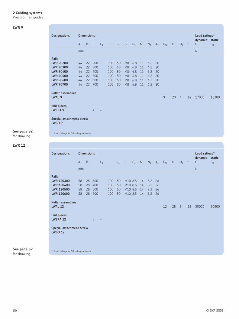
86 © SKF 2005
2 Guiding systems
Precision rail guides
LWR 12
LWR 9
See page 82
for drawing
See page 82
for drawing
Designations Dimensions Load ratings*
dynamic static
A B L L1 J J1 G G1 N N1 A1 DW U U1 t C C0
mm N
Rails
LWR 90200 44 22 200 100 50 M8 6.8 11 6.2 20
LWR 90300 44 22 300 100 50 M8 6.8 11 6.2 20
LWR 90400 44 22 400 100 50 M8 6.8 11 6.2 20
LWR 90500 44 22 500 100 50 M8 6.8 11 6.2 20
LWR 90600 44 22 600 100 50 M8 6.8 11 6.2 20
LWR 90700 44 22 700 100 50 M8 6.8 11 6.2 20
Roller assemblies
LWAL 9 9 20 4 14 17000 18300
End pieces
LWERA 9 4 –
Special attachment screw
LWGD 9
* Load ratings for 10 rolling elements
Designations Dimensions Load ratings*
dynamic static
A B L L1 J J1 G G1 N N1 A1 DW U U1 t C C0
mm N
Rails
LWR 120300 58 28 300 100 50 M10 8.5 14 8.2 26
LWR 120400 58 28 400 100 50 M10 8.5 14 8.2 26
LWR 120500 58 28 500 100 50 M10 8.5 14 8.2 26
LWR 120600 58 28 600 100 50 M10 8.5 14 8.2 26
Roller assemblies
LWAL 12 12 25 5 18 30000 30500
End pieces
LWERA 12 5 –
Special attachment screw
LWGD 12
* Load ratings for 10 rolling elements
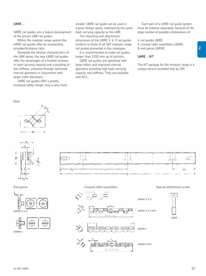
© SKF 2005 87
2
LWRE ..
LWRE rail guides are a logical development
of the proven LWR rail guides.
Within the modular range system the
LWRE rail guides offer an outstanding
price/performance ratio.
Alongside the familiar characteristics of
the LWR series, the new LWRE rail guides
offer the advantages of a fivefold increase
in load-carrying capacity and a doubling of
the stiffness, achieved through optimised
internal geometry in conjunction with
larger roller diameters.
LWRE rail guides offer a greatly
increased safety margin, thus a very much
End pieces Crossed roller assemblies Special attachment screw
smaller LWRE rail guide can be used in
a given design space, maintaining the same
load-carrying capacity as the LWR.
The mounting and attachment
dimensions of the LWRE 3, 6, 9 rail guides
conform to those of all SKF modular range
rail guides presented in this catalogue.
It is recommended to make rail guides
longer than 1200 mm up of sections.
LWRE rail guides are optimised with
large rollers and improved internal
geometry providing high load-carrying
capacity and stiffness. They are available
with ACS.
Each part of a LWRE rail guide system
must be ordered separately, because of the
large number of possible combinations of:
4 rail guides LWRE
2 crossed roller assemblies LWAKE
8 end pieces LWERE
LWRE .. KIT
The KIT package for the modular range is a
unique service provided only by SKF.
LWERE 3, 6, 9
LWGD
LWAKE 3, 6, 9
LWERE 4LWAKE 4
LWAKE 4 ACS
Rails
LWAKE 3, 6, 9 ACS

88 © SKF 2005
2 Guiding systems
Precision rail guides
LWRE 3/4/6 .. KIT
4 rail guides LWRE
2 crossed roller assemblies LWAKE
8 end pieces LWERE
See page 87 for drawing
See page 87 for drawing
See page 87 for drawing
Designations Load ratings* Stroke Rail Cage
dynamic static designations designations
C C0 min. max.
N mm
LWRE 3050 KIT 4230 5100 25 33 LWRE 3050 LWAKE 3 ×6
LWRE 3075 KIT 5803 7650 38 50 LWRE 3075 LWAKE 3 ×9
LWRE 3100 KIT 7263 10200 50 67 LWRE 3100 LWAKE 3 ×12
LWRE 3125 KIT 8644 12750 63 83 LWRE 3125 LWAKE 3 ×15
LWRE 3150 KIT 9964 15300 75 100 LWRE 3150 LWAKE 3 ×18
LWRE 3175 KIT 11238 17850 88 117 LWRE 3175 LWAKE 3 ×21
LWRE 3200 KIT 12471 20400 100 133 LWRE 3200 LWAKE 3 ×24
*Load ratings for 10 rolling elements
Including 8 end stops LWERE 3
Designations Load ratings* Stroke Rail Cage
dynamic static designations designations
C C0 min. max.
N mm
LWRE 4100 KIT 17300 20800 39 67 LWRE 4100 LWAKE 4 ×10
LWRE 4150 KIT 23735 31200 62 100 LWRE 4150 LWAKE 4 ×15
LWRE 4200 KIT 28541 39520 95 133 LWRE 4200 LWAKE 4 ×19
LWRE 4250 KIT 34246 49920 118 167 LWRE 4250 LWAKE 4 ×24
LWRE 4300 KIT 38622 58240 152 200 LWRE 4300 LWAKE 4 ×28
LWRE 4350 KIT 43902 68640 169 233 LWRE 4350 LWAKE 4 ×33
LWRE 4400 KIT 49009 79040 192 267 LWRE 4400 LWAKE 4 ×38
* Load ratings for 10 rolling elements
Including 8 end stops LWERE 4
Designations Load ratings* Stroke Rail Cage
dynamic static designations designations
C C0 min. max.
N mm
LWRE 6100 KIT 25743 27300 46 67 LWRE 6100 LWAKE 6 ×7
LWRE 6150 KIT 34000 39000 80 100 LWRE 6150 LWAKE 6 ×10
LWRE 6200 KIT 44204 54600 92 133 LWRE 6200 LWAKE 6 ×14
LWRE 6250 KIT 51431 66300 126 167 LWRE 6250 LWAKE 6 ×17
LWRE 6300 KIT 58382 78000 160 200 LWRE 6300 LWAKE 6 ×20
LWRE 6350 KIT 67304 93600 172 233 LWRE 6350 LWAKE 6 ×24
LWRE 6400 KIT 73781 105300 208 267 LWRE 6400 LWAKE 6 ×27
* Load ratings for 10 rolling elements
Including 8 end stops LWERE 6

© SKF 2005 89
2
See page 87 for drawing
See page 87 for drawing
See page 87 for drawing
LWRE 3/4/6 .. ACS - KIT
4 rail guides LWRE ACS
2 crossed roller assemblies LWAKE
8 end pieces LWERE
Designations Load ratings* Stroke Rail Cage
dynamic static designations designations
C C0 min. max.
N mm
LWRE 3050 ACS-KIT 4230 5100 20 33 LWRE 3050 ACS LWAKE 3 ×6 ACS
LWRE 3075 ACS-KIT 5294 6800 30 50 LWRE 3075 ACS LWAKE 3 ×6 ACS
LWRE 3100 ACS-KIT 6300 8500 45 67 LWRE 3100 ACS LWAKE 3 ×10 ACS
LWRE 3125 ACS-KIT 7731 11050 62 83 LWRE 3125 ACS LWAKE 3 ×13 ACS
LWRE 3150 ACS-KIT 9090 13600 79 100 LWRE 3150 ACS LWAKE 3 ×16 ACS
LWRE 3175 ACS-KIT 9964 15300 94 117 LWRE 3175 ACS LWAKE 3 ×18 ACS
LWRE 3200 ACS-KIT 11653 18700 100 133 LWRE 3200 ACS LWAKE 3 ×22 ACS
* Load ratings for 10 rolling elements
Including 8 end stops LWERE 3
Designations Load ratings* Stroke Rail Cage
dynamic static designations designations
C C0 min. max.
N mm
LWRE 4100 ACS-KIT 14536 16640 40 67 LWRE 4100 ACS LWAKE 4 ×8 ACS
LWRE 4150 ACS-KIT 19944 24960 79 100 LWRE 4150 ACS LWAKE 4 ×12 ACS
LWRE 4200 ACS-KIT 26170 35360 96 133 LWRE 4200 ACS LWAKE 4 ×17 ACS
LWRE 4250 ACS-KIT 30859 43680 129 167 LWRE 4250 ACS LWAKE 4 ×21 ACS
LWRE 4300 ACS-KIT 36452 54080 152 200 LWRE 4300 ACS LWAKE 4 ×26 ACS
LWRE 4350 ACS-KIT 41813 64480 175 233 LWRE 4350 ACS LWAKE 4 ×31 ACS
LWRE 4400 ACS-KIT 45964 72800 203 267 LWRE 4400 ACS LWAKE 4 ×35 ACS
* Load ratings for 10 rolling elements
Including 8 end stops LWERE 4
Designations Load ratings* Stroke Rail Cage
dynamic static designations designations
C C0 min. max.
N mm
LWRE 6100 ACS-KIT 22826 23400 37 67 LWRE 6100 ACS LWAKE 6 ×6 ACS
LWRE 6150 ACS-KIT 31318 35100 71 100 LWRE 6150 ACS LWAKE 6 ×9 ACS
LWRE 6200 ACS-KIT 39196 46800 105 133 LWRE 6200 ACS LWAKE 6 ×12 ACS
LWRE 6250 ACS-KIT 49056 62400 117 167 LWRE 6250 ACS LWAKE 6 ×16 ACS
LWRE 6300 ACS-KIT 56093 74100 151 200 LWRE 6300 ACS LWAKE 6 ×19 ACS
LWRE 6350 ACS-KIT 65107 89700 163 233 LWRE 6350 ACS LWAKE 6 ×23 ACS
LWRE 6400 ACS-KIT 71640 101400 197 267 LWRE 6400 ACS LWAKE 6 ×26 ACS
* Load ratings for 10 rolling elements
Including 8 end stops LWERE 6

90 © SKF 2005
2 Guiding systems
Precision rail guides
LWRE 3
LWRE 2211
See page 87
for drawing
See page 87
for drawing
Designations Dimensions Load ratings*
dynamic static
A B L L1 J J1 G G1 N N1 A1 DW t C C0
mm N
Rails
LWRE 3050 18 8 50 25 12.5 M4 3.3 6 3.2 8.7
LWRE 3075 18 8 75 25 12.5 M4 3.3 6 3.2 8.7
LWRE 3100 18 8 100 25 12.5 M4 3.3 6 3.2 8.7
LWRE 3125 18 8 125 25 12.5 M4 3.3 6 3.2 8.7
LWRE 3150 18 8 150 25 12.5 M4 3.3 6 3.2 8.7
LWRE 3175 18 8 175 25 12.5 M4 3.3 6 3.2 8.7
LWRE 3200 18 8 200 25 12.5 M4 3.3 6 3.2 8.7
Crossed roller assemblies
LWAKE 3 4 6.25 6300 8500
End pieces
LWERE 3 2 –
Special attachment screw
LWGD 3
* Load ratings for 10 rolling elements
Designations Dimensions Load ratings*
dynamic static
A B L L1 J J1 G G1 N N1 A1 DW t t1 t2 C C0
mm N
Rails
LWRE 22110080 22 11 80 40 20 M5 4.3 7.5 4.1 11 4 6.25 2.65 3.6 6300 8500
LWRE 22110120 22 11 120 40 20 M5 4.3 7.5 4.1 11 4 6.25 2.65 3.6 6300 8500
LWRE 22110160 22 11 160 40 20 M5 4.3 7.5 4.1 11 4 6.25 2.65 3.6 6300 8500
LWRE 22110200 22 11 200 40 20 M5 4.3 7.5 4.1 11 4 6.25 2.65 3.6 6300 8500
LWRE 22110240 22 11 240 40 20 M5 4.3 7.5 4.1 11 4 6.25 2.65 3.6 6300 8500
LWRE 22110280 22 11 280 40 20 M5 4.3 7.5 4.1 11 4 6.25 2.65 3.6 6300 8500
LWRE 22110320 22 11 320 40 20 M5 4.3 7.5 4.1 11 4 6.25 2.65 3.6 6300 8500
LWRE 22110360 22 11 360 40 20 M5 4.3 7.5 4.1 11 4 6.25 2.65 3.6 6300 8500
LWRE 22110400 22 11 400 40 20 M5 4.3 7.5 4.1 11 4 6.25 2.65 3.6 6300 8500
Crossed roller assemblies
LWAKE 3 4 6.25 6300 8500
End pieces
LWERE 3 2 –
* Load ratings for 10 rolling elements

© SKF 2005 91
2
LWRE 4
See page 87
for drawing
See page 87
for drawing
LWRE 6
Designations Dimensions Load ratings*
dynamic static
A B L L1 J J1 G G1 N N1 A1 DW t C C0
mm N
Rails
LWRE 4100 25 12 100 25 12.5 M4 3.3 6 3.2 12
LWRE 4150 25 12 150 25 12.5 M4 3.3 6 3.2 12
LWRE 4200 25 12 200 25 12.5 M4 3.3 6 3.2 12
LWRE 4250 25 12 250 25 12.5 M4 3.3 6 3.2 12
LWRE 4300 25 12 300 25 12.5 M4 3.3 6 3.2 12
LWRE 4400 25 12 400 25 12.5 M4 3.3 6 3.2 12
Crossed roller assemblies
LWAKE 4 6.5 8 17300 20800
End pieces
LWERE 4 4 –
Special attachment screw
LWGD 4
* Load ratings for 10 rolling elements
Designations Dimensions Load ratings*
dynamic static
A B L L1 J J1 G G1 N N1 A1 DW t C C0
mm N
Rails
LWRE 6100 31 15 100 50 25 M6 5.2 9.5 5.2 15
LWRE 6150 31 15 150 50 25 M6 5.2 9.5 5.2 15
LWRE 6200 31 15 200 50 25 M6 5.2 9.5 5.2 15
LWRE 6250 31 15 250 50 25 M6 5.2 9.5 5.2 15
LWRE 6300 31 15 300 50 25 M6 5.2 9.5 5.2 15
LWRE 6400 31 15 400 50 25 M6 5.2 9.5 5.2 15
Crossed roller assemblies
LWAKE 6 8 11 34000 39000
End pieces
LWERE 6 3 –
Special attachment screw
LWGD 6
* Load ratings for 10 rolling elements

92 © SKF 2005
2 Guiding systems
Precision rail guides
LWRE 3 ACS
LWRE 9
See page 87
for drawing
See page 87
for drawing
Designations Dimensions Load ratings*
dynamic static
A B L L1 J J1 G G1 N N1 A1 DW t C C0
mm N
Rails
LWRE 90200 44 22 200 100 50 M8 6.8 11 6.2 22
LWRE 90300 44 22 300 100 50 M8 6.8 11 6.2 22
LWRE 90400 44 22 400 100 50 M8 6.8 11 6.2 22
LWRE 90500 44 22 500 100 50 M8 6.8 11 6.2 22
LWRE 90600 44 22 600 100 50 M8 6.8 11 6.2 22
LWRE 90700 44 22 700 100 50 M8 6.8 11 6.2 22
Crossed roller assemblies
LWAKE 9 12 16 78000 78000
End pieces
LWERE 9 3 –
Special attachment screw
LWGD 9
* Load ratings for 10 rolling elements
Designations Dimensions Load ratings*
dynamic static
A B L L1 J J1 G G1 N N1 A1 DW t t3 C C0
mm N
Rails
LWRE 3050 ACS 18 8 50 25 12.5 M4 3.3 6 3.2 8.7 9
LWRE 3075 ACS 18 8 75 25 12.5 M4 3.3 6 3.2 8.7 9
LWRE 3100 ACS 18 8 100 25 12.5 M4 3.3 6 3.2 8.7 9
LWRE 3125 ACS 18 8 125 25 12.5 M4 3.3 6 3.2 8.7 9
LWRE 3150 ACS 18 8 150 25 12.5 M4 3.3 6 3.2 8.7 9
LWRE 3175 ACS 18 8 175 25 12.5 M4 3.3 6 3.2 8.7 9
LWRE 3200 ACS 18 8 200 25 12.5 M4 3.3 6 3.2 8.7 9
Crossed roller assemblies
LWAKE 3 ACS 4 6.25 6300 8500
End pieces
LWERE 3 2 –
Special attachment screw
LWGD 3
* Load ratings for 10 rolling elements

© SKF 2005 93
2
LWRE 2211 ACS
LWRE 4 ACS
See page 87
for drawing
See page 87
for drawing
Designations Dimensions Load ratings*
dynamic static
A B L L1 J J1 G G1 N N1 A1 DW t t3 C C0
mm N
Rails
LWRE 22110080 ACS 22 11 80 40 20 M5 4.3 7.5 4.1 11 9
LWRE 22110120 ACS 22 11 120 40 20 M5 4.3 7.5 4.1 11 9
LWRE 22110160 ACS 22 11 160 40 20 M5 4.3 7.5 4.1 11 9
LWRE 22110200 ACS 22 11 200 40 20 M5 4.3 7.5 4.1 11 9
LWRE 22110240 ACS 22 11 240 40 20 M5 4.3 7.5 4.1 11 9
LWRE 22110280 ACS 22 11 280 40 20 M5 4.3 7.5 4.1 11 9
LWRE 22110320 ACS 22 11 320 40 20 M5 4.3 7.5 4.1 11 9
LWRE 22110360 ACS 22 11 360 40 20 M5 4.3 7.5 4.1 11 9
LWRE 22110400 ACS 22 11 400 40 20 M5 4.3 7.5 4.1 11 9
Crossed roller assemblies
LWAKE 3 ACS 4 6.25 6300 8500
End pieces
LWERE 3
* Load ratings for 10 rolling elements
Designations Dimensions Load ratings*
dynamic static
A B L L1 J J1 G G1 N N1 A1 DW t t3 C C0
mm N
Rails
LWRE 4100 ACS 25 12 100 25 12.5 M4 3.3 6 3.2 12 17
LWRE 4150 ACS 25 12 150 25 12.5 M4 3.3 6 3.2 12 17
LWRE 4200 ACS 25 12 200 25 12.5 M4 3.3 6 3.2 12 17
LWRE 4250 ACS 25 12 250 25 12.5 M4 3.3 6 3.2 12 17
LWRE 4300 ACS 25 12 300 25 12.5 M4 3.3 6 3.2 12 17
LWRE 4350 ACS 25 12 350 25 12.5 M4 3.3 6 3.2 12 17
LWRE 4400 ACS 25 12 400 25 12.5 M4 3.3 6 3.2 12 17
Crossed roller assemblies
LWAKE 4 ACS 6.5 8 17300 20800
End pieces
LWERE 4 4 –
Special attachment screw
LWGD 4
* Load ratings for 10 rolling elements

94 © SKF 2005
2 Guiding systems
Precision rail guides
LWRE 9 ACS
LWRE 6 ACS
See page 87
for drawing
See page 87
for drawing
Designations Dimensions Load ratings*
dynamic static
A B L L1 J J1 G G1 N N1 A1 DW t t3 C C0
mm N
Rails
LWRE 6100 ACS 31 15 100 50 25 M6 5.2 9.5 5.2 15 15.3
LWRE 6150 ACS 31 15 150 50 25 M6 5.2 9.5 5.2 15 15.3
LWRE 6200 ACS 31 15 200 50 25 M6 5.2 9.5 5.2 15 15.3
LWRE 6250 ACS 31 15 250 50 25 M6 5.2 9.5 5.2 15 15.3
LWRE 6300 ACS 31 15 300 50 25 M6 5.2 9.5 5.2 15 15.3
LWRE 6400 ACS 31 15 400 50 25 M6 5.2 9.5 5.2 15 15.3
Crossed roller assemblies
LWAKE 6 ACS 8 11 34000 39000
End pieces
LWERE 6 3 –
Special attachment screw
LWGD 6
* Load ratings for 10 rolling elements
Designations Dimensions Load ratings*
dynamic static
A B L L1 J J1 G G1 N N1 A1 DW t t3 C C0
mm N
Rails
LWRE 90200 ACS 44 22 200 100 50 M8 6.8 11 6.2 22 22
LWRE 90300 ACS 44 22 300 100 50 M8 6.8 11 6.2 22 22
LWRE 90400 ACS 44 22 400 100 50 M8 6.8 11 6.2 22 22
LWRE 90500 ACS 44 22 500 100 50 M8 6.8 11 6.2 22 22
LWRE 90600 ACS 44 22 600 100 50 M8 6.8 11 6.2 22 22
LWRE 90700 ACS 44 22 700 100 50 M8 6.8 11 6.2 22 22
Crossed roller assemblies
LWAKE 9 ACS 12 16 78000 78000
End pieces
LWERE 9 3 –
Special attachment screw
LWGD 9
* Load ratings for 10 rolling elements

© SKF 2005 95
2
LWRM .. / LWRV ..
Guiding systems with high load carrying
capacity and maximum stiffness.
Needle roller assemblies for LWRM/LWRV
rail guides
LWHW needle roller assemblies have
aluminium cages which provide retention of
the needle rollers. They are available for
size 6 and 9 units.
When ordering, the appropriate cage
length in mm must be stated after the cage
designation, e. g: LWHW 10 ×225.
End pieces for LWRM/LWRV rail guides.
End pieces serve to restrict the drift of the
needle roller assemblies from the loaded
zone.
LWEARM and LWEARV end pieces
are fitted with a plastic wiper with a sealing
lip serving to reduce the risk
of contamination of the raceways.
All end pieces are supplied with the
necessary attachment screws.
The mounting and attachment
dimensions of the LWRM/LWRV rail guides
conform to those of the other SKF modular
range rail guides included in this catalogue.
Because of the large number of possible
combinations, all components
of LWRM/LWRV rail guides must be ordered
separately, e.g.:
2 rail guides LWRM
2 rail guides LWRV
2 needle roller assemblies LWHW
2 end pieces LWEARM.
Rails
End pieces Rolling element assemblies Special attachment screw
Aluminium
wiper
LWEARVwith wiper
LWEARMwith wiper
LWRM
LWRV
LWHW
LWGDwiper

96 © SKF 2005
2 Guiding systems
Precision rail guides
LWRM 6 / LWRV 6
LWRM 9 / LWRV 9
See page 95
for drawing
See page 95
for drawing
Designations Dimensions Load ratings*
dynamic static
A B L L1 J J1 G G1 N N1 A1 A2 A3 DW U t C C0
mm N
Rails
LWRM/LWRV 6100 31 15 100 50 25 M6 5.2 9.5 5.2 17 18 11
LWRM/LWRV 6150 31 15 150 50 25 M6 5.2 9.5 5.2 17 18 11
LWRM/LWRV 6200 31 15 200 50 25 M6 5.2 9.5 5.2 17 18 11
LWRM/LWRV 6250 31 15 250 50 25 M6 5.2 9.5 5.2 17 18 11
LWRM/LWRV 6300 31 15 300 50 25 M6 5.2 9.5 5.2 17 18 11
LWRM/LWRV 6400 31 15 400 50 25 M6 5.2 9.5 5.2 17 18 11
Needle roller assemblies
LWHW 10 2 10 3.75 10400 25500
End pieces
LWEARM 6 – 6
LWEARV 6 – 6
Special attachment screw
LWGD 6
* For 10 needle rollers per row
Designations Dimensions Load ratings*
dynamic static
A B L L1 J J1 G G1 N N1 A1 A2 A3 DW U t C C0
mm N
Rails
LWRM/LWRV 90200 44 22 200 100 50 M8 6.8 11 6.2 23.1 27 17
LWRM/LWRV 90300 44 22 300 100 50 M8 6.8 11 6.2 23.1 27 17
LWRM/LWRV 90400 44 22 400 100 50 M8 6.8 11 6.2 23.1 27 17
LWRM/LWRV 90500 44 22 500 100 50 M8 6.8 11 6.2 23.1 27 17
Needle roller assemblies
LWHW 15 2 15 4.5 16300 45000
End pieces
LWEARM 9 – 8.3
LWEARV 9 – 8.3
Special attachment screw
LWGD 9
* For 10 needle rollers per row

© SKF 2005 97
2
LWM .. / LWV ..
These rail guides enable the design of
linear guiding systems for heavy loads with
maximum stiffness. The internal geometry
is identical with that of the modular range
rails of the LWRM/LWRV series. As the same
needle roller assembly is used, the load
bearing characteristics are identical. The
external dimensions of the LWM/LWV rail
guides, however, differ slightly from those
of the LWRM/LWRV modular range
dimensions.
LWM/LWV rail guides are widely used in
machine tools. LWM/LWV rail guides have
as standard attachment hole type 15, i.e.
through hole with countersinking.
If attachment hole type 13 is ordered,
corresponding threaded inserts are
supplied along with the guide.
For new designs the choice of LWRM/
LWRV rail guides is recommended.
These offer the advantage of being
interchangeable with other rail guides
of the modular range.
Needle roller assemblies for LWM/LWV
rail guides
LWHW needle roller assemblies comprise
an aluminium cage with needle rollers
arranged at right angles to each other. The
needle rollers are retained by the cage.
End pieces for LWM/LWV rail guides
LWEAM and LWEAV end pieces are fitted
with a plastic wiper with sealing lip which
serves to keep the track free from dirt.
All end pieces are supplied together with
attachment screws. It is recommended that
rail guides longer than 1200 mm should be
made up of sections. If, for design reasons,
single-piece rails are required, these can be
supplied to special order.
Rails
End pieces Rolling element assemblies
AluminiumLWHW
Hole type 15
Hole type 15
Hole type 13
LWM rail
LWV rail
wiper
LWEAM with wiper
LWEAV with wiper
wiper
Special attachment screw
LWGD
Hole type 13

98 © SKF 2005
2 Guiding systems
Precision rail guides
LWM 3015 /
LWV 3015
LWM 4020 /
LWV 4020
See page 97
for drawing
See page 97
for drawing
Designations Dimensions Load ratings*
dynamic static
A B L L1 J1) J1min2) G N N1 N2 A1 A2 A3 DW U t C C0
mm N
Rails
LWM/LWV 3015100 30 15 100 40 15 M4 8.5 4.5 5.25 16 17.2 10.5
LWM/LWV 3015150 30 15 150 40 15 M4 8.5 4.5 5.25 16 17.2 10.5
LWM/LWV 3015200 30 15 200 40 15 M4 8.5 4.5 5.25 16 17.2 10.5
LWM/LWV 3015300 30 15 300 40 15 M4 8.5 4.5 5.25 16 17.2 10.5
LWM/LWV 3015400 30 15 400 40 15 M4 8.5 4.5 5.25 16 17.2 10.5
Needle roller assemblies
LWHW10 2 10 3.75 10400 25500
End pieces
LWEAM 3015 – 6
LWEAV 3015 – 6
Appropriate attachment screw
M3 DIN 84
* For 10 needle rollers per row1) For lengths L < J + 2 · J1min, J = 50 mm (except for LWM/LWV 3015)2) J1 depends upon the rail length and is of the same size at each end of the rail: J1 = (L – ΣJ)/2
Designations Dimensions Load ratings*
dynamic static
A B L L1 J1) J1min2) G N N1 N2 A1 A2 A3 DW U t C C0
mm N
Rails
LWM/LWV 4020100 40 20 100 80 15 M6 11.5 6.8 7.5 22.3 22 13.5
LWM/LWV 4020150 40 20 150 80 15 M6 11.5 6.8 7.5 22.3 22 13.5
LWM/LWV 4020200 40 20 200 80 15 M6 11.5 6.8 7.5 22.3 22 13.5
LWM/LWV 4020300 40 20 300 80 15 M6 11.5 6.8 7.5 22.3 22 13.5
LWM/LWV 4020400 40 20 400 80 15 M6 11.5 6.8 7.5 22.3 22 13.5
Needle roller assemblies
LWHW 15 2 15 4.5 16300 45000
End pieces
LWEAM 4020 – 8.3
LWEAV 4020 – 8.3
Appropriate attachment screw
M5 DIN 84
* For 10 needle rollers per row1) For lengths L < J + 2 · J1min, J = 50 mm (except for LWM/LWV 3015)2) J1 depends upon the rail length and is of the same size at each end of the rail: J1 = (L – ΣJ)/2

© SKF 2005 99
2
LWM 5025 /
LWV 5025
LWM 6035 /
LWV 6035
(On request)
See page 97
for drawing
See page 97
for drawing
Designations Dimensions Load ratings*
dynamic static
A B L L1 J1) J1min2) G N N1 N2 A1 A2 A3 DW U t C C0
mm N
Rails
LWM/LWV 50250100 50 25 100 80 20 M6 11.5 6.8 7.5 28 28 17
LWM/LWV 50250200 50 25 200 80 20 M6 11.5 6.8 7.5 28 28 17
LWM/LWV 50250300 50 25 300 80 20 M6 11.5 6.8 7.5 28 28 17
LWM/LWV 50250400 50 25 400 80 20 M6 11.5 6.8 7.5 28 28 17
LWM/LWV 50250500 50 25 500 80 20 M6 11.5 6.8 7.5 28 28 17
Needle roller assemblies
LWHW 15 2 15 4.5 16300 45000
End pieces
LWEAM 5025 – 8.9
LWEAV 5025 – 8.9
Appropriate attachment screw
M6 DIN 84
* For 10 needle rollers per row1) For lengths L < J + 2 · J1min, J = 50 mm (except for LWM/LWV 3015)2) J1 depends upon the rail length and is of the same size at each end of the rail: J1 = (L – ΣJ)/2
Designations Dimensions Load ratings*
dynamic static
A B L L1 J1) J1min2) G N N1 N2 A1 A2 A3 DW U t C C0
mm N
Rails
LWM/LWV 60350200 60 35 200 100 20 M8 15 9 10 36 36 20
LWM/LWV 60350300 60 35 300 100 20 M8 15 9 10 36 36 20
LWM/LWV 60350400 60 35 400 100 20 M8 15 9 10 36 36 20
LWM/LWV 60350500 60 35 500 100 20 M8 15 9 10 36 36 20
LWM/LWV 60350600 60 35 600 100 20 M8 15 9 10 36 36 20
LWM/LWV 60350700 60 35 700 100 20 M8 15 9 10 36 36 20
LWM/LWV 60350800 60 35 800 100 20 M8 15 9 10 36 36 20
LWM/LWV 60350900 60 35 900 100 20 M8 15 9 10 36 36 20
LWM/LWV 60351000 60 35 1000 100 20 M8 15 9 10 36 36 20
Needle roller assemblies
LWHW 20 2.5 20 5.5 32000 88000
End pieces
LWEAM 6035 – 8.9
LWEAV 6035 – 8.9
Appropriate attachment screw
M6 DIN 84
* For 10 needle rollers per row1) For lengths L < J + 2 · J1min, J = 50 mm (except for LWM/LWV 3015)2) J1 depends upon the rail length and is of the same size at each end of the rail: J1 = (L – ΣJ)/2

100 © SKF 2005
2 Guiding systems
Precision rail guides
LWM 7040 /
LWV 7040
(On request)
LWM 8050 /
LWV 8050
(On request)
See page 97
for drawing
See page 97
for drawing
Designations Dimensions Load ratings*
dynamic static
A B L L1 J1) J1min2) G N N1 N2 A1 A2 A3 DW U t C C0
mm N
Rails
LWM/LWV 70400200 70 40 200 100 20 M10 18.5 11 12.5 40 42 24
LWM/LWV 70400300 70 40 300 100 20 M10 18.5 11 12.5 40 42 24
LWM/LWV 70400400 70 40 400 100 20 M10 18.5 11 12.5 40 42 24
LWM/LWV 70400500 70 40 500 100 20 M10 18.5 11 12.5 40 42 24
LWM/LWV 70400600 70 40 600 100 20 M10 18.5 11 12.5 40 42 24
LWM/LWV 70400700 70 40 700 100 20 M10 18.5 11 12.5 40 42 24
LWM/LWV 70400800 70 40 800 100 20 M10 18.5 11 12.5 40 42 24
LWM/LWV 70400900 70 40 900 100 20 M10 18.5 11 12.5 40 42 24
LWM/LWV 70401000 70 40 1000 100 20 M10 18.5 11 12.5 40 42 24
Needle roller assemblies
LWHW 25 3 25 6 52000 143000
End pieces
LWEAM 7040 – 8.9
LWEAV 7040 – 8.9
Appropriate attachment screw
M6 DIN 84
* For 10 needle rollers per row1) For lengths L < J + 2 · J1min, J = 50 mm (except for LWM/LWV 3015)2) J1 depends upon the rail length and is of the same size at each end of the rail: J1 = (L – ΣJ)/2
Designations Dimensions Load ratings*
dynamic static
A B L L1 J1) J1min2) G N N1 N2 A1 A2 A3 DW U t C C0
mm N
Rails
LWM/LWV 80500200 80 50 200 100 20 M12 20 13 14 45 48.5 26
LWM/LWV 80500300 80 50 300 100 20 M12 20 13 14 45 48.5 26
LWM/LWV 80500400 80 50 400 100 20 M12 20 13 14 45 48.5 26
LWM/LWV 80500500 80 50 500 100 20 M12 20 13 14 45 48.5 26
LWM/LWV 80500600 80 50 600 100 20 M12 20 13 14 45 48.5 26
LWM/LWV 80500700 80 50 700 100 20 M12 20 13 14 45 48.5 26
LWM/LWV 80500800 80 50 800 100 20 M12 20 13 14 45 48.5 26
LWM/LWV 80500900 80 50 900 100 20 M12 20 13 14 45 48.5 26
LWM/LWV 80501000 80 50 1000 100 20 M12 20 13 14 45 48.5 26
Needle roller assemblies
LWHW 30 3.5 30 7 76500 212000
End pieces
LWEAM 8050 – 8.9
LWEAV 8050 – 8.9
Appropriate attachment screw
M6 DIN 84
* For 10 needle rollers per row1) For lengths L < J + 2 · J1min, J = 50 mm (except for LWM/LWV 3015)2) J1 depends upon the rail length and is of the same size at each end of the rail: J1 = (L – ΣJ)/2

© SKF 2005 101
2
Notes

Some things are made to withstandthe test of time.
The thread of a cobweb is proportionally more resistant than any material
ever invented by man - even a steel cable.
Here we see just one of the wonders of nature which have provided SKF with
the inspiration to develop products which will last for many years to come.
Screws, guidance systems and many other components bearing the name of
SKF are made from stainless steel and are designed to withstand a corrosive
environment, at the same time guaranteeing the highest quality of perfor-
mance with long-term reliability for all your applications.
With SKF technology lasts.
Linear motion from SKFwww.linearmotion.skf.com

© SKF 2005 103
3
Driving systemsBall and roller screw
SKF ball & roller screw assemblies are
high-quality products, suitable for a wide
range of applications where precision
driving systems are needed
( figures 1 and 2).
The high efficiency screw affords
the opportunity to displace loads by
transforming rotary action into linear
motion. The high efficiency screw has
rolling elements, balls or rollers, between
the nut and the screw shaft.
In all types of ball screws, the load
is transmitted from the screw shaft to
the nut through each ball: several recircu-
lating systems are available. To improve
positioning accuracy, backlash can be
reduced or eliminated ( figure 3).
Two non-competing designs to
cover requirements beyond ball screw
limitations. Load transfer from the nut
to the screw shaft through a number of
threaded or grooved rollers: resulting in a
large number of strong contact points
( figure 4).
Operating precision ( Table 1)
Comparison of the different positioning
components and systems.
Operating Guiding systems Driving systems Actuation Positioning
precision (µm) systems systems
0.1 – 1
1 – 10
10 – 100
100 – 1000
Lin
ear
ball b
eari
ngs
Pre
cisi
on r
ail
guid
es
Pro
file
rail
guid
es
Sta
ndard
slid
es
Cam
rolle
rguid
es
Rolle
rsc
rew
s
Ball s
crew
s
Lin
ear
moto
rs
Ele
ctro
-m
ech
anic
al
act
uato
rs
Sta
ndard
dri
ves
or
linear
moto
rs
with a
ll g
uid
ing s
yste
ms
Table 1
Figure 1 Figure 2
Figure 3 Figure 4
NB:
In addition to this catalogue we have all
product brochures available as pdf
document on the internet.
www.linearmotion.skf.com/doc

104 © SKF 2005
3 Driving systems
Ball and roller screws
Type Details Basic dynamic Precision High duty Adverse
load rating Ep (µ) on 300 mm cycles environment
(Spec. steel, pollution)
SD/BD/SHDiameterØ 6 to 16 mm Up to 7.6 kN G9 (130 µ) good
to G5 (23 µ)
SX/BX, SN/BN/PNSND/BND/PNDSL/BL, SLD/BLD Up to 95 kN G9 (130 µ) satisfactoryDin standard to G5 (23 µ)Ø 16 to 63 mm
PGFJ, PGFL, PGFE, PGCLØ 16 to 125 mm Up to 270 kN G5 (23 µ) satisfactory
to G1 (6 µ)
SRC, SRF, TRK/PRK, SVC,PVK Up to 2235 kN G5 (23 µ) exceptionalØ 8 to 210 mm to G1 (6 µ)
How to orientateyour choice
In our wide range, you are sure to find the
product which fits exactly your
requirements:
The miniature ball screws ( figure 5),
either with ball recirculation by integrated
tube or with inserts, are very compact.
Backdriving makes them highly efficient.
The large ball screws ( figure 6) enable
you to select the right level of
requirement: simple transport screws,
very fast screws with long lead, or
preloaded screws for more precision.
Ground ball screws for more rigidity and
precision ( figure 7)
Roller screws ( figure 8) which are far
beyond the limits of any ball screws as
for heavy loads, ultimate precision and
rigidity, high speed and acceleration and
very difficult environments.
Table 2 will guide you in your first
approach.
Figure 5 Figure 6
Figure 7 Figure 8
Table 2

© SKF 2005 105
3
Ball screws
Rolled ball screws
( figures 9, 10, 11 and 12).
SKF ball screw assemblies are high-quality
products, suitable for a wide range of
applications where precision driving
systems are needed.
SKF rolled thread ball screws are
available in four designs to cover most
requirements.
Complete assemblies
For reduced quantities and for all types of
nuts, SKF provides complete assemblies
with customised screw shaft.
A complete range of accessories is
available and can be delivered completely
assembled. Just ask when ordering
( figure 13).
Figure 13
Figure 10
Figure 12
Figure 9
Figure 11
Diameters Leads Nut types Precision classes Accessories
From 6 to 63 mm From 2 to 50 mm Cylindrical and flanged with G5 - G7 - G9 For screw shafts
axial play, backlash elimination or and nuts
preload, SKF & DIN standards
Table 3

106 © SKF 2005
3 Driving systems
Ball screws
Nut type:Miniature screw, axial play, internal recirculation nut. . . . SDMiniature screw, backlash elimination by oversize balls . . . . . . . . . . . . . . . . . . . . . . . . . . . . . . . BD
Miniature screw, axial play, recirculation by integrated tube. . . . . . . . . . . . . . . . . . . . . . . . . . . . . . SH
Universal screw, axial play. . . . . . . . . . . . . . . . . . . . . . . . SXUniversal screw, backlash elimination by oversize balls . . . . . . . . . . . . . . . . . . . . . . . . . . . . . . . BX
Precision screw, axial play . . . . . . . . . . . . . . . . . . . . . . . SNPrecision screw, backlash elimination by oversizeballs . . . . . . . . . . . . . . . . . . . . . . . . . . . . . . . . . . . . . . . . BN
Precision screw, axial play, DIN nut . . . . . . . . . . . . . . . SNDPrecision screw, backlash elimination by oversizeballs, DIN nut . . . . . . . . . . . . . . . . . . . . . . . . . . . . . . . BND
Precision screw, with optimal rigidity . . . . . . . . . . . . . . . PNPrecision screw, with optimal rigidity, DIN nut. . . . . . . PNDLong lead screw, axial play . . . . . . . . . . . . . . . . . . . . . . . SLLong lead screw, axial play, DIN nut . . . . . . . . . . . . . . . SLDLong lead screw, backlash elimination by oversizeballs. . . . . . . . . . . . . . . . . . . . . . . . . . . . . . . . . . . . . . . . BL
Long lead screw, backlash elimination by oversizeballs, DIN nut . . . . . . . . . . . . . . . . . . . . . . . . . . . . . . . BLD
Rotating nut with axial play . . . . . . . . . . . . . . . . . . . . . . SLTRotating nut with backlash elimination . . . . . . . . . . . . . TLT
Nominal diameter × Lead [mm]
Hand:Right. . . . . . . . . . . . . . . . . . . . . . . . . . . . . . . . . . . . . . . . . . . . . . . . . . . RLeft (on request). . . . . . . . . . . . . . . . . . . . . . . . . . . . . . . . . . . . . . . . . . L
Threaded length / Total length [mm]
Lead precision:. . . . . . . . . . . . . . . . . . . . . . . . . . . . . . . . . . . . . . . . . . . . . . . . . . . . . . . . . . . . . . . . . . . . . G9, G7, G5
Nut orientation:Threaded side or flange of nut towards shorter (S) or longer (L) machined end of shaft.In case of same end machining (–)
Machined end combination:See page 114-117
Required lengths for AA - SA (both sides):See page 114 . . . . . . . . . . . . . . . . . . . . . . . . . . . . . . . . . . . . . . . . . . . . . . . . . . . . . . . . . . . . . . . . . . . . . . . . . . . . . . . . . . . . . . **/**
Wipers:With wipers . . . . . . . . . . . . . . . . . . . . . . . . . . . . . . . . . . . . . . . . . . . . . . . . . . . . . . . . . . . . . . . . . . . . . . . . . . . . . . . . . . . . . . . . . . . . . . . . . WPRWithout wipers . . . . . . . . . . . . . . . . . . . . . . . . . . . . . . . . . . . . . . . . . . . . . . . . . . . . . . . . . . . . . . . . . . . . . . . . . . . . . . . . . . . . . . . . . . . . NOWPRSafety ring (for SH - SD only) . . . . . . . . . . . . . . . . . . . . . . . . . . . . . . . . . . . . . . . . . . . . . . . . . . . . . . . . . . . . . . . . . . . . . . . . . . . . . . . . . . . . RING
Ordering key
Example: NOWPR
— — ———–—– ————–———–—— ——–———————–/
R LG7 SA + K 25 20PND 330 44532 ×5 /
/
/
-
-

© SKF 2005 107
3
SD/BD - Miniature ball screws
Ball recirculation in composite inserts,
threaded end for easy mounting.
SD: axial play
BD: backlash elimination by oversize balls
SH - Miniature ball screws
Ball recirculation in tube inside the nut,
threaded end for easy mounting
Symbols = see page 151
Designations Dimensions Lead Basic load
ratings
dynamic static
d0 d1 d2 L A A2 D M Ph Ca Coa
Max h10 6g
mm kN
SD/BD 8 ×2.5 R 8 7.6 6.3 1050 23.5 7.5 17.5 M15 ×1 2.5 2.2 2.6
SD/BD 10 ×2 R 10 9.5 8.3 1050 22 7.5 19.5 M17 ×1 2 2.5 3.5
SD/BD 10 ×4 R 10 8.9 7.4 1050 22 8.0 21.0 M18 ×1 4 4.5 5.4
SD/BD 12 ×2 R 12 11.2 9.8 2100 20 8.0 20.0 M18 ×1 2 2.9 4.6
SD/BD 12 ×4 R 12 11.3 9.4 2100 34 10.0 25.5 M20 ×1 4 5.0 6.5
SD/BD 12 ×5 R 12 11.8 9.3 2100 36 10 23.0 M20 ×1 5 4.2 5.3
SD/BD 14 ×4 R 14 13.7 11.9 2100 30 8 27.0 M22 ×1.5 4 6.0 9.0
SD/BD 16 ×2 R 16 15.5 14.3 2100 27 12.0 29.5 M25 ×1.5 2 3.3 6.2
SD/BD 16 ×5 R 16 15.2 12.7 2100 42 12.0 32.5 M26 ×1.5 5 7.6 10.5
Designations Dimensions Lead Basic load
ratings
dynamic static
d0 d1 d2 L A A2 D M Ph Ca Coa
Max h10 6g
mm kN
SH 6 ×2 R 6 6 4.7 1050 20 7.5 16.5 M14 ×1 2 1.2 1.5
SH 10 ×3 R 10 9.9 7.9 1050 29 9.0 21 M18 ×1 3 2.3 3.5
SH 12.7 ×12.7 R 12.7 13.0 10.2 2100 50 12.0 29.5 M25 ×1.5 12.7 5.3 9.0

108 © SKF 2005
3 Driving systems
Ball screws
SX / BX - Universal ball screws
Ball recirculation in composite inserts,
threaded end for easy mounting,
accessories see pages 109 and 120-121.
Steel inserts optional.
SX: axial play
BX: backlash elimination by oversize balls
(a)
(b)
(a)
Legend:
(a) = wiper
(b) = lubrication
Symbols = see page 151
Designations Dimensions Lead Basic load
ratings
dynamic static
d0 d1 d2 L A A2 D M Ph Ca Coa
Max js13 6g
mm kN
SX / BX 20 ×5 R 20 19.4 16.7 5000 54 14 38 M35 ×1.5 5 14.5 24.4
SX / BX 25 ×5 R 25 24.6 21.7 5000 69 19 43 M40 ×1.5 5 19.4 37.8
SX / BX 25 ×10 R 25 24.6 20.5 5000 87 19 43 M40 ×1.5 10 25.8 43.7
SX / BX 32 ×5 R 32 31.6 28.7 6000 69 19 52 M48 ×1.5 5 22.1 50.5
SX / BX 32 ×10 R 32 32.0 27.8 6000 95 19 54 M48 ×1.5 10 28.9 55.7
SX / BX 40 ×5 R 40 39.6 36.7 6000 69 19 60 M56 ×1.5 5 24.1 63.2
SX / BX 40 ×10 40 39.4 34.0 6000 110 24 65 M60 ×2 10 63.6 127.1
SX / BX 50 ×10 R 50 49.7 44.0 6000 135 29 78 M72 ×2 10 81.9 189,1
SX / BX 63 ×10 R 63 62.8 57.0 6000 135 29 93 M85 ×2 10 91,7 243.5

© SKF 2005 109
3
FHRF
Round flanges (for SX nuts only)
FHSF
Square flanges (for SX nuts only)
Symbols = see page 151
Designations Dimensions
d0 Ph A A1 J H
h14 h14 JS12 h12
mm
FHRF 20 20 5 55 15 44 52
FHRF 25 25 5 70 20 50 60
FHRF 25 25 10 88 20 50 60
FHRF 32 32 5 70 20 59 69
FHRF 32 32 10 96 20 59 69
FHRF 40 ×5 40 5 70 20 69 82
FHRF 40 ×10 40 10 111 25 76 92
FHRF 50 50 10 136 30 91 110
FHRF 63 63 10 136 30 106 125
Designations Dimensions
d0 Ph A A1 J H
h14 h14 JS12 h12
mm
FHSF 20 20 5 55 15 45 60
FHSF 25 25 5 70 20 52 70
FHSF 25 25 10 88 20 52 70
FHSF 32 32 5 70 20 60 80
FHSF 32 32 10 96 20 60 80
FHSF 40 ×5 40 5 70 20 70 90
FHSF 40 ×10 40 10 111 25 78 100
FHSF 50 50 10 136 30 94 120
FHSF 63 63 10 136 30 104 130

110 © SKF 2005
3 Driving systems
Ball screws
Legend:
(a) = lubrication hole
(a)
Design 1 Design 2
(a)
SN / BN - Precision ball screws
Ball recirculation in composite inserts. Steel
insert optional.
SN: axial play
BN: backlash elimination by oversize balls.
SND / BND - Precision ball screws
Ball recirculation in composite inserts, Din
standard. Steel insert optional.
SND: axial play
BND: backlash elimination by oversize balls.
Symbols = see page 151
Designations Dimensions Lead Basic load
ratings
dynamic static
d0 d1 d2 L A A2 D D1 J G Ph Ca Coa
Max g9 js12 6 ×
mm kN
SN/BN 16 ×5 R 16 15.2 12.7 2100 50.5 10 28 48 38 M5 5 8.1 12.4
SN/BN 20 ×5 R 20 19.4 16.7 5000 52.5 12 33 57 45 M6 5 11.7 18.3
SN/BN 25 ×5 R 25 24.6 21.7 5000 52.5 12 38 62 50 M6 5 13.0 22.7
SN/BN 25 ×10 R 25 24.6 20.5 5000 85.0 12 43 67 55 M6 10 25.8 43.7
SN/BN 32 ×5 R 32 31.6 28.7 6000 57.5 12 45 70 58 M6 5 19.1 40.4
SN/BN 32 ×10 R 32 32.0 27.8 6000 79.0 16 54 87 70 M8 10 22.6 41.8
SN/BN 40 ×5 R 40 39.6 36.7 6000 64.5 14 53 80 68 M6 5 25.4 63.2
SN/BN 40 ×10 R 40 39.4 34.0 6000 99.0 16 63 95 78 M8 10 63.6 127.1
SN/BN 50 ×10 R 50 49.7 44.0 6000 99.0 16 72 110 90 M10 10 70.6 157.6
SN/BN 63 ×10 R 63 62.8 57.0 6000 103.0 20 85 125 105 M10 10 78.4 202.9
Designations Dimensions Lead Basic load Design
ratings
dynamic static
d0 d1 d2 L D1 D4 Ph Ca Coa
Max g6
mm kN
SND/BND 16 ×5 R 16 15.2 12.7 2100 28 38 5 8.1 12.4 1
SND/BND 20 ×5 R 20 19.4 16.7 5000 36 47 5 11.7 18.3 1
SND/BND 25 ×5 R 25 24.6 21.7 5000 40 51 5 13.0 22.7 1
SND/BND 25 ×10 R 25 24.6 20.5 5000 40 51 10 25.8 43.7 1
SND/BND 32 ×5 R 32 31.6 28.7 6000 50 65 5 19.1 40.4 1
SND/BND 32 ×10 R 32 32.0 27.8 6000 50 65 10 22.6 41.8 1
SND/BND 40 ×5 R 40 39.6 36.7 6000 63 78 5 25.4 63.2 2
SND/BND 40 ×10 R 40 39.4 34.0 6000 63 78 10 63.6 127.1 2
SND/BND 50 ×10 R 50 49.7 44.0 6000 75 93 10 70.6 157.6 2
SND/BND 63 ×10 R 63 62.8 57.0 6000 90 108 10 78.4 202.9 2

© SKF 2005 111
3
PND - Precision ball screws
Ball recirculation in composite inserts, nut
to DIN standard, preloaded for optimal
rigidity. Steel inserts optional
PN - Precision ball screws
Ball recirculation in composite inserts,
preloaded for optimal rigidity. Steel inserts
optional
Legend:
(a) = lubrication hole
(a)
Design 1 Design 2
(a)
Symbols = see page 151
Designations Dimensions Lead Basic load
ratings
dynamic static
d0 d1 d2 L A A2 D D1 J G Ph Ca Coa
Max g9 js12 6 ×
mm kN
PN 16 ×5 R 16 15.2 12.7 2100 52 10 28 48 38 M5 5 5.7 8.3
PN 20 ×5 R 20 19.4 16.7 5000 58 12 33 57 45 M6 5 8.2 12.2
PN 25 ×5 R 25 24.6 21.7 5000 70 12 38 62 50 M6 5 13.0 22.7
PN 25 ×10 R 25 24.6 20.5 5000 85 12 43 67 55 M6 10 14.2 21.8
PN 32 ×5 R 32 31.6 28.7 6000 80 12 45 70 58 M6 5 19.1 40.4
PN 32 ×10 R 32 32 27.8 6000 113 16 54 87 70 M8 10 22.6 41.8
PN 40 ×5 R 40 39.6 36.7 6000 94 14 53 80 68 M6 5 25.4 63.2
PN 40 ×10 R 40 39.4 34.0 6000 134 16 63 95 78 M8 10 52.5 101.7
PN 50 ×10 R 50 49.7 44.0 6000 157 16 72 110 90 M10 10 70.6 157.6
PN 63 ×10 R 63 62.8 57.0 6000 161 20 85 125 105 M10 10 78.4 202.9
Designations Dimensions Lead Basic load Design
ratings
dynamic static
d0 L D1 D4 D5 D6 L8 Ltn Ph Ca Coa
Max g6 H13 h13 h13
mm kN
PND 16 ×5 R 16 2100 28 38 5.5 48 40 50 5 5.7 8.3 1
PND 20 ×5 R 20 5000 36 47 6.6 58 44 50 5 8.2 12.2 1
PND 25 ×5 R 25 5000 40 51 6.6 62 48 62 5 13.0 22.7 1
PND 25 ×10 R 25 5000 40 51 6.6 62 48 75 10 14.2 21.8 1
PND 32 ×5 R 32 6000 50 65 9.0 80 62 74 5 19.1 40.4 1
PND 32 ×10 R 32 6000 50 65 9.0 80 62 102 10 22.6 41.8 1
PND 40 ×5 R 40 6000 63 78 9.0 93 70 88 5 25.4 63.2 2
PND 40 ×10 R 40 6000 63 78 9.0 93 70 130 10 52.5 101.7 2
PND 50 ×10 R 50 6000 75 93 11.0 110 85 155 10 70.6 157.6 2
PND 63 ×10 R 63 6000 90 108 11.0 125 95 157 10 78.4 202.9 2

112 © SKF 2005
3 Driving systems
Ball screws
SL/BL - Long lead ball screws
Ball recirculation through the face.
SL: axial play
BL: backlash elimination by oversize balls.
SLD/BLD - Long lead ball screws
Ball recirculation through the face, nut to
DIN standard.
SLD: axial play
BLD: backlash elimination by oversize balls
Legend:
(a) = lubrication hole
(a)
Design 1
Symbols = see page 151
Designations Dimensions Lead Basic load
ratings
dynamic static
d0 d1 d2 L A A2 D D1 J G Ph Ca Coa
Max g9 js12 6 ×
mm kN
SL/BL 25 ×20 R 25 24.3 21.7 5000 66.4 15 48 73 60 M6 20 23.0 51.6
SL/BL 25 ×25 R 25 24.4 21.5 5000 77.9 15 48 73 60 M6 25 22.6 51.0
SL/BL 32 ×20 R 32 30.0 27.5 6000 66.4 15 56 80 68 M6 20 25.7 65.3
SL/BL 32 ×32 R 32 31.1 28.4 6000 80.3 15 56 80 68 M8 32 26.0 68.3
SL/BL 32 ×40 R 32 29.6 26.9 6000 55.0 15 53* 80 68 M6 40 15.7 38.6
SL/BL 40 ×20 R 40 37.7 35.2 6000 86.8 15 63 95 78 M8 20 41.8 129.4
SL/BL 40 ×40 R 40 38.3 34.2 6000 110.3 25 72 110 90 M10 40 53.3 133.8
SL/BL 50 ×50 R 50 49.1 43.5 6000 134.0 25 85 125 105 M10 50 94.8 238.2
* Tolerance g6
Designations Dimensions Lead Basic load Design
ratings
dyn. static
d0 d1 d2 L A A2 D D1 J G Ph Ca Coa
Max g6 js12 6 ×
mm kN
SLD/BLD 32 ×32 R 32 31.1 28.4 6000 80.3 15 50 80 65 M8 32 26.0 68.3 1
© SKF 2005 113
3
Notes
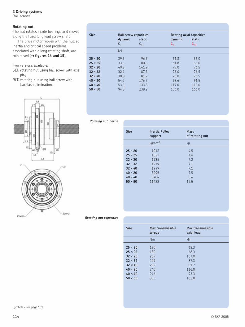
114 © SKF 2005
3 Driving systems
Ball screws
Rotating nut
The nut rotates inside bearings and moves
along the fixed long lead screw shaft.
The drive motor moves with the nut, so
inertia and critical speed problems,
associated with a long rotating shaft, are
minimised ( figures 14 and 15).
Two versions available:
SLT: rotating nut using ball screw with axial
play
BLT: rotating nut using ball screw with
backlash elimination.
Size Ball screw capacities Bearing axial capacities
dynamic static dynamic static
Ca Coa Ca Coa
kN
25 × 20 39.5 96.6 61.8 56.0
25 × 25 33.5 80.5 61.8 56.0
32 × 20 49.8 141.2 78.0 76.5
32 × 32 32.1 87.3 78.0 76.5
32 × 40 30.0 81.7 78.0 76.5
40 × 20 54.7 176.7 93.6 91.5
40 × 40 53.3 133.8 114.0 118.0
50 × 50 94.8 238.2 156.0 166.0
Size Inertia Pulley Mass
support of rotating nut
kgmm2 kg
25 × 20 1012 4.5
25 × 25 1023 4.6
32 × 20 1935 7.2
32 × 32 1919 7.1
32 × 40 1949 7.1
40 × 20 3095 7.5
40 × 40 3784 8.4
50 × 50 11482 15.5
Size Max transmissible Max transmissible
torque axial load
Nm kN
25 × 20 180 68.3
25 × 25 180 68.3
32 × 20 209 107.0
32 × 32 209 87.3
32 × 40 209 81.7
40 × 20 240 116.0
40 × 40 246 93.3
50 × 50 803 162.0
Symbols = see page 151
Rotating nut inertia
Rotating nut capacities

© SKF 2005 115
3
Symbols = see page 151
Figure 14 Figure 15
Designations Ø1 Ø2 Ø3 Ø4 Ø5 Ø6 Ø7 L L1 R1 R2 J1 J2 Z1 ×H1 Z2 ×H2 × H3
useful
length
h8 g6 max max mm
SLT/BLT 25 ×20 40 72.5 100 133 100 65 48 121.0 15 0.8 0.8 116 55 6 ×Ø9 6 ×M6 ×20 M6 ×1
SLT/BLT 25 ×25 40 72.5 100 133 100 65 48 126.2 15 0.8 0.8 116 55 6 ×Ø9 6 ×M6 ×20 M6 ×1
SLT/BLT 32 ×20 50 82 119.5 150 120 76 56 132.4 20 0.8 0.8 135 68 6 ×Ø9 6 ×M6 ×20 M6 ×1
SLT/BLT 32 ×32 50 82 119.5 150 120 76 50 126.8 20 0.8 0.8 135 68 6 ×Ø9 6 ×M6 ×20 M6 ×1
SLT/BLT 32 ×40 50 82 119.5 150 120 76 53 125.7 20 0.8 0.8 135 68 6 ×Ø9 6 ×M6 ×20 M6 ×1
SLT/BLT 40 ×20 58 93 125 159 125 80 63 136.4 20 0.8 0.8 142 75 8 ×Ø9 6 ×M6 ×20 M8 ×1
SLT/BLT 40 ×40 60 93 137 168 137 102 72 159.3 47 1.6 1.6 153 80 8 ×Ø9 6 ×M6 ×20 M8 ×1
SLT/BLT 50 ×50 70 120 170 210 170 110 85 163.3 20 1.6 1.6 190 106 8 ×Ø11 6 ×M8 ×30 M8 ×1
All tolerances js13 if not specified

116 © SKF 2005
3 Driving systems
Ball screws
Shaft end combinations for rolled ball
screws
In the order code, shaft end machining is
defined by:
– one letter for Ø < 16 mm
– two letters for Ø ≥ 16 mm
resulting from the combination of two
machined ends (see designation page 106).
UA: end machined to diameter d3 under
induction hardening, any possible lengths.
Machined ends are represented in detail
on page 117 for Ø < 16 mm and pages
118-119 for Ø ≥ 16 mm
Symbols = see page 151
Ø < 16 mm Ø ≥ 16 mm
Order code Two machined ends Order code Two machined ends
A (without cut only AA (without cut only
length indication) length indication)
A (+ length) cut + annealed
B 1 + 2 BA 1A + 2A
F* 2 + 2 FA* 2A + 2A
G* 2 + 3 GA* 2A + 3A
H 2 + 4 HA 2A + 4A
J 2 + 5 JA 2A + 5A
M 3 + 5 MA 3A + 5A
S (+ length) Ends to root diameter, SA (+ length) Ends to root diameter d2,
any possible lengths. any possible lengths.
UA (+ length) End machined to diameter
d3 under induction
hardening, any possible
lengths.
K Keyway K Keyway
Z To customer's drawing Z To customer's drawing
* Attention! This mounting requires the greatest precautions. Please contact us.
Dimensions Ø d2 Ø d3 Dimensions Ø d2 Ø d3
mm mm
16 × 5 12.7 9 32 × 32 28.4 26
20 × 5 16.7 14 32 × 40 26.9 24
25 × 5 21.7 19 40 × 5 36.7 34
25 × 10 20.5 18 40 × 10 34.0 31
25 × 20 21.7 19 40 × 20 35.2 32
25 × 25 21.5 18 40 × 40 34.2 31
32 × 5 28.7 26 50 × 10 44.0 41
32 × 10 DIN 27.8 25 50 × 50 43.5 40
32 × 10 26.0 23 63 × 10 57.0 54
32 × 20 27.5 24

© SKF 2005 117
3
d 0
1
c x 45° c x 45°
ba x d7
G1
B1 (B2)
B4
Ra
d4 G d5
2
c x 45°
G1
B1
ba x d7
d4 G
ra
3
c x 45°
B5
B3
m x d6
d4
ra
4
c x 45°
B5
B3
m x d6
d4
c x 45°
B6
(B2)
d5
ra
5
be
A
j
a N9
S A
Keyway
Standard end machining for nominal
diameter < 16 mm
Special ends are machined to customer
drawing on request
End length
Symbols = see page 151
Size d5 d4 B1 B2 B3 B4 B5 B6 G G1 m d6 c ba d7 ra a b e j S Keyway
d0
d0 h7 js7 js12 js12 js12 H11 js12 6g +0.14 h11/h12 h11 maxi N9 +0.5 DIN 6885
0 0
6 3 4 22 10 7 32 5.4 17 M4 ×0.7 7 0.5 3.8 0.5 1.2 2.9
8 4 5 24 12 7 36 5.6 19 M5 ×0.8 7.2 0.7 4.8 0.5 1.2 3.7 0.3
10 5 6 26 12 9 38 6.7 21 M6 ×1 7.5 0.8 5.7 0.5 1.5 4.5 0.3
12/12.7 6 8 38 12 10 50 7.8 22 M8 ×1 12.5 0.9 7.6 0.5 1.5 6.5 0.3 2 8 3 4.8 0.1 A2 ×2 ×8
14 8 10 40 16 12 56 9.0 28 M10 ×1.5 13.3 1.1 9.6 0.5 2.3 7.8 0.3 2 10 3 6.8 0.1 A2 ×2 ×10

118 © SKF 2005
3 Driving systems
Ball screws
Standard end machining for nominal
diameter ≥ 16 mm
Standard shaft ends for ball screws,
nominal diameter ≥ 16 mm, have been
developed to suit the SKF thrust bearings
FLBU, PLBU and BUF.
These standard ends are the same for all
screw types.
However, for the “SL/TL” long lead screw,
an additional shoulder, part of the threaded
length, will be machined to protect the
wiper and nut thread during assembly
(both sides). Apart from this, the end itself
is the same for all screw types.
For SL/BL only
For SD/BD, SX/BX, SN/BN/PN, SND/BND/PND
Symbols = see page 151
Dimensions Keyway to
Size d5 d4 d10 d11 d12 B1 B2 B3 B4 B5 B6 B7 B9 d8 G G1 m d6 c c1 ba d7 ra DIN 6885
d0 aN9 xi xb
h7 h6 h6 h7 js12 js12 js12 H11 js12 6g +0.14h11 h11 fixed end free end
+0 h12 (type 2A) (type 5A)
mm
16 8 10 / 10 8 53 16 13 69 10 29 2 0 12.5 M10 ×0.75 17 1.1 9.6 0.5 0.5 1.2 8.8 0.4 A2×2×12 A2×2×12
20 10 12 / 10 8 58 17 13 75 10 29 2 0 14.5 M12 ×1 18 1.1 9.6 0.5 0.5 1.5 10.5 0.8 A3×3×12 A2×2×12
0.41)
25 15 17 / 17 15 66 30 16 96 13 46 4.5 0 20 M17 ×1 22 1.1 16.2 0.5 0.5 1.5 15.5 0.8 A5×5×25 A5×5×25
0.41)
32 17 20 / 17 15 69 30 16 99 13 46 4.5 0 21.7 M20 ×1 22 1.1 16.2 0.5 0.5 1.5 18.5 1.2 A5×5×25 A5×5×25
0.81)
40 25 30 / 30 25 76 45 22 121 17.5 67 4.5 0 33.5 M30 ×1.5 25 1.6 28.6 1 0.5 2.3 27.8 0.8 A8×7×40 A8×7×40
0.41)
50 30 35 / 30 25 84 55 22 139 17.5 67 4.5 0 35.5 M35 ×1.5 27 1.6 28.6 1 0.5 2.3 32.8 1.2 A8×7×45 A8×7×40
0.81)
63 40 50 / 45 40 114 65 28 179 20.75 93 3 0 54 M50 ×1.5 32 1.85 42.5 1.5 1 2.3 47.8 1.2 A12×8×50 A12×8×50
0.81)
Dimensions Keyway to
Size d5 d4 d10 d11 d12 B1 B2 B3 B4 B5 B6 B7 B9 d8 G G1 m d6 c c1 ba d7 ra DIN 6885
d0 aN9 xi xb
h7 h6 h6 h7 js12 js12 js12 H11 js12 6g +0.14 h11 h11 fixed end free end
+0 h12 (type 2A) (type 5A)
mm
25 ×20 15 17 / 17 15 66 30 16 96 13 46 4.5 0 21.7 M25×20 22 1.1 16.2 0.5 0.5 1.5 15.5 0.8 A5×5×25 A5×5×25
25 ×25 15 17 / 17 15 66 30 16 96 13 46 4.5 0 21.5 M25×25 22 1.1 16.2 0.5 0.5 1.5 15.5 0.8 A5×5×25 A5×5×25
1.2
32 ×20 17 20 21.5 17 15 69 30 16 99 13 46 4.5 2 27.4 M32×20 22 1.1 16.2 0.5 0.5 1.5 18.5 0.81) A5×5×25 A5×5×25
1.2
32 ×32 17 20 21.5 17 15 69 30 16 99 13 46 4.5 2 28.4 M32×32 22 1.1 16.2 0.5 0.5 1.5 18.5 0.81) A5×5×25 A5×5×25
1.2
32 ×40 17 20 21.5 17 15 69 30 16 99 13 46 4.5 2 26.9 M32×40 22 1.1 28.6 0.5 0.5 1.5 18.5 0.81) A5×5×25 A5×5×25
40 ×20 25 30 / 30 25 76 45 22 121 17.5 67 6.5 0 35.2 M40×20 25 1.6 28.6 1 0.5 2.3 27.8 15.5 A8×7×40 A8×7×40
40 ×40 25 30 / 30 25 76 45 22 121 17.5 67 6.5 0 35.0 M40×40 25 1.6 28.6 1 0.5 2.3 27.8 18.5 A8×7×40 A8×7×40
1.2
50 ×50 30 35 37 30 25 84 55 22 139 17.5 67 4.5 3 43.4 M50×50 27 1.6 28.6 1 0.5 2.3 32.8 0.81) A8×7×45 A8×7×40
1) For ends 4A or 5A
1) For ends 4A or 5A

4A
m x d6
B5
B
3
B7 x d8
c1 x 45°
d 11
c x 45°
30°
B9 x d10
ra
m x d6
B7 x d8 B5
ra
c x 45°c1 x 45°
B3
d 11
For SL/BL only
For other types
5A
m x d6
d 11
d 12
c1 x 45° c x 45° c x 45°
B3 (B10)
B6
c1 x 45°
ra
B5
B7 x d8
B9 x d10
30°
d 12
d 11
B3
ra
c x 45°
(B10)
c x 45°c x 45°
B5B7 x d8
m x d6
B6
For SL/BL only
For other types
Keyway
// b //
a N9
For other types
1A
© SKF 2005 119
3
Standard machined ends for nominal diameter ≥ 16 mm
Threaded length = total length − end length
C1 x 45°30°B7 x d8
For SL/BL only
End length
For other types
Symbols = see page 151
2A
B4
B1
Ra
d4
(B2)G1
ba x d7
c x 45°
G d5
c x 45°
B7 x d8
30°c1 x 45°
c x 45° c x 45°
ba x d7
G1
B1 (B2)
B4
Ra
d4 G d5
For SL/BL only
For other types
3A
ra c x 45°c1 x 45°
30°
B7 x d8
B1
G1
ba x d7
d4 G
c x 45°
G1
B1
ba x d7
d4 G
ra
For SL/BL only
For other types

120 © SKF 2005
3 Driving systems
Ball screws
FLBU
Accessories for screw shaft, flanged bearing
units:
End bearings, axially locating flanged
housing with angular contact ball bearings
(back-to-back arrangement).
Designed for standard end machining 2A
or 3A
PLBU
Accessories for screw shaft, plummer
bearing units:
End bearings, fixed plummer housing with
angular contact ball bearings (back-to-back
arrangement).
Designed for standard end machining 2A
or 3A
B2
M
4× ∅ S1
2× ∅ S2∅ P
∅ P
L4
L2
L3
B3 B1
L1
H1
D1
H2
H3
H5
Symbols = see page 151
Designations Dimensions Basic load ratings
dynamic static
d0 B1 B2 H1 H2 L1 L4 S1 Ca Coa
JS7 H12
mm kN
PLBU 16 16 37 23 58 32 86 68 9 12.2 12.8
PLBU 20 20 42 25 64 34 94 77 9 13.3 14.7
PLBU 25 25 46 29 72 39 108 88 11 27.9 31.9
PLBU 32 32 49 29 77 45 112 92 11 24.6 31.9
PLBU 40 40 53 32 98 58 126 105 13 41.9 59.6
PLBU 50 50 59 35 112 65 144 118 13 54.5 79.8
PLBU 63 63 85 40 130 65 190 160 13 128 196.1
Designations Dimensions Basic load ratings
dynamic static
d0 D1 D3 D4 L1 L3 S1 Ca Coa
h7 H13
mm kN
FLBU 16 16 76 47 63 37 22 6.6 12.2 12.8
FLBU 20 20 76 47 63 42 25 6.6 13.3 14.7
FLBU 25 25 90 60 76 46 32 6.6 27.9 31.9
FLBU 32 32 90 60 74 49 32 9 24.6 31.9
FLBU 40 40 120 80 100 53 32 11 41.9 59.6
FLBU 50 50 130 90 110 59 32 13 54.5 79.8
FLBU 63 63 165 124 146 85 43.5 13 128 196.1

Designations Dimensions Basic load ratings
dynamic static
da A A2 A3 D1 D2 H J C Co
mm kN
FBS 204/QXXX 20 77 32 13 64 60 90 76 34.5 71
FBS 25/QXXX 25 82 32 15 88 80 120 102 53 116
FBS 30/QXXX 30 82 32 15 88 80 120 102 45.5 108
FBS 35/QXXX 35 82 32 15 98 90 130 113 57 143
FBS 40/QXXX 40 106 43.5 17 128 124 165 146 100 245
FBS 45/QXXX 45 106 43.5 17 128 124 165 146 129 320
FBS 50/QXXX 50 106 43.5 17 128 124 165 146 129 320
© SKF 2005 121
3
BUF - Plummer bearings
End bearings, axially free plummer housing
with deep-groove ball bearing. Designed for
standard end machining 4A or 5A
FBS – Q
Accessories for ground shaft, flanged
bearing units:
End bearings, axially locating flanged
housing with high precision angular contact
ball bearings (back-to-back arrangement, 4
matched in set)
FBS – D
Accessories for ground shaft, flanged
bearing units:
End bearings, axially locating flanged
housing with high precision angular contact
ball bearings (back-to-back arrangement, 2
matched in set)
Symbols = see page 151
Designations Dimensions Basic load ratings
dynamic static
d0 B1 H1 H2 L1 L4 S1 Ca Coa
JS7 H12
mm kN
BUF 16 16 24 58 32 86 68 9 5.07 2.36
BUF 20 20 26 64 34 94 77 9 5.07 2.36
BUF 25 25 28 72 39 108 88 11 9.56 4.75
BUF 32 32 34 77 45 112 92 11 9.56 4.75
BUF 40 40 38 98 58 126 105 13 19.5 11.2
BUF 50 50 39 112 65 144 118 13 19.5 11.2
BUF 63 63 38 130 65 190 160 13 33.2 21.6
Designations Dimensions Basic load ratings
dynamic static
da A A2 A3 D1 D2 H J C Co
mm kN
FBS 204/DXXX 20 47 32 13 64 60 90 76 21.2 35.5
FBS 25/DXXX 25 52 32 15 88 80 120 102 32.5 58.5
FBS 30/DXXX 30 52 32 15 88 80 120 102 28.1 54
FBS 35/DXXX 35 52 32 15 98 90 130 113 35.1 71
FBS 40/DXXX 40 66 43.5 17 128 124 165 146 61.8 122
FBS 45/DXXX 45 66 43.5 17 128 124 165 146 79.3 160
FBS 50/DXXX 50 66 43.5 17 128 124 165 146 79.3 160

122 © SKF 2005
3 Driving systems
Ball screws
Ground ball screws ( figure 16)
SKF offers a wide range of ground ball
screws to cover all requirements
Flanged nut with internal preload,
DIN standard
Double preloaded flanged nut,
DIN standard
Double cylindrical preloaded nut
Figure 16
Diameters Leads Nut types Precision classes
From 16 to 125 mm From 2 to 50 mm Cylindrical or flanged nuts G1 - G3 - G5
with preload or axial play
Table 4

© SKF 2005 123
3
Nut type:Nut with internal preload, DIN standard . . . . . . . . . . . . . . PGFJDouble preloaded flanged nut . . . . . . . . . . . . . . . . . . . . . PGFLDouble preloaded flanged nut, DIN . . . . . . . . . . . . . . . . . PGFECylindrical double preloaded nut . . . . . . . . . . . . . . . . . . . PGCLNut with axial play . . . . . . . . . . . . . . . . . . . . . . . . . . . . . . SGFLNut with axial play, DIN . . . . . . . . . . . . . . . . . . . . . . . . . . SGFECylindrical nut with axial play . . . . . . . . . . . . . . . . . . . . . . SGCL
Nominal diameter × Lead [mm]
Hand:Right. . . . . . . . . . . . . . . . . . . . . . . . . . . . . . . . . . . . . . . . . . . . . . . . . . . . . . . . . . . RLeft (on request) . . . . . . . . . . . . . . . . . . . . . . . . . . . . . . . . . . . . . . . . . . . . . . . . . . L
Number of circuits of balls
Threaded length / Total length [mm]
Lead precision:. . . . . . . . . . . . . . . . . . . . . . . . . . . . . . . . . . . . . . . . . . . . . . . . . . . . . . . . . . . . . . . . . . . . . . . . . . . . . . . . . G5, G3, G1
Nut orientation:Threaded side or flange of nut towards shorter (S) or longer (L) machined end of shaft.In case of same end machining (–)
Machined end combination to customer's drawing
Wipers:Always with wipers. . . . . . . . . . . . . . . . . . . . . . . . . . . . . . . . . . . . . . . . . . . . . . . . . . . . . . . . . . . . . . . . . . . . . . . . . . . . . . . . . . . . . . . . . . . . . WPR
Ordering key
Example:
WPR
WPR
— — ———–—– ———–PGFE
——– ——– ——–———–/
5
—
R LG1 HA + KPGFE 330 44532 ×5 /
-
-

124 © SKF 2005
3 Driving systems
Ball screws
PGFJ - Ground ball screws
Flanged nut with internal preload,
DIN standard
PGFE - Ground ball screws
Double flanged nut, preloaded,
DIN standard
Legend:
(a) = lead
(b) = lubrication hole
(b)
(a)
Design 1 Design 2
(b)
Legend:
(a) = lead
(b) = lubrication hole
(b)
Design 1 Design 2
(b)
(a)
NB:
Thrust bearing units for ground ball
screw See page 121.
Designations Dimensions Lead Basic load Design
ratings
dynamic static
d0 D D1 J A A2 L8 Ph Ca Coa
h6
mm kN
PGFE 16 ×5 R 16 28 48 38 79 12 40 5 9.7 14.2 1
PGFE 20 ×5 R 20 36 58 47 79 12 44 5 13.4 24.5 1
PGFE 25 ×5 R 25 40 62 51 88 14 48 5 15.6 33.6 1
PGFE 25 ×10 R 25 40 62 51 123 15 48 10 20.2 39.5 1
PGFE 32 ×5 R3 32 50 80 65 89 15 62 5 17.3 42.8 1
PGFE 32 ×10 R 32 50 80 65 146 18 62 10 42.2 80 1
PGFE 40 ×5 R 40 63 93 78 100 16 70 5 24.6 73 2
PGFE 40 ×10 R 40 63 93 78 146 18 70 10 46.5 98 2
PGFE 50 ×10 R 50 75 110 93 168 20 85 10 68 170 2
PGFE 63 ×10 R 63 90 125 108 170 22 95 10 77.5 227 2
Designations Dimensions Lead Basic load Design
ratings
dynamic static
d0 D D1 J A A2 L8 Ph Ca Coa
h6
mm kN
PGFJ 16 ×5 R 16 28 48 38 63 12 40 5 9.7 14.2 1
PGFJ 20 ×5 R 20 36 58 47 65 12 44 5 13.4 24.5 1
PGFJ 25 ×5 R 25 40 62 51 68 14 48 5 15.6 33.6 1
PGFJ 25 ×10 R 25 40 62 51 104 15 48 10 20.2 39.5 1
PGFJ 32 ×5 R 32 50 80 65 81 15 62 5 22.1 57 1
PGFJ 32 ×10 R 32 50 80 65 117 18 62 10 42.2 80 1
PGFJ 40 ×5 R 40 63 93 78 82 16 70 5 24.6 73 2
PGFJ 40 ×10 R 40 63 93 78 142 18 70 10 59.6 130 2
PGFJ 50 ×10 R 50 75 110 93 144 20 85 10 68 170 2
PGFJ 63 ×10 R 63 90 125 108 147 22 95 10 30 120 2

There’s no powerwithout performance.
Most people think of the cheetah as the fastest animal because it can reach a
speed of 100 kilometres per hour and can accelerate up to 70 in 2 seconds.
Certainly this is amazing, but the cheetah doesn’t possess the stamina of the
gazelle which can race at 100 kilometres per hour for several minutes.
SKF has drawn inspiration from this meeting of power with performance.
Tools like the compact electromechanical cylinders combine the features of
high acceleration, speed, compact dimensions, reliability and long duration.
With SKF your applications will run safely for many years to come.
Linear motion from SKFwww.linearmotion.skf.com

126 © SKF 2005
3 Driving systems
Roller screws
Roller screws
Two non-competing designs to cover
requirements beyond ball screw limitations.
Load transfer from the nut to the screw
shaft through a number of threaded or
grooved rollers: the resulting large number
of contact points ensures a much higher
load carrying capacity and a much longer
life than ball screws of similar size.
Ten reasons for using roller screws
High load ratings (SR-SV)
Very high rotational speed (SR)
High acceleration and deceleration rates
(SR)
Long life at high cycle rates (SR)
High reliability (SR-SV)
Resistance to hostile surroundings (SR)
Ability to accommodate shock loads (SR)
Small displacements with very good
repeatability (SV)
Nut rotation when speed becomes critical
(SR)
Frequent removal of the nut from the
screw shaft (SR, most SV)
“SR” Planetary roller screws
( figure 17)
Non-recirculating rollers yield high speed
and acceleration capabilities, exceptional
reliability and resistance to adverse
environments.
“SV” Recirculating roller screws
( figure 18)
Very fine lead of thread (1 mm) allows high
positioning accuracy, repeatability and
exceptional rigidity.
Features
Figure 17 Figure 18
Type Features
SRHigher static load up to 12 000 kN
SV
SRHigher dynamic load up to 2 235 kN
SV
SR Higher rotational speed - Ø 48 at over 3000 rpm
SR Higher acceleration over 7000 rad/sec2
SR Shock loads
SR Adverse environments (dust, ice, sand)
SV 1 mm lead
SRStainless steel
SV

© SKF 2005 127
3
Complete assemblies ( figure 19)
Selected roller screws, both planetary and
recirculating roller screws, are available
within reduced delivery times, with
customised screw shafts from premachined
stocked units: see pages 132-133 for
planetary and 144-145 for recirculating
roller screws.
The nuts are preloaded with oversize
rollers, thus of load capacity as with the
“split” nuts.
Lead precision G5 to ISO standard.
Ready for use
Roller screw and thrust bearing are
delivered greased with SKF LGEP2.
(Temperature range: – 20° / +120°C)
Maximum speed
For screw assembly BR + FLRBU or BV +FLRBU, the maximum speed is defined by
the product n × d0.
n × d0 < 140 000 for BR
< 20 000 for BV
(n = rotational speed
d0 = outside diameter of screw shaft)
Figure 19

128 © SKF 2005
3 Driving systems
Roller screws
Planetary roller screws
( figure 20)
Features
Many strong contact surfaces
Non-recirculating rollers
No weak point in the nut
Benefits
Long life: high load carrying capacity
Robust and shock resistant
Exceptional reliability
High speed & acceleration capabilities
Typical applications
The capacity to carry heavy loads for
thousands of hours in the most arduous
conditions makes planetary roller screws
suitable for the most demanding
applications. The robust nut can withstand
shock loads and the timing mechanism
ensures reliability even in harsh
environments and at high accelerations; the
long lead and the symmetrical design of the
nut permit high linear speeds.
Threaded rollers are the basis of
SR/BR/TR/PR planetary roller screws.
( figure 21).
Examples:
Machine tools
Steel industry
Tyre industry
Automatic handling
Military aircraft, tanks, rocket launchers,
radar, ships and submarines
Nuclear industry
Figure 20
Figure 21

© SKF 2005 129
3
Recirculating roller screws
( figure 22)
Features
Many strong contact points
Very small leads (1 mm)
No miniature parts
Benefits
Long life: high load carrying capacity
High positioning accuracy: fine resolution
Exceptional reliability
Typical applications
Ultimate positioning accuracy can be
obtained using the fine lead of SV/BV/PV
recirculating roller screws.
Their great mechanical advantage
minimised input torque and increases
resolution. They can simplify a complete
transmission and improve its rigidity. They
are often used in applications of advancing
technology where reliable optimum
performance is vital.
Examples:
Grinding machines
Laboratory equipment
Hospital equipment
Paper-making
Printing industry
Telescopes
Satellites
Grooved rollers are the basis of SV/PV
recirculating roller screws ( figure 23).
Figure 22
Figure 23

130 © SKF 2005
Notes

© SKF 2005 131
3
Play or preload:Axial play (standard range) . . . . . . . . . . . . . . . . . . . . . . . . . . . . . . . . . . SAxial play (Ultra Power range) . . . . . . . . . . . . . . . . . . . . . . . . . . . . . . . HPreload by rollers to eliminate backlash . . . . . . . . . . . . . . . . . . . . . . . . BNut preloaded for backlash elimination. . . . . . . . . . . . . . . . . . . . . . . . . TNut preloaded for optimum rigidity . . . . . . . . . . . . . . . . . . . . . . . . . . . P
Product:Planetary roller screw . . . . . . . . . . . . . . . . . . . . . . . . . . . . . . . . . . . . . . . . RRecirculating roller screw . . . . . . . . . . . . . . . . . . . . . . . . . . . . . . . . . . . . . . V
Nut type:Cylindrical nut with axial play . . . . . . . . . . . . . . . . . . . . . . . . . . . . . . . . . . . . . CNut with central flange and axial play . . . . . . . . . . . . . . . . . . . . . . . . . . . . . . . FNut with non-central flange and axial play . . . . . . . . . . . . . . . . . . . . . . . . . . . PPreloaded cylindrical nut . . . . . . . . . . . . . . . . . . . . . . . . . . . . . . . . . . . . . . . . . UPreloaded nut with central flange . . . . . . . . . . . . . . . . . . . . . . . . . . . . . . . . . . K
Nominal diameter × Lead [mm]
Hand:Right . . . . . . . . . . . . . . . . . . . . . . . . . . . . . . . . . . . . . . . . . . . . . . . . . . . . . . . . . . . . . . . . . . . . . . RLeft (on request) . . . . . . . . . . . . . . . . . . . . . . . . . . . . . . . . . . . . . . . . . . . . . . . . . . . . . . . . . . . . . L
Threaded length, total length [mm]
Lead precision:. . . . . . . . . . . . . . . . . . . . . . . . . . . . . . . . . . . . . . . . . . . . . . . . . . . . . . . . . . . . . . . . . . . . . . . . . . . . . . . . . . . . . . . G1 - G3 - G5
Nut orientation:(this only applies to flanged nuts SRF, SRP, TRK, PRK, PRP, PVK, PVP, HRP, HRF):For cylindrical nut . . . . . . . . . . . . . . . . . . . . . . . . . . . . . . . . . . . . . . . . . . . . . . . . . . . . . . . . . . . . . . . . . . . . . . . . . . . . . . . . . . . . . . . –Shorter machined end, g6 side of nut towards . . . . . . . . . . . . . . . . . . . . . . . . . . . . . . . . . . . . . . . . . . . . . . . . . . . . . . . . . . . . . . . SLonger machined end, g6 side of nut towards . . . . . . . . . . . . . . . . . . . . . . . . . . . . . . . . . . . . . . . . . . . . . . . . . . . . . . . . . . . . . . . . L
Shaft ends:To customer's drawing . . . . . . . . . . . . . . . . . . . . . . . . . . . . . . . . . . . . . . . . . . . . . . . . . . . . . . . . . . . . . . . . . . . . . . . . . . . . . . . . . . . . . . Z
Wipers:Wipers in the nut: mounted for SR, delivered separately for SVC . . . . . . . . . . . . . . . . . . . . . . . . . . . . . . . . . . . . . . . . . . . . . . . . . . . . . . . . . WPRWithout wipers . . . . . . . . . . . . . . . . . . . . . . . . . . . . . . . . . . . . . . . . . . . . . . . . . . . . . . . . . . . . . . . . . . . . . . . . . . . . . . . . . . . . . . . . . . . . . NOWPRNut without wiper recesses (non standard SR only) . . . . . . . . . . . . . . . . . . . . . . . . . . . . . . . . . . . . . . . . . . . . . . . . . . . . . . . . . . . . . . . . . . . . . . X
Ordering key
Example: WPR
— — ———–—–————– ——————–/
R
Z
—
ZG12039 425 590×
—
F
F
—
R
R
—
S
S ×
/
Example: NOWPRR L ZG52039 425 590×FRS /

132 © SKF 2005
3 Driving systems
Roller screws
Planetary roller screws
BRC – Range
Planetary roller screws without end
machining, lead precision G5 according to
ISO standard.
Nut preloaded by rollers for backlash
elimination.
Legend:
(a) = key
(b) = wiper
(c) = lubrication
(b)
(b)
(a)
(c)
Symbols = see page 151
Designations Dimensions Basic load ratings
dynamic static
d0 B6 d10 B5 D A Ca Coa
mm kN
BRC 15 ×5-R5 15 400 25 115 35 50 25.9 43.5
BRC 21 ×5-R5 21 570 40 178 45 64 50.5 81.9
BRC 30 ×5-R5 30 800 50 213 64 85 91.9 178.3
BRC 39 ×5-R5 39 1046 70 259 80 100 129.2 268.9
Screw ends can be machined
to customer requirements
Maximum threaded length: Can be cut
and machined to customer requirements

© SKF 2005 133
3
(a)
FLRBU / BRC – Range
Planetary roller screw with thrust bearing
unit
Legend: (a) = Thrust bearing FLRBU
Symbols = see page 151
Designations Dimensions Basic load ratings
dynamic static
d0 B7 B8 L1 L2 L3 D1 D3 D4 E Ca Coa
mm kN
FLRBU2 / BRC 15×5-R5 15 285 398 46 10 32 90 60 76 32 27.9 31.9
FLRBU4 / BRC 21×5-R5 21 392 568 77 13 60 90 60 74 32 40.1 63.8
FLRBU5 / BRC 30 ×5-R5 30 587 798 89 16 68 120 80 100 44 74.2 119.2
FLRBU6 / BRC 39×5-R5 39 787 1044 110 20 82 140 100 120 54 109.4 188.4

134 © SKF 2005
3 Driving systems
Roller screws
SRC - Range
Cylindrical nut with axial play
(d)(c)
Legend:
(c) = wiper recess
(d) = wiper
Symbols = see page 151
Designations Dimensions Basic load ratings
dynamic static
d0 Ph Itp sap d1 d2 D A a b H Q Ca Coa
g6/H7 h12 h9
mm kN
SRC 8 ×4 8 4 500 0.02 8.4 7.3 25 44 4 12 26.5 5 11.24 19.59
SRC 12 ×5 12 5 750 0.02 12.4 11.3 30 44 4 12 31.5 5 17.73 26.71
SRC 15 ×5 15 5 975 0.02 15.4 14.3 35 50 4 16 36.5 5 25.95 43.59
SRC 15 ×8 15 8 975 0.02 15.5 14.0 35 50 4 16 36.5 5 27.43 40.78
SRC 20 ×6 20 6 1300 0.02 20.4 19.3 40 50 4 16 41.5 5 26.83 44.86
SRC 21 ×5 21 5 1400 0.02 21.4 20.3 45 64 5 20 47.0 5 50.55 81.97
SRC 21 ×6 21 6 1400 0.02 21.4 20.3 45 64 5 20 47.0 5 52.77 82.18
SRC 21 ×8 21 8 1400 0.02 21.5 20.0 45 64 5 20 47.0 5 54.44 78.06
SRC 21 ×10 21 10 1400 0.04 21.8 19.7 45 64 5 20 47.0 5 59.24 83.01
SRC 24 ×6 24 6 1600 0.02 24.4 23.3 48 58 5 20 50.0 5 42.30 65.17
SRC 24 ×12 24 12 1600 0.04 24.8 22.7 48 58 5 20 50.0 5 47.65 62.34
SRC 25 ×5 25 5 1650 0.02 25.4 24.3 53 78 6 25 55.5 5 63.25 108.23
SRC 25 ×10 25 10 1650 0.04 25.8 23.7 53 78 6 25 55.5 5 72.63 105.31
SRC 25 ×15 25 15 1650 0.07 26.2 23.1 53 78 6 25 55.5 5 79.17 106.39
SRC 30 ×5 30 5 2000 0.02 30.4 29.3 64 85 6 32 66.5 5 91.98 178.32
SRC 30 ×6 30 6 2000 0.02 30.4 29.3 64 85 6 32 66.5 5 95.00 175.34
SRC 30 ×10 30 10 2000 0.04 30.8 28.7 64 85 6 32 66.5 5 106.32 174.36
SRC 30 ×20 30 20 2000 0.07 31.5 27.5 64 85 6 32 66.5 5 123.28 177.28
SRC 36 ×6 36 6 2400 0.02 36.4 35.3 68 80 5 25 70.0 5 90.45 179.39
SRC 36 ×9 36 9 2400 0.02 36.5 35.1 68 80 5 25 70.0 5 97.52 174.05
SRC 36 ×12 36 12 2400 0.04 36.8 34.7 68 80 5 25 70.0 5 106.60 181.10
SRC 36 ×18 36 18 2400 0.07 37.2 34.1 68 80 5 25 70.0 5 114.14 176.57
SRC 36 ×24 36 24 2400 0.07 37.5 33.5 68 80 5 25 70.0 5 123.60 184.38
SRC 39 ×5 39 5 2650 0.02 39.4 38.3 80 100 8 40 83.0 7 129.21 268.92
SRC 39 ×10 39 10 2650 0.04 39.8 37.7 80 100 8 40 83.0 7 152.62 270.93
SRC 39 ×15 39 15 2650 0.07 40.2 37.1 80 100 8 40 83.0 7 167.64 272.89
SRC 39 ×20 39 20 2650 0.07 40.5 36.5 80 100 8 40 83.0 7 172.82 260.89
SRC 39 ×25 39 25 2650 0.07 40.9 35.9 80 100 8 40 83.0 7 174.79 249.00
SRC 44 ×8 44 8 3000 0.04 44.4 43.2 80 90 6 32 82.5 7 130.48 261.47
SRC 44 ×12 44 12 3000 0.04 44.8 42.7 80 90 6 32 82.5 7 143.71 262.87
SRC 44 ×18 44 18 3000 0.07 45.2 42.1 80 90 6 32 82.5 7 157.74 264.94
SRC 44 ×24 44 24 3000 0.07 45.5 41.5 80 90 6 32 82.5 7 167.81 266.95
SRC 44 ×30 44 30 3000 0.07 45.9 40.9 80 90 6 32 82.5 7 165.86 246.44
Continued

© SKF 2005 135
3
SRC - Range
(Continued)
(d)(c)
Legend:
(c) = wiper recess
(d) = wiper
Symbols = see page 151
Designations Dimensions Basic load ratings
dynamic static
d0 Ph Itp sap d1 d2 D A a b H Q Ca Coa
g6/H7 h12 h9
mm kN
SRC 48 ×5 48 5 3300 0.02 48.4 47.3 100 127 8 45 103.0 7,0 198.08 481.53
SRC 48 ×8 48 8 3300 0.04 48.6 47.1 100 127 8 45 103.0 7,0 218.43 470.61
SRC 48 ×10 48 10 3300 0.04 48.8 46.7 100 127 8 45 103.0 7,0 231.54 475.11
SRC 48 ×15 48 15 3300 0.07 49.2 46.1 100 127 8 45 103.0 7,0 257.75 486.36
SRC 48 ×20 48 20 3300 0.07 49.5 45.5 100 127 8 45 103.0 7,0 265.69 462.27
SRC 48 ×25 48 25 3300 0.07 49.9 44.9 100 127 8 45 103.0 7,0 285.86 491.04
SRC 56 ×12 56 12 4000 0.04 56.8 54.7 100 112 8 40 103.0 7,0 212.17 433.12
SRC 56 ×24 56 24 4000 0.07 57.5 53.5 100 112 8 40 103.0 7,0 242.22 419.15
SRC 56 ×36 56 36 4000 0.07 58.3 52.3 100 112 8 40 103.0 7,0 258.33 424.24
SRC 60 ×10 60 10 4250 0.04 60.8 58.7 122 152 10 45 125.0 10.5 338.57 779.69
SRC 60 ×15 60 15 4250 0.07 61.2 58.1 122 152 10 45 125.0 10.5 373.06 782.69
SRC 60 ×20 60 20 4250 0.07 61.5 57.5 122 152 10 45 125.0 10.5 394.97 785.66
SRC 64 ×12 64 12 4600 0.04 64.8 62.7 115 129 8 45 118.0 7,0 296.38 763.30
SRC 64 ×18 64 18 4600 0.07 65.2 62.1 115 129 8 45 118.0 7,0 316.72 725.56
SRC 64 ×24 64 24 4600 0.07 65.5 61.5 115 129 8 45 118.0 7,0 328.93 689.62
SRC 64 ×30 64 30 4600 0.07 65.9 60.9 115 129 8 45 118.0 7,0 318.15 619.84
SRC 64 ×36 64 36 4600 0.07 66.3 60.3 115 129 8 45 118.0 7,0 309.12 589.38
SRC 75 ×10 75 10 5500 0.04 75.8 73.7 150 191 10 63 153.0 10.5 504.86 1486.68
SRC 75 ×15 75 15 5500 0.07 76.2 73.1 150 191 10 63 153.0 10.5 561.29 1491.30
SRC 75 ×20 75 20 5500 0.07 76.5 72.5 150 191 10 63 153.0 10.5 572.26 1495.87
SRC 80 ×12 80 12 6000 0.04 80.8 78.7 140 156 10 63 143.0 10.5 410.27 1163.16
SRC 80 ×18 80 18 6000 0.07 81.2 78.1 140 156 10 63 143.0 10.5 455.94 1167.63
SRC 80 ×24 80 24 6000 0.07 81.5 77.5 140 156 10 63 143.0 10.5 485.80 1172.06
SRC 80 ×36 80 36 6000 0.07 82.3 76.3 140 156 10 63 143.0 10.5 442.89 999.09
SRC 80 ×42 80 42 6000 0.07 82.7 75.7 140 156 10 63 143.0 10.5 425.64 932.95
SRC 99 ×20 99 20 7500 0.07 100.5 96.5 200 260 16 100 204.0 15,0 924.86 3090.44
SRC 100 ×24 100 24 8000 0.07 101.5 97.5 180 195 10 63 183.0 10.5 655.81 1825.82
SRC 120 ×24 120 24 8000 0.07 121.5 117.5 220 240 16 100 224.0 15,0 915.02 3027.05
SRC 120 ×25 120 25 8000 0.07 121.9 116.9 240 280 16 100 244.0 15,0 1127.43 4037.97
SRC 150 ×36 150 36 8000 0.07 152.3 146.3 280 305 16 100 284.0 15,0 1156.92 4108.09
SRC 150 ×25 150 25 8000 0.07 151.9 146.9 320 400 32 160 327.0 15,0 1596.53 6816.05
SRC 180 ×30 180 30 8000 0.07 182.3 176.3 420 515 32 160 427.0 20,0 1962.34 9069.02
SRC 210 ×30 210 30 8000 0.07 212.3 206.3 480 550 40 200 489.0 20,0 2295.60 11375.26
Continued

136 © SKF 2005
3 Driving systems
Roller screws
SRF - Range
Flanged nut with axial play (b)
(a)
Legend:
(a) = wiper recess
(b) = wiper
Symbols = see page 151
Designations Dimensions Basic load ratings
dynamic static
d0 Ph Itp sap d1 d2 D A D1 J G Q u Ca Coa
h12 js12
mm [°] kN
SRF 8 ×4 8 4 500 0.02 8.4 7.3 25 44 46 36 6×M4 M6 30 11.24 19.59
SRF 12 ×5 12 5 750 0.02 12.4 11.3 30 44 51 41 6×M4 M6 30 17.73 26.71
SRF 15 ×5 15 5 975 0.02 15.4 14.3 35 50 58 46 6×M5 M6 30 25.95 43.59
SRF 15 ×8 15 8 975 0.02 15.5 14 35 50 58 46 6×M5 M6 30 27.43 40.78
SRF 20 ×6 20 6 1300 0.02 20.4 19.3 40 50 63 51 6×M5 M6 30 26.83 44.86
SRF 21 ×5 21 5 1400 0.02 21.4 20.3 45 64 68 56 6×M5 M6 30 50.55 81.97
SRF 21 ×6 21 6 1400 0.02 21.4 20.3 45 64 68 56 6×M5 M6 30 52.77 82.18
SRF 21 ×8 21 8 1400 0.02 21.5 20 45 64 68 56 6×M5 M6 30 54.44 78.06
SRF 21 ×10 21 10 1400 0.04 21.8 19.7 45 64 68 56 6×M5 M6 30 59.24 83.01
SRF 24 ×6 24 6 1600 0.02 24.4 23.3 48 58 71 59 6×M5 M6 30 42.30 65.17
SRF 24 ×12 24 12 1600 0.04 24.8 22.7 48 58 71 59 6×M5 M6 30 47.65 62.34
SRF 25 ×5 25 5 1650 0.02 25.4 24.3 56 78 84 70 6×M6 M6 30 63.25 108.23
SRF 25 ×10 25 10 1650 0.04 25.8 23.7 56 78 84 70 6×M6 M6 30 72.63 105.31
SRF 25 ×15 25 15 1650 0.07 26.2 23.1 56 78 84 70 6×M6 M6 30 79.17 106.39
SRF 30 ×5 30 5 2000 0.02 30.4 29.3 64 85 97 81 6×M8 M6 30 91.98 178.32
SRF 30 ×6 30 6 2000 0.02 30.4 29.3 64 85 97 81 6×M6 M6 30 95.00 175.34
SRF 30 ×10 30 10 2000 0.04 30.8 28.7 64 85 97 81 6×M8 M6 30 106.32 174.36
SRF 30 ×20 30 20 2000 0.07 31.5 27.5 64 85 97 81 6×M8 M6 30 123.28 177.28
SRF 36 ×6 36 6 2400 0.02 36.4 35.3 68 80 102 85 6×M8 M6 30 90.45 179.39
SRF 36 ×9 36 9 2400 0.02 36.5 35.1 68 80 102 85 6×M8 M6 30 97.52 174.05
SRF 36 ×12 36 12 2400 0.04 36.8 34.7 68 80 102 85 6×M8 M6 30 106.60 181.10
SRF 36 ×18 36 18 2400 0.07 37.2 34.1 68 80 102 85 6×M8 M6 30 114.14 176.57
SRF 36 ×24 36 24 2400 0.07 37.5 33.5 68 80 102 85 6×M8 M6 30 123.60 184.38
SRF 39 ×5 39 5 2650 0.02 39.4 38.3 82 100 124 102 6×M10 M6 30 129.21 268.92
SRF 39 ×10 39 10 2650 0.04 39.8 37.7 82 100 124 102 6×M10 M6 30 152.62 270.93
SRF 39 ×15 39 15 2650 0.07 40.2 37.1 82 100 124 102 6×M10 M6 30 167.64 272.89
SRF 39 ×20 39 20 2650 0.07 40.5 36.5 82 100 124 102 6×M10 M6 30 172.82 260.89
SRF 39 ×25 39 25 2650 0.07 40.9 35.9 82 100 124 102 6×M10 M6 30 174.79 249.00
SRF 44 ×8 44 8 3000 0.04 44.4 43.2 82 90 124 102 6×M10 M6 30 130.48 261.47
SRF 44 ×12 44 12 3000 0.04 44.8 42.7 82 90 124 102 6×M10 M6 30 143.71 262.87
SRF 44 ×18 44 18 3000 0.07 45.2 42.1 82 90 124 102 6×M10 M6 30 157.74 264.94
SRF 44 ×24 44 24 3000 0.07 45.5 41.5 82 90 124 102 6×M10 M6 30 167.81 266.95
SRF 44 ×30 44 30 3000 0.07 45.9 40.9 82 90 124 102 6×M10 M6 30 165.86 246.44
Continued

© SKF 2005 137
3
SRF - Range
(Continued)
(b)
(a)
Legend:
(a) = wiper recess
(b) = wiper
Symbols = see page 151
Designations Dimensions Basic load ratings
dynamic static
d0 Ph Itp sap d1 d2 D A D1 J G Q u Ca Coa
h12 js12
mm [°] kN
SRF 48 ×5 48 5 3300 0.02 48.4 47.3 105 127 150 127 6×M12 M8×1 30 198.08 481.53
SRF 48 ×8 48 8 3300 0.04 48.6 47.1 105 127 150 127 6×M12 M8×1 30 218.43 470.61
SRF 48 ×10 48 10 3300 0.04 48.8 46.7 105 127 150 127 6×M12 M8×1 30 231.54 475.11
SRF 48 ×15 48 15 3300 0.07 49.2 46.1 105 127 150 127 6×M12 M8×1 30 257.75 486.36
SRF 48 ×20 48 20 3300 0.07 49.5 45.5 105 127 150 127 6×M12 M8×1 30 265.69 462.27
SRF 48 ×25 48 25 3300 0.07 49.9 44.9 105 127 150 127 6×M12 M8×1 30 285.86 491.04
SRF 56 ×12 56 12 4000 0.04 56.8 54.7 105 112 150 127 6×M12 M8×1 30 212.17 433.12
SRF 56 ×24 56 24 4000 0.07 57.5 53.5 105 112 150 127 6×M12 M8×1 30 242.22 419.15
SRF 56 ×36 56 36 4000 0.07 58.3 52.3 105 112 150 127 6×M12 M8×1 30 258.33 424.24
SRF 60 ×10 60 10 4250 0.04 60.8 58.7 122 152 180 150 6×M16 M8×1 30 338.57 779.69
SRF 60 ×15 60 15 4250 0.07 61.2 58.1 122 152 180 150 6×M16 M8×1 30 373.06 782.69
SRF 60 ×20 60 20 4250 0.07 61.5 57.5 122 152 180 150 6×M16 M8×1 30 394.97 785.66
SRF 64 ×12 64 12 4600 0.04 64.8 62.7 120 129 180 150 6×M16 M8×1 30 296.38 763.30
SRF 64 ×18 64 18 4600 0.07 65.2 62.1 120 129 180 150 6×M16 M8×1 30 316.72 725.56
SRF 64 ×24 64 24 4600 0.07 65.5 61.5 120 129 180 150 6×M16 M8×1 30 328.93 689.62
SRF 64 ×30 64 30 4600 0.07 65.9 60.9 120 129 180 150 6×M16 M8×1 30 318.15 619.84
SRF 64 ×36 64 36 4600 0.07 66.3 60.3 120 129 180 150 6×M16 M8×1 30 309.12 589.38
SRF 75 ×10 75 10 5500 0.04 75.8 73.7 150 191 210 180 8×M16 M8×1 22°30 504.86 1486.68
SRF 75 ×15 75 15 5500 0.07 76.2 73.1 150 191 210 180 8×M16 M8×1 22°30 561.29 1491.30
SRF 75 ×20 75 20 5500 0.07 76.5 72.5 150 191 210 180 8×M16 M8×1 22°30 572.26 1495.87
SRF 80 ×12 80 12 6000 0.04 80.8 78.7 150 156 210 180 8×M16 M8×1 22°30 410.27 1163.16
SRF 80 ×18 80 18 6000 0.07 81.2 78.1 150 156 210 180 8×M16 M8×1 22°30 455.94 1167.63
SRF 80 ×24 80 24 6000 0.07 81.5 77.5 150 156 210 180 8×M16 M8×1 22°30 485.80 1172.06
SRF 80 ×36 80 36 6000 0.07 82.3 76.3 150 156 210 180 8×M16 M8×1 22°30 442.89 999.09
SRF 80 ×42 80 42 6000 0.07 82.7 75.7 150 156 210 180 8×M16 M8×1 22°30 425.64 932.95
SRF 99 ×20 99 20 7500 0.07 100.5 96.5 200 260 275 245 12×M16 M8×1 15 924.86 3090.44
SRF 100 ×24 100 24 8000 0.07 101.5 97.5 180 195 255 220 12×M16 M8×1 15 655.81 1825.82
SRF 120 ×24 120 24 8000 0.07 121.5 117.5 220 240 295 260 12×M16 M8×1 15 915.02 3027.05
SRF 120 ×25 120 25 8000 0.07 121.9 116.9 260 280 340 305 12×M16 M12 15 1127.43 4037.97
SRF 150 ×36 150 36 8000 0.07 152.3 146.3 280 305 Consult SKF 1156.92 4108.09
SRF 150 ×25 150 25 8000 0.07 151.9 146.9 320 400 Consult SKF 1596.53 6816.05
SRF 180 ×30 180 30 8000 0.07 182.3 176.3 420 515 Consult SKF 1962.34 9069.02
SRF 210 ×30 210 30 8000 0.07 212.3 206.3 480 550 Consult SKF 2295.60 11375.26
Continued

138 © SKF 2005
3 Driving systems
Roller screws
TRU / PRU - Range
Cylindrical nut with backlash elimination
(TRU) or preloaded for optimum rigidity
(PRU)
Legend:
(c) = wiper recess
(d) = wiper
(d)(c)
Symbols = see page 151
Designations Dimensions Basic load ratings Preload torque
dynamic static
d0 Ph Itp d1 d2 D A a b H Q Ca Coa Tpe Tpr
g6/H7 h12 h9
mm kN Nm
TRU 8 ×4 8 4 400 8.4 7.3 25 44 4 12 26.5 5 6.19 9.79 0.07
PRU 8 ×4 8 4 400 8.4 7.3 25 44 4 12 26.5 5 6.19 9.79 0.06 - 0.13
TRU 12 ×5 12 5 600 12.4 11.3 30 44 4 12 31.5 5 9.77 13.36 0.13
PRU 12 ×5 12 5 600 12.4 11.3 30 44 4 12 31.5 5 9.77 13.36 0.12 - 0.25
TRU 15 ×5 15 5 750 15.4 14.3 35 50 4 16 36.5 5 14.30 21.80 0.19
PRU 15 ×5 15 5 750 15.4 14.3 35 50 4 16 36.5 5 14.30 21.80 0.18 - 0.36
TRU 15 ×8 15 8 750 15.5 14 35 50 4 16 36.5 5 15.11 20.39 0.19
PRU 15 ×8 15 8 750 15.5 14 35 50 4 16 36.5 5 15.11 20.39 0.18 - 0.36
TRU 20 ×6 20 6 1050 20.4 19.3 40 50 4 16 41.5 5 14.78 22.43 0.30
PRU 20 ×6 20 6 1050 20.4 19.3 40 50 4 16 41.5 5 14.78 22.43 0.26 - 0.58
TRU 21 ×5 21 5 1100 21.4 20.3 45 64 5 20 47.0 5 27.85 40.98 0.33
PRU 21 ×5 21 5 1100 21.4 20.3 45 64 5 20 47.0 5 27.85 40.98 0.31 - 0.63
TRU 21 ×6 21 6 1100 21.4 20.3 45 64 5 20 47.0 5 29.08 41.09 0.33
PRU 21 ×6 21 6 1100 21.4 20.3 45 64 5 20 47.0 5 29.08 41.09 0.31 - 0.63
TRU 21 ×8 21 8 1100 21.5 20 45 64 5 20 47.0 5 30.00 39.03 0.33
PRU 21 ×8 21 8 1100 21.5 20 45 64 5 20 47.0 5 30.00 39.03 0.31 - 0.63
TRU 21 ×10 21 10 1100 21.8 19.7 45 64 5 20 47.0 5 32.64 41.51 0.33
PRU 21 ×10 21 10 1100 21.8 19.7 45 64 5 20 47.0 5 32.64 41.51 0.31 - 0.63
TRU 24 ×6 24 6 1250 24.4 23.3 48 58 5 20 50.0 5 23.31 32.59 0.41
PRU 24 ×6 24 6 1250 24.4 23.3 48 58 5 20 50.0 5 23.31 32.59 0.39 - 0.78
TRU 24 ×12 24 12 1250 24.8 22.7 48 58 5 20 50.0 5 26.25 31.17 0.41
PRU 24 ×12 24 12 1250 24.8 22.7 48 58 5 20 50.0 5 26.25 31.17 0.39 - 0.78
TRU 25 ×5 25 5 1300 25.4 24.3 53 78 6 25 55.5 5 34.85 54.12 0.44
PRU 25 ×5 25 5 1300 25.4 24.3 53 78 6 25 55.5 5 34.85 54.12 0.42 - 0.84
TRU 25 ×10 25 10 1300 25.8 23.7 53 78 6 25 55.5 5 40.02 52.65 0.44
PRU 25 ×10 25 10 1300 25.8 23.7 53 78 6 25 55.5 5 40.02 52.65 0.42 - 0.84
TRU 25 ×15 25 15 1300 26.2 23.1 53 78 6 25 55.5 5 43.62 53.20 0.44
PRU 25 ×15 25 15 1300 26.2 23.1 53 78 6 25 55.5 5 43.62 53.20 0.42 - 0.84
TRU 30 ×5 30 5 1600 30.4 29.3 64 85 6 32 66.5 5 50.68 89.16 0.59
PRU 30 ×5 30 5 1600 30.4 29.3 64 85 6 32 66.5 5 50.68 89.16 0.57 - 1.13
TRU 30 ×6 30 6 1600 30.4 29.3 64 85 6 32 66.5 5 52.34 87.67 0.59
PRU 30 ×6 30 6 1600 30.4 29.3 64 85 6 32 66.5 5 52.34 87.67 0.57 - 1.13
TRU 30 ×10 30 10 1600 30.8 28.7 64 85 6 32 66.5 5 58.58 87.18 0.59
PRU 30 ×10 30 10 1600 30.8 28.7 64 85 6 32 66.5 5 58.58 87.18 0.57 - 1.13
TRU 30 ×20 30 20 1600 31.5 27.5 64 85 6 32 66.5 5 67.92 88.64 0.59
PRU 30 ×20 30 20 1600 31.5 27.5 64 85 6 32 66.5 5 67.92 88.64 0.85 - 1.41
Continued

© SKF 2005 139
3
TRU / PRU - Range
(Continued)
Legend:
(c) = wiper recess
(d) = wiper
(d)(c)
Symbols = see page 151
Designations Dimensions Basic load ratings Preload torque
dynamic static
d0 Ph Itp d1 d2 D A a b H Q Ca Coa Tpe Tpr
g6/H7 h12 h9
mm kN Nm
TRU 36 ×6 36 6 1900 36.4 35.3 68 80 5 25 70.0 5 49.83 89.69 0.80
PRU 36 ×6 36 6 1900 36.4 35.3 68 80 5 25 70.0 5 49.83 89.69 0.77 - 1.53
TRU 36 ×9 36 9 1900 36.5 35.1 68 80 5 25 70.0 5 53.73 87.03 0.80
PRU 36 ×9 36 9 1900 36.5 35.1 68 80 5 25 70.0 5 53.73 87.03 0.77 - 1.53
TRU 36 ×12 36 12 1900 36.8 34.7 68 80 5 25 70.0 5 58.73 90.55 0.80
PRU 36 ×12 36 12 1900 36.8 34.7 68 80 5 25 70.0 5 58.73 90.55 0.77 - 1.53
TRU 36 ×18 36 18 1900 37.2 34.1 68 80 5 25 70.0 5 62.89 88.29 0.80
PRU 36 ×18 36 18 1900 37.2 34.1 68 80 5 25 70.0 5 62.89 88.29 0.77 - 1.53
TRU 36 ×24 36 24 1900 37.5 33.5 68 80 5 25 70.0 5 68.10 92.19 0.80
PRU 36 ×24 36 24 1900 37.5 33.5 68 80 5 25 70.0 5 68.10 92.19 1.15 - 1.91
TRU 39 ×5 39 5 2100 39.4 38.3 80 100 8 40 83.0 7 71.19 134.46 0.92
PRU 39 ×5 39 5 2100 39.4 38.3 80 100 8 40 83.0 7 71.19 134.46 0.88 - 1.75
TRU 39 ×10 39 10 2100 39.8 37.7 80 100 8 40 83.0 7 84.09 135.46 0.92
PRU 39 ×10 39 10 2100 39.8 37.7 80 100 8 40 83.0 7 84.09 135.46 0.88 - 1.75
TRU 39 ×15 39 15 2100 40.2 37.1 80 100 8 40 83.0 7 92.36 136.45 0.92
PRU 39 ×15 39 15 2100 40.2 37.1 80 100 8 40 83.0 7 92.36 136.45 0.88 - 1.75
TRU 39 ×20 39 20 2100 40.5 36.5 80 100 8 40 83.0 7 95.22 130.45 0.92
PRU 39 ×20 39 20 2100 40.5 36.5 80 100 8 40 83.0 7 95.22 130.45 0.88 - 1.75
TRU 39 ×25 39 25 2100 40.9 35.9 80 100 8 40 83.0 7 96.30 124.50 0.92
PRU 39 ×25 39 25 2100 40.9 35.9 80 100 8 40 83.0 7 96.30 124.50 1.31 - 2.19
TRU 44 ×8 44 8 2400 44.4 43.2 80 90 6 32 82.5 7 71.89 130.73 1.12
PRU 44 ×8 44 8 2400 44.4 43.2 80 90 6 32 82.5 7 71.89 130.73 1.07 - 2.14
TRU 44 ×12 44 12 2400 44.8 42.7 80 90 6 32 82.5 7 79.18 131.44 1.12
PRU 44 ×12 44 12 2400 44.8 42.7 80 90 6 32 82.5 7 79.18 131.44 1.07 - 2.14
TRU 44 ×18 44 18 2400 45.2 42.1 80 90 6 32 82.5 7 86.91 132.47 1.12
PRU 44 ×18 44 18 2400 45.2 42.1 80 90 6 32 82.5 7 86.91 132.47 1.07 - 2.14
TRU 44 ×24 44 24 2400 45.5 41.5 80 90 6 32 82.5 7 92.46 133.48 1.12
PRU 44 ×24 44 24 2400 45.5 41.5 80 90 6 32 82.5 7 92.46 133.48 1.07 - 21.4
TRU 44 ×30 44 30 2400 45.9 40.9 80 90 6 32 82.5 7 91.38 123.22 1.12
PRU 44 ×30 44 30 2400 45.9 40.9 80 90 6 32 82.5 7 91.38 123.22 1.60 - 2.68
Continued
Continued

140 © SKF 2005
3 Driving systems
Roller screws
TRU / PRU - Range
(Continued)
Legend:
(c) = wiper recess
(d) = wiper
(d)(c)
Symbols = see page 151
Designations Dimensions Basic load ratings Preload torque
dynamic static
d0 Ph Itp d1 d2 D A a b H Q Ca Coa Tpe Tpr
g6/H7 h12 h9
mm kN Nm
TRU 48 ×5 48 5 2600 48.4 47.3 100 127 8 45 103.0 7 109.13 240.77 1.30
PRU 48 ×5 48 5 2600 48.4 47.3 100 127 8 45 103.0 7 109.13 240.77 1.24 - 2.47
TRU 48 ×8 48 8 2600 48.6 47.1 100 127 8 45 103.0 7 120.34 235.30 1.30
PRU 48 ×8 48 8 2600 48.6 47.1 100 127 8 45 103.0 7 120.34 235.30 1.24 - 2.47
TRU 48 ×10 48 10 2600 48.8 46.7 100 127 8 45 103.0 7 127.57 237.56 1.30
PRU 48 ×10 48 10 2600 48.8 46.7 100 127 8 45 103.0 7 127.57 237.56 1.24 - 2.47
TRU 48 ×15 48 15 2600 49.2 46.1 100 127 8 45 103.0 7 142.01 243.18 1.30
PRU 48 ×15 48 15 2600 49.2 46.1 100 127 8 45 103.0 7 142.01 243.18 1.24 - 2.47
TRU 48 ×20 48 20 2600 49.5 45.5 100 127 8 45 103.0 7 146.38 231.14 1.30
PRU 48 ×20 48 20 2600 49.5 45.5 100 127 8 45 103.0 7 146.38 231.14 1.24 - 2.47
TRU 48 ×25 48 25 2600 49.9 44.9 100 127 8 45 103.0 7 157.50 245.52 1.30
PRU 48 ×25 48 25 2600 49.9 44.9 100 127 8 45 103.0 7 157.50 245.52 1.24 - 2.47
TRU 56 ×12 56 12 3100 56.8 54.7 100 112 8 40 103.0 7 116.90 216.56 1.68
PRU 56 ×12 56 12 3100 56.8 54.7 100 112 8 40 103.0 7 116.90 216.56 1.60 - 3.19
TRU 56 ×24 56 24 3100 57.5 53.5 100 112 8 40 103.0 7 133.45 209.58 1.68
PRU 56 ×24 56 24 3100 57.5 53.5 100 112 8 40 103.0 7 133.45 209.58 1.60 - 3.19
TRU 56 ×36 56 36 3100 58.3 52.3 100 112 8 40 103.0 7 142.33 212.12 1.68
PRU 56 ×36 56 36 3100 58.3 52.3 100 112 8 40 103.0 7 142.33 212.12 2.39 - 3.99
TRU 60 ×10 60 10 3400 60.8 58.7 122 152 10 45 125.0 10.5 186.53 389.85 1.88
PRU 60 ×10 60 10 3400 60.8 58.7 122 152 10 45 125.0 10.5 186.53 389.85 1.79 - 3.58
TRU 60 ×15 60 15 3400 61.2 58.1 122 152 10 45 125.0 10.5 205.54 391.35 1.88
PRU 60 ×15 60 15 3400 61.2 58.1 122 152 10 45 125.0 10.5 205.54 391.35 1.79 - 3.58
TRU 60 ×20 60 20 3400 61.5 57.5 122 152 10 45 125.0 10.5 217.61 392.83 1.88
PRU 60 ×20 60 20 3400 61.5 57.5 122 152 10 45 125.0 10.5 217.61 392.83 1.79 - 3.58
TRU 64 ×12 64 12 3650 64.8 62.7 115 129 8 45 118.0 7 165.57 381.65 2.09
PRU 64 ×12 64 12 3650 64.8 62.7 115 129 8 45 118.0 7 165.57 381.65 1.99 - 3.98
TRU 64 ×18 64 18 3650 65.2 62.1 115 129 8 45 118.0 7 176.93 362.78 2.09
PRU 64 ×18 64 18 3650 65.2 62.1 115 129 8 45 118.0 7 176.93 362.78 1.99 - 3.98
TRU 64 ×24 64 24 3650 65.5 61.5 115 129 8 45 118.0 7 183.76 344.81 2.09
PRU 64 ×24 64 24 3650 65.5 61.5 115 129 8 45 118.0 7 183.76 344.81 1.99 - 3.98
TRU 64 ×30 64 30 3650 65.9 60.9 115 129 8 45 118.0 7 177.73 309.92 2.09
PRU 64 ×30 64 30 3650 65.9 60.9 115 129 8 45 118.0 7 177.73 309.92 1.99 - 3.98
TRU 64 ×36 64 36 3650 66.3 60.3 115 129 8 45 118.0 7 172.69 294.69 2.09
PRU 64 ×36 64 36 3650 66.3 60.3 115 129 8 45 118.0 7 172.69 294.69 1.99 - 3.98
Continued

© SKF 2005 141
3
TRK / PRK - Range
Flanged nut with backlash elimination
(TRK) or preloaded for optimum
rigidity (PRK)
Legend:
(a) = dowel pins to hold
preload
(b) = bolts for transport
(c) = wiper recess
(d) = wiper on request
(e) = equidistant
(a) (c)
(e)
3 (b)
(d)
Symbols = see page 151
Designations Dimensions Basic load ratings Preload torque
dynamic static
d0 Ph Itp d1 d2 D A D1 J G Q u Ca Coa Tpe Tpr
h12 js12
mm [°] kN Nm
TRK 8 ×4 8 4 400 8.4 7.3 25 44 46 36 6×M4 M6 30 6.19 9.79 0.07
PRK 8 ×4 8 4 400 8.4 7.3 25 44 46 36 6×M4 M6 30 6.19 9.79 0.06 - 0.13
TRK 12 ×5 12 5 600 12.4 11.3 30 44 51 41 6×M4 M6 30 9.77 13.36 0.13
PRK 12 ×5 12 5 600 12.4 11.3 30 44 51 41 6×M4 M6 30 9.77 13.36 0.12 - 0.25
TRK 15 ×5 15 5 750 15.4 14.3 35 50 58 46 6×M5 M6 30 14.30 21.80 0.19
PRK 15 ×5 15 5 750 15.4 14.3 35 50 58 46 6×M5 M6 30 14.30 21.80 0.18 - 0.36
TRK 15 ×8 15 8 750 15.5 14 35 50 58 46 6×M5 M6 30 15.11 20.39 0.19
PRK 15 ×8 15 8 750 15.5 14 35 50 58 46 6×M5 M6 30 15.11 20.39 0.18 - 0.36
TRK 20 ×6 20 6 1050 20.4 19.3 40 50 63 51 6×M5 M6 30 14.78 22.43 0.30
PRK 20 ×6 20 6 1050 20.4 19.3 40 50 63 51 6×M5 M6 30 14.78 22.43 0.26 - 0.58
TRK 21 ×5 21 5 1100 21.0 20.3 45 64 68 56 6×M5 M6 30 27.85 40.98 0.33
PRK 21 ×5 21 5 1100 21.0 20.3 45 64 68 56 6×M5 M6 30 27.85 40.98 0.31 - 0.63
TRK 21 ×6 21 6 1100 21.0 20.3 45 64 68 56 6×M5 M6 30 29.08 41.09 0.33
PRK 21 ×6 21 6 1100 21.0 20.3 45 64 68 56 6×M5 M6 30 29.08 41.09 0.31 - 0.63
TRK 21 ×8 21 8 1100 21.0 20.0 45 64 68 56 6×M5 M6 30 30.00 39.03 0.33
PRK 21 ×8 21 8 1100 21.0 20.0 45 64 68 56 6×M5 M6 30 30.00 39.03 0.31 - 0.63
TRK 21 ×10 21 10 1100 21.8 19.7 45 64 68 56 6×M5 M6 30 32.64 41.51 0.33
PRK 21 ×10 21 10 1100 21.8 19.7 45 64 68 56 6×M5 M6 30 32.64 41.51 0.31 - 0.63
TRK 24 ×6 24 6 1250 24.4 23.3 48 58 71 59 6×M5 M6 30 23.31 32.59 0.41
PRK 24 ×6 24 6 1250 24.4 23.3 48 58 71 59 6×M5 M6 30 23.31 32.59 0.39 - 0.78
TRK 24 ×12 24 12 1250 24.8 22.7 48 58 71 59 6×M5 M6 30 26.25 31.17 0.41
PRK 24 ×12 24 12 1250 24.8 22.7 48 58 71 59 6×M5 M6 30 26.25 31.17 0.39 - 0.78
TRK 25 ×5 25 5 1300 25.4 24.3 56 78 84 70 6×M6 M6 30 34.85 54.12 0.44
PRK 25 ×5 25 5 1300 25.4 24.3 56 78 84 70 6×M6 M6 30 34.85 54.12 0.42 - 0.84
TRK 25 ×10 25 10 1300 25.8 23.7 56 78 84 70 6×M6 M6 30 40.02 52.65 0.44
PRK 25 ×10 25 10 1300 25.8 23.7 56 78 84 70 6×M6 M6 30 40.02 52.65 0.42 - 0.84
TRK 25 ×15 25 15 1300 26.2 23.1 56 78 84 70 6×M6 M6 30 43.62 53.20 0.44
PRK 25 ×15 25 15 1300 26.2 23.1 56 78 84 70 6×M6 M6 30 43.62 53.20 0.42 - 0.84
TRK 30 ×5 30 5 1600 30.8 29.3 64 85 98 81 6×M8 M6 30 50.68 89.16 0.59
PRK 30 ×5 30 5 1600 30.8 29.3 64 85 98 81 6×M8 M6 30 50.68 89.16 0.57 - 1.13
TRK 30 ×6 30 6 1600 30.4 29.3 64 85 98 81 6×M8 M6 30 52.34 87.67 0.59
PRK 30 ×6 30 6 1600 30.4 29.3 64 85 98 81 6×M8 M6 30 52.34 87.67 0.57 - 1.13
TRK 30 ×10 30 10 1600 31.8 28.7 64 85 98 81 6×M8 M6 30 58.58 87.18 0.59
PRK 30 ×10 30 10 1600 31.8 28.7 64 85 98 81 6×M8 M6 30 58.58 87.18 0.57 - 1.13
TRK 30 ×20 30 20 1600 31.5 27.5 64 85 98 81 6×M8 M6 30 67.92 88.64 0.59
PRK 30 ×20 30 20 1600 31.5 27.5 64 85 98 81 6×M8 M6 30 67.92 88.64 0.85 - 1.41
Continued

142 © SKF 2005
3 Driving systems
Roller screws
Legend:
(a) = dowel pins to hold
preload
(b) = bolts for transport
(c) = wiper recess
(d) = wiper on request
(e) = equidistant
(a) (c)
(e)
3 (b)
(d)
TRK / PRK - Range
(Continued)
Symbols = see page 151
Designations Dimensions Basic load ratings Preload torque
dynamic static
d0 Ph Itp d1 d2 D A D1 J G Q u Ca Coa Tpe Tpr
h12 js12
mm [°] kN Nm
TRK 36 ×6 36 6 1900 36.4 35.3 68 80 102 85 6×M8 M6 30 49.83 89.69 0.80
PRK 36 ×6 36 6 1900 36.4 35.3 68 80 102 85 6×M8 M6 30 49.83 89.69 0.77 - 1.53
TRK 36 ×9 36 9 1900 36.5 35.1 68 80 102 85 6×M8 M6 30 53.73 87.03 0.80
PRK 36 ×9 36 9 1900 36.5 35.1 68 80 102 85 6×M8 M6 30 53.73 87.03 0.77 - 1.53
TRK 36 ×12 36 12 1900 36.8 34.7 68 80 102 85 6×M8 M6 30 58.73 90.55 0.80
PRK 36 ×12 36 12 1900 36.8 34.7 68 80 102 85 6×M8 M6 30 58.73 90.55 0.77 - 1.53
TRK 36 ×18 36 18 1900 37.2 34.1 68 80 102 85 6×M8 M6 30 62.89 88.29 0.80
PRK 36 ×18 36 18 1900 37.2 34.1 68 80 102 85 6×M8 M6 30 62.89 88.29 0.77 - 1.53
TRK 36 ×24 36 24 1900 37.5 33.5 68 80 102 85 6×M8 M6 30 68.10 92.19 0.80
PRK 36 ×24 36 24 1900 37.5 33.5 68 80 102 85 6×M8 M6 30 68.10 92.19 1.15 - 1.91
TRK 39 ×5 39 5 2100 39.4 38.3 82 100 124 102 6×M10 M6 30 71.19 134.46 0.92
PRK 39 ×5 39 5 2100 39.4 38.3 82 100 124 102 6×M10 M6 30 71.19 134.46 0.88 - 1.75
TRK 39 ×10 39 10 2100 39.8 37.7 82 100 124 102 6×M10 M6 30 84.09 135.46 0.92
PRK 39 ×10 39 10 2100 39.8 37.7 82 100 124 102 6×M10 M6 30 84.09 135.46 0.88 - 1.75
TRK 39 ×15 39 15 2100 40.2 37.1 82 100 124 102 6×M10 M6 30 92.36 136.45 0.92
PRK 39 ×15 39 15 2100 40.2 37.1 82 100 124 102 6×M10 M6 30 92.36 136.45 0.88 - 1.75
TRK 39 ×20 39 20 2100 40.5 36.5 82 100 124 102 6×M10 M6 30 95.22 130.45 0.92
PRK 39 ×20 39 20 2100 40.5 36.5 82 100 124 102 6×M10 M6 30 95.22 130.45 0.88 - 1.75
TRK 39 ×25 39 25 2100 40.9 35.9 82 100 124 102 6×M10 M6 30 96.30 124.50 0.92
PRK 39 ×25 39 25 2100 40.9 35.9 82 100 124 102 6×M10 M6 30 96.30 124.50 1.31 - 2.19
TRK 44 ×8 44 8 2400 44.4 43.2 82 90 124 102 6×M10 M6 30 71.89 130.73 1.12
PRK 44 ×8 44 8 2400 44.4 43.2 82 90 124 102 6×M10 M6 30 71.89 130.73 1.07 - 2.14
TRK 44 ×12 44 12 2400 44.8 42.7 82 90 124 102 6×M10 M6 30 79.18 131.44 1.12
PRK 44 ×12 44 12 2400 44.8 42.7 82 90 124 102 6×M10 M6 30 79.18 131.44 1.07 - 2.14
TRK 44 ×18 44 18 2400 45.2 42.1 82 90 124 102 6×M10 M6 30 86.91 132.47 1.12
PRK 44 ×18 44 18 2400 45.2 42.1 82 90 124 102 6×M10 M6 30 86.91 132.47 1.07 - 2.14
TRK 44 ×24 44 24 2400 45.5 41.5 82 90 124 102 6×M10 M6 30 92.46 133.48 1.12
PRK 44 ×24 44 24 2400 45.5 41.5 82 90 124 102 6×M10 M6 30 92.46 133.48 1.07 - 2.14
TRK 44 ×30 44 30 2400 45.9 40.9 82 90 124 102 6×M10 M6 30 91.38 123.22 1.12
PRK 44 ×30 44 30 2400 45.9 40.9 82 90 124 102 6×M10 M6 30 91.38 123.22 1.60 - 2.68
Continued
Continued

© SKF 2005 143
3
Legend:
(a) = dowel pins to hold
preload
(b) = bolts for transport
(c) = wiper recess
(d) = wiper on request
(e) = equidistant
(a) (c)
(e)
3 (b)
(d)
TRK / PRK - Range
(Continued)
Designations Dimensions Basic load ratings Preload torque
dynamic static
d0 Ph Itp d1 d2 D A D1 J G Q u Ca Coa Tpe Tpr
h12 js12
mm [°] kN Nm
TRK 48 ×5 48 5 2600 48.4 47.3 105 127 150 127 6×M12 M8×1 30 109.13 240.77 1.30
PRK 48 ×5 48 5 2600 48.4 47.3 105 127 150 127 6×M12 M8×1 30 109.13 240.77 1.24 - 2.47
TRK 48 ×8 48 8 2600 48.6 47.1 105 127 150 127 6×M12 M8×1 30 120.34 235.30 1.30
PRK 48 ×8 48 8 2600 48.6 47.1 105 127 150 127 6×M12 M8×1 30 120.34 235.30 1.24 - 2.47
TRK 48 ×10 48 10 2600 48.8 46.7 105 127 150 127 6×M12 M8×1 30 127.57 237.56 1.30
PRK 48 ×10 48 10 2600 48.8 46.7 105 127 150 127 6×M12 M8×1 30 127.57 237.56 1.24 - 2.47
TRK 48 ×15 48 15 2600 49.2 46.1 105 127 150 127 6×M12 M8×1 30 142.01 243.18 1.30
PRK 48 ×15 48 15 2600 49.2 46.1 105 127 150 127 6×M12 M8×1 30 142.01 243.18 1.24 - 2.47
TRK 48 ×20 48 20 2600 49.5 45.5 105 127 150 127 6×M12 M8×1 30 146.38 231.14 1.30
PRK 48 ×20 48 20 2600 49.5 45.5 105 127 150 127 6×M12 M8×1 30 146.38 231.14 1.24 - 2.47
TRK 48 ×25 48 25 2600 49.9 44.9 105 127 150 127 6×M12 M8×1 30 157.50 245.52 1.30
PRK 48 ×25 48 25 2600 49.9 44.9 105 127 150 127 6×M12 M8×1 30 157.50 245.52 1.24 - 2.47
TRK 56 ×12 56 12 3100 56.8 54.7 105 112 150 127 6×M12 M8×1 30 116.90 216.56 1.68
PRK 56 ×12 56 12 3100 56.8 54.7 105 112 150 127 6×M12 M8×1 30 116.90 216.56 1.60 - 3.19
TRK 56 ×24 56 24 3100 57.5 53.5 105 112 150 127 6×M12 M8×1 30 133.45 209.58 1.68
PRK 56 ×24 56 24 3100 57.5 53.5 105 112 150 127 6×M12 M8×1 30 133.45 209.58 1.60 - 3.19
TRK 56 ×36 56 36 3100 58.3 52.3 105 112 150 127 6×M12 M8×1 30 142.33 212.12 1.68
PRK 56 ×36 56 36 3100 58.3 52.3 105 112 150 127 6×M12 M8×1 30 142.33 212.12 2.39 - 3.99
TRK 60 ×10 60 10 3400 60.8 58.7 122 152 180 150 6×M16 M8×1 30 186.53 389.85 1.88
PRK 60 ×10 60 10 3400 60.8 58.7 122 152 180 150 6×M16 M8×1 30 186.53 389.85 1.79 - 3.58
TRK 60 ×15 60 15 3400 61.2 58.1 122 152 180 150 6×M16 M8×1 30 205.54 391.35 1.88
PRK 60 ×15 60 15 3400 61.2 58.1 122 152 180 150 6×M16 M8×1 30 205.54 391.35 1.79 - 3.58
TRK 60 ×20 60 20 3400 61.5 57.5 122 152 180 150 6×M16 M8×1 30 217.61 392.83 1.88
PRK 60 ×20 60 20 3400 61.5 57.5 122 152 180 150 6×M16 M8×1 30 217.61 392.83 1.79 - 3.58
TRK 64 ×12 64 12 3650 64.8 62.7 120 129 180 150 6×M16 M8×1 30 165.57 381.65 2.09
PRK 64 ×12 64 12 3650 64.8 62.7 120 129 180 150 6×M16 M8×1 30 165.57 381.65 1.99 - 3.98
TRK 64 ×18 64 18 3650 65.2 62.1 120 129 180 150 6×M16 M8×1 30 176.93 362.78 2.09
PRK 64 ×18 64 18 3650 65.2 62.1 120 129 180 150 6×M16 M8×1 30 176.93 362.78 1.99 - 3.98
TRK 64 ×24 64 24 3650 65.5 61.5 120 129 180 150 6×M16 M8×1 30 183.76 344.81 2.09
PRK 64 ×24 64 24 3650 65.5 61.5 120 129 180 150 6×M16 M8×1 30 183.76 344.81 1.99 - 3.98
TRK 64 ×30 64 30 3650 65.9 60.9 120 129 180 150 6×M16 M8×1 30 177.73 309.92 2.09
PRK 64 ×30 64 30 3650 65.9 60.9 120 129 180 150 6×M16 M8×1 30 177.73 309.92 1.99 - 3.98
TRK 64 ×36 64 36 3650 66.3 60.3 120 129 180 150 6×M16 M8×1 30 172.69 294.69 2.09
PRK 64 ×36 64 36 3650 66.3 60.3 120 129 180 150 6×M16 M8×1 30 172.69 294.69 1.99 - 3.98
Continued

144 © SKF 2005
3 Driving systems
Roller screws
Recirculating roller screws
BVC - Range
Recirculating roller screws without end
machining, lead precision G5 according to
ISO standard.
Nut preloaded by rollers for backlash
elimination.
Legend:
(a) = key
(b) = no wiper
(c) = lubrication
(b)(b)
(a)
(c)
Symbols = see page 151
Designations Dimensions Basic load ratings
dynamic static
d0 B6 d10 B5 D A Ca Coa
mm kN
BVC 20 ×1-R1 20 400 28 116 34 37 18.5 36.6
BVC 25 ×1-R1 25 500 33 159 42 44 32.9 68.4
BVC 32 ×1-R1 32 500 40 179 54 57 64.3 159.2
Screw ends can be machined
to customer requirements
Maximum threaded length: Can be cut
and machined to customer requirements

© SKF 2005 145
3
FLRBU / BVC
Recirculating roller screw with thrust
bearing unit
(a)
Legend: (a) = Thrust bearing FLRBU
Symbols = see page 151
Designations Dimensions Basic load ratings
dynamic static
d0 B7 B8 L1 L2 L3 D1 D3 D4 E Ca Coa
mm kN
FLRBU2 / BVC 20 ×1-R1 20 284 397 46 10 32 90 60 76 32 27.9 31.9
FLRBU3 / BVC 25 ×1-R1 25 341 497 77 13 60 90 60 74 32 40.1 63.8
FLRBU4 / BVC 32 ×1-R1 32 321 497 89 16 68 120 80 100 44 74.2 119.2

146 © SKF 2005
3 Driving systems
Roller screws
SVC - Range
Cylindrical nut with axial play, nut without
wiper recesses
d1 8 80 : D2
d1 100 125 : D2
-0,2-0,4
-0,4-0,7
(c)
Legend:
(c) = No wiper recess
Symbols = see page 151
Designations Dimensions Basic load ratings
dynamic static
d1 Ph Itp sap d0 d2 D A a b H Q Ca Coa
g6/H7 h12 h9
mm kN
SVC 8 ×1 8 1 500 0.02 7.7 7.1 20 31 2 12 20.8 5 8.4 11.0
SVC 10 ×1 10 1 650 0.02 9.7 9.1 22 31 2 12 22.8 5 8.9 11.4
SVC 10 ×2 10 2 650 0.02 9.7 9.1 22 31 2 12 22.8 5 8.9 11.4
SVC 12 ×1 12 1 750 0.02 11.7 11.1 24 31 2 12 24.8 5 10.3 14.0
SVC 12 ×2 12 2 750 0.02 11.7 11.1 24 31 2 12 24.8 5 10.3 14.0
SVC 16 ×1 16 1 1050 0.02 15.7 15.1 29 31 3 12 30.2 5 11.5 16.8
SVC 16 ×2 16 2 1050 0.02 15.7 15.1 29 31 3 12 30.2 5 11.5 16.8
SVC 20 ×1 20 1 1300 0.02 19.7 19.1 34 37 3 16 35.2 5 18.5 36.6
SVC 20 ×2 20 2 1300 0.02 19.7 19.1 34 37 3 16 35.2 5 18.5 36.6
SVC 25 ×1 25 1 1650 0.02 24.7 24.1 42 44 4 20 43.5 5 32.9 68.4
SVC 25 ×2 25 2 1650 0.02 24.7 24.1 42 44 4 20 43.5 5 32.9 68.4
SVC 32 ×1 32 1 2150 0.02 31.7 31.1 54 57 4 25 55.5 5 64.3 159.2
SVC 32 ×2 32 2 2150 0.02 31.7 31.1 54 57 4 25 55.5 5 64.3 159.2
SVC 40 ×1 40 1 2700 0.02 39.7 39.1 68 63 5 32 70.0 5 79.1 231.6
SVC 40 ×2 40 2 2700 0.04 39.3 38.2 68 72 5 32 70.0 5 49.9 117.2
SVC 50 ×1 50 1 3500 0.02 49.7 49.1 82 85 6 32 84.5 8 189.8 544.3
SVC 50 ×2 50 2 3500 0.04 49.3 48.7 82 85 6 32 84.5 8 98.1 249.4
SVC 50 ×3 50 3 3500 0.04 49.5 48.6 82 92 6 35 84.5 8 153.0 443.3
SVC 50 ×4 50 4 3500 0.04 49.3 48.2 82 85 6 32 84.5 8 98.1 249.4
SVC 63 ×2 63 2 4500 0.04 62.3 61.2 103 104 6 40 105.5 8 185.8 533.5
SVC 63 ×4 63 4 4500 0.04 62.3 61.2 103 104 6 40 105.5 8 185.8 533.5
SVC 80 ×4 80 4 6000 0.07 78.6 76.4 141 175 8 63 144.0 10 324.9 887.7
SVC 100 ×5 100 5 8000 0.07 98.3 95.5 175 205 10 80 178.0 10 468.5 1376.3
SVC 125 ×5 125 5 8000 0.07 123.3 120.5 220 250 12 100 223.0 12 756.0 2270.0

© SKF 2005 147
3d1 8 80 : D2
d1 100 125 : D2
-0,2-0,4
-0,4-0,7
PVU - Range
Cylindrical nut, preloaded for optimum
rigidity, nut without wiper recesses
(c)
Legend:
(c) = No wiper recess
Symbols = see page 151
Designations Dimensions Basic load ratings Preload torque
dynamic static
d1 ph Itp d0 d2 D A a b Q Ca Coa Tpr
g6/H7 h12 h9
mm kN Nm
PVU 8 ×1 8 1 400 7.7 7.1 20 31 2 12 5 4.8 5.5 0.02 - 0.08
PVU 10 ×1 10 1 500 9.7 9.1 22 31 2 12 5 5.1 5.7 0.03 - 0.10
PVU 10 ×2 10 2 500 9.7 9.1 22 31 2 12 5 5.1 5.7 0.03 - 0.10
PVU 12 ×1 12 1 600 11.7 11.1 24 31 2 12 5 5.9 7.0 0.05 - 0.15
PVU 12 ×2 12 2 600 11.7 11.1 24 31 2 12 5 5.9 7.0 0.05 - 0.15
PVU 16 ×1 16 1 825 15.7 15.1 29 31 3 12 5 6.6 8.4 0.10 - 0.20
PVU 16 ×2 16 2 825 15.7 15.1 29 31 3 12 5 6.6 8.4 0.10 - 0.20
PVU 20 ×1 20 1 1050 19.7 19.1 34 37 3 16 5 10.6 18.3 0.18 - 0.32
PVU 20 ×2 20 2 1050 19.7 19.1 34 37 3 16 5 10.6 18.3 0.20 - 0.35
PVU 25 ×1 25 1 1300 24.7 24.1 42 44 4 20 5 18.9 34.2 0.35 - 0.65
PVU 25 ×2 25 2 1300 24.7 24.1 42 44 4 20 5 18.9 34.2 0.40 - 0.70
PVU 32 ×1 32 1 1700 31.7 31.1 54 57 4 25 5 36.9 79.6 0.50 - 0.95
PVU 32 ×2 32 2 1700 31.7 31.1 54 57 4 25 5 36.9 79.6 0.50 - 0.95
PVU 40 ×1 40 1 2150 39.7 39.1 68 63 5 32 5 45.4 115.8 0.70 - 1.40
PVU 40 ×2 40 2 2150 39.3 38.2 68 72 5 32 5 28.7 58.6 0.70 - 1.40
PVU 50 ×1 50 1 2800 49.7 49.1 82 85 6 32 8 109.0 272.2 1.20 - 2.50
PVU 50 ×2 50 2 2800 49.3 48.7 82 85 6 32 8 56.3 124.7 1.20 - 2.50
PVU 50 ×3 50 3 2800 49.5 48.6 82 92 6 35 8 88.0 221.7 1.20 - 2.50
PVU 50 ×4 50 4 2800 49.3 48.2 82 85 6 32 8 56.3 124.7 1.20 - 2.50
PVU 63 ×2 63 2 3600 62.3 61.2 103 104 6 40 8 106.7 266.8 1.80 - 3.20
PVU 63 ×4 63 4 3600 62.3 61.2 103 104 6 40 8 106.7 266.8 2.00 - 3.50
PVU 80 ×4 80 4 4000 78.6 76.4 141 175 8 63 10 186.6 443.9 3.00 - 5.50
PVU 100 ×5 100 5 4000 98.4 95.5 175 205 10 80 10 269.1 688.2 4.50 - 7.50
PVU 125 ×5 125 5 4000 123.3 120.5 220 250 12 100 12 434.0 1385.0 7.00 - 10.00

148 © SKF 2005
3 Driving systems
Roller screws
(e)
(d)(c)
3 (b)
4 (b)
(a)
(f)
PVK - Range
Flanged nut, preloaded for optimum rigidity,
nut without wiper recesses
Legend:
(a) = dowel pins to hold preload
(b) = bolts for transport
(c) = wiper recess
(d) = wiper on request
(e) = equidistant
(f) = key to hold preloadSymbols = see page 151
Designations Dimensions Basic load ratings Preload torque
dynamic static
d1 Ph Itp d0 d2 D A D1 J G Q u Ca Coa Tpr
h12 js12
mm [°] kN Nm
PVK 8 ×1 8 1 400 7.7 7.1 22 40 43 33 6 ×M4 M6 30 4.8 5.5 0.02 - 0.08
PVK 10 ×1 10 1 500 9.7 9.1 22 40 43 33 6 ×M4 M6 30 5.1 5.7 0.03 - 0.10
PVK 10 ×2 10 2 500 9.7 9.1 22 40 43 33 6 ×M4 M6 30 5.1 5.7 0.03 - 0.10
PVK 12 ×1 12 1 600 11.7 11.1 25 40 46 36 6 ×M4 M6 30 5.9 7.0 0.05 - 0.15
PVK 12 ×2 12 2 600 11.7 11.1 25 40 46 36 6 ×M4 M6 30 5.9 7.0 0.05 - 0.15
PVK 16 ×1 16 1 825 15.7 15.1 30 40 51 41 6 ×M4 M6 30 6.6 8.4 0.10 - 0.20
PVK 16 ×2 16 2 825 15.7 15.1 30 40 51 41 6 ×M4 M6 30 6.6 8.4 0.10 - 0.20
PVK 20 ×1 20 1 1050 19.7 19.1 35 45 58 46 6 ×M5 M6 30 10.6 18.3 0.18 - 0.32
PVK 20 ×2 20 2 1050 19.7 19.1 35 45 58 46 6 ×M5 M6 30 10.6 18.3 0.20 - 0.35
PVK 25 ×1 25 1 1300 24.7 24.1 45 54 68 56 6 ×M5 M6 30 18.9 34.2 0.35 - 0.65
PVK 25 ×2 25 2 1300 24.7 24.1 45 54 68 56 6 ×M5 M6 30 18.9 34.2 0.40 - 0.70
PVK 32 ×1 32 1 1700 31.7 31.1 56 67 84 70 6 ×M6 M6 30 36.9 79.6 0.50 - 0.95
PVK 32 ×2 32 2 1700 31.7 31.1 56 67 84 70 6 ×M6 M6 30 36.9 79.6 0.50 - 0.95
PVK 40 ×1 40 1 2150 39.7 39.1 68 75 102 85 6 ×M8 M6 30 45.4 115.8 0.70 - 1.40
PVK 40 ×2 40 2 2150 39.3 38.2 68 84 102 85 6 ×M8 M6 30 28.7 58.6 0.70 - 1.40
PVK 50 ×1 50 1 2800 49.7 49.1 82 101 124 102 6 ×M10 M6 30 109.0 272.2 1.20 - 2.50
PVK 50 ×2 50 2 2800 49.3 48.7 82 101 124 102 6 ×M10 M6 30 56.3 124.7 1.20 - 2.50
PVK 50 ×3 50 3 2800 49.5 48.6 82 108 124 102 6 ×M10 M6 30 88.0 221.7 1.20 - 2.50
PVK 50 ×4 50 4 2800 49.3 48.2 82 101 124 102 6 ×M10 M6 30 56.3 124.7 1.20 - 2.50
PVK 63 ×2 63 2 3600 62.3 61.2 105 120 150 127 6 ×M12 M8 ×1 30 106.7 266.8 1.80 - 3.20
PVK 63 ×4 63 4 3600 62.3 61.2 105 120 150 127 6 ×M12 M8 ×1 30 106.7 266.8 2.00 - 3.50
PVK 80 ×4 80 4 4000 78.6 76.4 140 197 200 170 8 ×M16 M8 ×1 22°30 186.6 443.9 3.00 - 5.50
PVK 100 ×5 100 5 4000 98.4 95.5 180 237 240 210 10 ×M16 M8 ×1 15 269.1 688.2 4.50 - 7.50
PVK 125 ×5 125 5 4000 123.3 120.5 220 282 310 270 12 ×M18 M8 ×1 15 434.0 1385.0 7.00 - 10.0

© SKF 2005 149
3
FLRBU - Accessories for roller screws
Accessories for screw shaft, flanged thrust
bearing units: FLRBU
Symbols = see page 151
Flanged bearing Bearing Quantity
unit designations designations of bearings
FLRBU1 7201 BEGBP 2
FLRBU2 7303 BEGBP 2
FLRBU3 7204 BEGBP 4
FLRBU4 7305 BEGBP 4
FLRBU5 7307 BEGBP 4
FLRBU6 7310 BEGBP 4
FLRBU7 7313 BEGBP 4
Desig- Dimensions Attachment Angular Basic load Max preload Axial Tilt
nations screw contact ratings torque at rigidity rigidity
50 rpm
L1 L2 L3 L4 D1 D2 D3 D4 D5 S1 E Ca Coa
h7 H13
mm kN Nm N/µm Nm/mrad
FLRBU1 42 10 25 14 76 50 47 63 30 6.6 M6 ×25 27 13.3 14.7 0.1 150 40
FLRBU2 46 10 32 18 90 62 60 76 37 6.6 M6 ×25 32 27.9 31.9 0.25 190 51
FLRBU3 77 13 60 18 90 59 60 74 40 9.0 M8 ×25 32 40.1 63.8 0.25 400 140
FLRBU4 89 16 68 20 120 80 80 100 44 11.0 M10 ×30 44 74.2 119.2 1.1 450 160
FLRBU5 110 20 82 22 140 99 100 120 54 13.0 M12 ×40 54 109.4 188.4 1.1 600 715
FLRBU6 140 25 98.5 25 171 130 130 152 75 13.0 M12 ×40 67 208.8 392.3 1.5 750 1000
FLRBU7 180 30 133.5 28 225 170 170 198 95 17.5 M16 ×55 87 305.3 615.4 2 1250 1600

150 © SKF 2005
3 Driving systems
Roller screws
Thrust bearing units for the standard roller screw range
Flanged thrust Suitable for SRC & SRF Suitable for PRU & PRK
bearing
FLRBU1 SR 8 × 4 - R4 PR 8 ×4 - R4
PR 12 ×5 - R5
PR 15 ×5 - R5 – PR 15 ×8 - R5
FLRBU2 SR 12 × 5 - R5 PR 20 ×6 - R6
SR 15 × 5 - R5 – SR 15 × 8 - R5 PR 21 ×5 - R5 – PR 21 ×6 - R5 – PR 21 ×8 - R5
SR 20 × 6 - R6 PR 24 ×6 - R6 – PR 24 ×12 - R6
FLRBU3 SR 24 ×6 - R6 PR 21 ×10 - R5
PR 25 ×5 - R5 – PR 25 ×10 - R5 – PR 25 ×15 - R5
FLRBU4 SR 21 × 5 - R5 – SR 21×6 - R5 – SR 21×8 - R5 PR 30 ×5 - R5 – PR 30 ×6 - R5 – PR 30 ×10 - R5
SR 21 × 10 - R5 PR 30 ×20 - R5
SR 24 ×12 - R6 PR 36 ×6 - R6 – PR 36 ×9 - R6 – PR 36 ×12 - R6
SR 25 ×5 - R5 – SR 25 ×10 - R5 – SR 25 ×15 - R5 PR 36 ×18 - R6 – PR 36 ×24 - R6
PR 39 ×5 - R5
PR 44 ×8 - R6 – PR 44 ×12 - R6
FLRBU5 SR 30 ×5 - R5 – SR 30 ×6 - R5 – SR 30 ×10 - R5 PR 39 ×10 - R5 – PR 39 ×15 - R5 – PR 39 ×20 - R5
SR 36 ×6 - R6 – SR 36 ×9 - R6 – SR 36 ×12 - R6 PR 39 ×25 - R5
SR 36 ×18 - R6 PR 44 ×18 - R6 – PR 44 ×24 - R6 – PR 44 ×30 - R6
PR 48 ×5 - R5 – PR 48 ×8 - R5
PR 56 ×12 - R6
FLRBU6 SR 30 ×20 - R5 PR 48 ×10 - R5 – PR 48 ×15 - R5 – PR 48 ×20 - R5
SR 36 ×24 - R6 PR 48 ×25 - R5
SR 39 ×5 - R5 – SR 39 ×10 - R5 – SR 39 ×15 - R5 PR 56 ×24 - R6 – PR 56 ×36 - R6
SR 39 ×20 - R5 – SR 39 ×25 - R5 PR 60 ×10 - R5 – PR 60 ×15 - R5 – PR 60 ×20 - R5
SR 44 ×8 - R6 – SR 44 ×12 - R6 – SR 44 ×18 - R6 PR 64 ×12 - R6 – PR 64 ×18 - R6 – PR 64 ×24 - R6
SR 44 ×24 - R6 – SR 44 ×30 - R6 PR 64 ×30 - R6 – PR 64 ×36 - R6
SR 48 ×5 - R5 – SR 48 ×8 - R5 – SR 48 ×10 - R5
SR 48 ×15 - R5
SR 56 ×12 - R6
FLRBU7 SR 48 ×15 - R5 – SR 48 ×20 - R5 – SR 48 ×25 - R5
SR 56 ×24 - R6 – SR 56 ×36 - R6
SR 64 ×12 - R6 – SR 64 ×18 - R6 – SR 64 ×24 - R6
SR 64 ×30 - R6 – SR 64 ×36 - R6
Flanged thrust Suitable for SVC Suitable for PVU & PVK
bearing
FLRBU1 SV 8 ×1 - R1 – SV 8 ×2 - R2 PV 8 ×1 - R1 – PV 10 ×1 - R1
SV 10 ×1 - R1 – SV 10 ×2 - R2 PV 12 ×1 - R1 – PV 16 ×1 - R1
SV 12 ×1 - R1 – SV 12 ×2 - R2 PV 16 ×2 - R1 – PV 20 ×1 - R1
SV 16 ×1 - R1 – SV 16 ×2 - R2
FLRBU2 SV 20 ×1 - R1 and SV 20 ×2 - R2 PV 25 ×1 - R1 – PV 25 ×2 - R2
FLRBU3 SV 25 ×1 - R1 – SV 25 ×2 - R2 PV 32 ×1 - R1 – PV 32 ×2 - R2
PV 40 ×2 - R1
FLRBU4 SV 32 ×1 - R1 – SV 32 ×2 - R2 PV 40 ×1 - R1
SV 40 ×2 - R1 PV 50 ×2 - R1 – PV 50 ×4 - R2
FLRBU5 SV 40 ×1 - R1 PV 50 ×1 - R1 – PV 50 ×3 - R2
SV 50 ×2 - R1 – SV 50 ×4 - R2 PV 63 ×2 - R1 – PV 63 ×4 - R2
FLRBU6 SV 50 ×1 - R1 – SV 50 ×3 - R2 PV 80 ×4 - R1
SV 63 ×2 - R1 – SV 63 ×4 - R2
FLRBU7 SV 80 ×4 - R1 PV 100 ×5 - R1

© SKF 2005 151
3
Creq N Required load rating
Ca kN The dynamic load rating (L10 life) is such that 90% of
a sufficiently large sample of identical screws can be
expected to attain or exceed 1 million revolutions
under this constant and centrally acting pure axial
load without fatigue (flaking).
Coa kN The static load rating is that axial constant centrally
acting load which produces a total permanent
deformation of one raceway and roller of 0,0001
of the diameter of the curved surface of the roller.
F N Axial load
Fc N Compression load
Fm N Constant mean axial load
Fpr N The preload force between a nut half (or nut) and the
shaft
Fq N The squeeze load applied to two nut halves (or nuts)
by the housing or fixing bolts
Hv – Vickers hardness
I kgm2 Inertia
IL kgm2 Inertia of load
IM kgm2 Inertia of motor
Inn kgm2 Inertia of nut when turning nut
Ins kgm2 Inertia of rollers when turning shaft
Is kgmm2/m Inertia of screw shaft per metre
L 106 revs Life
L10 106 revs Basic life rating, millions of revolutions
L10h hours Basic life rating, operating hours
M µm Maximum difference between mean travels of screws
in a matched set
N – Number of thread starts on the screw shaft
Nr Number of rollers
P watts Power
Ph mm Lead
R N/µm Rigidity
Rn N/µm Nut rigidity including deflection of:
Rng N/µm Minimum guaranteed • the nut body
nut rigidity • rollers/nut contact
• rollers/screw shaft contact
Rnr N/µm Reference nut rigidity • length of screw shaft in
contact with rollers
Rs N/µm Screw shaft rigidity
Rt N/µm Total rigidity
T Nm Torque
TB Nm Brake torque
Tdt Nm Total torque at constant speed
Tf Nm Torque from friction in support bearings, motor, seals,
etc.
Tpe Nm Torque for play elimination
Tpr Nm Preload torque
Tst Nm Starting torque
Tt Nm Total torque
U mm Stroke length
V hr–1 Strokes per hour
W hr/day Hours per day life calculation
X days/year Days per year
Y years Years
Zs cc Grease quantity for screw shaft
Zn cc Grease quantity for nut
c µm Travel compensation - the difference between the
specified travel and the nominal travel. Its value
is always defined by the customer: if not specified
it will be assumed to be zero. (The specified travel
can also be defined by the specified lead multiplied by
the number of revolutions).
Symbols
do mm Nominal
d1 mm Outsidediameter of screw shaft
d2 mm Root
db mm Bore
ep µm Tolerance of actual mean travel, lm relative to
specified travel ls
f – Factors
g m/s2 Acceleration of gravity: 9,8
l mm Length
lo mm Nominal travel – the nominal lead multiplied by the
number of revolutions
l1 mm Threaded length
le mm Excess travel - at each end of the threaded length a
distance le is subtracted to leave lu, the useful
travel. The specified lead precision does not apply
to the lengths le. lu = l1 – 2 le
lm mm Actual mean travel. The curve is the result of
measurements at 20 °C of the screw shaft.
lm is the line which fits the curve by the method
of least squares.
ls mm Specified travel
ltp mm Maximum total length
lu mm Useful travel – the length of thread which is subject
to the specified lead precision
m kg Mass
mL kg Mass of the load
mn kg Mass of the nut
ms kg/m Mass of the screw shaft per metre
n rpm Rotational speed
ncr rpm Critical speed
np rpm Maximum permissible speed
sap mm Maximum axial play
t µm Manufacturing tolerance
v µm Travel variation – the band width or the distance
between the two straight lines parallel to the actual
mean travel which enclose the curve
v300 µm The bandwidth over any 300 mm section of the
useful travel. v300a and v300p are actual and
permissible values
vu µm The bandwidth over the useful travel. vua and vup
are actual and permissible values
δ µm Deflection
Ø ° Helix angle of the screw shaft thread
λ ° Friction angletan λ = µ
µ _ Coefficient of friction
µst _ Coefficient of friction when starting
µF _ Coefficient of friction for bearing
σ Mpa Nominal axial stress
σp Mpa Real axial stress
σt Mpa Total stress
τ Mpa Nominal shear stress
τp Mpa Real shear stress
η – Theoretical direct efficiency
η′ – Theoretical indirect efficiency
ηp – Real direct efficiency
η′ p – Real indirect efficiency
θ ° Angle of twist
ω rad/s2 Angular acceleration
Ω mm × rpm Speed quotient, np × do

The right solutionunder all conditions.
According to its own survival mode or defence demands, the chameleon can
quickly change its own skin colour in order to reduce its visibility to any predator.
This ability of a species to adapt to the surrounding environment has served as
an inspiration for SKF to create customised solutions which are totally in line
with individual requirements.
Beyond the standard product range SKF designs and manufactures the ideal
solutions to render each application faster and more efficient.
Ask SKF. Your customised solution is close at hand.
Linear motion from SKFwww.linearmotion.skf.com

© SKF 2005 153
4
About actuation systems
Linear drive applications often require
superior performance from the actuator.
They must exhibit this in terms of speed,
temperature stability, accuracy and noise
levels. SKF produces a complete range
of actuator products designed to satisfy the
most demanding requirements.
In addition to SKF the incorporation of
the Magnetic® brand results in excellence in
competence and the overall product
assortment, which includes telescopic
pillars ( figure 1), linear ( figure 2) and
rotary actuators ( figure 3) as well as
control units ( figure 4), providing a total
system solution for various applications.
SKF helds a leading position in the
industrial field where actuators are used in
many different applications. SKF supplies a
wide range of actuators but also offers
extensive knowledge and experience in
application engineering. This background
has developed through long-standing
partnership with leading companies in
many industrial sectors.
Operating precision ( Table 1)
Comparison of the different positioning
components and systems.
Actuation systemsFigure 1 Figure 2
Figure 3 Figure 4
Operating Guiding systems Driving systems Actuation Positioning
precision (µm) systems systems
0.1 – 1
1 – 10
10 – 100
100 – 1000
Lin
ear
ball b
eari
ngs
Pre
cisi
on r
ail
guid
es
Pro
file
rail
guid
es
Sta
ndard
slid
es
Cam
rolle
rguid
es
Rolle
rsc
rew
s
Ball s
crew
s
Lin
ear
moto
rs
Ele
ctro
-m
ech
anic
al
act
uato
rs
Sta
ndard
dri
ves
or
linear
moto
rs
with a
ll g
uid
ing s
yste
ms
Table 1
® SKF and Magnetic are registered trademarks of the SKF Group

154 © SKF 2005
4 Actuation systems
Selection guide
Selection guide
Selecting actuators, made easy
Finding the right electric actuator for
an application usually requires knowing
many application details and making
several calculations.
However, there are ways to narrow the
selection to one or two safe approximations
first. Using the selection guide, on following
pages 157-164 you may easily find those
actuators that meet your first criterias of
load and speed as well as basic information
about available controls and operating
devices. This is normally the most
important first step to carry out. On the
pages 167-293 you will find detailed
information and type keys of each
individual product(s). In case you need
more explanation on technical terminology
(glossary) and important considerations in
selecting the right actuator for your
applications, pages 302-304 may be
useful.
60 000
0
SLS 5
0020
SLS 5
0028
SLS 5
0050
SLS 3
4013
SKS 3
0423
SKS 2
5412
SKS 2
0406
SLS 1
8006
SKS 1
5404
STG
15020
STD
15020
STG
15040
STD
15040
ST
W 1
5040
SKD
15020
SKD
15040
SKG
15040
SKG
13020
STG
12010
STD
12010
RU
22
SKD
12010
STG
10007
SKD
10007
SKG
10010
STD
10007
RU
21
ST
W 1
0020
50 000
40 000
30 000
20 000
10 000
Linear actuators
Speed m
m/s
50.0
37.5
25.0
12.5
Load (N
)
Speed (no load)
Speed (full load)
Max. load (N)
Diagram 1
88-74 mm/s
NB:
In addition to this catalogue we have all
product brochures available as pdf
document on the internet.
www.linearmotion.skf.com/doc

© SKF 2005 155
4
MA
X6.-
A
MA
X3.-
A
RU
20
CAFS
/ M
- L-
A
ST
W 7
010
CAFS
/ M
- L-
B
SKG
6005
ECO
60/
80
CAR
40
ST
W 5
007
DSP
4550
ECO
70/
90
CAFM
- L-
B
MA
X3.-
B
MA
X1.-
A
MA
X6.-
B
CAT
32B
CAP
43B
ASM
4050
CAR
/ CAP
32
DSP
3250
CAFS
/M-
H-
A
CAFS
/M-
H-
B
MA
X3./ 6
.- C
CAT
33
CAP
43A
CAASM
3030
WSP
2650
DSP
2530
0
9000
8000
7000
6000
5000
4000
3000
2000
1000
Speed (no load)
Speed (full load)
Max. load (N)
Diagram 2Speed m
m/s
50.0
37.5
25.0
12.5
Load (N
)
2500
0
ECO
20-
50
CS70
MA
X1.-
B
ASM
2030
CAR
E 3
3A
CK50
MA
X1.-
C
HC 8
5 U
B
CAR
22
WSP
1550
CAR
E 3
3M
CAT
33H
CS50
ASM
1010
DSP
1010
WSP
1030
CK30-
40
CAR
E 3
3H
CS60
CALA 3
6A
CAT
21B
CS31
GC 8
4 T
L
WSP
0510
CS20
CS40
CC50
GC 8
4 U
B
CC40
CC10
CC20
GTD
0220
CS10
CC30
1500
2000
1000
500
Speed (no load)
Speed (full load)
Max. load (N)
Diagram 3
Speed m
m/s
50.0
37.5
25.0
12.5
Load (N
)
60-40 mm/s
60-55 mm/s
67-50 mm/s
174-150 mm/s

156 © SKF 2005
4 Actuation systems
Selection guide
4500
4000
3500
3000
2500
2000
1500
1000
500
0
TLC
12ZW
TM
S E
asy
TLG
1.-
A
TLT
10-
A2
TLT
10-
A1
TLG
1.-
B
TH
G1.-
B
TLT
10-
B1
TLT
10-
C2
TH
C 8
AW
TLG
1.-
C
TXG
TG
C 8
AW
TH
G1.-
C
TLT
10-
C1
TM
A
TM
D
ETE
Telescopic pillars
Diagram 4
Speed (no load)
Speed (full load)
Max. load (N)
Speed m
m/s
50.0
40.0
30.0
20.0
10.0
Load (N
)

© SKF 2005 157
4
Telescopic pillars Type Max. force Max. Speed Stroke Features Page
push pull no full (S)
load load
N mm/s mm No.
TELEMAG
TGC 1000 1000 11 9 200 - 700 Robust 168
THC 1800 1800 15 12 200 - 700 Robust 169
THG 2000 0 15 12 200 - 700 Robust 170
TLC 4000 4000 16 11 100 - 700 Robust 171
TLG 4000 0 33 25 200 - 700 Robust 172
TLT 4000 0 42 25 300 - 700 Compact 173
TMS
EASY 4000 0 28 16 250 - 700 For excentric loads 174
MECH 4000 0 – – 250 - 700 For excentric loads 174
TELESMART
TMD 800 0 60 35 700 Slim & stylish 177
TMA 1000 0 55 35 500 Slim & stylish 178
TXG 1500 0 23 17 200 - 600 Plug & play 179
MAGGEAR
ETE 800 200 8 8 200 In-line 180
Table 2
Linear actuator Type Max. force Max. Speed Stroke Features Page
push pull no full (S)
load load
N mm/s mm No.
CAT
CAT 21B 600 600 10 5 50 - 300 Compact 183
CAT 33H 1200 1200 174 150 100 - 400 Flexible, modular 184
CAT 33 3000 3000 48 38 100 - 400 Flexible, modular 186
CAT 32B 4000 4000 67 50 50 - 700 Flexible, modular 188
CAP
CAP 32 3500 3500 60 40 50 - 700 High duty factor 193
CAP 43A 3000 3000 48 35 100 - 400 Positioning 194
CAP 43B 4000 4000 65 50 50 - 700 Positioning 195
Table 3
Continued

Linear actuator Type Max. force Max. Speed Stroke Features Page
push pull no full (S)
load load
N mm/s mm No.
CAR
CAR 22 1500 1500 30 20 50 - 300 High duty factor 198
CAR 32 3500 3500 60 40 50 - 700 High duty factor 199
CAR 40 6000 6000 60 40 100 - 700 High duty factor 200
CARN 32 3500 3500 N/A N/A 50 - 700 No motor 201
CCBR 32 2500 2500 N/A N/A 50 - 700 No motor 202
MAGFORCE
GTD 200 200 30 25 50 - 300 Powerful 204
WSP 2600 2600 68 57 100 - 700 Powerful 205
ASM 4000 4000 58 48 100 - 700 Powerful 206
DSP 4500 4500 62 52 100 - 700 Powerful 207
SKG 15000 15000 66 55 100 - 700 Powerful 208
SKD 15000 15000 30 25 100 - 700 Powerful 209
STW 15000 15000 14 12 100 - 700 Powerful 210
STG 15000 15000 17 14 100 - 700 Powerful 211
STD 15000 15000 12 10 100 - 700 Powerful 212
SKS 30000 30000 54 45 100 - 700 Powerful 213
SLS 50000 50000 88 74 100 - 700 Powerful 214
ECOMAG
ECO 6000 2000 13 9 50 - 300 Compact 216
CALA 36
CALA 36A 600 600 23 12 50 - 200 In-line 219
MATRIX
MAX1 4000 4000 18 13 50 - 700 Silent operation 221
MAX3 8000 6000 18 13 50 - 700 Silent operation 222
MAX6 8000 6000 18 13 50 - 700 Plug & play 223
CARE
CARE 33H 800 800 45 32 50 - 500 Silent operation 224
CARE 33M 1400 1400 22 16 50 - 500 Silent operation 224
CARE 33A 2000 2000 12 8 50 - 300 Silent operation 224
RUNNER
RU 12000 8000 10 7 100 - 700 High push force 227
Table 3 (continued)
158 © SKF 2005
4 Actuation systems
Selection guide
Continued
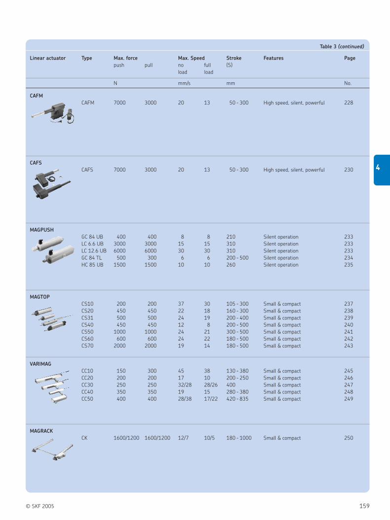
© SKF 2005 159
4
Linear actuator Type Max. force Max. Speed Stroke Features Page
push pull no full (S)
load load
N mm/s mm No.
CAFM
CAFM 7000 3000 20 13 50 - 300 High speed, silent, powerful 228
CAFS
CAFS 7000 3000 20 13 50 - 300 High speed, silent, powerful 230
MAGPUSH
GC 84 UB 400 400 8 8 210 Silent operation 233
LC 6.6 UB 3000 3000 15 15 310 Silent operation 233
LC 12.6 UB 6000 6000 30 30 310 Silent operation 233
GC 84 TL 500 300 6 6 200 - 500 Silent operation 234
HC 85 UB 1500 1500 10 10 260 Silent operation 235
MAGTOP
CS10 200 200 37 30 105 - 300 Small & compact 237
CS20 450 450 22 18 160 - 300 Small & compact 238
CS31 500 500 24 19 200 - 400 Small & compact 239
CS40 450 450 12 8 200 - 500 Small & compact 240
CS50 1000 1000 24 21 300 - 500 Small & compact 241
CS60 600 600 24 22 180 - 500 Small & compact 242
CS70 2000 2000 19 14 180 - 500 Small & compact 243
VARIMAG
CC10 150 300 45 38 130 - 380 Small & compact 245
CC20 200 200 17 10 200 - 250 Small & compact 246
CC30 250 250 32/28 28/26 400 Small & compact 247
CC40 350 350 19 15 280 - 380 Small & compact 248
CC50 400 400 28/38 17/22 420 - 835 Small & compact 249
MAGRACK
CK 1600/1200 1600/1200 12/7 10/5 180 - 1000 Small & compact 250
Table 3 (continued)

160 © SKF 2005
4 Actuation systems
Selection guide
Rotary actuators Type Max. Torque Max. Speed Size Features Page
Nm rpm mm No.
CRAB 17
CRAB 17 70 8 125 Compact 254
CRAB 17 105 20 125 Compact 254
CRAB 05
CRAB 05 100 3 86 Compact 257
Table 4
Control units Type Control Max. motor Input Output Page
connections
n° V V / A No.
KOM
KOM 1 Basic functions 4 230 / 120 24 / 6 259
KOM 2 Encoder processing 5 230 / 120 24 / 6 or 12 260
KOM 3 Basic functions 3 230 / 120 24 / 6 261
KOM 3T Basic functions 2 230 / 120 24 / 9 261
KOM 6 Encoder processing 4 230 / 120 24 / 6 or 12 262
MCU
MCU Basic functions 2 24 24 / 6 263
LD
LD-015 Encoder processing 2 230 / 120 24 / 10 264
LD-014 Encoder processing 4 230 / 120 24 / 12
SEM
SEM1 Basic functions 4 230 / 120 24 / 5 265
CAFC 04
M1 Encoder processing 1 230 / 120 40 / 6 266
M2 Encoder processing 2 230 / 120 40 / 6 266
M3 Encoder processing 3 230 / 120 40 / 6 266
Table 5
Continued

© SKF 2005 161
4
Control units Type Control Max. motor Input Output Page
connections
n° V V / A No.
CAFM
M1 Encoder processing 1 230 / 120 40 / 6 267
M2 Encoder processing 2 230 / 120 40 / 6 267
M3 Encoder processing 3 230 / 120 40 / 6 267
CAEN
15 Basic functions 1 230 24 / 15 267
10R Basic functions 1 230 / 120 24 / 1-10 268
CAEV
110/220 Basic functions 1 230 / 120 400 / 200 268
CAED ANR
5-24R - P O Encoder processing 1 22-28 24 / 5 268
9-24R - P O Encoder processing 1 22-28 24 / 9 268
CAED
3-24R Basic functions 1 24 24 / 3 269
5-24R Basic functions 1 24 24 / 5 269
9-24R Basic functions 1 24 24 / 9 269
CAEP
10P-SL Basic functions 1 230 24 / 2-10 269
8V Basic functions* 1 230 24 / 10 269
* Dimension of housing: 260 ×260 ×107 mm
CAEL
10-24R Basic functions 1 24DC/19AC 24 / 2-10 269
BCU
BCU Basic functions 3 230 / 120 24 / 7 270
Table 5 (continued)

162 © SKF 2005
4 Actuation systems
Selection guide
Hand switch Type Operating Max. operating Prot. class Colour Page
power motors
VDC / mA n° IP No.
EHA
EHA 1 12 / 50 4 67 Grey 272
EHA 2 12 / 50 5 67 Grey 273
EHA 3 12 / 50 4 67 Grey 274
IHA
IHA 1 – 5 67 Black 275
EHE
EHE 1 / 3 38 / 50 4 X7 Grey / black 276
EHE 6 38 / 50 5 X7 Grey 277
PHC
PHC – 4 66 Anthracite 278
CAFH
M1 40 / 50 1 X4 Grey / black 278
M2 40 / 50 2 X4 Grey / black 278
M3 40 / 50 3 X4 Grey / black 278
CAES
CAES 31B 30 / 33 1 54 Black 278
CAES 31C 30 / 33 1 54 Black 278
CAES 31D 30 / 33 1 54 Black 278
CAES 32D 30 / 33 2 54 Black 278
Table 6

© SKF 2005 163
4
Desk switch Type Operating Max. operating Prot. class Colour Page
Power motors
VDC / mA n° IP No.
ST
ST 12 / 50 3 X0 Black 283
LD
LD 5 / 50 2 32 Black 284
CAFH
T1 40 / 50 1 X4 Grey or black 285
T2 40 / 50 2 X4 Grey or black 285
Table 8
Foot switches Type Operating Max. operating Prot. class Colour Page
Power motors
VDC / mA n° IP No.
ST
ST 12 / 50 3 X5 Blue / anthracite 280
PFP
PFP1 – 1 21 Grey or anthracite 281
PFP2 – 2 21 Grey or anthracite 281
CAFHF
F1-DIN5 40 / 50 1 X4 Anthracite 281
F1-DIN7 40 / 50 1 X4 Anthracite 281
Table 7

164 © SKF 2005
4 Actuation systems
Selection guide/Combination matrix for actuators & controls
Junction box Type Operating Max. operating Prot. class Colour Page
Power motors
VDC / mA n° IP No.
CAFR
DIN5 40 / 50 2 X4 Grey 286
DIN7 40 / 50 2 X4 Grey 286
Easy3 Type Max. force Speed Stroke Features Page
push pull no load full load (S)
N mm/s mm No.
Easy3
02 600 600 23 12 50 - 200 In-line 288
03 2000 2000 12 8 100 - 300 Silent operation 288
04 2000 2000 12 8 100 - 300 Silent operation 289
05 2000 2000 12 8 100 - 300 Silent operation 289
10 7000 3000 7 4 100 - 200 Powerful & silent 290
11 7000 3000 7 4 100 - 200 Powerful & silent 290
12 7000 3000 7 4 100 - 200 Powerful & silent 291
13 7000 3000 7 4 100 - 200 Powerful & silent 291
Guiding tubes Type Section Stroke Page
(S)
2 3 mm No.
FRE
FRE x x 200 - 700 293
Table 10
Table 11
Table 12
Desk switch Type Max. operating motors Tube Colour Page
(pneumatic)
n° No.
PAM
PAM 1-130827 1 None Light grey 285
PAM 1-130659 1 2.65 m coiled Light grey 285
PAM 1-130256 1 1.50 m straight Anthracite 285
PAM 1-130966 1 3.00 m straight Anthracite 285
PAM 1-130348 1 2.65 m coiled Anthracite 285
Table 9

© SKF 2005 165
4
Combinations of actuators,
control units and operating unitsAre you looking for a complete system
including actuators, control units and
operating units?
A selection of control units and hand sets is
available for most actuators in this
catalogue.
PFP
PAM
PHC
LD-011 (DIN)
LD-011 (FCC)
STH (DSUB)
STG (DSUB)
STF (FCC)
STF (DSUB)
STC (DSUB)
STA (FCC)
STA (DSUB)
EHE6 (DSUB)
EHE1 (FCC)
EHA2 (DSUB)
EHA1 (DIN)
EHA1 (DSUB)
EHA3
IHA
CAFH
CAES 32D
CAES 31D
CAES 31B
CAES 31C
MAGRACK
VARIMAG
MAGTOP
MAGGEAR
ECOMAG
RUNNER
Telesmart, TMA/TMD
CRAB 17
CRAB 05
CAWA
CAFS
CAP 32
CAP 43
CARE33
Matrix, MAX3
Matrix, MAX1
CALA 36
CAR 40
CAR 32
CAR 22
CAT 32B
CAT 33/33H
CAT 21B
MAGFORCE
Telemag, TMS
Telesmart, TXG
Telemag, TLT
Telemag, TLG
Telemag, THG
Actuation systems
Act
uato
rsO
pera
ting u
nit
s
Plug and Play
Limitation
Customized
Control units
CAED
3-24R
CAED
5-24R
CAED
9-24R
CAEN
10R
CAEN
15
CAEV
110/2
20
CAEP
10P-S
L
CAED
AN
R
CAEL10-24R
CAFC04 M
1/M
2/M
3
CAEP
8V
KO
M1
KO
M2
KO
M3
KO
M3T
KO
M6
MCU
1
SEM
BCU
ZD
V-170250
LD
-014
LD
-015
Tele
mag, T
GC
(pneum
.)
Tele
mag, T
HC
(pneum
.)
Tele
mag, T
LC
(pneum
.)
Matr
ix, M
AX60/6
1
Matr
ix, M
AX62 t
o 6
5
MAG
PU
SH
Easy
3 K
its
Tele
smart
, TXG
CAFM
Runner
TM
A/T
MD

166 © SKF 2005
Notes

© SKF 2005 167
4
Telescopic pillars
TELEMAG
The TELEMAG line of telescopic pillars
features the best combination of minimum
retracted length and large stroke length
( figure 5). They are used wherever
robust and safe guiding systems are
needed.The attractive design allows
theTELEMAG to often become part of the
overall design of the equipment. The line of
TELEMAG actuators is complemented by
the KOM control units, which allow a
flexible and application focused system
control.
Benefits:
High offset load
Silent operation
Robust
Long life time
Figure 5
Type Force Max. Speed Stroke Retr. Length Voltage Protection Weight
push pull no full (S) (L)
load load
N mm/s mm mm V IP kg
TGC 8AWA 1000 1000 11 9 200 - 700 S + 145/150 120/230 AC 30 4.5 - 7.5
TGC 8AWD 1000 1000 11 9 300 - 700 S + 45/50 120/230 AC 30 5.9 - 9.5
THC 8AWA 1800 1800 15 12 200 - 700 S + 155/160 120/230 AC 30 7.9 - 13.5
THC 8AWD 1800 1800 15 12 230 - 700 S + 60/65 120/230 AC 30 8.6 - 17.5
TLC 12ZWA 4000 4000 16 11 100 - 700 S + 175/185 120/230 AC 30 15.2 - 24.5
TLC 12ZWD 4000 4000 16 11 255 - 700 S + 60/70 120/230 AC 30 18.3 - 30.5
THG 10/11-C 1000 0 15 12 200 - 700 S + 270/180 24 DC 30 8 - 14
TLT 10-C1 1000 0 36 25 300 - 700 S ×0.5 + 170 24 DC 40 15 - 30
TLG 10/11-C 1500 0 33 25 200 - 700 S + 180 24 DC 30 15 - 30
THG 10/11-B 2000 0 7 5 200 - 700 S + 270/180 24 DC 30 8 - 14
TLT 10-B1 2000 0 19 13 300 - 700 S ×0.5 + 170 24 DC 40 15 - 30
TLT 10/11-C2 2000 0 42 25 300 - 700 S ×0.5 + 240 24 DC 40 15 - 30
TLG 10/11-B 2500 0 17 13 200 - 700 S + 180 24 DC 30 15 - 30
TLT 10-A1 3000 0 16 11 300 - 700 S ×0.5 + 170 24 DC 40 15 - 30
TLG 10/11-A 4000 0 14 10 200 - 700 S + 180 24 DC 30 15 - 30
TLT 10/11-A2 4000 0 19 13 300 - 700 S ×0.5 + 240 24 DC 40 15 - 30

168 © SKF 2005
4 Actuation systems
Telescopic pillars
Type
Load /Speed:1000 N/11- 9 mm/s . . . . . . . . . . . . . . . . . . . . . . . . . . . . . . . . . . . . . . . . . . . . . . . . . . . . . . . . . . . . . . . . . . . . . . . A
Tube set:Tube set 2 × . . . . . . . . . . . . . . . . . . . . . . . . . . . . . . . . . . . . . . . . . . . . . . . . . . . . . . . . . . . . . . . . . . . . . . . . . . . . . . . . . . . . ATube set 3 × . . . . . . . . . . . . . . . . . . . . . . . . . . . . . . . . . . . . . . . . . . . . . . . . . . . . . . . . . . . . . . . . . . . . . . . . . . . . . . . . . . . . D
Control:Electrical control . . . . . . . . . . . . . . . . . . . . . . . . . . . . . . . . . . . . . . . . . . . . . . . . . . . . . . . . . . . . . . . . . . . . . . . . . . . . . . . . . . . . SPneumatic control. . . . . . . . . . . . . . . . . . . . . . . . . . . . . . . . . . . . . . . . . . . . . . . . . . . . . . . . . . . . . . . . . . . . . . . . . . . . . . . . . . . K
Motor voltage:230 V AC / 50 Hz. . . . . . . . . . . . . . . . . . . . . . . . . . . . . . . . . . . . . . . . . . . . . . . . . . . . . . . . . . . . . . . . . . . . . . . . . . . . . . . . . (no code)120 V AC / 60 Hz. . . . . . . . . . . . . . . . . . . . . . . . . . . . . . . . . . . . . . . . . . . . . . . . . . . . . . . . . . . . . . . . . . . . . . . . . . . . . . . . . . . . . . . 2
System of protection:Standard IP 30. . . . . . . . . . . . . . . . . . . . . . . . . . . . . . . . . . . . . . . . . . . . . . . . . . . . . . . . . . . . . . . . . . . . . . . . . . . . . . . . . . . . . (no code)UL approval . . . . . . . . . . . . . . . . . . . . . . . . . . . . . . . . . . . . . . . . . . . . . . . . . . . . . . . . . . . . . . . . . . . . . . . . . . . . . . . . . . . . . . . . . . . . . U
Construction:Push . . . . . . . . . . . . . . . . . . . . . . . . . . . . . . . . . . . . . . . . . . . . . . . . . . . . . . . . . . . . . . . . . . . . . . . . . . . . . . . . . . . . . . . . . . . . . . . . . . . . . . . . 0
Colour:Aluminium anodised . . . . . . . . . . . . . . . . . . . . . . . . . . . . . . . . . . . . . . . . . . . . . . . . . . . . . . . . . . . . . . . . . . . . . . . . . . . . . . . . . . . . . . . . . . . . . . 0
Stroke (S):200 mm (only for tube set 2 ×) . . . . . . . . . . . . . . . . . . . . . . . . . . . . . . . . . . . . . . . . . . . . . . . . . . . . . . . . . . . . . . . . . . . . . . . . . . . . . . . . . . . . . . . . 2300 mm . . . . . . . . . . . . . . . . . . . . . . . . . . . . . . . . . . . . . . . . . . . . . . . . . . . . . . . . . . . . . . . . . . . . . . . . . . . . . . . . . . . . . . . . . . . . . . . . . . . . . . . . . . 3400 mm . . . . . . . . . . . . . . . . . . . . . . . . . . . . . . . . . . . . . . . . . . . . . . . . . . . . . . . . . . . . . . . . . . . . . . . . . . . . . . . . . . . . . . . . . . . . . . . . . . . . . . . . . . 4500 mm . . . . . . . . . . . . . . . . . . . . . . . . . . . . . . . . . . . . . . . . . . . . . . . . . . . . . . . . . . . . . . . . . . . . . . . . . . . . . . . . . . . . . . . . . . . . . . . . . . . . . . . . . . 5600 mm . . . . . . . . . . . . . . . . . . . . . . . . . . . . . . . . . . . . . . . . . . . . . . . . . . . . . . . . . . . . . . . . . . . . . . . . . . . . . . . . . . . . . . . . . . . . . . . . . . . . . . . . . . 6700 mm . . . . . . . . . . . . . . . . . . . . . . . . . . . . . . . . . . . . . . . . . . . . . . . . . . . . . . . . . . . . . . . . . . . . . . . . . . . . . . . . . . . . . . . . . . . . . . . . . . . . . . . . . . 7
TELEMAG TGC
140
10
120
LS
76
10
140 120
85
97
Ordering key
Type code for accessories
TGC - 0 08 A W
TGC A S - 0U 0 58 A WExample:
— — —— — — ——— —
Legend:
S = stroke
L = retracted length
Type Force Max. speed Stroke Retr. Voltage Protection Weight
push pull no full Length
load load (S) (L)
N mm/s mm mm V AC IP kg
TGC 8AWA 1000 0 11 9 200 - 700 S + 145 120/230 30 4.5 - 7.5
TGC 8AWA 0 1000 11 9 200 - 700 S + 150 120/230 30 4.5 - 7.5
TGC 8AWD 1000 0 11 9 300 - 700 S + 45 120/230 30 5.9 - 9.5
TGC 8AWD 0 1000 11 9 300 - 700 S + 50 120/230 30 5.9 - 9.5
Accessories Order N°
Top mounting plate for 2 × tube set 964280
Bottom mounting plate for 2 × tube set 964281
Top mounting plate for 3 × tube set 964280
Bottom mounting plate for 3 × tube set 965121
Screw (4/plate) (not available for 3 × tube set, bottom plate) 510751
Screw (4/plate) only for 3 × tube set, bottom plate 510709
Lock washer (4/plate) 510024

© SKF 2005 169
4
TELEMAG THC
Type code for accessories
180
10L
S
150
97
10
180 150
113
129
Type
Load /Speed:1800 N/15 - 12 mm/s . . . . . . . . . . . . . . . . . . . . . . . . . . . . . . . . . . . . . . . . . . . . . . . . . . . . . . . . . . . . . . . . . . . . . . A
Tube set:Tube set 2 × . . . . . . . . . . . . . . . . . . . . . . . . . . . . . . . . . . . . . . . . . . . . . . . . . . . . . . . . . . . . . . . . . . . . . . . . . . . . . . . . . . . . ATube set 3 × . . . . . . . . . . . . . . . . . . . . . . . . . . . . . . . . . . . . . . . . . . . . . . . . . . . . . . . . . . . . . . . . . . . . . . . . . . . . . . . . . . . . D
Control:Electrical control . . . . . . . . . . . . . . . . . . . . . . . . . . . . . . . . . . . . . . . . . . . . . . . . . . . . . . . . . . . . . . . . . . . . . . . . . . . . . . . . . . . . SPneumatic control. . . . . . . . . . . . . . . . . . . . . . . . . . . . . . . . . . . . . . . . . . . . . . . . . . . . . . . . . . . . . . . . . . . . . . . . . . . . . . . . . . . K
Motor voltage:230 V AC / 50 Hz. . . . . . . . . . . . . . . . . . . . . . . . . . . . . . . . . . . . . . . . . . . . . . . . . . . . . . . . . . . . . . . . . . . . . . . . . . . . . . . . . (no code)120 V AC / 60 Hz. . . . . . . . . . . . . . . . . . . . . . . . . . . . . . . . . . . . . . . . . . . . . . . . . . . . . . . . . . . . . . . . . . . . . . . . . . . . . . . . . . . . . . . 2
System of protection:Standard IP 30. . . . . . . . . . . . . . . . . . . . . . . . . . . . . . . . . . . . . . . . . . . . . . . . . . . . . . . . . . . . . . . . . . . . . . . . . . . . . . . . . . . . . (no code)UL approval . . . . . . . . . . . . . . . . . . . . . . . . . . . . . . . . . . . . . . . . . . . . . . . . . . . . . . . . . . . . . . . . . . . . . . . . . . . . . . . . . . . . . . . . . . . . . U
Construction:Push . . . . . . . . . . . . . . . . . . . . . . . . . . . . . . . . . . . . . . . . . . . . . . . . . . . . . . . . . . . . . . . . . . . . . . . . . . . . . . . . . . . . . . . . . . . . . . . . . . . . . . . . 0
Colour:Aluminium anodised . . . . . . . . . . . . . . . . . . . . . . . . . . . . . . . . . . . . . . . . . . . . . . . . . . . . . . . . . . . . . . . . . . . . . . . . . . . . . . . . . . . . . . . . . . . . . . 0
Stroke (S):100 mm . . . . . . . . . . . . . . . . . . . . . . . . . . . . . . . . . . . . . . . . . . . . . . . . . . . . . . . . . . . . . . . . . . . . . . . . . . . . . . . . . . . . . . . . . . . . . . . . . . . . . . . . . . 1200 mm (only for tube set 2 ×) . . . . . . . . . . . . . . . . . . . . . . . . . . . . . . . . . . . . . . . . . . . . . . . . . . . . . . . . . . . . . . . . . . . . . . . . . . . . . . . . . . . . . . . . 2300 mm . . . . . . . . . . . . . . . . . . . . . . . . . . . . . . . . . . . . . . . . . . . . . . . . . . . . . . . . . . . . . . . . . . . . . . . . . . . . . . . . . . . . . . . . . . . . . . . . . . . . . . . . . . 3400 mm . . . . . . . . . . . . . . . . . . . . . . . . . . . . . . . . . . . . . . . . . . . . . . . . . . . . . . . . . . . . . . . . . . . . . . . . . . . . . . . . . . . . . . . . . . . . . . . . . . . . . . . . . . 4500 mm . . . . . . . . . . . . . . . . . . . . . . . . . . . . . . . . . . . . . . . . . . . . . . . . . . . . . . . . . . . . . . . . . . . . . . . . . . . . . . . . . . . . . . . . . . . . . . . . . . . . . . . . . . 5600 mm . . . . . . . . . . . . . . . . . . . . . . . . . . . . . . . . . . . . . . . . . . . . . . . . . . . . . . . . . . . . . . . . . . . . . . . . . . . . . . . . . . . . . . . . . . . . . . . . . . . . . . . . . . 6700 mm . . . . . . . . . . . . . . . . . . . . . . . . . . . . . . . . . . . . . . . . . . . . . . . . . . . . . . . . . . . . . . . . . . . . . . . . . . . . . . . . . . . . . . . . . . . . . . . . . . . . . . . . . . 7
Ordering key THC - 0 08 A W
— — —— — — ——— —
Legend:
S = stroke
L = retracted length
THC D S 2 - 0 0 48 A WExample:
Type Force Max. speed Stroke Retr. Voltage Protection Weight
push pull no full Length
load load (S) (L)
N mm/s mm mm V AC IP kg
THC 8AWA 1800 0 15 12 200 - 700 S + 155 120/230 30 7.9 - 13.5
THC 8AWA 0 1800 15 12 200 - 700 S + 160 120/230 30 7.9 - 13.5
THC 8AWD 1800 0 15 12 230 - 700 S + 60 120/230 30 8.6 - 17.5
THC 8AWD 0 1800 15 12 230 - 700 S + 65 120/230 30 8.6 - 17.5
Accessories Order N°
Top mounting plate for 2 × tube set 264265
Bottom mounting plate for 2 × tube set 264363
Top mounting plate for 3 × tube set 264265
Bottom mounting plate for 3 × tube set 264237
Screw (4/plate) for top mounting plate 510671
Screw (4/plate) for bottom mounting plate 510709
Plug AC Telemag 3p. 265518
Plug AC Telemag 5p. 265519

170 © SKF 2005
4 Actuation systems
Telescopic pillars
TELEMAG THG
180
10
150
97
10
180 150
113
129
LS
Ordering key
Type code for accessories
Type
Motor voltage:24 V DC . . . . . . . . . . . . . . . . . . . . . . . . . . . . . . . . . . . . . . . . . . . . . . . . . . . . . . . . . . . . . . . . . . . . . . . . . . . . . . . . . . 0
Load /Speed:2000 N / 7- 5 mm/s . . . . . . . . . . . . . . . . . . . . . . . . . . . . . . . . . . . . . . . . . . . . . . . . . . . . . . . . . . . . . . . . . . . . . . . . . . . . . . B
Tube set:Tube set 2 × . . . . . . . . . . . . . . . . . . . . . . . . . . . . . . . . . . . . . . . . . . . . . . . . . . . . . . . . . . . . . . . . . . . . . . . . . . . . . . . . . . . . . . . ATube set 3 × . . . . . . . . . . . . . . . . . . . . . . . . . . . . . . . . . . . . . . . . . . . . . . . . . . . . . . . . . . . . . . . . . . . . . . . . . . . . . . . . . . . . . . . D
Stroke (S):200 mm . . . . . . . . . . . . . . . . . . . . . . . . . . . . . . . . . . . . . . . . . . . . . . . . . . . . . . . . . . . . . . . . . . . . . . . . . . . . . . . . . . . . . . . . . . . . . 2300 mm . . . . . . . . . . . . . . . . . . . . . . . . . . . . . . . . . . . . . . . . . . . . . . . . . . . . . . . . . . . . . . . . . . . . . . . . . . . . . . . . . . . . . . . . . . . . . 3400 mm . . . . . . . . . . . . . . . . . . . . . . . . . . . . . . . . . . . . . . . . . . . . . . . . . . . . . . . . . . . . . . . . . . . . . . . . . . . . . . . . . . . . . . . . . . . . . 4500 mm . . . . . . . . . . . . . . . . . . . . . . . . . . . . . . . . . . . . . . . . . . . . . . . . . . . . . . . . . . . . . . . . . . . . . . . . . . . . . . . . . . . . . . . . . . . . . 5600 mm . . . . . . . . . . . . . . . . . . . . . . . . . . . . . . . . . . . . . . . . . . . . . . . . . . . . . . . . . . . . . . . . . . . . . . . . . . . . . . . . . . . . . . . . . . . . . 6700 mm . . . . . . . . . . . . . . . . . . . . . . . . . . . . . . . . . . . . . . . . . . . . . . . . . . . . . . . . . . . . . . . . . . . . . . . . . . . . . . . . . . . . . . . . . . . . . 7
Cable /connecting plug:Straight, 2.3 m, jack plug. . . . . . . . . . . . . . . . . . . . . . . . . . . . . . . . . . . . . . . . . . . . . . . . . . . . . . . . . . . . . . . . . . . . . . . . . . . . . . . . . . . 2Straight, 1.0 m, DIN8 plug . . . . . . . . . . . . . . . . . . . . . . . . . . . . . . . . . . . . . . . . . . . . . . . . . . . . . . . . . . . . . . . . . . . . . . . . . . . . . . . . . 3Straight, 2.3 m, DIN8 plug . . . . . . . . . . . . . . . . . . . . . . . . . . . . . . . . . . . . . . . . . . . . . . . . . . . . . . . . . . . . . . . . . . . . . . . . . . . . . . . . . 4Coiled, 0.6 m, DIN8 plug . . . . . . . . . . . . . . . . . . . . . . . . . . . . . . . . . . . . . . . . . . . . . . . . . . . . . . . . . . . . . . . . . . . . . . . . . . . . . . . . . . . B
Option:No option . . . . . . . . . . . . . . . . . . . . . . . . . . . . . . . . . . . . . . . . . . . . . . . . . . . . . . . . . . . . . . . . . . . . . . . . . . . . . . . . . . . . . . . . . . . . (no code)Encoder, 8 pulses /revolution . . . . . . . . . . . . . . . . . . . . . . . . . . . . . . . . . . . . . . . . . . . . . . . . . . . . . . . . . . . . . . . . . . . . . . . . . . . . . . . . . . 0Potentiometer, 1 kΩ, 2 Watt, 0.25% linearity, 10 turns (tube set 3 × only) . . . . . . . . . . . . . . . . . . . . . . . . . . . . . . . . . . . . . . . . . . . . . . . A
THG1 0 - - 0 0 0
Example:
— —B
THG1 0 - A 3 2 A - 0 0 0B
— — — ———–
Legend:
S = stroke
L = retracted length
Accessories Order N°
Top mounting plate for 2 × tube set 264265
Bottom mounting plate for 2 × tube set 264363
Top mounting plate for 3 × tube set 264265
Bottom mounting plate for 3 × tube set 264237
Screw (4/plate) for mounting plate (2 tube set) 510709
Screw (4/plate) for mounting plate (3 tube set) 510707
Type Force Max. speed Stroke Retr. Voltage Protection Weight
push pull no full Length
load load (S) (L)
N mm/s mm mm V DC IP kg
THG 10/11-BA 2000 0 7 5 200 - 700 S + 270 24 30 8 - 14
THG 10/11-BD 2000 0 7 5 200 - 700 S + 180 24 30 8 - 14

© SKF 2005 171
4
TELEMAG TLC
220
15
LS
200
129
15
220 200
146
163
Ordering key
Type code for accessories
Type
Load /Speed:4000 N/16 - 11 mm/s . . . . . . . . . . . . . . . . . . . . . . . . . . . . . . . . . . . . . . . . . . . . . . . . . . . . . . . . . . . . . . . . . . . . . . Z
Tube set:Tube set 2 × . . . . . . . . . . . . . . . . . . . . . . . . . . . . . . . . . . . . . . . . . . . . . . . . . . . . . . . . . . . . . . . . . . . . . . . . . . . . . . . . . . . . ATube set 3 × . . . . . . . . . . . . . . . . . . . . . . . . . . . . . . . . . . . . . . . . . . . . . . . . . . . . . . . . . . . . . . . . . . . . . . . . . . . . . . . . . . . . D
Control:Electrical control . . . . . . . . . . . . . . . . . . . . . . . . . . . . . . . . . . . . . . . . . . . . . . . . . . . . . . . . . . . . . . . . . . . . . . . . . . . . . . . . . . . . SPneumatic control. . . . . . . . . . . . . . . . . . . . . . . . . . . . . . . . . . . . . . . . . . . . . . . . . . . . . . . . . . . . . . . . . . . . . . . . . . . . . . . . . . . K
Motor voltage:230 V AC / 50 Hz . . . . . . . . . . . . . . . . . . . . . . . . . . . . . . . . . . . . . . . . . . . . . . . . . . . . . . . . . . . . . . . . . . . . . . . . . . . . . . . . (no code)120 V AC / 60 Hz . . . . . . . . . . . . . . . . . . . . . . . . . . . . . . . . . . . . . . . . . . . . . . . . . . . . . . . . . . . . . . . . . . . . . . . . . . . . . . . . . . . . . . 2
System of protection:Standard IP 30 . . . . . . . . . . . . . . . . . . . . . . . . . . . . . . . . . . . . . . . . . . . . . . . . . . . . . . . . . . . . . . . . . . . . . . . . . . . . . . . . . . . . (no code)UL approval . . . . . . . . . . . . . . . . . . . . . . . . . . . . . . . . . . . . . . . . . . . . . . . . . . . . . . . . . . . . . . . . . . . . . . . . . . . . . . . . . . . . . . . . . . . . . U
Construction:Push . . . . . . . . . . . . . . . . . . . . . . . . . . . . . . . . . . . . . . . . . . . . . . . . . . . . . . . . . . . . . . . . . . . . . . . . . . . . . . . . . . . . . . . . . . . . . . . . . . . . . . . . 0
Colour:Aluminium anodised . . . . . . . . . . . . . . . . . . . . . . . . . . . . . . . . . . . . . . . . . . . . . . . . . . . . . . . . . . . . . . . . . . . . . . . . . . . . . . . . . . . . . . . . . . . . . . 0
Stroke (S):100 mm, only for tube set 2 ×, push . . . . . . . . . . . . . . . . . . . . . . . . . . . . . . . . . . . . . . . . . . . . . . . . . . . . . . . . . . . . . . . . . . . . . . . . . . . . . . . . . . . . 1255 mm, only for tube set 3 ×, push . . . . . . . . . . . . . . . . . . . . . . . . . . . . . . . . . . . . . . . . . . . . . . . . . . . . . . . . . . . . . . . . . . . . . . . . . . . . . . . . . . . . 1200 mm, only for tube set 2 × . . . . . . . . . . . . . . . . . . . . . . . . . . . . . . . . . . . . . . . . . . . . . . . . . . . . . . . . . . . . . . . . . . . . . . . . . . . . . . . . . . . . . . . . . 2300 mm . . . . . . . . . . . . . . . . . . . . . . . . . . . . . . . . . . . . . . . . . . . . . . . . . . . . . . . . . . . . . . . . . . . . . . . . . . . . . . . . . . . . . . . . . . . . . . . . . . . . . . . . . . 3400 mm . . . . . . . . . . . . . . . . . . . . . . . . . . . . . . . . . . . . . . . . . . . . . . . . . . . . . . . . . . . . . . . . . . . . . . . . . . . . . . . . . . . . . . . . . . . . . . . . . . . . . . . . . . 4500 mm . . . . . . . . . . . . . . . . . . . . . . . . . . . . . . . . . . . . . . . . . . . . . . . . . . . . . . . . . . . . . . . . . . . . . . . . . . . . . . . . . . . . . . . . . . . . . . . . . . . . . . . . . . 5600 mm . . . . . . . . . . . . . . . . . . . . . . . . . . . . . . . . . . . . . . . . . . . . . . . . . . . . . . . . . . . . . . . . . . . . . . . . . . . . . . . . . . . . . . . . . . . . . . . . . . . . . . . . . . 6700 mm . . . . . . . . . . . . . . . . . . . . . . . . . . . . . . . . . . . . . . . . . . . . . . . . . . . . . . . . . . . . . . . . . . . . . . . . . . . . . . . . . . . . . . . . . . . . . . . . . . . . . . . . . . 7
TLC 12 Z W - 0
TLC 12 D KZ W - 0 0 7Example:
— — — — —— — ——––
Legend:
S = stroke
L = retracted length
Accessories Order N°
Top mounting plate for 2 × tube set 290268
Bottom mounting plate for 2 × tube set 290351
Top mounting plate for 3 × tube set 290268
Bottom mounting plate for 3 × tube set 290265
Screw (4/plate) for mounting plate 510707
Plug AC Telemag 3p. 265518
Plug AC Telemag 5p. 265519
Type Force Max. speed Stroke Retr. Voltage Protection Weight
push pull no full Length
load load (S) (L)
N mm/s mm mm V AC IP kg
TLC 12ZWA 4000 0 16 11 100 - 700 S + 175 120/230 30 15.2 - 24.5
TLC 12ZWA 0 4000 16 11 200 - 700 S + 185 120/230 30 15.2 - 24.5
TLC 12ZWD 4000 0 16 11 255 - 700 S + 60 120/230 30 18.3 - 30.5
TLC 12ZWD 0 4000 16 11 300 - 700 S + 70 120/230 30 18.3 - 30.5

172 © SKF 2005
4 Actuation systems
Telescopic pillars
TELEMAG TLG
220
15
LS
200
129
15
220 200
146
163
Ordering key
Type code for accessories
Type
Motor voltage:24 V DC . . . . . . . . . . . . . . . . . . . . . . . . . . . . . . . . . . . . . . . . . . . . . . . . . . . . . . . . . . . . . . . . . . . . . . . . . . . . . . . . . . . 0
Load /Speed:4000 N / 14 - 10 mm/s. . . . . . . . . . . . . . . . . . . . . . . . . . . . . . . . . . . . . . . . . . . . . . . . . . . . . . . . . . . . . . . . . . . . . . . . . . . . A2500 N / 17 - 13 mm/s . . . . . . . . . . . . . . . . . . . . . . . . . . . . . . . . . . . . . . . . . . . . . . . . . . . . . . . . . . . . . . . . . . . . . . . . . . . B1500 N / 34 - 25 mm/s . . . . . . . . . . . . . . . . . . . . . . . . . . . . . . . . . . . . . . . . . . . . . . . . . . . . . . . . . . . . . . . . . . . . . . . . . . . C
Tube set:Tube set 2 × . . . . . . . . . . . . . . . . . . . . . . . . . . . . . . . . . . . . . . . . . . . . . . . . . . . . . . . . . . . . . . . . . . . . . . . . . . . . . . . . . . . . . . . ATube set 3 × . . . . . . . . . . . . . . . . . . . . . . . . . . . . . . . . . . . . . . . . . . . . . . . . . . . . . . . . . . . . . . . . . . . . . . . . . . . . . . . . . . . . . . . D
Stroke (S):200 mm . . . . . . . . . . . . . . . . . . . . . . . . . . . . . . . . . . . . . . . . . . . . . . . . . . . . . . . . . . . . . . . . . . . . . . . . . . . . . . . . . . . . . . . . . . . . . 2300 mm . . . . . . . . . . . . . . . . . . . . . . . . . . . . . . . . . . . . . . . . . . . . . . . . . . . . . . . . . . . . . . . . . . . . . . . . . . . . . . . . . . . . . . . . . . . . . 3400 mm . . . . . . . . . . . . . . . . . . . . . . . . . . . . . . . . . . . . . . . . . . . . . . . . . . . . . . . . . . . . . . . . . . . . . . . . . . . . . . . . . . . . . . . . . . . . . 4500 mm . . . . . . . . . . . . . . . . . . . . . . . . . . . . . . . . . . . . . . . . . . . . . . . . . . . . . . . . . . . . . . . . . . . . . . . . . . . . . . . . . . . . . . . . . . . . . 5600 mm . . . . . . . . . . . . . . . . . . . . . . . . . . . . . . . . . . . . . . . . . . . . . . . . . . . . . . . . . . . . . . . . . . . . . . . . . . . . . . . . . . . . . . . . . . . . . 6700 mm . . . . . . . . . . . . . . . . . . . . . . . . . . . . . . . . . . . . . . . . . . . . . . . . . . . . . . . . . . . . . . . . . . . . . . . . . . . . . . . . . . . . . . . . . . . . . 7
Cable /connecting plug:Straight, 2.3 m, jack plug. . . . . . . . . . . . . . . . . . . . . . . . . . . . . . . . . . . . . . . . . . . . . . . . . . . . . . . . . . . . . . . . . . . . . . . . . . . . . . . . . . . 2Straight, 1.0 m, DIN8 plug . . . . . . . . . . . . . . . . . . . . . . . . . . . . . . . . . . . . . . . . . . . . . . . . . . . . . . . . . . . . . . . . . . . . . . . . . . . . . . . . . 3Straight, 2.3 m, DIN8 plug . . . . . . . . . . . . . . . . . . . . . . . . . . . . . . . . . . . . . . . . . . . . . . . . . . . . . . . . . . . . . . . . . . . . . . . . . . . . . . . . . 4Coiled, 0.6 m, DIN8 plug . . . . . . . . . . . . . . . . . . . . . . . . . . . . . . . . . . . . . . . . . . . . . . . . . . . . . . . . . . . . . . . . . . . . . . . . . . . . . . . . . . . B
Option:No option . . . . . . . . . . . . . . . . . . . . . . . . . . . . . . . . . . . . . . . . . . . . . . . . . . . . . . . . . . . . . . . . . . . . . . . . . . . . . . . . . . . . . . . . . . . . . . . . . 0Encoder, 8 pulses /revolution . . . . . . . . . . . . . . . . . . . . . . . . . . . . . . . . . . . . . . . . . . . . . . . . . . . . . . . . . . . . . . . . . . . . . . . . . . . . . . . . . . APotentiometer, 1 kΩ, 2 Watt, 0.25% linearity, 10 turns . . . . . . . . . . . . . . . . . . . . . . . . . . . . . . . . . . . . . . . . . . . . . . . . . . . . . . . . . . . . . . B
TLG1 0 - - 0 0 0
TLG1 0 - C A 6 2 A - 0 0 0Example:
— — — — — —–—––
Legend:
S = stroke
L = retracted length
Accessories Order N°
Top mounting plate for 2 × tube set 290268
Bottom mounting plate for 2 × tube set 290351
Top mounting plate for 3 × tube set 290268
Bottom mounting plate for 3 × tube set 290265
Screw (4/plate) for mounting plate 510707
Type Force Max. speed Stroke Retr. Voltage Protection Weight
push pull no full Length
load load (S) (L)
N mm/s mm mm V DC IP kg
TLG 10/11-A 4000 0 14 10 200 - 700 S + 180 24 30 15 - 30
TLG 10/11-B 2500 0 17 13 200 - 700 S + 180 24 30 15 - 30
TLG 10/11-C 1500 0 33 25 200 - 700 S + 180 24 30 15 - 30

© SKF 2005 173
4
TELEMAG TLT
220
15L
S
200
129
15
220 200
146
163
Ordering key
Type code for accessories
Type
Motor voltage:24 V DC. . . . . . . . . . . . . . . . . . . . . . . . . . . . . . . . . . . . . . . . . . . . . . . . . . . . . . . . . . . . . . . . . . . . . . . . . . . . . . . . . . . . 0
Load /Speed :4000 N / 19 - 13 mm/s . . . . . . . . . . . . . . . . . . . . . . . . . . . . . . . . . . . . . . . . . . . . . . . . . . . . . . . . . . . . . . . . . . . . . . . . . . . . A 23000 N / 16 - 11 mm/s . . . . . . . . . . . . . . . . . . . . . . . . . . . . . . . . . . . . . . . . . . . . . . . . . . . . . . . . . . . . . . . . . . . . . . . . . . . . A 12000 N / 19 - 13 mm/s . . . . . . . . . . . . . . . . . . . . . . . . . . . . . . . . . . . . . . . . . . . . . . . . . . . . . . . . . . . . . . . . . . . . . . . . . . . . B 12000 N / 45 - 25 mm/s . . . . . . . . . . . . . . . . . . . . . . . . . . . . . . . . . . . . . . . . . . . . . . . . . . . . . . . . . . . . . . . . . . . . . . . . . . . . C 21000 N / 36 - 25 mm/s. . . . . . . . . . . . . . . . . . . . . . . . . . . . . . . . . . . . . . . . . . . . . . . . . . . . . . . . . . . . . . . . . . . . . . . . . . . . . C 1
Stroke (S):300 mm . . . . . . . . . . . . . . . . . . . . . . . . . . . . . . . . . . . . . . . . . . . . . . . . . . . . . . . . . . . . . . . . . . . . . . . . . . . . . . . . . . . . . . . . . . . . . 3400 mm . . . . . . . . . . . . . . . . . . . . . . . . . . . . . . . . . . . . . . . . . . . . . . . . . . . . . . . . . . . . . . . . . . . . . . . . . . . . . . . . . . . . . . . . . . . . . 4500 mm . . . . . . . . . . . . . . . . . . . . . . . . . . . . . . . . . . . . . . . . . . . . . . . . . . . . . . . . . . . . . . . . . . . . . . . . . . . . . . . . . . . . . . . . . . . . . 5600 mm . . . . . . . . . . . . . . . . . . . . . . . . . . . . . . . . . . . . . . . . . . . . . . . . . . . . . . . . . . . . . . . . . . . . . . . . . . . . . . . . . . . . . . . . . . . . . 6700 mm . . . . . . . . . . . . . . . . . . . . . . . . . . . . . . . . . . . . . . . . . . . . . . . . . . . . . . . . . . . . . . . . . . . . . . . . . . . . . . . . . . . . . . . . . . . . . 7
Cable /connecting plug:Straight, 1.0 m, DIN8 plug . . . . . . . . . . . . . . . . . . . . . . . . . . . . . . . . . . . . . . . . . . . . . . . . . . . . . . . . . . . . . . . . . . . . . . . . . . . . . . . . . 3Straight, 2.3 m, DIN8 plug . . . . . . . . . . . . . . . . . . . . . . . . . . . . . . . . . . . . . . . . . . . . . . . . . . . . . . . . . . . . . . . . . . . . . . . . . . . . . . . . . 4Coiled, 0.6 m, DIN8 plug . . . . . . . . . . . . . . . . . . . . . . . . . . . . . . . . . . . . . . . . . . . . . . . . . . . . . . . . . . . . . . . . . . . . . . . . . . . . . . . . . . . B
Option:No option . . . . . . . . . . . . . . . . . . . . . . . . . . . . . . . . . . . . . . . . . . . . . . . . . . . . . . . . . . . . . . . . . . . . . . . . . . . . . . . . . . . . . . . . . . . . . . . . . 0Encoder, 8 pulses /revolution, only with jack plug . . . . . . . . . . . . . . . . . . . . . . . . . . . . . . . . . . . . . . . . . . . . . . . . . . . . . . . . . . . . . . . . . . A
TLT1 0 - - 0 0 0
TLT1 0 - B 1 5 1 A - 0 0 0Example:
— —— —— ———–
Legend:
S = stroke
L = retracted length
Accessories Order N°
Top mounting plate 290268
Bottom mounting 290265
Screw (4/plate) for mounting plate 510707
Type Force Max. speed Stroke Retr. Voltage Protection Weight
push pull no full Length
load load (S) (L)
N mm/s mm mm V DC IP kg
TLT10-A1 3000 0 16 11 300 - 700 0.5 ×S + 170 24 40 15 - 30
TLT10/11-A2 4000 0 19 13 300 - 700 0.5 ×S + 240 24 40 15 - 30
TLT10-B1 2000 0 19 13 300 - 700 0.5 ×S + 170 24 40 15 - 30
TLT10-C1 1000 0 36 25 300 - 700 0.5 ×S + 170 24 40 15 - 30
TLT10/11-C2 2000 0 42 25 300 - 700 0.5 ×S + 240 24 40 15 - 30

174 © SKF 2005
4 Actuation systems
Telescopic pillars
TMS
The TMS is a strong telescopic pillar
( figure 6) with an optimal stroke /
retracted length ratio for the lift of heavy
excentric loads.
The TMS is fast, silent and able to lift
400 kg centric load or 150 kg eccentric
load in a 2 m distance away from the pillar.
Benefits:
High offset load
Fast
Strong
Figure 6
Type Force Max. speed Stroke Retr. Length Voltage Protection Weight
push pull no full (S) (L)
load load
N mm/s mm mm V IP kg
EASY 4000 – 28 16 250 - 700 S ×0.5 + 176 24 SELV 64 - 85
MECHANICAL 4000 – – – 250 - 700 S ×0.5 + 176 – – 61 - 82

© SKF 2005 175
4
TMS EASY/MECHANICAL
Ordering key
Type
Voltage:No (mechanical). . . . . . . . . . . . . . . . . . . . . . . . . . . . . . . . . . . . . . . . . . . . . . . . . . . . . . . . . . . . . . . . . . . . . . . 024 V DC (easy) . . . . . . . . . . . . . . . . . . . . . . . . . . . . . . . . . . . . . . . . . . . . . . . . . . . . . . . . . . . . . . . . . . . . . . . . 1
Number of channels:Not used . . . . . . . . . . . . . . . . . . . . . . . . . . . . . . . . . . . . . . . . . . . . . . . . . . . . . . . . . . . . . . . . . . . . . . . . . . . . . . . 0
Connecting cable:Not used (mechanical) . . . . . . . . . . . . . . . . . . . . . . . . . . . . . . . . . . . . . . . . . . . . . . . . . . . . . . . . . . . . . . . . . . . . . . . . . 00Coiled, 1.5 m, jack plug (easy) . . . . . . . . . . . . . . . . . . . . . . . . . . . . . . . . . . . . . . . . . . . . . . . . . . . . . . . . . . . . . . . . . . . WR
Colour /Design:Not used . . . . . . . . . . . . . . . . . . . . . . . . . . . . . . . . . . . . . . . . . . . . . . . . . . . . . . . . . . . . . . . . . . . . . . . . . . . . . . . . . . . . . . . . 0
Options:None . . . . . . . . . . . . . . . . . . . . . . . . . . . . . . . . . . . . . . . . . . . . . . . . . . . . . . . . . . . . . . . . . . . . . . . . . . . . . . . . . . . . . . . . . . . . . . 000
Stroke (S):300 mm. . . . . . . . . . . . . . . . . . . . . . . . . . . . . . . . . . . . . . . . . . . . . . . . . . . . . . . . . . . . . . . . . . . . . . . . . . . . . . . . . . . . . . . . . . . . . . . . . . . 300400 mm. . . . . . . . . . . . . . . . . . . . . . . . . . . . . . . . . . . . . . . . . . . . . . . . . . . . . . . . . . . . . . . . . . . . . . . . . . . . . . . . . . . . . . . . . . . . . . . . . . . 400500 mm. . . . . . . . . . . . . . . . . . . . . . . . . . . . . . . . . . . . . . . . . . . . . . . . . . . . . . . . . . . . . . . . . . . . . . . . . . . . . . . . . . . . . . . . . . . . . . . . . . . 500600 mm. . . . . . . . . . . . . . . . . . . . . . . . . . . . . . . . . . . . . . . . . . . . . . . . . . . . . . . . . . . . . . . . . . . . . . . . . . . . . . . . . . . . . . . . . . . . . . . . . . . 600700 mm. . . . . . . . . . . . . . . . . . . . . . . . . . . . . . . . . . . . . . . . . . . . . . . . . . . . . . . . . . . . . . . . . . . . . . . . . . . . . . . . . . . . . . . . . . . . . . . . . . . 700
TMS 0 0 000 -- 00
TMS ZR1 0 0 000 -- 600 00Example:
— — —– ––—––———––

Figure 7
176 © SKF 2005
4 Actuation systems
Telescopic pillars
TELESMART
This cost effective telescopic pillar offers an
attractive design for height adjustable
desks, tables, chairs and lightweight
industrial workstations ( figure 7).
The TXG series has an integrated control
unit and combines the advantages of AC
and DC power. The TMA & TMD series are
very stylish and ideal for office
environment.
The pillars can be controlled by using
desk, hand or foot switches.
Benefits:
Easy plug and play system
Powerful and fast lifting
Attractive design
Cost effective
Type Force Max. speed Stroke Retr. Length Voltage Protection Weight
push pull no full (S) (L)
load load
N mm/s mm mm V IP kg
TMD 800 0 60 35 700 550 24 DC 20 8.5
TMA 1000 0 55 35 500 640 24 DC 20 8
TXG 1 1500 0 23 17 200 - 600 S + 160/180 24 DC 30 8 - 13
TXG 4/5 1500 0 23 17 200 - 600 S + 160/180 120 AC 30 9 - 14
TXG 8/9 1500 0 23 17 200 - 600 S + 160/180 230 AC 30 9 - 14

© SKF 2005 177
4
TELESMART TMD
60
550
16
134 30
200
Ordering key
Type code for accessories
Type
Voltage:24 V DC . . . . . . . . . . . . . . . . . . . . . . . . . . . . . . . . . . . . . . . . . . . . . . . . . . . . . . . . . . . . . . . . . . . . . . . . . . . . . 1
Number of channels:Not used . . . . . . . . . . . . . . . . . . . . . . . . . . . . . . . . . . . . . . . . . . . . . . . . . . . . . . . . . . . . . . . . . . . . . . . . . . . . . . . 0
Connecting cable:None. . . . . . . . . . . . . . . . . . . . . . . . . . . . . . . . . . . . . . . . . . . . . . . . . . . . . . . . . . . . . . . . . . . . . . . . . . . . . . . . . . . . . . . 0 0
Colour /Design:Natural anodized coating . . . . . . . . . . . . . . . . . . . . . . . . . . . . . . . . . . . . . . . . . . . . . . . . . . . . . . . . . . . . . . . . . . . . . . . . . . . . 5Black anodized coating . . . . . . . . . . . . . . . . . . . . . . . . . . . . . . . . . . . . . . . . . . . . . . . . . . . . . . . . . . . . . . . . . . . . . . . . . . . . . . 6
Options:With flange for crossbar one side . . . . . . . . . . . . . . . . . . . . . . . . . . . . . . . . . . . . . . . . . . . . . . . . . . . . . . . . . . . . . . . . . . . . . . . EWYWith flange for crossbar two sides . . . . . . . . . . . . . . . . . . . . . . . . . . . . . . . . . . . . . . . . . . . . . . . . . . . . . . . . . . . . . . . . . . . . . . 2CMNo flange for crossbar . . . . . . . . . . . . . . . . . . . . . . . . . . . . . . . . . . . . . . . . . . . . . . . . . . . . . . . . . . . . . . . . . . . . . . . . . . . . . . . . 2CN
Stroke / Retracted length:Stroke (S) = 700 mm, Retracted length (L) = 550 mm . . . . . . . . . . . . . . . . . . . . . . . . . . . . . . . . . . . . . . . . . . . . . . . . . . . . . . . . . . . . . . 700
TMD 1 0 - 0 0 - 0 0700
TMD 1 0 - 0 0 5 2CM - 0 0700Example:
— — —— ——–– —— ——
Accessories Order N°
Cable 1.0 m with DIN8-plug 306355-1000
Cable 1.5 m with DIN8-plug 306355-1500
Cable 2.5 m with DIN8-plug 306355-2500
Type Force Max. speed Stroke Retr. Voltage Protection Weight
push pull no full Length
load load (S) (L)
N mm/s mm mm V DC IP kg
TMD 800 0 60 35 700 550 24 20 8.5

178 © SKF 2005
4 Actuation systems
Telescopic pillars
TELESMART TMA
640
200
30
16
134
60
Ordering key
Type code for accessories
Type
Voltage:24 V DC . . . . . . . . . . . . . . . . . . . . . . . . . . . . . . . . . . . . . . . . . . . . . . . . . . . . . . . . . . . . . . . . . . . . . . . . . . . . . 1
Number of channels:Not used . . . . . . . . . . . . . . . . . . . . . . . . . . . . . . . . . . . . . . . . . . . . . . . . . . . . . . . . . . . . . . . . . . . . . . . . . . . . . . . 0
Connecting cable:None. . . . . . . . . . . . . . . . . . . . . . . . . . . . . . . . . . . . . . . . . . . . . . . . . . . . . . . . . . . . . . . . . . . . . . . . . . . . . . . . . . . . . . . 0 0
Colour /Design:Natural anodized coating . . . . . . . . . . . . . . . . . . . . . . . . . . . . . . . . . . . . . . . . . . . . . . . . . . . . . . . . . . . . . . . . . . . . . . . . . . . . 5Black anodized coating . . . . . . . . . . . . . . . . . . . . . . . . . . . . . . . . . . . . . . . . . . . . . . . . . . . . . . . . . . . . . . . . . . . . . . . . . . . . . . 6
Options:With flange for crossbar one side . . . . . . . . . . . . . . . . . . . . . . . . . . . . . . . . . . . . . . . . . . . . . . . . . . . . . . . . . . . . . . . . . . . . . . . EWYWith flange for crossbar two sides . . . . . . . . . . . . . . . . . . . . . . . . . . . . . . . . . . . . . . . . . . . . . . . . . . . . . . . . . . . . . . . . . . . . . . 2CMNo flange for crossbar . . . . . . . . . . . . . . . . . . . . . . . . . . . . . . . . . . . . . . . . . . . . . . . . . . . . . . . . . . . . . . . . . . . . . . . . . . . . . . . . 2CN
Stroke / Retracted length:Stroke (S) = 500 mm, Retracted length (L) = 640 mm . . . . . . . . . . . . . . . . . . . . . . . . . . . . . . . . . . . . . . . . . . . . . . . . . . . . . . . . . . . . . . 500
TMA 1 0 - 0 0 - 0 0500
TMA 1 0 - 0 0 5 2CM - 0 0500Example:
— — —— ——— —— ——
Accessories Order N°
Cable 1.0 m with DIN8-plug 306355-1000
Cable 1.5 m with DIN8-plug 306355-1500
Cable 2.5 m with DIN8-plug 306355-2500
Type Force Max. speed Stroke Retr. Voltage Protection Weight
push pull no full Length
load load (S) (L)
N mm/s mm mm V DC IP kg
TMA 1000 0 55 35 500 640 24 20 8

© SKF 2005 179
4
TELESMART TXG
10
150 220
SL
10
150220
140
180
120
Ordering key
Type code for accessories
Type
Motor voltage:24 V DC . . . . . . . . . . . . . . . . . . . . . . . . . . . . . . . . . . . . . . . . . . . . . . . . . . . . . . . . . . . . . . . . . . . . . . . . . . . . . 1120 V AC, 50/60 Hz, class II . . . . . . . . . . . . . . . . . . . . . . . . . . . . . . . . . . . . . . . . . . . . . . . . . . . . . . . . . . . . . 4120 V AC, 50/60 Hz, class I (mandatory for cable feedthrough) . . . . . . . . . . . . . . . . . . . . . . . . . . . . . . . . . . 5230 V AC, 50 Hz, class II . . . . . . . . . . . . . . . . . . . . . . . . . . . . . . . . . . . . . . . . . . . . . . . . . . . . . . . . . . . . . . . . 8230 V AC, 50 Hz, class I (mandatory for cable feedthrough) . . . . . . . . . . . . . . . . . . . . . . . . . . . . . . . . . . . . . 9
Output for an additional DC-Motor:Not used (Stand alone) . . . . . . . . . . . . . . . . . . . . . . . . . . . . . . . . . . . . . . . . . . . . . . . . . . . . . . . . . . . . . . . . . . . . 024 V DC (Master, not available for TXG1) . . . . . . . . . . . . . . . . . . . . . . . . . . . . . . . . . . . . . . . . . . . . . . . . . . . . . . 1
Cable /connecting plug:Not used . . . . . . . . . . . . . . . . . . . . . . . . . . . . . . . . . . . . . . . . . . . . . . . . . . . . . . . . . . . . . . . . . . . . . . . . . . . . . . . . . . . . 0 0
Colour:Colourless anodised . . . . . . . . . . . . . . . . . . . . . . . . . . . . . . . . . . . . . . . . . . . . . . . . . . . . . . . . . . . . . . . . . . . . . . . . . . . . . . . . 5
Options: (*24 V DC only, **230/120 V AC only)None . . . . . . . . . . . . . . . . . . . . . . . . . . . . . . . . . . . . . . . . . . . . . . . . . . . . . . . . . . . . . . . . . . . . . . . . . . . . . . . . . . . . . . . . . . . . 0 0 0Control connection feedthrough **. . . . . . . . . . . . . . . . . . . . . . . . . . . . . . . . . . . . . . . . . . . . . . . . . . . . . . . . . . . . . . . . . . . . . E Y XMains cable feedthrough ** . . . . . . . . . . . . . . . . . . . . . . . . . . . . . . . . . . . . . . . . . . . . . . . . . . . . . . . . . . . . . . . . . . . . . . . . . . E Y FEncoder for TXG * . . . . . . . . . . . . . . . . . . . . . . . . . . . . . . . . . . . . . . . . . . . . . . . . . . . . . . . . . . . . . . . . . . . . . . . . . . . . . . . . . . E Y SEncoder for other controls* . . . . . . . . . . . . . . . . . . . . . . . . . . . . . . . . . . . . . . . . . . . . . . . . . . . . . . . . . . . . . . . . . . . . . . . . . . E X GRetract, memory** . . . . . . . . . . . . . . . . . . . . . . . . . . . . . . . . . . . . . . . . . . . . . . . . . . . . . . . . . . . . . . . . . . . . . . . . . . . . . . . . . 2 C AControl connection feedthrough**, mains cable feedthrough** . . . . . . . . . . . . . . . . . . . . . . . . . . . . . . . . . . . . . . . . . . . . . . 2 A ARetract, memory**, mains cable feedthrough** . . . . . . . . . . . . . . . . . . . . . . . . . . . . . . . . . . . . . . . . . . . . . . . . . . . . . . . . . . 3 A WControl connection feedthrough **, retract, memory**. . . . . . . . . . . . . . . . . . . . . . . . . . . . . . . . . . . . . . . . . . . . . . . . . . . . . 3 A YControl connection feedthrough **, retract, memory**, mains cable feedthrough** . . . . . . . . . . . . . . . . . . . . . . . . . . . . . . 4 A GExtend, retract, memory**, parallel operation of 2 actuators** . . . . . . . . . . . . . . . . . . . . . . . . . . . . . . . . . . . . . . . . . . . . . . 4 A LExtend, retract, memory**, parallel operation of 2 actuators**, mains cable feedthrough ** . . . . . . . . . . . . . . . . . . . . . . . 5 A AExtend, retract, memory**, parallel operation of 2 actuators**, control connection feedthrough ** . . . . . . . . . . . . . . . . . . 5 A CExtend, retract, memory**, parallel operation of 2 actuators**, control/mains cable feedthrough ** . . . . . . . . . . . . . . . . . 6 A A
Stroke (S) / Retr. Length (L = S +180 or 160 mm): L=S+180 L=S+160
200 mm . . . . . . . . . . . . . . . . . . . . . . . . . . . . . . . . . . . . . . . . . . . . . . . . . . . . . . . . . . . . . . . . . . . . . . . . . . . . . . . . . . . . . . . . . 2 0 0 . . . . 4CY300 mm . . . . . . . . . . . . . . . . . . . . . . . . . . . . . . . . . . . . . . . . . . . . . . . . . . . . . . . . . . . . . . . . . . . . . . . . . . . . . . . . . . . . . . . . . 3 0 0 . . . . 4DY400 mm . . . . . . . . . . . . . . . . . . . . . . . . . . . . . . . . . . . . . . . . . . . . . . . . . . . . . . . . . . . . . . . . . . . . . . . . . . . . . . . . . . . . . . . . . 4 0 0 . . . . 4EY500 mm . . . . . . . . . . . . . . . . . . . . . . . . . . . . . . . . . . . . . . . . . . . . . . . . . . . . . . . . . . . . . . . . . . . . . . . . . . . . . . . . . . . . . . . . . 5 0 0. . . . . 4FY600 mm . . . . . . . . . . . . . . . . . . . . . . . . . . . . . . . . . . . . . . . . . . . . . . . . . . . . . . . . . . . . . . . . . . . . . . . . . . . . . . . . . . . . . . . . . 6 0 0 . . . . 4GY
TXG - 0 0 5 - 0 0
TXG 5 1 - 0 0 5 2AA - 0 0300Example:
— — —— ——— —— ——
Legend:
S = stroke
L = retracted length
Mains cable Plug Country Order N° Comment
Straight cable 3.5 m Euro General 304330 2-poles
Straight cable 3.5 m Schuko DE 304331 2-poles
Straight cable 3.5 m UL USA 304332 2-poles
Straight cable 3.5 m British standard UK 304333 2-poles
Top or bottom
mounting plate 304338
Type Force Max. speed Stroke Retr. Voltage Protection Weight
push pull no full Length
load load (S) (L)
N mm/s mm mm V IP kg
TXG 1 1500 0 23 17 200 - 600 S + 180/160 24 DC 30 8 - 13
TXG 4/5 1500 0 23 17 200 - 600 S + 180/160 120 AC 30 9 - 14
TXG 8/9 1500 0 23 17 200 - 600 S + 180/160 230 AC 30 9 - 14

180 © SKF 2005
4 Actuation systems
Telescopic pillars
MAGGEAR
With a stroke of 200 mm the MAGGEAR
( figure 8) is especially suitable to adjust
sit-sit workstations. Consisting of a small,
strong 24 VDC motor, a gear with spindle
and a push tube, the MAGGEAR can directly
be integrated into most table legs.
Benefits:
Small and slim
In-line layout
Low cost
32 1210
R10
S + 22
L = S + 76
22
130.5
67,4
33
39
24
3212
M5
Legend:
S = stroke
L = retracted length
Ordering key
Type
Load / Speed / Stroke (S):800 N (push) / 8 mm/s / 200 mm . . . . . . . . . . . . . . . . . . . . . . . . . . . . . . . . . . . . . . . . . . . . . . . . . . . . . . . . . . . . . . . . . . . . . . . . . . 8 1 5 2 0 1
E T E - 2 0 18 1 5
—— –––––——
Figure 8
Type Force Max. speed Stroke Retr. Length Voltage Protection Weight
push pull no full (S) (L)
load load
N mm/s mm mm V DC IP kg
ETE 800 200 8 8 200 S + 76 24 X0 1.0

© SKF 2005 181
4
Notes

182 © SKF 2005
4 Actuation systems
Linear actuators
Linear actuators
CAT
The CAT ( figure 9) modular design
concept makes it easy to interchange
critical components such as motors, gears,
screws, attachments, etc. Custom built
actuators are easily and cost efficiently built
from standard parts. The CAT range
flexibility makes it suitable for an infinite
number of applications.
Benefits:
Small
Robust
Highly efficient
Maintenance-free
Figure 9
Type Force Max. speed Stroke Retr. Length* Voltage Protection Weight
push pull no load full load (S) (L)
N mm/s mm mm V IP kg
CAT 21B 600 600 10 5 50 - 300 S + 100 12 / 24 DC X4 0.7 - 1.5
CAT 33H 1200 1200 174 150 100 - 400 S + 150 / 158 / 189 12 / 24 DC 20 / 44 / 54 / 65 2 - 2.7
120 / 230 / 400 AC
CAT 33 3000 3000 48 38 100 - 400 S + 150 / 158 / 189 12 / 24 DC 20 / 44 / 54 / 65 2 - 2.7
120 / 230 / 400 AC
CAT 32B 4000 4000 67 50 50 - 700 S + 167 / 175 / 206 12 / 24 DC 20 / 44 / 54 / 65 2 - 3.5
120 / 230 / 400 AC
* Dimension depends on selected front attachment

© SKF 2005 183
4
L=S+100
8
ø22
ø45
28.5 9.5
75.5
88
12.5
12 33
25
G1 / G2 K1 / K2CAT 21B
Ordering key
Type
Motor assembly:Right. . . . . . . . . . . . . . . . . . . . . . . . . . . . . . . . . . . . . . . . . . . . . . . . . . . . . . . . . . . . . . . . . . RLeft . . . . . . . . . . . . . . . . . . . . . . . . . . . . . . . . . . . . . . . . . . . . . . . . . . . . . . . . . . . . . . . . . . . L
Stroke (S):50 mm . . . . . . . . . . . . . . . . . . . . . . . . . . . . . . . . . . . . . . . . . . . . . . . . . . . . . . . . . . . . . . . . . . . . . . . . . 0 5 0
100 mm . . . . . . . . . . . . . . . . . . . . . . . . . . . . . . . . . . . . . . . . . . . . . . . . . . . . . . . . . . . . . . . . . . . . . . . . . 1 0 0200 mm . . . . . . . . . . . . . . . . . . . . . . . . . . . . . . . . . . . . . . . . . . . . . . . . . . . . . . . . . . . . . . . . . . . . . . . . . 2 0 0300 mm . . . . . . . . . . . . . . . . . . . . . . . . . . . . . . . . . . . . . . . . . . . . . . . . . . . . . . . . . . . . . . . . . . . . . . . . . 3 0 00 < S < 300 mm (S > 300 mm contact SKF) . . . . . . . . . . . . . . . . . . . . . . . . . . . . . . . . . . . . . . . . . . . . . - - -
Rear attachments:Single ear, hole diameter 6.35 mm . . . . . . . . . . . . . . . . . . . . . . . . . . . . . . . . . . . . . . . . . . . . . . . . . . . . . . . . . . . . . . . K 1Single ear, hole diameter 8 mm . . . . . . . . . . . . . . . . . . . . . . . . . . . . . . . . . . . . . . . . . . . . . . . . . . . . . . . . . . . . . . . . . . K 2
Front attachment:Hole diameter 6.35 mm . . . . . . . . . . . . . . . . . . . . . . . . . . . . . . . . . . . . . . . . . . . . . . . . . . . . . . . . . . . . . . . . . . . . . . . . . . . . G1Hole diameter 8 mm. . . . . . . . . . . . . . . . . . . . . . . . . . . . . . . . . . . . . . . . . . . . . . . . . . . . . . . . . . . . . . . . . . . . . . . . . . . . . . . G2
Options:No friction clutch . . . . . . . . . . . . . . . . . . . . . . . . . . . . . . . . . . . . . . . . . . . . . . . . . . . . . . . . . . . . . . . . . . . . . . . . . . . . . . . . . . . . . . . Z
Motor options:12 V DC. . . . . . . . . . . . . . . . . . . . . . . . . . . . . . . . . . . . . . . . . . . . . . . . . . . . . . . . . . . . . . . . . . . . . . . . . . . . . . . . . . . . . . . . . . . . . . . . . . . G12C24 V DC . . . . . . . . . . . . . . . . . . . . . . . . . . . . . . . . . . . . . . . . . . . . . . . . . . . . . . . . . . . . . . . . . . . . . . . . . . . . . . . . . . . . . . . . . . . . . . . . . . G24C
Options motors:Cable, 1.6 m, with plug (jack plug, 1/4" 2-pole) . . . . . . . . . . . . . . . . . . . . . . . . . . . . . . . . . . . . . . . . . . . . . . . . . . . . . . . . . . . . . . . . . . . . . . . . . . . . PCable, 1.6 m, no plug . . . . . . . . . . . . . . . . . . . . . . . . . . . . . . . . . . . . . . . . . . . . . . . . . . . . . . . . . . . . . . . . . . . . . . . . . . . . . . . . . . . . . . . . . . . . . . . . TMotor without cover . . . . . . . . . . . . . . . . . . . . . . . . . . . . . . . . . . . . . . . . . . . . . . . . . . . . . . . . . . . . . . . . . . . . . . . . . . . . . . . . . . . . . . . . . . . . . . . . . NEncoder . . . . . . . . . . . . . . . . . . . . . . . . . . . . . . . . . . . . . . . . . . . . . . . . . . . . . . . . . . . . . . . . . . . . . . . . . . . . . . . . . . . . . . . . . . . . . . . . . . . . . . . . . . . E
Example:
CAT 21B Z /××— —
1
–——–—– –—– —–
CAT R 21B Z /×× G1 G24C T1 K1200
—– —
Legend:
S = stroke
L = retracted length
Type Force Max. speed Stroke Retr. Length Voltage Protection Weight
push pull no load full load (S) (L)
N mm/s mm mm V DC IP kg
CAT 21B 600 600 10 5 50 - 300 S + 100 12 / 24 X4 0.7 - 1.5

184 © SKF 2005
4 Actuation systems
Linear actuators
CAT33H
See drawings of front and rear attachments
and motor options on page 190
L=S+ (150/158/189)*
73
24
55
29
23
Legend:
S = stroke
L = retracted length
Type Force Max. speed Stroke Retr. Length* Voltage Protection Weight
push pull no load full load (S) (L)
N mm/s mm mm V IP kg
CAT 33H 1200 1200 174 150 100 - 400 S + 150 / 158 / 189 12 / 24 DC 20 / 44 / 54 / 65 2 - 2.7
120 / 230 / 400 AC
* Dimension depends on selected front attachment

© SKF 2005 185
4
Dynamic load (N)/ Speed (mm/s) Motor options
1200/xx 900/xx 600/xx No motor 00001000/50-38 600/100-80 400/174-150 12 V DC, IP44 (65) C12C1000/50-38 600/100-80 400/174-150 12 V DC, flat motor, IP44 D12C1200/56-36 900/113-79 500/174-140 24 V DC, IP44 (65) C24C1200/27-17 800/60-35 500/100-69 24 V DC, low speed, IP44 (65) C24CW1200/56-36 900/113-79 500/174-140 24 V DC, flat motor, IP44 D24C1200/56-36 900/113-79 500/174-140 24 V DC, flat motor, brake, IP20 D24CB1200/56-36 900/113-79 500/174-140 24 V DC, flat motor, ext. shaft, IP44 D24CS1200/27-17 800/60-35 500/100-69 24 V DC, flat motor, low speed, IP44 D24CW1200/20 900/37 600/90 120 V AC/60 Hz, brake, IP54 E110C (25 mF)1200/20 900/37 600/90 120 V AC/60 Hz, brake, IP20 E110CB (25 mF)1200/20 900/37 600/90 230 V AC/50 Hz, IP54 E220C1200/20 900/37 600/90 230 V AC/50 Hz, brake, IP20 E220CB1200/20 900/37 600/90 230 V AC/50 Hz, IP54 E380C
1 2 4
Example:
Ordering key
Type
Motor assembly:Right . . . . . . . . . . . . . . . . . . . . . . . . . . . . . . . . . . . . . . . . . . . . . . . . . . . . . . . . . RLeft. . . . . . . . . . . . . . . . . . . . . . . . . . . . . . . . . . . . . . . . . . . . . . . . . . . . . . . . . . . L
Stroke (S):100 mm . . . . . . . . . . . . . . . . . . . . . . . . . . . . . . . . . . . . . . . . . . . . . . . . . . . . . . . . . . . . . . . . 1 0 0200 mm . . . . . . . . . . . . . . . . . . . . . . . . . . . . . . . . . . . . . . . . . . . . . . . . . . . . . . . . . . . . . . . . 2 0 0300 mm . . . . . . . . . . . . . . . . . . . . . . . . . . . . . . . . . . . . . . . . . . . . . . . . . . . . . . . . . . . . . . . . 3 0 0400 mm . . . . . . . . . . . . . . . . . . . . . . . . . . . . . . . . . . . . . . . . . . . . . . . . . . . . . . . . . . . . . . . . 4 0 0100 < S < 400 mm (S > 400 mm contact SKF) . . . . . . . . . . . . . . . . . . . . . . . . . . . . . . . . . . - - -
Rear attachment (see page 190):Fork ear, Ø 12.0 mm . . . . . . . . . . . . . . . . . . . . . . . . . . . . . . . . . . . . . . . . . . . . . . . . . . . . . . . . . . . . . . . . . . A 1Fork ear, Ø 12.7 mm . . . . . . . . . . . . . . . . . . . . . . . . . . . . . . . . . . . . . . . . . . . . . . . . . . . . . . . . . . . . . . . . . . A 2Single ear, Ø 12.0 mm . . . . . . . . . . . . . . . . . . . . . . . . . . . . . . . . . . . . . . . . . . . . . . . . . . . . . . . . . . . . . . . . K 1Single ear, Ø 12.7 mm . . . . . . . . . . . . . . . . . . . . . . . . . . . . . . . . . . . . . . . . . . . . . . . . . . . . . . . . . . . . . . . . K 2
Front attachment (see page 190):Hole, Ø 12.0 mm . . . . . . . . . . . . . . . . . . . . . . . . . . . . . . . . . . . . . . . . . . . . . . . . . . . . . . . . . . . . . . . . . . . . . . . . . G1Hole, Ø 12.7 mm . . . . . . . . . . . . . . . . . . . . . . . . . . . . . . . . . . . . . . . . . . . . . . . . . . . . . . . . . . . . . . . . . . . . . . . . . G2Male thread, M12 . . . . . . . . . . . . . . . . . . . . . . . . . . . . . . . . . . . . . . . . . . . . . . . . . . . . . . . . . . . . . . . . . . . . . . . . . G3Female thread, M12 . . . . . . . . . . . . . . . . . . . . . . . . . . . . . . . . . . . . . . . . . . . . . . . . . . . . . . . . . . . . . . . . . . . . . . . G4Fork ear, Ø = 10.1 mm. . . . . . . . . . . . . . . . . . . . . . . . . . . . . . . . . . . . . . . . . . . . . . . . . . . . . . . . . . . . . . . . . . . . . G5
Feed back:Encoder . . . . . . . . . . . . . . . . . . . . . . . . . . . . . . . . . . . . . . . . . . . . . . . . . . . . . . . . . . . . . . . . . . . . . . . . . . . . . . . (no code)Encoder (ony for CxxC motors) . . . . . . . . . . . . . . . . . . . . . . . . . . . . . . . . . . . . . . . . . . . . . . . . . . . . . . . . . . . . . . . . . . . . EEncoder (for all standard motors). . . . . . . . . . . . . . . . . . . . . . . . . . . . . . . . . . . . . . . . . . . . . . . . . . . . . . . . . . . . . . . . . E2
Options:Friction clutch . . . . . . . . . . . . . . . . . . . . . . . . . . . . . . . . . . . . . . . . . . . . . . . . . . . . . . . . . . . . . . . . . . . . . . . . . . . . . . . . . . . . FNo friction clutch . . . . . . . . . . . . . . . . . . . . . . . . . . . . . . . . . . . . . . . . . . . . . . . . . . . . . . . . . . . . . . . . . . . . . . . . . . . . . . . . . . Z
Options for CxxC motors:No cable. . . . . . . . . . . . . . . . . . . . . . . . . . . . . . . . . . . . . . . . . . . . . . . . . . . . . . . . . . . . . . . . . . . . . . . . . . . . . . . . . . . . . . . . . . . . . . . . . . . . . . . UEMC filter . . . . . . . . . . . . . . . . . . . . . . . . . . . . . . . . . . . . . . . . . . . . . . . . . . . . . . . . . . . . . . . . . . . . . . . . . . . . . . . . . . . . . . . . . . . . . . . . . . . . . MMotor without cover . . . . . . . . . . . . . . . . . . . . . . . . . . . . . . . . . . . . . . . . . . . . . . . . . . . . . . . . . . . . . . . . . . . . . . . . . . . . . . . . . . . . . . . . . . . . . NIP 65 (mandatory to state type of cable T2 or T2P) . . . . . . . . . . . . . . . . . . . . . . . . . . . . . . . . . . . . . . . . . . . . . . . . . . . . . . . . . . . . . . . . . . . . . IStraight cable, 2.0 m, no plug. . . . . . . . . . . . . . . . . . . . . . . . . . . . . . . . . . . . . . . . . . . . . . . . . . . . . . . . . . . . . . . . . . . . . . . . . . . . . . . . . . . . . . T 2Straight cable, 2.0 m, jack plug . . . . . . . . . . . . . . . . . . . . . . . . . . . . . . . . . . . . . . . . . . . . . . . . . . . . . . . . . . . . . . . . . . . . . . . . . . . . . . . . . . . . . T 2 P
——————
—
——–——–
—–———
—–CAT 33H × × /
CAT 33HL × ×400 4 A 1 T2PEG 5 F / C 2 4 C

186 © SKF 2005
4 Actuation systems
Linear actuators
CAT 33
See drawings of front and rear attachments
and motor options on page 190
L=S+ (150/158/189)*
73
24
55
29
23
Legend:
S = stroke
L = retracted length
Type Force Max. speed Stroke Retr. Length* Voltage Protection Weight
push pull no load full load (S) (L)
N mm/s mm mm V IP kg
CAT33 3000 3000 48 38 100 - 400 S + 150 / 158 / 189 12 / 24 DC 20 / 44 / 54 / 65 2 - 2.7
120 / 230 / 400 AC
* Dimension depends on selected front attachment

© SKF 2005 187
4
Ordering key
Example: CAT 3 3L × ×200 1 A 1 T2PE 2G 1 Z / C 2 4 C
1 2 4
Dynamic load (N)/ Speed (mm/s) Motor options
3000/xx 2000/xx 1000/xx No motor 00003000/13-10 2000/24-20 1000/48-38 12 V DC, IP44 (65) C12C2400/11-7 1600/21-15 800/39-21 12 V DC, flat motor, IP44 D12C3000/13-10 2000/26-20 1000/48-35 24 V DC, IP44 (65) C24C3000/7-5 2000/13-8 1000/26-19 24 V DC, low speed, IP44 (65) C24CW3000/13-10 2000/26-20 1000/48-35 24 V DC, flat motor, IP44 D24C3000/13-10 2000/26-20 1000/48-35 24 V DC, flat motor, IP44, extended shaft D24CS3000/7-5 2000/13-8 1000/26-19 24 V DC, flat motor, low speed, IP44 D24CW2400/6 1600/12 800/24 120 V AC/60 Hz, IP54 E110C2400/6 1600/12 800/24 120 V AC/60 Hz, brake, IP20 E110C3000/5 2000/10 1000/20 230 V AC/50 Hz, IP54 E220C3000/5 2000/10 1000/20 230 V AC/50 Hz, brake, IP20 E220CB3000/5 2000/10 1000/20 400 V AC/50 Hz, IP54 E380C
Type
Motor assembly:Right . . . . . . . . . . . . . . . . . . . . . . . . . . . . . . . . . . . . . . . . . . . . . . . . . . . . . . . . . . RLeft . . . . . . . . . . . . . . . . . . . . . . . . . . . . . . . . . . . . . . . . . . . . . . . . . . . . . . . . . . . . L
Stroke (S):100 mm . . . . . . . . . . . . . . . . . . . . . . . . . . . . . . . . . . . . . . . . . . . . . . . . . . . . . . . . . . . . . . . . 1 0 0200 mm . . . . . . . . . . . . . . . . . . . . . . . . . . . . . . . . . . . . . . . . . . . . . . . . . . . . . . . . . . . . . . . . 2 0 0300 mm . . . . . . . . . . . . . . . . . . . . . . . . . . . . . . . . . . . . . . . . . . . . . . . . . . . . . . . . . . . . . . . . 3 0 0400 mm . . . . . . . . . . . . . . . . . . . . . . . . . . . . . . . . . . . . . . . . . . . . . . . . . . . . . . . . . . . . . . . . 4 0 0100 < S < 400 mm (S > 400 mm contact SKF) . . . . . . . . . . . . . . . . . . . . . . . . . . . . . . . . . . - - -
Rear attachment (see page 190):Fork ear, Ø 12.0 mm . . . . . . . . . . . . . . . . . . . . . . . . . . . . . . . . . . . . . . . . . . . . . . . . . . . . . . . . . . . . . . . . . . A 1Fork ear, Ø 12.7 mm . . . . . . . . . . . . . . . . . . . . . . . . . . . . . . . . . . . . . . . . . . . . . . . . . . . . . . . . . . . . . . . . . . A 2Single ear, Ø 12.0 mm . . . . . . . . . . . . . . . . . . . . . . . . . . . . . . . . . . . . . . . . . . . . . . . . . . . . . . . . . . . . . . . . K 1Single ear, Ø 12.7 mm . . . . . . . . . . . . . . . . . . . . . . . . . . . . . . . . . . . . . . . . . . . . . . . . . . . . . . . . . . . . . . . . K 2
Front attachment (see page 190):Hole, Ø 12.0 mm . . . . . . . . . . . . . . . . . . . . . . . . . . . . . . . . . . . . . . . . . . . . . . . . . . . . . . . . . . . . . . . . . . . . . . . . . G1Hole, Ø 12.7 mm . . . . . . . . . . . . . . . . . . . . . . . . . . . . . . . . . . . . . . . . . . . . . . . . . . . . . . . . . . . . . . . . . . . . . . . . . G2Male thread, M12 . . . . . . . . . . . . . . . . . . . . . . . . . . . . . . . . . . . . . . . . . . . . . . . . . . . . . . . . . . . . . . . . . . . . . . . . G3Female thread, M12 . . . . . . . . . . . . . . . . . . . . . . . . . . . . . . . . . . . . . . . . . . . . . . . . . . . . . . . . . . . . . . . . . . . . . . G4Fork ear, Ø = 10.1 mm . . . . . . . . . . . . . . . . . . . . . . . . . . . . . . . . . . . . . . . . . . . . . . . . . . . . . . . . . . . . . . . . . . . . G5
Feed back:Encoder . . . . . . . . . . . . . . . . . . . . . . . . . . . . . . . . . . . . . . . . . . . . . . . . . . . . . . . . . . . . . . . . . . . . . . . . . . . . . . . (no code)Encoder (ony for CxxC motors) . . . . . . . . . . . . . . . . . . . . . . . . . . . . . . . . . . . . . . . . . . . . . . . . . . . . . . . . . . . . . . . . . . . . EEncoder (for all standard motors). . . . . . . . . . . . . . . . . . . . . . . . . . . . . . . . . . . . . . . . . . . . . . . . . . . . . . . . . . . . . . . . . E2
Options:Friction clutch . . . . . . . . . . . . . . . . . . . . . . . . . . . . . . . . . . . . . . . . . . . . . . . . . . . . . . . . . . . . . . . . . . . . . . . . . . . . . . . . . . . . FNo friction clutch . . . . . . . . . . . . . . . . . . . . . . . . . . . . . . . . . . . . . . . . . . . . . . . . . . . . . . . . . . . . . . . . . . . . . . . . . . . . . . . . . . Z
Options for CxxC motors:No cable . . . . . . . . . . . . . . . . . . . . . . . . . . . . . . . . . . . . . . . . . . . . . . . . . . . . . . . . . . . . . . . . . . . . . . . . . . . . . . . . . . . . . . . . . . . . . . . . . . . . . . UEMC filter . . . . . . . . . . . . . . . . . . . . . . . . . . . . . . . . . . . . . . . . . . . . . . . . . . . . . . . . . . . . . . . . . . . . . . . . . . . . . . . . . . . . . . . . . . . . . . . . . . . . . MMotor without cover. . . . . . . . . . . . . . . . . . . . . . . . . . . . . . . . . . . . . . . . . . . . . . . . . . . . . . . . . . . . . . . . . . . . . . . . . . . . . . . . . . . . . . . . . . . . . N
IP 65 (mandatory to state type of cable T2 or T2P) . . . . . . . . . . . . . . . . . . . . . . . . . . . . . . . . . . . . . . . . . . . . . . . . . . . . . . . . . . . . . . . . . . . . . IStraight cable, 2.0 m, no plug . . . . . . . . . . . . . . . . . . . . . . . . . . . . . . . . . . . . . . . . . . . . . . . . . . . . . . . . . . . . . . . . . . . . . . . . . . . . . . . . . . . . . T 2Straight cable, 2.0 m, jack plug . . . . . . . . . . . . . . . . . . . . . . . . . . . . . . . . . . . . . . . . . . . . . . . . . . . . . . . . . . . . . . . . . . . . . . . . . . . . . . . . . . . . T 2 P
————
—
——–——–
—–———
—–CAT 33 × ×
——/

188 © SKF 2005
4 Actuation systems
Linear actuators
L=S+(167/175/206)*
CAT32B
73
24
55
29
23
See drawings of front and rear attachments
and motor options on page 190
Legend:
S = stroke
L = retracted length
Type Force Max. speed Stroke Retr. Length* Voltage Protection Weight
push pull no load full load (S) (L)
N mm/s mm mm V IP kg
CAT 32B 4000 4000 67 50 50 - 700 S + 167 / 175 / 206 12 / 24 DC 20 / 44 / 54 / 65 2 - 3.5
120 / 230 / 400 AC
* Dimension depends on selected front attachment

© SKF 2005 189
4Type
Motor assembly:Right . . . . . . . . . . . . . . . . . . . . . . . . . . . . . . . . . . . . . . . . . . . . . . . . . . . . . . . . . RLeft. . . . . . . . . . . . . . . . . . . . . . . . . . . . . . . . . . . . . . . . . . . . . . . . . . . . . . . . . . . L
Stroke (S):50 mm . . . . . . . . . . . . . . . . . . . . . . . . . . . . . . . . . . . . . . . . . . . . . . . . . . . . . . . . . . . . . . . . 5 0
100 mm . . . . . . . . . . . . . . . . . . . . . . . . . . . . . . . . . . . . . . . . . . . . . . . . . . . . . . . . . . . . . . . . 1 0 0200 mm . . . . . . . . . . . . . . . . . . . . . . . . . . . . . . . . . . . . . . . . . . . . . . . . . . . . . . . . . . . . . . . . 2 0 0300 mm . . . . . . . . . . . . . . . . . . . . . . . . . . . . . . . . . . . . . . . . . . . . . . . . . . . . . . . . . . . . . . . . 3 0 0400 mm . . . . . . . . . . . . . . . . . . . . . . . . . . . . . . . . . . . . . . . . . . . . . . . . . . . . . . . . . . . . . . . . 4 0 0500 mm . . . . . . . . . . . . . . . . . . . . . . . . . . . . . . . . . . . . . . . . . . . . . . . . . . . . . . . . . . . . . . . . 5 0 0700 mm . . . . . . . . . . . . . . . . . . . . . . . . . . . . . . . . . . . . . . . . . . . . . . . . . . . . . . . . . . . . . . . . 7 0 050 < S < 700 mm (S > 700 mm contact SKF). . . . . . . . . . . . . . . . . . . . . . . . . . . . . . . . . . . . - - -
Rear attachment (see page 190):Fork ear, Ø 12.0 mm . . . . . . . . . . . . . . . . . . . . . . . . . . . . . . . . . . . . . . . . . . . . . . . . . . . . . . . . . . . . . . . . . . A 1Fork ear, Ø 12.7 mm . . . . . . . . . . . . . . . . . . . . . . . . . . . . . . . . . . . . . . . . . . . . . . . . . . . . . . . . . . . . . . . . . . A 2Single ear, Ø 12.0 mm. . . . . . . . . . . . . . . . . . . . . . . . . . . . . . . . . . . . . . . . . . . . . . . . . . . . . . . . . . . . . . . . . K 1Single ear, Ø 12.7 mm. . . . . . . . . . . . . . . . . . . . . . . . . . . . . . . . . . . . . . . . . . . . . . . . . . . . . . . . . . . . . . . . . K 2
Front attachment (see page 190):Hole, Ø 12.0 mm . . . . . . . . . . . . . . . . . . . . . . . . . . . . . . . . . . . . . . . . . . . . . . . . . . . . . . . . . . . . . . . . . . . . . . . . . G1Hole, Ø 12.7 mm . . . . . . . . . . . . . . . . . . . . . . . . . . . . . . . . . . . . . . . . . . . . . . . . . . . . . . . . . . . . . . . . . . . . . . . . . G2Male thread, M12. . . . . . . . . . . . . . . . . . . . . . . . . . . . . . . . . . . . . . . . . . . . . . . . . . . . . . . . . . . . . . . . . . . . . . . . . G3Female thread, M12 . . . . . . . . . . . . . . . . . . . . . . . . . . . . . . . . . . . . . . . . . . . . . . . . . . . . . . . . . . . . . . . . . . . . . . . G4Fork ear, Ø 10.1 mm . . . . . . . . . . . . . . . . . . . . . . . . . . . . . . . . . . . . . . . . . . . . . . . . . . . . . . . . . . . . . . . . . . . . . . G5
Feed back:Encoder . . . . . . . . . . . . . . . . . . . . . . . . . . . . . . . . . . . . . . . . . . . . . . . . . . . . . . . . . . . . . . . . . . . . . . . . . . . . . . . (no code)Encoder (ony for CxxC motors) . . . . . . . . . . . . . . . . . . . . . . . . . . . . . . . . . . . . . . . . . . . . . . . . . . . . . . . . . . . . . . . . . . . . EEncoder (for all standard motors). . . . . . . . . . . . . . . . . . . . . . . . . . . . . . . . . . . . . . . . . . . . . . . . . . . . . . . . . . . . . . . . . E2
Options:Friction clutch . . . . . . . . . . . . . . . . . . . . . . . . . . . . . . . . . . . . . . . . . . . . . . . . . . . . . . . . . . . . . . . . . . . . . . . . . . . . . . . . . . . . FNo friction clutch . . . . . . . . . . . . . . . . . . . . . . . . . . . . . . . . . . . . . . . . . . . . . . . . . . . . . . . . . . . . . . . . . . . . . . . . . . . . . . . . . . ZBack-up ball nut . . . . . . . . . . . . . . . . . . . . . . . . . . . . . . . . . . . . . . . . . . . . . . . . . . . . . . . . . . . . . . . . . . . . . . . . . . . . . . . . . . S
Options for CxxC motors:No cable . . . . . . . . . . . . . . . . . . . . . . . . . . . . . . . . . . . . . . . . . . . . . . . . . . . . . . . . . . . . . . . . . . . . . . . . . . . . . . . . . . . . . . . . . . . . . . . . . . . . . . UEMC filter. . . . . . . . . . . . . . . . . . . . . . . . . . . . . . . . . . . . . . . . . . . . . . . . . . . . . . . . . . . . . . . . . . . . . . . . . . . . . . . . . . . . . . . . . . . . . . . . . . . . . . MMotor without cover . . . . . . . . . . . . . . . . . . . . . . . . . . . . . . . . . . . . . . . . . . . . . . . . . . . . . . . . . . . . . . . . . . . . . . . . . . . . . . . . . . . . . . . . . . . . . NIP 65 (mandatory to state type of cable) . . . . . . . . . . . . . . . . . . . . . . . . . . . . . . . . . . . . . . . . . . . . . . . . . . . . . . . . . . . . . . . . . . . . . . . . . . . . . IStraight cable, 2.0 m, no plug . . . . . . . . . . . . . . . . . . . . . . . . . . . . . . . . . . . . . . . . . . . . . . . . . . . . . . . . . . . . . . . . . . . . . . . . . . . . . . . . . . . . . T 2Straight cable, 2.0 m, jack plug . . . . . . . . . . . . . . . . . . . . . . . . . . . . . . . . . . . . . . . . . . . . . . . . . . . . . . . . . . . . . . . . . . . . . . . . . . . . . . . . . . . . T 2 P
Ordering key Dynamic load (N)/ Speed (mm/s) Motor options
4000/xx 2500/xx 1500/xx No motor 00004000/17-12 2500/32-25 1500/63-48 12 V DC, IP44 (65) C12C3000/17-11 2000/34-19 1000/67-43 12 V DC, flat motor, IP44 D12C4000/17-13 2500/33-24 1500/65-50 24 V DC, IP44 (65) C24C4000/9-5 2500/18-10 1500/34-24 24 V DC, low speed motor, IP44 C24CW4000/17-13 2500/33-24 1500/65-50 24 V DC, flat motor, IP44 D24C4000/17-13 2500/33-24 1500/65-50 24 V DC, flat motor, brake, IP20 D24CB4000/17-13 2500/33-24 1500/65-50 24 V DC, flat motor, extended shaft, IP44 D24CS4000/9-5 2500/18-10 1500/34-24 24 V DC, flat motor, low speed, IP44 D24CW3500/8 2100/16 1300/32 120 V AC/60 Hz, IP54 E110C3500/8 2100/16 1300/32 120 V AC/60 Hz, brake, IP20 E110CB3500/6.5 2100/13 1300/26 230 V AC/50 Hz, IP54 E220C3500/6.5 2100/13 1300/26 230 V AC/50 Hz, brake, IP20 E220CB3500/6.5 2100/13 1300/26 400 V AC/50 Hz, IP54 E380C
1 2 4
Example:
CAT 32B × × /
CAT 32BL × ×400 2 A 1 T 2 PG 3 F / C 2 4 C
—— ————
—
——–——–
—–———
—–

190 © SKF 2005
4 Actuation systems
Linear actuators
L=S+150 (CAT 33/33H)*
L=S+167 (CAT 32B)
ø12 H8
ø22
13
38
L=S+189 (CAT 33/33H)*
L=S+206 (CAT 32B)
M12
x1.7
5
L=S+150 (CAT 33/33H)*
L=S+167 (CAT 32B)
M12
x1.7
5
L=S+158 (CAT 33/33H)*
L=S+175 (CAT 32B)
25.9
28
6.1
ø10.1
Front attachments and
retracted length
Motors
Rear attachments
ø12 e 8
52
20
27.5
13
ø12.7 e 8
52
20
27.5
13
ø12 e 8
52
24
13
ø12.7 e 8
52
24
13
G1
A1
A2
K1
K2
G5
Legend:
(a) = Cable length
(b) = Cover for brake
S = stroke
L = retracted length
* If S = 400 add 50 mm to retracted length
D12C, D24C, D24CB, D24CS, D24CW
C12CN, C24CN, C24CWN
C12C, C24C, C24CW
C12CM, C12CME, C24CM, C24CME,C24CWM, C24CWME
E110C, E110CB, E220C, E220CB
E380C
124
ø88
82
201
154104
145
ø88
900 mm (a)ø80
1000 mm (a)(b)
5010
8
ø75
300 mm (a)
300 mm (a)
ø120
98(b
)73
(c)
57
3917990
78
ø61.5 120
L=S+150 (CAT 33/33H)*
L=S+167 (CAT 32B)
ø12 H8
ø22
13
G2
G3
G4
Page with all detailed drawings of CAT 32B, CAT 33 and CAT 33H

© SKF 2005 191
4
Notes

192 © SKF 2005
4 Actuation systems
Linear actuators
CAP
The base for CAP positioning actuator
series ( figure 10) is the existing CAR
linear actuator series and CAT modular
range with a vast number of possibilities
such as motors, front and rear attachments
etc. Positioning accuracy and service life is
ensured by detecting the position directly
on the moving nut and by keeping the
moving parts to a minimum.
Benefits:
Easy installation
Robust and reliable
Maintenance-free
Left and right hand versions
Figure 10
Type Force Max. speed Stroke Retr. Length* Voltage Protection Weight
push pull no load full load (S) (L)
N mm/s mm mm V IP kg
CAP 32 3500 3500 60 40 50 - 700 S + 301 12 / 24 DC 20 / 44 / 54 2.9 - 5.0
120 / 230 AC
CAP 43A 3000 3000 48 35 100 - 400 S + 150 / 158 / 189 24 DC 44 / 65 2.0 - 2.7
CAP 43B 4000 4000 65 50 50 - 700 S + 167 / 175 / 206 24 DC 44 / 65 2.0 - 3.5
* Dimension depends on selected front attachment

© SKF 2005 193
4
CAP 32
Ordering key
Type
Motor assembly:Right . . . . . . . . . . . . . . . . . . . . . . . . . . . . . . . . . . . . . . . . . . . . . . . . . . . . . . . . . . . . . . . . . . . . . . . . . . . . RLeft. . . . . . . . . . . . . . . . . . . . . . . . . . . . . . . . . . . . . . . . . . . . . . . . . . . . . . . . . . . . . . . . . . . . . . . . . . . . . . L
Stroke (S):50 mm. . . . . . . . . . . . . . . . . . . . . . . . . . . . . . . . . . . . . . . . . . . . . . . . . . . . . . . . . . . . . . . . . . . . . . . . . . . . . . . . . . 0 5 0
100 mm. . . . . . . . . . . . . . . . . . . . . . . . . . . . . . . . . . . . . . . . . . . . . . . . . . . . . . . . . . . . . . . . . . . . . . . . . . . . . . . . . . 1 0 0200 mm. . . . . . . . . . . . . . . . . . . . . . . . . . . . . . . . . . . . . . . . . . . . . . . . . . . . . . . . . . . . . . . . . . . . . . . . . . . . . . . . . . 2 0 0300 mm. . . . . . . . . . . . . . . . . . . . . . . . . . . . . . . . . . . . . . . . . . . . . . . . . . . . . . . . . . . . . . . . . . . . . . . . . . . . . . . . . . 3 0 0500 mm. . . . . . . . . . . . . . . . . . . . . . . . . . . . . . . . . . . . . . . . . . . . . . . . . . . . . . . . . . . . . . . . . . . . . . . . . . . . . . . . . . 5 0 0700 mm. . . . . . . . . . . . . . . . . . . . . . . . . . . . . . . . . . . . . . . . . . . . . . . . . . . . . . . . . . . . . . . . . . . . . . . . . . . . . . . . . . 7 0 050 < S < 700 mm (S > 700 mm contact SKF) . . . . . . . . . . . . . . . . . . . . . . . . . . . . . . . . . . . . . . . . . . . . . . . . . . . . . - - -
Options:Back-up nut . . . . . . . . . . . . . . . . . . . . . . . . . . . . . . . . . . . . . . . . . . . . . . . . . . . . . . . . . . . . . . . . . . . . . . . . . . . . . . . . . . . . . . . . . . . S
Example:
ø120
R12
55
27.5
27.5
23 73
100
300
28
20
58
25
L = S + 301
155141 ø12 e8
M12×1.75
1000 mm
— —–———
Legend:
S = stroke
L = retracted length
3 2CAP × /× S
R 3 2CAP 5 0 0× 2 /× S E220CB
—– ——– —
Dynamic load (N)/Speed (mm/s) Motor options
3500/xx 2500/xx 1500/xx No motor 00002500/15-10 2000/30-20 1000/60-40 12 V DC, flat motor, IP44 D12C3500/15-10 2500/30-20 1500/60-40 24 V DC, flat motor, IP44 D24C3500/9-5 2500/18-10 1500/34-24 24 V DC, flat motor, low speed, IP44 D24CW3500/15-10 2500/30-20 1500/60-40 24 V DC, flat motor, extended shaft, IP44 D24CS3500/15-10 2500/30-20 1500/60-40 24 V DC, flat motor, brake, IP20 D24CB3500/8 2500/16 1500/32 120 V AC/60 Hz, single phase, IP54 E110C3500/8 2500/16 1500/32 120 V AC/60 Hz, single phase, brake, IP20 E110CB3500/6 2500/13 1500/26 230 V AC/50 Hz, single phase, IP54 E220C3500/6 2500/13 1500/26 230 V AC/50 Hz, single phase, brake, IP20 E220CB
1 2 4
See drawings of front and rear attachments
and motor options on page 196
Type Force Max. speed Stroke Retr. Length* Voltage Protection Weight
push pull no load full load (S) (L)
N mm/s mm mm V IP kg
CAP 32 3500 3500 60 40 50 - 700 S + 301 12 / 24 DC 20/44 / 54 2.9 - 5.0
120 / 230 AC* Dimension depends on selected front attachment

194 © SKF 2005
4 Actuation systems
Linear actuators
L = S + (150/158/189)*
Ø 4
3
(a) 2 m
CAP 43A
Type
Motor assembly:Right . . . . . . . . . . . . . . . . . . . . . . . . . . . . . . . . . . . . . . . . . . . . . . . . . . . . . . . . . . . . RLeft . . . . . . . . . . . . . . . . . . . . . . . . . . . . . . . . . . . . . . . . . . . . . . . . . . . . . . . . . . . . . L
Stroke (S):100 mm . . . . . . . . . . . . . . . . . . . . . . . . . . . . . . . . . . . . . . . . . . . . . . . . . . . . . . . . . . . . . . . . . . . 1 0 0200 mm . . . . . . . . . . . . . . . . . . . . . . . . . . . . . . . . . . . . . . . . . . . . . . . . . . . . . . . . . . . . . . . . . . . 2 0 0300 mm . . . . . . . . . . . . . . . . . . . . . . . . . . . . . . . . . . . . . . . . . . . . . . . . . . . . . . . . . . . . . . . . . . . 3 0 0400 mm . . . . . . . . . . . . . . . . . . . . . . . . . . . . . . . . . . . . . . . . . . . . . . . . . . . . . . . . . . . . . . . . . . . 4 0 0
Rear attachment (see page 196):Fork ear, Ø 12.0 mm . . . . . . . . . . . . . . . . . . . . . . . . . . . . . . . . . . . . . . . . . . . . . . . . . . . . . . . . . . . . . . . . . . . . . A 1Fork ear, Ø 12.7 mm . . . . . . . . . . . . . . . . . . . . . . . . . . . . . . . . . . . . . . . . . . . . . . . . . . . . . . . . . . . . . . . . . . . . . A 2Single ear, Ø 12.0 mm . . . . . . . . . . . . . . . . . . . . . . . . . . . . . . . . . . . . . . . . . . . . . . . . . . . . . . . . . . . . . . . . . . . . K 1Single ear, Ø 12.7 mm . . . . . . . . . . . . . . . . . . . . . . . . . . . . . . . . . . . . . . . . . . . . . . . . . . . . . . . . . . . . . . . . . . . . K 2
Front attachment (see page 196):Hole, Ø 12.0 mm . . . . . . . . . . . . . . . . . . . . . . . . . . . . . . . . . . . . . . . . . . . . . . . . . . . . . . . . . . . . . . . . . . . . . . . . . . . . G1Hole, Ø 12.7 mm . . . . . . . . . . . . . . . . . . . . . . . . . . . . . . . . . . . . . . . . . . . . . . . . . . . . . . . . . . . . . . . . . . . . . . . . . . . . G2Male thread, M12 . . . . . . . . . . . . . . . . . . . . . . . . . . . . . . . . . . . . . . . . . . . . . . . . . . . . . . . . . . . . . . . . . . . . . . . . . . . . G3Female thread, M12 . . . . . . . . . . . . . . . . . . . . . . . . . . . . . . . . . . . . . . . . . . . . . . . . . . . . . . . . . . . . . . . . . . . . . . . . . . G4Fork ear, Ø 10.1 mm. . . . . . . . . . . . . . . . . . . . . . . . . . . . . . . . . . . . . . . . . . . . . . . . . . . . . . . . . . . . . . . . . . . . . . . . . . G5
Options:Friction clutch . . . . . . . . . . . . . . . . . . . . . . . . . . . . . . . . . . . . . . . . . . . . . . . . . . . . . . . . . . . . . . . . . . . . . . . . . . . . . . . . . . . . F
Cable options for C24C(W) motors:No cable . . . . . . . . . . . . . . . . . . . . . . . . . . . . . . . . . . . . . . . . . . . . . . . . . . . . . . . . . . . . . . . . . . . . . . . . . . . . . . . . . . . . . . . . . . . . . . . . . . . . . . . UStraight, 2.0 m . . . . . . . . . . . . . . . . . . . . . . . . . . . . . . . . . . . . . . . . . . . . . . . . . . . . . . . . . . . . . . . . . . . . . . . . . . . . . . . . . . . . . . . . . . . . . . . . . . T 2
Options for motor:EMC filter . . . . . . . . . . . . . . . . . . . . . . . . . . . . . . . . . . . . . . . . . . . . . . . . . . . . . . . . . . . . . . . . . . . . . . . . . . . . . . . . . . . . . . . . . . . . . . . . . . . . . . . . . . . M
Options motor protection:Motor without cover . . . . . . . . . . . . . . . . . . . . . . . . . . . . . . . . . . . . . . . . . . . . . . . . . . . . . . . . . . . . . . . . . . . . . . . . . . . . . . . . . . . . . . . . . . . . . . . . . . . . . NProtection class IP 65 (always order motor cable when selecting IP65). . . . . . . . . . . . . . . . . . . . . . . . . . . . . . . . . . . . . . . . . . . . . . . . . . . . . . . . . . . . . . I
Ordering key
Example:
Dynamic load (N)/Speed (mm/s) Motor options
3000/xx 2000/xx 1000/xx No motor 00003000/7-5 2000/13-8 1000/26-19 24 V DC, IP44(65) C24CW3000/7-5 2000/13-8 1000/26-19 24 V DC, flat motor, low speed, IP44 D24CW3000/13-10 2000/26-20 1000/48-35 24 V DC, IP44(65) C24C3000/13-10 2000/26-20 1000/48-35 24 V DC, flat motor, IP44 D24C
1 2 4
See drawings of front and rear attachments
and motor options on page 196
–— –—
—
— — ——————
—–———
–—
Legend:
S = stroke
L = retracted length
(a) = cable length
CAP 43A × × F /
CAP 43AR × × 1 A 1300 T 2 M NG 2 F / C 2 4 C W
Type Force Max. speed Stroke Retr. Length* Voltage Protection Weight
push pull no load full load (S) (L)
N mm/s mm mm V DC IP kg
CAP 43A 3000 3000 48 35 100 - 400 S + 150 / 158 / 189 24 44 / 65 2 - 2.7
* Dimension depends on selected front attachment

© SKF 2005 195
4
CAP 43B
L = S + (167/175/206)*
Ø 4
3
(a) 2 m
Legend:
S = stroke
L = retracted length
(a) = cable length
See drawings of front and rear attachments
and motor options on page 196
Example: CAP 43BL × × 2 A 15 0 T 2 M IG 2 S / D 2 4 C W
Type
Motor assembly:Right. . . . . . . . . . . . . . . . . . . . . . . . . . . . . . . . . . . . . . . . . . . . . . . . . . . . . . . . . . . . . . RLeft . . . . . . . . . . . . . . . . . . . . . . . . . . . . . . . . . . . . . . . . . . . . . . . . . . . . . . . . . . . . . . . L
Stroke (S):50 mm . . . . . . . . . . . . . . . . . . . . . . . . . . . . . . . . . . . . . . . . . . . . . . . . . . . . . . . . . . . . . . . . . . . . . 5 0
100 mm . . . . . . . . . . . . . . . . . . . . . . . . . . . . . . . . . . . . . . . . . . . . . . . . . . . . . . . . . . . . . . . . . . . . . 1 0 0200 mm . . . . . . . . . . . . . . . . . . . . . . . . . . . . . . . . . . . . . . . . . . . . . . . . . . . . . . . . . . . . . . . . . . . . . 2 0 0300 mm . . . . . . . . . . . . . . . . . . . . . . . . . . . . . . . . . . . . . . . . . . . . . . . . . . . . . . . . . . . . . . . . . . . . . 3 0 0400 mm . . . . . . . . . . . . . . . . . . . . . . . . . . . . . . . . . . . . . . . . . . . . . . . . . . . . . . . . . . . . . . . . . . . . . 4 0 0500 mm . . . . . . . . . . . . . . . . . . . . . . . . . . . . . . . . . . . . . . . . . . . . . . . . . . . . . . . . . . . . . . . . . . . . . 5 0 0700 mm . . . . . . . . . . . . . . . . . . . . . . . . . . . . . . . . . . . . . . . . . . . . . . . . . . . . . . . . . . . . . . . . . . . . . 7 0 0
Rear attachment (see page 196):Fork ear, Ø 12.0 mm. . . . . . . . . . . . . . . . . . . . . . . . . . . . . . . . . . . . . . . . . . . . . . . . . . . . . . . . . . . . . . . . . . . . . . . . A 1Fork ear, Ø 12.7 mm. . . . . . . . . . . . . . . . . . . . . . . . . . . . . . . . . . . . . . . . . . . . . . . . . . . . . . . . . . . . . . . . . . . . . . . . A 2Single ear, Ø 12.0 mm . . . . . . . . . . . . . . . . . . . . . . . . . . . . . . . . . . . . . . . . . . . . . . . . . . . . . . . . . . . . . . . . . . . . . . K 1Single ear, Ø 12.7 mm . . . . . . . . . . . . . . . . . . . . . . . . . . . . . . . . . . . . . . . . . . . . . . . . . . . . . . . . . . . . . . . . . . . . . . K 2
Front attachment (see page 196):Hole, Ø 12.0 mm . . . . . . . . . . . . . . . . . . . . . . . . . . . . . . . . . . . . . . . . . . . . . . . . . . . . . . . . . . . . . . . . . . . . . . . . . . . . . . . G1Hole, Ø 12.7 mm . . . . . . . . . . . . . . . . . . . . . . . . . . . . . . . . . . . . . . . . . . . . . . . . . . . . . . . . . . . . . . . . . . . . . . . . . . . . . . . G2Male thread, M12. . . . . . . . . . . . . . . . . . . . . . . . . . . . . . . . . . . . . . . . . . . . . . . . . . . . . . . . . . . . . . . . . . . . . . . . . . . . . . . G3Female thread, M12. . . . . . . . . . . . . . . . . . . . . . . . . . . . . . . . . . . . . . . . . . . . . . . . . . . . . . . . . . . . . . . . . . . . . . . . . . . . . G4Fork ear, Ø 10.1 mm . . . . . . . . . . . . . . . . . . . . . . . . . . . . . . . . . . . . . . . . . . . . . . . . . . . . . . . . . . . . . . . . . . . . . . . . . . . . G5
Options:Friction clutch . . . . . . . . . . . . . . . . . . . . . . . . . . . . . . . . . . . . . . . . . . . . . . . . . . . . . . . . . . . . . . . . . . . . . . . . . . . . . . . . . . . . . . FBack-up nut . . . . . . . . . . . . . . . . . . . . . . . . . . . . . . . . . . . . . . . . . . . . . . . . . . . . . . . . . . . . . . . . . . . . . . . . . . . . . . . . . . . . . . . S
Cable options for C24C(W) motors:No cable . . . . . . . . . . . . . . . . . . . . . . . . . . . . . . . . . . . . . . . . . . . . . . . . . . . . . . . . . . . . . . . . . . . . . . . . . . . . . . . . . . . . . . . . . . . . . . . . . . . . . . . . . . UStraight, 2.0 m . . . . . . . . . . . . . . . . . . . . . . . . . . . . . . . . . . . . . . . . . . . . . . . . . . . . . . . . . . . . . . . . . . . . . . . . . . . . . . . . . . . . . . . . . . . . . . . . . . . . . T 2
Options for motor:EMC filter . . . . . . . . . . . . . . . . . . . . . . . . . . . . . . . . . . . . . . . . . . . . . . . . . . . . . . . . . . . . . . . . . . . . . . . . . . . . . . . . . . . . . . . . . . . . . . . . . . . . . . . . . . . . . . M
Options motor protection:Motor without cover . . . . . . . . . . . . . . . . . . . . . . . . . . . . . . . . . . . . . . . . . . . . . . . . . . . . . . . . . . . . . . . . . . . . . . . . . . . . . . . . . . . . . . . . . . . . . . . . . . . . . . . . NProtection class IP 65 (always order motor cable when selecting IP65) . . . . . . . . . . . . . . . . . . . . . . . . . . . . . . . . . . . . . . . . . . . . . . . . . . . . . . . . . . . . . . . . . I
Ordering key Dynamic load (N)/Speed (mm/s) Motor options
4000/xx 2500/xx 1500/xx No motor 00004000/17-13 2500/33-24 1500/65-50 24 V DC, IP44 (65) C24C4000/9-5 2500/18-10 1500/34-24 24 V DC, low speed, IP44 (65) C24CW4000/17-13 2500/33-24 1500/65-50 24 V DC, flat motor, IP44 D24C4000/9-5 2500/18-10 1500/34-24 24 V DC, flat motor, low speed, IP44 D24CW
1 2 4
————
—
— — ——————
——–——
——CAP 43B × × /
Type Force Max. speed Stroke Retr. Length* Voltage Protection Weight
push pull no load full load (S) (L)
N mm/s mm mm V DC IP kg
CAP 43B 4000 4000 65 50 50 - 700 S + 167 / 175 / 206 24 44 / 65 2 - 3.5
* Dimension depends on selected front attachment

196 © SKF 2005
4 Actuation systems
Linear actuators
Detailed drawings of attachments and motor options for CAP 43 and motor options for CAP 32ø
22
13 L=S+150 (CAP 43A)
L=S+167 (CAP 43B)
38
L=S+189 (CAP 43A)
L=S+206 (CAP 43B)
M12
x1.7
5
L=S+150 (CAP 43A)
L=S+167 (CAP 43B)
M12
x1.7
5
L=S+158 (CAP 43A)
L=S+175 (CAP 43B)
25.9
28
6.1
ø10.1
Front attachments and
retracted length
Motor options CAP 43
Motor options CAP 32
Rear attachments
ø12 e 8
52
20
27.5
13
ø12.7 e 8
52
20
27.5
13
ø12 e 8
52
24
13
ø12.7 e 8
52
24
13
G1
A1
A2
K1
K2G5
Legend:
(a) = Cable length
(b) = Cover for brake (D24CB)
(c) = D24CS version
S = stroke
L = retracted length
D24C, D24CW
C24C, C24CW
124
ø88
ø75ø120
57 73 (c
) 98 (b
)
300 mm (a)
300 mm (a)
3917988
D12C, D24C, D24CW, D24CS, D24CB
E110CB, E220CB, E110C, E220C
3917989
ø97
108
156(
b)
198(
b)15
0
AC-motor
1000 mm
300 mm (a)
300 mm (a)ø120
ø75
155141
ø12e8
20
2858 74
(c)
100(
b)
3917989
ø22
13 L=S+150 (CAP 43A)
L=S+167 (CAP 43B)
G2
G3
G4

© SKF 2005 197
4
CAR
The CAR range ( figure 11) of industrial
type actuators offers a unique standard of
performance, durability, and reliability. The
compact design incorporates well-proven
parts, like the SKF high efficiency ball
screw, a sturdy gearbox assembly, and high
quality DC and AC-motors. All to give the
best performance possible with extensive
operational life. Individual application
requirements can easily be matched thanks
to the modular design concept.
Benefits:
Robust and reliable
Long life time
Wide component range
Left and right hand versions
Type Force Max. speed Stroke Retr. Length* Voltage Protection Weight
push pull no load full load (S) (L)
N mm/s mm mm V IP kg
CAR 22 1500 1500 30 20 50 - 300 S + 205 12/24 DC 44 1.2 - 1.6
CAR 32 3500 3500 60 40 50 - 700 S + 218 12/24 DC 20/44/54 2.1 - 3.7
120/230 AC
CAR 40 6000 6000 60 40 100 - 700 S + 263 12/24 DC 20/44/54 5.8 - 8.4
120/230 AC
CARN 32 3500 3500 N/A N/A 50 - 700 S + 218 N/A N/A 0.8 - 3.3
CCBR 32 2500 2500 N/A N/A 50 - 700 S + 177 N/A N/A 1.1 - 1.5
* Dimension depends on selected front attachment
Figure 11

198 © SKF 2005
4 Actuation systems
Linear actuators
/
Ordering key
CAR 22
Type
Motor assembly:Right . . . . . . . . . . . . . . . . . . . . . . . . . . . . . . . . . . . . . . . . . . . . . . . . . . . . . . . . . . . . . . . . . . . . . . . . . . . . . . . . . . RLeft . . . . . . . . . . . . . . . . . . . . . . . . . . . . . . . . . . . . . . . . . . . . . . . . . . . . . . . . . . . . . . . . . . . . . . . . . . . . . . . . . . . L
Stroke (S):50 mm . . . . . . . . . . . . . . . . . . . . . . . . . . . . . . . . . . . . . . . . . . . . . . . . . . . . . . . . . . . . . . . . . . . . . . . . . . . . . . . . . . . . . . . 0 5 0
100 mm . . . . . . . . . . . . . . . . . . . . . . . . . . . . . . . . . . . . . . . . . . . . . . . . . . . . . . . . . . . . . . . . . . . . . . . . . . . . . . . . . . . . . . . 1 0 0150 mm . . . . . . . . . . . . . . . . . . . . . . . . . . . . . . . . . . . . . . . . . . . . . . . . . . . . . . . . . . . . . . . . . . . . . . . . . . . . . . . . . . . . . . . 1 5 0200 mm . . . . . . . . . . . . . . . . . . . . . . . . . . . . . . . . . . . . . . . . . . . . . . . . . . . . . . . . . . . . . . . . . . . . . . . . . . . . . . . . . . . . . . . 2 0 0300 mm . . . . . . . . . . . . . . . . . . . . . . . . . . . . . . . . . . . . . . . . . . . . . . . . . . . . . . . . . . . . . . . . . . . . . . . . . . . . . . . . . . . . . . . 3 0 050 < S < 300 (> 300 mm contact SKF) . . . . . . . . . . . . . . . . . . . . . . . . . . . . . . . . . . . . . . . . . . . . . . . . . . . . . . . . . . . . . . . . - - -
Dynamic load (N)/ Speed (mm/s) Motor options
1500/xx 1000/xx No motor 00001500/15-10 1000/30-20 12 V DC, flat motor, IP44 D12B1500/15-10 1000/30-20 24 V DC, flat motor, IP44 D24B
1 2
Example:
2 2CAR × ×
L 2 2CAR 5 0× × 1 / D 2 4 B
22
4935 66
16
2653
ø10 e8
M10×1.5
L = S + 205
16,5
8646
23
23
60
300
ø104
9
——
—
—— —
———
Legend:
S = stroke
L = retracted length
Type Force Max. speed Stroke Retr. Length Voltage Protection Weight
push pull no load full load (S) (L)
N mm/s mm mm V IP kg
CAR 22 1500 1500 30 20 50 - 300 S + 205 12/24 DC 44 1.2 - 1.6

DC-motor
© SKF 2005 199
4
CAR 32
Type
Motor assembly:Right . . . . . . . . . . . . . . . . . . . . . . . . . . . . . . . . . . . . . . . . . . . . . . . . . . . . . . . . . . . . . . . . . . . . . . . . . . . . RLeft . . . . . . . . . . . . . . . . . . . . . . . . . . . . . . . . . . . . . . . . . . . . . . . . . . . . . . . . . . . . . . . . . . . . . . . . . . . . . . L
Stroke (S):50 mm . . . . . . . . . . . . . . . . . . . . . . . . . . . . . . . . . . . . . . . . . . . . . . . . . . . . . . . . . . . . . . . . . . . . . . . . . . . . . . . . . . 5 0
100 mm . . . . . . . . . . . . . . . . . . . . . . . . . . . . . . . . . . . . . . . . . . . . . . . . . . . . . . . . . . . . . . . . . . . . . . . . . . . . . . . . . . 1 0 0200 mm . . . . . . . . . . . . . . . . . . . . . . . . . . . . . . . . . . . . . . . . . . . . . . . . . . . . . . . . . . . . . . . . . . . . . . . . . . . . . . . . . . 2 0 0300 mm . . . . . . . . . . . . . . . . . . . . . . . . . . . . . . . . . . . . . . . . . . . . . . . . . . . . . . . . . . . . . . . . . . . . . . . . . . . . . . . . . . 3 0 0500 mm . . . . . . . . . . . . . . . . . . . . . . . . . . . . . . . . . . . . . . . . . . . . . . . . . . . . . . . . . . . . . . . . . . . . . . . . . . . . . . . . . . 5 0 0700 mm . . . . . . . . . . . . . . . . . . . . . . . . . . . . . . . . . . . . . . . . . . . . . . . . . . . . . . . . . . . . . . . . . . . . . . . . . . . . . . . . . . 7 0 050 < S < 700 mm (> 700 mm contact SKF). . . . . . . . . . . . . . . . . . . . . . . . . . . . . . . . . . . . . . . . . . . . . . . . . . . . . . . - - -
Options:Friction clutch . . . . . . . . . . . . . . . . . . . . . . . . . . . . . . . . . . . . . . . . . . . . . . . . . . . . . . . . . . . . . . . . . . . . . . . . . . . . . . . . . . . . . . . . . . . . . FBack-up nut . . . . . . . . . . . . . . . . . . . . . . . . . . . . . . . . . . . . . . . . . . . . . . . . . . . . . . . . . . . . . . . . . . . . . . . . . . . . . . . . . . . . . . . . . . . . . . S
3 2CAR × /
Example:
×
R 3 2CAR 5 0 0× 2 /× F E220CB
Dynamic load (N)/Speed (mm/s) Motor options
3500/xx 2500/xx 1500/xx No motor 00002500/15-10 2000/30-20 1000/60-40 12 V DC, flat motor, IP44 D12C3500/15-10 2500/30-20 1500/60-40 24 V DC, flat motor, IP44 D24C3500/9-5 2500/18-10 1500/34-24 24 V DC, flat motor, low speed, IP44 D24CW3500/15-10 2500/30-20 1500/60-40 24 V DC, flat motor, extended shaft, IP44 D24CS3500/15-10 2500/30-20 1500/60-40 24 V DC, flat motor, brake, IP20 D24CB3500/8 2500/16 1500/32 120 V AC/60Hz, single phase, IP54 E110C3500/8 2500/16 1500/32 120 V AC/60Hz, single phase, brake, IP20 E110CB3500/6 2500/13 1500/26 220 V AC/50Hz, single phase, IP54 E220C3500/6 2500/13 1500/26 220 V AC/50Hz, single phase, brake, IP20 E220CB
1 2 4
Ordering key
AC-motor
—–
—
——– —
———–—
ø97
108
156(
b)15
0 198(
b)
3917987
3917987
5828
100(
b)
74(c
)
20
5771
L=S+218
M12x1.75
38
ø32
300 mm (a)
300 mm (a)
3917987
120 (c)
10455
27.5
27.5
23 73
3917987
Type Force Max. speed Stroke Retr. Length Voltage Protection Weight
push pull no load full load (S) (L)
N mm/s mm mm V IP kg
CAR 32 3500 3500 60 40 50 - 700 S + 218 12/24 DC 20/44/54 2.1 - 3.7
120/230 AC
Legend:
S = stroke
L = retracted length
(a) = Cable length
(b) = Cover for brake (D24CB)
(c) = D24CS version

200 © SKF 2005
4 Actuation systems
Linear actuators
4 0CAR × /×
R 4 0CAR 7 0 0× 2 /× F D24CB
Legend:
S = stroke
L = retracted length
(a) = Cable length
(b) = Cover for brake (D24CB)
(c) = D24CS version
CAR 40
Ordering key
Type
Motor assembly:Right . . . . . . . . . . . . . . . . . . . . . . . . . . . . . . . . . . . . . . . . . . . . . . . . . . . . . . . . . . . . . . . . . . . . . . . . . . . . RLeft. . . . . . . . . . . . . . . . . . . . . . . . . . . . . . . . . . . . . . . . . . . . . . . . . . . . . . . . . . . . . . . . . . . . . . . . . . . . . . L
Stroke (S):100 mm. . . . . . . . . . . . . . . . . . . . . . . . . . . . . . . . . . . . . . . . . . . . . . . . . . . . . . . . . . . . . . . . . . . . . . . . . . . . . . . . . . 1 0 0300 mm. . . . . . . . . . . . . . . . . . . . . . . . . . . . . . . . . . . . . . . . . . . . . . . . . . . . . . . . . . . . . . . . . . . . . . . . . . . . . . . . . . 3 0 0500 mm. . . . . . . . . . . . . . . . . . . . . . . . . . . . . . . . . . . . . . . . . . . . . . . . . . . . . . . . . . . . . . . . . . . . . . . . . . . . . . . . . . 5 0 0700 mm. . . . . . . . . . . . . . . . . . . . . . . . . . . . . . . . . . . . . . . . . . . . . . . . . . . . . . . . . . . . . . . . . . . . . . . . . . . . . . . . . . 7 0 050 < S < 700 (S > 700 mm contact SKF) . . . . . . . . . . . . . . . . . . . . . . . . . . . . . . . . . . . . . . . . . . . . . . . . . . . . . . . . . - - -
Options:Friction clutch . . . . . . . . . . . . . . . . . . . . . . . . . . . . . . . . . . . . . . . . . . . . . . . . . . . . . . . . . . . . . . . . . . . . . . . . . . . . . . . . . . . . . . . . . . . . . FBack-up nut. . . . . . . . . . . . . . . . . . . . . . . . . . . . . . . . . . . . . . . . . . . . . . . . . . . . . . . . . . . . . . . . . . . . . . . . . . . . . . . . . . . . . . . . . . . . . . S
Dynamic load (N)/Speed (mm/s) Motor options
6000/xx 4000/xx 2000/xx No motor 00006000/15-10 4000/30-20 2000/60-40 24 V DC, flat motor, IP44 D24D6000/15-10 4000/30-20 2000/60-40 24 V DC, flat motor, extended shaft, IP44 D24DS6000/15-10 4000/30-20 2000/60-40 24 V DC, flat motor, brake, IP20 D24DB6000/10 4000/20 2000/40 120 V AC/60Hz, single phase, IP54 E110D6000/10 4000/20 2000/40 120 V AC/60Hz, single phase, brake, IP20 E110DB6000/9 4000/17 2000/34 220 V AC/50Hz, single phase, IP54 E220D6000/9 4000/17 2000/34 220 V AC/50Hz, single phase, brake, IP20 E220DB
1 2 4
Example:
AC-motor DC-motor
—–
—
——– —
—–———
Type Force Max. speed Stroke Retr. Length Voltage Protection Weight
push pull no load full load (S) (L)
N mm/s mm mm V IP kg
CAR 40 6000 6000 60 40 100 - 700 S + 263 12/24 DC 20/44/54 5.8 - 8.4
120/230 AC

© SKF 2005 201
4
Ordering key
CARN 32
36
R12
6.5
ø22 H7
20
4.5M12×1.75
38
ø32
L = S + 218
2
ø6
ø49
28
ø12 e871
57
Type
Stroke (S):50 mm. . . . . . . . . . . . . . . . . . . . . . . . . . . . . . . . . . . . . . . . . . . . . . . . . . . . . . . . . . . . . . . . . . . . . . . . . . . . . . . . . . . . . . . . . . . . 0 5 0
100 mm. . . . . . . . . . . . . . . . . . . . . . . . . . . . . . . . . . . . . . . . . . . . . . . . . . . . . . . . . . . . . . . . . . . . . . . . . . . . . . . . . . . . . . . . . . . . 1 0 0200 mm. . . . . . . . . . . . . . . . . . . . . . . . . . . . . . . . . . . . . . . . . . . . . . . . . . . . . . . . . . . . . . . . . . . . . . . . . . . . . . . . . . . . . . . . . . . . 2 0 0300 mm. . . . . . . . . . . . . . . . . . . . . . . . . . . . . . . . . . . . . . . . . . . . . . . . . . . . . . . . . . . . . . . . . . . . . . . . . . . . . . . . . . . . . . . . . . . . 3 0 0500 mm. . . . . . . . . . . . . . . . . . . . . . . . . . . . . . . . . . . . . . . . . . . . . . . . . . . . . . . . . . . . . . . . . . . . . . . . . . . . . . . . . . . . . . . . . . . . 5 0 0700 mm. . . . . . . . . . . . . . . . . . . . . . . . . . . . . . . . . . . . . . . . . . . . . . . . . . . . . . . . . . . . . . . . . . . . . . . . . . . . . . . . . . . . . . . . . . . . 7 0 050 < S < 700 mm (S > 700 mm contact SKF) . . . . . . . . . . . . . . . . . . . . . . . . . . . . . . . . . . . . . . . . . . . . . . . . . . . . . . . . . . . . . . . . - - -
Gear ratio:25 : 1 . . . . . . . . . . . . . . . . . . . . . . . . . . . . . . . . . . . . . . . . . . . . . . . . . . . . . . . . . . . . . . . . . . . . . . . . . . . . . . . . . . . . . . . . . . . . . . . . . . . . . . . 112.5 : 1 (max. force 2500 N) . . . . . . . . . . . . . . . . . . . . . . . . . . . . . . . . . . . . . . . . . . . . . . . . . . . . . . . . . . . . . . . . . . . . . . . . . . . . . . . . . . . . 26.25 : 1 (max. force 1500 N) . . . . . . . . . . . . . . . . . . . . . . . . . . . . . . . . . . . . . . . . . . . . . . . . . . . . . . . . . . . . . . . . . . . . . . . . . . . . . . . . . . . . 4
Options:Friction clutch . . . . . . . . . . . . . . . . . . . . . . . . . . . . . . . . . . . . . . . . . . . . . . . . . . . . . . . . . . . . . . . . . . . . . . . . . . . . . . . . . . . . . . . . . . . . . . . . . . . . . . FBack-up nut . . . . . . . . . . . . . . . . . . . . . . . . . . . . . . . . . . . . . . . . . . . . . . . . . . . . . . . . . . . . . . . . . . . . . . . . . . . . . . . . . . . . . . . . . . . . . . . . . . . . . . . S
Example:
3 2CARN × × /
3 2CARN 2 0 0× × /2 S
55
27.5
27.5
23 73
ø7
h6
10
22
—– ——————–
Legend:
S = stroke
L = retracted length
Type Force Max. speed Stroke Retr. Length Voltage Protection Weight
push pull no load full load (S) (L)
N mm/s mm mm V IP kg
CARN 32 3500 3500 N/A N/A 50 - 700 S + 218 N/A N/A 0.8-3.3

202 © SKF 2005
4 Actuation systems
Linear actuators
Ordering key
CCBR 32
Type
Stroke (S):50 mm . . . . . . . . . . . . . . . . . . . . . . . . . . . . . . . . . . . . . . . . . . . . . . . . . . . . . . . . . . . . . . . . . . . . . . . . . . . . . . . . . . . . . . . . . . . . . . . . . . . . . . 0 5 0
100 mm . . . . . . . . . . . . . . . . . . . . . . . . . . . . . . . . . . . . . . . . . . . . . . . . . . . . . . . . . . . . . . . . . . . . . . . . . . . . . . . . . . . . . . . . . . . . . . . . . . . . . . 1 0 0200 mm . . . . . . . . . . . . . . . . . . . . . . . . . . . . . . . . . . . . . . . . . . . . . . . . . . . . . . . . . . . . . . . . . . . . . . . . . . . . . . . . . . . . . . . . . . . . . . . . . . . . . . 2 0 0300 mm . . . . . . . . . . . . . . . . . . . . . . . . . . . . . . . . . . . . . . . . . . . . . . . . . . . . . . . . . . . . . . . . . . . . . . . . . . . . . . . . . . . . . . . . . . . . . . . . . . . . . . 3 0 0500 mm . . . . . . . . . . . . . . . . . . . . . . . . . . . . . . . . . . . . . . . . . . . . . . . . . . . . . . . . . . . . . . . . . . . . . . . . . . . . . . . . . . . . . . . . . . . . . . . . . . . . . . 5 0 0700 mm . . . . . . . . . . . . . . . . . . . . . . . . . . . . . . . . . . . . . . . . . . . . . . . . . . . . . . . . . . . . . . . . . . . . . . . . . . . . . . . . . . . . . . . . . . . . . . . . . . . . . . 7 0 050 < S > 700 mm (S > 700 mm contact SKF) . . . . . . . . . . . . . . . . . . . . . . . . . . . . . . . . . . . . . . . . . . . . . . . . . . . . . . . . . . . . . . . . . . . . . . . . . . - - -
ø35
ø3
37
19
5
M30
×1
ø32
38
M12
L = S + 177
ø30
A
A
ø7 h8
2 h9
A–A
7.8
3 2CCBR ×
3 2CCBR 2 0 0×
—––————–
Example:
Legend:
S = stroke
L = retracted length
Type Force Max. speed Stroke Retr. Length Voltage Protection Weight
push pull no load full load (S) (L)
N mm/s mm mm V IP kg
CCBR 32 2500 2500 N/A N/A 50 - 700 S + 177 N/A N/A 1.1-1.5
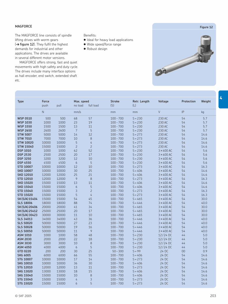
© SKF 2005 203
4
MAGFORCE
The MAGFORCE line consists of spindle
lifting drives with worm gears
( figure 12). They fulfil the highest
demands for industrial and other
applications. The drives are available
in several different motor versions.
MAGFORCE offers strong, fast and quiet
movements with high safety and duty cycle.
The drives include many interface options
as hall encoder, end switch, extended shaft
etc.
Benefits:
Ideal for heavy load applications
Wide speed/force range
Robust design
Figure 12
Type Force Max. speed Stroke Retr. Length Voltage Protection Weight
push pull no load full load (S) (L)
N mm/s mm mm V IP kg
WSP 0510 500 500 68 57 100 - 700 S + 230 230 AC 54 5.7
WSP 1030 1000 1000 23 19 100 - 700 S + 230 230 AC 54 5.7
WSP 1550 1500 1500 13 11 100 - 700 S + 230 230 AC 54 5.7
WSP 2650 2600 2600 7 5 100 - 700 S + 230 230 AC 54 5.7
STW 5007 5000 5000 14 12 100 - 700 S + 273 230 AC 54 14.6
STW 7010 7000 7000 10 8 100 - 700 S + 273 230 AC 54 14.6
STW 10020 10000 10000 5 4 100 - 700 S + 273 230 AC 54 14.6
STW 15040 15000 15000 2 2 100 - 700 S + 273 230 AC 54 14.6
DSP 1010 1000 1000 62 52 100 - 700 S + 230 3 ×400 AC 54 5.6
DSP 2530 2500 2500 20 17 100 - 700 S + 230 3 ×400 AC 54 5.6
DSP 3250 3200 3200 12 10 100 - 700 S + 230 3 ×400 AC 54 5.6
DSP 4550 4500 4500 6 5 100 - 700 S + 230 3 ×400 AC 54 5.6
STD 10007 10000 10000 12 10 100 - 700 S + 273 3 ×400 AC 54 16.3
SKD 10007 10000 10000 30 25 100 - 700 S + 406 3 ×400 AC 54 14.6
SKD 12010 12000 12000 25 21 100 - 700 S + 406 3 ×400 AC 54 14.6
STD 12010 12000 12000 9 8 100 - 700 S + 273 3 ×400 AC 54 16.3
SKD 15020 15000 15000 13 11 100 - 700 S + 406 3 ×400 AC 54 14.6
SKD 15040 15000 15000 6 5 100 - 700 S + 406 3 ×400 AC 54 14.6
STD 15040 15000 15000 3 2 100 - 700 S + 273 3 ×400 AC 54 16.3
STD 15020 15000 15000 5 4 100 - 700 S + 273 3 ×400 AC 54 16.3
SK (S/A) 15404 15000 15000 54 45 100 - 700 S + 465 3 ×400 AC 54 30.0
SLS 18006 18000 18000 88 74 100 - 700 S + 446 3 ×400 AC 54 40.0
SK (S/A) 20406 20000 20000 41 34 100 - 700 S + 465 3 ×400 AC 54 30.0
SK (S/A) 25412 25000 25000 20 17 100 - 700 S + 465 3 ×400 AC 54 30.0
SK (S/A) 30423 30000 30000 11 10 100 - 700 S + 465 3 ×400 AC 54 30.0
SLS 34013 34000 34000 43 36 100 - 700 S + 446 3 ×400 AC 54 40.0
SLS 50020 50000 50000 27 23 100 - 700 S + 446 3 ×400 AC 54 40.0
SLS 50028 50000 50000 19 16 100 - 700 S + 446 3 ×400 AC 54 40.0
SLS 50050 50000 50000 11 9 100 - 700 S + 446 3 ×400 AC 54 40.0
ASM 1010 1000 1000 58 48 100 - 700 S + 230 12 / 24 DC 44 5.0
ASM 2030 2000 2000 22 18 100 - 700 S + 230 12 / 24 DC 44 5.0
ASM 3030 3000 3000 10 8 100 - 700 S + 230 12 / 24 DC 44 5.0
ASM 4050 4000 4000 6 5 100 - 700 S + 230 12 / 24 DC 44 5.0
GTD 0220 200 200 30 25 50 - 300 S + 99 24 DC 00 0.9
SKG 6005 6000 6000 66 55 100 - 700 S + 406 24 DC 54 14.6
STG 10007 10000 10000 17 14 100 - 700 S + 273 24 DC 54 14.6
SKG 10010 10000 10000 36 30 100 - 700 S + 406 24 DC 54 14.6
STG 12010 12000 12000 13 11 100 - 700 S + 273 24 DC 54 14.6
SKG 13020 13000 13000 18 15 100 - 700 S + 406 24 DC 54 14.6
SKG 15040 15000 15000 10 8 100 - 700 S + 406 24 DC 54 14.6
STG 15040 15000 15000 4 3 100 - 700 S + 273 24 DC 54 14.6
STG 15020 15000 15000 6 5 100 - 700 S + 273 24 DC 54 14.6

204 © SKF 2005
4 Actuation systems
Linear actuators
Ordering key
Type
Load:200 N. . . . . . . . . . . . . . . . . . . . . . . . . . . . . . . . . . . . . . . . . . . . . . . . . . . . . . . . . . . . . . . . . . . . . . . . . . . . . . . . . . . . . . . 0 2
Gear ratio:20 : 1 . . . . . . . . . . . . . . . . . . . . . . . . . . . . . . . . . . . . . . . . . . . . . . . . . . . . . . . . . . . . . . . . . . . . . . . . . . . . . . . . . . . . . . . . . . . . . 20
Stroke (S):50 mm . . . . . . . . . . . . . . . . . . . . . . . . . . . . . . . . . . . . . . . . . . . . . . . . . . . . . . . . . . . . . . . . . . . . . . . . . . . . . . . . . . . . . . . . . . . . . . . . . 0 5 0
100 mm . . . . . . . . . . . . . . . . . . . . . . . . . . . . . . . . . . . . . . . . . . . . . . . . . . . . . . . . . . . . . . . . . . . . . . . . . . . . . . . . . . . . . . . . . . . . . . . . 1 0 0150 mm . . . . . . . . . . . . . . . . . . . . . . . . . . . . . . . . . . . . . . . . . . . . . . . . . . . . . . . . . . . . . . . . . . . . . . . . . . . . . . . . . . . . . . . . . . . . . . . . 1 5 0200 mm . . . . . . . . . . . . . . . . . . . . . . . . . . . . . . . . . . . . . . . . . . . . . . . . . . . . . . . . . . . . . . . . . . . . . . . . . . . . . . . . . . . . . . . . . . . . . . . . 2 0 0250 mm . . . . . . . . . . . . . . . . . . . . . . . . . . . . . . . . . . . . . . . . . . . . . . . . . . . . . . . . . . . . . . . . . . . . . . . . . . . . . . . . . . . . . . . . . . . . . . . . 2 5 0300 mm . . . . . . . . . . . . . . . . . . . . . . . . . . . . . . . . . . . . . . . . . . . . . . . . . . . . . . . . . . . . . . . . . . . . . . . . . . . . . . . . . . . . . . . . . . . . . . . . 3 0 0
Voltage:24 V DC . . . . . . . . . . . . . . . . . . . . . . . . . . . . . . . . . . . . . . . . . . . . . . . . . . . . . . . . . . . . . . . . . . . . . . . . . . . . . . . . . . . . . . . . . . . . . . . . . . . . . . . . . 0 2
4422
6.5
343132
6
32
10
S + 248 S + 127 S + 121 S + 108
Magforce GTD
Example:
GTD 0 20 2 2 0 -
GTD 0 20 2 2 0 -
Legend:
S = stroke
—————— ————
Type Force Max. speed Stroke Retr. Length Voltage Protection Weight
push pull no load full load (S) (L)
N mm/s mm mm V DC IP kg
GTD 0220 200 200 30 25 50 - 300 S + 99 24 00 0.9

© SKF 2005 205
4
Ordering key
Type
Load /Speed:500 N / 57 mm/s . . . . . . . . . . . . . . . . . . . . . . . . . . . . . . . . . . . . . . . . . . . . . . . . . . . . . . . . . . . . . . . . . . . . . . . . . . . . . . 0 5 1 0
1000 N / 19 mm/s . . . . . . . . . . . . . . . . . . . . . . . . . . . . . . . . . . . . . . . . . . . . . . . . . . . . . . . . . . . . . . . . . . . . . . . . . . . . . . 1 0 3 01500 N / 11 mm/s . . . . . . . . . . . . . . . . . . . . . . . . . . . . . . . . . . . . . . . . . . . . . . . . . . . . . . . . . . . . . . . . . . . . . . . . . . . . . . 1 5 5 02600 N / 5 mm/s . . . . . . . . . . . . . . . . . . . . . . . . . . . . . . . . . . . . . . . . . . . . . . . . . . . . . . . . . . . . . . . . . . . . . . . . . . . . . . 2 6 5 0
Stroke (S):100 mm. . . . . . . . . . . . . . . . . . . . . . . . . . . . . . . . . . . . . . . . . . . . . . . . . . . . . . . . . . . . . . . . . . . . . . . . . . . . . . . . . . . . . . . . . . . . . . . . 1 0 0200 mm. . . . . . . . . . . . . . . . . . . . . . . . . . . . . . . . . . . . . . . . . . . . . . . . . . . . . . . . . . . . . . . . . . . . . . . . . . . . . . . . . . . . . . . . . . . . . . . . 2 0 0300 mm. . . . . . . . . . . . . . . . . . . . . . . . . . . . . . . . . . . . . . . . . . . . . . . . . . . . . . . . . . . . . . . . . . . . . . . . . . . . . . . . . . . . . . . . . . . . . . . . 3 0 0400 mm. . . . . . . . . . . . . . . . . . . . . . . . . . . . . . . . . . . . . . . . . . . . . . . . . . . . . . . . . . . . . . . . . . . . . . . . . . . . . . . . . . . . . . . . . . . . . . . . 4 0 0500 mm. . . . . . . . . . . . . . . . . . . . . . . . . . . . . . . . . . . . . . . . . . . . . . . . . . . . . . . . . . . . . . . . . . . . . . . . . . . . . . . . . . . . . . . . . . . . . . . . 5 0 0600 mm. . . . . . . . . . . . . . . . . . . . . . . . . . . . . . . . . . . . . . . . . . . . . . . . . . . . . . . . . . . . . . . . . . . . . . . . . . . . . . . . . . . . . . . . . . . . . . . . 6 0 0700 mm. . . . . . . . . . . . . . . . . . . . . . . . . . . . . . . . . . . . . . . . . . . . . . . . . . . . . . . . . . . . . . . . . . . . . . . . . . . . . . . . . . . . . . . . . . . . . . . . 7 0 0
Customer options:Standard . . . . . . . . . . . . . . . . . . . . . . . . . . . . . . . . . . . . . . . . . . . . . . . . . . . . . . . . . . . . . . . . . . . . . . . . . . . . . . . . . . . . . . . . . . . . . . . . . . . . . . . . 0 1Brake for self-locking on push . . . . . . . . . . . . . . . . . . . . . . . . . . . . . . . . . . . . . . . . . . . . . . . . . . . . . . . . . . . . . . . . . . . . . . . . . . . . . . . . . . . . . . . 0 3Extended shaft. . . . . . . . . . . . . . . . . . . . . . . . . . . . . . . . . . . . . . . . . . . . . . . . . . . . . . . . . . . . . . . . . . . . . . . . . . . . . . . . . . . . . . . . . . . . . . . . . . . . 1 6Brake for self-locking on pull . . . . . . . . . . . . . . . . . . . . . . . . . . . . . . . . . . . . . . . . . . . . . . . . . . . . . . . . . . . . . . . . . . . . . . . . . . . . . . . . . . . . . . . . 2 4Bronze nut / Low temperature grease / Extended shaft . . . . . . . . . . . . . . . . . . . . . . . . . . . . . . . . . . . . . . . . . . . . . . . . . . . . . . . . . . . . . . . . . . . . . 8 1Others (brake, limit switch, ext. motorshaft, incr. encoder, potentiometer, …) . . . . . . . . . . . . . . . . . . . . . . . . . . . . . . . . . . . . . . . . . . . . . . . . . . . . XX
ø 3
0ø
12 2
28 1
99 1
61
90
SL = S + 230 mm
S + 255
ø 10
4410
ø 5
6
122
72120
Magforce WSP
Example:
WSP --
WSP - 8 12 6 5 0 - 4 0 0
Legend:
S = stroke
L = retracted length
—————————
Type Force Max. speed Stroke Retr. Length Voltage Protection Weight
push pull no load full load (S) (L)
N mm/s mm mm V AC IP kg
WSP 0510 500 500 68 57 100 - 700 S + 230 230 54 5.7
WSP 1030 1000 1000 23 19 100 - 700 S + 230 230 54 5.7
WSP 1550 1500 1500 13 11 100 - 700 S + 230 230 54 5.7
WSP 2650 2600 2600 7 5 100 - 700 S + 230 230 54 5.7

206 © SKF 2005
4 Actuation systems
Linear actuators
Ordering key
Type
Load /Speed:1000 N / 48 mm/s . . . . . . . . . . . . . . . . . . . . . . . . . . . . . . . . . . . . . . . . . . . . . . . . . . . . . . . . . . . . . . . . . . . . . . . . . . . . . . 1 0 1 02000 N / 18 mm/s . . . . . . . . . . . . . . . . . . . . . . . . . . . . . . . . . . . . . . . . . . . . . . . . . . . . . . . . . . . . . . . . . . . . . . . . . . . . . . 2 0 3 03000 N / 8 mm/s . . . . . . . . . . . . . . . . . . . . . . . . . . . . . . . . . . . . . . . . . . . . . . . . . . . . . . . . . . . . . . . . . . . . . . . . . . . . . . 3 0 3 04000 N / 5 mm/s . . . . . . . . . . . . . . . . . . . . . . . . . . . . . . . . . . . . . . . . . . . . . . . . . . . . . . . . . . . . . . . . . . . . . . . . . . . . . . 4 0 5 0
Stroke (S):100 mm. . . . . . . . . . . . . . . . . . . . . . . . . . . . . . . . . . . . . . . . . . . . . . . . . . . . . . . . . . . . . . . . . . . . . . . . . . . . . . . . . . . . . . . . . . . . . . . . 1 0 0200 mm. . . . . . . . . . . . . . . . . . . . . . . . . . . . . . . . . . . . . . . . . . . . . . . . . . . . . . . . . . . . . . . . . . . . . . . . . . . . . . . . . . . . . . . . . . . . . . . . 2 0 0300 mm. . . . . . . . . . . . . . . . . . . . . . . . . . . . . . . . . . . . . . . . . . . . . . . . . . . . . . . . . . . . . . . . . . . . . . . . . . . . . . . . . . . . . . . . . . . . . . . . 3 0 0400 mm. . . . . . . . . . . . . . . . . . . . . . . . . . . . . . . . . . . . . . . . . . . . . . . . . . . . . . . . . . . . . . . . . . . . . . . . . . . . . . . . . . . . . . . . . . . . . . . . 4 0 0500 mm. . . . . . . . . . . . . . . . . . . . . . . . . . . . . . . . . . . . . . . . . . . . . . . . . . . . . . . . . . . . . . . . . . . . . . . . . . . . . . . . . . . . . . . . . . . . . . . . 5 0 0600 mm. . . . . . . . . . . . . . . . . . . . . . . . . . . . . . . . . . . . . . . . . . . . . . . . . . . . . . . . . . . . . . . . . . . . . . . . . . . . . . . . . . . . . . . . . . . . . . . . 6 0 0700 mm. . . . . . . . . . . . . . . . . . . . . . . . . . . . . . . . . . . . . . . . . . . . . . . . . . . . . . . . . . . . . . . . . . . . . . . . . . . . . . . . . . . . . . . . . . . . . . . . 7 0 0
Customer options:12 V DC . . . . . . . . . . . . . . . . . . . . . . . . . . . . . . . . . . . . . . . . . . . . . . . . . . . . . . . . . . . . . . . . . . . . . . . . . . . . . . . . . . . . . . . . . . . . . . . . . . . . . . . . 0 124 V DC . . . . . . . . . . . . . . . . . . . . . . . . . . . . . . . . . . . . . . . . . . . . . . . . . . . . . . . . . . . . . . . . . . . . . . . . . . . . . . . . . . . . . . . . . . . . . . . . . . . . . . . . 0 224 V DC, brake for self-locking on push . . . . . . . . . . . . . . . . . . . . . . . . . . . . . . . . . . . . . . . . . . . . . . . . . . . . . . . . . . . . . . . . . . . . . . . . . . . . . . . . 0 624 V DC, bronze nut, low temperature grease . . . . . . . . . . . . . . . . . . . . . . . . . . . . . . . . . . . . . . . . . . . . . . . . . . . . . . . . . . . . . . . . . . . . . . . . . . . 0 724 V DC, brake for self-locking on push and pull . . . . . . . . . . . . . . . . . . . . . . . . . . . . . . . . . . . . . . . . . . . . . . . . . . . . . . . . . . . . . . . . . . . . . . . . . 0 924 V DC, brake for self-locking on push and pull, low temperature grease . . . . . . . . . . . . . . . . . . . . . . . . . . . . . . . . . . . . . . . . . . . . . . . . . . . . . 1 324 V DC, low temperature grease . . . . . . . . . . . . . . . . . . . . . . . . . . . . . . . . . . . . . . . . . . . . . . . . . . . . . . . . . . . . . . . . . . . . . . . . . . . . . . . . . . . . . 1 424 V DC, extended shaft . . . . . . . . . . . . . . . . . . . . . . . . . . . . . . . . . . . . . . . . . . . . . . . . . . . . . . . . . . . . . . . . . . . . . . . . . . . . . . . . . . . . . . . . . . . . 1 6Others (brake, limit switch, ext. motorshaft, incr. encoder, potentiometer, …) . . . . . . . . . . . . . . . . . . . . . . . . . . . . . . . . . . . . . . . . . . . . . . . . . . . . XX
L = S + 230S + 255
120
ø 3
0ø
12
ø 5
6
ø 10
44
10
S
ø 80
103
225 2
03 16531
Magforce ASM
Example:
Legend:
S = stroke
L = retracted length
ASM --
ASM - 0 23 0 3 0 - 7 0 0
—————————
Type Force Max. speed Stroke Retr. Length Voltage Protection Weight
push pull no load full load (S) (L)
N mm/s mm mm V DC IP kg
ASM 1010 1000 1000 58 48 100 - 700 S + 230 12 / 24 44 5.0
ASM 2030 2000 2000 22 18 100 - 700 S + 230 12 / 24 44 5.0
ASM 3030 3000 3000 10 8 100 - 700 S + 230 12 / 24 44 5.0
ASM 4050 4000 4000 6 5 100 - 700 S + 230 12 / 24 44 5.0

© SKF 2005 207
4
Ordering key
Type
Load /Speed :1000 N / 52 mm/s . . . . . . . . . . . . . . . . . . . . . . . . . . . . . . . . . . . . . . . . . . . . . . . . . . . . . . . . . . . . . . . . . . . . . . . . . . . . 1 0 1 02500 N / 17 mm/s . . . . . . . . . . . . . . . . . . . . . . . . . . . . . . . . . . . . . . . . . . . . . . . . . . . . . . . . . . . . . . . . . . . . . . . . . . . . 2 5 3 03200 N / 10 mm/s . . . . . . . . . . . . . . . . . . . . . . . . . . . . . . . . . . . . . . . . . . . . . . . . . . . . . . . . . . . . . . . . . . . . . . . . . . . . 3 2 5 04500 N / 5 mm/s . . . . . . . . . . . . . . . . . . . . . . . . . . . . . . . . . . . . . . . . . . . . . . . . . . . . . . . . . . . . . . . . . . . . . . . . . . . . 4 5 5 0
Stroke (S):100 mm . . . . . . . . . . . . . . . . . . . . . . . . . . . . . . . . . . . . . . . . . . . . . . . . . . . . . . . . . . . . . . . . . . . . . . . . . . . . . . . . . . . . . . . . . . . . . . 1 0 0200 mm . . . . . . . . . . . . . . . . . . . . . . . . . . . . . . . . . . . . . . . . . . . . . . . . . . . . . . . . . . . . . . . . . . . . . . . . . . . . . . . . . . . . . . . . . . . . . . 2 0 0300 mm . . . . . . . . . . . . . . . . . . . . . . . . . . . . . . . . . . . . . . . . . . . . . . . . . . . . . . . . . . . . . . . . . . . . . . . . . . . . . . . . . . . . . . . . . . . . . . 3 0 0400 mm . . . . . . . . . . . . . . . . . . . . . . . . . . . . . . . . . . . . . . . . . . . . . . . . . . . . . . . . . . . . . . . . . . . . . . . . . . . . . . . . . . . . . . . . . . . . . . 4 0 0500 mm . . . . . . . . . . . . . . . . . . . . . . . . . . . . . . . . . . . . . . . . . . . . . . . . . . . . . . . . . . . . . . . . . . . . . . . . . . . . . . . . . . . . . . . . . . . . . . 5 0 0600 mm . . . . . . . . . . . . . . . . . . . . . . . . . . . . . . . . . . . . . . . . . . . . . . . . . . . . . . . . . . . . . . . . . . . . . . . . . . . . . . . . . . . . . . . . . . . . . . 6 0 0700 mm . . . . . . . . . . . . . . . . . . . . . . . . . . . . . . . . . . . . . . . . . . . . . . . . . . . . . . . . . . . . . . . . . . . . . . . . . . . . . . . . . . . . . . . . . . . . . . 7 0 0
Customer options:Standard . . . . . . . . . . . . . . . . . . . . . . . . . . . . . . . . . . . . . . . . . . . . . . . . . . . . . . . . . . . . . . . . . . . . . . . . . . . . . . . . . . . . . . . . . . . . . . . . . . . . . . . 0 1Brake for self-locking on push . . . . . . . . . . . . . . . . . . . . . . . . . . . . . . . . . . . . . . . . . . . . . . . . . . . . . . . . . . . . . . . . . . . . . . . . . . . . . . . . . . . . . . 0 3Bronze nut, low temperature grease . . . . . . . . . . . . . . . . . . . . . . . . . . . . . . . . . . . . . . . . . . . . . . . . . . . . . . . . . . . . . . . . . . . . . . . . . . . . . . . . . 0 8Brake for self-locking on pull . . . . . . . . . . . . . . . . . . . . . . . . . . . . . . . . . . . . . . . . . . . . . . . . . . . . . . . . . . . . . . . . . . . . . . . . . . . . . . . . . . . . . . . 1 0Bronze nut, brake for self-locking on push . . . . . . . . . . . . . . . . . . . . . . . . . . . . . . . . . . . . . . . . . . . . . . . . . . . . . . . . . . . . . . . . . . . . . . . . . . . . 1 2Brake for self-locking on push and pull . . . . . . . . . . . . . . . . . . . . . . . . . . . . . . . . . . . . . . . . . . . . . . . . . . . . . . . . . . . . . . . . . . . . . . . . . . . . . . . 1 7Low temperature grease . . . . . . . . . . . . . . . . . . . . . . . . . . . . . . . . . . . . . . . . . . . . . . . . . . . . . . . . . . . . . . . . . . . . . . . . . . . . . . . . . . . . . . . . . . 3 0Extended shaft . . . . . . . . . . . . . . . . . . . . . . . . . . . . . . . . . . . . . . . . . . . . . . . . . . . . . . . . . . . . . . . . . . . . . . . . . . . . . . . . . . . . . . . . . . . . . . . . . 1 2 2Others (brake, limit switch, ext. motorshaft, incr. encoder, potentiometer, …) . . . . . . . . . . . . . . . . . . . . . . . . . . . . . . . . . . . . . . . . . . . . . . . . . . . XX
219
190
152
31
ø 48
108
90
4410
SL = S + 230 mm
S + 255
72120
ø 3
0ø
12
12790
ø 10
ø 5
6
Magforce DSP
Example:
Legend:
S = stroke
L = retracted length
DSP --
DSP - 1223 2 5 0 - 7 0 0
—————————
Type Force Max. speed Stroke Retr. Length Voltage Protection Weight
push pull no load full load (S) (L)
N mm/s mm mm V AC IP kg
DSP 1010 1000 1000 62 52 100 - 700 S + 230 3 ×400 54 5.6
DSP 2530 2500 2500 20 17 100 - 700 S + 230 3 ×400 54 5.6
DSP 3250 3200 3200 12 10 100 - 700 S + 230 3 ×400 54 5.6
DSP 4550 4500 4500 6 5 100 - 700 S + 230 3 ×400 54 5.6

208 © SKF 2005
4 Actuation systems
Linear actuators
Ordering key
Type
Load /Speed :6000 N / 55 mm/s. . . . . . . . . . . . . . . . . . . . . . . . . . . . . . . . . . . . . . . . . . . . . . . . . . . . . . . . . . . . . . . . . . . . . . . . . . . 0 6 0 0 5
10000 N / 30 mm/s. . . . . . . . . . . . . . . . . . . . . . . . . . . . . . . . . . . . . . . . . . . . . . . . . . . . . . . . . . . . . . . . . . . . . . . . . . . 1 0 0 1 013000 N / 15 mm/s. . . . . . . . . . . . . . . . . . . . . . . . . . . . . . . . . . . . . . . . . . . . . . . . . . . . . . . . . . . . . . . . . . . . . . . . . . . 1 3 0 2 015000 N / 8 mm/s. . . . . . . . . . . . . . . . . . . . . . . . . . . . . . . . . . . . . . . . . . . . . . . . . . . . . . . . . . . . . . . . . . . . . . . . . . . 1 5 0 4 0
Stroke (S):100 mm. . . . . . . . . . . . . . . . . . . . . . . . . . . . . . . . . . . . . . . . . . . . . . . . . . . . . . . . . . . . . . . . . . . . . . . . . . . . . . . . . . . . . . . . . . . . . . . . 1 0 0200 mm. . . . . . . . . . . . . . . . . . . . . . . . . . . . . . . . . . . . . . . . . . . . . . . . . . . . . . . . . . . . . . . . . . . . . . . . . . . . . . . . . . . . . . . . . . . . . . . . 2 0 0300 mm. . . . . . . . . . . . . . . . . . . . . . . . . . . . . . . . . . . . . . . . . . . . . . . . . . . . . . . . . . . . . . . . . . . . . . . . . . . . . . . . . . . . . . . . . . . . . . . . 3 0 0400 mm. . . . . . . . . . . . . . . . . . . . . . . . . . . . . . . . . . . . . . . . . . . . . . . . . . . . . . . . . . . . . . . . . . . . . . . . . . . . . . . . . . . . . . . . . . . . . . . . 4 0 0500 mm. . . . . . . . . . . . . . . . . . . . . . . . . . . . . . . . . . . . . . . . . . . . . . . . . . . . . . . . . . . . . . . . . . . . . . . . . . . . . . . . . . . . . . . . . . . . . . . . 5 0 0600 mm. . . . . . . . . . . . . . . . . . . . . . . . . . . . . . . . . . . . . . . . . . . . . . . . . . . . . . . . . . . . . . . . . . . . . . . . . . . . . . . . . . . . . . . . . . . . . . . . 6 0 0700 mm. . . . . . . . . . . . . . . . . . . . . . . . . . . . . . . . . . . . . . . . . . . . . . . . . . . . . . . . . . . . . . . . . . . . . . . . . . . . . . . . . . . . . . . . . . . . . . . . 7 0 0
Customer options:Standard . . . . . . . . . . . . . . . . . . . . . . . . . . . . . . . . . . . . . . . . . . . . . . . . . . . . . . . . . . . . . . . . . . . . . . . . . . . . . . . . . . . . . . . . . . . . . . . . . . . . . . . . 0 1Others (brake, limit switch, ext. motorshaft, incr. encoder, potentiometer, …) . . . . . . . . . . . . . . . . . . . . . . . . . . . . . . . . . . . . . . . . . . . . . . . . . . . . XX
Magforce SKG
Example:
Legend:
S = stroke
L = retracted length
SKG - 0 1-
SKG - 0 10 6 0 0 5 - 5 0 0
———–———–—–
Type Force Max. speed Stroke Retr. Length Voltage Protection Weight
push pull no load full load (S) (L)
N mm/s mm mm V DC IP kg
SKG 6005 6000 6000 66 55 100 - 700 S + 406 24 54 14.6
SKG 10010 10000 10000 36 30 100 - 700 S + 406 24 54 14.6
SKG 13020 13000 13000 18 15 100 - 700 S + 406 24 54 14.6
SKG 15040 15000 15000 10 8 100 - 700 S + 406 24 54 14.6

© SKF 2005 209
4
Ordering key
Type
Load /Speed :10000 N / 25 mm/s. . . . . . . . . . . . . . . . . . . . . . . . . . . . . . . . . . . . . . . . . . . . . . . . . . . . . . . . . . . . . . . . . . . . . . . . . . . 1 0 0 0 712000 N / 21 mm/s. . . . . . . . . . . . . . . . . . . . . . . . . . . . . . . . . . . . . . . . . . . . . . . . . . . . . . . . . . . . . . . . . . . . . . . . . . . 1 2 0 1 015000 N / 11 mm/s. . . . . . . . . . . . . . . . . . . . . . . . . . . . . . . . . . . . . . . . . . . . . . . . . . . . . . . . . . . . . . . . . . . . . . . . . . . 1 5 0 2 015000 N / 5 mm/s. . . . . . . . . . . . . . . . . . . . . . . . . . . . . . . . . . . . . . . . . . . . . . . . . . . . . . . . . . . . . . . . . . . . . . . . . . . 1 5 0 4 0
Stroke (S):100 mm. . . . . . . . . . . . . . . . . . . . . . . . . . . . . . . . . . . . . . . . . . . . . . . . . . . . . . . . . . . . . . . . . . . . . . . . . . . . . . . . . . . . . . . . . . . . . . . . 1 0 0200 mm. . . . . . . . . . . . . . . . . . . . . . . . . . . . . . . . . . . . . . . . . . . . . . . . . . . . . . . . . . . . . . . . . . . . . . . . . . . . . . . . . . . . . . . . . . . . . . . . 2 0 0300 mm. . . . . . . . . . . . . . . . . . . . . . . . . . . . . . . . . . . . . . . . . . . . . . . . . . . . . . . . . . . . . . . . . . . . . . . . . . . . . . . . . . . . . . . . . . . . . . . . 3 0 0400 mm. . . . . . . . . . . . . . . . . . . . . . . . . . . . . . . . . . . . . . . . . . . . . . . . . . . . . . . . . . . . . . . . . . . . . . . . . . . . . . . . . . . . . . . . . . . . . . . . 4 0 0500 mm. . . . . . . . . . . . . . . . . . . . . . . . . . . . . . . . . . . . . . . . . . . . . . . . . . . . . . . . . . . . . . . . . . . . . . . . . . . . . . . . . . . . . . . . . . . . . . . . 5 0 0600 mm. . . . . . . . . . . . . . . . . . . . . . . . . . . . . . . . . . . . . . . . . . . . . . . . . . . . . . . . . . . . . . . . . . . . . . . . . . . . . . . . . . . . . . . . . . . . . . . . 6 0 0700 mm. . . . . . . . . . . . . . . . . . . . . . . . . . . . . . . . . . . . . . . . . . . . . . . . . . . . . . . . . . . . . . . . . . . . . . . . . . . . . . . . . . . . . . . . . . . . . . . . 7 0 0
Customer options:Standard . . . . . . . . . . . . . . . . . . . . . . . . . . . . . . . . . . . . . . . . . . . . . . . . . . . . . . . . . . . . . . . . . . . . . . . . . . . . . . . . . . . . . . . . . . . . . . . . . . . . . . . . 0 1Others (brake, limit switch, ext. motorshaft, incr. encoder, potentiometer, …) . . . . . . . . . . . . . . . . . . . . . . . . . . . . . . . . . . . . . . . . . . . . . . . . . . . . XX
ø130
6269
219
L = S + 406
ø16
25
ø65
95
ø140
174
170
114.5
40
ø16
42
Magforce SKD
Example:
Legend:
S = stroke
L = retracted length
SKD - 0 1-
SKD - 0 1– 7 0 1 0 - 5 0 0
———–———–—–
Type Force Max. speed Stroke Retr. Length Voltage Protection Weight
push pull no load full load (S) (L)
N mm/s mm mm V AC IP kg
SKD 10007 10000 10000 30 25 100 - 700 S + 406 3 ×400 54 14.6
SKD 12010 12000 12000 25 21 100 - 700 S + 406 3 ×400 54 14.6
SKD 15020 15000 15000 13 11 100 - 700 S + 406 3 ×400 54 14.6
SKD 15040 15000 15000 6 5 100 - 700 S + 406 3 ×400 54 14.6

210 © SKF 2005
4 Actuation systems
Linear actuators
Ordering key
Type
Load /Speed :5000 N / 12 mm/s. . . . . . . . . . . . . . . . . . . . . . . . . . . . . . . . . . . . . . . . . . . . . . . . . . . . . . . . . . . . . . . . . . . . . . . . . . . 0 5 0 0 77000 N / 8 mm/s. . . . . . . . . . . . . . . . . . . . . . . . . . . . . . . . . . . . . . . . . . . . . . . . . . . . . . . . . . . . . . . . . . . . . . . . . . . 0 7 0 1 0
10000 N / 4 mm/s. . . . . . . . . . . . . . . . . . . . . . . . . . . . . . . . . . . . . . . . . . . . . . . . . . . . . . . . . . . . . . . . . . . . . . . . . . . 1 0 0 2 015000 N / 2 mm/s. . . . . . . . . . . . . . . . . . . . . . . . . . . . . . . . . . . . . . . . . . . . . . . . . . . . . . . . . . . . . . . . . . . . . . . . . . . 1 5 0 4 0
Stroke (S):100 mm. . . . . . . . . . . . . . . . . . . . . . . . . . . . . . . . . . . . . . . . . . . . . . . . . . . . . . . . . . . . . . . . . . . . . . . . . . . . . . . . . . . . . . . . . . . . . . . . 1 0 0200 mm. . . . . . . . . . . . . . . . . . . . . . . . . . . . . . . . . . . . . . . . . . . . . . . . . . . . . . . . . . . . . . . . . . . . . . . . . . . . . . . . . . . . . . . . . . . . . . . . 2 0 0300 mm. . . . . . . . . . . . . . . . . . . . . . . . . . . . . . . . . . . . . . . . . . . . . . . . . . . . . . . . . . . . . . . . . . . . . . . . . . . . . . . . . . . . . . . . . . . . . . . . 3 0 0400 mm. . . . . . . . . . . . . . . . . . . . . . . . . . . . . . . . . . . . . . . . . . . . . . . . . . . . . . . . . . . . . . . . . . . . . . . . . . . . . . . . . . . . . . . . . . . . . . . . 4 0 0500 mm. . . . . . . . . . . . . . . . . . . . . . . . . . . . . . . . . . . . . . . . . . . . . . . . . . . . . . . . . . . . . . . . . . . . . . . . . . . . . . . . . . . . . . . . . . . . . . . . 5 0 0600 mm. . . . . . . . . . . . . . . . . . . . . . . . . . . . . . . . . . . . . . . . . . . . . . . . . . . . . . . . . . . . . . . . . . . . . . . . . . . . . . . . . . . . . . . . . . . . . . . . 6 0 0700 mm. . . . . . . . . . . . . . . . . . . . . . . . . . . . . . . . . . . . . . . . . . . . . . . . . . . . . . . . . . . . . . . . . . . . . . . . . . . . . . . . . . . . . . . . . . . . . . . . 7 0 0
Customer options:Standard . . . . . . . . . . . . . . . . . . . . . . . . . . . . . . . . . . . . . . . . . . . . . . . . . . . . . . . . . . . . . . . . . . . . . . . . . . . . . . . . . . . . . . . . . . . . . . . . . . . . . . . . 0 1Limit switch . . . . . . . . . . . . . . . . . . . . . . . . . . . . . . . . . . . . . . . . . . . . . . . . . . . . . . . . . . . . . . . . . . . . . . . . . . . . . . . . . . . . . . . . . . . . . . . . . . . . . 0 5Low temperature grease . . . . . . . . . . . . . . . . . . . . . . . . . . . . . . . . . . . . . . . . . . . . . . . . . . . . . . . . . . . . . . . . . . . . . . . . . . . . . . . . . . . . . . . . . . . 0 8Others (brake, limit switch, ext. motorshaft, incr. encoder, potentiometer, …) . . . . . . . . . . . . . . . . . . . . . . . . . . . . . . . . . . . . . . . . . . . . . . . . . . . . XX
ø 116
70 35
143
15
4019
6
260
ø 116
174
L = S + 273
S + 293
5654
S
ø 4
0
ø 16
Magforce STW
Example:
Legend:
S = stroke
L = retracted length
STW --
STW - 0 1– 7 0 1 0 - 5 0 0
———–———–—–
Type Force Max. speed Stroke Retr. Length Voltage Protection Weight
push pull no load full load (S) (L)
N mm/s mm mm V AC IP kg
STW 5007 5000 5000 14 12 100 - 700 S + 273 230 54 14.6
STW 7010 7000 7000 10 8 100 - 700 S + 273 230 54 14.6
STW 10020 10000 10000 5 4 100 - 700 S + 273 230 54 14.6
STW 15040 15000 15000 2 2 100 - 700 S + 273 230 54 14.6

© SKF 2005 211
4
Ordering key
Type
Load /Speed :10000 N / 14 mm/s. . . . . . . . . . . . . . . . . . . . . . . . . . . . . . . . . . . . . . . . . . . . . . . . . . . . . . . . . . . . . . . . . . . . . . . . . . . 1 0 0 0 712000 N / 11 mm/s. . . . . . . . . . . . . . . . . . . . . . . . . . . . . . . . . . . . . . . . . . . . . . . . . . . . . . . . . . . . . . . . . . . . . . . . . . . 1 2 0 1 015000 N / 5 mm/s. . . . . . . . . . . . . . . . . . . . . . . . . . . . . . . . . . . . . . . . . . . . . . . . . . . . . . . . . . . . . . . . . . . . . . . . . . . 1 5 0 2 015000 N / 3 mm/s. . . . . . . . . . . . . . . . . . . . . . . . . . . . . . . . . . . . . . . . . . . . . . . . . . . . . . . . . . . . . . . . . . . . . . . . . . . 1 5 0 4 0
Stroke (S):100 mm. . . . . . . . . . . . . . . . . . . . . . . . . . . . . . . . . . . . . . . . . . . . . . . . . . . . . . . . . . . . . . . . . . . . . . . . . . . . . . . . . . . . . . . . . . . . . . . . 1 0 0200 mm. . . . . . . . . . . . . . . . . . . . . . . . . . . . . . . . . . . . . . . . . . . . . . . . . . . . . . . . . . . . . . . . . . . . . . . . . . . . . . . . . . . . . . . . . . . . . . . . 2 0 0300 mm. . . . . . . . . . . . . . . . . . . . . . . . . . . . . . . . . . . . . . . . . . . . . . . . . . . . . . . . . . . . . . . . . . . . . . . . . . . . . . . . . . . . . . . . . . . . . . . . 3 0 0400 mm. . . . . . . . . . . . . . . . . . . . . . . . . . . . . . . . . . . . . . . . . . . . . . . . . . . . . . . . . . . . . . . . . . . . . . . . . . . . . . . . . . . . . . . . . . . . . . . . 4 0 0500 mm. . . . . . . . . . . . . . . . . . . . . . . . . . . . . . . . . . . . . . . . . . . . . . . . . . . . . . . . . . . . . . . . . . . . . . . . . . . . . . . . . . . . . . . . . . . . . . . . 5 0 0600 mm. . . . . . . . . . . . . . . . . . . . . . . . . . . . . . . . . . . . . . . . . . . . . . . . . . . . . . . . . . . . . . . . . . . . . . . . . . . . . . . . . . . . . . . . . . . . . . . . 6 0 0700 mm. . . . . . . . . . . . . . . . . . . . . . . . . . . . . . . . . . . . . . . . . . . . . . . . . . . . . . . . . . . . . . . . . . . . . . . . . . . . . . . . . . . . . . . . . . . . . . . . 7 0 0
Customer options:Standard . . . . . . . . . . . . . . . . . . . . . . . . . . . . . . . . . . . . . . . . . . . . . . . . . . . . . . . . . . . . . . . . . . . . . . . . . . . . . . . . . . . . . . . . . . . . . . . . . . . . . . . . 0 1Others (brake, limit switch, ext. motorshaft, incr. encoder, potentiometer, …) . . . . . . . . . . . . . . . . . . . . . . . . . . . . . . . . . . . . . . . . . . . . . . . . . . . . XX
70 35
140
15.5
4019
325
5
ø 140
ø 4
0
ø 113
173ø 16
L = S + 273S + 293
61
S
Magforce STG
Example:
Legend:
S = stroke
L = retracted length
STG - 0 1-
STG - 0 11 5 0 2 0 - 6 0 0
———–———–—–
Type Force Max. speed Stroke Retr. Length Voltage Protection Weight
push pull no load full load (S) (L)
N mm/s mm mm V DC IP kg
STG 10007 10000 10000 17 14 100 - 700 S + 273 24 54 14.6
STG 12010 12000 12000 13 11 100 - 700 S + 273 24 54 14.6
STG 15020 15000 15000 6 5 100 - 700 S + 273 24 54 14.6
STG 15040 15000 15000 4 3 100 - 700 S + 273 24 54 14.6

212 © SKF 2005
4 Actuation systems
Linear actuators
Ordering key
Type
Load /Speed :10000 N / 10 mm/s. . . . . . . . . . . . . . . . . . . . . . . . . . . . . . . . . . . . . . . . . . . . . . . . . . . . . . . . . . . . . . . . . . . . . . . . . . . 1 0 0 0 712000 N / 8 mm/s. . . . . . . . . . . . . . . . . . . . . . . . . . . . . . . . . . . . . . . . . . . . . . . . . . . . . . . . . . . . . . . . . . . . . . . . . . . 1 2 0 1 015000 N / 4 mm/s. . . . . . . . . . . . . . . . . . . . . . . . . . . . . . . . . . . . . . . . . . . . . . . . . . . . . . . . . . . . . . . . . . . . . . . . . . . 1 5 0 2 015000 N / 2 mm/s. . . . . . . . . . . . . . . . . . . . . . . . . . . . . . . . . . . . . . . . . . . . . . . . . . . . . . . . . . . . . . . . . . . . . . . . . . . 1 5 0 4 0
Stroke (S):100 mm. . . . . . . . . . . . . . . . . . . . . . . . . . . . . . . . . . . . . . . . . . . . . . . . . . . . . . . . . . . . . . . . . . . . . . . . . . . . . . . . . . . . . . . . . . . . . . . . 1 0 0200 mm. . . . . . . . . . . . . . . . . . . . . . . . . . . . . . . . . . . . . . . . . . . . . . . . . . . . . . . . . . . . . . . . . . . . . . . . . . . . . . . . . . . . . . . . . . . . . . . . 2 0 0300 mm. . . . . . . . . . . . . . . . . . . . . . . . . . . . . . . . . . . . . . . . . . . . . . . . . . . . . . . . . . . . . . . . . . . . . . . . . . . . . . . . . . . . . . . . . . . . . . . . 3 0 0400 mm. . . . . . . . . . . . . . . . . . . . . . . . . . . . . . . . . . . . . . . . . . . . . . . . . . . . . . . . . . . . . . . . . . . . . . . . . . . . . . . . . . . . . . . . . . . . . . . . 4 0 0500 mm. . . . . . . . . . . . . . . . . . . . . . . . . . . . . . . . . . . . . . . . . . . . . . . . . . . . . . . . . . . . . . . . . . . . . . . . . . . . . . . . . . . . . . . . . . . . . . . . 5 0 0600 mm. . . . . . . . . . . . . . . . . . . . . . . . . . . . . . . . . . . . . . . . . . . . . . . . . . . . . . . . . . . . . . . . . . . . . . . . . . . . . . . . . . . . . . . . . . . . . . . . 6 0 0700 mm. . . . . . . . . . . . . . . . . . . . . . . . . . . . . . . . . . . . . . . . . . . . . . . . . . . . . . . . . . . . . . . . . . . . . . . . . . . . . . . . . . . . . . . . . . . . . . . . 7 0 0
Customer options:Standard . . . . . . . . . . . . . . . . . . . . . . . . . . . . . . . . . . . . . . . . . . . . . . . . . . . . . . . . . . . . . . . . . . . . . . . . . . . . . . . . . . . . . . . . . . . . . . . . . . . . . . . . 0 1Extended shaft . . . . . . . . . . . . . . . . . . . . . . . . . . . . . . . . . . . . . . . . . . . . . . . . . . . . . . . . . . . . . . . . . . . . . . . . . . . . . . . . . . . . . . . . . . . . . . . . . . . 1 1Safety nut on push . . . . . . . . . . . . . . . . . . . . . . . . . . . . . . . . . . . . . . . . . . . . . . . . . . . . . . . . . . . . . . . . . . . . . . . . . . . . . . . . . . . . . . . . . . . . . . . . 1 3Low temperature grease . . . . . . . . . . . . . . . . . . . . . . . . . . . . . . . . . . . . . . . . . . . . . . . . . . . . . . . . . . . . . . . . . . . . . . . . . . . . . . . . . . . . . . . . . . . 1 9Safety nut on push and pull . . . . . . . . . . . . . . . . . . . . . . . . . . . . . . . . . . . . . . . . . . . . . . . . . . . . . . . . . . . . . . . . . . . . . . . . . . . . . . . . . . . . . . . . . 3 4Others (brake, limit switch, ext. motorshaft, incr. encoder, potentiometer, …). . . . . . . . . . . . . . . . . . . . . . . . . . . . . . . . . . . . . . . . . . . . . . . . . . . . XX
ø 116
70 35
143
15
4019
6
260
ø 116
174
L = S + 273S + 293
5654
S
ø 4
0
ø 16
Magforce STD
Example:
STD --
STD - 0 11 5 0 2 0 - 7 0 0
Legend:
S = stroke
L = retracted length
———–———–—–
Type Force Max. speed Stroke Retr. Length Voltage Protection Weight
push pull no load full load (S) (L)
N mm/s mm mm V AC IP kg
STD 10007 10000 10000 12 10 100 - 700 S + 273 3 ×400 54 16.3
STD 12010 12000 12000 9 8 100 - 700 S + 273 3 ×400 54 16.3
STD 15020 15000 15000 5 4 100 - 700 S + 273 3 ×400 54 16.3
STD 15040 15000 15000 3 2 100 - 700 S + 273 3 ×400 54 16.3

© SKF 2005 213
4
Ordering key
Type
Option:No option . . . . . . . . . . . . . . . . . . . . . . . . . . . . . . . . . . . . . . . . . . . . . . . . . . . . . . . . . . . . . . . . . . . . . . . . . . . . . . . . . SWith limit switches . . . . . . . . . . . . . . . . . . . . . . . . . . . . . . . . . . . . . . . . . . . . . . . . . . . . . . . . . . . . . . . . . . . . . . . . . . A
Load /Speed:15000 N / 45 mm/s. . . . . . . . . . . . . . . . . . . . . . . . . . . . . . . . . . . . . . . . . . . . . . . . . . . . . . . . . . . . . . . . . . . . . . . . . . . 1 5 4 0 420000 N / 34 mm/s. . . . . . . . . . . . . . . . . . . . . . . . . . . . . . . . . . . . . . . . . . . . . . . . . . . . . . . . . . . . . . . . . . . . . . . . . . . 2 0 4 0 625000 N / 17 mm/s. . . . . . . . . . . . . . . . . . . . . . . . . . . . . . . . . . . . . . . . . . . . . . . . . . . . . . . . . . . . . . . . . . . . . . . . . . . 2 5 4 1 230000 N / 10 mm/s. . . . . . . . . . . . . . . . . . . . . . . . . . . . . . . . . . . . . . . . . . . . . . . . . . . . . . . . . . . . . . . . . . . . . . . . . . . 3 0 4 2 3
Stroke (S):100 mm. . . . . . . . . . . . . . . . . . . . . . . . . . . . . . . . . . . . . . . . . . . . . . . . . . . . . . . . . . . . . . . . . . . . . . . . . . . . . . . . . . . . . . . . . . . . . . . . 1 0 0200 mm. . . . . . . . . . . . . . . . . . . . . . . . . . . . . . . . . . . . . . . . . . . . . . . . . . . . . . . . . . . . . . . . . . . . . . . . . . . . . . . . . . . . . . . . . . . . . . . . 2 0 0300 mm. . . . . . . . . . . . . . . . . . . . . . . . . . . . . . . . . . . . . . . . . . . . . . . . . . . . . . . . . . . . . . . . . . . . . . . . . . . . . . . . . . . . . . . . . . . . . . . . 3 0 0400 mm. . . . . . . . . . . . . . . . . . . . . . . . . . . . . . . . . . . . . . . . . . . . . . . . . . . . . . . . . . . . . . . . . . . . . . . . . . . . . . . . . . . . . . . . . . . . . . . . 4 0 0500 mm. . . . . . . . . . . . . . . . . . . . . . . . . . . . . . . . . . . . . . . . . . . . . . . . . . . . . . . . . . . . . . . . . . . . . . . . . . . . . . . . . . . . . . . . . . . . . . . . 5 0 0600 mm. . . . . . . . . . . . . . . . . . . . . . . . . . . . . . . . . . . . . . . . . . . . . . . . . . . . . . . . . . . . . . . . . . . . . . . . . . . . . . . . . . . . . . . . . . . . . . . . 6 0 0700 mm. . . . . . . . . . . . . . . . . . . . . . . . . . . . . . . . . . . . . . . . . . . . . . . . . . . . . . . . . . . . . . . . . . . . . . . . . . . . . . . . . . . . . . . . . . . . . . . . 7 0 0
Customer options:Standard . . . . . . . . . . . . . . . . . . . . . . . . . . . . . . . . . . . . . . . . . . . . . . . . . . . . . . . . . . . . . . . . . . . . . . . . . . . . . . . . . . . . . . . . . . . . . . . . . . . . . . . . 0 1Others (ext. motorshaft, incr. encoder, potentiometer, …) . . . . . . . . . . . . . . . . . . . . . . . . . . . . . . . . . . . . . . . . . . . . . . . . . . . . . . . . . . . . . . . . . . . XX
90123
90
4545
212
302
ø 25210
145
203
S + 525S
124L = S + 465
ø 25
ø 6
0
ø 8
5
121
Magforce SKS / SKA
Example:
Legend:
S = stroke
L = retracted length
SK
SSK
- 0 1-
- 0 12 5 4 1 2 - 4 0 0
———–—– ———–—
Type Force Max. speed Stroke Retr. Length Voltage Protection Weight
push pull no load full load (S) (L)
N mm/s mm mm V AC IP kg
SKS / SKA 15404 15000 15000 54 45 100 - 700 S + 465 3 ×400 54 30.0
SKS / SKA 20406 20000 20000 41 34 100 - 700 S + 465 3 ×400 54 30.0
SKS / SKA 25412 25000 25000 20 17 100 - 700 S + 465 3 ×400 54 30.0
SKS / SKA 30423 30000 30000 11 10 100 - 700 S + 465 3 ×400 54 30.0
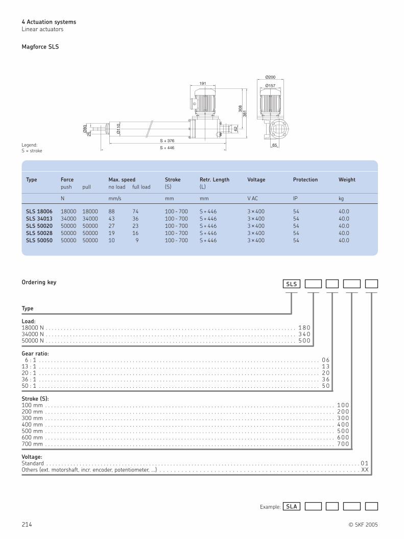
214 © SKF 2005
4 Actuation systems
Linear actuators
Ordering key
Type
Load:18000 N . . . . . . . . . . . . . . . . . . . . . . . . . . . . . . . . . . . . . . . . . . . . . . . . . . . . . . . . . . . . . . . . . . . . . . . . . . . . . . . . . . . 1 8 034000 N . . . . . . . . . . . . . . . . . . . . . . . . . . . . . . . . . . . . . . . . . . . . . . . . . . . . . . . . . . . . . . . . . . . . . . . . . . . . . . . . . . . 3 4 050000 N . . . . . . . . . . . . . . . . . . . . . . . . . . . . . . . . . . . . . . . . . . . . . . . . . . . . . . . . . . . . . . . . . . . . . . . . . . . . . . . . . . . 5 0 0
Gear ratio:6 : 1 . . . . . . . . . . . . . . . . . . . . . . . . . . . . . . . . . . . . . . . . . . . . . . . . . . . . . . . . . . . . . . . . . . . . . . . . . . . . . . . . . . . . . . . . . . . . . 0 6
13 : 1 . . . . . . . . . . . . . . . . . . . . . . . . . . . . . . . . . . . . . . . . . . . . . . . . . . . . . . . . . . . . . . . . . . . . . . . . . . . . . . . . . . . . . . . . . . . . . 1 320 : 1 . . . . . . . . . . . . . . . . . . . . . . . . . . . . . . . . . . . . . . . . . . . . . . . . . . . . . . . . . . . . . . . . . . . . . . . . . . . . . . . . . . . . . . . . . . . . . 2 036 : 1 . . . . . . . . . . . . . . . . . . . . . . . . . . . . . . . . . . . . . . . . . . . . . . . . . . . . . . . . . . . . . . . . . . . . . . . . . . . . . . . . . . . . . . . . . . . . . 3 650 : 1 . . . . . . . . . . . . . . . . . . . . . . . . . . . . . . . . . . . . . . . . . . . . . . . . . . . . . . . . . . . . . . . . . . . . . . . . . . . . . . . . . . . . . . . . . . . . . 5 0
Stroke (S):100 mm . . . . . . . . . . . . . . . . . . . . . . . . . . . . . . . . . . . . . . . . . . . . . . . . . . . . . . . . . . . . . . . . . . . . . . . . . . . . . . . . . . . . . . . . . . . . . . . . 1 0 0200 mm . . . . . . . . . . . . . . . . . . . . . . . . . . . . . . . . . . . . . . . . . . . . . . . . . . . . . . . . . . . . . . . . . . . . . . . . . . . . . . . . . . . . . . . . . . . . . . . . 2 0 0300 mm . . . . . . . . . . . . . . . . . . . . . . . . . . . . . . . . . . . . . . . . . . . . . . . . . . . . . . . . . . . . . . . . . . . . . . . . . . . . . . . . . . . . . . . . . . . . . . . . 3 0 0400 mm . . . . . . . . . . . . . . . . . . . . . . . . . . . . . . . . . . . . . . . . . . . . . . . . . . . . . . . . . . . . . . . . . . . . . . . . . . . . . . . . . . . . . . . . . . . . . . . . 4 0 0500 mm . . . . . . . . . . . . . . . . . . . . . . . . . . . . . . . . . . . . . . . . . . . . . . . . . . . . . . . . . . . . . . . . . . . . . . . . . . . . . . . . . . . . . . . . . . . . . . . . 5 0 0600 mm . . . . . . . . . . . . . . . . . . . . . . . . . . . . . . . . . . . . . . . . . . . . . . . . . . . . . . . . . . . . . . . . . . . . . . . . . . . . . . . . . . . . . . . . . . . . . . . . 6 0 0700 mm . . . . . . . . . . . . . . . . . . . . . . . . . . . . . . . . . . . . . . . . . . . . . . . . . . . . . . . . . . . . . . . . . . . . . . . . . . . . . . . . . . . . . . . . . . . . . . . . 7 0 0
Voltage:Standard . . . . . . . . . . . . . . . . . . . . . . . . . . . . . . . . . . . . . . . . . . . . . . . . . . . . . . . . . . . . . . . . . . . . . . . . . . . . . . . . . . . . . . . . . . . . . . . . . . . . . . . . 0 1Others (ext. motorshaft, incr. encoder, potentiometer, …) . . . . . . . . . . . . . . . . . . . . . . . . . . . . . . . . . . . . . . . . . . . . . . . . . . . . . . . XX
Magforce SLS
Example:
SLS
SLA
Legend:
S = stroke
—————— ————
Type Force Max. speed Stroke Retr. Length Voltage Protection Weight
push pull no load full load (S) (L)
N mm/s mm mm V AC IP kg
SLS 18006 18000 18000 88 74 100 - 700 S + 446 3 ×400 54 40.0
SLS 34013 34000 34000 43 36 100 - 700 S + 446 3 ×400 54 40.0
SLS 50020 50000 50000 27 23 100 - 700 S + 446 3 ×400 54 40.0
SLS 50028 50000 50000 19 16 100 - 700 S + 446 3 ×400 54 40.0
SLS 50050 50000 50000 10 9 100 - 700 S + 446 3 ×400 54 40.0

© SKF 2005 215
4
Notes

216 © SKF 2005
4 Actuation systems
Linear actuators
ECOMAG
The ECOMAG ( figure 13) is a compact
and cost effective actuator which is
designed for medical and home envi-
ronment. It allows precise movements and
ergonomically correct positioning. The
safety and reliability of the ECOMAG is well
proven.
Benefits:
Compact
Cost effective
Control unit can be mounted to the
actuator
Type Force Max. speed Stroke Retr. Length Voltage Protection Weight
push pull no load full load (S) (L)
N mm/s mm mm V DC IP kg
ECO 20 / 40 2000 0 13 9 50 - 300 S +160 24 X4 2.1
ECO 60 / 80 6000 0 7 4 50 - 300 S +160 24 X4 2.1
ECO 30 / 50 2000 2000 13 9 50 - 300 S +160 24 X4 2.5
ECO 70 / 90 6000 4000 7 4 50 - 300 S +160 24 X4 2.5
**
113
L = S + 160 72
26
26
165
ø30
(6, 8
, 10) 15 17
15 15
6
ø30
ø30
15 17
ø30
15 15
79 72
14025
25 22,4
83,4
Figure 13
Legend:
S = stroke
L = retracted length

© SKF 2005 217
4
ECOMAG
Ordering key
Type
Load /Housing:Push Pull Housing2000 N 0 Large. . . . . . . . . . . . . . . . . . . . . . . . . . . . . . . . . . . . . . . . . . . . . . . . . . . . . . . . . . . 22000 N 2000 N Large. . . . . . . . . . . . . . . . . . . . . . . . . . . . . . . . . . . . . . . . . . . . . . . . . . . . . . . . . . . 32000 N 0 Small. . . . . . . . . . . . . . . . . . . . . . . . . . . . . . . . . . . . . . . . . . . . . . . . . . . . . . . . . . . 42000 N 2000 N Small. . . . . . . . . . . . . . . . . . . . . . . . . . . . . . . . . . . . . . . . . . . . . . . . . . . . . . . . . . . 56000 N 0 Large. . . . . . . . . . . . . . . . . . . . . . . . . . . . . . . . . . . . . . . . . . . . . . . . . . . . . . . . . . . 66000 N 4000 N Large. . . . . . . . . . . . . . . . . . . . . . . . . . . . . . . . . . . . . . . . . . . . . . . . . . . . . . . . . . . 76000 N 0 Small. . . . . . . . . . . . . . . . . . . . . . . . . . . . . . . . . . . . . . . . . . . . . . . . . . . . . . . . . . . 86000 N 4000 N Small. . . . . . . . . . . . . . . . . . . . . . . . . . . . . . . . . . . . . . . . . . . . . . . . . . . . . . . . . . . 9
Encoder:Without (cable coiled with 2-pin Minifit plug / or client option) . . . . . . . . . . . . . . . . . . . . . . . . . . . . . . . . . . 0With (cable coiled with 8-pin DIN plug / or client option) . . . . . . . . . . . . . . . . . . . . . . . . . . . . . . . . . . . . . . . 9
Current cut-off:Without. . . . . . . . . . . . . . . . . . . . . . . . . . . . . . . . . . . . . . . . . . . . . . . . . . . . . . . . . . . . . . . . . . . . . . . . . . . . . . . . . . 0
Stroke (S):50 mm . . . . . . . . . . . . . . . . . . . . . . . . . . . . . . . . . . . . . . . . . . . . . . . . . . . . . . . . . . . . . . . . . . . . . . . . . . . . . . . . . . . 0 5
100 mm . . . . . . . . . . . . . . . . . . . . . . . . . . . . . . . . . . . . . . . . . . . . . . . . . . . . . . . . . . . . . . . . . . . . . . . . . . . . . . . . . . . 1 0150 mm . . . . . . . . . . . . . . . . . . . . . . . . . . . . . . . . . . . . . . . . . . . . . . . . . . . . . . . . . . . . . . . . . . . . . . . . . . . . . . . . . . . 1 5200 mm . . . . . . . . . . . . . . . . . . . . . . . . . . . . . . . . . . . . . . . . . . . . . . . . . . . . . . . . . . . . . . . . . . . . . . . . . . . . . . . . . . . 2 0250 mm . . . . . . . . . . . . . . . . . . . . . . . . . . . . . . . . . . . . . . . . . . . . . . . . . . . . . . . . . . . . . . . . . . . . . . . . . . . . . . . . . . . 2 5300 mm . . . . . . . . . . . . . . . . . . . . . . . . . . . . . . . . . . . . . . . . . . . . . . . . . . . . . . . . . . . . . . . . . . . . . . . . . . . . . . . . . . . 3 0
Fork Head (groove depth 17 mm):Hole, Ø 12 mm, groove width 10 mm . . . . . . . . . . . . . . . . . . . . . . . . . . . . . . . . . . . . . . . . . . . . . . . . . . . . . . . . . . . . . . . . M
Hinge (groove depth 15 mm):Hole, Ø 12 mm, groove width 10 mm . . . . . . . . . . . . . . . . . . . . . . . . . . . . . . . . . . . . . . . . . . . . . . . . . . . . . . . . . . . . . . . . . . . M
Hinge position:0° . . . . . . . . . . . . . . . . . . . . . . . . . . . . . . . . . . . . . . . . . . . . . . . . . . . . . . . . . . . . . . . . . . . . . . . . . . . . . . . . . . . . . . . . . . . . . . . . . 1
22.5° . . . . . . . . . . . . . . . . . . . . . . . . . . . . . . . . . . . . . . . . . . . . . . . . . . . . . . . . . . . . . . . . . . . . . . . . . . . . . . . . . . . . . . . . . . . . . . . . 245° . . . . . . . . . . . . . . . . . . . . . . . . . . . . . . . . . . . . . . . . . . . . . . . . . . . . . . . . . . . . . . . . . . . . . . . . . . . . . . . . . . . . . . . . . . . . . . . . . 377,5°. . . . . . . . . . . . . . . . . . . . . . . . . . . . . . . . . . . . . . . . . . . . . . . . . . . . . . . . . . . . . . . . . . . . . . . . . . . . . . . . . . . . . . . . . . . . . . . . 490° . . . . . . . . . . . . . . . . . . . . . . . . . . . . . . . . . . . . . . . . . . . . . . . . . . . . . . . . . . . . . . . . . . . . . . . . . . . . . . . . . . . . . . . . . . . . . . . . . 5
Colour:Black. . . . . . . . . . . . . . . . . . . . . . . . . . . . . . . . . . . . . . . . . . . . . . . . . . . . . . . . . . . . . . . . . . . . . . . . . . . . . . . . . . . . . . . . . . . . . . . . . . . AGrey RAL 7035 . . . . . . . . . . . . . . . . . . . . . . . . . . . . . . . . . . . . . . . . . . . . . . . . . . . . . . . . . . . . . . . . . . . . . . . . . . . . . . . . . . . . . . . . . . B
Options:No options . . . . . . . . . . . . . . . . . . . . . . . . . . . . . . . . . . . . . . . . . . . . . . . . . . . . . . . . . . . . . . . . . . . . . . . . . . . . . . . . . . . . . . . . . . . . . . . . . 0Back-up nut (available only for drives with 6kN, obligatory for UL 2601) - only for ECO7/9, L = + 23 mm . . . . . . . . . . . . . . . . . . . . . . AFOR ECO3,- / ECO5.- ONLY (no back up nut)
Quick-release, motor direction push, fork head bore parallel to lever, L = + 40 mm . . . . . . . . . . . . . . . . . . . . . . . . . . . . . . . . . . . . BQuick-release, motor direction push, fork head bore 90° to lever, L = + 40 mm . . . . . . . . . . . . . . . . . . . . . . . . . . . . . . . . . . . . . . . CQuick-release, motor direction pull, fork head bore parallel to lever, L = + 40 mm . . . . . . . . . . . . . . . . . . . . . . . . . . . . . . . . . . . . . FQuick-release, motor direction pull, fork head bore 90° to lever, L = + 40 mm. . . . . . . . . . . . . . . . . . . . . . . . . . . . . . . . . . . . . . . . GMechanical anti-pinching protection pull, motor direction push, L = + 13 mm . . . . . . . . . . . . . . . . . . . . . . . . . . . . . . . . . . . . . . . . KMechanical anti-pinching protection push, motor direction pull, L = + 13 mm . . . . . . . . . . . . . . . . . . . . . . . . . . . . . . . . . . . . . . . . L
0ECO M M
Example:
—– ————–– —— — — —-- 0 0 0
05ECO 1 5 M M 3 KA0 -- 0 0 0

218 © SKF 2005
4 Actuation systems
Linear actuators
CALA 36
CALA 36 ( figure 14) is a compact 12 or
24 V DC actuator, intended for industrial
use.
The motor and drive spindle are
connected in-line through a planetary gear
assembly. This makes the compact design
suitable in applications where space is
restricted. A comprehensive range of
suitable SKF control systems is available.
Benefits:
In-line layout
Aesthetic design
High operating reliability
Figure 14
Type Force Max. speed Stroke Retr. Length* Voltage Protection Weight
push pull no load full load (S) (L)
N mm/s mm mm V DC IP kg
CALA 36A 600 600 23 12 50 - 200 S + 215 / 226 / 257 12/24 44 0.9 - 1.4
* Dimension depends on selected front attachment

© SKF 2005 219
4
CALA 36A
G3
G6
G5
Ordering key
Type
Load /Speed:600 N/23 - 12 mm/s. . . . . . . . . . . . . . . . . . . . . . . . . . . . . . . . . . . . . . . . . . . . . . . . . . . . . . . . . . . . . . . . . . A
Stroke (S):50 mm . . . . . . . . . . . . . . . . . . . . . . . . . . . . . . . . . . . . . . . . . . . . . . . . . . . . . . . . . . . . . . . . . . . . . . . . . . . . . . . 0 5 0
100 mm . . . . . . . . . . . . . . . . . . . . . . . . . . . . . . . . . . . . . . . . . . . . . . . . . . . . . . . . . . . . . . . . . . . . . . . . . . . . . . . 1 0 0150 mm . . . . . . . . . . . . . . . . . . . . . . . . . . . . . . . . . . . . . . . . . . . . . . . . . . . . . . . . . . . . . . . . . . . . . . . . . . . . . . . 1 5 0200 mm . . . . . . . . . . . . . . . . . . . . . . . . . . . . . . . . . . . . . . . . . . . . . . . . . . . . . . . . . . . . . . . . . . . . . . . . . . . . . . . 2 0 050 mm < S < 200 mm . . . . . . . . . . . . . . . . . . . . . . . . . . . . . . . . . . . . . . . . . . . . . . . . . . . . . . . . . . . . . . . . . . . . - - -
Front attachment:Male thread, M12 . . . . . . . . . . . . . . . . . . . . . . . . . . . . . . . . . . . . . . . . . . . . . . . . . . . . . . . . . . . . . . . . . . . . . . . . . . . . . . . . . . . . G3Fork end, Ø 10.1 mm . . . . . . . . . . . . . . . . . . . . . . . . . . . . . . . . . . . . . . . . . . . . . . . . . . . . . . . . . . . . . . . . . . . . . . . . . . . . . . . . . G5Hole, Ø 10.0 mm . . . . . . . . . . . . . . . . . . . . . . . . . . . . . . . . . . . . . . . . . . . . . . . . . . . . . . . . . . . . . . . . . . . . . . . . . . . . . . . . . . . . G6
Motor voltage:12 V DC . . . . . . . . . . . . . . . . . . . . . . . . . . . . . . . . . . . . . . . . . . . . . . . . . . . . . . . . . . . . . . . . . . . . . . . . . . . . . . . . . . . . . . . . . . . . . . . . . D 1 224 V DC . . . . . . . . . . . . . . . . . . . . . . . . . . . . . . . . . . . . . . . . . . . . . . . . . . . . . . . . . . . . . . . . . . . . . . . . . . . . . . . . . . . . . . . . . . . . . . . . . D 2 4
Cable:Straight 0.25 m, no plug . . . . . . . . . . . . . . . . . . . . . . . . . . . . . . . . . . . . . . . . . . . . . . . . . . . . . . . . . . . . . . . . . . . . . . . . . . . . . . . . . . . . . . . . . UStraight 1.9 m, jack plug . . . . . . . . . . . . . . . . . . . . . . . . . . . . . . . . . . . . . . . . . . . . . . . . . . . . . . . . . . . . . . . . . . . . . . . . . . . . . . . . . . . . . . . . . T 2Straight 1.9 m, no plug . . . . . . . . . . . . . . . . . . . . . . . . . . . . . . . . . . . . . . . . . . . . . . . . . . . . . . . . . . . . . . . . . . . . . . . . . . . . . . . . . . . . . . . . . . T 2 P
CALA ×A3 6 × 4 /
Example:
Legend:
S = stroke
L = retracted length
—– —–—––————– — —–
CALA T 2 PD 1 21 5 0×A3 6 × 4 G 5 /

220 © SKF 2005
4 Actuation systems
Linear actuators
MATRIX
The MATRIX series ( figure 15) includes
powerful AC and DC-actuators. They run
very quietly, take up little space and can be
installed at virtually every angle in vertical
or horizontal position. The MATRIX range is
complemented by the KOM control units,
which allow a flexible and application
focused control system.
Benefits:
Long service life
Silent operation
Full system with control, operating units
and accessories
Synchronization possible
Compact and aesthetic
Safety nut in standard
Figure 15
Accessories
Type Force Max. speed Stroke Retr. Length Voltage Protection Weight
push pull no load full load (S) (L)
N mm/s mm mm V IP kg
MAX6.-C 3000 3000 18 15 50 - 700 S + 215** 120 / 230 AC 66 4.2
MAX6.-B 4000 4000 10 8 50 - 700 S + 215** 120 / 230 AC 66 4.5
MAX6.-A 8000 6000 8 6 50 - 700 S + 215** 120 / 230 AC 66 4.8
MAX1.-C 1500 1500 18 13 50 - 700 S + 195* 24 DC 66 3.6
MAX1.-B 2000 2000 9 6 50 - 700 S + 195* 24 DC 66 3.7
MAX3.-C 3000 3000 18 13 50 - 700 S + 215** 24 / 12 DC 66 4.0
MAX1.-A 4000 4000 7 5 50 - 700 S + 195* 24 DC 66 4.0
MAX3.-B 4000 4000 9 6 50 - 700 S + 215** 24 / 12 DC 66 4.2
MAX3.-A 8000 6000 7 5 50 - 700 S + 215** 24 / 12 DC 66 4.5
* stroke < 350 mm retr. Length stroke + 260 mm
** stroke > 350 mm retr. Length stroke + 280 mm
Mains cable Plug Country Order number Comment
Straight cable 3.5 Schuko DE 140306
Straight cable 3.5 SEV CH 140316
Straight cable 3.5 UL USA 140355
Straight cable 3.5 Hospital grade USA 140360
Straight cable 3.5 British standard UK 140350
Coiled cable 1.2 m / 2.2 m Schuko DE 140342
Coiled cable 1.2 m / 2.2 m SEV CH 140378
Straight cable 3.5 SEV CH 140422-3500 Polyurethane cable
Straight cable 3.5 Schuko DE 140426-3500 Polyurethane cable
Strain relief for mains cable ZBE-952253
Tool for plugs (Jack/D-Sub/Mains) 140375
Operating device adaptor (D-Sub 9-pole) 140420

© SKF 2005 221
4
Ordering key
Type
Motor voltage:24 V DC . . . . . . . . . . . . . . . . . . . . . . . . . . . . . . . . . . . . . . . . . . . . . . . . . . . . . . . . . . . . . . . . . 024V DC with integrated current cut-off . . . . . . . . . . . . . . . . . . . . . . . . . . . . . . . . . . . . . . . . 1
Load /Speed:4000 N / 7 - 5 mm/s . . . . . . . . . . . . . . . . . . . . . . . . . . . . . . . . . . . . . . . . . . . . . . . . . . . . . . . . . . . . A2000 N / 9 - 6 mm/s. . . . . . . . . . . . . . . . . . . . . . . . . . . . . . . . . . . . . . . . . . . . . . . . . . . . . . . . . . . . B1500 N / 18 - 13 mm/s. . . . . . . . . . . . . . . . . . . . . . . . . . . . . . . . . . . . . . . . . . . . . . . . . . . . . . . . . . . C
Stroke (S):50 mm . . . . . . . . . . . . . . . . . . . . . . . . . . . . . . . . . . . . . . . . . . . . . . . . . . . . . . . . . . . . . . . . . . . . . 0 5 0 2 4 5
100 mm . . . . . . . . . . . . . . . . . . . . . . . . . . . . . . . . . . . . . . . . . . . . . . . . . . . . . . . . . . . . . . . . . . . . . 1 0 0 2 9 5150 mm . . . . . . . . . . . . . . . . . . . . . . . . . . . . . . . . . . . . . . . . . . . . . . . . . . . . . . . . . . . . . . . . . . . . . 1 5 0 3 4 5200 mm . . . . . . . . . . . . . . . . . . . . . . . . . . . . . . . . . . . . . . . . . . . . . . . . . . . . . . . . . . . . . . . . . . . . . 2 0 0 3 9 5250 mm . . . . . . . . . . . . . . . . . . . . . . . . . . . . . . . . . . . . . . . . . . . . . . . . . . . . . . . . . . . . . . . . . . . . . 2 5 0 4 4 5300 mm . . . . . . . . . . . . . . . . . . . . . . . . . . . . . . . . . . . . . . . . . . . . . . . . . . . . . . . . . . . . . . . . . . . . . 3 0 0 4 9 5350 mm . . . . . . . . . . . . . . . . . . . . . . . . . . . . . . . . . . . . . . . . . . . . . . . . . . . . . . . . . . . . . . . . . . . . . 3 5 0 5 4 5400 mm . . . . . . . . . . . . . . . . . . . . . . . . . . . . . . . . . . . . . . . . . . . . . . . . . . . . . . . . . . . . . . . . . . . . . 4 0 0 6 6 0450 mm . . . . . . . . . . . . . . . . . . . . . . . . . . . . . . . . . . . . . . . . . . . . . . . . . . . . . . . . . . . . . . . . . . . . . 4 5 0 7 1 0500 mm . . . . . . . . . . . . . . . . . . . . . . . . . . . . . . . . . . . . . . . . . . . . . . . . . . . . . . . . . . . . . . . . . . . . . 5 0 0 7 6 0550 mm . . . . . . . . . . . . . . . . . . . . . . . . . . . . . . . . . . . . . . . . . . . . . . . . . . . . . . . . . . . . . . . . . . . . . 5 5 0 8 1 0600 mm . . . . . . . . . . . . . . . . . . . . . . . . . . . . . . . . . . . . . . . . . . . . . . . . . . . . . . . . . . . . . . . . . . . . . 6 0 0 8 6 0650 mm . . . . . . . . . . . . . . . . . . . . . . . . . . . . . . . . . . . . . . . . . . . . . . . . . . . . . . . . . . . . . . . . . . . . . 6 5 0 9 1 0700 mm . . . . . . . . . . . . . . . . . . . . . . . . . . . . . . . . . . . . . . . . . . . . . . . . . . . . . . . . . . . . . . . . . . . . . 7 0 0 9 6 0
Colour:Grey RAL 7035 . . . . . . . . . . . . . . . . . . . . . . . . . . . . . . . . . . . . . . . . . . . . . . . . . . . . . . . . . . . . . . . . . . . . . . . . . . . . . . A
Cable /Connecting plug:Straight, 2.5 m, Din 8 . . . . . . . . . . . . . . . . . . . . . . . . . . . . . . . . . . . . . . . . . . . . . . . . . . . . . . . . . . . . . . . . . . . . . . . . . . . C 5
Orientation of rear attachment:Standard (as drawing) . . . . . . . . . . . . . . . . . . . . . . . . . . . . . . . . . . . . . . . . . . . . . . . . . . . . . . . . . . . . . . . . . . . . . . . . . . . . . . . 1
Options 1:No options, only valid for actuator “A” . . . . . . . . . . . . . . . . . . . . . . . . . . . . . . . . . . . . . . . . . . . . . . . . . . . . . . . . . . . . . . . . . . . . . . 0Quick-release + EKZm*, push, fork head bore parallel to button (for actuator design “C” is L = + 115 mm) . . . . . . . . . . . . . . . . EQuick-release + EKZm*, push, fork head bore parallel to Bowden cable (for actuator design “C” is L = + 115 mm) . . . . . . . . . . GMechanical anti-pinching protection, pull, without fixing in term. position, (for actuator design “A” is L = + 45 mm, “B” and “C” is L = + 30 mm) . . . . . . . . . . . . . . . . . . . . . . . . . . . . . . . . . . . . . . . . . . . . . . . . . . . . . . . . . . . . . . . . . . . . . . . . . . . . . I
Mechanical anti-pinching protection, push, without fixing in term. position, (for actuator design “A” is L = + 45 mm, “B” and “C” is L = + 30 mm) . . . . . . . . . . . . . . . . . . . . . . . . . . . . . . . . . . . . . . . . . . . . . . . . . . . . . . . . . . . . . . . . . . . . . . . . . . . . . J
Motor direction push, only valid for actuator “B” and “C” . . . . . . . . . . . . . . . . . . . . . . . . . . . . . . . . . . . . . . . . . . . . . . . . . . . . . . . MMotor direction pull, only valid for actuator “B” and “C” . . . . . . . . . . . . . . . . . . . . . . . . . . . . . . . . . . . . . . . . . . . . . . . . . . . . . . . . N
Options 2:No options . . . . . . . . . . . . . . . . . . . . . . . . . . . . . . . . . . . . . . . . . . . . . . . . . . . . . . . . . . . . . . . . . . . . . . . . . . . . . . . . . . . . . . . . . . . . . . 0Encoder, 8 pulses /revolution, only with jack plug . . . . . . . . . . . . . . . . . . . . . . . . . . . . . . . . . . . . . . . . . . . . . . . . . . . . . . . . . . . . . A
Options 3:Emergency lowering, fork head bore parallel to clamping lever (for actuator design “A”, L + 30 mm) . . . . . . . . . . . . . . . . . . . . . . . . . . . V
*EKZm: mechanical anti-pinching
MAX1
4016
9
66
10748
ø12
42.5
28 28
L = S + 195/260
ø12
66
ø6.
3
S
MA X1 0 0 0- A C 5 1 -
Example:
–————– — — —V
MA X1 1 0 0 05 5 0 8 1 0B- A C 5 1 0 -G V
——–— — — — ——
Legend:
S = stroke
L = retracted length For data see Table on page 220

222 © SKF 2005
4 Actuation systems
Linear actuators
MAX3
4019
2
82
11250
10
ø1242
.528 28
S L = S + 215/280
ø12
82
ø6.
3
Legend:
S = stroke
L = retracted length
Ordering key
Type
Motor voltage:24 V DC . . . . . . . . . . . . . . . . . . . . . . . . . . . . . . . . . . . . . . . . . . . . . . . . . . . . . . . . . . . . . . . . . 012 V DC . . . . . . . . . . . . . . . . . . . . . . . . . . . . . . . . . . . . . . . . . . . . . . . . . . . . . . . . . . . . . . . . . 2
Load /Speed:8000 N / 7 - 5 mm/s . . . . . . . . . . . . . . . . . . . . . . . . . . . . . . . . . . . . . . . . . . . . . . . . . . . . . . . . . . . . A4000 N / 9 - 6 mm/s. . . . . . . . . . . . . . . . . . . . . . . . . . . . . . . . . . . . . . . . . . . . . . . . . . . . . . . . . . . . B3000 N / 18 - 13 mm/s. . . . . . . . . . . . . . . . . . . . . . . . . . . . . . . . . . . . . . . . . . . . . . . . . . . . . . . . . . . C
Stroke (S):50 mm . . . . . . . . . . . . . . . . . . . . . . . . . . . . . . . . . . . . . . . . . . . . . . . . . . . . . . . . . . . . . . . . . . . . . 0 5 0 2 6 5
100 mm . . . . . . . . . . . . . . . . . . . . . . . . . . . . . . . . . . . . . . . . . . . . . . . . . . . . . . . . . . . . . . . . . . . . . 1 0 0 3 1 5150 mm . . . . . . . . . . . . . . . . . . . . . . . . . . . . . . . . . . . . . . . . . . . . . . . . . . . . . . . . . . . . . . . . . . . . . 1 5 0 3 6 5200 mm . . . . . . . . . . . . . . . . . . . . . . . . . . . . . . . . . . . . . . . . . . . . . . . . . . . . . . . . . . . . . . . . . . . . . 2 0 0 4 1 5250 mm . . . . . . . . . . . . . . . . . . . . . . . . . . . . . . . . . . . . . . . . . . . . . . . . . . . . . . . . . . . . . . . . . . . . . 2 5 0 4 6 5300 mm . . . . . . . . . . . . . . . . . . . . . . . . . . . . . . . . . . . . . . . . . . . . . . . . . . . . . . . . . . . . . . . . . . . . . 3 0 0 5 1 5350 mm . . . . . . . . . . . . . . . . . . . . . . . . . . . . . . . . . . . . . . . . . . . . . . . . . . . . . . . . . . . . . . . . . . . . . 3 5 0 5 6 5400 mm . . . . . . . . . . . . . . . . . . . . . . . . . . . . . . . . . . . . . . . . . . . . . . . . . . . . . . . . . . . . . . . . . . . . . 4 0 0 6 8 0450 mm . . . . . . . . . . . . . . . . . . . . . . . . . . . . . . . . . . . . . . . . . . . . . . . . . . . . . . . . . . . . . . . . . . . . . 4 5 0 7 3 0500 mm . . . . . . . . . . . . . . . . . . . . . . . . . . . . . . . . . . . . . . . . . . . . . . . . . . . . . . . . . . . . . . . . . . . . . 5 0 0 7 8 0550 mm . . . . . . . . . . . . . . . . . . . . . . . . . . . . . . . . . . . . . . . . . . . . . . . . . . . . . . . . . . . . . . . . . . . . . 5 5 0 8 3 0600 mm . . . . . . . . . . . . . . . . . . . . . . . . . . . . . . . . . . . . . . . . . . . . . . . . . . . . . . . . . . . . . . . . . . . . . 6 0 0 8 8 0650 mm . . . . . . . . . . . . . . . . . . . . . . . . . . . . . . . . . . . . . . . . . . . . . . . . . . . . . . . . . . . . . . . . . . . . . 6 5 0 9 3 0700 mm . . . . . . . . . . . . . . . . . . . . . . . . . . . . . . . . . . . . . . . . . . . . . . . . . . . . . . . . . . . . . . . . . . . . . 7 0 0 9 8 0
Colour:Grey RAL 7035 . . . . . . . . . . . . . . . . . . . . . . . . . . . . . . . . . . . . . . . . . . . . . . . . . . . . . . . . . . . . . . . . . . . . . . . . . . . . . . A
Cable /Connecting plug:Straight, 2.5 m, Din 8 . . . . . . . . . . . . . . . . . . . . . . . . . . . . . . . . . . . . . . . . . . . . . . . . . . . . . . . . . . . . . . . . . . . . . . . . . . . C 5
Orientation of rear attachment:Standard (as drawing) . . . . . . . . . . . . . . . . . . . . . . . . . . . . . . . . . . . . . . . . . . . . . . . . . . . . . . . . . . . . . . . . . . . . . . . . . . . . . . . 1
Options 1:No options, only valid for actuator “A” . . . . . . . . . . . . . . . . . . . . . . . . . . . . . . . . . . . . . . . . . . . . . . . . . . . . . . . . . . . . . . . . . . . . . . 0Quick-release + EKZm*, push, fork head bore parallel to button (for actuator design “C” is L = + 115 mm) . . . . . . . . . . . . . . . . EQuick-release + EKZm*, push, fork head bore parallel to Bowden cable (for actuator design “C” is L = + 115 mm) . . . . . . . . . . GMechanical anti-pinching protection, pull, no fixing in term. position, (for actuator design “A” is L = + 45 mm, “B” and “C” is L = + 30 mm) . . . . . . . . . . . . . . . . . . . . . . . . . . . . . . . . . . . . . . . . . . . . . . . . . . . . . . . . . . . . . . . . . . . . . . . . . . . . . I
Mechanical anti-pinching protection, push, no fixing in term. position, (for actuator design “A” is L = + 45 mm, “B” and “C” is L = + 30 mm) . . . . . . . . . . . . . . . . . . . . . . . . . . . . . . . . . . . . . . . . . . . . . . . . . . . . . . . . . . . . . . . . . . . . . . . . . . . . . J
Electrical anti-pinching protection (safety switch), pull, for all actuators. . . . . . . . . . . . . . . . . . . . . . . . . . . . . . . . . . . . . . . . . . . . KElectrical anti-pinching protection (safety switch), push, for all actuators. . . . . . . . . . . . . . . . . . . . . . . . . . . . . . . . . . . . . . . . . . . LMotor direction push, only valid for actuator “B” and “C” . . . . . . . . . . . . . . . . . . . . . . . . . . . . . . . . . . . . . . . . . . . . . . . . . . . . . . . MMotor direction pull, only valid for actuator “B” and “C” . . . . . . . . . . . . . . . . . . . . . . . . . . . . . . . . . . . . . . . . . . . . . . . . . . . . . . . . N
Options 2:No options . . . . . . . . . . . . . . . . . . . . . . . . . . . . . . . . . . . . . . . . . . . . . . . . . . . . . . . . . . . . . . . . . . . . . . . . . . . . . . . . . . . . . . . . . . . . . . 0Encoder, 8 pulses /revolution (not possible with electrical anti-pinching protection), only with jack plug . . . . . . . . . . . . . . . . . . . . . A
Options 3:Emergency lowering, fork head bore parallel to clamping lever (for actuator design “A”, L + 30 mm). . . . . . . . . . . . . . . . . . . . . . . . . . . V
*EKZm: mechanical anti-pinching
MA X3 0 0 0- A C 5 1 -
Example:
–————– — — —V
MA X3 0 0 0 02 5 0 4 6 5B- A C 5 1 0 -E V
——–— — — — ——
For data see Table on page 220

© SKF 2005 223
4
MAX6
4011
5.5
70.5
192.
5
135
112 1150
ø12
42.5
28 28
S L = S + 215/280
ø12
85
Legend:
S = stroke
L = retracted length
Ordering key
Type
Motor voltage:230 V AC / 50 Hz, integrated pneumatic control . . . . . . . . . . . . . . . . . . . . . . . . . . . . . . . . . . 0120 V AC / 60 Hz, integrated pneumatic control . . . . . . . . . . . . . . . . . . . . . . . . . . . . . . . . . . 1230 V AC / 50 Hz, integrated low voltage control with additional 24 V DC output . . . . . . . . 2120 V AC / 60 Hz, control + 1 channel with additional 24 V DC output . . . . . . . . . . . . . . . . 3230 V AC / 50 Hz, integrated low voltage . . . . . . . . . . . . . . . . . . . . . . . . . . . . . . . . . . . . . . . 4120 V AC / 60 Hz, control . . . . . . . . . . . . . . . . . . . . . . . . . . . . . . . . . . . . . . . . . . . . . . . . . . . 5
Load /Speed:8000 N / 8 - 6 mm/s . . . . . . . . . . . . . . . . . . . . . . . . . . . . . . . . . . . . . . . . . . . . . . . . . . . . . . . . . . . . A4000 N / 10 - 8 mm/s. . . . . . . . . . . . . . . . . . . . . . . . . . . . . . . . . . . . . . . . . . . . . . . . . . . . . . . . . . . . B3000 N / 18 - 15 mm/s. . . . . . . . . . . . . . . . . . . . . . . . . . . . . . . . . . . . . . . . . . . . . . . . . . . . . . . . . . . C
Stroke (S):50 mm . . . . . . . . . . . . . . . . . . . . . . . . . . . . . . . . . . . . . . . . . . . . . . . . . . . . . . . . . . . . . . . . . . . . . 0 5 0 2 6 5
100 mm . . . . . . . . . . . . . . . . . . . . . . . . . . . . . . . . . . . . . . . . . . . . . . . . . . . . . . . . . . . . . . . . . . . . . 1 0 0 3 1 5150 mm . . . . . . . . . . . . . . . . . . . . . . . . . . . . . . . . . . . . . . . . . . . . . . . . . . . . . . . . . . . . . . . . . . . . . 1 5 0 3 6 5200 mm . . . . . . . . . . . . . . . . . . . . . . . . . . . . . . . . . . . . . . . . . . . . . . . . . . . . . . . . . . . . . . . . . . . . . 2 0 0 4 1 5250 mm . . . . . . . . . . . . . . . . . . . . . . . . . . . . . . . . . . . . . . . . . . . . . . . . . . . . . . . . . . . . . . . . . . . . . 2 5 0 4 6 5300 mm . . . . . . . . . . . . . . . . . . . . . . . . . . . . . . . . . . . . . . . . . . . . . . . . . . . . . . . . . . . . . . . . . . . . . 3 0 0 5 1 5350 mm . . . . . . . . . . . . . . . . . . . . . . . . . . . . . . . . . . . . . . . . . . . . . . . . . . . . . . . . . . . . . . . . . . . . . 3 5 0 5 6 5400 mm . . . . . . . . . . . . . . . . . . . . . . . . . . . . . . . . . . . . . . . . . . . . . . . . . . . . . . . . . . . . . . . . . . . . . 4 0 0 6 8 0450 mm . . . . . . . . . . . . . . . . . . . . . . . . . . . . . . . . . . . . . . . . . . . . . . . . . . . . . . . . . . . . . . . . . . . . . 4 5 0 7 3 0500 mm . . . . . . . . . . . . . . . . . . . . . . . . . . . . . . . . . . . . . . . . . . . . . . . . . . . . . . . . . . . . . . . . . . . . . 5 0 0 7 8 0550 mm . . . . . . . . . . . . . . . . . . . . . . . . . . . . . . . . . . . . . . . . . . . . . . . . . . . . . . . . . . . . . . . . . . . . . 5 5 0 8 3 0600 mm . . . . . . . . . . . . . . . . . . . . . . . . . . . . . . . . . . . . . . . . . . . . . . . . . . . . . . . . . . . . . . . . . . . . . 6 0 0 8 8 0650 mm . . . . . . . . . . . . . . . . . . . . . . . . . . . . . . . . . . . . . . . . . . . . . . . . . . . . . . . . . . . . . . . . . . . . . 6 5 0 9 3 0700 mm . . . . . . . . . . . . . . . . . . . . . . . . . . . . . . . . . . . . . . . . . . . . . . . . . . . . . . . . . . . . . . . . . . . . . 7 0 0 9 8 0
Colour:Grey RAL 7035 . . . . . . . . . . . . . . . . . . . . . . . . . . . . . . . . . . . . . . . . . . . . . . . . . . . . . . . . . . . . . . . . . . . . . . . . . . . . . . A
Cable /Connecting plug:No cable . . . . . . . . . . . . . . . . . . . . . . . . . . . . . . . . . . . . . . . . . . . . . . . . . . . . . . . . . . . . . . . . . . . . . . . . . . . . . . . . . . . . . . . 0
Orientation of rear attachment:Standard (as drawing) . . . . . . . . . . . . . . . . . . . . . . . . . . . . . . . . . . . . . . . . . . . . . . . . . . . . . . . . . . . . . . . . . . . . . . . . . . . . . . . 1
Options 1:No options, only valid for actuator “A” . . . . . . . . . . . . . . . . . . . . . . . . . . . . . . . . . . . . . . . . . . . . . . . . . . . . . . . . . . . . . . . . . . . . . . 0Quick-release + EKZm*, push, fork head bore parallel to button (for actuator design “C” is L = + 115 mm) . . . . . . . . . . . . . . . . EQuick-release + EKZm*, push, fork head bore parallel to Bowden cable (for actuator design “C” is L = + 115 mm) . . . . . . . . . . GMechanical anti-pinching protection, pull, no fixing in term. position, (for actuator design “A” is L = + 45 mm, “B” and “C” is L = + 30 mm) . . . . . . . . . . . . . . . . . . . . . . . . . . . . . . . . . . . . . . . . . . . . . . . . . . . . . . . . . . . . . . . . . . . . . . . . . . . . . I
Mechanical anti-pinching protection, push, no fixing in term. position, (for actuator design “A” is L = + 45 mm, “B” and “C” is L = + 30 mm) . . . . . . . . . . . . . . . . . . . . . . . . . . . . . . . . . . . . . . . . . . . . . . . . . . . . . . . . . . . . . . . . . . . . . . . . . . . . . J
Motor direction push, only valid for actuator “B” and “C” . . . . . . . . . . . . . . . . . . . . . . . . . . . . . . . . . . . . . . . . . . . . . . . . . . . . . . . MMotor direction pull, only valid for actuator “B” and “C” . . . . . . . . . . . . . . . . . . . . . . . . . . . . . . . . . . . . . . . . . . . . . . . . . . . . . . . . N
Options 2:No option . . . . . . . . . . . . . . . . . . . . . . . . . . . . . . . . . . . . . . . . . . . . . . . . . . . . . . . . . . . . . . . . . . . . . . . . . . . . . . . . . . . . . . . . . . . . . . . 0
Options 3:Emergency lowering, fork head bore parallel to clamping lever (for actuator design “A”, L + 30 mm) . . . . . . . . . . . . . . . . . . . . . . . . . . . V
*EKZm: mechanical anti-pinching
MA X6 0 0 0- A 0 1 0 -
Example:
–————– — — —V
MA X6 4 0 0 01 0 0 3 1 5C- A 0 1 0 -J V
——–— — — — –—
For data see Table on page 220

224 © SKF 2005
4 Actuation systems
Linear actuators
Legend:
S = stroke
L = retracted length
CARE 33
Efficient design provides the CARE 33
actuators ( figure 16) with a high
dynamic load capacity, silent operation and
low current consumption.
The safety features of the design make it
particularly suitable for solving a large
number of positioning needs in equipment
for ergonomic and/or industrial applications.
The gearbox floats so that the load path
passes directly through a support bearing
located in the rear attachment. This design
offers a long operational life and minimised
the transmitted noise level.
Benefits:
Silent operation
Multiple speed/load variants
Easy to adjust limit switches
Different attachment options
6.1
13
11
EØ12.7
Ø22
L=S+150
Ø10L=S+162
26
L=S+193
38
M12
Rear attachmentorientation view.
Figure 16
Type Force Max. speed Stroke Retr. Length* Voltage Protection Weight
push pull no load full load (S) (L)
N mm/s mm mm V DC IP kg
CARE 33H 800 800 45 32 50 - 500 S + 150 / 162 / 193 12 / 24 44 / 65 1.5 - 2.4
CARE 33M 1400 1400 22 16 50 - 500 S + 150 / 162 / 193 12 / 24 44 / 65 1.5 - 2.4
CARE 33A 2000 2000 12 8 50 - 300 S + 150 / 162 / 193 12 / 24 44 / 65 1.5 - 2.0
* Dimension depends on selected front attachment

© SKF 2005 225
4
Ordering key
Type
Load (N) /Speed (mm/s):2000/12 - 8. . . . . . . . . . . . . . . . . . . . . . . . . . . . . . . . . . . . . . . . . . . . . . . . . . . . . . . . . . . . . . . . . . . . . . . . . A1400/22 - 16 . . . . . . . . . . . . . . . . . . . . . . . . . . . . . . . . . . . . . . . . . . . . . . . . . . . . . . . . . . . . . . . . . . . . . . . M800/45 - 32 . . . . . . . . . . . . . . . . . . . . . . . . . . . . . . . . . . . . . . . . . . . . . . . . . . . . . . . . . . . . . . . . . . . . . . . H
Stroke:50 mm . . . . . . . . . . . . . . . . . . . . . . . . . . . . . . . . . . . . . . . . . . . . . . . . . . . . . . . . . . . . . . . . . . . . . . . . . . . . 0 5 0
100 mm . . . . . . . . . . . . . . . . . . . . . . . . . . . . . . . . . . . . . . . . . . . . . . . . . . . . . . . . . . . . . . . . . . . . . . . . . . . . 1 0 0150 mm . . . . . . . . . . . . . . . . . . . . . . . . . . . . . . . . . . . . . . . . . . . . . . . . . . . . . . . . . . . . . . . . . . . . . . . . . . . . 1 5 0200 mm . . . . . . . . . . . . . . . . . . . . . . . . . . . . . . . . . . . . . . . . . . . . . . . . . . . . . . . . . . . . . . . . . . . . . . . . . . . . 2 0 0300 mm . . . . . . . . . . . . . . . . . . . . . . . . . . . . . . . . . . . . . . . . . . . . . . . . . . . . . . . . . . . . . . . . . . . . . . . . . . . . 3 0 0400 mm (not possible for CARE 33A) . . . . . . . . . . . . . . . . . . . . . . . . . . . . . . . . . . . . . . . . . . . . . . . . . . . . . 4 0 0500 mm (not possible for CARE 33A) . . . . . . . . . . . . . . . . . . . . . . . . . . . . . . . . . . . . . . . . . . . . . . . . . . . . . 5 0 050 < S < 500 mm (S > 500 mm contact SKF) . . . . . . . . . . . . . . . . . . . . . . . . . . . . . . . . . . . . . . . . . . . . . . . . - - -
Front attachment:Hole, Ø = 12.0 mm. . . . . . . . . . . . . . . . . . . . . . . . . . . . . . . . . . . . . . . . . . . . . . . . . . . . . . . . . . . . . . . . . . . . . . . . . . . . 1Hole, Ø = 12.7 mm. . . . . . . . . . . . . . . . . . . . . . . . . . . . . . . . . . . . . . . . . . . . . . . . . . . . . . . . . . . . . . . . . . . . . . . . . . . . 2Hole, Ø = 10.0 mm, slot 6.1 mm (retracted length, L = S + 162 mm) . . . . . . . . . . . . . . . . . . . . . . . . . . . . . . . . . . . . . 3Male thread M12 (retracted length, L = S + 193 mm) . . . . . . . . . . . . . . . . . . . . . . . . . . . . . . . . . . . . . . . . . . . . . . . . . 4
Rear attachment:Hole, Ø = 12.0 mm . . . . . . . . . . . . . . . . . . . . . . . . . . . . . . . . . . . . . . . . . . . . . . . . . . . . . . . . . . . . . . . . . . . . . . . . . . . . . . 1Hole, Ø = 12.7 mm . . . . . . . . . . . . . . . . . . . . . . . . . . . . . . . . . . . . . . . . . . . . . . . . . . . . . . . . . . . . . . . . . . . . . . . . . . . . . . 2Hole, Ø = 8.0 mm . . . . . . . . . . . . . . . . . . . . . . . . . . . . . . . . . . . . . . . . . . . . . . . . . . . . . . . . . . . . . . . . . . . . . . . . . . . . . . 3Hole, Ø = 10.0 mm . . . . . . . . . . . . . . . . . . . . . . . . . . . . . . . . . . . . . . . . . . . . . . . . . . . . . . . . . . . . . . . . . . . . . . . . . . . . . . 4
Protection class:IP65 . . . . . . . . . . . . . . . . . . . . . . . . . . . . . . . . . . . . . . . . . . . . . . . . . . . . . . . . . . . . . . . . . . . . . . . . . . . . . . . . . . . . . . . . . . . . 1IP44 . . . . . . . . . . . . . . . . . . . . . . . . . . . . . . . . . . . . . . . . . . . . . . . . . . . . . . . . . . . . . . . . . . . . . . . . . . . . . . . . . . . . . . . . . . . . 2
Feed back:No option . . . . . . . . . . . . . . . . . . . . . . . . . . . . . . . . . . . . . . . . . . . . . . . . . . . . . . . . . . . . . . . . . . . . . . . . . . . . . . . . . . . . . . . . . . . 0Encoder (2-channel) . . . . . . . . . . . . . . . . . . . . . . . . . . . . . . . . . . . . . . . . . . . . . . . . . . . . . . . . . . . . . . . . . . . . . . . . . . . . . . . . . . . 1
Cable/Connection plug:Straight, 2.0 m, no connector. . . . . . . . . . . . . . . . . . . . . . . . . . . . . . . . . . . . . . . . . . . . . . . . . . . . . . . . . . . . . . . . . . . . . . . . . . . . . . 1Coiled, 2.0 m, jack plug. . . . . . . . . . . . . . . . . . . . . . . . . . . . . . . . . . . . . . . . . . . . . . . . . . . . . . . . . . . . . . . . . . . . . . . . . . . . . . . . . . . 2Straight, 2.0 m, DIN 8U-plug (for 2-channel encoder) . . . . . . . . . . . . . . . . . . . . . . . . . . . . . . . . . . . . . . . . . . . . . . . . . . . . . . . . . . 3Straight, 2.0 m, jack plug . . . . . . . . . . . . . . . . . . . . . . . . . . . . . . . . . . . . . . . . . . . . . . . . . . . . . . . . . . . . . . . . . . . . . . . . . . . . . . . . . 5
Orientation of rear attachment:0° . . . . . . . . . . . . . . . . . . . . . . . . . . . . . . . . . . . . . . . . . . . . . . . . . . . . . . . . . . . . . . . . . . . . . . . . . . . . . . . . . . . . . . . . . . . . . . . . . . 0 0 0
15° clockwise . . . . . . . . . . . . . . . . . . . . . . . . . . . . . . . . . . . . . . . . . . . . . . . . . . . . . . . . . . . . . . . . . . . . . . . . . . . . . . . . . . . . . . . . . . 0 1 530° clockwise . . . . . . . . . . . . . . . . . . . . . . . . . . . . . . . . . . . . . . . . . . . . . . . . . . . . . . . . . . . . . . . . . . . . . . . . . . . . . . . . . . . . . . . . . . 0 3 045° clockwise . . . . . . . . . . . . . . . . . . . . . . . . . . . . . . . . . . . . . . . . . . . . . . . . . . . . . . . . . . . . . . . . . . . . . . . . . . . . . . . . . . . . . . . . . . 0 4 560° clockwise . . . . . . . . . . . . . . . . . . . . . . . . . . . . . . . . . . . . . . . . . . . . . . . . . . . . . . . . . . . . . . . . . . . . . . . . . . . . . . . . . . . . . . . . . . 0 6 075° clockwise . . . . . . . . . . . . . . . . . . . . . . . . . . . . . . . . . . . . . . . . . . . . . . . . . . . . . . . . . . . . . . . . . . . . . . . . . . . . . . . . . . . . . . . . . . 0 7 590° clockwise . . . . . . . . . . . . . . . . . . . . . . . . . . . . . . . . . . . . . . . . . . . . . . . . . . . . . . . . . . . . . . . . . . . . . . . . . . . . . . . . . . . . . . . . . . 0 9 0
105° clockwise . . . . . . . . . . . . . . . . . . . . . . . . . . . . . . . . . . . . . . . . . . . . . . . . . . . . . . . . . . . . . . . . . . . . . . . . . . . . . . . . . . . . . . . . . . 1 0 5120° clockwise . . . . . . . . . . . . . . . . . . . . . . . . . . . . . . . . . . . . . . . . . . . . . . . . . . . . . . . . . . . . . . . . . . . . . . . . . . . . . . . . . . . . . . . . . . 1 2 0135° clockwise . . . . . . . . . . . . . . . . . . . . . . . . . . . . . . . . . . . . . . . . . . . . . . . . . . . . . . . . . . . . . . . . . . . . . . . . . . . . . . . . . . . . . . . . . . 1 3 5150° clockwise . . . . . . . . . . . . . . . . . . . . . . . . . . . . . . . . . . . . . . . . . . . . . . . . . . . . . . . . . . . . . . . . . . . . . . . . . . . . . . . . . . . . . . . . . . 1 5 0165° clockwise . . . . . . . . . . . . . . . . . . . . . . . . . . . . . . . . . . . . . . . . . . . . . . . . . . . . . . . . . . . . . . . . . . . . . . . . . . . . . . . . . . . . . . . . . . 1 6 5
Motor voltage:24 V DC . . . . . . . . . . . . . . . . . . . . . . . . . . . . . . . . . . . . . . . . . . . . . . . . . . . . . . . . . . . . . . . . . . . . . . . . . . . . . . . . . . . . . . . . . . . . . . . . . . . . . . 2 412 V DC . . . . . . . . . . . . . . . . . . . . . . . . . . . . . . . . . . . . . . . . . . . . . . . . . . . . . . . . . . . . . . . . . . . . . . . . . . . . . . . . . . . . . . . . . . . . . . . . . . . . . . 1 2
Self locking feature (mandatory when selecting load / speed version “H” or “M”):No self locking required . . . . . . . . . . . . . . . . . . . . . . . . . . . . . . . . . . . . . . . . . . . . . . . . . . . . . . . . . . . . . . . . . . . . . . . . . . . . . . . . . . . . . . . . . . . . . . 0Self locking for pulling load. . . . . . . . . . . . . . . . . . . . . . . . . . . . . . . . . . . . . . . . . . . . . . . . . . . . . . . . . . . . . . . . . . . . . . . . . . . . . . . . . . . . . . . . . . . . 1Self locking for pushing load. . . . . . . . . . . . . . . . . . . . . . . . . . . . . . . . . . . . . . . . . . . . . . . . . . . . . . . . . . . . . . . . . . . . . . . . . . . . . . . . . . . . . . . . . . . 2
CARE 3 3
CARE 2 4 1300M3 3 2 2 1 0 5 1 3 5
—–—– ———— ——— — — —— — —
Example:

226 © SKF 2005
4 Actuation systems
Linear actuators
RUNNER
The RUNNER ( figure 17) is a very
compact, high performance actuator
combining maximum load and maximum
speed. The system includes a single fault
safe control unit for up to 3 actuators as
well as corresponding accessories. The
RUNNER system is compatible with the
TELEMAG DC series.
Benefits:
High offset load
High push/pull force
Compact design
Silent operation
Long service life
Safety nut in standard
High security factor in static
Figure 17
Type Force Max. speed Stroke Retr. Length Voltage Protection** Weight
push pull no load full load (S) (L)
N mm/s mm mm V DC IP kg
R20 8000 8000 10 7 100 - 700 S + 215 / 315* 24 X4 / X6 4.7
R21 10000 8000 8 5 100 - 700 S + 215 / 315* 24 X4 / X6 4.7
R22 12000 8000 7 4 100 - 700 S + 215 / 315* 24 X4 / X6 4.7
* If stroke > or = to 500 mm: L = S + 315 mm
** Protection class in static, for outside applciations, please contact SKF

© SKF 2005 227
4
RU20 / RU21/ RU22
Ordering key
Type
Voltage:24 V DC . . . . . . . . . . . . . . . . . . . . . . . . . . . . . . . . . . . . . . . . . . . . . . . . . . . . . . . . . . . . . . . . . . . . . . 2
Load (N) / Speed (mm/s):12000/8000 N / 4-7 mm/s . . . . . . . . . . . . . . . . . . . . . . . . . . . . . . . . . . . . . . . . . . . . . . . . . . . . . . . . . . 210000/8000 N / 5-8 mm/s . . . . . . . . . . . . . . . . . . . . . . . . . . . . . . . . . . . . . . . . . . . . . . . . . . . . . . . . . . 18000/8000 N / 7-10 mm/s . . . . . . . . . . . . . . . . . . . . . . . . . . . . . . . . . . . . . . . . . . . . . . . . . . . . . . . . . 0
Stroke (S) / Retracted length (L):50 mm / 315 mm . . . . . . . . . . . . . . . . . . . . . . . . . . . . . . . . . . . . . . . . . . . . . . . . . . . . . . . . . . . . . . . . . 0 5 0 3 1 5
100 mm / 315 mm . . . . . . . . . . . . . . . . . . . . . . . . . . . . . . . . . . . . . . . . . . . . . . . . . . . . . . . . . . . . . . . . . 1 0 0 3 1 5150 mm / 365 mm . . . . . . . . . . . . . . . . . . . . . . . . . . . . . . . . . . . . . . . . . . . . . . . . . . . . . . . . . . . . . . . . . 1 5 0 3 6 5200 mm / 415 mm . . . . . . . . . . . . . . . . . . . . . . . . . . . . . . . . . . . . . . . . . . . . . . . . . . . . . . . . . . . . . . . . . 2 0 0 4 1 5250 mm / 465 mm . . . . . . . . . . . . . . . . . . . . . . . . . . . . . . . . . . . . . . . . . . . . . . . . . . . . . . . . . . . . . . . . . 2 5 0 4 6 5300 mm / 515 mm . . . . . . . . . . . . . . . . . . . . . . . . . . . . . . . . . . . . . . . . . . . . . . . . . . . . . . . . . . . . . . . . . 3 0 0 5 1 5350 mm / 565 mm . . . . . . . . . . . . . . . . . . . . . . . . . . . . . . . . . . . . . . . . . . . . . . . . . . . . . . . . . . . . . . . . . 3 5 0 5 6 5400 mm / 615 mm . . . . . . . . . . . . . . . . . . . . . . . . . . . . . . . . . . . . . . . . . . . . . . . . . . . . . . . . . . . . . . . . . 4 0 0 6 1 5450 mm / 665 mm . . . . . . . . . . . . . . . . . . . . . . . . . . . . . . . . . . . . . . . . . . . . . . . . . . . . . . . . . . . . . . . . . 4 5 0 6 6 5500 mm / 815 mm . . . . . . . . . . . . . . . . . . . . . . . . . . . . . . . . . . . . . . . . . . . . . . . . . . . . . . . . . . . . . . . . . 5 0 0 8 1 5550 mm / 865 mm . . . . . . . . . . . . . . . . . . . . . . . . . . . . . . . . . . . . . . . . . . . . . . . . . . . . . . . . . . . . . . . . . 5 5 0 8 6 5600 mm / 915 mm . . . . . . . . . . . . . . . . . . . . . . . . . . . . . . . . . . . . . . . . . . . . . . . . . . . . . . . . . . . . . . . . . 6 0 0 9 1 5650 mm / 965 mm . . . . . . . . . . . . . . . . . . . . . . . . . . . . . . . . . . . . . . . . . . . . . . . . . . . . . . . . . . . . . . . . . 6 5 0 9 6 5700 mm / 1015 mm . . . . . . . . . . . . . . . . . . . . . . . . . . . . . . . . . . . . . . . . . . . . . . . . . . . . . . . . . . . . . . . . 7 0 0 X X X
Protection class / Colour:IPX4, grey RAL 7035 . . . . . . . . . . . . . . . . . . . . . . . . . . . . . . . . . . . . . . . . . . . . . . . . . . . . . . . . . . . . . . . . . . . . . . . . . . . . . . AIPX6, grey RAL 7035. . . . . . . . . . . . . . . . . . . . . . . . . . . . . . . . . . . . . . . . . . . . . . . . . . . . . . . . . . . . . . . . . . . . . . . . . . . . . . B
Cable:Straight cable, 1.5 m, DIN-8 plug. . . . . . . . . . . . . . . . . . . . . . . . . . . . . . . . . . . . . . . . . . . . . . . . . . . . . . . . . . . . . . . . . . . . . . 1 5
Rear attachment - orientation / hole diameter:0°, Ø 12.0 mm. . . . . . . . . . . . . . . . . . . . . . . . . . . . . . . . . . . . . . . . . . . . . . . . . . . . . . . . . . . . . . . . . . . . . . . . . . . . . . . . . . . . . . . . . . 0
Options 1:No option . . . . . . . . . . . . . . . . . . . . . . . . . . . . . . . . . . . . . . . . . . . . . . . . . . . . . . . . . . . . . . . . . . . . . . . . . . . . . . . . . . . . . . . . . . . . . . . . 0
Options 2:No option . . . . . . . . . . . . . . . . . . . . . . . . . . . . . . . . . . . . . . . . . . . . . . . . . . . . . . . . . . . . . . . . . . . . . . . . . . . . . . . . . . . . . . . . . . . . . . . . . . . 0
Customization:No option . . . . . . . . . . . . . . . . . . . . . . . . . . . . . . . . . . . . . . . . . . . . . . . . . . . . . . . . . . . . . . . . . . . . . . . . . . . . . . . . . . . . . . . . . . . . . . . . . . . . . . . 0 0
0 --2R U 1 5 0 0 0 0
0 -1 -2R U 4 5 0 6 6 5 1 5B 0 0 0 0
— —— —––––––– ——– —–— — —
Example:
L = S + 215/315 S
28 11ø12 +0,3
+0,1
11 28
ø12 +0,3+0,1
45°
0°
90°
135°
30,7
95
47
94
168
53
Legend:
S = stroke
L = retracted length

228 © SKF 2005
4 Actuation systems
Linear actuators
L = S + 190/220
174
15
17
10.5
ø12
ø12
0°
3500
10
206
44
91
45
73.5
Legend:
S = stroke
L = retracted length
CAFM
The CAFM master control (Evolution III)*
( figure 18) with integrated CAF actuator
can control up to 3 actuators for simple
up/down movements. The CAFM master
control is manufactured in accordance with
the most comprehensive standards.
Additional feature: outlet for external
battery is also available.
* Evolution III is the CAFM version providing
higher degree of ESD protection, system
surveillance and shut down features.
Benefits:
Economical design solutions
High load capacity
Figure 18
Maintenance-free systems
Integration and approval made easy
Type Force Max. speed Stroke Retr. Length Voltage Protection Weight
push pull no load full load (S) (L)
N mm/s mm mm V AC IP kg
CAFM-H - motor A 3000 3000 20 12 50 - 300 S + 190 / 220 120 / 230 / 240 51/ X4 / 66 4.5
CAFM-H - motor B 3000 3000 14 9 50 - 300 S + 190 / 220 120 / 230 / 240 51/ X4 / 66 4.5
CAFM-L -motor A 7000* 3000 10 5 50 - 300 S + 190 / 220 120 / 230 / 240 51/ X4 / 66 4,5
CAFM-L - motor B 7000* 3000 7 4 50 - 300 S + 190 / 220 120 / 230 / 240 51/ X4 / 66 4.5
* Push force for strokes > 250 mm: 5000 N
Item / Product CAFM M1 CAFM M2 CAFM M3
Cable handset CAFH M1/S118C CAFH M2/S116C CAFH M3/S120C
CAFH M1/S118CE CAFH M2/S116CE CAFH M3/S120CE
CAFH M1/S746C CAFH M2/S784C CAFH M3/S822C
CAFH M1/S746CE CAFH M2/S784CE CAFH M3/S822CE
Foot switch CAFH F1/S401D CAFH F1/S401D CAFH F1/S402D
CAFH F1/S403D CAFH F1/S403D CAFH F1/S404D
Desk switch CAFH T1/S457D CAFH T2/S458D
Battery CAFB/S693D CAFB/S693D CAFB/S693D
Junction box CAFR/S238D CAFR/S238D CAFR/S239D
Accessories

© SKF 2005 229
4
Type
Actuator connections:Master control only . . . . . . . . . . . . . . . . . . . . . . . . . . . . . . . . . . . . . . . . . . . . . 1One (1) additional actuator . . . . . . . . . . . . . . . . . . . . . . . . . . . . . . . . . . . . . . . 2Two (2) additional actuators . . . . . . . . . . . . . . . . . . . . . . . . . . . . . . . . . . . . . . 3
Tube:Plastic, fixed. . . . . . . . . . . . . . . . . . . . . . . . . . . . . . . . . . . . . . . . . . . . . . . . . . . . . . . . 1Plastic, free with tube end stop (anti-jamming) . . . . . . . . . . . . . . . . . . . . . . . . . . . . 2Steel, fixed . . . . . . . . . . . . . . . . . . . . . . . . . . . . . . . . . . . . . . . . . . . . . . . . . . . . . . . . . 3Steel, free without tube end stop (anti-jamming) . . . . . . . . . . . . . . . . . . . . . . . . . . . 4
Stroke (S) / Retracted length (L):50 - 100 mm / 290 mm . . . . . . . . . . . . . . . . . . . . . . . . . . . . . . . . . . . . . . . . . . . . . . . - - - 2 9 0
101 - 150 mm / 340 mm . . . . . . . . . . . . . . . . . . . . . . . . . . . . . . . . . . . . . . . . . . . . . . . - - - 3 4 0151 - 200 mm / 410 mm . . . . . . . . . . . . . . . . . . . . . . . . . . . . . . . . . . . . . . . . . . . . . . . - - - 4 1 0201 - 250 mm / 510 mm (not available with plastic push tube) . . . . . . . . . . . . . . . . . - - - 5 1 0
Rear attachment length:Hole Ø 10 mm, plastic . . . . . . . . . . . . . . . . . . . . . . . . . . . . . . . . . . . . . . . . . . . . . . . . . . . . . . . . . . . . . . . . . . . . AHole Ø 12 mm, plastic . . . . . . . . . . . . . . . . . . . . . . . . . . . . . . . . . . . . . . . . . . . . . . . . . . . . . . . . . . . . . . . . . . . BHole Ø 12 mm, aluminium . . . . . . . . . . . . . . . . . . . . . . . . . . . . . . . . . . . . . . . . . . . . . . . . . . . . . . . . . . . . . . . . DHole Ø 10 mm, plastic natural, high load . . . . . . . . . . . . . . . . . . . . . . . . . . . . . . . . . . . . . . . . . . . . . . . . . . . . . EHole Ø 12 mm, plastic natural, high load . . . . . . . . . . . . . . . . . . . . . . . . . . . . . . . . . . . . . . . . . . . . . . . . . . . . . F
Orientation of rear attachment:0° . . . . . . . . . . . . . . . . . . . . . . . . . . . . . . . . . . . . . . . . . . . . . . . . . . . . . . . . . . . . . . . . . . . . . . . . . . . . . . . . . . . . . . 090°. . . . . . . . . . . . . . . . . . . . . . . . . . . . . . . . . . . . . . . . . . . . . . . . . . . . . . . . . . . . . . . . . . . . . . . . . . . . . . . . . . . . . . 9
Tube attachment:Hole Ø 10 mm (only for steel tube) . . . . . . . . . . . . . . . . . . . . . . . . . . . . . . . . . . . . . . . . . . . . . . . . . . . . . . . . . . . . . . . AHole Ø 12 mm (only for steel tube). . . . . . . . . . . . . . . . . . . . . . . . . . . . . . . . . . . . . . . . . . . . . . . . . . . . . . . . . . . . . . . BU-fork end with hole Ø 10 mm, (standard for plastic tube) . . . . . . . . . . . . . . . . . . . . . . . . . . . . . . . . . . . . . . . . . . . . CU-fork end with hole Ø 12 mm, (standard for plastic tube) . . . . . . . . . . . . . . . . . . . . . . . . . . . . . . . . . . . . . . . . . . . . DHole Ø 12 mm, with bushing 12 - 14 (only for steel tube) . . . . . . . . . . . . . . . . . . . . . . . . . . . . . . . . . . . . . . . . . . . . . EHole Ø 10 mm, with bushing 10 - 12 (only for steel tube) . . . . . . . . . . . . . . . . . . . . . . . . . . . . . . . . . . . . . . . . . . . . . F
Back-up nut:No . . . . . . . . . . . . . . . . . . . . . . . . . . . . . . . . . . . . . . . . . . . . . . . . . . . . . . . . . . . . . . . . . . . . . . . . . . . . . . . . . . . . . . . . . . 0Yes . . . . . . . . . . . . . . . . . . . . . . . . . . . . . . . . . . . . . . . . . . . . . . . . . . . . . . . . . . . . . . . . . . . . . . . . . . . . . . . . . . . . . . . . . . 1
Colour:Black . . . . . . . . . . . . . . . . . . . . . . . . . . . . . . . . . . . . . . . . . . . . . . . . . . . . . . . . . . . . . . . . . . . . . . . . . . . . . . . . . . . . . . . . . . BGrey . . . . . . . . . . . . . . . . . . . . . . . . . . . . . . . . . . . . . . . . . . . . . . . . . . . . . . . . . . . . . . . . . . . . . . . . . . . . . . . . . . . . . . . . . . . G
Quick release:No . . . . . . . . . . . . . . . . . . . . . . . . . . . . . . . . . . . . . . . . . . . . . . . . . . . . . . . . . . . . . . . . . . . . . . . . . . . . . . . . . . . . . . . . . . . . . . 0
Transformer & mains cable (PVC cable, class II):230 VAC, coiled cable, 3.0 m, grey, EU-plug . . . . . . . . . . . . . . . . . . . . . . . . . . . . . . . . . . . . . . . . . . . . . . . . . . . . . . . . . . . . . . . . . . . . . . . . A230 VAC, straight cable, 3.2 m, black, EU-plug . . . . . . . . . . . . . . . . . . . . . . . . . . . . . . . . . . . . . . . . . . . . . . . . . . . . . . . . . . . . . . . . . . . . . B 230 VAC, straight / coiled cable 3.0 m (1 m + 2 m), grey, EU-plug . . . . . . . . . . . . . . . . . . . . . . . . . . . . . . . . . . . . . . . . . . . . . . . . . . . . . . . G120 VAC, straight cable, 3.0 m, grey, US-plug . . . . . . . . . . . . . . . . . . . . . . . . . . . . . . . . . . . . . . . . . . . . . . . . . . . . . . . . . . . . . . . . . . . . . . H240 VAC, straight cable, 3.0 m, grey, UK-plug . . . . . . . . . . . . . . . . . . . . . . . . . . . . . . . . . . . . . . . . . . . . . . . . . . . . . . . . . . . . . . . . . . . . . . . I
Battery:No battery . . . . . . . . . . . . . . . . . . . . . . . . . . . . . . . . . . . . . . . . . . . . . . . . . . . . . . . . . . . . . . . . . . . . . . . . . . . . . . . . . . . . . . . . . . . . . . . . . . . . . 0Battery connection . . . . . . . . . . . . . . . . . . . . . . . . . . . . . . . . . . . . . . . . . . . . . . . . . . . . . . . . . . . . . . . . . . . . . . . . . . . . . . . . . . . . . . . . . . . . . . 2
Protection class:IP51 . . . . . . . . . . . . . . . . . . . . . . . . . . . . . . . . . . . . . . . . . . . . . . . . . . . . . . . . . . . . . . . . . . . . . . . . . . . . . . . . . . . . . . . . . . . . . . . . . . . . . . . . . . . 5 1IPX4. . . . . . . . . . . . . . . . . . . . . . . . . . . . . . . . . . . . . . . . . . . . . . . . . . . . . . . . . . . . . . . . . . . . . . . . . . . . . . . . . . . . . . . . . . . . . . . . . . . . . . . . . . . . X 4IP66 . . . . . . . . . . . . . . . . . . . . . . . . . . . . . . . . . . . . . . . . . . . . . . . . . . . . . . . . . . . . . . . . . . . . . . . . . . . . . . . . . . . . . . . . . . . . . . . . . . . . . . . . . . . 6 6
Example:
Dynamic load (N)/ Speed (mm/s) Motor* options
3000/20-13 7000/10-5 24 V DC, high speed A3000/14-9 7000/7-4 24 V DC B
H L * Overload protection is standard
CAFM × × 0 / 1
2 9 0CAFM 32 H × 1 0 0 × E 0 0 B 0F / B 1 B 2 X 4
Ordering key
——— —— ———— —— — —— —
— —
— — —

230 © SKF 2005
4 Actuation systems
Linear actuators
L = S + 190/220
100
15
17
10.5
ø12
0°
78
ø12
10
90°
R15
206
44
91
45
73.5Legend:
S = stroke
L = retracted length
CAFS
The efficient design of the CAF actuator
( figure 19) enables a high dynamic load
capacity in combination with a low current
consumption and noise level. The standard
design includes built-in limit switches and
flexible orientation of attachments.
Design options are available to optimize
application safety. The most common of
these is the metal back-up nut (mechanical
failure), nonfixed extension tube (prevents
crush injuries).
Benefits:
Economical design solutions
High load capacity
Maintenance-free
Integration and approval made easy
Figure 19
Type Force Max. speed Stroke Retr. Length Voltage Protection Weight
push pull no load full load (S) (L)
N mm/s mm mm V DC IP kg
CAFS-H - motor A 3000 3000 20 12 50 - 300 S + 190 / 220 12 / 24 51/ X4 / 66 3.5
CAFS-H - motor B 3000 3000 14 9 50 - 300 S + 190 / 220 12 / 24 51/ X4 / 66 3.5
CAFS-L - motor A 7000* 3000 10 5 50 - 300 S + 190 / 220 12 / 24 51/ X4 / 66 3.5
CAFS-L - motor B 7000* 3000 7 4 50 - 300 S + 190 / 220 12 / 24 51/ X4 / 66 3.5
* Push force for strokes > 250 mm: 5000 N
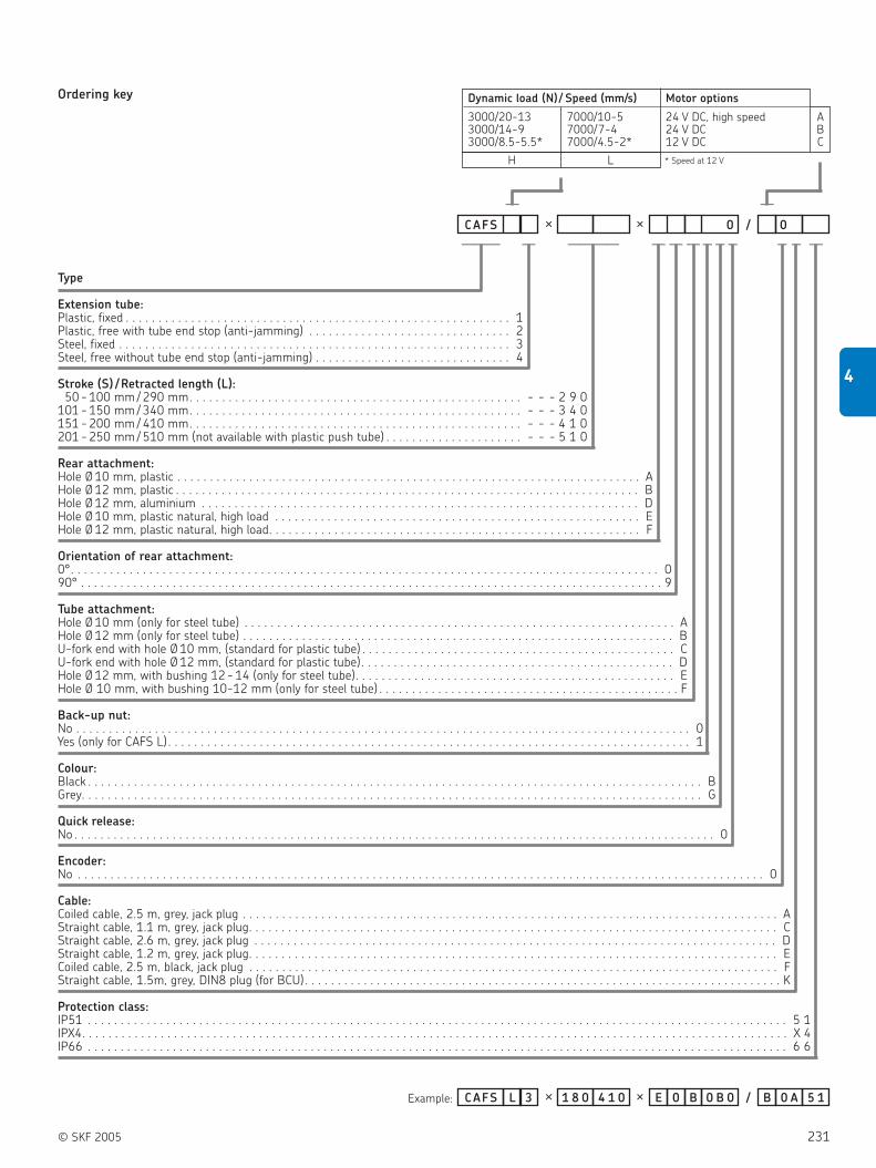
© SKF 2005 231
4
Type
Extension tube:Plastic, fixed . . . . . . . . . . . . . . . . . . . . . . . . . . . . . . . . . . . . . . . . . . . . . . . . . . . . . . . . . . . 1Plastic, free with tube end stop (anti-jamming) . . . . . . . . . . . . . . . . . . . . . . . . . . . . . . . 2Steel, fixed . . . . . . . . . . . . . . . . . . . . . . . . . . . . . . . . . . . . . . . . . . . . . . . . . . . . . . . . . . . . 3Steel, free without tube end stop (anti-jamming) . . . . . . . . . . . . . . . . . . . . . . . . . . . . . . 4
Stroke (S) /Retracted length (L):50 - 100 mm / 290 mm. . . . . . . . . . . . . . . . . . . . . . . . . . . . . . . . . . . . . . . . . . . . . . . . . . . - - - 2 9 0
101 - 150 mm / 340 mm. . . . . . . . . . . . . . . . . . . . . . . . . . . . . . . . . . . . . . . . . . . . . . . . . . . - - - 3 4 0151 - 200 mm / 410 mm. . . . . . . . . . . . . . . . . . . . . . . . . . . . . . . . . . . . . . . . . . . . . . . . . . . - - - 4 1 0201 - 250 mm / 510 mm (not available with plastic push tube) . . . . . . . . . . . . . . . . . . . . . - - - 5 1 0
Rear attachment:Hole Ø 10 mm, plastic . . . . . . . . . . . . . . . . . . . . . . . . . . . . . . . . . . . . . . . . . . . . . . . . . . . . . . . . . . . . . . . . . . . . . . . AHole Ø 12 mm, plastic . . . . . . . . . . . . . . . . . . . . . . . . . . . . . . . . . . . . . . . . . . . . . . . . . . . . . . . . . . . . . . . . . . . . . . . BHole Ø 12 mm, aluminium . . . . . . . . . . . . . . . . . . . . . . . . . . . . . . . . . . . . . . . . . . . . . . . . . . . . . . . . . . . . . . . . . . . DHole Ø 10 mm, plastic natural, high load . . . . . . . . . . . . . . . . . . . . . . . . . . . . . . . . . . . . . . . . . . . . . . . . . . . . . . . . EHole Ø 12 mm, plastic natural, high load. . . . . . . . . . . . . . . . . . . . . . . . . . . . . . . . . . . . . . . . . . . . . . . . . . . . . . . . . F
Orientation of rear attachment:0°. . . . . . . . . . . . . . . . . . . . . . . . . . . . . . . . . . . . . . . . . . . . . . . . . . . . . . . . . . . . . . . . . . . . . . . . . . . . . . . . . . . . . . . . . . 090° . . . . . . . . . . . . . . . . . . . . . . . . . . . . . . . . . . . . . . . . . . . . . . . . . . . . . . . . . . . . . . . . . . . . . . . . . . . . . . . . . . . . . . . . . 9
Tube attachment:Hole Ø 10 mm (only for steel tube) . . . . . . . . . . . . . . . . . . . . . . . . . . . . . . . . . . . . . . . . . . . . . . . . . . . . . . . . . . . . . . . . . . AHole Ø 12 mm (only for steel tube) . . . . . . . . . . . . . . . . . . . . . . . . . . . . . . . . . . . . . . . . . . . . . . . . . . . . . . . . . . . . . . . . . . BU-fork end with hole Ø 10 mm, (standard for plastic tube) . . . . . . . . . . . . . . . . . . . . . . . . . . . . . . . . . . . . . . . . . . . . . . . . CU-fork end with hole Ø 12 mm, (standard for plastic tube). . . . . . . . . . . . . . . . . . . . . . . . . . . . . . . . . . . . . . . . . . . . . . . . DHole Ø 12 mm, with bushing 12 - 14 (only for steel tube). . . . . . . . . . . . . . . . . . . . . . . . . . . . . . . . . . . . . . . . . . . . . . . . . EHole Ø 10 mm, with bushing 10-12 mm (only for steel tube) . . . . . . . . . . . . . . . . . . . . . . . . . . . . . . . . . . . . . . . . . . . . . . F
Back-up nut:No . . . . . . . . . . . . . . . . . . . . . . . . . . . . . . . . . . . . . . . . . . . . . . . . . . . . . . . . . . . . . . . . . . . . . . . . . . . . . . . . . . . . . . . . . . . . . . 0Yes (only for CAFS L) . . . . . . . . . . . . . . . . . . . . . . . . . . . . . . . . . . . . . . . . . . . . . . . . . . . . . . . . . . . . . . . . . . . . . . . . . . . . . . . . 1
Colour:Black . . . . . . . . . . . . . . . . . . . . . . . . . . . . . . . . . . . . . . . . . . . . . . . . . . . . . . . . . . . . . . . . . . . . . . . . . . . . . . . . . . . . . . . . . . . . . . BGrey. . . . . . . . . . . . . . . . . . . . . . . . . . . . . . . . . . . . . . . . . . . . . . . . . . . . . . . . . . . . . . . . . . . . . . . . . . . . . . . . . . . . . . . . . . . . . . . G
Quick release:No . . . . . . . . . . . . . . . . . . . . . . . . . . . . . . . . . . . . . . . . . . . . . . . . . . . . . . . . . . . . . . . . . . . . . . . . . . . . . . . . . . . . . . . . . . . . . . . . . . 0
Encoder:No . . . . . . . . . . . . . . . . . . . . . . . . . . . . . . . . . . . . . . . . . . . . . . . . . . . . . . . . . . . . . . . . . . . . . . . . . . . . . . . . . . . . . . . . . . . . . . . . . . . . . . . . . 0
Cable:Coiled cable, 2.5 m, grey, jack plug . . . . . . . . . . . . . . . . . . . . . . . . . . . . . . . . . . . . . . . . . . . . . . . . . . . . . . . . . . . . . . . . . . . . . . . . . . . . . . . . . . AStraight cable, 1.1 m, grey, jack plug. . . . . . . . . . . . . . . . . . . . . . . . . . . . . . . . . . . . . . . . . . . . . . . . . . . . . . . . . . . . . . . . . . . . . . . . . . . . . . . . . CStraight cable, 2.6 m, grey, jack plug . . . . . . . . . . . . . . . . . . . . . . . . . . . . . . . . . . . . . . . . . . . . . . . . . . . . . . . . . . . . . . . . . . . . . . . . . . . . . . . . DStraight cable, 1.2 m, grey, jack plug. . . . . . . . . . . . . . . . . . . . . . . . . . . . . . . . . . . . . . . . . . . . . . . . . . . . . . . . . . . . . . . . . . . . . . . . . . . . . . . . . ECoiled cable, 2.5 m, black, jack plug . . . . . . . . . . . . . . . . . . . . . . . . . . . . . . . . . . . . . . . . . . . . . . . . . . . . . . . . . . . . . . . . . . . . . . . . . . . . . . . . . FStraight cable, 1.5m, grey, DIN8 plug (for BCU) . . . . . . . . . . . . . . . . . . . . . . . . . . . . . . . . . . . . . . . . . . . . . . . . . . . . . . . . . . . . . . . . . . . . . . . . . K
Protection class:IP51 . . . . . . . . . . . . . . . . . . . . . . . . . . . . . . . . . . . . . . . . . . . . . . . . . . . . . . . . . . . . . . . . . . . . . . . . . . . . . . . . . . . . . . . . . . . . . . . . . . . . . . . . . . . 5 1IPX4. . . . . . . . . . . . . . . . . . . . . . . . . . . . . . . . . . . . . . . . . . . . . . . . . . . . . . . . . . . . . . . . . . . . . . . . . . . . . . . . . . . . . . . . . . . . . . . . . . . . . . . . . . . . X 4IP66 . . . . . . . . . . . . . . . . . . . . . . . . . . . . . . . . . . . . . . . . . . . . . . . . . . . . . . . . . . . . . . . . . . . . . . . . . . . . . . . . . . . . . . . . . . . . . . . . . . . . . . . . . . . 6 6
Example:
CAFS × × 0 / 0
4 1 0CAFS 3L × 1 8 0 5 1× E 0 0 B 0B / B 0 A
Dynamic load (N)/ Speed (mm/s) Motor options
3000/20-13 7000/10-5 24 V DC, high speed A3000/14-9 7000/7-4 24 V DC B3000/8.5-5.5* 7000/4.5-2* 12 V DC C
H L * Speed at 12 V
Ordering key
——— — ———— — — —— — —
— —
— — —

232 © SKF 2005
4 Actuation systems
Linear actuators
MAGPUSH
MAGPUSH linear actuators ( figure 20)
are extremely quiet and smooth running.
They take up little space, are maintenance-
free and can be installed vertically or
horizontally or at an intermediate angle.
The MAGPUSH actuators are very
robust and work in many applications. They
are ideally suited for raising and lowering
large loads.
Benefits:
Long stroke by a short assembly
dimension
Long service life
Silent operation
Robust
Figure 20
Type Force Max. speed Stroke Retr. Length Voltage Protection Weight
push pull no load full load (S) (L)
N mm/s mm mm V AC IP kg
GC 84 UB 400 400 8 8 210 S + 170 230 55 3.0
LC 6.6 UB 3000 3000 15 15 310 – 230 55 11.0
LC 12.6 UB 6000 6000 30 30 310 – 230 55 11.0
GC 84 TL 500 300 6 6 200 / 300 / 500 54 230 54 2.4
HC 85 UB 1500 1500 10 10 260 S + 190 230 55 6.0

© SKF 2005 233
4
MAGPUSH GC 84 UB
L = 380S
70
115
ø68
8134
402
1016
28
Type
Load / Speed / Stroke (S):400 N (push) / 8 mm /s / 210 mm . . . . . . . . . . . . . . . . . . . . . . . . . . . . . . . . . . . . . . . . . . . . . . . . . . . . . . . . . . . . . . . . . . . . . . . . . . . . . . . . . . . . . 0 1
Example:
Ordering key GC84UB - 0 1
GC84UB - 0 1
————— —
Type:LC6.6UB for 3000 N (push) / 15 mm /s / 310 mm. . . . . . . . . . . . . . . . . . . . . . . . . . . . . . . . . . . . . . . . . . . . . . . . . . . . . . . . . . . . . 6.6LC12.6UB for 6000 N (push) / 30 mm /s / 310 mm. . . . . . . . . . . . . . . . . . . . . . . . . . . . . . . . . . . . . . . . . . . . . . . . . . . . . . . . . . . . 12.6
Example:
Ordering key LC . UB - 0 1
LC6 .6UB - 0 1
–—
Legend:
S = stroke
L = retracted length
MAGPUSH LC .. UB
L = 545S
70
160
ø11
3
103,
556
,5
577
1424
42
Legend:
S = stroke
L = retracted length
Type Force Max. speed Stroke Retr. Length Voltage Protection Weight
push pull no load full load (S) (L)
N mm/s mm mm V AC IP kg
GC 84 UB 400 400 8 8 210 380 230 55 3.0
Type Force Max. speed Stroke Retr. Length Voltage Protection Weight
push pull no load full load (S) (L)
N mm/s mm mm V AC IP kg
LC 6.6 UB 3000 3000 15 15 310 545 230 55 11.0
LC 12.6 UB 6000 6000 30 30 310 545 230 55 11.0

234 © SKF 2005
4 Actuation systems
Linear actuators
MAGPUSH GC 84 TL
TL 20: L = 268.5TL 30: L = 359TL 50: L = 551
204
54
Type
Load / Speed / Stroke (S):500 N (push) 300 N (pull) / 6 mm/s / 200 mm . . . . . . . . . . . . . . . . . . . . . . . . . . . . . . . . . . . . . . . . . . . . . . . . . . . . . . . . . . . . . . . . . . . . . . . 2 0500 N (push) 300 N (pull) / 6 mm/s / 300 mm . . . . . . . . . . . . . . . . . . . . . . . . . . . . . . . . . . . . . . . . . . . . . . . . . . . . . . . . . . . . . . . . . . . . . . . 3 0500 N (push) 300 N (pull) / 6 mm/s / 500 mm . . . . . . . . . . . . . . . . . . . . . . . . . . . . . . . . . . . . . . . . . . . . . . . . . . . . . . . . . . . . . . . . . . . . . . . 50
Option:No option. . . . . . . . . . . . . . . . . . . . . . . . . . . . . . . . . . . . . . . . . . . . . . . . . . . . . . . . . . . . . . . . . . . . . . . . . . . . . . . . . . . . . . . . . . . . . . . . . . . . . . . . 0 1With integrated relais . . . . . . . . . . . . . . . . . . . . . . . . . . . . . . . . . . . . . . . . . . . . . . . . . . . . . . . . . . . . . . . . . . . . . . . . . . . . . . . . . . . . . . . . . . . . . . 0 2
Accessories for MAGPUSH GC 84 TL
Example:
Ordering key GC84TL -
GC84TL - 2 0 0 1
————— — —
Legend:
S = stroke
L = retracted length
Type Force Max. speed Stroke Retr. Length Voltage Protection Weight
push pull no load full load (S) (L)
N mm/s mm mm V AC IP kg
GC 84 TL 500 300 6 6 200 / 300 / 500 54 230 54 2.3 - 2.4
Accessories Order N°
Fixing bracket 940303
Pivot screws, alone 940306
Pull adapter 939185
Rear hinge, short 940646
Rear hinge, long 940611

© SKF 2005 235
4
MAGPUSH HC 85 UB
L = 450S
70
133
ø86
9043
476
1220
34
Type
Option:No option . . . . . . . . . . . . . . . . . . . . . . . . . . . . . . . . . . . . . . . . . . . . . . . . . . . . . . . . . . . . . . . . . . . . . . . . . . . . . . . . . . . . . . . . . . . . . . . . . . . . . . –Potentiometer 1000 Ohm. . . . . . . . . . . . . . . . . . . . . . . . . . . . . . . . . . . . . . . . . . . . . . . . . . . . . . . . . . . . . . . . . . . . . . . . . . . . . . . . . . . . . . . . . 3
Load / Speed / Stroke (S):1500 N / 10 mm/s / 260 mm. . . . . . . . . . . . . . . . . . . . . . . . . . . . . . . . . . . . . . . . . . . . . . . . . . . . . . . . . . . . . . . . . . . . . . . . . . . . . . . . . . . . . . . . . 0 1
Example:
HC85UB - 0 1
HC85UB - 3 0 1
Ordering key
–———— — —
Legend:
S = stroke
L = retracted length
Type Force Max. speed Stroke Retr. Length Voltage Protection Weight
push pull no load full load (S) (L)
N mm/s mm mm V AC IP kg
HC 85 UB 1500 1500 10 10 260 450 230 55 6.0

236 © SKF 2005
4 Actuation systems
Linear actuators
MAGTOP CS
The MAGTOP product family ( figure 21) is
a compact and cost-effective actuator,
primarily designed for the building and
construction segment.
The MAGTOP is suitable for the opening
and closing of windows, doors, smoke
vents, etc., and for skylight and dome-light
applications.
These rod actuators are powerful,
economical and capable of withstanding
high maximum loads (from 200 to 2000N)
and provide a wide range of opening and
closing strokes (up to 500 mm).
Benefits:
Compact and silent operation
Cost-effective
Maintenance-free
Easy to install
Rigid rod movement
Figure 21
Type Force Max. speed Stroke Retr. Length Voltage Protection Weight
push pull no load full load (S) (L)
N mm/s mm mm V IP kg
CS10 200 200 37 30 105 - 300 278 - 393 230 AC 44 1.3
CS20 450 450 22 18 160 - 300 266 - 411 230 AC 54 1.7
CS31 500 500 24 19 200 - 400 309 - 509 230 AC 55 2.1
CS40 450 450 12 8 200 - 500 330 - 630 230 AC / 24 DC 55 1.4
CS50 1000 1000 24 21 300 - 500 415 - 615 230 AC 55 3.4
CS60 600 600 24 22 180 - 500 345 - 620 230 AC 44 3.4
CS70 2000 2000 19 14 180 - 500 278 - 598 230 AC 40 6.5

© SKF 2005 237
4
MAGTOP CS10
max. 180
max. 180
max. 300
Type:Spindle actuator . . . . . . . . . . . . . . . . . . . . . . . . . . . . . . . . . . . . . . . . . . . . . . . . . . . . . . . . . . . . . . . CS
Load / Speed:200 N / 37 mm/s . . . . . . . . . . . . . . . . . . . . . . . . . . . . . . . . . . . . . . . . . . . . . . . . . . . . . . . . . . . . . . . . . . . . 1 0
Stroke (S):105 mm. . . . . . . . . . . . . . . . . . . . . . . . . . . . . . . . . . . . . . . . . . . . . . . . . . . . . . . . . . . . . . . . . . . . . . . . . . . . . . . . . 0 1 0 5165 mm. . . . . . . . . . . . . . . . . . . . . . . . . . . . . . . . . . . . . . . . . . . . . . . . . . . . . . . . . . . . . . . . . . . . . . . . . . . . . . . . . 0 1 6 5180 mm. . . . . . . . . . . . . . . . . . . . . . . . . . . . . . . . . . . . . . . . . . . . . . . . . . . . . . . . . . . . . . . . . . . . . . . . . . . . . . . . . 0 1 8 0240 mm. . . . . . . . . . . . . . . . . . . . . . . . . . . . . . . . . . . . . . . . . . . . . . . . . . . . . . . . . . . . . . . . . . . . . . . . . . . . . . . . . 0 2 4 0300 mm. . . . . . . . . . . . . . . . . . . . . . . . . . . . . . . . . . . . . . . . . . . . . . . . . . . . . . . . . . . . . . . . . . . . . . . . . . . . . . . . . 0 3 0 0
Supply voltage:230 V AC . . . . . . . . . . . . . . . . . . . . . . . . . . . . . . . . . . . . . . . . . . . . . . . . . . . . . . . . . . . . . . . . . . . . . . . . . . . . . . . . . . . . . . . . . . 2 3 0
Color:Silver EV1. . . . . . . . . . . . . . . . . . . . . . . . . . . . . . . . . . . . . . . . . . . . . . . . . . . . . . . . . . . . . . . . . . . . . . . . . . . . . . . . . . . . . . . . . . . . . . . . . . . S
Options:None . . . . . . . . . . . . . . . . . . . . . . . . . . . . . . . . . . . . . . . . . . . . . . . . . . . . . . . . . . . . . . . . . . . . . . . . . . . . . . . . . . . . . . . . . . . . . . . . . . . . . . . . . . . 0 0
C S 1 0 -- -2 3 0 -S 0 0
0 1 6 5C S 1 0 -- -2 3 0 -S 0 0
Ordering key
————– —– — —–—
Example:
Legend:
S = stroke
Type Force Max. speed Stroke Retr. Length Voltage Protection Weight
push pull no load full load (S) (L)
N mm/s mm mm V AC IP kg
CS10 200 200 37 30 105 - 300 278 - 393 230 44 1.3

238 © SKF 2005
4 Actuation systems
Linear actuators
MAGTOP CS20
Type:Spindle actuator . . . . . . . . . . . . . . . . . . . . . . . . . . . . . . . . . . . . . . . . . . . . . . . . . . . . . . . . . . . . . . . CS
Load / Speed:450 N / 22 mm/s . . . . . . . . . . . . . . . . . . . . . . . . . . . . . . . . . . . . . . . . . . . . . . . . . . . . . . . . . . . . . . . . . . . . 2 0
Stroke (S):160 mm. . . . . . . . . . . . . . . . . . . . . . . . . . . . . . . . . . . . . . . . . . . . . . . . . . . . . . . . . . . . . . . . . . . . . . . . . . . . . . . . . 0 1 6 0180 mm. . . . . . . . . . . . . . . . . . . . . . . . . . . . . . . . . . . . . . . . . . . . . . . . . . . . . . . . . . . . . . . . . . . . . . . . . . . . . . . . . 0 1 8 0200 mm. . . . . . . . . . . . . . . . . . . . . . . . . . . . . . . . . . . . . . . . . . . . . . . . . . . . . . . . . . . . . . . . . . . . . . . . . . . . . . . . . 0 2 0 0235 mm. . . . . . . . . . . . . . . . . . . . . . . . . . . . . . . . . . . . . . . . . . . . . . . . . . . . . . . . . . . . . . . . . . . . . . . . . . . . . . . . . 0 2 3 5300 mm. . . . . . . . . . . . . . . . . . . . . . . . . . . . . . . . . . . . . . . . . . . . . . . . . . . . . . . . . . . . . . . . . . . . . . . . . . . . . . . . . 0 3 0 0
Supply voltage:230 V AC . . . . . . . . . . . . . . . . . . . . . . . . . . . . . . . . . . . . . . . . . . . . . . . . . . . . . . . . . . . . . . . . . . . . . . . . . . . . . . . . . . . . . . . . . . 2 3 0
Color:Silver EV1. . . . . . . . . . . . . . . . . . . . . . . . . . . . . . . . . . . . . . . . . . . . . . . . . . . . . . . . . . . . . . . . . . . . . . . . . . . . . . . . . . . . . . . . . . . . . . . . . . . S
Options:None . . . . . . . . . . . . . . . . . . . . . . . . . . . . . . . . . . . . . . . . . . . . . . . . . . . . . . . . . . . . . . . . . . . . . . . . . . . . . . . . . . . . . . . . . . . . . . . . . . . . . . . . . . . 0 0
C S 2 0 -- -2 3 0 -S 0 0
0 1 8 0C S 2 0 -- -2 3 0 -S 0 0
Ordering key
————– —– — —–—
Example:
Legend:
S = stroke
Type Force Max. speed Stroke Retr. Length Voltage Protection Weight
push pull no load full load (S) (L)
N mm/s mm mm V AC IP kg
CS20 450 450 22 18 160 - 300 266 - 411 230 54 1.7

© SKF 2005 239
4
MAGTOP CS31
Type:Spindle actuator . . . . . . . . . . . . . . . . . . . . . . . . . . . . . . . . . . . . . . . . . . . . . . . . . . . . . . . . . . . . . . . CS
Load / Speed:500 N / 24 mm/s . . . . . . . . . . . . . . . . . . . . . . . . . . . . . . . . . . . . . . . . . . . . . . . . . . . . . . . . . . . . . . . . . . . . 3 1
Stroke (S):200 mm. . . . . . . . . . . . . . . . . . . . . . . . . . . . . . . . . . . . . . . . . . . . . . . . . . . . . . . . . . . . . . . . . . . . . . . . . . . . . . . . . 0 2 0 0300 mm. . . . . . . . . . . . . . . . . . . . . . . . . . . . . . . . . . . . . . . . . . . . . . . . . . . . . . . . . . . . . . . . . . . . . . . . . . . . . . . . . 0 3 0 0400 mm. . . . . . . . . . . . . . . . . . . . . . . . . . . . . . . . . . . . . . . . . . . . . . . . . . . . . . . . . . . . . . . . . . . . . . . . . . . . . . . . . 0 4 0 0
Supply voltage:230 V AC . . . . . . . . . . . . . . . . . . . . . . . . . . . . . . . . . . . . . . . . . . . . . . . . . . . . . . . . . . . . . . . . . . . . . . . . . . . . . . . . . . . . . . . . . . 2 3 0
Color:Silver EV1. . . . . . . . . . . . . . . . . . . . . . . . . . . . . . . . . . . . . . . . . . . . . . . . . . . . . . . . . . . . . . . . . . . . . . . . . . . . . . . . . . . . . . . . . . . . . . . . . . . S
Options:None . . . . . . . . . . . . . . . . . . . . . . . . . . . . . . . . . . . . . . . . . . . . . . . . . . . . . . . . . . . . . . . . . . . . . . . . . . . . . . . . . . . . . . . . . . . . . . . . . . . . . . . . . . . 0 0
C S 3 1 -- -2 3 0 -S 0 0
0 2 0 0C S 3 1 -- -2 3 0 -S 0 0
Ordering key
————– —– — —–—
Example:
Legend:
S = stroke
L = retracted length
S L200 308.8300 408.8400 508.8
Type Force Max. speed Stroke Retr. Length Voltage Protection Weight
push pull no load full load (S) (L)
N mm/s mm mm V AC IP kg
CS31 500 500 24 19 200 - 400 309 - 509 230 55 1.8

240 © SKF 2005
4 Actuation systems
Linear actuators
MAGTOP CS40
Type:Spindle actuator . . . . . . . . . . . . . . . . . . . . . . . . . . . . . . . . . . . . . . . . . . . . . . . . . . . . . . . . . . . . . . . CS
Load / Speed:450 N / 12 mm/s . . . . . . . . . . . . . . . . . . . . . . . . . . . . . . . . . . . . . . . . . . . . . . . . . . . . . . . . . . . . . . . . . . . . 4 0
Stroke (S): (adjustable from 1 mm to max. length)200 mm. . . . . . . . . . . . . . . . . . . . . . . . . . . . . . . . . . . . . . . . . . . . . . . . . . . . . . . . . . . . . . . . . . . . . . . . . . . . . . . . . 0 2 0 0300 mm. . . . . . . . . . . . . . . . . . . . . . . . . . . . . . . . . . . . . . . . . . . . . . . . . . . . . . . . . . . . . . . . . . . . . . . . . . . . . . . . . 0 3 0 0500 mm. . . . . . . . . . . . . . . . . . . . . . . . . . . . . . . . . . . . . . . . . . . . . . . . . . . . . . . . . . . . . . . . . . . . . . . . . . . . . . . . . 0 5 0 0
Supply voltage:230 V AC . . . . . . . . . . . . . . . . . . . . . . . . . . . . . . . . . . . . . . . . . . . . . . . . . . . . . . . . . . . . . . . . . . . . . . . . . . . . . . . . . . . . . . . . . . 2 3 024 V DC . . . . . . . . . . . . . . . . . . . . . . . . . . . . . . . . . . . . . . . . . . . . . . . . . . . . . . . . . . . . . . . . . . . . . . . . . . . . . . . . . . . . . . . . . . 0 2 4
Color:Silver EV1. . . . . . . . . . . . . . . . . . . . . . . . . . . . . . . . . . . . . . . . . . . . . . . . . . . . . . . . . . . . . . . . . . . . . . . . . . . . . . . . . . . . . . . . . . . . . . . . . . . S
Options:None . . . . . . . . . . . . . . . . . . . . . . . . . . . . . . . . . . . . . . . . . . . . . . . . . . . . . . . . . . . . . . . . . . . . . . . . . . . . . . . . . . . . . . . . . . . . . . . . . . . . . . . . . . . 0 0
C S 4 0 -- - -S 0 0
0 3 0 0C S 4 0 -- -0 2 4 -S 0 0
Ordering key
————– —– — —–—
Example:
Legend:
S = stroke
L = retracted length
Type Force Max. speed Stroke Retr. Length Voltage Protection Weight
push pull no load full load (S) (L)
N mm/s mm mm V IP kg
CS40 450 450 12 8 200 - 500 330 - 630 230 AC 55 1.4
24 DC

© SKF 2005 241
4
MAGTOP CS50
Type:Spindle actuator . . . . . . . . . . . . . . . . . . . . . . . . . . . . . . . . . . . . . . . . . . . . . . . . . . . . . . . . . . . . . . . CS
Load / Speed:1000 N / 24 mm/s . . . . . . . . . . . . . . . . . . . . . . . . . . . . . . . . . . . . . . . . . . . . . . . . . . . . . . . . . . . . . . . . . . . 5 0
Stroke (S):300 mm. . . . . . . . . . . . . . . . . . . . . . . . . . . . . . . . . . . . . . . . . . . . . . . . . . . . . . . . . . . . . . . . . . . . . . . . . . . . . . . . . 0 3 0 0500 mm. . . . . . . . . . . . . . . . . . . . . . . . . . . . . . . . . . . . . . . . . . . . . . . . . . . . . . . . . . . . . . . . . . . . . . . . . . . . . . . . . 0 5 0 0
Supply voltage:230 V AC . . . . . . . . . . . . . . . . . . . . . . . . . . . . . . . . . . . . . . . . . . . . . . . . . . . . . . . . . . . . . . . . . . . . . . . . . . . . . . . . . . . . . . . . . . 2 3 0
Color:Silver EV1. . . . . . . . . . . . . . . . . . . . . . . . . . . . . . . . . . . . . . . . . . . . . . . . . . . . . . . . . . . . . . . . . . . . . . . . . . . . . . . . . . . . . . . . . . . . . . . . . . . S
Options:None . . . . . . . . . . . . . . . . . . . . . . . . . . . . . . . . . . . . . . . . . . . . . . . . . . . . . . . . . . . . . . . . . . . . . . . . . . . . . . . . . . . . . . . . . . . . . . . . . . . . . . . . . . . 0 0
C S 5 0 -- -2 3 0 -S 0 0
5 0 0C S 5 0 -- -2 3 0 -S 0 0
Ordering key
————– —– — —–—
Example:
Legend:
S = stroke
S = max. 500
S = max. 300
Type Force Max. speed Stroke Retr. Length Voltage Protection Weight
push pull no load full load (S) (L)
N mm/s mm mm V AC IP kg
CS50 1000 1000 24 21 300 - 500 415 - 615 230 55 3.4

242 © SKF 2005
4 Actuation systems
Linear actuators
MAGTOP CS60
Type:Spindle actuator . . . . . . . . . . . . . . . . . . . . . . . . . . . . . . . . . . . . . . . . . . . . . . . . . . . . . . . . . . . . . . . CS
Load / Speed:600 N / 24 mm/s . . . . . . . . . . . . . . . . . . . . . . . . . . . . . . . . . . . . . . . . . . . . . . . . . . . . . . . . . . . . . . . . . . . . 6 0
Stroke (S):180 mm. . . . . . . . . . . . . . . . . . . . . . . . . . . . . . . . . . . . . . . . . . . . . . . . . . . . . . . . . . . . . . . . . . . . . . . . . . . . . . . . . 0 1 8 0225 mm. . . . . . . . . . . . . . . . . . . . . . . . . . . . . . . . . . . . . . . . . . . . . . . . . . . . . . . . . . . . . . . . . . . . . . . . . . . . . . . . . 0 2 2 5300 mm. . . . . . . . . . . . . . . . . . . . . . . . . . . . . . . . . . . . . . . . . . . . . . . . . . . . . . . . . . . . . . . . . . . . . . . . . . . . . . . . . 0 3 0 0500 mm. . . . . . . . . . . . . . . . . . . . . . . . . . . . . . . . . . . . . . . . . . . . . . . . . . . . . . . . . . . . . . . . . . . . . . . . . . . . . . . . . 0 5 0 0
Supply voltage:230 V AC . . . . . . . . . . . . . . . . . . . . . . . . . . . . . . . . . . . . . . . . . . . . . . . . . . . . . . . . . . . . . . . . . . . . . . . . . . . . . . . . . . . . . . . . . . 2 3 0
Color:Silver EV1. . . . . . . . . . . . . . . . . . . . . . . . . . . . . . . . . . . . . . . . . . . . . . . . . . . . . . . . . . . . . . . . . . . . . . . . . . . . . . . . . . . . . . . . . . . . . . . . . . . S
Options:None . . . . . . . . . . . . . . . . . . . . . . . . . . . . . . . . . . . . . . . . . . . . . . . . . . . . . . . . . . . . . . . . . . . . . . . . . . . . . . . . . . . . . . . . . . . . . . . . . . . . . . . . . . . 0 0
C S 6 0 -- -2 3 0 -S 0 0
0 2 2 5C S 6 0 -- -2 3 0 -S 0 0
Ordering key
————– —– — —–—
Example:
Legend:
S = stroke
Type Force Max. speed Stroke Retr. Length Voltage Protection Weight
push pull no load full load (S) (L)
N mm/s mm mm V AC IP kg
CS60 600 600 24 22 180 - 500 345 - 620 230 44 3.4

© SKF 2005 243
4
MAGTOP CS70
0 1 8 0C S 7 0 -- -2 3 0 -S 0 0Example:
Type:Spindle actuator . . . . . . . . . . . . . . . . . . . . . . . . . . . . . . . . . . . . . . . . . . . . . . . . . . . . . . . . . . . . . . . CS
Load / Speed:2000 N / 19 mm/s . . . . . . . . . . . . . . . . . . . . . . . . . . . . . . . . . . . . . . . . . . . . . . . . . . . . . . . . . . . . . . . . . . . 7 0
Stroke (S):180 mm. . . . . . . . . . . . . . . . . . . . . . . . . . . . . . . . . . . . . . . . . . . . . . . . . . . . . . . . . . . . . . . . . . . . . . . . . . . . . . . . . 0 1 8 0300 mm. . . . . . . . . . . . . . . . . . . . . . . . . . . . . . . . . . . . . . . . . . . . . . . . . . . . . . . . . . . . . . . . . . . . . . . . . . . . . . . . . 0 3 0 0400 mm. . . . . . . . . . . . . . . . . . . . . . . . . . . . . . . . . . . . . . . . . . . . . . . . . . . . . . . . . . . . . . . . . . . . . . . . . . . . . . . . . 0 5 0 0
Supply voltage:230 V AC . . . . . . . . . . . . . . . . . . . . . . . . . . . . . . . . . . . . . . . . . . . . . . . . . . . . . . . . . . . . . . . . . . . . . . . . . . . . . . . . . . . . . . . . . . 2 3 0
Color:Silver EV1. . . . . . . . . . . . . . . . . . . . . . . . . . . . . . . . . . . . . . . . . . . . . . . . . . . . . . . . . . . . . . . . . . . . . . . . . . . . . . . . . . . . . . . . . . . . . . . . . . . S
Options:None . . . . . . . . . . . . . . . . . . . . . . . . . . . . . . . . . . . . . . . . . . . . . . . . . . . . . . . . . . . . . . . . . . . . . . . . . . . . . . . . . . . . . . . . . . . . . . . . . . . . . . . . . . . 0 0
C S 7 0 -- -2 3 0 -S 0 0Ordering key
————– —– — —–—
Legend:
S = stroke
Type Force Max. speed Stroke Retr. Length Voltage Protection Weight
push pull no load full load (S) (L)
N mm/s mm mm V AC IP kg
CS70 2000 2000 19 14 180 - 500 278 - 598 230 40 6.5

244 © SKF 2005
4 Actuation systems
Linear actuators
VARIMAG CC
The VARIMAG product family ( figure 22) is
a compact and cost-effective actuator,
primarily designed for the building and
construction segment. VARIMAG chain
actuators are the ideal solution for
automatically controlled windows. They take
up very little space and the comprehensive
range provides the correct strokes, thrust
forces and chain resistance required for all
window application.
Benefits:
Compact and silent
Cost-effective
Take up minimum space
Easy to install
Figure 22
Type Force Max. speed Stroke Retr. Length Voltage Protection Weight
push pull no load full load (S) (L)
N mm/s mm mm V DC / AC IP kg
CC10 150 300 45 38 130 - 380 N / A 24 / 230 20 1.6 - 1.8
CC20 200 200 17 10 200 - 250 N / A 24 / 230 20 1.0
CC30 250 250 32 / 28 28 / 26 400 N / A 24 / 230 22 1.0
CC40 350 350 19 15 280 - 380 N / A 24 / 230 22 1.8
CC50 400 400 28 / 38 17 / 22 420 - 835 N / A 24 / 230 22 3.5 - 4.0

© SKF 2005 245
4
VARIMAG CC10
Type:Chain actuator . . . . . . . . . . . . . . . . . . . . . . . . . . . . . . . . . . . . . . . . . . . . . . . . . . . . . . . . . . . . . . . . . CC
Load / Speed:150 N (push), 300 N (pull) / 45 mm/s . . . . . . . . . . . . . . . . . . . . . . . . . . . . . . . . . . . . . . . . . . . . . . . . . . . . 1 0
Stroke (S):130 mm. . . . . . . . . . . . . . . . . . . . . . . . . . . . . . . . . . . . . . . . . . . . . . . . . . . . . . . . . . . . . . . . . . . . . . . . . . . . . . . . . 0 1 3 0150 mm. . . . . . . . . . . . . . . . . . . . . . . . . . . . . . . . . . . . . . . . . . . . . . . . . . . . . . . . . . . . . . . . . . . . . . . . . . . . . . . . . 0 1 5 0250 mm / 380 mm . . . . . . . . . . . . . . . . . . . . . . . . . . . . . . . . . . . . . . . . . . . . . . . . . . . . . . . . . . . . . . . . . . . . . . . . 0 3 8 0
Supply voltage:230 V AC . . . . . . . . . . . . . . . . . . . . . . . . . . . . . . . . . . . . . . . . . . . . . . . . . . . . . . . . . . . . . . . . . . . . . . . . . . . . . . . . . . . . . . . . . . 2 3 024 V DC . . . . . . . . . . . . . . . . . . . . . . . . . . . . . . . . . . . . . . . . . . . . . . . . . . . . . . . . . . . . . . . . . . . . . . . . . . . . . . . . . . . . . . . . . . 0 2 4
Color:Silver EV1. . . . . . . . . . . . . . . . . . . . . . . . . . . . . . . . . . . . . . . . . . . . . . . . . . . . . . . . . . . . . . . . . . . . . . . . . . . . . . . . . . . . . . . . . . . . . . . . . . . SWhite RAL 9016 . . . . . . . . . . . . . . . . . . . . . . . . . . . . . . . . . . . . . . . . . . . . . . . . . . . . . . . . . . . . . . . . . . . . . . . . . . . . . . . . . . . . . . . . . . . . . W
Options:None . . . . . . . . . . . . . . . . . . . . . . . . . . . . . . . . . . . . . . . . . . . . . . . . . . . . . . . . . . . . . . . . . . . . . . . . . . . . . . . . . . . . . . . . . . . . . . . . . . . . . . . . . . . 0 0
C C 1 0 -- - - 0 0
0 1 5 0C C 1 0 -- -0 2 4 -W 0 0
Ordering key
————– —– — —–—
Example:
Legend:
S = stroke
Type Force Max. speed Stroke Retr. Length Voltage Protection Weight
push pull no load full load (S) (L)
N mm/s mm mm V DC / AC IP kg
CC10 150 300 45 38 130 - 380 N / A 24 / 230 20 1.6 - 1.8

246 © SKF 2005
4 Actuation systems
Linear actuators
VARIMAG CC20
341/366
324/349
261/286
224/269
Type:Chain actuator . . . . . . . . . . . . . . . . . . . . . . . . . . . . . . . . . . . . . . . . . . . . . . . . . . . . . . . . . . . . . . . . . CC
Load / Speed:200 / 17 mm/s . . . . . . . . . . . . . . . . . . . . . . . . . . . . . . . . . . . . . . . . . . . . . . . . . . . . . . . . . . . . . . . . . . . . . . 2 0
Stroke (S):200 mm. . . . . . . . . . . . . . . . . . . . . . . . . . . . . . . . . . . . . . . . . . . . . . . . . . . . . . . . . . . . . . . . . . . . . . . . . . . . . . . . . 0 2 0 0250 mm. . . . . . . . . . . . . . . . . . . . . . . . . . . . . . . . . . . . . . . . . . . . . . . . . . . . . . . . . . . . . . . . . . . . . . . . . . . . . . . . . 0 2 5 0
Supply voltage:230 V AC . . . . . . . . . . . . . . . . . . . . . . . . . . . . . . . . . . . . . . . . . . . . . . . . . . . . . . . . . . . . . . . . . . . . . . . . . . . . . . . . . . . . . . . . . . 2 3 024 V DC . . . . . . . . . . . . . . . . . . . . . . . . . . . . . . . . . . . . . . . . . . . . . . . . . . . . . . . . . . . . . . . . . . . . . . . . . . . . . . . . . . . . . . . . . . 0 2 4
Color:Silver EV1. . . . . . . . . . . . . . . . . . . . . . . . . . . . . . . . . . . . . . . . . . . . . . . . . . . . . . . . . . . . . . . . . . . . . . . . . . . . . . . . . . . . . . . . . . . . . . . . . . . SWhite RAL 9016 . . . . . . . . . . . . . . . . . . . . . . . . . . . . . . . . . . . . . . . . . . . . . . . . . . . . . . . . . . . . . . . . . . . . . . . . . . . . . . . . . . . . . . . . . . . . . W
Options:None . . . . . . . . . . . . . . . . . . . . . . . . . . . . . . . . . . . . . . . . . . . . . . . . . . . . . . . . . . . . . . . . . . . . . . . . . . . . . . . . . . . . . . . . . . . . . . . . . . . . . . . . . . . 0 0
C C 2 0 -- - - 0 0
0 2 0 0C C 2 0 -- -0 2 4 -S 0 0
Ordering key
————– —– — —–—
Example:
24 V230 V
Type Force Max. speed Stroke Retr. Length Voltage Protection Weight
push pull no load full load (S) (L)
N mm/s mm mm V DC / AC IP kg
CC20 200 200 17 10 200 - 250 N / A 24 / 230 20 1.0

© SKF 2005 247
4
VARIMAG CC30
Type:Chain actuator . . . . . . . . . . . . . . . . . . . . . . . . . . . . . . . . . . . . . . . . . . . . . . . . . . . . . . . . . . . . . . . . . CC
Load / Speed:250 / 32 / 28 mm/s . . . . . . . . . . . . . . . . . . . . . . . . . . . . . . . . . . . . . . . . . . . . . . . . . . . . . . . . . . . . . . . . . . . 3 0
Stroke (S):400 mm (adjustable in 12.5 mm steps) . . . . . . . . . . . . . . . . . . . . . . . . . . . . . . . . . . . . . . . . . . . . . . . . . . . . . . . . 0 4 0 0
Supply voltage:230 V AC . . . . . . . . . . . . . . . . . . . . . . . . . . . . . . . . . . . . . . . . . . . . . . . . . . . . . . . . . . . . . . . . . . . . . . . . . . . . . . . . . . . . . . . . . . 2 3 024 V DC . . . . . . . . . . . . . . . . . . . . . . . . . . . . . . . . . . . . . . . . . . . . . . . . . . . . . . . . . . . . . . . . . . . . . . . . . . . . . . . . . . . . . . . . . . 0 2 4
Color:Silver EV1. . . . . . . . . . . . . . . . . . . . . . . . . . . . . . . . . . . . . . . . . . . . . . . . . . . . . . . . . . . . . . . . . . . . . . . . . . . . . . . . . . . . . . . . . . . . . . . . . . . SBlack . . . . . . . . . . . . . . . . . . . . . . . . . . . . . . . . . . . . . . . . . . . . . . . . . . . . . . . . . . . . . . . . . . . . . . . . . . . . . . . . . . . . . . . . . . . . . . . . . . . . . . BWhite . . . . . . . . . . . . . . . . . . . . . . . . . . . . . . . . . . . . . . . . . . . . . . . . . . . . . . . . . . . . . . . . . . . . . . . . . . . . . . . . . . . . . . . . . . . . . . . . . . . . . . W
Options:None . . . . . . . . . . . . . . . . . . . . . . . . . . . . . . . . . . . . . . . . . . . . . . . . . . . . . . . . . . . . . . . . . . . . . . . . . . . . . . . . . . . . . . . . . . . . . . . . . . . . . . . . . . . 0 0
0 4 0 0C C 3 0 -- - - 0 0
0 4 0 0C C 3 0 -- -0 2 4 -B 0 0
Ordering key
————– —– — —–—
Example:
Type Force Max. speed Stroke Retr. Length Voltage Protection Weight
push pull no load full load (S) (L)
N mm/s mm mm V DC / AC IP kg
CC30 250 250 32 / 28 28 / 26 400 N / A 24 / 230 22 1.0

248 © SKF 2005
4 Actuation systems
Linear actuators
VARIMAG CC40
NR.4+4-ø10
153.5 48 22
373/423~ 410/460
40
16
62
67
8.5356/406
1532
MT. 1.2
NR.2+2-ø5.5
=
=
171.5 6
29Type:Chain actuator . . . . . . . . . . . . . . . . . . . . . . . . . . . . . . . . . . . . . . . . . . . . . . . . . . . . . . . . . . . . . . . . . CC
Load / Speed:350 / 19 mm/s . . . . . . . . . . . . . . . . . . . . . . . . . . . . . . . . . . . . . . . . . . . . . . . . . . . . . . . . . . . . . . . . . . . . . . 4 0
Stroke (S):280 mm . . . . . . . . . . . . . . . . . . . . . . . . . . . . . . . . . . . . . . . . . . . . . . . . . . . . . . . . . . . . . . . . . . . . . . . . . . . . . . . . 0 2 8 0380 mm . . . . . . . . . . . . . . . . . . . . . . . . . . . . . . . . . . . . . . . . . . . . . . . . . . . . . . . . . . . . . . . . . . . . . . . . . . . . . . . . 0 3 8 0
Supply voltage:230 V AC . . . . . . . . . . . . . . . . . . . . . . . . . . . . . . . . . . . . . . . . . . . . . . . . . . . . . . . . . . . . . . . . . . . . . . . . . . . . . . . . . . . . . . . . . . 2 3 024 V DC. . . . . . . . . . . . . . . . . . . . . . . . . . . . . . . . . . . . . . . . . . . . . . . . . . . . . . . . . . . . . . . . . . . . . . . . . . . . . . . . . . . . . . . . . . 0 2 4
Color:Silver EV1. . . . . . . . . . . . . . . . . . . . . . . . . . . . . . . . . . . . . . . . . . . . . . . . . . . . . . . . . . . . . . . . . . . . . . . . . . . . . . . . . . . . . . . . . . . . . . . . . . . SWhite RAL 9016 . . . . . . . . . . . . . . . . . . . . . . . . . . . . . . . . . . . . . . . . . . . . . . . . . . . . . . . . . . . . . . . . . . . . . . . . . . . . . . . . . . . . . . . . . . . . . W
Options:None . . . . . . . . . . . . . . . . . . . . . . . . . . . . . . . . . . . . . . . . . . . . . . . . . . . . . . . . . . . . . . . . . . . . . . . . . . . . . . . . . . . . . . . . . . . . . . . . . . . . . . . . . . . 0 0
C C 4 0 -- - - 0 0
0 2 8 0C C 4 0 -- -2 3 0 -S 0 0
Ordering key
————– —– — —–—
Example:
Type Force Max. speed Stroke Retr. Length Voltage Protection Weight
push pull no load full load (S) (L)
N mm/s mm mm V DC / AC IP kg
CC40 350 350 19 15 280 - 380 N / A 24 / 230 22 1.8

© SKF 2005 249
4
VARIMAG CC50
515/609/723478/573/687
458/553/667
Type:Chain actuator . . . . . . . . . . . . . . . . . . . . . . . . . . . . . . . . . . . . . . . . . . . . . . . . . . . . . . . . . . . . . . . . . CC
Load / Speed:400 N / 17 / 38 mm/s . . . . . . . . . . . . . . . . . . . . . . . . . . . . . . . . . . . . . . . . . . . . . . . . . . . . . . . . . . . . . . . . . 5 0
Stroke (S):420 mm. . . . . . . . . . . . . . . . . . . . . . . . . . . . . . . . . . . . . . . . . . . . . . . . . . . . . . . . . . . . . . . . . . . . . . . . . . . . . . . . . 0 4 2 0600 mm. . . . . . . . . . . . . . . . . . . . . . . . . . . . . . . . . . . . . . . . . . . . . . . . . . . . . . . . . . . . . . . . . . . . . . . . . . . . . . . . . 0 6 0 0835 mm (push force: 200 N), only with 24 VDC . . . . . . . . . . . . . . . . . . . . . . . . . . . . . . . . . . . . . . . . . . . . . . . . . 0 8 3 5
Supply voltage:230 V AC . . . . . . . . . . . . . . . . . . . . . . . . . . . . . . . . . . . . . . . . . . . . . . . . . . . . . . . . . . . . . . . . . . . . . . . . . . . . . . . . . . . . . . . . . . 2 3 024 V DC . . . . . . . . . . . . . . . . . . . . . . . . . . . . . . . . . . . . . . . . . . . . . . . . . . . . . . . . . . . . . . . . . . . . . . . . . . . . . . . . . . . . . . . . . . 0 2 4
Color:Silver EV1. . . . . . . . . . . . . . . . . . . . . . . . . . . . . . . . . . . . . . . . . . . . . . . . . . . . . . . . . . . . . . . . . . . . . . . . . . . . . . . . . . . . . . . . . . . . . . . . . . . SWhite RAL 9016 . . . . . . . . . . . . . . . . . . . . . . . . . . . . . . . . . . . . . . . . . . . . . . . . . . . . . . . . . . . . . . . . . . . . . . . . . . . . . . . . . . . . . . . . . . . . . W
Options:None . . . . . . . . . . . . . . . . . . . . . . . . . . . . . . . . . . . . . . . . . . . . . . . . . . . . . . . . . . . . . . . . . . . . . . . . . . . . . . . . . . . . . . . . . . . . . . . . . . . . . . . . . . . 0 0
C C 5 0 -- - - 0 0
0 8 3 5C C 5 0 -- -0 2 4 -W 0 0
Ordering key
————– —– — —–—
Example:
Type Force Max. speed Stroke Retr. Length Voltage Protection Weight
push pull no load full load (S) (L)
N mm/s mm mm V DC / AC IP kg
CC50 400 400 28 / 38 17 / 22 420 - 600 N / A 24 / 230 22 3.5
CC50 200 400 17 18 835 N / A 24 22 4.0

250 © SKF 2005
4 Actuation systems
Linear actuators
MAGRACK CK
MAGRACK rack actuators ( figure 23) are
designed for the building and construction
segment, especially for large window
applications. They are ideal for heavy-duty
applications in corrosive environments.
They are also extremely flexible to use as
they have been designed to provide
synchronised thrust at two, three or four
points. The ability to combine two motors to
provide double thrust force should not be
undervalued. The advance of the thrust
Figure 23
Type:Rack actuator . . . . . . . . . . . . . . . . . . . . . . . . . . . . . . . . . . . . . . . . . . . . . . . . . . . . . . . . . . . . . . . . . CK
Design model:Rack without motor . . . . . . . . . . . . . . . . . . . . . . . . . . . . . . . . . . . . . . . . . . . . . . . . . . . . . . . . . . . . . . . . . . . 1 0Motor only . . . . . . . . . . . . . . . . . . . . . . . . . . . . . . . . . . . . . . . . . . . . . . . . . . . . . . . . . . . . . . . . . . . . . . . . . . 2 0Rack with motor . . . . . . . . . . . . . . . . . . . . . . . . . . . . . . . . . . . . . . . . . . . . . . . . . . . . . . . . . . . . . . . . . . . . . 3 0Two (2) racks with one (1) motor (tandem system)* . . . . . . . . . . . . . . . . . . . . . . . . . . . . . . . . . . . . . . . . . 4 0Two (2) racks with two (2) motors (tandem system)*. . . . . . . . . . . . . . . . . . . . . . . . . . . . . . . . . . . . . . . . . 5 0
Stroke (S):180 mm . . . . . . . . . . . . . . . . . . . . . . . . . . . . . . . . . . . . . . . . . . . . . . . . . . . . . . . . . . . . . . . . . . . . . . . . . . . . . . . 0 1 8 0230 mm . . . . . . . . . . . . . . . . . . . . . . . . . . . . . . . . . . . . . . . . . . . . . . . . . . . . . . . . . . . . . . . . . . . . . . . . . . . . . . . 0 2 3 0350 mm . . . . . . . . . . . . . . . . . . . . . . . . . . . . . . . . . . . . . . . . . . . . . . . . . . . . . . . . . . . . . . . . . . . . . . . . . . . . . . . 0 3 5 0550 mm . . . . . . . . . . . . . . . . . . . . . . . . . . . . . . . . . . . . . . . . . . . . . . . . . . . . . . . . . . . . . . . . . . . . . . . . . . . . . . . 0 5 5 0750 mm . . . . . . . . . . . . . . . . . . . . . . . . . . . . . . . . . . . . . . . . . . . . . . . . . . . . . . . . . . . . . . . . . . . . . . . . . . . . . . . 0 7 5 0
1000 mm . . . . . . . . . . . . . . . . . . . . . . . . . . . . . . . . . . . . . . . . . . . . . . . . . . . . . . . . . . . . . . . . . . . . . . . . . . . . . . . 1 0 0 0Only motor CK 20 . . . . . . . . . . . . . . . . . . . . . . . . . . . . . . . . . . . . . . . . . . . . . . . . . . . . . . . . . . . . . . . . . . . . . . . . . 0 0 0 0
Motor voltage:Without motor (selection of CK 10) . . . . . . . . . . . . . . . . . . . . . . . . . . . . . . . . . . . . . . . . . . . . . . . . . . . . . . . . . . . . . . . . . . . . . . 0 0 0230 V AC (not applicable for CK 10, max. force: 600N) . . . . . . . . . . . . . . . . . . . . . . . . . . . . . . . . . . . . . . . . . . . . . . . . . . . . . . . 2 3 024 V DC (not applicable for CK 10, max. force: 800 N) . . . . . . . . . . . . . . . . . . . . . . . . . . . . . . . . . . . . . . . . . . . . . . . . . . . . . . . 0 2 4
Color:Silver EV1. . . . . . . . . . . . . . . . . . . . . . . . . . . . . . . . . . . . . . . . . . . . . . . . . . . . . . . . . . . . . . . . . . . . . . . . . . . . . . . . . . . . . . . . . . . . . . . . . . . SWhite RAL 9016 (only for CK 20) . . . . . . . . . . . . . . . . . . . . . . . . . . . . . . . . . . . . . . . . . . . . . . . . . . . . . . . . . . . . . . . . . . . . . . . . . . . . . . . . W
Options:None . . . . . . . . . . . . . . . . . . . . . . . . . . . . . . . . . . . . . . . . . . . . . . . . . . . . . . . . . . . . . . . . . . . . . . . . . . . . . . . . . . . . . . . . . . . . . . . . . . . . . . . . . . . 0 0
*Linking bar not supplied, see code on the next page
C K -- - - 0 0
0 5 5 0C K 4 0 -- -0 2 4 -S 0 0
Ordering key
————– —– — —–—
Example:
points is always perfectly synchronised
thanks to the mechanical link provided by
the linking bar.
Benefits:
Compact and silent operation
Cost-effective
Maintenance-free
Easy to install
Tandem operation possible
Resistance to atmospheric agents
Type Force Max. speed Stroke Retr. Length Voltage Protection Weight
push pull no load full load (S) (L)
N mm/s mm mm V DC / AC IP kg
CK10 N / A N / A N / A N / A 180 - 1000 S + 145 N / A N / A 0.7 - 1.8
CK20 N / A N / A N / A N / A N / A N / A 24 / 230 55 1.1
CK30 800 / 600 800 / 600 12 / 7 10 / 5 180 - 1000 S + 145 24 / 230 55 1.4 / 2.7
CK40 800 / 600 800 / 600 12 / 7 10 / 5 180 - 1000 S + 145 24 / 230 55 1.4 / 2.7
CK50 1600 / 1200 1600 / 1200 12 / 7 10 / 5 180 - 1000 S + 145 24 / 230 55 1.4 / 2.7
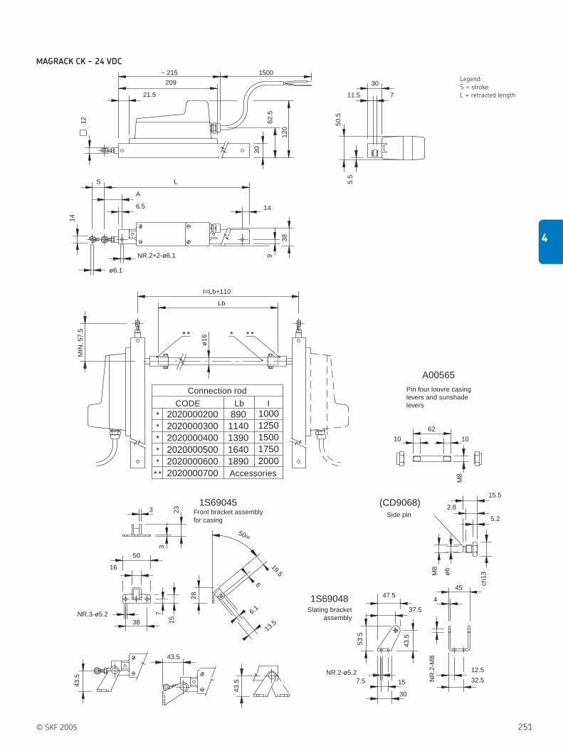
© SKF 2005 251
4
Legend:
S = stroke
L = retracted length21.5
6.5
NR.2+2-ø6.1
ø6.1
MIN
. 57.
5
NR.3-ø5.2
43.5
43.5
43.5
19.5
13.5
6.1
47.5
37.5
7.5
12.5
32.5
53.5
43.5
NR.2-ø5.2
2.8
5.2
15.5
50.5
5.5
62.5
11.5
~ 215
209
1500
120
30
1230
7
38
14
9
LS
A
14
I=Lb+110
Lb
ø16
3
3
50
23
7
38 15
28
6
50∞
15
30
NR
.2-M
8
4
M8
ø6
45
ch13
M8
(CD9068)
1S69048
1S69045
A00565
16
62
10 10
10001250150017502000
2020000200 8901140139016401890
2020000300
20200005002020000400
20200007002020000600
Pin four louvre casinglevers and sunshadelevers
Side pinFront bracket assemblyfor casing
Connection rod
Accessories
CODE Lb I
Slating bracketassembly
MAGRACK CK - 24 VDC

252 © SKF 2005
4 Actuation systems
Linear actuators
MAGRACK CK - 230 VAC
187.5
12
30
62.5
131.
5
6.5
A
S
14
L
NR.2+2-ø6.1
14
ø6.1
5.5
50.5
11.5 7
30
Lb
I=Lb+110
MIN
. 57.
5
ø16
38
43.5
43.5
43.5
37.5
47.5
43.5
53.5
NR
.2-M
8
4
45
NR.2-ø5.2
15
30
12.5
32.5
ø6
M8
ch13
5.2
2.8
15.5
NR.3-ø5.238
16
50
7
153
23
3
6
28
19.5
50∞
6.1
13.5
1S69045
1S69048
1500
21.5
~ 215
10001250150017502000
2020000200
9
( CD9068 )
M8
1010
62
A00565
8901140139016401890
2020000300
20200005002020000400
20200007002020000600
**
**
** *
* * ***
Legend:
S = stroke
L = retracted length
Pin four louvre casinglevers and sunshadelevers
Side pin
Front bracket assemblyfor casing
Connection rod
Accessories
CODE Lb I
Slating bracket assembly

© SKF 2005 253
4
Notes

19.3 24.3 36.0
ø72
.8 ø30 16
ø8±
0.2
ø3
39 3014.8 16.6
4
37
49.240
48
49.2
48
43.6ø42H8ø42H8
12
31.3
8ø28H8
8
31.3
19.2
18
ø42
1000 ø79.9
60
121.
5
E110C/E220C C24CN/C12CN/C90CN
ø61.5
133
(C24
C, C
12C
)
148
(C90
C)
ø79.7
161.
6
C12CE/C24CE/C90CE
Standard shaft design
Motor options
Type key code: 1
Type key code: 3
Type key code: S
Type key code: 2
Type key code: 4
Type key code: A
Type key code: B
254 © SKF 2005
4 Actuation systems
Rotary actuators
Rotary actuators
CRAB 17
The CRAB 17 ( figure 24) rotary actuator
is modular so that critical components can
be interchanged to meet the needs of a
special design priority. The purpose with
CRAB 17 is designed to be small and
compact but still be able to produce high
torque. As the actuator can withstand high
loads it can also serve as a load-bearing
element of your design.
Special bearings arrangements are not
usually required.
Benefits:
Multiple output shafts
Multiple motor options
Small and compact
Figure 24
Limit switch Manual override
Type Torque Max. speed Size Working range Voltage Protection Weight
Nm rpm mm degrees V IP kg
CRAB 17 70 8 125 multi turn 120 / 230 AC 20 / 44 3
CRAB 17 105 20 125 multi turn 12 / 24 / 90 DC 20 / 44 3
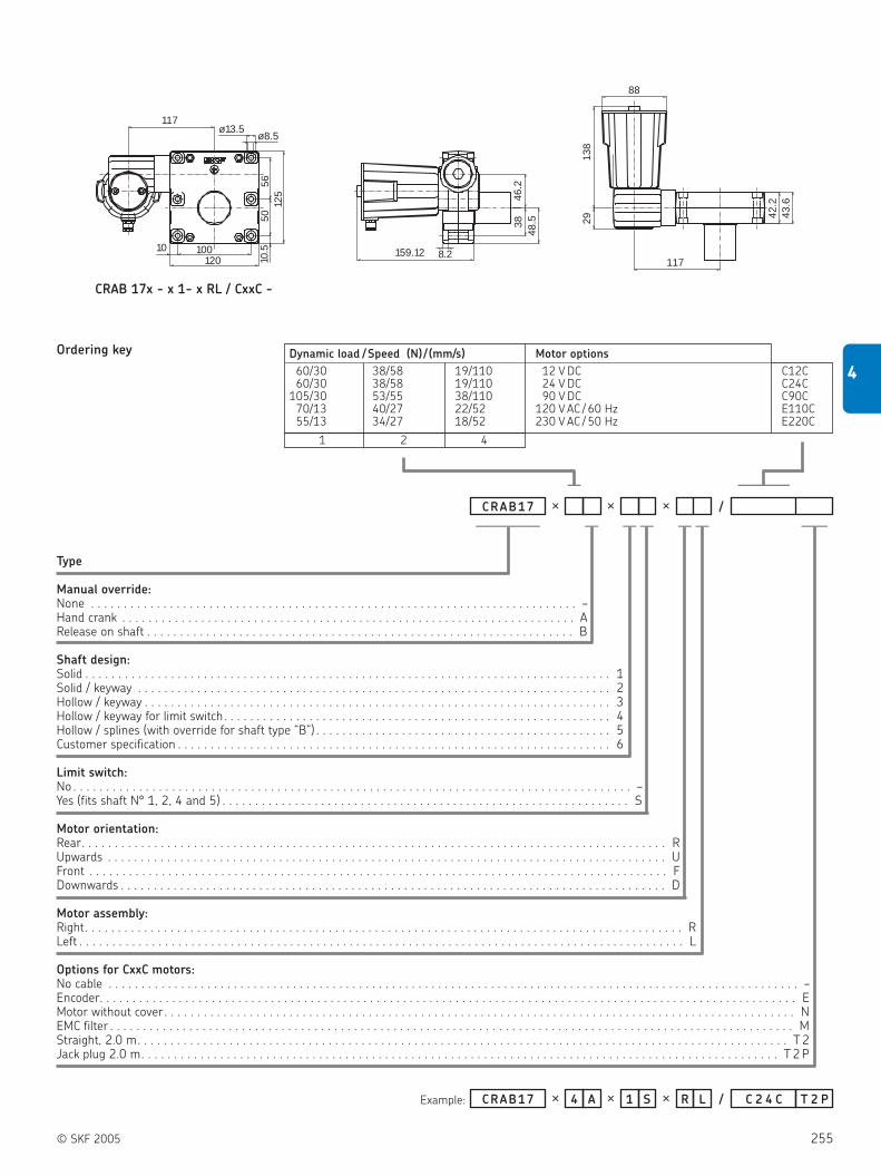
© SKF 2005 255
4
Type
Manual override:None . . . . . . . . . . . . . . . . . . . . . . . . . . . . . . . . . . . . . . . . . . . . . . . . . . . . . . . . . . . . . . . . . . . . . . . . . . –Hand crank . . . . . . . . . . . . . . . . . . . . . . . . . . . . . . . . . . . . . . . . . . . . . . . . . . . . . . . . . . . . . . . . . . . . . ARelease on shaft . . . . . . . . . . . . . . . . . . . . . . . . . . . . . . . . . . . . . . . . . . . . . . . . . . . . . . . . . . . . . . . . . B
Shaft design:Solid . . . . . . . . . . . . . . . . . . . . . . . . . . . . . . . . . . . . . . . . . . . . . . . . . . . . . . . . . . . . . . . . . . . . . . . . . . . . . . . . 1Solid / keyway . . . . . . . . . . . . . . . . . . . . . . . . . . . . . . . . . . . . . . . . . . . . . . . . . . . . . . . . . . . . . . . . . . . . . . . . 2Hollow / keyway . . . . . . . . . . . . . . . . . . . . . . . . . . . . . . . . . . . . . . . . . . . . . . . . . . . . . . . . . . . . . . . . . . . . . . . 3Hollow / keyway for limit switch. . . . . . . . . . . . . . . . . . . . . . . . . . . . . . . . . . . . . . . . . . . . . . . . . . . . . . . . . . . 4Hollow / splines (with override for shaft type “B”) . . . . . . . . . . . . . . . . . . . . . . . . . . . . . . . . . . . . . . . . . . . . . 5Customer specification . . . . . . . . . . . . . . . . . . . . . . . . . . . . . . . . . . . . . . . . . . . . . . . . . . . . . . . . . . . . . . . . . . 6
Limit switch:No . . . . . . . . . . . . . . . . . . . . . . . . . . . . . . . . . . . . . . . . . . . . . . . . . . . . . . . . . . . . . . . . . . . . . . . . . . . . . . . . . . . . . –Yes (fits shaft N° 1, 2, 4 and 5) . . . . . . . . . . . . . . . . . . . . . . . . . . . . . . . . . . . . . . . . . . . . . . . . . . . . . . . . . . . . . . S
Motor orientation:Rear. . . . . . . . . . . . . . . . . . . . . . . . . . . . . . . . . . . . . . . . . . . . . . . . . . . . . . . . . . . . . . . . . . . . . . . . . . . . . . . . . . . . . . . . . RUpwards . . . . . . . . . . . . . . . . . . . . . . . . . . . . . . . . . . . . . . . . . . . . . . . . . . . . . . . . . . . . . . . . . . . . . . . . . . . . . . . . . . . . . UFront . . . . . . . . . . . . . . . . . . . . . . . . . . . . . . . . . . . . . . . . . . . . . . . . . . . . . . . . . . . . . . . . . . . . . . . . . . . . . . . . . . . . . . . . FDownwards . . . . . . . . . . . . . . . . . . . . . . . . . . . . . . . . . . . . . . . . . . . . . . . . . . . . . . . . . . . . . . . . . . . . . . . . . . . . . . . . . . . D
Motor assembly:Right. . . . . . . . . . . . . . . . . . . . . . . . . . . . . . . . . . . . . . . . . . . . . . . . . . . . . . . . . . . . . . . . . . . . . . . . . . . . . . . . . . . . . . . . . . . RLeft . . . . . . . . . . . . . . . . . . . . . . . . . . . . . . . . . . . . . . . . . . . . . . . . . . . . . . . . . . . . . . . . . . . . . . . . . . . . . . . . . . . . . . . . . . . . L
Options for CxxC motors:No cable . . . . . . . . . . . . . . . . . . . . . . . . . . . . . . . . . . . . . . . . . . . . . . . . . . . . . . . . . . . . . . . . . . . . . . . . . . . . . . . . . . . . . . . . . . . . . . . . . . . . . . . . . –Encoder. . . . . . . . . . . . . . . . . . . . . . . . . . . . . . . . . . . . . . . . . . . . . . . . . . . . . . . . . . . . . . . . . . . . . . . . . . . . . . . . . . . . . . . . . . . . . . . . . . . . . . . . . . EMotor without cover . . . . . . . . . . . . . . . . . . . . . . . . . . . . . . . . . . . . . . . . . . . . . . . . . . . . . . . . . . . . . . . . . . . . . . . . . . . . . . . . . . . . . . . . . . . . . . . . NEMC filter . . . . . . . . . . . . . . . . . . . . . . . . . . . . . . . . . . . . . . . . . . . . . . . . . . . . . . . . . . . . . . . . . . . . . . . . . . . . . . . . . . . . . . . . . . . . . . . . . . . . . . . . MStraight, 2.0 m. . . . . . . . . . . . . . . . . . . . . . . . . . . . . . . . . . . . . . . . . . . . . . . . . . . . . . . . . . . . . . . . . . . . . . . . . . . . . . . . . . . . . . . . . . . . . . . . . . . T 2Jack plug 2.0 m. . . . . . . . . . . . . . . . . . . . . . . . . . . . . . . . . . . . . . . . . . . . . . . . . . . . . . . . . . . . . . . . . . . . . . . . . . . . . . . . . . . . . . . . . . . . . . . . . T 2 P
Example:
CRAB17 × ×× /
CRAB17 4× S LR×A 1× / T 2 PC 2 4 C
Dynamic load /Speed (N)/ (mm/s) Motor options
60/30 38/58 19/110 12 V DC C12C60/30 38/58 19/110 24 V DC C24C
105/30 53/55 38/110 90 V DC C90C70/13 40/27 22/52 120 V AC / 60 Hz E110C55/13 34/27 18/52 230 V AC / 50 Hz E220C
1 2 4
Ordering key
CRAB 17x - x 1- x RL / CxxC -
—————
————
— — — — — ——
—
159.12 8.2
3848
.546
.2
2913
8
88
117
42.2
43.6
117
100120
ø13.5ø8.5
10
5612
550
10.5

Figure 25
256 © SKF 2005
4 Actuation systems
Rotary actuators
CRAB 05
The design of the CRAB 05 rotary actuator
series ( figure 25) has been developed
from a completely new recliner technology.
This recliner technology is a new patent
and has been successfully used in the
automotive industry for car seat
applications. Car seat applications demand
low cost, high operation, high impact
strength and ease of operation, electrically
or manually, when adjusting the seat. This
design makes it possible to build low cost
and space saving solutions in application
where dynamic force demands are below
100 Nm.
Benefits:
Recliner
Multiple motor options
Thin and small
Type Torque Max. speed Size Working range Voltage Protection Weight
Nm rpm mm degrees V DC IP kg
CRAB 05 100 3 86 multi turn 24 20 0,5

© SKF 2005 257
4
Fig. A
Type
Coating:Black chromium-plated . . . . . . . . . . . . . . . . . . . . . . . . . . . . . . . . . . . . . . . . . . . . . . . . . . . . . . . . . . . . . . . . . . . . . . . . . . . . . . . . . BNatural chromium-plated . . . . . . . . . . . . . . . . . . . . . . . . . . . . . . . . . . . . . . . . . . . . . . . . . . . . . . . . . . . . . . . . . . . . . . . . . . . . . . . . C
Motor shaft connection:D-hole . . . . . . . . . . . . . . . . . . . . . . . . . . . . . . . . . . . . . . . . . . . . . . . . . . . . . . . . . . . . . . . . . . . . . . . . . . . . . . . . . . . . . . . . . . . . . . . . . DHexagonal hole . . . . . . . . . . . . . . . . . . . . . . . . . . . . . . . . . . . . . . . . . . . . . . . . . . . . . . . . . . . . . . . . . . . . . . . . . . . . . . . . . . . . . . . . . . H
Attachment /connection:Outer connection ears (see Fig. A). . . . . . . . . . . . . . . . . . . . . . . . . . . . . . . . . . . . . . . . . . . . . . . . . . . . . . . . . . . . . . . . . . . . . . . . . . . . . . . ECentre connection hexagonal 32 mm (see Fig. B only option “C” and “H”) . . . . . . . . . . . . . . . . . . . . . . . . . . . . . . . . . . . . . . . . . . . . . . . S
Motors:No motor. . . . . . . . . . . . . . . . . . . . . . . . . . . . . . . . . . . . . . . . . . . . . . . . . . . . . . . . . . . . . . . . . . . . . . . . . . . . . . . . . . . . . . . . . . . . . . . . . . . . 0 024 V DC for motor shaft connection “D” . . . . . . . . . . . . . . . . . . . . . . . . . . . . . . . . . . . . . . . . . . . . . . . . . . . . . . . . . . . . . . . . . . . . . . . . . . . . M D24 V DC for motor shaft connection “H”. . . . . . . . . . . . . . . . . . . . . . . . . . . . . . . . . . . . . . . . . . . . . . . . . . . . . . . . . . . . . . . . . . . . . . . . . . . . M H
Connection shaft:No shaft. . . . . . . . . . . . . . . . . . . . . . . . . . . . . . . . . . . . . . . . . . . . . . . . . . . . . . . . . . . . . . . . . . . . . . . . . . . . . . . . . . . . . . . . . . . . . . . . . . . . . . . . . 0 0D-shaft . . . . . . . . . . . . . . . . . . . . . . . . . . . . . . . . . . . . . . . . . . . . . . . . . . . . . . . . . . . . . . . . . . . . . . . . . . . . . . . . . . . . . . . . . . . . . . . . . . . . . . . . . S DHexagonal shaft . . . . . . . . . . . . . . . . . . . . . . . . . . . . . . . . . . . . . . . . . . . . . . . . . . . . . . . . . . . . . . . . . . . . . . . . . . . . . . . . . . . . . . . . . . . . . . . . . . S H
Example:
CRAB05
CRAB05 EC D M D S H
16.5
9
ø4
8 h8
ø63
66.214
7.93
30.8
M6(
3x)
27 46.5
R25.4
120°
ø42
(a)
133.
5
M6(3x)
26
120°
ø6
h85.
5
24 ø6
h8 ø8
ø42
133.
5
M6x
0.75
82125
33
13
5
M7x
0.75
50
50
70
ø8.5
R3 (6x)
120°(6x)
(b)
4
8.318 4.0
8+0.05
-0
32 +0.1- 0.2
86
M7x
0.75
ø6H
825
14
ø8.0+0.005- 0.05
7+0
-0.0
22(h
8)
ø20
30 216
ø4ø8.0+0.05- 0
164
14
8
50
70
50
ø8.5
86
8+0.05-0
8.05
7.05
+0.05-0
+0.0
5
-0
Fig. B
Connecting shaft SH
Connecting shaft SD
Motor MH
Motor MD
Legend:
(a) = Blade terminal
6.3 ×0.8 DIN 46244
(b) = Drive cross not fixed to
gear. Hardened 45HRC
Ordering key
————— — — — ——
CRAB05

258 © SKF 2005
4 Actuation systems
Control units
Control units
A large variety of control units ( figure
26) is available to operate the linear drives
and telescopic pillars. They allow the
connection of up to 5 actuators or several
external options. There is also a version to
operate battery powered DC-actuators.
For combinations of actuators and
control units please see the matrix on page
165.
Benefits:
Application focused system control
Operation of up to 5 actuators
Connections for foot, hand or desk
switches
Basic functions or encoder processing
versions
Figure 26
Control Type Control Max. motor Input Output
units connections
n° V V / A
KOM KOM 1 Basic functions 4 230 / 120 24 / 6
KOM 2 Encoder processing 5 230 / 120 24 / 6 or 12
KOM 3 Basic functions 3 230 / 120 24 / 6
KOM 3T Basic functions 2 230 / 120 24 / 9
KOM 6 Encoder processing 4 230 / 120 24 / 6 or 12
MCU MCU Basic functions 2 24 24 / 6
LD LD-015 Encoder processing 2 230 / 120 24 / 10
LD-014 Encoder processing 4 230 / 120 24 / 12
SEM SEM 1 Basic functions 4 230 / 120 24 / 5
CAFC 04 M1 Encoder processing 1 230 / 120 / 240 40 / 6
M2 Encoder processing 2 230 / 120 / 240 40 / 6
M3 Encoder processing 3 230 / 120 / 240 40 / 6
CAFM M1 Encoder processing 1 230 / 120 40 / 6
M2 Encoder processing 2 230 / 120 40 / 6
M3 Encoder processing 3 230 / 120 40 / 6
CAEN 10R Basic functions 1 230 / 120 24 / 1 - 10
15 Basic functions 1 230 24 / 15
CAEV 110 / 220 Basic functions 1 230 / 120 400 / 200
CAED ANR 5-24R-PO Encoder processing 1 22 - 28 24 / 5
9-24R-PO Encoder processing 1 22 - 28 24 / 9
CAED 3-24R Basic functions 1 24 24 / 3
5-24R Basic functions 1 24 24 / 5
9-24R Basic functions 1 24 24 / 9
CAEP 10P-SL Basic functions 1 230 24 / 2 - 10
8V Basic functions 1 230 24 / 10
CAEL 10-24R Basic functions 1 230 24 / 2 - 10
BCU 4 / 5 / 8 / 9 Basic functions 3 230 / 120 24 / 7

© SKF 2005 259
4
KOM1
Type
Number of channels:1 channel . . . . . . . . . . . . . . . . . . . . . . . . . . . . . . . . . . . . . . . . . . . . . . . . . . . . . . . . . . . . . . . . . . . . . . . . . . . . . . . . . . . . . 12 channels . . . . . . . . . . . . . . . . . . . . . . . . . . . . . . . . . . . . . . . . . . . . . . . . . . . . . . . . . . . . . . . . . . . . . . . . . . . . . . . . . . . . 23 channels . . . . . . . . . . . . . . . . . . . . . . . . . . . . . . . . . . . . . . . . . . . . . . . . . . . . . . . . . . . . . . . . . . . . . . . . . . . . . . . . . . . . 34 channels . . . . . . . . . . . . . . . . . . . . . . . . . . . . . . . . . . . . . . . . . . . . . . . . . . . . . . . . . . . . . . . . . . . . . . . . . . . . . . . . . . . . 42-channel with customised current cut-off . . . . . . . . . . . . . . . . . . . . . . . . . . . . . . . . . . . . . . . . . . . . . . . . . . . . . . . . . . A3-channel with customised current cut-off . . . . . . . . . . . . . . . . . . . . . . . . . . . . . . . . . . . . . . . . . . . . . . . . . . . . . . . . . . B4-channel with customised current cut-off . . . . . . . . . . . . . . . . . . . . . . . . . . . . . . . . . . . . . . . . . . . . . . . . . . . . . . . . . . C
Battery option:No battery . . . . . . . . . . . . . . . . . . . . . . . . . . . . . . . . . . . . . . . . . . . . . . . . . . . . . . . . . . . . . . . . . . . . . . . . . . . . . . . . . . . . . . . . . . 0With battery and charge circuit (not possible with enhanced power). . . . . . . . . . . . . . . . . . . . . . . . . . . . . . . . . . . . . . . . . . . . . 1With charge circuit for external battery . . . . . . . . . . . . . . . . . . . . . . . . . . . . . . . . . . . . . . . . . . . . . . . . . . . . . . . . . . . . . . . . . . . 3
Voltage:230 V AC, 50 / 60Hz. . . . . . . . . . . . . . . . . . . . . . . . . . . . . . . . . . . . . . . . . . . . . . . . . . . . . . . . . . . . . . . . . . . . . . . . . . . . . . . . . . . . . . 1120 V AC, 50 / 60Hz. . . . . . . . . . . . . . . . . . . . . . . . . . . . . . . . . . . . . . . . . . . . . . . . . . . . . . . . . . . . . . . . . . . . . . . . . . . . . . . . . . . . . . 2
Cable/Connecting plug:No . . . . . . . . . . . . . . . . . . . . . . . . . . . . . . . . . . . . . . . . . . . . . . . . . . . . . . . . . . . . . . . . . . . . . . . . . . . . . . . . . . . . . . . . . . . . . . . . . . . . . . 0
Colour:Grey, RAL 7035 . . . . . . . . . . . . . . . . . . . . . . . . . . . . . . . . . . . . . . . . . . . . . . . . . . . . . . . . . . . . . . . . . . . . . . . . . . . . . . . . . . . . . . . . . . . . . A
Customization:None . . . . . . . . . . . . . . . . . . . . . . . . . . . . . . . . . . . . . . . . . . . . . . . . . . . . . . . . . . . . . . . . . . . . . . . . . . . . . . . . . . . . . . . . . . . . . . . . . . . . . . . . . 0 0 0
Example:
KOM1 0 A- - 0 0 0
2KOM1 1 0 A- 0 - 0 0 0
Ordering key
———–– — — — — —–––––—
Accessories
Item Plug Country Order number Comment
Straight cable 3.5 m Schuko DE 140306
Straight cable 3.5 m SEV CH 140316
Straight cable 3.5 m UL USA 140355
Straight cable 3.5 m Hospital grade USA 140360
Straight cable 3.5 m British standard UK 140350
Coiled cable 1.2 m /2.2 m Schuko DE 140342
Coiled cable 1.2 m /2.2 m SEV CH 140378
Straight cable 3.5 m SEV CH 140422-3500 Polyurethane cable
Straight cable 3.5 m Schuko DE 140426-3500 Polyurethane cable
Tool for plugs (Jack /D-Sub/Mains) 140375
Operating device adaptor (DSub9) 140420
Type Control Max. motor Input Output
connections
n° V AC V DC / A
KOM 1 Basic functions 4 230 / 120 24 / 6

260 © SKF 2005
4 Actuation systems
Control units
Type
Number of channels:1 channel (not available with parallel option) . . . . . . . . . . . . . . . . . . . . . . . . . . . . . . . . . . . . . . . . . . . . . . . . . . . . . . . 12 channels . . . . . . . . . . . . . . . . . . . . . . . . . . . . . . . . . . . . . . . . . . . . . . . . . . . . . . . . . . . . . . . . . . . . . . . . . . . . . . . . . . 23 channels . . . . . . . . . . . . . . . . . . . . . . . . . . . . . . . . . . . . . . . . . . . . . . . . . . . . . . . . . . . . . . . . . . . . . . . . . . . . . . . . . . 34 channels (not available with memory option) . . . . . . . . . . . . . . . . . . . . . . . . . . . . . . . . . . . . . . . . . . . . . . . . . . . . . 45 channels (not available with memory option) . . . . . . . . . . . . . . . . . . . . . . . . . . . . . . . . . . . . . . . . . . . . . . . . . . . . . 5
Battery option:No battery. . . . . . . . . . . . . . . . . . . . . . . . . . . . . . . . . . . . . . . . . . . . . . . . . . . . . . . . . . . . . . . . . . . . . . . . . . . . . . . . . . . . . . . . 0With battery and charge circuit (not possible with enhanced power) . . . . . . . . . . . . . . . . . . . . . . . . . . . . . . . . . . . . . . . . . . 1With charge circuit for external battery. . . . . . . . . . . . . . . . . . . . . . . . . . . . . . . . . . . . . . . . . . . . . . . . . . . . . . . . . . . . . . . . . 3
Voltage:230 V AC, 50 / 60Hz . . . . . . . . . . . . . . . . . . . . . . . . . . . . . . . . . . . . . . . . . . . . . . . . . . . . . . . . . . . . . . . . . . . . . . . . . . . . . . . . . . . 1120 V AC, 50 / 60Hz . . . . . . . . . . . . . . . . . . . . . . . . . . . . . . . . . . . . . . . . . . . . . . . . . . . . . . . . . . . . . . . . . . . . . . . . . . . . . . . . . . . 2230 V AC, 50/60Hz with enhanced power . . . . . . . . . . . . . . . . . . . . . . . . . . . . . . . . . . . . . . . . . . . . . . . . . . . . . . . . . . . . . . . . . 4120 V AC, 50/60Hz with enhanced power . . . . . . . . . . . . . . . . . . . . . . . . . . . . . . . . . . . . . . . . . . . . . . . . . . . . . . . . . . . . . . . . . 5
Cable/Connecting plug:No cable . . . . . . . . . . . . . . . . . . . . . . . . . . . . . . . . . . . . . . . . . . . . . . . . . . . . . . . . . . . . . . . . . . . . . . . . . . . . . . . . . . . . . . . . . . . . . . 0
Colour:Grey, RAL 7035 . . . . . . . . . . . . . . . . . . . . . . . . . . . . . . . . . . . . . . . . . . . . . . . . . . . . . . . . . . . . . . . . . . . . . . . . . . . . . . . . . . . . . . . . . . A
Software options:Up and down function (up to 5 channels) . . . . . . . . . . . . . . . . . . . . . . . . . . . . . . . . . . . . . . . . . . . . . . . . . . . . . . . . . . . . . . . . . . . . . . . . EParallel operation of actuators (all connected actuators move together), 2, 3, 4 channels . . . . . . . . . . . . . . . . . . . . . . . . . . . . . . . . . . . PParallel operation of 2 × 2 actuators . . . . . . . . . . . . . . . . . . . . . . . . . . . . . . . . . . . . . . . . . . . . . . . . . . . . . . . . . . . . . . . . . . . . . . . . . . . . D3 free programmable memory positions . . . . . . . . . . . . . . . . . . . . . . . . . . . . . . . . . . . . . . . . . . . . . . . . . . . . . . . . . . . . . . . . . . . . . . . . M
Customization:None . . . . . . . . . . . . . . . . . . . . . . . . . . . . . . . . . . . . . . . . . . . . . . . . . . . . . . . . . . . . . . . . . . . . . . . . . . . . . . . . . . . . . . . . . . . . . . . . . . . . . . . . . 0 0 0
KOM2
Ordering key
Example:
KOM2 0 A- - 0 0 0
3KOM2 4 0 A P- 0 - 0 0 0
———— — — — ——— —–––––
Accessories
Type Control Max. motor Input Output
connections
n° V AC V / A
KOM 2 Encoder processing 5 230 / 120 24 / 6 or 12
Item Plug Country Order number Comment
Straight cable 3.5 m Schuko DE 140306
Straight cable 3.5 m SEV CH 140316
Straight cable 3.5 m UL USA 140355
Straight cable 3.5 m Hospital grade USA 140360
Straight cable 3.5 m British standard UK 140350
Coiled cable 1.2 m /2.2 m Schuko DE 140342
Coiled cable 1.2 m /2.2 m SEV CH 140378
Straight cable 3.5 m SEV CH 140422-3500 Polyurethane cable
Straight cable 3.5 m Schuko DE 140426-3500 Polyurethane cable
Tool for plugs (Jack /D-Sub/Mains) 140375
Operating device adaptor (DSub9) 140420

© SKF 2005 261
4
KOM3
Type
Number of channels:1 channel . . . . . . . . . . . . . . . . . . . . . . . . . . . . . . . . . . . . . . . . . . . . . . . . . . . . . . . . . . . . . . . . . . . . . . . . . . . . . . . . . . . . . . . . 12 channels . . . . . . . . . . . . . . . . . . . . . . . . . . . . . . . . . . . . . . . . . . . . . . . . . . . . . . . . . . . . . . . . . . . . . . . . . . . . . . . . . . . . . . . 23 channels . . . . . . . . . . . . . . . . . . . . . . . . . . . . . . . . . . . . . . . . . . . . . . . . . . . . . . . . . . . . . . . . . . . . . . . . . . . . . . . . . . . . . . . 32 channels (only for TLT-Telemag). . . . . . . . . . . . . . . . . . . . . . . . . . . . . . . . . . . . . . . . . . . . . . . . . . . . . . . . . . . . . . . . . . . . . T
Voltage:230 V AC, 50 / 60Hz. . . . . . . . . . . . . . . . . . . . . . . . . . . . . . . . . . . . . . . . . . . . . . . . . . . . . . . . . . . . . . . . . . . . . . . . . . . . . . . . . . . . . . 1120 V AC, 50 / 60Hz. . . . . . . . . . . . . . . . . . . . . . . . . . . . . . . . . . . . . . . . . . . . . . . . . . . . . . . . . . . . . . . . . . . . . . . . . . . . . . . . . . . . . . 2
Cable/Connecting plug:No . . . . . . . . . . . . . . . . . . . . . . . . . . . . . . . . . . . . . . . . . . . . . . . . . . . . . . . . . . . . . . . . . . . . . . . . . . . . . . . . . . . . . . . . . . . . . . . . . . . . . . 0
Colour:Grey RAL 7035 . . . . . . . . . . . . . . . . . . . . . . . . . . . . . . . . . . . . . . . . . . . . . . . . . . . . . . . . . . . . . . . . . . . . . . . . . . . . . . . . . . . . . . . . . . . . . A
Customization:None . . . . . . . . . . . . . . . . . . . . . . . . . . . . . . . . . . . . . . . . . . . . . . . . . . . . . . . . . . . . . . . . . . . . . . . . . . . . . . . . . . . . . . . . . . . . . . . . . . . . . . . . . 0 0 0
Ordering key
Example: TKOM3 0 A- 1 - 0 0 0
KOM3 0 A- - 0 0 0
———— — — —— —–––––
Accessories
Item Plug Country Order number Comment
Straight cable 3.5 m Schuko DE 140306
Straight cable 3.5 m SEV CH 140316
Straight cable 3.5 m UL USA 140355
Straight cable 3.5 m Hospital grade USA 140360
Straight cable 3.5 m British standard UK 140350
Coiled cable 1.2 m /2.2 m Schuko DE 140342
Coiled cable 1.2 m /2.2 m SEV CH 140378
Straight cable 3.5 m SEV CH 140422-3500 Polyurethane cable
Straight cable 3.5 m Schuko DE 140426-3500 Polyurethane cable
Tool for plugs (Jack /D-Sub/Mains) 140375
Operating device adaptor (DSub9) 140420
Type Control Max. motor Input Output
connections
n° V AC V / A
KOM 3 Basic functions 3 230 / 120 24 / 6
KOM 3T Basic functions 2 230 / 120 24 / 9

262 © SKF 2005
4 Actuation systems
Control units
KOM6
Type
Number of channels:1 channel (not available with parallel option) . . . . . . . . . . . . . . . . . . . . . . . . . . . . . . . . . . . . . . . . . . . . . . . . . . . . . . . 12 channels. . . . . . . . . . . . . . . . . . . . . . . . . . . . . . . . . . . . . . . . . . . . . . . . . . . . . . . . . . . . . . . . . . . . . . . . . . . . . . . . . . 23 channels. . . . . . . . . . . . . . . . . . . . . . . . . . . . . . . . . . . . . . . . . . . . . . . . . . . . . . . . . . . . . . . . . . . . . . . . . . . . . . . . . . 34 channels (not available with memory option) . . . . . . . . . . . . . . . . . . . . . . . . . . . . . . . . . . . . . . . . . . . . . . . . . . . . . 4
Battery option:No battery. . . . . . . . . . . . . . . . . . . . . . . . . . . . . . . . . . . . . . . . . . . . . . . . . . . . . . . . . . . . . . . . . . . . . . . . . . . . . . . . . . . . . . . . 0With battery and charge circuit (not possible with enhanced power) . . . . . . . . . . . . . . . . . . . . . . . . . . . . . . . . . . . . . . . . . . 1With charge circuit for external battery. . . . . . . . . . . . . . . . . . . . . . . . . . . . . . . . . . . . . . . . . . . . . . . . . . . . . . . . . . . . . . . . . 3
Voltage:230 V AC, 50 / 60Hz . . . . . . . . . . . . . . . . . . . . . . . . . . . . . . . . . . . . . . . . . . . . . . . . . . . . . . . . . . . . . . . . . . . . . . . . . . . . . . . . . . . 1120 V AC, 50 / 60Hz . . . . . . . . . . . . . . . . . . . . . . . . . . . . . . . . . . . . . . . . . . . . . . . . . . . . . . . . . . . . . . . . . . . . . . . . . . . . . . . . . . . 2230 V AC, 50/60Hz with enhanced power . . . . . . . . . . . . . . . . . . . . . . . . . . . . . . . . . . . . . . . . . . . . . . . . . . . . . . . . . . . . . . . . . 4120 V AC, 50/60Hz with enhanced power . . . . . . . . . . . . . . . . . . . . . . . . . . . . . . . . . . . . . . . . . . . . . . . . . . . . . . . . . . . . . . . . . 5
Cable/Connecting plug:Without cable . . . . . . . . . . . . . . . . . . . . . . . . . . . . . . . . . . . . . . . . . . . . . . . . . . . . . . . . . . . . . . . . . . . . . . . . . . . . . . . . . . . . . . . . . . 0
Colour:Grey, RAL 7035 . . . . . . . . . . . . . . . . . . . . . . . . . . . . . . . . . . . . . . . . . . . . . . . . . . . . . . . . . . . . . . . . . . . . . . . . . . . . . . . . . . . . . . . . . . A
Software options:Up and down function (up to 4 channels) . . . . . . . . . . . . . . . . . . . . . . . . . . . . . . . . . . . . . . . . . . . . . . . . . . . . . . . . . . . . . . . . . . . . . . . . EParallel operation of 2 × 2 actuators . . . . . . . . . . . . . . . . . . . . . . . . . . . . . . . . . . . . . . . . . . . . . . . . . . . . . . . . . . . . . . . . . . . . . . . . . . . . DParallel operation of actuators (all connected actuators move together), incl. 3 memory positions . . . . . . . . . . . . . . . . . . . . . . . . . . . . M3 free programmable memory positions . . . . . . . . . . . . . . . . . . . . . . . . . . . . . . . . . . . . . . . . . . . . . . . . . . . . . . . . . . . . . . . . . . . . . . . . . N
Customization:None . . . . . . . . . . . . . . . . . . . . . . . . . . . . . . . . . . . . . . . . . . . . . . . . . . . . . . . . . . . . . . . . . . . . . . . . . . . . . . . . . . . . . . . . . . . . . . . . . . . . . . . . 0 0 0
Example:
Ordering key KOM6 0 A- - 0 0 0
4KOM6 4 0 A N- 1 - 0 0 0
———— — — — ——— —–––––
Accessories
Type Control Max. motor Input Output
connections
n° V AC V / A
KOM 6 Encoder processing 4 230 / 120 24 / 6 or 12
Item Plug Country Order number Comment
Straight cable 3.5 m Schuko DE 140306
Straight cable 3.5 m SEV CH 140316
Straight cable 3.5 m UL USA 140355
Straight cable 3.5 m Hospital grade USA 140360
Straight cable 3.5 m British standard UK 140350
Coiled cable 1.2 m /2.2 m Schuko DE 140342
Coiled cable 1.2 m /2.2 m SEV CH 140378
Straight cable 3.5 m SEV CH 140422-3500 Polyurethane cable
Straight cable 3.5 m Schuko DE 140426-3500 Polyurethane cable
Tool for plugs (Jack /D-Sub/Mains) 140375
Operating device adaptor (DSub9) 140420

© SKF 2005 263
4
MCU
Type
Voltage:24 V DC. . . . . . . . . . . . . . . . . . . . . . . . . . . . . . . . . . . . . . . . . . . . . . . . . . . . . . . . . . . . . . . . . . . . . . . . . . . . . . . . . 1
Number of channels:1 channel . . . . . . . . . . . . . . . . . . . . . . . . . . . . . . . . . . . . . . . . . . . . . . . . . . . . . . . . . . . . . . . . . . . . . . . . . . . . . . . . . . 12 channels . . . . . . . . . . . . . . . . . . . . . . . . . . . . . . . . . . . . . . . . . . . . . . . . . . . . . . . . . . . . . . . . . . . . . . . . . . . . . . . . . 2
Cable/Connecting plug:Without cable . . . . . . . . . . . . . . . . . . . . . . . . . . . . . . . . . . . . . . . . . . . . . . . . . . . . . . . . . . . . . . . . . . . . . . . . . . . . . . . . . . . . 0 0
Colour:Grey . . . . . . . . . . . . . . . . . . . . . . . . . . . . . . . . . . . . . . . . . . . . . . . . . . . . . . . . . . . . . . . . . . . . . . . . . . . . . . . . . . . . . . . . . . . . . . . 3
Options:None. . . . . . . . . . . . . . . . . . . . . . . . . . . . . . . . . . . . . . . . . . . . . . . . . . . . . . . . . . . . . . . . . . . . . . . . . . . . . . . . . . . . . . . . . . . . . . . 0 0 0Cut-off current 7.5 A . . . . . . . . . . . . . . . . . . . . . . . . . . . . . . . . . . . . . . . . . . . . . . . . . . . . . . . . . . . . . . . . . . . . . . . . . . . . . . . . . . E W PCut-off current 9 A . . . . . . . . . . . . . . . . . . . . . . . . . . . . . . . . . . . . . . . . . . . . . . . . . . . . . . . . . . . . . . . . . . . . . . . . . . . . . . . . . . . . E X PEmergency lowering, channel 1 . . . . . . . . . . . . . . . . . . . . . . . . . . . . . . . . . . . . . . . . . . . . . . . . . . . . . . . . . . . . . . . . . . . . . . . . . . E Y ECut-off current 7.5 A, electric emergency lowering, channel 1 . . . . . . . . . . . . . . . . . . . . . . . . . . . . . . . . . . . . . . . . . . . . . . . . . 2 D UCut-off current 9 A, electric emergency lowering, channel 1 . . . . . . . . . . . . . . . . . . . . . . . . . . . . . . . . . . . . . . . . . . . . . . . . . . . 2 A T
Symbols/customization:Not used . . . . . . . . . . . . . . . . . . . . . . . . . . . . . . . . . . . . . . . . . . . . . . . . . . . . . . . . . . . . . . . . . . . . . . . . . . . . . . . . . . . . . . . . . . . . . . . . . . . . 0 0 0 0
Example:
446
271139
140
140
Ordering key MCU1 - 0 0 3 - 0 0 0 0
1MCU1 EYE- 0 0 3 - 0 0 0 0
—— ——–— —––––— ——
Accessories
Type Control Max. motor Input Output
connections
n° V DC V / A
MCU Basic functions 2 24 24 / 6
Item Data Plug Order number
Battery unit 4.5 Ah ZBA-142211
Mains adapter 230 V Euro plug ZDV-142331
Mains adapter 120 V UL plug ZDV-142332
Wall charging station ZLA-142221
Tool for plugs (Jack/D-Sub/Mains) 140375

264 © SKF 2005
4 Actuation systems
Control units
LD
Type
Number of channels:2 channels for TELESMART TXG . . . . . . . . . . . . . . . . . . . . . . . . . . . . . . . . . . . . . . . . . . . . . . . . . . . . . . . . . . . . . . . . . . . 0 1 5 - 0 0 52 channels for TMA/TMD . . . . . . . . . . . . . . . . . . . . . . . . . . . . . . . . . . . . . . . . . . . . . . . . . . . . . . . . . . . . . . . . . . . . . . . . 0 1 5 - 0 6 23 channels for TMA/TMD . . . . . . . . . . . . . . . . . . . . . . . . . . . . . . . . . . . . . . . . . . . . . . . . . . . . . . . . . . . . . . . . . . . . . . . . . 0 1 4 - 0 4 14 channels for TMA/TMD . . . . . . . . . . . . . . . . . . . . . . . . . . . . . . . . . . . . . . . . . . . . . . . . . . . . . . . . . . . . . . . . . . . . . . . . . 0 1 4 - 0 4 2
Voltage:230 V AC. . . . . . . . . . . . . . . . . . . . . . . . . . . . . . . . . . . . . . . . . . . . . . . . . . . . . . . . . . . . . . . . . . . . . . . . . . . . . . . . . . . . . . . . . . . . . . . . . . . . . . . 0 0 0120 V AC. . . . . . . . . . . . . . . . . . . . . . . . . . . . . . . . . . . . . . . . . . . . . . . . . . . . . . . . . . . . . . . . . . . . . . . . . . . . . . . . . . . . . . . . . . . . . . . . . . . . . . . 0 0 1
Example:
-LD - -
0 1 5 - 0 6 2LD - - 0 0 1
Ordering key
LD-014 LD-015
————— ————
24235
4 3 2 1 HS
9 8 7 6 5
256.5
14
4
77
418
5817
6315
117
174
8
107
203
4
3
2716
190
12.5
5.5
18
15
5.5
51 44
Type Control Max. motor Input Output
connections
n° V AC V / A
LD-014 Encoder processing 4 230 / 120 24 / 12
LD-015 Encoder processing 2 230 / 120 24 / 10

© SKF 2005 265
4
Example:
SEM
Type
Number of channels:2 channels . . . . . . . . . . . . . . . . . . . . . . . . . . . . . . . . . . . . . . . . . . . . . . . . . . . . . . . . . . . . . . . . . . . . . . . . . . . . . . . 24 channels . . . . . . . . . . . . . . . . . . . . . . . . . . . . . . . . . . . . . . . . . . . . . . . . . . . . . . . . . . . . . . . . . . . . . . . . . . . . . . . 4
Voltage / frequency:230 V / 50Hz. . . . . . . . . . . . . . . . . . . . . . . . . . . . . . . . . . . . . . . . . . . . . . . . . . . . . . . . . . . . . . . . . . . . . . . . . . . . . . . . . . . . 1120 V / 60Hz. . . . . . . . . . . . . . . . . . . . . . . . . . . . . . . . . . . . . . . . . . . . . . . . . . . . . . . . . . . . . . . . . . . . . . . . . . . . . . . . . . . . 2
Mains plug: Protection class II (2-pin mains plug)Euro (Standard) . . . . . . . . . . . . . . . . . . . . . . . . . . . . . . . . . . . . . . . . . . . . . . . . . . . . . . . . . . . . . . . . . . . . . . . . . . . . . . . . . . . . 1British Standard . . . . . . . . . . . . . . . . . . . . . . . . . . . . . . . . . . . . . . . . . . . . . . . . . . . . . . . . . . . . . . . . . . . . . . . . . . . . . . . . . . . 2UL . . . . . . . . . . . . . . . . . . . . . . . . . . . . . . . . . . . . . . . . . . . . . . . . . . . . . . . . . . . . . . . . . . . . . . . . . . . . . . . . . . . . . . . . . . . . . . 3
Colours:Grey RAL 7035 . . . . . . . . . . . . . . . . . . . . . . . . . . . . . . . . . . . . . . . . . . . . . . . . . . . . . . . . . . . . . . . . . . . . . . . . . . . . . . . . . . . . . . . B
Options, electrical:None . . . . . . . . . . . . . . . . . . . . . . . . . . . . . . . . . . . . . . . . . . . . . . . . . . . . . . . . . . . . . . . . . . . . . . . . . . . . . . . . . . . . . . . . . . . . . . . . . . 0
Fastening:Can be plugged into actuator . . . . . . . . . . . . . . . . . . . . . . . . . . . . . . . . . . . . . . . . . . . . . . . . . . . . . . . . . . . . . . . . . . . . . . . . . . . . . . . . . 0
Customer-specific adaptations:None . . . . . . . . . . . . . . . . . . . . . . . . . . . . . . . . . . . . . . . . . . . . . . . . . . . . . . . . . . . . . . . . . . . . . . . . . . . . . . . . . . . . . . . . . . . . . . . . . . . . . . . . 0 0 0
Ordering key SEM1 0 0- - 0 0 0
4SEM1 3 B 0 0- 2 - 0 0 0
———— — — — ——— —–––––
Type Control Max. motor Input Output
connections
n° V AC V / A
SEM Basic functions 4 230 / 120 24 / 5

266 © SKF 2005
4 Actuation systems
Control units
CAFC 04
Type
Number of actuators:1 actuator . . . . . . . . . . . . . . . . . . . . . . . . . . . . . . . . . . . . . . . . . . . . . . . . . . . . . . . . . . . . . . . . . . . . . . . . . . . . . . . . . . . . . 12 actuators . . . . . . . . . . . . . . . . . . . . . . . . . . . . . . . . . . . . . . . . . . . . . . . . . . . . . . . . . . . . . . . . . . . . . . . . . . . . . . . . . . . . 23 actuators . . . . . . . . . . . . . . . . . . . . . . . . . . . . . . . . . . . . . . . . . . . . . . . . . . . . . . . . . . . . . . . . . . . . . . . . . . . . . . . . . . . . 3
Mains cable (PVC cable class II):230 V AC, coiled cable, 3.0 m, grey, EU-plug . . . . . . . . . . . . . . . . . . . . . . . . . . . . . . . . . . . . . . . . . . . . . . . . . . . . . . . . . . . . . . . A230 V AC, straight cable, 3.2 m, black, EU-plug . . . . . . . . . . . . . . . . . . . . . . . . . . . . . . . . . . . . . . . . . . . . . . . . . . . . . . . . . . . . . B230 V AC, straight / coiled cable 3.0 m (1 m + 2 m), grey, EU-plug. . . . . . . . . . . . . . . . . . . . . . . . . . . . . . . . . . . . . . . . . . . . . . . G120 V AC, straight cable, 3.0 m, grey, US-plug . . . . . . . . . . . . . . . . . . . . . . . . . . . . . . . . . . . . . . . . . . . . . . . . . . . . . . . . . . . . . H240 V AC, straight cable, 3.0 m, grey, UK-plug . . . . . . . . . . . . . . . . . . . . . . . . . . . . . . . . . . . . . . . . . . . . . . . . . . . . . . . . . . . . . . I
Overload protection (factory pre-set):Yes . . . . . . . . . . . . . . . . . . . . . . . . . . . . . . . . . . . . . . . . . . . . . . . . . . . . . . . . . . . . . . . . . . . . . . . . . . . . . . . . . . . . . . . . . . . . . . . . . . . 1
Protection class:IPX4 . . . . . . . . . . . . . . . . . . . . . . . . . . . . . . . . . . . . . . . . . . . . . . . . . . . . . . . . . . . . . . . . . . . . . . . . . . . . . . . . . . . . . . . . . . . . . . . . . . . . . . . X 4
Battery options:No battery . . . . . . . . . . . . . . . . . . . . . . . . . . . . . . . . . . . . . . . . . . . . . . . . . . . . . . . . . . . . . . . . . . . . . . . . . . . . . . . . . . . . . . . . . . . . . . . . . . . . . . . 0Battery plug. . . . . . . . . . . . . . . . . . . . . . . . . . . . . . . . . . . . . . . . . . . . . . . . . . . . . . . . . . . . . . . . . . . . . . . . . . . . . . . . . . . . . . . . . . . . . . . . . . . . . . 2
Colour:Grey, RAL 7035 . . . . . . . . . . . . . . . . . . . . . . . . . . . . . . . . . . . . . . . . . . . . . . . . . . . . . . . . . . . . . . . . . . . . . . . . . . . . . . . . . . . . . . . . . . . . . . . . . . . . . G
CAFC04 × M G1× / X4
CAFC04 × M 1 GB 1× / 5 1 2
Ordering key
———— ——— ——— —
Example:
(b-c-d)
108 19
134
5.5
3500
150
(a)
75
18.5
190
Legend:
(a) = multi conductor locking plug DIN
(b) = 230 V straight 3.5 m black EU
(c) = 120 V straight 3.0 m grey US
(d) = 240 V straight 3.0 m grey UK
Accessories
Type Control Max. motor connections Input Output
n° V AC V / A
M1 Encoder processing 1 230 / 120 / 240 40 / 6
M2 Encoder processing 2 230 / 120 / 240 40 / 6
M3 Encoder processing 3 230 / 120 / 240 40 / 6
Item / Product CAF C04 M1 CAF C04 M2 CAF C04 M3
Cable handset CAFH M1 / S118C CAFH M2 / S116C CAFH M3 / S120C
CAFH M1 / S118CE CAFH M2 / S116CE CAFH M3 / S120CE
CAFH M1 / S746C CAFH M2 / S784C CAFH M3 / S822C
CAFH M1 / S746CE CAFH M2 / S784CE CAFH M3 / S822CE
Foot switch CAFH F1 / S401D CAFH F1 / S401D CAFH F1 / S402D
CAFH F1 / S403D CAFH F1 / S403D CAFH F1 / S404D
Desk switch CAFH T1 / S457D CAFH T2 / S458D
Battery CAFB / S693D CAFB / S693D CAFB / S693D
Junction box CAFR / S238D CAFR / S238D CAFR / S239D

© SKF 2005 267
4
CAFCM
CAEN
(a)
206
44
L = S + 190/220
174
15
3500
10
(b)
(c)
Legend:
(a) = battery connection or external switch
(b) = 230 V AC, coiled cable, 3.0 m, grey, EU-plug
230 V AC, straight cable, 3.2 m, black, EU-plug
230 V AC, straight/coiled cable 3.0 m (1 m + 2 m), grey, EU-plug
120 V AC, straight cable, 3.0 m, grey, US-plug
240 V AC, straight cable, 3.0 m, grey, UK-plug
(c) = multi conductor locking plug DIN
S = stroke (see page 228)
L = retracted length (see page 228)
CAEN156
223110
262
262267
3917980
3917980
NB:
See Type key on page 229 for futher
information.
Ordering key:
Type Control Max. motor Input Output
connections
n° V AC V / A
M1 Encoder processing 1 230 / 120 40 / 6
M2 Encoder processing 2 230 / 120 40 / 6
M3 Encoder processing 3 230 / 120 40 / 6
Type Control Max. motor Input Output
connections
n° V AC V / A
15 Basic functions 1 230 24 / 15
(on/off)

268 © SKF 2005
4 Actuation systems
Control units
CAEN
CAEV
CAED ANR
CAEN10ROrdering key:
CAEV 110/220Ordering key:
CAED ANR 5-24R-POOrdering key:
CAED ANR 9-24R-PO
Type Control Max. motor Input Output
connections
n° V AC V / A DC
10R Basic functions 1 230 / 120 24 / 1 - 10
Type Control Max. motor Input Output
connections
n° V AC VA
110/220 Basic functions 1 230 / 120 400 / 200
Type Control Max. motor Input Output
connections
n° V DC V / A
5-24R-PO Encoder processing 1 22 - 28 24 / 5
9-24R-PO Encoder processing 1 22 - 28 24 / 9
Available start capacitors: values = 3 µF / 4 µF / 6 µF / 8 µF or 12 µF

© SKF 2005 269
4
CAED
9
66
91
73,5
59
1 2 3 4 5 6 7
35
LED
35
16
CAEP
185
115150
220
75
3917
981
3917
981
CAEL
75
115
115
150
150
39179823917982
CAEP 10P-SLOrdering key:
CAEP 8V
CAEL 10-24ROrdering key:
CAED 3-24ROrdering key:
CAED 5-24R
CAED 9-24R
Type Control Max. motor Input Output
connections
n° V DC V / A DC
3-24R Basic functions 1 24 24 / 3
5-24R Basic functions 1 24 24 / 5
9-24R Basic functions 1 24 24 / 9
Type Control Max. motor Input Output
connections
n° V AC V / A DC
10P-SL Basic functions 1 230 24 / 2 - 10
8V* Basic functions 1 230 24 / 10
Type Control Max. motor Input Output
connections
n° V AC V / A DC
10-24R Basic functions 1 230 24 / 2 - 10
* Dimension of housing: 260 × 260 × 107 mm

270 © SKF 2005
4 Actuation systems
Control units
BCU12
5
161
191
147.
572
17
170
Type:
Voltage:120 V AC 50 / 60 Hz (Class II) . . . . . . . . . . . . . . . . . . . . . . . . . . . . . . . . . . . . . . . . . . . . . . . . . . . . . . . . . . . . . 4230 V AC 50 Hz (Class II) . . . . . . . . . . . . . . . . . . . . . . . . . . . . . . . . . . . . . . . . . . . . . . . . . . . . . . . . . . . . . . . . 8
Number of channels:3-channel . . . . . . . . . . . . . . . . . . . . . . . . . . . . . . . . . . . . . . . . . . . . . . . . . . . . . . . . . . . . . . . . . . . . . . . . . . . . . . 3
Mains power supply cable:Straight, 3.5 m, 2-pole plug, EU, class II . . . . . . . . . . . . . . . . . . . . . . . . . . . . . . . . . . . . . . . . . . . . . . . . . . . . . . . . . . 2 JStraight, 3.5 m, 2-pole plug, UK, class II . . . . . . . . . . . . . . . . . . . . . . . . . . . . . . . . . . . . . . . . . . . . . . . . . . . . . . . . . . 2 HStraight, 3.5m, 2-pole plug, UL, class II . . . . . . . . . . . . . . . . . . . . . . . . . . . . . . . . . . . . . . . . . . . . . . . . . . . . . . . . . . . 2 MStraight, 3.5m, 3-pole plug, UL, class I . . . . . . . . . . . . . . . . . . . . . . . . . . . . . . . . . . . . . . . . . . . . . . . . . . . . . . . . . . . . 2 L
Color / Design:Gray, RAL 7035 . . . . . . . . . . . . . . . . . . . . . . . . . . . . . . . . . . . . . . . . . . . . . . . . . . . . . . . . . . . . . . . . . . . . . . . . . . . . . . . . . . . 3
Option 1:DIN 8 motor plug and HD15 operating device plug . . . . . . . . . . . . . . . . . . . . . . . . . . . . . . . . . . . . . . . . . . . . . . . . . . . . . . . . . . 1
Option 2:None . . . . . . . . . . . . . . . . . . . . . . . . . . . . . . . . . . . . . . . . . . . . . . . . . . . . . . . . . . . . . . . . . . . . . . . . . . . . . . . . . . . . . . . . . . . . . . . . 0 0
Functions / symbols:None . . . . . . . . . . . . . . . . . . . . . . . . . . . . . . . . . . . . . . . . . . . . . . . . . . . . . . . . . . . . . . . . . . . . . . . . . . . . . . . . . . . . . . . . . . . . . . . . . . . . . . 0 0
Customer specification:None. . . . . . . . . . . . . . . . . . . . . . . . . . . . . . . . . . . . . . . . . . . . . . . . . . . . . . . . . . . . . . . . . . . . . . . . . . . . . . . . . . . . . . . . . . . . . . . . . . . . . . . . . . . 0 0
3BCU -0 0 0 0 0 0Ordering key
—1
—-
—3
3BCU 2 J -0 0 0 0 0 018 -3
——–– —– —– —–—–
Example:
Type Control Max. motor Input Output
connections
n° V AC V / A DC
BCU 43 Basic functions 3 120 24 / 7
BCU 53 Basic functions 3 230 24 / 7
BCU 83 Basic functions 3 120 24 / 7
BCU 93 Basic functions 3 230 24 / 7

© SKF 2005 271
4
The hand switches ( figure 27) serve for
operating one or several actuators. With
the pushbuttons field on the front panel the
movements of the actuators can be
controlled easily and precisely. The hand
switches are available with different plug
options. There is also an infrared version
for more flexibility in remote operating.
Benefits:
Easy and precise
Flexible and remote operation
Ergonomic design
Different plug options
Hand switches
Figure 27
Hand Type Operating power Max. operating Prot. class Colour
switches motors
VDC/ mA n° IP
EHA EHA 1 12 / 50 4 67 grey
EHA 2 12 / 50 5 67 grey
EHA 3 12 / 50 4 67 grey
IHA1 IHA1 – 5 67 black
EHE EHE 1 / 3 38 / 50 4 X7 grey / black
EHE 6 38 / 50 5 X7 grey
PHC PHC – 4 66 grey
CAFH M1 40 / 50 1 X4 black / grey
M2 40 / 50 2 X4 black / grey
M3 40 / 50 3 X4 black / grey
CAES 31B 30 / 33 1 54 black
31C 30 / 33 1 54 black
31D 30 / 33 1 54 black
32D 30 / 33 2 54 black

272 © SKF 2005
4 Actuation systems
Hand switches
Type
Number of channels:1 channel . . . . . . . . . . . . . . . . . . . . . . . . . . . . . . . . . . . . . . . . . . . . . . . . . . . . . . . . . . . . . . . . . . . . . . . . . . . . . . . . 12 channels . . . . . . . . . . . . . . . . . . . . . . . . . . . . . . . . . . . . . . . . . . . . . . . . . . . . . . . . . . . . . . . . . . . . . . . . . . . . . . . 23 channels . . . . . . . . . . . . . . . . . . . . . . . . . . . . . . . . . . . . . . . . . . . . . . . . . . . . . . . . . . . . . . . . . . . . . . . . . . . . . . . 34 channels . . . . . . . . . . . . . . . . . . . . . . . . . . . . . . . . . . . . . . . . . . . . . . . . . . . . . . . . . . . . . . . . . . . . . . . . . . . . . . . 4
Hook:No . . . . . . . . . . . . . . . . . . . . . . . . . . . . . . . . . . . . . . . . . . . . . . . . . . . . . . . . . . . . . . . . . . . . . . . . . . . . . . . . . . . . . . . . . . 0Yes mounted with hook . . . . . . . . . . . . . . . . . . . . . . . . . . . . . . . . . . . . . . . . . . . . . . . . . . . . . . . . . . . . . . . . . . . . . . . . . . 1
Colour:Grey RAL 7035 . . . . . . . . . . . . . . . . . . . . . . . . . . . . . . . . . . . . . . . . . . . . . . . . . . . . . . . . . . . . . . . . . . . . . . . . . . . . . . . . . . . . 1
Cable/Connecting plug:Straight, 2.5 m, D-sub 9-pin plug . . . . . . . . . . . . . . . . . . . . . . . . . . . . . . . . . . . . . . . . . . . . . . . . . . . . . . . . . . . . . . . . . . . . . . . ACoiled, 1.3 m / 2.3 m, D-sub 9-pin plug . . . . . . . . . . . . . . . . . . . . . . . . . . . . . . . . . . . . . . . . . . . . . . . . . . . . . . . . . . . . . . . . . . BStraight 2.5 m, (mini DIN 6-pin plug) . . . . . . . . . . . . . . . . . . . . . . . . . . . . . . . . . . . . . . . . . . . . . . . . . . . . . . . . . . . . . . . . . . . . CCoiled 1.0 m / 2.0 m, (only possible up to 3-channel) . . . . . . . . . . . . . . . . . . . . . . . . . . . . . . . . . . . . . . . . . . . . . . . . . . . . . . . . DCoiled 1.8 m / 2.8 m, D-sub 9-pin plug . . . . . . . . . . . . . . . . . . . . . . . . . . . . . . . . . . . . . . . . . . . . . . . . . . . . . . . . . . . . . . . . . . . ECoiled 2.5 m / 3.5 m, D-sub 9-pin plug, . . . . . . . . . . . . . . . . . . . . . . . . . . . . . . . . . . . . . . . . . . . . . . . . . . . . . . . . . . . . . . . . . . . F
Symbols:None . . . . . . . . . . . . . . . . . . . . . . . . . . . . . . . . . . . . . . . . . . . . . . . . . . . . . . . . . . . . . . . . . . . . . . . . . . . . . . . . . . . . . . . . . . . . . . . . 0 01 channel: Arrow up / down . . . . . . . . . . . . . . . . . . . . . . . . . . . . . . . . . . . . . . . . . . . . . . . . . . . . . . . . . . . . . . . . . . . . . . . . . . . . 1 0
Head. . . . . . . . . . . . . . . . . . . . . . . . . . . . . . . . . . . . . . . . . . . . . . . . . . . . . . . . . . . . . . . . . . . . . . . . . . . . . . . . . . . . . 1 1Foot . . . . . . . . . . . . . . . . . . . . . . . . . . . . . . . . . . . . . . . . . . . . . . . . . . . . . . . . . . . . . . . . . . . . . . . . . . . . . . . . . . . . . 1 2Level. . . . . . . . . . . . . . . . . . . . . . . . . . . . . . . . . . . . . . . . . . . . . . . . . . . . . . . . . . . . . . . . . . . . . . . . . . . . . . . . . . . . . 1 3
2 channels: Arrow up / down . . . . . . . . . . . . . . . . . . . . . . . . . . . . . . . . . . . . . . . . . . . . . . . . . . . . . . . . . . . . . . . . . . . . . . . . . . . . 2 0Head / level . . . . . . . . . . . . . . . . . . . . . . . . . . . . . . . . . . . . . . . . . . . . . . . . . . . . . . . . . . . . . . . . . . . . . . . . . . . . . . . . 2 1Head / foot . . . . . . . . . . . . . . . . . . . . . . . . . . . . . . . . . . . . . . . . . . . . . . . . . . . . . . . . . . . . . . . . . . . . . . . . . . . . . . . . 2 2Level / head. . . . . . . . . . . . . . . . . . . . . . . . . . . . . . . . . . . . . . . . . . . . . . . . . . . . . . . . . . . . . . . . . . . . . . . . . . . . . . . . 2 3
3 channels: Arrow up / down . . . . . . . . . . . . . . . . . . . . . . . . . . . . . . . . . . . . . . . . . . . . . . . . . . . . . . . . . . . . . . . . . . . . . . . . . . . . 3 0Head / level / foot. . . . . . . . . . . . . . . . . . . . . . . . . . . . . . . . . . . . . . . . . . . . . . . . . . . . . . . . . . . . . . . . . . . . . . . . . . . . 3 1Foot / level / head . . . . . . . . . . . . . . . . . . . . . . . . . . . . . . . . . . . . . . . . . . . . . . . . . . . . . . . . . . . . . . . . . . . . . . . . . . . 3 2
4 channels: Arrow up / down . . . . . . . . . . . . . . . . . . . . . . . . . . . . . . . . . . . . . . . . . . . . . . . . . . . . . . . . . . . . . . . . . . . . . . . . . . . . 4 0Head / level / foot / knee lever . . . . . . . . . . . . . . . . . . . . . . . . . . . . . . . . . . . . . . . . . . . . . . . . . . . . . . . . . . . . . . . . . . 4 1Level / head / foot / autocontour . . . . . . . . . . . . . . . . . . . . . . . . . . . . . . . . . . . . . . . . . . . . . . . . . . . . . . . . . . . . . . . . 4 2
Customer logo:Yes (position as per dimension drawing, template required) . . . . . . . . . . . . . . . . . . . . . . . . . . . . . . . . . . . . . . . . . . . . . . . . . . . . . . . . . . JNo . . . . . . . . . . . . . . . . . . . . . . . . . . . . . . . . . . . . . . . . . . . . . . . . . . . . . . . . . . . . . . . . . . . . . . . . . . . . . . . . . . . . . . . . . . . . . . . . . . . . . . N
EHA1
Example:
EHA1 - 1 - 0 0 0
EHA1 3 - 0 1 D 2 3 -J 0 0 0
154
40ø 32
38 × 4215 × 42
57 3029
40
Ordering key
——— — — ——–— —
Type Operating power Max. operating Prot. class Colour
motors
V DC / mA n° IP
EHA 1 12 / 50 4 67 grey
Item Order number
Hook with sticker 145361-0001

© SKF 2005 273
4
EHA2
Type
Number of channels:1 channel . . . . . . . . . . . . . . . . . . . . . . . . . . . . . . . . . . . . . . . . . . . . . . . . . . . . . . . . . . . . . . . . . . . . . . . . . . . . . . . . 12 channels . . . . . . . . . . . . . . . . . . . . . . . . . . . . . . . . . . . . . . . . . . . . . . . . . . . . . . . . . . . . . . . . . . . . . . . . . . . . . . . 23 channels . . . . . . . . . . . . . . . . . . . . . . . . . . . . . . . . . . . . . . . . . . . . . . . . . . . . . . . . . . . . . . . . . . . . . . . . . . . . . . 34 channels . . . . . . . . . . . . . . . . . . . . . . . . . . . . . . . . . . . . . . . . . . . . . . . . . . . . . . . . . . . . . . . . . . . . . . . . . . . . . . 45 channels . . . . . . . . . . . . . . . . . . . . . . . . . . . . . . . . . . . . . . . . . . . . . . . . . . . . . . . . . . . . . . . . . . . . . . . . . . . . . . 51 channel with 3 memory functions. . . . . . . . . . . . . . . . . . . . . . . . . . . . . . . . . . . . . . . . . . . . . . . . . . . . . . . . . . . A2 channels with 3 memory functions. . . . . . . . . . . . . . . . . . . . . . . . . . . . . . . . . . . . . . . . . . . . . . . . . . . . . . . . . . B3 channels with 3 memory functions . . . . . . . . . . . . . . . . . . . . . . . . . . . . . . . . . . . . . . . . . . . . . . . . . . . . . . . . . . C
Hook:No. . . . . . . . . . . . . . . . . . . . . . . . . . . . . . . . . . . . . . . . . . . . . . . . . . . . . . . . . . . . . . . . . . . . . . . . . . . . . . . . . . . . . . . . . . . 0Yes mounted with hook . . . . . . . . . . . . . . . . . . . . . . . . . . . . . . . . . . . . . . . . . . . . . . . . . . . . . . . . . . . . . . . . . . . . . . . . . . 1Hook supplied separately . . . . . . . . . . . . . . . . . . . . . . . . . . . . . . . . . . . . . . . . . . . . . . . . . . . . . . . . . . . . . . . . . . . . . . . . . 2
Colour:Grey RAL 7035 . . . . . . . . . . . . . . . . . . . . . . . . . . . . . . . . . . . . . . . . . . . . . . . . . . . . . . . . . . . . . . . . . . . . . . . . . . . . . . . . . . . 1
Cable/Connecting plug:Straight, 2.5 m, D-sub 9-pin plug . . . . . . . . . . . . . . . . . . . . . . . . . . . . . . . . . . . . . . . . . . . . . . . . . . . . . . . . . . . . . . . . . . . . . . . ACoiled, 1.3 m / 2.3 m, D-sub 9-pin plug . . . . . . . . . . . . . . . . . . . . . . . . . . . . . . . . . . . . . . . . . . . . . . . . . . . . . . . . . . . . . . . . . . BCoiled 1.8 m / 2.8 m, D-sub 9-pin plug . . . . . . . . . . . . . . . . . . . . . . . . . . . . . . . . . . . . . . . . . . . . . . . . . . . . . . . . . . . . . . . . . . . ECoiled, 2.5 m / 3.5 m, D-sub 9-pin plug . . . . . . . . . . . . . . . . . . . . . . . . . . . . . . . . . . . . . . . . . . . . . . . . . . . . . . . . . . . . . . . . . . . F
Symbols:None . . . . . . . . . . . . . . . . . . . . . . . . . . . . . . . . . . . . . . . . . . . . . . . . . . . . . . . . . . . . . . . . . . . . . . . . . . . . . . . . . . . . . . . . . . . . . . . . 0 01 channel: Arrow up / down . . . . . . . . . . . . . . . . . . . . . . . . . . . . . . . . . . . . . . . . . . . . . . . . . . . . . . . . . . . . . . . . . . . . . . . . . . . . 1 0
Head. . . . . . . . . . . . . . . . . . . . . . . . . . . . . . . . . . . . . . . . . . . . . . . . . . . . . . . . . . . . . . . . . . . . . . . . . . . . . . . . . . . . . 1 1Foot . . . . . . . . . . . . . . . . . . . . . . . . . . . . . . . . . . . . . . . . . . . . . . . . . . . . . . . . . . . . . . . . . . . . . . . . . . . . . . . . . . . . . 1 2Level. . . . . . . . . . . . . . . . . . . . . . . . . . . . . . . . . . . . . . . . . . . . . . . . . . . . . . . . . . . . . . . . . . . . . . . . . . . . . . . . . . . . . 1 3
2 channels: Arrow up / down . . . . . . . . . . . . . . . . . . . . . . . . . . . . . . . . . . . . . . . . . . . . . . . . . . . . . . . . . . . . . . . . . . . . . . . . . . . . 2 0Head / level . . . . . . . . . . . . . . . . . . . . . . . . . . . . . . . . . . . . . . . . . . . . . . . . . . . . . . . . . . . . . . . . . . . . . . . . . . . . . . . . 2 1Head / foot . . . . . . . . . . . . . . . . . . . . . . . . . . . . . . . . . . . . . . . . . . . . . . . . . . . . . . . . . . . . . . . . . . . . . . . . . . . . . . . . 2 2Level / head. . . . . . . . . . . . . . . . . . . . . . . . . . . . . . . . . . . . . . . . . . . . . . . . . . . . . . . . . . . . . . . . . . . . . . . . . . . . . . . . 2 3
3 channels: Arrow up / down . . . . . . . . . . . . . . . . . . . . . . . . . . . . . . . . . . . . . . . . . . . . . . . . . . . . . . . . . . . . . . . . . . . . . . . . . . . . 3 0Head / level / foot. . . . . . . . . . . . . . . . . . . . . . . . . . . . . . . . . . . . . . . . . . . . . . . . . . . . . . . . . . . . . . . . . . . . . . . . . . . . 3 1Foot / level / head . . . . . . . . . . . . . . . . . . . . . . . . . . . . . . . . . . . . . . . . . . . . . . . . . . . . . . . . . . . . . . . . . . . . . . . . . . . 3 2
4 channels: Arrow up / down . . . . . . . . . . . . . . . . . . . . . . . . . . . . . . . . . . . . . . . . . . . . . . . . . . . . . . . . . . . . . . . . . . . . . . . . . . . . 4 0Head / level / foot / knee lever . . . . . . . . . . . . . . . . . . . . . . . . . . . . . . . . . . . . . . . . . . . . . . . . . . . . . . . . . . . . . . . . . . 4 1Level / head / foot / autocontour . . . . . . . . . . . . . . . . . . . . . . . . . . . . . . . . . . . . . . . . . . . . . . . . . . . . . . . . . . . . . . . . 4 2
5 channels: Arrow up / down . . . . . . . . . . . . . . . . . . . . . . . . . . . . . . . . . . . . . . . . . . . . . . . . . . . . . . . . . . . . . . . . . . . . . . . . . . . . 5 0
Customer logo:Yes (position as per dimension drawing, template required) . . . . . . . . . . . . . . . . . . . . . . . . . . . . . . . . . . . . . . . . . . . . . . . . . . . . . . . . . . JNo . . . . . . . . . . . . . . . . . . . . . . . . . . . . . . . . . . . . . . . . . . . . . . . . . . . . . . . . . . . . . . . . . . . . . . . . . . . . . . . . . . . . . . . . . . . . . . . . . . . . . . N
Example:
154
40ø 32
38 × 4215 × 42
57 3029
40
Ordering key EHA2 - 1 - 0 0 0
EHA2 B - 2 1 A 4 2 -N 0 0 0
——— — — ——–— —
Type Operating power Max. operating Prot. class Colour
motors
V DC / mA n° IP
EHA 2 12 / 50 5 67 grey
Item Order number
Hook with sticker 145361-0001

274 © SKF 2005
4 Actuation systems
Hand switches
Type
Number of channels:1 channel . . . . . . . . . . . . . . . . . . . . . . . . . . . . . . . . . . . . . . . . . . . . . . . . . . . . . . . . . . . . . . . . . . . . . . . . . . . . . . . . 12 channels . . . . . . . . . . . . . . . . . . . . . . . . . . . . . . . . . . . . . . . . . . . . . . . . . . . . . . . . . . . . . . . . . . . . . . . . . . . . . . . 23 channels . . . . . . . . . . . . . . . . . . . . . . . . . . . . . . . . . . . . . . . . . . . . . . . . . . . . . . . . . . . . . . . . . . . . . . . . . . . . . . . 3
Hook:Hook mounted . . . . . . . . . . . . . . . . . . . . . . . . . . . . . . . . . . . . . . . . . . . . . . . . . . . . . . . . . . . . . . . . . . . . . . . . . . . . . . . . . 1Hook delivered separately . . . . . . . . . . . . . . . . . . . . . . . . . . . . . . . . . . . . . . . . . . . . . . . . . . . . . . . . . . . . . . . . . . . . . . . . 2
Colour:Grey RAL 7035 . . . . . . . . . . . . . . . . . . . . . . . . . . . . . . . . . . . . . . . . . . . . . . . . . . . . . . . . . . . . . . . . . . . . . . . . . . . . . . . . . . . . 3
Plug /Cable:Straight cable 2.5 m, High Density D-sub 15p . . . . . . . . . . . . . . . . . . . . . . . . . . . . . . . . . . . . . . . . . . . . . . . . . . . . . . . . . . . . . ACoiled cable 1.3 m / 2.3 m High Density D-sub 15p . . . . . . . . . . . . . . . . . . . . . . . . . . . . . . . . . . . . . . . . . . . . . . . . . . . . . . . . . B
Symbols:None . . . . . . . . . . . . . . . . . . . . . . . . . . . . . . . . . . . . . . . . . . . . . . . . . . . . . . . . . . . . . . . . . . . . . . . . . . . . . . . . . . . . . . . . . . . . . . . . 0 01 channel: Arrow up / down . . . . . . . . . . . . . . . . . . . . . . . . . . . . . . . . . . . . . . . . . . . . . . . . . . . . . . . . . . . . . . . . . . . . . . . . . . . . 1 0
Head . . . . . . . . . . . . . . . . . . . . . . . . . . . . . . . . . . . . . . . . . . . . . . . . . . . . . . . . . . . . . . . . . . . . . . . . . . . . . . . . . . . . 1 1Foot . . . . . . . . . . . . . . . . . . . . . . . . . . . . . . . . . . . . . . . . . . . . . . . . . . . . . . . . . . . . . . . . . . . . . . . . . . . . . . . . . . . . . 1 2Level . . . . . . . . . . . . . . . . . . . . . . . . . . . . . . . . . . . . . . . . . . . . . . . . . . . . . . . . . . . . . . . . . . . . . . . . . . . . . . . . . . . . 1 3Anti-trendelenburg. . . . . . . . . . . . . . . . . . . . . . . . . . . . . . . . . . . . . . . . . . . . . . . . . . . . . . . . . . . . . . . . . . . . . . . . . . 1 4
2 channels: Arrow up / down . . . . . . . . . . . . . . . . . . . . . . . . . . . . . . . . . . . . . . . . . . . . . . . . . . . . . . . . . . . . . . . . . . . . . . . . . . . . 2 0Head / foot . . . . . . . . . . . . . . . . . . . . . . . . . . . . . . . . . . . . . . . . . . . . . . . . . . . . . . . . . . . . . . . . . . . . . . . . . . . . . . . . 2 1Head / level. . . . . . . . . . . . . . . . . . . . . . . . . . . . . . . . . . . . . . . . . . . . . . . . . . . . . . . . . . . . . . . . . . . . . . . . . . . . . . . . 2 2Level / head . . . . . . . . . . . . . . . . . . . . . . . . . . . . . . . . . . . . . . . . . . . . . . . . . . . . . . . . . . . . . . . . . . . . . . . . . . . . . . . 2 3Level / Anti-Trendelenburg . . . . . . . . . . . . . . . . . . . . . . . . . . . . . . . . . . . . . . . . . . . . . . . . . . . . . . . . . . . . . . . . . . . . 2 9
3 channels: Arrow up / down . . . . . . . . . . . . . . . . . . . . . . . . . . . . . . . . . . . . . . . . . . . . . . . . . . . . . . . . . . . . . . . . . . . . . . . . . . . . 3 0Head / foot / level . . . . . . . . . . . . . . . . . . . . . . . . . . . . . . . . . . . . . . . . . . . . . . . . . . . . . . . . . . . . . . . . . . . . . . . . . . . 3 1Level / head / foot . . . . . . . . . . . . . . . . . . . . . . . . . . . . . . . . . . . . . . . . . . . . . . . . . . . . . . . . . . . . . . . . . . . . . . . . . . . 3 2Level / anti-trendelenburg / head . . . . . . . . . . . . . . . . . . . . . . . . . . . . . . . . . . . . . . . . . . . . . . . . . . . . . . . . . . . . . . . 3 9
Customer logo:Yes (position as per dimension drawing, template required) . . . . . . . . . . . . . . . . . . . . . . . . . . . . . . . . . . . . . . . . . . . . . . . . . . . . . . . . . . JNo . . . . . . . . . . . . . . . . . . . . . . . . . . . . . . . . . . . . . . . . . . . . . . . . . . . . . . . . . . . . . . . . . . . . . . . . . . . . . . . . . . . . . . . . . . . . . . . . . . . . . . N
EHA3
Example:
EHA3 - 3 - 0 0 0
154
40ø 32
38 × 4215 × 42
57 3029
40
Ordering key
——— — — ——–— —
EHA3 2 - 31 M 1 3 -N 0 0 0
Type Operating power Max. operating Prot. class Colour
motors
V DC / mA n° IP
EHA 3 12 / 50 4 67 grey
Item Order number
Hook with sticker 145361-0001

© SKF 2005 275
4
IHA1
Type
Number of channels:1 channel. . . . . . . . . . . . . . . . . . . . . . . . . . . . . . . . . . . . . . . . . . . . . . . . . . . . . . . . . . . . . . . . . . . . . . . . . . . . . . . . . . 12 channels . . . . . . . . . . . . . . . . . . . . . . . . . . . . . . . . . . . . . . . . . . . . . . . . . . . . . . . . . . . . . . . . . . . . . . . . . . . . . . . . . 23 channels . . . . . . . . . . . . . . . . . . . . . . . . . . . . . . . . . . . . . . . . . . . . . . . . . . . . . . . . . . . . . . . . . . . . . . . . . . . . . . . . . 34 channels . . . . . . . . . . . . . . . . . . . . . . . . . . . . . . . . . . . . . . . . . . . . . . . . . . . . . . . . . . . . . . . . . . . . . . . . . . . . . . . . . 45 channels . . . . . . . . . . . . . . . . . . . . . . . . . . . . . . . . . . . . . . . . . . . . . . . . . . . . . . . . . . . . . . . . . . . . . . . . . . . . . . . . . 51 channel with 3 memory functions . . . . . . . . . . . . . . . . . . . . . . . . . . . . . . . . . . . . . . . . . . . . . . . . . . . . . . . . . . . . . A2 channels with 3 memory functions . . . . . . . . . . . . . . . . . . . . . . . . . . . . . . . . . . . . . . . . . . . . . . . . . . . . . . . . . . . . B3 channels with 3 memory functions . . . . . . . . . . . . . . . . . . . . . . . . . . . . . . . . . . . . . . . . . . . . . . . . . . . . . . . . . . . . C
Codes:Code 1. . . . . . . . . . . . . . . . . . . . . . . . . . . . . . . . . . . . . . . . . . . . . . . . . . . . . . . . . . . . . . . . . . . . . . . . . . . . . . . . . . . . . . . . . . 1Code 2. . . . . . . . . . . . . . . . . . . . . . . . . . . . . . . . . . . . . . . . . . . . . . . . . . . . . . . . . . . . . . . . . . . . . . . . . . . . . . . . . . . . . . . . . . 2
Colour of housing:Black . . . . . . . . . . . . . . . . . . . . . . . . . . . . . . . . . . . . . . . . . . . . . . . . . . . . . . . . . . . . . . . . . . . . . . . . . . . . . . . . . . . . . . . . . . . . . . 0
Symbols:None. . . . . . . . . . . . . . . . . . . . . . . . . . . . . . . . . . . . . . . . . . . . . . . . . . . . . . . . . . . . . . . . . . . . . . . . . . . . . . . . . . . . . . . . . . . . . . . . 0 01 channel: Arrow up / down . . . . . . . . . . . . . . . . . . . . . . . . . . . . . . . . . . . . . . . . . . . . . . . . . . . . . . . . . . . . . . . . . . . . . . . . . . . . 1 0
Head . . . . . . . . . . . . . . . . . . . . . . . . . . . . . . . . . . . . . . . . . . . . . . . . . . . . . . . . . . . . . . . . . . . . . . . . . . . . . . . . . . . . 1 1Foot . . . . . . . . . . . . . . . . . . . . . . . . . . . . . . . . . . . . . . . . . . . . . . . . . . . . . . . . . . . . . . . . . . . . . . . . . . . . . . . . . . . . . 1 2Level . . . . . . . . . . . . . . . . . . . . . . . . . . . . . . . . . . . . . . . . . . . . . . . . . . . . . . . . . . . . . . . . . . . . . . . . . . . . . . . . . . . . 1 3
2 channels: Arrow up / down . . . . . . . . . . . . . . . . . . . . . . . . . . . . . . . . . . . . . . . . . . . . . . . . . . . . . . . . . . . . . . . . . . . . . . . . . . . . 2 0Head / foot . . . . . . . . . . . . . . . . . . . . . . . . . . . . . . . . . . . . . . . . . . . . . . . . . . . . . . . . . . . . . . . . . . . . . . . . . . . . . . . . 2 1Head / level . . . . . . . . . . . . . . . . . . . . . . . . . . . . . . . . . . . . . . . . . . . . . . . . . . . . . . . . . . . . . . . . . . . . . . . . . . . . . . . 2 2Level / head . . . . . . . . . . . . . . . . . . . . . . . . . . . . . . . . . . . . . . . . . . . . . . . . . . . . . . . . . . . . . . . . . . . . . . . . . . . . . . . 2 3
3 channels: Arrow up / down . . . . . . . . . . . . . . . . . . . . . . . . . . . . . . . . . . . . . . . . . . . . . . . . . . . . . . . . . . . . . . . . . . . . . . . . . . . . 3 0Head / foot / level . . . . . . . . . . . . . . . . . . . . . . . . . . . . . . . . . . . . . . . . . . . . . . . . . . . . . . . . . . . . . . . . . . . . . . . . . . . 3 1Level / head / foot . . . . . . . . . . . . . . . . . . . . . . . . . . . . . . . . . . . . . . . . . . . . . . . . . . . . . . . . . . . . . . . . . . . . . . . . . . . 3 2
4 channels: Arrow up / down . . . . . . . . . . . . . . . . . . . . . . . . . . . . . . . . . . . . . . . . . . . . . . . . . . . . . . . . . . . . . . . . . . . . . . . . . . . . 4 0Head / foot / level / knee lever . . . . . . . . . . . . . . . . . . . . . . . . . . . . . . . . . . . . . . . . . . . . . . . . . . . . . . . . . . . . . . . . . . 4 1Level / head / foot / autocontour . . . . . . . . . . . . . . . . . . . . . . . . . . . . . . . . . . . . . . . . . . . . . . . . . . . . . . . . . . . . . . . . 4 2
5 channels: Arrow up / down . . . . . . . . . . . . . . . . . . . . . . . . . . . . . . . . . . . . . . . . . . . . . . . . . . . . . . . . . . . . . . . . . . . . . . . . . . . 5 0
Customer logo:Yes (position as per dimension drawing, template required) . . . . . . . . . . . . . . . . . . . . . . . . . . . . . . . . . . . . . . . . . . . . . . . . . . . . . . . . . . JNo . . . . . . . . . . . . . . . . . . . . . . . . . . . . . . . . . . . . . . . . . . . . . . . . . . . . . . . . . . . . . . . . . . . . . . . . . . . . . . . . . . . . . . . . . . . . . . . . . . . . . . N
Customer-specific adaptions:None . . . . . . . . . . . . . . . . . . . . . . . . . . . . . . . . . . . . . . . . . . . . . . . . . . . . . . . . . . . . . . . . . . . . . . . . . . . . . . . . . . . . . . . . . . . . . . . . . . . . . . . . . 0 0 0
Example:
154
28
57
42
15
38
41
29
81
Ordering key IHA1 - 0 - 0 0 0
IHA1 4 - 1 0 3 2 -J 0 0 0
——— ——— — ——–—
Type Max. operating motors Prot. class Colour
n° IP
IHA 1 5 67 black
Item Order number
Hook with sticker 145361-0001
ZDV-140210-1014, Code 1, for KOM1 and KOM3
ZDV-140210-1024, Code 2, for KOM1 and KOM3
ZDV-140210-2010, Code 1, for KOM2 and KOM4
ZDV-140210-2011, Code 1, for KOM2 and KOM4 (1 channel handswitch)
ZDV-140210-2020, Code 2, for KOM2 and KOM4
ZDV-140210-2021, Code 2, for KOM2 and KOM4 (1 channel handswitch)
Infrared receiver

276 © SKF 2005
4 Actuation systems
Hand switches
EHE 1 / 3
Type:EHE, standard . . . . . . . . . . . . . . . . . . . . . . . . . . . . . . . . . . . . . . . . . . . . . . . . . . . . . . . . . . . . . . . . . . . EHE1EHE, with locking device . . . . . . . . . . . . . . . . . . . . . . . . . . . . . . . . . . . . . . . . . . . . . . . . . . . . . . . . . . . EHE3
Number of channels:1 channel . . . . . . . . . . . . . . . . . . . . . . . . . . . . . . . . . . . . . . . . . . . . . . . . . . . . . . . . . . . . . . . . . . . . . . . . . . . . . . . . 12 channels . . . . . . . . . . . . . . . . . . . . . . . . . . . . . . . . . . . . . . . . . . . . . . . . . . . . . . . . . . . . . . . . . . . . . . . . . . . . . . . 23 channels . . . . . . . . . . . . . . . . . . . . . . . . . . . . . . . . . . . . . . . . . . . . . . . . . . . . . . . . . . . . . . . . . . . . . . . . . . . . . . . 34 channels . . . . . . . . . . . . . . . . . . . . . . . . . . . . . . . . . . . . . . . . . . . . . . . . . . . . . . . . . . . . . . . . . . . . . . . . . . . . . . . 4
System of protection:IPX7 . . . . . . . . . . . . . . . . . . . . . . . . . . . . . . . . . . . . . . . . . . . . . . . . . . . . . . . . . . . . . . . . . . . . . . . . . . . . . . . . . . . . . . . . . 1
Colour:Black . . . . . . . . . . . . . . . . . . . . . . . . . . . . . . . . . . . . . . . . . . . . . . . . . . . . . . . . . . . . . . . . . . . . . . . . . . . . . . . . . . . . . . . . . . . AGrey RAL 7035 . . . . . . . . . . . . . . . . . . . . . . . . . . . . . . . . . . . . . . . . . . . . . . . . . . . . . . . . . . . . . . . . . . . . . . . . . . . . . . . . . . . B
Hook:No . . . . . . . . . . . . . . . . . . . . . . . . . . . . . . . . . . . . . . . . . . . . . . . . . . . . . . . . . . . . . . . . . . . . . . . . . . . . . . . . . . . . . . . . . . . . . . . . 0Yes. . . . . . . . . . . . . . . . . . . . . . . . . . . . . . . . . . . . . . . . . . . . . . . . . . . . . . . . . . . . . . . . . . . . . . . . . . . . . . . . . . . . . . . . . . . . . . . . 1
Symbols:1 channel: Arrow up / down . . . . . . . . . . . . . . . . . . . . . . . . . . . . . . . . . . . . . . . . . . . . . . . . . . . . . . . . . . . . . . . . . . . . . . . . . . . . 1 0
Head. . . . . . . . . . . . . . . . . . . . . . . . . . . . . . . . . . . . . . . . . . . . . . . . . . . . . . . . . . . . . . . . . . . . . . . . . . . . . . . . . . . . . 1 1Foot . . . . . . . . . . . . . . . . . . . . . . . . . . . . . . . . . . . . . . . . . . . . . . . . . . . . . . . . . . . . . . . . . . . . . . . . . . . . . . . . . . . . . 1 2Level. . . . . . . . . . . . . . . . . . . . . . . . . . . . . . . . . . . . . . . . . . . . . . . . . . . . . . . . . . . . . . . . . . . . . . . . . . . . . . . . . . . . . 1 3
2 channels: Arrow up / down . . . . . . . . . . . . . . . . . . . . . . . . . . . . . . . . . . . . . . . . . . . . . . . . . . . . . . . . . . . . . . . . . . . . . . . . . . . . 2 0Head / level . . . . . . . . . . . . . . . . . . . . . . . . . . . . . . . . . . . . . . . . . . . . . . . . . . . . . . . . . . . . . . . . . . . . . . . . . . . . . . . . 2 1Head / foot . . . . . . . . . . . . . . . . . . . . . . . . . . . . . . . . . . . . . . . . . . . . . . . . . . . . . . . . . . . . . . . . . . . . . . . . . . . . . . . . 2 2Level / head. . . . . . . . . . . . . . . . . . . . . . . . . . . . . . . . . . . . . . . . . . . . . . . . . . . . . . . . . . . . . . . . . . . . . . . . . . . . . . . . 2 3
3 channels: Arrow up / down . . . . . . . . . . . . . . . . . . . . . . . . . . . . . . . . . . . . . . . . . . . . . . . . . . . . . . . . . . . . . . . . . . . . . . . . . . . . 3 0Head / level / foot. . . . . . . . . . . . . . . . . . . . . . . . . . . . . . . . . . . . . . . . . . . . . . . . . . . . . . . . . . . . . . . . . . . . . . . . . . . . 3 1Foot / level / head . . . . . . . . . . . . . . . . . . . . . . . . . . . . . . . . . . . . . . . . . . . . . . . . . . . . . . . . . . . . . . . . . . . . . . . . . . . 3 2Level / head / foot . . . . . . . . . . . . . . . . . . . . . . . . . . . . . . . . . . . . . . . . . . . . . . . . . . . . . . . . . . . . . . . . . . . . . . . . . . . 3 3
4 channels: Arrow up / down . . . . . . . . . . . . . . . . . . . . . . . . . . . . . . . . . . . . . . . . . . . . . . . . . . . . . . . . . . . . . . . . . . . . . . . . . . . . 4 0Head / level / foot / knee lever . . . . . . . . . . . . . . . . . . . . . . . . . . . . . . . . . . . . . . . . . . . . . . . . . . . . . . . . . . . . . . . . . . 4 1Level / head / foot / autocontour . . . . . . . . . . . . . . . . . . . . . . . . . . . . . . . . . . . . . . . . . . . . . . . . . . . . . . . . . . . . . . . . 4 2
Customer logo:Yes (position as per dimension drawing, template required) . . . . . . . . . . . . . . . . . . . . . . . . . . . . . . . . . . . . . . . . . . . . . . . . . . . . . . . . . . ANo . . . . . . . . . . . . . . . . . . . . . . . . . . . . . . . . . . . . . . . . . . . . . . . . . . . . . . . . . . . . . . . . . . . . . . . . . . . . . . . . . . . . . . . . . . . . . . . . . . . . . . B
Example:
40
180
ø 32
64 304028
Ordering key - 1 - 0 0 0
EHE3 4 - 1 A 0 3 2 -A 0 0 0
——— — — —–— — —
Type Operating power Max. operating Prot. class Colour
motors
V DC / mA n° IP
EHE 1 / 3 38 / 50 4 X7 grey / black
Item Colour Order number
Hook with sticker grey 145361-0001
Hook with sticker black 145361-0003
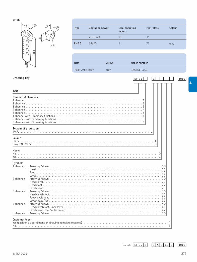
© SKF 2005 277
4
EHE6
Type
Number of channels:1 channel . . . . . . . . . . . . . . . . . . . . . . . . . . . . . . . . . . . . . . . . . . . . . . . . . . . . . . . . . . . . . . . . . . . . . . . . . . . . . . . . 12 channels . . . . . . . . . . . . . . . . . . . . . . . . . . . . . . . . . . . . . . . . . . . . . . . . . . . . . . . . . . . . . . . . . . . . . . . . . . . . . . . 23 channels . . . . . . . . . . . . . . . . . . . . . . . . . . . . . . . . . . . . . . . . . . . . . . . . . . . . . . . . . . . . . . . . . . . . . . . . . . . . . . . 34 channels . . . . . . . . . . . . . . . . . . . . . . . . . . . . . . . . . . . . . . . . . . . . . . . . . . . . . . . . . . . . . . . . . . . . . . . . . . . . . . . 45 channels . . . . . . . . . . . . . . . . . . . . . . . . . . . . . . . . . . . . . . . . . . . . . . . . . . . . . . . . . . . . . . . . . . . . . . . . . . . . . . . 51 channel with 3 memory functions . . . . . . . . . . . . . . . . . . . . . . . . . . . . . . . . . . . . . . . . . . . . . . . . . . . . . . . . . . . A2 channels with 3 memory functions . . . . . . . . . . . . . . . . . . . . . . . . . . . . . . . . . . . . . . . . . . . . . . . . . . . . . . . . . . B3 channels with 3 memory functions . . . . . . . . . . . . . . . . . . . . . . . . . . . . . . . . . . . . . . . . . . . . . . . . . . . . . . . . . . C
System of protection:IPX7. . . . . . . . . . . . . . . . . . . . . . . . . . . . . . . . . . . . . . . . . . . . . . . . . . . . . . . . . . . . . . . . . . . . . . . . . . . . . . . . . . . . . . . . . . 1
Colour:Black . . . . . . . . . . . . . . . . . . . . . . . . . . . . . . . . . . . . . . . . . . . . . . . . . . . . . . . . . . . . . . . . . . . . . . . . . . . . . . . . . . . . . . . . . . . AGrey RAL 7035. . . . . . . . . . . . . . . . . . . . . . . . . . . . . . . . . . . . . . . . . . . . . . . . . . . . . . . . . . . . . . . . . . . . . . . . . . . . . . . . . . . . B
Hook:No . . . . . . . . . . . . . . . . . . . . . . . . . . . . . . . . . . . . . . . . . . . . . . . . . . . . . . . . . . . . . . . . . . . . . . . . . . . . . . . . . . . . . . . . . . . . . . . . 0Yes. . . . . . . . . . . . . . . . . . . . . . . . . . . . . . . . . . . . . . . . . . . . . . . . . . . . . . . . . . . . . . . . . . . . . . . . . . . . . . . . . . . . . . . . . . . . . . . . 1
Symbols:1 channel: Arrow up / down . . . . . . . . . . . . . . . . . . . . . . . . . . . . . . . . . . . . . . . . . . . . . . . . . . . . . . . . . . . . . . . . . . . . . . . . . . . . 1 0
Head. . . . . . . . . . . . . . . . . . . . . . . . . . . . . . . . . . . . . . . . . . . . . . . . . . . . . . . . . . . . . . . . . . . . . . . . . . . . . . . . . . . . . 1 1Foot . . . . . . . . . . . . . . . . . . . . . . . . . . . . . . . . . . . . . . . . . . . . . . . . . . . . . . . . . . . . . . . . . . . . . . . . . . . . . . . . . . . . . 1 2Level. . . . . . . . . . . . . . . . . . . . . . . . . . . . . . . . . . . . . . . . . . . . . . . . . . . . . . . . . . . . . . . . . . . . . . . . . . . . . . . . . . . . . 1 3
2 channels: Arrow up / down . . . . . . . . . . . . . . . . . . . . . . . . . . . . . . . . . . . . . . . . . . . . . . . . . . . . . . . . . . . . . . . . . . . . . . . . . . . . 2 0Head / level . . . . . . . . . . . . . . . . . . . . . . . . . . . . . . . . . . . . . . . . . . . . . . . . . . . . . . . . . . . . . . . . . . . . . . . . . . . . . . . . 2 1Head / foot . . . . . . . . . . . . . . . . . . . . . . . . . . . . . . . . . . . . . . . . . . . . . . . . . . . . . . . . . . . . . . . . . . . . . . . . . . . . . . . . 2 2Level / head. . . . . . . . . . . . . . . . . . . . . . . . . . . . . . . . . . . . . . . . . . . . . . . . . . . . . . . . . . . . . . . . . . . . . . . . . . . . . . . . 2 3
3 channels: Arrow up / down . . . . . . . . . . . . . . . . . . . . . . . . . . . . . . . . . . . . . . . . . . . . . . . . . . . . . . . . . . . . . . . . . . . . . . . . . . . . 3 0Head / level / foot. . . . . . . . . . . . . . . . . . . . . . . . . . . . . . . . . . . . . . . . . . . . . . . . . . . . . . . . . . . . . . . . . . . . . . . . . . . . 3 1Foot / level / head . . . . . . . . . . . . . . . . . . . . . . . . . . . . . . . . . . . . . . . . . . . . . . . . . . . . . . . . . . . . . . . . . . . . . . . . . . . 3 2Level / head / foot . . . . . . . . . . . . . . . . . . . . . . . . . . . . . . . . . . . . . . . . . . . . . . . . . . . . . . . . . . . . . . . . . . . . . . . . . . . 3 3
4 channels: Arrow up / down . . . . . . . . . . . . . . . . . . . . . . . . . . . . . . . . . . . . . . . . . . . . . . . . . . . . . . . . . . . . . . . . . . . . . . . . . . . . 4 0Head / level / foot / knee lever . . . . . . . . . . . . . . . . . . . . . . . . . . . . . . . . . . . . . . . . . . . . . . . . . . . . . . . . . . . . . . . . . . 4 1Level / head / foot / autocontour . . . . . . . . . . . . . . . . . . . . . . . . . . . . . . . . . . . . . . . . . . . . . . . . . . . . . . . . . . . . . . . . 4 2
5 channels: Arrow up / down . . . . . . . . . . . . . . . . . . . . . . . . . . . . . . . . . . . . . . . . . . . . . . . . . . . . . . . . . . . . . . . . . . . . . . . . . . . . 5 0
Customer logo:Yes (position as per dimension drawing, template required) . . . . . . . . . . . . . . . . . . . . . . . . . . . . . . . . . . . . . . . . . . . . . . . . . . . . . . . . . . ANo. . . . . . . . . . . . . . . . . . . . . . . . . . . . . . . . . . . . . . . . . . . . . . . . . . . . . . . . . . . . . . . . . . . . . . . . . . . . . . . . . . . . . . . . . . . . . . . . . . . . . . . B
Example:
40
180
ø 32
64 304028
Ordering key EHE6 - 1 - 0 0 0
EHE6 B - 1 A 0 4 1 -B 0 0 0
——— — — —–— — —
Type Operating power Max. operating Prot. class Colour
motors
V DC / mA n° IP
EHE 6 38 / 50 5 X7 grey
Item Colour Order number
Hook with sticker grey 145361-0001
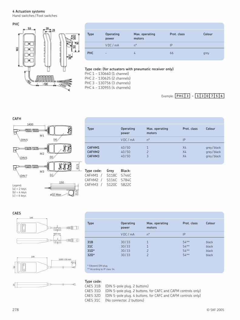
278 © SKF 2005
4 Actuation systems
Hand switches / Foot switches
PHC
3PHC - 31 0 7 5 6
CAFH
1400
DIN5 (a)
DIN5
DIN7
M1
M2
M3
(b)
(c)
61.5
150
ø32 Max 21.5
Legend:
(a) = 2 keys
(b) = 4 keys
(c) = 6 keys
Example:
Type code: (for actuators with pneumatic receiver only)
PHC 1 - 130660 (1 channel)
PHC 2 - 130625 (2 channels)
PHC 3 - 130756 (3 channels)
PHC 4 - 130955 (4 channels)
Type code: Grey Black:
CAFHM1 / S118C S746C
CAFHM2 / S116C S784C
CAFHM3 / S120C S822C
CAES
149
30± 5
5324
1500 ± 50 mm
149
500 mm
Type code:
CAES 31B (DIN 5-pole plug, 2 buttons)
CAES 31D (DIN 5-pole plug, 2 buttons, for CAFC and CAFM controls only)
CAES 32D (DIN 5-pole plug, 4 buttons, for CAFC and CAFM controls only)
CAES 31C (No connector, 2 buttons)
Type Operating Max. operating Prot. class Colour
power motors
V DC / mA n° IP
PHC – 4 66 grey
Type Operating Max. operating Prot. class Colour
power motors
V DC / mA n° IP
CAFHM1 40 / 50 1 X4 grey / black
CAFHM2 40 / 50 2 X4 grey / black
CAFHM3 40 / 50 3 X4 grey / black
Type Operating Max. operating Prot. class Colour
power motors
V DC / mA n° IP
31B 30 / 33 1 54** black
31C 30 / 33 1 54** black
31D* 30 / 33 2 54** black
32D* 30 / 33 2 54** black
* Elbowed DIN plug.
** According to IP class 54.

© SKF 2005 279
4
Foot switches
With the electrical foot switches
( figure 28) direct current actuators can
be operated. The large-size buttons enable
an easy and precise control of
the actuators. Depending on the plug the
foot switches can be used on different
control units.
Benefits:
Easy and precise
Flexible and remote operation
Ergonomic design
Different plug options
Figure 28
Foot Type Operating power Max. operating Prot. class Colour
switches motors
VDC/ mA n° IP
ST ST 12 / 50 3 X5 blue / anthracite
PFP PFP1 – 1 21 grey / anthracite
PFP2 – 2 21 grey / anthracite
CAFHF F1-DIN5 40 / 50 1 X4 anthracite
F1-DIN7 40 / 50 1 X4 anthracite

280 © SKF 2005
4 Actuation systems
Foot switches
ST
Type
Product group:Standard . . . . . . . . . . . . . . . . . . . . . . . . . . . . . . . . . . . . . . . . . . . . . . . . . . . . . . . . . . . . . . . . . . . . . . . . . . FFor microprocessor units (only for KOM2) . . . . . . . . . . . . . . . . . . . . . . . . . . . . . . . . . . . . . . . . . . . . . . . . . GFor first failure safety units (only for KOM6) . . . . . . . . . . . . . . . . . . . . . . . . . . . . . . . . . . . . . . . . . . . . . . . H
Voltage:Not used . . . . . . . . . . . . . . . . . . . . . . . . . . . . . . . . . . . . . . . . . . . . . . . . . . . . . . . . . . . . . . . . . . . . . . . . . . . . . 0
Number of channels:1 channel . . . . . . . . . . . . . . . . . . . . . . . . . . . . . . . . . . . . . . . . . . . . . . . . . . . . . . . . . . . . . . . . . . . . . . . . . . . . . . . 12 channels . . . . . . . . . . . . . . . . . . . . . . . . . . . . . . . . . . . . . . . . . . . . . . . . . . . . . . . . . . . . . . . . . . . . . . . . . . . . . . 23 channels . . . . . . . . . . . . . . . . . . . . . . . . . . . . . . . . . . . . . . . . . . . . . . . . . . . . . . . . . . . . . . . . . . . . . . . . . . . . . . 3
Cable/Connecting plug:Coiled cable, 2,5 m with D-sub plug. . . . . . . . . . . . . . . . . . . . . . . . . . . . . . . . . . . . . . . . . . . . . . . . . . . . L UCoiled cable, 2,5 m with FCC plug . . . . . . . . . . . . . . . . . . . . . . . . . . . . . . . . . . . . . . . . . . . . . . . . . . . . . L V
Colour:Charcoal . . . . . . . . . . . . . . . . . . . . . . . . . . . . . . . . . . . . . . . . . . . . . . . . . . . . . . . . . . . . . . . . . . . . . . . . . . . . . . . . . . . . . . . . . . 1Blue (RAL5015) . . . . . . . . . . . . . . . . . . . . . . . . . . . . . . . . . . . . . . . . . . . . . . . . . . . . . . . . . . . . . . . . . . . . . . . . . . . . . . . . . . . . 4
Options:None . . . . . . . . . . . . . . . . . . . . . . . . . . . . . . . . . . . . . . . . . . . . . . . . . . . . . . . . . . . . . . . . . . . . . . . . . . . . . . . . . . . . . . . . . . . . . . 0 0 0
Symbols:Without symbols . . . . . . . . . . . . . . . . . . . . . . . . . . . . . . . . . . . . . . . . . . . . . . . . . . . . . . . . . . . . . . . . . . . . . . . . . . . . . . . . . . . . . . . . . . . . . . 0 01- 3 channels: arrow up/down (on each pair of buttons) . . . . . . . . . . . . . . . . . . . . . . . . . . . . . . . . . . . . . . . . . . . . . . . . . . . . . . . . . . . . . . . X 12 channels:arrow up/down, M/1 (1 memory button) . . . . . . . . . . . . . . . . . . . . . . . . . . . . . . . . . . . . . . . . . . . . . . . . . . . . . . . . . . . . . . . . . . 2 73 channels: arrow up/down, M/1, 2/3 (3 memory buttons) . . . . . . . . . . . . . . . . . . . . . . . . . . . . . . . . . . . . . . . . . . . . . . . . . . . . . . . . . . . . 3 7
Ordering key ST 0 - 0 0 0
Example:
- 0 0
2ST F 0 - L U 4 0 0 0 3 7- 0 0
105
R 100
ø6.7
325
82
35
45
40
105
216
224192
—————————
Accessories
Type Operating Max. Prot. Colour
power operating class
motors
V DC / mA n° IP
ST 12 / 50 3 X5 blue / anthracite
Item Symbol Order number Item Symbol Order number
Rubber feet ZBE-135310 Symbol sticker level down 135309-0008
Threaded expansion inserts ZBE-521122 Symbol sticker head up 135309-0009
Symbol sticker arrow up 135309-0001 Symbol sticker head down 135309-0010
Symbol sticker arrow down 135309-0002 Symbol sticker foot up 135309-0011
Symbol sticker level up 135309-0007 Symbol sticker foot down 135309-0012

© SKF 2005 281
4
PFP
PFP 1K-130
2000386
86 1065.
52000
ø 5.5
38610
690
211195
PFP 2-130
R250
R37.5
R175
82
23180
80
17001400
(a)
(b)
Legend:
(a) = straight cable DIN5 or DIN7-pole-plug
(b) = coiled cable DIN5 or DIN7-pole-plug
CAFHF
K1PFP - 31 0 6 5 2
1PFP - 21 1 5 4 5
2PFP - 31 0 5 6 0
31
8
211
2000
5,5
106
90
195
PFP1-121
Type code:
Type code:
CAFH F1/S401D, coiled cable, DIN 5-pole plug
CAFH F1/S402D, coiled cable, DIN 7-pole plug
CAFH F1/S403D, straight cable, DIN 5-pole plug
CAFH F1/S404D, straight cable, DIN 7-pole plug
Type Operating Max. Prot. Colour
power operating class
motors
V DC / mA n° IP
PFP 1K N / A 1 21 grey / anthracite
PFP 1 N / A 1 21 grey / anthracite
PFP 2 N / A 2 21 grey / anthracite
Type Operating Max. Prot. Colour Suitable for
power operating class
motors
V DC / mA n° IP
F1-DIN 5 40 / 50 1 X4 anthracite CAFM M1/M2
and CAFC04 M1/M2
F1-DIN 7 40 / 50 1 X4 anthracite CAFM M3
and CAFC04 M3

282 © SKF 2005
4 Actuation systems
Desk switches
Desk switches
The desk switches ( figure 29) serve for
adjusting actuators in desks, chairs,
couches and other adjustable furniture.
They allow to operate up to 3 actuator
functions, also with memory positions, and
can easily be fitted to furniture without
compromising the design.
Benefits:
Easy and precise
Stylish design
Memory position
Figure 29
Desk Type Operating power Max. operating Prot. class Colour
switches motors
VDC/ mA n° IP
ST ST 12 / 50 3 X0 black
LD LD 5 / 50 2 32 black
CAFHT T1 40 / 50 1 X4 black / grey
T2 40 / 50 2 X4 black / grey
PAM PAM 1-130256 – 1 – Anthracite
PAM 1-130348 – 1 – Anthracite
PAM 1-130659 – 1 – Light grey
PAM 1-130827 – 1 – Light grey
PAM 1-130966 – 1 – Anthracite

© SKF 2005 283
4
ST 62
54
104
11.5
ø3.
5
20
20
2096
62
54
107.5
64.5
ø3.5
20
20
2018 12
96
149.5
138
146
138
Ordering key
Type
Product group:Standard . . . . . . . . . . . . . . . . . . . . . . . . . . . . . . . . . . . . . . . . . . . . . . . . . . . . . . . . . . . . . . . . . . . . . . . . . . . AFor microprocessor units (only for KOM2) . . . . . . . . . . . . . . . . . . . . . . . . . . . . . . . . . . . . . . . . . . . . . . . . . C
Voltage:Not used . . . . . . . . . . . . . . . . . . . . . . . . . . . . . . . . . . . . . . . . . . . . . . . . . . . . . . . . . . . . . . . . . . . . . . . . . . . . . 0
Number of channels:1 channel. . . . . . . . . . . . . . . . . . . . . . . . . . . . . . . . . . . . . . . . . . . . . . . . . . . . . . . . . . . . . . . . . . . . . . . . . . . . . . . . 12 channels . . . . . . . . . . . . . . . . . . . . . . . . . . . . . . . . . . . . . . . . . . . . . . . . . . . . . . . . . . . . . . . . . . . . . . . . . . . . . . . 23 channels . . . . . . . . . . . . . . . . . . . . . . . . . . . . . . . . . . . . . . . . . . . . . . . . . . . . . . . . . . . . . . . . . . . . . . . . . . . . . . . 3
Cable/Connecting plug:Straight cable, 2.5 m with D-sub plug. . . . . . . . . . . . . . . . . . . . . . . . . . . . . . . . . . . . . . . . . . . . . . . . . . . 0 UStraight cable, 1.5 m with FCC plug . . . . . . . . . . . . . . . . . . . . . . . . . . . . . . . . . . . . . . . . . . . . . . . . . . . . W V
Colour:Black . . . . . . . . . . . . . . . . . . . . . . . . . . . . . . . . . . . . . . . . . . . . . . . . . . . . . . . . . . . . . . . . . . . . . . . . . . . . . . . . . . . . . . . . . . . . . 6
Options:No options . . . . . . . . . . . . . . . . . . . . . . . . . . . . . . . . . . . . . . . . . . . . . . . . . . . . . . . . . . . . . . . . . . . . . . . . . . . . . . . . . . . . . . . . . 0 0 0Mounted on or underneath desktop, at a 90° angle . . . . . . . . . . . . . . . . . . . . . . . . . . . . . . . . . . . . . . . . . . . . . . . . . . . . . . . . . . . . . . . . . . . . . . . . . . . . M A U
Symbols:Up /down (1- 3 channels) - arrow on each pair of keys) . . . . . . . . . . . . . . . . . . . . . . . . . . . . . . . . . . . . . . . . . . . . . . . . . . . . . . . . . . . . . . . X 1Up /down, 1 memory function, - arrow M /1 (2 channels) . . . . . . . . . . . . . . . . . . . . . . . . . . . . . . . . . . . . . . . . . . . . . . . . . . . . . . . . . . . . . . 2 7Up /down, 3 memory functions, - arrow M /1, M /2, M /3 (3 channels) . . . . . . . . . . . . . . . . . . . . . . . . . . . . . . . . . . . . . . . . . . . . . . . . . . . . 3 7
Example:
ST 0 - 6 - 0 0
2ST 0A - W V 6 0 0 0 X 1- 0 0
STA straight STA 90°
—— ———————
Type Operating power Max. operating Prot. class Colour
motors
V DC / mA n° IP
ST 12 / 50 3 X0 black

284 © SKF 2005
4 Actuation systems
Desk switches
LD
Type
Channels:1-channel, without display, for LD control units. . . . . . . . . . . . . . . . . . . . . . . . . . . . . . . . . . . . . . . . . . . . . . . . . . . . . . . . . . . . . . . . 0 0 1 - 0 0 51-channel, with memory keys, with display, for LD control units with FCC plug . . . . . . . . . . . . . . . . . . . . . . . . . . . . . . . . . . . . . . . 0 0 2 - 0 1 61-channel, without memory and display, for TXG . . . . . . . . . . . . . . . . . . . . . . . . . . . . . . . . . . . . . . . . . . . . . . . . . . . . . . . . . . . . . . 0 0 1 - 0 0 61-channel, with memory keys, with display, for TXG . . . . . . . . . . . . . . . . . . . . . . . . . . . . . . . . . . . . . . . . . . . . . . . . . . . . . . . . . . . . 0 0 2 - 0 1 4
Example:
LD - 0 1 1 - -
LD - 0 1 1 - 0 0 2 - 0 1 6
Ordering key
— —————
Front view:
desk plate
desk plate
Side view:
Type Operating power Max. operating Prot. class Colour
motors
V DC / mA n° IP
LD 5 / 50 2 32 black

© SKF 2005 285
4
CAFHT
1400
84 28(a)
150
40
23 Legend:
(a) = DIN5 or DIN7
Type code:
CAFH T1/S457D, 2 keys, grey
CAFH T2/S458D, 4 keys, grey
CAFH T1/S459D, 2 keys, black
CAFH T2/S460D, 4 keys, black
PAM (pneumatic switch)
Type Operating power Max. operating Prot. class Colour
motors
V DC / mA n° IP
T1 40 / 50 1 X4 black / grey
T2 40 / 50 2 X4 black / grey
Type code Max. operating Tube Colour
motors
n° IP
PAM 1-130827 1 none light grey
PAM 1-130659 1 coiled 2.65 m light grey
PAM 1-130348 1 coiled 2.65 m anthracite
PAM 1-130256 1 straight 1.50 m anthracite
PAM 1-130966 1 straight 3.00 m anthracite
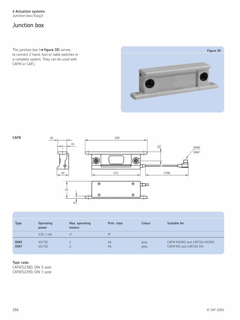
286 © SKF 2005
4 Actuation systems
Junction box / Easy3
Junction box
Type code:
CAFR/S238D, DIN 5-pole
CAFR/S239D, DIN 7-pole
The junction box ( figure 30) serves
to connect 2 hand, foot or table switches in
a complete system. They can be used with
CAFM or CAFC.
32
15
42
220
172
31
1700
DIN5
DIN7
61
8
CAFR
Figure 30
Type Operating Max. operating Prot. class Colour Suitable for
power motors
V DC / mA n° IP
DIN5 40 / 50 2 X4 grey CAFM M1/M2 and CAFC04 M1/M2
DIN7 40 / 50 2 X4 grey CAFM M3 and CAFC04 M3

© SKF 2005 287
4
Easy3
SKF has put together actuator systems with
component parts that are integrated to give
you optimal safety and excellent reliability.
Just switch the power on and you are ready
for operation. The system can handle the
indicated load with ease, in addition we
have taken the extra precaution of building
in adjustable end limits and overload
protection to safeguard the equipment from
impact damage ( figure 31).
Benefits:
Plug & play systems
Easy to order
Easy to install
Easy to use
Figure 31
Type Force Speed Stroke Retr. Length Voltage
push pull no load full load (S) (L)
N mm/s mm mm V
Easy3-02 600 600 23 12 50 - 200 S + 215 24 DC
Easy3-03 2000 2000 12 8 100 - 300 S + 150 24 DC
Easy3-04 2000 2000 12 8 100 - 300 S + 150 230 AC
Easy3-05 2000 2000 12 8 100 - 300 S + 150 230 AC
Easy3-10 7000 3000 7 4 100 - 200 S + 190 230 AC
Easy3-11 7000 3000 7 4 100 - 200 S + 190 230 AC
Easy3-12 7000 3000 7 4 100 - 200 S + 190 230 AC
Easy3-13 7000 3000 7 4 100 - 200 S + 190 230 AC

288 © SKF 2005
4 Actuation systems
Easy3
Easy3- 02
1 2 3 4 5 6 7
52
91 (a) 53
9
ø10
L =
S +
215
10 ø10
35 149
Legend:
S = stroke
L = retracted length
(a) = depth 59
Ordering key
Kit type
Stroke (S):50 mm . . . . . . . . . . . . . . . . . . . . . . . . . . . . . . . . . . . . . . . . . . . . . . . . . . . . . . . . . . . . . . . . . . . . . . . . . . . . . . . . . . . . . . . . . . . . . . . . . . . . . . . 5 0
100 mm . . . . . . . . . . . . . . . . . . . . . . . . . . . . . . . . . . . . . . . . . . . . . . . . . . . . . . . . . . . . . . . . . . . . . . . . . . . . . . . . . . . . . . . . . . . . . . . . . . . . . . . 1 0 0200 mm . . . . . . . . . . . . . . . . . . . . . . . . . . . . . . . . . . . . . . . . . . . . . . . . . . . . . . . . . . . . . . . . . . . . . . . . . . . . . . . . . . . . . . . . . . . . . . . . . . . . . . . 2 0 0
×CALA36E302
× 2 0 0CALA36E302Example:
—————— ——
140 33
5391 (a)
35
ø12
11.5
L =
S +
150
13 ø12
149
1 2 3 4 5 6 7
Legend:
S = stroke
L = retracted length
(a) = depth 59
Easy3-03
Ordering key
Kit type
Stroke (S):100 mm . . . . . . . . . . . . . . . . . . . . . . . . . . . . . . . . . . . . . . . . . . . . . . . . . . . . . . . . . . . . . . . . . . . . . . . . . . . . . . . . . . . . . . . . . . . . . . . . . . . . . . . 1 0 0200 mm . . . . . . . . . . . . . . . . . . . . . . . . . . . . . . . . . . . . . . . . . . . . . . . . . . . . . . . . . . . . . . . . . . . . . . . . . . . . . . . . . . . . . . . . . . . . . . . . . . . . . . . 2 0 0300 mm . . . . . . . . . . . . . . . . . . . . . . . . . . . . . . . . . . . . . . . . . . . . . . . . . . . . . . . . . . . . . . . . . . . . . . . . . . . . . . . . . . . . . . . . . . . . . . . . . . . . . . . 3 0 0
×CARE33E303
× 3 0 0CARE33E303Example:
—————— ——
Technical Stroke Linear Max dynamic Supply
data (S) speed load voltage
mm mm/s N V DC
EASY3-02 50 - 200 23 - 12 600 24
Technical Stroke Linear Max dynamic Supply
data (S) speed load voltage
mm mm/s N V DC
EASY3-03 100 - 300 12 - 8 2000 24

© SKF 2005 289
4
Easy3- 04
53
190 (a)
33 140
11,5
L =
S +
150
13
ø12
75
149
ø12
Legend:
S = stroke
L = retracted length
(a) = depth 150
Ordering key
Kit type
Stroke (S):100 mm . . . . . . . . . . . . . . . . . . . . . . . . . . . . . . . . . . . . . . . . . . . . . . . . . . . . . . . . . . . . . . . . . . . . . . . . . . . . . . . . . . . . . . . . . . . . . . . . . . . . . . . 1 0 0200 mm . . . . . . . . . . . . . . . . . . . . . . . . . . . . . . . . . . . . . . . . . . . . . . . . . . . . . . . . . . . . . . . . . . . . . . . . . . . . . . . . . . . . . . . . . . . . . . . . . . . . . . . 2 0 0300 mm . . . . . . . . . . . . . . . . . . . . . . . . . . . . . . . . . . . . . . . . . . . . . . . . . . . . . . . . . . . . . . . . . . . . . . . . . . . . . . . . . . . . . . . . . . . . . . . . . . . . . . . 3 0 0
×CARE33E304
× 1 0 0CARE33E304Example:
—————— ——
Easy3-05
53
190 (a)
33 140
11.5
13
ø12
75
149
ø12
L =
S +
150
Legend:
S = stroke
L = retracted length
(a) = depth 150
Ordering key
Kit type
Stroke (S):100 mm . . . . . . . . . . . . . . . . . . . . . . . . . . . . . . . . . . . . . . . . . . . . . . . . . . . . . . . . . . . . . . . . . . . . . . . . . . . . . . . . . . . . . . . . . . . . . . . . . . . . . . . 1 0 0200 mm . . . . . . . . . . . . . . . . . . . . . . . . . . . . . . . . . . . . . . . . . . . . . . . . . . . . . . . . . . . . . . . . . . . . . . . . . . . . . . . . . . . . . . . . . . . . . . . . . . . . . . . 2 0 0300 mm . . . . . . . . . . . . . . . . . . . . . . . . . . . . . . . . . . . . . . . . . . . . . . . . . . . . . . . . . . . . . . . . . . . . . . . . . . . . . . . . . . . . . . . . . . . . . . . . . . . . . . . 3 0 0
×CARE33E305
× 2 0 0CARE33E305Example:
—————— ——
Technical Stroke Linear Max dynamic Supply
data (S) speed load voltage
mm mm/s N V AC
EASY3-04 100 - 300 12 - 8 2000 230
Technical Stroke Linear Max dynamic Supply
data (S) speed load voltage
mm mm/s N V AC
EASY3-05 100 - 300 12 - 8 2000 230

290 © SKF 2005
4 Actuation systems
Easy3
Legend:
S = stroke
L = retracted length
Easy3-10
ø12,2ø12,2
206
173L = S + 190
150
40
25Ordering key
Kit type
Stroke (S):100 mm . . . . . . . . . . . . . . . . . . . . . . . . . . . . . . . . . . . . . . . . . . . . . . . . . . . . . . . . . . . . . . . . . . . . . . . . . . . . . . . . . . . . . . . . . . . . . . . . . . . . . . . 1 0 0150 mm . . . . . . . . . . . . . . . . . . . . . . . . . . . . . . . . . . . . . . . . . . . . . . . . . . . . . . . . . . . . . . . . . . . . . . . . . . . . . . . . . . . . . . . . . . . . . . . . . . . . . . . 1 5 0200 mm . . . . . . . . . . . . . . . . . . . . . . . . . . . . . . . . . . . . . . . . . . . . . . . . . . . . . . . . . . . . . . . . . . . . . . . . . . . . . . . . . . . . . . . . . . . . . . . . . . . . . . . 2 0 0
×EASY3-10
× 2 0 0EASY3-10Example:
—————— ——
Legend:
S = stroke
L = retracted length
Easy3-11
L = S + 190
100
ø12.2
206 150
40
25
ø12.2
206
173
L = S + 190
ø12.2
ø12.2
Ordering key
Kit type
Stroke (S):100 mm. . . . . . . . . . . . . . . . . . . . . . . . . . . . . . . . . . . . . . . . . . . 1 0 0150 mm. . . . . . . . . . . . . . . . . . . . . . . . . . . . . . . . . . . . . . . . . . . 1 5 0200 mm. . . . . . . . . . . . . . . . . . . . . . . . . . . . . . . . . . . . . . . . . . . 2 0 0
×EASY3-11
× 1 5 0EASY3-11Example:
—————— ——
Technical Stroke Linear Max dynamic Supply
data speed load voltage
(S) push pull
mm mm/s N V AC
EASY3-10 100 - 200 7 - 4 7000 3000 230
Technical Stroke Linear Max dynamic Supply
data speed load voltage
(S) push pull
mm mm/s N V AC
EASY3-11 100 - 200 7 - 4 7000 3000 230

© SKF 2005 291
4
Legend:
S = stroke
L = retracted length
(a) = depth 150
Easy3-12
190 (a)
75
L = S + 190
ø12.2
206
ø12.2
40
150
251 2 3
Ordering key
Kit type
Stroke (S):100 mm. . . . . . . . . . . . . . . . . . . . . . . . . . . . . . . . . . . . . . . . . . . 1 0 0150 mm. . . . . . . . . . . . . . . . . . . . . . . . . . . . . . . . . . . . . . . . . . . 1 5 0200 mm. . . . . . . . . . . . . . . . . . . . . . . . . . . . . . . . . . . . . . . . . . . 2 0 0
×EASY3-12
× 2 0 0EASY3-12Example:
—————— ——
Ordering key
Kit type
Stroke (S):100 mm. . . . . . . . . . . . . . . . . . . . . . . . . . . . . . . . . . . . . . . . . . . 1 0 0150 mm. . . . . . . . . . . . . . . . . . . . . . . . . . . . . . . . . . . . . . . . . . . 1 5 0200 mm. . . . . . . . . . . . . . . . . . . . . . . . . . . . . . . . . . . . . . . . . . . 2 0 0
×EASY3-13
× 1 0 0EASY3-13Example:
—————— ——
Easy3-13
190 (a)
1 2 3 75
L = S + 190
ø12.2
206
ø12.2
150
4025
Legend:
S = stroke
L = retracted length
(a) = depth 150
Technical Stroke Linear Max dynamic Supply
data speed load voltage
(S) push pull
mm mm/s N V AC
EASY3-12 100 - 200 7 - 4 7000 3000 230
Technical Stroke Linear Max dynamic Supply
data speed load voltage
(S) push pull
mm mm/s N V AC
EASY3-13 100 - 200 7 - 4 7000 3000 230

292 © SKF 2005
4 Actuation systems
Guiding tube sets
Guiding tube sets FRE
Guiding tube sets ( figure 32) are
suitable to be built into the base
construction of tables, chairs or other
applications. It is an open system in which
any kind of actuation systems (electric or
hydraulic) can be built in.
The guiding tube sets are attractively
designed, stable and can be used
universally. They consist of high-quality,
precise anodized aluminium profiles.
Benefits:
Attractive design
Stable
Universal use
Type Sections Dimension profiles in mm Retracted length
n. in mm
2 3 76 ×76 85 ×85 97 ×97 113 ×113 129 ×129 146 ×146 163 ×163
FRE-A085 X Stroke + 138
FRE-A113 X Stroke + 148
FRE-A146 X Stroke + 168
FRE-D097 X Stroke + 38
FRE-D129 X Stroke + 53
FRE-D163 X Stroke + 53
Figure 32

© SKF 2005 293
4
Type
Combination:2 sections tube-set / Largest tube size
85 ×85 mm . . . . . . . . . . . . . . . . . . . . . . . . . . . . . . . . . . . . . . . . . . . . . . . . . . . . . . . . . . . . . . . . . . A 0 8 5113 ×113 mm . . . . . . . . . . . . . . . . . . . . . . . . . . . . . . . . . . . . . . . . . . . . . . . . . . . . . . . . . . . . . . . . . . A 1 1 3146 ×146 mm . . . . . . . . . . . . . . . . . . . . . . . . . . . . . . . . . . . . . . . . . . . . . . . . . . . . . . . . . . . . . . . . . . A 1 4 6
97 ×97 mm. . . . . . . . . . . . . . . . . . . . . . . . . . . . . . . . . . . . . . . . . . . . . . . . . . . . . . . . . . . . . . . . . . B 0 9 7129 ×129 mm. . . . . . . . . . . . . . . . . . . . . . . . . . . . . . . . . . . . . . . . . . . . . . . . . . . . . . . . . . . . . . . . . . B 1 2 9163 ×163 mm. . . . . . . . . . . . . . . . . . . . . . . . . . . . . . . . . . . . . . . . . . . . . . . . . . . . . . . . . . . . . . . . . . B 1 6 3
3 sections tube-set / Largest tube size97 ×97 mm. . . . . . . . . . . . . . . . . . . . . . . . . . . . . . . . . . . . . . . . . . . . . . . . . . . . . . . . . . . . . . . . . . D 0 9 7
129 ×129 mm. . . . . . . . . . . . . . . . . . . . . . . . . . . . . . . . . . . . . . . . . . . . . . . . . . . . . . . . . . . . . . . . . . D 1 2 9163 ×163 mm. . . . . . . . . . . . . . . . . . . . . . . . . . . . . . . . . . . . . . . . . . . . . . . . . . . . . . . . . . . . . . . . . . D 1 6 3113 ×113 mm . . . . . . . . . . . . . . . . . . . . . . . . . . . . . . . . . . . . . . . . . . . . . . . . . . . . . . . . . . . . . . . . . . E 1 1 3146 ×146 mm . . . . . . . . . . . . . . . . . . . . . . . . . . . . . . . . . . . . . . . . . . . . . . . . . . . . . . . . . . . . . . . . . . E 1 4 6
Colour:Natural anodized. . . . . . . . . . . . . . . . . . . . . . . . . . . . . . . . . . . . . . . . . . . . . . . . . . . . . . . . . . . . . . . . . . . . . . . . . . . . . . . . . . 5Black anodized . . . . . . . . . . . . . . . . . . . . . . . . . . . . . . . . . . . . . . . . . . . . . . . . . . . . . . . . . . . . . . . . . . . . . . . . . . . . . . . . . . . 6
Options:No option . . . . . . . . . . . . . . . . . . . . . . . . . . . . . . . . . . . . . . . . . . . . . . . . . . . . . . . . . . . . . . . . . . . . . . . . . . . . . . . . . . . . . . . 0 0 0Cover . . . . . . . . . . . . . . . . . . . . . . . . . . . . . . . . . . . . . . . . . . . . . . . . . . . . . . . . . . . . . . . . . . . . . . . . . . . . . . . . . . . . . . . . . . . M C MPull version . . . . . . . . . . . . . . . . . . . . . . . . . . . . . . . . . . . . . . . . . . . . . . . . . . . . . . . . . . . . . . . . . . . . . . . . . . . . . . . . . . . . . . M C NPull version, with cover . . . . . . . . . . . . . . . . . . . . . . . . . . . . . . . . . . . . . . . . . . . . . . . . . . . . . . . . . . . . . . . . . . . . . . . . . . . . . 2 E A
Stroke:200 mm. . . . . . . . . . . . . . . . . . . . . . . . . . . . . . . . . . . . . . . . . . . . . . . . . . . . . . . . . . . . . . . . . . . . . . . . . . . . . . . . . . . . . . . . . . . . . . . . 2 0300 mm. . . . . . . . . . . . . . . . . . . . . . . . . . . . . . . . . . . . . . . . . . . . . . . . . . . . . . . . . . . . . . . . . . . . . . . . . . . . . . . . . . . . . . . . . . . . . . . . 3 0400 mm. . . . . . . . . . . . . . . . . . . . . . . . . . . . . . . . . . . . . . . . . . . . . . . . . . . . . . . . . . . . . . . . . . . . . . . . . . . . . . . . . . . . . . . . . . . . . . . . 4 0500 mm. . . . . . . . . . . . . . . . . . . . . . . . . . . . . . . . . . . . . . . . . . . . . . . . . . . . . . . . . . . . . . . . . . . . . . . . . . . . . . . . . . . . . . . . . . . . . . . . 5 0600 mm. . . . . . . . . . . . . . . . . . . . . . . . . . . . . . . . . . . . . . . . . . . . . . . . . . . . . . . . . . . . . . . . . . . . . . . . . . . . . . . . . . . . . . . . . . . . . . . . 6 0700 mm. . . . . . . . . . . . . . . . . . . . . . . . . . . . . . . . . . . . . . . . . . . . . . . . . . . . . . . . . . . . . . . . . . . . . . . . . . . . . . . . . . . . . . . . . . . . . . . . 7 0
Customization:None . . . . . . . . . . . . . . . . . . . . . . . . . . . . . . . . . . . . . . . . . . . . . . . . . . . . . . . . . . . . . . . . . . . . . . . . . . . . . . . . . . . . . . . . . . . . . . . . . . . . . . . . . 0 0 0
Ordering key FRE -- 0 0 0
Example:
-
FRE A 0 8 5 -- 505 MCM 0 0 0-
————— —–—––––—–––

294 © SKF 2005
4 Actuation systems
Spare parts
Spare parts
CAR 22 – Type codes for accessories and spare parts
CAR 32 – Type codes for accessories and spare parts
Item code Type Code
12 V DC-motor (flat motor) D12B
24 V DC-motor (flat motor) D24B
Limit switch for stroke = 50 mm CAXB 22 ×50
Limit switch for stroke = 100 mm CAXB 22 ×100
Limit switch for stroke = 150 mm CAXB 22 ×150
Limit switch for stroke = 200 mm CAXB 22 ×200
Limit switch for stroke = 300 mm CAXB 22 ×300
Limit switch for stroke = 700 mm CAXB 40 ×700
Proximity switch for CAXB CAXB Proximity Switch
Front mounting attachments type rod-end 575-22
Front mounting attachments type clevis 576-22
Rear mounting attachments type single ear bracket 580-22
Rear mounting attachments type ball-joint bracket 581-22
Control unit (suitable for D24B motor) CAED 5-24R
Handset matched for CAED CAES 31C
Item code Type Code
12 V DC-motor (flat motor) D12C
24 V DC-motor (flat motor) D24C
24 V DC-motor (flat motor with brake) D24CB
24 V DC-motor (flat motor with extended shaft) D24CS
24 V DC-motor (flat motor with low speed) D24CW
120 V AC-motor (cylindrical motor) E110C
120 V AC-motor (cylindrical motor with brake) E110CB
230 V AC-motor (cylindrical motor) E220C
230 V AC-motor (cylindrical motor with brake) E220CB
Capacitor value 25 µF (120 VAC) Capacitor 25 µF
Capacitor value 6 µF (230 VAC) Capacitor 6 µF
Limit switch for stroke = 50 mm CAXB 32 ×50
Limit switch for stroke = 100 mm CAXB 32 ×100
Limit switch for stroke = 200 mm CAXB 32 ×200
Limit switch for stroke = 300 mm CAXB 32 ×300
Limit switch for stroke = 500 mm CAXB 32 ×500
Limit switch for stroke = 700 mm CAXB 32 ×700
Proximity switch for CAXB CAXB Proximity Switch
Front mounting attachments type rod-end 575-32
Front mounting attachments type clevis 576-32
Rear mounting attachments type single ear bracket 580-32
Rear mounting attachments type Universal joint 582-32
Control unit (suitable for C24C, D24C/CB/CS motors) CAEP 10P-SL
Control unit (suitable for D24C/CB/CS motors) CAEL 10-24R
Control unit (suitable for C24C, D24C/CB/CS motors) CAEN 10R
Control unit (suitable for E110, E220 motors CAEV 110/220
Control unit (suitable for D24CW, C24CW motors) CAED 5-24R
Control unit (suitable for D24C/CB/CS motors) CAED 9-24R
Handset matched for CAEN, CAEP units CAES 31B
Handset matched for CAED, CAEV, CAEL units CAES 31C

© SKF 2005 295
4
CAR 40 – Type codes for accessories and spare parts
CAP 32 – Type codes for accessories and spare parts
Item code Type Code
24 V DC-motor (flat motor) D24D
24 V DC-motor (flat motor with extended shaft) D24DS
24 V DC-motor (flat motor with brake) D24DB
120 V AC-motor (cylindrical motor) E110D
120 V AC-motor (cylindrical motor with brake) E110DB
230 V AC-motor (cylindrical motor) E220D
230 V AC-motor (cylindrical motor with brake) E220DB
Capacitor value 12 µF (230 V AC-motor) Capacitor 12 µF
Limit switch for stroke = 100 mm CAXB 40 ×100
Limit switch for stroke = 300 mm CAXB 40 ×300
Limit switch for stroke = 500 mm CAXB 40 ×500
Limit switch for stroke = 700 mm CAXB 40 ×700
Proximity switch for CAXB CAXB Proximity Switch
Front mounting attachments type rod-end 575-40
Front mounting attachments type clevis 576-40
Rear mounting attachments type single ear bracket 580-40
Rear mounting attachments type ball-joint bracket 581-40
Item code Type Code
12 V DC-motor (flat motor) D12C
24 V DC-motor (flat motor) D24C
24 V DC-motor (flat motor with brake) D24CB
24 V DC-motor (flat motor with extended shaft) D24CS
24 V DC-motor (flat motor with low speed) D24CW
120 V AC-motor (cylindrical motor) E110C
120 V AC-motor (cylindrical motor with brake) E110CB
230 V AC-motor (cylindrical motor) E220C
230 V AC-motor (cylindrical motor with brake) E220CB
Capacitor value 25 µF (120 VAC) Capacitor 25 µF
Capacitor value 6 µF (230 VAC) Capacitor 6 µF
Limit switch for stroke = 50 mm CAXB 32 ×50
Limit switch for stroke = 100 mm CAXB 32 ×100
Limit switch for stroke = 150 mm CAXB 32 ×150
Limit switch for stroke = 200 mm CAXB 32 ×200
Limit switch for stroke = 300 mm CAXB 32 ×300
Limit switch for stroke = 500 mm CAXB 32 ×500
Limit switch for stroke = 700 mm CAXB 32 ×700
Proximity switch for CAXB CAXB Proximity Switch
Front mounting attachments type rod-end 575-32
Front mounting attachments type clevis 576-32
Rear mounting attachments type single ear bracket 580-32
Rear mounting attachments type Universal joint 582-32
Control unit (suitable for D24C/CB/CS/CW motors) CAEP 8V

296 © SKF 2005
4 Actuation systems
Spare parts
CCBR 32 – Type codes for accessories and spare parts
CAT 33 – Type codes for accessories and spare parts
Item code Type Code
Limit switch for stroke = 50 mm CAXB 32 ×50
Limit switch for stroke = 100 mm CAXB 32 ×100
Limit switch for stroke = 200 mm CAXB 32 ×200
Limit switch for stroke = 300 mm CAXB 32 ×300
Limit switch for stroke = 500 mm CAXB 32 ×500
Limit switch for stroke = 700 mm CAXB 32 ×700
Proximity switch for CAXB CAXB Proximity Switch
Front mounting attachments type rod-end 575-32
Front mounting attachments type clevis 576-32
Item code Type Code
12 V DC-motor (cylindrical motor) C12C
12 V DC-motor (flat motor) D12C
24 V DC-motor (cylindrical motor) C24C
24 V DC-motor (cylindrical with low speed) C24CW
24 V DC-motor (flat motor) D24C
24 V DC-motor (flat motor with brake) D24CB
24 V DC-motor (flat motor with extended shaft) D24CS
24 V DC-motor (flat motor with low speed) D24CW
120 V AC-motor (cylindrical motor) E110C
120 V AC-motor (cylindrical motor with brake) E110CB
230 V AC-motor (cylindrical motor) E220C
230 V AC-motor (cylindrical motor with brake) E220CB
400 V AC-motor (cylindrical motor) E380C
Capacitor value 25 µF (120 VAC) Capacitor 25 µF
Capacitor value 6 µF (230 VAC) Capacitor 6 µF
Limit switch for any stroke CAXC33
Front mounting attachments type rod-end 575-32
Front mounting attachments type clevis 576-32
CARN 32 – Type codes for accessories and spare parts
Item code Type Code
Limit switch for stroke = 50 mm CAXB 32 ×50
Limit switch for stroke = 100 mm CAXB 32 ×100
Limit switch for stroke = 200 mm CAXB 32 ×200
Limit switch for stroke = 300 mm CAXB 32 ×300
Limit switch for stroke = 500 mm CAXB 32 ×500
Limit switch for stroke = 700 mm CAXB 32 ×700
Proximity switch for CAXB CAXB Proximity Switch
Front mounting attachments type rod-end 575-32
Front mounting attachments type clevis 576-32
Rear mounting attachments type single ear bracket 580-32
Rear mounting attachments type Universal joint 582-32
Continued

© SKF 2005 297
4
CAT 33H – Type codes for accessories and spare parts
Item code Type Code
12 V DC-motor (cylindrical motor) C12C
12 V DC-motor (flat motor) D12C
24 V DC-motor (cylindrical motor) C24C
24 V DC-motor (cylindrical with low speed) C24CW
24 V DC-motor (flat motor) D24C
24 V DC-motor (flat motor with brake) D24CB
24 V DC-motor (flat motor with extended shaft) D24CS
24 V DC-motor (flat motor with low speed) D24CW
110 V AC-motor (cylindrical motor) E110C
230 V AC-motor (cylindrical motor) E220C
230 V AC-motor (cylindrical motor with brake) E220CB
400 V AC-motor (cylindrical motor) E380C
Capacitor value 6 µF (230 VAC) Capacitor 6 µF
Limit switch for any stroke CAXC33
Front mounting attachments type rod-end 575-32
Front mounting attachments type clevis 576-32
Rear mounting attachments type single ear bracket 580-32
Rear mounting attachments type Universal joint 582-32
Control unit (suitable for C24C, D24C/CB/CS motors) CAEP 10P-SL
Control unit (suitable for D24C/CB/CS motors) CAEL 10-24R
Control unit (suitable for C24C, D24C/CB/CS motors) CAEN 10R
Control unit (suitable for E110, E220 motors CAEV 110/220
Control unit (suitable for D24CW, C24CW motor) CAED 5-24R
Control unit (suitable for D24C/CB/CS motors) CAED 9-24R
Handset matched for CAEN, CAEP units CAES 31B
Handset matched for CAED, CAEV, CAEL units CAES 31C
CAT 33 – Type codes for accessories and spare parts
Item code Type Code
Rear mounting attachments type single ear bracket 580-32
Rear mounting attachments type Universal joint 582-32
Control unit (suitable for C24C, D24C/CB/CS motors) CAEP 10P-SL
Control unit (suitable for D24C/CB/CS motors) CAEL 10-24R
Control unit (suitable for C24C, D24C/CB/CS motors) CAEN 10R
Control unit (suitable for E110, E220 motors CAEV 110/220
Control unit (suitable for D24CW, C24CW motor) CAED 5-24R
Control unit (suitable for D24C/CB/CS motors) CAED 9-24R
Handset matched for CAEN, CAEP units CAES 31B
Handset matched for CAED, CAEV, CAEL units CAES 31C
(continued)

298 © SKF 2005
4 Actuation systems
Spare parts – Attachments / Limit switches
CAP 43 – Type codes for accessories and spare parts
Item code Type Code
24 V DC-motor (cylindrical motor) C24C
24 V DC-motor (cylindrical with low speed) C24CW
24 V DC-motor (flat motor) D24C
24 V DC-motor (flat motor with low speed) D24CW
Front mounting attachments type rod-end 575-32
Front mounting attachments type clevis 576-32
Rear mounting attachments type single ear bracket 580-32
Rear mounting attachments type Universal joint 582-32
Control unit (suitable for D24C motors) CAED-ANR
CAT 32B – Type codes for accessories and spare parts
Item code Type Code
12 V DC-motor (cylindrical motor) C12C
12 V DC-motor (flat motor) D12C
24 V DC-motor (cylindrical motor) C24C
24 V DC-motor (cylindrical with low speed) C24CW
24 V DC-motor (flat motor) D24C
24 V DC-motor (flat motor with brake) D24CB
24 V DC-motor (flat motor with extended shaft D24CS
24 V DC-motor (flat motor with low speed) D24CW
120 V AC-motor (cylindrical motor) E110C
120 V AC-motor (cylindrical motor with brake) E110CB
230 V AC-motor (cylindrical motor) E220C
230 V AC-motor (cylindrical motor with brake) E220CB
400 V AC-motor (cylindrical motor) E380C
Capacitor value 25 µF (120 VAC) Capacitor 25 µF
Capacitor value 6 µF (230 VAC) Capacitor 6 µF
Limit switch for stroke = 50 mm CAXB 32 ×50
Limit switch for stroke = 100 mm CAXB 32 ×100
Limit switch for stroke = 200 mm CAXB 32 ×200
Limit switch for stroke = 300mm CAXB 32 ×300
Limit switch for stroke =400 mm CAXB 32 ×400
Limit switch for stroke = 500mm CAXB 32 ×500
Limit switch for stroke = 700mm CAXB 32 ×700
Proximity switch for CAXB CAXB Proximity Switch
Front mounting attachments type rod-end 575-32
Front mounting attachments type clevis 576-32
Rear mounting attachments type single ear bracket 580-32
Rear mounting attachments type Universal joint 582-32
Control unit (suitable for C24C, D24C/CB/CS motors) CAEP 10P-SL
Control unit (suitable for D24C/CB/CS motors) CAEL 10-24R
Control unit (suitable for C24C, D24C/CB/CS motors) CAEN 10R
Control unit (suitable for E110, E220 motors CAEV 110/220
Control unit (suitable for D24CW, C24CW motor) CAED 5-24R
Control unit (suitable for D24C/CB/CS motors) CAED 9-24R
Handset matched for CAEN, CAEP units CAES 31B
Handset matched for CAED, CAEV, CAEL units CAES 31C
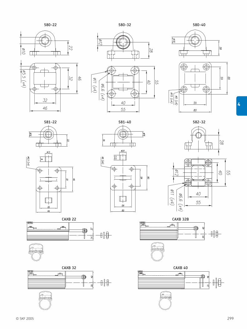
© SKF 2005 299
4
580-22 580-32 580-40
581-22 581-40 582-32
CAXB 22 CAXB 32B
CAXB 32 CAXB 40

300 © SKF 2005
4 Actuation systems
Spare parts – Motors
300
CAXC 33
575-22 575-32 575-40
576-22 576-32 576-40

© SKF 2005 301
4
D12C/D24C D24D E220C
ø70
ø40ø9
16
ø71
ø47
96ø1
50
ø55M8 (2x)
3917985
3917985
E220D D24D/D24DB/D24DS D12B/D24B

302 © SKF 2005
4 Actuation systems
Glossary and definitions
Anti-pinching (electric)
A safety option that is available on certain
SKF actuators. It shuts-off the motor when
an external force is applied in the opposite
direction to the direction of travel.
Anti-pinching (mechanical)
This safety mechanism allows the actuator
to push but not pull or pull but not push.
This feature is designed to prevent injury to
persons due to being trapped by the force
of the actuator.
Back up nut
A nut, usually metal, of greater anti-shear
strength than the drive nut and which only
makes contact with the threads of the
spindle when the threads of the drive nut
fail.
Emergency lowering
The emergency lowering safety feature
enables the actuator to be lowered in the
event of a power failure or malfunction.
This option is used in most medical & care
applications.
Encoder
A rotary or linear sensor device that, when
connected to a control unit, can be used to
determine the position of an electric linear
actuator.
First failure safety
First Failure Safety is a control system
utilising redundant micro processors in
which one processor monitors the functions
of the other and shuts down the system if a
malfunction in the microprocessor occurs.
Hall sensor
A sensor whose output changes based on
changes in magnetic flux. Typically used for
RPM, position, or current measurement.
IP protection
This standard describes a system for
classifying the degrees of protection
required by the enclosures of electrical
equipment. Developed by the European
Committee for Electrotechnical
Standardization (CENELEC), these
standards are designed to numerically rate
an electrical product based on the level of
protection its enclosure provides.
Limit switches
A switch used to limit motion or travel in a
particular direction. Mechanical devices that
when activated open or close an electrical
contact. When the contact is closed voltage
will flow through the switch, when open no
voltage will flow through the switch. Limit
switches come in various physical sizes and
configurations and can be mounted
internally or externally.
Potentiometer
The potentiometer is a displacement
transducer. It incorporates the sensor and
transducer function into one. A typical
potentiometer consists of a uniform coil of
wire of an element of high resistance such
as carbon, platinum or conductive plastic.
This uniform coil makes up the resistive
element of the potentiometer whose
resistance is proportional to its length.
Pull force
The maximum retracting force that an
electric linear actuator can produce in
Newton (N). Some SKF actuators do not
produce equal push and pull forces and
others do not permit pull force at all.
Push force
The maximum extending force that an
electric linear actuator can produce in
Newton (N). Some SKF actuators do not
produce equal push and pull forces and
others do not permit pull force at all.
Stroke length
Describes the length in millimetres that an
electric linear actuator will extend or
retract. Most standard products are
available in increments of 50 mm or
100 mm. Customer specific lengths are
available, minimum order quantities apply.
Thermal protection
Protects drives and control units from
overheating. A device that signals when an
electrical assembly becomes too hot. The
signal usually causes the shut-off of the
electrical device.
Linear speed
Linear speed is the term used when we talk
about the distance, in millimetres, the tube
in an actuator moves linearly over a given
period of time (mm/s.), moving a load from
its starting point to a new position. The
speed can vary in different ways,
depending, for example, on the motor
employed. Actuators with direct current
(DC) motors have a speed variation directly
proportional to the load on the device. That
is to say, the larger the load, the lower the
speed and vice versa. Actuators with
alternating current (AC) motors move at a
constant speed, which is not affected by the
load on the actuator. Other factors affecting
speed include ambient temperature and
how well or poorly the actuator is
integrated within an application. An
actuator integrated in such a way that it is
subject to uneven loads wears abnormally,
which results in increased friction forces
and decreased speed.
Dynamic load
Maximal dynamic load refers to the
maximum total weight or mass the actuator
can move. Often, the decisive factor for
maximal load is the size of the motor and
the gearing employed. When an actuator is
subject to loads exceeding the maximum
stated value, the device simply stops.
Certain actuator types have an integral
mechanical safety device similar to a slip-
clutch, designed to protect the motor and
gears from damage. Electrical limit switches
are another alternative. These protect the
actuator from damage caused by excessive
electrical current. All such safety devices
are part of an operating system and it is
important to be aware of them when using
SKF actuators with other operating
equipment.
Static load (value not available
in this brochure)
Maximal static load refers to the weight or
mass that an actuator can be subjected to
when standing still without causing
permanent damage or causing the actuator
to start “going backwards”. Subjecting an
actuator to loads in excess of stated values
can risk permanent deformation to some
part of the actuator. N.B. Remember that in
Glossary and definitions

© SKF 2005 303
4
Retracted length
“Retracted length” is an expression for the
shortest distance between the two fixed
points on an actuator when the actuator is
in its innermost position. The dimensions
given reflect a measurement from the
centre of the mounting holes, which means
that the actuator requires a few millimetres
beyond the given “retracted length” in order
to fit. Remember that very few actuators
are symmetrical. Thus it is important to
note other dimensions as well for optimum
fit and integration of the actuator. An
actuator should always be mounted, insofar
as is possible, so that it works linearly over
its entire working range.
Duty factors
A technical term expressing how long a
motor can handle non-stop operation
before it becomes overheated or otherwise
damaged. It should be noted that “ Duty
Factor ”, whether expressed as a percentage
or time, varies depending on the working
load for the motor. The duty-cycle tells how
often an actuator will be in operation within
an application and the amount of time
between operations. Because of the power
lost due to inefficiency dissipated as heat,
the actuator component with the lowest
allowable temperature – usually the motor –
sets the duty-cycle limit for the complete
actuator. Although, there is some heat loss
from friction in the gearbox and by ball-
screw and acme-screw drive systems. An
example of a duty cycle calculation: assume
an actuator runs for 10 seconds
cumulatively, up and down, and then does
not run for another 40 seconds. The duty
cycle is 10 /(40 +10), or 20 %.
Temperature
Ambient work site temperature can be
highly significant when making a choice
many applications and installations, it is not
the weight applied directly but rather the
load caused by leverage or similar forces
acting on the actuator that are the decisive
factor. An actuator is strongest in its
shortest position and weakest in its
outermost, most extended position.
DC-motors
An electric motor powered by direct current
electricity (12-48 VDC) that can be run on
batteries. These motors are suitable for use
in situations where you want to be able to
move the product easily and do not want a
cable in the way. The speed of a DC-motor
is directly proportional to the load, i.e., the
motor moves slowly under maximum load
and fastest when run with no load at all. In
many applications the actuator works both
pushing and pulling, which means that the
load works to “assist” in one direction and
“resist” in the other. Consequently,
considerable speed variations can arise.
AC-motors
An electric motor powered by alternating
current electricity (120-400 VAC), which
requires an electrician for its connection.
Start-up properties can be improved with
various accessories and different methods
of connection. There are many standard
accessories available for control and
regulation of an AC-motor. An AC-motor is
best suited to non-mobile products, i.e.,
fixed installations, often in industrial
environments. An actuator with an ACmotor
is less sensitive to load variations and
maintains virtually the same speed
regardless of load. The normal working
temperature for this type of motor is 70°C.
An AC-motor has few moving parts that
wear and is consequently rugged and has a
long life span.
between different actuators. Extreme heat
or cold can reduce the working capacity of
the equipment. If the equipment is used in
temperatures as low as about –20 °C, for
instance, the lubricant can harden and
impair the efficiency of the motor. If the
temperatures climb up towards 50 °C, for
instance, the grease can melt so that it
drains away from the screw system,
resulting in reduced or eliminated lubricant
effect and increasing the risk of overheating
in the motor.
Power consumption
An expression of how much electricity the
motor uses when working. For DC motors
the power consumption is directly
proportional to the load, and for AC motors
the power consumption is constant. With
alternating current, power consumption is
low, so simple cabling and other inexpensive
accessories suffice. Installation is easy and
the components are readily available. With
battery operation, it is often adequate to
use a small, lightweight battery that does
not require much space and is relatively
inexpensive.
Supply voltage
Supply voltage is a measure of the voltage
supplying a system, regardless of whether it
employs AC or DC-motors.
Properties of the sliding screw
( figure 33)
Sliding screws are manufactured from
rolled steel and the nut is made of plastic.
This is a relatively cost effective design with
favourable properties: plastic and metal
work well together without binding. Also,
actuators incorporating sliding screws
usually offer a price advantage over those
built around other types of screws. The
sliding screw works very quietly, which
means that it is well suited for office
environments, hospitals, etc. Another
significant advantage is the high friction
coefficient in the sliding screw. This design
is particularly well suited for actuators used
in applications where they should be self
locking, i.e., will not begin “moving
backwards” under the weight of the load.
For instance, when using the actuator to
drive vertically adjustable tables, a sliding
screw design allows you to put heavy loads
on the surface of the table without
changing its vertical position. In short, this
means that no additional locking
mechanism or brake will be necessary
Figure 33

304 © SKF 2005
4 Actuation systems
Glossary and definitions
significantly higher in applications where
positioning and repetitive precision are
important.
Self-locking
This property of the actuator means that it
will not continue to move under the weight
of the load after it has been switched off.
The self-locking ability depends on the total
efficiency of the actuator. If an actuator is
not self locking the function can be
obtained by using a brake. On DC-motors,
the motor has to be short circuited. Self-
locking load can under certain
circumstances not be completely ensured
on all actuator models due to the type of
application being run (e.g., high vibration
levels)!
Alignment
It is important that the product is mounted
properly from the beginning. If the actuator
is improperly installed, normal operation
may cause poor performance. Remember,
therefore, to carefully follow the
accompanying mounting instructions.
Naturally, you can turn to your supplier or
distributor whenever you have questions
about our products.
to keep the actuator in position when it is
not in operation (however, e.g., in extreme
vibrating application types additional
arrangements may be needed to prevent
back driving).
Properties of ball screws ( figure 34)
The ball screws incorporated in SKF
actuators are manufactured entirely of steel
and equipped with a row of bearings
located in a closed system between the nut
and screw. The design yields extremely low
friction coefficients between the nut and
the screw, because of the rolling contact
between the balls, the nut and raceway
(similar to ball bearings). Wear is
significantly reduced compared with a
sliding screw, which results in a life span 10
times longer for a ball screw under the
same working conditions. The durability of
the screw also means that it tolerates
extreme loads as well as high duty cycles.
Thanks to its low frictional resistance, the
ball screw can maintain a very low
operating temperature. As a consequence,
the ball screw is particularly well suited in
situations where it is required to operate
over long periods at high speeds.
High efficiency is one of the main
characteristics of ball screws. Thanks to this
high efficiency, it is possible to use a motor
half the size compared to a sliding screw
design. This means that, as a user, you
obtain a more economical solution. An
actuator based on a ball screw has minimal
play, and consequently its precision is
Figure 34

© SKF 2005 305
4
Notes

The highest power lies beneaththe smallest things.
An ant can lift up to thirty times and transport up to fifty times its own weight.
It’s the power of such small things that has inspired SKF to create solutions with
reduced dimensions yet endowed with great potential for your applications.
Behind compactness and decreased weight lies high performance which will lead
to greater precision and efficiency, while reducing cycle times to a minimum.
Miniature profile rail guides, miniature linear ball bearings, miniature ball screws,
miniature slides - small units that can be placed almost anywhere, but always of
the highest quality which you might expect from SKF.
Linear motion from SKFwww.linearmotion.skf.com

© SKF 2005 307
5
Positioning systemsGeneral
Positioning systems are compact
and economic complete solutions.
The assortment ranges from compact slides
without drives through to highly dynamic,
multi-axis systems with linear motor drive.
SKF offers the following positioning
systems:
Miniature slides ( figure 1);
Standard slides ( figure 2);
Dovetail slides ( figure 3);
Compact cross tables ( figure 4);
Precision slides without drive ( figure 5);
Precision slides with drive ( figure 6);
Linear ball bearing slides ( figure 7);
Linear axes, type Pico ( figure 8);
Profile rail slides ( figure 9);
Complete systems ( figure 10);
LZM miniature slides
With the new LZM miniature slide SKF
offers the ideal solution for linear motion
applications for short strokes and compact
boundary dimensions.
The use of miniature slides has
increased in medical applications,
measurement technologies, pneumatics,
micro mechanics and micro electronics
assembly, semiconductor manufacturing
and fibre optics. The different miniature
slide components meet the highest
precision standards; LZM miniature slides
feature high running accuracy and smooth
motion.
The LZM are manufactured with all
stainless steel components. Optimised
hardness enables long endurance life and
high performance within compact boundary
dimensions.
The miniature slides have been designed
to ensure high system stiffness and
precision guidance. Running accuracies of 2
µm over a stroke of 100 mm are attainable
depending on the particular application.
Ease of installation is another advantage of
the LZM miniature slides. Unlike cross roller
systems using 4 rails and cages to be
assembled on the production floor, the LZM
slide provides a complete slide that can
simply be bolted into place without the use
of precision devices to set preload.
Operating precision ( Table 1)
Comparison of the different positioning
components and systems.
Every application provides new challenges
for the modern designer. SKF will modify
existing designs to meet your specific
technical requirements.
Advantages for LZM miniature slides:
Compact design
High carrying capacity
Very good running accuracy
Smooth running
High stiffness
Easy assembly
Dimensions see table on page 313
Operating Guiding systems Driving systems Actuation Positioning
precision (µm) systems systems
0.1 – 1
1 – 10
10 – 100
100 – 1000
Lin
ear
ball b
eari
ngs
Pre
cisi
on r
ail
guid
es
Pro
file
rail
guid
es
Sta
ndard
slid
es
Cam
rolle
rguid
es
Rolle
rsc
rew
s
Ball s
crew
s
Lin
ear
moto
rs
Ele
ctro
-m
ech
anic
al
act
uato
rs
Sta
ndard
dri
ves
or
linear
moto
rs
with a
ll g
uid
ing s
yste
ms
Table 1
Figure 1

308 © SKF 2005
5 Positioning systems
General
TO and TS compact cross tables
Table top, centre and base of black
anodised aluminium with central viewing
hole. The slides are fitted with SKF
precision rail guides incorporating crossed
roller units. The TO design does not have a
drive but is provided with one lateral
locking device per axis. The TS design has a
micrometer attachment that is spring-
loaded in one direction. In addition one
lateral locking device is fitted per axis.
Dimensions see table on page 325
RSM and RSK precision slides
Slide top and base of grey cast iron.
The slides are provided with standard
patterns of mounting holes. The slide
top carries tapped holes, the base plate
counterbored holes for cylindrical screws to
DIN 912. They are fitted with SKF precision
rail guides incorporating crossed roller
units. The slides have a lead screw drive.
The RSM design has a micrometer knurl
with a vernier ring, while the RSK design is
fitted with a hand crank.
Dimensions see table on page 326
SSM and SSK dovetail slides
Slide top and base of grey cast iron.
The slides are provided with standard
patterns of mounting holes. Top and base
plate both carry tapped holes. The slides
have a lead screw drive. The SSM design
has a micrometer knurl with vernier ring,
while the SSK design is fitted with a hand
crank. Both designs are fitted with a lateral
locking device.
Dimensions see table on page 322
GCL standard slides
Slide top and base of steel. The slides are
provided with standard patterns of
mounting holes. The slide top carries
tapped holes, the base plate counterbored
holes for cylindrical screws to DIN 912. The
slides are fitted with SKF precision rail
guides with crossed roller units. Internal
stops serve as stroke limit.
Dimensions see table on page 316
GCLA standard slides
Slide top and base of black anodised
aluminium. In other respects, the design
corresponds to that of the GCL slides except
that they are lower in height.
Dimensions see table on page 318
RM standard slides
Especially small design. Slide top of steel,
guidance via SKF precision rails with
double-sided centre rail and crossed roller
units. Internal stops serve as stroke limits.
Dimensions see table on page 320
Figure 2
Figure 3 Figure 4 Figure 5

© SKF 2005 309
5
LZBB and LZAB linear ball bearing slides
The slides are fitted with SKF linear ball
bearings of ISO series 3. They are
driven via SKF rolled thread ball screws
attached on both sides. The slides are
protected by bellows. The LZBB design has
a closed housing. Shafts are attached on
both sides in shaft blocks which also
incorporate the bolt holes for attaching the
slide. The LZAB design has an open
housing. Shafts are attached over the entire
length by shaft supports to prevent shaft
deflection with large strokes or high loads.
The slide is attached via the bolt holes in
the two shaft supports.
Principal dimensions see table on page 332
RSS precision slides
Slide top and base of grey cast iron.
The slides are provided with standard
patterns of mounting holes. The slide
top carries tapped holes, the base plate
counterbored holes for cylindrical screws to
DIN 912. The slides are fitted with SKF
precision rail guides incorporating crossed
roller units. They are driven by pre-loaded
planetary roller screws attached on one
side. The slides are covered by bellows.
Limit switches can be fitted under the
lateral plate cover angles. The individual
slides can be assembled in various ways to
form cross tables or multi-axis systems.
Principal dimensions see table on page 328
LTP linear axes, type PICO
Linear axes are high dynamic units with a
high load carring capacity and stiffness. The
slide material is eloxated aluminium to
optimize the weight. The running accuracy
in a µm range and the preloaded ballscrews
lead to a precise positioning, required in
pick&place machines, medical applications
or precise handling units. The axes are
available in 2 widths, with stainless steel
cover, integrated endswitches, connected
with a Sub-D connector.
Principal dimensions see table on page 337
LTB profile rail slides
SKF profile rail slides are state-of-the-art
systems that offer high load-carrying
capacity and accuracy.
They are available
in five sizes: 110 – 170 – 235 – 320 – 400
with two drives: ball screws – linear motors
with three covers: without cover – with
bellows – with steel cover
Principal dimensions see table on page 342
Figure 6 Figure 7 Figure 8
Figure 9

Figure 11
310 © SKF 2005
5 Positioning systems
General
Complete systems
On special demand, SKF designs and
manufactures complete systems, either
from SKF standard components or special
solutions that are exactly tailored to the
respective application.
Please demand the responsible SKF
application engineer.
The different specifications are given
in Table 2.
Figure 10
NB:
In addition to this catalogue we have all
product brochures available as pdf
document on the internet.
www.linearmotion.skf.com/doc

Type Precision Load-carrying Dynamic capabilities Speed
capacity
Miniature slides
Standard slides
Dovetail slides
Compact cross tables
Precision slides without drive
Precision slides with drive
Linear ball bearing slides
Linear axes
Profile rail slides
Complete systems
Table 2
© SKF 2005 311
5

312 © SKF 2005
5 Positioning systems
Miniature slides
Miniature slides
LZM
Type
Carriage:Standard . . . . . . . . . . . . . . . . . . . . . . . . . . . . . . . . . . . . . . . . . . . . . . . . . . . . . . . . . . . . . . . . . . . . . . . . . . . . . . . . . . . . . . . . . . . . HS
Size:17 mm. . . . . . . . . . . . . . . . . . . . . . . . . . . . . . . . . . . . . . . . . . . . . . . . . . . . . . . . . . . . . . . . . . . . . . . . . . . . . . . . . . . . . . . . . . . . . . . . . . . . 720 mm. . . . . . . . . . . . . . . . . . . . . . . . . . . . . . . . . . . . . . . . . . . . . . . . . . . . . . . . . . . . . . . . . . . . . . . . . . . . . . . . . . . . . . . . . . . . . . . . . . . . 927 mm. . . . . . . . . . . . . . . . . . . . . . . . . . . . . . . . . . . . . . . . . . . . . . . . . . . . . . . . . . . . . . . . . . . . . . . . . . . . . . . . . . . . . . . . . . . . . . . . . . . . 1232 mm. . . . . . . . . . . . . . . . . . . . . . . . . . . . . . . . . . . . . . . . . . . . . . . . . . . . . . . . . . . . . . . . . . . . . . . . . . . . . . . . . . . . . . . . . . . . . . . . . . . . 15
Length [mm]:See table
Ordering key
—–– —–×
—– —––
Example: ×15 165
LZM HS
LZM HS

© SKF 2005 313
5
Main dimensions for miniature slide units
LZM
Designations Dimensions
W W2 W3 L2 M1×depth d3×d2×h H H1 M2 F
mm
LZM HS 7 17 12 7 8 M2×2.5 2.5×4.5×2.5 8 2.35 M3 15
LZM HS 9 20 15 9 13 M3×3 3.5×6×3.5 10 3.55 M4 20
LZM HS 12 27 20 12 15 M3×3.5 3.5×6×4.5 13 4.7 M4 25
LZM HS 15 32 25 15 20 M3×4 3.5×6×4.5 16 6 M4 40
Designations Dimensions Max. Number of holes Load-carrying
stroke capacities
L L4 E L1 Carriage Rail C C0 Ma/Mb Mc
mm n n N N Nm Nm
LZM HS 7 26 29 5.5 5.0 24 6 2 1000 1700 3.5 6
34 37 9.5 5.0 34 8 2 1100 2100 5.5 7
50 53 10.0 5.0 50 12 3 1500 3100 12.0 10
66 69 10.5 5.0 66 16 4 1800 4100 21.0 14
LZM HS 9 32 35 8.0 9.5 28 4 2 1600 2700 7.0 12
42 45 11.0 8.0 40 6 2 1900 3400 11.0 15
55 58 7.5 8.0 54 8 3 2300 4300 18.0 19
81 84 10.5 8.0 78 12 4 3000 6500 43.0 29
94 97 7.0 8.0 92 14 5 3300 7400 57.0 33
LZM HS 12 37 40 6.0 11.0 32 4 2 2500 3800 11.0 21
51 54 13.0 10.5 47 6 2 3100 5300 22.0 28
66 69 8.0 10.5 62 8 3 3600 6700 36.0 36
96 99 10.5 10.5 95 12 4 4700 9700 76.0 52
126 129 13.0 10.5 122 16 6 5700 12600 131.0 68
LZM HS 15 52 56 6.0 12.5 50 4 2 3800 6200 25.0 42
85 89 22.5 12.5 80 8 2 5400 10400 73.0 70
105 109 12.5 12.5 102 10 3 6200 12500 106.0 84
165 169 22.5 12.5 162 16 4 8400 19500 264.0 131
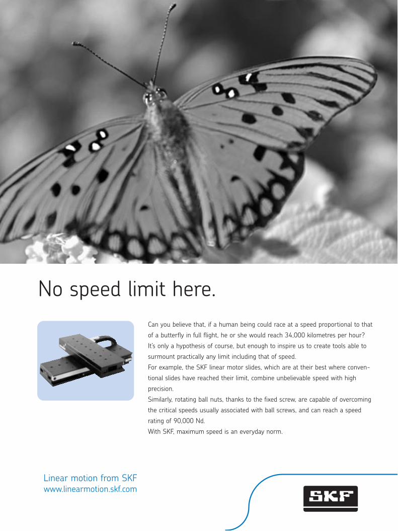
No speed limit here.
Can you believe that, if a human being could race at a speed proportional to that
of a butterfly in full flight, he or she would reach 34,000 kilometres per hour?
It’s only a hypothesis of course, but enough to inspire us to create tools able to
surmount practically any limit including that of speed.
For example, the SKF linear motor slides, which are at their best where conven-
tional slides have reached their limit, combine unbelievable speed with high
precision.
Similarly, rotating ball nuts, thanks to the fixed screw, are capable of overcoming
the critical speeds usually associated with ball screws, and can reach a speed
rating of 90,000 Nd.
With SKF, maximum speed is an everyday norm.
Linear motion from SKFwww.linearmotion.skf.com
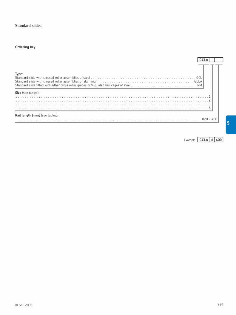
© SKF 2005 315
5
Type:Standard slide with crossed roller assemblies of steel . . . . . . . . . . . . . . . . . . . . . . . . . . . . . . . . . . . . . . . . . . . . . . . . . . . . . . . . . . . GCLStandard slide with crossed roller assemblies of aluminium . . . . . . . . . . . . . . . . . . . . . . . . . . . . . . . . . . . . . . . . . . . . . . . . . . . . . GCLAStandard slide fitted with either cross roller guides or V-guided ball cages of steel . . . . . . . . . . . . . . . . . . . . . . . . . . . . . . . . . . . . . RM
Size (see tables):. . . . . . . . . . . . . . . . . . . . . . . . . . . . . . . . . . . . . . . . . . . . . . . . . . . . . . . . . . . . . . . . . . . . . . . . . . . . . . . . . . . . . . . . . . . . . . . . . . . . . . . . . . . . . 1. . . . . . . . . . . . . . . . . . . . . . . . . . . . . . . . . . . . . . . . . . . . . . . . . . . . . . . . . . . . . . . . . . . . . . . . . . . . . . . . . . . . . . . . . . . . . . . . . . . . . . . . . . . . . 2. . . . . . . . . . . . . . . . . . . . . . . . . . . . . . . . . . . . . . . . . . . . . . . . . . . . . . . . . . . . . . . . . . . . . . . . . . . . . . . . . . . . . . . . . . . . . . . . . . . . . . . . . . . . . 3. . . . . . . . . . . . . . . . . . . . . . . . . . . . . . . . . . . . . . . . . . . . . . . . . . . . . . . . . . . . . . . . . . . . . . . . . . . . . . . . . . . . . . . . . . . . . . . . . . . . . . . . . . . . . 6
Rail length [mm] (see tables):. . . . . . . . . . . . . . . . . . . . . . . . . . . . . . . . . . . . . . . . . . . . . . . . . . . . . . . . . . . . . . . . . . . . . . . . . . . . . . . . . . . . . . . . . . . . . . . . . . . . . . . . . 020 - 400
Ordering key
Standard slides
— —––—––—GCLA
Example: 6 400GCLA

316 © SKF 2005
5 Positioning systems
Standard slides
GCL
Standard slides with crossed roller
assemblies, steel version, for manual
positioning
J1 J J1
Designations Dimensions Stroke
B H L S11) S2
1) G H1 H2 J J1 J2 J3 J4 J5
mm
GCL 2030 40 21 35 18 – M3 6.5 14.0 – 17.5 15 1×15 10 25
GCL 2045 40 21 50 30 – M3 6.5 14.0 1×15 17.5 15 2×15 10 25
GCL 2060 40 21 65 40 46 M3 6.5 14.0 2×15 17.5 15 3×15 10 25
GCL 2075 40 21 80 50 60 M3 6.5 14.0 3×15 17.5 15 4×15 10 25
GCL 2090 40 21 95 60 75 M3 6.5 14.0 4×15 17.5 15 5×15 10 25
GCL 2105 40 21 110 70 90 M3 6.5 14.0 5×15 17.5 15 6×15 10 25
GCL 2120 40 21 125 80 105 M3 6.5 14.0 6×15 17.5 15 7×15 10 25
GCL 3050 60 28 55 30 – M4 9.0 18.5 – 27.5 25 1×25 15 39
GCL 3075 60 28 80 45 55 M4 9.0 18.5 1×25 27.5 25 2×25 15 39
GCL 3100 60 28 105 60 80 M4 9.0 18.5 2×25 27.5 25 3×25 15 39
GCL 3125 60 28 130 75 105 M4 9.0 18.5 3×25 27.5 25 4×25 15 39
GCL 3150 60 28 155 90 130 M4 9.0 18.5 4×25 27.5 25 5×25 15 39
GCL 3175 60 28 180 105 155 M4 9.0 18.5 5×25 27.5 25 6×25 15 39
GCL 3200 60 28 205 130 180 M4 9.0 18.5 6×25 27.5 25 7×25 15 39
GCL 6100 100 45 110 60 70 M6 13 31.0 – 55.0 50 1×50 30 64
GCL 6150 100 45 160 95 120 M6 13 31.0 1×50 55.0 50 2×50 30 64
GCL 6200 100 45 210 130 170 M6 13 31.0 2×50 55.0 50 3×50 30 64
GCL 6250 100 45 260 165 220 M6 13 31.0 3×50 55.0 50 4×50 30 64
GCL 6300 100 45 310 200 270 M6 13 31.0 4×50 55.0 50 5×50 30 64
GCL 6400 100 45 410 280 370 M6 13 31.0 6×50 55.0 50 7×50 30 64
1) S1 Standard stroke order designation, e.g. GCL 2030
S2 Extended stroke order designation, e.g. GCL 2030/L

© SKF 2005 317
5
Designations Dimensions Load-carrying capacities Weight
with S1 with S2
J6 J7 J8 J9 Fig N C0 C0 GS
mm N N kg
GCL 2030 30 25 – – 1 3.4 250 – 0.18
GCL 2045 30 40 – – 1 3.4 360 – 0.26
GCL 2060 30 55 – – 1 3.4 470 430 0.34
GCL 2075 30 70 40 – 2 3.4 580 540 0.42
GCL 2090 30 85 55 – 2 3.4 720 610 0.50
GCL 2105 30 100 70 – 2 3.4 830 720 0.58
GCL 2120 30 115 85 – 2 3.4 940 790 0.68
GCL 3050 40 35 – – 1 4.5 480 – 0.57
GCL 3075 40 60 – – 1 4.5 800 720 0.80
GCL 3100 40 85 – – 1 4.5 1040 880 1.00
GCL 3125 40 110 – – 1 4.5 1360 1120 1.30
GCL 3150 40 135 85 – 3 4.5 1600 1280 1.50
GCL 3175 40 160 110 – 3 4.5 1920 1520 1.70
GCL 3200 40 185 135 85 4 4.5 2080 1680 2.00
GCL 6100 60 90 – – 1 6.6 2380 2040 3.10
GCL 6150 60 140 – – 1 6.6 3740 3060 4.50
GCL 6200 60 190 90 – 3 6.6 4760 4080 5.90
GCL 6250 60 240 140 – 3 6.6 6120 5100 7.20
GCL 6300 60 290 190 – 3 6.6 7140 6120 8.60
GCL 6400 60 390 290 190 4 6.6 7820 6120 11.40

318 © SKF 2005
5 Positioning systems
Standard slides
GCLA
Standard slides with slide top and base
made of black anodised aluminium, for
manual positioning.
In other respects the design is similar to
that of the GCL slides except for the slightly
reduced height.
Designations Dimensions Stroke
B H L S1 S21) G H1 J J1 J2 J3 J4 J5
mm
GCLA 2030 40 21 35 15 – M3 7.00 – 17.5 15 1 × 15 10 25
GCLA 2045 40 21 50 22 30 M3 7.00 1 × 15 17.5 15 2 × 15 10 25
GCLA 2060 40 21 65 30 45 M3 7.00 2 × 15 17.5 15 3 × 15 10 25
GCLA 2075 40 21 80 37 60 M3 7.00 3 × 15 17.5 15 4 × 15 10 25
GCLA 2090 40 21 95 45 75 M3 7.00 4 × 15 17.5 15 5 × 15 10 25
GCLA 2105 40 21 110 52 90 M3 7.00 5 × 15 17.5 15 6 × 15 10 25
GCLA 2120 40 21 125 60 105 M3 7.00 6 × 15 17.5 15 7 × 15 10 25
GCLA 3050 60 25 55 – 30 M4 8.25 – 27.5 25 1 × 25 15 41
GCLA 3075 60 25 80 37 55 M4 8.25 1 × 25 27.5 25 2 × 25 15 41
GCLA 3100 60 25 105 50 80 M4 8.25 2 × 25 27.5 25 3 × 25 15 41
GCLA 3125 60 25 130 62 105 M4 8.25 3 × 25 27.5 25 4 × 25 15 41
GCLA 3150 60 25 155 75 130 M4 8.25 4 × 25 27.5 25 5 × 25 15 41
GCLA 3175 60 25 180 87 155 M4 8.25 5 × 25 27.5 25 6 × 25 15 41
GCLA 3200 60 25 205 100 180 M4 8.25 6 × 25 27.5 25 7 × 25 15 41
GCLA 6100 100 40 110 50 70 M6 12.00 – 55.0 50 1 × 50 30 65
GCLA 6150 100 40 160 75 120 M6 12.00 1 × 50 55.0 50 2 × 50 30 65
GCLA 6200 100 40 210 100 170 M6 12.00 2 × 50 55.0 50 3 × 50 30 65
GCLA 6250 100 40 260 125 220 M6 12.00 3 × 50 55.0 50 4 × 50 30 65
GCLA 6300 100 40 310 150 270 M6 12.00 4 × 50 55.0 50 5 × 50 30 65
GCLA 6350 100 40 360 175 320 M6 12.00 5 × 50 55.0 50 6 × 50 30 65
GCLA 6400 100 40 410 200 370 M6 12.00 6 × 50 55.0 50 7 × 50 30 65
1) S2 Extended stroke order designation, e.g. GCL 2030L

© SKF 2005 319
5
Designations Dimensions Load-carrying capacities Weight
with S1 with S2
J6 J7 J8 J9 Fig N C0 C0 GA
mm N N kg
GCLA 2030 30 25 – – 1 3.8 430 – 0.10
GCLA 2045 30 40 – – 1 3.8 688 602 0.14
GCLA 2060 30 55 – – 1 3.8 946 774 0.19
GCLA 2075 30 70 – – 1 3.8 1204 946 0.23
GCLA 2090 30 85 45 – 2 3.8 1376 1113 0.28
GCLA 2105 30 100 50 – 2 3.8 1634 1290 0.32
GCLA 2120 30 115 30 – 2 3.8 1892 1376 0.37
GCLA 3050 40 35 – – 1 4.8 – 952 0.29
GCLA 3075 40 60 – – 1 4.8 1496 1224 0.43
GCLA 3100 40 85 – – 1 4.8 2040 1632 0.57
GCLA 3125 40 110 – – 1 4.8 2448 1904 0.70
GCLA 3150 40 135 75 – 2 4.8 2992 2312 0.84
GCLA 3175 40 160 86 – 2 4.8 3536 2584 0.97
GCLA 3200 40 185 55 – 2 4.8 4080 2992 1.10
GCLA 6100 60 90 – – 1 6.8 4320 3780 1.60
GCLA 6150 60 140 – – 1 6.8 6480 5400 2.40
GCLA 6200 60 190 100 – 2 6.8 8640 6480 3.10
GCLA 6250 60 240 80 – 2 6.8 10800 8100 3.90
GCLA 6300 60 290 150 – 2 6.8 13500 9720 4.70
GCLA 6350 60 340 200 80 3 6.8 15660 11340 5.40
GCLA 6400 60 390 230 90 3 6.8 17820 12420 6.20

320 © SKF 2005
5 Positioning systems
Standard slides/Slides, tables and compact cross tables
RM
Standard slides fitted with either cross
roller rail guides or V-guided ball cages, for
manual positioning; the opposing V-rails
are screwed to a steel base plate. Slide top
and bottom carry a standard pattern of
mounting holes.
Designations Dimensions Stroke
B H L S B1 G H1 H2 J J1
mm
RM 1020 20 8 25 12 7 M2.5 7.5 5 1×18 3.5
RM 1030 20 8 35 18 7 M2.5 7.5 5 1×28 3.5
RM 1040 20 8 45 25 7 M2.5 7.5 5 1×20 12.5
RM 1050 20 8 55 32 7 M2.5 7.5 5 1×30 12.5
RM 2060 30 12 65 40 12 M3 11.5 7 1×30 17.5
RM 2075 30 12 80 50 12 M3 11.5 7 1×45 17.5
RM 2090 30 12 95 60 12 M3 11.5 7 2×30 17.5
RM 3100 40 16 105 60 16 M4 15.5 9 1×50 27.5
RM 3125 40 16 130 75 16 M4 15.5 9 1×75 27.5
RM 3150 40 16 155 90 16 M4 15.5 9 2×50 27.5
continued
Designations Dimensions Load-carrying Weight
capacities
J2 J3 J4 J5 J6 J7 J8 J9 C0 GS
mm N kg
RM 1020 14 1×10 7.5 2×7.5 5.0 1×18 3.5 12.6 208 0.025
RM 1030 14 2×10 7.5 2×10 7.5 1×20 7.5 12.6 364 0.025
RM 1040 14 3×10 7.5 3×10 7.5 1×28 8.5 12.6 464 0.025
RM 1050 14 4×10 7.5 4×10 7.5 1×30 12.5 12.6 572 0.025
RM 2060 22 3×15 10.0 3×15 10.0 – – 20.0 860 0.160
RM 2075 22 4×15 10.0 4×15 10.0 – – 20.0 1032 0.190
RM 2090 22 5×15 10.0 5×15 10.0 – – 20.0 1290 0.230
RM 3100 30 3×25 15.0 3×25 15.0 – – 28.5 1904 0.460
RM 3125 30 4×25 15.0 4×25 15.0 – – 28.5 2312 0.580
RM 3150 30 5×25 15.0 5×25 15.0 – – 28.5 2856 0.690
continued

© SKF 2005 321
5
Type:Precision slides with rail guide system, crossed rollers . . . . . . . . . . . . . . . . . . . . . . . . . . . . . RDovetail slides . . . . . . . . . . . . . . . . . . . . . . . . . . . . . . . . . . . . . . . . . . . . . . . . . . . . . . . . . . . . . SCompact cross tables with rail guide system, crossed rollers . . . . . . . . . . . . . . . . . . . . . . . . . T
Versions:Only valid for dovetail tables:For manual operation, with micrometer knurl . . . . . . . . . . . . . . . . . . . . . . . . . . . . . . . . . . . . . SMFor manual operation, with hand crank . . . . . . . . . . . . . . . . . . . . . . . . . . . . . . . . . . . . . . . . . . . SK
Only valid for precision tables:For manual operation, with micrometer knurl . . . . . . . . . . . . . . . . . . . . . . . . . . . . . . . . . . . . . SMFor manual operation, with hand crank . . . . . . . . . . . . . . . . . . . . . . . . . . . . . . . . . . . . . . . . . . . SKFor motor drive. . . . . . . . . . . . . . . . . . . . . . . . . . . . . . . . . . . . . . . . . . . . . . . . . . . . . . . . . . . . . . SS
Only valid for compact cross tables:For manual operation, without drive . . . . . . . . . . . . . . . . . . . . . . . . . . . . . . . . . . . . . . . . . . . . . . OFor manual operation, with micrometer knurl . . . . . . . . . . . . . . . . . . . . . . . . . . . . . . . . . . . . . . . S
Table width B [mm] (see tables):. . . . . . . . . . . . . . . . . . . . . . . . . . . . . . . . . . . . . . . . . . . . . . . . . . . . . . . . . . . . . . . . . . . . . . . . . . . 85 - 300
Length L1 or dimension Sx Sy [mm]:L1 for dovetail and precision slides. . . . . . . . . . . . . . . . . . . . . . . . . . . . . . . . . . . . . . . . . . . . . . . . . . . . . . 80 - 1010Sx Sy for compact cross tables . . . . . . . . . . . . . . . . . . . . . . . . . . . . . . . . . . . . . . . . . . . . . . . . . . . . . . 025, 050, 100
Nominal stroke [mm] (not for compact cross tables):See tables
Designation suffix if desired:Slides or tables made of aluminium, black anodised . . . . . . . . . . . . . . . . . . . . . . . . . . . . . . . . . . . . . . . . . . . . . . . . . . . . . . . . . . . . . ASlides with thick top: only for precision slides. . . . . . . . . . . . . . . . . . . . . . . . . . . . . . . . . . . . . . . . . . . . . . . . . . . . . . . . . . . . . . . . . . . DSlides with thick top and T-slots: dovetail and precision slides . . . . . . . . . . . . . . . . . . . . . . . . . . . . . . . . . . . . . . . . . . . . . . . . . . . . DT
Locking device for dovetail slides (standard) . . . . . . . . . . . . . . . . . . . . . . . . . . . . . . . . . . . . . . . . . . . . . . . . . . . . . . . . . . . . . . . . . AR 1Locking device for precision slides and tables . . . . . . . . . . . . . . . . . . . . . . . . . . . . . . . . . . . . . . . . . . . . . . . . . . . . . . . . . . . . . . . . AR 2Locking device for compact cross tables (standard). . . . . . . . . . . . . . . . . . . . . . . . . . . . . . . . . . . . . . . . . . . . . . . . . . . . . . . . . . . . AR 3
For motor drive only:Preloaded planetary roller screw for RSS - slides. . . . . . . . . . . . . . . . . . . . . . . . . . . . . . . . . . . . . . . . . . . . . . . . . . . . . . . . . . . . . . . . . . . . . R
Screw diameter Ø in mm:Precision tables for RSS - slides. . . . . . . . . . . . . . . . . . . . . . . . . . . . . . . . . . . . . . . . . . . . . . . . . . . . . . . . . . . . . . . . . . . . . . . . . . . . . . . . . 8 - 20
Screw lead:1 - 5 mm for RSS - slides . . . . . . . . . . . . . . . . . . . . . . . . . . . . . . . . . . . . . . . . . . . . . . . . . . . . . . . . . . . . . . . . . . . . . . . . . . . . . . . . . . . . . . . 01 - 15
Ordering key
Slides, tables and compact cross tables
-R RSS 200 - 300 - - 1202Example 1: 710
-R SK 50 - 025Example 2: 080
-S SM 300 - 500 - AR1Example 3: 010
-S SK 50 - 025 - AR1Example 4: 080
-T O 085 - - AR3Example 5: 050
R
—-
—–SS
——–-
—–-
—–-
— ——––

322 © SKF 2005
5 Positioning systems
Dovetail slides
Dovetail slides
SSM / SSK
SSM – with micrometer ring with spring
preloading, allowing easy turning. One
division equals 0,02 mm.
SSK – as SSM, but instead of knurled screw
equipped with crank handle.
C2 C
øD
1
H
H1
A2
L1
J
C1
J
L2
2)G
C2
D1
G
B
A1
1)
Legend:
1) Locking device standard
2) Position grease nipple
Designations Dimensions Stroke Screw Weight
B H L1 L2 S A1 A2 C C1 C2 D1 H1 Ø J G GG
mm kg
SSM-50.080.025 50 25 80 50 25 37 42 19 6 31 23.5 12.3 M6×1 37 M4 0.7
SSK- 50.080.025 50 25 80 25 25 37 42 19 6 51 47.0 12.3 M6×1 37 M4 0.7
SSM-50.130.025 50 25 130 25 25 37 42 19 6 31 23.5 12.3 M6×1 37 M4 1.2
SSK-50.130.025 50 25 130 25 25 37 42 19 6 51 47.0 12.3 M6×1 37 M4 1.2
SSM-50.130.050 50 25 130 50 50 37 42 19 6 31 23.5 12.3 M6×1 37 M4 1.0
SSK-50.130.050 50 25 130 50 50 37 42 19 6 51 47.0 12.3 M6×1 37 M4 1.0
SSM-50.155.050 50 25 155 50 50 37 42 19 6 31 23.5 12.3 M6×1 37 M4 1.3
SSK-50.155.050 50 25 155 50 50 37 42 19 6 51 47.0 12.3 M6×1 37 M4 1.3
SSM-50.155.075 50 25 155 75 75 37 42 19 6 31 23.5 12.3 M6×1 37 M4 1.2
SSK-50.155.075 50 25 155 75 75 37 42 19 6 51 47.0 12.3 M6×1 37 M4 1.2
SSM-50.180.075 50 25 180 75 75 37 42 19 6 31 23.5 12.3 M6×1 37 M4 1.4
SSK-50.180.075 50 25 180 75 75 37 42 19 6 51 47.0 12.3 M6×1 37 M4 1.4
SSM-50.205.100 50 25 205 100 100 37 42 19 6 31 23.5 12.3 M6×1 37 M4 1.7
SSK-50.205.100 50 25 205 100 100 37 42 19 6 51 47.0 12.3 M6×1 37 M4 1.7
SSM-75.105.025 75 32 105 75 25 38 42 21 6 38 30.0 15 M10×1 62 M5 1.9
SSK-75.105.025 75 32 105 75 25 38 42 21 6 54 47.0 15 M10×1 62 M5 1.9
SSM-75.155.050 75 32 155 100 50 38 42 21 6 38 30.0 15 M10×1 62 M5 2.6
SSK-75.155.050 75 32 155 100 50 38 42 21 6 54 47.0 15 M10×1 62 M5 2.6
SSM-75.205.050 75 32 205 150 50 38 42 21 6 38 30.0 15 M10×1 62 M5 3.4
SSK-75.205.050 75 32 205 150 50 38 42 21 6 54 47.0 15 M10×1 62 M5 3.4
SSM-75.155.075 75 32 155 75 75 38 42 21 6 38 30.0 15 M10×1 62 M5 2.3
SSK-75.155.075 75 32 155 75 75 38 42 21 6 54 47.0 15 M10×1 62 M5 2.3
SSM-75.180.075 75 32 180 100 75 38 42 21 6 38 30.0 15 M10×1 62 M5 2.8
SSK-75.180.075 75 32 180 100 75 38 42 21 6 54 47.0 15 M10×1 62 M5 2.8
SSM-75.205.100 75 32 205 100 100 38 42 21 6 38 30.0 15 M10×1 62 M5 3.0
SSK-75.205.100 75 32 205 100 100 38 42 21 6 54 47.0 15 M10×1 62 M5 3.0
SSM-75.255.100 75 32 255 150 100 38 42 21 6 38 30.0 15 M10×1 62 M5 3.8
SSK-75.255.100 75 32 255 150 100 38 42 21 6 54 47.0 15 M10×1 62 M5 3.8
SSM-75.305.150 75 32 305 150 150 38 42 21 6 38 30.0 15 M10×1 62 M5 4.2
SSK-75.305.150 75 32 305 150 150 38 42 21 6 54 47.0 15 M10×1 62 M5 4.2
continued
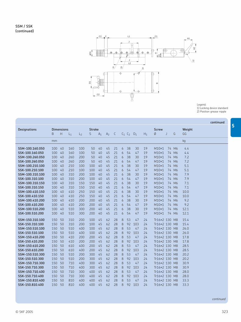
© SKF 2005 323
5
SSM / SSK
(continued)
C2 C
øD
1
H
H1
A2
L1
J
C1
J
L2
2)G
C2
D1
G
B
A1
1)
Legend:
1) Locking device standard
2) Position grease nipple
Designations Dimensions Stroke Screw Weight
B H L1 L2 S A1 A2 C C1 C2 D1 H1 Ø J G GG
mm kg
SSM-100.160.050 100 40 160 100 50 40 45 21 6 38 30 19 M10×1 74 M6 4.4
SSK-100.160.050 100 40 160 100 50 40 45 21 6 54 47 19 M10×1 74 M6 4.4
SSM-100.260.050 100 40 260 200 50 40 45 21 6 38 30 19 M10×1 74 M6 7.2
SSK-100.260.050 100 40 260 200 50 40 45 21 6 54 47 19 M10×1 74 M6 7.2
SSM-100.210.100 100 40 210 100 100 40 45 21 6 38 30 19 M10×1 74 M6 5.1
SSK-100.210.100 100 40 210 100 100 40 45 21 6 54 47 19 M10×1 74 M6 5.1
SSM-100.310.100 100 40 310 200 100 40 45 21 6 38 30 19 M10×1 74 M6 7.9
SSK-100.310.100 100 40 310 200 100 40 45 21 6 54 47 19 M10×1 74 M6 7.9
SSM-100.310.150 100 40 310 150 150 40 45 21 6 38 30 19 M10×1 74 M6 7.1
SSK-100.310.150 100 40 310 150 150 40 45 21 6 54 47 19 M10×1 74 M6 7.1
SSM-100.410.150 100 40 410 250 150 40 45 21 6 38 30 19 M10×1 74 M6 10.0
SSK-100.410.150 100 40 410 250 150 40 45 21 6 54 47 19 M10×1 74 M6 10.0
SSM-100.410.200 100 40 410 200 200 40 45 21 6 38 30 19 M10×1 74 M6 9.2
SSK-100.410.200 100 40 410 200 200 40 45 21 6 54 47 19 M10×1 74 M6 9.2
SSM-100.510.200 100 40 510 300 200 40 45 21 6 38 30 19 M10×1 74 M6 12.1
SSK-100.510.200 100 40 510 300 200 40 45 21 6 54 47 19 M10×1 74 M6 12.1
SSM-150.310.100 150 50 310 200 100 45 62 28 8 53 47 24 Tr16×2 130 M8 15.4
SSK-150.310.100 150 50 310 200 100 45 62 28 8 92 103 24 Tr16×2 130 M8 15.4
SSM-150.510.100 150 50 510 400 100 45 62 28 8 53 47 24 Tr16×2 130 M8 26.0
SSK-150.510.100 150 50 510 400 100 45 62 28 8 92 103 24 Tr16×2 130 M8 26.0
SSM-150.410.200 150 50 410 200 200 45 62 28 8 53 47 24 Tr16×2 130 M8 17.8
SSK-150.410.200 150 50 410 200 200 45 62 28 8 92 103 24 Tr16×2 130 M8 17.8
SSM-150.610.200 150 50 610 400 200 45 62 28 8 53 47 24 Tr16×2 130 M8 28.5
SSK-150.610.200 150 50 610 400 200 45 62 28 8 92 103 24 Tr16×2 130 M8 28.5
SSM-150.510.300 150 50 510 200 300 45 62 28 8 53 47 24 Tr16×2 130 M8 20.2
SSK-150.510.300 150 50 510 200 300 45 62 28 8 92 103 24 Tr16×2 130 M8 20.2
SSM-150.710.300 150 50 710 400 300 45 62 28 8 53 47 24 Tr16×2 130 M8 30.9
SSK-150.710.300 150 50 710 400 300 45 62 28 8 92 103 24 Tr16×2 130 M8 30.9
SSM-150.710.400 150 50 710 300 400 45 62 28 8 53 47 24 Tr16×2 130 M8 28.0
SSK-150.710.400 150 50 710 300 400 45 62 28 8 92 103 24 Tr16×2 130 M8 28.0
SSM-150.810.400 150 50 810 400 400 45 62 28 8 53 47 24 Tr16×2 130 M8 33.3
SSK-150.810.400 150 50 810 400 400 45 62 28 8 92 103 24 Tr16×2 130 M8 33.3
continued
continued

324 © SKF 2005
5 Positioning systems
Dovetail slides/Compact cross tables
SSM / SSK
(continued)
C2 C
øD
1
H
H1
A2
L1
J
C1
J
L2
2)G
C2
D1
G
B
A1
1)
Legend:
1) Locking device standard
2) Position grease nipple
Designations Dimensions Stroke Screw Weight
B H L1 L2 S A1 A2 C C1 C2 D1 H1 Ø J G GG
mm kg
SSM-200.310.100 200 60 310 200 100 45 62 28 8 53 47 25.0 Tr16×2 170 M8 24.7
SSK-200.310.100 200 60 310 200 100 45 62 28 8 92 103 25.0 Tr16×2 170 M8 24.7
SSM-200.410.100 200 60 410 300 100 45 62 28 8 53 47 25.0 Tr16×2 170 M8 33.2
SSK-200.410.100 200 60 410 300 100 45 62 28 8 92 103 25.0 Tr16×2 170 M8 33.2
SSM-200.510.200 200 60 510 300 200 45 62 28 8 53 47 25.0 Tr16×2 170 M8 37.2
SSK-200.510.200 200 60 510 300 200 45 62 28 8 92 103 25.0 Tr16×2 170 M8 37.2
SSM-200.610.200 200 60 610 400 200 45 62 28 8 53 47 25.0 Tr16×2 170 M8 45.7
SSK-200.610.200 200 60 610 400 200 45 62 28 8 92 103 25.0 Tr16×2 170 M8 45.7
SSM-200.610.300 200 60 610 300 300 45 62 28 8 53 47 25.0 Tr16×2 170 M8 41.1
SSK-200.610.300 200 60 610 300 300 45 62 28 8 92 103 25.0 Tr16×2 170 M8 41.1
SSM-200.710.300 200 60 710 400 300 45 62 28 8 53 47 25.0 Tr16×2 170 M8 49.6
SSK-200.710.300 200 60 710 400 300 45 62 28 8 92 103 25.0 Tr16×2 170 M8 49.6
SSM-200.710.400 200 60 710 300 400 45 62 28 8 53 47 25.0 Tr16×2 170 M8 45.0
SSK-200.710.400 200 60 710 300 400 45 62 28 8 92 103 25.0 Tr16×2 170 M8 45.0
SSM-200.810.400 200 60 810 400 400 45 62 28 8 53 47 25.0 Tr16×2 170 M8 53.5
SSK-200.810.400 200 60 810 400 400 45 62 28 8 92 103 25.0 Tr16×2 170 M8 53.5
SSM-300.410.100 300 75 410 300 100 55 74 20 10 80 66 34.5 Tr20×4 260 M10 64.6
SSK-300.410.100 300 75 410 300 100 55 74 20 10 146 125 34.5 Tr20×4 260 M10 64.6
SSM-300.510.100 300 75 510 400 100 55 74 20 10 80 66 34.5 Tr20×4 260 M10 80.7
SSK-300.510.100 300 75 510 400 100 55 74 20 10 146 125 34.5 Tr20×4 260 M10 80.7
SSM-300.510.200 300 75 510 300 200 55 74 20 10 80 66 34.5 Tr20×4 260 M10 72.4
SSK-300.510.200 300 75 510 300 200 55 74 20 10 146 125 34.5 Tr20×4 260 M10 72.4
SSM-300.610.200 300 75 610 400 200 55 74 20 10 80 66 34.5 Tr20×4 260 M10 88.6
SSK-300.610.200 300 75 610 400 200 55 74 20 10 146 125 34.5 Tr20×4 260 M10 88.6
SSM-300.710.300 300 75 710 400 300 55 74 20 10 80 66 34.5 Tr20×4 260 M10 96.4
SSK-300.710.300 300 75 710 400 300 55 74 20 10 146 125 34.5 Tr20×4 260 M10 96.4
SSM-300.810.400 300 75 810 400 400 55 74 20 10 80 66 34.5 Tr20×4 260 M10 104.3
SSK-300.810.400 300 75 810 400 400 55 74 20 10 146 125 34.5 Tr20×4 260 M10 104.3
SSM-300.1010.500 300 75 1010 500 500 55 74 20 10 80 66 34.5 Tr20×4 260 M10 128.3
SSK-300.1010.500 300 75 1010 500 500 55 74 20 10 146 125 34.5 Tr20×4 260 M10 128.3
continued

© SKF 2005 325
5
Compact cross tables
TO / TS
Designations Dimensions Stroke Load-carrying Weight
capacities
B H Sx Sy B1 C1 C2 C3 D N G J1 J2 C0 GA
mm N kg
TO 085 85 40 50 48 16 – – 22 Ø 4.2 / Ø 8 × 4.5 (4x) M5 20 70 3 400 0.8
TS 085 85 40 25 48 16 22.5 33 22 – M5 20 70 4 200 1.1
TO 160 160 70 100 105 15 – – 50 Ø 5 / Ø 10 × 5.5 (4x) M6 60 140 12 400 4.0
TS 160 160 70 50 105 15 25.0 50 50 – M6 60 140 15 600 4.8

326 © SKF 2005
5 Positioning systems
Precision slides
øD
1
H1
H
JD1
B
C2 C L1
J
J
C2
G
C1
Precision slides
RSM / RSK
Precision tables for manual operation with
micrometer knurl RSM, with hand crank
RSK
Designations Dimensions Stroke Screw Load-carrying Weight
capacities
B H L1 L2 S C C1 C2 D1 H1 Ø J G N C0 GG
mm kN kg
RSM50.080.025 50 25 80 55 25 14 5 37.5 23 12.3 M6×1 37 M4 4.5 1.70 0.7
RSM50.130.025 50 25 130 105 25 14 5 37.5 23 12.3 M6×1 37 M4 4.5 3.30 1.1
RSM50.130.050 50 25 130 80 50 14 5 37.5 23 12.3 M6×1 37 M4 4.5 2.50 1.0
RSM50.130.075 50 25 130 55 75 14 5 37.5 23 12.3 M6×1 37 M4 4.5 1.70 0.9
RSM50.180.075 50 25 180 105 75 14 5 37.5 23 12.3 M6×1 37 M4 4.5 3.30 1.3
RSM50.180.100 50 25 180 80 100 14 5 37.5 23 12.3 M6×1 37 M4 4.5 2.50 1.2
RSM75.130.025 75 32 130 105 25 15 6 46.0 30 15 M10×1 62 M4 4.5 3.40 2.2
RSK75.130.025 75 32 130 105 25 15 6 88.0 71 15 M10×1 62 M4 4.5 3.40 2.2
RSM75.180.050 75 32 180 130 50 15 6 46.0 30 15 M10×1 62 M4 4.5 5.10 3.0
RSK75.180.050 75 32 180 130 50 15 6 88.0 71 15 M10×1 62 M4 4.5 5.10 3.0
RSM75.180.025 75 32 180 150 50 15 6 46.0 30 15 M10×1 62 M4 4.5 4.25 2.8
RSK75.180.025 75 32 180 150 50 15 6 88.0 71 15 M10×1 62 M4 4.5 4.25 2.8
RSM75.180.075 75 32 180 105 75 15 6 46.0 30 15 M10×1 62 M4 4.5 3.40 2.6
RSK75.180.075 75 32 180 105 75 15 6 88.0 71 15 M10×1 62 M4 4.5 3.40 2.6
RSM75.230.075 75 32 230 155 75 15 6 46.0 30 15 M10×1 62 M4 4.5 5.10 3.4
RSK75.230.075 75 32 230 155 75 15 6 88.0 71 15 M10×1 62 M4 4.5 5.10 3.4
RSM75.230.075 75 32 230 130 100 15 6 46.0 30 15 M10×1 62 M4 4.5 4.25 3.3
RSK75.230.075 75 32 230 130 100 15 6 88.0 71 15 M10×1 62 M4 4.5 4.25 3.3
RSM75.230.075 75 32 230 105 125 15 6 46.0 30 15 M10×1 62 M4 4.5 3.40 3.1
RSK75.230.075 75 32 230 105 125 15 6 88.0 71 15 M10×1 62 M4 4.5 3.40 3.1
continued

© SKF 2005 327
5
Designations Dimensions Stroke Screw Load-carrying Weight
capacities
B H L1 L2 S C C1 C2 D1 H1 Ø J G N C0 GG
mm kN kg
RSM100.260.050 100 40 260 210 50 15 6 46 30 15.5 M10×1 74 M6 6.6 8.8 6.8
RSK100.260.050 100 40 260 210 50 15 6 88 71 15.5 M10×1 74 M6 6.6 8.8 6.8
RSM100.310.050 100 40 310 260 50 15 6 46 30 15.5 M10×1 74 M6 6.6 10.9 8.2
RSK100.310.050 100 40 310 260 50 15 6 88 71 15.5 M10×1 74 M6 6.6 10.9 8.2
RSM100.360.050 100 40 360 310 50 15 6 46 30 15.5 M10×1 74 M6 6.6 13.0 9.6
RSK100.360.050 100 40 360 310 50 15 6 88 71 15.5 M10×1 74 M6 6.6 13.0 9.6
RSM100.310.100 100 40 310 210 100 15 6 46 30 15.5 M10×1 74 M6 6.6 8.8 7.5
RSK100.310.100 100 40 310 210 100 15 6 88 71 15.5 M10×1 74 M6 6.6 8.8 7.5
RSM100.360.100 100 40 360 260 100 15 6 46 30 15.5 M10×1 74 M6 6.6 10.9 8.9
RSK100.360.100 100 40 360 260 100 15 6 88 71 15.5 M10×1 74 M6 6.6 10.9 8.9
RSM100.410.100 100 40 410 310 100 15 6 46 30 15.5 M10×1 74 M6 6.6 13.0 10.0
RSK100.410.100 100 40 410 310 100 15 6 88 71 15.5 M10×1 74 M6 6.6 13.0 10.0
RSM100.360.150 100 40 360 210 150 15 6 46 30 15.5 M10×1 74 M6 6.6 8.8 8.2
RSK100.360.150 100 40 360 210 150 15 6 88 71 15.5 M10×1 74 M6 6.6 8.8 8.2
RSM100.410.150 100 40 410 260 150 15 6 46 30 15.5 M10×1 74 M6 6.6 10.9 9.6
RSK100.410.150 100 40 410 260 150 15 6 88 71 15.5 M10×1 74 M6 6.6 10.9 9.6
RSM100.460.150 100 40 460 310 150 15 6 46 30 15.5 M10×1 74 M6 6.6 13.0 11.0
RSK100.460.150 100 40 460 310 150 15 6 88 71 15.5 M10×1 74 M6 6.6 13.0 11.0
RSM100.460.200 100 40 460 260 200 15 6 46 30 15.5 M10×1 74 M6 6.6 10.9 10.0
RSK100.460.200 100 40 460 260 200 15 6 88 71 15.5 M10×1 74 M6 6.6 10.9 10.0
RSM150.410.100 150 50 410 310 100 20 8 63 47 24.0 Tr16×2 116 M8 9 53.0 20.0
RSK150.410.100 150 50 410 310 100 20 8 122 102 24.0 Tr16×2 116 M8 9 53.0 20.0
RSM150.510.100 150 50 510 410 100 20 8 63 47 24.0 Tr16×2 116 M8 9 71.0 25.0
RSK150.510.100 150 50 510 410 100 20 8 122 102 24.0 Tr16×2 116 M8 9 71.0 25.0
RSM150.610.100 150 50 610 510 100 20 8 63 47 24.0 Tr16×2 116 M8 9 88.0 30.0
RSK150.610.100 150 50 610 510 100 20 8 122 102 24.0 Tr16×2 116 M8 9 88.0 30.0
RSM150.510.200 150 50 510 310 200 20 8 63 47 24.0 Tr16×2 116 M8 9 53.0 22.0
RSK150.510.200 150 50 510 310 200 20 8 122 102 24.0 Tr16×2 116 M8 9 53.0 22.0
RSM150.610.200 150 50 610 410 200 20 8 63 47 24.0 Tr16×2 116 M8 9 71.0 28.0
RSK150.610.200 150 50 610 410 200 20 8 122 102 24.0 Tr16×2 116 M8 9 71.0 28.0
RSM150.710.200 150 50 710 510 200 20 8 63 47 24.0 Tr16×2 116 M8 9 88.0 33.0
RSK150.710.200 150 50 710 510 200 20 8 122 102 24.0 Tr16×2 116 M8 9 88.0 33.0
RSM150.610.300 150 50 610 310 300 20 8 63 47 24.0 Tr16×2 116 M8 9 53.0 25.0
RSK150.610.300 150 50 610 310 300 20 8 122 102 24.0 Tr16×2 116 M8 9 53.0 25.0
RSM150.710.300 150 50 710 410 300 20 8 63 47 24.0 Tr16×2 116 M8 9 71.0 30.0
RSK150.710.300 150 50 710 410 300 20 8 122 102 24.0 Tr16×2 116 M8 9 71.0 30.0
RSM150.810.300 150 50 810 510 300 20 8 63 47 24.0 Tr16×2 116 M8 9 88.0 36.0
RSK150.810.300 150 50 810 510 300 20 8 122 102 24.0 Tr16×2 116 M8 9 88.0 36.0
RSM150.810.400 150 50 810 410 400 20 8 63 47 24.0 Tr16×2 116 M8 9 71.0 33.0
RSK150.810.400 150 50 810 410 400 20 8 122 102 24.0 Tr16×2 116 M8 9 71.0 33.0
continued

328 © SKF 2005
5 Positioning systems
Precision slides
RSS
Precision slides with crossed roller units
and pre-loaded planetary roller screws
Designations Dimensions Stroke Load-carrying
Maximum stroke between end stops capacities
B H L1 L2 S B6 C3 d D H6 H7 J L6 G N C0
mm kN
RSS100.260.050 100 40 260 210 50 164 19 5 30 15.5 65 74 290 M6 6.6 8.8
RSS100.310.050 100 40 310 260 50 164 19 5 30 15.5 65 74 340 M6 6.6 10.9
RSS100.360.050 100 40 360 310 50 164 19 5 30 15.5 65 74 390 M6 6.6 13.0
RSS100.310.100 100 40 310 210 100 164 19 5 30 15.5 65 74 340 M6 6.6 8.8
RSS100.360.100 100 40 360 260 100 164 19 5 30 15.5 65 74 390 M6 6.6 10.9
RSS100.410.100 100 40 410 310 100 164 19 5 30 15.5 65 74 440 M6 6.6 13.0
RSS100.360.150 100 40 360 210 150 164 19 5 30 15.5 65 74 390 M6 6.6 8.8
RSS100.410.150 100 40 410 260 150 164 19 5 30 15.5 65 74 440 M6 6.6 10.9
RSS100.460.150 100 40 460 310 150 164 19 5 30 15.5 65 74 490 M6 6.6 13.0
RSS100.460.200 100 40 460 260 200 164 19 5 30 15.5 65 74 490 M6 6.6 10.9
RSS200.410.100 200 60 410 310 100 264 30 10 47 25.0 85 154 450 M8 9.0 53.0
RSS200.510.100 200 60 510 410 100 264 30 10 47 25.0 85 154 550 M8 9.0 71.0
RSS200.610.100 200 60 610 510 100 264 30 10 47 25.0 85 154 650 M8 9.0 88.0
RSS200.510.200 200 60 510 310 200 264 30 10 47 25.0 85 154 550 M8 9.0 53.0
RSS200.610.200 200 60 610 410 200 264 30 10 47 25.0 85 154 650 M8 9.0 71.0
RSS200.710.200 200 60 710 510 200 264 30 10 47 25.0 85 154 750 M8 9.0 88.0
RSS200.610.300 200 60 610 310 300 264 30 10 47 25.0 85 154 650 M8 9.0 53.0
RSS200.710.300 200 60 710 410 300 264 30 10 47 25.0 85 154 750 M8 9.0 71.0
RSS200.810.300 200 60 810 510 300 264 30 10 47 25.0 85 154 850 M8 9.0 88.0
RSS200.810.400 200 60 810 410 400 264 30 10 47 25.0 85 154 850 M8 9.0 53.0
RSS200.910.400 200 60 910 510 400 264 30 10 47 25.0 85 154 950 M8 9.0 71.0
continued

© SKF 2005 329
5
RSS
(continued)
Designations Dimensions Stroke Load-carrying
Maximum stroke between end stops capacities
B H L1 L2 S B6 C3 d D H6 H7 J L6 G N C0
mm kN
RSS300.515.100 300 75 515 415 100 364 36 10 55 28 100 245 559 M10 11 58
RSS300.615.100 300 75 615 515 100 364 36 10 55 28 100 245 659 M10 11 73
RSS300.515.200 300 75 515 315 200 364 36 10 55 28 100 245 559 M10 11 31
RSS300.615.200 300 75 615 415 200 364 36 10 55 28 100 245 659 M10 11 49
RSS300.715.200 300 75 715 515 200 364 36 10 55 28 100 245 759 M10 11 64
RSS300.615.300 300 75 615 315 300 364 36 10 55 28 100 245 659 M10 11 24
RSS300.715.300 300 75 715 415 300 364 36 10 55 28 100 245 759 M10 11 40
RSS300.815.300 300 75 815 515 300 364 36 10 55 28 100 245 859 M10 11 58
RSS300.815.400 300 75 815 415 400 364 36 10 55 28 100 245 859 M10 11 31
RSS300.915.400 300 75 915 515 400 364 36 10 55 28 100 245 959 M10 11 49
continued
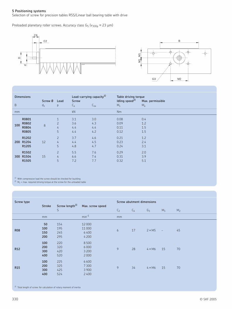
330 © SKF 2005
5 Positioning systems
Selection of screw for precision tables RSS/Linear ball bearing table with drive
C6
D
d
C2 B
M2G3
M1
M1
Preloaded planetary roller screws. Accuracy class G5 (v300p = 23 µm)
Dimensions Load-carrying capacity1) Table driving torque
Screw Ø Lead Screw Idling speed2) Max. permissible
B do p Ca Coa Ms Ma
mm kN Nm
R0801 1 3.1 3.0 0.08 0.4
100R0802
82 3.6 4.3 0.09 1.2
R0804 4 4.4 4.4 0.11 1.5
R0805 5 4.4 4.2 0.12 1.5
R1202 2 3.7 4.6 0.21 1.2
200 R1204 12 4 4.4 4.5 0.23 2.4
R1205 5 4.8 4.7 0.24 3.1
R1502 2 5.5 7.6 0.29 2.0
300 R1504 15 4 6.6 7.4 0.31 3.9
R1505 5 7.2 7.7 0.32 5.1
1) With compressive load the screw should be checked for buckling2) Ms = max. required driving torque at the screw for the unloaded table
Screw type Screw abutment dimensions
Stroke Screw length3) Max. screw speed
S C2 C6 G3 M1 M2
mm min–1 mm
50 154 12 000
R08100 195 11 000
6 17 2 × M5 – 45150 245 6 400
200 295 4 200
100 220 8 500
R12200 320 6 000
9 28 4 × M6 15 70300 420 3 200
400 520 2 000
100 225 6 600
R15200 325 7 300
9 34 4 × M6 15 70300 425 3 900
400 524 2 400
3) Total length of screw: for calculation of rotary moment of inertia

© SKF 2005 331
5
Ordering key
Linear ball bearing table with drive
Type
Design:Open design . . . . . . . . . . . . . . . . . . . . . . . . . . . . . . . . . . . . . . . . . . . . . . . . . . . . . . . . . . . . . . . . . . . . . . . . . . . . . ABClosed design . . . . . . . . . . . . . . . . . . . . . . . . . . . . . . . . . . . . . . . . . . . . . . . . . . . . . . . . . . . . . . . . . . . . . . . . . . . . BB
Slide width B [mm]:See tables
Total length of slide unit L [mm]:See tables
Screw Ø [mm] - screw lead [mm]:Screw Ø 12 - screw lead 05 . . . . . . . . . . . . . . . . . . . . . . . . . . . . . . . . . . . . . . . . . . . . . . . . . . . . . . . . . . . . . . . . . . . . . . . . . . . . . . . . . . . . . 1 2 0 5Screw Ø 16 - screw lead 05 . . . . . . . . . . . . . . . . . . . . . . . . . . . . . . . . . . . . . . . . . . . . . . . . . . . . . . . . . . . . . . . . . . . . . . . . . . . . . . . . . . . . . 1 6 0 5Screw Ø 20 - screw lead 05 . . . . . . . . . . . . . . . . . . . . . . . . . . . . . . . . . . . . . . . . . . . . . . . . . . . . . . . . . . . . . . . . . . . . . . . . . . . . . . . . . . . . . 2 0 0 5Screw Ø 25 - screw lead 05 . . . . . . . . . . . . . . . . . . . . . . . . . . . . . . . . . . . . . . . . . . . . . . . . . . . . . . . . . . . . . . . . . . . . . . . . . . . . . . . . . . . . . 2 5 0 5Screw Ø 25 - screw lead 10 . . . . . . . . . . . . . . . . . . . . . . . . . . . . . . . . . . . . . . . . . . . . . . . . . . . . . . . . . . . . . . . . . . . . . . . . . . . . . . . . . . . . . 2 5 1 0
Example:
—–LZ
—– —–230 ..
—–—1060
—–—K 2505
LZ AB 230 .. 1060 K 2505

332 © SKF 2005
5 Positioning systems
Linear ball bearing table
LZBB (on request)
Linear ball bearing slides with closed
housing and ball screw
Designations Dimensions Nominal Screw data
stroke*
B H L S1 S2 nmax d1 D C1
mm 1/min mm
LZBB 100.336.K1205 100 38 336 120 195 5100 6 38 24
LZBB 100.636.K1205 100 38 636 310 495 3450 6 38 24
LZBB 100.936.K1205 100 38 936 495 795 1600 6 38 24
LZBB 100.1236.K1205 100 38 1236 685 1095 920 6 38 24
LZBB 100.1536.K1205 100 38 1536 875 1395 600 6 38 24
LZBB 130.340.K1605 130 48 340 115 165 3800 10 47 28
LZBB 130.640.K1605 130 48 640 330 465 3800 10 47 28
LZBB 130.940.K1605 130 48 940 545 765 2150 10 47 28
LZBB 130.1240.K1605 130 48 1240 755 1065 1250 10 47 28
LZBB 130.1540.K1605 130 48 1540 970 1365 800 10 47 28
LZBB 130.1840.K1605 130 48 1840 1185 1665 560 10 47 28
LZBB 160.410.K2005 160 58 410 145 195 3050 12 55 36
LZBB 160.650.K2005 160 58 650 325 435 3050 12 55 36
LZBB 160.1010.K2005 160 58 1010 595 795 2450 12 55 36
LZBB 160.1250.K2005 160 58 1250 780 1035 1600 12 55 36
LZBB 160.1610.K2005 160 58 1610 1050 1395 960 12 55 36
LZBB 160.1850.K2005 160 58 1850 1230 1635 730 12 55 36
LZBB 180.350.K2005 180 67 350 80 115 3050 12 55 36
LZBB 180.650.K2005 180 67 650 300 415 3050 12 55 36
LZBB 180.950.K2005 180 67 950 515 715 2800 12 55 36
LZBB 180.1250.K2005 180 67 1250 740 1015 1600 12 55 36
LZBB 180.1550.K2005 180 67 1550 960 1315 1050 12 55 36
LZBB 180.1850.K2005 180 67 1850 1175 1615 730 12 55 36
LZBB 180.2150.K2005 180 67 2150 1400 1915 540 12 55 36
LZBB 180.2450.K2005 180 67 2450 1620 2215 420 12 55 36
LZBB 230.460.K2505 230 84 460 120 165 2450 14 68 36
LZBB 230.660.K2505 230 84 660 275 365 2450 14 68 36
LZBB 230.1060.K2505 230 84 1060 580 765 2450 14 68 36
LZBB 230.1260.K2505 230 84 1260 730 965 2050 14 68 36
LZBB 230.1660.K2505 230 84 1660 1035 1365 1200 14 68 36
LZBB 230.1860.K2505 230 84 1860 1185 1565 940 14 68 36
LZBB 230.2260.K2505 230 84 2260 1490 1965 640 14 68 36
LZBB 230.2460.K2505 230 84 2460 1640 2165 540 14 68 36
LZBB 230.2860.K2505 230 84 2860 1945 2565 400 14 68 36
LZBB 230.460.K2510 230 84 460 120 165 2450 14 68 36
LZBB 230.660.K2510 230 84 660 275 365 2450 14 68 36
LZBB 230.1060.K2510 230 84 1060 580 765 2450 14 68 36
LZBB 230.1260.K2510 230 84 1260 730 965 2050 14 68 36
LZBB 230.1660.K2510 230 84 1660 1035 1365 1200 14 68 36
LZBB 230.1860.K2510 230 84 1860 1185 1565 940 14 68 36
LZBB 230.2260.K2510 230 84 2260 1490 1965 640 14 68 36
LZBB 230.2460.K2510 230 84 2460 1640 2165 540 14 68 36
LZBB 230.2860.K2510 230 84 2860 1945 2565 400 14 68 36
* Maximum stroke between end stops: S1 with bellows (standard version); S2 without bellows (special version)

© SKF 2005 333
5
LZAB (on request )
Linear ball bearing slides with open
housing and ball screw
Designations Dimensions Nominal Screw data
stroke*
B H L S1 S2 nmax d1 D C1
mm 1/min mm
LZAB 100.336.K1205 100 48 336 115 195 5100 6 38 24
LZAB 100.636.K1205 100 48 636 295 495 3450 6 38 24
LZAB 100.936.K1205 100 48 936 475 795 1600 6 38 24
LZAB 100.1236.K1205 100 48 1236 655 1095 920 6 38 24
LZAB 100.1536.K1205 100 48 1536 835 1395 600 6 38 24
LZAB 130.340.K1605 130 57 340 110 165 3800 10 47 28
LZAB 130.640.K1605 130 57 640 320 465 3800 10 47 28
LZAB 130.940.K1605 130 57 940 530 765 2150 10 47 28
LZAB 130.1240.K1605 130 57 1240 740 1065 1250 10 47 28
LZAB 130.1540.K1605 130 57 1540 950 1365 800 10 47 28
LZAB 130.1840.K1605 130 57 1840 1155 1665 560 10 47 28
LZAB 160.410.K2005 160 66 410 140 195 3050 12 55 36
LZAB 160.650.K2005 160 66 650 320 435 3050 12 55 36
LZAB 160.1010.K2005 160 66 1010 585 795 2450 12 55 36
LZAB 160.1250.K2005 160 66 1250 765 1035 1600 12 55 36
LZAB 160.1610.K2005 160 66 1610 1035 1395 960 12 55 36
LZAB 160.1850.K2005 160 66 1850 1210 1635 730 12 55 36
LZAB 180.350.K2005 180 77 350 85 115 3050 12 55 36
LZAB 180.650.K2005 180 77 650 320 415 3050 12 55 36
LZAB 180.950.K2005 180 77 950 550 715 2800 12 55 36
LZAB 180.1250.K2005 180 77 1250 785 1015 1600 12 55 36
LZAB 180.1550.K2005 180 77 1550 1020 1315 1050 12 55 36
LZAB 180.1850.K2005 180 77 1850 1250 1615 730 12 55 36
LZAB 180.2150.K2005 180 77 2150 1485 1915 540 12 55 36
LZAB 180.2450.K2005 180 77 2450 1720 2215 420 12 55 36
LZAB 230.460.K2505 230 95 460 120 165 2450 14 68 36
LZAB 230.660.K2505 230 95 660 275 365 2450 14 68 36
LZAB 230.1060.K2505 230 95 1060 580 765 2450 14 68 36
LZAB 230.1260.K2505 230 95 1260 730 965 2050 14 68 36
LZAB 230.1660.K2505 230 95 1660 1035 1365 1200 14 68 36
LZAB 230.1860.K2505 230 95 1860 1185 1565 940 14 68 36
LZAB 230.2260.K2505 230 95 2260 1490 1965 640 14 68 36
LZAB 230.2460.K2505 230 95 2460 1640 2165 540 14 68 36
LZAB 230.2860.K2505 230 95 2860 1945 2565 400 14 68 36
LZAB 230.460.K2510 230 95 460 120 365 2450 14 68 36
LZAB 230.660.K2510 230 95 660 275 365 2450 14 68 36
LZAB 230.1060.K2510 230 95 1060 580 765 2450 14 68 36
LZAB 230.1260.K2510 230 95 1260 730 965 2050 14 68 36
LZAB 230.1660.K2510 230 95 1660 1035 1365 1200 14 68 36
LZAB 230.1860.K2510 230 95 1860 1185 1565 940 14 68 36
LZAB 230.2260.K2510 230 95 2260 1490 1965 640 14 68 36
LZAB 230.2460.K2510 230 95 2460 1640 2165 540 14 68 36
LZAB 230.2860.K2510 230 95 2860 1945 2565 400 14 68 36
* Maximum stroke between end stops: S1 with bellows (standard version); S2 without bellows (special version)

334 © SKF 2005
5 Positioning systems
Linear axes, type PICO
Ordering key
LTP
Type
Width:. . . . . . . . . . . . . . . . . . . . . . . . . . . . . . . . . . . . . . . . . . . . . . . . . . . . . . . . . . . . . . . . . . . . . . . . . . . . . . . . . . . . . . . . . 60 - 80
Length of axis [mm]:. . . . . . . . . . . . . . . . . . . . . . . . . . . . . . . . . . . . . . . . . . . . . . . . . . . . . . . . . . . . . . . . . . . . . . . . . . . . . . . . . . . . . . . . . . . . . . . . . . . . . .
Screw Ø [mm] - screw lead [mm]:Screw Ø 08 - screw lead 04 (for width = 60) . . . . . . . . . . . . . . . . . . . . . . . . . . . . . . . . . . . . . . . . . . . . . . . . . . . . . . . . . . . . . . . . . . . . 0804Screw Ø 12 - screw lead 05 (for width = 80) . . . . . . . . . . . . . . . . . . . . . . . . . . . . . . . . . . . . . . . . . . . . . . . . . . . . . . . . . . . . . . . . . . . . 1205Screw Ø 12 - screw lead 10 (for width = 80) . . . . . . . . . . . . . . . . . . . . . . . . . . . . . . . . . . . . . . . . . . . . . . . . . . . . . . . . . . . . . . . . . . . . 1210
Flange and couplingFor 2-ph. stepping motor. . . . . . . . . . . . . . . . . . . . . . . . . . . . . . . . . . . . . . . . . . . . . . . . . . . . . . . . . . . . . . . . . . . . . . . . . . . . . . . . . . . . . . . . . . . . 00For Ecostep® motor. . . . . . . . . . . . . . . . . . . . . . . . . . . . . . . . . . . . . . . . . . . . . . . . . . . . . . . . . . . . . . . . . . . . . . . . . . . . . . . . . . . . . . . . . . . . . . . . . 01For AC Servo motor . . . . . . . . . . . . . . . . . . . . . . . . . . . . . . . . . . . . . . . . . . . . . . . . . . . . . . . . . . . . . . . . . . . . . . . . . . . . . . . . . . . . . . . . . . . . . . . . . 02
Example:
—––LTP
—–60
—–230 -..
—–—0804
—–00
LTP 60 230 -.. 0804 00
NB:
3-step files of all standard axes are
available upon request.

© SKF 2005 335
5
Technical informations
Load carrying capacity of axes
Load carrying capacity of drive
Designation Load carrying capacity Static moments1) Moment of inertia
of axes
C Co Mox2) Moy
2) Moz2) Iz Iy
N N Nm Nm Nm mm4 mm4
LTP60 4150 8000 95.6 55.8 55.8 55510 365 900
LTP80 5830 10600 225.0 94.1 108.0 96430 892 300
1) Moments apply to pure moment load (no additional linear load)2) Designation of moments, see Table of dimensions
Designation Screw type Load carrying capacity1) Table drive torque
of drive
Nominal Ø Lead Lead accuracy Dynamic Static Idling Max. permissible
do p V300p Ca Coa Ms Ma
mm mm – µm/300mm N N Nm Nm
LTP60 8 4 G7 50 2000 1000 0.03 0.7
LTP80 12 5 G7 50 3500 1300 0.04 1.1
LTP80 12 10 G7 50 2800 1300 0.04 2.2
1) Value indicated = minimum load rating of either screw or locating bearing

336 © SKF 2005
5 Positioning systems
Linear axes, type PICO
LTP 60
LTP 80
74
5
I
ød
øD
M4×11 (8×)70
80
54
54
L3n × 74L3
74 L1 13
54
80
59A
79
AM
3454
A
59
M
Mox
L3
12
58
42
A
n × 54
MozL1
5
I
L3
72
ød
øD
Moy
59
M4×11 (4×)34
60
ø4.5 / ø8 × 4 depth
ø4.5 / ø8 × 4 depth
76.5
30.5
84.5
37.5

© SKF 2005 337
5
Designation Dimension Stroke1) Mass Screw data
L1 L3 n S do p lred2) amax nmax
mm mm – mm kg mm mm kgmm2 m/s2 1/min
LTP60.130.0804-XX 130 38 1 60 1.3 8 4 2.7 3.2 4500
LTP60.180.0804-XX 180 9 3 110 1.5 8 4 2.8 3.2 4500
LTP60.230.0804-XX 230 34 3 160 1.7 8 4 3.0 3.2 4500
LTP60.280.0804-XX 280 59 3 210 1.9 8 4 3.1 3.2 4500
LTP60.330.0804-XX 330 30 5 260 2.1 8 4 3.3 3.2 4500
LTP80.250.1205-XX 250 14 3 160 3.4 12 5 7.2 4.0 4500
LTP80.350.1205-XX 350 64 3 260 4.1 12 5 8.8 4.0 4500
LTP80.450.1205-XX 450 40 5 360 4.7 12 5 10.4 4.0 4500
LTP80.550.1205-XX 550 16 7 460 5.4 12 5 12.0 4.0 4500
LTP80.650.1205-XX 650 66 7 560 6.1 12 5 13.6 4.0 4500
LTP80.250.1210-XX 250 14 3 160 3.4 12 10 8.5 8.0 4500
LTP80.350.1210-XX 350 64 3 260 4.1 12 10 10.1 8.0 4500
LTP80.450.1210-XX 450 40 5 360 4.7 12 10 11.7 8.0 4500
LTP80.550.1210-XX 550 16 7 460 5.4 12 10 13.3 8.0 4500
LTP80.650.1210-XX 650 66 7 560 6.1 12 10 14.9 8.0 4500
1) Max. stroke between limit switches2) Red. moment of inertia (screw, coupling, slide moving part)
Designation Size Motor flange and coupling
A M D d dmax1) l
mm – mm mm mm mm
LTP60.xxx.xxxx-002) 47,2 M4 38,2 6,35 13 30
LTP60.xxx.xxxx-01 47,2 M4 38.2 8.00 13 30
LTP60.xxx.xxxx-02 44.6 M5 40.0 9.00 13 30
LTP80.xxx.xxxx-002) 47.2 M4 38.2 6.35 13 30
LTP80.xxx.xxxx-01 47.2 M4 38.2 8.00 13 30
LTP80.xxx.xxxx-02 44.6 M5 40.0 9.00 13 30
1) Coupling can be reworked to dmax2) Flange dimensions according to NEMA 23

338 © SKF 2005
5 Positioning systems
Linear axes, type PICO - Drive concepts
Drive concepts
Stepper motor drive
Note: Drive forces are based on nominal
motor torques (SM56.1.18.J3 for LTP60,
SM56.2.18.J3 for LTP80) as well as lead,
idling torque, efficiency and guiding friction
of the screw. There is a risk of step losses
Control unit data
Programmable control unit with
18 motion profiles
Digital current, speed and position control
Operating voltage 24 or 60 VDC
Adjustable motor current
Command value input via CANopen,
RS485 or Profibus interface
3 digital inputs, 3 digital outputs, freely
usable
Configured for motor and limit switches
Attachment on mounting plate
Dimensions 100 × 70 × 60 mm
(H×W×D)
Standard cable length 2 m
Including software
600
500
400
300
200
100
00 50 100 150
v [mm/s]
LTP60.xxx.0804 LTP80.xxx.1205800
600
400
200
00 50 100 150 200
v [mm/s] v [mm/s]
400
300
200
100
00 100 200 300 400
LTP80.xxx.1210
F [N] (60V)F [N] (24V) F [N] (60V)F [N] (24V)F [N] (60V)F [N] (24V)
when exceeding the indicated forces. 60 V
version upon request.
24 / 60 VDC
Limit switches
Motor (+ Brake)
ComputerControl UnitAxis
I / O
CANopen / RS232/ Profibus
Drive force and speed
Type Lenght Height Weight Brake force1) Step size
Motor Brake Motor Brake Fb
mm kg N µm
LTP60.xxx.0804 + 68 + 35 93 0.6 0.3 1000 20
LTP80.xxx.1205 + 94 + 35 94 1.0 0.3 1220 25
LTP80.xxx.1210 + 94 + 35 94 1.0 0.3 610 50
1) LTP60: the brake force is limited by the maximum allowed axial load capacity of the spindle.

© SKF 2005 339
5
Ecostep ® Servo drive
Note: Drive forces are based on nominal
motor torques (23S16 for LTP60, 23S21
for LTP80) as well as lead, idling torque,
efficiency and guiding friction of the screw.
The indicated values represent
the maximum permissible forces.
Control unit data
Programmable control unit with 256
motion profiles
Digital current, speed and position control
Adjustable motor current
Operating voltage from 24 to 70 VDC
Command value input via analog ±10 V,
CANopen or RS232 interface
6 digital inputs, 2 digital outputs, freely
useable
Configured for motor and limit switches
Dimensions 200 × 87 × 50 mm
(H×W×D)
Standard cable length 2 m
Including software
600
500
400
300
200
100
00 50 100 150 200
v [mm/s]
LTP60.xxx.08041200
1000
800
600
400
200
00 50 100 150 200 250
v [mm/s]
F [N] (60V)
LTP80.xxx.1205600
500
400
300
200
100
00 100 200 300 400 500
v [mm/s]
LTP80.xxx.1210
F [N] (24V)F [N] (60V) F [N] (24V) F [N] (60V) F [N] (24V)
24 - 70 VDC
Limit switches
Resolver
Motor (+ Brake)
ComputerControl UnitAxis
I / O
RS232
CANopen
Drive force and speed
Type Lenght Height Weight Brake force1)
Motor Brake Motor Brake Fb
mm kg N
LTP60.xxx.0804 + 73 + 35 93 0.5 0.3 1000
LTP80.xxx.1205 + 88 + 35 94 0.8 0.3 860
LTP80.xxx.1210 + 88 + 35 94 0.8 0.3 430
1) LTP60: the brake force is limited by the maximum allowed axial load capacity of the spindle.

340 © SKF 2005
5 Positioning systems
Linear axes, type PICO - Drive concepts/Profile rail guide slides
AC-Servo drive
Note: Drive forces are based on nominal
motor torques (DBL2 H00040 for LTP60,
DBL2 H00080 for LTP80) as well as lead,
idling torque, efficiency and guiding friction
of the screw. The indicated forces are
related to 100% duty cycle. Short-time
Control unit data
Programmable control unit with
256 motion profiles
Digital current, speed and position control
Adjustable motor current
Operating voltage 230 VAC, auxiliary
voltage 24 VDC
Command value input via ±10 V analog,
CANopen or RS232 interface; Profibus
fieldbus as option
2 digital inputs, 2 digital outputs, freely
usable
Configured for motor and limit switches
Mounting on cap rail
Dimensions 245 × 100 × 225 mm
(H×W×D)
Standard cable length 5 m
Including user-friendly software
overload permissible up to axial load rating
(Coa) of the screw.
500
400
300
200
100
00 100 200 300
v [mm/s]
F [N]
LTP60.xxx.08041000
800
600
400
200
00 100 200 300 400
v [mm/s]
F [N]
LTP80.xxx.1205500
400
300
200
100
00 200 400 600 800
v [mm/s]
F [N] (24V)
LTP80.xxx.1210
230 VAC
Limit switches
Resolver
Motor (+ Brake)
ComputerControl UnitAxis
I / O
24 VDC
RS232
CANopen (/Profibus)
Drive force and speed
Type Lenght Height Weight Brake force1)
Motor Brake Motor Brake Fb
mm kg N
LTP60.xxx.0804 + 73 + 35 93 1.1 0.3 1000
LTP80.xxx.1205 + 88 + 35 94 1.5 0.3 1300
LTP80.xxx.1210 + 88 + 35 94 1.5 0.3 940
1) LTP60 and LTP80.xxx.1205: the brake force is limited by the maximum allowed axial load capacity of the spindle.

© SKF 2005 341
5
Type:
Width of table:Width of bottom part (see dimension specifications) . . . . . . . . . . . . . . . . . . . . . . . . 110 to 400
Length of table:L1 length of bottom part (see dimension specifications). . . . . . . . . . . . . . . . . . . . . . . . . . . . 150 to 2860
Two driving possibilities:No preload . . . . . . . . . . . . . . . . . . . . . . . . . . . . . . . . . . . . . . . . . . . . . . . . . . . . . . . . . . . . . . . SH
Ball screwNo preload . . . . . . . . . . . . . . . . . . . . . . . . . . . . . . . . . . . . . . . . . . . . . . . . . . . . . . . . . . . . . . . SXPreloaded. . . . . . . . . . . . . . . . . . . . . . . . . . . . . . . . . . . . . . . . . . . . . . . . . . . . . . . . . . . . . . . . TNPreloaded . . . . . . . . . . . . . . . . . . . . . . . . . . . . . . . . . . . . . . . . . . . . . . . . . . . . . . . . . . . . . . . . TL
Linear motorMotor type . . . . . . . . . . . . . . . . . . . . . . . . . . . . . . . . . . . . . . . . . . . . . . . . . . . . . . . . . . . . . . . . FMotor type . . . . . . . . . . . . . . . . . . . . . . . . . . . . . . . . . . . . . . . . . . . . . . . . . . . . . . . . . . . . . . . . A
For ball screw Screw diameter . . . . . . . . . . . . . . . . . . . . . . . . . . . . . . . . . . . . . . . . . . . . . . . . . . . . . . . . . . 12 to 40For linear motor Number of motor phases . . . . . . . . . . . . . . . . . . . . . . . . . . . . . . . . . . . . . . . . . . . . . . . . . . . . . . 2 - 3
For ball screw Screw lead . . . . . . . . . . . . . . . . . . . . . . . . . . . . . . . . . . . . . . . . . . . . . . . . . . . . . . . . . . . . . . . . . . 05 to 40For linear motor Primary part length [cm] . . . . . . . . . . . . . . . . . . . . . . . . . . . . . . . . . . . . . . . . . . . . . . . . . . . . . . . . 09 - 40
For ball screw NothingFor linear motor Primary part width [cm] . . . . . . . . . . . . . . . . . . . . . . . . . . . . . . . . . . . . . . . . . . . . . . . . . . . . . . . . . . . . . 06 - 14
Covers:Without cover . . . . . . . . . . . . . . . . . . . . . . . . . . . . . . . . . . . . . . . . . . . . . . . . . . . . . . . . . . . . . . . . . . . . . . . . . . . . . . . . . . . . . . . . . . . . –With bellows . . . . . . . . . . . . . . . . . . . . . . . . . . . . . . . . . . . . . . . . . . . . . . . . . . . . . . . . . . . . . . . . . . . . . . . . . . . . . . . . . . . . . . . . . . . . . . BLWith steel cover. . . . . . . . . . . . . . . . . . . . . . . . . . . . . . . . . . . . . . . . . . . . . . . . . . . . . . . . . . . . . . . . . . . . . . . . . . . . . . . . . . . . . . . . . . . . SC
Precision class:Low precision . . . . . . . . . . . . . . . . . . . . . . . . . . . . . . . . . . . . . . . . . . . . . . . . . . . . . . . . . . . . . . . . . . . . . . . . . . . . . . . . . . . . . . . . . . . . . . . . . . . P10Medium precision . . . . . . . . . . . . . . . . . . . . . . . . . . . . . . . . . . . . . . . . . . . . . . . . . . . . . . . . . . . . . . . . . . . . . . . . . . . . . . . . . . . . . . . . . . . . . . . . . P5High precision . . . . . . . . . . . . . . . . . . . . . . . . . . . . . . . . . . . . . . . . . . . . . . . . . . . . . . . . . . . . . . . . . . . . . . . . . . . . . . . . . . . . . . . . . . . . . . . . . . . . P2Highest precision . . . . . . . . . . . . . . . . . . . . . . . . . . . . . . . . . . . . . . . . . . . . . . . . . . . . . . . . . . . . . . . . . . . . . . . . . . . . . . . . . . . . . . . . . . . . . . . . . P1
Ordering key .
.
—–
235
—–LTB
LTB
.
.
—
TN
—
25
——
05
-
-
—
BL
-
-
–––—
P2Example:
—––
0880
Profile rail guide slides

342 © SKF 2005
5 Positioning systems
Profile rail guide slides
LTB with screw drive
SKF profile rail slides are state-of-the-art
systems that offer high load-carrying
capacity and accuracy.
They are available in five sizes:
110 – 170 – 235 – 320 – 400
L2
L1
BH
L1
B B1
H1
L2
H2
with bellows with steel cover
170
Desig- Dimensions Stroke Screw Pitch
nations 1) 2) 3) 4) 5)
B B1 H H1 H2 L1 L2 S1 S2 Foz Foy Mox Moy Moz Ø p Coa
mm kN kNm mm kN
LTB 110 110 122 40 47 41 150 110 20 30 17.1 8.5 0.69 0.58 0.29 12 5 … 10 3.5 … 7.1
… … …
950 505 830
LTB 170 170 202 60 69 61 220 170 35 40 54 27 3.10 2.5 1.20 16 5 … 16 6.4 … 12.7… … …
1600 1085 1420
LTB 235 235 275 85 97 87 280 235 35 35 97.6 48.8 7.60 6.8 3.40 25 5 … 25 11.2 … 31.0… … …
2860 2195 2615
LTB 320 320 365 115 138 118 580 350 195 220 121.6 60.8 13.40 13.4 6.70 32 5 … 40 20.5 … 55.0… … …
2860 2180 2500
LTB 400 400 – 135 – – 620 450 145 160 216 108 29.20 29.2 14.60 40 5 … 40 35.1 … 64.0… … …
2860 2135 2400
1) Maximum stroke between end stops, with bellows2) Maximum stroke between end stops, with steel cover3) Maximum static load per table in X and Y4) Maximum static moments in X, Y and Z5) Maximum static load per screw
with two drives:
ball screws – linear motors
with three covers:
without cover – with bellows – with steel
cover

© SKF 2005 343
5
LTB with linear motor drive
H2
H1
B B1
L2
L1H
B
L2
L1
with bellows with steel cover
Designations Dimensions Stroke 1) 2) Motor 3)
B B1 H H1 H2 L1 L2 S1 S2 Foz Size Fp
mm kN N
LTB 110 110 123 40 49 43 150 110 20 30 16.9 F20906 105
… … …
950 505 830
230 190 20 30 16.9 F21806 210
… … …
950 455 750
350 280 40 60 25.0 F22706 315
… … …
950 405 660
LTB 170 170 202 60 69 61 280 200 55 70 53.6 F21806 210… … …
1600 1065 1390
340 280 40 50 53.4 F22706 315… … …
1600 1000 1310
LTB 235 235 275 85 97 87 340 235 25 95 95.8 A32008 600… … …
2860 2195 2615
320 45 70 94.9 A33008 900… … …
2860 2125 2530
410 75 100 94.0 A34008 1200… … …
2860 2050 2440
LTB 320 320 365 110 133 113 580 280 260 290 118.0 A32014 1200… … …
2860 2235 2570
580 320 225 250 116.0 A33014 1800… … …
2860 2200 2530
580 410 135 160 114.0 A34014 2400… … …
2860 2125 2440
1) Maximum stroke between end stops: S1 with bellows; S2 without bellows or with steel cover2) Foz is the maximum static load per table3) Fp is static maximum force (2 to 3s)

344 © SKF 2005
5 Positioning systems
Profile rail guide slides, preferred range
LTB
SKF profile rail guide slides LTB of the
preferred range are a price-efficient
alternative to the in-house production. The
LTB preferred range shows 2 widths in 3
lengths each and can be delivered in 2
working weeks. The slides are equipped
with preloaded profile rails and preloaded
ball screw, with bellows covers, end
switches and motor coupling.
156
M6 (4x)
235
46
10
70
85
40
n x 120 L3L3
Ø62
70
Ø41
,3
8
M6 (8x) 205146
Km8M8 (8x)
180
120
205
L1
235
25
20
12
170
15 L1 10
15
6.5
52
146
120
4040
40
146
L3 n x 120 L3
10
M6 (4x)M5 (8x)
60
70170
30
35
M6 (4x)
Ø63
Km6
Ø41
,3
70
LTB235.L1.TN2505-BL-P2/V
LTB170.L1.TN1605-BL-P2/V
11
2
2
1
22
1
2)
1)
2)
1)
Designation Dimension Stroke1) Weight Screw data
L1 L3 S n do p nmax
mm – kg mm 1/min
LTB170.340.TN1605-BL-P2/V 340 50 105 2 7.1 16 5 5620
LTB170.520.TN1605-BL-P2/V 520 20 240 4 9.2 16 5 5620
LTB170.700.TN1605-BL-P2/V 700 50 380 5 11.3 16 5 5620
LTB235.520.TN2505-BL-P2/V 520 20 215 4 20.0 25 5 3600
LTB235.700.TN2505-BL-P2/V 700 50 365 5 24.1 25 5 3600
LTB235.880.TN2505-BL-P2/V 880 20 515 7 28.1 25 5 3600
1) Max. stroke between limit switches

Union means strength.
Bees represent what is probably the most eloquent example of a society
within the natural world. They exhibit a primordial model of social caste with
subdivision of role, as well as full control over defence, labour and even
reproduction.
Small organisational wonders of this kind have provided inspiration to SKF in
the creation of solutions which transcend single components, resulting in
complete units and systems incorporating a wide range of products, to meet
the requirements of each individual customer.
With SKF, even the smallest things become great.
Linear motion from SKFwww.linearmotion.skf.com

346 © SKF 2005
Notes

© SKF 2005 347
5
Notes

348 © SKF 2005
SKF – The knowledge
engineering company
Developing a cleaner cleaner
The electric motor and its bearings are theheart of many household appliances. SKFworks closely with appliance manufacturersto improve their product’s performance,cut costs and reduce weight. A recent
Harnessing wind power
The growing industry of wind-generatedelectric power provides an environmentallycompatible source of electricity. SKF is workingclosely with global industry leaders to developefficient and trouble-free turbines, usingSKF knowledge to provide highly specializedbearings and condition monitoring systemsto extend equipment life in the extreme andoften remote environments of wind farms.
Delivering asset efficiency optimization
To optimize efficiency and boost productivity,many industrial facilities outsource someor all of their maintenance services to SKF,often with guaranteed performance contracts.Through the specialized capabilities andknowledge available from SKF Reliability
Systems, SKF provides a comprehensive rangeof asset efficiency services, from maintenancestrategies and engineering assistance, tooperator-driven reliability and machinemaintenance programs.
The business of the SKF Group consists of
the design, manufacture and marketing
of the world’s leading brand of rolling
bearings, with a global leadership position
in complementary products such as radial
seals. SKF also holds an increasingly
important position in the market for linear
motion products, high precision aerospace
bearings, machine tool spindles, plant
maintenance services and is an established
producer of high-quality bearing steel.
The SKF Group maintains specialized
businesses to meet the needs of the global
marketplace. SKF supports specific market
segments with ongoing research and
development efforts that have led to a
growing number of innovations,
new standards and new products.
SKF Group has global ISO 14001
environmental certification. Individual
divisions have been approved for quality
certification in accordance with either ISO
9000 or appropriate industry specific
standards.
Some 80 manufacturing sites worldwide
and sales companies in 70 countries make
SKF a truly international corporation. In
addition, our 7 000 distributor and dealer
partners around the world,
e-business marketplace and global
distribution system put SKF close
to customers for the supply of both
products and services. In essence, SKF
solutions are available wherever and
whenever our customers need them.
Overall, the SKF brand now stands for
more than ever before. It stands for the
knowledge engineering company ready to
serve you with world-class product
competences, intellectual resources and the
vision to help you succeed.
example produced a new generation ofvacuum cleaners with substantially moresuction. SKF’s knowledge in small bearingtechnology is also applied to manufacturersof power tools and office equipment.

© SKF 2005 349
Creating a new “cold remedy”
In the frigid winters of northern China, sub-zero temperatures can cause rail car wheelassemblies and their bearings to seize dueto lubrication starvation. SKF created a newfamily of synthetic lubricants formulatedto retain their lubrication viscosity even atthese extreme bearing temperatures. SKF’sknowledge of lubricants and friction areunmatched throughout the world.
flight control. SKF is also a leader in automotivedrive-by-wire, having jointly developed therevolutionary Filo and Novanta concept carswhich employ SKF mechatronics for steeringand braking. Further by-wire development hasled SKF to produce an allelectric forklift truckwhich uses mechatronics rather than hydraulicsfor all controls.
Planning for sustainable growth
By their very nature, bearings make a positivecontribution to the natural environment.Reduced friction enables machinery tooperate more efficiently, consume less powerand require less lubrication. SKF is continuallyraising the performance bar, enabling newgenerations of high-efficiency products andequipment. With an eye to the future, SKF’sglobal policies and manufacturing techniquesare planned and implemented to help protectand preserve the earth’s limited natural resources.We remain committed to sustainable,environmentally responsible growth.
Evolving by-wire technology
SKF has unique expertize and knowledgein fast growing by-wire technology, fromfly-by-wire, to drive-by-wire, to work-by-wire.SKF pioneered practical fly-by-wire technologyand is a close working partner with allaerospace industry leaders.As an example, virtually all aircraft of the Airbusdesign use SKF by-wire systems for cockpit
Maintaining a 320 km/h R&D lab
In addition to SKF’s renowned researchand development facilities in Europe and theUnited States, Formula One car racing providesa unique environment for SKF to push thelimits of bearing technology. For over 50 years,SKF products, engineering and knowledge havehelped make
Scuderia Ferrari a formidable force in F1racing. (The average racing Ferrari utilizesmore than 150 SKF components.) Lessonslearned here are applied to the productswe provide to automakers and the aftermarketworldwide.

350 © SKF 2005
Contacts
Linear motion from SKFwww.linearmotion.skf.com
Benelux
SKF Multitec Benelux B.V.
Nederland
Tel +31 (0) 30 6 029 029
Fax +31 (0) 30 6 029 028
België & Luxembourg
Tel +32 (0) 2 5 024 270
Fax +32 (0) 2 5 027 336
E-mail [email protected]
Danmark
SKF Multitec
Tel +45 65 92 77 77
Fax +45 65 92 74 77
E-mail [email protected]
Deutschland
SKF Linearsysteme GmbH
Tel +49 (0) 9721 657 232 / 233
Fax +49 (0) 9721 657 111
E-mail [email protected]
España & Portugal
SKF Productos Industriales S.A.
Tel +34 93 377 99 77 / 07
Fax +34 93 474 20 39
E-mail [email protected]
France
SKF Equipements
Tel +33 (0) 1 30 12 73 00
Fax +33 (0) 1 30 12 69 09
E-mail [email protected]
Italia
SKF Multitec S.p.A.
Tel +39 011 22 49 01
Fax +39 011 22 49 233
E-mail [email protected]
Norge
SKF Multitec
Tel +47 22 90 50 00
Fax +47 22 30 28 14
E-mail [email protected]
Schweiz
SKF Linear Motion
Tel +41 1 825 81 81
Fax +41 1 825 82 82
E-mail [email protected]
Suomi
SKF Multitec
Tel +358 9 615 00 850
Fax +358 9 615 00 851
E-mail [email protected]
Sverige
SKF Multitec
Tel +46 42 25 35 00
Fax +46 42 25 35 45
E-mail [email protected]
U.K.
SKF Engineering Products Ltd.
Tel +44 (0) 1582 496735
Fax +44 (0) 1582 496574
E-mail [email protected]
USA & Canada/South America
SKF Motion Technologies
Tel +1 610 861 4800
Toll free +1 800 541 3624
Fax +1 610 861 4811
E-mail [email protected]
Österreich
Linear Motion
SKF Österreich AG
Tel +43 (0) 2236 6709 0
Fax +43 (0) 2236 6709 220
E-mail [email protected]
Other countries
Actuation systems
Fax +41 61 921 37 04
E-mail [email protected]
Driving systems
Fax +41 61 921 37 04
E-mail [email protected]
Guiding & Positioning systems
Fax +41 61 921 37 04
E-mail [email protected]

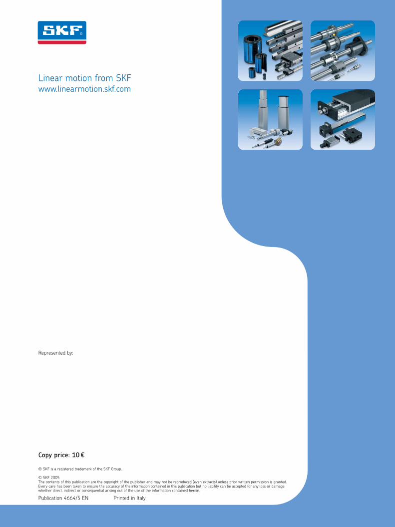
Linear motionstandard range
® SKF is a registered trademark of the SKF Group.
© SKF 2005The contents of this publication are the copyright of the publisher and may not be reproduced (even extracts) unless prior written permission is granted.Every care has been taken to ensure the accuracy of the information contained in this publication but no liability can be accepted for any loss or damagewhether direct, indirect or consequential arising out of the use of the information contained herein.
Publication 4664/5 EN Printed in Italy
Copy price: 10 ¤
Linear motion from SKFwww.linearmotion.skf.com
Represented by:
Lin
ear
motio
n sta
ndard
range