standard test method for determination of ignition delay...
TRANSCRIPT
Designation: D6890 − 16´1
Standard Test Method forDetermination of Ignition Delay and Derived Cetane Number(DCN) of Diesel Fuel Oils by Combustion in a ConstantVolume Chamber1,2
This standard is issued under the fixed designation D6890; the number immediately following the designation indicates the year oforiginal adoption or, in the case of revision, the year of last revision. A number in parentheses indicates the year of last reapproval. Asuperscript epsilon (´) indicates an editorial change since the last revision or reapproval.
ε1 NOTE—Subsection 11.3.2.1 was corrected editorially in March 2017.
1. Scope*
1.1 This automated laboratory test method covers the quan-titative determination of the ignition characteristics of conven-tional diesel fuel oil, oil-sands based fuels, hydrocarbon oils,blends of fuel containing biodiesel material, diesel fuel oilscontaining cetane number improver additives, and is applicableto products typical of ASTM Specification D975 grades No.1-D S15, No. 1-D S500, and No. 1-D S5000, and grades No.2-D S15, No. 2-D S500, and No. 2-D S5000 diesel fuel oils,European standard EN 590, and Canadian standards CAN/CGSB-3.517 and 3.520. The test method may also be appliedto the quantitative determination of the ignition characteristicsof diesel fuel blending components.
1.2 This test method measures the ignition delay of a dieselfuel injected directly into a constant volume combustionchamber containing heated, compressed air. An equation cor-relates an ignition delay determination to cetane number byTest Method D613, resulting in a derived cetane number(DCN).
1.3 This test method covers the ignition delay range from3.1 ms to 6.5 ms (64 DCN to 33 DCN). The combustionanalyzer can measure shorter and longer ignition delays, butprecision may be affected. For these shorter or longer ignitiondelays the correlation equation for DCN is given in AppendixX2. There is no information about how DCNs outside the 33 to64 range compare to Test Method D613 cetane numbers.
1.4 For purposes of determining conformance with theparameters of this test method, an observed value or acalculated value shall be rounded “to the nearest unit” in the
last right-hand digit used in expressing the parameter, inaccordance with the rounding method of Practice E29.
1.5 The values stated in SI units are to be regarded asstandard. No other units of measurement are included in thisstandard.
1.6 This standard does not purport to address all of thesafety concerns, if any, associated with its use. It is theresponsibility of the user of this standard to establish appro-priate safety and health practices and determine the applica-bility of regulatory limitations prior to use.
1.7 This international standard was developed in accor-dance with internationally recognized principles on standard-ization established in the Decision on Principles for theDevelopment of International Standards, Guides and Recom-mendations issued by the World Trade Organization TechnicalBarriers to Trade (TBT) Committee.
2. Referenced Documents
2.1 ASTM Standards:3
D613 Test Method for Cetane Number of Diesel Fuel OilD975 Specification for Diesel Fuel OilsD1193 Specification for Reagent WaterD4057 Practice for Manual Sampling of Petroleum and
Petroleum ProductsD4175 Terminology Relating to Petroleum Products, Liquid
Fuels, and LubricantsD4177 Practice for Automatic Sampling of Petroleum and
Petroleum ProductsD5854 Practice for Mixing and Handling of Liquid Samples
of Petroleum and Petroleum ProductsD6299 Practice for Applying Statistical Quality Assurance
and Control Charting Techniques to Evaluate AnalyticalMeasurement System Performance
D6300 Practice for Determination of Precision and Bias
1 This test method is under the jurisdiction of ASTM Committee D02 onPetroleum Products, Liquid Fuels, and Lubricants and is the direct responsibility ofSubcommittee D02.01 on Combustion Characteristics.
Current edition approved April 1, 2016. Published April 2016. Originallyapproved in 2003. Last previous edition approved in 2015 as D6890 – 15b. DOI:10.1520/D6890-16E01.
2 This test method is based on IP PM CQ/2001, published in the IP StandardMethods for Analysis and Testing of Petroleum and Related Products and BritishStandard 2000 Parts. Copyrighted by Energy Institute, 61 New Cavendish Street,London, W1G 7AR, UK. Adapted with permission of Energy Institute.
3 For referenced ASTM standards, visit the ASTM website, www.astm.org, orcontact ASTM Customer Service at [email protected]. For Annual Book of ASTMStandards volume information, refer to the standard’s Document Summary page onthe ASTM website.
*A Summary of Changes section appears at the end of this standard
Copyright © ASTM International, 100 Barr Harbor Drive, PO Box C700, West Conshohocken, PA 19428-2959. United States
This international standard was developed in accordance with internationally recognized principles on standardization established in the Decision on Principles for theDevelopment of International Standards, Guides and Recommendations issued by the World Trade Organization Technical Barriers to Trade (TBT) Committee.
1

Data for Use in Test Methods for Petroleum Products andLubricants
D6708 Practice for Statistical Assessment and Improvementof Expected Agreement Between Two Test Methods thatPurport to Measure the Same Property of a Material
E29 Practice for Using Significant Digits in Test Data toDetermine Conformance with Specifications
E456 Terminology Relating to Quality and Statistics2.2 ISO Standards:4
ISO 4010 Diesel Engines—Calibrating Nozzle, Delay PintleType
ISO 4259 Petroleum products—Determination and applica-tion of precision data in relation to methods of test
2.3 EN Standard:EN 590 Automotive Fuels—Diesel—Requirements and Test
Methods5
2.4 Energy Institute Standard:IP 41 Ignition Quality of Diesel Fuels—Cetane Engine Test
Method6
2.5 Canadian Standards:7
CAN/CGSB-3.517 Diesel FuelCAN/CGSB 3.520 Diesel Fuel Containing Low Levels of
Biodiesel (B1–B5)
3. Terminology
3.1 Definitions:3.1.1 accepted reference value (ARV), n—value that serves
as an agreed-upon reference for comparison and that is derivedas (1) a theoretical or established value, based on scientificprinciples, (2) an assigned value, based on experimental workof some national or international organization, such as the U.S.National Institute of Standards and Technology (NIST), or (3)a consensus value, based on collaborative experimental workunder the auspices of a scientific or engineering group. E456
3.1.1.1 Discussion—In the context of this test method,accepted reference value is understood to apply to the ignitiondelay of specific reference materials determined under repro-ducibility conditions by collaborative experimental work.
3.1.2 biodiesel, n—fuel comprised of mono-alkyl esters oflong chain fatty acids derived from vegetable oils or animalfats, designated B100.
3.1.3 biodiesel blend (BXX), n—blend of biodiesel fuel withdiesel fuel oils.
3.1.3.1 Discussion—In the abbreviation, BXX, the XX rep-resents the volume percentage of biodiesel fuel in the blend.
3.1.4 cetane number (CN), n—a measure of the ignitionperformance of a diesel fuel oil obtained by comparing it toreference fuels in a standardized engine test. D4175
3.1.4.1 Discussion—In the context of this test method,cetane number is that defined by Test Method D613/IP 41.
3.1.5 check standard, n—in QC testing, material having anaccepted reference value used to determine the accuracy of ameasurement system. D6299
3.1.5.1 Discussion—In the context of this test method,check standard refers to heptane.
3.1.6 hydrocarbon oil, n—a homogeneous mixture withelemental composition primarily of carbon and hydrogen thatmay also contain sulfur, oxygen, or nitrogen from residualimpurities and contaminants associated with the fuel’s rawmaterials and manufacturing processes and excluding addedoxygenated materials.
3.1.6.1 Discussion—Neither macro nor micro emulsions areincluded in this definition since neither are homogeneousmixtures.
3.1.6.2 Discussion—Examples of excluded oxygenated ma-terials are alcohols, esters, ethers, and triglycerides.
3.1.6.3 Discussion—The hydrocarbon oil may be manufac-tured from a variety of raw materials, for example petroleum(crude oil), oil sands, natural gas, coal, and biomass.
3.1.7 quality control (QC) sample, n—for use in qualityassurance programs to determine and monitor the precision andstability of a measurement system, a stable and homogeneousmaterial having physical or chemical properties, or both,similar to those of typical samples tested by the analyticalmeasurement system. The material is properly stored to ensuresample integrity, and is available in sufficient quantity forrepeated, long term testing. D6299
3.2 Definitions of Terms Specific to This Standard:3.2.1 calibration reference material, n—pure chemical hav-
ing an assigned ignition delay accepted reference value.
3.2.2 charge air, n—compressed air at a specified pressureintroduced to the combustion chamber at the beginning of eachtest cycle.
3.2.3 charge air temperature, n—temperature, in °C, of theair inside the combustion chamber.
3.2.4 combustion analyzer, n—integrated compression igni-tion apparatus to measure the ignition characteristics of dieselfuel oil.
3.2.5 derived cetane number (DCN), n—a number calcu-lated using a conversion equation to determine a cetanenumber.
3.2.5.1 Discussion—The conversion equation relates a mea-sured ignition delay or ignition delay and combustion delayfrom a combustion analyzer to a cetane number.
3.2.6 ignition delay (ID), n—that period of time, in milli-seconds (ms), between the start of fuel injection and the start ofcombustion as determined using the specific combustion ana-lyzer applicable for this test method.
3.2.6.1 Discussion—In the context of this test method, startof fuel injection is interpreted as the initial movement or lift ofthe injector nozzle needle as measured by a motion sensor; startof combustion is interpreted as that point in the combustion
4 Available from American National Standards Institute, 25 W. 43rd St., 4th floor,New York, NY 10036.
5 Available from European Committee for Standardization. Central Secretariat:rue de Stassart, 36, B-1050 Brussels, Belgium.
6 Available from Institute of Petroleum, 61 New Cavendish St., London, W1G7AR, U.K.
7 Available from Canadian General Standards Board (CGSB), 11 Laurier St.,Phase III, Place du Portage, Gatineau, Quebec K1A 0S5, Canada, http://www.tpsgc-pwgsc.gc.ca/ongc-cgsb.
D6890 − 16´1
2
Copyright by ASTM Int'l (all rights reserved); Mon Oct 9 20:59:49 EDT 2017Downloaded/printed by
cycle when a significant and sustained increase in rate-of-change in pressure, as measured by a pressure sensor in thecombustion chamber, ensures combustion is in progress.
3.2.7 operating period, n—the time, not to exceed 12 h,between successive calibration or QC testing, or both, of thecombustion analyzer by a single operator.
3.3 Abbreviations:3.3.1 ARV—accepted reference value.
3.3.2 CN—cetane number.
3.3.3 DCN—derived cetane number.
3.3.4 ID—ignition delay.
3.3.5 QC—quality control.
4. Summary of Test Method
4.1 A small specimen of diesel fuel oil is injected into aheated, temperature-controlled constant volume chamber,which has previously been charged with compressed air. Eachinjection produces a single-shot, compression ignition combus-tion cycle. ID is measured using sensors that detect the start offuel injection and the start of significant combustion for eachcycle. A complete sequence comprises 15 preliminary cyclesand 32 further cycles. The ID measurements for the last 32cycles are averaged to produce the ID result. An equationconverts the ID result to DCN (derived cetane number), whichis correlated to cetane number by Test Method D613.
5. Significance and Use
5.1 The ID and DCN values determined by this test methodcan provide a measure of the ignition characteristics of dieselfuel oil in compression ignition engines.
5.2 This test can be used in commerce as a specification aidto relate or match fuels and engines. It can also be useful inresearch or when there is interest in the ignition delay of adiesel fuel under the conditions of this test method.
5.3 The relationship of diesel fuel oil DCN determinationsto the performance of full-scale, variable-speed, variable-loaddiesel engines is not completely understood.
5.4 This test may be applied to non-conventional fuels. It isrecognized that the performance of non-conventional fuels infull-scale engines is not completely understood. The user istherefore cautioned to investigate the suitability of ignitioncharacteristic measurements for predicting performance infull-scale engines for these types of fuels.
5.5 This test determines ignition characteristics and requiresa sample of approximately 100 mL and a test time ofapproximately 20 min on a fit-for-use instrument.
6. Interferences
6.1 Minimize exposure of sample fuels, calibration refer-ence materials, QC samples, and check standard to sunlight orfluorescent lamp UV emissions to minimize induced chemicalreactions that can affect ignition delay measurements.8
6.1.1 Exposure of these fuels and materials to UV wave-lengths shorter than 550 nanometers for a short period of timemay significantly affect ignition delay measurements.
NOTE 1—The formation of peroxide and radicals can effect ignitiondelay measurement. These formations are minimized when the sample ormaterial is stored in the dark in a cold room at a temperature of less than10°C, and covered by a blanket of nitrogen.
6.2 Statistical analysis of data from a sequential testingstudy (Note 2) revealed a possible carryover effect in succeed-ing tests on samples containing 2–ethylhexylnitrate cetaneimprover at concentrations above 2000 ppm.
NOTE 2—In the sequential testing study, a fuel without cetane improverwas tested three times back-to-back. Then a fuel with 2–ethylhexylnitratecetane improver at concentrations above 2000 ppm was tested.Subsequently, the same fuel without cetane improver was tested threetimes. Statistical analyses of repeat data on two units were examined forevidence of hysteresis.
7. Apparatus
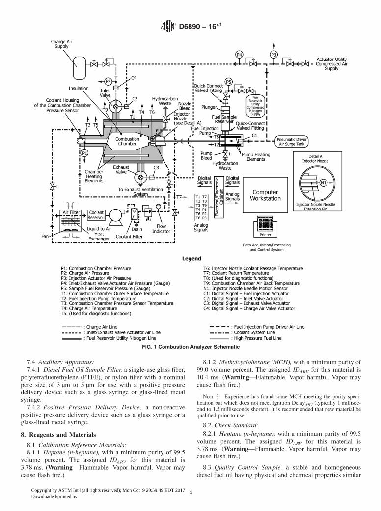
7.1 General—This test method uses an integrated automatedanalytical measurement system9 comprised of: (1) a constantvolume compression ignition combustion chamber with exter-nal electrical heating elements, suitable insulation and pneu-matically actuated intake and exhaust valves, (2) a heated,pneumatically actuated fuel injection system10 with pump,injector nozzle assembly, and associated sample reservoir, (3)a coolant system with a liquid-to-air heat exchanger, filter,circulating pump and flow control valves, (4) temperaturethermocouples, pressure gages and sensors, an injector nozzleneedle motion sensor, compressed gas pressure regulators,control valves, pneumatic actuator components, and solenoidvalves, and (5) a computer to control test sequencing, acquireand accumulate sensor signal data, provide processingcalculations, and automatically output a printed report of someimportant test parameters (see Fig. 1).
7.2 See Annex A2, Combustion Analyzer Equipment De-scription and Specifications, for detailed information.
7.3 Compressed Gas Pressure Regulators:7.3.1 Charge Air Regulator, a two-stage regulator capable of
controlling the downstream pressure to a minimum pressure of2.2 MPa.
7.3.2 Actuator Utility Compressed Air Regulator, a two-stage regulator capable of controlling the downstream pressureto a minimum pressure of 1.3 MPa.
7.3.3 Fuel Reservoir Utility Compressed NitrogenRegulator, a single or two-stage regulator capable of control-ling the downstream pressure to a minimum pressure of350. kPa.
8 Supporting data have been filed at ASTM International Headquarters and maybe obtained by requesting Research Report RR:D02-1502.
9 The sole source of supply of the combustion analyzer known to the committeeat this time is Advanced Engine Technology Ltd. (AET), 17 Fitzgerald Road, Suite102, Ottawa, Canada, K2H 9G1. If you are aware of alternative suppliers, pleaseprovide this information to ASTM International Headquarters. Your comments willreceive careful consideration at a meeting of the responsible technical committee,1
which you may attend.10 The fuel injection system is covered by a patent. Interested parties are invited
to submit information regarding the identification of an alternative(s) to thispatented item to the ASTM International Headquarters. Your comments will receivecareful consideration at a meeting of the responsible technical committee,1 whichyou may attend.
D6890 − 16´1
3
Copyright by ASTM Int'l (all rights reserved); Mon Oct 9 20:59:49 EDT 2017Downloaded/printed by
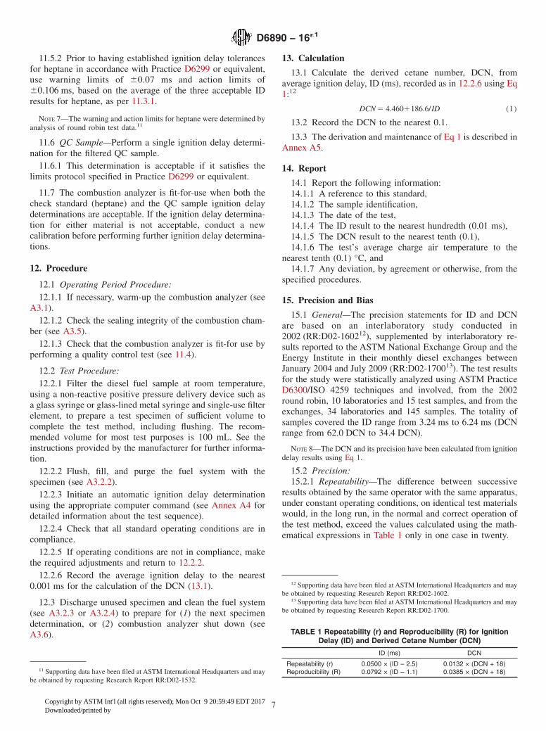
7.4 Auxiliary Apparatus:7.4.1 Diesel Fuel Oil Sample Filter, a single-use glass fiber,
polytetrafluorethylene (PTFE), or nylon filter with a nominalpore size of 3 µm to 5 µm for use with a positive pressuredelivery device such as a glass syringe or glass-lined metalsyringe.
7.4.2 Positive Pressure Delivery Device, a non-reactivepositive pressure delivery device such as a glass syringe or aglass-lined metal syringe.
8. Reagents and Materials
8.1 Calibration Reference Materials:8.1.1 Heptane (n-heptane), with a minimum purity of 99.5
volume percent. The assigned IDARV for this material is3.78 ms. (Warning—Flammable. Vapor harmful. Vapor maycause flash fire.)
8.1.2 Methylcyclohexane (MCH), with a minimum purity of99.0 volume percent. The assigned IDARV for this material is10.4 ms. (Warning—Flammable. Vapor harmful. Vapor maycause flash fire.)
NOTE 3—Experience has found some MCH meeting the purity speci-fication but which does not meet Ignition DelayARV (typically 1 millisec-ond to 1.5 milliseconds shorter). It is recommended that new material bequalified prior to use.
8.2 Check Standard:8.2.1 Heptane (n-heptane), with a minimum purity of 99.5
volume percent. The assigned IDARV for this material is3.78 ms. (Warning—Flammable. Vapor harmful. Vapor maycause flash fire.)
8.3 Quality Control Sample, a stable and homogeneousdiesel fuel oil having physical and chemical properties similar
FIG. 1 Combustion Analyzer Schematic
D6890 − 16´1
4
Copyright by ASTM Int'l (all rights reserved); Mon Oct 9 20:59:49 EDT 2017Downloaded/printed by

to those of typical sample fuels routinely tested. (Warning—Combustible. Vapor harmful.)
8.4 Charge Air, compressed air containing 19.9 volumepercent to 21.9 volume percent oxygen, less than 0.003 volumepercent hydrocarbons, and less than 0.025 volume percentwater. For charge air cylinders supplied with a blend of oxygenand nitrogen, it is required that a quality control test beperformed after an air cylinder has been changed. (Warning—Compressed gas under high pressure that supports combus-tion.)
8.5 Coolant System Fluid, a 50:50 volume mixture of waterand commercial ethylene glycol-based antifreeze. (Warning—Poison. May be harmful or fatal if inhaled or swallowed.)
8.5.1 Antifreeze, commercial automotive cooling systemethylene glycol-based solution.
8.5.2 Water, distilled or reagent-grade, conforming to Speci-fication D1193, Type IV.
8.6 Actuator Utility Compressed Air, oil free compressed airhaving less than 0.1 volume percent water supplied at aminimum sustained pressure of 1.5 MPa. (Warning—Compressed gas under high pressure that supports combus-tion.)
8.7 Fuel Reservoir Utility Compressed Nitrogen, com-pressed nitrogen having a minimum purity of 99.9 volumepercent. (Warning—Compressed gas under high pressure.)
9. Sampling and Test Specimen Preparation
9.1 Sampling:9.1.1 Collect diesel fuel oil samples in accordance with
Practices D4057 or D4177.9.1.1.1 Collect and store diesel fuel samples in a suitable
container such as a dark brown bottle, a metal can, or aminimally reactive plastic container to minimize exposure toUV emissions.
9.1.2 Refer to Practice D5854 for appropriate informationrelating to the mixing and handling of diesel fuel oil samples.
9.2 Test Specimen Preparation:9.2.1 Sample Fuel Temperature—Condition the diesel fuel
sample before opening the storage container, so that it is atroom temperature, typically 18 °C to 32 °C.
9.2.2 Filtration—Prepare a test specimen by filtering dieselfuel oil of sufficient volume to complete the test method,including flushing, through a nominal 3 µm to 5 µm porosityfilter element using a positive pressure delivery device such asa glass syringe or a glass-lined metal syringe.
9.2.2.1 Collect the specimen in a dark brown bottle, metalcan or minimally reactive plastic container.
10. Basic Apparatus Settings and Standard OperatingConditions
10.1 Installation of the apparatus requires placement on alevel floor and connection of all utilities. Engineering andtechnical support for this function is required, and the usershall be responsible to comply with all local and national codesand installation requirements.
10.2 Operation of the combustion analyzer, associatedequipment, instrumentation and computer system requires
setting a series of testing variables to prescribed specifications.Some of these settings are established by componentspecifications, others are operating conditions that aremonitored/controlled by the computer software or by operatoradjustment.
10.3 Settings Based on Component Specifications:10.3.1 Injector Nozzle Opening Pressure—Each time the
nozzle assembly is reassembled or replaced, or both, set thepressure-adjusting nut to release fuel in conformance with therequirements in the manufacturer’s equipment manual, usingan injector nozzle tester. For additional details, refer to theinstruction manual of the manufacturer.
10.3.2 Injector Nozzle Motion Sensor Position—Manuallyposition the motion sensor while visually observing the nozzleneedle movement signal on the computer monitor (see Fig.A4.1). The criteria for optimized setting are as follows:
10.3.2.1 The signal prior to the steep increase in needle liftis required to indicate some signal noise. If the signal trace isflat and constant, the motion sensor is too far away from thenozzle needle extension pin.
10.3.2.2 The peak of the steep increase in signal level isrequired to be visible on the computer monitor screen. If thesignal peak is flat, the motion sensor is too close to the nozzleneedle extension pin. For additional details, refer to theinstruction manual of the manufacturer.
10.3.3 Injector Nozzle Coolant Passage ThermocouplePosition—Proper positioning of the thermocouple in the injec-tor nozzle coolant passage is set by installing a compressionfitting nut and associated plastic ferrule on the stainless steelsheath of the thermocouple, using a specialized depth settingtool to establish the correct depth of penetration. Adjust thedepth of penetration (in accordance with the instruction manualof the manufacturer) by repositioning the plastic ferrule on thestainless steel sheath of the thermocouple and tightening thenut to a snug level of tightness. For additional details, refer tothe instruction manual of the manufacturer.
10.3.4 Charge Air Thermocouple Position—Proper posi-tioning of the thermocouple in the combustion chamber is setby installing a compression fitting nut and associated ferrule onthe stainless steel sheath of the thermocouple, crimping theferrule on the sheath using a specialized depth setting tool toestablish the correct depth of penetration. For additionaldetails, refer to the instruction manual of the manufacturer.
10.3.5 Rate of Decrease of Combustion Chamber Pressure,less than 3.5 kPa/s, as measured during the check of the sealingintegrity of the combustion chamber (see A3.5).
10.4 Standard Operating Conditions:10.4.1 Charge Air Pressure (P2), 2.130 MPa to 2.144 MPa.10.4.2 Charge Air Temperature (T4), 515 °C to 575 °C.10.4.2.1 The difference in temperature (T4max − T4min) as
determined and recorded by the computer, shall be less than2.5 °C during a 32 combustion cycle measurement determina-tion.
10.4.3 Combustion Chamber Outer Surface Temperature(T1)—Initially set by the manufacturer, the surface temperatureis monitored and controlled by the computer. Operator adjust-ment of the controller set-point is required, in accordance withthe calibration procedure.
D6890 − 16´1
5
Copyright by ASTM Int'l (all rights reserved); Mon Oct 9 20:59:49 EDT 2017Downloaded/printed by

10.4.4 Combustion Chamber Pressure Sensor Temperature(T3), 110. °C to 150. °C.
10.4.4.1 The difference in temperature (T3max − T3min) asdetermined and recorded by the computer, shall be less than8.0 °C during a 32 combustion cycle measurement determina-tion.
10.4.5 Coolant Return Temperature (T7), 30. °C to 50. °C.10.4.6 Fuel Sample Reservoir Pressure (P5), 310. kPa to
380. kPa. Visually check the gage reading, as this parameter isnot recorded by the data acquisition system.
10.4.7 Fuel Injection Pump Temperature (T2), 32 °C to38 °C.
10.4.8 Injector Nozzle Coolant Passage Temperature (T6)—The maximum (T6max) and minimum (T6min) temperatures asdetermined and recorded by the computer, shall be within46.0 °C 6 54.0 °C during a 32 combustion cycle measurementdetermination.
10.4.9 Injection Actuator Air Pressure (P3), 1.18 MPa to1.24 MPa.
10.4.10 Inlet/Exhaust Valve Actuator Air Pressure (P4),445 kPa to 515 kPa. Visually check the gage reading, as thisparameter is not recorded by the data acquisition system.
11. Calibration and Quality Control Testing
11.1 Calibration—Calibrate the combustion analyzer foronly the following reasons: (1) after it is installed andcommissioned, (2) after replacement of critical parts or com-ponents of combustion chamber assembly (see A2.2), fuelinjection system (see A2.3) or instrument sensors (see A2.4),(3) after calibration of the data acquisition board, injectionactuator air pressure sensor or charge air pressure sensor, (4)whenever check standard or QC sample determinations are notin statistical control as determined by Practice D6299 orequivalent and the assignable causes for QC non-compliancehave been suitably addressed.
11.2 Precalibration Procedures:11.2.1 Clean the combustion chamber pressure sensor as-
sembly (see A3.3 and A3.4).11.2.2 If necessary, start and warm-up the combustion
analyzer (see A3.1).
11.3 Calibration Procedure—Two filtered calibration refer-ence materials are tested: (1 ) heptane to affirm that thecombustion chamber charge air temperature setting producesignition delay measurements for this material that are withinspecification limits and, (2) methylcyclohexane to affirm thatthe measurement sensitivity of the combustion analyzer pro-duces ignition delay measurements for this material that arewithin specification limits.
11.3.1 Heptane Calibration Reference Material—Performthree consecutive ignition delay determinations.
11.3.1.1 The average of three acceptable ID results isrequired to be within 3.77 ms to 3.79 ms.
11.3.1.2 If the average ID is outside the limits, the combus-tion chamber outer surface temperature controller set-pointrequires adjustment to cause a change in the combustionchamber charge air temperature.
NOTE 4—ID increases when the combustion chamber outer surfacetemperature decreases and vice versa.
11.3.1.3 If the temperature controller set-point adjustmentfrom the previous setting, exceeds 64 °C, a system malfunc-tion is suspected and diagnostic procedures to determine andremedy the problem are recommended. Refer to the instruc-tions provided by the manufacturer.
NOTE 5—After a change of charge air cylinders that employ a blend ofoxygen and nitrogen, a temperature controller set-point adjustment be-yond 4 °C can accommodate the extreme limits of the 19.9 volumepercent to 21.9 volume percent oxygen in the blend.
11.3.1.4 After a temperature controller set-point adjustment,wait at least 10. min before initiating a new calibration so thatthe combustion analyzer attains thermal equilibrium.
11.3.1.5 To be an acceptable data set, each single result isrequired to be within 3.72 ms to 3.84 ms.
11.3.1.6 If any of the three results is outside the limits, asystem malfunction is suspected and diagnostic procedures todetermine and remedy the problem are recommended beforeperforming a new calibration. Refer to the instructions pro-vided by the manufacturer.
11.3.2 Methylcyclohexane Calibration ReferenceMaterial—Perform two consecutive ignition delay determina-tions.
11.3.2.1 To be an acceptable data set, each single result isrequired to be within 9.8 ms to 11.0 ms and the average of thetwo results is required to be within 9.9 ms to 10.9 ms.
11.3.2.2 If either of the two single results or the average ofthe two results is outside the respective limits, system perfor-mance is unacceptable and it is recommended that diagnosticprocedures be used to determine and remedy the problembefore performing a new calibration. Refer to the instructionsprovided by the manufacturer.
11.3.3 The combustion analyzer calibration is completewhen both heptane and methylcyclohexane data sets areacceptable.
11.4 Quality Control (QC Testing)—Conduct a regular sta-tistical quality assurance (quality control) program in accor-dance with the techniques of Practice D6299 or equivalent.
11.4.1 This test method requires quality control testing atthe beginning of each operating period by a single ignitiondelay determination for both the check standard (heptane) andone QC sample.
11.4.2 The QC sample is a typical diesel fuel oil having anignition delay that represents the primary range of use for thecombustion analyzer.
11.4.2.1 If the combustion analyzer is used for testing fuelshaving a very wide range of ignition delay, it may be useful tohave a second QC sample of a different ignition delay.
11.4.3 For locations using blends of oxygen and nitrogen asthe source for charge air, conduct a QC test whenever there isa change from one cylinder to another.
NOTE 6—The oxygen content of the new oxygen and nitrogen blendmay differ from that of the previous source and can have a significanteffect on ID measurements.
11.5 Check Standard—Perform a single ignition delay de-termination for filtered heptane.
11.5.1 This determination is acceptable if it satisfies thelimits protocol specified in Practice D6299 or equivalent.
D6890 − 16´1
6
Copyright by ASTM Int'l (all rights reserved); Mon Oct 9 20:59:49 EDT 2017Downloaded/printed by
11.5.2 Prior to having established ignition delay tolerancesfor heptane in accordance with Practice D6299 or equivalent,use warning limits of 60.07 ms and action limits of60.106 ms, based on the average of the three acceptable IDresults for heptane, as per 11.3.1.
NOTE 7—The warning and action limits for heptane were determined byanalysis of round robin test data.11
11.6 QC Sample—Perform a single ignition delay determi-nation for the filtered QC sample.
11.6.1 This determination is acceptable if it satisfies thelimits protocol specified in Practice D6299 or equivalent.
11.7 The combustion analyzer is fit-for-use when both thecheck standard (heptane) and the QC sample ignition delaydeterminations are acceptable. If the ignition delay determina-tion for either material is not acceptable, conduct a newcalibration before performing further ignition delay determina-tions.
12. Procedure
12.1 Operating Period Procedure:12.1.1 If necessary, warm-up the combustion analyzer (see
A3.1).12.1.2 Check the sealing integrity of the combustion cham-
ber (see A3.5).12.1.3 Check that the combustion analyzer is fit-for use by
performing a quality control test (see 11.4).
12.2 Test Procedure:12.2.1 Filter the diesel fuel sample at room temperature,
using a non-reactive positive pressure delivery device such asa glass syringe or glass-lined metal syringe and single-use filterelement, to prepare a test specimen of sufficient volume tocomplete the test method, including flushing. The recom-mended volume for most test purposes is 100 mL. See theinstructions provided by the manufacturer for further informa-tion.
12.2.2 Flush, fill, and purge the fuel system with thespecimen (see A3.2.2).
12.2.3 Initiate an automatic ignition delay determinationusing the appropriate computer command (see Annex A4 fordetailed information about the test sequence).
12.2.4 Check that all standard operating conditions are incompliance.
12.2.5 If operating conditions are not in compliance, makethe required adjustments and return to 12.2.2.
12.2.6 Record the average ignition delay to the nearest0.001 ms for the calculation of the DCN (13.1).
12.3 Discharge unused specimen and clean the fuel system(see A3.2.3 or A3.2.4) to prepare for (1) the next specimendetermination, or (2) combustion analyzer shut down (seeA3.6).
13. Calculation
13.1 Calculate the derived cetane number, DCN, fromaverage ignition delay, ID (ms), recorded as in 12.2.6 using Eq1:12
DCN 5 4.4601186.6/ID (1)
13.2 Record the DCN to the nearest 0.1.
13.3 The derivation and maintenance of Eq 1 is described inAnnex A5.
14. Report
14.1 Report the following information:14.1.1 A reference to this standard,14.1.2 The sample identification,14.1.3 The date of the test,14.1.4 The ID result to the nearest hundredth (0.01 ms),14.1.5 The DCN result to the nearest tenth (0.1),14.1.6 The test’s average charge air temperature to the
nearest tenth (0.1) °C, and14.1.7 Any deviation, by agreement or otherwise, from the
specified procedures.
15. Precision and Bias
15.1 General—The precision statements for ID and DCNare based on an interlaboratory study conducted in2002 (RR:D02-160212), supplemented by interlaboratory re-sults reported to the ASTM National Exchange Group and theEnergy Institute in their monthly diesel exchanges betweenJanuary 2004 and July 2009 (RR:D02-170013). The test resultsfor the study were statistically analyzed using ASTM PracticeD6300/ISO 4259 techniques and involved, from the 2002round robin, 10 laboratories and 15 test samples, and from theexchanges, 34 laboratories and 145 samples. The totality ofsamples covered the ID range from 3.24 ms to 6.24 ms (DCNrange from 62.0 DCN to 34.4 DCN).
NOTE 8—The DCN and its precision have been calculated from ignitiondelay results using Eq 1.
15.2 Precision:15.2.1 Repeatability—The difference between successive
results obtained by the same operator with the same apparatus,under constant operating conditions, on identical test materialswould, in the long run, in the normal and correct operation ofthe test method, exceed the values calculated using the math-ematical expressions in Table 1 only in one case in twenty.
11 Supporting data have been filed at ASTM International Headquarters and maybe obtained by requesting Research Report RR:D02-1532.
12 Supporting data have been filed at ASTM International Headquarters and maybe obtained by requesting Research Report RR:D02-1602.
13 Supporting data have been filed at ASTM International Headquarters and maybe obtained by requesting Research Report RR:D02-1700.
TABLE 1 Repeatability (r) and Reproducibility (R) for IgnitionDelay (ID) and Derived Cetane Number (DCN)
ID (ms) DCN
Repeatability (r) 0.0500 × (ID – 2.5) 0.0132 × (DCN + 18)Reproducibility (R) 0.0792 × (ID – 1.1) 0.0385 × (DCN + 18)
D6890 − 16´1
7
Copyright by ASTM Int'l (all rights reserved); Mon Oct 9 20:59:49 EDT 2017Downloaded/printed by
15.2.2 Reproducibility—The difference between two singleand independent results, obtained by different operators work-ing in different laboratories on identical test materials, would,in the long run, and in the normal and the correct operation ofthe test method, exceed the values calculated using the math-ematical expressions in Table 1 only in one case in twenty.
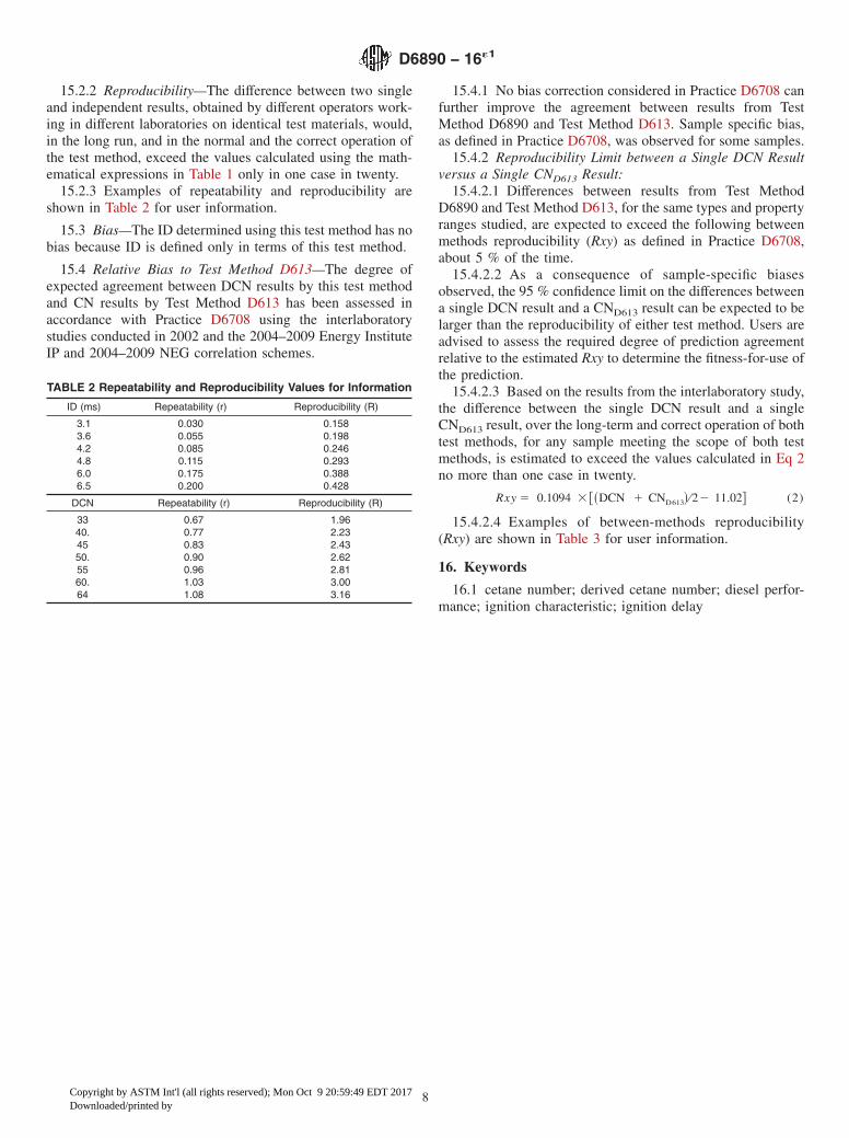
15.2.3 Examples of repeatability and reproducibility areshown in Table 2 for user information.
15.3 Bias—The ID determined using this test method has nobias because ID is defined only in terms of this test method.
15.4 Relative Bias to Test Method D613—The degree ofexpected agreement between DCN results by this test methodand CN results by Test Method D613 has been assessed inaccordance with Practice D6708 using the interlaboratorystudies conducted in 2002 and the 2004–2009 Energy InstituteIP and 2004–2009 NEG correlation schemes.
15.4.1 No bias correction considered in Practice D6708 canfurther improve the agreement between results from TestMethod D6890 and Test Method D613. Sample specific bias,as defined in Practice D6708, was observed for some samples.
15.4.2 Reproducibility Limit between a Single DCN Resultversus a Single CND613 Result:
15.4.2.1 Differences between results from Test MethodD6890 and Test Method D613, for the same types and propertyranges studied, are expected to exceed the following betweenmethods reproducibility (Rxy) as defined in Practice D6708,about 5 % of the time.
15.4.2.2 As a consequence of sample-specific biasesobserved, the 95 % confidence limit on the differences betweena single DCN result and a CND613 result can be expected to belarger than the reproducibility of either test method. Users areadvised to assess the required degree of prediction agreementrelative to the estimated Rxy to determine the fitness-for-use ofthe prediction.
15.4.2.3 Based on the results from the interlaboratory study,the difference between the single DCN result and a singleCND613 result, over the long-term and correct operation of bothtest methods, for any sample meeting the scope of both testmethods, is estimated to exceed the values calculated in Eq 2no more than one case in twenty.
Rxy 5 0.1094 3 @~DCN 1 CND613! ⁄22 11.02# (2)
15.4.2.4 Examples of between-methods reproducibility(Rxy) are shown in Table 3 for user information.
16. Keywords
16.1 cetane number; derived cetane number; diesel perfor-mance; ignition characteristic; ignition delay
TABLE 2 Repeatability and Reproducibility Values for Information
ID (ms) Repeatability (r) Reproducibility (R)
3.1 0.030 0.1583.6 0.055 0.1984.2 0.085 0.2464.8 0.115 0.2936.0 0.175 0.3886.5 0.200 0.428
DCN Repeatability (r) Reproducibility (R)
33 0.67 1.9640. 0.77 2.2345 0.83 2.4350. 0.90 2.6255 0.96 2.8160. 1.03 3.0064 1.08 3.16
D6890 − 16´1
8
Copyright by ASTM Int'l (all rights reserved); Mon Oct 9 20:59:49 EDT 2017Downloaded/printed by

ANNEXES
(Mandatory Information)
A1. HAZARDS INFORMATION
A1.1 Introduction
A1.1.1 In the performance of the standard test method thereare hazards to personnel. These are indicated in the text. Formore detailed information regarding the hazards, refer to theappropriate Material Safety Data Sheet (MSDS) for each of theapplicable substances to establish risks, proper handling, andsafety precautions.
A1.2 (Warning—Combustible. Vapor harmful.)
A1.2.1 Applicable Substances:A1.2.1.1 Diesel fuel oil, andA1.2.1.2 Quality control sample.
A1.3 (Warning—Flammable. Vapors harmful if inhaled.Vapors may cause flash fire.)
A1.3.1 Applicable Substances:A1.3.1.1 Heptane, andA1.3.1.2 Methylcyclohexane.
A1.4 (Warning—Poison. May be harmful or fatal if inhaledor swallowed.)
A1.4.1 Applicable Substances:A1.4.1.1 Ethylene glycol based antifreeze.
A1.5 (Warning—Compressed gas under high pressure thatsupports combustion.)
A1.5.1 Applicable Substances:A1.5.1.1 Compressed air.
A1.6 (Warning—Compressed gas under high pressure.)
A1.6.1 Applicable Substances:A1.6.1.1 Compressed nitrogen.
A1.7 (Warning—Hot surfaces.)
A1.7.1 Applicable Substances:A1.7.1.1 Protective cage enclosing the combustion
chamber,A1.7.1.2 Exposed areas of the combustion chamber around
the injector nozzle, andA1.7.1.3 Exposed areas of the combustion chamber near the
combustion chamber inside the combustion chamber protectivecage.
A2. COMBUSTION ANALYZER EQUIPMENT DESCRIPTION AND SPECIFICATIONS
A2.1 The combustion chamber assembly and fuel injectionsystem are critical to the proper operation of this test method.
A2.2 Combustion Chamber Assembly—The principle com-ponent of this assembly, illustrated in Fig. A2.1, is a corrosion-protected metal cylindrical block that is precision machinedand fabricated to include the following features:
A2.2.1 A cavity along a central axis of the body, having avolume of 0.211 L to 0.215 L, that constitutes the compressionignition combustion chamber.
A2.2.2 An opening at one end of the chamber to accommo-date insertion of the fuel injection nozzle assembly and which
includes a passage for circulation of liquid coolant to controlthe injector nozzle temperature.
A2.2.3 An opening at the other end of the chamber, toaccommodate insertion of a pressure sensor liquid-cooledhousing.
A2.2.4 Two drilled ports or passages between the combus-tion chamber cavity and the external surface of the assembly toaccommodate an inlet and an exhaust valve.
A2.2.5 Nine passages, drilled from the pressure sensor endof the block, parallel to the chamber axis, to accept individualelectric heating elements.
TABLE 3 Between Test Methods Reproducibility (Rxy)
= (DCN + CND613)/2 Reproducibility
33.0 2.4040.0 3.1745.0 3.7250.0 4.2655.0 4.8160.0 5.3664.0 5.80
D6890 − 16´1
9
Copyright by ASTM Int'l (all rights reserved); Mon Oct 9 20:59:49 EDT 2017Downloaded/printed by
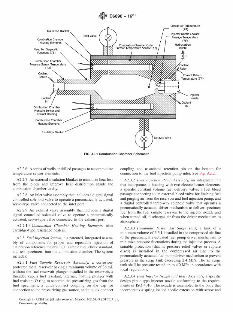
A2.2.6 A series of wells or drilled passages to accommodatetemperature sensor elements.
A2.2.7 An external insulation blanket to minimize heat lossfrom the block and improve heat distribution inside thecombustion chamber cavity.
A2.2.8 An inlet valve assembly that includes a digital signalcontrolled solenoid valve to operate a pneumatically actuated,servo-type valve connected to the inlet port.
A2.2.9 An exhaust valve assembly that includes a digitalsignal controlled solenoid valve to operate a pneumaticallyactuated, servo-type valve connected to the exhaust port.
A2.2.10 Combustion Chamber Heating Elements, ninecartridge-type resistance heaters.
A2.3 Fuel Injection System,10 a patented, integrated assem-bly of components for proper and repeatable injection ofcalibration reference material, QC sample fuel, check standard,and test specimens into the combustion chamber. The systemincludes:
A2.3.1 Fuel Sample Reservoir Assembly, a corrosion-protected metal reservoir having a minimum volume of 36 mLwithout the fuel reservoir plunger installed in the reservoir, athreaded cap, a fuel resistant, internal, floating plunger withfuel-resistant O-ring to separate the pressurizing gas from thefuel specimens, a quick-connect coupling on the cap forconnection to the pressurizing gas source, and a quick-connect
coupling and associated retention pin on the bottom forconnection to the fuel injection pump inlet. See Fig. A2.2.
A2.3.2 Fuel Injection Pump Assembly, an integrated unitthat incorporates a housing with two electric heater elements;a specific constant volume fuel delivery valve; a fuel bleedpassage connecting to an external bleed valve for flushing fueland purging air from the reservoir and fuel injection pump; anda digital controlled three-way solenoid valve that operates apneumatically-actuated driver mechanism to deliver specimenfuel from the fuel sample reservoir to the injector nozzle andwhen turned off, discharges air from the driver mechanism toatmosphere.
A2.3.3 Pneumatic Driver Air Surge Tank, a tank of aminimum volume of 5.5 L installed in the compressed air lineto the pneumatically-actuated fuel pump driver mechanism tominimize pressure fluctuations during the injection process. Asuitable protection (that is, pressure relief valves or rupturediscs) is installed in the compressed air line to thepneumatically-actuated fuel pump driver mechanism to preventpressure in the surge tank exceeding 2.4 MPa. The air surgetank shall be pressure tested up to 4.0 MPa in accordance withlocal regulations.
A2.3.4 Fuel Injector Nozzle and Body Assembly, a specificdesign pintle-type injector nozzle conforming to the require-ments of ISO 4010. The nozzle is assembled to the body thatincorporates a spring-loaded needle extension with screw and
FIG. A2.1 Combustion Chamber Schematic
D6890 − 16´1
10
Copyright by ASTM Int'l (all rights reserved); Mon Oct 9 20:59:49 EDT 2017Downloaded/printed by

lock nut for adjusting the nozzle opening pressure/releasesetting; a fuel bleed passage connecting to an external bleedvalve for bleeding fuel from the nozzle and nozzle body; andan adjusting mechanism that positions a motion sensor near theinjector nozzle needle extension pin, to determine when thenozzle needle lifts to initiate the start of injection.
A2.3.5 Fuel Injector Body End Cap, a machined plate withassociated gaskets and seals, to clamp the injector nozzle bodyin the combustion chamber block.
A2.3.6 Fuel Line, high-pressure fuel line with associatedfittings connecting the fuel injection pump assembly to the fuelinjector body assembly.
A2.4 Instrument Sensors, sensors used to measure andeither indicate the value of a variable or transmit the conditionfor control or data acquisition purposes as follows:
A2.4.1 Combustion Chamber Pressure Sensor (P1), a sen-sor installed to measure the pressure within the combustionchamber during each testing cycle.
A2.4.2 Charge Air Pressure Sensor (P2), a calibrated pres-sure sensor installed in the piping between the charge airsupply pressure regulator and the combustion chamber inletvalve.
A2.4.3 Injection Actuator Air Pressure Sensor (P3), a cali-brated pressure sensor installed in the piping between theutility air supply pressure regulator and the injection pumpdriver mechanism manual pressure control valve.
A2.4.4 Inlet/Exhaust Valve Actuator Air Pressure Gage(P4), a pressure gage installed in the piping between theinlet/exhaust actuator valves and the associated manual pres-sure control valve.
A2.4.5 Combustion Chamber Outer Surface TemperatureSensor (T1), a Type K thermocouple with stainless steel sheath,inserted in a well fastened to the outer surface of the block.
A2.4.6 Fuel Injection Pump Temperature Sensor (T2), aType K thermocouple with stainless steel sheath, inserted in awell of the injection pump body.
A2.4.7 Temperature Sensor Near the Combustion ChamberPressure Sensor (T3), a Type K thermocouple with stainlesssteel sheath, inserted in a well fastened to the outer surface ofthe block, near the combustion chamber pressure sensor.
A2.4.8 Charge Air Temperature Sensor (T4), a Type Kthermocouple with stainless steel sheath, inserted in the com-bustion chamber.
A2.4.9 Injector Nozzle Coolant Passage Temperature Sen-sor (T6), a Type K thermocouple with stainless steel sheath,inserted in the injector nozzle coolant passage.
A2.4.10 Coolant Return Temperature Sensor (T7), a Type Kthermocouple with stainless steel sheath, installed in thecoolant return piping of the injector nozzle coolant passage.
A2.4.11 Injector Nozzle Needle Motion Sensor (N1), amotion sensor, that can be adjusted to provide a suitable gapbetween its sensing surface and the end of injector nozzleneedle extension pin to detect the start of fuel injection.
A2.5 Computerized Control, Data Acquisition, Data Analy-sis and Reporting System, a PC-based computer, signalconverters, test sequence control logic, control logic for criticaltemperatures, computer keyboard for manual entry of operat-ing instructions, a monitor for visual observation of all testingfunctions, and a printer for printed copy output of test results.
A2.5.1 Computer, PC-type computer compatible with Win-dows14 operating system.
A2.5.2 Control System, a computer-based system to provideautomated control of the relevant combustion analyzer andsub-system component functions. Electrical and electroniccomponents of the control system are enclosed in a metalelectrical/electronic cabinet.
A2.5.3 Data Acquisition/Processing System, a computer-based system with associated instrumentation to collect andprocess all relevant signals from the injector nozzle needlemotion sensor, and temperature and pressure sensors. Thesystem includes an analog-to-digital (A/D) data acquisitionboard installed in the computer to acquire the output signalsfrom the sensors.
A2.5.4 Signal Conditioning Components, located in a metalelectrical/electronic cabinet including signal conditioners forthe temperature sensors, the combustion chamber pressuresensor, and the injector nozzle needle motion sensor.
A2.6 Circulating Coolant System
A2.6.1 General, a closed-loop circulating coolant system tocontrol the temperature of the combustion injector nozzle andcombustion chamber pressure sensor. The system includes:
14 Windows is a registered trademark of Microsoft Corporation, One MicrosoftWay, Redmond, WA 98052-6399.
FIG. A2.2 Fuel Reservoir Schematic
D6890 − 16´1
11
Copyright by ASTM Int'l (all rights reserved); Mon Oct 9 20:59:49 EDT 2017Downloaded/printed by

A2.6.2 Coolant Housing, liquid cooled housing which iscapable of fastening the combustion pressure sensor to thecombustion chamber and maintaining its temperature withinspecifications.
A2.6.3 Coolant Reservoir, reservoir that is connected to thecoolant loop and which contains coolant in addition to thevolume in the coolant loop. This excess coolant circulatesthrough the coolant loop as needed to top off any coolant loss.
A2.6.4 Coolant Pump, centrifugal pump capable of meetingthe pressure and flow requirements of the combustion analyzer.
A2.6.5 Heat Exchanger, liquid to air heat exchanger withassociated fan and air filter.
A2.6.6 Coolant Filter, filter installed in the coolant line,capable of removing foreign particles from the coolant systemfluid.
A2.6.7 Manual Flow Control Valve, Needle valve used tocontrol the coolant flow to the injector nozzle coolant passage.
A2.7 Optional Equipment
A2.7.1 UPS, an electrical unit capable of powering thecoolant system fan and pump during a utility power outage.
A3. COMBUSTION ANALYZER OPERATING FUNCTIONS
A3.1 Starting and Warm-up Procedure
A3.1.1 With the combustion analyzer in shut down mode,start a new operating period as follows:
A3.1.1.1 Position the combustion analyzer power switch toON.
A3.1.1.2 Initiate the automated warm-up sequence using theappropriate computer command.
A3.1.1.3 At the end of the automated warm-up sequence,the ramp-up and total warm-up times will be indicated on thecomputer monitor. Typical values for these times are 1300 s to1800 s for ramp-up time and 1500 s to 2300 s for total warm-uptime. Significant increases in the average ramp-up time (morethan 5 %) or total warm-up time (more than 10 %) areindicative of a potential malfunction of the heating elements ofthe combustion chamber. For diagnostic procedures, refer tothe instructions provided by the manufacturer.
A3.1.1.4 Open the valve at the source of each compressedgas and adjust the individual pressure regulators as needed toprovide the specification pressures.
A3.1.1.5 Perform at least one preliminary ignition delaydetermination for a typical diesel fuel oil sample or heptanefollowing the procedure described in 12.2. Check and adjust alloperating conditions so that the combustion analyzer complieswith the specification values and is ready for fit-for-usequalification testing. Discard the results of all preliminaryignition delay determinations.
A3.2 Fuel Injection System Procedure
A3.2.1 General—The sample fuel reservoir is illustrated inFig. A2.2, Fuel Reservoir Schematic. The floating plunger isinserted between the pressurizing nitrogen and the fuel in thereservoir when a fuel specimen is to be tested. The floatingplunger is omitted from the assembly during the sequencesinvolving flushing of fuel when the pressurizing nitrogen is indirect contact with the fuel specimen. One flushing functioninvolves forcing a portion of specimen fuel through the fuelinjection pump and injector nozzle passages to ensure that theyare full of fuel and free of any trapped air. A second flushingfunction is utilized to force all specimen fuel out of the
injection pump and injector nozzle passages after the comple-tion of a test determination. Details of these functions are asfollows:
A3.2.2 Flushing, filling, and purging the fuel injectionsystem and discharging the sample post test.
A3.2.2.1 Flushing the Fuel Injection System:(1) Fill the fuel sample reservoir with a volume of test
specimen that is at least equivalent to the volume of thestandard fuel sample reservoir (see A2.3.1) taking care to wetthe walls of the reservoir during filling.
(2) The standard fuel sample reservoir as described inA2.3.1 and as shown in Fig. A2.2 does not have a check valve.
(3) If the fuel sample reservoir is larger than the standardfuel sample reservoir, and it has a check valve, shake thereservoir by hand for at least 5 s.
(4) If the fuel sample reservoir does not have a check valve,completely fill the reservoir with test specimen.
NOTE A3.1—All fuel sample reservoirs with a volume larger than thestandard fuel sample reservoir, that also have a check valve, allow removalof the filled or partially filled reservoir from both the instrument and afilling/cleaning station.
(5) If this part of the procedure is done with the fuel samplereservoir on the instrument, flush the entire contents of thereservoir through the fuel injection system. Then use thecompressed nitrogen supply to blow a sufficient amount ofnitrogen through the fuel injection pump and injector bodybleed valves to remove residual test specimen from the fuelinjection system. Refer to the manufacturer’s instructions forthe details of the procedure.
(6) If the fuel sample reservoir has a check valve, it may befilled in a well ventilated location using a filling/cleaningstation remote from the instrument. If this is done, connect thereservoir to the filling/cleaning station and fill it as directed inA3.2.2.1(1). Flush a small volume of the test specimen throughthe filling/cleaning station and refill the reservoir so that itagain contains a volume of test specimen at least equivalent tothe volume of a standard fuel sample reservoir. Remove thefuel sample reservoir from the loading station and install it ontothe instrument. Flush the entire contents of the fuel sample
D6890 − 16´1
12
Copyright by ASTM Int'l (all rights reserved); Mon Oct 9 20:59:49 EDT 2017Downloaded/printed by

reservoir through the fuel injection system. Then use thecompressed nitrogen supply to blow a sufficient amount ofnitrogen through the fuel injection pump and injector bodybleed valves to remove residual test specimen from the fuelinjection system. Refer to the instructions provided by themanufacturer for the details of this flushing procedure.
A3.2.2.2 Filling and Purging the Fuel Injection System:(1) Fill the fuel sample reservoir with another volume of
test specimen that is at least equivalent to the volume of thestandard fuel sample reservoir. Purge any air from the fuelinjection system using this volume of test specimen.
(2) If the filling and purging procedure is done with the fuelsample reservoir on the instrument, fill the reservoir as inA3.2.2.1(1). Pressurize the fuel injection system with com-pressed nitrogen to force the test specimen through the systemand purge the system of air. See manufacturer’s instructions fordetails of this procedure.
(3) If the fuel sample reservoir has a check valve, it may befilled in a well ventilated location remote from the instrument.Fill the fuel sample reservoir by installing it on a filling/cleaning station and filling it as in A3.2.2.1(1). Then install thefilled reservoir onto the instrument. Pressurize the fuel injec-tion system with compressed nitrogen to force the test speci-men through the system and purge the system of air. Refer tothe instructions provided by the manufacturer for the details ofthis filling and purging procedure.
(4) The fuel system is now ready for the measurementprocedure.
A3.2.3 Discharging Unused Specimen and Cleaning FuelSystem:
A3.2.3.1 Discharge any unused specimen from the fuelsample reservoir, and clean the fuel injection system.
(1) If the fuel sample reservoir does not have a check valve,blow a sufficient amount of nitrogen from the compressednitrogen system to remove unused test specimen from thereservoir and fuel injection system. Refer to manufacturer’sinstructions for the details of this procedure.
(2) If the fuel sample reservoir has a check valve, removethe reservoir from the instrument and connect it to thefilling/cleaning station. Use compressed nitrogen to flush allresidual test specimen from the reservoir. Refer to the manu-facturer’s instructions for the details of this procedure.
(3) Blow a sufficient amount of nitrogen from the com-pressed nitrogen system, using the fuel system flushingadaptor, through the fuel injection system to remove unusedtest specimen from the system. Refer to manufacturer’s in-structions for the details of this procedure.
(4) The fuel system is now prepared for the next testmethod sequence, which includes flushing and purging the fuelinjection system prior to testing. (See A3.2.2.)
A3.2.4 Discharging Unused Specimen and Cleaning FuelSystem, after Fuel Samples Containing 2EHN Cetane Improverat Either Unknown Concentrations or Concentrations Greaterthan 2000 ppm Have Just Been Tested (No Hardware Modifi-cations Required):
A3.2.4.1 If the test specimen contains 2-ethyl hexylnitrate,commonly called cetane improver or 2EHN, at a concentration
greater than 2000 ppm the cleaning procedure above may notbe sufficient. Discharging unused sample and cleaning thereservoir and fuel injection system after these samples includesuse of either toluene or n-heptane solvent.
A3.2.4.2 Discharge any unused specimen from the fuelsample reservoir and fuel system (see A3.2.3.1(1) orA3.2.3.1(2).
A3.2.4.3 If the fuel sample reservoir does not have a checkvalve, completely fill the reservoir with toluene or heptane.Slowly flush the entire contents of the fuel sample reservoirthrough the fuel injection system, taking a minimum of 2 minto complete the flushing. Using the compressed nitrogensupply, blow a sufficient amount of nitrogen through thereservoir and fuel injection system to remove residual tolueneor heptane from the system. Refer to the instructions providedby the manufacturer for the details of this discharging proce-dure.
A3.2.4.4 If the fuel sample reservoir has a check valve,connect the reservoir to the filling/cleaning station. Fill thereservoir with a volume of toluene or heptane that is at leastequivalent to the volume of the standard fuel reservoir. Flush asmall amount of solvent through the filling/cleaning station,then add enough solvent to restore the original volume in thereservoir. Remove the fuel sample reservoir from the filling/cleaning station and shake it for 5 s to completely wet the wallsof the reservoir. Connect the fuel sample reservoir to theinstrument. Slowly flush the entire contents of the fuel samplereservoir through the fuel injection system, taking a minimumof 2 min to complete the flushing. Using the compressednitrogen supply, blow a sufficient amount of nitrogen throughthe reservoir and fuel injection system to remove residualtoluene or heptane from the system.
A3.2.4.5 The fuel injection system is now prepared for thenext test method sequence, which includes flushing and purg-ing the fuel injection system prior to testing. (See A3.2.)
A3.3 Pressure Sensor Assembly Cleaning Procedure
A3.3.1 (Warning—Avoid skin contact with the surfaces ofthe pressure sensor assembly and combustion chamber if thecombustion analyzer is not at room temperature.)
A3.3.2 General—Performing periodic (twice per day) igni-tion delay determinations with heptane has been found to havethe same effect as manually cleaning the pressure sensorassembly. Manual cleaning of the pressure sensor assembly isonly required if the tip of the injector nozzle pintle breaks off,causing fuel to be sprayed directly onto pressure sensor’ssensing surface.
A3.3.3 Cleaning Sensor Assembly:A3.3.3.1 If a diesel fuel oil was used for the preliminary
ignition delay determination of the operating period, performan additional ignition delay determination with heptane beforeperforming fit-for-use qualification testing.
A3.3.3.2 At the conclusion of each operating period, per-form an ignition delay determination using heptane.
NOTE A3.2—If the combustion analyzer is to be left idle for more than24 h before the start of the next operating period, flush the fuel injectionsystem with a diesel fuel oil.
D6890 − 16´1
13
Copyright by ASTM Int'l (all rights reserved); Mon Oct 9 20:59:49 EDT 2017Downloaded/printed by
A3.4 Alternative Pressure Sensor Assembly Cleaning Pro-cedure
A3.4.1 Check that the valve at the source of each com-pressed gas is closed, decompress the combustion chamberusing the appropriate computer command, and position thecombustion analyzer power switch to OFF.
A3.4.2 Disconnect the pressure sensor signal cable, removethe combustion chamber pressure sensor from its housing,clean the sensing surface of the pressure sensor and the hole ofthe pressure sensor housing in accordance with the instructionsof the manufacturer.
A3.4.3 Reinstall the pressure sensor in its housing.
A3.4.4 Wipe any oily deposits from the sensor signal cableand connector and connect the cable to the pressure sensor.
A3.4.5 Position the combustion analyzer power switch toON.
A3.4.6 Warm-up the combustion analyzer.
A3.5 Combustion Chamber Sealing Integrity Check Pro-cedure
A3.5.1 Using the appropriate computer command, start anautomated sealing integrity check of the warmed-up combus-tion chamber. This procedure tests the effectiveness of thecombustion chamber seals by pressurizing the chamber with a
standard charge of compressed air. The pressure variationinside the chamber is monitored for a period of 20. s. The rateof decrease of pressure is displayed on the computer monitor.
A3.5.2 The operator is responsible to check that the dis-played rate of decrease of pressure is less than the specified3.5 kPa ⁄s maximum limit.
A3.5.3 If the rate of decrease of pressure exceeds the limit,inadequate sealing is confirmed and diagnostic procedures todetermine and remedy the problem are required before per-forming tests. Refer to the instructions provided by themanufacturer.
A3.6 Combustion Analyzer Shut Down Procedure
A3.6.1 Check that all specimen has been discharged fromthe fuel injection system and the fuel reservoir and associatedcomponents are clean.
A3.6.2 Close the valve at the source of each compressedgas.
A3.6.3 Open the appropriate bleed valves to decompress thepiping between the compressed gas regulators and combustionanalyzer. Close all bleed valves after decompressing the piping.
A3.6.4 Position the combustion analyzer power switch toOFF.
NOTE A3.3—Electric power for the circulating coolant system willremain on for 3 h after the combustion analyzer is shut down.
A4. SUPPLEMENTAL PROCEDURE INFORMATION
A4.1 Test Sequence
A4.1.1 General—An automated test run consists of 15preliminary (pre-test injections) + 32 subsequent (test injec-tions) combustion cycles. A combustion cycle involves: (1)charging the chamber to the test pressure, (2) injecting a smallvolume of fuel sample into the combustion chamber, and (3)releasing of the combustion gases. During the combustioncycle, the injector nozzle needle motion sensor measures themotion of the injector nozzle needle and the combustionchamber pressure sensor measures the charge air pressure.
A4.1.2 A simplified example of the output of the nozzleneedle motion sensor and the combustion chamber pressuresensor recorded for a single combustion cycle during a testsequence is shown in Fig. A4.1.
A4.1.3 The ignition delays of the 32 test injections areaveraged to produce the analytical ID result.
A4.1.4 During each of the 32 test injections the followingparameters are recorded:
ParametersIDDCNCharge air pressure (P2 )Injection actuator air pressure (P3)Charge air temperature (T4)Combustion chamber pressure sensor temperature (T3)Injector nozzle coolant passage temperature (T6)Coolant return temperature (T7)Fuel injection pump temperature (T2)
A4.1.5 The individual measured values of the above param-eter for each of the 32 combustion cycles as well as theiraverage, minimum and maximum are automatically printed ona test report at the end of each test (see Appendix X1).
D6890 − 16´1
14
Copyright by ASTM Int'l (all rights reserved); Mon Oct 9 20:59:49 EDT 2017Downloaded/printed by

A5. DERIVATION AND MAINTENANCE OF DCN EQUATION
A5.1 Derived cetane number (DCN) is defined as a numbercalculated using a conversion equation to determine a cetanenumber (see 3.2.5).
A5.2 This equation has been derived using the 2004 ILSdata set and initially validated using the 2002 ILS data set andthe 2004 IP and NEG exchange scheme fuels. The derivation isdescribed in RR:D02-1602.12
A5.3 The conversion equation (Eq 1) appears in Section 13.The ongoing validation of the DCN equation shall be moni-
tored and evaluated through the monthly NEG and IP fuelexchange programs. The validation data shall be reviewed bySubcommittee D02.01 through the application of PracticeD6708 with a frequency of at least every three years. As aresult of the review, Subcommittee D02.01 may make thedecision to, if necessary, modify the existing equation ordevelop a new one. As part of this review, the sample types willbe examined, and if certain types are underrepresented, furthersteps may be taken to evaluate how they perform.
APPENDIXES
(Nonmandatory Information)
X1. EXAMPLE OF TEST OUTPUT
FIG. A4.1 Signals of Motion Sensor and Combustion Chamber Pressure Sensor During a Single Combustion Cycle
D6890 − 16´1
15
Copyright by ASTM Int'l (all rights reserved); Mon Oct 9 20:59:49 EDT 2017Downloaded/printed by

FIG. X1.1 Example of Test Output
D6890 − 16´1
16
Copyright by ASTM Int'l (all rights reserved); Mon Oct 9 20:59:49 EDT 2017Downloaded/printed by

X2. CORRELATION EQUATION
X2.1 This is a conversion equation for derived cetanenumber outside the ignition delay range 3.1 ms to 6.5 ms:
DCN 5 83.99~ID 2 1.512! ~20.658!13.547 (X2.1)
There is no precision for this equation for derived cetanenumber outside the range of 3.3 ms to 6.4 ms.
NOTE X2.1—The equation was derived from a correlation test program,comprising ASTM National Exchange Group (NEG) check fuels,heptamethylnonane, cetane and an in-house check fuel.15
SUMMARY OF CHANGES
Subcommittee D02.01 has identified the location of selected changes to this standard since the last issue(D6890–15b) that may impact the use of this standard. (Approved April 1, 2016.)
(1) Revised 1.1; revised Section 3, Terminology, and Section15, Precision and Bias.
(2) Added new 1.4; added Practice E29 to Referenced Docu-ments.
Subcommittee D02.01 has identified the location of selected changes to this standard since the last issue(D6890–15a) that may impact the use of this standard. (Approved Dec. 1, 2015.)
(1) Revised 5.2.
Subcommittee D02.01 has identified the location of selected changes to this standard since the last issue(D6890–15) that may impact the use of this standard. (Approved Oct. 1, 2015.)
(1) Revised subsection 1.1 and 1.2 in Scope.
Subcommittee D02.01 has identified the location of selected changes to this standard since the last issue(D6890–13bε1) that may impact the use of this standard. (Approved July 1, 2015.)
(1) Added clarifying language to 11.1, 12.2.6, A3.5.2, andA3.5.3.
(2) Decimal points were added to values in 7.3.3, 10.4.2,10.4.4, 10.4.5, 10.4.10, 11.3.1.4, A3.5.1, and Table 2.
ASTM International takes no position respecting the validity of any patent rights asserted in connection with any item mentionedin this standard. Users of this standard are expressly advised that determination of the validity of any such patent rights, and the riskof infringement of such rights, are entirely their own responsibility.
This standard is subject to revision at any time by the responsible technical committee and must be reviewed every five years andif not revised, either reapproved or withdrawn. Your comments are invited either for revision of this standard or for additional standardsand should be addressed to ASTM International Headquarters. Your comments will receive careful consideration at a meeting of theresponsible technical committee, which you may attend. If you feel that your comments have not received a fair hearing you shouldmake your views known to the ASTM Committee on Standards, at the address shown below.
This standard is copyrighted by ASTM International, 100 Barr Harbor Drive, PO Box C700, West Conshohocken, PA 19428-2959,United States. Individual reprints (single or multiple copies) of this standard may be obtained by contacting ASTM at the aboveaddress or at 610-832-9585 (phone), 610-832-9555 (fax), or [email protected] (e-mail); or through the ASTM website(www.astm.org). Permission rights to photocopy the standard may also be secured from the Copyright Clearance Center, 222Rosewood Drive, Danvers, MA 01923, Tel: (978) 646-2600; http://www.copyright.com/
15 Supporting data have been filed at ASTM International Headquarters and maybe obtained by requesting Research Report RR:D02-1531.
D6890 − 16´1
17
Copyright by ASTM Int'l (all rights reserved); Mon Oct 9 20:59:49 EDT 2017Downloaded/printed by