standard transformer applications - zettlermagnetics.com · general transformer glossary •input...
TRANSCRIPT

Standard Transformer Applications
ZETTLER MAGNETICS

General Transformer Glossary
• Input Voltage/Current
• Output Voltage/Current
• Frequency
• Topology/Duty Cycle
• OCL/Leakage Inductance.
• Temperature rise
• Ambient Temperature. Ta70B

Safety Related Info
• Output Voltage Limit• EN60950… SELV for 42.4Vpk or 60VDC
• UL5085… Class II 30Vmax
Class III 30-100V or 150V
• EN61558-2-6… 50VRMS/120V ripple free DC
• Transformer Class• Class I/II/III in EN60950/EN61558 Protection
• Class I/II/III in UL5085 Voltage

Safety related info
• Insulation Grade• Class A 105C 100C max
• Class E 120C 115C max
• Class B 130C 120C max
• Class F 155C 140C max
• Class H 180C 165C max
• TEX-E or Twisted Wire
• MW82 wire and etc.

Creepage and Clearance
6.4mm creepage
3.2mm margin
Secondary
Primary
and clearance
& clearanceOnly 3.2 mm creepage
leadout
8.2mm creepage & clearance
leadout w/ sleeve
5.0 mm3.2 mm

Laminated Transformer Types
• Print PCB Transformer
• UI Core low profile pin type transformer
• Current Sensing Transformer
• Lead type transformer
• Power everywhere
• New edge why still use the laminated transformer?

Laminated transformer materials
• Lamination materialLamination: Z11, H12, H14, H18, H23, H50
• Standard SizesEI28/30/35/41/48/57/66
• Insulation materialsBobbin (PET, NYLON), TAPE (Polyester), Varnish (C1105, AC43)
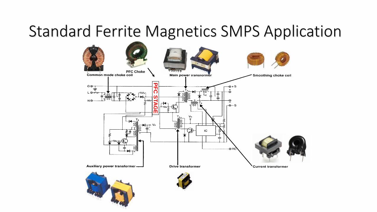
Standard Ferrite Magnetics SMPS Application
PF
C S
TA
GE
PFC Choke
Choke Types
• Choke Types by Application• Common Mode Choke
• Differential Mode Choke
• Energy Stock Choke (PFC, BUCK)
• Choke Types by Material• Ferrite Core
• Powdered Core (iron, MPP, Sendust)
• Laminated Core (EI, taped, Amorphous)

Ferrite XFMR Types
• Ferrite XFMR Types by Application• Flyback XFMR (with Gap)
• Forward XFMR
• PushPull
• Full bridge
• Ferrite XFMR Types by Shapes• EE 13, EE 16… …
• EFD20,
• ER28, ETD34…
• Planar E40

Ferrites (continued)
• Ferrite XFMR Material• TDK PC-40
• Nicera NC-2H
• China Material TDG, DMEGC ……
• Ferrite XFMR Bobbins• EE 13, EE 16… …
• EFD20,
• ER28, ETD34…
• Phenolic PM9820 T375J

Core Suppliers
NO., SupplierQuality
(50)Cost(15)
Delivery time(15)
Service(20)
Total Grade
1 TDK 48 11 10 17 86 A
2 TDG 47 12 12 18 89 A
3 ACME 47 14 12 19 92 A
4 DMEGC 47 14 14 18 93 A
6 NEC 45 11 12 16 84 B
5 MAGSOURCE 43 14 12 15 84 B
7 GUANDA 40 15 10 14 79 C

Core SuppliersItem Symbol Conditions Unit
NiceraNC-2H
TDKPC47
TDKPC40
TDGTP4
TDGTP4A
DMEGCDRM40
DMEGCDRM44
ACMEP4
ACMEP41
Initial permeability
μiF:10KHzB<0.25mT
25℃ ___2300±25%
2500±25%
2300±25%
2300±25%
2400±25%
2300±25%
2400±25%2500±25%
2400±25%
Saturation flux density
BsF:10KHzH:800A/m
25℃
mT
500 520 530 510 510 510 510 480 495
100℃
370 440 420 390 390 390 400 380 395
Remanent flux density
Br25℃
mT140 180 95 100 110 95 130 100 170
100℃ 92 60 55 55 60 55 60 70 70
Coercivity Hc25℃
A/m15.9 13 14.3 14 13 14 15 10 11
100℃ 8 6 8.8 9 6.5 9 6 6 6
Curie temperature
Tcf:10KHzB<0.25mT
℃ 230 230 215 ≧215 ≧220 ≧215 ≧215 ≧220 ≧230
Density d ______ Kg/m3 4.80×10³ 4.80×10³ 4.80×10³ 4.80×10³ 4.80×10³ 4.80×10³ 4.80×10³ 4.80×10³ 4.80×10³
Power Loss Pcv100KHz-200mT
25℃
KW/m3
600 600 600 650 600 600 600 700 650
60℃ 430 400 450 480 410 450 400 540 500
100℃
400 250 410 410 300 410 300 450 350
120℃
480 360 500 500 400 500 380 500 500
The relative price level High High High Medium medium medium medium medium medium
Delivery2-
3months2-
3months2-
3months1-2weeks 1-2weeks 1-2weeks 1-2weeks 1-2weeks 1-2weeks
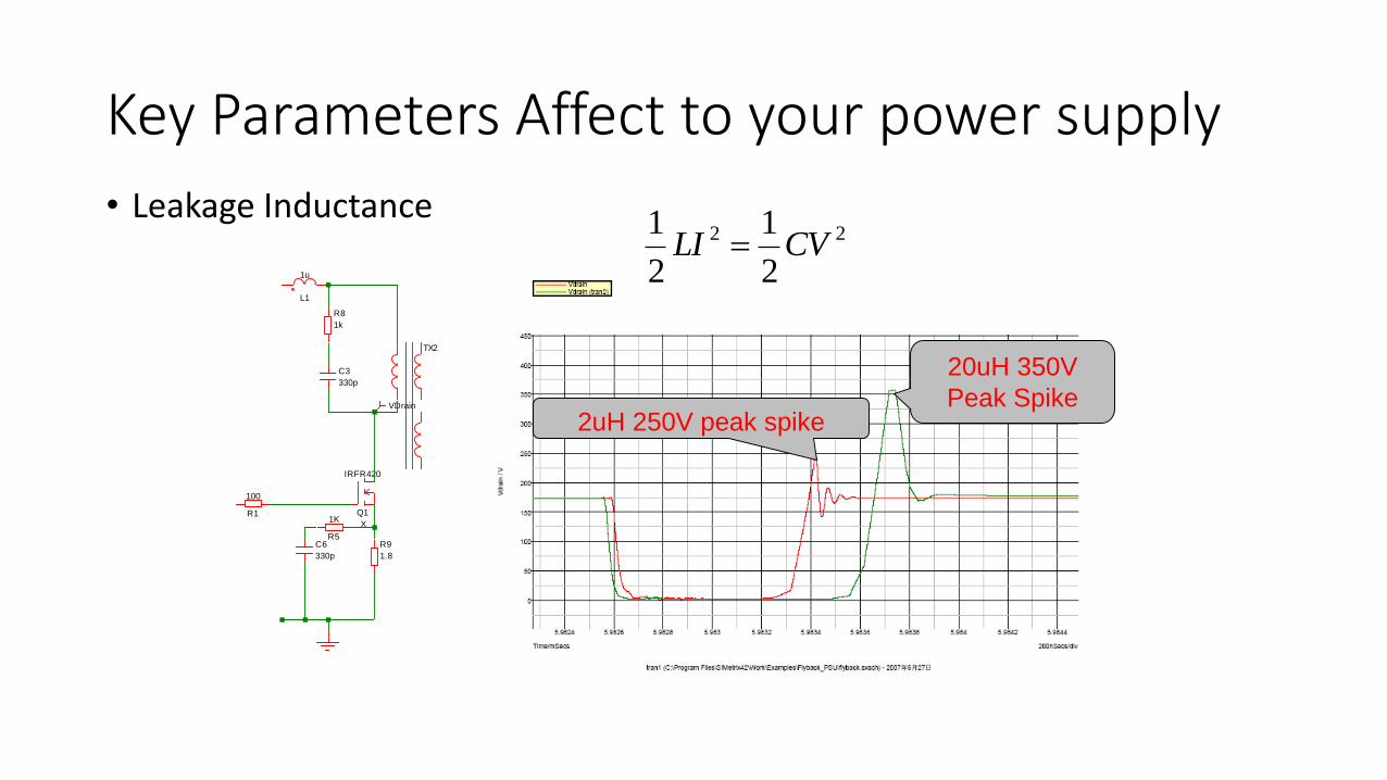
Key Parameters Affect to your power supply
• Leakage Inductance
L1
1u
VDrain
TX2
R5
1K
C3
330p
R9
1.8
Q1
IRFR420
X
R8
1k
R1
100
C6
330p
2uH 250V peak spike
20uH 350V
Peak Spike
22
2
1
2
1CVLI

Leakage Inductance
a
dxxLo0
2∝
cLo
3
a2a1 ∝
)3
a2a1(*
X
K cLo
How about Multi-section?
)3
a2a1( ∝ cLo

Leakage Inductance

Key Parameters Affect to your power supply
fDdep
76
???* 2IDCRPcopper
B sin( t)
+ -
- + - +
+ -
B sin( t)
Wire Diameter Skin Effect Copper loss
NO, the SKIN effect caused a Rac
KRdcRac *
• Minimize eddy currents using Leitz wire bundle. Each conductor in bundle has a diameter less than a skin depth.
• Twisting of paralleled wires causes effects of
intercepted flux to be canceled out between adjacent twists of the conductors. Hence little if any eddy currents.
IS:
2I*K*RdcsPCopperLos
Not Really, the proximity effect.

Proximity Effect
Rac=RdcXFr Famous Dowell Curve

Gap Fringing Effect
• Fringing cause significant eddy loss
• Avoid the fringing loss by design
• Fringing increases the OCL
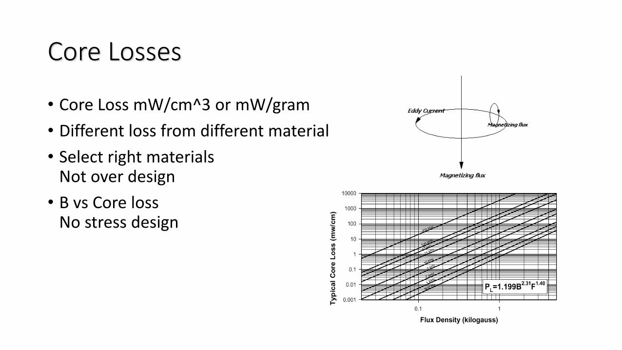
Core Losses
• Core Loss mW/cm^3 or mW/gram
• Different loss from different material
• Select right materialsNot over design
• B vs Core lossNo stress design

Gap, ue, Bdc
1 103
0.01 0.1 10
500
1000
1500
2000
2500
3000
3500
4000
4500
i
rev B BM
rev1 B BM
BM
leNI4.0H
• Bsat inherent characteristics
• Bdc decided by peak current
• OCL decided by turns and gapping size
• Basic formula:
le
lgui1
uiue

Powder Core Characteristics
• Distribute gap
• Soft Saturation
• Different powder size different core loss
• Thermal Aging issue
• Choose right core materials

Common Mode Choke
• Impedance
1 103
1 104
1 105
1 106
1 107
1 108
1 109
1 1010
0.1
1
10
100
1 103
Radians/sec
Ohm
s
943.503
0.895
Z.in 1ji
4.472 109
5.135 103
i
1 103
1 104
1 105
1 106
1 107
1 108
1 109
1 1010
100
0
100
Radians/sec
Degre
es
arg Zin j i deg
i
L1
1m
• EMI Filtering Network
• Mostly are low pass LC
filtering circuit.
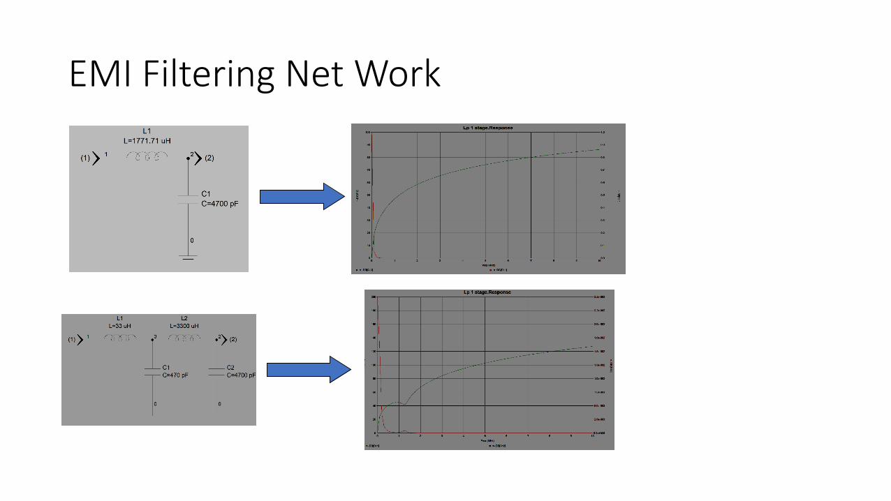
EMI Filtering Net Work

Magnetics Thermal Engineering
• Temperature Rise. Plossincludes copper loss and core loss
• Forced Ventilation Effect 0 15 30 45 60 75 90 105 120 135 1500.2
0.29
0.38
0.47
0.56
0.64
0.73
0.82
0.91
1
Tempearure rise Vs Air flow
Cubic Feets Minutes
% T
empe
ratu
re
f x( )
x
833.0
)(
Asurf
mwPlossdT

Reference
• Leakage Inductance by N.H. Crowhurst 1949
• Soft Ferrites, Properties and Applications, 2nd Edition 1988 by Snelling E.C.
• Switching Mode Power supply Handbook by Keith. H. Billings
• Micrometals Catalogue Edition 2000
• ZETTLER Magnetics Catalog
• www.zettlermagnetics.com