standard water and sewer specifications …hendutil.net/documents/hudspecs.pdf · standard water...
TRANSCRIPT

STANDARD WATER AND SEWER SPECIFICATIONS FOR SUBDIVISION AND GENERAL SYSTEM ADDITIONS
SEPTEMBER 2015


TABLE OF CONTENTS
Division 1 - Standard Water System Specifications * Division 2 - Standard Sewer System Specifications * Division 3 - Standard Specifications for Pressure Wastewater * * See Separate Table of Contents Preceding Each Division

DIVISION 1
STANDARD WATER SYSTEM SPECIFICATIONS
STANDARD WATER SYSTEM SPECIFICATIONS
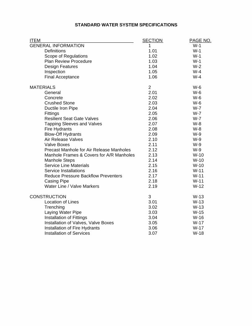
ITEM SECTION PAGE NO. GENERAL INFORMATION 1 W-1 Definitions 1.01 W-1 Scope of Regulations 1.02 W-1 Plan Review Procedure 1.03 W-1 Design Features 1.04 W-2 Inspection 1.05 W-4 Final Acceptance 1.06 W-4 MATERIALS 2 W-6 General 2.01 W-6 Concrete 2.02 W-6 Crushed Stone 2.03 W-6 Ductile Iron Pipe 2.04 W-7 Fittings 2.05 W-7 Resilient Seat Gate Valves 2.06 W-7 Tapping Sleeves and Valves 2.07 W-8 Fire Hydrants 2.08 W-8 Blow-Off Hydrants 2.09 W-9 Air Release Valves 2.10 W-9 Valve Boxes 2.11 W-9 Precast Manhole for Air Release Manholes 2.12 W-9 Manhole Frames & Covers for A/R Manholes 2.13 W-10 Manhole Steps 2.14 W-10 Service Line Materials 2.15 W-10 Service Installations 2.16 W-11 Reduce Pressure Backflow Preventers 2.17 W-11 Casing Pipe 2.18 W-11 Water Line / Valve Markers 2.19 W-12 CONSTRUCTION 3 W-13 Location of Lines 3.01 W-13 Trenching 3.02 W-13 Laying Water Pipe 3.03 W-15 Installation of Fittings 3.04 W-16 Installation of Valves, Valve Boxes 3.05 W-17 Installation of Fire Hydrants 3.06 W-17 Installation of Services 3.07 W-18
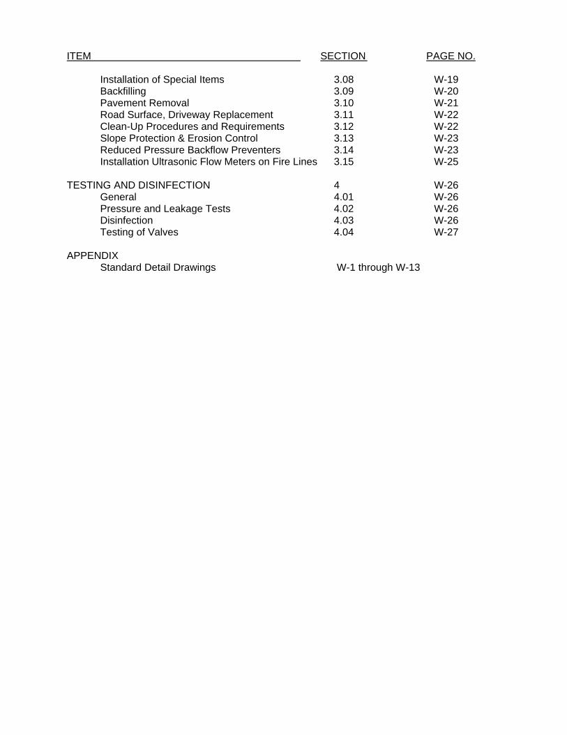
ITEM SECTION PAGE NO. Installation of Special Items 3.08 W-19 Backfilling 3.09 W-20 Pavement Removal 3.10 W-21
Road Surface, Driveway Replacement 3.11 W-22 Clean-Up Procedures and Requirements 3.12 W-22 Slope Protection & Erosion Control 3.13 W-23 Reduced Pressure Backflow Preventers 3.14 W-23 Installation Ultrasonic Flow Meters on Fire Lines 3.15 W-25 TESTING AND DISINFECTION 4 W-26 General 4.01 W-26 Pressure and Leakage Tests 4.02 W-26 Disinfection 4.03 W-26 Testing of Valves 4.04 W-27 APPENDIX Standard Detail Drawings W-1 through W-13
W-1
SECTION 1 - GENERAL 1.01 DEFINITIONS Water Department - Hendersonville Utility District of Sumner County, Tennessee City - City of Hendersonville, Sumner County, Tennessee Planning Commission - Hendersonville Regional Planning Commission Developer - Owner of a proposed development in which water lines are to be located.
Contractor - Contractor who is installing water lines in a proposed development or project.
Engineer - One who has prepared the construction drawings and specifications for the
installation of water lines in a proposed development or project. As provided by the laws of the State of Tennessee, individual must be a registered professional engineer and drawings and specifications must bear their official seal.
State Regulatory Authority - Tennessee Department of Environment and Conservation
Division of Water Supply 1.02 SCOPE OF REGULATIONS
These regulations shall apply to any person, developer, firm, business or entity interested in and desiring to construct additional water lines or to extend water lines within the Hendersonville Utility District’s service boundaries or to construct additional water lines or extend water lines in a way that affects the water service provided by the District.
1.03 PLAN REVIEW PROCEDURE
Before any connection is made to a water line of the Water Department, a Developer or other party through their Engineer shall submit and receive approval of a proposed plan. The submittal shall consist of neat scaled drawings and specifications and at least two (2) copies for review and mark-up. Water Department will retain one (1) copy. Once noted changes have been corrected, Engineer is to submit eight (8) sets of plans to Water Department for approval stamp. Water Department will retain one set of stamped drawings with the remainder to be returned to the Engineer. Drawings will not be deemed approved until the Water Department’s stamp of approval has been affixed to the cover sheet of the drawings and specifications. A copy of the preliminary plat or overall drawing showing the total site and location of the site shall be provided with the drawings.
The approval of the Water Department must be obtained before submittal of the drawings and specifications to the State Regulatory Authority. Both approvals must be obtained before construction is started. Evidence of State Regulatory Authority approval must be furnished to the Water Department before beginning construction. Approval of drawings for proposed water line construction for new subdivisions and other developments must be obtained from the Water Department before final approval for

W-2
such developments will be granted by the Planning Commission. Approval of drawings shall be valid for one (1) year from the date of approval. Plan submittal procedure shall be as follows:
1. All drawings shall be submitted to the Water Department with a letter of transmittal
and a check for the plan review fee. 2. The Water Department will review the drawings and specifications. Upon approval
drawings will be returned to the Design Engineer or Developer for submittal to the State Regulatory Authority.
3. One (1) set of State approved drawings along with copy of approval letter shall be submitted to the Water Department before start of construction.
4. Commencement of utility construction activity shall not occur until all approvals have been obtained. Contractor is responsible for all construction notifications prior to start of project.
Submitted drawings shall include the water main plans, existing and finished grades for the roadways, curbs, gutters, sidewalks and ground as well as the location, size and invert elevation of other utilities and drainage structures. The drawings shall also include the latest revision date if applicable.
For off-site water mains existing topo shall be shown including roadway paving, property lines, right-of-way, existing overhead and underground utilities, and any other feature which could affect construction. STATE APPROVED PLANS
One set of the plan document stamped “APPROVED FOR CONSTRUCTION” and with the approved stamp from the State of Tennessee, Division of Water shall be available at the job sites at all times during construction. The Engineer or a person qualified other than the contractor or his representative, and approved by the public water system shall provide continuous adequate inspection during construction to assure that all work is done in accordance with approved plan documents. The Department’s representative shall have access to the project at any time during construction. If the Department Representative observes work being done in a manner that does not conform to the approved plan documents or District Standards, he shall have the authority, through the Engineer’s representative, the water system’s agent or directly to the contractor to order the cessation of all work affected by the nonconformity until such discrepancies are rectified.
1.04 DESIGN FEATURES
Water system design features shall generally conform to good municipal practice with adequate line sizes and valving. Each plan will be reviewed for conformity to Water Department practices and general plans. The following is provided for general information. Line Size shall be adequate for the intended water service with no line smaller than 6-inches in diameter. Any line serving a fire hydrant shall be at least 6-inches in diameter, and where required, 8-inch lines or larger shall be used to ensure adequate fire flows at proper pressures. Fire Hydrant Spacing and Locations shall be confirmed by the City of Hendersonville Fire Department before final placement during construction. In general, for residential
W-3
areas one fire hydrant will be placed near each street intersection with intermediate hydrants set so that hydrants are not over 500 feet apart. For commercial districts or commercial subdivisions, intermediate hydrants shall be set so that hydrants are not over 300 feet apart. Fire hydrants shall have a cut-off valve in the lead line from the main to the hydrant. Fire hydrants shall be provided at the end of all dead-end water mains. Blow-offs - shall be standard fire hydrant with valve Water Pressure shall be sufficient to provide proper service to all levels of a building requiring water service. The water system operates with storage facilities having overflow elevations at about 675 feet above sea level. In certain areas, high-level systems exist to provide pressures for satisfactory operation. In general, any building at or above 570 feet above sea level will have to be served by a high-level system unless approved by District personnel. Storage facilities will be generally be required on high-level systems serving more than 50 customers and may be required on smaller systems. Backflow Preventers shall be installed where required by the District. Details of this installation shall be approved prior to installation. The backflow preventer shall be installed such that it is protected from freezing and in a manner to allow for proper drainage. See Section 3.14 - Reduced Pressure Backflow Preventers. Private Fire Protection Systems shall be metered by a master meter and a double check valve shall be installed as per section 2.15, 2.17, 3.14 and 3.15. Separation of Water Mains and Sewers shall be maintained in accordance with the following guidelines:
For parallel installations, line separation is to be at least 10 feet edge of ditch to edge of ditch from all other utilities. If this condition cannot be obtained vertical crossing, of the water line shall be at least 18-inches above the top of the sewer. If this condition is also unobtainable, the sewer line is to be constructed of materials and have a joint design equivalent to water main standards as approved by the Water Department and shall be pressure tested to 50 PSI to assure water tightness. Where the water line crosses house sewers, storm sewers, or sanitary sewers, a separation of at least 18-inches shall be provided between the bottom of the water line and the top of the sewer. .. Water mains passing under sewers shall be protected (in addition to the above water line construction) by providing: at least 18-inches between the bottom of the sewer and the top of the water line; adequate structural support of the sewer to prevent excessive joint deflection or damage to the water line; centering of the water line section to result in the water line joints being removed from the sewer line to the maximum possible extent. No water line shall pass through or come into contact with any part of the sewer or sewer manhole. Easements - a minimum of 15 feet easement shall be dedicated for a water main constructed outside a public right-of-way.
W-4
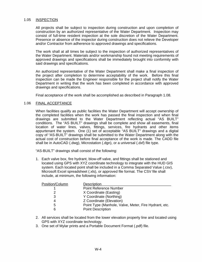
1.05 INSPECTION
All projects shall be subject to inspection during construction and upon completion of construction by an authorized representative of the Water Department. Inspection may consist of full-time resident inspection at the sole discretion of the Water Department. Presence or absence of the inspector during construction does not relieve the Developer and/or Contractor from adherence to approved drawings and specifications. The work shall at all times be subject to the inspection of authorized representatives of the Water Department. Materials and/or workmanship found not meeting requirements of approved drawings and specifications shall be immediately brought into conformity with said drawings and specifications. An authorized representative of the Water Department shall make a final inspection of the project after completion to determine acceptability of the work. Before this final inspection can be made the Engineer responsible for the project shall notify the Water Department in writing that the work has been completed in accordance with approved drawings and specifications. Final acceptance of the work shall be accomplished as described in Paragraph 1.08.
1.06 FINAL ACCEPTANCE
When facilities qualify as public facilities the Water Department will accept ownership of the completed facilities when the work has passed the final inspection and when final drawings are submitted to the Water Department reflecting actual “AS BUILT” conditions. The “AS BUILT” drawings shall be complete and show all easements, final location of water lines, valves, fittings, services, fire hydrants and other items appurtenant the system. One (1) set of acceptable “AS BUILT” drawings and a digital copy of “AS-BUILT” drawings shall be submitted to the Water Department along with the actual cost of construction before final acceptance of the work is made. The CADD file shall be in AutoCAD (.dwg), Microstation (.dgn), or a universal (.dxf) file type. “AS-BUILT” drawings shall consist of the following: 1. Each valve box, fire hydrant, blow-off valve, and fittings shall be stationed and
located using GPS with XYZ coordinate technology to integrate with the HUD GIS system. Each located point shall be included in a Comma Separated Value (.csv), Microsoft Excel spreadsheet (.xls), or approved file format. The CSV file shall include, at minimum, the following information:
Position/Column Description 1 Point Reference Number 2 X Coordinate (Easting) 3 Y Coordinate (Northing) 4 Z Coordinate (Elevation) 5 Point Type (Manhole, Valve, Meter, Fire Hydrant, etc. 6 Point Description 2. All services shall be located from the lower elevation property line and located using
GPS with XYZ coordinate technology. 3. One set of Mylar prints and a Portable Document Format (.pdf) file.

W-5
Final acceptance by the Water Department will be made in writing upon satisfactory completion of the project including final inspection, submittal of acceptable “AS BUILT” drawings, and payment of all fees due. The Developer shall guarantee the work for a period of one year from the date of final acceptance and shall immediately correct any deficiencies in the work due to materials and/or workmanship. The date of final acceptance shall be that date on which the Developer has fulfilled all conditions necessary for final acceptance including passing a final inspection, submittal of acceptable “AS BUILT” drawings, and payment of all fees due.
* * *
W-6
SECTION 2 - MATERIALS 2.01 - GENERAL
All materials to be incorporated in the project shall be first quality, new and undamaged material conforming to all applicable portions of these specifications.
2.02 CONCRETE
Cement - Cement shall be Portland cement of a brand approved by the Engineers and shall conform to “Standard Specifications for Portland Cement,” Type 1, ASTM Designation C-150, latest revision. Cement shall be furnished in undamaged 94 pound, one cubic foot sacks and shall show no evidence of lumping. Concrete Fine Aggregate - Fine aggregate shall be clean, hard uncoated natural sand conforming to ASTM Designation C-33, latest revision, “Standard Specifications for Concrete Aggregate.” Concrete Coarse Aggregate - Coarse aggregate shall consist of clean, hard, dense particles of stone or gravel conforming to ASTM Designation C-33, latest revision, “Standard Specifications for Concrete Aggregate.” Aggregate shall be well graded between 1-1/2-inch and #4 sieve sizes. Water - Water used in mixing concrete shall be clean and free from organic matter, pollutants and other foreign materials. Ready-Mix Concrete - Ready-mix concrete shall be secured only from a source approved by the Engineer and conform to ASTM Designation C-94, latest revision, “Specifications for Ready-Mix Concrete.” Before any concrete is delivered to the job site, the supplier must furnish a statement of the proportions of cement, find aggregate and coarse aggregate to be used for each mix ordered and must receive the Engineer’s approval of such proportions. Class “A” Concrete - Class “A” concrete shall have a minimum compressive strength of 4,000 pounds per square inch in 28 days and shall contain not less than 6 sacks of cement per cubic yard. Class “B” Concrete - Class “B” concrete shall have a minimum compressive strength of 2,000 pounds per square inch in 28 days and shall contain not less than 4-1/2 sacks of cement per cubic yard. Metal Reinforcing - Reinforcing bars shall be intermediate grade steel conforming to ASTM Designation A-15, latest revision, “Standard Specifications for Billet Steel Bars for Concrete Reinforcement.” Bars shall be deformed with a cross-sectional area at all points equal to that of plain bars of equal nominal size.
2.03 CRUSHED STONE
Crushed stone for pipe bedding shall be Tennessee Department of Transportation (TDOT), Bureau of Highways, Standard Size No. 67 and shall meet TDOT Standards for road construction.
.

W-7
2.04 DUCTILE IRON PIPE
Ductile iron pipe for water lines shall conform to USA Standard A21, Class 52 for centrifugally cast ductile iron pipe. The pipe shall be manufactured of iron having acceptance values of 60-42-10. Pipe shall be at least Class 52 or heavier where indicated on the drawings.
Pipe shall be furnished in lengths of 18 feet to 20 feet and, unless otherwise indicated, shall be provided with a compression type slip joint equal to the Fastite joint as manufactured by American. Gaskets and lubricants shall be furnished with the pipe. All pipes shall be capped and/or plugged on both ends to prevent debris contamination during transit and storage. Pipe shall be furnished with standard thickness cement lining on the inside with a bituminous seal coat and a bituminous coating on the outside. Cement lining shall conform to ANSI Standard A21.4. The exterior of the pipe shall be clearly marked to indicate the manufacturer, date of manufacture, the pipe class and weight. Exterior markings shall also positively identify the pipe as being Ductile Iron. Pipe manufacturer shall furnish, upon request, the test date for quality control during the manufacturing period for pipe furnished on the project. Testing and inspection shall be in accordance with ANSI A21.53. Tests to include hydrostatic test (500 psi - 10 sec.); tensile test; impact test; one sample to be taken during each casting period for approximately 3 hours. Pipe manufacturer shall provide certified test reports to the Engineer to verify that all pipe furnished was manufactured and tested in compliance with all requirements of ANSI A21.53/AWWA C-153 and ANSI A21.10/AWWA C-110, latest revisions.
2.05 FITTINGS All fittings shall be compact ductile iron, cement lined, bituminous coated, manufactured
in accordance with USA Standards A21.53, latest revision, unless otherwise indicated or directed. Minimum pressure rating shall be 350 psi. Unless indicated otherwise on the Drawings, mechanical joint fittings shall be used.
Fitting manufacturer shall furnish certificates that fittings were manufactured in
compliance with ANSI A21.53, latest revision. All fittings, valves and etc. shall be restrained. Each fitting shall be assembled to the
ductile iron pipe by the use of pipe retainer glands similar to Mega lug Series 1100 by EBAA iron or Uni-Flange Series 1400 by Ford Meter Box Company. This is in addition to or in lieu of standard concrete thrust blocking.
2.06 RESILIENT SEAT GATE VALVES
Resilient seat gate valves shall be iron body, machined surface, modified wedge disc, resilient rubber seat ring type valves with non-rising stems (NRS). Resilient seat gate valves shall have the bronze stem nut cast integrally with the cast iron valve disc. The valve shall have machined seating surface and capable of being installed and operated in either direction. Valves shall be furnished with mechanical joint ends in accordance with USA Standard A21.11 unless otherwise shown or directed. Valves shall be suitable for installation in approximately vertical position in buried pipe lines. Stem seal shall
W-8
consist of O-ring seals. All valves shall open to the left (counterclockwise) and shall be provided with 2-inch square operating nut. All underground gate valves which have nuts deeper than 48 inches below the valve box top shall have extended stems with nuts located within one foot of the valve box cap.
Valves shall be for working pressures up to 200 PSI and shall be equal to latest
specifications of AWWA C-509 or C-515, latest revision in all respects. Valves shall be equal to Mueller A-2370-20 or M&H. Valve manufacturer shall furnish certificates that all valve furnished have been tested and manufactured in compliance with AWWA C509, latest revision in all respects.
Iron body resilient seat gate valves shall be as manufactured by Mueller or M&H.
2.07 TAPPING SLEEVES AND VALVES
Tapping sleeves shall consist of mechanical joint tapping sleeve or Mueller 304 stainless steel or approved equal and a tapping valve. The valve shall conform to all applicable specifications for gate valves. All bolts are to be stainless steel or brass.
2.08 FIRE HYDRANTS
The location of each fire hydrant shall be located on a property line division unless designated by the City of Hendersonville Fire Department and approved by the Hendersonville Utility District.
All fire hydrants shall be iron bodied, fully bronze mounted hydrants manufactured to
equal or exceed AWWA Specification C-502, latest revision for Dry-Barrel Fire Hydrants. Hydrants shall be suitable for 150 PSI working pressure and shall be subjected to a test pressure of 300 PSI. Inlet connection shall be 6-inch mechanical joint unless noted otherwise on project drawings. Main hydrant valve shall be compression type, closing with the pressure, with 5-1/4-inch valve opening.
Hydrants shall be of the “dry head” type with an oil reservoir and provision for automatic
lubrication of stem threads and bearing surfaces each time the hydrant is operated. Double O-ring seals shall be provided to keep water out of the hydrant top. Operating nut shall be 1-1/2-inch pentagon, opening to left, and shall be equipped with a weather cap.
Hydrants shall be provided with automatic multi-port drain ports arranged to momentarily
flush under pressure each time hydrant is operated. A positive stop shall be provided on the operating stem to prevent over travel when operating valve.
Fire hydrant shall be supplied with a bituminous coating for buried portion of hydrant and
a yellow enamel finish or approved equal for above ground portions of the hydrant. Single Pumper Hydrant - The single pumper fire hydrant shall be Mueller A-423 Yellow
or M&H style 129 5-1/4”. Minimum bury shall be 4-feet. Single pumper fire hydrants shall be equipped with two 2-1/2-inch hose nozzles, one 4-
1/2-inch pumper nozzle, breakable safety flange and safety stem coupling. Bronze nozzles shall be securely locked to prevent them for blowing off. Hose threads shall be National standard. Nozzle caps shall be equipped with non-kink chains.
W-9
Note: See Standard Detail for anchoring of fire hydrant assembly. 2.09 BLOW-OFF HYDRANT
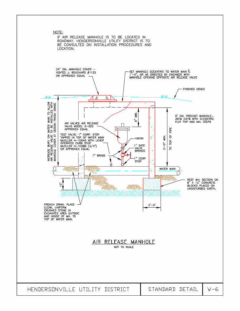
Shall be standard fire hydrants with valve. 2.10 AIR RELEASE VALVE
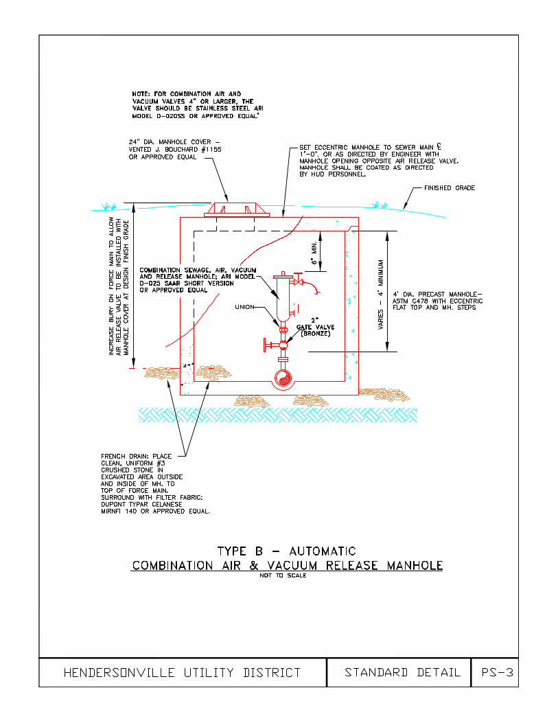
Automatic air release valves shall be designed to allow a quantity of air to escape out of the orifice when air accumulates at high points in the water line. Valves shall be tested for service to pressures of 300 psi and can be made of cast iron housings. Valves shall be of similar construction to ARI Valves Model D-025 SAAR short version or approved equal. Inlet shall be one inch in diameter.
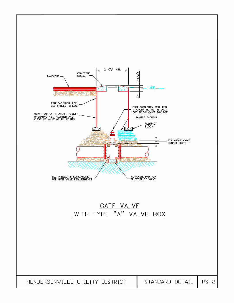
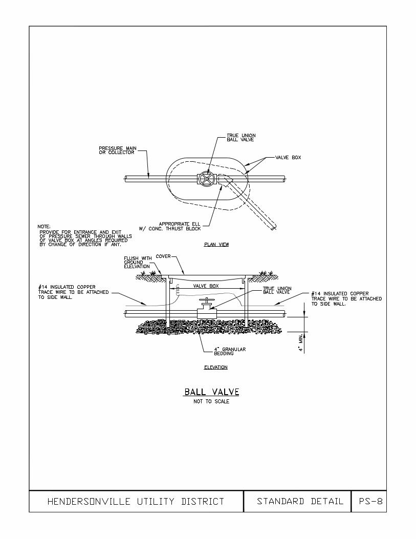
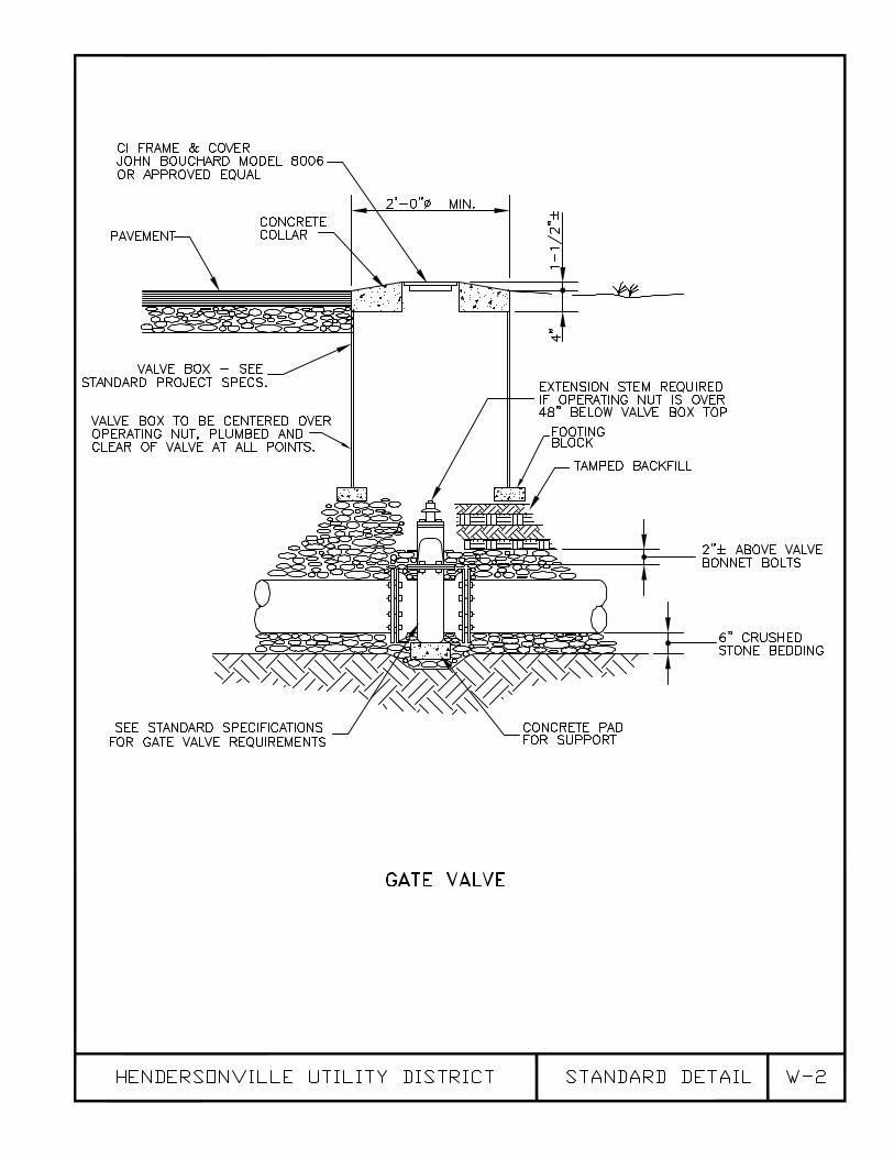
2.11 VALVE BOXES
Valve boxes shall be made of pre-cast concrete sections measuring 11” x 13-1/4” inside dimension and 17” x 19-1/4” outside dimension. The base section shall be enlarged to enclose and protect the valve operating nut without actually being in contact with the pipe or valve. Cover shall be heavy cast iron with the word “WATER” cast in raised letters equal to John Bouchard and Sons Company, Nashville, Tennessee, No. 8006, Roadway Type or approved equal. The word “WATER” will read with the direction of the main. Footing blocks for standard concrete valve boxes are to be pre-cast blocks measuring 12” x 12” x 4”. No reinforcing steel is required in footing blocks. Valve box frames and covers shall be made of heavy cast iron and shall meet the requirements of ASTM A-48, Class 30. The valve box frames and covers shall be as manufactured by Bouchard No. 8006, Roadway Type, Nashville Standard or equal. The cover shall be marked “WATER”.
2.12 PRECAST MANHOLES FOR AIR RELEASE MANHOLES
Precast manholes shall conform to the latest revision of ASTM C-478. Drawings of manhole sections proposed for use on this project must be submitted to the Owner or his authorized representative for approval prior to use. Steps shall be furnished in accordance with Paragraph 2.17 and care must be taken to assure a firmly embedded step with no cracks from mortar shrinkage which will allow leakage. Aluminum in contact with concrete shall be coated with heavy bitumastic paint. Loose steps and shrinkage cracks passing through manhole walls shall be cause for rejection.
Manhole sections showing evidence of cracking, crazing, honeycombing, crumbling or
excessive roughness will not be acceptable. Sections with improper cut-outs, misalignments or other defects shall not be utilized in the project.
Manhole sections shall be steam or water cured and shall not be delivered to job site
until at least 7 days old. Each section shall be marked with date of manufacture and manufacturer’s mark in a permanent manner.
Testing and Acceptance of precast manhole sections shall be done in accordance with
ASTM C-478 by an independent laboratory suitable to the Owner or his authorized representative. Compression tests shall be run on specimens obtained from each day’s production: a minimum of 2 cylinders or cores per day’s run but no less than the

W-10
maximum number designated by ASTM C-478. The absorption test shall be run on a minimum of 2 randomly selected manhole sections per each day’s production.
2.13 MANHOLE FRAMES AND COVERS FOR AIR RELEASE MANHOLES
Manhole castings shall conform to ASTM Designation A-48, latest revision, Class 30 and shall be free from scale, lumps blisters, sand holes and defects of every nature which would impair their use. Castings shall be well cleaned with a smooth tough asphaltic coating. Covers shall be of the vented indented type with the words “WATER” cast in raised letters thereon. Bearing surfaces of frames and covers shall be machined to provide a solid bearing and prevent rocking. Pattern drawings and weights of castings shall be submitted for the approval of the Owner or his authorized representative.
Manhole frames and covers shall be equal to those listed below for particular
applications. NON-TRAFFIC (Standard) John Bouchard No. 1155 TRAFFIC Same as Non-Traffic type as specified above Exceptions to the above shall be noted on construction drawings. 2.14 MANHOLE STEPS
Steps shall be No. R-1981-Q or plastic encapsulated steel equal to No. PS 1-45 as manufactured by M.A. Industries, Inc.
2.15 SERVICE LINE MATERIALS 2.15.1 Corporation stops shall be Mueller H-1500 or Ford F1000-3Q or approved equal
with compression type connections for copper tubing. 2.15.2 All taps shall be direct tap into the main. No saddle taps are to be used without
the approval of the Water Department. 2.15.3 Small copper piping in the ground shall be of standard soft water pipe (tubing) for
water services, ASTM B-88, Type “K” with bronze fittings, corporation stops and valves having compression type connections copper pipe (tubing).
2.15.4 Meter Yokes: Meter yokes shall be Ford LSVBHH41233WRQ for 3/4”,
LSVBHH41444WQ for 1”, and VBB77-12-11-77-NL for 2” or approved equal. Yokes to be fitted with Duel checks and angle ball valves (360 degree rotation) with provision for locking and hard copper cross tubes, Mueller 110 or “T” series compression inlet and outlet fittings. Copper cross tubes are to be of sufficient weight and hardness that they will not be bent during service installation or meter replacement.
2.15.5 Meter boxes for 3/4-inch and 1-inch meters shall be as manufactured by Mid
States Plastics, Inc. Model MSBC 1015-18 or approved equal, with solid cast iron lids with 2-inch TR/PL hole or as required by HUD depending on the size of the meter. Meter box for 2-inch meters shall be Model MSBC 1730-18 with solid cast iron lid with 2-inch TR/PL hole.
2.15.6 Meters larger than 2-inches are to be direct read type meters with transmitter as
manufactured by Sensus or approved equal.
W-11
2.15.7 Ball valves are the only approved valve for setting ¾” to 2” meters. 2.16 SERVICE INSTALLATIONS
Service lines including corporation stop, water line, meter yokes, and meter box shall be installed by the Contractor. All commercial water taps are to be one (1) inch or larger. Water meters up to and including 2-inch shall be installed by the Water Department. Meters over 2-inches shall be installed by the Contractor and shall be Sensus meter with direct read transmitter included.
2.17 REDUCED PRESSURE BACKFLOW PREVENTERS Backflow preventers shall be required on all commercial and industrial facilities as well
as all irrigation services. All backflow preventers shall consist of a mechanical, independently operating, hydraulically dependent relief valve located between two independently operating, internally loaded check valves which, in turn, are located between two tightly closing shut-off valves. All backflow preventers shall meet the requirements of AWWA C-511 latest revision as manufactured by Watts or approved equal.
2.18 CASING PIPE Where noted on the Drawings or required by these Specifications, roadway, railroad or
other crossings shall be made utilizing carrier pipe within a casing pipe. Sizes of carrier pipe and casing pipe shall be as noted on the Drawings or described in these Specifications.
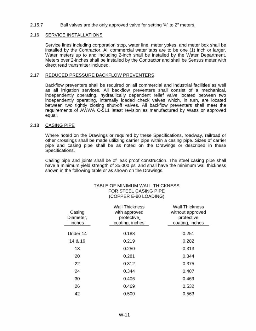
Casing pipe and joints shall be of leak proof construction. The steel casing pipe shall
have a minimum yield strength of 35,000 psi and shall have the minimum wall thickness shown in the following table or as shown on the Drawings.
TABLE OF MINIMUM WALL THICKNESS FOR STEEL CASING PIPE (COPPER E-80 LOADING)
Casing Diameter,
inches
Wall Thickness with approved
protective coating, inches
Wall Thickness without approved
protective coating, inches
Under 14 0.188 0.251 14 & 16 0.219 0.282 18 0.250 0.313 20 0.281 0.344 22 0.312 0.375 24 0.344 0.407 30 0.406 0.469 26 0.469 0.532 42 0.500 0.563

W-12
The casing pipe shall extend to the points indicated on the Drawings. The ends of the
casing shall be protected against the entrance of foreign material but not tightly sealed, in a manner approved by the Engineer.
2.19 WATER LINE / VALVE MARKERS Water line and valve markers are to be installed to identify location of water mains and
valves until final paving is complete or as directed by the Hendersonville Utility District. Markers for valves and/or water lines shall be one piece for driving or settling in the ground. Marker units shall be weather resistant with identifying color and permanently affixed marker identifying water main and/or water valve and shall be a minimum of 62-inches in length. Units shall be flexible and resistant to damage by vehicles, animals, or vandals. Marker units shall be Carsonite Utility Marker, manufactured by Carsonite International - Carson City, Nevada or approved equal.
* * *
W-13
SECTION 3 - CONSTRUCTION 3.01 LOCATION OF LINES
The streets, roads, and easements in which lines shall be placed shall be shown on the drawings. Final location of the pipe lines within these locations shall be made by the Engineer and the Water Department at the time of construction. All water lines shall be constructed of Class 52 ductile iron pipe. Water line and valve markers are to be installed to identify location of water mains and valves until final paving is complete or as directed by the Hendersonville Utility District.
3.02 TRENCHING
Trenching must be done in a neat and workmanlike manner, maintaining proper alignment except where necessary to make deviations to miss obstruction. Trenching for installation of water distribution piping shall be such that the pipe will have a minimum cover of 30-inches over the bell. The bottom of trenches must be shaped by hand and bell holes must be dug so that full length of pipe is resting on trench bottom. Blocking shall not be used.
All shade trees, telephone poles, power poles, etc. along the line of work shall be protected, and sufficient barricades, lanterns, etc. shall be provided for the protection of the public.
3.02.1 Rock Excavation in Trenches
Where rock is encountered in trenches, the excavation shall be carried to a depth of 12-inches below the barrel of the pipe and the excess excavation shall be backfilled with approved bedding material firmly compacted. Boulders and large stones, rock or shell shall be removed to provide a clearance of at least 12-inches below all parts of the pipe or fittings and to a clear width of at least 12-inches on each side of all pipe and appurtenances.
Where rock is encountered, the Contractor shall “mattress” the trench during blasting operations and shall use all precautions necessary to protect adjacent property against damage resulting from his operations. Rock excavation in proximity to other pipes or structures shall be conducted with the utmost care to prevent damage to the existing structures and any such damage caused shall be promptly repaired at the Contractor’s expense. Blasting operations shall be conducted within 25 feet of finished sewer or water pipe; and rock excavation shall be completed at least 25 feet ahead of pipe laying.
Extreme care shall be exercised in blasting with the signals of danger given and displaced before the firing of any charge. The Contractor shall, in all his acts, conform to and obey all rules and regulations for the protection of life and property that may be imposed by any public authorities, or they may be made from time to time by the Engineer relative, to the storing and handling of explosives and the blasting operations. No blasting shall be done at any time except by persons experienced in this line of work.
3.02.2 Obstructions of Streets, Premises, Etc.
All materials excavated shall be placed so as to interfere as little as possible with public vehicular traffic. In general, excavated material shall be kept clear of the
W-14
sidewalk except where local conditions make other arrangements desirable. In this event the Contractor will receive appropriate instructions from the Engineer.
At such street crossings and other points as may be directed by the Engineer the trenches shall be bridged in a proper and secure manner so as to prevent any serious interruption of travel upon the roadway or sidewalk and also to afford necessary access to particular public premises.
The Contractor will not be permitted under any circumstances to close to vehicular traffic any roadway, neutral grounds, or street except by special permission of the City for a specified period. Alternate streets crossing the work must always be kept open. Contractor shall notify local police and fire officials in the event closure is allowed.
3.02.3 Surface Obstructions
All buildings, walls, fences, poles, bridges, railroads, trees, and other property improvements encountered shall be carefully protected from all injury. In the event that any of the foregoing are damaged or removed during the process of the work they shall be repaired or replaced in a satisfactory manner. Special care must be exercised in trenching under or near railroads in order to avoid or minimize delays or injuries. Where it is necessary to cross beneath railroad tracks the Contractor shall make such installations in a casing of larger diameter as approved by the railroad company, the Engineer and the Water Department.
3.02.4 Subsurface Obstructions
In excavating, backfilling and laying pipe, care must taken not to remove, disturb, or injure other pipes, conduits, or structures without the approval of the Water Department. If necessary the Contractor, at his own expense, shall sling, shore up and maintain such structures in operation and within the reasonable time shall repair any damage done thereto. Repairs to these facilities shall be made to the satisfaction of the Water Department.
The Contractor shall give sufficient notice to the interested utility of his intention
to remove or disturb any other pipe, conduit, etc. and shall abide by their regulations governing such work. In the event subsurface structures are broken or damaged in the prosecution of the work, the Contractor shall immediately notify the proper authorities and shall be responsible for any damage to persons or property caused by such breaks.
When pipes providing service to adjoining buildings are broken during the
progress of the work the Contractor shall notify the Water Department immediately. Contractor shall be responsible for repair of all damaged facilities. The Owner reserves the right to make repairs at the Contractor’s expense without prior notification. Delays that would result in buildings being without service overnight or for needlessly long periods during the day will not be tolerated. Should it become necessary to move the position of a pipe, conduit, or structure relocation shall be done by the Contractor in strict accordance with instructions given by the Engineer or the Water Department.
The Water Department or Engineer will not be liable for any claim made by the
Contractor based on underground obstructions being different than indicated on the drawings. Where ordered by the Engineer, the Contractor shall uncover

W-15
subsurface obstructions in advance of construction so that the method of avoiding same may be determined before pipe laying reaches the obstructions.
The Contractor shall be governed by instructions of the Engineer regarding the
laying of pipe along State Highways and the latter will determine whether the pipe shall be laid over, under, or along the end of various drainage structures encountered.
3.03 LAYING WATER PIPE 3.03.1 General
In case of any item not covered by this section, the manufacturer’s recommendations shall govern the manner in which water pipe is laid.
Immediately before being placed in trench, all pipes shall be examined for defects and shall be swabbed clean and free of all dirt or rubbish. While suspended in sling and before lowering in trench, pipe shall be inspected and if found to be defective removed at once from work area. Bell holes for bell and spigot and mechanical joint pipe shall be dug in trench to allow entire length of pipe barrel to be bedded and to allow proper jointing of pipe. Alignment of pipe shall be as true as possible in order to avoid air pockets. Open ends of the pipe shall be securely plugged to prevent the entrance of foreign materials when work is suspended either for the night or for any other reason. Dead ends of the pipe and unused branches of crosses, tees, valves, etc. shall be closed with plugs suitable to the type of pipe in use. Cutting of pipe shall be done in a neat, workmanlike manner without damage to pipe, coatings and linings and so that a smooth end remains at right angles to axis of pipe. No pipe shall be laid which prevents successful jointing, laying or backfilling of trench.
3.03.2 Removal of Water
The Contractor shall be responsible for handling run-off and ground water in such a way as to maintain trenches and excavations in a dry condition until the work is completed. Pumps, piping, well points, labor, fuel, and other facilities necessary to control, intercept, remove and/or dispose of water shall be provided by the Contractor at his own expense. Water removed from trenches or holes shall be discharged to natural drains in such a way as to avoid danger or damage to adjacent property owners. No discharge into sanitary sewers will be permitted.
Where the Contractor fails, refuses, or neglects to control water in trenches or
other excavations, and corrective work is deemed by the Engineer to be necessary as a consequence thereof, such work shall be at the Contractor's expense.
Work under this section shall be approved by the City of Hendersonville Public Works Department.

W-16
3.03.3 Ductile Iron Pipe
Provision of AWWA Specifications C600, latest revision, “AWWA Standard for Installation of Gray and Ductile Cast Iron Water Mains” shall apply. Laying conditions shall be Type 2 (flat bottom trench without blocks) with tamped backfill.
Joints shall be an approved slip-on type or mechanical joint. Unless otherwise
indicated on Drawings, lines laid below ground shall have approved slip-on joints; lines laid above ground shall have mechanical joints. Flanged joints shall be used only where designated on Drawings. Cement joints will not be permitted.
Mechanical joint and slip-on type water line shall be jointed together in trench
according to recommendations of pipe manufacturer. Inside of bell and outside of spigot end shall be thoroughly cleaned to remove oil, grit, excess coating and other foreign matter. Circular rubber gasket shall be flexed inward and inserted in gasket recess of bell socket. Thin film of gasket lubricant shall be applied to inside surface of gasket or spigot end of pipe or both. Gasket lubricant shall be as supplied by pipe manufacturer and approved by Engineer. Spigot end of pipe shall be inserted into socket, with care used to keep joint end to bottom of socket with forked tool, jack-type tool, or other device approved by Engineer. Pipe not furnished with depth mark shall be marked before assembly to assure that spigot is inserted to full depth of joint. Field cut pipe lengths shall be filled or ground to resemble spigot end as manufactured. All mechanical joints shall have a three foot splice piece between fittings.
Whenever it is desirable to deflect slip-on joint pipe in order to form long-radius
curve amount of deflection shall not to exceed maximum limits as follows: Diameter Joint Length Deflection 6” thru 12” 18 ft. 18 in. 14” thru 30” 18 ft. 10 in. Whenever water lines cross over or under sewer lines, the water line is to be
encased in concrete. Minimum vertical separation between water and sewer is to be 18-inches.
All pipe joints installed inside of casing pipe shall be restrained by the use of
locking gaskets. 3.04 INSTALLATION OF FITTINGS 3.04.1 General Fittings in pipe lines shall be firmly secured to prevent the fitting from being blown
off the line when under pressure. When connections are made between the new work and existing mains, the connections shall be made using materials approved by Hendersonville Utility District.
All tees, caps, plugs, bends or other fittings subjected to unbalanced forces
tending to pull the joints apart shall be protected with concrete thrust blocks. Thrust blocks shall be provided in accordance with details shown on Drawings and must bear against an undisturbed trench face. Thrust blocks may be required by HUD.
W-17
All fittings shown on the drawings are to be restrained to the ductile iron pipe by
the use of pipe retainer glands similar to Mega lug Series 1100 by EBAA iron or Uni-Flange Series 1400 by Ford Meter Box Company. This is in addition to or in lieu of standard concrete thrust blocking.
Fittings shall be placed in locations indicated on Drawings or designated by
Engineer and shall be installed in accordance with provisions of these Specifications dealing with laying of Ductile Iron Pipe. Joints shall be as designated under Section 2, Materials.
All fittings may be subject to inspection by Engineer or Water Department before
being placed in trench. Any defective, unsound or damaged fittings shall be rejected and Contractor shall remove at once from work area.
3.04.2 Fittings
Fittings shall be installed in accordance with provisions of these specifications dealing with lying of ductile iron pipe. Joints shall be as designated under Division 2, “Materials”.
3.05 INSTALLATION OF VALVES, VALVE BOXES
Valves shall be placed in the locations indicated on the Plans or at locations designated by the Engineer. All valves shall be set vertically. Before being placed in the trench, all valves shall be carefully examined by the Contractor and Engineer to see that they are in good working order. At the intersection of all lines a valve shall be installed in each direction or as directed by the Hendersonville Utility District.
A valve box shall be placed over each valve. All operating nuts shall be 48-inches below
the top of the valve box unless approved by the Water Department. The valve box shall not come in contact with valve, valve stem, extension, or operating
nut at any point. Backfill around boxes shall be tamped to maintain centered and plumbed alignment of box.
Box shall be installed with top set flush with finished surface in paved areas and to 2-
inches above natural ground level in unpaved areas. Valve and valve box installations shall conform to the standard detail drawing of these
specifications. All valves shown on the drawings are to be restrained to the ductile iron pipe by the use of pipe retainer glands similar to Mega lug Series 1100 by EBAA iron or Uni-Flange Series 1400 by Ford Meter Box Company. This is in addition to or in lieu of standard concrete thrust blocking.
Upon completion of project, the Contractor shall operate all buried valves in accordance
with manufacturer’s recommendations in the presence of HUD Representative to verify proper operation.
3.06 INSTALLATION OF FIRE HYDRANTS
Hydrants shall be located generally as shown on the Drawings subject to review and approval by the Hendersonville Utility District and Fire Department. Location shall provide complete accessibility and minimize possibility of damage from vehicles or injury to pedestrians.
W-18
Hydrants shall stand plumb (vertically) with pump nozzle facing street or public rights-of-way. Hydrants shall be set so that ground line, as indicated on hydrant barrel, is within 6-inches of finished grade. Hydrants without ground lines marked on barrel shall be set so that barrel flange is 6-inches above finished grade. Hydrant barrels shall be minimum bury of 48-inches. Greater burial depths might be required to accomplish the above described grade setting. It is desired to accomplish the proper grade setting without the use of barrel extensions.
A hydrant drain consisting of at least 7 cubic feet of clean, washed gravel or crushed
stone covered with non-woven fabric shall be placed around base of hydrant. After installation is complete hydrant will be tested for drainage and Contractor must correct situation if hydrant does not drain satisfactorily.
The Contractor shall use locked joint base fittings, anchoring fittings, or pipe clamps and
tie rods to anchor valve and the fire hydrant to main line tee. (See detail drawings enclosed.) All fire hydrant and valve restraints are to be restrained to the ductile iron pipe by the use of pipe retainer glands similar to Mega lug Series 1100 by EBAA iron or Uni-Flange Series 1400 by Ford Meter Box Company. All fire hydrants placed at the end of the line shall be restrained by using lock type gaskets in the last three joints of pipe before the valve. There should be no less than 3 feet of pipe between the valve and hydrant.
Concrete thrust block may be poured at base of hydrant with care taken not to plug
hydrant drains. Blocks may be poured in addition to retainer glands, locked joint base fittings, anchoring fittings, or pipe clamps and tie rods.
Painting of hydrants after installation shall be required if factory finish is not satisfactory
or has been damaged. All hydrants shall be yellow unless otherwise directed by the Engineer.
In case of damaged or otherwise unsatisfactory paint, Contractor shall apply two (2)
coats of approved enamel. Hydrant installation shall conform to details in these specifications. 3.07 INSTALLATION OF SERVICES
Services shall be installed in the best workmanlike manner with 30-inches minimum cover. Corporation cock at the main shall be installed in top quadrant of the main. The service line shall run from main to meter box in as straight a line as possible and at an angle of 90 degrees to the main. Water service line is to extend a minimum of 3-feet past the meter yoke.
Meter box shall be installed in public right-of-way adjacent to right-of-way line with top of
casting at finished grade. Top of meter yoke must be 18-inches below final grade. Installation shall be in accordance with the standard detail drawing of these
specifications.

W-19
3.08 INSTALLATION OF SPECIAL ITEMS 3.08.1 Connections to Existing Mains
Connections to existing mains for line extensions or fire hydrant installation shall be made in the manner approved by the Water Department.
Where existing mains must be valved off to make connections, the Contractor
shall notify the Water Department not less than 72 hours prior to the making of the connection. The actual time of the service interruption shall be subject to the approval of the Water Department.
It shall be the responsibility of the Contractor to measure outside diameters of
existing pipes before ordering tapping sleeves or other fittings intended for connection to existing mains.
3.08.2 Concrete Work
Concrete is to be proportioned in two classes according to use as follows:
Class “A” for reinforced concrete structures, non-reinforced portions of manholes,
control chambers and interceptor structures, curbs and gutters, driveways, sidewalks, and surface base courses for highway and street paving.
Class “A” concrete is to be proportioned one 94 lb. sack Portland Cement, 195
lbs. sand, and 270 lbs. coarse aggregate. These proportions may be varied by the Engineer after the materials supplied have been tested and proportions for the greatest density and workability determined. In no case shall more than 7.25 bags or less than 5.5 bags of Portland cement per cubic yard of concrete will be required.
Class “A” concrete shall have a minimum compressive strength of 4,000 lbs. per square inch in 28 days.
Class “B” for encasement around sewers and water lines for cradle, refill and tunnel backfill, for thrust blocks.
Class “B” concrete shall have a minimum compressive strength of 2,000 psi and
shall contain not less than 4-1/2 sacks of cement per cubic yard of concrete. The relative amounts of fine and coarse aggregate shall be comparable to that for Class “A” concrete.
Standard Detail W-4 shall be used with the installation of a 5-1/4 inch Mueller A-
423 yellow fire hydrant assembly or approved equal. Blow-off installation shall conform to the standard detail drawings of these
specifications. 3.08.3 Installation of Stub-outs for Future Lines
The Contractor shall anchor the valve and stub-out for future lines to the main line tee. These anchors are to be in addition to the standard concrete thrust blocking.

W-20
3.09 BACKFILLING 3.09.1 General
Backfilling shall be carried out as expeditiously as possible but shall not be undertaken until the Engineer has been given the opportunity to inspect the work. The Contractor must carry out all backfilling operations with due regard to: (1) the protection of pipes, structures and appurtenances; (2) the use of prescribed backfill materials; and (3) procedures to obtain the desired degree of compaction. No equipment may be used which will result in damage to or misalignment of the pipe.
3.09.2 Acceptable Backfill Material
All backfill material shall be free from cinders, ashes, refuse, vegetable or organic material, boulders, rocks or stones, or other material that in the opinion of the Engineer is unsuitable. From one foot above top of pipe to within twelve-inches of finished grade in unpaved areas back fill may contain stones up to six inches in their greatest dimension, unless otherwise specified. Back fill containing rock must contain enough dirt to fill voids between rocks.
When backfill material is not specified on Project Drawings or elsewhere in these Specifications Contractor may backfill with the excavated material provided material consists of loam, clay, sand, gravel, or other materials that, in opinion of Engineer or Water Department, are suitable for backfilling.
Backfilling shall not be done in freezing weather and it shall not be made with
frozen material. No fill shall be made where material already in trench is frozen. Backfill shall not be made with material which, in Engineer's or Water Department’s opinion, is too wet.
Where crushed stone backfill is required the crushed stone shall be No. 67 size
as designated by the Tennessee Department of Transportation Standards for crushed stone used in road construction.
3.09.3 Backfilling Under Pipe
All trenches shall be backfilled by hand from bottom of trench to centerline of pipe. Approved backfill material (Crushed Stone No. 67) shall be placed in 6-inch layers and thoroughly compacted by hand tamping. Backfill material shall be deposited in trench for its full width on each side of pipe, fittings and appurtenances simultaneously. Care must be taken to compact fill along sides of pipe and appurtenances adjacent to pipe wall.
3.09.4 Backfilling Under Pipe in Rock
Where trench is excavated in rock or shale a 12-inch space below pipe shall be backfilled with approved bedding (Crushed Stone No. 67) material firmly compacted to form a cushion for pipe and appurtenances.
3.09.5 Backfilling Over Pipe
From centerline of pipe, fittings and appurtenances to a depth of 1 foot above top of pipe, trench shall be backfilled by hand or by approved mechanical methods of
W-21
6-inch layers and thoroughly compacted. Contractor shall use special care in placing this portion of backfill in order to avoid injuring or moving pipe.
After the backfill has been placed to a depth of at least 12-inches above top of
pipe additional backfill may be placed by means of front end loaders, bulldozers or other suitable mechanical equipment subject to a 9-inch limitation of maximum thickness of layers placed before compaction.
3.09.6 Backfilling To Grade
From one foot above top of pipe to grade, trench shall be backfilled by hand or by approved mechanical methods (power equipment).
3.09.6.1 In Areas Subject to Vehicular Traffic or Under Sidewalks
Where excavation is made through pavement, curbs, driveways, sidewalks, road shoulders, or other areas subject to vehicular traffic or supporting permanent structures, or where such areas, items or structures are undercut by excavation, entire backfill shall be crushed stone (No. 67) which shall be placed in layers or lifts not exceeding 9-inches in thickness.
After placing in layers crushed stone shall be carefully compacted to
maximum density or minimum volume. Such backfill, placed where called for on the Drawings or as directed by the Engineer shall be designated as Crushed Stone Backfill.
Where excavation is made through permanent pavements backfill shall
be placed as described above to subgrade elevation only. Remainder of backfill shall be crushed stone placed as directed to finished pavement grade to serve as temporary pavement.
The last 8 to 10-inches of backfill shall be compacted pug mix to stabilize
trench cut.
3.09.6.2 In Areas Not Subject to Vehicular Traffic Where excavation is made in areas not subject to vehicular traffic or supporting permanent structures and where settlement is not as critical Contractor may backfill trench from 1 foot above top of pipe to top of trench with approved excavated material using hand or approved methods. Backfill material shall be brought up to the original ground level in layers and walked in with suitable equipment. More restrictive compaction of this backfill material will not be required; however, the Contractor shall be responsible for bringing in such additional fill material as may be required from time to time during the one year warranty period to fill in areas where excessive settlement has occurred.
3.10 PAVEMENT REMOVAL The Contractor shall take necessary steps to minimize damage where existing paved
streets, roads, parking lots, drives, or sidewalks must be disturbed during construction of the project. Permanent type pavement shall be cut or sawed in a straight line before removal and care shall be taken during excavation to avoid damage to adjacent pavement. Areas shall be suitably protected where trucks or other heavy equipment
W-22
must cross curbs or sidewalks. A Street Cut Permit shall be obtained from the City of Hendersonville Public Works Department prior to commencement of any work within the right-of-way.
3.11 REPLACING ROAD SURFACING, DRIVEWAY, ETC.
In paved or improved roads or where sidewalks, curbs, gutters or driveways have been damaged by the Contractor, items shall be repaired or replaced without needless delay in the best workmanlike manner with the same kind of materials as were removed or damaged in construction operation. Underlying foundation courses of roads, driveways, finished surface, etc. shall conform to undisturbed portions of the damaged item and shall in every respect be equal to quality, materials, and workmanship to the original, undisturbed item.
Decision of the Owner or his authorized representative shall be final as to classification
of any form of pavement or surfacing not specified on the Construction Drawings or of any forms of pavement or surfacing where classification is in question. Should the Contractor fail or refuse to repair any damage after receiving directions of the Owner or his authorized representative the Owner may, after 24 hours written notice, employ such force and furnish such materials as may be necessary to do the work with cost to be billed to the Contractor.
City of Hendersonville Public Works Department shall make final acceptance of all right-of-way street related facilities. A Street Cut Permit shall be obtained from the City of Hendersonville Public Works Department prior to commencement of any work within the right-of-way. All asphalt repairs must be approved by the City of Hendersonville Public Works Department.
All water valves and manholes will be adjusted to the final surface elevations by the
Contractor. Cost to be merged into price for pavement replacement. 3.12 CLEAN-UP PROCEDURES AND REQUIREMENTS
The Contractor shall not, without the permission of the Engineer or Water Department, remove from the line of work any earth excavated there from which may be suitable for backfilling or surfacing until the excavation has been refilled and surfaced.
Within areas of existing development, as soon as the backfilling of any excavation is
completed, the Contractor must at once begin the removal of all dirt except that which is actually necessary to provide for the settlement of the fill. Contractor shall also remove all pipes and other material placed or left on the street except material needed for the replacement of paving. The street shall be made passable for traffic and opened as soon as possible. Following the above work the repairing and complete restoration of the street surfaces, bridges, crossings, and all places affected by the work shall be completed as promptly as possible.
All excavated material shall be cleared from adjacent street surfaces, gutters, sidewalks,
parkways, railroads, grass plots, yards, etc., and all work shall be left in an acceptable condition. Contractor will be required to re-grass lawns or neutral grounds where trenches are excavated in these locations or where contractor has damaged lawns or neutral grounds by his operations.
The Engineer or Water Department shall be sole authority in determining when rough
and final clean-up shall occur. Rough clean-up shall consist of removal of rocks larger

W-23
than one foot in any dimension, grading of excess backfill material over pipe line or removal of sand material, opening of any drainage device, restoration of any street or roadway to condition so that traffic may safely and conveniently use street or roadway, restoration of pedestrian ways to condition where pedestrians may safely and conveniently use same. In general rough clean-up shall commence no later than one day after pipe laying and backfilling or no farther behind pipe laying operations than 1,000 feet; whichever time limit is shortest. Final clean-up consisting of pavement replacement, sidewalk replacement, removal of rocks, hand raking with seeding, strawing, etc. of lawns and neutral grounds, adjusting grade of ground over pipeline, property repairs, and other items shall, in general, be prosecuted no later than 2 to 3 weeks after pipe has been laid and backfilled.
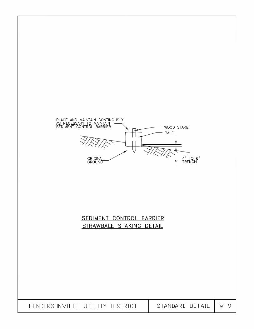
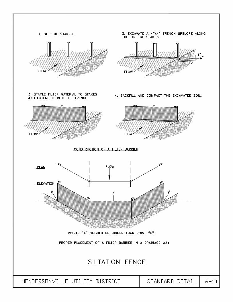
3.13 SLOPE PROTECTION AND EROSION CONTROL
Consists of temporary control measures as shown in the Drawings or directed by the Engineer or as required by the State of Tennessee - Water Pollution Control Division during the life of the Contract to control erosion and water pollution through the use of hay bales and other control devices. All slope protection and erosion control shall be approved by the City of Hendersonville Public Works Department.
The Contractor’s attention is directed to the requirement for executing a Notice of Intent
(NOI) for storm water discharges. The Developer will pay required fee and transmit the NOI package to the State for review and approval. This NOI must be approved by the State of Tennessee prior to beginning work.
It shall be the responsibility of the Contractor to fully comply with all requirements and
regulations of the NOI, storm water discharge regulations, and all other requirements contained herein.
Note: The Developer/Contractor’s attention is directed to the fact that a permit from the Division of Water Pollution Control might be required for aquatic resource alteration for work in and/or around streams.
3.14 INSTALLATION OF REDUCED PRESSURE BACKFLOW PREVENTERS All backflow prevention assemblies shall be installed in accordance with the
Manufacturer’s installation instructions. The Hendersonville Utility District reserves the right to supersede these instructions when necessary.
The entire backflow prevention assembly, including test cocks, shut-off valves, strainers,
and any other part, must be easily accessible for annual testing and repair. The entire backflow prevention assembly shall be located a minimum of 12-inches plus
the nominal diameter of the device above the floor surface. Maximum height above the floor surface shall not be more than 48-inches. Clearance from all wall surfaces or other obstructions shall be a minimum of 6-inches.
All backflow prevention assemblies shall be protected from freezing, vandalism, abuse,
and any other corrosive, sticky, greasy, abrasive environment. No electrical grounding shall be allowed upstream of the backflow prevention assembly. Grounding after the backflow prevention assembly will be allowed with prior approval from Hendersonville Utility District personnel.

W-24
All backflow prevention assemblies shall be positioned where discharge from the relief port will not create undesirable condition that might cause undue damage to the backflow assemblies operation. An approved Air Gap shall separate the relief port of the backflow prevention assembly from any drainage system. Any indoor installation of a backflow prevention assembly must have a floor drain that is 2-1/2 times the diameter of the size of the backflow preventer. The installation will be considered non compliant if sufficient drainage is not included, Installation will not be approved unless a waiver is signed by the owner of the company and/or the property.
An approved strainer, fitted with a drain cock, shall be installed on the immediate
upstream side of the backflow prevention assembly. Below ground installation of backflow prevention assemblies are not permitted. Duplicate backflow prevention assemblies shall be installed in parallel in cases where
the water supply cannot be interrupted for routine testing and maintenance of a single assembly.
All new backflow prevention assembly installations shall include test fittings and
protective caps. Threads on test fittings must be wrapped with teflon tape. Backflow prevention assemblies that are installed on in-ground irrigation systems or
hose bibb connections shall be removed during winter periods to protect from freezing unless the assembly is protected by an approved engineered protective covering.
All backflow prevention assemblies installed on fire sprinkler systems must be tested
and maintained annually by licensed sprinkler contractors with certified cross connection personnel. Only licensed sprinkler contractors with certified cross connection personnel may install, repair, or test backflow prevention devices on fire protection systems. Annual test records must be submitted to the Hendersonville Utility District within seventy-two (72) hours of inspection/test. Test reports shall be delivered to the Hendersonville Utility District Senior Inspector. Double check valve and Double Check Detector Check valve assemblies are allowed only on fire sprinkler systems.
All other water lines, meters, chill lines, boiler lines or other lines that are deemed to
require backflow protection shall include an approved reduced pressure backflow prevention assembly to Hendersonville Utility District specifications. All commercial buildings, regardless of type of business that occupies the property, must have a reduced pressure backflow prevention assembly installed for the domestic water line between the water meter and the first connection.
All in-ground irrigation systems, hose bibb or hydrant bibbs that are directly connected to
a water meter must have a reduced pressure backflow prevention assembly installed between the water meter and the first connection.
In situations where a backflow prevention assembly fails a test Hendersonville Utility
District will give notice in writing of a certain amount of days to have the problem resolved. The amount of days will be determined by the degree of hazard of the property being protected. In the event that the backflow prevention assembly is not repaired Hendersonville Utility District will allow a maximum of two (2) re-tests before the water service is disconnected. Backflow prevention assemblies on irrigation systems, hose connections and bibb connections will be allowed a maximum of two (2) re-tests before water service is discontinued.
W-25
The Hendersonville Utility District reserves the right to discontinue water service to any commercial or residential user who is in danger of contaminating the public water supply. The Hendersonville Utility District will consider a failed backflow prevention assembly as a dangerous threat to the public water supply. For annual testing purposes the Hendersonville Utility District reserves the right to access any area or property where a backflow prevention assembly is located.
All secondary “Watering Meters” ( meters such as for irrigation, filling swimming pools,
fire protection, etc.), regardless of application must be protected by a reduced pressure backflow prevention assembly installed to Hendersonville Utility District specifications.
Atmospheric vacuum breakers, hose-bibb vacuum breakers, dual check devices, and
spill-resistant pressure vacuum breaker assemblies are not considered sufficient protection against backflow or backsiphonage by the Hendersonville Utility District and cannot be used in any application.
The Hendersonville Utility District reserves the right to inspect any building or property to
determine if backflow protection is needed. The District also reserves the right to require any property or building that is deemed a potential to contaminate the water supply to be retrofitted with backflow prevention.
3.15 INSTALLATION OF ULTRASONIC FLOW METERS ON FIRE LINES
Installation and use of ultrasonic flow meters must be equal to and/or exceed the operating specifications of the Prosonic FM-500 Ultrasonic Flow Meter. Each ultrasonic flow meter must have a certificate of conformance from the manufacturer showing the unit has passed all operational, functional, and accuracy tests in accordance with the manufacturer’s quality assurance procedures prior to installation. Ultrasonic flow meter, wiring and transducer mounting must be installed in accordance with manufacturer’s specifications and recommendations. Suppression of display may not be used to either limit small flow values or high flow levels. Periodic calibration(s) on the ultrasonic flow meter shall be conducted based on the manufacturer’s recommendations. Calibration records shall be maintained for three (3) years. Business owners shall grant Hendersonville Utility District staff access to the ultrasonic flow meter during normal business hours (7:30 AM – 4:30 PM) Mon-Fri. to allow verification of installation and displayed gallon usage. It is the responsibility of the business owner to adhere to the Hendersonville Utility District’s policy for the maintenance and operation of the ultrasonic flow meter, including all cost associated with it.
* * *

W-26
SECTION 4 - TESTING AND DISINFECTION 4.01 GENERAL
Upon completion of the construction work the Contractor shall conduct the necessary pressure and leakage tests in the presence of an authorized representative of the Water Department. The Main shall be disinfected using AWWA rules C-651, latest revision
Inspection, testing, tap and connection fees shall be paid by the contractor or developer prior to acceptance. Note: No connections to the existing water system will be permitted until the new lines have been satisfactorily inspected, tested, and disinfected.
4.02 PRESSURE TESTS
Each section of the completed water main extension shall be subjected to a pressure test. The section to be tested shall be valved off after having been filled with water and a positive displacement test pump shall be used to pump clean water into the section to build up a test pressure of 200 psi. The test pump shall then be valved off from the system and the pressure shall be observed over a period of one hour. A drop in pressure of 5 psi or more during the one hour test shall be taken as an indication of leakage. In the event leaks are found and corrected the Contractor shall repeat the pressure test using the same procedure described above. Should the system fail to pass the pressure test, the Contractor shall be required to locate and correct the leaks and to retest the system until satisfactory results can be obtained.
The Contractor shall provide a suitable acceptable pressure gauge with 5 lb. or smaller
graduations. Pressure gauge shall be in good condition and shall be subject to such tests for proof of accuracy as required.
4.03 DISINFECTION
All water main extensions and appurtenances shall be disinfected as per AWWA C-651, latest revision. The contractor will be required to furnish a gallon meter and a diffuser. The contractor will be required to record the gallons used during flushing. Samples of water shall then be taken by methods and personnel approved by the Engineer and the Owner and shall be submitted to the bacteriological laboratory of the State Division of Water or the Owner as the Owner may direct. In the event any of the bacteriological samples show the presence of coliform organisms or an excessive total count, the disinfection procedure shall be repeated until samples of satisfactory bacteriological quality can be obtained. All chlorine used must come from the pipe supplier. No chlorine from a pool place will be accepted. The Contractor shall furnish the chlorine for main disinfection and shall furnish all labor, tools and equipment for the disinfection and sampling. The sample bottles will be furnished at no cost by the Water Department. Disinfection procedures shall generally be in accordance with the AWWA Standard for Disinfecting Water Mains, AWWA C651 (latest revision).

W-27
New Line Disinfection 65% HTH granules/powder Required for 24 hour detention time @ (50 mg/l)
Pipe Length
Pipe Diamerter
100 ft ounces
200 ft ounces
300 ft ounces
400 ft ounces
500 ft ounces
600 ft ounces
700 ft ounces
800 ft ounces
900 ft ounces
1000 ft ounces
4” .7 1.3 2.0 2.7 3.3 4.0 4.7 5.4 6.0 6.7 6” 1.5 3.0 4.5 6.0 7.5 9.0 10.5 12.1 13.6 15.1 8” 2.7 5.4 8.0 10.7 13.4 16.1 18.8 21.4 24.1 26.8
10” 4.2 8.4 12.6 16.7 20.9 25.1 29.3 33.5 37.7 41.9 12” 6.0 12.1 18.1 24.1 30.1 36.2 42.2 48.2 54.2 60.3 16” 10.7 21.4 32.1 42.9 53.6 64.3 75.0 85.7 96.4 107.1 18” 13.6 27.1 40.7 54.2 67.8 81.4 94.9 108.5 122.1 135.6 24” 24.1 48.2 72.3 96.4 120.5 144.7 168.8 192.9 217.0 241.1
* Note: When rounding off, always round up.
Formulas:
Pipe Volume, gal/ft3 = (.758) (D)2 (L) (7.48)
Feed rate, Ounces = [ (desired dosage, mg/L) (pipe volume, gal. / 1,000,000) (8.34) ] x 16 (% chemical purity, expressed as decimal)
4.04 Testing of Valves
Upon completion of project, the Contractor shall operate all buried valves in accordance with manufacturers recommendations in the presence of HUD Representative to verify proper operation.
* * *


DIVISION 2
STANDARD SPECIFICATIONS FOR WASTEWATER COLLECTION SYSTEMS
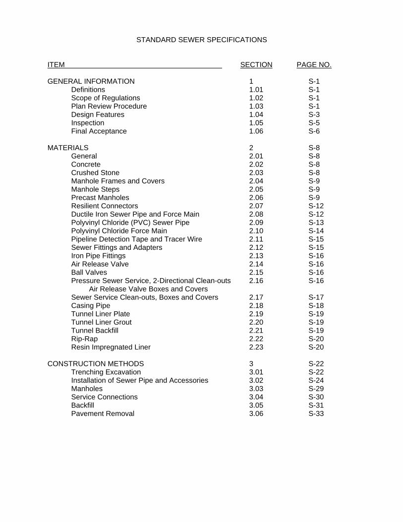
STANDARD SEWER SPECIFICATIONS
ITEM SECTION PAGE NO. GENERAL INFORMATION 1 S-1 Definitions 1.01 S-1 Scope of Regulations 1.02 S-1 Plan Review Procedure 1.03 S-1 Design Features 1.04 S-3 Inspection 1.05 S-5 Final Acceptance 1.06 S-6 MATERIALS 2 S-8 General 2.01 S-8 Concrete 2.02 S-8 Crushed Stone 2.03 S-8
Manhole Frames and Covers 2.04 S-9 Manhole Steps 2.05 S-9 Precast Manholes 2.06 S-9
Resilient Connectors 2.07 S-12 Ductile Iron Sewer Pipe and Force Main 2.08 S-12
Polyvinyl Chloride (PVC) Sewer Pipe 2.09 S-13 Polyvinyl Chloride Force Main 2.10 S-14 Pipeline Detection Tape and Tracer Wire 2.11 S-15
Sewer Fittings and Adapters 2.12 S-15 Iron Pipe Fittings 2.13 S-16 Air Release Valve 2.14 S-16 Ball Valves 2.15 S-16 Pressure Sewer Service, 2-Directional Clean-outs 2.16 S-16 Air Release Valve Boxes and Covers Sewer Service Clean-outs, Boxes and Covers 2.17 S-17 Casing Pipe 2.18 S-18 Tunnel Liner Plate 2.19 S-19 Tunnel Liner Grout 2.20 S-19 Tunnel Backfill 2.21 S-19 Rip-Rap 2.22 S-20 Resin Impregnated Liner 2.23 S-20 CONSTRUCTION METHODS 3 S-22 Trenching Excavation 3.01 S-22 Installation of Sewer Pipe and Accessories 3.02 S-24 Manholes 3.03 S-29 Service Connections 3.04 S-30 Backfill 3.05 S-31 Pavement Removal 3.06 S-33

ITEM SECTION PAGE NO. Pavement Replacement 3.07 S-33 Clean-up Procedures and Requirements 3.08 S-34 Slope Protection and Erosion Control 3.09 S-34
Sewer Line Videotaping 3.10 S-35 GPS Location Requirements 3.11 S-35 Manhole Sealing and Protective Coating 3.12 S-35 Lining by Resin Impregnated Felt Tube Method 3.13 S-37
TESTING 4 S-39 General 4.01 S-39 Visual Inspection 4.02 S-39 Air Pressure Tests 4.03 S-40 Roundness Tests 4.04 S-41 Infiltration Tests (Leakage Tests) 4.05 S-41 Vacuum Testing of Manholes 4.06 S-42 Testing of Force Mains and Pressure Sewers 4.07 S-42 Testing of Valves 4.08 S-43 GREASE TRAP POLICY 5 S-44 General 5.01 S-44 Precast Concrete Grease Trap Interceptor Sizing 5.02 S-44 Piping 5.03 S-44 Baffles 5.04 S-45 Manholes (Access Openings) 5.05 S-45 Location and Operation 5.06 S-45 Grease Trap Material 5.07 S-45 Sand/Grit and Oil/Water Separators 5.08 S-45 APPENDIX Standard Detail Drawings S-1 through S-20

S-1
SECTION 1 - GENERAL 1.01 DEFINITIONS Sewer Department - Hendersonville Utility District of Sumner County, Tennessee City - City of Hendersonville, Sumner County, Tennessee Planning Commission - Hendersonville Regional Planning Commission Developer - Owner of a proposed development in which sewer lines are to be located. Contractor - Contractor who is installing sewer lines in a proposed development or project.
Engineer - One who has prepared the construction drawings and specifications for the installation of sewer lines in a proposed development. As provided by the laws of the State of Tennessee, he must be a registered professional engineer and drawings, specifications, and calculations must bear his official seal.
State Regulatory Authority - Tennessee Department of Environment & Conservation
Division of Water Pollution Control 1.02 SCOPE OF REGULATIONS These regulations shall apply to any persons, developer, firm, business or entity
interested in and desiring to construct additional sewer lines or to extend or replace existing sewer lines within the Hendersonville Utility District’s service boundaries or to construct additional sewer lines or extend or replace existing sewer lines in a way that affects the sewer service provided by the District.
1.03 PLAN REVIEW PROCEDURE Before any connection is made to a sewer line of the Sewer Department, a Developer, or
other party, through their Engineer shall submit and receive approval of a proposed plan. The submittal shall consist of neat, scaled drawings and specifications and at least two (2) copies for review and mark-up. Sewer Department will retain one (1) copy. Once noted changes have been corrected, Engineer is to submit eight (8) sets of plans to Sewer Department for approval stamp. Sewer Department will retain one set of stamped drawings with the remainder to be returned to the Engineer. Drawings will not be deemed approved until the Sewer Department’s stamp of approval has been affixed to the cover sheet of the drawings and specifications. A copy of the preliminary plat or overall drawing showing the total site and location of the site shall be provided with the drawings.
The approval of the Sewer Department must be obtained before submittal of the
drawings and specifications to the State Regulatory Authority. Both approvals must be obtained before construction is started. Evidence of State Regulatory Authority approval must be furnished to the Sewer Department before beginning construction. Approval of drawings for proposed sewer line construction for new subdivisions and other developments must be obtained from the Sewer Department before final approval for such developments will be granted by the Planning Commission. Approval of drawings shall be valid for one (1) year from the date of approval. Contractor shall retain one set
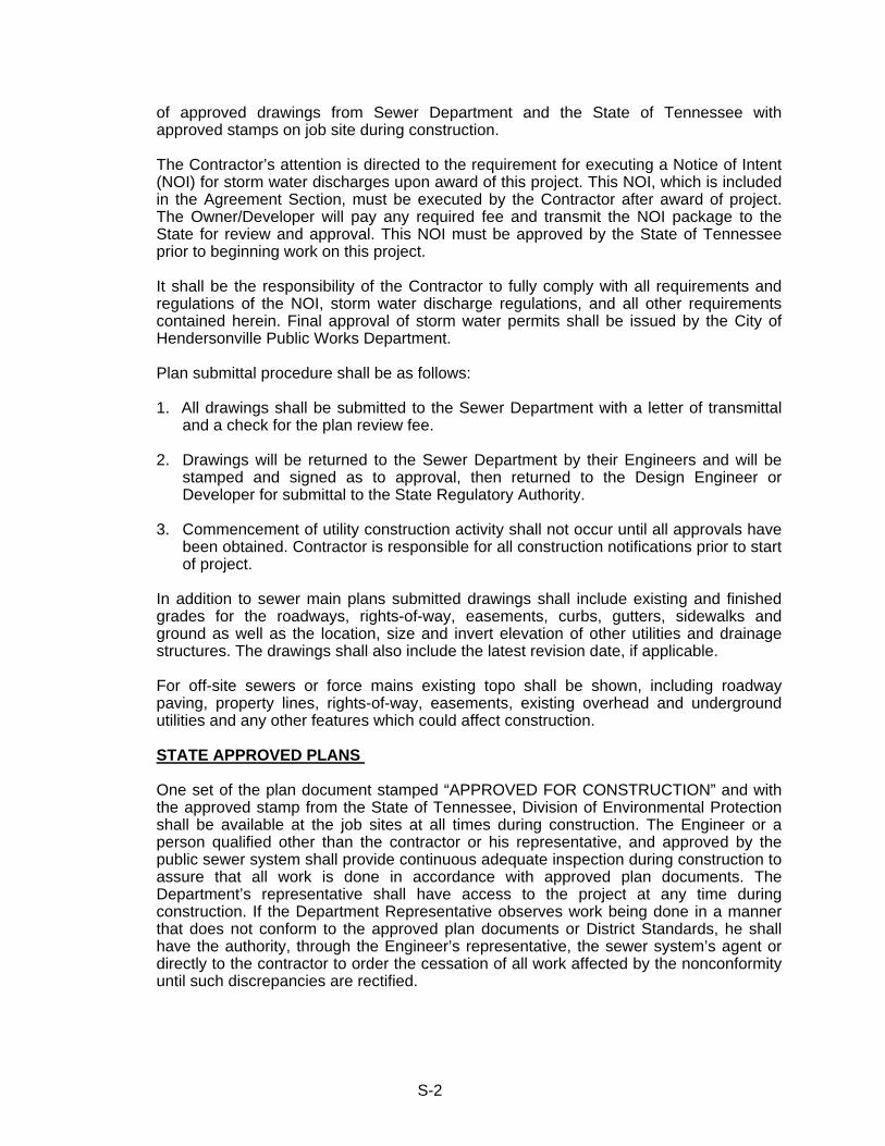
S-2
of approved drawings from Sewer Department and the State of Tennessee with approved stamps on job site during construction.
The Contractor’s attention is directed to the requirement for executing a Notice of Intent
(NOI) for storm water discharges upon award of this project. This NOI, which is included in the Agreement Section, must be executed by the Contractor after award of project. The Owner/Developer will pay any required fee and transmit the NOI package to the State for review and approval. This NOI must be approved by the State of Tennessee prior to beginning work on this project.
It shall be the responsibility of the Contractor to fully comply with all requirements and
regulations of the NOI, storm water discharge regulations, and all other requirements contained herein. Final approval of storm water permits shall be issued by the City of Hendersonville Public Works Department.
Plan submittal procedure shall be as follows:
1. All drawings shall be submitted to the Sewer Department with a letter of transmittal and a check for the plan review fee.
2. Drawings will be returned to the Sewer Department by their Engineers and will be
stamped and signed as to approval, then returned to the Design Engineer or Developer for submittal to the State Regulatory Authority.
3. Commencement of utility construction activity shall not occur until all approvals have
been obtained. Contractor is responsible for all construction notifications prior to start of project.
In addition to sewer main plans submitted drawings shall include existing and finished
grades for the roadways, rights-of-way, easements, curbs, gutters, sidewalks and ground as well as the location, size and invert elevation of other utilities and drainage structures. The drawings shall also include the latest revision date, if applicable.
For off-site sewers or force mains existing topo shall be shown, including roadway
paving, property lines, rights-of-way, easements, existing overhead and underground utilities and any other features which could affect construction.
STATE APPROVED PLANS
One set of the plan document stamped “APPROVED FOR CONSTRUCTION” and with the approved stamp from the State of Tennessee, Division of Environmental Protection shall be available at the job sites at all times during construction. The Engineer or a person qualified other than the contractor or his representative, and approved by the public sewer system shall provide continuous adequate inspection during construction to assure that all work is done in accordance with approved plan documents. The Department’s representative shall have access to the project at any time during construction. If the Department Representative observes work being done in a manner that does not conform to the approved plan documents or District Standards, he shall have the authority, through the Engineer’s representative, the sewer system’s agent or directly to the contractor to order the cessation of all work affected by the nonconformity until such discrepancies are rectified.
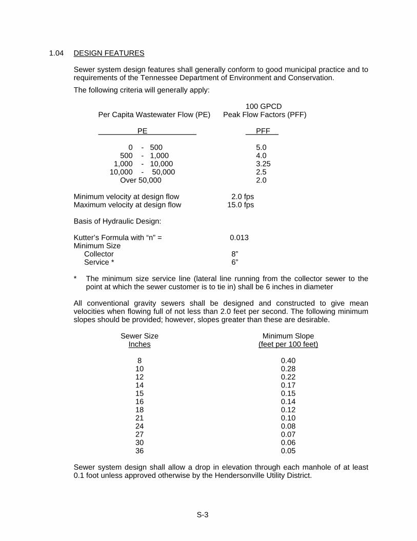
S-3
1.04 DESIGN FEATURES Sewer system design features shall generally conform to good municipal practice and to
requirements of the Tennessee Department of Environment and Conservation. The following criteria will generally apply: 100 GPCD Per Capita Wastewater Flow (PE) Peak Flow Factors (PFF) PE PFF 0 - 500 5.0 500 - 1,000 4.0 1,000 - 10,000 3.25 10,000 - 50,000 2.5 Over 50,000 2.0 Minimum velocity at design flow 2.0 fps Maximum velocity at design flow 15.0 fps Basis of Hydraulic Design: Kutter’s Formula with “n” = 0.013 Minimum Size Collector 8” Service * 6” * The minimum size service line (lateral line running from the collector sewer to the
point at which the sewer customer is to tie in) shall be 6 inches in diameter All conventional gravity sewers shall be designed and constructed to give mean
velocities when flowing full of not less than 2.0 feet per second. The following minimum slopes should be provided; however, slopes greater than these are desirable.
Sewer Size
Inches Minimum Slope
(feet per 100 feet)
8 0.40 10 0.28 12 0.22 14 0.17 15 0.15 16 0.14 18 0.12 21 0.10 24 0.08 27 0.07 30 0.06 36 0.05
Sewer system design shall allow a drop in elevation through each manhole of at least
0.1 foot unless approved otherwise by the Hendersonville Utility District.
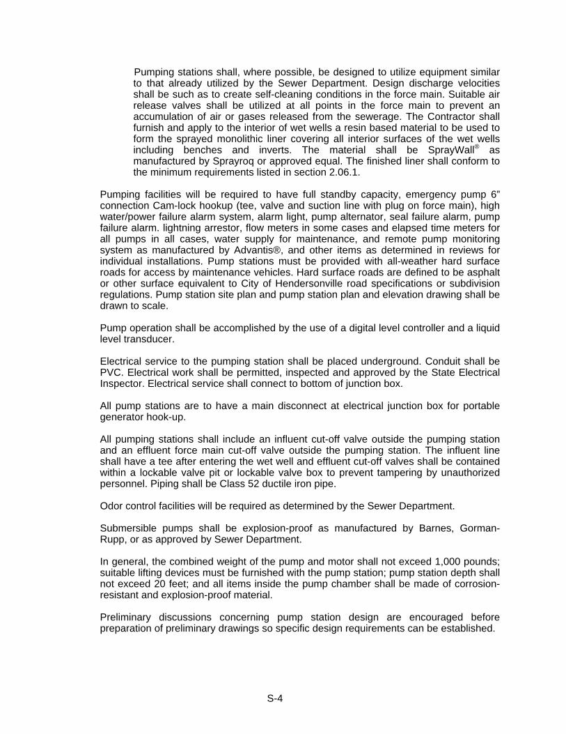
S-4
Pumping stations shall, where possible, be designed to utilize equipment similar to that already utilized by the Sewer Department. Design discharge velocities shall be such as to create self-cleaning conditions in the force main. Suitable air release valves shall be utilized at all points in the force main to prevent an accumulation of air or gases released from the sewerage. The Contractor shall furnish and apply to the interior of wet wells a resin based material to be used to form the sprayed monolithic liner covering all interior surfaces of the wet wells including benches and inverts. The material shall be SprayWall® as manufactured by Sprayroq or approved equal. The finished liner shall conform to the minimum requirements listed in section 2.06.1.
Pumping facilities will be required to have full standby capacity, emergency pump 6”
connection Cam-lock hookup (tee, valve and suction line with plug on force main), high water/power failure alarm system, alarm light, pump alternator, seal failure alarm, pump failure alarm. lightning arrestor, flow meters in some cases and elapsed time meters for all pumps in all cases, water supply for maintenance, and remote pump monitoring system as manufactured by Advantis®, and other items as determined in reviews for individual installations. Pump stations must be provided with all-weather hard surface roads for access by maintenance vehicles. Hard surface roads are defined to be asphalt or other surface equivalent to City of Hendersonville road specifications or subdivision regulations. Pump station site plan and pump station plan and elevation drawing shall be drawn to scale.
Pump operation shall be accomplished by the use of a digital level controller and a liquid
level transducer. Electrical service to the pumping station shall be placed underground. Conduit shall be
PVC. Electrical work shall be permitted, inspected and approved by the State Electrical Inspector. Electrical service shall connect to bottom of junction box.
All pump stations are to have a main disconnect at electrical junction box for portable
generator hook-up. All pumping stations shall include an influent cut-off valve outside the pumping station
and an effluent force main cut-off valve outside the pumping station. The influent line shall have a tee after entering the wet well and effluent cut-off valves shall be contained within a lockable valve pit or lockable valve box to prevent tampering by unauthorized personnel. Piping shall be Class 52 ductile iron pipe.
Odor control facilities will be required as determined by the Sewer Department. Submersible pumps shall be explosion-proof as manufactured by Barnes, Gorman-
Rupp, or as approved by Sewer Department. In general, the combined weight of the pump and motor shall not exceed 1,000 pounds;
suitable lifting devices must be furnished with the pump station; pump station depth shall not exceed 20 feet; and all items inside the pump chamber shall be made of corrosion-resistant and explosion-proof material.
Preliminary discussions concerning pump station design are encouraged before
preparation of preliminary drawings so specific design requirements can be established.
S-5
Pipe Material shall be designated on approved construction drawings and shall conform to applicable specifications included in Section 2 of these Standard Specifications. The Engineer shall, therefore, designate pipe materials on all construction drawings.
Separation of Water Mains and Sewers shall be maintained in accordance with the
following guidelines:
For parallel installations, line separation is to be at least 10 feet edge to edge. If this cannot be obtained the bottom of the water line shall be at least 18 inches above the top of the sewer. If this condition is also unobtainable the sewer line is to be constructed of materials and have a joint design equivalent to water main standards as approved by the Water Department and shall be pressure tested to 50 psi to assure water tightness. Where the water line crosses house sewers, storm sewers, or sanitary sewers, a separation of at least 18 inches shall be provided between the bottom of the water line and the top of the sewer. If this separation cannot be obtained sewers within 10 feet of the water line shall be constructed of materials and have a joint design equivalent to water main standards as approved by the Water Department. Such sewer lines shall be pressure tested to 50 psi to assure water tightness. In addition to the above sewer line construction water mains passing under sewers shall be protected by providing: at least 18 inches between the bottom of the sewer and the top of the water line; adequate structural support of the sewer to prevent excessive joint deflection or damage to the water line; centering of the water line section to result in the water line joints being removed from the sewer line to the maximum possible extent.
No water line shall pass through or come into contact with any part of a sewer or sewer manhole.
Sanitary Sewer Services - Sewer services shall not enter manholes except in the cases
of terminal manholes. Easements - All sewers constructed in easements shall be C900 DR-14 PVC pipe. A
dedicated water and sewer easement as listed below, unless approved otherwise by the Hendersonville Utility District. When sanitary sewers are constructed outside a public right-of-way, easements must be provided to the Hendersonville Utility District using the following:
Sewer Depth (feet) * Easement Width Required (minimum) 0 - 12 20 feet 12 - 20 30 feet * No sewer is allowed less than 36-inches deep or deeper than 20 feet without special
approval by the Hendersonville Utility District. Also any section of sewer which is less than 4-feet or over 12 feet deep to the invert at any point or will not be readily accessible is to be constructed using C900 PVC pipe from manhole to manhole. Force mains shall be in accordance with this division and Division 3 of the Standard Specifications.
1.05 INSPECTION All projects shall be subject to inspection during and upon completion of construction by
an authorized representative of the Sewer Department. Inspection may consist of full-time resident inspection or part-time inspection at the sole discretion of the Sewer

S-6
Department. Presence or absence of the inspector during construction does not relieve the Developer and/or Contractor from adherence to approved drawings and specifications.
The work shall, at all times, be subject to the inspection of authorized representatives of
the Sewer Department and materials and/or workmanship found not meeting requirements of approved drawings and specifications shall be immediately brought into conformity with said drawings and specifications.
An authorized representative of the Sewer Department shall make a final inspection of
the project after completion to determine acceptability of the work. Before this final inspection can be made the Engineer responsible for the project shall notify the Sewer Department in writing that the work has been completed in accordance with approved drawings and specifications.
An authorized representative of the Tennessee Department of Environment and
Conservation shall have the right to inspect the construction work and shall be notified of the final inspection date on the work.
Final acceptance of the work shall be accomplished as described in Paragraph 1.06. 1.06 FINAL ACCEPTANCE When facilities qualify as public facilities the Sewer Department will accept ownership of
the completed facilities when the work has passed the final inspection and when final drawings are submitted to the Sewer Department reflecting actual “AS BUILT” conditions. The “AS BUILT” drawings shall be complete and show final location of sewer lines, manholes, services, easements and other items appurtenant to the system. One (1) set of acceptable “AS BUILT” drawings, and cost of installation shall be submitted to the Sewer Department before final acceptance of the work is made.
“As built” drawings shall consist of the following:
1. Finished Invert elevation of each manhole and top finished grade elevation of each
casting
2. Each manhole, tee, clean out, valve box, and fittings shall be GPS located with XYZ coordinates to integrate with HUD GIS system. Each located point shall be included in a Comma Separated Value (.csv), Microsoft Excel spreadsheet (.xls), or approved file format. The CSV file shall include, at minimum, the following information:
Position/Column Description 1 Point Reference Number 2 X Coordinate (Easting) 3 Y Coordinate (Northing) 4 Z Coordinate (Elevation) 5 Point Type (Manhole, Valve, Meter, Fire Hydrant, etc.
6 Point Description
3. All services shall be located (in feet) from the nearest downstream manhole of each section and include the length and depth of service.

S-7
4. Final televised digital log sheet that include the distance to each clean out and house and/or lot number on DVD, or CD of each sewer section. (2 Each)
5. One set of Mylar prints and a Portable Document Format (.pdf) file.
6. Tee location form in digital format shall include the line designation, station number, distance in feet from the nearest downstream manhole, length, depth of service and lot number.
Final acceptance by the Sewer Department will be made in writing upon satisfactory
completion of the project including final inspection, submittal of acceptable “AS BUILT” drawings and payment of all fees due. The Developer/Contractor shall guarantee the work for a period of one year from the date of final acceptance and shall immediately correct any deficiencies in the work due to materials and/or workmanship which occur during the guarantee period. The date of final acceptance shall be that date on which the Developer/Contractor has fulfilled all conditions necessary for final acceptance including passing a final inspection, submittal of acceptable “AS BUILT” drawings, and payment of all fees due.
* * *
S-8
SECTION 2 - MATERIALS 2.01 GENERAL
All materials to be incorporated in the project shall be first quality, new, and undamaged material conforming to all applicable portions of these Specifications.
2.02 CONCRETE Cement - Cement shall be Portland cement of a brand approved by the Engineer and
shall conform to “Standard Specifications for Portland Cement," Type 1, ASTM Designation C-150, latest revision. Cement shall be furnished in undamaged 94- pound, one cubic foot sacks and shall show no evidence of lumping.
Concrete Fine Aggregate - Fine aggregate shall be clean, hard uncoated natural sand
conforming to ASTM Designation C-33, latest revision, "Standard Specifications for Concrete Aggregate."
Concrete Coarse Aggregate - Coarse aggregate shall consist of clean, hard, dense
particles of stone or gravel conforming to ASTM Designation C-33, latest revision, "Standard Specifications for Concrete Aggregate." Aggregate shall be well graded between 1-1/2-inch and #4 sieve sizes.
Water - Water used in mixing concrete shall be clean and free from organic matter,
pollutants, and other foreign materials. Ready-Mix Concrete - Ready-mix concrete shall be secured only from a source
approved by the Engineer and shall conform to ASTM Designation C-94, latest revision, "Specifications for Ready-Mix Concrete." Before any concrete is delivered to the job site the supplier must furnish a statement of the proportions of cement, fine aggregate, and coarse aggregate to be used for each mix ordered and must receive the Engineer's approval of such proportions.
Class "D" Concrete - Class "D" concrete shall have a minimum compressive strength of
4,500 pounds per square inch in 28 days and shall contain not less than 5.5 sacks of cement per cubic yard.
Class "C" Concrete - Class "C" concrete shall have a minimum compressive strength of
2,000 pounds per square inch in 28 days and shall contain not less than 4.5 sacks of cement per cubic yard.
Metal Reinforcing - Reinforcing bars shall be intermediate grade steel conforming to
ASTM Designation A-615, latest revision, "Standard Specifications for Billet Steel Bars for Concrete Reinforcement." Bars shall be deformed with a cross-sectional area at all points equal to that of plain bars of equal nominal size.
2.03 CRUSHED STONE
Crushed stone for pipe bedding shall meet the quality requirements of ASTM D-692 and the grading requirements of AASHTO M-43 for size 67. Crushed stone for backfill shall meet the quality requirements of ASTM D-692 and the grading requirements of AASHTO M-43 for size 67.
S-9
2.04 MANHOLE FRAMES & COVERS
Manhole castings shall conform to ASTM Designation A-48, latest revision, Class 30, and shall be free from scale, lumps, blisters, sandholes, and defects of every nature which would impair their use. Castings shall be well cleaned with a smooth tough asphaltic coating. Covers shall be of the solid-indented type with the words "SANITARY SEWER" cast in raised letters thereon. Bearing surfaces of frames and covers shall be machined to provide a solid bearing and prevent rocking. Pattern drawings and weights of castings shall be submitted for the approval of the Engineer.
Vented lids shall be furnished and installed at ends of lines and at approximately 1,400
feet along line segments. Locations of all vented lids shall be at locations determined by the Engineer.
Manhole frames and covers (minimum clear openings to be 24 inches) shall be equal to
those listed below for particular applications. NON-TRAFFIC John Bouchard No. 1155 (Standard) TRAFFIC Same as Non-Traffic type specified above WATERTIGHT To be used where manhole casting is subject to flood or
submergence by surface runoff John Bouchard No. 1123
WATERTIGHT INSERT To be used as directed by Engineer. Manhole frame and cover to be same as non-traffic type as specified above. Insert to be Sewer Guard as manufactured by Preco Industries Ltd. or equal.
Exceptions to the above shall be noted on the Construction Drawings. 2.05 MANHOLE STEPS
Steps shall be aluminum, equal to #15295 by Alcoa or plastic encapsulated steel equal to No. PS 1-45 as manufactured by M.A. Industries, Inc., East Point, Georgia.
2.06 PRECAST MANHOLES
Precast manholes shall conform to the latest revision of ASTM C-478, latest revision. Drawings of manhole sections proposed for use on this project must be submitted to the Engineer for approval prior to use. Steps shall be furnished in accordance with Paragraph 5 of this Section and care must be taken to assure a firmly embedded step with no cracks from mortar shrinkage which will allow leakage. Loose steps and shrinkage cracks passing through manhole walls shall be cause for rejection.
All manholes constructed and installed shall be cast with XYPEX® Admix C-1000 in the
concrete for waterproofing and corrosive protection. The manufacturer’s recommended addition rate for Concentrate C-1000 is 3% by weight of cement. XYPEX® C-1000 shall

S-10
be as supplied by Tom Williams; 1231 Antioch Pike; Nashville, Tennessee. Precast manholes with XYPEX® C-1000 Admix shall be as manufactured by Cloud Concrete Products of Lavergne, Tennessee or Engineer approved equal.
Manhole sections showing evidence of cracking, crazing, honeycombing, crumbling, or
excessive roughness will not be acceptable. Sections with improper cut-outs, misalignments or other defects shall not be utilized in the project.
Manhole sections shall be steam or water cured and shall not be delivered to job site
until at least 7 days old. Each section shall be marked in a permanent manner with date of manufacture, manufacturer's mark, and manhole location or manhole number. Manhole sections to receive pipes shall be furnished with appropriate cut-outs with resilient connectors for installation of pipe.
On precast manhole sidewall an approved flexible plastic gasket equal to RAM-NEK
shall be applied to the joint surface to placement of next manhole section. The placement of this gasket shall also be required under all manhole castings and adjustment rings for castings. All joints shall be wiped with Portland cement and brushed to a smooth finish
Testing and Inspection of precast manhole sections shall be done at the site of
manufacture in accordance with ASTM C- 478, latest revision by the manufacturer. Compression tests shall be run on specimens obtained from each day's production: a minimum of 2 cylinders or cores per day's run but no less than the maximum number designated by ASTM C-478, latest revision. The absorption test shall be run on a minimum of two randomly selected manhole sections per each day's production. Three (3) copies of certified test reports shall be submitted to the Engineer.
In addition to testing required of the manufacturer as described above the Owner may
provide an independent testing laboratory to make visual inspections of manhole sections produced from selected sections. The random samples will be selected by the Owner's testing laboratory and will be taken from stock on the manufacturer's yard intended for use on this project. Core samples shall be cut from designated sections amounting to no more than 4% of the total production in order to run compressive strength and absorption tests. The manufacturer shall cut the cores and seal the holes but this testing shall be done by the Owner's testing laboratory and paid for by the Owner. In the event the samples fail to conform to the Specifications the manufacturer may furnish additional test specimens to the extent permitted by the Specifications. Testing done by the Owner's testing laboratory shall be in accordance with ASTM C-478, latest revision.
2.06.1 MANHOLE SEALING AND PROTECTIVE COATING Manhole sealing involves materials to be used for sealing manhole sidewalls and
benches. For voids, leaks, and/or invert work required, Strong-Seal QSR®, Strong Plug®, or approved equal, shall be used.
Materials for cementitious sealant applications shall be Strong-Seal® MS2-C or
Hendersonville Utility District approved equal. This material shall be a calcium aluminate cement and used in accordance with manufacturer’s recommendations. Material shall be a factory blended requiring only the addition of water at the jobsite.

S-11
The Contractor shall submit materials to be used to the Hendersonville Utility District for review and approval.
The cementitious liner product shall be used to form a structural monolithic liner
covering all interior surfaces and have the following minimum requirements: 1. TENSILE STRENGTH, psi ASTM C-496 >800 2. COMPRESSIVE STRENGTH, psi ASTM C-109 >8000 3. FLEXURAL STRENGTH, psi ASTM C-293 >1000 4. SHRINKAGE @90% R.H. ASTM C-596 0% 5. BOND, psi ASTM C-882 <2000 6. DENSITY, WHEN APPLIED Pounds per cubic foot 134 ± 5 7. FREEZE / THAW, cycles ASTM C-666 100 (no visible damage) For manholes located along or near creeks and Old Hickory Lake, manholes
where force mains discharge that need resistance to sulfide corrosion, all wetwells located within the system, or as directed by the Sewer Department the Contractor shall furnish and apply to the interior of manholes a calcium aluminum cement based and resin based material to be used to form the sprayed monolithic liner covering all interior surfaces of the manhole including benches and inverts. The material shall consist of Strong-Seal® profile mix or Warren Environmental® epoxy liner to a minimum of 125 mils or as required by the Hendersonville Utility District. An approved equal to the above liner material is the SpectraShield® Liner Systems. The finished liner shall conform to the minimum requirements listed below:
1. Compressive Strength, psi ASTM D-695 10,500 2. Tensile Strength, psi ASTM D-538 7,000 3. Shrinkage, psi ASTM D-2566 ½ of 1% 4. Flexure Strength, psi ASTM D-790 12,000 5. Bond shall exceed tensile strength 6. Flexure Modulus (initial), psi ASTM D-790 735,000 7. Density 8% pcf
S-12
The finished manholes shall be corrosion resistant to: Hydrogen Sulfide; 20% Sulfuric Acid; 17% Nitric Acid; 5% Sodium Hydroxide as well as other common ingredients of the sanitary sewerage environment.
Note: All sealing and coating of interior manhole and invert surfaces shall be by
the spray applied method only. 2.07 RESILIENT CONNECTORS
All connections of pipes to manhole sidewalls shall be made with resilient connectors. Resilient connectors for connection of pipes to manhole sidewalls shall be Kor-N-Seal or approved equal.
Openings in the manhole sidewall shall be so constructed as to include the resilient connector such that it is an integral part of the sidewall and to provide for the required size and location of the pipe to connect to the manhole. The sidewall opening shall be manufactured to allow for lateral and vertical movement as well as angular adjustments through 20 degrees. The resilient connector shall be Kor-N-Seal as manufactured by NPC, Inc. or approved equal. The resilient connector shall meet all physical and performance requirements as set forth by ASTM C-923, latest revision.
2.08 DUCTILE IRON PIPE (ONLY ALLOWED WHEN REQUIRED BY UTILITY DISTRICT
DUE TO UNDERGROUND CONDITIONS) Ductile iron pipe for gravity lines shall conform to USA Standard A21.52, latest revision
for centrifugally cast pipe. The pipe shall be manufactured of iron having acceptance values of 60-42-10.
Pipe shall be furnished in lengths of 18 feet to 20 feet and, unless otherwise indicated,
shall be provided with a compression type slip joint equal to the Fastite joint as manufactured by American. Gaskets and lubricants shall be furnished with the pipe. Ductile iron pipe installed within 100 feet of underground fuel tanks shall be installed with Viton joint gaskets or approved equal.
Pipe shall be furnished with Protecto 401 ceramic epoxy lining with standard thickness
on the inside as recommended by manufacturer. Lining shall conform to ASTM D 714 Standards, latest revision. The exterior of the pipe shall be clearly marked to indicate the manufacturer, date of manufacture, the pipe class and weight. Exterior markings shall also positively identify the pipe as being Ductile Iron.
Ductile iron pipe shall be furnished with wall thickness in accordance with the following schedule (or heavier), unless noted otherwise on the Drawings (Thickness Class 52).
Nominal Pipe Diameter Minimum Wall Thickness 6" 0.31" 8" 0.33" 10" 0.35" 12" 0.37" 16" 0.40" 18" 0.41" 20" 0.42" 24" 0.44" 30" 0.47" 36" 0.53"

S-13
Ductile iron pipe for force mains shall be at least Thickness Class 52 unless shown
otherwise on the Drawings. Ductile iron pipe on piers or in tunnel/bore shall be at least Thickness Class 52 unless
shown otherwise on the Drawings. All ductile iron pipe shall be first quality with manufacturer's identification and pipe class
clearly shown on each section. Pipe manufacturer shall furnish, upon request, the test date for quality control during the
manufacturing period for pipe furnished on the project. Testing and inspection shall be in accordance with ASA A.21.51, latest revision. Tests to include hydrostatic test (500 psi - 10 sec.); tensile test; impact test; one sample to be taken during each casting period of approximately 3 hours.
2.09 POLYVINYL CHLORIDE (PVC) SEWER PIPE PVC sewer pipe may be used for 18-inch gravity sewer lines or smaller. PVC sewer pipe
shall be SDR 35, or heavier, manufactured in accordance with ASTM D-3034, latest revision, for type PSM sewer pipe and fittings, 6-inch through 15-inch; ASTM F-679 (wall thickness T-1), 18-inch through 27-inch. For sewer pipe to be installed at depths greater than 12-feet, PVC pipe C-900, DR14 shall be used. Pipe shall be furnished in lengths not exceeding 13 feet. Pipe shall be furnished with integral bells. Gaskets and lubricants shall be furnished by the pipe manufacturer. Pipe and fittings shall be made of PVC plastic having a cell classification of 12454-B or 12454-C as defined in ASTM D-1784, latest revision.
Joints shall be compression type utilizing an elastomeric gasket providing a positive seal
against groundwater and root intrusion as well as sewage leakage and shall be in accordance with ASTM D-3212,latest revision. Gaskets shall comply with physical requirements specified in ASTM F-477, latest revision. Lubricant shall be furnished with the gaskets and shall be entirely compatible with gasket and pipe material.
Joints shall show no signs of leakage when tested as follows (supersedes ASTM D-
3034): Typical joint assembly shall be subjected to internal hydrostatic pressure of 10.8 psig for 10 minutes without leakage; assembly shall also be subjected to internal vacuum of 22 inches of mercury or external pressure of 10.8 psig for 10 minutes without leakage. The above internal pressure and vacuum (or external pressure) tests shall be run on a typical joint assembly in concentric alignment and in a position of angular deflection to at least 3.
Testing and inspection of all pipes shall be done at the factory with a certified copy of
test results furnished to the Engineer prior to any pipe being installed. Tests shall be done in accordance with ASTM D-3034 or ASTM F-679, latest revision and shall include: Pipe and Fitting Dimensions; Pipe Flattening; Impact Resistance; Pipe Stiffness; Joint Tightness; and Extrusion Quality. At least 1% of the production of each size furnished for this project shall be tested.
Each pipe section shall be marked with the following information:

S-14
6-inches to 15-inches: Manufacturer's name or trademark; nominal pipe size; PVC cell classification; Legend "Type PSM Dr 35 PVC Sewer Pipe"; ASTM D-3034, latest revision.
16-inches or greater: Manufacturer's name or trademark; nominal pipe size;
PVC cell classification; Legend "PS 46 PVC Sewer Pipe"; ASTM F-679, latest revision.
2.10 POLYVINYL CHLORIDE (PVC) PRESSURE SEWER FORCE MAIN PIPE AWWA C-900 PVC force main pipe (4-inch through 12-inch) shall be DR-18; 235 PSI;
w/cast iron pipe equivalent OD’s and shall conform to ANSI / AWWA C-900 manufactured in accordance with ASTM D1784, latest revision. All pipe shall be manufactured from Class 12454-B Polyvinyl chloride plastic (PVC 1120) as defined in ASTM D-1784. The pipe shall have NSF approval. The following test shall be performed for each machine and on each size and type of pipe being produced with test results furnished to the Engineer prior to any pipe being installed.
Flattening Test - Once per shift in accordance with ASTM D-2412, latest revision. Upon
completion of the test, the specimen shall not be split, cracked, or broken. Acetone Test (Extrusion Quality Test) - Once per shift in accordance with ASTM D-2152,
latest revision. There shall be no flaking, peeling, cracking, or visible deterioration on the inside or outside surface after completion of the tests.
Quick Burst Test - Once per 24 hours in accordance with ASTM 1599. Minimum Bursting SDR Pressure Rating Pressure, psi 18 235 985 Wall Thickness and Outside Dimensions Tests - Once per hour in accordance with
ASTM D-2122. Bell Dimension Test - Once per hour in accordance with ASTM D-3139, latest revision. In addition to the above, the pipe manufacturer shall furnish a certificate stating that he
is fully competent to manufacture PVC pipe of uniform texture and strength and in full compliance with these Specifications and further stating that he has manufactured such pipe and done so in sufficient quantities to be certain that it will meet all normal field conditions. In addition, the manufacturer’s equipment and quality control facilities must be adequate to ensure that each extrusion of pipe is uniform in texture, dimensions, and strength. Also furnish a certificate from the manufacturer certifying that the pipe furnished for this project meets the requirements of these Specifications.
All pipe shall be manufactured in the United States of America. All pipe for any one
project shall be made by the same manufacturer. The pipe may be furnished in the manufacturer’s standard laying lengths of 20 feet. The
Contractor’s methods of storing and handling the pipe shall be approved by the Engineer. All pipe shall be supported within 5 feet of each end; in between the end supports, there shall be additional supports at least every 15 feet. The pipe shall be
S-15
stored away from heat or direct sunlight. The practice of stringing pipes out along the proposed water line routes will not be allowed.
Certain information shall be applied to each piece of pipe. At the least, this shall consist
of: Normal Size Type of material SDR or class Manufacturer NSF Seal of Approval AWWA C-900 Pipe that fails to comply with the requirements set forth in these Specifications shall be
rejected. Pressure Class at 73.4º shall be 235 PSI (DR 18). Joints shall be compression type
conforming to ASTM D-3139 and F-477. Latest revision shall be used for 4-inch or larger. All joints shall be designed to withstand the same pressure as required for the pipe.
Furnish detection tape and trace wire as per specifications in this Section. Fittings for C-900 force main pipe 4-inch through 12-inch shall be compact ductile iron
conforming to USA Std. A21.53-84, latest revision. Fittings shall have interior lining and exterior coating as specified for ductile iron pipe. Fittings for 12-inch and smaller pipe may be either cast iron or ductile iron.
2.11 PIPELINE DETECTION TAPE AND TRACER WIRE Detectable pipeline location tape shall be plastic composition film containing one layer of
metalized foil laminated between two layers of inert plastic film specifically formulated for prolonged use underground. Tape shall be a minimum of 5.5 mils thickness and continuously printed in permanent ink to indicate caution for a buried sewer line below.
All pressure sewers and force mains not constructed of ferrous material shall be
installed with detectable tape and tracer wire. Detectable tape shall be 3 inches wide and shall be an inert, bonded layer plastic with a
metalized foil core and shall be highly resistant to alkalis, acids, or other destructive chemical components likely to be encountered in soils. The tape shall be brightly colored (Green) to contrast with soil and shall bear the imprint "CAUTION -- SEWER LINE BURIED BELOW." Tape shall be Terra-Tape as manufactured by Reef Industries, Inc. or approved equal.
Additionally, the Contractor shall provide and install a 14-gauge insulated copper wire on
top of the newly installed PVC force main or pressure sewer main. (See Special Detail in Contract Drawings.)
2.12 SEWER FITTINGS AND ADAPTERS Fittings and adapters for use with PVC or DIP pipe shall be manufactured in accordance
with the Specifications for the respective types of pipe, including the required interior coating of Protector 401 ceramic epoxy lining for DI fittings.

S-16
Note: Special coupling adapters for point repairs on sewer lines and/or joining sewer lines shall provide for shear / differential settlement protection and shall be Mission Flex-Seal ARC sewer couplings as manufactured by Mission Rubber Company or Owner-approved equal.
2.13 IRON PIPE FITTINGS All fittings shall be compact ductile iron, lined with Protecto 401 ceramic epoxy lining,
manufactured in accordance with ASTM D714 Standards, latest revision, unless otherwise indicated or directed. Minimum pressure rating shall be 350 psi. Mechanical joint fittings shall be used unless indicated otherwise on the drawings.
Fitting manufacturer shall furnish certificates that fittings were manufactured in
compliance with ASTM standards, latest revision. 2.14 AUTOMATIC AIR RELEASE VALVES FOR PRESSURE SEWERS (FORCE MAINS) Automatic air release valves shall be ARI Valves, Model D-025 (w/attachments) SAAR
short version or approved equal as per special detail on the Contract Drawings. Air release valve shall be installed in eccentric manhole with required protective coatings in accordance with these specifications and details and as directed by HUD personnel.
2.15 BALL VALVES Valves on pressure sewers 1½-inch through 3-inch shall be PVC ball valves of true
union design with permanently lubricated teflon seats and elastomer "O"-ring seals. The valves are to be opened and closed with a quarter turn. Working pressure at 70 degrees F shall be 150 pounds per square inch.
2.16 PRESSURE SEWER SERVICE, 2-DIRECTIONAL CLEAN-OUTS, AIR RELEASE
VALVE BOXES, AND COVERS Typical sewer boxes shall be as indicated on the Contract Drawings or as set forth
below: The box shall be a minimum of 16" x 10-3/4" x 12" and 6-inch extensions made of
injection molded plastic meeting ASTM D-2853-70, Class 1212, as manufactured by Brooks Products, Inc. or approved equal. The cover shall be green with "SEWER" imprinted on the top. The box and lid shall have UV stabilizer additive to assure resistance to material degradation from ultraviolet light. A 2½-inch diameter, 16-gauge steel reflector with dichromate coating shall be applied to the underside of the plastic cover for electronic detection.
If the valve box must be located in a roadway or roadway shoulder subject to traffic the
valve box shall be constructed of cast iron in accordance with the following: Valve Boxes - Valve boxes are to be made of pre-cast concrete sections measuring 11"
x 13-1/4" inside dimensions and 17" x 19-1/4" outside dimensions with the height of 12 to 15 inches. Reinforcement shall be placed and shall conform to the requirements of ASTM A-15 and ASTM A-305 for intermediate grade.

S-17
Footing blocks for standard concrete valve boxes are to be pre-cast in blocks measuring 12" x 12" x 4". No reinforcing steel is required in footing blocks.
Valve Box Frames and Covers shall be made of heavy cast iron and shall meet the
requirements of ASTM A-48, Class 40. All casting shall be made accurately to the required dimensions and shall be sound,
smooth, clear and free of blemishes of other defects. Defective castings which have been plugged or otherwise treated to remedy defects shall be rejected. Contact surfaces of frames and covers to be machined so that the covers rest securely in the frames with no rocking. The cover shall be in contact with the frames for the entire perimeter of the contact surface.
The valve box frames and covers shall be as manufactured by Bouchard No. 8006,
Roadway Type, Nashville Standard or equal. The cover shall be marked "SEWER." 2.17 SEWER SERVICE CLEAN-OUTS, WYES, BOXES, AND COVERS Typical sewer service clean-outs (6-inch Minimum) shall be installed as per Standard
Details. The clean-out shall consist of a clean-out wye (no tees) along with a 45° bend ( a long sweep wye is also acceptable). The 6-inch plug or cap shall be contained in a plastic (meter type) box. Sewer Service Clean-outs shall be installed on all sewer services at the property line and right-of-way or easement line. It is the responsibility of the property owner to maintain the clean-out. Any existing service replaced or repaired shall have clean-outs installed per the requirements of this section.
The box shall be a minimum of 16" x 10-3/4" x 12" and 6-inch extensions made of
injection molded plastic meeting ASTM D-2853-70, Class 1212, as manufactured by Brooks Products, Inc. or approved equal. The cover shall be green with "SEWER" imprinted on the top. The box and lid shall have UV stabilizer additive to assure resistance to material degradation from ultraviolet light. A 2½-inch diameter, 16-gauge steel reflector with dichromate coating shall be applied to the underside of the plastic cover for electronic detection.
If the valve box must be located in a roadway or roadway shoulder subject to traffic the
valve box shall be constructed of cast iron in accordance with the following: Valve Boxes - Valve boxes are to be made of pre-cast concrete sections measuring 11"
x 13-1/4" inside dimensions and 17" x 19-1/4" outside dimensions with the height of 12 to 15 inches. Reinforcement shall be placed and shall conform to the requirements of ASTM A-15 and ASTM A-305 for intermediate grade.
Footing blocks for standard concrete valve boxes are to be pre-cast in blocks measuring
12" x 12" x 4". No reinforcing steel is required in footing blocks. Valve Box Frames and Covers shall be made of heavy cast iron and shall meet the
requirements of ASTM A-48, Class 40. All casting shall be made accurately to the required dimensions and shall be sound,
smooth, clear and free of blemishes of other defects. Defective castings which have been plugged or otherwise treated to remedy defects shall be rejected. Contact surfaces of frames and covers to be machined so that the covers rest securely in the frames with no rocking. The cover shall be in contact with the frames for the entire perimeter of the contact surface.
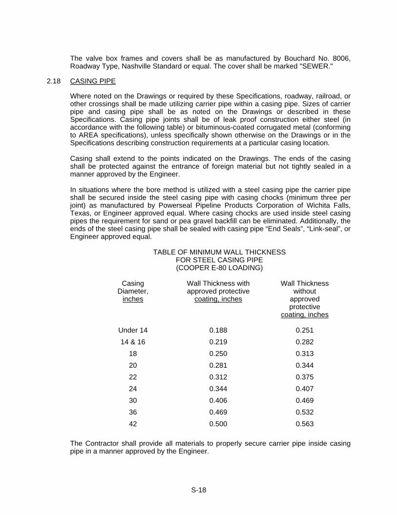
S-18
The valve box frames and covers shall be as manufactured by Bouchard No. 8006,
Roadway Type, Nashville Standard or equal. The cover shall be marked "SEWER."
2.18 CASING PIPE
Where noted on the Drawings or required by these Specifications, roadway, railroad, or other crossings shall be made utilizing carrier pipe within a casing pipe. Sizes of carrier pipe and casing pipe shall be as noted on the Drawings or described in these Specifications. Casing pipe joints shall be of leak proof construction either steel (in accordance with the following table) or bituminous-coated corrugated metal (conforming to AREA specifications), unless specifically shown otherwise on the Drawings or in the Specifications describing construction requirements at a particular casing location.
Casing shall extend to the points indicated on the Drawings. The ends of the casing
shall be protected against the entrance of foreign material but not tightly sealed in a manner approved by the Engineer.
In situations where the bore method is utilized with a steel casing pipe the carrier pipe
shall be secured inside the steel casing pipe with casing chocks (minimum three per joint) as manufactured by Powerseal Pipeline Products Corporation of Wichita Falls, Texas, or Engineer approved equal. Where casing chocks are used inside steel casing pipes the requirement for sand or pea gravel backfill can be eliminated. Additionally, the ends of the steel casing pipe shall be sealed with casing pipe “End Seals”, “Link-seal”, or Engineer approved equal.
TABLE OF MINIMUM WALL THICKNESS
FOR STEEL CASING PIPE (COOPER E-80 LOADING)
Casing
Diameter, inches
Wall Thickness withapproved protective
coating, inches
Wall Thickness without
approved protective
coating, inches
Under 14 0.188 0.251 14 & 16 0.219 0.282
18 0.250 0.313 20 0.281 0.344 22 0.312 0.375 24 0.344 0.407 30 0.406 0.469 36 0.469 0.532 42 0.500 0.563
The Contractor shall provide all materials to properly secure carrier pipe inside casing
pipe in a manner approved by the Engineer.

S-19
The carrier pipe (water or sewer main) shall be secured inside the steel casing pipe by the use of casing chocks (three per joint) as manufactured by Powerseal Pipeline Products Corporation of Wichita Falls, Texas, or Owner / Engineer approved equal.
2.19 TUNNEL LINER PLATE The steel lining shall consist of 8-gauge steel plates conforming to ASTM A-569, latest
revision not to exceed 18 inches wide. Each circumferential ring shall be composed of the number and length of plates to complete the required diameter. The Contractor shall submit details of the lining for approval.
The strength of the casing or tunnel lining will be determined by its section modulus. Thickness of the metal for these steel plates shall not be less than 8-gauge allowing for standard mill tolerance conforming to AASHTO M-167.
All plates shall be punched for bolting on both longitudinal and circumferential seams, shall be of the lap type with offset equal to gauge of metal for full width of plates including flanges and shall have staggered-bolt construction so fabricated as to allow the cross-section of the plate to be continuous through the seam. All plates shall be of uniform fabrication and those intended for one size tunnel shall be interchangeable.
The new material used for the construction of these plates shall be new and unused and suitable for the purpose intended. Workmanship shall be first class in every respect.
After the plates are formed to shape and after all holes are punched, the plates shall be galvanized conforming to ASTM A-123, latest revision. Plates shall then be bituminous coated conforming to AASHTO M-190.
All nuts and bolts shall be galvanized and conform to ASTM A-307, Grade A and ASTM
A-153. Plates shall be fabricated with grout holes to facilitate grouting above and around the
tunnel liner. These grout openings shall be 2-inch I.P.T. half couplings welded into a hole in the center corrugation of a plate and a galvanized C.I. plug shall be provided for each opening to permit tight closure after grout holes so that the spacing of holes will be on a maximum spacing of 18-inch centers at the top of the tunnel and at the top quarter points staggered with holes at the top.
Field coating material shall be asphaltic mastic Trumball 5X, or approved equal, and shall be applied with hydraulic spray equipment using a minimum of 2,400 pounds pressure at the nozzle tip. The material shall be supplied at spraying consistency and shall be applied both to the outside and inside of the liner plates. Plates may be hot-dipped to produce a similar coating.
2.20 TUNNEL LINER GROUT The grout shall consist of Portland cement, water, sand and 2% approved additive
(Bentorite, Septamine Seax, Hydrocide liquid, etc.). One part Portland cement with additive shall be combined to four parts clean sand and sufficient water added to provide a grout having the consistency of thick cream when well mixed.
2.21 TUNNEL BACKFILL Material used to backfill the tunnel/bore shall be pressure grout as approved by the
Engineer.

S-20
2.22 RIP-RAP Rip-Rap stone material shall be sound, durable, free from cracks, pyrite intrusion and
other structural defects. Wear shall not exceed sixty by the Los Angeles Method. When crushed aggregate is subjected to five alternations of the sodium sulfate soundness test the weighted percentage of loss shall not be more than fifteen. At least 90 percent of the stone shall not be less than 8 inches wide by 12 inches long by 12 inches deep and shall be approximately rectangular in shape.
2.23 RESIN IMPREGNATED FLEXIBLE FELT TUBE PIPE LINER (FOR GRAVITY SEWER
ONLY) The pipe relining material shall be as manufactured and installed by Insituform of
Knoxville, Tennessee or Owner approved equal and be in conformance with the requirements of ASTM F1216 and/or ASTM F1743, latest editions.
The installer must have at least five years active experience and a minimum of 25,000
linear feet of installation of CIPP products in gravity sewer and/or pressure pipe applications. Acceptable documentation must be submitted to the Owner with the bid documents.
The liner material shall be fabricated from materials which, when cured, will be chemically resistant to withstand internal exposure to domestic sewage and hydrogen sulfide gases.
The liner shall be fabricated to a size that, when installed, will neatly fit the internal
circumference of the existing sewer pipe shown to be lined. Allowance shall be made for circumferential stretching during insertion.
The Contractor shall, by his field data, determine exact segment lengths of the material
to be fabricated and/or impregnated. In addition, the sewer line shall be televised and hydraulically and/or heavy cleaned to determine exact locations of all service lines. This televising and cleaning shall be merged into the unit price bid for cured-in-place lining of existing sewers.
The Contractor shall furnish a general purpose, unsaturated, polyester resin and catalyst system compatible with Insituform Process, or equal, that provides cured physical strengths specified below:
PHYSICAL STRENGTH PROPERTIES
Tensile Stress ASTM D-638 3,000 PSI Flexural Stress ASTM D-790 4,500 PSI Flexural Modulus ASTM D-790 250,000 PSIof Elasticity
If during the Contractor’s cleaning and televising procedures, portions of this existing
sewer main are found to require Point Repair prior to the cured-in-place lining; the Contractor shall bring this matter to the attention of the Engineer for consideration.
The cured-in-place liner shall be furnished and installed in the thickness necessary to
withstand earth loads as shown on the Contract Drawings. The minimum liner shall be furnished and installed in the thickness necessary to result in a SDR classification of 30.
S-21
The Contractor shall prepare cured in place liner design calculations for the conditions provided above and submit these calculations to the Engineer for review prior to ordering liner materials.
Unless indicated on the Contract Drawings otherwise, the existing service lines shall be
reinstated by the use of a television camera and a remote control cutting device which will re-establish the service to not less than 100 percent capacity in conjunction with the installation of an epoxied-on-saddle, stainless steel service bands, etc.
Expanded Hydrophilic Rubber Joint Seal: Rubber joint seal shall be extended hydrophilic
rubber compound from chloroprene (Neoprene) rubber and a hydrophilic resin, which expands upon contact with water. The rubber joint seal shall be bonded with adhesive on one face to hold it in place during assembly. On contact with water, the rubber shall swell up to 8 times its original volume if necessary and mold itself to completely fill any gaps and exert pressure evenly to ensure the seal. The Contractor may propose alternative sealing materials or products in lieu of a hydrophilic rubber joint seal, provided the alternative will result in a positive seal between the liner and the existing host sewer pipe to ensure no groundwater tracking through the annulus space into a manhole. Any alternative must be approved by the Owner and/or Engineer prior to installation.
* * *

S-22
SECTION 3 - CONSTRUCTION 3.01 TRENCH EXCAVATION 3.01.1 General - Trenching must be done in a neat and workmanlike manner
maintaining proper vertical and horizontal alignment. Alignment shall be maintained by the use of offset hubs and batter boards at maximum 50-foot intervals or with laser device or with other methods approved by the Sewer Department. The Engineer shall check all cut sheets before construction begins.
Trenches shall be neatly excavated to the alignment and depth required for the
proper installation of pipe, bedding material, and appurtenances. Trenches shall be opened up far enough ahead of pipe laying to reveal obstructions but, in general, shall not include more than 300 feet of continuous open trench at any time. The Contractor will be required to follow up trenching operations promptly with pipe laying, backfill and clean-up and, in event of failure to do so, may be prohibited from opening additional trenches until such work is completed.
The Contractor shall plan his operations so as to cause a minimum of
inconvenience to property owners and to traffic. No road, street or alley may be closed unless absolutely necessary, and then only if the following conditions are met:
1. Permit is secured from appropriate State, County or Municipal
authorities having jurisdiction. 2. Fire and Police Departments are notified before road is closed. 3. Suitable detours are provided and are clearly marked.
No driveways shall be cut or blocked without first notifying the occupants of the
property. Every effort shall be made to schedule the blocking of drives to suit the occupants’ convenience and, except in case of emergency, drives shall not be blocked for a period of more than 8 hours. The Contractor shall furnish and maintain barricades, signs, flashing lights, and other warning devices as necessary for the protection of public safety. Flagman shall be provided as required on heavily traveled streets to avoid traffic jams or accidents.
Trench width shall be held to a minimum consistent with proper working space
for the assembly of pipe. Maximum trench width up to a point one foot above top of pipe shall be limited to the outside pipe diameter plus 16 inches. Boulders, large stone, shale, and rock shall be removed to provide clearance of 6 inches below and on each side of the pipe. Trench walls shall be kept as nearly vertical as possible with due consideration to soil conditions encountered and when necessary, sheeting or bracing shall be provided to protect life and property. Where unstable soil conditions are encountered at the trench bottom the Contractor shall remove such additional material as may be directed by the Engineer and replace the excavated material with approved backfill or otherwise provide stable bedding for pipe as directed by Engineer and approved by Sewer Department.
The Contractor shall excavate by hand wherever necessary to protect existing structures or utilities from damage or to prevent overdepth excavation in the trench subgrade.
S-23
Excavated material shall be stored safely away from the edge of trench and in such a way as to avoid encroachment on private property.
3.01.2 Rock Excavation - Where rock excavation is encountered in trenches the
excavation shall be carried to a depth of 12 inches below the bottom of the pipe. The rock shall also be removed to a width of at least 12 inches beyond the outside of the pipe on each side so that no rock is left within 12 inches of the outside wall of the pipe. Where rock is excavated in the bottom of the trench, the trench shall be brought back to grade by the use of crushed stone which shall be compacted to form a stable base for the pipe laying operation. If track drills are used for drilling rock water must be provided and used with the drilling operation to control dust.
The Contractor shall exercise all necessary precautions in blasting operations.
Suitable blasting mats shall be provided and utilized as required. Blasting shall be done only by experienced personnel. Careless shooting, resulting in the ejection of stones or other debris during blasting, shall be corrected immediately by the Contractor's representative.
No blasting shall be done unless the Contractor has taken out the necessary
insurance to fully protect the Owner from all possible damages resulting from the blasting operations. The blasting shall be done in accordance with all recognized safety precautions and in accordance with regulations of authorities having jurisdiction. In addition, the Contractor shall exercise the necessary care to safeguard the storing of blasting materials on the property.
Where rock is encountered in the immediate vicinity of gas mains, telephone cables, building footings, gasoline tanks, or other hazardous areas the Contractor shall remove the rock in a manner that will ensure protection of these structures. Care shall be taken in blasting operations to see that pipe or other structures previously installed are not damaged by blasting. In general, blasting shall not be done within 25 feet of the completed pipeline or any existing structure.
Excavated rock that cannot be utilized in trench backfill as permitted under
Paragraph 4 of this Section shall be removed from the site and disposed of as directed by the Engineer.
3.01.3 Sheeting and Shoring - The Contractor shall provide such bracing, sheeting, or
shoring as may be necessary for the protection of life and property. Sheeting will be required where necessary to restrict the trench width to acceptable limits above the top of pipe.
Sheeting, shoring, or bracing shall conform to applicable safety codes and shall
be left in place until the pipe is laid, checked, and backfilled to a safe level at or above top of pipe. The bracing or sheeting may then be removed in an approved manner unless the Engineer specifically directs that the sheeting be left in place. Where the sheeting is left in place, either at the direction of the Engineer or option of the Contractor, the sheeting shall be cut off at least 18 inches below the finished ground level.
Care shall be taken in removing sheeting to avoid weakening the trench,
increasing the backfill load, or endangering adjacent property. Voids left by the

S-24
removal of sheeting shall be filled in and compacted with suitable material using tamps intended for this purpose.
3.01.4 Surface Obstructions - All buildings, walls, fences, poles, bridges, railroads,
trees, and other property improvements encountered shall be carefully protected from all injury and, in the event that any of the foregoing are damaged or removed during the process of the work, shall be repaired or replaced in a satisfactory manner. Special care must be exercised in trenching under or near railroads in order to avoid or minimize delays or injuries resulting therefrom. Where it is necessary to cross beneath railroad tracks the Contractor shall make such installations in a casing of larger diameter as approved by the railroad company, the Engineer(s) and the Water Department.
3.01.5 Subsurface Obstructions - In excavating, backfilling, and laying pipe care must
be taken not to remove, disturb, or injure other pipes, conduits, or structures without the approval of the utility. If necessary the Contractor, at his own expense, shall sling, shore up, and maintain such structures in operation and, within a reasonable time, shall repair any damage done thereto. Repairs to these facilities shall be made to the satisfaction of the utility.
The Contractor shall give sufficient notice to the interested utility of his intention
to remove or disturb any other pipe, conduit, etc. and shall abide by their regulations governing such work. In the event subsurface structures are broken or damaged in the prosecution of the work the Contractor shall immediately notify the proper authorities and shall be responsible for any damage to persons or property caused by such breaks.
When pipes or conduits providing service to adjoining buildings are broken during
the progress of the work the Contractor shall have them repaired at once. Delays, such as would result in buildings being without service overnight or for needlessly long periods during the day, will not be tolerated and the HUD reserves the right to make repairs at the Contractor's expense without prior notification. Should it become necessary to move the position of a pipe, conduit or structure, such work shall be done by the Contractor in strict accordance with instructions given by the Engineer or the utility involved.
3.02 INSTALLATION OF SEWER PIPE AND ACCESSORIES 3.02.1 General - The Contractor shall use only experienced men in the final assembly of
pipe in the trench and all pipes shall be laid in accordance with these Specifications and the recommended practice of the pipe manufacturer. Trench bottoms shall be carefully prepared, shall be free of water, and bedding, as specified, shall be in place.
Care shall be exercised to ensure that pipe of the proper strength or
classification, meeting the Specifications in every respect, is provided at the site of pipe laying operations. Recommended tools, equipment, lubricant, and other accessories needed for proper assembly or installation of the pipes shall be provided at the site of the work. Any damaged or defective pipe discovered during the pipe laying operations shall be discarded and removed from the site of the pipe laying operations.
Alignment and grade shall be carefully maintained during the laying operations.
The method used for maintaining grade and alignment must be acceptable to the

S-25
Engineer and must produce the desired results. The top of the bedding material must be brought to the exact grade and must be shaped so as to provide effective support for the bottom quadrant of the pipe except at the bells.
The Contractor shall exercise care in the storage and handling of pipe both on
the storage yard and at the site of laying operations. Suitable clamps, slings, or other lifting devices shall be provided for handling pipe and fittings. Pipe and fittings shall be carefully lowered into the trench piece by piece. Pipe and fittings shall be carefully inspected for defects and for dirt or other foreign material immediately before placing them in the trench. Suitable swabs shall be available at the site of laying operations and any dirt or foreign material shall be removed from the pipe before it is lowered into the trench.
Whenever water lines cross over or under sewer lines the water line is to be
encased in concrete. Minimum vertical separation between water and sewer is to be 18-inches.
3.02.2 Pipe Bedding and Envelope - Trench width from a point 1 foot above the top of
the pipe (top of "pipe zone") down to bottom of trench shall be held to a minimum consistent with the provision of necessary space for proper assembly of the pipe. In general, the trench width shall not exceed the outside pipe diameter plus 16 inches.
A minimum of 6 inches of #67 crushed stone bedding shall be placed in the
bottom of the trench to provide continuous support of the bottom quadrant of the pipe. The Contractor shall bring the crushed stone bedding up to the level required to provide support of the bottom quadrant and shall then shape the bedding to receive the pipe. Bell holes shall be dug so that the bottom of the bells will not support the pipe.
After the bedding has been shaped and the pipe has been installed the pipe shall
be carefully backfilled with crushed stone bedding material placed by hand and compacted up to a level 12 inches above the top of the pipe.
The pipe bedding and envelope shall consist of clean, crushed stone, free from debris and other objectionable materials, placed in even layers simultaneously on each side of the pipe, and shall be thoroughly consolidated to completely fill the haunches of the pipe. Consolidation by jetting will not be allowed.
3.02.3 Pipelaying - After the pipe has been cleaned and inspected for defects and lowered into the trench the mating surfaces of the compression joint shall be wiped clean and coated with lubricant of a type supplied by the pipe manufacturer. The pipe shall then be assembled with due care being taken to ensure that the spigot end of the pipe is shoved home and that the pipe is left in proper grade and alignment.
Whenever pipe laying operations are to be discontinued for a period of time
exceeding 2 hours the end of the pipe shall be carefully secured to avoid displacement or misalignment and a tight fitting plug or stopper shall be placed in the line. Upon resumption of laying operations the plug or stopper shall not be removed from the line until any water, mud or other debris has been removed to avoid entry into the completed section of the sewer.
S-26
Installation of sewer pipe shall conform to provisions of these Specifications and recommendations of the pipe manufacturer. Installation instructions provided by the pipe manufacturer shall be available at all times at the location of the work.
The proper gaskets and lubricants shall be furnished by the pipe manufacturer
and lubricants shall be delivered to the job site in properly labeled unopened containers.
Wye branches or tees and other fittings shall be placed in the sewer line as
shown on the drawings, or as directed by the Engineer, as pipe laying progresses. The Contractor shall keep accurate records of their location. Whenever it is necessary to cut a joint of pipe in order to fit the trench conditions, the cutting shall be done using the equipment as recommended by the manufacturer for the specific type of pipe involved. The cut shall be made so as to leave smooth end at right angles to the axis of the bore and the end shall be beveled or finished as required to make the joint without risk or damage to the gasket.
a. Laying Ductile Iron Pipe in Gravity Sewers - Where ductile iron pipe is
shown, specified or directed by the Engineer the pipe shall be of the type and class as indicated. Ductile iron pipe to be installed in trench shall be laid on crushed stone bedding and shall be backfilled with compacted crushed stone around and above the pipe as specified for other pipe material. The bedding material shall be shaped to provide continuous support for the ductile iron pipe throughout its length except at bells. Unless otherwise indicated ductile iron pipe shall be laid with slip type compression joints equal to the manufacturer's standard for pressure water pipe and assembly of the joints shall be in accordance with the manufacturer's recommendations using lubricant and accessories as provided by the pipe manufacturer.
Whenever it is necessary to cut a joint in order to fit the trench conditions, the cutting shall be done using the equipment as recommended by the manufacturer for the specific type of pipe involved. The cut shall be made so as to leave a smooth end at right angles to the axis of the bore and the end shall be beveled or finished as required to make the joint without risk of damage to the gasket. In stream crossings, ravines, shallow cuts and other locations where the pipe will not be laid on bedding placed on original subgrade ductile iron pipe shall be supported on concrete piers as detailed on the Drawings or as directed by the Engineer. Piers shall be of Class “D” concrete with reinforcing as shown. The tops of piers shall be carefully set at the exact elevation and shall be shaped so as to provide support for the bottom half of the pipe with allowance being made for the outside diameter of the pipe plus the thickness of a layer of tarred felt around the outside of the pipe. After the concrete has attained satisfactory strength the ductile iron pipe may be installed across the piers using one or more layers of tarred felt between the surface of the concrete and the outside diameter of the pipe. The Contractor may, at his option, install the pipe to exact grade and alignment using temporary supports and then construct the permanent piers for the pipe provided suitable precautions are taken to avoid any misalignment during the construction of the piers.
S-27
b. Laying Sewage Force Mains - Sewage force mains shall be constructed
of C-900 DR-18 PVC pressure pipe as described in these specifications and as shown on the Construction Drawings.
Trenches for sewage force mains shall be deep enough to provide no less than 30 inches of cover for installed pipe. The bottom of the trench shall be carefully graded to provide continuous support for the bottom quadrant of the pipe except at bell joints where bell holes shall be dug down to an elevation 6 inches below the outside of the pipe and 6 inches beyond the outside diameter of the pipe on the sides. The trench bottom shall be brought back to grade using crushed stone where excavation is removed from the bottom of the trench.
The Contractor will be required to exercise care to maintain satisfactory grades and alignments and avoid unnecessary kinks, sags, or high points. Exact grades or centerline elevations are not indicated or required but grades shall be such as to provide a continuous upward slope to discharge point or other summit point where facilities for release of air shall be provided. In trenching for sewage force mains the Contractor will be required to excavate far enough ahead of pipe laying to be made. Should the Contractor fail to observe this precaution and encounter an obstruction necessitating adjustment in pipe grade or alignment he shall remove and replace such joints of pipe already laid as may be necessary in order to accomplish the desired correction without humps or sags.
Changes in grade or alignment may be made by means of deflection in pipe joints provided that the recommended deflection as shown in published tables supplied by the pipe manufacturer are not exceeded and that the work required for the installation of the line does not encroach on adjoining property not within the granted easement. The Contractor shall have on hand at the site of work a table showing the permissible deflections whenever the pipe laying is in progress.
Assembly of the pipe joints shall be in accordance with the manufacturer's instructions using gaskets and lubricants supplied by the pipe manufacturer. Pipe fittings shall be supplied by the pipe manufacturer. Pipe fittings shall be provided as indicated on the Drawings as directed by the Engineer. Fittings shall be suitably braced in accordance with standard details to avoid the pipe from being blown apart due to internal pressure. Bracing shall be sufficient to withstand normal operating pressure plus 50 psi with due allowance for the character of soil against which the braces will be placed.
Detectable pipeline location tape shall be plastic composition film
containing one layer of metalized foil laminated between two layers of inert plastic film specifically formulated for prolonged use underground. Tape shall be a minimum of 5.5 mils thickness, green in color, and continuously printed in permanent ink to indicate caution for a buried sewer line below.
All pressure sewers and force mains not constructed of ferrous material
shall be installed with detectable tape and tracer wire.
S-28
Detectable tape shall be 3 inches wide and shall be an inert, bonded layer plastic with a metalized foil core and shall be highly resistant to alkalis, acids, or other destructive chemical components likely to be encountered in soils. The tape shall be brightly colored (Green) to contrast with soil and shall bear the imprint "CAUTION -- SEWER LINE BURIED BELOW." Tape shall be Terra-Tape as manufactured by Reef Industries, Inc. or approved equal.
Additionally, the Contractor shall provide and install a 14-gauge insulated
copper wire on top of the newly installed PVC force main or pressure sewer main.
c. Laying PVC Sewer Pipe - Installation of the pipe shall be in strict
accordance with ASTM Designation D-2321, Standard Recommended Practice for Underground Installation of Flexible Thermoplastic Sewer Pipe. Due precautions must be taken in placing the backfill under the pipe haunches and on the sides of the pipe to ensure proper support of the pipe and at the same time avoid any misalignment. Attention is called to the fact that these Specifications limit pipe diametric deflection to 5%.
After the pipe has been placed and brought to grade the pipe shall be held in place while crushed stone is carefully worked in around the pipe for firm support of bottom and sides. Extreme care shall be taken in backfilling around the pipe to avoid raising the pipe above the grade line but at the same time provide the required support. The crushed stone shall be placed in small quantities and distributed by hand up to the top of the pipe. Backfill shall be compacted on the sides by means of small hand tamps or vibrators but excessive tamping over the top of the pipe should be avoided.
Should the bottom or sides of the trench be unstable to the extent that firm support cannot be provided for the bottom or sides of the pipe the Engineer shall be notified so that suitable corrective measures may be authorized.
PVC pipe shall pass a go/no-go mandrel inspection sized to 95% of the pipe diameter of the actual pipe diameter after the pipe is in place and completely backfilled. No testing shall be performed on PVC pipe until after backfilling (see testing specifications).
d. Connections to Structures - Connections of pipes to manholes or other
large structures shall be made using Kor-N-Seal or approved equal.
e. Connections to Existing System - No pipe shall be connected to the existing sewage system until all new upstream construction has been completed, tested, and is free of foreign materials and obvious defects have been corrected. In addition, approval must be given by the Sewer Department for connections. New lines must remain disconnected from the existing system by actual physical separation, by plugs of a type approved by the Sewer Department, or by other means approved by the Sewer Department. A note on the construction drawings stating this requirement shall be required for the approval of the drawings.
S-29
3.03 MANHOLES Individual riser sections shall be furnished for the exact conditions to be encountered in the field. A maximum of 16-inches below casting will be allowed. Misalignment of pipe openings with the "cast in" resilient connectors or steps within the section or with other sections shall be cause for rejection.
Precast manhole sections shall be joined with male and female ends joined together to
provide a smooth uniform joint which shall be structurally sound and watertight. A flexible, acid and alkali-sewage and water-resistant sealant equal to Ram-Nek as manufactured by K.T. Snyder Company, Inc. shall be applied to the joint surface for placement of the next manhole section, casting ring, or casting. A maximum of 3 precast manhole castings rings may be used to adjust the casting to final grade. All joints shall be wiped with Portland cement and brushed to a smooth finish
Manholes shall be constructed on Class "D" concrete slabs with flow channel. Flow
channels shall consist of smooth uniform cross sections conforming to the cross section of the pipe so as to provide a minimum of turbulence and avoid deposition of solids. Flow channels shall have at least equal to ½ the pipe diameter. The finished flow of the manhole shall have a slope of approximately ½ inch from wall to channel to provide for proper drainage but, at the same time, offer a safe footing for workmen. A minimum fall of 0.1 foot shall be maintained across the manhole.
Manhole frames and covers and steps shall conform to Section 2 of these
Specifications.
Manholes shall have diameters as indicated on the Drawings. Where 5-feet or larger diameter manholes are called for the diameter of the upper part of the barrel may be reduced to 4-feet when the specified diameter is maintained up to a point 5 feet above invert of incoming sewer or up to a point 2 feet above top of pipes entering or leaving manhole, whichever is greater. Manholes where air relief valves are installed shall have eccentric manholes and shown on the construction drawings or as directed by the engineer or sewer department.
Drop connections shall be provided whenever an incoming sewer enters the manhole
26-inches above the outlet to permit the use of the drop connection fittings. The top tee shall be ductile iron and the first joint extending from the tee shall be ductile iron. The ductile iron shall be tied into the PVC pipe with transition fittings. Drop connections shall be one size smaller than the incoming sewer except that the minimum size drop shall be 8 inches in diameter. Where drop connections are required the manhole base slab shall be extended to support the drop pipe and the entire drop pipe assembly shall be encased in Class “C” concrete having a minimum cover of 8 inches outside the pipe.
On precast manhole sections no pipe opening may be cut or enlarged by use of sledge
hammer or other impact-type tool which could cause structural damage to the riser section.
Connections of pipes to manholes or other large structures shall be made using Kor-N-
Seal or approved equal

S-30
Where shown on the Construction Drawings, or where directed by the Engineer, the Contractor shall install vents with odor control systems, where required, at manholes to provide for ventilation of the sewer line. Vents shall be installed in accordance with Standard Detail Drawings. Vent pipe shall be 4-inch ductile iron connected to the manhole as high as practicable while maintaining adequate cover on the vent pipe and vented at a minimum of 1-foot above 100 year flood elevation or as directed by the Engineer or Sewer Department.
Vent pipe shall have at least a 2-foot bury, sloped to drain from the support pole to the
manhole, and be connected through the manhole wall with a non-shrink grout. Vent pipe shall be painted with 2 coats of bitumastic paint as approved by the Sewer Department.
For existing manhole sidewalls and/or inverts to be sealed, a Portland cement based
hydraulic cement as manufactured by Preco Industries Ltd., Plainview, New York or equal shall be used for voids, brickwork joints, leaks, and/or invert.
See “Section 2 - Materials” regarding the requirement for XYPEX® C-1000 concrete
admix for waterproofing and corrosive protection for all manholes. For manholes located along or near creeks and Old Hickory Lake, all wetwells located
within the system, or as directed by the Sewer Department the Contractor shall furnish and apply to the interior of manholes a resin based material to be used to form the sprayed monolithic liner covering all interior surfaces of the manhole including benches and inverts. The material shall be SprayWall as manufactured by Sprayroq or approved equal.
For materials to be used for sealant applications see Section 2 - Materials. The
Contractor shall submit materials to be used to the Sewer Department for review and approval.
3.04 SERVICE CONNECTIONS Sewer service lines shall be provided as shown on the Drawings or as directed by the
Engineer. The service connection shall be made in the manner as directed with the size and type pipe as indicated. Service pipe shall be laid on a minimum slope of 1/4-inch per foot unless otherwise directed in writing. Excavation, laying and backfilling for service lines shall conform to applicable specifications for main sewer.
NOTE: 90° Bends are not permitted. Service line connection shall include the furnishing and installation of 6-inch connection
openings for riser pipes for existing and/or future house services. Opening shall be "Y" branches. The connection shall be plugged either at the "Y" connection, or at the end of the 6-inch service line.
Pipe stoppers for ductile iron service and main line pipe shall consist of standard cast
iron bell and spigot caps and plugs. Pipe stoppers for PVC service line pipe shall consist of 6-inch plastic quick caps
w/stainless steel clamps as manufactured by Fernco, or approved equal. Sewer service shall be installed to the property line, right-of-way, or easement line.

S-31
In the event that it should be necessary to install a service connection where a tee has not been provided, a new tee must be installed on the main line for the sewer service connection. New tee shall be installed using Shear Guard coupling or approved equal. No saddles shall be attached to the main sewer for service connection unless approved by HUD.
Excavation, laying and backfilling for service lines shall conform to the applicable
specifications. “As-Built” drawings submitted to the Sewer Department shall contain length, depth,
distance from downstream manhole to service and shown on the drawings. A digital copy of the “AS-BUILT” drawings is to be provided to the Sewer Department upon completion of sewer installation and prior to final acceptance by the Sewer Department. All sewers must be televised and a copy furnished to the Sewer Department in either CD or DVD format. GPS location requirements as per section 1.06 Final Acceptance.
3.05 BACKFILL
General - Backfilling above the pipe envelope shall be carried out as expeditiously as possible but shall not be undertaken until the Engineer has been given the opportunity to inspect the work. The Contractor must carry out all backfilling operations with due regard to: the protection of pipes, structures and appurtenances; the use of prescribed backfill materials; and procedures to obtain the desired degree of compaction. No equipment or method may be used which will result in damage to or misalignment of the pipe.
Where crushed stone backfill is required the crushed stone shall be No. 67 size as
designated by Tennessee Department of Transportation Standards for crushed stone used in road surfacing.
3.05.1 Backfill For Trenches - Backfill up to the spring line of the pipe shall be placed as
pipe laying progresses in order to maintain proper grade and alignment. Additional backfill shall not be placed until after the pipe has been inspected by the Engineer or Sewer Department and approved for backfill.
Backfill to the spring line of pipe and to a depth of 12 inches above the top of
pipe (pipe zone) shall be crushed stone placed by hand to avoid damage or misalignment of the pipe. Additional backfill may be placed by means of front-end loaders, bulldozers, or other suitable mechanical equipment subject to a 9-inch limitation of maximum thickness of layers placed before compaction.
In highways, streets, drives, or other paved or traveled areas or within 3 feet of
these areas and where called for on the Drawings, the Contractor shall backfill entire trench with crushed stone which shall be placed in layers or lifts not exceeding 9 inches in thickness. After placing in layers, crushed stone shall be carefully compacted to maximum density or minimum volume. Stone backfill in areas other than as described above, and where directed by the Engineer or Sewer Department, shall be designated as crushed stone backfill.
Where the trench is located in open country or on public right-of-way more than 3
feet from the roadway or shoulder the backfill up to a point 12 inches above the top of the pipe shall be placed as specified under Pipe Bedding and Envelope. Above this point the backfill may consist of excavated material provided such
S-32
material is selected to exclude rocks larger than 6 inches in any dimension. No rocks larger than 1-1/2 inches may be used in the top 6 inches in any dimension.
In wide, deep trenches the Engineer may, at his discretion, permit the use of rock
larger than 6 inches in the backfill provided such rock is carefully placed in such a manner that the final position of the rock will not be within the vertical prism lying directly over the pipe or within 9 inches on either side of the pipe.
Sufficient care must be exercised to avoid leaving any holes or voids over,
around, or under stones, boulders, or other backfill materials which may later be filled by leaching or settlement of surrounding material thereby causing future trench settlement. Where the Contractor desires to use excavated rock for backfill material and such rock meets the dimensional requirements as specified herein the Contractor shall provide additional backfill material of a suitable mature to fill the voids as required.
The Contractor shall be responsible for and shall protect all sewers, storm
sewers and electric, telephone, water or other pipes or conduits against danger or damage while the trenches are being backfilled and from future settlement of the backfill. Where such damage should occur as a result of the Contractor's operations he shall repair such damage promptly to the Engineer's satisfaction.
The Contractor's attention is called to the fact that he will be held completely
responsible for any damage to pavement, sidewalks, curbs, gutters, meter or valve boxes, street inlets, or other structure or appurtenances as a result of the Contractor's operations. It should be specifically noted that the Contractor shall be responsible for damage even though the character or nature of the original pavement or structure was such that it was not capable of carrying the load of the construction equipment regardless of the construction methods used.
3.05.2 Backfill at Manholes and Other Structures - Backfill around manholes located in
highways, streets, or other traveled areas shall consist of #67 stone and shall be placed completely around the manhole to a point 12-inches above the sewer pipe. Backfill around manholes, piers, or other structures in locations not subject to traffic may consist of excavated material subject to the following restrictions:
1. No rock larger than 6 inches in any dimension shall be placed within 6
inches of the manhole walls or pipes entering or leaving the manhole.
2. No rock larger than 6 inches in any dimension shall be placed in the vertical prism above and extending 9 inches outside of the pipe lines.
3. Crushed stone shall be used under, around, and up to a point 12 inches
over the tops of any pipes entering or leaving the manholes. This requirement shall include the inlet pipe for drop manholes.
4. Excavated material used for backfill shall be carefully placed in layers not
exceeding 9 inches and compacted in such manner as to fill all voids and prevent excessive settlement.

S-33
3.05.3 Backfill for Force Mains - Backfill around sewage force mains of ductile iron areas shall consist of selected excavated material or fine dry earth placed by hand around both sides of the pipe and tamped to eliminate voids and provide firm support for the pipe. The selected backfill shall be compacted in 4 inch layers and shall be continued in this manner until the backfill has been placed to a finished depth of 12 inches over the top of the pipe. No rocks or stone larger than 2 inches shall be included in the selected backfill around the pipe. Where PVC pipe is permitted by the Sewer Department backfill shall consist of hand-placed crushed stone placed in 4-inch to 6-inch layers and worked into place around pipe to a finished depth of 12 inches over the top of the pipe.
After the backfill has been placed and compacted in layers to a depth of 12
inches above the top of the pipe the remainder of the backfill may be placed by machine and compacted by running suitable wheel type construction equipment along the ditch provided that no rock larger than 6 inches in any dimension is included within the backfill and no rock larger than 1-1/2 inches is included in the top 6 inches. Should the Contractor fail, refuse, or neglect to systematically exclude or remove oversize rock from the backfill material he may be required to place and compact the backfill by other suitable methods which will permit the rocks to be detected and removed.
In areas subject to light traffic or under temporary type pavement the backfill shall
be the same as provided above except that the backfill must be placed and compacted in 12-inch layers all the way to the top of the trench.
Under highways, roadways, streets or parking lots having permanent type
pavement or heavy traffic, when indicated on approved construction drawings, the backfill shall consist of crushed stone placed in 4-inch to 6-inch layers and thoroughly compacted up to the top of the trench.
3.06 PAVEMENT REMOVAL
Where existing paved streets, roads, parking lots, drives, or sidewalks must be disturbed during construction of the project the Contractor shall take necessary steps to minimize damage. Permanent type pavement shall be cut or sawed in a straight line before removal and care shall be taken during excavation to avoid damage to adjacent pavement. Where trucks or other heavy equipment must cross curbs or sidewalks such areas shall be suitably protected. A Street Cut Permit shall be obtained from the City of Hendersonville Public Works Department prior to commencement of any work within the right-of-way.
3.07 PAVEMENT REPLACEMENT
In paved roads or where sidewalks, curbs, gutters or driveways have been damaged by the Contractor and where replacement of surfaces or damaged items is required, items shall be repaired or replaced without any needless delay in the best workmanlike manner with same kind of materials as were removed or damaged in the construction operation. Underlying foundation courses of roads, finished surface, etc. shall conform to undisturbed portions of damaged items and shall, in every respect, be equal to quality materials and workmanship in original undisturbed item. Decision of the Engineer shall be final as to classification of any form of pavement or surfacing not specified on project drawings or any forms of pavement or surfacing where classification is at all doubtful. Should Contractor fail or refuse to repair any damage after receiving directions of the
S-34
Engineer the Sewer Department may, after 24 hours written notice, employ such force and furnish such materials as may be necessary to do the work with cost to be billed to Contractor. Final acceptance of the repair(s) shall be the responsibility of the City of Hendersonville Public Works Department. All asphalt repairs must be approved by the City of Hendersonville Public Works Director.
3.08 CLEAN-UP PROCEDURES AND REQUIREMENTS
The Contractor shall not remove from the line of work any excavated material which may be suitable for backfilling or surfacing until the excavation has been refilled and surfaced without the permission of the Engineer or Sewer Department.
Upon completion of backfilling and when in areas of existing development, the
Contractor must at once begin the removal of all material except that actually necessary to provide for the settlement of the fill. Contractor shall also remove all the pipe and other material placed or left on the street except material needed for the replacement of paving and the street shall be opened and made passable for traffic. Following the above work the repairing and complete restoration of the street surfaces, bridges, crossings, and all places affected by the work shall be done as promptly as possible.
All excavated material shall be cleared from adjacent street surfaces, gutters, sidewalks,
parkways, railroads, grass plots, yards, etc., and the whole work shall be left in tidy and acceptable conditions. Contractor will be required to re-grass lawns or neutral grounds where trenches are excavated in these locations or where Contractor has damaged lawns or neutral grounds by his operations.
The Engineer or Sewer Department shall be sole authority in determining when rough
and final clean-up shall occur. Rough clean-up shall consist of removal of rocks larger than one foot in any dimension, grading of excess backfill material over pipe line or removal of sand material, opening of any drainage device, restoration of any street or roadway to condition so that traffic may safely and conveniently use street or roadway and restoration of pedestrian ways to condition where pedestrians may safely and conveniently use same. In general rough clean-up shall commence no later than one day after pipe laying and backfilling or no farther behind pipe laying operations than 1,000 feet, whichever time limit is shortest. Final clean-up consisting of pavement replacement, sidewalk replacement, removal of rocks, hand raking with seeding, strawing, etc. of lawns and neutral grounds, adjusting grade of ground over pipeline, property repairs, and other items shall, in general, be prosecuted no later than 2 to 3 weeks after pipe has been laid and backfilled.
3.9 SLOPE PROTECTION AND EROSION CONTROL
The City of Hendersonville Public Works Department is the responsible party for compliance with all applicable standards of Stormwater Pollution Control. Developers/Contractors are directed to obtain information and approval(s) from the Public Works Department.
Note: The Developer/Contractor’s attention is directed to the fact that a permit from the
Division of Water Pollution Control might be required for aquatic resource alteration for work in and/or around streams.

S-35
3.10 SEWER LINE VIDEOTAPING A remote controlled, adequately lit camera that will travel the length of each section of
gravity sewer at a rate of no more than 30 feet per second from manhole to manhole shall be used to televise all newly installed sewers. The camera shall be of design and manufacture for the express purpose of televising sanitary sewer mains. The camera’s path shall be recorded with an on-screen display of footage traveled. Auditory notations by the camera operator regarding locations of service connections, pipe defects, indications of faulty installation and all other important points of interest shall be recorded as a permanent record. Video quality of the recording shall be such that the condition of all interior sections of the sewer main and service laterals on that section shall be easily identifiable. Audio quality shall be adequate to clearly understand remarks by the camera operator. The camera shall allow for articulation that enables a clear view of service laterals in a direction perpendicular to the direction of the sewer main and at a variety of vertical angles to allow viewing of laterals at varying slopes. The image must be clear to the test cap or first bend and clean-out on the service lateral.
The contractor or developer shall deliver to the Hendersonville Utility District on CD-
ROM or DVD media two (2) copies of digital files that represent the videotaping of all sewer mains in a project or development. The disk and its jacket shall be clearly labeled with the name of the of the project or development and its phase or section as well as the installation date. The video record of each section of the sewer main between manholes shall be represented by a separate MPEG format digital file. Each file shall be labeled according to a naming convention provided by the Sewer Department. All references to manholes and sewer mains with regard to videotaping shall be by the same naming convention as that shown on construction plans approved by the Sewer Department. An index file shall be provided with each disc that explains the meaning of each file name and the company that produced it. Additionally, two (2) sets of hard copy printouts of the sewer main noting distances to services, the downstream manhole and other defects or points of interest shall be provided.
3.11 GPS LOCATION REQUIREMENTS The Contractor shall be required prior to closeout of the project to provide GPS XY
coordinates for all new manholes and clean-outs. The GPS data shall be of high accuracy mapping quality, capable of reliability delivering sub-meter accuracy. All data shall be provided to the Engineer for inclusion with the Record Drawings. All costs associated with this requirement shall be merged into unit price bid items for new manholes and cleanout assemblies.
3.12 MANHOLE SEALING AND PROTECTIVE COATING Manhole sidewall, invert, and bench sealing and rehabilitation shall be performed on
existing manholes indicated or as directed by the Engineer. The sealing of sidewalls and inverts in the manhole shall conform to the following specifications and Section 2 - Materials.
The manhole coating and sealing materials as allowed in Section 2 - Materials shall be
applied in strict accordance with manufacturer’s recommendations and as approved by the Engineer.
Safety regulations and precautions set out by the manufacturer and OSHA shall be
strictly observed.

S-36
Manholes to be waterproofed and sealed must first be cleaned by high-velocity cleaning equipment to remove all foreign matter from the walls and base. This cleaning shall remove oil, grease, loose mortar, paints, protective coatings, efflorescence, laitance and curing compounds.
The Contractor shall use a spray from above of a 10 percent solution of muriatic acid.
The Contractor shall wash this material off and the manhole allowed to dry. The manhole and invert shall then be gone over by patching with a quick setting
Portland Cement based hydraulic cement to seal all cracks, etc. This work shall be done in complete accordance with the manufacturer's
recommendations. For material requirements see Section 2 - Materials. The manhole is now ready for the sealing application process. Mixing shall be as per the
manufacturer's recommendations. The first coat shall be applied by vertical brush strokes so that all brick joints in the direction receive an adequate coating of material. The first coat will be white in color to ease inspection and make the second coat visually simple to apply. After the first coat has cured, the surface is ready for the second coat. This second coat will be gray in color and should be applied with horizontal brush strokes to insure complete coverage of joints.
The sealant coatings shall be applied and be capable of withstanding a hydrostatic
pressure of 7 psi (16 feet of water). This sealing and waterproofing procedure shall be applied to the sidewalls, base, invert,
and benches. As necessary to accomplish this work, the Contractor shall control the sewage flow through the manhole.
After all sealing, the Engineer and Contractor shall inspect the sealed manholes after
rainfall events have sufficiently raised the ground water table. See Section 4 - Testing and Acceptance for other requirements including vacuum testing.
This inspection shall be scheduled at a time to be determined by the Engineer. See Special Condition to Contract for requirements of the Contractor to provide pre-
construction and post-construction photographs for all manholes rehabilitated on this Project.
Manholes which do not pass this inspection / testing shall be resealed at no additional
costs to the Owner. The Contractor's attention is directed to the fact that most of the existing manholes do
not contain steps installed in the sidewall. This may require the Contractor to perform some work by the use of short portable ladders or other equipment.
NOTE: Where protective coatings (Sewer Guard® Epoxy Liner) are called out for
manholes or vault structures the minimum coverage for the trowelable form shall be 1/2-inch in thickness. The minimum coverage for the sprayable form shall be 125 mils in thickness. Also note Material Specifications for other materials by Spraywall, Inc., etc.

S-37
3.13 LINING BY RESIN IMPREGNATED FLEXIBLE FELT TUBE METHOD The Contractor shall clean and televise the existing sewers prior to beginning the lining
process. All house service protrusions or other obstructions shall be cleared and a log of all services shall be made in the televising process.
Where defects or obstructions which prevent relining still exist after either of the cleaning
operations, the Contractor shall dig-down at this location for the purpose of opening the pipe to permit the relining operation.
When required due to sewage flow conditions, bypass pumping shall be provided for the
flow of sewage around the sections to be lined. Suitable locations and facilities shall be provided for the flexible felt tube to be
impregnated with the uncured resin. A resin and catalyst system shall be used similar to Instituform of North America, Inc., or equal.
The felt tube liner shall be inserted through the existing manhole by means of an
inversion process and the application of a hydrostatic head and/or air pressure head sufficient to fully extend it to the next designated manhole. This insertion and procedure shall be performed in accordance with manufacturer’s recommendations.
Contractor shall install hydrophilic rubber joint seal around all liners at all manhole inlet
and outlet connections. Seal the area where the line enters or leaves each manhole. Finish the inside of the
manhole with a quick set cement grout to raise the invert to the grade of the liner pipe. Also use this grout to dress up around the end of the liner. This space may be sealed with a mechanical seal, chemical seal, or combination of both. The chosen method must be approved by the Owner and/or Engineer.
If the pipe liner fails to make a tight seal due to broken or misaligned pipe at the
manhole wall or other reason, the Contractor shall apply a seal at that point. The seal shall be approved by the Owner and/or Engineer.
The temperature of water discharged to the sewer system from processing liners shall
not exceed 150 ºF maximum or the level allowed by State or local standards. After the inversion process is complete the Contractor shall supply a suitable heat
source and water recirculation equipment. The equipment shall be capable of delivering hot water throughout the section by means of a pre-strung hose to uniformly raise the water temperature above the temperature required to effect a cure of the resin. This temperature shall be determined by the resin/catalyst system employed.
Heat monitors shall be provided to gauge the temperature of the incoming and outgoing
water and/or steam supply.
The cure period shall be of a duration recommended by the resin manufacturer. The Contractor shall seal the liner at the manholes with a resin mixture compatible with
the liner and in accordance with the manufacturer’s recommendations.
S-38
The Contractor shall reinstate existing sewer services by the use of a television camera and a remote control cutting device which will reestablish the service to not less than 100 percent capacity in conjunction with epoxied-on-saddle, etc.
Watertightness of the liner shall be tested while curing and under a positive head.
Renew all existing sewer service lines (which are not of new PVC materials) to the street
right-of-way per method shown on the Contract Drawings. Excavated and replaced sewer services shall be replaced with approved epoxied-on-saddle and 6-inch PVC sewer service pipe per “Section 2 – Materials”.
After sewer main line has been lined, existing sewer service shall have service opening
reinstated 100% after mainline has fully cured. DFW saddle shall be epoxied and banded onto the CIP mainline using epoxy adhesive that can be applied under dry, wet or underwater conditions to service that yields a chemical welded watertight seal between renewed services and mainline.
All service lines (which are not of new PVC materials) are to be replaced from the
property or easement line to the mainline with new 6-inch PVC service.
* * *
S-39
SECTION 4 - TESTING 4.01 GENERAL
Testing and inspection of the completed work shall be accomplished by one or more of the following methods:
1. Visual and Video Inspection 2. Air Pressure Testing 3. Infiltration Test (Leakage Tests) 4. Roundness Testing 5. Vacuum Testing of Manholes Prior to testing and final inspection of the completed work by the Sewer Department an
inspection and testing fee as established by the Hendersonville Utility District must be paid by the contractor or developer to the Hendersonville Utility District.
Upon completion of construction the Contractor shall remove all sand, dirt, brick and
other foreign materials from the sewers and shall conduct his own inspection to locate any defects and determine when the sewers are ready for final inspection, testing, and acceptance by the Engineer. After all apparent defects have been corrected the Contractor shall notify the Engineer and request a final inspection.
No sewer line shall be allowed to discharge into the existing sewage system until said
line is free of foreign materials and obvious defects have been corrected. New lines, then, must remain disconnected from the existing sewer system by actual physical separation, by plugs of type approved by the Sewer Department, or by other means approved by the Sewer Department.
Testing of the system before final inspection by the Sewer Department shall consist of
visual observation and leakage tests conducted by the Engineer and observed by the Sewer Department. The Sewer Department will not conduct a final inspection until receiving written notification from the Engineer that the construction is completed in accordance with approved drawings and specifications. This notification shall include a report of the results of the visual observation and leakage tests. Upon final inspection and testing of the proposed sewer additions the contractor or developer shall deliver to the Hendersonville Utility District on CD-ROM or DVD media two (2) copies of digital files that represent the videotaping of all sewer mains in a project or development.
4.02 VISUAL AND VIDEO INSPECTION
The Engineer or Sewer Department shall make visual inspection of pipe, fittings, and other materials to be incorporated into the work before they are installed. Items found to be defective or otherwise not in accordance with Drawings and Specifications shall be immediately removed from the site of the work.
Visual inspection of pipe, joints, manholes, etc. will proceed as work is being done and
no backfill shall be placed until this is accomplished unless otherwise approved by the Engineer or Sewer Department. Acceptance of work at this stage in no way relieves Contractor of responsibility and does not preclude testing by any of the following methods at the discretion of the Engineer or Sewer Department.
On completion of the work, all sewers and manholes will be inspected for foreign matter,
including sand and mud brought in by infiltration or inflow, and any such matter shall be
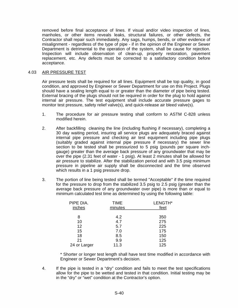
S-40
removed before final acceptance of lines. If visual and/or video inspection of lines, manholes, or other items reveals leaks, structural failures, or other defects, the Contractor shall repair such immediately. Any sags, humps, bends, or other evidence of misalignment - regardless of the type of pipe - if in the opinion of the Engineer or Sewer Department is detrimental to the operation of the system, shall be cause for rejection. Inspection will include observation of clean-up, property restoration, pavement replacement, etc. Any defects must be corrected to a satisfactory condition before acceptance.
4.03 AIR PRESSURE TEST
Air pressure tests shall be required for all lines. Equipment shall be top quality, in good condition, and approved by Engineer or Sewer Department for use on this Project. Plugs should have a sealing length equal to or greater than the diameter of pipe being tested. External bracing of the plugs should not be required in order for the plug to hold against internal air pressure. The test equipment shall include accurate pressure gages to monitor test pressure, safety relief valve(s), and quick-release air bleed valve(s).
1. The procedure for air pressure testing shall conform to ASTM C-828 unless
modified herein.
2. After backfilling cleaning the line (including flushing if necessary), completing a 30 day waiting period, insuring all service plugs are adequately braced against internal pipe pressure and checking air test equipment including pipe plugs (suitably graded against internal pipe pressure if necessary) the sewer line section to be tested shall be pressurized to 5 psig (pounds per square inch-gauge) greater than the average back pressure of any groundwater that may be over the pipe (2.31 feet of water - 1 psig). At least 2 minutes shall be allowed for air pressure to stabilize. After the stabilization period and with 3.5 psig minimum pressure in pipeline air supply shall be disconnected and the time observed which results in a 1 psig pressure drop.
3. The portion of line being tested shall be termed "Acceptable" if the time required
for the pressure to drop from the stabilized 3.5 psig to 2.5 psig (greater than the average back pressure of any groundwater over pipe) is more than or equal to minimum calculated test time as determined by using the following table:
PIPE DIA. TIME LENGTH* inches minutes feet 8 4.2 350 10 4.7 275 12 5.7 225 15 7.0 175 18 8.5 150 21 9.9 125 24 or Larger 11.3 125 * Shorter or longer test length shall have test time modified in accordance with
Engineer or Sewer Department’s decision.
4. If the pipe is tested in a “dry” condition and fails to meet the test specifications allow for the pipe to be wetted and tested in that condition. Initial testing may be in the “dry” or “wet” condition at the Contractor’s option.
S-41
5. Observe safety precautions during test. Caution all workers to remain clear of
test plugs which can blow out under considerable force at any time the line is pressurized.
4.04 ROUNDNESS TEST
Sewers constructed of PVC pipe shall pass a go/no-go mandrel sized to 95% of the actual pipe diameter with the pipe in place and backfill completed.
Contractor shall provide a suitable ball or mandrel having a diameter equal to 95% of the
actual inside pipe diameter which he shall pull through each section of pipe while the Engineer observes the test. Any section of sewer showing a deflection of more than 5% of the actual inside diameter shall be considered to have failed and shall be re-laid to correct the condition. Mandrel shall be pulled without mechanical pulling devices and shall not be performed until a minimum of 30 days after backfilling operations.
4.05 INFILTRATION TEST (LEAKAGE TESTS)
In addition to any other testing which may be required any infiltration observed in any section of sewer shall be measured by using flow weirs. The weir test shall be made on the flow of water from sewers in not over 1,000 foot sections at any one time when, in Engineer's opinion, groundwater level is at highest point during a normal year. Contractor shall furnish all weirs, other materials, and labor required for such test. Weirs shall be in good condition and approved for the intended use by the Engineer. Engineer shall be responsible only for direction, reading, recording data, and calculating infiltration rates.
Maximum allowable infiltration shall be 25 gallons per mile per inch diameter per 24 hour
period but in no case shall exceed 1,500 gallons per mile of pipe per day for pipe 30 inches in diameter or larger. Joints shall be tight and leakage in excess of that specified herein shall be repaired.
The Infiltration Test shall not be relied on as the sole indicator of leakage if groundwater
is determined to be less than 2 feet over the top of the pipe. If the quantity of infiltration is in excess of the maximum quantity specified above the
joints shall be remade, the sewer re-laid, or other work performed by and at the expense of the Contractor in order to reduce the amount of leakage to an amount within the limits specified. The test will be repeated until the section of sewer passes the test requirements.
All visible leaks in pipes and manholes must be corrected regardless of the amount of
infiltration. 4.05.1 Exfiltration Test - In case period of year of highest groundwater is not available
before sewer is needed by the Owner exfiltration testing may be used by the Contractor if approved by the Engineer.
Such testing shall be done between manhole segments by plugging the incoming
lines on the downstream manhole and the upstream manhole. The method of filling the sewer with water shall be approved before use by the Engineer and extreme care shall be used in conducting the test to avoid damage to the main sewer, service laterals, and service plugs. The line shall be filled slowly in such a

S-42
manner to allow exhausting of air from the line as it fills. Suitable methods of measuring leakage rate shall be utilized as approved by the Engineer. Generally exfiltration testing will not be used on line segments where the water elevation at the upstream manhole is more than 5 feet above the invert elevation at the downstream manhole so that pipe joints will not be subject to excessive internal pressures.
Maximum allowable exfiltration rate shall be 25 gallons per mile per inch
diameter per 24-hour period but in no case shall exfiltration exceed 1,500 gallons per mile per day for pipe 30 inches in diameter or larger.
If the quantity of exfiltration is in excess of the maximum quantity specified above
the joints shall be remade, the sewer re-laid, or other work performed by and at the expense of the Contractor in order to reduce the amount of leakage to an amount within the limits specified. The test will be repeated until the section of sewer passes the test requirements.
4.06 VACUUM TESTING OF MANHOLES
Before final acceptance all manholes shall be required to pass a vacuum test of at least 10" Hg. This test shall be considered acceptable if the vacuum remains at 10" Hg. or drops to no less than 9" Hg. within one (1) minute. If the manhole fails the initial test the Contractor shall locate the leak and make appropriate repairs acceptable to the Engineer in preparation for additional tests.
It is also called to the Contractor's attention that he will be required to furnish all
equipment necessary for this test including the manhole sealing apparatus, gauges, pump, plugs, and operating personnel. All vacuum testing is to be done after binder has been installed.
4.07 TESTING FORCE MAINS AND PRESSURE SEWERS
Before final acceptance force mains shall be pressure tested by suitably closing the end of the main with a test plug of approved design suitably braced against the internal pressure to prevent blowout and possible injury to personnel. Contractor shall furnish all labor, materials, and equipment for testing the force main including, but not limited to, water for testing, test pump, pressure gauges, test plugs, etc. Test shall be performed by the Contractor and witnessed by the Owner or his authorized representative.
The force main shall be filled with water taking care to eliminate air from the high points.
A positive displacement test pump shall be used to pump clean water into the main to build up a test pressure equal to the normal system pressure plus 50 psi with a maximum test pressure of 100 psi. Test pressure will be determined by the Engineer. The test pump shall then be valved off from the system and the pressure shall be observed over a period of one hour. A drop in pressure of 5 psi or more during the one-hour test period shall be taken as an indication of leakage. In the event leaks are found and corrected the Contractor shall repeat the pressure test using the same procedure described above. Should the Contractor be unable to obtain a satisfactory pressure test over a duration of one hour he shall then be required to perform a leakage test using a water tap and standard water meter to measure the leakage in the test section at system pressure over a period of 24 hours. Leakage during the 24-hour period must not exceed the allowable leakage for mechanical or push-on joints as shown in AWWA C600, latest revision. Leakage shall not exceed the quantity determined by the formula: L = (SDP.5) divided by 133,200 where L is the allowable leakage in gallons per hour; S is the length

S-43
of pipe tested, in feet; D is the nominal pipe diameter in inches; and P is the average test pressure during the leakage test in pounds per square inch.
Should the system fail to pass the leakage test the Contractor will be required to locate
and correct the leaks and to retest the system until satisfactory results can be obtained. The Contractor shall provide suitable first quality pressure gauges with 5 lb. or smaller
graduations and a standard 3/4 x 5/8-inch water meter in the event the meter is required for the leakage test. Pressure gauges and water meter shall be in good condition and shall be subject to such tests for proof of accuracy as the Owner or his authorized representative may require.
4.08 TESTING OF VALVES
Upon completion of the work the Contractor/Developer shall operate all buried valves in the presence of the Engineer or Sewer Department to verify proper operation of each valve.
* * *
S-44
SECTION 5 - GREASE TRAP, SAND/GRIT, OIL/WATER POLICY - (ONLY REQUIRED FOR COMMERCIAL AND INDUSTRIAL CUSTOMERS)
5.01 GENERAL All commercial and industrial customers that generate fats, oils, or grease shall install a
grease trap or grease trap interceptor as required by the Hendersonville Utility District. The purpose of the grease trap, grease trap interceptor, or grease and oil interceptor) is to create conditions that allow separation and retention of suspended grease from wastewater prior to the wastewater entering the sanitary sewer system. Proposed designs with specifications, sources or certification shall be submitted for review and approval by the Hendersonville Utility District.
The successful removal of grease from wastewater is the responsibility of the
owner/user of the grease trap. Damages and blockages sustained by the public sewer system resulting from inadequate or improper removal of grease from the wastewater are the liability of the owner/user of the grease trap. Routine cleaning and/or pumping at prescribed intervals shall be required.
Owners/users of the grease trap shall maintain dated records of these operations in an accessible location in ready view and shall make such records available upon request to officials of the Hendersonville Utility District. Owners/users of grease trap(s) shall comply with the current Hendersonville Utility District’s policies, regulations, and procedures. Trapzilla® type grease traps can be used at existing structures only or for upgrades upon approval by Hendersonville Utility District personnel. They are not permitted for use at any new buildings.
5.02 PRE-CAST CONCRETE GREASE TRAP INTERCEPTOR SIZING The minimum volume of a pre-cast concrete interceptor shall be 2,000 gallons.
Installation of grease trap interceptors in series shall be required when the required effective capacity of the grease interceptor is greater than 2,000 gallons. All grease interceptors shall have a H-20 rating.
5.03 PIPING The inlet and outlet piping shall have a clean-out tee installed. Inlet piping shall enter the receiving chamber 2-1/2 inches above the invert of the outlet
piping. On the inlet pipe inside the receiving chamber, a 4 inch inside diameter sanitary tee in the vertical position with the top unplugged shall be provided as a turndown. To provide air circulation and to prevent “air lock”, a pipe (nipple) shall be installed in the top of the tee and extend to a minimum of 6 inches of clearance from the interceptor ceiling, but not less than the inlet pipe diameter. A pipe shall be installed in the bottom of the tee to extend to a point 24 inches below the water level. (See Detail)
The outlet piping shall be the same size as the inlet piping, but in no case smaller than 4
inches inside diameter. The outlet piping shall start 12 inches above the floor of the interceptor. Outlet piping shall contain a tee installed horizontally with the top opening containing a removable plug to receive a cleaning snake to the downstream direction. (See Detail)
5.04 BAFFLES

S-45
Grease interceptors shall have a concrete baffle the full width of the interceptor,
extending from the floor to within 6 inches of the ceiling. The baffle shall have an inverted 90 degree sweep fitting at least equal in diameter size to the inlet piping, but not less than 4 inches inside diameter. The bottom of the sweep shall be placed in the vertical position in the inlet compartment 12 inches above the floor. The sweep shall rise to the horizontal position and extend through the baffle to the outlet compartment. The baffle wall shall be sealed to the sweep. (See Detail)
The inlet compartment shall be 2/3 of the total liquid capacity with the outlet
compartment at 1/3 the liquid capacity of the interceptor. The minimum depth of the liquid capacity shall be 42 inches.
5.05 MANHOLES (ACCESS OPENING) Access to grease interceptors shall be provided by two (2 manholes with 24-inch
minimum dimensions terminating 1 inch above finished grade with a H-20 cast iron frame and cover. “Sewer” shall be cast in the cover. An 8 inch thick concrete pad extending a minimum of 12 inches beyond the outside dimension of the manhole frame shall be provided. One manhole shall be located above the inlet tee and the other manhole shall be located above the outlet tee. A minimum of 24 inches of clear opening above each manhole access shall be maintained to facilitate maintenance, cleaning, pumping and inspections.
Access openings shall be sealed water and gas tight to contain odors and bacteria, and
to exclude insects, vermin and ground water. 5.06 LOCATION AND OPERATION Grease traps or oil and grease separators shall be located so as to be readily accessible
for cleaning, maintenance and inspections. Grease traps should be located close to the fixture(s) discharging greasy water.
Grease traps shall be cleaned routinely at prescribed intervals. Removal of grease from
wastewater routed to public or private sanitary sewer system is the responsibility of the user /owner of the grease trap/
5.07 GREASE TRAP MATERIAL Grease interceptors shall be constructed of sound durable materials, not subject to
excessive corrosion or decay, and shall be water and gas tight. Each interceptor shall be structurally designed to withstand any anticipated load to be applied on the interceptors such as vehicular traffic in parking or driving areas.
5.08 OIL / GRIT AND OIL / WATER SEPARATORS All new businesses or industries that wash cars shall be required to install sand/grit and
oil/water separators in accordance with the standard details shown at the end of this Division – 2. For all new businesses or industries that use petroleum base products in their day to day activities will be required to install and oil/water separator if they operate with an open floor drain in accordance with the standard details shown at the end of this Division – 2.
* * *
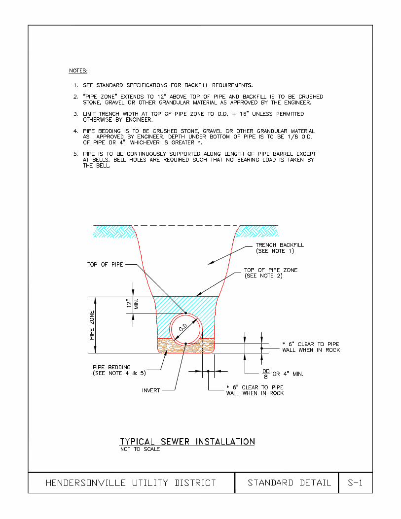


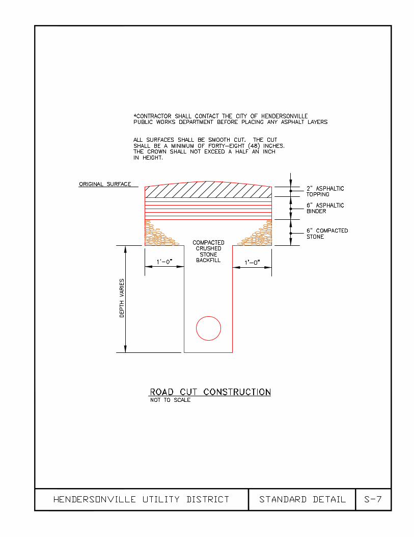
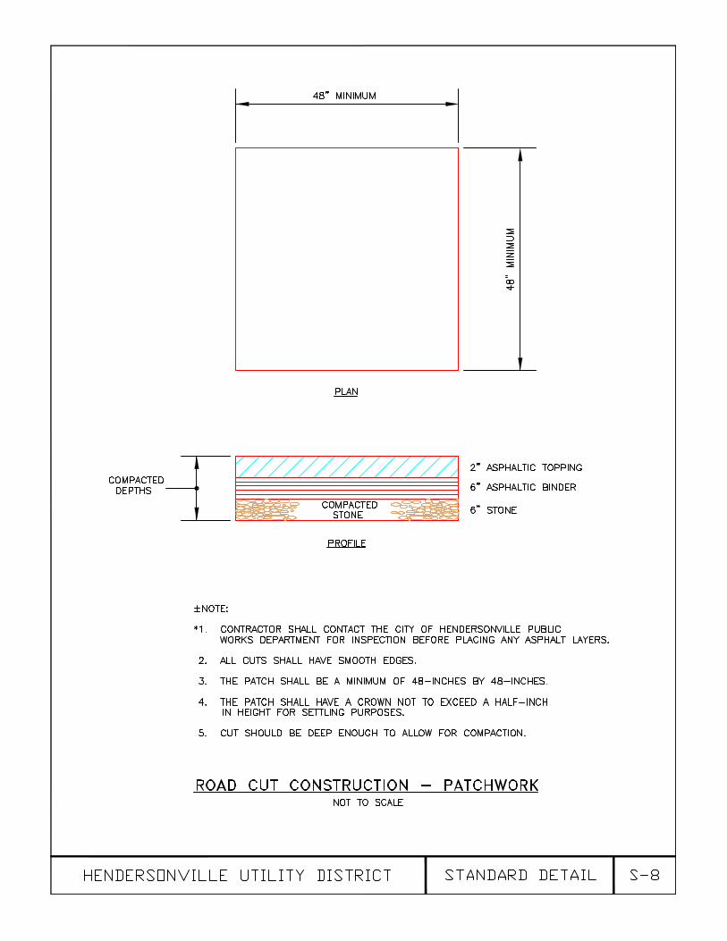

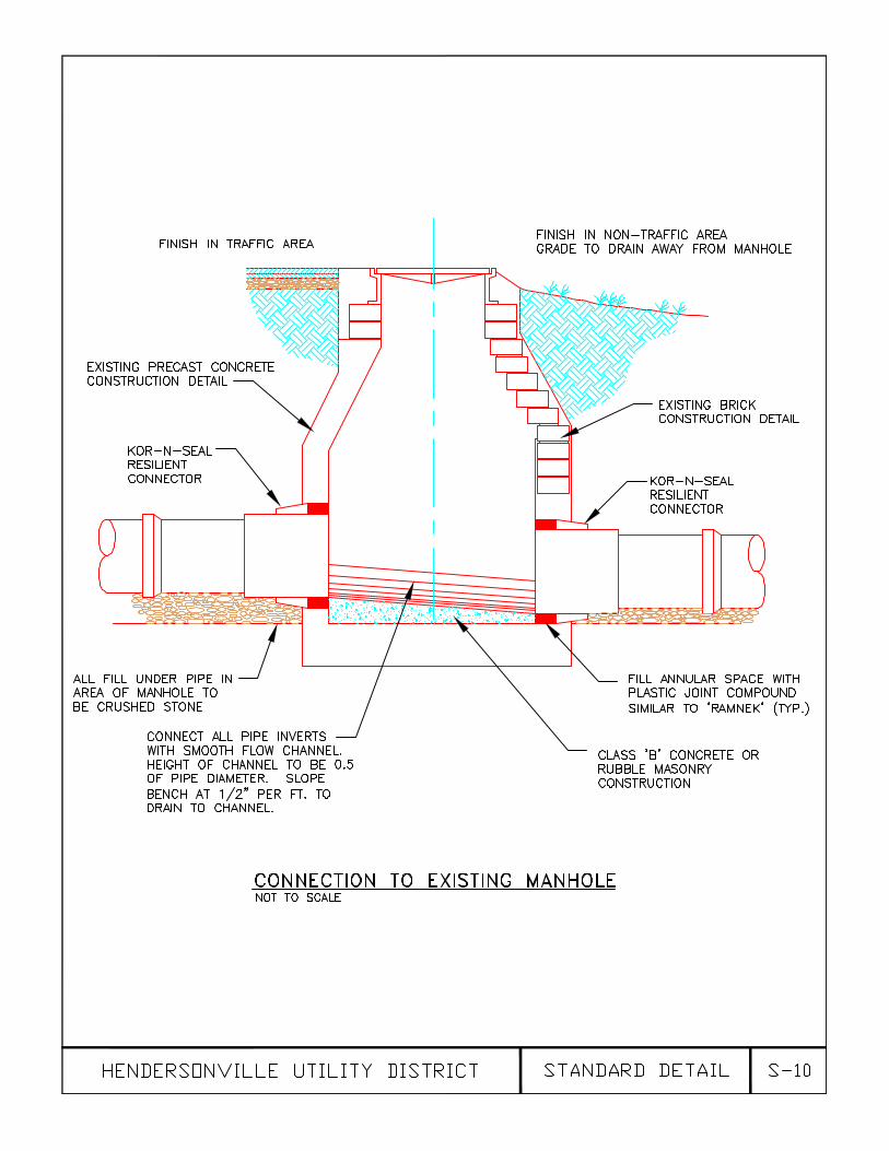
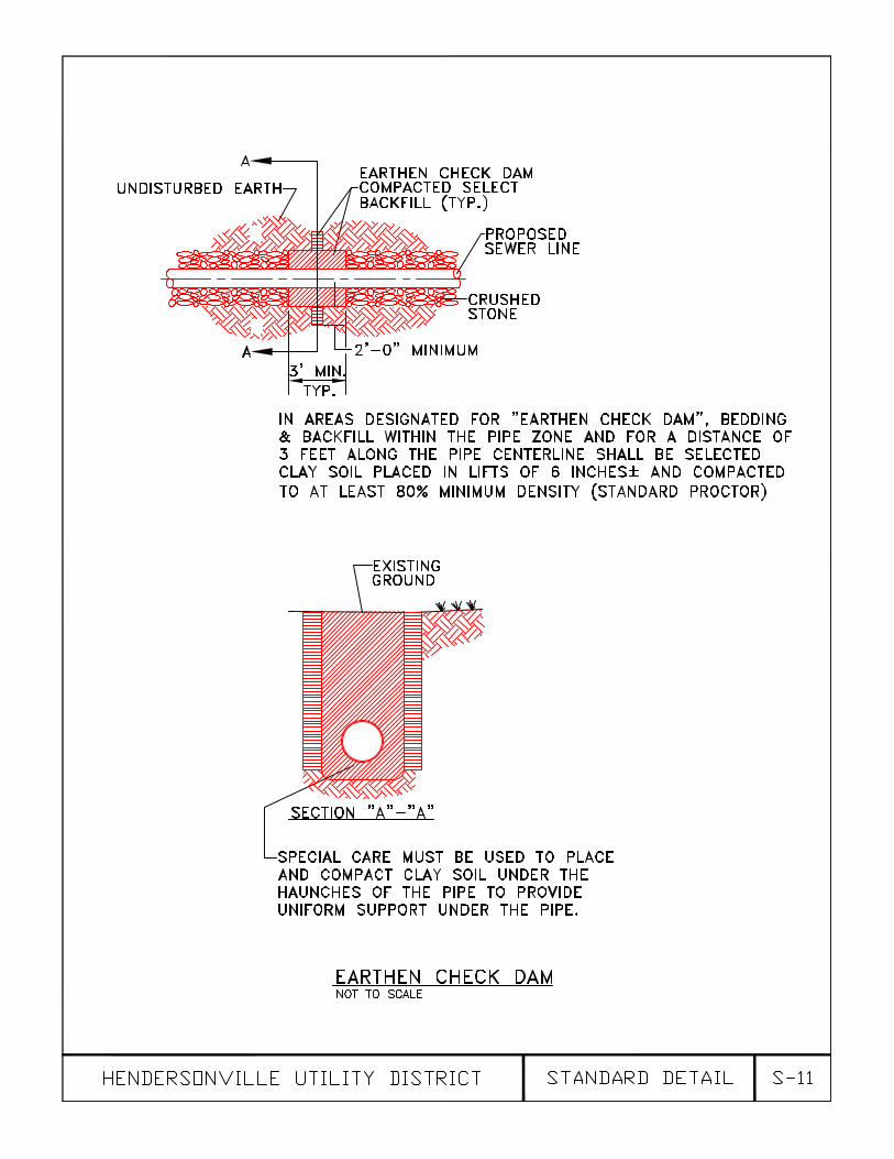


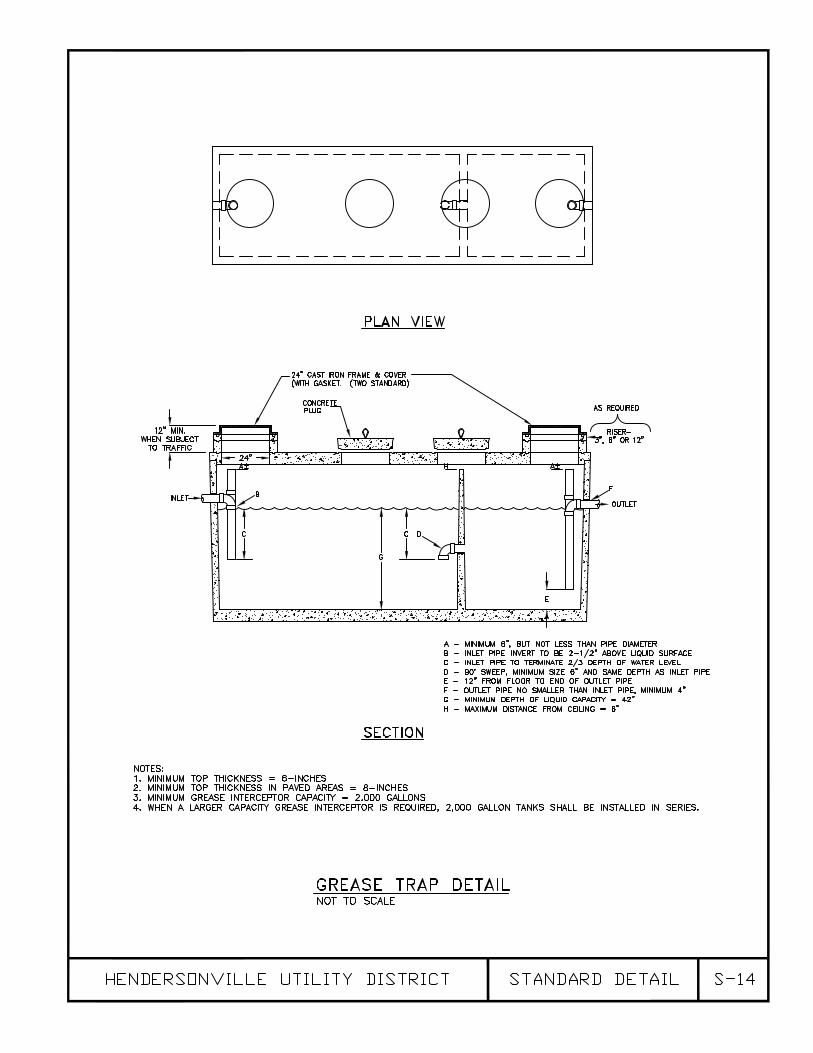
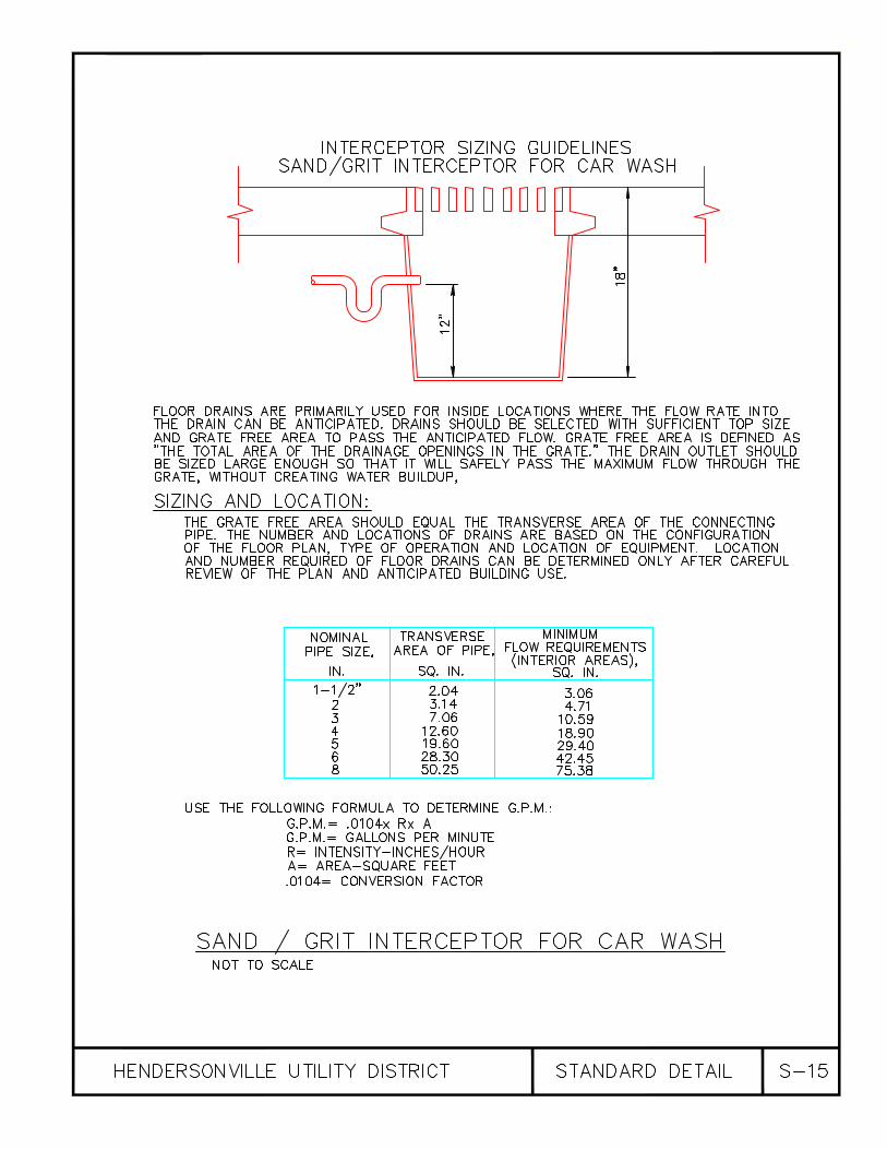
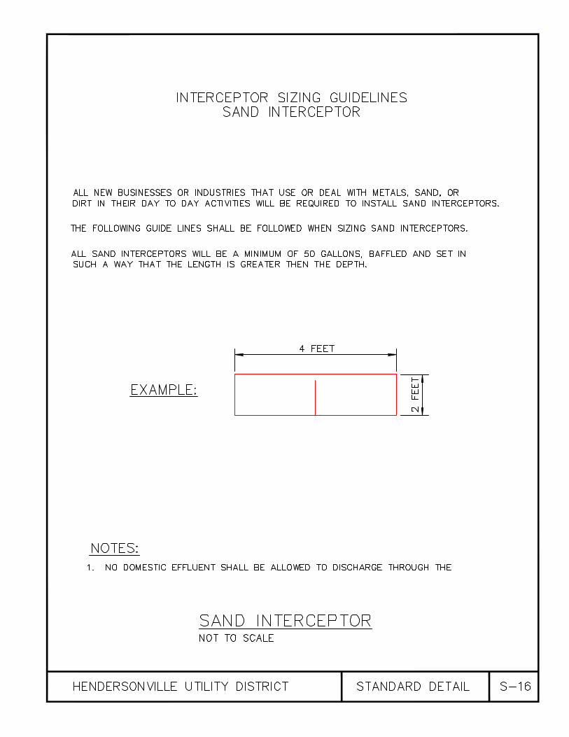

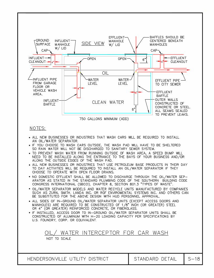
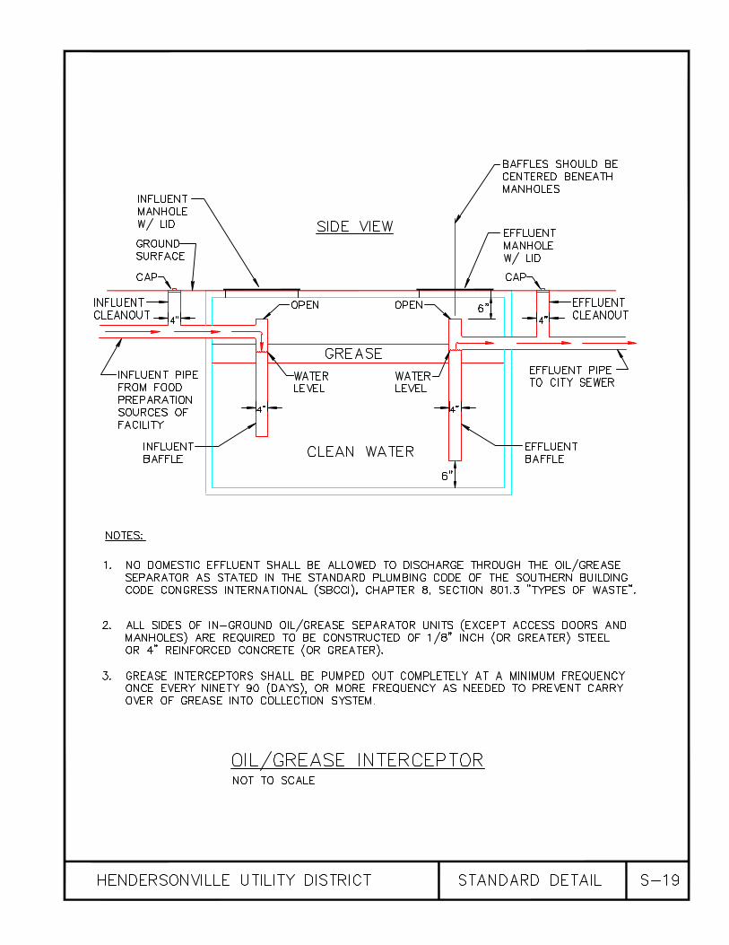


DIVISION 3
STANDARD SPECIFICATIONS FOR PRESSURE WASTEWATER COLLECTION SYSTEMS, COLLECTOR MAIN, SERVICE CONNECTIONS, AND
GRINDER PUMP INSTALLATIONS
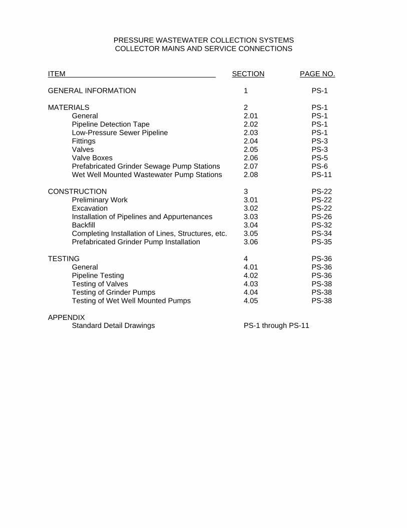
PRESSURE WASTEWATER COLLECTION SYSTEMS COLLECTOR MAINS AND SERVICE CONNECTIONS
ITEM SECTION PAGE NO. GENERAL INFORMATION 1 PS-1 MATERIALS 2 PS-1 General 2.01 PS-1 Pipeline Detection Tape 2.02 PS-1 Low-Pressure Sewer Pipeline 2.03 PS-1 Fittings 2.04 PS-3 Valves 2.05 PS-3 Valve Boxes 2.06 PS-5 Prefabricated Grinder Sewage Pump Stations 2.07 PS-6 Wet Well Mounted Wastewater Pump Stations 2.08 PS-11 CONSTRUCTION 3 PS-22 Preliminary Work 3.01 PS-22 Excavation 3.02 PS-22 Installation of Pipelines and Appurtenances 3.03 PS-26 Backfill 3.04 PS-32 Completing Installation of Lines, Structures, etc. 3.05 PS-34 Prefabricated Grinder Pump Installation 3.06 PS-35 TESTING 4 PS-36 General 4.01 PS-36 Pipeline Testing 4.02 PS-36 Testing of Valves 4.03 PS-38 Testing of Grinder Pumps 4.04 PS-38 Testing of Wet Well Mounted Pumps 4.05 PS-38 APPENDIX Standard Detail Drawings PS-1 through PS-11
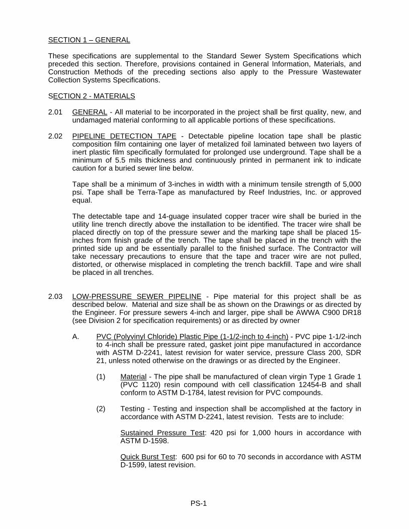
PS-1
SECTION 1 – GENERAL These specifications are supplemental to the Standard Sewer System Specifications which preceded this section. Therefore, provisions contained in General Information, Materials, and Construction Methods of the preceding sections also apply to the Pressure Wastewater Collection Systems Specifications. SECTION 2 - MATERIALS 2.01 GENERAL - All material to be incorporated in the project shall be first quality, new, and
undamaged material conforming to all applicable portions of these specifications. 2.02 PIPELINE DETECTION TAPE - Detectable pipeline location tape shall be plastic
composition film containing one layer of metalized foil laminated between two layers of inert plastic film specifically formulated for prolonged use underground. Tape shall be a minimum of 5.5 mils thickness and continuously printed in permanent ink to indicate caution for a buried sewer line below.
Tape shall be a minimum of 3-inches in width with a minimum tensile strength of 5,000 psi. Tape shall be Terra-Tape as manufactured by Reef Industries, Inc. or approved equal. The detectable tape and 14-guage insulated copper tracer wire shall be buried in the utility line trench directly above the installation to be identified. The tracer wire shall be placed directly on top of the pressure sewer and the marking tape shall be placed 15-inches from finish grade of the trench. The tape shall be placed in the trench with the printed side up and be essentially parallel to the finished surface. The Contractor will take necessary precautions to ensure that the tape and tracer wire are not pulled, distorted, or otherwise misplaced in completing the trench backfill. Tape and wire shall be placed in all trenches.
2.03 LOW-PRESSURE SEWER PIPELINE - Pipe material for this project shall be as
described below. Material and size shall be as shown on the Drawings or as directed by the Engineer. For pressure sewers 4-inch and larger, pipe shall be AWWA C900 DR18 (see Division 2 for specification requirements) or as directed by owner
A. PVC (Polyvinyl Chloride) Plastic Pipe (1-1/2-inch to 4-inch) - PVC pipe 1-1/2-inch
to 4-inch shall be pressure rated, gasket joint pipe manufactured in accordance with ASTM D-2241, latest revision for water service, pressure Class 200, SDR 21, unless noted otherwise on the drawings or as directed by the Engineer.
(1) Material - The pipe shall be manufactured of clean virgin Type 1 Grade 1
(PVC 1120) resin compound with cell classification 12454-B and shall conform to ASTM D-1784, latest revision for PVC compounds.
(2) Testing - Testing and inspection shall be accomplished at the factory in
accordance with ASTM D-2241, latest revision. Tests are to include:
Sustained Pressure Test: 420 psi for 1,000 hours in accordance with ASTM D-1598.
Quick Burst Test: 600 psi for 60 to 70 seconds in accordance with ASTM
D-1599, latest revision.

PS-2
Flattening Test: In accordance with ASTM D-2241, latest revision. Extrusion Quality: In accordance with ASTM D-2152 latest revision, using
acetone immersion. Dimensions: Wall thickness and outside dimensions shall met applicable
portions of ASTM D-2122, latest revision.
Tests shall be run on the maximum number of specimens called for under ASTM D-2241, latest revision for all pipe manufactured in each size and strength classification. If any specimen fails to meet any above-stated test requirement all pipe of that size and type between successful tests shall be excluded from use on this project. The manufacturer shall provide the Sewer Department with three (3) certified copies of statements verifying that all required tests have been performed on the pipe provided for this project and that the pipe provided passed all tests. Such statements shall be submitted to the Sewer Department for review before any pipe is shipped to the job site.
(3) Joint Design - Pipe joints shall be slip-joint gasket design conforming to
ASTM D-3139. Gaskets shall conform to ASTM F-477. Gaskets and lubricants shall be compatible with the pipe material and the intended service and shall be furnished by the pipe manufacturer.
Unless approved otherwise by the Sewer Department each gasket shall be factory installed in the bell end of the pipe and locked in place. The joint design shall be approved by the Sewer Department before the Contractor will be permitted to install any pipe on this project.
(4) Manufacturing Standard - The manufacturer’s equipment and quality
control facilities must be adequate to ensure that all pipe produced is uniform and meets the requirements of the specifications. All pipe for this project shall be manufactured in the USA by the same manufacturer unless specifically approved otherwise by the Engineer.
Pipe used on this project shall have been approved by the NSF and the
manufacturer shall provide certification to that effect.
(5) Laying Lengths - The pipe may be furnished in the manufacturer’s standard laying lengths from 18 feet to 40 feet.
(6) Shipment and Storage - Shipment packets shall be constructed to protect
the pipe usually with supports not more than 5 feet from the pipe ends and such that unsupported lengths do not exceed 15 feet. While in storage and shipment pipe shall be protected from excessive heat or cold and shielded from direct sunlight.
(7) Marking - Each length of pipe is to be permanently marked with:
manufacturer's name, nominal size, Class pressure rating or SDR number, material designation, ASTM D-2241, and NSF approval
B. PVC (Polyvinyl Chloride) Plastic Pipe (less than 1-1/2-inch diameter) - PVC pipe
less than 1-1/2-inch diameter shall meet all the requirements of Part A above except as specifically stated below. Pipe shall be PVC pressure pipe, Schedule
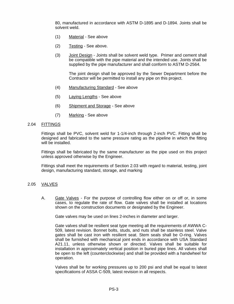
PS-3
80, manufactured in accordance with ASTM D-1895 and D-1894. Joints shall be solvent weld.
(1) Material - See above (2) Testing - See above.
(3) Joint Design - Joints shall be solvent weld type. Primer and cement shall be compatible with the pipe material and the intended use. Joints shall be supplied by the pipe manufacturer and shall conform to ASTM D-2564.
The joint design shall be approved by the Sewer Department before the Contractor will be permitted to install any pipe on this project.
(4) Manufacturing Standard - See above (5) Laying Lengths - See above (6) Shipment and Storage - See above (7) Marking - See above
2.04 FITTINGS
Fittings shall be PVC, solvent weld for 1-1/4-inch through 2-inch PVC. Fitting shall be designed and fabricated to the same pressure rating as the pipeline in which the fitting will be installed.
Fittings shall be fabricated by the same manufacturer as the pipe used on this project
unless approved otherwise by the Engineer. Fittings shall meet the requirements of Section 2.03 with regard to material, testing, joint
design, manufacturing standard, storage, and marking
2.05 VALVES A. Gate Valves - For the purpose of controlling flow either on or off or, in some
cases, to regulate the rate of flow. Gate valves shall be installed at locations shown on the construction documents or designated by the Engineer.
Gate valves may be used on lines 2-inches in diameter and larger.
Gate valves shall be resilient seat type meeting all the requirements of AWWA C-509, latest revision. Bonnet bolts, studs, and nuts shall be stainless steel. Valve gates shall be cast iron with resilient seat. Stem seals shall be O-ring. Valves shall be furnished with mechanical joint ends in accordance with USA Standard A21.11, unless otherwise shown or directed. Valves shall be suitable for installation in approximately vertical position in buried pipe lines. All valves shall be open to the left (counterclockwise) and shall be provided with a handwheel for operation.
Valves shall be for working pressures up to 200 psi and shall be equal to latest specifications of ASSA C-509, latest revision in all respects.
PS-4
Valve boxes for gate valves shall be as described below under heading “Valve Boxes.”
B. Ball Valves - On lines less than 2-inches in diameter ball valves are to be used (and may be used on lines up to 4-inches in diameter) for controlling flow either on or off or to regulate the rate of flow. Ball valves shall be installed at locations shown on the drawings or designated by the Engineer.
Ball valves shall be true union type with PVC body, high impact ABS operating
handle, teflon seat rings, and elastomer O-ring seals. Valves are to open and close with one-quarter turn. Pressure rating at 30 F to 120 F shall be no less than 150 psi.
Ball valves shall be as manufactured by Asahi/America, Hayward, or approved
equal. Valve boxes for ball valves shall be as described below under heading "Valve
Boxes."
C. Check Valves - A check valve shall be located on each service line in the customer service box to protect against backflow from the collection system to the customer's premises in the event the customer's service line breaks.
Valve shall be 1-1/4-inch PVC with an internal flapper designed to swing clear of
the flow path during forward flow and to seat tightly against backflow. Valve shall be full-flow design, angle seat, weighted flapper to seat against low pressures while holding up to 50 psi under some operating conditions (test pressures may be higher--see line testing specification). Seal shall be Buna-N or as approved by Engineer.
Valve shall be supplied with compression type ends to serve as union
connections. Body shall be PVC compatible with intended application (1-1/4-inch Schedule 40 PVC service piping). Valve shall be as manufactured by Flo Control, Inc. or approved equal.
D. Air Releases Valves - At the locations shown on the drawings or where directed
by the Sewer Department air release valves (ARV) shall be installed to vent accumulations of air or other gases while the system lines remain under pressure. Valve size shall be as shown on the drawings and suitable for system operating pressures of 0 to 50 psi (test pressures will be higher-see specification requirements for line testing, this project). Valve shall be suitable for use in sewage (septic tank effluent). Installation will be in accordance with the detail drawings.
Valve shall be APCO No. 200A or approved equal.
E. Air and Vacuum Valves - At the locations shown on the drawings or where
directed by the Sewer Department air and vacuum valves (A/VV) shall be installed to vent large quantities of air or relieve vacuum conditions. Valve size shall be as shown on the drawings and suitable for system operating pressures of 0 to 50 psi (test pressures will be higher--see specification requirements for line testing, this project). Valve shall be suitable for use in sewage (septic tank effluent). Installation will be in accordance with the detail drawings.

PS-5
Valve shall be APCO No. 140 series or approved equal.
2.06 VALVE BOXES
Valve boxes for this project are designated on the drawings as one of the following types:
A. Type "A" Valve Box - For all valve boxes clean-out assemblies, ball valves and
other lever or hand wheel operated valves, air release valves, and air and vacuum valves, the valve box shall be constructed of precast concrete with a cast iron frame and cover in accordance with project detail drawings.
Frame and cover shall be heavy cast iron construction (traffic type) providing an
opening of approximately 12-inches by 20-inches. Frame and cover shall be equal to John Bouchard Company No. 8110 with word "SEWER" cast in the cover.
B. Type "B" Valve Box - At locations where more room is required than is available
in a Type "A" valve box a Type "B" valve box shall be used. The box shall be constructed of precast concrete with a cast iron frame and cover in accordance with project detail drawings.
Frame and cover shall be heavy cast iron construction (traffic type) providing an
opening approximately 12-inches by 30-inches. Frame and cover shall be John Bouchard Company No. 8122, or approved equal, with word "SEWER" cast in the cover.
Upon completion of the pressure sewer system all pressure sewer valve boxes in
public rights-of-way or dedicated easements shall be painted with orange paint. The Developer shall submit paint for approval.
C. Type "C" Valve Box - At the customer service connection housing a clean-out
connection, cut-off (ball) valve and check valve, a Type "C" valve box shall be installed in accordance with project detail drawings.
Valve box shall be a standard plastic meter box with a nominal size of 15-inches
by 21-inches (bottom dimensions) by 12-inch height with (normally) one 6-inch extension piece for an overall (normal) height of 18-inches. Box shall be injection molded meeting the requirements of ASTM D-2853, latest revision. Material shall be polyolefin with inorganic component reinforcing (or as otherwise approved by Sewer Department) with UV stabilizer additive to provide resistance to material degradation from exposure to sunlight.
The cover shall be cast iron. The cover shall contain a corrosion-resistant steel
plate affixed to the underside to enable a buried cover to be found with electronic detection equipment. The cover shall be imprinted with the word "SEWER."
PS-6
2.07 PREFABRICATED GRINDER SEWAGE PUMP STATIONS 2.07.1 General
The Contractor shall furnish and install a factory-built simplex or duplex grinder pump station consisting of either locations shown on the drawings or as directed by the Engineer or Sewer Department. The Contractor shall be responsible for all material furnished by him and shall replace, at his own expense, all such material found defective in manufacture or damaged on delivery. This shall include the furnishing of all material and labor required for the replacement of installed material discovered defective. The Contractor shall be responsible for the safe storage of material furnished by him until it has been incorporated in the completed project. All motors and electrical and mechanical components shall be stored in a dry environment. The interior of all pipe, fittings, and other accessories shall be kept free from dirt and foreign material at all times. The Contractor shall provide a 1-inch water service with meter to all proposed wastewater pump stations 80 GPM or larger or as directed by the Sewer Department. All water services shall be equipped with a reduced pressure backflow preventer and 120 V ground fault circuit interrupter.
2.07.2 Products Grinder Pump:
The manufacturer shall furnish a factory-built simples or duplex grinder pump station consisting of either one or two grinder pump units as applicable with mercury switch level controls, discharge piping, pump-mounting plates with bottom rail supports, upper rail supports or guide rails, a quick disconnect coupling, lifting chain, reinforced fiberglass pump cover plate, and all necessary parts and equipment installed in a fiberglass reinforced polyester tank as described in the following specifications. The discharge piping and/or check valves shall be so designed as to prevent siphoning of wastewater from the pump basin when conditions of negative pressure exist at the point of connection to the pressure system piping network. The grinder pump station shall be as manufactured by Barnes or approved equal.
Operating Conditions:
The pumps shall be of centrifugal type. The pumps provided shall be capable of delivering a minimum of 16 GPM against a normal rated total dynamic head of 85 feet or actual conditions, whichever is greater, with a maximum shut-off head of 110 feet. Pump motor shall be a minimum of 2 hp, single phase, 230-volt, 3,450 rpm, 60 cycle. The pumps shall not overload at any point on the performance curve and shall be free from harmful effects of cavitations at either high or low head.
PS-7
Tank: The tank shall be a minimum of 24-inches in diameter for simplex systems and a
minimum of 48-inches in diameter for duplex systems of depth as shown on the attached drawings.
The tank shall be molded of fiberglass reinforced polyester resin of the lay-up
and spray technique to assure that the interior surface is smooth and resin rich. The tank shall have a minimum wall thickness of 1/4-inch. A heavy rib or flange
shall extend around the basin for strength and shall have holes through the rib for anchoring in concrete to prevent flotation.
A flexible coupling bedded in gravel with stainless steel bands shall be placed on
the outside of the tank for the discharge line and embedded in gravel. Flexible coupling shall be E-One or approved equal.
Tank Cover: Cover shall be 7/15-inch thick fiberglass with reinforcing ribs with high-
temperature bake epoxy paint. Cover shall be bolted to basin with cap screws. Nuts for screws shall be completely embedded in the fiberglass to prevent turning and for corrosion resistance. Cover to be sealed with caulking compound or a gasket fastened to covers.
A basin inlet flange with O-ring for 4-inch Schedule 40 plastic pipe shall be
included but not mounted on the basin. Flange to be mounted in the field at inlet height required by the installation. Conduit fittings shall be furnished for sealing cords from control box into conduit entering basin. This is to prevent sewer gases from carrying to control box.
Check Valve: A heavy all-rubber flapper type check valve or ball check valve shall be an
integral part of the lift out discharge seal assembly and shall lift out with the pump assembly.
Shut-Off Valve: A 2-inch PVC ball with extension handle to top of basin shall be installed in the
discharge line for closing when pump assembly is removed. Discharge from station shall be through side of basin and shall consist of 2-inch NPT flexible coupling
Pump and Motor: The grinder pump and motor are to be especially designed and manufactured so
that they can operate completely submerged in the liquid being pumped. Electrical power cord shall be laid in conduit and shall be sealed by use of a cord grip with individual conductors additionally sealed into the cord-cap assembly with epoxy sealing compound, thus eliminating water getting into the motor by following individual conductors inside the insulation unless the pump has a waterproof underground cable. The cord grip shall have a male taper pipe thread which is threaded into a female taper pipe thread in a cord cap. The cord cap shall be sealed into the motor housing with a Buna-N O-ring, providing an
PS-8
electrical connection which is completely watertight, yet may be easily removed for service.
The combination centrifugal pump impeller and grinder unit shall be attached to a
common motor and pump shaft made of stainless steel. The grinder unit shall be on the suction side of the pump impeller and discharging directly into the impeller inlet leaving no exposed shaft to permit packing of ground solids. The grinder shall have two stages or have grinding impeller and shredding ring. Both stationary and rotating cutters shall be made of hardened and ground stainless steel. Pump and motor housings are to be high-quality grey iron castings. Impeller shall be bronze. All fasteners shall be of a high-grade stainless steel.
The pump motor shaft shall be sealed by two mechanical carbon and ceramic
faced seals within an oil-filled chamber to provide clean, constant lubrication. The shaft shall be supported by a ball radial and thrust bearing and a lower bronze radial sleeve bearing, between bearing, between the shaft seals to minimize overhang, both running in oil.
The motor winding and rotor are to be mounted in a sealed, submersible type
housing which is filled with clean, high dielectric oil for bearing lubrication and to transmit heat from motor winding to outer housing. Motor winding shall be securely held in the housing with machine screws or it shall be pressed into the housing.
Controls for Simplex Station: Sealed float type mercury switches shall be supplied to control sump level and
alarm signal. The mercury tube switches shall be sealed in a solid polyurethane float for corrosion and shock resistance. The support wire shall have a heavy neoprene jacket and a weight shall be attached to cord above the float to prevent sharp bends in the cord when the float operates under water. The float switches shall hang in the sump supported only by the cord that is held to the NEMA 4 fiberglass junction box. Two float switches shall be used to control level: one for pump turn-on, one for pump turn-off, and a third switch shall be provided for alarm control.
A red alarm light is to be supplied for mounting on the control box. The light shall consist of a 40-watt high-intensity bulb and a red polycarbonate
lens with a neoprene gasket. The alarm light will flash to indicate a high water condition and go out when the water level drops.
Operation of Simplex System: On sump level rise, the lower mercury switch shall
first be energized, then upper level switch shall next energize and start pump. With pump operating sump level shall lower to low switch turn-off setting and pump shall stop. If level continues to rise when pump is operating the alarm switch shall energize. All level switches shall be adjustable for level settings from the surface.
Electrical Control Panel for Simplex Station: Control panel shall have a NEMA 4X weatherproof enclosure. A lock hasp shall
be provided on door. A circuit breaker shall be provided for the pump and a magnetic starter with one leg overload protection for single phase operation shall be supplied. H-O-A switches and run lights shall be supplied for the pump.

PS-9
Terminal strip shall be provided for connecting pump and control valves. Additional terminals shall be provided to connect alarm. Control circuit shall be 115V or a transformer shall be supplied to give 24V control circuit. The control panels shall be provided with a disconnect switch that will permit the servicing of the various electrical components without such components being subject electrical power. All electrical connections shall be to the bottom of the electrical disconnect and control panels. Duct seal is to be used in all conduits.
Note: Control panel must be UL listed. Controls for Duplex Station: Sealed float type mercury switches shall be supplied to control sump level and
alarm signal. The mercury tube switches shall be sealed in a solid polyurethane float for corrosion and shock resistance. The support wire shall have a heavy neoprene jacket. A weight shall be attached to cord above the float to hold switch in place in sump. Weight shall be above the float to effectively prevent sharp bends in the cord when the float operates. The float switches shall hang in the sump supported only by the cord that is held to the NEMA 4X cast iron or cast aluminum junction box. Three float switches shall be used to control level: one for pump turn-on, one for pump turn-off, and a one for both pumps turn-on. A fourth switch shall be provided for alarm control.
A red alarm light is to be supplied for mounting on the control box. The light shall consist of a 40-watt high-intensity bulb and a red polycarbonate
lens with a neoprene gasket. The alarm light will flash to indicate a high water condition and go out when the water level drops.
Operation of Duplex System: On sump level rise the lower mercury switch shall first be energized, then upper
level switch shall next energize and start lead pump. With lead pump operating sump level shall lower to low switch turn-off setting and pump shall stop. Alternating relay shall index on stopping of pump so that lag pump will start on the next operation. If sump level continues to rise when lead pump is operating override switch shall energize and start lag pump. Both lead and lag pump shall operate together until low-level switch turns off both pumps. If level continues to rise when both pumps are operating, alarm switch shall energize and signal the alarm. If one pump should fail for any reason the second pump shall operate on the override control and if level continues to rise the alarm switch shall energize and signal the alarm. All level switches shall be adjustable for level setting from the surface.
Electrical Control Panel for Duplex Station: Control panel shall have a NEMA 3 R/12 weatherproof enclosure. A lock hasp
shall be provided on door. A circuit breaker shall be provided for each pump and a magnetic starter with a leg overload protection shall be supplied. An alternating relay or solid state alternator shall be provided to alternate pumps on each successive cycle of operation. Starters shall have auxiliary contact to operate both pumps on override condition. An interlock relay shall be provided to automatically reconnect the control circuit in case of circuit breaker trip on one pump. H-O-A switches and run lights shall be supplied for each pump. Terminal
PS-10
strip shall be provided for connecting pump and control wires. Additional terminals shall be provided to connect alarm. Control circuit shall be 115V or a transformer shall be supplied to give 24V control circuit. The control panels shall be provided with a disconnect switch that will permit the servicing of the various electrical components without such components being subject electrical power.
Note: Control panel must be UL listed. Wiring: It shall be the responsibility of the electrical contractor to furnish and install,
according to the drawings and in compliance with appropriate national and local codes, the branch circuit protection and all wiring to the pump leads and to the high alarm indicator lamp.
Corrosion Protection: All materials exposed to wastewater shall have inherent corrosion protection: i.e.,
cast iron, fiberglass, stainless steel, PVC. Any exterior steel surfaces are to be suitably protected against corrosion.
Serviceability:
The grinder pump unit shall have provisions for lifting to facilitate easy removal of
the unit from the tank if necessary. Manufacturer: The equipment specified shall be the product of a company experienced in the
design and manufacture of grinder pumps for specific use in low-pressure sewage systems. The company shall submit detailed installation and user instructions for its product; submit evidence of an established service support program including complete parts and service manuals; and be responsible for maintaining a continuing inventory of grinder pump replacement parts.
Warranty: The manufacturer shall warrant its product to be free from defects in material and
factory workmanship for a period of one year from date of acceptance. Repair or parts replacement required as a result of such defects will be made free of charge during this period.
The manufacturer will provide the General Contractor specific instructions on the
assembly and installation of the pump stations and related equipment. The manufacturer will furnish, at his own expense, the services of a factory-
trained serviceman to instruct the Owner's personnel in the operation and maintenance of the pumps and related equipment. The individual performing the instruction to the Owner is to be trained and/or certified by the manufacturer as its authorized operation, maintenance, and service specialist.
Execution Install grinder sewage pump station as shown on the drawings and in
accordance with the manufacturer’s recommendations.
PS-11
Obtain the services of the manufacturer’s service engineer to check the installation of each grinder sewage pump station and make any field adjustments necessary to ensure proper operation.
For typical grinder pump installations see Standard Drawings attached hereto. 2.08 WET WELL MOUNTED WASTEWATER PUMP STATIONS 2.08.1 General For wastewater pump stations to operate over 180 gpm, the contractor shall
furnish and install one factory-built above ground fiberglass reinforced automatic pump station. The station shall be complete with all equipment specified herein, factory installed in a fiberglass reinforced polyester resin enclosure.
The principal items of equipment shall include two (2) self-priming, horizontal,
centrifugal v-belt motor driven sewage pumps, valves, internal piping, motor control center with heavy duty thermal-magnetic circuit breakers, magnetic motor starters, automatic liquid level control system, and internal wiring. Pump station shall be as manufactured by the Gorman Rupp Company or approved equal.
The Contractor shall coordinate inspection and tests with the pump station
manufacturer. Manufacturer is to inspect the installation and operation of the equipment and provide to the Sewer Department a written certification that the facilities are properly installed and operating in accordance with the requirements of the manufacturer.
After installation representatives of the manufacturer shall conduct field tests to
demonstrate that capacities and operating characteristics specified are developed. In addition the manufacturer shall furnish a certificate stating the pumps and equipment were installed in accordance with the manufacturer's recommendation.
Pumps must be designed to handle raw, unscreened, domestic wastewater.
Pumps shall have 3-inch suction connection, and 4-inch discharge connection. Each pump shall be selected to perform under the required operation conditions as determined by the Engineer.
The Contractors attention is directed to the fact that stand-by power is required
for all wet well mounted pump stations. Type of stand-by power is to be determined on a case by case basis and as required by the Sewer Department.
The Contractor shall provide a 1-inch water service with meter to all proposed
wastewater pump stations. For some wastewater pump stations odor control facilities may be required.
These type facilities will be directed by the Sewer Department prior to approval for construction.
PS-12
2.08.2 Products Solids Handling Capability All internal passages, impeller vanes, and recirculation ports shall pass a 2.5-
inch spherical solid. Smaller internal passages that create a maintenance nuisance or interfere with priming and pump performance shall not be permitted. Upon request from the engineer certified drawings showing size and location of the recirculation port(s) shall be submitted for approval.
Re-prime Performance Consideration shall be given to the sanitary sewage service anticipated in which
debris is expected to lodge between the suction check valve and its seat resulting in the loss of the pump suction leg and siphoning of liquid from the pump casing to the approximate centerline of the impeller. Such occurrence shall be considered normal, and the pump must be capable of automatic, unattended operation with an air release line installed.
During unattended operation the pump shall retain adequate liquid in the casing
to insure automatic re-priming while operating at its rated speed in a completely open system. The need for a suction check valve or external priming device shall not be required.
Pump must re-prime 18 vertical feet at the specified speed and impeller
diameter. Re-prime lift is defined as the static height of the pump suction above the liquid while operating only one-half of the liquid remaining in the pump casing. The pump must re-prime and deliver full capacity within five minutes after the pump is energized in the re-prime condition.
Station Enclosure The station enclosure shall contain and protect all pumps, interior piping, valves
and associated controls. Enclosure shall incorporate the following design and service features:
Access panels must be supplied on all sides. Location and size shall permit
access for routine maintenance functions such as pump and motor inspection, drive belt adjustment, and pump clean-out. Panels shall be secured with tamper-proof hardware. A continuous hinge and latch shall be installed on at least two access panels. The hinged panels shall allow easy access to the electrical controls for frequent adjustments and inspections. A two-point mechanical latch assembly shall secure the panel at top and bottom. Latch handle locks shall be match keyed, requiring only one key to open all access panels. A vent in one access panel shall allow free air flow for enclosure ventilation.
The complete station enclosure, less base, must be completely removable after
disengaging reusable tamper-proof hardware. After disassembly no portion of the enclosure (except electrical service entrance) shall project above the base surface to interfere with maintenance or endanger personnel. Disassembly and removal of the enclosure shall require no more than two people working without assistance of lifting equipment.
PS-13
Station enclosure shall be manufactured of molded reinforced orthophthalic polyester resins with a minimum of 30% fiberglass, and a maximum of 70% resin. Resin fillers or extenders shall not be used.
All interior surfaces of the housing shall be coated with a polyester resin-rich
finish providing maintenance-free service, abrasion resistance, and protection from sewage, greases, oils, gasoline, and other common chemicals.
Outside surfaces of the enclosure shall be coated with gel-coat pigmented resin
to insure long maintenance-free life and UV protection. Color used shall de-emphasize the presence of dirt, grease, etc.
Station base shall be constructed of pre-cast reinforced concrete encapsulated in
a fiberglass mold. The design shall resist deformation of the structure during shipping, lifting, or handling. Base shall incorporate drainage provisions and an opening sized to permit installation of piping and service connections to the wet well. After installation the opening shall serve as a grout dam to be utilized by the contractor. The base shall incorporate anchor bolt recesses for securing the complete station to a concrete pad (supplied by the contractor) in accordance with the project plans.
A blower mounted in the station roof shall be sized to exchange station air
volume at least once every two minutes. Blower motor shall energize automatically at approximately 70 degrees Fahrenheit and turned off at 55 degrees Fahrenheit. The blower motor control circuit shall incorporate a thermal-magnetic circuit breaker providing overload protection. Exhaust and inlet locations shall prevent the entrance of rain, snow, or debris.
Pump and Motor Pumps shall be horizontal, self-priming centrifugal type, designed specifically for
handling raw, unscreened, domestic sanitary sewage. Pump solids handling capability and performance criteria shall be in accordance with requirements listed under Performance Criteria.
Pump casing shall be cast iron Class 30 with integral volute scroll. Pump cover
plate shall be cast iron Class 30 and retained by hand nuts for complete access to pump interior. Cover plate removal must provide ample clearance for removal of stoppages, and allow service the impeller, seal, wear plate or check valve without removing suction or discharge piping. O-ring of Buna-N material shall seal cover plate to pump casing.
Rotating assembly, which includes impeller, shaft, mechanical shaft seal, lip
seals, bearings, seal plate and bearing housing must be removable as a single unit without disturbing the pump casing or piping. Seal plate and bearing housing shall be ductile iron Class 30. Separate oil filled cavities, vented to atmosphere, shall be provided for shaft seal and bearings. Cavities must be cooled by the liquid pumped and lip seals will prevent leakage of oil. The bearing cavity shall have an oil level sight gauge and fill plug check valve. The check valve shall vent the cavity but prevent introduction of moist air to the bearings.
Impeller shall be ductile iron, two-vane, semi-open, non-clog, with integral pump
out vanes on the back shroud. Impeller shall thread onto the pump shaft and be secured with a lock screw and conical washer. Shaft shall be AISI 17-4 PH stainless steel unless otherwise specified by the engineer.

PS-14
Bearings shall be anti-friction ball or tapered roller type of proper size and design
to withstand all radial and thrust loads expected during normal operation. Bearings shall be oil lubricated from a dedicated reservoir.
Shaft seal shall be oil lubricated mechanical type. The stationary and rotating
seal faces shall be tungsten titanium carbide alloy. Each mating surface shall be lapped to one-half light band flatness (5.8 millionths of an inch), as measured by an optical flat under monochromatic light. The stationary seal seat shall be double floating by virtue of a dual O-ring design; an external O-ring secures the stationary seat to the seal plate, and an internal O-ring holds the faces in alignment during periods of mechanical or hydraulic shock (loads which cause shaft deflection, vibration, and axial/radial movement). Elastomers shall be Viton. Cage and spring shall be AISI 316 stainless steel. Seal shall be oil lubricated from a dedicated reservoir. The same oil shall not lubricate both shaft seal and shaft bearings.
Suction check valve shall be molded neoprene with integral steel and nylon
reinforcement. A blow-out center shall protect pump casing from hydraulic shock or excessive pressure. Removal or installation of the check valve must be accomplished through the cover plate opening without disturbing the suction piping. Sole function of check valve shall be to save energy by eliminating need to re-prime after each pumping cycle. Pumps requiring a suction check valve to assist re-prime will not be acceptable.
Spool flanges shall be one-piece ductile iron class 30 fitted to suction and/or
discharge ports. Each spool shall have one 1-1/4-inch NPT and one 1/4-inch NPT tapped hole with pipe plugs for mounting gauges or other equipment.
Pump Valves Check Valve: Each pump shall be equipped with a full flow type check valve,
capable of passing a 3-inch spherical solid, with flanged ends and be fitted with an external lever and spring. The valve seat shall be constructed of stainless steel and shall be replaceable. The valve body shall be cast iron and incorporate a 3-inch clean-out port. Valve clapper shall have a molded neoprene seating surface incorporating low pressure sealing rings. Valve hinge pin and internal hinge arm shall be stainless steel supported on each end in brass bushings. Sealing bushing shall have double o-rings. O-rings shall be easily replaceable without requiring access to interior of valve body. Valve shall be rated at 175 PSI water working pressure, 350 PSI hydrostatic test pressure. Valves other than full flow type or valves mounted in such a manner that prevents the passage of a 3-inch spherical solid shall not be acceptable.
Plug Valve: A 3-way plug valve must allow either or both pumps to be isolated
from the force main. The plug valve shall be non-lubricated, tapered type. Valve body shall be semi-steel with flanged end connections drilled to 125 pound standard. The drip-tight shutoff plug shall be mounted in stainless steel bearings and shall have a resilient facing bonded to the sealing surface. Valve shall be operated with a single lever actuator providing lift, turn, and reseat action. The lever shall have a locking device to hold the plug in the desired position.
Flanged header pipe shall be centrifugally cast, ductile iron, complying with
ANSI/ AWWA A21.51/C115 and class 53 thickness. Flanges shall be cast iron class 125 and Comply with ANSI B16.1. Contractor must insure all pipes

PS-15
connected to the pump station are supported to prevent piping loads from being transmitted to pumps or station piping. Pump station discharge force main piping shall be anchored with thrust blocks where shown on the contract drawings.
Pump Drive Unit Pump motors shall be horizontal ODP, 1,800 RPM, NEMA design B with cast
iron frame with copper windings, induction type, with class F insulation and 1.15 Service Factor for normal starting torque and low starting current characteristics, suitable for continuous service. The motors shall not overload at the design condition or at any head in the operating range as specified. Motors shall be suitable for operation using the utility power available specified in part 1 of this section. Motors shall be tested in accordance with provisions of ANSI/IEEE Std. 112, Method B.
Power to pumps transmitted V-belt drive assemblies. The sheave/belt
combination shall provide the speed ratio needed to achieve the specified pump operating conditions. Each drive assembly shall utilize at least two V-belts providing minimum a combined safety factor of 1.5. Single belt drives or systems with a safety factor of less than 1.5 are not acceptable. Computation of safety factors shall be based on performance data published by the drive manufacturer.
Pump drives to be enclosed on all sides by a guard constructed of fabricated
steel or combination of materials including expanded, perforated, or solid sheet metal. No opening to a rotating member shall exceed 1/2-inch.
Electrical Control Panel Electrical control equipment shall be mounted within a common NEMA 1
stainless steel, dead front type control enclosures. Doors shall be hinged and sealed with a neoprene gasket and equipped with captive closing hardware. Control components shall be mounted on removable steel back panels secured to enclosure with collar studs. All control devices and instruments shall be mounted using threaded fasteners and shall be clearly labeled to indicate function.
2.08.3 Pump and Motor Controls Circuit Breakers and Operating Mechanisms A properly sized heavy duty circuit breaker, with RMS interrupting rating of
14,000 amperes at 240 volts, shall be furnished for each pump motor. The circuit breakers must be sealed by the manufacturer after calibration to prevent tampering. An operating mechanism installed on each motor circuit breaker shall penetrate the control panel door. A padlockable operator handle shall be secured on the exterior surface. Interlocks must prevent opening the door until circuit breakers are in "OFF" position.
Motor Starters An open frame, across-the-line, NEMA rated magnetic starter with under-voltage
release, and overload protection on both phases, shall be furnished for each pump motor. Starters of NEMA size 1 and above shall allow addition of at least two auxiliary contacts. Starters rated "O", "OO", or fractional sizes are not acceptable. Power contacts to be double-break type made of cadmium oxide

PS-16
silver. Coils to be epoxy molded for protection from moisture and corrosive atmospheres. Contacts and coils shall be easily replaceable without removing the starter from its mounted position. Each starter shall have a metal mounting plate for durability. Overload relays shall be solid-state block type having visual trip indication with trip-free operation. Electrically resetting the overload will cause one (1) normally open and one (1) normally closed isolated alarm/control contact to reset thus re-establishing a control circuit. Trip setting shall be governed by solid-state circuitry and adjustable current setting. Trip classes shall be 10, 15 and 20. Additional features to include phase loss protection, selectable jam/stall protection and selectable ground fault protection. A reset push-button, mounted through the control panel door, shall permit resetting the overload relays without opening the door.
Control Circuit A normal duty thermal-magnetic circuit breaker shall protect all control circuits by
interrupting control power. Pump mode selector switches shall permit manual start or stop of each pump
individually or permit automatic operation under control of the liquid level control system. Manual operation shall override all shutdown systems except the motor overload relays. Selector switches to be oil-tight design with contacts rated NEMA A300 minimum.
Pump alternator relay to be electromechanical industrial design. Relay contacts
to be rated 10 amperes minimum at 120 volts non-inductive. A switch shall permit the station operator to select automatic alternation of pumps, to select pump number one to be "lead" for each pumping cycle, or to select pump number two to be "lead" pump for each pumping cycle.
Six digit elapsed time meter (non-reset type) shall be connected to each motor
starter to indicate total running time of each pump in "hours" and "tenths of hours". An integral pilot light shall be wired in parallel to indicate that the motor is energized and should be running. A high pump temperature protection circuit shall override the level control and shut down the pump motor(s) when required to protect the pump from excessive temperature. A thermostat shall be mounted on each pump casing and connected to a pump shutdown circuit. If casing temperature rises to a level sufficient to cause damage, the thermostat causes the shutdown circuit to interrupt power to the motor. A visible indicator mounted through the control panel door shall indicate motor stopped due to high pump temperature. The motor shall remain locked out until the pump has cooled and circuit has been manually reset. Automatic reset of this circuit is not acceptable.
A duplex ground fault receptacle providing 115 VAC, 60 Hz, single phase current,
will be mounted on the side of the control enclosure. Receptacle circuit shall be protected by a 15 ampere thermal-magnetic circuit breaker.
2.08.4 Wiring It shall be the responsibility of the electrical contractor to furnish and install the
branch circuit protection and all wiring to the pump leads and to the high alarm indicator lamp according to the drawings and in compliance with appropriate national and local codes.

PS-17
2.08.5 Liquid Level Control The level control system shall start and stop the pump motors in response to
changes in wet well level as set forth herein. The level control system shall be capable of operating as either an air bubbler type level control system, submersible transducer type system, or ultrasonic transmitter type system as indicated on the construction drawings.
The level control system shall utilize the alternator relay to select first one pump,
then the second pump, to run as lead pump for a pumping cycle. Alternation shall occur at the end of a pumping cycle.
The level control system shall utilize an electronic pressure switch which shall
continuously monitor the wet well level permitting the operator to read wet well level at any time. Upon operator selection of automatic operation the electronic pressure switch shall start the motor for one pump when the liquid level in the wet well rises to the "lead pump start level". When the liquid is lowered to the "lead pump stop level" the electronic pressure switch shall stop this pump. These actions shall constitute one pumping cycle. Should the wet well level continue to rise the electronic pressure switch shall start the second pump when the liquid reaches the "lag pump start level" so that both pumps are operating. These levels shall be adjustable as described below.
The electronic pressure switch shall be capable of operating on a supply voltage
of 12VDC in an ambient temperature range of -10 degrees C (14 degrees F) through 55 degrees C (131 degrees F). Control range shall be 0 to 12.0 feet of water with an overall repeat accuracy of (plus/minus) 0.1 feet of water. Memory shall be retained using a non-volatile lithium battery back-up.
Pressure Switch Components The internal pressure sensor shall be a strain gauge transducer and shall receive
an input pressure from the air bubbler system. The transducer shall convert the input to a proportional electrical signal for distribution to the display and electronic comparators. The transducer output shall be filtered to prevent control response to level pulsations or surges. The transducer range shall be 0-15 PSI, temperature compensated from -40 degrees C (-40 degrees F) through 85
degrees C (185 degrees F), with a repeat accuracy of (plus/minus) 0.25% full scale about a fixed temperature. Transducer overpressure rating shall be 3 times full scale.
The electronic pressure switch shall incorporate a digital back lighted LCD panel
display which, upon operator selection, shall indicate liquid level in the wet well and the preset start and stop level for both lead and lag pump. The display shall include twenty (20), 0.19" high alphanumeric characters calibrated to read out directly in feet of water, accurate to within one-tenth foot (0.1 foot), with a full scale indication of not less than 12 feet. The display shall be easily convertible to indicate English or metric units.
Level adjustments shall be electronic comparator set-points to control the levels
at which the lead and lag pumps start and stop. Each of the level settings shall be easily adjustable with the use of membrane type switches and accessible to the operator without opening any cover panel on the electronic pressure switch. Controls shall be provided to permit the operator to read the selected levels on the display. Such adjustments shall not require hard wiring, the use of electronic
PS-18
test equipment, artificial level simulation or introduction of pressure to the electronic pressure switch.
Each output relay in the electronic pressure switch shall be solid state. Each
relay input shall be optically isolated from its output and shall incorporate zero crossover switching to provide high immunity to electrical noise. The "ON" state of each relay shall be indicated by illumination of a light emitting diode. The output of each relay shall be individually fused providing overload and short circuit protection. Each output relay shall have an inductive load rating equivalent to one NEMA size 4 contactor. A pilot relay shall be incorporated for loads greater than a size 4 contactor.
The electronic pressure switch shall be equipped with an output board which
shall include LED status indicators and a connector with cable for connection to the main unit. The electronic pressure switch shall be equipped with pump start delay(s) preset at a fixed delay time of five (5) seconds.
Circuit design in which application of power to the lag pump motor starter is
contingent upon completion of the lead pump circuit shall not be acceptable. The electronic pressure switch shall be equipped with a simulator system
capable of performing system cycle testing functions. The electronic pressure switch shall be capable of controlling liquid levels in
either a pump up or pump down application. The electronic pressure switch shall be equipped with a security access code to
prevent accidental set-up changes and provide liquid level set-point lock-out. The electronic pressure switch shall be equipped with one (1) 0-33 ft. W.C. input, one (1) scalable analog input of either 0-5VDC, 0-10VDC, or 4-20mA, and one (1) 4-20mA scalable output. Output is powered by 10VDC supply. Load resistance for 4-20mA output shall be 100-400 ohms.
The electronic pressure switch shall include a DC power supply to convert
120VAC control power to 12VDC EPS power. The power supply shall be 500 mA (6W) minimum and be UL listed Class II power limited power supply.
The electronic pressure switch shall be contained within a NEMA 4X enclosure
including a polycarbonate face and stainless steel case. The electronic pressure switch shall be equipped with an electronic comparator
and solid state output relay to alert maintenance personnel to a high liquid level in the wet well. An indicator visible on the front of the control panel shall indicate that a high wet well level exists. The alarm signal shall be maintained until the wet well level has been lowered and the circuit has been manually reset. High water alarm shall be furnished with a dry contact wired to terminal blocks.
An alarm silence push-button and relay shall be provided to permit maintenance
personnel to de-energize the audible alarm device while corrective actions are under way. After silencing the alarm device manual reset of the alarm condition shall clear the alarm silence relay automatically. The push-button shall be oil tight design with contacts rated NEMA A300 minimum.

PS-19
Air Bubbler System The level control system shall be the air bubbler type containing air bubbler
piping which extends into the wet well. A pressure sensor contained within the electronic pressure switch shall sense the air pressure in this piping to provide wet well level signals for the remainder of the level control system.
Two vibrating reed industrial rated air pumps shall be furnished to deliver free air
at a rate of approximately 5 cubic feet per hour and a pressure not to exceed 7 psi. Liquid level control systems utilizing air compressors delivering greater quantities of air at higher pressures, requiring pressure reducing valves, air storage reservoirs, and other maintenance nuisance items will not be acceptable. A selector switch shall be furnished to provide manual alternation of the air pumps. The switch shall be connected in such a manner that either pump may be selected to operate continuously. The selector switch shall be oil-tight design with contacts rated NEMA A300 minimum.
An air bell constructed of PVC 3-inches in diameter shall be provided for
installation at the outlet of the air bubbler line in the wet well and attached to the wall with stainless steel supports. The air bell shall have a 3/8-inch NPT tapped fitting for connection to the bubbler line. An air flow indicator gauge shall be provided and connected to the air bubbler piping to provide a visual indication of rate of flow in standard cubic feet per hour.
2.08.6 Pump Station Accessories Station Heater Pump station shall be provided with a 1300/1500 watt, 115 volt electric heater
with cord and grounding plug. Ungrounded heaters shall not be acceptable. Drain Kit: Pumps to be supplied with a drain kit for ease of maintenance. The kit to contain
10' length of reinforced plastic hose with a female quick connect fitting at one end, and factory installed drain fittings in each pump. Fittings include a pipe nipple, bushing, bronze gate valve and male quick connect fitting.
Spare Parts Kit: The following minimum spare parts shall be furnished with the pump station: a) One spare pump mechanical seal (complete with shaft sleeve). b) One cover plate O-Ring. c) One rotating assembly O-Ring. d) One set of impeller clearance adjustment shims. Air Release Valves: Each pump shall be equipped with an automatic air release valve designed to
vent air to atmosphere during initial priming or unattended repriming cycles. Upon completion of the priming or repriming cycle the valve shall automatically close to prevent recirculation. A visible indication of valve closure shall be evident and shall operate solely on discharge pressure. Valves which connect to the suction line or rely on vacuum pumps are not acceptable.
PS-20
All valve parts exposed to sewage shall be cast iron, stainless steel, or similar
corrosion resistant materials. Diaphragms shall be fabric-reinforced neoprene or similar inert material.
Gauge Kit A gauge kit shall be supplied for each pump. Suction pressure must be
monitored by a glycerin-filled compound gauge and discharge pressure by a glycerin-filled pressure gauge. Gauges to be at least 4-inches in diameter graduated in feet water column. Rated accuracy shall be 1% of full scale reading. Compound gauge shall be graduated -34 to +34 feet water column minimum. Pressure gauge shall be graduated 0 to 140 feet water column minimum.
Gauges to be factory mounted on a resilient panel with frame assembly secured
to pumps or piping. Gauge installations shall be complete with all hoses and fittings, including a shutoff valve for each gauge line at the point of connection to suction and discharge pipes.
Portable Pump Discharge Connection: The station header pipe shall incorporate a 2-way plug valve to permit
emergency access to the pump station force main after isolation of the pumps. Valve body shall be cast iron with flanged end connections drilled to 125 pound standard. The plug valve shall be non-lubricated type furnished with a drip-tight shutoff plug mounted in stainless steel or Teflon over phenolic bearings and shall have a resilient facing bonded to the sealing surface.
The bypass connection shall be accessible behind the hinged access panel on
the wet well side of the station enclosure and shall terminate with a male OPW type quick connect fitting
UL Label Requirement: Pump station controls shall conform to third party safety certification. The panel
shall bear a serialized UL label listed for "Enclosed Industrial Control Panels". The enclosure and all components mounted on the sub-panel or control cover shall conform to UL descriptions and procedures.
Transient Voltage Surge Suppressor: The control panel shall be equipped with a transient voltage surge suppressor to
minimize damage to the pump motors and control from transient voltage surges. The suppressor shall utilize silicon-oxide varistors encapsulated in a non-conductive housing. The arrestor shall have a current rating of 60,000 Amps, and a Joule rating of 1500.
Phase Monitor: The control panel shall be equipped to monitor the incoming power and shut
down the pump motors when required to protect the motor(s) from damage caused by phase reversal, phase loss, voltage unbalance, and low voltage. A time delay shall be provided to minimize nuisance trips. The motor(s) shall automatically restart when power conditions return to normal.

PS-21
Auxiliary Power Transformer:
The lift station shall be equipped with a 3 KVA step-down transformer to supply
115 volt, AC, single-phase for the control and auxiliary equipment. The primary and secondary side of the transformer to be protected by a thermal magnetic circuit breaker sized to meet the power requirements of the transformer. An operating mechanism shall penetrate the control panel door and a padlockable operator handle shall be secured on the exterior surface. Interlocks must prevent opening the door until circuit breakers are in "OFF" position.
Alarm Light (External): Station manufacturer will supply one 115 VAC alarm light fixture with vapor-tight
shatter resistant red globe, conduit box, and mounting base. The design must prevent rain water from collecting in the gasketed area of the fixture between the base and globe. The alarm light will be shipped loose for installation by the Contractor.
Muffin Monster (Grinder): For stations with a design of 300 gallons per minute or more, a Muffin Monster or
approved equal type grinder shall be required. The grinder shall be mounted to the wall of the wet well on the influent line to the wastewater pump station.
2.08.7 Telemetry Communication All pumping duplex or larger type pumping stations with a capacity of 40 gpm or
greater, or as directed by the Hendersonville Utility District, shall be required to have the Advantis® Pump Scout remote monitor satellite system. The system shall provide alarms and alerts for at a minimum high/low water alarm, pump run hours, breaker trip, motor starter or pump failure, and power loss. The system shall also provide a daily report of all activity at the remote location including acknowledgements for the person that responded. The equipment shall consist of Nema 4X enclosure, battery backup, power supply and antenna. Remote monitor communication equipment to be obtained from Advantis, LLC of Marshall, Texas, 903-472-5663 or as directed by HUD personnel. Developer or installing contractor shall be required to pay for start-up and first six months of monitoring in addition to installation and equipment cost.
* * *

PS-22
SECTION 3 - CONSTRUCTION (Low Pressure Sewage Collection System) 3.01 PRELIMINARY WORK 3.01.1 Location of Lines - The streets, roads and easements in which lines shall be
placed shall be shown on the drawings. Any change from locations shall be approved by the Sewer Department before construction
3.01.2 Location and Protection of Underground Utilities - Prior to trenching the
Contractor shall determine, insofar as possible, the actual location of all underground utilities in the vicinity of these operations and shall clearly mark their locations so they may be avoided by equipment operators. Utility lines or services that appear to lie in the path of construction shall be uncovered in advance to determine the exact location and depth and to avoid damage due to trenching operations. Existing facilities shall be protected during construction or removed and replaced in equal condition as necessary.
Should any existing utility line or service be damaged during, or as a result of, the
Contractor's operations the Contractor shall take such emergency measures as may be necessary to minimize damage and shall immediately notify the utility involved. The Contractor shall then repair the damage to the satisfaction of the utility or shall pay the utility for making the repairs. In all cases the restoration and/or repair shall be such that the damaged structure will be in as good or better condition as before the damage occurred.
3.01.3 Removal of Obstructions - The Contractor shall be responsible for the removal,
safeguarding and replacement of fences, walls, structures, culverts, street signs, billboards, shrubs, mailboxes, or other obstructions which must be moved to facilitate construction. Such obstructions must be restored to at least their original condition.
3.01.4 Clearing and Grubbing - The Contractor shall be responsible for cutting,
removing and disposing of all trees, brush, stumps, roots and weeds within the construction area. Disposal shall be by means of chippers, landfills, or other approved method and not in conflict with State or local ordinances.
Care shall be taken to avoid unnecessary cutting or damage to trees not in the
construction area. The Contractor will be responsible for loss or damage to trees as well as other damages outside the permanent easement or rights-of-way resulting from the Contractor's activities.
3.02. EXCAVATION 3.02.1 General - The Contractor shall perform all required excavation and backfilling
incidental to the installation of the sewers, manholes, force mains, and other appurtenances. Excavation shall be carried to the depths indicated on the Drawings or as necessary to permit the installation of pipe, bedding, structures, or appurtenances. Care shall be taken to provide a firm, undisturbed, uniform surface in the bottoms of trenches and excavations for structures. Where the excavation exceeds the required depth the Contractor shall bring the excavation to proper grade through the use of an approved incompressible backfill material (generally crushed stone or fill concrete, depending upon the nature of the facility to be placed thereon). In the event unstable soil conditions are encountered at
PS-23
the bottom of the excavation the Engineer may direct the Contractor to continue the excavation to firm soil or to provide pilings or other suitable special foundations.
The Contractor shall take such precautions as may be necessary to avoid
endangering personnel, pavement, adjacent utilities or structures through cave-ins, slides, settlement or other soil disturbance resulting from his operations. The Contractor shall be responsible for storage of excavated material, disposal of surplus excavated material, trench dewatering and other operations incidental to excavation and backfilling operations.
The Contractor shall be responsible for storage of excavated material, disposal of
surplus excavated material, trench dewatering and other operations incidental to excavation and backfill operations.
3.02.2 Pavement Removal - Where existing paved streets, roads, parking lots, drives or
sidewalks must be disturbed during construction of the project the Contractor shall take the necessary steps to minimize damage. Permanent type pavement shall be cut or sawed in a straight line before removal and care shall be taken during excavation to avoid damage to adjacent pavement. Where trucks or other heavy equipment must cross curbs or sidewalks such areas shall be suitably protected. A Street Cut Permit shall be obtained from the City of Hendersonville Public Works Department prior to commencement of any work within the right-of-way.
3.02.3 Trench Excavation - Trenches shall be neatly excavated to the alignment and
depth required for the proper installation of pipe, bedding material, and appurtenances.
Trenching for installation of low-pressure sewage collection piping shall be such
that the pipe will have a minimum cover of thirty (30) inches. The bottom of trenches must be shaped by hand and bell holes must be dug so that full length of pipe is resting on trench bottom. Blocking shall not be used.
Trenches shall be opened up far enough ahead of pipe laying to reveal
obstructions but, in general, shall not include more than 300 feet of continuous open trench at any time. The Contractor will be required to follow up trenching operations promptly with pipe laying, backfill and clean-up and in the event of failure to do so may be prohibited from opening additional trenches until such work is completed.
The Contractor shall plan his operations so as to cause a minimum of
inconvenience to property owners and to traffic. No road, street or alley may be closed unless absolutely necessary, and then only if the following conditions are met:
1. Permit is secured from appropriate State, County or Municipal authorities
having jurisdiction.
2. Fire and Police Departments are notified before road is closed.
3. Suitable detours are provided and are clearly marked.

PS-24
No driveways shall be cut or blocked without first notifying the occupants of the property. Every effort shall be made to schedule the blocking of drives to suit the occupants’ convenience and, except in case of emergency, drives shall not be blocked for a period of more than 8 hours.
The Contractor shall furnish and maintain barricades, signs, flashing lights, and
other warning devices as necessary for the protection of public safety. Flagman shall be provided as required on heavily traveled streets to avoid traffic jams or accidents.
Trench width shall be held to a minimum consistent with proper working space
for the assembly of pipe. Maximum trench width up to a point one foot above top of pipe shall be limited to the outside pipe diameter plus 16-inches. Boulders, large stone, shale, and rock shall be removed to provide clearance of 6-inches below and on each side of the pipe.
Trench walls shall be kept as nearly vertical as possible with due consideration to
soil conditions encountered and when necessary sheeting or bracing shall be provided to protect life and property.
Where unstable soil conditions are encountered at the trench bottom the
Contractor shall remove such additional material as may be directed by the Engineer and replace the excavated material with approved backfill.
The Contractor shall excavate by hand wherever necessary to protect existing
structures or utilities from damage or to prevent over-depth excavation in the trench subgrade.
Excavated material shall be stored safely away from the edge of trench and in
such a way as to avoid encroachment on private property. 3.02.4 Excavation for Structures - Excavation for manholes, junction boxes, piers, or
other structure shall be only as large as may be required for the structure and for working room around the structure. Earth excavation shall generally extend to the outer limits of the structure at the bottom and shall slope outward at such angle as may be required for stability of excavated face. Rock excavation shall be carried to a point 6-inches outside the structure so that no rock is left within 6-inches of the finished structure.
Care shall be taken as the excavation approaches the desired grade to avoid
over-depth excavation and provide a firm and undisturbed soil surface on which footings, slabs, or foundations are to be placed. Should the Contractor excavate below the desired grade level excavation shall be brought to grade by the use of Class B concrete at the expense of the Contractor. The use of tamped earth backfill under foundations, footings, or slabs will not be acceptable.
Where structures rest partially upon rock the rock shall be excavated to a point 6-
inches below bottom of structure and compacted crushed stone shall be used to bring the excavation back to grade. Where the structure will rest completely on sound solid rock the rock shall be excavated to a point 4-inches below bottom of structure and compacted crushed stone shall be used to bring the excavation back to grade. The Contractor is cautioned to use care in leveling prior to the setting of precast manholes of junction boxes.
PS-25
Should the material found at the desired subgrade appear to be unstable or
otherwise unsuitable for support of the structure such condition shall be immediately called to the attention of the Engineer. The Engineer may direct that such unsuitable material be removed and replaced with concrete, may modify the foundation design to suit the condition, or may determine the bearing capacity of the material for the load to be supported; but, in any case, Engineer shall provide written instructions to the Contractor as to the procedure to be followed.
3.02.5 Rock Excavation - Where rock excavation is encountered in trenches the
excavation shall be carried to a depth of 6-inches below the bottom of the pipe. The rock shall also be removed to a width of at least 6-inches beyond the outside of the pipe on each side so that no rock is left within 6-inches of the outside wall of the pipe. The trench shall be brought back to grade by the use of crushed stone which shall be compacted to form a stable base for the pipe laying operation where rock is excavated in the bottom of the trench. If track drills are used for drilling rock, water must be provided and used with the drilling operation to control dust.
The Contractor shall exercise all necessary precautions in blasting operations.
Suitable blasting mats shall be provided and utilized as required. Blasting shall be done only by experienced men. Careless shooting, resulting in the ejection of stones or other debris during blasting, shall be corrected immediately by the Contractor's representative.
No blasting shall be conducted unless the Contractor shall have taken out the
necessary insurance to fully protect the Owner from all possible damages resulting from the blasting operations. The blasting shall be done in accordance with all recognized safety precautions and in accordance with regulations of authorities having jurisdiction. In addition the Contractor shall exercise the necessary care to safeguard the storing of blasting materials on the property.
Where rock is encountered in the immediate vicinity of gas mains, telephone
cables, building footings, gasoline tanks, or other hazardous areas, Contractor shall remove the rock in a manner that will ensure protection of these structures. Care shall be taken in blasting operations to see that pipe or other structures previously installed are not damaged by blasting. In general blasting shall not be done within 25 feet of the completed pipeline or any existing structure.
3.02.6 Sheeting and Shoring - The Contractor shall provide such bracing, sheeting, or
shoring as may be necessary for the protection of life and property. Sheeting will be required where necessary to restrict the trench width to acceptable limits above the top of pipe.
Sheeting, shoring, or bracing shall conform to applicable safety codes and shall
be left in place until the pipe is laid, checked, and backfilled to a safe level at or above top of pipe. The bracing or sheeting may then be removed in an approved manner unless the Engineer specifically directs that the sheeting be left in place. Where the sheeting is left in place, either at the direction of the Engineer or option of the Contractor, the sheeting shall be cut off at least 18-inches below the finished ground level.

PS-26
Care shall be taken in removing sheeting to avoid weakening the trench, increasing the backfill load, or endangering adjacent property. Voids left by the removal of sheeting shall be filled in and compacted with suitable material using tamps intended for this purpose.
3.02.7 Storage of Excavated Material - Excavated material shall be deposited in such a
manner as to avoid danger to workmen, sewer, or traffic and to cause minimum inconvenience through blocking of drives, sidewalks, natural drains, etc. Where indicated on the Drawings or necessitated by prevailing conditions the Contractor shall haul away and stockpile excavated material.
3.02.8 Disposal of Surplus Excavated Material - Excavated material that is unsuitable or
unnecessary for backfilling shall be hauled to sites as directed by the Engineer for use as fill on the project. No surplus excavated material may be disposed of except as provided herein unless specifically authorized by the Engineer. Any material which is not suitable or not required for the fill on the project shall be disposed of by the Contractor.
3.02.9 Subsurface Obstructions - In excavating, backfilling, and laying pipe, care must
be taken not to remove, disturb, or injure other pipes, conduits, or structures without the approval of the utility. If necessary the Contractor, at his own expense, shall sling, shore up, and maintain such structures in operation and, within a reasonable time, shall repair any damage done thereto. Repairs to these facilities shall be made to the satisfaction of the Sewer Department.
The Contractor shall give sufficient notice to the interested utility of his intention
to remove or disturb any other pipe, conduit, etc. and shall abide by their regulations governing such work. In the event subsurface structures are broken or damaged in the prosecution of the work the Contractor shall immediately notify the proper authorities and shall be responsible for any damage to persons or property caused by such breaks.
When pipes or conduits providing service to adjoining buildings are broken during
the progress of the work the Contractor shall have them repaired at once. Delays such as would result in buildings being without service overnight or for needlessly long periods during the day will not be tolerated and the District reserves the right to make repairs at the Contractor's expense without prior notification. The Contractor shall not deviate from the planned position of any pipe, conduit, or structure except in strict accordance with instructions given by the Engineer or utility involved.
3.03 INSTALLATION OF PIPELINES AND APPURTENANCES 3.03.1 General - The Contractor shall use only experienced men in the final assembly of
pipe in the trench and all pipe shall be laid in accordance with these Specifications and the recommended practice of the pipe manufacturer. Trench bottoms shall be carefully prepared; shall be free of water; and specified bedding shall be in place.
Care shall be exercised to ensure that pipe of the proper strength or
classification, meeting the Specifications in every respect, is provided at the site of pipe laying operations. Recommended tools, equipment, lubricant, and other accessories needed for proper assembly or installation of the pipes shall be provided at the site of the work. Any damaged or defective pipe discovered
PS-27
during the pipe laying operations shall be discarded and removed from the site of the pipe laying operations.
Alignment and grade shall be carefully maintained during the laying operations.
The method used for maintaining grade and alignment must be acceptable to the Engineer and must produce the desired results. The top of the bedding material must be brought to the exact grade and must be shaped so as to provide effective support for the bottom quadrant of the pipe except at the bells.
The Contractor shall exercise care in the storage and handling of pipe both on
the storage yard and at the site of laying operations. Suitable clamps, slings, or other lifting devices shall be provided for handling pipe and fittings. Pipe and fittings shall be carefully lowered into the trench piece by piece. Pipe and fittings shall be carefully inspected for defects and for dirt or other foreign material immediately before placing them in the trench. Suitable swabs shall be available at the site of laying operations and any dirt or foreign material shall be removed from the pipe before it is lowered into the trench.
Bell holes for bell and spigot and mechanical joint pipe shall be dug in trench to
allow entire length of pipe barrel to be bedded and to allow proper jointing of pipe.
Cutting of pipe shall be done in a neat, workmanlike manner without damage to
pipe, coatings and linings and so that a smooth end remains at right angles to axis of pipe.
3.03.2 Pipe Bedding and Envelope - Trench width from a point 1 foot above the top of
the pipe (top of "pipe zone") down to bottom of trench shall be held to a minimum, consistent with the provision of necessary space for proper assembly of the pipe. In general, the trench width shall not exceed the outside pipe diameter plus 16-inches.
A minimum of 12-inches of crushed stone bedding shall be placed in the bottom
of the trench to provide continuous support of the bottom quadrant of the pipe; minimum of 12-inches of crushed stone or select excavated material bedding in rock. The Contractor shall bring the crushed stone bedding up to the level required to provide support of the bottom quadrant and shall then shape the bedding to receive the pipe. Bell holes shall be dug so that the bottom of the bells will not support the pipe.
After the bedding has been shaped and the pipe has been installed the pipe shall be carefully backfilled with crushed stone bedding 12-inches above the top of the pipe. The pipe bedding and envelope shall consist of clean, crushed stone, free from debris and other objectionable materials, placed in even layers simultaneously on each side of the pipe, and shall be thoroughly consolidated to completely fill the haunches of the pipe. Consolidation by jetting will not be allowed.
3.03.3 Pipe Laying - After the pipe has been cleaned and inspected for defects and
lowered into the trench the mating surfaces of the compression joint shall be wiped clean and coated with lubricant of a type supplied by the pipe manufacturer. The pipe shall then be assembled with due care being taken to
PS-28
insure that the spigot end of the pipe is shoved home and that the pipe is left in proper grade and alignment.
Whenever pipe laying operations are to be discontinued for a period of time
exceeding two (2) hours the end of the pipe shall be carefully secured to avoid displacement or misalignment and a tight fitting plug or stopper shall be placed in the line. Upon resumption of laying operations the plug or stopper shall not be removed from the line until any water, mud or other debris has been removed to avoid entry into the completed section of the sewer.
Installation of sewer pipe including force mains shall conform to provisions of
these Specifications and recommendations of the pipe manufacturer. Installation instructions provided by the pipe manufacturer shall be available at all times at the location of the work.
The proper gaskets and lubricants shall be furnished by the pipe manufacturer
and lubricants shall be delivered to the job site in properly labeled unopened containers.
Cradle, encasement, or cap concrete shall be provided in locations as shown on
the Drawings or where the nature of the work requires such protection. In the event the cradle, encasement, or cap concrete is required but is not shown on the Drawings, the Contractor shall obtain written authorization from the Engineer for the installation of such protection. Cradle, encasement, and cap concrete will be measured in cubic yards, based on the linear feet of cradle, encasement, or cap concrete furnished and placed on each pipe size, multiplied by the cubic yards per linear foot for each pipe size indicated in the cradle tabulation or shown on the encasement cross-sections included in the Contract Drawings.
Whenever it is necessary to cut a joint of pipe in order to fit the trench conditions
the cutting shall be done using the equipment as recommended by the manufacturer for the specific type of pipe involved. The cut shall be made so as to leave smooth end at right angles to the axis of the bore and the end shall be beveled or finished as required to make the joint without risk or damage to the gasket.
3.03.4 Installation of Pressure Sewer - Lay the pressure sewer to and keep it at the lines
and grades required by the Drawings. All fittings shall be at the required locations and spigots well centered in the bells.
Unless otherwise indicated by the drawings all pressure sewers shall have at
least 30-inches of cover. No departure from this policy shall be made except at the order of the Sewer Department.
Provide and use tools and facilities that are satisfactory to the Sewer Department
and that will allow the work to be done in a safe and convenient manner. Use a derrick, ropes, or other suitable equipment to lower all pipe fittings into the trench one piece at a time. Carefully lower each piece so that neither it nor any protective coating or lining it may have will be damaged. Under no circumstances shall Contractor drop or dump pressure sewer materials into the trench.
No pipes or fittings shall be lowered into the trench until they have been swabbed
to remove any mud, debris, etc. that may have accumulated within them. After the pipe has been lowered remove all unnecessary materials from it.

PS-29
Before any pipe is laid brush and wipe clean the outside of its spigot end and the inside of its bell and ensure that the pipe is dry and oil-free.
Take every precaution to keep foreign material from getting into the pipe while it
is being placed in the line. If the crew laying the pipe cannot put it into the trench and in place without allowing earth to get inside it then place a heavy, tightly woven canvas bag of suitable size over each end of the pipe and leave it there until it is time to connect that pipe to the one adjacent to it.
Place no debris, tools, clothing, or other materials in the pipe during laying
operations. After a length of pipe has been placed in the trench center the spigot end in the
bell of the adjacent pipe and then insert to the depth specified by the manufacturer and bring to the correct line and grade. Secure the pipe in place by tamping an approved backfill material around it.
Bell holes shall be big enough so that there is ample room for the pipe joints to
be properly made. Between bell holes carefully grade the bottom of the trench so that each pipe barrel will rest on a solid foundation for its entire length.
Whenever pipe laying is not in progress close the open ends of pipe in the trench
that cannot be completed until a later time with packing in order to make them as watertight as possible. This shall be done not only at the end of each working day but also before work is stopped for lunch periods, bad weather, or any other reason. If there is water in a trench seal shall remain in place until the trench has been pumped completely dry.
The cutting of pipe so that fittings or closure pieces can be inserted shall be done
in a neat and workmanlike manner and without any damage to the pipe. Follow the manufacturer's recommendations concerning how to cut and machine the ends of the pipe in order to leave a smooth end at right angles to the pipe's axis.
The flame cutting of pipe by means of an oxyacetylene torch will not be allowed. Lay pipe with the bell ends facing in the direction of laying unless otherwise
directed by the Engineer. Wherever pipe must be deflected from a straight line (in either the vertical or
horizontal plane) in order to avoid obstructions of plumb stems or wherever long radius curves are permitted the amount of deflection shall not exceed that necessary for the joint to be satisfactorily made nor that recommended by the pipe manufacturer and shall be approved by the Engineer.
Lay no pipe in water or when it is the Engineer's opinion that trench conditions are unsuitable. If crushed stone is used to improve trench conditions or as backfill for bedding the pipe, this shall be considered incidental to the project.
Install thrust blocks wherever the force main changes direction (e.g., at tees and
bends), at dead ends, or at any other point where the manufacturer recommends and/or the Engineer indicates that they are to be used.

PS-30
Make all joints, whether standard mechanical or push-on joints, in conformance with the recommendations of the joint manufacturer as approved by the Engineer or Owner.
The detectable tape and 14-guage insulated copper tracer wire shall be buried in
the utility line trench directly above the installation to be identified. The tracer wire shall be placed directly on top of the pressure sewer and the marking tape shall be placed 15-inches from finish grade of the trench. The tape shall be placed in the trench with the printed side up and be essentially parallel to the finished surface. The Contractor will take necessary precautions to ensure that the tape and tracer wire are not pulled, distorted, or otherwise misplaced in completing the trench backfill. Tape and wire shall be placed in all trenches.
3.03.5 Pressure Sewer Service Assemblies Materials Ball Valve: The valve on the service line at the connection to the main shall be a
PVC ball valve of true union design with permanently lubricated Teflon seats and elastomer "O"-ring seals. The valves are to open and close with a quarter turn.
Working pressure at 70°F shall be 150 pounds per square inch. Redundant Check Valve (E-1 Glass Line): Each service line shall include a check
valve for installation in the discharge line between the grinder pump and the pressure sewer to ensure maximum protection against backflow in the event of sewer service line break.
Installation The service line shall have a minimum of 24-inches of cover. Sewer Service
Clean-outs shall be installed at the property line and right-of-way or easement line.
The valve box shall not transmit shock or stress to the valve and shall be
centered and plumb over the wrench nut of the valve with the box cover flush with the surface of the finish pavement or centered over the valve and clean-out or approximately 1/2-inch above the ground surface or such other level as may be directed.
3.03.6 Pressure Sewer Valves Air Release Valves: At the locations shown on the Contract Drawings and in
accordance with these Specifications, install an air release valve. The valve shall have a body of cast iron construction, a stainless steel float and a Buna-N seat. The valve shall have a 2-inch inlet.
Fittings: Fittings shall be of the solvent welded type for use in conjunction with
valves. Fittings shall be fabricated by the manufacturer of the pipe used. Valve Boxes Shall be as indicated on the Contract Drawings: Unless otherwise
shown valve boxes shall be a standard plastic meter box with a nominal size of 36" x 15" x 18" and a 6" extension. The meter box shall be injection molded meeting ASTM D-2853-70, Class 1212. It shall be a rigid combination of
PS-31
polyolefin with inorganic component reinforcing and UV stabilizer additive to assure resistance to material degradation for ultraviolet light.
The cover shall be molded of the same material and designed with no molded
protrusions for latching. A 2-1/2-inch diameter 16-gauge steel reflector with dichromate coating shall be applied to the underside of the plastic cover for electronic detection. The cover shall be green with the words "CONTROL VALVE" imprinted on the top.
3.03.7 Laying Sewage Force Mains - Sewage force mains shall be constructed as
shown on the Construction Drawings or as directed by HUD. For force mains 4-inch and larger, valves shall be installed every 1000 feet or as directed by HUD personnel.
Trenches for sewage force mains shall be deep enough to provide no less than
30-inches of cover for installed pipe. The bottom of the trench shall be carefully graded to provide continuous support for the bottom quadrant of the pipe except at bell joints where bell holes shall be dug. In the event rock is encountered in the trench, such rock shall be removed down to an elevation 6-inches below the outside of the pipe and 6-inches beyond the outside diameter of the pipe on the sides. The trench bottom shall be brought back to grade using crushed stone where rock is removed in the bottom of the trench.
The Contractor will be required to exercise care to maintain satisfactory grades
and alignments and avoid unnecessary kinks, sags, or high points. Exact grades or centerline elevations are not indicated or required, but grades shall be such as to provide a continuous upward slope to discharge point or other summit point where facilities for release of air shall be provided. In trenching for sewage force mains, the Contractor will be required to excavate far enough ahead of pipe laying to be made. Should the Contractor fail to observe this precaution and encounter an obstruction necessitating adjustment in pipe grade or alignment. Contractor shall remove and replace such joints of pipe already laid as may be necessary in order to accomplish the desired correction without humps or sags.
Changes in grade or alignment may be made by means of deflection in pipe
joints provided that the recommended deflection as shown in published tables supplied by the pipe manufacturer are not exceeded and that the work required for the installation of the line does not encroach on adjoining property not within the granted easement. The Contractor shall have on hand at the site of work a table showing the permissible deflections whenever the pipelaying is in progress.
Assembly of the pipe joints shall be in accordance with the manufacturer's
instructions using gaskets and lubricants supplied by the pipe manufacturer. Pipe fittings shall be supplied by the pipe manufacturer. Pipe fittings shall be provided as indicated on the Drawings as directed by the Engineer. Fittings shall be suitably braced in accordance with standard details to avoid the pipe from being blown apart due to internal pressure. Bracing shall be sufficient to withstand normal operating pressure plus 50 psi with due allowance for the character of soil against which the braces will be placed.
Detectable pipeline location tape (3-inches wide) shall be plastic composition film
containing one layer of metalized foil laminated between two layers of inert plastic film specifically formulated for prolonged use underground. Tape shall be a minimum of 5.5 mils thickness, green in color, and continuously printed in permanent ink to indicate caution for a buried sewer line below.
PS-32
All pressure sewers and force mains not constructed of ferrous material shall be
installed with detectable tape and tracer wire. Detectable tape shall be 3-inches wide and shall be an inert, bonded layer plastic
with a metalized foil core and shall be highly resistant to alkalis, acids, or other destructive chemical components likely to be encountered in soils. The tape shall be brightly colored (Green) to contrast with soil and shall bear the imprint "CAUTION -- SEWER LINE BURIED BELOW." Tape shall be Terra-Tape as manufactured by Reef Industries, Inc. or approved equal.
Additionally, the Contractor shall provide and install a 14-gauge insulated copper
wire on top of the newly installed PVC force main or pressure sewer main. 3.03.8 Connections to Existing System - No pipe shall be connected to the existing
sewage system until all new upstream construction has been completed, pipe is free of foreign materials, and obvious defects have been corrected. New lines must remain disconnected from the existing system by actual physical separation by plugs of a type approved by the Engineer or by other means approved by the Engineer.
3.03.9 Automatic Sewage Air Release Valves The Contractor shall install an automatic combination sewage air/vacuum valve
for the sewer force main to allow for unrestricted venting and re-entry of air where shown on the Drawings or where directed by the Engineer.
The combination sewage air valve installation shall be constructed in accordance
with the Standard Detail Drawing. The combination valve shall be furnished with flushing accessories and shall have a 2-inch inlet and 2-inch outlet for the combination air and vacuum valve unless otherwise shown on the Drawings.
The valve shall be an APCO Automatic Sewage Air Release Valve, Model
400WA (with attachments), or approved equal. The Contractor is cautioned to allow for an increase of bury on the force main at
the location of the combination sewage air/vacuum valve installation to provide for the proper manhole cover at designed finish grade.
3.04 BACKFILL 3.04.1 General - Backfilling above the pipe envelope shall be carried out as
expeditiously as possible but shall not be undertaken until the Engineer has been given the opportunity to inspect the work. The Contractor must carry out all backfilling operations with due regard to: the protection of pipes, structures and appurtenances; the use of prescribed backfill materials; and procedures to obtain the desired degree of compaction. No equipment or method may be used which will result in damage to or misalignment of the pipe.
3.04.2 Acceptable Backfill Material - Crushed stone shall be No. 67 size as designated
by Tennessee Department of Transportation Standards for crushed stone used in road surfacing when required.
Where crushed stone is not required but the excavated material is unsuitable for
use in the backfill the Contractor may use fine, dry selected earth or clay as

PS-33
backfill material. Material containing excessive organic matter (stumps, roots, refuse or foreign matter or hard clay lumps that cannot readily be compacted) will not be acceptable for use as backfill.
In highways, streets, drives, or other paved or traveled areas or within 3 feet of these areas and where called for on the Drawings the Contractor shall backfill entire trench with crushed stone which shall be placed in layers or lifts not exceeding 9-inches in thickness. After placing in layers crushed stone shall be carefully compacted to maximum density or minimum volume. Stone backfill in areas other than as described above, and where directed by the Engineer, shall be designated as crushed stone backfill.
Where the trench is located in open country or on public right-of-way more than 3
feet from the roadway or shoulder the backfill up to a point 12-inches above the top of the pipe shall be placed as specified under “Pipe Bedding and Envelope”. Above this point the backfill may consist of excavated material provided such material is selected to exclude rocks larger than 6-inches in any dimension. No rocks larger than 1-1/2 inches may be used in the top 6-inches in any dimension.
Sufficient care must be exercised to avoid leaving any holes or voids over,
around, or under stones, boulders, or other backfill materials which may later be filled by leaching or settlement of surrounding material thereby causing future trench settlement.
The Contractor shall be responsible for and shall protect all sewers, storm
sewers, electric, telephone, water or other pipes or conduits against danger or damage while the trenches are being backfilled and from future settlement of the backfill. Contractor shall repair any damage promptly to the Engineer's satisfaction.
The Contractor's attention is called to the fact that he will be held completely
responsible for any damage to pavement, sidewalks, curbs, gutters, meter or valve boxes, street inlets, or other structure or appurtenances as a result of the Contractor's operations. It should be specifically noted that the Contractor shall be responsible for damage even though the character or nature of the original pavement or structure was such that it was not capable of carrying the load of the construction equipment regardless of the construction methods used.
3.04.2 Other Backfill - Backfill around manholes located in highways, streets, or other
traveled areas shall consist of such material and shall be placed in such manner as described for adjacent trenches under "Backfill" above. Backfill around manholes, piers, or other structures in locations not subject to traffic may consist of excavated material subject to the following restrictions:
1. No rock larger than 6-inches in any dimension shall be placed within 6-
inches of the manhole walls or pipes entering or leaving the manhole.
2. No rock larger than 6-inches in any dimension shall be placed in the vertical prism above and extending 9-inches outside of the pipe lines.
3. Crushed stone shall be used under, around, and up to a point 12-inches
over the tops of any pipes entering or leaving the manholes. This requirement shall include the inlet pipe for drop manholes.
PS-34
4. Excavated material used for backfill shall be carefully placed in layers not exceeding 9-inches and compacted in such manner as to fill all voids and prevent excessive settlement.
3.05 COMPLETING INSTALLATION OF LINES, STRUCTURES, ETC. 3.05.1 General - The Contractor shall not, without the permission of the Engineer or
Sewer Department, remove from the line any earth excavated which may be suitable for backfilling or surfacing until the excavation has been refilled and surfaced.
As soon as the backfilling of any excavation is completed and when in areas of
existing development the Contractor must at once begin the removal of all surplus dirt except that actually necessary to provide for the settlement of the fill.
Contractor shall also remove all the pipe and other material placed or left on the street except material needed for the replacement of paving and the street shall be opened up and made passable for traffic. Following the above work the repairing and complete restoration of the street surfaces, bridges, crossings, and all places affected by the work shall be done as promptly as possible.
All excavated material shall be cleared from adjacent street surfaces, gutters,
sidewalks, parkways, railroads, grass plots, yards, etc., and the whole work shall be left in tidy and acceptable condition. Contractor will be required to re-grass lawns or neutral grounds where trenches are excavated in these locations or where Contractor has damaged lawns or neutral grounds by his operations.
The Sewer Department shall be sole authority in determining time in which rough
and final clean-up shall be conducted. Rough clean-up shall consist of removal of large rocks, grading of excess backfill material over pipe line or removal of said material, opening of any drainage device, restoration of any street or roadway to condition so that traffic may safely and conveniently use street or roadway, restoration of pedestrian ways to condition where pedestrians may safely and conveniently use same. Rough clean-up shall be prosecuted no later than 1 day after pipe laying and backfilling or no farther behind pipe laying operations than 1,000 feet, whichever time limit is shortest. Final clean-up consisting of pavement replacement, side of lawns and neutral grounds, adjusting grade of ground over pipeline, property repairs, and other items shall be prosecuted as soon as is practical after pipe has been laid and backfilled and no later than 2 to 3 weeks after completion of backfilling.
3.05.2 Final Grading and Seeding - Final clean-up shall consist of, among other items,
placing of topsoil, final grading of disturbed areas and seeding of areas where grass growth was damaged or destroyed by the Contractor's operation. In areas of established lawns no rock shall be left in the top 6-inches of soil and the finished grade shall be that which existed before construction began. In all cases lawn areas shall be left neat and in a condition so that hand mowing is as easy and convenient as before construction began. The lawn areas and other areas disturbed by Contractor's activities shall have ground cover restored at least equal to the condition which existed before construction began. In established lawn areas new grass shall be of the same type as originally present. Grass and other ground cover shall be properly applied, fertilized, strawed, and watered as necessary and required to establish a good stand of grass.

PS-35
Fertilizer shall be “Vertigreen,” “Vigaro,” or approved equal. It shall contain not less than 5% nitrogen, 10% phosphorus, and 4% potash. If, by test, the area soil requires adjustment of the pH for proper growth of ground cover, ground limestone shall be applied to bring the pH into the proper range.
In existing garden areas disturbed by sewer construction the Contractor shall
place topsoil to a finished depth of 24-inches and fine rake the garden area. The topsoil may be obtained by stripping the garden area prior to construction and stockpiling the topsoil or bringing in additional topsoil. Seeding and mulching shall be omitted in garden areas.
3.05.3 Pavement Replacement - Before trenching in paved roadways for street
crossings the Contractor shall straight-line cut pavement on each side of trench. This is to be done to minimize damage to existing paving. During construction suitable precautions shall be taken to protect the pavement edges and surfaces and minimize damage.
As soon as the pipe has been installed the trench shall be backfilled as specified
and, where directed by the Sewer Department, a temporary pavement patch shall be provided in areas which have permanent paving. “Permanent Paving” shall mean asphaltic concrete (“hot mix”) or Portland cement concrete. Cold mix, surface treatments, and crushed stone are excluded from the “permanent pavement” classification. The temporary pavement patch shall consist of at least 6-inches of compacted stone base brought to within 2-inches of the surface of the existing permanent pavement. A 2-inch layer of cold mix asphaltic concrete shall then be applied to protect the base, prevent “pot holes” or “chuck holes”, and provide a reasonably smooth pavement surface until the permanent patch is made. The temporary pavement patch shall be placed within 48 hours of receipt of written instruction of the Sewer Department.
3.05.4 SLOPE PROTECTION AND EROSION CONTROL - Consists of temporary
control measures as shown in the Drawings or directed by the Engineer or as required by the State of Tennessee - Water Pollution Control Division during the life of the Contract to control erosion and water pollution through the use of hay bales and other control devices. All slope protection and erosion control shall be approved by the City of Hendersonville Public Works Department.
The Contractor’s attention is directed to the requirement for executing a Notice of
Intent (NOI) for storm water discharges. The Developer will pay required fee and transmit the NOI package to the State for review and approval. This NOI must be approved by the State of Tennessee prior to beginning work.
It shall be the responsibility of the Contractor to fully comply with all requirements
and regulations of the NOI, storm water discharge regulations, and all other requirements contained herein.
Note: The Developer/Contractor’s attention is directed to the fact that a permit from the Division of Water Pollution Control might be required for aquatic resource alteration for work in and/or around streams.
3.06 PREFABRICATED GRINDER SEWAGE PUMP STATIONS
The contractor shall refer to material specifications concerning work on this item and Standard Drawings PS-10.
* * *
PS-36
SECTION 4 - TESTING 4.01 GENERAL
Upon completion of construction the Contractor shall remove all sand, dirt, brick, and other foreign materials from the sewers and shall conduct his own inspection to locate any defects and determine when the sewers are ready for testing and final inspection by the Engineer and the Sewer Department. All apparent defects shall be corrected by the Contractor before testing or final inspection is requested.
No sewer line shall be allowed to discharge into the existing sewage system until said
line is free of foreign materials and obvious defects have been corrected. New lines must remain disconnected from the existing system by actual physical separations, by plugs of type approved by the Sewer Department, or by other means approved by the Sewer Department.
Testing of the system before final inspection by the Sewer Department shall consist of
visual observation and leakage tests conducted by the Developer and observed by the Sewer Department. The Sewer Department will not conduct a final inspection until receiving written notification from the Developer that the construction is complete in accordance with approved Drawings and Specifications. This notification shall include a report of the results of the visual observation and leakage tests.
4.02 PIPELINE TESTING
Pressure sewers installed as part of this project shall be tested for leakage as described herein. The tests shall be run on the collector mains and all services installed as part of this project. The primary test shall be hydrostatic pressure test which shall, if necessary, be supplemented by a leakage measurement test. The Contractor and/or Developer shall furnish all labor, tools, equipment, and materials for making the test. In the event that the test results are unsatisfactory the Contractor shall correct the defect(s) and repeat the test until satisfactory results are obtained. Test shall be made in the presence of the Sewer Department.
All test equipment shall be in first-class working order for use in any tests. Pressure
gauges used for pressure and leakage tests shall be good quality gauges, accurate to within 2-1/2% of full scale, range to 200 psi (300 psi where specified test pressure exceeds 175 psi), 2-inch (minimum) diameter, 5-point graduations. Water meter for leakage tests shall be standard 5/8-inch x 3/4-inch water meter meeting requirements of AWWA C-700, latest revision for cold water meters displacement type.
Pressure gauge and water meter shall be subject to such tests for proof of accuracy as
the Sewer Department may require. 4.02.1 Pipeline Pressure Test - Each section of pipeline, including services, shall be
subject to a pressure test. The section to be tested shall be valved off after having been filled with clean water and all entrapped air expelled. If valves are not available at high points Contractor shall make necessary taps to allow entrapped air to be expelled. Such taps shall be plugged after testing has been satisfactorily completed.

PS-37
After the line section has been filled with water and entrapped air expelled, a positive displacement test pump shall be used to pump clean water into the pipeline section and pump up to a test pressure of 50 psi. The test pump shall then be valved off from the system and the pressure shall be observed over a period of at least one hour.
A drop in pressure of 5 psi or more during the one-hour test period shall indicate test failure.
The Contractor shall correct the problem(s) and repeat the test as necessary until the pipeline section passes the pressure test.
Should the Contractor be unable to obtain satisfactory results in the pressure test a leakage test must be satisfactorily performed or the pipeline section shall not be accepted.
4.02.2 Pipeline Leakage Test - A leakage test must be performed on any pipeline
section failing the pressure test described above. Such test shall be performed as a supplementary test after the Contractor has utilized all reasonable methods to find and correct the cause of the pressure test failure.
The test shall be performed utilizing a water line tap (corporation stop) or other tap as approved by the Engineer and a standard water meter to measure line leakage. Leakage test shall be run at system operating pressure plus 25 psi for a period of 24 hours maximum, 2 hours minimum, with actual time as designated by Engineer to allow practical observation of leakage.
Leakage during the designated test period shall not exceed that tabulated below. Leakage is defined as the amount of water which must be supplied to the test section to maintain the specified test pressure after the initial filling of the line with water.
ALLOWABLE LEAKAGE PER 1,000 FEET OF PIPELINE
(Gallons per 2 hours)Line Size,
Inches T e s t P r e s s u r e, psi
25 50 75 100 1-1/4 0.05 0.07 0.09 0.10 1-1/2 0.06 0.08 0.10 0.12
2 0.08 0.11 0.14 0.16 2-1/2 0.10 0.14 0.17 0.20
3 0.12 0.17 0.21 0.24 4 0.16 0.23 0.28 0.32

PS-38
The following formula shall be used for computing allowable leakage: Q = L D P.5 133,200
Where: Q is allowable leakage, gallons per hour L is length of pipe tested, feet D is diameter of pipe tested, inches P is average pressure during leakage test, pounds test, pounds per square inch gauge. All visible leaks are to be repaired regardless of the amount of leakage. 4.03 TESTING OF VALVES Upon completion of the work the Contractor/Developer shall operate all buried valves in
the presence of the Engineer/Sewer Department Representative to verify proper operation of each valve.
4.04 TESTING OF GRINDER PUMPS Upon completion of the work the Contractor/Developer shall operate and test all grinder
pumps in the presence of the Engineer/Sewer Department representative to verify proper operation and performance of each pump station. This test shall include operating all valves, measuring amp draw for pumps, and checking all controls.
4.05 TESTING OF WET WELL MOUNTED PUMPS Prior to acceptance by owner an operational test of all pumps, drives, and control
systems shall be conducted to determine if the installed equipment meets the purpose and intent of the specifications. Tests shall demonstrate that all equipment is electrically, mechanically, structurally, and otherwise acceptable; it is safe and in optimum working condition; and conforms to the specified operating characteristics. Pump station start-up shall be coordinated with the manufacturer’s technical representative and Engineer.
After pump station installation the Contractor along with representatives of the pump
manufacturer shall conduct the following tests and the Engineer shall witness these tests:
A. Head Measurements - With the discharge valve shut pump(s) shall be run long
enough to obtain an accurate shut-off head reading. Caution: Do not run at shut-off long enough to cause pump damage; such time to be established by recommendation from pump manufacturer. The Contractor shall furnish suitable gauges, taps, and etc.
B. Electrical measurements - Contractor shall measure current draw from each pump
motor at all stages of operation.
PS-39
C. Flow tests - Discharge rate(s) shall be established for each pump. This may be accomplished by accurately calibrated flow measurement equipment or calculated rates based on timing wet well drawdown.
D. Methods and equipment to be used for the above tests to be as approved by
Engineer. A written start-up report shall be furnished to the Engineer including results of the pump
tests and a statement from the manufacturer’s representative that the equipment has been installed properly and is operating according to specifications. All gauges, taps, etc. needed for start-up shall be furnished by the Contractor / Pump manufacturer.
* * *