standardization and check procedures for region laboratory equipment€¦ · standardization and...
TRANSCRIPT

Standardization and Check Procedures for Region Laboratory Equipment

Standardization and Check Procedures for Region Laboratory Equipment
1 | P a g e
2018
The procedures in this document meet the standardization and check requirement of AASHTO R 18 and/or the procedure standards referenced for each piece of equipment.

Standardization and Check of Region Laboratory Equipment
2 | P a g e
2018
Introduction Verification Procedures (VP’s) are in-house written procedures for performing standardization or check of laboratory equipment. The procedures are uniquely identified, describe the equipment required to perform, designates the frequency to occur and includes a step-by-step procedure for performing the activity. All Verification Procedures (VP’s) consist of two parts: Procedure: The procedure portion covers:
• What test procedure(s) the equipment is used in • What measurement standard is required to perform the standardization/check • The required accuracy of the measurement standards • Whether the procedure is a check or a standardization • The tolerances for the equipment • A step by step explanation of how to standardize or check the equipment.
Worksheet: The Worksheet is used to document the following:
• unique identification of the equipment • Frequency of standardization/check • name of the person performing the standardization/check • Date the equipment was standardized/checked • Date of the previous standardization/check. • Date of the next standardization/check, SML or Region. • Measurement standards used to perform the standardization/check • Specification and tolerances for the equipment being standardized/checked • Actual measurement(s) of the equipment • Whether the equipment is satisfactory or unsatisfactory for use • Whether the equipment requires a correction factor to be applied. • What steps were taken (replace, repair, dispose, removed from service, apply
correction, none). • Additional comments
Standardization and Check Procedures for Region Laboratory Equipment
3 | P a g e
2018
Table of Contents Introduction ................................................................................................................................2 Standards/ Measurement Standards ...........................................................................................6
Correction of Standard Measurements .....................................................................................................6
Entering Data ..............................................................................................................................6
As Found/As Left .................................................................................................................................................7
CHECK PROCEDURE: VP-01 (SIEVES) ........................................................................................8 Worksheet: VP-01....................................................................................................................10 Worksheet: VP-01 (pg. 2) ........................................................................................................11 CHECK PROCEDURE: VP-02 (Single Use Mold) ...........................................................................12 Worksheet: VP-02 .....................................................................................................................13 STANDARDIZATION PROCEDURE: VP-4 (Concrete Pressure Gauge) ...........................................14 Worksheet: VP-04 .....................................................................................................................16 STANDARDIZATION PROCEDURE: VP-5 (Unit Weight) ................................................................17 Worksheet: VP- 05 ....................................................................................................................19 STANDARDIZATION PROCEDURE: VP-10 (Ovens W/O Openings) ...............................................21 Worksheet: VP-10 .....................................................................................................................25 STANDARDIZATION PROCEDURE: VP-11(Oven with Opening) ...................................................26 Worksheet: VP-11 .....................................................................................................................28 STANDARDIZATION PROCEDURE: VP-12 (Thermometer - Ice Point) ..........................................29 Worksheet: VP-12 .....................................................................................................................31 STANDARDIZATION PROCEDURE: VP-13 (Thermometer - Working Range) ................................32 Worksheet: VP-13 .....................................................................................................................34 CHECK PROCEDURE: VP-14 (Using Internal Bore Gauge)............................................................35 Worksheet: VP-14 .....................................................................................................................38 STANDARDIZATION PROCEDURE: VP-17 (Mechanical Sieving Device)........................................39 Worksheet: VP-17 .....................................................................................................................41 CHECK PROCEDURE: VP-19 (Mechanical SE Shaker) ...................................................................42 Worksheet: VP-19 .....................................................................................................................44 CHECK PROCEDURE: VP-20 (S.E. Weighted Foot) .......................................................................45 Worksheet: VP-20 .....................................................................................................................46 STANDARDIZE PROCEDURE: VP-23 (WATER BATH)................................................................47 Worksheet: VP-23....................................................................................................................48 STANDARDIZATION PROCEDURE: VP-31(Vacuum System) .........................................................49 Worksheet: VP-31 .....................................................................................................................51 CHECK PROCEDURE: VP-32 (Slump Cone) ..................................................................................52 Worksheet: VP-32 .....................................................................................................................53 CHECK PROCEDURE: VP- 41 (SOIL TEST MOLDS) .................................................................54 Worksheet A: VP-41 (4 INCH MOLD) .........................................................................................56 Worksheet B: VP-41 (6 INCH MOLD) .........................................................................................57

Standardization and Check of Region Laboratory Equipment
4 | P a g e
2018
CHECK PROCEDURE: VP – 42 (Grooving Tool) ............................................................................59 Worksheet: VP-42 .....................................................................................................................60 CHECK PROCEDURE: VP – 43 (Liquid Limit Device) .....................................................................61 Worksheet: VP-43 .....................................................................................................................63 CHECK PROCEDURE: VP – 44 (Manual Rammer) ........................................................................64 Worksheet: VP-44 .....................................................................................................................65 STANDARDIZATION PROCEDURE: VP – 45 (Mechanical Compactor) ..........................................66 Worksheet: VP-45 .....................................................................................................................69 CHECK PROCEDURE: VP – 46 (Straight Edge) .............................................................................71 Worksheet: VP-46 .....................................................................................................................72 STANDARDIZATION PROCEDURE: VP- 51 (MIXING ROOMS, MOIST CABINETS, MOIST ROOMS & WATER STORAGE TANKS) .............................................................................................................73 Worksheet: VP-51....................................................................................................................75 CHECK PROCEDURE: VP-53 (Bearing Blocks) ..............................................................................77 Worksheet: VP- 53a (Grout Blocks) ...........................................................................................78 Worksheet: VP- 53b (Cylinder Blocks) .......................................................................................79 STANDARDIZATION PROCEDURE: VP- 58 (Gyratory Compactor) ................................................80 Worksheet: VP-58 .....................................................................................................................83 STANDARDIZATION PROCEDURE: VP- 59 (Gyratory Compactor Standard Block)........................84 Worksheet: VP-59 .....................................................................................................................85 STANDARDIZE PROCEDURE: VP- 67 (Pycnometer) .....................................................................86 Worksheet: VP-67....................................................................................................................88 STANDARDIZATION PROCEDURE: VP- 73 (VOLUMETRIC AIR METER) ...............................89 Worksheet: VP-73....................................................................................................................92 Worksheet: VP-73 (pg. 2) ........................................................................................................93 Worksheet: VP-73 (pg. 3) ........................................................................................................94 Worksheet: VP-73 (pg. 4) ........................................................................................................95 CHECK PROCEDURE: VP-74 (Cube Molds) .................................................................................96 Worksheet: VP-74R ...................................................................................................................98 STANDARDIZATION PROCEDURE : VP-76 (Manual SE Shaker) ....................................................99 Worksheet: VP-76 ................................................................................................................... 101 CHECK PROCEDURE: VP- 77 (SE Irrigation Tubes)..................................................................... 102 Worksheet: VP-77 ................................................................................................................... 103 CHECK PROCEDURE: VP-79 (NCAT IGNITION FURNACE) ................................................... 104 Worksheet: VP-79.................................................................................................................. 105 CHECK PROCEDURE: VP- 81 (Retaining Rings) .......................................................................... 106 Worksheet: VP-81a (4 inch) ..................................................................................................... 108 Worksheet: VP-81b (6 inch)..................................................................................................... 109 STANDARDIZATION PROCEDURE: VP-84 (Uncompacted Void Apparatus) ................................ 110 Worksheet: VP-84 ................................................................................................................... 112 CHECK PROCEDURE: VP-86 (Capping Compound) .................................................................... 115 Worksheet: VP-86 ................................................................................................................... 116 STANDARDIZATION PROCEDURE: VP- 88 (Internal Calibration Vessel) ..................................... 117

Standardization and Check Procedures for Region Laboratory Equipment
5 | P a g e
2018
Worksheet: VP-88 ................................................................................................................... 119 STANDARDIZATION PROCEDURE: VP- 89 (External Calibration Vessel) .................................... 120 Worksheet: VP-89 ................................................................................................................... 122 STANDARDIZATION PROCEDURE: VP-90 (Thermometer - Dry Well)......................................... 123 Worksheet: VP-90 ................................................................................................................... 125 CHECK PROCEDURE: VP-91 (Infrared Gun or Camera) ............................................................. 126 Worksheet: VP-91 ................................................................................................................... 128 STANDARDIZATION PROCEDURE: VP-92 (Rebound Hammer) .................................................. 129 Worksheet: VP-92 ................................................................................................................... 130 CHECK PROCEDURE: VP – 93 (Metal Ruler or Tape) ................................................................. 131 Worksheet: VP-93 ................................................................................................................... 132 CHECK PROCEDURE: VP-94 (Sieve Gauge Blocks) ..................................................................... 133 Worksheet: VP-94 ................................................................................................................... 135 STANDARDIZATION PROCEDURE: VP-97 (Field Probe Thermometers) ..................................... 136 Worksheet: VP-97 ................................................................................................................... 137 CHECK PROCEDURE: VP-98 (T 606 Mold) ................................................................................. 138 Worksheet: VP-98a ................................................................................................................. 143 Worksheet: VP-98b ................................................................................................................. 145 Worksheet: VP-98c.................................................................................................................. 146 Worksheet: VP-98d ................................................................................................................. 149 STANDARDIZATION PROCEDURE: VP-103 (VACUUM SYSTEM) .............................................. 151 Worksheet: VP-103 ............................................................................................................... 152 STANDARDIZATION PROCEDURE: VP-104 (VACUUM SYSTEM) .............................................. 153 Worksheet: VP-104 ............................................................................................................... 154 CHECK PROCEDURE: VP-105 (Field Probe Thermometers for HMA Inspection) ....................... 155 Worksheet: VP-105 ................................................................................................................. 156
Standardization and Check of Region Laboratory Equipment
6 | P a g e
2018
Standards/ Measurement Standards A Standard or Measurement Standard is equipment used to calibrate/standardize/check other equipment. This equipment must be calibrated by an accredited calibration laboratory, traceable to N.I.S.T. (National Institute of Standards and Technology), and cannot be used in daily work. All equipment used to perform the standardization/check must be recorded on the verification worksheet and identified with a unique ID number. All Certificates of Calibration for Standards should be kept in a separate file to make it easy to verify the calibration of the Standard.
Correction of Standard Measurements
If the calibration company notes a required correction on the Certificate of Calibration this correction must be noted on all worksheets that reference the Standard. Example: The Certificate of Calibration for Standard thermometer shows the thermometer requires a correction of -1˚F. When using the Standard for standardization of an oven the correction of -1˚F must be noted on the worksheet to indicate the Standard requires a correction factor. The correction information can be a simple statement in the comments section of the worksheet as shown below: Standard thermometer 93410034 requires a -1˚F correction, recorded readings include this correction.
Entering Data All entries must be made in permanent ink or can be typed on the computer and a .pdf printed or stored electronically. If a correction must be made, the verification technician must put one straight line through the incorrect data, initial it and write the corrected data underneath the old lined out data. If there is not enough room for the correction a new worksheet may be created and the original sheet may be attached to the new worksheet if required. Units of measure must be recorded on individual measurements if the worksheet does not specify the unit of measure (i.e. kg, ˚ F, mmHg, etc.). If the worksheet does not state units of measure but you are using only one unit of measure you may define the unit of measure in the comments section like this:
Standardization and Check Procedures for Region Laboratory Equipment
7 | P a g e
2018
Unit of measure for all measurements above is ˚F All measurements must be entered individually. Do not use repeat signs or down arrows to indicate repeated measurements. Make sure all required data is entered into the header of the worksheet. You may leave the Time Charged blank if your laboratory is not using this information. If the piece of equipment being standardized or checked has not been previously standardized or checked, enter “New” as the Previous Verification Date. Indicate the due date and frequency for the Next Verification. If a piece of equipment was standardized/checked but was not used, and the laboratory has stored it in such a manner that the standardization/check has not changed, the laboratory may roll the previous standardization when the equipment is put into service like this: Equipment used and stored in a protected environment until ___date____________. Make sure the Next Verification Date is revised to the in-service date + the frequency of verification (apply a new verification sticker if applicable).
As Found/As Left
As found/Set Temp are notations that provide information on the reliability of the equipment. If a piece of equipment requires adjustment each time it is standardized or checked the frequency of standardization/check should be increased or the equipment may be in need of repair. Example: Ovens - enter the target temperature and indicator setting in the “as found” column. If no adjustment is needed enter the same temperature in the “set temp” column for reading one, then continue entering the time and temperature reading in the “set temp” column, unless something changes.

Standardization and Check of Region Laboratory Equipment
8 | P a g e
2018
CHECK PROCEDURE: VP-01 (SIEVES) Equipment Verified: SIEVES Standard References: ASTM E11, AASHTO R 18 Purpose This method provides instructions for checking the physical condition of laboratory test sieves ranging in size from 75 mm (3 in.) to 0.075 mm (No. 200) for initial acceptance and at prescribed intervals thereafter. Inspection Equipment Required:
1. A caliper readable to 0.01 mm (use for 4.75 mm (No. 4) sieve and coarser). 2. An eye comparator with a 0.1 mm scale or a magnifier (use with sieves finer than 4.75
mm (No. 4). Tolerance Sieves shall meet the physical requirements specified in ASTM E11. Procedure
1. For sieves having openings equal to or greater than 4.75 mm (No. 4), select and measure, using the calipers, the dimensions of at least 4 or 5 sieve openings in each sieve to ensure that the openings in the wire cloth conform to the requirements in Table 1. Include openings that appear distorted or unusual in size. Measure each of the openings as the distance between parallel wires measured at the center of each opening. Measure each opening in both the x (horizontal) and y (vertical) directions. Record the measurements for each of the selected openings. If a sieve has less than 5 full openings, measure all full openings
2. For sieves smaller than 4.75 mm (No. 4), inspect the sieve cloth against a uniformly
illuminated background. Use the eye comparator or magnifier to examine any suspicious areas of the cloth. If obvious deviations, such as weaving defects, creases, wrinkles, or excessive foreign matter in the cloth, are found, the wire cloth is unacceptable.
3. Inspect the general condition of the sieve. Check the frame and solder joints for cracks
or holes (check for pinholes in the finer sieves). Press on the screen from either side, the screen should not flex upward or downward more than 1/8”.

Standardization and Check Procedures for Region Laboratory Equipment
9 | P a g e
2018
4. Make sure the sieve has an appropriate label (i.e. the ID # and sieve size).
5. Mark acceptable sieves by placing a signed and dated sticker on the frame of the sieve.
Sieve Size Metric Opening Tolerance English
Opening Tolerance Metric (in.) or # (mm) Max. (in) Min. (in) Max. (mm) Min. (mm)
3" 75 3.062 2.843 77.78
72.22 2-1/2" 63 2.576 2.384 65.44 60.56 2" 50 2.050 1.887 52.06 47.94 1-1/2" 37.5 1.542 1.411 39.17 35.83 1-1/4" 31.5 1.298 1.182 32.97 30.03 1" 25 1.033 0.935 26.24 23.76 3/4" 19 0.788 0.708 20.01 17.99 5/8" 16 0.665 0.595 16.89 15.11 1/2" 12.5 0.522 0.463 13.25 11.75 3/8" 9.5 0.398 0.350 10.11 8.89 5/16" 8 0.336 0.294 8.54 7.46 1/4“ 6.3 0.266 0.230 6.76 5.84 #4 4.75 0.202 0.172 5.12 4.38
Table 1 – Sieve Size and Opening Tolerance

Standardization and Check of Region Laboratory Equipment
10 | P a g e
2018
Worksheet: VP-01 Sieves Frequency: Regions-Yearly
Standard References: ASTM E11, AASHTO R 18
Equipment ID: Date: Technician: Next Date Due:
Standard ID # Standard ID # Calipers
Sieves 4.75 mm (#4) and Greater Sieve Size: Opening Tolerance: Sieve ID #: Sieve ID #: Sieve ID #: X Y X Y X Y Opening 1 Opening 1 Opening 1 Opening 2 Opening 2 Opening 2 Opening 3 Opening 3 Opening 3 Opening 4 Opening 4 Opening 4 Opening 5 Opening 5 Opening 5
Sieve Meets Tolerance: ☐ Yes ☐ No
Sieve Meets Tolerance: ☐ Yes ☐ No
Sieve Meets Tolerance: ☐ Yes ☐ No
Sieve Condition Acceptable: ☐ Yes ☐ No
Sieve Condition Acceptable: ☐ Yes ☐ No
Sieve Condition Acceptable: ☐ Yes ☐ No
Action Taken: ☐ Replace ☐ None
Action Taken: ☐ Replace ☐ None
Action Taken: ☐ Replace ☐ None
Sieve Size: Opening Tolerance: Sieve ID #: Sieve ID #: Sieve ID #: X Y X Y X Y Opening 1 Opening 1 Opening 1 Opening 2 Opening 2 Opening 2 Opening 3 Opening 3 Opening 3 Opening 4 Opening 4 Opening 4 Opening 5 Opening 5 Opening 5
Sieve Meets Tolerance: ☐ Yes ☐ No
Sieve Meets Tolerance: ☐ Yes ☐ No
Sieve Meets Tolerance: ☐ Yes ☐ No
Sieve Condition Acceptable: ☐ Yes ☐ No
Sieve Condition Acceptable: ☐ Yes ☐ No
Sieve Condition Acceptable: ☐ Yes ☐ No
Action Taken: ☐ Replace ☐ None
Action Taken: ☐ Replace ☐ None
Action Taken: ☐ Replace ☐ None
Comments:
Standardization and Check Procedures for Region Laboratory Equipment
11 | P a g e
2018
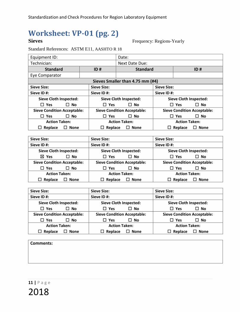
Worksheet: VP-01 (pg. 2) Sieves Frequency: Regions-Yearly
Standard References: ASTM E11, AASHTO R 18
Equipment ID: Date: Technician: Next Date Due:
Standard ID # Standard ID # Eye Comparator
Sieves Smaller than 4.75 mm (#4) Sieve Size: Sieve Size: Sieve Size: Sieve ID #: Sieve ID #: Sieve ID #:
Sieve Cloth Inspected: ☐ Yes ☐ No
Sieve Cloth Inspected: ☐ Yes ☐ No
Sieve Cloth Inspected: ☐ Yes ☐ No
Sieve Condition Acceptable: ☐ Yes ☐ No
Sieve Condition Acceptable: ☐ Yes ☐ No
Sieve Condition Acceptable: ☐ Yes ☐ No
Action Taken: ☐ Replace ☐ None
Action Taken: ☐ Replace ☐ None
Action Taken: ☐ Replace ☐ None
Sieve Size: Sieve Size: Sieve Size: Sieve ID #: Sieve ID #: Sieve ID #:
Sieve Cloth Inspected: ☒ Yes ☐ No
Sieve Cloth Inspected: ☐ Yes ☐ No
Sieve Cloth Inspected: ☐ Yes ☐ No
Sieve Condition Acceptable: ☐ Yes ☐ No
Sieve Condition Acceptable: ☐ Yes ☐ No
Sieve Condition Acceptable: ☐ Yes ☐ No
Action Taken: ☐ Replace ☐ None
Action Taken: ☐ Replace ☐ None
Action Taken: ☐ Replace ☐ None
Sieve Size: Sieve Size: Sieve Size: Sieve ID #: Sieve ID #: Sieve ID #:
Sieve Cloth Inspected: ☐ Yes ☐ No
Sieve Cloth Inspected: ☐ Yes ☐ No
Sieve Cloth Inspected: ☐ Yes ☐ No
Sieve Condition Acceptable: ☐ Yes ☐ No
Sieve Condition Acceptable: ☐ Yes ☐ No
Sieve Condition Acceptable: ☐ Yes ☐ No
Action Taken: ☐ Replace ☐ None
Action Taken: ☐ Replace ☐ None
Action Taken: ☐ Replace ☐ None
Comments:

Standardization and Check of Region Laboratory Equipment
12 | P a g e
2018
CHECK PROCEDURE: VP-02 (Single Use Mold) Equipment Verified: SINGLE USE CONCRETE CYLINDER MOLDS Standard References: AASHTO M-205 Purpose This procedure provides instructions for verifying compliance of single use plastic cylinder molds. Standard Equipment Required
Inside Caliper reading to 1/16” (1 mm)
18- inch Scale reading to 1/16” (1 mm)
Tolerance Single use molds shall meet criteria described in sections 3 and 6 of AASHTO M-205. Procedure
1. Inspect three molds from each shipment delivered to the Materials Laboratory as follows:
2. Measure the inside diameter of the mold and record on the worksheet.
3. Measure the inside height of the mold at two locations and record on the worksheet.
4. Check the resistance of the mold to damage under use by filling it in three lifts with a 1"-#4 crushed aggregate. Rod each lift 25 times. After filling the mold, empty it, wipe lightly with a clean cloth and examine for damage.
5. Check mold for water tightness by filling it with room temperature water and allowing it to stand for three (3) hours, then note any visible leakage.
6. When the inspection is complete, report the following:
7. Brand of molds;
8. Shipment or lot samples taken from;
9. Date sampled, date tested;
10. Brief description, type of mold, nominal dimensions, type of material;
11. Water tightness (complies or fails); and
12. If sample fails, record average diameter or height and maximum and minimum diameter or height.
13. Mark the boxes of molds that have been inspected with the inspection date, pass or fail, and the inspector's name.

Standardization and Check Procedures for Region Laboratory Equipment
13 | P a g e
2018
Worksheet: VP-02 Single Use Plastic Concrete Cylinder Molds Frequency: Per shipment Standard References: AASHTO T 23 Equipment ID: Verifying Technician: Date Verified Next Verification Date: Previous Verification Date: Time Charged:
Standard ID# Standard ID#
Caliper 18 in. Ruler
Single Use Plastic Single Use Plastic Single Use Plastic
BRAND LOT #
DATE SAMPLED DATE TESTED
SAMPLE #1 SAMPLE #2 SAMPLE #3
HEIGHT +/- 2% DIAMETER +/- 1% WALL THICKNESS
WATER TIGHTNESS (Leak Test) Pass Fail Pass Fail Pass Fail
Comments:

Standardization and Check of Region Laboratory Equipment
14 | P a g e
2018
STANDARDIZATION PROCEDURE: VP-4 (Concrete Pressure Gauge)
Equipment Verified: CONCRETE AIR METER PRESSURE GAUGE Standard References: AASHTO T 152, Annex A 1.9, Manufacturer’s Instructions
Purpose To perform a Calibration test to check the Air Content Graduations on the Pressure Gauge, Type B Meter.
Standard Equipment Required Calibration tubes and measures: as provided by the gauge manufacturer.
Tolerance Adjust gauge hand if two readings at 5% are in error by more than 0.2%.
Procedure Note: - The procedure described below generally follows the written instructions for Type B meters manufactured by Forney or Watts. Consult the manufactures instruction for meters manufactured by other manufacturers.
1. Fill the base full of water
2. Screw the short piece of straight tubing into the threaded petcock hole on the underside of the cover. Clamp the cover on the base with the tube extending down into the water.
3. With both petcocks open, add water with the syringe through the petcock having the pipe extension below, until all air is forced out opposite petcock. Leave both petcocks open.
4. Pump up air pressure to a little beyond the pre-determined initial pressure line. Wait a few seconds for compressed air to cool to normal temperature and then stabilize the gauge hand at the proper initial pressure by pumping or bleeding off as needed.
5. Close both petcocks and immediately press down on the thumb lever exhausting air into the base. Wait a few seconds until the needle stabilizes. If all the air was eliminated and the initial pressure line was correctly selected, the gage should read 0%. If two or more tests show a consistent variation from zero% in the result, then change the initial pressure line to compensate for the variation. Use the newly established “initial pressure” line for subsequent tests.
6. Screw curved tube into the outer end of the petcock and by pressing on thumb lever end controlling flow with petcock lever, fills the 5% calibrating vessel (345 ml) level full of water from the base.

Standardization and Check Procedures for Region Laboratory Equipment
15 | P a g e
2018
7. Release the air at the free petcock. Open the other petcock and let the water in the curved pipe run back into the base. There is now 5% air in the base.
8. With petcocks open, pump air pressure in exact manner outlined in paragraph 4. Close petcocks and immediately press thumb lever. Wait a few seconds for the exhaust air to warm to normal temperature, and for the needle to stabilize. The dial should now read 5%.
9. If two or more consistent tests show that gage reads incorrectly at 5% air in excess of 0.2%, then remove gauge glass and reset the dial hand to 5% by turning the recalibrating screw.
10. When gauge needle reads correctly at 5%, additional water may be withdrawn in the same manner to check results at 10%, 15%, 20%, etc.
Standardization and Check of Region Laboratory Equipment
16 | P a g e
2018
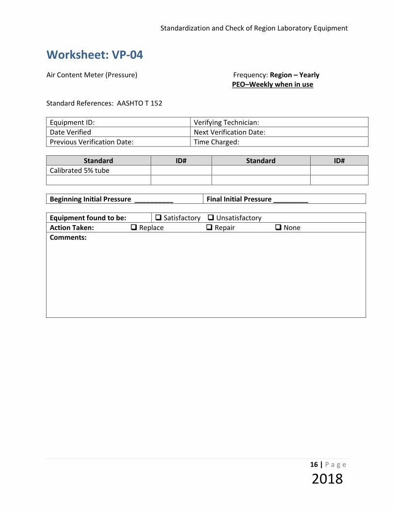
Worksheet: VP-04 Air Content Meter (Pressure) Frequency: Region – Yearly PEO–Weekly when in use Standard References: AASHTO T 152 Equipment ID: Verifying Technician: Date Verified Next Verification Date: Previous Verification Date: Time Charged:
Standard ID# Standard ID#
Calibrated 5% tube
Beginning Initial Pressure __________ Final Initial Pressure _________
Equipment found to be: Satisfactory Unsatisfactory Action Taken: Replace Repair None Comments:
Standardization and Check Procedures for Region Laboratory Equipment
17 | P a g e
2018
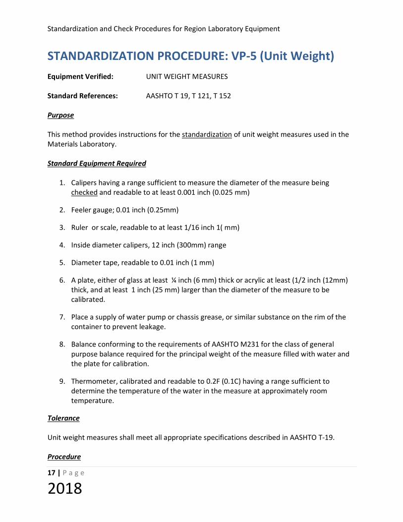
STANDARDIZATION PROCEDURE: VP-5 (Unit Weight) Equipment Verified: UNIT WEIGHT MEASURES Standard References: AASHTO T 19, T 121, T 152 Purpose This method provides instructions for the standardization of unit weight measures used in the Materials Laboratory. Standard Equipment Required
1. Calipers having a range sufficient to measure the diameter of the measure being checked and readable to at least 0.001 inch (0.025 mm)
2. Feeler gauge; 0.01 inch (0.25mm)
3. Ruler or scale, readable to at least 1/16 inch 1( mm)
4. Inside diameter calipers, 12 inch (300mm) range
5. Diameter tape, readable to 0.01 inch (1 mm)
6. A plate, either of glass at least ¼ inch (6 mm) thick or acrylic at least (1/2 inch (12mm) thick, and at least 1 inch (25 mm) larger than the diameter of the measure to be calibrated.
7. Place a supply of water pump or chassis grease, or similar substance on the rim of the container to prevent leakage.
8. Balance conforming to the requirements of AASHTO M231 for the class of general purpose balance required for the principal weight of the measure filled with water and the plate for calibration.
9. Thermometer, calibrated and readable to 0.2F (0.1C) having a range sufficient to determine the temperature of the water in the measure at approximately room temperature.
Tolerance Unit weight measures shall meet all appropriate specifications described in AASHTO T-19. Procedure

Standardization and Check of Region Laboratory Equipment
18 | P a g e
2018
1. Measure the height and insure that it is approximately equal to the diameter. In no case
shall the height be less than 80% or greater than 150% of the diameter.
2. Check to see that the top is smooth and plane by placing the plate on the top and insure that the 0.01 in. feeler gage cannot be inserted between the plate and the top of the measure.
3. Check to see that the top and bottom are parallel by measuring the distance from the plate to table on each side, divide the shorter distance by the longer distance for each two opposite sides, neither result shall exceed 0.5 degrees (0.87%).
4. Determine the thickness of metal of the upper 1 1/2 inches (38 mm) of the wall with the calipers in two locations, 90 degrees apart. Compare the average of the two measurements with the standards of T 19.
5. Measure the inside diameter with the inside calipers and scale. Determine the outside diameter by means of the diameter tape. Determine the wall thickness as one half the differences in diameters and compare with the standards of T 19.
6. Measure and record the external height of the measure at two places 90 degrees apart. Determine the inside height of the measure by measuring from the plate across the measure to the bottom of the measure. Determine the bottom thickness as the difference between the two heights
7. Record the empty weight of the measure with the plate.
8. Fill the measure with water (approx. room temperature)
9. Cover the measure with the plate to eliminate bubbles or excess water (use grease if necessary).
10. Record the weight of the measure, plate, and water. .
11. Measure the water temperature and determine the density of water using the table on the worksheet.
12. Calculate the weight of the water.
13. Calculate the volume of the measure
14. Calculate the calibration factor.
Standardization and Check Procedures for Region Laboratory Equipment
19 | P a g e
2018
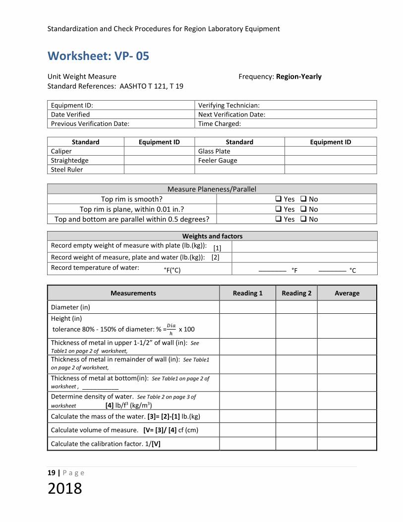
Worksheet: VP- 05 Unit Weight Measure Frequency: Region-Yearly Standard References: AASHTO T 121, T 19
Equipment ID: Verifying Technician: Date Verified Next Verification Date: Previous Verification Date: Time Charged:
Standard Equipment ID Standard Equipment ID Caliper Glass Plate Straightedge Feeler Gauge Steel Ruler
Measure Planeness/Parallel
Top rim is smooth? Yes No Top rim is plane, within 0.01 in.? Yes No
Top and bottom are parallel within 0.5 degrees? Yes No
Measurements Reading 1 Reading 2 Average
Diameter (in)
Height (in) tolerance 80% - 150% of diameter: % =𝐷𝐷𝐷𝐷𝐷𝐷
ℎ x 100
Thickness of metal in upper 1-1/2” of wall (in): See Table1 on page 2 of worksheet,
Thickness of metal in remainder of wall (in): See Table1 on page 2 of worksheet,
Thickness of metal at bottom(in): See Table1 on page 2 of worksheet , __________
Determine density of water. See Table 2 on page 3 of worksheet [4] lb/f3 (kg/m3)
Calculate the mass of the water. [3]= [2]-[1] lb.(kg)
Calculate volume of measure. [V= [3]/ [4] cf (cm)
Calculate the calibration factor. 1/[V]
Weights and factors Record empty weight of measure with plate (lb.(kg)): [1] Record weight of measure, plate and water (lb.(kg)): [2] Record temperature of water: °F(°C) _______ °F _______ °C

Standardization and Check of Region Laboratory Equipment
20 | P a g e
2018
Capacity Upper 1-1/2” Remainder Cubic feet Bottom of Wall of Wall <0.4 0.2 in. 0.10 in. 0.10 in. 0.4 to 1.5 0.2 in. 0.20in. 0.12 in.
Table 1 Thickness of Metal (minimum)
F C lb./ft.3 kg/m 3 F C lb./ft.3 kg/m 3
59.0 15 62.372 999.10 73.4 23 62.274 997.54 60.0 15.6 62.366 999.01 75.0 23.9 62.261 997.32 60.8 16 62.361 998.94 75.2 24 62.259 997.29 62.6 17 62.350 998.77 77.0 25 62.243 997.03 64.4 18 62.340 998.60 78.8 26 62.227 996.77 65.0 18.3 62.336 998.54 80.0 26.7 62.216 996.59 66.2 19 62.328 998.40 80.6 27 62.209 996.50 68.0 20 62.315 998.20 82.4 28 62.192 996.23 69.8 21 62.302 997.99 84.2 29 62.175 995.95 70.0 21.1 62.301 997.97 85.0 29.4 62.166 995.83 71.6 22 62.288 997.77 86.0 30 62.156 995.65
Table 2 Unit Mass of Water (FOP for AASHTO T121)
Equipment found to be : Satisfactory Unsatisfactory Action Taken: Replace Repair None Comments:
Standardization and Check Procedures for Region Laboratory Equipment
21 | P a g e
2018
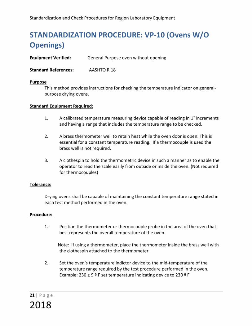
STANDARDIZATION PROCEDURE: VP-10 (Ovens W/O Openings) Equipment Verified: General Purpose oven without opening Standard References: AASHTO R 18 Purpose
This method provides instructions for checking the temperature indicator on general-purpose drying ovens.
Standard Equipment Required:
1. A calibrated temperature measuring device capable of reading in 1° increments
and having a range that includes the temperature range to be checked. 2. A brass thermometer well to retain heat while the oven door is open. This is
essential for a constant temperature reading. If a thermocouple is used the brass well is not required.
3. A clothespin to hold the thermometric device in such a manner as to enable the
operator to read the scale easily from outside or inside the oven. (Not required for thermocouples)
Tolerance:
Drying ovens shall be capable of maintaining the constant temperature range stated in each test method performed in the oven.
Procedure:
1. Position the thermometer or thermocouple probe in the area of the oven that best represents the overall temperature of the oven.
Note: If using a thermometer, place the thermometer inside the brass well with
the clothespin attached to the thermometer. 2. Set the oven’s temperature indictor device to the mid-temperature of the
temperature range required by the test procedure performed in the oven. Example: 230 ± 9 º F set temperature indicating device to 230 º F

Standardization and Check of Region Laboratory Equipment
22 | P a g e
2018
3. Take the first reading at least 1 hour after closing the oven (oven should remain undisturbed).
4. Take as many readings as necessary to determine if the setting on the
temperature indicating device accurately represents the internal temperature of the oven (three consecutive readings, taken no less than 1/2 hour apart if using a liquid-in-glass thermometer and no less than 15 minutes apart if using a thermocouple, are adequate.)
5. If the internal temperature measured in the oven does not agree with the setting
on the temperature indicating device, adjust the temperature indicating device to the measured internal temperature. Allow at least 1/2 hour for the temperature to stabilize and repeat step 3. Continue until the setting on the temperature indicating device and the internal temperature are the same.
6. Repeat the procedure from step 2 until temperature ranges are checked for all
test procedures which require the oven. 7. If the oven does not have a means of adjusting the temperature indicator.
Record the setting of the temperature indicating device where you achieve the target temperature. Record this setting in the “As Left” line of the worksheet and set it equal to the target temperature.
Example: Temperature indicating device is set at 231 º F to reach target temperature of 230 º F. “As Left” is 231 º F = 230 º F.
Standardization and Check Procedures for Region Laboratory Equipment
23 | P a g e
2018
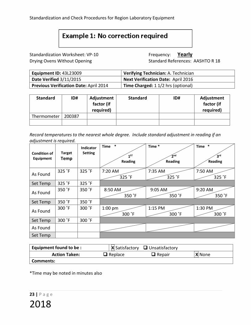
Standardization Worksheet: VP-10 Frequency: Yearly Drying Ovens Without Opening Standard References: AASHTO R 18 Equipment ID: 43L23009 Verifying Technician: A. Technician Date Verified 3/11/2015 Next Verification Date: April 2016 Previous Verification Date: April 2014 Time Charged: 1 1/2 hrs (optional)
Standard ID# Adjustment
factor (if required)
Standard ID# Adjustment factor (if required)
Thermometer 200387
Record temperatures to the nearest whole degree. Include standard adjustment in reading if an adjustment is required.
Condition of Equipment
Target Temp
Indicator Setting
Time * 1ST Reading
Time * 2nd Reading
Time * 3rd Reading
As Found 325 ˚F 325 ˚F 7:20 AM 325 ˚F
7:35 AM 325 ˚F
7:50 AM 325 ˚F
Set Temp 325 ˚F 325 ˚F
As Found 350 ˚F 350 ˚F 8:50 AM 350 ˚F
9:05 AM 350 ˚F
9:20 AM 350 ˚F
Set Temp 350 ˚F 350 ˚F
As Found 300 ˚F 300 ˚F 1:00 pm 300 ˚F
1:15 PM 300 ˚F
1:30 PM 300 ˚F
Set Temp 300 ˚F 300 ˚F As Found
Set Temp Equipment found to be : X Satisfactory Unsatisfactory
Action Taken: Replace Repair X None Comments:
*Time may be noted in minutes also

Standardization and Check of Region Laboratory Equipment
24 | P a g e
2018
Standardization Worksheet: VP-10 Frequency: Yearly Drying Ovens Without Opening Standard References: AASHTO R 18 Equipment ID: 43L23009 Verifying Technician: A. Technician Date Verified 3/11/2015 Next Verification Date: April 2016 Previous Verification Date: April 2014 Time Charged: 1 1/2 hrs (optional)
Standard ID# Adjustment
factor (if required)
Standard ID# Adjustment factor (if required)
Thermometer 200387
Record temperatures to the nearest whole degree; include standard adjustment in reading if an adjustment is required.
Condition of Equipment
Target Temp
Indicator Setting
Time * 1ST Reading
Time * 2nd Reading
Time * 3rd Reading
As Found 300 ˚F 300 ˚F 0 min 293 ˚F
30 min 295 ˚F
50 min
Set Temp Adjustment required
As Found 300 ˚F 305 ˚F 0 min 300 ˚F
25 min 301 ˚F
52 min 300 ˚F
Set Temp 300 ˚F 305 ˚F
As Found 325 ˚F 325 ˚F 0 min 325 ˚F
30 min 324 ˚F
50 min 325 ˚F
Set Temp 325 ˚F 325 ˚F
As Found 350 ˚F 350 ˚F 0 min 360 ˚F
35 min 359 ˚F
54 min 361 ˚F
Set Temp Adjustment required
As Found 350 ˚F 340 ˚F 0 min 350 ˚F
30 min 350 ˚F
55 min 350 ˚F
Set Temp 350 ˚F 340 ˚F Equipment found to be : X Satisfactory Unsatisfactory
Action Taken: Replace Repair X None Comments:
*Time may be noted as a bracket of times (i.e. 8:00 am – 8:30 am)
Example: Oven with no adjustment-Set temp correction
Standardization and Check Procedures for Region Laboratory Equipment
25 | P a g e
2018
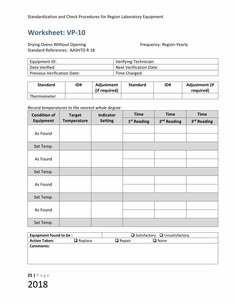
Worksheet: VP-10 Drying Ovens Without Opening Frequency: Region-Yearly Standard References: AASHTO R 18 Equipment ID: Verifying Technician: Date Verified Next Verification Date: Previous Verification Date: Time Charged:
Standard ID# Adjustment
(if required) Standard ID# Adjustment (if
required) Thermometer
Record temperatures to the nearest whole degree
Condition of Equipment
Target Temperature
Indicator Setting
Time Time Time 1st Reading 2nd Reading 3rd Reading
As Found
Set Temp.
As Found
Set Temp.
As Found
Set Temp.
As Found
Set Temp.
Equipment found to be : Satisfactory Unsatisfactory Action Taken: Replace Repair None Comments:

Standardization and Check of Region Laboratory Equipment
26 | P a g e
2018
STANDARDIZATION PROCEDURE: VP-11(Oven with Opening) Equipment Verified: GENERAL PURPOSE DRYING OVEN with Access Opening
Standard References: AASHTO R 18
Purpose
This method provides instructions for checking the temperature settings on general-purpose drying ovens having a thermometer access opening.
Standard Equipment Required
1. A calibrated thermometer capable of reading in 1° increments and having a
range that includes the temperature range checked. 2. A clothespin to hold the thermometer for the operator to read the scale easily
from outside the oven. Tolerance
Drying ovens shall be capable of maintaining the constant temperature range stated in the test methods.
Procedure
1. Set the oven for the desired temperature.
Note: If the oven is used at more than one temperature, verify the oven for each range of temperatures.
2. Place the thermometer through cork or thermometer holder. Insert the thermometer through the hole in the top of the oven. Position thermometers so the appropriate portion of thermometer scale is readable from outside the oven, but the thermometer is as far inside the oven as possible
3. Take the first reading at least 1 hour after closing the oven (oven should remain undisturbed).
4. Take as many readings as necessary to determine if the setting on the temperature indicating device accurately represents the internal temperature of the oven (three consecutive readings, taken no less than 1/2 hour apart if using a liquid-in-glass thermometer and no less than 15 minutes apart if using a thermocouple, are adequate.)

Standardization and Check Procedures for Region Laboratory Equipment
27 | P a g e
2018
5. If the internal temperature measured in the oven does not agree with the setting on the temperature-indicating device, adjust the temperature-indicating device to the measured internal temperature. Allow at least 1/2 hour for the temperature to stabilize and repeat step 3. Continue until the setting on the temperature-indicating device and the internal temperature are the same.
6. Repeat the procedure from step 2 until all temperature ranges for the oven are checked.
7. If the oven does not have a means of adjusting the temperature indicator, record the setting of the temperature-indicating device and mark this on the oven as the set temperature (234˚ F = 230˚F. Also, record this setting in the “As Left” line of the worksheet and set it equal to the target temperature.
Example: Temperature indicating device is set at 234 º F to reach target temperature of 230 º F. “As Left” is 234 º F = 230 º F.
Standardization and Check of Region Laboratory Equipment
28 | P a g e
2018
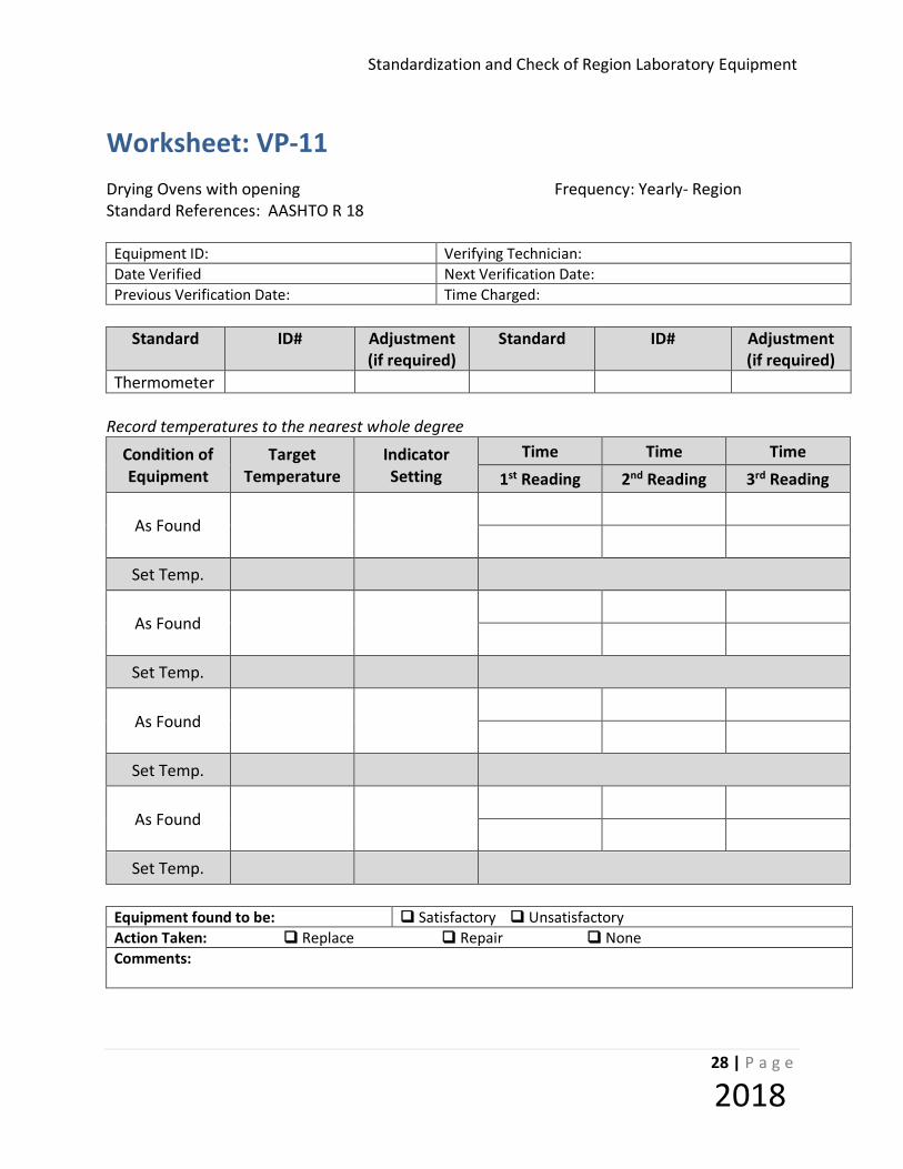
Worksheet: VP-11 Drying Ovens with opening Frequency: Yearly- Region Standard References: AASHTO R 18
Equipment ID: Verifying Technician: Date Verified Next Verification Date: Previous Verification Date: Time Charged:
Standard ID# Adjustment
(if required) Standard ID# Adjustment
(if required) Thermometer
Record temperatures to the nearest whole degree
Condition of Equipment
Target Temperature
Indicator Setting
Time Time Time 1st Reading 2nd Reading 3rd Reading
As Found
Set Temp.
As Found
Set Temp.
As Found
Set Temp.
As Found
Set Temp.
Equipment found to be: Satisfactory Unsatisfactory Action Taken: Replace Repair None Comments:

Standardization and Check Procedures for Region Laboratory Equipment
29 | P a g e
2018
STANDARDIZATION PROCEDURE: VP-12 (Thermometer - Ice Point) Equipment: Thermometers (Standardized at Ice Point) Standard References: AASHTO R 18, ASTM E77 Purpose This method provides instructions for the standardization of thermometric device at ice point. Standard Equipment Required 1. Dewar flask (to prevent excessive melting of ice during process) 2. Appropriate stand with thermometer holder 3. Siphon tube (to remove excess water from flask) 4. Crushed/shaved ice (made from distilled water) 5. Ice shaving machine or other suitable device to generate crushed/shaved ice 6. Protective gloves (surgical or equivalent) Tolerance Thermometers shall be accurate to one degree within their accuracy range. Procedure
1. Surgical or plastic gloves free of foreign particles shall be worn by the operator.
2. Ice is crushed/shaved to the consistency of a “snow-cone” with particles 2 to 5 mm diameter.
3. Place ice in the Dewar flask with distilled water and pack firmly. After approximately
15 to 30 minutes, siphon excess water, resulting from melting of the ice from the flask and add ice to replace that, which has melted. The ice bath is ready to use when it has set for 15 to 30 minutes, no ice is floating in the flask, and there is no excess water on the surface of the ice. Put as much ice in the flask as possible and fill the crevices with distilled water. Throughout the procedure, replace excess water with ice.
4. Clean the thermometer with distilled water at or below room temperature.

Standardization and Check of Region Laboratory Equipment
30 | P a g e
2018
5. Loosen the ice at the center of the bath with an object such as a clean glass rod to a
depth approximately equal to the thermometer’s immersion depth. Gently place the thermometer through the holder into the region of the loosened ice.
6. Immerse the thermometer in the ice to the immersion line or 0˚ C mark.
a. If the thermometer touches a firm surface before reaching the immersion line or
0˚ C mark, then remove it and loosen the ice to a greater depth.
b. If the thermometer passes the immersion line or 0˚ C mark before resting on a firm foundation, remove the thermometer, repack the ice, and loosen the ice to the correct depth.
7. Firmly pack the ice around the thermometer so it is perpendicular to the stand and
holder.
8. Once the thermometer is stable, leave it in the ice bath for a minimum of three minutes. Tap the stem gently and observe the reading. Take successive readings at least one minute apart. Readings shall agree within one tenth of a division.
a. Organic liquid thermometers will require approximately 15 minutes to stabilize.
b. Liquid in Glass thermometers are stable when the mercury stops moving.
c. Metal Probe thermometers are stable when the reading stops fluctuating.

Standardization and Check Procedures for Region Laboratory Equipment
31 | P a g e
2018
Worksheet: VP-12 Thermometers (Ice Point) Frequency: Region-Yearly Standard References: AASHTO R 18, ASTM E77 Technician: Date: Next Due Date:
Standard ID #
Thermometer ID #
Desired Temp Reading (1) Reading (2) Meets Spec: Action Taken if
not in Spec:
Yes No Disposed Adjusted
Yes No
Disposed Adjusted
Yes No
Disposed Adjusted
Yes No
Disposed Adjusted
Yes No
Disposed Adjusted
Yes No
Disposed Adjusted
Yes No
Disposed Adjusted
Yes No
Disposed Adjusted
Yes No
Disposed Adjusted
Yes No
Disposed Adjusted
Comments:

Standardization and Check of Region Laboratory Equipment
32 | P a g e
2018
STANDARDIZATION PROCEDURE: VP-13 (Thermometer - Working Range) Equipment: Thermometers (Standardized at Working Range)
Standard References: AASHTO R 18, ASTM E77
Purpose This method provides instructions for the standardization of thermometers using an oil bath, oven, thermostatically or non-thermostatically controlled water bath.
Standard Equipment Required 1. Standard thermometer(s) calibrated at appropriate test temperature(s).
2. A thermostatically controlled water or oil bath, oven, or non-thermostatically
controlled water bath. 3. Sand-filled container for use in oven.
4. Corks or thermometer holders as necessary.
Tolerance Thermometers shall be accurate to one degree within their accuracy range.
Specifications Thermometers shall be standardized at the temperature(s) defined by their intended use.
Procedure 1. Establish appropriate temperature for working range thermometer.
a. Thermostatically controlled bath, set at desired temperature. b. Non-thermostatically controlled bath, adjust water to desired temperature and
continually monitor. c. Oven, set at desired temperature and place Sand-filled container in oven.
2. Allow sufficient time for bath or oven to stabilize, then place Standard thermometer in bath or oven.
3. Place the Working thermometer(s) to be standardized into the bath or oven and
allow them to stabilize. Multiple thermometers may be standardized at one time in this process.
Standardization and Check Procedures for Region Laboratory Equipment
33 | P a g e
2018
4. After 1/2 hour record the temperature of the Working thermometer(s) and Standard thermometer (with adjustment if required).
5. Record two more readings not less than 1/2 hour apart.
6. Determine the average correction between the Working thermometer(s) and the
Standard thermometer, record on the worksheet.
7. Indicate the average temperature correction on the Working thermometer or adjust the Working thermometer to agree with the temperature of the Standard thermometer.

Standardization and Check of Region Laboratory Equipment
34 | P a g e
2018
Worksheet: VP-13 Thermometers (Working Range) Frequency: Region-Yearly Standard References: AASHTO R 18, ASTM E77
Technician: Date: Next Due Date:
Standard ID# Adjustment
(if required) Standard ID# Adjustment
(if required) Thermometer
Thermometer ID #
Desired Temp
Temp of Standard
(w/adjustment if required)
Time Time Time Average Correction Reading (1) Reading (2) Reading (3)
Meets Spec: Yes No Action Taken if not in Spec.: Disposed Adjusted
Meets Spec: Yes No Action Taken if not in Spec.: Disposed Adjusted
Meets Spec: Yes No Action Taken if not in Spec.: Disposed Adjusted
Meets Spec: Yes No Action Taken if not in Spec.: Disposed Adjusted
Meets Spec: Yes No Action Taken if not in Spec.: Disposed Adjusted
Meets Spec: Yes No Action Taken if not in Spec.: Disposed Adjusted
Comments:

Standardization and Check Procedures for Region Laboratory Equipment
35 | P a g e
2018
CHECK PROCEDURE: VP-14 (Using Internal Bore Gauge)
Equipment Checked: 150mm GYRATORY SPECIMEN MOLD and TOP/BOTTOM PLATES Standard References: WSDOT T 312, WSDOT SOP 731, AASHTO T 312-11 Purpose This procedure provides instructions for checking the critical dimension of gyratory specimen molds and bottom/top plates. Standard Equipment Required
1. Length Measuring Instrument (Outside Calipers or Micrometer) – With appropriate range and a minimum resolution of 0.01mm (0.0005 in.).
2. Calibrated Master Ring – A calibrated master ring of the same nominal size as the mold
diameter shall be used to set the measuring instrument reference for each series of measurements. A 150mm ANSI/ASME B89.1.6 Class Z standard is acceptable for 150mm sized molds.
3. Three-Point Bore Gauge – Minimum resolution shall be 0.001mm (0.00005 in.).
4. Verified straight edge.
5. Verified feeler Gauge, 0.025mm (0.001 in.).
Frequency of Check Minimum frequency of this evaluation is 12 months or 80 hours of operation. Tolerance The gyratory specimen molds and bottom/top plates checked at a temperature of 64° F to 82° F (18° C to 28° C) shall meet the dimensional tolerances specified in the applicable test method listed above. Note 1: May confirm this temperature range with an infrared thermometer. Procedure
Standardization and Check of Region Laboratory Equipment
36 | P a g e
2018
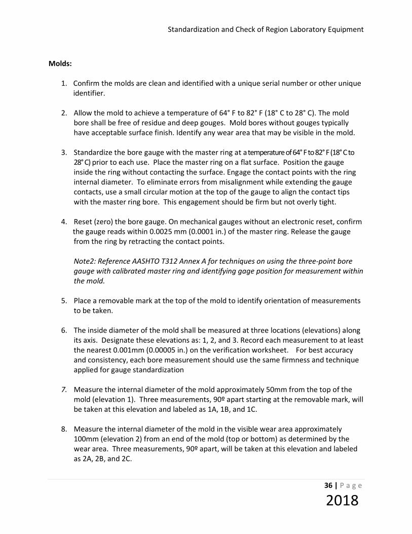
Molds:
1. Confirm the molds are clean and identified with a unique serial number or other unique
identifier.
2. Allow the mold to achieve a temperature of 64° F to 82° F (18° C to 28° C). The mold bore shall be free of residue and deep gouges. Mold bores without gouges typically have acceptable surface finish. Identify any wear area that may be visible in the mold.
3. Standardize the bore gauge with the master ring at a temperature of 64° F to 82° F (18° C to
28° C) prior to each use. Place the master ring on a flat surface. Position the gauge inside the ring without contacting the surface. Engage the contact points with the ring internal diameter. To eliminate errors from misalignment while extending the gauge contacts, use a small circular motion at the top of the gauge to align the contact tips with the master ring bore. This engagement should be firm but not overly tight.
4. Reset (zero) the bore gauge. On mechanical gauges without an electronic reset, confirm
the gauge reads within 0.0025 mm (0.0001 in.) of the master ring. Release the gauge from the ring by retracting the contact points.
Note2: Reference AASHTO T312 Annex A for techniques on using the three-point bore
gauge with calibrated master ring and identifying gage position for measurement within the mold.
5. Place a removable mark at the top of the mold to identify orientation of measurements
to be taken. 6. The inside diameter of the mold shall be measured at three locations (elevations) along
its axis. Designate these elevations as: 1, 2, and 3. Record each measurement to at least the nearest 0.001mm (0.00005 in.) on the verification worksheet. For best accuracy and consistency, each bore measurement should use the same firmness and technique applied for gauge standardization
7. Measure the internal diameter of the mold approximately 50mm from the top of the
mold (elevation 1). Three measurements, 90º apart starting at the removable mark, will be taken at this elevation and labeled as 1A, 1B, and 1C.
8. Measure the internal diameter of the mold in the visible wear area approximately
100mm (elevation 2) from an end of the mold (top or bottom) as determined by the wear area. Three measurements, 90º apart, will be taken at this elevation and labeled as 2A, 2B, and 2C.

Standardization and Check Procedures for Region Laboratory Equipment
37 | P a g e
2018
9. Measure the internal diameter of the mold at 50mm from the bottom of the mold (elevation 3). Three measurements, 90º apart, will be taken at this elevation and labeled as 3A, 3B, and 3C.
10. Each individual bore measurement shall be compared to the specified range of
149.90mm – 150.20mm (new molds at 149.90mm – 150.00mm) and given a pass/fail rating.
11. Verify height of mold and record on worksheet.
Mold Plates:
1. Confirm the mold plates are clean and properly identified. Allow the end plates to achieve a temperature of 64° F to 82° F (18° C to 28° C). The plates shall be free of residue and deep gouges. Surfaces in contact with the asphalt mixture shall be flat. Minor abrasion marks from aggregates are acceptable. Surfaces in contact with the SGC frame or compaction ram shall be free of raised burrs that may cause the plate to wobble during gyration. Small recesses on the side of the plate interfacing the SGC (opposite the asphalt mixture) can reduce rocking and are acceptable.
2. Determine the maximum diameter of the end plate by measuring in several locations.
Place a removable mark at this position. Record the maximum plate diameter to the nearest 0.01mm (0.0005 in.). Designate this as measurement “A”.
3. Measure the diameter at a 90º orientation to the maximum diameter. Record this
diameter as measurement “B”. 4. Each individual measurement reading shall be compared to the specified range
(149.50mm - 149.75mm) and given a pass/fail rating. 5. Using a verified straight-edge and feeler gauge, ensure that the plate is flat by taking
two observations 90º apart while trying to insert the feeler gauge between the plate and straight-edge. Record the results as measurement A and B on the verification worksheet.
Standardization and Check of Region Laboratory Equipment
38 | P a g e
2018
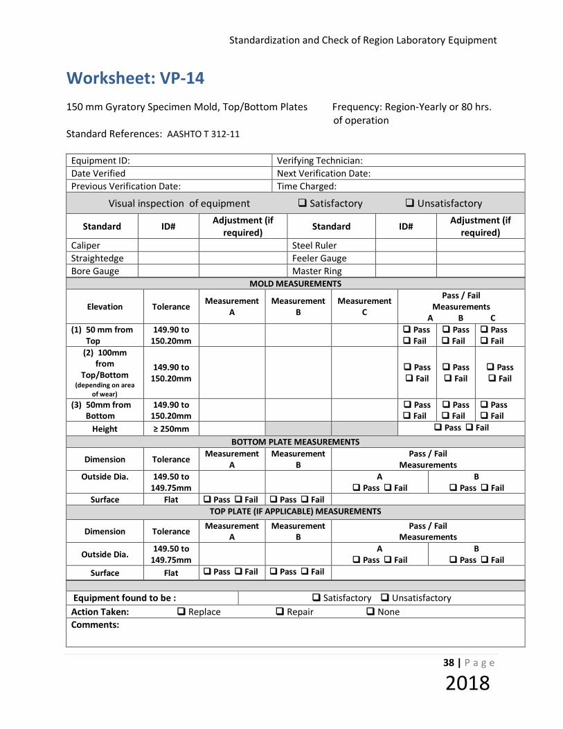
Worksheet: VP-14 150 mm Gyratory Specimen Mold, Top/Bottom Plates Frequency: Region-Yearly or 80 hrs. of operation Standard References: AASHTO T 312-11
Equipment ID: Verifying Technician: Date Verified Next Verification Date: Previous Verification Date: Time Charged:
Visual inspection of equipment Satisfactory Unsatisfactory
Standard ID# Adjustment (if required) Standard ID# Adjustment (if
required) Caliper Steel Ruler Straightedge Feeler Gauge Bore Gauge Master Ring
MOLD MEASUREMENTS
Elevation Tolerance Measurement A
Measurement B
Measurement C
Pass / Fail Measurements
A B C (1) 50 mm from Top
149.90 to 150.20mm
Pass Fail
Pass Fail
Pass Fail
(2) 100mm from
Top/Bottom (depending on area
of wear)
149.90 to 150.20mm Pass
Fail Pass Fail
Pass Fail
(3) 50mm from Bottom
149.90 to 150.20mm
Pass Fail
Pass Fail
Pass Fail
Height ≥ 250mm Pass Fail BOTTOM PLATE MEASUREMENTS
Dimension Tolerance Measurement A
Measurement B
Pass / Fail Measurements
Outside Dia.
149.50 to 149.75mm
A Pass Fail
B Pass Fail
Surface Flat Pass Fail Pass Fail TOP PLATE (IF APPLICABLE) MEASUREMENTS
Dimension Tolerance Measurement A
Measurement B
Pass / Fail Measurements
Outside Dia. 149.50 to 149.75mm
A Pass Fail
B Pass Fail
Surface Flat Pass Fail Pass Fail
Equipment found to be : Satisfactory Unsatisfactory Action Taken: Replace Repair None Comments:

Standardization and Check Procedures for Region Laboratory Equipment
39 | P a g e
2018
STANDARDIZATION PROCEDURE: VP-17 (Mechanical Sieving Device)
Equipment Verified: MECHANICAL SIEVING DEVICE Standard References: AASHTO T 27 Purpose This procedure provides instructions on testing for sieving thoroughness. Separate instructions are provided for round sieves, 12 inches (300 mm) in diameter or less and for rectangular screens and round screens exceeding 12 inches (300 mm) in diameter. Standard Equipment Required
1. A set of sieves with standard or non-standard frames as appropriate for the sieving device being checked.
2. Balance, with a capacity required for the principal weight of the sample and readable to
at least 0.1 g. 3. Pans, weighing pans, and other appropriate sieve cleaning tools as required.
Tolerance As specified in AASHTO T 27, sieving action and time shall be sufficient to assure that, after completion, not more than 0.5 percent by weight of the total sample passes any sieve during one minute of continuous hand sieving. (For rectangular sieves or others exceeding 12 inch (300 mm) diameter, one minute of additional mechanical sieving shall be used in the evaluation.)
Procedure
Check the mechanical shaker using a normal set of sieves (coarse and fine) and a material sample of sufficient size and particle distribution for the required sieves. In no case shall the amount of material on any one sieve smaller than 4.74 mm (No. 4) exceed 4 g per square inch of sieving surface. For sieves larger than 4.74 mm, (No. 4), limit the amount of material to one particle deep.) 1. Weigh and record the total weight of the sample.
Standardization and Check of Region Laboratory Equipment
40 | P a g e
2018
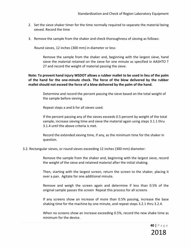
2. Set the sieve shaker timer for the time normally required to separate the material being sieved. Record the time
3. Remove the sample from the shaker and check thoroughness of sieving as follows:
Round sieves, 12 inches (300 mm) in diameter or less: Remove the sample from the shaker and, beginning with the largest sieve, hand
sieve the material retained on the sieve for one minute as specified in AASHTO T 27 and record the weight of material passing the sieve.
Note: To prevent hand injury WSDOT allows a rubber mallet to be used in lieu of the palm
of the hand for the one-minute check. The force of the blow delivered by the rubber mallet should not exceed the force of a blow delivered by the palm of the hand.
Determine and record the percent passing the sieve based on the total weight of
the sample before sieving. Repeat steps a and b for all sieves used. If the percent passing any of the sieves exceeds 0.5 percent by weight of the total
sample, increase sieving time and sieve the material again using steps 3.1.1 thru 3.1.4 until the above criteria is met.
Record the extended sieving time, if any, as the minimum time for the shaker in
question.
3.2. Rectangular sieves, or round sieves exceeding 12 inches (300 mm) diameter:
Remove the sample from the shaker and, beginning with the largest sieve, record the weight of the sieve and retained material after the initial shaking.
Then, starting with the largest screen, return the screen to the shaker, placing it
over a pan. Agitate for one additional minute. Remove and weigh the screen again and determine if less than 0.5% of the
original sample passes the screen Repeat this process for all screens If any screens show an increase of more than 0.5% passing, increase the base
shaking time for the machine by one minute, and repeat steps 3.2.1 thru 3.2.4. When no screens show an increase exceeding 0.5%, record the new shake time as
minimum for the device.
Standardization and Check Procedures for Region Laboratory Equipment
41 | P a g e
2018
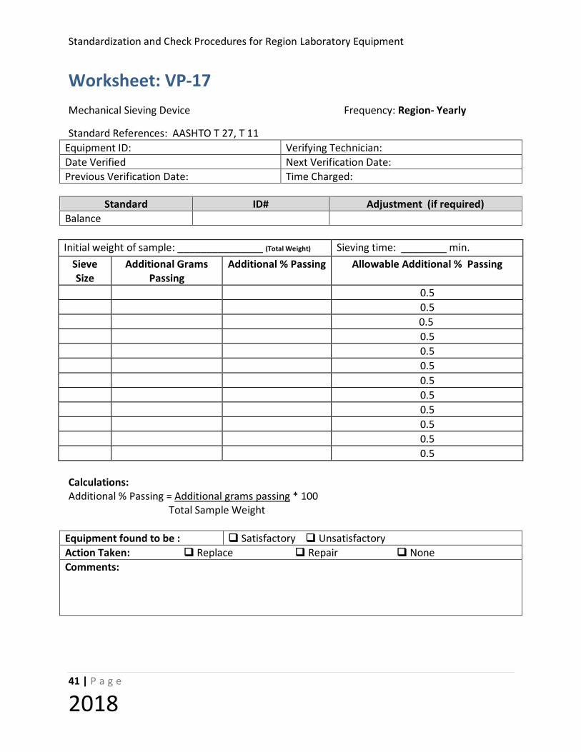
Worksheet: VP-17 Mechanical Sieving Device Frequency: Region- Yearly
Standard References: AASHTO T 27, T 11 Equipment ID: Verifying Technician: Date Verified Next Verification Date: Previous Verification Date: Time Charged:
Standard ID# Adjustment (if required) Balance
Initial weight of sample: _______________ (Total Weight) Sieving time: ________ min. Sieve Size
Additional Grams Passing
Additional % Passing Allowable Additional % Passing
0.5 0.5 0.5 0.5 0.5 0.5 0.5 0.5 0.5 0.5 0.5 0.5
Calculations: Additional % Passing = Additional grams passing * 100 Total Sample Weight
Equipment found to be : Satisfactory Unsatisfactory Action Taken: Replace Repair None Comments:

Standardization and Check of Region Laboratory Equipment
42 | P a g e
2018
CHECK PROCEDURE: VP-19 (Mechanical SE Shaker) Equipment Verified: MECHANICAL SAND EQUIVALENT TEST SHAKER Standard References: AASHTO T 176 Purpose This method provides instruction for checking the mechanical shaker to insure operation at the specified amplitude and number of cycles per minute. Standard Equipment Required
1. A measuring device capable of measuring the specified throw of 8 ± 0.04 inches 2. Handheld mechanical counting device capable of reading to 500 counts, minimum. 3. A noncontact tachometer readable to 500 units per minute may also be used. (A
Mitutoyo Non-contact Digital Tachometer, Model 982-522, has been found to be satisfactory for this purpose.)
4. A timer, readable to 1 second.
Tolerance
175 ± 2 cycles per minute (2.92 ±0.03 Hz)
8 ± 0.04 inches (203.3 ±1.02 mm) throw
Procedure
1. Measure the cycles per minute:
a. Using a mechanical counting device Operate the shaker for 60 + 1 seconds and record the number of cycles in one direction as cycles per minute.
b. Using a non-contact tachometer
i. Start the shaker and hold the tachometer in such a manner as to cause
the beam of light emitted from the lens to be broken by one edge of the moving part of the shaker, and record the reading displayed on the tachometer as cycles per minute.

Standardization and Check Procedures for Region Laboratory Equipment
43 | P a g e
2018
2. Measure throw
a. Having first taken the proper steps to insure personal safety, manually operate
the mechanism to one extreme of its throw. b. Measure the distance along a straight line, parallel to the movement of the
shaker, from a stationary point on the frame to a fixed point on the part that holds the graduated plastic cylinder.
c. Slowly, manually operate the shaker in such a way as to cause the movable part
of the shaker to move to its extreme position and record the difference between the first measurement and the second. This value equals the throw of the shaker.
3. Record the results and insure that the values obtained meet the tolerances referenced
above.
4. If the cycles per minute or throw does not meet the tolerances, take the shaker out of service and either replaced or repair it to conform to the referenced tolerances.
Standardization and Check of Region Laboratory Equipment
44 | P a g e
2018
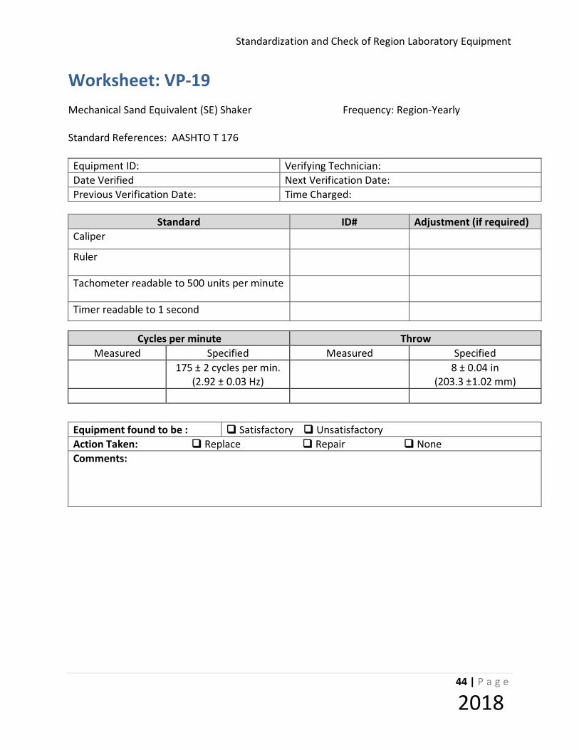
Worksheet: VP-19 Mechanical Sand Equivalent (SE) Shaker Frequency: Region-Yearly Standard References: AASHTO T 176 Equipment ID: Verifying Technician: Date Verified Next Verification Date: Previous Verification Date: Time Charged:
Standard ID# Adjustment (if required)
Caliper
Ruler
Tachometer readable to 500 units per minute
Timer readable to 1 second
Cycles per minute Throw Measured Specified Measured Specified
175 ± 2 cycles per min. (2.92 ± 0.03 Hz)
8 ± 0.04 in (203.3 ±1.02 mm)
Equipment found to be : Satisfactory Unsatisfactory Action Taken: Replace Repair None Comments:
Standardization and Check Procedures for Region Laboratory Equipment
45 | P a g e
2018
CHECK PROCEDURE: VP-20 (S.E. Weighted Foot) Equipment Verified: SAND EQUIVALENT WEIGHTED FOOT ASSEMBLY Standard References: AASHTO T 176 Purpose This method provides instructions for checking the condition and mass of the weighted foot assembly Standard Equipment Required Calipers, readable to 0.001 inch Balance, 5 kg capacity, readable to 1 g Tolerance The mass of the weighted foot assembly shall be 1000 grams + 5 grams. The distance from the bottom of the foot to the top of the sand indicator shall be 256.5 mm + 0.40 mm. Procedure Determine and record the weight of the weighted foot assembly to the nearest 1 g. Measure the distance from the bottom of the weighted foot to the top of the sand indicator to the nearest 0.01 mm.

Standardization and Check of Region Laboratory Equipment
46 | P a g e
2018
Worksheet: VP-20 Sand Equivalent Weighted Foot Assembly Frequency: Region – Yearly Standard References: AASHTO T 176 Equipment ID: Verifying Technician: Date Verified Next Verification Date: Previous Verification Date: Time Charged:
Standard ID# Adjustment (if necessary)
Caliper Balance
Weighted Foot
Assembly Tolerance Measurement Acceptable
Mass of assembly 1000 grams +/- 5 grams Yes No
Distance from bottom of foot to top of
indicator
256.5 mm +/- 0.40 mm Yes No
Equipment found to be : Satisfactory Unsatisfactory Action Taken: Replace Repair None Comments:

Standardization and Check Procedures for Region Laboratory Equipment
47 | P a g e
2018
STANDARDIZE PROCEDURE: VP-23 (WATER BATH) Equipment Verified: Water Bath Standard References: Purpose This method provides instructions for verifying the temperature settings on water baths. Note: Water baths do not require standardization if the temperature of the water in the bath is monitored,
using a floating standardized thermometer. Inspection Equipment Required
Thermometer, calibrated and readable to 0.03°C (± 0.05°F) Cork of appropriate size or thermometer holder
Tolerance Baths shall be standardized at the temperature defined by their intended use Procedure
1. Refer to appropriate test procedure for water bath specifications.
2. Place the thermometer through cork or thermometer holder. Position the thermometer in the water bath so that the appropriate portion of thermometer scale is readable.
3. Take the first reading at least one hour after the thermometer and bath have come to
temperature.
4. Take three consecutive readings, no less than 30 minutes apart and record. If any reading is not within the range allowed for the type of bath, adjust temperature indicator and start readings over.

Standardization and Check of Region Laboratory Equipment
48 | P a g e
2018
Worksheet: VP-23 Water Bath Frequency: Region-Yearly Standard References: Equipment ID: Verifying Technician: Date Verified Next Verification Date: Previous Verification Date: Time Charged:
Standard ID# Adjustment (if required)
Thermometer
Target
Temperature After 1 Hour After ½ Hour After ½ Hour After ½ Hour Acceptable
Yes No Yes No Yes No
Equipment found to be : Satisfactory Unsatisfactory Action Taken: Replace Repair None Comments:
Standardization and Check Procedures for Region Laboratory Equipment
49 | P a g e
2018
STANDARDIZATION PROCEDURE: VP-31(Vacuum System) Equipment Verified: Vacuum System Standard Reference: AASHTO T 209, WSDOT T 718, T 100, WSDOT T 606 Purpose This method provides instructions to verify that minimum vacuum is achieved and to correct readings on the vacuum gauge. Standard Equipment Required Absolute pressure gauge.
Water trap.
Hoses, connectors, and any other miscellaneous fittings.
Pycnometer (metal or glass)
Tolerance When all pycnometer(s) are connected to the vacuum system with the valve(s) fully open, a maximum of 30mm Hg will be measured. Note: If an adjustment is shown on the Certificate of Calibration for the absolute pressure gauge, make sure the reading is adjusted accordingly. Example: If the absolute pressure gauge has a correction of +3.3 mmHg then a gauge reading of 30 mmHg it is actually 33.3 mmHg. Procedure 1. Connect the absolute pressure gauge to the system with the water trap in line between the
system and the gauge. A hose tees off the main line to the bench mounted valve, which can be used for the connection.
2. Check all connections for air tightness. 3. Fill all pycnometers one-half full of water and connect to the system. 4. Open the vacuum line fully and allow the system to stabilize.
Standardization and Check of Region Laboratory Equipment
50 | P a g e
2018
5. Record the vacuum achieved. 6. Close vacuum line and bleed vacuum system slowly to atmospheric pressure. 7. Repeat steps 4 and 5. If both checks meet tolerance, stop.
a. Mark the appropriate vacuum level on the gauge for reference. For WSDOT FOP for AASHTO T-209 bleed the vacuum slowly to 30mm Hg (4.0kPa) and mark the gauge for reference.
b. If either test fails to meet tolerance, repeat steps 4 and 5 until two consecutive tests
meet tolerance. If two consecutive tests do not meet tolerance, discontinue use of the vacuum system until repairs can be made.

Standardization and Check Procedures for Region Laboratory Equipment
51 | P a g e
2018
Worksheet: VP-31 Vacuum System Frequency: Region – Yearly Standard References: AASHTO T 209, WSDOT T 718, WSDOT T 606 Equipment ID: Verifying Technician: Date Verified Next Verification Date: Previous Verification Date: Time Charged:
Standard ID# Adjustment (if required)
Absolute Pressure Gauge
Vacuum Pressure Air Tightness First Reading Second Reading
Yes No Yes No Yes No Yes No Yes No Yes No
Equipment found to be : Satisfactory Unsatisfactory Action Taken: Replace Repair None Comments:

Standardization and Check of Region Laboratory Equipment
52 | P a g e
2018
CHECK PROCEDURE: VP-32 (Slump Cone)
Equipment Verified: SLUMP CONE Standard References: AASHTO T 119 Purpose This method provides instructions for checking the critical dimensions of the slump cone used in the above test method. Standard Equipment Required 1. Calipers or ruler readable to 1/16 inch (1mm) 2. Ruler readable to 1/16 inch (1 mm) Tolerance 1. Metal thickness shall be not less than BWG 16 gage (0.065 inches).
2. If produced by a spinning process the min. thickness shall not be less than 0.045 inch (1.14 mm).
3. Base shall be 8 + 1/8 inch (203 + 3 mm). 4. Top shall be 4 + 1/8 inch (102 + 3 mm) 5. Height shall be 12 + 1/8 inch (305 + 3 mm) Procedure 1. Measure the inside diameter at the top of the cone to the nearest 1mm by taking two
readings 90° apart using the calipers and record the results.
2. Invert the cone and repeat Step 1 using a ruler.
3. Place the cone on a flat glass surface. Measure the height of the cone by using the ruler and record the results.
4. Measure the thickness of the cone to the nearest 1mm by taking two (2) readings 90° apart
at the top of the cone and two (2) readings 90° apart at the bottom of the cone and record the results.
5. Examine the interior to determine that it is relatively smooth, free of projections and free of
dents.
Standardization and Check Procedures for Region Laboratory Equipment
53 | P a g e
2018
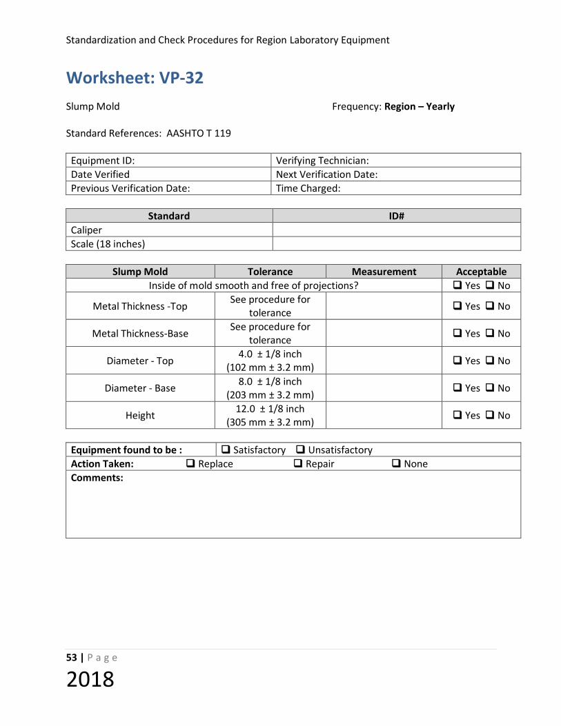
Worksheet: VP-32 Slump Mold Frequency: Region – Yearly Standard References: AASHTO T 119 Equipment ID: Verifying Technician: Date Verified Next Verification Date: Previous Verification Date: Time Charged:
Standard ID#
Caliper Scale (18 inches)
Slump Mold Tolerance Measurement Acceptable
Inside of mold smooth and free of projections? Yes No
Metal Thickness -Top See procedure for tolerance Yes No
Metal Thickness-Base See procedure for tolerance Yes No
Diameter - Top 4.0 ± 1/8 inch (102 mm ± 3.2 mm) Yes No
Diameter - Base 8.0 ± 1/8 inch (203 mm ± 3.2 mm) Yes No
Height 12.0 ± 1/8 inch (305 mm ± 3.2 mm) Yes No
Equipment found to be : Satisfactory Unsatisfactory Action Taken: Replace Repair None Comments:
Standardization and Check of Region Laboratory Equipment
54 | P a g e
2018
CHECK PROCEDURE: VP- 41 (SOIL TEST MOLDS) Equipment Verified: SOIL TEST MOLDS
Standard References: AASHTO T 99, T 180 Purpose This procedure provides instructions for checking the critical dimensions of the 4 and 6-inch molds used in soil testing. Inspection Equipment Required 1. Calipers capable of measuring the height and inside diameter of the molds and readable to 0.01 mm (0.001 inch)
2. Feeler Gauge, readable to 0.125 mm (0.005 inch)
3. Straight edge checked for planeness
4. Balance capable of determining mass of water, glass plate, and measure to the nearest 0.05 kg (0.1 lb)
5. Thermometer, readable to at least 0.5°C (1°F)
Tolerance The height, diameter and volume of the molds checked shall meet the dimensional tolerances specified in the applicable test method listed above. The base plate shall be flat within 0.127 mm (0.005 inch) Check Mold Procedure
1. Measure and record the inside diameter of the mold, determined by taking two readings 90 degrees apart, to the nearest 0.001 inch.
2. Turn the mold over and repeat step 1.
3. Measure and record the height of the mold, determined by taking two readings 90 degrees apart, to the
nearest 0.001 inch.
4. Place a thin layer of grease on the rim of the measure to prevent water leakage.

Standardization and Check Procedures for Region Laboratory Equipment
55 | P a g e
2018
5. Determine the mass of the glass plate and measure
6. Fill the measure with room temperature water and cover with glass plate such to eliminate any bubbles and excess water.
7. Determine the mass of the water, plate, and measure.
8. Measure the temperature of the water and determine its density from the table below.
Density of Water
Temperature kg/m³ lb/ft³ °C °F
15.6 60 999.01 62.366 18.3 65 998.54 62.336 21.1 70 997.97 62.301 23.0 73.4 997.54 62.274 23.9 75 997.32 62.261 26.7 80 996.59 62.216 29.4 85 995.83 62.166
9. Calculate the volume, V, of the measure. V = (B – C)/D
Where:
V = volume of the measure, m3 (ft3); B = mass of the water, plate glass, and measure, kg (lb); C = mass of the plate glass and measure, kg (lb); D = density of the water for the measured kg/m3 (lb/ft3)
10. Record the results.
Check Base Plate Procedure
1. Place the edge of the straightedge into the recessed area of the base plate. 2. Attempt to slide the feeler gauge between the base plate and the straightedge. The
base plate is not plane if the feeler gauge fits between the base plate and the straightedge.
3. Record the results.
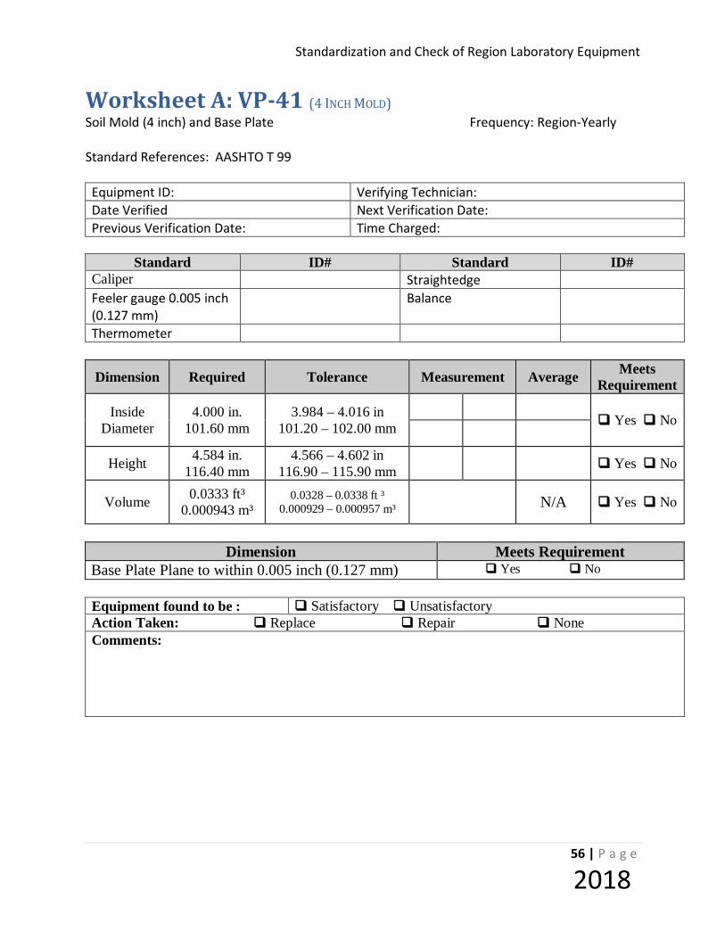
Standardization and Check of Region Laboratory Equipment
56 | P a g e
2018
Worksheet A: VP-41 (4 INCH MOLD) Soil Mold (4 inch) and Base Plate Frequency: Region-Yearly Standard References: AASHTO T 99 Equipment ID: Verifying Technician: Date Verified Next Verification Date: Previous Verification Date: Time Charged:
Standard ID# Standard ID#
Caliper Straightedge Feeler gauge 0.005 inch (0.127 mm) Balance
Thermometer
Dimension Required Tolerance Measurement Average Meets Requirement
Inside Diameter
4.000 in. 101.60 mm
3.984 – 4.016 in 101.20 – 102.00 mm
Yes No
Height 4.584 in. 116.40 mm
4.566 – 4.602 in 116.90 – 115.90 mm Yes No
Volume 0.0333 ft³ 0.000943 m³
0.0328 – 0.0338 ft ³ 0.000929 – 0.000957 m³ N/A Yes No
Dimension Meets Requirement
Base Plate Plane to within 0.005 inch (0.127 mm) Yes No Equipment found to be : Satisfactory Unsatisfactory Action Taken: Replace Repair None Comments:

Standardization and Check Procedures for Region Laboratory Equipment
57 | P a g e
2018
Worksheet B: VP-41 (6 INCH MOLD) Soil Mold (6 inch) and Base Plate Frequency: Region-Yearly Standard References: AASHTO T 180 Equipment ID: Verifying Technician: Date Verified Next Verification Date: Previous Verification Date: Time Charged:
Standard ID# Standard ID#
Caliper Straightedge Feeler gauge 0.005 inch (0.127 mm) Balance
Thermometer
Dimension Required Tolerance Measurement Average Meets Requirement
Inside Diameter
6.000 in. 152.40 mm
5.974 – 6.026 in 145.40 – 153.10 mm
Yes No
Height 4.584 in. 116.40 mm
4.566 – 4.602 in 116.90 – 115.90 mm Yes No
Volume 0.0750 ft³ 0.002124 m³
0.0741 – 0.0759 ft ³ 0.002096 – 0.002149 m³ N/A Yes No
Dimension Meets Requirement
Base Plate Plane to within 0.005 inch (0.127 mm) Yes No Equipment found to be : Satisfactory Unsatisfactory Action Taken: Replace Repair None Comments:

Standardization and Check of Region Laboratory Equipment
58 | P a g e
2018
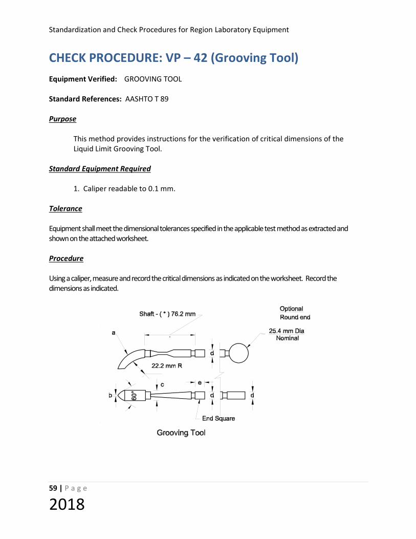
Standardization and Check Procedures for Region Laboratory Equipment
59 | P a g e
2018
CHECK PROCEDURE: VP – 42 (Grooving Tool) Equipment Verified: GROOVING TOOL Standard References: AASHTO T 89 Purpose This method provides instructions for the verification of critical dimensions of the Liquid Limit Grooving Tool. Standard Equipment Required 1. Caliper readable to 0.1 mm. Tolerance Equipment shall meet the dimensional tolerances specified in the applicable test method as extracted and shown on the attached worksheet. Procedure Using a caliper, measure and record the critical dimensions as indicated on the worksheet. Record the dimensions as indicated.

Standardization and Check of Region Laboratory Equipment
60 | P a g e
2018
Worksheet: VP-42 Grooving Tool Frequency: Region-Yearly Standard References: AASHTO T 89 Equipment ID: Verifying Technician: Date Verified Next Verification Date: Previous Verification Date: Time Charged:
Standard ID#
Caliper
Grooving tool Tolerance Measurement (mm) Acceptable
Curved end Thickness (a) 10.0 ± 0.1 mm Yes No Curved end cutting edge (b) 2.0 ± 0.1* mm Yes No Curved end width (c) 13.5 ± 0.1 mm Yes No Gauge depth (d) 10.0 ± 0.2 mm Yes No
* An additional wear tolerance of +0.1 mm shall be allowed for dimension “b” for used grooving tools Equipment found to be : Satisfactory Unsatisfactory Action Taken: Replace Repair None Comments:

Standardization and Check Procedures for Region Laboratory Equipment
61 | P a g e
2018
CHECK PROCEDURE: VP – 43 (Liquid Limit Device) Equipment Verified: LIQUID LIMIT DEVICE Standard References: AASHTO T 89, Fig 1, Section 4.1 Purpose This method provides instructions for checking critical dimensions and calibration of the liquid limit device used in the above test procedure. Standard Equipment Required 1. Calipers readable to 0.1 mm 2. Height gauge 10 mm + 0.2 mm (Square end of the grooving tool may be used if verified) 3. Worksheet VP-43 (attached) Tolerance Equipment shall meet the dimensional tolerances specified in the applicable test method as extracted and shown on the worksheet. Procedure
1. Measure the dimensions described in AASHTO T 89 with caliper and record results on the work sheet.
2. Check for wobble on the rise of the cup as an indication of wear on the pin.
3. Check for wear as described in AASHTO T 89, section 4.1 and record observations on the
worksheet.

Standardization and Check of Region Laboratory Equipment
62 | P a g e
2018
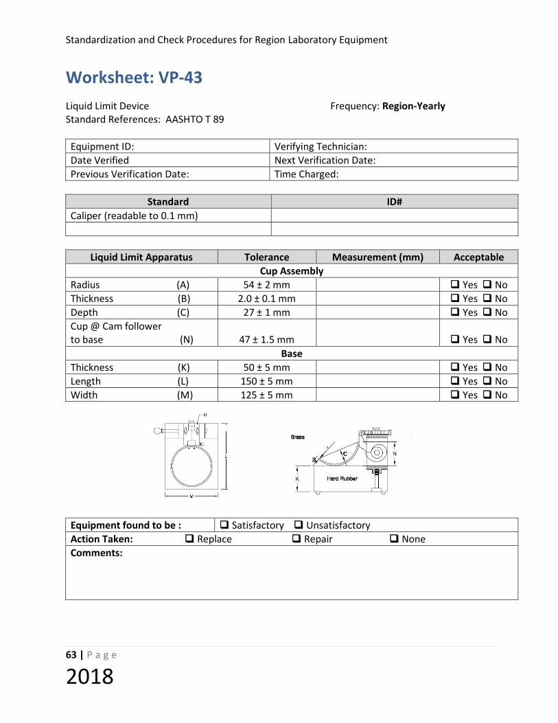
Standardization and Check Procedures for Region Laboratory Equipment
63 | P a g e
2018
Worksheet: VP-43 Liquid Limit Device Frequency: Region-Yearly Standard References: AASHTO T 89 Equipment ID: Verifying Technician: Date Verified Next Verification Date: Previous Verification Date: Time Charged:
Standard ID#
Caliper (readable to 0.1 mm)
Liquid Limit Apparatus Tolerance Measurement (mm) Acceptable
Cup Assembly Radius (A) 54 ± 2 mm Yes No Thickness (B) 2.0 ± 0.1 mm Yes No Depth (C) 27 ± 1 mm Yes No Cup @ Cam follower to base (N) 47 ± 1.5 mm Yes No
Base Thickness (K) 50 ± 5 mm Yes No Length (L) 150 ± 5 mm Yes No Width (M) 125 ± 5 mm Yes No
Equipment found to be : Satisfactory Unsatisfactory Action Taken: Replace Repair None Comments:
Standardization and Check of Region Laboratory Equipment
64 | P a g e
2018
CHECK PROCEDURE: VP – 44 (Manual Rammer) Equipment Verified 5.5 lb MANUAL RAMMER T 99 10.0 lb MANUAL RAMMER T 180 Standard References: AASHTO T 99, T 180, WSDOT T 606 Purpose This procedure provides instructions for the verification of the weight and critical dimensions of the manual rammer. Standard Equipment Required 1. Balance, capacity 5 kg (10 lb), readable to 1 g (0.01 lb) 2. Tape measure, readable to 0.20 mm (1/16 inch) 3. Calipers, readable to 0.025 mm (0.001 inch) Tolerance Manual Rammers shall meet all applicable tolerance described in AASHTO T 99, AASHTO T 180 and WSDOT T 606. Procedure 1. Measure and record the diameter of the rammer face determined by taking two readings
90 degrees apart using the calipers.
2. Measure and record the drop height by pulling the handle out and measuring the distance from the bottom edge of the tube to the rammer face using the tape measure inserted inside the tube.
3. Record the weight of the rammer:
a. Remove the rammer handle knob;
b. Slide the rammer out of the tube;
c. Replace the knob and nuts into the rammer;
d. Weigh the rammer; and
e. Adjust the weight if necessary by removing the rammer head from the handle shaft and adding or removing shot.
4. Measure and record the diameter of the vent holes near the end of the rammer.
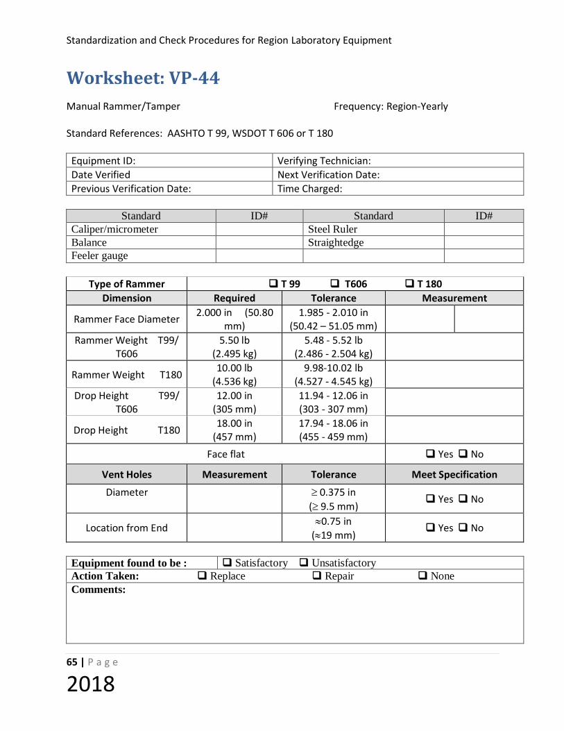
Standardization and Check Procedures for Region Laboratory Equipment
65 | P a g e
2018
Worksheet: VP-44 Manual Rammer/Tamper Frequency: Region-Yearly Standard References: AASHTO T 99, WSDOT T 606 or T 180 Equipment ID: Verifying Technician: Date Verified Next Verification Date: Previous Verification Date: Time Charged:
Standard ID# Standard ID#
Caliper/micrometer Steel Ruler Balance Straightedge Feeler gauge
Type of Rammer T 99 T606 T 180
Dimension Required Tolerance Measurement
Rammer Face Diameter 2.000 in (50.80 mm)
1.985 - 2.010 in (50.42 – 51.05 mm)
Rammer Weight T99/ T606
5.50 lb (2.495 kg)
5.48 - 5.52 lb (2.486 - 2.504 kg)
Rammer Weight T180 10.00 lb (4.536 kg)
9.98-10.02 lb (4.527 - 4.545 kg)
Drop Height T99/ T606
12.00 in (305 mm)
11.94 - 12.06 in (303 - 307 mm)
Drop Height T180 18.00 in (457 mm)
17.94 - 18.06 in (455 - 459 mm)
Face flat Yes No
Vent Holes Measurement Tolerance Meet Specification
Diameter ≥ 0.375 in
(≥ 9.5 mm) Yes No
Location from End ≈0.75 in (≈19 mm)
Yes No
Equipment found to be : Satisfactory Unsatisfactory Action Taken: Replace Repair None Comments:

Standardization and Check of Region Laboratory Equipment
66 | P a g e
2018
STANDARDIZATION PROCEDURE: VP – 45 (Mechanical Compactor) Equipment Verified: MECHANICAL COMPACTOR Standard References: AASHTO T 99, T 180, ASTM D2168 Purpose This method provides instructions for checking critical dimensions of the mechanical compactor used in the above test procedures (manual verses mechanical comparison only). Standard Equipment Required 1. Balance, capacity 5 kg (10 lb) readable to 1 g (0.01 lb) 2. Tape Measure, readable to 0.20 mm (1/16 inch). 3. Calipers, readable to 0.025 mm (0.001 inch). 4. Soil Sample for calibration Tolerance Mechanical compactors shall meet all applicable tolerances described in AASHTO T 99 and AASHTO T 180 Procedure 1. Measure the specified parameters indicated in the above test procedure for the
mechanical compactor. 2. The mechanical compactor shall be calibrated by ASTM D 2168.
a. Inspect the mechanical compactor for wear and malfunction
b. Operate for a minimum of 25 drops, allowing the rammer to fall on the soil
c. Obtain approximately 50 pounds of required material for calibration. Allow the sample
to air dry, sieve and retain material passing the #4 sieve.

Standardization and Check Procedures for Region Laboratory Equipment
67 | P a g e
2018
d. Prepare two samples, one using the mechanical compactor and one using the manual rammer and determine the optimum moisture and maximum density for each sample.
e. Determine the percent difference in the maximum density. f. If the two samples are within 2 percent, the mechanical compactor is within
specifications. If not, prepare two additional samples using the soil prepared in step c, and repeat steps d and e. If the average of the three samples are within 2 percent, the mechanical compactor is within specification. If not adjust the rammer mass and repeat steps c through e. Repeat until the average difference in maximum density between the mechanical compactor and manual rammer is within 2 percent.
Note: If a larger than permitted change in rammer mass is necessary, improper operation of the mechanical compactor is indicated inspect and adjust to discover the problem and eliminate the cause of the malfunction and repeat the calibration. Do not make makeshift modifications that could affect the operation of the mechanical compactor. If results indicate that the mass needs to be reduced, carefully recheck all the equipment and the calibrations. If removal of mass is still indicated the drop height should be adjusted. Do not add more than 10 percent to the original mass. If more than 10 percent is required, the mechanical compactor should be rebuilt or repaired. Do not use the mechanical compactor if the indicated mass change is still larger than allowed. Calculations Determine W, the percentage difference of maximum dry unit weight values for a single set of data. If the absolute value of W is equal to or less than 2.0, the mechanical compactor is satisfactory for immediate use. If the absolute value of W is greater than 2.0, then obtain two additional sets of data. Use the same soil sample, prepared in accordance with 5.2, that was used previously. Determine W, the average percentage difference of maximum dry unit mass values for three sets of data. If the absolute value of W is equal to or less than 2.0, the mechanical compactor is satisfactory for immediate use. If the absolute value of W is greater than 2.0, then adjust the rammer mass of the mechanical compactor in accordance with the method stated below. Then secure three new values of γ' max and compute a new value of W. Repeat this procedure until the absolute value of W is equal to or less than 2.0. Make changes in the weight of the mechanical hammer with due consideration to good workmanship. Makeshift modifications that could affect the operation of the mechanical compactor are not permitted. The maximum permissible variation in the weight of the mechanical hammer as the result of calibration is as follows: The total mass added to the original mass of the hammer as received from the manufacturer must not exceed ten percent of its original mass. If it is necessary to add more than ten percent, the mechanical compactor is to be rebuilt or repaired. If the calibration indicates that the mass of the original rammer needs

Standardization and Check of Region Laboratory Equipment
68 | P a g e
2018
to be reduced to less than 5.5 lbf (2.49 kg) or 10 lbf (4.54 kg) depending on the test method rammer standard, carefully recheck all equipment and calibrations and report the procedure. If removal of mass is still indicated, the height-of-drop should be adjusted. If a larger change than that permitted is found to be necessary, then improper operation of the mechanical compactor is indicated. Evaluate and adjust the mechanical compactor in order to determine and eliminate the cause of the malfunction and repeat the calibration procedure. Weight values as follows: W = ��γ′max − γ𝑚𝑚𝐷𝐷𝑚𝑚��/γ𝑚𝑚𝐷𝐷𝑚𝑚] × 100 𝑊𝑊� = ��γ�′max − γ�𝑚𝑚𝐷𝐷𝑚𝑚��/γ�𝑚𝑚𝐷𝐷𝑚𝑚] × 100 W = percentage difference of maximum unit weight values for a single set of data, 𝑊𝑊� = average percentage difference of maximum unit weight values for three sets of data, γ max = maximum unit weight value obtained by the manual method, γ� Rmax = average of three maximum unit weight values obtained by the manual method, γ 'max = maximum unit weight value obtained by the mechanical method, and γ�′ max = average of three maximum unit weight values obtained by the mechanical method.

Standardization and Check Procedures for Region Laboratory Equipment
69 | P a g e
2018
Worksheet: VP-45 Mechanical Compactor Frequency: Region-Yearly Standard References: AASHTO T 99 & WSDOT T 606 Equipment ID: Verifying Technician: Date Verified Next Verification Date: Previous Verification Date: Time Charged:
Standard ID# Standard ID#
Caliper readable to 0.001 in Feeler gauge Balance readable to 0.01 lb. 10 lb. capacity
Measuring device readable to 1/16 inch
Straightedge
Dimension Required Tolerance Measurement
Rammer Face Diameter
2.000 in (50.80 mm)
1.985 - 2.010 in (50.42 – 51.05
mm)
Rammer Weight 5.50 lb. (2.495 kg)
5.48 - 5.52 lb. (2.486 - 2.504 kg)
Drop Height 12.00 in (457 mm)
11.94 - 12.06 in (455 - 459 mm)
Is the rammer face flat? Yes No
Manual Rammer Mechanical Compactor γ max γ� Rmax
W γ 'max γ�′ R max 𝑊𝑊�
1. 1.
2. Average of three maximum unit weight values
Percentage of difference
2. Average of three maximum unit weight values
Percentage of difference
3. 3.
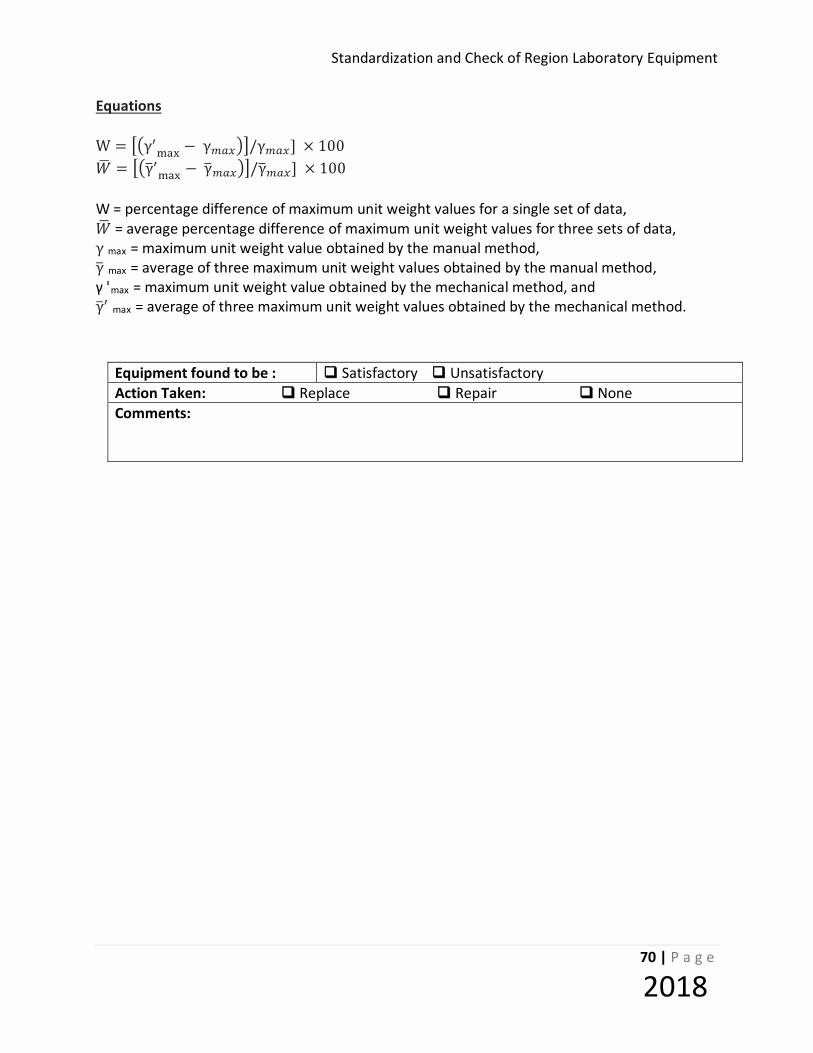
Standardization and Check of Region Laboratory Equipment
70 | P a g e
2018
Equations W = ��γ′max − γ𝑚𝑚𝐷𝐷𝑚𝑚��/γ𝑚𝑚𝐷𝐷𝑚𝑚] × 100 𝑊𝑊� = ��γ�′max − γ�𝑚𝑚𝐷𝐷𝑚𝑚��/γ�𝑚𝑚𝐷𝐷𝑚𝑚] × 100 W = percentage difference of maximum unit weight values for a single set of data, 𝑊𝑊� = average percentage difference of maximum unit weight values for three sets of data, γ max = maximum unit weight value obtained by the manual method, γ� Rmax = average of three maximum unit weight values obtained by the manual method, γ 'max = maximum unit weight value obtained by the mechanical method, and γ�′ max = average of three maximum unit weight values obtained by the mechanical method.
Equipment found to be : Satisfactory Unsatisfactory Action Taken: Replace Repair None Comments:

Standardization and Check Procedures for Region Laboratory Equipment
71 | P a g e
2018
CHECK PROCEDURE: VP – 46 (Straight Edge) Equipment Verified: STRAIGHT EDGE Standard References: AASHTO T 99, T 180 Purpose This method provides instruction for the verification of the planeness of the straight edge. Standard Equipment Required
1. Measurement standard Feeler gage: 0.25 mm (0.01 inch) 2. Measurement standard Carpenter’s level, or Straightedge, equal to or longer than the
checked straight edge. Tolerance The straight edge shall meet the tolerance specified in AASHTO T 99 and T 180. Procedure
1. Measure and record the length of the straightedge. 2. Place the carpenter’s level or verified straightedge on its edge on a counter. Hold the
straightedge on its edge against the edge of the carpenters level and attempt to slide the feeler gage between the straightedge and the level. If the feeler gauge fits between the straight edge and the level, the straight edge is not plane.
3. Record results

Standardization and Check of Region Laboratory Equipment
72 | P a g e
2018
Worksheet: VP-46 Straight edge Frequency: Region Yearly Standard References: AASHTO T 99 & T 180 Equipment ID: Verifying Technician: Date Verified Next Verification Date: Previous Verification Date: Time Charged:
Standard ID# Standard ID#
Straightedge Glass plate Feeler gauge
Straightedge Tolerance Measurement
Length > 10 in (> 254 mm )
Base plate 4 in maximum
Plane of longitudinal edge 0.01 in 10 in 0.250 mm in 250 mm Yes No
One beveled edge? Yes No Condition of beveled edge Satisfactory Unsatisfactory
Equipment found to be : Satisfactory Unsatisfactory Action Taken: Replace Repair None Comments:
Standardization and Check Procedures for Region Laboratory Equipment
73 | P a g e
2018
STANDARDIZATION PROCEDURE: VP- 51 (MIXING ROOMS, MOIST CABINETS, MOIST ROOMS & WATER STORAGE TANKS) Equipment Verified: Mixing Rooms, Moist Cabinets, Moist Cabinets & Water Storage
Tanks for Sample Preparation and Curing Standard References: AASHTO M 201, T 106, T 22 Purpose: This procedure provides instructions on verifying compliance of the mixing room, moist cabinet, moist room, and water storage tank to ensure conformance with the referenced standards. Inspection Equipment Required
1. Reference Thermometer, readable to 1.0°F (0.5°C), having a range of 68 to 81°F (20 to 27.5°C)
2. Reference Humidity Sensing Device (Sling Psycrometer) Tolerance
1. Temperature in moist cabinets and rooms shall be 73.4 ± 3°F (23 ± 2°C).
2. Humidity in moist cabinets and rooms shall be not less than 95 percent. 4. Temperature of mixing room shall be 73.4 ± 7°F (23 ± 4°C), during mixing operations. 5. Humidity in mixing room shall be not less than 50 percent, during mixing operations. 3. Water temperature of water storage (curing) tanks shall be 73.4 ± 3°F (23 ± 2°C).
Procedure
1. Place the reference thermometer as close to the recording sensor as possible, keep the door to the moist room, cabinet or mixing room closed for a minimum of 5 minutes before taking a reading.
2. Record the temperature reading of both the temperature recorder and the reference thermometer.
3. If a discrepancy of more than 2°F (1.0°C) exists, adjust the recording thermometer to within 1°F (0.5°C).
4. Measure and record the humidity in the moist room, moist cabinet and mixing room. 5. If actual temperatures or the humidity are not in allowable ranges, make adjustments as
necessary.
Standardization and Check of Region Laboratory Equipment
74 | P a g e
2018
6. Observe that there is free-lime present in the bottom of the water storage tanks. 7. Observe that water in the storage tank is stirred at intervals not to exceed 1 month. 8. Observe that tanks are cleaned and refilled with water containing 3 g/L of calcium
hydroxide at intervals not to exceed 24 months.

Standardization and Check Procedures for Region Laboratory Equipment
75 | P a g e
2018
Worksheet: VP-51 Mixing Room, Moist Cabinet, Moist Room & Water Storage Tank Frequency: 6 months Standard References: AASHTO M 201, T 22, T 106 Equipment ID: Verifying Technician: Date Verified Next Verification Date: Previous Verification Date: Time Charged:
Standard ID#
Thermometer Humidity sensing device
Temperature Check
Environment Tolerance Reference
Thermometer Reading
Recording Thermometer
Reading Difference Adjustment
required
Moist Cabinet
73.4 ± 3°F (23 ± 2°C) Yes No
Moist Room 73.4 ± 3°F (23 ± 2°C) Yes No
Mixing Room 73.4 ± 7°F (23 ± 4°C) Yes No
Water Tank 73.4 ± 3°F (23 ± 2°C) Yes No
Humidity Check
Environment Tolerance Reference Humidity Sensing Device Reading
Adjustment required
Moist Cabinet ≥ 95% Yes No
Moist Room ≥ 95% Yes No Mixing Room ≥ 50% Yes No
Water Storage Tank Condition Acceptable If “No” Action taken to correct issue
Free Lime checked Yes No Water thoroughly stirred at intervals
not to exceed once a month Yes No
Tanks cleaned and refilled at intervals not to exceed 24 months Yes No
Equipment found to be : Satisfactory Unsatisfactory Action Taken: Replace Repair None Comments:
Standardization and Check of Region Laboratory Equipment
76 | P a g e
2018

Standardization and Check Procedures for Region Laboratory Equipment
77 | P a g e
2018
CHECK PROCEDURE: VP-53 (Bearing Blocks) Equipment Verified: BEARING BLOCKS Standard References: AASHTO T 22 and AASHTO T 106 Purpose: This procedure provides instructions for checking the diameter, planeness, and the spherical seating of the bearing blocks for determining the compressive strength of concrete cylinders or mortar grout cubes. Standard Equipment Required 1. Calipers capable of reading to 0.001 in 2. Verified Straightedge 3. Feeler gauges: 0.013 mm (0.0005 in) for new blocks 0.025mm (0.001 in) for blocks in-service Tolerance See worksheets for tolerances Procedure 1. Measure the diameter of the upper and lower blocks. 2. Check bearing surface by attempting to insert a thickness gauge between the straightedge
and the block surface. 3. Rotate the straight edge, 90 degrees in the plane of the surface and repeat the check. 4. Check that the upper block seat is spherical and moves freely. 5. Record as acceptable blocks, which meet the planeness, diameter, and spherical criteria
above. 6. Remove from service and machine or replace blocks that exceed the allowable values.

Standardization and Check of Region Laboratory Equipment
78 | P a g e
2018
Worksheet: VP- 53a (Grout Blocks) Grout Cube Bearing Blocks Frequency: Region-Yearly Standard References: T 106 Equipment ID: Verifying Technician: Date Verified Next Verification Date: Previous Verification Date: Time Charged:
Standard Equipment ID Standard Equipment ID Caliper Ruler Straightedge Feeler gauge
General Requirements for Upper and Lower Blocks
Plane within 0.001 inch (NEW blocks plane within 0.0005 inch) Yes No
Rockwell hardness not less than 60 HRC Yes No
Specific Requirements for Lower Bearing Block: Bearing face diameter between 71.6mm (2.82 in.) and 73.7mm (2.9 in.) Yes No
Specific Requirements for Top Spherically Seated Bearing Block
Spherically seated face properly lubricated and free to move in any direction Yes No
Bearing face diameter between 71.6mm (2.82 in.) and 79.5mm (3.13 in.) Yes No
Equipment found to be : Satisfactory Unsatisfactory Action Taken: Replace Repair None Comments:

Standardization and Check Procedures for Region Laboratory Equipment
79 | P a g e
2018
Worksheet: VP- 53b (Cylinder Blocks) Concrete Cylinder Bearing Blocks Frequency: Region-Yearly Standard References: T 22 Equipment ID: Verifying Technician: Date Verified Next Verification Date: Previous Verification Date: Time Charged:
Standard Equipment ID Standard Equipment ID Caliper Ruler Straightedge Feeler gauge
General Requirements Bearing Blocks
Plane within 0.001 inch (New blocks plane within 0.0005 inch) Yes No Thickness - minimum 1 inch, see T-22 for exceptions Yes No Horizontal dimension 3% greater than diameter of specimens Yes No Rockwell hardness not less than 55 Yes No Concentric Rings - required if block is 0.5 inch larger than cylinder
Lower Bearing Blocks Thickness - minimum 1 inch new, 0.9 inch after resurfacing Yes No Provision for centering specimens on lower block Yes No
Specific Requirements for Top Spherically Seated Bearing Block Size of spherical face: Max. 6.5 inch dia. for 4 inch cylinders Max. 10 inch dia. for 6 inch cylinders Yes No
Spherical block held close in the spherical seat Yes No Free to move 4o minimum in any direction Yes No Ball and socket cleaned and lubricated periodically (Lubricant a petroleum type oil - not a pressure grease) Yes No
If radius of sphere is less than radius of largest specimen tested: Is thickness of face at edge as great as difference in radii Yes No
Center of sphere at center of bearing plate Yes No Is Spherical portion & socket free from deformation Yes No Radius of bearing face equal to or greater than the radius of sphere Yes No Diameter of the sphere at least 75% of diameter of specimen Yes No Diameter Radius Bearing Face Sphere Equipment found to be : Satisfactory Unsatisfactory Action Taken: Replace Repair None Comments:

Standardization and Check of Region Laboratory Equipment
80 | P a g e
2018
STANDARDIZATION PROCEDURE: VP- 58 (Gyratory Compactor) Equipment Verified: GYRATORY COMPACTOR Standard References: AASHTO T 312, AASHTO T 344 Purpose This procedure identifies the equipment needed to standardize the Superpave Gyratory Compactor (SGC) in accordance with the manufacturer’s calibration manual. The SGC requires yearly standardization unless moved. If the SGC or the testing facility housing the SGC is moved, the SGC will be standardized prior to use. Standard Equipment Required All measuring equipment, devices, or spacers used to standardize the SGC must be calibrated/standardized/checked on a yearly basis. An accredited calibration company, in accordance with AASHTO R 18, shall perform all calibration of equipment.
Hydraulic oil filter kit; Pine Instruments Part No AFGBA10 (Pine SGC AFGB1A Only). Load Cell Standard Height Block. Timer, readable to 0.1 seconds. Straight edge. Feeler Gauge, 0.001 inch (0.025 mm). Dynamic Internal Angle Measuring Device w/HMS (Hot Mix Simulator) with manual. Manufacturer’s Calibration Manual for SGC.
Tolerance Measurements determined shall conform to the requirements defined in AASHTO T 312 and AASHTO T 344. Procedure

Standardization and Check Procedures for Region Laboratory Equipment
81 | P a g e
2018
1. The hydraulic system shall be serviced by filtering the entire volume of the fluid reservoir
according to the manufacturer’s procedure (Pine AFGB1A only; Manual Sec 5.3, Pg V-8), prior to verifying the ram pressure.
2. Standardize the ram pressure using the calibrated load cell provided for the machine and
the manufacturer’s calibration procedure. 3. The standardization process shall be repeated until measurements are within the
allowable tolerance of 600 KPa ± 18 KPa per the manufacturer’s instructions. 4. Record the load cell pressure on the work sheet. 5. Standardize the height LVDT using the standard height block and the manufacturer’s
calibration procedure. Repeat this process until the measured results are within the allowable tolerances.
6. Using a verified timer, count the number of rotations in one minute. Repeat this process
two times. Average the results and compare them to the allowable tolerance of 30.0 gyrations/min. ± 0.5 gyrations/min. Make necessary adjustments per manufacturer’s instructions. Repeat until the measured results are within the allowable tolerances.
7. Verify Dwell Setting:
Troxler – dwell set at 0 Interlaken – dwell set at 0 Pine (AFGC125X) – dwell set at 0 Portable Pine (AFGB1A) – dwell set at 2 Pine (AFG1A) – dwell set at 0
8. Measure the internal angle of gyration per the Dynamic Internal Angle Measuring Device w/HMS procedure and AASHTO T 344 Standard Method of Test for Evaluation of Superpave Gyratory Compactor (SGC) Internal Angle of Gyration Using Simulated Loading. If necessary, make adjustments according to the compactor manufacturer instructions and measure the angle again. This process shall be repeated until two consecutive effective internal angle measurements are obtained that are within the allowable tolerance of 1.16º ± 0.02º. Attach a printout of the internal angle calibration consisting of the last set of four angle measurements to the SGC worksheet.
9. If available through any particular brand and model of SGC, obtain a printout of the
calibration from the SGC internal computer and attach it to the worksheet. Ram Head or End Plate (If Applicable)
Standardization and Check of Region Laboratory Equipment
82 | P a g e
2018
1. Confirm the ram head/end plate is clean and at a temperature of 64°F to 82°F (18° C to 28° C). Ram head/end plate shall be free of residue and deep gouges. Surfaces in contact with the asphalt mixture shall be flat. Minor abrasion marks from aggregates are acceptable. Surfaces in contact with the SGC frame shall be free of raised burrs that may cause the ram head/end plate to wobble during gyration. Small recesses on the side of the ram head/end plate interfacing the SGC (opposite the asphalt mixture) can reduce rocking and are acceptable.
2. Determine the maximum diameter of the ram head/end plate by measuring in several
locations. Place a removable mark at this position. Record the maximum plate diameter to the nearest 0.025 mm (0.001 in.). Designate this as measurement “A”.
3. Measure the diameter at a 90º orientation to the maximum diameter. Record this diameter
as measurement “B”. 4. Each individual measurement reading shall be compared to the specified range (149.50mm
- 149.75mm) and given a pass/fail rating. 5. Using a verified straight-edge and feeler gauge, ensure that the ram head/end plate is flat
by taking two observations 90º apart while trying to insert the feeler gauge between the ram head/end plate and straight-edge. Record the results as a pass/fail rating for A and B on the verification worksheet.
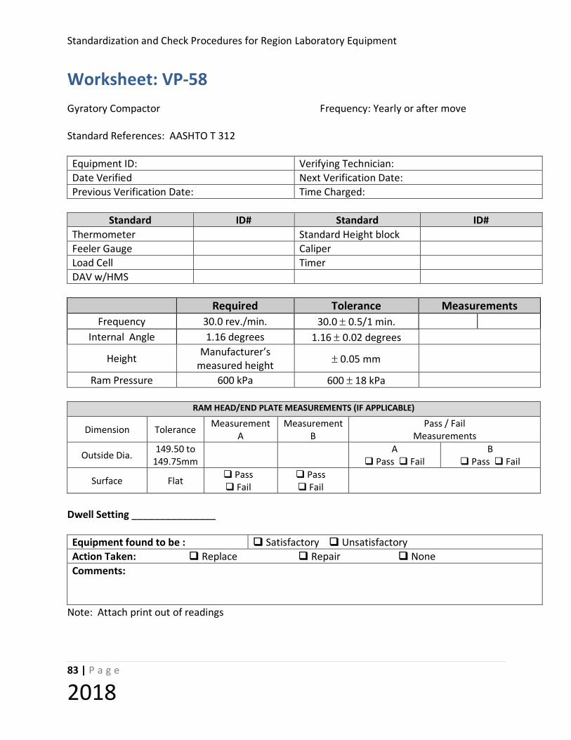
Standardization and Check Procedures for Region Laboratory Equipment
83 | P a g e
2018
Worksheet: VP-58 Gyratory Compactor Frequency: Yearly or after move Standard References: AASHTO T 312 Equipment ID: Verifying Technician: Date Verified Next Verification Date: Previous Verification Date: Time Charged:
Standard ID# Standard ID#
Thermometer Standard Height block Feeler Gauge Caliper Load Cell Timer DAV w/HMS
Required Tolerance Measurements
Frequency 30.0 rev./min. 30.0 ± 0.5/1 min. Internal Angle 1.16 degrees 1.16 ± 0.02 degrees
Height Manufacturer’s measured height ± 0.05 mm
Ram Pressure 600 kPa 600 ± 18 kPa
RAM HEAD/END PLATE MEASUREMENTS (IF APPLICABLE)
Dimension Tolerance Measurement A
Measurement B
Pass / Fail Measurements
Outside Dia. 149.50 to 149.75mm A
Pass Fail B
Pass Fail
Surface Flat Pass Fail
Pass Fail
Dwell Setting _______________ Equipment found to be : Satisfactory Unsatisfactory Action Taken: Replace Repair None Comments:
Note: Attach print out of readings

Standardization and Check of Region Laboratory Equipment
84 | P a g e
2018
STANDARDIZATION PROCEDURE: VP- 59 (Gyratory Compactor Standard Block) Equipment Verified: GYRATORY COMPACTOR STANDARD BLOCK Standard References: AASHTO T 312 Purpose: This procedure identifies the equipment needed to calibrate the gyratory compactor in accordance with the manufacturer’s manual. Standard Equipment Required 1. Caliper, readable to 0.01 mm Tolerance Measurements shall conform to the requirements defined in AASHTO T 312. Procedure 1. Measure and record the block height at 90° intervals around its perimeter. 2. Average the 4 measurements 3. Determine if they are within the required tolerance.

Standardization and Check Procedures for Region Laboratory Equipment
85 | P a g e
2018
Worksheet: VP-59 Gyratory Standard Block Frequency: Yearly- Region or after move Standard References: AASHTO T 312, Manufacturer’s Recommendation Equipment ID: Verifying Technician: Date Verified Next Verification Date: Previous Verification Date: Time Charged:
Standard ID#
Caliper readable to 0.01 mm
Dimension
A Required
B 1st
C 2nd
D 3rd
E 4th
F Average*
Difference A-F
Height (measured to nearest
0.01 mm)
Average* = 𝐵𝐵+𝐶𝐶+𝐷𝐷+𝐸𝐸4
Equipment found to be : Satisfactory Unsatisfactory Action Taken: Replace Repair None Comments:

Standardization and Check of Region Laboratory Equipment
86 | P a g e
2018
STANDARDIZE PROCEDURE: VP- 67 (Pycnometer) Equipment Verified: PYCNOMETER Standard References: AASHTO T 209/ WSDOT T 606 Purpose: This method provides instructions for verifying the mass of each pycnometer used in the determination of the maximum specific gravity. The procedure applies to either flask type: Glass Jars or Metal Vessels. Standard Equipment Required
1. Balance- 11,000 gram capacity and readable to 0.1 gram.
2. Vacuum pump or water aspirator capable of 30 mm Hg or less absolute pressure, for evacuating air from the flask.
3. Standardized thermometric device of suitable range and readable to
1oF (0.5oC)
4. Water bath large enough to accommodate up to six 2000 ml flasks and capable of maintaining a temperature of 77 ± 1oF (25 ± 5oC) for rice specific gravity and 68 ° ± 1oF (20° ± 0.5oC) for T606 specific gravity.
Tolerance The weight of the pycnometer, cover plate, and the enclosed water at 77 oF (25oC) for rice specific gravity and 68 oF (20o C) for T606 specific gravity shall not vary more than 0.1 gram after weighing three times. Procedure
1. Glass Jars shall be inspected prior to use to ensure they are suitable for use. Glass jars may require grinding with silicon carbide powder to assure the openings are smooth.
2. Fill the jars or vessels approximately 3/4 full with water at 77 oF (25oC) for rice
specific gravity and 68 oF (20o C) for T606 specific gravity.

Standardization and Check Procedures for Region Laboratory Equipment
87 | P a g e
2018
3. Connect the jars (vessels) to the vacuum system; apply a partial vacuum of 30 ml Hg
or less absolute pressure for a period of 15+ 2 minutes. Agitate container either continuously by mechanical device or manually by vigorous shaking at 2 minute intervals.
4. Release vacuum and disconnect the hoses, fill each pycnometer with water and
bring contents to a temperature of:
a. 77 oF (25oC) for rice specific gravity in a constant temperature water bath of 77 oF (25oC) for 10 minutes
b. 68 oF (20o C) for T606 specific gravity in a constant temperature water bath of
68 oF (20o C) for 10 minutes. Filling Pycnometer: For glass vessels: Completely fill pycnometer with water, slide glass cover plate over opening, remove from water bath, wipe all moisture off of pycnometer and plate or cover, then weigh and record. For metal vessels: Place the cover and fill the unit completely with water, wipe all moisture off of pycnometer and plate or cover, then weigh and record.
5. Repeat steps 3 - 6 until each pycnometer has at least three readings that are within 0.1 gram of each other.
6. Record the average of the three readings in step 6 as the calibration weight.
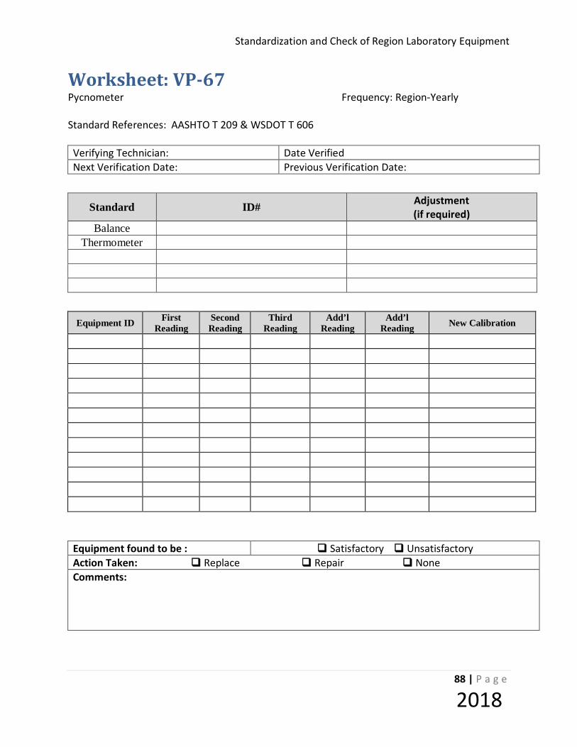
Standardization and Check of Region Laboratory Equipment
88 | P a g e
2018
Worksheet: VP-67 Pycnometer Frequency: Region-Yearly Standard References: AASHTO T 209 & WSDOT T 606 Verifying Technician: Date Verified Next Verification Date: Previous Verification Date:
Standard ID# Adjustment
(if required) Balance
Thermometer
Equipment ID First
Reading Second Reading
Third Reading
Add’l Reading
Add’l Reading New Calibration
Equipment found to be : Satisfactory Unsatisfactory Action Taken: Replace Repair None Comments:

Standardization and Check Procedures for Region Laboratory Equipment
89 | P a g e
2018
STANDARDIZATION PROCEDURE: VP- 73 (VOLUMETRIC AIR METER) Equipment Verified: VOLUMETRIC AIR METER Standard References: AASHTO T 196 Purpose: This method provides instructions for calibrating the volume of Volumetric Air Meter and associated Cup. Inspection Equipment Required
1. Calipers or ruler, readable to 0.01 in. (0.25 mm) 2. Plate (glass or polycarbonate), at least 1/4 in. (6 mm) thick and at least 1 in. (25 mm)
larger than the diameter of the measure to be calibrated.
3. Grease, a supply of water insoluble grease. Note – Petroleum jelly, vacuum grease, water pump grease, or chassis grease are examples of suitable material used to form a seal between the plate and measure.
4. Thermometer, having a range of at least 50 to 90°F (10 to 32°C) and readable to 1°F
(0.5°C) . 5. Balance, shall have sufficient capacity, be readable to 0.1 percent of the mass or better,
and conform to the requirements of M 231. Tolerance Equipment shall meet the tolerances required by the referenced standard. Procedure A. CALIBRATION OF BOWL
1. Measure the inside diameter and the inside height of the bowl.
2. Determine bowl diameter to height ratio.
3. Place a thin layer of grease on the rim of bowl to prevent leakage of water.
4. Determine the mass of empty bowl and plate to nearest 0.01 lb.

Standardization and Check of Region Laboratory Equipment
90 | P a g e
2018
5. Fill the bowl with room temperature water and cover with plate in such a way as to eliminate bubbles and excess water. Remove any water that may have overflowed onto bowl or plate.
6. Determine the mass of water, plate, and bowl to nearest 0.01 lb.
7. Measure the temperature of the water to the nearest 1°F (0.5°C) and determine its density from Table 1 below. Note – interpolate if necessary.
8. Calculate the volume of bowl, Vb, to nearest 0.001 ft³.
B. CALIBRATION OF TOP SECTION
1. Determine the mass of empty bowl and top section to nearest 0.01 lb.
2. Fill the bowl and top section to the 0.0 mark with room temperature water.
3. Observe the junction between bowl and top section for leakage.
4. Determine the mass of the bowl, top section and water to nearest 0.01 lb.
5. Calculate the mass of water in the top section.
6. Measure the temperature of the water to the nearest 1°F (0.5°C) and determine its density from Table 1 below. Note – interpolate if necessary.
7. Calculate the volume of top section and verify it is at least 20% larger than volume of
bowl.
8. Verify transparent scale is graduated in increments not greater than 0.5 from 0 to 9 percent.
9. Empty water from bowl and top section, then refill to the 5.0 graduation mark with room temperature water.
10. Verify the scale graduation is within ± 0.1 percent volume of the bowl.
11. Fill to the 3.0 mark and repeat step 10.
12. Fill to the 1.0 mark and repeat step 10.
C. CALIBRATION OF CUP

Standardization and Check Procedures for Region Laboratory Equipment
91 | P a g e
2018
1. Determine the mass of empty cup and plate to nearest 0.01 lb.
2. Fill the cup with room temperature water and cover with plate in such a way as to eliminate bubbles and excess water. Remove any water that may have overflowed onto cup or plate.
3. Determine the mass of water, plate, and cup to nearest 0.01 lb.
4. Measure the temperature of the water to the nearest 1°F (0.5°C) and determine its density from Table 1 below. Note – interpolate if necessary.
5. Calculate the volume of cup, Vc, to nearest 0.001 ft³.
6. Verify the capacity of cup is equal to 1.0 ± 0.4 percent of the volume of the bowl.
°F °C lb./ft.3 kg/m 3
60.0 15.6 62.366 999.01 65.0 18.3 62.336 998.54 70.0 21.1 62.301 997.97 73.4 23 62.274 997.54 75.0 23.9 62.261 997.32 80.0 26.7 62.216 996.59 85.0 29.4 62.166 995.83
Density of Water Table 1

Standardization and Check of Region Laboratory Equipment
92 | P a g e
2018
Worksheet: VP-73 Air Meter (Volumetric) Frequency: 36 months
Standard References: AASHTO T 196 Equipment ID: Verifying Technician: Date Verified Next Verification Date: Previous Verification Date: Time Charged:
Standard ID Standard ID Balance Calipers/Ruler Thermometer
Bowl Measurement/Calculation Tolerance Acceptable
Diameter: [1] (in.)
Height: [2] (in.)
Diameter to height ratio (D/H): [1] / [2] 1 – 1.25 Yes No
Empty mass of bowl and plate:
[1] lb. (kg)
Mass of bowl, plate and water: [2] lb. (kg)
Calculate the mass of the water: [2] - [1] = [3] lb. (kg)
Water temperature: °F (°C)
Density of water (See Table 1): [4] = lb/ft3 (kg/m3)
Calculate volume of bowl: [Vb] = [3] / [4] = ft3 (m3) ≥ 0.075 ft3 Yes No
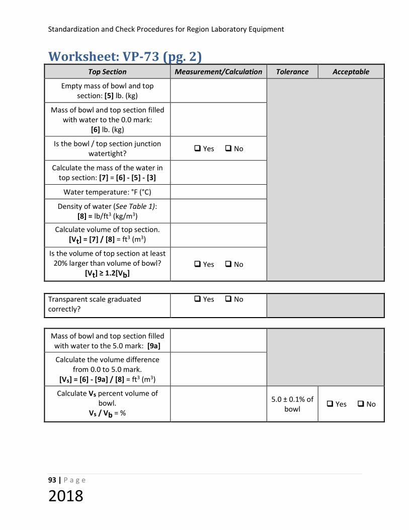
Standardization and Check Procedures for Region Laboratory Equipment
93 | P a g e
2018
Worksheet: VP-73 (pg. 2) Top Section Measurement/Calculation Tolerance Acceptable
Empty mass of bowl and top section: [5] lb. (kg)
Mass of bowl and top section filled with water to the 0.0 mark:
[6] lb. (kg)
Is the bowl / top section junction watertight? Yes No
Calculate the mass of the water in top section: [7] = [6] - [5] - [3]
Water temperature: °F (°C)
Density of water (See Table 1): [8] = lb/ft3 (kg/m3)
Calculate volume of top section. [Vt] = [7] / [8] = ft3 (m3)
Is the volume of top section at least 20% larger than volume of bowl?
[Vt] ≥ 1.2[Vb] Yes No
Transparent scale graduated correctly?
Yes No
Mass of bowl and top section filled with water to the 5.0 mark: [9a]
Calculate the volume difference from 0.0 to 5.0 mark.
[V₅] = [6] - [9a] / [8] = ft3 (m3)
Calculate V₅ percent volume of bowl.
V₅ / Vb = % 5.0 ± 0.1% of
bowl Yes No

Standardization and Check of Region Laboratory Equipment
94 | P a g e
2018
Worksheet: VP-73 (pg. 3) Mass of bowl and top section filled with water to the 3.0 mark: [9b]
Calculate the volume difference from 0.0 to 3.0 mark.
[V₃] = [6] - [9b] / [8] = ft3 (m3)
Calculate V₃ percent volume of bowl.
V₃ / Vb = % 3.0 ± 0.1% of
bowl Yes No
Mass of bowl and top section filled
with water to the 1.0 mark: [9c]
Calculate the volume difference from 0.0 to 1.0 mark.
[V₁] = [6] - [9c] / [8] = ft3 (m3)
Calculate V₁ percent volume of bowl.
V₁ / Vb = % 1.0 ± 0.1% Yes No
Cup Measurement/Calculation Tolerance Acceptable
Empty mass of cup and plate: [10]
Mass of cup, plate and water: [11]
Calculate the weight of the water. [11] - [10] = [12] lb. (kg)
Water temperature: °F (°C)
Density of water (See Table 1): [13] = lb/ft3 (kg/m3)
Calculate volume of cup. [Vc] = [12] / [13] = ft3 (m3)
Calculate Vc percent volume of bowl.
Vc / Vb = % 1.0 ± 0.04% Yes No

Standardization and Check Procedures for Region Laboratory Equipment
95 | P a g e
2018
Worksheet: VP-73 (pg. 4)
Equipment found to be : Satisfactory Unsatisfactory Action Taken: Replace Repair None Comments:
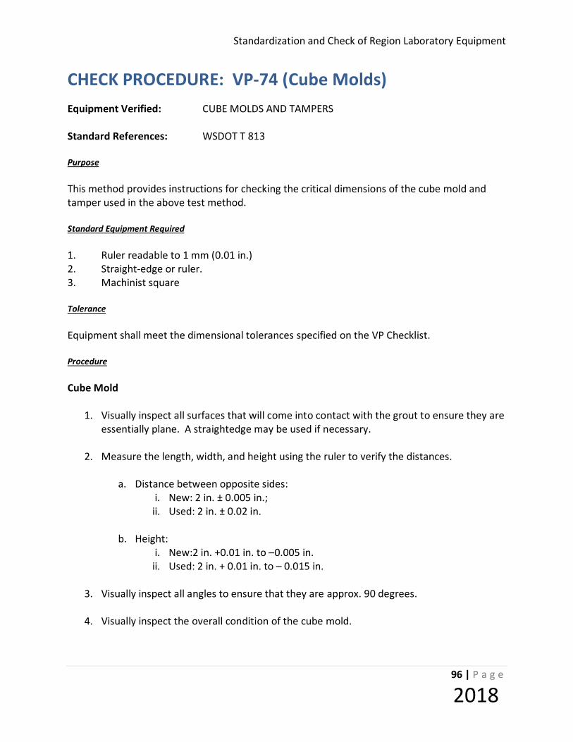
Standardization and Check of Region Laboratory Equipment
96 | P a g e
2018
CHECK PROCEDURE: VP-74 (Cube Molds) Equipment Verified: CUBE MOLDS AND TAMPERS Standard References: WSDOT T 813 Purpose This method provides instructions for checking the critical dimensions of the cube mold and tamper used in the above test method. Standard Equipment Required 1. Ruler readable to 1 mm (0.01 in.) 2. Straight-edge or ruler. 3. Machinist square Tolerance Equipment shall meet the dimensional tolerances specified on the VP Checklist. Procedure Cube Mold
1. Visually inspect all surfaces that will come into contact with the grout to ensure they are essentially plane. A straightedge may be used if necessary.
2. Measure the length, width, and height using the ruler to verify the distances.
a. Distance between opposite sides: i. New: 2 in. ± 0.005 in.; ii. Used: 2 in. ± 0.02 in.
b. Height:
i. New:2 in. +0.01 in. to –0.005 in. ii. Used: 2 in. + 0.01 in. to – 0.015 in.
3. Visually inspect all angles to ensure that they are approx. 90 degrees.
4. Visually inspect the overall condition of the cube mold.

Standardization and Check Procedures for Region Laboratory Equipment
97 | P a g e
2018
Tamper 1. Measure dimensions of the tamper face. 2. Visually inspect the overall condition of the tamper.

Standardization and Check of Region Laboratory Equipment
98 | P a g e
2018
Worksheet: VP-74R Cube Mold and Tamper (Region) Frequency: Yearly Standard References: AASHTO T 106
Equipment ID: Verifying Technician: Date Verified Next Verification Date: Previous Verification Date: Time Charged:
Check Equipment Type ID# Check Equipment Type ID#
Steel Rule Machinist Square Caliper Feeler gauge Straightedge
Mold & Tamper Tolerance Measurement Acceptance
New Used Mold New Used N/A Yes No
Mold condition acceptable? N/A N/A N/A Yes No Tamper condition acceptable? N/A N/A N/A Yes No
Planeness of sides <0.001 in. <0.002 in. N/A Yes No
Cube dimension (distance from opposite side) 2 in. ± 0.005 2 in. ± 0.02
Yes No Yes No Yes No Yes No Yes No Yes No
Height of each compartment 2 in. + 0.01 to –0.005 in.
2 in. + 0.01 to -0.015 in
Yes No Yes No Yes No
Angles of mold 90 ± 0.5° 90 ± 0.5° N/A Yes No Tamping block end area ½ x 1 inch Yes No
Equipment found to be : Satisfactory Unsatisfactory Action Taken: Replace Repair None Comments:

Standardization and Check Procedures for Region Laboratory Equipment
99 | P a g e
2018
STANDARDIZATION PROCEDURE : VP-76 (Manual SE Shaker) Equipment Verified: MANUAL SAND EQUIVALENT TEST SHAKER
Standard References: AASHTO T 176
Purpose
This method provides instruction for checking the manual shaker to insure operation at the specified amplitude and that the counter is functioning properly. Standard Equipment Required
1. A measuring device capable of measuring the specified throw of 5 inches and accurate to at least 1/16 inch. (2 mm)
2. Handheld mechanical counting device capable of reading to 500 counts, minimum.
3. Verified timer, readable to 1 second.
Tolerance
Manual shakers shall be capable of operation at 100 cycles in 45 + 5 seconds have a hand assisted half stroke of 5 + 0.2 inches (127 + 5.08 mm). Procedure
1. With manual shaker in the center position, check that the half stroke indicator is aligned with the center mark on the back of the shaker box or the wall. The half stroke indicator is usually an arrow shaped pointer located in the middle of the upper platform.. If the half stroke indicator is not proper aligned with the center mark the back of the shaker box or the wall mark a new center mark opposite the half stroke indicator at the proper position.
2. Measure the half stroke distance along a straight line parallel to the movement of the
shaker, from the center mark. Mark offsets of 0.1 inch from the half stroke distance. Repeat this for the half stroke distance on either side of the center mark.
3. While holding one of the spring steel uprights apply enough force in the direction of the
counter to move the half stroke indicator to the stroke limit mark. See 2 above.
Standardization and Check of Region Laboratory Equipment
100 | P a g e
2018
4. If needed adjust the counter so it will advance one digit each time the half stroke indicator is within the range of stroke limit mark.
5. Operate the shaker through three complete test cycles to determine if the counter is
functioning properly.
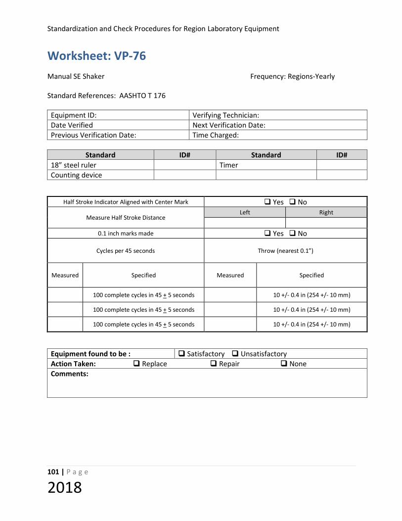
Standardization and Check Procedures for Region Laboratory Equipment
101 | P a g e
2018
Worksheet: VP-76 Manual SE Shaker Frequency: Regions-Yearly Standard References: AASHTO T 176 Equipment ID: Verifying Technician: Date Verified Next Verification Date: Previous Verification Date: Time Charged:
Standard ID# Standard ID#
18” steel ruler Timer Counting device
Half Stroke Indicator Aligned with Center Mark Yes No
Measure Half Stroke Distance Left Right
0.1 inch marks made Yes No
Cycles per 45 seconds
Throw (nearest 0.1”)
Measured
Specified Measured Specified
100 complete cycles in 45 + 5 seconds 10 +/- 0.4 in (254 +/- 10 mm)
100 complete cycles in 45 + 5 seconds 10 +/- 0.4 in (254 +/- 10 mm)
100 complete cycles in 45 + 5 seconds 10 +/- 0.4 in (254 +/- 10 mm)
Equipment found to be : Satisfactory Unsatisfactory Action Taken: Replace Repair None Comments:

Standardization and Check of Region Laboratory Equipment
102 | P a g e
2018
CHECK PROCEDURE: VP- 77 (SE Irrigation Tubes) Equipment Verified: Sand Equivalent Irrigation Tubes Standard References: AASHTO T 176 Purpose: To ensure the proper control of the hydraulic force and amount of solution is used in irrigating (i.e. flushing) the fines from the sand particles. Standard Equipment Required No. 60 drill bit or wire gauge. Procedure
1. Inspect the tube to insure that it is reasonably straight.
2. Measure the tube must be a minimum of 510 mm.
3. Inspect the soldered joint at the end of the tube. Joint at end of tube must have 100 percent seal.
a. The integrity of the soldered end may be tested by allowing water or working solution to flow freely from the tube. If any fluid flows from the tube except from the two drilled holes the tube is defective and must be replaced.
4. Check the drilled holes using either a No. 60 wire gauge or No. 60 wire drill.
a. Insert the wire gauge or drill in each hole, do not force the wire gauge or drill into the hole.
i. If the wire gauge or drill does not fit in the hole use a No. 60 wire drill to carefully enlarge the hole to the proper size.
ii. If the hole is too large the irrigation tube must be replaced.
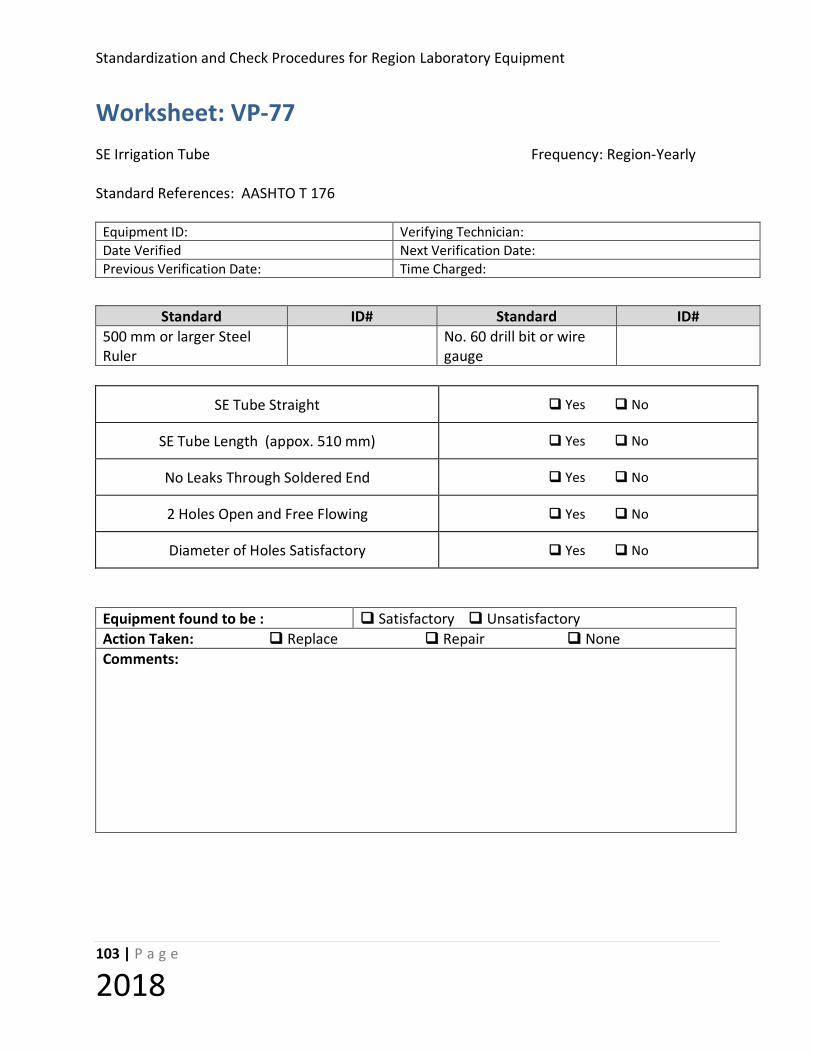
Standardization and Check Procedures for Region Laboratory Equipment
103 | P a g e
2018
Worksheet: VP-77 SE Irrigation Tube Frequency: Region-Yearly Standard References: AASHTO T 176
Equipment ID: Verifying Technician: Date Verified Next Verification Date: Previous Verification Date: Time Charged:
Standard ID# Standard ID# 500 mm or larger Steel Ruler
No. 60 drill bit or wire gauge
SE Tube Straight Yes No
SE Tube Length (appox. 510 mm) Yes No
No Leaks Through Soldered End Yes No
2 Holes Open and Free Flowing Yes No
Diameter of Holes Satisfactory Yes No
Equipment found to be : Satisfactory Unsatisfactory Action Taken: Replace Repair None Comments:
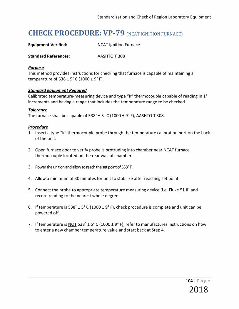
Standardization and Check of Region Laboratory Equipment
104 | P a g e
2018
CHECK PROCEDURE: VP-79 (NCAT IGNITION FURNACE) Equipment Verified: NCAT Ignition Furnace Standard References: AASHTO T 308 Purpose This method provides instructions for checking that furnace is capable of maintaining a temperature of 538 ± 5° C (1000 ± 9° F). Standard Equipment Required Calibrated temperature-measuring device and type “K” thermocouple capable of reading in 1° increments and having a range that includes the temperature range to be checked.
Tolerance The furnace shall be capable of 538˚ ± 5° C (1000 ± 9° F), AASHTO T 308. Procedure 1. Insert a type “K” thermocouple probe through the temperature calibration port on the back
of the unit.
2. Open furnace door to verify probe is protruding into chamber near NCAT furnace thermocouple located on the rear wall of chamber.
3. Power the unit on and allow to reach the set point of 538° F.
4. Allow a minimum of 30 minutes for unit to stabilize after reaching set point. 5. Connect the probe to appropriate temperature measuring device (i.e. Fluke 51 II) and
record reading to the nearest whole degree. 6. If temperature is 538˚ ± 5° C (1000 ± 9° F), check procedure is complete and unit can be
powered off. 7. If temperature is NOT 538˚ ± 5° C (1000 ± 9° F), refer to manufactures instructions on how
to enter a new chamber temperature value and start back at Step 4.

Standardization and Check Procedures for Region Laboratory Equipment
105 | P a g e
2018
Worksheet: VP-79 NCAT Ignition Furnace Frequency: 12 Months
Standard References: AASHTO T 308
Technician: Date: Next Due Date:
Standard ID# Adjustment (if required)
Thermometric Device Thermocouple
Equipment ID # Desired Temp
Furnace Display
Standard Reading
Acceptable (if no, make adjustments and repeat steps)
Yes No Yes No
Yes No
Yes No Yes No
Yes No
Yes No
Yes No
Yes No
Equipment found to be : Satisfactory Unsatisfactory Action Taken: Replace Repair None Comments:

Standardization and Check of Region Laboratory Equipment
106 | P a g e
2018
CHECK PROCEDURE: VP- 81 (Retaining Rings) Equipment Verified: RETAINING RINGS Standard References: AASHTO T 22, ASTM C1231 Purpose: This method provides instruction for checking the retaining rings used in conjunction with neoprene inserts for testing cylinders. Equipment Required
• Calipers • Straightedge • Feeler Gauge • Machinist’s Square • Ruler
Tolerance:
Item Measurement Tolerance Retaining ring Height 1.0 ±.1 in. [25 ± 3 mm]
Retaining ring Inside diameter Not less than 102 % or greater than 107 % of the diameter of the cylinder.
Retaining ring Thickness At least 0.47 in. [12 mm] for 6 in [150 mm]
diameter retainers and at least 0.35 in. [9 mm] for 4 in. [100 mm] diameter retainers.
Base plate Thickness At least 0.47 in. [12 mm] for 6 in. [150 mm] retainers and at least 0.3 in. [8 mm] for 4 in.
[100 mm] retainers. Contact surface of
base plate Planeness Plane to within 0.002 in. [0.05 mm]
Contact surface of base plate Surface condition
No gouges, grooves, protrusions, or indentations greater than 0.010 in. [0.25 mm]
deep or greater than 0.05 in.2 [32 mm2] in surface area
Standardization and Check Procedures for Region Laboratory Equipment
107 | P a g e
2018
Procedure: 1. Using the straightedge, machinist’s square, and feeler gauge, determine if the bearing faces
are plain and that outside dents or gouges do not exceed specifications.
2. Measure the inside diameter.
3. Measure the thickness of the bearing surface.
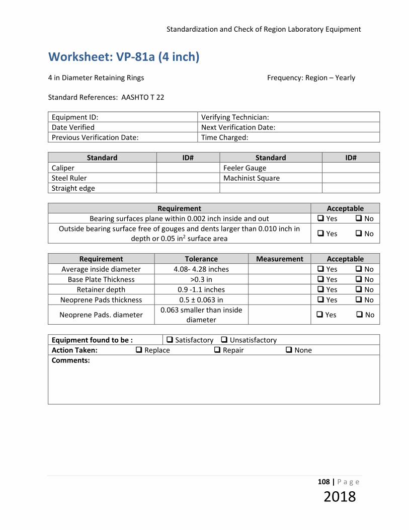
Standardization and Check of Region Laboratory Equipment
108 | P a g e
2018
Worksheet: VP-81a (4 inch) 4 in Diameter Retaining Rings Frequency: Region – Yearly Standard References: AASHTO T 22 Equipment ID: Verifying Technician: Date Verified Next Verification Date: Previous Verification Date: Time Charged:
Standard ID# Standard ID#
Caliper Feeler Gauge Steel Ruler Machinist Square Straight edge
Requirement Acceptable
Bearing surfaces plane within 0.002 inch inside and out Yes No Outside bearing surface free of gouges and dents larger than 0.010 inch in
depth or 0.05 in2 surface area Yes No
Requirement Tolerance Measurement Acceptable
Average inside diameter 4.08- 4.28 inches Yes No Base Plate Thickness >0.3 in Yes No
Retainer depth 0.9 -1.1 inches Yes No Neoprene Pads thickness 0.5 ± 0.063 in Yes No
Neoprene Pads. diameter 0.063 smaller than inside diameter Yes No
Equipment found to be : Satisfactory Unsatisfactory Action Taken: Replace Repair None Comments:
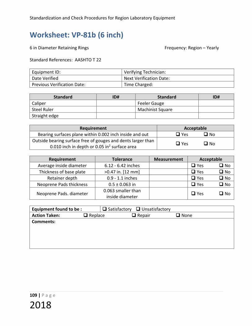
Standardization and Check Procedures for Region Laboratory Equipment
109 | P a g e
2018
Worksheet: VP-81b (6 inch) 6 in Diameter Retaining Rings Frequency: Region – Yearly Standard References: AASHTO T 22 Equipment ID: Verifying Technician: Date Verified Next Verification Date: Previous Verification Date: Time Charged:
Standard ID# Standard ID#
Caliper Feeler Gauge Steel Ruler Machinist Square Straight edge
Requirement Acceptable
Bearing surfaces plane within 0.002 inch inside and out Yes No Outside bearing surface free of gouges and dents larger than
0.010 inch in depth or 0.05 in2 surface area Yes No
Requirement Tolerance Measurement Acceptable
Average inside diameter 6.12 - 6.42 inches Yes No Thickness of base plate >0.47 in. [12 mm] Yes No
Retainer depth 0.9 - 1.1 inches Yes No Neoprene Pads thickness 0.5 ± 0.063 in Yes No
Neoprene Pads. diameter 0.063 smaller than inside diameter Yes No
Equipment found to be : Satisfactory Unsatisfactory Action Taken: Replace Repair None Comments:

Standardization and Check of Region Laboratory Equipment
110 | P a g e
2018
STANDARDIZATION PROCEDURE: VP-84 (Uncompacted Void Apparatus) Equipment Verified: UNCOMPACTED VOID APPARATUS Standard References: AASHTO T-304 Purpose: This method provides instruction for checking the acceptability of the Uncompacted Void Apparatus. STANDARD EQUIPMENT REQUIRED:
• Calipers having a range sufficient for the measurements needed and being calibrated and readable to at least 0.1 mm.
• A glass plate at least 4 mm thick, and approximately 60 mm square.
• A supply of grease to be used when calibrating the cylindrical measure.
• Scale or balance accurate and readable to +/-0.1 g within the range of use, capable of weighing the
cylindrical measure and its contents.
• Thermometer, calibrated and readable to 0.1 C (0.2F) having a range sufficient to determine the temperature of the water between 18 and 24 C.
• A supply of freshly boiled deionized water for calibrating the measure
TOLERANCE:
Cylinder- Diameter = approx. 39 mm, Height= approx. 86mm, round with no dents Metal spatula- length =100mm, width minimum 20mm Glass plate- 60 mm x 60 mm, min of 4 mm thick Distance from bottom of cone to top of cylinder = 115 ± 2 mm
PROCEDURE:
1. Measure the inside diameter of the cylinder

Standardization and Check Procedures for Region Laboratory Equipment
111 | P a g e
2018
2. Measure the inside height of the cylinder
3. Measure the glass plate, Length, Width, & Thickness
4. Measure from the top of the cylinder to the bottom of the cone
5. Measure the spatula, Length & Width
6. Check the angles at the spatula’s end with a carpenter square to make sure they
are at right angle to the blade.
7. Calibrate the cylinder
a. Apply a light coating of grease to top edge of empty cylinder
b. Weight the cylinder, grease, and glass plate
c. Fill the cylinder with freshly boiled deionized water
d. Place glass plate on top of measure, ensuring no trapped air bubbles
e. Dry the outer surface of the measure
f. Weight the cylinder, grease, glass plate, and water
g. Remove the grease and reweigh the empty cylinder
h. Density of water determined using table 1
i. Calculate the volume of the measure to 0.1 mL
CALCULATIONS
( )
−
=D
EMV *1000
Where: E= Mass of cylinder, grease, and top plate in grams M= Mass of cylinder, grease, top plate, and deionized water in grams D=Density of water from table 1 Kg/m3
V= Calibration value nearest 0.1 mL
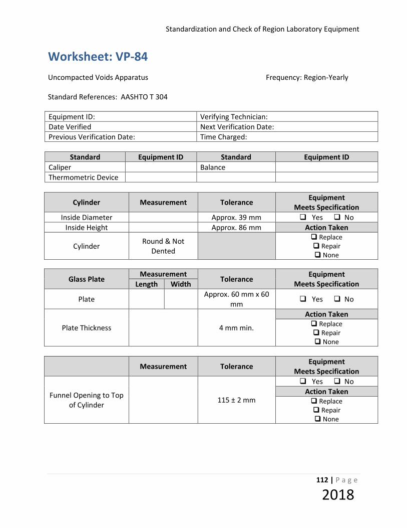
Standardization and Check of Region Laboratory Equipment
112 | P a g e
2018
Worksheet: VP-84 Uncompacted Voids Apparatus Frequency: Region-Yearly Standard References: AASHTO T 304 Equipment ID: Verifying Technician: Date Verified Next Verification Date: Previous Verification Date: Time Charged:
Standard Equipment ID Standard Equipment ID Caliper Balance Thermometric Device
Cylinder Measurement Tolerance Equipment Meets Specification
Inside Diameter Approx. 39 mm Yes No Inside Height Approx. 86 mm Action Taken
Cylinder Round & Not Dented
Replace Repair None
Glass Plate Measurement
Tolerance Equipment Meets Specification Length Width
Plate Approx. 60 mm x 60 mm Yes No
Plate Thickness 4 mm min.
Action Taken Replace Repair None
Measurement Tolerance Equipment Meets Specification
Funnel Opening to Top of Cylinder 115 ± 2 mm
Yes No Action Taken Replace Repair None

Standardization and Check Procedures for Region Laboratory Equipment
113 | P a g e
2018
Spatula Measurement Tolerance Equipment Meets Specification Length Width
Length Approx. 100mm x 20 mm Yes No Sides Straight Yes No
End Angle Right Angles Yes No Action Taken
Replace Repair None
Calibration of Cylinder Measurement
Mass of cylinder, grease, and top plate in grams (E) Mass of cylinder, grease, top plate, and deionized water in grams
(M)
Temperature of water °C Density of water from table 1 Kg/m3 (D)
Empty mass of cylinder in grams Calibration value nearest 0.1 mL (V)
Comments:
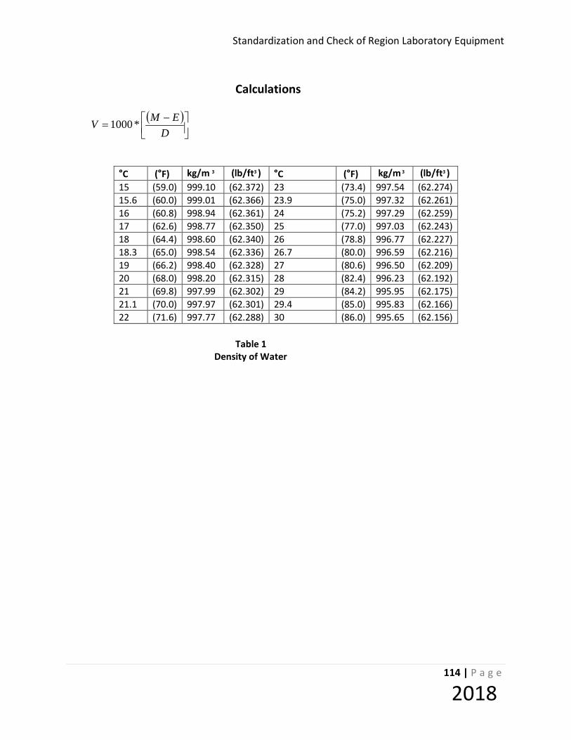
Standardization and Check of Region Laboratory Equipment
114 | P a g e
2018
Calculations
( )
−
=D
EMV *1000
°C (°F) kg/m 3 (lb/ft3 ) °C (°F) kg/m 3 (lb/ft3 ) 15 (59.0) 999.10 (62.372) 23 (73.4) 997.54 (62.274) 15.6 (60.0) 999.01 (62.366) 23.9 (75.0) 997.32 (62.261) 16 (60.8) 998.94 (62.361) 24 (75.2) 997.29 (62.259) 17 (62.6) 998.77 (62.350) 25 (77.0) 997.03 (62.243) 18 (64.4) 998.60 (62.340) 26 (78.8) 996.77 (62.227) 18.3 (65.0) 998.54 (62.336) 26.7 (80.0) 996.59 (62.216) 19 (66.2) 998.40 (62.328) 27 (80.6) 996.50 (62.209) 20 (68.0) 998.20 (62.315) 28 (82.4) 996.23 (62.192) 21 (69.8) 997.99 (62.302) 29 (84.2) 995.95 (62.175) 21.1 (70.0) 997.97 (62.301) 29.4 (85.0) 995.83 (62.166) 22 (71.6) 997.77 (62.288) 30 (86.0) 995.65 (62.156)
Table 1
Density of Water
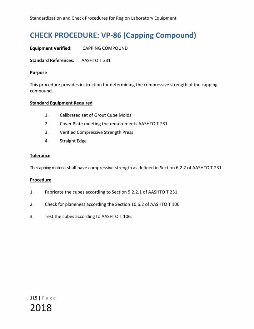
Standardization and Check Procedures for Region Laboratory Equipment
115 | P a g e
2018
CHECK PROCEDURE: VP-86 (Capping Compound) Equipment Verified: CAPPING COMPOUND Standard References: AASHTO T 231 Purpose This procedure provides instruction for determining the compressive strength of the capping compound. Standard Equipment Required 1. Calibrated set of Grout Cube Molds
2. Cover Plate meeting the requirements AASHTO T 231
3. Verified Compressive Strength Press
4. Straight Edge
Tolerance The capping material shall have compressive strength as defined in Section 6.2.2 of AASHTO T 231. Procedure 1. Fabricate the cubes according to Section 5.2.2.1 of AASHTO T 231 2. Check for planeness according the Section 10.6.2 of AASHTO T 106 3. Test the cubes according to AASHTO T 106.

Standardization and Check of Region Laboratory Equipment
116 | P a g e
2018
Worksheet: VP-86 Capping Compound Frequency: On receipt of a new lot and at 3 month intervals Standard References: AASHTO T 231 Equipment ID: Verifying Technician: Date Verified Next Verification Date: Previous Verification Date: Time Charged:
Standard ID# Standard ID#
Straightedge Compression tester
Cube Number Planeness Checked
Load (lbf)
Compressive Strength
(5000 psi required)
1
2
3
Average
Equipment found to be : Satisfactory Unsatisfactory Action Taken: Replace Repair None Comments:

Standardization and Check Procedures for Region Laboratory Equipment
117 | P a g e
2018
STANDARDIZATION PROCEDURE: VP- 88 (Internal Calibration Vessel) Equipment Verified: Type B Air Meter Internal Calibration Vessel Standard Reference: AASHTO T 152 Purpose: This method provides instructions for verifying the volume of metal or plastic internal calibration vessels used to verify a type B Portland cement concrete air meter. Standard Equipment Required Calibrated Type B Portland cement concrete air meter. Tolerance Although no specific tolerances exist for internal calibration vessels it is the intent of the verification process to ensure that these devices provide accurate, repeatable results. There are several factors, including altitude, manufacturing variance, and air meter base dimensions that will slightly affect the apparent volume of an internal calibration canister. This procedure will determine the apparent volume of the vessels when they are utilized in verification of the air meter. Procedure
Calibrate the air meter to be used in verification of the vessel in accordance with VP-4. Verify that the indicated air content is 5.0 +/- 0.1% when 5% of the water is removed from the base to ensure that the meter is functioning properly. Adjust the gauge of the air meter that is being used to verify internal calibration vessels so that it indicates exactly 5.0% air content when 5% of the water has been removed from the base of the air meter. Repeat this process if necessary to ensure consistent operation of the meter.
Inspect the internal calibration vessel for any signs of damage that would prevent it from operating properly.
Fill the base of the air meter full with water and place the internal vessel to be verified in an upright position in the base.
Standardization and Check of Region Laboratory Equipment
118 | P a g e
2018
Clamp the top of the air meter to the base then remove any remaining air in the base by adding water through one of the petcocks. Gently rock the meter to assist in removing any trapped air being careful not to topple the calibration vessel in the air meter base.
5. Pump up the air meter to the initial pressure point determined in step #1. Wait a moment
for the air temperature in the chamber to reach equilibrium then re-verify that the air meter is at the correct initial pressure. Adjust if necessary.
6. Close the petcocks and immediately depress the lever to release the compressed air from
the chamber into the air meter base. Hold the lever down while waiting a moment for the air temperature in the chamber and base to reach equilibrium. Tap the back of the gauge gently while it is stabilizing.
7. Record the air content indicated on the gauge on the worksheet. 8. Gently release the pressure in the air meter base through the petcocks then repeat steps 3
through 7 until a uniform (within 0.1% consistently) reading is achieved. Record at least two trials on the worksheet.
9. Place a permanent label indicating the average apparent volume of the internal calibration
vessel to the nearest 0.1%.
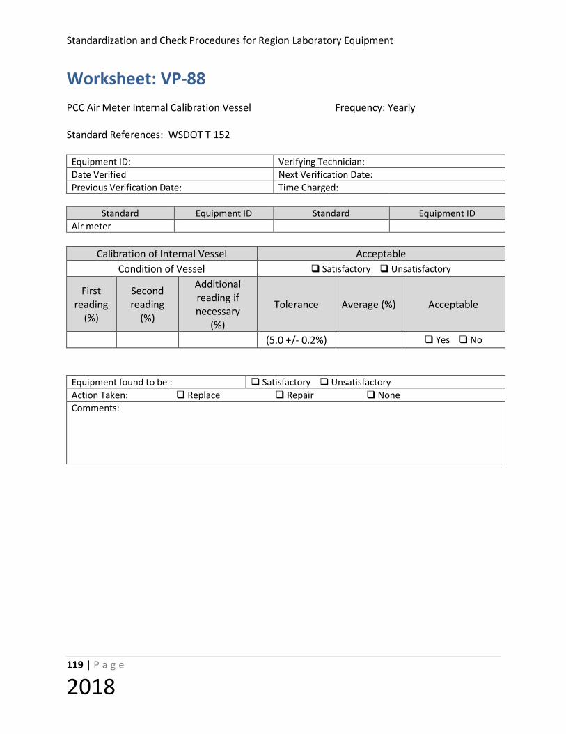
Standardization and Check Procedures for Region Laboratory Equipment
119 | P a g e
2018
Worksheet: VP-88 PCC Air Meter Internal Calibration Vessel Frequency: Yearly Standard References: WSDOT T 152
Equipment ID: Verifying Technician: Date Verified Next Verification Date: Previous Verification Date: Time Charged:
Standard Equipment ID Standard Equipment ID Air meter
Calibration of Internal Vessel Acceptable
Condition of Vessel Satisfactory Unsatisfactory
First reading
(%)
Second reading
(%)
Additional reading if necessary
(%)
Tolerance Average (%) Acceptable
(5.0 +/- 0.2%) Yes No
Equipment found to be : Satisfactory Unsatisfactory Action Taken: Replace Repair None Comments:

Standardization and Check of Region Laboratory Equipment
120 | P a g e
2018
STANDARDIZATION PROCEDURE: VP- 89 (External Calibration Vessel) Equipment Verified: Type B Air Meter External Calibration Vessel Standard Reference: AASHTO T 152 Purpose: This method provides instructions for verifying the volume of the metal or plastic external calibration vessels used to calibrate a type B Portland cement concrete air meter. Standard Equipment Required 1. Balance with a minimum 1000 gram capacity, readable to 0.1 gram. 2. Glass cover plate. (The glass plate used in VP-84 is satisfactory.) 3. Calibrated liquid in glass thermometer of suitable range and readable to 0.2oF (0.1oC) Tolerance The theoretical interior volume of most of these vessels is 0.0125 ft.3 for air meters with a volume of 0.25 ft.3 . This corresponds to an equivalent mass of 353.3 grams of water @ 68.0oF. Correspondingly, a 7.1 gram mass of water @ 68.0oF represents 0.1% of the volume of the air meter base. Therefore, a tolerance of +/-3.0 grams of water @ 68.0oF applied to the mass of water contained in the calibration vessel represents less than 0.05% error in volume of the air meter base. Procedure 1. Clean any debris or adherent particles from both the interior and exterior or the vessel
and inspect for damage that would change the interior volume of the vessel. 2. Obtain and record the mass of the empty vessel and glass cover plate. 3. Fill the vessel completely full with water that is as close to 68 oF as possible. Use the
glass cover plate (and if necessary to seal the top of the vessel a small amount of light grease). Be certain all air bubbles are removed from the vessel. Record the temperature of the water.
Standardization and Check Procedures for Region Laboratory Equipment
121 | P a g e
2018
4. Remove any water from the exterior surface of the vessel and glass cover plate then obtain and record the mass of the vessel, water and glass cover plate.
5. Calculate the mass of the water by subtracting the mass of the empty vessel and glass
cover plate from the mass of the filled vessel and glass cover plate. 6. If the mass of the water contained in the vessel is 353.3 +/- 3.0 grams the vessel is
satisfactory for use. 7. If the water’s mass is outside of this tolerance, machine the top rim of the vessel to
achieve the desired tolerance or replace the vessel.

Standardization and Check of Region Laboratory Equipment
122 | P a g e
2018
Worksheet: VP-89 PCC Air Meter External Calibration Vessel Frequency: Regions-Yearly Standard References: WSDOT T 152 Equipment ID: Verifying Technician: Date Verified Next Verification Date: Previous Verification Date: Time Charged:
Standard Equipment ID Standard Equipment ID
Balance Thermometer
Calibration of External Vessel Measurement
Condition of Vessel Satisfactory Unsatisfactory Mass of vessel, grease, and cover plate in
grams
Mass of vessel , g rease, cover plate, and water in grams
Mass of water in grams Water Temperature* in °F Mass 353.3 ± 3.0 grams? Yes No
Vessel Volume Satisfactory? Yes No
* (The temperature of the water used for calibration should be maintained as close to 68o F as possible.) Equipment found to be : Satisfactory Unsatisfactory Action Taken: Replace Repair None Comments:

Standardization and Check Procedures for Region Laboratory Equipment
123 | P a g e
2018
STANDARDIZATION PROCEDURE: VP-90 (Thermometer - Dry Well) Equipment: Thermometers (Standardized using Dry Well) Standard References: AASHTO R 18, ASTM E77 Purpose This method provides instructions for the standardization of thermometers in a Dry-well Calibrator. This method in not intended for temperatures lower than 100° F. Standard Equipment Required Standard Dry-well Calibrator appropriate to the thermometer working range. Tolerance Thermometers shall be accurate to one degree within their accuracy range. Specifications Thermometers shall be standardized at the temperature ranges defined by their intended use. Procedure 1. Set the Calibrator at the lowest setting to be checked for the thermometer’s working range
and allow the calibrator to heat for 20 minutes 2. Insert the probe or stem of the thermometer into the dry well and let stabilize for 5
minutes. Choose a well that allows probe or stem to slip in easily while maintaining contact with all sides of the well.
3. Record the temperature of the Dry-well display and the thermometer being standardized. 4. With the thermometer still in the Dry-well, change the set point of the Calibrator to the
middle temperature of the thermometer’s working range. 5. Note: It is acceptable to check multiple thermometers at each setting before moving to the
next setting rather than one thermometer per setting. 6. Allow the Dry-well to reach the desired temperature and stabilize for 5 minutes. 7. Record the temperature of the Dry-well display and the thermometer being standardized.
Standardization and Check of Region Laboratory Equipment
124 | P a g e
2018
8. With the thermometer still in the Dry-well, change the set point of the Calibrator to the high temperature (not to exceed Calibrator’s capacity) of the thermometer’s working range.
9. Allow the Dry-well to reach the desired temperature and stabilize for 5 minutes. 10. Record the temperature of the Dry-well display and the thermometer being standardized. 11. Determine the average correction between the working thermometer(s) and the Standard
Dry-well calibrator, record on worksheet. 12. Indicate the average temperature correction on the Working thermometer or adjust the
Working thermometer to agree with the temperature of Standard Dry-well calibrator. 13. After last reading, “cool” the Calibrator per the manufacturer’s recommendation before
turning power off.

Standardization and Check Procedures for Region Laboratory Equipment
125 | P a g e
2018
Worksheet: VP-90 Thermometers (Dry-Well) Frequency: Yearly- Region Standard References: AASHTO R 18, ASTM E77
Technician: Date: Next Due Date:
Standard ID# Adjustment (if required)
Dry Well
Thermometer ID #
Working Range
Desired Temp
Temp of Dry-well
(w/adjust if required)
Thermometer Reading
Average Correction
Meets Spec:
Action Taken if not in
Spec:
Low
Yes No
Disposed Adjusted Middle
High
Low
Yes No
Disposed Adjusted Middle
High
Low
Yes No
Disposed Adjusted Middle
High
Low
Yes No
Disposed Adjusted Middle
High
Low
Yes No
Disposed Adjusted Middle
High
Low
Yes No
Disposed Adjusted Middle
High
Low
Yes No
Disposed Adjusted Middle
High Comments:
Standardization and Check of Region Laboratory Equipment
126 | P a g e
2018
CHECK PROCEDURE: VP-91 (Infrared Gun or Camera) Equipment Verified: Infrared Gun or Camera
Standard References: SOP 733
Purpose This method provides instructions for the standardization of Infrared guns and cameras. Standard Equipment Required NIST traceable Infrared Calibrator Tolerance Accuracy per manufacturer’s statement for device Procedure 1. Set the IR Calibrator to 50 ºC and allow it to heat for 20 minutes. 2. Set the IR device to .95 emissivity. 3. Hold the IR device at a 90º angle to the center of the calibrator and close enough so the
target area of the device is completely contained within IR target of the calibrator. Do not touch the surface of the IR calibrator!
4. Record the temperature of the display and the reading of the IR device. 5. Set the IR Calibrator to 100 ºC and wait for it to achieve the required temperature and
stabilize. 6. Repeat steps 3 & 4 7. Set the IR Calibrator to 150 ºC and wait for it to achieve the required temperature and
stabilize. 8. Repeat steps 3 & 4 9. Calculate the difference between the IR calibrator and the temperature reading of the IR
device.

Standardization and Check Procedures for Region Laboratory Equipment
127 | P a g e
2018
10. Indicate the temperature correction on the IR device and record data on VP-91W form. For
adjustable IR devices, adjust the IR device reading to agree with the verified reading.

Standardization and Check of Region Laboratory Equipment
128 | P a g e
2018
Worksheet: VP-91 Infrared Gun and Camera Frequency: SML-12 months Standard References: ASTM E 77 Equipment ID: Verifying Technician: Date Verified Next Verification Date: Previous Verification Date: Time Charged:
Standard ID# Standard ID#
IR Calibrator
Calibrator Reading
°C IR device Reading °C Difference °C
Adjusted IR device
50
Yes No 100
150
Equipment found to be : Satisfactory Unsatisfactory Action Taken: Replace Repair None Comments:
Standardization and Check Procedures for Region Laboratory Equipment
129 | P a g e
2018
STANDARDIZATION PROCEDURE: VP-92 (Rebound Hammer)
Equipment Verified: REBOUND HAMMER
Standard References: ASTM C 805M
Purpose This method provides instruction for verifying a rebound hammer using a calibration anvil.
Standard Equipment Required
1. Rebound Hammer, consisting of a spring-loaded steel hammer that when released strikes a steel plunger in contact with the concrete surface. The spring-loaded hammer must travel with a consistent and reproducible velocity. The rebound distance of the steel hammer from the steel plunger is measured on a linear scale attached to the frame of the instrument.
2. Calibration Anvil- approximately 150-mm [6-in.] diameter by 150-mm [6-in.] high
cylinder made of tool steel with an impact area hardened to 66 + 2 HRC as measured by Test Methods E 18. An instrument guide is provided to center the rebound hammer over the impact area and keep the instrument perpendicular to the surface.
Tolerance Average of 10 readings must be within +2 of the manufacturer’s hardness value of the calibration anvil Procedure
1. Place calibration anvil on a concrete floor or slab
2. Place the rebound hammer in the instrument guide and take a series of ten readings
3. Average the ten readings
4. If the average of the ten readings is outside of the tolerance, clean and lubricate the rebound hammer per the manufacturer’s recommendation and repeat steps 1-4.
5. If after cleaning the rebound hammer is still not within the tolerance limit the hammer must be sent in to the manufacturer or an accredited repair facility for correction.

Standardization and Check of Region Laboratory Equipment
130 | P a g e
2018
Worksheet: VP-92 Rebound Hammer Frequency: Yearly or 2,000 blows Standard References: ASTM C 805 Equipment ID: Verifying Technician: Date Verified Next Verification Date: Previous Verification Date: Time Charged:
Standard ID# Standard ID# Anvil 66 ± 2 HRC
Calibration Anvil Hardness Value: _________
Reading # Result 1 2 3 4 5 6 7 8 9
10
Average Equipment found to be : Satisfactory Unsatisfactory Action Taken: Replace Repair None Comments:

Standardization and Check Procedures for Region Laboratory Equipment
131 | P a g e
2018
CHECK PROCEDURE: VP – 93 (Metal Ruler or Tape) Equipment Verified: Metal Ruler or Metal Measuring Tape Standard References: AASHTO T19, T119, T121, T702, T721 Purpose This method provides instruction for the verification of a metal ruler or metal measuring tape. Standard Equipment Required
24” Standardized Steel Rule Tolerance Within ± 1/32 of the standard rule Procedure
1. Visually inspect the ruler for defects (ie bends, breaks and readability of graduations).
2. Divide the rule into six even increments (i.e. 12” rule = 2”, 4”, 6”, 8”, 10”, 12”)
3. Compare the incremental readings of the reference ruler to the ruler being standardized.
4. Record the measurements.

Standardization and Check of Region Laboratory Equipment
132 | P a g e
2018
Worksheet: VP-93 Metal Ruler/Tape Measure Frequency: Regions- Yearly Standard References: AASHTO T 119, T 720, T 702 Equipment ID: Verifying Technician: Date Verified Next Verification Date: Previous Verification Date: Time Charged:
Standard ID# Standard ID#
Steel Ruler
Length of ruler being verified: ____________
Reference Measurement Length Measured Difference
(Note: for metal tape measure only the length required for the test will be verified) Equipment found to be : Satisfactory Unsatisfactory Action Taken: Replace Repair None Comments:
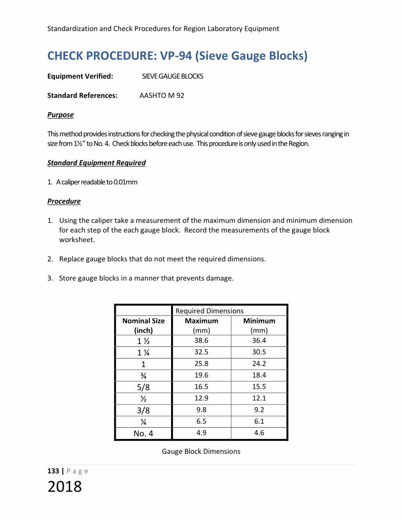
Standardization and Check Procedures for Region Laboratory Equipment
133 | P a g e
2018
CHECK PROCEDURE: VP-94 (Sieve Gauge Blocks)
Equipment Verified: SIEVE GAUGE BLOCKS Standard References: AASHTO M 92 Purpose This method provides instructions for checking the physical condition of sieve gauge blocks for sieves ranging in size from 1½” to No. 4. Check blocks before each use. This procedure is only used in the Region. Standard Equipment Required 1. A caliper readable to 0.01mm Procedure 1. Using the caliper take a measurement of the maximum dimension and minimum dimension
for each step of the each gauge block. Record the measurements of the gauge block worksheet.
2. Replace gauge blocks that do not meet the required dimensions. 3. Store gauge blocks in a manner that prevents damage.
Gauge Block Dimensions
Required Dimensions Nominal Size
(inch) Maximum
(mm) Minimum
(mm) 1 ½ 38.6 36.4
1 ¼ 32.5 30.5
1 25.8 24.2
¾ 19.6 18.4
5/8 16.5 15.5
½ 12.9 12.1
3/8 9.8 9.2
¼ 6.5 6.1
No. 4 4.9 4.6

Standardization and Check of Region Laboratory Equipment
134 | P a g e
2018
Table 1

Standardization and Check Procedures for Region Laboratory Equipment
135 | P a g e
2018
Worksheet: VP-94 Sieves Gauge Frequency: Yearly Standard References: AASHTO M 92 Equipment ID: Verifying Technician: Date Verified Next Verification Date: Previous Verification Date: Time Charged:
Standard ID# Standard ID#
Caliper 0.01 mm
Measures Required Dimensions
Nominal Size (inch)
Maximum (mm)
Minimum (mm)
Maximum (mm)
Minimum (mm)
1 ½ 38.6 36.4
1 ¼ 32.5 30.5
1 25.8 24.2
¾ 19.6 18.4
5/8 16.5 15.5
½ 12.9 12.1
3/8 9.8 9.2
¼ 6.5 6.1
No. 4 4.9 4.6
Equipment found to be : Satisfactory Unsatisfactory Action Taken: Replace Repair None Comments:

Standardization and Check of Region Laboratory Equipment
136 | P a g e
2018
STANDARDIZATION PROCEDURE: VP-97 (Field Probe Thermometers) Equipment Verified: Field Probe Thermometers (Non-laboratory use only) Standard References: AASHTO T 309, AASHTO R 18, ASTM E77 Purpose This method provides instructions for the standardization of thermometers used for determining the temperature of concrete in the field. Thermometers shall be standardized by comparing thermometer readings at two temperatures at least 27° F apart. Standard Equipment Required Refer to the equipment required in VP-12, VP-13 or VP-90. Tolerance Thermometers shall be accurate to one degree within their accuracy range. Specifications
Procedure Working Range Accuracy T 309 0 ºF - 120 ºF 1 ºF (0.5 ºC)
Procedure Field Probe Thermometers used for T 309 shall be standardized using any two of the following options as long the temperatures are 27° F apart. Option 1: VP-12 (Ice Point)
1. Follow procedure directions. 2. Only one reading is necessary.
Option 2: VP-13 (Working Range)
1. Follow procedure directions. 2. Only one reading is necessary.
Option 3: VP-90 (Dry-Well)
1. Can only be used at temperatures from 100° F to 120° F (if using in conjunction with VP-13 at 77° F, minimum setting would be 104° F.
2. Follow procedure directions. 3. Only one reading is necessary.
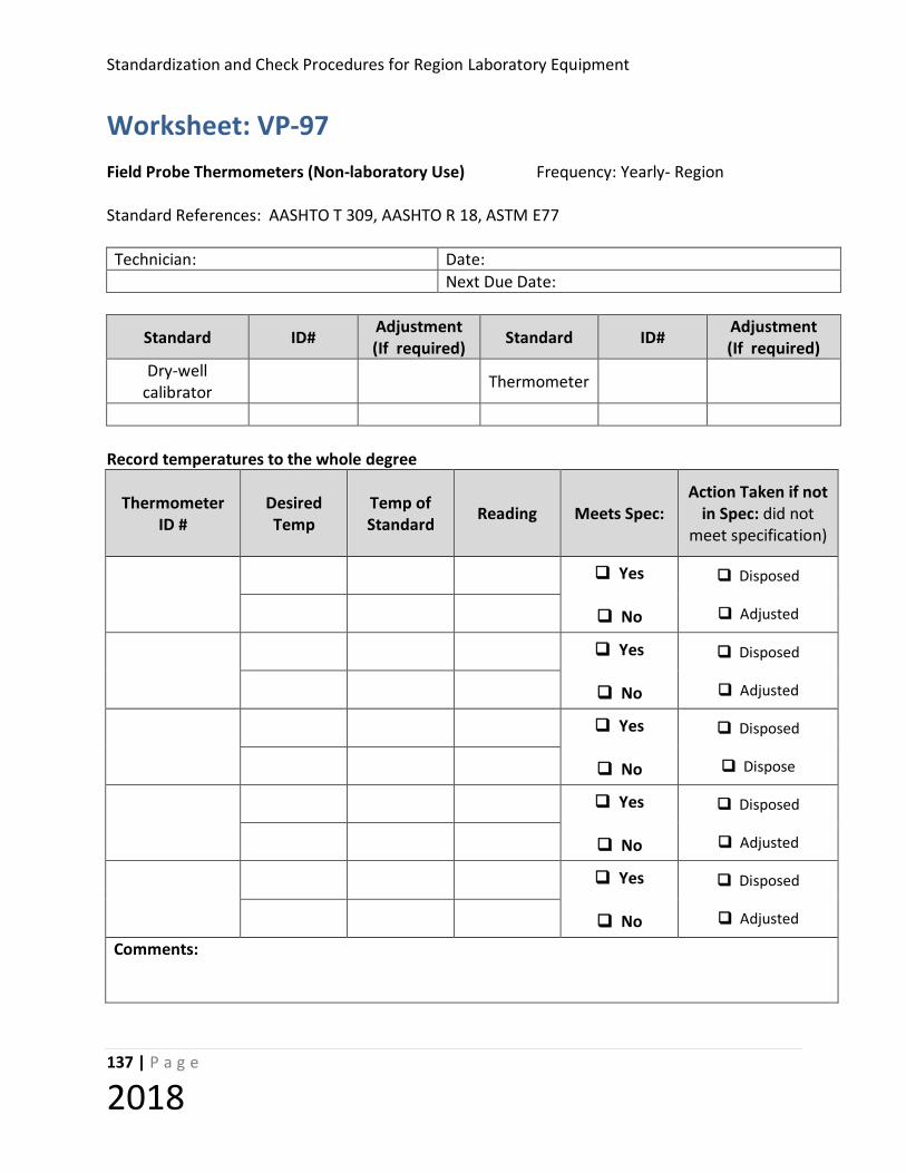
Standardization and Check Procedures for Region Laboratory Equipment
137 | P a g e
2018
Worksheet: VP-97 Field Probe Thermometers (Non-laboratory Use) Frequency: Yearly- Region Standard References: AASHTO T 309, AASHTO R 18, ASTM E77 Technician: Date: Next Due Date:
Standard ID# Adjustment (If required) Standard ID# Adjustment
(If required) Dry-well
calibrator Thermometer
Record temperatures to the whole degree
Thermometer ID #
Desired Temp
Temp of Standard Reading Meets Spec:
Action Taken if not in Spec: did not
meet specification)
Yes
No
Disposed
Adjusted
Yes
No
Disposed
Adjusted
Yes
No
Disposed
Dispose
Yes
No
Disposed
Adjusted
Yes
No
Disposed
Adjusted
Comments:
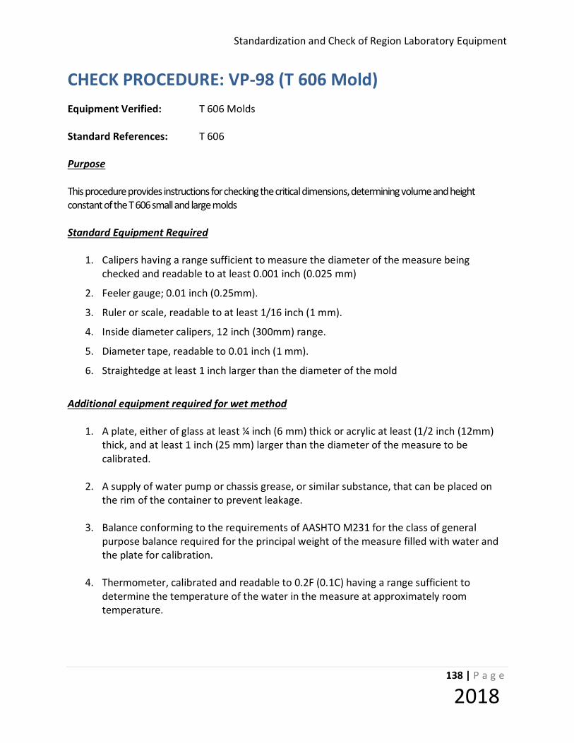
Standardization and Check of Region Laboratory Equipment
138 | P a g e
2018
CHECK PROCEDURE: VP-98 (T 606 Mold) Equipment Verified: T 606 Molds
Standard References: T 606 Purpose This procedure provides instructions for checking the critical dimensions, determining volume and height constant of the T 606 small and large molds Standard Equipment Required
1. Calipers having a range sufficient to measure the diameter of the measure being checked and readable to at least 0.001 inch (0.025 mm)
2. Feeler gauge; 0.01 inch (0.25mm).
3. Ruler or scale, readable to at least 1/16 inch (1 mm).
4. Inside diameter calipers, 12 inch (300mm) range.
5. Diameter tape, readable to 0.01 inch (1 mm).
6. Straightedge at least 1 inch larger than the diameter of the mold
Additional equipment required for wet method
1. A plate, either of glass at least ¼ inch (6 mm) thick or acrylic at least (1/2 inch (12mm) thick, and at least 1 inch (25 mm) larger than the diameter of the measure to be calibrated.
2. A supply of water pump or chassis grease, or similar substance, that can be placed on
the rim of the container to prevent leakage.
3. Balance conforming to the requirements of AASHTO M231 for the class of general purpose balance required for the principal weight of the measure filled with water and the plate for calibration.
4. Thermometer, calibrated and readable to 0.2F (0.1C) having a range sufficient to
determine the temperature of the water in the measure at approximately room temperature.
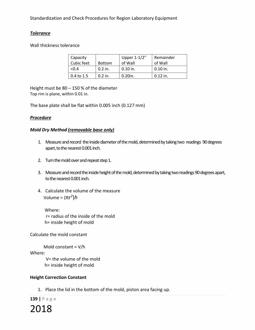
Standardization and Check Procedures for Region Laboratory Equipment
139 | P a g e
2018
Tolerance Wall thickness tolerance
Capacity Upper 1-1/2” Remainder Cubic feet Bottom of Wall of Wall <0.4 0.2 in. 0.10 in. 0.10 in. 0.4 to 1.5 0.2 in. 0.20in. 0.12 in.
Height must be 80 – 150 % of the diameter Top rim is plane, within 0.01 in. The base plate shall be flat within 0.005 inch (0.127 mm) Procedure Mold Dry Method (removable base only)
1. Measure and record the inside diameter of the mold, determined by taking two readings 90 degrees apart, to the nearest 0.001 inch.
2. Turn the mold over and repeat step 1.
3. Measure and record the inside height of the mold, determined by taking two readings 90 degrees apart,
to the nearest 0.001 inch.
4. Calculate the volume of the measure Volume = (πr2)h Where: r= radius of the inside of the mold h= inside height of mold Calculate the mold constant Mold constant = V/h Where: V= the volume of the mold h= inside height of mold Height Correction Constant
1. Place the lid in the bottom of the mold, piston area facing up.
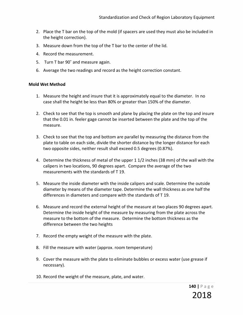
Standardization and Check of Region Laboratory Equipment
140 | P a g e
2018
2. Place the T bar on the top of the mold (if spacers are used they must also be included in the height correction).
3. Measure down from the top of the T bar to the center of the lid.
4. Record the measurement.
5. Turn T bar 90˚ and measure again.
6. Average the two readings and record as the height correction constant.
Mold Wet Method
1. Measure the height and insure that it is approximately equal to the diameter. In no case shall the height be less than 80% or greater than 150% of the diameter.
2. Check to see that the top is smooth and plane by placing the plate on the top and insure
that the 0.01 in. feeler gage cannot be inserted between the plate and the top of the measure.
3. Check to see that the top and bottom are parallel by measuring the distance from the
plate to table on each side, divide the shorter distance by the longer distance for each two opposite sides, neither result shall exceed 0.5 degrees (0.87%).
4. Determine the thickness of metal of the upper 1 1/2 inches (38 mm) of the wall with the
calipers in two locations, 90 degrees apart. Compare the average of the two measurements with the standards of T 19.
5. Measure the inside diameter with the inside calipers and scale. Determine the outside
diameter by means of the diameter tape. Determine the wall thickness as one half the differences in diameters and compare with the standards of T 19.
6. Measure and record the external height of the measure at two places 90 degrees apart.
Determine the inside height of the measure by measuring from the plate across the measure to the bottom of the measure. Determine the bottom thickness as the difference between the two heights
7. Record the empty weight of the measure with the plate.
8. Fill the measure with water (approx. room temperature)
9. Cover the measure with the plate to eliminate bubbles or excess water (use grease if
necessary).
10. Record the weight of the measure, plate, and water.
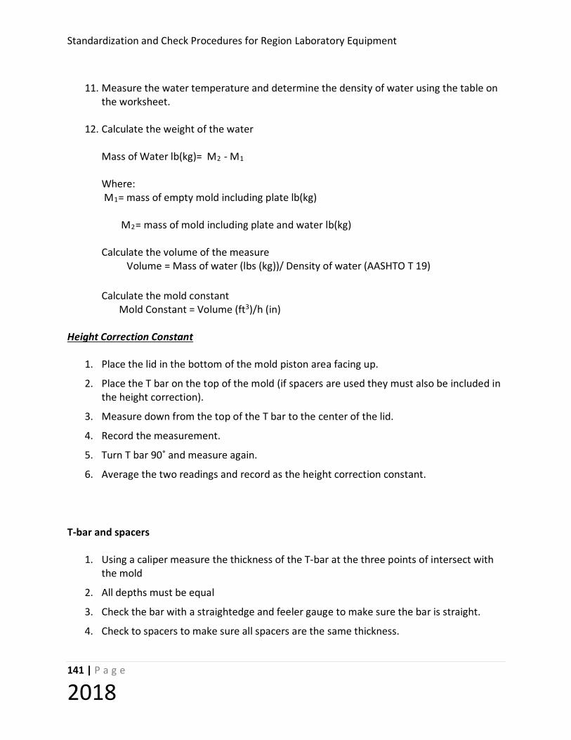
Standardization and Check Procedures for Region Laboratory Equipment
141 | P a g e
2018
11. Measure the water temperature and determine the density of water using the table on
the worksheet.
12. Calculate the weight of the water
Mass of Water lb(kg)= M2 - M1 Where: M1= mass of empty mold including plate lb(kg) M2= mass of mold including plate and water lb(kg) Calculate the volume of the measure Volume = Mass of water (lbs (kg))/ Density of water (AASHTO T 19) Calculate the mold constant Mold Constant = Volume (ft3)/h (in)
Height Correction Constant
1. Place the lid in the bottom of the mold piston area facing up.
2. Place the T bar on the top of the mold (if spacers are used they must also be included in the height correction).
3. Measure down from the top of the T bar to the center of the lid.
4. Record the measurement.
5. Turn T bar 90˚ and measure again.
6. Average the two readings and record as the height correction constant.
T-bar and spacers
1. Using a caliper measure the thickness of the T-bar at the three points of intersect with the mold
2. All depths must be equal
3. Check the bar with a straightedge and feeler gauge to make sure the bar is straight.
4. Check to spacers to make sure all spacers are the same thickness.
Standardization and Check of Region Laboratory Equipment
142 | P a g e
2018
5. Place the piston inside an empty mold, place the T bar and spacers (if needed) on top of the mold and measure down to the center of the mold.
6. Take two measurements and average
7. Record this measurement as the height correction constant.
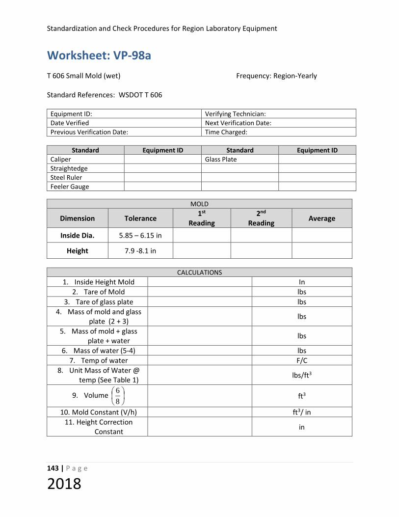
Standardization and Check Procedures for Region Laboratory Equipment
143 | P a g e
2018
Worksheet: VP-98a T 606 Small Mold (wet) Frequency: Region-Yearly Standard References: WSDOT T 606
Equipment ID: Verifying Technician: Date Verified Next Verification Date: Previous Verification Date: Time Charged:
Standard Equipment ID Standard Equipment ID Caliper Glass Plate Straightedge Steel Ruler Feeler Gauge
MOLD
Dimension Tolerance 1st Reading
2nd Reading Average
Inside Dia. 5.85 – 6.15 in
Height 7.9 -8.1 in
CALCULATIONS
1. Inside Height Mold In 2. Tare of Mold lbs
3. Tare of glass plate lbs 4. Mass of mold and glass
plate (2 + 3) lbs
5. Mass of mold + glass plate + water lbs
6. Mass of water (5-4) lbs 7. Temp of water F/C
8. Unit Mass of Water @ temp (See Table 1) lbs/ft3
9. Volume
86 ft3
10. Mold Constant (V/h) ft3/ in 11. Height Correction
Constant in

Standardization and Check of Region Laboratory Equipment
144 | P a g e
2018
T bar # Depth 1 Depth 2 Depth 3 Depth same for all legs
Plane on face 0.01 in 10 in
□ Yes □ No □ Yes □ No □ Yes □ No □ Yes □ No
Space bar # Depth 1 Depth 2 @ 90˚
Depth same for both ends
Plane on face 0.01 in 10 in
□ Yes □ No □ Yes □ No □ Yes □ No □ Yes □ No
Table 1
Unit Mass of Water
F C lb./ft.3 kg/m 3 F C lb./ft.3 kg/m 3
59.0 15 62.372 999.10 73.4 23 62.274 997.54 60.0 15.6 62.366 999.01 75.0 23.9 62.261 997.32 60.8 16 62.361 998.94 75.2 24 62.259 997.29 62.6 17 62.350 998.77 77.0 25 62.243 997.03 64.4 18 62.340 998.60 78.8 26 62.227 996.77 65.0 18.3 62.336 998.54 80.0 26.7 62.216 996.59 66.2 19 62.328 998.40 80.6 27 62.209 996.50 68.0 20 62.315 998.20 82.4 28 62.192 996.23 69.8 21 62.302 997.99 84.2 29 62.175 995.95 70.0 21.1 62.301 997.97 85.0 29.4 62.166 995.83 71.6 22 62.288 997.77 86.0 30 62.156 995.65
Equipment found to be : Satisfactory Unsatisfactory Action Taken: Replace Repair None Comments:
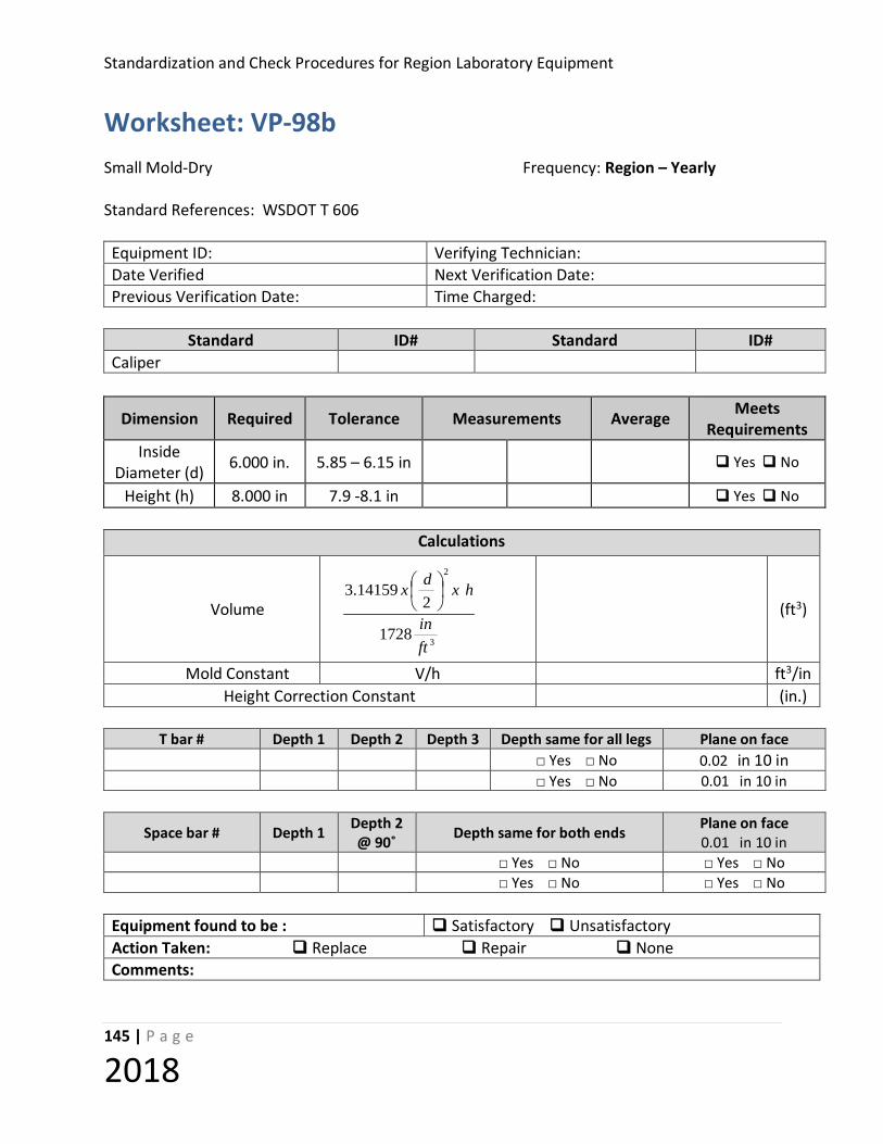
Standardization and Check Procedures for Region Laboratory Equipment
145 | P a g e
2018
Worksheet: VP-98b Small Mold-Dry Frequency: Region – Yearly Standard References: WSDOT T 606 Equipment ID: Verifying Technician: Date Verified Next Verification Date: Previous Verification Date: Time Charged:
Standard ID# Standard ID#
Caliper
Dimension Required Tolerance Measurements Average Meets Requirements
Inside Diameter (d) 6.000 in. 5.85 – 6.15 in Yes No
Height (h) 8.000 in 7.9 -8.1 in Yes No
Calculations
Volume
(ft3)
Mold Constant V/h ft3/in Height Correction Constant (in.)
T bar # Depth 1 Depth 2 Depth 3 Depth same for all legs Plane on face
□ Yes □ No 0.02 in 10 in □ Yes □ No 0.01 in 10 in
Space bar # Depth 1 Depth 2 @ 90˚ Depth same for both ends Plane on face
0.01 in 10 in □ Yes □ No □ Yes □ No □ Yes □ No □ Yes □ No
Equipment found to be : Satisfactory Unsatisfactory Action Taken: Replace Repair None Comments:
3
2
1728
214159.3
ftin
hxdx
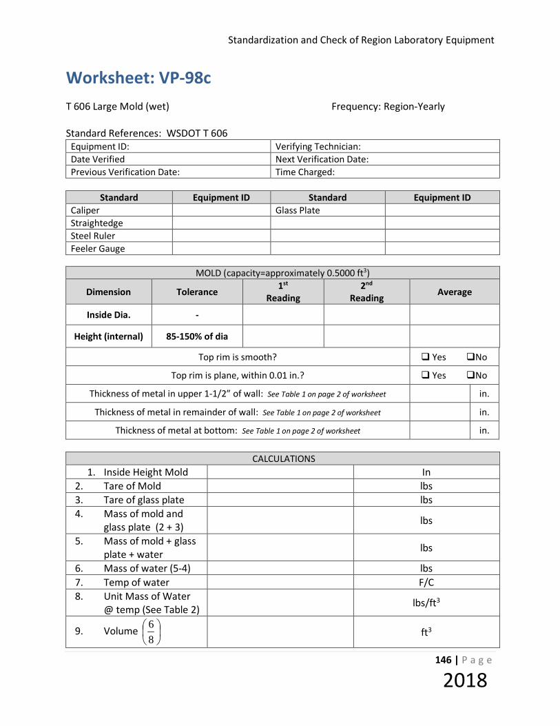
Standardization and Check of Region Laboratory Equipment
146 | P a g e
2018
Worksheet: VP-98c T 606 Large Mold (wet) Frequency: Region-Yearly Standard References: WSDOT T 606
Equipment ID: Verifying Technician: Date Verified Next Verification Date: Previous Verification Date: Time Charged:
Standard Equipment ID Standard Equipment ID Caliper Glass Plate Straightedge Steel Ruler Feeler Gauge
MOLD (capacity=approximately 0.5000 ft3)
Dimension Tolerance 1st Reading
2nd Reading Average
Inside Dia. -
Height (internal) 85-150% of dia
Top rim is smooth? Yes No
Top rim is plane, within 0.01 in.? Yes No
Thickness of metal in upper 1-1/2” of wall: See Table 1 on page 2 of worksheet in.
Thickness of metal in remainder of wall: See Table 1 on page 2 of worksheet in.
Thickness of metal at bottom: See Table 1 on page 2 of worksheet in.
CALCULATIONS 1. Inside Height Mold In
2. Tare of Mold lbs 3. Tare of glass plate lbs 4. Mass of mold and
glass plate (2 + 3) lbs
5. Mass of mold + glass plate + water lbs
6. Mass of water (5-4) lbs 7. Temp of water F/C 8. Unit Mass of Water
@ temp (See Table 2) lbs/ft3
9. Volume
86 ft3
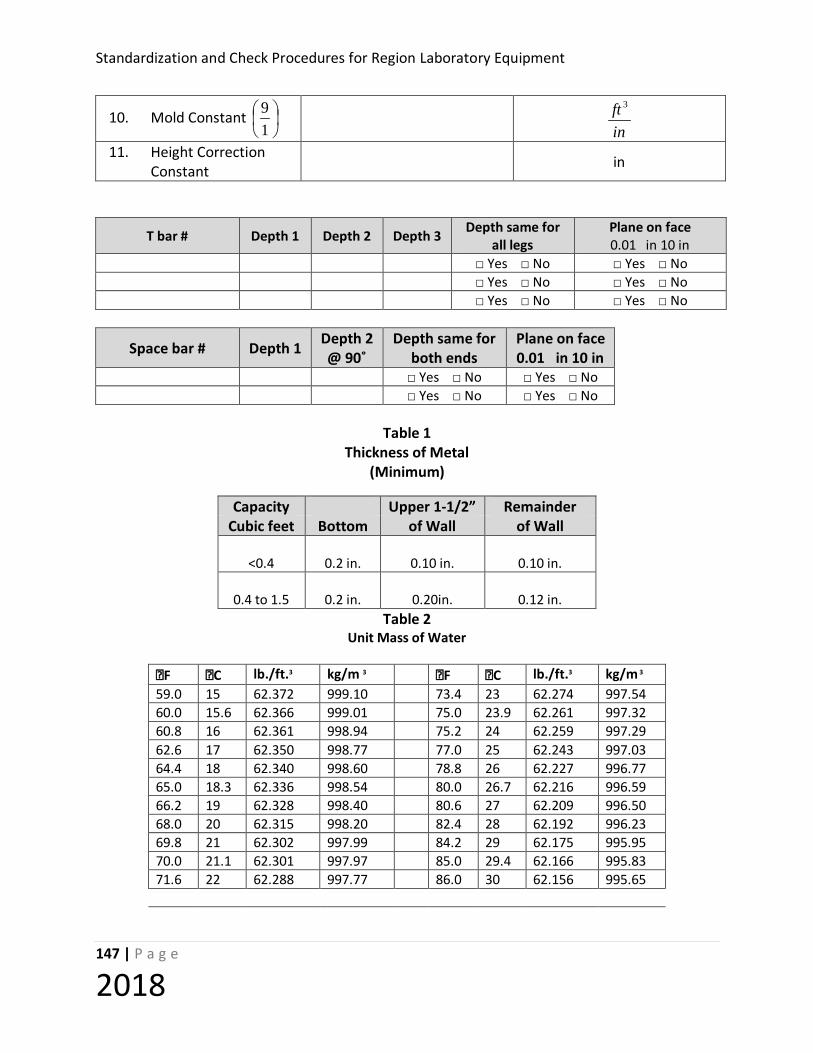
Standardization and Check Procedures for Region Laboratory Equipment
147 | P a g e
2018
10. Mold Constant
19
inft 3
11. Height Correction Constant in
T bar # Depth 1 Depth 2 Depth 3 Depth same for all legs
Plane on face 0.01 in 10 in
□ Yes □ No □ Yes □ No □ Yes □ No □ Yes □ No □ Yes □ No □ Yes □ No
Space bar # Depth 1 Depth 2 @ 90˚
Depth same for both ends
Plane on face 0.01 in 10 in
□ Yes □ No □ Yes □ No □ Yes □ No □ Yes □ No
Table 1
Thickness of Metal (Minimum)
Capacity Upper 1-1/2” Remainder
Cubic feet Bottom of Wall of Wall
<0.4
0.2 in.
0.10 in.
0.10 in.
0.4 to 1.5
0.2 in.
0.20in.
0.12 in. Table 2
Unit Mass of Water
F C lb./ft.3 kg/m 3 F C lb./ft.3 kg/m 3
59.0 15 62.372 999.10 73.4 23 62.274 997.54 60.0 15.6 62.366 999.01 75.0 23.9 62.261 997.32 60.8 16 62.361 998.94 75.2 24 62.259 997.29 62.6 17 62.350 998.77 77.0 25 62.243 997.03 64.4 18 62.340 998.60 78.8 26 62.227 996.77 65.0 18.3 62.336 998.54 80.0 26.7 62.216 996.59 66.2 19 62.328 998.40 80.6 27 62.209 996.50 68.0 20 62.315 998.20 82.4 28 62.192 996.23 69.8 21 62.302 997.99 84.2 29 62.175 995.95 70.0 21.1 62.301 997.97 85.0 29.4 62.166 995.83 71.6 22 62.288 997.77 86.0 30 62.156 995.65

Standardization and Check of Region Laboratory Equipment
148 | P a g e
2018
Equipment found to be : Satisfactory Unsatisfactory Action Taken: Replace Repair None Comments:

Standardization and Check Procedures for Region Laboratory Equipment
149 | P a g e
2018
Worksheet: VP-98d Large Mold-Dry Frequency: Region – Yearly Standard References: WSDOT T 606 Equipment ID: Verifying Technician: Date Verified Next Verification Date: Previous Verification Date: Time Charged:
Standard ID# Standard ID#
Caliper Feeler gauge Straightedge Glass plate Steel Ruler
MOLD (capacity=approximately 0.5000 ft3)
Dimension Tolerance 1st Reading
2nd Reading Average
Inside Dia. (Top) -
Height (internal) 85-150% of dia
Top rim is smooth? Yes No
Top rim is plane, within 0.01 in.? Yes No
Thickness of metal in upper 1-1/2” of wall: See Table 1 on page 2 of worksheet in.
Thickness of metal in remainder of wall: See Table 1 on page 2 of worksheet in.
Thickness of metal at bottom: See Table 1 on page 2 of worksheet in.
Calculations
Volume
ft3
Mold Constant V/h ft3/in Height Correction Constant in
3
2
1728
214159.3
ftin
hxd
x

Standardization and Check of Region Laboratory Equipment
150 | P a g e
2018
T bar # Depth 1 Depth 2 Depth 3 Depth same for all legs
Plane on face 0.01 in 10 in
□ Yes □ No □ Yes □ No □ Yes □ No □ Yes □ No □ Yes □ No □ Yes □ No
Space bar # Depth 1 Depth 2 @ 90˚
Depth same for both ends
Plane on face 0.01 in 10 in
□ Yes □ No □ Yes □ No □ Yes □ No □ Yes □ No
Equipment found to be : Satisfactory Unsatisfactory Action Taken: Replace Repair None Comments:
Table 1 Thickness of Metal
(Minimum)
Capacity Upper 1-1/2” Remainder Cubic feet Bottom of Wall of Wall
<0.4
0.2 in.
0.10 in.
0.10 in.
0.4 to 1.5
0.2 in.
0.20in.
0.12 in.

Standardization and Check Procedures for Region Laboratory Equipment
151 | P a g e
2018
STANDARDIZATION PROCEDURE: VP-103 (VACUUM SYSTEM) Equipment Verified: CoreLok Vacuum System Standard Reference: AASHTO T 331, WSDOT SOP 731 Purpose This method provides instructions to verify that minimum vacuum is achieved. Inspection Equipment Required
1. Absolute pressure gauge
Tolerance The CoreLok sample chamber shall reach a vacuum of 4mmHg or lower when measured. Note: If an adjustment is shown on the Certificate of Calibration for the absolute pressure gauge, make sure the reading is adjusted accordingly. Example: If the absolute pressure gauge has a correction of +3.3mmHg then a gauge reading of 30mmHg is actually 33.3mmHg. Procedure
1. If the CoreLok pump is cold. Turn the CoreLok unit on. Make sure it is set on Program 1. Close the lid and run Program 1 a total of 4 times.
2. After the 4th run, place the absolute vacuum gauge in the sample chamber and start the unit again.
3. While the unit is running, verify that the vacuum gauge reaches a vacuum of 4mmHg or lower.
4. Repeat steps 2 and 3.
5. If both readings on the gauge are ≤ 4mmHg, your CoreLok system is working correctly. If the vacuum gauge reads > 4mmHg, call the InstroTek office at (919) 975-8371 for troubleshooting options.
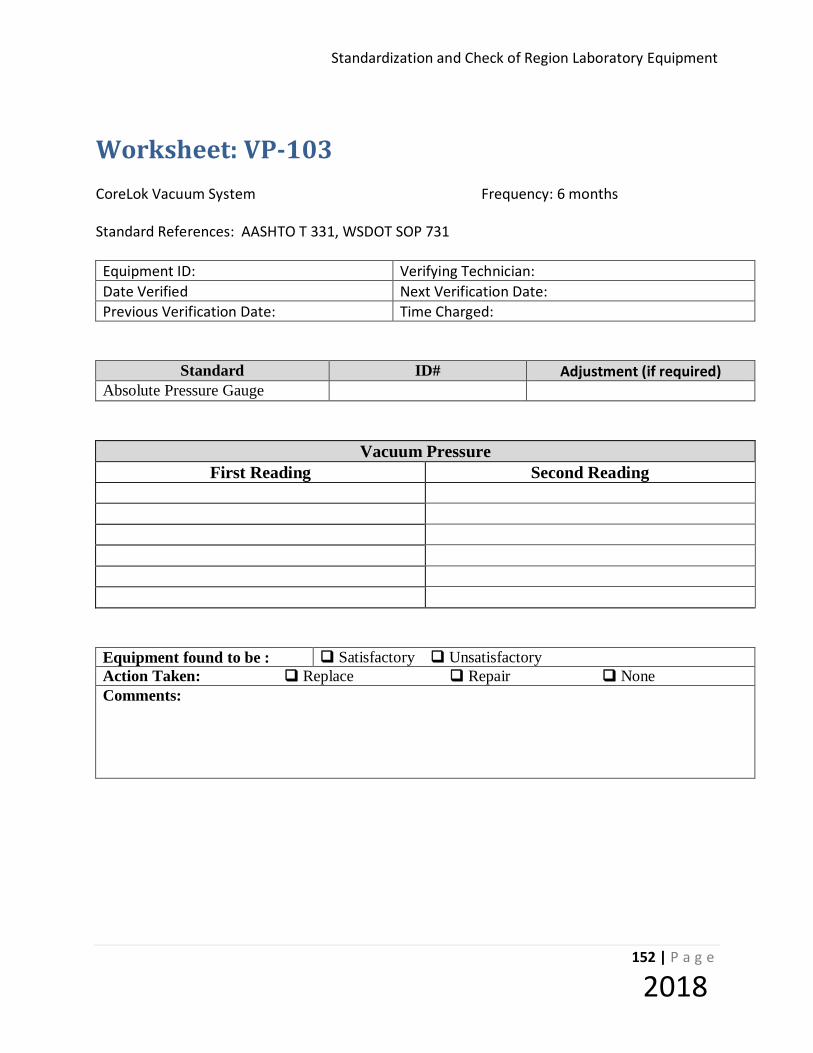
Standardization and Check of Region Laboratory Equipment
152 | P a g e
2018
Worksheet: VP-103 CoreLok Vacuum System Frequency: 6 months Standard References: AASHTO T 331, WSDOT SOP 731 Equipment ID: Verifying Technician: Date Verified Next Verification Date: Previous Verification Date: Time Charged:
Standard ID# Adjustment (if required) Absolute Pressure Gauge
Vacuum Pressure First Reading Second Reading
Equipment found to be : Satisfactory Unsatisfactory Action Taken: Replace Repair None Comments:

Standardization and Check Procedures for Region Laboratory Equipment
153 | P a g e
2018
STANDARDIZATION PROCEDURE: VP-104 (VACUUM SYSTEM) Equipment Verified: CoreDry Vacuum System Standard Reference: AASHTO PP 75, WSDOT SOP 731 Purpose This method provides instructions to verify that minimum vacuum is achieved and to correct readings on the vacuum gauge. Inspection Equipment Required
2. Absolute pressure gauge
Tolerance The CoreDry sample chamber shall reach a maximum of 6mmHg when measured. Note: If an adjustment is shown on the Certificate of Calibration for the absolute pressure gauge, make sure the reading is adjusted accordingly. Example: If the absolute pressure gauge has a correction of +3.3mmHg then a gauge reading of 30mmHg is actually 33.3mmHg. Procedure
1. Dry the cold trap and remove samples and/or debris from the sample chamber. Turn the unit on. Press the start button and allow the unit to run a total of 7 cycles. This may require starting the unit multiple times based on the settings of your CoreDry.
2. After the 7th cycle, place the absolute pressure gauge in the sample tank and start the unit again.
3. While the unit is running, verify that the vacuum gauge reaches a vacuum of 6mmHg or lower and the gauge readout matches the digital readout on your CoreDry.
4. Repeat steps 2 and 3.
5. If both readings on the gauge are ≤ 6mmHg and the absolute pressure gauge readout matches the CoreDry digital readout, your CoreDry system is working correctly. If the absolute pressure gauge reads > 6mmHg or does not match the CoreDry digital readout, call the InstroTek office at (919) 975-8371 for troubleshooting options.
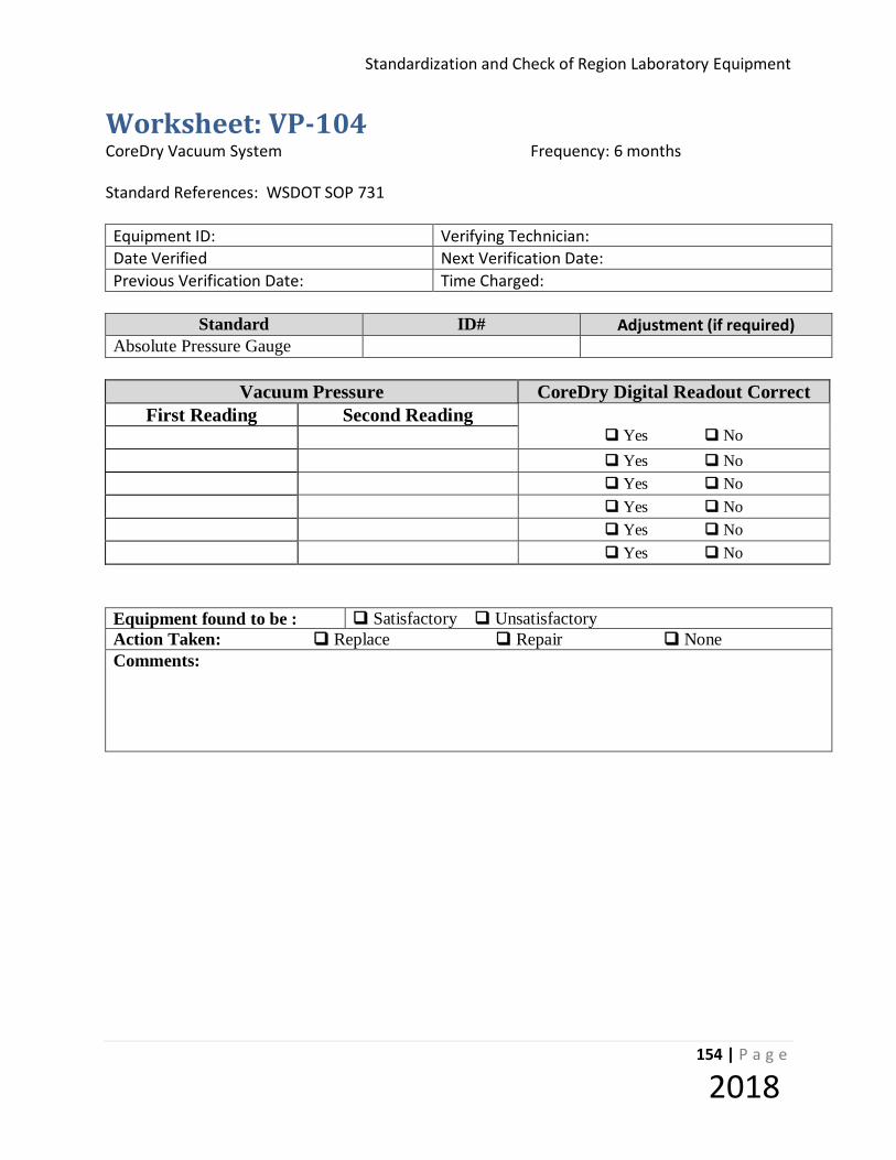
Standardization and Check of Region Laboratory Equipment
154 | P a g e
2018
Worksheet: VP-104 CoreDry Vacuum System Frequency: 6 months Standard References: WSDOT SOP 731 Equipment ID: Verifying Technician: Date Verified Next Verification Date: Previous Verification Date: Time Charged:
Standard ID# Adjustment (if required)
Absolute Pressure Gauge
Vacuum Pressure CoreDry Digital Readout Correct First Reading Second Reading
Yes No Yes No Yes No Yes No Yes No Yes No
Equipment found to be : Satisfactory Unsatisfactory Action Taken: Replace Repair None Comments:
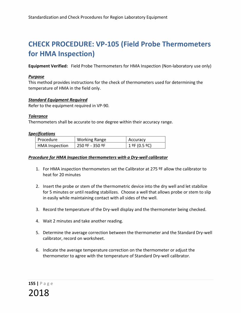
Standardization and Check Procedures for Region Laboratory Equipment
155 | P a g e
2018
CHECK PROCEDURE: VP-105 (Field Probe Thermometers for HMA Inspection) Equipment Verified: Field Probe Thermometers for HMA Inspection (Non-laboratory use only) Purpose This method provides instructions for the check of thermometers used for determining the temperature of HMA in the field only. Standard Equipment Required Refer to the equipment required in VP-90. Tolerance Thermometers shall be accurate to one degree within their accuracy range. Specifications
Procedure Working Range Accuracy HMA Inspection 250 ºF - 350 ºF 1 ºF (0.5 ºC)
Procedure for HMA Inspection thermometers with a Dry-well calibrator
1. For HMA inspection thermometers set the Calibrator at 275 ºF allow the calibrator to heat for 20 minutes
2. Insert the probe or stem of the thermometric device into the dry well and let stabilize
for 5 minutes or until reading stabilizes. Choose a well that allows probe or stem to slip in easily while maintaining contact with all sides of the well.
3. Record the temperature of the Dry-well display and the thermometer being checked.
4. Wait 2 minutes and take another reading.
5. Determine the average correction between the thermometer and the Standard Dry-well
calibrator, record on worksheet.
6. Indicate the average temperature correction on the thermometer or adjust the thermometer to agree with the temperature of Standard Dry-well calibrator.
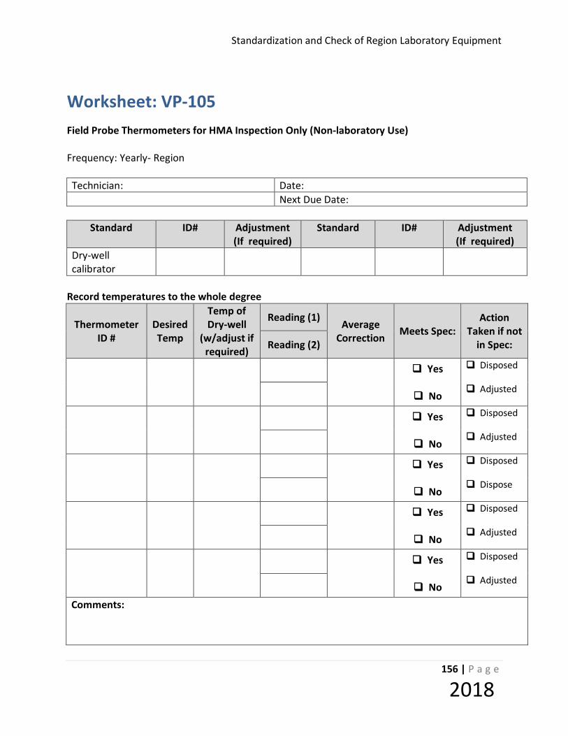
Standardization and Check of Region Laboratory Equipment
156 | P a g e
2018
Worksheet: VP-105 Field Probe Thermometers for HMA Inspection Only (Non-laboratory Use) Frequency: Yearly- Region Technician: Date: Next Due Date:
Standard ID# Adjustment
(If required) Standard ID# Adjustment
(If required) Dry-well calibrator
Record temperatures to the whole degree
Thermometer ID #
Desired Temp
Temp of Dry-well
(w/adjust if required)
Reading (1) Average
Correction Meets Spec: Action
Taken if not in Spec: Reading (2)
Yes
No
Disposed
Adjusted
Yes
No
Disposed
Adjusted
Yes
No
Disposed
Dispose
Yes
No
Disposed
Adjusted
Yes
No
Disposed
Adjusted
Comments:
Standardization and Check Procedures for Region Laboratory Equipment
157 | P a g e
2018