standardized facilities preventive maintenance work · pdf filenasa facilities standardized...
TRANSCRIPT

National Aeronautics and Space Administration
Standardized Facilities Preventive Maintenance Work Task Guide (with initial performance frequencies and PT&I alarm values)
August 2001

NASA Facilities Standardized Maintenance Task Guide
August 2001 Page i
Foreword
NASA sites have been converting to Performance Based Contracting for facilities maintenance during the same time that they have been moving to Reliability Centered Maintenance (RCM). Because of these parallel efforts at multiple sites, NASA had lost the initial opportunity to incorporate Standardized Preventive Maintenance (PM) work tasks that incorporated sensible and cost-effective RCM philosophy and Predictive Testing & Inspection (PT&I) technologies where applicable. This Guide provides samples tasks for the most common types of equipment found at NASA Centers (including Component Facilities). These tasks may be useful to the Centers in characterizing minimum maintenance requirements for maintenance contracts and for the future development of site and equipment specific tasks.
The work tasks in this Guide follow the approach developed in the NASA Reliability-Centered Maintenance Guide1, Appendix J. Alert and alarm values, when applicable, have been included within the procedures. The alert and alarm values, along with the procedure steps, provide information applicable to a large population of machines, but not specific to any one machine. In order to be useful, the procedure may need to be changed to completely address the differences found both between Centers, and between different sites within the same Center. Within the same Center or site, differences will often be encountered due to different systems configurations, especially parallel configurations of the same machine that results in reduced system criticality and the related reduced consequences of failure. Between Centers, differences are often related to operating environments. This Guide is intended to be a tool that the Centers can use, along with Reliability-Centered Maintenance analysis, to develop effective facilities maintenance.
Comments or suggestions related to the content of this guide should be sent to:
National Aeronautics and Space Administration NASA Headquarters, Attention: Code JX Washington, DC 20546
1 The latest version of the Reliability-Centered Maintenance Guide can be found on the NASA Internet web page (www.hq.nasa.gov/office/codej/codejx/)

NASA Facilities Standardized Maintenance Task Guide
August 2001 Page ii
Table of Contents
Foreword................................................................................................................................................................. i Table of Contents................................................................................................................................................... ii Standard Work Task .............................................................................................................................................. 1
Reliability-Centered Maintenance Issues........................................................................................................... 1 Equipment Selection .......................................................................................................................................... 1 Maintenance Approach ...................................................................................................................................... 2
Predictive Testing and Inspection .................................................................................................................. 3 Age Exploration............................................................................................................................................. 3 Maintenance Approach Tables....................................................................................................................... 4 Periodicity Codes........................................................................................................................................... 5 Procedure Layout ........................................................................................................................................... 5
Equipment Maintenance Approach........................................................................................................................ 6 Transformers...................................................................................................................................................... 6 Circuit Breakers and Switchgear........................................................................................................................ 8 High Voltage Electric Power Distribution Switches........................................................................................ 11 Electric Power Distribution Relays/Meters...................................................................................................... 12 Low Voltage Distribution ................................................................................................................................ 14 Interior Emergency Area Lighting................................................................................................................... 15 Electrical Distribution Support Structures ....................................................................................................... 16 Motors.............................................................................................................................................................. 17 Pumps .............................................................................................................................................................. 18 Valves .............................................................................................................................................................. 19 Backflow Preventer.......................................................................................................................................... 20 Heating, Ventilation and Air Conditioning (HVAC) Units ............................................................................. 21 Filters ............................................................................................................................................................... 25 Steam Traps ..................................................................................................................................................... 26 Air Compressors .............................................................................................................................................. 27 Cranes, Elevators and Lifts .............................................................................................................................. 28 Fire Detection/Protection ................................................................................................................................. 29
Appendix A: Procedures Appendix B: Equipment Selection Analysis

NASA Facilities Standardized Maintenance Task Guide
August 2001 Page 1
Standard Work Task
The objective of the Standard Work Task is to provide instructions without becoming overly detailed. Simple steps, that provide little value for the typical work force, have not been included. In some high-risk industry, like nuclear power, work tasks are extremely detailed and often do not allow even minor deviation when accomplishing. That is not the basis for the NASA Standard Work Task.
Reliability-Centered Maintenance Issues This Guide is developed to help NASA Centers provide a convenient standardized starting point for how to perform preventive maintenance tasks for facilities systems and sets initial PT&I alarm limits. Reliability-Centered Maintenance (RCM) is discussed in detail in NASA's Reliability-Centered Maintenance Guide2. The focus of RCM is the selection of the most effective maintenance approach and requires an understanding of the selected machine's failure modes and the consequences of that failure. The consequences of failure will vary both from Center to Center and within any single Center, depending on the operating context of the machine or machine system.
A detailed RCM analysis of the common NASA facilities equipment is beyond the scope of this Guide and is a function to be performed by the NASA Center. However, the application of RCM principles has been used to identify and develop the sample procedures found in this Guide. For each equipment category in this Guide, there is a discussion of the most common (the dominant) failure modes. Failure modes are equipment and component-specific failures that result in functional failure of the facility system or subsystem. For example, a machinery system composed of a motor and pump can fail catastrophically due to failure of the motor windings, pump and motor bearings, shaft, impeller, controller, or seals. In addition, a functional failure also occurs if the pump performance degrades such that insufficient discharge pressure or flow exists to meet operating requirements.
Dominant failure modes are those failure modes responsible for a significant proportion of all the failures of the item. They are the most common modes of failure; the modes with the highest probability of occurring. They are the failure modes we try to control through maintenance. Other failure modes may not warrant maintenance because the likelihood of their occurring is remote or their effects are inconsequential.
Equipment Selection The equipment selected for inclusion in this Guide is based upon an analysis of maintenance data provided by the Centers. This data included systems listings, maintenance procedures, and labor hours. The labor hours provided were either estimated hours used by the Center maintenance scheduling and management systems or actual hours expended. After a detailed review of the data, a Pareto analysis of the actual hours expended was used to identify the approximately 20% of the items that account for approximately 80% of the Center’s 2 The latest version of the Reliability-Centered Maintenance Guide can be found on the NASA Internet web page (www.hq.nasa.gov/office/codej/codejx/).

NASA Facilities Standardized Maintenance Task Guide
August 2001 Page 2
maintenance cost. There are 105 line items (equipment types) represented in the data including a Miscellaneous category of items that did not clearly fit one of the common equipment types.
The outcome of the analysis was a classic Pareto. The top 20% of the equipment types, as regards hours expended, was 21 of the 105 equipment categories. And the actual labor expended for those 21 equipment categories was approximately 80% of the total labor hours expended. That is, out of approximately 1,426,104 hours reported expended, approximately 1,136,603 hours is attributable to 21 equipment categories. Appendix B provides more details on the data analysis that was performed.
Maintenance Approach The maintenance approach is based upon identifying, mitigating, and/or preventing failure. In addition to the failure mode, the consequence of failure must also be considered. For each equipment category in this Guide, there is a table that identifies the maintenance approach for the Equipment Items within the category. The table includes the Equipment Item, the applicable procedures, and three Periodicity Codes. The Periodicity Codes are provided to assist the NASA Centers in determining how often to perform the maintenance task based upon the consequences of failure. The periodicity can range from never performing (that is, let the equipment item run to failure), to performing often, sometimes on an hourly basis. Table 1 provides the method used to rank system criticality based upon the consequences of failure. This method is based upon a recommended approach for ranking potential industrial fire hazards3 and is adapted from the military’s safety program4. The word “facility” usually means the system, building, or area.
The periodicity is a recommended strategy based upon the three mid-rankings, as these are the areas where maintenance is most likely. For the lowest ranked systems (identified as Rank Number 1 on Table 1), a run-to-failure approach is often used. And in the highest ranked systems (Ranking Number 5), a redesign effort is usually undertaken to shift the consequence of failure to a lower rank. Facility systems rarely have a Catastrophic consequence of failure because such a system design would be intolerable.
3 Industrial Fire Hazards Handbook, Third Edition, Arthur Cote, Editor-in-Chief, National Fire Protection Association, 1990, page 23. 4 US Department of Defense, MIL-STD-882A, Military Standard: System Safety Program Requirements, 1977.
An RCM analysis of the system, performed by the NASA Center, is necessary to assess the operating conditions/environment and the consequence of failure (factoring equipment redundancy) to then selecting the optimal maintenance approach.
NASA Facilities Standardized Maintenance Task Guide
August 2001 Page 3
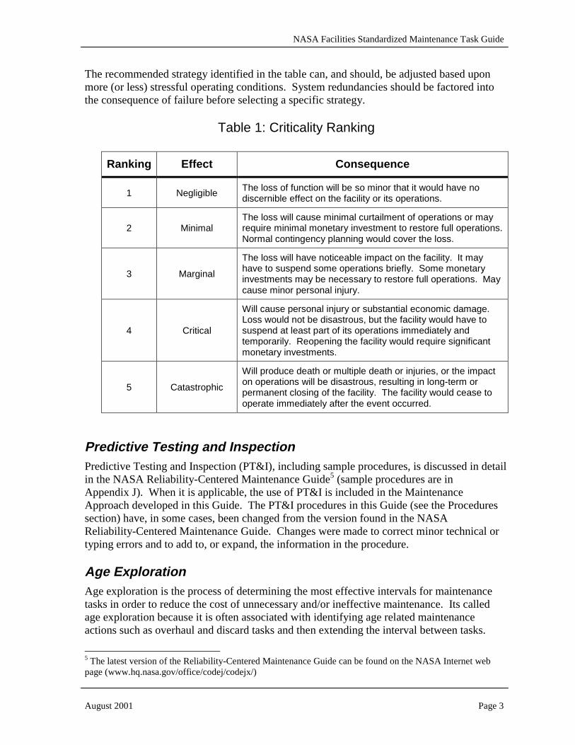
The recommended strategy identified in the table can, and should, be adjusted based upon more (or less) stressful operating conditions. System redundancies should be factored into the consequence of failure before selecting a specific strategy.
Table 1: Criticality Ranking
Ranking Effect Consequence
1 Negligible The loss of function will be so minor that it would have no discernible effect on the facility or its operations.
2 Minimal The loss will cause minimal curtailment of operations or may require minimal monetary investment to restore full operations. Normal contingency planning would cover the loss.
3 Marginal
The loss will have noticeable impact on the facility. It may have to suspend some operations briefly. Some monetary investments may be necessary to restore full operations. May cause minor personal injury.
4 Critical
Will cause personal injury or substantial economic damage. Loss would not be disastrous, but the facility would have to suspend at least part of its operations immediately and temporarily. Reopening the facility would require significant monetary investments.
5 Catastrophic
Will produce death or multiple death or injuries, or the impact on operations will be disastrous, resulting in long-term or permanent closing of the facility. The facility would cease to operate immediately after the event occurred.
Predictive Testing and Inspection Predictive Testing and Inspection (PT&I), including sample procedures, is discussed in detail in the NASA Reliability-Centered Maintenance Guide5 (sample procedures are in Appendix J). When it is applicable, the use of PT&I is included in the Maintenance Approach developed in this Guide. The PT&I procedures in this Guide (see the Procedures section) have, in some cases, been changed from the version found in the NASA Reliability-Centered Maintenance Guide. Changes were made to correct minor technical or typing errors and to add to, or expand, the information in the procedure.
Age Exploration Age exploration is the process of determining the most effective intervals for maintenance tasks in order to reduce the cost of unnecessary and/or ineffective maintenance. Its called age exploration because it is often associated with identifying age related maintenance actions such as overhaul and discard tasks and then extending the interval between tasks.
5 The latest version of the Reliability-Centered Maintenance Guide can be found on the NASA Internet web page (www.hq.nasa.gov/office/codej/codejx/)
NASA Facilities Standardized Maintenance Task Guide
August 2001 Page 4
The concept of age exploration was introduced as an RCM process in Nowlan and Heap’s seminal publication, Reliability-Centered Maintenance6. When introduced, most maintenance actions were based on elapsed time or cycles and there was limited cost effective condition monitoring technologies (PT&I) available. Throughout this Guide overhaul and discard tasks are always based on monitored conditions, when cost effective PT&I is available. However the recommended task periodicity is just that, a recommendation, even when applicable PT&I technologies are not available. The use of Age Exploration should be evaluated to determine effective maintenance intervals. Age Exploration of safety-related components is possible, but only if they are de-coupled from their safety function. For example, the overhaul interval of safety relief valves could be examined using Age Exploration if a sample population of the valves could be operated and examined in a controlled condition, under the same in-service conditions, but not tied to the safety relief function.
Related to Age Exploration is the setting of inspection and PT&I monitoring intervals. Inspection is performed to uncover hidden failure. PT&I monitoring intervals are set in order to determine the onset of failure and to take an action before the failure occurs. Like all time/cycle tasks, if the interval is too short, there will be wasted effort (labor and material). And if the interval is too long, failures will occur. All of the intervals identified in this Guide are recommendations that must be examined by the Center and adjusted based upon specific machine conditions. For example, all of the PT&I intervals should be adjusted by the data analysts as they see conditions change. A quarterly vibration collection may shift to monthly or even weekly as a degrading condition develops. Likewise, following overhaul, the vibration data collection could start with a monthly interval and then move to a quarterly or semi-annual basis as the machine moves away from the infant mortality failure region.
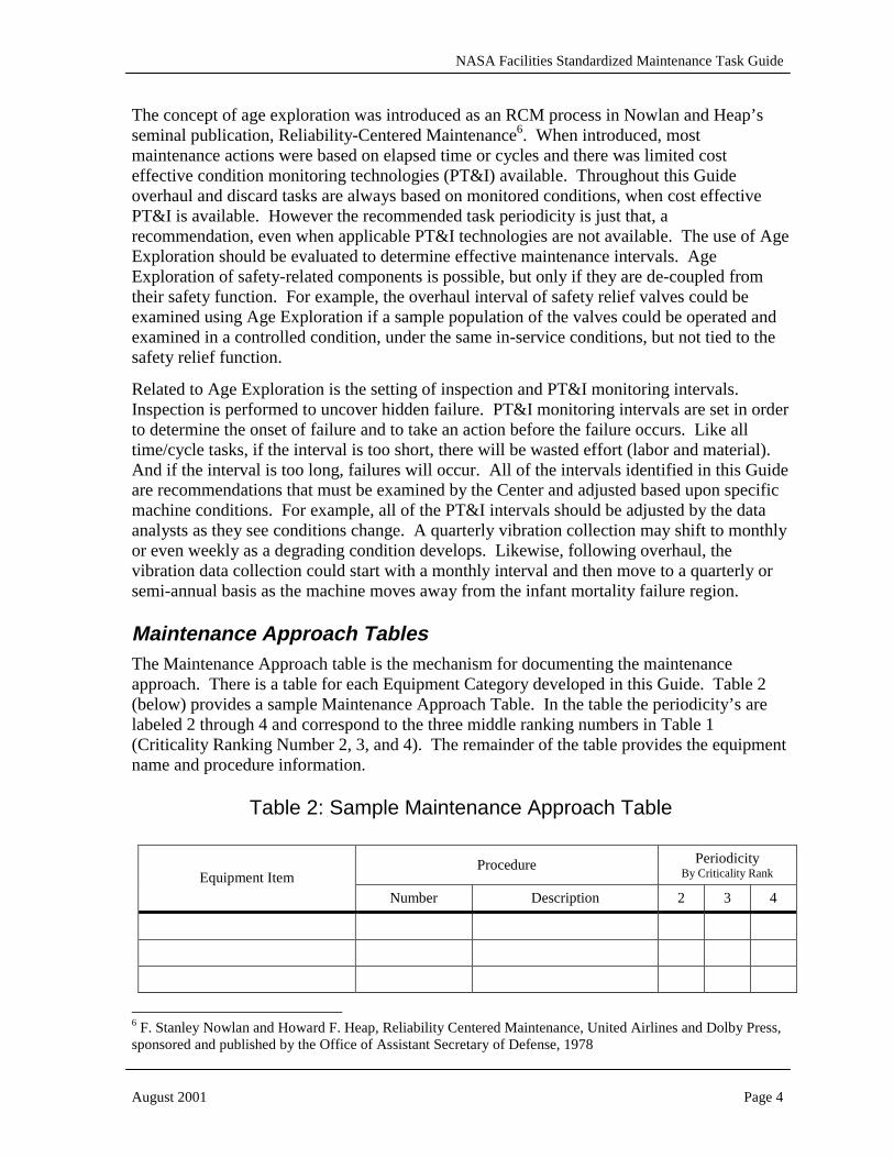
Maintenance Approach Tables The Maintenance Approach table is the mechanism for documenting the maintenance approach. There is a table for each Equipment Category developed in this Guide. Table 2 (below) provides a sample Maintenance Approach Table. In the table the periodicity’s are labeled 2 through 4 and correspond to the three middle ranking numbers in Table 1 (Criticality Ranking Number 2, 3, and 4). The remainder of the table provides the equipment name and procedure information.
Table 2: Sample Maintenance Approach Table
Procedure Periodicity By Criticality Rank Equipment Item
Number Description 2 3 4
6 F. Stanley Nowlan and Howard F. Heap, Reliability Centered Maintenance, United Airlines and Dolby Press, sponsored and published by the Office of Assistant Secretary of Defense, 1978
NASA Facilities Standardized Maintenance Task Guide
August 2001 Page 5
Periodicity Codes The Periodicity Codes describe how often the procedure is to be performed. NASA Centers will want to modify the periodicity code to fit the site. Codes used in this Guide are:
D = Daily W = Weekly M = Monthly Q = Quarterly S = Semi-Annually A = Annually OC = On Condition: usually based upon results of a Predictive Testing & Inspection test.
Multiples of the above are sometimes used and are identified by a number followed by a letter. For example, 5A indicates a procedure is scheduled every 5 years.
Procedure Layout The Standard Work Task is presented in a column format. The first column provides a heading or procedure number. The second column has text. There are no special characters or text highlighting (such as bolding) in order to enable a smooth transition into the CMMS.
The procedure layout is such that all actions are taken in sequence. A person performing the procedure should arrive at the work site with all of the necessary tools and materials (including reference material).
Standard Work Task headings are as follows:
Procedure Number - The number is assigned for use in referring to the procedure in this Guide.
System Description - This section is text that describes the machine/equipment application.
Procedure Description - Text to describe what the procedure does. The body of the procedure is often divided into sub-sections. Each sub-section has a heading and that heading is duplicated in the Procedure Description. This ensures that the entire scope of work is well understood.
Related Tasks - Identifies other tasks that should be performed. Usually tasks with a shorter periodicity. For example, an annual procedure will identify any semi-annual, quarterly, or monthly procedures to ensure that all work is done during a single visit to the work site.
Labor (Hrs) - This area is reserved for the NASA Center use. No estimates are provided in this Guide.
Special Tools - Identifies tools and test equipment that the technician will need at the job site. Common tools are not usually identified.
Materials - All materials that will be needed at the job site are listed in this section.
Reference Data - Identifies information, such as a test procedure, that the technician will need in order to perform the task. This section does not identify reference data that may have

NASA Facilities Standardized Maintenance Task Guide
August 2001 Page 6
been used to develop the procedure. Only that reference data needed to perform the task is listed in this section.
Warning Summary - A warning is identified in the procedure anytime there is the potential for injury (including toxic release to the environment). This section lists every warning that is part of the procedure. If a warning is used many times in the procedure, it is only listed once in this section.
Caution Summary - Similar to warning summary. A caution is identified in the procedure anytime there is the potential for damage to the equipment or damage to collateral equipment. Although not listed in a summary block, the procedure may also contain a Note. A note provides relevant information to the person performing the procedure.
Preliminary - The first part of the procedure is identified as the preliminary section. This section includes all steps taken before going to the job site, or if at the job site, before starting work on the specified machine. Although there is not a maximum number of preliminary steps, this section is usually less than 10 steps.
Procedure - The start of the procedure is clearly identified by the title “Procedure.” The first step in the procedure is labeled “A” and is a phrase that identifies the work to be accomplished. The next step is labeled “A1” and is an action item. Each subsequent action step is numbered in ascending order, “A2, A3, ...” If the procedure can be broken into discrete sections, there maybe a “B” , “C”, etc.
Inspection Data - If data is to be collected, there will usually be an Inspection Data section. The procedure will identify the data and direct where it is to recorded in the Inspection Data section or other location. The Inspection Data section is always located at the end of the Procedure section.
A section at the end of the Standard Work Task is identified as Engineers Notes. The Engineers Notes provides background information that may be useful when developing site-specific procedures. It is not part of the procedure in that it is not designed to be provided (printed out) for use in the field or entered into the site CMMS. The Engineers Notes are a tool for use in developing site-specific procedures.
Equipment Maintenance Approach
Transformers Equipment types: Facility Transformer (Dry Type and Oil Filled), Distribution Transformer (Dry Type, Silicone and Mineral Oil Filled), Power Transformer (Oil Filled).
Reliability-Centered Maintenance Issues
Transformers have either dry insulation or liquid (mineral oil or silicone) insulation. Liquid insulated units consist of a steel tank, core and windings, high and low voltage bushings, temperature, liquid level, and pressure gauges, a dry nitrogen system or conservator, internal tap changer, concrete base, and connection to the local ground equipoise. Dry type units include the core and windings, high and low voltage bushings, temperature gauges, a vented

NASA Facilities Standardized Maintenance Task Guide
August 2001 Page 7
covering or enclosure, and the same internal tap changer, concrete base, and ground connection as liquid insulated units. On-load tap changers are not included in this section.
Procedure Periodicity By Criticality Rank Equipment Item
Number Description 2 3 4
Facility Transformer, dry type, less than 300kVA, 120/208 volt secondary.
Tran-01 Inspect and Clean Dry Type Transformer
RTF 5A 3A
Tran-02 Inspect and Clean Liquid Filled Transformer
RTF 3A 1A
PT&I-04 Test Insulation RTF 3A 1A
Facility Transformer, oil filled, less than 300kVA, 120/208 volt secondary.
PT&I-06 Sample and Test Transformer Oil RTF 3A 1A
Tran-02 Inspect and Clean Liquid Filled Transformer
3A 3A 1A
PT&I-04 Test Insulation 3A 3A 1A
PT&I-06 Sample and Test Transformer Oil 1A 1A 1A
Distribution Transformer, silicone oil filled, from 4160 to 24,000 volts, 300kVA to 2MVA.
PT&I-07 Power Factor Test 3A 3A 1A
Tran-02 Inspect and Clean Liquid Filled Transformer
3A 3A 1A
PT&I-04 Test Insulation 3A 3A 1A
PT&I-06 Sample and Test Transformer Oil 1A 1A 1A
Distribution Transformer, mineral oil filled, from 4160 to 24,000 volts, 300kVA to 2MVA.
PT&I-07 Power Factor Test 3A 3A 1A
Tran-01 Inspect and Clean Dry Type Transformer
3A 3A 1A
PT&I-04 Test Insulation 3A 3A 1A
Distribution Transformer, dry type, from 4160 to 24,000 volts, 300kVA to 2MVA.
PT&I-07 Power Factor Test 3A 3A 1A
Tran-02 Inspect and Clean Liquid Filled Transformer
1A 1A 1A
PT&I-04 Test Insulation 1A 1A 1A
PT&I-06 Sample and Test Transformer Oil 1A 1A SA
PT&I-07 Power Factor Test 1A 1A 1A
Power Transformer, oil filled, above 24,000 volts, over 2MVA.
PT&I-09 Power Factor Test 1A 1A 1A
Transformer dominant failure modes are deterioration of the electrical insulation, deterioration of the electrical connections, and exterior corrosion. Over time, heat generated internally slowly breaks down the paper insulation in all types of transformers. For oil filled transformers, the oil insulation system also deteriorates, also due to heat. In dry type units, moisture contamination contributes to the insulation deterioration. Repeated heating and

NASA Facilities Standardized Maintenance Task Guide
August 2001 Page 8
cooling cycling can loosen connections, both internal (tap connections, winding termination points) and external (bushing connections). Harsh ambient conditions can corrode transformer tanks, cooling fins, and attached accessories such as control panels and conservator tanks.
Most of the above failure modes progress slowly over time. Consequently go/no-go tests such as turns-ratio testing are ineffective at finding failure patterns. Trending test data is necessary to identify these failure patterns. The maintenance approach for transformers therefore focuses on using applicable PT&I technologies such as infrared thermography, oil testing and insulation power factor testing.
The Institute of Electrical and Electronic Engineers reports that the average downtime following a failure was 342 hours when there was no spare replacement transformer (601 to 15,000 volt) available7. This was the amount of time necessary to repair the unit and return it to service. However, a significant number of transformer failures are catastrophic in nature, can not be repaired and must be replaced. Costs of new units vary depending on size and type, and can range from $1,500 for a pole mount 25kVA unit to $250,000 for a 50MVA substation/switchyard unit. Additionally, lead-time for receiving a new unit ranges from 6-8 weeks for a small pole mount unit to 16-24 weeks for a larger, substation unit.
Circuit Breakers and Switchgear Equipment types:
Circuit Breakers: Low Voltage (600 Volts and below) – Air and Molded Case. Medium Voltage (601 to 69,000 Volts) –SF6, Oil Filled, Air, and Vacuum. High Voltage (above 69,000 Volts) –SF6 and Oil Filled. Switchgear: Low Voltage and Medium Voltage.
Reliability-Centered Maintenance Issues
Circuit breakers come in four basic configurations:
• Molded Case – a sealed breaker with self-contained tripping and overload mechanisms.
• Oil Filled – mineral oil is the primary insulating medium. Normally medium and high voltage range.
• Vacuum – a ceramic cylinder contains the operating contacts. The insulating medium is a lack of air in the bottle, which allows for close contacts. This type of breaker is normally only used for medium voltage systems.
• Sulfur Hexifloride (SF6) – SF6 is used as the insulating medium. Operating voltage can be as high as 500 kV rated.
Circuit breakers include the mounting frame, tanks (for oil breakers), breaker control panel, operating mechanism, and connection bushings. Relays associated with these circuit breakers are not included in this section.
7 IEEE Committee Report, Report on Reliability Survey of Industrial Plants, IEEE Transactions on Industry Applications and contained in the current ANSI/IEEE std 244-1986, IEEE Recommended Practice for Protection and Coordination of Industrial and Commercial Power Systems, Table 47A.

NASA Facilities Standardized Maintenance Task Guide
August 2001 Page 9
Procedure Periodicity By Criticality Rank Equipment Item
Number Description 2 3 4
Low Voltage Circuit Breaker, molded case
Panel-01 Inspection of Low Voltage Panels RTF 3A A
Brkr-01 Inspect and Test Air Circuit Breaker
5A 3A A Low Voltage Circuit Breaker, Air.
PT&I-05 Test Insulation 5A 3A A
Brkr-01 Inspect and Test Air Circuit Breaker
5A 3A A
PT&I-05 Test Insulation 5A 3A A Medium Voltage Circuit Breaker, Air
PT&I-08 Power Factor Test 5A 3A A
Brkr-02 Inspect and Test Vacuum or Oil Filled Circuit Breaker
3A 3A A
PT&I-05 Test Insulation 3A 3A A Medium Voltage Circuit Breaker, Vacuum
PT&I-08 Power Factor Test 3A 3A A
Brkr-02 Inspect and Clean Transformer 3A 3A A
PT&I-05 Test Insulation 3A 3A A
PT&I-08 Power Factor Test 3A 3A A
Medium Voltage Circuit Breaker, Oil Filled
PT&I-09 Power Factor Test 3A 3A A
Brkr-03 Inspect and Test SF6 Circuit Breaker
3A 3A A
PT&I-05 Test Insulation 3A 3A A Medium Voltage Circuit Breaker, SF6
PT&I-08 Power Factor Test 3A 3A A
Brkr-02 Inspect and Test Vacuum or Oil Filled Circuit Breaker
3A 3A A
PT&I-05 Test Insulation 3A 3A A
PT&I-08 Power Factor Test 3A 3A A
High Voltage Circuit Breaker, Oil Filled
PT&I-09 Power Factor Test 3A 3A A
Brkr-03 Inspect and Test SF6 Circuit Breaker
3A 3A A
PT&I-05 Test Insulation 3A 3A A
PT&I-08 Power Factor Test 3A 3A A
High Voltage Circuit Breaker, SF6
PT&I-09 Power Factor Test 3A 3A A
Dominant failure modes for circuit breakers are binding in the operating mechanism, control circuitry failure, development of high resistance in the power connections, exterior corrosion, and deterioration of the electrical insulation. Of these failure modes, binding operating

NASA Facilities Standardized Maintenance Task Guide
August 2001 Page 10
mechanism and control circuitry failure are the most common, resulting in a circuit breaker that will not open or close as required. For oil filled breakers the oil system also deteriorates due to repeated operations, and for SF6 breakers (SF6 gas is the insulating medium) leaks in the SF6 containment is a dominant failure mode.
It should be noted in the periodicity section of the above table that some breakers have recommended maintenance frequencies of no longer than three years, and only low voltage molded case breakers should be run to failure. The limiting factors for these determinations is both cost and reliability. The cost of new breakers varies depending on the type and size. A small 20 amp molded case breaker can cost under $20. However, a 115kV, 1200 amp SF6 breaker can often cost well over $60,000, thus requiring a maintenance frequency of no longer than three years. Medium and high voltage units (especially SF6 and air breakers) also benefit from maintenance cycles of three years or less. Lead times for receiving new breakers will also vary. Most molded case breakers are stocked by electrical supply houses and can be delivered to the work site within two to three days. Medium and high voltage breakers are almost always special order items and can have lead times from eight weeks to six months, depending on the breaker size and type.
Switchgear is normally made up of individual compartments that contain the circuit breakers and control circuits. Those compartments are attached to an insulated bus enclosure. The circuit breakers rack onto/into the bus enclosure to energize. The switchgear includes the enclosures, control circuits, mounting frame, mounting base, and bus work.
Dominant failure modes for switchgear are high resistance at bolted connections, control relay failure, and corrosion for units installed outdoors or in harsh environments. Additional failure modes that cause operational difficulties include racking mechanism failure (not allowing a breaker to be racked in/out) and shutter assembly/insulation barrier failure (which would not allow a breaker to be racked in or leave energized bus connection uncovered).
Procedure Periodicity By Criticality Rank Equipment Item
Number Description 2 3 4
Swthgear-01 Clean and Inspect Switchgear 5A 3A A Low Voltage Switchgear
PT&I-05 Test Insulation 5A 3A A
Swthgear-01 Clean and Inspect Switchgear 3A 3A A
PT&I-05 Test Insulation 3A 3A A Medium Voltage Switchgear
PT&I-08 Power Factor Test 3A 3A A
Of the dominant failure modes the one with the most serious consequences is high resistance at bolted connections. Switchgear bus and breaker stabs are made from copper bar stock and are normally made on an as ordered basis. Typically the bar is bent into specific angles and various lengths to fit the configuration of the switchgear. A failure at one of the bolted connections normally results in a bus bar that becomes greatly distorted and not able to be reused. Replacement times depend on the manufacturer being able to obtain the proper
NASA Facilities Standardized Maintenance Task Guide
August 2001 Page 11
copper bar stock and then manufacturing it into the proper configuration. A minimum of two weeks is normally required. As a result the use of PT&I technologies, Infrared Thermography and Ultrasonic testing, become very important for long term reliability.
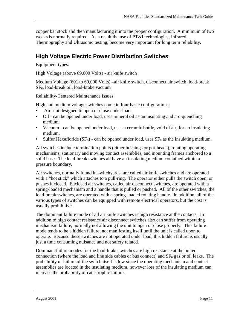
High Voltage Electric Power Distribution Switches Equipment types:
High Voltage (above 69,000 Volts) - air knife switch
Medium Voltage (601 to 69,000 Volts) –air knife switch, disconnect air switch, load-break SF6, load-break oil, load-brake vacuum
Reliability-Centered Maintenance Issues
High and medium voltage switches come in four basic configurations: • Air -not designed to open or close under load. • Oil - can be opened under load, uses mineral oil as an insulating and arc-quenching
medium. • Vacuum - can be opened under load, uses a ceramic bottle, void of air, for an insulating
medium. • Sulfur Hexafloride (SF6) - can be opened under load, uses SF6 as the insulating medium.
All switches include termination points (either bushings or pot-heads), rotating operating mechanisms, stationary and moving contact assemblies, and mounting frames anchored to a solid base. The load-break switches all have an insulating medium contained within a pressure boundary.
Air switches, normally found in switchyards, are called air knife switches and are operated with a “hot stick” which attaches to a pull-ring. The operator either pulls the switch open, or pushes it closed. Enclosed air switches, called air disconnect switches, are operated with a spring-loaded mechanism and a handle that is pulled or pushed. All of the other switches, the load-break switches, are operated with a spring-loaded rotating handle. In addition, all of the various types of switches can be equipped with remote electrical operators, but the cost is usually prohibitive.
The dominant failure mode of all air knife switches is high resistance at the contacts. In addition to high contact resistance air disconnect switches also can suffer from operating mechanism failure, normally not allowing the unit to open or close properly. This failure mode tends to be a hidden failure, not manifesting itself until the unit is called upon to operate. Because these switches are not operated under load, this hidden failure is usually just a time consuming nuisance and not safety related.
Dominant failure modes for the load-brake switches are high resistance at the bolted connection (where the load and line side cables or bus connect) and SF6 gas or oil leaks. The probability of failure of the switch itself is low since the operating mechanism and contact assemblies are located in the insulating medium, however loss of the insulating medium can increase the probability of catastrophic failure.

NASA Facilities Standardized Maintenance Task Guide
August 2001 Page 12
For all types of switches harsh ambient conditions can corrode enclosures, contaminate insulation and insulators, and cause operating mechanisms to corrode or loosen.
Procedure Periodicity By Criticality Rank Equipment Item
Number Description 2 3 4
Switch-01 Inspect and Test Air Switch 5A 3A A
PT&I-02 Qualitative Infrared Thermography Inspection
A 6M Q Medium and High Voltage Air Knife Switch
PT&I-05 Test Insulation RTF 3A A
Switch-01 Inspect and Test Air Switch 3A 2A A
PT&I-02 Qualitative Infrared Thermography Inspection
A A 6M Medium Voltage Disconnect Air Switch
PT&I-05 Test Insulation 3A 2A A
Switch-02 Inspect and Test Loadbreak Switch 3A 2A A Medium Voltage Oil Loadbreak Switch PT&I-02 Qualitative Infrared Thermography
Inspection A 6M Q
Switch-03 Inspect and Test Loadbreak Switch 3A 2A A Medium Voltage Vacuum and SF6Loadbreak Switch PT&I-02 Qualitative Infrared Thermography
Inspection A 6M Q
The maintenance approach for high and medium voltage air knife switches is a combination of infrared thermography to identify high resistance contacts and connections, and both visual inspection and testing to verify insulation integrity. These switches are usually exposed to the environment and often undergo large temperature swings. This can lead to contact assemblies becoming loose, contributing to high resistance connections. The maintenance approach for the remaining air and load-break switches is also infrared thermography and visual inspection and testing, with the testing emphasis being on the insulating medium. Most of these switches can expect to have a life expectancy of at least 30 years. Replacement costs of switches cover a wide range, depending on the application and switch rating. A 15kV knife switch can cost as little as $600 per phase, where as a six-position SF6 load-break switch, rated 15kV, 1200 amps, can cost upwards of $50,000. All switches of these types tend to be manufactured on an as-ordered basis, with lead times on the order of eight weeks not uncommon.
Electric Power Distribution Relays/Meters Equipment types: Solid-state; Protective Relays, Metering, and Event Recording. Electromechanical; Protective Relays. Analog; Metering and Event Recording.
Reliability-Centered Maintenance Issues
NASA Facilities Standardized Maintenance Task Guide
August 2001 Page 13
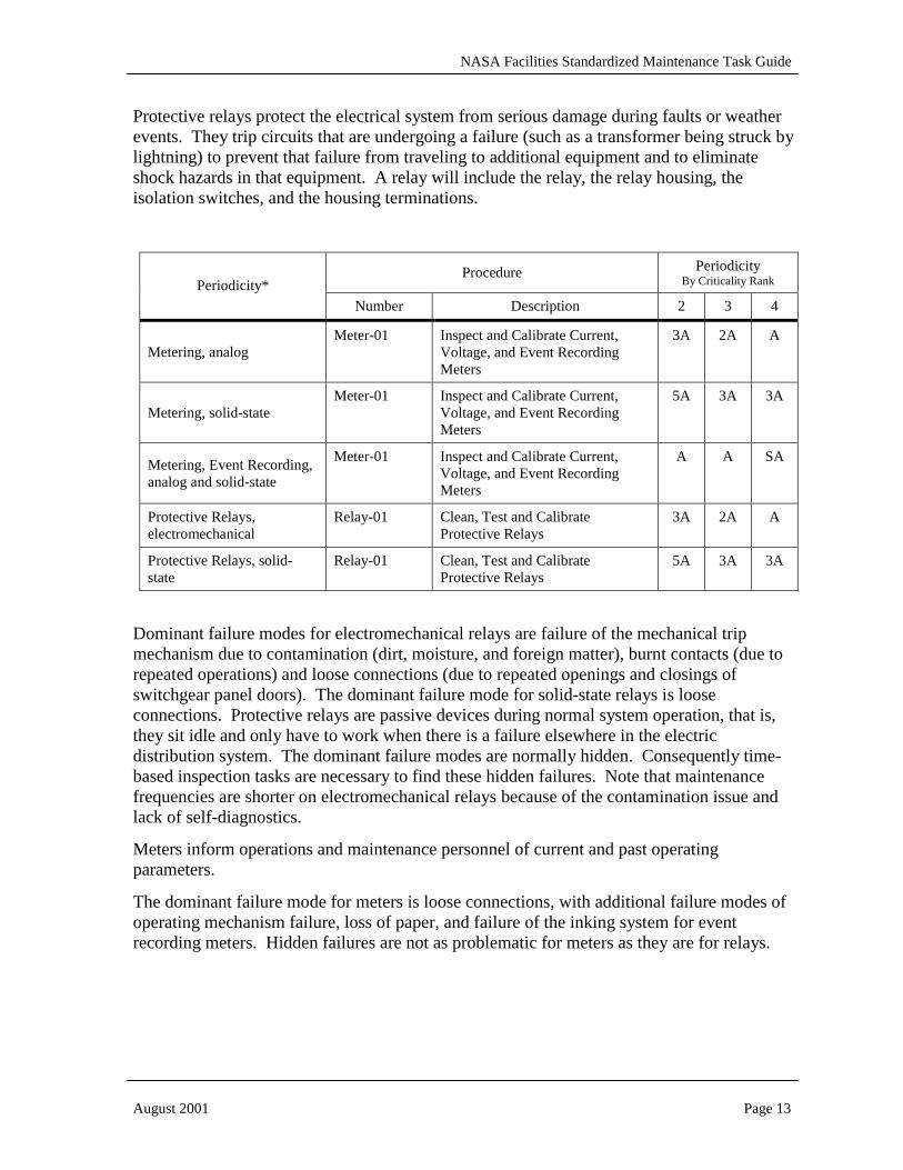
Protective relays protect the electrical system from serious damage during faults or weather events. They trip circuits that are undergoing a failure (such as a transformer being struck by lightning) to prevent that failure from traveling to additional equipment and to eliminate shock hazards in that equipment. A relay will include the relay, the relay housing, the isolation switches, and the housing terminations.
Procedure Periodicity By Criticality Rank Periodicity*
Number Description 2 3 4
Metering, analog Meter-01 Inspect and Calibrate Current,
Voltage, and Event Recording Meters
3A 2A A
Metering, solid-state Meter-01 Inspect and Calibrate Current,
Voltage, and Event Recording Meters
5A 3A 3A
Metering, Event Recording, analog and solid-state
Meter-01 Inspect and Calibrate Current, Voltage, and Event Recording Meters
A A SA
Protective Relays, electromechanical
Relay-01 Clean, Test and Calibrate Protective Relays
3A 2A A
Protective Relays, solid-state
Relay-01 Clean, Test and Calibrate Protective Relays
5A 3A 3A
Dominant failure modes for electromechanical relays are failure of the mechanical trip mechanism due to contamination (dirt, moisture, and foreign matter), burnt contacts (due to repeated operations) and loose connections (due to repeated openings and closings of switchgear panel doors). The dominant failure mode for solid-state relays is loose connections. Protective relays are passive devices during normal system operation, that is, they sit idle and only have to work when there is a failure elsewhere in the electric distribution system. The dominant failure modes are normally hidden. Consequently time-based inspection tasks are necessary to find these hidden failures. Note that maintenance frequencies are shorter on electromechanical relays because of the contamination issue and lack of self-diagnostics.
Meters inform operations and maintenance personnel of current and past operating parameters.
The dominant failure mode for meters is loose connections, with additional failure modes of operating mechanism failure, loss of paper, and failure of the inking system for event recording meters. Hidden failures are not as problematic for meters as they are for relays.

NASA Facilities Standardized Maintenance Task Guide
August 2001 Page 14
Low Voltage Distribution Equipment types: 240/120 Volt Electrical Panel, 600 Volt Electrical Panel, 240/120 Volt Disconnect Switch, 600 Volt Disconnect Switch, 600 Volt Motor Control Center.
Reliability-Centered Maintenance Issues
Dominant failure modes of low voltage electrical panels are high resistance connections and molded case circuit breakers not operating properly, either tripping erroneously or not opening when required. Because of their relatively low cost, molded case breakers are generally replaced and not repaired. Most low voltage panels and their associated breakers are standard stock items. Procurement time is normally not an issue. Dominant failure modes of disconnect switches are high resistance connections and operating mechanism failure due to binding. As with panels, disconnect switches are also low in cost and readily available.
Procedure Periodicity By Criticality Rank Equipment Item
Number Description 2 3 4
Panel-01 Inspect and Clean Electrical Panels RTF 3A A 240/120 volt Electrical Panel – Interior PT&I-02 Qualitative Infrared Thermography
Inspection 5A 3A A
Panel-01 Inspect and Clean Electrical Panels 3A 2A A 240/120 volt Electrical Panel – Exterior PT&I-02 Qualitative Infrared Thermography
Inspection 3A 2A A
Panel-01 Inspect and Clean Electrical Panels 5A 3A A
600 volt Electrical Panel PT&I-02 Qualitative Infrared Thermography Inspection
5A 3A A
Panel-01 Inspect and Clean Electrical Panels 5A 3A A 240/120 volt Disconnect Switch – Interior PT&I-02 Qualitative Infrared Thermography
Inspection 5A 3A A
Panel-01 Inspect and Clean Electrical Panels 3A 2A A 240/120 volt Disconnect Switch – Exterior PT&I-02 Qualitative Infrared Thermography
Inspection 3A 2A A
Panel-01 Inspect and Clean Electrical Panels 5A 3A A
600 volt Disconnect Switch PT&I-02 Qualitative Infrared Thermography Inspection
5A 3A A
MCC-01 Inspect and Clean Motor Control Centers and Motor Starter Contactors
3A 2A A
PT&I-02 Qualitative Infrared Thermography Inspection
A A A
600 volt Motor Control Centers (with and without Motor Starter Contactors)
PT&I-05 Test Insulation 3A 2A A

NASA Facilities Standardized Maintenance Task Guide
August 2001 Page 15
An additional failure mode for both electrical panels and disconnect switches in outdoor locations is corrosion. Consequently maintenance frequencies for exterior mounted units are slightly different as referenced in the maintenance approach table.
The maintenance approach for electrical panels and disconnect switches focuses on the non-intrusive technologies infrared thermography, ultrasonic noise, and visual inspection. Historically, the maintenance on these items included tightening each electrical connection. Not only is this time consuming, but also it adds little value as most connections are not in need of tightening and the approach increases the chance for causing damage by over-tightening or breaking connectors.
Motor control centers (MCC) are more complex than electrical panels and disconnects. An MCC includes the enclosure, installed circuit breakers, main connection cubicle, installation pad and ground connection, and all installed control circuits. Protective relays and metering, however, are not included in this section. MCC’c can handle large amounts of current, and in some cases include motor contactors for remote operation. Dominant failure modes are high resistance connections (both cable and phase bus), molded case circuit breakers not operating properly, either tripping erroneously or not opening when required, burnt motor contacts (due to continued opening and closing), and failure of control relays. The maintenance approach for MCC’s includes a combination of non-intrusive technologies for monitoring the electrical connections, and visual inspection, measurement, and restoration for contactors and control circuits.
Unlike electrical panels and disconnect switches, motor control centers are normally made to order, with delivery times ranging from four weeks to six months. Additionally, cost of a new unit depends on the amount of cubicles, with eight (two columns of four) normally being the smallest size available. Minimum cost of an eight-cubicle unit would be approximately $10,000.
Interior Emergency Area Lighting Equipment types: Self-contained wall/ceiling mount units (incandescent and florescent) and 32 Volt Centralized System.
Reliability-Centered Maintenance Issues
Most interior emergency lighting systems are self-contained incandescent or florescent units, which have one or two lights, a battery, and a loss of normal power sensing circuit to turn the lamp on. These types of systems are normally inexpensive, easily repaired or replaced, and require minimal attention.
A centralized emergency lighting system uses individual low voltage (normally 32 volts) light fixtures located throughout a facility. The fixtures are powered from a single set of batteries. Like self-contained units, there is a loss of normal power sensing circuit to turn on all of the lamps. Unlike self-contained units, a centralized system has the capability to be expanded with additional fixtures, and larger batteries can be added giving a longer illumination time.

NASA Facilities Standardized Maintenance Task Guide
August 2001 Page 16
Dominant failure modes are the loss of normal power sensing circuit and battery weakness or failure. Both of these are hidden failures, that is, the failure is not evident to occupants of the facility. Interior emergency area lighting is designed to illuminate on loss of electrical power to the facility and to operate for at least 90 minutes8. Consequently, the maintenance approach is based on periodic testing to confirm proper operation, with the inspection periodicity being determined buy national and local building and fire protection codes.
Procedure Periodicity By Criticality Rank Equipment Item
Number Description 2 3 4
EmLights-01 Inspect/Repair Self-Contained Wall/Ceiling Units
A A A Self-Contained Wall/Ceiling Mount Units EmLights-03 Annual 90 Minute Operational
Test A A A
EmLights-02 Inspect/Repair 32 Volt System SA SA Q
EmLights-03 Annual 90 Minute Operational Test
A A A 32 Volt Centralized System
PT&I-11 Battery Impedance Test A 6M Q
Electrical Distribution Support Structures Equipment types: Wooden Power Poles and Cable Vaults
Procedure Periodicity By Criticality Rank Equipment Item
Number Description 2 3 4
Wooden Power Pole Pole-01 Inspect Wooden Power Pole 5A 3A A
Cable Vaults Vault-01 Inspect Cable Vaults 5A 3A A
Reliability-Centered Maintenance Issues
Wooden power poles are used throughout most of the NASA centers as the primary support for overhead electrical power distribution. They are normally spruce poles treated with creosote, and are buried at least 10 feet below grade. At most NASA centers the individual poles are not part of the maintenance database and are included with power cable maintenance. Consequently the total number of power poles is not known.
Dominant failure modes for wooden power poles are wood rot and animal/insect damage. Wood rot and insect damage normally occurs near the base of the pole at the earth/pole
8 National Fire Protection Association, NFPA Standard 101, Life Safety Code, 1999

NASA Facilities Standardized Maintenance Task Guide
August 2001 Page 17
intersection. This is due to the poles being direct buried in the soil with no supporting concrete at the base. This is a hidden failure and can not be discovered without an inspection and/or test. Animal damage is normally concentrated in the upper regions of the pole.
Failure of a pole (falling down or breaking during a storm) will normally cause an entire electrical power feeder to be lost. There is also a potential safety hazard if the overhead line remains energized and in close proximity to people.
Cable distribution vaults are used throughout the NASA Centers for underground distribution. They are concrete with round steel access covers, are usually 10 to 20 feet deep, and are located 300 to 400 yards apart. They are used for access to underground power cables, control cables, and communication (data and telephone) cables. They are also used as cable pulling points during installations. As with wooden power poles they are not always a standalone part of the maintenance database.
Dominant failure modes for cable vaults are cracking or deterioration of the concrete (due to settling, excessive water, or damage) and failure of the cable racks (due to corrosion). The maintenance approach for cable vaults is periodic visual inspections to identify degraded conditions.
Motors Equipment types: Induction and Synchronous Motors
Reliability-Centered Maintenance Issues
Motors throughout the NASA centers range from fractional horsepower (hp) units to 60,000 hp units. A motor includes the foundation and mounting, electrical connection box, motor frame, and all of the components within the motor frame. Not included in this section is the motor controller and other components of the power supply.
Dominant failure modes for electric motors are; bearing failure (bearing failure modes include seizing, fracture, and race & ball/roll surface degradation), insulation system failure (resulting in short and open circuits), mechanical failure of rotor components, and mechanical failure of the housing including the bearing seating surfaces, the frame, and the motor feet. An additional failure mode on synchronous motors is loss of field or failure of the field to flash (both caused by diode failures, brush/slip ring failure or control circuit failure). Failure of the field to flash would be a hidden failure, as it only becomes apparent when trying to start-up the motor.
Maintenance approach for motors is based on using non-invasive technologies such as vibration analysis and infrared thermography to identify beginning mechanical failures (such as bearing and rotor/frame failures) before they cause loss of function, and electrical testing to trend insulation condition.
It should be noted that routine periodic lubrication of motor bearings is not a recommended maintenance approach. This is because bearing failure is often induced by over greasing. Several NASA Centers no longer routinely lubricate motor bearings and are replacing failed

NASA Facilities Standardized Maintenance Task Guide
August 2001 Page 18
bearing with pre-lubricated sealed bearings.9 Lubricating of bearings should only be performed when indicated by the vibration analysis program.
Procedure Periodicity By Criticality Rank Equipment Item
Number Description 2 3 4
Induction motors 600 Volts and less, 15 hp and less
Motor-01 Inspect and Test Motor RFT 2A A
Motor-01 Inspect and Test Motor 2A 2A A
PT&I-01 Vibration Data Collection SA Q M
PT&I-02 Qualitative Infrared Thermography Inspection
A A A Induction motors 600 Volts and less, more than 15 hp
PT&I-03 Test Insulation 3A 2A A
Motor-01 Inspect and Test Motor 2A 2A A
PT&I-01 Vibration Data Collection SA Q M
PT&I-02 Qualitative Infrared Thermography Inspection
A A SA
PT&I-03 Test Insulation 2A 2A A
Induction motors above 600 Volts
PT&I-10 Extract Fluid Sample for Analysis A SA Q
Motor-01 Inspect and Test Motor 2A 2A A
PT&I-01 Vibration Data Collection SA Q M
PT&I-02 Qualitative Infrared Thermography Inspection
A A SA
PT&I-03 Test Insulation 2A 2A A
Synchronous motors
PT&I-10 Extract Fluid Sample for Analysis A SA Q
Replacement costs of motors vary over a wide range. Small 120-volt fractional hp motors will normally cost less than $200 and are a stock item for most electrical suppliers. On the other hand, a 4160-volt 1000 hp motor will probably cost in excess of $20,000 and have a lead-time of up to six months.
Pumps Equipment types: Pumps
A pump system consists of a driver (usually an electric motor), a coupling and the pump. Pumps most commonly fall into two general categories; Centrifugal (single and multi-stage) or Positive Displacement (sliding vane, reciprocating piston, rotating screw, peristaltic, 9 A recent case study indicated that 86 percent of motor failures in their study plant was attributed to over-greasing. Using Vibration Analysis to Grease Motors?, John C. Robertson, maintenance reliability specialist, Strategic Work Systems, November 1998
NASA Facilities Standardized Maintenance Task Guide
August 2001 Page 19
diaphragm, etc.). Pump design is selected based on application. The purpose of a pump is to add energy (head pressure) to a fluid system in order to do some form of work.
Reliability-Centered Maintenance Issues
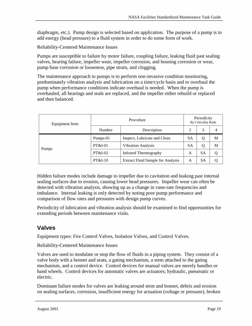
Pumps are susceptible to failure by motor failure, coupling failure, leaking fluid past sealing valves, bearing failure, impeller wear, impeller corrosion, and housing corrosion or wear, pump base corrosion or looseness, pipe strain, and clogging.
The maintenance approach to pumps is to perform non-invasive condition monitoring, predominately vibration analysis and lubrication on a time/cycle basis and to overhaul the pump when performance conditions indicate overhaul is needed. When the pump is overhauled, all bearings and seals are replaced, and the impeller either rebuild or replaced and then balanced.
Procedure Periodicity By Criticality Rank Equipment Item
Number Description 2 3 4
Pumps-01 Inspect, Lubricate and Clean SA Q M
PT&I-01 Vibration Analysis SA Q M
PT&I-02 Infrared Thermography A SA Q Pumps
PT&I-10 Extract Fluid Sample for Analysis A SA Q
Hidden failure modes include damage to impeller due to cavitation and leaking past internal sealing surfaces due to erosion, causing lower head pressures. Impeller wear can often be detected with vibration analysis, showing up as a change in vane-rate frequencies and imbalance. Internal leaking is only detected by noting poor pump performance and comparison of flow rates and pressures with design pump curves.
Periodicity of lubrication and vibration analysis should be examined to find opportunities for extending periods between maintenance visits.
Valves Equipment types: Fire Control Valves, Isolation Valves, and Control Valves.
Reliability-Centered Maintenance Issues
Valves are used to modulate or stop the flow of fluids in a piping system. They consist of a valve body with a bonnet and seats, a gating mechanism, a stem attached to the gating mechanism, and a control device. Control devices for manual valves are merely handles or hand wheels. Control devices for automatic valves are actuators; hydraulic, pneumatic or electric.
Dominant failure modes for valves are leaking around stem and bonnet, debris and erosion on sealing surfaces, corrosion, insufficient energy for actuation (voltage or pressure), broken

NASA Facilities Standardized Maintenance Task Guide
August 2001 Page 20
return spring, improper calibration (automatic valves) and over-pressure discharge (pressure relief valves). Valves in continuous service are rarely operated and are the most susceptible to failure when needed during shutdown. A simple and effective maintenance activity is to simply operate the valve to help prevent failure. Other preventive maintenance techniques are focused on providing adequate lubrication, leak prevention and corrosion inhibition.
New valves must be stored properly to avoid corrosion on machined surfaces and bent valve stems. Valves can easily be damaged in storage and transport by mishandling the stems, handles or gland adjustment pieces. Valves should be cleaned and flushed out before placing in service.
Procedure Periodicity By Criticality Rank Equipment Item
Number Description 2 3 4
Fire Control Valves Valve-01 Inspect, Test and Clean A A A
Isolation Valves Valve-02 Inspect, Test and Clean A A S
Control Valves Valve-03 Inspect, Test and Clean A A S
Procedures for pressure relief valves are not developed in this guide. See ASME PTC 25-1994 (and 1998 Special Addenda), Pressure Relief Devices10 for standards for conducting and reporting tests on reclosing and non-reclosing pressure relief devices. The PTC covers the methods and procedures to determine relieving capacity and additional operating characteristics that may be required for certification or other purposes by other codes.
Backflow Preventer Equipment type: Backflow Preventer
Procedure Periodicity By Criticality Rank Equipment Item
Number Description 2 3 4
Backflow Preventer BFP-01 Inspect and Clean 3A 2A A
Backflow preventer is a mechanical device designed to protect the potable water supply system from contamination. It is a single device containing a double set of check valves separated by an open air space. It is used as a physical connection to non-potable water systems. In order to ensure the device is working as designed, it must be tested periodically.
Many backflow preventers are certified and registered with water supply authorities. Tampering with, or unauthorized work on, backflow preventers may violate local statutes. 10 American Society of Mechanical Engineers (ASME) Performance Test Code (PTC) 25-1994 (and 1998 Special Addenda), Pressure Relief Devices.

NASA Facilities Standardized Maintenance Task Guide
August 2001 Page 21
Reliability-Centered Maintenance Issues
Dominant failure modes for backflow preventers are check seal failure caused by debris or erosion of sealing surfaces or pressure relief valve failure in reduced pressure (RP) backflow preventers. Maintenance methods typically involve removing the back flow preventer from the piping system, disassembling the unit, inspecting the sealing surfaces, checking for corrosion, lubricating and reassembling the device then placing it back into service.
Periodicity of testing, inspections and cleaning may be governed by local statue or regulating authorities.
Heating, Ventilation and Air Conditioning (HVAC) Units Equipment types: Direct Exchange Air Conditioning (A/C) Units (Room A/C Units, Heat Pump Units, Split-System Condenser Units), Package A/C Units, Air Handling Units and Fan Coil Units, Fans, Variable Air Volume (VAV) Terminals, Heaters, Chillers (Centrifugal, Reciprocating, Rotary Screw, and Absorption)
HVAC nomenclature:
• Direct Exchange (DX) - systems designed with one heat transfer step, typically refrigerant-to-air. This differs from water-coil systems that have multiple heat transfer steps typically air-to-water-to-refrigerant.
• Room A/C units (also known as Window A/C units) are direct exchange, generally .75 to 3 tons in cooling capacity and seldom ducted.
• Heat Pumps are DX A/C units with reversing capability i.e. the condenser becomes the evaporator and vice-versa. They are commonly found in sizes ranging from 1.5 to 5 tons.
• Split System, Sidewall A/C units and Package A/C units are the primary configurations for DX A/C systems. The split system has two parts, an evaporator coil and condenser unit. The evaporator is installed indoors, in a supply air stream, and the condenser is installed outdoors. Heat is transferred between the two via insulated copper tubing containing refrigerant. Sidewall units and package units are combined (evaporator and condenser), the difference being that sidewall units are mounted to vertical surfaces, package units horizontally. They commonly range from 5 to 50 tons, with package units found as large as 150 tons. All three configurations are typically ducted. Large package units, that have motors 25 hp and greater, should be included in the vibration analysis program.
• Air Handler is a catchall phrase, however it typically refers to ducted air-moving equipment large enough for a person to enter. Air handlers can be supply or exhaust, fresh-air (makeup) or re-circulating. Supply air handlers are often configured with chilled/hot water coils. Smaller water-coil units are frequently called “fan coil units”. Large package units may also be referred to as “air handlers.”
• The term “Fan” applies to air moving equipment consisting of a prime mover, typically a motor, a coupling system, often pulley/belt, a fan and an airflow control device called a damper. Types of fans include variable and fixed-pitch propeller, vaneaxial, squirrel

NASA Facilities Standardized Maintenance Task Guide
August 2001 Page 22
cage centrifugal, airfoil centrifugal and plug centrifugal. The choice of fan type depends on the application.
• A Variable Air Volume (VAV) terminal is a duct-mounted, thermostat-controlled device used to modulate air flow to control heating and cooling of a local space. It typically consists of a variable damper, a damper actuator, hot/cold water coils and may also be equipped with a small fan.
• Chiller refers to equipment used to continuously chill water. A chiller consists of an evaporator heat exchanger, a condenser heat exchanger and a compressor. Other significant elements include a purge system, control system and valves. Various mechanical means are employed to compress the refrigerant gas - centrifugal, piston (reciprocating) and rotary screws. A fourth type of chiller uses a chemical process and is called “absorption chiller” or “absorption unit.”
Reliability-Centered Maintenance Issues
Air Conditioning Equipment
See the section on Motors for a detailed discussion on the maintenance approach for this common component. Follow the guidelines in that section for smaller units discussed in this section.
Common failure modes for direct exchange air conditioning units are refrigerant leaks, compressor failure, fan motor failure, filter failure and clogging, damper control failure, coil fin damage and condensate drain blockage. For units with belt driven fans and compressors, belt and sheave failure are also dominant failure modes. Outdoor condenser units require thorough filter inspections and cleaning to reduce the risk of clogged coil fins.
DX units providing less than 10 tons of cooling are excluded from vibration data collection routes because the cost of motor/fan replacement does not justify the cost of data collection and analysis. Often compressors are sealed units that are run to failure, typically lasting several decades.
Dominant failure modes for chilled water coil air handlers are fan shaft bearing failure, fan imbalance, damper failure, coil blockage, coil corrosion, condenser drain pan overflow, and excessive biological growth. For belt driven units, sheaves and belt failure are also dominant failure modes.
The periodicity of maintenance for air handlers is largely affected by the operating environment and the purpose for which the air handler is used. Filter changes for pre-filter stages are relatively low cost and can be replaced on a calendar basis. Final filters featuring 95% or higher filtration rates (ULPA, HEPA) are more expensive by comparison to pre-filters and should be changed on a performance basis. Filter manufacturers provide guidance regarding the maximum pressure differential across the filter. Once this maximum pressure differential is reached, the filter must be changed. The lead-time for ordering high filtration media is often long and should be accounted for when scheduling filter changes.
Fans

NASA Facilities Standardized Maintenance Task Guide
August 2001 Page 23
Dominant failure modes for fans are dirt buildup on blades causing imbalance and excessive vibration, belt and sheave failure, bearing failure, damper failure and fan blade damage, fan motor failure, filter failure and clogging. Routine scheduled fan cleaning reduces imbalance and has a significant effect on service life of bearings. Maintenance methods and scheduling are designed to address each of these failure modes.
Variable pitch fan blade linkage is prone to failure due to the significant number of moveable parts excited by fan vibration. Annual inspections and lubrication of pitch adjustment linkage are necessary to avoid failure. Where possible, pitch adjustment linkage may be replaced with variable speed motors.
Fan units with air-drying refrigerant coils should additionally be treated as Fan Coil Units.
VAV Terminals
Dominant failure modes for VAV terminals are damper failure, coil clogging and loss of calibration causing inconsistent airflow. Occasional checks for proper damper functionality, proper cleaning of coil strainers as well as cleaning moving parts is sufficient for long VAV life. Occasionally a power outage will cause a reset condition in VAV terminals requiring re-calibration to restore proper operation. Proper water treatment is a key factor in reducing the amount of maintenance required by VAV terminals.
Chillers
Compressor-type chillers (centrifugal, reciprocating and screw type) draw significant amounts of power for operation. Heat transfer efficiency changes due to contamination buildup can change rapidly and has a large effect on the cost of operation. Chiller data is examined closely to catch trends indicating changes in efficiency and loss of refrigerant.
Chiller efficiency is directly affected by cleanliness of heat exhangers, (condenser and evaporator), and leaks. Many chillers operate at low pressures and leaks draw outside air (non-condensable gas) into the refrigeration cycle. Purge units are designed to eject non-condensable gas from the chiller. Improperly functioning purge units will release excessive refrigerant during the purge cycles. Excessive release of refrigerants is both expensive and a potential environmental issue.
The condenser tube water is prone to contamination and treatment depletion because of exposure to atmosphere in the cooling tower. For this reason, condenser components, i.e. tubes, strainers and piping, should be cleaned and inspected at least annually.
Evaporator operation is more stable than condenser operation because the chilled water typically loops in a closed system. For this reason, evaporator tube cleaning may be spaced from three to five years, depending on findings during cleanings.

NASA Facilities Standardized Maintenance Task Guide
August 2001 Page 24
Procedure Periodicity By Criticality Rank Equipment Item
Number Description 2 3 4
Room A/C Unit, Heat Pump Unit, Split-System Condenser Unit
HVAC-01 Inspect and Clean (DX Coil) A A S
HVAC-01 Inspect and Clean (DX Coil) A A S
HVAC-02 Inspect and Clean (Water Coil) A A S
HVAC-03 Belt Check, Filter Change & Lubrication
A S Q
Air Handler, Package A/C Unit, Fan Coil unit
PT&I-01 Vibration Analysis A Q M
HVAC-04 Inspect and Clean A A A
Motor-01 Inspect and Test Motor 2A 2A A
PT&I-01 Vibration Data Collection SA Q M
PT&I-02 Qualitative Infrared Thermography Inspection
A A A
VAV Terminal, Heater
PT&I-03 Test Insulation 3A 2A A
Fan-01 Inspect and Clean A S Q
HVAC-03 Belt Check, Filter Change & Lubrication
A A A
Motor-01 Inspect and Test Motor 2A 2A A
Panel-01 Inspect and Clean Electrical Panels 5A 3A A
PT&I-01 Vibration Data Collection SA Q M
PT&I-02 Qualitative Infrared Thermography Inspection
A A A
Fans
PT&I-03 Test Insulation 3A 2A A
Chiller-01 Readiness Inspection and Cleaning, Clean Condenser/Absorber Tubes
A A A
Chiller-02 Evaporator Tube Inspection and Cleaning
5A 4A 3A
Motor-01 Inspect and Test Motor 2A 2A A
Panel-01 Inspect and Clean Electrical Panels 5A 3A A
PT&I-01 Vibration Analysis SA Q M
PT&I-02 Qualitative Infrared Thermography Inspection
A SA Q
Chiller
PT&I-10 Extract Fluid Sample for Analysis A A SA
NASA Facilities Standardized Maintenance Task Guide
August 2001 Page 25
In addition to the efficiency concerns and purge unit failures listed above, dominant modes of failure for centrifugal compressors are linkage failure, motor coupling failure, motor failure and tube failure. For reciprocating compressors, failure modes include drive failure, coupling or belt failure, internal bearing wear, lubrication failure and tube failure. Failure modes for screw compressors include drive failure, coupling failure, internal mechanical wear, gear wear, lubrication failure and tube failure.
Preventive maintenance for chillers is staged in at least two intervals, routine maintenance required throughout the year, and an annual readiness inspection. The frequency of time-consuming maintenance activities such as condenser and evaporator tube cleaning can be strongly affected by water treatment programs. Better water treatment lowers the cost of chiller maintenance. Examination of heat exchanger efficiency over time is the best indicator of required maintenance interval. Trending data such as refrigerant pH and replenishment amounts can be used to discover slowly developing problems. Refrigerant pH is an indicator of air leaking into the refrigerant through leaking joints under vacuum.
The most common cause of unscheduled shutdown for absorption chillers is crystallization caused by: failure of system controls, malfunction of a pressure-reducing valve, or introduction of air into the machine. Also, interruption of electric power, which will cause the machine to shut down without the normal dilution cycle, may result in crystallization. Other significant failure modes are solvent pump failure, seal failure, steam valve failure and internal corrosion. Careful maintenance practices will ensure low occurrence of leaks and allow longer periods between scheduled maintenance activities.
Filters Equipment types: Water Cooler, Process Water Filter, and Air-Cooled Equipment/Air Compressors
Reliability-Centered Maintenance Issues
Filters consist of the filter media, the media cartridge and the filter housing.
Common failure modes for filters are clogging, rupturing or seal failure. Care should be taken to only install manufacturer recommended filters. Improper filter selection may result in poor air flow causing overheating, excessive energy usage, poor exhaust and safety hazards. Manufacturers recommended maximum static pressure drop across filter media should be observed to avoid failure.
Low-cost filters are typically changed on a calendar-based period. High-cost filters are monitored for condition based on static pressure drop across filter media. Each filter should have a log showing when it was last serviced or changed. Filters used for potable water should be clearly labeled at the filter housing showing when filters were last changed and what the filtration level is.
Filters, like any part of a water system, are strongly affected by water quality and treatment. Investment in proper water treatment has a long-standing proven track record of lowering overall costs associated with water circulation. Shocking the system with spikes of chemical treatments have a predictable negative effect on the life of filters.

NASA Facilities Standardized Maintenance Task Guide
August 2001 Page 26
For those filters that do not have a condition monitoring capability, the filter change periodicity should be evaluated by the Centers using an Age Exploration process (see the section on Age Exploration) to determine the optimal change time.
Procedure Periodicity By Criticality Rank Equipment Item
Number Description 2 3 4
Drinking Water Cooler Filter-01 Change Filter A A S
Process Water Filter Filter-02 Change Filters A SA SA
Air-Cooled Equipment/Air Compressors
Filter-03 Change Intake Air Filters A SA Q
Steam Traps Equipment types: Steam Traps
Procedure Periodicity By Criticality Rank Equipment Item
Number Description 2 3 4
Steam Traps Strap-01 Test and Purge A SA Q
Steam traps allow condensate and non-condensable gasses to escape from a steam system while retaining the steam. In order to ensure the device is working as designed, it must be tested periodically.
Reliability-Centered Maintenance Issues
Dominant failure modes for steam traps are failure to properly open or close, clogged strainer, or blocked discharge. Improperly functioning steam traps waste money by discharging valuable steam to the atmosphere and creating excessive pressure in low-pressure condensate systems. Signs of trap failure include; high room temperatures where steam traps are installed, condensate receiver venting steam, difficulty maintaining boiler pressure, water hammer, repeated condensate pump seal failure, high fuel utilization, and steam in condensate lines.
Maintenance for steam traps consists of cleaning the strainer, verifying the discharge remains free of blockage and checking the opening and closing to ensure proper operation.
Additionally, improperly insulated steam pipes are susceptible to corrosion. This is a hidden failure in that condensate can creep underneath insulation and cause weak spots in steam piping. Infrared thermography along steam pipes is capable of locating areas where the insulation is affected by water buildup.

NASA Facilities Standardized Maintenance Task Guide
August 2001 Page 27
Air Compressors Equipment types: Centrifugal, Rotary Screw, and Reciprocating Piston Air Compressors
Reliability-Centered Maintenance Issues
A compressor consists of a motor, coupling, compressor, a cooling system, receiver tank and control valve. Air compressors fall into three categories; Rotary Screw, Centrifugal and Reciprocating Piston. Air compression is an exothermic process and compressors require proper cooling for long service life. Air-cooled compressors have either integrally mounted or separate oil and air coolers. Water-cooled compressors require coolant systems free of blockage, crimped hoses and tubes and adequate coolant for long service life.
Dominant failure modes include motor failure, coupling/belt failure, bearing failure, relief valve failure, lubrication breakdown or depletion, seal failure, corrosion, moisture trap overfilling, clogged filters, equipment support failure, tubing rupture and pressure switch failure.
Hot air has the ability to absorb much moisture. This moisture is carried into the compressor, then as the air cools, the moisture condenses inside the compressor receiving tank. Condensate must be reliably drained to prevent hidden corrosion, leading to premature failure of the pressure vessel.
Maintenance procedures focus on providing optimum operating conditions for properly sized compressors including filter changes, oil changes, belt changes, moisture trap drainage, tank drainage. High performance filters are recommended. Wear particle analysis of the lubricant is recommended over vibration analysis for reciprocating compressors due to the inability of vibration analysis to detect subtle changes in the midst of high level vibration caused by stroking pistons and valves. Vibration analysis is effective for centrifugal and rotary screw type compressors.
Procedure Periodicity By Criticality Rank Equipment Item
Number Description 2 3 4
PT&I-01 Vibration Data Collection SA Q M
PT&I-10 Extract Fluid Sample for Analysis SA Q M
AComp-01 Operation Inspection SA Q M Air Compressors
AComp-02 Belt Inspection and Replacement A SA Q
Efficiency is critical. Belt drives are easier to maintain and provide the most flexibility in pressure selection. Automatic belt-tensioning devices ensure transmission efficiency and protect bearings from excess stress.
The ratio of runtime to load time should be as low as possible to eliminate unnecessary idling. Data should be recorded and logged to allow proper tuning of the control system.

NASA Facilities Standardized Maintenance Task Guide
August 2001 Page 28
Sites with multiple compressors should rotate the load through all compressors for maximum life cycle.
Cranes, Elevators and Lifts Equipment types: Cranes and Hoists, Lift Platforms, Elevators, Slings
Procedure Periodicity By Criticality Rank Equipment Item
Number Description 2 3 4
Cranes and Hoists Hoist-01 Inspect, Lubricate, Test and Clean A Q M
Lift Platforms Hoist-02 Inspect Lubricate, Test and Clean A Q M
Elevators Elevator-01 Inspect, Lubricate, Test and Clean A SA Q
Motor-01 Inspect and Test Motor 2A 2A A
Panel-01 Inspect and Clean Electrical Panels 3A 2A A
PT&I-01 Vibration Data Collection SA Q M
PT&I-02 Qualitative Infrared Thermography Inspection
A A A
PT&I-10 Extract Fluid Sample for Analysis A SA Q
Cranes and Hoists, Lift Platforms, and Elevators
PT&I-03 Test Insulation 3A 2A A
Slings Sling-01 Inspect D D D
Reliability-Centered Maintenance Issues
Cranes and hoists consist of a control system, supporting boom (moveable or fixed), a winch motor, clutch mechanism, a take-up drum, a wire rope, pulley blocks, hooks, straps and spreader devices with accompanying attachment devices. Dominant modes of hoist failure include wire rope failure, chain failure, hook failure, strap failure, motor drive clutch failure, wheel surface failure, wheel bearing failure, electrical failure due to overheating or loose connections, wear due to misaligned travel ways, boom failure, corrosion, hydraulic fluid loss, limit switch failure causing over-travel and indicator light failure.
Lift platforms consist of a hydraulic lifting mechanism, hydraulic pump, fluid reservoir, hydraulic actuators, mobile platform, batteries, drive motor, steering mechanism, wheels, extension boom or scissors boom. Dominant modes of failure are battery failure, corrosion, tire flattening, bearing failure, hydraulic pump failure, hydraulic hose failure and motor failure.
Elevators consist of a passenger car, guide ways, pulleys, lifting winch with wire rope, motor, clutch and winding drum and brakes. Additionally, there are level indicators, control system, alarm system and door opening mechanisms. Dominant modes of failure include wire rope wear, motor failure, travel way degradation, door opening mechanism failure, user interface failure and control calibration.
NASA Facilities Standardized Maintenance Task Guide
August 2001 Page 29
Maintenance methods include proper and frequent lubrication of all moving parts, travel ways and wire ropes, as well as frequent inspection of hooks, straps, wire ropes, beams and supports for signs of overloading and excess stress. Additionally, the use of hydraulic and lubrication fluid testing for identifying mechanical wear and/or fluid change-out is recommended when it can be cost justified. Variables for justification include the expected benefit of the analysis compared to volume of fluid (for example, small amounts of oil – generally less than 50 gallons - are usually cheaper to replace and dispose of than to test for degradation), cost of taking and shipping the fluid sample, cost of the actual test and analysis, and the criticality of the equipment. Periodicity of maintenance is strongly affected by application and amount of use. Frequently used cranes may be inspected and lubricated daily, and others used for stand-by purposes my only require annual inspection and maintenance.
Because of the dangers inherent to cranes, hoists, elevators and lift platforms, the federal Occupational Safety and Heath Administration (OSHA) has developed strict inspection guidelines. These guidelines call for inspections of lifting equipment, not only on a mandatory periodic basis, but on a per-use basis as well11. It is the intent and design of these rigid inspection requirements to avoid failures of any kind. In addition, NASA has developed a safety standard12.
Most cranes require some level of monthly inspection and all in-service cranes, hoists and lifts require annual inspection surveys. Personnel elevators are federally regulated and require certified inspections by licensed inspectors.
There are currently no officially recognized substitution inspection methods available to offset the cost of maintenance with cranes, hoists, elevators or lifting straps.
The maintenance approach for electric motors and electric systems control panels is discussed in the Motors and in the Low Voltage Distribution sections of this Guide. When possible, the use of PT&I should be included. However, vibration readings are difficult at best. For motor-driven cable systems the relatively slow and varying speed and acceleration, combined with short cycles (due to cable wind-up or trolley length) make vibration readings difficult.
Fire Detection/Protection Equipment types:
Fire Detection Systems (control panels, smoke and heat detectors)
Fire Protection – Water Systems, Wet and Dry Chemical
Reliability-Centered Maintenance Issues
A fire detection system is a passive system that senses when a fire has started. The system will then alarm or it can alarm and also initiate a fire protection system action. A fire
11 OSHA Standards - 29 CFR, Part 1910 Subpart N - Materials Handling and Storage, Section 1910.179 12 NSS/GO-1740.9B, NASA Safety Standard For Lifting Devices and Equipment (and its proposed revision NSS 8719.9)

NASA Facilities Standardized Maintenance Task Guide
August 2001 Page 30
detection system consists of heat and/or smoke sensors, pull stations, alarm bells or buzzers, and control panels.
Dominant failure modes for fire detection systems are failure of a detector, failure of system power (battery), and loose electrical connections, both at the detector and the control panel. Some newer digital systems have self-diagnostics. Even so failures are, for the most part, hidden.
A fire protection system is an active system that is designed to control or extinguish a fire. A water based fire protection system consists of piping, sprinkler heads, valves, relays, pumps and motors, and control panels. A chemical based fire protection system consists of piping, spray heads, pressurized cylinders, valves, and control panels. Pumps and motors are discussed in separate sections.
Dominant failure modes for fire protection systems are corrosion at sprinkler heads (which won’t allow full water flow or the device to actuate), loss of system pressure due to leaks, and no signal from the fire detection system (not signaling the system to operate). Sprinkler head corrosion and loss of signal from the detection system are hidden failures.
There are many types and manufacturers of these types of systems. As a result manufactures recommendations are often basic in nature, with many references to The National Fire Protection Association (NFPA) and local fire codes regarding the required maintenance frequencies.
Procedure Periodicity By Criticality Rank Equipment Item
Number Description 2 3 4
Fire Detection Systems Fire-01 Inspect Fire Detection Systems A A A
Fire Protection Systems – Water Systems
Fire-02 Inspect Water Fire Protection Systems
A A A
Fire Protection Systems – Wet and Dry Chemical
Fire-03 Inspect Chemical Fire Protection Systems
A A A