standards for design and construction - brunswick-glynn...
TRANSCRIPT

Planning and Construction Division 700 Gloucester Street, Suite 300, Brunswick, Georgia 31520
STANDARDS FOR
WATER AND SEWER DESIGN AND CONSTRUCTION
February 2012

�STANDARDS�FOR�WATER�AND�SEWER�DESIGN�AND�CONSTRUCTION�
���
Page�1�of�1��
The Brunswick – Glynn County Joint Water and Sewer Commission expresses its sincere appreciation and gratitude to those local developers, utility contractors, consulting engineers and Georgia EPD Officials who contributed to the development of these standards.

�STANDARDS�FOR�WATER�AND�SEWER�DESIGN�AND�CONSTRUCTION�
���
Page�1�of�1��
TABLE OF CONTENTS
SECTION 1 GENERAL INFORMATION
SECTION 2 WATER DISTRIBUTION SYSTEMS
SECTION 3 GRAVITY SEWER SYSTEMS
SECTION 4 SANITARY SEWER LIFT STATIONS AND FORCE MAINS
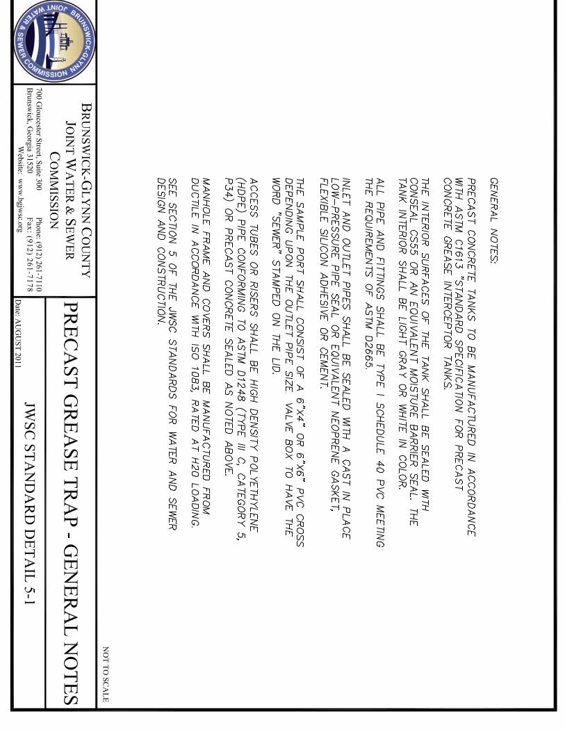
SECTION 5 GREASE INTERCEPTORS, OIL AND SAND SEPARATORS
STANDARDS�FOR�WATER�AND�SEWER��DESIGN�AND�CONSTRUCTION��
�
�
���������������������������������������������
SECTION 1 GENERAL INFORMATION

�STANDARDS�FOR�WATER�AND�SEWER�DESIGN�AND�CONSTRUCTION�
���
Page�1�of�1��
TABLE OF CONTENTS SECTION 1 GENERAL INFORMATION 1.1 INTRODUCTION 1.2 DEFINITIONS 1.3 ABBREVIATIONS 1.4 PRELIMINARY INFORMATION REQUESTS 1.5 DEDICATION OF EXISTING PRIVATELY OWNED UTILITY SYSTEMS 1.6 PLAN SUBMITTAL REQUIREMENTS (NEW CONSTRUCTION)
1.7 PROTECTION OF EXISTING UTILITIES 1.8 PERMITTING 1.9 SURFACE RESTORATION 1.10 REFERENCE POINTS AND LAYOUT

STANDARDS�FOR�WATER�AND�SEWER�DESIGN�AND�CONSTRUCTION��
Page�1�of�10��
SECTION 1 GENERAL INFORMATION 1.1 INTRODUCTION
The Planning and Construction Division is the department within the Joint Water and Sewer Commission (JWSC) responsible for assisting in the planning, design, construction and acceptance of developer installed water and sewer utility systems as public infrastructure. The purpose of this document is to define the minimum requirements for the design and construction of such systems. The following documents form a part of these design and construction standards and are incorporated herein by reference:
Joint Water and Sewer Commission, Water and Sewer Ordinances, City of Brunswick
Joint Water and Sewer Commission, Water and Sewer Ordinances, Glynn County
Joint Water and Sewer Commission, Water and Wastewater Systems, Development Procedures Joint Water and Sewer Commission, Record Drawing (As-Built) Standards.
Some JWSC Capital Improvement Projects (CIP's) and system rehabilitation projects may be designed and constructed in-house or by outside Engineers and Utility Contractors under contract to the JWSC. Such projects shall also conform to the requirements of these Design and Construction Standards and Specifications.
1.2 DEFINITIONS
Unless specifically stated otherwise, the meaning of the words and phrases used herein shall be as follows: Joint Water and Sewer Commission: A body corporate and politic, a political subdivision of the State of Georgia and a public corporation created by an act of the General Assembly (Ga. L. 2006, p. 3661) acting by and through its commissioners, and responsible for the operations of the Utility.

STANDARDS�FOR�WATER�AND�SEWER�DESIGN�AND�CONSTRUCTION��
Page�2�of�10��
City: The City of Brunswick, a municipal corporation, created and existing under the laws of the State of Georgia, acting by and through its Mayor and Commissioners. County: Glynn County, a political subdivision of the State of Georgia, acting by and through its Board of Commissioners. Developer/Owner: Any person or legal entity undertaking development. Environmental Protection Division (EPD): The Environmental Protection Division, Department of Natural Resources, State of Georgia. Infiltration/Inflow: Groundwater or surface water which leaks or otherwise enters into sanitary sewers through defective pipes, joints, manholes, yard drains, down spouts, sump pumps, or by other means or openings. Planning and Construction Division: The department within the Joint Water and Sewer Commission (JWSC) responsible for assisting in the planning, design, construction and acceptance of developer installed water and sewer utility systems as public infrastructure. Residential Equivalent Unit (REU): That portion of a user's facility that has an impact on the water and/or wastewater systems equivalent to a single family unit. Satellite System: A private and independently owned water and/or wastewater system, including infrastructure, appurtenances, structures, lift stations, and devices, which connect to the Utility's public water and/or wastewater systems. Specials: Non standard fitting. Utility: The combined or unified water and wastewater systems of the City and County and any additions and extensions thereto, owned and operated by the Joint Water and Sewer Commission, acting by and through its commissioners. Virgin: Not recycled. Wall Castings: A component of ductile iron piping systems specifically designed and fabricated to be imbedded in poured-in-place concrete structures.

STANDARDS�FOR�WATER�AND�SEWER�DESIGN�AND�CONSTRUCTION��
Page�3�of�10��
1.3 ABBREVIATIONS
The following abbreviations shall have the designated meanings: AADF Annual Average Daily Flow (Water Demand) AASHTO American Association of State Highway and Transportation Officials ADWF Daily Average Dry Weather Flow (Wastewater Demand) ANSI American National Standards Institute API American Petroleum Institute ASCE American Society of Civil Engineers ASSE American Society of Safety Engineers ASTM American Society of Testing and Materials AWG American Wire Gauge AWWA American Water Works Association DIP Ductile Iron Pipe EPD Georgia Environmental Protection Division FPS Feet per second FPVC Fusible Polyvinyl Chloride GDOT Georgia Department of Transportation GPD Gallons per Day GPM Gallons per Minute HDPE High Density Polyethylene IAPMO International Association of Plumbing and Mechanical Officials JWSC Joint Water & Sewer Commission MDF Maximum Daily Flow (Water Demand) MGD Million Gallons per Day MIG Metal Inert Gas NEMA National Equipment Manufacturing Association NPT National Pipe Thread NSF National Sanitation Foundation OSHA Occupational Safety and Health Administration PE Polyethylene PF Peak Flow (Wastewater Demand) PHF Peak Hourly Flow (Water Demand) PLC Programmable Logic Controller PVC Polyvinyl Chloride REU Residential Equivalent Unit RMS Root Mean Square RPZ Reduced pressure zone RTU Remote Terminal Unit SCADA Supervisory Control and Data Acquisition VFD Variable Frequency Drive WPCF Water Pollution Control Federation

STANDARDS�FOR�WATER�AND�SEWER�DESIGN�AND�CONSTRUCTION��
Page�4�of�10��
1.4 PRELIMINARY INFORMATION REQUESTS
Upon request, the JWSC Planning and Construction Division will respond to questions regarding the availability of water and sewer service at a particular location. Such requests should be made in writing and include detailed information as to the size and location of the parcel to be served. Such information includes but is not limited to street address, Parcel ID Number, Owner's name, existing and proposed land use. A request form may be found on the JWSC website (http://bgjwsc.org) by clicking on the "Forms and Applications" tab. Existing utility locations provided by the Planning and Construction Division shall be based upon the best available information from JWSC files such as GIS maps, record drawings, etc. No warranty is made by the JWSC, expressed or implied, as to the completeness or accuracy of such information. Use of this information for planning and design purposes without proper field verification, shall be at the user's own risk. For new and existing developments requesting water and sewer service, the JWSC reserves the right, to specify the point of service, the size and type of service, and the general layout of the overall system consistent with the standards and guidelines presented herein.
1.5 DEDICATION OF EXISTING PRIVATELY OWNED UTILITY SYSTEMS
Typically the JWSC does not accept privately owned utility systems for dedication as public infrastructure. This includes but is not limited to private on-site water distribution systems, private on-site gravity sewer systems, and private wastewater pumping stations and force mains. The JWSC Board of Commissioners, at its discretion, may consider exceptions to this policy provided that one or more of the following criteria are met.
a. Ownership of the system must be consistent with our service delivery
strategy such that ownership of the system is necessary to extend water and sewer services to other potential customers.
b. JWSC's system reliability or capacity may be improved or increased as a result of the dedication.
c. Dedication of the system is warranted to eliminate or prevent potential
environmental damage.

STANDARDS�FOR�WATER�AND�SEWER�DESIGN�AND�CONSTRUCTION��
Page�5�of�10��
If accepted for ownership and maintenance the system must meet current design and construction standards of the JWSC or the standards of the City of Brunswick or Glynn County at the time of installation and the system must be functioning properly. The Planning and Construction Division will assist the utility owner in the identification of items of non-compliance with current standards. However the burden of proof of compliance remains with the utility owner. To this end, the following events shall occur:
d. For water distribution systems, verification of the location, size, and materials of construction for all pipes, valves, hydrants, services, meters and other appurtenances will be required. Any components which are found to be defective or not in compliance with current standards and specifications must be relocated, repaired and/or replaced all at the expense of the existing utility owner. Adequate clearance must be maintained between all water lines and structures to allow future operation, maintenance and repairs to be conducted without endangering the structural integrity of any existing dwelling or structure.
e. For the wastewater collection and transmission systems, verification of the location, size, and materials of construction for all gravity sewer pipes, manholes, service laterals and other appurtenances will be required. Pipe slopes must be verified to ensure adequate scouring velocity in the mains. Any components which are found to be defective or not in compliance with current standards and specifications must be relocated, repaired and/or replaced all at the expense of the existing utility owner. Adequate clearance must be maintained between all sewer lines and structures to allow future operation, maintenance and repairs to be conducted without endangering the structural integrity of any existing dwelling or structure.
f. The existing utility owner shall engage the services of a registered land surveyor to prepare and submit record drawings of the water and sewer infrastructure in accordance with the JWSC Record Drawing (As-Built) Standards.
g. Upon receipt of the preliminary record drawings, the JWSC will begin the confirmation process as outlined in the JWSC Development Procedures. This involves televising the wastewater collection system to determine system integrity and to confirm the slopes and location of manholes, mains, services, and service line cleanouts/stub-outs at properties to be served. During this process a list of wastewater system defects, issues of non-compliance with standards and/or drawing errors and omissions that require correction and re-verification prior to submission of the record drawings for final inspection may be developed by the JWSC staff.

STANDARDS�FOR�WATER�AND�SEWER�DESIGN�AND�CONSTRUCTION��
Page�6�of�10��
h. After the correction of any such defects or issues of non-compliance and verification of same by the JWSC, final record drawings with all applicable signatures and certifications shall be submitted and a final inspection of the water and wastewater systems shall be conducted. Upon the completion of the final inspection, the water and wastewater systems are determined either compliant or non-compliant. If compliant, the JWSC operational superintendents and project inspector endorse a JWSC statement on the record drawing to that effect. If non-compliant the process reverts to item (g.) above until all issues have been resolved.
Once the Record Drawings have been approved as compliant with applicable standards, the existing utility owner shall submit to the JWSC Executive Director the following as applicable:
i. Water/Wastewater Systems Dedication Application j. Proposed easements, to include metes and bounds description of the
property to be dedicated k. A survey in recordable form signed and sealed by a duly licensed surveyor
depicting the metes and bounds description stated above Upon review and approval of the proposed easement documents by the JWSC legal counsel, the Executive Director places the acceptance of the dedication on the next regular meeting of the JWSC Board of Commissioners for acceptance.
1.6 PLAN SUBMITTAL REQUIREMENTS (NEW CONSTRUCTION) After review and approval of the conceptual water and wastewater system drawings in accordance with the Joint Water and Sewer Commission, Water and Wastewater Systems, Development Procedures, one (1) complete set of detailed construction plans shall be prepared and submitted to the JWSC . The detailed construction plans shall be prepared on 24"x36" sheets and shall be signed and sealed by a professional engineer registered in the State of Georgia. The construction plan submittal shall include the following information as a minimum:
a. An overall water and sewer master plan with proposed phases clearly indicated
b. A north arrow and graphic scale on all plan sheets c. Vicinity map d. Lot numbers and street names e. Permanent or temporary benchmark f. Horizontal datum to be based on the Georgia State Plan, East Zone, and
NAD83 with sub-meter accuracy g. Vertical datum to be based on NAVD88 h. Owner/Developer contact information including name, address, phone and
fax numbers, e-mail address, etc.

STANDARDS�FOR�WATER�AND�SEWER�DESIGN�AND�CONSTRUCTION��
Page�7�of�10��
i. Engineer's contact information including name, address, phone and fax numbers, e-mail address, etc.
j. Ownership of the proposed systems shall be clearly designated as` "Private" or "JWSC". See Joint Water and Sewer Commission, Water and Wastewater Systems, Development Procedures for additional information.
k. Plan sheets for proposed water and sewer facilities drawn at a maximum scale of 1"=50' (Exception: If requested and approved by the JWSC, certain projects may be drawn using up to 1"=100' scale provided that the information shown is legible.)
l. All facilities shall be clearly shown and labeled on the plan sheets including pipes, valves, fire hydrants, water services, sewer services, pumping stations and manholes (information to be shown includes but is not limited to size, station numbers, material of construction, slopes, appurtenances, etc.)
m. Plan sheets shall have all existing and proposed easements clearly marked with size and location.
n. Plan and profile sheets for proposed gravity sewers and forcemains drawn at a maximum scale of 1"=50' horizontal and 1"=5' vertical.
o. Plan and profile sheets shall include station numbers, pipe size, length, materials, slopes, manhole top and invert elevations. Profile sheets shall show both existing and proposed grades, storm drain crossings, water main crossings and other utility crossings as appropriate. Forcemain elevations shall be shown every 100' and at all grade changes.
p. Roadway cross sections with proposed utility locations depicted q. Miscellaneous construction details in accordance with Appendix 2B;
Appendix 3B and Appendix 4B of these Standards and Specifications r. The following notes must appear on all construction plan submittals:
All water and sewer construction shall conform with the requirements of the Design and Construction Standards and Specifications of the Joint Water & Sewer Commission. In the event of a discrepancy between these construction plans and the aforementioned standards and specifications, the Design and Construction Standards and Specifications shall take precedence unless the deviation has been approved in writing by the JWSC. The minimum horizontal and vertical separation between water lines, sewer lines and storm drains shall conform to the latest Georgia EPD requirements. A minimum distance of 20' or two times the depth of the main, whichever is greater, shall be maintained from all buildings, foundations and the top of bank of all ponds. Any deviation from this requirement must be approved in writing by the JWSC.

STANDARDS�FOR�WATER�AND�SEWER�DESIGN�AND�CONSTRUCTION��
Page�8�of�10��
Pressure and leakage testing shall be performed in accordance with the Design and Construction Standards and Specifications of the JWSC. Disinfection of water mains shall be performed in accordance with the Design and Construction Standards and Specifications of the JWSC. At least 72 hours prior to commencement of the work, the contractor shall notify the Utilities Protection Center (UPC) at 1-800-282-7411 to request underground utility locate service.
In the event that a construction plan submittal is deemed "Non-Compliant" after JWSC review, the plans shall be revised and one (1) set resubmitted until the plans are deemed "Compliant". Construction plans which have been revised and submitted for final review and approval shall have the revisions listed in the revision block on all affected sheets and the revisions shall be clearly marked (clouded) to highlight the changes. The JWSC requires and keeps three (3) sets of design plans that have been signed, sealed and submitted on 24"x36" sheets with all plan review comments addressed. In addition, one (1) set of approved plans must be kept at the jobsite at all times. The Design Engineer is encouraged to submit, prior to the pre-construction conference, a sufficient number of plans in order to meet JWSC and the Developer/Owner's needs. Any changes to the project which are made after final plan approval and that materially affect the system design shall require, additional plan submission, review and approval. JWSC approval shall be valid for a period of one year. If construction has not commenced within one year, a re-submittal is required.
1.7 PROTECTION OF EXISTING UTILITIES The protection of existing utilities shall be solely the responsibility of the contractor. The location and size of existing utilities, if any, shown on the construction plans may not be complete or accurate as to horizontal or vertical location. The existence of buried or overhead utilities not shown shall not relieve the contractor of his responsibilities under this requirement. The contractor shall excavate and visually, verify the existence, size and location of all existing utilities. At least 72 hours prior to commencement of the work, the contractor shall notify the Utilities Protection Center (UPC) at 1-800-282-7411 to request underground utility locate service. The contractor shall indemnify and hold harmless the JWSC, their officers, agents and employees from any claims or actions for damage to any existing utility or any liability which may arise there from.

STANDARDS�FOR�WATER�AND�SEWER�DESIGN�AND�CONSTRUCTION��
Page�9�of�10��
1.8 PERMITTING
Glynn County R/W Permit
All work on City of Brunswick or Glynn County Rights-of-Way requires a permit from the appropriate Public Works Department. The Contractor is solely responsible for obtaining such permits and paying all required fees prior to commencement of the work. GDOT Utility Encroachment Permit
All utility construction on the Georgia Department of Transportation (GDOT) Rights-of-Way requires a utility encroachment permit. The JWSC will obtain such permits. Certain information is required from the Developer/Contractor/Engineer before such applications are filed. Contact the JWSC for additional information.
The Contractor will be given a copy of the GDOT permit. The contractor shall perform all work within the GDOT right-of way in accordance with all applicable requirements of the permitting agency.
Railroad Crossing Permits
All utility construction on the CSX, Norfolk Southern and Colonel’s Island Railroads rights-of-way require a utility encroachment permit from the appropriate agency if their respective form of ownership (easement, fee simple etc.) gives them the right to require same. Unless otherwise noted, the Developer/Contractor/Engineer shall obtain the utility encroachment permit from the appropriate agency and pay all required fees. The contractor shall perform all work within the railroad right-of way in accordance with all applicable requirements of the permitting agency. NPDES Permit
Unless otherwise noted, the Developer/Contractor/Engineer shall prepare and file the Notice of Intent for Coverage under the applicable NPDES General Permit to Discharge Storm Water Associated with Construction Activity and pay all required fees. The Contractor shall be responsible for implementation of the Erosion, Sedimentation and Pollution Control Plan, including rainfall monitoring, inspections and all other requirements of the permit.
Land Disturbing Activity Permit (LDA)
If required and unless otherwise noted, the Developer/Contractor/Engineer shall obtain the Land Disturbing Activity Permit and pay all required fees. The contractor shall be responsible for implementing all requirements of said permit.

STANDARDS�FOR�WATER�AND�SEWER�DESIGN�AND�CONSTRUCTION��
Page�10�of�10��
1.9 SURFACE RESTORATION
All disturbed areas shall be re-vegetated immediately after construction in a manner consistent with the Manual for Erosion and Sediment Control in Georgia. All erosion and sediment controls shall be installed prior to or concurrent with the start of construction.
Any reference points, right-of-way monuments, property corners, benchmarks or other monuments disturbed as a result of construction shall be restored by a Registered Land Surveyor licensed to practice in the State of Georgia, with all associated costs borne by the contractor. Likewise all landscaping, street signs, mailboxes, traffic signs and other street furniture disturbed by construction operations shall be restored by the contractor to their original condition without additional compensation.
Existing pavements shall be removed to clean straight lines by saw cutting. See the standard construction details for additional information.
1.10 REFERENCE POINTS AND LAYOUT
The contractor shall be responsible for all construction lay-out and staking including setting of grades, lines and levels; and the location of existing and proposed easements and/or rights-of way. The contractor's surveyor shall provide centerline alignment for construction purposes and establish and maintain benchmarks and horizontal control points. The contractor shall assume all responsibility for the correctness of the grade and alignment stakes.

STANDARDS�FOR�WATER�AND�SEWER�DESIGN�AND�CONSTRUCTION��
�
�
���������������������������������������������
SECTION 2 WATER DISTRIBUTION SYSTEMS

STANDARDS�FOR�WATER�AND�SEWER�DESIGN�AND�CONSTRUCTION��
�
Page�1�of�3��
�
TABLE OF CONTENTS SECTION 2 WATER DISTRIBUTION SYSTEMS
2.1 GENERAL 2.2 DESIGN FLOWS 2.2.1 Annual Average Daily Flow (AADF) 2.2.2 Maximum Daily Flow (MDF) 2.2.3 Peak Hourly Flow (PHF) 2.2.4 Fire Flow Requirements 2.3 SIZING OF WATER MAINS 2.3.1 Major Transmission Mains 2.3.2 Distribution Mains 2.3.3 Velocities in Water Mains 2.3.4 Hazen Williams Roughness Coefficients 2.4 MATERIAL SPECIFICATIONS 2.4.1 Potable Water Pipe 2.4.1.1 Ductile Iron Pipe 2.4.1.2 Polyvinyl Chloride (PVC) Pipe 2.4.1.3 Polyethylene Tubing 2.4.1.4 High Density Polyethylene (HDPE) Pipe 2.4.1.5 Steel Casing Pipe 2.4.2 Fittings 2.4.2.1 Ductile Iron Fittings 2.4.2.2 PVC Fittings 2.4.2.3 Non-Standard Fittings and Wall Castings 2.4.3 Joints 2.4.3.1 Mechanical Joints 2.4.3.2 Flanged Joints 2.4.3.3 Restrained Joints 2.4.4 Valves and Appurtenances 2.4.4.1 Gate Valves 2.4.4.2 Fire Hydrants 2.4.4.3 Valve Boxes 2.4.4.4 Tapping Valves and Sleeves

STANDARDS�FOR�WATER�AND�SEWER�DESIGN�AND�CONSTRUCTION��
�
Page�2�of�3��
2.4.5 Water Services and Appurtenances 2.4.5.1 Corporation Stops 2.4.5.2 Curb Stops 2.4.5.3 Double Strapped Tapping Saddles 2.4.5.4 Meter Boxes (Residential) 2.4.5.5 Meter Boxes (1 ½” to 2”)
2.4.6 Backflow Prevention Devices 2.4.6.1 Double Check Valve (DCV) Assemblies 2.4.6.2 Reduced Pressure Zone (RPZ) Assemblies 2.4.7 Miscellaneous Items 2.4.7.1 Detection Tape 2.4.7.2 Tracer Wire 2.4.7.3 Casing Spacers 2.4.7.4 End Seals
2.5 INSTALLATION OF WATER MAINS AND APPURTENANCES 2.5.1 Product Delivery, Handling and Storage 2.5.2 Excavation and Backfilling
2.5.2.1 General Excavation 2.5.2.2 Dewatering 2.5.2.3 Backfilling and Compaction
2.5.3 Water Mains 2.5.3.1 Pipe Installation
2.5.3.2 Pipe Alignment 2.5.3.3 Pipe Cover 2.5.3.4 Separation Requirements 2.5.3.5 Thrust Restraints 2.5.3.6 Tracer Wire and Detection Tape 2.5.3.7 Casing Spacers 2.5.3.8 Pressure and Leakage Testing 2.5.3.9 Disinfection of Water Mains
2.5.4 Valves and Appurtenances 2.5.4.1 Valves
2.5.4.2 Fire Hydrants

STANDARDS�FOR�WATER�AND�SEWER�DESIGN�AND�CONSTRUCTION��
�
Page�3�of�3��
2.5.5 System Connections
2.5.5.1 Water Main Connections 2.5.2.2 Water Service Connections 2.5.5.3 Backflow Prevention Devices
APPENDICES
Appendix 2A Water Distribution System - Acceptable Manufacturers
Appendix 2B Standard Construction Details
2-1 Pressure Pipe Trench Detail 2-2 Utility Conflict Detail 2-3 PVC Joints Restraints - Tee 2-4 PVC Joints Restraints - Horizontal Bend 2-5 PVC Joints Restraints - Reducer 2-6 PVC Joints Restraints - In-Line Valve 2-7 PVC Joints Restraints - Vertical Offset 2-8 PVC Joints Restraints - Temporary Dead End 2-9 Tracer Wire Installation 2-10 Steel Casing and Carrier Pipe Installation 2-11 Temporary Sample Tap 2-12 Temporary Sample Tap Using Water Service 2-13 Water Valve Detail 2-14 Fire Hydrant Detail 2-15 Connection to Existing Water Main 2-16 Single Water Service Detail 2-17 Double Water Service Detail 2-18 Multiple Water Service Manifold 2-19 Water Meter Installation Detail (3-Inch and Larger) 2-20 Double Check Valve (DCV) Assembly
(3-Inch through 10-Inch) 2-21A Reduced Pressure Zone (RPZ) Assembly
(3-Inch through 10-Inch) 2-21B Reduced Pressure Zone (RPZ) Assembly
(2.5-Inch diameter and smaller) 2-22 Asphalt Pavement Replacement 2-23 Concrete Pavement Replacement 2-24 Transite to PVC Water Main Splice

STANDARDS�FOR�WATER�AND�SEWER�DESIGN�AND�CONSTRUCTION��
�
Page�1�of�23��
SECTION 2 WATER DISTRIBUTION SYSTEMS 2.1 GENERAL �
This section provides the minimum guidelines for the design and construction of water transmission and distribution systems. The method of design and/or construction shall be in accordance with these Design and Construction Standards and Specifications and the following:
Georgia Rules for Safe Drinking Water Chapter 391-3-5 promulgated under the Georgia Safe Drinking Water Act Georgia Environmental Protection Division Minimum Standards for Public Water Systems, Latest Edition American Water Works Association (AWWA) Applicable Federal, State and Local Requirements
In the event of conflicts among the various sources cited above, the most stringent criteria shall take precedence.
2.2 DESIGN FLOWS
Each water system component shall be designed to meet certain flow requirements to ensure that water will be available in adequate quantities to meet demand characteristics throughout the system. The various flow requirements are described below. 2.2.1 Annual Average Daily Flow (AADF)
The average daily demand expresses the average amount of water used in a system during an average day. One Residential Equivalent Unit (REU) is the equivalent demand that can be expected for one residential connection. The AADF shall be 300 gallons per day per REU. In as much as the AADF will often be exceeded, it is generally not appropriate to use AADF for design purposes.

STANDARDS�FOR�WATER�AND�SEWER�DESIGN�AND�CONSTRUCTION��
�
Page�2�of�23��
2.2.2 Maximum Daily Flow (MDF)
The maximum daily demand expresses the maximum amount of water used in a system in one day during peak demand. Normally expressed in gallons per day, the MDF is normally used in the design of water production and storage facilities. For water systems located in the City District, North Mainland District and South Mainland District of Glynn County, the estimated MDF shall be calculated as 1.54 times the AADF. For water systems located on St. Simons Island the MDF shall be calculated as 1.40 times the AADF.
2.2.3 Peak Hourly Flow (PHF)
The peak hourly demand expresses the maximum amount of water used in any hour during a day. Normally expressed in gallons per minute, PHF is used, in conjunction with fire flow requirements, in the design of water distribution systems. For water systems located in the City District, North Mainland District and South Mainland District of Glynn County, the estimated PHF shall be calculated as 2.2 times the AADF. For water systems located in on St. Simons Island, the estimated PHF shall be calculated as 2.0 times the AADF.
2.2.4 Fire Flow Requirements
A minimum fire flow of 500 gallons per minute with a residual pressure of 20 PSI for 2 hours at the fire hydrant shall be required.
2.3 SIZING OF WATER MAINS
Water distribution systems must be designed to maintain a residual pressure of at least 20 PSI at each service connection and at all points in the distribution system under all conditions of flow, including fire flow. All construction plan submittals shall be accompanied by a hydraulic analysis prepared by a Professional Engineer registered in the State of Georgia, demonstrating compliance with these design and construction standards and specifications. The hydraulic analysis shall clearly state the basis for the design flows. 2.3.1 Major Transmission Mains
The size of major transmission mains or extensions to such mains, throughout the system shall be in accordance with JWSC Water and Sewer Master Plan, latest revision. Contact the JWSC for additional information and guidance with regard to this requirement.

STANDARDS�FOR�WATER�AND�SEWER�DESIGN�AND�CONSTRUCTION��
�
Page�3�of�23��
2.3.2 Distribution Mains
The minimum water main size in residential subdivisions to which fire hydrants are connected shall be eight (8) inches in diameter. It is preferred that such subdivisions be designed with two feeds from a distribution main external to the project wherever possible. In cases where two feeds are not practical, the size of the single main extension serving the development or looped grid must be verified in the hydraulic analysis. Distribution mains smaller than eight (8) inches in diameter will be considered on a case by case basis, but in no case shall distribution mains smaller than two (2) inch be used. No more than five (5) REU's may be served by a single two (2) inch main.
2.3.3 Velocities in Water Mains
The hydraulic analysis must demonstrate that expected velocities in new distribution mains do not exceed five (5) feet per second at the PHF.
2.3.4 Hazen Williams Roughness Coefficients
The hydraulic analysis shall use roughness coefficients (C-factors) in the Hazen-Williams formula in accordance with the following:
Pipe C-factor Ductile iron pipe (sixteen (16) inches in diameter and above) 120 Ductile iron pipe (Less than sixteen (16) inches in diameter) 130 PVC pipe (All sizes) 140 HDPE pipe (All sizes) 140
2.4 MATERIAL SPECIFICATIONS
The contractor shall furnish potable water piping systems in accordance with the material specifications detailed below. All references to industry standards (ASTM, ANSI, AWWA, etc.) shall be to the latest revision unless stated otherwise. All materials shall be new. These material specifications include a list of acceptable manufacturers for the various water system components (See Appendix 2A). The contractor may choose freely from the manufacturers list and material submittals for such items are not required. Only products and materials from the acceptable manufacturer's lists herein may be used in the work. Any item required but not specified herein, or any product or manufacturer other than those listed will be considered a substitution. Material submittals are required for such items. Substitutions will not be allowed without the prior written approval of the JWSC. Substitutions, if allowed, shall meet all criteria of the detailed specifications.

STANDARDS�FOR�WATER�AND�SEWER�DESIGN�AND�CONSTRUCTION��
�
Page�4�of�23��
The burden of proof for compliance of any proposed substitution rests with the Contractor/Developer/Owner. The JWSC will be the sole judge as to the acceptance of a proposed substitution and such decisions will be final. 2.4.1 Potable Water Pipe
Pipe for potable water lines shall be ductile iron, polyvinyl chloride (PVC), polyethylene tubing or high density polyethylene (HDPE). Pipe sizes and applications shall conform to the following table.
Figure WD-1 Pipe Size and Application Table
PIPE PIPE SIZE JOINT TYPE APPLICATION
Ductile Iron 4" diameter and larger
Mech. Joint Push-on Joint Flanged Joint*
Water Mains Above Ground Below Ground
PVC DR 14 PVC DR 18 PVC DR 25
4" diameter and larger
Push-on Joint
Water Mains Below Ground
PVC SDR 21 2" diameter Push-on Joint Water Mains Below Ground
Polyethylene Tubing
2" diameter and smaller
(See Below) Water Services
HDPE 2" diameter and larger
Fused Water Mains Water Services Below Ground
Steel 4" diameter and larger
Welded Casings Only
* Flanged joints for above ground applications only 2.4.1.1 Ductile Iron Pipe Ductile iron pipe wall thicknesses and pressure class shall conform to ANSI A21.50 (AWWA C150) and ANSI A21.51 (AWWA C151) with pressure class 150 as a minimum. Each length shall be clearly marked with the name of the manufacturer, pressure rating, thickness or pressure class and nominal pipe diameter. All ductile iron pipe shall be externally coated with a bituminous coating per ANSI A21.51. In areas of corrosive soils as defined in AWWA C105, Appendix A, all bolts, nuts, studs and other uncoated parts of joints for underground installations shall be coated with asphalt or coal tar prior to backfilling.

STANDARDS�FOR�WATER�AND�SEWER�DESIGN�AND�CONSTRUCTION��
�
Page�5�of�23��
The interior of all ductile iron pipe, fittings and specials shall be cement lined with a seal coat. The lining shall comply with ANSI A21.4 (AWWA C104). In areas of severely aggressive soils, provide polyethylene encasement for all ductile iron piping systems in accordance with AWWA C105. 2.4.1.2 Polyvinyl Chloride (PVC) Pipe Pipe shall be virgin polyvinyl chloride (PVC) pipe for potable water and shall have a bell type coupling with a thickened wall section integral with the pipe barrel in accordance with ASTM D3139. Provisions must be made for expansion and contraction at each joint with flexible ring gaskets made of rubber or other suitable material. Elastomeric seals shall meet ASTM F477. PVC water pipe four (4) inches through twelve (12) inches in diameter shall conform to AWWA C900 Pressure Class (PC) 235 DR-18. PVC water pipe fourteen (14) inches and larger shall conform to AWWA C905 Pressure Class (PC) 235 DR-18. Pipe is to be manufactured to ductile iron pipe equivalent outside diameters. Pipe for water mains shall be blue in color with each length marked with name of the manufacturer, pressure rating, nominal pipe diameter and the seal of the National Sanitation Foundation (NSF). PVC water pipe two (2) inches in diameter and smaller shall conform to ASTM D2241, Pressure Rating (PR) 200 SDR-21 with push-on type jointing. Glued or Solvent weld joints shall not be used. Pipe for water mains shall be blue in color (preferred) with each length marked with name of the manufacturer, pressure rating, nominal pipe diameter and the seal of the National Sanitation Foundation (NSF). If blue is not available, white may be used. 2.4.1.3 Polyethylene Tubing All water services two (2) inches in diameter and smaller shall be manufactured of PE 3408, high density polyethylene in accordance with AWWA C901, ASTM D1248, ASTM D2239, ASTM D2737 and ASTM D3350. Tubing shall have a minimum working pressure of 200 PSI, shall be copper tube size SDR-9 and shall be blue in color. Couplings shall be made of bronze with compression fittings on both ends suitable for connection to polyethylene tubing with inserts. Tubing shall be approved for use with potable water by the National Sanitation Foundation and shall be continuously marked at intervals of not more than four (4) feet with the nominal size, pressure rating, NSF seal, manufacturer's name, standard dimension ratio and ASTM specification.

STANDARDS�FOR�WATER�AND�SEWER�DESIGN�AND�CONSTRUCTION��
�
Page�6�of�23��
2.4.1.4 High Density Polyethylene (HDPE) Pipe Materials used for the manufacturing of polyethylene pipe and fittings shall be PE3408 high density polyethylene meeting cell classification 345464C per ASTM D3350; and meeting Type III, Class B or Class C, Category 5, Grade P34 per ASTM D1248. HDPE pipe four (4) inches in diameter and larger shall conform to AWWA C906, DR-11, ductile iron pipe size and NSF 61 Standard. HDPE pipe shall be manufactured in accordance with ASTM F714, Polyethylene (PE) Plastic Pipe (SDR-PR) based on Controlled Outside Diameter and shall be so marked. Pipe sizes are nominal and may require up-sizing so that the inside pipe diameter is approximately the same as the PVC pipe diameter where applicable. HDPE pipe used for potable water shall be permanently identified by multiple co-extruded blue color stripes equally spaced into the outside surface of the pipe. Electro fusion branch saddles for wet tap applications shall meet AWWA C906 and be designed and manufactured in accordance with ASTM F1055 for use with HDPE pipe. Outlets shall be in accordance with ASTM D3261 specifically manufactured for HDPE pipe. Polyethylene flange adaptors shall be made with sufficient through bore length to be clamped in a butt fusion joining machine without the use of a stub end holder. The sealing surface of the flange adaptor shall be machined with a series of small v-shaped grooves to provide gasket-less sealing or to restrain the gasket against blow out. Flange adaptors shall be fitted with convoluted type ductile iron back up rings meeting ASTM A536, Grade 65/45/12. Flange bolts and nuts shall be grade 2 or higher. Polyethylene mechanical joint adaptors used for connections of HDPE pipe to ductile iron or PVC piping, mechanical joint fittings or valves shall be self restraining, fusible mechanical joint adaptors and shall be of the same SDR rating as the pipe. Adaptors shall include longer T-bolts or all thread rods with nuts at the mechanical joint bell. 2.4.1.5 Steel Casing Pipe Steel casing pipe shall conform to either ASTM A139 for Electric Fusion (arc) Welded Steel Pipe with a minimum yield strength of 35,000 PSI or API-5LX, Grade X-42.

STANDARDS�FOR�WATER�AND�SEWER�DESIGN�AND�CONSTRUCTION��
�
Page�7�of�23��
Wall thicknesses shall meet the requirements of the American Railway Engineering Association Manual of Recommended Practice or the Georgia (GDOT) Standard Specifications. For street or highway crossings which are not under railroad or GDOT jurisdiction, the GDOT standards shall be used. Pipe inside diameter shall be in accordance the JWSC standard water construction details. Pipe lengths shorter than eight (8) feet long may not be used unless approved by the JWSC.
2.4.2 Fittings
Fittings for PVC and ductile iron pipe 4-inches in diameter and larger shall be ductile iron with mechanical joints for below ground applications and flanged joints for above ground installations. Fittings for PVC piping two (2) inches in diameter and smaller shall be push-on bell type. 2.4.2.1 Ductile Iron Fittings Ductile iron fittings shall conform to ANSI A21.10 (AWWA C110), ANSI A21.11 (AWWA C111), A21.15 (AWWA C115), and/or A21.53 (AWWA C153). Compact fittings shall normally be used but this does not preclude the use of standard or long body fittings where shown on the plans or at the direction of the JWSC. All ductile iron fittings shall be externally coated and internally lined as specified in paragraph 2.4.1.1 of this section. Fittings shall have cast on them the pressure rating, nominal diameter, manufacturer's name, foundry location and type of fitting (degrees or fraction of a circle). Cast letters and figures shall be on the outside body of the fitting. Fittings shall have a minimum working pressure of 250 PSI. 2.4.2.2 PVC Fittings PVC 1120, SDR-21 fittings shall be injection molded, push-on bell type with elastomeric rubber seals in accordance with ASTM D3139. Seals shall conform to ASTM F477. 2.4.2.3 Non-Standard Fittings and Wall Castings The JWSC shall approve all fittings having non-standard dimensions and cast specifically for a particular project. Such fittings shall meet the requirements of the same standards listed in paragraph 2.4.2.1 and shall have the same diameter and thickness as standard fittings. Laying lengths and types of ends shall be determined by the particular application and the piping to which they connect.

STANDARDS�FOR�WATER�AND�SEWER�DESIGN�AND�CONSTRUCTION��
�
Page�8�of�23��
Wall castings shall be as indicated on the drawings. Flanges shall be faced and drilled to 125-pound ANSI Standards. Flanges shall be tapped for studs.
2.4.3 Joints
The type of joints used for piping and fittings shall be in accordance with the following specifications. Joints shall be made in accordance with the manufacturer's printed instructions. 2.4.3.1 Mechanical Joints Mechanical joint materials, assembly and bolting shall be in accordance with ANSI A21.11 (AWWA C11). All glands shall be epoxy coated ductile iron. 2.4.3.2 Flanged Joints Flanged joints for ductile iron piping shall conform to ANSI A21.10 (AWWA C110), and ANSI A21.15 (AWWA C115). Flanges shall be in accordance with ANSI B16.1, Class 125. Gaskets shall be used on all flanges. Gaskets shall be rubber ring type with cloth inserts and a minimum thickness of one eighth (1/8) inches. Bolts and nuts shall be Grade B conforming to ASTM A307. The number and size of bolts shall be in accordance with the same ANSI Standard as the flanges. 2.4.3.3 Restrained Joints On ductile iron fittings, mechanical joint restraints shall be incorporated into the design of the follower gland. Restraint devices shall consist of multiple gripping wedges incorporated into the follower gland and meeting the requirements of ANSI A21.10 (AWWA C110). Gland body, wedges and wedge actuating components shall be ductile iron in accordance with ASTM A536. Dimensions of the gland shall be such that it can be used with the standard mechanical joint bell and tee head bolts. Twist off nuts (same size as the tee head bolts) shall be used to ensure proper actuation of the restraining device. The mechanical joint restraint shall be designed to accommodate the full working pressure of the pipe with a minimum safety factor of 2.0. Where called for on the plans, joints on ductile iron piping may be restrained by utilizing a joint restrained gasket which includes a stainless steel locking segment vulcanized into the rubber gasket. The gasket shall be rated for operating pressures up to 250 PSI in accordance with ANSI A21.11 (AWWA C111).

STANDARDS�FOR�WATER�AND�SEWER�DESIGN�AND�CONSTRUCTION��
�
Page�9�of�23��
Where it is necessary to restrain PVC pipe bells adjacent to valves and fittings, a harness restraint device shall be used in lieu of thrust blocking. The restraint shall be manufactured of ductile iron in accordance with ASTM A536. A split ring shall be used behind the pipe bell with a serrated ring to grip the pipe. A sufficient number of steel tie rods/bolts shall be used to connect the bell ring and the gripping ring. The harness restraint device shall accommodate the full working pressure of the pipe with a minimum safety factor of 2.0. The use of concrete thrust blocks as a method of joint restraint shall be limited to situations such as ties to or work associated with existing systems where exposing several joints of pipe is not feasible due to existing ground conditions. In such cases other restraining devices may be required at the direction of the JWSC. Concrete thrust blocks may be used in combination with tie rods in accordance with the JWSC standard construction details. Where used concrete shall be 2,500 PSI minimum. Where tie rods are used as a method of restraint at mechanical joint fittings and valves, offset eyebolts shall be used to connect tie rods to the fitting. Tie rods shall be steel, threaded as required and installed with a washer and nut (same material as the rod) on either side of the joint. The size and number of tie rods shall be in accordance with the Figure WD-2.
Figure WD-2
Tie Rod Size and Number Table
Pipe Size No. of Rods Rod Size 4" 2 3/4" 6" 2 3/4" 8" 2 3/4"
10" 4 3/4" 12" 4 3/4" 14" 6 3/4" 16" 6 3/4"
>16" * * * Contact JWSC
2.4.4 Water Valves and Appurtenances
Water valves shall be of the size and type shown on the approved construction plans. All valves shall open by turning left or "counter-clockwise". Extension stems on buried valves will be used only at the direction of the JWSC.

STANDARDS�FOR�WATER�AND�SEWER�DESIGN�AND�CONSTRUCTION��
�
Page�10�of�23��
2.4.4.1 Gate Valves Gate valves four (4) inches in diameter and larger shall be resilient seat wedge type conforming to applicable sections of AWWA C509 or C515 designed for a minimum working pressure of 250 PSI. When fully open, gate valves shall have a clear port equal to the nominal diameter of the pipe on which it is installed. Buried gate valves shall be non-rising stem type, epoxy coated, iron body, bronze mounted with all exterior mounted bolts and nuts of 316 stainless steel. Buried gate valves shall have mechanical joint ends and be equipped with a two (2) inch square operating nut and adjustable valve boxes and covers. Valve boxes shall be as specified in paragraph 2.4.4.3 below. Gate valves installed above ground may be hand wheel operated, non-rising stem type with flanged ends meeting the same general construction as buried valves. Hand wheels shall not be used inside structures or vaults. Gate valves two (2) inches to three (3) inches in diameter shall be non-rising stem, resilient seat wedge type with epoxy coated iron body and two (2) inch square operating nut. Valve shall conform to the applicable requirements of AWWA C509 and ASTM A126 Class B with threaded ends and designed for 200 PSI working pressure. 2.4.4.2 Fire Hydrants Fire hydrants shall be of the compression type, closing with line pressure, and conforming to AWWA C502. Fire hydrants shall have a minimum valve opening of five and one-fourth (5 ¼) inches with two and one-half (2 ½) inch hose nozzles and one four and one-half (4 ½) inch pumper nozzle. Hydrants shall open left or counterclockwise. The nozzle caps shall be securely chained to the hydrant barrel and be constructed of heavy duty corrosion resistant material. Fire hydrants shall be fully bronze mounted. All nuts and bolts shall be 304 stainless steel. All working parts, including the valve seat ring, shall be removable through the top of the hydrant without disturbing the barrel. The operating threads shall be totally enclosed in an operating chamber separated from the hydrant barrel by a rubber o-ring stem seal and lubricated by a grease or oil reservoir. The hydrant operating nut shall be pentagon shaped (5-sided) measuring one and one-half (1 ½) inches from point to flat. The inlet connection shall be six (6) inch mechanical joint type.

STANDARDS�FOR�WATER�AND�SEWER�DESIGN�AND�CONSTRUCTION��
�
Page�11�of�23��
Fire hydrants shall be traffic type such that the barrel will break away from the standpipe at a point above grade to prevent damage to the barrel and stem. Fire hydrants shall be of a non-freezing type design and shall be provided with a simple and positive automatic drain which will be fully closed whenever the main valve is opened. The entire outside surfaces of the fire hydrant barrel above grade shall be factory primed and then painted with Koppers GLAMORTEX 501 red enamel paint. The base shoe shall be painted with a minimum 4 mils thick epoxy and the lower barrel shall be asphaltic or epoxy coated. 2.4.4.3 Valve Boxes Valve boxes shall be cast iron, heavy duty roadway, screw type adjustable to six (6) inches up and down from the nominal required cover over the pipe. Six (6) inch PVC C900 Pipe shall be used to extend valve boxes to grade. Cast iron castings shall be manufactured of clean, even grain, gray cast iron conforming to ASTM A48, Class 20B. Valve boxes shall have cast iron drop covers with the word "WATER" stamped on it. 2.4.4.4 Tapping Valves and Sleeves Tapping sleeves shall be used for live tap applications or where directed by the JWSC. Tapping sleeves shall be stainless steel wrap around type conforming to ASTM A126 and shall accommodate the full working pressure of the system. Tapping valves shall meet the requirements of paragraph 2.4.4.1 of this section. Tapping valves shall be flanged on one end for connection to the tapping saddle and mechanical joint on the other end. MJ tapping saddles and valves shall be used where the main to be tapped is not level so that the valve operator may be installed in a vertical position.
2.4.5 Water Services and Appurtenances
2.4.5.1 Corporation Stops Corporation stops are required on all water services. Corporation stops shall be made of brass conforming to AWWA C800, ASTM B62 and/or ASTM B584 and shall accommodate the full working pressure of the system. The inlet connection shall be AWWA standard iron pipe (IPT) thread. The outlet connection shall be compression type for polyethylene tubing.

STANDARDS�FOR�WATER�AND�SEWER�DESIGN�AND�CONSTRUCTION��
�
Page�12�of�23��
2.4.5.2 Curb Stops Curb stops shall be ball valve type conforming to AWWA C800. Curb stops shall be made of brass conforming to AWWA C800, ASTM B62 and/or ASTM B584 and shall accommodate the full working pressure of the system. Service line connections shall be compression type for polyethylene tubing. 2.4.5.3 Double Strapped Tapping Saddles Double strapped tapping saddles shall be epoxy coated ductile iron body type with NPT service outlet. The saddles shall have a self energizing o-ring rubber gasket, two alloy steel straps, and a female iron pipe tap conforming to AWWA C800. 2.4.5.4 Meter Boxes (Residential) Meter boxes for residential services shall be furnished and installed by the contractor/developer. Boxes shall be oval in shape, of cast iron construction with minimum dimensions of 20" L x 10¼" W x 9¾" D suitable for a one (1) inch meter set. 2.4.5.5 Meter Boxes (1 ½” to 2”) Meter boxes for one and one-half (1½) inch to two (2) inch meters shall be rectangle in shape. Boxes shall be constructed of a light weight plastic composite material with a minimum tensile strength of 3400 PSI. Dimensions shall be suitable for the meter installed.
2.4.6 Backflow Prevention Devices
2.4.6.1 Double Check Valve (DCV) Assemblies The backflow preventer shall feature modular check assemblies with center stem guiding. Each check module shall have a captured spring and be accessible through a bolted cover plate. Seats shall be replaceable without special tools. The device shall be completely factory assembled and include, in addition to the check modules, tight closing resilient seated shut off valves, test cocks and strainer. The assembly shall meet the requirements of USC Manual 8th Edition, ASSE No. 1015, AWWA C510, CSA B64.5, IAPMO PA31 and UL Classified File No. EX3185.

STANDARDS�FOR�WATER�AND�SEWER�DESIGN�AND�CONSTRUCTION��
�
Page�13�of�23��
2.4.6.2 Reduced Pressure Zone (RPZ) Assemblies The RPZ shall consist of an internal pressure differential relief valve located in a zone between two positive seating check modules with captured springs and silicone seat discs. Seats and seat discs shall be replaceable in both check modules and the relief valve. There shall be no threads or screws in the waterway exposed to line fluids. Service of all internal components shall be through a single access cover secured with stainless steel bolts. The assembly shall also include two resilient seated isolation valves, four resilient seated test cocks and an air gap drain fitting. The assembly shall meet the requirements of USC Manual 8th Edition, ASSE Std. 1013, AWWA C511, IAPMO File No. 1563 and CSA B64.4.
2.4.7 Miscellaneous Items� 2.4.7.1 Detection Tape
Detection tape shall be composed of a solid aluminum foil encased in a protective plastic jacket. The tape shall be safety blue in color, shall be at least two and half (2-1/2) inches wide and will bear the printed identification "CAUTION: BURIED WATER LINE BELOW". 2.4.7.2 Tracer Wire Water pipe tracer wire shall be AWG 12/1, single conductor solid copper with blue jacket, UL rated suitable for direct burial, temperature range -20° C to 60° C, 600 Volts RMS. 2.4.7.3 Casing Spacers Casing spacers shall be a two piece shell per carrier pipe and made from T-304 stainless steel of a minimum 14 gauge thickness. Each shell section shall be lined with a 0.090" thick, ribbed PVC extrusion with a retaining section that overlaps the edges of the shell and prevents slippage. Bearing surfaces (runners) shall be ultra high molecular weight polyethylene to provide abrasion resistance and a low coefficient of friction. The runners shall be attached to support structures (risers) at appropriate positions to properly support the carrier pipe within the casing pipe. The runners shall be mechanically bolted to the riser. Risers shall be made of T-304 stainless steel of a minimum 10 gauge. All risers shall be MIG welded to the shell. Bottom risers six (6) inches and over in height shall be reinforced. All reinforcing plates shall be 10 gauge T-304 stainless steel and shall be MIG welded to mating parts. All nuts, bolts and washers shall be 304 stainless steel.

STANDARDS�FOR�WATER�AND�SEWER�DESIGN�AND�CONSTRUCTION��
�
Page�14�of�23��
2.4.7.4 End Seals Unless dictated otherwise by GDOT or railroad specifications, casing and seals shall be pull-over type made from neoprene with T-304 stainless steel bands for securing to the carrier and casing pipe.
2.5 INSTALLATION OF WATER MAINS AND APPURTENANCES
The contractor shall install potable water piping systems in accordance with the specifications detailed below. All references to industry standards (ASTM, ANSI, AWWA, etc.) shall be to the latest revision unless stated otherwise. 2.5.1 Product Delivery, Handling and Storage
The contractor shall inspect all materials delivered to the job site for damage. Materials shall be unloaded and stored with a minimum of handling. Materials shall be stored above ground and the interior of pipe and fittings shall be kept free of dirt and debris. Store non-metallic piping and rubber gaskets under cover and protect from exposure to sunlight. Pipe, fittings, valves, hydrants and other appurtenances shall be handled to ensure delivery at the point of installation in sound, undamaged condition. If coating or linings of pipe or fittings are damaged, such pipe and fittings shall be removed from the site and new materials furnished. Pipe shall not be dragged.
2.5.2 Excavation and Backfilling
2.5.2.1 General Excavation The contractor shall examine the work site and inform himself fully as to the nature of all materials to be encountered during excavation for the construction of the various facilities and related appurtenances. The contractor shall perform excavation of all substances encountered to the depth shown on the drawings. Trench width and/or depth shall be as shown on the JWSC Standard Details. Excavation shall not be carried below the required level. Where excavation is carried below the grade indicated through error, the contractor shall refill to the proper grade with AASHTO Class A-3 soil or granular backfill if directed by the JWSC Inspector and compact to obtain a suitable pipe support. All excavation work shall be in accordance with OSHA safety standards, including OSHA Excavation Standards (29 CFR Subpart P 1926.650).

STANDARDS�FOR�WATER�AND�SEWER�DESIGN�AND�CONSTRUCTION��
�
Page�15�of�23��
2.5.2.2 Dewatering The contractor shall keep all excavations clear of water while pipe and appurtenances are being installed. All water pumped or bailed from trenches and other excavated areas shall be conveyed to a point of discharge where it will cause no hazard to the safety and protection of the public, to private property or to other work in progress. 2.5.2.3 Backfilling and Compaction If unsuitable materials are encountered, such materials may not be used for backfilling operations and shall be removed from the site. Unsuitable material includes but is not limited to debris, muck, clay, large clods, stones, wood, stumps, and roots. Generally piping and appurtenances shall be observed by the JWSC Inspector prior to backfilling. Should it be necessary to backfill trenches, prior to observation by JWSC inspector, pipe joints shall be left exposed for observation. Backfill and compaction shall be performed to achieve the densities specified below. Methods for the placement of backfill and compaction shall be subject to the approval of the JWSC. For excavation under pavement, backfill shall be placed in uniform, six (6) inch compacted layers and compacted to 98% of its maximum density as determined by Laboratory Modified Proctor Test, ASTM D1557 to an elevation of one (1) foot above the top of the pipe. The remainder of the trench backfill shall be placed in twelve (12) inch compacted layers and compacted to 98% of its maximum density as determined by Laboratory Modified Proctor Test, ASTM D1557. When excavating under existing pavement, such pavement shall be removed to clean straight lines by saw cutting. Backfill shall be placed in uniform, six (6) inch compacted layers and compacted to 98% of its maximum density as determined by ASTM D1557 to an elevation of one (1) foot above the top of the pipe. The remainder of the trench backfill shall consist of graded aggregate to be placed in six (6) inch compacted layers and compacted to 98% of its maximum density as determined by ASTM D1557. The in-place density is to be tested by ASTM D2922 or ASTM D1556. See the JWSC Standard Details for additional information.

STANDARDS�FOR�WATER�AND�SEWER�DESIGN�AND�CONSTRUCTION��
�
Page�16�of�23��
For excavation not under pavement, backfill shall be placed in uniform layers, six (6) inch compacted layers and compacted to 98% of its maximum density as determined by Laboratory Modified Proctor Test, ASTM D1557 to an elevation of one (1) foot above the top of the pipe. The remainder of the trench backfill shall be placed in twelve (12) inch compacted layers and compacted to 98% of its maximum density as determined by Laboratory Modified Proctor Test, ASTM D1557. If deemed necessary by the JWSC, the contractor shall, at his expense, retain the services of an independent testing laboratory to make in place density tests of backfilled trenches to confirm compaction as specified herein.
2.5.3 Water Mains
2.5.3.1 Pipe Installation All PVC C900/C905 pipe shall be laid in accordance with AWWA C605. All ductile iron pipe and fittings shall be laid in accordance with the manufacturer's recommendations and AWWA C600. Each section of pipe shall rest upon the pipe bed for the full length of its barrel, with recesses excavated to accommodate bells and joints. Excavation, cleaning, laying, jointing and backfilling shall follow as closely as possible during prosecution of the work. In no case shall pipe be left in the trench overnight without completing the jointing. All precautions shall be taken to prevent sand, dirt and debris from entering the pipe during installation. Any time that pipe installation is not in progress, open pipe ends shall be closed by a watertight plug or other method approved by the JWSC Inspector. Plugs shall remain in pipe ends until all water has been removed from the trench and any foreign material that enters the pipe shall be removed immediately. No pipe shall be installed when trench or weather conditions are unsuitable for such work, as determined by JWSC. 2.5.3.2 Pipe Alignment Pipe alignment and gradient shall be straight or shall follow true curves as near as practicable. Curvature in pipe lines, where required, shall be well within (no more than 80% of) the manufacturer's allowable joint deflection or laying radius for the pipe supplied. Otherwise fittings shall be required.

STANDARDS�FOR�WATER�AND�SEWER�DESIGN�AND�CONSTRUCTION��
�
Page�17�of�23��
Water mains shall be installed in locations shown on the plans. New water mains in residential subdivisions shall generally be located five (5) feet behind the curb where curb and gutter is used. Where roadside ditches are used in lieu of curb and gutter, the water mains should be placed at the edge of the road shoulder no closer than four (4) feet from the edge of pavement. The placement of water lines, valves and hydrants within the ditch shall require the approval of the JWSC. 2.5.3.3 Pipe Cover Pipe shall be laid with a minimum cover of forty two (42) inches in paved areas and thirty six (36) inches in unpaved areas with an allowable maximum of sixty (60) inches. Cover in all areas shall be measured from crown of pipe to finish grade. Reductions in pipe cover requirements require the approval of the JWSC. Cover requirements are shown on the JWSC Standard Details. Greater depths are permissible when required to clear obstructions, conflicts, etc. The contractor shall contact the JWSC in advance for instructions as to the modifications necessary. A detail for utility conflicts is shown on the JWSC Standard Details. 2.5.3.4 Separation Requirements Water lines shall not be laid closer than ten (10) feet horizontally from a sanitary sewer main or septic tank line. Exceptions require the approval of the JWSC Planning and Construction Division. Sanitary sewer lines shall pass beneath water lines with the top of the sewer being at least eighteen (18) inches below the bottom of the water line, where sewer lines cross water lines. No joints in the sewer line shall be located closer than ten (10) feet horizontal distance from the water line. 2.5.3.5 Thrust Restraints All non-flanged fittings and valves shall be restrained. This shall be accomplished using mechanical restraints at fittings and mechanical restraint along adjacent joints of pipe in accordance with the JWSC Standard Details. Restraining devices and tie rods, where required, shall be in accordance with paragraph 2.4.3.3 above.

STANDARDS�FOR�WATER�AND�SEWER�DESIGN�AND�CONSTRUCTION��
�
Page�18�of�23��
The use of concrete thrust blocks as a method of joint restraint shall be limited to situations such as point repair where exposing several joints of pipe is not feasible due to existing ground conditions. In such cases other restraining devices may be required at the direction of the JWSC. Concrete thrust blocks may be used in combination with tie rods in accordance with the JWSC standard construction details. Where used concrete shall be 2,500 PSI minimum. All joints within steel casing pipe shall be restrained with mechanical restraining devices. Harness restraints on PVC (caps) pipe installed within casings may require larger casing pipes. 2.5.3.6 Tracer Wire and Detection Tape Contractor shall furnish and install locate wiring on all non-metallic water mains in accordance with the JWSC Standard Details. Locate wire shall be brought to grade outside a valve box or locating station box, as required, at four hundred and seventy five (475) foot intervals (maximum). In addition, all water mains shall have detection tape installed two (2) feet above the pipe. Tracer wire and detection tape shall be as specified in paragraphs 2.4.7.1 and 2.4.7.2 above. Installed locate wiring shall be tested by the contractor as part of the inspection process, using a qualified tester and suitable testing equipment. The contractor shall notify the JWSC Inspector at least 48 hours in advance of the locate wire field testing schedule. 2.5.3.7 Casing Spacers All carrier pipes located within steel casings shall be installed utilizing casing spacers in accordance with the JWSC Standard Details. Casing spacers shall be installed one (1) foot on either side of each carrier pipe joint and at no more than ten (10) foot intervals along the pipe. A casing spacer shall also be installed within two feet of the ends of the casing pipe. See paragraph 2.4.7.4 for material specifications. 2.5.3.8 Pressure and Leakage Testing Upon completion of backfilling operations and prior to disinfection, all completed water lines shall be subject to hydrostatic (pressure and leakage) testing in accordance with AWWA C600 or AWWA C605 as appropriate and as outlined below. Pressure and leakage testing shall be conducted simultaneously. The contractor shall test all new water lines in the presence of a JWSC Inspector.

STANDARDS�FOR�WATER�AND�SEWER�DESIGN�AND�CONSTRUCTION��
�
Page�19�of�23��
The test pressure shall be measured at the lowest point. All required blow offs shall be installed by the contractor prior to the hydrostatic test. See also paragraph 2.5.7.10 below for required sampling locations for bacteriological testing. The contractor shall furnish clean water as well as temporary plugs, caps, bulkheads, test pump and all other necessary equipment and labor for the test. The section of water main to be tested shall be filled with water of approved quality and all air shall be expelled from the pipe. Water for testing may be obtained from any existing fire hydrant or special wet tap of an existing water line provided that the method of backflow prevention used is approved by the JWSC Inspector. The JWSC will operate all valves and hydrants on the existing water distribution system. If blow offs or other outlets are not available at high points for releasing air, the contractor shall make the necessary taps at such points and shall plug such holes at the completion of the test. The Table below lists the approximate amount of water which must be added to the pipe to raise line pressure from 0 to 150 PSI when no air is present.
Figure WD-3
Water / Pipe Ratio Table
Pipe Diameter Gallons/1000 LF 6" 0.73 8" 1.31 10" 2.04 12" 2.94 16" 5.22
If the actual field test quantities (additional water amount) is over 4 times greater than the amounts listed in the table above, severe air entrapment is likely and additional efforts should be made to expel air from the pipe prior to testing. All piping shall be pressure and leakage tested for a minimum of 2-hours duration at 150 PSI. All valved sections shall be hydrostatically tested to ensure sealing (leak allowance) of all line valves. During the 2-hour test period, no pipe will be accepted if pressure loss is greater than 5 PSI regardless of the leakage test results. The allowable testing leakage shall not exceed 11.65 GPD/Mile/inch of nominal diameter at a pressure of 150 PSI. If the initial test results are unsatisfactory, damaged or defective pipe, fittings and valves shall be repaired or replaced and the test repeated until satisfactory results are obtained.

STANDARDS�FOR�WATER�AND�SEWER�DESIGN�AND�CONSTRUCTION��
�
Page�20�of�23��
2.5.3.9 Disinfection of Water Mains Upon satisfactory completion of the hydrostatic test, all new water lines and other pipe related installations which may have been contaminated by the work shall be disinfected in accordance with AWWA C651, the Rules for Safe Drinking Water as published by the Georgia Environmental Protection Division, and as outlined below. The contractor shall disinfect all new water lines in the presence of a JWSC Inspector. Prior to disinfection, water lines shall be thoroughly flushed to remove contaminated materials from the line. The contractor is referred to AWWA C651 for precautions during construction and procedures for flushing. Disinfection shall be accomplished by introducing chlorine into the main to be disinfected. The disinfection procedure used may be any of the methods or procedures outlined in AWWA C651. A chlorine residual of at least 25 milligrams per liter (mg/l) shall be maintained for 24 hours in the water line to be disinfected. After the 24 hour holding or contact period, the heavily chlorinated water shall be flushed from the main until the chlorine residual within the main reaches the level of chlorine normally carried in the distribution system (1.0 mg/l). De-chlorination of the flushing water may be required if the highly chlorinated water is to be discharged directly to a surface water stream or storm drain system. If the water can be sheet-flowed over a large area or discharged to a holding pond, de-chlorination may be avoided. After final flushing and before the new water main is connected to the distribution system, two consecutive sets of acceptable samples, taken at least 24-hours apart, shall be collected from the new main. At least one set of samples shall be collected from every twelve-hundred (1200) linear feet of new water main, plus one set from the end of each line and at least one set from each branch. The JWSC Water Compliance Coordinator, in conjunction with the JWSC inspector, will determine the number and location of the required sampling points to meet the current standards. All required sampling taps shall be installed by the contractor, at his expense, prior to disinfection. The collection of samples and bacteriological testing will be performed by the JWSC at the Contractor's expense unless noted otherwise on the construction plans. If the bacteriological tests are unsatisfactory, disinfection procedure shall be repeated until satisfactory results are obtained.

STANDARDS�FOR�WATER�AND�SEWER�DESIGN�AND�CONSTRUCTION��
�
Page�21�of�23��
2.5.4 Valves and Appurtenances
2.5.4.1 Valves All buried valves shall be carefully mounted in their respective positions free from distortion and strain. Valves shall be placed as shown on the drawings. Unless noted otherwise in line valve spacing shall be every eight-hundred (800) feet (maximum) in residential/rural locations and every five-hundred (500) feet (maximum) in commercial and industrial areas. Gate valves shall be installed as near as possible to tee and cross fittings. The contractor shall check all exposed bolts on all valves to ensure that they are tight prior to installation. Where required, extension stems shall be furnished and located as directed by the JWSC. Adjustable valve boxes shall be installed with each buried valve, placed vertically and concentric with the valve stem. Any valve box which has been moved from its original position by trench settlement or other causes, and which prevents the use of a valve wrench for opening and closing of the valve, shall be reset by the Contractor prior to final acceptance. The entire assembly shall be plumb. In unpaved areas, a poured in place reinforced concrete valve pad shall be installed around all valve boxes. The concrete thickness shall be four (4) inches for poured in place collars. The top of poured in place collar shall be level with the top of the cast iron valve box and level with the final grade. A typical buried valve installation is shown on the JWSC Standard Details. 2.5.4.2 Fire Hydrants Immediately before installation of the fire hydrant, the hydrant shall be thoroughly inspected and cleaned; and shall be opened and closed to determine if all parts are in working order with valves seating properly and drain valve operating freely. All fire hydrants shall have a minimum cover of 36-inches over the branch supply line and shall be restrained as shown on the JWSC Standard Details. The hydrant assembly includes the hydrant tee, six (6) inch hydrant supply pipe, six (6) inch gate valve and valve box, tie rods and all other appurtenances as shown on the aforementioned detail.

STANDARDS�FOR�WATER�AND�SEWER�DESIGN�AND�CONSTRUCTION��
�
Page�22�of�23��
Hydrant drainage shall be provided by installing at least seven (7) cubic feet of No.57 gravel around the hydrant and below the top of the hydrant supply pipe. The barrel of the hydrant shall be set plumb with the lowest discharge outlet at least fifteen (15) inches and no more than twenty four (24) inches above final grade. The minimum spacing for fire hydrants shall be 500 feet unless directed otherwise by the JWSC. No fire hydrant shall be installed within ten (10) feet of any private or commercial driveway unless directed by the JWSC.
2.5.5 System Connections
Unless otherwise approved, all connections and ties to the existing public water system shall be performed by the JWSC upon payment of applicable fees. 2.5.5.1 Water Main Connections No taps shall be made within 5 pipe diameters or five (5) feet (whichever is smaller) of a joint. The contractor/developer shall coordinate the tap with the JWSC and pay all applicable fees. The contractor/developer shall furnish and install the required tapping saddle and tapping valve in accordance with JWSC Standards, after which JWSC personnel will make the actual tap to the main. A typical water main connection is shown on the JWSC Standard Details. 2.5.5.2 Water Service Connections (5/8-inch Meter): All water service connections to mains within new developments under construction and not yet accepted by the JWSC shall be performed in accordance with the JWSC Standards and shall include service tap, corporation stop, service tubing, curb stop and meter box. Water meters will be installed by the JWSC. Water service connections to existing mains shall be made by the JWSC upon payment of all operational, impact and account setup fees. No service taps shall be made within 5 pipe diameters or 5-feet (whichever is smaller) of a joint. Service tubing shall be as specified in paragraph 2.4.1.3 above. Typical residential water service details for single, double or multiple service lines are shown on the JWSC Standard Details.

STANDARDS�FOR�WATER�AND�SEWER�DESIGN�AND�CONSTRUCTION��
�
Page�23�of�23��
(1-1/2-inch and larger): Water service connections to existing mains shall be made by the JWSC. The contractor/developer shall coordinate the tap with the JWSC and pay all applicable fees. The contractor/developer shall furnish and install the required tapping saddle and tapping valve in accordance with JWSC standards, after which JWSC personnel will make the actual tap to the main. No service taps shall be knowingly made within five (5) pipe diameters or five (5) feet (whichever is smaller) of a joint. Water meters will be obtained from the JWSC but may be installed by a licensed plumber or utility contractor. Unless otherwise approved, meters shall be installed in vaults below ground. Above ground installations may be approved on a case by case basis. Meters one and one-half (1 ½) inches and larger shall be installed with a bypass. Typical large meter installation details are shown on the JWSC Standard Details. 2.5.5.3 Backflow Prevention Devices Backflow prevention devices shall be installed in accordance with applicable state and local ordinances. Double check valve assemblies shall be used in low to medium (non-health) hazard locations such as restaurants, lawn sprinkler systems, swimming pools, fire sprinkler systems, etc. For high (health) hazard locations such as hospitals, medical clinics, car wash facilities, wastewater treatment plants, pumping stations, etc., a reduced pressure zone (RPZ) assembly shall be used. Fire suppression systems utilizing reclaimed water or other chemicals and additives are also considered high hazard locations. Typical installation requirements are shown on the JWSC Standard Details.

STANDARDS�FOR�WATER�AND�SEWER�DESIGN�AND�CONSTRUCTION��
�
�
���������������������������������������������
APPENDIX 2A ACCEPTABLE MANUFACTURERS

STANDARDS�FOR�WATER�AND�SEWER�DESIGN�AND�CONSTRUCTION��
�
Page�1�of�2��
APPENDIX 2A
WATER DISTRIBUTION SYSTEM ACCEPTABLE MANUFACTURERS
PARAGRAPH PRODUCT MANUFACTURERS 2.4.1 Potable Water Pipe
2.4.1.1 Ductile Iron Pipe American Cast Iron Pipe Company U.S, Pipe and Foundry Clow McWane
2.4.1.2 Polyvinyl Chloride (PVC) Pipe J.M. Eagle Blue Brute Diamond Plastics Corporation North American Pipe Corporation National Pipe and Plastics Vulcan
2.4.1.3 Polyethylene Tubing Charter, ADS 2.4.1.4 High Density Polyethylene (HDPE) Pipe Performance, JM, Lamson 2.4.1.5 Steel Casing Pipe See note 1 N/A
2.4.2 Fittings
2.4.2.1 Ductile Iron American Cast Iron Pipe Company U.S, Pipe and Foundry Clow McWane
2.4.2.2 PVC J.M. Eagle Blue Brute Diamond Plastics Corporation North American Pipe Corporation National Pipe and Plastics Vulcan
2.4.2.3 Non-Standard Fittings and Wall Castings See note 1
2.4.3 Joints 2.4.3.3 Mechanical Joint Restraints EBAA Iron Sales
Harness (Bell) Restraints EBAA Iron Sales 2.4.4 Valves and Appurtenances
2.4.4.1 Gate Valves (4" and Larger) Gate Valves (2")
Clow Mueller Matco
2.4.4.2 Fire Hydrants Clow Medallion Mueller Supercenturian
2.4.4.3 Valve Boxes Star Segma
2.4.4.4 Tapping Sleeves JCM Smith Blair
2.4.5 Water Services and Appurtenances
2.4.5.1 Corporation Stops Mueller Ford

STANDARDS�FOR�WATER�AND�SEWER�DESIGN�AND�CONSTRUCTION��
�
Page�2�of�2��
PARAGRAPH PRODUCT MANUFACTURERS 2.4.5.2 Curb Stops Mueller
Ford 2.4.5.3 Double Strapped Tapping Saddles JCM 2.4.5.4 Meter Boxes (Residential) Pentair 2.4.5.5 Meter Boxes (1-1/2” and 2” Meters) Pentair
2.4.6 Backflow Prevention Devices
2.4.6.1 Double Check Valve (DCV) Assemblies Watts, Hersey, Febco 2.4.6.2 Reduced Pressure Zone (RPZ)
Assemblies Watts, Hersey, Febco
2.4.7 Miscellaneous Items
2.4.7.1 Detection Tape Omega, Proline 2.4.7.2 Tracer Wire Copperhead, Apex 2.4.7.3 Polyethylene Wrap Trumbull 2.4.7.4 Casing Spacers BWM, Cascade 2.4.7.5 End Seals BWM, Cascade
Note: 1. Where no manufacturer is listed for a particular item of material or equipment, the contractor may
select the manufacturer provided that all requirements of these standards for that particular item of material or equipment are met. Submittals of such items are required.

STANDARDS�FOR�WATER�AND�SEWER�DESIGN�AND�CONSTRUCTION��
�
�
���������������������������������������������
APPENDIX 2B STANDARD CONSTRUCTION DETAILS


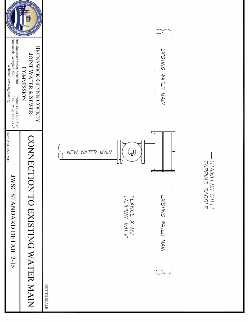


STANDARDS�FOR�WATER�AND�SEWER�DESIGN�AND�CONSTRUCTION��
�
�
���������������������������������������������
SECTION 3 GRAVITY SEWER SYSTEMS

STANDARDS�FOR�WATER�AND�SEWER�DESIGN�AND�CONSTRUCTION��
�
Page�1�of�2��
�
TABLE OF CONTENTS
SECTION 3 GRAVITY SEWER SYSTEMS
3.1 GENERAL 3.2 DESIGN FLOWS 3.2.1 Daily Average Dry Weather Flow (ADWF)
3.2.2 Calculation of Peak Flow
3.3 SIZING OF GRAVITY SEWER MAINS
3.3.1 Major Outfalls 3.3.2 Collector Sewers
3.4 GRAVITY SEWER MAIN PIPE SLOPE REQUIREMENTS
3.4.1 Discussion 3.4.2 Gravity Sewer Main Grades
3.5 MATERIAL SPECIFICATIONS
3.5.1 General Considerations 3.5.2 Polyvinyl Chloride (PVC) Pipe and Fittings 3.5.3 Ductile Iron (D.I.P.) Pipe 3.5.4 High Density Polyethylene (HDPE) Pipe and Service Connections 3.5.5 Fusible Polyvinyl Chloride (FPVC) Pipe and Service Connections 3.5.6 Manholes
3.5.6.1 Manhole Diameter 3.5.6.2 Precast Concrete Manholes 3.5.6.3 Fiberglass Manholes 3.5.6.4 Manhole Frames and Covers
3.6 INSTALLATION OF SEWER MAINS AND APPURTENANCES
3.6.1 Gravity Sewer Main Depth 3.6.2 Gravity Sewer Main Location and Alignment 3.6.3 Gravity Sewer and Water Main Separation Requirements 3.6.4 Encasements and Casings and Aerial Crossings 3.6.5 Gravity Main Stub-outs 3.6.6 Sewer Services 3.6.7 Sewer Manholes
3.6.7.1 Location 3.6.7.2 Spacing 3.6.7.3 Clearance Requirements 3.6.7.4 Depth 3.6.7.5 Drop Manholes 3.6.7.6 Grade Rings

STANDARDS�FOR�WATER�AND�SEWER�DESIGN�AND�CONSTRUCTION��
�
Page�2�of�2��
3.6.7.7 Corrosion Protection
3.6.8 Pipe Trench Construction, Bedding, Backfill and Workmanship
3.6.8.1 Rigid Pipe 3.6.8.2 Flexible Pipe 3.6.8.3 Unsuitable Materials
3.6.9 Gravity Sewer System Testing and Inspection
3.6.9.1 Low Pressure Air Test 3.6.9.2 Infiltration Test 3.6.9.3 Vacuum Test 3.6.9.4 Visual Inspection 3.6.9.5 Deflection Testing
APPENDICES
Appendix 3A Gravity Sewer Systems Acceptable Manufacturers
Appendix 3B Standard Construction Details
3-1 Gravity Main Stub Out Manhole 3-2A Standard Manhole Section 3-2B Standard Manhole Plan 3-3A Outside Drop Manhole Section 3-3B Outside Drop Manhole Plan 3-4A Inside Drop Manhole Section 3-4B Inside Drop Manhole Plan 3-5 General Notes – Sewer Services 3-6 Single Sewer Service – Plan View 3-7 Double Sewer Service – Plan View 3-8 Sewer Service – Sectional View 3-9 Sewer Service Cleanout 3-10A Trench Detail – Rigid Pipe 3-10B Trench Detail – Rigid Pipe 3-11A Trench Detail – Flexible Pipe 3-11B Trench Detail – Flexible Pipe

STANDARDS�FOR�WATER�AND�SEWER�DESIGN�AND�CONSTRUCTION��
�
Page�1�of�36��
SECTION 3 GRAVITY SEWER SYSTEMS 3.1 GENERAL �
This section provides the minimum guidelines for the design of gravity sanitary sewer collection systems. The method of design and/or construction shall be according to these Design and Construction Standards and Specifications and the following:
Recommended Standards for Sewage Works (Ten State Standards) Latest Edition Georgia Environmental Protection Division State of Georgia Regulations for Water and Sewerage Works, Latest Edition Applicable Federal, State and Local Requirements
In the event of conflicts among the various sources cited above, the most stringent criteria shall take precedence.
3.2 DESIGN FLOWS
Each system component shall be designed to meet certain flow requirements. The various flow requirements are described below. 3.2.1 Daily Average Dry Weather Flow (ADWF)
Daily Average Dry Weather Flow (ADWF) shall be 300 gallons per day per Residential Equivalent Unit (REU) or 115 gallons per day per capita. The basis for one (REU) shall be a single-family unit occupied by an average of 2.6 persons. Where sewer service beyond the basis of the established REU is required, the Sewage Flow Table shown below (adapted from the Georgia Environmental Division Large Community Design Guidance Document, Pages 8 & 9, Appendix A) shall be used.

STANDARDS�FOR�WATER�AND�SEWER�DESIGN�AND�CONSTRUCTION��
�
Page�2�of�36��
Figure GS-1
Sewage Flow Table
FACILITY Gallons/Day (GPD) Assembly Hall 5 per seat Barber Shop/Beauty Parlor 125 per chair + 20/employee Boarding House* 100 per room Bowling Alley 75 per lane + 20/employee Church w/o Day Care or Kindergarten 5 per sanctuary seat Correctional Institution/Prison 250 per inmate Country Club, Recreation Facilities Only 25 per member Day Care Center, No Meals 15 per person Dental Office 100 per chair + 20/employee Department Store 10 per 100 SF Factory Without Showers With Showers
25 per employee 35 per employee
Food Service Establishments* Restaurants (Up to 12 hours per day) Restaurants (12 hours per day to 18 hours per day) Restaurants (Above 18 hours per day) Bar and Cocktail Lounge Drive-in Restaurant Carry-out Only
35 per seat + 20/employee 50 per seat + 20/employee 75 per seat + 20/employee 30 per seat + 20/employee 50 per space + 20/employee 50 per 100 SF + 20/employee
Funeral Home 10 per 100 SF Hospital Inpatient Outpatient
300 per bed 275 per bed
Hotel* 100 per room Kindergarten, No Meals 15 per person Laundry, Commercial 1,000 per machine Laundry, Coin 150 per machine Lodges* 100 per room Mobile Home Park 300 per site Motel* 100 per room Nursing Home* 150 per bed Office 10 per 100 SF Physician's Office 200 per exam room Schools* Boarding Day, Restrooms Only Day, Restrooms and Cafeteria Day, Restrooms, Gym and Cafeteria
100 per person 12 per person 16 per person 20 per person
Service Stations, Interstate Locations 425 + 150 per pump Service Stations, Other Locations 300 + 100 per pump Service Station Car Wash 500 per stall Shopping Center (Not including food service or laundry)
10 per 100 SF
Stadium 5 per seat Supermarket/Grocery Store 20 per 100 SF Theater 5 per seat

STANDARDS�FOR�WATER�AND�SEWER�DESIGN�AND�CONSTRUCTION��
�
Page�3�of�36��
FACILITY Gallons/Day (GPD) Travel Trailer Park* With Independent Water & Sewer Connection Without Independent Water & Sewer Connection
175 per site 35 per site
Warehouse 10 per 100 SF *Add 300 gallons per machine to amount indicated if laundry or dish washing machines are installed
Note: Where historical data is available from flow monitoring or other
approved devices as in the case of existing systems, ADWF shall be as averaged from seven (7) days within the monitoring period of flow with no rainfall event greater than .5 (5/10ths) inches of rain in any of the seven 24-hour periods being averaged.
3.2.2 Calculation of Peak Flow (PF) For gravity systems, the Daily Average Dry Weather Flow (ADWF) to be conveyed must be adjusted to allow for the maximum diurnal or peak flow that is expected to occur as follows:
Peak Flow = PF x Average Dry Weather Flow (ADWF)
Where:
Peaking Factor = PF = 5 / P 0.1667 as referenced in ASCE Manual and Reports of Engineering Practice #60 and WPCF Manual of Practice #FD- 5, (Babbitt Equation); Population = P = used as P/1,000 in the equation with each 300 GPD (REU) considered as serving 2.6 persons as follows: For residential use, (i.e. 5 single family residences times 2.6 persons/residence = 13 and 13/1,000 = P = 0.013); For Commercial Use, by dividing the total calculated GPD from the EPD Sewage Flow Table (Figure GS-1) by 300 GPD/REU and multiplying the REU’s by 2.6, (i.e. 4,000 GPD/300 GPD = 13.3 REU’s X 2.6 persons/REU = 35 and 35/1,000 = P = 0.035);

STANDARDS�FOR�WATER�AND�SEWER�DESIGN�AND�CONSTRUCTION��
�
Page�4�of�36��
For Industrial Use, by employee count GPD from EPD Sewage Flow Table (Figure GS-1)divided by 300 GPD/REU and then multiplying the REU’s by 2.6 persons/REU to approximate employee population, plus the maximum gallon per minute wastewater discharge capability, (as provided by the process design engineer), multiplied by 1,440 minutes/day and divided by 300 GPD to obtain REU’s then multiplying the REU’s by 2.6 to obtain an approximate equivalent population for process flow, (i.e. 25 factory employee @ 30 GPD = 900 GPD/300 GPD = 3 REU’s X 2.6 persons/REU = 8 and peak process water discharge @ 150 GPM X 1,440min/day = 216,000 GPD/300 GPD per REU = 720 REU’s X 2.6 persons/REU = 1,872, then 1,872 for process water population approximation + 8 factory employee population approximation = 1,880 and 1,880/1,000 = P = 1.88).
3.3 SIZING OF GRAVITY SEWER MAINS
3.3.1 Major Outfalls
The size of major outfall sewers or extensions to such mains, throughout the system shall be in accordance with JWSC Water and Sewer Master Plan, latest revision. Contact the Planning and Construction Division for additional information and guidance with regard to this requirement.
3.3.2 Collector Sewers
All gravity sewer mains shall be designed to convey the Design Peak Flow at a flow depth not to exceed 94% of the pipe inside diameter or less than 0.6 inches, and at a self-cleansing velocity of between 1.99 FPS and 2.01 FPS. Gravity sewer mains intended for public use and JWSC operation and maintenance shall be sized to meet these hydraulic guidelines with the minimum pipe size being 8-inches in diameter, unless specifically allowed subject to the 6-inch pipe diameter exceptions cited in paragraph 3.4.2 below.
3.4 GRAVITY SEWER MAIN PIPE SLOPE REQUIREMENTS
3.4.1 Discussion
The major items for consideration in the regulation of gravity sewer pipe slopes are carrying capacity at peak flow and self-cleansing velocity. The inability to convey peak flow results in system surcharging and potential sanitary sewer overflows. The lack in the development of self-cleansing velocity, at least during the flows diurnal peak, results in solids deposition, system odors, and the eventual reduction in pipe capacity leading to blockages and overflows.

STANDARDS�FOR�WATER�AND�SEWER�DESIGN�AND�CONSTRUCTION��
�
Page�5�of�36��
An additional consideration in the JWSC jurisdictional area, and numerous other coastal areas, is wastewater piping system detention time. Lengthy wastewater detention or travel time through gravity piping systems encourages the development of corrosive and odorous gases that damage piping infrastructure, cause odor complaints and increase the cost of system operation by requiring the addition of chemicals to inhibit or mitigate the effects of aging wastewater. Therefore, design of gravity sewer systems in this standard shall stress the development of self-cleansing velocities as the most practical and effective method of minimizing wastewater detention times in sewer mains.
Standardized slopes, as recommended by Ten States Standards in concert with the minimum pipe diameters and minimum flow depths suggested in these guidelines, often forces the designer to hold to a pipe grade that does not provide adequate velocities at “projected” flow rates and/or forces a pipe grade that shortens the potential reach of a proposed sewer main when projected flow rates would develop self-cleansing velocity at a lesser grade.
In an effort to address these aforementioned issues, the JWSC’s pipe slope design requirements are developed to provide a range of acceptable pipe slopes based on good hydraulic engineering practice using “projected” pipe flow rates based on REU’s and peaking factors as defined by appropriate engineering literature, organizational experience, policy and regulatory guidelines.
3.4.2 Gravity Sewer Main Grades
Gravity sewer mains intended for public use and O&M by the JWSC or extensions to public systems which are to remain private shall be in accordance with the preferred slopes shown in Figure GS-2 for minimum pipe diameters. Where adherence to the minimum eight (8) inch pipe diameter will not develop self-cleansing velocities at “projected” ultimate contributory flows, six (6) inch diameter pipe may be used, if approved as an exception, defined as follows.
A six (6) inch diameter pipe exception shall only apply for limited reaches of gravity sewer where self-cleansing velocities can not be developed in eight (8) inch pipes by “projected” flow peaks during the 24-hour diurnal cycle; and when such gravity mains are strategically located such that system expansion from those lines is highly improbable, as in the case of limited boundary development subdivisions.

STANDARDS�FOR�WATER�AND�SEWER�DESIGN�AND�CONSTRUCTION��
�
Page�6�of�36��
The use of the Manning Equation indicates that flows in excess of 12,000 gpd and peak flows of 61 gpm, using the Babbitt Peaking Equation, are needed to develop self-cleaning velocities at the diurnal peak in an eight (8) inch line on a grade of 0.40%. This equates to 39 single family residences or REU’s. The six (6) inch pipe diameter exception shall be considered valid when this quantity of “projected” contributory flow for any gravity sewer reach is not available.
Grades for pipe diameters greater than the cited six (6) inch and eight (8) inch minimums shall be based on the same design criteria as stated above in article 3.3.2, and in consideration of “projected” flows. Alternatives to the six (6) inch exception include low pressure systems, step systems, vacuum systems or on-site treatment systems.
The maximum slope for all pipe diameters shall be such that the velocity in the pipes does not exceed 5 fps at 94% of the pipe inside diameter when calculated using Manning’s Equation and projected flow peaks.
Figure GS-2 Gravity Sewer Main Pipe Slope Table for six (6) inch and eight (8) inch Pipes
Using Manning Flow and Babbitt PF Equations
Nominal Diameter
Pipe Material
Projected Flow
(REU's) Projected
Population Calculated
Peaking Factor
Projected ADWF (GPD)
Projected Peak Flow
(GPM)
Self Cleansing Minimum Slope (%)
Flow Depth
(Inches)
Maximum Capacity
@ Minimum
Slope (GPM)
6 PVC HDPE 4 10.4 10.7 1,200 9 1.75 0.61 467
6 PVC HDPE 5 13.0 10.3 1,500 11 1.53 0.68 437
6 PVC HDPE 6 15.6 10.0 1,800 13 1.35 0.75 410
6 PVC HDPE 7 18.2 9.7 2,100 14 1.25 0.80 395
6 PVC HDPE 8 20.8 9.5 2,400 16 1.11 0.88 372
6 PVC HDPE 9 23.4 9.3 2,700 18 1.02 0.94 357
6 PVC HDPE 10 26.0 9.2 3,000 19 0.95 1.00 344
6 PVC HDPE 11 28.6 9.0 3,300 21 0.89 1.05 333
6 PVC HDPE 12 31.2 8.9 3,600 22 0.86 1.09 328
6 PVC HDPE 13 33.8 8.8 3,900 24 0.80 1.15 316
6 PVC HDPE 14 36.4 8.7 4,200 25 0.76 1.20 308
6 PVC HDPE 15 39.0 8.6 4,500 27 0.72 1.26 300
6� PVC HDPE 16 41.6 8.5 4,800 28 0.69 1.30 293
6� PVC HDPE 17 44.2 8.4 5,100 30 0.66 1.35 287
6� PVC HDPE 18 46.8 8.3 5,400 31 0.64 1.39 283

STANDARDS�FOR�WATER�AND�SEWER�DESIGN�AND�CONSTRUCTION��
�
Page�7�of�36��
Nominal Diameter
Pipe Material
Projected Flow
(REU's) Projected
Population Calculated
Peaking Factor
Projected ADWF (GPD)
Projected Peak Flow
(GPM)
Self Cleansing Minimum Slope (%)
Flow Depth
(Inches)
Maximum Capacity
@ Minimum
Slope (GPM)
6� PVC HDPE 19 49.4 8.3 5,700 33 0.62 1.44 278
6� PVC HDPE 20 52.0 8.2 6,000 34 0.59 1.49 271
6� PVC HDPE 21 54.6 8.1 6,300 36 0.57 1.54 267
6� PVC HDPE 22 57.2 8.1 6,600 37 0.55 1.59 262
6� PVC HDPE 23 59.8 8.0 6,900 38 0.54 1.62 260
6� PVC HDPE 24 62.4 7.9 7,200 40 0.52 1.67 255
6� PVC HDPE 25 65.0 7.9 7,500 41 0.51 1.70 252
6� PVC HDPE 26 67.6 7.8 7,800 42 0.50 1.73 250
6� PVC HDPE 27 70.2 7.8 8,100 44 0.48 1.79 245
6� PVC HDPE 28 72.8 7.7 8,400 45 0.48 1.80 245
6� PVC HDPE 29 75.4 7.7 8,700 46 0.47 1.83 242
6� PVC HDPE 30 78.0 7.6 9,000 48 0.45 1.90 237
6� PVC HDPE 31 80.6 7.6 9,300 49 0.44 1.94 234
6� PVC HDPE 32 73.2 7.6 9,600 50 0.44 1.96 234
6� PVC HDPE 33 85.8 7.5 9,900 52 0.42 2.03 229
6� PVC HDPE 34 88.4 7.5 10,200 53 0.42 2.04 229
6� PVC HDPE 35 91.0 7.5 10,500 54 0.41 2.07 226
6� PVC HDPE 36 93.6 7.4 10,800 56 0.40 2.12 223
6� PVC HDPE 37 96.2 7.4 11,100 57 0.39 2.17 221
6� PVC HDPE 38 98.8 7.4 11,400 58 0.39 2.19 221
6� PVC HDPE 39 101.4 7.3 11,700 59 0.38 2.22 218
6� PVC HDPE 40 104.0 7.3 12,000 61 0.38 2.25 218
8 PVC HDPE 40 104.0 7.3 12,000 61 0.40 2.00 481
8 PVC HDPE� 41 106.6 7.3 12,300 62 0.40 2.01 481
8 PVC HDPE� 42 109.2 7.2 12,600 63 0.39 2.04 475
8 PVC HDPE� 43 111.8 7.2 12,900 65 0.39 2.07 475
8 PVC HDPE� 44 114.4 7.2 13,200 66 0.38 2.10 469
8 PVC HDPE� 45 117.0 7.1 13,500 67 0.38 2.12 469
8 PVC HDPE� 46 119.6 7.1 13,800 68 0.37 2.15 463
8 PVC HDPE� 47 122.2 7.1 14,100 69 0.37 2.17 463
8 PVC HDPE� 48 124.8 7.1 14,400 71 0.36 2.21 456

STANDARDS�FOR�WATER�AND�SEWER�DESIGN�AND�CONSTRUCTION��
�
Page�8�of�36��
Nominal Diameter
Pipe Material
Projected Flow
(REU's) Projected
Population Calculated
Peaking Factor
Projected ADWF (GPD)
Projected Peak Flow
(GPM)
Self Cleansing Minimum Slope (%)
Flow Depth
(Inches)
Maximum Capacity
@ Minimum
Slope (GPM)
8 PVC HDPE� 49 127.4 7.0 14,700 72 0.35 2.25 450
8 PVC HDPE� 50 130.0 7.0 15,000 73 0.34 2.28 444
8 PVC HDPE� 51 132.6 7.0 15,300 74 0.34 2.30 444
8 PVC HDPE� 52 135.2 7.0 15,600 76 0.34 2.32 444
8 PVC HDPE� 53 137.8 7.0 15,900 77 0.34 2.34 444
8 PVC HDPE� 54 140.4 6.9 16,200 78 0.33 2.38 437
8 PVC HDPE� 55 143.0 6.9 16,500 79 0.33 2.39 437
8 PVC HDPE� 56 145.6 6.9 16,800 80 0.32 2.43 430
8 PVC HDPE� 57 148.2 6.9 17,100 82 0.32 2.45 430
8 PVC HDPE� 58 150.8 6.9 17,400 83 0.32 2.47 430
8 PVC HDPE� 59 153.4 6.8 17,700 84 0.31 2.51 424
8 PVC HDPE� 60 156.0 6.8 18,000 85 0.31 2.52 424
8 PVC HDPE� 61 158.6 6.8 18,300 86 0.31 2.54 424
8 PVC HDPE� 62 161.2 6.8 18,600 88 0.30 2.60 417
8 PVC HDPE� 63 163.8 6.8 18,900 89 0.30 2.61 417
8 PVC HDPE� 64 166.4 6.7 19,200 90 0.30 2.62 417
8 PVC HDPE� 65 169.0 6.7 19,500 91 0.29 2.66 410
8 PVC HDPE� 66 171.6 6.7 19,800 92 0.29 2.68 410
8 PVC HDPE� 67 174.2 6.7 20,100 93 0.29 2.69 410
8 PVC HDPE� 68 176.8 6.7 20,400 95 0.28 2.75 403
8 PVC HDPE� 69 179.4 6.7 20,700 96 0.28 2.76 403
8 PVC HDPE� 70 182.0 6.6 21,000 97 0.28 2.78 403
8 PVC HDPE� 71 184.6 6.6 21,300 98 0.28 2.79 403
8 PVC HDPE� 72 187.2 6.6 21,600 99 0.27 2.83 395
8 PVC HDPE� 73 189.8 6.6 21,900 100 0.27 2.85 395
8 PVC HDPE� 74 192.4 6.6 22,200 101 0.27 2.86 395
8 PVC HDPE� 75 195.0 6.6 22,500 103 0.27 2.89 395
8 PVC HDPE� 76 197.6 6.6 22,800 104 0.26 2.94 388
8 PVC HDPE� 77 200.2 6.5 23,100 105 0.26 2.96 388
8 PVC HDPE� 78 202.8 6.5 23,400 106 0.26 2.97 388
8 PVC HDPE� 79 205.4 6.5 23,700 107 0.26 2.98 388

STANDARDS�FOR�WATER�AND�SEWER�DESIGN�AND�CONSTRUCTION��
�
Page�9�of�36��
Nominal Diameter
Pipe Material
Projected Flow
(REU's) Projected
Population Calculated
Peaking Factor
Projected ADWF (GPD)
Projected Peak Flow
(GPM)
Self Cleansing Minimum Slope (%)
Flow Depth
(Inches)
Maximum Capacity
@ Minimum
Slope (GPM)
8 PVC HDPE 80 208.0 6.5 24,000 108 0.26 3.00 388
8 PVC HDPE 81 210.6 6.5 24,300 109 0.26 3.01 388
8 PVC HDPE 82 213.2 6.5 24,600 111 0.25 3.08 380
8 PVC HDPE 83 215.8 6.5 24,900 112 0.25 3.10 380
8 PVC HDPE 84 218.4 6.4 25,200 113 0.25 3.11 380
8 PVC HDPE 85 221.0 6.4 25,500 114 0.25 3.13 380
8 PVC HDPE 86 223.6 6.4 25,800 115 0.24 3.18 373
8 PVC HDPE 87 226.2 6.4 26,100 116 0.24 3.19 373
8 PVC HDPE 88 228.8 6.4 26,400 117 0.24 3.21 373
8 PVC HDPE 89 231.4 6.4 26,700 118 0.24 3.22 373
8 PVC HDPE 90 234.0 6.4 27,000 119 0.24 3.23 373
8 PVC HDPE 91 236.6 6.4 27,300 121 0.24 3.26 373
8 PVC HDPE 92 239.2 6.3 27,600 122 0.23 3.32 365
8 PVC HDPE 93 241.8 6.3 27,900 123 0.23 3.33 365
8 PVC HDPE 94 244.4 6.3 28,200 124 0.23 3.35 365
8 PVC HDPE 95 247.0 6.3 28,500 125 0.23 3.36 365
8 PVC HDPE 96 249.6 6.3 28,800 126 0.23 3.37 365
8 PVC HDPE� 97 252.2 6.3 29,100 127 0.23 3.39 365
8 PVC HDPE� 98 254.8 6.3 29,400 128 0.23 3.40 365
8 PVC HDPE� 99 257.4 6.3 29,700 129 0.22 3.47 357
8 PVC HDPE� 100 260.0 6.3 30,000 130 0.22 3.48 357
8 PVC HDPE� 101 262.6 6.2 30,300 131 0.22 3.49 357
8 PVC HDPE� 102 265.2 6.2 30,600 133 0.22 3.52 357
8 PVC HDPE� 103 267.8 6.2 30,900 134 0.22 3.54 357
8 PVC HDPE� 104 270.4 6.2 31,200 135 0.22 3.56 357
8 PVC HDPE� 105 273.0 6.2 31,500 136 0.22 3.57 357
8 PVC HDPE� 106 275.6 6.2 31,800 137 0.22 3.58 357
8 PVC HDPE� 107 278.2 6.2 32,100 138 0.21 3.65 349
8 PVC HDPE� 108 280.8 6.2 32,400 139 0.21 3.66 349
8 PVC HDPE� 109 283.4 6.2 32,700 140 0.21 3.68 349
8 PVC HDPE� 110 286.0 6.2 33,000 141 0.21 3.68 349

STANDARDS�FOR�WATER�AND�SEWER�DESIGN�AND�CONSTRUCTION��
�
Page�10�of�36��
Nominal Diameter
Pipe Material
Projected Flow
(REU's) Projected
Population Calculated
Peaking Factor
Projected ADWF (GPD)
Projected Peak Flow
(GPM)
Self Cleansing Minimum Slope (%)
Flow Depth
(Inches)
Maximum Capacity
@ Minimum
Slope (GPM)
8 PVC HDPE� 111 288.6 6.2 33,300 142 0.21 3.70 349
8 PVC HDPE� 112 291.2 6.1 33,600 143 0.21 3.72 349
8 PVC HDPE� 113 293.8 6.1 33,900 144 0.21 3.73 349
8 PVC HDPE� 114 296.4 6.1 34,200 145 0.21 3.75 349
8 PVC HDPE� 115 299.0 6.1 34,500 146 0.21 3.76 349
8 PVC HDPE� 116 301.6 6.1 34,800 148 0.20 3.85 340
8 PVC HDPE� 117 304.2 6.1 35,100 149 0.20 3.87 340
8 PVC HDPE� 118 306.8 6.1 35,400 150 0.20 3.88 340
8 PVC HDPE� 119 309.4 6.1 35,700 151 0.20 3.90 340
8 PVC HDPE� 120 312.0 6.1 36,000 152 0.20 3.91 340
8 PVC HDPE� 121 314.6 6.1 36,300 153 0.20 3.92 340
8 PVC HDPE� 122 317.2 6.1 36,600 154 0.20 3.94 340
8 PVC HDPE� 123 319.8 6.0 36,900 155 0.20 3.95 340
8 PVC HDPE� 124 322.4 6.0 37,200 156 0.20 3.97 340
8 PVC HDPE� 125 325.0 6.0 37,500 157 0.20 3.98 340
8 PVC HDPE� 126 327.6 6.0 37,800 158 0.20 4.00 340
8 PVC HDPE� 127 330.2 6.0 38,100 159 0.20 4.01 340
8 PVC HDPE� 128 332.8 6.0 38,400 160 0.19 4.09 332
Notes For Table GS-2:
1. REU (GPD) = 300 2. Plastic Pipe Manning "n" = 0.010 (For clean pipe with little deposits/debris 3. Metal Pipe Manning "n" = 0.013 (For clean pipe with little deposits/debris 4. Required Self-Cleansing Velocity = 1.99 to 2.01 feet per second 5. Minimum Pipe Flow Depth = 0.6 inches
3.5 MATERIAL SPECIFICATIONS
The contractor shall furnish gravity sewer piping systems in accordance with the material specifications detailed below. All references to industry standards (ASTM, ANSI, AWWA, etc.) shall be to the latest revision unless stated otherwise. All materials shall be new. These material specifications include a list of acceptable manufacturers for the various water system components. The contractor may choose freely from the manufacturers list and material submittals for such items are not required. Only products and materials from the acceptable manufacturer's lists herein may be used in the work.

STANDARDS�FOR�WATER�AND�SEWER�DESIGN�AND�CONSTRUCTION��
�
Page�11�of�36��
Any item required but not specified herein, or any product or manufacturer other than those listed will be considered a substitution. Material submittals are required for such items. Substitutions will not be allowed without the prior written approval of the JWSC Planning and Construction Division. Substitutions, if allowed, shall meet all criteria of the detailed specifications. The burden of proof of compliance for any proposed substitution rests with the Contractor/Developer/Owner. The JWSC Planning and Construction Division will be the sole judge as to the acceptance of a proposed substitution and such decisions will be final. 3.5.1 General Considerations
The type, class, grade, and alignment of sewer pipe may be changed only at manholes. The only exception to this being where a gravity sewer main crosses under a storm drain and the invert of the storm drain is less than 3 feet above the crown of the sewer main. In such cases, a full twenty (20) foot joint of ductile iron pipe shall be centered under the storm drain and joined to PVC or HDPE pipe with a mechanical joint or stress resistant coupling.
Gravity sewer mains shall be ASTM 3034, SDR-26 heavy wall sewer pipe or DR-17 HDPE. Gravity sewer mains within steel casings or PVC DR18 casing pipes shall be ASTM 3034, SDR 26 heavy wall sewer pipe and shall be installed with approved skids or spacers to hold grade and prevent flotation in accordance with these specifications. Ductile iron pipe is only permitted for gravity sewer use where the mains or laterals are above ground as in ditch crossings. The only exception being storm drain crossings as cited above. All material shall be free from defects impairing strength and durability, shall be of the best commercial quality for the purpose specified, shall have structural properties sufficient to safely sustain or withstand strains and stresses to which it is normally subjected and be true to detail. Pipe to be installed underground using open-cut methods shall be PVC push-on joint type as described in these specifications, or as accepted within these specifications for storm drain crossings. Pipe installed above ground shall be Sewer-Safe restrained joint ductile iron pipe or flanged ductile iron pipe as described in these specifications.

STANDARDS�FOR�WATER�AND�SEWER�DESIGN�AND�CONSTRUCTION��
�
Page�12�of�36��
For pipe bursting or horizontal boring construction, the pipe shall be high density polyethylene (HDPE) or Fusible PVC of a suitable ASTM Standard, classification and pressure rating as described in these specifications. The “depth of cut” shall be defined as the vertical distance from pipe invert to finish grade.
3.5.2 Polyvinyl Chloride (PVC) Pipe and Fittings
Each length shall be clearly marked with the name of the manufacturer, location of the plant, pressure rating, nominal pipe diameter and length. All PVC sanitary sewer pipe shall be green. Storage and handling of PVC pipe shall be in accordance with Chapter 6 of AWWA Manual M23. PVC 1120, Class 160, SDR 26 Pipe shall conform to ASTM D3034 for sizes four (4) inch thru fifteen (15) inch diameter pipe and ASTM F679 for 18 inch through 36 inch diameter pipe. The pipe material shall be clean, virgin, National Sanitation Foundation approved, Class 12454-B PVC compound conforming to ASTM resin specification D1784 with wall thickness T-1. Pipe shall have a bell type coupling with a thickened wall section integral with the pipe barrel in accordance with ASTM D3212. Elastomeric seals shall meet ASTM F477 or ASTM F913. The pipe shall be designed to pass without failure a sustained pressure test of 340 psi in conformance with ASTM D1598 and a quick burst test of 400 psi in conformance with ASTM D1599. Fittings shall meet the requirements of ASTM D3034 and ASTM F1336 for sizes four (4) inch through fifteen (15) inch in diameter and ASTM F679 and ASTM F1336 for eighteen (18) inch through thirty six (36) inch in diameter with minimum wall thickness of SDR 26. Fittings shall be gasket joint type meeting the requirements of ASTM D3212. Elastomeric gaskets shall conform to ASTM F477 or ASTM F913. PVC material shall have a cell classification of 12454-B in accordance with ASTM D1784.
PVC 1120, Pressure Class (PC) 235 of DR-18 for twenty-four (24) inch diameter or less and DR-21 for greater than twenty-four (24) inch diameter pipe (used as casing pipe for easements and allowed rights-of-way) shall conform to AWWA Standard C900 or C905, as appropriate for pipe diameter. All pipes shall be hydrostatically proof tested at the factory in conformance with UNI-B-11 standards. In case of conflict between standards specified herein, the requirements of AWWA Standard C900 and C905 shall prevail. Pipe is to be manufactured to ductile iron pipe equivalent outside diameters. The pipe material shall be clean, virgin, National Sanitation Foundation approved, Class 12454-B PVC compound conforming to ASTM resin specification D1784.

STANDARDS�FOR�WATER�AND�SEWER�DESIGN�AND�CONSTRUCTION��
�
Page�13�of�36��
Pipe shall have a bell type coupling with a thickened wall section integral with the pipe barrel in accordance with ASTM D3139. Elastomeric seals shall meet ASTM F477. The pipe shall be designed to pass without failure a sustained pressure test of 500 psi in conformance with ASTM D1598 and a quick burst test of 755 psi in conformance with ASTM D1599. Where PVC Casing Pipes can be installed using horizontal directional drilling techniques, equivalently rated fusible PVC pipe may be approved. PVC Fittings six (6) inches through twelve (12) inches may be used with PVC C900 pipe. Fittings shall be PVC injection molded, made from materials meeting or exceeding the requirements of cell class 12454-B material as defined in ASTM D1784. All PVC fittings must comply with or exceed, AWA C907. All fittings must be designed to the pressure class of the pipe used, with a pressure rating of 150 psi and a 2.5 to 1 factor of safety. Virgin materials only shall be used in the manufacture of PVC pressure fittings. These fittings must have UL-FM approval and shall comply with or exceed all ASTM Standards for PVC fittings. All fittings must have NSF-61 approval. The elastomeric gasket shall comply with the requirements specified in ASTM F477.
3.5.3 Ductile Iron (D.I.P.) Pipe and Fittings
D.I.P. wall thickness and pressure class shall conform to ANSI Specification A21.50 (AWWA C150) and ANSI A21.51 (AWWA C151) with pressure class 350 as a minimum. Pipe shall also be certified by ISO 9000 by an accredited registrar. Pipe shall be clearly marked with the name of the manufacturer, location of the foundry, pressure rating, thickness or pressure class, nominal pipe diameter, weight of pipe without lining, maximum depth of bury and length. All pipe furnished by the manufacturer shall be cast and machined at one foundry location to assure quality control and provide satisfactory test data. All ductile iron pipe shall be color coded green by field painting a green stripe, three (3) inches wide, along the crown of the pipe barrel. All ductile iron pipes and fittings shall be externally coated with a bituminous coating as specified in ANSI A21.51 and be continuous smooth, neither brittle when cold or sticky when exposed to the sun, and be strongly adherent to the fitting. If the pipe is installed in a corrosive soil, then all bolts, nuts, studs and other uncoated parts of joints for underground installation shall be coated with asphalt or coal-tar prior to backfilling.

STANDARDS�FOR�WATER�AND�SEWER�DESIGN�AND�CONSTRUCTION��
�
Page�14�of�36��
All ductile iron pipes and fittings shall be Sewer Safe internally lined with an approved amine cured novalac epoxy coating containing at least 20% by volume of ceramic quartz pigment. Ductile iron fittings shall have a minimum working pressure of 350 psi. Fittings shall conform to ANSI Specifications A21.10 (AWWA C110), A21.11 (AWWA C111), A21.15 (AWWA C115) and/or A21.53 (AWWA C153). Fittings shall also be certified by ISO 9000 by an accredited registrar. Compact fittings shall normally be installed. Long body fittings shall be used where the drawings specifically call for long body fittings, where compact fittings are not available, or at the option of the contractor when the laying length is not controlled by compact fittings patterns. All fittings shall be UL/FM approved and shall conform to NSF Standard 61, as applicable. All fittings furnished by the approved manufacturer shall be cast and machined at one foundry location to assure quality control and provide satisfactory test data. Fittings shall have cast on them the pressure rating, nominal diameter of openings, manufacturer’s name, foundry location, plant code and degrees or fraction of the circle. Cast letters and figures shall be on the outside body of the fitting. All ductile iron fittings shall be externally coated and internally lined as specified in this specification.
3.5.4 High Density Polyethylene (HDPE) Pipe and Service Connections
For Horizontal Directional Drilling or Pipe Bursting, HDPE Pipe shall be ductile iron pipe size outside diameter, SDR 11 high performance, high molecular weight, high density polyethylene pipe, and shall conform to ASTM D 1248 (Type III C, Category 5, P34). Minimum cell classification values shall be 345434C as referenced in ASTM D 3350. All pipe resin shall be manufactured by the same company that manufactures the pipe itself in accordance with these specifications to insure complete resin compatibility and total product accountability. Fittings for service connections shall be Inserta-Tee or electro-fusion type fittings only.
3.5.5 Fusible Polyvinyl Chloride (FPVC) Pipe and Service Connections
For Horizontal Directional Drilling or Pipe Bursting, Fusible C-900, C-905, DR-18 FPVC and 1120, SDR-26 FPVC pipe shall be cast iron pipe size outside diameter, conforming to ASTM D3034. All piping shall be made from a PVC compound conforming to cell classification 12454 per ASTM D1784. Pipe shall be extruded with plain ends which shall be square to the pipe and free of any bevel or chamfer.

STANDARDS�FOR�WATER�AND�SEWER�DESIGN�AND�CONSTRUCTION��
�
Page�15�of�36��
There shall be no bell or spigot gasket of any kind incorporated into the pipe. Pipe shall be manufactured in standard 40 foot nominal lengths, with other lengths available upon request. For gravity sewer use, pipe shall be green in color. The pipe shall be marked per industry standards. The pipe shall be homogeneous throughout and be free of visible cracks, holes, foreign material, blisters, or other visible deleterious faults. Fittings for service connections shall be Inserta-Tee or watertight stainless steel saddle type fittings suitable for use on C-900 pipe.
3.5.6 Manholes
3.5.6.1 Manhole Diameter The minimum manhole inside diameters for gravity sewer lines six (6) inch through sixteen (16) inch shall be four (4) feet; for lines eighteen (18) inches through thirty (30) inches – five (5) feet; for lines thirty six (36) inch through forty eight (48) inch – six (6) feet; and for lines greater than forty eight (48) inches – eight (8) feet. Where the depth of a manhole, (from finished grade to lowest pipe invert), is fifteen (15) feet or greater, the minimum manhole diameter shall be five (5) feet. 3.5.6.2 Precast Concrete Manholes Precast concrete manholes or calcium aluminate cement concrete manholes used shall conform to all requirements of ASTM Designation C478 at minimum and be provided with "O" ring gasket type joints, conforming to ASTM Designation C443-77, or flexible joint sealant roping of butyl rubber conforming to Federal Specification SS-S-210A, AASHTO M-198, Type B-Butyl Rubber with a minimum cross section of 1 ¼ inches, and shall be:
(a) constructed using a top section cast monolithically and shaped as an eccentric cone, or for manhole depths five (5) feet or less be a concentric cone, joint systems must match associated riser or base sections; the clear opening for the manhole frame & cover shall not be less than twenty four (24) inches for main sewers six (6) inches through eighteen (18) inches in diameter, and not less than thirty two (32) for main sewers greater than eighteen (18) inches in diameter; (b) constructed using riser sections cast monolithically having a minimum lay length of sixteen (16) inches and of joint systems matching associated base and cone sections;

STANDARDS�FOR�WATER�AND�SEWER�DESIGN�AND�CONSTRUCTION��
�
Page�16�of�36��
(c) constructed using a base section cast monolithically having a minimum lay length of sixteen (16) inches and a joint system matching associated riser and cone sections;
(d) constructed, where depth permits, using a precast eccentric transition section to reduce base section diameters of six (6) foot or greater, to five (5) foot diameter at finish grade. Such transitions shall not be made less than four (4) vertical feet above the invert bench;
(e) constructed, where manhole depth will not permit a diameter transition section, using a precast flat slab top section with centered thirty two (32) diameter hole for the manhole frame & cover opening; (f) constructed using precast inverts providing clearance for pipe projecting a minimum of two (2) inch inside the manhole wall, troughs formed and finished to provide a minimum slope of 1.25% from the pipe outlet to the inlets, minimum concrete thickness from the bottom of the lowest invert to the bottom of the base not less than eight (8) inches, invert benches with a uniform 2:1 slope from the high point at the manhole wall to the lip of the invert trough; trough depth from the lip of the invert trough to the invert of the pipe to be 50% of the main pipe diameter; inverts shall be free from depressions, high spots, voids, chips or fractures over one fourth (¼) inch in diameter or depth;
(g) hand-formed inverts, when approved for use, shall meet or exceed the durability, strength, configuration and hydraulic “smoothness” as required for precast inverts. Filler for inverts shall be holed burned brick; (h) steps, on the vertical or straight wall of four (4) foot and five (5) foot diameter manholes shall be aligned vertically on sixteen (16) inch centers, secured to the wall with a compression fit in tapered holes or cast in place, coated with a copolymer polypropylene plastic coating, reinforced with one-half (½) inch diameter grade 60 bar with serrated treads and tall end lugs; step pullout strength shall be 2000 lbs. minimum when tested according to ASTM C497; steps shall begin no less than eighteen (18) inches from the manhole rim and end no closer than sixteen (16) inches above the manhole bench;
(i) steps shall not be used on manholes greater than five (5) foot in diameter or where a concentric cone or flat-slab top is the final section;

STANDARDS�FOR�WATER�AND�SEWER�DESIGN�AND�CONSTRUCTION��
�
Page�17�of�36��
(j) lifting, devices for handling precast manhole section components shall comply with OSHA Standard 1926.704;
(k) manhole entrance couplings with the entry pipes greater than eighteen (18) inch in diameter shall be fitted with pipe entrance connectors conforming to ASTM C923, and for eighteen (18) inch pipes and smaller to ASTM C-425 using neoprene boot inserts tightened to the pipe using a stainless steel adjustable band, (“A-Loc” or approved equal), rigid cement or synthetic type grout collars are not acceptable as a seal between the manhole and entry pipe in new construction.
3.5.6.3 Fiberglass Manholes Water tight fiberglass manholes shall be reinforced polyester manufactured from commercial grade polyester resin or other suitable polyester or vinyl ester resins with fiberglass reinforcements. Manhole shall be a one piece unit manufactured to meet or exceed all specifications of A.S.T.M. D-3753 latest edition or approved equal. Fiberglass manholes shall be bedded and fully encased in a Class I gravel envelope from the base to the top of the fiberglass structure to insure lateral support; the thickness of the gravel envelope shall be no less than six (6) inches around the entire circumference of the structure.
(a) Resin: The resins used shall be a commercial grade unsaturated polyester resin or other suitable polyester or vinyl ester resin.
(b) Reinforcing Materials: The reinforcing materials shall be commercial Grade "E" type glass in the form of continuous roving and chop roving, having a coupling agent that will provide a suitable bond between the glass reinforcement and the resin.
(c) Interior Surfacing Material: The inner surface exposed to the chemical environment shall be a resin-rich layer of 0.010 to 0.020 inch thick. The inner surface layer exposed to the corrosive environment shall be followed with a minimum of two passes of chopped roving of minimum length 0.5 inch (13 mm) to maximum length of 2.0 inch (50.8 mm) and shall be applied uniformly to an equivalent weight of 3 oz/ft. Each pass of chopped roving shall be well rolled prior to the application of additional reinforcement. The combined thickness of the inner surface and interior layer shall not be less than 0.10 inch (2.5 mm).

STANDARDS�FOR�WATER�AND�SEWER�DESIGN�AND�CONSTRUCTION��
�
Page�18�of�36��
(d) Wall Construction Procedure: After the inner layer has been applied the manhole wall shall be constructed with chop and continuous strand filament wound manufacturing process, which insures continuous reinforcement and uniform strength and composition. The cone section, if produced separately, shall be affixed to the barrel section at the factory with resin-glass reinforced joint resulting in a one-piece unit. Seams shall be fiber-glassed on the inside and the outside using the same glass-resin jointing procedure. Field joints shall not be acceptable by anyone other than the manufacturer or approved equal.
(e) Exterior Surface: For a UV inhibitor the resin on the exterior surface of the manhole shall have gray pigment added to a minimum thickness 0.125 inches.
(f) Stub-outs and Connections: Upon request stub-outs may be installed. Installation of SDR, PVC, or sewer pipe must be performed by sanding, priming, and using resin fiber-reinforce hand lay-up. The resin and fiberglass shall be the same type and grade as used in the fabrication of the fiberglass manhole. Inserta-Tee fittings may be requested and installed per manufacturer’s instructions. Kor-N-Seal boots may be installed by the manhole manufacturer using fiberglass reinforced pipe stub-outs for the Kor-N-Seal boot sealing surface.
(g) Manhole Bottom: Fiberglass manholes will be required to
have resin fiber-reinforced bottom. Deeper manholes may require a minimum of two fiberglass channel stiffening ribs. All fiberglass manholes manufactured with a fiberglass bottom will have minimum three (3) inch wide anti-flotation rings as required based on the depth of the manhole, the weight of the gravel backfill and the groundwater uplift forces anticipated at the site. The manhole bottom shall be a minimum of one-half (½) inch thick.
(h) Fiberglass enclosed invert and bench area: A fiberglass enclosed invert and bench area shall be installed in the manhole by the manufacturer. The invert will be formed using a non-corrosive material and completely enclosed in a minimum one-fourth (1/4) inch layer of fiberglass chop.
(i) Height Adjustment: Fiberglass manholes must have the ability to be height adjustable with the use of a height adjustment ring. Height adjustment can be made as a field operation without the use of uncured resins or fiberglass lay-ups. Fiberglass manholes must maintain all load and soundness characteristics required by ASTM D3753 after height adjustment has occurred.

STANDARDS�FOR�WATER�AND�SEWER�DESIGN�AND�CONSTRUCTION��
�
Page�19�of�36��
(j) Fillers and Additives: Fillers, when used, shall be inert to the environment and manhole construction. Sand shall not be accepted as approved filler. Additives, such as thixotropic agents, catalysts, promoters, etc., may be added as required by the specific ASTMD-3753 standard. The resulting reinforced-plastic material must meet the requirements of this specification.
(k) Manufacture: Manhole cylinders, man-way reducers, and connectors shall be produced from fiberglass-reinforced polyester resin using a combination of chop and continuous filament wound process. (l) Interior Access: All manholes shall be designed so that a ladder or step system can be supported by the installed manhole.
(m) Man-way Reducer: Man-way reducers will be concentric with respect to the larger portion of the manhole diameters through 60 inches. Larger manholes may have concentric or eccentric man-way reducer openings. (n) Cover and Ring Support: The manhole shall provide an area from which a grade ring or brick can be installed to accept a typical metal ring and cover and have the strength to support a traffic load without damage to the manhole.
(o) Exterior Surface: The exterior surface shall be relatively smooth with no sharp projections. Handwork finish is acceptable if enough resin is present to eliminate fiber show. The exterior surface shall be free of blisters larger than 0.5 inch in diameter, de-lamination or fiber show.
(p) Interior Surface: The interior surface shall be resin rich with no exposed fibers. The surface shall be free of crazing, de-lamination, and blisters larger than 0.5 inch in diameter, and wrinkles of 0.125 inch or greater in depth. Surface pits shall be permitted if they are less than 0.75 inch in diameter and less than 0.0625 inches deep. Voids that cannot be broken with finger pressure and are entirely below the resin surface shall be permitted if they are less than 0.5 inch in diameter and less than 0.0625 inch thick.

STANDARDS�FOR�WATER�AND�SEWER�DESIGN�AND�CONSTRUCTION��
�
Page�20�of�36��
(q) Wall Thickness: Fiberglass manholes forty eight (48) inch in diameter and up to twenty (20) feet in depth will have a minimum wall thickness of .3125 inches. Fiberglass manholes forty eight (48) inch in diameter and twenty (20) feet to thirty (30) feet in depth will have a minimum wall thickness of .5 inches.
(r) Repairs: Any manhole repairs are subject to meet all requirements of this specification.
(s) Manhole Length: Manhole lengths shall be in six (6) inch increments +/- two (2) inches.
(t) Diameter Tolerance: Tolerance of inside diameter shall be +/- 1% of required manhole diameter.
(u) Load Rating: The complete manhole shall have a minimum dynamic-load rating of 16,000 lbs. when tested in accordance with ASTM 3753 8.4 (note 1). To establish this rating the complete manhole shall not leak, crack, or suffer other damage when load tested to 40,000 lbs. and shall not deflect vertically downward more than 0.25 inch at the point of load application when loaded to 24,000 lbs.
(v) Stiffness: The manhole cylinder shall have the minimum pipe-stiffness values shown in the table below when tested in accordance with A.S.T.M. 3753 8.5 (note 1).
Figure GS-3 Pipe-Stiffness Table
LENGTH (FT) F/AY (PSI)
3.0 to 6.5 0.75 7.0 to 12.5 1.26 13.0 to 20.5 2.01
(w) Soundness: In order to determine soundness, the manufacturer shall apply an air or water pressure test to the manhole test sample. Test pressure shall not be less than 3 psig or greater than 5 psig. While holding at the established pressure, inspect the entire manhole for leaks. Any leakage through the laminate is cause for failure of the test. Refer to ASTM 3753 8.6.
(x) Chemical Resistance: The fiberglass manhole and all related components shall be fabricated from corrosion proof material suitable for atmospheres containing hydrogen sulfide and dilute sulfuric acid as well as other gases associated with the wastewater collection system.

STANDARDS�FOR�WATER�AND�SEWER�DESIGN�AND�CONSTRUCTION��
�
Page�21�of�36��
(y) PHYSICAL PROPERTIES:
Hoop Axial Tensile Strength (PSI) 18,000 5,000 Tensile Modulus (PSI) 600,000 700,000 Flexural Strength (PSI) 26,000 4,500 Flexural Modulus (PSI) 1,400,000 700,000 Compressive (PSI) 18,000 10,000
(z) TEST METHODS/QC/CERTIFICATION: All tests shall be performed as specified in ASTM 3753 latest edition, section 8. Test method D-790 (see note 5) and test method D-695; each completed manhole shall be examined by the manufacturer for dimensional requirements, hardness, and workmanship. All required A.S.T.M. 3753 testing shall be completed and records of all testing shall be kept and copies of test records shall be presented to customer upon formal written request within a reasonable time period; and as a basis of acceptance the Manufacturer shall provide an independent certification which consists of a copy of the manufacturer's test report and accompanied by a copy of the test results stating the manhole has been sampled, tested, and inspected in accordance with the provisions of this specification and meets all requirements.
3.5.6.4 Manhole Frames and Covers Manhole frames and covers shall be Gray Cast Iron conforming to specification ASTM-A48 Class 35B. Castings shall be of uniform quality, and free from blowholes, porosity, hard spots, shrinkage distortion and other defects. Frames and covers shall be smooth, well-cleaned by shot blasting and shall remain unpainted. All castings shall be manufactured true to pattern, and component parts shall fit together in a satisfactory manner. The frame and cover shall be designed to withstand an AASHTO H-20 wheel loading. The frame and cover shall have an “O” Ring type rubber seal or neoprene gasket designed to eliminate or significantly reduce surface water infiltration, have two non-penetrating pick-holes in the cover and four one (1) inch diameter anchor holes in the frame flange. The cover shall read “Sanitary Sewer”
(a) manhole frames and covers on four (4) foot diameter
manholes shall have a minimum inside opening diameter of not less than twenty three (23) inches and no more than twenty four (24) inches and considered a standard twenty four (24) inch frame & cover;

STANDARDS�FOR�WATER�AND�SEWER�DESIGN�AND�CONSTRUCTION��
�
Page�22�of�36��
(b) manhole frames and covers on five (5) foot diameter manholes and greater shall have a minimum inside opening diameter of not less than thirty (30) inches and not more than of thirty one (31) inches and considered a standard thirty two (32) inch frame & cover;
(c) manhole frames and covers within easements and in areas
where security is an issue shall be equipped with manhole locking devices or bolt down covers.
3.6 INSTALLATION OF SEWER MAINS AND APPURTENANCES
The contractor shall install gravity sewer systems in accordance with the installation specifications detailed in this section. All references to industry standards (ASTM, ANSI, AWWA, etc.) shall be to the latest revision unless stated otherwise.
3.6.1 Gravity Sewer Main Depth�
Gravity sewer mains shall be designed meeting minimum depth requirements of thirty six (36) inches as measured from finished grade to pipe crown. This depth is based on the minimum height of standard precast manhole sections commonly available; however, where manholes are made of fiberglass or other approved materials where manhole depths can be manufactured to specified heights, this depth restriction may be waived and a minimum depth of thirty (30) inches approved. Gravity sewer mains with service laterals shall not be constructed at any depth greater than fifteen (15) feet as measured from finished grade to pipe crown. Gravity sewer mains without service laterals shall not be constructed at any depth greater than twenty (20) feet as measured from the finished grade to pipe invert. Where such deep lines must be constructed, a gravity sewer high-line with services connecting directly into the deep manholes will be allowed. Such high-lines must be off-set at least ten (10) foot laterally from the deep line. Major sanitary sewer transmission mains eighteen (18) inch diameter and greater may be excepted from depth restrictions upon approval by the JWSC.
3.6.2 Gravity Sewer Main Location and Alignment
Gravity sewer mains shall be designed for installation on the centerline of roadways as much as possible where landscaping, trees or other obstruction to manhole access is anticipated or probable.

STANDARDS�FOR�WATER�AND�SEWER�DESIGN�AND�CONSTRUCTION��
�
Page�23�of�36��
At no time, shall gravity sewer mains or manholes be less than ten (10) feet inside of road rights-of-way lines. Gravity sewer manholes may not be designed or constructed to be less than four (4) feet off roadway curb & gutters. No gravity sewer manholes may be designed or constructed to lie within ditch lines.
Gravity sewer mains shall be installed with a straight alignment between manholes.
Gravity sewer mains up to twelve (12) feet in depth that are not in public rights-of-way shall be centered in a twenty (20) foot wide exclusive easement dedicated to the JWSC. The JWSC retains the right to require additional or less easement width where maintenance or access circumstances warrant. Gravity sewer mains greater than twelve (12) feet in depth that are not in public rights-of-way shall be centered in a thirty (30) foot wide exclusive easement dedicated to the JWSC. The JWSC retains the right to require additional or less easement width where maintenance or access circumstances warrant. All gravity sewer main easements shall be accessible and unobstructed to JWSC maintenance vehicle traffic with a stabilized twelve (12) foot wide access with a minimum Load Bearing Ratio (LBR) of 30. The access must be adequately graded for service vehicle use and provided with adequate drainage. The access travel area may, at minimum, be composed of a sturdy grassed surface to prevent erosion from storm runoff and maintainable by mowers or bush hogs. Easements interrupted by wetlands, streams or ditches that would preclude the travel of maintenance equipment from end to end must be provided with auxiliary lateral ingress/egress easements to permit access to the sewer line easement so that each line segment and manhole is accessible to maintenance service vehicles. A truck turnaround area should be provided at the intersection of all ingress/egress and sanitary sewer line easements. A horizontal distance of six (6) feet minimum shall be maintained from all gravity sewer mains or manholes to drainage structures, telephone duct banks, electrical transformers, signal relays, power poles and other structures in the right-of-way as well as any other parallel underground utilities. Gravity sewer mains crossing other underground utilities, (with the exception of water mains), shall have a minimum vertical separation of six (6) inches. All distances shall be measured from the outside edge of the pipes. Exceptions must be approved by JWSC.

STANDARDS�FOR�WATER�AND�SEWER�DESIGN�AND�CONSTRUCTION��
�
Page�24�of�36��
Gravity sewer mains located adjacent to storm water retention, ponds, lakes and water courses shall be designed with sufficient easement and spacing from bank crowns. The potential for side slope collapse shall be based on 3 to 1 side slopes and the pipe’s depth of bury. The JWSC reserves the right to require casing pipe in such situations where inadequate spacing can be demonstrated.
3.6.3 Gravity Sewer and Water Main Separation Requirements
There should be no physical connections between a public or private potable water supply system and a sanitary sewer, or appurtenances which would permit the passage of any sewage or polluted water into the potable supply. No water pipes shall pass through or come in contact with any part of a sewer manhole. Sanitary sewers shall be laid at least ten (10) feet horizontally from an existing or proposed water main. On a case by case basis, when this separation is not possible or practical, a deviation may be allowed if the water main is in a separate trench or on an undisturbed earth shelf located on one side of the sewer and at an elevation so that the bottom of the water main is at least eighteen (18) inches above the top of the sanitary sewer. At crossings, pipe joints shall be as far as possible and equidistant from the point of crossing. Water main preferred on top. Separation shall be measured from the outside edge of the pipe to the outside edge of the pipe. A full length of water main pipe must be centered at the crossing. Water pipe joints shall be arranged so that all water main joints are at least six (6) feet from all gravity sewer line joints. Where a water main must cross under a gravity sanitary sewer, adequate structural support shall be provided for the sewer to prevent damage to the water main.
3.6.4 Encasements and Casing and Aerial Crossings
Reaches of gravity sewer located in easements that cross wetlands, which are to be restored as wetlands, shall be sub-aqueous, shall be encased in corrosion resistant coated steel or Fusible PVC casing and treated for leakage. Those runs which include manholes, located across wetlands, shall be accessible to maintenance vehicles. A stabilized access road, twelve (12) foot wide with a minimum Load Bearing Ratio (LBR) of 30 shall be provided and indicated on the Record Drawings for easements requiring multiple manholes. The access road should be designed to provide for adequate drainage and to prevent erosion from storm runoff. A truck turnaround area should be provided at the end of all access roads.

STANDARDS�FOR�WATER�AND�SEWER�DESIGN�AND�CONSTRUCTION��
�
Page�25�of�36��
Reaches of gravity sewer located in easements that cross under streams or within three (3) vertical feet of the bottom of canals, ponds, lakes or ditches that may be considered Waters of the State or otherwise environmentally sensitive due to local recreational use, shall be sub-aqueous, shall be encased in a corrosion resistant coated steel or Fusible PVC casing and tested for leakage. Casing ends shall extend a minimum of twenty five (25) feet beyond stream banks and be electronically marked using an approved method or signed to show the casing end points. Such crossings shall be limited in length as much as possible and no reach of gravity sewer across such water body shall exceed four hundred (400) linear feet between manholes. Reaches of gravity sewer crossing public rights-of-way on State, County and City Primary Roads or railroads shall be encased in corrosion resistant coated steel or Fusible PVC casing (if allowed by the Railroad or Department of Transportation Authority) and tested for leakage. Casing ends shall extend a minimum of ten (10) feet beyond the furthermost edge of pavement, curb and gutter, storm drain systems or sidewalks, whichever is greater, and be electronically marked using an approved method to allow the positive identification of casing end points. Such crossings shall be limited in length as much as possible and no reach of gravity sewer shall exceed four hundred (400) linear feet between manholes. Reaches of gravity sewer crossing streams, ditches and canals where sub-aqueous crossings are not practical by system design due to grade considerations may be aerial crossings. Where stream width allows, one pipe joint of Sewer Safe DIP shall be used with precast concrete pipe piers having saddle type top sections and anchored galvanized pipe straps. Such piers shall be set a minimum of ten (1) feet beyond the existing stream banks with bases set a minimum of two (2) feet below the existing stream bottom. Where the stream width dictates that more than one joint of Sewer Safe DIP be used, the crossing pipe shall be Sewer Safe DIP flanged joint with piers set adjacent to each pipe joint and end piers set and as specified for single joint crossings. Attachment to stream bridges and or other stream crossing structures will not be permitted.
3.6.5 Gravity Main Stub-outs
Gravity sewer main stub-outs shall be provided to all undeveloped property and/or future phases of the project in accordance with the sewer master plan for the collection system service area.
STANDARDS�FOR�WATER�AND�SEWER�DESIGN�AND�CONSTRUCTION��
�
Page�26�of�36��
Where gravity stub-outs are required, they shall be extended to within four (4) feet of the property line, plat line or phase line and shall extend a minimum of ten (10) feet past the edge of pavement or a distance of 1.5 times the sewer depth whichever is greater. The stub-out shall be terminated with a “no-invert” manhole with the effluent line plugged by a mechanical plumber’s plug. (See JWSC Standard Detail) Where gravity sewer extensions are made where there is no reasonable definition of undeveloped or un-subdivided property to be served with a stub-out, as specified above, the end of line manhole shall be set so as not to accept any wastewater contribution from the installed system and be constructed without an invert or any influent line wall core or hole.
3.6.6 Sewer Services
Single gravity services shall be provided to each lot or parcel provided that adequate and accessible utility corridors are also provided for maintenance. Each residential lot shall have only one connection point to the public sanitary sewer system main. Where commercial developments require multiple connection points to a sanitary sewer main, an internal privately owned piping system shall be installed that will drain to the public main at only one connection point. Where services must be constructed through private property to access the public sanitary sewer system, it is the property owner’s responsibility to secure a private sewer utility easement with the owner of the property through which the line will be constructed and provide documentation of such filed easement with the JWSC. Gravity sewer services shall be at least one nominal diameter less than the size of the gravity main to which it is connected. Where the size of the service must be the same size of the main a sanitary sewer manhole shall be installed. No sanitary sewer service that is larger than the diameter of the serving sewer main shall be permitted unless specific plans by the JWSC to upgrade the sewer main allow a temporary connection to be approved. Gravity sewer services shall be a minimum of four (4) inches in diameter where serving a single unit or six (6) inches in diameter where serving two lots with a common connection to the main. All service laterals shall be constructed from the main to the lot to be served at a one-eighth (1/8) inch per foot slope (1%).

STANDARDS�FOR�WATER�AND�SEWER�DESIGN�AND�CONSTRUCTION��
�
Page�27�of�36��
Gravity sewer service stub-outs shall be marked with a two (2) inch diameter pressure treated pine post. The bottom of the post shall be set two (2) to three (3) inches above the top and directly over the end of the stub-out and protrude approximately two (2) feet above finished grade. The post shall be painted green. A service shall be designed to connect to the gravity main with an inline wye fitting rotated 45 degrees up. The invert elevation of the service at the wye connection shall be at or above the crown of the mainline pipe and the sewer flow shall enter the main through the wye positioned at 10 o’clock or 2 o’clock on the main. No service connections made at the 12 o’clock position on a main will be acceptable (See JWSC Standard Details). Single/Multiple Family Residential Gravity Sewer Services:
(a) Where a service is to serve a single lot or a lot on which an
indivisible duplex, triplex or quadraplex unit is being constructed, the service shall be installed at the center of the lot and front the property being served. Such services shall be perpendicular to the main. All service stub-outs shall be properly marked as noted above and shall have a clean-out installed within one foot of the property or easement line and within private property, to separate private from public responsibility upon connection. The responsibility for the clean-out shall be the owners (See JWSC Standard Details).
(b) Where adjacent residential properties can share a common
service line the service wye that splits the discharge between the users must be constructed completely within the public rights-of-way corridor or easement using a six by four (6X4) inch double-wye fitting with the four (4) inch branching service lines from the wye ending at a point at the property line that will not conflict with other utility components such as transformers, phone pedestals, water meters, light poles, etc. Each four (4) inch branch stub-out shall be properly marked as noted in this Section and shall have a clean-out installed within one foot of the property or easement line and within private property, to separate private from public responsibility upon connection. The responsibility for the clean-out shall be the owners. Such double services may be approved for light commercial properties upon approval of the JWSC (See JWSC Standard Details).

STANDARDS�FOR�WATER�AND�SEWER�DESIGN�AND�CONSTRUCTION��
�
Page�28�of�36��
Double services, as described above may be applicable for certain commercial properties upon approval by the JWSC. Services shall be limited to 60’ maximum length from either the sewer main or the manhole to the property line. All services shall run perpendicular to the gravity sewer main line; no services shall be constructed parallel to the rights-of-way or easement line or run diagonally across rights-of-ways or easements with the exception of cul-de-sacs or where sharp curves in roadways or easements occur.. Services shall be marked with an “S” inscribed in the curb face, directly over the service line, and painted green. Services shall terminate no less than thirty (30) inch deep and no greater than sixty (60) inch deep at the property line and where not expected to be in conflict with other crossing underground utilities. Services that cross under storm drain structures or ditches, and do not have a minimum one and one half (1 1/2) foot vertical clearance between the invert of the storm drain pipe or the ditch bottom, shall be constructed with one joint of sewer safe D.I.P. centered under the storm pipe or ditch. Private clean-outs shall not be installed in the Rights-of-way or easements. The responsibility for the protection and repair of clean-out shall be the owners. Service connections are not permitted on trunk sewers larger than 15" in diameter. Service Connections to manholes are allowed as follows:
(a) Inline manhole connections are limited to 2 services, one from
each side of the rights-of-way or easement and installed perpendicular to the Rights-of-Way or easement.
(b) Terminal manholes located in residential cul-de-sacs are
allowed 3 service connections. The invert of each service connection shall be a minimum of five (5) inches above the invert of the manholes effluent (outgoing) main line.
Services shall not be connected to main line stub-outs without a manhole.
STANDARDS�FOR�WATER�AND�SEWER�DESIGN�AND�CONSTRUCTION��
�
Page�29�of�36��
3.6.7 Sewer Manholes 3.6.7.1 Location
Manholes shall be installed at the end of each main and at all changes in grade, pipe size, pipe material, or alignment and at all pipe intersections. The only recognized exception shall be where pipe material changes are allowed on a particular reach of main by this standard (i.e. D.I.P installed under storm drains, water mains, etc.). Manholes where pipe diameter changes occur shall establish invert elevations by matching pipe crowns. Where the vertical difference in pipe inverts, caused by matching crowns occurs, are less than 1.5 feet in 4’ diameter manholes and 2 feet in 5’ or larger manholes between influent and effluent lines, transitional flow slides may be used so long as they do not interfere with the smooth flow through the primary manhole trough or other influent line flows. Manholes shall be located on the centerline of roadways or out of the wheel lane and a minimum of four (4) feet from the edge of the manhole to the curb and gutter; but never installed in ditch lines. Manholes shall not be installed in the flow line of inverted crown roads or within the design high water limits of gutters, swales, or retention/detention areas. Manholes located within easements shall have the ring and cover set six (6) inches to eight (8) inches above final grade. 3.6.7.2 Spacing The maximum spacing of manholes shall be four hundred (400) feet for sewer mains less than or equal to fifteen (15) inches diameter and five hundred (500) feet for sewer mains greater than fifteen (15) inches diameter. A gravity main exceeding the maximum length may be allowed where a practical and sufficient reason can be demonstrated; however, such additional length shall not exceed the allowed maximum distance by more than fifty (50) feet. 3.6.7.3 Clearance Requirements
Manholes shall have three (3) feet minimum clearance from outside edge to outside edge of other utility components, such as storm drains and storm drain boxes, utility poles, transformers, phone pedestals and cable systems.

STANDARDS�FOR�WATER�AND�SEWER�DESIGN�AND�CONSTRUCTION��
�
Page�30�of�36��
3.6.7.4 Depth
The design depth for all manholes is to be at no less than thirty six (36) inches from the top of the manhole to the pipe crown. 3.6.7.5 Drop Connections
Outside and Inside drop connections are only allowed within limited boundary subdivision developments to be dedicated as public infrastructure, where the potential for gravity system extensions from the manhole to adjacent properties is blocked or unanticipated by the sewer master plan, and the main line pipe size is eight (8) inches or greater. Where outside drops are acceptable, they shall be required where the vertical difference between inverts is greater than one and one-half (1 ½) feet in four (4) foot diameter manholes or two (2) feet in manholes greater than four (4) feet in diameter (See JWSC Standard Details). Inside drops will only be approved where connections are being made to an existing system where depth restraints preclude the practical installation of an outside drop. Outside drops, where the vertical distance of the drop is ten (10) feet or less, shall be constructed of SDR-35 PVC pipe, bedded and backfilled along with the entire manhole structure to within ten (10) inches of the final grade with Class I material; where the vertical distance of the drop is greater than ten (10) feet, the drop shall be encased in a concrete column of a minimum two (2) inches thickness around all pipe walls, and poured so as to provide a concrete base as a foundation for the drop bottom connection; the entire concrete structure shall be tied to the manhole wall with rebar studs for the full depth of the drop. Inside drops, where approved, must enter the manhole with a PVC tee fitting with a gasketed cap cut to one-half (½) of the host pipe diameter attached to the branch following the slope of the pipe reach being drained, the down leg placed closely against the manhole wall fastened with (316) stainless steel anchor bolts and bands on two (2) foot centers, an angled fitting and invert trough at the base to direct the flow smoothly into the existing flow line; all PVC piping and fittings shall be SDR-35 (See JWSC Standard Details). 3.6.7.6 Grade Rings
Grade rings, where necessary to serve as spacers between the top cone of the manholes and the base of the manhole cover frame to bring the manhole design or finish grade, shall be hard rubber or approved equal to absorb vibration in paved areas and high density polyethylene or cement rings in off road applications. Adjustments using clay or cement brick are not acceptable.

STANDARDS�FOR�WATER�AND�SEWER�DESIGN�AND�CONSTRUCTION��
�
Page�31�of�36��
On new construction, an adjustment using metal riser rings to extend the manhole cover frame to grade is not permitted. No adjustment using grade rings between the top cone section and the manhole cover frame shall exceed sixteen (16) inches. 3.6.7.7 Corrosion Protection
Manhole corrosion protection shall be provided for manholes in accordance with the following schedule based on detention time of sewer flow from the uppermost region of the contributing pipe reach using an average velocity of two (2) feet/sec.
Vapor H2S Corrosion Risk Level Detention Time Corrosion Protection 0-10 PPM No or Low Risk <2 Hours None
11-50 PPM Moderate Risk 2 - 4 Hours Coal Tar Epoxies
>50 PPM High Risk >4 Hours Calcium Aluminates Epoxy Coatings Approved Lining Systems
FM Discharge Manhole High Risk N.A.
Calcium Aluminates Epoxy Coatings Approved Lining Systems
(a) Corrosion protection for High Risk manholes shall be hydrogen sulfide resistant cementious products containing calcium aluminates applied at a minimum of one-half (½) inch to three- fourths (¾) inch in thickness or epoxy coatings applied a minimum of 150 mil thickness onto all interior manhole surfaces, excluding the trough, after proper substrate preparation; or precast manholes manufactured of calcium aluminate cement concrete; or manholes manufactured of fiberglass. Alternatives that provide equal or better protection may be approved.
(b) Any manholes receiving the discharge from upstream lift
stations shall be considered a High Risk manhole and the 2nd and 3rd manholes downstream shall be considered Moderate Risk manholes and protected per this standard.
3.6.8 Pipe Trench Construction, Bedding, Backfill and Workmanship
At no time shall the bedding, haunching, initial backfill or final backfill be less than, or in contradiction to the pipe manufactures recommendations for the pipe materials being used.

STANDARDS�FOR�WATER�AND�SEWER�DESIGN�AND�CONSTRUCTION��
�
Page�32�of�36��
3.6.8.1 Rigid Pipe
Rigid Pipe Materials (DIP) shall be laid in a Type 2 (flat bottomed) trench with a pipe bedding of Class I gravel or naturally occurring clean compacted sand, as necessary to provide a firm unyielding pipe foundation; or where the natural trench foundation is weak, on a Class I (#57 or #64 stone) gravel of sufficient depth to provide a firm and unyielding foundation, (in both cases, the compacted bedding shall extend across the entire width of the trench to undisturbed trench walls on either side of the pipe); initial backfill (from bedding to pipe crown) shall be hand tampered gravel or sand material free from cinders, ashes, refuse, vegetable, or organic material, boulders, rocks, or stones, frozen soil or other materials that, in the opinion of the JWSC is unsuitable. Final backfill in non-traffic areas, (from pipe crown to final grade), shall be Class IV material or better and free of boulders, rocks and stones greater than twelve (12) inches in their greatest dimension, tree trunks or limbs, brush from clearing, refuse or trash, frozen soil or any organic materials which may decompose and create voids. Final backfill in traffic areas shall be Class III material mechanically compacted in two (2) foot lifts to 95% modified proctor to within ten (10) inches of final grade, eight (8) inches of crusher run gravel compacted to 95% modified proctor, and two (2) inches of Type III asphalt pavement to final grade or other pavement type or dimension as required by the road authority on the encroachment permit. 3.6.8.2 Flexible Pipe
Flexible Pipe Materials (PVC, HDPE) shall be laid in a Type 2 trench with Class I gravel or naturally occurring clean compacted sand bedding material as necessary to provide a firm unyielding pipe foundation; or, where the naturally existing foundation is weak, on a Class I gravel bedding of sufficient depth to provide a firm and unyielding foundation; initial backfill (from bedding to crown of the pipe) shall be Class I material placed with shovel slicing (hauching) or clean naturally occurring hand-tamped sand along the sides of the pipe to insure firm side support and that no voids exist along the pipe barrel or between the pipe barrel and the undisturbed trench walls. Final backfill for traffic areas and non-traffic areas shall be as specified for rigid pipe materials. 3.6.8.3 Unsuitable Materials
Where rock or other unsuitable material is encountered at pipe grade, such rock or unsuitable material shall be removed to a minimum of six (6) inches below the proposed pipe grade line, refilled with Class I material to the correct pipe grade to protect the pipe from point loadings from below and provide base material for adjustment to grade and trench drainage; initial backfill and final backfill shall follow as per standards herein delineated.

STANDARDS�FOR�WATER�AND�SEWER�DESIGN�AND�CONSTRUCTION��
�
Page�33�of�36��
3.6.9 Gravity Sewer System Testing and Inspection
All gravity sanitary sewer lines up to thirty (30) inches in diameter, to include connected services and/or main stub-outs shall be low pressure air tested in accordance with ASTM F1417 and conducted in substantial conformance with the procedures below. a. air testing shall be performed as soon as possible after completing a
reasonable length of gravity sewer installation, and before scheduling Preliminary Record Drawing Line Televising;
b. the system installer shall furnish all equipment, material, and personnel to conduct the test using low pressure air;
c. the test equipment shall be approved and the test conducted in the presence of a JWSC Construction Inspector;
d. testing shall be conducted after backfilling has been completed but before finish grading or surface improvements;
e. all wye’s, tees, and lateral stubs or other fittings shall be suitably capped to withstand the internal test pressures;
f. after a manhole-to-manhole section of line has been cleaned, it shall be plugged at each manhole with pneumatic plugs inflated to 25 psi internal pressure; plug bracing may be used as necessary to keep plugs from being blown out of lines;
g. one of the test plugs shall have two factory equipped hole connections in addition to the hose connection used to inflate the plug. One connection shall be used to continuously monitor the rising air pressure in the sealed line. The other connection shall be used only for introducing the low pressure air into the sealed line;
h. three and one-half (3 ½) inch diameter, 0-30 psi air gauge shall be supplied for reading the internal pressure of the line being tested. Calibrations from the 0-10 psi range shall be in tenths;
i. low pressure air shall be introduced into the sealed line until the internal pressure reaches 3.5 psi greater than the average back pressure of any ground water that may be above the pipe, but not greater than 9.0 psi. At least two (2) minutes shall be allowed for the air pressure to stabilize.

STANDARDS�FOR�WATER�AND�SEWER�DESIGN�AND�CONSTRUCTION��
�
Page�34�of�36��
After this period the hose used to introduce the pressure shall be disconnected from the air source in such a manner as to retain the pressure in the sealed line and the compressor shut down;
j. the portion of the line being tested shall be accepted if it does not loose air at a rate greater than 0.0015 cfm per square foot of internal pipe surface when tested at an average pressure between 3.5 and 4.0 psi greater than any back pressure exerted by ground water that may be over the pipe at the time of the test;
k. time requirements for pressure drop of 1.0 psi or 0.5 psi 3.5 to 2.5 or 3.5-3.0 psi greater than the average back pressure of any ground water that may be over the pipe) shall not be less than the time shown for the given diameter in the tables provided in the ASTM Standards;
l. where high ground water is known to exist, the height in feet of ground water above the invert of the sewer shall be divided by 2.31 and added to 3.5 psi to establish the amount of pressure to be used for the test;
m. if, the line fails to meet the requirements of the test, the source of leakage shall be identified and corrected and the line retested.
3.6.9.1 Low Pressure Air Test Gravity sewer mains greater than thirty (30) diameter shall be low pressure air tested at the joints and/or noted defects using equipment capable of isolating each joint or defect from the rest of the pipe. Testing pressures and passing values shall be the same as cited above. 3.6.9.2 Infiltration Test
Where gravity sewer lines cannot be low pressure air tested in accordance with this Standard, the system shall be subjected to an infiltration test to establish leakage less than 100 gallons per inch per day per mile (gal/in/day/mile) using a V-notch weir; however, where ground water conditions are not favorable for testing, (ground water levels less than eight (8) feet over the pipe invert for any individual line segment), the end of the line to be checked shall be plugged at the downstream manhole, the upstream manhole partially filled to place a 3.5 psi head on the subject line at the lowest end, and the change in water depth noted during the test period converted to a volume; such volume and test time duration shall be compared against the 100 gal/in/day/mile Standard.

STANDARDS�FOR�WATER�AND�SEWER�DESIGN�AND�CONSTRUCTION��
�
Page�35�of�36��
3.6.9.3 Vacuum Test All sanitary sewer manholes shall be vacuum tested in accordance with ASTM C 1244-93 and conducted in substantial conformance with the following procedures:
a. The entire manhole structure, to include the joint between the cast iron
frame & cover and the top cone or adjustment ring, shall be tested as a unit;
b. All lift holes shall be plugged
c. All pipes entering the manhole shall be temporarily plugged, taking care to securely brace the pipes and plugs to prevent them from being drawn into the manhole
d. Place vacuum test head on the top of the manhole structure, setting the sealing face so that the joint between the manhole frame & cover and the main structure is included in the area to be tested;
e. Draw a vacuum of ten (10) inches of mercury on the manhole, shut the valve on the vacuum line of the test head and turn off the vacuum pump;
f. Measure the time in seconds that it takes for the vacuum to drop to nine (9) inches of mercury;
g. Compare the time of the pressure drop from ten (10) inches to nine (9) inches of mercury with the allowable time value for the manhole diameter and depth as shown on the table in the Section appendix;
h. If the manhole fails the initial test, necessary repairs shall be made by an approved method and the manhole retested until a satisfactory test is obtained.
3.6.9.4 Visual Inspection
All sanitary sewer mains will be visually inspected using color CCTV provided equipment by a PACP (Pipeline Assessment Certification Program) certified operator using PACP certified software. This service will be provided by the JWSC upon demonstration by the installer that the sewer lines and manholes have passed air and vacuum tests, the lines have been hydraulically cleaned using a combination cleaner and presentation of a Preliminary Record Drawing of the sanitary sewer system as installed.

STANDARDS�FOR�WATER�AND�SEWER�DESIGN�AND�CONSTRUCTION��
�
Page�36�of�36��
The CCTV equipment shall include inclinometer capabilities that capture the line grade values in percent as the camera proceeds along the line and also provides a chart showing the average line grade from pipe start to pipe end for verification of Record Drawing slopes. The system installer is responsible for providing adequate trafficable access to the system components to perform this work.
A CCTV re-inspection of any and all defects found in mains during any previous test shall be required prior to acceptance. 3.6.9.5 Deflection Testing
Deflection testing shall be performed on any flexible pipe reach installation where CCTV inspection observations indicate that the pipe may be deflected or ovalized in any dimension beyond allowable values. Where required, deflection testing shall be performed in substantial compliance with the following procedures:
a. Deflection testing shall be accomplished by pulling a five (5%) mandrel
through the line if it has been installed for less than thirty days, or a seven and one-half (7 ½ %) mandrel on any line which has been installed longer than thirty days.
b. An approved mandrel, proving ring, pulling ropes and cables shall be provided by the installer for testing PVC pipe.
c. The mandrel shall be hand pulled through the pipe using no wenches or other mechanical devices except a pulley at the manhole invert. The pulley allows the mandrel to be pulled from ground level rather than from inside the manhole.
d. If, at any point in the pipe one (1) man is unable to hand pull the mandrel through the pipe, then the pipe will be deemed unacceptable.
e. The failed pipe shall be repaired by the installer, the mandrel re-pulled and the line re-televised at the Contractor's expense.

STANDARDS�FOR�WATER�AND�SEWER�DESIGN�AND�CONSTRUCTION��
�
�
���������������������������������������������
APPENDIX 3A ACCEPTABLE MANUFACTURERS

STANDARDS�FOR�WATER�AND�SEWER�DESIGN�AND�CONSTRUCTION��
�
Page�1�of�2��
APPENDIX 3A
GRAVITY SEWER SYSTEMS ACCEPTABLE MANUFACTURERS
PARAGRAPH PRODUCT MANUFACTURERS 3.5 Material Specifications
3.5.2 PVC 1120, Class 160, SDR 26 PVC 1120, Pressure Class (PC) 235
Vulcan Plastics JM Eagle
SDR 26 Gasketed Fittings Multi-Fittings GPK Products Plastic Trends
PVC 1120, Class 118, SDR 35 Vulcan Plastics JM Eagle
SDR 35 Gasketed Fittings Multi-Fittings GPK Products Plastic Trends
No Hub Fittings Fernco LDR
PVC 1120, Class 150, DR 18 Vulcan Plastics JM Eagle
DR 18 Sewer Safe Mechanical Joint Fittings Star Pipe Sigma Corp.
3.5.3 Ductile Iron Pipe Griffin Pipe US Pipe
Ductile Iron Pipe Sewer Safe Mechanical Joint Fittings
Star Pipe Sigma Corp.
3.5.4 High Density Polyethylene (HDPE) Pipe Performance Pipe JM Eagle Lamson & Sessions
3.5.5 Fusible Polyvinyl Chloride (PVC) Pipe Underground Solutions Inc. (ONLY MANUFACTURE)
Sewer Safe Coupling HyMax Star Pipe Sigma Corp.
3.5.6 Manholes
3.5.6.2 Precast Concrete Manholes Hanson Pipe and Precast MegaCast MST Concrete Products
3.5.6.3 Fiberglass Manholes L.F. Manufacturing, Inc. 3.5.6.4 Manhole Frame and Covers U.S. Foundry and Manufacturing
3.6.7 Sewer Manholes
3.6.7.6 Grade Rings Sealing Systems, Inc. Custom Concrete
3.6.7.7 Corrosion Protection Moderate Risk Raven Epoxy
Sewer Shield Parsonpoxy Hydro-Pox Epoxy

STANDARDS�FOR�WATER�AND�SEWER�DESIGN�AND�CONSTRUCTION��
�
Page�2�of�2��
PARAGRAPH PRODUCT MANUFACTURERS 3.6.7 Sewer Manholes
High Risk Spectra Shield SewperCoat Green Monster
Significant Risk SewperCoat Green Monster

STANDARDS�FOR�WATER�AND�SEWER�DESIGN�AND�CONSTRUCTION��
�
�
���������������������������������������������
APPENDIX 3B STANDARD CONSTRUCTION DETAILS


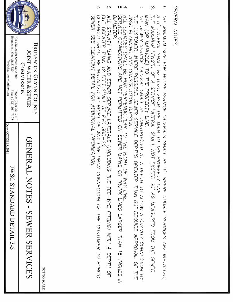


STANDARDS�FOR�WATER�AND�SEWER�DESIGN�AND�CONSTRUCTION��
�
�
���������������������������������������������
SECTION 4 SANITARY SEWER LIFT STATIONS AND FORCE MAINS

STANDARDS�FOR�WATER�AND�SEWER�DESIGN�AND�CONSTRUCTION��
�
Page�1�of�4��
�
TABLE OF CONTENTS SECTION 4 SANITARY SEWER LIFT STATIONS AND FORCE MAINS
4.1 GENERAL 4.2 DESIGN FLOWS
4.2.1 Daily Average Dry Weather Flow (ADWF) 4.2.2 Peaking Factors
4.3 SIZING OF FORCE MAINS 4.4 WET WELL DESIGN CRITERIA
4.4.1 Wet Well Volume 4.4.2 Wet Well Level Control Settings
4.5 DEDICATED WASTEWATER LIFT STATIONS
4.5.1 Lift Station Types 4.5.1.1 Low Flow Lift Stations
4.5.1.2 Standard Duplex Lift Stations 4.5.1.3 Standard Triplex Lift Stations
4.5.2 Site Requirements
4.5.2.1 Site Dimensions 4.5.2.2 Fencing 4.5.2.3 Site Access, Ground Cover and Drainage 4.5.2.4 Site Electrical Power 4.5.2.5 Facility Water Supply 4.5.2.6 Facility Bypass Pumping Connection 4.5.2.7 Facility Elevation Benchmark
4.5.3 Wet Well Configuration
4.5.3.1 Size and Depth 4.5.3.2 Piping and Equipment Layout 4.5.3.3 Ventilation 4.5.3.4 Access Hatches
4.5.4 Precast Concrete Structures
4.5.4.1 Materials 4.5.4.2 Corrosion Protection 4.5.4.3 Installation

STANDARDS�FOR�WATER�AND�SEWER�DESIGN�AND�CONSTRUCTION��
�
Page�2�of�4��
4.5.5 Fiberglass Structures (Alternate Construction Material)
4.5.5.1 Materials 4.5.5.2 Pipe Connections 4.5.5.3 Defects Not Permitted 4.5.5.4 Physical Requirements 4.5.5.5 Backfill Material 4.5.5.6 Documentation
4.5.6 Influent Manhole and Wet Well Influent Line 4.5.6.1 Influent Manhole 4.5.6.2 Wet Well Influent Line
4.5.7 Wet Well and Discharge Header Piping
4.5.7.1 Interior Piping 4.5.7.2 Exterior Piping
4.5.8 Valves and Appurtenances
4.5.8.1 Isolation (Plug) Valves 4.5.8.2 Check Valves 4.5.8.3 Air Release Valves 4.5.8.4 Discharge Gauge Fittings
4.5.9 Pumping Equipment 4.5.9.1 General Requirements
4.5.9.2 Submersible Pumps 4.5.9.3 Grinder Pumps 4.5.9.4 Pump Warranty
4.5.10 Site Electrical Work 4.5.10.1 General
4.5.10.2 Electrical Service 4.5.10.3 Control Panel Connections
4.5.11 Electrical Equipment and Controls
4.5.11.1 General Requirements 4.5.11.2 Submersible Lift Station Motor Control Center

STANDARDS�FOR�WATER�AND�SEWER�DESIGN�AND�CONSTRUCTION��
�
Page�3�of�4��
4.5.12 Remote Terminal Unit (RTU) - System and Panel
4.5.12.1 General 4.5.12.2 Warranty 4.5.12.3 System Requirements
4.5.13 Combination MCC/RTU panel 4.5.14 Low Flow Station (Only) Remote Terminal Unit (RTU) System
4.5.14.1 General 4.5.14.2 Warranty 4.5.14.3 System Requirements
4.5.15 Emergency Power 4.5.16 On-site Standby Generators & Automatic Transfer Controls
4.5.16.1 General 4.5.16.2 Engine-Generator Controls 4.5.16.3 Automatic Transfer Controls/Switches 4.5.16.4 Starting Batteries and Charging Systems 4.5.16.5 Generator Set Enclosure
4.5.17 Lift Station Testing
4.6 PRIVATE LIFT STATIONS
4.6.1 General Requirements 4.6.2 Single Family Residential & Single Lot Commercial Lift Stations 4.6.2.1 Owner Responsibilities
4.6.2.2 System Components
4.6.3 Multi-Family, Multi-Lot and/or Multi-User Commercial Stations 4.6.3.1 Owner Responsibilities
4.6.3.2 System Components
4.7 FORCE MAINS
4.7.1 General 4.7.2 Force Main Manifolds 4.7.3 Force Main Size 4.7.4 Force Main Depth 4.7.5 Force Main Location 4.7.6 Materials

STANDARDS�FOR�WATER�AND�SEWER�DESIGN�AND�CONSTRUCTION��
�
Page�4�of�4��
4.7.6.1 Pipe 4.7.6.2 Joints 4.7.6.3 Fittings 4.7.6.4 Valves 4.7.6.5 Force Main Casings
4.7.7 Force Main Testing APPENDICES Appendix 4A Sanitary Sewer, Lift Station and Force Mains
Acceptable Manufacturers
Appendix 4B Standard Construction Details
4-1 Wetwell level Settings 4-2 Typical Pumping Station - Section 4-3 Typical Pumping Station - Plan 4-4 ARV Manhole 4-5 Transducer Stilling Well 4-6 Facility Bypass Pumping Connection 4-7 Low Pressure System Onsite Service Connection 4-8 Low Pressure System Flush Connection

STANDARDS�FOR�WATER�AND�SEWER�DESIGN�AND�CONSTRUCTION��
�
Page�1�of�62��
SECTION 4 SANITARY SEWER LIFT STATIONS AND FORCEMAINS 4.1 GENERAL �
This section provides the minimum guidelines for the design of wastewater lift stations and their associated forcemains that are considered an integral component of the facility's pumping system. The method of design and/or construction shall be according to, these Design and Construction Standards and Specifications and the following:
Recommended Standards for Sewage Works (Ten State Standards) Latest Edition Georgia Environmental Protection Division State of Georgia Regulations for Water and Sewerage Works, Latest Edition Applicable Federal, State and Local Requirements
In the event of conflicts among the various sources cited above, the most stringent criteria shall take precedence.
4.2 DESIGN FLOWS
Each system component shall be designed to meet certain flow requirements. The various flow requirements are described below. 4.2.1 Daily Average Dry Weather Flow (ADWF)
Daily Average Dry Weather Flow (ADWF) shall be 300 gallons per day per Residential Equivalent Unit (REU) or 115 gallons per day per capita. The basis for one (REU) shall be a single-family unit occupied by an average of 2.6 persons. Where sewer service beyond the basis of the established REU is required, the Sewage Flow Table shown below (Adapted from the Georgia Environmental Division Large Community Design Guidance Document, Pages 8 & 9, Appendix A) shall be used. ADWF estimates for existing facilities that are scheduled for rehabilitation shall be made using data obtained from flow monitoring the existing system over a period of not less than seven (7) days, from which an average daily flow is to be developed. If any rainfall event measuring more than .5 (5/10ths) inches of rain in any of the seven (7) twenty-four (24) hour periods occurs, the monitoring shall continue to provide at least seven (7) days without rainfall.

STANDARDS�FOR�WATER�AND�SEWER�DESIGN�AND�CONSTRUCTION��
�
Page�2�of�62��
Flow monitored data shall be adjusted for other potential loadings as appropriate, (i.e. seasonal usages, tourist loading, etc.) as may be developed or estimated from water use records, percentage of increased occupancy or other rational methods approved by the JWSC.
ADWF for existing facilities that may be scheduled for upgrading to accommodate additional flows from proposed developments shall be made using a combination of flow monitoring and REU calculations.
Figure LS-1 Sewage Flow Table
FACILITY Gallons/Day (GPD)
Assembly Hall 5 per seat Barber Shop/Beauty Parlor 125 per chair + 20/employee Boarding House* 100 per room Bowling Alley 75 per lane + 20/employee Church w/o Day Care or Kindergarten 5 per sanctuary seat Correctional Institution/Prison 250 per inmate Country Club, Recreation Facilities Only 25 per member Day Care Center, No Meals 15 per person Dental Office 100 per chair + 20/employee Department Store 10 per 100 SF Factory Without Showers With Showers
25 per employee 35 per employee
Food Service Establishments* Restaurants (Up to 12 hours per day) Restaurants (12 hours per day to 18 hours per day) Restaurants (Above 18 hours per day) Bar and Cocktail Lounge Drive-in Restaurant Carry-out Only
35 per seat + 20/employee 50 per seat + 20/employee 75 per seat + 20/employee 30 per seat + 20/employee 50 per space + 20/employee 50 per 100 SF + 20/employee
Funeral Home 10 per 100 SF Hospital Inpatient Outpatient
300 per bed 275 per bed
Hotel* 100 per room Kindergarten, No Meals 15 per person Laundry, Commercial 1,000 per machine Laundry, Coin 150 per machine Lodges* 100 per room Mobile Home Park 300 per site Motel* 100 per room Nursing Home* 150 per bed Office 10 per 100 SF Physician's Office 200 per exam room Schools* Boarding Day, Restrooms Only Day, Restrooms and Cafeteria Day, Restrooms, Gym and Cafeteria
100 per person 12 per person 16 per person 20 per person

STANDARDS�FOR�WATER�AND�SEWER�DESIGN�AND�CONSTRUCTION��
�
Page�3�of�62��
FACILITY Gallons/Day (GPD) Service Stations, Interstate Locations 425 + 150 per pump Service Stations, Other Locations 300 + 100 per pump Service Station Car Wash 500 per stall Shopping Center (Not including food service or laundry)
10 per 100 SF
Stadium 5 per seat Supermarket/Grocery Store 20 per 100 SF Theater 5 per seat Travel Trailer Park* With Independent Water & Sewer Connection Without Independent Water & Sewer Connection
175 per site 35 per site
Warehouse 10 per 100 SF *Add 300 gallons per machine to amount indicated if laundry or dish washing machines are installed
Note: Where historical data is available from flow monitoring or other
approved devices as in the case of existing systems, ADWF shall be as averaged from seven (7) days within the monitoring period of flow with no rainfall event greater than .5 (5/10ths) inches of rain in any of the seven(7) twenty-four (24) hour periods being averaged.
4.2.2 Peaking Factors
Upon calculation of the anticipated ADWF in gallons per day for the basin that is to discharge to the pumping facility, a peaking factor of 2.0 shall be applied to the average daily flow expressed in gallons per minute, (ADWF in gpd / 1,440 minutes per day = ADWF in gpm), to account for the daily (diurnal) peak flow in gallons per minute. This gpm figure with the Peaking Factor being applied shall be the required pump rate for the facility; (i.e. 46,080 gpd/1,440 minutes per day = 32 gpm ADWF * 2.0 = 64 gpm = required pump rate). This factor has been determined adequate for pump sizing in the JWSC jurisdictional area and is based on a series of flow monitoring studies conducted on existing lift station basins ranging in size from 25 REU’s to 200 REU’s (per capita populations of 65 to 520, respectively).
4.3 SIZING OF FORCE MAINS
The discharge piping, to include valves, bends and the force main is to be considered an integral part of the lift station pumping system whether the facility is new or being upgraded to handle additional flows. Force mains and associated discharge piping for a single family use lift station discharging to gravity shall be sized for peak flow (required pump rate) at a minimum velocity of 2.0 fps with one pump running and a maximum velocity of 5.0 fps with both pumps running in a duplex station.

STANDARDS�FOR�WATER�AND�SEWER�DESIGN�AND�CONSTRUCTION��
�
Page�4�of�62��
For triplex or quadraplex facilities velocity shall not exceed 5.0 fps with two or three pumps running respectively. Common force mains for low pressure or STEP type systems shall be sized for the flow of the planned system based on the probability analysis of simultaneous pump operation in each pressure zone and line segments common to pressure zones. Line velocities, based on this analysis, shall be a minimum of 2.5 fps at least once during the 24 hr diurnal cycle and no greater than that velocity necessary to discharge the highest head pump on the pressure zone at 11 gpm.
4.4 WETWELL DESIGN CRITERIA
4.4.1 Wetwell Volume
The minimum required wet well storage volume between the SCADA High Water Alarm Level and the all pumps “off” level (top of the submersible pump motor or the required submergence of a self-priming pump suction leg) shall be calculated as follows:
Required Volume = VR = .25TQ + VL + VA
Where:
T = Minimum Cycle Time (see table below) Q = Required Pump Rate VL = Lag Level Volume VA = SCADA High Water Alarm Level Volume
Pump Hp Minimum Cycle Time (T)
<20 15 Minutes 20 to 100 20 Minutes
>100 25 Minutes
The distance/volume between the pump “off” level, mid-motor pump housing elevation to the wet well bottom is subject to pump dimensions and is not considered useable volume. The designer shall be responsible for calculating this additional vertical distance and adding this additional wet well depth.

STANDARDS�FOR�WATER�AND�SEWER�DESIGN�AND�CONSTRUCTION��
�
Page�5�of�62��
4.4.2 Wetwell Level Control Settings
To reduce wetwell turbulence caused by cascading influent that results in odor/corrosion problems and air entrainment, and to provide wet well structures that are in large degree self-cleaning, this Standard requires that the invert of the wet well influent line coming from the contributing system influent manhole be set at the mid-motor elevation of submersible pumps or at the required submergence elevation of suction lift pumps plus 0.5 feet. This vertical increment will ensure a reasonable time period of free flow through the gravity influent line and influent manhole at the design pump rate and thereby the full development of self-cleansing velocity, through these structures as required in this standard. Based on this requirement, the design settings for level control in wet wells shall be as follows:
Low Water Level (LWL) Alarm : Top of submersible pump volute.
Pump “Off” Level (Pump Off): 50% immersion of submersible pump motor mid-point of pump motor housing or pump manufacturers minimum water level, whichever is greater.
Lead Pump “On” Level (Pump On): The vertical dimension in the design wetwell from the Pump “Off” level needed to store the volume required by V=0.25TQ.
Lag Pump “On” Level (Lag On): Pump On Level + 0.5 vertical feet (6 inches) Lag Pump On settings for triplex or quadraplex pump installations shall follow the same dimensional protocol of 6 inch increments and be labeled as Lag2 On, Lag3 On, etc. SCADA High Water Level (SHW): Highest Lag On level + 0.5 vertical feet (6 inches). This elevation shall not exceed the influent manhole lowest invert elevation or lowest invert elevation in the wetwell if an influent manhole is not used.
Audio/Visual High Water Level (AVHW): SCADA HW elevation + 0.5 feet (6 inches). This level setting is intended to mitigate neighborhood alarm noise complaints and the only setting that allows a surcharge of the lowest contributing gravity sewer system main entering the influent manhole. Where primary level control is provided by a Level Transducer, the AVHW float ball and installation shall be as specified for all such devices in this Standard.

STANDARDS�FOR�WATER�AND�SEWER�DESIGN�AND�CONSTRUCTION��
�
Page�6�of�62��
Note: Where flow matching pumping systems are approved for use, (either by VFD or mechanical flow matching technology using pre-rotation basin technology), level control settings shall be by specific facility design and as approved by the JWSC.
4.5 DEDICATED WASTEWATER LIFT STATIONS
Lift stations to be dedicated shall have a minimum required pumping rate of 22 gallons per minute (gpm) at peak diurnal flow and a minimum upstream contributory loading of 16,000 gallons per day (gpd) as calculated in Paragraph 4.2 of this Standard.
Lift stations not meeting this standard, shall be privately owned, operated and maintained under the supervision of a Licensed Georgia Wastewater Collections System Operator. Such privately owned facilities and their contributing gravity systems shall be considered Satellite Systems of the JWSC requiring an agreement with the JWSC to discharge to the Public System.
Any future consideration by the JWSC to accept Public ownership of a privately owned facility shall be precedent upon such facility’s adherence to this Standard or upgrade to this Standard. 4.5.1 Lift Station Types 4.5.1.1 Low Flow Lift Stations
Low Flow Lift Stations shall be defined as those facilities whose loading requires pumping capacities between 22 gpm and 79 gpm. These facilities are intended to serve limited areas where the service area cannot be expanded and wastewater service cannot be otherwise provided by on-site (septic) systems or low pressure systems capable of discharging to Public gravity. Such facilities, where approved, shall be grinder pump duplex stations meeting all criteria of this Standard. 4.5.1.2 Standard Lift Stations
Standard Duplex Lift Stations shall be defined as those facilities whose loading requires pumping rates between 80 gpm and 749 gpm. Standard Triplex Lift Stations shall be defined as those facilities whose loading requires pumping rates between 750 gpm and 3,000 gpm. Triplex facilities shall be flow proportional and be equipped with an automatic standby power generator.

STANDARDS�FOR�WATER�AND�SEWER�DESIGN�AND�CONSTRUCTION��
�
Page�7�of�62��
Standard Quadraplex Lift Stations shall be defined as those facilities whose loading requires pumping rates greater than 3,000 gpm. Quadraplex facilities shall be flow proportional and be equipped with an automatic standby power generator. 4.5.1.3 Initial/Ultimate Lift Stations
Initial/Ultimate Lift Stations shall be defined as those facilities whose initial loading requirement is significantly less than the ultimate loading requirement as determined by a submitted and approved build-out plan. Such facilities shall be designed to meet all criteria of this Standard with exceptions as noted herein.
4.5.2 Site Requirements
The property, on which the facility is constructed, is to include the influent manhole and all related lift station appurtenances. 4.5.2.1 Site Dimensions Minimum site dimensions of the property shall be as follows:
a. Four (4) foot and five (5) foot diameter wet wells – minimum 30’ x 30’ (restricted to Low Flow Stations)
b. Six (6) foot and eight (8) foot diameter wet wells – minimum 50’ X 50’
c. Ten(10) foot diameter and greater – minimum 60’ X 60’
d. Rectangular structures – minimum 60’ X 60’
e. Irregular sites and site sizes may be considered by the JWSC where
atypical conditions exist. 4.5.2.2 Fencing
Fencing is required on all sites and shall be placed a minimum of two (2) feet inside of all site property lines and constructed as follows:
a. The fence shall be six (6) feet high, consisting of two (2) inch mesh by nine (9) gauge aluminum coated steel fabric with green PVC coating, conforming to the latest revision of ASTM A-491. The fence shall have a seven (7) gauge aluminum coated steel coil spring tension wire along the bottom of the fence fabric.

STANDARDS�FOR�WATER�AND�SEWER�DESIGN�AND�CONSTRUCTION��
�
Page�8�of�62��
Three strands of twelve and one-half (12-½) gauge aluminum coated steel of barbed wire with four (4) point aluminum barb spaced five (5) inches apart mounted on the barbed wire support arms shall be installed along the top of the fence fabric.
b. The posts shall be galvanized line posts, two and a half (2 ½) inch O.D. (3.65 lbs per ft); galvanized corner posts, three (3) inch O.D. (2.27 lbs per ft) with extra long pressed steel sleeves. Corner and gate post shall have necessary struts and tie bracing. Provide water tight closure caps on all posts.
c. Gate shall be a pair of 8’-0” long (sixteen (16) foot total width) six (6) feet high sections and shall be equipped with a prop post center latch and hasp assembly. A ground anchor cast in concrete shall be provided. Gates shall be factory fabricated, green PVC coated conforming to the latest revision of ASTM A-429 and equipped with gate holders. Duckbill backstops shall be provided for swing side of both gate sections.
d. The gate entrance shall be set back at least twenty feet from a public or private road in order to allow vehicles to pull off the road before opening the gate.
e. Where aesthetics are a concern, the fencing cloth may be interwoven with vinyl stripping to obscure the site from public view. The color of stripping shall be dark green.
4.5.2.3 Site Access, Ground Cover and Drainage
a. The entire site shall be covered with a geotextile filter fabric covered with six (6) inches of compacted crusher run (GAB) stone. Stone shall be clean with no soil or foreign material present.
b. The graveled area shall be treated with a high quality, long lasting, EPA environmentally approved weed killer.
c. Site shall be serviced by a twelve (12) foot wide all weather road with top of road above the two (2) year flood elevation.
d. Drainage structures and conveyances shall not be allowed and no catch basin shall be located within the pumping station site. The entire site shall graded such that storm water runoff sheet flows outwards and away from structures and other appurtenances and into proper drainage channels.

STANDARDS�FOR�WATER�AND�SEWER�DESIGN�AND�CONSTRUCTION��
�
Page�9�of�62��
e. No site shall be located within the backwater of any lake, pond, ditch, canal or other water body without such flood level being taken into consideration by raising the site grade, the structure openings or providing watertight structure hatches above such backwater levels. The twenty-five year flood elevation shall be the governing factor if backwater levels are not historically available or known.
f. Pump stations shall be designed and located on the site so as to minimize the effects resulting from odor, noise, and lighting.
g. Where the location of the facility would require backing onto a public road to leave the site an area along the access or at the facility gate shall be wide enough to provide a service vehicle turnaround.
h. Any proposed on-site landscaping or specialized ground cover being considered to improve the aesthetics of the site or block the site from view shall be approved by the JWSC. No trees will be permitted within the property boundary.
4.5.2.4 Site Electrical Power
a. All power lines within the site shall be underground. No overhead power line will be allowed to cross the site.
b. All facilities shall be served with three-phase power. If three-phase power is not available the Design Engineer shall submit a copy of written communication from the commercial power provider stating at what cost three-phase power would be available. In cases where pump station location has been optimized for both elevation and power supply and providing three-phase power costs are disproportionally high, variable frequency drives (VFD’s) will be considered to operate the three phase motors. Prior written approval will be required from the JWSC to utilize single-phase power. Add-a-phase units are not allowed.
c. A facility yard light and pole shall be provided for night operations and security purposes. The light shall be a 120V 500W Quartz or Halogen floodlight pointed at the control panel. The light shall be placed on a switch with a 24-hour timer capable of illuminating the facility on a selectable periodic basis. The switch and timer shall be housed in a weather-proof enclosure on the light pole. The light pole shall extend a minimum of twelve (12) feet from grade with the light fixture mounted within one (1) foot of its top for maximum coverage.
STANDARDS�FOR�WATER�AND�SEWER�DESIGN�AND�CONSTRUCTION��
�
Page�10�of�62��
4.5.2.5 Facility Water Supply a. The facility shall be provided with a one (1) inch water service line for
clean-up use and testing.
b. The water service line shall be protected with the installation of a reduced pressure backflow assembly installed within the fenced enclosure. The RPZ shall be in accordance with Paragraph 2.4.6.2 of these Standards and Specifications.
Where requested by the JWSC, the backflow preventer piping shall be provided with a 4-20 milli-amp pressure transducer to sense area potable water pressures.
c. The water service line shall incorporate a frost-proof yard hydrant. Yard hydrants are to be stainless steel and have locking capability. No water meter will be required for water use at lift stations.
4.5.2.6 Facility Bypass Pumping Connection A facility bypass pumping connection shall be provided in accordance with the JWSC Standard Details.
a. The facility shall be provided with an external connection to the force
main serving the station for use during emergency and maintenance situations.
b. The bypass connection shall be sized to the diameter of the main pumps discharge line and be set downstream from the isolation valves of the main pump piping header.
c. The bypass connection shall be provided with a plug valve, set on the underground horizontal run to the bypass connection, and a check valve and CAM Lock with cap set on the aboveground horizontal run to the pump connection point.
d. The bypass connection shall be placed and oriented on the site to facilitate the setting of a bypass pump between the influent manhole and the bypass connection.
e. The bypass connection shall be provided with a 3'x3'x6" concrete slab base.
f. The point of attachment to the bypass connection shall be oriented horizontal and not protrude above its concrete slab more than 1 foot.

STANDARDS�FOR�WATER�AND�SEWER�DESIGN�AND�CONSTRUCTION��
�
Page�11�of�62��
g. The bypass connection piping and fittings shall be epoxy lined
“Sewer-Safe” D.I.P. with exterior coating the same as the lift station discharge header piping.
4.5.2.7 Facility Elevation Benchmark
A Standard Brass Benchmark shall be set into the wet well slab top with the NAVD88 Mean Sea Level Elevation stamped on the face of the benchmark by a Georgia Registered Land Surveyor. An alternate location for the benchmark may be approved where structure configuration is atypical.
4.5.3 Wetwell Configuration
4.5.3.1 Size and Depth a. The maximum wetwell depth, as measured from the wet well rim to the
lowest point of the sump, shall not exceed 20 feet.
b. The minimum circular wetwell diameter shall be 6 feet; (surface area 28ft2), for all but low flow stations for which wet well diameters of five (5) feet shall be used.
c. The minimum rectangular wetwell dimensions, where approved for
special applications where wetwell depth is critical, shall be 6 feet by 6 feet or other dimension providing an equal or larger surface area; (surface area 36ft2).
d. Where the JWSC has approved a facility having an initial and an
ultimate flow design, the wetwell shall be sized for the ultimate pump rate whereas the storage height (and consequent level control settings) shall be established on the initial pump rate. The level settings shall be as stipulated in Paragraph 4.4.2 of this Standard.
4.5.3.2 Piping and Equipment Layout a. All wetwell inverts and pump intake sumps shall be configured to
provide self-cleaning characteristics. Water surface levels at low water level shall be minimized to allow the removal of debris before the pump loses prime during a manual maintenance pump-down by operators.

STANDARDS�FOR�WATER�AND�SEWER�DESIGN�AND�CONSTRUCTION��
�
Page�12�of�62��
b. The wetwell shall have only one (1) influent line with its invert set 0.5 feet above the “Pump-Off” (mid-point of pump motor housing elevation), and it shall enter the wetwell coplanar, (aligned parallel and in-line), with the pump discharge lines in accordance with the JWSC Standard Details.
c. The wetwell inverts shall be sloped downward from the top of the
submersible pump motor toward the wet well pump sump at a 60 degree angle from the vertical. Flat areas for pump connection discharge elbows shall be eliminated or sloped with coated grout materials as much as possible to shed debris (See the JWSC Standard Details).
d. The wetwell pump sump geometry shall provide for the required
spacing between pumps, sump walls and floor as required by the manufacturer while simultaneously minimizing the water surface area at the “lowest” water level (top of pump) to allow the vortex to engulf floating solids quickly before the pump loses prime during periodic cleaning cycles in manual operation.
e. The wetwell shall be provided with appropriately placed adjacent
sleeves, 24 inches below finished grade, for access of the power and control conduits. The sleeves shall be of proper size to accommodate all necessary power and control conduits.
f. Where the design flow of the station requires a pressure transducer for
level control, an additional sleeve shall be required. It shall be placed 24” below finished grade and centered between the discharge legs. The sleeve shall be 2” in diameter. A slotted 6” PVC/HDPE joint of pipe shall be installed within the wet well, between the discharge legs, to serve as the housing and stilling well for the transducer. The stilling well shall terminate at the level of the pump intakes and be securely fastened to the discharge piping. The transducer shall be set within the stilling well at the low water level elevation of the station (See JWSC Standard Details).
4.5.3.3 Ventilation The ventilation for the wet well shall be designed as a passive gravity ventilation system where the air volume in the wet well is either increased or decreased as the wastewater level fluctuates due to inflow and outflow. The passive ventilation shall be sized to vent at a rate equal to the maximum pumping rate of the station, not to exceed maximum permissible design airflow through the vent pipe of 600 feet per minute (fpm). Passive “gooseneck” vents shall be turned down so that the opening faces the top slab of the wet well.

STANDARDS�FOR�WATER�AND�SEWER�DESIGN�AND�CONSTRUCTION��
�
Page�13�of�62��
The minimum allowable passive vent diameter shall be 6 inches. Stainless steel screens shall be required to prevent birds and/or insects entry into the wet well. The vent shall be placed diametrically opposite of the control panel. Vent piping shall be 304 stainless steel. 4.5.3.4 Access Hatches
Access hatches shall provide the required clear opening for pump removal and be set in the concrete top so as to allow the pump to be removed through the approximate center of the hatch. The hatch material shall be Aluminum Alloy 6063-T5 & T6, one-fourth (¼) inch plate, with flush type lock and inside spoon handle having a live load capacity of 300 pounds per square foot. The frame shall be equipped with a stainless steel hinged and hasp-equipped cover, two (2) upper guide bar holders and stainless steel chain holders. The door shall be torsion bar loaded for ease of lifting, shall have a safety locking handle in the open position and safety grate. All fastening hardware used inside the wet well shall be stainless steel.
a. Pump access covers shall be suitably sized to provide adequate clearances for installation and removal of the pumping units.
b. Hatches should be sized for the ultimate pump design. The access hatch should be designed for a minimum width of 36" or 6" beyond the manufacturer’s minimum required width, whichever is greater.
c. The minimum hatch length should be forty-eight (48) inches for standard duplex stations and ninety-six (96) inches for triplex stations or the sum of the pump width, centerline pump separation, plus twelve (12) inches, whichever is greater.
d. Low Flow Station hatches shall be sized to adequately remove the pumps and shall not be required to adhere to the minimum requirements.
4.5.4 Precast Concrete Structures
4.5.4.1 Materials Precast wet well bases, sections and related structures shall conform to the requirements of ASTM C478 (specification for precast concrete manhole sections and structures) except as modified herein. Cement shall be minimum 4,000 psi concrete meeting the requirements of ASTM C150 (specification for Portland cement, type II).

STANDARDS�FOR�WATER�AND�SEWER�DESIGN�AND�CONSTRUCTION��
�
Page�14�of�62��
Minimum wall thickness shall be 1/12th the inside diameter in inches plus one (1) inch. Ring reinforcement shall be custom-made with openings to meet indicated pipe alignment conditions and invert elevations. Bases for wet wells shall be cast integrally with the bottom section. A Flexible Neoprene-EPDM pipe connector, conforming to ASTM C443 shall be used to connect the sewer influent pipe to the precast concrete wet well. The connector shall be a minimum of three-eighths (3/8) inches thick or greater and resistant to ozone, weathering, aging, chemicals and petroleum products. The securing bands shall be stainless steel and screw assembly and totally non-magnetic Series 304 stainless steel. The connector shall be of a size specifically designed for the specified pipe material and size. The interior annular space between the exterior of the pipe and the interior of the connector shall be filled with a Type II lean cement grout. The exterior (below grade) of precast concrete wet wells shall be given two coats of an approved bituminous water proofing materials. 4.5.4.2 Corrosion Protection
The interior corrosion protection for precast concrete wet wells shall be in accordance with the following schedule based on detention time of sewer flow from the uppermost region of the contributing pipe reach using an average velocity of two (2) feet/sec.
Figure LS-1 Interior Corrosion Protection Table
Vapor H2S Corrosion Risk Level Detention Time Corrosion Protection
0-10 PPM No or Low Risk <2 Hours None 11-50 PPM Moderate Risk 2 - 4 Hours Coal Tar Epoxies
>50 PPM High Risk >4 Hours Calcium Aluminates Epoxy Coatings Approved Coating Systems
a. Corrosion protection for High Risk Wet Wells shall be hydrogen sulfide resistant cementious products containing calcium aluminates applied one-half (½) inch to three-fourths (¾) inches of thickness onto all interior surfaces after proper substrate preparation; precast wet well structures manufactured of calcium aluminate cement concrete or precast structures with approved epoxy coatings applied a minimum of 150 mil thickness.

STANDARDS�FOR�WATER�AND�SEWER�DESIGN�AND�CONSTRUCTION��
�
Page�15�of�62��
Alternatives that provide equal or better protection may be approved. A (ten 10) year warranty will be required.
b. All wet wells designed with the intention of being used as a receiving wet well from upstream lift stations, or considered by the JWSC to be Regional Lift Stations, shall be considered High Risk Wet Wells.
4.5.4.3 Installation The base section shall be set in a twelve (12) inch (minimum) leveling course of granular material (57 stone). Precast concrete sections shall be set so the wet well will be vertical and with sections in true alignment. All holes in sections used for their handling and the annular space between the wall and entering pipes shall be thoroughly plugged with an approved, non-shrinking mortar or grout, applied and cured in strict conformance with the manufacturer’s recommendations, so that there will be zero leakage through openings and around pipes. The mortar shall be finished smooth and flush with the adjoining interior and exterior wall surfaces. Joint contact surfaces shall be formed with machined castings and shall be exactly parallel and sealed with a joint sealer over the entire joint surface. Joints shall be water tight. Excess joint sealer shall be trimmed flush with the inside and outside surface of the structure.
All exterior joints of precast concrete wet well shall be sealed with one twelve (12) inch wide exterior joint sealant membrane centered on the joint. The tape shall be capable of sealing joints against groundwater infiltration. The installation of the membrane shall be in conformance with the recommendations of the manufacturer. The concrete surface must be smooth, clean, dry and free of voids, loose aggregate, dirt or other matter that will hinder the adhesion of the membrane. A primer shall be used in accordance with the recommendations of the membrane manufacturer.
4.5.5 Fiberglass Structures (Alternate Construction Material)
Fiberglass wet wells, when approved for use by the JWSC, shall meet the following requirements.

STANDARDS�FOR�WATER�AND�SEWER�DESIGN�AND�CONSTRUCTION��
�
Page�16�of�62��
4.5.5.1 Materials
Unless otherwise noted by the JWSC, a circular fiberglass wet well may be used in lieu of a precast concrete wetwell. The fiberglass wet well shall be designed (signed and sealed) by a Georgia Professional Engineer and meet all applicable configuration criteria as shown in Paragraph 4.5.3 of this Standard. The wet well shall include a twenty four (24) inch (minimum) thick twelve (12) inch thick inside the wet well and twelve (12) inch thick outside the wet well reinforced concrete hold-down base which extends twenty four (24) inches beyond the outside of the wet well, a six (6) inch (minimum) thick reinforced concrete top slab, pump access frame and cover and other standard wet well features. Pumps shall be anchored to a one (1) inch thick steel plate.
Fiberglass reinforced polyester wet wells shall be manufactured from commercial grade polyester resin or vinyl ester resin, with fiberglass reinforcements. The resin system shall be suitable for atmospheres containing hydrogen sulfide and dilute sulfuric acid as well as other gases associated with the wastewater collection systems. The wetwell shall be a one-piece unit unless otherwise approved by the JWSC. The resins used shall be a commercial grade unsaturated polyester resin.
The reinforcing materials shall be commercial Grade "E" type glass in the form of mat, continuous roving, chopped roving, roving fabric or a combination of the above, having a coupling agent that will provide a suitable bond between the glass reinforcement and the resin.
If reinforcing materials are used on the surface exposed to the contained substance, they shall be a commercial grade chemical-resistant glass that will provide a suitable bond with the resin and leave a resin rich surface.
Fillers, when used, shall be inert to the environment and wetwell construction. Additives, such as thixotropic agents, catalysts, promoters, etc., may be added as required by the specific manufacturing process to be used. The resulting reinforced plastic material must meet the requirement of this specification.
The exterior surface shall be relatively smooth with no sharp projections. Handwork finish is acceptable if enough resin is present to eliminate fiber show. The exterior surface shall be free of blisters larger than one-half (1/2) inch in diameter, delamination and fiber show.

STANDARDS�FOR�WATER�AND�SEWER�DESIGN�AND�CONSTRUCTION��
�
Page�17�of�62��
The interior surface shall be resin rich with no exposed fibers. The surface shall be free of grazing, delamination, and blisters larger than one-half (1/2) inch in diameter, and wrinkles of one-eighth (1/8) inch or greater in depth. Surface pits shall be permitted up to six (6) square feet if they are less than three-fourths (3/4) inch in diameter and less than one-sixteenth (1/16) inch deep.
The bottom to be fabricated using fiberglass material as stated in Paragraph 4.5.5.1 with material and installation to meet all physical requirements of Paragraph 4.5.5.4 below. The Bottom shall be attached to wetwell pipe with fiberglass layup to comply with ASTM D3299 specifications. When reinforcement is necessary for strength, the reinforcement shall be fiberglass channel laminated to wet well bottom.
The fiberglass wet well top shall be fabricated using fiberglass material as stated in Paragraph 4.5.5.1 with material and installation to meet all physical requirements of Paragraph 4.5.5.4 below. The top is to be attached to wetwell pipe with fiberglass layup to comply with ASTM D3299 specifications. When reinforcement is necessary for strength, the reinforcement shall be fiberglass channel laminated to wetwell top.
4.5.5.2 Pipe Connections
Effluent, service, or discharge lines may be factory installed. Approved methods are PVC sewer pipe, Inserta-Tee fittings, or Kor-N-Seal boots. The installation of stub outs shall be fiberglass layup to comply with ASTM D3299 specifications.
4.5.5.3 Defects Not Permitted
Any of the following defects observed or present in the finished structure shall be cause for rejection.
a. Exposed fibers: glass fibers not wet out with resin. b. Resin runs: runs of resin and sand on the surface. c. Dry areas: areas with glass not wet out with resin. d. Delamination: separation in the laminate. e. Blisters: light colored areas larger than one-half (1/2) inch in
diameter.
f. Crazing: cracks caused by sharp objects.

STANDARDS�FOR�WATER�AND�SEWER�DESIGN�AND�CONSTRUCTION��
�
Page�18�of�62��
g. Pits or Voids: air pockets.
h. Wrinkles: smooth irregularities in the surface.
i. Sharp projection: fiber or resin projections necessitating gloves for handling.
4.5.5.4 Physical Requirements
LOAD RATING: The complete wet well shall have a minimum dynamic-load rating of 16,000 ft-lbs. To establish this rating, the complete wetwell shall not leak, crack, or suffer other damage when load tested to 40,000 ft-lbs and shall not deflect vertically downward more than one-fourth(1/4) inch at the point of load application when loaded to 24,000 lbs.
STIFFNESS: The wet well cylinder shall have a minimum pipe-stiffness value shown in the following table when tested in accordance with this Article of the Standard:
LENGTH (FT) F/AY (PSI)
0 TO 10 1.26 10 TO 20 2.01
PHYSICAL PROPERTIES:
HOOP AXIAL Tensile Strength (PSI) 18,000 5,000Tensile Modulus (PSI) 800,000 700,000Flexural Strength (PSI) 26,000 4,500Flexural Modulus (PSI) Without Ribs 48”,60”, 72” With Ribs 96”, 144”
1,400,000700,000
700,000700,000
TEST METHODS: Tests shall be performed as specified in ASTM D3753, Section 8
4.5.5.5 Backfill Material
Unless shown otherwise on the drawings, sand or crushed stone shall be used for backfill around the wetwell for a distance of two feet from the outside surface and extending from the bottom of the excavation to the bottom of the top slab. Suitable material chosen from the excavation may be used for the remainder of the backfill. The material chosen shall be free of large lumps or clods, which will not readily break down under compaction. This material will be subject to approval by the JWSC. Backfill material shall be free of vegetation or other extraneous material. Excavated materials which are to be used for fill or backfill may be stockpiled on the site. Top soil should be stockpiled separately and used for finish grading around the structure.

STANDARDS�FOR�WATER�AND�SEWER�DESIGN�AND�CONSTRUCTION��
�
Page�19�of�62��
a. Backfill operations shall not begin until the concrete has been
allowed to cure and the forms removed.
b. Backfill shall be placed in layers of not more than twelve (12) loose measure inches and mechanically tamped to at least 95% Standard Proctor Density. Flooding will not be permitted. Backfill shall be placed in such a manner as to prevent any wedging action against the structure.
4.5.5.6 Documentation
Each wetwell shall be marked with the following information.
a. Manufacturer's name or trademark
b. Manufacturing special number
c. Total length and nominal diameter
Marking shall be placed on the interior wall of the wetwell near the top so as to be readable after installation.
4.5.6 Influent Manhole and Wetwell Influent Line
All lift stations shall be equipped with only one influent line to the wetwell to serve as an approach pipe to the self-cleaning wet well pump sump, and one influent manhole to facilitate bypass pumping. 4.5.6.1 Influent Manhole The influent manhole shall be located within the fenced lift station enclosure area or extension thereof and placed on the same side of the wetwell as the bypass pump connection. The horizontal distance between the wet well and the influent manhole shall be the greatest possible horizontal distance within the confines of the site; however, at a minimum the horizontal distance shall be one (1) foot of horizontal separation for every one (1) foot of vertical wet well depth to avoid taking both structures out if construction work on either is necessary in the future.
All influent manholes shall be outside drop manholes with the influent line being a minimum of two (2) vertical feet above the manhole invert to provide a nominal pumping range during bypass operations. The influent manhole shall be five (5) foot in diameter minimum. Where a wetwell diameter less than the 6 foot minimum is approved, the influent manhole may be four (4) foot in diameter.

STANDARDS�FOR�WATER�AND�SEWER�DESIGN�AND�CONSTRUCTION��
�
Page�20�of�62��
The corrosion protection on the influent manhole shall be the same as that required on the wetwell at the site. The manhole frame & cover on the influent manhole shall be a JWSC Standard thirty-two (32) inch frame & cover. 4.5.6.2 Wet Well - Influent Line The effluent line from the influent manhole to the wet well shall enter the wet well 0.5 feet above the “Pump-Off” (mid-point of pump motor housing) elevation, be at least one nominal diameter larger than the largest diameter influent line coming from the basin gravity sewer system and be sloped no greater than 2% and no less than needed to provide self-cleansing velocity at the facility design pump rate. Larger diameter lines between the influent manhole and wet well may be considered where pump range volume is an issue so long as self-cleaning velocity at the pump-off level is obtained.
4.5.7 Wetwell and Discharge Header Piping
4.5.7.1 Interior Piping
All interior wet well discharge piping shall be epoxy lined/exterior coated Class 53 Flange by Flange Ductile Iron Pipe (DIP) with 316 Stainless Steel nuts, bolts and washers; or, IPS DR 11.0 (160 psi) Flange by Flange High Density Polyethylene (HDPE) with 316 Stainless Steel backup rings, nuts, bolts and washers. Each discharge leg shall be one continuous pipe joint. All nuts, bolts and accessories within the wet well shall be 316 Stainless Steel. 4.5.7.2 Exterior Piping All pipe and fittings outside of the wet well and above ground shall be epoxy lined “Sewer-Safe” Class 53 Flange by Flange Ductile Iron Pipe (DIP). All bolts, washers and nuts shall be 316 Stainless Steel. Bolt threads shall be coated with “Never Seize” type coating. All above ground pipe, fittings and valves shall receive two coats of an exterior coating of “moisture cured aluminized urethane” or epoxy paint with surface preparation in accordance with the paint manufacturer’s recommendation. The paint color shall be tan.
All header discharge piping, fittings and valves shall be constructed approximately three (3) feet above grade and horizontal to the top of the wet well.

STANDARDS�FOR�WATER�AND�SEWER�DESIGN�AND�CONSTRUCTION��
�
Page�21�of�62��
Adjustable pipe stands constructed of 304 Stainless Steel – one and one-half (1 ½) inch all thread into a two and one-half (2 ½) inch SCH 40 pipe w/ nine (9) inch by nine (9) inch by a quarter (¼) inch base plate fixed with four (4) seven-sixteenth (7/16) inch X three (3) inch lag bolts at the corners shall be provided as support. The strength and number of pipe stands may vary depending on header length and weight.
4.5.8 Valves and Appurtenances
All lift station pumps shall be equipped with an isolation valve, check valve and discharge gauge fitting on its discharge header. The common manifold header for the pumps shall be equipped with combination air/vacuum air release valve and an isolation valve to isolate the entire pumping system from the serving force main. 4.5.8.1 Isolation (Plug) Valves Lift Station Isolation valves on submersible pump installations shall be Plug Valves mounted horizontally on the discharge header.
a. All plug valves shall be of non-lubricated, eccentric plug type with
Buna “N” neoprene, epoxy or fusion bonded, nylon faced plugs. Valve bodies shall be ASTM A126, Class B cast iron with all exterior mounted bolts and nuts to be stainless steel.
b. Port areas of four (4) inch through twelve (12) inch valves shall be
100% of full pipe area.
c. The valve seat material shall consist of either a welded in one-eighth (1/8) inch overlay of 90% pure nickel, or 316 Stainless Steel screwed into the cast iron body.
d. Upper and lower plug stem bearings shall be sleeve-type of a
stainless steel or other non-corrosive bearing material.
e. The packing shall be adjustable and the bonnet shall be bolted.
f. All bolts, nuts and washers shall be 316 Stainless Steel.
g. The valves shall be rated for a minimum of 150 psi, and shall provide drip-tight shut off with this pressure in either direction.
h. The interior of all plug valves shall be epoxy coated.

STANDARDS�FOR�WATER�AND�SEWER�DESIGN�AND�CONSTRUCTION��
�
Page�22�of�62��
i. All plug valves eight (8) inches and larger shall be equipped with totally enclosed worm gear actuators complying with AWWA C504. All gearing shall run in oil. The actuator housing shall be semi-steel with seals to prevent dirt or water from entering the housing. Shaft bearings shall be permanently lubricated bronze bushings. Appropriately sized hand wheel operators shall be provided for each gear-actuated valve.
4.5.8.2 Check Valves Lift Station Check Valves on submersible pump installations shall be swing check valves mounted horizontally on the discharge header.
a. All check valve interiors shall be fully coated with a liquid thermosetting epoxy suitable for use in wastewater applications.
b. Swing Check valves shall conform to the requirements of AWWA
C508.
c. Swing Check valves larger than two (2) inch nominal size shall be cast iron body with stainless steel bolts and nuts, flanged ends, 316 Stainless Steel shaft connected to a steel outside lever and stainless steel spring, swing-type with straight-away passageway of full pipe area. The valve shall have renewable bronze seat ring and rubber-faced disc.
d. Swing Check valves larger than two (2) inches shall be 150 psi
working pressure.
e. Swing Check valves two (2) inches and smaller nominal size shall be all brass swing check valves, 200 psi working pressure.
f. All check valves shall be placed upstream of the pump isolation
valve.
4.5.8.3 Air Release Valves
Lift Station Air Release Valves on submersible pump installation discharge headers shall be combination (air release and vacuum release) type valves placed on the discharge header manifold piping upstream of the manifolds station isolation valve on the common header.

STANDARDS�FOR�WATER�AND�SEWER�DESIGN�AND�CONSTRUCTION��
�
Page�23�of�62��
a. Combination air release valves shall be two (2) inch inlet (minimum), stainless steel internal trim (including float, lever arm, leakage, etc.), stainless steel assembly bolts, stainless steel backwash accessories including quick disconnects and stainless steel ball valves (gate valve are also acceptable). The body of the air valve shall be 316 Stainless Steel or iron or steel body with fusion bonded epoxy (twelve (12) Mils thickness, minimum) or ceramic coating (inside and outside surfaces) or nylon plastic.
4.5.8.4 Discharge Gauge Fittings
Discharge Gauge fittings shall be installed on the discharge header pipe of each submersible pump.
a. The gauge fitting shall be installed on discharge header pipe a minimum of six (6) inches upstream from each pumps check valve.
b. The gauge fitting shall be installed by drilling and tapping a one-
fourth (¼) inch NPT hole, installing a 316 Stainless Steel nipple (approximate two (2) inches in length), attaching a one-fourth (¼) inch Stainless Steel ball valve, another 316 Stainless Steel nipple (approximately two (2) inches in length) to the ball valve, and attaching a one-fourth (¼) inch NPT Quick Connect coupler to the nipple.
c. One (1) four and one-half (4 ½) inch diameter face glycerin filled
Wika discharge gauge, graduated in 1 psi increments (0 – 60 psi) and one (1) foot increments of H2O (0 – 140 feet H2O) scale range, with quick-disconnect, shall be provided for each submersible pump. Gauges shall be provided in plastic protective cases and equipped with quick disconnects.
4.5.9 Pumping Equipment
Lift station pumps shall be submersible pumps and shall meet the following requirements. 4.5.9.1 General Requirements
All pumps designed and selected shall be within +/- 20% of the pumps best efficiency point. When possible, the pump selection shall be made in the center of the family of curves.
STANDARDS�FOR�WATER�AND�SEWER�DESIGN�AND�CONSTRUCTION��
�
Page�24�of�62��
Where the JWSC has approved the station to be designed as an initial/ultimate facility, the pump’s base elbow should be sized for the ultimate pumps. The pump manufacturer shall provide an adapter plate for the initial pumps. 4.5.9.2 Submersible Pumps
Submersible Pumps and installation shall be in accordance with the follow minimum standards:
a. Pumping equipment shall be premium quality submersible non-clog pumps for sewage service. Wet-pit pumps shall be complete with a submersible electric motor, floor-mounted discharge base and elbow, guide rails, motor electrical cable (minimum forty (40) feet in length) to connect at the demarcation box (no splicing allowed) and all other appurtenances specified or otherwise required for proper operation.
b. Equipment furnished and installed shall be fabricated, assembled,
erected and placed in proper operating condition in full accordance with drawings, specifications, engineering data, instructions and recommendations of the equipment manufacturer, unless exceptions are noted and approved by the JWSC.
c. Pump performance shall be stable and free from cavitations and
noise throughout the specified operating head range at minimum suction submergence. Pump shall be designed so that reverse rotation at rated head will not cause damage to any component.
d. Major pump components shall be of gray cast iron. All exposed
nuts, bolts, washers, anchor bolts and other fastening devices coming in contact with sewage shall be 316 Stainless Steel.
e. The impeller casing shall have well-rounded water passages and smooth interior surfaces free from cracks, porosity, blowholes, or other irregularities. The impeller shall be semi-open or enclosed one-piece casting with no more than two non-clog passages and must pass a minimum three (3) inch solid. The interior water passages shall have uniform sections and smooth surfaces and shall be free from cracks and porosity. The impeller shall be dynamically balanced and securely locked to the shaft. All interior water passages and impeller shall be coated with an approved epoxy coating to increase efficiency and resist wear.

STANDARDS�FOR�WATER�AND�SEWER�DESIGN�AND�CONSTRUCTION��
�
Page�25�of�62��
f. Pumps shall have mechanical seals, which shall require neither maintenance nor adjustment and shall be readily accessible for inspection and replacement. The seals shall not rely upon the pumped media for lubrication and shall not be damaged if the pump is run un-submerged for extended periods while pumping under load. Mechanical seals shall be solid hard faced, (not laminated type). The bottom seal shall be tungsten carbide or silicon carbide material. The top seal may be carbon-ceramic, tungsten carbide or silicon carbide material. Replaceable or adjustable wear rings shall be provided for all pumps.
g. All mating surfaces (pump assembly), of major components shall be machined and fitted with o-rings where watertight sealing is required.
h. The pump manufacturer shall furnish a discharge base and
discharge elbow for the pump supplied. The base shall be sufficiently rigid to firmly support the guide rails, discharge piping and pump under all operating conditions. The base shall be suitable for bolting to the floor, (bolting to a standard one (1) thick metal plate), of the wet well. The face of the discharge elbow inlet flange shall make contact with the face of the pump discharge nozzle flange. The pump and motor assembly shall be a “quick disconnect” type connected to and supported by the discharge base and guide rails allowing the pump to be removed from the wet well and replaced without the need for unbolting any flange, lowering the liquid level or requiring operating personnel to enter the wet well. Pump shall be provided with a sealing flange and guide rail sliding bracket. The bracket shall be designed to obtain a leak proof seal between flange faces as final alignment of the pump occurs in the connected position. The bracket shall maintain proper contact and a suitably sealed connection between flange faces under all operating conditions. Metal to metal mating surfaces are acceptable, if machined finished.
i. The pump shall be driven by a totally submersible electric motor. Pump motor shall be of sufficient horsepower as to be non-overloading over the entire length of the pump curve. The stator housing shall be a watertight casing. Motor insulation shall be moisture resistant, Class F, 155 degree C. at a minimum. Motors 25 HP and larger shall be VFD rated including Class H winding insulation. Motor shall be NEMA Design B for continuous duty at 40 degree C ambient temperature and designed for at least 10 starts per hour.

STANDARDS�FOR�WATER�AND�SEWER�DESIGN�AND�CONSTRUCTION��
�
Page�26�of�62��
All motors shall be 3 phase. Motor bearings shall be anti-friction, permanently lubricated type. Motor shall be designed to operate in a totally, partially or non-submerged condition without damage to the motor. Pump cable assembly shall bear a permanently embossed code or legend indicating the cable is suitable for submerged use. Cable sizing shall conform to NEC requirements. The cable shall enter the pump(s) through a heavy-duty stainless steel assemble with grommet. The system used shall ensure a water tight submersible seal. Cable shall terminate in a junction chamber. Junction chamber shall be sealed from the motor by a compression seal.
j. All rotating parts shall be machined and in near perfect rotational
balance as possible. Excessive vibration shall be sufficient cause for rejection of the equipment. The pump impellers shall be re-balanced after being trimmed.
k. Pump shall be equipped with two guide rails (no cable wire
assembly). Guide rails shall be a minimum of two (2) inch diameter and sized to fit the discharge base and the sliding bracket and shall extend upwards from the discharge base to the access hatch cover at the top of the wet well. Intermediate rail braces shall be supplied and solidly secured to the wet well wall. Braces secured to the discharge piping shall not be accepted. Guide rails and brackets shall be 316 Stainless Steel.
l. A heavy duty chain and shackle appropriately sized (3/8” minimum) for removing and installing the pump shall be selected and provided by the pump manufacturer. Unless approved otherwise by the JWSC, the lift chains shall be shackled to a heavy duty 316 Stainless Steel lifting bail attached to the pump/motor housing for removal and reinstallation. Three feet of excess chain above the top of the wet well shall be provided to expedite removal. A chain/motor electric cable holder shall be provided and appropriately sized to accommodate the lift chains and motor electrical cables provided without deformation. Chain/electric cable holder shall include extra heavy duty three-eighths (3/8) inch rod hooks for attaching control floats, lifting chains, and other wet well accessories (6 hooks minimum) and be located on the side of the wet well hatch opening opposite to the discharge piping. The chain, shackles, lifting bail, and cable holder shall be 316 Stainless Steel.
m. Exterior of pump shall be coated with manufacturer’s standard
finish.

STANDARDS�FOR�WATER�AND�SEWER�DESIGN�AND�CONSTRUCTION��
�
Page�27�of�62��
n. Pump discharge base shall be leveled, plumbed and aligned into position to fit connecting piping. The discharge base shall be solidly secured to the wet well floor using a one (1) inch thick steel hold-down plate and appropriately sized 316 Stainless Steel anchors then grouted after initial fitting and alignment and before final bolting of the discharge piping. This work shall be inspected by the JWSC prior to any liquid being allowed into the wet well. After final alignment and bolting, pump discharge base and all connections shall be inspected. If any movement or opening of any joints is observed, any and all piping, including pump discharge base, shall be corrected.
4.5.9.3 Grinder Pumps Grinder Pumps and installation (for Low Flow Stations only) shall be in accordance with the follow minimum standards:
a. Pump shall be of the centrifugal type with an integrally built grinder
unit and submersible motor. The grinder unit shall be capable of macerating all material in normal domestic and sewage including reasonable amounts of foreign objects such as small wood, sticks, plastic, thin rubber, sanitary napkins, disposable diapers and the like into fine slurry that will pass freely through the pump and two (2) inch discharge pipe connection.
b. Stator winding shall be of the open type with Class F insulation
rated for 130°C (266°F) maximum operating temperature. All motors shall be 3 phase. Motors shall have two heavy duty ball bearings to support the pump shaft and take the radial and thrust loads. Ball bearings shall be designed for 50,000 hours L-10 life. Stator shall be heat shrunk into the motor housing.
c. The common motor, pump and grinder shaft shall be of 416
Stainless Steel, threaded, on the pump end, to accept the impeller and grinder assembly.
d. The motor shall be protected by two mechanical seals mounted in
tandem in a seal chamber. The seal chamber shall be oil filled to lubricate the seal faces and transmit the heat from the shaft to the outer motor shell. The bottom seal shall be tungsten carbide or silicon carbide material. The top seal may be carbon-ceramic, tungsten carbide or silicon carbide material. Seal faces shall be carbon ceramic and lapped to a flatness of one light band. An electrode shall be mounted in the seal chamber to detect any water entering the chamber through the lower seal.

STANDARDS�FOR�WATER�AND�SEWER�DESIGN�AND�CONSTRUCTION��
�
Page�28�of�62��
Water in the chamber shall create an alarm condition. The alarm condition signal shall not stop the motor but act as a warning only, indicating that service is required.
e. The pump impeller shall be of the recessed type to provide an open
and unobstructed passage through the volute for the ground solids. The impeller shall be constructed of cast iron and shall be threaded onto a stainless steel shaft. The grinder assembly shall consist of a grinder, an impeller and a shredding ring and shall be mounted directly below the volute passage. Grinder impeller shall be threaded onto a stainless steel shaft and shall be locked to the shaft with a screw and a washer. The shredding ring shall be pressed into an iron holding flange for easy removal and replacement. Shredding ring shall be reversible for double life without disassembly of the pump unit. The holding flange shall be provided with tapped holes such that screws can be used to push the shredding ring from the housing. All grinding of solids shall be from the action of the impeller against the shredding ring. Both the grinder and the shredding ring shall be constructed of 440C stainless steel hardened to 58 to 60 on the Rockwell C scale.
f. All iron casting shall be pre-treated with a phosphate and chromic
rinse and shall be painted before machining. All machined surfaces exposed to sewage shall be repainted. All pump and motor fasteners shall be 316 Stainless Steel.
g. All mating surfaces of the pumps major components shall be
machined and fitted with o-rings where seating is required. h. The motor power cord shall be rubber coasted wire and shall be
fastened by means of a cord grip in the top of the pump. The motor shall contain a waterproof junction box, which will provide space to connect the power cord to the motor leads. The motor leads shall seal between the motor housing and the junction box by means of a rubber compression fitting around each wire. The power cord shall have a green carrier ground conductor that attaches to the motor flange.
i. The pump manufacturer shall furnish a discharge base and
discharge elbow for the pump supplied. The bases shall be sufficiently rigid to firmly support the guide rails, discharge pipe and pump assembly under all pumping conditions. The base shall be bolted to the well floor and sealed on the wet well exterior to prohibit any intrusion or leakage from the wet well. The face of the discharge elbow inlet flange shall make contact with the face of the pump discharge nozzle flange.

STANDARDS�FOR�WATER�AND�SEWER�DESIGN�AND�CONSTRUCTION��
�
Page�29�of�62��
The pump and motor assembly shall be a quick disconnect type connected to and supported by the discharge base and guide rails allowing the pump to be removed from the wet well and replaced without the need of unbolting any flange, lowering the liquid level or requiring operating personnel to enter the wet well. Pump shall be provided with a sealing flange and a guide rail sliding bracket. The bracket shall be designed to obtain a leak proof seal between the flange faces as final alignment of the pump occurs on the connected position. The bracket shall maintain proper contact and suitably sealed connection between flange faces under all operating conditions.
j. All rotating parts shall be machined and in near perfect rotational
balance. Excessive vibration shall be sufficient for rejection of the equipment. The impellers shall be rebalanced after being trimmed.
k. Pump shall be equipped with two (2) guide rails. Guide rails shall
be a minimum of one (1) inch diameter and sized to fit the discharge base and the sliding bracket and shall extend upwards from the discharge base to the access hatch cover at the top of the wet well. Guide rails and brackets shall be 316 Stainless Steel.
l. A heavy duty chain and shackle appropriately sized (one-fourth
(1/4) inch minimum) for removing and installing the pump shall be selected and provided by the pump manufacturer. The chain shall be 316 Stainless Steel and attached.
4.5.9.4 Pump Warranty
PUMP WARRANTY (Solids Handling and Grinder Pumps):
a. The manufacturer shall warrant to the JWSC, for permanent installation in municipal sewage service, submersible pump and motor against defects in materials and workmanship including normal wear and tear to the following parts:
i. mechanical seals ii. bearings, shafts iii. motor electrical cables iv. motor stators.

STANDARDS�FOR�WATER�AND�SEWER�DESIGN�AND�CONSTRUCTION��
�
Page�30�of�62��
The warranty shall include no less than 100% coverage for original equipment manufactured (OEM) parts and in-shop labor for pump/motor repairs for a minimum of eighteen (18) months at NO COST to the JWSC. This warranty shall not apply to parts that fail due to abuse, neglect, mishandling, or acts of God. The warranty period shall commence upon the date of final acceptance for use of the pumping station and/or of a replacement pump by the JWSC and upon completion of manufacturers startup.
b. During the warranty period, the pump distributor shall, at no cost to the JWSC, transport and repair the defective pump/motor within forty eight (48) hours or provide a loaner capable of maintaining the operation of the JWSC site. Where, due to the size of the pump/motor a forty-eight (48) hour repair is not feasible and/or a loaner is not available, the distributer shall cover the cost of an appropriately sized engine driven back-up pump to be installed at the site to maintain the station until the pump is repaired and reinstalled or until a loaner is provided. This clause shall only be invoked where the lift station site is considered critical and the availability of only one operating pump at the facility would create a high liability situation. This judgment call shall be at the sole discretion of the JWSC.
4.5.10 Site Electrical Work
4.5.10.1 General
All wiring shall meet the requirements of the National Electrical Code. All wiring outside the control panels shall be enclosed in rigid PVC conduit sized for 40% fill unless indicated otherwise. A separate conduit shall be used for each pump power cable sized for not more than 40% fill. Each conduit shall be sealed gas tight with duct seal putty at motor control panel entry. 4.5.10.2 Electrical Service
The pumping station incoming service shall consist of type THW or XHHW copper conductors in rigid PVC conduit installed a minimum of forty-eight (48) inches below final grade. Electric service shall be sized as required by ultimate station electrical loadings.
Electric service shall be routed within Public rights-of-way, or if approved due to special considerations, within dedicated easements. As-Built documentation shall include a diagram indicating actual routing from utility transformer/s to station meter and to control panel.

STANDARDS�FOR�WATER�AND�SEWER�DESIGN�AND�CONSTRUCTION��
�
Page�31�of�62��
If overhead service, an electrical pole shall be set outside of the pump station fencing then installed underground within the pump station's fenced enclosure. 4.5.10.3 Control Panel Connections
The power line and each motor line shall enter the bottom of the motor control panel separately and each in SCH 40 PVC sized as per National Electric Code. Each line shall travel directly from motor control panel to the pump motors and contain only one pulling 90 degree elbow at the base of each panel/box. The motor control panel and service shall be grounded per NEC Article 250 and utilize a minimum of two grounding electrodes at least six (6) feet apart and eight (8) feet deep. The neutral conductor shall not serve as the grounding conductor to the main breaker panel. A separate conductor shall be used for this purpose. Grounding system shall be zinc coated and buried so as not to present a trip hazard above vapor barrier and below gravel.
4.5.11 Electrical Equipment and Controls
Controls shall be compatible with pumps supplied meeting both pump manufacturer requirements and the minimum standard below pump supplier shall assume sole source responsibility for pumps and controls.
4.5.11.1 General Requirements
Pump motors greater than or equal to 20 Hp shall require a 480 volt service. If a pump motor is less than 20 Hp, but the kilo-volt-amps (kVA) as determined by the equation:
kVA = (Total Load) x (Voltage) x (1.73/1000)
is greater than 150, a 480 volt service shall be used. Otherwise, a 230 volt service may be used.
If the pump motor is less than 25 Hp, across the line starters can be used. Therefore, pump breakers are sized by multiplying the full load amperage (FLA) for the specific motor at the appropriate voltage by 300% and rounding up to the nearest breaker size.
If the pump motor is over 25 Hp, VFD’s are required. Therefore, pump breakers are sized by multiplying the full load amperage (FLA) for the specific motor at the appropriate voltage by 200% and rounding up to the nearest breaker size.

STANDARDS�FOR�WATER�AND�SEWER�DESIGN�AND�CONSTRUCTION��
�
Page�32�of�62��
If the JWSC has approved the station to be designed as an initial/ultimate station, the pump breakers shall be sized for the initial pumps. The dimensions of the control panel shall accommodate the ultimate size components.
The Main and Emergency breaker sizes shall be determined by adding the pump breaker size, the FLA of additional pump motors (beyond the one), and any auxiliary loads and rounding down to the nearest breaker size. If the total load for a 240-volt service is less than or equal to 100 Amps, 100 Amp emergency and main breakers should be used. If the total is greater than 100 and less than 200 Amps, round down to the nearest available breaker size, but, set the service size to 200 Amps. If the total is greater than 200 Amps, the service size shall be the same as the emergency and main breaker size. Where the JWSC has approved an initial/ultimate station, the main and emergency breakers, as well as service size shall be designed for ultimate design conditions.
Starters shall be sized corresponding to the NEMA ratings. If the JWSC has approved the station to be designed as an initial/ultimate station, the starters shall be sized for the ultimate pumps with a note added to the drawings stating: "Heater coil sized to protect the initial pumps". 4.5.11.2 Submersible Lift Station Motor Control Center Submersible Lift Station Motor Control Center (MCC) shall be constructed in accordance with UL 508A requirements for enclosed industrial control panels and shall bear the UL508A serialized label. A. Enclosure
i. Minimum submersible lift station enclosure size for Motor Control
Panel shall be forty-eight (48) inches high, thirty-six (36) inches wide and twelve (12) inches deep.
ii. Minimum low flow submersible lift station enclosure size for Motor control Panel shall be thirty-six (36) inches high, thirty (30) inches wide and twelve (12) inches deep.
iii. All control components hall be housed in a NEMA 12/4x316 stainless steel enclosures rated NEMA 12 with dip shield resulting in a NEMA 12/4 x rating. The enclosure shall have a single handle and a 3 point latch system with padlock feature (no keyed locking handles will be accepted.)

STANDARDS�FOR�WATER�AND�SEWER�DESIGN�AND�CONSTRUCTION��
�
Page�33�of�62��
iv. The enclosure shall have a brushed finish and collar studs. The enclosure shall also have 90 degree flanged lip all around where the outer door makes contact with enclosure to make a more efficient seal.
v. The enclosure shall have a hinged inner door(s) (dead front) fabricated from 0.125 inch thick marine alloy grained aluminum. The inner door shall have an adjustable latching mechanism to keep door firmly closed and shall be comprised of captive hardware. The inner door(s) shall have stainless steel hardware to be secured open for service.
vi. The enclosure shall have a twelve gauge steel, formed, removable sub panel. The sub-panel shall be degreased, cleaned, treated with phosphate process, then primed and painted with white industrial grade baking enamel.
vii. The enclosure and mounting system shall be devices to keep them open when service is being rendered. Mounting system to be as shown in the JWSC Standard Detail.
viii. Enclosures shall be sized to enable all breakers and controls to be located not more than five (5) feet zero (0) inches above grade or the walkway.
ix. Construction of MCC III type panels shall have VFD manufacturer recommended cooling as part of overall panel construction.
B. Panel Components At a minimum, the panel shall consist of the following components:
i. Motor Starter/Controller - one per pump
ii. Thermal Magnetic Circuit Breakers - one per pump
iii. Circuit breaker operators (thru inner door type) - one per pump
iv. Power Monitor - one
v. Alarm Light - one
vi. Duplex GFI Receptacle – two (2)
vii. Generator Receptacle and Manual Transfer - one (if not equipped with a generator set and automatic transfer switch

STANDARDS�FOR�WATER�AND�SEWER�DESIGN�AND�CONSTRUCTION��
�
Page�34�of�62��
viii. Hand-Off-Automatic Selector Switch - one per pump
ix. Moisture Sensors - one per pump
x. Heat Sensors - one per pump
xi. Audible Alarm Device
xii. Relays - six (11 pin 120 VAC with matching sockets)
xiii. Indicator Lights (LED Type) for "Run", "Seal Fail", and "Over Temperature" - one set for each pump
xiv. RTU Circuit Breaker
xv. Power Distribution Block
xvi. Lightning Arrestor - one
xvii. Elapsed Time Meter - one per pump
xviii. Thermostatically Controlled Panel Heater
xix. Control Transformer when 480 Volt, 3-phase power is used
C. Motor Starter/Controller To extend the useful life of the pump station components including the pump and motors, one of the following two (2) starter/controllers is required for each pump/motor based upon the motor horsepower. A minimum eighteen (18) month warranty is required on all starter/controllers (including VFD equipment). The warranty shall include materials or workmanship which does not conform to these specifications.
i. Type “one” (MCC I): 0-25 HP 208/230 VAC started across the line shall be protected at 300% of nameplate FLA (full load amperage), using NEMA motor starters.
ii. Type “two” (MCC II): 26 HP and above 460/480 VAC, requires a variable frequency drives with an internal bypass protected at 200 % of motor nameplate FLA.
Motor Starters (MCC-I Only): Motor Starters shall be NEMA rated Magnetic Motor Starter with solid state overload relay with life time coil warranty.

STANDARDS�FOR�WATER�AND�SEWER�DESIGN�AND�CONSTRUCTION��
�
Page�35�of�62��
Overload relay includes phase loss and phase unbalance. Device must be manufactured to ensure full voltage is applied to coil even at 85% of nominal eliminating contact chatter and premature contact failure. When lower than acceptable voltages are applied the motor starter will not start or will break the circuit to prevent contact chatter. Starters shall be mounted twelve (12) inches (minimum) from the bottom of the cabinet.
Variable Frequency Drive (VFD) Controllers (MCC II Only): The Variable Frequency Drive shall be rated for input voltage. The variable frequency drive shall be microprocessor based control for three phase induction motors. The VFD’s shall be Pulse Width Modulated (PWM) design. Adjustable current source VFD’s are not acceptable. Insulated Gate Bipolar Transistors shall be used in inverter section. Bipolar Junction Transistors, GTOs or SCRs are not acceptable. The VFD’s shall have efficiency at full load speed that exceeds 97% for motors over 40HP. The VFD’s shall limit harmonic distortion onto the utility system to a voltage and current level as defined by IEEE 519 for general systems applications, by using the standard 3% nominal impedance integral ac three phase line reactor. The system containing the VFD’s shall comply with the 5% level of total harmonic distortion of line voltage and the line current limits as defined in IEEE 519-1992. If the system cannot meet the harmonic levels with the VFD provided with standard input line re actor or optional input isolation transformer, the VFD manufacturer shall supply a multiple bridge rectifier AC to DC conversion section with phase shifting transformer for all drives above 100 horse power. The multiple rectifier converters shall cause multiple pulse current waveforms that will more neatly approximate a true sine wave to reduce voltage harmonic content on utility line. Harmonic filters are not acceptable above 100HP. The device shall be capable of communicating with JWSC approved programmable logic controller with optional Profibus communication capability. The VFD’s shall be mounted a minimum of twelve (12) inch from bottom of cabinet.
D. Thermal Magnetic Circuit Breakers
i. Protector operators are to be quick make, quick break and trip free. The thermal and magnetic elements shall operate independently and multiple pole breakers be designed with common trip bar breaking all poles when a fault is received on any pole.
ii. All “Normal Main” breakers shall be minimum “E” frame. “E” frame circuit breakers shall contain a self-test “Trip Selector” permitting a mechanical simulation of the over current tripping device and shall be rated a minimum of a 460 Volt @ 14 KAIC for 240 Volt systems

STANDARDS�FOR�WATER�AND�SEWER�DESIGN�AND�CONSTRUCTION��
�
Page�36�of�62��
and 600 Volt @ 18KAIC for 460/480 Volt systems. The use of Q-frame breakers is not acceptable.
iii. All “Emergency Main” breakers shall be minimum “E” frame. “E” frame circuit breakers shall contain a self-test “Trip Selector” permitting a mechanical simulation of the over current tripping device and shall be rated a minimum of 460Volt @ 14KAIC for 240 Volt systems and 600 Volt @ 18 KAIC for 460/480 Volt systems. The “Emergency Main” breaker current rating must be equal to or less than the current rating of the generator receptacle. The use of Q-frame breakers is not acceptable.
iv. All “Pump” breakers shall be minimum “E” frame. “E” frame circuit breakers shall contain a self-test “Trip Selector” permitting a mechanical simulation of the over current tripping device and shall be rated a minimum of 460 Volt @ 14 KAIC for 240 Volt systems and 600 Volt @ 18 KAIC for 460/480 Volt systems. The use of “MCP”, Motor Circuit Protectors or Q-frame breakers is not acceptable.
v. All “Control” breakers shall be rated for 120/240 @ 20 KAIC (Q Frame).
E. Circuit Breaker Each circuit breaker shall be mounted with breaker handles extending through the dead front panel door. F. Audible Alarm A horn shall be provided on the left hand upper side of enclosure and shall sound upon high level at 90db at ten (10) feet. A silenced push button shall be mounted on exterior bottom left of cabinet to energize a relay to disconnect the horn when pressed. Horn will be wired to allow remote silencing via the local RTU and radio link.
G. Alarm Light A red alarm light shall be provided and shall be mounted using threaded stainless steel pipe to top of panel.

STANDARDS�FOR�WATER�AND�SEWER�DESIGN�AND�CONSTRUCTION��
�
Page�37�of�62��
H. Duplex GFI Receptacle Two GFI duplex receptacles shall be provided, one to be mounted on the appropriate weather proof enclosure and the other to be mounted on the outside bottom right hand side of the cabinet. The receptacle face shall be flush with front of cabinet and be supported as required by NEC. The receptacles shall be rated 20 amps, 125vac.
I. Generator Receptacle A generator receptacle shall be mounted in accordance with the standard detail. A 30° panel mounting adapter and flip cover shall be supplied. The generator receptacle must be sized equal to or greater than the current rating of the Emergency Main breaker. The generator receptacle shall not be required if a generator set is installed on the site.
J. Manual Transfer Switch If Automatic Generator is not specified, a manual transfer switch shall be provided with one normal power circuit breaker and one emergency power circuit breaker interlocked mechanically to prevent both breakers from being closed at the same time. The emergency breaker will be fed from the generator receptacle. Panel manufacturer is to size breaker and receptacle per facility requirements.
K. Hand-Off-Automatic Selector Switches A three position selector switch shall be provided for each pump and be mounted on the inner door. The switches shall be heavy duty 30mm devices.
L. Moisture Sensors The panel shall be equipped with moisture sensing relays for each pump energizing red status indicator lights mounted on the dead front and send a signal to the PLC. Relays shall not disconnect control power to the pumps. Indicator lights shall remain energized until manually reset. M. Heat Sensors The panel shall be equipped with heat sensing relays for each pump energizing red status indicator lights, mounted on the dead front and send a signal to the PLC. Relays shall not disconnect control power to the pumps. Indicator lights shall remain energized until manually reset.

STANDARDS�FOR�WATER�AND�SEWER�DESIGN�AND�CONSTRUCTION��
�
Page�38�of�62��
N. Power Monitor A power monitor relay shall be installed and connected to the control circuits. When the power to the RTU is deactivated it shall disconnect control power from the motor starters and open the 24vdc monitor circuit to the RTU and shall have a dedicated set of contacts to provide input for the RTU. The power monitor relay shall be deactivated in the event that any of the following two (2) conditions occur and shall have a dedicated set of contacts to provide input to RTU.
i. Phase loss (single Phasing) when one of any three lines drops to
83% of nominal voltage.
ii. Low voltage (brown out) when all three line voltages drop to 85% or less of nominal voltage.
O. Relays All relays shall be large ice cube style case and be 3 poles double throw octal type relays for all 120 volt applications. Relays must be standard 11 pin octal type relays with contacts rated 10 amps @ 120VAC. Relays are to have internal LEDs and test push button as standard. Matching 11 pin sockets shall be supplied.
P. Indicator Lights Lights shall be provided to indicate Pump Run, Seal Fail, (each pump) and motor over temperature (each pump). Indicator lights shall be LED type heavy duty 30mm.
Q. RTU Circuit Breaker RTU shall be powered through a 20 ampere circuit breaker “Q” Frame.
R. Power Distribution Block Power distribution block with touch safe cover shall be provided, sized for 600 volt, 175 amps minimum. The power distribution block shall have a flammability rating of UL 94V-0 and shall be based upon NEC. Power block shall be Busmann 16 series. S. Lightning Arrestor A secondary arrestor, complying with ANSI 62.2 shall be installed in accordance with manufacturer’s instructions on the outside bottom of the cabinet.

STANDARDS�FOR�WATER�AND�SEWER�DESIGN�AND�CONSTRUCTION��
�
Page�39�of�62��
T. Elapsed Time Meters Elapsed Time Meters shall be five digits non-resetting interfaced with appropriate motor starter and shall be mounted on the dead front door. One will be required for each pump. U. Level Control Systems Lift station level control systems shall be either floats or Level Transducer in accordance with the following guidelines:
i. All Low Flow Lift Station with a design pump rate between 22 gpm
and 79 gpm shall be float controlled;
ii. All Standard Duplex Lift Stations with a design pump rate between 80 gpm and 349 gpm shall be float controlled;
iii. All Standard Duplex Lift Stations with a design pump rate between
350 gpm and 749 gpm shall be Level Transducer controlled, with the exception of the Audio/Visual High Water Alarm system, which shall be by float;
iv. All Triplex, Quadraplex and Initial/Ultimate Lift Stations shall be
Level Transducer controlled, with the exception of the Audio/Visual High Water Alarm system, which shall be by float.
v. Where a Level Transducer level control system is required, the
transducer shall be installed within a slotted six (6) inch DR-11 HDPE casing pipe installed within the wet well as follows:
a. The transducer casing pipe shall be placed between the
pump intakes on submersible installations, to serve as the housing and stilling well for the transducer assembly;
b. The stilling well pipe shall be open on both ends and slotted
between six (6) inches from the bottom and twenty-four (24) inches from the bottom with slots approximately three (3) inches center to center; slots shall be one-half (½) inch wide by four (4) inches long and cut on opposite sides of the pipe.
c. The stilling well shall terminate on the “wet” end at the level of the pump intakes in the pump sump or in a sloped recessed area constructed in the sump invert that provides the same elevation relative to the pump intakes.

STANDARDS�FOR�WATER�AND�SEWER�DESIGN�AND�CONSTRUCTION��
�
Page�40�of�62��
d. On submersible installations, the stilling well pipe on the dry end shall terminate approximately two (2) feet below the access hatch and on the same side of the wet well as the guide rails.
e. Stilling well pipe shall be vertical and plumb to facilitate removal for cleaning and maintenance of the transducer.
f. On submersible pump installations the casing shall be securely fastened to guide rail brackets with 316 Stainless Steel brackets and off-set so as not to interfere with the installation/removal of pumps.
g. The transducer shall be set within the stilling well casing at the Low Water Level elevation. At the Low Water Level (LWL) elevation in the wet well the transducer calibration setting shall correlate with the “zero” depth of water level.
Level Transducer: The submersible level sensor, where required, shall be a solid state instrument designed to continuously measure and transmit liquid level data. The transducer shall have a 4-20ma output with 24 VDC supply. The transducer shall be calibrated for 0 – 24 feet of water. Transducer shall have conduit adapter, and cable length as required by the installation. The transducer shall not have a breathing (vent line) or boxes. Transducers shall be capable of field calibration and shall have a manufacturer’s one year warranty from date of installation. The transducer shall be in stainless steel housing. The transducer shall be installed in a stilling well as described in this article of the Standard. The electrical connections shall be (two) 2 wire, shielded waterproof cable attached to a terminal strip with screwed connections.
Level Control: Floats, where required, shall activate when switch is horizontal and deactivate when liquid level drops below the activation elevation. The float shall have a chemical resistant polypropylene casing with a firmly bonded electrical cable protruding. One end of the cable shall be permanently connected to the switch with the entire assembly encapsulated to form a completely water tight unit. The float shall be mounted from above on a 316 Stainless Steel hanger.
V. Control Transformer Control transformer shall be 480 Volt Primary, 120 Volt Secondary sized as necessary to carry all connected loads.

STANDARDS�FOR�WATER�AND�SEWER�DESIGN�AND�CONSTRUCTION��
�
Page�41�of�62��
W. Control Wiring Identification All wiring shall be color coded sized as follows:
120 VAC (Un-switched Hot) #12 AWG Black 120 VAC (Dry Contacts) # 12 AWG Red 120 VAC (Neutral) # 12 AWG White 120 VAC (Switched Hot) # 12 AWG Red 24 VDC + # 16 AWG Orange 24VDC - # 16 AWG Brown
Control Wiring shall be numbered or lettered at each end. Wire numbers/letters shall be Pass & Seymore “Legrande” or JWSC P&CD equal.
X. Wire Duct All wiring shall be routed through a wiring duct system to provide protection and an organized appearance.
Y. Terminals Terminals shall be provided for interface with field installed equipment. The terminal blocks shall be mounted on a 30 degree angle for ease of field connection. Z. Nameplates All components shall be labeled using a laser screen Mylar nameplate. The nameplate shall be a laminated two part system using black letters on a white background providing protection against fading, pealing or warping. The labeling system shall be computer controlled to provide logos, post-script type or custom designs. The uses of laminate or plastic engraved legend plates will not be accepted. AA. Mounting Hardware All components shall be mounted using stainless steel machine screws. All mounting holes shall be drilled and tapped. The use of self tapping screws shall not be acceptable.
Note: UL Labels: The entire control system shall bear a UL 508 serialized label “Enclosed Industrial Control Panel”. The use of the label “Industrial Control Panel Enclosure” without the UL508 serialized label is not acceptable.
STANDARDS�FOR�WATER�AND�SEWER�DESIGN�AND�CONSTRUCTION��
�
Page�42�of�62��
4.5.12 Remote Terminal Unit (RTU) - System and Panel
An approved manufacturer as listed in the Approved Materials Section of this Standard shall manufacture the remote terminal unit (RTU). The panel shall be constructed in accordance with UL 508A requirements for enclosed industrial control panels. 4.5.12.1 General
The manufacturer shall be responsible for all efforts necessary to select, furnish, supervise installation and connections, calibrate and to place into operation all SCADA system instrumentation and controls along with all other associated equipment and accessories. The manufacturer shall furnish all materials necessary for a complete operational radio based SCADA System as described herein. System shall include all materials necessary to interface field instruments and devices with the various control panels and SCADA system and shall provide for surge protection of the units.
The base function of the RTU shall be to monitor the status of and provide control of lift station pumps, and to provide historic data of facility operations. 4.5.12.2 Warranty Warranty on system function and equipment shall be two (2) years from the date of start-up. Warranty shall include any problems (to include lightning and other surges) which prevent satisfactory operation of the system. Warranty shall include, but not be limited to parts, labor and travel expenses. 4.5.12.3 System Requirements RTU’s shall meet or exceed the following requirements:
a. Each RTU shall incorporate the power supply, logic, memory,
communications interface and input/output circuitry. b. The unit must be microprocessor based, use a 16 bit processor as a
minimum and include the following capabilities:
i. Fused, user configurable, digital and input/output
ii. User configurable digitally scaled analog inputs

STANDARDS�FOR�WATER�AND�SEWER�DESIGN�AND�CONSTRUCTION��
�
Page�43�of�62��
iii. On-board trickle type battery charger and battery
iv. Bounceless changeover circuitry for primary to battery power transfer
c. Each digital input/output shall be user configurable through either the
host computer or local terminal; each must use a standard input/output module. The selected modules must provide the ability to use input signals up to 140VAC and 30VDC, and provide output signals to the interface with control voltages up to 280VAC/60VDC.
d. Configuration of the digital inputs/outputs shall include the following
as a minimum:
i. Normally closed/open point type
ii. Accumulation of time on the transitions
iii. Accumulation of pulse counts (up to 20 per second)
iv. Manual/Automatic mode
v. Analog point type
vi. Enable/disable of selected features
vii. Run time accumulation
viii. Number of starts
ix. Time between starts
e. Each analog input/output shall be digitally scaled to assure accuracy. Analog conversion method shall, at a minimum, use dual slope integration techniques with a least two (2) processor samples per second. Analog inputs shall have twelve (12) bit minimum accuracy available. Either voltage or current mode shall be jumper selectable on the unit for each input. Analog outputs shall have twelve (12) bit accuracy. Configuration of the analog inputs/outputs shall have the following features as a minimum:
i. Point type
ii. Communication to the host computer on set point violation
iii. Local alarm output interface for set point deviation

STANDARDS�FOR�WATER�AND�SEWER�DESIGN�AND�CONSTRUCTION��
�
Page�44�of�62��
iv. Value range
v. Filter constant
vi. Low and high gain
vii. Low and high set point
viii. Set point dead band
ix. Set point delay time
x. Scaling
xi. Enabling/disabling of selected features
f. RTU shall be Driver and MODBUS programmable to existing SCADA
or approved equivalent
g. Communication Modem:
i. Modem supplied shall be MODBUS Protocol Modem or approved equivalent.
ii. VHF Transceiver Radio installations shall include FCC license amendment to include operations at new locations. FCC licensing shall be the approved manufacturer’s responsibility to provide radio frequency and radio testing each site.
iii. Antenna and cable shall be selected to be compatible with the transceiver and be installed to deliver clear and reliable signals by approved manufacturer.
h. Contact points for all SCADA systems shall at a minimum provide
Input/output functionality and relays for the following settings:
i. Off level
ii. Low level
iii. Lead level
iv. Lag level(s)

STANDARDS�FOR�WATER�AND�SEWER�DESIGN�AND�CONSTRUCTION��
�
Page�45�of�62��
v. High level
vi. Power fail (phase failure)
vii. Pump run status (all pumps)
viii. Pump fail status (all pumps)
ix. Pump enable/disable
x. Wet Well Water level (transducer facilities only)
xi. Water pressure (where required to monitor local water pressure on public mains)
4.5.13 Combination MCC/RTU Panel
The combination MCC/RTU panel shall include all of the components listed above for the MCC panel and for the RTU panel. The MCC portion of the panel shall include the motor starter/controller as noted in Article 4.5.11.2 of this Standard (MCC-I, MCC-II). All exceptions to the above requirements are provided below. The MCC/RTU shall incorporate all low voltage control and automation components being mounted behind the left hand dead front door. The enclosure shall have a full length aluminum barrier separating the low voltage side from the high voltage power devices. The high power components will be located behind the right hand dead front door. All pilot devices displays etc. shall be on the left hand dead front door. The main, emergency and pump breaker handles reset buttons etc. shall be on the right hand dead front door. The battery, charger and associated equipment shall be mounted near the bottom left hand side of the enclosure and the terminal blocks shall be placed approximately where the battery and charger shelf are located.
Minimum enclosure size for MCC/RTU shall be sixty (60) inches tall forty-eight (48) inches wide and twelve (12) inches deep.
All control components listed here-in shall be housed in a NEMA 12/4X 316 stainless steel enclosures and shall have inner door separating control and automation components from power related equipment.
4.5.14 Low Flow Station (Only) Remote Terminal Unit (RTU) System
The approved material section of this standard will provide a list of approved parts to be installed inside the enclosure.

STANDARDS�FOR�WATER�AND�SEWER�DESIGN�AND�CONSTRUCTION��
�
Page�46�of�62��
4.5.14.1 General Low flow site RTU’s minimum shall be monitor only.
The manufacturer shall be responsible for all efforts necessary to select, furnish, supervise installation and connections, calibrate and to place into operation all required system instrumentation and controls along will all other associated equipment and accessories.
The enclosure shall be 14”x12”x6” weather proof NEMA 4X polycarbonate enclosure. The parts list shall consist of the minimum parts herein:
a. Modular Backplane
b. Digital monitoring module card (DMM)
c. Broadband DC block protector
d. Radio interface module
e. Internal coax connector (pig tail)
4.5.14.2 Warranty Warranty on system function and equipment shall be one (1) year from the date of start-up. Warranty shall include any problems (to include lightning and other surges) which prevent satisfactory operation of the system. Warranty shall include, but not be limited to parts, labor and travel expenses. 4.5.14.3 System Requirements
RTU’s shall meet or exceed the following requirements:
a. Programming:
i. The device shall be configured, programmed, and setup
using any standard Internet web browser software.
ii. All connected equipment can be monitored and configured from an internet connection to the world-wide-web.
iii. Screens shall be Password protected to provide secure access.

STANDARDS�FOR�WATER�AND�SEWER�DESIGN�AND�CONSTRUCTION��
�
Page�47�of�62��
iv. Operational programming software or user skills shall not be proprietary.
b. Radio Communication:
i. Communication shall be via Radio wave using DFS primary
protocol or equivalent MODBUS protocol and shall communicate through the data transmission services using existing licensed frequencies.
ii. A factory approved antenna and mast shall be provided as part of the onsite communication structure with accordance to manufactures communication height.
iii. N-Series coax cable shall be installed between broadband DC block protector and the antenna.
iv. Antenna masts shall be anchored According to the manufactures specifications unless other inspection conflicts are noted.
v. All Grounding of communications shall be grounded by one (1) - eight (8) foot copper ground rod and bonded to GA Powers grounding strap.
vi. All antenna connections shall be protected by heat shrink.
vii. All mast connections shall be brass or bronze coated with galvanized coating or spray.
viii. FCC Licensing shall be the approved manufacturer’s responsibility to provide radio frequency and radio testing of each site.
c. Alarming and Monitoring: The device shall monitor connected alarms
and analyze and report the following information with alarm notifications sent immediately, or at user selectable time delays:
i. High water alarm (From level controller)
ii. Lag float alarm
iii. Float sequence failures
iv. Power failure alarm

STANDARDS�FOR�WATER�AND�SEWER�DESIGN�AND�CONSTRUCTION��
�
Page�48�of�62��
v. Phase monitor
vi. Pump 1,2 On/Off Cycles
vii. Starter failures
viii. Pump 1,2 Runtimes
ix. Hand / Off / Auto switch position
x. High pump temperature alarm, Pump #1 & #2
d. Power Supply:
i. Incoming electrical service shall be 115 VAC, 60 Hz, single-
phase power.
ii. Fuse protected 12 VDC power supply shall be powered from the 120-volt incoming power and shall include tapered charge type battery circuitry to maximize battery life. The power supply shall be rated at minimum 2.0 Amps @ 12 VDC.
iii. A 12-volt battery charging power supply and battery backup with a 2-hour minimum operation time shall be provided.
e. Protection: A single-phase lightning arrestor shall be connected to
each line of the incoming side of the power input terminals. The installation shall include a good (minimum eight (8) foot deep) copper ground rod bonded to GA Power grounding strap.
4.5.15 Emergency Power
Lift Stations with a design capacity of 1,500 gpm or greater shall be provided with a permanently mounted on-site generator set and automatic transfer switch. Pump stations with a design capacity less than 1,500 gpm shall be equipped with a generator receptacle for use with a portable generator. Generator receptacles, where applicable, shall be matched to accommodate the use of JWSC portable generators.
4.5.16 On-site Standby Generators & Automatic Transfer Controls
On-Site generators shall be installed in accordance with NEC Article 702, Optional Standby Systems.

STANDARDS�FOR�WATER�AND�SEWER�DESIGN�AND�CONSTRUCTION��
�
Page�49�of�62��
4.5.16.1 General
On-Site generators shall be sized by the manufacturer based upon the lift stations running electrical load and motor-starting requirements as specified by a Georgia Licensed Engineer, taking into consideration the characteristics of the generator and engine.
On-Site generators shall be sized, designed and capable of operating two pumps simultaneously on duplex and triplex facilities and three pumps simultaneously on quadraplex facilities taking into account the pump motor starting sequence delay interval. The design shall allow for a maximum 20% voltage dip at motor start of the second or third pump while the originally started pump is in full operation. Where the facility includes differing motor sizes, the largest motor shall always be started first.
The generator shall be equipped with field-forcing equipment to sustain the rated excitation and current up to three times the generator’s rated output. Downstream and generator circuit breakers shall be coordinated so that the branch circuit breaker trips first. An under-voltage relay shall be provided to trip breakers and shut down the engine if over current at less than full voltage occurs for a predetermined length of time.
On-Site generators shall be powered by a diesel fueled engine capable of supplying the shaft power required by the actual/required maximum load applied to the generator. The diesel fueled generator shall be provided with a UL 142 compliant above ground fuel storage tank or integral belly tank sized to provide a minimum of 24 hours of continuous run time based on full facility power requirements and loadings. 4.5.16.2 Engine-Generator Controls Controls shall meet or exceed the following requirements:
a. General controls shall include:
i. Manual start/stop
ii. Auto/remote start
iii. Emergency stop
iv. Fault reset
v. Remote start input active
STANDARDS�FOR�WATER�AND�SEWER�DESIGN�AND�CONSTRUCTION��
�
Page�50�of�62��
vi. Fuel gauge
vii. Exercise function
viii. 3-Phase voltage regulator
ix. Fault history
x. Output circuit breaker
b. Instruments for the engine shall include:
i. Oil Pressure
ii. Coolant temperature
iii. Engine speed
iv. Engine running hours
v. Number of starts
vi. Battery voltage c. Safety controls for engine shut-down shall only be manually reset
and shall include:
i. Low oil pressure
ii. High engine coolant temperature
iii. Failure to crank shutdown
iv. Over crank (failure to start)
v. High/low battery voltage/weak battery
vi. Over-speed
vii. Low fuel
d. Instruments for generator shall include:
i. 3-Phase L-L and L-N voltage
ii. Frequency

STANDARDS�FOR�WATER�AND�SEWER�DESIGN�AND�CONSTRUCTION��
�
Page�51�of�62��
iii. 3 Phase current
iv. Kilowatt hour
v. Total kilovolt-amps
e. Safety control for generator shut-down shall only be manually reset
and shall include:
i. Under and over voltage
ii. Under and over frequency
iii. Over current and short circuit
iv. Reverse power
f. Instruments and controls shall be mounted on the generator control panel
g. Actuating the safety devices shall shut-down the generator set, indicate the cause of the shut-down by lighting the appropriate indicating light, and provide separate outputs for the remote alarm indication panel and the computer.
4.5.16.3 Automatic Transfer Controls/Switches
Automatic Transfer Controls/Switches shall be provided and shall conform to all of the requirements of UL 1008 and be so listed and labeled; Bypass isolation switches that allow the ATS to be removed for repairs shall be provided.
a. Automatic transfer switches shall be Double-throw type switches
having the following ratings:
i. Continuous rating.
ii. Inrush rating
iii. Load interrupting
iv. Thermal and Magnetic

STANDARDS�FOR�WATER�AND�SEWER�DESIGN�AND�CONSTRUCTION��
�
Page�52�of�62��
b. Automatic transfer switches shall include a pause-in-neutral position with an adjustable time delay that causes the motor to be disconnected from the power source during transfer and allows the motor voltage to collapse to a safe level prior to re-energization. Automatic transfer switch position indicating panel shall include:
4.5.16.4 Starting Batteries and Charging Systems
Starting batteries for the standby generator shall be wet cell lead-acid batteries having a cranking capacity adequately sized for the specific application. 4.5.16.5 Generator Set Enclosure
Generator Set enclosure shall be an aluminum sound attenuated weather protective enclosure with the following features:
a. Stainless Steel hardware
b. Compact footprint
c. Package listed to UL 2200
d. Fuel and electrical stub-up area within enclosure perimeter
e. Two or more recessed doors per side, depending on dimensions.
f. Pad-lockable doors with weather protective seals
g. Enclosed exhaust silencer
h. Rain collar and rain cap
i. Access lifting points for spreader bars or forklift
j. Window for control viewing
k. Exterior oil and coolant drains with interior valves for ease of service
l. Sound attenuated 70 dB(A) at twenty-three (23) feet (non-residential)
4.5.17 Lift Station Testing
Each Lift Station shall be subjected to testing in accordance with JWSC Water and Waste Water Developmental Standards and Procedures.

STANDARDS�FOR�WATER�AND�SEWER�DESIGN�AND�CONSTRUCTION��
�
Page�53�of�62��
4.6 PRIVATE LIFT STATIONS
This section delineates the minimum standards for wastewater lift stations intended for private ownership, operation and maintenance that will discharge to the publically owned and operated gravity sewer systems or low pressure system force mains of the JWSC.
These Standards shall encompass individual residential, single property service commercial, multi-service/multi-lot facilities that require less than 22 gpm falling below the threshold for public ownership, and those facilities discharging greater than 22 gpm not “intended” for dedication by a documented “Notice of Intent” from the property owner to the JWSC. 4.6.1 General Requirements
No Publically owned and operated sanitary sewer system or lift station shall be permitted to discharge, directly or indirectly, to a privately owned and operated lift station.
All piping systems contributing flow to a private lift station shall be privately owned and operated by the facility owner and/or allowed by a documented agreement between the owners of contributing systems and the lift station owner. Such agreements shall establish the rights and responsibilities for operation and maintenance of the lift station and of the individual piping systems between the parties. The JWSC shall be provided with a copy of such agreement(s) prior to the payment of connection fees.
With the exception of individual residential and single property commercial lift stations, private lift station and sanitary sewer system owners shall be required to enter into a Satellite System Working Agreement with the JWSC prior to payment of connection fees to discharge to the public system.
Private Lift Stations of capacities suitable for dedication to the JWSC that have not been designed and constructed in accordance with the Dedicated Lift Station Standards herein stated shall not be considered for public ownership until such facility is brought to the minimum current Standards for Dedicated Lift Stations. Exempted from this policy will be lift stations designed and constructed in accordance with City of Brunswick or Glynn County Standards at the time of installation and that are functioning properly.

STANDARDS�FOR�WATER�AND�SEWER�DESIGN�AND�CONSTRUCTION��
�
Page�54�of�62��
The served property for a low pressure connection to the public force main shall be adjacent or contiguous to the publicly owned low pressure force main; the acquisition of an easement through private property to access a low pressure system force main that is not adjacent or contiguous to the property is the responsibility of the owner.
With the exception of Single Family Residential and Single Lot Commercial Lift Stations serving only one (1), water account customer, all private lift stations shall display a sign in a prominent location at the facility fitted to a post or enclosing fence. The sign shall identify the facility as a wastewater lift station, identify the owner and provide an emergency contact phone number after the phrase “In Case of Emergency Call”. The sign lettering shall be large enough to be easily read from fifty (50) feet away with the lettering and sign made of durable weather resistant material.
4.6.2 Single Family Residential & Single Lot Commercial Lift Stations
4.6.2.1 Owner Responsibilities
The individual property owner shall be responsible for the selection, purchase and installation of the on-site wastewater collection and transmission system to the approved point of connection to the public facilities. Where an existing septic system is on the property, it shall be abandoned in accordance with Environmental Health Department Standards.
All on-site pumping systems shall be installed by a Georgia Licensed Master Plumber or Utility Contractor and permitted through the appropriate local Code Enforcement Department. The property owner shall remain responsible for the operation, maintenance, repair and replacement of all on-site systems up to the point of connection to the public system. 4.6.2.2 System Components
The lift station (pumping system) shall include a holding tank, anti-floatation collars, grinder pump and electrical and controls. An alarm system that provides a light and/or audible signal when the water in the holding tank is above the normal operating range shall be provided.
The grinder pump shall be designed to handle the required flow rate (gpm) at the estimated backflow pressure (pressure head) for the individual application being considered.

STANDARDS�FOR�WATER�AND�SEWER�DESIGN�AND�CONSTRUCTION��
�
Page�55�of�62��
The pump line (force main) from the lift station to the point of connection to the public low pressure system force main or gravity sewer system service line shall be, at minimum, one and one-fourth (1¼) inch diameter PVC or HDPE pressure pipe. At no time shall a force main from a private pumping system lay within a public right-of-way without obtaining a road encroachment permit from the proper authorizing authority with a copy of which submitted to the JWSC with the connection application When discharging to a public gravity sewer system, the pump line (force main) shall discharge to a gravity sewer system manhole if the force main is connected to a public gravity main within a road right-of-way. If connecting to a gravity main from private property or through an easement, the private force main shall be connected to a sanitary sewer service line in accordance with JWSC Standards for Gravity Sewer Service connections. Requirements for corrosion protection as specified in Section 3 for manholes do not apply for discharge rates of 22 gpm or less.
When connecting to a publically owned and operated Low Pressure Force Main, the pressure line from the lift station shall connect to the Low Pressure System Force Main stub-out provided for the property in accordance with the JWSC Force Main Connection Standards.
A force main crossing of property not owned by the owner of the lift station to reach a public sewer system connection point shall require an easement from the owner of the property being crossed. Such documentation shall be filed with the JWSC along with the connection permit application. All on-site systems shall be inspected by a JWSC inspector prior to being placed in service.
4.6.3 Multi-Family, Multi-Lot and/or Multi-User Commercial Stations
4.6.3.1 Owner Responsibilities
The system owner shall be responsible for the selection, purchase and installation of the on-site wastewater collection and transmission system to the approved point of connection to the public facilities. The system owner shall remain responsible for the operation, maintenance, repair and replacement of all components up to the point of connection to the public system. The system owner shall be required to enter into a Satellite System Working Agreement with the JWSC prior to payment of connection fees to discharge to the public system.

STANDARDS�FOR�WATER�AND�SEWER�DESIGN�AND�CONSTRUCTION��
�
Page�56�of�62��
4.6.3.2 System Components
System shall be designed by a Licensed Georgia Professional Engineer to pump the design peak hourly flow with one pump out of service.
System shall be designed and constructed in accordance with all applicable regulations and guidelines of the Georgia Environmental Protection Division.
System shall have a minimum of 2 pumps with each pump being of the same capacity with the rated flow of each pump being as required for the estimated daily flow in gpm + a 2.0 peaking factor. The pump line (force main) from the lift station to the point of connection to the public low pressure system force main or gravity sewer system service line shall be, at minimum, one and one-fourth(1 ¼ ) inch diameter PVC or HDPE pressure pipe. At no time shall a force main from a private pumping system lay within a public right-of-way. Where a public gravity sewer main or manhole or low pressure force main is not available contiguous to the property, the owner shall acquire easements through adjoining property or properties to the point of connection approved by the JWSC. When discharging to a public gravity sewer system, the pump line 9force main) shall connect to a gravity sewer system service line draining to a manhole or gravity main in accordance with JWSC Standards for Gravity Sewer Service connections. Requirements for corrosion protection as specified in Section 3 for manholes do not apply for discharge rates of 22 gpm or less. When connecting to a publically owned and operated Low Pressure Force Main, the pressure line from the lift station shall connect to the Low Pressure System Force Main stub-out provided for the property ion accordance with JWSC Force Main Connection Standards. A force main crossing of property not owned by the owner of the lift station to reach a public sewer system connection point shall require an easement from the owner of the property being crossed. Such documentation shall be filled with JWSC along with the connection permit application. All on-site systems shall be inspected by a JWSC inspector prior to being placed in service.

STANDARDS�FOR�WATER�AND�SEWER�DESIGN�AND�CONSTRUCTION��
�
Page�57�of�62��
4.7 FORCE MAINS
4.7.1 General
Force mains shall discharge to sanitary sewer gravity system manholes at the manhole invert level in such a manner as to minimize turbulence and join the normal flow of wastewater through the manhole without disrupting or impeding other flow or flows entering or passing through the manhole. Where the discharge manhole has no other flows entering it, the force main discharge shall be directed straight through the manhole, through a properly constructed invert, into the manhole effluent line.
No force main, with the exception as noted in section 4.6.2.2, System Components for Single Family Residential and Single Lot Commercial Lift Station and stations discharging less than 22 gpm), shall connect to a sanitary sewer manhole that does not meet the requirements for corrosion protection as cited in the Section 3 of these standards for the discharge manhole and downstream manholes.
No force main shall be discharged to a sanitary sewer system unless such downstream gravity system has been verified by the JWSC to have adequate capacity to accept the discharge.
Force mains shall have isolation valves installed at two-thousand (2,000) foot intervals beginning at the isolation valve installed at the lift station. Lift stations with force mains less than two-thousand (2,000) feet to the point of discharge do not require isolation valves beyond the lift station.
4.7.2 Force Main Manifolds
Other than in low pressure systems, force mains from proposed public or private lift stations may not generally be manifolded with existing publicly owned force mains. Where manifolding is recommended for a proposed lift station by the developer’s or owner’s engineer for consideration by the JWSC, hydraulic modeling will be required. Such modeling shall demonstrate velocities for all interconnected pipes within standard parameters as described in Section 4.7.3 to be considered. No force main from a private lift station shall be allowed to manifold with a public force main without documented agreement shown on the approved record drawing, or by written legally binding documentation submitted to the JWSC with the connection application by the owner, accepting responsibility for any private pumping system upgrades that may become necessary if the private lift station’s ability to discharge into the public force main, due to changing flow conditions in the public force main were

STANDARDS�FOR�WATER�AND�SEWER�DESIGN�AND�CONSTRUCTION��
�
Page�58�of�62��
to occur, and/or for any damage or associated liabilities that may result as a failure of such public force main to accept the discharge from the private lift station.
Force mains from single-family residential or single lot commercial users shall only connect to publically owned Low Pressure System force mains at service connections provided at the property line or public right-of-way in accordance with these Standards.
4.7.3 Force Main Size
The minimum size pressure sewer service laterally for single-family residential or single lot commercial shall be one and one-fourth (1 ¼) inch in diameter. Force mains for a single facility use lift station discharging to gravity shall be sized for peak flow (required pump rate) at a minimum velocity of 2.5 fps with one pump running and a maximum velocity of 5.0 fps with both pumps running in a duplex station. For triplex or quadraplex facilities velocities shall not exceed 5.0 fps with two or three pumps running respectively. Force mains in manifolded systems, where approved, shall be sized as demonstrated by hydraulic modeling to provide a minimum velocity of 2.0 fps with the minimum of pumps operating as needed to handle the required pump rates of all connected facilities, (i.e. one pump in each duplex facility, two pumps in each triplex facility, three pumps in each quadraplex facility), and to provide a maximum velocity of 5.0 fps with the maximum of pumps operating in each facility, (i.e. two pumps operating in a duplex facility, three pumps operating in a triplex facility, four pumps operating in a quadraplex facility).
With the exception of single-family residential or single lot commercial, no public force main shall be smaller than two (2) inches in diameter while still meeting the minimum and maximum velocities in this standard.
Where the JWSC has approved an Initial/Ultimate Lift Station design concept and the parameters outlined above cannot be achieved with one force main, dual interconnected parallel force mains shall be used. The interconnection of such dual force main systems shall be designed and constructed with valving to provide the use of either force main individually or together simultaneously within required velocity and flow parameters.

STANDARDS�FOR�WATER�AND�SEWER�DESIGN�AND�CONSTRUCTION��
�
Page�59�of�62��
4.7.4 Force Main Depth
Force mains shall be designed meeting minimum cover requirements of thirty-six (36) inches with a maximum of 60 inches. Cover shall be measured from finished grade.
Force main depths shall be designed so as to reduce or minimize the number of high points in the pipeline by varying the depth along the route as is reasonable to maintain a consistent pipe elevation. Changes in elevation which exceed two feet will require an air/vacuum release valve.
4.7.5 Force Main Location
Force mains shall be designed and constructed along the shoulder or within public rights-of-way on the opposite side from water mains.
Force mains shall be designed and constructed within appropriately sized easements dedicated to the JWSC. Easements provided shall be maintenance vehicle and equipment trafficable all weather easements.
A horizontal distance of three (3) foot minimum shall be maintained from all force mains to drainage structures, telephone duct banks, electrical transformers, signal relays, power poles, and other structures in the right-of-way as well as any other parallel underground utility with the exception of water mains.
Where force mains cross other underground utilities, with the exception of water mains, a minimum vertical separation of six (6) inch shall be maintained. All distances shall be measured from the outside edge of the pipes. The vertical separation between force mains and other crossing utilities shall be filled with a suitable pipe bedding material and compacted or filled with flowable fill to prevent settlement, contact and potential pipe to pipe abrasion caused by the vibration of flow through the force main.
Force main connections to manholes shall be cored and booted connections in accordance with Paragraph 4.7.1 of this Standard. Force mains shall not be constructed within or below open ditch bottoms unless crossing on a perpendicular. Where crossing open ditch bottoms, the forcemain shall be a minimum of sixteen (16) inches below the bottom of the ditch and encased in concrete for the full width of the ditch as measured across the top of ditch banks.
Force mains shall be located outside of paved areas except at roadway crossings.

STANDARDS�FOR�WATER�AND�SEWER�DESIGN�AND�CONSTRUCTION��
�
Page�60�of�62��
Sewer force main and water main separations shall be in accordance with Georgia EPD requirements and as follows:
a. At crossings, pipe joints shall be as far as possible and equidistant
from the point of crossing with the water main on top. Separation shall be measured from the outside edge of the pipe to the outside edge of the pipe. A full length of pipe must be centered at the crossing.
b. Alternatively, at such crossings, the pipes shall be arranged so that all water main joints are at least 6’ from all joints in the sewer force main.
Sewer force mains crossing major ditches, canals, streams, creeks and rivers shall be sub-aqueous crossings installed by horizontal directional drilling or other boring/tunneling method approved by the JWSC. Such crossings shall be provided with isolation valves on both sides of the crossing. Both sides of the crossing shall be treated as high points in the force main and have air release/vacuum valves installed. The placement of isolation valves and air valves shall be a minimum of fifteen (15) feet horizontally away from stream bank tops. The crossing pipe shall be perpendicular to the stream. Aerial crossings and bridge attachments shall not be permitted. No sewer force main shall be designed or constructed under ponds, lakes, retention ponds or other bodies of water other than in crossings as described above. No sewer force main shall be designed or constructed to lay closer than twenty (20) horizontal feet from the top of the bank of any body of water noted in this article.
Tracer Wire shall be provided on all installed force mains; tracer wire shall be continuous or properly spliced single strand No. 10 solid plastic coated (30 mil) copper wire from iron fitting to iron fitting.
Detection Tape shall be provided on all force mains; detection tape shall be two (2) inches wide Mylar encased metal marking tape and shall be buried eight (8) inches – twelve (12) inches below plan-finished grades.
4.7.6 Materials
4.7.6.1 Pipe
Force main piping shall be color coded green. Force main piping shall be fused joint DR 17.0 HDPE meeting the requirements of ASTM D3035 - DIP size with butt fused joints; or, SDR 21 Class 200 PVC meeting the requirement of ASTM D2241, with elastomeric integral bell gasketed joints meeting the requirements of ASTM D-3036; or, AWWA C-900 and C-905

STANDARDS�FOR�WATER�AND�SEWER�DESIGN�AND�CONSTRUCTION��
�
Page�61�of�62��
DR-18 PVC. Where specifically approved by the JWSC for special conditions on short runs, interior coated CL52 DIP meeting the requirements of ASTM A-746, with elastomeric push-on joints, mechanical joints conforming to ANSI A-21.11, or flange joints conforming to ANSI 21.1. All bolts and bolt studs associated with flange joint pipe connections shall conform to ANSI B-16.1. 4.7.6.2 Joints Force mains shall have mechanically restrained joints at changes in direction. The restrainer shall be manufactured of ductile iron and shall meet or exceed all the requirements of ANSI A21.11 (AWWA C111) and ASTM A536. The restrainer system shall provide anchoring ductile iron pipe and fittings, valves and PVC pipe to mechanical joint pipe or fittings, or bell to spigot PVC pipe joints. The restrainer shall accommodate the full working pressure rating of the pipe plus surge allowance. In the assembly of the restraint device, all bolts shall be tightened to the correct torque range as recommended by the restraint manufacturer. Concrete thrust blocking will not be permitted. 4.7.6.3 Fittings
Horizontal and vertical directional changes in force mains shall be accomplished with bends of 45 degrees or less and properly restrained; no 90 degree bends will be permitted.
All fittings on pvc force mains shall be inside coated “sewer safe” mechanical joint cast iron or ductile iron fittings properly restrained.
4.7.6.4 Valves Force Main isolation valves shall be interior coated plug valves. Plug valves eight (8) inch and greater shall be provided with worm gear actuators, and extension stems with operating nut no more than eight (8) inches below finish grade. Isolation valve/check valve connections by a new or replacement force main to an existing force main shall be by cutting-in a mechanical joint wye fitting to discharge in the direction of normal flow. Wet tapping with a “T” connection will not be permitted.
Air release valves shall be two (2) inch air release valve assemblies installed within sealed manholes. Air release valves shall be provided at all force main high points. On force mains discharging to gravity systems combination valves (air release and vacuum valves) shall be utilized in the place of air-only release. The size, depth and configuration of the sealed

STANDARDS�FOR�WATER�AND�SEWER�DESIGN�AND�CONSTRUCTION��
�
Page�62�of�62��
Air Release/Vacuum vault shall be such as to allow the entry and work of maintenance personnel (See JWSC Standards Details). 4.7.6.5 Force Main Casings
Force mains crossings under major roads, railroads or other major obstructions shall be installed within a casing.
Where Steel Pipe is to be used as a casing it shall conform to either ASTM Standard A139 for “Electric Fusion (arc) Welded Steel Pipe” with minimum yield strength of 35,000 psi or “API Specification API-5LX, Grade X-42 Welded Steel Pipe”. Wall thickness shall meet the requirements of the latest Revision of the American Railway Engineering Association Manual of Recommended Practice or the Georgia Department of Transportation Standard Specification for Road and Bridge construction, as applicable. For street uses which are not GDOT or railroad, use GDOT casing thickness. All pipe furnished by the manufacturer shall be cast and machined at one foundry location to assure quality control and provide satisfactory test data. Full pipe length shall be provided. No short pipe lengths less than eight (8) feet long will be allowed unless approved by the JWSC. The pipe ends shall be tapered where welding is required. Where HDPE pipe is to be used, it shall be DR 9 HDPE meeting the requirements of ASTM D3035 and butt-fusion welded.
Casing pipe interior diameter shall, at a minimum, be twice the outside diameter of the force main being encased.
4.7.7 Force Main Testing
Force mains shall be hydrostatically tested to 1.5 times the working pressure of the associated lift stations, or 100 psi, whichever is greater in accordance with the procedures of AWWA C600. Testing shall be observed and approved by a JWSC inspector.
All installed isolation, air release and check valves shall be tested for proper operation, set and marking
Force main tracer wire shall be checked for continuity along the pipe run and checked at terminus points for proper connection.

STANDARDS�FOR�WATER�AND�SEWER�DESIGN�AND�CONSTRUCTION��
�
�
���������������������������������������������
APPENDIX 4A ACCEPTABLE MANUFACTURERS

STANDARDS�FOR�WATER�AND�SEWER�DESIGN�AND�CONSTRUCTION��
�
Page�1�of�3��
APPENDIX 4A
SANITARY SEWER – LIFT STATION AND FORCE MAINS ACCEPTABLE MANUFACTURERS
PARAGRAPH PRODUCT MANUFACTURERS
4.5.2 Site Requirements
4.5.2.6 Bypass Pumping Connection Cam Lock Dixon OPW
Bypass Piping PVC 1120, Class 150, DR 18
Vulcan Plastics JM Eagle
DR 18 Sewer Safe Mechanical Joint Fittings Star Pipe Sigma Corp.
Bypass Piping Ductile Iron Pipe
Griffin Pipe US Pipe
Ductile Iron Pipe Sewer Safe Mechanical Joint Fittings
Star Pipe Sigma Corp.
4.5.3 Wet Well Configuration
4.5.3.4 Access Hatches U.S. Foundry
4.5.4 Precast Concrete Structures
4.5.4.1 Precast Concrete Structures MST Inc. Hanson Pipe and Precast Mega Cast
4.5.4.2 Moderate Risk Corrosion Protection Raven Epoxy Sewer Shield Parsonpoxy Hydro-Pox Epoxy
High Risk Corrosion Protection Spectra Shield SewperCoat Green Monster
Significant Risk Corrosion Protection SewperCoat Green Monster
4.5.5 Fiberglass Structures
4.5.5.1 Fiberglass Structures Xerxes L.F. manufacturing Flowtite
4.5.7 Wet Well and Discharge Header Piping
4.5.7.1 Interior Piping High density Polyethylene (HDPE) Pipe
Performance Pipe JM Eagle Lamson & Sessions
Interior Piping Class 53 Flange by Flange Ductile Iron Pipe
Star Pipe Sigma Corp.
4.5.7.2 Exterior Piping Class 53 Flange by Flange Ductile Iron Pipe
Griffin Pipe US Pipe
Exterior Pipe Fittings Flange by Flange Star Pipe Sigma Corp.

STANDARDS�FOR�WATER�AND�SEWER�DESIGN�AND�CONSTRUCTION��
�
Page�2�of�3��
PARAGRAPH PRODUCT MANUFACTURERS 4.5.8 Valves and Appurtenances
4.5.8.1 Isolation (Plug) Valves Mueller Dezurik
4.5.8.2 Check Valves Clow 4.5.8.3 Air Release Valve 4.5.8.4 Discharge Gauge Fittings
4.5.9 Pumping Station
4.5.9.2 Submersible Pumps Flygt, KSB, Ebarra 4.5.9.3 Grinder Pumps Flygt, KSB, Ebarra
4.5.11 Electrical Equipment and Controls
4.5.11.1 A Enclosure Hoffman APX Flygt Bison
4.5.11.2 B Panel Components Listed Below 4.5.11.2 C Motor Starters
Variable Frequency Drives
Square D Yasakawa ITT
4.5.11.2 D & E Circuit Breakers Square D GE Cutler Hammer Westing House
4.5.11.2 F Audible Alarm Federal Signal 4.5.11.2 G Alarm Light Federal Signal 4.5.11.2 H GFI Receptacles ISO
GE Morris Levite
4.5.11.2 I Generator Receptacles Crouse Hinds 4.5.11.2 J Manual Transfer Switch Square D
GE Westinghouse
4.5.11.2 K Hand Off Auto Switches Cutler Hammer Square D
4.5.11.2 N Power Monitor Diversified Electronics 4.5.11.2 O Relays NTE
Allen Bradley AA Electric Idec
4.5.11.2 S Lighting Arrestors Ditek Delta
4.5.11.2 T Elapsed Time Meter ENG Yokogawa
4.5.11.2 U Level Controls Roto Float Blue Ribbon ITT
4.5.11.2 V Transformers Warrick GE ACME

STANDARDS�FOR�WATER�AND�SEWER�DESIGN�AND�CONSTRUCTION��
�
Page�3�of�3��
PARAGRAPH PRODUCT MANUFACTURERS 4.5.12 Remote Terminal Unit
4.5.12 RTU (SCADA) Data Flow Systems Scadatek
4.5.14 Low Flow Station (Only) RTU System
4.5.14.1 RTU (SCADA) Data Flow Systems Scadatek
4.5.16 On-Site Standby Generators & Automatic
Transfer Controls
4.5.16 Standby Generators Onan Caterpillar
4.5.16.2 Engine-Generator Controls Onan Caterpillar
4.5.16.3 Auto Transfer Switches Onan Caterpillar
4.7.6 Force Main Materials
4.7.6.1 SDR 21 Class 200 PVC Pipe AWWA C-900/C-905 DR-18
Vulcan Plastics JM Eagle U.S. Plastic Corp.
DR 11 (HDPE) Pipe High Density Polyethylene Performance Pipe JM Eagle Lamson & Sessions
Interior Coated CL52 Ductile Iron Pipe Griffin Pipe US Pipe
4.7.6.3 Sewer Safe Mechanical Joint Fittings Star Pipe Sigma Corp.
Sewer Safe Coupling HyMax Star Pipe Sigma Corp.
4.7.6.4 Isolation (Plug) Valves Air Release Valves
Clow Mueller

STANDARDS�FOR�WATER�AND�SEWER�DESIGN�AND�CONSTRUCTION��
�
�
���������������������������������������������
APPENDIX 4B STANDARD CONSTRUCTION DETAILS


STANDARDS�FOR�WATER�AND�SEWER�DESIGN�AND�CONSTRUCTION��
�
�
�������������������������������������������
SECTION 5 GREASE INTERCEPTORS
OIL AND SAND SEPARATORS

STANDARDS�FOR�WATER�AND�SEWER�DESIGN�AND�CONSTRUCTION��
�
Page�1�of�2��
�
TABLE OF CONTENTS SECTION 5 GREASE INTERCEPTORS OIL AND SAND SEPARATORS
5.1 GENERAL 5.2 APPLICABILITY 5.2.1 Food Service Establishments 5.2.2 Maintenance and Service Facilities 5.3 DESIGN CRITERIA 5.3.1 Location 5.3.2 Capacity
5.3.2.1 Grease Interceptors (Precast Concrete) 5.3.2.2 Grease Interceptors (Pre-engineered Systems) 5.3.2.3 Pre-engineered Oil and Solids Separators
5.4 MATERIAL SPECIFICATIONS 5.4.1 Precast Concrete 5.4.1.1 Tanks 5.4.1.2 Piping 5.4.1.3 Tank Access 5.4.1.4 Sample Port 5.4.1.5 Acceptable Manufacturers 5.4.2 Pre-engineered Grease Interceptors 5.4.2.1 Construction 5.4.2.2 Acceptable Manufacturers 5.4.3 Pre-engineered Oil and Water Separators 5.4.3.1 Construction 5.4.3.2 Acceptable Manufacturers

STANDARDS�FOR�WATER�AND�SEWER�DESIGN�AND�CONSTRUCTION��
�
Page�2�of�2��
APPENDICES
Appendix 5A Standard Construction Details
5-1 Precast Grease Trap – General Notes 5-2 Precast Grease Trap – Top Plan 5-3 Precast Grease Trap – Wall Plan 5-4 Precast Grease Trap - Section

STANDARDS�FOR�WATER�AND�SEWER�DESIGN�AND�CONSTRUCTION��
�
Page�1�of�8��
SECTION 5 GREASE INTERCEPTORS OIL AND SAND SEPARATORS 5.1 GENERAL
The Wastewater Pretreatment Compliance Coordinator within the Joint Water and Sewer Commission (JWSC) is responsible for assisting in the implementation of Article II of the Water and Sewer Ordinances of the City of Brunswick and Glynn County, Georgia. This section provides the minimum guidelines for the design and construction of grease interceptors and separators used to minimize the discharge of pollutants associated with commercial waste discharged into the sanitary sewer system which may interfere with the normal operation of said system. The method of design and/or construction shall be in accordance with accepted engineering practices, these Design and Construction Standards and Specifications and the following:
Joint Water and Sewer Commission, Water and Sewer Ordinances, City of Brunswick - Article II
Joint Water and Sewer Commission, Water and Sewer Ordinances, Glynn County - Article II
5.2 APPLICABILITY
Grease interceptors and separators are required in accordance with the above referenced ordinances at the following locations and at other locations deemed necessary by the Wastewater Pretreatment Compliance Coordinator 5.2.1 Food Service Establishments
Facilities likely to discharge fats, oils and grease which are newly constructed, or existing facilities which shall be expanded or renovated to include a food service facility where such facilities did not previously exist, shall be required to install an approved, pretreatment device/interceptor. Pretreatment devices/interceptors shall be installed prior to the opening or reopening of such facilities.
Likewise, existing commercial facilities shall be required to install an approved, pretreatment device/interceptor when any of the following conditions exist:

STANDARDS�FOR�WATER�AND�SEWER�DESIGN�AND�CONSTRUCTION��
�
Page�2�of�8��
i. Facilities that are found to be contributing fats, oils and grease in quantities sufficient to cause line stoppages or necessitate increased maintenance on the collection system
ii. Remodeling of the food preparation or kitchen waste plumbing facility
iii. Facility change of ownership or lease holder
5.2.2 Maintenance and Service Facilities
All maintenance or service facilities shall provide approved oil and solids removal equipment or facilities sufficient to meet the effluent limits set forth in the aforementioned ordinances. This also includes the remodeling of an automotive related enterprise, commercial laundry or other users that potentially may contribute wastes with petroleum-based oils, greases or lint.
5.3 DESIGN CRITERIA
Approved types of grease interceptors include either interior and exterior sealed concrete construction or pre-engineered package systems of steel or fiberglass construction. Any unit requiring the installation of an outlet filter shall have an approved sample port installed immediately outside the unit. Oil and solids separators for use at maintenance and service establishments shall be pre-engineered package systems of steel or fiberglass construction. Sanitary wastes shall not be routed through the devices.
5.3.1 Location
For food service establishments, the best location for grease pretreatment devices/interceptors is in an area outside of an outside wall and installed in-ground. An alternative device and location will be evaluated on an individual basis for facilities when space limitations prohibit the installation of an in-ground unit, or when special conditions exist, such as highly variable flows, high levels of grease discharge, or other unusual situations that are not adequately addressed by the design formulas below. Each grease pretreatment device/interceptor shall be installed and connected so that it is easily accessible for inspection, cleaning, and removal of the intercepted grease at any time whether the unit is installed outside in-ground or inside the facility. For maintenance and service facilities the unit shall be located outside of any building and accessible for proper maintenance and inspection.

STANDARDS�FOR�WATER�AND�SEWER�DESIGN�AND�CONSTRUCTION��
�
Page�3�of�8��
For both food service establishments and maintenance and service facilities, when located in areas where additional weight loads may exist, the units shall be installed with traffic bearing covers. A separate sampling manhole may be required at the discretion of the JWSC.
5.3.2 Capacity
Capacity will be based on the following design criteria and must meet the required effluent quality parameters stated in Section 2-16-38 of the above referenced water and sewer ordinances. Certain applications may require the installation of multiple units in series with outlet filters and approved sample port. 5.3.2.1 Grease Interceptors (Precast Concrete) For restaurants and food service establishments, interceptor capacity shall be calculated as follows: Capacity = (S) X (GS) X (HR/12) X (LF) where (S) = Number of seats in dining area (GS) = Gallons of wastewater per seat (Use 25) (HR) = Number of hours in operation (Daily) (LF) = Loading Factor (See Table Below)
Location Loading Factor
(LF) Interstate Highways 1.25 Four (4) - Lane Highways 1.00 Two (2) - Lane Highways 0.8 Other Locations 0.5 For hospitals, nursing homes and other commercial kitchens with varied seating capacity, interceptor capacity shall be calculated as follows: Capacity = (M) X (GM) X (LF) where (M) = Number of meals per day (GM) = Gallons of wastewater per seat (Use 5) (LF) = Loading Factor (See Table Below)

STANDARDS�FOR�WATER�AND�SEWER�DESIGN�AND�CONSTRUCTION��
�
Page�4�of�8��
Location Loading
Factor (LF)
Locations With Dishwashers 1.0 Locations Without Dishwashers 0.5
5.3.2.2 Grease Interceptors (Pre-engineered Systems) Pre-engineered grease interceptors shall remove grease and other floatable materials, solids and other settle able materials from wastewater. The effluent from such units shall have no degreasers, surfactants or emulsifiers. The pre-engineered unit must provide adequate treatment time to limit effluent discharge levels of non-emulsified solvent extractable matter of animal or vegetable origin to a maximum of 100 parts per million (PPM) and total suspended solids (TSS) to 1,000 PPM. Submittal data for pre-engineered grease interceptors shall include the following data as a minimum:
Maximum Gravity Flow Rate (GPM) Total Liquid Capacity (Gallons) Grease Storage capacity (Gallons) Solids Storage Capacity (Gallons)
The submittal shall also include supporting calculations to justify the design flow rate of the unit, anticipated influent and effluent wastewater characteristics and any other assumptions or criteria used in the design of the unit. The Owner shall be responsible for the proper operation and maintenance of the units and the JWSC reserves the right to require additional facilities or modifications based upon operational performance. 5.3.2.3 Pre-engineered Oil and Solids Separators Pre-engineered oil and solids separators shall remove free oil and other floatable materials from wastewater. The effluent from such units shall have no degreasers, surfactants or emulsifiers. The pre-engineered unit must provide adequate treatment time to limit effluent discharge levels of non-emulsified solvent extractable matter of mineral or synthetic origin to a maximum of ten (10) parts per million (PPM) and total suspended solids (TSS) to 1,000 PPM.

STANDARDS�FOR�WATER�AND�SEWER�DESIGN�AND�CONSTRUCTION��
�
Page�5�of�8��
Submittal data for pre-engineered oil and solids separators shall include the following data as a minimum:
Maximum Gravity Flow Rate (GPM) Total Liquid Capacity (Gallons) Grease Storage capacity (Gallons) Solids Storage Capacity (Gallons)
The submittal shall also include supporting calculations to justify the design flow rate of the unit, anticipated influent and effluent wastewater characteristics and any other assumptions or criteria used in the design of the unit. The Owner shall be responsible for the proper operation and maintenance of the units and the JWSC reserves the right to require additional facilities or modifications based upon operational performance.
5.4 MATERIAL SPECIFICATIONS 5.4.1 Precast Concrete
5.4.1.1 Tanks Precast concrete tanks shall be manufactured in a National Precast Concrete Association (NPCA) certified manufacturing plant. Tanks shall be manufactured in accordance with ASTM C1613 Standard Specification for Precast Concrete Grease Interceptor Tanks.
The interior and exterior of all precast concrete tanks shall be sealed with Conseal CS55 or an equivalent moisture barrier sealant. The interior shall be light gray or white in color while the exterior may be any color. Any knockouts shall leave a minimum concrete thickness of one (1) inch in the tank wall. They shall accommodate a minimum four (4) inch and maximum six (6) inch diameter pipe. No knockouts or openings shall be permitted below the tank liquid level. Any inlet opening or knockout shall be positioned such that at least one (1) inch clearance will exist between the top of any inlet tee and the bottom surface of the tank top or access opening insert. Both the inlet and outlet openings may have seals cast into the tank. All tanks shall be provided with a concrete partition, sealed with Conseal CS55 or an equivalent moisture barrier sealant, so that the tank contains two compartments. The partition shall be located at a point not less than two-thirds (2/3) the length of the tank from the inlet end.

STANDARDS�FOR�WATER�AND�SEWER�DESIGN�AND�CONSTRUCTION��
�
Page�6�of�8��
The partition shall contain a knockout one-third (1/3) down from the top of the wall which shall accommodate a minimum four (4) inch and maximum six (6) inch diameter standpipe. 5.4.1.2 Piping All pipe and fittings used in conjunction with the tank shall be Type I Schedule 40 PVC meeting the requirements of ASTM D2665. Inlet and outlet pipes shall be sealed with a cast in place low-pressure pipe seal or equivalent neoprene gasket, flexible silicon adhesive or cement. The inlet tee shall extend down a minimum of 25% and a maximum of 50% of the total liquid depth. It shall extend at least five (5) inches above the liquid level. The inlet and outlet tees shall be positioned at least eight (8) inches from the tank wall and be accessible through the access openings. The invert elevation of the outlet tee shall be at least two (2) inches lower than the invert elevation of the inlet tee. The outlet tee shall consist of a Polylok PL625 effluent filter. Other effluent filters must be submitted to and approved by the JWSC. The standpipe located at the interior partition shall extend above the liquid level and one-half (1/2) to two-thirds (2/3) down into the liquid level (the gray water area of the tank contents). 5.4.1.3 Tank Access Tank access openings shall be provided in the tank top for routine maintenance and inspection. Access openings shall be properly located over the inlet tee and outlet filter. Manhole frames and covers shall be manufactured from ductile iron in accordance with ISO 1083, rated at H20 loading capable of one-man operation using standard tools. Covers shall be designed and maintained to prevent water inflow. If required access tubes or risers shall be high density polyethylene (HDPE) pipe conforming to ASTM D1248 (Type III C, Category 5, P34) or precast concrete sealed as specified in Paragraph 5.4.1.1 above. 5.4.1.4 Sample Port A sample port shall be provided outside and downstream of the tank outlet. The sample port shall consist of a six (6) inch by six (6) inch cross with the bottom of the cross extending a minimum of ten (10) inches below the invert of the outlet pipe. The sample port shall be housed in a cast iron valve box with lid.

STANDARDS�FOR�WATER�AND�SEWER�DESIGN�AND�CONSTRUCTION��
�
Page�7�of�8��
5.4.1.5 Acceptable Manufacturers The following manufacturers of sealed precast concrete tanks have been approved for use by the JWSC:
Bartow Precast Concrete Hanson Pipe and Precast Southern Precast Concrete
Other manufacturers must be submitted to and approved by the JWSC.
5.4.2 Pre-engineered Grease Interceptors
5.4.2.1 Construction Pre-engineered grease interceptors shall be of steel or fiberglass construction in accordance with the manufacturer's standard fabrication procedures. Steel tanks shall be adequately protected against corrosion. The interceptor shall be constructed to minimize turbulence, promote separation and settling and prevent re-suspension and scouring of collected materials Temporary backwater conditions will not cause trapped contaminants to be scoured from the unit. Each unit shall be comprised of two cells or chambers, providing integral baffling. Wastewater shall enter below the normal liquid level and each unit shall be provided with an inlet and outlet cleanout, sample and ventilation ports together with an extension collar and frame and cover to allow access for removal of grease and solids. Each interceptor shall be installed in accordance with the manufacturer's instructions. 5.4.2.2 Acceptable Manufacturers The following manufacturers of pre-engineered grease interceptors have been approved for use by the JWSC:
Highland Tanks, HT-PGI Triple Basin LF Manufacturing, two chamber fiberglass tank Proceptor, two chamber fiberglass tank
Other manufacturers must be submitted to and approved by the JWSC.
5.4.3 Pre-engineered Oil and Sand Separators
5.4.3.1 Construction

STANDARDS�FOR�WATER�AND�SEWER�DESIGN�AND�CONSTRUCTION��
�
Page�8�of�8��
Pre-engineered oil and sand separators shall be of steel or fiberglass construction in accordance with the manufacturer's standard fabrication procedures. Steel tanks shall be adequately protected against corrosion. The separator shall be constructed to minimize turbulence, promote separation and settling and prevent re-suspension and scouring of collected materials Temporary backwater conditions will not cause trapped contaminants to be scoured from the unit. Each unit shall be comprised of two cells or chambers, providing integral baffling. Wastewater shall enter below the normal liquid level and each unit shall be provided with an inlet and outlet cleanout, sample and ventilation ports together with an extension collar and frame and cover to allow access for removal of oil and solids. Each separator shall be installed in accordance with the manufacturer's instructions. 5.4.3.2 Acceptable Manufacturers The following manufacturers of pre-engineered oil and sand separators have been approved for use by the JWSC:
Highland Tanks, HT-PGI Triple Basin LF Manufacturing, two chamber fiberglass tank Proceptor, two chamber fiberglass tank
Other manufacturers must be submitted to and approved by the JWSC.

STANDARDS�FOR�WATER�AND�SEWER�DESIGN�AND�CONSTRUCTION��
�
�
���������������������������������������������
APPENDIX 5A STANDARD CONSTRUCTION DETAILS