standards for illustrations reports the u. s geological water … · 2002-12-17 · causey dam...
TRANSCRIPT

Standards for IllustrationsReportsWater Resources
theDivision
U. s Geological Survey,
U .S . Geological Survey
Open-File Report 95-415
Click here to return to USGS publications

Type styles and sizes for headings and co-op note :
PR-11-B (LD 14, UV 5, Imp
)
PR-10-8 (LD 13, UV 5, Imp
)
PRS-B (LD 11, UV 5, Imp
)Plates or sheets 18" to 24"
Plates or sheets less than 18" widePlates or sheets wider than 24"
For Map Series
For Book Reports- :
For Book Reports :
V . FORMAT5.05 Marginal information
CARTOGRAPHIC TECHNICAL STANDARDS
1
Interior/Survey Heading - Set flush left using Press Roman Bold type :
DEPARTMENT OF THE INTERIORU .S . GEOLOGICAL SURVEY
DEPARTMENT OF THE INTERIORU .S . GEOLOGICAL SURVEY
Co-op Note - Center type using Press Roman Bold . Show the line "Prepared incooperation with . . ." in caps and lowercase ; use caps for the remainder ofthe note .
Prepared in cooperation with theSTATE OF WASHINGTON
1
Series Identification }leading - Set flush right using Press Roman Bold type .For Map Series :
GEOLOGIC QUADRANGLE MAP
MISCELLANEOUS INVESTIGATIONS SERIESCAUSEY DAM QUADRANGLE . UTAH
MAP 1-900GQ-790
GEOLOGIC QUADRANGLE MAP
HYDROLOGIC INVESTIGATIONSCAUSEY DAM QUADRANGLE, UTAH
ATLAS HA-345BEDROCK GEOLOGY \ GQ-790
2 em space
PROFESSIONAL PAPER 5648
BULLETIN 1243-B
WATER-SUPPLY PAPER 1839-BPLATE 3
PLATE 5
PLATE 1
I Souvenir Medium, Helvetica Regular, or similar type
PUBLICATIONS DIVISION
Replaces Subject:T . S. Paper
T. S. P. 3 , 00 .1 MARGINAL INFORMATION3.00 .1
EDated IBM Composer Type for Marginal Effective-12/l/75 Information 4/1/77

INFORMATION FOR TOP MARGIN(To Scale)
DEPARTMENT OF THE INTERIORU.S. GEOLOGICAL SURVEY
TOP LEFT
Prepared in cooperation with theSOUTHWEST FLORIDA WATER MANAGEMENT DISTRICT
MIDDLE
WATER-RESOURCES INVESTIGATIONSREPORT 85-4242
TOP RIGHT

CARTOGRAPHIC TECHNICAL STANDARDS
The series identification note is positioned flush right with the widest part of themap (border, neatline, or type matter) so that it will be visible after the map isfolded . When there are grid-coordinate numbers on the map, the bottom of the seriesidentification type will measure 2 .5 mm above the top of the grid-coordinate type .(See example 1 .) When a map or plate does not contain grid-coordinate type, the bottomof the series identification type will measure 5 mm above the neatline .
(See example2 .) When the series heading is positioned directly above the explanation, the word"EXPLANATION" should be dropped 1.5 mm below the neatline to assure a space of 6 .5 mmbetween the bottom of the series note type and the top of the word "EXPLANATION ."(See example 3 .) The bottom of the type of all headings should measure the same distancfrom the neatline . Set type in same style and size as Interior Credit note (leftheading, T.S .P . 3.01 .1 .)
EXAMPLE t
EXAMPLE 2
EXAMPLE 3
173
PROFESSIONAL PAPER 3771PROFESSIONALPAPER 377
AITI
;~________-___Pi -T_31
-~---~
PLATE 91E DW_____________--147,30
5 mm
II
1 . Examples of some series identification notes are as follows :
MISCELLANEOUS INVESTIGATIONS SERIESMAP I-487
GEOPHYSICAL INVESTIGATIONSMAP GP-600
HYDROLOGIC INVESTIGATIONSATLAS HA-513 (SHEET 1 OF 4)
2 . When a specific type geology (economic, surfical, bedrock, etc .) is publishedin the Geologic Quadrangle Map Series, the type geology shall be indicated aspart of the identification note as follows :
GEOLOGIC QUADRANGLE MAPCAUSEY DAM QUADRANGLE, UTAH
BEDROCK GEOLOGY
GQ-790
V . FORMAT
5.05 Marginal information
GEOLOGIC QUADRANGLE MAPSPINE BUTTE QUADRANGLE WYOMINGI
___________-___ __-__ -
11 9.2, -I-
15 mm
----------------- -ERPUFRTfOF r
PUBLICATIONS DIVISION
Replaces Subject:T. S. P. MARGINAL INFORMATION
T . S. Paper3.02 .1
Dated Series Identification on Note Effective12/3/76

T . S . Paper No.
3.02 .1 (2) Replaces
3 . State names will be spelled out whenever possible . Line widths will not includemore than 45 character spaces . The designer should try to condense them furtherwherever possible by abbreviating state names when more than one is indicated .
GEOLOGIC QUADRANGLE MAPBLOOMSBURY QUADRANGLE, NEW JERSEY
GQ-595GEOLOGIC QUADRANGLE MAP
RIEGELSVILLE QUADRANGLE, PA.-N. J.GQ-593
4 . In the GQ Series where geology is illustrated in two or more states and in aprincipal quadrangle and a part or parts of adjoining quadrangles, the ad-joining quadrangle title shall be included :
GEOLOGIC QUADRANGLE MAPASHLAND AND CATLETTSBURG QUADRANGLE
KENTUCKY-OHIOGQ-196
The chapter letter will appear on all plates in the upper right heading, if thebook report is one of a series containing several chapters even though plates areconsecutively numbered .
WATER-SUPPLY PAPER 1839-BPLATE 1
BULLETIN 1242-BPLATE 5
PROFESSIONAL PAPER 562-APLATE 3
Note : The Kentucky geologic quadrangles and some special series (such as Moon andMars maps) will maintain their present type styles and formats throughouttheir present series .
174PUBLICATIONS D)VIS1C ,, i

Some map and book publications are the end product of scientific studies performedin cooperation with others outside the Survey . For such publications the Directorhas instructed that a note of cooperation must appear on all map series work andall principal maps or plates in pockets of books .
The wording for the note of cooperation is generally given in the letter of trans-mittal accompanying the job and that wording should be followed exactly . Shouldthe co-op note appearing on a mill copy differ from that given in the transmittalletter or on another map in the same report, contact the operating Division forclarification .
The co-op note will be positioned at the top of the plate and centered betweenthe Geological Survey/Interior Credit Note and the Series Identification Note .The bottom of the type will be alined with the bottom of the two headings, asindicated in example below.
EXAMPLE :
Headings for maps in book reports will read:
DEPARTMENT OF THE INTERIORU.S . GEOLOGICAL SURVEY
Headings for maps in the series will read :
DEPARTMENT OF THE INTERIORU.S . GEOLOGICAL SURVEY
Note :
Some foreign maps and special wall maps (not regular series) willhave individual instructions for placement of co-op notes .
*Fefer to T.S.P. 3.01.1
V . FORMAT5 .05 Marginal information
CARTOGRAPHIC TECHNICAL STANDARDS
175
Series ID
PUKWAnor+S D"1orr
Replaces Subject:T . S . P . 3 .03 .2 I MARGINAL INFORMATION
T. S. Paper 3 .03 .2
Dated 5/20/78Cooperation Notes on Book Report plates
Effective 11/1/78(in pocket) and Map Series sheets

CARTOGRAPHIC TECHNICAL STANDARDS
V . FORMAT5 .05 Marginal information
Rectangular-shaped maps .--Place credit notes 8 mm below the neatline if coordinatesare shown ; aline the base credit note with west neatline and the geologic or hydrologiccredit note with the east neatline .
36°45' 36`45'90°15'e inn
~ nrn
90°00
Base from U.S . Geological Survey, 1967 --~ --
-" --±-u
-'Geology mapped m 1970-71
Where coordinates are not shown, put the notes 5 mm below the neatline .
5 mn
5ionBase from U.S Geological Survey, 1967-----
--J"------Geology mapped in 1970-71
Irregularly shaped maps . --If a map does not have a border and is of an irregular;hape, put the credit notes as close to the lower corners as possible .
Repeated base maps . --If a base map is repeated, show the base credit note onlyonce rather than under each image . Place the credit note below the south,neatlineor border and flush left with the west neatline .
17 7
PUBLICATIONS DIVISION
Replaces Subject:T.S.P . MARGINAL INFORMATION T . S. Paper
3 .04 .3
Dated Placement of credit notes Effective12/15/76

V . FORMAT5 .05 Marginal information
CARTOGRAPHIC TECHNICAL STANDARDS
The addition of a magnetic declination and/or north arrow is not automatic but de-pendent on several factors; therefore, the decision of usage and form will liewith the map designer .
The magnetic declination will be,updated to the year the map is published bychecking the current edition of the isogonic chart . Do not change the degreefigure unless the change is 30' or more .
The magnetic declination diagram will be used on quadrangle maps from the scale of1 :20 000 up to and including 1 :125 000. It will be centered in the space betweenthe base credit note and scales . The top of the degree number will be 8 mm belowthe neat line .
Neat lineC
I
I
E
I
I-_____________-__ :
i____________
cT~oweyT957` - ____ _ __ ______ ~o_ ____ _f _
tbl ~
SCALETTb~~
)0
1
1951
Note : When using Tope . Divmarginal data, use as is
17 9
Topographic Division type style is Trade Gothic Ronan (TG), in indicated sins
Branch of Cartography type stye is Univers Light Condensed (ULCI, in indicated sins
For Carto . new sefngs use : ULCtype in appropriate sue
When this placement is not possible, as on an irregular-shaped map, place themagnetic declination along or near the bottom of the map in an area that isaesthetically pleasing .
If the map covers more than 1 degree (30' in Alaska) of latitude or longitude,the magnetic declination diagram will not be used . On these medium-scale maps avariable magnetic declination note will be used . Use the same wording as on thebase map, and place the note on a line 3 mm below the datum note .
To match Topographic Division type, use Trade Gothic Roman (TG) type in the pointsize indicated in parenthesis on the right side of the illustrations, below .
Fornew type use Univers Light Condensed (ULC) in the point size indicated on the rightside of the illustrations below .
CONTOUR INTERVALS 200 AND 1000 FEETAREAS NOT SURVEYED IN DETAIL INDICATED BY BROKEN LINES
NATIONAL GEODETIC VERTICAL DATUM OF 1929DEPTH CURVES IN FEET-DATUM IS MEAN LOWER LOW WATER
SHORELINE SHOWN REPRESENTS THE APPROXIMATE LINE OF MEAN HIGH WATERMAGNETIC DECLINATION AT SOUTH EDGE OF SHEET VARIES FROM 27° TO 28° EAST
CONTOUR INTERVALS 200 AND 1000 FEETAREAS NOT SURVEYED IN DETAI INDICATED BY BROKEN
LINES
NATIONAL GEODETIC VERTICAL DATUM OF 1919DEPTH CURVES IN FEET-DATUM IS MEAN LOWER LOW WATER
SHORELINE SHOWN REPRESENTS THE APPROXIMATE LINE OF MEAN HIGH WATER1951 MAGNETIC DECLINATION AT SOUTH EDGE OF SHEET VARIES FROM 27° TO 29' EAST
-Alsatl-
0
UR INTERVALS 2DETIC VERTICAL DA
I7 nI
Is PL)
17 rrtl
17 PL)
PUBLICATIONS DIVISION
ReplacesT. S. P. 3 .06, 0
Subject:T . S. Paper x.06.1
MARGINAL INFORMATION
Doted 8/1/78 Magnetic Declination and North Arrow Effective 2/16/79

T, S . Paper No .
3 .06 .1
(2)
Replaces 3 .06 .1
(8/1/78)
A variable magnetic declination note will not be required on maps covering largeareas at scales of 1 :250 000 or smaller (1 :500 000 1 :000 000, etc .)
Mine maps generally have only the north arrow without the magnetic declination .Only when the author shows magnetic declinations on his manuscripts or he specifi-cally requests that they be added will the magnetic declination be shown on thesemaps . Authors may also request that the magnetic declination and year remain thesame as when they mapped the area, in which case the year mapped must be given .
On very small maps and mine maps and on figures where a geographic grid is shown,a north arrow is not required as the grid will indicate direction .
Foreign reports will show capital N and MN centered above the arrowheads . Truenorth and magnetic north are not spelled out .
hT Canto. aaw wniass w: Uletpe is appropriate size .
True and magnetic north arrows will always carry the note "Approximate meandeclination, 19 ."
The following information and precedures are helpful in selecting the correctdegree of deviation bewtween magnetic north and true north . Magentic declination isrequired on certain maps, and accurately determining the declination for a given mapfrom the isogonic chart is not always easy . The diagrams shown on the followingpage are copied from transparent overlays that should be used in determining declin-ations . These overlays were designed to help the cartographer and/or technician inlocating on the isogonic chart the geographic position and in selecting the properdegree of deviation of the map being worked on . The overlays are available on requestfrom the Branch of Technical Coordination and Standards
18 0
_ j
EE0
PUBLICATION5 DIVISION

Replaces 3 .06 .1 (8/1/78)
1°xl° Diagrams
30'
30'
+ .
46'
30
45'
31'
30'
30'
MAGNETIC DECLINATIONDETERMINER
(See cartographic technical standard 3.06 .1for additional information)
These diagrams should be used to locate thegeographic position of your map on theisogonic chart, thereby aiding you in selectingthe correct degree reading for the declinationdiagram
Apply the following steps in selecting andusing the appropriate diagram -
1
Check the latitude and longitude fromany comer of your map
2. Select the 1°xl° diagram that is nearestin latitude to the latitude of your map
3 . Locate your map area geographically(within the 1° latitude and longitudelines) on the latest available isogonicchart (USGS Map 1-911)
4. Position the selected 1°xl° diagramover the 1°xl° location on theisogonic chart.
5 . Considering the latitude and longitudeon your map, visually locate yourmap area in the exact block on thediagram by using the appropriate di-visions, 30' and 15' lines and(or) thedashed 7'/z' lines .
6 . Select the isogonic (red) line nearest toyour map location . (If it falls nearerthe middle of two isogonic lines, addor subtract '/z°)
7 . Locate the isoporic (blue) line nearestto your map location. Multiply theannual minutes change shown onthe isoporic line by the number ofyears since the date of publicationshown on the isogonic chart (map1-911) . The number of minutes ofannual change will dictate if themagnetic-declination (compass vari-ation) has moved east or west of truenorth into the next 30' or 1 full de-gree This example would be 9°.18 1
V . FORMAT5 .05 Marginal information
T . S . Paper No . 3 .06 ,1
(3)
Example
39'30'00'99 ° 07'30"
H
X 40°
99`41`
39`
37'
99'41 .
101' 99'
1975
39'
37'
PUBLICATIONS DIVISION
a detailed base, suchand other border datablack on the thematicscreenedthethe
E=-
V . FORMAT5 .05 Marginal information
CARTOGRAPHIC TECHNICAL STANDARDS
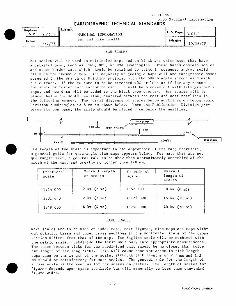
liar scales will be used on multicolor maps and on black-and-white maps that haveas USES, NOS, or DMA Quadrangles . These bases contain scaleswhich should be retained to print in screened and/or solidmap . The majority of geologic maps will use topographic bases
in the Branch of Printing photolab with the 50% biangle screen used withculture . If the culture is to be screened 40% or less or if for any reasonscale or border data cannot be used, it will be blocked out with lithographer's
tape, and new data will be added to the black type overlay . Bar scales will beplaced below the south neatline, centered between the east and west neatlines inthe following manner . The normal distance of scales below neatlines on topographicDivision quadrangles is 6 mm as shown below . When the Publications Division pre-pares its own base, the scale should be placed 8 mm below the neatline .
5
BAR SCALES
0 1 KILOMETER
The length of the scale is important to the appearance of the map ;a general guide for quadrangle-size maps appears below . For maps that arequadrangle size, a general rule is to show them approximately one-third ofwidth of the map, and usually no longer than 178 mm .
RAKE SCALES
Rake scales are to be used on index maps, text figures, mine maps and maps with-out detailed bases and under cross sections if the horizontal scale of the crosssection differs from that of the map . The English scale will be combined withthe metric scale . Subdivide the first unit only into appropriate measurements .The space between ticks for the subdivided unit should be no closer than twicethe length of the long ticks . This will cause some variation in tick lengthdepending on the length of the scale, although tick lengths of 2 .5 mm and 1.3nun should be satisfactory for most scales . The general rule for the length ofa rake scale is the same as for bar scales on plates . The length of scales forfigures depends upon space available but will generally be less than one-thirdfigure width .
18 3
therefore,notthe
uLCa pt. ~.p.=-6M.
PUBLICATIONS DIVISION
Fractional Overall length Fr~ctinnal Overallscale of scales scale length of
scales
1:24 000 2 km (2 mi) 1:62 500 8 km (6 mi)
1 :31 680 2 km (2 mi) 1 :125 000 ` 15 km (10 mi)
1 :48 000 6 km (4 mi) 1 :250 000 40 km (30 mi)
Replaces Subject:. S . P. 3,07 .1 MARGINAL INFORMATION
T . S. Paper 3 .07 .1
Dated Bar and Rake Scales Effective2/7/77 10/16/78

T . S . Paper No . 3 .07 .1(2)
Four
1 .2 .3 .
4 .
factors that should be considered when subdividing a scale*are :
The space available between the division (long ticks) .In what increments are the division (long ticks) .The mile scale should be subdivided according to thesystem ; for example when subdividing 1 mile, divideinto 2, 5, or 10 parts .The kilometer-scale measurements should be in sub-multiples of 10 according to the metric system ; forexample, when subdividing 1 kilometer divide into2, 5, or 10 parts .
A general guide for rake scale subdivisions *is as follows :
Author's copy received
*See page 51 .
0
18 4
Replaces 3 .07 .1(2/7/77)
inch-pound
Increments rearranged
0
2
4
6
8
10
12
14 KILOMETERS
and metric scale added
1T I 1 I
I
I
I
I~
I ,~
0
2
4
6
8
10 MILES
Occasionally, scales on author's originals (and mill copy) are divided intoodd increments . Using the author's measurements, we rearrange the divisionsinto more practical increments, e .g . :
PUBLICATIONS DIVISION+
0
Space betweenDivisions
(long ticks)
Number ofSubdivisions(short ticks)
Examples
Less than 19 mm 1(use only when 0 50 100 150 200 KILOMETERSnecessary)
0 50 100 MILES
19 mm to 51 mm 1 or 40 2 4 6 8 KILOMETERS11 I 1
T 10 2 4 MILES
More than 51 mm 9 05 10 15 20 KILOMETERS
0 5 10 MILES
0 1 1
I, 11 1.
I 1I 1 I
0
0 1000 2000
IT __ T__T-r
0 1000

CARTOGRAPHIC TECHNICAL STANDARDS
The contour interval and datum notes will appear beneath the scale only if topographiccontours are shown on the map . There may be times.when the datum note will be usedwithout the contour interval note, as on mine maps where datum for shaft levels is given ;however, a contour-interval note will never be shown without a
When the Topographic Division's contour-interval note is being usedchanges or additions are necessary, match their type style, which is Trade GothicRoman (TG), as indicated at right below (on old topographic bases, match their existingtypestyles) .When Branch of Cartography is preparing a new contour-interval notewill use Univers Light Condensed (ULC), as indicated on left below .
ULC I pt C
CONTOUR INTERVALS 200 AND 1000 FEET - - - --NATIONAL GEOOETC VERTCAL DATUM OF 199
TG I pL C1 : 24 0002 pL "ding
Maps that contain open-water areas must be checked for fathom and depth contourines . The contour, datum, fathom, and other notes that appear on these maps
have many variations depending on the map's geographic location in addition toseveral other factors . The following are typical examples :
CONTOUR INTERVAL 50 FEETWITH SUPPLEMENTARY CONTOURS AT 25 FOOT INTERVALS
NATIONAL GEODETIC VERTICAL DATUM OF 1929BATHYMETRIC CONTOUR INTERVAL 10 METERS
SUPPLEMENTED BY 2 METER INTERVALS TO MAXIMUM DEPTH
DATUM : MEAN LOW WATERTHE RELATIONSHIP BETWEEN THE TWO DATUMS IS VARIABLE
CONTOUR INTERVAL 1 .5 METERS
NATIONAL GEODETIC VERTICAL DATUM OF 1929
BATHYMETRIC CONTOUR INTERVAL 1 METER WITH SUPPLEMENTARY0.5 METER CONTOURS-DATUM IS MEAN LOW WATERTHE RELATIONSHIP BETWEEN THE TWO DATUMS IS VARIABLE
THE MEAN RANGE OF TIDE IS APPROXIMATELY 2 .1 METERS
CONTOUR INTERVAL 5 FEET
NATIONAL GEODETIC VERTICAL DATUM OF 1929
DEPTH CURVES AND SOUNDINGS IN FEET-DATUM IS MEAN LOW WATERSHORELINE SHOWN REPRESENTS THE APPROXIMATE LINE OF MEAN HIGH WATER
THE MEAN RANGE OF TIDE IS APPROXIMATELY 39 FEET
CONTOUR INTERVAL 40 FEETCONTOUR INTERVAL ON RIVER SURFACE S FEET
NATIONAL GEODETIC VERTICAL DATUM OF 1929
18 5
V . FORMAT5.05 Marginal information
datum note .
on base copy and
completely, they
E- 1 :250 000
1 :24 000
E- 1 :62 500
R~pbcis3 " 09 .1
Subl8ct: MARGINAL INFORMATION T . S. Pa 3 .09 .1'. S. P. placement and type style for contour
Dated 3/1/77interval and vertical datum notes Effective 2/16/79

T . S. Paper No.
3.09.1
Replaces
3.09 .1
(3/1/77)
When two quadrangles with different contour intervals have been mosaicked to forma new base,the contour note should be similar to the example below .
ULE ~ ~tC
CONTOUR INTERVAL 10 FEET IN EASTERN PART OF MAP-AND 20 FEET IN WESTERN PART
Sample datum note without contour-interval note :
Other sample notes :
DATUM IS PORTAL OF THE 1 LEVELALTITUDE APPROXIMATELY 10.326 FEET
CONTOUR INTERVALS 25 AND 50 FEET
CONTOUR INTERVALS 40, 50, AND 80 FEET
CONTOUR INTERVAL 50 FEET-
DOTTED LINES REPRESENTS 10-FOOT CONTOURS
18 6
TG7pt.C
Note : All above examples are illustrated in ULC type .
Refer to T.S .P . 3.09 .2 for proper wording of vertical datum notes based ongeographic location .
PUBLICATIONS DIVISIO++
V. FORMAT5 .05 Marginal information
CARTOGRAPHIC TECHNICAL STANDARDS
On Book Reports each plate has a title only ; on Map Series each sheet has a title withauthorship and date centered under the title .
The variety of map sizes and conditions makes it difficult to set hard-and-fastrules for map titles . The following items will be used as a guide .
1 .
Souvenir Medium (SM) caps will be the style of type normally used for titles, andcaps and lowercase for authorship .
2 .
All Geologic Quadrangle Maps at 1 :24,000 scale should use 20 pt . Souvenir Mediumsingle line titles and 18 pt . for two-line titles . Designers should order thenext smaller size of type when titles consisting of more than two lines tendto become too dominant on a plate or map . Very short titles may be set in alarger size .
3 . When titles are set in open space areas (display title) reduce or enlarge thesize Of type according to the amount of space available .
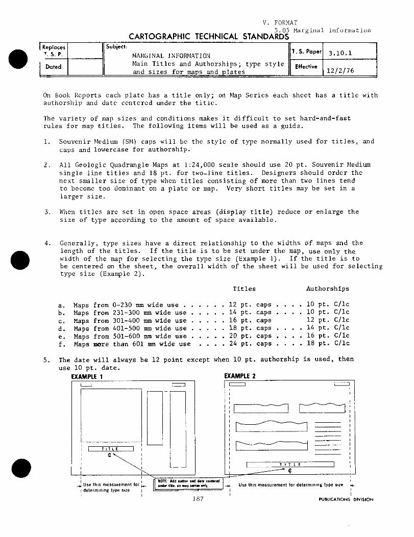
4 .
Generally, type sizes have a direct relationship to the widths of maps and thelength of the titles .
If the title is to be set under the map, use only thewidth of the map for selecting the type size (Example 1) . If the title is tobe centered on the sheet, the overall width of the sheet will be used for selectingtype size (Example 2) .
a .
Maps from 0-230 mm wide use . .b .
Maps from 231-300 mm wide use .c .
Maps from 301-400 mm wide use .d .
Maps from 401-500 mm wide use .e .
Maps from 501-600 mm wide use .f .
Maps more than 601 mm wide use
5 . The date will always be 12 point except when 10 pt . authorship is used, thenuse 10 pt . date .
EXAMPLE 1
EXAMPLE 2
TITLE
II
"
~
I
II
II
IL
J
I T I T L E
I
I
I- I
iIIIII
I Use this measurement for'
NOTE yea onMOr and dote conmod
I~I
If
nndor udo. on rn.p oorla only
-o1
Use this measurement for determining type suedetermining type size
I
II
I
I
I187
PUBLICATIONS DIVISION
Replaces Subject:
T. S. P. MARGINAL INFORMATIONT . S. Paper 3 .10 .1
DatedMain Titles and Authorships ; type style Effectiveand sizes for maps and plates 12/2/76
Titles Authorships
. . . . 12 pt . caps . . . . 10 pt . C/lc. . . . 14 pt . caps . . . . 10 pt . C/lc. . . . 16 pt . caps 12 pt . C/lc. . . . 18 pt . caps . . . . 14 pt . C/lc. . . . 20 pt . caps . . . . 16 pt . C/lc. . . . 24 pt . caps . . . . 18 pt . C/lc

The maintitles will be identical for all sheets and will be set in Souvenir Mediumcap_ s .
(See T .S .° . 3 .hv .EXAMPLE :
WATER RESOURCES, MARYLANDIndividual sheet titles (subtitles) will be positioned above the main title andwill be set in Souvenir Medium (caps and lowercase) in the next available smallersize than the main title . See example 1 .
EXAMPLE t
V . FORMAT5 .05 Marginal information
CARTOGRAPHIC TECHNICAL STANDARDS
D
Water yield and water use
be
EXAMPLE 2
EXAMPLE 3
F7
GROUND WATER
0
WATER RESOURCES, MARYLAND
WATER RESOURCES, MARYLANDBy
BYA. B. Jones and John Smith
A. B . Jones and John Smith1977
1977
189PUBLICATIONS orvISiow
WATERYIELD
WATER USE
i0
0
Replaces Subject: MARGINAL INFORMATIONT. S. P. Titles and Subtitles, also sheet
T . S. Paper 3.10.2
Dated identification note for reports Effective 2/22/78containing two or more ma sheets
WATER RESOURCES,BY
A. B . Jones and John Smith1977
MARYLAND
Whenever subtitles are placed within the body of the individual map, no sub-titles will be added above the main title . Most "Map Series" subtitles willset in Souvenir Light in the same size or larger than the title and will beplaced at the top of the sheet whenever possible . See examples 2 and 3 .

Paper No . 3 . 10 . 2 ( 2)
Replaces
Book report
subtitles may be set in SL, L', ULC in a size that wouldbest identify the data and compliment the map appearance, and stillcomply with geologic and hydrologic type standards . (See example 4 .)
EXAMR_= -*
GOLD
MERCURY
ARSENIC
ANTIMONY
GEOCHEMICAL MAPS SHOWING DISTRIBUTION OF GOLD,MERCURY, ARSENIC, AND ANTIMONY IN THE
CORTEZ-BUCKHORN AREA, UREKA COUNTY, NEVADA
The series identification note in the upper right corner of Map Seriessheets should be ident=cal in all cases and should contain, in parentheses,both the sheet number and the total number of sheets in the set . The seriesidentification note for "Book Report" plates should be identical on allplates but should show the individual plate number only . (See examples below .)
For map series
For book reports
HYDROLOGIC INVESTIGATIONSATLAS HA-000 (SHEET 1 OF 2)
PROFESSIONAL PAPER 448-APLATE 1
PROFESSIONAL PAPER 448-A
Note : Also refer to T .S .P .'s 3 .00 .1 and 3 .02 .1
190
PLATE 2
PUBLICATIONS DIVISION

United States Department of' the Interior(A :()1,()GICAL SURVE)REST()N, VA 22(192
In Reply Refer To :
January 6, 1987WGS-Mail Stop 435
WATER RESOURCES DIVISION MEMORANDUM NO . 87 .21
Subject : PUBLICATIONS--Use of sea level to represent National GeodeticVertical Datum of 1929
The recent WRD memorandums (86 .101, 86 .104, and 87 .04) requiring use ofNational Geodetic Vertical Datum of 1929 (NGVD of 1929) were intended toincrease the technical precision of our reports . NGVD of 1929 has a preciseengineering basis, and its use is necessary to ensure precision of futureinterpretation of data . Whether we are aware of it or not, our field measure-ments such as lake and ground-water levels, elevations of stream gages, topsof well casings, and so forth, that, in conversation, are referred to sealevel as the reference datum, actually are referred to the NGVD of 1929 .Although scientifically correct, the use of NGVD of 1929 in text of ourreports has been a cause of concern to WRD authors and to many readers whorecognize that, even though "sea level" has no precise meaning in an engineer-ing sense, it is a widely used and understood conceptual datum . Accordingly,the following statement should be included in all USGS and cooperator-seriesreports where for purposes of ease of understanding and conciseness, "Sealevel" is used instead of "National Geodetic Vertical Datum of 1929" :
Sea level : In this report "sea level" refers to theNational Geodetic Vertical Datum of 1929 (NGVD of 1929)--a geodetic datum derived from a general adjustment of thefirst-order level nets of both the United States andCanada, formerly called "Mean Sea Level of 1929 ."
This statement, which replaces the current statement defining NGVD of 1929,should be placed at the bottom of the table of conversion factors andabbreviations .
NGVD of 1929 should continue to be used in the datum note of plates thatshow topographic contours, in accordance with the standards of the NationalMapping Division and Coast and Geodetic Survey . Contributions to scientificjournals generally have not included this statement, and use of "sea level"in these publications without the explanatory statement is acceptable inthose instances where the precise meaning provided by NGVD of 1929 is notneeded .
V . FORMAT5 .06 Sea level

WRD Memorandum No . 87 .21
I believe this change serves the interest of scientific precision, whilesimultaneously retaining the readability and clarity of our reports .
WRD Distribution : A, B . S, F0, PO
This memorandum supplements WRD Memorandum 87 .04 .
ames F . DanielAssistant Chief Hydrologistfor Scientific Information Management
WATER RESOURCES DIVISIONPUBLICATIONS GUIDE
V . FORMAT
Replaces
Effective
3/1/71
Article No . : 3.07 .1Article No . :
Date :
Subject : ILLUSTRATIONS -- Photographs - Quality ; only glossy printsacceptable
Some reports received in the Publications Unit, Reports Section containxerox or similar machine prints of photographs in lieu of the requiredglossy prints . Machine-made prints lack the clarity and legibilityrequired for review and approval .
Only glossy prints will be acceptable for approval for publication andopen-file release. One glossy print is required for each photograph ina report . Photographs in copies of reports to be placed in the Washingtonfile must also be glossy prints . Glossy prints should be prepared fromcontinuous-tone negatives - negatives that have not been screened .
Those reports containing xerox or similar prints of photographs will bereturned to the originating office for preparation and inclusion ofappropriate glossy prints .
Reference :
WRD memorandum 70 .146, dated April 20, 1970 .Cross Reference :
3.07.3--Requirements for submitting photographs .
5 .07 Photographs

WATER RESOURCES DIVISIONPUBLICATIONS GUIDE
Replaces
Effective
3/1/71
Article No . : 3 .07 .2Article No . :
Date :
Subject : ILLUSTRATIONS -- Photographs - Characteristics of a good photo-graph
Characteristics of good photographs are :
1 . The focus is sharp -- any reproduction of a photograph is of lesserquality than the original photograph, therefore, photographs thatare out of focus will not reproduce satisfactorily and will notbe approved for publication .
2 . The contrast is not too dark or too light -- middle tones of grayreproduce the best . The best prints for reproduction are thosemade from negatives of evenly illuminated subjects in which thedetails are sharp . A good print for reproduction is one that hasmaximum detail in both shadow and highlight areas .
3 . The photograph should show clearly what the photographer intendedit to show . Objects such as trees or fences that obscure the viewof the subject result in unsatisfactory photographs . Photographswith this problem should be retaken from a different position toeliminate the interfering objects.
4 . The use of brand names in Survey publications generally is notallowed. Photographs should be taken so that any brand name onthe object being photographed is either not visible or not readible . If this is not possible, the brand name must be removedfrom the photograph when final reproduction copy is made .
5 . Objects that can be used for scale comparison of the subject arenecessary in most photographs . They can be persons, vehicles,hammers, rulers, etc . Photomicrographs require a drafted linearscale .
V . FORMAT5 .07 Photographs
6 . Enlargements usually make unsatisfactory copy for reproduction .Coarse grained prints generally result from the enlarging process .Enlargements can be avoided by using cameras thet make negativesat or near the desired publication size .
7 . Polaroid prints are not satisfactory for use as reproduction copybecause they deteriorate with age . However, a Polaroid camera canbe used to advantage in conjunction with a secoipd camera . A photograph of the subject can be taken first with the Polaroid camerato determine if a satisfactory photograph of the subject can beobtained at that site . If so, then the subject can be rephotographedwith the second camera .
195

WATER RESOURCES DIVISIONPUBLICATIONS GUIDE
V . FORMAT5 .07 Photographs
Replaces
3 .07 .3
Effective 3/20/74
Article No . : 3.07 .3Article No . : Dated 3/1/71
Date :
Subject : ILLUSTRATIONS -- Photographs - Requirements for submittingphotographs
1 . Each photograph in a report must clearly relate to the subject matter ofthe text . If a photograph doesn't relate to the text, it doesn't belongin the report .
2 . Continuous-tone glossy prints must be submitted for approval . Printsshould be mounted on a piece of white 8 x 10 1/2-inch paper . Printsshould be at the proposed publication size . Vertical aerial photographsmust have a scale and a north arrow . Photographs must be clearly iden-tified by figure number .
3 . Suggested "crop" lines can be indicated beyond the edges of the photo-graph by the author .
4 . If an author wishes to have information such as lines and lettering addedto a photograph, the following procedure should be used :
a . Use a duplicate print of the photograph . Indentations made on thesurface of the photograph $wring the process of delineating featuresmakes the photograph unsatisfactory for reproduction .
b . Tape a piece of plastic or transparent paper over the photograph .This should be larger than the photograph .
c . Add corner registration marks to the overlay at the corners of thephotographic image .
d . Compile on the overlay the information to be added to the photograph .Use black ink .
5 . Proper credit for the photograph must be shown . The credit line usuallyis placed at the end of the title for the photograph . If the photographwas taken by :
a . The author -- the photographer's name must not be shown .
b . Department of the Interior personnel other than the author -- thephotographer's name cannot be shown, except with the prior approvalof the Director of Communications, Office of the Secretary .
c . Another Federal agency -- the source of the photograph must be shown .Written permission from the agency is required and must accompany thereport for approval .
197

d . A private individual or company or from a copyrighted publication --the source of the photograph including the photographer's name, ifknown, must be shown . Written permission must be obtained and acopy of the letter must accompany the report for approval .
6 . For Survey publications, the Publications Division requires that two con-tinuous-tone glossy prints and the negative (if available) of each photo-graph be transmitted to them at the time original illustrations arerequested .
7 . Once a photograph has been approved for publication in a Survey report,it becomes the property of the Survey . Copies of the negatives used forreproduction are sent by the Publications Division to the Denver FilmLibrary for filing . An author may obtain prints of the photographs fromthe library .
Cross reference : 3.07.1 -- Quality ; only glossy prints acceptable

WATER RESOURCES DIVISIONPUBLICATIONS GUIDE
Subject : ILLUSTRATIONS -- Photographs - Reproduction
V . FORMAT5 .07 Photographs
Replaces
Effective
3/1/71
Article No . : 3 .07 .5Article No . :
Date :
Reproduction of photographs is accomplished by screening the negativeof a photograph so that the resulting image is composed of minute dots .The detail of a printed photograph is proportional to the density ofthe dots . The greater the density of the dots, the less the non-printing open spaces, and hence, the greater detail . Continuous-toneprinting, printing a negative without a screen, is not done by theSurvey .
1 . Most photographs are printed using a 150-line screen . The resultingdetail is satisfactory for almost all photographs appearing in WaterResources Division's reports.
2 . Increased detail can be obtained by using 200- or 300-line screens .Requests for use of these screens must be in memorandum form andaccompany the report when it is transmitted for Director's approval .To date, the photographs in only a few Water Resources Divisionreports have been printed using 200-line screens . Reports withphotographs of fossil assemblages are the only ones where 300-linescreens are used for the photographs .
3 . "Bleeding," a reproduction technique, is used to allow the printedimage of a photograph to extend to the edges of the page on whichit is printed. This technique is restricted to special reports,usually those written for the lay reader, to enhance the appearanceof the publication .
WATER RESOURCES DIVISIONPUBLICATIONS GUIDE
V . FORMAT
Replaces
Effective
3/1/71
Article No . : 3 .07 .6Article No . :
Date :
Subject : ILLUSTRATIONS -- Photographs - Colored photographs
5.07 Photographs
The use of colored photographs in Federal publications is governed bythe "Printing & Binding Regulations" established by the Joint Committeeon Printing, Congress of the United States . Requests for use of coloredphotographs must be in memorandum form and accompany the report whenit is transmitted for Director's approval . If the Director's Officeapproves the use of colored photographs, the request is then forwardedto the Department for approval . Departmental approval constitutesCongressional approval under the present system .
Two types of colored photographs can be used in reports ; multicolor andduatones . Multicolor photographs are printed using the three primarycolors - yellow, red, blue - and black . Duatones photographs areprinted in black and one other color .
If a multicolor photograph is approved for publication, the authorshould furnish three continuous-tone colored glossy prints and thenegative, transparency, or slide for use by the Branch of TechnicalIllustrations . If a duatone is approved for publication, the authorshould furnish two continuous-tone glossy black-and-white prints andthe negative .

Photographs
Article 3 .02 .3
If the relative size of items being photographed is not self-evident, itshould be indicated by placing a familiar object (for example, a hammer,ruler, or knife) in the photograph or by a scale shown on its border (noton the image) .
Croplines are used to eliminate unwanted parts of the photograph andto adjust for inadvertent camera tilt . Croplines should not be drawnacross the photograph, but at the edges only . If symbols or lines needto be added, an overlay should be prepared using corner ticks forregistration to show placement . Write "top" at the top of the photo-graph mounting sheet to insure proper orientation .
The source of the photograph must be given only if photographer was not anInterior Department employee or if the photograph has been copyrighted .
Special mounting of photographs is necessary to avoid damage to the emulsion .Photographs should be secured to a sheet of paper by cutting four diagonalslots in the sheet through which the photograph corners can be inserted andtaped on the back .
The author's name and the figure number should be typed on a label pastedto the back of the photograph or penciled on the mounting sheet . Do notwrite on the front or back of photographs, and do not use paperclips .
V . FORMAT5 .07 Photographs

WATER RESOURCES DIVISION PUBLICATIONS GUIDE
Subject : PROCESSING MANUSCRIPTS AFTER DIRECTOR'S APPROVAL .--Preparing Camera-Ready Copy
Article 7 .02 .4
The purpose of a mockup is twofold--it enables the designer to develop aneffective presentation of the material, and it serves as a typist's guide tominimize the amount of retyping and proofreading .
Additional instructions for preparing WRI and Open-File Reports are givenin Sections 10 and 11, respectively ; procedures for designing books inthe STOP format (Sequential Thematic Organization of Publications) aregiven in article 2 .02 .4 .
Layout of WRI and Open-File Reports, as well as those in many non-Surveyseries, is generally done by an editor, but could be done by authors orclerical staff . With practice and by following the principles describedin this article, one can avoid the common errors and create a professional-quality layout within a few hours for any type of published material .
COVER
V1 . CAMERA-READY COPY6 .01 Covers
This article explains the mechanics of book design, with specific instructionsfor cover, preliminary pages, abstract, text, and placement of f'l.gares andtables . Although this article assumes printing on both sides of a page andan 8 1/2 X 11-inch format, such as for WRI and Open-File Reports, the principlesare applicable to books of other dimensions and to printing on one side of apage as well .
Although the cover of each approved manuscript has presumably been checked toverify conformance to publisher's requirements, it is advisable to reinspectall details when preparing camera-ready copy, especially the wording andspelling of the title, because the cover is the most conspicuous part of thereport . All art covers must be included in the report package submittedto Headquarters for Director's approval, and must be approved by the Director .
The cover contains four main components--cover 1 (outside front), cover 2(inside front), cover 3 (inside back), and cover 4 (outside back) . Theprinter generally will print them on a single sheet . If the report is to bemore than a quarter of an inch thick, the cover will also include a spinebackstrip) . A page containing the copy for each of these components, includingthe spine, must be supplied to the printer with the camera-ready copy .
7 .02 .4 Preparing the mockup
Cover - Placement of illustrationsPreliminary pages and tablesAbstract - Figure captions and tableText headings
- Completion of mockup

Article 7 .02 .4
Texture and color .--Most Federal reports are required to be printed onuncoated (dull finish) paper because it is less expensive than coated (glossy)paper . Covers may be any desired pastel shade, including white, but inGeological Survey reports only one ink color is permitted . If coloredpaper is used, the ink must be dark enough to show clearly . If whitelettering on a colored background is desired, prepare the copy in the usualmanner but instruct the printer to "reverse" the print . A bold type shouldbe used in "reverse" copy to prevent letters from "filling in" with surroundingink .
Photographs printed on uncoated covers may give disappointing results becausethe ink will be absorbed, diminishing contrast . Line drawings, silhouettes,lettering, and uniformly screened areas, however, will be satisfactory onpaper of any finish . If a cover photograph is required, consult GPO to be surethat suitable cover stock can be provided .
The ink color used on cover 1 will be used on cover 4, and may be used oncovers 2 and 3 as well unless specified otherwise, because the four componentsare printed as one sheet .
Binding .--If. the report contains less than 96 pages, it will be saddlestitched (stapled down the inside center) or side stitched (stapled on theoutside at the left margin) . If the report contains more than 96 pages(fewer pages if heavy text paper is used), it will be side stitched orperfect bound (squared off with glue binding) . Wire, ring, or plasticbindings will be used only if specified ; these are more expensive than astaple or glue binding .
Cover 1 (outside front)
In simplest form, Geological Survey report covers consist of the title,department and bureau identification, report series and number, and state-ment of cooperation . Covers do not bear the authors' names nor the dateand city of publication ; these are given on the title page .
If special lettering is used, its size and weight must be balanced and com-patible . (See article 7 .02 .3 .) Specifications for standard typescript coversare given below ; examples are given in articles 3 .01 .2, 10 .04 .1, 11 .04 .1,and 12 .04 . If other than a standard designed cover is desired, an examplemust be included for inspection when the report is submitted for Director'sapproval .

Department Identification .--For typescript covers to be reproduced byoffset printing, the Department seal is placed near the lower right corner .For art covers, the Department seal may be centered on cover 4, if necessary .For covers of reports to be copied on office equipment, the edge of theseal may produce a "halo" or splice line, in which case it may be omitted .If the seal is omitted, the following imprint must be typed beginningfour lines below the top of the page and centered :
- Open-File Report 86-XXXX
DEPARTMENT OF THE INTERIOR
U .S . GEOLOGICAL SURVEY
Report Title . 1 --Use capital letters, align flush left one inch from the leftmargin . If the above imprint is used, begin title 4 lines below it ; if thedepartment seal is used, begin at least 7 lines below the top of the page . Ifpossible, make the top line the longest, but avoid hyphenation or illogicalseparation of words . If the title contains 2 lines or more, they should bedouble spaced . A centered 6-inch horizontal line is typed across the page 3or 4 lines below the report title .
Bureau Identification .--On reports bearing the Department seal (rather thanthe above imprint), the words U .S . GEOLOGICAL SURVEY are typed on the thirdline below the horizontal line, in capital letters, flush left .
Report Series and Number .--Two lines below the words "U .S . GEOLOGICAL SURVEY,"or 6 lines below the horizontal line, the report series and number, asindicated on the approval notice, is typed in capital and lowercase, for example :
- Water-Resources Investigations Report 86-XXXX
Statement of Cooperation .--The statement of cooperation is aligned flushleft with the title and double spaced about 4 inches above the bottom ofthe page ; for example :
Prepared in cooperation with theNEW YORK STATE DEPARTMENT OF HEALTH
VI . CAMERA-READY COPY6 .01 Covers
Article 7 .02 .4
For WRI and Open-File Reports, the name of the cooperator should be letteredthe same size as that of the Geological Survey .
1 Water Resources Division Memorandum No . 81 .127, dated September 8, 1981,describes the requirements for a good report title .

Cover 2 (inside front)
In WRI and Open-file Reports, cover 2 is blank . This should be indicatedby stating in nonreproducing blue on the bottom of cover 1, and on aseparate page :
"cover 2 is blank ."
Article 7 .03 .2 gives instructions for indicating the presence (or absence)of printing on covers 1 through 4 on the GPO Printing and Binding Requisitionform SF-1 .
Reports to be printed in non-Survey series may require special copy for cover2, such as a list of county officials . Whenever this is the case, be surethat the following information is included :
DEPARTMENT OF THE INTERIOR
Secretary
U .S . GEOLOGICAL SURVEY
Director
The Secretary's name is all-capitals ; Director's name is capital andlowercase.
If the list of officials is on the back of the title page, cover 2 willbe blank . (See example in article 3 .01 .2 .)
Cover 3 (inside back)
Cover 3 of a report may contain printing or may be blank ; some reportscontain a map pocket .
In any case, the printer must be informed as to whatto do . Prepare a sheet (in nonreproducing blue) stating "cover 3 blank" or"cover 3 map envelope ." Specific instructions regarding the size and con-figuration of the envelope must be included in Printing and BindingRequisition form SF-1 . (See article 7 .03 .3 .) If cover 3 is to containprinting, write "cover 3" (in nonreproducing blue) at the top of the copyand also specify the desired enlargement or reduction, if any, and howthe copy is to be positioned .
Cover 4 (outside back)
Article 7 .02 .4
If copy is prepared for cover 4, give precise instructions, or, if cover 4is to be blank, indicate so on a separate sheet . Remember that if thereport is to be perfect bound or saddle stitched, the cover will be printedas one sheet, with covers 1 and 4 on one side and covers 2 and 3 on thereverse side .

V1 . CAMERA-READY COPY6 .02 Pagination
Article 7.02 .4
Spine (backstrip) .--If the camera-ready copy is to be perfect bound, letteringwill be required for the spine . The lettering should be in a size thatwill fit on the spine (no longer than the book's left margin and no higherthan the estimated thickness of the book) . The simplest procedure isto type or letter the material lengthwise on 8 1/2 X 11-inch paper, positioningthe words exactly as they are to appear on the printed cover ; for example:
[Top]
[Bottom]
Smith
GROUND WATER IN MERCER COUNTY, N.J .
USGS/WRI 82-XXXX
On this sheet, write "spine" in nonreproducing blue and enclose it with theother cover copy. Some titles may need to be shortened or the author'sname or series number omitted. Indicate top of book to insure that thespine reads downward . The spine copy can be printed on cover 4 of saddle-stitched books, if desired .
When the camera-ready copy of the cover has been completed, insert a copy ofeach component in proper order in the mockup . Thus, the first two sheets ofthe mockup will be covers 1 and 2, and the last will be covers 3 and 4 withspine copy .
PRELIMINARY PAGES
Pagination .--In camera-ready copy, the preliminary pages (contents, list ofconversion factors, glossary, and so forth) are numbered with lowercaseroman numerals, and the text, beginning with the abstract as page 1, isnumbered in arabic . Odd-numbered pages must be on the right, evennumbers on the left . In standard-format Geological Survey reports, thepage number is centered about 5/8 1 bf an inch above the page bottom; otherpublishers may place page numbers elsewhere, such as in the outsidecorners.
Title page .-In WRI and Open-File reports, the title page closely resemblesthe cover, except that it includes the author's names (first name, middleinitial, and last name, in capitals and lowercase, just below the title;and gives the city, State, and date of publication approximately one inchabove the page bottom . (Typographic instructions for the title page arealso given in article 5.01 .3 ; examples are given in articles 3.01 .2, 10 .04.1,11 .04 .1, and 12 .04 .1 .) If a frontispiece is used, see article 5.05.8.
Back of title page .--The material for this page depends on the publisher.In WRI and Open-File reports, this page lists the Department Secretary,the Director of the Geological Survey, the originating office address(see examples in articles 10 .04 .1 and 11 .04.1), and ordering information;in non-Survey reports it may list non-Federal government officials or beleft blank . If such officials are listed, the Department Secretary andDirector of the Geological Survey also must be included .
1 Top of number, base of number should be placed 11" from the trim edge . Printersuse page numbers when centering pages for printing so all numbers should bein the same location on each page .
209

Contents (not "Table of Contents" ) .--This will normally begin on page iiiwhich, in final copy, will face the back of the title page . The wording ofheadings should be exactly as in the review copy, and the material is singlespaced . Leaders (rows of dots or dashes) should extend to the right, leavingroom for page numbers once they have been determined .
Other preliminary pages .--At this point, the person making the mockup willassemble all remaining preliminary matter on a facing-page basis, cutting andpositioning until visual balance is achieved . In some reports, the contents,list of illustrations, and list of tables may fit on a single page ; in others,they may run onto several pages . The list of illustrations (plates and figures)normally precedes the list of tables . The list of tables is followed by thelist of conversion factors, which, if short, may be on the same page asthe list of tables . The list of conversion factors should not be listedin the table of contents . A "Glossary" or " Definition of Terms" section,if used, may be placed at the back of the report and listed in the tableof contents . It follows the "References" section and precedes the appendices,if any, and big, end-of-report tables, if any .
As a rule of thumb, typescript should begin and end at the same depth on eachpair of facing pages . A transparent ruler at least 12 inches long and markedin both inches and picas will be useful in measuring the vertical spacing . Tohelp achieve balance across facing pages, space may be added between majorsections .
When the preliminary matter has been arranged and pasted down with rubbercement, tape, or wax, the roman numerals may be penciled in at the bottom ofeach page . Also, the number of lines skipped between components and the lineon which typing begins should be indicated to help the typist avoid guesswork .
If the preliminary material ends on an odd-numbered (right-hand) page, thenext sheet should be marked "page blank" in nonreproducing blue . Thisboth informs the printer that there is no copy for that page and enablesthe abstract to begin on the right, in accordance with tradition .
ABSTRACT
Article 7 .02 .4
In nearly all reports, the first page of text (page 1) is the abstract . Thispage begins with the title, usually centered in capital letters, doublespaced, and arranged in "inverted pyramid" fashion--that is, the top line isthe longest . If this forms an awkward wordbreak or requires hyphenation, analternative arrangement should be developed .
Two or three lines below the title is the word "By" and the author's name(s)on the same line (usually first name followed by middle initial and lastname) . Three or four lines below the author's name(s), the word "ABSTRACT"is centered in capital letters . (See example in article 3 .01 .2 .)

If the abstract is short and appears isolated on the page, three remediesare possible :
1 . Double space the abstract, perhaps in italics, but leaving thetitle and author's name(s) in Roman type .
2 . Drop the title from line 7 to line 13 and begin the abstractfarther down .
3 . Indent the abstract on both sides to form a 5- or 5 1/2-inch line ;this will make it narrower and a line or two longer .
4 . Develop a combination of the above .
5 . Begin the introduction a few spaces below the abstract rather thanon the next page . If this is done, typing the abstract in italicsand (or) indenting it slightly on both sides will give the necessarycontrast and improve the appearance of the page . Italic typeshould not be used for lengthy abstracts, however, because it isdifficult to read .
The introduction is the first part of the text following the abstract .The introduction may begin either on page 1 below the abstract, on page2, or on page 3 (right-hand page), leaving page 2 blank . (If the lastoption is chosen, leave page 2 blank and insert a sheet containing thenote "page 2 blank" in nonreproducing blue .)
The designer will find it helpful to establish the image area for the report .For 8 1/2 X 11-inch paper, this is generally 6 1/2 inches wide and 8 3/4 inches(53 lines) deep, beginning on line 7 . This gives a slightly largerbottom margin and provides space for the page number . Top and sidemargins should be 1 inch wide .
Paragraphs .--Paragraphs may be(in camera-ready copy only)balanced ; that is, the number of linesruns just one line over the limit, thecarry two lines over to the next page,by rearranging the preceding material .slightly widening line lengths so that the last line of a paragraph isabsorbed ; (2) deleting space between headings, or (3) backtracking a fewpages to gain space elsewhere .
The
TEXT
. VI . CAMERA-READY COPY6 .02 Pagination
Article 7 .02 .4
broken and continued on the followingimage areas on facing pages should
should be equal . If a paragraphdesigner must decide whether toor to create the necessary spaceThe latter can be done by (1)
pagebe

PLACEME14T OF ILLUSTRATIONS AND TABLES
VI . CAMERA-READY COPY6 .03 Illustrations
Article 7 .02 .4
Headings .--When a new heading is reached, there is no need to begin a newpage unless the heading is so close to the bottom of the page that littleor no text can follow it . When this occurs, lengthen the typed areaeither by adding a line or two from the previous page, by expanding thespace above preceding headings, or by slightly narrowing the lines incertain paragraphs so that those paragraphs will each become one linelonger . If the page is still too short, achieve balance by shorteningthe material on the facing page by an approximately equivalent amount .This discrepancy will almost never be noticed, regardless of the lengthof other pages in the book . It is important, however, to leave sufficientspace above the new heading so that it will stand out .
List of references .--The list of references preferably should begin on anew page . However, the list may begin on the last page of text, dependingon the number of bibliographic entries, the amount of space left on thepreceding page, and the number of entries that will run over onto a new page .
Placement of illustrations (figures and plates) and tables requiresattention not only to their size, but also to the wording of the text .For example, a table and a map may be intended to face each other, twophotographs may belong side by side for comparison, or six or eight similargraphs could be reduced and grouped together on a page or on facing pages .
When laying out the single-spaced text on facing pages, note the principal(not necessarily the first) reference to all tables and figures andinspect those components for size and relation to other components .From the author's illustrations, obtain an idea as to whether the materialwill require a full page, two or more facing pages, or less than a page,and how they should be grouped . A table or figure should be positionedjust after its principal reference and, if possible, within the chapteror subsection in which it is discussed--that is, before the next heading .An illustration or table should be placed within the next chapter only whenthe advantages would outweigh the disadvantages .
When working through the mockup, indicate to the typist the exact amountof vertical space needed for each table or illustration and heading .
When placing illustrations and tables, avoid broad-measure layout wherepossible because it inconveniences the reader, who must turn the booksideways to read it, and because it is out of step with the general layoutof the book . However, broad measure often is necessary, particularly withcomputer printouts . Where broad measure cannot be avoided, the imbalancecan be minimized if two such pages are placed facing each other so thatboth can be viewed as a unit .
A series of similar illustrations may be reduced and grouped with two ormore on a page or series of pages . If this is done, the captions probablywill need to be rephrased to reflect the new arrangement . For example,a revised caption for a series of graphs numbered 6 through 12 would referto figures 6A through 6G .
FIGURE AND TABLE TITLES
COMPLETION OF MOCKUP
vi . cnr1i.F;n-READY cony6 .03 Illustrations
Article 7 .02 .4
A copy of illustrations and tables reduced or enlarged to publicationsize can greatly facilitate layout work ; these can usually be obtainedthrough a local graphics firm . Alternatively, this work may be left tothe printer . Simply draw a rectangle in nonreproducing blue on the camera-ready copy showing the exact area to be occupied by the material, andindicate on each component the desired dimensions and the page on whichit is to be inserted . When the critical desired dimension has beendetermined, the other dimension can be calculated from a circular propor-tional scale, obtainable at graphics firms . If the other dimension istoo short or too long, cropping or reformatting will be necessary .
Illustrations and tables provide an advantage in layout because they notonly add variety to the typescript but can generally be reformatted asappropriate . For example, a table may be expanded by double spacing,may be separated into halves to occupy two facing pages, or may be compressedor photoreduced to fit a small area . Similarly, an illustration can beexpanded or reduced by altering the borders, cropping nonessential areas, orregrouping the components . In all cases, legibility is the prime concern .
When preparing the mockup, figure and table titles should be designed toan appropriate width--slightly narrower than the component they describe, withthe top line equal to or slightly longer than the rest . Each line of the titleshould be approximately the same length .
To prevent a title from blending into the surrounding text, place figures atthe bottom of the page and tables at the top, or provide extra space betweenthe title and the text . Alternatively, type all titles in italics . (Notethat italics should not be underscored .)
When all components have been assembled and all pages rechecked to verifythat no copy has been omitted or placed out of sequence, and that all facingpages are balanced, the page numbers are assigned and transferred to thetable of contents . Verify that all section headings given in the tableof contents contain the same wording and rank as those in the text . Also,verify that the amount of space to be left for figures, tables, and sectionheadings is indicated to avoid errors and retyping .

Article 7 .02 .4
As a final inspection, start again with the front cover and view all pages,two at a time with even numbers on the left, to insure that every component isaccounted for and correctly numbered (including blank pages) .
Reports to be reproduced by offset printing will contain a total number ofpages that is a multiple of 4 . For example, if the text ends on page 31 andcontains 6 preliminary pages (i-vi), the total is 37 . However, to reach 40(the next multiple of 4), 3 extra sheets must be added, on each of whichis written, in nonreproducing blue, "pages
, _blank ."
This informsthe printer that there is no copy for the last three pages . If the reportis to be machine-copied (two-sided), this rule does not apply .
The completed mockup should be a full-size replica of the printed report,minus the illustrations, tables and titles, except that all pages are one-sided . Final drafting may now be completed because the exact dimensionsare known . After all rubber cement, dirt, and extraneous pencil markshave been removed, the mockup is given to the author for inspection,then to the typist for preparing the camera-ready copy .

Replaces
2.5
Effective
3/29/71
Article No . : 3 .0LArticle No . : Dated 7/31/64
Date :
Subject : ILLUSTRATIONS -- Titles
WATER RESOURCES DIVISIONPUBLICATIONS GUIDE
Guidelines for titles
VI . CAMERA-READY COPY6 .04 Titles
I . Titles of illustrations, whether of plates or figures in bookrublications or of separately published maps and charts, requirecareful consideration by author and reviewers before Director'sapproval because they must be both informative and concise . Fol-lowing such approval significant changes should not be made intitles without agreement by the originating Division .
II . Titles of separately published maps and charts should give maximuminformation to the user . Titles that adequately express contentand location will facilitate proper cataloging in libraries andbibliograrhic indexes .
III . Titles for separately published maps and charts and for plates inbooks must be short because of the demands for brevity of citationand space limitations for placement of titles . Titles for figuresin books are set in type by the printer, may be longer, and mayinclude explanatory material .
IV . Concise titles providing maximum information are most desirable,but the kind of illustration (map, diagram, chart, photograph, etc ., .its anode of publication, and its complexity influence this goal .Each illustration is different, and individual judgment must beused in every case to describe its composition .
Factors controlling content and form of titles
V . Identification of kind of illustrationIn book reports the kind of illustration should be indicated inshort titles in "Table of Contents - Illustrations" but generallyis omitted beneath the illustration in the text . The kind ofillustration generally is indicated in titles of separately pub-lished maps and charts . Map series publications include principallygeologic and hydrologic maps so that "Geologic map of
" or"Geologic and hydrologic map of ***" is preferred over "Geology of
" even though short texts, columnar sections, cross sections,and other illustrative material of secondard importance may bepresent .
VI . Geographic locationTitles of separately published maps and charts and titles of platesof book reports should indicate geographic location as completelyas demands for brevity and space limitations permit . The county orsection of a State should be included in the title where the quad-rangle name alone is not sufficiently informative . Where severalcounty or State names are required for a complete geographic
215

location, a regional geographic location (southwestern, central,Rocky Mountains, Missouri River basin, etc .) may be substituted .Designation of geographic location is not necessary in titles offigures bound within a publication unless the geographic locationof the figure is only part of the entire area studied .
VII . QualificationsWhen special conditions such as the quality of the base map, or theaccuracy, geologic detail, method, and objectives of an investiga-tion affect the character of a map, the title may include qualifyingadjectives such as preliminary, sketch, generalized, reconnaissance,surficial, or bedrock .
VIII . Subsidiary illustrations and specialized dataIf essential for giving maximum information, the presence of sub-sidiary illustrations or specialized data can be shown in the titleby such additions as "*** and structure," "*** and cross sections,""*x-* showing water-table configuration." Subsidiary illustrationsmay require subtitles which identify the type of illustration ;expanded subtitles may be necessary to avoid ambiguity .
IX . Titles on multisheet maps, jackets, and separate textsWhen separately published maps and maps in book reports are printedin several sheets, common titles that apply to all sheets shouldappear on each ; the individual sheets may carry sheet titles andmay include subsidiary titles . Separately printed texts also shouldcarry the common title . The common title should appear on thejacket of map publications .
Processing titles in book reports
X. Brief titles of illustrations in book reports are listed in "Tableof Contents - Illustrations ." This typed list is a part of the textand a duplicate copy should accompany the illustrations to serve asan invoice for the geologic map editor and Branch of TechnicalIllustrations .
In addition complete individual titles are typed double-spaced onseparate pages ; the original is placed in the text as the pagefollowing the most important reference ; and a carbon copy and theCheck Sheet for Illustrations are attached to the mill copy (copyreviewed by critics, corrected, and sent forward for Director'sapproval) of the illustration . All changes in titles must be madeon the carbon copy attached to the mill copy . Before the mill copyis sent to Branch of Technical Illustrations, Branch of Texts willcheck title changes on appropriate pages in the text so that titlesaccompanying the illustration and in the text are in agreement .This assures that titles for figures to be set in type by GovernmentPrinting Office (titles as cited in the body of the text) and titlesplaced on plates by Branch of Technical Illustrations are in generalagreement with titles given in the "Table of Contents ."
216

WATER RESOURCES DIVISION PUBLICATIONS GUIDE
Subject : PROCESSING MANUSCRIPT AFTER DIRECTOR'S APPROVAL--Preparing Camera-Ready Copy
7 .02 .6 Final page makeup
Article 7 .02 .6
Final page makeup for printing or duplication may begin as soon as theillustrations, text, tables, and all other components have been completed,inspected, and corrected . This task consists of five steps, as explainedbelow :
1 . Add components such as tables and illustrations, display lettering,Department seal, running heads, equations, and so forth to the pages .
2 . Splice or opaque to make minor corrections .
3 . Inspect and clean up camera-ready copy .
4 . Mark printing instructions on camera-ready copy .
5 . Perform final verification .
ASSEMBLY OF COMPONENTS
VI . CAMERA-READY COPY6 . 0 5 Preparation
Add components made separately from the main typescript . This is best doneat a light table with a ruled sheet or grid placed beneath the copy to insureexact alignment . Insert only line copy that is at publication size ; in offsetprinting, halftonesl and all copy to be reduced or enlarged must be separatedout for they are treated individually by the printer . If the report is to beduplicated inhouse, all components must be at publication size .
When positioning illustrations, tables, and titles in the camera-ready copy,view the facing pages side by side to insure balance . Also be sure that allcomponents are firmly attached and lie flat .
damaging the copy . In someretyped and pasted over theor lines .
SPLICING OR OPAQUING
Splice or opaque minor corrections rather than retype an entire page . Usea light table to obtain correct alignment, and use a sharp blade to avoid
cases, it may be easier to have a full paragraphincorrect part than to splice individual words
Material submitted for printing is either "line copy" or "halftone ."Line copy is artwork or text consisting solely of lines or patterns ;it may be photographed directly because it contains no intermediate gray .Halftones are photographs that must be "screened," or converted to a dotpattern to produce the desired gray . Map bases that are screened arealso treated separately .
217

INSPECTION AND CLEAN UP
Inspect and clean up camera-ready copy . This should be done after all splicingand pasting are complete . Starting with the cover 1, carefully view eachpair of facing pages side by side to verify balance, even margins, and generalharmony between headings and typescript . If rubber cement has been used,dirt and streaks will probably be visible ; these can be removed with a crepe"pickup" (available at graphics firms) or with a piece of dried rubber cement .When erasing pencil marks, be careful not to crease the paper or smear thetypescript . If a smudge or spot cannot be removed, cover it with whitecorrecting fluid . All penciled notes must be erased except those written innonreproducing blue ; these may simply be crossed out (in the same blue) sothat the printer will not mistake them for instructions .
MARKING PRINTING INSTRUCTIONS
Mark printing instructions on each cover component and on all pages that areto be blank, that contain copy to be reduced, enlarged, screened, printed asa foldout, or that contain a map jacket . All printing instructions on thecamera-ready copy must be written in nonreproducing blue .
COVER
Each of the four cover pages (and spine copy, if used) should be identifiedas cover 1, cover 2, and so forth ; those to be left blank should alsobe clearly marked "blank" in nonreproducing blue . If covers 1 and 4 form acontinuous design, this must be explained to the printer, and, if there isto be a backstrip, be sure the design of the covers 1 and 4 will accommodateit . Again, note that, unless specified otherwise, the printer will printcovers 1 and 4 in the same color .
SPECIAL PROCEDURES
Article 7 .02 . 6
Special procedures for any page, such as screening a particular area, reversingthe color (white lettering on colored background) or using a "flopped" image(negative turned dull side up to print the image backwards), must be spelledout, and the exact location and area to be occupied by that component must beindicated on the camera copy . Also, each component must be labeled to indicatethe desired dimensions (or percentage reduction) as well as the page on whichit is to be inserted . For halftones, the line screen should be specified(most will be 133 or 150 lines per inch) . For shaded areas or screened basemaps, the density (30 percent, 50 percent, and so forth) must also be indicated .Further information on art preparation may be obtained from District and Region,from the Publications Planning Unit at Headquarters, or from local graphicsfirms .

PRINTOUTS
If oversized copy such as a computer printout is to be reduced to occupya full page, it should be separated out and a blank page inserted bearingthe page number and any other necessary lettering . (If the page numberand any other lettering are typed on the printout, they will be reducedand be inconsistent with the rest of the report .) The area to be occupied bythe reduced copy should be indicated in nonreproducing blue on the pagebearing the page number, and the printout itself must be marked to indicatefinal dimensions (or percentage reduction) and on which page it is to appear .If several pages are to be reduced, indicate those page numbers in non-reproducing blue on a blank page, then provide the typed page numbers ona separate sheet, about one inch apart . The printer will add these numbersafter the printout has been reduced .
CROPPING
When specifying reductions or enlargements, remember that the proportionsdo not change ; that is, the height will change by the same percentageas the width . To alter the proportions, either crop or redesign the material .If a photograph or other original material is to be cropped, do notwrite on it ; instead, indicate the croplines on a transparent overlay ormount the component on a larger piece of paper and indicate crop linesoutside the photograph . Also be sure to indicate the desired final sizeand the page on which the photograph is to appear . (See article 3 .02 .3 .)
PROOFS
Article 7 .02 .6
If the report requires special reductions or insertion of screen copy,a proof should be ordered from the printer to .verify that all componentsare properly done and positioned correctly .
FINAL VERIFICATION
VI . CAMERA-READY COPY6.05 Preparation
Final verification should be done by the author and each coauthor, pre-ferably on a duplicate of the camera-ready copy . This is the author'slast opportunity to detect errors and make alterations . Authors shouldinspect, then carefully read, each pair of facing pages, beginning with thecover and including all separate components, to verify that :
1 . All statements, data, and references to tables, figures, and publicationsare accurate .
2 . All previous corrections have been made and no new errors introduced .

4 . The table of conversion factors is correct in all details .
5 . All alignment is even and the visual effect pleasing .
Article 7 .02 .6
3 . The table of contents and the lists of plates, figures, and tablesgive correct page numbers and are worded consistently with the headings inthe text .
After the camera copy has been corrected to incorporate the author's finalchanges, each corrected page should be inspected to verify that no errors havebeen introduced . The only task then remaining is to write the printer'sinstructions and, if the report is to be printed through GPO, to complete thePrinting and Binding Requisition form SF-1 . (See article 7 .03 .3 .) Thecamera-ready copy, together with photographs and other special components,may then be delivered to the printer or publisher .

These components and the remainder of the report should be arranged andtyped single-spaced, as explained in Section 7 .02, "Preparing camera-ready copy ."
Tht, footnote is typed to 8 point lettering
Contents, List of Conversion Factors,Abstract, and Text
The text is typed in one-column format (6- to 6 1/2-inch line length),generally beginning on line 7 and continuing to line 52 or 53, giving atotal depth of 8 3/4 inches excluding page number . Paragraphs andsentences may be broken and run onto the next page if at least two linesare carried over . New sections should begin three or four lines belowthe previous one (space permitting) and need not begin on a new page .
Tables and Illustrations
Tables
Page-Size Illustrations
221
VI . CAMERA-READY COPY6 . 0 5 Preparation
Article 10 .04 .1
Tables and illustrations are preferably positioned upright on the page sothat they can be viewed without turning the book sideways . If they mustbe positioned sideways (broad measure), orient them so that they can beturned clockwise for viewing . If two illustrations, two tables, or atable and an illustration are to face each other, they should be similarlyoriented, if possible .
Tables may be designed to fit within the image area of a single page orless, across two facing pages, or in a series of pages . They may betyped double spaced if necessary to improve legibility and may also bephotoreduced if necessary . Because the smallest lettering size permittedfor a WRIR is 8 point (to insure legibility of paper copies made frommicrofilm), the maximum reduction for elite type is 80 percent of originalsize, and that for pica type and computer printouts is 67 and 65 percent,respectively . Therefore, the maximum image area for elite type beforereduction is about 8 X 11 inches, and that for pica type and computerprintouts is about 10 X 13 inches .
Page-size illustrations, together with title and page number, will occupyno more than the standard image area . If an illustration is orientedsideways, use a side title typed in broad measure (maximum length, 8 1/2 inches) .If an illustration will not be legible at page size, it should be redesignedto fit across two facing pages, with a dividing point through the middleto allow for the margins and binding . (This technique is more economicalthan printing foldouts or separate plates .) Single illustrations designedfor two facing pages will start on an even-numbered page, and the titleshould be centered across both pages, again allowing for the insidemargin . All lettering should be at least 8-pointl size to ensure legibilityof copy produced from microfilm . Because solid black or dense dot andline patterns cannot be photocopied clearly, solid black areas should beavoided, and the density of dot patterns and lines should not exceed 40rows per linear inch .

Oversize Illustrations
Article 10 .04 .1
Except for size limitations, procedures for printing oversize illustrationsthrough GPO are the same as for page-size illustrations . 2 However, authorsshould bear in mind that OFSS will reproduce oversize illustrations inblack and white only . If multicolor must be used on an oversized illustration,follow instructions given in article 9 .02 .3 .
2 Standard paper sizes for oversize illustrations are 26 X 36 inches,36 X 44 inches, and 44 X 58 inches . Maximum image size of GeologicalSurvey presses is 42 X 56 inches . Maximum image size of commercialpresses is 48 X 75 inches .
222

LINEWEIGHTS
VII . SUPPLEMENTAL INFORPA.ATION7 .01 Lineweights
Technical penpoint size/ Inked
metric size
Scribed Jewel scribingpoint size
4/1 .00 .030
3/0 .80 --- .025
2 .5/0 .70 .020
2/0.50 .015
1/0.40 .012
0/0.35 .010
ON 0 .25 .008

WATER RESOURCES DIVISIONPUBLICATIONS GUIDE
Replaces
Effective 1/25/74
Article No . : 3 .11 .1Article No . :
Date :
Subject : ILLUSTRATIONS -- Original artwork
Original artwork is defined as the creation of an illustration by an authoror an artist from an idea, rough sketch, or photograph . The use of originalartwork in reports is encouraged because it enables an author to present dataor concepts that are not easily portrayed through the use of maps, graphs, orphotographs and because it adds reader interest to the report .
Generally this type of illustration is used in "popular" reports and can beused in a variety of ways such as the cover of the report, numbered illus-trations within the report, and unnumbered "spot" illustrations that are usedto eliminate white space on pages that are only partly filled with text .
The author or artist is allowed to add his name or initials in an inconspic-uous place on the artwork if he or she so desires . This is the only form ofcredit for the artwork that is allowed by the U.S . Geological Survey .
Some references of reports containing original artwork are :
VII . SUPPLEMENTAL INFORMATION7 .02 Original artwork
1 . Dover, T . B ., Leonard, A . R ., and Laine, L . L ., 1968, Water for Oklahoma :U.S . Geol . Survey Water-Supply Paper 1890 . Figures 1, 2, 5-11, and 14-18 were prepared from rough sketches furnished by the authors . Unnumbered spot illustrations are used as fillers on pages 22, 29, 54, 71, and 103 .
2 . Harshbarger, J . W., Lewis, D . D ., Skibitzke, H. E., Heckler, W. L ., andKister, L . R ., revised by H. L . Baldwin, 1966, Arizona water : U.S . Geol .Survey Water-Supp .Ly Paper 1648 . The sketches on the cover and on the pagepreceding page 1 are based on the content and theme of the report . Notethe artist's name below the tractor . Figures 1, 2, 3, 5, 6, 11, 17, and22 were prepared from rough sketches furnished by the authors . Note theartistic additions to figures 9, 13, and 16 . Unnumbered spot illustra-tions were used to introduce major topics in the report and as a filleron page 80 .
3 . Murata, K . J . and Richter, D. H ., 1966, Chemistry of the lavas of the1959-60 eruption of Kilauea Volcano, Hawaii : U.S . Geol . Survey Prof .Paper 537-A .
The cover of this report is a sketch made from a photograph .Note artist's name in lower left corner .
4 . Robinson, G . D., Wanek, A . A., Hays, W . H ., and McCallum, M. E ., illus-trated by John R. Stacy, 1964, Philmont country - The rocks and landscapeof a famous New Mexico ranch : U.S . Geol . Survey Prof . Paper 505 . Thecover of this report is a sketch based on the theme of the report . Notethe artist's name on the lower right part of the back cover . This reportcontains many numbered illustrations prepared by the artist . Note thesketches prepared from photographs ; figures 37, 79, 94, 105, 112, and 119 .
225

Optima
6 Point SolidIn I Ft'4i A1 .gm hdoi \1e " .lo , ISm ~ II ilx du,v i,w,n Ilx (n " ,Juf ;ual vww " , , " lald, .lmv! e,. Iny.i,rtp .uxlF'iuHinFlh,i,um W�" Ilu., .uhIx" f~ivunti Ilu lllx S� oonhu~lv,nul�Ihlx ",nngwniluur nc,rl " lui Ilu Sun
A8(tHl( " Iil)KIMN()R)Kvl(l\'Y\11! ah(doighilAlmnulp' "lu�,x,i
7 Point SolidIn 18911 Major John Wt" vle) l'o-ell thedue(t(v or tfle Geological Sune1 eslal,-6shtd the Engraving and Printing Dni-sion Since !his earl! beginning theType Section has provided tl rx, compo " -
AHCDEI(,HIIKLn1NOP(1RSTLIV~V\1Z atxdefghljklmnotxlrstu,vwyz 1234567890
8 Point Solidin 1890 Major John Wesle\ Powell,the director of the Geological Sur-ve\ established the Engraving andPrinting DI\ Ision Since this earl,beginning, the Type Section has
ABCDEFGHIJKLMNOPQRSTUVV\A1 Z
9 Point SolidIn 1890 Major John WesleyPowell, the director of theGeological Survey establishedthe Engraving and Printing Di-vision
Since this early begin-
ABCDEFGHIJKLMNOPQRSTUVWXYZ
10 Point SolidIn 1890 MajorJohn Wesley Powell, thedirector of the Geological Survey estab-lished the Engraving and Printing Divi-sion . Since this early beginning, theType Section has provided type com-
ABCDEFGHIJKLMNOPQRSTUVWXYZ
11 Point Solid
In 1890 Major John Wesley Powell,the director of the Geological Sur-vey established the Engraving andPrinting Division . Since this earlybeginning, the Type Section has
ABCDEFGHIJKLMNOPQRSTUVWXYZ
12 Point Solid
In 1890 MajorJohn Wesley Pow-ell, the director of the GeologicalSurvey established the Engraving
and Printing Division . Since
this early beginning, the Type
ABCDEFGHIJKLMNOPQRSTUVWXYZ
6 Point
I Point Leaded
Characters Per Pica 4 50hi18'h'M.n,nlduiN, " .I," ,1',n� II Iln "dunanwpu " (~�Jukaaltimw ",o .LddnInJdx InKvmu,~ .nxll'iinlnmlir .i"uni
1uq, Ihr, .nl, N " f;ni n,l; III,- lypv`rvlemha.ln nxLvll,ln
nlwrnhn~n,w~l" Ln Ilq ~u� ,',lln,mf ;n .ill,lrs,¢I"' x,4111x1"imrxlmih,mhllumunll,napx . fl .aell ' ,unlx .aunmunnnwda .llo "unhnu,um N I,ia uomlw,.0um unlJ 14'.' "
121456-840
VII . SUPPLEMENTAL INFORMATION7 . 03 Type examples
7 Point
1 Point Leaded
Characters Per Pica 3 86In 1890 Major John We,lel Powell, thedirector oft he Geological tiwve, e,tahli,hrYl the f ngrakingand Printing Dn ision
Since this early beginning the 1 yjx " Se " c turn has pio, uied tyjx' (omt><xi-lion need, for the Surve\The original Typo, Section set type b1 hand with only three conlpusiltir%
Hand (omp 111110n
8 Point
1 Point Leaded
Characters Per Pica 3.38In 1890 Major John Wesley Powell, the director of the Geological Survey establishedthe Engraving and Printing Division
Since thisearly beginning, the Type Section hasprovided tvpe composition needs for the SurveyThe original Type Section set type by hand with only three compositors
Hand
abcdefghijklmnopqrstuvwxyz 1234567890
9 Point
2 Point Leaded
Characters Per Pica 3.00In 1890 Major John Wesley Powell, the director of the Geological SurveyestabllshedtheEngravingandPrinting Division .
Slncethisearlybeginning,the Type Section has provided type composition needs for the Survey .The original Type Section set type by hand with only three compositors.
abcdefghijklmnopqrstuvwxyz 1234567890
10 Point 2 Point Leaded
Characters Per Pica 2.70
In 1890 Major John Wesley Powell, the director of the GeologicalSurvey established the Engraving and Printing Division .
Since thisearly beginning, the Type Section has provided type composition
needs for the Survey .
abcdefghijklmnopqrstuvwxyz 1234567890
I1 Point
2 Point Leaded
Characters Per Pica 2 45
In 1890 MajorJohn Wesley Powell, the director ofthe Geolog-
ical Survey established the Engraving and Printing Divi
sion .
Since this early beginning, the Type Section has pro-
vided type composition needs for the Survey .
abcdefghijklmnopqrstuvwxyz 1234567890
12 Point
2 Point Leaded
Characters Per Pica 2.25
In 1890 Major John Wesley Powell, the director of the
Geological Survey established the Engraving and Printing
Division .
Since this early beginning, the Type Section
has provided type composition needs for the Survey.
abcdefghijklmnopqrstuvwxyz 1234567890
227

14 Point
ABCDEFGHIJKLMNOPQRSTUVWXYZabcdefghijklmnopqrstuvwxyz 1234567890
ABCDEFGHIJKLMNOPQRSTUVWXYZabcdefghijklmnopqrstuvwxyz 1234567890
ABCDEFGHIJKLMNOPQRSTUVWXYZabcdefghijklmnopqrstuvwxyz 1234567890
ABCDEFGHIJKLMNOPQRSTUVWXYZabcdefghijklmnopqrstuvwxyz 1234567890
ABCDEFGHIJKLMNOPQRSTUVWXYZabcdefghijklmnopqrstuvwxyz 1234567890
OptimaCharacters Per Pica 1 .93
16 Point
Characters Per Pica 1 .69
18 Point
Characters Per Pica 1 .50
20 Point
Characters Per Pica 1 .35
24 Point
Characters Per Pica 1 .13
30 Point
Characters Per Pica 0.90
ABCDEFGHIJKLMNOPQRSTUVWXYZ abcdefghijklmnopqrstuvwxyz123456789033 Point
Characters Per Pica 0.83
ABCDEFGHIJKLMNOPQRSTUVWXYZ abcdefghijklmnopqrstuvwxyz 1234567890

6 Point SolidIn 1890 Motor John Wesley Powell. the dare,-ten of tlu Geologial Survey established theEngreemq end Ihrralng Urvrsum Smoe thisearly heft nodng .the Type Section has pro-vided t yro. compusairn needs for the SurveyABCDI.FG111JKLMNOPQRSTL4'N'Xl'7 abcdefghilkimnopgrstu%wxyt
7 Point Solidin 1890 Major John Wesley Powell . thedirector of the Geological Survey es-tablished the Engraving and PrintingDivision Since this early beginning,the Type Section has provided typeABCDEFGHIJKLMNOPQRSTUVWXYZ
8 Point SoldIn 1890 Major John Wesley Pow-ell, the director of the GeologicalSurvey established the Engravingand Printing Division . Sincethisearly beginning, the Type Section
ABCDEFGHIJKLMNOPQRSTUVWXYZ
9 Point SolidIn 1890 Major John WesleyPowell, the director of theGeological Survey establishedthe Engraving and PrintingDivision . Since this early
ABCDEFGHIJKLMNOPQRSTUVWXYZ
10 Point SolidIn 1890 Major John Wesley Powell,the director of the Geological Surveyestablished the Engraving and Print-ing Division . Since this early begin-ning, the Type Section has provided
ABCDEFGHIJKLMNOPQRSTUVWXYZ
11 Point SolidIn 1890 Major John Wesley Powell,the director of the Geological Sur-vey established the Engraving andPrinting Division . Since thisearly beginning, the Type Section
ABCDEFGHIJKLMNOPQRSTUVWXYZ abcdefghijklmnopgrstuvwxyz 1234567890
12 Point SolidIn 1890 Major John WesleyPowell, the director of theGeological Survey establishedthe Engraving and Printing Di-vision .
Since this early begin-
6 Point
I Point Leaded
Characters Per Pica 4 38In 1890 Main. John Wesley Powell, the ch-tor of the Geological Survey established the Cngravlrg andPrinting Division
Since this early beginning . the lype Section has provided type composition needs for theSurveyThe original Type Section set type by hand with only three composhtits
Hand composition c ontmued as the
1234567890
7 Point
1 Point Leaded
Characters Per Pica 3.76In 1890 Major John Wesley Powell, the director of the Geological Survey established theEngraving and Printing Division
Sincethis early beginning, the Type Section has providedtype composition needs for the Survey .The originalType Section set type by hand with only three compositors .
Hand composition
abcdefghijklmnopgrstuvu'xy : 1234567890
8 Point
1 Point Leaded
Characters Per Pica 3.29In 1890 Major John Wesley Powell, the director of the Geological Sun'ey established the Engraving and Printing Division.
Since this early beginning, the TypeSection has provided type composition needs for the Survey.The original Type Section set type by hand with only three compositors .
Hand
abcdefghijklmnopgrstuvwxyz 1234567890
9 Point 2 Point Leaded
Characters Per Pica 2 .92In 1890 Major John Wesley Powell, the director of the Geological Surveyestablished the Engraving and Printing Division .
Since this early begin-ning, the Type Section has provided type composition needs for theSurvey .
abcdefghijklmnopgrstuvwxyz 1234567890
10 Point 2 Point Leaded
Characters Per Pica 2 .63In 1890 Major John Wesley Powell, the director of the GeologicalSurvey established the Engraving and Printing Division .
Sincethis early beginning, the Type Section has provided type composi-tion needs for the Survey .
abcdefghijklmnopgrstuvwxyz 1234567890
VII . SUPPLEMENTAL INFORMATION7 .03 Type examples
Souvenir Medium
11 Point 2 Point Leaded
Characters Per Pica 2 39In 1890 Major John Wesley Powell, the director of theGeological Survey established the Engraving and PrintingDivision .
Since this early beginning, the Type Section hasprovided type composition needs for the Survey .
12 Point
2 Point Leaded
Characters Per Pica 2.19
In 1890 Major John Wesley Powell, the director of theGeological Survey established the Engraving andPrinting Division . Since this early beginning, theType Section has provided type composition needs for
ABCDEFGHIJKLMNOPQRSTUVWXYZ abcdefghijklmnopgrstuvwxyz 1234567890
22 9

Souvenir Medium14 Point
ABCDEFGHIJKLMNOPQRSTUVWXYZabcdefghijklmnopqrstuvwxyz 1234567890
ABCDEFGHIJKLMNOPQRSTUVWXYZabitdefghijklmnopgrstuvwxyz 1234567890
ABCDEFGHIJKLMNOPQRSTUVWXYZabcdefghijklmnopqrstuvwxyz 1234567890
ABCDEFGHIJKLMNOPQRSTUVWXYZabcdefghijklmnopqrstuvwxyz 1234567890
Characters Per Pica 1 .88
16 Point
Characters Per Pica 1 .64
18 Point
Characters Per Pica 1 .46
20 Point
Characters Per Pica 1 .32
24 Point
Characters Per Pica 1 .10
ABCDEFGHIJKLMNOPQRSTUVWXYZabcdefghijklmnopqrstuvwxyz 123456789030 Point
Characters Per Pica 0.88
ABCDEFGHIJKLMNOPQRSTUVWXYZ abcdefghijklmnopqrstuvwxz123456789033 Point
Characters Per Pica 0.80
ABCDEFGHIJKLMNOPQRSTUVWXYZ abcdefghijklmnopqrstuvwacyz 1234567890

UO
Lwv
lzh
23 1
N
N
VII . SUPPLEMENTAL INFORMATION7 .04 Map report mock-up
3d
.. :rte
"wn"'o'D . . ~e .w1x3L. ids ~-Qnod =10 3-7dd 1
mSID

Base Irom
U. S.
Geological Survey1:24,000 and MIssIgs'PP' giverCommission 1:62,500 Quadrangles
EXPLANATION
- 320^- WATER-TABLE CONTOUR--Shows altitude of water table.Dashed where inferred. Hachures indicate depression.Contour interval 20 feet Datum is sea level
WELL FOR WHICH MEASUREMENT MADE IN FALL 1984WAS USED AS CONTROL
0
WELL FOR WHICH HISTORIC MEASUREMENT WAS USEDAS SUPPLEMEMNTARY CONTROL
GAGE FOR WHICH LOW-STAGE MEASUREMENT MADEIN FALL 1984 WAS USED AS CONTROL
Figure 7 .--Altitude of the water table in the alluvium and fluvial deposits in theMemphis urban area, fall 1984.
23 3
VII . SUPPLEMENTAL INFORMATION7 .05 Illustration examples

Obion-Forked DeerRiver basin
Tennessee River WesternValley basin
-II
` ..... . . ..
a._ ;
..� , .
-nlI . .n .e. 1
n " . . I
Y.
Lower Cumberland
Upper CumberlandRiver basin
River basin
.~ . .~ .. . ., . . .. ..u. . . ..
mr,-a`
.. . . ..e . . . ....I
. . . ..lr\ .e . . ;
Memphis Area
Hatchie Riverbasin
basin
Duck-Buffalo
Elk-Shoal
Lower TennesseeRiver basin
River basin
River basin
Clinch River
Holston Riverbasin
basin
industrial water users during 1981 in the 13 major hydrologic basins of Tennessee .
0
10 20 30 MILESI-1Tr'-J0 1020 YO KILOMETERS
EXPLANATION
Ground water
Surface water
t~ mee ., v
Figure 3 .--Surface-water and- ground-water withdrawal by self-supplied commercial and

0
0 .2
0 .3
0.4
J0 .5N
0.6
0 .7
0.8
0 9
Figure 20 .--Nondimensional plot of temperature data betweenthe depths of 120 and 910 feet in well Fa :R-1 matched withtype curves from Bredehoeft and Papadopulos (1965) .
f(p, z/L)
_14i~ -14 A38.1 feet, the vertical head gradient is 0.058.
K = (v7)/(dh/dz)From L)arcy's law:
_ (6.6 x 10 -4)/(0.058)v 7 = K(dh/d z)
- 1 . 14 x
10- 2 ft/dwhere
K is the hydraulic conductivity;
This value is in agreement With publis!-ieci valuesdh/dz is the vertical head gradient ; and
for the hydraulic conductivity of silt, clay, andvz is the vertical velocity .
mixtures of sand, silt, and (=lay (U .S . 0epartmentof the Interior, 1977, p. 29) . The vertical velocity
Solving for K and substituting the value of ver- between the Fort Pillow Sane and the ~Memphistical velocity determined above and the measured
Sand is limited by the relatively thick confiningvertical gradient between the two aquifers :
bed of low hydraulic conductivity.
The value of
VII . SUPPLEMENTAL INFORMATION7 .05 Illustration examples

SAMPLE TYPE REDUCTION TABLESFOR KROY LETTERING
The following Kroy type samples (Helvetica Light, Helvetica Regular, andSouvenir Medium) have been reduced by 25, 35, 45, and 50 percent .
The number shoum at the end of certain lines is the approximate equivalentsize the type is after reduction .
6 point HL at 25% reduction ABCDEFabcdef 123456 -2
10 point HL at 25% reduction ABCDEFabcdef 123456
12 point HL at 25% reduction ABCDEFabcdef 123456 -2 a
14 point HL at 25% reduction ABCDEFabcdef 123456 -2 = 1618 point HL at 25% reduction ABCDEFabcdef 123456 -2 > !z
8 point HR at 25% reduction ABCDEFabcdef 123456 -2
10 point HR at 25% reduction ABCDEFabcdef 123456 -2
12 point HR at 25% reduction ABCDEFabcdef 123456 -2
14 point HR at 2596 reduction' ABCDEFabcdef 123456 -2
8 point SM at 2576 reduction ABCDEFabcdef 123456 -2
10 point SM at 25% reduction ABCDEFabcdef 123456 -2
12 point SM at 25% reduction ABCDEFabcdef 123456 -2
14 point SM at 25% reduction ABCDEFabcdef 123456 -2
18 point SM at 25% reduction ABCDEFabcdef 12
VII . SUPPLEMENTAL INFORMATION7 .06 Reduction tables
18 point HR at 25% reduction ABCDEFabcdef 123456

li point HL dl 3t.% reduction AHCULFabcdf" 1 1 :3451 . - .
10 point HL at 35% reduotlon ABCDEFabodet 123456 -2
> ~D
12 point HL at 35% reduction ABCDEFabcdef 123456 -2
14 point HL at 35% reduction ABCDEFabcdef 123456 -2
C 10
18 point HL at 35% reduction ABCDEFabcdef 123456 -2 = 12
0 point HR at 35% reduction ABCDEFabcdef 123456 -2
10 point HR at 36% reduction ABCDEFabcdef 123466 -2
12 point HR at 35% reduction ABCDEFabcdef 123456 -2
14 point HR at 35% reduction ABCDEFabcdef 123456 -2
18 point HR at 35% reduction ABCDEFabcdef 123456
B point SM at 35% reduction ABCDEFabcdef 123456
10 point SM at 35% reduction ABCDEFabcdef 123456
12 point SM at 35% reduction ABCDEFabcdef 123456
14 point SM at 35% reduction ABCDEFabcdef 123456
18 point SM at 35% reduction ABCDEFabcdef 123
8 Oolnl HL al 45% red-l- AbODEFabCdcl 123456 -2
10 point HL at 45% reduction ABCDEFabodet 123456 -2
12 point HL at 45% reduction ABCDEFabcdef 123456 -2
~D
14 point HL at 45% reduction ABCDEFabcdef 123456 -2
18 point HL at 45% reduction ABCDEFabcdef 123456 = /Q
a point MR at 46% reduction ABCDEFabcdat 123456 -2
10 point HR at 45% reduction ABCDEFabcdef 123456 -2
12 point HR at 45% reduction ABCDEFabcdef 123456 -2
14 point HR at 45% reduction ABCDEFabcdef 123456 -2
18 point HR at 45% reduction ABCDEFabcdef 1234
e point 6M at 45% reduction ABCDEFabcdef 123456
10 point SM at 45% reduction ABCDEFabcdat 123456
12 point SM at 4576 reduction ABCDEFabcdef 123456
14 point SM at 45% reduction ABCDEFabcdef 123456
18 point SM at 45% reduction ABCDEFabcdef 12
238
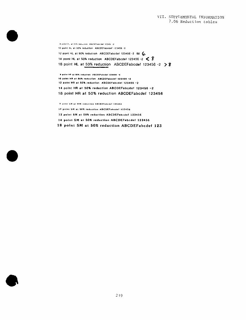
6 pout HL t eow t-,1- ABCVC1 .boaet 1a345t -7
10 point HL at 50% reduction ABCDEFabcdel 123456 -2
12 point HL at 50% reduction ABCDEFabcdef 123456 -2
14 point HL at 50% reduction ABCDEFabcdel 123456 -2
18 point HL at 50% reduction ABCDEFabcdef 123456 -2 > $
a point MR at 60% fed-tion ABCDEFebbd .f 123466 -2
10 point MR at 50% reduction ABCDEFabcdef 123456 -212 point HR at 50% reduction ABCDEFabcdef 123456 -2
14 point HR at 50% reduction ABCDEFabcdef 123456 -2
18 point HR at 50% reduction ABCDEFabcdef 123456
6 point SM .1 50% ~ .d . .tlon ABCDEFabcdef 123456
10 point SM at 5016 reduction ABCDEFabcdef 123456
12 point SM at 50% reduction ABCDEFabcdef 123456
14 point SM at 50% reduction ABCDEFabcdef 123456
18 point SM at 50% reduction ABCDEFabcdef 123
VII . SUPPLEMENTAL INFORMATION7 .06 Reduction tables