standatrd bs en 1160 installation-and-characteristics equipment-for-lng & lpg
TRANSCRIPT

BRITISH STANDARD BS EN 1160:1997
Installations and equipment for liquefied natural gas — General characteristics of liquefied natural gas
The European Standard EN 1160:1996 has the status of aBritish Standard
ICS 75.060; 75.180

BS EN 1160:1997
This British Standard, having been prepared under thedirection of the EngineeringSector Board, was publishedunder the authority of the Standards Board and comesinto effect on15 January 1997
© BSI 11-1998
The following BSI references relate to the work on this standard:Committee reference GSE/38 Draft for comment 93/712075 DC
ISBN 0 580 26446 7
Committees responsible for this British Standard
The preparation of this British Standard was entrusted to Technical Committee GSE/38, Installation and equipment for LNG, upon which the following bodies were represented:
British Gas plcDepartment of TransportHealth and Safety ExecutiveInstitution of Gas EngineersCo-opted members
Amendments issued since publication
Amd. No. Date Comments

BS EN 1160:1997
© BSI 11-1998 i
Contents
PageCommittees responsible Inside front coverNational foreword ii
Foreword 2Text of EN 1160 3

BS EN 1160:1997
ii © BSI 11-1998
National foreword
This British Standard has been prepared by Technical Committee GSE/38 and is the English language version of EN 1160:1996 Installations and equipment for liquefied natural gas — General characteristics of liquefied natural gas, published by the European Committee for Standardization (CEN).EN 1160 was produced as a result of international discussions in which the United Kingdom took an active part.A British Standard does not purport to include all the necessary provisions of a contract. Users of British Standards are responsible for their correct application.
Compliance with a British Standard does not of itself confer immunity from legal obligations.
Summary of pagesThis document comprises a front cover, an inside front cover, pages i and ii, the EN title page, pages 2 to 13 and a back cover.This standard has been updated (see copyright date) and may have had amendments incorporated. This will be indicated in the amendment table on the inside front cover.
www.bzfxw.com
EUROPEAN STANDARD
NORME EUROPÉENNE
EUROPÄISCHE NORM
EN 1160
June 1996
ICS 75.060; 75.180.00
Descriptors: Gas installation, liquefied natural gas, characteristics, physical properties, construction materials, safety, accident prevention, toxicity, fire protection
English version
Installations and equipment for liquefied natural gas — General characteristics of liquefied natural gas
Installations et équipements relatifs au gaz naturel liquéfié —Caractéristiques générales du gaz naturel liquéfié
Anlagen und Ausrüstung für Flüssigerdgas — Allgemeine Eigenschaften von Flüssigerdgas
This European Standard was approved by CEN on 1996-04-20. CEN membersare bound to comply with the CEN/CENELEC Internal Regulations whichstipulate the conditions for giving this European Standard the status of anational standard without any alteration.Up-to-date lists and bibliographical references concerning such nationalstandards may be obtained on application to the Central Secretariat or to anyCEN member.This European Standard exists in three official versions (English, French,German). A version in any other language made by translation under theresponsbility of a CEN member into its own language and notified to theCentral Secretariat has the same status as the official versions.CEN members are the national standards bodies of Austria, Belgium,Denmark, Finland, France, Netherlands, Norway, Portugal, Spain, Sweden,Switzerland and United Kingdom.
CENEuropean Committee for Standardization
Comité Européen de NormalisationEuropäisches Komitee für Normung
Central Secretariat: rue de Stassart 36, B-1050 Brussels
© 1996 Copyright reserved to CEN membersRef. No. EN 1160:1996 E
www.bzfxw.com
EN 1160:1996
© BSI 11-19982
Foreword
This European Standard has been prepared by Technical Committee CEN/TC 282, Installations and equipment for LNG, of which the secretariat is held by AFNOR.This European Standard shall be given the status of a national standard, either by publication of an identical text or by endorsement, at the latest by December 1996, and conflicting national standards shall be withdrawn at the latest by December 1996.According to the CEN/CENELEC Internal Regulations, the natural standards organizations of the following countries are bound to implement this European Standard: Austria, Belgium, Denmark, Finland, France, Germany, Greece, Iceland, Ireland, Italy, Luxembourg, Netherlands, Norway, Portugal, Spain, Sweden, Switzerland and the United Kingdom.
Contents
PageForeword 21 Scope 32 Normative references 33 Definition 34 Abbreviations 35 General characteristics of LNG 35.1 Introduction 35.2 Properties of LNG 35.3 Evaporation of LNG 45.4 Spillage of LNG 55.5 Ignition 55.6 Containment 55.7 Other physical phenomena 66 Materials of construction 76.1 Materials used in the LNG industry 76.2 Thermal stresses 87 Health and safety 87.1 Exposure to cold 87.2 Exposure to gas 87.3 Fire precautions and protection 97.4 Odour 9Annex A (informative) Bibliography 10Annex B (informative) Materials thatcan be used in contact with LNG 12Table 1 — Examples of LNG 4Table 2 — Rate of evaporation 5Table 3 — Main materials used in directcontact and general use 7Table 4 — Main materials not in directcontact under normal operations with LNG 7Table B.1 — Stainless steels at ambientand low temperatures for sheets/platesand strips 12Table B.2 — Stainless steels at ambientand low temperature for nuts and bolts 12Table B.3 — Stainless steels at ambientand low temperature for bars 12Table B.4 — Stainless steels at ambient andlow temperatures for steel forgings 13Table B.5 — Ferronickel and nickel alloys 13Table B.6 — Aluminium alloys 13

www.bzfxw.com
EN 1160:1996
© BSI 11-1998 3
1 ScopeThis European Standard gives guidance on the characteristics of liquefied natural gas (LNG) and the cryogenic materials used in the LNG industry. It also gives guidance on health and safety matters. It is intended to act as a reference document for the implementation of other standards of CEN/TC 282, Installations and equipment for liquefied natural gas.It is intended as a reference for use by persons who design or operate LNG facilities.
2 Normative referencesThis European Standard incorporates by dated or undated reference, provisions from other publications. These normative references are cited at the appropriate places in the text and the publications are listed hereafter. For dated references, subsequent amendments to or revisions of any of these publications apply to this European standard only when incorporated in it by amendment or revision. For undated references the latest edition of the publication referred to applies.prEN 1473, Installation and equipment for liquefied natural gas — Design of on-shore installation.
3 DefinitionFor the purposes of this standard, the following definition applies:
liquefied natural gas
a colourless fluid in the liquid state composed predominantly of methane and which may contain minor quantities of ethane, propane, nitrogen or other components normally found in natural gas
4 AbbreviationsFor the purposes of this standard, the following abbreviations apply:
— LNG liquefied natural gas;— RPT rapid phase transition;— BLEVE boiling liquid expanding vapour explosion;— SEP surface emissive power.
5 General characteristics of LNG5.1 Introduction
It is recommended that all personnel concerned with the handling of LNG should be familiar with both the characteristics of the liquid and the gas produced.
The potential hazard in handling LNG stems mainly from three important properties:
a) it is extremely cold. At atmospheric pressure, depending upon composition, LNG boils at about – 160 °C. At this temperature the vapour is more dense than ambient air (see examples in Table 1);b) very small quantities of liquid are converted into large volumes of gas. One volume of LNG produces approximately 600 volumes of gas (see examples in Table 1);c) natural gas, similar to other gaseous hydrocarbons, is flammable. At ambient conditions the flammable mixture range with air is from approximately 5 % to 15 % gas by volume.
5.2 Properties of LNG
5.2.1 Composition
LNG is a mixture of hydrocarbons composed predominantly of methane and which can contain minor quantities of ethane, propane, nitrogen or other components normally found in natural gas.The physical and thermodynamic properties of methane and other components of natural gas can be found in reference books (see annex A) and thermodynamic calculation codes.For the purpose of this standard, LNG shall have a methane content of more than 75 % and a nitrogen content of less than 5 %.Although the major constituent of LNG is methane, it should not be assumed that LNG is pure methane for the purpose of estimating its behaviour.When analysing the composition of LNG special care should be taken to obtain representative samples not causing false analysis results due to distillation effects. The most common method is to analyse a small stream of continuously evaporated product using a specific device that is designed to provide a representative gas sample of liquid without fractionation. Another method is to take a sample from the outlet of the main product vaporizers. This sample can then be analysed by normal gas chromatographic methods, such as those described in ISO 6568 or ISO 6974.
5.2.2 Density
The density of LNG depends on the composition and usually ranges from 430 kg/m3 to 470 kg/m3, but in some cases can be as high as 520 kg/m3. Density is also a function of the liquid temperature with a gradient of about 1,35 kg·m–3·°C–1. Density can be measured directly but is generally calculated from composition determined by gas chromatographic analysis. The method as defined in ISO 6578 is recommended.NOTE Method generally known as Klosek McKinley method.
www.bzfxw.com
EN 1160:1996
4 © BSI 11-1998
5.2.3 Temperature
LNG has a boiling temperature depending on composition and usually ranging from – 166 °C to – 157 °C at atmospheric pressure. The variation of the boiling temperature with the vapour pressure is about 1,25 × 10⁻⁴ °C/Pa.The temperature of LNG is commonly measured using copper/copper nickel thermocouples or using platinum resistance thermometers such as those defined in ISO 8310.
5.2.4 Examples of LNG
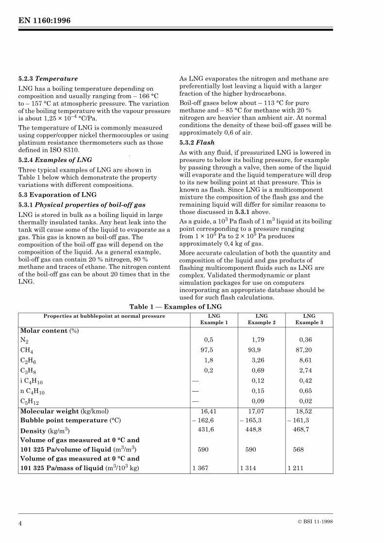
Three typical examples of LNG are shown inTable 1 below which demonstrate the property variations with different compositions.
5.3 Evaporation of LNG
5.3.1 Physical properties of boil-off gas
LNG is stored in bulk as a boiling liquid in large thermally insulated tanks. Any heat leak into the tank will cause some of the liquid to evaporate as a gas. This gas is known as boil-off gas. The composition of the boil-off gas will depend on the composition of the liquid. As a general example, boil-off gas can contain 20 % nitrogen, 80 % methane and traces of ethane. The nitrogen content of the boil-off gas can be about 20 times that in the LNG.
As LNG evaporates the nitrogen and methane are preferentially lost leaving a liquid with a larger fraction of the higher hydrocarbons.Boil-off gases below about – 113 °C for pure methane and – 85 °C for methane with 20 % nitrogen are heavier than ambient air. At normal conditions the density of these boil-off gases will be approximately 0,6 of air.
5.3.2 Flash
As with any fluid, if pressurized LNG is lowered in pressure to below its boiling pressure, for example by passing through a valve, then some of the liquid will evaporate and the liquid temperature will drop to its new boiling point at that pressure. This is known as flash. Since LNG is a multicomponent mixture the composition of the flash gas and the remaining liquid will differ for similar reasons to those discussed in 5.3.1 above.As a guide, a 103 Pa flash of 1 m3 liquid at its boiling point corresponding to a pressure ranging from 1 × 10⁵ Pa to 2 × 10⁵ Pa produces approximately 0,4 kg of gas.More accurate calculation of both the quantity and composition of the liquid and gas products of flashing multicomponent fluids such as LNG are complex. Validated thermodynamic or plant simulation packages for use on computers incorporating an appropriate database should be used for such flash calculations.
Table 1 — Examples of LNGProperties at bubblepoint at normal pressure LNG
Example 1LNG
Example 2LNG
Example 3
Molar content (%)N2 0,5 1,79 0,36
CH4 97,5 93,9 87,20
C2H6 1,8 3,26 8,61
C3H8 0,2 0,69 2,74
i C4H10 — 0,12 0,42
n C4H10 — 0,15 0,65
C5H12 — 0,09 0,02
Molecular weight (kg/kmol) 16,41 17,07 18,52Bubble point temperature (°C) – 162,6 – 165,3 – 161,3
Density (kg/m3) 431,6 448,8 468,7
Volume of gas measured at 0 °C and101 325 Pa/volume of liquid (m3/m3) 590 590 568Volume of gas measured at 0 °C and101 325 Pa/mass of liquid (m3/103 kg) 1 367 1 314 1 211
www.bzfxw.com
EN 1160:1996
© BSI 11-1998 5
5.4 Spillage of LNG
5.4.1 Characteristics of LNG spills
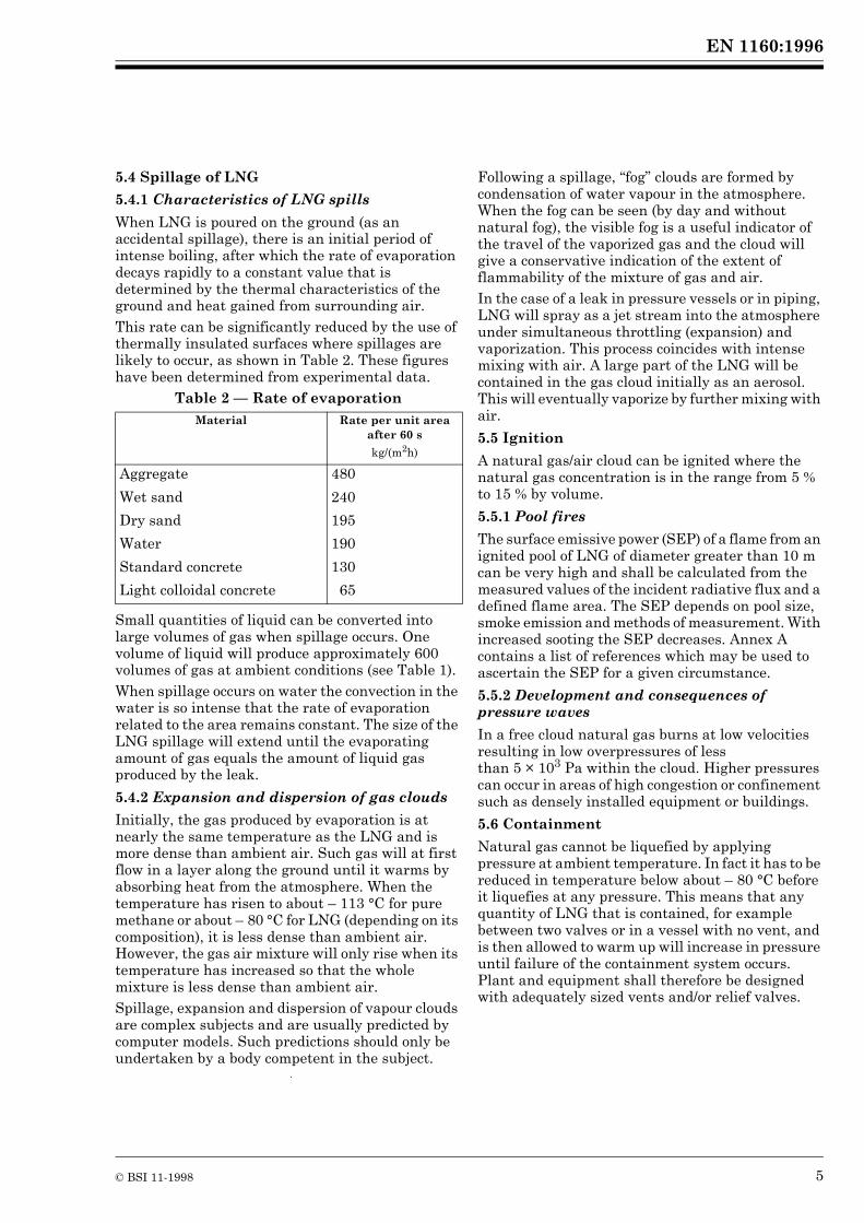
When LNG is poured on the ground (as an accidental spillage), there is an initial period of intense boiling, after which the rate of evaporation decays rapidly to a constant value that is determined by the thermal characteristics of the ground and heat gained from surrounding air.This rate can be significantly reduced by the use of thermally insulated surfaces where spillages are likely to occur, as shown in Table 2. These figures have been determined from experimental data.
Table 2 — Rate of evaporation
Small quantities of liquid can be converted into large volumes of gas when spillage occurs. One volume of liquid will produce approximately 600 volumes of gas at ambient conditions (see Table 1).When spillage occurs on water the convection in the water is so intense that the rate of evaporation related to the area remains constant. The size of the LNG spillage will extend until the evaporating amount of gas equals the amount of liquid gas produced by the leak.
5.4.2 Expansion and dispersion of gas clouds
Initially, the gas produced by evaporation is at nearly the same temperature as the LNG and is more dense than ambient air. Such gas will at first flow in a layer along the ground until it warms by absorbing heat from the atmosphere. When the temperature has risen to about – 113 °C for pure methane or about – 80 °C for LNG (depending on its composition), it is less dense than ambient air. However, the gas air mixture will only rise when its temperature has increased so that the whole mixture is less dense than ambient air.Spillage, expansion and dispersion of vapour clouds are complex subjects and are usually predicted by computer models. Such predictions should only be undertaken by a body competent in the subject.
Following a spillage, “fog” clouds are formed by condensation of water vapour in the atmosphere. When the fog can be seen (by day and without natural fog), the visible fog is a useful indicator of the travel of the vaporized gas and the cloud will give a conservative indication of the extent of flammability of the mixture of gas and air.In the case of a leak in pressure vessels or in piping, LNG will spray as a jet stream into the atmosphere under simultaneous throttling (expansion) and vaporization. This process coincides with intense mixing with air. A large part of the LNG will be contained in the gas cloud initially as an aerosol. This will eventually vaporize by further mixing with air.
5.5 Ignition
A natural gas/air cloud can be ignited where the natural gas concentration is in the range from 5 % to 15 % by volume.
5.5.1 Pool fires
The surface emissive power (SEP) of a flame from an ignited pool of LNG of diameter greater than 10 m can be very high and shall be calculated from the measured values of the incident radiative flux and a defined flame area. The SEP depends on pool size, smoke emission and methods of measurement. With increased sooting the SEP decreases. Annex A contains a list of references which may be used to ascertain the SEP for a given circumstance.
5.5.2 Development and consequences of pressure waves
In a free cloud natural gas burns at low velocities resulting in low overpressures of less than 5 × 10³ Pa within the cloud. Higher pressures can occur in areas of high congestion or confinement such as densely installed equipment or buildings.
5.6 Containment
Natural gas cannot be liquefied by applying pressure at ambient temperature. In fact it has to be reduced in temperature below about – 80 °C before it liquefies at any pressure. This means that any quantity of LNG that is contained, for example between two valves or in a vessel with no vent, and is then allowed to warm up will increase in pressure until failure of the containment system occurs. Plant and equipment shall therefore be designed with adequately sized vents and/or relief valves.
Material Rate per unit area after 60 s
kg/(m2h)
Aggregate 480
Wet sand 240
Dry sand 195
Water 190
Standard concrete 130
Light colloidal concrete 65

www.bzfxw.com
EN 1160:1996
6 © BSI 11-1998
5.7 Other physical phenomena
5.7.1 Rollover
The term rollover refers to a process whereby large quantities of gas can be emitted from an LNG tank over a short period. This could cause overpressurization of the tank unless prevented or designed for.It is possible in LNG storage tanks for two stably stratified layers or cells to be established, usually as a result of inadequate mixing of fresh LNG with a heel of different density. Within cells the liquid density is uniform but the bottom cell is composed of liquid that is more dense than the liquid in the cell above. Subsequently, due to the heat leak into the tank, heat and mass transfer between cells and evaporation at the liquid surface, the cells equilibrate in density and eventually mix. This spontaneous mixing is called rollover and if, as is often the case, the liquid at the bottom cell has become superheated with respect to the pressure in the tank vapour space, the rollover is accompanied by an increase in vapour evolution. Sometimes, the increase is rapid and large. In a few instances the pressure rise in the tank has been sufficient to cause pressure relief valves to lift.An early hypothesis was that when the density of the top layer exceeded that of the lower layer an inversion would occur, hence the name rollover. More recent research shows that this is not the case and that, as described above, it is rapid mixing that occurs.Potential rollover incidents are usually preceded by a period during which the boil-off gas production rate is significantly lower than normal. Boil-off rates should therefore be closely monitored to ensure that the liquid is not storing heat. If this is suspected, attempts should be made to circulate liquid to promote mixing.Rollover can be prevented by good stock management. LNG from different sources and having different compositions should preferably be stored in separate tanks. If this is not practical, good mixing should be ensured during tank filling.A high nitrogen content in peak shaving LNG can also cause a rollover soon after the cessation of tank filling.Experience shows that this type of rollover can best be prevented by keeping the nitrogen content of LNG below 1% and by closely monitoring the boil-off rate.
5.7.2 RPT
When two liquids at two different temperatures come into contact, explosive forces can occur, given certain circumstances. This phenomenon, called rapid phase transition (RPT), can occur when LNG and water come into contact. Although no combustion occurs, this phenomenon has all the other characteristics of an explosion.RPTs resulting from an LNG spill on water have been both rare and with limited consequences.The universally applicable theory that agrees with the experimental results can be summarized as follows. When two liquids with very different temperatures come into direct contact, if the temperature (expressed in kelvin) of the warmer of the two is greater than 1,1 times the boiling point of the cooler one, the rise in temperature of the latter is so rapid that the temperature of the surface layer can exceed the spontaneous nucleation temperature (when bubbles appear in the liquid). In some circumstances this superheated liquid vaporizes within a short time via a complex chain reaction mechanism and thus produces vapour at an explosive rate.For example, liquids can be brought into intimate contact by mechanical impact and this has been known to initiate RPTs in experiments with LNG or liquid nitrogen on water.Various research programmes are in progress to gain a better understanding of RPTs, to quantify the severity of the phenomena and to ascertain whether prevention measures are warranted.
5.7.3 BLEVE
Any liquid at or near its boiling point and above a certain pressure will extremely rapidly vaporize if suddenly released due to failure of the pressure system. This violent expansion process has been known to propel whole sections of failed vessels several hundred metres. This is known as a boiling liquid expanding vapour explosion (BLEVE).A BLEVE is highly unlikely to occur on an LNG installation because either the LNG is stored in a vessel which will fail at a low pressure (see A.5) and where the rate of vapour evolution is small, or it is stored and transferred in insulated pressure vessels and pipes which are inherently protected from fire damage.
EN 1160:1996
© BSI 11-1998 7
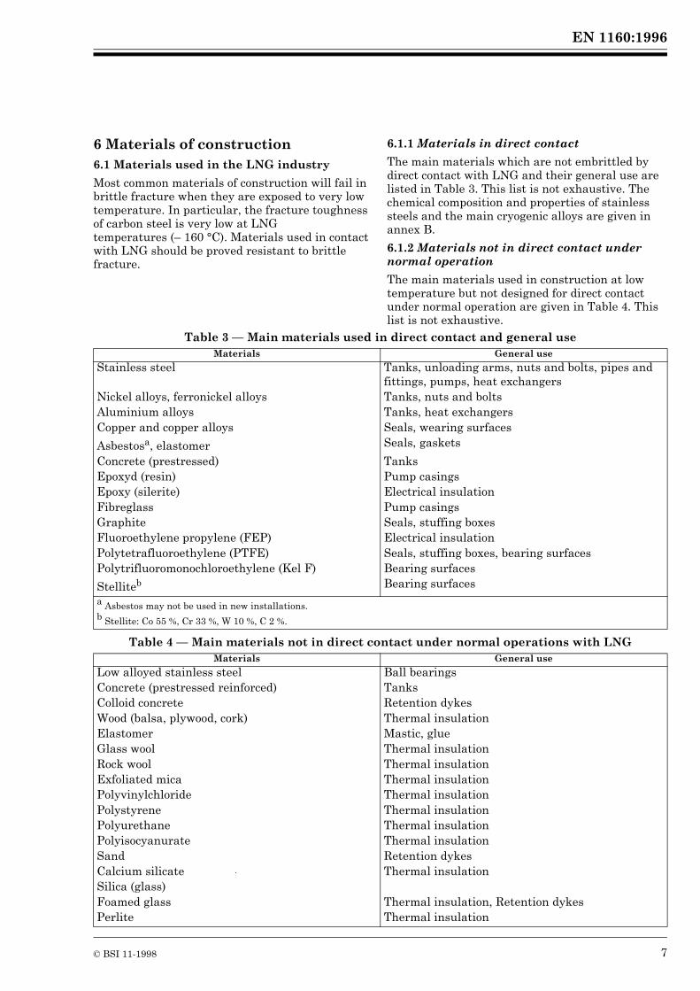
6 Materials of construction6.1 Materials used in the LNG industry
Most common materials of construction will fail in brittle fracture when they are exposed to very low temperature. In particular, the fracture toughness of carbon steel is very low at LNGtemperatures (– 160 °C). Materials used in contact with LNG should be proved resistant to brittle fracture.
6.1.1 Materials in direct contact
The main materials which are not embrittled by direct contact with LNG and their general use are listed in Table 3. This list is not exhaustive. The chemical composition and properties of stainless steels and the main cryogenic alloys are given in annex B.
6.1.2 Materials not in direct contact under normal operation
The main materials used in construction at low temperature but not designed for direct contact under normal operation are given in Table 4. This list is not exhaustive.
Table 3 — Main materials used in direct contact and general use
Table 4 — Main materials not in direct contact under normal operations with LNG
Materials General use
Stainless steel Tanks, unloading arms, nuts and bolts, pipes and fittings, pumps, heat exchangers
Nickel alloys, ferronickel alloys Tanks, nuts and boltsAluminium alloys Tanks, heat exchangersCopper and copper alloys Seals, wearing surfaces
Asbestosa, elastomer Seals, gaskets
Concrete (prestressed) TanksEpoxyd (resin) Pump casingsEpoxy (silerite) Electrical insulationFibreglass Pump casingsGraphite Seals, stuffing boxesFluoroethylene propylene (FEP) Electrical insulationPolytetrafluoroethylene (PTFE) Seals, stuffing boxes, bearing surfacesPolytrifluoromonochloroethylene (Kel F) Bearing surfaces
Stelliteb Bearing surfacesa Asbestos may not be used in new installations.b Stellite: Co 55 %, Cr 33 %, W 10 %, C 2 %.
Materials General use
Low alloyed stainless steel Ball bearingsConcrete (prestressed reinforced) TanksColloid concrete Retention dykesWood (balsa, plywood, cork) Thermal insulationElastomer Mastic, glueGlass wool Thermal insulationRock wool Thermal insulationExfoliated mica Thermal insulationPolyvinylchloride Thermal insulationPolystyrene Thermal insulationPolyurethane Thermal insulationPolyisocyanurate Thermal insulationSand Retention dykesCalcium silicate Thermal insulationSilica (glass)Foamed glass Thermal insulation, Retention dykesPerlite Thermal insulation

EN 1160:1996
8 © BSI 11-1998
6.1.3 Other information
Since copper, brass and aluminium have low melting points and could fail in an ignited LNG spill, stainless steel and 9 % nickel steel tend to be used. Aluminium is often used for heat exchangers. Liquefaction plant tube and plate exchangers are protected by a steel chamber called a cold box. Aluminium can also be used for inner tank suspended roofs.Equipment specifically designed for liquid oxygen or liquid nitrogen is normally also suitable for LNG.Equipment designed for normal operation on LNG at higher pressure and temperature should also be designed to take account of the drop in temperature of the fluid in the event of depressurization.
6.2 Thermal stresses
Most cryogenic equipment used in LNG facilities will undergo fast cooling from ambient temperature down to LNG temperature.Temperature gradients occur during these cooling down operations producing thermal stresses which are transient, cyclical and maximal along the walls directly in contact with LNG.These stresses increase with the thickness of the materials, and when this thickness exceeds approximately 10 mm they can become significant.For especially critical points, transition or shock stresses can be calculated using an approved method and tested for brittle fracture.
7 Health and safetyThe following recommendations are given in order to provide guidance to persons involved in operating LNG plant and are not intended to supersede national legal requirements.
7.1 Exposure to cold
The low temperatures associated with LNG can result in a variety of effects on exposed parts of the body. If a person is not suitably protected against low ambient temperatures, the person’s reactions and capabilities can be adversely affected.
7.1.1 Handling, cold contact burns
Contact with LNG can produce a blistering effect on the skin similar to a burn. The gas issuing from LNG is also extremely cold and can produce burns. Delicate tissues, such as those of the eyes, can be damaged by exposure to this cold gas even though it would be too brief to affect the skin of the face and hands.
Unprotected parts of the body should not be allowed to touch uninsulated pipes or vessels containing LNG. The extremely cold metal can adhere and the flesh can be torn when attempts are made to withdraw from it.
7.1.2 Frostbite
Severe or prolonged exposure to cold vapours and gases can cause frostbite. Local pain usually gives warning of freezing but sometimes no pain is experienced.
7.1.3 Effect of cold on the lungs
Prolonged breathing of extremely cold atmospheres can damage the lungs. Short exposure can produce breathing discomfort.
7.1.4 Hypothermia
The danger from hypothermia can be present at temperatures up to 10 °C. Persons apparently suffering from the effects of hypothermia should be removed from the cold area and rapidly rewarmed in a warm bath with the temperature between 40 °C and 42 °C. Dry heat shall not be used for warming.
7.1.5 Recommended protective clothing
When handling LNG the eyes should be protected with an appropriate face shield or safety goggles if exposure to LNG is reasonably foreseeable.Leather gloves should always be worn when handling anything that is, or could have been, in contact with the cold liquid or gas. Gloves should be a loose fit so that they can be readily removed should liquid splash in or on them. Even when using gloves, equipment should only be held for a short time.Tight fitting overalls or similar type of clothing should be worn, preferably without pockets orturn-ups, and trousers should be worn outside boots or shoes. Clothing which has been contaminated with cold liquid or vapour should be ventilated before the wearer goes into a confined space or near an ignition source.Operating personnel should be aware that protective clothing only gives a measure of protection against occasional splashes of LNG and contact with LNG should be avoided.
7.2 Exposure to gas
7.2.1 Toxicity
LNG and natural gas are not toxic.
EN 1160:1996
© BSI 11-1998 9
7.2.2 Asphyxia
Natural gas is a simple asphyxiant. The normal oxygen content of the air is 20,9 % by volume. Atmospheres containing less than 18 % oxygen are potentially asphyxiant. In the case of high concentrations of gas, there can be nausea or dizziness due to anoxia. Removal from exposure however, normally causes the symptoms to disappear rapidly. The oxygen and hydrocarbon content of atmospheres where natural gas could be present, should be measured prior to entry.NOTE Even if the oxygen content is shown to be adequate to prevent asphyxia, a flammability test should be made before entry. Only instruments made for this purpose should be used for such tests.
7.3 Fire precautions and protection
It is recommended that fire extinguishers of the dry powder type (preferably potassium carbonate) are conveniently available when handling LNG. Personnel involved in handling LNG should be trained in the use of dry powder extinguishers on liquid fires.High expansion foam or foamed glass blocks can be useful in covering LNG pool fires and hence greatly reducing the radiation from them.A water supply should be available for cooling purposes, and for foam generation if equipment is available. Water should not be used to extinguish fires.The design of fire precautions and protection shall comply with prEN 1473.
7.4 Odour
LNG vapour is odourless.
EN 1160:1996
10 © BSI 11-1998
Annex A (informative)Bibliography
A.1 General
(1) Safety tools for LNG risk evaluation: cloud dispersion and radiation, D. NÉDELKA, B. WEISS, B. BAUER (Gaz de France), IGU H12-91, Berlin (July 1991).
(2) Methodology of Gaz de France concerning matters of LNG terminals, D. NÉDELKA, A. GOY (Gaz de France), Paper 1, Session III, LNG 10, Kuala Lumpur (May 1992).(3) Grundlagen sicherheitstechnischer Erfordernisse im Umgang mit Flüssigerdgas (LNG), K.A. HOPFER, gwf Gas-Erdgas 130 (1989), S 27-32.
A.2 LNG fire
(1) Calculation of radiation effects, D. NÉDELKA (Gaz de France), EUROGAS Trondheim (May 1990).(2) The MONTOIR 35 m diameter LNG pool fire experiments, D. NÉDELKA, J. MOORHOUSE, R.F. TUCKER, (Gaz de France, British Gas, Shell Research), Paper 3, Session III, LNG 9, Nice (Nov 1989).(3) Fire safety assessment for LNG storage facilities, B.J. LOWESMITH, J. MOORHOUSE, P. ROBERT, Paper 2, Session III, Intern. Conference on LNG (LNG 10), Kuala Lumpur 1992.(4) Prediction of the heat radiation and safety distances of large fires with the model OSRAMO, A. SCHÖNBUCHER et al, 7th Int. Symp. on Loss Prevention and Safety Promotion in the process industries, 68-1/68-16, Proceedings, Taormina (1992).(5) Das experimentell validierte Ballen-Strahlungsmodell OSRAMO, Teil 1: Theoretische Grundlagen, A. SCHÖNBUCHER et al, Tü 33 (1992), 137/140.
(6) Das experimentell validierte Ballen-Strahlungsmodell OSRAMO, Teil 2: Sicherheitstechnische Anwendung (Sicherheitsabstände), A. SCHÖNBUCHER et al, Tü 33 (1992), 219/223.(7) LNG fire: A thermal radiation model for LNG fires, Topical report, June 29, 1990, Gas Research Institute, 8600 West Bryn Mawr Avenue, Chicago, Illinois 60631.(8) Thermal radiation from LNG trench fires, Volume III, Final report, September 1982 – September 1984, Gas Research Institute, 8600 West Bryn Mawr Avenue, Chicago, Illinois 60631.(9) Methods of the calculation of the physical effects of the escape of dangerous material, Chapter 6 — Heat radiation, G.W. HOFTIJER, TNO Organization for Industrial Research — Division of Technology for Society, P.O. Box 342, 7300 AH Apeldoorn, Netherlands.(10) Large scale LNG and LPG pool fires in the assessment of major hazards, G.A. MIZNER and J.A. EYRE, Institution of Chemical Engineers Symposium, Series No. 71 (1982).
A.3 RPT
(1) Contribution to the study of the behaviour of LNG spilled onto the sea, A. SALVADORI, J.C. LEDIRAISON, D. NÉDELKA, (Gaz de France), Session III, LNG 7, Djakarta (May 1983).(2) Rapid phase transitions of cryogenic liquids boiling on water surface, J.D. SAINSON, C. BARADEL, M. ROULEAU, J. LEBLOND (Gaz de France, ESPCI, ENS), Paper 9, Session II, Eurotherm Louvain (May 1990).
(3) Propagation of vapor explosion in a stratified geometry. Experiments with liquid nitrogen and water, J.D. SAINSON, M. GABILLARD, T. WILLIAMS (Gaz de France, Gas Research Institute), CSNI – Fuel Coolant Interaction — Santa Barbara (Jan. 1993).
A.4 Rollover
(1) LNG stratification and rollover, J.A. SARSTEN, Pipeline and Gas Journal, vol. 199, p. 37 (Sep. 1972).
(2) Tests on LNG behaviour in large scale tank at Fos-sur-Mer terminal, F. BELLUS, Y. RÉVEILLARD, C. BONNAURE, L. CHEVALIER (Gaz de France), Paper 9, Session III, LNG 5 (May 1977).
EN 1160:1996
© BSI 11-1998 11
(3) Management of LNG storage tanks. Stratification, mixing and ageing of LNG, O. MARCEL,A. GIRARD-LAOT, P. LANGRY (Gaz de France), Paper 4, Session III, LNG 10, Kuala Lumpur (May 1992).
(4) LNG tank filling: Operational procedures to prevent stratification, M. BAUDINO (SNAM), Paper H5, 16th World Gas Conference, Munich (1985).
A.5 BLEVE
(1) LNG and explosions of BLEVE type, L. MONTENEGRO FORMIGUERA (Catalana de Gas y Electricidad), Gas National Conference XIII, Madrid (May 1987).
A.6 LNG handbooks
(1) Encyclopédie de gaz — L’Air Liquide — Elsevier (1976).
(2) LNG materials and fluids: A users manual of property data in graphic format, National Bureau of Standards, Boulder, Colorado, USA, Douglas Man (1977).
A.7 Spillage of LNG
(1) Boiling and spreading rates of instantaneous spills of liquid methane on water, D.J. CHATLOS, R.C. REID, Gas Research Institute 81/0045 (April 1982).
(2) Verein Deutscher Ingenieure, Arbeitsblatt VDI 3783, Blatt 1: Ausbreitung von Freisetzungen, Sicherheitsanalyse.(3) Verein Deutscher Ingenieure, Arbeitsblatt VDI 3783, Blatt 2: Ausbreitung von störfallbedingten Freisetzungen schwerer Gase, Sicherheitsanalyse.
A.8 Standards
EN 485-2, Aluminium and aluminium alloys — Sheet, strip and plate — Part 2: Mechanical properties.EN 515, Aluminium and aluminium alloys — Wrought products — Temper designations.EN 573-3, Aluminium and aluminium alloys — Chemical composition and form of wrought products — Part 3: Chemical composition.EN 10028-4, Flat products made of steels for pressure purposes — Part 4: Nickel alloy steels with specified low temperature properties.EN 10045-1, Metallic materials — Charpy impact test — Part 1: Test method.EN 10088-1, Stainless steels — Part 1: List of stainless steels.EN 10088-2, Stainless steels — Part 2: Technical delivery conditions for sheet/plate and strip for general purposes.EN 10088-3, Stainless steels — Part 3: Technical delivery conditions for semi-finished products, bars, rods and sections for general purposes.EN 26501, Ferronickel — Specification and delivery requirements (ISO 6501:1988).prEN 754-2, Aluminium and aluminium alloys — Cold drawn rod/bar and tube — Part 2: Mechanical properties.
prEN 755-2, Aluminium and aluminium alloys — Extruded rod/bar, tube and profile — Part 2: Mechanical properties.prEN 10222-6, Steel forgings for pressure purposes — Part 6: Austenitic, martensitic and austenitic-ferritic stainless steels.ISO 6208, Nickel and nickel alloy plate, sheet and strip.ISO 6568, Natural gas — Simple analysis by gas chromatography.ISO 6578, Refrigerated hydrocarbon liquids — Static measurement — Calculation procedure.ISO 6974, Natural gas Determination of hydrogen, inert gases and hydrocarbons up to C8 — Gas chromatographic method.ISO 8310, Refrigerated light hydrocarbon fluids — Measurement of temperature in tanks containing liquefied gases — Resistance thermometers and thermocouples.ISO 9722, Nickel and nickel alloys — Composition and form of wrought products.ISO 9723, Nickel and nickel alloy bars.
stor··fallbedingten

EN 1160:1996
12 © BSI 11-1998
Annex B (informative)Materials that can be used in contact with LNGThis annex gives the grades of the main materials that can be used in contact with LNG.The references of the European or international standards (or drafts) which give the chemical composition or mechanical properties of the materials are indicated in Table B.1 to Table B.6Table B.1 gives the values of the impact energy KV (J) at – 196 °C.
Table B.1 — Stainless steels at ambient and low temperatures for sheets/plates and strips
Table B.2 — Stainless steels at ambient and low temperature for nuts and bolts
Table B.3 — Stainless steels at ambient and low temperature for bars
Steel grade designation KV (J)a
Name Number (– 196 °C)long tr
X2CrNi18-9 1.4307 — ≥ 70X2CrNiMo17-12-2 1.4404 90 70X2CrNiMo17-12-3 1.4432 90 70X2CrNiMo18-14-3 1.4435 90 70X5CrNi18-10 1.4301 90 70X6CrNiTi18-10 1.4541 90 70X6CrNiMoNb17-12-2 1.4580 90 70X5CrNiMo17-12-2 1.4401 90 70X3CrNiMo17-13-3 1.4436 90 70X2CrNiMo18-15-4 1.4438 90 70X2CrNiN18-10 1.4311 90 70X2CrNiMoN17-13-3 1.4429 90 70X2CrNiMoN18-12-4 1.4434 90 70X2CrNiMoN17-13-5 1.4439 90 70X1NiCrMoCu25-20-5 1.4539 90 70a The values of impact energy at – 196 °C are those of a French standard because the European Standard of stainless steels for pressure purposes is not available yet.NOTE Chemical composition: see EN 10088-1. Mechanical properties: see EN 10088-2.
Steel grade designation
X5CrNi18-10
X4CrNi18-12
X5CrNiMo17-12-2
X3CrNiMo 17-13-3NOTE See EN 10088-2 for mechanical properties.
Steel grade designationName Number
X2CrNi18-9 1.4307X2CrNiMo17-12-2 1.4404X2CrNiMo17-12-3 1.4432X2CrNiMo18-14-3 1.4435X5CrNi18-10 1.4301X6CrNiTi18-10 1.4541X6CrNiMoNb17-12-2 1.4580X5CrNiMo17-12-2 1.4401X3CrNiMo17-13-3 1.4436X2CrNiMo18-15-4 1.4438X8CrNiS18-9 1.4305X2CrNiN18-10 1.4311X2CrNiMoN17-13-3 1.4429X2CrNiMoN17-13-5 1.4439X1NiCrMoCu25-20-5 1.4539NOTE See EN 10088-3 for mechanical properties.See EN 10088-1 for chemical properties.

EN 1160:1996
© BSI 11-1998 13
Table B.4 — Stainless steels at ambient and low temperatures for steel forgings
Table B.5 — Ferronickel and nickel alloys
Table B.6 — Aluminium alloys
Steel grade designation
Name Number
X2CrNi18-9 1.4307
X2CrNiMo17-12-2 1.4404
X2CrNiMo17-12-3 1.4432
X5CrNi18-10 1.4301
X6CrNiTi18-10 1.4541
X4CrNiMo17-12-2 1.4401
X2CrNiN18-10 1.4311
X6CrNiNb18-10 1.4550NOTE See prEN 10222-6 for mechanical properties.See prEN 10088-1 for chemical properties.
Designation Chemical compositionReference standard
Mechanical propertiesReference standard
FeNi40LC EN 26501 EN 26501X8Ni9 (1.5662) EN 10028-4 EN 10028-4FeNi32Cr21AlTi ISO 9722 ISO 6208
ISO 9723FeNi32Cr21AlTiHC ISO 9722 ISO 6208
ISO 9723NiCr15Fe8 ISO 9722 ISO 6208
ISO 9723NiMo16Cr15Fe6W4 ISO 9722 ISO 6208
ISO 9723NiMo28 ISO 9722 ISO 6208
ISO 9723
Alloy designation Chemical composition Mechanical properties
Number Chemical symbols Reference standard Reference standard
EN AW-5083 EN AW-AlMg4,5Mn0,7 EN 573-3 EN 485-2prEN 754-2prEN 755-2
EN AW-5086 EN AW-AlMg4 EN 573-3 EN 485-2prEN 754-2prEN 755-2

BSI389 Chiswick High RoadLondonW4 4AL
|||||||||||||||||||||||||||||||||||||||||||||||||||||||||||||||||||||||||||||||||||||||||||||||||||||||||||||||||||||||||||||||
BSI Ð British Standards Institution
BSI is the independent national body responsible for preparing British Standards. Itpresents the UK view on standards in Europe and at the international level. It isincorporated by Royal Charter.
Revisions
British Standards are updated by amendment or revision. Users of British Standardsshould make sure that they possess the latest amendments or editions.
It is the constant aim of BSI to improve the quality of our products and services. Wewould be grateful if anyone finding an inaccuracy or ambiguity while using thisBritish Standard would inform the Secretary of the technical committee responsible,the identity of which can be found on the inside front cover. Tel: 020 8996 9000.Fax: 020 8996 7400.
BSI offers members an individual updating service called PLUS which ensures thatsubscribers automatically receive the latest editions of standards.
Buying standards
Orders for all BSI, international and foreign standards publications should beaddressed to Customer Services. Tel: 020 8996 9001. Fax: 020 8996 7001.
In response to orders for international standards, it is BSI policy to supply the BSIimplementation of those that have been published as British Standards, unlessotherwise requested.
Information on standards
BSI provides a wide range of information on national, European and internationalstandards through its Library and its Technical Help to Exporters Service. VariousBSI electronic information services are also available which give details on all itsproducts and services. Contact the Information Centre. Tel: 020 8996 7111.Fax: 020 8996 7048.
Subscribing members of BSI are kept up to date with standards developments andreceive substantial discounts on the purchase price of standards. For details ofthese and other benefits contact Membership Administration. Tel: 020 8996 7002.Fax: 020 8996 7001.
Copyright
Copyright subsists in all BSI publications. BSI also holds the copyright, in the UK, ofthe publications of the international standardization bodies. Except as permittedunder the Copyright, Designs and Patents Act 1988 no extract may be reproduced,stored in a retrieval system or transmitted in any form or by any means ± electronic,photocopying, recording or otherwise ± without prior written permission from BSI.
This does not preclude the free use, in the course of implementing the standard, ofnecessary details such as symbols, and size, type or grade designations. If thesedetails are to be used for any other purpose than implementation then the priorwritten permission of BSI must be obtained.
If permission is granted, the terms may include royalty payments or a licensingagreement. Details and advice can be obtained from the Copyright Manager.Tel: 020 8996 7070.