starfighters fuel tank. directorate project number: kca-4244
TRANSCRIPT

TO:
FROM: TA-B1C/NEPA Compliance
TA-A3
Avoid Verbal Orders
DATE: 11/3/2009
SUBJECT KSC Record of Environmental Consideration (REC) CHECKLIST #: 7667
3. ENVIRONMENTAL REQUIREMENTS
2. NEPA DETERMINATIONS
a. Non-Permit Requirements
b. Permit Requirements
EPB Reviewer: LPH
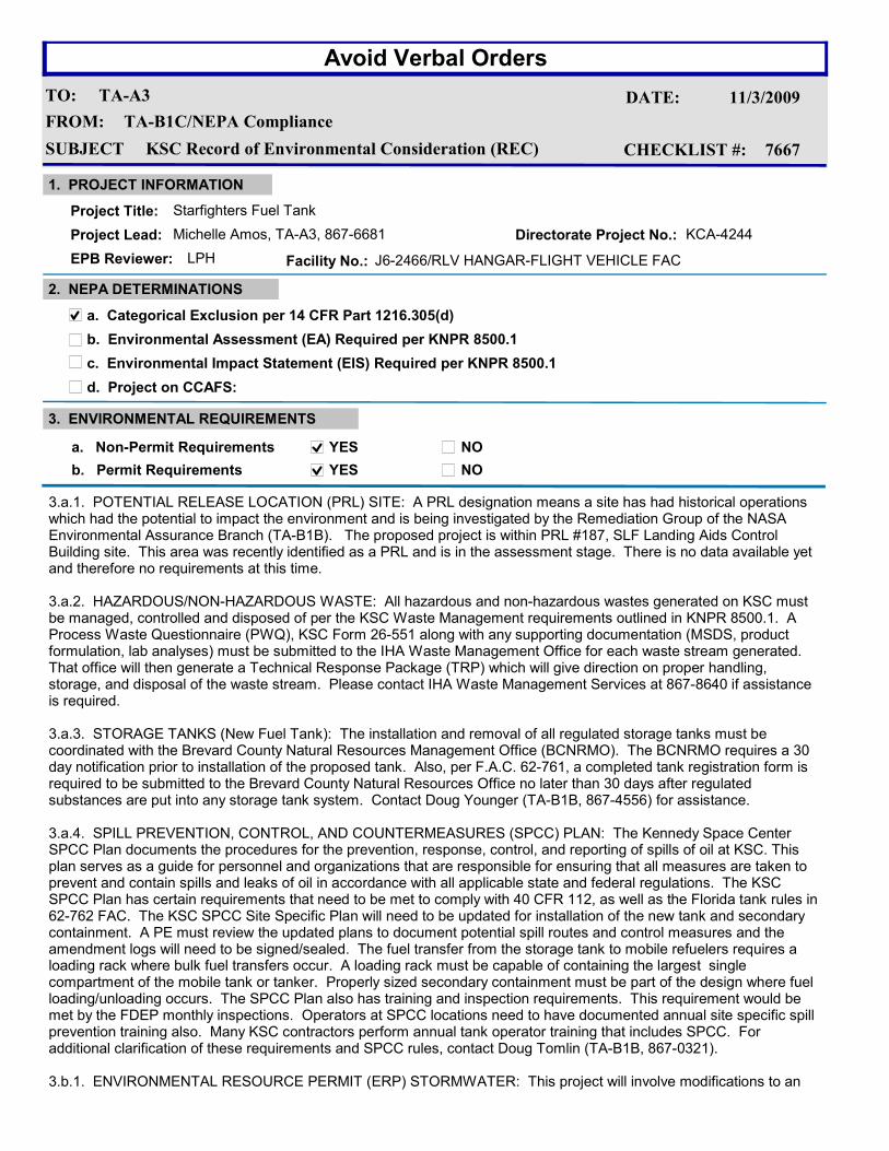
3.a.1. POTENTIAL RELEASE LOCATION (PRL) SITE: A PRL designation means a site has had historical operations which had the potential to impact the environment and is being investigated by the Remediation Group of the NASA Environmental Assurance Branch (TA-B1B). The proposed project is within PRL #187, SLF Landing Aids Control Building site. This area was recently identified as a PRL and is in the assessment stage. There is no data available yet and therefore no requirements at this time.
3.a.2. HAZARDOUS/NON-HAZARDOUS WASTE: All hazardous and non-hazardous wastes generated on KSC must be managed, controlled and disposed of per the KSC Waste Management requirements outlined in KNPR 8500.1. A Process Waste Questionnaire (PWQ), KSC Form 26-551 along with any supporting documentation (MSDS, product formulation, lab analyses) must be submitted to the IHA Waste Management Office for each waste stream generated. That office will then generate a Technical Response Package (TRP) which will give direction on proper handling, storage, and disposal of the waste stream. Please contact IHA Waste Management Services at 867-8640 if assistance is required.
3.a.3. STORAGE TANKS (New Fuel Tank): The installation and removal of all regulated storage tanks must be coordinated with the Brevard County Natural Resources Management Office (BCNRMO). The BCNRMO requires a 30 day notification prior to installation of the proposed tank. Also, per F.A.C. 62-761, a completed tank registration form is required to be submitted to the Brevard County Natural Resources Office no later than 30 days after regulated substances are put into any storage tank system. Contact Doug Younger (TA-B1B, 867-4556) for assistance.
3.a.4. SPILL PREVENTION, CONTROL, AND COUNTERMEASURES (SPCC) PLAN: The Kennedy Space Center SPCC Plan documents the procedures for the prevention, response, control, and reporting of spills of oil at KSC. This plan serves as a guide for personnel and organizations that are responsible for ensuring that all measures are taken to prevent and contain spills and leaks of oil in accordance with all applicable state and federal regulations. The KSC SPCC Plan has certain requirements that need to be met to comply with 40 CFR 112, as well as the Florida tank rules in 62-762 FAC. The KSC SPCC Site Specific Plan will need to be updated for installation of the new tank and secondary containment. A PE must review the updated plans to document potential spill routes and control measures and the amendment logs will need to be signed/sealed. The fuel transfer from the storage tank to mobile refuelers requires a loading rack where bulk fuel transfers occur. A loading rack must be capable of containing the largest single compartment of the mobile tank or tanker. Properly sized secondary containment must be part of the design where fuel loading/unloading occurs. The SPCC Plan also has training and inspection requirements. This requirement would be met by the FDEP monthly inspections. Operators at SPCC locations need to have documented annual site specific spill prevention training also. Many KSC contractors perform annual tank operator training that includes SPCC. For additional clarification of these requirements and SPCC rules, contact Doug Tomlin (TA-B1B, 867-0321).
3.b.1. ENVIRONMENTAL RESOURCE PERMIT (ERP) STORMWATER: This project will involve modifications to an
a. Categorical Exclusion per 14 CFR Part 1216.305(d)
b. Environmental Assessment (EA) Required per KNPR 8500.1
c. Environmental Impact Statement (EIS) Required per KNPR 8500.1
YES NO
YES NO
d. Project on CCAFS:
1. PROJECT INFORMATION
Project Title: Starfighters Fuel Tank
Project Lead: Michelle Amos, TA-A3, 867-6681 Directorate Project No.: KCA-4244
Facility No.: J6-2466/RLV HANGAR-FLIGHT VEHICLE FAC

TO:
FROM: TA-B1C/NEPA Compliance
TA-A3
Avoid Verbal Orders
DATE: 11/3/2009
SUBJECT KSC Record of Environmental Consideration (REC) CHECKLIST #: 7667
Upon evaluation of the subject project, the above determinations have been made and identified. Contact
the Environmental Program Office (TA-B1C) at 867-8448 for re-evaluation should there be any modifications
to the scope of work.
4
Date
existing permitted stormwater management system. The permit application and supporting calculations, drawings, and documentation including an electronic version in PDF format should be submitted to Doug Durham, NASA Environmental Assurance Branch (TA-B1B). Contact Doug Durham at 867-8429 for assistance.
3.b.2. EXCAVATION PERMIT: A KSC Excavation Permit will be required for any digging proposed by this project. Please contact the Utility Locate/Excavation Permit Request Customer Helpline at 867-2406 for an underground utility scan and dig permit.
No other environmental issues were identified based upon the information provided in the KSC Checklist. This Record of Environmental Consideration (REC) does not relinquish the project lead from obtaining and complying with any other internal NASA permits or directives necessary to ensure all organizations potentially impacted by this project are notified and concur with the proposed project.
Due to potential changes in regulations, permit requirements and environmental conditions, statements in this REC are valid for 6 months, and subject to review after this period. It is the responsibility of the project lead to notify the Environmental Management Branch (TA-B1C) if the scope of the project has changed since the original checklist was submitted.
cc: M. Amos/TA-A3 D. Younger/TA-B1B D. Tomlin/TA-B1B
11/4/2009 8:46:12 AM
Lynne Phillips
KSC FORM 21-608V2 NS (REV. 01/08) PREVIOUS EDITIONS ARE OBSOLETE Page 1
KSC ENVIRONMENTAL CHECKLIST1. PROJECT TITLE:
Starfighters Fuel Tank3. PROJECT LOCATION:
Check the appropriate box (Yes, No, Undetermined) to identify if any component of the proposed project (including, but not limited to: construction,installation, demolition, removal, activation or operation) will involve any of the items listed. Use the attached instructions. Provide more specificinformation for each item marked Yes or Undetermined in the third column.
2. PROJECT NO.:
KCA-42444. FACILITY NAME/NO.:
J6-2313 Landing Aids Control Bldg6. PHONE NO.:
(321) 867-6681
10. a-r.
KSC CCAFS PAFB
OTHER
5. REQUESTOR/PROJECT LEAD:
ORG/MAIL CODE: TA-A3
Michelle E. Amos
8. PHONE NO.:
(321) 867-6681
7. PREPARER OF CHECKLIST:
ORG/MAIL CODE: Ta-A3
Michelle Amos
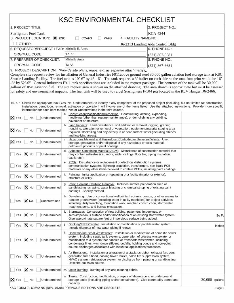
9. PROJECT DESCRIPTION: (Provide site plans, maps, etc. as separate attachment(s))Complete site request review for installation of General Industries F911above ground steel 30,000 gallon aviation fuel storage tank at KSCShuttle Landing Facility. The fuel tank is 10’-6” by 46’- 6”. The tank requires a 3’ buffer on each side so the total foot print would be 16’-6” by 52’-6”. General Industries F911 tank specifications are included in the request package. The contents of the tank will be 30,000gallons of JP-8 Aviation fuel. The site request area is shown on the attached drawing. The area shown is approximate but must be assessedfor safety and environmental impacts. The fuel tank will be used to refuel Starfighters F-104 jets located in the RLV Hanger, J6-2466.
Yes UndeterminedNo
a.
Yes UndeterminedNo
b.
Yes UndeterminedNoc.
Yes UndeterminedNod.
Yes UndeterminedNoe.
Yes UndeterminedNo
Paint, Sealant, Caulking Removal: Includes surface preparation such assandblasting, scraping, water blasting or chemical stripping of existing paintcoatings. Specify method.
f.
Yes UndeterminedNog.
Yes UndeterminedNo
Construction/Modification/Demolition: Constructing, altering, expanding,modifying (other than routine maintenance), or demolishing any building,pavement or structure.
h.
Yes UndeterminedNo
Land Impacts: Land disturbance, soil addition or removal, digging, grading,trenching, alteration or removal of vegetation, equipment/material staging arearequired, stockpiling and any activity in or near surface water (including ditchesand low-lying areas).
i.
Yes UndeterminedNo
k.
Yes UndeterminedNo j.
Yes UndeterminedNol.
Yes UndeterminedNo m.
Yes UndeterminedNon.
Hazardous Material and Hazardous, Controlled or Universal Waste: Use,storage, generation and/or disposal of any hazardous or toxic material,petroleum products or paint coatings.
Asbestos Containing Material (ACM): Disturbance of construction material thatmay contain asbestos (i.e., roofs, walls, ceilings, floor tile, piping insulation,caulk, etc.).
PCBs: Disturbance or replacement of electrical distribution systems,communication systems, lightning protection, transformers, non-liquid PCBmaterials or any other items believed to contain PCBs, including paint coatings.
Painting: Initial application or repainting of a facility (interior or exterior),structure or utility.
Dewatering: Use of conventional wellpoints, hydraulic pumps, or other means totransfer groundwater (including water in utility manholes) for project activitiesincluding utility trenching, foundation work, roadbed construction, stormwatertreatment pond, and borrow excavation.
Stormwater: Construction of new building, pavement, impervious, orsemi-impervious surface and/or modification of an existing stormwater system.Give approximate square feet of impervious surface being added.
Sq Ft
Drinking/FIREX Water: Installation or modification of potable water system.Include diameter of new water piping if known.
inches
Domestic/Industrial Wastewater: Installation or modification of domestic sewersystem, including septic tank systems, generation of process wastewater ormodification to a system that handles or transports wastewater, includingcondensate lines, washdown effluent, outfalls, holding ponds and non-pointsource discharges associated with industrial applications/processes.
Air Emissions: Installation or alteration of a stack, scrubber, exhaust fan, vent,generator, fume hood, cooling tower, boiler, halon fire suppression system,HVAC system, refrigeration system; or discharge from painting or sandblasting.Describe emission source.
Open Burning: Burning of any land clearing debris.
Tanks: Construction, modification, or repair of aboveground or undergroundstorage tanks (including piping and/or containment). Give commodity stored andcapacity.
30,000 gallons
KSC FORM 21-608V2 NS (REV. 01/08) PREVIOUS EDITIONS ARE OBSOLETE
Yes UndeterminedNo o.
Yes UndeterminedNo p.
Yes UndeterminedNoq.
Yes UndeterminedNo
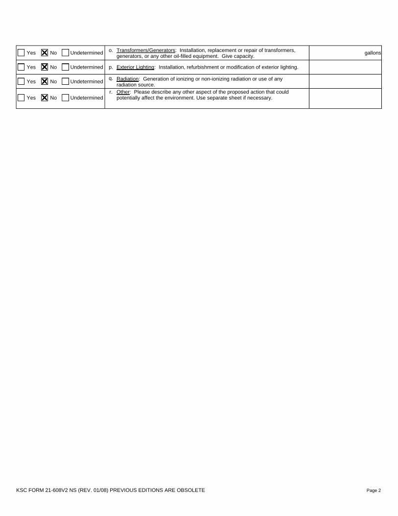
Radiation: Generation of ionizing or non-ionizing radiation or use of anyradiation source.
r.
Page 2
Transformers/Generators: Installation, replacement or repair of transformers,generators, or any other oil-filled equipment. Give capacity.
gallons
Exterior Lighting: Installation, refurbishment or modification of exterior lighting.
Other: Please describe any other aspect of the proposed action that couldpotentially affect the environment. Use separate sheet if necessary.
D ~ D
D ~ D
D ~ D
D ~ D -
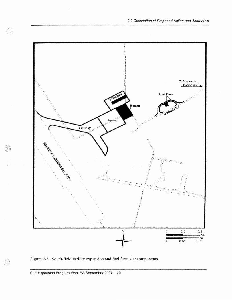
2.0 Description of Proposed Action and Altemative
To Kenned-j' PIII'kwayN .
Fue1F_
N 0
+ 0
Figure 2-3. South~field facility expansion and fuel farm site components.
SLF Expansion Program Final EAlSeptember 2007 29
,.-.:...'---'~-""'-.. ;:;'>
0. 1
0.06
0.2 Ikfn
ItrU 0.12
AVOID VERBAL ORDERS
TO:
SUBJECT:
SITE PLAN:
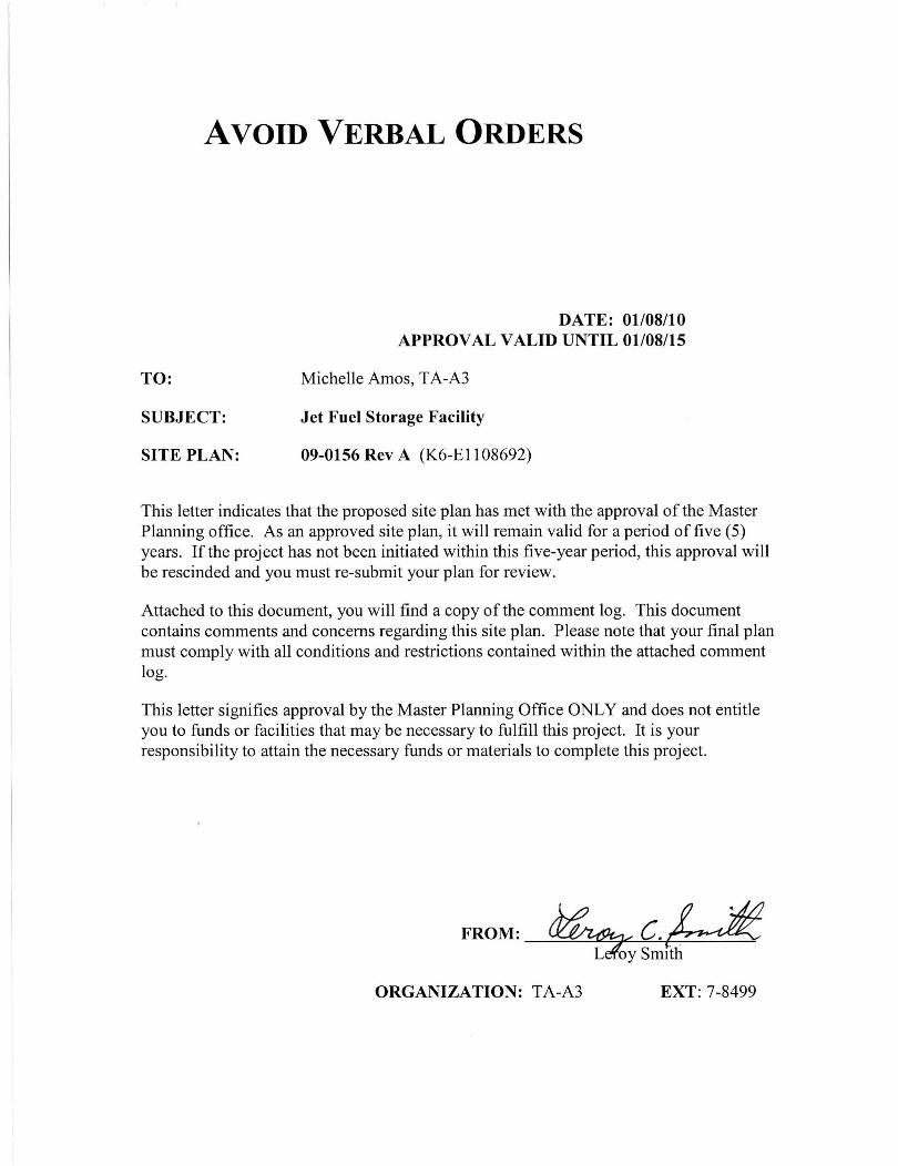
DATE: 01/08/10 APPROVAL VALID UNTIL 01/08/15
Michelle Amos, TA-A3
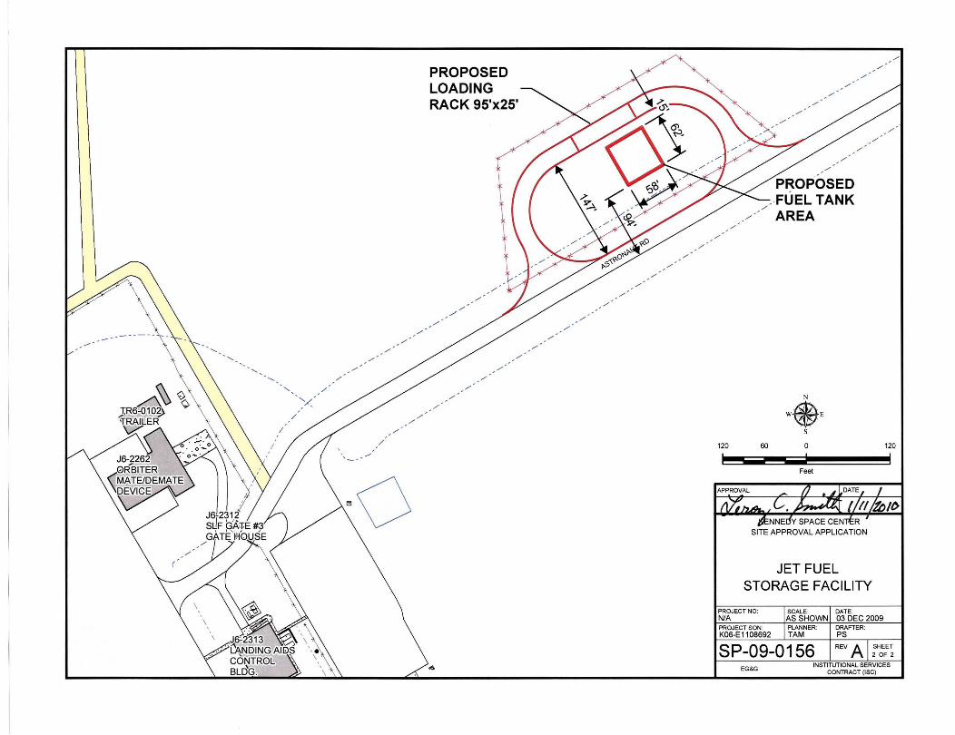
Jet Fuel Storage Facility
09-0156 Rev A (K6-EII08692)
This letter indicates that the proposed site plan has met with the approval of the Master Planning office. As an approved site plan, it will remain valid for a period of five (5) years. If the project has not been initiated within this five-year period, this approval will be rescinded and you must re-submit your plan for review.
Attached to this document, you will find a copy of the comment log. This document contains comments and concerns regarding this site plan. Please note that your final plan must comply with all conditions and restrictions contained within the attached comment log.
This letter signifies approval by the Master Planning Office ONLY and does not entitle you to funds or facilities that may be necessary to fulfill this project. It is your responsibility to attain the necessary funds or materials to complete this project.
FROM: ~c.U L oy SmIth
ORGANIZATION: TA-A3 EXT: 7-8499
./
./
./
./
./
,-"- , /
Y / ,-
./
./
/
---
PROPOSED LOADING RACK 95'x25'
./
./
./ ./
./
./
./
./
./
./
./
./
./
./
,-./
./ .
./
./
./
./
./
./
./
./
./
./
./
./
PROPOSED . FUEL TANK
./
./ AREA ./
./
N
WeE s
120 60 0 120
- -- ---Feet
JET FUEL STORAGE FACILITY
PROJECT NO: SCALE: DATE: N/A AS SHOWN 03 DEC 2009 PROJECT SON : PLANNER: DRAFTER: K06-E 11 08692 TAM PS
SP-09-0156 REV A SHEET 2 OF 2
EG&G INSTITUTIONAL SERVICES
CONTRACT (ISC)
1
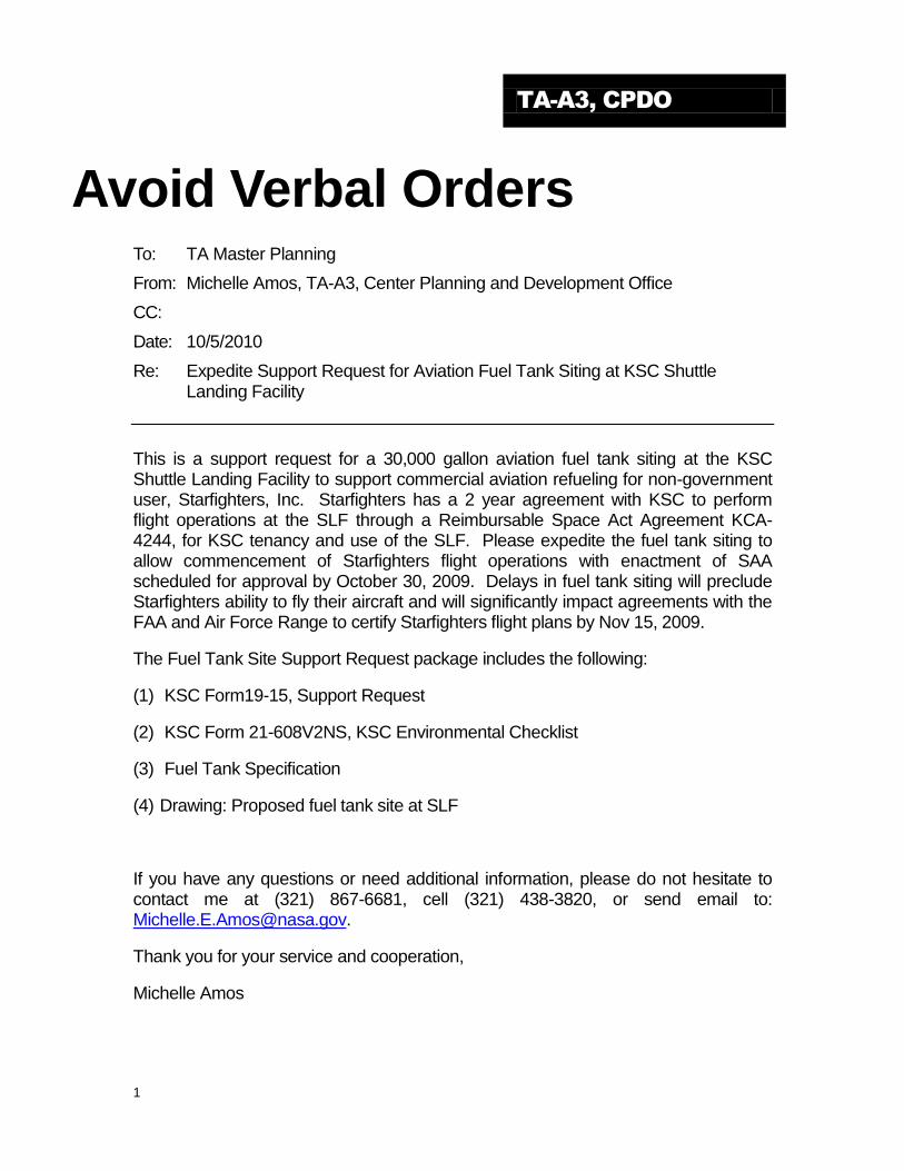
TA-A3, CPDO
Avoid Verbal Orders To: TA Master Planning
From: Michelle Amos, TA-A3, Center Planning and Development Office
CC:
Date: 10/5/2010
Re: Expedite Support Request for Aviation Fuel Tank Siting at KSC Shuttle Landing Facility
This is a support request for a 30,000 gallon aviation fuel tank siting at the KSC Shuttle Landing Facility to support commercial aviation refueling for non-government user, Starfighters, Inc. Starfighters has a 2 year agreement with KSC to perform flight operations at the SLF through a Reimbursable Space Act Agreement KCA-4244, for KSC tenancy and use of the SLF. Please expedite the fuel tank siting to allow commencement of Starfighters flight operations with enactment of SAA scheduled for approval by October 30, 2009. Delays in fuel tank siting will preclude Starfighters ability to fly their aircraft and will significantly impact agreements with the FAA and Air Force Range to certify Starfighters flight plans by Nov 15, 2009.
The Fuel Tank Site Support Request package includes the following:
(1) KSC Form19-15, Support Request
(2) KSC Form 21-608V2NS, KSC Environmental Checklist
(3) Fuel Tank Specification
(4) Drawing: Proposed fuel tank site at SLF
If you have any questions or need additional information, please do not hesitate to contact me at (321) 867-6681, cell (321) 438-3820, or send email to: [email protected].
Thank you for your service and cooperation,
Michelle Amos

·UL'''U_r.rbolhprtno.,._.od d i _ii_",*",_ • D! .... dHVI_I'Dg" _ ... .,._nment ID IIINIEPI<8PCC"_
• BuIlID ..... 011~ • ;' 'S11 _ UL 'do
.Po10n0.,. ........ Iii"kMil ... ..,._"...01 .... ,.-_. _ ..,go "1f .. 1 ...... ""on jell.
·c __ ....... b ........ """'j ..... t:or , _ # .. onojll ~uot' ,
• C, , .... ....,. ""'" iIDiIlD lID,ooo goIo .. • Qudy_ ...... Prog ... ·811Lk>a I~MIn_ror
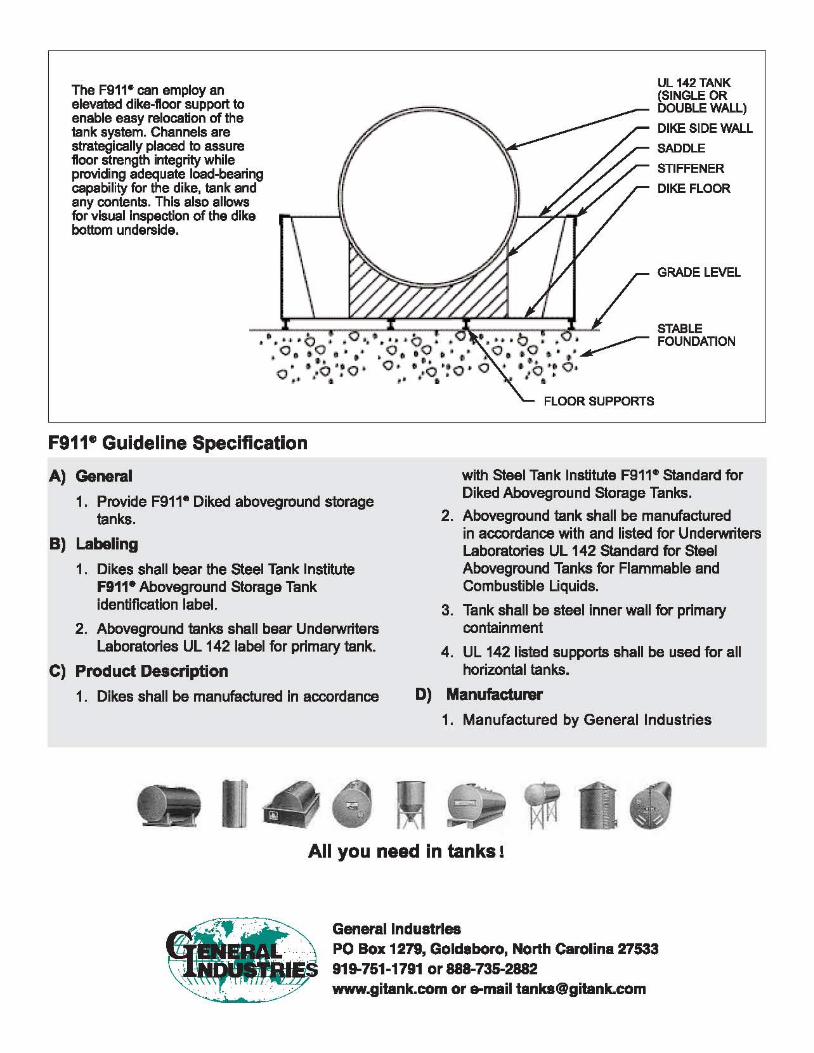
The F911- can employ an elevated dike-floor support to enable easy relocation of the tank system. Channels are strategically placed to assure floor strength integrity while providing adequate load-bearing capability for the dike, tank and any contents. This also allows for visual inspection of the dike bottom underside.
UL 142 TANK (SINGLE OR DOUBLE WALL)
DIKE SIDE WALL
SADDLE
STIFFENER
DIKE FLOOR
GRADE LEVEL
" • •• STABLE •• I I -0 " '1 .··· 0 •• • ••• .0... ~ FOUNDATION
0, , 0 " . " O. ,0 ,,' . O, .. O .. .. ~ • "I . • .. " 1 0 ' •
• ·.O·~O· O. · .O·~O· 0 ... O·~ O . o p i • • " • • I ..
F911e Guideline Specification
A) General
1. Provide F911° Diked aboveground storage tanks.
B) Labeling
1. Dikes shall bear the steel Tank Institute F911· Aboveground Storage Tank identification label.
2. Aboveground tanks shall bear Underwriters Laboratories UL 142 label for primary tank.
C) Product Description
1. Dikes shall be manufactured in accordance
FLOOR SUPPORTS
with Steel Tank Institute F911· Standard for Diked Aboveground Storage Tanks.
2. Aboveground tank shall be manufsctured in accordance with and listed for Underwriters Laboratories UL 142 Standard for Steel Aboveground Tanks for Flammable and Combustible Liquids.
3. Tank shall be steel inner wall for primary containment
4. UL 142 listed supports shall be used for all horizontal tanks.
D) Manufactunsr
1. Manufactured by General Industries
All you need in tanks!
General Industries PO Box 1279, Goldsboro, North Carolina 27533 919-751-1791 or 888-735-2882 www.gitank.comor&[email protected]
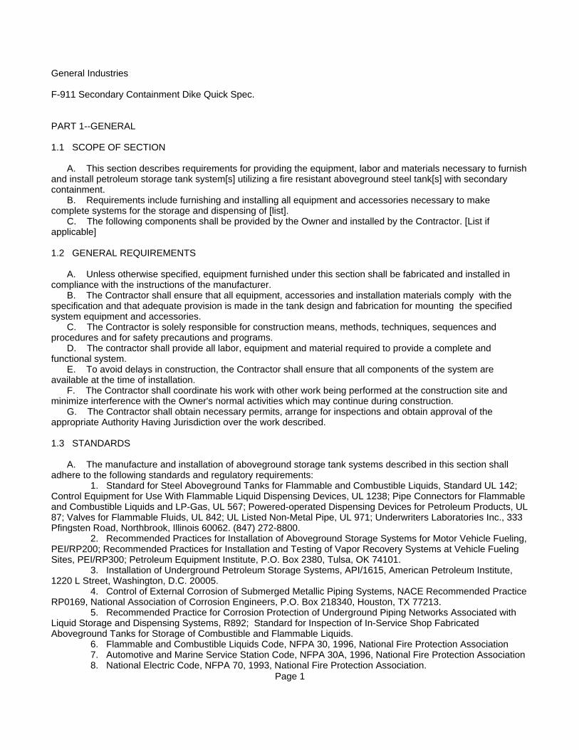
General Industries
F-911 Secondary Containment Dike Quick Spec.
PART 1--GENERAL
1.1 SCOPE OF SECTION
A. This section describes requirements for providing the equipment, labor and materials necessary to furnish and install petroleum storage tank system[s] utilizing a fire resistant aboveground steel tank[s] with secondary containment. B. Requirements include furnishing and installing all equipment and accessories necessary to make complete systems for the storage and dispensing of [list]. C. The following components shall be provided by the Owner and installed by the Contractor. [List if applicable]
1.2 GENERAL REQUIREMENTS
A. Unless otherwise specified, equipment furnished under this section shall be fabricated and installed in compliance with the instructions of the manufacturer. B. The Contractor shall ensure that all equipment, accessories and installation materials comply with the specification and that adequate provision is made in the tank design and fabrication for mounting the specified system equipment and accessories. C. The Contractor is solely responsible for construction means, methods, techniques, sequences and procedures and for safety precautions and programs. D. The contractor shall provide all labor, equipment and material required to provide a complete and functional system. E. To avoid delays in construction, the Contractor shall ensure that all components of the system are available at the time of installation. F. The Contractor shall coordinate his work with other work being performed at the construction site and minimize interference with the Owner's normal activities which may continue during construction. G. The Contractor shall obtain necessary permits, arrange for inspections and obtain approval of the appropriate Authority Having Jurisdiction over the work described.
1.3 STANDARDS
A. The manufacture and installation of aboveground storage tank systems described in this section shall adhere to the following standards and regulatory requirements: 1. Standard for Steel Aboveground Tanks for Flammable and Combustible Liquids, Standard UL 142; Control Equipment for Use With Flammable Liquid Dispensing Devices, UL 1238; Pipe Connectors for Flammable and Combustible Liquids and LP-Gas, UL 567; Powered-operated Dispensing Devices for Petroleum Products, UL87; Valves for Flammable Fluids, UL 842; UL Listed Non-Metal Pipe, UL 971; Underwriters Laboratories Inc., 333 Pfingsten Road, Northbrook, Illinois 60062. (847) 272-8800. 2. Recommended Practices for Installation of Aboveground Storage Systems for Motor Vehicle Fueling, PEI/RP200; Recommended Practices for Installation and Testing of Vapor Recovery Systems at Vehicle Fueling Sites, PEI/RP300; Petroleum Equipment Institute, P.O. Box 2380, Tulsa, OK 74101. 3. Installation of Underground Petroleum Storage Systems, API/1615, American Petroleum Institute, 1220 L Street, Washington, D.C. 20005. 4. Control of External Corrosion of Submerged Metallic Piping Systems, NACE Recommended Practice RP0169, National Association of Corrosion Engineers, P.O. Box 218340, Houston, TX 77213. 5. Recommended Practice for Corrosion Protection of Underground Piping Networks Associated with Liquid Storage and Dispensing Systems, R892; Standard for Inspection of In-Service Shop Fabricated Aboveground Tanks for Storage of Combustible and Flammable Liquids. 6. Flammable and Combustible Liquids Code, NFPA 30, 1996, National Fire Protection Association 7. Automotive and Marine Service Station Code, NFPA 30A, 1996, National Fire Protection Association 8. National Electric Code, NFPA 70, 1993, National Fire Protection Association.
Page 1
9. National Fire Prevention Code, 1994, Building Officials and Code Administrators 10. Standard Fire Prevention Code, 1995, Southern Building Code Congress International 11. Occupational Safety and Health Standards, particularly Flammable and Combustible Liquids, 29CFR 1910.106, Personal Protective Equipment 29CFR 1910 Subpart I, Excavations 29CFR 1926.650 Subpart P, U. S. Department of Labor, Occupational Safety and Health Administration (OSHA), Washington, D.C. 12. Clean Water Act and Oil Pollution Act of 1990, Spill Prevention, Control and Countermeasure (SPCC)Plans, 40 CFR 112, 113 and 114. 13. Uniform Building Code ... 14. Applicable state and local regulations and ordinances B. In case of differences between building codes, state laws, local ordinances, utility company regulations, and contract documents, the most stringent shall govern. C. The codes and standards listed are the latest as of this publication. Codes and standards are continuously updated. The Contractor shall confirm the construction standard edition enforced by the authority having jurisdiction.
1.4 SUBMITTALS
A. The Contractor shall provide one (1) set of shop drawings of the following system components for approvalbefore commencing construction. 1. Shop drawings of the tank(s) by the tank manufacturer. 2. Assembly and installation drawings. 3. Other. [List] B. The Contractor shall provide product data sheets and descriptive material for major components to be provided. 1. Tank coatings. 2. Pumps, valves and fittings. 3. Piping, venting equipment, leak detection equipment, and overfill prevention equipment. 4. Other system accessories. [List] C. Submittals shall be delivered to the Engineer within [10 days] of notice to proceed. The Engineer shall review the drawings and return them to the Contractor approved, or with appropriate comments, within [14 days] ofreceipt.
1.5 CONSTRUCTION DOCUMENTATION
A. At contract close-out, the Contractor shall provide three (3) sets of the following installation instructions: 1. Tank(s) 2. Pumps, [dispensers], valves and fittings 3. Vapor recovery components 4. Other [List] B. The Contractor shall provide three (3) sets of manufacturers' system component operation and maintenance manual instructions. C. The Contractor shall provide record ("as-built") drawings and photographs of the following: 1. All underground system components. 2. The completed tank system in place. D. The Contractor shall provide copies of all testing and inspection reports to the Owner prior to substantial completion.
1.6 GUARANTEES, WARRANTIES AND INSURANCE
A. The Contractor shall provide the following insurance [List type and limits] B. The Contractor shall provide the following guarantees/warranties [List requirements] PART 2--PRODUCTS
2.1 SECONDARY CONTAINMENT DIKED STORAGE TANK(S) (Tank 1)
A. The storage tank(s) shall be STI F-911® aboveground tank(s) for the storage of petroleum product(s) at Page 2
near atmospheric pressure. Number, size(s) and weight(s) of tank(s) shall be as follows (exact dimensions and weights vary between manufacturers; verify with manufacturer):(1) _________ gals. capacity (nominal) Horizontal Cylindrical tank for ___________ storage.Dimensions to be (______diameter, _______length): (Consult with manufacturer for exact dimensions.) 1. The primary tanks shall be manufactured in accordance with Underwriters' Laboratories UL-142, 2. The listed assembly shall meet the requirements defined by NFPA 30A. 3. The tank shall consist of an inner steel wall. 4. The inner and outer steel wall shall be UL 142 construction capable of providing containment of the primary storage tank's content. 5. A legible Underwriters' Laboratories label, and Steel Tank Institute label shall be affixed to the side of theaboveground storage tank(s). 6. Steel outer wall of the tank shall be coated to prolong weather resistance and to further reduce maintenance needs as per the following: SSPC-SP-6 blast, Zinc Epoxy primer at 2-3mils DFT and Urethane at 4-6mils DFT. 7. The storage tank and supports shall be delivered as a complete Underwriters' Laboratories listed unit. 8. The storage tank and supports shall meet all Uniform Building Code requirements. B. Tank(s) shall be designed for use aboveground and include integral secondary containment. C. The [Contractor] [Owner] shall register each tank and serial number with Steel Tank Institute in accordance with instructions provided by the manufacturer with the tank. D. Manway (as required by engineer). E. Provide an interstitial monitoring tube for monitoring the tank's interstice for liquids. F. Provide an (external vertical ladder, ships ladder and platform, OSHA stairs and platform) to allow access totop of tank for filling and maintenance that complies with applicable OSHA standards and building codes. G. Tank(s) will be provided with rainshields and elevation beams attached at the factory. H. Accepted Manufacturers: General Industries or equal, all other Manufacturers must have Engineers approval30 days prior to bid.
2.2 VENTING REQUIREMENTS
A. Provide one (1) normal atmospheric or pressure/vacuum vent for the primary tank(s). 1. Vents shall discharge upward or laterally, and be protected from intrusion of rain[, and incorporate a flame arrestor.] 2. When applicable, tanks located in Stage II Vapor Recovery mandated air quality areas shall be provided with pressure/vacuum vents. 3. Vents for tanks containing Class 1 liquids shall terminate at least 12 feet above ground level and be located at least five feet from building openings. 4. Vent installation shall comply with applicable sections of the fire and mechanical codes, including, but not limited to, NFPA 30A (2-4.5.e) or NFPA 30 (2-3.5). 5. Accepted manufacturers and part numbers: [List] B. Provide one (1) emergency vent for each primary tank or primary tank compartment. 1. Vent size shall be determined by the tank configuration, the primary tank capacity, and the product stored. 2. Emergency venting shall comply with provisions of NFPA 30A or NFPA 30. 3. Accepted manufacturers and part numbers: [List] C. Provide one (1) emergency vent for each secondary containment tank interstice. 1. The venting capacity is determined by the tank configuration, secondary tank capacity, and the product stored. 2. Emergency venting shall comply with provisions of NFPA 30A, NFPA 30, and UL 142. 3. Vents shall be located as close to the center of the tank as possible. 4. Accepted manufacturers and part numbers: [List] 2.3 TANK FILLING AND OVERFILL PREVENTION COMPONENTS
A. For tank(s) with Top fill assembly, provide one (1) 7-1/2 gallon Spill Container with drain back, lockable tight fill cap, adapter, fill pipe, and drop tube per tank 1. The bottom of the fill drop tube shall be cut at a 45 degree angle with the open end facing the long
Page 3
dimension of the tank. 2. Terminate drop tube six inches from the bottom of the tank. 3. Comply with provisions of NFPA 30 or NFPA 30A. [4. Provide a Stage I vapor recovery system to capture displaced vapors during tank filling process.] 5. Provide a Climbing Device that complies with local juristictions. (Heights to be determined upon mounting location: Head or Shell side) Engineer to determine the following options: A. Vertical Ladder (with or without platform). [List]
B. Ships Ladder C. OSHA Stairs and platform
B. For tank(s) with Grade fill assembly, provide one (1) 15 gallon Spill Container [2" or 3"], lockable tight fill cap, adapter, fill pipe, swing check valve, ball valve, overfill valve and drop tube per tank 1. The bottom of the fill drop tube shall be cut at a 45 degree angle with the open end facing the long dimension of the tank. 2. Terminate drop tube six inches from the bottom of the tank. 3. Comply with provisions of NFPA 30 or NFPA 30A. [4. Provide a Stage I vapor recovery system to capture displaced vapors during tank filling process.] C. Provide overfill prevention equipment which complies with the requirements of NFPA 30A or NFPA 30 andwhich incorporates the follwing features: 1. An audible alarm which will sound when the product level in the tank has reached 90% of tank capacity. 2. A positive shut-off fill limiter which will stop the flow of liquid into the tank when product level reaches 95% of tank capacity. 3. The limiting device shall be rated to accept the fill flow rate and pressure. 4. Acceptable Manufacturers: [List] D. The Contractor shall provide a means for determining the liquid level in tank which is accessible to the delivery operator, in accordance with NFPA 30A. 2.4 MONITORING AND GAUGING SYSTEM A. Provide leak detection for each tank interstice to continuously monitor both the primary and secondary containment tanks. B. Probe shall be installed in each storage tank's interstitial monitoring tube. The location of the monitoring console and external alarms are noted on the engineering drawings. C. Guage Stick, Cap and Striker plates to be provided for determining the amount of fuel within primary tank. D. Acceptable manufacturers and model numbers are: [List] 2.5 PIPING (As Applicable)
As per Engineer's Specifications.
2.6 VALVES, FITTINGS AND FLEXIBLE CONNECTORS
A. Provide a [fire impact valve] [shear section] on product pipe beneath each dispenser. Model [list] B. Provide all-steel flexible connectors at dispenser connections as shown in the drawings. [Flexible connectors may not be required for system with flexible piping systems] 1. Provide all-steel construction with a UL-listing for use aboveground (UL567). Do not use connectors with low melting point materials. [a. Flexible connectors for suction piping shall be rated for full vacuum service at 760mm Hg (mercury)vacuum.] 2. Flexible connectors shall have one swivel end and one female pipe thread end. Units shall be clearly marked with a lay line to minimize chances of twisting during installation. 3. Flexible connectors installed with a 90 degree bend shall be not less than [24] [30]- inches long. 4. Acceptable manufacturers are: [list] C. Provide corrosion protection using cathodic protection or isolation boots for each flexible connector in contact with the soil. 1. Isolation boots shall completely isolate the metallic flexible connectors from the soil. 2. A liquid-tight seal which can be tested at not less than 10 psig.
Page 4
3. Seal to FRP piping with at least two stainless steel hose clamps per end. Coat buried clamps with dielectric material after installation. 4. Acceptable manufacturers are: [list] D. Provide a steel or nodular iron block valve to allow the tank and piping to be isolated and secured. E. Provide an anti-siphon device in the product piping at the tank which will prevent the flow of liquid from the tank unless the suction pump is operating, in accordance with NFPA 30A and BOCA. F. Provide a pressure relief valve in each segment of blocked piping which will relieve excessive pressure resulting from thermal expansion and return any excess product to the tank. G. Provide portable Class ABC [20 pound] [40 pound] fire extinguisher(s) and weather proof cabinet(s) at dispenser island(s) and [other locations] in accordance with applicable fire codes. H. Provide [quantity] [size] diameter ["U" shaped steel pipe guards] [bollards] to be placed at the ends of the pump island, primed and painted. 2.7 PUMPING EQUIPMENT, VALVES AND FITTINGS--FUEL DISPENSING APPLICATIONS
As per Engineer's Specifications.
2.8 PUMP CONTROLS
As per Engineer's Specifications.
2.9 HI LEVEL ALARMS SYSTEMS
As per Engineer's Specifications.
PART 3--EXECUTION
3.1 GENERAL
A. Familiarity with the Site. 1. Contractor shall familiarize himself with the location of all public utility facilities and structures that may be found in the vicinity of the construction. 2. The Contractor shall conduct his operation to avoid damage to the utilities or structures. Should any damage occur due to the Contractor's operations, repairs shall be made at the Contractor's expense in a manner acceptable to the Owner. 3. The Contractor is responsible for meeting all the requirements established by the agencies for utility work, as well as work affecting utilities and other government agencies.
3.2 SITE PREPARATION
A. The site shall be prepared to ensure adequate support for the tank system and drainage of surface water. 1. The foundation and tank supports shall be capable of supporting the weight of the tank and associated equipment when full. 2. The foundation may be comprised of concrete, asphalt, gravel or other stable material designed to prevent tank movement, and must be rated for the seismic zone noted in Section 2.1 A 8 for each tank. B. Provide a chain link fence at least 6 feet high, separated from the tanks by at least 10 feet and having a gate that is properly secured against unauthorized entry. (NFPA 30A) 1. Regional and local fire codes authorities shall be consulted for local requirements. 2. Fencing at the tank area is not required by NFPA if the property on which the tanks are located is secured with a perimeter security fence. C. Provide barriers around aboveground tanks to protect the tank(s) against vehicular collision in accordance with fire regulations and building codes. NFPA 30A or BOCA. D. Maintain legal separation distances from property lines, buildings, public ways, dispensers, vehicles being fueled and other storage tanks. 1. Caution: Distance requirements vary significantly between jurisdictions. 2. National standards dealing with set back and separation distances are included in NFPA 30A, or BOCA.
Page 5
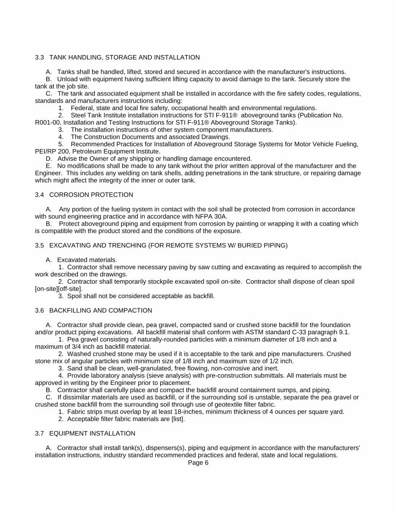
3.3 TANK HANDLING, STORAGE AND INSTALLATION
A. Tanks shall be handled, lifted, stored and secured in accordance with the manufacturer's instructions. B. Unload with equipment having sufficient lifting capacity to avoid damage to the tank. Securely store the tank at the job site. C. The tank and associated equipment shall be installed in accordance with the fire safety codes, regulations,standards and manufacturers instructions including: 1. Federal, state and local fire safety, occupational health and environmental regulations. 2. Steel Tank Institute installation instructions for STI F-911® aboveground tanks (Publication No. R001-00, Installation and Testing Instructions for STI F-911® Aboveground Storage Tanks). 3. The installation instructions of other system component manufacturers. 4. The Construction Documents and associated Drawings. 5. Recommended Practices for Installation of Aboveground Storage Systems for Motor Vehicle Fueling, PEI/RP 200, Petroleum Equipment Institute. D. Advise the Owner of any shipping or handling damage encountered. E. No modifications shall be made to any tank without the prior written approval of the manufacturer and the Engineer. This includes any welding on tank shells, adding penetrations in the tank structure, or repairing damagewhich might affect the integrity of the inner or outer tank.
3.4 CORROSION PROTECTION
A. Any portion of the fueling system in contact with the soil shall be protected from corrosion in accordance with sound engineering practice and in accordance with NFPA 30A. B. Protect aboveground piping and equipment from corrosion by painting or wrapping it with a coating which is compatible with the product stored and the conditions of the exposure.
3.5 EXCAVATING AND TRENCHING (FOR REMOTE SYSTEMS W/ BURIED PIPING)
A. Excavated materials. 1. Contractor shall remove necessary paving by saw cutting and excavating as required to accomplish thework described on the drawings. 2. Contractor shall temporarily stockpile excavated spoil on-site. Contractor shall dispose of clean spoil [on-site][off-site]. 3. Spoil shall not be considered acceptable as backfill.
3.6 BACKFILLING AND COMPACTION
A. Contractor shall provide clean, pea gravel, compacted sand or crushed stone backfill for the foundation and/or product piping excavations. All backfill material shall conform with ASTM standard C-33 paragraph 9.1. 1. Pea gravel consisting of naturally-rounded particles with a minimum diameter of 1/8 inch and a maximum of 3/4 inch as backfill material. 2. Washed crushed stone may be used if it is acceptable to the tank and pipe manufacturers. Crushed stone mix of angular particles with minimum size of 1/8 inch and maximum size of 1/2 inch. 3. Sand shall be clean, well-granulated, free flowing, non-corrosive and inert. 4. Provide laboratory analysis (sieve analysis) with pre-construction submittals. All materials must be approved in writing by the Engineer prior to placement. B. Contractor shall carefully place and compact the backfill around containment sumps, and piping. C. If dissimilar materials are used as backfill, or if the surrounding soil is unstable, separate the pea gravel or crushed stone backfill from the surrounding soil through use of geotextile filter fabric. 1. Fabric strips must overlap by at least 18-inches, minimum thickness of 4 ounces per square yard. 2. Acceptable filter fabric materials are [list].
3.7 EQUIPMENT INSTALLATION
A. Contractor shall install tank(s), dispensers(s), piping and equipment in accordance with the manufacturers' installation instructions, industry standard recommended practices and federal, state and local regulations.
Page 6
B. Calibration and start-up of equipment shall be performed by factory-trained and qualified personnel. C. Pipe installation. (As Applicable) 1. Maintain at least 1/8 inch slope in all pipe back to the tanks to prevent traps as prescribed in the standards. 2. Provide at least two secondary pipe diameter clearance between parallel piping runs. Separate crossedpiping by at least four-inches.
3.8 ELECTRICAL
As per Engineer's Specifications.
3.9 CONCRETE
As per Engineer's Specifications.
3.10 ASPHALTIC PAVING
As per Engineer's Specifications.
3.11 TESTING
A. The Contractor is responsible for testing all installed systems for liquid tightness and proper operation, including: 1. Pre-installation inspection of all materials. 2. Product, containment and vent piping during construction. 3. Containment sump integrity. 4. System tightness test after all work, including paving, is completed and before the system is placed in service. 5. Post installation inspection and testing eleven months after substantial completion of all work and approval of the Owner. B. Test each component of the system for calibration, tightness and proper operation in accordance with the instructions of the component manufacturer. C. Testing shall be documented by the Contractor and witnessed by the Engineer. 1. Record the date and time of the test, the name of the tester and his affiliation with the project, and thenames of each individual witnessing the test. 2. Record the test method, duration and results. 3. Provide a record of the testing to the Owner at the time of system start-up. D. Testing shall be witnessed by the Owner. 1. The Owner shall witness tank delivery and setting in place, anchoring, piping backfilling, piping tests, final precision testing and system start-up. 2. The Owner shall indicate approval of all testing witnessed in writing. E. Tests shall be performed in conformance with the manufacturers' instructions, state laws and the quoted industry standards, particularly PEI/RP200 and PEI/RP100. 1. If a conflict exists between the test protocols, the most stringent test shall be performed. 2. Any conflict which affects manufacturers' warranties must be resolved before beginning construction. 3. The Contractor shall document all tests in writing, signed by the individuals who performed and witnessed the test. F. The Contractor shall demonstrate the operation of all systems to the Owner at the time of the final start-uptest. 1. Provide one day of instruction on the proper operation and maintenance of all components. 2. Demonstrations shall include, but are not limited to, pump operation, monitoring and gauging systems, fuel filter replacement and leak detection.
3.12 TESTING PRIMARY AND SECONDARY TANKS
A. Air pressure testing of the inner tank and secondary containment tank shall be conducted on-site, in the presence of the Engineer, before placing the tank in service.
Page 7
B. Refer to Publication No. R001 for complete procedural details. C. Other integrity tests may be required by the local authority having jurisdiction.
3.13 TESTING PRODUCT, CONTAINMENT AND VENT PIPING
A. Test product and vent piping in accordance with manufacturer's instructions and quoted industry standards, particularly PEI/RP-100. B. Maintain minimum 10 psig pressure on all piping during backfilling and paving operations. C. Tightness test the piping at 50 psig before it is buried or connected to the tank. Soap and examine all connections for leakage. 3.15 TEST DOCUMENTATION AND REPORTING
A. The Contractor shall document all testing and provide copies to the Owner and authorities having jurisdiction. Test records shall include: 1. Date and time of test. 2. Name of tester. 3. Names of any inspectors present. 4. Test procedure followed. 5. Test results. B. Provide documentation for all testing with contract close-out documentation to the Owner. C. The Contractor shall ensure that future testing is not impaired. The Contractor may be requested to demonstrate the tests as a part of the final approval process. 1. Inspection of tank interstices. 2. Periodic hydrostatic testing of containment sump. Caution: Piping which has contained flammable or combustible liquids may not be air tested under any circumstances. (NFPA 30) 3.16 TANK LABELING AND WARNING PLACARDS
As per the specifications of NFPA 30, NFPA 30A and local Building Codes. END OF SECTION
Page 8
1
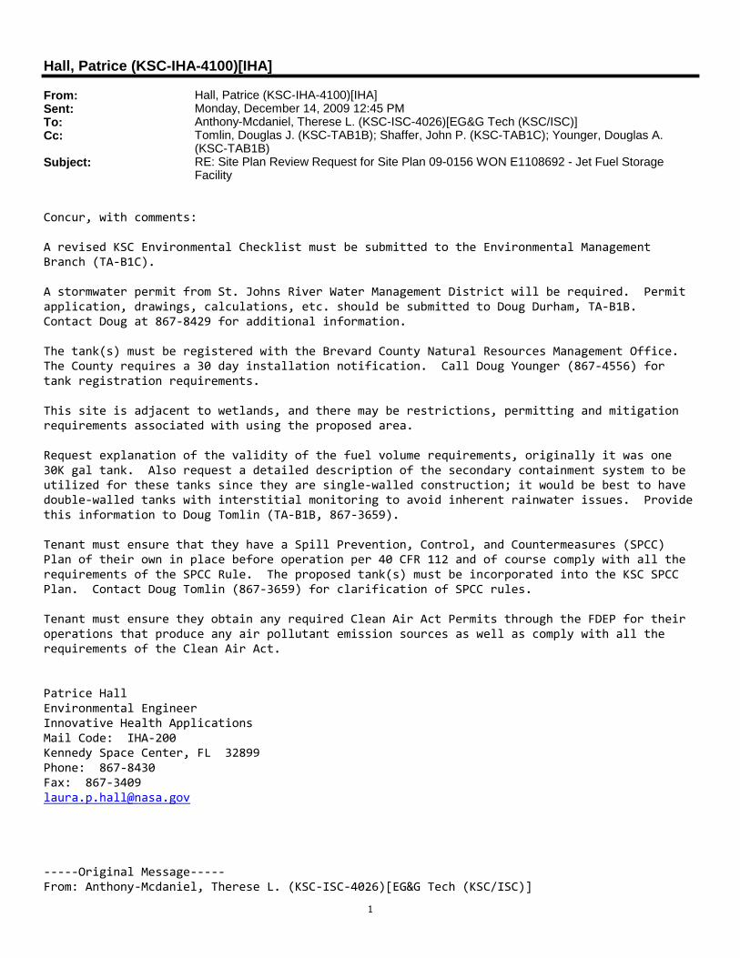
Hall, Patrice (KSC-IHA-4100)[IHA]
From: Hall, Patrice (KSC-IHA-4100)[IHA]Sent: Monday, December 14, 2009 12:45 PMTo: Anthony-Mcdaniel, Therese L. (KSC-ISC-4026)[EG&G Tech (KSC/ISC)]Cc: Tomlin, Douglas J. (KSC-TAB1B); Shaffer, John P. (KSC-TAB1C); Younger, Douglas A.
(KSC-TAB1B)Subject: RE: Site Plan Review Request for Site Plan 09-0156 WON E1108692 - Jet Fuel Storage
Facility
Concur, with comments:
A revised KSC Environmental Checklist must be submitted to the Environmental ManagementBranch (TA-B1C).
A stormwater permit from St. Johns River Water Management District will be required. Permitapplication, drawings, calculations, etc. should be submitted to Doug Durham, TA-B1B.Contact Doug at 867-8429 for additional information.
The tank(s) must be registered with the Brevard County Natural Resources Management Office.The County requires a 30 day installation notification. Call Doug Younger (867-4556) fortank registration requirements.
This site is adjacent to wetlands, and there may be restrictions, permitting and mitigationrequirements associated with using the proposed area.
Request explanation of the validity of the fuel volume requirements, originally it was one30K gal tank. Also request a detailed description of the secondary containment system to beutilized for these tanks since they are single-walled construction; it would be best to havedouble-walled tanks with interstitial monitoring to avoid inherent rainwater issues. Providethis information to Doug Tomlin (TA-B1B, 867-3659).
Tenant must ensure that they have a Spill Prevention, Control, and Countermeasures (SPCC)Plan of their own in place before operation per 40 CFR 112 and of course comply with all therequirements of the SPCC Rule. The proposed tank(s) must be incorporated into the KSC SPCCPlan. Contact Doug Tomlin (867-3659) for clarification of SPCC rules.
Tenant must ensure they obtain any required Clean Air Act Permits through the FDEP for theiroperations that produce any air pollutant emission sources as well as comply with all therequirements of the Clean Air Act.
Patrice HallEnvironmental EngineerInnovative Health ApplicationsMail Code: IHA-200Kennedy Space Center, FL 32899Phone: 867-8430Fax: [email protected]
-----Original Message-----From: Anthony-Mcdaniel, Therese L. (KSC-ISC-4026)[EG&G Tech (KSC/ISC)]
2
Sent: Monday, December 07, 2009 3:31 PMTo: Lamott, Gerard M. (KSC-USA-93410)[UNITED SPACE ALLIANCE LLC]; Kler, Francis O. (KSC-ISC-5000)[Yang Enterprises (KSC/ISC)]; Murray, Pamela D CTR USAF AFSPC InDyne Inc/IOMS; Hall,Patrice (KSC-IHA-4100)[IHA]; Feile, Ronald E. (KSC-ISC-5300)[EG&G Tech (KSC/ISC)];Czerwinski, Douglas A. (KSC-ISC-2300)[EG&G Tech (KSC/ISC)]; Feeney, Ellen S. (KSC-ISC-2020)[EG&G Tech (KSC/ISC)]; Der, Frank D. (KSC-TAB3A); Stoeckel, William D CTR USAF AFSPCInDyne Inc/IOMS; Leech, Timothy C Civ USAF AFSPC 45 CES/CEAO; Dutt, George L. (KSC-ITD00);Caroglanian, Armen (GSFC-5670); KSC-ISC-ENVIRONMENTALSHARED; Minderman, Donald J. (KSC-TAB3B); Taff, Albert E. (KSC-TAB2)[REDE CRITIQUE A JOINT VENTURE]; [email protected];Brown, Donald L. (KSC-IMCS-300)[Abacus Technology]; Hopper, Stacey L. (KSC-ISC-4026)[EG>ech (KSC/ISC)]; [email protected]; Hall, James E. (KSC-ISC-2200)[EG&G Tech(KSC/ISC)]; Denyer, Michael L. (KSC-ISC-2020)[EG&G Tech (KSC/ISC)]; Levison, Eric S. (KSC-SGS-3650)[SGS]; Sturgill, Charles E. (KSC-ISC-5200)[EG&G Tech (KSC/ISC)]; Schoen, Ronald E.(KSC-TAB3A); KSC-NASA-Master-Planning; Willis, Christopher G. (KSC-SCJ-980)[SC Jones ServicesInc]; Morse, Gary A. (KSC-IT000); Creech, John N. (KSC-PHB10); Stevens, Michael B. (KSC-TAA20); Walsh, Sandy (KSC-TAA30); Strunk, Ruth A. (KSC-ISC-4013)[EG&G Tech (KSC/ISC)];Cicirelli, Dale L. (KSC-ISC-2100)[EG&G Tech (KSC/ISC)]; KSC-DL-EGG-Project-Services; Cook,Charles CTR USAF AFSPC CSR 7230; Knutson, Andrew D. (KSC-PHI20); Lopetz, Laura A. (KSC-ISC-4027)[EG&G Tech (KSC/ISC)]; Amos, Michelle E. (KSC-TAA30); Facemire, David L. (KSC-SAE20);Fowler, Derick C. (KSC-ISC-2220)[Yang Enterprises (KSC/ISC)]; Catchpole, Philip R. (KSC-IMCS-420)[Analex Corp., North America Operations, LLC]; King, Teresa (KSC-IHA-4000)[IHA];[email protected]; Stocky, David A. (KSC-SGS-4350)[SGS]; Brown, Stephen D. (KSC-SAE30); [email protected]; Davis, Chuck (KSC-TAB2B); KSC-Resource-Protection; KSC-MESC-ENV; Friers, Thomas R. (KSC-TAB20)Subject: Site Plan Review Request for Site Plan 09-0156 WON E1108692 - Jet Fuel StorageFacility
Hello,
I am sending you a Site Plan Review Request for Site Plan 09-0156 WON E1108692 - Jet FuelStorage Facility.
Please review and comment back within 7 days. I have attached a copy of the site plan to thisemail. Thank you for your prompt attention.
*See attached Site Plan Request document*
Site Plan Maps (2 pages)http://jboscpwprod.ksc.nasa.gov/Siteplans/K06-E1108692/SP-09-0156-a.docx
Comment Log (View other reviewers' posted comments as they are updated)http://jboscpwprod.ksc.nasa.gov/Siteplans/K06-E1108692/CommentLog.RTF
Thanks,
Therese Anthony-McDanielISC Master Planning/Space AllocationP: 321.867.2180 F: 321.867.1175~Please consider the environment before printing this email.
TO:
FROM: TA-B1C/NEPA Compliance
TA-A3
Avoid Verbal Orders
DATE: 11/3/2009
SUBJECT KSC Record of Environmental Consideration (REC) CHECKLIST #: 7667
3. ENVIRONMENTAL REQUIREMENTS
2. NEPA DETERMINATIONS
a. Non-Permit Requirements
b. Permit Requirements
EPB Reviewer: LPH
3.a.1. POTENTIAL RELEASE LOCATION (PRL) SITE: A PRL designation means a site has had historical operations which had the potential to impact the environment and is being investigated by the Remediation Group of the NASA Environmental Assurance Branch (TA-B1B). The proposed project is within PRL #187, SLF Landing Aids Control Building site. This area was recently identified as a PRL and is in the assessment stage. There is no data available yet and therefore no requirements at this time.
3.a.2. HAZARDOUS/NON-HAZARDOUS WASTE: All hazardous and non-hazardous wastes generated on KSC must be managed, controlled and disposed of per the KSC Waste Management requirements outlined in KNPR 8500.1. A Process Waste Questionnaire (PWQ), KSC Form 26-551 along with any supporting documentation (MSDS, product formulation, lab analyses) must be submitted to the IHA Waste Management Office for each waste stream generated. That office will then generate a Technical Response Package (TRP) which will give direction on proper handling, storage, and disposal of the waste stream. Please contact IHA Waste Management Services at 867-8640 if assistance is required.
3.a.3. STORAGE TANKS (New Fuel Tank): The installation and removal of all regulated storage tanks must be coordinated with the Brevard County Natural Resources Management Office (BCNRMO). The BCNRMO requires a 30 day notification prior to installation of the proposed tank. Also, per F.A.C. 62-761, a completed tank registration form is required to be submitted to the Brevard County Natural Resources Office no later than 30 days after regulated substances are put into any storage tank system. Contact Doug Younger (TA-B1B, 867-4556) for assistance.
3.a.4. SPILL PREVENTION, CONTROL, AND COUNTERMEASURES (SPCC) PLAN: The Kennedy Space Center SPCC Plan documents the procedures for the prevention, response, control, and reporting of spills of oil at KSC. This plan serves as a guide for personnel and organizations that are responsible for ensuring that all measures are taken to prevent and contain spills and leaks of oil in accordance with all applicable state and federal regulations. The KSC SPCC Plan has certain requirements that need to be met to comply with 40 CFR 112, as well as the Florida tank rules in 62-762 FAC. The KSC SPCC Site Specific Plan will need to be updated for installation of the new tank and secondary containment. A PE must review the updated plans to document potential spill routes and control measures and the amendment logs will need to be signed/sealed. The fuel transfer from the storage tank to mobile refuelers requires a loading rack where bulk fuel transfers occur. A loading rack must be capable of containing the largest single compartment of the mobile tank or tanker. Properly sized secondary containment must be part of the design where fuel loading/unloading occurs. The SPCC Plan also has training and inspection requirements. This requirement would be met by the FDEP monthly inspections. Operators at SPCC locations need to have documented annual site specific spill prevention training also. Many KSC contractors perform annual tank operator training that includes SPCC. For additional clarification of these requirements and SPCC rules, contact Doug Tomlin (TA-B1B, 867-0321).
3.b.1. ENVIRONMENTAL RESOURCE PERMIT (ERP) STORMWATER: This project will involve modifications to an
a. Categorical Exclusion per 14 CFR Part 1216.305(d)
b. Environmental Assessment (EA) Required per KNPR 8500.1
c. Environmental Impact Statement (EIS) Required per KNPR 8500.1
YES NO
YES NO
d. Project on CCAFS:
1. PROJECT INFORMATION
Project Title: Starfighters Fuel Tank
Project Lead: Michelle Amos, TA-A3, 867-6681 Directorate Project No.: KCA-4244
Facility No.: J6-2466/RLV HANGAR-FLIGHT VEHICLE FAC
TO:
FROM: TA-B1C/NEPA Compliance
TA-A3
Avoid Verbal Orders
DATE: 11/3/2009
SUBJECT KSC Record of Environmental Consideration (REC) CHECKLIST #: 7667
Upon evaluation of the subject project, the above determinations have been made and identified. Contact
the Environmental Program Office (TA-B1C) at 867-8448 for re-evaluation should there be any modifications
to the scope of work.
4
Date
existing permitted stormwater management system. The permit application and supporting calculations, drawings, and documentation including an electronic version in PDF format should be submitted to Doug Durham, NASA Environmental Assurance Branch (TA-B1B). Contact Doug Durham at 867-8429 for assistance.
3.b.2. EXCAVATION PERMIT: A KSC Excavation Permit will be required for any digging proposed by this project. Please contact the Utility Locate/Excavation Permit Request Customer Helpline at 867-2406 for an underground utility scan and dig permit.
No other environmental issues were identified based upon the information provided in the KSC Checklist. This Record of Environmental Consideration (REC) does not relinquish the project lead from obtaining and complying with any other internal NASA permits or directives necessary to ensure all organizations potentially impacted by this project are notified and concur with the proposed project.
Due to potential changes in regulations, permit requirements and environmental conditions, statements in this REC are valid for 6 months, and subject to review after this period. It is the responsibility of the project lead to notify the Environmental Management Branch (TA-B1C) if the scope of the project has changed since the original checklist was submitted.
cc: M. Amos/TA-A3 D. Younger/TA-B1B D. Tomlin/TA-B1B
11/4/2009 8:46:12 AM
Lynne Phillips