start-up experience at the robbins resource recovery facility
TRANSCRIPT

..
PEER-REVIEW
Start-up Experience at the Robbins Resource Recovery Facility while Focusing on the Environment
Bruce C. Studley Foster Wheeler Power Systems, Inc.
Perryville Corporate Park Clinton, NJ 08809-4000
Roy H. Moyer Robbins Resource Recovery Facility
Foster Wheeler Illinois, Inc. 1 3400 South Kedzie Ave.
Robbins, IL 60472
569

INTRODUCTION
In early November, 1 996, a new generation of advanced combustion technology using circulating fluidized bed (CFB) boilers began continuous operation in Robbins, Illinois, a suburb of Chicago.
The Robbins Waste-to-Energy and Recycling Facility processes a minimum of 1 ,600 Tons-per-day of Municipal Solid Waste. Approximately 400 tons-per-day of waste will be recycled with the remaining 1 200 tons fed to one of two 600 ton-per-day circulating fluidized bed steam generating units.
The Robbins Facility is designed and operates with the most advanced pollution control equipment. Foster Wheeler and facility personnel, in conjunction with the Illinois Environmental Protection Agency and Cook County Department of Environmental Control, have undertaken a number of programs to optimize environmental performance at the facility, including an on-going, aggressive ambient air monitoring program using a chemical mass balance model and ambient air mercury testing.
This paper provides an overview of the design, approach to start-up, actual experiences to date, and the overall operations ofthe Robbins Facility with emphasis on the monitoring programs and environmental controls.
FACILITY DESCRIPTION
Overview
The Robbins Resource Recovery Facility, as shown in Figures 1 and 2, is a resource recovery plant that is located in the Village of Robbins, southern Cook County, Illinois. The recovery processes involve the separation of recyclable materials (e.g., aluminum, ferrous, glass, compost feed) from the waste stream and the conversion of the remainder to electrical energy. These processes are accomplished in the facility's (RDF) Refuse Derived Fuel Plant and Power Plant. In order to have a high level of reliability and availability, the Plants were designed and constructed with redundant systems and supporting equipment.
The RDF Plant will receive about 2,050 tons of municipal solid waste (MSW) per day (Monday to Friday and half a day on Saturday) from surrounding communities via approximately 200 refuse collection and transfer trucks. The MSW (about 500,000 Tons per year) will be inspected and processed through an automated recovery system to separate out the recyclable materials (about 1 25,000 tons per year) which will be sold to recycling companies. The material that is larger than 2.5" will be shredded in order to produce RDF (about 375,000 tons per year). The RDF will be screened to recover any ferrous material.
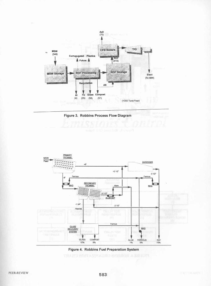
The Power Plant will then bum the RDF in two state-of-the-art circulating fluidized bed (CFB) boilers which will produce steam to power a steam turbine and drive a 55 MWHIhr. electric generator. A simplified process flow diagram of the Facility is shown in Figure 3.
PEER-REVIEW 570

RDFPlant
The RDF Plant consists ofthe tipping floor, two parallel processing systems, RDF storage building and two truck weigh scales. Each processing line is designed to handle 85 tons of MSW per hour.
MSW collection and transfer trucks will be weighed at the inbound truck weigh scale and then proceed directly to the tippiJlg floor. The trucks will dump the MSW directly on the floor where there is a two (2) day storage capacity. The waste composition of the MSW which was used for design purposes is described in Table 1 .
The MSW is inspected with unprocessable materials (e.g. white goods, large furniture, carpet, etc.) removed with mobile grapples and loaded into trailers for disposal to a landfill. Front-end loaders will be used to manage the MSW for efficient storage. The grapples will also be used to mix and load the MSW onto the feed conveyors to the processing lines. The processing lines include primary and secondary trommels. The trommels are large cylindrical drums with thousands of holes of uniform size. The primary trommels have 5.5" diameter holes. The secondary trommels have 1 .75" diameter holes at the input end and 2.5" diameter holes at the outlet end. The trommels are on a three (3) degree angle sloping from the inlet to the outlet.
As the trommels rotate, the materials that are less than the size of the holes fall through to the conveyor below. This material from the primary trommel is run under a magnet to remove ferrous material and then is conveyed to the secondary trommel. There the material less than 1.75", is dropped out and is conveyed to the glass system for further segregation and processing. The remaining material that is greater than 1 .75" but less than 2.5" is separated out and is conveyed directly to the RDF storage building. The oversize material from the secondary trommels is processed under the eddy current separators to remove aluminum cans. With respect to the glass recovery system, it will yield an organicfree glass product and a compostable organic material. The glass product will be sold for use in concrete aggregate, and the organic material will be processed off-site into compost for use as a soil amendment.
The oversize material from both the primary and secondary trommels is conveyed to the heavy-duty shredders. The shredders reduce the material to 3.5" or smaller. The shredders are enclosed in reinforced concrete structures with a fire suppression and protection system, explosion venting through the roof and relief panels. The shredder enclosures are located outside and adjacent to the processing building. A simplified process flow diagram of the materials recovery and fuel preparation system is shown in Figure 4.
The shredded material is then conveyed to the RDF storage building where it can be used immediately or stored until needed. The RDF storage building provides a 3-day inventory of fuel.
In order to minimize dust and odors within the MSW tipping floor, processing areas and RDF storage area, combustion air for the boilers is drawn from these areas. This causes a slight negative pressure in the buildings which results in air always being drawn in.
Power Plant
The Power Plant consists of two (2) parallel, 600 tons per day (based on a design RDF heat content of 6,170 Btu/lb.) circulating fluidized bed boilers, each producing 229,000 pounds per hour of superheated
PEER-REVIEW 571
steam. They will be operated 24 hours per day, 345 days per year. It is estimated that 20 days of maintenance will be performed on each boiler per year. However, even during periods of major maintenance, one of the boilers will remain in service so that the plant will effectively be in operation 365 days per year.
At the maximum continuous rating (MCR) of the boilers, 458,000 pounds per hour of high pressure superheated steam (900 psig @ 8300 F) are generated and directed to one 55 MW turbine generator. The electricity generated by the condensing turbine that is not required for in-plant use is exported to Commonwealth Edison. The furnace system within each boiler is capable of handling fuel with a higher heating value (HHV) range of 4500-7000 Btu/lb. In each boiler, the RDF furnace is fed through the front wall ofthe furnace. The top supported boiler walls are water-cooled, welded-tube-and-fin construction. During start-up, bed inventory will be sand. The bed inventory silo will later be filled with screened bed ash material and sand, which will be used thereafter to make up lost material.
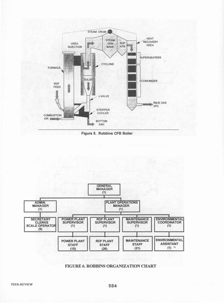
Following each furnace is a single high-efficiency steam-cooled cyclone. The design effectively handles the thermal variations which occur when burning RDF and will give reliable operation for many years. The cyclone separates entrained solids including unburned carbon from the flue gas and returns them to the furnace, providing excellent carbon bum-out. A cross-section of the boiler is shown in Figure 5.
Downstream of the cyclone is a vestibule that encloses the steam-generating boiler bank and the pendant finishing superheater. The heat-recovery area (HRA) is the final segment of the steam generator. It encloses the primary superheater and economizer. All tubes in the HRA are designed on a large clear spacing with a low inter-tube velocity to minimize any accumulation of sticky ash deposits. Flue gas leaving the economizer will pass through the air emissions control system prior to discharge to the exhaust stack.
Flue gases are cleaned in an air emissions control system which includes dry scrubbers and fabric filters. The air emissions are continuously monitored in accordance with the facility's Air Quality Permit issued by the Illinois Environmental Protection Agency (IEP A). Lime and activated carbon are injected to control the acid gasses and mercury levels. A selective, non-catalytic reduction (SNCR) system, using Urea, is also injected for NOx reduction.
Due to the highly efficient combustion characteristics of the CFB technology at relatively low combustion temperatures (1 5000 - 1700°F) and high gas residence time, together with staged combustion, NOx emissions have been extremely low. So low that Urea injection has not been necessary to meet permit limits.
To meet the hydrogen chloride and sulfur dioxide emission permit limits, each boiler is equipped with a dry flue-gas scrubber in combination with a fabric-filter baghouse. In the dry flue-gas scrubbers, lime slurry is atomized and injected into the flue-gas stream, neutralizing the acid-gas components. The water in the slurry is evaporated by the hot flue gas producing dry powder reaction products. Additionally, small quantities of activated carbon are mixed with the lime slurry and sprayed into the flue-gas scrubber to reduce emissions of mercury.
PEER-REVIEW 572

The particulate matter, consisting of flyash, dry scrubber reaction products and unreacted lime, is collected on an array of fabric filter bags contained in multiple modular units (with redundant capacity). Approximately 99.6% of the particulate is being removed.
The continuous emissions-monitoring system is being used to control and record flue-gas opacity, sulfur dioxide, carbon dio�de, carbon monoxide, nitrogen oxide, and total hydrocarbons ensuring compliance with applicable environmental standards. All of this data is also available to be telemetered to the IEPA.
Overall, the advanced combustion technology available by using the CFB boilers, coupled with the front end processing of all waste into RDF, and the highly efficient air emissions control system, have resulted in air emissions well below permit limits. The results of recent stack testing, which were performed in mid January, 1997 are compared to the regulatory limits in Table 2. The continuously monitored pollutant values and their limits, are summarized in Table 3.
That portion of bottom ash which is not recycled for use in maintaining CFB inventory, and flyash, are conveyed to their respective storage locations. The flyash can either be conditioned with water, loaded into covered trucks and sent to an approved ash disposal site, or transported dry for possible use by a local cement company. All ash streams are periodically tested and have been classified as nonhazardous.
APPROACH TO START-UP
On November 23, 1 994 upon completing financing and with the necessary permits issued, the Project was provided with its official Notice to Proceed. This notice initiated a thirty-three (33) month schedule which was the original duration planned for the engineering, procurement, construction, and start-up of the Facility. As with other Foster Wheeler facilities, which relies on its own family of companies for the engineering, boiler supply, construction and start-up, this project was aggressively pursued and fast tracked to assure on-time completion. This proven approach resulted in completing the Facility seven (7) months ahead of schedule with Commercial Operation declared on January 22, 1997.
Preparation for the Start-up and Operation was initiated by Foster Wheeler Illinois (FWI), a wholly owned subsidiary of Foster Wheeler Power Systems (FWPS), during the early engineering phase of the project. This consisted of reviewing all applicable technical specifications and drawings to assure lessons learned at other FWPS Plants were incorporated. Also, a detailed review of all permits were undertaken to summarize the various programs, plans and reports for which FWI would be responsible. These, along with the programs and plans normally incorporated by FWPS, were then all logically placed into an overall Start-up Activity Schedule. This particular schedule consisted of over 190 tasks. Primary activities included:
• Staffing Plan • Training Program • Operations and Maintenance Manual • Test and Turnover Manual • Subsystem Startup Schedule • Startup Plan
PEER-REVIEW 573
• Equipment Purchases and Plant Supplies • Plant Normal and Emergency Procedures • Outside Services and Sub-Contractors
The original staffing plan called for 79 employees organized as depicted in Figure 6. Operating Supervisors were placed at the Facility a full year prior to Start-up.
FWI and FWPS developed for the Robbins Resource Recovery Facility a detailed Start-up Plan and Operations and Maintenance Manual. This in-depth set of documents was prepared in accordance with the Construction PermitlPSD, Solid Waste Permit and an environmental Consent Decree with the Illinois Attorney General's Office, along with Foster Wheeler's standard programs and procedures. The manual serves as both a technical and administrative reference and contains the necessary information to assist the plant staff in the start-up, operation and maintenance of the facility. In addition, an entire volume has been dedicated to an overview of all permits with a compliance summary to assure a proper understanding of the permits that exist and their operating criteria. In total, seventeen (17)
volumes were required. The Table of Contents for the Robbins Resource Recovery Facility Start-up Plan and Operations and Maintenance Manual is shown in Table 4. The major parts of the manual are listed below and are followed by a brief description of their purpose and contents.
1) System Operating Procedures
The System Operating Procedures are designed and written in accordance with Foster Wheeler's operating philosophy and are based on the plant's unique design as defined in the drawings and equipment specifications. They are also based upon the operating instructions furnished by the various equipment vendors. Each operating procedure contains as a minimum, the following sections:
• System Overview • Major Components • Control of Major Components • System Operating Instructions (SOl) • Troubleshooting • Appendix - System Operating Instructions • Appendix - Initial Valve and Switch Alignment
The system operating, maintenance and start-up procedures presented in volumes 1 to 3 were developed specifically with the end user or plant staff in mind and are a plant specific document. Each section describes a system with an overview, annotated list of components and description of the control system. These are purposely kept concise and when coupled with the Engineering Flow Diagrams in volumes 12 to 1 7, provide an understanding of each system and its operation. The next part, the system operating instructions (SOl), coupled with the initial valve and switch alignment in the section's appendix explains exactly how each system is to be prepared, started-up, operated (normal), and shutdown. Finally, the
..
last part, the troubleshooting guide, provides the necessary information to analyze and correct malfunctions, abnormalities, etc. to assure the continuous operation of the system.
PEER-REVIEW 574

2) Maintenance
The Maintenance program contained in the manual was designed to provide an effective inspection, maintenance, repair and parts replacement program. Through the implementation of this program, equipment within the plant will receive the appropriate maintenance to assure maximum productivity and reliable performance. Because of the number and complexity of equipment and parts and the need to assure that an or�anized maintenance program exists, a computerized maintenance management system was implemented. This system allows all necessary information about equipment, including parts, warranties, vendors and labor to be organized and easily accessed. In addition, the system provides the best means of planning for and completing all preventive and predictive maintenance, routine testing and reporting, inspections, etc.
3) Safety
Emphasizing Foster Wheeler's policy to maintain safe working conditions for employees, subcontractors and visitors, accident prevention can only be achieved by taking a structured approach through a formal plant safety program. Within the Safety Program Manual, the following information and procedures are included:
• Safety Policy • Contractor Orientation & Safety • Safety Program Outline • Hazardous Communication Program • Safety Organization and Responsibility • Respiratory Protection Program • Safety Miscellaneous MemoslFocus Topics • Exposure Monitoring and Control Program • Safety Handbook • Hearing Conservation Program • Safety Inspections • Bloodborne Pathogens Exposure Control Prog. • OSHA Inspections • Chemical Hygiene Plan for Chemistry Lab. • Record Keeping and Reporting • Fall Protection Program • Medical Exams • Walking-Working Surfaces Safety Prog. • Substance Abuse Program • Cranes • Alternate Work Program (Light Duty) • Safe Sling Use • Employee Training Summary • Industrial Vehic1es • Personnel Protective Equipment • Process Safety Management • Emergency Planning • Special Conditions • Safe Work Permits • Torch Cutting and Welding • Electrical Safety Program • Portable Power Tools • Lock OutlTag Out Clearance Program • Abrasive Grinding Machinery • Confined Space Entry Program • Signs and Tags
4) Training
To prepare newly hired personnel to assume positions at the Robbins Resource Recovery Facility, a comprehensive training program was developed and implemented. The program consists of several different curriculum, each combining formal classroom instruction with hands-on and on-the-job training. The training program for the Robbins Resource Recovery Facility is comprised of three major areas:
• Operator Training, including appropriate portions of classroom and hands-on instructions. • Maintenance Training, including specialized classroom instruction and hands-on training. • Supervisor Training, including specialized training as well as classroom instruction at various
times with their respective groups.
PEER·REVIEW 575
The operations training course was designed to cover the theory of plant operation, safety and fire protection, and design and operating principles of the individual equipment, including environmental considerations. Also included was instruction regarding start-up, routine and emergency operation, and shutdown of all systems and components. Similarly, the maintenance courses are developed from material covering subjects such as tools, work practices, methods, safety and fire protection.
These basic training courses which also include specialized safety videotapes and materials are enhanced by the addition of facility specific vendor training during and following start-up of the facility. Within the Training Manual the following topics were included:
• Plant Orientation • Safety, Security and Emergency Response Plan • First Aid and CPR • Fire Fighting and Protection Systems • Supervisor Training • Power Plant Principles • System Operating Procedures • Maintenance Training • Vendor Training
5) PERMITS
The Permit Overview and Compliance Summary contained within the manual was developed to help the Robbins Resource Recovery Facility's staff to more easily understand the applicable regulatory compliance issues. Each summary section is based on operation ofthe facility. Therefore, preconstruction and construction activities are considered completed within the scope of this section. By having the compliance information summarized in a user friendly format, additional emphasis will be placed on always adhering to permit requirements. An actual copy of each permit is included in the manual, each under its own tab, and is periodically used for compliance evaluation. The following permits have been included:
.
• IEP A Construction PermitlPSD Approval • IEPA Solid Waste Construction Permit • NPDES-Storm Water Permit • Water Pollution Control Permit • Federal Aviation Administration Permit • Illinois Department of Transportation Permit (IDOT) - Roadway • Wetland Permit - Construction • Sewer Related Permits • Endangered Species • Hazardous Waste • Illinois Historic Preservation Review
..
In addition to the permits, other documents, which will assure the safe and proper operation of the
PEER-REVIEW 576

facility while minimizing the impact on the environment, include:
• Hazard and Operability Study (HAZOP) • Emission Test Plan • Continuous Emissions Monitoring Procedures • Mercury OAtimization Plan • NOx Abatement/Optimization Plan • Remedial/Corrective Action Plan • Ash Management Plan • Noise Survey • Ambient Air Monitoring Program
STARTUP ACCOMPLISHMENTS
Through proper planning and the proper allocation of resources, coupled with working very closely with the IEPA and Illinois Attorney General's office, the Robbins Resource Recovery Facility was commissioned and started up ahead of schedule. With construction starting in February, 1995 the electrical switchyard was completed with the back-feeding of power on June 12, 1996. Overall mechanical completion from a construction perspective occurred on September 20, 1996. Through the sequential turnover of subsystems and systems prior to mechanical completion an effective and orderly startup was possible. On September 9, 1996 MSW was first delivered to allow for check-out and startup ofthe RDF Plant. In parallel with this effort the Power Plant was commissioned with natural gas firing, via the auxiliary burners provided on both boilers, on September 19, 1996. This was followed shortly thereafter by the blowing of steam lines and the initial synchronization of the turbine generator, using natural gas, on October 31, 1996.
With the facility properly commissioned, and all major systems and equipment proven reliable, RDF was introduced and properly fired within the boilers beginning on November 8, 1996. Prior to the introduction ofRDF the boilers are first fired using natural gas via auxiliary burners to obtain a cyclone outlet gas temperature of greater than 1500°F. This assures that the RDF will be properly combusted with sufficient temperatures to destroy any organics. A cold start can be accomplished in less than 6 hours with a hot start in under 1.5 hours.
After completing all final checks as the boilers were fired on RDF, the plant was raised to full load operation to allow tuning of the control system for full automatic operation. Once completed, a seven (7) day Facility Acceptance Test was undertaken. This test started on January 14, 1997 and was successfully completed 7 days later on January 21, 1997. Acceptance criteria consisted of:
• RDF Processing Capacity • RDF Processing Recovery (greater than 25%) • BoilerlPower Plant Availability • Boiler/ Power Plant Capacity • Electrical Generating Rate • Boiler Residue Rate • Environmental Compliance
PEER-REVIEW 577

With respect to the RDF plant, recovery overall has exceeded the 25% minimum requirements. Recovery rates for specific recyclable materials are shown below.
•
•
•
•
Ferrous Material Aluminum Cans Glass Material Compostable Organics
CONCLUSIONS
90%
65%
90%
55%
Although only recently started and placed into commercial operation, the Robbins Resource Recovery Facility has not only established new benchmarks of environmental performance, it has already benefited the Village of Robbins. The Robbins Facility by accepting, separating and processing all residential and commercial waste delivered to the plant has allowed the village, and surrounding communities to reduce or eliminate the cost of separate recycling programs and disposal of materials prohibited in landfills.
The pretrommeling of MSW and the glass-recovery system, combined with the proven high efficiency, stable combustion and low emissions of the CFB combustion design give the Robbins Facility several unique attributes when compared to other waste-to-energy projects. These attributes are:
• Low Air Emissions • High Materials-Recovery Capabilities • Superior Energy-Recovery Efficiency • Low Ash Generation • Low Overall Waste-Disposal Cost
The ambient air monitoring program, which has been in operation at various locations around the suburbs of Chicago for over a year, will continue to collect and analyze air samples now that the facility has been placed into service. Based on the extremely low air emissions from the facility, its impact on the ambient air is expected to be truly non-existent.
As additional operating data and information from the facility and the various programs become available, future papers will be published to allow all interested parties to keep informed on this next generation resource recovery facility.
PEER-REVIEW 578
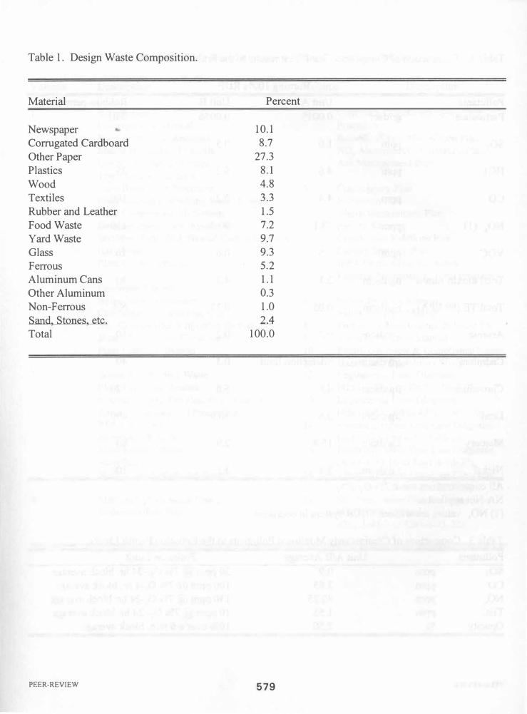
Table 1. Design Waste Composition.
Material Percent
Newspaper 10.1 Corrugated Cardboard 8.7
Other Paper 27.3
Plastics 8.1 Wood 4.8
Textiles 3.3
Rubber and Leather 1.5 Food Waste 7.2
Yard Waste 9.7
Glass 9.3
Ferrous 5.2
Aluminum Cans 1.1 Other Aluminum 0.3
Non-Ferrous 1.0 Sand, Stones, etc. 2A Total 100.0
PEER-REVIEW 579

Table 2. Comparison of Compliance Stack Test results to the Emission Permit Limits.
Burning 1 00% RDF
Pollutants Unit A Unit B Robbins pennit
Particulate gr/dscf 0.001 5 0.0056 0.01
S02 ppm 1 .0 0.5 30
HC1 ppm 4.6 6.2 25
CO ppm 4.4 2.2 1 00
NOx (1) ppm 73.1 90.4 1 30
VOC ppm 1 .5 0.6 10
Total dioxin-furans ngldscm 2.1 4.9 30
Total TE (89 EPA) ngldscm 0.05 0.13 NA
Arsenic ,ugldscm 0.2 0.2 1 0
Cadmium ,ugldscm <detection limit 0.3 40
Chromium ,ugldscm 4.8 5.6 1 20
Lead ,ugldscm 3.6 30.9 490
Mercury ,ug/dscm 1 5.8 2.9 80
Nickel ,ugldscm 3.1 3.1 1 00
All concentrations are at 7% O2 NA-Not applicable (1) NOx values are without SNCR system in operation
Table 3. Comparison of Continuously Monitored Pollutants to the Emission Permit Limits.
Pollutants Unit Al B Average Emission Limit S02 ppm 0.9 30 ppm @ 7% O2 -24 hr. block average CO ppm 3.85 1 00 ppm @ 7% O2-4 hr. block average
..
NOx ppm 80.25 1 30 ppm @ 7% O2-24 hr. block average THC ppm 1 .55 1 0 ppm @ 7% O2- 24 hr. block average Opacity % 2.50 1 0% over a 6 min. block average
PEER-REVIEW 580

Table 4. Start-up Plan and Operations and Maintenance Manual Table of Contents
Yolume Description Yulutne Description
Introduction 4 Continuous Emissions Monitoring DesctDPtion of Manual Procedures Manual Revision Requests Remedial/Corrective Action Plan Matrix of Vendors Manuals NO. Abatement/Optimization Plan List of Enclosed Drawings Ash Management Plan Test/Turnover Program Plant Black Start Procedure 5 Contingency Plan Plant Cooling/Circulating Water System Inspection Plan Plant Compressed Air System Waste Management Plan Demineralized Water System Record Keeping Scrubber, Lime & Activated Carbon Systems Community Relations Plan Bag House Facility Staffing Plan Plant Control System IEPA Notification Procedure
Fugitive Particulate Control Program 2 Feedwater System
Boiler/Steam Generator 6 Safety Program Manual Combustion Air and Flue Gas 7 Safety Program Manual No. ControllUREA Injection System 8 Preventive Maintenance & Spare Pts. Steam Turbine and Condenser 9 Training Program Manual Plant Electrical System 10 Permit Overview & Compliance Summ.
11 Hazard and Operability Study 3 WastelRawlPotable Water 12 Engineering Flow Diagrams
Plant Fire Water System (4261-1-50-1 to 4261-1-50-203) Bottom and Fly Ash Handling Systems 13 Engineering Flow Diagrams Refuse Receiving and Processing (4261-1-50-204 to 4261-1-50-510) RDF Fuel Feed 14 Electrical Power One-Line Diagrams Blowdown System (4261-173-1 to 4261-1-73-18) Main Steam System 15 Electrical Power One-Line Diagrams Sampling (4261-1-73-19 to 4261-1-73-37) Natural Gas System and Burners 16 Electrical Power One-Line Diagrams
(4261-1-73-38 to 4261-1-73-59) 4 Mercury Optimization Plan 17 Site Preparation Plan Drawings
Emissions Test Plan (4261-1-51-100 and 4261-1-41-3 to 4261-1-41-22)
PEER-REVIEW 581

Figure 1. Photograph of the Robbins Resource Recovery Facility.
Figure 2. Computer Model of the Robbins Resource Recovery Facility.
PEER-REvIEW 582
PEER-REVIEW
.. MSW (548)
Corrugugatad PI •• tlce
i Future i , '
AI Fe Gla.. Compost
(4) (25) (58) (51) (1000 TonslYear)
Figure 3. Robbins Process Flow Diagram
PRIMARY
Elect
(50MW)
MSW _ TROMMEl � � ��-OO--Oo--, • o o�� OOOO�� i +6"
�HREDOER
��.�_ct�ooO ----- ----------r-··--il ____ _ ------------
____ '7 +2112·
-6" Ferrous
-1314"
Heavies
Lf�tj GLASS COMPOST 10% 9%
-2112"
Ferrous
! ALUM
1%
Ferrous
FERROUS 5%
Figure 4. Robbins Fuel Preparation System
583
RDF 75%
ADMIN. MANAGER
(1)
I SECRETARY
CLERKS SCALE OPERA TOF
(6)
PEER-REVIEW
--------
J-VALVE
STRIPPER COOLER
-
IJ
HEAT
AREA
�TOJEGAS APC
Figure 5. Robbins CFB Boiler
GENERAL MANAGER
(1) •
PLANT OPERATIONS MANAGER
(1)
POWER PLANT RDFPLANT MAINTENANCE ENVIRONMENTAL SUPERVISOR SUPERVISOR SUPERVISOR COORDINATOR
(1) (1) (1) (1)
I I I I POWER PLANT RDFPLANT MAINTENANCE ENVIRONMENTAL
STAFF STAFF STAFF ASSISTANT (18) (26) (21) (1) ..
FIGURE 6. ROBBINS ORGANIZATION CHART
584