starter kit specification · 2.1. lesson 1: “welcome to arduino” (this lesson is for the...
TRANSCRIPT

Starter Kit
Specification
Version: 1.0 Date: 2014-11-30
Contents 1. Introduction .............................................................................................................................. 1
2. Learning Lessons ....................................................................................................................... 3
2.1. Lesson 1: “Welcome to Arduino” .................................................................................. 3
2.2. Lesson 2:“LED Blink” ..................................................................................................... 5
2.3. Lesson 3:“Rolling Light” ................................................................................................. 7
2.4. Lesson 4: “Button Controlled LED” ................................................................................ 9
2.5. Lesson 5: “PWM fading” ............................................................................................. 10
2.6. Lesson 6:“RGB LED Display” ........................................................................................ 12
2.7. Lesson 7: “Buzzer Warning” ........................................................................................ 14
2.7.1. Making Sound with Active Buzzer ................................................................... 14
2.7.2. Making sound with Passive Buzzer .................................................................. 15
2.8. Lesson 8: “Tilt Switch” ................................................................................................. 16
2.9. Lesson 9: “Potentiometer Analog Reading” ................................................................ 17
2.10. Lesson 10: “PS2 Joystick” ........................................................................................ 19
2.11. Lesson 11: “Light Controlled Lamp” ........................................................................ 21
2.12. Lesson 12: “Sound Controlled Lamp” ...................................................................... 23
2.13. Lesson 13:“Remote Controlled Lamp” .................................................................... 25
2.14. Lesson 14: “1 Digital 8‐Segment LED Display” ........................................................ 29
2.15. Lesson 15: “4 Digital 8‐Segment LED Display Dynamic Scanning Display” .............. 31
2.16. Lesson 16: “8*8 Dot Matrix LED Display” ................................................................ 34
2.17. Lesson 17: “Infrared Receiver” ................................................................................ 36
2.18. Lesson 18: “Infrared Sender” .................................................................................. 39
2.19. Lesson 19: “1602LCD” ............................................................................................. 42
2.20. Lesson 20:“Temperature Measurement” ................................................................ 44
2.21. Lesson 21: “Sound Sensor Playing” ......................................................................... 45
2.22. Lesson 22: “Noise Warning” .................................................................................... 48
2.23. Lesson 23: “Fire Alarm” ........................................................................................... 49
2.24. Lesson 24: “Stepper Motor Driving” ....................................................................... 51
2.25. Lesson 25: “PWM Servo Control” ............................................................................ 55
2.26. Lesson 26: “Relay controlling” ................................................................................ 57
2.27. Lesson 27:“Interactive Servo Motor” ...................................................................... 58
2.28. Lesson 28: “Electronic Clock” .................................................................................. 61
2.29. Lesson 29: “Alarm clock” ......................................................................................... 62
2.30. Lesson 30: “Infrared Remote Controlled Stepper” ................................................. 63
2.31. Lesson 31: “74HC595 IO expansion” ....................................................................... 67
3. Appendix ................................................................................................................................. 70
3.1. MB‐102 Breadboard .................................................................................................... 70
3.2. Infiduino Uno R3 ......................................................................................................... 70
1
1. Introduction
This is a Starter Kit for Arduino beginners. It includes some discrete components,
some wires, some modules, the extension board and so on. The purpose for this kit is to
help you learn some basics for Arduino programming language and some electronic
knowledge. Some learning lessons are provided based on these parts. But you can also
do some awesome projects of your own by using these components, just make your
thoughts fly. The Kit includes many common components that you may come across during
your electronic journey in the future. Please see the following Part List to see what is
included in the Kit.
Part List
1. 1 x Infiduino Uno R3 board + 1 x USB cable
2. 1 x Infiduino Extension board + 1 x GPIO Extension Board + 1 x Connecting Cable
3. 1 x Breadboard
4. 10 x 3mm Red LEDs
5. 10 x 3mm Green LEDs
6. 10 x 3mm Yellow LEDs
7. 1 x 5mm RGB LED
8. 5 x Button
9. 20 x (330 ohm + 1k ohm +10k ohm)resistor
10. 1 x 1K potentiometer
11. 1 x 10K potentiometer
12. 1 x 2.54mm Straight 40 Pin Header
13. 1 x 2.54mm Elbow 40 Pin Header
14. 1 x 5516 LDR(Photoresistor)
15. 1 x Ball switch
16. 1 x Active Buzzer
17. 1 x Passive Buzzer
18. 1 x 74HC595 8bit Shift Register
19. 1 x LM35
20. 1 x NPN Transistor
21. 1 x Infrared Receiver
22. 1 x Infrared Sender
23. 1 x Infrared Phototransistor
24. 1 x Infrared Remote controller
25. 1 x Stepper Motor
26. 1 x Servo motor
27. 1 x 1602 LCD
28. 1 x 1-Digit Eight-segment Display
29. 1 x 4-Digit Eight-segment Display
30. 1 x 8*8 Dot Matrix Led Display
2
31. 1 x Stepper Motor Driver Board
32. 1 x Sound Sensor Module
33. 1 x PS2 Joystick module
34. 1 x RTC module
35. 1 x Relay Module
36. 65 x Jump Wires
37. 10 x Female-Female Dupont wires
38. 10 x Male-Female Dupont wires
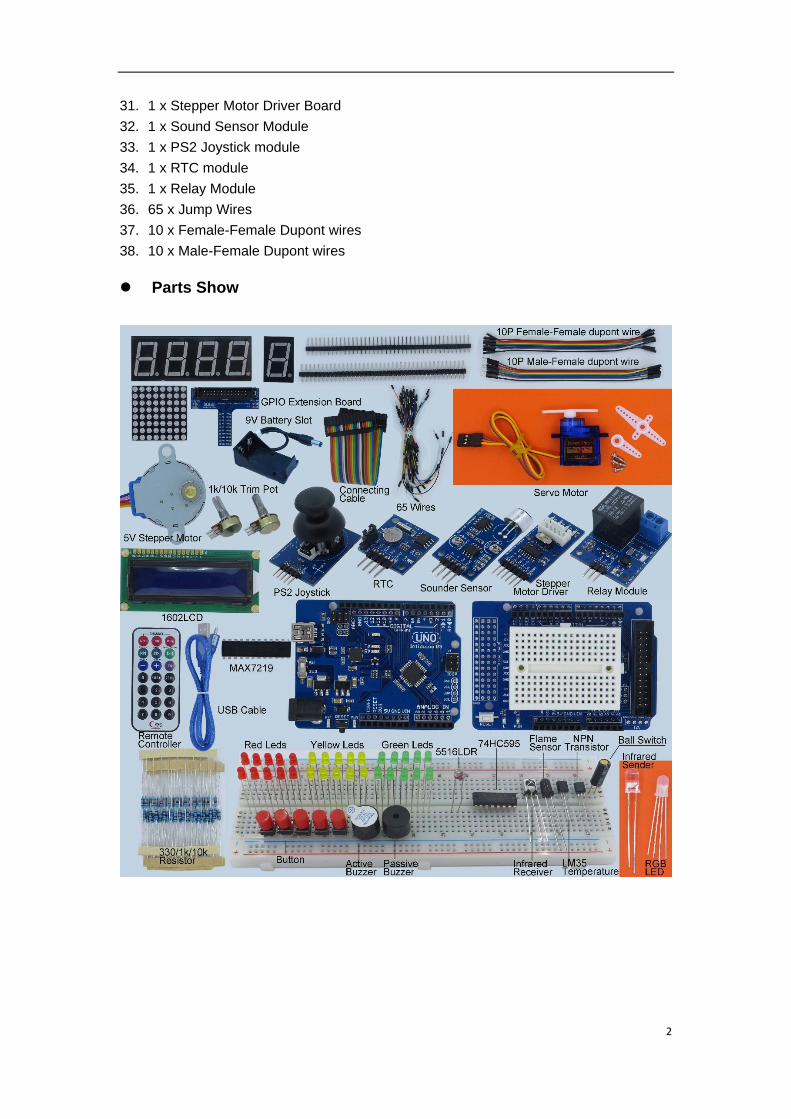
Parts Show
3
2. Learning Lessons
For all the lessons below, the board we use is Infiduino Uno R3. The official Arduino
and other compatible boards can also work.
2.1. Lesson 1: “Welcome to Arduino”
(This lesson is for the newbies to Arduino. If you already have some knowledge
about Arduino then you can skip this part.)
Arduino is one of the most popular open-source hardware item throughout the world
now. If you're not a professional electronic designer and you want to do some awesome
electronic project by your own, then Arduino is a good choice. For in-depth understanding
of Arduino you can visit the official website: http://arduino.cc/. For this part we will show
how to write the basic code using Arduino programming language. First please make sure
you already have an Arduino Board or other compatible board like Infiduino in hand. Then
install the Arduino development environment properly for your system (download Arduino).
Then LET'S GO!
Step by Step downloading.
1. Step 1: Hardware connection
Connect your Arduino with PC through the USB cable.
2. Step 2: Install the USB driver
When you do the above step for the first time, your PC should find a new hardware.
Then your system will try to install the USB driver. Please browser to the folder named
".../drivers" of you Arduino IDE folder, and install the USB driver manually.
3. Step 3:Set up a new file
Open your Arduino IDE and set up a new file(through commands "File->New").
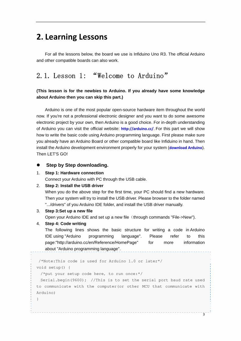
4. Step 4: Code writing
The following lines shows the basic structure for writing a code in Arduino
IDE using "Arduino programming language". Please refer to this
page:"http://arduino.cc/en/Reference/HomePage" for more information
about "Arduino programming language".
/*Note:This code is used for Arduino 1.0 or later*/
void setup() {
/*put your setup code here, to run once:*/
Serial.begin(9600); //This is to set the serial port baud rate used
to communicate with the computer(or other MCU that communicate with
Arduino)
}
4
void loop() {
/*put your main code here, to run repeatedly:*/
Serial.println("Welcome to Arduino");
Serial.println("Congratulations, you've done a great job!");
while(1);
}
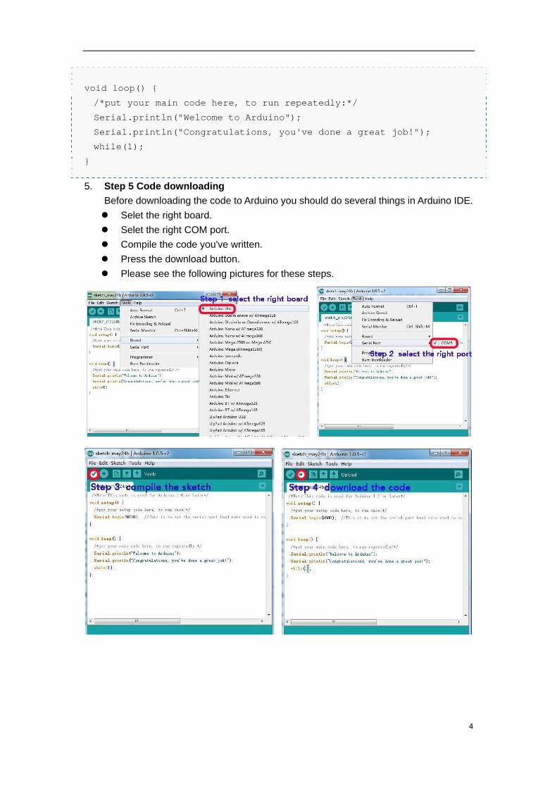
5. Step 5 Code downloading
Before downloading the code to Arduino you should do several things in Arduino IDE.
Selet the right board.
Selet the right COM port.
Compile the code you've written.
Press the download button.
Please see the following pictures for these steps.
5
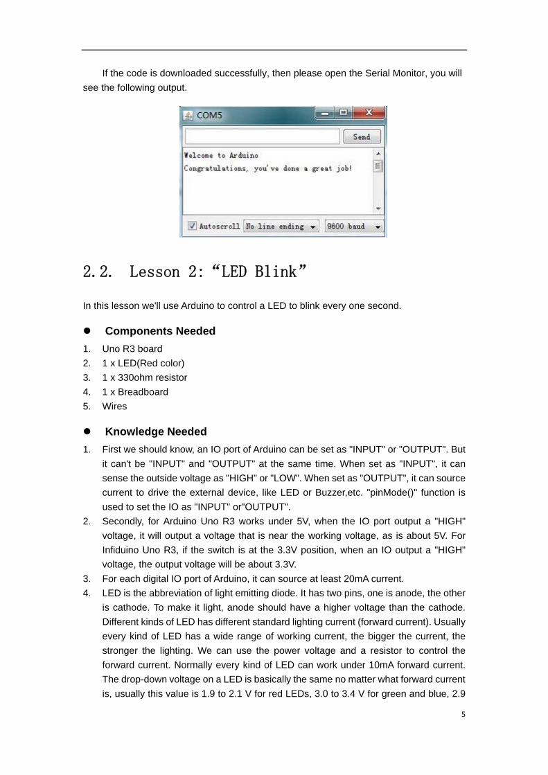
If the code is downloaded successfully, then please open the Serial Monitor, you will
see the following output.
2.2. Lesson 2:“LED Blink”
In this lesson we'll use Arduino to control a LED to blink every one second.
Components Needed
1. Uno R3 board
2. 1 x LED(Red color)
3. 1 x 330ohm resistor
4. 1 x Breadboard
5. Wires
Knowledge Needed
1. First we should know, an IO port of Arduino can be set as "INPUT" or "OUTPUT". But
it can't be "INPUT" and "OUTPUT" at the same time. When set as "INPUT", it can
sense the outside voltage as "HIGH" or "LOW". When set as "OUTPUT", it can source
current to drive the external device, like LED or Buzzer,etc. "pinMode()" function is
used to set the IO as "INPUT" or"OUTPUT".
2. Secondly, for Arduino Uno R3 works under 5V, when the IO port output a "HIGH"
voltage, it will output a voltage that is near the working voltage, as is about 5V. For
Infiduino Uno R3, if the switch is at the 3.3V position, when an IO output a "HIGH"
voltage, the output voltage will be about 3.3V.
3. For each digital IO port of Arduino, it can source at least 20mA current.
4. LED is the abbreviation of light emitting diode. It has two pins, one is anode, the other
is cathode. To make it light, anode should have a higher voltage than the cathode.
Different kinds of LED has different standard lighting current (forward current). Usually
every kind of LED has a wide range of working current, the bigger the current, the
stronger the lighting. We can use the power voltage and a resistor to control the
forward current. Normally every kind of LED can work under 10mA forward current.
The drop-down voltage on a LED is basically the same no matter what forward current
is, usually this value is 1.9 to 2.1 V for red LEDs, 3.0 to 3.4 V for green and blue, 2.9
6
to 4.2 V for violet, pink, purple and white.
5. Because the IO port of Arduino can source at least 20mA current,So we can use the
Digital IO to drive an LED directly. We just need 10mA current here.
6. In this test, we will drive the LED with a current of about 10mA. The circuit is as the
following picture. What value of resistor we should use? We can use Ohm law to select
the resistor."Current=(VCC-Vd)/R."
In the above formula, VCC instead of the output voltage of the IO when it output a
"HIGH" voltage, we'll use 5V here. Vd instead of the drop-down voltage of the LED, usually
we can select 2.0V for red LED(to be accurate for this, you can use a multi-meter to
measure it or referring to the datasheet of the LED). So if we want the LED works with a
current of about 10mA, we can make R=300ohm. So we will choose a 330ohm resistor
here.
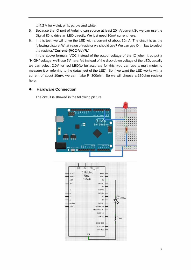
Hardware Connection
The circuit is showed in the following picture.
7
Code Writing
For an IO, before using it to do something, we should first set it as INPUT or OUTPUT
(through the pinMode() function). When set as INPUT, the IO can sense the outside voltage
level. When set as OUTPUT, the IO can output a HIGH voltage or a LOW voltage. In this
example, we should set the IO as OUTPUT, then it will light the led when it output a HIGH
voltage level (use the digitalWrite() function).
/*
Blink
Turns on an LED on for one second, then off for one second,
repeatedly.
*/
void setup() {
// initialize the digital pin as an output.
pinMode(2, OUTPUT);
}
void loop() {
digitalWrite(2, HIGH); // set the LED on
delay(1000); // wait for a second
digitalWrite(2, LOW); // set the LED off
delay(1000); // wait for a second
}
Download the code to Arduino then you can see the LED blinks every one second.
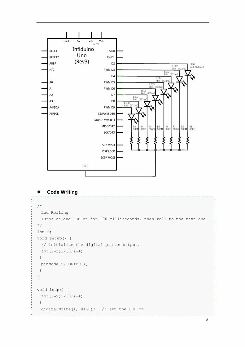
2.3. Lesson 3:“Rolling Light”
This lesson use the same hardware knowledge as the above one. But we can learn
how to use the "for()" loop function. In this test we will light one LED for 100 milliseconds,
then roll to the next one.
Components Needed
1. Uno R3 board
2. 8 x LED(Red color)
3. 8 x 330ohm resistor
4. 1 x Breadboard
5. Wires
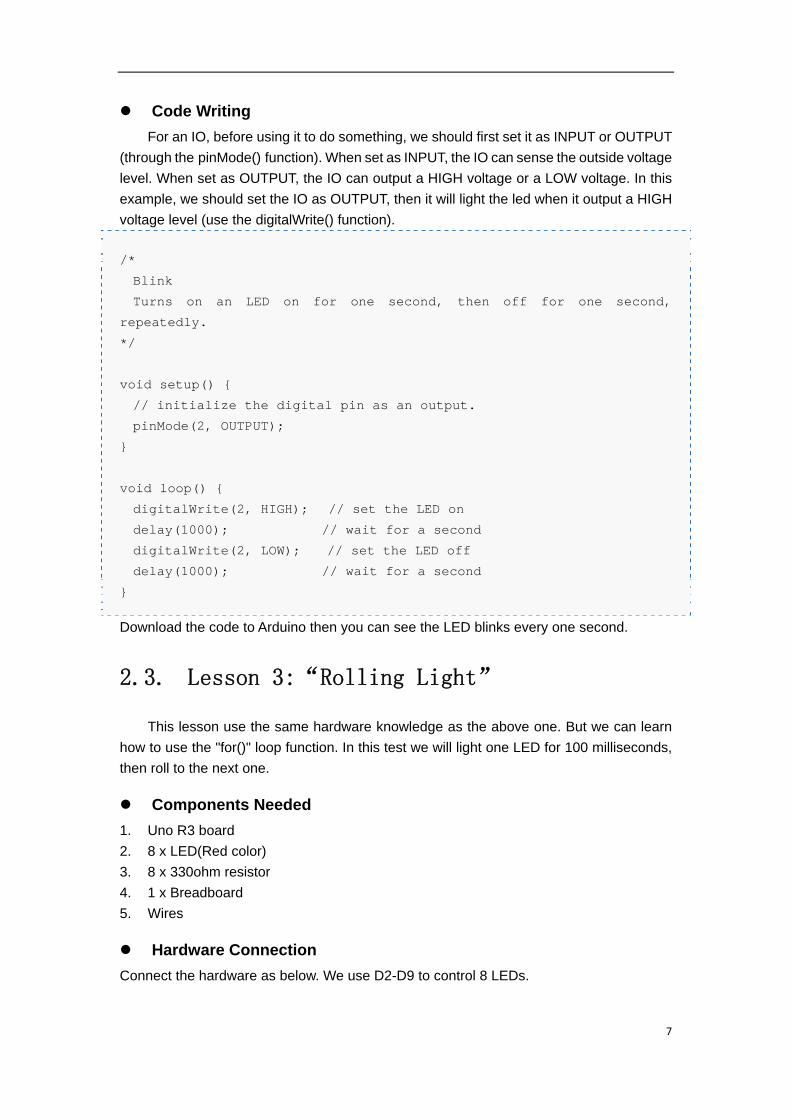
Hardware Connection
Connect the hardware as below. We use D2-D9 to control 8 LEDs.
8
Code Writing
/*
Led Rolling
Turns on one LED on for 100 milliseconds, then roll to the next one.
*/
int i;
void setup() {
// initialize the digital pin as output.
for(i=2;i<10;i++)
{
pinMode(i, OUTPUT);
}
}
void loop() {
for(i=2;i<10;i++)
{
digitalWrite(i, HIGH); // set the LED on
9
delay(100); // wait for a second
digitalWrite(i, LOW); // set the LED off
}
}
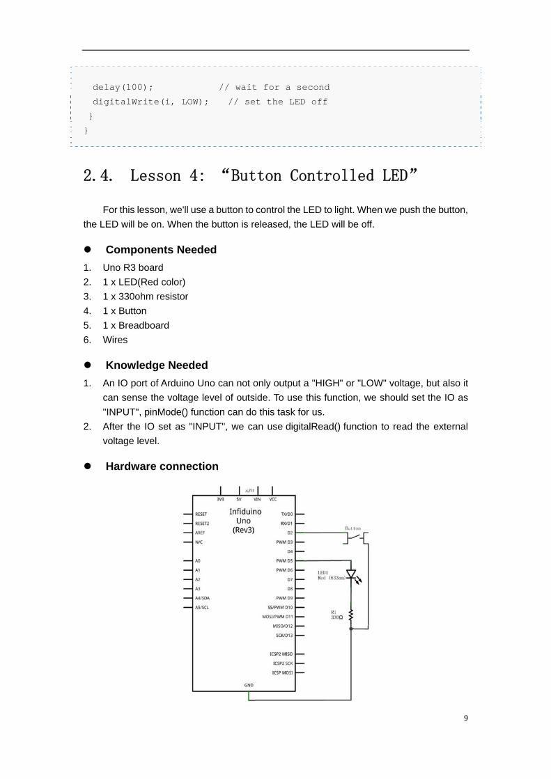
2.4. Lesson 4: “Button Controlled LED”
For this lesson, we'll use a button to control the LED to light. When we push the button,
the LED will be on. When the button is released, the LED will be off.
Components Needed
1. Uno R3 board
2. 1 x LED(Red color)
3. 1 x 330ohm resistor
4. 1 x Button
5. 1 x Breadboard
6. Wires
Knowledge Needed
1. An IO port of Arduino Uno can not only output a "HIGH" or "LOW" voltage, but also it
can sense the voltage level of outside. To use this function, we should set the IO as
"INPUT", pinMode() function can do this task for us.
2. After the IO set as "INPUT", we can use digitalRead() function to read the external
voltage level.
Hardware connection
10
Code Writing
Based on the hardware connection, we should set D2 as INPUT, and also we should
enable the internal pull-up resistor. So we should use INPUT_PULLUP in pinMode()
function.
/*Note:This code is used for Arduino 1.0.1 or later*/
/*
Button Controlled LED
Turns on an LED when push the button.
*/
void setup() {
// initialize the digital pin as an output.
pinMode(2, INPUT_PULLUP);
pinMode(5, OUTPUT);
}
void loop() {
int sensorValue = digitalRead(2);
if(sensorValue)
{
digitalWrite(5, HIGH); // set the LED on
}
else
digitalWrite(5, LOW); // set the LED off
}
2.5. Lesson 5: “PWM fading”
Previous test, we've already made an LED light. But the lighting strength is stable. For
this test, we will use the PWM method to change the lighting strength of an LED, make it
light from dark to bright continuous.
Components Needed
1. Uno R3 board
2. 1 x LED(Red color)
3. 1 x 330ohm resistor
4. 1 x Breadboard
5. Wires
Knowledge Needed
PWM means Pulse Width Modulation. It is a good method for getting analog results
with digital means. For some power components like a resistor generating heat or an LED
11
emitting light or other similar components, the PWM method will get a same result as when
we exert an different analog voltage to the components. Please refer to PWM
Introduction for reference. In this lesson we will use the analogWrite()to change the light
strength of the LED. Note not all the IOs of Infiduino/Arduino has this function, this only
works on pin 3, 5, 6, 9, 10, and 11.
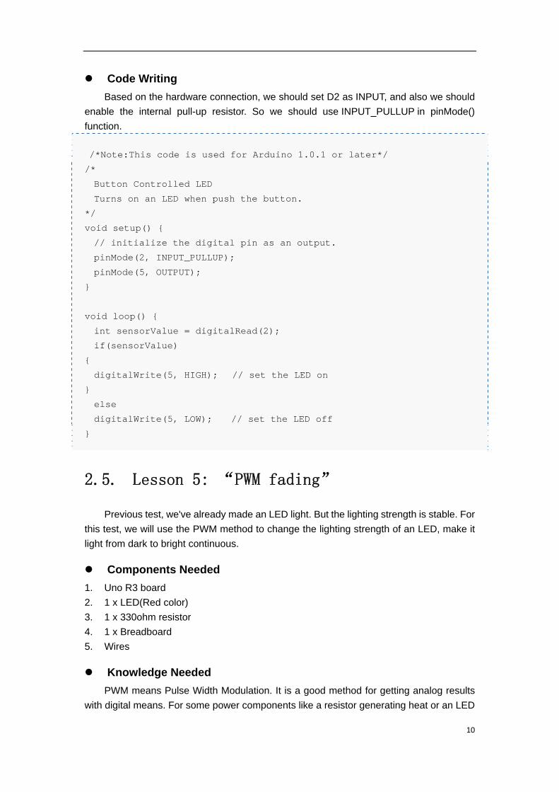
Hardware Connection.
Connect the anode of the LED to digital output pin 9(D9) on Arduino through a 330-
ohm resistor. Connect the cathode directly to ground.
Code Writing
/*
Fade
This example shows how to fade an LED on pin 9
using the analogWrite() function.
This example code is in the public domain.
*/
int brightness = 0; // how bright the LED is
int fadeAmount = 5; // how many points to fade the LED by
12
void setup() {
// declare pin 9 to be an output:
pinMode(9, OUTPUT);
}
void loop() {
// set the brightness of pin 9:
analogWrite(9, brightness);
// change the brightness for next time through the loop:
brightness = brightness + fadeAmount;
// reverse the direction of the fading at the ends of the fade:
if (brightness == 0 || brightness == 255) {
fadeAmount = -fadeAmount ;
}
// wait for 30 milliseconds to see the dimming effect
delay(30);
}
2.6. Lesson 6:“RGB LED Display”
Components Needed
1. Uno R3 board
2. 1 x RGB LED
1 3 x 330ohm resistor
3. 1 x Breadboard
4. Wires
Knowledge Needed
The RGB LED has 3 kinds of LEDs (Red, Green, Blue) integrated in one package.
The RGB led included in the Starter Kit is a common-anode kind, which means the 3 LEDs
have their anode connected together. Usually the longest pin is the common used pin. We
can use the PWM fading function to change the lighting strength of each color led, because
all color light can be gained through three primary colour(red, green,blue), so we can gain
various color in this test through the RGB LED.
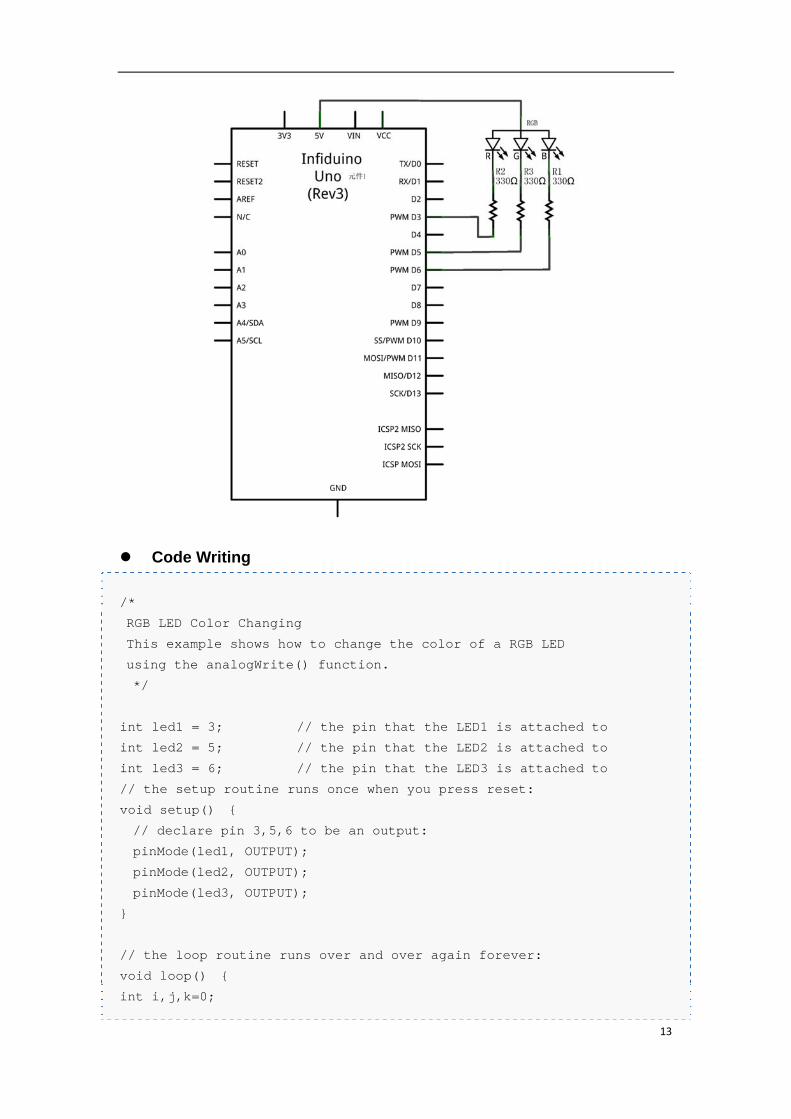
Hardware Connection
Make sure each led is controlled by a PWM port( Port 3, 5, 6, 9, 10, or 11). In this
lesson we use D3/D5/D6.
13
Code Writing
/*
RGB LED Color Changing
This example shows how to change the color of a RGB LED
using the analogWrite() function.
*/
int led1 = 3; // the pin that the LED1 is attached to
int led2 = 5; // the pin that the LED2 is attached to
int led3 = 6; // the pin that the LED3 is attached to
// the setup routine runs once when you press reset:
void setup() {
// declare pin 3,5,6 to be an output:
pinMode(led1, OUTPUT);
pinMode(led2, OUTPUT);
pinMode(led3, OUTPUT);
}
// the loop routine runs over and over again forever:
void loop() {
int i,j,k=0;
14
for(i=0;i<10;i++)
{
analogWrite(led1, i*25);
for(j=0;j<10;j++)
{
analogWrite(led2, j*25);
for(k=0;k<10;k++)
{
analogWrite(led3, k*25);
delay(10);
}
}
}
}
2.7. Lesson 7: “Buzzer Warning”
There are two kinds of buzzer in the kit. One is called passive buzzer(you can see
the green PCB in it), and the other one is active buzzer(it's totally packaged and you can't
see the PCB in it).
2.7.1. Making Sound with Active Buzzer
Components Needed
1. Uno R3 board
2. 1 x Active Buzzer
3. 1 x 1k ohm resistor
4. 1 x 10k ohm resistor
5. 1 x SS8050 NPN transistor
6. 1 x Breadboard
7. Wires
Knowledge Needed
Active Buzzer has oscillating circuit in it. When there is a rated voltage exerted on it,
it will make a sound. The active buzzer in the kit has a rated voltage of 5V, and a rated
current of no more than 30mA, usually an IO port can drive it directly. But in order to prevent
the IO from being damaged, we use a NPN transistor to amplify the current.
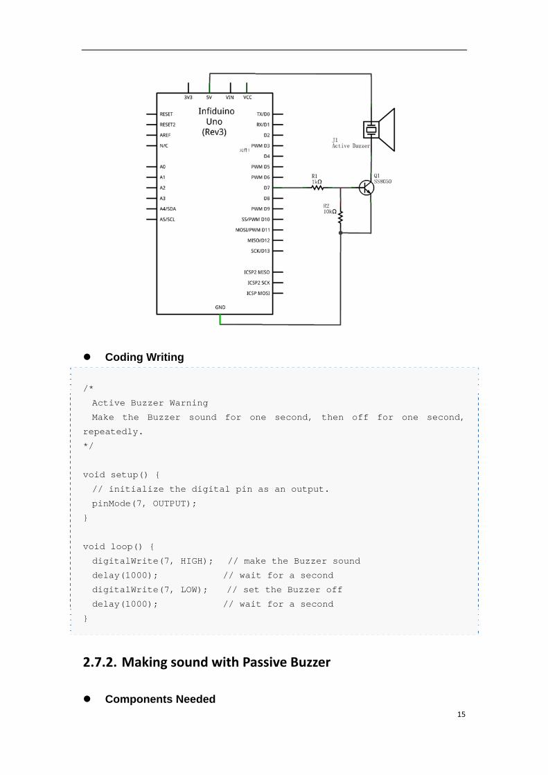
Hardware Connection.
The following picture shows how it is connected.
15
Coding Writing
/*
Active Buzzer Warning
Make the Buzzer sound for one second, then off for one second,
repeatedly.
*/
void setup() {
// initialize the digital pin as an output.
pinMode(7, OUTPUT);
}
void loop() {
digitalWrite(7, HIGH); // make the Buzzer sound
delay(1000); // wait for a second
digitalWrite(7, LOW); // set the Buzzer off
delay(1000); // wait for a second
}
2.7.2. Making sound with Passive Buzzer
Components Needed
16
1. Uno R3 board
2. 1 x Passive Buzzer
3. 1 x 1k ohm resistor
4. 1 x 10k ohm resistor
5. 1 x SS8050 NPN transistor
6. 1 x Breadboard
7. Wires
Knowledge Needed
Passive Buzzer will not make a sound if we just use a HIGH voltage to drive it directly.
Because there is no oscillating circuit in it. We can use the PWM mechanism to make it cry.
The Resonant Frequency of the passive buzzer in the kit is 2048HZ, the rated voltage
also is 5V.
Hardware Connection.
The hardware connection is the same as the Active Buzzer sounding example.
Coding Writing
The following code will make a PWM wave with a frequency of about 2000HZ. The
duty cycle is 50%.
/*
Passive Buzzer Warning
Make the Passive Buzzer sound continuously.
*/
void setup() {
// initialize the digital pin as an output.
pinMode(7, OUTPUT);
}
void loop() {
digitalWrite(7, HIGH); // set D7 HIGH
delayMicroseconds(250);
digitalWrite(7, LOW); // set D7 LOW
delayMicroseconds(250);
}
2.8. Lesson 8: “Tilt Switch”
The tilt switch is also a Ball switch. Check the following pictures to see how it works.
17
In fact it is like a button. The difference is that the Tilt switch is on or off based on the
angle of it. We can use the same example as Button Controlled LED, just change the
button to the Tilt Switch.
2.9. Lesson 9: “Potentiometer Analog
Reading”
Through this test, we can learn how to use the Analog port of Arduino, and learn how
to use analogRead() function.
Components Needed
1. Uno R3 board
2. 1 x Potentiometer(1k or 10k)
3. Wires
Knowledge Needed
1. A0-A5 port of Arduino can be used as analog pins. These pin can not only be used as
general IO ports, but also can read the exact voltage of the outside(0V-5V).
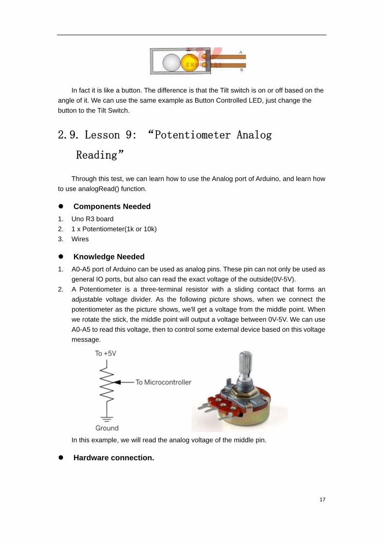
2. A Potentiometer is a three-terminal resistor with a sliding contact that forms an
adjustable voltage divider. As the following picture shows, when we connect the
potentiometer as the picture shows, we'll get a voltage from the middle point. When
we rotate the stick, the middle point will output a voltage between 0V-5V. We can use
A0-A5 to read this voltage, then to control some external device based on this voltage
message.
In this example, we will read the analog voltage of the middle pin.
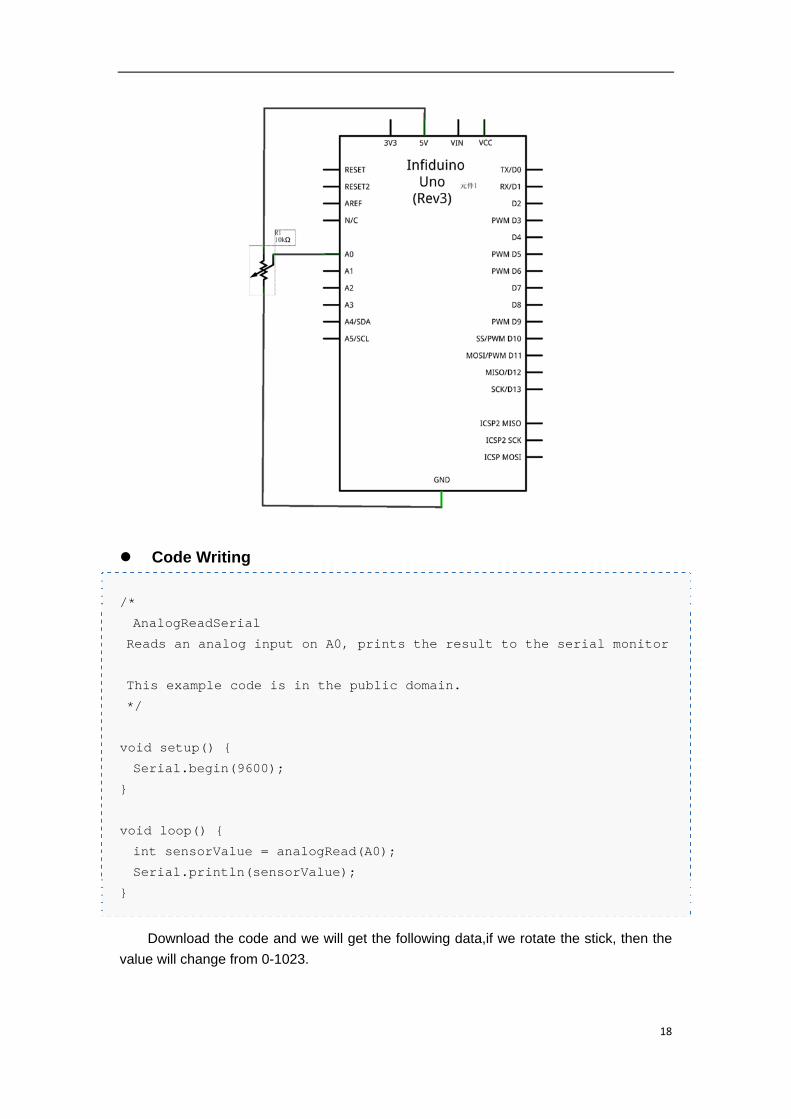
Hardware connection.
18
Code Writing
/*
AnalogReadSerial
Reads an analog input on A0, prints the result to the serial monitor
This example code is in the public domain.
*/
void setup() {
Serial.begin(9600);
}
void loop() {
int sensorValue = analogRead(A0);
Serial.println(sensorValue);
}
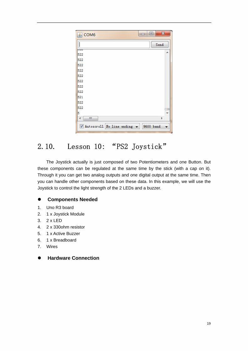
Download the code and we will get the following data,if we rotate the stick, then the
value will change from 0-1023.
19
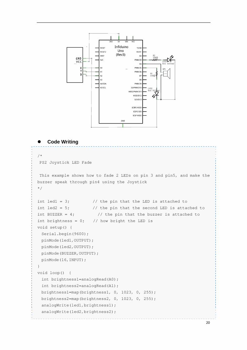
2.10. Lesson 10: “PS2 Joystick”
The Joystick actually is just composed of two Potentiometers and one Button. But
these components can be regulated at the same time by the stick (with a cap on it).
Through it you can get two analog outputs and one digital output at the same time. Then
you can handle other components based on these data. In this example, we will use the
Joystick to control the light strength of the 2 LEDs and a buzzer.
Components Needed
1. Uno R3 board
2. 1 x Joystick Module
3. 2 x LED
4. 2 x 330ohm resistor
5. 1 x Active Buzzer
6. 1 x Breadboard
7. Wires
Hardware Connection
20
Code Writing
/*
PS2 Joystick LED Fade
This example shows how to fade 2 LEDs on pin 3 and pin5, and make the
buzzer speak through pin4 using the Joystick
*/
int led1 = 3; // the pin that the LED is attached to
int led2 = 5; // the pin that the second LED is attached to
int BUZZER = 4; // the pin that the buzzer is attached to
int brightness = 0; // how bright the LED is
void setup() {
Serial.begin(9600);
pinMode(led1,OUTPUT);
pinMode(led2,OUTPUT);
pinMode(BUZZER,OUTPUT);
pinMode(16,INPUT);
}
void loop() {
int brightness1=analogRead(A0);
int brightness2=analogRead(A1);
brightness1=map(brightness1, 0, 1023, 0, 255);
brightness2=map(brightness2, 0, 1023, 0, 255);
analogWrite(led1,brightness1);
analogWrite(led2,brightness2);
21
if(digitalRead(16))
digitalWrite(4,HIGH);
else
digitalWrite(4,LOW);
}
2.11. Lesson 11: “Light Controlled Lamp”
Components Needed
1. Uno R3 board
2. 1 x 5516LDR
3. 1 x 330ohm resistor
4. 1 x 10k ohm resistor
5. 1 x LED(Red color)
6. 1 x Breadboard
7. Wires
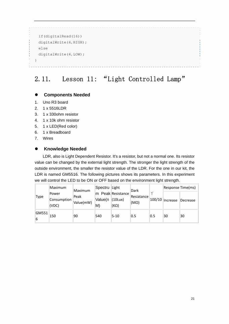
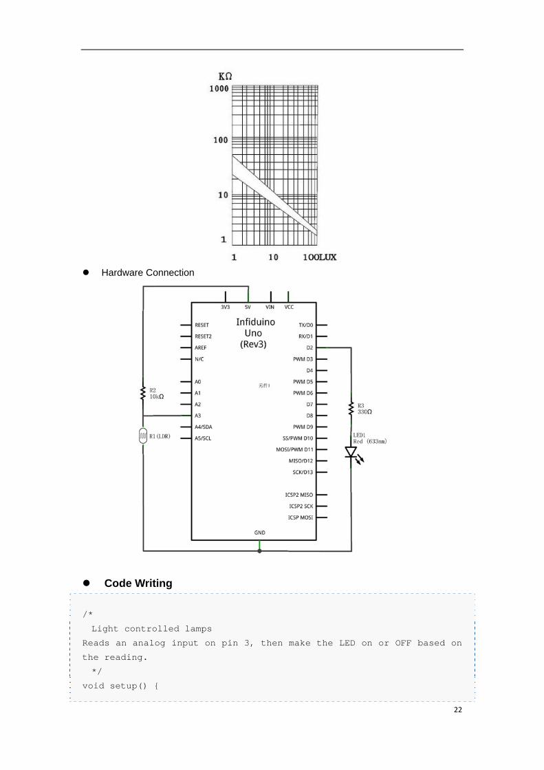
Knowledge Needed
LDR, also is Light Dependent Resistor. It's a resistor, but not a normal one. Its resistor
value can be changed by the external light strength. The stronger the light strength of the
outside environment, the smaller the resistor value of the LDR. For the one in our kit, the
LDR is named GM5516. The following pictures shows its parameters. In this experiment
we will control the LED to be ON or OFF based on the environment light strength.
Type
Maximum
Power
Consumption
(VDC)
Maximum
Peak
Value(mW)
Spectru
m Peak
Value(n
M)
Light
Resistance
(10Lux)
(KΩ)
Dark
Resiatance
(MΩ)
ㄚ
100/10
Response Time(ms)
Increase Decrease
GM551
6 150 90 540 5‐10 0.5 0.5 30 30
22
Hardware Connection
Code Writing
/*
Light controlled lamps
Reads an analog input on pin 3, then make the LED on or OFF based on
the reading.
*/
void setup() {
23
pinMode(2,OUTPUT);
}
void loop() {
int sensorValue = analogRead(A3);
if(sensorValue>500)
{
digitalWrite(2,HIGH);
}
else
digitalWrite(2,LOW);
}
For the above code, the LED will be on if you put the LDR in a dark place. Or else, the LED
will be off.
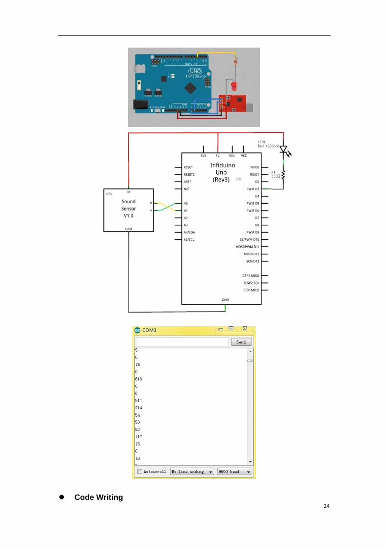
2.12. Lesson 12: “Sound Controlled Lamp”
Components Needed
1. Uno R3 board
2. 1 x LED(Red color)
3. 1 x 330ohm resistor
4. 1 x Sound Sensor Module
5. 1 x Breadboard
6. Wires
Knowledge Needed
This lesson will need our Sound Sensor Module. It can measure the noise strength of
the outside environment. Most of the Sound Sensor in the market only output analog data.
We redesigned it and make it can output a "HIGH" value when the environment sound
exceeds a threshold(which can be set by the potentiometer named "THRESHOLD"). In this
example, when you make a big loud noisy near the Sound Sensor, the led will be turned
on.
Hardware Connection
24
Code Writing
25
/*
Sound controlled lamps
Reads the analog output of Sound Sensor through A0, prints the result
to the serial monitor.
Read the digital output of Sound Sensor throug A1, then use the value
to control the LED through D3.
Connect the pins in the following way:
GND----GND
VCC----5V
A------A0
D------A1
*/
void setup() {
Serial.begin(9600);
pinMode(3, OUTPUT);
}
void loop() {
digitalWrite(3, HIGH); // set the LED off
int sensorValue = analogRead(A0); //Read the analog value of the
sound sensor
int digitalVlaue = digitalRead(15);
Serial.println(sensorValue);//Print the analog value to serial
monitor
if(digitalVlaue){
digitalWrite(3, LOW); // If the digital value of the sound sensor
is 1, set the LED on.
delay(1000); // wait for a second
}
}
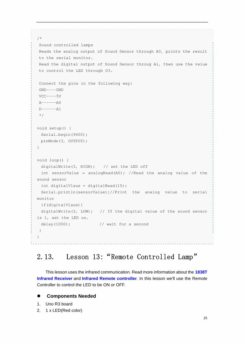
2.13. Lesson 13:“Remote Controlled Lamp”
This lesson uses the infrared communication. Read more information about the 1838T
Infrared Receiver and Infrared Remote controller. In this lesson we'll use the Remote
Controller to control the LED to be ON or OFF.
Components Needed
1. Uno R3 board
2. 1 x LED(Red color)
26
3. 1 x 330ohm resistor
4. 1 x 1838T Infrared Receiver
5. 1 x Infrared Remote controller
6. 1 x Breadboard
7. Wires
Knowledge Needed
1. A Remote Controller can send out infrared signal. Usually it send out a series of signal
under 38KHZ. Some binary data("0" or "1") are modulated on the 38KHZ signal and
then sent out based on some particular protocol. The Remote Controller in the kit uses
the NEC protocol.
2. The 1838T Infrared Receiver can receive the 38KHZ signal and demodulate it, then
output the original binary signal.
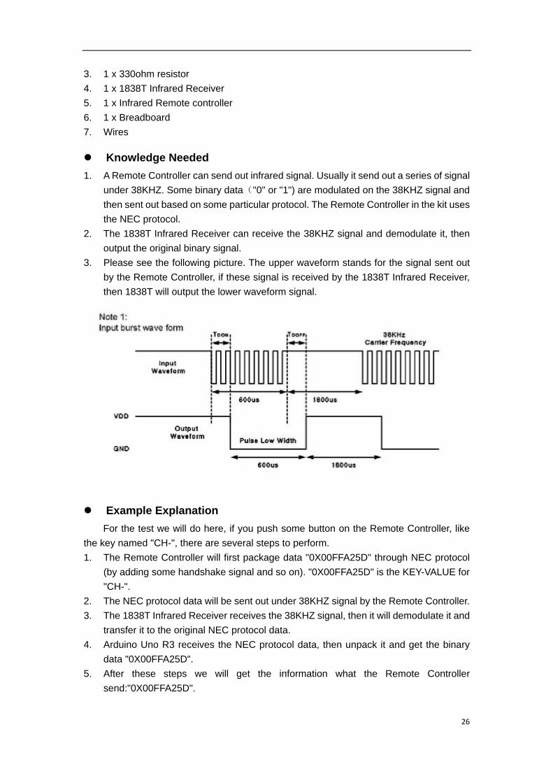
3. Please see the following picture. The upper waveform stands for the signal sent out
by the Remote Controller, if these signal is received by the 1838T Infrared Receiver,
then 1838T will output the lower waveform signal.
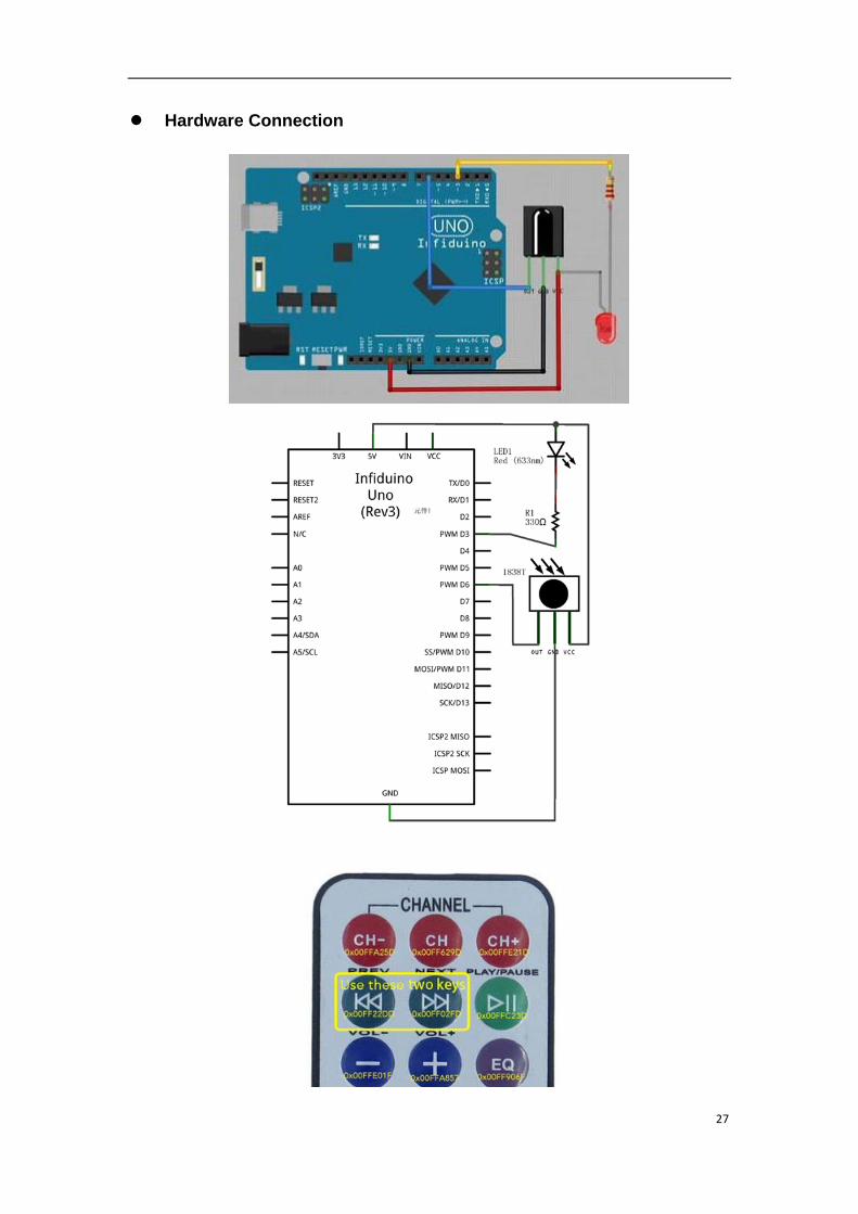
Example Explanation
For the test we will do here, if you push some button on the Remote Controller, like
the key named "CH-", there are several steps to perform.
1. The Remote Controller will first package data "0X00FFA25D" through NEC protocol
(by adding some handshake signal and so on). "0X00FFA25D" is the KEY-VALUE for
"CH-".
2. The NEC protocol data will be sent out under 38KHZ signal by the Remote Controller.
3. The 1838T Infrared Receiver receives the 38KHZ signal, then it will demodulate it and
transfer it to the original NEC protocol data.
4. Arduino Uno R3 receives the NEC protocol data, then unpack it and get the binary
data "0X00FFA25D".
5. After these steps we will get the information what the Remote Controller
send:"0X00FFA25D".
27
Hardware Connection
28
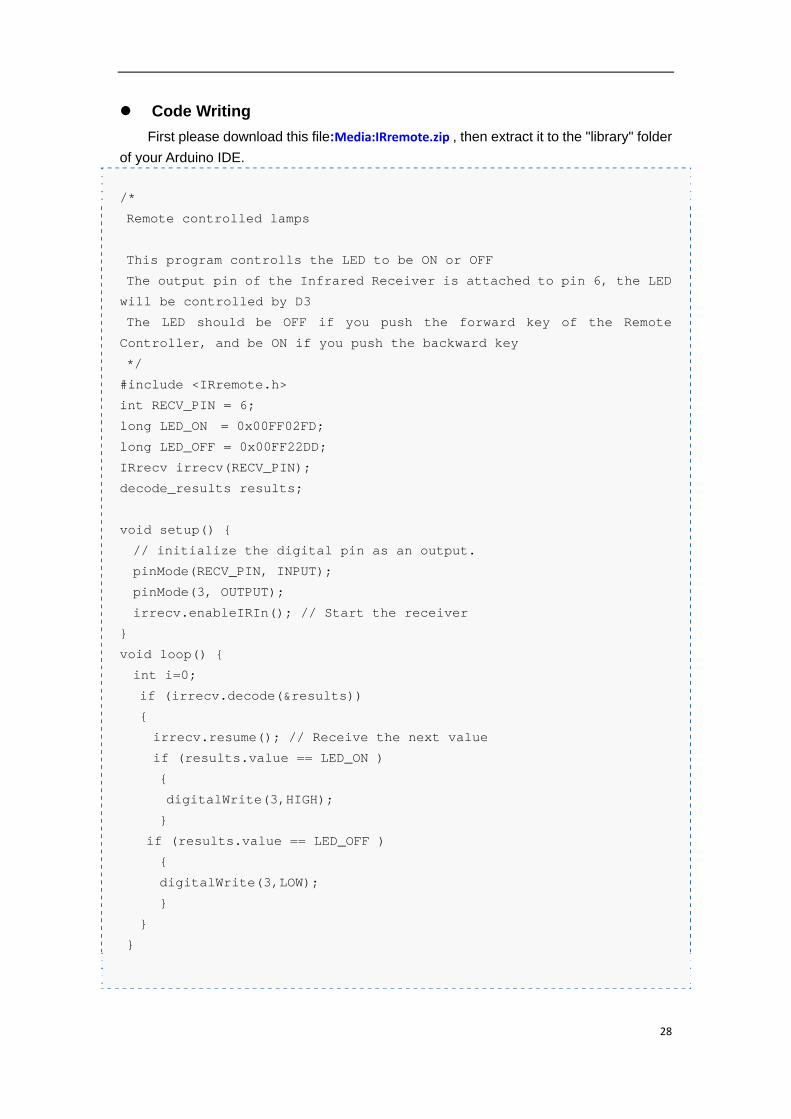
Code Writing
First please download this file:Media:IRremote.zip , then extract it to the "library" folder
of your Arduino IDE.
/*
Remote controlled lamps
This program controlls the LED to be ON or OFF
The output pin of the Infrared Receiver is attached to pin 6, the LED
will be controlled by D3
The LED should be OFF if you push the forward key of the Remote
Controller, and be ON if you push the backward key
*/
#include <IRremote.h>
int RECV_PIN = 6;
long LED_ON = 0x00FF02FD;
long LED_OFF = 0x00FF22DD;
IRrecv irrecv(RECV_PIN);
decode_results results;
void setup() {
// initialize the digital pin as an output.
pinMode(RECV_PIN, INPUT);
pinMode(3, OUTPUT);
irrecv.enableIRIn(); // Start the receiver
}
void loop() {
int i=0;
if (irrecv.decode(&results))
{
irrecv.resume(); // Receive the next value
if (results.value == LED_ON )
{
digitalWrite(3,HIGH);
}
if (results.value == LED_OFF )
{
digitalWrite(3,LOW);
}
}
}
29
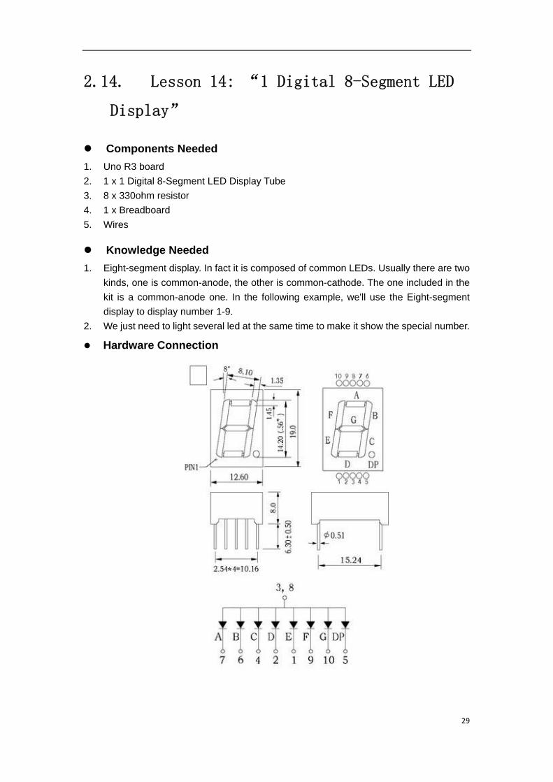
2.14. Lesson 14: “1 Digital 8-Segment LED
Display”
Components Needed
1. Uno R3 board
2. 1 x 1 Digital 8-Segment LED Display Tube
3. 8 x 330ohm resistor
4. 1 x Breadboard
5. Wires
Knowledge Needed
1. Eight-segment display. In fact it is composed of common LEDs. Usually there are two
kinds, one is common-anode, the other is common-cathode. The one included in the
kit is a common-anode one. In the following example, we'll use the Eight-segment
display to display number 1-9.
2. We just need to light several led at the same time to make it show the special number.
Hardware Connection
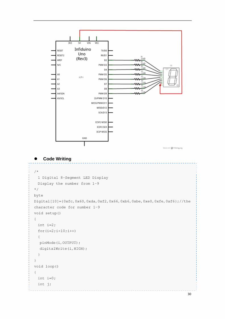
30
Code Writing
/*
1 Digital 8-Segment LED Display
Display the number from 1-9
*/
byte
Digital[10]={0xfc,0x60,0xda,0xf2,0x66,0xb6,0xbe,0xe0,0xfe,0xf6};//the
character code for number 1-9
void setup()
{
int i=2;
for(i=2;i<10;i++)
{
pinMode(i,OUTPUT);
digitalWrite(i,HIGH);
}
}
void loop()
{
int i=0;
int j;
31
//Display number 1-9
for(i=0;i<10;i++)
{
//for every number, send the character code to the digital pin
for(j=0;j<8;j++)
{
if(Digital[i]&1<<j)
digitalWrite(9-j,LOW);
else
digitalWrite(9-j,HIGH);
}
delay(500);
}
}
2.15. Lesson 15: “4 Digital 8-Segment LED
Display Dynamic Scanning Display”
Components Needed
1. Uno R3 board
2. 1 x 4 Digital 8-Segment LED Display Tube
3. 8 x 330ohm resistor
4. 1 x Breadboard
5. Wires
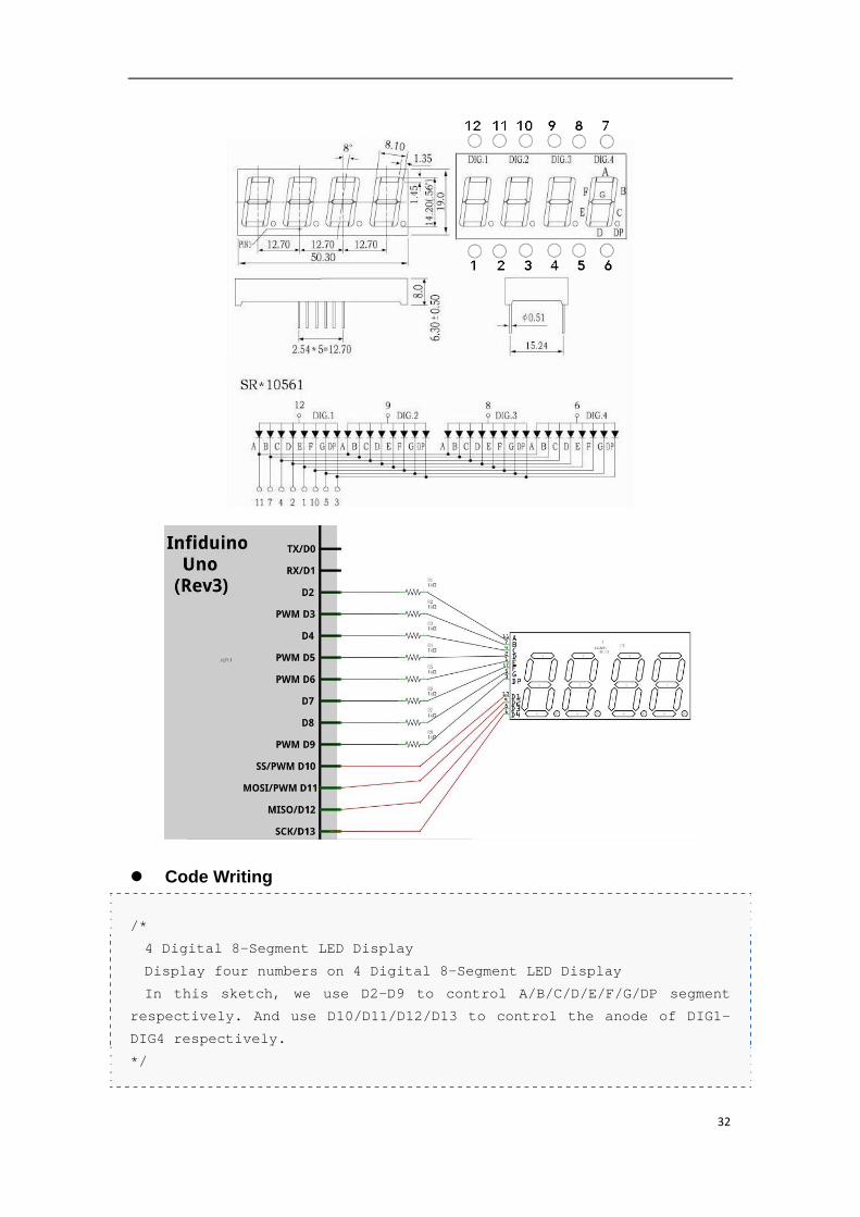
Knowledge Needed
1. Please see the following picture to see the pin definition and other parameters. For
this 4 bit Display Tube, we can only light one bit at one time.
2. In order to make all 4 bit tube can display numbers, the Dynamic Scanning Mechanism
should be used here. We will light bit 1 to bit 4 in turn (only one bit will be lighting at a
time). If the loop time is not more than 20ms (more than 50HZ) our eye usually will not
see its blinking.
Hardware Connection
32
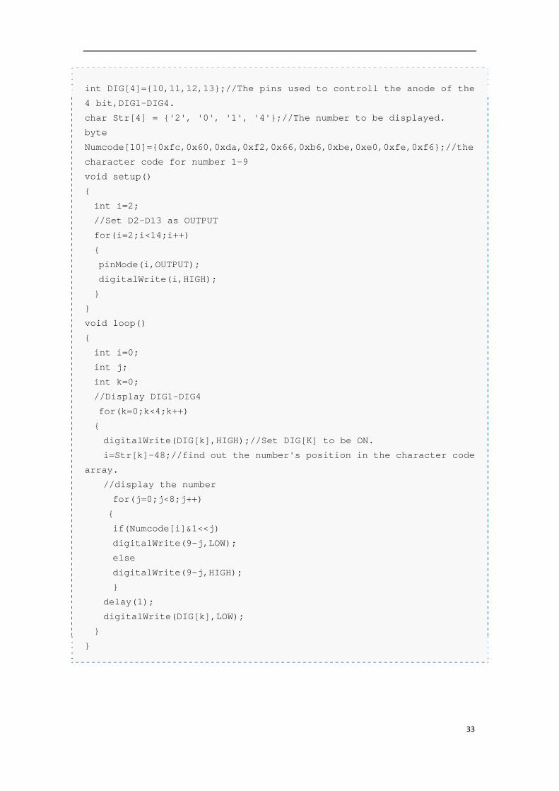
Code Writing
/*
4 Digital 8-Segment LED Display
Display four numbers on 4 Digital 8-Segment LED Display
In this sketch, we use D2-D9 to control A/B/C/D/E/F/G/DP segment
respectively. And use D10/D11/D12/D13 to control the anode of DIG1-
DIG4 respectively.
*/
33
int DIG[4]={10,11,12,13};//The pins used to controll the anode of the
4 bit,DIG1-DIG4.
char Str[4] = {'2', '0', '1', '4'};//The number to be displayed.
byte
Numcode[10]={0xfc,0x60,0xda,0xf2,0x66,0xb6,0xbe,0xe0,0xfe,0xf6};//the
character code for number 1-9
void setup()
{
int i=2;
//Set D2-D13 as OUTPUT
for(i=2;i<14;i++)
{
pinMode(i,OUTPUT);
digitalWrite(i,HIGH);
}
}
void loop()
{
int i=0;
int j;
int k=0;
//Display DIG1-DIG4
for(k=0;k<4;k++)
{
digitalWrite(DIG[k],HIGH);//Set DIG[K] to be ON.
i=Str[k]-48;//find out the number's position in the character code
array.
//display the number
for(j=0;j<8;j++)
{
if(Numcode[i]&1<<j)
digitalWrite(9-j,LOW);
else
digitalWrite(9-j,HIGH);
}
delay(1);
digitalWrite(DIG[k],LOW);
}
}
34
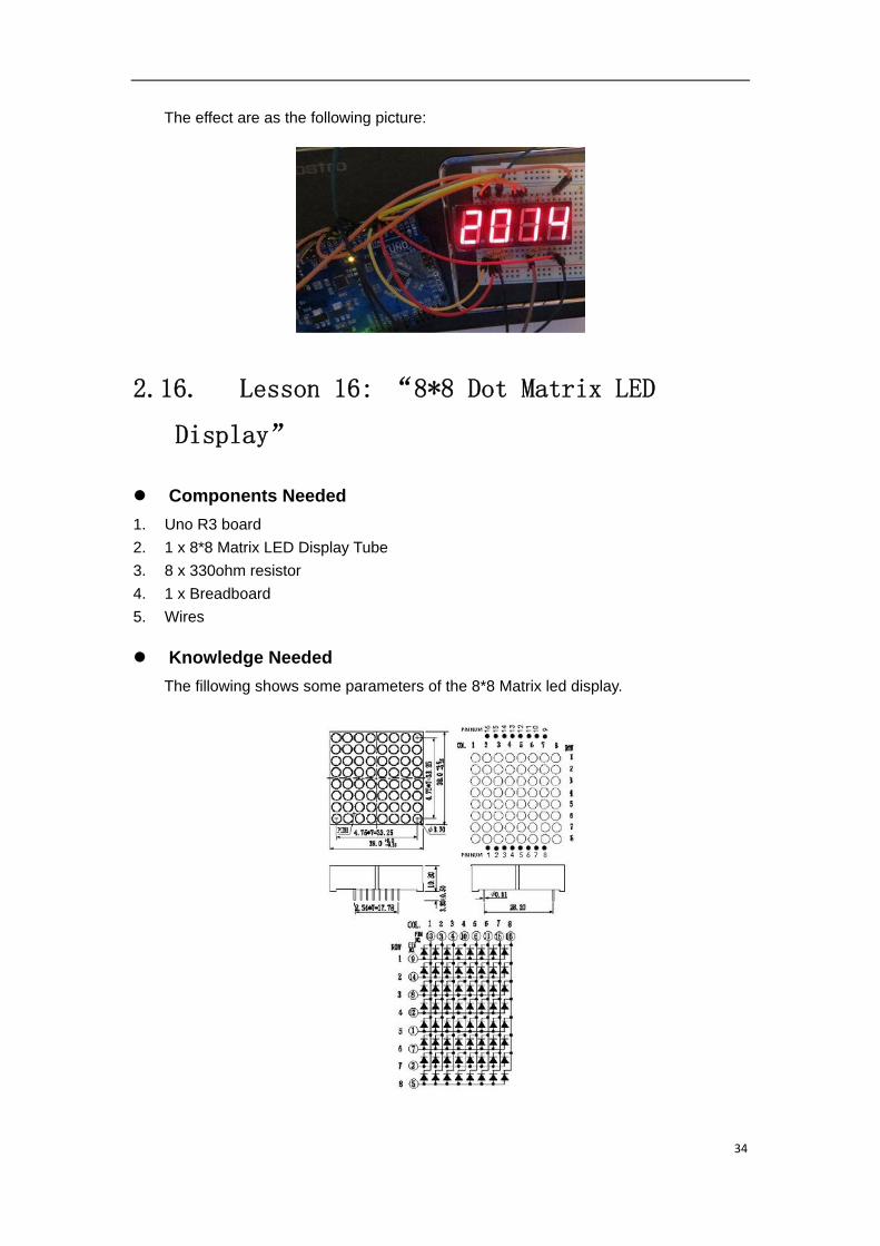
The effect are as the following picture:
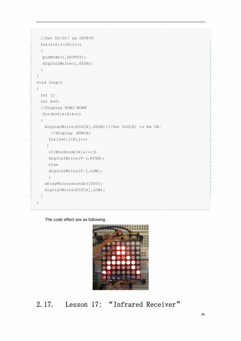
2.16. Lesson 16: “8*8 Dot Matrix LED
Display”
Components Needed
1. Uno R3 board
2. 1 x 8*8 Matrix LED Display Tube
3. 8 x 330ohm resistor
4. 1 x Breadboard
5. Wires
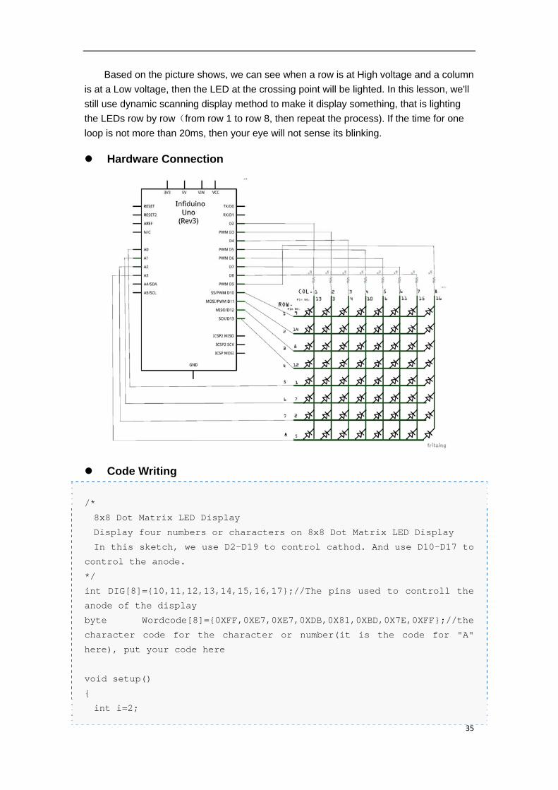
Knowledge Needed
The fillowing shows some parameters of the 8*8 Matrix led display.
35
Based on the picture shows, we can see when a row is at High voltage and a column
is at a Low voltage, then the LED at the crossing point will be lighted. In this lesson, we'll
still use dynamic scanning display method to make it display something, that is lighting
the LEDs row by row(from row 1 to row 8, then repeat the process). If the time for one
loop is not more than 20ms, then your eye will not sense its blinking.
Hardware Connection
Code Writing
/*
8x8 Dot Matrix LED Display
Display four numbers or characters on 8x8 Dot Matrix LED Display
In this sketch, we use D2-D19 to control cathod. And use D10-D17 to
control the anode.
*/
int DIG[8]={10,11,12,13,14,15,16,17};//The pins used to controll the
anode of the display
byte Wordcode[8]={0XFF,0XE7,0XE7,0XDB,0X81,0XBD,0X7E,0XFF};//the
character code for the character or number(it is the code for "A"
here), put your code here
void setup()
{
int i=2;
36
//Set D2-D17 as OUTPUT
for(i=2;i<18;i++)
{
pinMode(i,OUTPUT);
digitalWrite(i,HIGH);
}
}
void loop()
{
int j;
int k=0;
//Display ROW1-ROW8
for(k=0;k<8;k++)
{
digitalWrite(DIG[k],HIGH);//Set DIG[K] to be ON.
//display ROW(k)
for(j=0;j<8;j++)
{
if(Wordcode[k]&1<<j)
digitalWrite(9-j,HIGH);
else
digitalWrite(9-j,LOW);
}
delayMicroseconds(1000);
digitalWrite(DIG[k],LOW);
}
}
The code effect are as following.
2.17. Lesson 17: “Infrared Receiver”
37
In the following example, we use an Infrared Remote Controller to send signals to
Arduino (by pushing some key).
Components Needed
1. Uno R3 board
2. 1 x 1838T Infrared Receiver
3. 1 x Infrared Remote controller
4. 1 x Breadboard
5. Wires
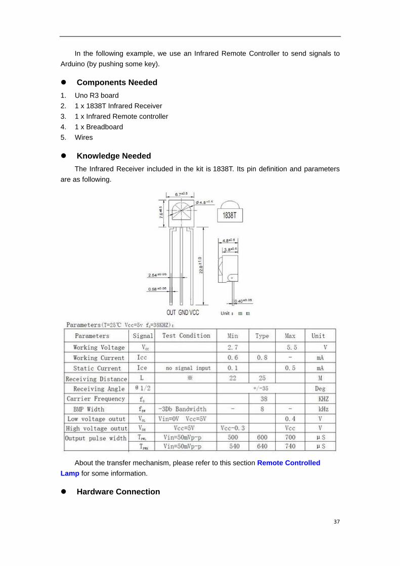
Knowledge Needed
The Infrared Receiver included in the kit is 1838T. Its pin definition and parameters
are as following.
About the transfer mechanism, please refer to this section Remote Controlled
Lamp for some information.
Hardware Connection
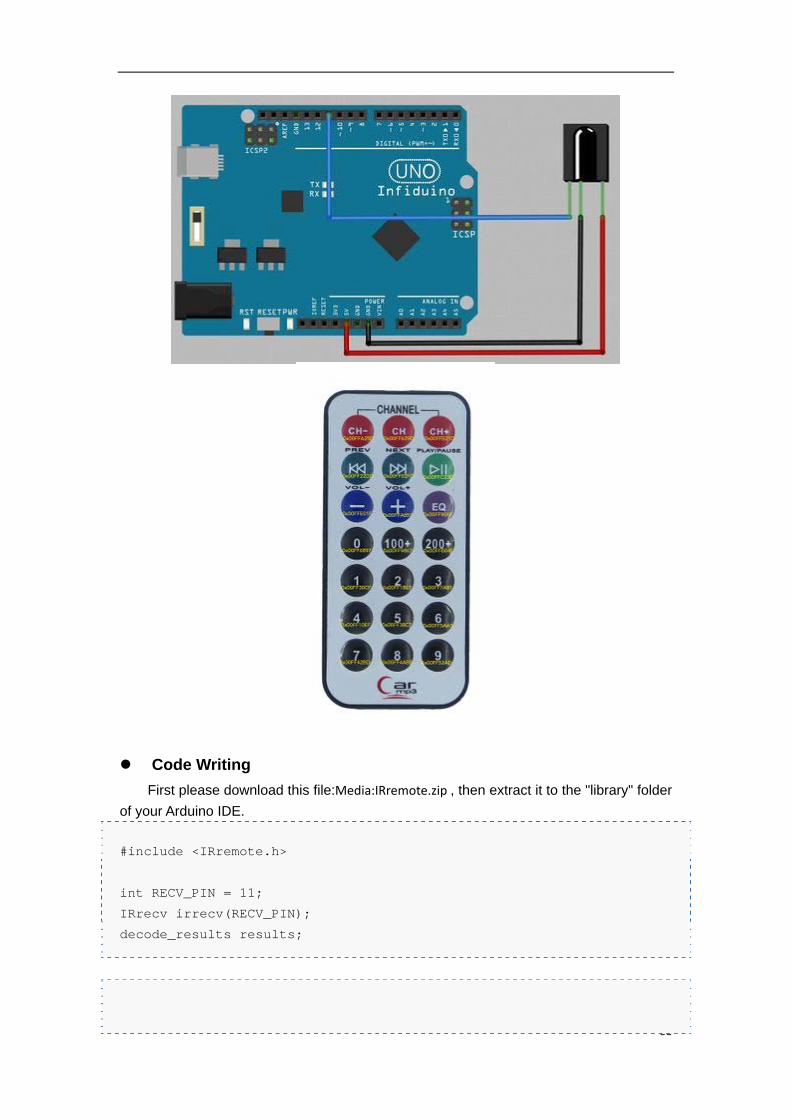
38
Code Writing
First please download this file:Media:IRremote.zip , then extract it to the "library" folder
of your Arduino IDE.
#include <IRremote.h>
int RECV_PIN = 11;
IRrecv irrecv(RECV_PIN);
decode_results results;
39
void setup()
{
Serial.begin(9600);
irrecv.enableIRIn(); // Start the receiver
}
void loop() {
if (irrecv.decode(&results)) {
Serial.println(results.value, HEX);
irrecv.resume(); // Receive the next value
}
}
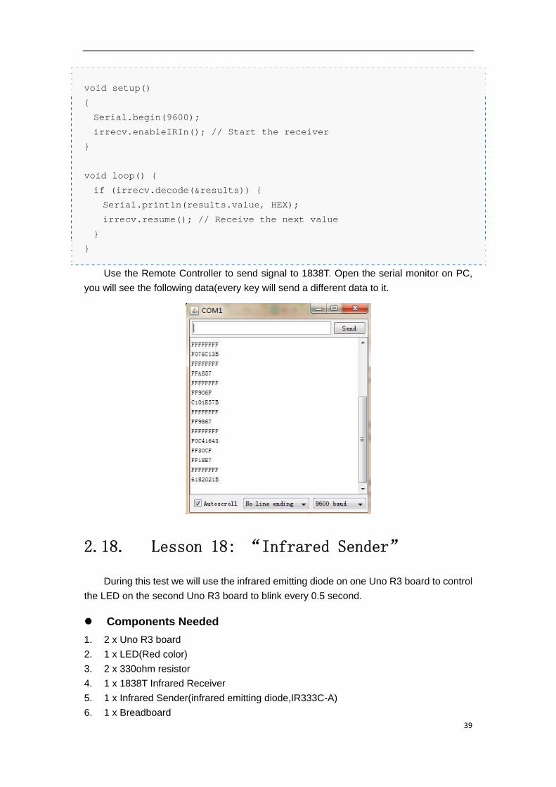
Use the Remote Controller to send signal to 1838T. Open the serial monitor on PC,
you will see the following data(every key will send a different data to it.
2.18. Lesson 18: “Infrared Sender”
During this test we will use the infrared emitting diode on one Uno R3 board to control
the LED on the second Uno R3 board to blink every 0.5 second.
Components Needed
1. 2 x Uno R3 board
2. 1 x LED(Red color)
3. 2 x 330ohm resistor
4. 1 x 1838T Infrared Receiver
5. 1 x Infrared Sender(infrared emitting diode,IR333C-A)
6. 1 x Breadboard
40
7. Wires
Knowledge Needed
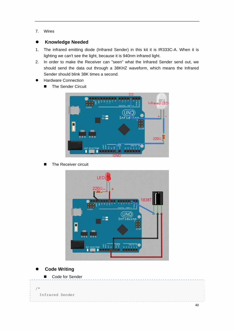
1. The infrared emitting diode (Infrared Sender) in this kit it is IR333C-A. When it is
lighting we can't see the light, because it is 940nm infrared light.
2. In order to make the Receiver can "seen" what the Infrared Sender send out, we
should send the data out through a 38KHZ waveform, which means the Infrared
Sender should blink 38K times a second.
Hardware Connection
The Sender Circuit
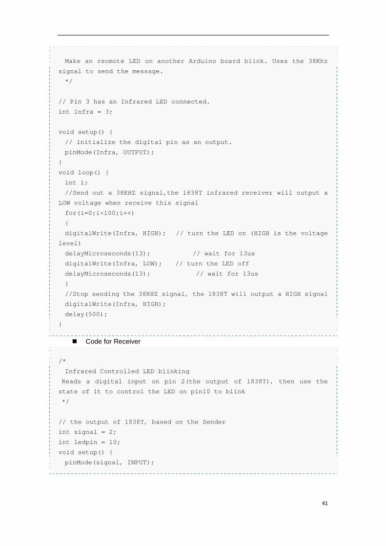
The Receiver circuit
Code Writing
Code for Sender
/*
Infrared Sender
41
Make an reomote LED on another Arduino board blink. Uses the 38Khz
signal to send the message.
*/
// Pin 3 has an Infrared LED connected.
int Infra = 3;
void setup() {
// initialize the digital pin as an output.
pinMode(Infra, OUTPUT);
}
void loop() {
int i;
//Send out a 38KHZ signal,the 1838T infrared receiver will output a
LOW voltage when receive this signal
for(i=0;i<100;i++)
{
digitalWrite(Infra, HIGH); // turn the LED on (HIGH is the voltage
level)
delayMicroseconds(13); // wait for 13us
digitalWrite(Infra, LOW); // turn the LED off
delayMicroseconds(13); // wait for 13us
}
//Stop sending the 38KHZ signal, the 1838T will output a HIGH signal
digitalWrite(Infra, HIGH);
delay(500);
}
Code for Receiver
/*
Infrared Controlled LED blinking
Reads a digital input on pin 2(the output of 1838T), then use the
state of it to control the LED on pin10 to blink
*/
// the output of 1838T, based on the Sender
int signal = 2;
int ledpin = 10;
void setup() {
pinMode(signal, INPUT);
42
pinMode(ledpin, OUTPUT);
}
void loop() {
// read the input pin,then make the led blink based on it
int signalState = digitalRead(signal);
if(signalState)
digitalWrite(ledpin,LOW);
else
digitalWrite(ledpin,HIGH);
}
2.19. Lesson 19: “1602LCD”
Components Needed
1. Uno R3 board
2. 1 x 1602LCD
3. 1 x 10k Potentiometer
4. 1 x Breadboard
5. Wires
Knowledge Needed
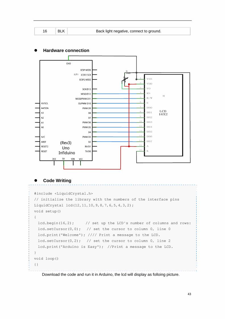
Arduino language has a LCD library which can support all HD44780 (or other
compatible driver) drived LCDs. Please check this page for more information:
LiquidCrystal Library. For the 1602 lcd in the kit, the pin definition are as following.
Pin
Number Sign Description
1 VSS The Power Ground signal,connect to 0V
2 VDD Power supply,connect to +5V
3 VL Contrast regulation pin, use a 10k potentiometer to regulate the
contrast.
4 RS Data/Command selection
5 R/W Read/Write selection, HIGH for reading, LOW for writing.
6 E LCD enable signal, when chaning from HIGH to LOW, the LCD can
excute the command.
7-14 D0-
D7 Data line
15 BLA Back light positive, connect to 5V normaly, 3.3V also works, but a bit
dark.
43
16 BLK Back light negative, connect to ground.
Hardware connection
Code Writing
#include <LiquidCrystal.h>
// initialize the library with the numbers of the interface pins
LiquidCrystal lcd(12,11,10,9,8,7,6,5,4,3,2);
void setup()
{
lcd.begin(16,2); // set up the LCD's number of columns and rows:
lcd.setCursor(0,0); // set the cursor to column 0, line 0
lcd.print("Welcome"); //// Print a message to the LCD.
lcd.setCursor(0,2); // set the cursor to column 0, line 2
lcd.print("Arduino is Easy"); //Print a message to the LCD.
}
void loop()
{}
Download the code and run it in Arduino, the lcd will display as folloing picture.
44
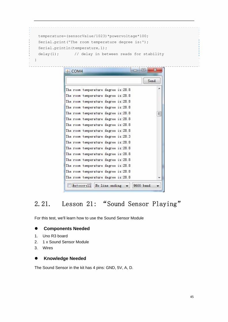
2.20. Lesson 20:“Temperature Measurement”
LM35DZ is a sensor which can measure the room temperature. It is very easy to use.
The one included in the kit is LM35DZ and can measure the temperature between 0°C to
+100°C.
Hardware Connection
Just provide the 5V voltage from Arduino, then use A0-A5 to measure the voltage
output by LM35DZ.
Code Writing.
/*
Temperature Measurement
Reads an analog input on A0(output from LM35DZ), change it to the
real room temperature and print it to serial monitor.
*/
float powervoltage=5;//define the power supply voltage.
void setup() {
// initialize serial communication at 9600 bits per second:
Serial.begin(9600);
}
void loop() {
float temperature;
// read the input on analog pin 0:
float sensorValue = analogRead(A0);
// print out the value you read:
45
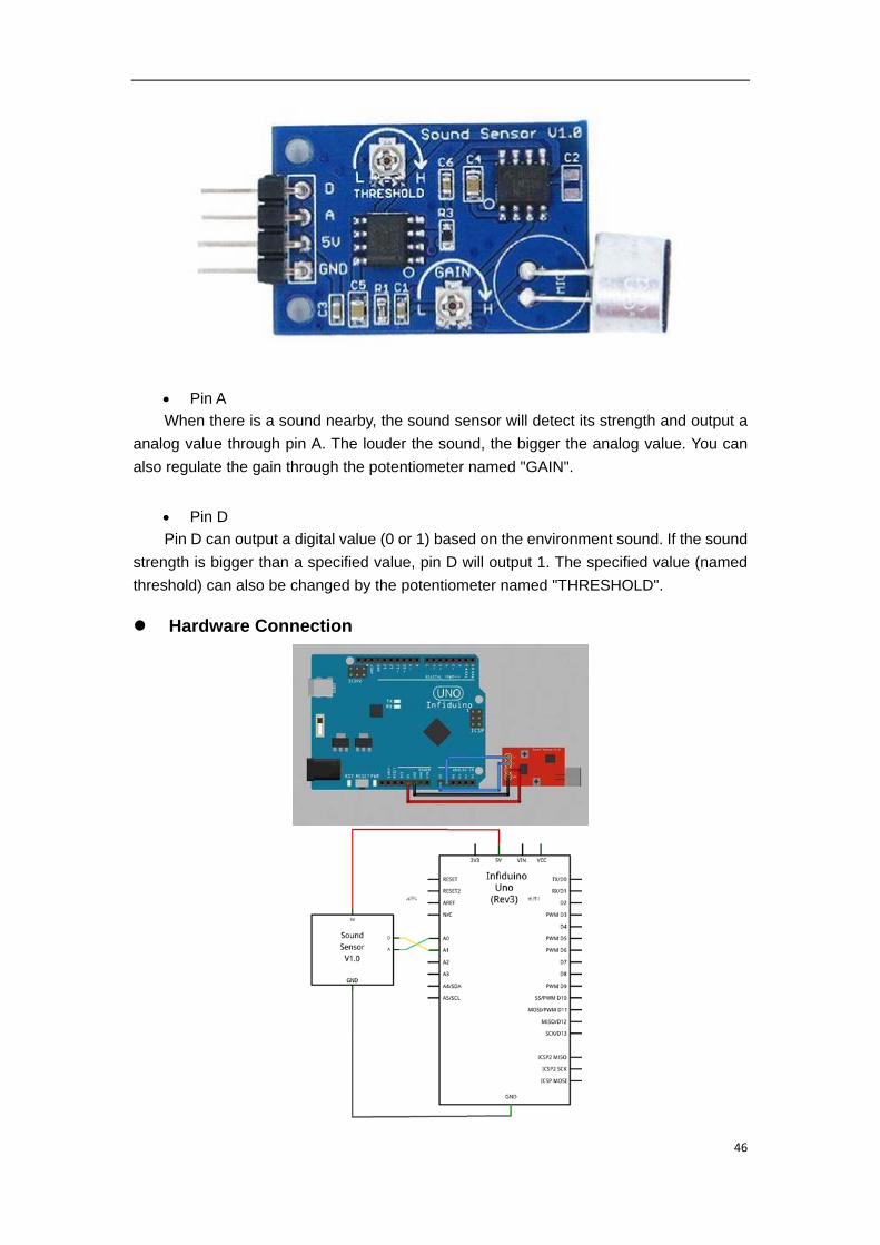
temperature=(sensorValue/1023)*powervoltage*100;
Serial.print("The room temperature degree is:");
Serial.println(temperature,1);
delay(1); // delay in between reads for stability
}
2.21. Lesson 21: “Sound Sensor Playing”
For this test, we'll learn how to use the Sound Sensor Module
Components Needed
1. Uno R3 board
2. 1 x Sound Sensor Module
3. Wires
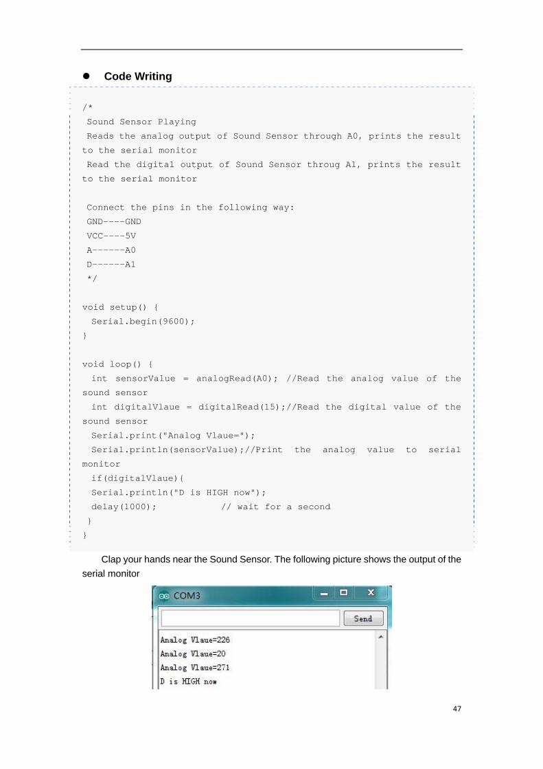
Knowledge Needed
The Sound Sensor in the kit has 4 pins: GND, 5V, A, D.
46
Pin A
When there is a sound nearby, the sound sensor will detect its strength and output a
analog value through pin A. The louder the sound, the bigger the analog value. You can
also regulate the gain through the potentiometer named "GAIN".
Pin D
Pin D can output a digital value (0 or 1) based on the environment sound. If the sound
strength is bigger than a specified value, pin D will output 1. The specified value (named
threshold) can also be changed by the potentiometer named "THRESHOLD".
Hardware Connection
47
Code Writing
/*
Sound Sensor Playing
Reads the analog output of Sound Sensor through A0, prints the result
to the serial monitor
Read the digital output of Sound Sensor throug A1, prints the result
to the serial monitor
Connect the pins in the following way:
GND----GND
VCC----5V
A------A0
D------A1
*/
void setup() {
Serial.begin(9600);
}
void loop() {
int sensorValue = analogRead(A0); //Read the analog value of the
sound sensor
int digitalVlaue = digitalRead(15);//Read the digital value of the
sound sensor
Serial.print("Analog Vlaue=");
Serial.println(sensorValue);//Print the analog value to serial
monitor
if(digitalVlaue){
Serial.println("D is HIGH now");
delay(1000); // wait for a second
}
}
Clap your hands near the Sound Sensor. The following picture shows the output of the
serial monitor
48
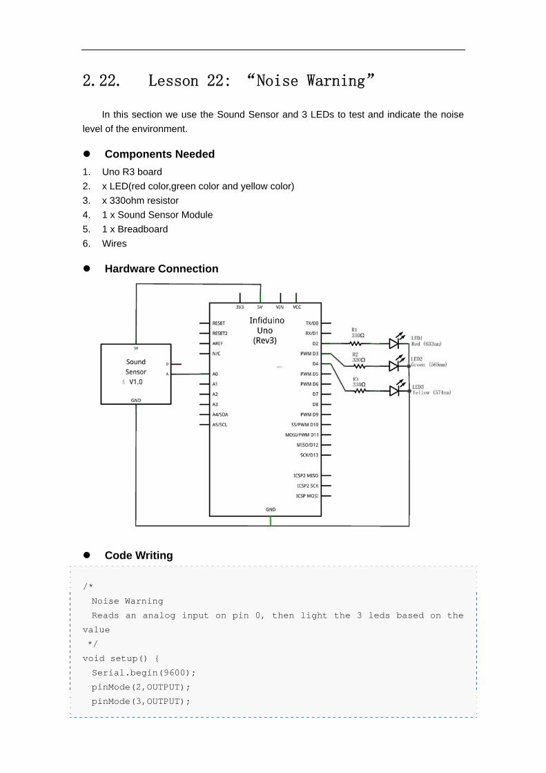
2.22. Lesson 22: “Noise Warning”
In this section we use the Sound Sensor and 3 LEDs to test and indicate the noise
level of the environment.
Components Needed
1. Uno R3 board
2. x LED(red color,green color and yellow color)
3. x 330ohm resistor
4. 1 x Sound Sensor Module
5. 1 x Breadboard
6. Wires
Hardware Connection
Code Writing
/*
Noise Warning
Reads an analog input on pin 0, then light the 3 leds based on the
value
*/
void setup() {
Serial.begin(9600);
pinMode(2,OUTPUT);
pinMode(3,OUTPUT);
49
pinMode(4,OUTPUT);
}
void loop() {
// read the input on analog pin 0:
int noisyValue = analogRead(A0);
//light the specific LED based on the analog value
if(noisyValue<=100)
{
digitalWrite(2,HIGH);
digitalWrite(3,LOW);
digitalWrite(4,LOW);
}
else if(100<noisyValue<=600)
{
digitalWrite(2,LOW);
digitalWrite(3,HIGH);
digitalWrite(4,LOW);
}
else
{
digitalWrite(2,LOW);
digitalWrite(3,LOW);
digitalWrite(4,HIGH);
}
}
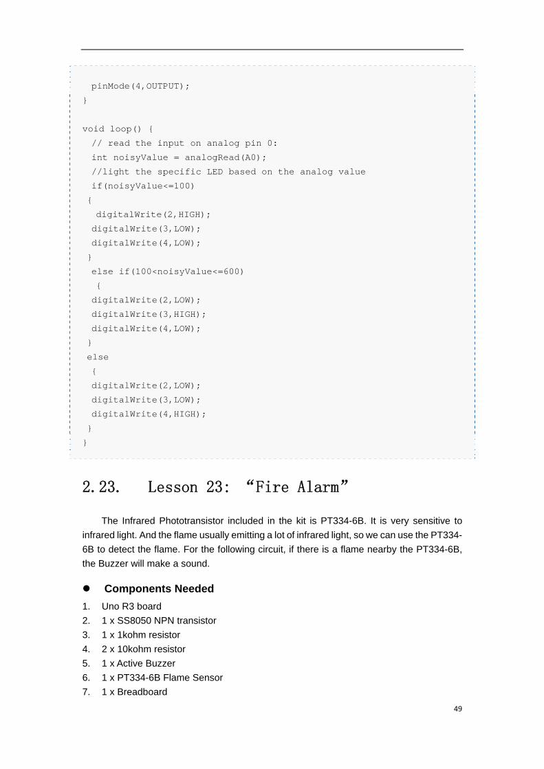
2.23. Lesson 23: “Fire Alarm”
The Infrared Phototransistor included in the kit is PT334-6B. It is very sensitive to
infrared light. And the flame usually emitting a lot of infrared light, so we can use the PT334-
6B to detect the flame. For the following circuit, if there is a flame nearby the PT334-6B,
the Buzzer will make a sound.
Components Needed
1. Uno R3 board
2. 1 x SS8050 NPN transistor
3. 1 x 1kohm resistor
4. 2 x 10kohm resistor
5. 1 x Active Buzzer
6. 1 x PT334-6B Flame Sensor
7. 1 x Breadboard
50
8. Wires
Hardware Connection.
Code writing
/*
Fire Alarm
Reads an analog input on pin 0, prints the result to the serial
monitor, and use it to control the Buzzer through D9
*/
void setup() {
// initialize serial communication at 9600 bits per second:
Serial.begin(9600);
pinMode(9,OUTPUT);
}
// the loop routine runs over and over again forever:
void loop() {
// read the input on analog pin 0:
int sensorValue = analogRead(A0);
// print out the value you read:
Serial.println(sensorValue);
51
//If there is a flame nearby, make the Buzzer speak.
if(sensorValue>500)
digitalWrite(9,HIGH);
else
digitalWrite(9,LOW);
}
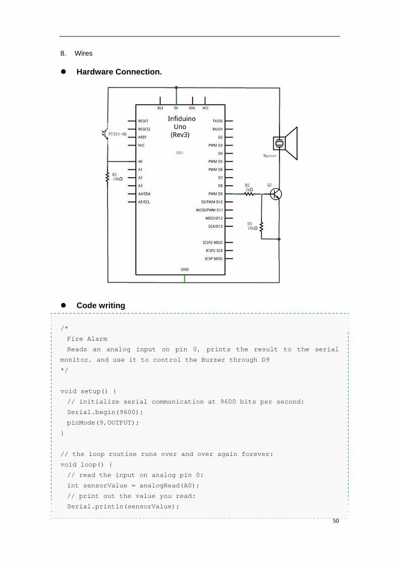
2.24. Lesson 24: “Stepper Motor Driving”
Components Needed
1. Uno R3 board
2. 1 x Stepper Motor Driver
3. 1 x Stepper Motor
Knowledge Needed
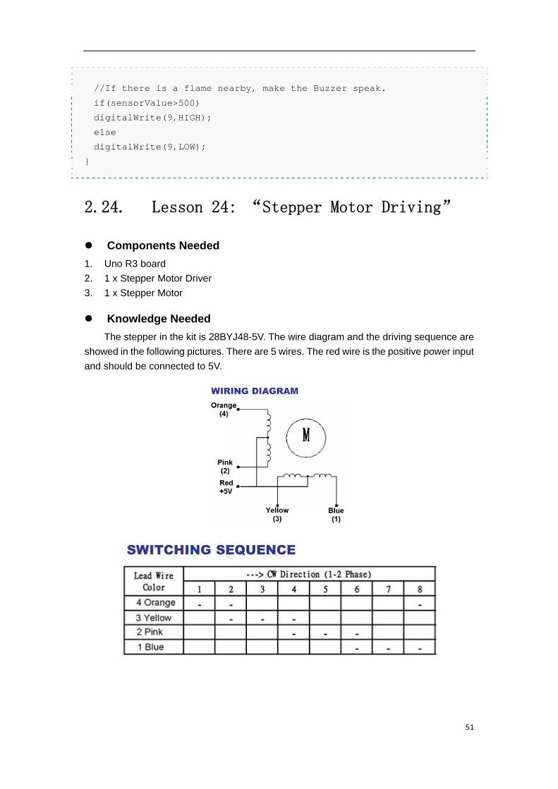
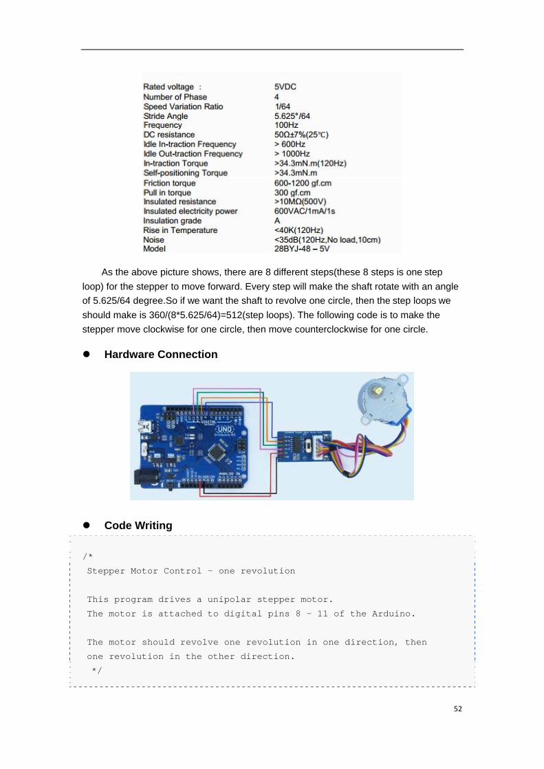
The stepper in the kit is 28BYJ48-5V. The wire diagram and the driving sequence are
showed in the following pictures. There are 5 wires. The red wire is the positive power input
and should be connected to 5V.
52
As the above picture shows, there are 8 different steps(these 8 steps is one step
loop) for the stepper to move forward. Every step will make the shaft rotate with an angle
of 5.625/64 degree.So if we want the shaft to revolve one circle, then the step loops we
should make is 360/(8*5.625/64)=512(step loops). The following code is to make the
stepper move clockwise for one circle, then move counterclockwise for one circle.
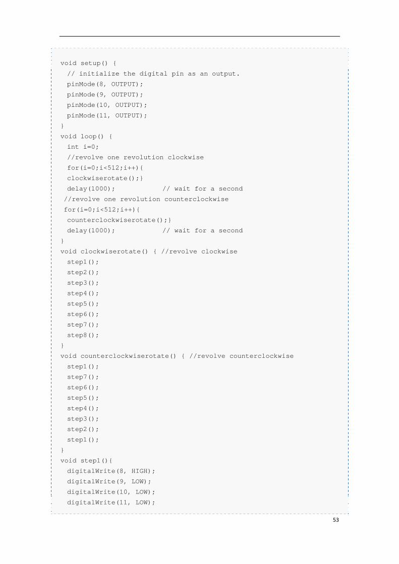
Hardware Connection
Code Writing
/*
Stepper Motor Control - one revolution
This program drives a unipolar stepper motor.
The motor is attached to digital pins 8 - 11 of the Arduino.
The motor should revolve one revolution in one direction, then
one revolution in the other direction.
*/
53
void setup() {
// initialize the digital pin as an output.
pinMode(8, OUTPUT);
pinMode(9, OUTPUT);
pinMode(10, OUTPUT);
pinMode(11, OUTPUT);
}
void loop() {
int i=0;
//revolve one revolution clockwise
for(i=0;i<512;i++){
clockwiserotate();}
delay(1000); // wait for a second
//revolve one revolution counterclockwise
for(i=0;i<512;i++){
counterclockwiserotate();}
delay(1000); // wait for a second
}
void clockwiserotate() { //revolve clockwise
step1();
step2();
step3();
step4();
step5();
step6();
step7();
step8();
}
void counterclockwiserotate() { //revolve counterclockwise
step1();
step7();
step6();
step5();
step4();
step3();
step2();
step1();
}
void step1(){
digitalWrite(8, HIGH);
digitalWrite(9, LOW);
digitalWrite(10, LOW);
digitalWrite(11, LOW);
54
delay(2);
}
void step2(){
digitalWrite(8, HIGH);
digitalWrite(9, HIGH);
digitalWrite(10, LOW);
digitalWrite(11, LOW);
delay(2);
}
void step3(){
digitalWrite(8, LOW);
digitalWrite(9, HIGH);
digitalWrite(10, LOW);
digitalWrite(11, LOW);
delay(2);
}
void step4(){
digitalWrite(8, LOW);
digitalWrite(9, HIGH);
digitalWrite(10, HIGH);
digitalWrite(11, LOW);
delay(2);
}
void step5(){
digitalWrite(8, LOW);
digitalWrite(9, LOW);
digitalWrite(10, HIGH);
digitalWrite(11, LOW);
delay(2);
}
void step6(){
digitalWrite(8, LOW);
digitalWrite(9, LOW);
digitalWrite(10, HIGH);
digitalWrite(11, HIGH);
delay(2);
}
void step7(){
digitalWrite(8, LOW);
digitalWrite(9, LOW);
digitalWrite(10, LOW);
digitalWrite(11, HIGH);
55
delay(2);
}
void step8(){
digitalWrite(8, HIGH);
digitalWrite(9, LOW);
digitalWrite(10, LOW);
digitalWrite(11, HIGH);
delay(2);
}
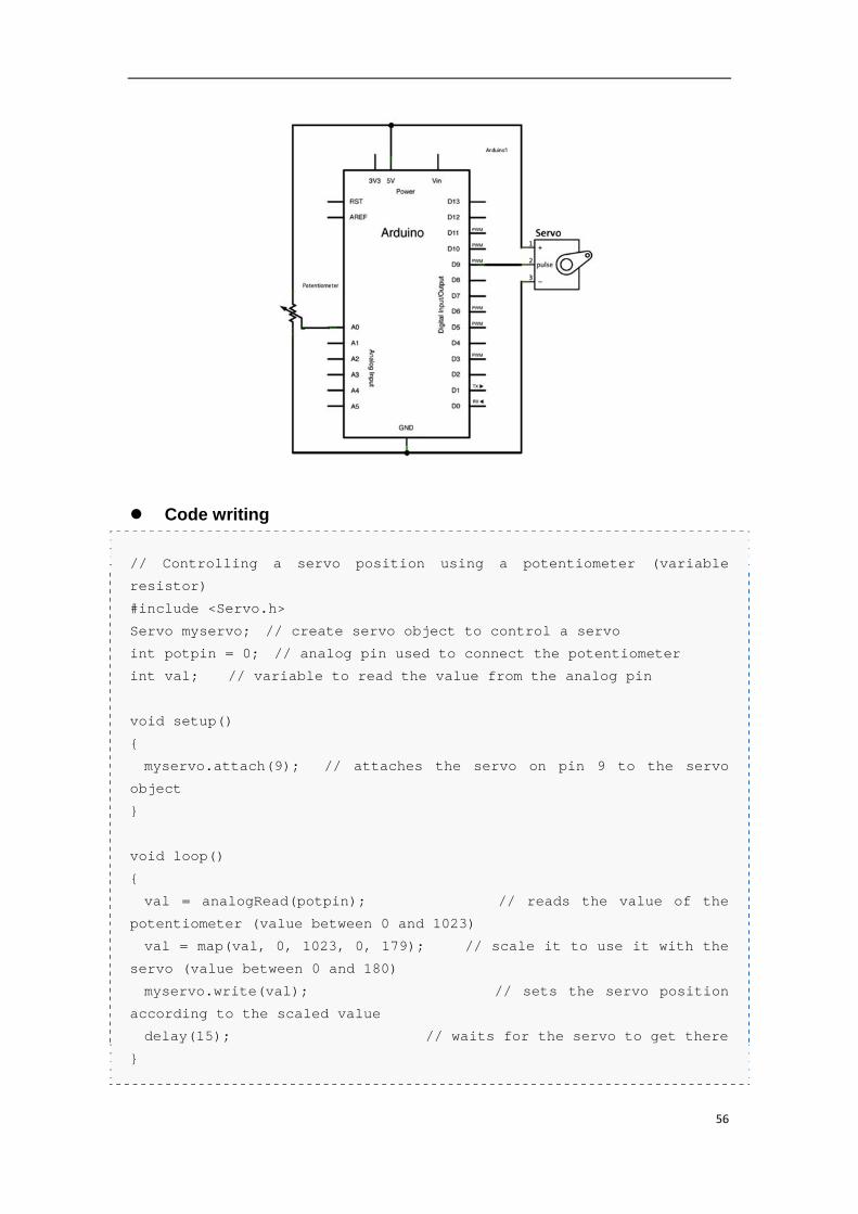
2.25. Lesson 25: “PWM Servo Control”
Components Needed
1. Uno R3 board
2. 1 x 10k Potentiometer
3. SG90 Servo Motor
4. Wires
Knowledge Needed
Servo Motor can be controlled through the PWM. The frequency of the control signal
is 50HZ, the width of positive pulse controls the angle. For detailed information about Servo
please refer to this page: Servo Motor. A servo usually has 3 pins. For the servo in the kit
(named SG90), the red wire is the power signal and should be connected 5V voltage. The
brown wire is the ground signal and should be connected to 0V. The orange wire is the
controlling signal and should be fed with a PWM signal. Arduino has a "Servo library" to
control a servo. In this lesson we will control the position of the rudder through the
Potentiometer.
Hardware Connection
56
Code writing
// Controlling a servo position using a potentiometer (variable
resistor)
#include <Servo.h>
Servo myservo; // create servo object to control a servo
int potpin = 0; // analog pin used to connect the potentiometer
int val; // variable to read the value from the analog pin
void setup()
{
myservo.attach(9); // attaches the servo on pin 9 to the servo
object
}
void loop()
{
val = analogRead(potpin); // reads the value of the
potentiometer (value between 0 and 1023)
val = map(val, 0, 1023, 0, 179); // scale it to use it with the
servo (value between 0 and 180)
myservo.write(val); // sets the servo position
according to the scaled value
delay(15); // waits for the servo to get there
}
57
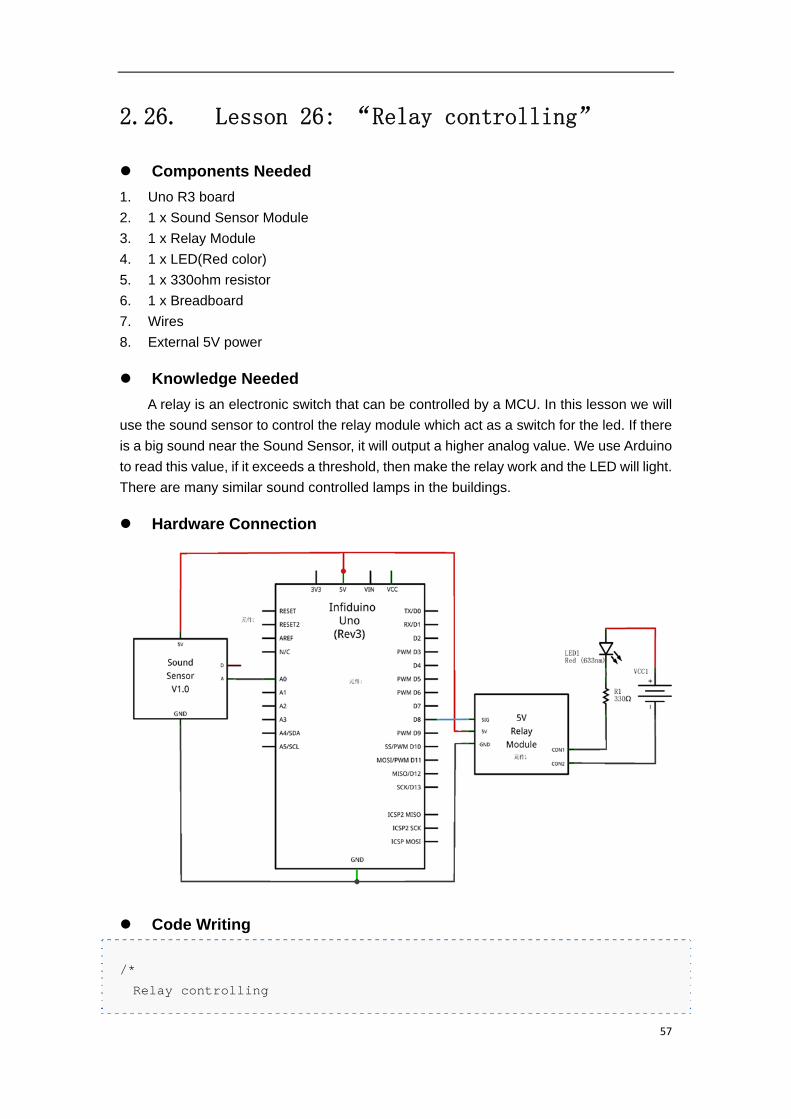
2.26. Lesson 26: “Relay controlling”
Components Needed
1. Uno R3 board
2. 1 x Sound Sensor Module
3. 1 x Relay Module
4. 1 x LED(Red color)
5. 1 x 330ohm resistor
6. 1 x Breadboard
7. Wires
8. External 5V power
Knowledge Needed
A relay is an electronic switch that can be controlled by a MCU. In this lesson we will
use the sound sensor to control the relay module which act as a switch for the led. If there
is a big sound near the Sound Sensor, it will output a higher analog value. We use Arduino
to read this value, if it exceeds a threshold, then make the relay work and the LED will light.
There are many similar sound controlled lamps in the buildings.
Hardware Connection
Code Writing
/*
Relay controlling
58
Reads an analog input on pin 0, prints the result to the serial
monitor, and use it to control the Relay through D8
*/
void setup() {
// initialize serial communication at 9600 bits per second:
Serial.begin(9600);
pinMode(8,OUTPUT);
}
// the loop routine runs over and over again forever:
void loop() {
// read the input on analog pin 0:
int sensorValue = analogRead(A0);
// print out the value you read:
Serial.println(sensorValue);
//If there is a big sound nearby, make the led light for one second.
if(sensorValue>500)
{
digitalWrite(8,HIGH);
delay(1000);
}
else
digitalWrite(8,LOW);
}
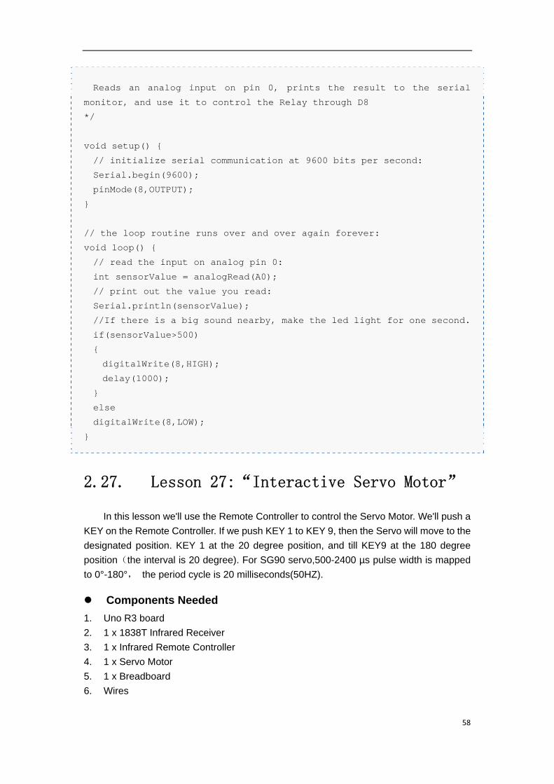
2.27. Lesson 27:“Interactive Servo Motor”
In this lesson we'll use the Remote Controller to control the Servo Motor. We'll push a
KEY on the Remote Controller. If we push KEY 1 to KEY 9, then the Servo will move to the
designated position. KEY 1 at the 20 degree position, and till KEY9 at the 180 degree
position(the interval is 20 degree). For SG90 servo,500-2400 µs pulse width is mapped
to 0°-180°, the period cycle is 20 milliseconds(50HZ).
Components Needed
1. Uno R3 board
2. 1 x 1838T Infrared Receiver
3. 1 x Infrared Remote Controller
4. 1 x Servo Motor
5. 1 x Breadboard
6. Wires
59
Hardware Connection
Code writing
First please download this file:Media:IRremote.zip , then extract it to the "library" folder
of your Arduino IDE.
/*
Interactive Servo Motor - one revolution
This program drives a Servo motor by the Remote Controller.
The Servo motor is attached to digital pins D5 of the Arduino. The
output pin of the Infrared Receiver is attached to pin 6
The motor should revolve to an angle(0 degree to 180 degree) if you
push the KEY named 1-9 on the Remote Controller.Each KEY will set the
shaft at an paticular position.
*/
#include <IRremote.h>
int Servopin=5;
int RECV_PIN = 6;
long KEY_1 = 0x00FF30CF;
long KEY_2 = 0x00FF18E7;
long KEY_3 = 0x00FF7A85;
long KEY_4 = 0x00FF10EF;
long KEY_5 = 0x00FF38C7;
60
long KEY_6 = 0x00FF5AA5;
long KEY_7 = 0x00FF42BD;
long KEY_8 = 0x00FF4AB5;
long KEY_9 = 0x00FF52AD;
IRrecv irrecv(RECV_PIN);
decode_results results;
int Position;
void setup() {
// initialize the digital pin as an output.
pinMode(RECV_PIN, INPUT);
pinMode(Servopin,OUTPUT);
irrecv.enableIRIn(); // Start the receiver
}
void loop() {
int i=0;
if (irrecv.decode(&results))
{
irrecv.resume(); // Receive the next value
if (results.value == KEY_1 )
{
Position=1;
}
else if (results.value == KEY_2 )
{
Position=2;
}
else if (results.value == KEY_3 )
{
Position=3;
}
else if (results.value == KEY_4 )
{
Position=4;
}
else if (results.value == KEY_5 )
{
Position=5;
}
else if (results.value == KEY_6 )
{
Position=6;
}
61
else if (results.value == KEY_7 )
{
Position=7;
}
else if (results.value == KEY_8 )
{
Position=8;
}
else
Position=9;
}
int angle=Position*(180/9);//Calculate the angle should be moved
based on the key pushed on the Remote Controller.
for(int i=0;i<=5;i++)
{
moveangle(Servopin,angle);//move the shaft to an angle based on the
key pushed on the Remote Controller
}
}
void moveangle(int Servopin,int angle)//the pulsewidth function,move
the shaft to an angle based on the KEY pushed.
{
int pulsewidth=(angle*11)+500;//change the angle to 500-2480us
pulsewidth
digitalWrite(Servopin,HIGH);
delayMicroseconds(pulsewidth);
digitalWrite(Servopin,LOW);
delay(20-pulsewidth/1000);
}
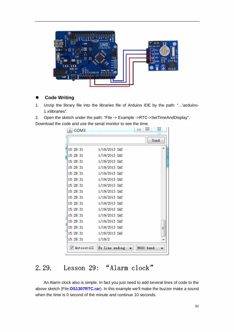
2.28. Lesson 28: “Electronic Clock”
The RTC module is based on the DS1307, it communicates with Arduino through I2C
port. You can download File:DS1307RTC.rar to test it.
Hardware Connection.
62
Code Writing
1. Unzip the library file into the libraries file of Arduino IDE by the path: “…\arduino-
1.x\libraries”.
2. Open the sketch under the path: “File -> Example ->RTC->SetTimeAndDisplay”.
Download the code and use the serial monitor to see the time.
2.29. Lesson 29: “Alarm clock”
An Alarm clock also is simple. In fact you just need to add several lines of code to the
above sketch (File:DS1307RTC.rar). In this example we'll make the buzzer make a sound
when the time is 0 second of the minute and continue 10 seconds.
63
Hardware Connection
Code Writing.
You just need to change this code
void loop()
{
printTime();
}
to this code
void loop()
{
printTime();
if(clock.second==0)
digitalWrite(3,HIGH);
if(clock.second==10)
digitalWrite(3,LOW);
}
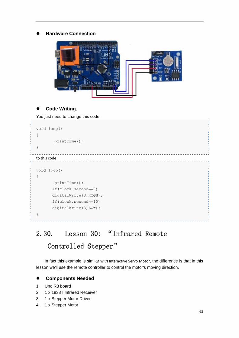
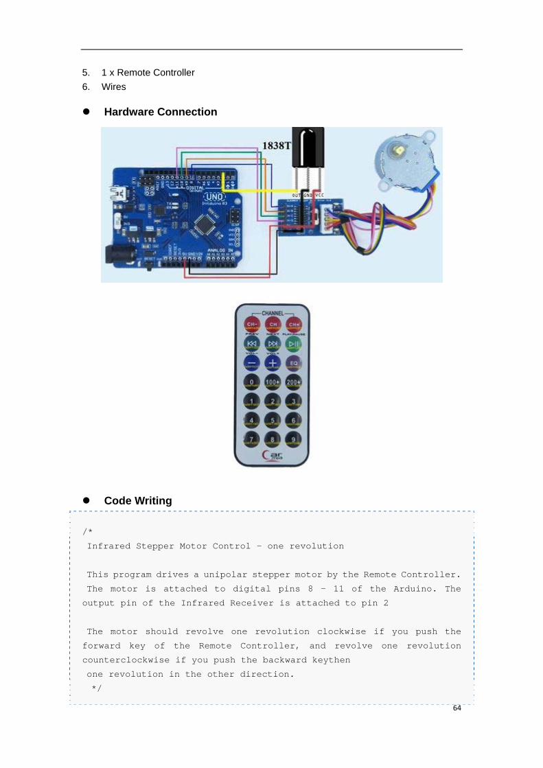
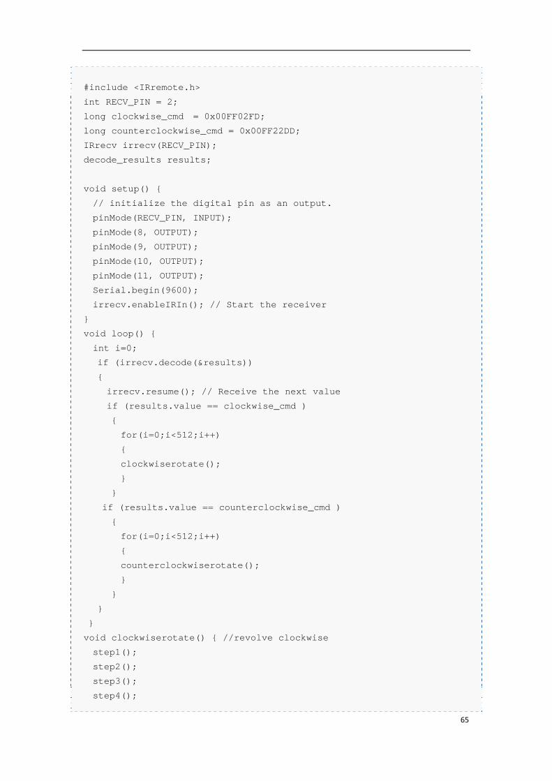
2.30. Lesson 30: “Infrared Remote
Controlled Stepper”
In fact this example is similar with Interactive Servo Motor, the difference is that in this
lesson we'll use the remote controller to control the motor's moving direction.
Components Needed
1. Uno R3 board
2. 1 x 1838T Infrared Receiver
3. 1 x Stepper Motor Driver
4. 1 x Stepper Motor
64
5. 1 x Remote Controller
6. Wires
Hardware Connection
Code Writing
/*
Infrared Stepper Motor Control - one revolution
This program drives a unipolar stepper motor by the Remote Controller.
The motor is attached to digital pins 8 - 11 of the Arduino. The
output pin of the Infrared Receiver is attached to pin 2
The motor should revolve one revolution clockwise if you push the
forward key of the Remote Controller, and revolve one revolution
counterclockwise if you push the backward keythen
one revolution in the other direction.
*/
65
#include <IRremote.h>
int RECV_PIN = 2;
long clockwise_cmd = 0x00FF02FD;
long counterclockwise_cmd = 0x00FF22DD;
IRrecv irrecv(RECV_PIN);
decode_results results;
void setup() {
// initialize the digital pin as an output.
pinMode(RECV_PIN, INPUT);
pinMode(8, OUTPUT);
pinMode(9, OUTPUT);
pinMode(10, OUTPUT);
pinMode(11, OUTPUT);
Serial.begin(9600);
irrecv.enableIRIn(); // Start the receiver
}
void loop() {
int i=0;
if (irrecv.decode(&results))
{
irrecv.resume(); // Receive the next value
if (results.value == clockwise_cmd )
{
for(i=0;i<512;i++)
{
clockwiserotate();
}
}
if (results.value == counterclockwise_cmd )
{
for(i=0;i<512;i++)
{
counterclockwiserotate();
}
}
}
}
void clockwiserotate() { //revolve clockwise
step1();
step2();
step3();
step4();
66
step5();
step6();
step7();
step8();
}
void counterclockwiserotate() { //revolve counterclockwise
step1();
step7();
step6();
step5();
step4();
step3();
step2();
step1();
}
void step1(){
digitalWrite(8, LOW);
digitalWrite(9, HIGH);
digitalWrite(10, HIGH);
digitalWrite(11, HIGH);
delay(2);
}
void step2(){
digitalWrite(8, LOW);
digitalWrite(9, LOW);
digitalWrite(10, HIGH);
digitalWrite(11, HIGH);
delay(2);
}
void step3(){
digitalWrite(8, HIGH);
digitalWrite(9, LOW);
digitalWrite(10, HIGH);
digitalWrite(11, HIGH);
delay(2);
}
void step4(){
digitalWrite(8, HIGH);
digitalWrite(9, LOW);
digitalWrite(10, LOW);
digitalWrite(11, HIGH);
delay(2);
}
67
void step5(){
digitalWrite(8, HIGH);
digitalWrite(9, HIGH);
digitalWrite(10, LOW);
digitalWrite(11, HIGH);
delay(2);
}
void step6(){
digitalWrite(8, HIGH);
digitalWrite(9, HIGH);
digitalWrite(10, LOW);
digitalWrite(11, LOW);
delay(2);
}
void step7(){
digitalWrite(8, HIGH);
digitalWrite(9, HIGH);
digitalWrite(10, HIGH);
digitalWrite(11, LOW);
delay(2);
}
void step8(){
digitalWrite(8, LOW);
digitalWrite(9, HIGH);
digitalWrite(10, HIGH);
digitalWrite(11, LOW);
delay(2);
}
void stoprotate()
{
digitalWrite(8, HIGH);
digitalWrite(9, HIGH);
digitalWrite(10, HIGH);
digitalWrite(11, HIGH);
}
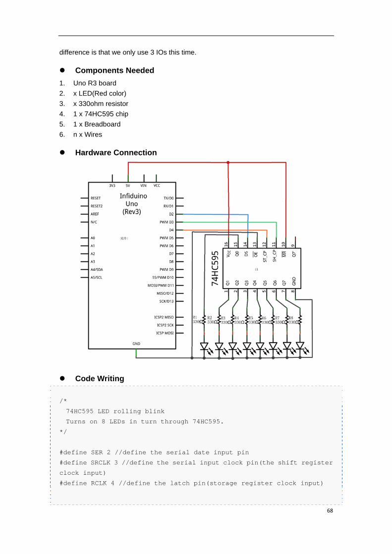
2.31. Lesson 31: “74HC595 IO expansion”
The Arduino/Infiduino board has 14 digital input/output pins. But sometimes this
maybe not enough. 74HC595 can help us to solve this problem. With its help we can
change 3 IOs to 8. For this lesson we'll redo the Lesson 3 Rolling Light example. The
68
difference is that we only use 3 IOs this time.
Components Needed
1. Uno R3 board
2. x LED(Red color)
3. x 330ohm resistor
4. 1 x 74HC595 chip
5. 1 x Breadboard
6. n x Wires
Hardware Connection
Code Writing
/*
74HC595 LED rolling blink
Turns on 8 LEDs in turn through 74HC595.
*/
#define SER 2 //define the serial date input pin
#define SRCLK 3 //define the serial input clock pin(the shift register
clock input)
#define RCLK 4 //define the latch pin(storage register clock input)
69
void setup() {
// initialize the digital pin as an output.
pinMode(SER, OUTPUT);
pinMode(SRCLK, OUTPUT);
pinMode(RCLK, OUTPUT);
digitalWrite(SRCLK,LOW);
digitalWrite(RCLK,LOW);
}
void loop()
{
int i=0;
byte j=0x80;
for(i = 0 ; i < 8; i++)
{
write595(j);
j>>= 1;
delay(100);
}
}
void write595(byte data)
{
int i;
for(i = 0 ; i < 8; i++)
{
if(data & 0x80) digitalWrite(SER,HIGH);//SER=1
else digitalWrite(SER,LOW);//SER=0
data <<= 1;
digitalWrite(SRCLK,HIGH);//SRCLK=1
digitalWrite(SRCLK,LOW);//SRCLK=1
}
digitalWrite(RCLK,HIGH);//SRCLK=1
digitalWrite(RCLK,LOW);//SRCLK=1
}
70
3. Appendix
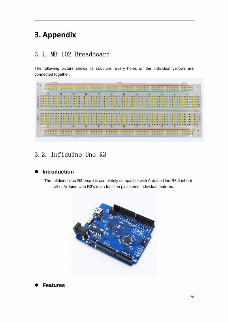
3.1. MB-102 Breadboard
The following picture shows its structure. Every holes on the individual yellows are
connected together.
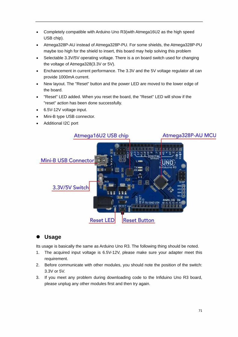
3.2. Infiduino Uno R3
Introduction
The Infiduino Uno R3 board is completely compatible with Arduino Uno R3.It inherit
all of Arduino Uno R3's main function plus some individual features.
Features
71
Completely compatible with Arduino Uno R3(with Atmega16U2 as the high speed
USB chip).
Atmega328P-AU instead of Atmega328P-PU. For some shields, the Atmega328P-PU
maybe too high for the shield to insert, this board may help solving this problem
Selectable 3.3V/5V operating voltage. There is a on board switch used for changing
the voltage of Atmega328(3.3V or 5V).
Enchancement in current performance. The 3.3V and the 5V voltage regulator all can
provide 1000mA current.
New layout. The "Reset" button and the power LED are moved to the lower edge of
the board.
"Reset" LED added. When you reset the board, the "Reset" LED will show if the
"reset" action has been done successfully.
6.5V-12V voltage input.
Mini-B type USB connector.
Additional I2C port
Usage
Its usage is basically the same as Arduino Uno R3. The following thing should be noted.
1. The acquired input voltage is 6.5V-12V, please make sure your adapter meet this
requirement.
2. Before communicate with other modules, you should note the position of the switch:
3.3V or 5V.
3. If you meet any problem during downloading code to the Infiduino Uno R3 board,
please unplug any other modules first and then try again.