starters for centrifugal chillers - daikin...
TRANSCRIPT
Installation, Operation and Maintenance Manual IOMM Starter
Group: Chiller
Part Number: 331375501
Effective: Sept. 2005
Supercedes: New
Starters for Centrifugal Chillers Low Voltage, Solid State and Wye-Delta Medium/High Voltage, Solid State and Across-the-Line
2 IOMM Starter
Table of Contents
General....................................................................................................................3 Variable Frequency Drives ............................................................................................................4 Basic Electrical Terms...................................................................................................................4
Installation..............................................................................................................5 Mounting Arrangements................................................................................................................5 Receiving and Setting....................................................................................................................6 Location and Mounting .................................................................................................................6
Power Wiring .........................................................................................................8 Connection Sizes.........................................................................................................................10
Control Wiring .....................................................................................................13 Low Voltage Starters...................................................................................................................14 Medium/high Voltage Starters .....................................................................................................15
Startup ..................................................................................................................18 Low Voltage Solid State (LVSS) .................................................................................................18 Low Voltage Wye-Delta (LVYD .................................................................................................21 Medium/High Voltage, Solid State ..............................................................................................24
Operation, Low Voltage Starters, 200 – 600 Volts.............................................27 Introduction.................................................................................................................................27 Viewing Data...............................................................................................................................27 Changing Parameters...................................................................................................................32 Fault Code Troubleshooting Chart ..............................................................................................40 General Troubleshooting Chart ...................................................................................................48
Operation, Medium/High Voltage Starters, 2300V – 7.2KV............................52 Introduction.................................................................................................................................52 Viewing Data...............................................................................................................................52 Changing Parameters...................................................................................................................53 Quick Start ..................................................................................................................................55 Troubleshooting ..........................................................................................................................57 Fault/Log Codes ..........................................................................................................................59 LED Diagnostics .........................................................................................................................62
Maintenance .........................................................................................................63 Index of Figures & Tables ...................................................................................65
"McQuay" is a registered trademark of McQuay International ©2005 McQuay International
"Illustrations and data cover McQuay International products at the time of publication and we reserve the right to make changes in design and construction at anytime without notice".
IOMM Starter 3
General
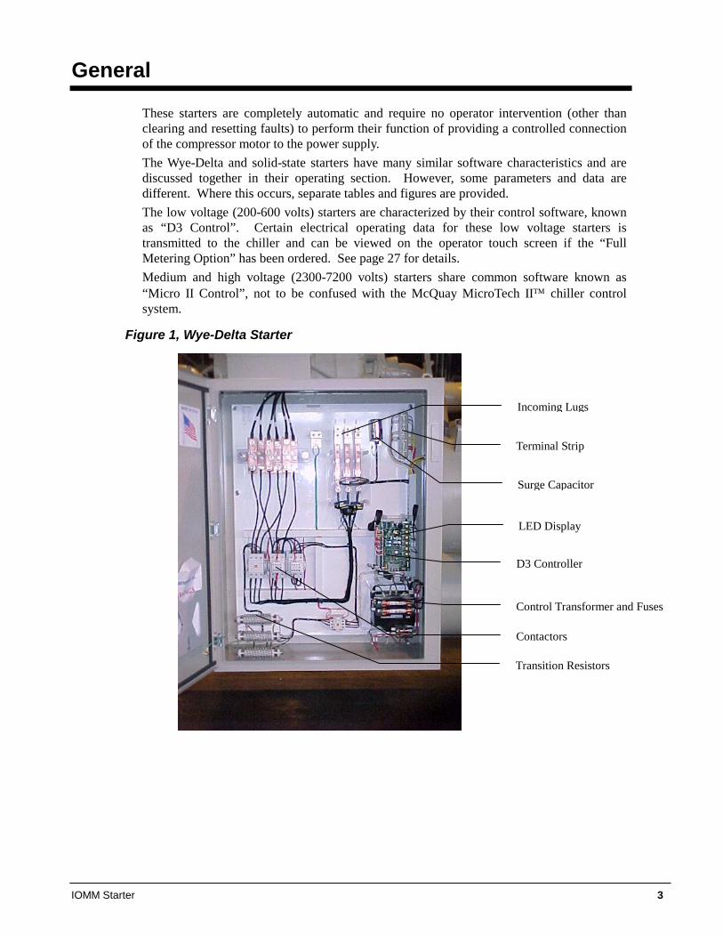
These starters are completely automatic and require no operator intervention (other than clearing and resetting faults) to perform their function of providing a controlled connection of the compressor motor to the power supply. The Wye-Delta and solid-state starters have many similar software characteristics and are discussed together in their operating section. However, some parameters and data are different. Where this occurs, separate tables and figures are provided. The low voltage (200-600 volts) starters are characterized by their control software, known as “D3 Control”. Certain electrical operating data for these low voltage starters is transmitted to the chiller and can be viewed on the operator touch screen if the “Full Metering Option” has been ordered. See page 27 for details. Medium and high voltage (2300-7200 volts) starters share common software known as “Micro II Control”, not to be confused with the McQuay MicroTech II™ chiller control system.
Figure 1, Wye-Delta Starter
LED Display
Incoming Lugs
Surge Capacitor
Terminal Strip
D3 Controller
Control Transformer and Fuses
Contactors
Transition Resistors
4 IOMM Starter
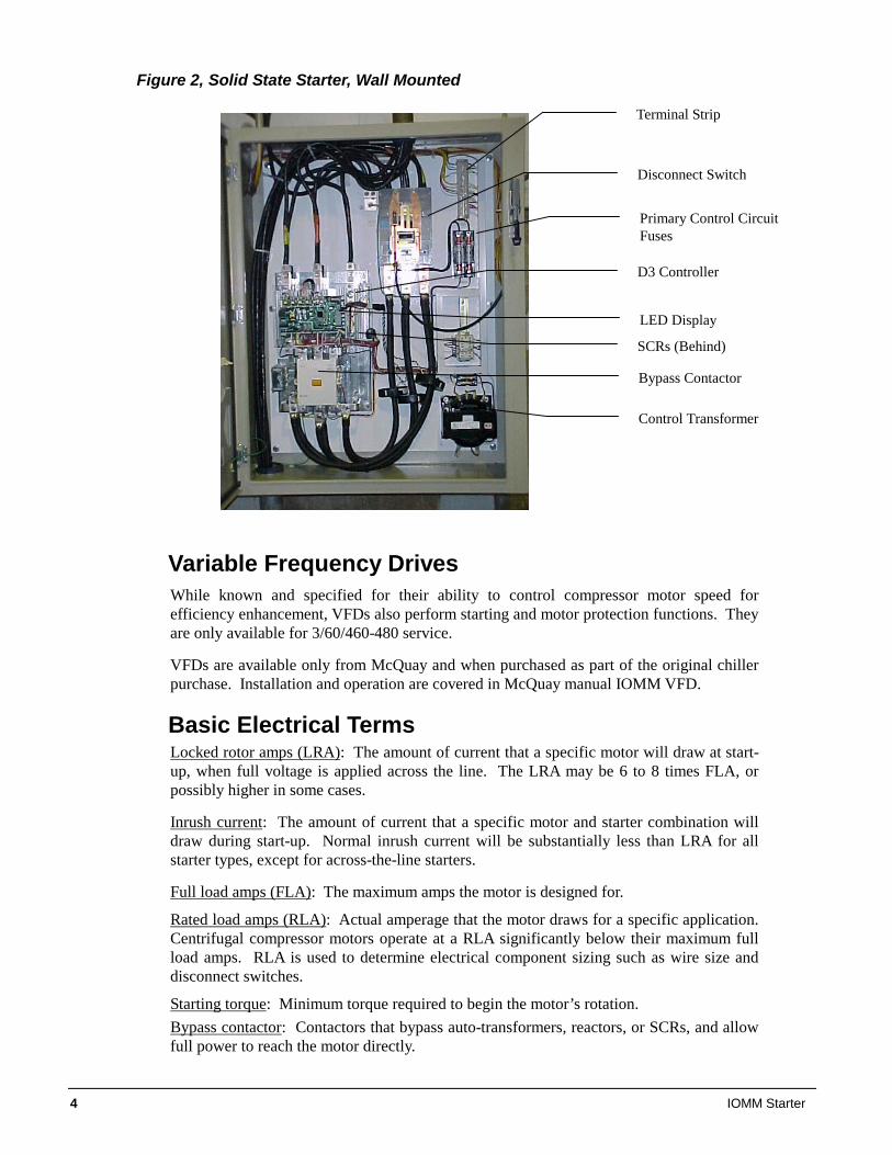
Figure 2, Solid State Starter, Wall Mounted
Variable Frequency Drives While known and specified for their ability to control compressor motor speed for efficiency enhancement, VFDs also perform starting and motor protection functions. They are only available for 3/60/460-480 service.
VFDs are available only from McQuay and when purchased as part of the original chiller purchase. Installation and operation are covered in McQuay manual IOMM VFD.
Basic Electrical Terms Locked rotor amps (LRA): The amount of current that a specific motor will draw at start-up, when full voltage is applied across the line. The LRA may be 6 to 8 times FLA, or possibly higher in some cases.
Inrush current: The amount of current that a specific motor and starter combination will draw during start-up. Normal inrush current will be substantially less than LRA for all starter types, except for across-the-line starters.
Full load amps (FLA): The maximum amps the motor is designed for.
Rated load amps (RLA): Actual amperage that the motor draws for a specific application. Centrifugal compressor motors operate at a RLA significantly below their maximum full load amps. RLA is used to determine electrical component sizing such as wire size and disconnect switches.
Starting torque: Minimum torque required to begin the motor’s rotation. Bypass contactor: Contactors that bypass auto-transformers, reactors, or SCRs, and allow full power to reach the motor directly.
Terminal Strip
Disconnect Switch
Primary Control Circuit Fuses
Control Transformer
SCRs (Behind)
D3 Controller
Bypass Contactor
LED Display
IOMM Starter 5
Interrupting capacity: The maximum fault current that a circuit breaker or fused disconnect can successfully interrupt. As the rating increases, the construction becomes heavier duty. For disconnect switches with fuses, the rating is based on 0 to 600 volts. For circuit breakers, the voltage and amperage relationship is considered with interrupting capacity decreasing as voltage increases. Withstand rating: There is a period of time that the short circuit current passes to the shorted circuit before the protection device can open. This time can be as long as 0.020 seconds (one cycle). The withstand rating of a starter is the maximum short circuit current that it can pass safely without emitting sparks or debris. Phase amps: The current draw inside the delta connection of a wye-delta motor winding. It is equal to 0.577 x RLA of the motor for a specific load. Open transition: A reduced voltage starter characteristic occurring when the motor is temporarily disconnected from power at the time the starter changes from the starting mode to the final running mode. A second smaller inrush spike will occur. McQuay does not recommend use of this type of starter. Closed transition: A reduced voltage starter characteristic when the motor is NOT temporarily disconnected from the line during the transition from starting mode to operating mode. The electrical load is transferred to resistors during the transition phase and the second inrush spike is suppressed.
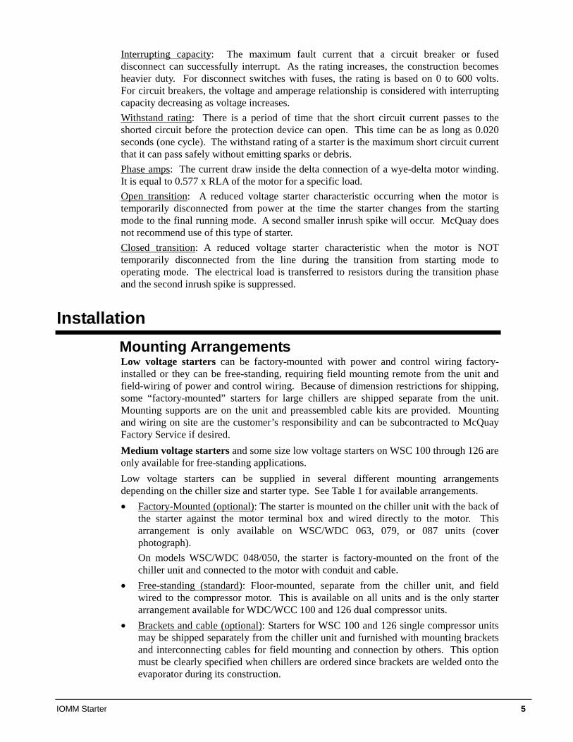
Installation Mounting Arrangements Low voltage starters can be factory-mounted with power and control wiring factory-installed or they can be free-standing, requiring field mounting remote from the unit and field-wiring of power and control wiring. Because of dimension restrictions for shipping, some “factory-mounted” starters for large chillers are shipped separate from the unit. Mounting supports are on the unit and preassembled cable kits are provided. Mounting and wiring on site are the customer’s responsibility and can be subcontracted to McQuay Factory Service if desired. Medium voltage starters and some size low voltage starters on WSC 100 through 126 are only available for free-standing applications. Low voltage starters can be supplied in several different mounting arrangements depending on the chiller size and starter type. See Table 1 for available arrangements. • Factory-Mounted (optional): The starter is mounted on the chiller unit with the back of
the starter against the motor terminal box and wired directly to the motor. This arrangement is only available on WSC/WDC 063, 079, or 087 units (cover photograph). On models WSC/WDC 048/050, the starter is factory-mounted on the front of the chiller unit and connected to the motor with conduit and cable.
• Free-standing (standard): Floor-mounted, separate from the chiller unit, and field wired to the compressor motor. This is available on all units and is the only starter arrangement available for WDC/WCC 100 and 126 dual compressor units.
• Brackets and cable (optional): Starters for WSC 100 and 126 single compressor units may be shipped separately from the chiller unit and furnished with mounting brackets and interconnecting cables for field mounting and connection by others. This option must be clearly specified when chillers are ordered since brackets are welded onto the evaporator during its construction.
6 IOMM Starter
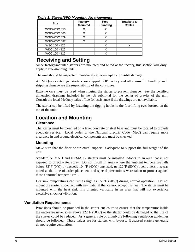
Table 1, Starter/VFD Mounting Arrangements Size Factory-
Mounted Free-
Standing Brackets &
Cables WSC/WDC 050 X X WSC/WDC 063 X X WSC/WDC 079 X X WSC/WDC 087 X X WSC 100 - 126 X X WDC 100 - 126 X WCC 100 - 126 X
Receiving and Setting Since factory-mounted starters are mounted and wired at the factory, this section will only apply to free-standing units.
The unit should be inspected immediately after receipt for possible damage.
All McQuay centrifugal starters are shipped FOB factory and all claims for handling and shipping damage are the responsibility of the consignee.
Extreme care must be used when rigging the starter to prevent damage. See the certified dimension drawings included in the job submittal for the center of gravity of the unit. Consult the local McQuay sales office for assistance if the drawings are not available.
The starter can be lifted by fastening the rigging hooks to the four lifting eyes located on the top of the unit.
Location and Mounting Clearance The starter must be mounted on a level concrete or steel base and must be located to provide adequate service. Local codes or the National Electric Code (NEC) can require more clearance in and around electrical components and must be checked.
Mounting Make sure that the floor or structural support is adequate to support the full weight of the unit.
Standard NEMA 1 and NEMA 12 starters must be installed indoors in an area that is not exposed to direct water spray. Do not install in areas where the ambient temperature falls below 32°F (0°C) or exceeds 104°F (40°C) enclosed, or 122°F (50°C) open unless this was noted at the time of order placement and special precautions were taken to protect against these abnormal temperatures.
Heatsink temperatures can run as high as 158°F (70°C) during normal operation. Do not mount the starter in contact with any material that cannot accept this heat. The starter must be mounted with the heat sink fins oriented vertically in an area that will not experience excessive shock or vibration.
Ventilation Requirements Provisions should be provided in the starter enclosure to ensure that the temperature inside the enclosure never rises above 122°F (50°C) or the starter could be damaged or the life of the starter could be reduced. As a general rule of thumb the following ventilation guidelines should be followed. These values are for starters with bypass. Bypassed starters generally do not require ventilation.
IOMM Starter 7
Safety Precautions Electrical codes require that all equipment (starter, motor, operator station, etc.) be properly grounded. An incoming disconnect must be locked open before wiring or servicing the starter, motor, or other related equipment. The equipment must only be serviced by qualified personnel fully familiar with the equipment.
The opening of the branch circuit protective device may be an indication that a fault current has been interrupted. To reduce the risk of electrical shock, current carrying parts and other components of the starter should be inspected and replaced if damaged.
Equipment is at line voltage when AC power is connected. Pressing the Stop push-button on the chiller control panel does not remove AC mains potential. All phases must be disconnected before it is safe to work on machinery or touch motor terminals and control equipment parts.
Power Factor Capacitors, Surge Capacitors and Lightning Arrestors These devices MUST NOT be used with solid state starters. The SCR’s in the starter will be damaged by the di/dt levels created.
On wye-delta starters, they are connected between the starter and the motor.
8 IOMM Starter
Power Wiring
Power wiring between the starter and the compressor motor terminals is field supplied and installed on units with remote-mounted, free-standing starters. See the field wiring diagram on page 16.
Wiring, fuse and wire size must be in accordance with the National Electric Code (NEC). Standard NEMA motor starters require modification to meet McQuay specifications. Refer to McQuay Specification R35999901.
CAUTION
Important: Voltage unbalance not to exceed 2% with a resultant current unbalance of 6 to 10 times the voltage unbalance per NEMA MG-1, 1998
Standard. This is an important restriction that must be adhered to.
WARNING
Qualified and licensed electricians must perform wiring. Shock hazard exists.
Refer to Figure 5 on page 16 for power wiring connections.
Power wiring to compressors must be in proper phase sequence. Motor rotation is set up for clockwise rotation facing the lead end with phase sequence of 1-2-3. Care must be taken that the proper phase sequence is carried through the starter to compressor. With the phase sequence of 1-2-3 and L1 connected to T1 and T6, L2 connected to T2 and T4, and L3 connected to T3 and T5, rotation is proper. See diagram in terminal box cover.
The McQuay start-up technician will check the phase sequence. Note: Do not make final connections to motor terminals until wiring has been checked and approved by a McQuay technician.
CAUTION
Connections to terminals must be made with copper lugs and copper wire.
Under no circumstances should a compressor be brought up to speed unless proper sequence and rotation have been established. Serious damage can result if the compressor starts in the wrong direction. Such damage is not covered by product warranty.
IOMM Starter 9
Motor Terminal Insulation It is the installing contractor's responsibility to insulate the compressor motor terminals when the unit voltage is 600 volts or greater, or in high humidity locations that could cause condensation on the motor terminals that are at about 50°F (10°C). The required material is shipped in as a kit (775123601) placed in the motor terminal box on all medium and high voltage units. It can be ordered for high humidity applications.
This is to be done after the McQuay start-up technician has checked for proper phase sequence and motor rotation.
Following this verification by the McQuay technician, the contractor should apply the following items.
Materials required for 600+volts or high humidity: 1. Loctite® brand safety solvent (12 oz. package available as McQuay part number
350A263H72) 2. 3M™ Co. Scotchfil brand electrical insulation putty (available in a 60-inch roll as
McQuay part number 350A263H81) 3. 3M Co. Scotchkote™ brand electrical coating (available in a 15 oz. can with brush as
McQuay Part Number 350A263H16) 4. Vinyl plastic electrical tape The above items are also available at most electrical supply outlets.
Application procedure: 1. Disconnect and lock out the power source to the compressor motor. 2. Using the safety solvent, clean the motor terminals, motor barrel adjacent to the
terminals, lead lugs, and electrical cables within the terminal 4OX to remove all dirt, grime, moisture and oil.
3. Wrap the terminal with Scotchfil putty, filling in all irregularities. The final result should be smooth and cylindrical.
4. Doing one terminal at a time, brush the Scotchkote coating on the motor barrel to a distance of up to 1/2 in. around the terminal and on the wrapped terminal, the rubber insulation next to the terminal, and the lug and cable for approximately 10 in. Wrap additional Scotchfil insulation over the Scotchkote coating.
5. Tape the entire wrapped length with electrical tape to form a protective jacket. 6. Finally, brush on one more coat of Scotchkote coating to provide an extra moisture
barrier. General Wiring Practice Wire groups
Signal wiring refers to wires connected to the control terminals that are low voltage, below 15V.
• Shielded wire is required to prevent electrical noise interference from causing improper operation or nuisance trips.
• Signal wire should be rated for at least 300V. • Keep signal wire as far away as possible from control and power wiring.
Control wiring is wiring connected to the control terminal strip that carry 24V to 220V. • Use only UL or CSA recognized wire. • Use copper wire rated for 60/75°C. • Power wiring to the motor must have the maximum possible separation from all other
wiring. Do not run control wiring in the same conduit; this separation reduces the possibility of coupling electrical noise between circuits. Minimum spacing between metallic conduits containing different wiring groups should be three inches (76 mm).
• Minimum spacing between different wiring groups should be six inches (152 mm).
10 IOMM Starter
• Wire runs outside of an enclosure should be run in metallic conduit or have shielding/armor with equivalent attenuation.
• Different wire groups should cross at 90 degrees whenever power and control wiring cross.
• Different wire groups should be run in separate conduits. • Adhere to local electrical codes. • The National Electrical Code and Canadian Electrical Code requires that an approved
circuit disconnecting device be installed in series with the incoming AC supply in a location readily accessible to personnel installing or servicing this equipment. If a disconnect switch is not supplied with the starter, one must be installed.
• Supply and motor wiring will usually enter and leave the enclosure from the top. Wire connections can be determined to best suit specific installations. Wire runs should be properly braced to handle both starting and fault currents. Size power cable per local electrical codes. Long lengths of cable to the motor of over 150 feet must be de-rated.
BEFORE APPLYING MAIN POWER The starter has been fully tested before leaving the factory to help a rapid and problem-free start-up. Before applying power to the starter, consult the start-up checklist below.
1. Inspect starter and remove any foreign matter. 2. Inspect the starter for any shipping damage. 3. Ensure that all electrical connections are as per the system schematics supplied with
the starter and/or connection diagrams. 4. Ensure that all connections are properly tightened. 5. Test L to T resistance of each phase and ensure that it is greater than 50 kohms.
Reverse leads and test again. 6. Check that the gate to cathode resistance of each SCR is between 8 and 50 ohms. 7. Check the resistance of all power and motor leads to ground to ensure that there is no
foreign matter present or damage to the insulation which can short one or more of the phases to ground.
8. Apply 120 Vac control voltage to the starter.
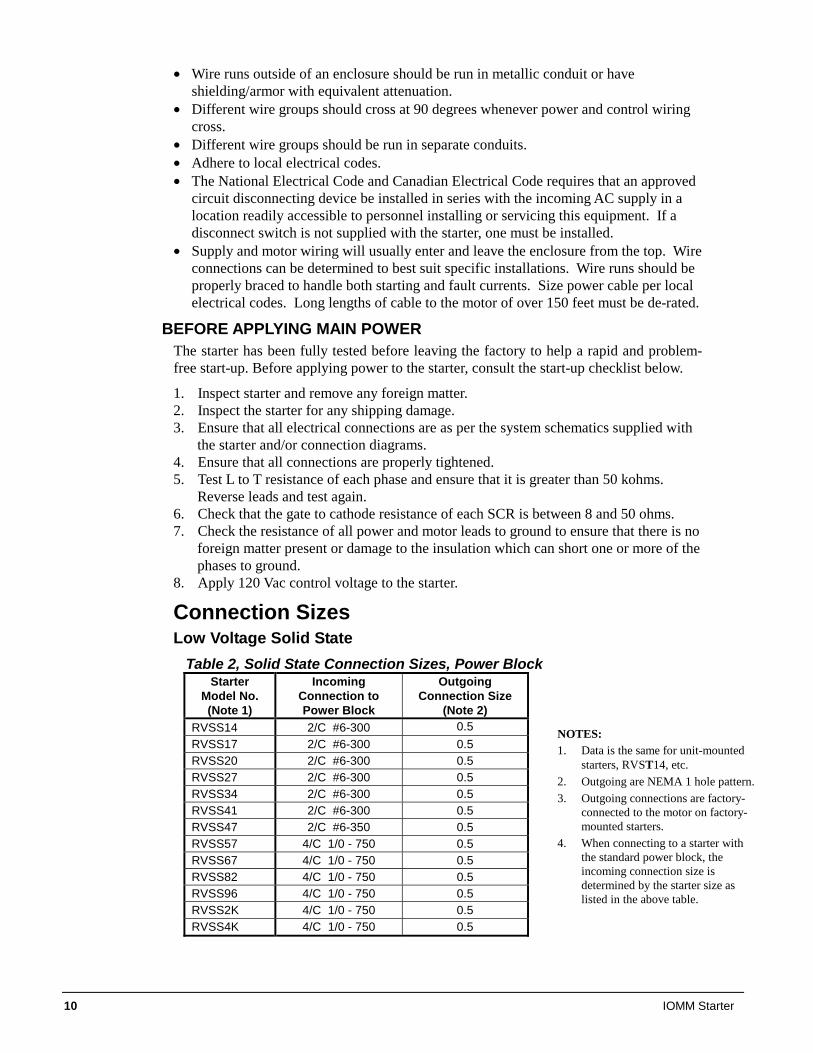
Connection Sizes Low Voltage Solid State
Table 2, Solid State Connection Sizes, Power Block Starter
Model No. (Note 1)
Incoming Connection to Power Block
Outgoing Connection Size
(Note 2) RVSS14 2/C #6-300 0.5 RVSS17 2/C #6-300 0.5 RVSS20 2/C #6-300 0.5 RVSS27 2/C #6-300 0.5 RVSS34 2/C #6-300 0.5 RVSS41 2/C #6-300 0.5 RVSS47 2/C #6-350 0.5 RVSS57 4/C 1/0 - 750 0.5 RVSS67 4/C 1/0 - 750 0.5 RVSS82 4/C 1/0 - 750 0.5 RVSS96 4/C 1/0 - 750 0.5 RVSS2K 4/C 1/0 - 750 0.5 RVSS4K 4/C 1/0 - 750 0.5
NOTES: 1. Data is the same for unit-mounted
starters, RVST14, etc. 2. Outgoing are NEMA 1 hole pattern.3. Outgoing connections are factory-
connected to the motor on factory-mounted starters.
4. When connecting to a starter with the standard power block, the incoming connection size is determined by the starter size as listed in the above table.
IOMM Starter 11
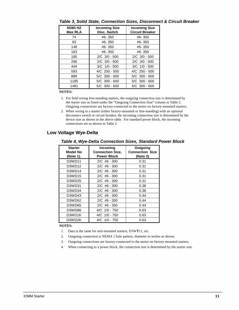
Table 3, Solid State, Connection Sizes, Disconnect & Circuit Breaker 50/60 HZ Max RLA
Incoming Size Disc. Switch
Incoming Size Circuit Breaker
74 #6- 350 #6- 350 93 #6- 350 #6- 350
148 #6- 350 #6- 350 163 #6- 350 #6- 350 185 2/C 3/0 - 500 2/C 3/0 - 500 296 2/C 3/0 - 500 2/C 3/0 - 500 444 3/C 1/0 - 500 3/C 1/0 - 500 593 4/C 250 - 500 4/C 250 - 500 889 5/C 300 - 600 5/C 300 - 600
1185 5/C 300 - 600 5/C 300 - 600 1481 5/C 300 - 600 5/C 300 - 600
NOTES:
1. For field wiring free-standing starters, the outgoing connection size is determined by the starter size as listed under the “Outgoing Connection Size” column in Table 2. Outgoing connections are factory-connected to the motor on factory-mounted starters.
2. When wiring to a starter (either factory-mounted or free-standing) with an optional disconnect switch or circuit breaker, the incoming connection size is determined by the device size as shown in the above table. For standard power block, the incoming connections are as shown in Table 2.
Low Voltage Wye-Delta
Table 4, Wye-Delta Connection Sizes, Standard Power Block Starter
Model No (Note 1).
Incoming Connection Size,
Power Block
Outgoing Connection Size
(Note 2) D3WD11 2/C #6 - 300 0.31 D3WD12 2/C #6 - 300 0.31 D3WD14 2/C #6 - 300 0.31 D3WD15 2/C #6 - 300 0.31 D3WD25 2/C #6 - 300 0.31 D3WD31 2/C #6 - 300 0.38 D3WD34 2/C #6 - 300 0.38 D3WD43 2/C #6 - 300 0.44 D3WD62 2/C #6 - 350 0.44 D3WD65 2/C #6 - 350 0.44 D3WD86 4/C 1/0 - 750 0.63 D3WD1K 4/C 1/0 - 750 0.63 D3WD2K 4/C 1/0 - 750 0.63
NOTES: 1. Data is the same for unit-mounted starters, D3WT11, etc. 2. Outgoing connection is NEMA 1 hole pattern, diameter in inches as shown. 3. Outgoing connections are factory-connected to the motor on factory-mounted starters. 4. When connecting to a power block, the connection size is determined by the starter size.
12 IOMM Starter
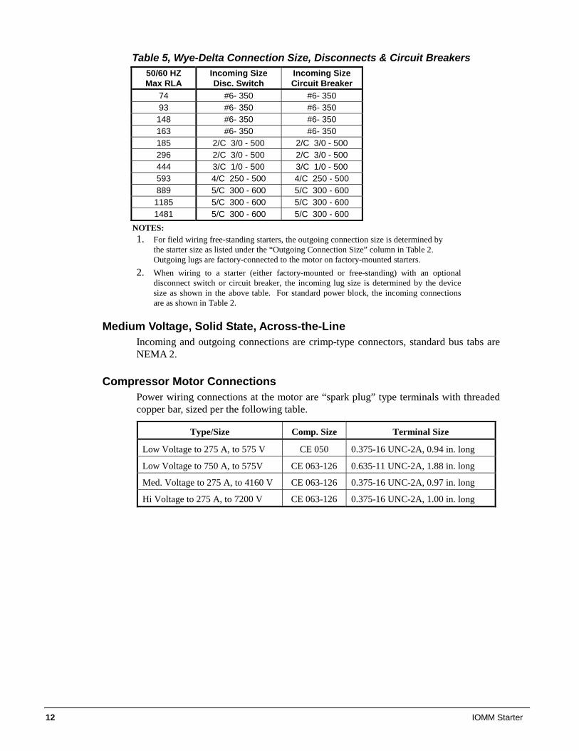
Table 5, Wye-Delta Connection Size, Disconnects & Circuit Breakers 50/60 HZ Max RLA
Incoming Size Disc. Switch
Incoming Size Circuit Breaker
74 #6- 350 #6- 350 93 #6- 350 #6- 350
148 #6- 350 #6- 350 163 #6- 350 #6- 350 185 2/C 3/0 - 500 2/C 3/0 - 500 296 2/C 3/0 - 500 2/C 3/0 - 500 444 3/C 1/0 - 500 3/C 1/0 - 500 593 4/C 250 - 500 4/C 250 - 500 889 5/C 300 - 600 5/C 300 - 600
1185 5/C 300 - 600 5/C 300 - 600 1481 5/C 300 - 600 5/C 300 - 600
NOTES: 1. For field wiring free-standing starters, the outgoing connection size is determined by
the starter size as listed under the “Outgoing Connection Size” column in Table 2. Outgoing lugs are factory-connected to the motor on factory-mounted starters.
2. When wiring to a starter (either factory-mounted or free-standing) with an optional disconnect switch or circuit breaker, the incoming lug size is determined by the device size as shown in the above table. For standard power block, the incoming connections are as shown in Table 2.
Medium Voltage, Solid State, Across-the-Line Incoming and outgoing connections are crimp-type connectors, standard bus tabs are NEMA 2.
Compressor Motor Connections Power wiring connections at the motor are “spark plug” type terminals with threaded copper bar, sized per the following table.
Type/Size Comp. Size Terminal Size
Low Voltage to 275 A, to 575 V CE 050 0.375-16 UNC-2A, 0.94 in. long
Low Voltage to 750 A, to 575V CE 063-126 0.635-11 UNC-2A, 1.88 in. long
Med. Voltage to 275 A, to 4160 V CE 063-126 0.375-16 UNC-2A, 0.97 in. long
Hi Voltage to 275 A, to 7200 V CE 063-126 0.375-16 UNC-2A, 1.00 in. long
IOMM Starter 13
Control Wiring
Control wiring is required between the starter and the unit for three purposes:
1. Transmit start and stop commands from the unit to the starter.
2. Transmit electrical information concerning motor operation from the starter to the unit control system.
3. Supply control power from the starter transformer to the unit control panels.
General Practice Signal wiring refers to wires connected to the control terminals that are low voltage, below 15V.
• Shielded wire is required to prevent electrical noise interference from causing improper operation or nuisance trips.
• Signal wire should be rated for at least 300V. • Keep signal wire as far away as possible from control and power wiring.
Control wiring refers to wires connected to the control terminal strip that carry 24V to 220V.
• Use only UL or CSA recognized wire. • Use copper wire rated for 60/75°C.
Control Power Wiring Control power wiring for starters covered in this manual is shown on Figure 5 on page 16. Low voltage starters may have additional control wiring as shown on Figure 4 if the optional full metering package is ordered with the unit.
The control circuit on the McQuay centrifugal packaged chiller is designed for 115-volts. Control power can be supplied from three different sources:
• If the unit is supplied with a factory-mounted starter, the control circuit power supply is factory-wired from a transformer located in the starter.
• A free-standing starter furnished by McQuay, or by the customer to McQuay specifications, will have a control transformer in it and requires field wiring to terminals in the compressor terminal box.
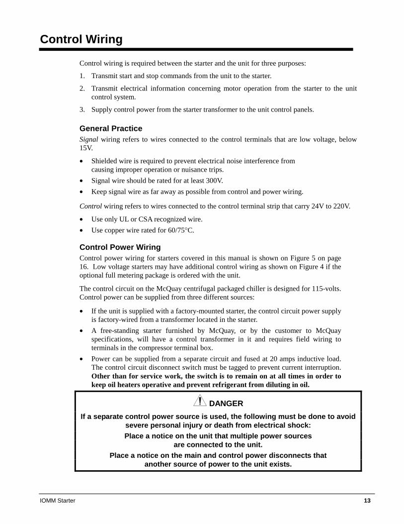
• Power can be supplied from a separate circuit and fused at 20 amps inductive load. The control circuit disconnect switch must be tagged to prevent current interruption. Other than for service work, the switch is to remain on at all times in order to keep oil heaters operative and prevent refrigerant from diluting in oil.
DANGER If a separate control power source is used, the following must be done to avoid
severe personal injury or death from electrical shock: Place a notice on the unit that multiple power sources
are connected to the unit. Place a notice on the main and control power disconnects that
another source of power to the unit exists.
14 IOMM Starter
Separate Power Source
Chiller control power usually comes from a control transformer located in the starter and factory or field wired to the chiller control panel. In the event a separate transformer supplies control voltage, it must be rated at 3 KVA, with an inrush rating of 12 KVA minimum at 80% power factor and 95% secondary voltage. For control wire sizing, refer to NEC. Articles 215 and 310. In the absence of complete information to permit calculations, the voltage drop should be physically measured.
Table 6, Control Power Line Sizing Maximum Length, ft (m) Wire Size (AWG) Maximum Length, ft (m) Wire Size (AWG)
0 (0) to 50 (15.2) 12 120 (36.6) to 200 (61.0) 6 50 (15.2) to 75 (22.9) 10 200 (61.0) to 275 (83.8) 4 75 (22.9) to 120 (36.6) 8 275 (83.8) to 350 (106.7) 3
Notes: 1. Maximum length is the distance a conductor will traverse between the control power
source and the unit control panel. 2. Panel terminal connectors will accommodate up to number 10 AWG wire. Larger
conductors will require an intermediate junction box. The Unit On/Off switch located in the Unit Control Panel should be turned to the "Off" position any time compressor operation is not desired.
Low Voltage Starters Control wiring for low voltage starters is per the wiring diagram on page 16. If the optional
“Full Metering Display” has been ordered, the following section will apply.
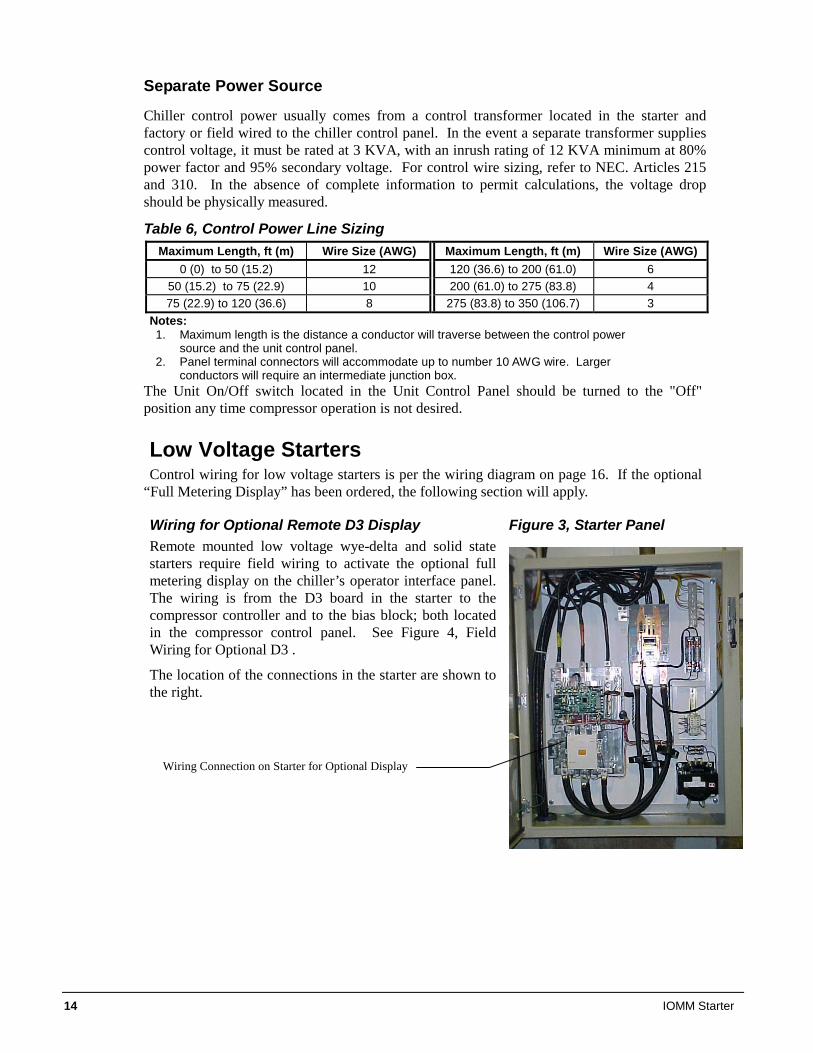
Wiring for Optional Remote D3 Display Figure 3, Starter Panel Remote mounted low voltage wye-delta and solid state starters require field wiring to activate the optional full metering display on the chiller’s operator interface panel. The wiring is from the D3 board in the starter to the compressor controller and to the bias block; both located in the compressor control panel. See Figure 4, Field Wiring for Optional D3 .
The location of the connections in the starter are shown to the right.
Wiring Connection on Starter for Optional Display
IOMM Starter 15
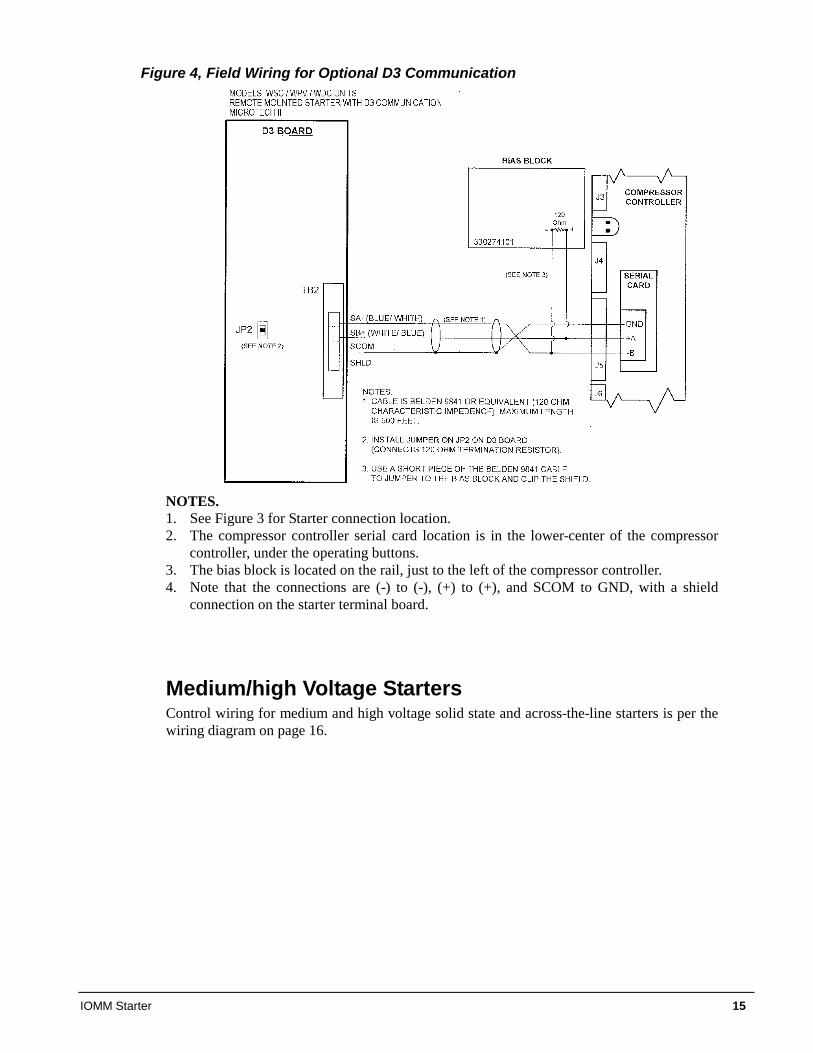
Figure 4, Field Wiring for Optional D3 Communication
NOTES. 1. See Figure 3 for Starter connection location. 2. The compressor controller serial card location is in the lower-center of the compressor
controller, under the operating buttons. 3. The bias block is located on the rail, just to the left of the compressor controller. 4. Note that the connections are (-) to (-), (+) to (+), and SCOM to GND, with a shield
connection on the starter terminal board.
Medium/high Voltage Starters Control wiring for medium and high voltage solid state and across-the-line starters is per the wiring diagram on page 16.
16 IOMM Starter
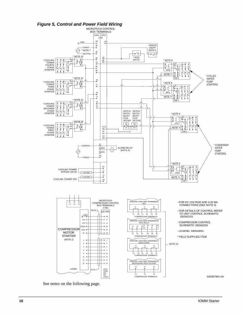
Figure 5, Control and Power Field Wiring
80
CP2
CP1
H
O
A
C4
H
A
O
C3
H
A
O
79
78
77
74
73
54
CF
86
EF
86C
25
1
2
11
11
12
22
1
2
6
11
12
22
NOTE 2
NOTE 2
(115V) (24V)
25
55
70
H
A
O
H
A
O
HO
A C
H
O
A C
H
O
A C
C2
C1 T3-S
PE
L1
L2CP2
CP1
24
23(5A)
24(5)
23
3
4
3
4
76
75
PE
85
86
81
84
A82(NO)
83(NC)
POWER
EP2
EP1
L1 L2 L3
GND
T4 T5 T6T1 T2 T3
T4 T5 T6T1 T2 T3
T1 T2 T3
T3T1 T2
U V W
T4 T3 T5T1 T6 T2
T1 T2 T3
T4 T3 T5T1 T6 T2
GND
LESSTHAN30VOR24VAC
53
71
71
52
1-10 VDC
1-10 VDC
MICROTECH CONTROLBOX TERMINALS
* COOLINGTOWER
FOURTHSTAGE
STARTER
* COOLINGTOWER
THIRDSTAGE
STARTER
* COOLINGTOWER
SECONDHSTAGE
STARTER
* COOLINGTOWER
FIRSTSTAGE
STARTER
COOLING TOWERBYPASS VALVE
COOLING TOWER VFD
ALARM RELAY(NOTE 4)
MICROTECHCOMPRESSOR CONTROL
BOX TERMINALSCTB1
-LOAD-
COMPRESSORMOTOR
STARTER(NOTE 1)
115 VAC
STARTER LOAD SIDE TERMINBALSVFD
STARTER LOAD SIDE TERMINBALSWYE-DELTA
STARTER LOAD SIDE TERMINBALSSOLID STATE
STARTER LOAD SIDE TERMINBALSMEDIUM AND HIGH VOLTAGE
COMPRESSOR TERMINALS
COMPRESSOR TERMINALS
COMPRESSOR TERMINALS
COMPRESSOR TERMINALS
NOTE 12
- FOR DC VOLTAGE AND 4-20 MA CONNECTIONS (SEE NOTE 3)
- FOR DETAILS OF CONTROL REFER TO UNIT CONTROL SCHEMATIC 330342101
- COMPRESSOR CONTROL SCHEMATIC 330342201
- LEGEND: 330343001
* FIELD SUPPLIED ITEM
* NOTE 7
* NOTE 10
* NOTE 10
* NOTE 10
* NOTE 10
330387901-0A
COMMON
NEUTRAL
POWER
See notes on the following page.
IOMM Starter 17
NOTES for Wiring Diagram
1. Compressor motor starters are either factory-mounted and wired, or shipped separate for field-mounting and wiring. If provided by others, starters must comply with McQuay specification 359AB99. All line and load side power conductors must be copper.
2. If starters are freestanding, then field control wiring between the starter and the control panel is required. Minimum wire size for 115 Vac is 12 GA for a maximum length of 50 feet. If greater than 50 feet, refer to McQuay for recommended wire size minimum. Wire size for 24 Vac is 18 GA. All wiring to be installed as NEC Class 1 wiring system and must be made with copper wire and copper lugs only. All 24 Vac wiring must be run in separate conduit from 115 Vac wiring.
3. Main power wiring between starter and motor terminal is factory-installed when chillers are supplied with unit-mounted starters.
4. For wye-delta, and solid state starters connected to six (6) terminal motors (low voltage), the conductors between the starter and motor carry phase current and wire size selection is based on 58 percent of the motor rated load amperes (RLA). Wiring of free-standing starters must be in accordance with the NEC and connection to the compressor motor terminals shall be made with copper wire and copper lugs only. Main power wiring between the starter and motor terminals is factory-installed when chillers are supplied with unit-mounted starters.
5. The “Full Metering” option will require some field wiring when free-standing starters are used, as shown in Figure 4 on page 15.
18 IOMM Starter
Startup
General The startup of McQuay centrifugal chillers, including the starters, is performed by McQuay authorized and trained technicians. They review the starter connections, phase sequence, and settings prior to starting the chiller.
Setting a freestanding starter and power and control wiring from it to the chiller is the responsibility of the owner/contractor. See the installation and power and control wiring sections of this manual before commencing installation.
In the rare instances where a starter is being replaced after the chiller has been in service, McQuay service is not automatically involved but can be contracted to supervise the starter installation.
For general information, brief startup instructions are included on the following pages.
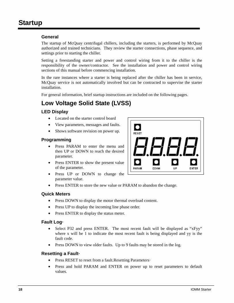
Low Voltage Solid State (LVSS) LED Display
• Located on the starter control board • View parameters, messages and faults. • Shows software revision on power up.
Programming • Press PARAM to enter the menu and
then UP or DOWN to reach the desired parameter.
• Press ENTER to show the present value of the parameter.
• Press UP or DOWN to change the parameter value.
• Press ENTER to store the new value or PARAM to abandon the change.
Quick Meters • Press DOWN to display the motor thermal overload content. • Press UP to display the incoming line phase order. • Press ENTER to display the status meter.
Fault Log· • Select P32 and press ENTER. The most recent fault will be displayed as “xFyy”
where x will be 1 to indicate the most recent fault is being displayed and yy is the fault code.
• Press DOWN to view older faults. Up to 9 faults may be stored in the log.
Resetting a Fault· • Press RESET to reset from a fault.Resetting Parameters· • Press and hold PARAM and ENTER on power up to reset parameters to default
values.
IOMM Starter 19
Emergency Thermal Reset· • Press RESET and DOWN to perform an emergency thermal reset.
Messages (LVSS) No Line Ready Accelerating Up to Speed Run – Done with ramp but not yet
Up to Speed. Decelerating Overload Alarm – The motor
overload level is between 90% and 100%.
Overload Fault – The motor overload level has reached 100%.
Overload Lockout – A start is not allowed until the motor overload level cools below 60%.
Control Power Lockout – A start is not allowed because the control power is too low.
xxx xxx = overload content. Press DOWN to toggle.
xx xx = Alarm code. If the condition persists, a fault will occur.
xx xx = Fault code. Press RESET to clear.
Instantaneous Overcurrent – Press RESET to clear.
Default – Flashes when parameter defaults are loaded.
Default Meter Display (P13) (LVSS) 0: Status 1: Ave RMS Current 2: L1 RMS Current 3: L2 RMS Current 4: L3 RMS Current 5: Current Imbalance % 6: Ground Fault Current
7: Ave L-L Voltage RMS 8: L1-L2 Voltage RMS 9: L2-L3 Voltage RMS 10: L3-L1 Voltage RMS 11: Overload % 12: PF 13: KW
14: KVA 15: KWh 16: MWh 17: Phase Rotation 18: Line Frequency 19: Analog Input
Analog Output Function (P28) (LVSS) 0: OFF (no output) 1: Ave Current (0 – 200% RLA) 2: Ave Current (0 – 800% RLA) 3: Ave Voltage (0 – 750VAC) 4: Thermal Overload% 5: KW (0 - 10KW)
6: KW (0 – 100KW) 7: KW (0 – 1MW) 8: KW (0 – 10MW) 9: Analog Input 10: Output Voltage (% of FV) 11: Calibrate (full 100% output)
CT Burden Switch Settings (P1 and P23) (LVSS) FLA in Amps Setting
864:1 CTs 2640:1 CTs 5760:1 CTs 8000:1 CTs SW1 SW2 24 to 42 73 to128 160 to 280 223 to 390 Off Off 42 to 50 128 to 151 280 to 330 390 to 465 Off On
50 to 108 151 to 330 330 to 720 465 to 1000 On Off 108 to 190 330 to 590 720 to 1280 1000 to 1800 On On
Parameters (LVSS)
DESCRIPTION Values DEFAULT SET TO:
P1 Motor FLA 1 to 9999 Amps 10 P2 Motor RLA 1 to 9999 Amps 10 P3 Motor Service Factor 1.00 to 1.99 1.08 P4 Motor Overload Class OFF, 1 to 40 10 P5 Initial Motor Current 50 to 400 %FLA 250 P6 Maximum Motor Current 100 to 800 %FLA 300 P7 Ramp Time 0 to 300 seconds 10 P8 UTS Time 1 to 900 seconds 15
P9 Stop Mode CoS: Coast dcL: Voltage Decel CoS
P10 Decel Begin Level 100 to 0 %Volts 40 Continued on next page.
20 IOMM Starter
DESCRIPTION Values DEFAULT SET TO:
P11 Decel End Level 50 to 0 %Volts 20 P12 Decel Time 1 to 180 seconds 15 P13 Default Meter Display 0 to 19 1 P14 Overcurrent Trip Level OFF, 50 to 800 %RLA OFF
P15 Overcurrent Trip Delay Time 0.1 to 90.0 seconds 2.0
P16 Rated RMS Voltage
100, 110, 120, 200, 208, 220, 230, 240, 350, 380, 400, 415, 440, 460, 480,
575, 600, 660, 1000 Volts
480
P17 Over Voltage Trip Level OFF, 1 to 40 % rated Volts 10 P18 Under Voltage Trip Level OFF, 1 to 40 % rated Volts 10
P19 Over/Under Voltage Delay Time 0.1 to 90.0 seconds 1.0
P20 Current Imbalance Trip Level 5 to 40 % 10
P21 Controlled Fault Stop OFF, On OFF P22 Auto Fault Reset Time OFF, 1 to 120 seconds 60
P23 CT Ratio 72, 96, 144, 288, 864, 2640, 2880, 5760, 8000 2640
P24 Control Source TEr: Terminal NEt: Network tEr
P25 Modbus Address 1 to 247 1 P26 Modbus Baud Rate 1.2, 2.4, 4.8, 9.6, 19.2 Kbps 19.2 P27 Modbus Timeout OFF, 1 to 120 seconds 3 P28 Analog Output Function 0 to 11 1 P29 Analog Output Span 1 to 125 % 100 P30 Analog Output Offset 0 to 99 % 0 P31 Passcode 0 to 9999 – P32 Fault Log xFyy –
Fault/Alarm Codes (LVSS)
Description Controlled Stop
Auto Reset
00 No fault - - 01 UTS Time Limit Expired Y Y 02 Motor Thermal Overload Trip Y N 10 Phase Rotation Error, not ABC N Y 12 Low Line Frequency N Y 13 High Line Frequency N Y 15 Input power not three phase N Y 21 Low Line L1-L2 Voltage Y Y 22 Low Line L2-L3 Voltage Y Y 23 Low Line L3-L1 Voltage Y Y 24 High Line L1-L2 Voltage Y Y 25 High Line L2-L3 Voltage Y Y 26 High Line L3-L1 Voltage Y Y 27 Phase Loss N Y 28 No Line Voltage N Y 30 I.O.C. (Instantaneous Overcurrent) N N 31 Overcurrent Y N 37 Current Imbalance Y Y 38 Ground Fault Y N 39 No Current at Run N Y 40 Shorted / Open SCR N N 41 Current While Stopped N N 47 Stack Protection Fault N Y 48 Bypass Contactor Fault (on STOP input) Y N 50 Control Power Low N Y 51 Current Sensor Offset Error - N 52 Burden Switch Error N N
IOMM Starter 21
Description Controlled Stop
Auto Reset
60 Thermistor Trip (on DIN#1) N N 61 Stack OT Switch Trip (on DIN#2) N N 71 Analog Input Trip Y Y 82 Modbus Timeout Y Y 94 CPU Error – Software Fault N N 95 CPU Error – Parameter Storage Fault N N 96 CPU Error – Illegal Instruction Trap N N 97 CPU Error – Software Watchdog Fault N N 98 CPU Error – Spurious Interrupt N N 99 CPU Error – Program Storage Fault N N
• If a fault occurs that has a Y in the “Controlled Stop” column, and P21 (Controlled Fault Stop) is set to On, and P9 (Stop Mode) is set to dcL, then the starter will perform a voltage decel to stop. Otherwise it will coast to stop.
• If a fault occurs that has a Y in the “Auto Reset” column, and P22 (Auto Fault Reset Time) is set to some value other than OFF, then the fault will automatically be cleared after the time specified by P22.
Low Voltage Wye-Delta (LVYD
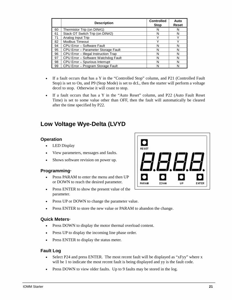
Operation • LED Display
• View parameters, messages and faults.
• Shows software revision on power up.
Programming· • Press PARAM to enter the menu and then UP
or DOWN to reach the desired parameter.
• Press ENTER to show the present value of the parameter.
• Press UP or DOWN to change the parameter value.
• Press ENTER to store the new value or PARAM to abandon the change.
Quick Meters· • Press DOWN to display the motor thermal overload content.
• Press UP to display the incoming line phase order.
• Press ENTER to display the status meter.
Fault Log • Select P24 and press ENTER. The most recent fault will be displayed as “xFyy” where x
will be 1 to indicate the most recent fault is being displayed and yy is the fault code.
• Press DOWN to view older faults. Up to 9 faults may be stored in the log.
22 IOMM Starter
Resetting a Fault • Press RESET to reset from a fault.
Resetting Parameters • Press and hold PARAM and ENTER on power up to reset parameters to default values.
Emergency Thermal Reset • Press RESET and DOWN to perform an emergency thermal reset.
Messages (LVYD) No Line Ready Running in wye mode. Running in delta mode. Overload Alarm – The motor
overload level is between 90% and 100%.
Overload Fault – The motor overload level has reached 100%.
Overload Lockout – A start is not allowed until the motor overload level cools below 60%.
Control Power Lockout – A start is not allowed because the control power is too low.
xxx xxx = overload content. Press DOWN to toggle.
xx xx = Alarm code. If the condition persists, a fault will occur.
xx xx = Fault code. Press RESET to clear.
Instantaneous Overcurrent – Press RESET to clear.
Default – Flashes when parameter defaults are loaded.
Default Meter Display (P5) (LVYD) 0: Status 1: Ave RMS Current 2: L1 RMS Current 3: L2 RMS Current 4: L3 RMS Current 5: Current Imbalance % 6: Ground Fault Current
7: Ave L-L Voltage RMS 8: L1-L2 Voltage RMS 9: L2-L3 Voltage RMS 10: L3-L1 Voltage RMS 11: Overload % 12: PF 13: KW
14: KVA 15: KWh 16: MWh 17: Phase Rotation 18: Line Frequency 19: Analog Input
Analog Output Function (P20) (LVYD) 0: OFF (no output) 1: Ave Current (0 – 200% RLA) 2: Ave Current (0 – 800% RLA) 3: Ave Voltage (0 – 750VAC) 4: Thermal Overload% 5: KW (0 - 10KW)
6: KW (0 – 100KW) 7: KW (0 – 1MW) 8: KW (0 – 10MW) 9: Analog Input 10: Reserved 11: Calibrate (full 100% output)
CT Burden Switch Settings (P1 and P15) (LVYD) RLA in Amps Setting
864:1 CTs 2640:1 CTs 5760:1 CTs 8000:1 CTs SW1 SW2 24 to 42 73 to 128 160 to 280 223 to 390 Off Off 42 to 50 128 to 151 280 to 330 390 to 465 Off On
50 to 108 151 to 330 330 to 720 465 to 1000 On Off 108 to 190 330 to 590 720 to 1280 1000 to 1800 On On
Parameters (LVYD) DESCRIPTION Values DEFAULT
P1 Motor RLA 1 to 9999 Amps 1 P2 Motor Service Factor 1.00 to 1.99 1.08 P3 Motor Overload Class OFF, 1 to 40 10 P4 Transition Time 1 to 30 seconds 10 P5 Default Meter Display 0 to 19 0
Continued on next page.
IOMM Starter 23
DESCRIPTION Values DEFAULT
P6 Sequence Complete Delay Time 0.1 to 5.0 seconds 2.0
P7 Overcurrent Trip Level OFF, 50 to 800 %RLA OFF
P8 Overcurrent Trip Delay Time 0.1 to 90.0 seconds 2.0
P9 Rated RMS Voltage
100, 110, 120, 200, 208, 220, 230, 240, 350, 380, 400, 415, 440, 460, 480,
575, 600, 660, 1000 Volts
480
P10 Over Voltage Trip Level OFF, 1 to 40 % rated Volts 10 P11 Under Voltage Trip Level OFF, 1 to 40 % rated Volts 15
P12 Over/Under Voltage Delay Time 0.1 to 90.0 seconds 1.0
P13 Current Imbalance Trip Level 5 to 40 % 20
P14 Auto Fault Reset Time OFF, 1 to 120 seconds 60
P15 CT Ratio 72, 96, 144, 288, 864, 2640, 2880, 5760, 8000 2640
P16 Control Source TEr: Terminal NEt: Network tEr
P17 Modbus Address 1 to 247 2 P18 Modbus Baud Rate 1.2, 2.4, 4.8, 9.6, 19.2 Kbps 19.2 P19 Modbus Timeout OFF, 1 to 120 seconds 3 P20 Analog Output Function 0 to 11 1 P21 Analog Output Span 1 to 125 % 100 P22 Analog Output Offset 0 to 99 % 0 P23 Passcode 0 to 9999 – P24 Fault Log xFyy –
Fault/Alarm Codes (LVYD)
Description Auto Reset
00 No fault - 02 Motor Thermal Overload Trip N 10 Phase Rotation Error, not ABC Y 12 Low Line Frequency Y 13 High Line Frequency Y 15 Input power not three phase Y 21 Low Line L1-L2 Voltage Y 22 Low Line L2-L3 Voltage Y 23 Low Line L3-L1 Voltage Y 24 High Line L1-L2 Voltage Y 25 High Line L2-L3 Voltage Y 26 High Line L3-L1 Voltage Y 27 Phase Loss Y 28 No Line Voltage Y 30 I.O.C. (Instantaneous Overcurrent) N 31 Overcurrent N 37 Current Imbalance Y 38 Ground Fault N 39 No Current at Run Y 40 Open Line or Motor Lead N 41 Current While Stopped N 48 2M Feedback Fault (on DIN#2) N 50 Control Power Low Y 51 Current Sensor Offset Error N
24 IOMM Starter
Description Auto Reset
52 Burden Switch Error N 60 Thermistor Trip (on DIN#1) N 71 Analog Input Trip Y 82 Modbus Timeout Y 94 CPU Error – Software Fault N 95 CPU Error – Parameter Storage Fault N 96 CPU Error – Illegal Instruction Trap N 97 CPU Error – Software Watchdog Fault N 98 CPU Error – Spurious Interrupt N 99 CPU Error – Program Storage Fault N
If a fault occurs that has a Y in the “Auto Reset” column, and P14 (Auto Fault Reset Time) is set to some value other than OFF, then the fault will automatically be cleared after the time specified by P14.
Medium/High Voltage, Solid State Quick Start
Motor FLA
Parameter Description The motor FLA parameter must be set to the full load amps of the motor connected to the starter for the starter to function correctly. NOTE: The starter uses the entered motor FLA for every current based calculation. If the motor FLA is not entered correctly, the current ramp profile and many of the starter’s advanced protection features will not function properly.
Parameter Values The motor FLA parameter is adjustable from 1 to 1200 amps in 1-amp increments.
Parameter Default The default value for the motor FLA is 1 amp.
Serv. Fact (Service Factor)
Description The service factor parameter should be set to the service factor of the motor. The service factor is used for the overload calculations. The service factor is factory set, will be checked by the start-up technician and should not require further adjustment. If the service factor of the motor is not known, then the service factor should be set to 1.08.
Values The service factor can be set from 1.00 to 1.99, in 0.01 increments. NOTE: The NEC (National Electrical Code) does not allow the service factor to be set above 1.40. Check with other local electrical codes for their requirements.
Default The default value for the service factor is 1.08.
IOMM Starter 25
Start Mode Description The Start Mode parameter allows for an optimal start of the motor based on the application. For a description of the possible Start Mode parameters, refer to page 31 in the Operations chapter. Values
The Start Mode Parameter can be set to Curr, TT, or Tach. Default
The default value for the Start Mode is Curr.
Stop Mode Description The Stop Mode parameter allows for the most suitable stop of the motor based on the application. For a description of the possible Stop Mode parameters, refer to page 31 in the Operations chapter of the starter manual.
Values The Stop Mode can be set to Coas, VDCL, or TT.
Default The default value for the Stop Mode is Coas.
Int. Curr. (initial current) Description The initial current parameter is set as a percentage of the motor FLA parameter setting. The initial current parameter sets the current that will initially reach the motor when a start is commanded.
If the motor does not rotate within a few seconds after a start command, the initial current should be increased. If the motor takes off too quickly after a start command, the initial current should be decreased.
The initial current must be set to a value that is lower than the maximum current parameter setting.
A typical setting for the initial current parameter is from 50% to 175%.
Values The initial current is adjustable from 50% to 400% in 1% intervals. Default The default value for the initial current is 100%.
Max. Curr. (maximum current) Description The maximum current parameter is set as a percentage of the motor FLA parameter setting. The maximum current parameter performs two functions. It sets the current for the end of the ramp profile and sets the maximum current that is allowed to reach the motor while the motor is being started.
If the ramp time expires before the motor has reached full speed, the starter will hold the current at the maximum current level until the stall time expires, the motor reaches full speed, or the overload trips.
Typically, the maximum current is set to 600% unless the power system or load dictates the setting of a lower maximum current.
Values The maximum current is adjustable from 100% to 600% in 1% intervals.
26 IOMM Starter
Default The default value for the maximum current is 600%.
Ramp Time Description The ramp time sets the amount of time that it takes for the starter to linearly increase the current from the initial current level to the maximum current level. A typical ramp time setting is from 15 to 30 seconds.
Settings The ramp time is adjustable from 0 to 120 seconds in 1 second intervals. Default The default value for the ramp time is 15 seconds.
Overload Default
The default value for the overload parameter is 10.
Phase Order Description The line phasing parameter sets the phase sensitivity of the starter. This can be used to protect the motor from a possible change in the incoming phase sequence. If the incoming phase sequence does not match the set phase rotation, the starter will display phs err while stopped and will fault if a start is attempted.
Values The line phasing can be set to:
• INS - will run with either phase sequence • ABC - will only run with ABC phase sequence • CBA - will only run with CBA phase sequence
Default The default value for the phase sensitivity parameter is ABC.
IOMM Starter 27
Operation, Low Voltage Starters, 200 – 600 Volts Introduction This section contains information on low voltage, Wye-Delta and solid-state starters as manufactured by Benshaw Inc. for McQuay centrifugal Chillers. They are known collectively as “D3” starters, which is their software designation. These low voltage starters have similar software (designated D3) and are grouped together in this manual. Model numbers are as follows: D3WD11 to D3WD2K Wye-Delta, Free-standing D3WT11 to D3WT65 Wye-Delta, Factory (Terminal) Mounted RVSS14 to RVSS4K Solid State, Free-standing RVST14 to RVST82 Solid State, Factory (Terminal) Mounted
Viewing Data The information in this section applies to low voltage, solid start and wye-delta starters, with the exceptions noted at the end of the section beginning on page 36.
Starter information is available on the starter-mounted LED as explained beginning on page 30. If the optional “Full Meter Display” (available only on low voltage starters) is ordered with the unit, power information will also be available on the chiller’s operator interface touchscreen, as explained below.
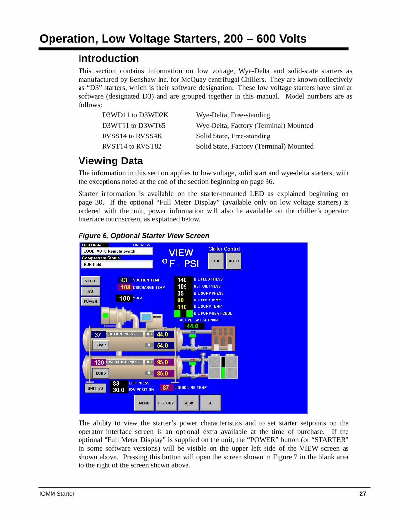
Figure 6, Optional Starter View Screen
The ability to view the starter’s power characteristics and to set starter setpoints on the operator interface screen is an optional extra available at the time of purchase. If the optional “Full Meter Display” is supplied on the unit, the “POWER” button (or “STARTER” in some software versions) will be visible on the upper left side of the VIEW screen as shown above. Pressing this button will open the screen shown in Figure 7 in the blank area to the right of the screen shown above.
28 IOMM Starter
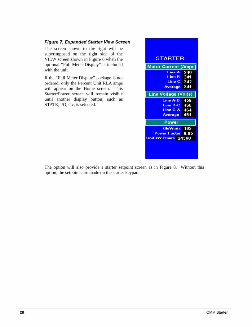
Figure 7, Expanded Starter View Screen The screen shown to the right will be superimposed on the right side of the VIEW screen shown in Figure 6 when the optional “Full Meter Display” is included with the unit.
If the “Full Meter Display” package is not ordered, only the Percent Unit RLA amps will appear on the Home screen. This Starter/Power screen will remain visible until another display button; such as STATE, I/O, etc, is selected.
The option will also provide a starter setpoint screen as in Figure 8. Without this option, the setpoints are made on the starter keypad.
IOMM Starter 29
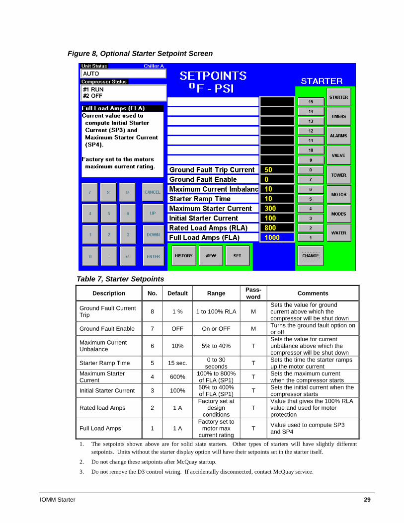
Figure 8, Optional Starter Setpoint Screen
Table 7, Starter Setpoints
Description No. Default Range Pass- word Comments
Ground Fault Current Trip 8 1 % 1 to 100% RLA M
Sets the value for ground current above which the compressor will be shut down
Ground Fault Enable 7 OFF On or OFF M Turns the ground fault option on or off
Maximum Current Unbalance 6 10% 5% to 40% T
Sets the value for current unbalance above which the compressor will be shut down
Starter Ramp Time 5 15 sec. 0 to 30 seconds T Sets the time the starter ramps
up the motor current Maximum Starter Current 4 600% 100% to 800%
of FLA (SP1) T Sets the maximum current when the compressor starts
Initial Starter Current 3 100% 50% to 400% of FLA (SP1) T Sets the initial current when the
compressor starts
Rated load Amps 2 1 A Factory set at
design conditions
T Value that gives the 100% RLA value and used for motor protection
Full Load Amps 1 1 A Factory set to
motor max current rating
T Value used to compute SP3 and SP4
1. The setpoints shown above are for solid state starters. Other types of starters will have slightly different setpoints. Units without the starter display option will have their setpoints set in the starter itself.
2. Do not change these setpoints after McQuay startup.
3. Do not remove the D3 control wiring. If accidentally disconnected, contact McQuay service.
30 IOMM Starter
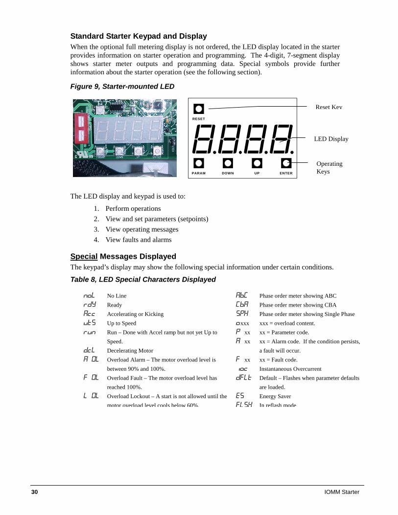
Standard Starter Keypad and Display When the optional full metering display is not ordered, the LED display located in the starter provides information on starter operation and programming. The 4-digit, 7-segment display shows starter meter outputs and programming data. Special symbols provide further information about the starter operation (see the following section).
Figure 9, Starter-mounted LED
The LED display and keypad is used to:
1. Perform operations 2. View and set parameters (setpoints) 3. View operating messages 4. View faults and alarms
Special Messages Displayed The keypad’s display may show the following special information under certain conditions.
Table 8, LED Special Characters Displayed
PARAM DOWN UP ENTER
RESET
LED Display
Operating Keys
Reset Key
No Line Ready Accelerating or Kicking Up to Speed Run – Done with Accel ramp but not yet Up to
Speed. Decelerating Motor Overload Alarm – The motor overload level is
between 90% and 100%. Overload Fault – The motor overload level has
reached 100%. Overload Lockout – A start is not allowed until the
motor overload level cools below 60%.
Phase order meter showing ABC Phase order meter showing CBA Phase order meter showing Single Phase
xxx xxx = overload content. xx xx = Parameter code. xx xx = Alarm code. If the condition persists,
a fault will occur. xx xx = Fault code.
Instantaneous Overcurrent Default – Flashes when parameter defaults
are loaded. Energy Saver
In reflash mode
IOMM Starter 31
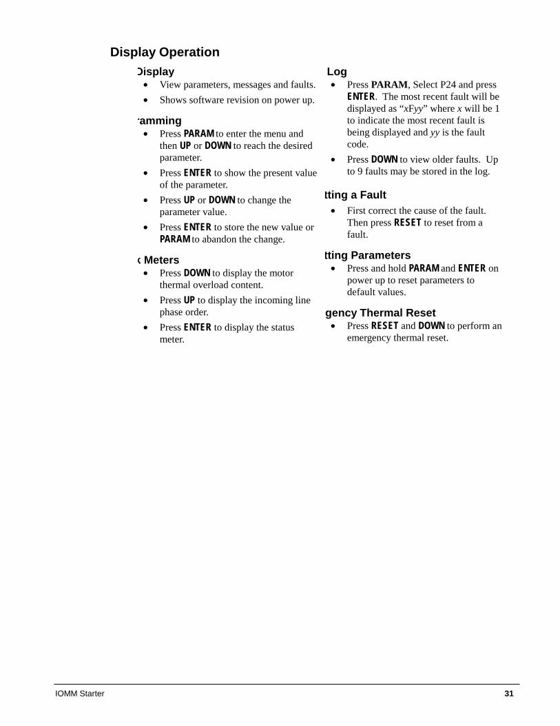
Display Operation Display
• View parameters, messages and faults. • Shows software revision on power up.
ramming • Press PARAM to enter the menu and
then UP or DOWN to reach the desired parameter.
• Press ENTER to show the present value of the parameter.
• Press UP or DOWN to change the parameter value.
• Press ENTER to store the new value or PARAM to abandon the change.
k Meters • Press DOWN to display the motor
thermal overload content. • Press UP to display the incoming line
phase order. • Press ENTER to display the status
meter.
Log • Press PARAM, Select P24 and press
ENTER. The most recent fault will be displayed as “xFyy” where x will be 1 to indicate the most recent fault is being displayed and yy is the fault code.
• Press DOWN to view older faults. Up to 9 faults may be stored in the log.
tting a Fault • First correct the cause of the fault.
Then press RESET to reset from a fault.
tting Parameters • Press and hold PARAM and ENTER on
power up to reset parameters to default values.
rgency Thermal Reset • Press RESET and DOWN to perform an
emergency thermal reset.
32 IOMM Starter
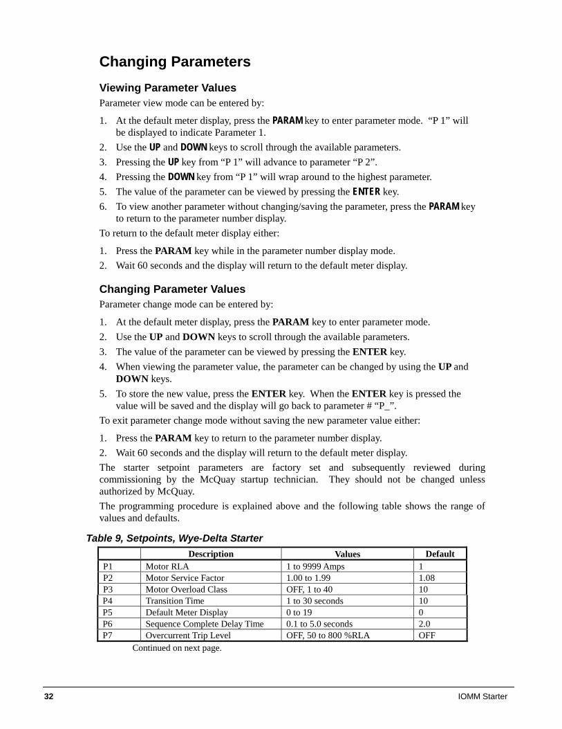
Changing Parameters Viewing Parameter Values Parameter view mode can be entered by:
1. At the default meter display, press the PARAM key to enter parameter mode. “P 1” will be displayed to indicate Parameter 1.
2. Use the UP and DOWN keys to scroll through the available parameters. 3. Pressing the UP key from “P 1” will advance to parameter “P 2”. 4. Pressing the DOWN key from “P 1” will wrap around to the highest parameter. 5. The value of the parameter can be viewed by pressing the ENTER key. 6. To view another parameter without changing/saving the parameter, press the PARAM key
to return to the parameter number display. To return to the default meter display either:
1. Press the PARAM key while in the parameter number display mode. 2. Wait 60 seconds and the display will return to the default meter display.
Changing Parameter Values Parameter change mode can be entered by:
1. At the default meter display, press the PARAM key to enter parameter mode. 2. Use the UP and DOWN keys to scroll through the available parameters. 3. The value of the parameter can be viewed by pressing the ENTER key. 4. When viewing the parameter value, the parameter can be changed by using the UP and
DOWN keys. 5. To store the new value, press the ENTER key. When the ENTER key is pressed the
value will be saved and the display will go back to parameter # “P_”. To exit parameter change mode without saving the new parameter value either:
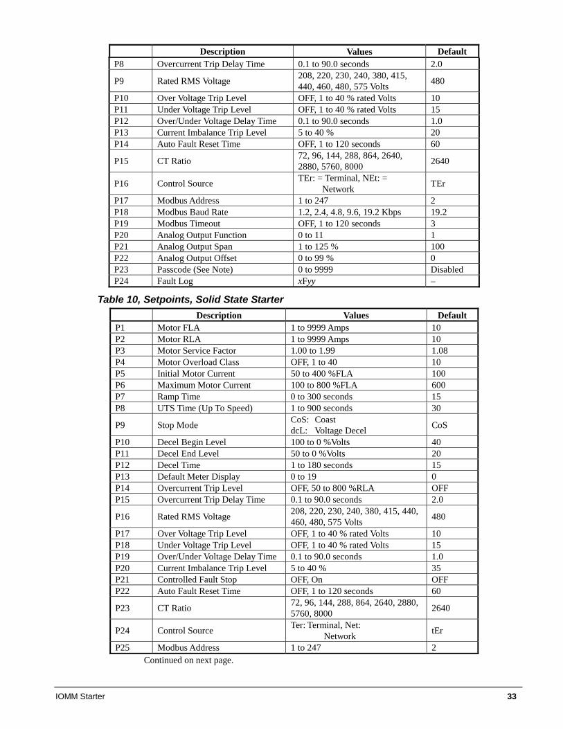
1. Press the PARAM key to return to the parameter number display. 2. Wait 60 seconds and the display will return to the default meter display. The starter setpoint parameters are factory set and subsequently reviewed during commissioning by the McQuay startup technician. They should not be changed unless authorized by McQuay. The programming procedure is explained above and the following table shows the range of values and defaults.
Table 9, Setpoints, Wye-Delta Starter Description Values Default
P1 Motor RLA 1 to 9999 Amps 1 P2 Motor Service Factor 1.00 to 1.99 1.08 P3 Motor Overload Class OFF, 1 to 40 10 P4 Transition Time 1 to 30 seconds 10 P5 Default Meter Display 0 to 19 0 P6 Sequence Complete Delay Time 0.1 to 5.0 seconds 2.0 P7 Overcurrent Trip Level OFF, 50 to 800 %RLA OFF
Continued on next page.
IOMM Starter 33
Description Values Default P8 Overcurrent Trip Delay Time 0.1 to 90.0 seconds 2.0
P9 Rated RMS Voltage 208, 220, 230, 240, 380, 415, 440, 460, 480, 575 Volts 480
P10 Over Voltage Trip Level OFF, 1 to 40 % rated Volts 10 P11 Under Voltage Trip Level OFF, 1 to 40 % rated Volts 15 P12 Over/Under Voltage Delay Time 0.1 to 90.0 seconds 1.0 P13 Current Imbalance Trip Level 5 to 40 % 20 P14 Auto Fault Reset Time OFF, 1 to 120 seconds 60
P15 CT Ratio 72, 96, 144, 288, 864, 2640, 2880, 5760, 8000 2640
P16 Control Source TEr: = Terminal, NEt: = Network TEr
P17 Modbus Address 1 to 247 2 P18 Modbus Baud Rate 1.2, 2.4, 4.8, 9.6, 19.2 Kbps 19.2 P19 Modbus Timeout OFF, 1 to 120 seconds 3 P20 Analog Output Function 0 to 11 1 P21 Analog Output Span 1 to 125 % 100 P22 Analog Output Offset 0 to 99 % 0 P23 Passcode (See Note) 0 to 9999 Disabled P24 Fault Log xFyy –
Table 10, Setpoints, Solid State Starter Description Values Default
P1 Motor FLA 1 to 9999 Amps 10 P2 Motor RLA 1 to 9999 Amps 10 P3 Motor Service Factor 1.00 to 1.99 1.08 P4 Motor Overload Class OFF, 1 to 40 10 P5 Initial Motor Current 50 to 400 %FLA 100 P6 Maximum Motor Current 100 to 800 %FLA 600 P7 Ramp Time 0 to 300 seconds 15 P8 UTS Time (Up To Speed) 1 to 900 seconds 30
P9 Stop Mode CoS: Coast dcL: Voltage Decel CoS
P10 Decel Begin Level 100 to 0 %Volts 40 P11 Decel End Level 50 to 0 %Volts 20 P12 Decel Time 1 to 180 seconds 15 P13 Default Meter Display 0 to 19 0 P14 Overcurrent Trip Level OFF, 50 to 800 %RLA OFF P15 Overcurrent Trip Delay Time 0.1 to 90.0 seconds 2.0
P16 Rated RMS Voltage 208, 220, 230, 240, 380, 415, 440, 460, 480, 575 Volts 480
P17 Over Voltage Trip Level OFF, 1 to 40 % rated Volts 10 P18 Under Voltage Trip Level OFF, 1 to 40 % rated Volts 15 P19 Over/Under Voltage Delay Time 0.1 to 90.0 seconds 1.0 P20 Current Imbalance Trip Level 5 to 40 % 35 P21 Controlled Fault Stop OFF, On OFF P22 Auto Fault Reset Time OFF, 1 to 120 seconds 60
P23 CT Ratio 72, 96, 144, 288, 864, 2640, 2880, 5760, 8000 2640
P24 Control Source Ter: Terminal, Net: Network tEr
P25 Modbus Address 1 to 247 2 Continued on next page.
34 IOMM Starter
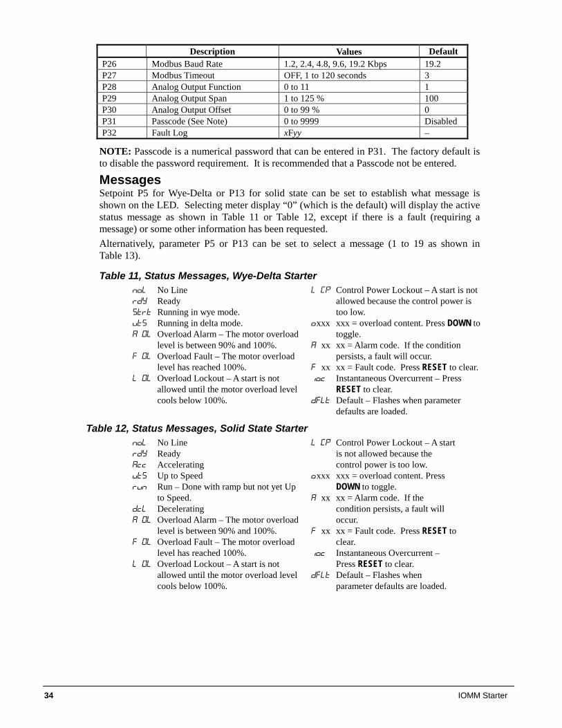
Description Values Default P26 Modbus Baud Rate 1.2, 2.4, 4.8, 9.6, 19.2 Kbps 19.2 P27 Modbus Timeout OFF, 1 to 120 seconds 3 P28 Analog Output Function 0 to 11 1 P29 Analog Output Span 1 to 125 % 100 P30 Analog Output Offset 0 to 99 % 0 P31 Passcode (See Note) 0 to 9999 Disabled P32 Fault Log xFyy –
NOTE: Passcode is a numerical password that can be entered in P31. The factory default is to disable the password requirement. It is recommended that a Passcode not be entered.
Messages Setpoint P5 for Wye-Delta or P13 for solid state can be set to establish what message is shown on the LED. Selecting meter display “0” (which is the default) will display the active status message as shown in Table 11 or Table 12, except if there is a fault (requiring a message) or some other information has been requested. Alternatively, parameter P5 or P13 can be set to select a message (1 to 19 as shown in Table 13).
Table 11, Status Messages, Wye-Delta Starter No Line Ready Running in wye mode. Running in delta mode. Overload Alarm – The motor overload
level is between 90% and 100%. Overload Fault – The motor overload
level has reached 100%. Overload Lockout – A start is not
allowed until the motor overload level cools below 100%.
Control Power Lockout – A start is not allowed because the control power is too low.
xxx xxx = overload content. Press DOWN to toggle.
xx xx = Alarm code. If the condition persists, a fault will occur.
xx xx = Fault code. Press RESET to clear. Instantaneous Overcurrent – Press
RESET to clear. Default – Flashes when parameter
defaults are loaded.
Table 12, Status Messages, Solid State Starter No Line Ready Accelerating Up to Speed Run – Done with ramp but not yet Up
to Speed. Decelerating Overload Alarm – The motor overload
level is between 90% and 100%. Overload Fault – The motor overload
level has reached 100%. Overload Lockout – A start is not
allowed until the motor overload level cools below 100%.
Control Power Lockout – A start is not allowed because the control power is too low.
xxx xxx = overload content. Press DOWN to toggle.
xx xx = Alarm code. If the condition persists, a fault will occur.
xx xx = Fault code. Press RESET to clear.
Instantaneous Overcurrent – Press RESET to clear.
Default – Flashes when parameter defaults are loaded.
IOMM Starter 35
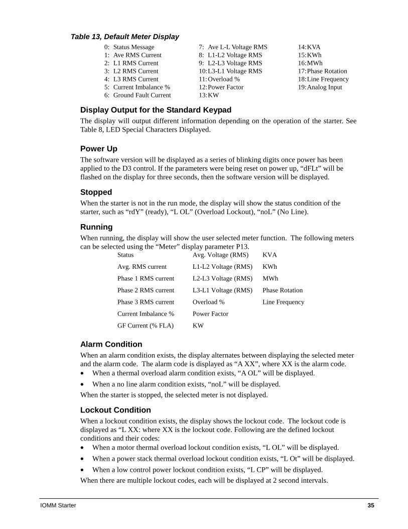
Table 13, Default Meter Display 0: Status Message 1: Ave RMS Current 2: L1 RMS Current 3: L2 RMS Current 4: L3 RMS Current 5: Current Imbalance % 6: Ground Fault Current
7: Ave L-L Voltage RMS 8: L1-L2 Voltage RMS 9: L2-L3 Voltage RMS 10: L3-L1 Voltage RMS 11: Overload % 12: Power Factor 13: KW
14: KVA 15: KWh 16: MWh 17: Phase Rotation 18: Line Frequency 19: Analog Input
Display Output for the Standard Keypad The display will output different information depending on the operation of the starter. See Table 8, LED Special Characters Displayed.
Power Up The software version will be displayed as a series of blinking digits once power has been applied to the D3 control. If the parameters were being reset on power up, “dFLt” will be flashed on the display for three seconds, then the software version will be displayed.
Stopped When the starter is not in the run mode, the display will show the status condition of the starter, such as “rdY” (ready), “L OL” (Overload Lockout), “noL” (No Line).
Running When running, the display will show the user selected meter function. The following meters can be selected using the “Meter” display parameter P13.
Status Avg. Voltage (RMS) KVA
Avg. RMS current L1-L2 Voltage (RMS) KWh
Phase 1 RMS current L2-L3 Voltage (RMS) MWh
Phase 2 RMS current L3-L1 Voltage (RMS) Phase Rotation
Phase 3 RMS current Overload % Line Frequency
Current Imbalance % Power Factor
GF Current (% FLA) KW
Alarm Condition When an alarm condition exists, the display alternates between displaying the selected meter and the alarm code. The alarm code is displayed as “A XX”, where XX is the alarm code. • When a thermal overload alarm condition exists, “A OL” will be displayed. • When a no line alarm condition exists, “noL” will be displayed. When the starter is stopped, the selected meter is not displayed.
Lockout Condition When a lockout condition exists, the display shows the lockout code. The lockout code is displayed as “L XX: where XX is the lockout code. Following are the defined lockout conditions and their codes: • When a motor thermal overload lockout condition exists, “L OL” will be displayed. • When a power stack thermal overload lockout condition exists, “L Ot” will be displayed. • When a low control power lockout condition exists, “L CP” will be displayed. When there are multiple lockout codes, each will be displayed at 2 second intervals.
36 IOMM Starter
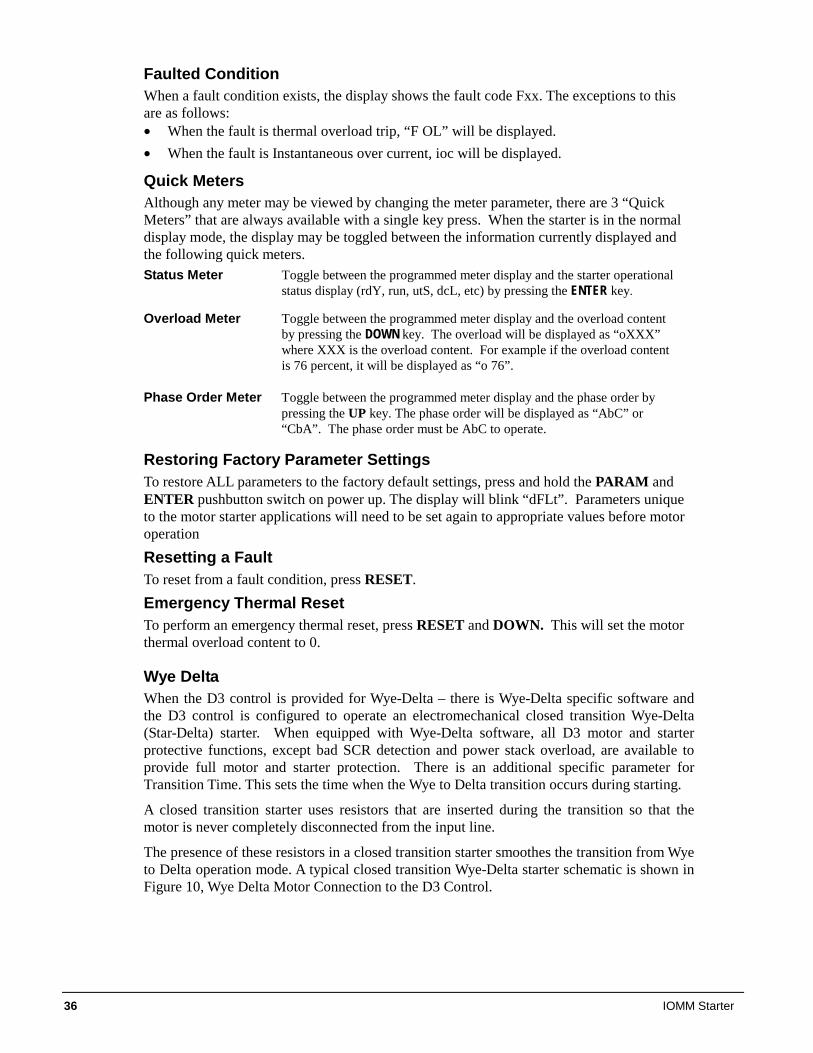
Faulted Condition When a fault condition exists, the display shows the fault code Fxx. The exceptions to this are as follows: • When the fault is thermal overload trip, “F OL” will be displayed. • When the fault is Instantaneous over current, ioc will be displayed.
Quick Meters Although any meter may be viewed by changing the meter parameter, there are 3 “Quick Meters” that are always available with a single key press. When the starter is in the normal display mode, the display may be toggled between the information currently displayed and the following quick meters. Status Meter Toggle between the programmed meter display and the starter operational
status display (rdY, run, utS, dcL, etc) by pressing the ENTER key.
Overload Meter Toggle between the programmed meter display and the overload content by pressing the DOWN key. The overload will be displayed as “oXXX” where XXX is the overload content. For example if the overload content is 76 percent, it will be displayed as “o 76”.
Phase Order Meter Toggle between the programmed meter display and the phase order by pressing the UP key. The phase order will be displayed as “AbC” or “CbA”. The phase order must be AbC to operate.
Restoring Factory Parameter Settings To restore ALL parameters to the factory default settings, press and hold the PARAM and ENTER pushbutton switch on power up. The display will blink “dFLt”. Parameters unique to the motor starter applications will need to be set again to appropriate values before motor operation
Resetting a Fault To reset from a fault condition, press RESET.
Emergency Thermal Reset To perform an emergency thermal reset, press RESET and DOWN. This will set the motor thermal overload content to 0.
Wye Delta When the D3 control is provided for Wye-Delta – there is Wye-Delta specific software and the D3 control is configured to operate an electromechanical closed transition Wye-Delta (Star-Delta) starter. When equipped with Wye-Delta software, all D3 motor and starter protective functions, except bad SCR detection and power stack overload, are available to provide full motor and starter protection. There is an additional specific parameter for Transition Time. This sets the time when the Wye to Delta transition occurs during starting.
A closed transition starter uses resistors that are inserted during the transition so that the motor is never completely disconnected from the input line.
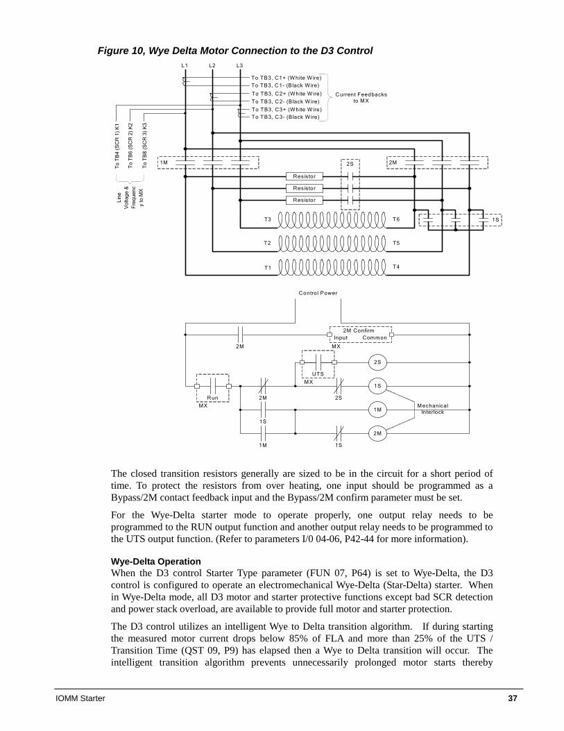
The presence of these resistors in a closed transition starter smoothes the transition from Wye to Delta operation mode. A typical closed transition Wye-Delta starter schematic is shown in Figure 10, Wye Delta Motor Connection to the D3 Control.
IOMM Starter 37
Figure 10, Wye Delta Motor Connection to the D3 Control
M echanicalInterlock
T1
T2
T3 T6
T5
T4
Resistor
Resistor
Resistor
1M
L1 L2 L3
2M2S
1S
1S
2S
1M
2M
2S
Control Power
2M
1S
1M 1S
Run
MX
UTS
M X
2M M X
Input Com m on
To TB3, C1+ (W hite W ire)
To TB3, C2+ (W hite W ire)
To TB3, C3+ (W hite W ire)
To TB3, C1- (B lack W ire)
To TB3, C 2- (B lack W ire)
To TB3, C 3- (B lack W ire)
Current Feedbacks to M X
Lin
e V
olta
ge
&
Fre
que
nc
y to
MX
To
TB
4 (
SC
R 1
) K
1
To
TB
6 (
SC
R 2
) K
2
To
TB
8 (
SC
R 3
) K
3
2M Confirm
The closed transition resistors generally are sized to be in the circuit for a short period of time. To protect the resistors from over heating, one input should be programmed as a Bypass/2M contact feedback input and the Bypass/2M confirm parameter must be set.
For the Wye-Delta starter mode to operate properly, one output relay needs to be programmed to the RUN output function and another output relay needs to be programmed to the UTS output function. (Refer to parameters I/0 04-06, P42-44 for more information).
Wye-Delta Operation When the D3 control Starter Type parameter (FUN 07, P64) is set to Wye-Delta, the D3 control is configured to operate an electromechanical Wye-Delta (Star-Delta) starter. When in Wye-Delta mode, all D3 motor and starter protective functions except bad SCR detection and power stack overload, are available to provide full motor and starter protection.
The D3 control utilizes an intelligent Wye to Delta transition algorithm. If during starting the measured motor current drops below 85% of FLA and more than 25% of the UTS / Transition Time (QST 09, P9) has elapsed then a Wye to Delta transition will occur. The intelligent transition algorithm prevents unnecessarily prolonged motor starts thereby
38 IOMM Starter
reducing motor heating. If a Wye to Delta transition has not already occurred, a transition will always occur when the complete UTS / Transition Time (QST 09, P9) expires.
The D3 control can operate two configurations of Wye-Delta starters, open transition and closed transition. An open transition starter momentarily disconnects the motor from the input line during the transition from Wye to Delta operating mode. A closed transition starter uses resistors that are inserted during the transition so that the motor is never completely disconnected from the input line. The presence of these resistors in a closed transition starter smoothes the transition from Wye to Delta operating mode. A typical closed transition Wye-Delta starter schematic is shown in Figure 10.
For the Wye-Delta starter mode to operate properly, one output relay needs to be programmed to the RUN output function and another output relay needs to be programmed to the UTS output function. (Refer to parameters I/0 04-06, P42-44 for more information.)
Based on the typical closed transition schematic shown in Figure 10, Wye Delta Motor Connection to the D3 Control, when a start command is given the starter will enter the Wye starting mode by energizing the relay programmed as RUN.
The transition to Wye (Starting) mode occurs as follows:
1. Start command is given to the starter.
2. The RUN relay is energized which energizes the 1S contactor.
3. When the 1S contactor pulls in, the 1M contactor is energized.
The D3 starter will remain in the Wye mode until either:
1. The start command is removed.
2. The Transition Time (QST 09, P9) expires
or
The measured motor current is less than 85% of FLA and at least 25% of the Transition Time (QST 09, P9) has elapsed.
3. A fault occurs.
When the Transition Time (QST 09, P9) expires, the starter will change from Wye starting mode to the Delta or normal running mode by energizing the relay programmed as UTS. In Delta mode, the RUN and UTS relays are both energized and the motor is connected in the normal running Delta configuration.
The transition to Delta (Run) mode occurs as follows:
1. The Transition Time (QST 09, P9) expires
or
The measured motor current is less than 85% of FLA and at least 25% of the Transition Time (QST 09, P9) has elapsed.
2. The UTS relay is energized which energizes the 2S contactor.
3. When the 2S contactor pulls in, resistors are inserted in the circuit and the 1S contactor is DE-energized.
4. When the 1S contactor drops out the 2M contactor is energized.
5. When the 2M contactor is pulled in, feedback can be sent to the D3 control board to confirm that the transition sequence to Delta is complete.
IOMM Starter 39
The starter will remain in the Delta or running mode until the start command is removed or a fault occurs.
Usually the D3 intelligent Wye to Delta transition algorithm provides an optimal transition point that minimizes the transient current and torque surges that can occur. However sometimes, based on the motor and loading, the Wye to Delta transition will occur only after the Transition Time has expired. In order to reduce the current surge that can take place during the transition from Wye to Delta mode, the Transition Time parameter (QST 09, P9) should be adjusted so that the transition occurs as close to full speed as possible within the constraints of the load. If the transition time is set too short, a large current and torque surge may occur during the transition. If the transition time is set too long, the motor may not have sufficient torque to continue accelerating when in Wye mode and may stop accelerating at a low speed until the transition to Delta mode occurs. If this occurs, the start is unnecessarily prolonged and motor heating is increased.
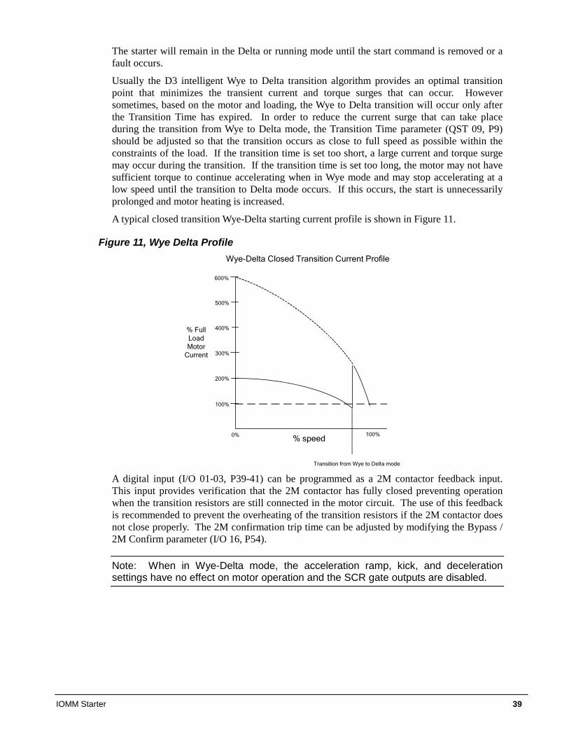
A typical closed transition Wye-Delta starting current profile is shown in Figure 11.
Figure 11, Wye Delta Profile
100%
200%
300%
400%
500%
600%
0% 100%% speed
Wye-Delta Closed Transition Current Profile
% Full Load Motor
Current
Transition from Wye to Delta mode
A digital input (I/O 01-03, P39-41) can be programmed as a 2M contactor feedback input. This input provides verification that the 2M contactor has fully closed preventing operation when the transition resistors are still connected in the motor circuit. The use of this feedback is recommended to prevent the overheating of the transition resistors if the 2M contactor does not close properly. The 2M confirmation trip time can be adjusted by modifying the Bypass / 2M Confirm parameter (I/O 16, P54).
Note: When in Wye-Delta mode, the acceleration ramp, kick, and deceleration settings have no effect on motor operation and the SCR gate outputs are disabled.
40 IOMM Starter
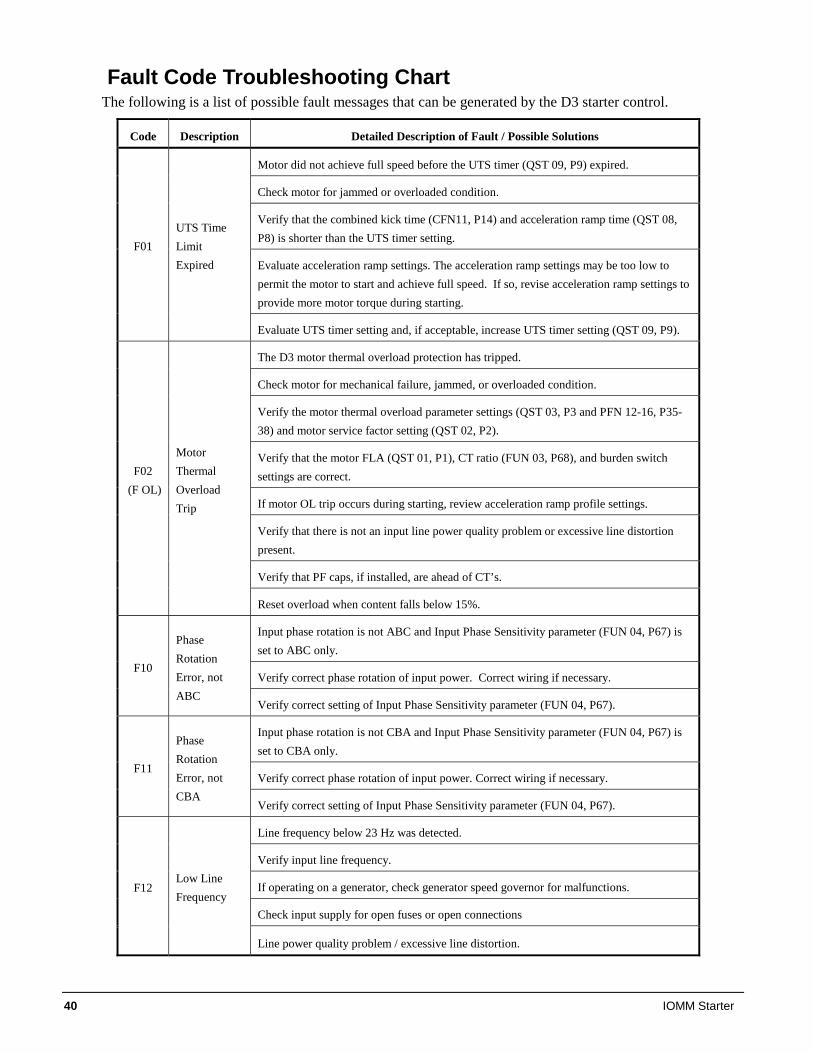
Fault Code Troubleshooting Chart The following is a list of possible fault messages that can be generated by the D3 starter control.
Code Description Detailed Description of Fault / Possible Solutions
Motor did not achieve full speed before the UTS timer (QST 09, P9) expired.
Check motor for jammed or overloaded condition.
Verify that the combined kick time (CFN11, P14) and acceleration ramp time (QST 08, P8) is shorter than the UTS timer setting.
Evaluate acceleration ramp settings. The acceleration ramp settings may be too low to permit the motor to start and achieve full speed. If so, revise acceleration ramp settings to provide more motor torque during starting.
F01 UTS Time Limit Expired
Evaluate UTS timer setting and, if acceptable, increase UTS timer setting (QST 09, P9).
The D3 motor thermal overload protection has tripped.
Check motor for mechanical failure, jammed, or overloaded condition.
Verify the motor thermal overload parameter settings (QST 03, P3 and PFN 12-16, P35-38) and motor service factor setting (QST 02, P2).
Verify that the motor FLA (QST 01, P1), CT ratio (FUN 03, P68), and burden switch settings are correct.
If motor OL trip occurs during starting, review acceleration ramp profile settings.
Verify that there is not an input line power quality problem or excessive line distortion present.
Verify that PF caps, if installed, are ahead of CT’s.
F02 (F OL)
Motor Thermal Overload Trip
Reset overload when content falls below 15%.
Input phase rotation is not ABC and Input Phase Sensitivity parameter (FUN 04, P67) is set to ABC only.
Verify correct phase rotation of input power. Correct wiring if necessary. F10
Phase Rotation Error, not ABC
Verify correct setting of Input Phase Sensitivity parameter (FUN 04, P67).
Input phase rotation is not CBA and Input Phase Sensitivity parameter (FUN 04, P67) is set to CBA only.
Verify correct phase rotation of input power. Correct wiring if necessary. F11
Phase Rotation Error, not CBA
Verify correct setting of Input Phase Sensitivity parameter (FUN 04, P67).
Line frequency below 23 Hz was detected.
Verify input line frequency.
If operating on a generator, check generator speed governor for malfunctions.
Check input supply for open fuses or open connections
F12 Low Line Frequency
Line power quality problem / excessive line distortion.
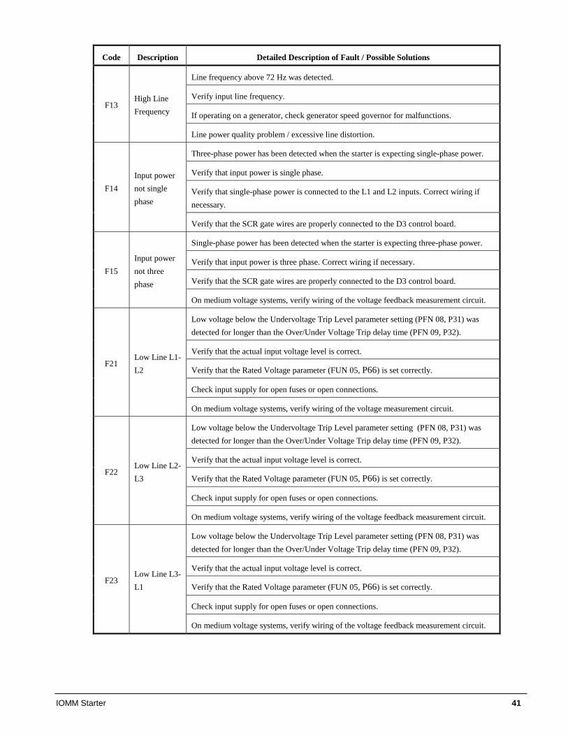
IOMM Starter 41
Code Description Detailed Description of Fault / Possible Solutions
Line frequency above 72 Hz was detected.
Verify input line frequency.
If operating on a generator, check generator speed governor for malfunctions. F13
High Line Frequency
Line power quality problem / excessive line distortion.
Three-phase power has been detected when the starter is expecting single-phase power.
Verify that input power is single phase.
Verify that single-phase power is connected to the L1 and L2 inputs. Correct wiring if necessary.
F14 Input power not single phase
Verify that the SCR gate wires are properly connected to the D3 control board.
Single-phase power has been detected when the starter is expecting three-phase power.
Verify that input power is three phase. Correct wiring if necessary.
Verify that the SCR gate wires are properly connected to the D3 control board. F15
Input power not three phase
On medium voltage systems, verify wiring of the voltage feedback measurement circuit.
Low voltage below the Undervoltage Trip Level parameter setting (PFN 08, P31) was detected for longer than the Over/Under Voltage Trip delay time (PFN 09, P32).
Verify that the actual input voltage level is correct.
Verify that the Rated Voltage parameter (FUN 05, P66) is set correctly.
Check input supply for open fuses or open connections.
F21 Low Line L1-L2
On medium voltage systems, verify wiring of the voltage measurement circuit.
Low voltage below the Undervoltage Trip Level parameter setting (PFN 08, P31) was detected for longer than the Over/Under Voltage Trip delay time (PFN 09, P32).
Verify that the actual input voltage level is correct.
Verify that the Rated Voltage parameter (FUN 05, P66) is set correctly.
Check input supply for open fuses or open connections.
F22 Low Line L2-L3
On medium voltage systems, verify wiring of the voltage feedback measurement circuit.
Low voltage below the Undervoltage Trip Level parameter setting (PFN 08, P31) was detected for longer than the Over/Under Voltage Trip delay time (PFN 09, P32).
Verify that the actual input voltage level is correct.
Verify that the Rated Voltage parameter (FUN 05, P66) is set correctly.
Check input supply for open fuses or open connections.
F23 Low Line L3-L1
On medium voltage systems, verify wiring of the voltage feedback measurement circuit.
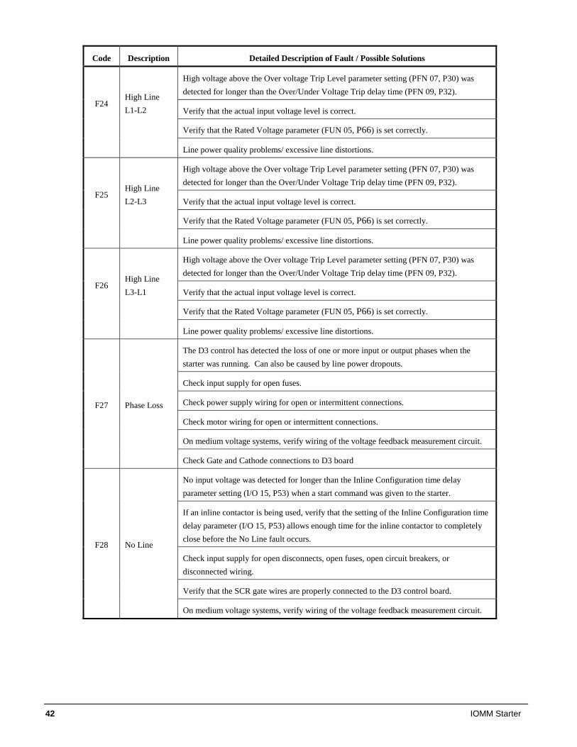
42 IOMM Starter
Code Description Detailed Description of Fault / Possible Solutions
High voltage above the Over voltage Trip Level parameter setting (PFN 07, P30) was detected for longer than the Over/Under Voltage Trip delay time (PFN 09, P32).
Verify that the actual input voltage level is correct. F24
High Line L1-L2
Verify that the Rated Voltage parameter (FUN 05, P66) is set correctly.
Line power quality problems/ excessive line distortions.
High voltage above the Over voltage Trip Level parameter setting (PFN 07, P30) was detected for longer than the Over/Under Voltage Trip delay time (PFN 09, P32).
Verify that the actual input voltage level is correct. F25
High Line L2-L3
Verify that the Rated Voltage parameter (FUN 05, P66) is set correctly.
Line power quality problems/ excessive line distortions.
High voltage above the Over voltage Trip Level parameter setting (PFN 07, P30) was detected for longer than the Over/Under Voltage Trip delay time (PFN 09, P32).
Verify that the actual input voltage level is correct. F26
High Line L3-L1
Verify that the Rated Voltage parameter (FUN 05, P66) is set correctly.
Line power quality problems/ excessive line distortions.
The D3 control has detected the loss of one or more input or output phases when the starter was running. Can also be caused by line power dropouts.
Check input supply for open fuses.
Check power supply wiring for open or intermittent connections.
Check motor wiring for open or intermittent connections.
On medium voltage systems, verify wiring of the voltage feedback measurement circuit.
F27 Phase Loss
Check Gate and Cathode connections to D3 board
No input voltage was detected for longer than the Inline Configuration time delay parameter setting (I/O 15, P53) when a start command was given to the starter.
If an inline contactor is being used, verify that the setting of the Inline Configuration time delay parameter (I/O 15, P53) allows enough time for the inline contactor to completely close before the No Line fault occurs.
Check input supply for open disconnects, open fuses, open circuit breakers, or disconnected wiring.
Verify that the SCR gate wires are properly connected to the D3 control board.
F28 No Line
On medium voltage systems, verify wiring of the voltage feedback measurement circuit.
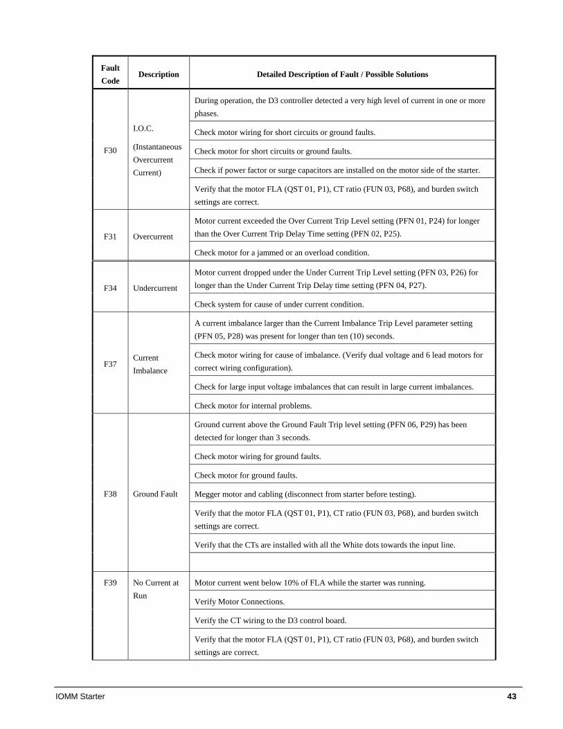
IOMM Starter 43
Fault Code
Description Detailed Description of Fault / Possible Solutions
During operation, the D3 controller detected a very high level of current in one or more phases.
Check motor wiring for short circuits or ground faults.
Check motor for short circuits or ground faults.
Check if power factor or surge capacitors are installed on the motor side of the starter.
F30
I.O.C.
(Instantaneous Overcurrent Current)
Verify that the motor FLA (QST 01, P1), CT ratio (FUN 03, P68), and burden switch settings are correct.
Motor current exceeded the Over Current Trip Level setting (PFN 01, P24) for longer than the Over Current Trip Delay Time setting (PFN 02, P25). F31 Overcurrent
Check motor for a jammed or an overload condition.
Motor current dropped under the Under Current Trip Level setting (PFN 03, P26) for longer than the Under Current Trip Delay time setting (PFN 04, P27). F34 Undercurrent
Check system for cause of under current condition.
A current imbalance larger than the Current Imbalance Trip Level parameter setting (PFN 05, P28) was present for longer than ten (10) seconds.
Check motor wiring for cause of imbalance. (Verify dual voltage and 6 lead motors for correct wiring configuration).
Check for large input voltage imbalances that can result in large current imbalances.
F37 Current Imbalance
Check motor for internal problems.
Ground current above the Ground Fault Trip level setting (PFN 06, P29) has been detected for longer than 3 seconds.
Check motor wiring for ground faults.
Check motor for ground faults.
Megger motor and cabling (disconnect from starter before testing).
Verify that the motor FLA (QST 01, P1), CT ratio (FUN 03, P68), and burden switch settings are correct.
Verify that the CTs are installed with all the White dots towards the input line.
F38 Ground Fault
Motor current went below 10% of FLA while the starter was running.
Verify Motor Connections.
Verify the CT wiring to the D3 control board.
F39 No Current at Run
Verify that the motor FLA (QST 01, P1), CT ratio (FUN 03, P68), and burden switch settings are correct.
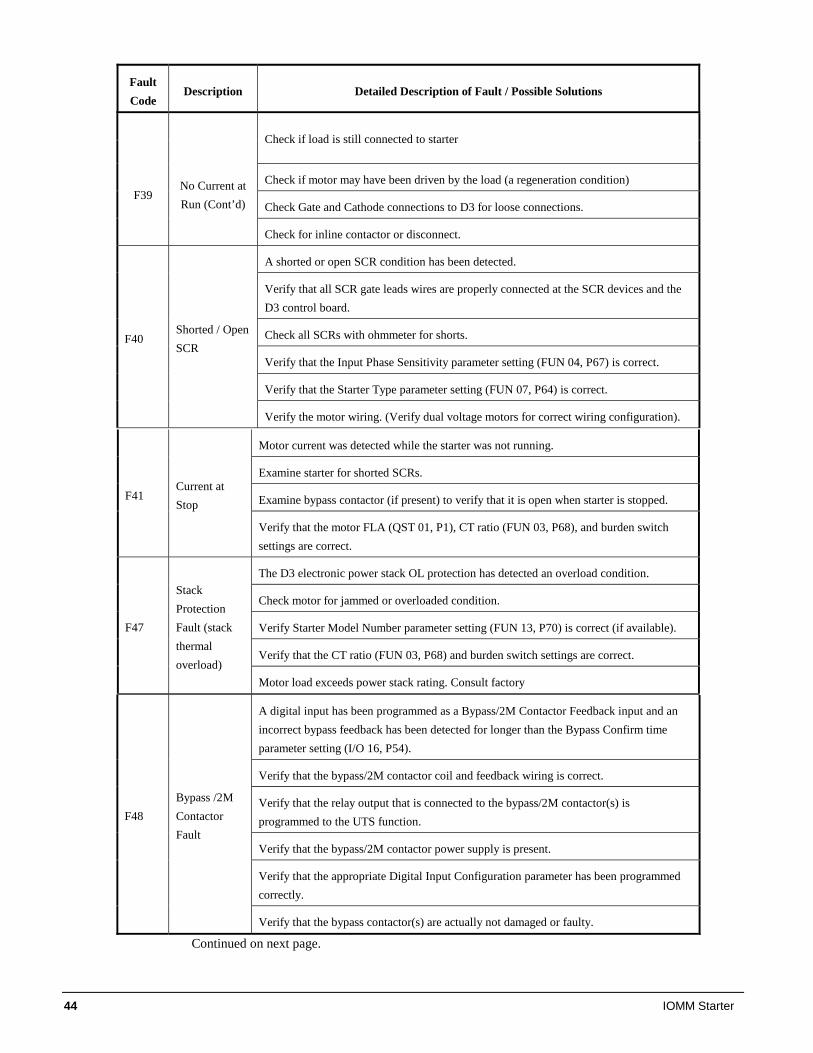
44 IOMM Starter
Fault Code
Description Detailed Description of Fault / Possible Solutions
Check if load is still connected to starter
Check if motor may have been driven by the load (a regeneration condition)
Check Gate and Cathode connections to D3 for loose connections. F39
No Current at Run (Cont’d)
Check for inline contactor or disconnect.
A shorted or open SCR condition has been detected.
Verify that all SCR gate leads wires are properly connected at the SCR devices and the D3 control board.
Check all SCRs with ohmmeter for shorts.
Verify that the Input Phase Sensitivity parameter setting (FUN 04, P67) is correct.
Verify that the Starter Type parameter setting (FUN 07, P64) is correct.
F40 Shorted / Open SCR
Verify the motor wiring. (Verify dual voltage motors for correct wiring configuration). Motor current was detected while the starter was not running.
Examine starter for shorted SCRs.
Examine bypass contactor (if present) to verify that it is open when starter is stopped. F41 Current at Stop
Verify that the motor FLA (QST 01, P1), CT ratio (FUN 03, P68), and burden switch settings are correct.
The D3 electronic power stack OL protection has detected an overload condition.
Check motor for jammed or overloaded condition.
Verify Starter Model Number parameter setting (FUN 13, P70) is correct (if available).
Verify that the CT ratio (FUN 03, P68) and burden switch settings are correct.
F47
Stack Protection Fault (stack thermal overload)
Motor load exceeds power stack rating. Consult factory
A digital input has been programmed as a Bypass/2M Contactor Feedback input and an incorrect bypass feedback has been detected for longer than the Bypass Confirm time parameter setting (I/O 16, P54).
Verify that the bypass/2M contactor coil and feedback wiring is correct.
Verify that the relay output that is connected to the bypass/2M contactor(s) is programmed to the UTS function.
Verify that the bypass/2M contactor power supply is present.
Verify that the appropriate Digital Input Configuration parameter has been programmed correctly.
F48 Bypass /2M Contactor Fault
Verify that the bypass contactor(s) are actually not damaged or faulty.
Continued on next page.
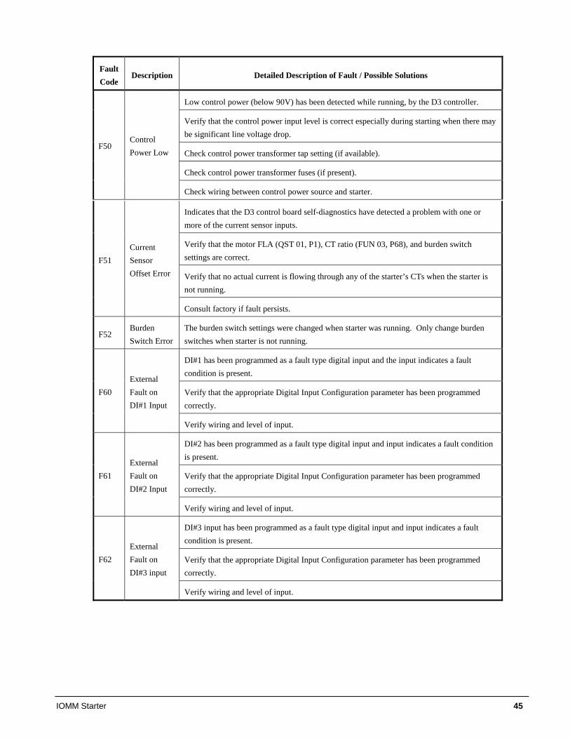
IOMM Starter 45
Fault Code
Description Detailed Description of Fault / Possible Solutions
Low control power (below 90V) has been detected while running, by the D3 controller.
Verify that the control power input level is correct especially during starting when there may be significant line voltage drop.
Check control power transformer tap setting (if available).
Check control power transformer fuses (if present).
F50 Control Power Low
Check wiring between control power source and starter.
Indicates that the D3 control board self-diagnostics have detected a problem with one or more of the current sensor inputs.
Verify that the motor FLA (QST 01, P1), CT ratio (FUN 03, P68), and burden switch settings are correct.
Verify that no actual current is flowing through any of the starter’s CTs when the starter is not running.
F51 Current Sensor Offset Error
Consult factory if fault persists.
F52 Burden Switch Error
The burden switch settings were changed when starter was running. Only change burden switches when starter is not running.
DI#1 has been programmed as a fault type digital input and the input indicates a fault condition is present.
Verify that the appropriate Digital Input Configuration parameter has been programmed correctly.
F60 External Fault on DI#1 Input
Verify wiring and level of input.
DI#2 has been programmed as a fault type digital input and input indicates a fault condition is present.
Verify that the appropriate Digital Input Configuration parameter has been programmed correctly.
F61 External Fault on DI#2 Input
Verify wiring and level of input.
DI#3 input has been programmed as a fault type digital input and input indicates a fault condition is present.
Verify that the appropriate Digital Input Configuration parameter has been programmed correctly.
F62 External Fault on DI#3 input
Verify wiring and level of input.
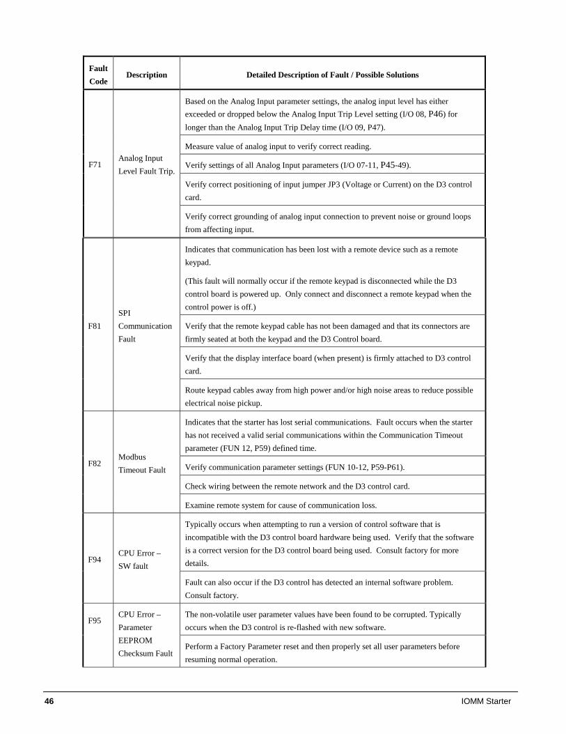
46 IOMM Starter
Fault Code
Description Detailed Description of Fault / Possible Solutions
Based on the Analog Input parameter settings, the analog input level has either exceeded or dropped below the Analog Input Trip Level setting (I/O 08, P46) for longer than the Analog Input Trip Delay time (I/O 09, P47).
Measure value of analog input to verify correct reading.
Verify settings of all Analog Input parameters (I/O 07-11, P45-49).
Verify correct positioning of input jumper JP3 (Voltage or Current) on the D3 control card.
F71 Analog Input Level Fault Trip.
Verify correct grounding of analog input connection to prevent noise or ground loops from affecting input.
Indicates that communication has been lost with a remote device such as a remote keypad.
(This fault will normally occur if the remote keypad is disconnected while the D3 control board is powered up. Only connect and disconnect a remote keypad when the control power is off.)
Verify that the remote keypad cable has not been damaged and that its connectors are firmly seated at both the keypad and the D3 Control board.
Verify that the display interface board (when present) is firmly attached to D3 control card.
F81 SPI Communication Fault
Route keypad cables away from high power and/or high noise areas to reduce possible electrical noise pickup.
Indicates that the starter has lost serial communications. Fault occurs when the starter has not received a valid serial communications within the Communication Timeout parameter (FUN 12, P59) defined time.
Verify communication parameter settings (FUN 10-12, P59-P61).
Check wiring between the remote network and the D3 control card.
F82 Modbus Timeout Fault
Examine remote system for cause of communication loss.
Typically occurs when attempting to run a version of control software that is incompatible with the D3 control board hardware being used. Verify that the software is a correct version for the D3 control board being used. Consult factory for more details. F94
CPU Error – SW fault
Fault can also occur if the D3 control has detected an internal software problem. Consult factory.
The non-volatile user parameter values have been found to be corrupted. Typically occurs when the D3 control is re-flashed with new software.
F95 CPU Error – Parameter EEPROM Checksum Fault
Perform a Factory Parameter reset and then properly set all user parameters before resuming normal operation.
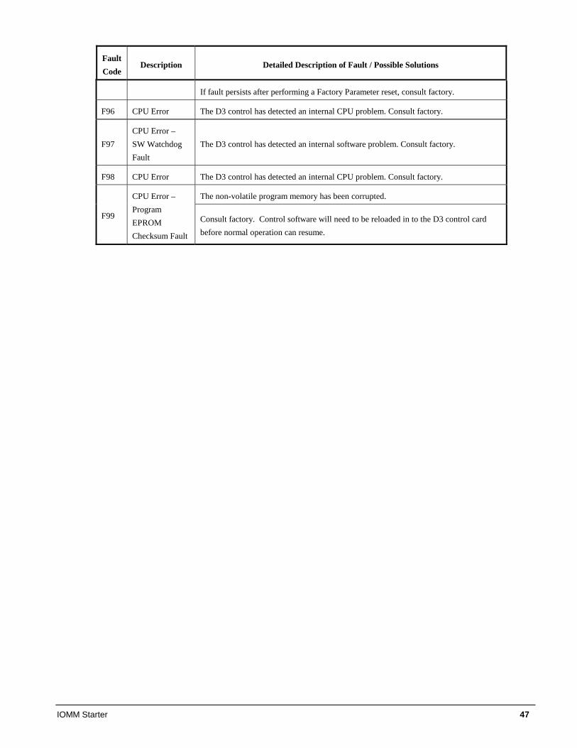
IOMM Starter 47
Fault Code
Description Detailed Description of Fault / Possible Solutions
If fault persists after performing a Factory Parameter reset, consult factory.
F96 CPU Error The D3 control has detected an internal CPU problem. Consult factory.
F97 CPU Error – SW Watchdog Fault
The D3 control has detected an internal software problem. Consult factory.
F98 CPU Error The D3 control has detected an internal CPU problem. Consult factory.
The non-volatile program memory has been corrupted.
F99
CPU Error – Program EPROM Checksum Fault
Consult factory. Control software will need to be reloaded in to the D3 control card before normal operation can resume.
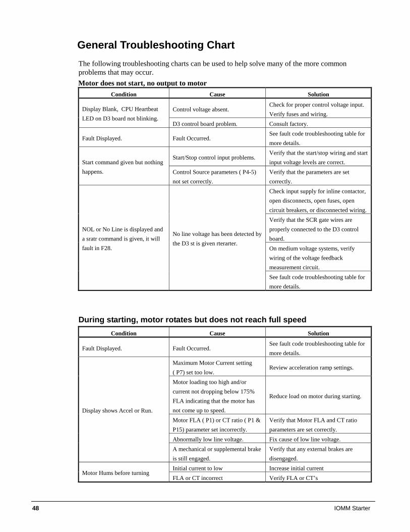
48 IOMM Starter
General Troubleshooting Chart The following troubleshooting charts can be used to help solve many of the more common problems that may occur. Motor does not start, no output to motor
Condition Cause Solution
Control voltage absent. Check for proper control voltage input. Verify fuses and wiring.
Display Blank, CPU Heartbeat LED on D3 board not blinking.
D3 control board problem. Consult factory.
Fault Displayed. Fault Occurred. See fault code troubleshooting table for more details.
Start/Stop control input problems. Verify that the start/stop wiring and start input voltage levels are correct. Start command given but nothing
happens. Control Source parameters ( P4-5) not set correctly.
Verify that the parameters are set correctly. Check input supply for inline contactor, open disconnects, open fuses, open circuit breakers, or disconnected wiring. Verify that the SCR gate wires are properly connected to the D3 control board. On medium voltage systems, verify wiring of the voltage feedback measurement circuit.
NOL or No Line is displayed and a sratr command is given, it will fault in F28.
No line voltage has been detected by the D3 st is given rterarter.
See fault code troubleshooting table for more details.
During starting, motor rotates but does not reach full speed Condition Cause Solution
Fault Displayed. Fault Occurred. See fault code troubleshooting table for more details.
Maximum Motor Current setting ( P7) set too low.
Review acceleration ramp settings.
Motor loading too high and/or current not dropping below 175% FLA indicating that the motor has not come up to speed.
Reduce load on motor during starting.
Motor FLA ( P1) or CT ratio ( P1 & P15) parameter set incorrectly.
Verify that Motor FLA and CT ratio parameters are set correctly.
Abnormally low line voltage. Fix cause of low line voltage.
Display shows Accel or Run.
A mechanical or supplemental brake is still engaged.
Verify that any external brakes are disengaged.
Initial current to low Increase initial current Motor Hums before turning
FLA or CT incorrect Verify FLA or CT’s
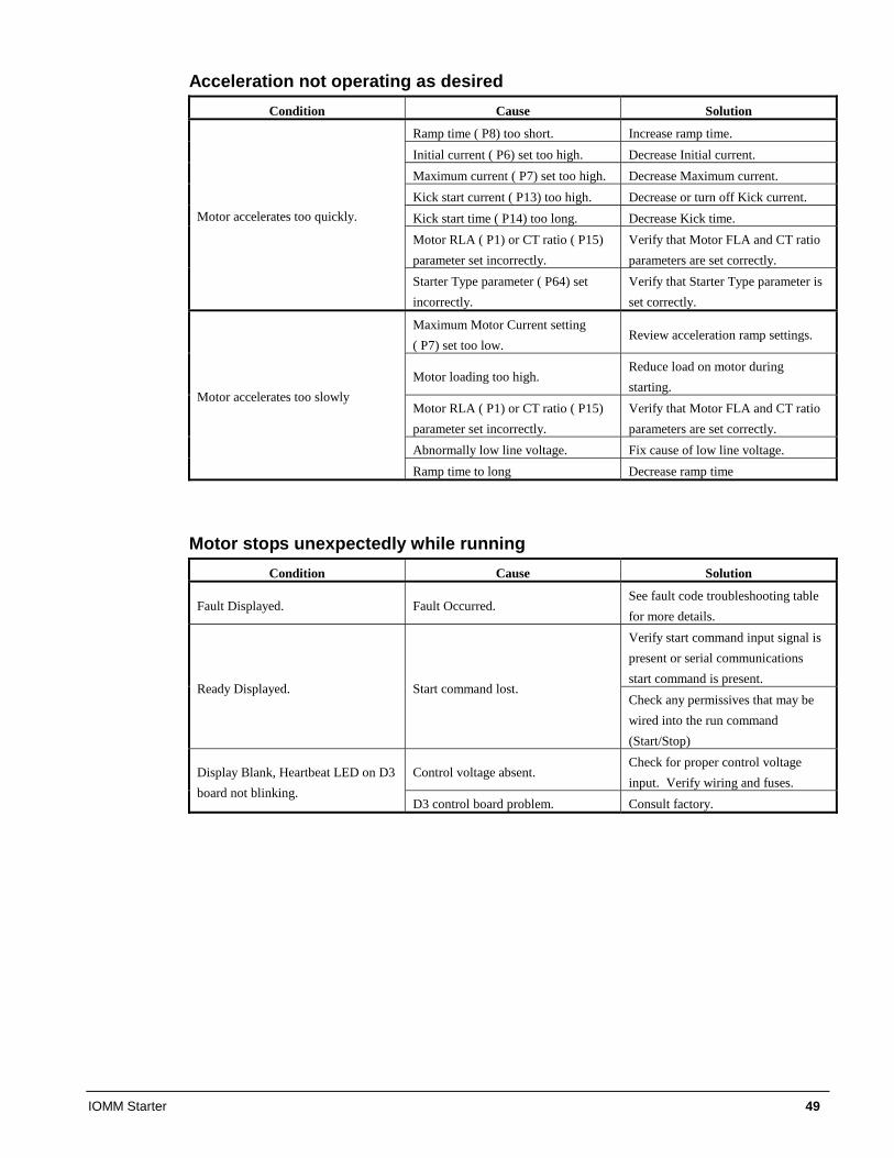
IOMM Starter 49
Acceleration not operating as desired Condition Cause Solution
Ramp time ( P8) too short. Increase ramp time. Initial current ( P6) set too high. Decrease Initial current. Maximum current ( P7) set too high. Decrease Maximum current. Kick start current ( P13) too high. Decrease or turn off Kick current. Kick start time ( P14) too long. Decrease Kick time. Motor RLA ( P1) or CT ratio ( P15) parameter set incorrectly.
Verify that Motor FLA and CT ratio parameters are set correctly.
Motor accelerates too quickly.
Starter Type parameter ( P64) set incorrectly.
Verify that Starter Type parameter is set correctly.
Maximum Motor Current setting ( P7) set too low.
Review acceleration ramp settings.
Motor loading too high. Reduce load on motor during starting.
Motor RLA ( P1) or CT ratio ( P15) parameter set incorrectly.
Verify that Motor FLA and CT ratio parameters are set correctly.
Abnormally low line voltage. Fix cause of low line voltage.
Motor accelerates too slowly
Ramp time to long Decrease ramp time
Motor stops unexpectedly while running Condition Cause Solution
Fault Displayed. Fault Occurred. See fault code troubleshooting table for more details. Verify start command input signal is present or serial communications start command is present.
Ready Displayed. Start command lost. Check any permissives that may be wired into the run command (Start/Stop)
Control voltage absent. Check for proper control voltage input. Verify wiring and fuses.
Display Blank, Heartbeat LED on D3 board not blinking.
D3 control board problem. Consult factory.
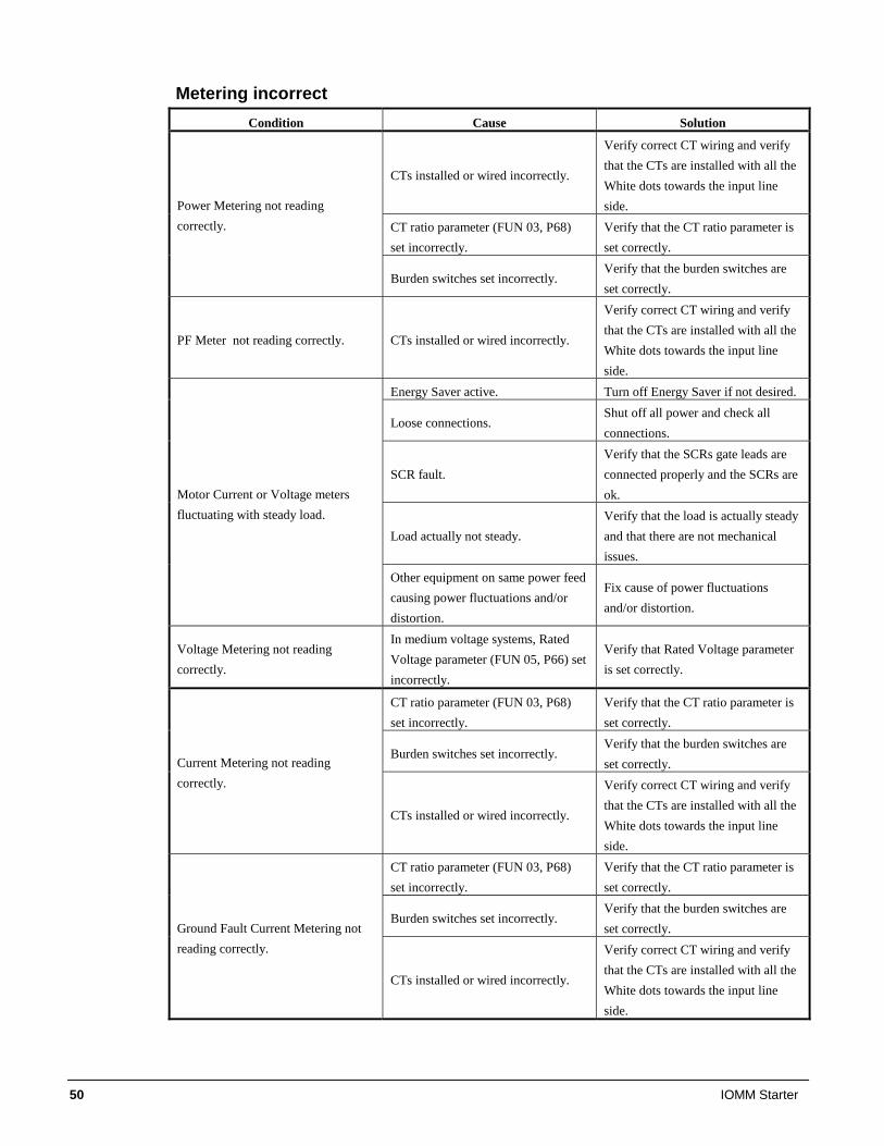
50 IOMM Starter
Metering incorrect Condition Cause Solution
CTs installed or wired incorrectly.
Verify correct CT wiring and verify that the CTs are installed with all the White dots towards the input line side.
CT ratio parameter (FUN 03, P68) set incorrectly.
Verify that the CT ratio parameter is set correctly.
Power Metering not reading correctly.
Burden switches set incorrectly. Verify that the burden switches are set correctly.
PF Meter not reading correctly. CTs installed or wired incorrectly.
Verify correct CT wiring and verify that the CTs are installed with all the White dots towards the input line side.
Energy Saver active. Turn off Energy Saver if not desired.
Loose connections. Shut off all power and check all connections.
SCR fault. Verify that the SCRs gate leads are connected properly and the SCRs are ok.
Load actually not steady. Verify that the load is actually steady and that there are not mechanical issues.
Motor Current or Voltage meters fluctuating with steady load.
Other equipment on same power feed causing power fluctuations and/or distortion.
Fix cause of power fluctuations and/or distortion.
Voltage Metering not reading correctly.
In medium voltage systems, Rated Voltage parameter (FUN 05, P66) set incorrectly.
Verify that Rated Voltage parameter is set correctly.
CT ratio parameter (FUN 03, P68) set incorrectly.
Verify that the CT ratio parameter is set correctly.
Burden switches set incorrectly. Verify that the burden switches are set correctly. Current Metering not reading
correctly.
CTs installed or wired incorrectly.
Verify correct CT wiring and verify that the CTs are installed with all the White dots towards the input line side.
CT ratio parameter (FUN 03, P68) set incorrectly.
Verify that the CT ratio parameter is set correctly.
Burden switches set incorrectly. Verify that the burden switches are set correctly. Ground Fault Current Metering not
reading correctly.
CTs installed or wired incorrectly.
Verify correct CT wiring and verify that the CTs are installed with all the White dots towards the input line side.
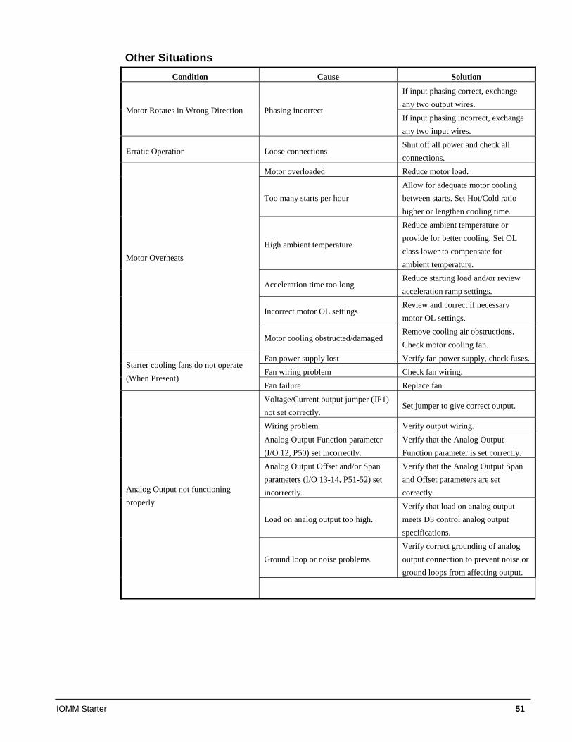
IOMM Starter 51
Other Situations Condition Cause Solution
If input phasing correct, exchange any two output wires.
Motor Rotates in Wrong Direction Phasing incorrect If input phasing incorrect, exchange any two input wires.
Erratic Operation Loose connections Shut off all power and check all connections.
Motor overloaded Reduce motor load.
Too many starts per hour Allow for adequate motor cooling between starts. Set Hot/Cold ratio higher or lengthen cooling time.
High ambient temperature
Reduce ambient temperature or provide for better cooling. Set OL class lower to compensate for ambient temperature.
Acceleration time too long Reduce starting load and/or review acceleration ramp settings.
Incorrect motor OL settings Review and correct if necessary motor OL settings.
Motor Overheats
Motor cooling obstructed/damaged Remove cooling air obstructions. Check motor cooling fan.
Fan power supply lost Verify fan power supply, check fuses. Fan wiring problem Check fan wiring.
Starter cooling fans do not operate (When Present)
Fan failure Replace fan Voltage/Current output jumper (JP1) not set correctly.
Set jumper to give correct output.
Wiring problem Verify output wiring. Analog Output Function parameter (I/O 12, P50) set incorrectly.
Verify that the Analog Output Function parameter is set correctly.
Analog Output Offset and/or Span parameters (I/O 13-14, P51-52) set incorrectly.
Verify that the Analog Output Span and Offset parameters are set correctly.
Load on analog output too high. Verify that load on analog output meets D3 control analog output specifications.
Ground loop or noise problems. Verify correct grounding of analog output connection to prevent noise or ground loops from affecting output.
Analog Output not functioning properly
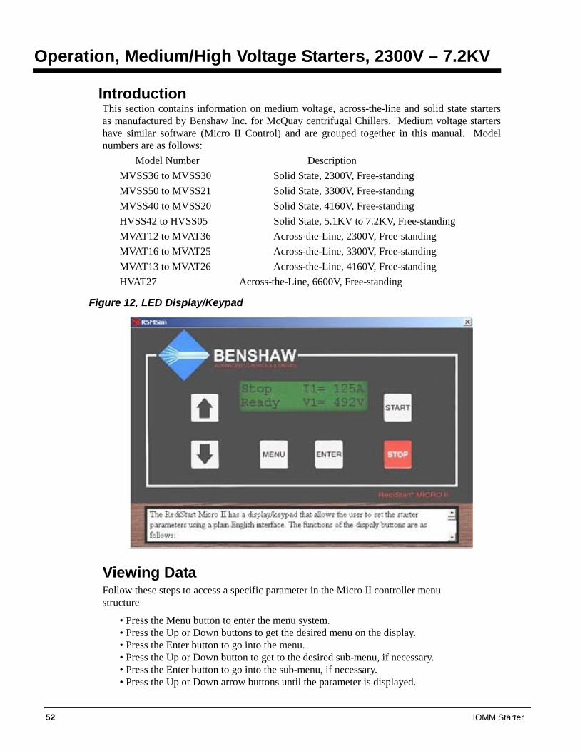
52 IOMM Starter
Operation, Medium/High Voltage Starters, 2300V – 7.2KV
Introduction This section contains information on medium voltage, across-the-line and solid state starters as manufactured by Benshaw Inc. for McQuay centrifugal Chillers. Medium voltage starters have similar software (Micro II Control) and are grouped together in this manual. Model numbers are as follows:
Model Number Description MVSS36 to MVSS30 Solid State, 2300V, Free-standing MVSS50 to MVSS21 Solid State, 3300V, Free-standing MVSS40 to MVSS20 Solid State, 4160V, Free-standing HVSS42 to HVSS05 Solid State, 5.1KV to 7.2KV, Free-standing MVAT12 to MVAT36 Across-the-Line, 2300V, Free-standing MVAT16 to MVAT25 Across-the-Line, 3300V, Free-standing MVAT13 to MVAT26 Across-the-Line, 4160V, Free-standing HVAT27 Across-the-Line, 6600V, Free-standing
Figure 12, LED Display/Keypad
Viewing Data Follow these steps to access a specific parameter in the Micro II controller menu structure
• Press the Menu button to enter the menu system. • Press the Up or Down buttons to get the desired menu on the display. • Press the Enter button to go into the menu. • Press the Up or Down button to get to the desired sub-menu, if necessary. • Press the Enter button to go into the sub-menu, if necessary. • Press the Up or Down arrow buttons until the parameter is displayed.
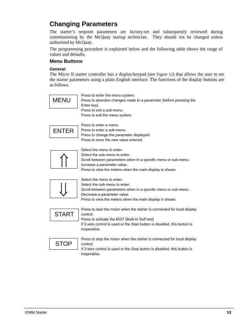
IOMM Starter 53
Changing Parameters The starter’s setpoint parameters are factory-set and subsequently reviewed during commissioning by the McQuay startup technician. They should not be changed unless authorized by McQuay. The programming procedure is explained below and the following table shows the range of values and defaults. Menu Buttons General: The Micro II starter controller has a display/keypad (see Figure 12) that allows the user to set the starter parameters using a plain English interface. The functions of the display buttons are as follows.
Press to enter the menu system. Press to abandon changes made to a parameter (before pressing the Enter key). Press to exit a sub-menu. Press to exit the menu system.
Press to enter a menu. Press to enter a sub-menu. Press to change the parameter displayed. Press to store the new value entered. Select the menu to enter. Select the sub-menu to enter. Scroll between parameters when in a specific menu or sub-menu. Increase a parameter value. Press to view the meters when the main display is shown.
Select the menu to enter. Select the sub-menu to enter. Scroll between parameters when in a specific menu or sub-menu. Decrease a parameter value. Press to view the meters when the main display is shown. Press to start the motor when the starter is connected for local display control. Press to activate the BIST (Built-In Self test) If 2-wire control is used or the Start button is disabled, this button is inoperative. Press to stop the motor when the starter is connected for local display control. If 2-wire control is used or the Stop button is disabled, this button is inoperative.
MENU
ENTER
START
�
�
STOP
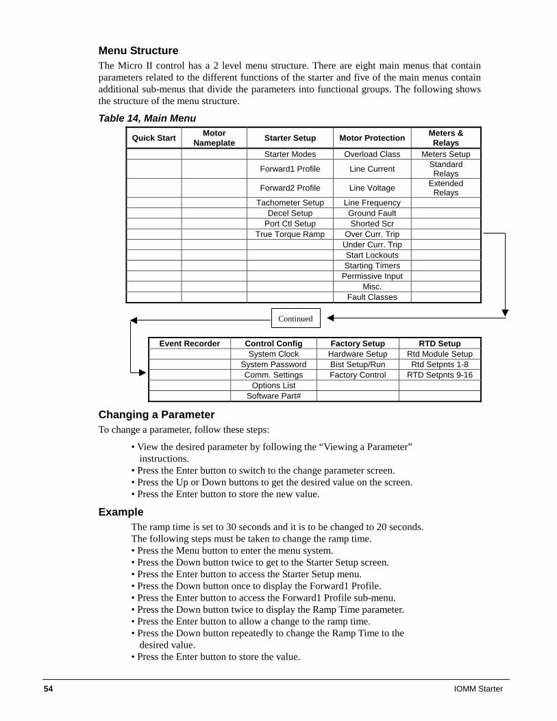
54 IOMM Starter
Menu Structure The Micro II control has a 2 level menu structure. There are eight main menus that contain parameters related to the different functions of the starter and five of the main menus contain additional sub-menus that divide the parameters into functional groups. The following shows the structure of the menu structure.
Table 14, Main Menu
Quick Start Motor Nameplate Starter Setup Motor Protection Meters &
Relays Starter Modes Overload Class Meters Setup
Forward1 Profile Line Current Standard Relays
Forward2 Profile Line Voltage Extended Relays
Tachometer Setup Line Frequency Decel Setup Ground Fault Port Ctl Setup Shorted Scr True Torque Ramp Over Curr. Trip Under Curr. Trip Start Lockouts Starting Timers Permissive Input Misc. Fault Classes
Event Recorder Control Config Factory Setup RTD Setup System Clock Hardware Setup Rtd Module Setup System Password Bist Setup/Run Rtd Setpnts 1-8 Comm. Settings Factory Control RTD Setpnts 9-16 Options List Software Part#
Changing a Parameter To change a parameter, follow these steps:
• View the desired parameter by following the “Viewing a Parameter” instructions.
• Press the Enter button to switch to the change parameter screen. • Press the Up or Down buttons to get the desired value on the screen. • Press the Enter button to store the new value.
Example The ramp time is set to 30 seconds and it is to be changed to 20 seconds. The following steps must be taken to change the ramp time. • Press the Menu button to enter the menu system. • Press the Down button twice to get to the Starter Setup screen. • Press the Enter button to access the Starter Setup menu. • Press the Down button once to display the Forward1 Profile. • Press the Enter button to access the Forward1 Profile sub-menu. • Press the Down button twice to display the Ramp Time parameter. • Press the Enter button to allow a change to the ramp time. • Press the Down button repeatedly to change the Ramp Time to the
desired value. • Press the Enter button to store the value.
Continued
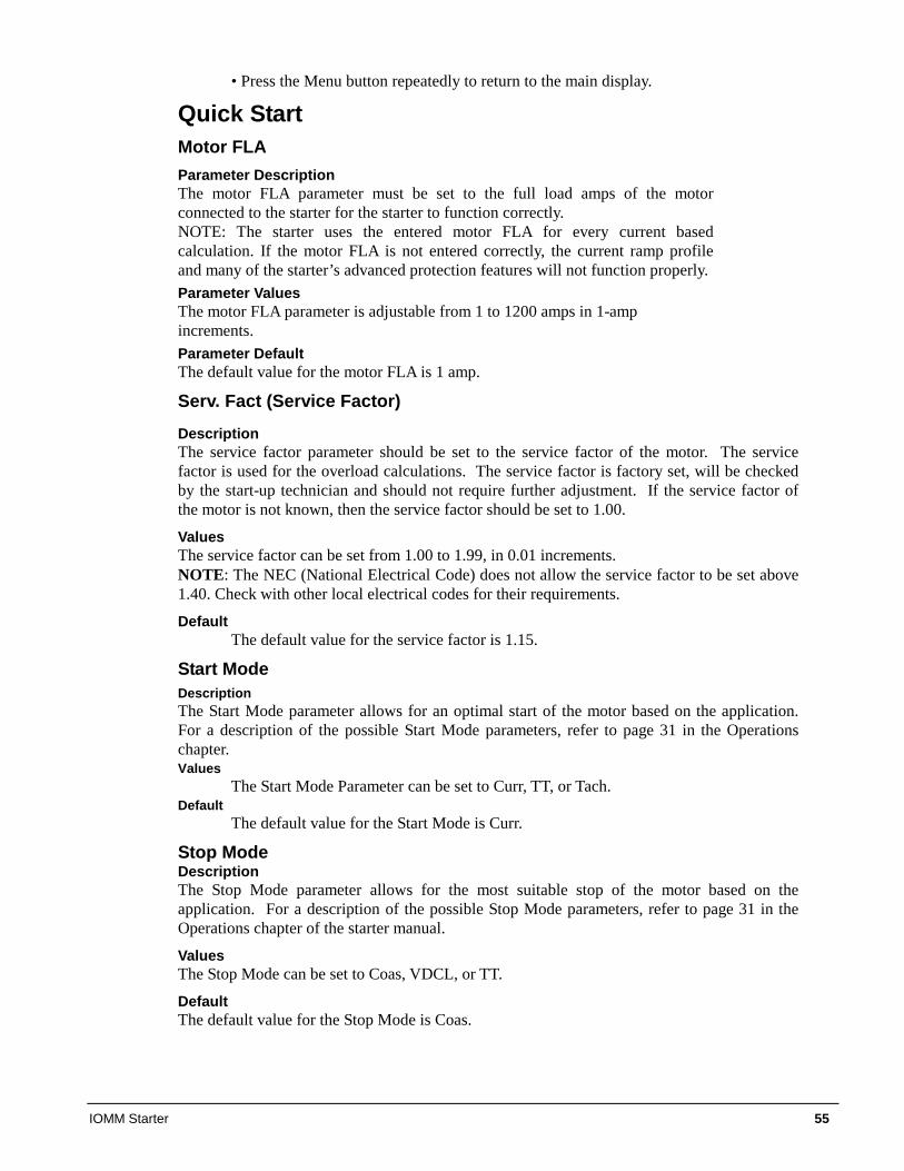
IOMM Starter 55
• Press the Menu button repeatedly to return to the main display.
Quick Start Motor FLA Parameter Description The motor FLA parameter must be set to the full load amps of the motor connected to the starter for the starter to function correctly. NOTE: The starter uses the entered motor FLA for every current based calculation. If the motor FLA is not entered correctly, the current ramp profile and many of the starter’s advanced protection features will not function properly. Parameter Values The motor FLA parameter is adjustable from 1 to 1200 amps in 1-amp increments. Parameter Default The default value for the motor FLA is 1 amp.
Serv. Fact (Service Factor)
Description The service factor parameter should be set to the service factor of the motor. The service factor is used for the overload calculations. The service factor is factory set, will be checked by the start-up technician and should not require further adjustment. If the service factor of the motor is not known, then the service factor should be set to 1.00.
Values The service factor can be set from 1.00 to 1.99, in 0.01 increments. NOTE: The NEC (National Electrical Code) does not allow the service factor to be set above 1.40. Check with other local electrical codes for their requirements.
Default The default value for the service factor is 1.15.
Start Mode Description The Start Mode parameter allows for an optimal start of the motor based on the application. For a description of the possible Start Mode parameters, refer to page 31 in the Operations chapter. Values
The Start Mode Parameter can be set to Curr, TT, or Tach. Default
The default value for the Start Mode is Curr.
Stop Mode Description The Stop Mode parameter allows for the most suitable stop of the motor based on the application. For a description of the possible Stop Mode parameters, refer to page 31 in the Operations chapter of the starter manual.
Values The Stop Mode can be set to Coas, VDCL, or TT.
Default The default value for the Stop Mode is Coas.
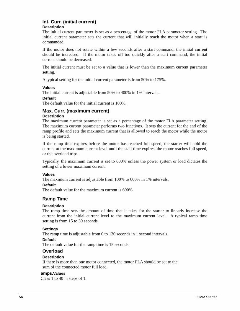
56 IOMM Starter
Int. Curr. (initial current) Description The initial current parameter is set as a percentage of the motor FLA parameter setting. The initial current parameter sets the current that will initially reach the motor when a start is commanded.
If the motor does not rotate within a few seconds after a start command, the initial current should be increased. If the motor takes off too quickly after a start command, the initial current should be decreased.
The initial current must be set to a value that is lower than the maximum current parameter setting.
A typical setting for the initial current parameter is from 50% to 175%.
Values The initial current is adjustable from 50% to 400% in 1% intervals. Default The default value for the initial current is 100%.
Max. Curr. (maximum current) Description The maximum current parameter is set as a percentage of the motor FLA parameter setting. The maximum current parameter performs two functions. It sets the current for the end of the ramp profile and sets the maximum current that is allowed to reach the motor while the motor is being started.
If the ramp time expires before the motor has reached full speed, the starter will hold the current at the maximum current level until the stall time expires, the motor reaches full speed, or the overload trips.
Typically, the maximum current is set to 600% unless the power system or load dictates the setting of a lower maximum current.
Values The maximum current is adjustable from 100% to 600% in 1% intervals. Default The default value for the maximum current is 600%.
Ramp Time Description The ramp time sets the amount of time that it takes for the starter to linearly increase the current from the initial current level to the maximum current level. A typical ramp time setting is from 15 to 30 seconds.
Settings The ramp time is adjustable from 0 to 120 seconds in 1 second intervals. Default The default value for the ramp time is 15 seconds. Overload Description If there is more than one motor connected, the motor FLA should be set to the sum of the connected motor full load.
amps.Values Class 1 to 40 in steps of 1.
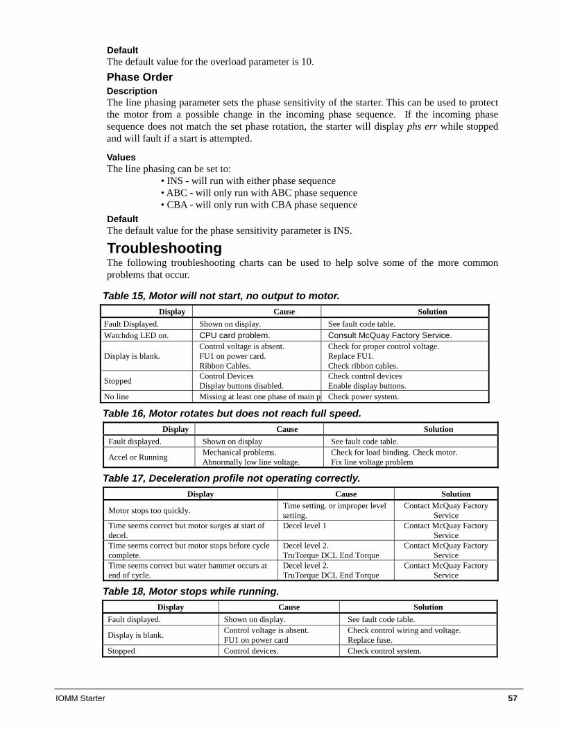
IOMM Starter 57
Default The default value for the overload parameter is 10. Phase Order Description The line phasing parameter sets the phase sensitivity of the starter. This can be used to protect the motor from a possible change in the incoming phase sequence. If the incoming phase sequence does not match the set phase rotation, the starter will display phs err while stopped and will fault if a start is attempted.
Values The line phasing can be set to:
• INS - will run with either phase sequence • ABC - will only run with ABC phase sequence • CBA - will only run with CBA phase sequence
Default The default value for the phase sensitivity parameter is INS.
Troubleshooting The following troubleshooting charts can be used to help solve some of the more common problems that occur.
Table 15, Motor will not start, no output to motor. Display Cause Solution
Fault Displayed. Shown on display. See fault code table. Watchdog LED on. CPU card problem. Consult McQuay Factory Service.
Display is blank. Control voltage is absent. FU1 on power card. Ribbon Cables.
Check for proper control voltage. Replace FU1. Check ribbon cables.
Stopped Control Devices Display buttons disabled.
Check control devices Enable display buttons.
No line Missing at least one phase of main po Check power system.
Table 16, Motor rotates but does not reach full speed. Display Cause Solution
Fault displayed. Shown on display See fault code table. Accel or Running Mechanical problems.
Abnormally low line voltage. Check for load binding. Check motor. Fix line voltage problem
Table 17, Deceleration profile not operating correctly. Display Cause Solution
Motor stops too quickly. Time setting. or improper level setting.
Contact McQuay Factory Service
Time seems correct but motor surges at start of decel.
Decel level 1
Contact McQuay Factory Service
Time seems correct but motor stops before cycle complete.
Decel level 2. TruTorque DCL End Torque
Contact McQuay Factory Service
Time seems correct but water hammer occurs at end of cycle.
Decel level 2. TruTorque DCL End Torque
Contact McQuay Factory Service
Table 18, Motor stops while running. Display Cause Solution
Fault displayed. Shown on display. See fault code table. Display is blank. Control voltage is absent.
FU1 on power card Check control wiring and voltage. Replace fuse.
Stopped Control devices. Check control system.
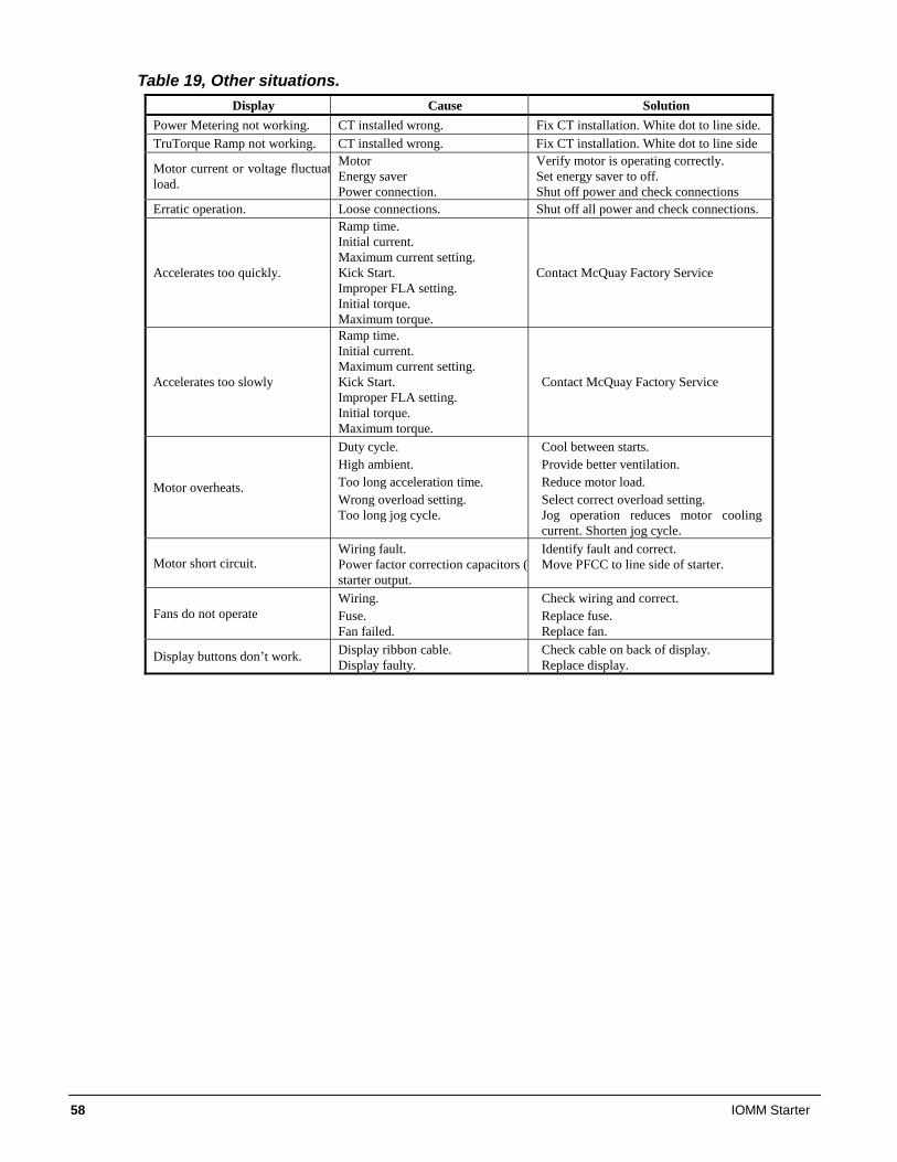
58 IOMM Starter
Table 19, Other situations. Display Cause Solution
Power Metering not working. CT installed wrong. Fix CT installation. White dot to line side. TruTorque Ramp not working. CT installed wrong. Fix CT installation. White dot to line side
Motor current or voltage fluctuatload.
Motor Energy saver Power connection.
Verify motor is operating correctly. Set energy saver to off. Shut off power and check connections
Erratic operation. Loose connections. Shut off all power and check connections.
Accelerates too quickly.
Ramp time. Initial current. Maximum current setting. Kick Start. Improper FLA setting. Initial torque. Maximum torque.
Contact McQuay Factory Service
Accelerates too slowly
Ramp time. Initial current. Maximum current setting. Kick Start. Improper FLA setting. Initial torque. Maximum torque.
Contact McQuay Factory Service
Motor overheats.
Duty cycle. High ambient. Too long acceleration time. Wrong overload setting. Too long jog cycle.
Cool between starts. Provide better ventilation. Reduce motor load. Select correct overload setting. Jog operation reduces motor cooling current. Shorten jog cycle.
Motor short circuit. Wiring fault. Power factor correction capacitors (Pstarter output.
Identify fault and correct. Move PFCC to line side of starter.
Fans do not operate Wiring. Fuse. Fan failed.
Check wiring and correct. Replace fuse. Replace fan.
Display buttons don’t work. Display ribbon cable. Display faulty.
Check cable on back of display. Replace display.
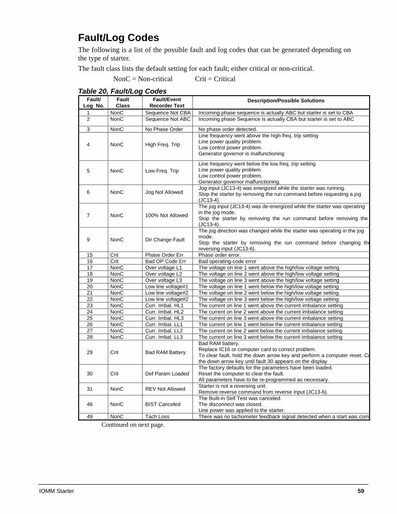
IOMM Starter 59
Fault/Log Codes The following is a list of the possible fault and log codes that can be generated depending on the type of starter. The fault class lists the default setting for each fault; either critical or non-critical. NonC = Non-critical Crit = Critical
Table 20, Fault/Log Codes Fault/
Log No. Fault Class
Fault/Event Recorder Text
Description/Possible Solutions
1 NonC Sequence Not CBA Incoming phase sequence is actually ABC but starter is set to CBA 2 NonC Sequence Not ABC Incoming phase Sequence is actually CBA but starter is set to ABC
3 NonC No Phase Order No phase order detected.
4 NonC High Freq. Trip
Line frequency went above the high freq. trip setting Line power quality problem. Low control power problem. Generator governor is malfunctioning
5 NonC Low Freq. Trip Line frequency went below the low freq. trip setting Line power quality problem. Low control power problem. Generator governor malfunctioning.
6 NonC Jog Not Allowed Jog input (JC13-4) was energized while the starter was running. Stop the starter by removing the run command before requesting a jog (JC13-4).
7 NonC 100% Not Allowed
The jog input (JC13-4) was de-energized while the starter was operating in the jog mode. Stop the starter by removing the run command before removing the (JC13-4).
9 NonC Dir Change Fault
The jog direction was changed while the starter was operating in the jog mode. Stop the starter by removing the run command before changing thereversing input (JC13-6).
15 Crit Phase Order Err Phase order error. 16 Crit Bad OP Code Err Bad operating-code error 17 NonC Over voltage L1 The voltage on line 1 went above the high/low voltage setting 18 NonC Over voltage L2 The voltage on line 2 went above the high/low voltage setting 19 NonC Over voltage L3 The voltage on line 3 went above the high/low voltage setting 20 NonC Low line voltage#1 The voltage on line 1 went below the high/low voltage setting 21 NonC Low line voltage#2 The voltage on line 2 went below the high/low voltage setting 22 NonC Low line voltage#2 The voltage on line 3 went below the high/low voltage setting 23 NonC Curr. Imbal. HL1 The current on line 1 went above the current imbalance setting 24 NonC Curr. Imbal. HL2 The current on line 2 went above the current imbalance setting 25 NonC Curr. Imbal. HL3 The current on line 3 went above the current imbalance setting 26 NonC Curr. Imbal. LL1 The current on line 1 went below the current imbalance setting 27 NonC Curr. Imbal. LL2 The current on line 2 went below the current imbalance setting 28 NonC Curr. Imbal. LL3 The current on line 3 went below the current imbalance setting
29 Crit Bad RAM Battery
Bad RAM battery. Replace IC16 or computer card to correct problem. To clear fault, hold the down arrow key and perform a computer reset. Cothe down arrow key until fault 30 appears on the display
30 Crit Def Param Loaded The factory defaults for the parameters have been loaded. Reset the computer to clear the fault. All parameters have to be re-programmed as necessary.
31 NonC REV Not Allowed Starter is not a reversing unit. Remove reverse command from reverse input (JC13-6).
46 NonC BIST Canceled The Built-in Self Test was canceled. The disconnect was closed. Line power was applied to the starter.
49 NonC Tach Loss There was no tachometer feedback signal detected when a start was comContinued on next page.
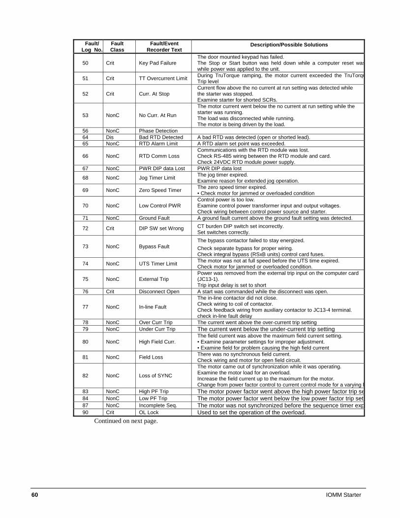
60 IOMM Starter
Fault/
Log No. Fault Class
Fault/Event Recorder Text
Description/Possible Solutions
50 Crit Key Pad Failure The door mounted keypad has failed. The Stop or Start button was held down while a computer reset waswhile power was applied to the unit.
51 Crit TT Overcurrent Limit During TruTorque ramping, the motor current exceeded the TruTorquTrip level
52 Crit Curr. At Stop Current flow above the no current at run setting was detected while the starter was stopped. Examine starter for shorted SCRs.
53 NonC No Curr. At Run
The motor current went below the no current at run setting while the starter was running. The load was disconnected while running. The motor is being driven by the load.
56 NonC Phase Detection 64 Dis Bad RTD Detected A bad RTD was detected (open or shorted lead). 65 NonC RTD Alarm Limit A RTD alarm set point was exceeded.
66 NonC RTD Comm Loss Communications with the RTD module was lost. Check RS-485 wiring between the RTD module and card. Check 24VDC RTD module power supply.
67 NonC PWR DIP data Lost PWR DIP data lost
68 NonC Jog Timer Limit The jog timer expired. Examine reason for extended jog operation.
69 NonC Zero Speed Timer The zero speed timer expired. • Check motor for jammed or overloaded condition
70 NonC Low Control PWR Control power is too low. Examine control power transformer input and output voltages. Check wiring between control power source and starter.
71 NonC Ground Fault A ground fault current above the ground fault setting was detected.
72 Crit DIP SW set Wrong CT burden DIP switch set incorrectly. Set switches correctly.
73 NonC Bypass Fault The bypass contactor failed to stay energized. Check separate bypass for proper wiring. Check integral bypass (RSxB units) control card fuses.
74 NonC UTS Timer Limit The motor was not at full speed before the UTS time expired. Check motor for jammed or overloaded condition.
75 NonC External Trip Power was removed from the external trip input on the computer card (JC13-1). Trip input delay is set to short
76 Crit Disconnect Open A start was commanded while the disconnect was open.
77 NonC In-line Fault
The in-line contactor did not close. Check wiring to coil of contactor. Check feedback wiring from auxiliary contactor to JC13-4 terminal. check in-line fault delay
78 NonC Over Curr Trip The current went above the over-current trip setting 79 NonC Under Curr Trip The current went below the under-current trip setting
80 NonC High Field Curr. The field current was above the maximum field current setting. • Examine parameter settings for improper adjustment. • Examine field for problem causing the high field current
81 NonC Field Loss There was no synchronous field current. Check wiring and motor for open field circuit.
82 NonC Loss of SYNC
The motor came out of synchronization while it was operating. Examine the motor load for an overload. Increase the field current up to the maximum for the motor. Change from power factor control to current control mode for a varying l
83 NonC High PF Trip The motor power factor went above the high power factor trip se84 NonC Low PF Trip The motor power factor went below the low power factor trip sett87 NonC Incomplete Seq. The motor was not synchronized before the sequence timer exp90 Crit OL Lock Used to set the operation of the overload.
Continued on next page.
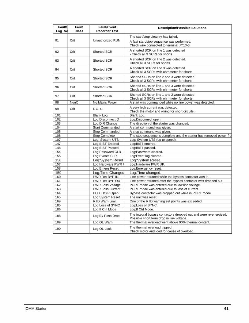
IOMM Starter 61
Fault/
Log NoFault Class
Fault/Event Recorder Text
Description/Possible Solutions
91 Crit Unauthorized RUN The start/stop circuitry has failed. A fast start/stop sequence was performed. Check wire connected to terminal JC13-3.
92 Crit Shorted SCR A shorted SCR on line 1 was detected • Check all 3 SCRs for shorts
93 Crit Shorted SCR A shorted SCR on line 2 was detected. Check all 3 SCRs for shorts
94 Crit Shorted SCR A shorted SCR on line 3 was detected Check all 3 SCRs with ohmmeter for shorts.
95 Crit Shorted SCR Shorted SCRs on line 2 and 3 were detected Check all 3 SCRs with ohmmeter for shorts.
96 Crit Shorted SCR Shorted SCRs on line 1 and 3 were detected Check all 3 SCRs with ohmmeter for shorts.
97 Crit Shorted SCR Shorted SCRs on line 1 and 2 were detected Check all 3 SCRs with ohmmeter for shorts.
98 NonC No Mains Power A start was commanded while no line power was detected.
99 Crit I. O. C. A very high current was detected. Check the motor and wiring for short circuits.
101 Blank Log Blank Log. 102 Log:Disconnect O Log:Disconnect open. 103 Log:DIR Change The direction of the starter was changed. 104 Start Commanded A start command was given. 105 Stop Commanded A stop command was given. 106 Stop Complete The stop sequence is complete and the starter has removed power fro107 Log: System UTS Log: System UTS (up to speed). 147 Log:BIST Entered Log:BIST entered. 148 Log:BIST Passed Log:BIST passed. 154 Log:Password CLR Log:Password cleared. 155 Log:Events CLR Log:Event log cleared. 156 Log:System Reset Log:System Reset. 157 Log:Hardware PWR U Log:Hardware PWR UP. 158 Log:Emerg Reset Log:Emergency reset. 159 Log:Time Changed Log:Time changed. 160 PWR Ret BYP IN Line power returned while the bypass contactor was in. 161 PWR Ret BYP OUT Line power returned after the bypass contactor was dropped out. 162 PWR Loss Voltage PORT mode was entered due to low line voltage. 163 PWR Loss Current PORT mode was entered due to loss of current. 164 PORT BYP Open Bypass contactor was dropped out while in PORT mode. 165 Log:System Reset The unit was reset. 169 RTD Warn Limit One of the RTD warning set points was exceeded. 185 Log:Loss of SYNC Log:Loss of SYNC. 186 Log:If Ctrl Mode Log:If Ctrl Mode.
188 Log:By-Pass Drop The integral bypass contactors dropped out and were re-energized. Possible short term drop in line voltage.
189 Log:OL Warn The thermal overload went above 90% thermal content.
190 Log:OL Lock The thermal overload tripped. Check motor and load for cause of overload.
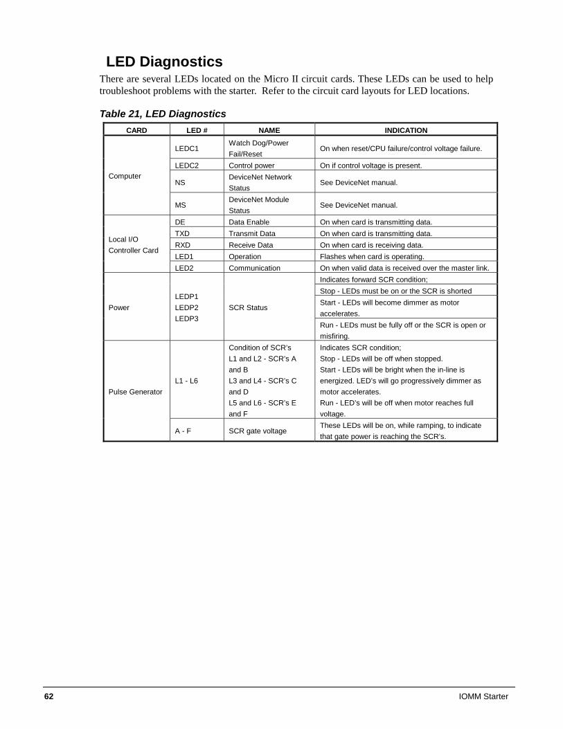
62 IOMM Starter
LED Diagnostics There are several LEDs located on the Micro II circuit cards. These LEDs can be used to help troubleshoot problems with the starter. Refer to the circuit card layouts for LED locations.
Table 21, LED Diagnostics CARD LED # NAME INDICATION
LEDC1 Watch Dog/Power Fail/Reset
On when reset/CPU failure/control voltage failure.
LEDC2 Control power On if control voltage is present.
NS DeviceNet Network Status
See DeviceNet manual. Computer
MS DeviceNet Module Status
See DeviceNet manual.
DE Data Enable On when card is transmitting data. TXD Transmit Data On when card is transmitting data. RXD Receive Data On when card is receiving data. LED1 Operation Flashes when card is operating.
Local I/O Controller Card
LED2 Communication On when valid data is received over the master link. Indicates forward SCR condition; Stop - LEDs must be on or the SCR is shorted Start - LEDs will become dimmer as motor accelerates.
Power LEDP1 LEDP2 LEDP3
SCR Status
Run - LEDs must be fully off or the SCR is open or misfiring.
L1 - L6
Condition of SCR’s L1 and L2 - SCR’s A and B L3 and L4 - SCR’s C and D L5 and L6 - SCR’s E and F
Indicates SCR condition; Stop - LEDs will be off when stopped. Start - LEDs will be bright when the in-line is energized. LED’s will go progressively dimmer as motor accelerates. Run - LED’s will be off when motor reaches full voltage.
Pulse Generator
A - F SCR gate voltage These LEDs will be on, while ramping, to indicate that gate power is reaching the SCR’s.
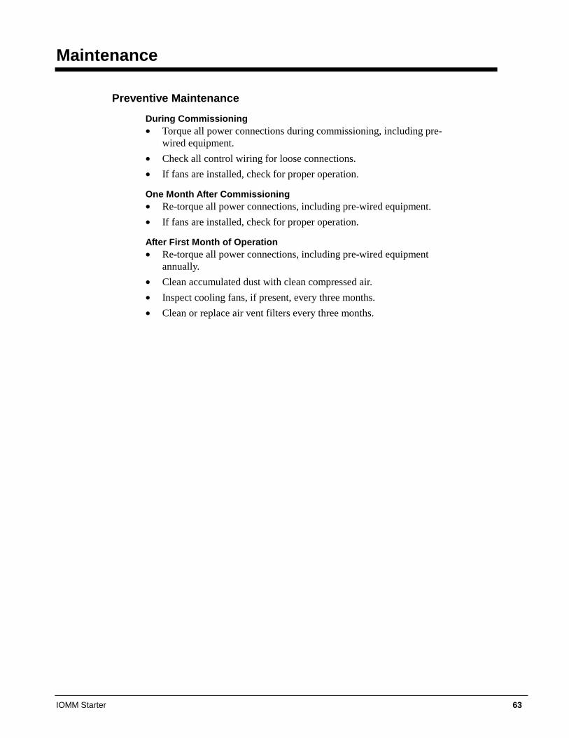
IOMM Starter 63
Maintenance
Preventive Maintenance
During Commissioning • Torque all power connections during commissioning, including pre-
wired equipment. • Check all control wiring for loose connections. • If fans are installed, check for proper operation.
One Month After Commissioning • Re-torque all power connections, including pre-wired equipment. • If fans are installed, check for proper operation.
After First Month of Operation • Re-torque all power connections, including pre-wired equipment
annually. • Clean accumulated dust with clean compressed air. • Inspect cooling fans, if present, every three months. • Clean or replace air vent filters every three months.

64 IOMM Starter
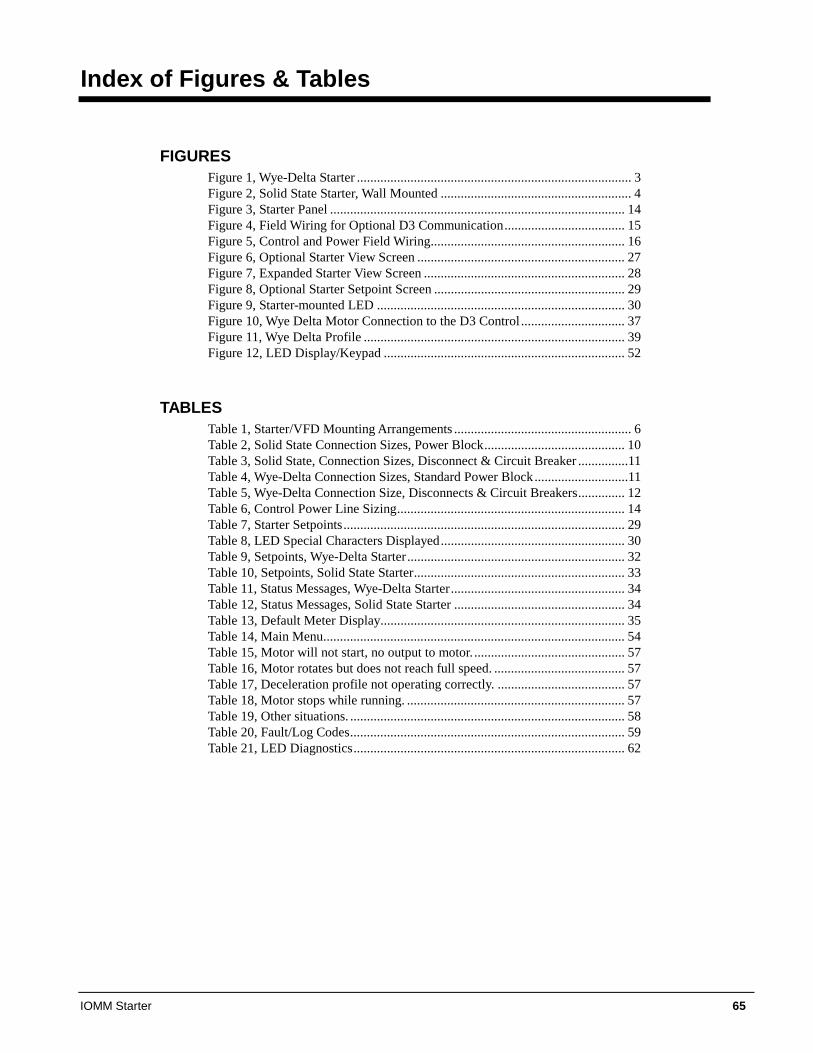
IOMM Starter 65
Index of Figures & Tables
FIGURES Figure 1, Wye-Delta Starter .................................................................................. 3 Figure 2, Solid State Starter, Wall Mounted ......................................................... 4 Figure 3, Starter Panel ........................................................................................ 14 Figure 4, Field Wiring for Optional D3 Communication.................................... 15 Figure 5, Control and Power Field Wiring.......................................................... 16 Figure 6, Optional Starter View Screen .............................................................. 27 Figure 7, Expanded Starter View Screen ............................................................ 28 Figure 8, Optional Starter Setpoint Screen ......................................................... 29 Figure 9, Starter-mounted LED .......................................................................... 30 Figure 10, Wye Delta Motor Connection to the D3 Control ............................... 37 Figure 11, Wye Delta Profile .............................................................................. 39 Figure 12, LED Display/Keypad ........................................................................ 52
TABLES Table 1, Starter/VFD Mounting Arrangements ..................................................... 6 Table 2, Solid State Connection Sizes, Power Block.......................................... 10 Table 3, Solid State, Connection Sizes, Disconnect & Circuit Breaker ...............11 Table 4, Wye-Delta Connection Sizes, Standard Power Block............................11 Table 5, Wye-Delta Connection Size, Disconnects & Circuit Breakers.............. 12 Table 6, Control Power Line Sizing.................................................................... 14 Table 7, Starter Setpoints.................................................................................... 29 Table 8, LED Special Characters Displayed....................................................... 30 Table 9, Setpoints, Wye-Delta Starter................................................................. 32 Table 10, Setpoints, Solid State Starter............................................................... 33 Table 11, Status Messages, Wye-Delta Starter.................................................... 34 Table 12, Status Messages, Solid State Starter ................................................... 34 Table 13, Default Meter Display......................................................................... 35 Table 14, Main Menu.......................................................................................... 54 Table 15, Motor will not start, no output to motor. ............................................. 57 Table 16, Motor rotates but does not reach full speed. ....................................... 57 Table 17, Deceleration profile not operating correctly. ...................................... 57 Table 18, Motor stops while running. ................................................................. 57 Table 19, Other situations. .................................................................................. 58 Table 20, Fault/Log Codes.................................................................................. 59 Table 21, LED Diagnostics................................................................................. 62

Post Office Box 2510, Staunton, Virginia 24402-2510 USA • (800) 432-1342 • www.mcquay.com IOMM Starter (09/05)
This document contains the most current product information as of this printing. For the most up-to-date product information, please go to www.mcquay.com.