startup guide
TRANSCRIPT
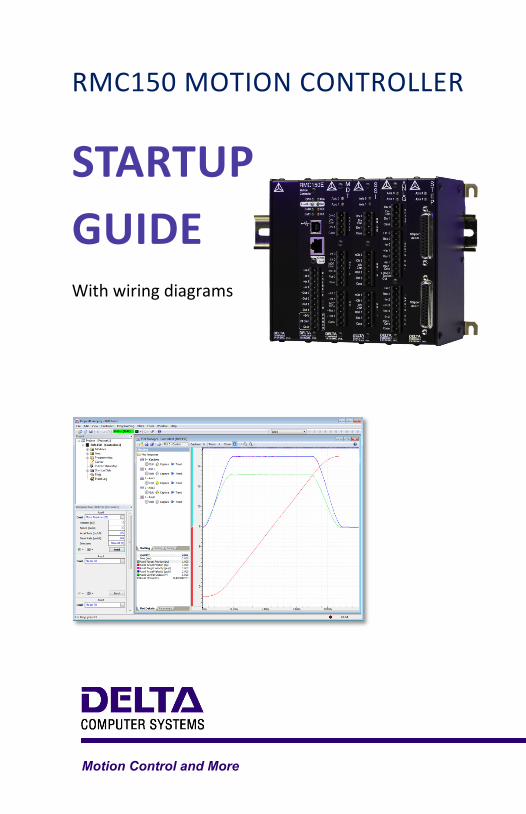
RMC150 MOTION CONTROLLER
STARTUP GUIDE With wiring diagrams
Motion Control and More

RMC150 Startup Guide
deltamotion.com ii
Where to Get Help
Video Tutorials
In RMCTools, on the Help menu, click Video Tutorials.
RMCTools Help
In RMCTools, on the Help menu, click Help Topics.
Forum
forum.deltamotion.com
Delta Technical Support
Phone: +1-360-254-8688
Email: [email protected]

Contents
deltamotion.com 1
Contents
Step 1: Mounting ............................................................. 2
Step 2: Wiring ................................................................. 3
Step 3: Install RMCTools ................................................ 4
Step 4: Connect RMC to PC ........................................... 5
Step 5: Start a New Project ............................................ 6
Step 6: Define the Axes ................................................ 10
Step 7: Test an Actuator ............................................... 12
Step 8: Test Feedback Device ..................................... 15
Step 9: Scale and Offset ............................................... 19
Step 10: Set the Output Polarity ................................... 20
Step 11: Tuning ............................................................ 21
Continuing the Motion Application ................................ 24
Diagnostic Tools ........................................................... 26
Appendix A: Wiring ....................................................... 27
Appendix B: Mounting Dimensions ............................... 40
Appendix C: Agency Compliance ................................. 41
Version 4.00, June 1, 2017 Copyright © 2017, Delta Computer Systems, Inc.
RMC150 Startup Guide
2 Delta Computer Systems, Inc.
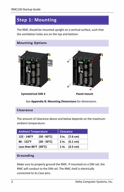
Step 1: Mounting
The RMC should be mounted upright on a vertical surface, such that the ventilation holes are on the top and bottom.
Mounting Options
Symmetrical DIN 3 Panel-mount
See Appendix B: Mounting Dimensions for dimensions.
Clearance
The amount of clearance above and below depends on the maximum ambient temperature:
Ambient Temperature Clearance
122 - 140°F (50 - 60°C) 3 in. (7.6 cm)
86 - 122°F (30 - 50°C) 2 in. (5.1 cm)
Less than 86°F (30°C) 1 in. (2.5 cm)
Grounding
Make sure to properly ground the RMC. If mounted on a DIN rail, the RMC will conduct to the DIN rail. The RMC shell is electrically connected to its Case pins.
Step 2: Wiring
deltamotion.com 3
Step 2: Wiring
Wire the power, actuators and feedback devices to the RMC according to the instructions in Appendix A: Wiring on page 27.
Note: Remove power from the RMC before connecting any wires.
Wiring Topic Page
General Wiring Information 28
Power 29
Control Output (Drive) 29
SSI Inputs 30
Start/Stop and PWM Inputs (Magnetostrictive) 32
Analog Inputs
Voltage Transducer 34
Potentiometer 35
Current Transducer 35
Resolver Inputs 37
Discrete Inputs/Outputs
Discrete Outputs 38
Discrete Inputs 39

RMC150 Startup Guide
4 Delta Computer Systems, Inc.
Step 3: Install RMCTools
Download
1. Go to http://www.deltamotion.com/dloads/
2. Choose the RMC70 or RMC150 category, then choose the Software category.
3. Choose the RMCTools 32-bit or 64-bit version as required for your computer.
4. Run the rmctoolsinstall32.exe or rmctoolsinstall64.exe file and follow the instructions.
Start RMCTools
On the Windows Start menu, choose All Programs and then RMCTools.
PC Requirements for RMCTools
Operating System* Windows® XP/Vista/7/8/10
*Windows XP requires Service Pack 2 or newer.
Step 4: Connect RMC to PC
deltamotion.com 5
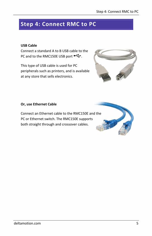
Step 4: Connect RMC to PC
USB Cable Connect a standard A to B USB cable to the PC and to the RMC150E USB port .
This type of USB cable is used for PC peripherals such as printers, and is available at any store that sells electronics.
Or, use Ethernet Cable
Connect an Ethernet cable to the RMC150E and the PC or Ethernet switch. The RMC150E supports both straight through and crossover cables.
RMC150 Startup Guide
6 Delta Computer Systems, Inc.
Step 5: Start a New Project
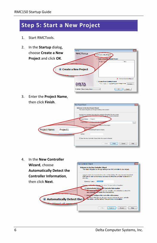
1. Start RMCTools.
2. In the Startup dialog, choose Create a New Project and click OK.
3. Enter the Project Name, then click Finish.
4. In the New Controller Wizard, choose Automatically Detect the Controller Information, then click Next.

Step 5: Start a New Project
deltamotion.com 7
5. RMC150E via USB:
A. Click USB and click Next.
B. When the RMC appears in the list, choose it and click Next.
RMC150E via Ethernet:
A. Click Ethernet and click Next.
B. Use the MAC address (on the RMC150E label) to identify the RMC in the list, then click the RMC.
C. If the RMC does not have an IP address (0.0.0.0), click Configure Device, choose Use the following IP address, set the IP Address and Subnet Mask, then click OK.
D. Click Next.
RMC150 Startup Guide
8 Delta Computer Systems, Inc.
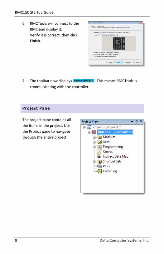
6. RMCTools will connect to the RMC and display it. Verify it is correct, then click Finish.
7. The toolbar now displays . This means RMCTools is communicating with the controller.
Project Pane
The project pane contains all the items in the project. Use the Project pane to navigate through the entire project.
Step 5: Start a New Project
deltamotion.com 9
Set Up Universal I/O Channels
If your RMC includes a Universal I/O module, you must first set up the high-speed channels before using them as part of an axis.
1. In the Project pane, expand the Modules folder and double-click the UI/O module.
2. On the Quad/SSI page, choose the desired Mode for each channel. Typically, this will be Quadrature Input or SSI Axis Input. For more details, refer to the UI/O module topic in the RMCTools help.
Saving Settings
Throughout the startup procedure, make sure to save the configuration changes you make or they may be lost!
1. Save RMCTools Project
On the File menu, click Save.
2. Update Flash
On the Controller menu, click Update Flash.
IF YOU DO NOT UPDATE FLASH, CHANGES TO THE RMC WILL BE LOST WHEN POWER IS REMOVED!
3. Repeat Often
Make sure to save often to prevent loss of data.
Tip: On the File menu, click Save and Update Flash to perform both operations at once.
RMC150 Startup Guide
10 Delta Computer Systems, Inc.
Step 6: Define the Axes
To use a physical input or output, it must be assigned to an internal software axis. The RMC starts with default axis assignments which you will likely need to change.
Note: It is important to define the axes at the start of the project. Major changes to axes later may result in lost axis parameters.
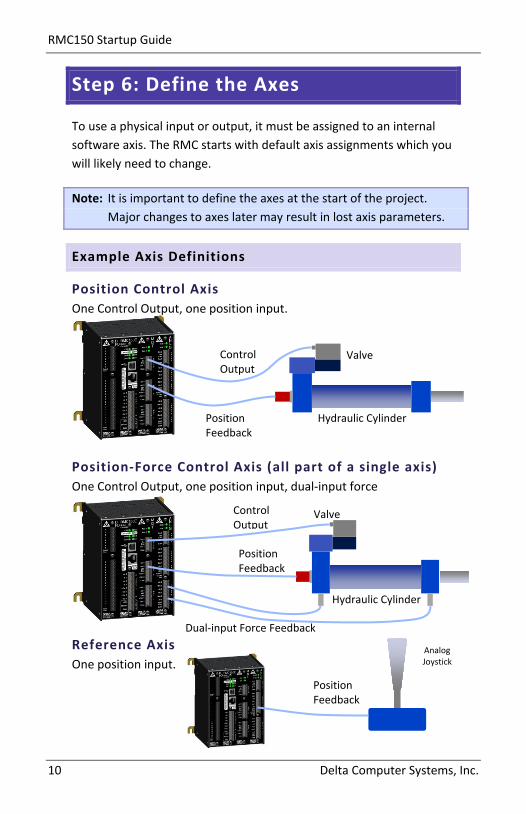
Example Axis Definitions
Position Control Axis One Control Output, one position input.
Position-Force Control Axis (all part of a single axis) One Control Output, one position input, dual-input force
Reference Axis One position input.
Control Output
Position Feedback
Dual-input Force Feedback
Valve
Hydraulic Cylinder
Analog Joystick
Position Feedback
Control Output
Position Feedback
Valve
Hydraulic Cylinder

Step 6: Define the Axes
deltamotion.com 11
View Axis Definitions
1. In the Project tree, expand the Axes folder and double-click Axis Definitions.
2. The Axis Definitions dialog opens:
The list displays the software axes. To see the assigned hardware, click an axis in the list. The hardware assigned to that axis will be highlighted in the image.
Edit Axis Definitions
Use the Axis Definitions dialog to change the axis definitions:
• Click New to add an axis. • Click Change to edit the selected axis. • Click to remove an axis.
If you need to make significant changes to the axis definitions, first delete all the axes, then create new ones.
For more details, click the Help button.
RMC150 Startup Guide
12 Delta Computer Systems, Inc.
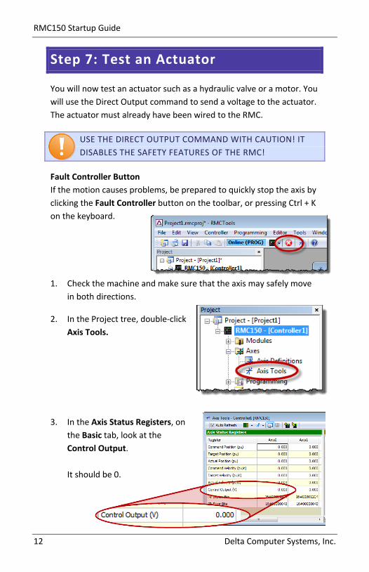
Step 7: Test an Actuator
You will now test an actuator such as a hydraulic valve or a motor. You will use the Direct Output command to send a voltage to the actuator. The actuator must already have been wired to the RMC.
USE THE DIRECT OUTPUT COMMAND WITH CAUTION! IT DISABLES THE SAFETY FEATURES OF THE RMC!
Fault Controller Button If the motion causes problems, be prepared to quickly stop the axis by clicking the Fault Controller button on the toolbar, or pressing Ctrl + K on the keyboard.
1. Check the machine and make sure that the axis may safely move in both directions.
2. In the Project tree, double-click Axis Tools.
3. In the Axis Status Registers, on the Basic tab, look at the Control Output. It should be 0.
Step 7: Test an Actuator
deltamotion.com 13
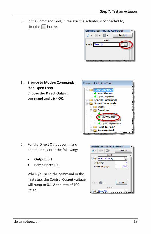
5. In the Command Tool, in the axis the actuator is connected to, click the button.
6. Browse to Motion Commands, then Open Loop. Choose the Direct Output command and click OK.
7. For the Direct Output command parameters, enter the following:
• Output: 0.1 • Ramp Rate: 100
When you send the command in the next step, the Control Output voltage will ramp to 0.1 V at a rate of 100 V/sec.
RMC150 Startup Guide
14 Delta Computer Systems, Inc.
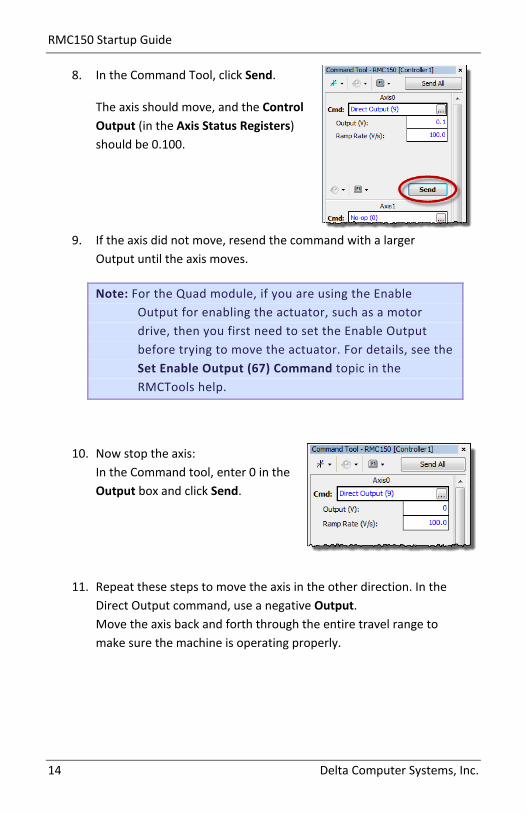
8. In the Command Tool, click Send.
The axis should move, and the Control Output (in the Axis Status Registers) should be 0.100.
9. If the axis did not move, resend the command with a larger Output until the axis moves.
Note: For the Quad module, if you are using the Enable Output for enabling the actuator, such as a motor drive, then you first need to set the Enable Output before trying to move the actuator. For details, see the Set Enable Output (67) Command topic in the RMCTools help.
10. Now stop the axis: In the Command tool, enter 0 in the Output box and click Send.
11. Repeat these steps to move the axis in the other direction. In the Direct Output command, use a negative Output. Move the axis back and forth through the entire travel range to make sure the machine is operating properly.
Step 8: Test Feedback Device
deltamotion.com 15
Step 8: Test Feedback Device
Now that you have connected and tested an actuator, you will connect and verify a feedback device. The device must already have been wired to the RMC.
Configure Feedback
In Axis Tools, in the Axis Parameters pane, on the Setup tab, you will configure certain parameters depending on the type of input you are using.
Refer to the procedure for your transducer type and module:
Transducer Type Module Page
Start/Stop or PWM (Magnetostrictive)
MDT (M) 16
SSI (linear or rotary)
SSI (S), Universal I/O (UI/O)
16
Analog (Voltage or Current)
ANLG (H), ANALOG INPUTS (A), ANLG2 (G), Universal I/O (UI/O)
17
Quadrature Encoder (A, B, Z)
QUAD (Q), Universal I/O (UI/O)
17
Resolver RESOLVER (R) 17
RMC150 Startup Guide
16 Delta Computer Systems, Inc.
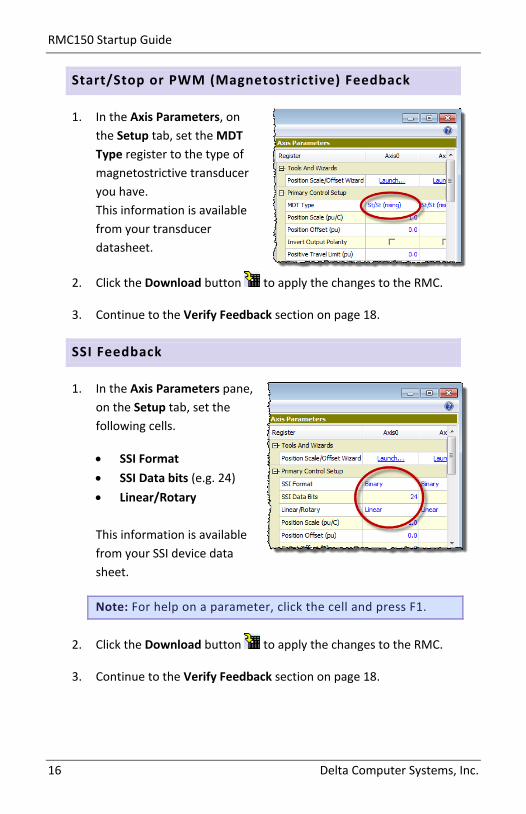
Start/Stop or PWM (Magnetostrictive) Feedback
1. In the Axis Parameters, on the Setup tab, set the MDT Type register to the type of magnetostrictive transducer you have. This information is available from your transducer datasheet.
2. Click the Download button to apply the changes to the RMC.
3. Continue to the Verify Feedback section on page 18.
SSI Feedback
1. In the Axis Parameters pane, on the Setup tab, set the following cells.
• SSI Format • SSI Data bits (e.g. 24) • Linear/Rotary
This information is available from your SSI device data sheet.
Note: For help on a parameter, click the cell and press F1.
2. Click the Download button to apply the changes to the RMC.
3. Continue to the Verify Feedback section on page 18.
Step 8: Test Feedback Device
deltamotion.com 17
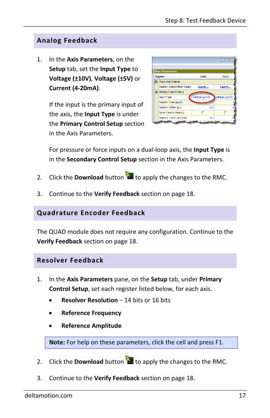
Analog Feedback
1. In the Axis Parameters, on the Setup tab, set the Input Type to Voltage (±10V), Voltage (±5V) or Current (4-20mA).
If the input is the primary input of the axis, the Input Type is under the Primary Control Setup section in the Axis Parameters.
For pressure or force inputs on a dual-loop axis, the Input Type is in the Secondary Control Setup section in the Axis Parameters.
2. Click the Download button to apply the changes to the RMC.
3. Continue to the Verify Feedback section on page 18.
Quadrature Encoder Feedback
The QUAD module does not require any configuration. Continue to the Verify Feedback section on page 18.
Resolver Feedback
1. In the Axis Parameters pane, on the Setup tab, under Primary Control Setup, set each register listed below, for each axis.
• Resolver Resolution – 14 bits or 16 bits
• Reference Frequency
• Reference Amplitude
Note: For help on these parameters, click the cell and press F1.
2. Click the Download button to apply the changes to the RMC.
3. Continue to the Verify Feedback section on page 18.

RMC150 Startup Guide
18 Delta Computer Systems, Inc.
Verify Feedback
1. In the Axis Status Registers pane, on the All tab, expand the Feedback section. For secondary inputs, expand the Pressure/Force/Accel Feedback section.
2. Depending on your feedback type, look at the Counts, Volts or Current register. It may be changing slightly.
3. Use the Direct Output command to move the axis back and forth (as described in the Test an Actuator section).
4. As the axis moves, look for a corresponding change in the Counts, Volts or Current. If it does not change smoothly, recheck the wiring, verify that the parameters on the Setup tab are correct, and check for smoothly changing Counts, Volts or Current again.
5. Save the project and update Flash.
Step 9: Scale and Offset
deltamotion.com 19
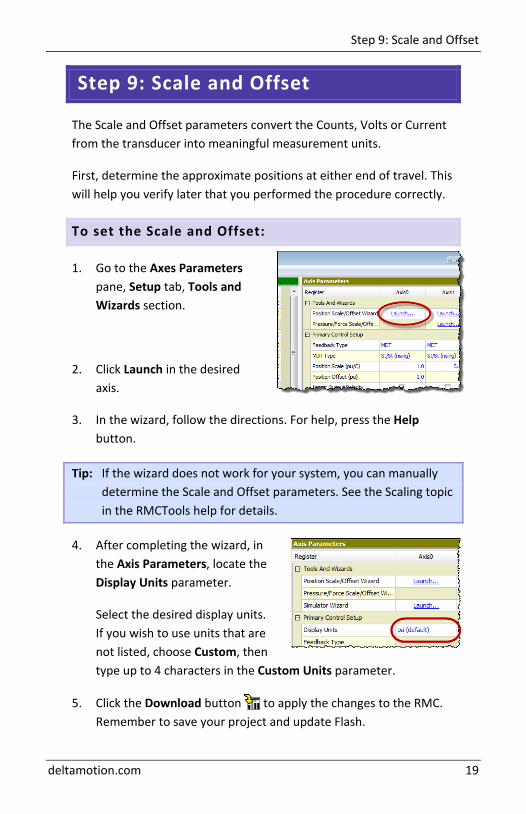
Step 9: Scale and Offset
The Scale and Offset parameters convert the Counts, Volts or Current from the transducer into meaningful measurement units.
First, determine the approximate positions at either end of travel. This will help you verify later that you performed the procedure correctly.
To set the Scale and Offset:
1. Go to the Axes Parameters pane, Setup tab, Tools and Wizards section.
2. Click Launch in the desired axis.
3. In the wizard, follow the directions. For help, press the Help button.
Tip: If the wizard does not work for your system, you can manually determine the Scale and Offset parameters. See the Scaling topic in the RMCTools help for details.
4. After completing the wizard, in the Axis Parameters, locate the Display Units parameter.
Select the desired display units. If you wish to use units that are not listed, choose Custom, then type up to 4 characters in the Custom Units parameter.
5. Click the Download button to apply the changes to the RMC. Remember to save your project and update Flash.
RMC150 Startup Guide
20 Delta Computer Systems, Inc.
Step 10: Set the Output Polarity
The Actual Position, Pressure, Force or Velocity must increase when the RMC applies a positive output voltage. If this condition is not met, you will not be able to perform closed-loop control.
1. Send the Direct Output command with a positive Output value that is large enough to move the axis.
2. On the Basic tab of the Axis Status Registers pane, observe the Actual Position and note whether it is increasing or decreasing:
Increasing The Output Polarity is correct. Go to Enable the Axes below.
Decreasing You must invert the Output Polarity:
A. In the Axis Parameters pane, on the Setup tab, double-click the Invert Output Polarity parameter to set it.
B. Click the Download button to apply the change to the RMC.
Enable the Axes
In order to send motion commands other than Direct Output, the axes must be enabled after the RMC starts up.
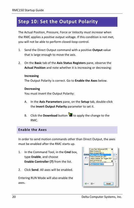
1. In the Command Tool, in the Cmd box, type Enable, and choose Enable Controller (7) from the list.
2. Click Send. All axes will be enabled.
Entering RUN Mode will also enable the axes.
Step 11: Tuning
deltamotion.com 21
Step 11: Tuning
In order to control an axis in closed-loop, it must first be tuned. You can use autotuning or manually tune the axis.
Autotuning – Position Axes Only
Autotuning can be used for most position control axes.
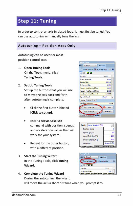
1. Open Tuning Tools On the Tools menu, click Tuning Tools.
2. Set Up Tuning Tools Set up the buttons that you will use to move the axis back and forth after autotuning is complete.
• Click the first button labeled [Click to set up].
• Enter a Move Absolute command with position, speeds, and acceleration values that will work for your system.
• Repeat for the other button, with a different position.
3. Start the Tuning Wizard In the Tuning Tools, click Tuning Wizard.
4. Complete the Tuning Wizard During the autotuning, the wizard will move the axis a short distance when you prompt it to.

RMC150 Startup Guide
22 Delta Computer Systems, Inc.
5. When the wizard is complete, the Gain Calculator will open. Use the slider bar to choose gains. Begin by pulling the slider close to the bottom, then click Apply Gains.
6. Use the buttons you previously set up to move the axis back and forth. The plot will automatically be displayed.
Tip: To halt the axis, click the Fault Controller button on the toolbar, or press Ctrl+K.
7. If the Actual Position is not following the Target Position very well, pull the slider bar up, apply gains, and move the axis again. Repeat until the Actual Position tracks the Target Position very well.
Tuning With an Existing Plot
If the autotuning does not work for your system, you can use the Tuning Wizard with an existing plot.
1. In the Tuning Tools, use the move buttons to make moves and adjust the Proportional Gain until the axis has some control.
2. Start the Tuning Wizard and choose Use Existing Plot. The Wizard will prompt you to choose one of the plots of the moves you made.
3. When the wizard completes, use the Gain Calculator as described above.
Step 11: Tuning
deltamotion.com 23
Manual Tuning–Position, Pressure, or Force Axes
You can manually tune systems for which autotuning does not work. For instructions:
4. On the help menu, choose Help Topics. 5. On the Index tab, type tuning and double-click about. 6. The Tuning Overview topic describes tuning.
In the Manual Tuning section, choose a procedure. For most position control applications, choose Tuning a Hydraulic Position Axis or Motor in Velocity Mode. For pressure or force, choose the procedure that applies to your axis.
After tuning, save the project and update Flash.

RMC150 Startup Guide
24 Delta Computer Systems, Inc.
Continuing the Motion Application
After setting up and tuning the RMC, it is ready to perform motion and be integrated into the rest of your application. The RMC has numerous features to assist you. The major components are listed here to guide you when continuing your motion application.
Commands
The RMC has a rich set of pre-programmed commands that perform anything from simple moves to complex motion to system control. For a list of all the commands, see the Command List topic in the RMCTools help.
User Programs
A User Program carries out simple or advanced sequences of commands on the RMC. This allows the RMC to respond to events within its control-loop time rather than the scan rate of a PLC or other host controller. It also reduces the PLC programming required.
A User Program consists of multiple steps linked together in sequences. Each step can issue any RMC command to one or several axes. The link types allow branching and looping, waiting for conditions and many other features. Simple and complex mathematical operations are also possible in the user program.
A User Program runs on a task. Each task can run one user program at a time. The RMC150 has ten tasks. Therefore, an RMC150 controller may run up to ten User Programs simultaneously.
For details on creating and running User Programs, see the User Programs topic in the help.

Continuing the Motion Application
deltamotion.com 25
Communications
Most PLCs or other host controllers can communicate with the RMC, which includes reading status, writing values, and sending commands to the RMC. The RMC150E supports Ethernet and PROFIBUS-DP.
See the Communications section of the RMCTools help for more detailed information.
Discrete I/O
Discrete I/O augments the communications of the RMC. Discrete I/O is often faster than the communications, and is therefore well-suited for starting a sequence in the RMC at a specific time. See the Discrete I/O topic in the RMCTools help for details.
Variables
Variables help make the User Programs very flexible and easy to maintain. Variables can be used to effortlessly change programs and easily modify User Program parameters via a PLC. Variables can also be used to store data.
For details on using variables, see the Variables topic in the help.
Program Triggers
Use the Program Triggers to start User Programs based on conditions defined by the user. For example,
• Start a User Program by writing to an RMC variable from a PLC. • Start a User Program when a discrete input turns on. • Automatically start a User Program when the RMC starts up. • When an error condition occurs, automatically start a User
Program to handle it.
See the Program Triggers topic in the RMCTools help for details.

RMC150 Startup Guide
26 Delta Computer Systems, Inc.
Diagnostic Tools
This section describes the main diagnostic tools of RMCTools that will aid you in monitoring and troubleshooting your system.
Plots
The RMC provides very flexible plotting capabilities. Virtually any register in the RMC can be plotted, and multiple registers may be plotted simultaneously. You can easily capture events with the plot trigger. For details on using plots, see the Plots topics in the help.
Event Log
The Event Log Monitor displays all events that have occurred in the controller, such as issued commands, changed parameters and errors. The Event Log Monitor is an important aid in troubleshooting.
The Event Log can help you:
• Determine if a command was successfully issued. The entire command, with parameters, is displayed.
• Find out which, if any, error occurred. • See where a command was issued from, for example, from a PLC,
from a User Program or from the Command Tool.
To open the Event Log:
• In the Project Pane, expand the controller, and double-click Event Log .
Note: The Event Log is very useful! When you don’t know what happened, or why something did not happen, look at the Event Log.
15BAppendix A: Wiring
deltamotion.com 27
Appendix A: Wiring
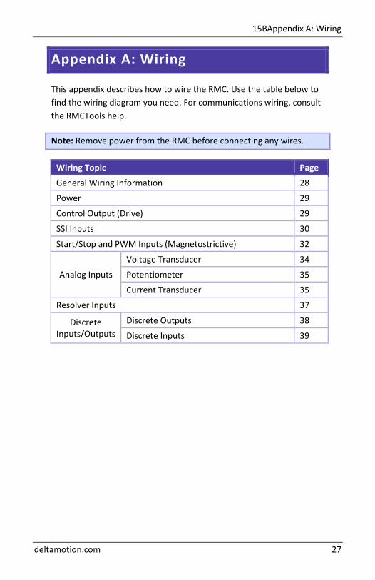
This appendix describes how to wire the RMC. Use the table below to find the wiring diagram you need. For communications wiring, consult the RMCTools help.
Note: Remove power from the RMC before connecting any wires.
Wiring Topic Page
General Wiring Information 28
Power 29
Control Output (Drive) 29
SSI Inputs 30
Start/Stop and PWM Inputs (Magnetostrictive) 32
Analog Inputs
Voltage Transducer 34
Potentiometer 35
Current Transducer 35
Resolver Inputs 37
Discrete Inputs/Outputs
Discrete Outputs 38
Discrete Inputs 39

RMC150 Startup Guide
28 Delta Computer Systems, Inc.
General Wiring Information
For CE compliance and to minimize electrical interference: • Use twisted pairs for all wiring where possible. • Use shielded cables for all wiring. • Keep RMC wiring separate from AC mains or conductors carrying
high currents, especially high frequency switching power such as conductors between servo drives and motors or amplifiers and proportional valves.
For UL and CUL compliance: • Power supply must be Class 2. • All RMC inputs and outputs must be connected to Class 2 circuits
only.
For products labeled Class I, Division 2: • Conductors must be copper only. Follow wire gauge and clamp
screw torque as listed below.
Wire Gauge and Clamp Screw Torque
Use the table below to determine proper wire gauge and torque for the clamp screws on the terminal blocks.
Module Gauge Torque RMC150E, MDT (M), SSI (S), Analog (H, A, G), RES (R)
26-12 AWG ( 0.13 - 3.3 mm2)
4.5 lb-in (0.51 Nm)
DI/O, UI/O 28-16 AWG ( 0.08 - 1.3 mm2)
2.2 lb-in (0.25 Nm)
15BAppendix A: Wiring
deltamotion.com 29
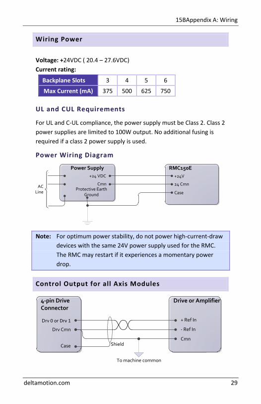
Drive or Amplifier4-pin Drive Connector
Drv 0 or Drv 1
Drv Cmn
Case Shield
+ Ref In
- Ref In
Cmn
To machine common
RMC150EPower Supply+24 VDC
CmnProtective Earth
Ground
+24V
24 Cmn
CaseAC
Line
Wiring Power
Voltage: +24VDC ( 20.4 – 27.6VDC) Current rating:
Backplane Slots 3 4 5 6
Max Current (mA) 375 500 625 750
UL and CUL Requirements
For UL and C-UL compliance, the power supply must be Class 2. Class 2 power supplies are limited to 100W output. No additional fusing is required if a class 2 power supply is used.
Power Wiring Diagram
Note: For optimum power stability, do not power high-current-draw devices with the same 24V power supply used for the RMC. The RMC may restart if it experiences a momentary power drop.
Control Output for all Axis Modules
RMC150 Startup Guide
30 Delta Computer Systems, Inc.
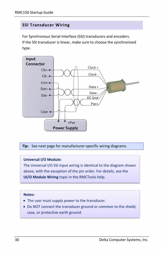
SSI Transducer Wiring
For Synchronous Serial Interface (SSI) transducers and encoders. If the SSI transducer is linear, make sure to choose the synchronized type.
Input Connector
Clk+
Clk-
Cmn
Dat+
Dat-
Case
Clock +
Clock -
Data +
Data -
Power Supply+Pwr
Pwr+
DC Gnd
Tip: See next page for manufacturer-specific wiring diagrams.
Universal I/O Module: The Universal I/O SSI input wiring is identical to the diagram shown above, with the exception of the pin order. For details, see the UI/O Module Wiring topic in the RMCTools help.
Notes: • The user must supply power to the transducer. • Do NOT connect the transducer ground or common to the shield,
case, or protective earth ground
15BAppendix A: Wiring
deltamotion.com 31
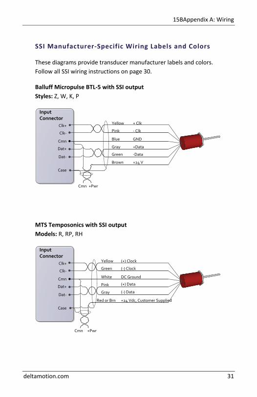
SSI Manufacturer-Specific Wiring Labels and Colors
These diagrams provide transducer manufacturer labels and colors. Follow all SSI wiring instructions on page 30.
Balluff Micropulse BTL-5 with SSI output Styles: Z, W, K, P
Input Connector
+ Clk
- Clk
+Data
-Data
+PwrCmn
Clk+
Clk-
Cmn
Dat+
Dat-
Case
+24 V
GND
Yellow
Pink
Gray
Green
Brown
Blue
MTS Temposonics with SSI output Models: R, RP, RH
Input Connector
(+) Clock
(-) Clock
(+) Data
+PwrCmn
Clk+
Clk-
Cmn
Dat+
Dat-
Case
+24 Vdc, Customer Supplied
DC Ground
Yellow
Green
Pink
Gray
Red or Brn
White
(-) Data
RMC150 Startup Guide
32 Delta Computer Systems, Inc.
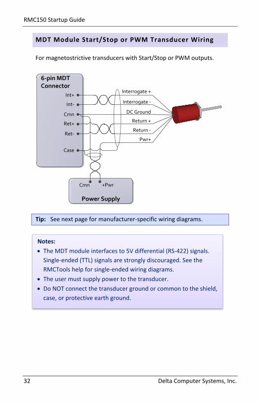
MDT Module Start/Stop or PWM Transducer Wiring
For magnetostrictive transducers with Start/Stop or PWM outputs.
6-pin MDT Connector
Interrogate +
Interrogate -
Return +
Return -
Power Supply
+PwrCmn
Int+
Int-
Cmn
Ret+
Ret-
Case
Pwr+
DC Ground
Tip: See next page for manufacturer-specific wiring diagrams.
Notes: • The MDT module interfaces to 5V differential (RS-422) signals.
Single-ended (TTL) signals are strongly discouraged. See the RMCTools help for single-ended wiring diagrams.
• The user must supply power to the transducer. • Do NOT connect the transducer ground or common to the shield,
case, or protective earth ground.
15BAppendix A: Wiring
deltamotion.com 33
6-pin MDT Connector
(+) Interrogation
(-) Interrogation
(+) Gate Out, (+) Start/Stop
+PwrCmn
Int+
Int-
Cmn
Ret+
Ret-
Case
+ VDC
DC Ground
Yellow
Green
Pink
Gray
Red
White
(-) Gate Out, (-) Start/Stop
or
or
or
or
or
or
Wh/Gy
Gy/Wh
Or/Wh
Wh/Or
Wh/Gr
Wh/Bu
- VDC
Frame
-Pwr
Blue or Gr/Wh
Brown or Bu/Wh
MDT Manufacturer-Specific Wiring Labels and Colors
These diagrams provide transducer manufacturer labels and colors. Follow all MDT wiring instructions on page 32.
Balluff Micropulse BTL-5, digital RS-485 output Styles: Z, W, K, E, P, R, AT
MTS Temposonics with digital output (Start/Stop or PWM) Models: LH, LS, LD, LF, LPS, LPR, G, EP2, ER
MTS Temposonics II with DPM or RPM personality module
6-pin MDT Connector
(+) Interrogation or Start
(-) Interrogation or Start
(+) Gate or (+) Stop
+PwrCmn
Int+
Int-
Cmn
Ret+
Ret-
Case
Customer Supplied Power (+Vdc)
DC Ground
Yellow
Green
Pink
Gray
Red or Brn
White
(-) Gate or (-) Stop
6-pin MDTConnector
Interrogate + Input
Interrogate - Input
Pulse + Output
Pulse - Output
+PwrCmn
Int+
Int-
Cmn
Ret+
Ret-
Case
Pwr+
GND
Yellow
Pink
Gray
Green
Brown
Blue
White GND
White wire must remain unconnected.
RMC150 Startup Guide
34 Delta Computer Systems, Inc.
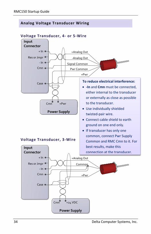
Input Connector
+Analog Out
-Analog Out
Pwr Common
+Pwr
Power Supply
+PwrCmn
+ In
Res or Jmpr
- In
Cmn
Case
Signal Common
Input Connector
+Analog Out
Common
Power Supply
+24 VDCCmn
+ In
Res or Jmpr
- In
Cmn
Case
+Pwr
Analog Voltage Transducer Wiring
Voltage Transducer, 4- or 5-Wire
Voltage Transducer, 3-Wire
To reduce electrical interference: • -In and Cmn must be connected,
either internal to the transducer or externally as close as possible to the transducer.
• Use individually shielded twisted-pair wire.
• Connect cable shield to earth ground on one end only.
• If transducer has only one common, connect Pwr Supply Common and RMC Cmn to it. For best results, make this connection at the transducer.
15BAppendix A: Wiring
deltamotion.com 35
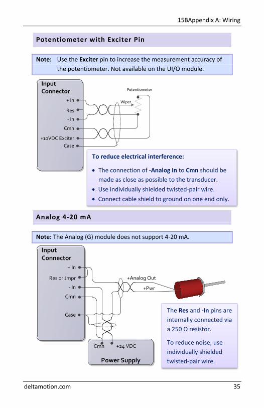
Input Connector
+ In
Res
- In
Cmn
+10VDC ExciterCase
Potentiometer
Wiper
Input Connector
+Analog Out
Power Supply
+24 VDCCmn
+ In
Res or Jmpr
- In
Cmn
Case
+Pwr
Potentiometer with Exciter Pin
Note: Use the Exciter pin to increase the measurement accuracy of the potentiometer. Not available on the UI/O module.
Analog 4-20 mA
Note: The Analog (G) module does not support 4-20 mA.
To reduce electrical interference:
• The connection of -Analog In to Cmn should be made as close as possible to the transducer.
• Use individually shielded twisted-pair wire. • Connect cable shield to ground on one end only.
The Res and -In pins are internally connected via a 250 Ω resistor.
To reduce noise, use individually shielded twisted-pair wire.
RMC150 Startup Guide
36 Delta Computer Systems, Inc.
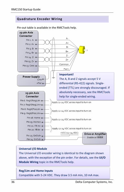
Quadrature Encoder Wiring
Pin-out table is available in the RMCTools help.
Important! The A, B and Z signals accept 5 V differential (RS-422) signals. Single-ended (TTL) are strongly discouraged. If absolutely necessary, see the RMCTools help for single-ended wiring.
Reg/Lim and Home Inputs Compatible with 5-24 VDC. They draw 3.5 mA min, 10 mA max.
Universal I/O Module The Universal I/O encoder wiring is identical to the diagram shown above, with the exception of the pin order. For details, see the UI/O Module Wiring topic in the RMCTools help.

15BAppendix A: Wiring
deltamotion.com 37
Resolver Module Transducer Wiring
The wiring diagram below is for resolvers that fall within the Resolver module’s signal specifications (800 Hz to 5 kHz and 1.41 to 4.8 VRMS). The Ref In input is only used for reference signals outside of these specifications, and requires contacting Delta for assistance.
8-pin Resolver Connector
Ref Winding +
Ref Winding -
Sin Winding -
Cos Winding +
R1
Ref In
R3
S1
S3
S4Cos Winding -
Sin Winding +
S2
Case
Pin Function
R1 Reference Output +
Ref In Reference In (normally not used)
R3 Reference Output -
S1 Sine Input +
S3 Sine Input -
S2 Cosine Input +
S4 Cosine Input -
Case Controller Chassis Ground (shield)

RMC150 Startup Guide
38 Delta Computer Systems, Inc.
Discrete Output Wiring
The RMC150E, DI/O and UI/O outputs are solid state relays. When off, they have high impedance, and when on, they have low impedance.
When switching inductive loads, place a diode or tranzorb across the load to protect the switch when it turns off. Otherwise, a voltage spike in excess of the 30 V rating of the SSR may occur. See the RMC150E Discrete I/O Wiring topic in the RMCTools help for more details.
DI/O and UI/O Module Outputs can be wired in either a high-side or low-side configuration. Because all the outputs share a common, all outputs on the same module must be wired the same.
RMC150E Module Each output has a “+” and “–” connection. Outputs can be wired in either a high-side or low-side configuration.
RMC150E DI/O UI/O
On Impedance 50Ω max, 25Ω typical
Max Current 75 mA (50 mA for Class I Div 2)
75 mA (Class I Div 2 not available)
Max Voltage 30 V
RMC Module Resistiveload
+VCC (12-24 VDC)
Output +
Output -
RMC Module+VCC (12-24 VDC)
Output +
Output -Resistiveload
RMC Module
+VCC (12-24 VDC)
Output
Output
ResistiveLoad…
Output Cmn
RMC Module+VCC (12-24 VDC)
Output
Output ResistiveLoad…
Output Cmn
15BAppendix A: Wiring
deltamotion.com 39
PLCRMC Module
Input b
Input Common
Power
Output
Input a Output
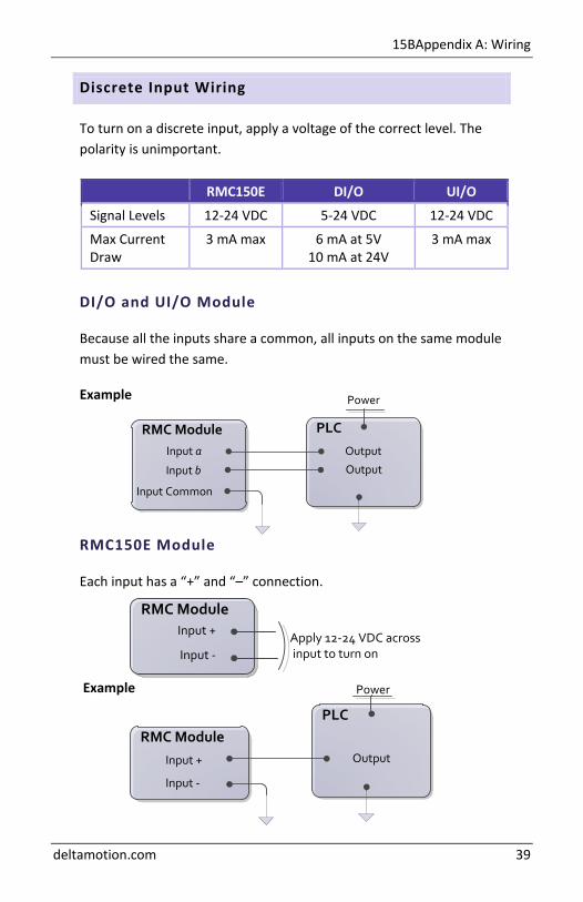
Discrete Input Wiring
To turn on a discrete input, apply a voltage of the correct level. The polarity is unimportant.
DI/O and UI/O Module
Because all the inputs share a common, all inputs on the same module must be wired the same.
Example
RMC150E Module
Each input has a “+” and “–” connection.
Example
RMC150E DI/O UI/O
Signal Levels 12-24 VDC 5-24 VDC 12-24 VDC
Max Current Draw
3 mA max 6 mA at 5V 10 mA at 24V
3 mA max
RMC ModuleInput +
Input -Apply 12-24 VDC across input to turn on
PLCRMC Module
Input +
Input -
Power
Output

RMC150 Startup Guide
40 Delta Computer Systems, Inc.
Appendix B: Mounting Dimensions
Backplane Slots 3 4 5 6
Total Width
4.10 in. (104.1 mm)
5.10 in. (129.5 mm)
6.10 in. (154.9 mm)
7.10 in. (180.3 mm)
Note: Allow space for the connectors on the front of the RMC.
17BAppendix C: Agency Compliance
deltamotion.com 41
Appendix C: Agency Compliance
CE
For CE compliance and to minimize electrical interference: • Use twisted pairs for all wiring where possible. • Use shielded cables for all wiring. • Keep RMC wiring separate from AC mains or conductors carrying
high currents, especially high frequency switching power such as conductors between servo drives and motors or amplifiers and proportional valves.
UL and CUL
For UL and CUL compliance: • Power supply must be Class 2. • All RMC inputs and outputs must be connected to Class 2 circuits
only.
Class I Div 2
Products marked “Class I Division 2, Group A, B, C, D” are suitable for use in Class I Division 2, Groups A, B, C, and D hazardous locations and nonhazardous locations only.
WARNING – EXPLOSION HAZARD – DO NOT DISCONNECT EQUIPMENT WHILE THE CIRCUIT IS LIVE OR UNLESS THE AREA IS KNOWN TO BE FREE OF IGNITABLE CONCENTRATIONS.
WARNING – EXPLOSION HAZARD – SUBSTITUTION OF ANY COMPONENT MAY IMPAIR SUITABILITY FOR CLASS I, DIVISION 2.
Surrounding air temperature of 60° C.
The RMC150E USB port is intended for configuration, programming, and troubleshooting purposes only. It should not be connected during normal operation.
See page 28 for wire gauge, screw clamp torque and wire type requirements.
The RMC Family of Motion Control
Connect. Control. Optimize.