state of california • department of …ahmct.ucdavis.edu/pdf/ucd-arr-15-09-30-05.pdffinal report...
TRANSCRIPT

STATE OF CALIFORNIA • DEPARTMENT OF TRANSPORTATION
TECHNICAL REPORT DOCUMENTATION PAGE TR0003 (REV 10/98)
ADA Notice For individuals with sensory disabilities, this document is available in alternate
formats. For information call (916) 654-6410 or TDD (916) 654-3880 or write
Records and Forms Management, 1120 N Street, MS-89, Sacramento, CA 95814.
1. REPORT NUMBER
CA16-1846
2. GOVERNMENT ASSOCIATION NUMBER 3. RECIPIENT'S CATALOG NUMBER
4. TITLE AND SUBTITLE
Development and Testing of Responder Phase III
5. REPORT DATE
June 28, 2017
6. PERFORMING ORGANIZATION CODE
AHMCT Research Center, UC Davis
7. AUTHOR
Stephen Donecker, Travis Swanston, Kin Yen, Bahram Ravani, and Ty A. Lasky
8. PERFORMING ORGANIZATION REPORT NO.
UCD-ARR-15-09-30-05
9. PERFORMING ORGANIZATION NAME AND ADDRESS
AHMCT Research Center
UCD Dept. of Mechanical & Aerospace Engineering
Davis, California 95616-5294
10. WORK UNIT NUMBER
11. CONTRACT OR GRANT NUMBER
IA65A0416, Task 1846
13. TYPE OF REPORT AND PERIOD COVERED
Final Report
June 2013 – September 2015 12. SPONSORING AGENCY AND ADDRESS
California Department of Transportation
P.O. Box 942873, MS #83
Sacramento, CA 94273-0001 14. SPONSORING AGENCY CODE
Caltrans
15. SUPPLEMENTARY NOTES
16. ABSTRACT
This report documents the research project “Development and Testing of Responder Phase III.” Under previous research, a Responder
system has been developed to provide relevant and timely information to first responders, allow responders to provide information on the
scene and incident to others in the organization, and support reliable and always available communications. The primary goal of the current
project was to migrate the Responder system to the latest computing and communications technologies, including smartphone and tablet
systems. The project includes review of previous phase efforts, updating of requirements, review of commercial systems, design and
development of Phase III Responder system, and testing and reporting. The research product will provide Caltrans with a more field-ready
system to support first responders in rural environments.
17. KEY WORDS
First response, Highway maintenance, emergency response,
first responder, incident management
18. DISTRIBUTION STATEMENT
No restrictions. This document is available to the
public through the National Technical Information
Service, Springfield, Virginia 22161.
19. SECURITY CLASSIFICATION (of this report)
Unclassified
20. NUMBER OF PAGES
118
21. COST OF REPORT CHARGED
Reproduction of completed page authorized
DISCLAIMER
The research reported herein was performed by the Advanced Highway Maintenance and
Construction Technology (AHMCT) Research Center, within the Department of Mechanical and
Aerospace Engineering at the University of California – Davis, for the Division of Research,
Innovation and System Information (DRISI) at the California Department of Transportation.
AHMCT and DRISI work collaboratively to complete valuable research for the California
Department of Transportation.
The contents of this report reflect the views of the author(s) who is (are) responsible for the
facts and the accuracy of the data presented herein. The contents do not necessarily reflect the
official views or policies of the STATE OF CALIFORNIA or the FEDERAL HIGHWAY
ADMINISTRATION. This report does not constitute a standard, specification, or regulation.
The contents of this report do not necessarily reflect the official views or policies of the
University of California. This report does not constitute an endorsement of any products or services
described herein.
For individuals with sensory disabilities, this document is available in Braille, large print,
audiocassette, or compact disk. To obtain a copy of this document in one of these alternate formats,
please contact: the Division of Research, Innovation and System Information, MS-83, California
Department of Transportation, P.O. Box 942873, Sacramento, CA 94273-0001.

Advanced Highway Maintenance
and Construction Technology Research Center
Department of Mechanical and Aerospace Engineering
University of California at Davis
Development and Testing of Responder Phase III
Stephen Donecker, Travis Swanston, Kin Yen, Bahram Ravani &
Ty A. Lasky (Principal Investigator)
Report Number: CA16-1846
AHMCT Research Report: UCD-ARR-15-09-30-05
Final Report of Contract: IA65A0416, Task 1846
June 28, 2017
California Department of Transportation
Division of Research, Innovation and System Information

Development and Testing of Responder Phase III
ii
ABSTRACT
This report documents the research project “Development and Testing of Responder
Phase III.” Under previous research, a Responder system has been developed to provide relevant
and timely information to first responders, allow responders to provide information on the scene
and incident to others in the organization, and support reliable and always available
communications. The primary goal of the current project was to migrate the Responder system to
the latest computing and communications technologies, including smartphone and tablet systems.
The project includes review of previous phase efforts, updating of requirements, review of
commercial systems, design and development of Phase III Responder system, and testing and
reporting. The research product will provide Caltrans with a more field-ready system to support
first responders in rural environments.

Development and Testing of Responder Phase III
iii
TABLE OF CONTENTS
Abstract ..................................................................................................................................... ii
Table of Contents .................................................................................................................... iii
List of Figures ........................................................................................................................... v
List of Tables .......................................................................................................................... vii
List of Acronyms and Abbreviations .................................................................................... viii
Acknowledgments..................................................................................................................... x
Chapter 1: Introduction ........................................................................................................... 1
Research Approach .......................................................................................................................... 1
Overview of Research Results and Benefits ................................................................................... 1
Chapter 2: Responder System Concept ................................................................................... 2
Chapter 3: Responder Requirements ...................................................................................... 4
Chapter 4: High-Level System Design .................................................................................. 12
Responder Physical Architecture ................................................................................................. 12
Responder Truck Architecture ..................................................................................................... 13
Chapter 5: System Details ...................................................................................................... 16
Software .......................................................................................................................................... 16
Hardware ........................................................................................................................................ 40
Portable Responder System .......................................................................................................... 47
Chapter 6: Responder System Installation ............................................................................ 50
Chapter 7: System Testing and Demonstration .................................................................... 56
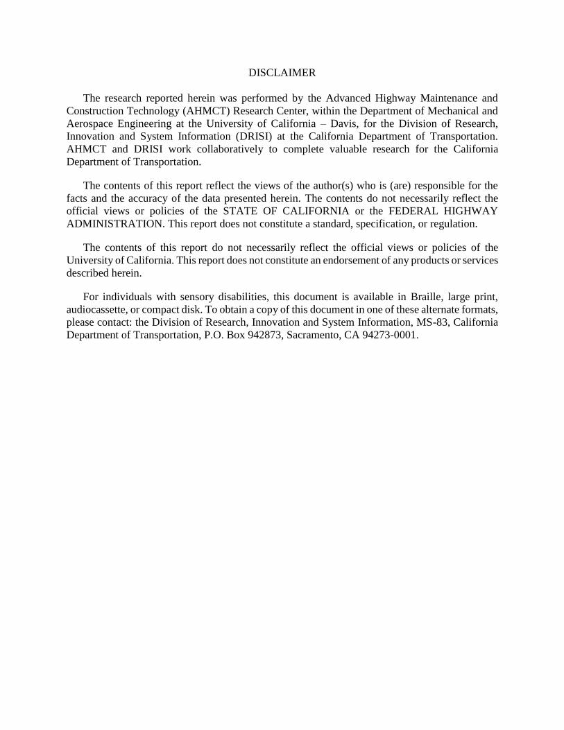
Radio Measurements ..................................................................................................................... 56
Mitigation of Radio Frequency Interference ............................................................................... 58
Chapter 8: Conclusions and Future Research ..................................................................... 59
References .............................................................................................................................. 61
Appendix A: Responder System Quick Start Guide .............................................................. 62
Entering an Incident ...................................................................................................................... 62
Checking Related Information...................................................................................................... 68
Previewing and Sending an Incident Mail ................................................................................... 76
Editing an Existing Incident .......................................................................................................... 78
Appendix B: Responder System User Guide ......................................................................... 79
Responder Software Startup ......................................................................................................... 79
Using the Responder HMI App .................................................................................................... 80

Development and Testing of Responder Phase III
iv
Responder System Maintenance ................................................................................................... 85
Frequently Asked Questions ......................................................................................................... 86
Appendix C: Responder System Mounting Bracket Designs ............................................... 88
Appendix D: Cellular Signal Coverage and Strength .......................................................... 97

Development and Testing of Responder Phase III
v
LIST OF FIGURES
Figure 2.1: Responder concept ................................................................................................................................... 3 Figure 4.1: Responder in-vehicle software architecture ......................................................................................... 13 Figure 5.1: Caltrans Intelligent Roadway Information System (IRIS) map tiles are the basis for the
Responder road map ........................................................................................................................................ 19 Figure 5.2: Responder topographic map ................................................................................................................. 20 Figure 5.3: Responder app navigation drawer, top and bottom portions ............................................................ 22 Figure 5.4: Reports screen ........................................................................................................................................ 23 Figure 5.5: Reports menu.......................................................................................................................................... 24 Figure 5.6: Reports screen, in ascending order by creation time .......................................................................... 25 Figure 5.7: Sample Report Entry screen, part 1 and 2 / 4 ...................................................................................... 26 Figure 5.8: Sample Report Entry screen, part 3 and 4 / 4 ...................................................................................... 27 Figure 5.9: Infrastructure type (left) and Incident type (right) dialogs for Report Entry .................................. 29 Figure 5.10: Vehicle type (left) and Special considerations (right) dialogs for Report Entry ............................. 30 Figure 5.11: Sample Gallery screen ......................................................................................................................... 31 Figure 5.12: Gallery menu ........................................................................................................................................ 32 Figure 5.13: Sample Map screen, road map ............................................................................................................ 33 Figure 5.14: Sample Map screen, topo map ............................................................................................................ 34 Figure 5.15: Sample Map screen, aerial photo ........................................................................................................ 35 Figure 5.16: Weather screen ..................................................................................................................................... 36 Figure 5.17: Roadway screen .................................................................................................................................... 36 Figure 5.18: Sample mail screen ............................................................................................................................... 37 Figure 5.19: Contact list ............................................................................................................................................ 38 Figure 5.20: Example received email inbox entry ................................................................................................... 38 Figure 5.21: Example received email report as it appears in Microsoft Outlook ................................................ 39 Figure 5.22: Example received email report as it appears in Mozilla Thunderbird ............................................ 40 Figure 5.23: Responder HMI tablet screen shot, including icons for the Responder app and the ERG 2016
app for hazmat info .......................................................................................................................................... 41 Figure 5.24: Responder system box internal view .................................................................................................. 42 Figure 5.25: Responder system box mounted under right rear seat in vehicle .................................................... 42 Figure 5.26: Satellite antenna mounted on vehicle light bar .................................................................................. 43 Figure 5.27: Responder system cellular modem ..................................................................................................... 45 Figure 5.28: Responder system diversity antenna on right side of the vehicle light bar. This incorporates
antennas for Wi-Fi, cellular, and GPS. .......................................................................................................... 46 Figure 5.29: Responder system Wi-Fi card installed inside the Responder computer system (Logic Supply
Nuvo-3100VTC embedded computer) ............................................................................................................ 47 Figure 5.30: Portable Responder system in its ruggedized case ............................................................................ 48 Figure 5.31: Portable Responder system deployed ................................................................................................. 48 Figure 5.32: Tentative method for restraining the Portable Responder system .................................................. 49 Figure 6.1: Responder truck before installation: front view .................................................................................. 50 Figure 6.2: Responder truck before installation: side view.................................................................................... 51 Figure 6.3: Responder truck before installation: rear view ................................................................................... 51 Figure 6.4: Responder truck rear seat area before installation ............................................................................. 52 Figure 6.5: Responder system box in-vehicle install location ................................................................................ 53 Figure 6.6: Responder system as installed in the vehicle ........................................................................................ 54 Figure 6.7: Responder system antennas .................................................................................................................. 55 Figure 7.1: Responder system demonstration to Caltrans personnel ................................................................... 56 Figure 7.2: In-vehicle radio head install .................................................................................................................. 57 Figure 7.3: In-vehicle radio body install .................................................................................................................. 58 Figure C.1: Switch mount ......................................................................................................................................... 89 Figure C.2: Upper plate for LTE cellular, GPS, and Wi-Fi antenna mount ........................................................ 90 Figure C.3: Upper plate for satellite antenna mount .............................................................................................. 91 Figure C.4: Lower plate for all antenna mounts ..................................................................................................... 92 Figure C.5: Portable Responder system satellite antenna magnetic mount plate ................................................ 93 Figure C.6: Portable Responder system satellite antenna mount pin block ......................................................... 94

Development and Testing of Responder Phase III
vi
Figure C.7: Portable Responder system satellite antenna mount concept upper view ........................................ 95 Figure C.8: Portable Responder system satellite antenna mount concept lower view ........................................ 96 Figure D.1: Snow-affected routes (yellow) for California. Red boundaries represent Caltrans districts. ......... 97 Figure D.2: Snow-affected routes (yellow) for northern California. Red boundaries represent Caltrans
districts. ............................................................................................................................................................. 98 Figure D.3: Snow-affected routes (yellow) for central California. Red boundaries represent Caltrans districts.
........................................................................................................................................................................... 99 Figure D.4: Snow-affected routes (yellow) for southern California. Red boundaries represent Caltrans
districts. ........................................................................................................................................................... 100 Figure D.5: AT&T signal strength for SR 299 from west of Nubieber to state line in Caltrans District 2
(survey: July 27, 2013 from 9:25 – 11:09) .................................................................................................... 101 Figure D.6: Verizon signal strength for SR 299 from west of Nubieber to state line in Caltrans District 2
(survey: July 27, 2013 from 9:25 – 11:09) .................................................................................................... 102 Figure D.7: T-Mobile signal strength for SR 395 from Round Valley to state line in Caltrans District 9
(survey: August 24, 2013 from 11:04 – 14:04) ............................................................................................. 103 Figure D.8: AT&T signal strength for SR 395 from Round Valley to state line in Caltrans District 9 (survey:
August 24, 2013 from 11:04 – 14:04) ............................................................................................................ 103 Figure D.9: Verizon signal strength for SR 395 from Round Valley to state line in Caltrans District 9 (survey:
August 24, 2013 from 11:04 – 14:04) ............................................................................................................ 104 Figure D.10: T-Mobile signal strength for SR 88 from west of Pioneer to the state line in Caltrans District 10
(survey: August 3, 2013 from 12:25 – 13:52) ............................................................................................... 105 Figure D.11: AT&T signal strength for SR 88 from west of Pioneer to the state line in Caltrans District 10
(survey: August 3, 2013 from 12:25 – 13:52) ............................................................................................... 105 Figure D.12: Verizon signal strength for SR 88 from west of Pioneer to the state line in Caltrans District 10
(survey: August 3, 2013 from 12:25 – 13:52) ............................................................................................... 106

Development and Testing of Responder Phase III
vii
LIST OF TABLES
Table 3.1: Responder Phase III Requirements ......................................................................................................... 4 Table 5.1: Options for infrastructure type on Report Entry screen ..................................................................... 27 Table 5.2: Options for incident type on Report Entry screen ................................................................................ 28 Table 5.3: Options for vehicle type on Report Entry screen .................................................................................. 28 Table 5.4: Options for special considerations on Report Entry screen ................................................................. 28 Table 5.5: Truck heading for optimal satellite communication in each Caltrans district for the Inmarsat 4-F3
(Americas) ......................................................................................................................................................... 44 Table D.1: Heat map key relating color to signal strength .................................................................................. 101

Development and Testing of Responder Phase III
viii
LIST OF ACRONYMS AND ABBREVIATIONS
Acronym Definition
3D Three-dimensional
AHMCT Advanced Highway Maintenance and Construction Technology Research Center
API Application Programming Interface
ATMS Advanced Transportation Management System
BGAN Broadband Global Area Network
CAD Computer-Aided Design
Caltrans California Department of Transportation
CCTV Closed-Circuit TV
CDEC California Data Exchange Center
CHP California Highway Patrol
CMS Changeable Message Sign
CNRFC California Nevada River Forecast Center
COTS Commercial Off–The-Shelf
CWWP Commercial Wholesale Web Portal
DHIPP Digital Highway Inventory Photography Program
DMS Dynamic Message Sign
DOE Division of Equipment
DOT Department of Transportation
DRISI Caltrans Division of Research, Innovation and System Information
EMS Emergency Medical Services
GDAL Geospatial Data Abstraction Library
GPS Global Positioning System
HMI Human Machine Interface
HTTP Hypertext Transfer Protocol
ID Identification
IEEE Institute of Electrical and Electronics Engineers
IP Internet Protocol
IR Infrared
IRIS Intelligent Roadway Information System
ISM Industrial, Scientific, and Medical
ITS Intelligent Transportation Systems
JSON JavaScript Object Notation
LTE Long-Term Evolution
LRS Linear Reference System
MADIS Meteorological Assimilation Data Ingest System
MSU Montana State University
NED National Elevation Dataset
NOAA National Oceanic and Atmospheric Administration
NWS National Weather Service
OES Office of Emergency Services
OS Operating System
OSM OpenStreetMap
OSS One-Stop-Shop
PDF Portable Document Format
PIO Public Information Office
QOS Quality of Service
R&D Research & Development
RF Radio Frequency
RWIS Road Weather Information System

Development and Testing of Responder Phase III
ix
Acronym Definition
SR State Route
SWR Standing Wave Ratio
TAG Technical Advisory Group
TCP/IP Transmission Control Protocol / Internet Protocol
TMC Transportation Management Center
UCD University of California – Davis
USGS United States Geological Survey
VDS Vehicle Detector Station
Wi-Fi Wireless Fidelity
WTI Western Transportation Institute
XML Extensible Markup Language

Development and Testing of Responder Phase III
x
ACKNOWLEDGMENTS
The authors thank the California Department of Transportation (Caltrans) for their support, in
particular Ian Turnbull, Chief, Office of Intelligent Transportation Systems (ITS) Engineering and
Support, and Melissa Clark, Asfand Siddiqui, and Gurprit Hansra with the Division of Research,
Innovation and System Information. The authors also thank Carlos Aguilar, Joe Baltazar, Geno
Cervantes, Javier Del Rio, Keith Farnsworth, Philip Graham, Michael Gunn, Francisco Gutteres,
Steve Hardie, Ed Hardimann, Ed Lamkin, Kevin Marshall, Ferdinand Milanes, Mitchell Ngo,
Sidra Pauly, Jeremiah Pearce, James Province, John Schmidt, Chris Seale, Bill Stein, and Larry
Wooster of Caltrans for their guidance and support. For assistance with the Caltrans data feeds,
the authors thank Sean Campbell and Keith Koeppen. The authors also thank Doug Galarus and
his researchers at the Western Transportation Institute for their pioneering work in earlier phases
of Responder development. The authors thank Tomás Guerra of OZ Engineering LLC, and Israel
Lopez and James Whalen of the Nevada Department of Transportation (DOT) for assistance with
the Nevada data feeds. For their assistance with the Oregon data feeds, the authors thank Robert
Fedele, Kyle Hedspeth, and Galen McGill of the Oregon DOT. The authors also thank Caltrans
District 6 for the gracious loan of their maintenance supervisor vehicle. The authors also thank the
Caltrans district maintenance personnel in Districts 2, 3, 4, and 9 for their valuable system testing
and feedback. The authors acknowledge the dedicated efforts of the AHMCT team who have made
this work possible.

Development and Testing of Responder Phase III
1
CHAPTER 1:
INTRODUCTION
Incident response is a critical function for the California Department of Transportation
(Caltrans). It is important to provide relevant and timely information to responders, including for
example weather. In addition, it is important for first responders to be able to provide relevant
information from the scene and the incident to others in the organization who are involved in the
process. Reliable and always available communication is a key component for incident response.
Under the Responder Phase II research project [7], a system was developed by the Western
Transportation Institute (WTI) of Montana State university (MSU) at Bozeman to meet these needs
for Caltrans.
The goal of the current Responder Phase III research project was to migrate the existing
Responder system to the latest computing and communications technologies, including
smartphone and tablet systems. As part of this Phase III research project, the Advanced Highway
Maintenance and Construction Technology (AHMCT) Research Center at the University of
California – Davis (UCD) designed and developed this next-generation Responder system. The
project included review of previous phase efforts, updating of requirements, review of commercial
systems, design and development of Phase III Responder system, and testing and reporting. The
research product will provide Caltrans with a field-ready system ready for full deployment to
support first responders in rural environments.
Research Approach
This work builds on AHMCT’s experience with winter maintenance operations, our strength
in sensing and system integration, and our established Mechatronic hardware and software
knowledge base [2,4-6,9-13].
The research methodology included:
Update prototype system concept and requirements
Literature and product review
Prototype system development
Prototype system testing and evaluation
Overview of Research Results and Benefits
The key deliverables of this project include:
Updated prototype system high-level design
Updated requirements
System software and hardware design and code
User guide
Field test of Responder system

Development and Testing of Responder Phase III
2
CHAPTER 2:
RESPONDER SYSTEM CONCEPT
Caltrans maintenance staff is first responder to incidents on the state roadways. They must
collect information, determine the appropriate response, and access and manage resources at-
scene. These events must be done in concurrence with providing transportation management
services to respond to and recover from the incident. Caltrans currently does not have an efficient
means to collect at-scene incident information and the capacity to share this information with
transportation management centers and other emergency responders. In most Caltrans districts,
emergency responders rely on voice communications to exchange information. In addition, many
districts lack the ability to distribute incident support information to responders via data networks.
Such information could better prepare responders for incident support, provide assistance for
incident management, and guide responders in making safe and sound decisions. Caltrans needs a
communication tool for first responders to allow photos, drawings, weather information, and maps
to be shared between responders and a transportation management center (TMC) during an
incident via Wireless Fidelity (Wi-Fi), cellular, satellite, or other forms of communications.
As a key element of this project, AHMCT has developed the third-generation of the Responder
system. This is a communication tool that integrates hardware, software, and communications to
provide incident responders with an easy to use means to accurately collect and communicate at-
scene information with their managers and the TMC. The system is particularly useful to those in
rural areas with sparse communication coverage. The incident responder will use a smart device
such as a tablet or cell phone. The Responder system provides access to critical information such
as weather, fire, and TMC field element status to responders. It manages communications via
multiple channels, selecting the best channel based on availability, bandwidth, and cost. Responder
includes a store-and-forward architecture to address situations where communications is
temporarily unavailable. The Responder system does not rely on any centralized server, as it must
function in situations with complete communications degradation.
Unique features of the system include the ability for users to capture, annotate, and transmit
images. Using Global Positioning System (GPS) readings, the system automatically downloads
local weather data, retrieves maps and aerial photos, and pinpoints the responder’s location on the
maps. By simply clicking on the “SEND” button, an email message is automatically composed
and sent to the TMC operator or other emergency/first responder parties. The system connects to
the most efficient and available service (Wi-Fi, cellular, satellite, or other communication) on its
own; photos and sketches are compressed to minimize transmission time. With an emphasis on
ease of use, the system allows responders to concentrate on work at the scene without burdening
them with data input and reporting. The high-level Responder concept and architecture is shown
in Figure 2.1.

Development and Testing of Responder Phase III
3
Long-Range WiFi
Satellite Internet Service
Cellular Internet Service
Satellite Backhaul
TMC
TMC End User
First Responder
Figure 2.1: Responder concept
The Responder system allows first responders to collect and share at-scene information quickly
and efficiently. It is especially valuable in:
Major incidents such as landslides, floods and earthquakes, where the damage could be
extensive
Remote rural areas where communication is often limited to voice, and coverage is
sparse
When the first responder is new or inexperienced in responding to certain situations
The use of this system will save resources by:
Having the ability to evaluate what is happening at the scene from a maintenance
yard/location or TMC without extended delay
Sending the correct employees and equipment to the incident in a timely manner based
on the initial information that can be seen in the photo(s) and/or report(s) submitted by
Caltrans staff at the incident scene
Being able to provide real-time information to other staff, such as the Public
Information Office (PIO), who may have to answer to outside agencies regarding what
is happening at the incident.

Development and Testing of Responder Phase III
4
CHAPTER 3:
RESPONDER REQUIREMENTS
The requirements for the current phase of Responder research and development (R&D) are
derived from those presented in [3]. These requirements were developed through extensive project
workshops, user feedback, and review. The requirements as presented in this chapter drove all
system architecture, design, and implementation decisions.
Unless otherwise note, requirements marked as partially (yellow) or not met (red) are included
in a plan provided to DRISI by AHMCT for future implementation.
Table 3.1: Responder Phase III Requirements
Key (status as of 5/31/17)
Requirement met
Requirement partially met
Requirement not met
1. A system shall be implemented to collect incident information.
1.1. The system shall collect and store incident metadata.
1.2. The system shall collect the incident location.
1.2.1. The system shall record the precise location of the incident using latitude and
longitude.
1.2.2. The system shall record post mile location of the incident.
1.3. The system shall collect the incident occurrence time.
1.4. The system shall collect a description of the incident.
1.4.1. The system shall record the type of incident.
1.4.1.1. The system shall record analysis of spill impacts for Hazmat incidents.1
1.4.1.2. The system shall record severity of incidents.
1 This can be recorded in the description field.

Development and Testing of Responder Phase III
5
1.4.2. The system shall record traffic control, closures, and directions of traffic in a
form.
1.4.3. The system shall record equipment needed for incident clearance.
1.4.4. The system shall record incident measurements.
1.5. The system shall collect incident photographs.
1.6. The system shall collect incident sketches.
1.7. The system shall facilitate sketches.
1.7.1. The system shall facilitate sketches to annotate incident photographs.
1.7.2. The system shall facilitate sketches to annotate maps.
1.7.3. The system shall facilitate sketches to annotate aerial photos.
1.7.4. The system shall facilitate free-form sketches.
1.8. The system shall store incident information as a collection, not disparate pieces.
1.9. The system shall allow incident information to be edited.
1.10. The system shall allow incident information to be deleted.
1.11. The system shall store incident information in a format compatible with
database import utilities.
1.12. The system shall automatically identify incidents.
1.12.1. The system shall identify incidents by date, time, organization, name of
responder, county, and/or road.
1.12.2. The system shall facilitate searching and organizing incidents by date,
organization, name of responder, county, and/or road.
1.13. The system shall allow for the entry of a free-form incident name.

Development and Testing of Responder Phase III
6
2. The system shall be used by Caltrans’ staff, but shall be of potential for use
by EMS (Emergency Medical Services), fire and other agencies.
2.1. The system shall be usable by one primary field contact person for
communication with dispatch.
2.2. The system shall transmit incident information to an operator selectable or
editable list of contacts and groups.
2.3. The system shall be usable by other agencies.
2.3.1. The system shall be configurable for use by other agencies.
3. The system shall be deployed within Caltrans’ vehicles in the field.
3.1. The system shall be flexible in deployment to include the possibility of a
briefcase, partially fixed within a vehicle, or entirely fixed within a vehicle.
3.1.1. The system shall be portable.
3.2. The system shall be storable in a “box” behind the driver’s seat.
3.3. The system shall be storable in a “box” in the bed of a truck.
3.4. The system shall use hardened equipment.
3.4.1. The system shall be usable in temperatures between -20°F to 120°F.
3.4.2. The system shall be storable in temperatures between -20°F to 150°F.
3.4.3. The system shall release heat generated during operation.
3.4.4. The system shall be usable in all weather conditions including rain, snow, bright
sun, and wind.
3.5. The system shall have a charging/docking station.
3.5.1. The system shall have an ergonomic charging/docking station.
3.5.2. The system shall facilitate easy retrieval and replacement of equipment.
3.5.3. The system shall facilitate easily recharging batteries.
3.5.4. The system shall have a charging/docking station that is resistant to liquid spills,
dirt, and other debris.
3.6. The system shall be operable directly off vehicle power.

Development and Testing of Responder Phase III
7
3.7. The system shall be stored within the vehicle in a manner such that it doesn’t
interfere with other work.
3.8. The system shall allow for antennas to be permanently fixed.
3.9. The system shall allow for antennas to be removable.
3.10. The system shall have a modular hardware design.
4. The system shall be operational within and in the vicinity of Caltrans’
vehicles in the field.
4.1. The system shall be usable up to 200 feet from the vehicle.
5. The system shall be easy to use.
5.1. The system shall include a checklist for use and procedure at the scene.
5.2. The system shall include a reference guide for basic operation.
5.3. The system shall include a user manual including detailed trouble-shooting.
5.4. The system shall provide a mechanism to capture photographs.
5.5. The system shall facilitate preview of photographs.
5.6. The system shall facilitate management of photographs.
5.7. The system shall facilitate archival of photographs.
5.7.1. The system shall facilitate deletion of photographs.
5.8. The system shall require minimal navigation to complete operations.
5.9. The system shall use functional names for interface elements.
5.10. The system shall facilitate pre-stored configuration information and default
values.
5.10.1. The system shall store default contact information (email address) for incident
information transmission.
5.10.1.1. The system shall allow the user to override default contact information
by selection or entry.
5.11. The system shall be designed for ease of use so as not to require embedded help.

Development and Testing of Responder Phase III
8
5.12. The system shall be reliable.
6. The system shall automate the collection of incident information.
6.1. The system shall automatically geo-locate the responder.
7. The system shall minimize the amount of time required for use.
7.1. The system shall facilitate the collection and entry of incident information in
less than 20 minutes.
7.2. The system shall facilitate automated transmission of incident information.
7.3. The system shall allow users to multitask while communication tasks are in
process.
8. The system shall transmit information to the TMC and other outside
agencies.
8.1. The system shall transmit incident information to an operator selectable or
editable list of contacts and groups.
8.2. The system shall preview messages prior to transmission.
8.3. The system shall automatically scale and compress photos and sketches for
transmission.
8.3.1. The system shall default to minimal suitable quality for transmission.
8.3.2. The system shall allow the user to override image quality.
8.4. The system shall facilitate breaking messages into “chunks” in the event of
transmission problems.
8.5. The system shall transmit incident records as soon as possible.
8.6. The system shall allow the transmission of all incident information including all
sketches and photographs.
8.7. The system shall allow the selection and transmission of incident information
including selected sketches and photographs.
8.8. The system shall allow the transmission of text-only incident information.
8.9. The system shall mark information that has been successfully transmitted.

Development and Testing of Responder Phase III
9
8.9.1. The system shall use marked information to facilitate interpretation of multiple
transmissions to a recipient.
9. The system shall receive information from outside sources.
9.1. The system shall display weather information based on the responder’s
location.2
9.1.1. The system shall display weather forecasts based on the responder’s position.
9.1.2. The system shall display wind directions.
9.1.3. The system shall display storm information.
9.1.4. The system shall display wildland fire information.
9.1.5. The system shall display RWIS (Road Weather Information System) data
9.1.6. The system shall display Chain Control.
9.1.7. The system shall display projected stream flows.
9.1.8. The system shall display weather information from CDEC (California Data
Exchange Center), MESOWEST, & MADIS (Meteorological Assimilation Data Ingest
System).3
9.1.9. The system shall display zone forecasts.
9.1.10. The system shall display road camera (CCTV) displays.
9.2. The system shall display road maps based on the responder’s location.4
9.2.1. The system shall include pre-loaded road maps.
2 All information sources (feeds) are being acquired and parsed. All relevant information is being extracted and sent
to the Responder database. The display of this information currently uses prototype screens that are not optimal for
such display. These displays will be updated in AHMCT’s planned pending work. 3 All weather information is being obtained from other reliable sources, e.g. the National Weather Service. CDEC
does not provide weather, to our knowledge. MESOWEST requires membership, including payment, to obtain its
data. MADIS requires a user account. AHMCT applied for a MADIS account, but did not receive a reply. AHMCT
sent MADIS several requests for status of the account application, and received no replies. As the needed weather
information was being obtained from reliable sources, no further attempt was made related to MADIS. 4 The system will include mapping tiles for all appropriate zoom levels. Exact zoom levels are TBD in discussion with
TAG. For the road map, Responder uses the same map tiles used in Caltrans’ IRIS (Intelligent Roadway
Information System) traffic management system.

Development and Testing of Responder Phase III
10
9.3. The system shall display aerial photos based on the responder’s location.5
9.3.1. The system shall include pre-loaded aerial photos.
9.3.2. The system shall include pre-loaded Caltrans’ Digital Highway Inventory
Photography Program (DHIPP) aerials photos.
9.3.3. The system may indicate creation dates for aerial photos.6
9.4. The system shall display topographic maps based on the responder’s location.7
9.4.1. The system shall include pre-loaded topographic maps.
9.4.2. The system may indicate creation dates for topographic maps.
9.5. The system shall display Caltrans’ maps.8
9.5.1. The system may indicate creation dates for Caltrans’ maps.9
9.6. The system shall display expected traffic volumes.
9.7. The system shall display chemical information for Hazmat spills.10
9.8. The system shall download data to responders while en route to and at the scene
of an incident.
9.9. The system shall not download unnecessary information such as graphics and
links.
9.10. The system shall use incident location information to identify and expedite
downloads.
9.11. The system shall display information within a user-selectable radius.
5 The system will include aerial photo tiles for all appropriate zoom levels. Exact zoom levels are TBD in discussion
with TAG. Aerial photos will be based on content provided by Caltrans DRISI. 6 While this requirement uses “may” rather than “shall”, AHMCT hopes to address it. However, it is not clear whether
creation date is available from Caltrans DRISI for the included aerial photos. 7 The system will include topographic map tiles for all appropriate zoom levels. Exact zoom levels are TBD in
discussion with TAG. Topographic map tiles will be generated by AHMCT, per prior discussions with TAG. 8 This requirement is unclear. The difference between “road maps” (requirement 9.2) and “Caltrans maps”
(requirement 9.5) needs explanation. 9 While this requirement uses “may” rather than “shall”, AHMCT hopes to address it. However, it is not clear whether
creation date is available for “Caltrans maps”, particularly since this term is not currently clear. 10 AHMCT recommends use of a separate app, “ERG 2016”, as it provides advanced navigation, searching and
viewing capabilities for the 2016 Emergency Response Guidebook. This app can be installed from Google Play
Store. The app has been installed on the Responder tablet.

Development and Testing of Responder Phase III
11
9.12. The system shall minimize dependencies on Caltrans’ server resources.
10. The system shall have data communications capability in all areas of
District 2.
10.1. The system shall be operable in rural areas including mountainous areas.
10.2. The system shall be operable in urban areas.
10.3. The system shall attempt to automatically mitigate communication failures.
10.3.1. The system shall retry sends or downloads in the case of failure.
10.3.2. The system shall switch over to another communication device, if available, in
the event of a failure.
10.4. The system shall notify the user if communication fails.
11. The system shall display diagnostic information for system devices.11
11.1. The system shall display diagnostic information in clearly separate location
from other information.
11 AHMCT is implementing diagnostics and status in pending work.

Development and Testing of Responder Phase III
12
CHAPTER 4:
HIGH-LEVEL SYSTEM DESIGN
The Responder system design was developed based on the concept presented in Chapter 2 and
the detailed requirements of Chapter 3. This design is presented here.
Responder Physical Architecture
Figure 2.1 illustrates the Responder physical architecture. The Responder system is designed
to be completely independent of any centralized server. Obviously, information from any
particular data source, e.g. CMS status, requires communications with an associated server, e.g.
the Caltrans Commercial Wholesale Web Portal (CWWP). However, Responder is independent of
any particular server, as it will continue to support all functionality that does not depend on a
particular unavailable server. This was a key requirement for Responder, and drove many of the
architecture and detailed design decisions.
For the end user, i.e. the Caltrans first responder, the human machine interface (HMI) is all
that they will have to know, or should know, about Responder. The remainder of the system should
be transparent to them. The user interacts with the HMI app on either a smartphone or a tablet.
This app is discussed in detail in a separate chapter.
The HMI communicates with the in-vehicle system using long-range Wi-Fi, with a range of at
least 200 feet. In extreme situations, such as natural disasters, all known communication may be
down. The in-vehicle system acts as a Wi-Fi router for any Responder users within range.
As noted previously and as clearly illustrated in the cellular survey results, rural (and in
extreme cases urban), responders often operate in areas where cellular communications is
intermittent, including large areas where no signal is available. To accommodate this constraint,
the Responder system implements a store-and-forward architecture. Under normal conditions
wherein cellular signal is available, the system transmits and receives as would any other cellular
data-equipped system, e.g. a smartphone. Responder also includes satellite communications,
which is used in cases where cellular signal is unavailable. However, when no communications is
possible, the system then stores up any reports, messages, data, and monitors for cell or satellite
signal availability. Upon detecting a communications signal with sufficient quality of service
(QOS), the system forwards all stored messages. Selection of appropriate communications medium
is done by an arbiter, as discussed in the next section.
The system communicates over the Internet to transmit information from the Caltrans
responder to the TMC and other external entities, e.g. the California Highway Patrol (CHP). This
information includes incident report (e.g. location, location description, infrastructure type, lane
blockage, incident type, vehicle type, special considerations, incident description, and start/open
timestamps), incident photos, and any user-annotated photos, maps, and aerial photos related to
the incident. Information is also communicated to the responder on request. This information
includes weather, zone forecasts, storm alerts, RWIS data, projected stream flows, wildland fires,
Caltrans chain control, CHP incidents, road information, CCTV still images, and CMS messages.
This information is available for all of California, and, for many information types, for 30 miles
beyond the California border with Arizona, Nevada, and Oregon.

Development and Testing of Responder Phase III
13
Responder Truck Architecture
The Responder truck software architecture is presented in Figure 4.1.
Cellular A Modem
Cellular B Modem
Satellite Modem
Wi-Fi
Communications Arbiter
ReportManager
TileManager
EmailManager
Backhaul Interface
Other/Future Technology
...
ResponderApp
FeedManager
CCTV CMS Chain CHP CalFireStream
FlowRoadInfo
RWISVDS /Traffic
DailyWeather
InciWebFire
ZoneAlerts
ZoneForecast
CAAZNVOR
CAAZNVOR
CAOR
Figure 4.1: Responder in-vehicle software architecture
The interface between the in-vehicle system and the HMI is via long-range Wi-Fi. Multiple
responders can be supported, allowing significant flexibility in how Caltrans decides to manage
its incidents.

Development and Testing of Responder Phase III
14
The first component of the in-vehicle architecture is the Communications Arbiter. The
Communications Arbiter interfaces to multiple cellular modems, as well as a satellite modem. As
implemented, Responder includes cellular communications modem for Verizon service, based on
the results of the cellular signal survey discussed in Appendix C. For use in situations where no
cellular communications is possible, Responder also includes satellite communications. The
assorted communications options have a range of speed (cellular is higher, satellite is lower), cost
(satellite is higher, cellular is lower), and data caps (satellite is typically lower, cellular is higher).
The Communications Arbiter selects the optimal communications channel based on these factors.
Other factors could also be incorporated into the arbitration algorithm. As implemented, the
Communications Arbiter can support future communications systems as they become available
and make sense for Caltrans. This could include, for example, data communications over 800 MHz
radio. The Communications Arbiter interfaces between the communications systems and the report
and feed managers, which communicate over the Internet.
The second component is the Report Manager. This component handles all reports provided
by the user. It tracks reports by date and time, and assigns a unique identification (ID) to each
report. A list of available reports is provided to the Responder HMI app, so that the user can bring
up prior reports.
The Mail Manager is the third component of the architecture. It works with the
Communications Arbiter to send reports to the TMC and external agencies in the form of an email.
The mail manager keeps track of the mail transmission status and provides the administrator a
configurable store-and-forward feature. The manager provides feedback to the HMI as necessary
to update the application to the mail queue status (i.e. in process, successful, failed).
The Feed Manager is the fourth component of the in-vehicle architecture. A key portion of the
HMI app is the feed request and response screen. This allows the user to request various
information (discussed in the previous section) which can be critical in managing an incident. The
Feed Manager accepts feed information requests from the user, and provides detailed response to
the extent possible, by way of communications through the arbiter. It will not always be possible
to give current, up-to-date information for every feed, for two reasons. First, there will be times
where no communications is available between the Responder in-vehicle system and the Internet.
Second, each feed relies on a specific server, and any server is subject to unavailability for multiple
reasons. As such, the Feed Manager will provide most current information available, and will make
clear, via a timestamp, the “freshness” or age of the information.
The Feed Manager will also pre-fetch information via the most available and lowest-cost
method, when feasible. Upon system start-up, ideally in the maintenance yard, the Feed Manager
can be instructed to begin querying relevant feed sources and pre-fetching information. This
process continues where possible as the vehicle travels to the incident site. In this way, when the
vehicle is at the incident site, which is likely more isolated than the maintenance yard and the route
between, it will have as much information pre-loaded as is feasible. Thus, feed information can
still be provided from the store of pre-fetched information in cases where either communications
is completely degraded, or when a feed source is unavailable. This can also minimize
communication costs, as higher-priced satellite communications are used less.

Development and Testing of Responder Phase III
15
The fifth component of the in-vehicle architecture is the Tile Manager. This component stores
all necessary tile images, and provides tiles to the HMI app to support the various forms of
mapping. The tiles include the roadway map, aerial map, and topographic map. All tiles are pre-
loaded to eliminate data transmission cost and server dependencies. The tiles provide a wide range
of zoom levels based upon the stated needs of Caltrans responders. Tiles will be updated at some
regular, to be determined, interval based on the rate of change of the information. It is currently
anticipated that the tiles would not need to be updated more than once a year, likely less often, as
the roadway and landscape does not change that frequently.

Development and Testing of Responder Phase III
16
CHAPTER 5:
SYSTEM DETAILS
To facilitate incorporation of the Responder system into Caltrans core business practices, the
design and implementation was based completely on COTS hardware. Some component
integration is needed to assemble the electronics box. However, this integration is well within
Caltrans Division of Equipment (DOE) capabilities, or of a competent 3rd-party contractor. Thus,
it will be fairly easy for Caltrans to procure and install Responder systems in its vehicles. The
system uses custom software developed by AHMCT. Software installation is straightforward. This
chapter discusses the primary software and hardware components of the Responder system.
Software
The Responder software is divided into two main programs: the HMI app running on a
smartphone or tablet, and the Responder system program. The user interacts directly with the HMI
app, which communicates to the vehicle-based Responder system or the portable Responder
system via long-range Wi-Fi. The Responder system program manages all aspects of Responder
data, along with communications over the Internet using a variety of communications systems—
it is best understood in reference to Figure 4.2. Unless otherwise indicated, Responder software is
implemented in Java. The operating system (OS) for the in-vehicle system is Linux (Ubuntu
14.04.5). The HMI OS is Android.
Responder System Program
Report Manager
The Report Manager handles all reports provided by the user via the HMI app. It tracks reports
by date and time, and assigns a unique ID to each report, and to subsequent report revisions. A list
of available reports is provided to the Responder HMI app, via the main menu “Reports” option,
so that the user can bring up prior reports. The Report Manager works with the Communications
Arbiter to send reports to the TMC and external agencies in the form of an email with attachments.
The Report Manager extracts all incident report details from the user’s input, and updates the
internal Responder database. The values of every field in the report are stored in a local database,
along with pictures, snapshots, annotations, messages, and other pertinent information. All aspects
of the Responder report are collected each time a report is saved either manually or automatically
as various actions are completed. When the app user attempts to send the report as an email, the
Report Manager communicates with the Communications Arbiter and attempts to send the
message immediately. This message is a compiled form of the Responder report in human-readable
text format, along with any selected pictures, screenshots, and annotations. The Report Manager
stores the request to send this message and, if a communication channel is available, begins
sending the message in a priority fashion. If at any point the message transfer is interrupted, the
Report Manager provides status information to the user. It continues to attempt to send the message
in any way possible, logging attempts and other metadata along the way. If no direct
communications channels are available through the Communications Arbiter, the Report Manager
uses built-in store-and-forward technology to hold the message until a communications channel
becomes available.

Development and Testing of Responder Phase III
17
Feed Manager
The Feed Manager accepts feed information requests from the app, and provides detailed
response to the extent possible, by way of communications through the Communications Arbiter.
It will not always be possible to give current, up-to-date information for every feed, for two
reasons. First, there will be times where no communications is available between the Responder
in-vehicle system and the Internet. Second, each feed relies on a specific server, and any server is
subject to unavailability for multiple reasons. As such, the Feed Manager will provide the most
current information available, and will make clear, via a timestamp, the age of the supplied
information.
In concert with the Communications Arbiter, the Feed Manager pre-fetches information via
the most available and lowest-cost method, when feasible. While seeking to use the least expensive
communications channel possible, the Feed Manager processes all received feed information into
the database even though the app user requested only a subset of this information. For example a
user may be near a Caltrans district boundary and request data within a 10-mile radius, which
demands requesting all district data from the two adjacent districts even though the end user only
requested a small subset of this data. All data from both districts will be processed into the
database. It is quite possible that a user that has requested data from an area of interest may change
the radius of the requested area or may move location, and thus the app could use this pre-fetched
data, improving responsiveness and reducing data transmission and cost. Upon system start-up,
ideally in the maintenance yard, the Feed Manager can be requested to begin querying relevant
feed sources and pre-fetching information over a large area of interest based upon the anticipated
incident location. This process continues as the vehicle travels to the incident site. In this way,
when the vehicle is at the incident site, which is likely more isolated than the maintenance yard
and the route between, the Responder system will have as much information pre-loaded as is
feasible. Thus, feed information can still be provided from the store of pre-fetched information in
cases where either communications is completely degraded, or when a feed source is unavailable.
This can also minimize communication costs, as higher-priced satellite communications are used
less.
The feed acquisition and parsing portion of the Feed Manager was developed in Python12, as
this language is well-suited for the necessary Internet communications, and parsing of Extensible
Markup Language (XML)13 and JavaScript Object Notation (JSON)14 formatted files. Most feeds
are available in XML and/or JSON format. Some feeds are less structured, and the parsers must
resort to cruder methods, often referred to as “scraping.” These feed parsers will be in a sense more
“brittle,” subject to complete failure if the underlying web site format changes. Wherever possible,
structured JSON or XML feeds were used. If a scraping approach feed parser were to break,
revising it for a newer format should in general be straightforward. Python has built-in modules
for Internet data requests, XML and JSON parsing, and many other modules quite useful for
12 https://www.python.org 13 https://en.wikipedia.org/wiki/XML 14 http://json.org/

Development and Testing of Responder Phase III
18
parsing, such as the regular expression module.15 It also has modules specifically geared for screen
scraping.
The Feed Manager coordinates requests from the app with feed information stored in the
database, as provided by the feed parsers. The database includes timestamp information for each
feed. Based on the assumed characteristics of each feed source (e.g. frequency of update), the
request time, and the database timestamp, the Feed Manager chooses whether to provide the
existing database information, or to update this information by a request to the relevant feed parser.
In this manner, communications costs are reduced. In the case that a feed update is requested but
fails for some reason, the Feed Manager will provide the most current information. The timestamp
is always provided to the app.
The Feed Manager also handles geographic constraints on feed requests. The app allows the
user to set the range (radius, in miles) for individual feeds. For example, display of CMS
information for 20 miles from the user’s location can be set as a default. This information is used
to properly query the feed parser (e.g. only the districts intersected by that 20-mile radius circle),
and to limit subsequent queries for feeds that include sub-feeds, such as the CalFire feed. This
again reduces communications costs.
Tile Manager
The Tile Manager stores all necessary tile images, and serves them to the HMI app to support
the various forms of mapping. The Tile Manager contains a set of tiles for the roadway map, the
aerial map, and the topographic map. All tiles are pre-loaded onto the Responder system Tile
Manager on system setup to eliminate data transmission costs and server dependencies. The tiles
provide a wide range of zoom levels based upon the stated needs of Caltrans responders. Tiles can
be updated at a regular interval based on the rate of change of the information. It is currently
anticipated that the tiles would not need to be updated more than once a year, and likely less often,
as the tile information (roads, terrain, and similar) is fairly static.
The front end of the Tile Manager is based on the widely-used Apache Hypertext Transfer
Protocol (HTTP) server.16 This open-source software provides access to the tile file structure
through a standard HTTP request. Given the current location of the user view window and the
selected zoom level, the map Application Programming Interface (API) makes a request to the Tile
Manager, which responds with the appropriate set of tiles to the HMI application. Which set of
tiles to send depends on the selected HMI mapping mode: road map, aerial map, or topographic
map.
The tile sources are an essential issue. For the road map, Responder uses the same map tiles
used in the Intelligent Roadway Information System (IRIS), the Advanced Transportation
Management System (ATMS) used in Districts 1, 2, 5, and 10 [8]. A sample of the IRIS map is
15 https://docs.python.org/2/howto/regex.html 16 http://httpd.apache.org/

Development and Testing of Responder Phase III
19
shown in Figure 5.1. The tiles are designed and rendered from OpenStreetMap17 (OSM) data, and
include county boundaries, highway exit numbers, and CHP dispatch boundaries and labels.
Figure 5.1: Caltrans Intelligent Roadway Information System (IRIS) map tiles are the basis
for the Responder road map
The aerial photos and the DHIPP aerial photos were provided by Caltrans DRISI, specifically
from Transportation System Information (TSI). These tiles may need more frequent updating than
other Responder tiles.
The topographic tiles were developed and rendered by AHMCT, leveraging tool chains and
methodologies developed under the IRIS research effort, coupled with significant advancements
in AHMCT technology to develop and render 3-dimensional (3D) contoured and shaded
topographic map tiles. The tiles were developed and rendered using the toolchain consisting of
17 https://www.openstreetmap.org/

Development and Testing of Responder Phase III
20
GDAL18 (Geospatial Data Abstraction Library), ImageMagick,19 and Mapnik.20 The primary
source for the topographic data was the National Elevation Dataset (NED)21 from the United States
Geological Survey (USGS). However, many other datasets and shape files were sourced from
various government agencies. A sample of the Responder topographic map is shown in Figure 5.2.
Figure 5.2: Responder topographic map
Communications Arbiter
The Communications Arbiter supports interfaces to Wi-Fi, cellular modems, satellite modems,
and any other current or future Transmission Control Protocol / Internet Protocol-based (TCP/IP-
based) network modem with minimal configuration. As designed, the Responder implementation
includes a Wi-Fi interface, a cellular communications modem with Verizon service, and a
Broadband Global Area Network (BGAN) satellite communications modem and antenna. As
discussed in Appendix C, based on AHMCT’s extensive route surveys of cellular signal strength
from T-Mobile, AT&T, and Verizon Wireless, it was clearly determined that cellular data service
in rural districts is best provided by Verizon Wireless. In almost all cases, Verizon coverage is a
superset of AT&T and T-Mobile coverage areas. The Communications Arbiter was designed and
18 http://www.gdal.org/ 19 http://www.imagemagick.org/ 20 http://mapnik.org/ 21 http://nationalmap.gov/elevation.html

Development and Testing of Responder Phase III
21
developed to provide an assortment of communications options that have various data rates,
speeds, and availabilities.
Sorted from low to high:
Speed: Satellite → Cellular → Wi-Fi
Cost: Wi-Fi → Cellular → Satellite
Availability: Wi-Fi → Cellular → Satellite
The Communications Arbiter selects the optimal communications channel based on these factors,
weighting functions, and rules set by the Responder system administrator. Other factors could also
be incorporated into the arbitration algorithm. As implemented, the Communications Arbiter is
extensible and can support future communications systems as they become available and make
sense for Caltrans. This could include, for example, data communications over the 800 MHz radio,
modems in the 700 MHz band, and in the Industrial, Scientific, and Medical (ISM) bands. The
Communications Arbiter handles all communications between the various wireless backhaul
systems and the Report and Feed Managers. In the current implementation, Wi-Fi is used only for
communications between the Responder managers and the app—it is not used for Internet
communications.
Human Machine Interface (HMI) App
The Responder HMI app runs on an Android tablet or smartphone. The tablet provides a better
form factor, particularly for annotating photos and maps. The app is written in Java. There are
seven primary screens: report list, report entry, gallery, maps, weather, roadway, and mail. Each
screen includes an icon and name identifying the screen type, and a screen-specific menu to access
configuration and any appropriate options. The app also includes a navigation drawer for quick
access to the app’s screens.

Development and Testing of Responder Phase III
22
Navigation Drawer
Figure 5.3: Responder app navigation drawer, top and bottom portions
The navigation drawer is a simple menu providing access to the app’s other screens. The menu,
as shown in Figure 5.3, includes Reports, Map, Gallery, Mail, Roadway, and Weather. This menu
is available anywhere in the application by either swiping from the left side of the screen towards
the center, or by clicking on the application icon (a.k.a. “the hamburger”, three horizontal lines) in
the upper-left corner of the screen. We found that a navigation drawer is the best choice for an app
such as Responder, i.e. one with many functional views.
Reports Screen
The Reports screen provides a list of existing incident reports, identified by date and time
(creation as well as last update), location (county/route/postmile), user, and organization. The user
can select any existing incident report on the list in order to make changes or additions to that
incident report. The user adds a new incident report by clicking the plus (+) sign in the lower-right
corner of the screen. The Reports menu also supports sorting by user name, organization, location,

Development and Testing of Responder Phase III
23
creation time, and update time, all either ascending or descending. The Reports screen is shown in
Figure 5.4. The Reports menu is shown in Figure 5.5. Finally, the same Reports screen, now sorted
in ascending order by creation time, is shown in Figure 5.6.
Figure 5.4: Reports screen

Development and Testing of Responder Phase III
24
Figure 5.5: Reports menu

Development and Testing of Responder Phase III
25
Figure 5.6: Reports screen, in ascending order by creation time
Report Entry Screen
The Report Entry screen is the heart of the Responder app. Here, the user inputs the primary
information regarding an incident. Some fields on this screen are populated automatically, such as
the latitude and longitude as provided by the included GPS sensor. Others, such as
county/route/post mile, are also automatically populated—here, by mapping from
latitude/longitude using a high-resolution geospatial database developed by AHMCT, including a
data point approximately every 50 feet for every California highway. This mapping could normally
be done using the existing Caltrans post mile web service; however, as Internet connectivity cannot
be assumed for Responder, an on-board database was essential. The Report screen provides input
fields for organization (including district), incident start and stop date and time, incident reporter,
location note, infrastructure type, highway direction, lanes blocked, type of vehicles involved, type
of incident, any special considerations (e.g. hazmat). The Report screen also has a free-form text
field where the user can type in a detailed description of the incident. The user can also use voice
entry with text recognition instead of typing. This approach has been tested in relatively quiet
conditions, but has not been attempted in a noisy roadside environment. A sample Report Entry

Development and Testing of Responder Phase III
26
screen is shown in Figure 5.7 – 5.8. Options for infrastructure type, incident type, vehicle type,
and special considerations are provided in Tables 5.1-5.4, respectively, while the corresponding
screen dialogs are shown in Figures 5.9 – 5.10, respectively. Multiple selections can be made for
each of these entries. These options were developed in close collaboration with the project TAG.
Figure 5.7: Sample Report Entry screen, part 1 and 2 / 4

Development and Testing of Responder Phase III
27
Figure 5.8: Sample Report Entry screen, part 3 and 4 / 4
Table 5.1: Options for infrastructure type on Report Entry screen
Bridge Connector Conventional Highway
Mainline Off Ramp On Ramp
Rest Area Surface Street Tunnel

Development and Testing of Responder Phase III
28
Table 5.2: Options for incident type on Report Entry screen
Abandoned Vehicle Accident Major Injuries Accident Minor Injuries
Accident No Details Accident Property Damage Disabled Vehicle
Emergency Closure Jumper Possible Fatality
Vehicle Fire Other
Table 5.3: Options for vehicle type on Report Entry screen
Aircraft Bicyclist Big Rig
Bus Motorcycle Pedestrian
State Equipment Trailer Train
Truck Vehicle Other
Table 5.4: Options for special considerations on Report Entry screen
Avalanche Bomb Damaged Hybrid / Electric
Vehicle
Dust Fire Flood
Fog Gas Leak Hazmat
Mudslide Power Lines Down Roadway Debris
Rockslide Secondary Incident Spilled Load
Other

Development and Testing of Responder Phase III
29
Figure 5.9: Infrastructure type (left) and Incident type (right) dialogs for Report Entry

Development and Testing of Responder Phase III
30
Figure 5.10: Vehicle type (left) and Special considerations (right) dialogs for Report Entry
Gallery Screen
The Gallery screen, as illustrated in Figure 5.11, is similar to those found in standard Android
apps like the Gallery app and Google Photos. It provides thumbnails of all images related to this
incident. This will include photos; snapshots of maps, aerial photos, and topo maps; and
annotations of any of these. Once a user selects an image by clicking and holding, the user can
annotate the image by clicking on the pencil icon near the upper-right corner. The
counterclockwise and clockwise arrows support rotation of the selected images. The Gallery menu,
shown in Figure 5.12, allows the user to delete one or more selected images.

Development and Testing of Responder Phase III
31
Figure 5.11: Sample Gallery screen

Development and Testing of Responder Phase III
32
Figure 5.12: Gallery menu
Map Screen
The Map screen, shown in Figures 5.13 – 5.15, provides maps, with the initial view set by the
current location of the user, and the default zoom level. The map view has three available modes:
standard road map, aerial images, and topographic map. Figure 5.13 shows a road map. Figure
5.14 shows a topographic map. Finally, Figure 5.15 shows an aerial photo. The user chooses the
view mode from the action menu. Zooming is done by the usual “pinch” gesture, as well as the
“double-click-slide” gesture, as currently used on most smart devices. Panning is done via
“swiping” gestures. The user can take a snapshot of the current map view and annotate the snapshot
from the Gallery.

Development and Testing of Responder Phase III
33
Figure 5.13: Sample Map screen, road map

Development and Testing of Responder Phase III
34
Figure 5.14: Sample Map screen, topo map

Development and Testing of Responder Phase III
35
Figure 5.15: Sample Map screen, aerial photo
Weather Screen
The Weather screen, shown in Figure 5.16, provides a menu allowing the user to request the
latest weather-related information. This includes weather, zone forecasts, zone alerts, RWIS data,
projected stream flows, and wildland fires.

Development and Testing of Responder Phase III
36
Figure 5.16: Weather screen
Roadway Screen
The Roadway screen, shown in Figure 5.17, provides essentially a menu allowing the user to
request the roadway-related information. This includes chain controls where relevant, CHP
Computer-Aided Dispatch (CAD) incidents, road information, road camera still images, and CMS
messages. Roadway information is provided for all of California, as well as for approximately
30 miles over the border into neighboring states Arizona, Nevada, and Oregon.
Figure 5.17: Roadway screen

Development and Testing of Responder Phase III
37
Mail Screen
The Mail screen allows the user to preview the auto-generated incident report message, select
recipients from a contact list, and send the message. The screen shows the message recipients, and
a preview of the message body. This body is generated based on the user’s inputs on the report
screen. The preview also shows any images that will be attached, based on the user’s selections on
the gallery screen. To add recipients, the user clicks on the “Recipients” field, and selects from the
contact list. Finally, assuming that the message is as the user intended, they can send it by pressing
the send button, i.e. the right-facing triangle near the upper-right. See Figure 5.18 for a sample
Mail screen. The contact list, which allows selection of multiple contacts, is shown in Figure 5.19.
The app includes a configurable default contact list. The inbox entry for the received email is
shown in Figure 5.20. The resulting received email report is shown as it appears in Microsoft
Outlook in Figure 5.21, and in Mozilla Thunderbird in Figure 5.22. Note that the exact appearance
of the received email is email client-dependent. For example, notice the difference in attachment
display between Figures 5.21 and 5.22. As Caltrans has standardized on Outlook, this will not be
an issue unless other agencies are included as recipients.
Figure 5.18: Sample mail screen

Development and Testing of Responder Phase III
38
Figure 5.19: Contact list
Figure 5.20: Example received email inbox entry

Development and Testing of Responder Phase III
39
Figure 5.21: Example received email report as it appears in Microsoft Outlook

Development and Testing of Responder Phase III
40
Figure 5.22: Example received email report as it appears in Mozilla Thunderbird
Hardware
HMI
The Responder HMI app will run on Android tablets and smartphones running Android
version 7.0 and higher and has specifically been developed and thoroughly tested on a Google
Nexus 6 smartphone and a Google Nexus 9 tablet. The Responder HMI app was also tested on a
Google Pixel smartphone. Based on image and map snapshot annotation, the tablet form-factor is
preferred. The Responder test system includes a Google Nexus 9 tablet. A screen shot from this
tablet’s home page is shown in Figure 5.23.

Development and Testing of Responder Phase III
41
Figure 5.23: Responder HMI tablet screen shot, including icons for the Responder app and
the ERG 2016 app for hazmat info
System Box
The Responder System box incorporates all of the COTS electronics into a tightly-integrated,
commercially-manufactured case. The box contains a Sierra Wireless GX450 cellular modem
employing Verizon service. The modem is also compatible with AT&T service, the Linux-based
system embedded computer (Logic Supply Nuvo-3100VTC embedded computer with i7 / 1 TB /
4-port switch), and the satellite transceiver electronics. The box was designed by AHMCT to fit
these components, provide environmental protection including cooling, and integrate well into the
Responder test vehicle, a Caltrans 2014 Dodge Ram Quad Cab (C# 7009878). The case was
manufactured to our design by Protocase.22 The manufactured cases are quite cost-competitive vs.
manually customizing a generic case, and the quality is significantly higher. Figures 5.24 and 5.25
show the internals of the system box, and the system box mounted in the vehicle, respectively.
Figure 5.24 shows the satellite modem (Hughes 9450-C11 BGAN), cellular modem (Sierra
22 http://www.protocase.com

Development and Testing of Responder Phase III
42
Wireless GX450), and system computer (Neousys rugged Intel Ivy Bridge compact in-vehicle
computer).
Figure 5.24: Responder system box internal view
Figure 5.25: Responder system box mounted under right rear seat in vehicle
Satellite Communications
The satellite communication is provided by a Hughes 9540-C11 BGAN mobile satellite
terminal. This system includes a satellite antenna which is mounted on the light bar above the roof

Development and Testing of Responder Phase III
43
(see Figure 5.26), and the transceiver incorporated into the Responder system box (see
Figure 5.24). The antenna autonomously tracks the geostationary Inmarsat BGAN satellite. Note
that the Hughes 9540-C11 BGAN mobile satellite terminal has not been designed or tested for
mobile operation in the Responder system, i.e. it should only be used when the vehicle is stationary.
The system supports up to 464 kbps shared data rate and 128 kbps streaming IP (Internet Protocol).
Hughes provides further information including technical specifications.23 Satellite communication
will generally be the last choice for the Responder system, as it is slower and more expensive than
cellular; however, satellite communications should be available as long as there is line-of-sight to
the satellite. Caltrans has expressed concerns about rain fade—this issue must be addressed in
more extended field testing.
Figure 5.26: Satellite antenna mounted on vehicle light bar
For optimal satellite communication for the vehicular Responder system, it is important to park
the truck at or near an optimal heading for a given district. In general, the truck should be parked
pointing approximately southeast (135 degrees). For a more precise heading, the truck should be
parked according to the azimuth angle in Table 5.5.
23 http://www.hughes.com/resources/hughes-9450-c11-flyaway-system-data-sheet/download

Development and Testing of Responder Phase III
44
Table 5.5: Truck heading for optimal satellite communication in each Caltrans district
for the Inmarsat 4-F3 (Americas)24
District Elevation (degrees) Azimuth (degrees)
1 35.5 128.0 2 36.6 130.3 3 38.9 130.9 4 39.2 129.5 5 42.3 130.7 6 41.4 132.8 7 44.7 133.9 8 45.1 135.5 9 41.5 135.1
10 39.5 131.0 11 46.5 135.0 12 45.2 134.5
Cellular Communications
Cellular communication is provided by a Sierra Wireless AirLink GX450 LTE (Long-Term
Evolution) cellular modem (see Figure 5.27), incorporated into the system box (see Figure 5.24).
This modem has been used by AHMCT in similar projects, and has been quite reliable. The cellular
antenna is shown in Figure 5.28. Cellular communication uses Verizon service. As discussed in
Appendix C, AHMCT has performed a cellular signal coverage and strength survey over all snow-
affected routes in California, which provides a very good representation of performance for the
rural and semi-rural areas targeted for Responder use. Throughout the areas surveyed, Verizon
almost uniformly provided better coverage and signal strength. For future implementation,
Caltrans could opt to incorporate multiple cellular modems using diverse service providers. Based
on our survey data, this option was not pursued in the test system.
24 www.dishpointer.com

Development and Testing of Responder Phase III
45
Figure 5.27: Responder system cellular modem

Development and Testing of Responder Phase III
46
Figure 5.28: Responder system diversity antenna on right side of the vehicle light bar. This
incorporates antennas for Wi-Fi, cellular, and GPS.
Wi-Fi Communications
For communications between the Responder system box and the HMI, Responder uses Wi-Fi.
The system box includes Expansion 2.4 GHz Wi-Fi cards (see Figure 5.29). The Wi-Fi supports
the Institute of Electrical and Electronics Engineers (IEEE) 802.11b/g/n protocols. To provide long
range, the router uses a high-gain Wi-Fi antenna incorporated in the diversity antenna shown in
Figure 5.28. This arrangement meets the system requirement of at least a 200 feet range for the
responder to operate away from the vehicle. Typically, the range is much longer.
Satellite antenna
Diversity antenna:
Wi-Fi, GPS, and Cellular

Development and Testing of Responder Phase III
47
Figure 5.29: Responder system Wi-Fi card installed inside the Responder computer system
(Logic Supply Nuvo-3100VTC embedded computer)
Portable Responder System
As part of its vision for the Responder system, Caltrans expressed interest in a portable version
of Responder that could be used independently of a vehicle. In the current research, AHMCT
designed implemented such a portable Responder system. For maximum cost efficiency as well as
flexibility in field operation and support, AHMCT designed the portable Responder to use the
exact same components as the vehicle-based Responder system, to the extent possible. The same
Responder system box components noted above are integrated into a Pelican case for
environmental protection and for portable convenience. In this implementation, there is no system
box case; rather, the components are integrated directly inside the Pelican 1550 case. The case
contains the necessary antennas (satellite antenna and integrated cellular, GPS, and Wi-Fi antenna)
including magnetic mounts, and cabling, for ease of use and portability. The portable Responder
system can be powered from a 12-volt charger receptacle or a direct connection to a vehicle battery.
This would make it easier for Caltrans to share a small number of portable Responder systems
among multiple districts (perhaps within each region), as opposed to having vehicle-integrated
systems which must stay with the vehicle “owned” by an individual district. Other power options
may be used with the portable Responder system, including a generator, rechargeable batteries,
etc. Each power option must be considered for anticipated Caltrans operations vs. that approach’s
pros and cons (e.g. weight, emissions, and vehicle dependence). The portable system components
were procured during this research. The portable Responder system stored in its ruggedized case
is shown in Figure 5.30. The deployed portable Responder system is shown in Figure 5.31.
Caltrans requested a method for securing the portable Responder system. One tentative
approach for Caltrans consideration and validation is shown in Figure 5.32. This method is not
guaranteed to secure the system. The method has not been tested for any level of crashworthiness.
AHMCT does not have facilities or resources required for such testing. Prior to Caltrans relying
on this method, AHMCT strongly recommends that Caltrans validate the method’s
crashworthiness, or that Caltrans has the method validated by a third party.

Development and Testing of Responder Phase III
48
Figure 5.30: Portable Responder system in its ruggedized case
Figure 5.31: Portable Responder system deployed

Development and Testing of Responder Phase III
49
Figure 5.32: Tentative method for restraining the Portable Responder system

Development and Testing of Responder Phase III
50
CHAPTER 6:
RESPONDER SYSTEM INSTALLATION
For this project, the in-vehicle Responder system was installed on a Caltrans supervisor truck,
a 2014 Dodge Ram Quad Cab pick-up truck (C# 7009878). This system was graciously provided
by Caltrans District 6. Front, side, and rear views of the truck before installation are shown in
Figures 6.1 – 6.3. The Responder truck’s rear seat area is shown in Figure 6.4.
Figure 6.1: Responder truck before installation: front view

Development and Testing of Responder Phase III
51
Figure 6.2: Responder truck before installation: side view
Figure 6.3: Responder truck before installation: rear view

Development and Testing of Responder Phase III
52
Figure 6.4: Responder truck rear seat area before installation

Development and Testing of Responder Phase III
53
The in-vehicle Responder system was designed to be tightly integrated, yet also able to be
fairly easily installed in the range of Caltrans supervisor vehicles. All Responder component
installations will vary depending on the vehicle configuration. The installation under this research
is considered fairly typical and representative. The in-vehicle system box, manufactured by
Protocase, as implemented for the test vehicle in the current research was designed to fit under the
right rear seat of the Dodge Ram Quad Cab. This dictated the maximum outer dimensions of the
case. It also had implications on the system’s thermal management. If Responder is installed on a
different type of supervisor vehicle, it may be necessary to revise case dimensions. The case layout
is based on the system components selected (see Chapter 5), and any case design must
accommodate these components, and provide appropriate mounting and ventilation along with
fans for thermal management. The case must also fit in the target location. The system box
installation location without the box is shown in Figure 6.5, and with the box in Figure 6.6. The
system box is secured using the frame below the seat; as such, no mounting holes are drilled in the
vehicle floorboard. In fact, no holes or permanent modifications to the vehicle were ever made
during installation.
The Responder system is powered by the vehicle and is controlled by the ignition switch and
a system cutoff switch located near the bottom of the vehicle center console. It is recommended
that the Responder system only be used when the vehicle is running. Additionally, there are use
cases where the vehicle operator may want to disable the Responder system, thus necessitating the
cutoff switch.
Figure 6.5: Responder system box in-vehicle install location

Development and Testing of Responder Phase III
54
Figure 6.6: Responder system as installed in the vehicle
The antenna installations are shown in Figure 6.7. The vehicle’s voice radio antennas are seen
at the left (permanent mount) and attached to the center of the roof of the vehicle. While these
radios and antennas are not part of Responder, there is always the possibility of Radio Frequency
(RF) interference between the systems. The RF interference issue must be addressed in the
integration design, and tested as part of installation. The Responder satellite antenna is mounted
in the center of the truck’s light bar. The diversity antenna incorporates a long-range Wi-Fi
antenna, a cellular antenna, and a GPS antenna, all mounted on a ground plane at the right side of
the light bar. By using the standard Caltrans light bar mount for Responder antenna mounting, no

Development and Testing of Responder Phase III
55
holes are drilled in the vehicle body. In addition, the antenna mounting hardware will be
compatible with most Caltrans trucks with similar light bar mount installed as a standard package.
The “universal” antenna mounting hardware design is an important consideration for Caltrans.
Figure 6.7: Responder system antennas
Diversity antenna:
Wi-Fi, GPS, and Cellular
Satellite antenna

Development and Testing of Responder Phase III
56
CHAPTER 7:
SYSTEM TESTING AND DEMONSTRATION
Under the current research, the Responder system components were tested in-house by
AHMCT. The complete system was also tested by AHMCT. The Responder system as developed
and tested by AHMCT provides all of the essential functionality, and meets the extensive system
requirements. The system was demonstrated to Caltrans on several occasions (see Figure 7.1), and
is ready for detailed field testing by the Caltrans district. Such further verification testing by
Caltrans personnel is needed in order to fully assess the viability of Responder for implementation
in Caltrans. This testing is in progress under a follow-on research project that allows month-long
test periods in each of the four participating Caltrans districts (2, 3, 4, and 9).
Figure 7.1: Responder system demonstration to Caltrans personnel
Radio Measurements
Radio frequency (RF) interference is an important consideration in the design of any complex
communications system. Responder certainly falls into this category. The Responder system
includes Wi-Fi communication between the vehicle and the HMI, along with cellular and satellite
communication. In addition, the vehicle includes two radios, a high-band system at 800 MHz and
a low-band system at 47 MHz. The two radios are not part of the Responder system, but must
coexist with it. The Responder communications systems, by their design, should not interfere with
each other, and should present no interference to the vehicle radios. However, there is concern
regarding interference from the vehicle radios to the Responder communications systems. The
most vulnerable Responder subsystem is the satellite communications antenna with its very
sensitive receiver. Caltrans users, in the past, have seen interference from high-band truck radios
to prior versions of the antenna used in the satellite system. Such interference can completely

Development and Testing of Responder Phase III
57
overwhelm the satellite system front-end, rendering communications impossible. Since the
satellite system is the last-resort communications option for Responder, this is an important
consideration.
The radios were installed in the Responder truck by the California Office of Emergency
Services (OES). Antenna locations are shown in Figure 6.7. In-vehicle install of the radio head
units is shown in Figure 7.2, with the radio body installations under the rear seat shown in
Figure 7.3. Upon installation, OES measured the RF output for both radios, and impedance match
between the installed antenna and the radio was verified to be within specification. In addition, the
center frequency and bandwidth of each antenna was measured and verified.
Figure 7.2: In-vehicle radio head install
Development and Testing of Responder Phase III
58
Figure 7.3: In-vehicle radio body install
Mitigation of Radio Frequency Interference
When transmitting, the 800 MHz radio has spurious emissions which are approximately 70 dB
below the transmit signal power. To keep these emissions from interfering with the satellite
receiver in the frequency range of 1518 – 1559 MHz, we have employed an in-line band pass filter
at the output of the radio. We specified and ordered a cavity band pass filter from K&L Microwave
with a center frequency of 838 MHz, pass band of 64 MHz, insertion loss of 0.15 dB, and a stop
band attenuation of 80 dB at 1525 MHz. This band pass filter easily installs into the radio system
by disconnecting the antenna cable from the radio, adding a short pigtail from the radio to the band
pass filter, and then connecting the antenna cable to the other end of the filter.

Development and Testing of Responder Phase III
59
CHAPTER 8:
CONCLUSIONS AND FUTURE RESEARCH
Key contributions of this research project included:
Migration of the Responder system to the latest computing and communications
technologies, including smartphone and tablet systems
Design and development of Phase III Responder system
System testing by AHMCT, including reporting.
The use of the Responder system is expected to enhance Caltrans first response capabilities by
providing needed information to responders, and allowing responders to report on the scene and
the incident to others in the organization. This will lead to increased safety for Caltrans personnel,
improved safety and mobility for the traveling public, and enhanced resource utilization.
The Responder system redesign and development has led to a system that is ready for extended
field testing by Caltrans. Caltrans and AHMCT are executing a follow-up study for the Responder
system. The focus of this study is one-month extensive field testing periods by each of the four
participating Caltrans districts (2, 3, 4, and 9). Each district will have the Responder system for a
one-month period to allow the opportunity for comprehensive field testing. The mix of districts
and timeframes will provide rural, semi-rural, and urban testing in a wide range of environmental
conditions. It is anticipated that this testing will identify some bugs, and will also lead district
personnel to request additional features or enhancements. AHMCT will address these in the study.
The goal of the study is to provide Caltrans with a field-ready system to support first responders
in rural environments, in a manner that is also effective in urban scenarios.
Following Caltrans field testing, it is expected that the Responder system will be ready for full-
scale implementation. The hardware components are all COTS, and have been tightly integrated
in a design well-suited to Caltrans supervisor vehicles. The HMI hardware is based on COTS
tablets and/or smartphones. Communications systems and services are COTS, and can easily be
procured for additional systems. The Responder hardware design is well-suited for either 3rd-party
installation or in-house installation by Caltrans DOE. The custom Responder software (both
managers and HMI app) has been developed to meet Caltrans’ Responder requirements, and can
be adapted as future needs arise. Software installation is a relatively straight-forward process, and
is well-suited for broader implementation. District-specific configuration is also intuitive and well-
documented.
The Responder system was developed over three phases, with initial development by WTI, and
final development and implementation by AHMCT. It was designed specifically for Caltrans’
requirements. However, the architecture and implementation of Responder is quite flexible.
Responder capabilities would be very useful to any DOT. In fact, variations on the Responder
system would be extremely useful for other agencies, e.g. public safety (CHP and similar), fire,
and similar first responder agencies. Responder could be adapted and/or extended for application
in any of these agencies. AHMCT recommends consideration of a pooled fund study for National

Development and Testing of Responder Phase III
60
use of Responder in DOTs, or, more broadly, in first responder agencies. Short of such a pooled
fund study, adapting Responder for a specific agency or state’s needs would be a logical next step.
Development and Testing of Responder Phase III
61
REFERENCES
1. S. Donecker, K. Yen, B. Ravani, and T. Lasky, "Mobile Real Time Information System
for Snow Fighter Supervisors - System Design & Test," AHMCT Research Center Rept.
# UCD-ARR-15-09-30-01, 2015.
2. S.M. Donecker, T.A. Lasky, and B. Ravani, "A Mechatronic Sensing System for Vehicle
Guidance and Control," IEEE/ASME Transactions on Mechatronics, 8(4): pp. 500-510,
2003.
3. D.E. Galarus, L.A.F. Koon, and D. Richter, "Redding Responder Business Case and
Documentation for Caltrans FSR," Western Transportation Institute, 2009.
4. T.A. Lasky and B. Ravani, "Application of GPS for Vehicle Control in an Automated
Highway System Environment," in Second World Congress on Intelligent Transportation
Systems, Yokohama, Japan, pp. 1102-1107, November, 1995.
5. T.A. Lasky, K.S. Yen, and B. Ravani, "Advanced Construction and Maintenance Systems
(Acms) for Winter Operations in Rural Environments," in Rural Advanced Technology
and Transportation Systems International Conference, Flagstaff, AZ, 1999.
6. T.A. Lasky, K.S. Yen, and B. Ravani, "The Advanced Snowplow Driver Assistance
System," in Sixth Annual World Congress on Intelligent Transportation Systems,
Toronto, Canada, 1999.
7. D. Richter, K. Bateman, and D. Galarus, "Responder Phase 2 Final Report," Western
Transportation Institute, 2009.
8. T. Swanston, K. Yen, B. Ravani, and T. Lasky, "Enhancement and Technical Support of
Intelligent Roadway Information System (Iris) in Caltrans Districts 1, 2, 5 and 10,"
AHMCT Research Center Rept. # UCD-ARR-14-12-31-01, 2014.
9. K. Yen, M. Darter, H. Nguyen, B. Ravani, and T. Lasky, "Development and Field-
Operational Testing of a Mobile Real-Time Information System for Snow Fighter
Supervisors," AHMCT Research Center Rept. # UCD-ARR-06-12-31-07, 2006.
10. K. Yen, B. Ravani, and T. Lasky, "Research Planning for Caltrans Emergency
Maintenance Response," AHMCT Research Center Rept. # UCD-ARR-11-06-30-01,
2011.
11. K.S. Yen, H.-S. Tan, A. Steinfeld, C.H. Thorne, B. Bougler, E. Cuelho, P. Kretz, D.
Empey, R.R. Kappesser, H.A. Ghaida, M. Jenkinson, S. Owen, W.-B. Zhang, T.A.
Lasky, and B. Ravani, "Advanced Snowplow Development and Demonstration: Phase I:
Driver Assistance," AHMCT Rept. # UCD-ARR-99-06-30-03, 1999.
12. K.S. Yen, H.-S. Tan, A. Steinfeld, C.H. Thorne, S.M. Donecker, B. Bougler, P. Kretz, D.
Empey, R.R. Kappesser, H.A. Ghaida, M. Jenkinson, S. Owen, W.-B. Zhang, T.A.
Lasky, and B. Ravani, "Development of an Advanced Snowplow Driver Assistance
System (Asp-Ii)," AHMCT Rept. # UCD-ARR-00-06-30-02, 2000.
13. K.S. Yen, H.-S. Tan, A.-J. van Zadelhoff, J. Lins, B. Bougler, K. Hawley, A. Nazari, A.
Steinfeld, P. Kretz, V. Reveles, R. Battersby, M. Jenkinson, S.R. Owen, W.-B. Zhang,
T.A. Lasky, and B. Ravani, "A Rural Field Test of the Roadview System," AHMCT
Rept. # UCD-ARR-02-06-30-01, 2002.

Development and Testing of Responder Phase III
62
APPENDIX A:
RESPONDER SYSTEM QUICK START GUIDE
The basic workflow for entering and updating an incident is provided here. The process is very
intuitive.
Entering an Incident
Initiating an Incident Report
Go to the Reports screen, click the plus sign (+) in the lower-right corner. This will initiate a
new incident report, and the app will switch to the Report Entry screen. When the user clicks the
crosshairs icon in the upper-right of the Report Entry screen, the app will populate the latitude and
longitude as provided by the tablet’s GPS sensor. County/route/post mile are also automatically
populated at that point.

Development and Testing of Responder Phase III
63
Entering Incident Information
On the Report Entry screen, select (by clicking) each information field, and enter the
appropriate information, either using the keyboard, voice input, or the associated dialog. The
Report Entry screen provides input fields for:
organization (including district)
incident start and stop date and time
incident reporter name and organization
location description
infrastructure type
highway direction

Development and Testing of Responder Phase III
64
lanes blocked
type of vehicles involved
type of incident
special considerations (e.g. hazmat)
detailed description of the incident.

Development and Testing of Responder Phase III
65
Adding Photos
The camera can be selected from the Navigation Drawer by clicking on the Camera entry. The
user can then take a photo. The camera controls are standard, including the simple one-touch round
button to take a photo. Each photo is added to the Gallery screen.

Development and Testing of Responder Phase III
66
The Gallery screen (left, below) supports annotation, rotation, and deletion of images. To add
photos to a report mail, the user can simply select the desired images by clicking and holding on
the images, all within the Attachment screen (right, below). This screen is entered by clicking on
the paperclip icon on the Mail screen.

Development and Testing of Responder Phase III
67
Annotating Photos and Other Images
For any photo or other image in the Gallery, including map snapshots, tap on that image to
view it full screen, including access to annotation tools. Alternatively, click and hold on the image,
and select the pencil icon to begin annotating the image. Any annotated image will also be saved
to the gallery

Development and Testing of Responder Phase III
68
Checking Related Information
During an incident, the responder may need to check related information to help decide
appropriate actions. To do this, navigate to the Weather or the Roadway menus, both part of the
Navigation Drawer. Each of these has several pieces of information. The Weather menu includes
weather, zone forecasts, zone alerts, RWIS data, projected stream flows, and wildland fires. The
Roadway menu includes chain controls where relevant, CHP incidents, road information, road
camera still images, and CMS messages. Upon selecting the item, the corresponding information
will be shown in a separate screen. Many of these information sources includes a radius setting (in
miles) to control the amount of information downloaded and/or displayed. The radius setting is
located in the menu for the appropriate screens.

Development and Testing of Responder Phase III
69

Development and Testing of Responder Phase III
70
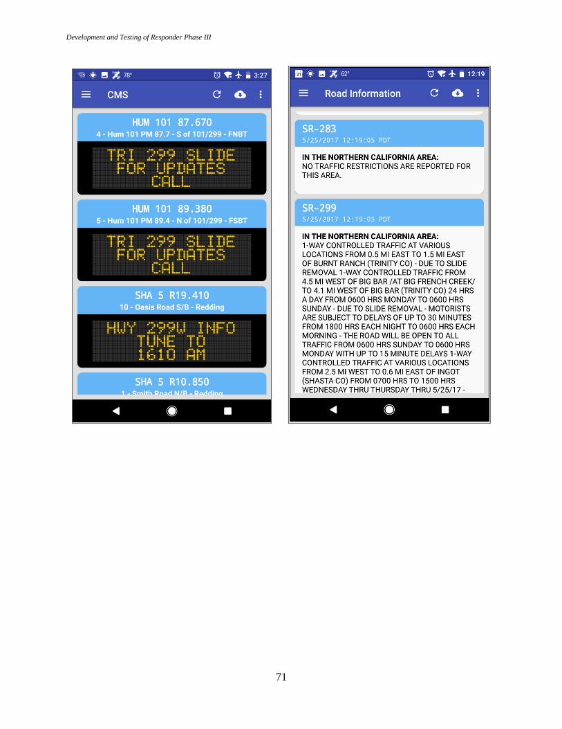
Development and Testing of Responder Phase III
71

Development and Testing of Responder Phase III
72

Development and Testing of Responder Phase III
73

Development and Testing of Responder Phase III
74

Development and Testing of Responder Phase III
75

Development and Testing of Responder Phase III
76
Previewing and Sending an Incident Mail
To preview the auto-generated incident report message, navigate to the Mail screen. The screen
shows the mail recipients, and a preview of the mail body. This body is generated based on the
user’s inputs on the Report Entry screen. The preview also shows any images that will be attached,
based on the user’s selections on the Attachment screen, which is accessed by clicking the
paperclip icon on the Mail screen. To add recipients, click on the “Recipients” field, and select
from the contact list. Finally, assuming that the message is as the user intended, send it by pressing
the “SEND” button at the bottom of the screen.

Development and Testing of Responder Phase III
77

Development and Testing of Responder Phase III
78
Editing an Existing Incident
To edit an existing incident, navigate to the Reports list, and select that report. Incidents are
identified by date and time, user name, organization name, and location. Clicking on an incident
will then load that incident, and switch to the Report Entry screen for subsequent editing, using
similar procedures as those for entering a new incident.
.

Development and Testing of Responder Phase III
79
APPENDIX B:
RESPONDER SYSTEM USER GUIDE
The Responder system is designed to be quite intuitive, and to leverage well-known interfaces and
interactions with mobile apps. However, some guidance may be needed for use of the system.
Responder Software Startup
Responder In-Vehicle System Startup
The Responder in-vehicle system box starts up automatically when the vehicle is started and
the system power switch is in the on position, and shuts down when either the key or the system
power switch is turned off. The system will continue to run if the engine is stopped if key is left in
the on or accessory position and the system power switch remains on. The system power switch
allows the vehicle to be operated without the Responder system turned on. It is recommended that
the engine be left running while the Responder system is in use, to avoid draining the vehicle
battery.
Powering on the HMI Tablet or Smartphone
Press and release the power button. The device will boot up. When it reaches a normal Android
home screen, the device is fully booted and ready.
Responder App Startup
The Responder app is started like any other Android tablet or smartphone app. Assuming the
Responder icon is visible on the screen, the user simply taps the icon once. If it is not, then the
user must enter the main menu (the method varies by Android version), swipe to find the
Responder app icon, and tap it. It is strongly recommended that the Responder icon be installed
onto the HMI device’s main screen.
On startup, Responder will begin at the Reports screen, where the user can add a new incident,
or select an existing incident to modify.

Development and Testing of Responder Phase III
80
Using the Responder HMI App
Creating a New Incident Report
On the app’s Reports screen, tap the plus sign (+) in the lower-right corner of the screen. This
initiates a new incident report, and switches to the Report Entry screen for detailed data entry.

Development and Testing of Responder Phase III
81
Selecting an Existing Incident Report for Editing
On the Reports screen, tap the entry for the incident to be edited. Incidents are identified by
date and time, user name, organization name, and location. This will then load that incident, and
switch to the Report Entry screen for subsequent editing.
Gallery Screen
The Gallery screen provides a grid of photos and other images related to the current incident.
It is similar to those found in standard Android apps like the Gallery app and Google Photos. It
provides thumbnails of all images related to this incident. This will include photos; snapshots of
maps, aerial photos, and topo maps; and annotations of photos and snapshots. The gallery screen
allows the user to annotate an image by clicking on that image and selecting the pencil icon in the
upper-right. It also allows the user to rotate selected images.

Development and Testing of Responder Phase III
82
To delete photos, click and hold on the image(s) to be deleted. Then click the action menu
icon in the upper right corner, and select delete. Use caution in doing so, as this cannot be
undone.
Weather Menu
The Weather menu, located in the Navigation Drawer, allows the user to request the latest
weather-related information. This includes weather, zone forecasts, zone alerts, RWIS data,
projected stream flows, and wildland fires. To view any information, click the related item to
bring up the information screen.

Development and Testing of Responder Phase III
83
Roadway Menu
The Roadway menu allows the user to request current roadway-related information. This
includes chain controls where relevant, CHP CAD incidents, road information, road camera still
images, and CMS messages. Roadway information is provided for all of California, as well as for
approximately 30 miles over the border into neighboring states of Arizona, Nevada, and Oregon.
To view any information, click the related item to bring up the information screen.
Mail Preview / Send
The Mail screen allows the user to preview the auto-generated incident report mail, select
recipients from a contact list, attach images, and send the message. The screen shows the message
recipients, and a preview of the message body, including attachment thumbnails. This body is
generated based on the user’s inputs on the report screen. The preview shows any images that will
be attached, based on the user’s selections on the Attachment screen. To add recipients, the user

Development and Testing of Responder Phase III
84
clicks on the contacts icon (person with + sign) and selects from the Contact list. The Contact list
allows selection of multiple recipients in one operation. To add attachments, the user clicks on the
paperclip icon, and selects multiple images by clicking and holding on the images. Finally,
assuming that the message is as the user intended, they can send it by pressing the send button
(right-facing triangle) at the top-right of the screen.

Development and Testing of Responder Phase III
85
Responder System Maintenance
Responder In-Vehicle System Maintenance
The in-vehicle system should need minimal maintenance. The system box vents should be
checked regularly for dust and dirt build-up depending on environmental conditions, and cleaned
as needed. Additionally, the system cover should be opened once or twice a year depending on
vehicle environmental conditions, and the internal compartments inspected and cleaned as
necessary. This will maintain proper airflow and cooling for the system. If any of the system
cabling (power, communications) had to be left exposed, these should be checked regularly for
signs of wear, and replaced if the cable is compromised in any way.
Responder HMI Hardware Maintenance
The Responder HMI hardware is a standard Android smartphone or tablet, and should be
maintained as such. The unit should be charged regularly. For optimal battery life, it is best if the
unit is not fully discharged, and is not left on the charger once the unit is fully charged. In addition,
the unit should not be left in a vehicle in extreme temperatures, particularly in very high
temperatures. Exposing the unit to very high temperatures for any extended duration can
compromise the unit’s battery life.
Smartphone and tablet batteries do have limited lifetime. If the unit will no longer take a
charge, or the charge only lasts for a short time relative to its known previous pattern, it may be
time to replace the battery, or the device. Some units have a replaceable battery. For these units,
follow the manufacturer’s instructions for removing the battery, order the correct replacement
battery, and install the replacement. If the battery is not replaceable, you will need to replace the
entire unit. Whichever method is used, be sure to properly recycle the unit and/or battery.

Development and Testing of Responder Phase III
86
The screen should be cleaned regularly to improve Responder app readability. To clean the
screen, use a soft, lint-free cloth, e.g. a microfiber cloth. Do not use a paper towel, as this can
scratch the screen. Do not use Windex or other chemicals or cleaning solvents; this can destroy
special coatings on some screens. If the screen is extremely dirty, you can use a cleaning solution
of one part distilled water, one part 70% alcohol. Be sure to turn the unit’s power completely off
before using this cleaning solution. Note that simply turning the unit’s screen off is not sufficient.
Frequently Asked Questions
Why am I not getting GPS data?
First, verify that the GPS notification icon is indicating the no signal state. Next, make sure
that location is enabled on the tablet. Swipe down the notification bar and verify that the location
icon is enabled. Click on the icon if necessary. If the GPS notification icon is still indicating the
no signal state, then you need to move to another location to acquire a suitable GPS solution/lock.
If you are in a GPS-compromised location, you will get either a reduced accuracy solution, or no
solution. Examples include in a building, in a metal shelter or lean-to, under heavy tree foliage,
and in deep ravines or canyons.
Where can find saved incidents?
Saved incidents are located in the Reports screen, identified by location, responder name,
responder location, creation timestamp, and last updated timestamp. Selecting an existing incident
report will switch to the Report screen for continued editing.
When is communications with the internet established?
Internet communications will be available to the Responder app whenever the in-vehicle
system can establish a connection. If cellular signal or satellite is available, then communications
will be established. If neither is available, communications will not occur during that time. All
email transmission requests will be stored for future transmission, to occur when communications
is next established, up to a configurable expiration time.
How do I clean the tablet screen?
The screen should be cleaned regularly to improve Responder app readability. To clean the
screen, use a soft, lint-free cloth, e.g. a microfiber cloth. Do not use a paper towel, as this can
scratch the screen. Do not use Windex or other chemicals or cleaning solvents; this can destroy
special coatings on some screens. If the screen is extremely dirty, you can use a cleaning solution
of one part distilled water, one part 70% alcohol. Be sure to turn the unit’s power completely off
before using this cleaning solution. Note that simply turning the unit’s screen off is not sufficient.
What do I do if the tablet locks up?
Tablets could lock up for many reasons. This could be related to the state of several installed
applications or the operating system. If the tablet is completely unresponsive, try to power the

Development and Testing of Responder Phase III
87
tablet off and back on again. Generally, holding down the power button long enough (in some
cases up to 20 seconds) should bring up a dialog box asking if you want to power off the tablet.
Click “Yes”. If the dialog gives the option of “Restart”, choose that, and simply wait for the system
to fully restart. If the dialog gives the options of “Sleep” or “Shut down”, choose “Shut down”.
Then, wait for the tablet to power off, wait a few more seconds, and then press the power button
to power back on. Ideally, this will solve whatever caused the tablet to lock up.
If the Responder app is the only app that is locked up, you can bring up the list of running apps
by pressing the standard Android “Tasks” icon, wait a few seconds, and then close the app either
by clicking the “X” in the upper right corner of the app image, or by swiping the app image to the
right.
Why doesn’t the tablet connect to the in-vehicle Responder system box?
Typically, if the tablet cannot connect to the Responder system box, then Wi-Fi needs to be
enabled and configured.
First, assure that Wi-Fi is enabled. Swipe down the notification bar and click on the Wi-Fi
icon.
Next, in the Wi-Fi settings menu, look for the Responder system box’s Wi-Fi access point.
Select it, and enter the right credentials (password). If you do not know these, check with your
supervisor or your district’s Responder administrator.
To connect to the Responder system box, you must be in range. The tablet should be able to
connect to the Responder system box at least 200 feet from the vehicle.
Why don’t I get a satellite signal?
Satellite signal, like any other RF signal, is subject to blockage. Generally, consider
environmental factors. If line-of-sight to the satellite is blocked, you will not get satellite
communications. Examples include in a vehicle maintenance bay, in a metal shelter or lean-to,
under heavy tree foliage, and in deep ravines or canyons. Other possible causes include rain fade;
this is subject to additional testing in follow-up research.
What if the tablet gets wet?
If the tablet gets wet, turn it off immediately. Allow the tablet to dry for as long as possible
before turning it back on again. Never use a hair dryer, oven, or microwave to speed up the drying
process.

Development and Testing of Responder Phase III
88
APPENDIX C:
RESPONDER SYSTEM MOUNTING BRACKET DESIGNS
Several custom brackets were designed and fabricated for the in-vehicle Responder system.
The CAD (Computer-Aided Design) drawings for these brackets are provided in this appendix.

Development and Testing of Responder Phase III
89
Figure C.1: Switch mount

Development and Testing of Responder Phase III
90
Figure C.2: Upper plate for LTE cellular, GPS, and Wi-Fi antenna mount

Development and Testing of Responder Phase III
91
Figure C.3: Upper plate for satellite antenna mount

Development and Testing of Responder Phase III
92
Figure C.4: Lower plate for all antenna mounts

Development and Testing of Responder Phase III
93
Figure C.5: Portable Responder system satellite antenna magnetic mount plate

Development and Testing of Responder Phase III
94
Figure C.6: Portable Responder system satellite antenna mount pin block

Development and Testing of Responder Phase III
95
Figure C.7: Portable Responder system satellite antenna mount concept upper view

Development and Testing of Responder Phase III
96
Figure C.8: Portable Responder system satellite antenna mount concept lower view

Development and Testing of Responder Phase III
97
APPENDIX D:
CELLULAR SIGNAL COVERAGE AND STRENGTH
The Responder system is meant to function well throughout California, i.e. in both rural and
urban areas. However, its most challenging design constraints arise in communications-challenged
rural areas. The lower reliability and intermittent availability of cellular communications in rural
environments was one of the main motivations for Responder. Given this, it is worthwhile to
independently quantify the nature of this problem.
Figure D.1: Snow-affected routes (yellow) for California. Red boundaries represent
Caltrans districts.
Under separate research, AHMCT performed a cellular survey on all snow-affected routes in
California [1]. This survey determined cellular coverage and signal strength along all state routes

Development and Testing of Responder Phase III
98
where Caltrans performs winter maintenance. The area covered is shown in Figures C.1 – C.4.
These snow-affected routes correlate strongly with Caltrans rural areas.
Figure D.2: Snow-affected routes (yellow) for northern California. Red boundaries
represent Caltrans districts.

Development and Testing of Responder Phase III
99
Figure D.3: Snow-affected routes (yellow) for central California. Red boundaries represent
Caltrans districts.
To determine cellular coverage and signal strength for multiple cellular providers, AHMCT
developed a survey strategy, cellular data collection hardware, and an Android application to
sample and record signal strength. The data collection hardware and software, and detailed survey
results are presented in [1]. Examples that are relevant for Responder are provided in Figures C.5
and C.6 (State Route 299 (SR 299) in northeast District 2), Figures C.7 – C.9 (SR 395 in
District 9), and Figures C.10 – C.12 (SR 88 in District 10). The data was collected using an
AHMCT research vehicle. The process consisted of driving each snow-affected route while
capturing the providers’ (T-Mobile, AT&T, and Verizon) signal strength as measured by the
AHMCT’s PowerMeter application. Location coordinates were also recorded using the
smartphone’s built-in GPS receiver. To perform the full survey, AHMCT spent three full working
weeks on the road, logging a total of approximately 5000 miles.

Development and Testing of Responder Phase III
100
Figure D.4: Snow-affected routes (yellow) for southern California. Red boundaries
represent Caltrans districts.
Figures C.5 and C.6 show the signal strength for AT&T and Verizon, respectively, on SR 299
from west of Nubieber to state line. Verizon provides better coverage and signal strength than
AT&T in this rural area. Throughout the results, red areas represent the highest signal strength
(“hot”), while orange, yellow, green, turquoise, and blue represent decreasing (“cooler”) signal
strength. If an area is not colored, no signal was detected for that carrier in that particular area.
Table C.1 provides a key mapping color to strength.

Development and Testing of Responder Phase III
101
Table D.1: Heat map key relating color to signal strength
Color Signal Strength
Red -75 dBm
Orange -81 dBm
Yellow -87 dBm
Green -93 dBm
Turqoise -99 dBm
Blue -105 dBm
None No signal detected
Figure D.5: AT&T signal strength for SR 299 from west of Nubieber to state line in
Caltrans District 2 (survey: July 27, 2013 from 9:25 – 11:09)

Development and Testing of Responder Phase III
102
Figure D.6: Verizon signal strength for SR 299 from west of Nubieber to state line in
Caltrans District 2 (survey: July 27, 2013 from 9:25 – 11:09)
Figures C.7 – C.9 show the signal strength for T-Mobile, AT&T, and Verizon, respectively,
on SR 395 from Round Valley to state line. Here again, in much of this rural area, Verizon provides
the better coverage. Note that between Bridgeport and Walker, Verizon does have a significant
coverage gap. For any operations in this area, AT&T would be a much better choice. However,
Verizon has better signal strength and coverage near Walker and Coleville. As such, for District 9
Responder implementation, inclusion of two cellular modems is well-justified. The best choice for
dual-modem service would be AT&T and Verizon.

Development and Testing of Responder Phase III
103
Figure D.7: T-Mobile signal strength for SR 395 from Round Valley to state line in
Caltrans District 9 (survey: August 24, 2013 from 11:04 – 14:04)
Figure D.8: AT&T signal strength for SR 395 from Round Valley to state line in Caltrans
District 9 (survey: August 24, 2013 from 11:04 – 14:04)

Development and Testing of Responder Phase III
104
Figure D.9: Verizon signal strength for SR 395 from Round Valley to state line in Caltrans
District 9 (survey: August 24, 2013 from 11:04 – 14:04)
As a final rural example, Figures C.10, C.11, and C.12 show the signal strength for T-Mobile,
AT&T, and Verizon, respectively, on SR 88 from west of Pioneer to the state line. Again, Verizon
provides better coverage and signal strength than T-Mobile or AT&T in this rural area. This
general pattern was repeated in essentially all of the California snow-affected roadways, which
again strongly correlate with rural areas. For semi-rural to rural areas, Verizon would be a good
vendor for cellular data transmission. As noted in the District 9 example, inclusion of a second
cellular modem with AT&T service could be justified in some areas.

Development and Testing of Responder Phase III
105
Figure D.10: T-Mobile signal strength for SR 88 from west of Pioneer to the state line in
Caltrans District 10 (survey: August 3, 2013 from 12:25 – 13:52)
Figure D.11: AT&T signal strength for SR 88 from west of Pioneer to the state line in
Caltrans District 10 (survey: August 3, 2013 from 12:25 – 13:52)

Development and Testing of Responder Phase III
106
Figure D.12: Verizon signal strength for SR 88 from west of Pioneer to the state line in
Caltrans District 10 (survey: August 3, 2013 from 12:25 – 13:52)
Beyond concluding which provider is the better choice in rural areas, the cellular coverage
results clearly demonstrate that there are significant rural areas with either low signal strength or
no coverage, for any cellular provider. This matches Caltrans and others intuitive or experience-
based expectation, but clearly quantifies the issue. This conclusion provides a scientific basis for
the decision to include additional means of communication, specifically satellite-based, for
Responder. As satellite communication is also subject to blockage, e.g. in deep canyons or valleys,
this also emphasizes the importance of Responder’s use of a store-and-forward architecture. This
architecture is discussed in Chapter 4. With this architecture, Responder can bridge areas of no
communications, storing all messages and requests. Upon entering an area with cell or satellite
coverage, the system then forwards messages and requests, and downloads any feed responses.