state of ohio department of transportation … supp specs.pdf · page 1 of 41 state of ohio...
TRANSCRIPT

Page 1 of 41
STATE OF OHIO
DEPARTMENT OF TRANSPORTATION
SUPPLEMENTAL SPECIFICATION 800
REVISIONS TO THE 2013 CONSTRUCTION & MATERIAL SPECIFICATIONS
DATED 01-17-2014
103.05 On page 17, Replace the subsection with the following:
103.05 Requirement of Contract Bond. Furnish Contract Bonds within 10 days after receiving
notice of award. Furnish Contract Bonds to the Director on the prescribed form, in the amount of the
contract, and according to ORC 5525.16.
105.17 On page 29, Replace the last paragraph with the following section:
Clean hard fill consisting of reinforced or non-reinforced concrete, asphalt concrete, brick, block,
tile or stone that is free of all steel as per 703.16 shall be managed in one or more of the following
ways:
1. Recycled into a usable construction material.
2. Disposed in licensed construction and demolition debris facility.
3. Used in legitimate fill operations on the site of generation according to 105.16.
4. Used in legitimate fill operations on a site other than the site of generation to bring a site
up to grade on an existing roadbed or parking lot project.
A Beneficial Reuse Certification form needs to be properly executed by the Recipient prior to
any material leaving the project.
106.09.E
On page 33, replace the subsection with the following:
E. Manufactured Products. In order for a manufactured product to be subject to Federal
requirements, the product must consist of at least 90% steel or iron content when it is delivered
to the job site for installation.
Examples of products subject to Federal requirements include, but are not limited to, the
following:
1. Steel or iron products used in pavements, bridges, tunnels or other structures, which
include , but are not limited to, the following: fabricated structural steel, reinforcing steel, piling,
high strength bolts, anchor bolts, dowel bars, permanently incorporated sheet piling, bridge
bearings, cable wire/strand, prestressing/post-tensioning wire, motor/machinery brakes and other
equipment for moveable structures;
2. Guardrail, guardrail posts, end sections, terminals, cable guardrail;
3. Steel fencing material, fence posts;
4. Steel or iron pipe, conduit, grates, manhole covers, risers;
5. Mast arms, poles, standards, trusses, or supporting structural members for signs,
luminaires, or traffic control systems; and
6. Steel or iron components of precast concrete products, such as reinforcing steel, wire mesh
and pre-stressing or post-tensioning strands or cables

Page 2 of 41
The miscellaneous steel or iron components, subcomponents and hardware necessary to encase,
assemble and construct the above components (or manufactured products that are not
predominately steel or iron) are not subject to Federal requirements. Examples include, but are
not limited to, cabinets, covers, shelves, clamps, fittings, sleeves, washers, bolts, nuts, screws, tie
wire, spacers, chairs, lifting hooks, faucets, door hinges, etc.
F. Proof of Domestic Origin. Furnish documentation to the Engineer showing the domestic
origin of all steel and iron products covered by this section, before they are incorporated into the
Work. Products without a traceable domestic origin will be treated as a non-domestic product.
107.10
On page 36, Replace the paragraph starting with “All areas proposed” with the following section:
Except for locations utilized specifically for;
1. parking of equipment between workdays for maintenance type projects;
2. disposal or stockpile locations that currently hold a Federal, ODNR or OEPA sanctioned
permit that specifically allows the disposal or stockpiling activity. This exception requires the
contractor to provide the Engineer with the permitted facility‟s name, location, site ID number and
the permit holder‟s certification that disposal or stockpiling the project generated material is
compliant with the recipient‟s permit.
All areas proposed to be utilized by the Contractor outside the project construction limits and not
described above shall be reviewed by environmental contractor(s) that are prequalified by the
Department for each environmental resource. This exception applies to projects with “maintenance”
in the project description. Have the consultant(s) certify that the proposed site to be utilized for the
contractor will not impact:
107.19 On page 43, Replace the entire subsection with the following:
107.19 Environmental Protection. Comply with all Federal, State, and local laws and
regulations controlling pollution of the environment. Avoid polluting streams, lakes, ponds, and
reservoirs with fuels, oils, bitumens, chemicals, sediments, or other harmful materials, and avoid
polluting the atmosphere with particulate and gaseous matter.
By execution of this contract, the Contractor, will be deemed to have stipulated as follows:
A. That any facility that is or will be utilized in the performance of this contract, unless such
contract is exempt under the Clean Air Act, as amended (42 U.S.C. 1857 et seq., as amended by
Pub.L. 91-604), and under the Federal Water Pollution Control Act, as amended (33 U.S.C. 1251 et
seq., as amended by Pub.L. 92-500), Executive Order 11738, and regulations in implementation
thereof (40 CFR 15) is not listed, on the date of contract award, on the U.S. Environmental
Protection Agency (EPA) List of Violating Facilities pursuant to 40 CFR 15.20.
B. That the firm agrees to comply and remain in compliance with all the requirements of Section
114 of the Clean Air Act and Section 308 of the Federal Water Pollution Control Act and all
regulations and guidelines listed thereunder.
C. That the firm shall promptly notify the Department of the receipt of any communication from
the Director, Office of Federal Activities, EPA, indicating that a facility that is or will be utilized for
the contract is under consideration to be listed on the EPA List of Violating Facilities.
D. That the firm agrees to include or cause to be included the requirements of paragraph 1 through
4 of this Section in every nonexempt subcontract, and further agrees to take such action as the
government may direct as a means of enforcing such requirements.
Page 3 of 41
Fording of streams is prohibited. Causeways for stream and river crossings or for Work below a
bridge are permitted provided:
A. The causeway complies with the requirements of the 404 Permit the Department obtained for
the Project.
B. The Contractor obtains a 404 Permit from the U.S. Army Corps of Engineers if the Department
has not obtained such a permit. Obtain the 404 Permit prior to beginning construction of the
causeway. The Department does not guarantee that the Contractor will be able to obtain a 404
Permit.
Comply with all current provisions of the Ohio Water Pollution Control Act, (OWPCA), (ORC
Chapter 6111). The Department will obtain a storm water permit under the OWPCA provisions
when the plan work acreage requires a permit. Apply for a permit to cover operations outside the
Project limits shown on the plans as required by the OWPCA provisions. When the Department has
not applied for a permit on the Project and a permit is required under the provisions of the OWPCA
because of the total area of the Contractor‟s work, apply for, obtain, and comply with the required
permit for both the Work within Project limits and the Contractor‟s work.
The Department has obtained the required permits from the U.S. Army Corps of Engineers and
Ohio EPA for Work in the “Waters of the United States” and isolated wetlands under ORC Chapter
6111. Comply with the requirements of these permits.
When equipment is working next to a stream, lake, pond, or reservoir, appropriate spill response
equipment is required. Do not stockpile fine material next to a stream, lake, pond, or reservoir.
Take precautions to avoid demolition debris and discharges associated with the excavation and
hauling of material from entering the stream. Remove any material that does fall into the stream as
soon as possible.
When excavating in or adjacent to streams, separate such areas from the main stream by a dike or
barrier to keep sediment from entering the stream. Take care during the construction and removal of
such barriers to minimize sediment entering the stream.
Contain, collect, characterize and legally dispose of all waste water and sludge generated during
the work. Do not mix waste water with storm water. Do not discharge any waste water without the
appropriate regulatory permits. Manage waste water and sludge in accordance with ORC Chapter
6111 and all other laws, regulations, permits and local ordinances relating to this waste. Waste
water management is incidental to the Work unless otherwise specified in the contract.
Control the fugitive dust generated by the Work according to OAC-3745-17-07(B), OAC-3745-
17-08, OAC-3745-15-07, and OAC-3745-17-03 and local ordinances and regulations. Prior to the
initiation of abrasive coating removal, pavement cutting or any other construction operation that
generates dust, demonstrate to the Engineer that construction related dust will be controlled with
appropriate Reasonable Available Control Measures (RACM) as described in OEPA Engineering
Guide #57 (http://epa.ohio.gov/dapc/engineer/eguides.aspx).
In addition, use dust control measures when fugitive dust creates unsafe conditions as determined
by the Engineer. Perform this work without additional compensation except for Item 616.
Perform open burning according to 105.16.
109.05.C.6 On page 74, Replace the first paragraph with the following:
6. Subcontract Work. For Work performed by an approved subcontractor, the Department will
pay an amount to cover administrative costs of 8% on the first $10,000 of work and 5% for work in

Page 4 of 41
excess of $10,000 as provided in 109.05.C.2 through 109.05.C.5. No additional mark-up is allowed
for work of a sub-subcontractor or trucking services employed by a subcontractor.
109.05.C.6 On page 74, Delete Table 109.05-2.
109.05.C.8.a On page 75, Replace the first paragraph of 109.05.C.8.a with:
8. Trucking.
a. Trucking firms and owner operators not subject to prevailing wage will be paid at the
invoiced cost plus 8% on the first $10,000 of trucking and 5% for trucking in excess of $10,000 to
cover administrative costs.
109.05.C.8.a On page 75, Delete Table 109.05-3.
202.02
On page 89, Replace the third paragraph of 204.02 with the following:
Use removed or excavated materials in the Work when the material conforms to the specifications; if
not, then dispose of the material according to 105.16 and 105.17.
205.04.A On page 113, Replace the second sentence of the third paragraph of 205.04.A with the following:
Control dust according to 107.19.
208
On page 119, Replace the section title of 208.10 with the following: 208.10 Cushion Blasting
208.01
On page 119, Replace the last sentence of the second paragraph with the following:
Controlled blasting techniques include presplitting, cushion blasting, and sliver cut blasting.
208.10
On page 126, Replace the section title with the following: 208.10 Cushion Blasting.
251.03 On page 136, Replace the last paragraph of 251.03 with the following:
If the Contract does not include resurfacing, seal the perimeter surface of the repaired area by
applying a 2 inch (50mm) to 4 inch (100 mm) wide strip of approved 705.04 material or 702.01
approved PG binder.
255.07 On page 145, Replace the last paragraph of 255.07 with the following:
Seal the perimeter surface of the repaired areas by applying a 2 inch (50 mm) to 4 inch (100 mm)
wide strip of approved 705.04 material or 702.01 approved PG binder.

Page 5 of 41
255.08 On page 145, Replace the last paragraph of 255.08 with the following:
If maintaining traffic in adjacent lanes, schedule work in order to place the concrete in the
prepared repair area within 48 hours after removing the existing pavement. In accordance with
standard drawing MT-101.90, drums may be used as a separator to the adjacent traveled lane for
repairs 60 feet or less in length. If unable to complete placement of the concrete in the exposed
repair area by the end of the daily work shift, fill repair areas less than 4 feet from the traveled lane
with a temporary patch material suitable to the Engineer or cover unfilled repair areas 10 feet (3 m)
or less in length with a steel plate. Do not leave repair areas unfilled with concrete when work is
suspended on weekends or holidays. If unable to complete placement of the concrete in the exposed
repair area before suspending work for a weekend or holiday or within the time specified above, fill
the excavation with an asphalt concrete mixture or other suitable temporary patch material with a
durable surface as the Engineer directs. Maintain the temporary patches while they are in service.
301.02 On page 155, Replace the second paragraph of 301.02 with the following:
Submit for the Laboratory‟s approval the desired percentage of the aggregate passing the No. 4
(4.75 mm) sieve and blend of individual components. The Contractor may use reclaimed asphalt
concrete pavement according to 401.04. The Laboratory will establish the required binder content
within a range of 4.7 to 7 percent. Do not make changes in these JMF values due to unsatisfactory
results or other conditions except as authorized by the Laboratory. Obtain a new JMF approval for
any desired change to an existing JMF.
301.04 On page 155, Replace 301.04 with the following:
301.04 Spreading and Finishing. Ensure that the maximum compacted depth of any one layer is
6 inches (150 mm). Ensure that the temperature of the mixture when delivered to the paver is a
minimum of 250 °F (120 °C). Ensure the temperature of the mixture is sufficient for the roller
coverage to be effective in compacting the mixture.
302.02 On page 157, Replace the third, fourth and fifth paragraph of 302.02 with the following:
The Contractor may use reclaimed asphalt concrete pavement according to 401.04. Should
problems with proper coating or other material issues related to the use of reclaimed asphalt concrete
pavement or reclaimed asphalt shingles be evident, the Laboratory may restrict the allowable
percentage of reclaimed asphalt concrete pavement to the reduced limits shown in tables 401.04-1
and 401.04-2 or may eliminate use of reclaimed asphalt shingles. In this case the virgin binder
content will be adjusted by the Laboratory.
Add hydrated lime in the dry form at a rate of 0.75 percent by the dry weight of aggregate for
asphalt concrete base, if antistrip additive is required and hydrated lime is used.
Design the asphalt concrete base to yield 4.0 percent air voids and the following properties:

Page 6 of 41
Property
Acceptable Range of Values
Minimum Maximum
Binder Content, % Note 1 6.0[Total]
Stability, lb (N), 70 blow 3000 (13,345) --
Flow, 0.25 mm, 70 blow -- 28
Voids in Mineral Aggregate %
Note 1: See Tables in 401.04
12.0 --
302.04
On page 158, Replace 302.04 with the following:
302.04 Spreading and Finishing. Ensure that the compacted depth of any one layer is a
minimum of 4 inches (100 mm) and a maximum of 7.75 inches (190 mm). Ensure that the
temperature of the mixture when delivered to the paver is a minimum of 250 F (120 C). Ensure
the temperature of the mixture is sufficient for the roller coverage to be effective in compacting the
mixture.
401.17
On page 181, Add the following after the 1st paragraph of 401.17:
Construct longitudinal joints using string line or other controls as a point of reference to provide a
straight longitudinal joint. Prior to placing adjacent pavement, trim any locations along the
longitudinal joint that deviate horizontally from the point of reference. Maintain a consistent overlap
of 1 inch to 1 ½ inches on adjacent pavement when closing longitudinal joints.
402.03
Beginning on page 183, Replace the first two paragraphs of 402.03 with the following:
402.03 Polymer Binders. If an asphalt binder is modified by SBR at an asphalt concrete mixing
plant, equip the plant with an automated SBR flow control and monitoring system. Obtain the
Department‟s approval of the system before operating and demonstrate the system calibration to the
District. If the District waives the demonstration, provide a letter documenting calibration data for
the flow system to the DET for each project. Obtain written approval from the Laboratory for the use
of SBR and ensure the QCP contains methods for properly controlling and sampling SBR binder
blends.
For drum mix plants, introduce the SBR directly into the asphalt binder line through means of an
in-line motionless blender or other device approved by the Laboratory which is able to provide a
homogeneous blend. Ensure the in-line motionless blender design provides aggressive interaction of
asphalt binder and SBR emulsion to provide a homogenous blend at the sampling port. Some
blenders such as „swirl‟ type blenders do not accomplish proper blending. The Astec in line SBR
blender or similar design accomplishes proper blending. Locate a sampling valve between the in-
line blender and the plant drum, at least 12 ft (3 m) downstream of the in-line blender and at least 5
ft (1 m) downstream of a piping elbow. Ensure the sampling valve port is at least 1 in. (2.54cm) in
diameter. Ensure the sampling valve can be opened quickly for maximizing sample flow for the
purpose of obtaining a proper sample. In place of an in-line sampling valve, a sample may be taken
from a 3-5 gallon (11-19 liter) surge tank as long as the tank is downstream of the required blender
and the in-line flow can be quickly and directly diverted to the surge tank. Contents of the tank
should be drained into a 5 gallon (19 liter) sampling bucket and stirred before filling the required
Page 7 of 41
sample container. Provide a sampling valve port that is in a position to safely obtain the required
sample volume in the required 5 gallon (19 liter) sampling bucket. Provide a stable sampling rack to
obtain a sample.
402.04 On page 184, Replace Item 2 in the first paragraph of 402.04 with the following:
2. Injection equipment has variable water injection control controlled by the plant operation
rate and the water injection can never exceed 2.2 percent by weight of asphalt binder.
403.03
On page 185, Replace the entire subsection 403.03 with the following:
403.03 Quality Control Program (QCP). Create and implement a Quality Control Program
(QCP) for each paving season. The QCP will cover processes conducted to provide an asphalt
mixture at the paving site that is uniform in composition, conforms to the specification requirements
and that when placed is free of any defect (ex. segregation, lack of mixture and texture uniformity,
raveling, rutting, holes, debris etc.) within the Contractor‟s control at project completion. A
minimum of 3 weeks before mix production, but no later than February 28, submit a hard copy of the
proposed QCP to the Laboratory for review and approval.
Send a hard copy and a digital copy (if available) of the approval letter and approved QCP to the
DET in every District in which work is performed. Keep copies of the approval letter and the
approved QCP in each Contractor plant laboratory and plant operation control room. Digital copies
of the approved QCP and approval letter in pdf format are allowed in each Contractor plant
laboratory and plant operation control room with the following requirements: The file icon must be
appropriately labeled and be on the computer desktop of a computer in each area, the QCP must
contain a Table Of Contents inside the front cover locating all sections by page number and the QCP
must be page numbered, and out of date QCPs must be removed from the computer desktop.
Failure to comply with the approved QCP may result in removal of personnel in accordance with
Supplement 1041, removal from VA, and adversely affect the Contractor‟s Prequalification rating.
The QCP is a reflection of a Contractor‟s sincerity and ability in producing a quality product.
Development of this program beyond the minimum requirements specified below is encouraged and
is taken into consideration by the QCQC when reviewing Contractor plant operation for qualification
for VA.
Include in the program:
A. The assignment of quality control responsibilities. Quality control includes all efforts required
to achieve a product meeting specifications. The QCP will list individuals as required below and
note their designated responsibilities to meet QCP requirements. Provide a Quality Control Manager
holding a Supplement 1041 Level 3 approval and who is a company employee. Assign Level 2
technicians for all Level 2 QC testing duties, and provide a list designating their responsibilities and
expected actions. Ensure only approved personnel handle and test samples at all times. If Level 2
consultant technicians are used provide a document in the QCP and to them listing designated
responsibilities and expected actions (if different from employee expectations). Define in the QCP
who is responsible at plants and specific methods for assuring haul vehicles meet all requirements
and proper bed release products are used. Provide a Field Quality Control Supervisor (FQCS),
holding Supplement 1041 Field Quality Control Supervisor approval and who is a company
employee, who is routinely and usually at the paving site during placement of any non-temporary
Page 8 of 41
asphalt concrete pavement. Ensure personnel obtaining and handling cores at the project site are
approved Level 2 technicians, FQCS or personnel approved by the Laboratory.
B. Provisions to meet the Department mix specifications.
C. Procedures for extra testing (e.g., job start, responses to poor test results or field mix problems,
aggregate stock testing, reclaimed asphalt concrete pavement checks, moistures) and any other
testing necessary to control materials not already defined in these Specifications.
D. Methods to maintain all worksheets, including all handwritten records, and other test and
sample records from the plant or project for the duration of the contract or 5 years, whichever is
longer. Define the test record process. Define company records retention requirements. Provide
copies of all test reports and forms used in the quality control process.
E. Procedures for equipment calibration and documentation for Level 2 lab equipment.
Provide documentation that all Level 2 lab equipment has been calibrated at the time of the Level 2
lab approval inspection. Procedures for calibration record storage.
F. Method of Quick Calibration and documentation for each plant type.
G. Procedure for random sampling to be used at the plant and documentation method. Procedures
for sample taking, tracking, handling and documentation method for all samples taken at the project
paving site including taking of all cores used for density determination or density gauge correlation.
H. All procedures to meet the processing, testing and documentation requirements for RAP and
RAS in 401.04 including test forms, record keeping, technician responsibilities, etc.
I. Procedure for ensuring that every Contractor employee involved in the testing of asphalt mix
and operation of the asphalt plant facility has read the QCP and has on site access to all applicable
Department specifications, proposals, policies, and the current approved JMF.
J. Means to meet the handling and storage requirements of 402.03 and asphalt binder suppliers for
all asphalt binders.
K. Means to meet delivered mixture uniformity/coating and hauling/trucking requirements.
L. Define the roles and responsibilities of the Field Quality Control Supervisors. List approved
Field Quality Control Supervisors.
M. Signature of the Quality Assurance Manager and, if different, the person in authority to enforce
all operations covered by the QCP as outlined in this subsection.
N. Specify in the QCP warning bands to be used by technicians for all tests and give specific
instruction how they will be used for tests in concert with Table 441.10-1 specification requirements.
421.04 On page 208, Replace 421.04 with the following:
421.04 Weather Limitations. Apply the mixture only when it is not raining and the existing
pavement surface and atmospheric temperature is a minimum of 45 degrees and rising and there is
no forecast of an atmospheric temperature below 32 degrees within 24 hours from the time the
mixture is applied. Between September 30 and May 1, do not apply the mixture if the existing
pavement surface temperature is less than 50 F (10 C).
421.08
On page 209, Replace the entire subsection 421.08 with the following:
421.08 Surface Preparation. Before applying the mixture, thoroughly clean the surface.
Remove raised pavement markers according to 621.08, when specified. The Contractor may fill the
depression caused by the removal of the casting with material meeting this specification.

Page 9 of 41
Remove any existing pavement markings, except 740.02 (traffic paint), using an abrasion method
conforming to 614.11.G.
Apply a tack coat conforming to Item 407, consisting of one part asphalt emulsion and three parts
water. Apply the tack coat at a rate of 0.06 to 0.12 gallon per square yard (0.25 to 0.45 L/m²).
Protect drainage structures, monument boxes, water valve, etc. during material application.
421.10 On page 210, Replace the third and fourth paragraphs of 421.10 with the following:
If a leveling course and a surface course are specified, apply the paving mixture at 14 2 pounds
per square yard (7.6 ± 1.1 kg/m²) for the leveling course and 16 1 pounds per square yard (8.7 0.6
kg/m²) for the surface course. Apply the two courses at a minimum combined rate of 30 pounds per
square yard (16.3 kg/m²), regardless of the above tolerances
If a surface course is specified and it is not placed on another Microsurfacing course, apply the
paving mixture at a minimum of 18 pounds per square yard (9.8 kg/m²).
421.10 On page 210, Add the following to the end of the seventh paragraph of 421.10:
Provide uniform appearance of the entire surface area regardless of the means used to spread
material.
421.13 On page 211, Replace the second paragraph of 421.11 with the following:
The cost of any removal of any existing pavement markings according to 421.08 is incidental to
Microsurfacing.
422.02 Materials
On page 212, Replace the 1st full paragraph with the following:
Use polymer emulsified binder conforming to 702.16 Type A.
422.04
On page 214, Replace the entire section 422.04 with the following:
422.04 Weather Limitations. Place the chip seal when the pavement temperature is between 60
F (16 C) and 140 F (60 C). Do not schedule the performance of this work for the time period
before May 1 or after September 1. Do not place chip seal if any of the following conditions exist:
A. The atmospheric temperature is below 70 °F (21 °C).
B. Impending weather conditions do not allow for proper curing.
C. If temperatures are forecasted below 50 F (10 C) within 24 hours from the time of work.
422.06 On page 215, Replace the 2
nd paragraph of 422.06 with the following:
Remove all existing pavement markings, except 740.02 (traffic paint), using an abrasion method
conforming to 614.11,G.
442.02
On page 238, Replace the first paragraph of 442.02 with the following:

Page 10 of 41
442.02 Type A Mix Design. Design the mixture composition for a Type A mix according to
441.02 and the most recent Asphalt Institute Superpave Mix Design Manual (SP-2) for design
procedures and material properties except as modified by this subsection. Include in the JMF
submittal the standard Department cover and summary page; all printouts from the gyratory
compactor (all gyratory points not necessary); and analysis covering the required mix properties.
Unless otherwise directed submit one compacted gyratory sample and loose mix for compaction of
another sample, in addition to a 5-pound (2000 g) loose sample, for each JMF.
446.05
Starting on page 247, Replace the 6th
, 7th
, and 8th
paragraphs of 446.05 with the following:
For each Lot three cores will be taken as follows from cold longitudinal joints and seven cores will
be taken from the mat not including the joints. If locations not according to this specification are
given, immediately inform the Engineer. Do not take cores from ramp joints. Take joint cores from
the first, last and randomly from one of the three middle sublots. Determine the longitudinal
location of the joint core within the sublot randomly and also randomly determine whether or not the
cold longitudinal joint core is to be taken from a confined or unconfined joint if both exist in the mat
to be cored. Do not take cores on the sloped face of a wedge before the adjoining lane is placed.
Take joint cores such that the core's closest edge is six inches (150 mm) from the edge of the joint
upper notch of a wedge joint or 4 inches (100 mm) from the edge of a vertical face joint. If a nine
inch or wider wedge joint is used take the core three inches from the upper wedge joint notch. Take
the seven random mat cores that are not for the joint coring such that the core's closest edge is at
least twelve inches from the cold longitudinal joint wedge joint upper notch or vertical face edge. If
taken, locate cores for the Contractor‟s quality control (QC sister core) longitudinally from and
within four inches (100 mm) of the random core. In addition to the QC sister cores, three extra cores
may be taken from the first lot of a JMF for testing to correlate density gauges. Do not take
additional cores beyond what is noted above unless clearly identified in the approved Contractor‟s
QCP. Clearly label all cores with mat locations so that they may be readily identified. Any unlabeled
cores may be destroyed by the Department. Notify the Laboratory if any questions arise. Do not
store additional cores anywhere (project, in vehicles or at the plant) beyond what are required to be
taken for testing. Test all Contractor QC cores and maintain records of all tests (core tests and
correlated gauge tests) per the QCP. Destroy all cores immediately after testing is complete.
The Department will determine the pay factor for each Lot cored by the pay schedule in Table
446.05-1 for Lots with three cold longitudinal joint cores and Table 446.05-2 for Lots with less than
three cold longitudinal joint cores. The Department will verify the MTD if the MSG determination
has a deviation from the MTD of less than or equal to 0.020. If the MTD is not verified, establish a
new MTD according to the procedures established in 441.09. If less than 10 cores are available for
determining the mean, the Laboratory will determine disposition of the Lot.
Fill core holes by the next workday with asphalt concrete. Before filling, ensure the holes are dry
and tack them with asphalt material conforming to 407.02. Properly compact the asphalt concrete
used for filling the hole and leave it flush with the pavement.
451.09 Starting on page 256, Replace the entire subsection 451.09 Joints with the following:
451.09 Joints. Unless otherwise directed, construct all transverse joints normal to the centerline
of the pavement lane and of the type, dimensions, and at locations specified.

Page 11 of 41
Determine contraction and longitudinal joint sawing time limits to protect the concrete from early
cracking by using HIPERPAV software. Obtain the software according to Supplement 1033.
Twenty four (24) hours before placing concrete pavement create a HIPERPAV project date file
according to Supplement 1033.
Provide the completed file and the printout to the Engineer. When HIPERPAV predicts early age
slab cracking will occur, whether due to standard construction practices, joint sawing methods, mix
design or curing, either do not start construction until modifications have been made to eliminate
HIPERPAV‟s predicted slab cracking or do not pave.
Perform a HIPERPAV analysis for each pour.
If software analysis determines joint sawing could exceed twenty four (24) hours, assure all joints
are sawed by the 24th hour.
A HIPERPAV analysis showing paving can proceed does not eliminate the requirements of
451.17.
Accurately mark the correct locations of all joints that will be saw cut along both edges of the
pavement. Ensure the method of marking remains clearly visible after the paver passes and until the
joint saw cut is completed.
A. Longitudinal Joint. Construct longitudinal joints between simultaneously placed lanes by
sawing.
When a standard (water cooled diamond bladed) concrete saw is used to make the longitudinal
joint between simultaneously placed lanes, saw the joint within the timeframe provided in the
HIPERPAV output. For pavement less than or equal to 10 inches (255 mm), saw the joint to a
minimum depth of one-fourth the specified pavement thickness. For pavements greater than 10
inches (255 mm) thick, saw the joint to a minimum depth of one-third the specified pavement
thickness. Saw joints 1/4 ± 1/16 inch (6 ± 1.6 mm) wide measured at the time of sawing.
When using early-entry (dry cut, light weight) saws to make the longitudinal joint between
simultaneously placed lanes, only use saw blades and skid plates as recommended by the saw
manufacturer for the coarse aggregate type being used in the concrete. Perform the early-entry
sawing after initial set and before final set. Saw the joint 1/8 inch (3 mm) wide and 2 1/4 to 2 1/2
inches (56 to 63 mm) deep.
Place deformed epoxy coated steel tiebars or the epoxy coated hook bolt alternate (wiggle bolt)
with epoxy coated coupling, in longitudinal joints during consolidation of the concrete. Install them
at mid-depth in the slab by approved mechanical equipment. As an alternate procedure, rigidly
secure them on chairs or other approved supports to prevent displacement. Provide tie bars or
wiggle bolts of the size and spaced as shown on the standard construction drawings. If used,
securely fasten hook bolts or wiggle bolts with couplings to the form at the longitudinal construction
joint as shown on the standard construction drawings.
B. Transverse Joints
Unless otherwise directed, construct all transverse joints normal to the centerline of the
pavement lane and of the type, dimensions, and at locations specified.
For all transverse joints, install round, straight, smooth, steel dowel bars of the size shown in
Table 451.09-1.
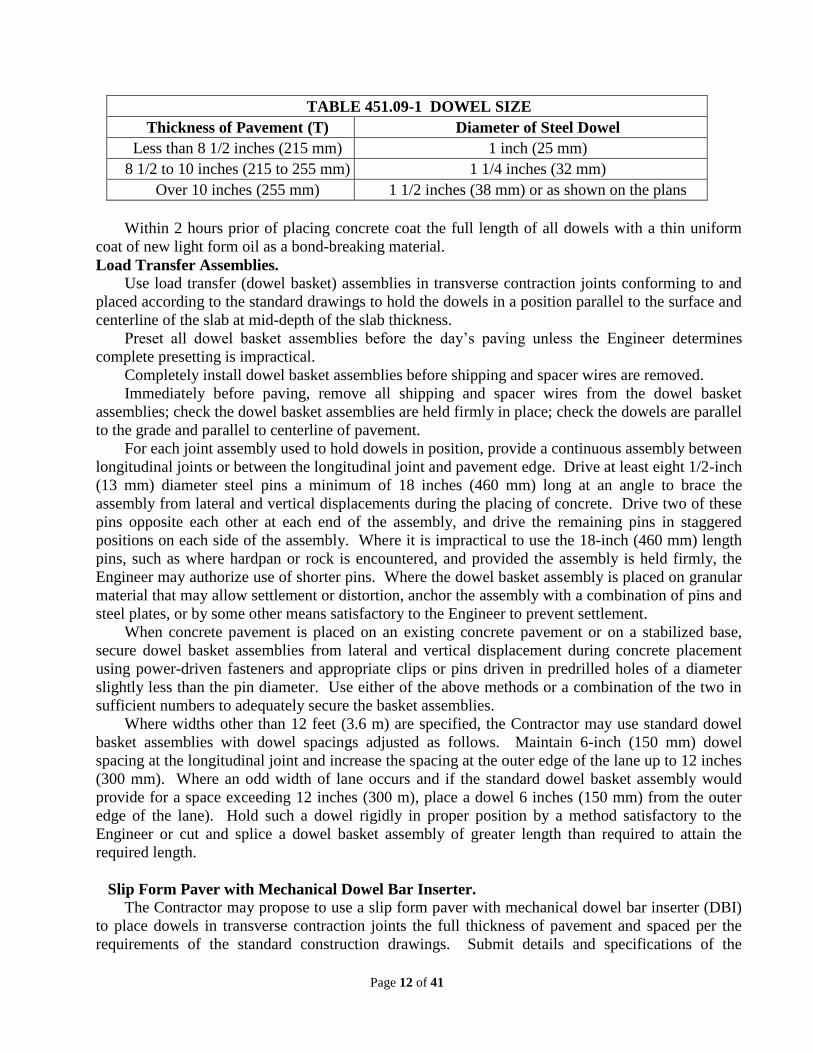
Page 12 of 41
TABLE 451.09-1 DOWEL SIZE
Thickness of Pavement (T) Diameter of Steel Dowel
Less than 8 1/2 inches (215 mm) 1 inch (25 mm)
8 1/2 to 10 inches (215 to 255 mm) 1 1/4 inches (32 mm)
Over 10 inches (255 mm) 1 1/2 inches (38 mm) or as shown on the plans
Within 2 hours prior of placing concrete coat the full length of all dowels with a thin uniform
coat of new light form oil as a bond-breaking material.
Load Transfer Assemblies. Use load transfer (dowel basket) assemblies in transverse contraction joints conforming to and
placed according to the standard drawings to hold the dowels in a position parallel to the surface and
centerline of the slab at mid-depth of the slab thickness.
Preset all dowel basket assemblies before the day‟s paving unless the Engineer determines
complete presetting is impractical.
Completely install dowel basket assemblies before shipping and spacer wires are removed.
Immediately before paving, remove all shipping and spacer wires from the dowel basket
assemblies; check the dowel basket assemblies are held firmly in place; check the dowels are parallel
to the grade and parallel to centerline of pavement.
For each joint assembly used to hold dowels in position, provide a continuous assembly between
longitudinal joints or between the longitudinal joint and pavement edge. Drive at least eight 1/2-inch
(13 mm) diameter steel pins a minimum of 18 inches (460 mm) long at an angle to brace the
assembly from lateral and vertical displacements during the placing of concrete. Drive two of these
pins opposite each other at each end of the assembly, and drive the remaining pins in staggered
positions on each side of the assembly. Where it is impractical to use the 18-inch (460 mm) length
pins, such as where hardpan or rock is encountered, and provided the assembly is held firmly, the
Engineer may authorize use of shorter pins. Where the dowel basket assembly is placed on granular
material that may allow settlement or distortion, anchor the assembly with a combination of pins and
steel plates, or by some other means satisfactory to the Engineer to prevent settlement.
When concrete pavement is placed on an existing concrete pavement or on a stabilized base,
secure dowel basket assemblies from lateral and vertical displacement during concrete placement
using power-driven fasteners and appropriate clips or pins driven in predrilled holes of a diameter
slightly less than the pin diameter. Use either of the above methods or a combination of the two in
sufficient numbers to adequately secure the basket assemblies.
Where widths other than 12 feet (3.6 m) are specified, the Contractor may use standard dowel
basket assemblies with dowel spacings adjusted as follows. Maintain 6-inch (150 mm) dowel
spacing at the longitudinal joint and increase the spacing at the outer edge of the lane up to 12 inches
(300 mm). Where an odd width of lane occurs and if the standard dowel basket assembly would
provide for a space exceeding 12 inches (300 m), place a dowel 6 inches (150 mm) from the outer
edge of the lane). Hold such a dowel rigidly in proper position by a method satisfactory to the
Engineer or cut and splice a dowel basket assembly of greater length than required to attain the
required length.
Slip Form Paver with Mechanical Dowel Bar Inserter. The Contractor may propose to use a slip form paver with mechanical dowel bar inserter (DBI)
to place dowels in transverse contraction joints the full thickness of pavement and spaced per the
requirements of the standard construction drawings. Submit details and specifications of the

Page 13 of 41
proposed equipment to the Engineer at least 14 calendar days prior to mobilizing the equipment to
the project.
The use of any slip form paver with DBI is allowed only after acceptable performance is
demonstrated with a test section and approved by the Engineer. Continued verification during all
contract paving is required for each production day as detailed below.
Provide all equipment, perform all testing, and evaluate the slip form paver with DBI as detailed
in the following sections.
1. MIT Scan-2 Equipment and Reporting
Provide MIT Scan-2 equipment to determine the location of dowel bars in either fresh or
hardened concrete including horizontal translation, longitudinal translation, vertical translation,
horizontal skew, vertical tilt, and cover.
Provide equipment for determining dowel bar alignment that has an onboard computer that runs
the test; collects and stores the test data on a memory card; performs the preliminary evaluation; and
provides a printout of results immediately after scanning. Provide MagnoProof software to provide
a detailed report of all required alignment parameters in an Excel spreadsheet and a graphical color
representation.
Ensure the equipment is properly calibrated conforming to the manufacturer‟s specifications and
for the specific project conditions. Provide calibration documentation to the Engineer prior to the
start of construction. Establish a standard protocol for scanning direction.
Provide trained personnel to operate the equipment and documentation of training prior to start
of construction.
Provide a print out, at the time of scanning, for horizontal translation, longitudinal translation,
vertical translation, horizontal skew, vertical tilt, and cover for each bar in each joint scanned. For
each Test Section and daily, for each day of production, provide a complete report to the Engineer at
the completion of scanning along with a digital copy of all data collected in the manufacturer‟s
native file format as well as all calibration files. Include the standard report generated using the
MagnoProof software in Excel format and with color graphical representation of each joint. Include
in the report project contract number, county-route-section, placement date, scan date, station
location and lane, joint ID number, name of operator, and all required alignment parameters.
If non-magnetic dowel bar materials are to be used, propose and demonstrate alternative
measurement equipment to the Engineer showing capability to provide measures equal or similar to
the acceptance and rejection criteria of Table 451.09-2. Obtain the Engineer's approval of alternative
equipment prior to paving. If no alternative equipment can demonstrate the required capability, do
not use the slip form paver with DBI.
Prior to paving, review the measurement equipment applicability for the project conditions with
the Engineer, including: ambient moisture conditions, dowel material, metallic concrete aggregate
and potential contributors to magnetic interference (presence of tiebars, reinforcing steel or other
embedded or underlying steel items that may affect measurement accuracy). Establish how the
measurement device can meet the project conditions. If the measurement device cannot meet the
project conditions, do not use the slip form paver with DBI.
2. Acceptance/Rejection
The required dowel bar tolerances are given in Table 451.09-2. Dowel bar alignment is
measured as detailed below. Any dowel bar exceeding any Acceptance Tolerance in Table 451.09-2
is considered misaligned. Rejection Criteria is in absolute inches.
Table 451.09-2
Individual Dowel Bar Alignment Tolerances
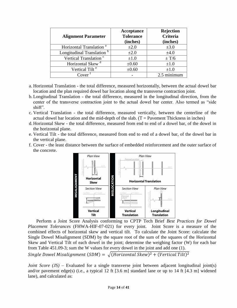
Page 14 of 41
Alignment Parameter
Acceptance
Tolerance
(inches)
Rejection
Criteria
(inches)
Horizontal Translation a
±2.0 ±3.0
Longitudinal Translation b
±2.0 ±4.0
Vertical Translation c
±1.0 ± T/6
Horizontal Skew d
±0.60 ±1.0
Vertical Tilt e
±0.60 ±1.0
Cover f - 2.5 minimum
a. Horizontal Translation - the total difference, measured horizontally, between the actual dowel bar
location and the plan required dowel bar location along the transverse contraction joint.
b. Longitudinal Translation - the total difference, measured in the longitudinal direction, from the
center of the transverse contraction joint to the actual dowel bar center. Also termed as “side
shift”.
c. Vertical Translation - the total difference, measured vertically, between the centerline of the
actual dowel bar location and the mid-depth of the slab. (T = Pavement Thickness in inches)
d. Horizontal Skew - the total difference, measured from end to end of a dowel bar, of the dowel in
the horizontal plane.
e. Vertical Tilt - the total difference, measured from end to end of a dowel bar, of the dowel bar in
the vertical plane.
f. Cover - the least distance between the surface of embedded reinforcement and the outer surface of
the concrete.
Perform a Joint Score Analysis conforming to CPTP Tech Brief Best Practices for Dowel
Placement Tolerances (FHWA-HIF-07-021) for every joint. Joint Score is a measure of the
combined effects of horizontal skew and vertical tilt. To calculate the Joint Score: calculate the
Single Dowel Misalignment (SDM) by the square root of the sum of the squares of the Horizontal
Skew and Vertical Tilt of each dowel in the joint; determine the weighing factor (W) for each bar
from Table 451.09-3; sum the W values for every dowel in the joint and add one (1).
( ) √( ) ( )
Joint Score (JS) – Evaluated for a single transverse joint between adjacent longitudinal joint(s)
and/or pavement edge(s) (i.e., a typical 12 ft [3.6 m] standard lane or up to 14 ft [4.3 m] widened
lane), and calculated as:

Page 15 of 41
( ) ∑
where:
n = number of dowels in the single joint
Wi = weighting factor (Table 451.09-3) for dowel i
Table 451.09-3
Weighting Factors in Joint Score (JS) Determination
Single Dowel Misalignment (SDM) W, Weighting Factor
SDM ≤ 0.6 in. (15 mm) 0
0.6 in. (15 mm) < SDM ≤ 0.8 in. (20 mm) 2
0.8 in. (20 mm) < SDM ≤ 1 in. (25 mm) 4
1 in. (25 mm) < SDM ≤ 1.5 in. (38 mm) 5
1.5 in. (38 mm) < SDM 10
Joint Score Trigger (JST) – A scaling of the Joint Score risk value to account for the actual number
of dowels required in a single joint for pavement width other than 12 ft (3.6 m), calculated as:
( )
Include the Joint Score and Joint Score Trigger for every joint scanned in the report to the
Engineer. Any joint with a Joint Score equal to or greater than the Joint Score Trigger is considered
locked and rejectable.
3. Test Section
Prior to production use of a DBI slip form paver, perform at least a 500-foot (150 m) long test
section for acceptance of the machine. Measure the alignment and location of each dowel bar in the
test section using the MIT Scan-2. The test section will be considered acceptable if the following
acceptance criteria are met:
1. Each Joint Score (JS) is less than Joint Score Trigger (JST);
2. Ninety percent (90%) of the dowel bars meet the Acceptance Tolerances of Table 451.09-2;
3. None of the dowels exceed the Rejection Tolerances of 451.09-2.
If the test section acceptance criteria is not met, use the data to refine the paving process and
reduce/eliminate misalignments and mislocations. Modify, repair or replace any slip form paver
with DBI that does not meet the acceptance criteria and perform another test section. Do not begin
production paving until the slip form paver with DBI test section acceptance criteria is met.
Perform corrective action of all joints in the test section according to Section 5 below.
Perform a new test section for any new slip form paver with DBI that will be used for any
contract item of work.
Perform a new test section at the beginning of every construction season; after major paver
maintenance/repairs; at mobilization or remobilization to a project, for major concrete mix design
changes or different concrete mix designs; and as required by Section 4 of this specification.
If the length of the section to be paved makes it unreasonable to perform the test section, scan
all joints for conformance with the requirements of Section 2, Acceptance/Rejection. Correct any
joints with dowels found to be rejectable or JS greater than JST according to Section 5, Corrective
Action.

Page 16 of 41
Determine during the test section if embedded tiebars are affecting the Rejection Tolerances and
JS‟s. If the test section demonstration shows interference, exclude from the JS and JST calculations
any dowel bar(s) closer than 12 in. (300 mm) in any direction to tiebars in the longitudinal joint(s).
At the Engineer‟s discretion, establish the location of excluded dowels by another equivalent non-
destructive method or by probing.
4. Paving Quality Control Testing (QCT) for Dowel Bar Inserters
When using the accepted slip form paver and DBI for any contract item of work, perform
quality control scans with the MIT-Scan 2 equipment at the following minimum:
a. Measure the alignments and location for every 10th joint and calculate the JS and JST for
each measured joint. Acceptable QCT is when all measures are within the acceptance
tolerances in Table 451.09-2 and JS is less than JST.
i. When the daily QCT finds more than 10 percent of the joints scanned have dowels
exceeding the acceptance tolerances of Table 451.09-2 but the JS is less than the JST,
increase the scanning frequency to every 5th joint. Evaluate the paving process to
reduce/eliminate misalignments and mislocations and continue to pave. The QCT frequency
will revert back to every 10th joint when two consecutive days of scanning every 5th joint
show no dowels exceeding the acceptance tolerances of Table 451.09-2 and all JSs are less
than the JST.
ii. When QCT finds any individual dowel bars exceeding the rejection criteria of Table
451.09-2 or the JS is found to exceed the JST, the joint is considered to be locked and
immediate investigation needs to be made as follows:
1. Scan joints in front and behind the locked joint location until five (5) consecutive joints
in both directions are found with no dowel bars exceeding the rejection criteria of Table
451.09-2 and no JS is found to exceed the JST.
2. If the additional scanned joints show no additional dowel bars exceeding the rejection
criteria of Table 451.09-2 and no JS exceeding the JST, evaluate equipment to determine
what caused the original problem. Before continuing paving increase the frequency of
QCT to conform to 4.a.i.
3. If the additional scanned joints show additional dowel bars exceeding rejection criteria of
Table 451.09-2 or joints with a JS exceeding the JST, stop paving. Investigate to
determine the cause of the dowel bar rejection issues and provide the causes and
alternative corrections to the Engineer.
The Engineer will determine if the corrections will correct the problem and may allow
paving to temporarily continue to validate if the corrections work. During any
evaluation, scan all joints to determine if the corrections were successful. If successful,
continue QCT scanning at the frequency of 4.a.i. If not successful, discontinue paving,
repair or replace the slip form paver and DBI, and repeat the Test Section
b. All dowel bars found beyond rejection criteria of Table 451.09-2 or joints with a JS
exceeding the JST require a corrective action proposal conforming to Section 5, Corrective
Action.
Provide report formats as described in Section 1, MIT Scan-2 Equipment and Reporting.
5. Corrective Action
Submit a proposal for corrective action to the Engineer for any dowel that exceeds the rejection
criteria in Table 451.09-2 or any joint that has a JS greater than the JST. As a minimum, include the
following in the corrective action proposal:

Page 17 of 41
1. Locations of rejectable dowels with identification information as described in Section 1, MIT
Scan-2 Equipment and Reporting.
2. Locked joint identification information as described in Section 1, MIT Scan-2 Equipment and
Reporting.
3. Proposed method of remediation for each identified location, including supporting
documentation of the effectiveness of the means of proposed remediation.
The Department may not require corrective action for random dowels that exceed the rejection
criteria of Table 451.09-2 depending on location; what alignment parameter was the cause for the
rejection; and the frequency of the rejectable dowels.
The Department may not require corrective action for all JS exceeding the JST, if they are
random in nature. Up to two (2) consecutive joints with a JS exceeding the JST may be accepted,
provided that the adjacent three (3) joints before or after do not have dowels exceeding Table
451.09-2 rejection limits and have JS‟s less than the JST. The Department will require corrective
action where there are more than two (2) consecutive joints with a JS exceeding the JST.
Do not proceed with any corrective action until the Engineer approves the proposed method(s)
of correction.
C. Expansion Joints. Where a pressure relief joint is not provided adjacent to a bridge structure,
construct expansion joints at the first two regularly spaced joint locations adjacent to the bridge
approach slab on each side of the bridge. If the pavement is constructed in two or more separately
placed lanes, construct the transverse expansion joints in a continuous line for the full width of the
pavement and shoulders.
Construct expansion joints according to the standard construction drawings. Install the face of
the expansion joint perpendicular to the concrete surface except when expansion joint is installed at
a skewed bridge approach slab.
Use round, straight, smooth, steel dowels, and within 2 hours of placing concrete, coat the
dowels with a thin uniform coat of new light form oil as a bond-breaking material to provide free
movement. After coating the dowel, install a sleeve of metal or other approved material
approximately 3 inches (75 mm) long, with crimped end, overlapping seams fitting closely around
the dowel, and a depression or interior projection to stop the dowel a sufficient distance from the
crimped end to allow 1 inch (25 mm) for longitudinal dowel movement with pavement expansion on
one free end of each dowel. If approved by the Engineer, use other means to allow for 1 inch (25
mm) of expansion.
Punch or drill proper size dowel holes into the preformed expansion joint filler to assure a tight
fit around each dowel.
Form a 1-inch (25 mm) wide and 1-inch (25 mm) deep opening on top of the expansion joint
filler and seal this opening with 705.04 joint sealers.
D. Contraction Joints. For pavement less than or equal to 10 inches (225 mm) thick, saw
contraction joints with a standard (water cooled diamond bladed) concrete saw to a minimum depth
of one-fourth of the specified pavement thickness. For pavement greater than 10-inches (255 mm)
thick, saw contraction joints to a minimum depth of one-third the specified pavement thickness.
When cutting joints using a standard (water cooled diamond blade) saw assure the joint is 1/4 ±
1/16-inch (6 ± 1.6 mm) wide when measured at the time of sawing.
When using the option of early-entry (dry cut, light weight) saws, only use saw blades and skid
plates as recommended by the saw manufacturer for the coarse aggregate type being used in the
concrete. Perform the early entry contraction joint sawing after initial set and before final set. Saw

Page 18 of 41
the contraction joint 2-1/4 to 2-1/2-inches (56 to 63 mm) deep. Ensure any early entry saw joints are
approximately 1/8-inch (3 mm) wide at the time of sawing.
If the pavement is constructed in two or more separately placed lanes, install the joints
continuous for the full width of the pavement. Saw the pavement with sawing equipment approved
by the Engineer as soon as the saw can be operated without damaging the concrete. Provide saws
with adequate guides, blade guards, and a method of controlling the depth of cut. After wet sawing,
clean the joint using a jet of water. After dry sawing clean the joint using air under pressure. During
sawing of contraction joints, maintain a standby saw in working condition with an adequate supply
of blades.
E. Construction Joints. Install dowelled construction joints at the end of each day‟s work and
when work is suspended for a period of more than 30 minutes.
Use dowels in transverse construction joints. Within 2 hours of placing concrete, coat the free
half of all dowels with a thin uniform coat of new light form oil. Use an adequate bulkhead, with
openings provided for dowel bars spaced as specified and shaped to fit the typical section of the
pavement, to form a straight joint. During placing of concrete, hold dowels rigidly in position.
Locate construction joints at or between contraction joints. If located between contraction
joints, construct the construction joint no closer than 10 feet (3 m) to the last contraction joint.
451.10 On page 264, Replace paragraph 3and 4 with the following two paragraphs:
Texture the surface in the longitudinal or transverse direction using a broom to produce a
uniform, gritty, texture. Immediately following the broom drag texture, tine the pavement in the
longitudinal direction using an approved device that produces uniform tine spacing 3/4 inches wide
(19 mm), 1/8 inch deep (3 mm) and 1/8 inch wide (3 mm). Do not tine within 3 inches (75 mm) of
pavement edges or longitudinal joints. Only use equipment that will tine the full width of the
pavement in one operation and uses string line controls for line and grade to assure straight tining
texture.
Use transverse tining in small areas only with the approval of the Engineer. Use equipment that
produces a random pattern of grooves [0.05 inch (1.3 mm) to 0.08 inch (2.0 mm) deep and 0.10 inch
(3 mm) wide] spaced at 3/8 to 1-3/4 inches (10 to 45 mm), with 50 percent of spacings less than 1
inch (25 mm). Transverse tining may be used as an option for shoulders of main line or shoulders of
ramps and gore areas. Tine all mainline shoulders or all ramp shoulders in a consistent direction if
choosing this option. Request the use of transverse tining and identify the locations for approval at
the preconstruction meeting.
501.05.B
On page 295, after the fourth paragraph, and sentence change the first section to:
This section applies to working drawings for the following:
1. Cofferdams and Excavation Bracing, impacting active traffic, or with an exposed height over
eight feet, except when a complete design is already shown in the plans. Perform all work as
specified below:
a. Locate Cofferdams and Excavation Bracing according to the contract, if shown.
b. Maintain temporary horizontal and vertical clearances according to the contract.
c. Include the effects of AASHTO live and dead load surcharges as necessary.
d. Design Cofferdams and Excavation Bracing in accordance with the latest AASHTO Guide Design
Specifications for Bridge Temporary Works, Section 4

Page 19 of 41
506.01
On page 306, change the last sentence to:
When subsequent static load tests are specified, the Office of Geotechnical Engineering will
determine whether subsequent static load tests are to be performed and the location of all piles to be
tested
506.02
On page 306, in the second paragraph, change the last sentence to:
If the Contractor finds it necessary to use a different hammer, the Office of Geotechnical
Engineering will determine if an additional static load test is necessary.
506.04
On page 309, change the first sentence of the first paragraph to:
If the Contractor subsequently finds it necessary to use a different hammer, the Office of
Geotechnical Engineering will determine if an additional static load test is necessary; the Contractor
shall complete any such additional test at no additional cost to the Department.
507.04
On page 310, change the eight paragraph to:
When using open ended diesel hammers, provide electronic equipment, such as a saximeter, or
equivalent, for the Engineer‟s use to accurately measure and record the average stroke for each unit
of length driven.
508.02
On page 316, after the third and last paragraph of this section, add the following sentence,
Inserts cast into prestressed members for the purposes of falsework support shall be galvanized
according to 711.02 and shall be shown in the shop drawings according to 515.06.
511.05
On pages 325 and 326, Replace section 511.05, (delete the second paragraph), with the following:
Mix concrete according to 499.08.
511.07
On page 326, Replace the 2nd paragraph of 511.07 with the following:
Place and finish concrete to the lines and grades shown in the plans. Unless otherwise noted, the
proposed beam seat elevations shown in the plans for prestressed beam superstructures are based on
the design midspan camber for prestressed beams which are 30 days old (D30). Adjust each beam
seat elevation using measured midspan camber data provided by the fabricator if available. In the
absence of measured midspan camber, adjust each beam seat elevation using the following:
ΔY = Dt – D30 ≥ 0
Where:
ΔY = Distance that each seat elevation shall be lowered from plan elevation to account
for midspan camber growth rounded to the nearest 1/8-inch
Dt = (1 + ψ) D0
D30 = Design Midspan Camber at Day 30 provided in the plans; inch
D0 = Design Midspan Camber at Day 0 provided in the plans; inch

Page 20 of 41
ψ = 1.97 KS KF KTD
KS = 1.45 – 0.13 (V/S) ≥ 1.0
V/S = Ratio of the prestressed concrete member‟s volume-to-surface area exposed to the
atmosphere. For each of the standard I-beam sections, this ratio is provided on PSID-1-13; inch
KF = 5/(1 + f′ci)
f′ci = Compressive strength of prestressed concrete at release provided in the plans; ksi
KTD = t/(61 - 4 f′ci + t)
t = Age of prestressed concrete measured between release of prestressing force (i.e.
0.75 days) and time of deck placement; days
Provide the Engineer with revised plan sheets and Design Camber calculations or measured camber
data signed, sealed and dated by an Ohio Registered Professional Engineer at least 7 days prior to
constructing the beam seats. The revised plan sheets shall include the measured camber data (if
available), Design Camber (Dt) and beam age (t) assumed for establishing the revised elevations.
Provide haunch reinforcement for prestressed I-beam members as necessary to extend the beam‟s
composite reinforcement at least two inches into the design deck thickness. All revisions resulting
from adjusted beam seat elevations shall be clearly marked as revised. Do not begin work until the
Engineer approves the revised plan.
511.09
On page 331, Revise the fourth paragraph to the following:
Form construction joints using bulkheads with keyways. Locate keyways clear of exposed
surfaces by approximately one-third the thickness of the joint. Construct transverse or longitudinal
construction joints in deck slabs with keys located between the reinforcing mats and having a depth
of 3/4 inch (19 mm).
511.19
On page 339, Revise the 1th
paragraph to:
After completing all curing operations and allowing the deck to thoroughly dry, seal the following
areas with a high molecular weight methacrylate (HMWM) sealer. Flood the areas and squeegee off
the excess material as specified in Item 512 before opening the deck to traffic:
511.24
On page 343, Add the following after the 1st paragraph of 511.24:
Work necessary to adjust seat elevations and deck haunches for prestressed beam members is
incidental to the affected structural concrete items. The Department will pay for final quantities as
measured and field verified.
512.03.F
On page 346, Change the second paragraph of 512.03.F to:
Use one of the following methods to produce a surface profile that feels and looks like 100 grit
sandpaper or coarser. Provide the Engineer sandpaper for comparison. Perform the ASTM D7682-
12, Method B, Standard Test Method for Replication and Measurement of Concrete Surface Profile
Using Replica Putty to obtain a replica coupon of the prepared concrete surface on a flat, test
section, on the first day of production, and as requested by the Engineer. With a micrometer,
measure the surface profile obtained on the coupon, and provide the coupon to the Engineer.

Page 21 of 41
1. Water blast at 7,000 psi (48 MPa) minimum, or
2. Abrasive blast, followed by air brooming or power sweeping, to remove dust from the surface and
opened pores,
3. or use a combination of water blast and abrasive blast.
512.03.G.1.b
On page 347, Change 512.03.G.1.b to:
b. Provide documentation to the Engineer that the ambient, surface and material temperature is
50 ºF (10 ºC) or above, 5 ºF higher than the dew point, and the relative humidity is 80% or below
during the application of the sealer.
513.03
On page 361, under the Level UF, Description of Capabilities, change the last sentence to:
Quality assurance of shop drawings, material test reports, and inspection according to Supplement
1078.
Under the Level 1, Description of Capabilities, change the last sentence to:
Quality assurance of shop drawings, material test reports, and inspection according to Supplement
1078.
Under the Level 2, Description of Capabilities, change the last sentence to:
Quality assurance of shop drawings, material test reports, and inspection according to Supplement
1078.
Under the Level 3, Description of Capabilities, change the last sentence to:
Quality assurance of shop drawings, material test reports, and inspection according to Supplement
1078.
Under the Level 4, Description of Capabilities, change the last sentence to:
Quality assurance of shop drawings, material test reports, and inspection according to Supplement
1078.
Under the Level 5, Description of Capabilities, change the last sentence to:
Quality assurance of shop drawings, material test reports, and inspection according to Supplement
1078.
Under the Level 6, Description of Capabilities, change the last sentence to:
Quality assurance of shop drawings, material test reports, and inspection according to Supplement
1078.
513.22
On page 372, in the third paragraph, change the last sentence to:
For galvanized structures with welded shear connectors, remove the galvanic coating by grinding at
each connector prior to welding.
514.19
On page 396, Revise the first paragraph to:

Page 22 of 41
(QCP #9). After the intermediate coat cures and before applying the finish coat, caulk gaps or
crevices greater than 1/8 inch (3 mm). Allow for the cure of the caulk, per the Manufacturer‟s
recommendations prior to the application of the finish coat.
515.08
On page 404, add the following material to the list:
Welded wire reinforcement…………………….709.12
Change the last sentence to:
For gradation, use No. 6, 67, 68, 7, 78 or 8 size coarse aggregate.
515.14
On page 407, at the end of the section add the following paragraph:
Unless otherwise shown in the plans, do not install inserts or holes in the beam web within a distance
of 1.5 times the beam height from the end of the beam.
515.15
On page 407, change B to:
B. W/c ratio (maximum = 0.40)
515.15
On page 408, change the 8th paragraph to:
Screed the top surface of composite members and finish the surface with a wire broom, in a
transverse direction and penetrating the finished surface approximately 1/4 inch(6 mm) + 1/16 inch
(1.5 mm) -1/8 inch (3 mm) at a maximum spacing of 1-1/2 inches (38 mm).
515.17
On page 411, Replace the Beam Sweep and Camber Tolerances table with the following:
Beam Sweep and Camber Tolerances
Description Box Beam I Beam
Horizontal Sweep ±1/8" per 10 ft (1 mm/m)
max ±3/4" (19 mm)
±1/8" per 10 ft (1 mm/m)
max ±1" (25 mm)
Max Gap between beam 1" (25 mm) N/A
Deviation from Design
camber (Dt) [1]
+ Sacrificial Haunch[2]
or
-1/8" per 10 ft (1 mm/m)
max -1/2" (13 mm)
+ Sacrificial Haunch[2]
or
Variation in camber between
beams in same span max 1/2" (13 mm) N/A
[1] Design camber (Dt) calculated in accordance with 511.07.
[2] Unless otherwise noted, the Sacrificial Haunch thickness is 2”.
515.18
On page 411, Add the following after the 3rd paragraph of 515.18:
Page 23 of 41
The Department will not accept for shipping, prestressed members with measured camber
exceeding the Design Camber (Dt), used to establish the seat elevations, according to 511.07, by
more than the Sacrificial Haunch thickness, until a corrective work plan has been approved by the
Engineer. The plan shall be signed, sealed and dated by an Ohio Registered Engineer and shall
include all revised plan information necessary to place the deck to the plan thickness. If the
prestressed members are acceptable, exclusive of the deviation from Design Camber, the Department
will pay for all costs incurred resulting from measured camber exceeding Design Camber calculated
for the actual beam age at the time of deck placement, as Extra Work, 109.05.
516.07
On page 415, change the second paragraph to:
Accurately set, level and align elastomeric bearings, bearing plates and bolsters. Set bearing plates
and bolsters on 1/8-inch (3 mm) thick sheet lead conforming to 711.19.
523.04
On page 430, change the last sentence to:
Submit an electronic version of the report and data files from the testing and analysis to the Office of
Geotechnical Engineering and the Office of Construction Administration.
524.09
On page 436, change the second paragraph of this section to the following;
Tie and support the reinforcing steel so it remains within the required tolerances. Securely tie
spacers at quarter points around the cage perimeter and space at intervals not to exceed 5 feet (1.5 m)
along the length of the cage. If the size of the longitudinal reinforcing steel equals or exceeds 1-inch
(25 mm) in diameter, the Contractor may increase the distance between the spacing devices to a
maximum of 10 feet (3 m). Use spacers of adequate dimensions to ensure a minimum annular space
between outside of cage and side of hole or casing of 3 inches (75 mm) for shaft diameters up to 4
feet (1.2 m) and 6 inches (150 mm) for shaft diameters larger than 4 feet (1.2 m). The Contractor
may use round plastic spacers.
526.04
On page 440, change the paragraph to:
Immediately before placing concrete according to Item 511.07, thoroughly moisten the subgrade or
subbase with water in the amount and manner directed by the Engineer. When the bridge
superstructure and the approach slab require QC/QA, make at least one set of test cylinders for each
50 cubic yards (35 cubic meters) of concrete. Include the results of the cylinders into the LOT for the
511 superstructure item.
526.08
On page 440, change the 1st paragraph to:
The Department will calculate the final adjusted payment per 511 and Supplement 1127. The
Department will pay for accepted quantities at the contract price as follows which includes all
concrete, curbs, reinforcing steel, dowels, joints, and other materials:
526.08 On page 440, Add the new item as follows:

Page 24 of 41
Item Unit Description
526 Square Yard Reinforced Concrete Approach Slabs with QC/QA
(Square Meter)
602.03
On page 447, Replace the first sentence of 602.03 C.:
Cast-in-place structures are headwalls, wingwalls, pipe cradles, collars, and other units.
608.01
On page 460, Replace the entire section 608.01 Description with the following:
608.01 Description. This work consists of constructing walks, curb ramps, and steps as per plans,
specifications and standard drawings.
608.02
On page 460, Replace the entire section 608.02 Materials with the following:
608.02 Materials. Furnish materials conforming to:
Aggregate Base ............... 304.01 and 304.02
Asphalt concrete Type 1 ........................ 448
Concrete,
Class QC Misc or QC 1* .................. 499
Reinforcing steel .......................... 509.02
Crushed aggregate meeting
grading requirements of ............... 703.10
Detectable Warning Devices............. 712.14
Expansion joint material ................... 705.03
* Replacing Coarse aggregate in the concrete mixes with Recycled Concrete Aggregate conforming
to Supplement 1117 is an option
608.07
On page 462, Replace the entire section 608.07 Curb Ramps with the following:
608.07 Curb Ramps. Excavate, form, place, finish, and cure according to 608.03.A, 608.03.B,
608.03.C, and 608.03.E. Finish ramps to a rougher final surface texture than the adjacent walk and
with striations transverse to the ramp slope using a coarse broom or other method approved by the
Engineer.
Provide detectable warning devices conforming to 712.14 in curb ramps. Install the detectable
warning devices according to manufacturer‟s written recommendations and standard drawings.
Provide a warranty to conform with the requirements of 712.14. Provide the manufacturer‟s written
installation instructions and the 5-year warranty to the Engineer at or before the pre construction
meeting.
611.02
On page 472, Remove “with welded bell inlet” from the second to last item of 611.02 A.:
Corrugated polyethylene smooth lined pipe ....................................... 707.33
On page 472, Remove “with welded bell inlet” from the last item of 611.02 A.:
Steel reinforced thermoplastic ribbed pipe ...................................... SS938
Page 25 of 41
611.04.A
On page 476, Replace the entire section 611.04.A Shop Drawings with the following:
A. Shop Drawings. Prepare shop drawings and calculations for C&MS items 706.051, 706.052,
706.053, 706.13 and “Special Design” 706.02 as required below. Have an Ohio Registered Engineer
prepare, sign, seal and date all drawings and calculations. Have another Ohio Registered Engineer
check all drawings and calculations, then sign, and seal and date all drawings and calculations.
Submit load rating report in accordance to the most current version of ODOT‟s Bridge Design
Manual along with one copy of the shop drawings and one copy of the calculations to the Office of
Structural Engineering for all structures with a 10 foot or larger span. Submit an additional copy of
the shop drawings and calculations to the Engineer.
1. If Reinforced Concrete Circular Pipe, 706.02, requires a “Special Design” with a specified
D-load requirement other than Tables 706.02-1 through 706.02-4, submit shop drawings and design
calculations. Design the pipe to meet the D-load requirements to ensure the performance of this
specification. Include the following information in the submittal: all structural design and loading
information, all material specifications, all dimensions, and the installation plan.
2. Submittals for Precast reinforced concrete 3-sided flat topped culverts, precast reinforced
concrete arch sections, or precast reinforced concrete round sections, (706.051, 706.052, or 706.053)
shall include structural analysis methods, structural design criteria and calculations, structure details,
and shop drawings. Include details for a precast slab bottom if required.
3. To substitute a precast reinforced concrete 3-sided flat topped culvert (706.051), a
reinforced concrete arch section (706.052), or a precast reinforced concrete round section (706.053)
for one another, the submittal shall include hydraulic calculations. The proposed culvert shall meet
or exceed the same hydraulic requirements as the specified culvert and minimum cover
requirements. If the specified culvert is on pedestal walls, include the shop drawings for the pedestal
wall design in the submittal because 3-sided flat topped culverts, arch culverts, and round sections
require different pedestal wall designs.
4. To substitute either a precast reinforced concrete 3-sided flat topped culvert, a precast
reinforced concrete arch section, or a precast reinforced concrete round section (706.051, 706.052, or
706.053) placed on a precast or cast-in-place slab bottom for a precast reinforced concrete box
culvert (706.05), the submittal shall include hydraulic calculations. The proposed culvert shall meet
or exceed the same hydraulic requirements as the specified box culvert and minimum cover
requirements. The Department may allow the bottom slab to be cast-in-place but will not issue a
time extension for any delays resulting from the use of a cast-in-place bottom slab.
Department approval of shop drawings and calculations is not required.
611.04.B
On page 477 through 479, Replace the entire section 611.04 B. Installation Plan with the
following:
Submit a written installation plan to the Engineer for installing all conduit and drainage structures
for review and acceptance.
Submit the installation plan at least 15 days before any conduit or drainage structure work begins.
Do not perform work without an accepted installation plan.
Include the following required information for each conduit type and size:

Page 26 of 41
1. Trench and excavation cross-sections with dimensions.
2. Locations where the conduit is installed in a cut situation and where it is installed in a
fill situation.
3. Type of bedding and backfill material used and maximum lift thickness.
4. Compaction density requirements for bedding and backfill and compaction equipment.
5. Identify the starting location (outlet or inlet) for each run of conduit. All conduit must
be laid from the outlet to the inlet unless approved by the Engineer. Bell or groove-end
Type A conduit must have a bell or groove-end at the inlet.
6. Maximum allowable joint gap between conduit sections.
7. Other installation details as necessary.
8. Provide written confirmation from the conduit manufacturer that the pipe material and
strength supplied are appropriate for the material and density requirements described
in the installation plan for the backfill and bedding as well as the height of cover.
Ensure the pipe material meets the durability design specified in the plans. This
confirmation by the conduit manufacturer will not relieve the Contractor of the
responsibility for obtaining the required results.
Include the following required information for each type of drainage structure:
1. Trench and excavation cross-sections with dimensions.
2. Locations where the drainage structure is installed in a cut situation and where it is
installed in a fill situation.
3. Type of bedding and backfill material used and maximum lift thickness.
4. Compaction density requirements for bedding and backfill and compaction equipment.
5. Location.
6. Other installation details as necessary.
Deviations from the installation plan during construction require a revision of the installation
plan. Resubmit all revisions to the installation plan to the Engineer within 14 days of the change with
the conduit manufacturer‟s written confirmation that the pipe material and strength supplied are
appropriate for the material and density requirements described in the newly revised installation plan
for the backfill and bedding. If the conduit manufacturer does not provide this written confirmation
to the newly revised installation plan, all the conduit installed according to the unconfirmed plan
must be replaced. No new installation plans will be considered until all previous installation plans
have been confirmed and accepted.
Provide the conduit manufacturer's structural calculations when specified or within 10 days when
requested by the Engineer.
For structural plate and metal pipe arch conduit with a span of 57 inches (1440 mm) or larger,
ensure the manufacturer provides match-marked ends on the conduit. Include a layout drawing in the
installation plan.
For metal conduit with two structural plate thicknesses specified, identify the location of the
thicker plates. For precast concrete 3-sided flat and arch topped structures (706.051 and 706.052)
provide a 3 inch (75 mm) deep keyway centered on the leg and at least 6 inches (150 mm) wider
than the thickness of the leg at the bottom. For precast concrete round sections (706.053) provide an
8-inch (200 mm) deep keyway for spans up to 24 feet (7.3 m) and a 10-inch (254 mm) deep keyway
for spans greater than 24 feet, (7.3 m). Center the keyway on the precast arch base. The width of the
keyway must be 8 inches (200 mm) greater than the thickness of the precast arch base. For non-
Page 27 of 41
vertical leg arches set on pedestal walls, a one sided keyway is acceptable if the required pedestal
wall design thickness is not sufficient for a full keyway.
611.04.C
On page 478, Replace the first sentence.
Perform work so that it can be verified by the Contractor‟s representative doing the inspection.
611.04.D
On page 479, Replace the first sentence.
Provide a performance report for each performance inspection.
611.04.D
On page 479, Delete “D. Conduit diameter report from the Manufacturer”
On page 479, Add “J. Conduit Evaluation”
On page 480, Replace the first sentence of the first paragraph with the following:
Submit a performance report to the Engineer within 14 days of completing the performance
inspection of the conduit run or drainage structure.
611.05
On page 480, Delete the entire third paragraph.
“Provide a firm bed for the full width and length of the trench. If bedding material is not provided,
loosen the middle third of the bed to seat the conduit. Provide a firm bed beneath the drainage
structure.”
611.07
On page 480, Replace the second sentence of the first paragraph.
Any planned temporary diversion of flows and drainage is the responsibility of the Contractor.
Maintain flows and drainage or provide temporary diversion at no additional cost to the Department.
On page 480, Delete “in the presence of the Engineer” from the first sentence of the second
paragraph.
611.08
On page 482, Delete “in the presence of the Engineer” from the third sentence of the first paragraph
of 611.08 Joining Conduit.
On page 483, Replace the entire first sentence of 611.08.B.3
For precast reinforced concrete box culverts, precast reinforced concrete 3-sided flat topped culverts,
precast reinforced concrete arch sections, and precast reinforced concrete round sections (706.05,
706.051, 706.052, and 706.053), place the sections according to the installation plan.

Page 28 of 41
On page 483, Replace the entire first sentence of 611.08.B.3.c
For precast reinforced concrete arch sections and precast reinforced concrete round sections
(706.052 and 706.053), install a 7/8 x 1 3/8-inch (24 x 34 mm) preformed flexible joint sealant
(706.14) along the outside joint chamfer.
On page 483 & 484, Replace the entire first sentence of 611.08.B.3.d
For precast reinforced concrete box culverts, precast reinforced concrete 3-sided flat topped culverts,
precast reinforced concrete arch sections, and precast reinforced concrete round sections (706.05,
706.051, 706.052, and 706.053), apply an approved epoxy-urethane sealer per the plans to all top
surfaces not covered by membrane waterproofing.
611.10
On page 485, Delete “in the presence of the Engineer” from the first sentence of the second
paragraph.
611.11
On page 486, in the last paragraph, first sentence, Replace “4 x 4-W1.4 x W1.4” with “2 x 2-W0.9 x
W0.9”
On page 486, in the last paragraph, after the second sentence, Add the sentence:
Provide support beneath the mesh where necessary using galvanized support chairs or #4 reinforcing
steel, meeting the material requirements of 509.02
On page 487, in the second paragraph, Delete the second sentence “Provide galvanized reinforcing
steel support chairs beneath the mesh where necessary.”
611.12
On page 487, Replace the entire sixth paragraph.
In each phase of construction of a conduit, perform the inspection no sooner than 30 days and no
later than 90 days after the completion of the finished grade when not below pavement and after the
completion of the rough subgrade when any portion of the conduit is below pavement. The Engineer
may permit inspection beyond the 90 day limit. If any corrections are made to the installed pipe after
the completion of the finished grade or rough subgrade and prior to the performance inspection, wait
30 days after the correction was made to do the performance inspection. If the contract duration will
not permit a 30 day waiting period then the Engineer may adjust the waiting period.
611.13
On page 489, Replace the entire first sentence of the first paragraph.
Have an independent Registered Engineer evaluate the Performance Inspection results and any
defects as required by AASHTO LRFD Bridge Construction Specifications, Section 26 for metal
Page 29 of 41
conduit, Section 27 for concrete conduit, and Section 30 for plastic conduit, with modifications
according to this specification.
611.17
On page 493, in the first paragraph, Replace the last sentence with:
When a pay item calls for conduit to be field paved, all work and materials necessary for the item are
included in the contract unit price for each conduit.
611.17
On page 493, Add the following paragraph after the second paragraph.
All conduits and drainage structures installed without required submittals per 611.04 are considered
unacceptable materials per 106.07.
On page 493, Replace the third paragraph.
The Department will pay for accepted quantities at the contract prices as follows:
On page 493, Delete the following pay structure from the third paragraph.
“After installation of conduit or drainage structure 60%
After performance inspection is completed 10%”
After acceptance of the conduit or drainage structure 30%”
614.03 On page 499, Add the following paragraph after the fourth paragraph
Furnish object markers that are a minimum size of 6 x 12 inches and that consists of reflective
sheeting adhered to an aluminum or plastic plate.
614.08
On page 502, Replace the last sentence in the second paragraph with the following:
The Contractor may, instead of using flaggers, or supplemental to them, furnish, install, maintain
and operate a traffic signal or signals, for the purpose of regulating traffic according to a written
agreement approved by the Engineer.
614.08 On page 502, Add the following paragraph after the second paragraph:
The Contractor may (supplemental to using flaggers) furnish, install, maintain and operate
automated flagger assistance devices (AFADs) with incidental items, for the purpose of assisting the
flagger(s) in regulating traffic according to a written agreement approved by the Engineer. AFADs
shall be furnished per the Department‟s Approved List and shall be used in accordance with
Supplemental Specification 830.
614.11.G
On page 506, Add the following sentence before the first sentence:

Page 30 of 41
Conflicting markings are considered to be any markings not actively in use, not behind channelizing
devices or portable barrier and/or could be misinterpreted by the traveling public or cause confusion
to the driver as determined by the engineer.
615.05
On page 516, Replace the 5th
paragraph of 615.05 with the following:
Where Class A or Class B pavement is shown on the plans, provide either rigid pavement or flexible
pavement conforming to the following minimum requirements:
MINIMUM COURSE THICKNESS REQUIRED
Pavement Type Course Make-Up Class A Class B
Rigid 452 9 in (230 mm) 7 in (180 mm)
Flexible
448 Type 1[1] 1-1/4 in (32 mm) 1-1/4 in (32 mm)
448 Type 2[2][5] 1-3/4 in (45 mm) 1-1/2 in (38 mm)
302[3][5] 5-1/2 in (140 mm) 3-1/2 in (90 mm)
304[4][5] 6 in (150 mm) 6 in (150 mm)
[1] Meet surface course requirements. The Contractor may use Type 2 surface.
[2] Meet intermediate course requirements.
[3] The Contractor may use 301 or 448 Type 2 intermediate course.
[4] The Contractor may use 2-1/2 inches (65 mm) 301, 302, or 448 Type 2 intermediate course in lieu of 6 inches (150
mm) of 304.
[5] The Engineer may waive maximum placement lift thicknesses if quality control testing conforming to Supplement
1055 is performed and a final density between 93 and 96.5 percent is achieved.
625.22
On page 548, Replace the first sentence in the third paragraph with the following:
Foundations for light poles or light towers include excavation, dewatering, sleeving, casing,
reinforcing steel, raceways, concrete, backfilling, and when required the 8 foot or 10 foot foundation
section of concrete barrier, and the disposal of surplus excavation.
630.07.B
On page 560, Replace the section with the following:
Use self-aligning aluminum mounting clips, stainless steel T-bolts, stainless steel washers, and
stainless steel nylon insert lock nuts, to attach extrusheet signs to sign attachment assemblies, beam
or U-channel post supports, and for U-channel post sections used to attach exit number and
supplemental panels to extrusheet signs. Use aluminum bolts, washers, lock washers, and nuts to
assemble extrusheet signs shipped in two pieces. Tighten nuts and lock nuts using hand tools only.
Do not use pneumatic, hydraulic, battery, electric or other power-assisted tools.
630.14
On page 561, Replace the first paragraph with the following
Method of Measurement. The Department will measure Ground Mounted Post Support by the
number of feet (meters) measured from the bottom of the support to the top of the support, and will
include driving, hardware for anchor base installation, and furnishing and placing of patching
materials for excavations in paved areas. The Department will not measure the overlap length of
post for the anchor base installation.
630.14

Page 31 of 41
On page 561, Replace the first sentence in the second paragraph with the following
The Department will measure Foundations for ground mounted pipe supports, ground mounted
structural beam supports, rigid overhead sign supports and span wire sign supports by the number of
each for one pipe, structural beam, pole, end frame or strain pole, and will include excavation,
dewatering, sleeving, casing, reinforcing steel, concrete, backfilling raceways, and when required the
10 foot (3m) foundation section of concrete barrier, and the disposal of surplus excavation.
630.14
On page 562, Replace the first paragraph with the following
The Department will measure One Way Support and Street Name Sign Support by the number of
feet (meters) measured from the bottom of the support to the top of the support, and will include
driving, hardware for anchor base installation, and furnishing and placing of patching materials for
excavations in paved areas. The Department will not measure the overlap length of post for the
anchor base installation.
632.06
On page 574, Add the following sentences at the end of the second paragraph
Before closing serrations, apply a bead of Room-Temperature Vulcanizing (RTV) silicone to all
serrated surfaces and then tighten. RTV silicone shall be white to facilitate visual inspection. On
heads with dual concentric serrated rings, completely fill the space between the rings with RTV
silicone.
632.11
On page 575, Replace the last sentence in the second paragraph with the following:
Conform to all applicable state and local nuisance dust regulations, and OAC 3745-17-08 while
saw cutting.
632.24
On page 546, Add the following paragraph after the 2nd
paragraph
Furnish each enclosure with at least one padlock. Use padlocks with a bronze or brass lock body
and a corrosion protected steel shackle. Obtain the appropriate master key number from the
maintaining agency.
632.29
On page 549, Replace the 6th
paragraph with the following:
The Department will measure Power Service by the number of complete units, and will include
weatherhead, conduit, fittings, clamps and other necessary hardware, installation of meter base,
ground wire connection, and disconnect switch with enclosure and padlock.
632.30
On page 583, Replace the first and second Item with the following:
632 Each Vehicular Signal Head, (Yellow or Black), (Aluminum or Polycarbonate), ___-
Section ___ inch (___ mm) Lens ___-Way (with Backplate)

Page 32 of 41
632 Each Vehicular Signal Head, Optically Programmed, (Yellow or Black), (Aluminum or
Polycarbonate), ___-Section, ___ inch (___ mm) Lens, ___-Way (with
Backplate)
632 .30
On page 564, Replace this individual item description with the following:
632 Each Pedestrian Signal Head, (Aluminum or Polycarbonate) (Countdown), Type ___
644.04
On page 617, Replace the second sentence in the first paragraph with the following:
However, if applying thermoplastic to pavements that are older than six months, ensure that both
the pavement surface and the ambient air temperature at the time of application are not less than 70
°F (21 °C) and rising.
648.05
On page 630, Replace the second sentence in the first paragraph with the following:
However, if applying spray thermoplastic to pavements that are older than six months, ensure that
both the pavement surface and the ambient air temperature at the time of application are not less than
70 °F (21 °C) and rising.
659.01
On page 638, Replace paragraphs one through four with the following:
659.01 Description. This work consists of placing topsoil, preparing the seed bed, and placing
and incorporating seed, agricultural lime, commercial fertilizer, and placing mulching material used
to achieve NPDES final stabilization.
Perform this work in areas shown on the plans for seeding and mulching.
Perform seeding and mulching after completing all work in the area and within 7 days of
obtaining final grade. If it is anticipated that future work may disturb an area, place temporary
NPDES compliant Best Management Practices as needed until final stabilization measures under this
item can be installed. If the Contractor disturbs a final area, then the Contractor shall restore this
area. With the Engineer‟s approval, the Contractor may apply permanent seed between October 30
and March 1 on projects started and completed within the same calendar year.
702.01
On page 696, Replace the entire section 702.01 Asphalt Binders with the following:
702.01 Asphalt Binders. General. According to AASHTO M 320-10 Table 1 except as follows.
Ensure PG 70-22M, PG 76-22M, PG 88-22M, and PG 64-28 meet the requirements of Table
702.01-1.
An independent laboratory will not be owned or operated, in whole or part, by the binder
supplier, Contractor, or affiliates of either.
Materials and Manufacture. Replace the requirements of AASHTO M 320-10 Table 1 Section 5
“Materials and Manufacture” Section with the following:
5.1 Supply PG Binder from the refining of crude petroleum, or combination of asphalt binders
from the refining of crude petroleum, or asphalt binders and suitable liquid from the refining of
crude petroleum, and possible organic modifiers for performance enhancement. Material from the

Page 33 of 41
crude refining stream is considered neat. Liquid from crude refining may be used for adjustments,
but do not used liquid from crude refining for the purpose of substitution of crude refined asphalt
binder in a PG Binder. In the event of a failure investigation where asphalt binders exhibit unusual
properties a supplier may be requested by the Laboratory to supply information about the makeup of
a PG Binder. Failure to cooperate will mean removal from Supplement 1032 certification.
5.2 A modifier may be any approved material of suitable manufacture that is proven
compatible with asphalt binder (does not separate appreciably in routine storage), and that is
dissolved or reacted in asphalt binder to improve its performance. Performance enhancement is
defined as a decrease in the temperature susceptibility of the asphalt binder while maintaining or
improving desirable properties in a neat asphalt binder such as coat ability, adhesiveness and
cohesiveness. Unless otherwise noted limit modifiers to no more than 6.0 percent by PG Binder
weight.
5.3 The use of previously used materials in a PG Binder must be approved by the Department.
Since no standard test procedures exist for reprocessed materials (and original tests were not
developed with the use of such materials in mind), appropriate test methods may be chosen by the
Department for review. Department approval does not relieve the binder supplier from full
responsibility for content and use of any previously used material in a PG Binder nor guarantee
suitable performance enhancement as defined above. The detected presence in a PG Binder sample
of any unapproved previously used material will mean immediate removal from Supplement 1032
certification. Limit approved reprocessed materials to 6.0 percent by PG Binder weight.
5.4 Ensure the PG Binder is homogeneous, free from water and deleterious materials, and
does not foam when heated to 350 ºF (175 ºC). Prove the asphalt binder (before modification or
after modification if liquid modifier used) is fully compatible with a negative result by means of the
Spot Test per AASHTO T 102 using standard naphtha solvent. If standard naphtha shows a positive
result, a retest using reagent grade 35 percent Xylene/ 65 percent Heptane (volume) may be used.
5.5 Ensure the PG Binder is at least 99.0 percent soluble as determined by AASHTO T44.
Ensure any insoluble component is free of fibers or discrete particles more than 75 µm.
5.6 Ensure flash point is 500 ºF (260 ºC) minimum. Ensure mass change on RTFO of the final
PG Binder grade is 0.5 percent maximum.
5.7 Ensure that PG 64-22 has a Penetration (AASHTO T49) of no more than 75.
5.8 Direct Tension testing is not required, unless otherwise required in this specification.
Requirements for PG Modified Binder. Furnish PG Modified Binder according to the
requirements of Table 702.01-1 by modifying a non-oxidized, non-air blown, neat asphalt binder by
using a styrene butadiene latex rubber compound (SBR polymer), a styrene butadiene styrene
polymer block copolymer (SB, SBS polymer),an ethylene/ nbutyl acrylate/ glycidyl methacrylate
copolymer (Elvaloy) as specified or Ground Tire Rubber (GTR) according to Supplemental
Specification 887. For SB, SBS products the polymer supplier will certify to the refiner and
Contractor that the polymer used meets a minimum 68 percent by weight butadiene content.
Perform SB, SBS, Elvaloy or GTR modification prior to shipment to the asphalt concrete mixing
plant (pre-blend). Perform SBR modification at the asphalt concrete mixing plant (post-blend) or
prior to shipment to the asphalt concrete mixing plant (pre-blend) where allowed by specification.
Polyphosphoric acid (PPA) is allowed in PG binders as follows. PPA is a polymer of
orthophosphoric acid. When using PPA ensure all the applicable requirements of the required PG
binder in Table 702.01-1 are met. Ensure PPA does not contain water. To retain Supplement 1032
certification suppliers of PPA modified asphalt will provide a written certification to OMM that the
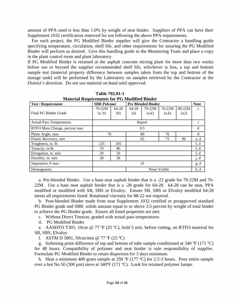
Page 34 of 41
amount of PPA used is less than 1.0% by weight of neat binder. Suppliers of PPA can have their
Supplement 1032 certification removed for not following the above PPA requirements.
For each project, the PG Modified Binder supplier will give the Contractor a handling guide
specifying temperature, circulation, shelf life, and other requirements for assuring the PG Modified
Binder will perform as desired. Give this handling guide to the Monitoring Team and place a copy
in the plant control room and plant laboratory.
If PG Modified Binder is retained at the asphalt concrete mixing plant for more than two weeks
before use or beyond the supplier recommended shelf life, whichever is less, a top and bottom
sample test (material property difference between samples taken from the top and bottom of the
storage tank) will be performed by the Laboratory on samples retrieved by the Contractor at the
District‟s direction. Do not use material on hand until approved.
Table 702.01-1
Material Requirements for PG Modified Binder Test / Requirement SBR Polymer Pre Blended Binder Note
Final PG Binder Grade
70-22M
(a, b)
64-28
(b)
64-28
(a)
70-22M
(a,k)
76-22M
(a,k)
88-22M
(a,l)
c
Actual Pass Temperatures Report i
RTFO Mass Change, percent max 0.5 d
Phase Angle, max 78 80 76 d
Elastic Recovery, min 65 75 90 e, d
Toughness, in. lb 125 105 f, d
Tenacity, in lb. 70 80 f, d
Elongation, in. min 20 20 f, d
Ductility, in. min 28 28 j, d
Separation, F max 10 g, d
Homogeneity None Visible h, d
a. Pre-blended Binder. Use a base neat asphalt binder that is a -22 grade for 70-22M and 76-
22M. Use a base neat asphalt binder that is a -28 grade for 64-28. 64-28 can be neat, PPA
modified or modified with SB, SBS or Elvaloy. Ensure SB, SBS or Elvaloy modified 64-28
meets all requirements listed. Rotational viscosity for 88-22 not required.
b. Post-blended Binder made from neat Supplement 1032 certified or preapproved standard
PG Binder grade and SBR solids amount equal to or above 3.5 percent by weight of total binder
to achieve the PG Binder grade. Ensure all listed properties are met.
c. Without Direct Tension, graded with actual pass temperatures
d. PG Modified Binder
e. AASHTO T301, 10cm @ 77 ºF (25 ºC), hold 5 min. before cutting, on RTFO material for
SB, SBS, Elvaloy
f. ASTM D 5801, 50cm/min @ 77 ºF (25 ºC)
g. Softening point difference of top and bottom of tube sample conditioned at 340 ºF (171 ºC)
for 48 hours. Compatibility of polymer and neat binder is sole responsibility of supplier.
Formulate PG Modified Binder to retain dispersion for 3 days minimum.
h. Heat a minimum 400 gram sample at 350 ºF (177 ºC) for 2.5-3 hours. Pour entire sample
over a hot No 50 (300 µm) sieve at 340ºF (171 ºC). Look for retained polymer lumps.

Page 35 of 41
i. Actual high and low temperature achieved by PG Modified Binder beyond required grade,
but will not grade out to the next standard PG Binder grade for low temperature.
j. AASHTO T51, @ 39 ºF (4 ºC), 1 cm/min
k. SB, SBS,Elvaloy or Supplemental Specification 887 GTR
l. SB, SBS, Elvaloy
706.02
On page 742, Replace part 6.2.4 with the following:
6.2.4 Ensure that no more than two holes are cast, drilled, or otherwise neatly made in the shell
of each piece of pipe for the purpose of handling or laying. Taper the holes unless drilled, and
before backfilling, fill the tapered holes with portland cement mortar, precast concrete plugs secured
with portland cement mortar, or a device on the Department‟s approved list specifically designed for
filling the hole. Fill drilled holes with portland cement mortar.
706.04
On page 749, Replace part 10 with the following:
10 Ensure that no more than two holes are cast, drilled, or otherwise neatly made in the shell of
each piece of pipe for the purpose of handling or laying. Taper the holes unless drilled, and before
backfilling, fill the tapered holes with portland cement mortar, precast concrete plugs secured with
portland cement mortar, or a device on the Department‟s approved list specifically designed for
filling the hole. Fill drilled holes with portland cement mortar.
706.05:
On page 752, Replace the first paragraph with the following:
7.1 For the following box sizes, span by rise, refer to ASTM C1577: 8x4, 5, 6, 7; 10x5, 6, 7, 8, 9;
and 12x4, 6, 8, 10 feet. For the following box sizes, span by rise, refer to SS940: 14x4, 5, 6, 7, 8, 9,
10; 16x4, 5, 6, 7, 8, 9, 10; 18x4, 5, 6, 7, 8, 9, 10; and 20x4, 5, 6, 7, 8, 9, 10 feet.
706.051
On page 752, Revise the 4th paragraph of 706.051 as follows:
Ensure that the manufacturer submits design calculations, a structural load rating and shop drawings
according to 611.04. Ensure that the shop drawings include the following:
706.052
On page 757, Revise the 4th paragraph of 706.052 as follows:
5. Ensure the manufacturer submits design calculations, a structural load rating and shop drawings
according to 611.04. Ensure the shop drawings include the following:
706.053
On page 761, Revise the 4th paragraph of 706.053 as follows:
5. Ensure the manufacturer submits design calculations, a structural load rating and shop drawings
according to 611.04. Ensure the shop drawings include the following:
706.13
On page 767, Replace part 7 with the following:
Page 36 of 41
7.0 Ensure that no more than two holes are cast, drilled, or otherwise neatly made in the shell of
each piece of each riser section for the purpose of handling or laying. Taper the holes unless drilled,
and before backfilling fill the tapered holes with portland cement mortar, precast concrete plugs
secured with portland cement mortar, or a device on the Department‟s approved list specifically
designed for filling the hole. Fill drilled holes with portland cement mortar.
708.01 On page 784, Revise the second paragraph to:
5.1 A green colorant approximately No. 34159 of FS 595C.
708.02.B.1.f
On page 785, Revise sentence in f. Color to:
Greenish gray, approximating FS-595C-34159, visual comparison.
708.02.C.1.f
On page 785, Revise sentence in a. Color to:
White, meeting or exceeding, FS-595C-37875 according to ASTM E 1347.
708.02.D.1.a
On page 786, Revise sentence in a. Finish, Specular gloss, ASTM D 523 to:
Use Fed. Std. 595C-16440 Gray: 70 % minimum after 3000 hours weathering resistance. Color
change less than 2.0 ΔE*, (C.I.E 1976 L*a*b*) ASTM D2244.
708.02.D.1.f.(1)
On page 786, Revise the table in f. Colors to:
( 1) Specified.[2]
Brown FS-595C, 10324
Green FS-595C, 14277
Blue FS-595C, 15526 [2]
Contractor‟s choice unless specified on plans
712.14
On page 815, Add the entire section 712.14 Detectable Warning Devices as follows:
712.14 Detectable Warning Devices Furnish materials conforming to the following requirements:
Products must be compliant with the Americans with Disabilities Act (ADA).
Products will be designed to be physically embedded into concrete and be of a color that visually
contrasts with the concrete. Do not use black as a color.
Products may be manufactured from materials of cast iron, stainless steel, polymer concrete,
reinforced polymer composite, or granite. Products may be designed as either one time installation
products or replaceable products.
Surface applied, stamped concrete, concrete, and brick products will not be permitted.
Detectable Warning Devices will be provided with a minimum 5 year written warranty with at
least the following:
1. The installed device will remain ADA compliant for the term of the warranty period.
2. During the warranty period at least 85% of the truncated domes on installed device will remain
entirely intact.
Page 37 of 41
3. The installed device will remain securely affixed to and flush with the concrete substrate.
4. Any surface coating applied to the installed product will remain in place and color fast.
5. At no cost to the Department, the manufacturer will replace the product, including all installation
costs, if during the 5 year warranty period the product fails to comply with the above warranty
requirements. Any new device installed under the warranty will meet the requirements of this
specification
As part of the Department Acceptance process for inclusion on the Qualified Product‟s List
(QPL) submit the proposed warranty to the Department along with material samples, dimensional
drawings, and written installation procedures.
Upon acceptance by the Department the materials will be listed on the QPL
Furnish materials according to the Department‟s Qualified Product List (QPL)
Begin warranty period upon Contract acceptance.
At the preconstruction meeting provide the Engineer with the written warranty signed by the
executive officer of the manufacturing company
725.11.C
On page 777, Delete the following sentence from the second paragraph:
If the ballast is to be wired line to grounded neutral or phase to grounded neutral, the ballast may be
either the isolated primary winding design or the auto transformer design.
730.14 On page 838, Replace the entire section with the following
Furnish sand castings according to ASTM B 26/B 26M, 356-T6 or T7. Furnish self-aligning
aluminum extrusheet sign mounting clips with manufacturer identification mark conspicuously
incorporated in relief on the top surface of the casting, and in accordance with Supplemental
Specification 992. Furnish permanent mold castings according to ASTM B 108, 356-T6 or T7.
Furnish certified material according to Supplement 1092 or 1093.
732.01
On page 843, Add the following sentence after the sixth sentence in the third paragraph of the
section:
Tri-studs shall be secured to the head using stainless steel nylon-insert or distorted thread locknuts.
732.01
On page 843, Add the following sentence after the third paragraph of the section:
For polycarbonate signal heads, obtain proper exterior colors by use of colored plastic rather than
painting.
732.11
On page 853, Add the following sentences at the end of the first paragraph:
A rectangular, rounded-corner aluminum Pole Identification Tag with minimum dimensions of 1 x 3
x 0.040 inches shall be attached to the pole at a height of 6 inches above the base plate. The Pole
Identification Tag shall be clearly and deeply stamped with the ODOT Standard Construction
Drawing Number, Design Number, and the fabrication date of the pole (e.g., TC-81.21, DES. 12, 05-
12) in characters with a minimum height of 3/8 in. Attach to the pole with four stainless steel 3/16
inch rivets.

Page 38 of 41
732.11
On page 853, Replace the last sentence in the third paragraph with the following:
Weld according to 513.21
732.12
On page 854, Add the following sentences at the end of the first paragraph:
A rectangular, rounded-corner aluminum Pole Identification Tag with minimum dimensions of 1 x 3
x 0.040 inches shall be attached to the pole at a height of 6 inches above the base plate. The Pole
Identification Tag shall be clearly and deeply stamped with the ODOT Standard Construction
Drawing Number, Design Number, and the fabrication date of the pole (e.g., TC-81.21, DES. 12, 05-
12) in characters with a minimum height of 3/8 in. Attach to the pole with four stainless steel 3/16
inch rivets.
733.03
On page 862, Add the following paragraph after the fifth paragraph:
Any fasteners (rivets, bolts, etc.) that penetrate the cabinet exterior shall be tack-welded or brazed on
the inside surface to prevent punch-thru if the fastener head is ground off from the outside. The
preferred method of cabinet construction uses no such fasteners, but internal welds only.
733.03.A.2.i
On page 867, Replace the third sentence in the section with the following:
Wire a second non-GFCI convenience outlet, not fed thru the UPS system (if used).
733.03.B.1.i
On page 871, Replace the second sentence in the section with the following:
Furnish a pushbutton with a 5-foot (1.5 m) cord, and panel connector, not hard wired, unless a
strain-relieving panel feed-thru bushing is provided.
733.03.B.1.k
On page 871, Replace the third sentence in the section with the following:
This relay shall maintain output equal to or exceeding the requirements of the cabinet main
overcurrent protective device over the NEMA TS-2 Environmental Operating Range of -30 to +165
degrees Fahrenheit.
733.03.C.4.a
On page 874, Add the following sentence after the first paragraph:
Flash Transfer Relays shall use AC coils only; the use of a series rectifier in combination with a
DC coil is prohibited.
733.03.C.4.b
On page 874, Replace the section in its entirety with the following:
Furnish a rack mounted detector test panel with test switches. Test switches shall call vehicle
phases 1-8, pedestrian phases 2,4,6,8 and EVPE channels A,B,C,D as defined in the published
ODOT Plan Insert Sheet for default 332/336 cabinet input file assignments. Furnish switches with
three position “on/off/momentary on” switches.

Page 39 of 41
733.03.E.1
On page 884, Replace the section in its entirety with the following:
1. General. Furnish Model 336 cabinets that meet the basic cabinet specifications “Traffic
Signal Control Equipment Specifications”, California Department of Transportation, latest
edition. Ensure that the manufacturer of these Model 336 cabinets is listed on the ODOT QPL.
733.09.A
On page 891, Replace the second paragraph in its entirety with the following:
Ensure the UPS cabinet has a mastic tape, neoprene foam, or silicone weather-resistant seal
between the cabinet bottom flange and the concrete foundation. Minimum tape thickness shall be
1/8-inch (3 mm) and the tape shall be continuous with no gaps between tape pieces or between
cabinet and foundation. Sealing tape shall completely cover the bottom cabinet flange and shall be
rated for a temperature range of at least -30 °F to +140° F.
733.03.D
On page 884 Add the following subsection:
D. Type 334. 1. General. Furnish Model 334C cabinets that meet the specifications
“Traffic Signal Control Equipment Specifications” and “Transportation Electrical Equipment
Specifications”, California Department of Transportation. Ensure that the manufacturer of the
cabinets is listed on the CalTrans QPL at the time of the project award.
2. Cabinets. Furnish cabinets that are constructed of aluminum and are supplied
unpainted. An anodic coating is not required. Supply galvanized anchor bolts with nuts and washers
with each cabinet. Furnish 3/4-inch (19 mm) diameter by 16 inches (0.4 m) minimum length anchor
bolts with an “L” bend on the unthreaded end.
3. Terminals and Wiring. Ensure that the vehicle detector field wiring inputs connect to
side mounted terminal blocks. Install terminal blocks and associated wiring to the input file. Label
the field wiring terminals of the side mounted terminal block by a permanent screening process to
identify the input panel (I), the input file slot number (1 through 14) and the channel terminal (D, E,
J, or K). An example is “I4-E”. Ensure that all terminals on these detector blocks are accessible
without removing equipment from the EIA mounting rack.
4. Accessories. a. Fully equip the cabinets with two channel loop detector sensors, transfer relay, power
supply, conflict monitor and switchpacks. When ramp meter warning signs with flashers are used,
include a NEMA or Caltrans type flasher wired for control from the controller.
b. Furnish a police panel in each cabinet with the Caltrans required switches. No
pushbutton with cord is provided.
c. Furnish an aluminum shelf with integral storage compartment in the rack below the
controller. Ensure that the storage compartment has telescoping drawer guides for full
extension. Ensure that the compartment top has a non-slip plastic laminate attached.
d. Ensure that each cabinet has two fluorescent lights installed at the top of the cabinet,
one near each door. Wire the lights to the door switches such that opening either door will turn on
both lights.
5. Lightning/Surge Protection. Comply with the requirements of 733.03.C.5.
6. Conflict Monitor. Furnish a Model 208 conflict monitor unit.

Page 40 of 41
Furnish 334 cabinet according to the Department‟s Qualified Products List (QPL).
740.09
On page 853 Replace the entire section with the following:
740.09 Glass Beads.
Furnish certified test data for the arsenic and lead content of all glass bead samples sent to the
Department for testing to ensure that all glass beads furnished to the Department contain no more
than 200 parts per million of arsenic or lead as determined in accordance with Environmental
Protection Agency testing methods 3052, 6010B, or 6010C, according to SEC 1504 STANDARDS.
Section 109 of title 23, United States Code, (r) Pavement Markings.
A. Type A. Furnish Type A glass beads for traffic paint conforming to Supplement 1008 and
to AASHTO M 247, Type 1 without flotation properties but dual coated (for moisture resistance and
adhesion), with the following exception: 4.6 Flotation Test.
Ensure that the glass beads for traffic paint are packaged in bags designated “740.02”. Use
materials certified according to Supplement 1089.
B. Type B. Furnish Type B glass beads for polyester marking material conforming to Supplement
1008 and AASHTO M 247, Type 1 with 50 5 percent flotation coating and ensure that a 50 5
percent moisture resistant coating is retained on each sieve, with the following exception: 4.6
Flotation Test. Ensure that the minimum percent floating equals 90 of flotation coated beads or 40.5
percent of total mixture.
Ensure that the glass beads for polyester marking material are packaged in bags designated
“POLY”.
Use materials certified according to Supplement 1089.
C. Type C. Furnish Type C glass beads for thermoplastic material conforming to Supplement 1008
and meeting the following specification.
Sieve Size Percent Retained
No. 16 (1.18 mm) 3 maximum Refractive Index 1.50 to 1.60
No. 20 (850 µm) 5 to 20 Roundness 80 minimum
No. 40 (425 µm) 65 to 95 Coating
Moisture resistant
(for drop-on beads only) No. 50 (300 µm) 0 to 5
Ensure the glass bead packaging is clearly marked “THERMO”
Use materials certified according to Supplement 1089.
D. Type D. Furnish Type D glass beads for Epoxy Pavement Marking conforming to Supplement
1008.
Ensure that the glass bead packaging clearly indicates EPOXY - SIZE I or EPOXY SIZE II.
Ensure that the glass beads have the following gradation when tested according to Supplement
1089.

Page 41 of 41
SIZE I SIZE II
Sieve Size Percent Retained Sieve Size Percent Retained
No. 10 (2.00 mm) 0 No. 20 (850 µm) 0 to 5
No. 12 (1.70 mm) 0 to 5 No. 30 (600 µm) 5 to 20
No. 14 (1.40 mm) 5 to 20 No. 50 (300 µm) 30 to 75
No. 16 (1.18 mm) 40 to 80 No. 80 (180 µm) 9 to 32
No. 18 (1.00 mm) 10 to 40 No. 100 (150 µm) 0 to 5
No. 20 (850 µm) 0 to 5 Pan 0 to 2
Pan 0 to 2
Reflective Media: Ensure that the glass beads are smooth, clear, free from any air inclusions,
and scratches that might affect their functions as a retro-reflective media, and that have the
characteristics listed below.
Roundness (Percent by Weight): Ensure that not more than 20 percent of the glass beads are
irregular or fused spheroids and that at least 80 percent of the beads are true beads.
Index of Refraction: Ensure that the refractive index of the beads is a minimum of 1.50 as
determined by the liquid immersion method at 77 °F (25 °C). Ensure that the silica content of glass
beads is not less than 60 percent.
Coating: Furnish Size I glass beads that are coated with a silane-type adherence coating to
enhance its embedment in, and adherence to the applied binder film. Ensure that the coated beads
emit a yellow-green fluorescence when tested by the Dansyl Chloride test procedure. Furnish Size II
glass beads that are treated with a moisture-proof coating. Ensure that both types of glass beads
show no tendency to absorb moisture in storage and remain free of clusters and lumps. Ensure that
they flow freely from the dispensing equipment at any time when surface and atmosphere conditions
are satisfactory for marking operations.
Determine the moisture-resistance of the glass beads on the basis of the following test:
Place 2.2 pounds (1 kg) of beads in a washed cotton bag, having a thread count of 50 per square
inch (8/cm2) (warp and woof) and immerse the bag in a container of water for 30 seconds. Remove
the bag and force the excess water from the sample by squeezing the bag. Suspend and allow them
to drain for two hours at room temperature 70 to 72 °F (21 to 22 °C). After draining, mix the sample
in the bag by shaking thoroughly. Transfer a sample slowly to a clean, dry glass funnel having a
stem 4 inches (100 mm) in length, with a 3/8-inch (10 mm) inside diameter stem entrance opening,
and a minimum exit opening of 1/4 inches (6 mm). Ensure that the entire sample flows freely
through the funnel without stoppage. When first introduced to the funnel, if the beads clog, it is
permissible to tap the funnel to initiate flow.
Use materials certified according to Supplement 1089.
STATE OF OHIO
DEPARTMENT OF TRANSPORTATION
SUPPLEMENTAL SPECIFICATION 804
FIBER OPTIC CABLE AND COMPONENTS
July 19, 2013
804.01 Description
804.02 General
804.03 Materials
804.04 Warranties
804.05 Fiber Optic Cable
804.06 Fan-Out Kit
804.07 Drop Cable
804.08 Fiber Optic Patch Cord
804.09 Fiber Termination Panel
804.10 Fusion Splice
804.11 Fiber Optic Connectors
804.12 Splice Enclosure
804.13 Fiber Optic Media Converter
804.14 Testing
804.15 Packaging and Shipping
804.16 Fiber Optic Training
804.17 Method of Measurement
804.18 Basis of Payment
804.01 Description
This work consists of furnishing and installing fiber optic cable and components. This
specification describes the requirements for communication system cables, splicing, associated
interface devices, and power cables.
804.02 General
All materials and equipment furnished shall be new, of first quality, of latest design and be
completely free of defects in material and poor workmanship. All materials, cables, fiber and
hardware shall be of the same type and manufacturer to assure uniformity, interchangeability of
components, single responsibility and most satisfactory service. Each major component shall
have the manufacturer’s name, type or style, model number and serial number on a weatherproof
decal or tag permanently attached to the equipment. All fibers in the cable shall be usable fibers
and shall be free of surface imperfections, material and inclusions in order to meet or exceed one
hundred percent (100%) of the optical, mechanical, and environmental requirements contained in
this specification.
A. Applicable Documents

All work described in this section shall meet or exceed the applicable provisions of the following
industry documents:
1. U.S Department of Agriculture, Rural Electrification Administration Specification for
Totally Filled Optical Fiber Cable, PE-90
2. EIA/TIA-455-a, Standard Test Procedure for Fiber Optic Fibers, Cables, Transducers,
Sensors, Connecting and Terminating Devices, and Other Fiber Optic Components
3. EIA/TIA-455-25a, Repeated Impact Testing Of Fiber Optic Cables and Cable Assem-
blies
4. EIA-455-28b, Method for Measuring Dynamic Tensile Strength of Optical Fibers
5. EIA-455-33a, Fiber Optic Cable Tensile Loading and Bending Test
6. EIA-455-34, Interconnection Device Insertion Loss Test
7. EIA-455-41, Compressive Loading Resistance of Fiber Optic Cables
8. EIA/TIA-455-81a, Compound Flow (Drip) Test for Filled Fiber Optic Cable
9. EIA/TIA-455-82b, Fluid Penetration Test for Fluid-Blocked Fiber Optic Cable
10. EIA-455-89a, Fiber Optic Cable Jacket Elongation and Tensile Strength
11. EIA-455-95, Absolute Optical Power Test for Optical Fibers and Cables
12. EIA-455-104, Fiber Optic Cable Cyclic Flexing Test
13. EIA/TIA-598, Color Coding of Fiber Optic Cables
14. EIA/ANSI-472 Generic Requirement for Optical Fiber and Optical Fiber Cables
15. ANSI/ICEA S-87-640
16. ANSI/TIA/EIA-526-7: OFSTP-7 Measurement of Optical Power Loss of Installed
Single-Mode Fiber Cable Plant
804.03 Materials
Furnish materials conforming to: 904.01. Provide all materials required for the installation and
splicing of the specified communications cables, power cables, and associated interface devices.
All materials, cables, fiber and hardware shall be commercially-available items.
804.04 Manufacturer Warranties
Provide a three (3) year manufacturer’s warranty to all items contained in this specification with
the exception of fiber optic cable, which shall be warranted by the manufacturer for a period of
one (1) year. This one (1) year transferrable warranty shall cover the cable against significant
degradation of the fiber caused by cable defects incurred either during the manufacturing or
installation process.
804.05 Fiber Optic Cable
Fiber optic cable shall be loose tube, single-mode dielectric cable.
In instances where new fiber optic cable is being spliced to existing fiber optic cable, THE NEW
CABLE SHALL MATCH the existing type of fiber optic cable, unless it does not meet the
following specifications:
1. ITU-T G.652 (Categories A, B, C and D)
2. IEC Specification 60793-2-50 Type B1.3
3. TIA/EIA 492-CAAB
4. Telecordia GR-20

Provide written manufacturer certification that the offered cable complies with all optical,
electrical and mechanical requirements set forth in this and all referenced specifications. Any
deviation of the offered cable from the requirements set forth herein shall be conspicuously noted
by colored highlights and/or callout bubbles in the submitted material documentation. All cables
shall be free of material or manufacturing defects and dimensional non-uniformity that would:
1. Interfere with the cable installation using acceptable installation practices.
2. Degrade the transmission performance and environmental resistance after installation.
3. Inhibit proper connection to interfacing elements.
4. Otherwise yield an inferior or inoperative installation.
Certain mechanical requirements such as central anti-buckling members and other items
necessary to comply with the maximum bend requirements in 904.01 may be omitted, if
approved by the Engineer.
A. Cable Wraps
Cable Wraps
Furnish and install cable wraps (markers) on the fiber optic cable installed in each pull box
(median and round). The wraps shall be 4 inches long “snap on type”, UV stabilized, and solid
color throughout. The wording shall include no advertising logo or message.
Color and text shall be as follows:
For ODOT cable: yellow background with black print text “ODOT fiber optic cable – ITS 614-
387-4113”. The cable wraps shall also include the fiber count of the appropriate fiber it is placed
upon.
B. Cable Installation
When ordering optical fiber cable, extreme caution shall be exercised so as to ensure that no
additional splicing, beyond that indicated in the plans, shall be required. Should the Contractor
believe additional splices are required; this matter shall be immediately brought to the attention
of the Engineer for resolution. The contractor shall be certified by the cable manufacturer to
perform installation with the cable manufacturers recommended procedures including, but not
limited to the following:
1. Proper attachment to the cable strength elements for pulling during installation.
2. Cable tensile limitations and the tension monitoring procedures.
3. Cable bending radius limitations.
Contractor shall present certification to Engineer prior to installing any cable.
Comply with the cable manufacturer's specifications at all times. To accommodate long
continuous installation lengths, bi-directional pulling of the optical fiber cable is permissible and
shall be implemented as follows:
1. From the midpoint of a pull station, pull the fiber optic cable into the conduit from the
shipping reel in accordance with the manufacturer's specifications.
2. When this portion of the pull is complete, the remainder of the cable shall be removed
from the reel to make the inside end available for pulling in the opposite direction.

3. This is accomplished by hand pulling the cable from the reel and laying it into large
"figure eight" loops on the ground. The purpose of the figure eight pattern is to avoid
cable tangling and kinking.
4. The figure eight loops shall be laid carefully one upon the other (to prevent
subsequent tangling) and shall be in a protected area.
5. The inside reel end of the cable shall be available for installation.
6. Should it be necessary to set up a winch at an intermediate manhole or pull box, the
required length of cable shall be pulled to that point and brought out of the manhole
and coiled into a figure eight.
7. The figure eight is then turned over to gain access to the free cable end. This can then
be reinserted into the duct system for installation into the next section.
Ensure that the minimum bending radius of the optical fiber cable is not compromised when
preparing this stored cable slack. Installation shall involve the placement of optical fiber cables
in an inner duct. Ensure that inner ducts are secured to prevent movement during the cable
installation process.
The sheath termination hardware on the optical fiber cables shall not be pulled over any sheave
blocks.
When power equipment is used to install optical fiber cabling, the pulling speed shall not exceed
100 feet per minute. The pulling tension and bending radii limitation for optical fiber cables
shall not be exceeded under any circumstances. Large diameter wheels, pulling sheaves, and
cable guides shall be used to maintain the appropriate bending radius. Tension monitoring shall
be provided at all times during the pulling operation and shall be accomplished using commercial
dynamometers, load cell instruments, or shearing pins.
B.1. Slack Installation
Proper storage of slack cable, both long term and short term, will be required. Slack cable shall
not be left lying free on the ground or floor of a building except during the actual pulling
process. The cable shall be neatly coiled, adhering to the bend radius requirements, on racks or
bays, as directed by the Engineer. Submit certified shop drawings of the materials and
installation of the anchored mounting channels to be installed in pull boxes and aerial hardware
according to 625.06. The cost for the fiber optic cable used in the slack installation (both aerial
and underground) and mounting hardware shall be included in this pay item and shall be paid per
location per cable.
B.1.A. Underground Slack Installation
In underground installations, coil 150 feet of fiber slack in each 48” or 32” pullbox. Should the
Contractor believe that this amount of slack is not capable of being stored, the Engineer shall
provide direction.
B.1.B. Aerial Slack Installation
Where slack installation is designated, but a splice enclosure is not designated, provide a 100 feet
in-line aerial mounted slack cable installation.

Where an aerial splice enclosure is shown, provide 50 feet of aerial mounted slack for each cable
entering the splice enclosure. Where the fiber cable is being brought aerially into an
underground installation, provide 40 feet of slack for each cable run entering the designated pull
box.
804.06 Fan-Out Kit
Only four (4) drop cable fibers are required for the full duplex daisy-chain fiber optic
communication design; the remaining fibers are typically unused spares. Fan out and apply
connectors to all unused drop cable fibers and insert them into the termination panel. Color
coded, Pre-connectorized, pre-tested pigtails may also be used. Connectors attached to fibers
from the fan-out kit shall be incidental to the fan-out kit.
804.07 Drop Cable
Drop cables are used to connect the fiber trunk cable to termination point. Unused drop cable
fibers shall be left for future use. Spare drop cable fibers at the splice enclosure end shall be
placed inside of the enclosure with sufficient excess to provide two service loops.
Spare drop cable fibers at the device end shall be inserted into the fan-out kit, connectorized and
inserted in the termination panel.
Drop cables routed down through a pole from aerial interconnect shall be provided with strain
relief (cable support assembly). Cost of the cable support assembly shall be incidental to the bid
item price of the drop cable. A minimum of 15 feet (4.5 meters) slack drop cable shall be
provided in each device cabinet or termination panel location. Slack drop cable shall be coiled
and bound to the cabinet or wall via tie wrap or other approved means. Any means of securing
the slack cable shall NOT apply stress to the drop cable. Tie wraps shall be loosely wrapped
around the cable.
804.08 Fiber Optic Patch Cord
Patch cords for connections to/from fan-out kits and/or fiber termination panels shall be
equipped with approved connectors on both ends of the patch cord. The optical connectors on
the other end of these patch cords shall be compatible with the connectors furnished on the
optical device transmit and receive cards. Patch cords shall be of a length that minimizes the
amount of slack that needs to be stored in the cabinet.
804.09 Fiber Termination Panel
Provide a termination panel in a place that provides the most room for making connections,
minimizes fiber bending, and does not subject fibers to interference from door openings or
routine maintenance operations inside the cabinet space.
A. NEMA Cabinet
Termination panel shall be attached to the inside wall of the cabinet.
B. Caltrans Signal Cabinet (332, 336)
Termination panel shall utilize standard 19-inch rack mount panels.
C. Caltrans (334) or AASHTO/ITE/NEMA ITS Cabinet
Termination panel shall utilize standard 19-inch rack mount panels.
An emergency restoration kit shall be provided with each fiber termination panel to perform
temporary splices. This kit shall include all necessary materials to perform a minimum of 5
mechanical splices. Tools, such as cleavers, strippers, etc, shall be provided by the owning
agency. Each mechanical splice kit shall be capable of achieving not more than 0.5dB loss at any
wavelength and contain LC/SC/ST type connectors. This kit shall be incidental to each
termination panel. The emergency restoration kit shall be of the same manufacturer as the cable
being installed.
804.10 Fusion Splicing
All permanent optical splices shall be of the core alignment fusion type method. Splicing shall
occur only at locations identified in the plans or approved by the Engineer. The splicing of fibers
shall be between fibers of identical color contained in fiber buffer tubes of identical color (splice
through in-kind fibers inside of in-kind buffer tubes), or as specified in the plans. All splicing
equipment shall be in good working order, properly calibrated, and meeting all industry
standards and safety regulations. Cable preparation, closure installation, and splicing shall be
accomplished in accordance with accepted and approved industry standards. Upon completion
of the splicing operation, all waste material shall be deposited in suitable containers, removed
from the job site, and disposed of in an environmentally acceptable manner. No individual splice
loss measured in a single direction shall exceed 0.05 dB.
804.11 Fiber Optic Connectors
In the event that particular components proposed in the system are not compatible or cannot fit
within the cabinets with the proposed type connectors, the contractor shall detail a plan to use
other connectors to the Engineer for approval. The plan shall include the type of connector,
except for the pigtails connecting to the components requiring different connectors, and new
proposed cabinet layout. The contractor shall be compensated for any change in materials and
any labor involved. Optical fiber connectors shall satisfy all of the interface parameters of
equipment components as may be defined by the transmission equipment specifications.
Pigtails shall have sufficient length to extend from the fiber splice closure to the termination
panel, allowing for routing, securing, and slack. The connector shall be pre-terminated on the
fiber cable or pigtail and core-aligned fusion spliced to the fiber trunk cable.
No-epoxy, no-polish quick mount single-mode UPC connectors shall be provided.
804.12 Splice Enclosure
At splice locations, a ring cut methodology shall be used, as described below. Trunk cable
jacketing shall be cut back a sufficient distance to allow unused trunk fiber tubes to be stored
uncut/unopened with two service loops inside the enclosure. The trunk cable tube that contains
the interconnect fibers shall be opened to expose the inner fibers. The remaining trunk cable
fibers in the opened tube shall remain uncut and stored in the splice tray with a minimum of two
service loops. The only trunk cable fibers that are to be cut are the trunk cable fibers being
spliced into the drop cable. Cost for the splices shall be incidental to the fiber optic cable being
spliced. If all fiber optic cable is existing, then splices will be itemized separately. If the
contractor must cut the cable at the splice enclosure location, the additional splices for through
fibers shall be included in the cost of the splice enclosure.

804.13 Fiber Optic Media Converter
Traffic signal controllers and/or cabinets and ITS cabinets are to be equipped with media
converters. Install and activate each media converter in the controller housing or cabinet.
804.14 Testing
All testing listed below shall be incidental to the cost of the fiber optic cable and shall be
completed and approved, prior to acceptance of the fiber optic cable by the Engineer.
A. Optical Fiber Cable Factory and Reel Testing
Obtain a factory test data sheets for each reel of optical fiber cable delivered. The tests shall be
performed by the factory at 1550 nm and shall include directional Optical Time Domain
Reflectometer (OTDR) traces and test data for each fiber in the cable. Each fiber on the reel
shall be tested at 1550 nm prior to installation to ensure no damage occurs to the fiber in transit
and that the length of cable is correct. These two test results shall be provided to the Engineer
prior to installation as part of final acceptance of the section of cable for payment.
All cabled optical fibers > 1000 meters in length shall be attenuation tested. The attenuation of
each fiber shall be provided with each cable reel. Supply the Engineer with the factory, and pre-
installation test results documenting that the cables meet all relevant EIA specifications.
Single-mode fibers utilized in the cables specified herein shall be subjected to and successfully
pass a tensile proof stress test equivalent to 100 kpsi (0.70 gN/m2) for 1.0 second.
Fibers shall contain no factory splices.
B. Post-Installation Testing
Test all continuous fiber with a light source utilizing procedures as stated in ANSI/TIA/EIA-526-
7: MEASUREMENT OF OPTICAL POWER LOSS OF INSTALLED SINGLE-MODE FIBER
CABLE PLANT - OFSTP-7. Testing procedures shall utilize – one jumper reference.
Bidirectional testing of optical fibers shall be performed.
Coordinate with the Engineer for specific locations for the testing. Provide the Engineer written
notification a minimum 14 calendar days before testing the fiber optic cable. Testing shall not
begin unless receiving written authorization and fiber locations and test points from the
Engineer.
Tests shall be performed as listed below:
1. All single mode fiber cables shall be tested at both 1310 nm and 1550 nm after
installation.
Fibers will be considered acceptable if the Optical Time Domain Reflectometer
(OTDR) trace for that fiber shows an end to end loss of less than xx dB + yy (0.05)dB
+ zz (0.2)dB (where yy is the number of splices (a number to be provided by the
Engineer), zz is the number of connector pairs and xx is calculated using the following
formula: xx = distance x fiber attenuation/unit distance at the required wavelength).
In addition, no splice may show a loss of greater than 0.05 dB and no connector pairs

may show a loss of greater than 0.2 dB, regardless of the total accumulated end-to-end
loss. Any additional tests required by the ANSI/TIA/EIA standard shall also be
performed and also included in the written test report.
2. Test each fiber strand from both ends of the fiber utilizing an OTDR at the
wavelengths specified above. Overall, the OTDR test results shall be made up of the
wavelength of the conducted test, the link length, attenuation, cable identification, and
the locations of the near end, the far end and each splice point or points of
discontinuity. Electronic format results for each fiber strand shall be submitted as part
of the final documentation, prior to acceptance. All test results shall be turned over to
the Engineer in electronic format provided by the manufacturer of the test equipment
used by the contractor to perform the tests. Those results must be provided such that
they can be viewable without the use of special software or additional equipment,
unless the software or equipment is also delivered to the Engineer. If software is
provided, a separate pdf document showing all fiber test results must be submitted to
be placed in the project file. Any software or equipment so delivered will become the
permanent property of the maintaining agency and will not be returned.
3. If the cable fails to meet the above requirements, it shall be replaced by the Contractor
at the Contractor’s expense. Test results shall include a record of wavelength, fiber
type, fiber and bundle number, test equipment and model number, date reference setup,
and operator (crew members). In the event that test results are not satisfactory, make
adjustments, replacements, and changes as necessary and then repeat the test or tests
that disclosed faulty or defective material, equipment, or installation method.
Additional tests shall be performed as the Engineer deems necessary. Tests related to
connected equipment of others shall be done only with the permission and presence of
the Contractor involved. Perform only that testing required to prove that the fiber
connections are correct.
804.15 Packaging and Shipping
The completed cable shall be packaged for shipment on wooden reels.
The cable and reel shall be wrapped in a water resistant covering. Each end of the cable shall be
securely fastened to the reel to prevent the cable from coming loose during transit. At least six
feet of cable length on each end of the cable shall be accessible for testing. Both ends of the
cable shall be sealed to prevent the ingress of moisture. Each cable reel shall have a durable
weatherproof label or tag showing the manufacturer's name, the cable type, and the actual length
of cable on the reel, the Contractor's name, the contract number, and the reel number. A
shipping record shall also be included in a weatherproof envelope showing the above
information and also include the date of manufacture, cable characteristics (size, attenuation,
etc.), cable identification number and any other pertinent information. The minimum diameter of
the reel shall be at least thirty times the diameter of the cable. The optical fiber cable shall be in
one continuous length per reel with no factory splices in the fiber. Each reel shall be marked to
indicate the direction the reel shall be rolled to prevent loosening of the cable. Installation
procedures and technical support information shall be furnished at the time of delivery.

804.16 Fiber Optic Training
Provide both formal classroom and "in-field" operations and maintenance training for up to
twenty (20) designated personnel on the fiber optic cable system and its components. All
training shall be coordinated at a mutually agreed upon time and location. All training material
generated for each course shall contain "hand-outs" for each attendee. These hand-outs shall
serve not only as subject guidance, but as quick-reference material for future use. All course
material, in reproducible form, shall be delivered to the Engineer immediately following course
completion. Two (2) DVD copies of the training program shall be provided. The schedule for
such training shall be submitted to the Engineer for approval at least two (2) weeks prior to the
proposed starting date.
A. Classroom Training
Personnel shall be trained to install, splice, and test fiber optic cable. This training shall be a
minimum of 32 hours. The 32 hours of fiber optic training shall be a four (4) day course taught
by personnel from the manufacturer of the fiber optic cable. Topics in the course shall include:
safety, theory, fiber types, cable placement techniques, fiber optic sheath removal, hardware
types, fault location with an Optical Time Domain Reflectometer (OTDR), Dense Wave Division
Multiplexing (DWDM), splicing and termination methods and applications, theory and principles
of splicing, fusion splicing, mechanical splicing, cable preparation procedures for installing
optical connectors, installing connectors, mocking up a typical traffic control system, cable
system testing and documentation, attenuation test procedures, and overall cable system
maintenance. This course shall include lectures, demonstrations, and hands-on experience with
the equipment. Students shall be given hand-outs to use as guides for field applications.
B. Field Training
Field training shall be provided. This training shall consist of the following as a minimum: eight
(8) hours of fiber optic communications plant trouble shooting including fault location using an
optical power meter/light source and using an Optical Time Domain Reflectometer (OTDR)
cable tester, four (4) hours of field splicing (which shall include re-enterable rotary mechanical
splicing (for emergency temporary repair) and fusion splicing techniques), and four (4) hours of
training on the installation, maintenance, and replacement of fiber interconnect centers.
C. Course Outline And Workbooks
For both types of training, four (4) copies of all proposed training material shall be submitted for
approval, which shall include course curriculums, draft manuals, and resumes of instructors.
Submittals shall be made to the Engineer at least four (4) weeks prior to the scheduled starting
date. For the classroom training, provide for each participant a course workbook, which shall be
provided in loose-leaf format in a three (3) ring binder.
804.17 Method of Measurement
The Department will measure Fiber Optic Cable by the number of feet, excluding slack, and will
include the costs for equipment, labor and miscellaneous materials.
The Department will measure Fan-Out Kit by the number of each, and will include all costs for
material, equipment, tools and labor to provide and install the fan-out kit.
The Department will measure Drop Cable by the number of each, and will include all costs for
material, equipment, tools and labor to provide and install the drop cable.

The Department will measure Fiber Optic Patch Cord by the number of each, and will include
supplying and installing connectors on all ends of the patch cord.
The Department will measure Fiber Termination Panel by the number of each, and will include
all materials, tools and labor to provide and install a termination panel.
The Department will measure Fusion Splice by the number of each, and will include all costs for
equipment, material and labor to provide a permanent fused splice including splice protection.
The Department will measure Fiber Optic Connector by the number of each.
The Department will measure Splice Enclosure by the number of each, and will include aerial or
pull box wall mounting brackets as required.
The Department will measure Slack Installation by the number of each, and will include all
materials, equipment and labor to provide a slack installation.
The Department will measure Fiber Optic Media Converter by the number of each.
The Department will measure Fiber Optic Fusion Splicer by the number of each.
The Department will measure Fiber Optic Optical Time Domain Reflectometer (OTDR) by the
number of each.
The Department will measure Fiber Optic Cleaver by the number of each.
The Department will measure Fiber Optic Power Meter by the number of each.
The Department will measure Fiber Optic Visual Fault Locator by the number of each.
The Department will measure Fiber Optic Training by the number of each.
804.18 Basis of Payment
The Department will pay for accepted quantities at the contract prices as follows:
Item Unit Description
804 Foot Fiber Optic Cable,_____ Fiber
804 Each Fan-Out Kit, _____ Fiber
804 Foot Drop Cable, _____ Fiber
804 Each Fiber Optic Patch Cord, _____ Fiber
804 Each Fiber Termination Panel, _____ Fiber
804 Each Fusion Splice
804 Each Fiber Optic Connector
804 Each Splice Enclosure
804 Each Slack Installation
804 Each Fiber Optic Media Converter
804 Each Fiber Optic Fusion Splicer
804 Each Fiber Optic, Optical Time Domain Reflectometer (OTDR)
804 Each Fiber Optic Cleaver
804 Each Fiber Optic Power Meter
804 Each Fiber Optic Visual Fault Locator
804 Each Fiber Optic Training

1
STATE OF OHIO
DEPARTMENT OF TRANSPORTATION
SUPPLEMENTAL SPECIFICATION 811
CONDUIT AND DRAINAGE STRUCTURES
January 18, 2013
811.01 Conduit Description
811.02 Conduit Materials
811.03 Conduit Definitions
811.04 Conduit Material Provisions
811.05 Submittals
811.06 Conduit Excavation
811.07 Conduit Bedding
811.08 Laying Conduit
811.09 Joining Conduit
811.10 Exterior Coatings and Membrane Waterproofing
811.11 Conduit Backfilling
811.12 Conduit Placement and Compaction Requirements
811.13 Clearing Site and Restoring Damaged Surfaces
811.14 Field Paving of New or Existing Conduit
811.15 Conduit Method of Measurement
811.16 Conduit Basis of Payment
811.17 Structure Description
811.18 Structure Materials
811.19 Structure Construction Methods, General
811.20 Structure Excavation and Backfill
811.21 Structure Brick and Block Masonry
811.22 Precast Structure Concrete Modular Construction
811.23 Structure Concrete (Cast-In-Place)
811.24 Structure Method of Measurement
811.25 Structure Basis of Payment
811.01 Conduit Description. This work consists of constructing or reconstructing long span
structures, pipe culverts, sewers, and drains (referred to below as Type A, Type B, Type C, Type D,
Type E, and Type F conduits formerly referred to as 603) per the 2010 CMS.
Use removed or excavated materials in the Work when the material conforms to the specifications;
if not, then recycle or dispose of the material according to 105.16 and 105.17.
811.02 Conduit Materials. Furnish materials conforming to:
Soil and granular embankment ........... 203.02.R
Structural backfill, Types 1 and 2 .......... 703.11
The Engineer will allow Type 3 structural backfill, conforming to 703.11, to be used as bedding
below the pipe only when pumping operations do not control severe ground water problems. Place
at least 12 inches (300 mm) of Type 1 structural backfill on top of the Type 3 structural backfill to
prevent piping.
Embankment....................................... 203.02.R

2
Concrete for collars and encasement,
Class C ....................................... 499 and 511
Concrete for field paving using aggregate
No. 7, 8, or 78, Class C ............. 499 and 511
Reinforcing steel
(collars and encasement) .................... 509.02
Mortar .......................................................... 602
Non-shrink mortar .................................. 705.22
Bituminous pipe joint filler .................... 706.10
Resilient and flexible gasket joints for:
Concrete sewer and culvert ................ 706.11
Vitrified clay, B & S ........................... 706.12
Preformed butyl rubber joint filler ......... 706.14
44 - W1.4 W1.4 galvanized
welded wire fabric for field paving .... 709.08
Type 2 membrane waterproofing ........... 711.25
Type 3 membrane waterproofing ........... 711.29
Fabric wrap, Type .................................. 712.09
Joint wrap ..................... ASTM C 877, Type III
Buried Liner Waterproofing Membrane . 711.22
Furnish pipe of the size and kind specified in the Proposal and conforming to applicable
subsections of 706 and 707. The metric equivalent pipe size may vary with material type for the
same English size pipe. The difference in sizes shall not be construed as an exclusion of a material
type. The kinds of pipe allowed for each of the designated types of conduit are as follows:
Type A Conduits - Culverts:
Non-reinforced concrete pipe, Class 3 ... 706.01
Reinforced concrete pipe ........................ 706.02
Reinforced concrete pipe, epoxy coated . 706.03
Reinforced concrete elliptical pipe ......... 706.04
Precast reinforced concrete box sections 706.05
Precast reinforced concrete 3-sided flat
topped culverts ................................. 706.051
Precast reinforced concrete
arch sections ..................................... 706.052
Precast reinforced concrete round
sections ............................................. 706.053
Vitrified clay pipe
(extra strength only) ........................... 706.08
Corrugated steel conduits ....... 707.01 or 707.02
Structural plate corrugated
steel structures .................................... 707.03
Precoated, galvanized steel culverts ....... 707.04
Bituminous coated corrugated steel
pipe and pipe arches with
paved invert ........................ 707.05 or 707.07
Corrugated aluminum
alloy pipe ................................ 707.21 or 707.22
Aluminum alloy structural
plate conduits ...................................... 707.23
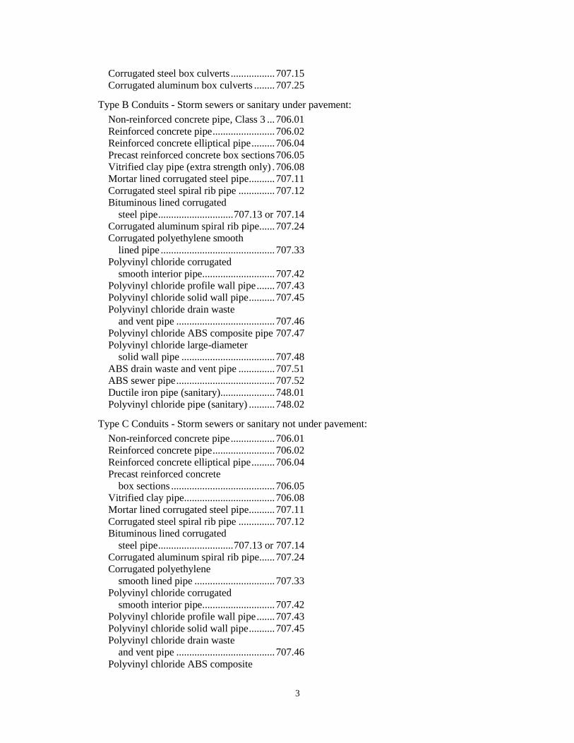
3
Corrugated steel box culverts ................. 707.15
Corrugated aluminum box culverts ........ 707.25
Type B Conduits - Storm sewers or sanitary under pavement:
Non-reinforced concrete pipe, Class 3 ... 706.01
Reinforced concrete pipe ........................ 706.02
Reinforced concrete elliptical pipe ......... 706.04
Precast reinforced concrete box sections 706.05
Vitrified clay pipe (extra strength only) . 706.08
Mortar lined corrugated steel pipe .......... 707.11
Corrugated steel spiral rib pipe .............. 707.12
Bituminous lined corrugated
steel pipe ............................. 707.13 or 707.14
Corrugated aluminum spiral rib pipe ...... 707.24
Corrugated polyethylene smooth
lined pipe ............................................ 707.33
Polyvinyl chloride corrugated
smooth interior pipe ............................ 707.42
Polyvinyl chloride profile wall pipe ....... 707.43
Polyvinyl chloride solid wall pipe .......... 707.45
Polyvinyl chloride drain waste
and vent pipe ...................................... 707.46
Polyvinyl chloride ABS composite pipe 707.47
Polyvinyl chloride large-diameter
solid wall pipe .................................... 707.48
ABS drain waste and vent pipe .............. 707.51
ABS sewer pipe ...................................... 707.52
Ductile iron pipe (sanitary)..................... 748.01
Polyvinyl chloride pipe (sanitary) .......... 748.02
Type C Conduits - Storm sewers or sanitary not under pavement:
Non-reinforced concrete pipe ................. 706.01
Reinforced concrete pipe ........................ 706.02
Reinforced concrete elliptical pipe ......... 706.04
Precast reinforced concrete
box sections ........................................ 706.05
Vitrified clay pipe ................................... 706.08
Mortar lined corrugated steel pipe .......... 707.11
Corrugated steel spiral rib pipe .............. 707.12
Bituminous lined corrugated
steel pipe ............................. 707.13 or 707.14
Corrugated aluminum spiral rib pipe ...... 707.24
Corrugated polyethylene
smooth lined pipe ............................... 707.33
Polyvinyl chloride corrugated
smooth interior pipe ............................ 707.42
Polyvinyl chloride profile wall pipe ....... 707.43
Polyvinyl chloride solid wall pipe .......... 707.45
Polyvinyl chloride drain waste
and vent pipe ...................................... 707.46
Polyvinyl chloride ABS composite

4
pipe ..................................................... 707.47
Polyvinyl chloride large-diameter
solid wall pipe .................................... 707.48
ABS drain waste and vent pipe .............. 707.51
ABS sewer pipe ...................................... 707.52
Ductile iron pipe (sanitary)..................... 748.01
Polyvinyl chloride pipe (sanitary) .......... 748.02
Type D Conduits - Drive pipes and bikeways:
Non-reinforced concrete pipe, Class 3 ... 706.01
Reinforced concrete pipe ........................ 706.02
Reinforced concrete elliptical pipe ......... 706.04
Vitrified clay pipe
(extra strength only) ........................... 706.08
Corrugated steel conduits ....... 707.01 or 707.02
Structural plate corrugated
steel structures .................................... 707.03
Corrugated aluminum
alloy pipe ............................ 707.21 or 707.22
Aluminum alloy structural
plate conduits ...................................... 707.23
Corrugated polyethylene
smooth lined pipe ............................... 707.33
Polyvinyl chloride corrugated
smooth interior pipe ............................ 707.42
Polyvinyl chloride profile wall pipe ....... 707.43
Polyvinyl chloride solid wall pipe .......... 707.45
Polyvinyl chloride large-diameter
solid wall pipe .................................... 707.48
Type E Conduits - Miscellaneous small drain connections and headers:
Non-reinforced concrete pipe ................. 706.01
Reinforced concrete pipe ........................ 706.02
Reinforced concrete elliptical pipe ......... 706.04
Concrete drain tile, extra quality ............ 706.07
Vitrified clay pipe ................................... 706.08
Clay drain title, extra quality .................. 706.09
Corrugated steel conduit ......... 707.01 or 707.02
Corrugated aluminum
alloy pipe ................................ 707.21 or 707.22
Corrugated polyethylene
drainage pipe ...................................... 707.32
Corrugated polyethylene
smooth lined pipe ............................... 707.33
Smooth-wall polyvinyl chloride
underdrain pipe (non-perforated) ....... 707.41
Polyvinyl chloride corrugated
smooth interior pipe ............................ 707.42
Polyvinyl chloride profile wall pipe ....... 707.43
Polyvinyl chloride solid wall pipe .......... 707.45

5
Polyvinyl chloride drain waste
and vent pipe ...................................... 707.46
Polyvinyl chloride ABS composite
pipe ..................................................... 707.47
Polyvinyl chloride large-diameter
solid wall pipe .................................... 707.48
ABS drain waste and vent pipe .............. 707.51
ABS sewer pipe ...................................... 707.52
Type F Conduits - Conduits on steep slopes; underdrain outlets:
Corrugated steel conduits (steep slope conduit)
.................................. 707.05, Type C or 707.07
Corrugated aluminum alloy pipe
(steep slope conduit) ........... 707.21 or 707.22
Corrugated polyethylene smooth
lined pipe (underdrain outlets) ........... 707.33
Smooth-wall polyvinyl chloride underdrain
pipe (non-perforated) .......................... 707.41
Polyvinyl chloride corrugated smooth
interior pipe (underdrain outlets) ........ 707.42
Polyvinyl chloride solid wall pipe
(underdrain outlets) ............................ 707.45
811.03 Conduit Definitions. For the purposes of this specification, the following definitions are
used:
A. Long span structure includes all of the following material kinds: 706.05, 706.051, 706.052,
706.053, 707.15, and 707.25.
B. Plastic pipe includes all of the following materials kinds: 707.31, 707.32, 707.33, 707.41,
707.42, 707.43, 707.44, 707.45, 707.46, 707.47, 707.51, 707.52, and 748.02.
C. Corrugated metal pipe includes all of the following material kinds: 707.01, 707.02, 707.03,
707.04, 707.05, 707.07, 707.11, 707.12, 707.13, 707.14, 707.21, 707.22, 707.23, and 707.24.
D. Iron pipe includes the following material kind: 748.01.
E. Rigid Pipe includes all of the following material kinds: 706.01, 706.02, 706.03, 706.04, 706.08,
706.09, and 748.06.
F. Conduit includes long span structures, pipe, culverts, sewers, drains, or any other item specified
herein.
G. Backfill is soil, granular embankment, or structural backfill placed above the bedding to the
elevation as describe.
H. A cut situation is an existing field situation when the top of the conduit is below the existing
ground where an embankment may be constructed.
I. A fill situation is an existing field situation when the top of the conduit is above the existing
ground where an embankment is to be constructed.
J. A fill situation, meets the requirements of a cut if the fill is constructed to at least 2 feet (600
mm) above the top of the conduit before placing the conduit.
K. The conduit rise is the vertical distance from outside wall to outside wall or outside corrugation
measured at the middle of the conduit.
6
L. The conduit span is the horizontal distance from outside wall to outside wall or outside
corrugation measured at the widest point of the conduit.
M. The conduit spring line is equal to the rise divided by two.
N. Trench width is the horizontal distance between the vertical walls of the trench measured in
feet.
811.04 Conduit Material Provisions. The local will allow any of the following alternate material
provisions:
A. The Contractor may use Type 1 or 2 structural backfill if granular or soil embankment is
required or allowed.
B. Supply pipe of the required size or one size larger.
C. If 707.05 or 707.07 conduit is specifically itemized or specified in the Proposal, the Contractor
may provide conduit conforming to 707.04 and having a bituminous paved invert. Provide the same
corrugation profile and sheet thickness listed in the Proposal.
D. The Contractor may furnish higher strength concrete or plastic pipe of the same type where
lower strength pipe is specified.
E. The Contractor may furnish a thicker metal pipe of the same corrugation profile and type where
a lesser thickness is permitted or specified.
F. For metal pipe 54 inch (1350 mm) diameter or larger and pipe-arch, ensure the manufacturer
provides match marked ends and a layout drawing.
811.05 Submittals. Prepare shop drawings and calculations when required below. Have a
Registered Engineer prepare, sign, seal and date all calculations. Have another Registered Engineer
check all drawings and calculations, sign, and seal and date all calculations. Submit load rating
calculations to the Office of Structural Engineering for all structures with a 10 foot span and greater
in accordance to the most current version of ODOT’s Bridge Design Manual. Submit two copies of
the shop drawings and calculations to the Engineer. The Engineer will submit one copy to the Local
Authority according to the following:
A. If Reinforced Concrete Circular Pipe, 706.02, requires a “Special Design” with a specified
D-load requirement above the minimum D-load, submit shop drawings and design calculations.
Design the pipe to meet the D-load requirements required to meet the performance of this
specification. Include the following information in the submittal: all structural design and
loading information, all material specifications, all dimensions, and the installation plan.
B. Precast reinforced concrete 3-sided flat topped culverts, precast reinforced concrete arch
culverts, or precast reinforced concrete round sections, (706.051, 706.052, or 706.053) must
submit structural analysis methods, structural design criteria and calculations, structure details,
and shop drawings. Include details for a precast slab bottom if required.
C. Submit hydraulic calculations if requesting approval to substitute a precast reinforced
concrete 3-sided flat topped culvert (706.051), a reinforced concrete arch culvert (706.052), or
a precast reinforced concrete round section (706.053) for one another. The proposed culvert
must meet or exceed the same hydraulic requirements as the specified culvert and minimum
cover requirements. If the specified culvert is on pedestal walls, include the shop drawings for
the pedestal wall design in the submittal because 3-sided flat topped culverts, arch culverts, and
round sections require different pedestal wall designs.

7
D. Submit hydraulic calculations if requesting approval to substitute either a precast
reinforced concrete 3-sided flat topped culvert, a precast reinforced concrete arch culvert, or a
precast reinforced concrete round section (706.051, 706.052, or 706.053) placed on a precast or
cast-in-place slab bottom for a precast reinforced concrete box culvert (706.05). The proposed
culvert must meet the same hydraulic requirements as the specified box culvert and minimum
cover requirements. The Local Authority may allow the bottom slab to be cast-in-place but will
not issue a time extension for any delays resulting from the use of a cast-in-place bottom slab.
811.06 Conduit Excavation. Measure trench width at the span of the conduit. Center the trench
excavation about the centerline of the conduit.
Use Method A for a cut situation, and use Method B for a fill situation.
A. Method A. Excavate the trench for the conduit. Provide vertical trench walls.
If long span culvert is used, provide a minimum trench width of the span plus 2 feet (0.6 m) on
each side.
If rigid pipe is used, provide a minimum trench width of the span times 1.33.
If plastic or corrugated metal pipe is used, provide a minimum trench width of the span times
1.25 plus 1 foot (0.3 m).
If plastic pipe is used and the ID is 8 inch (200 mm) or less furnish a minimum trench width of
the OD.
Increase these minimums to a width that allows the jointing of the conduit, and the placement
and compaction of the backfill.
B. Method B. Construct the embankment to a height at least equal to half of the rise and to a
width on each side of the conduit two times the span of the conduit before excavating for the conduit.
Excavate the trench in the constructed embankment to a width conforming to Method A above.
Furnish a firm foundation for the conduit bed for its full length. The Engineer will require the
removal of unsuitable material below the conduit bedding or below the bottom of the conduit if
bedding is not required for the width of the trench. Replace the unsuitable material with structural
backfill. Remove rock or shale in the conduit foundation for at least 6 inches (150 mm) below the
bottom of the bedding. Replace the rock or shale with structural backfill. Unless in the contract
documents, the Local Authority will pay for this work according to 109.05.
If the Engineer changes the flow line by more than one foot (0.3m), the Local Authority will pay
according to 109.05.
The Contractor may jack or tunnel the pipe with the written permission of the Director.
811.07 Conduit Bedding. Type 1 bedding consists of structural backfill extending at least 6
inches (150 mm) below the bottom of the conduit for the full width of the trench. Compact the
bedding according to 811.11.
Use Type 1 bedding for 706.05, or 706.051, 706.052, and 706.053 on slab bottoms. Also use Type
1 bedding for 707.03, 707.15, and 707.25 on corrugated invert plates.
Type 2 bedding consists of structural backfill extending at least 3 inches (75 mm) for all 706 rigid
pipe conduits and 6 inches (150 mm) for all other conduits below the bottom of the conduit for the
full width of the trench. Extend the bedding up around the pipe for a depth of not less than 30
percent of the rise of the conduit. Shape the bedding to fit the conduit with recesses shaped to receive
the bell of bell-and-spigot pipe. Leave the bedding below the middle one-third of the pipe span un-
compacted. Compact the remaining bedding according to 811.11.

8
Use Type 2 bedding for Types A, B, C, and D conduits except for long span structures and for
conduits that require Type 3 bedding.
Type 3 bedding consists of a natural foundation with recesses shaped to receive the bell of bell-
and-spigot pipe. Scarify and loosen the middle one-third of the pipe span.
Use Type 3 bedding for Type C and Type D conduits of the following materials: 706.01, 706.02,
or 706.03.
Type 4 bedding consists of a natural foundation shaped to fit the conduit with recesses shaped to
receive the bell of bell-and-spigot pipe.
Use Type 4 bedding for Types E and F conduits.
811.08 Laying Conduit. Lay the conduit in the center of the trench starting at the outlet end with
the bell or groove-end laid upgrade. Ensure that the conduit is in contact with the bedding throughout
its full length such that line and grade is maintained. Lay metal conduits according to one of the
following methods:
A. If the seam is longitudinally either riveted or welded, place the seam or weld at the spring line.
B. If the metal pipe is fabricated helically (having a continuous seam running around the outside of
the pipe), arrange the corrugations so the helix angle or twist is rotating downstream in the direction
of the flow to increase hydraulic performance.
Maintain flows at all times until the new facilities are completed and in service. Maintain the
flows through existing facilities to be replaced unless a temporary bypass conduit is used.
Construct the inlet and outlet ends of all conduit runs with pipe ends as normally fabricated by the
manufacturer. If field cutting is necessary, locate the cut end at an interior joint within the run and
provide a cradle, collar, or band to ensure a stable joint.
Construct a concrete collar on the last joint if field cutting is necessary to meet a structure or
headwall.
Erect 707.03, 707.15, 707.23, and 707.25 conduits according to 522.03. Where two plate
thicknesses are specified, locate the thicker plates at the bottom and corner plates in pipe-arch
structures, and the bottom row, if centered, or bottom two rows, if not centered, in round structures.
Set the 706.051 units on the concrete footing shown on the plans. Unless otherwise shown on
the plans, provide a 3-inch (75 mm) deep keyway centered on the precast leg. The width of the
keyway shall be 6 inches (150 mm) greater than the thickness of the precast leg. Place the units in a
1/2-inch (13 mm) bed of mortar. If proper line and grade of the structure cannot be maintained on the
bed of mortar, set the units on 5 × 5-inch (125 × 125 mm) masonite or steel shims. Fill the entire
keyway joint with mortar.
Set the 706.052 units on the concrete footing shown on the plans. Unless otherwise shown on
the plans, provide a 3-inch (75 mm) deep keyway centered on the precast leg. The width of the
keyway shall be 6 inches (150 mm) greater than the thickness of the precast leg. Place the units on 5
× 5-inch (125 × 125 mm) masonite or steel shims to provide a minimum 1/2-inch (13 mm) gap
between the footing and bottom of the unit’s bottom leg. Fill the entire keyway joint with mortar.
Set the 706.053 arches on the concrete footing shown on the plans. Unless otherwise shown on
the plans, provide an 8-inch (200 mm) deep keyway for spans up to 24 feet (7.3 m) and a 10-inch
(250 mm) deep keyway for all spans greater than 24 feet (7.3 m). Center the keyway on the precast
arch base. The width of the keyway must be 8 inches (200 mm) greater than the thickness of the
precast arch base. For non-vertical leg arches set on pedestal walls, a one-sided keyway is acceptable
if the required pedestal wall design thickness is not sufficient for a full keyway. Place masonite or
steel shims to provide a minimum of 1.5-inch (38 mm) gap between the footing and the bottom of
9
the precast arch base. Fill the entire keyway joint with mortar. Provide 5000 psi (34.5 MPa) mortar.
For arches that gain structural continuity by a cast-in-place closure at the project site, provide
concrete with the same compressive strength as the precast arch.
If reinforced concrete pipe has elliptical reinforcing, the top and bottom of the pipe are clearly
marked on the pipe. Handle and place reinforced concrete pipe with elliptical reinforcement and
reinforced concrete horizontal elliptical pipe with single cage reinforcement with the reinforcement
markings along a vertical plane as marked on the pipe. Handle and place reinforced concrete pipe
with auxiliary supports (S-stirrups) with the centerline of the auxiliary support system (S-stirrups) in
a vertical plane as marked on the pipe.
For 706.05, 706.051, 706.052, or 706.053 structures fill the lifting devices with mortar. Cover the
exterior of the lifting devices with joint-wrap material if outside the limits of the membrane
waterproofing. Use joint-wrap with a minimum width of 9 inches (225 mm). Use only lifting devices
that do not require a hole through the structure.
For all 707 conduit, use only lifting devices that do not require a hole through the structure.
Immediately after placing conduit, construct the end treatments at both the outlet and inlet ends.
These end treatments include headwalls, concrete riprap, rock channel protection, sod or other
erosion control items.
811.09 Joining Conduit. Join the conduit sections so that the ends are fully entered and the inner
surfaces are flush and even. Furnish sealed, banded, or bolted joints for Types A, B, C, D, and F
conduits. Provide open joints for Type E conduits wrapped with 4-inch (100 mm) wide tarred paper
or tarred burlap with pack soil placed around this material to hold it in place during backfilling.
The Engineer may allow joint materials other than those listed below, provided the Contractor
demonstrates the proposed material makes durable sealed joints.
Furnish joints that do not allow infiltration of backfill material into the conduit or use a fabric
wrap on the outside of the conduit.
Install conduit so that match marks align and in accordance with the layout drawings supplied by
the manufacturer.
A. Joints.
1. Metal Pipe.
If using corrugated metal pipe, provide coupling bands conforming to 707.01 or 707.02.
These bands will have the same coating as the pipe being joined and use gasketed coupling bands or
fabric wrap the coupling bands when using structural backfill Type 2 for the bedding or backfill. A
maximum difference between adjacent pipe sections of 1/2 inch (15 mm) will be allowed before
coupling bands are placed. Securely strut the end of each pipe section for pipe diameters 54 inches
(1350 mm) or greater that have a wall thickness of less than 0.109 inch (2.77 mm). Install the ties or
strapping in the first or second valley of the annular corrugations on each end of each piece of pipe.
Install two struts per end such that they are perpendicular to one another and cross at their midpoints.
Strut by using wire ties or other approved methods. Remove the strutting after securing the coupling
bands.
Bell and spigot joints conforming to 707.12 may be used for corrugated steel spiral rib
conduits. Ensure the spigot and bell ends are clean and free from dirt or debris prior to assembly.
Place a gasket in the first corrugation of the spigot end and thoroughly lubricate the gasket and the
bell end of the receiving conduit prior to assembly. Ensure the spigot is securely driven home into
the bell upon final assembly.
2. Rigid Pipe.

10
a. For 706.01, 706.02, or 706.04, 706.05, or 706.08 that require sealed joints, use any of
the following methods:
i. Apply 706.10 to the pipe in sufficient quantity to completely fill the joint once
the pipe is placed in its final position at a gap of 1 inch (25.4 mm) or less. After placing the pipe in
its final position, point and trowel the 706.10 to form a smooth transition on the inside and a
complete seal on the outside.
ii. Apply 706.14 to the pipe in sufficient quantity to seal the joint but not necessarily
fill the joint once the pipe is placed in its final position at a gap of 1 inch (25.4 mm) or less.
Immediately before installing 706.14, clean the joint free of all debris then prime both sides of the
joint with an asphalt based primer according to the 706.14 manufacturer’s recommendations.
iii. Provide 706.11 or 706.12 as specified.
b. For 706.03 conduit, use fibrated coal tar joint compound applied according to the
manufacturer’s recommendations.
c. If resilient and flexible gasket joints conforming to 706.11 or 706.12 are specified on
sanitary sewer conduits, test the joints for infiltration or exfiltration according to ASTM C 969. If
any section of conduit fails to meet the test requirements, make corrections until the test
requirements for the section are met.
B. Filling Joints. After placing 706.05, 706.051, or 706.052 in their final position with a
maximum joint gap of 1 inch (25.4 mm), clean the joint gap or joint of all debris and perform the
following:
1. For 706.05 joints, fill the top exterior joint gap and the bottom and side interior joint gap
with mortar. Next, for any exterior joint not covered by membrane waterproofing, cover the exterior
joint with a 9-inch (225 mm) wide strip of joint wrap. Center the joint wrap on the joint. Use a
continuous length of joint wrap sufficient to extend from the bottom of the vertical face on one side
to the bottom vertical face on the other side.
2. For 706.051, fill the top keyway joint with 705.22. The side or leg joints shall also be filled
with 705.22 for the keyway type joint or filled per 706.05 for a tongue and grove type joint. Clean
the joint of all debris immediately before installing the joint filling material. Wet all surfaces of the
keyway joint, but do not allow free standing water in the joint. Prepare, place, and cure the 705.22
according to the manufacturer’s recommendations. Next cover the exterior joint with a 12-inch (300
mm) wide strip of joint wrap. Center the joint wrap on the joint. Use a continuous length of joint
wrap sufficient to extend from the bottom of the vertical face on one side to the bottom vertical face
on the other side. Apply membrane waterproofing to the precast sections after they are installed.
3. For 706.052 and 706.053, install a 7/8 × 1 3/8-inch (24 × 34 mm) 706.14 joint filler along
the outside joint chamfer. Use a continuous length of joint filler sufficient to extend from the bottom
of the vertical face on one side to the bottom vertical face on the other side. Before installing the
joint filler, prime the joint chamfer with a primer according to manufacturer’s recommendations. For
706.052 and 706.053, cover all exterior joints with a 12-inch (300 mm) wide strip of joint wrap
centered on the joint. Use a continuous length of joint wrap sufficient to extend from the bottom of
the vertical face on one side of the structure to the bottom vertical face on the other side. Next, apply
all waterproofing as shown on the plans. Apply membrane waterproofing to the precast sections after
they are installed.
C. Sealing Concrete Surfaces. For 706.05, 706.051, 706.052, or 706.053 apply an approved
epoxy-urethane sealer per the plans to all top surfaces not covered by membrane waterproofing.
Extend the sealer 1 foot (0.3 m) below the backfill on all sides of the culvert sections including the
joint.

11
The Engineer and Contractor will visually inspect all conduit and joints before any backfill is
placed. Rejoin, re-lay, or replace all conduit out of joint tolerance, alignment, settled, or damaged.
811.10 Exterior Coatings and Membrane Waterproofing. If shown on the plans, externally
apply membrane waterproofing to 706.05, 706.051, 706.052 or 706.053. Apply the membrane
waterproofing to the top surface and extend it vertically down both sides of the structure. Clean the
concrete surfaces when the membrane waterproofing does not adhere to the structure. Apply the
membrane waterproofing to all surfaces that will be in contact with the backfill. Apply the
waterproofing according to the appropriate requirements of Item 512.
Apply waterproofing to 707.03, 707.15, 707.23, and 707.25 conduits with less than eight feet (2.4
m) of cover by one of the following methods.
A. Coat the exterior of the conduit above the limits of the bedding and within the limits of backfill.
Ensure that all plate seams and bolts are thoroughly sealed. The coating material and application
shall conform to AASHTO M 243. Allow asphalt mastic material to dry 48 hours and tar base
material to dry 28 hours before placing the conduit backfill. Rib stiffeners do not need to be coated.
B. Construct Buried Liner Waterproofing Membrane protection in the fill per the manufacturer’s
recommendations. The Buried Liner Waterproofing Membrane protection will be a seamless
continuous sheet placed over the conduit and extend at least 10 feet (3.3 m) outside of the paved
shoulder and for the width of the trench.
811.11 Conduit Backfilling. Place backfill to the limits described and according to the
compaction requirements. Place the backfill in the trench and embankment outside the trench
uniformly on both sides of the conduit for all conduit installations.
A. General. The Contractor may operate small compaction equipment with less than a total weight
of 1 ton (0.9 metric ton) over the conduit to compact the backfill. Do not use hoe packs on top of the
conduit until 2 feet (0.6 m) of backfill is compacted on top of the conduit. The Contractor may
operate compaction equipment with less than a total weight of 8 tons (7 metric tons), but more than 1
ton (0.9 metric ton), over the conduit after placing and compacting 2 feet (0.6 m) of backfill. Do not
operate equipment with a total weight of 8 tons (7 metric tons) or more, until placing and compacting
a cover of 4 feet (1.2 m) over the top of the conduit. The above restrictions apply when working
within one span on each side of the conduit, or 6 feet (1.8 m), whichever is less. As shown on the
plans, encase conduits with the specified thickness of Class C concrete.
B. Long Span.
1. For all long span structures except 706.053 in cut, place and compact structural backfill
over the top of the section to a minimum depth 4 feet (1.2 m) or to the subgrade elevation whichever
is less and for a width of 2 feet (0.6 m) on each side of the section. Use soil, granular embankment,
or structural backfill to construct the adjacent embankment and for the remaining depth to the
subgrade. Construct the adjacent material according to Item 203.
2. For all long span structures except 706.053 in fill, place and compact structural backfill
over the top of the section to a minimum depth of 2 feet (0.6 m) or to the subgrade elevation
whichever is less and for a width of 2 feet (0.6 m) on each side of the section. Use soil, granular
embankment, or structural backfill to construct the adjacent embankment and for the remaining
depth to the subgrade. Construct the adjacent material according to Item 203.
3. For 706.053 structures in cut or fill, place and compact structural backfill on both sides of
the structure to the following minimum limits: vertically from the base up to a height of 75 percent
of the rise; horizontally on each side of the structure to a sloping line that begins 2 feet (0.6 m) from
the base of the structure and slopes up and away from the structure at a 1H:1V slope (45 degree
angle). Use soil, granular embankment, or structural backfill to construct the adjacent embankment
and for the remaining depth to the subgrade. Construct the adjacent material according to Item 203.

12
C. Type A and B. Backfill Types A and B conduits except for long span structures as follows
1. In a cut situation, place and compact structural backfill above the bedding for the full depth
of the trench. Within the trench and more than 4 feet (1.2 m) above the top of the conduit, if the
trench can accommodate compaction equipment, the Contractor may construct Item 203
Embankment. For plastic pipe with an ID 8 inch (200 mm) or less, place and compact structural
backfill above the bedding for the full depth of the trench.
2. In a fill situation, place and compact structural backfill above the bedding for the full depth
of the trench specified in 811.06.B. Above these limits, uniformly place the lesser of one pipe span
or 4 feet (1.2 m) of structural backfill on each side of the conduit and to a depth of 2 feet (0.6 m)
above the top of the conduit. Construct the embankment outside the limits of the backfill. For
plastic pipe with an ID 8 inch (200 mm) or less, place and compact structural backfill above the
bedding for the full depth of the trench.
D. Type C and D. Backfill Type C and D conduits as follows:
1. In a cut situation, for plastic pipe, place and compact structural backfill above the bedding
and to 6 inches (150 mm) over the top of the pipe. All other conduit material types place and
compact backfill. For plastic pipe with an ID 8 inch (200 mm) or less, place and compact structural
backfill above the bedding for the full depth of the trench.
2. In a fill situation, for plastic pipe, place and compact structural backfill above the bedding
for the full depth of the trench specified in 811.06.B. Above these limits, uniformly place the lesser
of one pipe span or 4 feet (1.2 m) of structural backfill on each side of the conduit and vertically to
the top of the conduit. Then place for a depth of 6 inches (150 mm) structural backfill over the top
of the pipe equal to the trench width centered on the pipe center line. Construct the embankment
outside the limits of the backfill. All other conduit material types place and compact backfill. For
plastic pipe with an ID 8 inch (200 mm) or less, place and compact structural backfill above the
bedding for the full depth of the trench.
E. Type E. Place and compact backfill above the bedding to a height equal to two-thirds of the
conduit rise then place and lightly compact backfill for a depth of 12 inches (0.3 m) above the pipe.
Place no stones larger than 4 inches (100 mm) that will be part of the embankment in contact with
the pipe.
F. Type F. Place and compact backfill above the bedding. Backfill Type F conduits for underdrain
outlets according to 605.03.C.
811.12 Conduit Placement and Compaction Requirements. Place soil, granular embankment,
or Structural Backfill Type 1 or 2 in lifts not to exceed 8 inches (200 mm). The Local Authority will
perform all compaction testing according to Supplement 1015. The compaction requirements per
material type are as follows:
A. For soil embankment, compact each lift until 96 percent of AASHTO T 99 is achieved.
B. For granular embankment and Structural Backfill, Type 1 or 2, compact each lift of material
according to 811.12.E using mechanical devices, hoe packs, jumping jacks, hand devices, vibrating
plates, or other equipment that meets the restrictions in 811.11. Provide compaction equipment that
compacts the material under the haunch of the pipe. If the compaction equipment cannot fully
compact the material under the haunch, supplement the compaction equipment by using shovel
slicing, spud bars, or mechanical spud bars to compact the material under the haunch of the pipe.
Use shovel slicing and spud bars in conjunction with the compaction operations to compact the
material and to manipulate the material under the haunch of the pipe.
C. For Structural Backfill Type 2, compact each lift of material according to 811.12.E using flood
compaction or mechanical devices, hoe packs, jumping jacks, hand devices, vibrating plates, or other

13
equipment that meets the restrictions in 811.11. Provide compaction equipment that compacts the
material under the haunch of the pipe. If the compaction equipment cannot fully compact the
material under the haunch, supplement the compaction equipment by using shovel slicing, spud bars,
or mechanical spud bars to compact the material under the haunch of the pipe. Use shovel slicing
and spud bars in conjunction with the compaction operations to compact the material and to
manipulate the material under the haunch of the pipe
D. Place Structural Backfill Type 3 in layers not to exceed 12 inches (300 mm) loose depth.
Vibrate, tamp, or compact to approximately 85 percent of the original layer thickness.
E. At the beginning of the work, construct a test section in the conduit trench. The Engineer will
use at least 96 percent of the test section maximum dry density for acceptance of the production
areas. Use at least the same number of passes or compactive effort used to construct the test section
to compact the production areas. Use compaction equipment with a total weight or centrifugal force
of at least 1/2 ton (0.5 metric tons). Supply the manufacture’s specification for the compaction
equipment. Except when using a hoe pack, use at least six passes with the compaction equipment in
the production areas.
The Engineer may reduce the minimum passes if the passes are detrimental to compaction.
Construct a new test section if the pipe type, bedding material, backfill material, or trench
conditions change.
F. If using trench boxes with either Type A or B conduits, configure the trench box so that the
bedding and backfill material is compacted directly against the trench walls.
G. The Engineer may adjust the lift thickness to obtain the required compaction, fill all the voids,
achieve the proper seating of the backfill material, and achieve the stability of the backfill material
and the pipe. Do not use equipment or methods that compromise the structural integrity of the pipe.
811.13 Clearing Site and Restoring Damaged Surfaces. Immediately after completion of the
placing and compacting of the backfill remove and dispose of all surplus material according to
811.01 and clear the site and restore all required surfaces
811.14 Field Paving of New or Existing Conduit. Field pave the bottom of the conduit with
concrete as shown on the plans.
For new pipe installations, do not pave until at least 4 feet (1.2 m) of fill is placed on top of the
conduit, or the top of subgrade is reached. If the paving is placed before completion of the entire fill,
clean any gaps between the conduit and concrete paving, then fill with heated bituminous material
conforming to 705.04.
Reinforce the paving with 4 4-W1.4 W1.4 galvanized welded wire fabric (or comparable).
Provide a mesh with a width 4 inches (100 mm) less than the finished paving. Securely fasten the
mesh to the conduit near each edge and at the center of the mesh at points not more than 4 feet (1.2
m) apart along the flow line of the culvert. Repair any damage to the galvanizing or other coating
material caused by placement or by tack welding. Use wire brushing and paint with zinc rich paint
to make the repairs.
For aluminum structural plate, securely fasten the mesh to the circumferential seam bolts with
galvanized tie wire.
Provide a paving that is 3 inches (75 mm) thick measured from the top of the corrugations of the
conduit to a height equal to 1/3 of the rise. Provide galvanized reinforcing steel support chairs
beneath the mesh where necessary. Give special care to the mesh during concrete placement. After
placing the concrete, strike it off with a template to produce the proper radius, and finish with a float
to produce a smooth finish. Cure the concrete according to 451.10.

14
811.15 Conduit Method of Measurement. The Local Authority will measure conduit by the
number of feet (meters), measured from center-to-center of appurtenant small structures or between
open ends inclusive of lengths of pipe bends and branches. The Local Authority will not deduct for
catch basins, inlets, or manholes that are 6 feet (2 m) or less across, measured in the direction of
flow. Where the location of an appurtenance or an open end is changed with the approval of the
Engineer to accommodate full conduit sections, the Local Authority will measure the length placed.
Conduits placed on slopes steeper than 3:1 or with beveled or skewed ends will be measured along
the invert.
When the pay item calls for concrete encasement, payment for furnishing and placing the concrete
encasement and for any additional excavation required shall be included in the unit bid price for the
pertinent conduit. When the pay item calls for a new conduit to be field paved, payment for the field
paving, including all work and materials necessary for the item, shall be included in the unit bid price
for the pertinent conduit.
The Local Authority will measure field paving of existing pipe by the number of feet (meters).
811.16 Conduit Basis of Payment. The Local Authority will pay for accepted quantities at the
contract prices as follows:
Item Unit Description
811 Foot (Meter) ___" (___ mm) Conduit, Type ___
811 Foot (Meter) ___ ___ Conduit, Type ___
811 Foot (Meter) ___" (___ mm) Conduit
Reconstructed, Type ___
811 Foot (Meter) Type ___ Precast Reinforced
Concrete Flat Topped
Three-Sided Culvert, ___'
(___ mm) Span ___'
(___ mm) Rise
811 Foot (Meter) Type ___Precast Reinforced
Concrete Arch Sections,
___' (___ mm) Span
___' (___ mm) Rise
811 Foot (Meter) Type ___Precast Reinforced Concrete Round
Sections,
___' (___ mm) Span × ___' (___ mm) Rise
811 Foot (Meter) ___' (___ mm) Rise ___'
(___ mm) Span Conduit,
Type A Corrugated Steel Box Culvert,
___' (___ mm) Minimum
Cover, ___' (___ mm)
Maximum Cover
811 Foot (Meter) ___' (___ mm) Rise ___'
(___ mm) Span Conduit,
Type ___Corrugated
Aluminum Box Culvert,
___' (___ mm) Minimum
Cover, ___' (___ mm)
Maximum Cover

15
811 Foot (Meter) ___" (___ mm) Conduit,
Type ___, with Field
Paving of Pipe
811 Foot (Meter) ___" (___ mm) Conduit,
Type ___, Field Paving of Existing Pipe
811 Foot (Meter) Conduit, Type F for underdrain outlets
811.17 Structure Description. This work consists of constructing or reconstructing manholes,
catch basins, inlets, inspection wells, junction chambers or precast reinforced concrete outlets of the
type and sizes specified; or adjusting existing castings to grade, as specified (formerly referred to as
604) per the 2010 CMS.
Use removed or excavated materials in the Work when the material conforms to the specifications;
if not, then recycle or dispose of the material according to 105.16 and 105.17.
811.18 Structure Materials. Furnish materials conforming to:
Structure concrete, Class C. ................ 499, 511
Brick and masonry units .............................. 704
Precast reinforced concrete manhole,
catch basin, and inlet sections ............ 706.13
Precast reinforced concrete outlet .......... 706.15
Preformed expansion joint fillers ........... 705.03
Epoxy coated reinforcing steel . 509.02, 709.00
Cast frames, grates,
and covers ............. 711.12, 711.13, or 711.14
Welded frames and grates ......... 513.17, 711.01
Steps ......................... 711.13, 711.30, or 711.31
Structural backfill,
Types 1, 2 and 3 ................................. 703.11
Resilient and flexible gasket joints ......... 706.11
Curing materials ........................ 705.05, 705.07
Mortar .......................................................... 602
Non-shrink Mortar… .................. ………705.22
811.19 Structure Construction Methods, General. Construct the specified structures according
to the plans. Place inlets, catch basins, inspection wells, junction chambers or precast outlets at the
locations and elevations shown in the plans according to the standard construction drawings or as
directed by the Engineer. Place manhole castings at the elevation and station with offset to the
center of the casting or as directed by the Engineer. Place the manhole base at the elevation and
station with offset to agree with the pipe station, offset and pipe invert elevation according to the
standard construction drawings or as directed by the Engineer. Use flat slab top manholes as shown
on the standard construction drawing. Do not remove the flat slab top manhole lifting devices.
If the Engineer changes the structure elevation by more than 1 foot (0.3 m), the Local Authority
will pay according to 109.05.
Thoroughly mortar with a flush mortar joint the underdrain outlet pipe to the precast reinforced
concrete outlet. Furnish and place lateral sewer connections including drops and leads except pipe
included in Item 811 Conduits.
Locate or cut conduits as shown on the standard construction drawings so they do not protrude
inside the structure walls.
16
Take adequate precautions to prevent structure concrete or mortar cement from freezing. Preheat
the brick, concrete block, or precast concrete structure throughout the entire mass to a temperature
between 50 to 80 F (10 to 27 C) before placing mortar if the ambient temperature is 40 F (4 C) or
less.
Set iron frames, tops, and covers of the type shown on the plans in a mortar bed with a flush
mortar joint.
Prevent earth or debris resulting from construction operations from entering the manholes, catch
basins, junction chamber, inlets, and precast reinforced concrete outlets. Remove any debris.
A. Reconstruction to grade
1. Carefully remove and clean the existing castings.
2. Remove the existing walls of manholes down to the spring line or below as necessary.
3. Remove existing walls of catch basins and inlets below the window openings, grates, or any
points of wall failure.
4. Using the salvaged casting, reconstruct the structure to the new grade, conforming as nearly
as practicable to the existing dimension and type of construction.
B. Adjustment to grade
1. Carefully remove and clean the existing frame, adjust the height of supporting walls, and
reset the existing frame in a bed of concrete mortar or structure concrete to the new grade.
2. Carefully remove the existing cover or grate and install a casting or an acceptable adjusting
device on file at the Laboratory or an adjusting device approved by the Engineer to the new
grade and install per the manufacturer’s recommendations.
811.20 Structure Excavation and Backfill. Excavate to dimensions that provide ample room for
construction.
The Engineer will require the removal of unsuitable material below the structure bedding.
Replace unsuitable material with 811.12 Structural Backfill. When the Engineer requires the
removal and replacement of unsuitable material below the bedding for precast structures and below
the structure for cast-in-place structures, the Local Authority will provide compensation according to
the Contract or by Supplemental Agreement.
Ensure that the backfilling follows the completion of the work as closely as the type of
construction will permit. Do not disturb the structure while backfilling. Backfill structures located
within the pavement area with structural backfill to the subgrade according to 811.11, Type A or B
conduit. Backfill structures outside of the pavement area according to 811.11, Type C conduit.
811.21 Structure Brick and Block Masonry. Thoroughly wet brick and concrete block masonry
units before laying in the mortar, and lay the brick and masonry units with a flush mortar joint.
Take adequate precautions to prevent concrete and mortar from freezing. Do not set brick and
masonry units having a temperature of 40 F (4 C) or less with mortar until heated. When required,
heat to ensure that a temperature of 50 to 80 F (10 to 27 C) is obtained throughout the entire mass
of the material.
Cure the exposed surfaces of all brick and block masonry by covering with wet burlap for 48
hours or by applying curing membrane according to Item 511.
811.22 Precast Structure Concrete Modular Construction. Furnish precast structures
according to the contract documents. Extra openings or excessive diameter of openings are cause for
rejection of the precast structure. Furnish precast bases on a compacted structural backfill bed

17
having a minimum thickness of 3 inches (75 mm). Ensure that the structural backfill bed is level and
uniformly support the entire area of the base.
After placing the pipe, grout all openings between the pipe and structure less than 4 inches (100
mm) with mortar and grout all openings between the pipe and structure greater than 4 inches (100
mm) with non-shrink mortar. Seal all joints between modules with materials specified in 811.11 for
Type A, B, C, D, or F conduit.
Cure median inlets with the same materials and methods specified in 622.07.
The manufacturer of precast modular items must be certified according to Supplement 1073.
811.23 Structure Concrete (Cast-In-Place). Place and furnish structure concrete as shown on
the plans.
811.24 Structure Method of Measurement. The Local Authority will measure Manholes, Inlets,
Catch Basins, Monument Assemblies, Reference Monuments, Inspection Wells, Junction Chambers,
and Precast Reinforced Concrete Outlets, whether new, reconstructed, or adjusted to grade, by the
number of each type of structure complete and accepted.
811.25 Structure Basis of Payment. The Local Authority will pay for accepted quantities at the
contract prices as follows:
Item Unit Description
811 Each Manhole
811 Each Inlet
811 Each Catch Basin
811 Each Inspection Wells
811 Each Junction Chambers
811 Each Manhole, Catch Basin or Inlet Reconstructed to Grade
811 Each Manhole, Catch Basin, Inlet, or Monument Box Adjusted to Grade
811 Each Precast Reinforced Concrete Outlet
Designer Notes:
This specification is NOT permitted for use on ODOT projects.
Use for Local Projects Only.
Designer is responsible for furnishing conduit meeting structural, hydraulic and durability design.
Refer to archived L&D Vol. 2, for Height of Cover Figures.
Refer to SCD DM-1.4 for Conduit Installation.
This Supplemental Specification slated to be rescinded in January 2015.

STATE OF OHIO
DEPARTMENT OF TRANSPORTATION
SUPPLEMENTAL SPECIFICATION 816
VIDEO DETECTION SYSTEM
January 20, 2012
816.01 Description
816.02 Materials
816.03 Documentation and Testing
816.04 Installation Requirements
816.05 Training
816.06 Method of Measurement
816.07 Basis of Payment
816.01 Description. This work consists of furnishing and installing video detection equipment
complete and ready for service.
816.02 Materials. The video detection system shall consist of power supply, hard-wired video
cameras, all necessary video and power cabling with end connectors, mounting brackets, surge
protection as recommended by the manufacturer, video detection processors/extension modules
capable of processing the number of camera and phase combination video sources shown on the
project plans. Provide sufficient number of cameras to process vehicle presence, passage and
system detection zones as shown on the project plans.
Furnish materials from the Department’s Qualified Products List (QPL) conforming to the
following:
Video Detection System…………………………………………907
816.03 Documentation and Testing. All product documentation shall be written in the English
language. Provide one bound copy and one PDF version of the user’s manual.
Perform functional tests and 10-day performance test according to 632.28.
816.04 Installation Requirements. Run all cables serving the cameras unspliced between the
camera and controller cabinet, with ten feet of slack provided in the controller cabinet.
816.05 Training. Furnish two days of training in the operation, setup and maintenance of the
video detection system installed as part of the Contract. Furnish all handouts, manuals and
product information. For the training, use the same models of equipment furnished for the
project. The maintaining agency shall furnish the facilities in which the training will take place.
Furnish all media and test equipment needed to present the training.

Coordinate video detection training with the Engineer a minimum of 30 days in advance of
proposed date of training.
816.06 Method of Measurement. The Department will measure Video Detection System by
each intersection shown on the plans, in place, complete and ready for service and will include
all materials, testing, labor and software.
The Department will measure Training on a lump sum basis, and will include providing the
instruction materials, instructor travel expenses and test or media equipment for presenting the
training material.
816.07 Basis of Payment. The Department will pay for accepted quantities at the contract prices
as follows:
Item Unit Description
816 Each Video Detection System
816 Lump Training for Video Detection System
1
STATE OF OHIO
DEPARTMENT OF TRANSPORTATION
SUPPLEMENTAL SPECIFICATION 832
TEMPORARY SEDIMENT AND EROSION CONTROL
January 17, 2014
832.01 Description
832.02 Definitions 832.03 SCD References 832.04 Requirements and Provisions 832.05 Locate and Furnish BMP 832.06 Causeways and Access Fills (Stream and River Crossings and Fills) 832.07 Causeway and Access Fills Construction and Payment 832.08 Maintenance 832.09 Storm Water Pollution Prevention Plan 832.10 SWPPP Acceptance 832.11 Inspections and SWPPP Updates 832.12 Compensation
832.13 Method of Measurement 832.14 Basis of Payment
832.01 Description. This work consists of locating, furnishing, installing, and maintaining temporary sediment and erosion control Best Management Practices (BMP) for earth disturbing activity areas, developing a Storm Water Pollution Prevention Plan, and filing a Co-Permittee form as required. Furnish a Storm Water Pollution Prevention Plan if required prior to any earth disturbing activity. Furnish and install temporary sediment and erosion control best management practices in compliance with all NPDES and surface water permits. Amend the Storm Water Pollution Prevention Plan in accordance with the OEPA NPDES Permit. In the event of conflict between these requirements and pollution control laws, rules, or regulations of other Federal, State, or local agencies, adhere to the more restrictive laws, rules, or regulations.
832.02 Definitions
BMP. Temporary sediment and erosion control best management practices designed and installed by methods compliant with the Ohio NPDES Permit (Appendix E of this specification Part III. G. 2.), by this specification and location shown on the SWPPP. .
C&MS. Construction and Material Specifications of the Ohio Department of Transportation dated as shown on the plans.
CECI. Contractor’s Erosion Control Inspector. Must have active CESSWI or CPESC certification.

2
CESSWI. Certified Erosion, Sediment, and Storm Water Inspector sponsored by the Soil and Water Conservation Society and International Erosion Control Association. Information on certified individuals is available at www.cesswi.org.
CPESC. Certified Professional in Erosion and Sediment Control as sponsored by the Soil and Water Conservation Society and International Erosion Control Association. Information on certified individuals is available at www.cpesc.net.
Co-Permittee. A requirement of OEPA NPDES Permit (Appendix E of this specification, Part I. F. Notice of Intent Requirements).
EDA. Earth Disturbing Activity is any activity that exposes bare ground or an erodible material to storm water, including any “Disturbance” as defined in OEPA NPDES Permit, Part VII, Definition H.
Contractor EDA. Any EDA that is not shown on the plans as part of the project. EDA not shown on the plans and occurring within the project limits is also Contractor EDA.
Project EDA. Any EDA that is shown on the plans as part of the project.
Total EDA. Combined Project EDA and Contractor EDA.
EPA. Environmental Protection Agency.
Isolated Wetland Permit. Ohio EPA permit allowing the discharge of fill material into an isolated wetland.
NOI. Notice of Intent.
NOT. Notice of Termination.
NPDES. National Pollutant Discharge Elimination System.
OEPA. Ohio Environmental Protection Agency.
OEPA NPDES Permit. Ohio EPA Storm Water Construction General Permit (OHC 000004) Appendix E of this specification.
OES. Office of Environmental Services-ODOT.
OHWM. The line on the shore established by the fluctuations of water and indicated by physical characteristics such as clear, natural line impressed on the bank, shelving, changes in the character of soil, destruction of terrestrial vegetation, the presence of litter and debris, or other appropriate means that consider the characteristics of the surrounding areas or defined in accordance with the most current version of 33 CFR 328.
Operator. As defined in OEPA NPDES Permit ( Appendix E of this specification, Part VII. Definitions, Q.)
OWPCA. Ohio Water Pollution Control Act (Ohio Revised Code 6111.01 et seq.).
3
PCN. Pre-Construction Notification for 404 permit.
SCD. Standard Construction Drawing.
SWPPP. Storm Water Pollution Prevention Plan.
USACE. United States Army Corps of Engineers.
404 Permit. USACE permit authorizing discharge of fill material into Waters of the US, per Section 404 of the Clean Water Act.
401 Water Quality Certification (401 WQC). Ohio EPA permit authorizing discharge of fill material, per Section 401 of the Clean Water Act.
Waters of the United States. Defined in Code of Federal Regulations, 33 CFR Part 328.
832.03 SCD References. Construct the following features according to the SCDs as listed on the plan title sheet.
Construction Fence ........................................................... DM-4.3 Dikes ................................................................................. DM-4.3 Filter Fabric Ditch Check ................................................. DM-4.4 Inlet Protection .................................................................. DM-4.4 Perimeter Filter Fabric Fence ........................................... DM-4.4 Rock Channel Protection Type C or D with/without Filter ................................................................................. DM-4.3/4.4 Sediment Basins and Dams .............................................. DM-4.3 Slope Drains ...................................................................... DM-4.3 Construction Entrance (Type 1 Driveway) ......................... BP 4.1
832.04 Requirements and Provisions. Furnish a SWPPP to represent compliance with OEPA NPDES Permit (See Appendix E), related rules, specifications, SCD, and permits. The Department will furnish the Contractor a copy of the NOI and the OEPA approval letter at or before the Pre-Construction meeting.
Locate, furnish, install, and maintain temporary sediment and erosion control Best Management Practices (BMP) that are compliant with the Clean Water Act (33 USC Section 1251 et seq.), the OWPCA, the 404 permit, the 401 WQC, the Isolated Wetland Permit, local government agency requirements, specifications, SCD, and other related rules and permits.
File a Co-Permittee form when the project requires a Notice of Intent (NOI) to the Ohio EPA.. Information about the Co-Permittee form can be found at http://epa.ohio.gov/Portals/35/storm/StormWater_Co-Permittee_NOI.pdf For a copy of the Co-Permittee form see Appendix D. When a co-permittee form is required, furnish the Department with a copy of the OEPA Co-permittee NOI approval letter at or before the Pre-Construction meeting.
Post Construction controls described in Appendix E (Part III.G.2.e) are not temporary erosion control features. Construction requirements and compensation for post construction controls are
4
detailed in the project plans. Provide protective measures that ensures sediment, debris and any contamination will not enter the Post Construction controls. All costs associated with these protective measures are included in the compensation for post construction controls.
The following provisions survive the completion and/or termination of the contract.
Provision 1. If a governmental agency or a local governmental authority finds a violation of the above noted requirements, or that the BMP are incomplete, or that the SWPPP is incomplete or that the implementation of the SWPPP is not being performed correctly or completely, full responsibility is borne by the Contractor to make all corrections.
Provision 2. If a governmental agency or a local governmental authority furnishes an assessment, damage judgment or finding, fine, penalty, or expense for a violation of the above noted requirements, or that the BMP are incomplete, or that the SWPPP is incomplete or that the implementation of the SWPPP is not being performed correctly or completely, the Contractor will reimburse the Department within 10 Calendar Days of the amount for any of the above. The Department may withhold the amount of money requested for the above from the Contractor's next pay estimate and deliver that sum to the governmental agency or local governmental authority issuing the assessment, damage judgment or finding, fine, penalty or expense.
Provision 3. The Contractor agrees to indemnify and hold harmless the Department, and will reimburse the Department for any assessments, damage judgment or finding, fine, penalty, or expense as a result of the failure of performing this portion of the Contract. The Department may withhold the amount of any assessments, damage judgment or finding, fine, penalty or expense from the Contractor's next pay estimate.
Provision 4. If a governmental agency or a local governmental authority furnishes a stop work order for any of the following: a violation of the above noted requirements; BMP are incomplete; SWPPP is incomplete; implementation of the SWPPP is not being performed correctly or completely, the Department will find the Contractor in default.
Provision 5. If the Department or any government regulatory agency finds a violation of the above noted requirements, or that the BMP are incomplete, or that the SWPPP is incomplete or that the implementation of the SWPPP is not being performed correctly or completely, the Contractor shall correct and mitigate the conditions within 48 hours of notification by the Department or regulatory agency. Failure to correct non-compliant site conditions may result in the Department suspending work for the entire project until the corrections are performed. Repeated non-compliance with the SWPPP or failure to regularly update the SWPPP as needed to match the site conditions may result in removal of the Contractors Superintendent in accordance with C&MS 108.05.
EDA Requirements. Furnish appropriate BMP for all EDA. Unless otherwise indicated, BMP will be compensated provided that the BMP are designed, installed and maintained appropriately. For projects that do not require a SWPPP as indicated in the table below, furnish a written plan for acceptance by the Engineer that identifies the location, extent and purpose of the BMP proposed. Compensation will not be provided for the written plan.

5
An estimated amount is established in the proposal for BMP to be used for project EDA and estimated Contractor EDA as outlined below:
Scenarios for Routine Maintenance Projects
(as identified on the Plan Title Sheet) Project EDA
(acres) Estimated Contractor EDA (acres) [1]
EDA = 0 0 < EDA < 1 1 ≤ EDA < 5 EDA = 0 A B C 0 < EDA < 5 B B C
Scenarios for Non Routine Maintenance Projects
Project EDA (acres)
Estimated Contractor EDA (acres) [1] EDA = 0 0 < EDA < 1 EDA ≥ 1
EDA = 0 A B D 0 < EDA < 1 E [2] F EDA ≥ 1 F F F
[1] If the actual Contractor EDA in the SWPPP exceeds the estimated Contractor EDA on the
Title Sheet resulting in a Total EDA > 1 acre (0.4 ha), use Scenario D. [2] If project EDA and estimated Contractor EDA are less than 1 acre (0.4 ha), use Scenario E.
If Project EDA and Estimated Contractor EDA are greater than 1 acre (0.4 ha), use Scenario F. If the actual Contractor EDA exceeds the estimated Contractor EDA and results in the Total EDA exceeding 1 acre (0.4 ha), use Scenario D.
Scenario A: No requirements for SWPPP, NOI and NOT.
Scenario B: Furnish BMP for Contractor EDA. No SWPPP, NOI or NOT are required. BMP used for Contractor EDA will not be compensated.
Scenario C: Furnish a BMP, SWPPP, NOI, and NOT for Contractor EDA only. BMP used for Contractor EDA, SWPPP, NOI and NOT will not be compensated.
Scenario D: Furnish a NOI, SWPPP with BMP, and a NOT for all EDA areas. The NOI, SWPPP, BMP, and the NOT will not be compensated.
Scenario E: Furnish BMP for all EDA. No SWPPP, NOI or NOT are required. BMP used for the Project EDA will be compensated.
Scenario F: Furnish a SWPPP with BMP for all EDA areas and file a Co-Permittee form.
The SWPPP and these BMP will be compensated. The Department will furnish a NOI and NOT.
832.05 Locate and Furnish BMP. Locate and furnish the BMP in accordance with the
OEPA NPDES Permit and the SWPPP.
The Department may accept other materials or alternative controls as BMP provided the Contractor submits a written proposal for the alternatives to the Engineer. Alternative controls, upon acceptance by the Engineer, will be compensated per unit price for the BMP as shown in Appendix F.
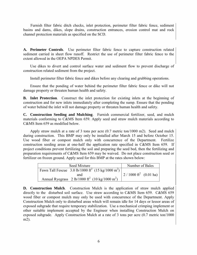
6
Furnish filter fabric ditch checks, inlet protection, perimeter filter fabric fence, sediment basins and dams, dikes, slope drains, construction entrances, erosion control mat and rock channel protection materials as specified on the SCD.
A. Perimeter Controls. Use perimeter filter fabric fence to capture construction related sediment carried in sheet flow runoff. Restrict the use of perimeter filter fabric fence to the extent allowed in the OEPA NPDES Permit.
Use dikes to divert and control surface water and sediment flow to prevent discharge of construction related sediment from the project.
Install perimeter filter fabric fence and dikes before any clearing and grubbing operations.
Ensure that the ponding of water behind the perimeter filter fabric fence or dike will not damage property or threaten human health and safety.
B. Inlet Protection. Construct the inlet protection for existing inlets at the beginning of construction and for new inlets immediately after completing the sump. Ensure that the ponding of water behind the inlet will not damage property or threaten human health and safety.
C. Construction Seeding and Mulching. Furnish commercial fertilizer, seed, and mulch materials conforming to C&MS Item 659. Apply seed and straw mulch materials according to C&MS Item 659 as modified below.
Apply straw mulch at a rate of 3 tons per acre (0.7 metric ton/1000 m2). Seed and mulch during construction. This BMP may only be installed after March 15 and before October 15. Use wood fiber or compost mulch only with concurrence of the Department. Fertilize construction seeding areas at one-half the application rate specified in C&MS Item 659. If project conditions prevent fertilizing the soil and preparing the seed bed, then the fertilizing and preparation requirements of C&MS Item 659 may be waived. Do not place construction seed or fertilizer on frozen ground. Apply seed for this BMP at the rates shown below:
Seed Mixture Number of Bales Fawn Tall Fescue 3.0 lb/1000 ft2 (15 kg/1000 m2)
and Annual Ryegrass 2 lb/1000 ft2 (10 kg/1000 m2)
2 / 1000 ft2 (0.01 ha)
D. Construction Mulch. Construction Mulch is the application of straw mulch applied directly to the disturbed soil surface. Use straw according to C&MS Item 659. C&MS 659 wood fiber or compost mulch may only be used with concurrence of the Department. Apply Construction Mulch only to disturbed areas which will remain idle for 14 days or lessor areas of exposed subgrade that require temporary stabilization. Use a mechanical crimping implement or other suitable implement accepted by the Engineer when installing Construction Mulch on exposed subgrade. Apply Construction Mulch at a rate of 3 tons per acre (0.7 metric ton/1000 m2).
7
E. Winter Seeding and Mulching. Apply seed and straw mulch materials according to C&MS Item 659 as modified above. Apply straw mulch at a rate of 3 tons per acre (0.7 metric ton/1000 m2). Winter Seed and Mulch is required for EDA operations occurring between October 15 and March 15 and can only be installed during that time. When straw mulch is used in this BMP, it is required to be crimped in place. Crimped mulch is required to be anchored into the soil surface with a mechanical crimping implement or other suitable implement accepted by the Engineer. Bonded Fiber Matrix may be used instead of straw mulch.. All mulch and BFM used in this BMP must be capable of providing sufficient durable protective cover that provides OEPA NPDES Permit compliant erosion control for a minimum of 6 months. Provide maintenance of the BMP throughout the 6 month period. The Department will not provide compensation for reapplication or repair of this BMP during the 6 month period. The use of other seed and/or mulch materials in this time period requires specific Department approval. The use of winter seeding and mulching is not an acceptable practice for protecting the subgrade surface.
F. Slope Protection. Place dikes, install slope drains, and construct ditches to divert water from bare non-vegetated areas and to protect cut and fill slopes. Protect the side slopes from erosion by placing dikes at the top of fill slopes prior to construction of the slope. Construct ditches and dikes prior to construction of cut slopes to divert runoff away from the slope. Ensure that all sediment-laden discharges from slope protection are directed into an appropriate sediment control BMP.
Furnish Construction Slope Protection at the required locations as the slopes are constructed. Furnish all permanent slope protection as shown in the construction plans when final grade is complete.
G. Ditch Checks and Ditch Protection. Place filter fabric ditch checks or rock checks across a ditch and perpendicular to the flow. Use rock checks to protect the ditch from erosion. Use filter fabric ditch checks to filter sediment from the flowing water only when appropriate and when sediment dams/basins are considered a safety hazard or infeasible as determined by the Engineer
Place ditch checks as soon as the ditch is cut. If working on a ditch, replace the ditch checks by the end of the workday.
Install filter fabric ditch checks for drainage areas less than or equal to 2 acres (0.8 ha) as shown in the SCD. Install rock checks for drainage areas between 2 to 5 acres (0.8 to 2.0 ha) as shown in the SCD.
Install ditch checks in conjunction with Sediment Basins and Dams when appropriate.
Furnish Construction Ditch Protection at the required locations as the ditches are cut. Furnish all permanent ditch protection as shown in the construction plans when final grade is complete.
H. Sediment Basins and Dams. Design and construct Sediment Basins and Dams in accordance with and as described in the OEPA NPDES Permit for “sediment settling ponds”. Design and construct Sediment Basins and Dams at concentrated and critical flow locations to settle out sediment before the water leaves the EDA area. Do not construct Sediment Basins and Dams in any jurisdictional waterways .

8
All sediment basins requiring a dewatering device (riser and outlet pipe) shall incorporate a surface water dewatering device as described in the OEPA NPDES Permit. The Department will provide compensation for appropriately sized outlet pipes and surface dewatering device as described in Appendix F.
Compensation will not be provided for dewatering devices not included in the SWPPP and appropriately sized by the PE/CPESC. Compensation will be provided once for each dewatering device purchased exclusively for the project.
Complete the construction of the Sediment Basins and Dams before starting EDA operations.
When needed or when directed by the Engineer, install construction fence around the Sediment Basins and Dams.
I. River, Stream, and Water Body Protection. Provide appropriate river, stream and water body protection to all surface waters on and, adjacent to the project. River, Stream, and Water Body Protection may include diverting project water flow using dikes and slope protection. The Contractor may use a combination of BMP. Show all surface waters located within & adjacent to Project and Contractor EDA on the SWPPP.
J. Stream Relocation, Temporary Channels and Ditches that carry Waters of the United
States. Perform this work in compliance with the OEPA NPDES Permit and any other applicable permits (i.e. 404/401 Permits). Stabilize Stream Relocation, Temporary Channels and Ditches with Construction Slope Protection or 70 percent grass growth before diverting flow into the new channel.
K. Concrete washout areas BMP. Compensation for this BMP is incidental to the concrete work.
L. Construction Entrances. Furnish Construction Entrance materials conforming to C&MS 712.09 Type B Filter Blankets for Rock Channel Protection and C&MS 703.01, Size Number 1 and 2, CCS aggregate. Furnish Construction Entrance protection at the locations shown on the SWPPP and as required below:
1. At locations where construction vehicles enter or leave EDA areas. 2. At all points of egress to public roads. 3. At all access locations where runoff from the construction access road is not
protected by sediment controls.
Provide the appropriate size culvert as needed to prevent water from flowing onto paved surfaces and from overtopping the construction entrance surface. Identify the culvert size on the SWPPP. Install a maximum of three Construction Entrances per mile along the length of the project. The length of the project is the plan length along the project’s longest axis. Additional construction entrances in excess of the maximum require acceptance from the Engineer.
Locate and identify all Construction Entrances on the SWPPP.

9
Provide a configuration consisting of 6 inches of aggregate over geotextile fabric. Provide geometry according to a Type 1 Driveway as shown in the SCD. Provide a minimum 10 foot width and length measuring a minimum of 150 feet and not exceeding 200 feet from edge of pavement.
Construction Entrance removal includes the appropriate disposal of geotextile fabric and pipe. Aggregate may be incorporated into embankment work when approved by the Department.
M. Project fueling and refueling BMP locations. Compensation for this BMP is incidental to the project.
The SWPPP shall include BMP to prevent and respond to spills or leaks as required by the OEPA NPDES Permit.
The Contractor will provide a separate Spill Prevention Control & Countermeasure Plan if required for the project as described in 40 CFR Part 112. The Contractor will not be compensated for the SPCC Plan.
N. All other BMP that are required and not specifically referenced in Appendix F will not be paid as a separate item, but will be included by the Contractor as part of the total project cost.
832.06 Causeways and Access Fills (Stream and River Crossings and Fills). Fording of jurisdictional waters, including all streams and rivers is not allowed. Evaluate the 404/401 permits to determine whether or not causeway and access fills are permitted in the contract. If a causeway and access fills have been permitted, construct fill(s) per the 404/401 permits, and the application submitted for those permits. Only the footprint area (acreage) of temporary fill, and volume of temporary fill as permitted and contained in the permit application will be allowed. The footprint area (acreage) of temporary fill, and volume of temporary fill may be furnished in the construction plans. The construction plans may furnish additional information or restrictions for causeways or access fills. If the Contractor proposes a causeway and access fill(s) which has not been permitted through the 404/401 permit process, the Contractor is required to coordinate the request for the causeway and access fill(s) with the project engineer and OES. The Department makes no guarantee to granting the request. The causeway and access fills request will be coordinated by OES with the USACE and OEPA where applicable.
Supply the project engineer/OES with the following information:
A. A plan and profile drawing showing the causeway and access fills with OHWM elevation.
B. Volume of temporary fill below the OHWM. C. The surface area of temporary fill below the OHWM. D. A restoration plan for the area affected by the causeway and access fills. E. Time frames for placement and removal of the causeway and access fills. F. Temporary Access Fill Checklist
The time frame allowed for the coordination of the causeway and access fill(s) will be 60 days, at a minimum, and the causeway and access fill(s) will not occur prior to the 404 Permit being authorized by the USACE and Ohio EPA, if an individual 401 is required. All coordination with the USACE and/or OEPA will be performed through OES.

10
832.07 Causeway and Access Fills Construction and Payment. Begin planning and installing causeways and access fills as early in construction as possible to avoid conflicts with 404/401 permits or other environmental commitments that have been included in the construction plans.
Access fills in streams or rivers may include, but are not limited to, cofferdams, access pads, temporary bridges, etc.
Make every attempt to minimize disturbance to water bodies during construction, maintenance and removal of the causeway and access fills. Construct the causeway and access fills as narrow as practical and perpendicular to the stream banks. Make the causeway and access fills in shallow areas rather than deep pools where possible. Minimize clearing, grubbing, and excavation of stream banks, bed, and approach sections. Construct the causeway and access fills as to not erode stream banks or allow sediment deposits in the channel.
Prior to the initiation of any in-stream work, establish a monument upstream of proposed temporary crossing or temporary construction access fill to visually monitor the water elevation in the waterway where the fill is permitted. Maintain the monument throughout the project. Provide a visual mark on the monument that identifies the elevation 1 foot above the Ordinary High Water Mark (OHWM). If the OHWM is not shown on the plans, the Department will establish the OHWM based on the definition of OHWM (832.02) or the peak discharge from the 2 year event, using the method described in the most current version of the Department’s Location and Design Manual Volume II.
Ensure that the monument can be read from the bank of the waterway. Have this elevation set and certified by an Ohio Registered Surveyor.
Temporary causeway and access fill placed by the contractor above the OHWM are not subject to the 404/401 permit constraints.
Should the water elevation of the waterway, exceed the elevation 1 foot above OHWM, the Department will compensate the Contractor for repair of any resulting damage to the permitted temporary access fill up to the elevation of 1 foot above the OHWM. The Department will not pay for repair and maintenance of temporary access structures that are related to the construction access fill.
If the pool elevation of the waterway exceeds the 1 foot above the OHWM elevation as read from the monument, the contractor is entitled to an excusable, non-compensable delay in accordance with Section 108.06 of the Construction & Materials Specifications.
All costs associated with furnishing and maintaining the above referenced monument is incidental to the work.
Construct the causeway and access fills to a water elevation at least 1 foot (0.3 m) above the OHWM. If the causeway fills more than one-third the width of the stream, then use culvert pipes to allow the movement of aquatic life. Maintain normal downstream flows. Ensure that any ponding of water behind the causeway and access fills will not damage property or threaten human health and safety.

11
The following minimum requirements apply to causeways where culverts are used.
A. Furnish culverts on the existing stream bottom. B. Avoid a drop in water elevation at the downstream end of the culvert. C. Furnish culverts with a diameter at least two times the depth of normal stream flow
measured at the causeway centerline or with a minimum diameter of 18 inches (0.5 m) whichever is greater.
D. Furnish a sufficient number of culverts normal to the flow to completely cross the channel from stream bank to stream bank with no more than 10 feet (3 m) between each culvert.
For all fill and surface material placed in the channel, around the culverts, or on the surface of
the causeway and access fills furnish clean, non-erodible, nontoxic dumped rock fill, Type B, C, or D, as specified in C&MS 703.19.B. Extend rock fill up the slope from original stream bank for 50 feet (10 m) to catch and remove erodible material from equipment.
When the work requiring the causeway and access fills all portions of the causeway (including all rock and culverts) and access fills will be removed in its entirety. The material will not be disposed in other waters of the US or isolated wetland. The stream bottom affected by the causeway and access fills will be restored to its pre-construction elevations. The causeway and access fills will not be paid as a separate item but will be included by the Contractor as part of the total project cost.
All environmental protection and control associated with the 404/401 permit activities are incidental to the work within the boundaries of the 404/401 permit or as otherwise identified in the 404/401 permit application.
832.08 Maintenance. Properly maintain all BMP throughout all phases and sequencing of construction activities. Dispose of silt removed from BMP according to C&MS 105.16. When the Contractor properly places the erosion control Items then the Department will pay for the cost to maintain or replace these items of work by the following:
If a recorded rain event is greater than 0.5 inches (13mm), the Department will pay to replace all BMP that have failed during the event at the unit price for those BMP including Sediment Removal as described in Appendix F.
Example: A 0.6 inch rain event damaged a 300 ft. segment of a 900 ft. run of filter fabric
fence. The damaged segment was repaired and the sediment was removed. How do we pay for
the 300 ft of repair and sediment removed?
Pay for 300 ft. of new Item Perimeter Filter Fabric Fence and Item Miscellaneous Sediment
Removal.
If a recorded rain event is less than or equal to 0.5 inches (13mm), the Department will pay to remove the sediment per the unit price for Sediment Removal as described in Appendix F. No compensation will be provided for BMP that fail during rain events of less than equal to 0.5 inches (13mm).

12
For all Perimeter Filter Fabric Fence, Filter Fabric Ditch Checks, Rock Checks, and Inlet Protection, Dikes, remove trapped sediment and any other debris which has accumulated when sediment reaches a height of one-half the BMP. Compensation will be paid at the unit price for Miscellaneous Sediment Removal as described in Appendix F.
When the sediment fills the sediment storage zone (as described in the OEPA NPDES Permit) of a Sediment Basin or Dam, remove deposited sediment per the unit price for Basin Sediment Removal as described in Appendix F. Remove Sediment Basins and Dams after the contributing drainage area has been stabilized.
When erodible materials accumulate at the surface of the construction entrance, furnish additional stone as needed to prevent tracking. Compensation for additional stone needed to maintain the Construction Entrance will be paid at the unit price for Construction Entrance. If tracking occurs, restore and clean the affected roadway surface at no additional cost to the Department.
Remove all BMP before the project is accepted. Dispose of the removed materials including sediment according to C&MS 105.16 and C&MS 105.17. Maintain the BMP until the up-slope permanent grass coverage is greater than 70% and the site reaches final stabilization in accordance with the OEPA NPDES Permit (See Appendix E, Part VII, J). At this stage, remove the BMP.
832.09 Storm Water Pollution Prevention Plan. If required, prepare the SWPPP as outlined in this specification. All activity identified by the SWPPP that is not specifically identified as a pay item elsewhere shall be included in the Lump Sum price bid for the SWPPP. At a minimum, the design and information requirements that must be included in the SWPPP are as follows:
A. Provide a site specific SWPPP designed and sealed by a Professional Engineer who holds a current CPESC certification.
B. Location of the required BMP for both on and off project EDA areas. C. Furnish quantity totals for all BMP required for the execution of the proposed plan. D. Location of a minimum of 100 feet (30 m) from the water's edge of any stream,
ephemeral stream, wetland, or body of water: 1. Concrete or asphalt plant areas 2. Material and equipment staging or storage areas 3. Dewatering Areas 4. Concrete truck wash out BMP areas 5. Construction access BMP locations 6. Vehicle fueling and refueling locations
E. Furnish an implementation schedule for each construction sequence. G. Furnish the total EDA areas in acres and identify each drainage area (watershed)
impacted by the proposed construction.

13
H. Locate all slopes that will be inactive for 14 calendar days or longer. I. Furnish the names of the individuals on site who will serve as the PE/CPESC
SWPPP designer and CECI. J. Describe the type of construction activities that will be taking place. K. Furnish an estimated quantity for Basin Sediment Removal and Miscellaneous
Sediment Removal for removing sediment from Sediment Basins and Dams, inlet protection, ditch checks, rock checks, perimeter filter fabric fence, and all other types of filter fabrics, straw or hay bales, or any other BMP.
L. Furnish signatures of all contractors and subcontractors involved in BMP practices
(see Appendix B).
If there are plan sheets which meet any of the requirements in Appendix E, use that information. Design files may be furnished to the awarded Contractor in electronic form upon request.
832.10 SWPPP Acceptance. Furnish the initial SWPPP to the Department for acceptance. The Department will allow work to begin upon receiving an acceptable SWPPP. See Appendix C for a sample acceptance form. The Department may assess critically the following:
A. The type and location of BMP with totals. B. The SWPPP is for this project. C. There is no language in the SWPPP about any BMP being directed for use by the
Engineer. D. The total estimated BMP quantities agree with the (per Each) “Erosion Control“
amount identified in the proposal. E. The SWPPP accounts for the various phases of construction and the associated
degree of earthwork disturbance over the life of the project. F. The SWPPP delineates overall watershed areas and individual BMP watersheds.
Enough detail is shown in the SWPPP to verify that the BMP are appropriate for the application. If topographic mapping contained in the plans is not sufficient to identify and delineate the watersheds associated with the work, provide the appropriate mapping. .
G. All perimeter filter fabric fence is identified in the SWPPP and supporting runoff
calculations are attached.
14
H. The SWPPP identifies the locations and specific geometry of the required Sediment Basins and Dams and related control structures. Provide the following information for each Sediment Basin and Sediment Dam: 1. Calculations demonstrating compliance with the 48 hour draw down time (if
required by the OEPA NPDES Permit), 2. Size of the contributing drainage area, 3. Volume of the Sediment Storage Zone 4. Volume of the Dewatering Zone (if required by the OEPA NPDES Permit), 5. Basin excavation quantity or dam embankment quantity 6. Quantity of rock channel protection 7. Riser Pipe and outlet structure details (if required by the OEPA NPDES
Permit).
Revise the accepted SWPPP as needed to maintain compliance with OEPA NPDES Permit. Revisions and amendments (See Appendix E, Part III, D) to the accepted SWPPP will be at no additional cost to the Department.
832.11 Inspections and SWPPP Updates. Perform the required OEPA NPDES Permit inspections and prepare inspection reports (see Appendix E).
The inspections must be performed by one of the following parties:
A. The PE/CPESC who signed and sealed the SWPPP. B. The CPESC inspector who is under the supervision of the Engineer who signed and
sealed the SWPPP. C. The CESSWI inspector who is under the supervision of the Engineer who signed
and sealed the SWPPP.
Prepare the inspection reports for projects that have a SWPPP. Submit inspection reports to the Engineer every 7 days and within 24 hours of a 0.5 inch (13 mm) or greater rainfall event throughout the life of the contract. The inspection frequency may be reduced per the Ohio NPDES Permit Part III.G.2.i.
The reporting CECI will update, amend and revise the SWPPP as the contractor’s operations and site conditions warrant. Identify all revisions and updates to the SWPPP and indicate what measures will be taken to maintain OEPA NPDES Permit compliance in the report. Include the following in the inspection report; the OEPA NPDES Permit inspection checklist (see appendix E, Part III.G.2.i), a map identifying all BMP needed, installed, maintained or removed since the last inspection report, certification that all construction activities are compliant with the SWPPP and the signature of the CECI responsible for the inspection. Provide a record of all written questions and comments from the Engineer related to the SWPPP. Include all responses to the Engineer’s questions and comments in the inspection report. The signature of the PE/CPESC who sealed the SWPPP is required as part of the inspection report, on a monthly basis or when modifications to the SWPPP design are made. Include the certification requirements according to OEPA NPDES Permit (Part V. H.) with all reporting sign offs.
15
A BMP Inventory form is furnished in Appendix A to assist in documenting and recording the BMP quantities for payment. The BMP inventory form in Appendix A is not a substitute for the inspection report described above.
The CECI is required to notify the Department within 24 hours of any compliance deficiencies or verified complaints related to the SWPPP or OEPA NPDES Permit. Within 48 hours of the Department’s or CECI’s notice of deficiency, the contractor is required to construct, install, repair or correct the BMP measures needed to resume OEPA NPDES Permit compliance.
832.12 Compensation. The Department will furnish Item 832 Each, Erosion Control with an amount in the proposal to pay for BMP work. The fixed amount shown in the proposal is included (as any other bid items) in the Total Bid Amount. This fixed amount is the Department’s estimate of the total cost of BMP work required to be performed for the project. If the BMP work exceeds this amount, the BMP work will still be paid at the pre-determined prices. All BMP work will be paid at the proposal pre-determined unit price times the correctly installed BMP number of units. The payment due will be deducted from Item 832 Each, Erosion Control. C&MS Table 104.02-2 does not apply to reductions in this contract item.
The Lump Sum amount bid for the SWPPP includes all work associated with development, design, NPDES required inspection, modification, revision, updates, amendments and reporting related to the SWPPP. Changes made to the SWPPP, but not caused by the Department, are the financial responsibility of the Contractor. Additional compensation will only be permitted for Department accepted amendments to the SWPPP resulting from revisions to the contract documents as per sections 104.02.B, 104.02.D and 104.02.F. Provide the additional costs for the amended SWPPP to the Department prior to beginning the associated revised work. All costs associated with providing and maintaining the required CPESC and CESSWI personnel, conducting the NPDES required inspections, and support engineering services are included in the contract Lump Sum bid for SWPPP. The Department will only pay for one accepted SWPPP regardless of the number of Construction phases, revisions, amendments or project redesigns.
832.13 Method of Measurement
The Department will measure the SWPPP as a Lump Sum.
The Department will measure Construction Seeding and Mulching by the number of square yards (square meters).
The Department will measure Slope Drains by the number of feet (meters) of conduit.
The Department will measure Sediment Basins by the number of cubic yards (cubic meters) of excavation.
The Department will measure Sediment Basin surface dewatering device by each.
The Department will measure Sediment Dams by the number of cubic yards (cubic meters) of embankment.
Any pipe required for the outlet structure of a sediment basin or dam is incidental to the unit price paid for Sediment Basins and Dams.

16
The Department will measure Perimeter Filter Fabric Fence, and Construction Fence by the number of feet (meters).
The Department will measure Filter Fabric Ditch Check by the number of feet (meters).
The Department will measure Inlet Protection by the number of feet (meters).
The Department will measure Dikes by the number of cubic yards (cubic meters) of embankment.
The Department will measure Construction Ditch Protection and Construction Slope Protection by the number of square yards (square meters).
The Department will measure Rock Channel Protection, Type C or D (with or without filter) by the number of cubic yards (cubic meters).
The Department will measure Sediment Removal by the number of cubic yards (cubic meters).
The Department will measure Construction Mulching by the number of square yards (square meters) regardless if the application is crimped or not.
The Department will measure Winter Seeding and Mulching by the number of square yards (square meters).
The Department will measure Construction Entrance protection by the number of cubic yards (cubic meters)
832.14 Basis of Payment
The Department will pay the contract Lump Sum price bid for the SWPPP.
The Department will make partial payments for the Storm Water Pollution Prevention Plan according to C&MS Section 109.09 and as modified by the following schedule:
The Department will release 60 percent of the lump sum amount bid for Storm Water Pollution Prevention Plan to the Contractor with the first regular estimate payable after the Engineer has accepted the Storm Water Pollution Prevention Plan submission.
The Department will release 30 percent of the lump sum amount bid for Storm Water Pollution Prevention Plan to the Contractor with the first regular estimate payable after 50 percent of the project is complete.
The Department will release the remaining 10 percent of the lump sum amount bid for Storm Water Pollution Prevention Plan to the Contractor with the first regular estimate payable after 90 percent of the project is complete.
The Department will pay for appropriate, properly installed and accepted BMP per Item 832 Each, Erosion Control. BMP compensation will be based on the unit prices shown in Appendix F.

17
The Department will not pay for BMP Items which are required as a result of the Contractor’s negligence, carelessness, or failure to install permanent controls.
The Department will not pay for BMP that does not provide effective sediment and erosion control for the EDA.
The Department will not pay for any causeway and access fills.
The Department will not pay to replace BMP that have failed as a result of improper maintenance or installation.
The Department will not pay for concrete washout area BMP. Concrete washout area BMP are considered incidental to the concrete work.
The Department will not pay for BMP which are required as a part of the work and are not specifically identified as a separate item. Compensation for BMP that are required for NPDES Permit compliance and are not included in Appendix F of this specification are considered incidental to the work.
Item Unit Description
832 Lump Sum Storm Water Pollution Prevention Plan
832 Each Erosion Control

Appendix A Weekly and Rain Event Erosion Control
BMP Inventory
Contractor Project No. Co-Rt-Sec Date R=Replacement W=Working M=Maintenance I=Install D=Delete Rain Amt
Station to Station Side
Off
set
Bal
loon
Ref
.
Perim
eter
Con
trol
Inle
t Pro
tect
ion
Con
str.
Spee
d
Dik
es F
ill S
lope
s
Dik
es C
ut S
lope
s
Slop
e D
rain
s
FF D
itch
Che
cks
Roc
k D
itch
Che
cks
Sedi
men
t Bas
ins
Stre
am R
eloc
ate
Stre
am C
ross
ing
Dat
e w
ork
was
C
ompl
ete
Notes:
This form is furnished to assist in documenting and recording the BMP quantities for payment. This form is not a substitute for the inspection report described in 832.11.

Appendix B SIGNATURE LIST
NPDES and Surface Water Pollution Prevention Plan
Contractors and Sub-contactors responsible for any Earth Disturbing Activity Duty to inform contractors and subcontractors
(Ohio EPA Permit No.:OHC000004 Part III. E)
Signature Printed Name Title Company Date

Appendix C Sample SWPPP Acceptance Form
The Department has received the SWPPP for Project:
Co-Rt-Sec:
The submittal is dated: The Department Accepts the Submittal. Project Engineer, Project Supervisor Date

Appendix D
Application form available at http://epa.ohio.gov/Portals/35/storm/StormWater_Co-Permittee_NOI.pdf

Appendix E

Appendix E

Appendix E

Appendix E

Appendix E

Appendix E

Appendix E

Appendix E

Appendix E

Appendix E

Appendix E
Appendix E

Appendix E

Appendix E
Appendix E

Appendix E

Appendix E
Appendix E

Appendix E
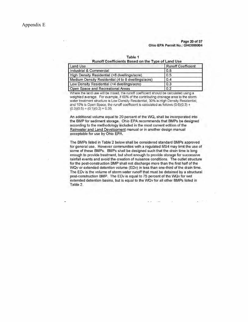
Appendix E

Appendix E

Appendix E

Appendix E

Appendix E

Appendix E
Appendix E
Appendix E

Appendix E

Appendix E

Appendix E

Appendix E

Appendix E

Appendix E

Appendix E
Appendix E

Appendix E

Appendix E

Appendix F
Temporary Sediment and Erosion Control Best Management Practices (BMP)
Unit Price Schedule, October 2013
EROSION CONTROL PRICES
Project Identified EDA (acres) Fixed
Price Comment <5 5
to 10 10 to
15 15 to
20 >20
Ite
m Unit Description Price ($)
832 Sq. Yd. Construction Seeding and Mulching 1.00 0.92 0.83 0.75 0.74
Based on NOI acres
832 Feet Slope Drains 12.00 832 Cu.
Yd. Sediment Basins and Dams 13.50 [3]
832 Feet Perimeter Filter Fabric Fence 4.05 3.10 2.85 2.55 2.30 Based on NOI acres
832 Feet Filter Fabric Ditch Check 11.00 832 Feet Inlet Protection 11.25 832 Cu.
Yd. Dikes 3.00
832 Sq. Yd. Construction Ditch Protection 2.50
832 Cu. Yd.
Rock Channel Protection, Type C or D with Filter 55.00 [1]
832 Cu. Yd.
Rock Channel Protection, Type C or D without Filter 50.00 [1]
832 Cu. Yd. Basin Sediment Removal 10.00
832 Cu. Yd. Miscellaneous Sediment Removal 15.50
832 Feet Construction Fence 5.75 832 Sq.
Yd. Construction Mulching 0.79 0.71 0.58 0.56 0.54 Based on NOI acres
832 Sq. Yd. Winter Seeding and Mulching 1.08 1.00 0.92 0.85 0.81
Based on NOI acres
832 Cu. Yd. Construction Entrance 75.25
[1] Add the following amount per cubic yard for the cost of Type C or D Rock materials. [3] Add the amount for the appropriately sized surface dewatering device for sediment basin outlet.
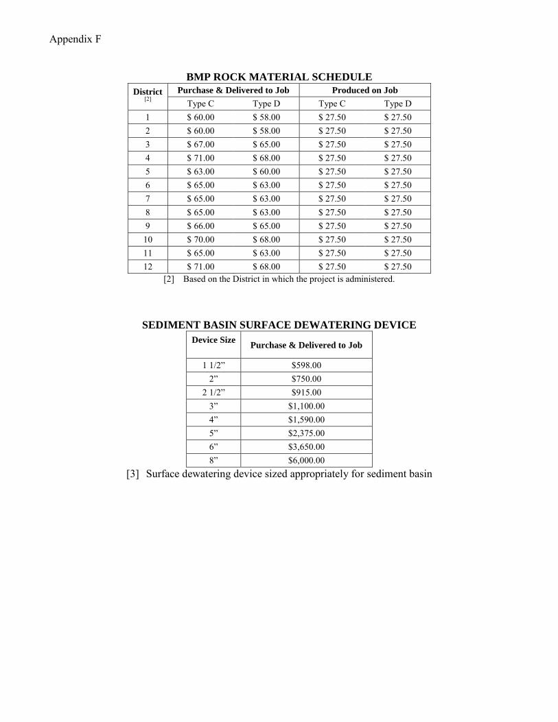
Appendix F
BMP ROCK MATERIAL SCHEDULE
District [2]
Purchase & Delivered to Job Produced on Job
Type C Type D Type C Type D 1 $ 60.00 $ 58.00 $ 27.50 $ 27.50 2 $ 60.00 $ 58.00 $ 27.50 $ 27.50 3 $ 67.00 $ 65.00 $ 27.50 $ 27.50 4 $ 71.00 $ 68.00 $ 27.50 $ 27.50 5 $ 63.00 $ 60.00 $ 27.50 $ 27.50 6 $ 65.00 $ 63.00 $ 27.50 $ 27.50 7 $ 65.00 $ 63.00 $ 27.50 $ 27.50 8 $ 65.00 $ 63.00 $ 27.50 $ 27.50 9 $ 66.00 $ 65.00 $ 27.50 $ 27.50 10 $ 70.00 $ 68.00 $ 27.50 $ 27.50 11 $ 65.00 $ 63.00 $ 27.50 $ 27.50 12 $ 71.00 $ 68.00 $ 27.50 $ 27.50
[2] Based on the District in which the project is administered.
SEDIMENT BASIN SURFACE DEWATERING DEVICE
Device Size Purchase & Delivered to Job
1 1/2” $598.00 2” $750.00
2 1/2” $915.00 3” $1,100.00 4” $1,590.00 5” $2,375.00 6” $3,650.00 8” $6,000.00
[3] Surface dewatering device sized appropriately for sediment basin

Designer Note:
Provide this Supplemental Specification on all plans. Under the Erosion Control heading, provide the following Reference Items:
Item 832 Each Erosion Control - Provide an encumbered dollar value to be placed in the proposal for Item: 832 Each Erosion Control. This amount is for both the “quantity” and “total” fields. This amount should only be provided in the C2 Estimate, the Special Considerations Field on the Plan Package Submittal Form, and in the Plans. Example: $10,000 set up for Item 832 Each Erosion Control then 10,000 placed in the “quantity” and “total” fields. Item 832 Lump Sum Storm Water Pollution Prevention Plan - Provide a Lump Sum item for Storm Water Pollution Prevention Plan for projects that have 1 or more acres of estimated Total EDA.
Delete all C&MS 207 Items and all SS 877 Items. For additional guidance on the NPDES process for ODOT projects, see the NPDES Construction Permit Implementation Plan flowchart on the Office of Structural Engineering website. For help estimating the encumbered dollar value for the Item 832 - Erosion Control, see the BMP Estimator on the DRRC website (http://www.dot.state.oh.us/drrc/). Projects that require OEPA Watershed Specific Storm Water Permits (such as the Big Darby or Olentangy) will need to modify this specification by Special Provision Note.
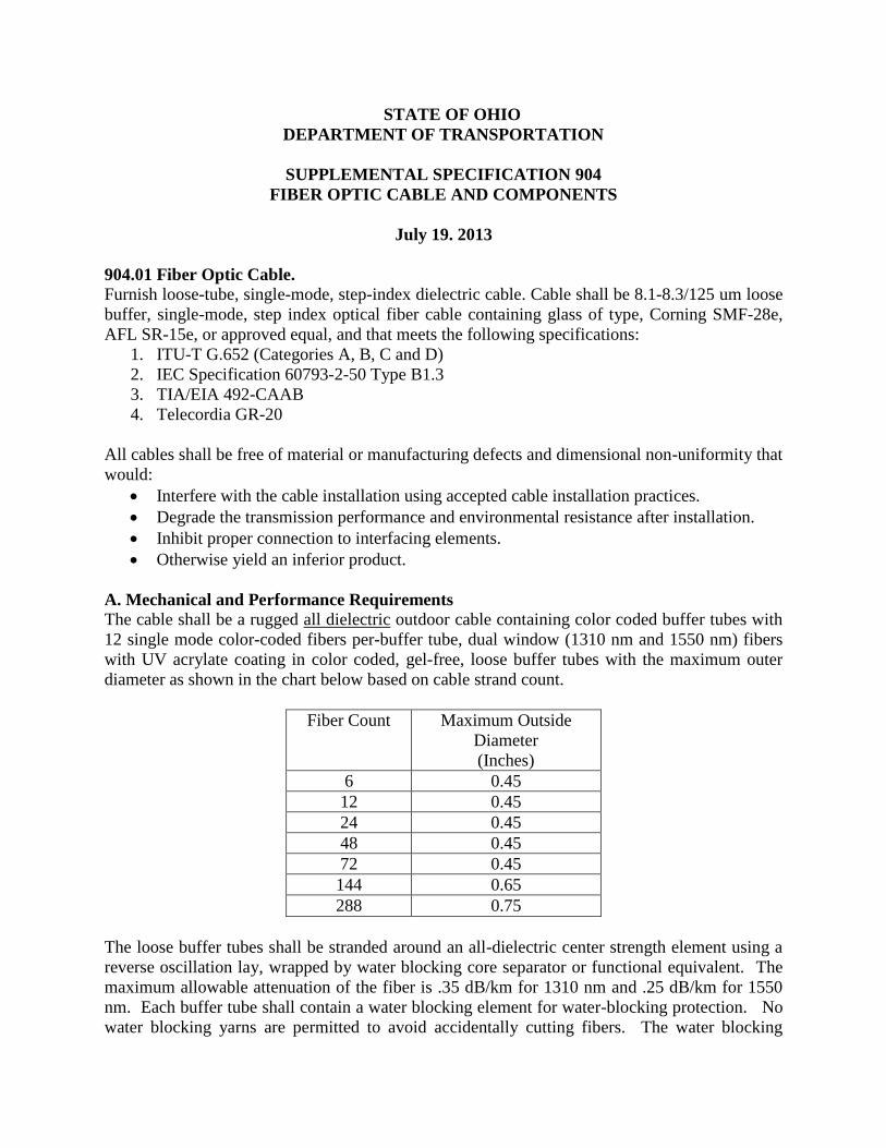
STATE OF OHIO
DEPARTMENT OF TRANSPORTATION
SUPPLEMENTAL SPECIFICATION 904
FIBER OPTIC CABLE AND COMPONENTS
July 19. 2013
904.01 Fiber Optic Cable.
Furnish loose-tube, single-mode, step-index dielectric cable. Cable shall be 8.1-8.3/125 um loose
buffer, single-mode, step index optical fiber cable containing glass of type, Corning SMF-28e,
AFL SR-15e, or approved equal, and that meets the following specifications:
1. ITU-T G.652 (Categories A, B, C and D)
2. IEC Specification 60793-2-50 Type B1.3
3. TIA/EIA 492-CAAB
4. Telecordia GR-20
All cables shall be free of material or manufacturing defects and dimensional non-uniformity that
would:
Interfere with the cable installation using accepted cable installation practices.
Degrade the transmission performance and environmental resistance after installation.
Inhibit proper connection to interfacing elements.
Otherwise yield an inferior product.
A. Mechanical and Performance Requirements
The cable shall be a rugged all dielectric outdoor cable containing color coded buffer tubes with
12 single mode color-coded fibers per-buffer tube, dual window (1310 nm and 1550 nm) fibers
with UV acrylate coating in color coded, gel-free, loose buffer tubes with the maximum outer
diameter as shown in the chart below based on cable strand count.
Fiber Count Maximum Outside
Diameter
(Inches)
6 0.45
12 0.45
24 0.45
48 0.45
72 0.45
144 0.65
288 0.75
The loose buffer tubes shall be stranded around an all-dielectric center strength element using a
reverse oscillation lay, wrapped by water blocking core separator or functional equivalent. The
maximum allowable attenuation of the fiber is .35 dB/km for 1310 nm and .25 dB/km for 1550
nm. Each buffer tube shall contain a water blocking element for water-blocking protection. No
water blocking yarns are permitted to avoid accidentally cutting fibers. The water blocking

elements shall be non-nutritive to fungus, electrically non-conductive, and homogeneous; it shall
also be free from dirt or foreign matter. This water blocking element will preclude the need for
other water-blocking material; the buffer-tube shall be gel-free. Water swellable tape shall be
applied longitudinally around the outside of the stranded tubes/fillers. The water swellable tape
shall be non-nutritive to fungus, electrically non-conductive, and homogenous. It shall also be
free from dirt and foreign matter. The cable manufacturer shall be TL 9000 registered. The
optical fiber cable shall withstand water penetration when tested with a one-meter static head or
equivalent continuous pressure applied at one end of a one-meter length of filled cable for one
hour. No water shall leak through the open cable end. Testing shall be done in accordance with
EIA-455-82B.
B. Outer Jacket
Cables shall be all dielectric cable (with no armoring) and shall be jacketed (sheathed) with
medium density polyethylene as defined by ASTM D1248, Type II, Class C, Category 4 and
Grades J4, E7 and E8. If the project plans require armored cable, the cable shall have two
jackets, one molded to the outside of the armor and one that floats freely within the armor and
contains the buffer tubes and other fiber optic cable construction components as required.
Jacketing material shall be applied directly over the tensile strength members to provide
mechanical protection, and to serve as the primary moisture barrier. This cable sheath shall be
designed to meet or exceed the tensile criteria defined in EIA-455-89a. Each jacketed fiber shall
have a tensile strength in excess of 50 lbs. The polyethylene shall contain carbon black to
provide ultra-violet light protection, and it shall not promote the growth of fungus. The jacket or
sheath shall be free of any holes, splits, or blisters. The cable jacket shall contain no metal
elements and shall be of a consistent thickness. The cable shall contain at least one ripcord under
the sheath for easy sheath removal.
C. Crush Resistance
The non-armored optical fiber cables shall withstand a compressive load of 220 N/cm applied
uniformly over the length of the cable. The average increase in attenuation for the fibers shall be
0.10 dB at 1550 nm for a cable subjected to this load. The cable shall not exhibit any
measurable increase in attenuation after load removal. Testing shall be in accordance with EIA-
455-41, "compressive loading resistance of fiber optic cable," except that the load shall be
applied at the rate of 3 mm to 20 mm per minute and maintained for 10 minutes. Manufacturer’s
certification shall be submitted for approval.
D. Cyclic Flexing
The cable shall be capable of withstanding 25 cycles of mechanical flexing at a rate of 30 1
cycles/minute. The average increase in attenuation for the fibers shall be 0.10dB at 1550 nm at
the completion of the test. Outer cable jacket cracking or splitting observed under 10x
magnification shall constitute failure. The test shall be conducted in accordance with EIA-455-
104, except that the sheave diameter shall be a maximum diameter of 20 times the cable outer
diameter (O.D.). The cable shall be tested in accordance with test conditions I and III of EIA-
455-104. The cable shall withstand 25 impact cycles. The average increase in attenuation for the
fibers shall be 0.20dB at 1550 nm (single-mode). The cable jacket shall not exhibit evidence

of cracking or splitting. The test shall be conducted in accordance with EIA/TIA-455-25A.
Manufacturer’s certification shall be submitted for approval.
E. Tensile Strength
Tensile strength shall be provided by high tensile strength aramid yarns and fiberglass, which
shall be helically stranded evenly around the cable core. The cable shall withstand a tensile load
of 2700 Newtons (N) [600 lbs.] without exhibiting an average increase in attenuation of greater
than 0.10dB. The test shall be conducted in accordance with EIA-455-33A, using a maximum
mandrel and sheave diameter of 560 mm. The load shall be applied for one hour in test
condition II of EIA-455-33A. The optical fiber cable shall withstand a maximum pulling tension
of 2700N (600 lbs.) during installation (short term) with no damage and 845N (190 lbs.) installed
(long term). Manufacturer’s certification shall be submitted for approval.
F. Temperature
The shipping, storage, installation, and operating temperature range of the cable shall meet or
exceed -20 °F to +155 °F (-29 °C to +60°C).
G. Loose Buffer
Single-mode fibers shall be contained in a loose buffer tube. The configuration shall be
dimensionally sized to minimize local stresses and microbend losses. Buffer tubes shall be
2.5mm in outer diameter. The optical fiber cable shall be an approved product of the U.S.
Department Of Agriculture, Rural Electrification Administration in accordance with the require-
ments of REA-PE-90, or as otherwise indicated, and shall conform to EIA/TIA-598. Each
optical fiber shall consist of a doped silica core surrounded by a concentric silica cladding.
Buffer tubes shall be polypropylene. Fillers shall be included in the cable core to lend symmetry
to the cable cross section where needed. The central anti-buckling member shall consist of a
glass reinforced plastic rod; the purpose of the central member is to prevent buckling of the
cable.
H. Colors
All optical fibers shall be identifiable by standard color codes as defined in EIA/TIA-598. Each
fiber shall be distinguishable, as determined by the maintaining agency, from others by means of
color coding and shall conform to the following EIA/TIA sequence of colors:
1. Blue 7. Red
2. Orange 8. Black
3. Green 9. Yellow
4. Brown 10. Violet
5. Slate 11. Rose
6. White 12. Aqua
The colors shall be in accordance with the Munsell color shades. The fiber coloring shall be an
ultraviolet (UV) curable ink which is applied to the outside of the optical fiber protective coating
layer and shall not be an integral component of the coating layer itself in order to produce more
distinguishable colored fiber.
Buffer tubes containing fibers shall also be color-coded with distinct and recognizable colors
according to the following sequence of colors:

1. Blue 13. Blue with black tracer
2. Orange 14. Orange with black tracer
3. Green 15. Green with black tracer
4. Brown 16. Brown with black tracer
5. Slate 17. Slate with black tracer
6. White 18. White with black tracer
7. Red 19. Red with black tracer
8. Black 20. Black with white tracer or black with yellow tracer
9. Yellow 21. Yellow with black tracer
10. Violet 22. Violet with black tracer
11. Rose 23. Rose with black tracer
12. Aqua 24. Aqua with black tracer
The color formulation shall be compatible with the fiber coating and be heat stable. Color
formulation shall not fade or smear or be susceptible to migration and it shall not affect the
transmission characteristics of the optical fibers and shall not cause fibers to stick together.
I. Cable Marking
The fiber optic cable outer jacket shall be capable of being marked by the vendor, on a project-
by-project basis, with manufacturer’s name, the year of manufacture, the words “optical fiber
cable”, fiber count, type of fiber, the name of the cable owner (e.g., “ODOT I.T.S.”), Project ID
number (“PID # xxxxx”) and sequential linear foot markings. The markings shall be repeated
every 3 feet. The actual length of the cable shall be within -0/+1% of the length marking. The
marking shall be in a contrasting color to the cable jacket. The marking shall be 2.5 mm in
height and must be permanent weatherproof and shall not wear off during the installation in the
underground conduit system.
J. Quality Assurance Provision
The fiber optic cable shall meet or exceed the requirements of this specification when measured
in accordance with the methods of the individual requirements or the following methods as
defined in EIA-455-A:
1. Fiber dimensions
2. Attenuation
3. Numerical aperture
4. Fiber proof test
5. Crush resistance
6. Cable bending
7. Tensile load
8. Impact resistance
9. Attenuation vs. Temperature
904.05 Fan-Out Kit
Furnish a 900um fan-out kit assembly of size twelve fiber capacity. Minimum length shall be 24
inches. It shall be outdoor-rated for operation with a minimum operating temperature range of -
40 °F to +149 °F (-30 °C to +65°C). Each assembly shall contain a Fan-Out Top, Fan-Out
Bottom, Fan-Out Tubing, epoxy, syringe, and insert.

904.06 Drop Cable
All drop cable shall meet the requirements of 904.01, except for 904.01.I, Cable Marking. All
Drop Cable shall be marked by the vendor with the manufacturer’s name, year of manufacture,
the words “Optical Fiber Cable” or similar, fiber count, type of fiber, and sequential linear foot
marking. The markings shall be repeated every 3 feet. The actual length of the cable shall be
within +/-1% of the length marking. The marking shall be in contrasting color to the cable
jacket, minimum 2.5mm in height, permanent and weatherproof, and shall not wear off during
installation in the underground conduit system.
904.07 Fiber Optic Patch Cord
The optical patch cords furnished shall consist of a single fiber jacketed cable equipped with
optical connectors at each end. Each patch cable shall have a unique identification label on each
end. Labels shall be marked in indelible ink and shall not crimp, kink or otherwise harm the
patch cable. Patch cords for connection between two Fiber Distribution Panels (FDPs) shall be
equipped with approved connectors on each end. The sheath shall be flame retardant and coded
NFR in accordance with the national electric code. The patch cord jacket shall be resistant to
ultraviolet radiation. Optical fiber connectors shall satisfy the interface parameters of the
equipment components as defined by the transceiver equipment specifications. All connectors
shall be of Type UPC or APC. No SPC-type connectors shall be permitted.
904.08 Fiber Termination Panel
A. NEMA Cabinet Type
Fiber termination panels shall house and protect the connectors on each pigtail. The optical
connectors on each pigtail shall be inserted securely in a connector panel that is manufactured to
be mated with the LC (UPC) connector type. The connector panel shall be made by the housing
manufacturer and be designed for the specified housing. Maximum optical loss across the
connection shall be 0.25dB. The fiber optic cable shall be of a sufficient length that will allow
the cable to be pulled from the cabinet through conduit to adjacent overhead or underground
splice enclosures and fusion spliced to the trunk fiber optic cables as depicted in the
communications splicing diagrams, leaving 75 feet of slack at the splice enclosure and 15 feet of
slack in the cabinet. The termination panel shall use LC connectors for the equipment side and
specified connectors shall be core-aligned fusion spliced or factory pre-connectorized to the fiber
optic drop cable that leads to the splice enclosure.
The fiber termination panel shall be compact, rugged and shelf mountable to ensure secure
mounting within existing NEMA controller cabinets. 24-fiber termination panels shall not
exceed 10 inches Length x 4.5 inches Width x 2.5 inches Depth.
48-fiber termination panels may consist of two side-by-side 24-fiber termination panels. Panel
shall be manufactured by Corning, Gatorpatch, AFL, or approved equal.
B. Caltrans (332,334,336) Cabinet or AASHTO/ITE/NEMA ITS Cabinet Type
The fiber termination panel enclosure shall consist of a self-contained enclosure including LC
style fiber optic connectors. Outdoor rated fiber optic cable shall be pre-terminated to the patch

panel. Fiber optic cable shall be of a sufficient length that will allow the cable to be pulled from
the cabinet through conduit to adjacent overhead or underground splice enclosures and fusion
spliced to the trunk fiber optic cables as depicted in the communications splicing diagrams,
leaving 75 feet of slack at the splice enclosure and 15 feet of slack in the cabinet..
All connector terminations shall be ceramic UPC connectors. Dimensions of patch panels shall
mount inside a standard EIA 19-inch rack.
Patch Panel Enclosures shall be equipped with a locking mechanism for front and back of patch
panel assembly to prevent unauthorized access.
Patch Panels shall utilize modules capable of housing 12-24 fiber optic LC-type connectors. The
modules shall interface with the cabinet equipment via LC connectors and the fiber optic trunk
cable via MTP connectors. The fiber optic cable shall be secured in a manner that no strain is
presented to the MTP connector.
904.09 Fiber Optic Connectors
All optical fiber termination components shall meet or exceed the applicable provisions of
EIA/TIA-455-A. All optical fiber connectors shall be of industry standard and of type for single-
mode optical fiber and shall meet or exceed the applicable provisions of EIA/TIA-455-2b,
EIA/TIA-455-5a, and EIA-455-34. All connectors shall be compliant with industry standard
ANSI/TIA/EIA-568B.3. The connector shall comply with TIA/EIA fiber optic connector
intermateability standard (FOCIS) document, TIA/EIA-604-3. Single-mode pigtails shall be
provided with factory pre-connectorized single-mode connectors. Connectors shall have a
maximum loss of 0.5 dB through each mated pair of single-mode fibers. Each connector shall be
capable of 100 repeated matings with maximum increase in splice loss limited to 0.2 dB per
connector. Single mode fiber optic pigtails shall be provided. Optical fiber cable used for
pigtails shall be of the tight buffered type protected by aramid fibers. The pigtail jacket shall be
resistant to ultraviolet radiation. Connector reflectance shall be measured at the factory to be = -
40 dB for super physical contact (SPC), -55 dB for ultra physical contact (UPC), and -60 dB for
angle polished contact (APC). Strain-relief boot color shall be white for SPC, blue for UPC, and
green for APC. Manufacturer shall be ISO 9001 and TL 9000 registered. All connectors shall
be LC-type UPC. No SPC type connectors shall be permitted.
904.10 Splice Enclosure
The splice enclosure shall be weatherproof, corrosion resistant, rodent proof, re-enterable, and
crush resistant. The splice enclosure shall be of clam-shell design with upper and lower pieces
that are tightened down and sealed using screws / bolts. The splice enclosure shall easily fit into
a 32 inch pull box along with loops of slack cable in box (approximately 100 ft.). The splice
enclosure shall be a complete kit including all components and hardware for installation. The
splice enclosure shall be suitable for application in the temperature range of -40 °C to +70 °C.
The splice enclosure shall provide space, allowing entry of fiber optic cable without exceeding
the minimum bend radius of the cable. The enclosure shall have provisions for cable and pigtail
strain-relief, and shall be equipped with strain-relief hardware. The splice enclosure shall be
designed to permit selective fiber splicing (looping a backbone cable in and out while only
cutting into the desired fibers). The size of the enclosure shall allow all the fibers of the largest

optical fiber trunk cable to be fusion spliced to a second cable of the same size, plus additional
pigtails. The splice enclosure shall allow splicing of all fibers up to the maximum number.
904.11 Fiber Optic Media Converter
Operating temperature range shall be -20 °F to +155 °F (-29 °C to +68 °C). Electrical power for
freestanding units shall be provided by NEMA 5-15 compatible plug and/or Class 2 switching
power supply with a minimum cord length of 6 feet. Established and documented MTBF shall
be 100,000 hours, minimum.
A. Fiber Optic to Ethernet Media Converter
Converter shall provide RJ-45 interface compatible with 100BaseT-TX: Cat. 5, EIA/TIA-568
100-Ohm UTP cable.
B. Fiber Optic to RS-232 Media Converter
Converter shall provide a RS232 Asynchronous communications channel using a 9-pin D-sub or
RJ-45 connector using industry-standard pin configuration or a plug-in module connection to a
controller unit. The FO Module shall be one of the following, per project operational
requirements:
1. A free-standing, shelf-mounted enclosed unit.
2. A plug-in module compatible with an ODOT-approved Caltrans or NEMA controller
unit, and approved in writing by the manufacturer of the controller.
904.12 Fiber Optic Fusion Splicer
The Fiber Optic Fusion Splicer shall be one of the following types:
1. AFL FSM-70S
2. CORNING M90e-XSM-T-P
3. SUMITOMO TYPE-Q101-CA
4. Or Approved Equal, that meets the following minimum specifications as determined by
the ODOT Department of Traffic Engineering:
o Splicing Method – Core Alignment
o Applicable Fibers – SM, MM, DS, NZ-DS
o Cladding Diameter – 80-125 um
o Splice loss estimation using Core Alignment
o Camera Axis – X and Y
o Typical Splicing time of Single-Mode Fiber less than or equal to 13 seconds
o Operating Temperature – (-10 to +50 C)
o Color LCD Monitor
o High wind velocity protection
o Average Splice Loss (dB) – 0.02 SM, 0.01 MM, 0.04 DS
o Internal Battery w/ AC adapter– capable of performing minimum of 100 splices
on full charge
o Ability to download splice data to PC via USB
o Internal Splice Data Storage = 2,000 splice results
o Maximum Dimension (inches)– 8 x 9.5 x 6
o Carrying Case – Hard if available

904.13 Fiber Optic Optical Time Domain Reflectometer (OTDR)
The Fiber Optic OTDR shall be one of the following types and shall include adapters for FC, ST,
SC, and LC type connectors:
1. AFL M210-25K-01-HC2
2. CORNING OV-MiniXK-TK
3. FLUKE OFP-100-QI
4. Or Approved Equal, that meets the following minimum specifications as determined by
the ODOT Department of Traffic Engineering:
o Shall have a Built-in Optical Power Meter
o Shall have a Built-in Visual Fault Locator
o Internal Memory storage – 500 traces
o Color Display
o Multi-mode and Single-mode fiber testing capability
o Ability to download splice data to PC via USB
o Rugged Construction
o Carrying case, Hard when available
o Operating Temperature – (-10 to +45 C)
o Li-Ion Battery w/ AC adapter
o Digital Fiber Scope for video inspection that is compatible with the UPC and
APC types of connectors.
o Maximum Dimension (inches)– 11 x 5.5 x 3
904.14 Fiber Optic Cleaver
The Fiber Optic Cleaver shall be one of the following types:
1. AFL CT-30A
2. CORNING FBC-012
3. SUMITOMO FC-7
4. Or Approved Equal, that meets the following minimum specifications as determined by
the ODOT Department of Traffic Engineering:
o Fiber Blade Life – 24,000
o Fiber scrap collection-free with use of integrated scrap container
o Carrying Case, Hard if available
904.15 Fiber Optic Power Meter
The Fiber Optic Power Meter shall include dual optical light sources (LED / LASER) and shall
be one of the following types:
1. AFL OPM4
2. CORNING LTK-400SD
3. FLUKE FTK1450
5. Or Approved Equal, that meets the following minimum specifications as determined by
the ODOT Department of Traffic Engineering:
o Calibration Wavelengths (nm) – 850, 1300, 1310, and 1550
o Include SC, ST, and LC adapters
o Measurement range – (+6 TO -50 dBm)
o Accuracy – ±0.25 dB
o Resolution – 0.01 dB

o Measurement Units –dBm, W
o Power – AA Batteries
o Operating Temperature – (-10 to +50 C)
o Maximum Dimensions (inches) – 7.5 x 4 x 2.5
o Carrying Case – Hard if available
904.16 Fiber Optic Visual Fault Locator
The Fiber Optic Visual Fault Locator shall be one of the following types:
1. AFL VF12-01-0900PR
2. CORNING VFL350
3. FLUKE VisiFault with NF380 adapter
4. Or Approved Equal, that meets the following minimum specifications as determined by
the ODOT Department of Traffic Engineering:
o Emitter Type – Laser Class II
o Wavelength – 650 nm ± 20 nm
o Maximum Output Power – 1.3 mW (into single-mode fiber)
o Modulation – 2-3 Hz or CW selectable
o Operating Temperature – (-10 to 40 C)
o Maximum Dimensions (inches) – 7 x 2.5 x 1.5
o Power – AA or AAA Batteries
o Connection Ferrule Diameter – 2.5 mm and 1.25 mm
o Compatible Fiber Optic Connectors – SC, LC, and ST
o Carrying Case – Hard if available

STATE OF OHIO
DEPARTMENT OF TRANSPORTATION
SUPPLEMENTAL SPECIFICATION 907
VIDEO DETECTION SYSTEM
January 20, 2012
Provide a 60-month warranty or the manufacturer’s standard warranty, whichever is greater, for the
following equipment:
1. Camera Heads
2. Combined Camera Head/Processor Units
3. Processors
4. Rack Mount Cards
5. Hubs
6. Portable Interface Devices
Ensure that the warranty period begins on the date of shipment to the project. Ensure that each system
has a permanent label or stamp indicating the date of shipment.
The warranty to include technical support which shall be available from the supplier, at no cost, via
telephone within 4 hours of the time a call is made, from factory-certified personnel or factory certified
installers.
The warranty is to include updates to the video detection processor firmware and application software
which shall be available from the manufacturer without charge.
A. Functional Capabilities. Provide camera systems able to transmit video signals up to 1,000 feet.
Furnished video detection system configuration shall utilize video processors with 1 or more video inputs
and 1 video output, responding to specific site applications, camera locations and detection zones shown
on the project plans.
B. Interface. Provide video inputs that accept signals from an external video source. Provide an
interface connector located on the front of the video processing unit.
Provide an indication of the presence of the video signal. The indicator shall assert upon valid video
synchronization and turn off when the presence of a valid video signal is removed.
Provide one video output per processor module. The video output shall have the capability to show text
and graphical overlays to aid in system setup. The overlays shall display real-time actuation of detection
zones upon vehicle detection or presence. Control of the overlays and video switching shall also be
provided. The video output interface connector shall be BNC, RCA, VGA, or DVI type.
Provide a communications port on the front panel. The port shall use a DB9 or RJ45 type connector. The
communications interface shall allow the user to remotely configure the system and/or to extract
calculated vehicle/roadway information.
Furnish interface software. The interface protocol shall support multi-drop or point-to multipoint
communications. Each video detection system shall have the capability to be individually IP addressable
either built in or with third party video server units.
Provide open collector outputs meeting NEMA TS2 requirements. The open collector output will be used
for vehicle detection indicators as well as discrete outputs for alarm conditions.
Provide LED status indicators on the front panel. The LEDs shall illuminate when an output is asserted.
Provide one output LED for each output.
Provide a dedicated mouse compatible port on the front panel of the video processing unit. The mouse
port shall be used as part of the system setup and configuration. Provide a compatible mouse with each
video detection system.
C. Functionality. Detection zones shall be programmed via an on-board menu displayed on a video
monitor and a pointing device connected to the video detection processor. The menu shall facilitate
placement of detection zones and setting of zone parameters or to view system parameters.
The video detection processor shall detect vehicles in real time as they travel across each detection zone
and provide indication on the video display.
The video detection processor shall default to a safe condition, such as minimum recall, fixed recall or a
constant call on each active detection channel, in the event of unacceptable interference with the video
signal or low visibility conditions.
A user-selected output shall be active during the low-visibility condition that can be used to modify the
controller operation if connected to the appropriate controller input modifier(s). The system shall
automatically revert to normal detection mode when the low-visibility condition no longer exists.
A minimum of 24 detection zones per camera input shall be possible, and each detection zone shall be
capable of being sized to suit the site and the desired vehicle detection region/type.
The video detection processor's memory shall be non-volatile to prevent data loss during power outages.
The video detection processor shall maintain normal operation of existing detection zones when one zone
is being added or modified. The video detection processor shall output a constant call on any detector
channel corresponding to a zone being modified and shall resume normal operation upon completion.
The video detection processor shall output minimum recall, fixed recall or constant call for each enabled
detector output channel if a loss of video signal occurs. The recall behavior shall be user selectable for
each output. The video detection processor shall output a constant call during the background “learning”
period.
Detection zone outputs shall be configurable to allow the selection of presence, pulse, extend, and delay
outputs. Timing parameters of pulse, extend, and delay outputs shall be user definable between 0.1 to
25.0 seconds.
Up to six detection zones per camera view shall have the capability to count the number of vehicles
detected, measure classification and speed. The data values shall be internally stored within the processor
module for later retrieval through the communication port. The data collection interval shall be user

definable in periods of 5, 15, 30, or 60 minutes or by intersection cycle. Real-time data shall be retrieved
by the PC-based software provided with the system.
Cameras shall be completely compatible with the video detection processor and shall be certified by the
manufacturer to ensure proper system operation.
The camera shall use a color CCD sensing element with resolution of no less than 470 lines horizontal
and 400 lines vertical.
The camera shall include mechanisms to compensate for changing of lighting by using an electronic
shutter and/or auto-iris lens.
The camera shall include a motorized variable focal length lens with factory preset focus that requires no
field adjustment. If zooming of the camera lens to suit the site geometry by means of a portable interface
device is required, the portable interface shall be provided. The horizontal field of view shall be
adjustable from 10 to 45 degrees minimum.
The camera electronics shall include automatic gain control (AGC) to produce a satisfactory image at
night.
The camera shall be housed in a weather-tight sealed enclosure. The housing shall be field rotatable to
allow proper alignment between the camera and the traveled road surface.
The camera enclosure shall be equipped with a sunshield. The sunshield shall include a provision for
water diversion to prevent water from flowing in the camera's field of view.
The camera enclosure shall include a thermostatically controlled heater to assure proper operation of the
lens shutter at low temperatures and prevent moisture condensation on the optical faceplate of the
enclosure.
When mounted outdoors in the enclosure, the camera shall operate satisfactorily in a temperature
range from -30°F to +140°F (-34 °C to +60 °C) and a humidity range from 0% RH to 100% RH.
The camera enclosure shall be equipped with weather-tight connections for all cables.
The cable provided shall be as recommended by the manufacturer for optimal video detection
performance. The cable shall be either multi-paired jacketed cable or coaxial cable. Coaxial cable can be
used between the camera and the video detection processor in the traffic signal controller cabinet and
shall be as recommended by the manufacturer, or a Department approved 75 ohm precision video cable
with 20 AWG solid bare copper conductor (9.9 ohms/M), RG-59, U-Type, solid polyethylene insulating
dielectric, 98% (min) tinned copper double-braided shield and light blue polyethylene jacket previously
proven to provide successful operation with the video detection system.
For coaxial cable, the signal attenuation shall not exceed 0.78 dB per 100 feet (30 m) at 10 MHz.
Coaxial cable shall be suitable for installation in conduit and in exposed sunlight environment.
75-ohm BNC plug connectors shall be used at both the camera and cabinet ends. The coaxial cable, BNC
connector, and crimping tool recommended by the manufacturer of the video detection system shall be
used and installed per the manufacturer's recommended instructions to ensure proper connection.

Multi-paired jacketed cable shall include a minimum of four individually paired No. 19 AWG
communication cables with an overall shield. Pairs shall not be individually shielded. Paired cable and
power cables may be installed under the same outer jacket.
Power cable, if required, shall be rated for 90°C, 300 volt, 16 AWG, stranded, three conductor cable with
a nominal outside diameter of approximately 0.330 inches (8 mm). Conductor insulation color code shall
be black, white and green. Outside jacket shall be black.
Camera power cable shall be suitable for installation in conduit and in exposed sunlight environment, and
UL listed.
The power and video cable may be installed under the same outer jacket.
Provide surge protection devices for all new or added video detection devices as recommended by the
manufacturer. Coaxial cable shall be protected with an inline or panel mounted surge suppressor as
recommended by the manufacturer, or approved equal. Surge suppressor shall be installed and grounded
per video detection manufacturer’s recommendations.