state-of-the-art in the use of (ls-dyna) forming
TRANSCRIPT
STATE-OF-THE-ART IN THE USE OF (LS-DYNA)FORMING SIMULATION IN HYDROFORMING
AND PRECEDING PROCESSES
A. Haas1, H. Bauer
1, Lerch, I.
1, M. Mihsein
2, R. Hall
2, A. Böhm
3
1 - FH Aalen , University of Applied SciencesFachbereich Maschinenbau
73430 Aalen, Germany
2 - School of Engineering and the Built Environment (SEBE)University of Wolverhampton
Wolverhampton, WV1 1SB, UK
3 - Siempelkamp Pressen Systeme GmbH & Co.Division Allform
47803 Krefeld, Germany

Rapid and reliable methods for component development and economic manufacturing layout are today crucialfactors for the application of hydroforming techniques in mass production of lightweight components for theautomotive industry. Optimum design of components taking into consideration special process-specific factorsenhances safety and also the cost-effectiveness. The feasibility study, the component configuration anddefinition of a production sequence are closely interlinked. Once the approximate product geometry orcomponent design, respectively, is known, a FEA (Finite Element Analysis) simulation has to be performed tostudy the forming process and appropriate die design. The FEA has become an established feature ofhydroforming technology. The objective of FEA study is to replace costly and elaborate experimental testingby fast, low-cost computer simulation.
Benefits of FEA Simulation
Introduction
Modern systems for the development and manufacturing of new products are strongly connected to market demands. Toachieve fast and effective response to market needs, the concept and design phase must take place in a virtual CA-xenvironment. The development time of new products can be reduced by these integration of computer aided technologiesinto design, process planning (layout) and product optimisation of hydroforming components. Concurrent Engineering hasto be performed to ensure optimal ratio between development times and development costs.
In a market oriented system of product development, modern CA-x technologies are combined with technologies ofrapid prototyping, rapid tooling and production planning. Market demands, such as batch size, product geometry andfunctionally or fashion trends have to be considered when development cycles and production layout are planned (Figure1).
Mainly in the development phase, but also in production layout planning of hydroforming components the CA-xtechnology play an important key role. CAD/CAM and FEA techniques enable the shape design, final product design anddetermination of manufacturing technology in a virtual environment.
The use of FEA forming simulation provides several key benefits:
• it can provide a more detailed insight into the real behaviour of a structure, by representing accurately the material behaviour, contact and friction, and geometric nonlinearity.
• it allows the number of physical prototyping tests to be reduced. Detailed FE forming analysis can be used in place of prototyping tryouts, provided that the engineer has confidence that the analysis can produce reliable results.
• it provide an accurate estimate of the limit load for limit state design of part and process designs(Figure 2).
In the following sections of this paper the use of FEA, especially LS-DYNA, in several key areas of hydroformingtechnology and preceding processes is considered.
FEA Process Sequence
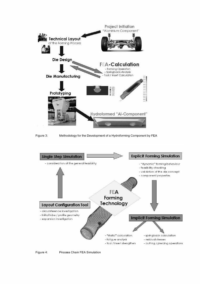
Figure 3 shows in principle the methodology for the development of a hydroforming component by means of FEAforming simulation. In a second step, after the project initiation and technical layout discussion, the FEA calculationsupports permanently the die design process and manufacturing of the complex tools or dies. Within the productdevelopment of complex hydroforming parts the simulation of the forming steps utilising FEA has gained increasingimportance. FEA technique in manufacturing layout of hydroforming processes is used:
• to check the production feasibility of the component
• to analyse and optimise the final component quality and expected process reliability
• to determine an indication of the required process forces for the die and machine design
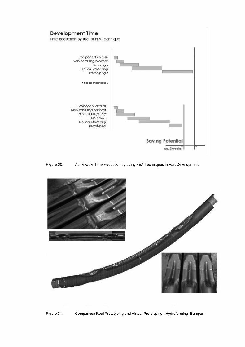
First, by help of the configuration layout tool an analysis of the component takes place, where the component crosssections with their circumferences and radii as well as the course of the component centreline are checked regarding theirhydroformability. On the basis of the results from the component analysis the definition of the starting tube dimensions andthe interpretation of the additional manufacturing steps take place. In order to determine failure and quality aspects in thelater on explicit forming simulation, a single step solver simulation should be done first, to check the general feasibility ofthe component. For very complex components and manufacturing processes a validation through an explicit simulationprogram, such as LS-DYNA, is necessary by an detailed look to each of the individual forming steps, followed by animplicit calculation, where the springback behaviour, the residual stresses and if necessary, piercing or punching operationare calculated. The whole process methodology for FEA calculation can be seen in Figure 4. The effect of this methodologyis, that a reduction of the number of the tools and respectively the costs of tools can be achieved by the application of theFEA feasibility study. For example, it is possible to reduce the necessity time for the prototyping from 6 to 1 or 2 weeks.That means, that no die modification is necessary by using FEA study’s in prior. This fact leads to an obvious shortening ofthe development time as well as to savings of development costs.

Die and Process Development
The economic and efficient design of dies for hydroforming and preceding processes is increasingly being supported bythe application of LS-DYNA. This is especially the case for the preforming and hydroforming operations, where LS-DYNAhas proven to be quite valuable for the prediction of important process parameters, including axial forces and stress or straindistribution.
The more accurate predictions of structural response obtained from FEA can mean that each design iteration is moreeffective. Once the important features of a component have been established, fewer prototypes may need to be constructed.Prototype manufacture and real testing (prototyping) is expensive and time-consuming. Although prototypes are stillrequired, the reduction in the number of variants tested may help to reduce the cost and duration of the design phase.
Fundamentals of Preforming Processes
In designing the hydroforming process for the production of automotive structural components, a number of factors mustbe taken into account to ensure technically and economically production methods. The layout of the preforming process andpreforming die respectively, determine both the process flow and the final component quality as well as the requiredmachines. In the following a few general methods of preforming and their necessity are discussed. The development and thevalidation of these preforming variants is done by means of FEA simulation techniques.
Preforming
Introduction
Preforming is necessary to load the prebent part into the hydroform die , all square sections of the bent tubes have to betighter than the opening of the hydroform die. Considering the positioning tolerance of handling systems like robots orCNC-feeder systems and the bending process usually means that the gap between outer tube surface and hydroform dieshould be between 0.5 and 1.5 mm. Only at the tube ends the outer shape of the tube is similar to the die cavity. Very oftenthe necessary tube circumference and thereby the tube diameter itself has to be adjusted to the square section with themaximum expansion in hydroform process. Three different cases can be distinguished:
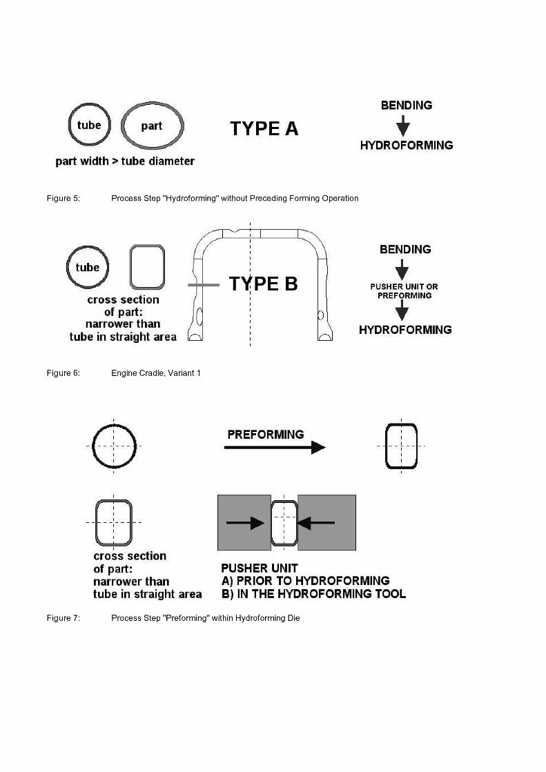
Faultless loading of the bent tube into the hydroform die means that sufficient circumferential gap around tube for saveloading is available. Normally in this case after bending (rotary draw bending or press bending) the tube can be hydroformedwithout intermediate processes. This is most economic way to produce engine cradles with hydroforming technology. If, forinstance, only a flattened tube is necessary as a starting part (bending not considered) for hydroforming it is possible to useelliptical tube material made by extrusion forming. During closure of the hydroform die, a slight bending in second planeof the prebent tube is possible (see Figure 5).
a) If after bending, loading of the prebent tube is not possible, because the tube width in the split plane of the hydroformdie is wider than opening of the die cavity. The tube is not bent in this specific forming area (Figure 6), a preformingoperation is necessary to flatten the tube in the described area. Sometimes the flattening operation can be integratedin the hydroform die with so-called pusher units (Figure 7) which are activated by special hydraulic, gas or wedge slide units. In general this methodology is very problematical for most die shapes and for aluminium material because of extremely complex die setup and inevitable gap’s between this sliding units, in which aluminium materialmoves by internal pressurising within hydroform process.
b) After bending a loading of the prebent tube is not possible for above mentioned reason but the contour of the hydroform die is tighter than the tube in a prebent section or in a few other areas. In this case a flattening procedureis sometimes not possible; this leads to a preforming process in a die with tapered sides (Figure 8), in which the tubecan either be flattened or drawn within such an operation. The operation allows a pre-distribution of the material inmany different ways to guarantee the optimum wall thickness distribution in the hydroform process to achieve a highvariety of different square section geometry’s as shown in Figure 9. As an advantage in comparison to case B is thatthere are more possibilities to change the contour of the prebent tube but as a disadvantage a press operation including handling and lubricating is necessary. In comparison to case B the die contact friction is relatively high [5.8] which leads to press forces in a range of about 500 to 3000 kN depending mainly on the die design, tube material and dimension.
Figure 10 shows the different possibilities for preforming die layout to produce starting parts from straight tubes forhydroforming:
• Flattening
• Conical radial preforming
• Conic radial preforming with synchronously bending operation of the tube centre line
In practise, a combination of these operations is often required. Figure 10 also shows a fictitious example for a workpieceproduced by means of a combination of all the mentioned forming possibilities. With regard to the conic radial preforming,
attention must paid, as already mentioned above, to the press forces and tool loads that may occur. For sidemember partsfor truck rails with workpiece length from 1500 to 4000 mm and reductions from d0 = 140 mm to d = 125 mm using a wallthickness between 3 and 4 mm very often forces are expected up to 5000kN. Further, contact stresses up to 1200 N/mm2occurred due to material movement along the tool surface. A reduction of the friction force between tube and die surfaceusing optimised coating (TiC, TiN) and lubrication systems has to be carefully carried out. This also applies to conic radialpreforming with superimposed bending (Figure 10 – variant 3).
Design Guidelines for Preforming Processes and Parts
How can a hydroform process oriented geometry be obtained starting from a given part design that can be manufacturedfrom a (round) tube and economically produced? The known requirements are:
• The starting part must be perfectly placed in the hydroforming tool.
• After tool closing, a defined position of the workpiece ends must be ensured (so that no "sliding" occurs thus avoiding an inaccurate starting position for the hydroforming process)
The two following examples illustrate further design guide lines:
• The centre of gravity of the starting part cross section should be situated at the centre of gravity of the hydroformed workpiece cross-section.
This leads to a homogeneous wall thickness reduction during the hydroforming process with regard to the partcircumference and also minimises the risk of a local tube failure (bursting). If the said requirement does not apply the riskof bursting in areas with excess material persists. In Figure 11 cross- sections of an engine cradle preformed in a preformingdie are shown. Figure 11 further shows the result of the real hydroforming operation for the different preforming variants 1and 5.2. The preforming process was been optimised by using FEA simulation technique, after failure mode wrinkling wasdetected in the real prototyping. The starting geometry for hydroforming is shown in Figure 12 whereas a) shows the resultfor preforming die “variant 1” and b) illustrates the optimised variant 5.2. Figure 13 shows the wrinkle formation in FEA(plastic strain distribution) in these problematical area after hydroforming operation. Figure 14 shows the problem-freeforming out by optimised preforming die.
A further design guideline for a starting part in the hydroforming process is:
• All cross sectional radii of the starting part must be greater than or the same as the radii of the hydroforming workpiece.
If this is not been realised in component design, the inner parts of these radii are subjected to tensile stress duringhydroforming and are enlarged again. This can lead to micro cracks at the inside surface which may be impossible to detect(Figure 15).
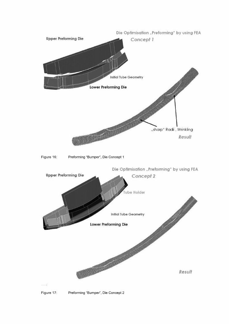
Figure 16 shows a combination of a bending and a preforming operation taking place in a hydroform die as a preformingoperation with tool optimisation by using FEA technique. The basic suitability of different tooling variants with and without“tube holder” at the tube ends and different segmentation of these active die units are first checked. In a first step threedifferent preforming die layout were investigated by using FEA. Die concept, no “tube holder” and no segmentation of thedie cavity as well as the resulting part geometry is shown in Figure 16. It can be clearly shown, that these die layout leadsto part radii after preforming which are smaller as the radii of the hydroforming workpiece. Further a excessive wrinkleformation can be expected. Figure 17 shows the concept of die layout 2 and the resulting preforming operation. Within thisdie concept, a segmentation of the upper die was done. The use of the “tube holder” guarantee a better preforming shape;also with a wrinkle formation but no “sharp” radii. In Figure 18 the most expensive die layout is presented. The upper andthe die layout is segmented. As expected, the preforming part looks best with these die layout. Cost reasons, almost doublethe costs as for die concept 2 (+ 35.000 Euro) , have lead to an decision which bases on concept 2 with some ideas of concept1 and 3.
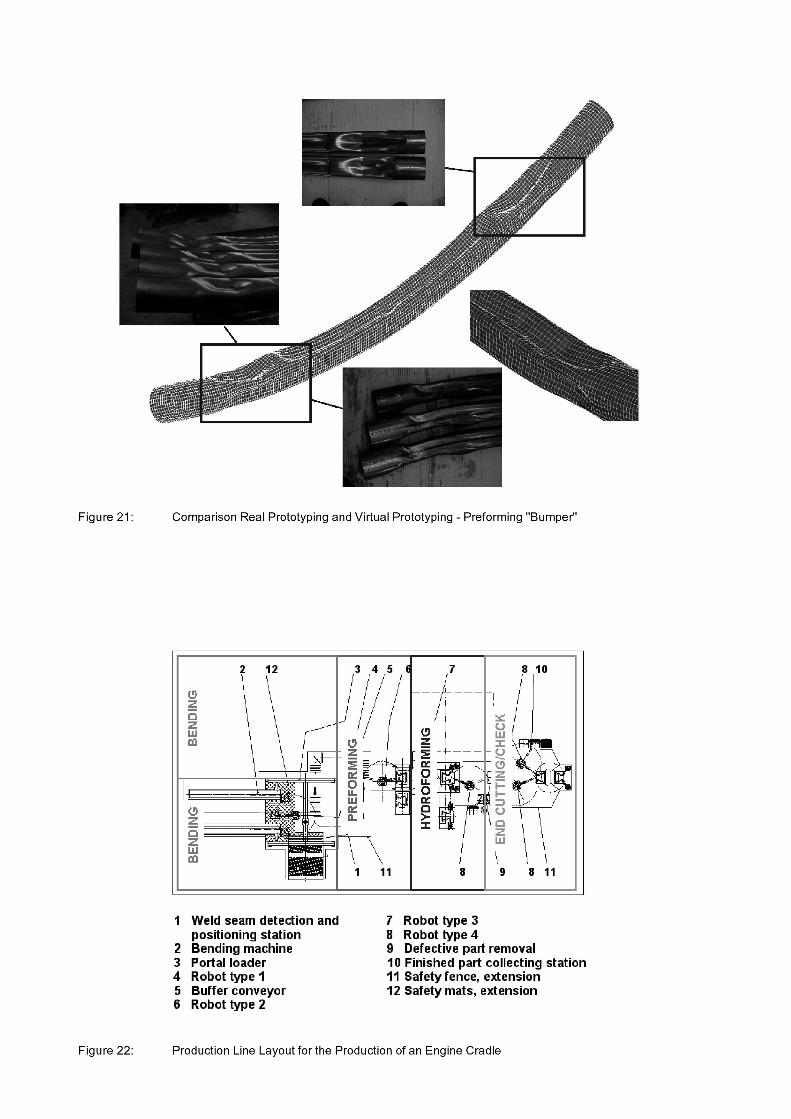
The second step of the FEA feasibility study consists of optimising more precisely the tool cavity of the concept 2. Figure19 shows a relatively simple die concept which was built according to the results from these investigation step. No diesegmentation was done within these concept. Both tube ends have a straight vertical end area. These vertical end area is onlybuilt in the lower, not in the upper die, where a tangential tube end area is built. Figure 20 illustrates the comparison of FEAfeasibility study and achieved part geometry in real prototyping. As can be seen, all failure areas have identical shape in realprototyping or virtual prototyping, respectively.
Summary
Preforming currently advanced to a stage where the various process variants can be used to produce a wide variety ofstarting parts for hydroforming. The decision as to which production steps are to be integrated in the preforming processdepends on a wide variety of factors. Some of these were discussed in the above, such as the different cases of preformingand general die and part layout. Accurate predications of the local deformations observed in the preforming process wereobtained by the FEA simulation in prior and also afterwards to the real tool set-up. From this point of the study it cangenerally be concluded that explicit FEA simulations of preforming operations are reliable, efficient. Today, suchoptimisations can be performed within relatively short periods of time and result in a high planning reliability.
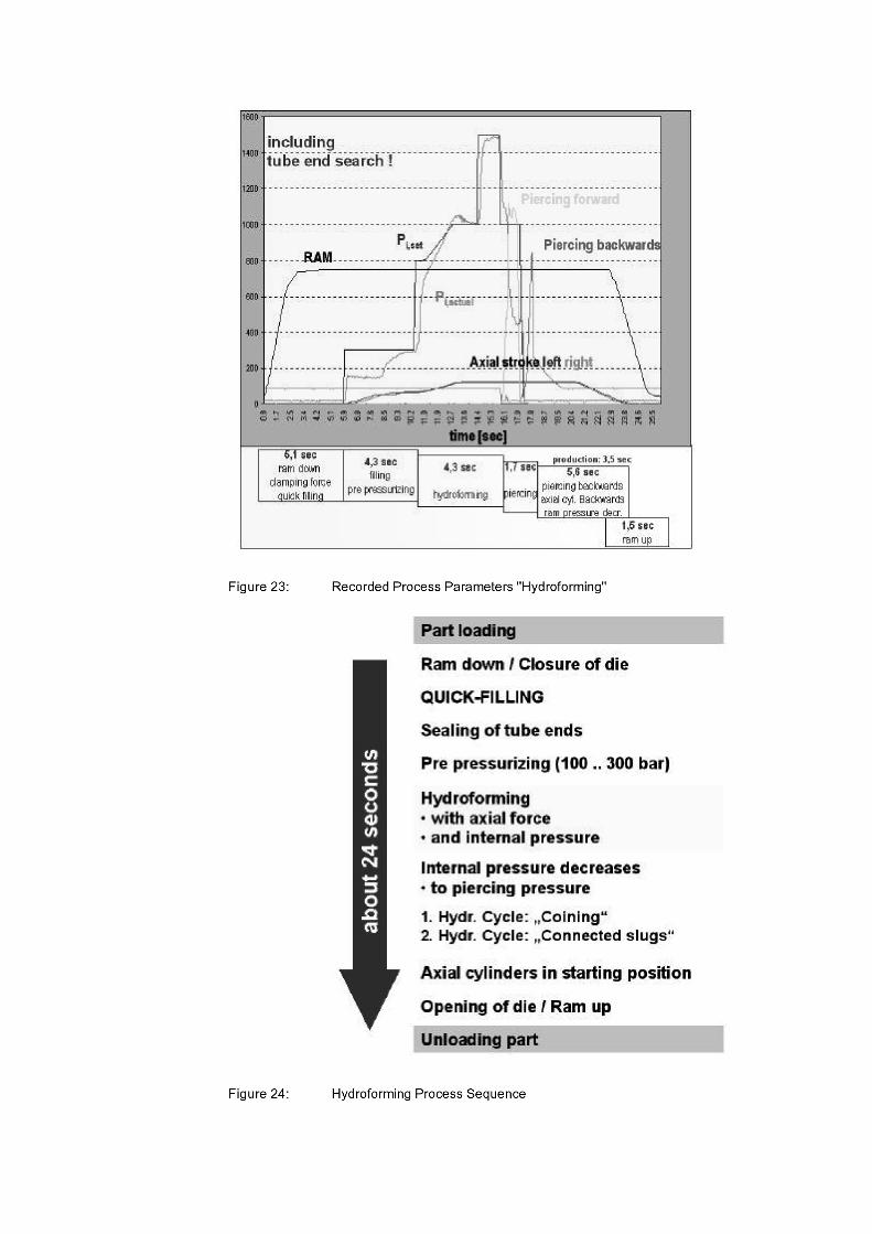
Hydroforming
Production processes in the wide field of metal forming, especially hydroforming, are time consuming (Figure 22, 23)and expensive. Usually the necessary studies relating to the practicability of the hydroforming process and to the design ofthe dies and parts are done experimentally with high expenditure and loss of time. The main goal in hydroformingtechnology is the reduction of costs during the prototyping and the shortening of the development cycles includingoptimising tooling or die geometry, respectively.
The designing of the tooling for the production of automotive structural components must taken into account a numberof factors to ensure technically and economically viable production (Figure 21). The design of the die and the general dielayout determine quality and the accuracy of the final hydroformed component.
Introduction
Regarding the accuracy, one must bear in mind that the metal forming technology have different boundary conditionsthan machining. In machining the generation of a geometry is an incremental process with a small interaction zone betweentool and workpiece. Effects of wear, thermal expansion, and so on can be detected and corrected during the process andaccounted for in each workpiece. In metal forming, especially hydroforming, the shape of the workpiece is stored in the diegeometry as a whole and therefore transformed to the workpiece as a whole. Due to that, the ranges of accuracy inhydroforming and in machining are quite different, e.g. IT 6 to IT 16 and IT 0 to IT 10, respectively. A high accuracy, i.e.,a low IT-number, is obtained in machining processes, while in hydroforming the accuracy is lower. In hydroforming i.e.,typical values concerning the shape of calibrated extruded profiles were deviations of ± 0.25 mm. The deviations increasewith increasing complexity of the processes and parts.
Additional effects are:
• the die geometry due to wear,
• the errors in the machines which lead to an offset and tilting, and
• distortion of the parts due to residual stresses.
Especially the combination of the requested precision in combination with the complex geometry’s lead to an increasein high-quality hydroforming processes with optimised process and die technology to close the gap between the desired andachievable tolerance.
Die Design in Hydroforming Process
A common comment heard within the industry is: For hydroforming you just need a good machine and a simple toolwhich is mainly made by two die halves similar to the outer shape of the final component and some axial cylinders.Unfortunately this is wrong ! The mentioned “one die = two halves” – procedure might work for some prototyping samplesbut is far away from mass production application.
The major task of the die is the production of the designed components shape and profile. This is achieved by themachined shape of die cavity providing a "barrier" to the expansion of the raw material caused by the interior pressure andaxial forces being applied to the workpiece.
Together with trouble free production, the die must also ensure the required component quality with particular regard toexternal dimensions. So, the die is still the key element of every hydroforming process and therefore an important aspect ofthe
• availability of the whole system
• production safety, and
• part quality.

Regarding the hydroforming die, the achievable shape is greatly influenced by the general die layout, the manufacturingaccuracy of the form imparting surfaces and by the rigidity of the die components.
A number of other factors that also have an important influence in finished part quality are
• the manufacturing concept
• preceding forming operations
• tube material
• friction condition
Die Design in General
On the one hand hydroforming dies must be suitable to produce the required component properties, on the other hand acost-effective design must be aimed for, with size a determining factor. When it comes to die design, an optimal balancemust be found between these contradictory parameters.
With regard to die size, the horizontal forces arising from the interior pressure are of major significance. Whereas theforces exerted in clamping direction are compensated by the machine force, horizontal forces acting on the die result instresses and corresponding die deformation. Rigidity of the die itself can be ensured by careful design. Solid guides (Figure24) along the die ensure the absorption of potential lateral stresses. Both stresses and deformations should be kept tomanageable levels through suitable die design, as the stresses can cause damage to the die over the operating period anddeformations can lead to undesirable variances in component dimension [5.9].
Figure 25 shows a square section view of an example of a mass production hydroform die with insert technology. Ingeneral, to achieve the best possible hydroforming part quality, the whole die system should be as strong as possible. Thisincludes a rigid guiding of the upper and lower tool halves:
• pillars are pre-guide the upper and lower die during closure
• during hydroforming the upper and lower die are guided by guiding plates (Figure 4.50)and the contour of the wear resistant inserts all along the length of the component. Separate guidance of the press system itself is not necessaryor contrary to this.
• pressure and matching plates allows the optimisation of the stiffness behaviour of large hydroform die sunder loads within a range of more than 20.000 kN especially if the press ram is not loaded in centre or non-symmetrical.
• wear resistant inserts allows the replacement of areas with higher wear without excessive downtime or appreciable machining costs. The insert size depends on the coating method (TiC / TiN) used. For safety reasons the inserts andpressure plates should be available as spare parts which means that a complete spare tool is not required. Every inserts causes split planes within the die which usually causes no reduction of part quality if the inserts are designedand machined according to the state-of-the-art. However, extra split planes over and above this ideal can generate split line marks on the part surface, i.e. for the use of tubular aluminium material.
Designing Dies with Help of Finite Element Analysis
The complex nature of die geometry’s makes analysis of the stress and elastic strain conditions in the die virtuallyessential. Finite element analysis is a useful aid in the design of dies. At University of Aalen programs such asPro/Mechanica, ANSYS are used. Figure 26 shows a problem zone within a die inserts with regard to maximum stresses.The sharp edges and small drainage wholes in the ground of the die cavity result in very high notch stresses which wouldprobably cause die fracture in volume production. Special insert design must be used at these points to alleviate the stresscondition.
Finite element analysis can be used to compute the optimum dimensions and geometry of basic die plates, inserts andsliding units as well as axial punches or punch caps (Figure 27). The integration of openings to accommodate hydraulicpiercing units and active forming cylinders for sliding or pusher units is of particular importance in the FE analysis. Inaddition to the sharp contour edges of the inserts, zones of this kind are subject to high stress concentrations. In extremecases it is necessary to dispense with the piercing of particularly critical points during the hydroforming process.
The Application of FEA for the Development of Hydroforming Parts
The task of the process simulation is to execute general feasibility studies for industrial applications of hydroformingtechnology by using the FEA in order to obtain a reduction of the production development phase (time to market) or areduction of the development costs (brake even point).
Crucial starting points for the optimisation of time, costs and quality of the configuration of the procedure are situatedduring the first stage of the hydroform component development, where a modification of the process-influencing parametersis possible still without time-consuming and expensive steps, e.g. die modifications.

In general, hydroforming parts have complex shapes with variable cross-sections and centrelines. This requires, asmentioned above, that additional preforming operations must be considered together with the hydroforming process itself.The simulation of the forming steps utilising FEA has gained increasing importance for component and process design. Itserves to examine the production feasibility, to analyse and optimise the final component quality and expected processreliability. In Addition, it supplies the initial information about the required process forces for the die and machine design.
A further substantial function of the FEA manufacturing simulation is to carry out early predicates concerning theadjusting product properties (wall thickness distribution, stress- ,strain distribution, cold hardening). In addition theinspection of the time course is of crucial importance during the forming. Also the calculation of the influence of any elasticstrains referring to the springback behaviour of the components formed by use of interior high pressure is not to be ignoredregarding the measurement and form tolerances.
Figure 28 shows in principle the methodology for the development of a hydroform component on the basis of the CADdata of the component design. In a first step of the component analysis, the component cross sections with theircircumferences and radii as well as the course of the component centreline are analysed by hand. On the basis of the resultsfrom the component analysis the definition of the starting tube dimensions and the interpretation of the additionalmanufacturing steps take place.
In order to determine the manufacturing sequence in the following FE analysis for their feasibility, the knowledge of aset of boundary conditions is necessary.
To these boundary conditions belongs essentially the
• material parameters
• tube dimensions
• component geometry
• friction model (Coulomb)
For very complex components a repetition of the individual development steps can be necessary both during thetheoretical process (procedure) configuration as well as at the prototyping. Such iteration loops are not drawn in this figure.
The effect of this, that a reduction of the number of the tools and respectively the costs of tools can be achieved by theapplication of the FEA feasibility study. Hence a reducing of the time for the prototyping (real tryout) from 6 to 1 or 2 weekscan be achieved. This is possible because there is in 95% of all cases no die modification necessary during the realprototyping. This fact leads to an obvious shortening of the development time as well as to savings of development costs.An increase of the quality accompanied by an increased manufacturing integrity for batch production can be derivedadditionally by the analysis of the FEA manufacturing simulation (Figure 29).
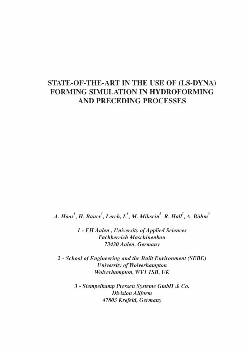
Figure 30 shows the results for the hydroforming process of the Bumper-part which was already regarded in thepreforming section. Considering the preceding forming steps, reasonable agreement between analysis and real tryout isfound. Accurate predications of the local deformations observed in the hydroforming process were obtained by the FEAsimulation in prior to the real tool set-up.
Right, to sum up, as was shown, process simulations with FEA technique can be used successfully for improvements ofthe die design and die layout. A reduction of time and costs by an simultaneously increase of quality can be achieved.
Conclusion
Constant optimisation of the whole or overall production steps of a hydroforming component, e.g. preceding formingoperations, hydroforming dies, presses and hydroforming production line technology today ensures the economicapplication of the hydroforming process. In addition, successful efficient methods are available for component and processdevelopment by using FEA techniques. Future research and development work is appropriate for further improvements inthe FEA technology by using valid input parameters as well as the numerical aspects on the solution quality of FEAfeasibility studies of hydroforming processes.