state reduction and minimization - university of...
TRANSCRIPT
E&CE 223 Digital Circuits and Systems (A. Kennings) Page 1
State Reduction and Minimization
Similar to synchronous sequential circuit design, in asynchronous design we might obtain a large flow table.
Reasonable to assume that it might be possible to combine/merge multiple states into a single state (just like in synchronous sequential circuits). Especially true given a flow tables that might have:
Lots of don’t care outputs for unstable states (since we won’t stay in this situation too long).
Don’t care next state information if we assume fundamental mode operation (some transitions will not occur).
Smaller table that performs our task likely to result in a much smaller circuit.
Can use implication charts and merger diagrams to reduce the flow table.

E&CE 223 Digital Circuits and Systems (A. Kennings) Page 2
Compatible States
With don’t cares, equivalency is replaced with compatibility.
Two states A and B are compatible if, for every input combination we find:
A and B produce the same outputs where specified, AND
A and B have compatible next states where specified.
Don’t cares match with anything…
E&CE 223 Digital Circuits and Systems (A. Kennings) Page 3
Implication Chart – Compatible States
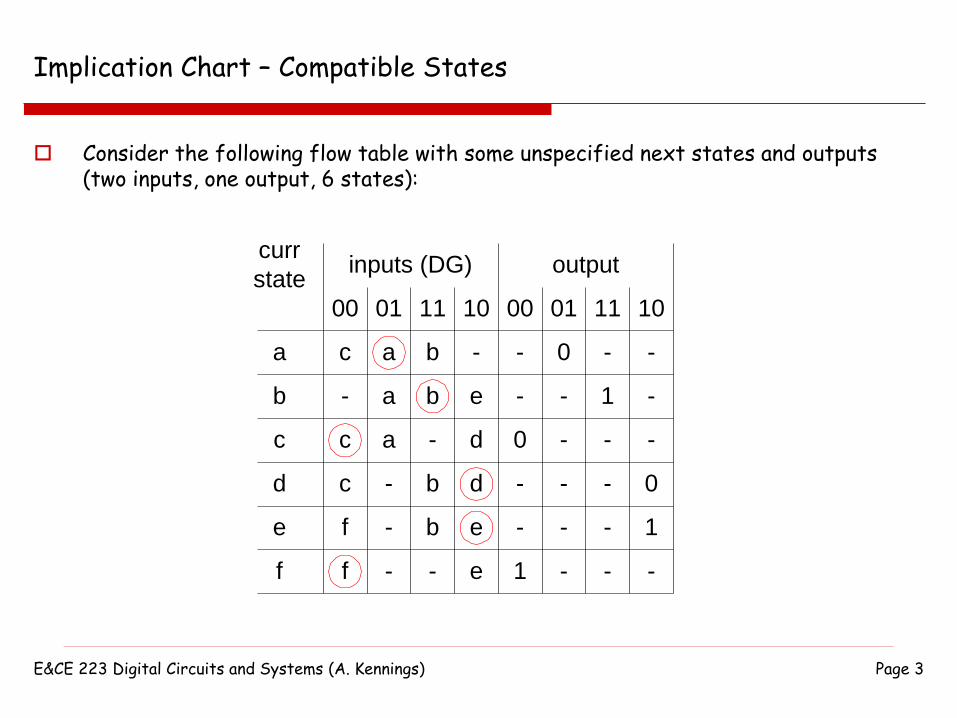
Consider the following flow table with some unspecified next states and outputs (two inputs, one output, 6 states):
-
00 01
a
b
a
inputs (DG)
c
d
c
a
c
c
a
-
curr
state
11 10
e
f
output
-
0
-
-
-
1
b -
f
f
-
- - e
eb
b d
d-
eb
00 01 11 10
-
-
-
-
0
-
1
-
-
-
-
-
-
-
-
-
0
1

E&CE 223 Digital Circuits and Systems (A. Kennings) Page 4
Implication Chart – Compatible States
Build the implication chart (list states along left and bottom side – like lower triangle of a matrix):
b
c
d
e
f
a b c d e
-
00 01
a
b
a
inputs (DG)
c
d
c
a
c
c
a
-
curr
state
11 10
e
f
output
-
0
-
-
-
1
b -
f
f
-
- - e
eb
b d
d-
eb
00 01 11 10
-
-
-
-
0
-
1
-
-
-
-
-
-
-
-
-
0
1
E&CE 223 Digital Circuits and Systems (A. Kennings) Page 5
Implication Chart – Compatible States
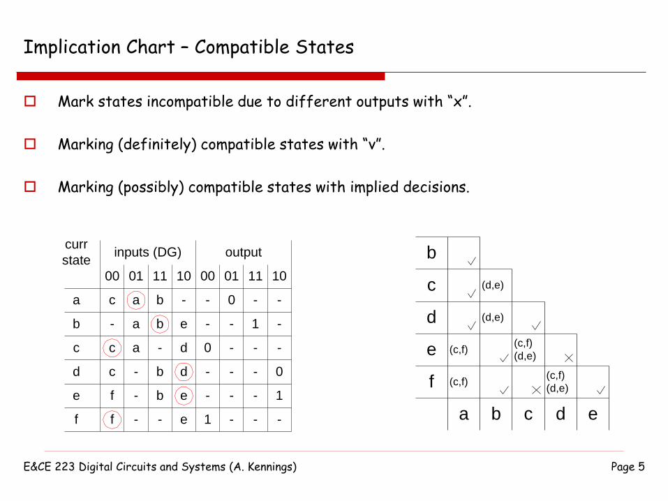
Mark states incompatible due to different outputs with “x”.
Marking (definitely) compatible states with “v”.
Marking (possibly) compatible states with implied decisions.
b
c
d
e
f
a b c d e
(c,f)
(c,f)
(d,e)
(d,e)
(c,f)
(d,e)
(c,f)
(d,e)
-
00 01
a
b
a
inputs (DG)
c
d
c
a
c
c
a
-
curr
state
11 10
e
f
output
-
0
-
-
-
1
b -
f
f
-
- - e
eb
b d
d-
eb
00 01 11 10
-
-
-
-
0
-
1
-
-
-
-
-
-
-
-
-
0
1

E&CE 223 Digital Circuits and Systems (A. Kennings) Page 6
Implication Chart – Compatible States
Scan columns again and again, checking implied decisions to remove compatibilities…
b
c
d
e
f
a b c d e
(c,f)
(c,f)
(d,e)
(d,e)
(c,f)
(d,e)
(c,f)
(d,e)
-
00 01
a
b
a
inputs (DG)
c
d
c
a
c
c
a
-
curr
state
11 10
e
f
output
-
0
-
-
-
1
b -
f
f
-
- - e
eb
b d
d-
eb
00 01 11 10
-
-
-
-
0
-
1
-
-
-
-
-
-
-
-
-
0
1
E&CE 223 Digital Circuits and Systems (A. Kennings) Page 7
Merger Diagram
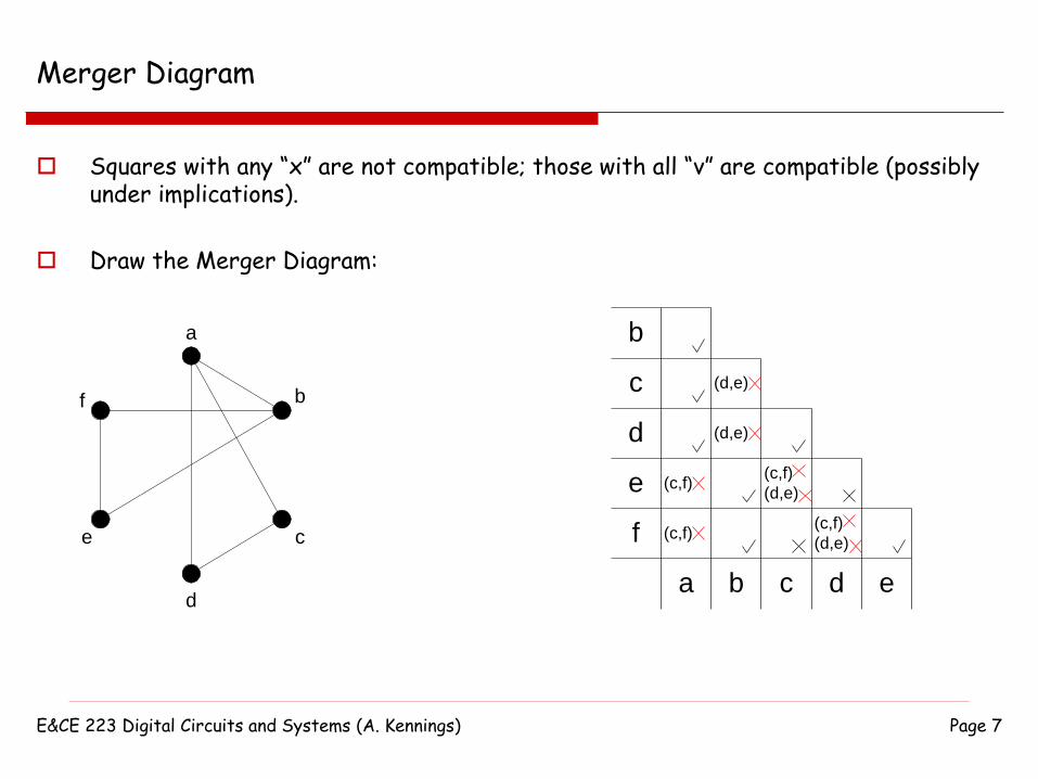
Squares with any “x” are not compatible; those with all “v” are compatible (possibly under implications).
Draw the Merger Diagram:
a
b
c
d
e
f
b
c
d
e
f
a b c d e
(c,f)
(c,f)
(d,e)
(d,e)
(c,f)
(d,e)
(c,f)
(d,e)

E&CE 223 Digital Circuits and Systems (A. Kennings) Page 8
Merger Diagram
We now look for large cliques in the graph (clique is part of the graph in which every node is connected to every other node)…
a
b
c
d
e
f
We can now merge states (a,c,d) and (b,e,f). We have reduced 6 states down to 2 states by merging.
a
b
c
d
e
f

E&CE 223 Digital Circuits and Systems (A. Kennings) Page 9
Important!!!
We need to check that each state is included at least once.
We need to make sure that any implied compatibilities are true…
For our solution (a,c,d) and (b,e,f) all states are included.
For our solution implied compatibilities are true. In this example, (a,c,d) and (b,e,f) requires no implied compatibilities.
E&CE 223 Digital Circuits and Systems (A. Kennings) Page 10
Final Result
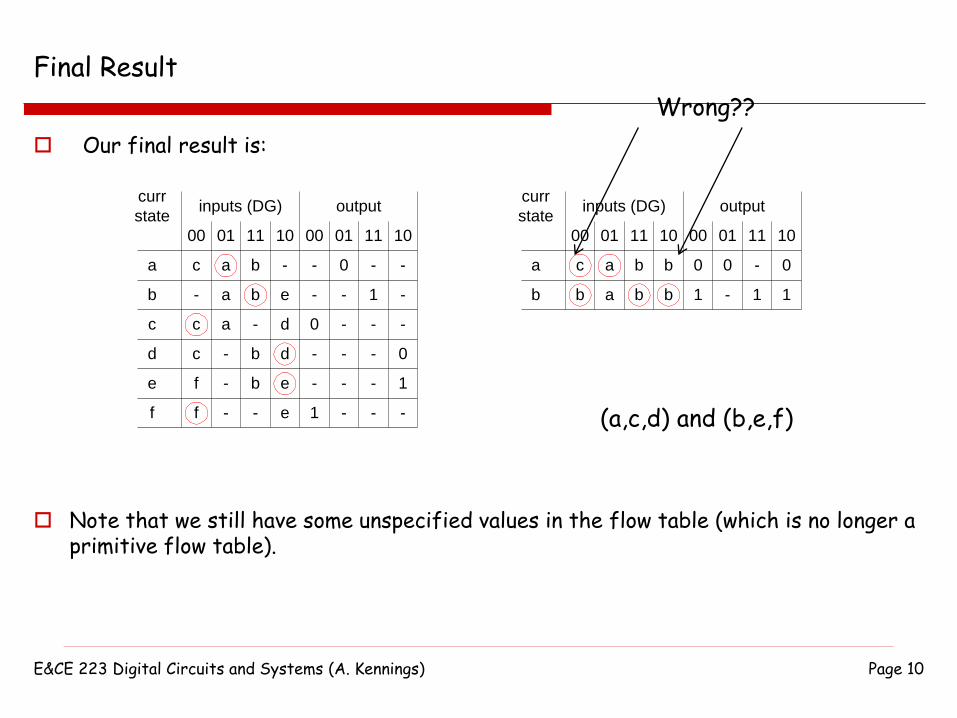
Our final result is:
-
00 01
a
b
a
inputs (DG)
c
d
c
a
c
c
a
-
curr
state
11 10
e
f
output
-
0
-
-
-
1
b -
f
f
-
- - e
eb
b d
d-
eb
00 01 11 10
-
-
-
-
0
-
1
-
-
-
-
-
-
-
-
-
0
1
b
00 01
a
b
a
inputs (DG)
c
a
curr
state
11 10
output
0
1
b b
bb
00 01 11 10
-
0
1
- 0
1
Note that we still have some unspecified values in the flow table (which is no longer a primitive flow table).
(a,c,d) and (b,e,f)
Wrong??
E&CE 223 Digital Circuits and Systems (A. Kennings) Page 11
Summary
Given a flow table (or a state table), we can always try to reduce the number of states using an implication chart and a merger diagram.
Both tables (the original table) and the reduced table) will perform the same function.
The idea is that having a smaller table will result in a simpler circuit.
E&CE 223 Digital Circuits and Systems (A. Kennings) Page 12
Textbook
Reduction of flow tables and state tables using implication charts and merger diagrams is covered in Chapter 9, Section 9.5 of the course textbook.

E&CE223 Digital Circuits And Systems (A. Kennings) Page 13
Race Conditions; Critical and Non-Critical Races
A race condition occurs in an asynchronous circuit when 2 or more state variables change in response to a change in the value of a circuit input.
Unequal circuit delays may imply that the 2 or more state variables may not change simultaneously – this can cause a problem.
Assume two state variables change…
If the circuit reaches the same final, stable state regardless of the order in which the state variables change, then the race in non-critical.
If the circuit reaches a different final, stable state depending on the order in which the state variables change, then the race is critical.
We need to avoid critical races for predictability and to ensure our circuit does the intended function!
E&CE223 Digital Circuits And Systems (A. Kennings) Page 14
Non-Critical Race
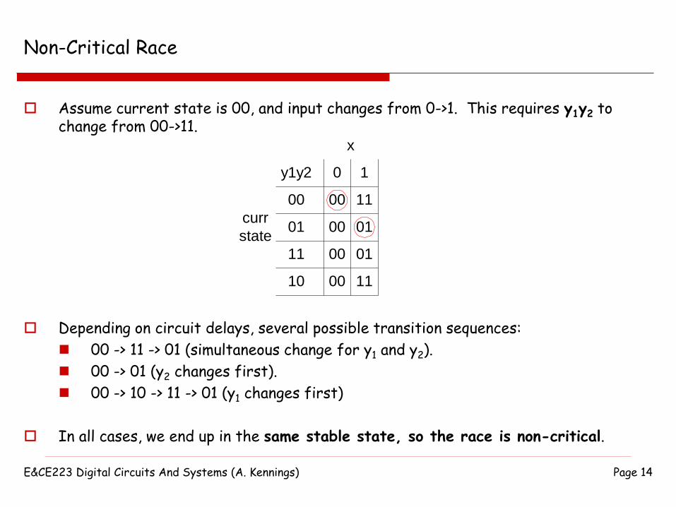
Assume current state is 00, and input changes from 0->1. This requires y1y2 to change from 00->11.
Depending on circuit delays, several possible transition sequences:
00 -> 11 -> 01 (simultaneous change for y1 and y2).
00 -> 01 (y2 changes first).
00 -> 10 -> 11 -> 01 (y1 changes first)
In all cases, we end up in the same stable state, so the race is non-critical.
00
0 1
00
01
y1y2
curr
state
11
x
11
10
00
01
00
00
01
11
E&CE223 Digital Circuits And Systems (A. Kennings) Page 15
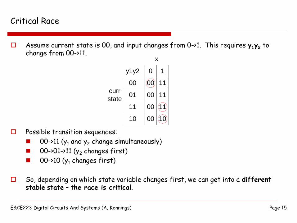
Critical Race
Assume current state is 00, and input changes from 0->1. This requires y1y2 to change from 00->11.
Possible transition sequences:
00->11 (y1 and y2 change simultaneously)
00->01->11 (y2 changes first)
00->10 (y1 changes first)
So, depending on which state variable changes first, we can get into a differentstable state – the race is critical.
00
0 1
00
01
y1y2
curr
state
11
x
11
10
00
11
00
00
11
10
E&CE223 Digital Circuits And Systems (A. Kennings) Page 16
Why Races Exist
Races are a consequence of how states are assigned when designing a circuit.
That is, races exist in the transition tables, but not in the flow tables.
This should be somewhat clear.
Races are a consequence of state variables changing at the same time and therefore can’t happen until binary state assignment is done.
Flow tables are entirely symbolic, so no problems there…
Transition tables have binary values assigned, so potential problems there…
E&CE223 Digital Circuits And Systems (A. Kennings) Page 17
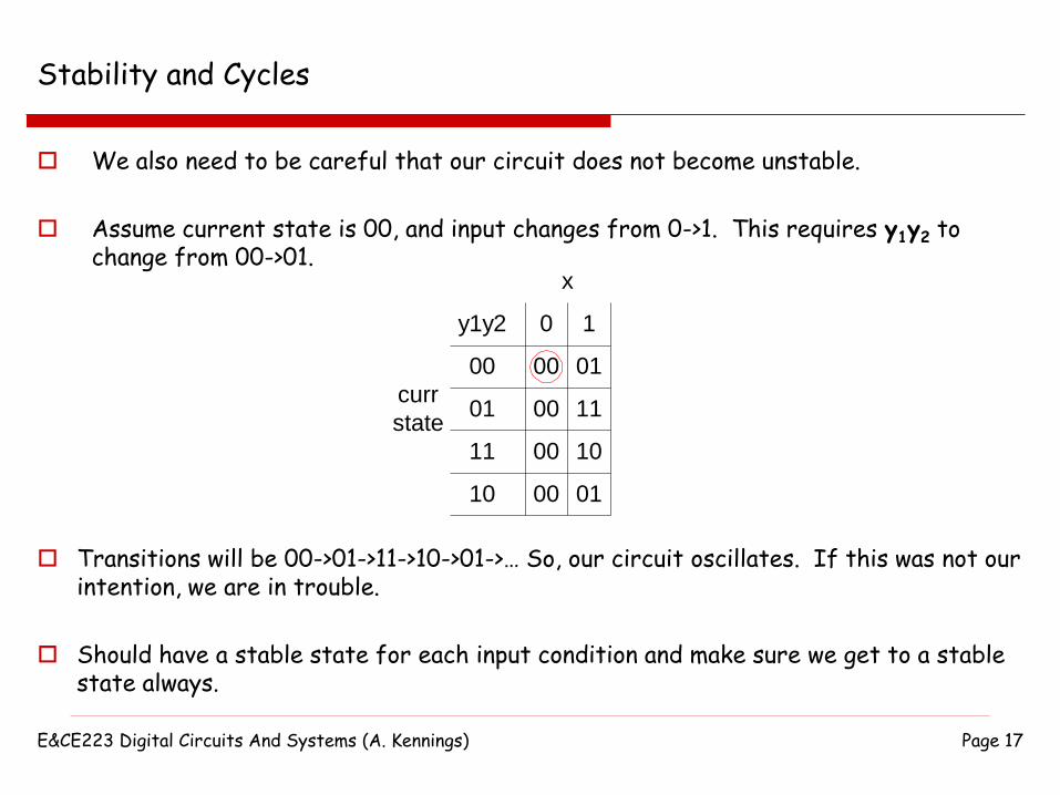
Stability and Cycles
We also need to be careful that our circuit does not become unstable.
Assume current state is 00, and input changes from 0->1. This requires y1y2 to change from 00->01.
Transitions will be 00->01->11->10->01->… So, our circuit oscillates. If this was not our intention, we are in trouble.
Should have a stable state for each input condition and make sure we get to a stable state always.
00
0 1
00
01
y1y2
curr
state
01
x
11
10
00
11
00
00
10
01
E&CE223 Digital Circuits And Systems (A. Kennings) Page 18
Race Free State Assignment
We can prevent races (pre-emptive) by performing state assignment such that transitions from one stable state to another stable state only require one state variable to change at a time.
Can consider a few different methods for performing race-free state assignment.
E&CE223 Digital Circuits And Systems (A. Kennings) Page 19
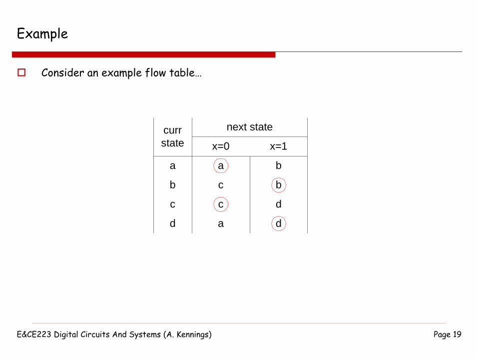
Example
Consider an example flow table…
curr
state
next state
x=0 x=1
a
b
c
d
a
c
c
a
b
b
d
d
E&CE223 Digital Circuits And Systems (A. Kennings) Page 20
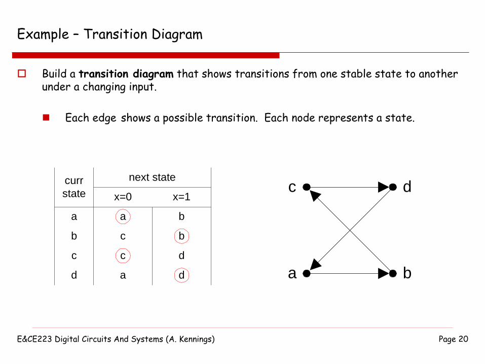
Example – Transition Diagram
Build a transition diagram that shows transitions from one stable state to another under a changing input.
Each edge shows a possible transition. Each node represents a state.
curr
state
next state
x=0 x=1
a
b
c
d
a
c
c
a
b
b
d
d
c
a b
d
E&CE223 Digital Circuits And Systems (A. Kennings) Page 21
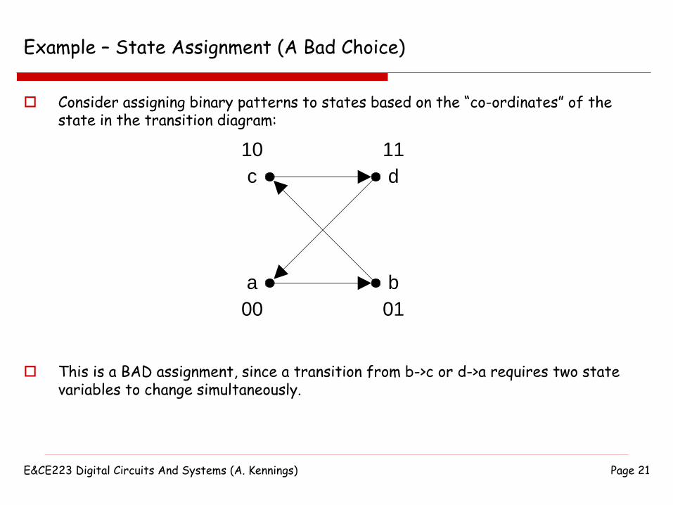
Example – State Assignment (A Bad Choice)
Consider assigning binary patterns to states based on the “co-ordinates” of the state in the transition diagram:
c
a b
d
00 01
10 11
This is a BAD assignment, since a transition from b->c or d->a requires two state variables to change simultaneously.
E&CE223 Digital Circuits And Systems (A. Kennings) Page 22
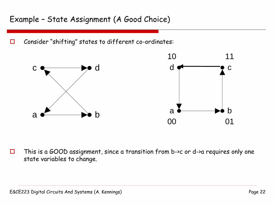
Example – State Assignment (A Good Choice)
Consider “shifting” states to different co-ordinates:
c
a b
d
This is a GOOD assignment, since a transition from b->c or d->a requires only one state variables to change.
d
a b
c
00 01
10 11
E&CE223 Digital Circuits And Systems (A. Kennings) Page 23
Method One for Race Free State Assignment
Given a flow table, try and “embed” the symbolic states into the co-ordinates of a “n-dimensional” cube such that the path from stable state to stable state:
Is direct along a single edge of the cube, or
Goes through newly introduced unstable states along edges of the cube.
E&CE223 Digital Circuits And Systems (A. Kennings) Page 24
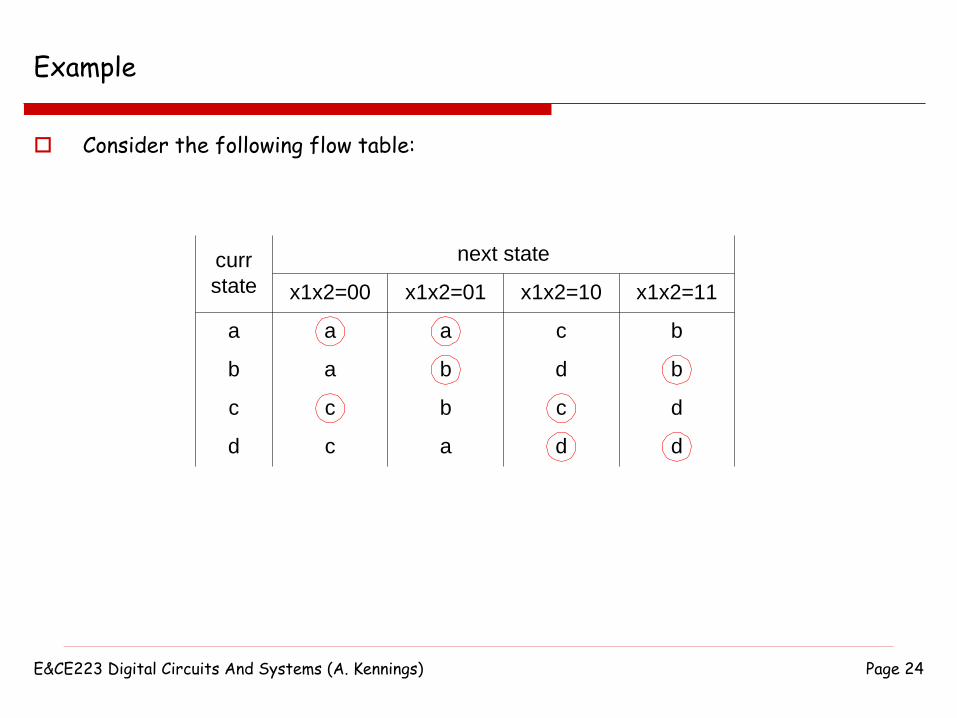
Example
Consider the following flow table:
curr
state
next state
x1x2=00 x1x2=01
a
b
c
d
a
a
c
c
a
b
b
a
x1x2=10 x1x2=11
c
d
c
d
b
b
d
d

E&CE223 Digital Circuits And Systems (A. Kennings) Page 25
Example – Transition Diagram
We can attempt to embed 4 states into a 2-dimensional cube and draw the transition diagram:
curr
state
next state
x1x2=00 x1x2=01
a
b
c
d
a
a
c
c
a
b
b
a
x1x2=10 x1x2=11
c
d
c
d
b
b
d
d
If we try, we see that there is no way to re-arrange the states to the corners of the cube to get rid of the diagonals in the transition diagram…
No state assignment that has only one state variable changing at a time.
c
a b
d

E&CE223 Digital Circuits And Systems (A. Kennings) Page 26
Example – Transition Diagram
Solution is to introduce additional, unstable states and use them as “intermediate” states during transitions.
I.e., embed the 4-states into the corners of a 3-dimensional cube.
c
a b
d
a b
d
c
e
g
f
E&CE223 Digital Circuits And Systems (A. Kennings) Page 27
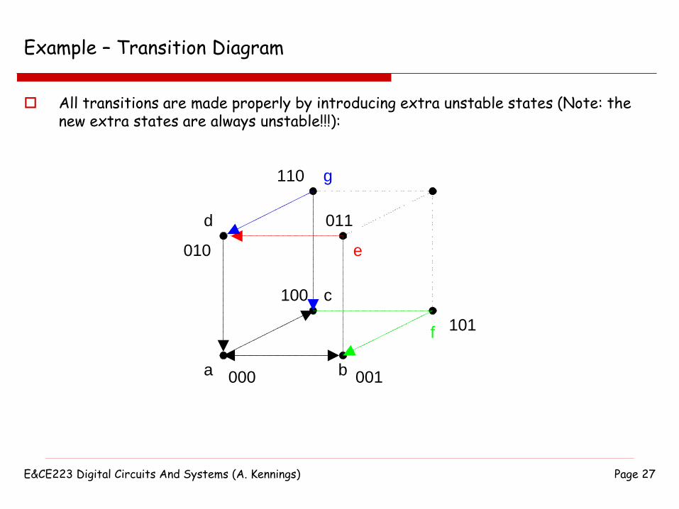
Example – Transition Diagram
All transitions are made properly by introducing extra unstable states (Note: the new extra states are always unstable!!!):
a b
d
c
e
g
f
000 001
010
100
110
011
101
E&CE223 Digital Circuits And Systems (A. Kennings) Page 28
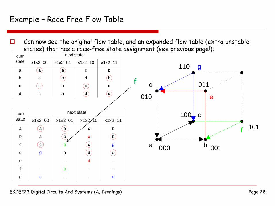
Example – Race Free Flow Table
Can now see the original flow table, and an expanded flow table (extra unstable states) that has a race-free state assignment (see previous page!):
curr
state
next state
x1x2=00 x1x2=01
a
b
c
d
a
a
c
c
a
b
b
a
x1x2=10 x1x2=11
c
d
c
d
b
b
d
d
curr
state
next state
x1x2=00 x1x2=01
a
b
c
d
a
a
c
g
a
b
b
a
x1x2=10 x1x2=11
c
e
c
d
b
b
g
d
e - - d -
f - b - -
g c - - d
a b
d
c
e
g
f
000 001
010
100
110
011
101
f

E&CE223 Digital Circuits And Systems (A. Kennings) Page 29
Method Two for Race Free State Assignment
Method useful for flow tables with <= 4 states.
Replace a state with multiple (two) equivalent states
Note: Outputs must be the same for the equivalent states!!!
Best to do an example…
Page 30
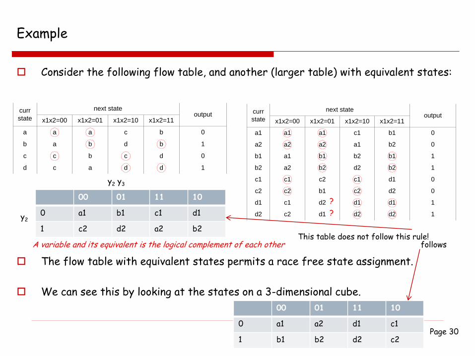
Example
Consider the following flow table, and another (larger table) with equivalent states:
curr
state
next state
x1x2=00 x1x2=01
a
b
c
d
a
a
c
c
a
b
b
a
x1x2=10 x1x2=11
c
d
c
d
b
b
d
d
output
0
1
0
1
curr
state
next state
x1x2=00 x1x2=01 x1x2=10 x1x2=11output
d1 c1 d2 d1 d1 1
d2 c2 d1 d2 d2 1
c1 c1 c2 c1 d1 0
c2 c2 b1 c2 d2 0
b1 a1 b1 b2 b1 1
b2 a2 b2 d2 b2 1
a1 a1 a1 c1 b1 0
a2 a2 a2 a1 b2 0
The flow table with equivalent states permits a race free state assignment.
We can see this by looking at the states on a 3-dimensional cube.
00 01 11 10
0 a1 b1 c1 d1
1 c2 d2 a2 b2
y2 y3
y2
A variable and its equivalent is the logical complement of each otherThis table does not follow this rule!
00 01 11 10
0 a1 a2 d1 c1
1 b1 b2 d2 c2
follows
?
?
E&CE223 Digital Circuits And Systems (A. Kennings) Page 31
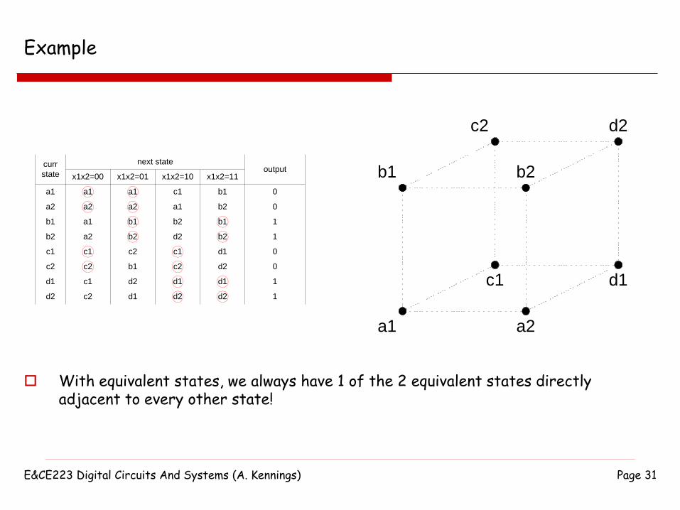
Example
curr
state
next state
x1x2=00 x1x2=01 x1x2=10 x1x2=11output
d1 c1 d2 d1 d1 1
d2 c2 d1 d2 d2 1
c1 c1 c2 c1 d1 0
c2 c2 b1 c2 d2 0
b1 a1 b1 b2 b1 1
b2 a2 b2 d2 b2 1
a1 a1 a1 c1 b1 0
a2 a2 a2 a1 b2 0
With equivalent states, we always have 1 of the 2 equivalent states directly adjacent to every other state!
a1 a2
b1
c1
b2
d1
c2 d2

E&CE223 Digital Circuits And Systems (A. Kennings) Page 32
Method Three for Race Free State Assignment
Can use the idea of one-hot encoding to get a race free state assignment…
Given n-states, let the i-th state be encoded as 0…010..0 where the 1 is in the i-thlocation.
For a transition from i-th stable state to j-th stable state, introduce unstable state with encoding 0..010..010..0 where the 1s are in the i-th and j-th position.
Again, best illustrated with an example…
E&CE223 Digital Circuits And Systems (A. Kennings) Page 33
Textbook
Races, stability and Race Free State Assignment are described in Chapter 9, Sections 9.2 and in Section 9.6 of the course textbook.

E&CE223 Digital Circuits and Systems (Fall 2004 - A. Kennings) Page 34
Hazards
Asynchronous circuits should conform to certain restrictions to operate properly:
Circuit should operate in fundamental mode (only one input changing at any time).
Circuit should be free of critical races.
One more problem, HAZARDS, that may cause circuit to malfunction.
E&CE223 Digital Circuits and Systems (Fall 2004 - A. Kennings) Page 35
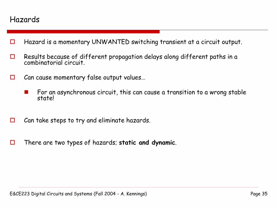
Hazards
Hazard is a momentary UNWANTED switching transient at a circuit output.
Results because of different propagation delays along different paths in a combinatorial circuit.
Can cause momentary false output values…
For an asynchronous circuit, this can cause a transition to a wrong stable state!
Can take steps to try and eliminate hazards.
There are two types of hazards; static and dynamic.

E&CE223 Digital Circuits and Systems (Fall 2004 - A. Kennings) Page 36
Static Hazards
Static-0 Hazard:
Occurs when output is 0 and should remain at 0, but temporarily switches to a 1 due to a change in an input.
Static-1 Hazard:
Occurs when output is 1 and should remain at 1, but temporarily switches to a 0 due to a change in an input.
0
1
static-0 hazard (0->0)
0
1
static-1 hazard (1->1)
E&CE223 Digital Circuits and Systems (Fall 2004 - A. Kennings) Page 37
Dynamic Hazards
0
1
dynamic hazard (1->0)
0
1
dynamic hazard (0->1)
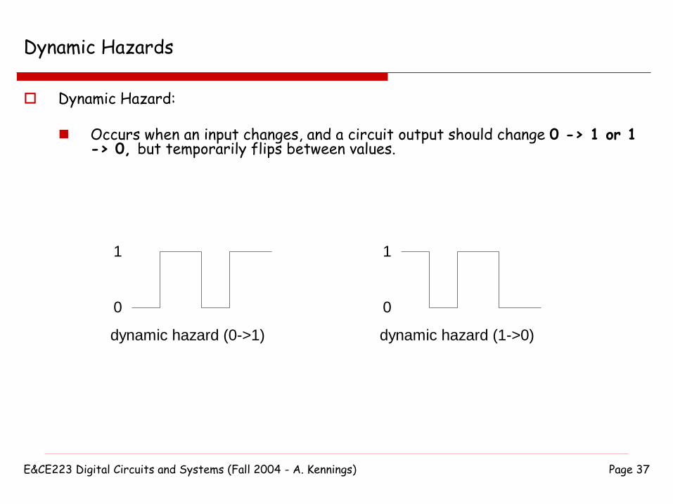
Dynamic Hazard:
Occurs when an input changes, and a circuit output should change 0 -> 1 or 1 -> 0, but temporarily flips between values.
E&CE223 Digital Circuits and Systems (Fall 2004 - A. Kennings) Page 38
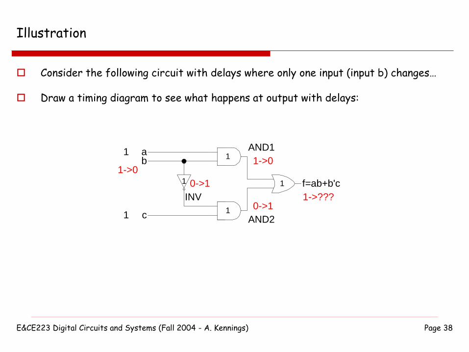
Illustration
Consider the following circuit with delays where only one input (input b) changes…
Draw a timing diagram to see what happens at output with delays:
ab
c
INV
AND1
AND2
f=ab+b'c1
1
1
1
1
1
1->0
0->1
1->0
0->11->???
E&CE223 Digital Circuits and Systems (Fall 2004 - A. Kennings) Page 39
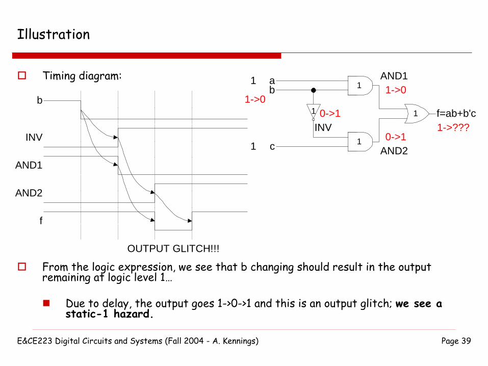
Illustration
Timing diagram:
b
INV
AND1
AND2
f
OUTPUT GLITCH!!!
From the logic expression, we see that b changing should result in the output remaining at logic level 1…
Due to delay, the output goes 1->0->1 and this is an output glitch; we see a static-1 hazard.
ab
c
INV
AND1
AND2
f=ab+b'c1
1
1
1
1
1
1->0
0->1
1->0
0->11->???
E&CE223 Digital Circuits and Systems (Fall 2004 - A. Kennings) Page 40
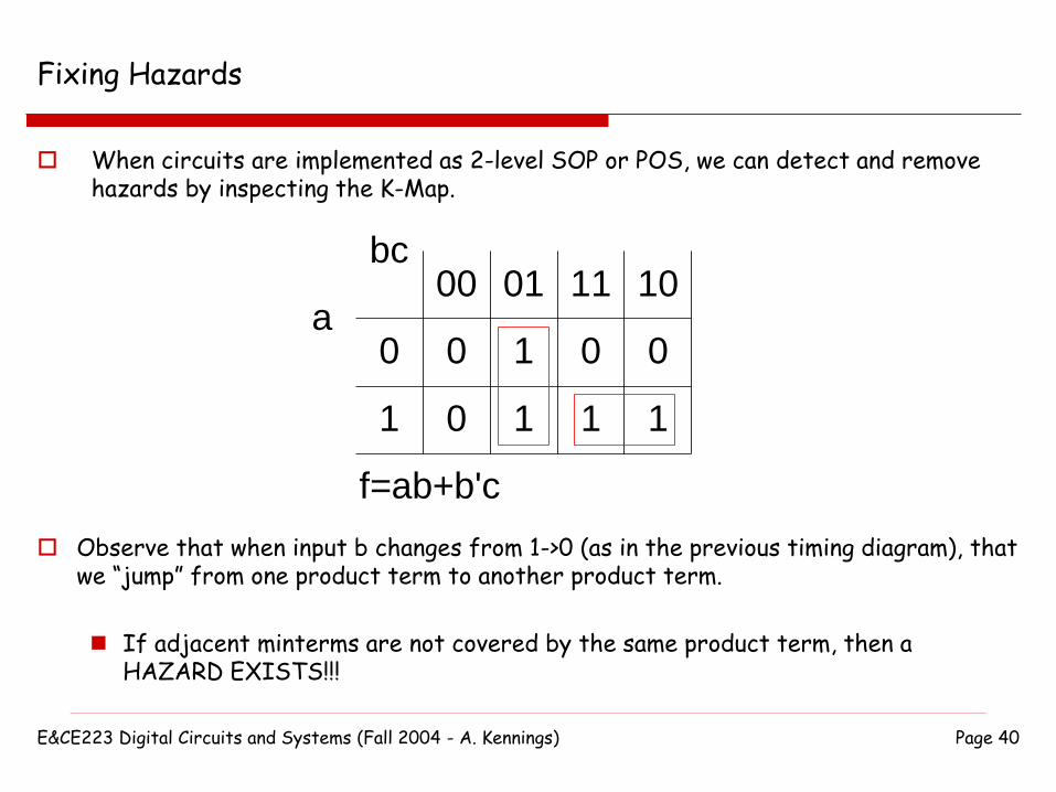
Fixing Hazards
When circuits are implemented as 2-level SOP or POS, we can detect and remove hazards by inspecting the K-Map.
00 01 11 10
0
1
0
0
1
1
0
1
0
1
f=ab+b'c
a
bc
Observe that when input b changes from 1->0 (as in the previous timing diagram), that we “jump” from one product term to another product term.
If adjacent minterms are not covered by the same product term, then a HAZARD EXISTS!!!
E&CE223 Digital Circuits and Systems (Fall 2004 - A. Kennings) Page 41
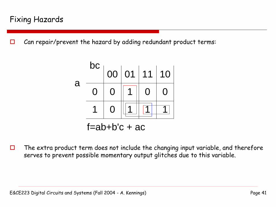
Fixing Hazards
Can repair/prevent the hazard by adding redundant product terms:
00 01 11 10
0
1
0
0
1
1
0
1
0
1
f=ab+b'c + ac
a
bc
The extra product term does not include the changing input variable, and therefore serves to prevent possible momentary output glitches due to this variable.
E&CE223 Digital Circuits and Systems (Fall 2004 - A. Kennings) Page 42
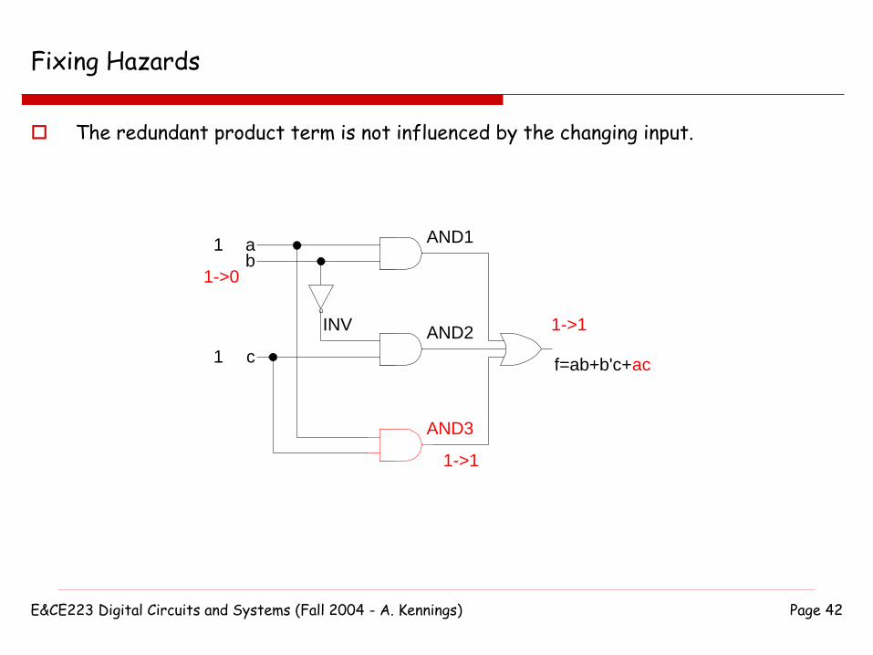
Fixing Hazards
The redundant product term is not influenced by the changing input.
ab
c
INV
AND1
AND2
f=ab+b'c+ac
1
1
1->0
1->1
1->1
AND3

E&CE223 Digital Circuits and Systems (Fall 2004 - A. Kennings) Page 43
Fixing Hazards
For 2-level circuits, if we remove all static-1 hazards using the K-Map (adding redundant product terms), we are guaranteed that there will be no static-0 hazards or dynamic hazards.
If we work with Product-Of-Sums, we might find static-0 hazards when moving from one sum term to another sum term. We can remove these hazards by adding redundant sum-terms.

E&CE223 Digital Circuits and Systems (Fall 2004 - A. Kennings) Page 44
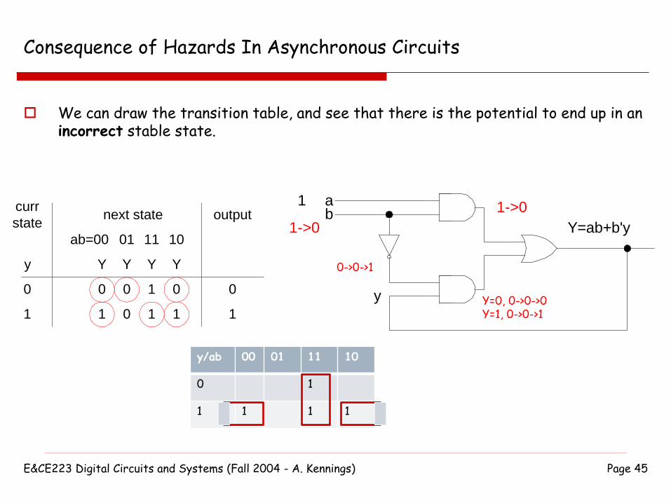
Consequence of Hazards In Asynchronous Circuits
Consider our first circuit with a hazard, but assume it is not combinatorial, but rather asynchronous:
ab
Y=ab+b'y
1
1->0
y
1->0
E&CE223 Digital Circuits and Systems (Fall 2004 - A. Kennings) Page 45
Consequence of Hazards In Asynchronous Circuits
We can draw the transition table, and see that there is the potential to end up in an incorrect stable state.
ab=00 01 11 10
0
1
y
next statecurr
stateoutput
Y Y Y Y
0
1
0
1
1
1
0
0
0
1
ab
Y=ab+b'y
1
1->0
y
1->0
y/ab 00 01 11 10
0 1
1 1 1 1
0->0->1
Y=0, 0->0->0Y=1, 0->0->1
E&CE223 Digital Circuits and Systems (Fall 2004 - A. Kennings) Page 46
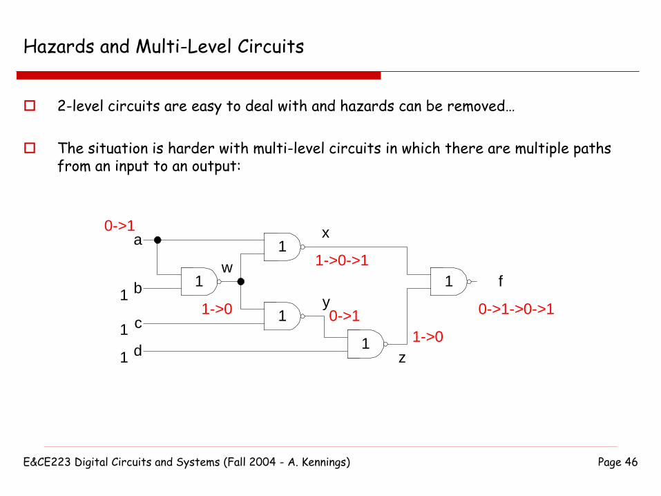
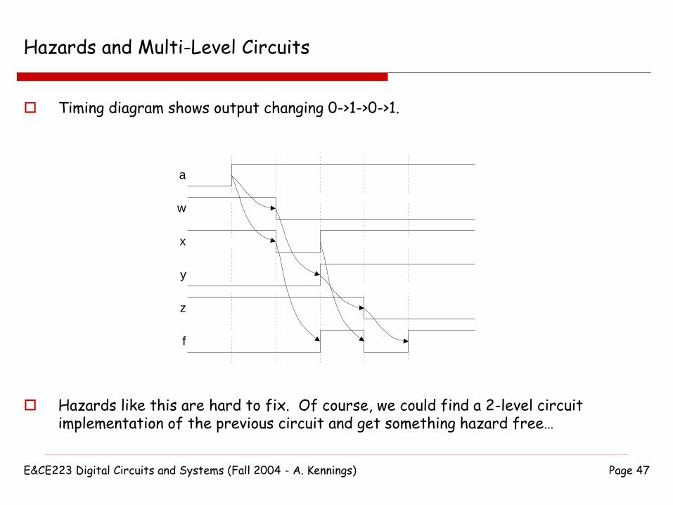
Hazards and Multi-Level Circuits
2-level circuits are easy to deal with and hazards can be removed…
The situation is harder with multi-level circuits in which there are multiple paths from an input to an output:
a
b
c
d
w
x
y
z
f
1
0->1
1
1
1->0
1->0->1
0->1
1->0
0->1->0->1
1
1
1
1
1
E&CE223 Digital Circuits and Systems (Fall 2004 - A. Kennings) Page 47
Hazards and Multi-Level Circuits
Timing diagram shows output changing 0->1->0->1.
Hazards like this are hard to fix. Of course, we could find a 2-level circuit implementation of the previous circuit and get something hazard free…
a
w
x
y
z
f
E&CE223 Digital Circuits and Systems (Fall 2004 - A. Kennings) Page 48
Fixing Hazards With Latches
Can also fix hazards with SR (or S’R’) Latches.

E&CE223 Digital Circuits and Systems (Fall 2004 - A. Kennings) Page 49
Fixing Hazards With Latches
Recall an SR Latch can tolerate momentary 0s appearing at its inputs (since we might momentarily move from a set or reset to a hold and then back):
Q
!Q
R (reset)
S (set)
E&CE223 Digital Circuits and Systems (Fall 2004 - A. Kennings) Page 50
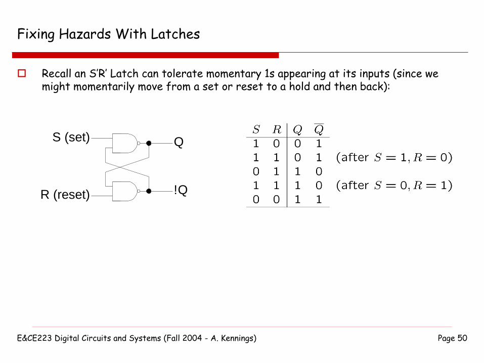
Fixing Hazards With Latches
Recall an S’R’ Latch can tolerate momentary 1s appearing at its inputs (since we might momentarily move from a set or reset to a hold and then back):
Q
!Q
S (set)
R (reset)

E&CE223 Digital Circuits and Systems (Fall 2004 - A. Kennings) Page 51
Fixing Hazards With Latches
Consider our original circuit with a static-1 hazard (temporary 0 at output):
ab
c
f=ab+b'c
1
1
1->0 00 01 11 10
0
1
0
0
1
1
0
1
0
1
f=ab+b'c
a
bc

E&CE223 Digital Circuits and Systems (Fall 2004 - A. Kennings) Page 52
Fixing Hazards With Latches
Consider that we take our output f from the output of a latch. Since we are trying to fix static-1 hazards we need to be able to tolerate
momentary 0s at latch inputs => Use a SR Latch (NOR Latch). To get the function f from the latch output, we need equations for S and R of the
latch (so that the latch gets SET when f should be one, otherwise RESET).
00 01 11 10
0
1
0
0
1
1
0
1
0
1
Equation for S
a
bc00 01 11 10
0
1
1
1
0
0
1
0
1
0
Equation for R
a
bc
ab
c
f=ab+b'c
1
1
1->0 00 01 11 10
0
1
0
0
1
1
0
1
0
1
f=ab+b'c
a
bc

E&CE223 Digital Circuits and Systems (Fall 2004 - A. Kennings) Page 53
Fixing Hazards With Latches
Draw a circuit using the latch, and see that glitch in output due to the hazard is gone.
ab
c
S
1
1
1->0 R
0->0
0->0
0->0
1->0
0->1
f
1->1
1->0->1
1->1
0->0

E&CE223 Digital Circuits and Systems (Fall 2004 - A. Kennings) Page 54
Textbook
Hazards are covered in Chapter 9, Section 9.7 of the course textbook.